An Active Magnetic Damper Concept for Stabilization of Gas … · · 2017-06-09An Active Magnetic...
11
© 2014 IEEE IEEE Transactions on Industrial Electronics, Vol. 61, No. 6, pp. 3089-3098, June 2014 An Active Magnetic Damper Concept for Stabilization of Gas Bearings in High-Speed Permanent-Magnet Machines A. Looser, J. W. Kolar This material is published in order to provide access to research results of the Power Electronic Systems Laboratory / D-ITET / ETH Zurich. Internal or personal use of this material is permitted. However, permission to reprint/republish this material for advertising or promotional purposes or for creating new collective works for resale or redistribution must be obtained from the copyright holder. By choosing to view this document, you agree to all provisions of the copyright laws protecting it.
Transcript of An Active Magnetic Damper Concept for Stabilization of Gas … · · 2017-06-09An Active Magnetic...
© 2014 IEEE
IEEE Transactions on Industrial Electronics, Vol. 61, No. 6, pp. 3089-3098, June 2014
An Active Magnetic Damper Concept for Stabilization of Gas Bearings in High-SpeedPermanent-Magnet Machines
A. Looser,J. W. Kolar
This material is published in order to provide access to research results of the Power Electronic Systems Laboratory / D-ITET / ETH Zurich. Internal or personal use of this material is permitted. However, permission to reprint/republish this material for advertising or promotional purposes or for creating new collective works for resale or redistribution must be obtained from the copyright holder. By choosing to view this document, you agree to all provisions of the copyright laws protecting it.

IEEE TRANSACTIONS ON INDUSTRIAL ELECTRONICS, VOL. 61, NO. 6, JUNE 2014 3089
An Active Magnetic Damper Concept forStabilization of Gas Bearings in High-Speed
Permanent-Magnet MachinesAndreas Looser, Student Member, IEEE, and Johann W. Kolar, Fellow, IEEE
Abstract—The successful application of ultrahigh-speedelectrical-drive systems in industrial products is currently limitedby lacking high-speed bearing technologies permitting high relia-bility and long lifetime. Promising bearing technologies for highrotational speeds are contactless bearing concepts such as activemagnetic bearings or gas bearings. While magnetic bearingsusually are major electromechanical systems with substantialcomplexity, gas bearings allow compact realizations with high loadcapacity and stiffness; however, poor dynamic stability has beenlimiting their use at high rotational speeds. Following a hybridbearing approach with an aerodynamic gas bearing for loadsupport, a small-sized active magnetic damper concept is proposedto enable the stable high-speed operation of the gas bearing witha minimum of additional complexity and costs. As for the effectivestabilization of the gas bearing, a high-quality displacementmeasurement is essential, and a new eddy-current-based rotor-displacement self-sensing concept employing an auxiliarysignal injection and rotor displacement measurement circuit ispresented. A hardware implementation of the proposed concept isshown providing high-resolution measurement signals.
Index Terms—Active magnetic damper, high-speed permanent-magnet machines, signal injection self-sensing, vibration control.
I. INTRODUCTION
FUTURE ultrahigh-speed electrical drives are expected inemerging applications such as turbocompressor systems
for fuel cells and heat pumps, generators for portable gas orair turbines, printed circuit board (PCB) drilling, machiningspindles, and optical devices [1], [2]. Rotational speeds forthese applications range from 200 kr/min to 1 Mr/min at powerratings of a few tens of watts to a few kilowatts. The mainchallenges and limitations involved with high-speed machinedesign which are of thermal, elastic, and rotordynamical naturehave been discussed in [3]. Thus, a multiphysical machineoptimization has been performed in [4] for the design of a200-kr/min 2-kW permanent-magnet machine. An optimizedmachine design with low losses at high speeds as well as arobust mechanical rotor construction in order to cope with ro-tordynamics and the high stresses at high rotational speeds hasbeen presented in [5], and the operation of a 100-W permanent-
Manuscript received January 31, 2013; revised April 25, 2013 and July 25,2013; accepted August 18, 2013. Date of publication October 1, 2013; date ofcurrent version December 20, 2013.
The authors are with Power Electronic Systems Laboratory, ETH Zurich,8092 Zurich, Switzerland (e-mail: [email protected]; [email protected]).
Color versions of one or more of the figures in this paper are available onlineat http://ieeexplore.ieee.org.
Digital Object Identifier 10.1109/TIE.2013.2284152
magnet machine has been demonstrated at speeds up to1 Mr/min [1]. However, the use of such ultrahigh-speed drivesystems in industrial applications is limited mainly due to theabsence of reliable bearings with long lifetime at high rotationalspeeds. Precision ball bearings designed for dental drills witha maximum rated speed of 400 kr/min (corresponding to aDN number of 1.5 million)1 showed a total lifetime of around200–300 h in cyclic tests where the speed was varied between200 and 500 kr/min. However, for future industrial high-speedapplications, a lifetime of several years at speeds beyond500 kr/min would be required.
Promising candidates for high-speed bearings with longerlifetimes are contactless concepts such as active magnetic bear-ings or gas bearings, where, for the latter, the rotor is carriedby the fluid film generated between the bearing bushing and thejournal.
For active magnetic bearings, very high speed operationhas been demonstrated with a self-bearing permanent-magnetmotor design at rotational speed of up to 400 kr/min [6], whichin recent achievements could be further increased to 505 kr/min[7]. Aside from the possibility for high-speed operation, oneof the main benefits of active magnetic bearings is also theircapability of active vibration control of structural resonance[8], which can allow operation at speeds beyond the rotor’snatural frequencies. However, employing active magnetic bear-ings usually increases the drive system complexity due to theadditional actuators, sensors, power amplifiers, and control andoften yields less compact drive systems, particularly for drivesystems of small rated power.
Gas bearings exist as aerostatic and aerodynamic bearings.For the aerostatic bearing, the rotor is carried by the fluidfilm generated by an external pressurized air supply. For aero-dynamic bearings, the fluid film is generated by the journalrotation itself, therewith eliminating the need of an externalpressurized air supply and allowing for a very compact design.As illustrated in Fig. 1 for the case of a plain journal bearing,a pressure is generated when the journal is displaced by ε.Under rotation, the fluid is dragged into the formed converginggap, generating a high pressure. On the diverging side, a lowerpressure occurs. As a result, a net force acts on the journal,restoring the journal to its centered position. Compared tomagnetic bearings, gas bearings can usually be designed much
1The DN number is defined as the bearing diameter (D) in millimeters timesthe rotational speed (N) in revolutions per minute.
0278-0046 © 2013 IEEE

3090 IEEE TRANSACTIONS ON INDUSTRIAL ELECTRONICS, VOL. 61, NO. 6, JUNE 2014
Fig. 1. Working principle of a gas-lubricated plain journal bearing: Due tothe formation of a converging air gap when the journal is displaced, the airis dragged into the converging gap, generating a pressure distribution whichresults in a force restoring the journal to its centered position.
smaller for the same load capacity and stiffness, for whichreason more compact drive systems can be realized.
One of the major challenges with high-speed gas bearings,however, is the self-excited whirl instability which limits themaximum operating speed. The phenomenon of whirl instabil-ity has been known from the beginning of fluid film lubricationand has been thoroughly studied, e.g., in [9]. Usually, the bear-ing restoring force encloses an angle φ to the displacement vec-tor ε, which is known as the bearing’s attitude angle. Thus, themain causes for the instability are the destabilizing azimuthalforce component perpendicular to the journal displacement,instead of a purely radial force into the bearing center (asvisualized in Fig. 1), combined with relatively low dampingfrom the fluid film itself. In order to cope with the gas bearing’sinstability encountered at higher speeds or with heavier rotors, avariety of gas-bearing types have been developed in the historyof fluid film lubrication. Gas-bearing types known for their rel-atively good stability are, e.g., the tilting-pad bearing [10], theherringbone-grooved bearing [11], and also the foil bearings.For foil bearings, speeds of up to 700 kr/min have been re-ported, however driven by a relatively light air turbine [12]. Foilbearings supporting the rotor of a permanent-magnet brush-less dc machine at a speed of 350 kr/min are reported in [13].
A further increase of rotational speed up to 1.2 Mr/minhas been achieved with a helium-driven turbine employing aflexible supported bearing bushing and an oil damper [14].However, with the elastic support, also the overall stiffness ofthe bearing-damper assembly is reduced. In [15], the conceptof the damped elastic support has been applied to a permanent-magnet synchronous machine, and a speed of 410 kr/min hasbeen achieved; in order to increase the speed to the targeted600 kr/min, a further increase in accuracy for rotor fabricationis suggested.
Another approach to stabilize fluid film bearings is encoun-tered, e.g., in [16] where active magnetic bearings are used forvibration control. Although increasing the size and complexityof the drive system, the active magnetic bearings are effectivelyused to control the oil whirl and oil whip instability of a journalbearing, therewith increasing the range of operation.
It can be summarized that, generally, there have been twostrategies to improve the gas bearing’s stability. Improvementshave been achieved either by a reduction of the destabilizingazimuthal force component usually accomplished by a spe-cial bearing geometry and/or by the introduction of additionaldamping from outside the fluid film.
In a given application, the bearings need to support a rotorof an electrical machine capable of providing a required shaftpower. The rotor of such a system will be heavier than theair turbines used for record speed bearing tests, and therefore,instability occurs already at lower speeds as the aforementionedexamples with permanent-magnet rotors show. A stable designfor, e.g., a herringbone-grooved journal bearing supporting arelatively heavy permanent-magnet rotor would theoretically bepossible by scaling down the gas-bearing clearance. However,this approach is hardly feasible because of the requirement forhigh precision fabrication with very tight production toleranceswhich finally would limit an industrial implementation. Un-fortunately, gas-bearing designs with more relaxed productiontolerances would become unstable already at lower speeds formany of the targeted permanent-magnet machine applications.
Therefore, a hybrid bearing concept employing a self-sensingactive magnetic damper (AMD) was proposed by the authors in[17], intended to enable stable operation at high speeds also forheavy permanent-magnet rotors. The hybrid concept combinesthe advantages of high load capacity and stiffness of the gasbearing with the capability of vibration control of the activemagnetic damper and allows for a feasible gas-bearing designwhich, without active control, would become unstable at highspeeds. With the proposed concept, no decrease of overall stiff-ness and load capacity has to be traded for better stability as isthe case with the concept of a damped elastic support. Further-more, the increase of complexity added by the active magneticdamper is kept at a minimum due to the absence of additionalsensors, i.e., due to the self-sensing approach; the absence ofadditional sensors allows to keep the rotor length as short aspossible, which is a key factor in high-speed machine design.With the damper only providing vibration control and not thefull rotor support, the damper can be designed very small.
In this paper, the original conceptual work is advanced withan implementation of the proposed self-sensing topology ona PCB and measurements thereof. Moreover, a new flexibleprinted circuit (FPC) winding is presented, replacing the wire-wound conventional air-gap winding and allowing for an evenmore compact damper design which then enables a more effi-cient motor design.
First, the hybrid bearing concept, including motor, gas bear-ings, and magnetic damper, is explained in Section II. The rotordisplacement self-sensing method employing an eddy-current-based high frequency signal injection approach is described inSection III. The hardware implementation of the self-sensingcircuit together with the FPC winding is presented inSection IV, where, also, measurement results for the radial rotordisplacement self-sensing in a prototype permanent-magnetmachine are shown.
II. HYBRID BEARING CONCEPT
A conceptual drawing of a high-speed permanent-magnetmachine with the proposed hybrid bearing approach is shownin Fig. 2. The electrical motor is a slotless-type permanent-magnet synchronous machine constructed according to themachine design in [5], which has been well proven for high ro-tational speeds. The rotor consist of a diametrically magnetized

LOOSER AND KOLAR: ACTIVE MAGNETIC DAMPER CONCEPT FOR STABILIZATION OF GAS BEARINGS 3091
Fig. 2. Conceptual drawing of a high-speed permanent-magnet machine witha hybrid bearing concept employing gas bearings in combination with activemagnetic dampers.
permanent magnet encased in a retaining sleeve to protectthe brittle permanent magnet from breaking due to the highcentrifugal forces at high speeds. For the motor winding,slotless-type air-gap windings with litz wire are used in orderto minimize the eddy-current losses caused by the permanent-magnet field at high frequencies. For the same reason, the statorback iron consists of amorphous iron. More information onthe conceptual design of high-speed slotless permanent-magnetmachines is found in [1], [5], and [18].
The gas bearings are located outside the motor’s activeregion. A restriction to the type of journal gas bearing is nota priori given. In order to minimize the amount of requireddamping, a gas bearing with improved performance at highspeeds is favored, such as the gas-bearing types discussed inSection I. For manufacturing reasons, a bearing type with afixed geometry (i.e., without foils or moving parts) is preferred,e.g., the herringbone-grooved journal bearing depicted in Fig. 2.The axial bearing can be a spiral grooved or Rayleigh-stepbearing, as commonly used in gas-bearing systems. For axialbearings, unstable behavior is much less of a concern than forjournal bearings. Therefore, no magnetic dampers are requiredfor axial stabilization.
Two active magnetic bearing concepts are known for therealization of the magnetic damper, namely, the homopolar andthe heteropolar concept. The term heteropolar refers to a con-figuration where the rotor is exposed to a magnetic field withalternating polarity as it rotates, and the term homopolar de-notes a configuration with unchanging polarity [19]. Generally,both a homopolar and a heteropolar damper topology wouldbe suited for vibration control of a shaft rotating at high speeds.
The heteropolar damper concept requires a diametricallymagnetized permanent magnet which is already existing andneeded for drive torque generation. Hence, integration into theactive region of the motor is straightforward with an additionalair-gap winding for the damper and yields a very compactdesign [6]. Clearly, by integrating the damper into the activeregion of the motor, the torque capability of the machine is re-duced. A damper design of minimal wall thickness is thereforeadvantageous.
A homopolar damper realization would require additionalaxially magnetized permanent magnets; this complicates therotor construction for which reason the homopolar concept isnot further considered.
The force generation principle of the heteropolar damperdesign is visualized in Fig. 3. The inner winding (damper wind-
Fig. 3. Force generation by means of a two-pole-pair winding for the mag-netic damper winding arranged on the inner diameter of the motor winding.(a) Situation with a rotor angle of θr = 0 and an AMD current space vectorphase angle of ϕ = 0. (b) Situation with arbitrary angles θr and ϕ.
ing) is used to produce a fundamental current distribution witha pole-pair number of two; hence, with the magnetic field of thediametrically magnetized permanent magnet, Lorentz forces acton the winding, respectively, and a resultant reaction force isobtained on the rotor. The outer winding (motor winding) withonly one pole pair produces a force couple, and therefore, atorque results on the rotor.
The damper forces in the two radial directions x and y canbe described as
fx =KI · id (1)
fy =KI · iq (2)
where KI is the force-current constant of the damper and id andiq are the rotor flux-oriented stator currents in dq coordinates.Note that KI is the direction independent for the presentmachine design with a diametrically magnetized permanentmagnet. The rotating dq-coordinate system is defined by therotor angle θr, which is given by the direction of the permanent-magnet flux. Accordingly, the flux-oriented currents can bedefined as
id = − I sin(ϕ− θr) (3)
iq = I cos(ϕ− θr) (4)
where I and ϕ denote the AMD current space vector’s ampli-tude and phase angle, respectively.
In Fig. 3(a), the situation of a pure q current is drawn,resulting in a force in the y-direction. Rotating the current dis-tribution by −45◦ corresponds to a pure d current distribution,

3092 IEEE TRANSACTIONS ON INDUSTRIAL ELECTRONICS, VOL. 61, NO. 6, JUNE 2014
Fig. 4. Bode diagram of (solid line) the dynamic stiffness (f/ε) and its phaseangle for the gas bearing and (dashed line) the damping force (d/ε) providedby the magnetic damper, which is needed to stabilize the rotor in the unstableregion around 300 kr/min.
resulting in a force in the x-direction. The situation for arbitraryrotor and current space vector angles is depicted in Fig. 3(b).
In the simplest case, vibration control is accomplished bygenerating damper forces proportional to the rotor’s radialvelocities. Based on the velocity in the according directions
vx =d
dtεx (5)
vy =d
dtεy (6)
expressed in terms of the rotor displacements εx and εy , thedamping control reference currents are given by
i∗d = − d
KI· vx (7)
i∗q = − d
KI· vy (8)
where d is the damping factor. For vibrations with high fre-quencies, the aforementioned time derivative would yield veryhigh damper currents. Therefore, a first-order low-pass filter isapplied, limiting damping at higher frequencies.
Considering the example of a herringbone-type bearing witha diameter of 6 mm, a length of 8 mm, a clearance of 15 μm, andcurved grooves, optimized for maximum stability at 500 kr/min,the highest amount of damping force occurs at speeds around300 kr/min. For this operating point, the dynamic stiffness ofthe gas bearing (bearing reaction force per displacement, f/ε)has been calculated using a finite difference method to solve thepartial differential equation for the bearing clearance averagepressure, which is based on the narrow groove theory originallyproposed in [20]. Based on a rotor dynamic analysis incorpo-rating the calculated dynamic bearing stiffness, the requireddamping force needed for stabilization can be determined. Thecalculated damper force as well as the dynamic stiffness of thegas bearing is plotted in the Bode diagram in Fig. 4. Compared
Fig. 5. Speed-dependent root loci of the bearing-rotor system. (a) Unstablesystem without active magnetic stabilization. (b) Stable system with activemagnetic stabilization.
to the force provided by the gas bearing, the required dampingforce is relatively small. As a result, the magnetic dampers canbe designed significantly smaller compared to a drive systemwith magnetic bearings providing the full rotor support.
The speed-dependent root loci of the rotor-bearing systemwithout active stabilization are depicted in Fig. 5(a). Withincreasing speed, the poles move toward the imaginary axisand become unstable at a speed of around 80 kr/min. Fig. 5(b)shows the root loci of the system employing active magneticdamping. The system is stabilized for all speeds, and accord-ingly, all unstable poles have shifted into the left half of theimaginary plane.
In order to produce damping forces in response to radialrotor motion, an accurate radial rotor velocity measurement isneeded. As the velocity can be easily obtained with the timederivative of the displacement, a rotor displacement measure-ment could also be used. Rotor radial displacements or veloci-ties to be measured are expected on the order of 0.1–10 μm and1–100 mm/s, respectively. With AMBs, the radial clearance isusually on the order of some hundreds of micrometers whilethe clearance of the gas bearings will be maximally 10 or20 μm. Hence, the sensitivity and resolution requirements ofthe rotor displacement measurement are expected to be muchhigher compared to the requirements for state-of-the-art AMBs.Achieving high sensitivity and accuracy of the velocity ordisplacement measurement is therefore considered as one ofthe main challenges implicated by the proposed hybrid bearingconcept.

LOOSER AND KOLAR: ACTIVE MAGNETIC DAMPER CONCEPT FOR STABILIZATION OF GAS BEARINGS 3093
Fig. 6. Eddy-current displacement measurement employing two oppositelyarranged search coils.
III. DISPLACEMENT MEASUREMENT—EDDY-CURRENT
SELF-SENSING
Commonly used approaches for rotor displacement mea-surement in self-sensing magnetic bearings are based on theobservation of the actuator’s inductance which is a function ofthe magnetic air gap and hence also of the rotor displacement.Therewith, the bearing linear power amplifier or switched am-plifier is used to modulate the bearing current or superimpose atest signal in order to observe the displacement-dependent self-or mutual-inductance change [21]–[23]. In order to observe aninductance change caused by a displaced rotor, ferromagneticmaterials on the rotor are required, which, however, is notthe case for the present machine. Therefore, no change of theinductance occurs, and the method cannot be applied.
In conventional active magnetic bearing systems, eddy-current sensors have been commonly used and have beenwell proven [24]. Furthermore, they are not restricted to onlyferromagnetic materials and have shown very high sensi-tivity. Therefore, eddy-current-based position sensing seemspromising.
For the present magnetic damper, a concept is proposed,where the damper coils, which are implemented as air-gapwindings, are simultaneously used as eddy-current displace-ment sensors. With the twofold use of the damper winding,i.e., a winding in a self-sensing configuration, no additionalrotor length is required for position sensing. To obtain the highsensitivity of the eddy-current displacement measurement, theinjection of a test signal with a frequency of up to 10 MHzis required. Signal injection at such a high frequency cannotbe easy accomplished by a linear or switched power amplifierused for the damper current; thus, an auxiliary signal injectionand measurement circuit is required. Although the term self-sensing does not apply to the full system as auxiliary circuitsare needed on the electronic side, it applies fully to the machinepart which can be realized in smaller size due to reduced partcount. Therefore, the denotation is continued in the following.
For the measurement in the x-direction, a coil pair withcoils denoted as Lx+ and Lx− is required, as depicted inFig. 6. When the rotor is displaced by a positive value ofεx, the impedance of Lx+ decreases due to eddy currentson the approaching rotor. Accordingly, the impedance of Lx−increases. For the measurement in the y-direction, another coilpair with coils denoted as Ly+ and Ly− is required. Thus, inorder to measure the displacement of the rotor in the two radialdirections x and y, a damper winding with two pairs of oppo-sitely arranged coils could be employed, as illustrated in Fig. 7.
Fig. 7. (a) Winding scheme of the two-phase magnetic damper winding withoppositely arranged coil pairs for eddy-current-based high frequency signalinjection displacement sensing. The dots designate the winding sense of thecoils. (b) Wire-wound prototype winding.
Fig. 8. Bridge-connected windings Lx+ and Lx− for the measurement ofthe displacement-dependent impedance change using differentially coupledinductors. The high frequency injected current ihf splits according to theinstantaneous impedance value of the coils Lx+ and Lx−, yielding modulatedmeasurement signal ux with an amplitude proportional to the rotor displace-ment εx.
All four coils Lx+, Lx−, Ly+, and Ly− connected in seriesform the first phase of the damper winding, denoted as phaseA. The order of the series connection is chosen later in orderto meet the requirements for the intended signal injectionself-sensing technique. To form a damper winding with a pole-pair number of p = 2 and m = 2 phases, another set of series-connected coils is required for the second phase B, with itsconductors arranged 45◦ from the conductors of phase A. PhaseB is preferably implemented as an ordinary series connectionof the winding turns denoted as LB ; no additional tappings arerequired within phase B.
For the derivation of the displacement measurement princi-ple, the impedance of the coil Lx− is assumed a general func-tion Zx− = Zx(εx, εy) of the rotor displacements εx and εy .Assuming symmetry, Lx+ corresponds to Zx+ = Zx(−εx, εy).For very small rotor displacements, the coil impedances canthen be described by their first-order approximations as
Zx+ ≈Z0 −∂Zx
∂εx· εx +
∂Zx
∂εy· εy (9)
Zx− ≈Z0 +∂Zx
∂εx· εx +
∂Zx
∂εy· εy (10)
where Z0 = Zx(0, 0) denotes the coil impedance for a per-fectly centered rotor. To measure the impedance change, ameasurement bridge as depicted in Fig. 8 is proposed. Nodifferential voltage measurement is needed as would be the casewith a conventional Wheatstone bridge. Instead, the common

3094 IEEE TRANSACTIONS ON INDUSTRIAL ELECTRONICS, VOL. 61, NO. 6, JUNE 2014
Fig. 9. Self-sensing high frequency signal injection circuit for displacementmeasurement in x- and y-directions (εx and εy) with power amplifiers andcontrol. Actuator currents (brown and blue for phase A and phase B) and highfrequency injected currents (green and orange) are colored according to theAMD winding scheme of Fig. 7.
mode voltage is canceled with the use of differentially coupledinductors Lm.
Assuming ideal inductors Lm without a parasitic series re-sistance, the voltage across the inductor measured to ground isgiven by
ux = ihf · Zm
Z0 +∂Zx
∂εy· εy + 2Zm
· ∂Zx
∂εx· εx (11)
where ihf denotes the current injected by a high frequency cur-rent source. Assuming that the impedance change (∂Zx/∂εy) ·εy due to a displacement in the y-direction is small comparedto the nominal coil impedance Z0, the measured voltage simpli-fies to
ux = ihf · Zm
Z0 + 2Zm· ∂Zx
∂εx· εx (12)
and is directly proportional to the displacement εx. If a parasiticseries resistance of Lm is present, an offset voltage would occurfor which reason the voltage ux is better measured on theterminals of the third coupled winding as indicated in Fig. 8.
Fig. 9 shows a possible combination of the measurementbridge and the required series connection of the winding coilsof phase A. In order to obtain position information in bothradial directions x and y, high frequency test signals need tobe injected. As the two coil pairs for position measurement inthe x- and y-directions are magnetically coupled, orthogonalinjection signals are needed to avoid a coupling of the twomeasurement channels. Hence, e.g., a sine and a cosine or 90◦
shifted rectangular signals can be used for signal injection. Thehigh frequency currents denoted as Ihf cosωt and Ihf sinωtare injected capacitively through Cin, which is necessary fortwo reasons. First, the damper current from the power am-plifier is not supposed to be influenced at low frequencies,and second, the signal-injecting buffers need to be decoupledfrom the midpoint of the windings which otherwise wouldexpose the buffers to the high back-electromotive force (back-EMF) voltage at high rotational speeds. A further additionalcapacitor Cm is added which represents a short circuit forthe high frequency signal. The output of the power amplifier
Fig. 10. Back-EMF-based angular rotor position measurement with compen-sation of resistive and inductive voltage contributions due to the AMD actuatorcurrent iA. The back-EMF voltages are indicated as ui,x and ui,y , respectively.
for phase A needs to exhibit low impedance to ground athigh frequencies whereby, together with Cm, the measurementbridge is obtained. A low output impedance of the poweramplifier can be accomplished by connecting an LC filter toits output stage. The capacitor Cm has to be dimensionednot to affect the damper current from the power amplifierat low frequencies. Given an injection frequency of 10 MHzand assuming a damper control bandwidth of less than 10 kHz,the impedance of Cm at these frequencies differs at least by60 dB; hence, signal separation can be easily guaranteed.
In order to obtain the displacements, the known steps for thedemodulation of an amplitude-modulated signal are followed.First, the signals ux and uy are fed through a bandpass filterfollowed by a frequency mixer. After the mixer, the signals areprocessed through a low-pass filter which eliminates the highfrequency spectral components and yields a signal proportionalto the displacements εx and εy . The displacement signals arethen further processed to obtain the radial velocities needed forthe control of the damper currents.
In order to transform the damper reference currents fromthe rotating dq-coordinate system of the rotor into windingreference currents according to
i∗A = i∗d cos θr − i∗q sin θr (13)
i∗B = i∗d sin θr + i∗q cos θr (14)
also the angular rotor position θr needs to be provided.Therefore, the back-EMF voltage is measured at the wind-ing midpoint tapping. According to Luomi et al. [5], theradial component of the magnetic field density in the air gapof a slotless machine with a diametrically magnetized perma-nent magnet is Br ∝ cos(θr). Therefore, the induced voltagesui,x and ui,y over the coils Lx and Ly must be proportionalto ui,x ∝ θr · cos θr and ui,y ∝ θr · sin θr. The integration ofthe back EMF yields again proportionality to the permanent-magnet flux and, hence, signals proportional to cos θr andsin θr which can be used directly for the aforementionedtransformation.
In Fig. 9, the back-EMF-based angular position measurementis indicated by a simple voltage measurement and the subse-quent integrator block. Aside from the back-EMF voltage, alsoresistive and inductive voltages occur across the winding coilsdue to the AMD actuator current iA. Thus, in order to cancel outthese unwanted voltage contributions in the measurement, thevoltage is measured relative to a reference potential generatedby means of a resistive voltage divider Rm as depicted inFig. 10.
LOOSER AND KOLAR: ACTIVE MAGNETIC DAMPER CONCEPT FOR STABILIZATION OF GAS BEARINGS 3095
TABLE IDAMPER WINDING SPECIFICATIONS
Fig. 11. Measurement bridge output voltage Ux normalized with the injectedcurrent Ihf as a function of the rotor displacement εx.
IV. HARDWARE IMPLEMENTATION AND MEASUREMENTS
In the preliminary work [17], a wire-wound air-gap wind-ing [see Fig. 7(b)] and sensitivity measurements thereof werepresented showing the feasibility of the proposed self-sensingapproach. For the sensitivity measurement, a 6-mm stainlesssteel rod in place of the rotor and a wire-wound winding asspecified in Table I are used. The winding is connected ina measurement bridge according to Fig. 8. A high frequencycurrent with an amplitude of Ihf = 20 mA is injected into thewinding, and the voltage Ux is measured at the measurementbridge output. For the coupled inductor Lm, a double-aperturecore (Epcos K1) with an inductance of 3× 10 μH is used.Fig. 11 shows the measured output voltage Ux normalized withthe injected current Ihf as a function of the rotor displacementεx for various frequencies. If the voltage Uhf is also measured,the relative impedance change of the winding can be deter-mined as
ΔZx
Z0=
Ux(IhfZm + Uhf )
U2x + IhfZmUhf
. (15)
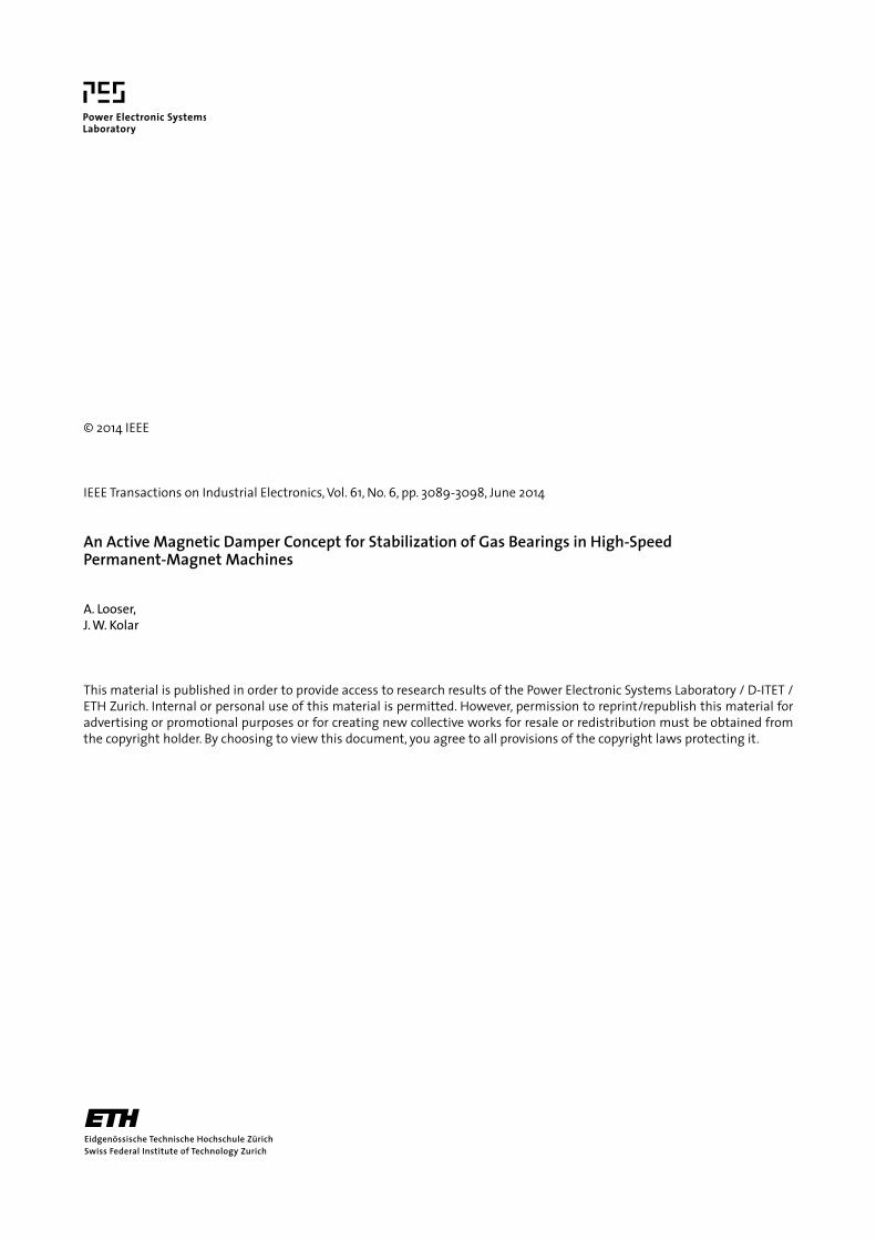
The obtained impedance change as a function of the rotordisplacement εx is plotted in Fig. 12. At a frequency of 10 MHz,
Fig. 12. Impedance change ΔZx of a damper winding coil related to its totalimpedance Z as a function of the rotor displacement εx.
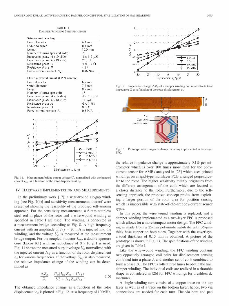
Fig. 13. Prototype active magnetic damper winding implemented as two-layerFPC.
the relative impedance change is approximately 0.1% per mi-crometer which is over 100 times more than for the eddy-current sensor for AMBs analyzed in [25] which uses printedwindings on a rigid-type multilayer PCB arranged perpendicu-lar to the rotor. The higher sensitivity mainly originates fromthe different arrangement of the coils which are located ata closer distance to the rotor. Furthermore, due to the self-sensing approach, the proposed concept profits from exploit-ing a larger portion of the rotor area for position sensingwhich is inaccessible with state-of-the-art eddy-current sensortypes.
In this paper, the wire-wound winding is replaced, and adamper winding implemented as a two-layer FPC is proposedwhich allows for a more compact motor design. The FPC wind-ing is made from a 25-μm polyimide substrate with 35-μm-thick base copper on both sides. Together with the coverlays,a total thickness of 0.15 mm is obtained. A picture of theprototype is shown in Fig. 13. The specifications of the windingare given in Table I.
Like the wire-wound winding, the FPC winding containstwo oppositely arranged coil pairs for displacement sensingcombined into a phase A and another set of coils combined toform a phase B. The FPC is rolled three times to obtain the finaldamper winding. The individual coils are realized in a rhombicshape as considered in [26] for FPC windings for brushless dcmachines.
A single winding turn consist of a copper trace on the toplayer as well as of a trace on the bottom layer; hence, two viaconnections are needed for each turn. The via bore and pad

3096 IEEE TRANSACTIONS ON INDUSTRIAL ELECTRONICS, VOL. 61, NO. 6, JUNE 2014
Fig. 14. Prototype PCB implementation of the proposed self-sensing circuit,top and bottom views. Dimensions: 22.5× 38× 6.5 mm3.
diameters were constrained to 100 and 300 μm, respectively, formanufacturing effort and cost reasons. In order to minimize thedc winding resistance, the copper trace width should be chosenmaximal and hence equal to the via-pad diameter. However,with such wide traces, high proximity effect losses inducedby the permanent-magnet field at high speed would be theconsequence. As a compromise, the width of the copper tracesis chosen to be 170 μm, resulting in a decreased copper fillingfactor. Higher copper filling factors without an increase ofproximity effect losses could only be achieved when allowingsmaller via-pad diameters.
Three electrical connections are needed for both coil pairsof phase A. Phase B requires two connections. Hence, for theeight connections in total, a standard eight-way 0.5-mm pitchflexible-flat-cable connector is used to connect the winding tothe power amplifier and measurement circuit.
The proposed self-sensing circuit, including the measure-ment bridges, high frequency signal injection, demodulation,power amplifiers, and angular rotor position measurement, hasbeen implemented on a four-layer PCB. A picture of the real-ized PCB which is populated with components on both sidesis shown in Fig. 14. For the coupled inductors, ACM-4532common mode chokes from TDK Inc. are used. One-nanofaradceramic capacitors are used for Cin and Cm. High frequencysignal injection is accomplished using a Linear TechnologyLTC6902 precision oscillator configured to provide two 90◦
phase-shifted rectangular signals with a frequency of 10 MHz.An additional operational amplifier is used as voltage followerin order to provide an injected current with an amplitude ofapproximately 10 mA. Demodulation is accomplished withdifferential signaling through a bandpass and amplifier stage,whose output signals are rectified using single-pole double-throw analog switches. An integrated low-pass filter (LT6600-2.5) eliminates the high frequency spectral components andprovides a voltage signal proportional to the displacement.The damper current control and power amplification is imple-mented with an Analog Devices AD8397 operational amplifierproviding a maximum damper current of 310 mA for eachphase. The signal processing circuitry is running from a 5-V
Fig. 15. High-speed electric machine prototype (250 W and 500 kr/min) withhybrid bearing system.
single supply; the power amplifiers are powered by a ±8-Vdual supply.
In a test setup, the described FPC winding is integrated intoan electric machine which is designed for a power of 250 Wand a target speed of up to 500 kr/min. Fig. 15 shows a pictureof the electric machine with the installed FPC dampers.
The maximum allowable speed of the machine depends onthe construction and material selection of the used rotor. For arotor with a titanium grade V retaining sleeve and an encap-sulated samarium–cobalt magnet, the rotor natural frequenciesand material stresses due to centrifugal forces would allow fora maximum speed of 500 kr/min. For a rotor designed withstainless steel 1.4301, however, a maximum speed of approx-imately 400 kr/min is allowable. For first tests, a steel rotoris used because of lower wear and superior gliding propertiesduring start and stop or in case of a bearing touchdown. Theweight of the steel rotor is 16 g. The journal bearing is an eight-pad Rayleigh-step bearing with minimal clearance of nominally8 μm and a diameter and length of 6 mm. The axial bearing isrealized as a spiral grooved bearing.
The machine is operated with a Celeroton CC-75-400 pulse-amplitude-modulated inverter. At start-up, the rotor slides atfirst on the bearing bushings and lifts of at approximately15 kr/min. From there, the rotor is carried by the fluid film ofthe gas bearing.
The displacement measurement with the FPC winding wascalibrated manually by tracing the rotor along the inner surfaceof the bearing bushing to obtain a circle with a radius of thebearing clearance. In this static case, it was found that the di-rections of the measurement signal matched well with thedirections of the physical displacement. In a next step, themachine was operated at low speeds where the gas bearingsbehave dynamically stable without the damper being active. Atlow speeds, only synchronous whirling motion is present whichis the response of the rotor-bearing system to the synchronousexcitation of the rotor imbalance. Fig. 16 shows the measureddisplacement output signals of the PCB prototype at a rota-tional speed of 22 kr/min. The synchronous whirl amplitudeis around 30% of the bearing nominal clearance which corre-sponds to approximately 2.4 μm. It can be seen that the syn-chronous whirling motion is represented with high resolution;the measurement signal noise corresponds to approximately200 nm.
In a next step, using the displacement signals, the controlloop will be closed to provide a damping force and stabilizethe gas bearing at higher speeds, finally up to 500 kr/min.

LOOSER AND KOLAR: ACTIVE MAGNETIC DAMPER CONCEPT FOR STABILIZATION OF GAS BEARINGS 3097
Fig. 16. Open-loop rotor displacement measurement of synchronous whirl ata speed of 22 kr/min over time. A displacement of 1 p.u. corresponds to thegas-bearing clearance (8 μm).
Hence, with the developed prototype, the expectations fora high sensitivity displacement measurement by means of theeddy-current-based self-sensing approach have been confirmed.Giving the possibility to measure rotor motion of submicrome-ter amplitude, the proposed self-sensing concept is considereda solid basis for vibration control of gas bearings at ultrahighspeeds.
V. CONCLUSION
In order to enable the use of ultrahigh-speed electrical-drivesystems with high reliability and long lifetime in industrialapplications, a hybrid bearing concept employing gas bear-ings in combination with a new small-sized self-sensing mag-netic damper with auxiliary signal injection and displacementmeasurement electronics has been proposed. With the newapproach of eddy-current-based displacement self-sensing, amethod has been presented which is ideally suited for air-gapwindings which are the preferred choice of winding types ofultrahigh-speed permanent-magnet machines for the targetedapplications. With the self-sensing approach and with theintegration of the active magnetic damper into the permanent-magnet machine, the amount of additional components, com-plexity, and costs is minimized. A very high sensitivitymeasurement has been shown with a prototype realizationof the proposed concept which is expected to enable sta-ble operation of gas bearings and permanent-magnet rotorsat highest operational speeds without compromising the gasbearing’s high load capacity and stiffness and allow for moregenerous or feasible production tolerances and, hence, lowercosts.
REFERENCES
[1] C. Zwyssig, J. Kolar, and S. Round, “Megaspeed drive systems: Pushingbeyond 1 million r/min,” IEEE/ASME Trans. Mechatronics, vol. 14, no. 5,pp. 564–574, Oct. 2009.
[2] D. Krahenbuhl, C. Zwyssig, and J. Kolar, “Half-controlled boost rectifierfor low-power high-speed permanent-magnet generators,” IEEE Trans.Ind. Electron., vol. 58, no. 11, pp. 5066–5075, Nov. 2011.
[3] A. Borisavljevic, H. Polinder, and J. Ferreira, “On the speed limits ofpermanent-magnet machines,” IEEE Trans. Ind. Electron., vol. 57, no. 1,pp. 220–227, Jan. 2010.
[4] P.-D. Pfister and Y. Perriard, “Very-high-speed slotless permanent-magnetmotors: Analytical modeling, optimization, design, and torque measure-
ment methods,” IEEE Trans. Ind. Electron., vol. 57, no. 1, pp. 296–303,Jan. 2010.
[5] J. Luomi, C. Zwyssig, A. Looser, and J. Kolar, “Efficiency optimizationof a 100-W 500 000-r/min permanent-magnet machine including air-friction losses,” IEEE Trans. Ind. Appl., vol. 45, no. 4, pp. 1368–1377,Jul./Aug. 2009.
[6] T. Baumgartner, R. Burkart, and J. Kolar, “Analysis and design of an ultra-high-speed slotless self-bearing permanent-magnet motor,” in Proc. 38thAnnu. IEEE IECON, Oct. 2012, pp. 4477–4483.
[7] T. Baumgartner, R. Burkart, and J. Kolar, “Analysis and design of a300 W–500 000 rpm slotless self-bearing permanent-magnet motor,”IEEE Trans. Ind. Electron., to be published.
[8] J. Fang, S. Zheng, and B. Han, “AMB vibration control for structuralresonance of double-gimbal control moment gyro with high-speed mag-netically suspended rotor,” IEEE/ASME Trans. Mechatronics, vol. 18,no. 1, pp. 32–43, Feb. 2013.
[9] H. Marsh, “The stability of aerodynamic gas bearings,” in Mechani-cal Engineering Science Monograph. London, U.K.: Inst. Mech. Eng.,Jun. 1965.
[10] D. Kim, A. M. Rimpel, S. S. Chang, and J. H. Kim, “Design and man-ufacturing of mesoscale tilting pad gas bearings for 100–200 W classpowerMEMS applications,” ASME J. Eng. Gas Turbines Power, vol. 131,no. 4, pp. 042503-1–042503-11, Apr. 2009.
[11] D. Flemming and B. Hamrock, “Optimization of self-acting herringbonejournal bearings for maximum stability,” in Proc. 6th Int. Gas BearingSymp., Mar. 1974, pp. CI–Cu.
[12] M. Salehi, H. Heshmat, J. F. Walton, and M. Tomaszewski, “Operation ofa mesoscopic gas turbine simulator at speeds in excess of 700,000 rpmon foil bearings,” ASME J. Eng. Gas Turbines Power, vol. 129, no. 1,pp. 170–176, Mar. 2004.
[13] D. Kim, M. S. Hossain, S.-J. Son, C.-J. Choi, and D. Krähenbühl, “Fivemillimeter air foil bearing operating at 350,000 rpm in a micro electricmotor drive,” in Proc. ASME/STLE IJTC, 2011, pp. 163–166.
[14] T. Waumans, J. Peirs, F. Al-Bender, and D. Reynaerts, “Aerodynamicjournal bearing with a flexible, damped support operating at 7.2 millionDN,” J. Micromech. Microeng., vol. 21, no. 10, p. 104014, 2011.
[15] J. Peirs, C. Zwyssig, T. Waumans, F. Al-Bender, and D. Reynaerts,“600 000 rpm electrical motor/generator supported by air bearings,” inProc. 12th Int. Workshop Micro Nanotechnol. Power Generation EnergyConvers. Appl. PowerMEMS, Dec. 2012, pp. 165–168.
[16] A. El-Shafei and A. S. Dimitri, “Controlling journal bearing instabilityusing active magnetic bearings,” ASME J. Eng. Gas Turbines Power,vol. 132, no. 1, p. 012502, 2010.
[17] A. Looser and J. Kolar, “A hybrid bearing concept for high-speedapplications employing aerodynamic gas-bearings and a self-sensingactive magnetic damper,” in Proc. 37th Annu. IEEE IECON, Nov. 2011,pp. 1686–1691.
[18] A. Looser, T. Baumgartner, J. Kolar, and C. Zwyssig, “Analysis and mea-surement of three-dimensional torque and forces for slotless permanent-magnet motors,” IEEE Trans. Ind. Appl., vol. 48, no. 4, pp. 1258–1266,Jul./Aug. 2012.
[19] G. Schweitzer and E. Maslen, Magnetic Bearings—Theory, Design, andApplication to Rotating Machinery. New York, NY, USA: Springer-Verlag, 2009.
[20] J. Vohr and C. Chow, “Characteristics of herringbone-grooved, gas-lubricated journal bearings,” J. Basic Eng., vol. 87, no. 3, pp. 568–578,Sep. 1965.
[21] T. Kuwajima, T. Nobe, K. Ebara, A. Chiba, and T. Fukao, “An estimationof the rotor displacements of bearingless motors based on a high fre-quency equivalent circuits,” in Proc. 4th IEEE Int. Conf. Power Electron.Drive Syst., Oct. 2001, vol. 2, pp. 725–731.
[22] A. Schammass, R. Herzog, P. Buehler, and H. Bleuler, “New resultsfor self-sensing active magnetic bearings using modulation approach,”IEEE Trans. Control Syst. Technol., vol. 13, no. 4, pp. 509–516,Jul. 2005.
[23] T. Tera, Y. Yamauchi, A. Chiba, T. Fukao, and M. Rahman, “Perfor-mances of bearingless and sensorless induction motor drive based onmutual inductances and rotor displacements estimation,” IEEE Trans. Ind.Electron., vol. 53, no. 1, pp. 187–194, Feb. 2006.
[24] R. Larsonneur and P. Buehler, “New radial sensor for active magneticbearings,” in Proc. 9th Int. Symp. Magn. Bearings, 2004, pp. 495–499.
[25] A. Muesing, C. Zingerli, and J. W. Kolar, “PEEC-based numerical opti-mization of compact radial position sensors for active magnetic bearings,”in Proc. 5th CIPS Conf., 2008, pp. 1–5.
[26] B. Dehez, M. Markovic, and Y. Perriard, “Analysis and comparison ofclassical and flex-PCB slotless windings in BLDC motors,” in Proc. IEEE15th ICEMS, Oct. 2012, pp. 1–6.

3098 IEEE TRANSACTIONS ON INDUSTRIAL ELECTRONICS, VOL. 61, NO. 6, JUNE 2014
Andreas Looser (S’08) received the M.Sc. degreein electrical engineering, focusing on electrical-drivesystems, power electronics, and very large scaleintegration, from ETH Zürich, Zürich, Switzerland,in 2007, where he has been working toward the Ph.D.degree with a focus on high-speed electrical drivesand bearing technology in the Power ElectronicSystems Laboratory since 2008.
He has also been working as a Research Associatein the Power Electronic Systems Laboratory, ETHZurich.
Johann W. Kolar (M’89–SM’04–F’10) receivedthe M.Sc. and Ph.D. degrees (summa cum laude/promotio sub auspiciis praesidentis rei publicae)from the Vienna University of Technology, Vienna,Austria.
Since February 1, 2001, he has been a Profes-sor and the Head of the Power Electronic SystemsLaboratory, ETH Zurich, Zurich, Switzerland. Hehas proposed numerous novel pulse width modula-tion converter topologies and modulation and controlconcepts, e.g., the Vienna Rectifier, the Swiss Recti-
fier, and the Three-Phase AC–AC Sparse Matrix Converter. He has publishedover 550 scientific papers in international journals and conference proceedingsand filed more than 110 patents.