AN-1197Selecting Inductors for Buck Converters inductance is chosen to be such that ‘r' is 0.3 at...
18
Application Report SNVA038B – May 2001 – Revised April 2013 AN-1197 Selecting Inductors for Buck Converters ..................................................................................................................................................... ABSTRACT This application report provides design information to help select an off-the-shelf inductor for any continuous-mode buck converter application. Contents 1 Introduction .................................................................................................................. 2 2 Background: The Inductor Current Waveform .......................................................................... 2 3 Estimating Requirements for the Application ............................................................................ 3 3.1 Basic Method to Calculate L ...................................................................................... 3 3.2 Example 1 ........................................................................................................... 4 3.3 Voltseconds Method to Calculate L .............................................................................. 5 3.4 Example 2 ........................................................................................................... 5 3.5 Summary of Requirements ....................................................................................... 6 4 Characterizing an Off-the-Shelf Inductor ................................................................................. 6 4.1 Summary of Inductor Parameters ................................................................................ 9 5 Evaluating the Inductor for the Actual Application ...................................................................... 9 5.1 Example 3 ......................................................................................................... 10 6 Conclusions ................................................................................................................ 12 Appendix A Optimizing the Size of the Inductor ............................................................................ 15 List of Figures 1 Inductor Current Waveform ................................................................................................ 3 2 Design Flow Chart for Selection of Inductor ........................................................................... 14 3 Optimization Chart for Setting 'r' ......................................................................................... 16 List of Tables 1 Specifications of Available Inductor ...................................................................................... 3 2 Complete Design Table for Evaluating the Inductor for a Given Application ...................................... 13 3 Optimization Table for Fixing Current Ripple Ratio ‘r' ................................................................ 16 All trademarks are the property of their respective owners. 1 SNVA038B – May 2001 – Revised April 2013 AN-1197 Selecting Inductors for Buck Converters Submit Documentation Feedback Copyright © 2001–2013, Texas Instruments Incorporated
Transcript of AN-1197Selecting Inductors for Buck Converters inductance is chosen to be such that ‘r' is 0.3 at...

Application ReportSNVA038B–May 2001–Revised April 2013
AN-1197 Selecting Inductors for Buck Converters.....................................................................................................................................................
ABSTRACT
This application report provides design information to help select an off-the-shelf inductor for anycontinuous-mode buck converter application.
Contents1 Introduction .................................................................................................................. 22 Background: The Inductor Current Waveform .......................................................................... 23 Estimating Requirements for the Application ............................................................................ 3
3.1 Basic Method to Calculate L ...................................................................................... 33.2 Example 1 ........................................................................................................... 43.3 Voltseconds Method to Calculate L .............................................................................. 53.4 Example 2 ........................................................................................................... 53.5 Summary of Requirements ....................................................................................... 6
4 Characterizing an Off-the-Shelf Inductor ................................................................................. 64.1 Summary of Inductor Parameters ................................................................................ 9
5 Evaluating the Inductor for the Actual Application ...................................................................... 95.1 Example 3 ......................................................................................................... 10
6 Conclusions ................................................................................................................ 12Appendix A Optimizing the Size of the Inductor ............................................................................ 15
List of Figures
1 Inductor Current Waveform................................................................................................ 3
2 Design Flow Chart for Selection of Inductor ........................................................................... 14
3 Optimization Chart for Setting 'r'......................................................................................... 16
List of Tables
1 Specifications of Available Inductor ...................................................................................... 3
2 Complete Design Table for Evaluating the Inductor for a Given Application ...................................... 13
3 Optimization Table for Fixing Current Ripple Ratio ‘r' ................................................................ 16
All trademarks are the property of their respective owners.
1SNVA038B–May 2001–Revised April 2013 AN-1197 Selecting Inductors for Buck ConvertersSubmit Documentation Feedback
Copyright © 2001–2013, Texas Instruments Incorporated
Introduction www.ti.com
1 Introduction
The first part shows how the designer should estimate his requirements, specifically the requiredinductance.
The next part takes an off-the-shelf inductor and shows how to interpret the specs provided by the vendorin greater detail. A step-by-step procedure is provided.
Finally, all the previous steps are consolidated in a single design table, which answers the question: “Howwill the selected inductor actually perform in a specific application?”
The important point to note here is that though every inductor is designed assuming certain specific‘design conditions', that does not imply that these conditions cannot be varied. In fact, every inductor canbe satisfactorily used for many applications. But to be able to do this, the designer must know how to beable to accurately predict, or extrapolate, the performance of the inductor to a new set of conditions, whichare his specific ‘application conditions'. It will be shown that ‘intuition' can be rather misleading. A detailedprocedure is required and is presented in the form of the Design Table (Table 2) and the Selection FlowChart (Figure 2).
2 Background: The Inductor Current Waveform
Refer to Figure 1, which shows the current through an inductor in continuous mode operation (bold line).Consider its main elements:
1. IDC
• is the geometrical center of the AC/ramp component
• is the average value of the total inductor current waveform
• is the current into the load, since the average current through the output capacitor, as for anycapacitor in steady state, is zero
2. IPEAK is IDC + ΔI/2, and it determines the peak energy in the core (e = ½ × L × I2), which in turn isdirectly related to the peak field the core must withstand without saturating.
3. ITROUGH is IDC - ΔI/2 and determines the constant residual level of current/energy in the inductor. Notethat it depends on the load, even though it is not itself transferred to the load.
4. The AC component of the current is:IAC = ΔI = IPEAK − ITROUGH (1)
5. The DC component is the load current for the case shown in Figure 1, IDC = IO .
where IO is the maximum rated load.
6. and ‘r' is defined as the ratio of the AC to DC components (current ripple ratio) evaluated at maximumload, IO. Note that by definition 'r' is a constant for a given converter/application (as it is calculated onlyat maximum load), and it is also defined only for continuous conduction mode.
(2)
A high inductance reduces ΔI and results in lower ‘r' (and lower RMS current in the output capacitor), butmay result in a very large and impractical inductor. So typically, for most buck regulators, ‘r' is chosen tobe in the range of 0.25–0.5 (at the maximum rated load). See Appendix A. Once the inductance isselected, as we decrease the load on the converter (keeping input voltage constant), ΔI remains fixed butthe DC level decreases and so the current ripple ratio increases. Ultimately, at the point of transition todiscontinuous mode of operation, the DC level is ΔI/2 as shown in Figure 1. So:
• The current ripple ratio at the point of transition to discontinuous mode is 2. Therefore, the upper limitfor 'r' is also 2.
• The load at which this happens can be shown by simple geometry to be r/2 times IO. So for example, ifthe inductance is chosen to be such that ‘r' is 0.3 at a load of 2A, the transition to discontinuous modeof operation will occur at 0.15 times 2A, which is 300 mA.
NOTE: If the inductor is a ‘swinging' inductor, its inductance normally increases as load currentdecreases and the point of transition to discontinuous mode may be significantly lower. Wedo not consider such inductors in this application report.
2 AN-1197 Selecting Inductors for Buck Converters SNVA038B–May 2001–Revised April 2013Submit Documentation Feedback
Copyright © 2001–2013, Texas Instruments Incorporated

www.ti.com Estimating Requirements for the Application
Figure 1. Inductor Current Waveform
Table 1. Specifications of Available Inductor
Reference Values Control Values Calculation DataPart Number
IDC (Amps) LDC (µH) Et (Vµsecs) DCR (nom) mΩ Et100 (Vµsecs)
P0150 0.99 137 59.4 387 10.12
3 Estimating Requirements for the Application
There are two equivalent ways to go about calculating the required inductance and the designer should beaware of both.
3.1 Basic Method to Calculate L
From the general rule V = L × dl/dt, we get during the ON time of the converter:
(3)
where VIN is the applied DC input voltage, VSW is the voltage across the switch when it is ON, D is the dutycycle and f is the switching frequency in Hz. Solving for ΔI we can write ‘r' as:
(4)
Now, for a buck regulator, we can show that the duty cycle is:
(5)
where VD is the forward drop across the catch diode (≅ 0.5V for a Schottky diode).
‘r' can be finally written as:
(6)
and L is therefore:
(7)
where f is in Hz.
3SNVA038B–May 2001–Revised April 2013 AN-1197 Selecting Inductors for Buck ConvertersSubmit Documentation Feedback
Copyright © 2001–2013, Texas Instruments Incorporated
Estimating Requirements for the Application www.ti.com
3.2 Example 1
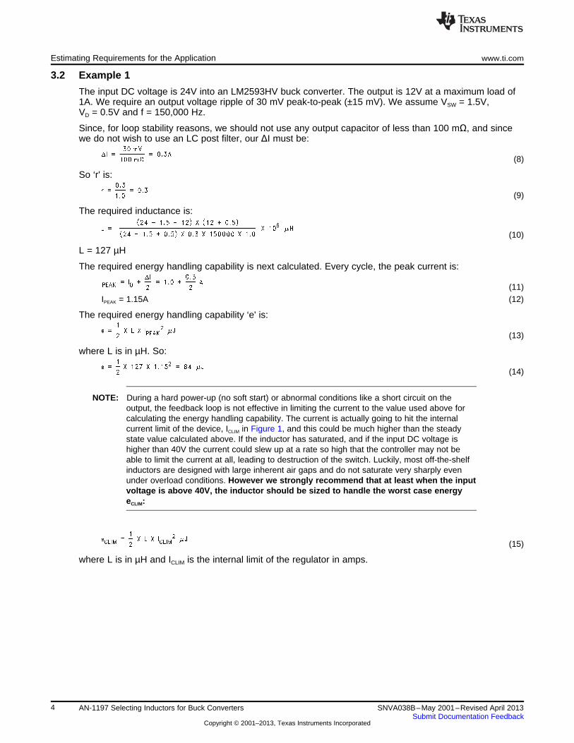
The input DC voltage is 24V into an LM2593HV buck converter. The output is 12V at a maximum load of1A. We require an output voltage ripple of 30 mV peak-to-peak (±15 mV). We assume VSW = 1.5V,VD = 0.5V and f = 150,000 Hz.
Since, for loop stability reasons, we should not use any output capacitor of less than 100 mΩ, and sincewe do not wish to use an LC post filter, our ΔI must be:
(8)
So ‘r' is:
(9)
The required inductance is:
(10)
L = 127 µH
The required energy handling capability is next calculated. Every cycle, the peak current is:
(11)IPEAK = 1.15A (12)
The required energy handling capability ‘e' is:
(13)
where L is in µH. So:
(14)
NOTE: During a hard power-up (no soft start) or abnormal conditions like a short circuit on theoutput, the feedback loop is not effective in limiting the current to the value used above forcalculating the energy handling capability. The current is actually going to hit the internalcurrent limit of the device, ICLIM in Figure 1, and this could be much higher than the steadystate value calculated above. If the inductor has saturated, and if the input DC voltage ishigher than 40V the current could slew up at a rate so high that the controller may not beable to limit the current at all, leading to destruction of the switch. Luckily, most off-the-shelfinductors are designed with large inherent air gaps and do not saturate very sharply evenunder overload conditions. However we strongly recommend that at least when the inputvoltage is above 40V, the inductor should be sized to handle the worst case energyeCLIM:
(15)
where L is in µH and ICLIM is the internal limit of the regulator in amps.
4 AN-1197 Selecting Inductors for Buck Converters SNVA038B–May 2001–Revised April 2013Submit Documentation Feedback
Copyright © 2001–2013, Texas Instruments Incorporated
www.ti.com Estimating Requirements for the Application
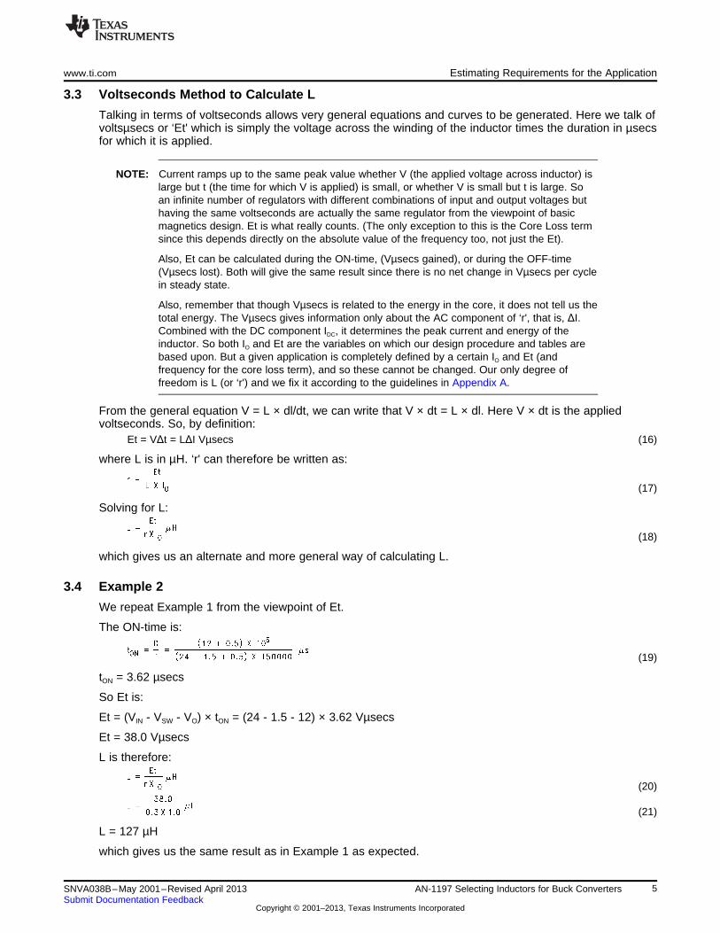
3.3 Voltseconds Method to Calculate L
Talking in terms of voltseconds allows very general equations and curves to be generated. Here we talk ofvoltsµsecs or ‘Et' which is simply the voltage across the winding of the inductor times the duration in µsecsfor which it is applied.
NOTE: Current ramps up to the same peak value whether V (the applied voltage across inductor) islarge but t (the time for which V is applied) is small, or whether V is small but t is large. Soan infinite number of regulators with different combinations of input and output voltages buthaving the same voltseconds are actually the same regulator from the viewpoint of basicmagnetics design. Et is what really counts. (The only exception to this is the Core Loss termsince this depends directly on the absolute value of the frequency too, not just the Et).
Also, Et can be calculated during the ON-time, (Vµsecs gained), or during the OFF-time(Vµsecs lost). Both will give the same result since there is no net change in Vµsecs per cyclein steady state.
Also, remember that though Vµsecs is related to the energy in the core, it does not tell us thetotal energy. The Vµsecs gives information only about the AC component of ‘r', that is, ΔI.Combined with the DC component IDC, it determines the peak current and energy of theinductor. So both IO and Et are the variables on which our design procedure and tables arebased upon. But a given application is completely defined by a certain IO and Et (andfrequency for the core loss term), and so these cannot be changed. Our only degree offreedom is L (or ‘r') and we fix it according to the guidelines in Appendix A.
From the general equation V = L × dl/dt, we can write that V × dt = L × dl. Here V × dt is the appliedvoltseconds. So, by definition:
Et = VΔt = LΔI Vµsecs (16)
where L is in µH. ‘r' can therefore be written as:
(17)
Solving for L:
(18)
which gives us an alternate and more general way of calculating L.
3.4 Example 2
We repeat Example 1 from the viewpoint of Et.
The ON-time is:
(19)
tON = 3.62 µsecs
So Et is:
Et = (VIN - VSW - VO) × tON = (24 - 1.5 - 12) × 3.62 Vµsecs
Et = 38.0 Vµsecs
L is therefore:
(20)
(21)
L = 127 µH
which gives us the same result as in Example 1 as expected.
5SNVA038B–May 2001–Revised April 2013 AN-1197 Selecting Inductors for Buck ConvertersSubmit Documentation Feedback
Copyright © 2001–2013, Texas Instruments Incorporated

Characterizing an Off-the-Shelf Inductor www.ti.com
3.5 Summary of Requirements• An inductance of 127 µH (or greater, based on maximum ‘r' of 0.3)
• DC load of 1A (to ensure acceptable temperature rise, specify ΔT) OR steady state Energy handlingcapability of 84 µJ
• Peak load of 4.0A (to rule out core saturation if DC input voltage ≥40V) OR peak energy handlingcapability of 1016 µJ. (Max Current Limit of LM2593HV is 4.0A)
• Et of 38 Vµsecs
• Frequency 150 kHz
These can be communicated directly to a vendor for a custom-built design.
4 Characterizing an Off-the-Shelf Inductor
With reference to our design flow chart in Figure 2, the first pass selection is based upon inductance andDC current rating. We tentatively select a part from Pulse Engineering because its L and IDC are close toour requirements, even though the rest does not seem to fit our application (see Table 1 and the followingbullets). In particular the frequency for which the inductor was designed is 250 kHz, but our application is150 kHz. We are intuitively lead to believe that since we are decreasing the frequency our core losses willgo up, and so will the peak flux density. In fact the reverse happens in our case, and that is why it isimportant to follow the full procedure presented below. ‘Intuition' can be very misleading.
The vendor also states that:• The inductor is such that 380 mW dissipation corresponds to 50°C rise in temperature.
• The core loss equation for the core is 6.11 × 10⁻¹⁸ × B2.7 × f2.04 mW where f is in Hz and B is in Gauss.
• The inductor was designed for a frequency of 250 kHz.
• Et100 is the Vµsecs at which ‘B' is 100 Gauss.
NOTE: For core loss equations it is conventional to use half the peak-to-peak flux swing. So, likemost vendors, the ‘B' above actually refers to ΔB/2. This must be kept in mind in thecalculations that follow.
The step-by-step calculations are:
a) AC Component of Current:
This can be easily calculated from: Et = LΔI Vµsecs
where: L is in µH.
So:
(22)
b) ‘r':
So this inductor has been designed for the following ‘r':
(23)
r = 0.438
at a load current of 0.99A.
c) Peak Current:
(24)
IPEAK = 1.21A
6 AN-1197 Selecting Inductors for Buck Converters SNVA038B–May 2001–Revised April 2013Submit Documentation Feedback
Copyright © 2001–2013, Texas Instruments Incorporated

www.ti.com Characterizing an Off-the-Shelf Inductor
d) RMS Current:
(25)
(26)
IRMS = 0.998A
e) Copper Loss:
This is:
PCU = IRMS2 × DCR mW
where: DCR is in mΩ.
In most cases, to a close approximation, we can simply use IDC instead of IRMS in the above equation. Alsosometimes, the vendor may have directly given the RMS current rating of the inductor.
PCU = 0.9982 × 387 mW
PCU = 385 mW
f) The AC Component of the B-Field:
This is proportional to the AC component of the inductor current.
The vendor has provided the information that an Et of Et100 = 10.12 Vµsecs produces 100 Gauss (B). Sosince the inductor is designed for an Et = 59.4 Vµsecs, we get:
(27)
B = 587 Gauss
But this is half the peak-to-peak swing by convention. So:
ΔB = 2 × B = 1174 Gauss
CHECK: We can use the alternative form for ΔB as given in Table 2. We asked the vendor for moredetails than he had provided on the datasheet and we learned that the effective area of the core, Ae, is0.0602 cm2 and the number of turns is N = 84. So
(28)
(29)
which is what we expected.
g) The DC Component of the B-Field:
This is proportional to the DC component of the inductor current. In fact the instantaneous value of B canalways be considered proportional to the instantaneous value of the current (for a given inductor).
The proportionality constant is known from f) above, that is, a ΔI of 0.434A produces a ΔB of 1174 Gauss.So the DC component of the B-field must be:
(30)
where:
IDC = IO = 0.99A
(31)
BDC = 2678 Gauss
7SNVA038B–May 2001–Revised April 2013 AN-1197 Selecting Inductors for Buck ConvertersSubmit Documentation Feedback
Copyright © 2001–2013, Texas Instruments Incorporated
Characterizing an Off-the-Shelf Inductor www.ti.com
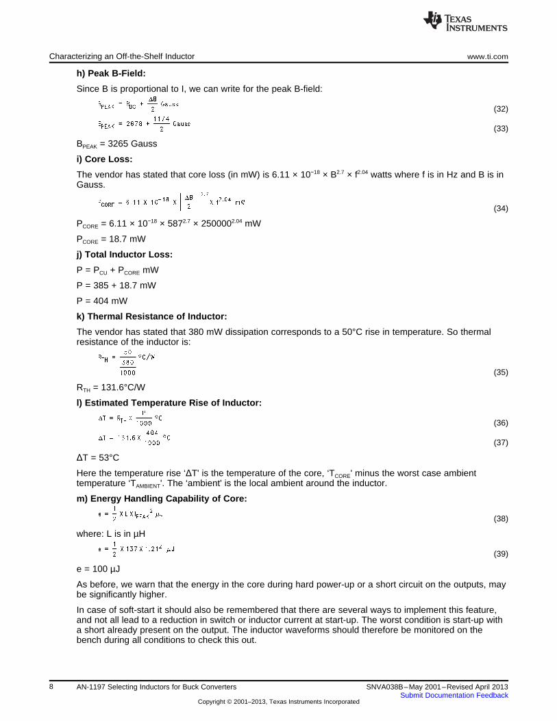
h) Peak B-Field:
Since B is proportional to I, we can write for the peak B-field:
(32)
(33)
BPEAK = 3265 Gauss
i) Core Loss:
The vendor has stated that core loss (in mW) is 6.11 × 10⁻¹⁸ × B2.7 × f2.04 watts where f is in Hz and B is inGauss.
(34)
PCORE = 6.11 × 10−18 × 5872.7 × 2500002.04 mW
PCORE = 18.7 mW
j) Total Inductor Loss:
P = PCU + PCORE mW
P = 385 + 18.7 mW
P = 404 mW
k) Thermal Resistance of Inductor:
The vendor has stated that 380 mW dissipation corresponds to a 50°C rise in temperature. So thermalresistance of the inductor is:
(35)
RTH = 131.6°C/W
l) Estimated Temperature Rise of Inductor:
(36)
(37)
ΔT = 53°C
Here the temperature rise ‘ΔT' is the temperature of the core, ‘TCORE' minus the worst case ambienttemperature ‘TAMBIENT'. The ‘ambient' is the local ambient around the inductor.
m) Energy Handling Capability of Core:
(38)
where: L is in µH
(39)
e = 100 µJ
As before, we warn that the energy in the core during hard power-up or a short circuit on the outputs, maybe significantly higher.
In case of soft-start it should also be remembered that there are several ways to implement this feature,and not all lead to a reduction in switch or inductor current at start-up. The worst condition is start-up witha short already present on the output. The inductor waveforms should therefore be monitored on thebench during all conditions to check this out.
8 AN-1197 Selecting Inductors for Buck Converters SNVA038B–May 2001–Revised April 2013Submit Documentation Feedback
Copyright © 2001–2013, Texas Instruments Incorporated
www.ti.com Evaluating the Inductor for the Actual Application
Also it will be seen that all inductors of a ‘family, that is, using the same core will typically have the samerated energy capability. So if this core is found to be inadequate, normally the only way out is to move to aphysically larger core/inductor. Other options include the use of improved and more expensive corematerials.
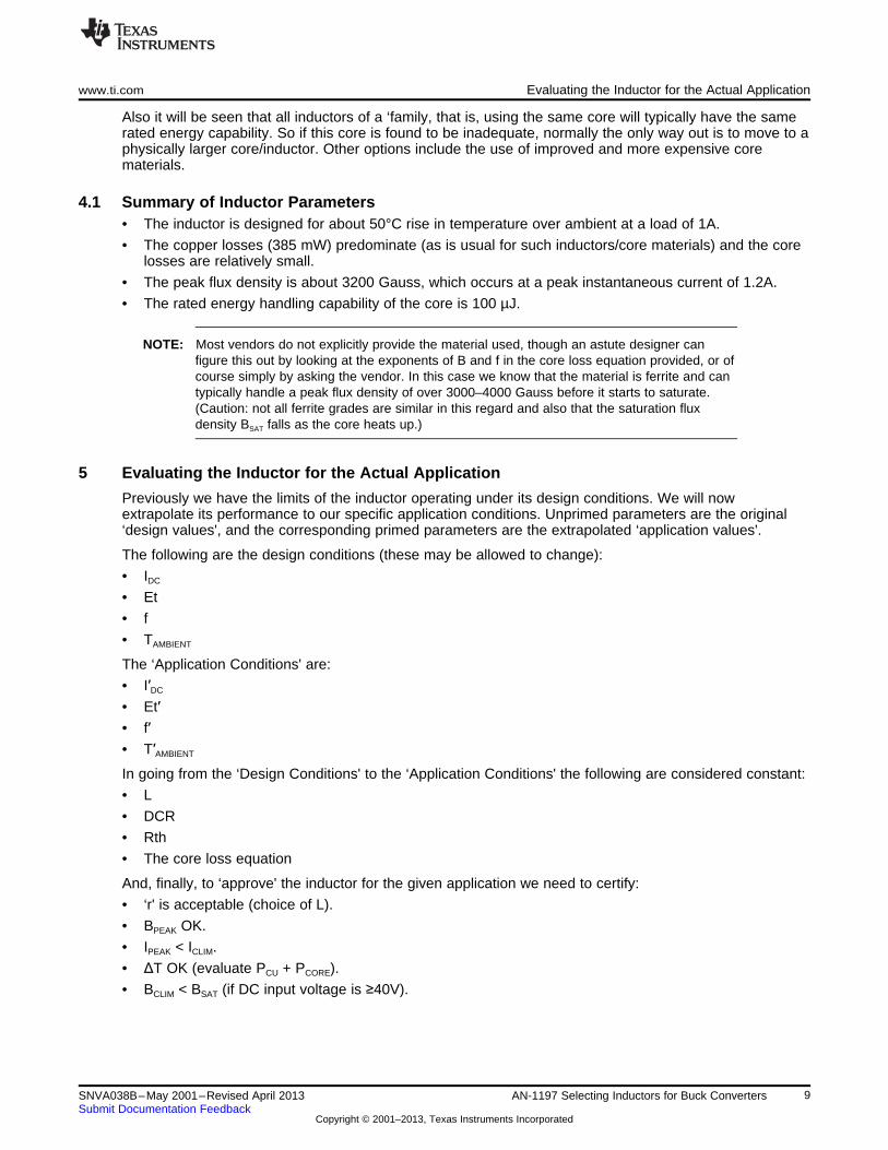
4.1 Summary of Inductor Parameters• The inductor is designed for about 50°C rise in temperature over ambient at a load of 1A.
• The copper losses (385 mW) predominate (as is usual for such inductors/core materials) and the corelosses are relatively small.
• The peak flux density is about 3200 Gauss, which occurs at a peak instantaneous current of 1.2A.
• The rated energy handling capability of the core is 100 µJ.
NOTE: Most vendors do not explicitly provide the material used, though an astute designer canfigure this out by looking at the exponents of B and f in the core loss equation provided, or ofcourse simply by asking the vendor. In this case we know that the material is ferrite and cantypically handle a peak flux density of over 3000–4000 Gauss before it starts to saturate.(Caution: not all ferrite grades are similar in this regard and also that the saturation fluxdensity BSAT falls as the core heats up.)
5 Evaluating the Inductor for the Actual Application
Previously we have the limits of the inductor operating under its design conditions. We will nowextrapolate its performance to our specific application conditions. Unprimed parameters are the original‘design values', and the corresponding primed parameters are the extrapolated ‘application values'.
The following are the design conditions (these may be allowed to change):
• IDC
• Et
• f
• TAMBIENT
The ‘Application Conditions' are:
• I′DC
• Et′• f′• T′AMBIENT
In going from the ‘Design Conditions' to the ‘Application Conditions' the following are considered constant:
• L
• DCR
• Rth
• The core loss equation
And, finally, to ‘approve' the inductor for the given application we need to certify:
• ‘r' is acceptable (choice of L).
• BPEAK OK.
• IPEAK < ICLIM.
• ΔT OK (evaluate PCU + PCORE).
• BCLIM < BSAT (if DC input voltage is ≥40V).
9SNVA038B–May 2001–Revised April 2013 AN-1197 Selecting Inductors for Buck ConvertersSubmit Documentation Feedback
Copyright © 2001–2013, Texas Instruments Incorporated

Evaluating the Inductor for the Actual Application www.ti.com
We assume the vendor has provided all the following inputs:
• Et (Vµsecs)
• Et100 (Vµsecs per 100 Gauss)
• L (µH)
• IDC (Amps)
• DCR (mΩ)
• f (Hz)
• The form for core losses (mW) as a *Bb*fc, where B is in Gauss, f in Hz. Note that B is half the peak-to-peak flux swing.
• Thermal resistance of inductor in free air (°C/W)
If any of these are unknown, the vendor should be contacted. Table 2 condenses the step-by-stepprocedure given earlier and also shows how to ‘extrapolate' the performance of the inductor.
5.1 Example 3
This shows the complete selection procedure. Refer to Table 2 and Figure 2. We have seen that the‘Design Conditions' of the inductor are:
• Et = 59.4 Vµsecs
• f = 250,000 Hz
• IDC = 0.99A
Our ‘Application Conditions' are:
• Et′ = 38 Vµsecs
• f′ = 150,000 Hz
• I′DC = 1A
(We assume that TAMBIENT is unchanged so we can ignore it above).
We need to verify that using the inductor in the given application:
(a) current ripple ratio ‘r' is close to desired
(b) peak flux density/current are within bounds
(c) temperature rise is acceptable
Using Table 2:
a) ‘r':
Design Value:
(40)
(41)
r = 0.438
Extrapolated to our Application:
(42)
(43)
r′ = 0.277
We expected ‘r′’ to be slightly lower than 0.3 since the chosen inductor has a higher inductance than werequired (137 µH instead of 127 µH). This is acceptable however as the output voltage ripple will be lessthan demanded.
10 AN-1197 Selecting Inductors for Buck Converters SNVA038B–May 2001–Revised April 2013Submit Documentation Feedback
Copyright © 2001–2013, Texas Instruments Incorporated
www.ti.com Evaluating the Inductor for the Actual Application
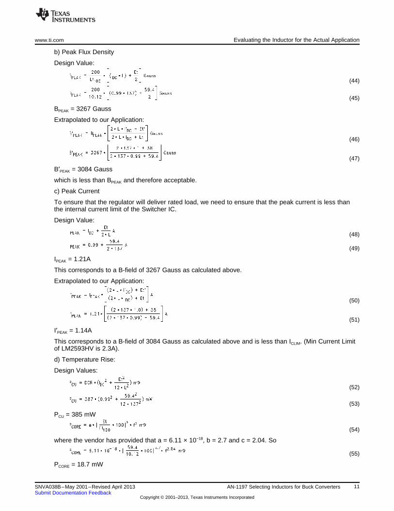
b) Peak Flux Density
Design Value:
(44)
(45)
BPEAK = 3267 Gauss
Extrapolated to our Application:
(46)
(47)
B′PEAK = 3084 Gauss
which is less than BPEAK and therefore acceptable.
c) Peak Current
To ensure that the regulator will deliver rated load, we need to ensure that the peak current is less thanthe internal current limit of the Switcher IC.
Design Value:
(48)
(49)
IPEAK = 1.21A
This corresponds to a B-field of 3267 Gauss as calculated above.
Extrapolated to our Application:
(50)
(51)
I′PEAK = 1.14A
This corresponds to a B-field of 3084 Gauss as calculated above and is less than ICLIM. (Min Current Limitof LM2593HV is 2.3A).
d) Temperature Rise:
Design Values:
(52)
(53)
PCU = 385 mW
(54)
where the vendor has provided that a = 6.11 × 10⁻¹⁸, b = 2.7 and c = 2.04. So
(55)
PCORE = 18.7 mW
11SNVA038B–May 2001–Revised April 2013 AN-1197 Selecting Inductors for Buck ConvertersSubmit Documentation Feedback
Copyright © 2001–2013, Texas Instruments Incorporated

Conclusions www.ti.com
So:
(56)
(57)
ΔT = 53°C
because the vendor has stated that 380 mW dissipation in the inductor causes 50°C rise in temperature.
Extrapolated to our Application:
(58)
(59)
P′CU = 389 mW
(60)
(61)
P′CORE = 2 mW
So:
(62)
(63)
ΔT′ = 51°C
which is considered to be acceptable in this application.
6 Conclusions
By the detailed selection procedure above, we can expect the selected inductor to work well for the givenlower frequency application example. As mentioned earlier, we would have ‘intuitively' thought that sincethe inductance and current rating is about what we need, if we lowered the frequency from 250 kHz to150 kHz, the peak current and field would increase. But they actually decrease as we can now see. Thereason being, that the inductor was designed for a higher Et in mind (59.4 Vµsecs vs. our 38 Vµsecs). Asstated earlier, Et in effect, defines the regulator configuration itself, so we did not just lower the frequency,we actually went to an entirely different input-output voltage combination to what the inductor had beenoriginally designed for. As we can now guess, the original inductor had been probably designed for amuch higher applied voltage to what we subjected it to. But this was not obvious at first sight. The fullprocedure as given in Table 2 and Figure 2 is therefore necessary to avoid such ‘errors of intuition'.
The data sheets of Texas Instruments Simple Switchers also generally include simple nomograms andthese are useful in most cases, but limit the selection to certain previously specified or custom builtinductors and are also based on certain assumptions. In particular, there are many factors to considerwhen fixing a certain current ripple ratio ‘r', which happens to be the key input in the process of selectionan inductor. Nomograms are easy to use but assume a certain ‘r' which may not be ideal for all purposes.In fact in the example discussed above, we did in fact select an inductance higher than what thenomograms may have recommended, because of output voltage ripple considerations.
In general, this application report should help in selecting a more optimum and readily available off-the-shelf inductor.
12 AN-1197 Selecting Inductors for Buck Converters SNVA038B–May 2001–Revised April 2013Submit Documentation Feedback
Copyright © 2001–2013, Texas Instruments Incorporated

www.ti.com Conclusions
Table 2. Complete Design Table for Evaluating the Inductor for a Given Application (1)
Design Conditions Application ConditionsDesign Parameters IDC, Et, f, TAMBIENT I′DC = IO, Et′, f′, T′AMBIENT
AC Component of Current Amps
(64)(65)
Current Ripple Ratio ‘r' (ΔI/IDC)
(66)(67)
Peak Current in Inductor Amps
(68)(69)
RMS Current in Inductor Amps
(70) (71)
AC Flux Density Gauss
(73)(72)
Peak Flux Density Gauss
(75)(74)
Copper Losses mW
(77)(76)
Core Losses mW
(79)(78)
Energy in Core µJ(80)
(81)
Temperature Rise (ΔT) °C
(82)(83)
(1) Et in Vµsecs, DCR in mΩ, L in µH, f in Hz, Effective Area Ae in cm2, N is number of turns
13SNVA038B–May 2001–Revised April 2013 AN-1197 Selecting Inductors for Buck ConvertersSubmit Documentation Feedback
Copyright © 2001–2013, Texas Instruments Incorporated

Conclusions www.ti.com
Figure 2. Design Flow Chart for Selection of Inductor
14 AN-1197 Selecting Inductors for Buck Converters SNVA038B–May 2001–Revised April 2013Submit Documentation Feedback
Copyright © 2001–2013, Texas Instruments Incorporated

www.ti.com
Appendix A Optimizing the Size of the Inductor
The size of the inductor is related to the energy handling capability required. The energy handlingcapability is ½*L*IPEAK
2. For a given application, if we reduce inductance, it seems that this would increaseΔI and thereby IPEAK, which would cause the energy requirement to increase since it depends on square ofcurrent. However, a detailed calculation shows agin that reality is counterintuitive. The energy handlingrequirement is actually substantially reduced if the inductance is decreased. In terms of ‘r', we can in factwrite the energy handling capability as
(84)
where ‘r' is ΔI/IO and Et is in Vµsecs.
For a given application, Et is fixed as is IO, so the term in square brackets gives ‘e' the shape shown inFigure 3. We can see that the energy handling requirement (size of inductor) decreases as ‘r' increases (Ldecreasing). The best value is the ‘knee' and so it is a good idea to target an ‘r' of 30%–40%. No greatimprovement in the size of the inductor will take place by increasing ‘r' much more than this, but the RMScurrent in the output cap, and also the RMS current in the input capacitor (especially for large duty cycles),will increase substantially. The absolute value of the RMS ripple current in the input capacitor is muchhigher than in the output capacitor, and the designer should watch out for the cost penalty on the inputcapacitor too! Refer to Table 3 for the complete set of optimization equations expressed as a function of‘r'.
While optimizing, the following points need to be considered:
• For a given application, having defined input and output voltages and load current, Et is fixed as are Dand IO. So the only degree of freedom is in selecting the ‘r'. The equations in Table 3 are thereforewritten in terms of ‘r'.
• Table 3 provides the general equations required for optimization but also provides the values at an ‘r'of 0.3 in the adjacent column as a benchmark. This is also equivalent to the ‘flat top approximation'often used for quick estimates.
• Figure 3 plots the variation of each parameter, normalized to the benchmark values (that is, set to unityat an ‘r' of 0.3).
• Note that when calculating dissipation in the switch, one must consider whether the switch is a bipolartransistor or a FET. If it is a FET, we need to apply I2*R where I is the RMS switch current and R is theRDS of the FET. If it is bipolar, we need to use V*I where V is the saturation voltage across the switch,and I is the average switch current. That is why both have been provided in Table 3. Also note that fora bipolar switch, the dissipation is seems almost independent of ‘r'. In practice, the saturation voltagedrop depends on the instantaneous value of current, so dissipation does increase slightly with ‘r'.
• Referring to Figure 3 we can see that the RMS inductor current hardly changes over a very wide rangeof ‘r'. That is why, earlier in this application report, it was mentioned that for the purpose of evaluatingcopper losses we may use IO
2 instead of IRMS2.
• The core losses also increase substantially with increasing ‘r'. It can be shown that even if we keep thesame core size, the flux density BAC will go up as r½. Going to a smaller core could increase thisfurther.
• The RMS capacitor currents in the input and output are the main components to consider becausethey can increase rapidly with ‘r'. So for example, if we increase ‘r' to 0.6 (from 0.3), the energyhandling requirement of the inductor falls by about 35% but the dissipation in the output capacitors (ifESR is unchanged) will increase by 400%! Alternatively stated, we now need to select an outputcapacitor with twice the ripple current rating.
• It must also be kept in mind that there is an output voltage ripple ΔV = ESR x ΔI associated with thecurrent ripple. Now, the ESR of the output capacitor cannot usually be decreased below 100 mΩ–200mΩ (with voltage mode control) for loop stability reasons. So for high loads (and high ‘r'), thedissipation in the output capacitor will necessarily be high since we cannot reduce ESR further. Thismay call for physically large sized output capacitors to handle the dissipation. In addition, the outputvoltage ripple will be high too, and since we cannot reduce this by reducing the ESR, we will need toadd on a post LC filter. So, for high load currents, it may become necessary to decrease ‘r'substantially. This in turn will lead to a large inductor with slow transient response ability.
15SNVA038B–May 2001–Revised April 2013 AN-1197 Selecting Inductors for Buck ConvertersSubmit Documentation Feedback
Copyright © 2001–2013, Texas Instruments Incorporated

Appendix A www.ti.com
• We have implied that the physical size of the inductor is related to its energy handling capability only.This in turn suggests that we are talking of inductor designs that are core-saturation limited. While thisis usually true if the core material is a ferrite, it may not be true of some powdered iron inductors forexample. The size of these may be limited not by core saturation but by core losses, which depend onflux swing, or ΔI, not I (or ‘e'). So, while Figure 3 is still valid, the criterion of ‘best choice' may change.It may be necessary to choose or restrict ‘r' to much smaller values than the ‘knee'.
This completes the information required to optimize not only the inductor but the buck regulator itself. Thekey factor affecting cost/size of almost all the components is the current ripple ratio ‘r' and this needs to becarefully optimized as previously discussed.
Figure 3. Optimization Chart for Setting 'r'
Table 3. Optimization Table for Fixing Current Ripple Ratio ‘r' (1)
For ‘r' = 0.3Parameters As a Function of ‘r' (to a first approximation)
Energy Handling Capability µJ 2.2 × IO × Et
(85)
RMS Current in Output Cap Amps 0.09 × IO(86)
RMS Current in Input Cap Amps(88)
(87)
RMS Current in Inductor Amps IO
(89)
RMS Current in Switch Amps(91)
(90)
Average Current in Switch Amps IO × D IO × D
Average Current in Diode Amps IO × (1 – D) IO × (1 – D)(1) r = ΔI/IO, Et in Vµsecs
16 AN-1197 Selecting Inductors for Buck Converters SNVA038B–May 2001–Revised April 2013Submit Documentation Feedback
Copyright © 2001–2013, Texas Instruments Incorporated

www.ti.com Appendix A
17SNVA038B–May 2001–Revised April 2013 AN-1197 Selecting Inductors for Buck ConvertersSubmit Documentation Feedback
Copyright © 2001–2013, Texas Instruments Incorporated

IMPORTANT NOTICE
Texas Instruments Incorporated and its subsidiaries (TI) reserve the right to make corrections, enhancements, improvements and otherchanges to its semiconductor products and services per JESD46, latest issue, and to discontinue any product or service per JESD48, latestissue. Buyers should obtain the latest relevant information before placing orders and should verify that such information is current andcomplete. All semiconductor products (also referred to herein as “components”) are sold subject to TI’s terms and conditions of salesupplied at the time of order acknowledgment.
TI warrants performance of its components to the specifications applicable at the time of sale, in accordance with the warranty in TI’s termsand conditions of sale of semiconductor products. Testing and other quality control techniques are used to the extent TI deems necessaryto support this warranty. Except where mandated by applicable law, testing of all parameters of each component is not necessarilyperformed.
TI assumes no liability for applications assistance or the design of Buyers’ products. Buyers are responsible for their products andapplications using TI components. To minimize the risks associated with Buyers’ products and applications, Buyers should provideadequate design and operating safeguards.
TI does not warrant or represent that any license, either express or implied, is granted under any patent right, copyright, mask work right, orother intellectual property right relating to any combination, machine, or process in which TI components or services are used. Informationpublished by TI regarding third-party products or services does not constitute a license to use such products or services or a warranty orendorsement thereof. Use of such information may require a license from a third party under the patents or other intellectual property of thethird party, or a license from TI under the patents or other intellectual property of TI.
Reproduction of significant portions of TI information in TI data books or data sheets is permissible only if reproduction is without alterationand is accompanied by all associated warranties, conditions, limitations, and notices. TI is not responsible or liable for such altereddocumentation. Information of third parties may be subject to additional restrictions.
Resale of TI components or services with statements different from or beyond the parameters stated by TI for that component or servicevoids all express and any implied warranties for the associated TI component or service and is an unfair and deceptive business practice.TI is not responsible or liable for any such statements.
Buyer acknowledges and agrees that it is solely responsible for compliance with all legal, regulatory and safety-related requirementsconcerning its products, and any use of TI components in its applications, notwithstanding any applications-related information or supportthat may be provided by TI. Buyer represents and agrees that it has all the necessary expertise to create and implement safeguards whichanticipate dangerous consequences of failures, monitor failures and their consequences, lessen the likelihood of failures that might causeharm and take appropriate remedial actions. Buyer will fully indemnify TI and its representatives against any damages arising out of the useof any TI components in safety-critical applications.
In some cases, TI components may be promoted specifically to facilitate safety-related applications. With such components, TI’s goal is tohelp enable customers to design and create their own end-product solutions that meet applicable functional safety standards andrequirements. Nonetheless, such components are subject to these terms.
No TI components are authorized for use in FDA Class III (or similar life-critical medical equipment) unless authorized officers of the partieshave executed a special agreement specifically governing such use.
Only those TI components which TI has specifically designated as military grade or “enhanced plastic” are designed and intended for use inmilitary/aerospace applications or environments. Buyer acknowledges and agrees that any military or aerospace use of TI componentswhich have not been so designated is solely at the Buyer's risk, and that Buyer is solely responsible for compliance with all legal andregulatory requirements in connection with such use.
TI has specifically designated certain components as meeting ISO/TS16949 requirements, mainly for automotive use. In any case of use ofnon-designated products, TI will not be responsible for any failure to meet ISO/TS16949.
Products Applications
Audio www.ti.com/audio Automotive and Transportation www.ti.com/automotive
Amplifiers amplifier.ti.com Communications and Telecom www.ti.com/communications
Data Converters dataconverter.ti.com Computers and Peripherals www.ti.com/computers
DLP® Products www.dlp.com Consumer Electronics www.ti.com/consumer-apps
DSP dsp.ti.com Energy and Lighting www.ti.com/energy
Clocks and Timers www.ti.com/clocks Industrial www.ti.com/industrial
Interface interface.ti.com Medical www.ti.com/medical
Logic logic.ti.com Security www.ti.com/security
Power Mgmt power.ti.com Space, Avionics and Defense www.ti.com/space-avionics-defense
Microcontrollers microcontroller.ti.com Video and Imaging www.ti.com/video
RFID www.ti-rfid.com
OMAP Applications Processors www.ti.com/omap TI E2E Community e2e.ti.com
Wireless Connectivity www.ti.com/wirelessconnectivity
Mailing Address: Texas Instruments, Post Office Box 655303, Dallas, Texas 75265Copyright © 2013, Texas Instruments Incorporated