AMT Fault Diagnosis Technology Based on … Fault Diagnosis Technology Based on Simulink and LabVIEW...
7
Sensors & Transducers, Vol. 25, Special Issue, December 2013, pp. 118-124 118 S S S e e e n n n s s s o o o r r r s s s & & & T T T r r r a a a n n n s s s d d d u u u c c c e e e r r r s s s © 2013 by IFSA http://www.sensorsportal.com AMT Fault Diagnosis Technology Based on Simulink and LabVIEW Yanqiong TENG, Lan TANG, Junqiang DING School of Transportation and Automobile Engineering, Xihua University, Chengdu, Sichuan 610039, P. R. China Tel.: 18030407562, fax: 028-87720534 E-mail: [email protected] Received: 16 September 2013 /Accepted: 15 October 2013 /Published: 23 December 2013 Abstract: For the selecting and shifting gear actuator fault generation mechanism of automated manual transmission (AMT), application logic redundancy law diagnostic strategies was developed. Based on MATLAB/Simulink and LabVIEW software platform to build a simulation model for co-simulation signal model, normal/abnormal analog signal was input to simulate. Finally, by artificially set shift fault and the acquisition of AMT bench test failure output and shifting actuator motion information, the design diagnosis was verified. The simulation and test results show that the proposed fault diagnosis control strategy is correct. Simulink and LabVIEW joint simulation could shorten the product development cycle, which provides a new way of thinking for the development of the control system of the AMT fault diagnosis method. Copyright © 2013 IFSA. Keywords: Automated manual transmission, Fault diagnosis, Fault disposal, Build model, Test. 1. Introduction Because of the use of advanced electronic technology, AMT transform the traditional manual transmission. With the unique characteristics such as economic, convenient, safe and comfortable, all motorists much welcomed, AMT has become a hotspot in the research and development of automotive engineers. Since 1980, China began on the ATM automatic transmission technology research [1-3]. As the national "863 program" is one of the key projects, "the development of advanced automotive technology," clearly put forward for AMT technologies. AMT is a complex system to improve the transmission efficiency, simplify operations and improve the driving ability of automatic control, at the same time, the probability of failure also increasing, which is an urgent need to develop a fault diagnosis and treatment technology, safety and reliability for the system to provide protection. Therefore, fault diagnosis and treatment is the key AMT system development technologies. At present, the domestic independent research and development of the automatic transmission research institutions diagnosis there are many, but the market has not yet appeared the automatic transmission diagnosis instrument of mass production products, the main reason is the key technologies of AMT did not get very good settlement. For example, the adaptive control problem, the reliability of AMT, adaptive system and fault diagnosis technology etc. Beijing Institute of Technology, Chongqing University, Jilin University, Shandong University and a number of units issued a related paper, and tested on the bench or on the vehicle. Article number P_SI_450
Transcript of AMT Fault Diagnosis Technology Based on … Fault Diagnosis Technology Based on Simulink and LabVIEW...
Sensors & Transducers, Vol. 25, Special Issue, December 2013, pp. 118-124
118
SSSeeennnsssooorrrsss &&& TTTrrraaannnsssddduuuccceeerrrsss
© 2013 by IFSAhttp://www.sensorsportal.com
AMT Fault Diagnosis Technology Based on Simulink and LabVIEW
Yanqiong TENG, Lan TANG, Junqiang DING
School of Transportation and Automobile Engineering, Xihua University, Chengdu, Sichuan 610039, P. R. China Tel.: 18030407562, fax: 028-87720534
E-mail: [email protected]
Received: 16 September 2013 /Accepted: 15 October 2013 /Published: 23 December 2013 Abstract: For the selecting and shifting gear actuator fault generation mechanism of automated manual transmission (AMT), application logic redundancy law diagnostic strategies was developed. Based on MATLAB/Simulink and LabVIEW software platform to build a simulation model for co-simulation signal model, normal/abnormal analog signal was input to simulate. Finally, by artificially set shift fault and the acquisition of AMT bench test failure output and shifting actuator motion information, the design diagnosis was verified. The simulation and test results show that the proposed fault diagnosis control strategy is correct. Simulink and LabVIEW joint simulation could shorten the product development cycle, which provides a new way of thinking for the development of the control system of the AMT fault diagnosis method. Copyright © 2013 IFSA. Keywords: Automated manual transmission, Fault diagnosis, Fault disposal, Build model, Test. 1. Introduction
Because of the use of advanced electronic technology, AMT transform the traditional manual transmission. With the unique characteristics such as economic, convenient, safe and comfortable, all motorists much welcomed, AMT has become a hotspot in the research and development of automotive engineers. Since 1980, China began on the ATM automatic transmission technology research [1-3]. As the national "863 program" is one of the key projects, "the development of advanced automotive technology," clearly put forward for AMT technologies. AMT is a complex system to improve the transmission efficiency, simplify operations and improve the driving ability of automatic control, at the same time, the probability of failure also increasing, which is an urgent need to
develop a fault diagnosis and treatment technology, safety and reliability for the system to provide protection. Therefore, fault diagnosis and treatment is the key AMT system development technologies.
At present, the domestic independent research and development of the automatic transmission research institutions diagnosis there are many, but the market has not yet appeared the automatic transmission diagnosis instrument of mass production products, the main reason is the key technologies of AMT did not get very good settlement. For example, the adaptive control problem, the reliability of AMT, adaptive system and fault diagnosis technology etc. Beijing Institute of Technology, Chongqing University, Jilin University, Shandong University and a number of units issued a related paper, and tested on the bench or on the vehicle.
Article number P_SI_450
Sensors & Transducers, Vol. 25, Special Issue, December 2013, pp. 118-124
119
The fault diagnosis of AMT form is mainly used in the vehicle fault self diagnosis method, namely control TCU automatic mechanical transmission in the completion of the automatic transmission control on vehicle, monitoring and diagnosis of the relevant information and data. When there is failure to failure are stored code form, and can alarm to the driver. At the same time take fault-tolerant control, so that the vehicle can continue to repair center to repair. Ge Anlin [4] , from Jilin University, has done a lot of work on the study of AMT fault diagnosis, a fault diagnosis, fuzzy AMT control system of AMT system fault diagnosis of automotive electronic control system and fault self diagnosis technique based on. Gu Yongming [5] analyzed the failure mode in AMT system engine, clutch, transmission parts, and establish a diagnosis model. Jiang Wei [6-8] analysis of the car in the beginning and the running fault state of AMT, and gives the corresponding handling. In this paper, the transmission of a heavy commercial vehicle as the research object, analysis of sensor and actuator fault diagnosis and control strategy, simulation and bench test. Correctness of fault diagnosis strategy is validated in the test rig. 2. Subject Investigated
The research object of this paper engine is a commercial heavy duty engine. Transmission of AMT transmission of a gear factory production, it has 6 forward gears and one reverse gear, gear shift lever after the modification, specially used in AMT production. Shift actuator using pure electric; complete the shift action with DC motor. The clutch is a gas operated, implementing agencies for the use of BOSCH Rexroth company production of pneumatic actuator, which is controlled by the electromagnetic valve to complete separation of the clutch and joint action. Electronic control unit TCU as the main control chip MCU using MC9S12DP512 chip produced by the company named Freescale, run cycle accurate to the millisecond. CAN bus communication for engine ECU and TCU, real time TCU read ECU information, and controls the engine in the process of shifting, the engine speed [9, 10].
In the AMT control system, failures follow a similar system function structure can be divided into three categories: TCU fault, sensor fault, actuator fault. In this paper, the shifting actuator fault diagnoses were studied. 3. Shifting Actuator Diagnosis Analysis
The shifting actuating mechanism comprises a gear motor, gear motor, angle position sensor, linear position sensor and gear. In AMT control, when the clutch separation, executing mechanism finishes the up-shift or downshift work. Position sensor failure, will cause the TCU not recognize the current motor
position, not for the closed-loop control. Motor and reducer fault, will cause the shift function failure. 3.1. Analysis of the Shift Motor Diagnosis
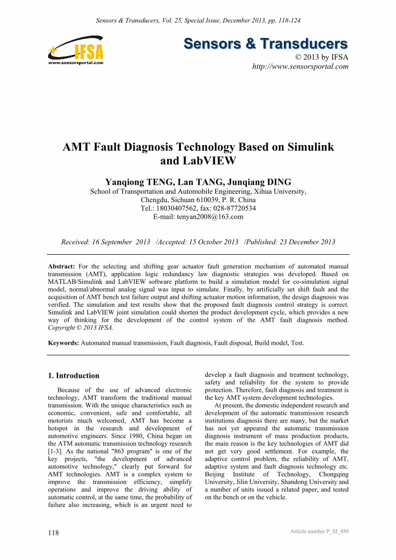
Shifting operation respectively by using two DC motor controls, the one responsible for the gear selection work, one is responsible for the shift work. According to the output characteristics of a sensor, fault diagnosis can be motor angular position sensor. The logic analysis of the sensor signal will be continuously collected and normal signal, determine whether the sensor fault, the diagnosis process is shown in Fig. 1.
Fig. 1. Shift motor position sensor diagnostic process.
In the Fig. 1, EMPSSV as the supply voltage of the position sensor, when EMPSSV and normal working voltage of 5 V is larger than the limit value of theta, think that the sensor output signal will be unreliable, the working voltage of TCU output position sensor fault. According to the mechanical characteristics of shift, the motor rotation angle in a certain range, output of the sensor is also have a certain range, if the output sensor is greater than or less than the maximum minimum value that the output of the sensor fault. 3.2. Shifting Actuator Fault Diagnosis
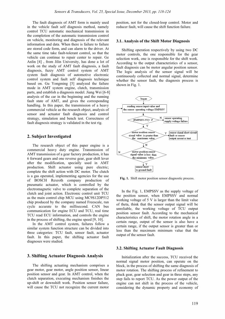
Initialization after the success, TCU received the normal signal motor position, can operate on the block, in the process of shifting the same diagnosis of motor rotation. The shifting process of refinement to pluck gear, gear selection and gear in three steps, any step fails to report TCU. As the power output of the engine can not shift in the process of the vehicle, considering the dynamic property and economy of
Sensors & Transducers, Vol. 25, Special Issue, December 2013, pp. 118-124
120
the vehicle, so the rule shift time must be in a certain range, if beyond the time reporting fault to the TCU, the diagnostic process is shown in Fig. 2., the gearshift process as an example to illustrate the shifting process diagnosis. The shift motor from the receiver to the rotation of the motor to rotate the command to the target location design time is 300 ms, after 300 ms delay; the motor is not to the target location, and then pick a fault to mark a position 1. Continue to follow the motor position, after 600 ms delay, the motor does not reach the target position, TCU will pick block fault mark position 2. For different flags, TCU take the fault treatment in different ways. Gear fault diagnosis method and principle of gear fault hanging with the same gear off fault, so do not describe here.
Fig. 2. Shifting process diagnosis flowchart
3.3. Shift Actuator Fault Handling
According to the shifting characteristics, for different fault locations have different processing modes. If the position sensor is faulty, TCU first determine the fault position and fault type, and TCU should be stored for sensor fault code, the fault codes for repair when parking. When the motor position sensor fault system, not in the shift process, TCU shielding shift signal, even when the vehicle meet the shifting conditions, also no longer shift operation until the fault is cleared, then restore the shift operation. When the sensor fails, the vehicle is the shift in the process first determines the fault location, three cases treatment: place or repair station. If gearing fails, the system will require manual intervention. 4. AMT Modeling and Simulation of
Shifting Process Fault System
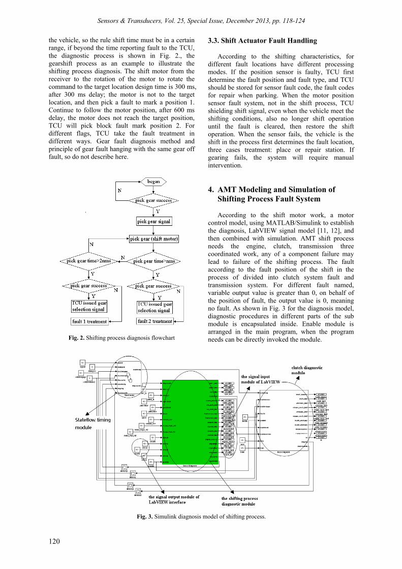
According to the shift motor work, a motor control model, using MATLAB/Simulink to establish the diagnosis, LabVIEW signal model [11, 12], and then combined with simulation. AMT shift process needs the engine, clutch, transmission three coordinated work, any of a component failure may lead to failure of the shifting process. The fault according to the fault position of the shift in the process of divided into clutch system fault and transmission system. For different fault named, variable output value is greater than 0, on behalf of the position of fault, the output value is 0, meaning no fault. As shown in Fig. 3 for the diagnosis model, diagnostic procedures in different parts of the sub module is encapsulated inside. Enable module is arranged in the main program, when the program needs can be directly invoked the module.
Fig. 3. Simulink diagnosis model of shifting process.
Sensors & Transducers, Vol. 25, Special Issue, December 2013, pp. 118-124
121
In shift process the AMT control system will trigger the Stateflow timing module. Timing module triggers diagnostic module timing, real-time monitoring shifting process.
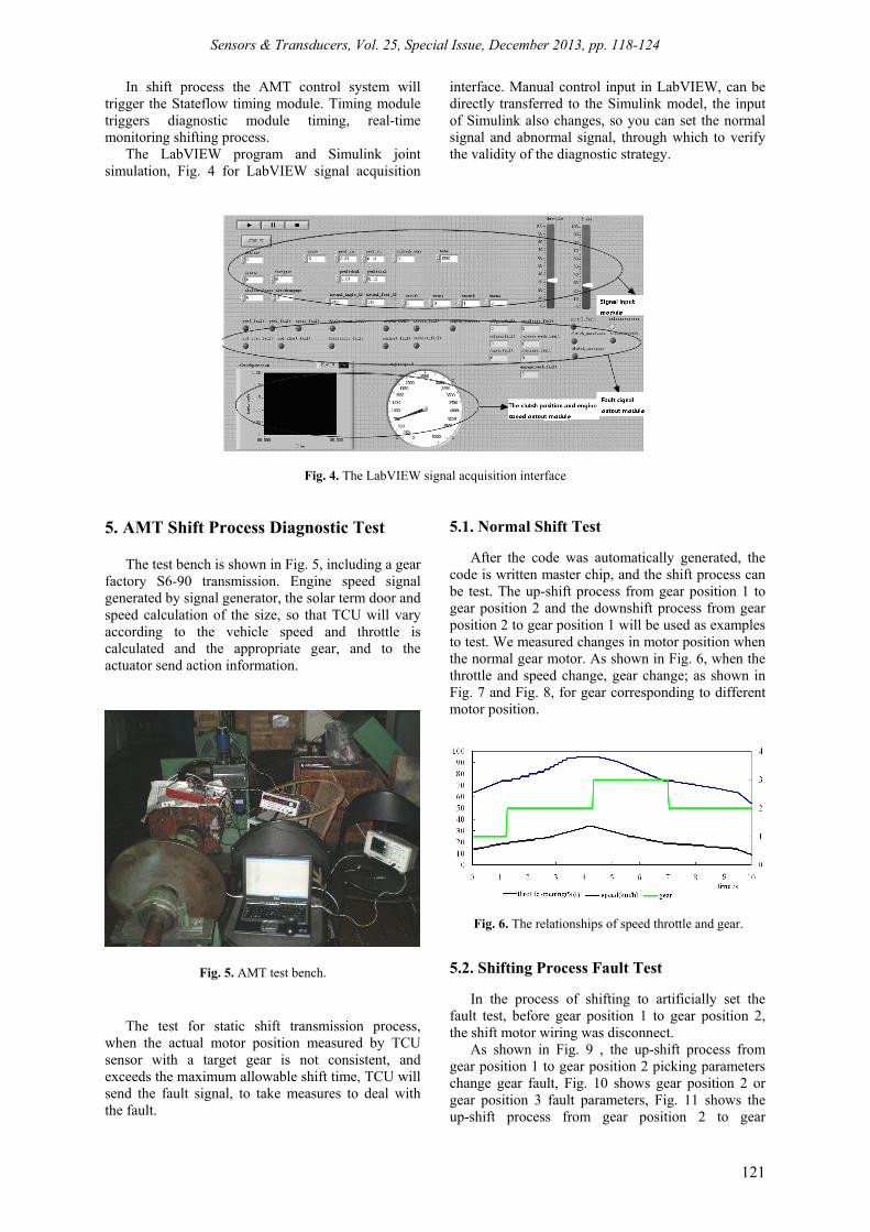
The LabVIEW program and Simulink joint simulation, Fig. 4 for LabVIEW signal acquisition
interface. Manual control input in LabVIEW, can be directly transferred to the Simulink model, the input of Simulink also changes, so you can set the normal signal and abnormal signal, through which to verify the validity of the diagnostic strategy.
Fig. 4. The LabVIEW signal acquisition interface 5. AMT Shift Process Diagnostic Test
The test bench is shown in Fig. 5, including a gear factory S6-90 transmission. Engine speed signal generated by signal generator, the solar term door and speed calculation of the size, so that TCU will vary according to the vehicle speed and throttle is calculated and the appropriate gear, and to the actuator send action information.
Fig. 5. AMT test bench.
The test for static shift transmission process, when the actual motor position measured by TCU sensor with a target gear is not consistent, and exceeds the maximum allowable shift time, TCU will send the fault signal, to take measures to deal with the fault.
5.1. Normal Shift Test
After the code was automatically generated, the code is written master chip, and the shift process can be test. The up-shift process from gear position 1 to gear position 2 and the downshift process from gear position 2 to gear position 1 will be used as examples to test. We measured changes in motor position when the normal gear motor. As shown in Fig. 6, when the throttle and speed change, gear change; as shown in Fig. 7 and Fig. 8, for gear corresponding to different motor position.
Fig. 6. The relationships of speed throttle and gear.
5.2. Shifting Process Fault Test
In the process of shifting to artificially set the fault test, before gear position 1 to gear position 2, the shift motor wiring was disconnect.
As shown in Fig. 9 , the up-shift process from gear position 1 to gear position 2 picking parameters change gear fault, Fig. 10 shows gear position 2 or gear position 3 fault parameters, Fig. 11 shows the up-shift process from gear position 2 to gear

Sensors & Transducers, Vol. 25, Special Issue, December 2013, pp. 118-124
122
position 3 stop hanging the variation of each parameter block fault.
5.3. Shifting Motor Position Sensor Fault Test Elected shift motor position sensor of any fault
occurs, the TCU will not be able to control the motor, the gear shifting signal TCU shielding, keep the gear.
Fig. 12 and Fig. 13 are respectively selected processing gear motor position sensor and position sensor shift motor faults TCU take. When the sensor values exceed the motor position limit, indicating that the sensor failure, the TCU measures are taken to keep the gear, the figure shows even increase the speed and throttle, TCU is no longer a shift command.
Fig. 7. Motor position change of up-shift process from gear position 1 to gear position 2.
Fig. 8. Motor position change of downshift process
from gear position 2 to gear position 1.
Fig. 9. Parameter changes while picking fault occurs of downshift process from gear position 2 to gear position 1.

Sensors & Transducers, Vol. 25, Special Issue, December 2013, pp. 118-124
123
Fig. 10. Parameter changes while shifting fault occurs of up-shift process from gear position 2 to gear position 3.
Fig. 11. Parameter changes while gear meshing fault occurs of up-shift process from gear position 2 to gear position 3.
(a). Gear selection sensor output.
(b). Gear selection sensor fault handling.
(a). Shift sensor output.
(b). Shift sensor fault handling.
Fig. 12. Gear selection sensor output and fault handling.
Fig. 13. Shift sensor output and fault handling.
6. Conclusions
According to the logic of redundant input shaft, output shaft speed sensor and the motor position
sensor fault diagnosis strategy, in the Matlab/Simulink software environment, the fault diagnosis model of AMT system. Using the classical PID control and feedback control, LabVIEW and

Sensors & Transducers, Vol. 25, Special Issue, December 2013, pp. 118-124
124
Simulink joint debugging, experimental verification of the model control effect. The model is converted into code, written in TCU, through the transmission bench test, man-made shift process fault, respectively verified during a shift gear off, gear, gear fault. Real time data acquisition speed, throttle, a comparative analysis of diagnosis information, sensor information, fault information and design, show that the method is feasible. At the same time caused by sensor failure, sensor failure when the vehicle is no longer shift, indicate that the sensor fault handling strategy. Simulation and test results show that: the strategy of AMT mechanism fault diagnosis of graphical programming language LabVIEW and Simulink co simulation fault processing system for AMT based development approach method is correct and feasible, has certain engineering application value.
Acknowledgements This work was financially supported in part by
the National Natural Science Foundation of China (Grant No. 60970072), the Natural Science Foundation of Education Department of Sichuan Province (Grant No. 10ZA100) and the Research Fund of Key Laboratory of Automotive Engineering of Sichuan Province (Grant No. SGXZD9902-10-1).
References [1]. Ge Anlin, Automatic transmission theoretical design,
China Machine Press, 1993. [2]. Yin Xiaofeng, Li Lei, Liao Zhiming and Wang
Wenping. Current development situation and outlook of automatic transmission technology, Journal of Mechanical Transmission, Vol. 34, Issue 8, 2010, pp. 87-91.
[3]. Teng Yanqiong, Yin Xiaofeng and Zhang Dewang. Gear-shift control strategy for a 6 speed wet-type DCT, in Proceedings of the International Conference on Mechatronics and Control Engineering, Applied Mechanics and Materials: Advances in Mechatronics and Control Engineering (ICMCE’12), China, Guangzhou, 29-30 November 2012, 278-280, pp. 1459-1465.
[4]. Qin Guihe, Ge Anlin and Lei Yulong, Automatic mechanical transmission line fault diagnosis system, Transactions of the Chinese Society for Agricultural Machinery, Vol. 32, Issue 5, 2001, pp. 75-77.
[5]. Gu Yongming, Research on fault diagnosis and fault disposal of AMT, Chongqing University, 2009.
[6]. Jiang Wei, Research on vehicle fault diagnosis and fault disposal of heavy truck AMT, Chongqing University, 2009.
[7]. Hossein Janhangiri and Fatemeh Dashti, A Comprehensive Performance Evaluation Model of E-Readiness and IT Performance Based on Strategies, Journal of Computational Intelligence and Electronic Systems, Vol. 1, Issue 2, 2012, pp. 193-199.
[8]. Huang Jianming, Research on control strategy of automated mechanical transmission, Chongqing University, 2004.
[9]. Li Su, Li Xiaoying and Li Zhiqin, Automobile engine dynamic process and its control, China Communications Press, 2000.
[10]. Musaab Hassan, Electrostatically Actuated 3C-SiC MEMS for Frequency Mixing, Journal of Mechatronics, Vol. 1, Issue 1, 2012, pp. 21-24.
[11]. Ding Junqiang, Study on fault diagnosis technology about heavy truck of AMT, Xihua University, 2010.
[12]. P. Manju and V. Subbiah, Effect of Changing Membership Functions in the Operation of Fuzzy Based Unified Power Flow Controller in a Power System Network, Journal of Computational Intelligence and Electronic Systems, Vol. 2, Issue 1, 2013, pp. 60-65.
___________________
2013 Copyright ©, International Frequency Sensor Association (IFSA). All rights reserved. (http://www.sensorsportal.com)