AMS Victorian Electricity Transmission Network Services - AMS 10-64... · AMS – Victorian...
28
AMS – Victorian Electricity Transmission Network Instrument Transformers (PUBLIC VERSION) Document number AMS 10-64 Issue number 10 Status Approved Approver J. Dyer Date of approval 14/08/2015
-
Upload
nguyenkhue -
Category
Documents
-
view
222 -
download
5
Transcript of AMS Victorian Electricity Transmission Network Services - AMS 10-64... · AMS – Victorian...
AMS – Victorian Electricity Transmission Network
Instrument Transformers (PUBLIC VERSION)
Document number AMS 10-64
Issue number 10
Status Approved
Approver J. Dyer
Date of approval 14/08/2015
AusNet Services Number 10-64
Instrument Transformers
ISSUE 10 14/08/2015 2 / 28
UNCONTROLLED WHEN PRINTED
ISSUE/AMENDMENT STATUS
Issue Number
Date Description Author Approved by
5 22/11/06 Editorial review. G. Lukies
D. Postlethwaite
G. Towns
6 23/02/07 Review and update. G. Lukies
S. Dick
G. Towns
7 17/03/07 Editorial review. G. Lukies
D. Postlethwaite
G. Towns
8 24/10/07 Updated to include reference to 500 kV CT Life Analysis document.
G. Lukies G. Towns
9 18/01/13 Revised Structure and General Updat.e D. Meade D. Postlethwaite
10 14/08/15 Review and update. P. Seneviratne
D. Platt
J. Dyer
Disclaimer
This document belongs to AusNet Services and may or may not contain all available information on the subject matter this document purports to address. The information contained in this document is subject to review and AusNet Services may amend this document at any time. Amendments will be indicated in the Amendment Table, but AusNet Services does not undertake to keep this document up to date.
To the maximum extent permitted by law, AusNet Services makes no representation or warranty (express or implied) as to the accuracy, reliability, or completeness of the information contained in this document, or its suitability for any intended purpose. AusNet Services (which, for the purposes of this disclaimer, includes all of its related bodies corporate, its officers, employees, contractors, agents and consultants, and those of its related bodies corporate) shall have no liability for any loss or damage (be it direct or indirect, including liability by reason of negligence or negligent misstatement) for any statements, opinions, information or matter (expressed or implied) arising out of, contained in, or derived from, or for any omissions from, the information in this document.
Contact
This document is the responsibility of the Asset Management division of AusNet Services. Please contact the undersigned or author with any inquiries.
John Dyer
AusNet Services
Level 31, 2 Southbank Boulevard
Melbourne Victoria 3006
Ph: (03) 9695 6000
AusNet Services Number 10-64
Instrument Transformers
ISSUE 10 14/08/2015 3 / 28
UNCONTROLLED WHEN PRINTED
Table of Contents
1 Executive Summary ..................................................................................................................... 4
1.1 New Assets.................................................................................................................................................. 4
1.2 Inspection, Monitoring & Testing ................................................................................................................ 4
1.3 Maintenance ................................................................................................................................................ 5
1.4 Refurbishment ............................................................................................................................................. 5
1.5 Replacement ............................................................................................................................................... 5
2 Introduction .................................................................................................................................. 6
2.1 Purpose ....................................................................................................................................................... 6
2.2 Scope ........................................................................................................................................................... 6
3 Asset Summary ............................................................................................................................ 7
3.1 Population .................................................................................................................................................... 7
3.2 Age Profile ................................................................................................................................................... 9
3.3 Asset Condition and Performance ........................................................................................................... 12
3.4 Key Issues ................................................................................................................................................. 21
4 Risk Assessment ....................................................................................................................... 22
4.1 Dependability Management...................................................................................................................... 22
4.2 Current Transformers................................................................................................................................ 22
4.3 VoltageTransformers ................................................................................................................................ 25
5 Strategies .................................................................................................................................... 27
5.1 New Assets................................................................................................................................................ 27
5.2 Inspection, Monitoring & Testing .............................................................................................................. 27
5.3 Maintenance .............................................................................................................................................. 27
5.4 Refurbishment ........................................................................................................................................... 27
5.5 Replacement ............................................................................................................................................. 28
AusNet Services Number 10-64
Instrument Transformers
ISSUE 10 14/08/2015 4 / 28
UNCONTROLLED WHEN PRINTED
1 Executive Summary
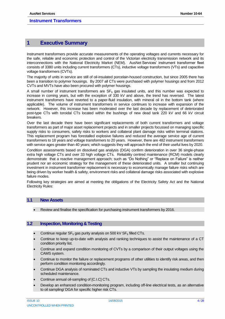
Instrument transformers provide accurate measurements of the operating voltages and currents necessary for the safe, reliable and economic protection and control of the Victorian electricity transmission network and its interconnections with the National Electricity Market (NEM). AusNet Services’ instrument transformer fleet consists of 3380 units including current transformers (CTs), inductive voltage transformers (VTs) and capacitive voltage transformers (CVTs).
The majority of units in service are still of oil-insulated porcelain-housed construction, but since 2005 there has been a transition to polymer housings. By 2007 all CTs were purchased with polymer housings and from 2012 CVTs and MVTs have also been procured with polymer housings.
A small number of instrument transformers are SF6 gas insulated units, and this number was expected to increase in coming years, but with the exception of 330 kV and above, the trend has reversed. The latest instrument transfomers have reverted to a paper-fluid insulation, with mineral oil in the bottom tank (where applicable). The volume of instrument transformers in service continues to increase with expansion of the network. However, this increase has been moderated over the last decade by replacement of deteriorated post-type CTs with toroidal CTs located within the bushings of new dead tank 220 kV and 66 kV circuit breakers.
Over the last decade there have been significant replacements of both current transformers and voltage transformers as part of major asset replacement projects and in smaller projects focussed on managing specific supply risks to consumers, safety risks to workers and collateral plant damage risks within terminal stations. This replacement program has forestalled explosive failures and reduced the average service age of current transformers to 18 years and voltage transformers to 20 years. However, there are 482 instrument transformers with service ages greater than 40 years; which suggests they will approach the end of their useful lives by 2020.
Condition assessments based on dissolved gas analysis (DGA) confirm deterioration in over 36 single-phase extra high voltage CTs and over 33 high voltage CTs. Reliability centred maintenance (RCM) models clearly demonstrate that a reactive management approach; such as “Do Nothing” or “Replace on Failure” is neither prudent nor an economic strategy for the management of these deteriorated units. A smaller but continuing investment in instrument transformer replacement is necessary to economically manage failure risks which are being driven by worker health & safety, environment risks and collateral damage risks associated with explosive failure modes.
Following key strategies are aimed at meeting the obligations of the Electricity Safety Act and the National Electricity Rules:
1.1 New Assets
Review and finalise the specification for purchasing instrument transformers by 2016.
1.2 Inspection, Monitoring & Testing
Continue regular SF6 gas purity analysis on 500 kV SF6 filled CTs.
Continue to keep up-to-date with analysis and ranking techniques to assist the maintenance of a CT condition priority list.
Continue and expand condition monitoring of CVTs by a comparison of their output voltages using the CAMS system.
Continue to monitor the failure or replacement programs of other utilities to identify risk areas, and then perform condition monitoring accordingly.
Continue DGA analysis of nominated CTs and inductive VTs by sampling the insulating medium during scheduled maintenance.
Continue annual oil-sampling of [C.I.C] CTs.
Develop an enhanced condition-monitoring program, including off-line electrical tests, as an alternative to oil sampling/ DGA for specific higher risk CTs.
AusNet Services Number 10-64
Instrument Transformers
ISSUE 10 14/08/2015 5 / 28
UNCONTROLLED WHEN PRINTED
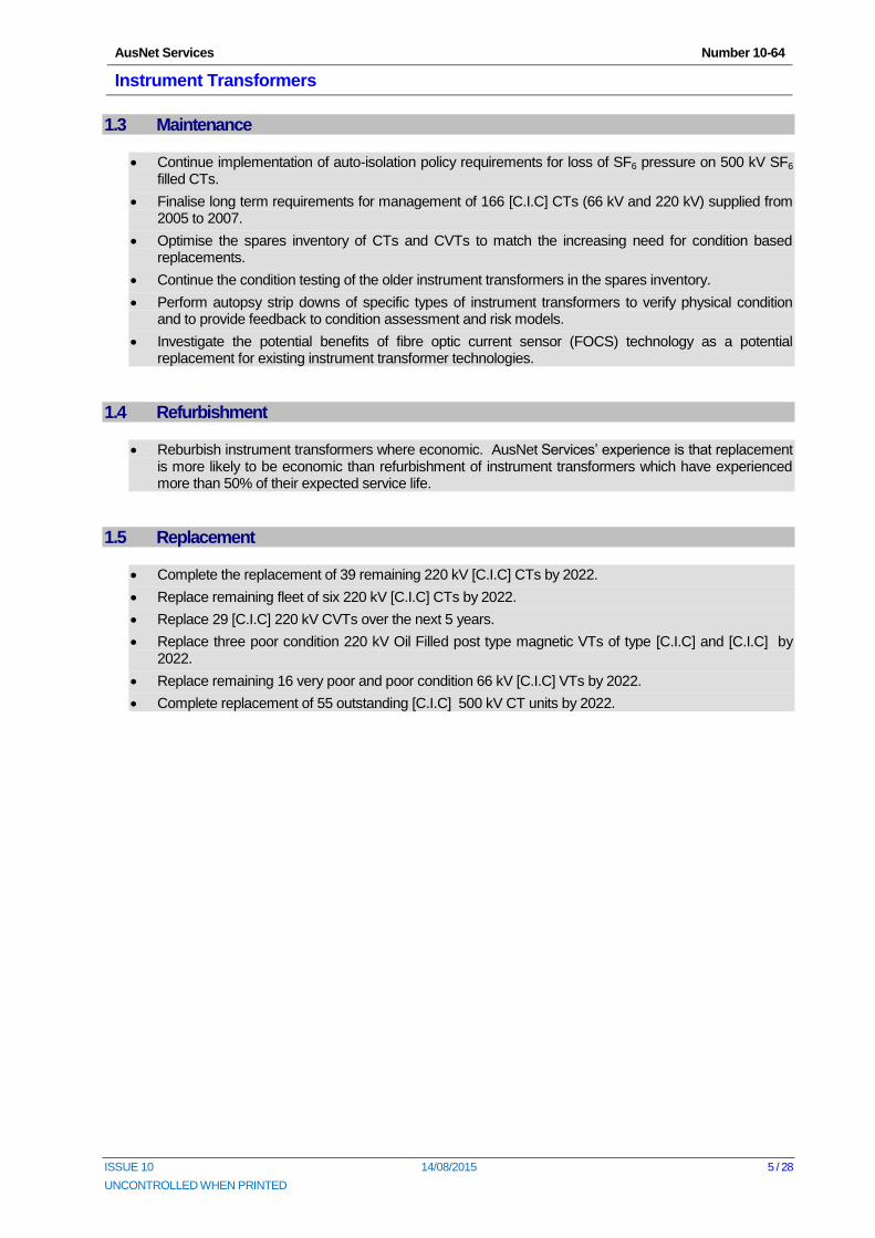
1.3 Maintenance
Continue implementation of auto-isolation policy requirements for loss of SF6 pressure on 500 kV SF6 filled CTs.
Finalise long term requirements for management of 166 [C.I.C] CTs (66 kV and 220 kV) supplied from 2005 to 2007.
Optimise the spares inventory of CTs and CVTs to match the increasing need for condition based replacements.
Continue the condition testing of the older instrument transformers in the spares inventory.
Perform autopsy strip downs of specific types of instrument transformers to verify physical condition and to provide feedback to condition assessment and risk models.
Investigate the potential benefits of fibre optic current sensor (FOCS) technology as a potential replacement for existing instrument transformer technologies.
1.4 Refurbishment
Reburbish instrument transformers where economic. AusNet Services’ experience is that replacement is more likely to be economic than refurbishment of instrument transformers which have experienced more than 50% of their expected service life.
1.5 Replacement
Complete the replacement of 39 remaining 220 kV [C.I.C] CTs by 2022.
Replace remaining fleet of six 220 kV [C.I.C] CTs by 2022.
Replace 29 [C.I.C] 220 kV CVTs over the next 5 years.
Replace three poor condition 220 kV Oil Filled post type magnetic VTs of type [C.I.C] and [C.I.C] by 2022.
Replace remaining 16 very poor and poor condition 66 kV [C.I.C] VTs by 2022.
Complete replacement of 55 outstanding [C.I.C] 500 kV CT units by 2022.
AusNet Services Number 10-64
Instrument Transformers
ISSUE 10 14/08/2015 6 / 28
UNCONTROLLED WHEN PRINTED
2 Introduction
2.1 Purpose
The purpose of this Asset Management Strategy is to document economic inspection, maintenance, refurbishment and replacement strategies to manage the performance of single-phase post type current transformers and voltage transformers throughout their life cycle.
2.2 Scope
This asset management strategy (AMS) applies to all independent single-phase post type current transformers (CTs) and voltage transformers (VTs) and capacitive voltage transformers (CVTCCs) in AusNet Services’ Victorian electricity transmission network.
The discussion of voltage transformers is divided into capacitive (CVT) and inductive (VT) types. In addition, but not included in this assessment, there are:
An estimated 1,100 toroidal current transformers that are built into transformers, Gas Insulated Switchgear (GIS) and bulk oil circuit breakers (CBs).
Between 100 and 200 connected coupling units (CCUs) on transformer bushings, bulk-oil circuit breaker bushings and post CTs to provide a low-burden voltage source.
This asset management strategy (AMS) does not include instrument transformers operating on the distribution network or instrument transformers situated within zone substations. The strategies in this document are limited to maintaining design capabilities in terms of equipment performance and rating. Improvements in quality or capacity of supply are not included in the scope of this document.
AusNet Services Number 10-64
Instrument Transformers
ISSUE 10 14/08/2015 7 / 28
UNCONTROLLED WHEN PRINTED
3 Asset Summary
3.1 Population
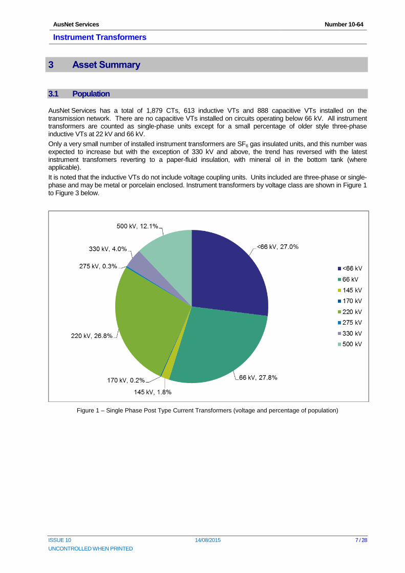
AusNet Services has a total of 1,879 CTs, 613 inductive VTs and 888 capacitive VTs installed on the transmission network. There are no capacitive VTs installed on circuits operating below 66 kV. All instrument transformers are counted as single-phase units except for a small percentage of older style three-phase inductive VTs at 22 kV and 66 kV.
Only a very small number of installed instrument transformers are SF6 gas insulated units, and this number was expected to increase but with the exception of 330 kV and above, the trend has reversed with the latest instrument transfomers reverting to a paper-fluid insulation, with mineral oil in the bottom tank (where applicable).
It is noted that the inductive VTs do not include voltage coupling units. Units included are three-phase or single-phase and may be metal or porcelain enclosed. Instrument transformers by voltage class are shown in Figure 1 to Figure 3 below.
Figure 1 – Single Phase Post Type Current Transformers (voltage and percentage of population)
AusNet Services Number 10-64
Instrument Transformers
ISSUE 10 14/08/2015 8 / 28
UNCONTROLLED WHEN PRINTED
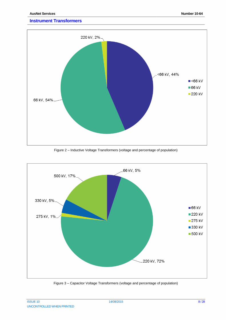
Figure 2 – Inductive Voltage Transformers (voltage and percentage of population)
Figure 3 – Capacitor Voltage Transformers (voltage and percentage of population)
AusNet Services Number 10-64
Instrument Transformers
ISSUE 10 14/08/2015 9 / 28
UNCONTROLLED WHEN PRINTED
3.2 Age Profile
3.2.1 General
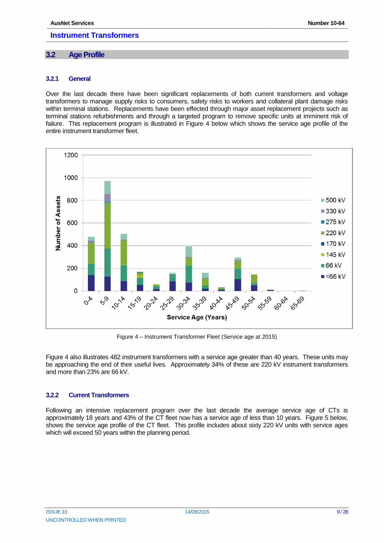
Over the last decade there have been significant replacements of both current transformers and voltage transformers to manage supply risks to consumers, safety risks to workers and collateral plant damage risks within terminal stations. Replacements have been effected through major asset replacement projects such as terminal stations refurbishments and through a targeted program to remove specific units at imminent risk of failure. This replacement program is illustrated in Figure 4 below which shows the service age profile of the entire instrument transformer fleet.
Figure 4 – Instrument Transformer Fleet (Service age at 2015)
Figure 4 also illustrates 482 instrument transformers with a service age greater than 40 years. These units may be approaching the end of their useful lives. Approximately 34% of these are 220 kV instrument transformers and more than 23% are 66 kV.
3.2.2 Current Transformers
Following an intensive replacement program over the last decade the average service age of CTs is approximately 18 years and 43% of the CT fleet now has a service age of less than 10 years. Figure 5 below, shows the service age profile of the CT fleet. This profile includes about sixty 220 kV units with service ages which will exceed 50 years within the planning period.
AusNet Services Number 10-64
Instrument Transformers
ISSUE 10 14/08/2015 10 / 28
UNCONTROLLED WHEN PRINTED
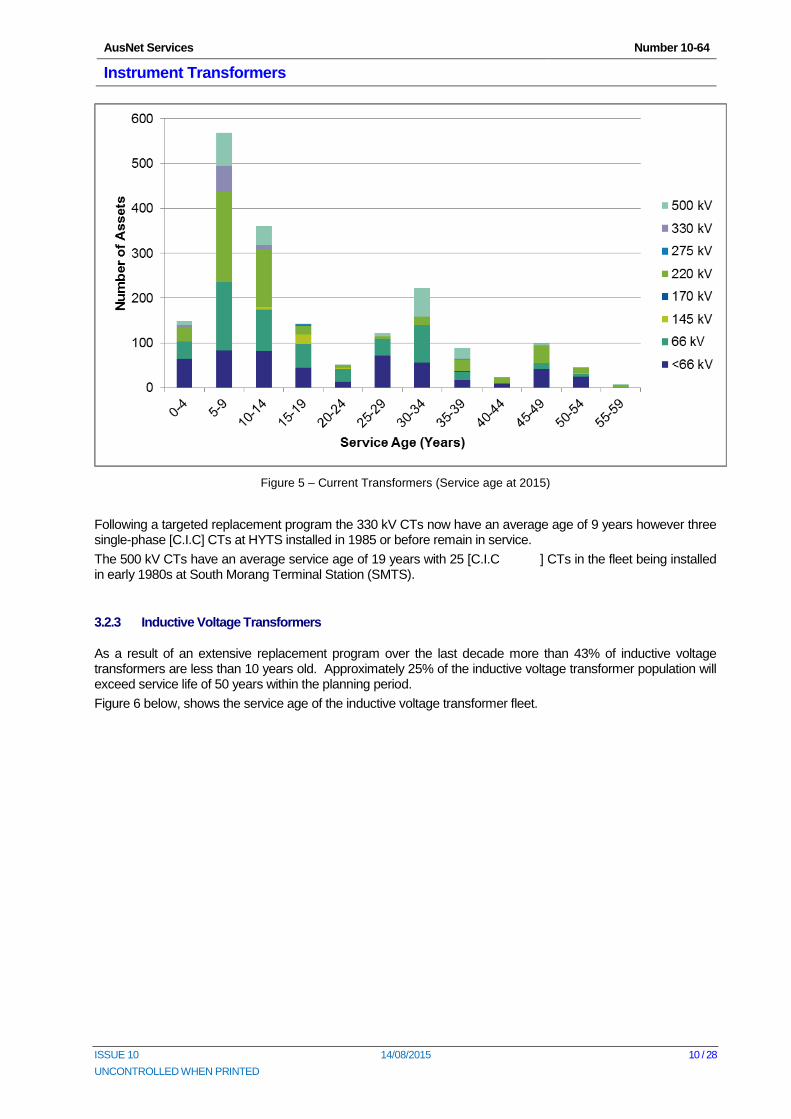
Figure 5 – Current Transformers (Service age at 2015)
Following a targeted replacement program the 330 kV CTs now have an average age of 9 years however three single-phase [C.I.C] CTs at HYTS installed in 1985 or before remain in service.
The 500 kV CTs have an average service age of 19 years with 25 [C.I.C ] CTs in the fleet being installed in early 1980s at South Morang Terminal Station (SMTS).
3.2.3 Inductive Voltage Transformers
As a result of an extensive replacement program over the last decade more than 43% of inductive voltage transformers are less than 10 years old. Approximately 25% of the inductive voltage transformer population will exceed service life of 50 years within the planning period.
Figure 6 below, shows the service age of the inductive voltage transformer fleet.
AusNet Services Number 10-64
Instrument Transformers
ISSUE 10 14/08/2015 11 / 28
UNCONTROLLED WHEN PRINTED
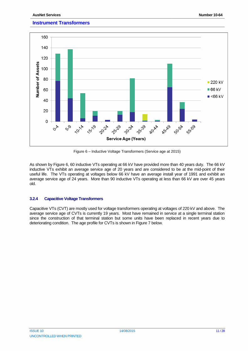
Figure 6 – Inductive Voltage Transformers (Service age at 2015)
As shown by Figure 6, 60 inductive VTs operating at 66 kV have provided more than 40 years duty. The 66 kV inductive VTs exhibit an average service age of 20 years and are considered to be at the mid-point of their useful life. The VTs operating at voltages below 66 kV have an average install year of 1991 and exhibit an average service age of 24 years. More than 90 inductive VTs operating at less than 66 kV are over 45 years old.
3.2.4 Capacitive Voltage Transformers
Capacitive VTs (CVT) are mostly used for voltage transformers operating at voltages of 220 kV and above. The average service age of CVTs is currently 19 years. Most have remained in service at a single terminal station since the construction of that terminal station but some units have been replaced in recent years due to deteriorating condition. The age profile for CVTs is shown in Figure 7 below.
AusNet Services Number 10-64
Instrument Transformers
ISSUE 10 14/08/2015 12 / 28
UNCONTROLLED WHEN PRINTED
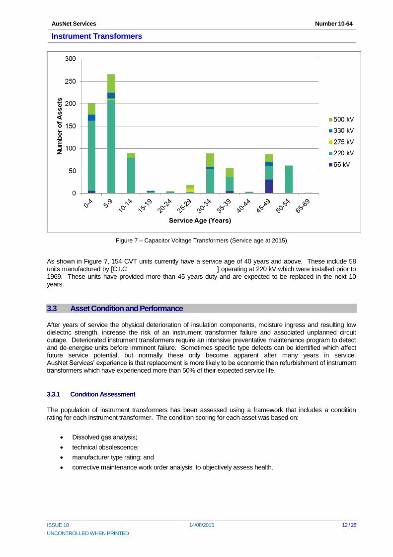
Figure 7 – Capacitor Voltage Transformers (Service age at 2015)
As shown in Figure 7, 154 CVT units currently have a service age of 40 years and above. These include 58 units manufactured by [C.I.C ] operating at 220 kV which were installed prior to 1969. These units have provided more than 45 years duty and are expected to be replaced in the next 10 years.
3.3 Asset Condition and Performance
After years of service the physical deterioration of insulation components, moisture ingress and resulting low dielectric strength, increase the risk of an instrument transformer failure and associated unplanned circuit outage. Deteriorated instrument transformers require an intensive preventative maintenance program to detect and de-energise units before imminent failure. Sometimes specific type defects can be identified which affect future service potential, but normally these only become apparent after many years in service. AusNet Services’ experience is that replacement is more likely to be economic than refurbishment of instrument transformers which have experienced more than 50% of their expected service life.
3.3.1 Condition Assessment
The population of instrument transformers has been assessed using a framework that includes a condition rating for each instrument transformer. The condition scoring for each asset was based on:
Dissolved gas analysis;
technical obsolescence;
manufacturer type rating; and
corrective maintenance work order analysis to objectively assess health.
AusNet Services Number 10-64
Instrument Transformers
ISSUE 10 14/08/2015 13 / 28
UNCONTROLLED WHEN PRINTED
Regular dissolved gas analysis (DGA) of oil samples from CTs and inductive VTs is a principle input for condition assessment of instrument transformers. This calculated assessment of insulation condition permits the planned removal of units that have deteriorated beyond prudent limits. Monitoring of many units in the last decade has confirmed that the deterioration rate accelerates as the unit approaches the end of its useful life. DGA analysis has also shown that deterioration is not uniform across the fleet however a strong correlation between CTs of similar manufacturing batches is observed.
Technical obsolescence contributes to the overall condition assessments based on the age of the asset, the availability of spare parts and manufacturer support.
Manufacturer type rating is based on known defects with a particular brand or type of instrument transformer.
The corrective maintenance work order analysis is based on the analysis of all the corrective work orders raised against the Insulation System, the Electrical System, the Tank/External components associated with each asset.
The overall condition score for each asset is based on the sum of the weighted value for Technical Obsolescence, Corrective Maintenance Work Orders and the known Manufacturer Type Issues.
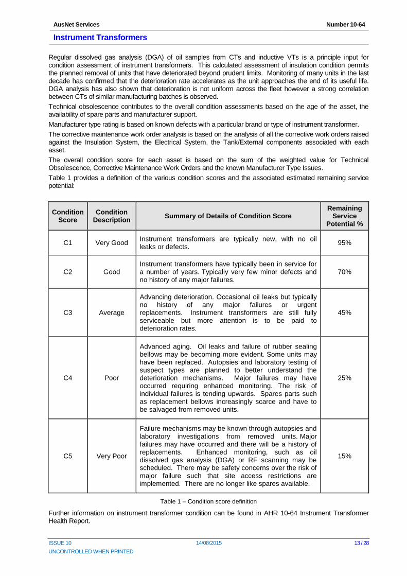
Table 1 provides a definition of the various condition scores and the associated estimated remaining service potential:
Condition Score
Condition Description
Summary of Details of Condition Score Remaining
Service Potential %
C1 Very Good Instrument transformers are typically new, with no oil leaks or defects.
95%
C2 Good Instrument transformers have typically been in service for a number of years. Typically very few minor defects and no history of any major failures.
70%
C3 Average
Advancing deterioration. Occasional oil leaks but typically no history of any major failures or urgent replacements. Instrument transformers are still fully serviceable but more attention is to be paid to deterioration rates.
45%
C4 Poor
Advanced aging. Oil leaks and failure of rubber sealing bellows may be becoming more evident. Some units may have been replaced. Autopsies and laboratory testing of suspect types are planned to better understand the deterioration mechanisms. Major failures may have occurred requiring enhanced monitoring. The risk of individual failures is tending upwards. Spares parts such as replacement bellows increasingly scarce and have to be salvaged from removed units.
25%
C5 Very Poor
Failure mechanisms may be known through autopsies and laboratory investigations from removed units. Major failures may have occurred and there will be a history of replacements. Enhanced monitoring, such as oil dissolved gas analysis (DGA) or RF scanning may be scheduled. There may be safety concerns over the risk of major failure such that site access restrictions are implemented. There are no longer like spares available.
15%
Table 1 – Condition score definition
Further information on instrument transformer condition can be found in AHR 10-64 Instrument Transformer Health Report.
AusNet Services Number 10-64
Instrument Transformers
ISSUE 10 14/08/2015 14 / 28
UNCONTROLLED WHEN PRINTED
3.3.2 Current Transformers
Explosive failures of a 220 kV CT at Jeeralang power station in 2004, two 500 kV [C.I.C] CTs at Moorabool terminal station in 2002 and 2005 and a 66 kV unit at Terang in 2006 have highlighted the importance of DGA analysis in economic management of the CT fleets. Laboratory confirmation of significant partial discharge behaviour provided the necessary foundation for DGA to drive the condition-based replacement of the 330 kV and 500 kV [C.I.C] CT fleets over the last eight years. Targeted projects are currently underway to remove specific, high-risk CTs from service including:
remaining [C.I.C] 220 kV and 66 kV CTs;
[C.I.C] 500 kV CTs; and
[C.I.C] 220 kV CTs.
[C.I.C] CTs
The remaining 330 kV and 220 kV [C.I.C] CTs are currently on annual DGA sampling regimes and the test results suggest that this fleet will require replacement within the next five years. In addition the 66 kV [C.I.C] CTs continue to be monitored closely with several units found with 1-2 ppm of acetylene gas indicating permanent deterioration of the insulating system.
Investigations indicate that the [C.I.C] CTs show a design/manufacturing deficiency in the capacitive voltage grading structure of the insulation and the earth screen grounding connection. Adivce is that electrical switching or lightning transient currents passing through the capacitive structure create an over-voltage condition that punctures the last few capacitive layers to earth. Partial discharge then continues to degrade the installation until cascade insulation failure begins. The degradation of the insulation can rapidly advance causing explosive failure, resulting in worker safety risks, damage to adjacent equipment and long unplanned outages of network plant.
[C.I.C] CTs
There are 41 [C.I.C] CTs (66 kV and 220 kV CT’s) supplied from 2005 to 2007. These [C.I.C] CT’s, plus a proportion of [C.I.C] CT’s supplied between 2005 and 2007 have polymer bushing materials manufactured from ‘Plast ‘ and that those specific bushings chemically react with the oil, producing gasses that mimic overheating. The risk associated with mimic-gassing has been limited to encompass only 220 kV Type [C.I.C] CT’s and two batches of 220 kV [C.I.C] CT’s that were manufactured between 2005 and 2007,
The phenomenon is an ongoing concern, but one of the worst examples has been subjected to numerous electrical tests in the Yarraville Lab, before being confirmed fully fit for service. AusNet Services has identified similar units with the same deterioration mode. Standard Maintenance Instruction (SMI) 22-01-01 requires that all forms of [C.I.C] CT’s will have dissolved gasses analysed during each routine overhaul. These tests are considered sufficient to monitor dielectric performance, but less invasive condition monitoring will be considered within for the longer term management of these assets; e.g. [C.I.C] series CT’s are provided with a port to monitor dielectric dissipation factor (DDF).
[C.I.C] CTs
The presence of acetylene within the [C.I.C] 500 kV CTs indicates the likelihood of low level electrical arcing. In addition Radio Frequency (RF) discharge has also been intermittently detected. The volumes of acetylene and other heating by-product gases being produced are slowly trending upwards. Autopsy investigation has confirmed the Dielectric Loss Angle (DLA) testing tap connection is inadequate which can lead to burnt paper at the lead connection to the outer foil. Since 2007 a targeted replacement program resulted in renewal of over 30 units. Deterioration rates appear slow and steady, and can be tracked. The majority of the remaining [C.I.C] units are expected to be replaced over the next 10 years.
[C.I.C] CTs
Only six 220 kV CT units remain in AusNet Services’ fleet by this manufacturer. These CTs cannot be readily condition-assessed as they have no oil sampling facility, so the unknown condition presents an increasing risk. With these CT’s now between 30 and 40 years old, the risk is now considered to outweigh their useful life, so the remaining units are programmed for replacement within 5 years.
AusNet Services Number 10-64
Instrument Transformers
ISSUE 10 14/08/2015 15 / 28
UNCONTROLLED WHEN PRINTED
3.3.2.1 Condition Profile
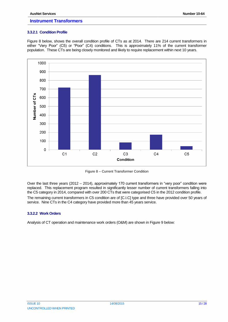
Figure 8 below, shows the overall condition profile of CTs as at 2014. There are 214 current transformers in either “Very Poor” (C5) or “Poor” (C4) conditions. This is approximately 11% of the current transformer population. These CTs are being closely monitored and likely to require replacement within next 10 years.
Figure 8 – Current Transformer Condition
Over the last three years (2012 – 2014), approximately 170 current transformers in “very poor” condition were replaced. This replacement program resulted in significantly lesser number of current transformers falling into the C5 category in 2014, compared with over 200 CTs that were categorised C5 in the 2012 condition profile.
The remaining current transformers in C5 condition are of [C.I.C] type and three have provided over 50 years of service. Nine CTs in the C4 category have provided more than 45 years service.
3.3.2.2 Work Orders
Analysis of CT operation and maintenance work orders (O&M) are shown in Figure 9 below:
AusNet Services Number 10-64
Instrument Transformers
ISSUE 10 14/08/2015 16 / 28
UNCONTROLLED WHEN PRINTED
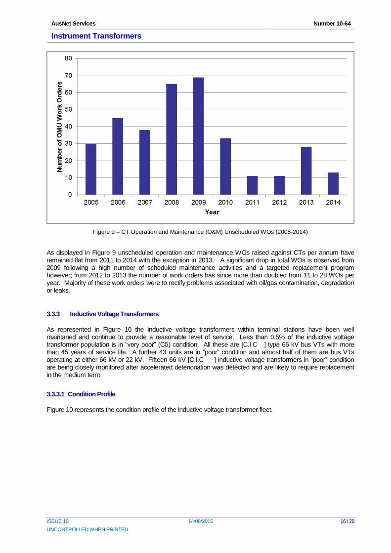
Figure 9 – CT Operation and Maintenance (O&M) Unscheduled WOs (2005-2014)
As displayed in Figure 9 unscheduled operation and maintenance WOs raised against CTs per annum have remained flat from 2011 to 2014 with the exception in 2013. A significant drop in total WOs is observed from 2009 following a high number of scheduled maintenance activities and a targeted replacement program however; from 2012 to 2013 the number of work orders has since more than doubled from 11 to 28 WOs per year. Majority of these work orders were to rectify problems associated with oil/gas contamination, degradation or leaks.
3.3.3 Inductive Voltage Transformers
As represented in Figure 10 the inductive voltage transformers within terminal stations have been well maintaned and continue to provide a reasonable level of service. Less than 0.5% of the inductive voltage transformer population is in “very poor” (C5) condition. All these are [C.I.C ] type 66 kV bus VTs with more than 45 years of service life. A further 43 units are in “poor” condition and almost half of them are bus VTs operating at either 66 kV or 22 kV. Fifteen 66 kV [C.I.C ] inductive voltage transformers in “poor” condition are being closely monitored after accelerated deterioriation was detected and are likely to require replacement in the medium term.
3.3.3.1 Condition Profile
Figure 10 represents the condition profile of the inductive voltage transformer fleet.
AusNet Services Number 10-64
Instrument Transformers
ISSUE 10 14/08/2015 17 / 28
UNCONTROLLED WHEN PRINTED
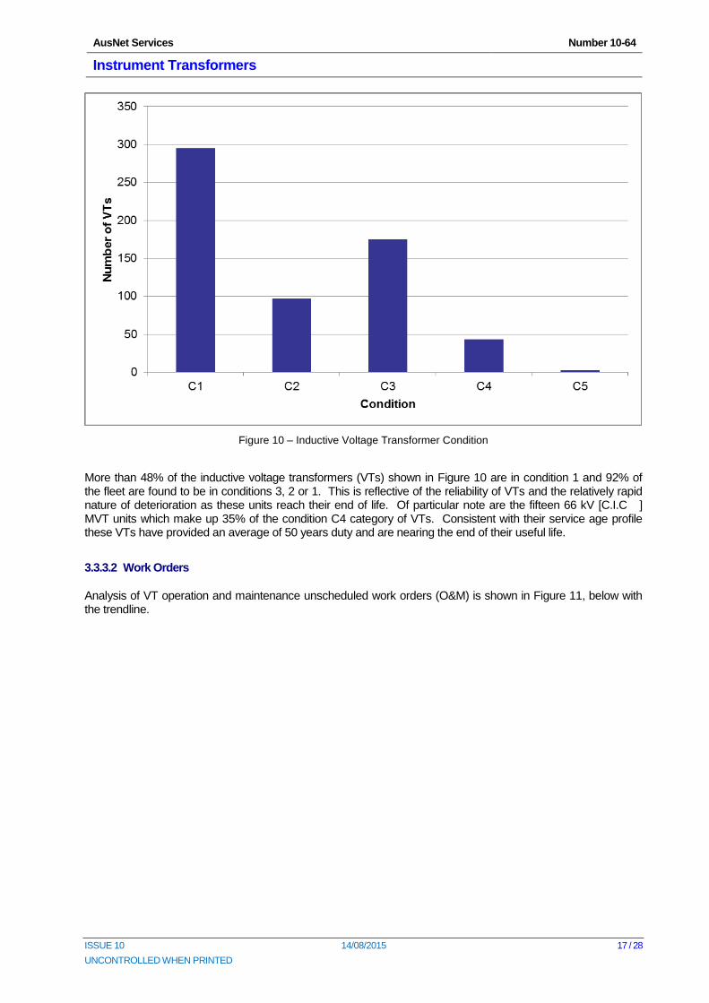
Figure 10 – Inductive Voltage Transformer Condition
More than 48% of the inductive voltage transformers (VTs) shown in Figure 10 are in condition 1 and 92% of the fleet are found to be in conditions 3, 2 or 1. This is reflective of the reliability of VTs and the relatively rapid nature of deterioration as these units reach their end of life. Of particular note are the fifteen 66 kV [C.I.C ] MVT units which make up 35% of the condition C4 category of VTs. Consistent with their service age profile these VTs have provided an average of 50 years duty and are nearing the end of their useful life.
3.3.3.2 Work Orders
Analysis of VT operation and maintenance unscheduled work orders (O&M) is shown in Figure 11, below with the trendline.
AusNet Services Number 10-64
Instrument Transformers
ISSUE 10 14/08/2015 18 / 28
UNCONTROLLED WHEN PRINTED
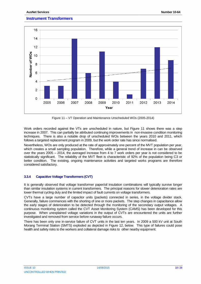
Figure 11 – VT Operation and Maintenance Unscheduled WOs (2005-2014)
Work orders recorded against the VTs are unscheduled in nature, but Figure 11 shows there was a step increase in 2007. This can partially be attributed continuing improvements in non-invasive condition monitoring techniques. There is also a notable drop of unscheduled WOs between the years 2010 and 2011, which follows a targeted replacement program in 2009, but the work order rate has since normalised.
Nevertheless, WOs are only produced at the rate of approximately one percent of the MVT population per year, which creates a small sampling population. Therefore, while a general trend of increase in can be observed over the years 2005 – 2014, the averaged increase from 4 to 7 work orders per year is not considered to be statistically significant. The reliability of the MVT fleet is characteristic of 92% of the population being C3 or better condition. The existing, ongoing maintenance activities and targeted works programs are therefore considered satisfactory.
3.3.4 Capacitive Voltage Transformers (CVT)
It is generally observed that voltage transformer paper/oil insulation combinations will typically survive longer than similar insulation systems in current transformers. The principal reasons for slower deterioration rates are lower thermal cycling duty and the limited impact of fault currents on voltage transformers.
CVTs have a large number of capacitor units (packets) connected in series, in the voltage divider stack. Generally, failure commences with the shorting of one or more packets. The step changes in capacitance allow the early stages of deterioration to be detected through the monitoring of the secondary output voltages. A continuous monitoring system called the CVT Asset Monitoring System (CAMS) has been developed for this purpose. When unexplained voltage variations in the output of CVTs are encountered the units are further investigated and removed from service before runaway failure occurs.
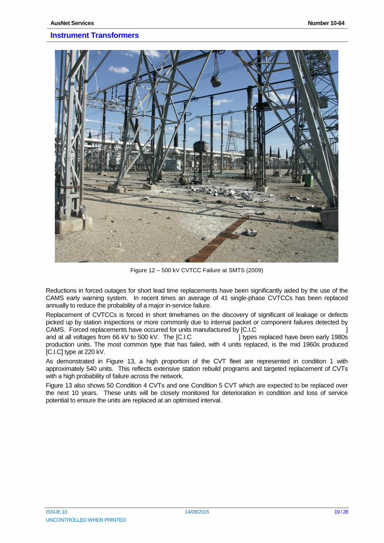
There has been only one in-service failure of CVT units in the last ten years. In 2009 a 500 kV unit at South Morang Terminal Station (SMTS) exploded as depicted in Figure 12, below. This type of failures could pose health and safety risks to the workers and collateral damage risks to other nearby equipment.
AusNet Services Number 10-64
Instrument Transformers
ISSUE 10 14/08/2015 19 / 28
UNCONTROLLED WHEN PRINTED
Figure 12 – 500 kV CVTCC Failure at SMTS (2009)
Reductions in forced outages for short lead time replacements have been significantly aided by the use of the CAMS early warning system. In recent times an average of 41 single-phase CVTCCs has been replaced annually to reduce the probability of a major in-service failure.
Replacement of CVTCCs is forced in short timeframes on the discovery of significant oil leakage or defects picked up by station inspections or more commonly due to internal packet or component failures detected by CAMS. Forced replacements have occurred for units manufactured by [C.I.C ] and at all voltages from 66 kV to 500 kV. The [C.I.C ] types replaced have been early 1980s production units. The most common type that has failed, with 4 units replaced, is the mid 1960s produced [C.I.C] type at 220 kV.
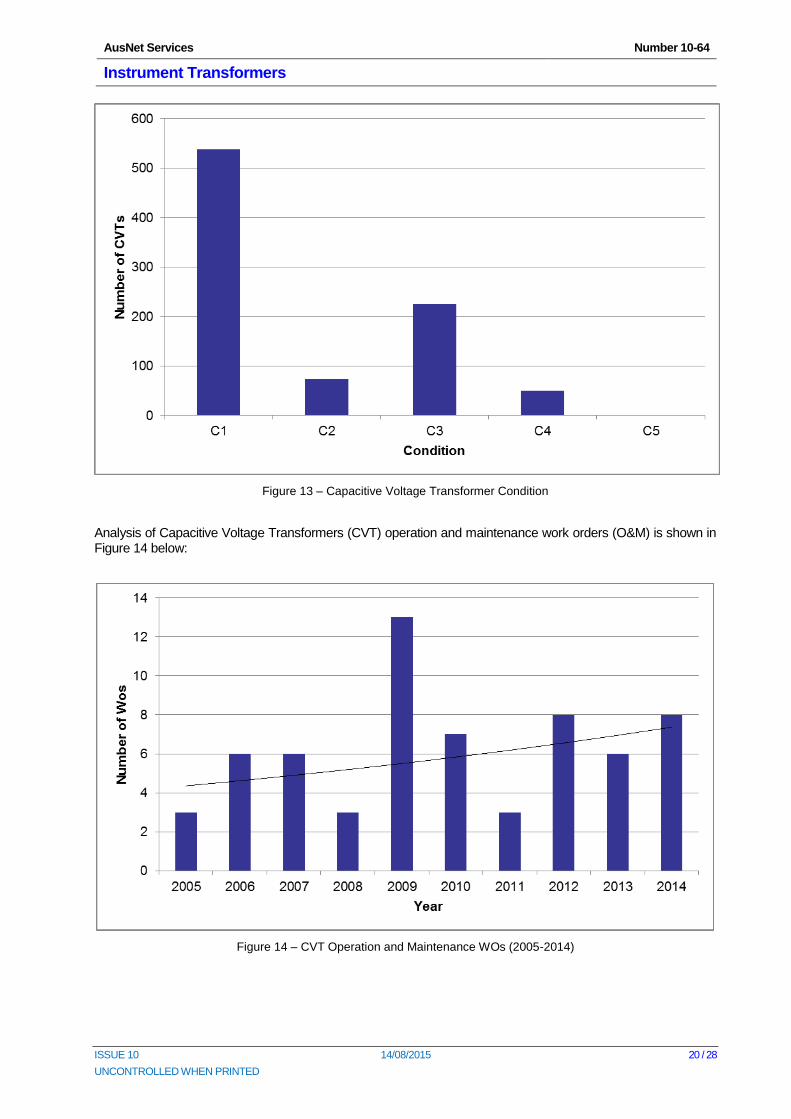
As demonstrated in Figure 13, a high proportion of the CVT fleet are represented in condition 1 with approximately 540 units. This reflects extensive station rebuild programs and targeted replacement of CVTs with a high probability of failure across the network.
Figure 13 also shows 50 Condition 4 CVTs and one Condition 5 CVT which are expected to be replaced over the next 10 years. These units will be closely monitored for deterioration in condition and loss of service potential to ensure the units are replaced at an optimised interval.
AusNet Services Number 10-64
Instrument Transformers
ISSUE 10 14/08/2015 20 / 28
UNCONTROLLED WHEN PRINTED
Figure 13 – Capacitive Voltage Transformer Condition
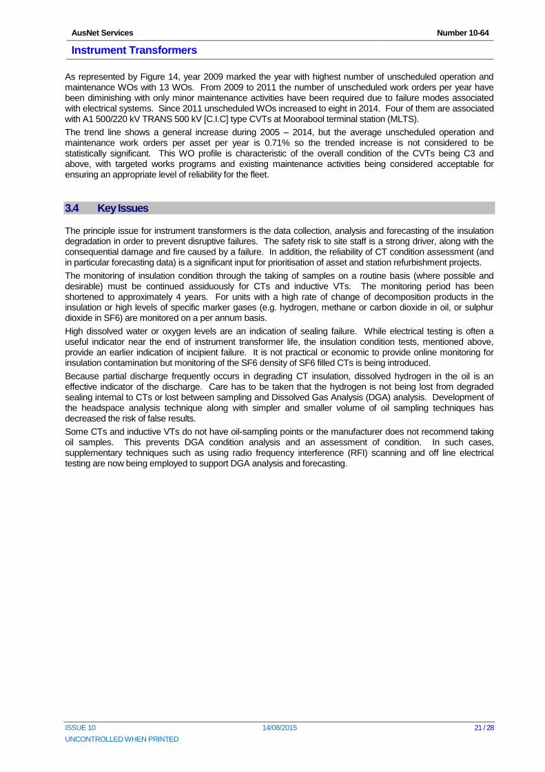
Analysis of Capacitive Voltage Transformers (CVT) operation and maintenance work orders (O&M) is shown in Figure 14 below:
Figure 14 – CVT Operation and Maintenance WOs (2005-2014)
AusNet Services Number 10-64
Instrument Transformers
ISSUE 10 14/08/2015 21 / 28
UNCONTROLLED WHEN PRINTED
As represented by Figure 14, year 2009 marked the year with highest number of unscheduled operation and maintenance WOs with 13 WOs. From 2009 to 2011 the number of unscheduled work orders per year have been diminishing with only minor maintenance activities have been required due to failure modes associated with electrical systems. Since 2011 unscheduled WOs increased to eight in 2014. Four of them are associated with A1 500/220 kV TRANS 500 kV [C.I.C] type CVTs at Moorabool terminal station (MLTS).
The trend line shows a general increase during 2005 – 2014, but the average unscheduled operation and maintenance work orders per asset per year is 0.71% so the trended increase is not considered to be statistically significant. This WO profile is characteristic of the overall condition of the CVTs being C3 and above, with targeted works programs and existing maintenance activities being considered acceptable for ensuring an appropriate level of reliability for the fleet.
3.4 Key Issues
The principle issue for instrument transformers is the data collection, analysis and forecasting of the insulation degradation in order to prevent disruptive failures. The safety risk to site staff is a strong driver, along with the consequential damage and fire caused by a failure. In addition, the reliability of CT condition assessment (and in particular forecasting data) is a significant input for prioritisation of asset and station refurbishment projects.
The monitoring of insulation condition through the taking of samples on a routine basis (where possible and desirable) must be continued assiduously for CTs and inductive VTs. The monitoring period has been shortened to approximately 4 years. For units with a high rate of change of decomposition products in the insulation or high levels of specific marker gases (e.g. hydrogen, methane or carbon dioxide in oil, or sulphur dioxide in SF6) are monitored on a per annum basis.
High dissolved water or oxygen levels are an indication of sealing failure. While electrical testing is often a useful indicator near the end of instrument transformer life, the insulation condition tests, mentioned above, provide an earlier indication of incipient failure. It is not practical or economic to provide online monitoring for insulation contamination but monitoring of the SF6 density of SF6 filled CTs is being introduced.
Because partial discharge frequently occurs in degrading CT insulation, dissolved hydrogen in the oil is an effective indicator of the discharge. Care has to be taken that the hydrogen is not being lost from degraded sealing internal to CTs or lost between sampling and Dissolved Gas Analysis (DGA) analysis. Development of the headspace analysis technique along with simpler and smaller volume of oil sampling techniques has decreased the risk of false results.
Some CTs and inductive VTs do not have oil-sampling points or the manufacturer does not recommend taking oil samples. This prevents DGA condition analysis and an assessment of condition. In such cases, supplementary techniques such as using radio frequency interference (RFI) scanning and off line electrical testing are now being employed to support DGA analysis and forecasting.
AusNet Services Number 10-64
Instrument Transformers
ISSUE 10 14/08/2015 22 / 28
UNCONTROLLED WHEN PRINTED
4 Risk Assessment
AusNet Services uses a range of techniques to assess risk and thus determine the replacement requirements for each asset class. These techniques include dependability management methodology and modelling, engineering review of condition assessment data, calculation of long run sustainablity based on expected asset life and total population of assets, assessment of projects in progress and engineering knowledge of assets and the operational environment. The various techniques are applied depending on the asset type and the asset data available. The range of resulting risk assessments and replacement forecasts are compared, contrasted and brought together using engineering judgement to inform the management of risk and development of the replacement forecast.
4.1 Dependability Management
Dependability management brings together asset condition data, asset failure rates and the cost impact of asset failure to determine economic replacements. The dependability management program employs Availability Workbench software to provide an economic analysis of terminal station assets over a ten-year period.
This section summarises the reliability modelling of AusNet Services’ instrument transformers located within terminal stations. It sums the probabilistic replacements and equivalent risk costs and identifies the economic instrument transformer replacements or refurbishments required to prudently maintain failure risks. Key inputs to this dependability process are asset condition, remaining service potential (RSP%), failure rate and the effects of asset failure.
The following scenarios demonstrated are:
Run to Failure1; and
Risk Optimised Scenario.
Please refer to AMS 20-11 Dependability Management for more detail on the methodology used to calibrate this risk optimised process.
4.2 Current Transformers
4.2.1 Run to Failure Scenario1
A total life cycle cost of [C.I.C ] comprising the health & safety costs, environment costs, collateral damage costs and reactive current transformer replacement costs (labour, equipment and spare) are shown in Error! Reference source not found..
1 Replace on condition where there is no economically significant safety or environmental impact in relation to the optimised maintenance or
replacement of an asset.
AusNet Services Number 10-64
Instrument Transformers
ISSUE 10 14/08/2015 23 / 28
UNCONTROLLED WHEN PRINTED
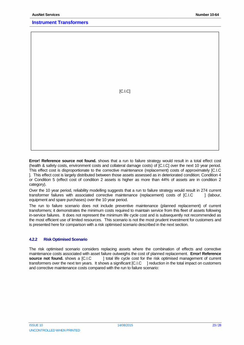
Error! Reference source not found. shows that a run to failure strategy would result in a total effect cost (health & safety costs, environment costs and collateral damage costs) of [C.I.C] over the next 10 year period. This effect cost is disproportionate to the corrective maintenance (replacement) costs of approximately [C.I.C ]. This effect cost is largely distributed between those assets assessed as in deteriorated condition; Condition 4 or Condition 5 (effect cost of condition 2 assets is higher as more than 44% of assets are in condition 2 category).
Over the 10 year period, reliability modelling suggests that a run to failure strategy would result in 274 current transformer failures with associated corrective maintenance (replacement) costs of [C.I.C ] (labour, equipment and spare purchases) over the 10 year period.
The run to failure scenario does not include preventive maintenance (planned replacement) of current transformers; it demonstrates the minimum costs required to maintain service from this fleet of assets following in-service failures. It does not represent the minimum life cycle cost and is subsequently not recommended as the most efficient use of limited resources. This scenario is not the most prudent investment for customers and is presented here for comparison with a risk optimised scenario described in the next section.
4.2.2 Risk Optimised Scenario
The risk optimised scenario considers replacing assets where the combination of effects and corrective maintenance costs associated with asset failure outweighs the cost of planned replacement. Error! Reference source not found. shows a [C.I.C ] total life cycle cost for the risk optimised management of current transformers over the next ten years. It shows a significant [C.I.C ] reduction in the total impact on customers and corrective maintenance costs compared with the run to failure scenario:
[C.I.C]
AusNet Services Number 10-64
Instrument Transformers
ISSUE 10 14/08/2015 24 / 28
UNCONTROLLED WHEN PRINTED
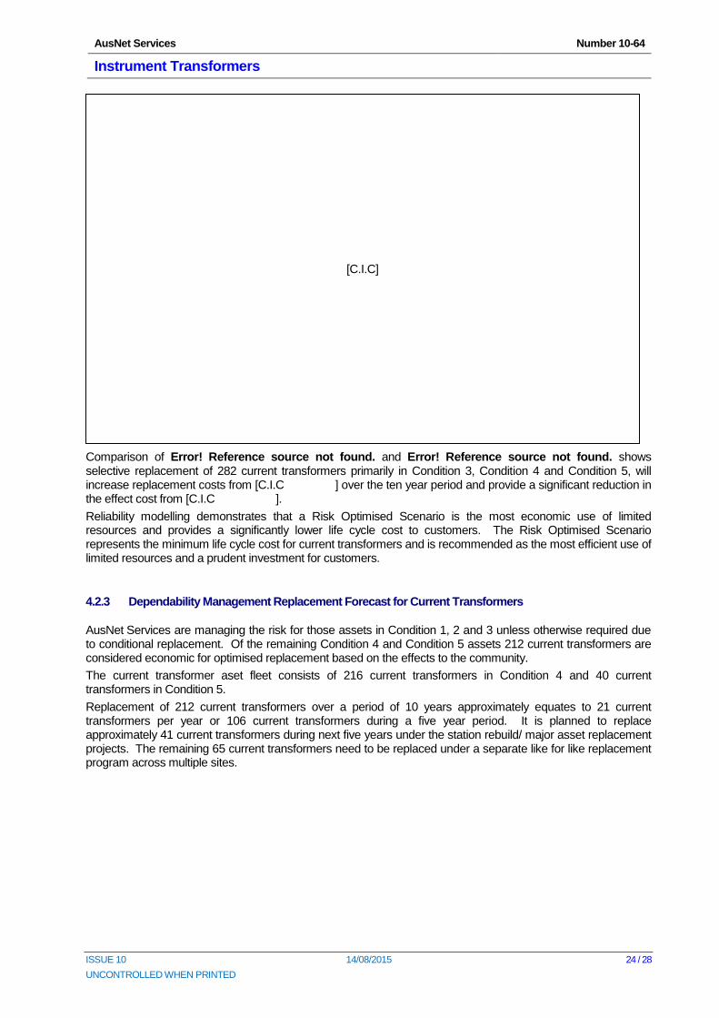
Comparison of Error! Reference source not found. and Error! Reference source not found. shows selective replacement of 282 current transformers primarily in Condition 3, Condition 4 and Condition 5, will increase replacement costs from [C.I.C ] over the ten year period and provide a significant reduction in the effect cost from [C.I.C ].
Reliability modelling demonstrates that a Risk Optimised Scenario is the most economic use of limited resources and provides a significantly lower life cycle cost to customers. The Risk Optimised Scenario represents the minimum life cycle cost for current transformers and is recommended as the most efficient use of limited resources and a prudent investment for customers.
4.2.3 Dependability Management Replacement Forecast for Current Transformers
AusNet Services are managing the risk for those assets in Condition 1, 2 and 3 unless otherwise required due to conditional replacement. Of the remaining Condition 4 and Condition 5 assets 212 current transformers are considered economic for optimised replacement based on the effects to the community.
The current transformer aset fleet consists of 216 current transformers in Condition 4 and 40 current transformers in Condition 5.
Replacement of 212 current transformers over a period of 10 years approximately equates to 21 current transformers per year or 106 current transformers during a five year period. It is planned to replace approximately 41 current transformers during next five years under the station rebuild/ major asset replacement projects. The remaining 65 current transformers need to be replaced under a separate like for like replacement program across multiple sites.
[C.I.C]
AusNet Services Number 10-64
Instrument Transformers
ISSUE 10 14/08/2015 25 / 28
UNCONTROLLED WHEN PRINTED
4.3 VoltageTransformers
4.3.1 Run to Failure Scenario2
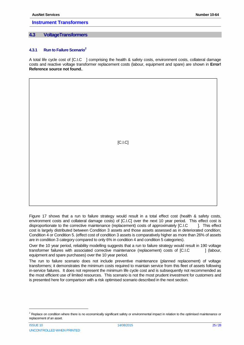
A total life cycle cost of [C.I.C ] comprising the health & safety costs, environment costs, collateral damage costs and reactive voltage transformer replacement costs (labour, equipment and spare) are shown in Error! Reference source not found..
Figure 17 shows that a run to failure strategy would result in a total effect cost (health & safety costs, environment costs and collateral damage costs) of [C.I.C] over the next 10 year period. This effect cost is disproportionate to the corrective maintenance (replacement) costs of approximately [C.I.C ]. This effect cost is largely distributed between Condition 3 assets and those assets assessed as in deteriorated condition; Condition 4 or Condition 5. (effect cost of condition 3 assets is comparatively higher as more than 26% of assets are in condition 3 category compared to only 6% in condition 4 and condition 5 categories).
Over the 10 year period, reliability modelling suggests that a run to failure strategy would result in 190 voltage transformer failures with associated corrective maintenance (replacement) costs of [C.I.C ] (labour, equipment and spare purchases) over the 10 year period.
The run to failure scenario does not include preventive maintenance (planned replacement) of voltage transformers; it demonstrates the minimum costs required to maintain service from this fleet of assets following in-service failures. It does not represent the minimum life cycle cost and is subsequently not recommended as the most efficient use of limited resources. This scenario is not the most prudent investment for customers and is presented here for comparison with a risk optimised scenario described in the next section.
2 Replace on condition where there is no economically significant safety or environmental impact in relation to the optimised maintenance or
replacement of an asset.
[C.I.C]
AusNet Services Number 10-64
Instrument Transformers
ISSUE 10 14/08/2015 26 / 28
UNCONTROLLED WHEN PRINTED
4.3.2 Risk Optimised Scenario
The risk optimised scenario considers replacing assets where the combination of effects and corrective maintenance costs associated with asset failure outweighs the cost of planned replacement. Error! Reference source not found. shows a [C.I.C ] total life cycle cost for the risk optimised management of voltage transformers over the next ten years. It shows a significant [C.I.C ] reduction in the total impact on customers and corrective maintenance costs compared with the run to failure scenario:
Comparison of Error! Reference source not found. and Error! Reference source not found.8 shows selective replacement of 623 Voltage transformers primarily in Condition 3, Condition 4 and Condition 5, will increase replacement costs from [C.I.C ] over the ten year period and provide a significant reduction in the effect cost from [C.I.C ].
Reliability modelling demonstrates that a Risk Optimised Scenario is the most economic use of limited resources and provides a significantly lower life cycle cost to customers. The Risk Optimised Scenario represents the minimum life cycle cost for Voltage transformers and is recommended as the most efficient use of limited resources and a prudent investment for customers.
4.3.3 Dependability Management Replacement Forecast for Voltage Transformers
AusNet Services is managing the risk for those assets in Condition 1, 2 and 3 unless otherwise required due to conditional replacement. Of the Condition 4 and Condition 5 voltage transformers, 97 are considered economic for optimised replacement based on the effects to the community.
The voltage transformer asset fleet consists of 93 voltage transformers in Condition 4 and 4 voltage transformers in Condition 5.
Replacement of 97 voltage transformers over a period of 10 years approximately equates to 10 voltage transformers per year or 48 voltage transformers during a five year period. It is planned to replace approximately 31 voltage transformers during next five years under the station rebuild/ major asset replacement projects. The remaining 17 voltage transformers need to be replaced under a separate like for like replacement program across multiple sites.
[C.I.C]
AusNet Services Number 10-64
Instrument Transformers
ISSUE 10 14/08/2015 27 / 28
UNCONTROLLED WHEN PRINTED
5 Strategies
The following strategies are being implemented to improve our ability to quantify deteriorating condition and reduce the risks of explosive failure:
5.1 New Assets
Review and finalise the specification for purchasing instrument transformers by 2016.
5.2 Inspection, Monitoring & Testing
Continue regular SF6 gas purity analysis on 500 kV SF6 filled CTs.
Continue to keep up-to-date with analysis and ranking techniques to assist the maintenance of a CT condition priority list.
Continue and expand condition monitoring of CVTs by a comparison of their output voltages using the CAMS system.
Continue to monitor the failure or replacement programs of other utilities to identify risk areas, and then perform condition monitoring accordingly.
Continue DGA analysis of nominated CTs and inductive VTs by sampling the insulating medium during scheduled maintenance.
Continue annual oil-sampling of [C.I.C] CTs.
Develop an enhanced condition-monitoring program, including off-line electrical tests, as an alternative to oil sampling/ DGA for specific higher risk CTs.
5.3 Maintenance
Continue implementation of auto-isolation policy requirements for loss of SF6 pressure on 500 kV SF6 filled CTs.
Finalise long term requirements for management of 166 [C.I.C] CTs (66 kV and 220 kV) supplied from 2005 to 2007.
Optimise the spares inventory of CTs and CVTs to match the increasing need for condition based replacements.
Continue the condition testing of the older instrument transformers in the spares inventory.
Perform autopsy strip downs of specific types of instrument transformers to verify physical condition and to provide feedback to condition assessment and risk models.
Investigate the potential benefits of fibre optic current sensor (FOCS) technology as a potential replacement for existing instrument transformer technologies.
5.4 Refurbishment
Reburbish instrument transformers where economic. AusNet Services’ experience is that replacement is more likely to be economic than refurbishment of instrument transformers which have experienced more than 50% of their expected service life.
AusNet Services Number 10-64
Instrument Transformers
ISSUE 10 14/08/2015 28 / 28
UNCONTROLLED WHEN PRINTED
5.5 Replacement
Complete the replacement of 39 remaining 220 kV [C.I.C] CTs by 2022.
Replace remaining fleet of six 220 kV Ducon CTs by 2022.
Replace 29 [C.I.C] 220 kV CVTs over the next 5 years.
Replace three poor condition 220 kV Oil Filled post type magnetic VTs of type [C.I.C] by 2022.
Replace remaining 16 very poor and poor condition 66 kV [C.I.C] VTs by 2022.
Complete replacement of 55 outstanding [C.I.C] 500 kV CT units by 2022.