Amphenol - Farnell element14 · Amphenol ® 62GB solder connectors ... Rotated inserts are,...
81
1 62 GB- Series Plugs Miniature Bayonet Lock Connectors Complies with MIL-C-26482 CE-2Pa This miniature bayonet lock connector series offers designers important features not found in any other range of connectors. They are developed and manufactured entirely in the U.K. by AMPHENOL Ltd., and have full qualification approval to British Standards Specification BS 9522 F0017 and British Defence Specification DEF STAN 59-35 (Part 3) Sec. 7. Amphenol This catalogue to be used in conjunction with Catalogues: CE-2Ra – 62GB Series Receptacles CE-2Aa – 62GB Series Accessories
Transcript of Amphenol - Farnell element14 · Amphenol ® 62GB solder connectors ... Rotated inserts are,...
1
62 GB- Series PlugsMiniature Bayonet Lock ConnectorsComplies with MIL-C-26482
CE-2Pa
This miniature bayonet lock connector series offers designersimportant features not found in any other range of connectors.
They are developed and manufactured entirely in the U.K.by AMPHENOL Ltd., and have full qualification approval toBritish Standards Specification BS 9522 F0017 and BritishDefence Specification DEF STAN 59-35 (Part 3) Sec. 7.
Amphenol
This catalogue to be used in conjunction with Catalogues:CE-2Ra – 62GB Series ReceptaclesCE-2Aa – 62GB Series Accessories
2
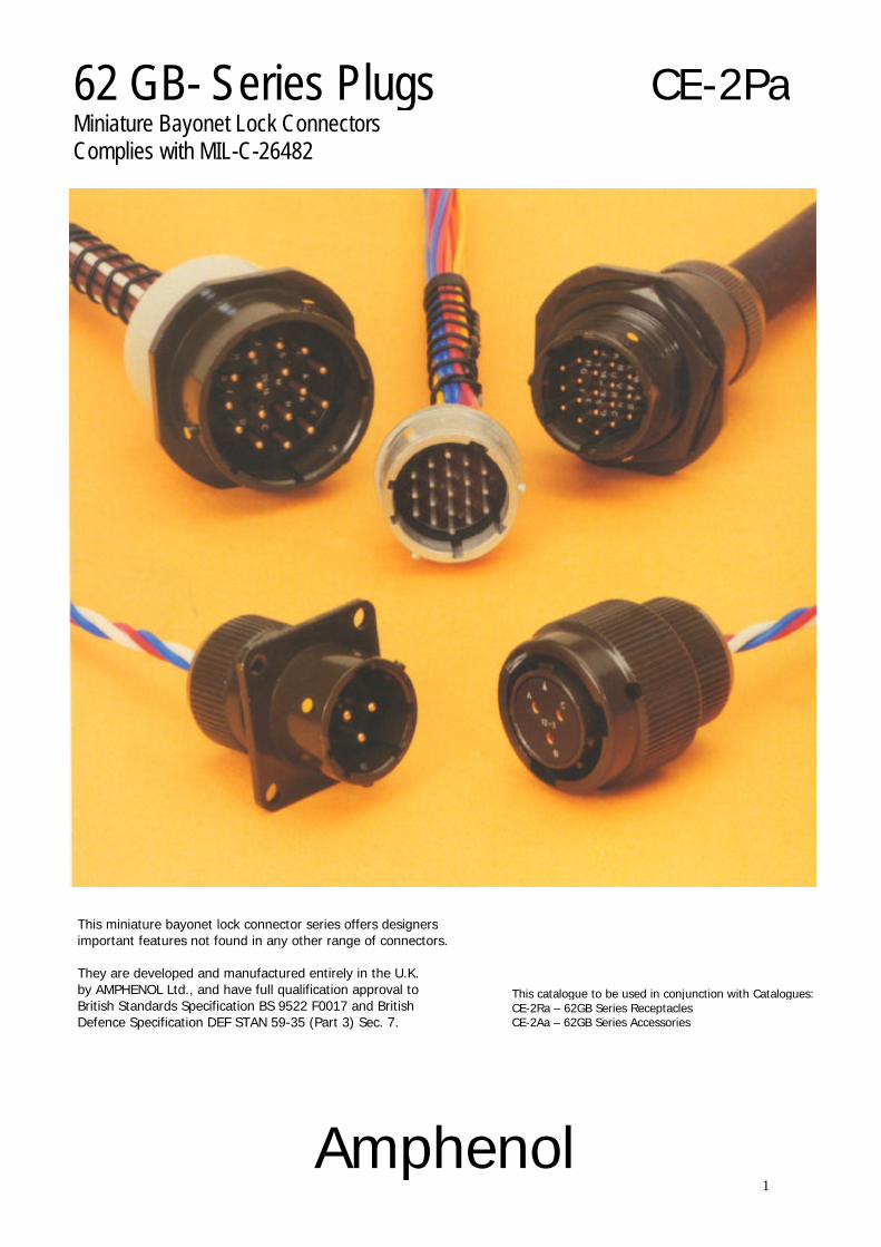
62GB andPattern 608New Planforms
Current:
(a) Maximum current per individual contact (in isolation)* at ambienttemperature of 85°C
Contact size 12: 23 A
(b) Maximum current per contact through all contacts simultaneously atan ambient temperature of 85°C
Contact size 12: 20 A
Current:
(a) Maximum current perindividual contact (inisolation)* at ambienttemperature of 85°C
Contact size 8: 45 A
(b) Maximum current per contactthrough all contactssimultaneously at an ambienttemperature of 85°C
Contact size 8: 40 A
Sea level 8500m (27,900ft) 21,340m (70,OOOft)1013 mbar � 320 mbar 44 mbar
Voltage rating I II III I II III I II IIIWorking voltages ** 700 1200 1500 550 650 800 330 380 450
(nominal)d.c. or a.c. peakVoltage proof 2100 3000 3000 1100 1300 1300 660 760 750
d.c. or a.c. peak
* i.e. when only one contact per connector is electrically loaded.� 1 mbar=102 N/m2=100 Pa** Establishment of electrical safety factors is the responsibility of the user
CONTENTS Page
Amphenol 62GB Solder Connectors 4
Schedule of Tests 5-6
Connector Styles Available 7
Insert Availability 8
Ordering 62GB Series Connectors 10-11
Plugs - Table of Styles 12-13
Plugs 14-19
Insert Orientations 20
Key/Keyway Orientations 21

4
Amphenol ® 62GBsolder connectors
This miniature bayonet lock connector series offersdesigners important features not found in any other rangeof connectors. The range has full qualification approval toBritish Standards Specification BS 9522 FOO 17 and BritishDefence Specification DEF STAN 59-35 (Part 3) Sec. 7.
62GB Series connectors - developed and manufacturedentirely in the United Kingdom by Amphenol Limited. Theyare the first and only British connectors to have achievedthis. A doubly strong position which Amphenol are wellgeared to handle. The manufacturing facilities of theWhitstable plant have been cited as exemplary in Europe.Certainly the layout is extensive and extremely efficient;safety awards have been attained every time returns havebeen submitted to the British Safety Council.
62GB Series connectors have been well established withGovernment authorities on an international scale and userscan be found in Sweden, Denmark, Norway, Finland,Germany, Spain, Holland, India, Canada and Italy.
Derating
Connectors must be derated under the followingoperating conditions:
1. At elevated ambient temperatures, the current ratingsare reduced so that total maximum hot spottemperature of 125°C is not exceeded.
2. At high altitudes, revised voltage ratings becomeeffective as shown on page 7.
3. When connectors to different specifications areintermated (e.g. BS 9522 FOO 17 andMIL-C26482), the combination must not beoperated under conditions more severe than theless stringent clause of either specification.
Amphenol 62GB connectors are designed to meetthe most stringent requirements of bothspecifications.
Military Specifications
British Standards Specification BS 9522 FOO 17closely corresponds to the United States MilitarySpecification MIL-C-26482 solder terminations.Certain differences exist between the schedules whichcan be seen on pages 2 and 3.
Approved gauges are used to check interchangeabilityof 62GB series with other connectors manufactured toBS 9522 FOO 17 or MIL-C-26482.
Basic Construction
Connector shells are machined from solid aluminium barstock - not forged or extruded as in competitive designs.Machining has inherent advantages in terms of strengthand adaptability. 62GB Series can be supplied in brass orstainless steel, for instance.
The normal shell finish used, which has a high resistance tocorrosion, is zinc cobalt olive drab. Other finishes may besupplied to special order, such as cadmium plate which isavailable by adding deviation (714) to the end of partnumber.
Inserts are of polychloroprene rubber compounded to anAmphenol specification. Operating temperature range is-55°C to 125°C, and the connectors have gold-platedcontacts designed for soldered connections. Configurationsfor size 20 contacts range between 2 contacts in the size 812.7mm (0.5in diameter) shell up to a maximum of 61contacts in the size 2436.1 mm (1.5in diameter) shell.Intermediate sizes, and contact data for heavier currentratings are shown in the insert availability chart on page 6and 7.
Hermetic connectors with glass sealed dialectric aremanufactured with mild steel shells and nickel ironcontacts plated tin over copper.
* Other finishes are available on request.
Protection Against Mis-Mating or Cross-Plugging
In BS 9522 FOO 17 positive shell-to-shell keying isprovided with keys and keyways in a choice of either thenormal (N) or any of the four preferred alternatepositions: B, C, E and F. This prevents mismating betweenshells of different orientations and overcomes thedifficulties associated with rotated inserts and a standardkey-keyway orientation. In the latter system, damage tothe inserts or contacts can result if excessive force is usedto engage non-mating pairs.
Rotated inserts are, however, permissible in BS 9522 FOO17 connectors if required to mate with or replace units toMIL-C-26482 mounted in existing equipment. Connectorshave normal orientations manufactured to BS 9522 FOO 17or MIL-C-26482 are fully intermateable as also areconnectors with inserts in positions W, X, Y or Z.
This catalogue to be used in conjunction with Catalogues:CE-2Ra – 62GB Series ReceptaclesCE-2Aa – 62GB Series Accessories

5
Schedule of TestsRequired for QualificationApproval
Tests
Visual Examination
Dimensions, outline mass(includingcontacts) Compatability Gaugingprocedure
Polarization
Engaging and separating force, connector
Contact Holding Force
Sealing (air pressure)
Sealing Hermetic
Contact Resistance
Housing (Shell) Continuity
Insulation Resistance
Voltage Proof
Soldering
Bumping
Vibration
Shock
Acceleration (Steady State)
Rapid Change of Temperature
Climatic Sequence
Flammability
Damp Heat (Steady State)
Brief Description
Engagement max: 0,90 Nm (8.0 lbf.in.) to4,97 Nm (44 lbf.in.) according to shell size.Separation min: 0,22 Nm (2.0 lbf.in.) to 1,58Nm (14.0 lbf.in.) according to shell size.
0,21 N (0.047 lbf) min.size 200,56 N (0.126 lbf)min. size 16
Max leakage 28,53 uNm/s (1 cm3/h), 1bar (14.5 p.s.i.) differential.
Hermetic receptacles have a max leak of 0.1 microncubic foot per hour (1 x 10⁻⁶Cm3/s)
5 milliohms max.
200 milliohms max. 5 milliohms max.grounding spring styles.
5,000 Megaohms at 500 - 50 V d.c.
See page 7. Duration 1 minute
As BS 9520: 1974, Clause 1.2.6.6,Method 2.
As BS 9520: 1974, Clause 1.2.6.1. 4,000-10 bumps / 390m / s2 (40 gn).
As BS 9520: 1974, Clause 1.2.6.2.1. Procedure A. 10 Hzto 5000 Hz, 0.75 mm / 10 gn.
As BS 9520: 1974, Clause 1.2.6.3. 981m/s2 (100 g n).
As BS 9520: 1974, Clause 1.2.6.4. 490m/s2 (50 gn).
As BS 9520: 1974, Clause 1.2.6.7. -550C to - 1250 C.
As BS 9520: 1974, Clause 1.2.6.11.Severity 55/125/56.
As BS 9520: 1974, Clause 1.2.6.8. Directflame applied, duration 1 minute.
As BS 9520: 1974, Clause 1.2.6.14.Severity 56 days.

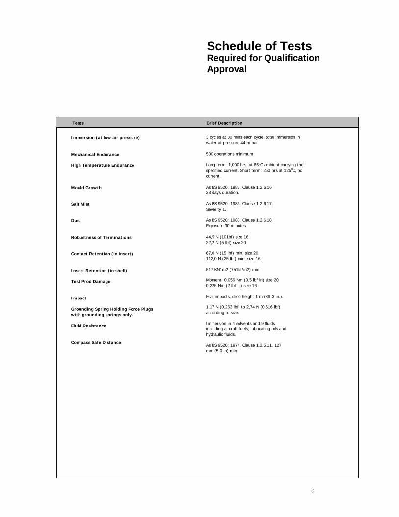
6
Schedule of TestsRequired for QualificationApproval
Tests Brief Description
Immersion (at low air pressure)
Mechanical Endurance
High Temperature Endurance
Mould Growth
Salt Mist
Dust
Robustness of Terminations
Contact Retention (in insert)
Insert Retention (in shell)
Test Prod Damage
Impact
Grounding Spring Holding Force Plugswith grounding springs only.
Fluid Resistance
Compass Safe Distance
3 cycles at 30 mins each cycle, total immersion inwater at pressure 44 m bar.
500 operations minimum
Long term: 1,000 hrs. at 850 C ambient carrying thespecified current. Short term: 250 hrs at 1250 C, nocurrent.
As BS 9520: 1974, Clause 1.2.6.15. 28days duration.
As BS 9520: 1974, Clause 1.2.6.16.Severity 1.
As BS 9520: 1974, Clause 1.2.6.17Exposure 30 minutes.
44,5 N (101bf) size 1622,2 N (5 lbf) size 20
67,0 N (15 lbf) min. size 20112,0 N (25 lbf) min. size 16
517 KN1m2 (751bf/in2) min.
Moment: 0,056 Nm (0.5 lbf in) size 200,225 Nm (2 lbf in) size 16
Five impacts, drop height 1 m (3ft.3 in.).
1,17 N (0.263 lbf) to 2,74 N (0.616 lbf)according to size.
Immersion in 4 solvents and 9 fluidsincluding aircraft fuels, lubricating oils andhydraulic fluids.
As BS 9520: 1974, Clause 1.2.5.11. 127mm (5.0 in) min.
7
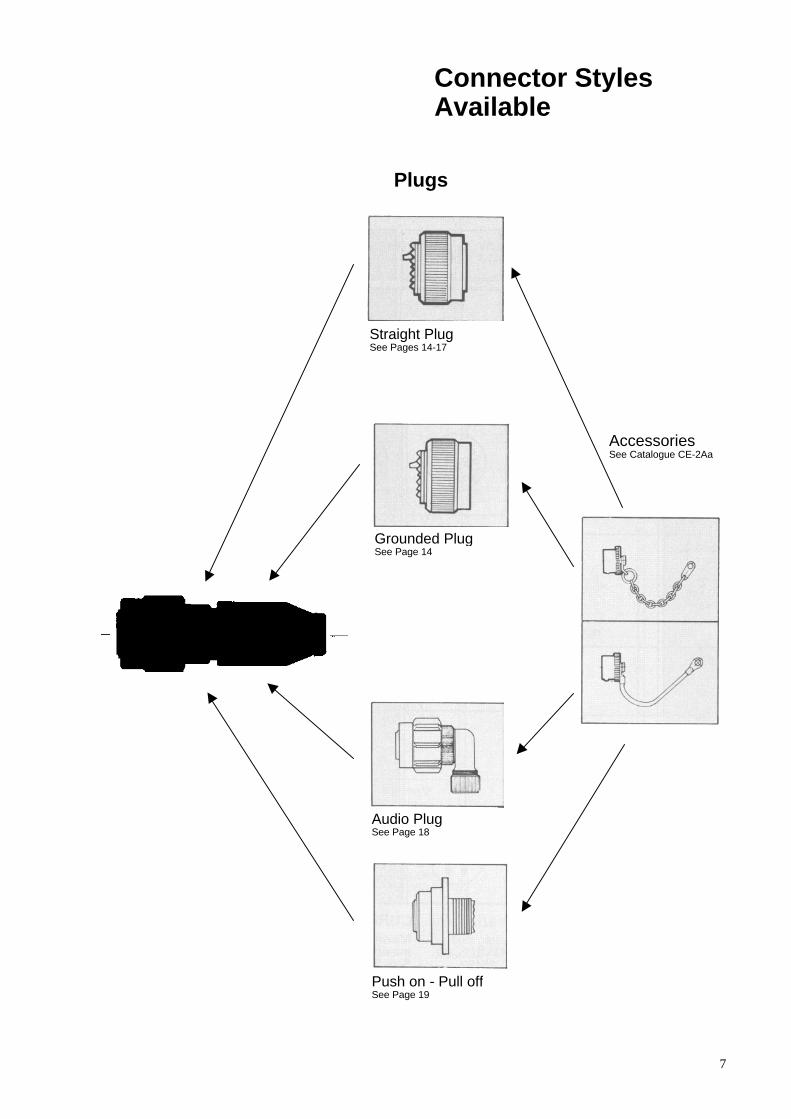
Connector StylesAvailable
Plugs
Straight PlugSee Pages 14-17
Grounded PlugSee Page 14
AccessoriesSee Catalogue CE-2Aa
Audio PlugSee Page 18
Push on - Pull offSee Page 19
8
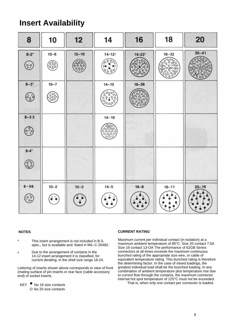
Insert Availability
NOTES
* This insert arrangement is not included in B.S.spec., but is available and. listed in MIL-C-26482.
� Due to the arrangement of contacts in the14-12 insert arrangement it is classified, forcurrent derating, in the shell size range 18-24.
Lettering of inserts shown above corresponds to view of front(mating surface of pin inserts or rear face (cable accessoryend) of socket inserts.
KEY • No 16 size contactsO No 20 size contacts
CURRENT RATING
Maximum current per individual contact (in isolation) at amaximum ambient temperature of 85°C: Size 20 contact 7.5ASize 16 contact 13-OA The performance of 62GB Seriesconnectors at all times exceeds the maximum continuousbunched rating of the appropriate size wire, or cable ofequivalent temperature rating. This bunched rating is thereforethe determining factor. In the case of mixed loadings, thegreatest individual load shall be the bunched loading. In anycombination of ambient temperature plus temperature rise dueto current flow through the contacts, the maximum connectorinternal hot spot temperature of 125°C must not be exceeded.
That is, when only one contact per connector is loaded.

9
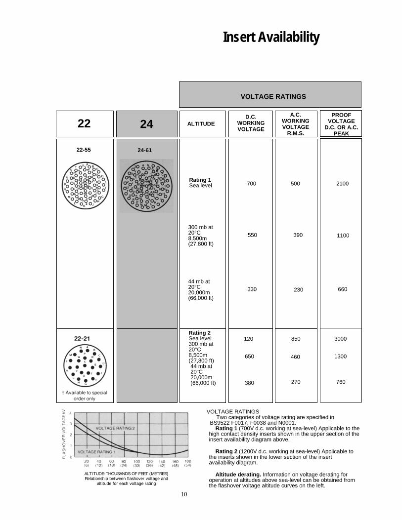
Insert Availability
VOLTAGE RATINGS
ALTITUDE-THOUSANDS OF FEET (METRES)Relationship between flashover voltage and
altitude for each voltage rating
VOLTAGE RATINGSTwo categories of voltage rating are specified in
BS9522 F0017, F0038 and N0001.Rating 1 (700V d.c. working at sea-level) Applicable to the
high contact density inserts shown in the upper section of theinsert availability diagram above.
Rating 2 (1200V d.c. working at sea-level) Applicable tothe inserts shown in the lower section of the insertavailability diagram.
Altitude derating. Information on voltage derating foroperation at altitudes above sea-level can be obtained fromthe flashover voltage altitude curves on the left.
22
22-55
D.C.WORKINGVOLTAGE
A.C.WORKINGVOLTAGE
R.M.S.
PROOFVOLTAGE
D.C. OR A.C.PEAK
Rating 1Sea level
300 mb at20°C8,500m(27,800 ft)
44 mb at20°C20,000m(66,000 ft)
Rating 2Sea level300 mb at20°C8,500m(27,800 ft)44 mb at20"C20,000m(66,000 ft)
700
550
330
1200
650
380
500
390
230
850
460
270
2100
1100
660
3000
1300
760
24 ALTITUDE
24-61
10
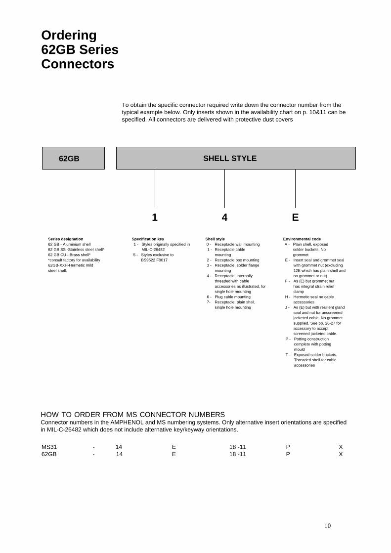
Ordering62GB SeriesConnectors
To obtain the specific connector required write down the connector number from thetypical example below. Only inserts shown in the availability chart on p. 10&11 can bespecified. All connectors are delivered with protective dust covers
62GB SHELL STYLE
1 4 E
Environmental codeA - Plain shell, exposed
solder buckets. Nogrommet
E - Insert seal and grommet sealwith grommet nut (excluding12E which has plain shell andno grommet or nut)
F - As (E) but grommet nuthas integral strain reliefclamp
H - Hermetic seal no cableaccessories
J - As (E) but with resilient glandseal and nut for unscreenedjacketed cable. No grommetsupplied. See pp. 26-27 foraccessory to acceptscreened jacketed cable.
P - Potting constructioncomplete with pottingmould
T - Exposed solder buckets.Threaded shell for cableaccessories
Shell style 0 - Receptacle wall mounting1 - Receptacle cable
mounting2 - Receptacle box mounting3 - Receptacle, solder flange
mounting4 - Receptacle, internally
threaded with cableaccessories as illustrated, forsingle hole mounting
6 - Plug cable mounting7- Receptacle, plain shell,
single hole mounting
Specification key1 - Styles originally specified in
MIL-C-264825 - Styles exclusive to
BS9522 F0017
Series designation62 GB - Aluminium shell62 GB SS -Stainless steel shell*62 GB CU - Brass shell**consult factory for availability62GB-XXH-Hermetic mildsteel shell.
HOW TO ORDER FROM MS CONNECTOR NUMBERSConnector numbers in the AMPHENOL and MS numbering systems. Only alternative insert orientations are specifiedin MIL-C-26482 which does not include alternative key/keyway orientations.
MS31 - 14 E 18 -11 P X62GB - 14 E 18 -11 P X
11
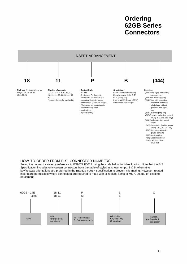
Ordering62GB SeriesConnectors
INSERT ARRANGEMENT
18 11 P B (044)
Shell size (in sixteenths of aninch) 8, 10, 12, 14, 1618,20,22,24
Number of contacts2, 3, 4, 5, 6, 7, 8, 10, 11, 12,16, 19, 21', 23, 26, 32, 41, 55,61* consult factory for availability
Contact StyleP - PinsS - Sockets For hermeticconnectors. P3 denotes pincontacts with solder bucketterminations. (Standard range).P2 denotes pin contacts withflattened and piercedterminations.(Special order).
Orientation(Omit if normal orientation)Keys/Keyways: A', B, C, D',E. F, (see p. 31)Inserts: W,X,Y,Z.(see p56/57)*Inactive for new designs
Deviations(044) Rough grip heavy duty
coupling ring.(046) Box mounting plug.(214)Fitted with extension
back shell and strainrelief clamp withoutgrommet on F typesonly
(218) Lever coupling ring(219)Contacts for flexible punted
wrung (57A and 12E only)(639) Bright cadmium plated
shells(345) Contacts for flexible punted
wiring 12H,13H 17H only(276) Hermetics with gold
plated contacts.(608) Black anodise.(416) Electroless nickel(714) Cadmium plate
olive drab
HOW TO ORDER FROM B.S. CONNECTOR NUMBERSSelect the connector style by reference to BS9522 F0017 using the code below for identification. Note that the B.S.Specification includes only certain connectors from the table of styles as shown on pp. 8 & 9. Alternativekey/keyway orientations are preferred in the BS9522 F0017 Specification to prevent mis-mating. However, rotatedinserts are permissible where connectors are required to mate with or replace items to MIL-C-26482 on existingequipment.
62GB - 14EC2098
18-1118 11
PM
BB
O
StyleInsertArrangement,see above
M - Pin contactsF - Socket contacts
AlternativeKey/Key wayOrientation
Variant.0 – Standard
connector

12
PlugsTable of Styles
62GB-56T
62GB-56TG
62GB-16A
62GB-56T(046)
62GB-16E
62GB-16F
62GB-16P
Page No.
14
14
15
15
16
16
17

13
PlugsTable of Styles
62GB-16J
62GB-5039-10
62GB-5055-10
62GB-5056-10
62GB-5074
Page No.
17
18
18
18
19
14
Plugs
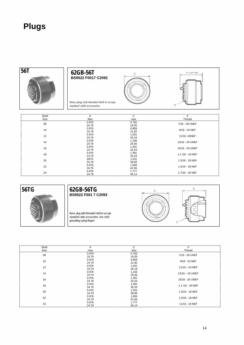
56T 62GB-56TBS9522 F0017 C2092
Basic plug with threaded shell to acceptstandard cable accessories
ShellSize
AMax
Cmax
XThread
0.976 0.75008 24.79 19.05 7/16 - 28 UNEF
0.976 0.85910 24.79 21.82 9/16 - 24 NEF
0.976 1.03112 24.79 26.19 11/16 -24NEF
0.976 1.15614 24.79 29.36 13/16 - 20 UNEF
0.976 1.28116 24.79 32.54 15/16 - 20 UNEF
0.976 1.39118 24.79 35.33 1.1 /16 - 18 NEF
&976 1.53120 24.79 38.89 1.3/16 - 18 NEF
0.976 1.65622 24.79 42.06 1.5/16 - 18 NEF
0.976 1.77724 24.79 45.14 1.7/16 - 18 NEF
56TG 62GB-56TGBS9522 F001 7 C2093
Basic plug with threaded shell to acceptstandard cable accessories. Has shellgrounding spring fingers
ShellSize
Amax
Cmax
XThread
0.976 0.75008 24.79 19.05 7/16 - 28 UNEF
0.976 0.85910 24.79 21.82 9/16 - 24 NEF
0.976 1.03112 24,79 26.19 11/16 – 24 NEF
0.976 1.15614 24.79 29.36 13/16 – 20 UNEF
0.976 1.28116 24.79 32.54 15/16 - 20 UNEF
0.976 1.39118 24.79 35.33 1.1 /16 - 18 NEF
0.976 1.53120 24.79 38.89 1.3/16 - 18 NEF
0.976 1.65622 24.79 42.06 1.5/16 - 18 NEF
0.976 1.77724 24.79 45.14 11/16 - 18 NEF

15
Plugs
16A 62GB-1 6A
Plug with general duty back shell.No grommet provided.
ShellSize
Amax
Cmax
Gmax
MThread
1.614 0.750 0.56108 41.00 19.05 14.25 1/2 - 28 UNEF
1.614 O.859 0,68610 41.00 21.82 17.43 5/8 - 24 NEF
1.614 1.031 0.81112 41.00 26.19 20.60 3/4 - 20 UNEF
1.614 1,156 0.93614 41.00 29.36 23.78 7/8 - 20 UNEF
1.614 1.281 1.06116 41.00 32.54 26.95 1 - 20 UNEF
1.614 1.391 1.18618 41.00 35.33 30.13 1.3/16 -18 NEF
1.614 1.531 1.31120 41.00 38-89 33.30 1.3/16 - 18 NEF
1.614 1.656 1.43622 41.00 42.06 36.75 1.7/16 - 18 NEF
1.658 1.777 1.56124 42.11 45.14 39.65 1.7116 - 18 NEF
56T 62GB-56T(046)
Box-mounting plug. Available for shell size 16:other sizes to special order. Cable accessoriescannot be fitted.
ShellSize
Amax
Jmax
K L
1.042 1.317 1,00016 26.47 33.45 25.40 6.32 NC
1.042 1.625 1.25020 26.47 41.28 31.75 6.32 NC
1.042 1.625 1.25022 26.47 41.28 31.75 6.32 NC
16
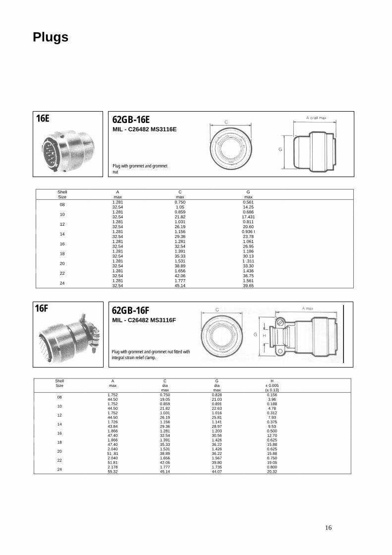
16E 62GB-16EMIL - C26482 MS3116E
Plug with grommet and grommetnut
ShellSize
Amax
Cmax
Gmax
1.281 0.750 0.56108 32.54 1.05 14.251.281 0.859 0.68610 32.54 21.82 17.4311.281 1.031 0.81112 32.54 26.19 20.601.281 1.156 0.936 I14 32.54 29.36 23.781.281 1.281 1.06116 32.54 32.54 26.951.281 1.391 1.18618 32.54 35.33 30.131.281 1.531 1 .31120 32.54 38.89 33.301.281 1.656 1.43622 32.54 42.06 36.751.281 1.777 1.56124 32.54 45.14 39.65
16F 62GB-16FMIL - C26482 MS3116F
Plug with grommet and grommet nut fitted withintegral strain relief clamp.
ShellSize
Amax
Cdiamax
Gdiamax
H± 0.005(± 0.13)
1.752 0.750 0.828 0.15608 44.50 19.05 21.03 3.961.752 0.859 0.891 0.18810 44.50 21.82 22.63 4.781.752 1.031 1.016 0.31212 44.50 26.19 25.81 7.931.726 1.156 1.141 0.37514 43.84 29.36 28.97 9.531.866 1.281 1.203 0.50016 47.40 32.54 30.56 12.701.866 1.391 1.426 0.62518 47.40 35.33 36.22 15.882.040 1.531 1.426 0.62520 51 .81 38.89 36.22 15.882.040 1.656 1.567 0.75022 51.81 42.06 39.80 19.052.178 1.777 1.735 0.80024 55.32 45.14 44.07 20.32
Plugs

17
16P 62GB-16PMIL-C26482 MS3116P
For potted seal. Supplied complete withdetachable potting mould and location ring.
ShellSize
Amax
Cmax
Gmax
Zmin
1.306 0.750 0.572 0.26008 33.17 19.05 14.53 6.601.415 0.859 0.666 0.46310 35.94 21.82 16.92 11.761.384 1.031 0.822 0.55712 35.15 26.19 20.88 14.141.384 1.156 0.907 0.59014 35.15 29.36 23.04 14.991.384 1.281 1.040 0.71316 35.15 32.54 26.41 18.111.384 1.391 1.165 0.83518 35.15 35.33 29.59 22.211.539 1.531 1.285 1.01520 39.09 38.89 32.64 25.781.539 1.656 1.400 1.01522 39.09 42.06 35.56 25.781.602 1.777 1.540 126524 40.69 45.14 39.12 32.13
16J 62GB - 16J
Plug with cable clamp for unscreenedjacketed cable. No grommet supplied.
ShellSize
Amax
Cmax
Gmax
Zmin max
1.836 0.750 0.561 0.168 0.23008 46.64 19.05 14.25 4.28 5.841.836 0.859 0.686 0.205 0.31210 46.64 21.82 17.43 5.21 7.931.937 1.031 0.811 0.388 0.44212 49.20 26.19 20.60 8.59 11.232.137 1.156 0.936 0.416 0.53914 54.28 29.36 23.78 10.57 13.692.337 1.281 1.061 0.550 0.61616 59.36 32.54 26.95 13.97 15.652.537 1.391 1.186 0.600 0.67218 64.45 35.33 30.13 15.24 17.072.758 1.531 1.311 0.635 0.74720 70.05 38.89 33.30 16.13 18.982.958 1.656 1.436 0.670 0.84622 75.13 42.06 36.75 17.02 21.493.002 1.777 1.561 0.740 0.89424 76.25 45.14 39.65 18.80 22.71
Plugs
18
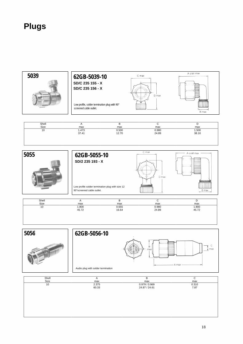
5039 62GB-5039-10SD/C 235 155 - XSD/C 235 156 - X
Low profile, solder termination plug with 90°screened cable outlet.
ShellSize
Amax
Bmax
Cmax
Dmax
10 1.473 0.500 0.980 1.50037.41 12.70 24.89 38.10
5055 62GB-5055-10SD/2 235 193 - X
Low profile solder termination plug with size 1290°screened cable outlet.
Shell A B C DSize max max max max10 1.800 0.655 0.980 1.800
45.72 16.64 24.89 45.72
5056 62GB-5056-10
Audio plug with solder termination
ShellSize
Amax
Bmax
Cmax
10 2.375 0.979 / 0.969 0.31060.33 24.87 / 24.61 7.87
Plugs
19
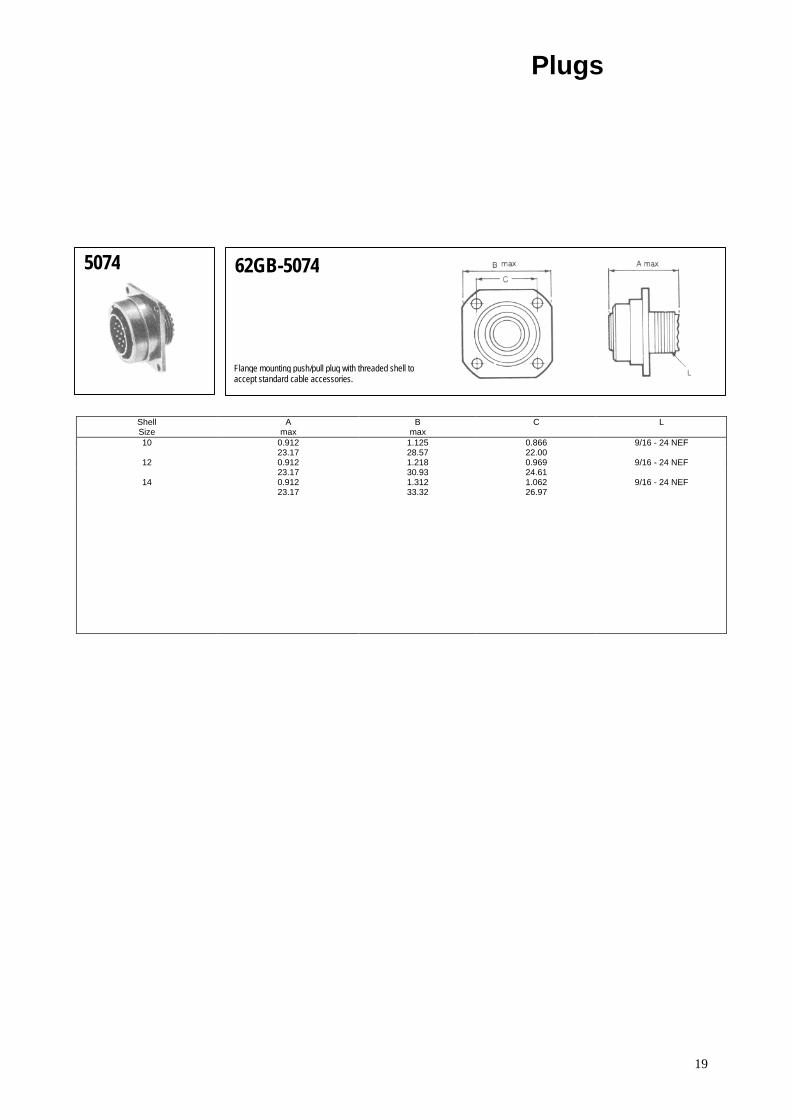
5074 62GB-5074
Flange mounting push/pull plug with threaded shell toaccept standard cable accessories.
ShellSize
Amax
Bmax
C L
10 0.912 1.125 0.866 9/16 - 24 NEF23.17 28.57 22.00
12 0.912 1.218 0.969 9/16 - 24 NEF23.17 30.93 24.61
14 0.912 1.312 1.062 9/16 - 24 NEF23.17 33.32 26.97
Plugs

20
Insert OrientationsFor M I L-C-26482 and forreplacement purposes inBS9522 FOO 17
Normal positionwith pin contacts
Alternative position of insertwith socket contacts(∅ counterclockwise)
Each diagram shows mating face of insert.
Alternate position of insertwith pin contacts
(∅ clockwise)
Orientation ∅ (degrees)Insert
Arrangement Normal W X Y Z
8-2 0 58 122 - -
8-3 0 60 210 - -
8-33 0 90 - - -
8-4 0 45 - - -
8-98 0 - - - -
10-2 0 - - - -
10-6 0 90 - - -
10-7 0 - - - -
12-3 0 - - 180 -
12-10 0 60 155 270 295
14-5 0 40 92 184 273
14-12 0 43 90 - -
14-15 0 17 110 155 234
14-19 0 30 165 315 -
16-18 0 54 152 180 331
16-23 0 158 270 - -
16-26 0 60 - 275 338
18-11 0 62 119 241 340
18-32 0 85 138 222 265
20-16 0 238 318 333 347
20-41 0 45 126 225 -
22-21 0 16 135 175 349
22-55 0 30 142 226 314
24-61 0 90 180 270 324
21
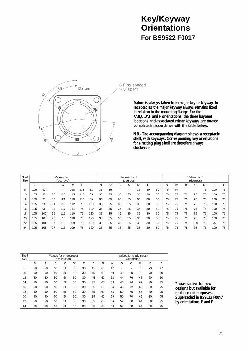
Key/KeywayOrientationsFor BS9522 F0017
Datum is always taken from major key or keyway. Inreceptacles the major keyway always remains fixedin relation to the mounting flange. For theA',B,C,D',E and F orientations, the three bayonetlocations and associated minor keyways are rotatedcomplete, in accordance with the table below.
N.B.- The accompanying diagram shows a receptacleshell, with keyways. Corresponding key orientationsfor a mating plug shell are therefore alwaysclockwise.
ShellSize
Values for ∝(degrees)
Values for θ(degrees)
Values for β(degrees)
N A* B C D* E F N A* B C D* E F N A* B C D* E F
8 105 92 - - 118 118 82 35 35 - - 35 30 50 75 75' - - 75 100 75
10 105 95 85 125 115 115 85 35 35 35 35 35 30 50 75 75 75 75 75 100 75
12 105 97 89 121 113 115 85 35 35 35 35 35 30 50 75 75 75 75 75 100 75
14 105 98 91 119 112 75 120 35 35 35 35 35 30 50 75 75 75 75 75 100 75
16 105 99 93 117 111 75 120 35 35 35 35 35 30 50 75 75 75 75 75 100 75
18 105 100 95 115 110 75 120 35 35 35 35 35 30 50 75 75 75 75 75 100 75
20 105 100 95 115 110 75 120 35 35 35 35 35 30 50 75 75 75 75 75 100 75
22 105 101 97 113 109 7S 120 35 35 35 35 35 30 50 75 75 75 100 75 75 75
24 105 101 97 113 109 75 120 35 35 35 35 35 30 50 75 75 75 75 75 100 75
ShellSize
Values for ϕ (degrees)Orientation
Values for ω (degrees)Orientation
N A* B C D* E F N A* B C D* E F
8 50 50 50 50 50 30 45 60 47 - - 73 73 47
10 50 50 50 50 50 30 45 60 50 40 80 70 70 50
12 50 50 50 50 50 30 45 60 52 44 76 68 70 50
14 50 50 50 50 50 30 35 60 53 46 74 67 30 75
16 50 50 50 50 50 30 35 60 54 48 72 66 30 75
18 50 50 50 50 50 30 35 60 55 50 70 65 30 75
20 50 50 50 50 50 30 35 60 55 50 70 65 30 75
22 50 50 50 50 50 30 35 60 56 52 68 64 30 75
24 50 50 50 50 50 30 35 60 56 52 68 64 30 75
* now inactive for newdesigns but available forreplacement purposes.Superseded in BS9522 F0017by orientations E and F.

22

1
62 GB- Series Receptacles Miniature Bayonet Lock Connectors Complies with MIL-C-26482
CE-2Ra
This miniature bayonet lock connector series offers designers important features not found in any other range of connectors. They are developed and manufactured entirely in the U.K. by AMPHENOL Ltd., and have full qualification approval to British Standards Specification BS 9522 F0017 and British Defence Specification DEF STAN 59-35 (Part 3) Sec. 7.
Amphenol
This catalogue to be used in conjunction with Catalogues: CE-2Pa – 62GB Series Plugs CE-2Aa – 62GB Series Accessories

2
62GB and Pattern 608 New Planforms
Current:
(a) Maximum current per individual contact (in isolation)* at ambient temperature of 85°C
Contact size 12: 23 A
(b) Maximum current per contact through all contacts simultaneously at
an ambient temperature of 85°C
Contact size 12: 20 A
Current:
(a) Maximum current per individual contact (in isolation)* at ambient temperature of 85°C
Contact size 8: 45 A
(b) Maximum current per contact
through all contacts simultaneously at an ambient temperature of 85°C
Contact size 8: 40 A
Sea level 8500m (27,900ft) 21,340m (70,OOOft) 1013 mbar 320 mbar 44 mbar
Voltage rating I II III I II III I II III Working voltages ** 700 1200 1500 550 650 800 330 380 450
(nominal) d.c. or a.c. peak Voltage proof 2100 3000 3000 1100 1300 1300 660 760 750
d.c. or a.c. peak
* i.e. when only one contact per connector is electrically loaded. 1 mbar=102 N/m2=100 Pa
** Establishment of electrical safety factors is the responsibility of the user

CONTENTS Page Amphenol 62GB Solder Connectors 4
Schedule of Tests 5-6
Connector Styles Available 7
Insert Availability 9-10
Ordering 62GB Series Connectors 11-12
Box Mounting Receptacles - Table of Styles 13-14
Box Mounting Receptacles 15-19
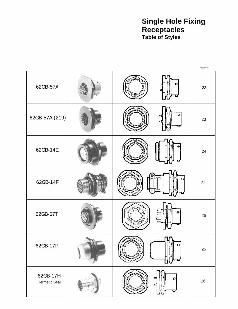
Single Hole Fixing Receptacles - Table of Styles 20-22
Single Hole Fixing Receptacles 23-30
Cable Mounting Receptacles - Table of Styles 31
Cable Mounting Receptacles 32-34
Insert Orientations 35
Key/Keyway Orientations 36

4
Amphenol ® 62GB solder connectors
This miniature bayonet lock connector series offers designers important features not found in any other range of connectors. The range has full qualification approval to British Standards Specification BS 9522 FOO 17 and British Defence Specification DEF STAN 59-35 (Part 3) Sec. 7.
62GB Series connectors - developed and manufactured
entirely in the United Kingdom by Amphenol Limited. They are the first and only British connectors to have achieved this. A doubly strong position which Amphenol are well geared to handle. The manufacturing facilities of the Whitstable plant have been cited as exemplary in Europe. Certainly the layout is extensive and extremely efficient; safety awards have been attained every time returns have been submitted to the British Safety Council.
62GB Series connectors have been well established with
Government authorities on an international scale and users can be found in Sweden, Denmark, Norway, Finland, Germany, Spain, Holland, India, Canada and Italy.
Derating
Connectors must be derated under the following operating conditions:
1. At elevated ambient temperatures, the current ratings
are reduced so that total maximum hot spot temperature of 125°C is not exceeded.
2. At high altitudes, revised voltage ratings become
effective as shown on page 7. 3. When connectors to different specifications are
intermated (e.g. BS 9522 FOO 17 and MIL-C26482), the combination must not be operated under conditions more severe than the less stringent clause of either specification.
Amphenol 62GB connectors are designed to meet the most stringent requirements of both specifications.
Military Specifications
British Standards Specification BS 9522 FOO 17 closely corresponds to the United States Military Specification MIL-C-26482 solder terminations. Certain differences exist between the schedules which can be seen on pages 2 and 3.
Approved gauges are used to check interchangeability of 62GB series with other connectors manufactured to BS 9522 FOO 17 or MIL-C-26482.
Basic Construction 62GB Series can be supplied in brass or stainless steel. The normal shell finish used, which has a high resistance to corrosion, is zinc cobalt olive drab. Other finishes may be supplied to special order, such as cadmium plate which is available by adding deviation (714) to the end of part number. Inserts are of polychloroprene rubber compounded to an Amphenol specification. Operating temperature range is -55°C to 125°C, and the connectors have gold-plated contacts designed for soldered connections. Configurations for size 20 contacts range between 2 contacts in the size 8 12.7mm (0.5in diameter) shell up to a maximum of 61 contacts in the size 2436.1 mm (1.5in diameter) shell. Intermediate sizes, and contact data for heavier current ratings are shown in the insert availability chart on page 6 and 7.
Hermetic connectors with glass sealed dialectric are manufactured with mild steel shells and nickel iron contacts plated tin over copper.
* Other finishes are available on request. Protection Against Mis-Mating or Cross-Plugging
In BS 9522 FOO 17 positive shell-to-shell keying is provided with keys and keyways in a choice of either the normal (N) or any of the four preferred alternate positions: B, C, E and F. This prevents mismating between shells of different orientations and overcomes the difficulties associated with rotated inserts and a standard key-keyway orientation. In the latter system, damage to the inserts or contacts can result if excessive force is used to engage non-mating pairs.
Rotated inserts are, however, permissible in BS 9522 FOO 17 connectors if required to mate with or replace units to MIL-C-26482 mounted in existing equipment. Connectors have normal orientations manufactured to BS 9522 FOO 17 or MIL-C-26482 are fully intermateable as also are connectors with inserts in positions W, X, Y or Z.
1
This catalogue to be used in conjunction with Catalogues: CE-2Pa – 62GB Series Receptacles CE-2Aa – 62GB Series Accessories

5
Schedule of Tests Required for Qualification Approval
Tests
Visual Examination Dimensions, outline mass(including contacts) Compatability Gauging procedure Polarization Engaging and separating force, connector Contact Holding Force Sealing (air pressure) Sealing Hermetic Contact Resistance Housing (Shell) Continuity Insulation Resistance Voltage Proof Soldering Bumping Vibration Shock Acceleration (Steady State) Rapid Change of Temperature Climatic Sequence Flammability Damp Heat (Steady State)
Brief Description
Engagement max: 0,90 Nm (8.0 lbf.in.) to 4,97 Nm (44 lbf.in.) according to shell size. Separation min: 0,22 Nm (2.0 lbf.in.) to 1,58 Nm (14.0 lbf.in.) according to shell size. 0,21 N (0.047 lbf) min.size 20 0,56 N (0.126 lbf)min. size 16 Max leakage 28,53 uNm/s (1 cm3/h), 1 bar (14.5 p.s.i.) differential. Hermetic receptacles have a max leak of 0.1 micron cubic foot per hour (1 x 10⁻⁶Cm3/s) 5 milliohms max. 200 milliohms max. 5 milliohms max. grounding spring styles. 5,000 Megaohms at 500 - 50 V d.c. See page 7. Duration 1 minute As BS 9520: 1974, Clause 1.2.6.6, Method 2. As BS 9520: 1974, Clause 1.2.6.1. 4,000 -10 bumps / 390m / s2 (40 gn). As BS 9520: 1974, Clause 1.2.6.2.1. Procedure A. 10 Hz to 5000 Hz, 0.75 mm / 10 gn. As BS 9520: 1974, Clause 1.2.6.3. 981 m/s2 (100 g n). As BS 9520: 1974, Clause 1.2.6.4. 490 m/s2 (50 gn). As BS 9520: 1974, Clause 1.2.6.7. -550 C to - 1250 C. As BS 9520: 1974, Clause 1.2.6.11. Severity 55/125/56. As BS 9520: 1974, Clause 1.2.6.8. Direct flame applied, duration 1 minute. As BS 9520: 1974, Clause 1.2.6.14. Severity 56 days.
6
Schedule of Tests Required for Qualification Approval
Tests Brief Description
Immersion (at low air pressure) Mechanical Endurance High Temperature Endurance Mould Growth Salt Mist Dust Robustness of Terminations Contact Retention (in insert) Insert Retention (in shell) Test Prod Damage Impact Grounding Spring Holding Force Plugs with grounding springs only. Fluid Resistance Compass Safe Distance
3 cycles at 30 mins each cycle, total immersion in water at pressure 44 m bar. 500 operations minimum Long term: 1,000 hrs. at 850C ambient carrying the specified current. Short term: 250 hrs at 1250C, no current. As BS 9520: 1983, Clause 1.2.6.16 28 days duration. As BS 9520: 1983, Clause 1.2.6.17. Severity 1. As BS 9520: 1983, Clause 1.2.6.18 Exposure 30 minutes. 44,5 N (101bf) size 16 22,2 N (5 lbf) size 20 67,0 N (15 lbf) min. size 20 112,0 N (25 lbf) min. size 16 517 KN1m2 (751bf/in2) min. Moment: 0,056 Nm (0.5 lbf in) size 20 0,225 Nm (2 lbf in) size 16 Five impacts, drop height 1 m (3ft.3 in.). 1,17 N (0.263 lbf) to 2,74 N (0.616 lbf) according to size. Immersion in 4 solvents and 9 fluids including aircraft fuels, lubricating oils and hydraulic fluids. As BS 9520: 1974, Clause 1.2.5.11. 127 mm (5.0 in) min.

7
Connector Styles Available
Receptacles
Box Mounting See Pages 13-19
Accessories See Catalogue CE-2Aa
Single Hole Mounting See Pages 20-30
Cable MountingSee Pages 31-34
Hermetic SealSee Pages 19 & 26

8

9
Insert Availability
NOTES * This insert arrangement is not included in B.S.
spec., but is available and. listed in MIL-C-26482.
Due to the arrangement of contacts in the 14-12 insert arrangement it is classified, for current derating, in the shell size range 18-24.
Lettering of inserts shown above corresponds to view of front (mating surface of pin inserts or rear face (cable accessory end) of socket inserts.
KEY • No 16 size contacts O No 20 size contacts
CURRENT RATING Maximum current per individual contact (in isolation) at a maximum ambient temperature of 85°C: Size 20 contact 7.5A Size 16 contact 13-OA The performance of 62GB Series connectors at all times exceeds the maximum continuous bunched rating of the appropriate size wire, or cable of equivalent temperature rating. This bunched rating is therefore the determining factor. In the case of mixed loadings, the greatest individual load shall be the bunched loading. In any combination of ambient temperature plus temperature rise due to current flow through the contacts, the maximum connector internal hot spot temperature of 125°C must not be exceeded.
That is, when only one contact per connector is loaded.
10
Insert Availability
VOLTAGE RATINGS
ALTITUDE-THOUSANDS OF FEET (METRES)Relationship between flashover voltage and
altitude for each voltage rating
VOLTAGE RATINGSTwo categories of voltage rating are specified in
BS9522 F0017, F0038 and N0001. Rating 1 (700V d.c. working at sea-level) Applicable to the
high contact density inserts shown in the upper section of the insert availability diagram above.
Rating 2 (1200V d.c. working at sea-level) Applicable to
the inserts shown in the lower section of the insert availability diagram.
Altitude derating. Information on voltage derating for
operation at altitudes above sea-level can be obtained from the flashover voltage altitude curves on the left.
22
22-55
D.C.WORKING VOLTAGE
A.C. WORKING VOLTAGE
R.M.S.
PROOFVOLTAGE
D.C. OR A.C. PEAK
Rating 1Sea level
300 mb at 20°C 8,500m (27,800 ft)
44 mb at 20°C 20,000m (66,000 ft)
Rating 2Sea level 300 mb at 20°C 8,500m (27,800 ft) 44 mb at 20"C 20,000m (66,000 ft)
700
550
330
120
650
380
500
390
230
850
460
270
2100
1100
660
3000
1300
760
24 ALTITUDE
24-61

11
Ordering 62GB Series Connectors
To obtain the specific connector required write down the connector number from the typical example below. Only inserts shown in the availability chart on p. 10&11 can be specified. All connectors are delivered with protective dust covers
62GB SHELL STYLE
1 4 E
Environmental code A - Plain shell, exposed
solder buckets. No grommet
E - Insert seal and grommet seal with grommet nut (excluding 12E which has plain shell and no grommet or nut)
F - As (E) but grommet nut has integral strain relief clamp
H - Hermetic seal no cable accessories
J - As (E) but with resilient gland seal and nut for unscreened jacketed cable. No grommet supplied. See pp. 26-27 for accessory to accept screened jacketed cable.
P - Potting construction complete with potting mould
T - Exposed solder buckets. Threaded shell for cable accessories
Shell style 0 - Receptacle wall mounting 1 - Receptacle cable
mounting 2 - Receptacle box mounting 3 - Receptacle, solder flange
mounting 4 - Receptacle, internally
threaded with cable accessories as illustrated, for single hole mounting
6 - Plug cable mounting 7- Receptacle, plain shell,
single hole mounting
Specification key 1 - Styles originally specified in
MIL-C-26482 5 - Styles exclusive to
BS9522 F0017
Series designation 62 GB - Aluminium shell 62 GB SS -Stainless steel shell* 62 GB CU - Brass shell* *consult factory for availability 62GB-XXH-Hermetic mild steel shell.
HOW TO ORDER FROM MS CONNECTOR NUMBERS Connector numbers in the AMPHENOL and MS numbering systems. Only alternative insert orientations are specified in MIL-C-26482 which does not include alternative key/keyway orientations.
MS31 - 14 E 18 -11 P X 62GB - 14 E 18 -11 P X

12
Ordering 62GB Series Connectors
INSERT ARRANGEMENT
18 11 P B (044) Shell size (in sixteenths of an inch) 8, 10, 12, 14, 16 18,20,22,24
Number of contacts 2, 3, 4, 5, 6, 7, 8, 10, 11, 12, 16, 19, 21', 23, 26, 32, 41, 55, 61 * consult factory for availability
Contact Style P - Pins S - Sockets For hermetic connectors. P3 denotes pin contacts with solder bucket terminations. (Standard range). P2 denotes pin contacts with flattened and pierced terminations. (Special order).
Orientation (Omit if normal orientation) Keys/Keyways: A', B, C, D', E. F, (see p. 31) Inserts: W,X,Y,Z.(see p56/57) *Inactive for new designs
Deviations (044) Rough grip heavy duty
coupling ring. (046) Box mounting plug. (214)Fitted with extension
back shell and strain relief clamp without grommet on F types only
(218) Lever coupling ring (219)Contacts for flexible punted
wrung (57A and 12E only) (639) Bright cadmium plated
shells (345) Contacts for flexible punted
wiring 12H,13H 17H only (276) Hermetics with gold
plated contacts. (608) Black anodise. (416) Electroless nickel (714) Cadmium plate
olive drab
HOW TO ORDER FROM B.S. CONNECTOR NUMBERS Select the connector style by reference to BS9522 F0017 using the code below for identification. Note that the B.S. Specification includes only certain connectors from the table of styles as shown on pp. 8 & 9. Alternative key/keyway orientations are preferred in the BS9522 F0017 Specification to prevent mis-mating. However, rotated inserts are permissible where connectors are required to mate with or replace items to MIL-C-26482 on existing equipment.
62GB - 14E C2098
18-11 18 11
PM
B B
O
Style Insert Arrangement, see above
M - Pin contacts F - Socket contacts
Alternative Key/Key way Orientation
Variant. 0 – Standard
connector
13
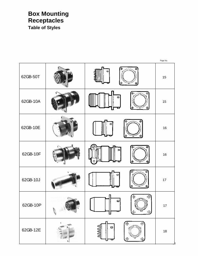
Box Mounting Receptacles Table of Styles
62GB-50T
Page No.
15
62GB-10A 15
62GB-10E 16
62GB-10F 16
62GB-10J 17
62GB-10P 17
62GB-12E 18
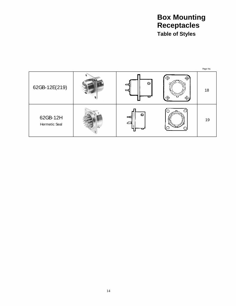
14
Page No.
62GB-12E(219) 18
62GB-12H Hermetic Seal
19
Box Mounting Receptacles Table of Styles
15
Shell Size
A max
B ± 0.005 (± 0.13)
c max sq.
D TP Sq.
E dia. ± 0.010
(± 0.254)
F ±0 005 (± 0.13)
G dia
max.
Y dia. max.
X Thread
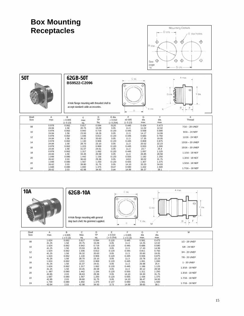
0.978 0.062 0.817 0.594 0120 0.445 0.434 0.473 08 24.84 1.58 20.75 15.09 3.05 11.3 11.02 12.02 7/16 – 28 UNEF
0.978 0.062 0.942 0.719 0.120 0.445 0.558 0.590 10 24.84 1.58 23.93 18.26 3.05 11.3 14.17 14.99 9/16 – 24 NEF
0.978 0.062 1.036 0.812 0.120 0.445 0.683 0.750 12 24.84 1.58 26.32 20.63 3.05 11.3 17.35 19.05 11/16 - 24 NEF
0.978 0.062 1.130 0.906 0.120 0.445 0.808 0.875 14 24.84 1.58 28.70 23.10 3.05 11.3 20.52 22.23 13/16 – 20 UNEF
0.978 0.062 1.223 0.969 0.120 0.445 0.933 1.000 16 24.84 1.58 31.07 24.61 3.05 11.3 23.7 25.4 15/16 – 20 UNEF
0.978 0.062 1.317 1.062 0.120 0.445 1.057 1.125 18 24.84 1.58 33.45 26.58 3.05 11.3 26.85 28.58 1.1/16 - 18 NEF
1.048 0.080 1.442 1.156 0.120 0.555 1.182 1.250 20 26.62 2.03 36.63 29.36 3.05 1410 30.02 31.75 1.3/16 - 18 NEF
1.048 0.080 1.567 1.250 0.120 0.555 1.307 1.375 22 26.62 2.03 39.80 31.75 3.05 14.10 33.20 34.93 1.5/16 - 18 NEF
1.048 0.080 1.692 1.375 0147 0.590 1.432 1.500 24 26.62 2.03 42.98 34.93 3.d4 14.99 36.37 38.1 1.7/16 – 18 NEF
Shell Size
A max.
B ± 0.005 ( ± 0.13)
C Max. sq.
D TP sq.
E ± 0.010
( ± 0.254)
F ± 0.005 ( ± 0.13)
G dia
max.
Y dia. max.
M
1.624 0.062 0.817 0.594 0.120 0.445 0.561 0.473 08 41.25 1.58 20.75 15.09 3.05 11.3 14.25 12.02 1/2 - 28 UNEF
1.624 0.062 0.942 0.719 0.120 0.445 0.686 0.590 10 41.25 1.58 23.93 18.26 3.05 11.3 17.43 14.99 5/8 - 24 NEF
1.624 0.062 1.036 0.812 0.120 0.445 0.811 0.750 12 41.25 1.58 26.32 20.63 3.05 11.3 20.60 19.05 3/4 - 20 UNEF
1.624 0.062 1.130 0.906 0.120 0.445 0.936 0.875 14 41.25 1.58 28.70 23.10 3.05 11.3 23.78 22.23 7/8 - 20 UNEF
1.624 0.062 1223 0.969 0.120 0.445 1.061 1.000 16 41.25 1.58 31.07 24.61 3.05 11.3 26.98 25.4 1 - 20 UNEF
1.624 0.062 1.317 1.062 0.120 0.445 1.186 1.125 18 41.25 1.58 33.45 26.58 3.05 11.3 30.12 28.58 1.3/16 - 18 NEF
1 .687 0.080 1.442 1.156 0.120 0.555 1.311 1 250 20 42.85 2.03 36.63 29.36 3 05 14.10 33.30 31.75 1.3/16 - 18 NEF
1.687 0.080 1.567 1.250 0.120 0.555 1.436 1.375 22 42.85 2.03 39.80 31.75 3.05 14.10 36.47 34.93 1.7/16 - 18 NEF
1.730 0.080 1.692 1.375 0 147 0.590 1.561 1.500 24 43.94 2.03 42.98 34.93 3.73 14.99 39.65 38.1 1.7/16 - 18 NEF
Box Mounting Receptacles
50T 62GB-50T BS9522-C2096
4-hole flange mounting with threaded shell to accept standard cable accessories.
10A 62GB-10A
4-Hole flange mounting with general duty back shell. No grommet supplied.
16
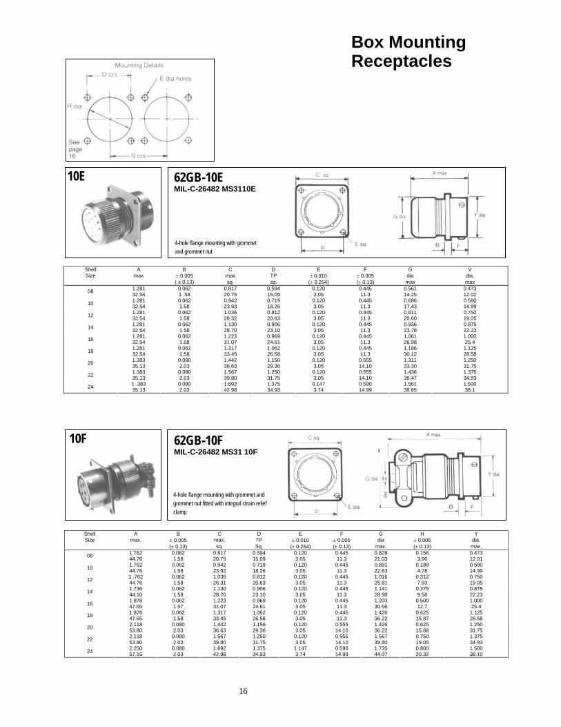
Box Mounting Receptacles
10E 62GB-10E MIL-C-26482 MS3110E
Shell A B C D E F G V Size max ± 0.005 max TP ± 0.010 ± 0.005 dia dia.
( ± 0.13) sq. sq. (± 0.254) (± 0.13) max max 1.281 0.062 0.817 0.594 0.120 0.445 0.561 0.473 08 32.54 1 .58 20.75 15.09 3.05 11.3 14.25 12.02 1.281 0.062 0.942 0.719 0.120 0.445 0.686 0.590 10 32.54 1.58 23.93 18.26 3.05 11.3 17.43 14.99 1.281 0.062 1.036 0.812 0.120 0.445 0.811 0.750 12 32.54 1.58 26.32 20.63 3.05 11.3 20.60 19.05 1.281 0.062 1.130 0.906 0.120 0.445 0.936 0.875 14 32.54 1.58 28.70 23.10 3.05 11.3 23.78 22.23 1.281 0.062 1.223 0.969 0.120 0.445 1.061 1.000 16 32.54 1.58 31.07 24.61 3.05 11.3 26.98 25.4 1.281 0.062 1.317 1.062 0.120 0.445 1.186 1.125 18 32.54 1.58 33.45 26.58 3.05 11.3 30.12 28.58 1.383 0.080 1.442 1.156 0.120 0.555 1.311 1.250 20 35.13 2.03 36.63 29.36 3.05 14.10 33.30 31.75 1.383 0.080 1.567 1.250 0.120 0.555 1.436 1.375 22 35.13 2.03 39.80 31.75 3.05 14.10 36.47 34.93 1 .383 0.080 1.692 1.375 0.147 0.590 1.561 1.500 24 35.13 2.03 42.98 34.93 3.74 14.99 39.65 38.1
10F 62GB-10F MIL-C-26482 MS31 10F
Shell A B C D E F G H Y Size max. ± 0.005 max. TP ± 0.010 ± 0.005 dia ± 0.005 dia.
(± 0.13) sq. Sq. (± 0.254) (± 0.13) max. (± 0.13) max. 1.762 0.062 0.817 0.594 0.120 0.445 0.828 0.156 0.473 08 44.76 1.58 20.75 15.09 3.05 11.3 21.03 3.96 12.01 1.762 0.062 0.942 0.719 0.120 0.445 0.891 0.188 0.590 10 44.76 1.58 23.92 18.26 3.05 11.3 22.63 4.78 14.99 1 .762 0.062 1.036 0.812 0.120 0.445 1.016 0.312 0.750 12 44.76 1.58 26.31 20.63 3.05 11.3 25.81 7.93 19.05 1.736 0.062 1.130 0.906 0.120 0.445 1.141 0.375 0.875 14 44.10 1.58 28.70 23.10 3.05 11.3 28.98 9.58 22.23 1.876 0.062 1.223 0.969 0.120 0.445 1.203 0.500 1.000 16 47.65 1.57 31.07 24.61 3.05 11.3 30.56 12.7 25.4 1.876 0.062 1.317 1.062 0.120 0.445 1.426 0.625 1.125 18 47.65 1.58 33.45 26.58 3.05 11.3 36.22 15.87 28.58 2.118 0.080 1.442 1.156 0.120 0.555 1.426 0.625 1.250 20 53.80 2.03 36.63 29.36 3.05 14.10 36.22 15.88 31.75 2.118 0.080 1.567 1.250 0.120 0.555 1.567 0.750 1.375 22 53.80 2.03 39.80 31.75 3.05 14.10 39.80 19.05 34.93 2.250 0.080 1.692 1.375 1.147 0.590 1.735 0.800 1.500 24 57.15 2.03 42.98 34.93 3.74 14.99 44.07 20.32 38.10
4-hole flange mounting with grommet and grommet nut
4-hole flange mounting with grommet and grommet nut fitted with integral strain relief clamp
17
Box Mounting Receptacles
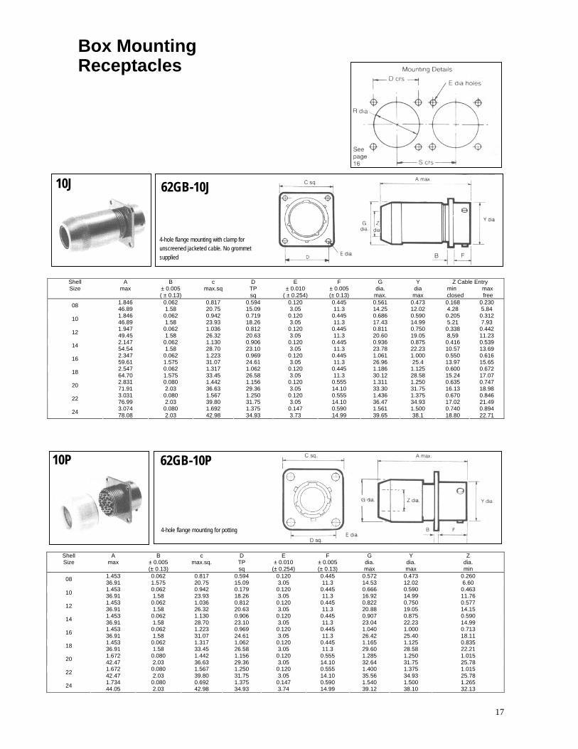
Shell Size
A max
B ± 0.005 ( ± 0.13)
c max.sq
D TP sq
E ± 0.010
( ± 0.254)
F ± 0.005 (± 0.13)
G dia. max.
Y dia max
Z Cable Entry min max closed free
1.846 0.062 0.817 0.594 0.120 0.445 0.561 0.473 0.168 0.230 08 46.89 1.58 20.75 15.09 3.05 11.3 14.25 12.02 4.28 5.84 1.846 0.062 0.942 0.719 0.120 0.445 0.686 0.590 0.205 0.312 10 46.89 1.58 23.93 18.26 3.05 11.3 17.43 14.99 5.21 7.931.947 0.062 1.036 0.812 0.120 0.445 0.811 0.750 0.338 0.442 12 49.45 1.58 26.32 20.63 3.05 11.3 20.60 19.05 8,59 11.232.147 0.062 1.130 0.906 0.120 0.445 0.936 0.875 0.416 0.539 14 54.54 1.58 28.70 23.10 3.05 11.3 23.78 22.23 10.57 13.69 2.347 0.062 1.223 0.969 0.120 0.445 1.061 1.000 0.550 0.616 16 59.61 1.575 31.07 24.61 3.05 11.3 26.96 25.4 13.97 15.65 2.547 0.062 1.317 1.062 0.120 0.445 1.186 1.125 0.600 0.672 18 64.70 1.575 33.45 26.58 3.05 11.3 30.12 28.58 15.24 17.072.831 0.080 1.442 1.156 0.120 0.555 1.311 1.250 0.635 0.747 20 71.91 2.03 36.63 29.36 3.05 14.10 33.30 31.75 16.13 18.98 3.031 0.080 1.567 1.250 0.120 0.555 1.436 1.375 0.670 0.846 22 76.99 2.03 39.80 31.75 3.05 14.10 36.47 34.93 17.02 21.49 3.074 0.080 1.692 1.375 0.147 0.590 1.561 1.500 0.740 0.894 24 78.08 2.03 42.98 34.93 3.73 14.99 39.65 38.1 18.80 22.71
10P 62GB-10P
4-hole flange mounting for potting
Shell Size
A max
B ± 0.005 (± 0.13)
c max.sq.
D TP sq
E ± 0.010
(± 0.254)
F ± 0.005 (± 0.13)
G dia. max
Y dia. max
Z dia. min
1.453 0.062 0.817 0.594 0.120 0.445 0.572 0.473 0.260 08 36.91 1.575 20.75 15.09 3.05 11.3 14.53 12.02 6.60 1.453 0.062 0.942 0.179 0.120 0.445 0.666 0.590 0.463 10 36.91 1.58 23.93 18.26 3.05 11.3 16.92 14.99 11.76 1.453 0.062 1.036 0.812 0.120 0.445 0.822 0.750 0.577 12 36.91 1.58 26.32 20.63 3.05 11.3 20.88 19.05 14.151.453 0.062 1.130 0.906 0.120 0.445 0.907 0.875 0.590 14 36.91 1.58 28.70 23.10 3.05 11.3 23.04 22.23 14.991.453 0.062 1.223 0.969 0.120 0.445 1.040 1.000 0.713 16 36.91 1.58 31.07 24.61 3.05 11.3 26.42 25.40 18.11 1.453 0.062 1.317 1.062 0.120 0.445 1.165 1.125 0.835 18 36.91 1.58 33.45 26.58 3.05 11.3 29.60 28.58 22.21 1.672 0.080 1.442 1.156 0.120 0.555 1.285 1.250 1.015 20 42.47 2.03 36.63 29.36 3.05 14.10 32.64 31.75 25.781.672 0.080 1.567 1.250 0.120 0.555 1.400 1.375 1.015 22 42.47 2.03 39.80 31.75 3.05 14.10 35.56 34.93 25.78 1.734 0.080 0.692 1.375 0.147 0.590 1.540 1.500 1.265 24 44.05 2.03 42.98 34.93 3.74 14.99 39.12 38.10 32.13
10J
4-hole flange mounting with clamp for unscreened jacketed cable. No grommet supplied
62GB-10J

18
Box Mounting Receptacles
12E 62GB-12E BS9522 - F0017 - C2097 MIL-C-26482 MS3112E
Shell Size
A max
8 ± 0.005 (± 0.13)
C max sq.
D TP sq.
E ± 0 010
(± 0.254)
F ± 0.005 ( ± 0.13)
G dia. max.
L V dia.
max. 0.978 0.062 0.817 0.594 0.120 0.445 0.434 0.800 0.473 08 24.84 1.58 20.75 15.09 3.05 11.3 11.02 20.32 12.02 0.978 0.062 0.942 0.719 0.120 0.445 0.558 0.800 0.590 10 24.84 1.58 23.93 18.26 3.05 11.3 14.17 20.32 14.990.978 0.062 1.036 0.812 0.120 0.445 0.683 0.800 0.750 12 24.84 1.58 26.32 20.63 3.05 11.3 17.35 20.32 19.050.978 0.062 1.130 0.906 0.120 0.445 0.808 0.800 0.875 14 24.84 1.58 28.70 23.10 3.05 11.3 20.52 20.32 22.23 0.978 0.062 1.223 0.969 0.120 0.445 0.933 0.800 1.000 16 24.84 1.58 31.07 24.61 3.05 11.3 23.70 20.32 25.4 0.978 0.062 1.317 1.062 0.120 0.445 1.057 0.800 1.125 18 24.84 1.58 33.45 26.58 3.05 11.3 26.85 20.32 28.581.048 0.080 1.442 1.156 0.120 0.555 1.182 0.875 1.250 20 26.62 2.03 36.63 29.36 3.05 14.10 30.02 22.23 31.75 1.048 0.080 1.567 1.250 0.120 0.555 1.307 0.875 1.375 22 26.62 2.03 39.80 31.75 3.05 14.10 33.20 22.23 34.93 1 .048 0.080 1.692 1.375 0.147 0.590 1.432 0.875 1.500 24 26.62 2.03 42.98 34.93 3.74 14.99 36.37 22.23 38.1
BS9522 - F0017 - C2262
K
L
Shell Size
A max
B ± 0.005 (±0.13)
C max sq.
D TP sq.
E dia
0.010
F ± 0.005 (± 0.13)
G dia. Max
J ± 0.020 (± 0.51) min max. max min
Y dia
max.
Z
0.982 0.062 0.817 0.594 0.120 0.445 0.434 0.089 0.030 0.028 0.198 0.166 0.473 0.800 08 24.95 1.58 20.75 15.09 3.05 11.3 11.02 2.26 0.76 0.70 5.03 4.22 12.02 20.32 0.982 0.062 0.942 0.719 0.120 0.445 0.558 0.089 0.030 0.028 0.198 0.166 0.590 0.800 10 24.95 1.58 23.93 18.26 3.05 11.3 14.17 2.26 0.76 0.70 5.03 4.22 14.99 20.32 0.982 0.062 1.036 0.812 0.120 0.445 0.683 0.089 0.030 0.028 0.198 0.166 0.750 0.800 12 24.95 1.58 26.32 20.63 3.05 11.3 17.35 2.26 0.76 0.70 5.03 4.22 19.05 20.320.982 0.062 1.130 0.906 0.120 0.445 0.808 0.089 0.030 0.028 0.198 0.166 0.875 0.800 14 24.95 1.58 28.70 23.10 3.05 11.3 20.52 2.26 0.76 0.70 5.03 4.22 22.23 20.320.982 0.062 1.223 0.969 0.120 0.445 0.933 0.089 0.030 0.028 0.198 0.166 1.000 0.800 16 24.95 1 .58 31.07 24.61 3.05 11.3 23.70 2.26 0.76 0.70 5.03 4.22 25.4 20.32 0.982 0.062 1.317 1.062 0.120 0.445 1.057 0.089 0.030 0.028 0.198 0.166 1.125 0.800 18 24.95 1.58 33.45 26.58 3.05 11.3 26.85 2.26 0.76 0.70 5.03 4.22 28.58 20.321.057 0.080 1.442 1.156 0.120 0.555 1.182 0.076 0.030 0.028 0.185 0.153 1.250 0.875 20 26.85 2.03 36.63 29.36 3.05 14.10 30.02 1.93 0.76 0.70 4.70 3.89 31.75 22.231.057 0.080 1.567 1.250 0.120 0.555 1.307 0.076 0.030 0.028 0.185 0.153 1.375 0.875 22 26.85 2.03 39.80 31.75 3.05 14.10 33.20 1.93 0.76 0.70 4.70 3.89 34.93 22.23 1.057 0.080 1.692 1.375 0.147 0.590 1.432 0.076 0.030 0.028 0.185 0.153 1.500 0.875 24 26.85 2.03 42.98 34.93 3.74 14.99 36.37 1.93 0.76 0.70 4.70 3.89 38.1 22 23
62GB-12E (219) 12E (219)
4-hole flange mounting with plain shell with film wire terminations

19
Box Mounting Receptacles Hermetic Seal
12H 62GB-12H
Shell Size
A max
B ± 0.005 (± 0.13)
C max sq.
D E 0.008
(± 0.203) (±.051) .002
F ± 0.005 (± 0.13)
R ±0.005 (±0.13)
S Y
0.828 0.062 0.812 0.594 0.120 0.443 0.568 1.250 0.473 08 21.03 1.57 20.61 15.08 3.05 11.25 14.42 31.73 12.010.828 0.062 0.937 0.719 0.120 0.443 0.695 1.359 14.99 10 21.03 1.57 23.79 18.29 3.05 11.25 17.53 34.52 14.990.828 0.062 1.031 0.812 0.120 0.443 0.864 1.531 0.750 12 21.03 1.57 26.17 20.57 3.05 11.25 21.84 38.89 19.05 0.828 0.062 1.125 0.906 0.120 0.443 0.989 1.656 0.875 14 21.03 1.57 28.57 23.11 3.05 11.25 25.15 42.06 22.23 0.828 0.062 1.218 0.969 0.120 0.443 1.113 1.781 1.000 16 21.03 1.57 30.93 24.64 3.05 11.25 28.19 45.24 25.400.828 0.062 1.312 1.062 0.120 0.443 1.238 1.891 1.125 18 21.03 1.57 33.32 26.92 3.05 11.25 31.49 48.03 28.58 0.890 0.093 1.437 1.156 0.120 0.561 1.363 2.031 1.250 20 22.60 2.36 36.49 29.46 3.05 14.24 34.54 51.59 30.75 0.890 0.093 1.562 1.250 1.120 0.561 1.488 2.156 1.375 22 22.60 2.36 39.67 31.75 3.05 14.24 37.85 54.76 34.930 890 0.093 1.687 1.375 0.147 0.593 1.615 2.277 1.500 24 22.60 2.36 42.84 35.05 3.81 15.06 41.15 57.84 38.10
4-hole square mounting with exposed solder buckets or flattened and pierced pins.
20
Single Hole Fixing Receptacles Table of Styles
62GB-57A
Page No.
23
62GB-57A (219) 23
62GB-14E 24
62GB-14F 24
62GB-57T 25
62GB-17P 25
62GB-17H Hermetic Seal 26
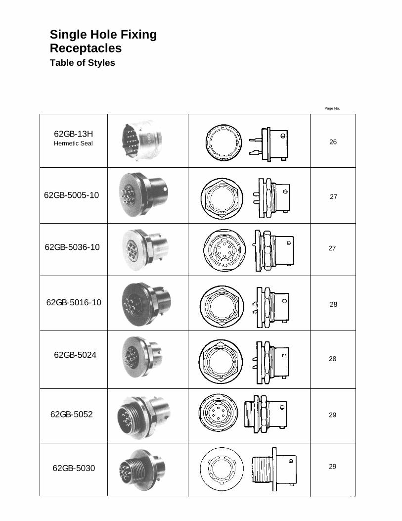
21
Single Hole Fixing Receptacles
Table of Styles
62GB-13H Hermetic Seal
62GB-5005-10
62GB-5036-10
62GB-5016-10
62GB-5024
62GB-5052
62GB-5030
Page No.
26
27
27
28
28
29
29
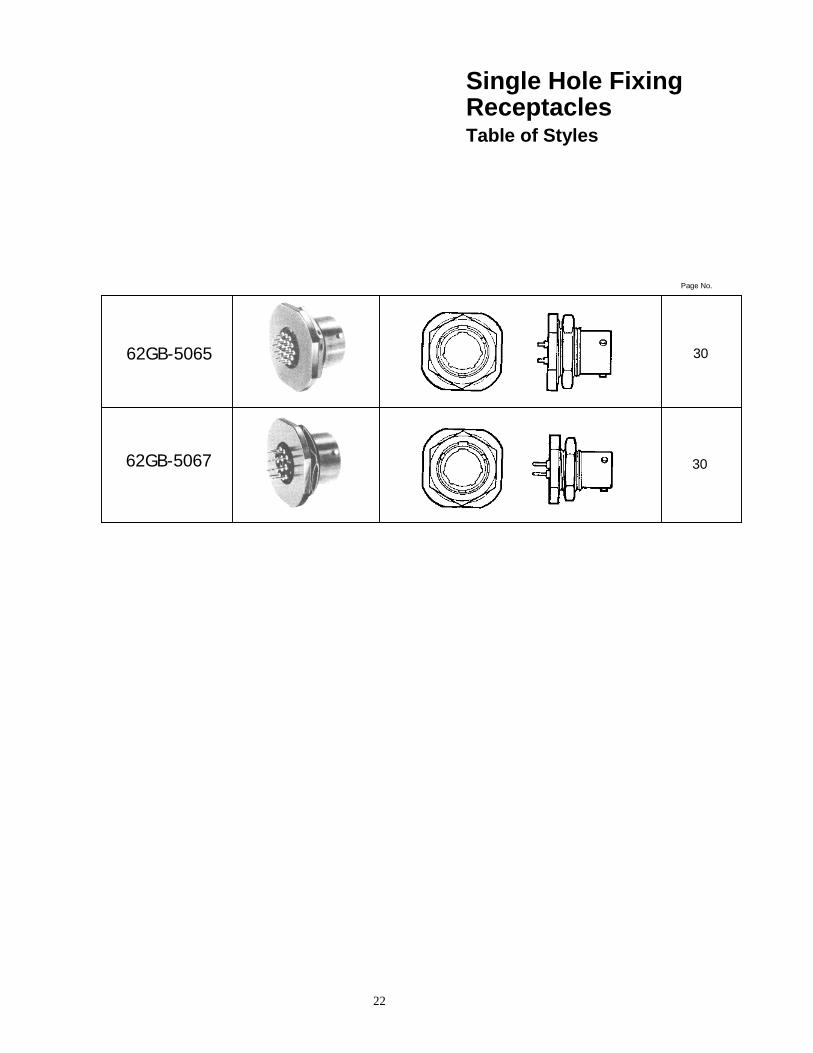
22
Single Hole Fixing Receptacles Table of Styles
62GB-5065
62GB-5067
Page No.
30
30
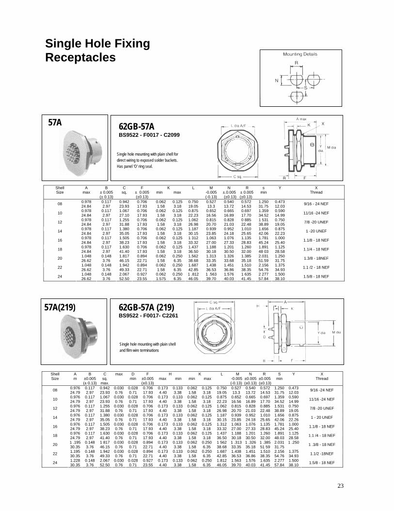
23
Single Hole Fixing Receptacles
57A 62GB-57A BS9522 - F0017 - C2099
Single hole mounting with plain shell for direct wiring to exposed solder buckets. Has panel 'O' ring seal.
Shell Size
A max
B ± 0.005 (± 0.13)
C sq,
F ± 0.005 (±0.13)
K min max
L M -0.005 (-0.13)
N R ±.0.005 ± 0.005(±0.13) (±0.13)
s min
Y X Thread
0.978 0.117 0.942 0.706 0.062 0.125 0.750 0.527 0.540 0.572 1.250 0.473 08 24.84 2.97 23.93 17.93 1.58 3.18 19.05 13.3 13.72 14.53 31.75 12.03 9/16 - 24 NEF
0.978 0.117 1.067 0.706 0.062 0.125 0.875 0.652 0.665 0.697 1.359 0.590 10 24.84 2.97 27.10 17.93 1.58 3.18 22.23 16.56 16.89 17.70 34.52 14.99 11/16 -24 NEF
0.978 0.117 1.255 0.706 0.062 0.125 1.062 0.815 0.828 0 885 1 531 0.750 12 24.84 2.97 31.88 17.93 1.58 3.18 26.98 20.70 21.03 22.48 38.89 19.05 7/8 -20 UNEF
0.978 0.117 1.380 0.706 0.062 0.125 1.187 0.939 0.952 1.010 1.656 0.875 14 24.84 2.97 35.05 17.93 1.58 3.18 30.15 23.85 24.18 25.65 42.06 22.23 1 -20 UNEF
0.978 0.117 1.505 0.706 0.062 0.125 1 312 1.063 1.076 1.135 1.781 1.000 16 24.84 2.97 38.23 17.93 1.58 3.18 33.32 27.00 27.33 28.83 45.24 25.40 1.1/8 - 18 NEF
0.978 0.117 1.630 0.706 0.062 0.125 1.437 1.188 1.201 1.260 1.891 1.125 18 24.84 2.97 41.40 17.93 1.58 3.18 36.50 30.18 30.50 32.00 48 03 28.58 1.1/4 - 18 NEF
1.048 0.148 1.817 0.894 0.062 0.250 1.562 1.313 1.326 1.385 2.031 1.250 20 26.62 3.76 46.15 22.71 1.58 6.35 38.68 33.35 33.68 35.18 51.59 31.75 1.3/8 - 18NEF
1.048 0.148 1.942 0.894 0.062 0.250 1.687 1.438 1.451 1.510 2.156 1.375 22 26.62 3.76 49.33 22.71 1.58 6.35 42.85 36.53 36.86 38.35 54.76 34.93 1.1 /2 - 18 NEF
1.048 0.148 2.067 0.927 0.062 0.250 1 .812 1 .563 1.576 1 635 2 277 1.500 24 26.62 3.76 52.50 23.55 1.575 6.35 46.05 39.70 40.03 41.45 57.84 38.10 1.5/8 - 18 NEF
57A(219) 62GB-57A (219) BS9522 - F0017- C2261
Single hole mounting with plain shell and film wire terminations
Shell Size
A m
B ±0.005 (± 0.13)
C sq.
max.
max D min
F ±0.005 (±0.13)
H max min
K min max
L M N R -0.005 ±0.005 ±0.005(-0.13) (±0.13) (±0.13)
S min
Y X Thread
0.976 0.117 0.942 0.030 0.028 0.706 0.173 0.133 0.062 0.125 0.750 0.527 0.540 0.572 1.250 0.473 08 24.79 2.97 23.93 0.76 0.71 17.93 4.40 3.38 1.58 3.18 19.05 13.3 13.72 14.53 31.75 12.03 9/16 -24 NEF
0.976 0.117 1.067 0.030 0.028 0.706 0.173 0.133 0.062 0.125 0.875 0.652 0.665 0.697 1.359 0.590 10 24.79 2.97 23.93 0.76 0.71 17.93 4.40 3.38 1.58 3.18 22.23 16.56 16.89 17.70 34.52 14.99 11/16 -24 NEF
0.976 0.117 1.255 0.030 0.028 0.706 0.173 0.133 0.062 0.125 1.062 0.815 0.828 0.885 1.531 0.750 12 24.79 2.97 31.88 0.76 0.71 17.93 4.40 3.38 1.58 3.18 26.98 20.70 21.03 22.48 38.89 19.05 7/8 -20 UNEF
0.976 0.117 1.380 0.030 0.028 0.706 0.173 0.133 0.062 0.125 1.187 0.939 0.952 1.010 1.656 0.875 14 24.79 2.97 35.05 0.76 0.71 17.93 4.40 3.38 1.58 3.18 30.15 23.85 24.18 25.65 42.06 22.26 1 - 20 UNEF
0.976 0.117 1.505 0.030 0.028 0.706 0.173 0.133 0.062 0.125 1.312 1.063 1.076 1.135 1.781 1.000 16 24.79 2.97 38.23 0.76 0.71 17.93 4.40 3.38 1.58 3.18 33.32 27.00 27.33 28.83 45.24 25.40 1.1/8 - 18 NEF
0.976 0.117 1.630 0.030 0.028 0.706 0.173 0.133 0.062 0.125 1.437 1.188 1.201 1.260 1.891 1.125 18 24.79 2.97 41.40 0.76 0.71 17.93 4.40 3.38 1.58 3.18 36.50 30.18 30.50 32.00 48.03 28.58 1.1 /4 - 18 NEF
1 .195 0.148 1 817 0.030 0.028 0.894 0.173 0.133 0.062 0.250 1 562 1 .313 1 .326 1 .385 2.031 1 .250 20 30.35 3.76 46.15 0.76 0.71 22.71 4.40 3.38 1.58 6.35 38.68 33.35 35.18 51 59 31.75 1 .3/8 - 18 NEF
1.195 0.148 1.942 0.030 0.028 0.894 0.173 0.133 0.062 0.250 1.687 1.438 1.451 1.510 2.156 1.375 22 30.35 3.76 49.33 0.76 0.71 22.71 4.40 3.38 1.58 6.35 42.85 36.53 36.86 38.35 54.76 34.93 1.1/2 -18NEF
1.228 0.148 2.067 0.030 0.028 0.927 0.173 0.133 0.062 0.250 1.812 1.563 1.576 1.635 2.277 1.500 24 30.35 3.76 52.50 0.76 0.71 23.55 4.40 3.38 1.58 6.35 46.05 39.70 40.03 41.45 57.84 38.10 1.5/8 - 18 NEF

24
Single Hole Fixing Receptacles
14E 62GB-14E MIL-C-26482 MS3114E BS9522 - F0017 - C2098
Single hole mounting with grommet and grommet nut. Has panel 'O' ring seal
Shell Size
A max
B ±0.005 (±0.13)
C max sq.
F ±0.005 (±0.13)
G Dia Max
K min max
L M N R -0.005 ±0.005 ±0.005 (-0.13) ( ±0.13) (±0.13)
S Y X Thread
1.344 0.117 0.942 0.706 0 713 0.062 0.125 0.750 0.527 0.540 0.572 1.250 0.473 08 34.14 2.97 23.93 17.93 18.11 1.58 3.18 19.05 13.3 13.72 14.53 31.75 12.03 9/16-24NEF
1.344 0.117 1.067 0.706 0.838 0.062 0.125 0.875 0.652 0.665 0.697 1.359 0.590 10 34.14 2.97 27.10 17.93 21.29 1.58 3.18 22.23 16.56 16.89 17.70 34.52 14.99 11/16 -24 NEF
1.344 0.117 1.255 0.706 0.963 0.062 0.125 1.062 0.815 0.828 0.885 1.531 0.750 12 34.14 2.97 31 .88 17.93 24.46 1.58 3.18 26.98 20.70 21.03 22.48 38.89 19.05 7/8 -20 UNEF
1 .344 0.117 1.380 0.706 1.088 0.062 0.125 1.187 0.939 0.952 1.010 1.656 0.875 14 34.14 2.97 35.05 17.93 27.63 1.58 3.18 30.15 23.85 24.18 25.65 42.06 22.23 1 - 20 UNEF
1.344 0.117 1.505 0.706 1.213 0.062 0.125 1.312 1.063 1.076 1.135 1.781 1.000 16 34.14 2.97 38.23 17.93 30.81 1.58 3.18 33.32 27.00 27.33 28.83 45.24 25.40 1.1/8 -18NEF
1.344 0.117 1.630 0.706 1.338 0.062 0.125 1.437 1.188 1.201 1.260 1.891 1.125 18 34.14 2.97 41.40 17.93 33.98 1.58 3.18 36.50 30.18 30.50 32.00 48.03 28.58 1.1/4 –18 NEF
1.576 0.148 1 817 0.894 1.463 0.062 0.250 1.562 1.313 1.326 1.385 2.031 1.250 20 40.03 3.76 46.15 22.71 37.16 1.58 6.35 38.68 33.35 33.68 35.18 51.59 31.75 1.3/8 - 18 NEF
1.576 0.148 1.942 0.894 1 .588 0.062 0.250 1.687 1.438 1.451 1.510 2.156 1.375 22 40.03 3.76 49.33 22.71 40.33 1.58 6.35 42.85 36.53 36.86 38.35 54.76 34.93 1.1 /2 - 18 NEF
1.609 0.148 2.067 0.927 1.713 0.062 0.250 1.812 1.563 1.576 1.635 2.277 1.500 24 40.87 3.76 52.50 23.55 43.51 1.58 6.35 46.05 39.70 40.03 41.45 57.84 38.10 1.5/8 - 18 NEF
14F 62GB-1 4F MIL-C-26482 MS3114F
Single hole mounting with grommet and grommet nut fitted with integral strain relief clamp. Has panel 'O' ring seal
Shell Size
A max
B ±0.005 (±0.13)
C max sq.
F ±0.005 (±0.13)
G dia. max.
H 0.005
(± 0.13)
K min max
L M N R -0.005 ±0.005 ±0.005 (-0.13) (±0.13) (±0.13)
S Y X Thread
1.762 0.117 0.942 0.706 0.828 0.156 0.062 0.125 0.750 0.527 0.540 0.572 1 250 0.473 08 44.75 2.97 23.93 17.93 21.03 3.96 1.58 3.18 19.05 13.3 13.72 14.53 31.75 12.03 9/16 -24 NEF
1.762 0.117 1.067 0.706 0.891 0.188 0.062 0.125 0.875 0.652 0.665 0.697 1.359 0.590 10 44.75 2.97 27.10 17.93 22.63 4.78 1.58 3.18 22.23 16.56 16.89 17.70 34.52 14.99 11/16 - 124 NEF
1.762 0.117 1.255 0.706 1.016 0.312 0.062 0.125 1.062 0.815 0.828 0.885 1.531 0.750 12 44 75 2.97 31.88 17.93 25.81 7.93 1.58 3.18 26.98 20.70 21.03 22.48 38.89 19.05 7/8 - 20 UNEF
1 .736 0.117 1.380 0.706 7.147 0.375 0.062 0.125 1.187 0.939 0.952 1.010 1.656 0.875 14 44.10 2.97 35.05 17.93 28.97 9.53 1.58 3.18 30.15 23.85 24.18 25.65 42.06 22.23 1 - 20 NEF
1.876 0.117 1.505 0.706 1.203 0.500 0.062 0.125 1.312 1.063 1.076 1.135 1.781 1.000 16 47.65 2.97 38.23 17.93 30.56 12.7 1.58 3.18 33.32 27.00 27.33 28.83 45.24 25.40 1.1/8 - 18 NEF
1.876 0.117 1.630 0.706 1.426 0.625 0.062 0.125 1.437 1.188 1.201 1.260 1.891 7.125 18 47.65 2.97 41.40 17.93 36.22 15.88 1.58 3.18 36.50 30.18 30.50 32.00 48.03 28.58 1.1/4 - 18 NEF
2.118 0.148 1.817 0.894 1.426 0.625 0.062 0.250 1.562 1.313 1.326 1.385 2.031 1.250 20 53.8 3. 76 46.15 22.71 36.22 15.88 1.58 6.35 38 68 33.35 33.68 35.18 51 .59 31.75 1.3/8 - 18 NEF
2.118 0.148 1.942 0.894 7.567 0.750 0.062 0.250 1.687 1.438 1.451 1.510 2.756 1.375 22 53.8 3.76 49.33 22.71 39.80 19.05 1.58 6.35 42.85 36.53 36.86 38.35 54.76 34.93 1.1/2 -18 NEE
2.250 0.148 2.067 0.927 1.735 0.800 0.062 0.250 1.812 1.563 1.576 1.635 2.277 1.500 24 57.15 3.76 52.50 23.55 44.07 20.32 1.58 6.35 46.05 39.70 40.03 41.45 57.84 38.10 1.5/8 - 18 NEF
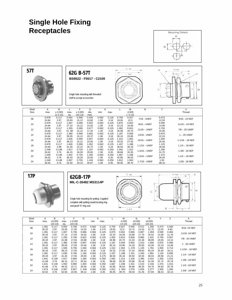
25
Single Hole Fixing Receptacles
57T 62G B-57T BS9522 - F0017 - C2100
Single hole mounting with threaded shell to accept accessories
Shell Size
A max
B ± 0.005 (± 0.13)
c max. sq.
F ± 0.005 (±0.13)
G dia, max.
K min max
L M -0.005 (- 0.13)
N Y X Thread
0.978 0.117 0.942 0.595 0.426 0.062 0.125 0.750 0.527 0.473 08 24.84 2.97 23.93 15.12 10.82 1.58 3.18 19.05 13.3 7/16 - UNEF 12.03 9/16 - 24 NEF
0.978 0.117 1.067 0.595 0.552 0.062 0.125 0.875 0.652 0.590 10 24.84 2.97 27.10 15.12 14.02 1.58 3.18 22.23 16.56 9/16 – UNEF 14.99 11/16 – 24 NEF
0.978 0.117 1.255 0.595 0.677 0.062 0.125 1.062 0.815 0.750 12 24.84 2.97 31 .88 15.12 17.20 1.58 3.18 26.98 20.70 11/16 – UNEF 19.05 7/8 – 20 UNEF
0.978 0.117 1.380 0.595 0.802 0.062 0.125 1.187 0.939 0.875 14 24.84 2.97 35.05 15.12 20.37 1.58 3.18 30.15 23.85 13/16 - UNEF 22.23 1 – 20 UNEF
0.978 0.117 1.505 0.595 0.927 0.062 0.125 1.312 1.063 1.000 16 24.84 2.97 38.23 15.12 23.55 1.58 3.18 33.32 27.00 15/16 – UNEF 25.40 1.1/18 – 18 NEF
0.978 0.117 1.630 0.595 1.052 0.062 0.125 1.437 1.188 1.125 18 24.84 2.98 41.40 15.12 26.72 1.58 3.18 36.50 30.18 1.1/16 – UNEF 28.58 1.1/4 – 18 NEF
1.048 0.148 1.817 0.720 1.167 0.062 0.250 1.562 1.313 1.250 20 26.62 3.76 46.15 18.29 29.65 1 58 6.35 38.68 33.35 1.3/16 – UNEF 31.75 1.3/8 - 18 NEF
1.048 0.148 1.942 0.720 1.292 0.062 0.250 1.687 1.438 1.375 22 26,62 3.76 49.33 18.29 32.82 1.58 6.35 42.85 36.53 1.5/16 – UNEF 34.93 1.1/2 – 18 NEF
1.048 0.148 2.067 0.753 1.416 0.062 0.250 1.812 1.563 1.50 24 26.62 3.76 52.50 19.13 35.97 1.58 6.35 46.05 39.70 1.7/16 - UNEF 38.10 1.5/8 - 18 NEF
17P 62GB-17P MIL-C-26482 MS3114P
Single hole mounting for potting. Supplied complete with potting mould locating ring and panel 'O' ring seal
Shell Size
A max.
B ±0.005 (±0.13)
C max. sq.
F ± 0.005 (±0.13)
G K min max.
L M -0.005 (-0.13)
N ±0.005 (±0.13)
R ±0.005 (±0.13)
Y Z X Thread
1.391 0.117 0.942 0.706 0.572 0.062 0.125 0.750 0.527 0.540 0.572 1.250 0.473 0.260 08 35.33 2.97 23.93 17.93 14.53 1.58 3.175 19.05 13.3 13.72 14.53 31.75 12.03 6.60 9/16 -24 NEF
1.391 0.117 1.067 0.706 0.666 0.062 0.125 0.875 0.652 0.665 0.697 1.359 0.590 0.463 10 35.33 2.97 27.10 17.93 16.92 1.58 3.18 22.23 16.56 16.89 17.70 34.52 14.99 11.76 11/16 -24 NEF
1.391 0.117 1.255 0.706 0.822 0.062 0.125 1.062 0.815 0.828 0.885 1.531 0.750 0.557 12 35.33 2.97 31.88 17.93 20.88 1.58 3.18 26.98 20.70 21.03 22.48 38.89 19.05 14.15 7/8 - 20 UNEF
1.391 0.117 1.380 0.706 0.907 0.062 0.125 1.187 0.939 0.952 1.010 1.656 0.875 0.590 14 35.33 2.97 35.05 17.93 23.06 1.58 3.18 30.15 23.85 24.18 25.65 42.06 22.23 14.99 1 - 20 UNEF
1.391 0.117 1.505 0.706 1.040 0.062 0.125 1.312 1 063 1 .076 1.135 1.781 1.000 0.713 16 35.33 2.97 38.23 17.93 26.42 1.58 3.18 33.32 27.00 27.33 28.83 45.24 25.40 18.11 1.1/18 – 18 NEF
1.391 0.117 1.630 0.706 1.165 0.062 0.125 1.437 1.188 1.201 1.260 1.891 1.125 0.835 18 35.33 2.97 41.40 17.93 29.59 1.58 3.175 36.50 30.18 30.50 32.00 48.03 28.58 21.21 1.1/4 - 18 NEF
1.641 0.148 1.817 0.894 1.285 0.062 0.250 1.562 1.313 1.326 1.385 2.031 1.250 1.015 20 41.68 3.76 46.15 22.71 32.64 1.58 6.35 38.68 33.35 33.68 35.18 51.59 31.75 25.78 1.3/8 –18 NEF
1.641 0.148 1.942 0.894 1.400 0.062 0.250 1.687 1.438 1.451 1.510 2.156 1.375 1.015 22 41.68 3.76 49.33 22.71 35.56 1.58 6.35 42.85 36.53 36.86 38.35 54.76 34.93 25.78 1.1/2 –18 NEF
1.674 0.148 2.067 0.927 1 .540 0.062 0.250 1.812 1 .563 1.576 1.635 2.277 1.500 1.265 24 42.52 3.76 52.50 23.55 39.12 1.58 6.35 46.05 39.70 40.03 41.45 57.84 38.10 32.13 1.5/8 - 18 NEF
26
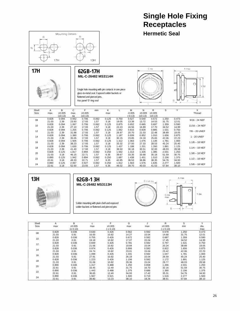
Single Hole Fixing Receptacles Hermetic Seal
17H 62GB-17H MIL-C-26482 MS3114H
Single hole mounting with pin contacts in one piece glass-to-metal seal. Exposed solder buckets or flattened and pierced pins. Has panel 'O' ring seal
Shell Size
A max.
B ±0.005 (±0.13)
C max.
sq
F ±0.005 (±0.13)
min K max
L M -0.005 (-0.13)
N R ±0.005 ±0.005 (±0.13) (±0.13)
S Y X Thread
0.828 0.094 0.942 0.706 0.062 0.125 0.750 0.527 0.540 0.572 1.250 0.473 08 21.03 2.39 23.93 17.93 1.57 3.18 19.05 13.39 13.72 14.53 31.75 12.01 9/16 - 24 NEF
0.828 0.094 1.067 0.706 0.062 0.125 0.875 0.652 0.665 0.697 1.359 0.590 10 21.03 2.39 27.10 17.93 1.57 3.18 22.23 16.56 16.89 17.70 34.52 14.99 11/16 – 24 NEF
0.828 0.094 1.255 0.706 0.062 0.125 1.062 0.815 0.828 0.885 1.531 0.750 12 21.03 2.39 31.88 17.93 1.57 3.18 26.97 20.70 21.03 22.48 38.89 19.05 7/8 – 20 UNEF
0.828 0.094 1.380 0.706 0.062 0.125 1.187 0.939 0.952 1.010 1.656 0.875 14 21.03 2.39 35.05 17.93 1.57 3.18 30.15 23.85 24.18 25.65 42.06 22.23 1 - 20 UNEF
0.828 0.094 1.505 0.706 0.062 0.125 1.312 1.063 1.076 1.135 1.781 1.000 16 21.03 2.39 38.23 17.93 1.57 3.18 33.32 27.00 27.33 28.53 45.24 25.40 1.1/8 – 18 NEF
0.828 0.094 1.630 0.706 0.062 0.125 1.437 1.188 1.201 1.260 1.891 1.125 18 21.03 2.39 41.40 17.93 1.57 3.18 36.50 30.18 30.51 32.00 48.03 28.58 1.1/4 – 18 NEF
0.828 0.125 1.817 0.894 0.062 0.250 1.562 1.313 1.326 1.385 2.031 1.250 20 21.03 3.18 46.15 22.71 1.57 6.35 39.67 33.35 33.68 35.18 51.59 30.75 1.3/8 – 18 NEF
0.890 0.125 1.942 0.894 0.062 0.250 1.687 1.438 1.451 1.510 2.156 1.375 22 22.61 3.18 49.33 22.71 1.57 6.35 42.85 36.53 36.86 38.35 54.76 34.93 1.1/2 – 18 NEF
0.890 0.125 2.067 0.927 0.062 0.250 1.812 1.563 1.576 1.635 2.277 1.500 24 22.61 3.18 52.50 23.55 1.57 6.35 46.02 39.70 40.03 41.53 57.84 38.10 1.5/8 – 18 NEF
13H 62GB-1 3H MIL-C-26482 MS3113H
Solder mounting with plain shell and exposed solder buckets or flattened and pierced pins
Shell Size
A max
B ±0.005 (± 0.13)
c max
F ±0.005
( ± 0.13)
G max
J max
R ±0.005
( ± 0.13)
S min
Y dia. max
0.828 0.036 0.630 0.426 0.562 0.592 0.578 1.250 0.473 08 21.03 0.91 16.00 10.82 14.27 15.04 14.68 31.75 12.010.828 0.036 0.755 0.426 0.672 0.592 0.687 1.359 0.590 10 21.03 0.91 19.18 10.82 17.07 15.04 17.45 34.52 14.990.828 0.036 0.849 0.426 0.781 0.592 0.797 1.531 0.750 12 21.03 0.91 21.56 10.82 19.84 15.04 20.24 38.89 19.05 0.828 0.036 0.974 0.426 0.906 0.592 0.922 1.656 0.875 14 21.03 0.91 24.74 10.82 23.01 15.04 23.42 42.06 22.23 0.828 0.036 1.099 0.426 1.031 0.592 1.047 1.781 1.000 16 21.03 0.91 27.91 10.82 26.19 15.04 26.59 45.24 25.400.828 0.036 1.223 0.426 1.156 0.592 1.172 1.891 1.125 18 21.03 0.91 31.06 10.82 29.36 15.04 29.77 48.03 28.58 0.890 0.036 1.317 0.488 1.250 0.658 1.266 2.031 1.250 20 22.61 0.91 33.45 12.40 31.75 16.70 32.16 51.59 30.75 0.890 0.036 1.443 0.488 1.375 0.686 1.390 2.156 1.375 22 22.61 0.91 36.65 12.40 34.93 17.42 35.31 54.76 34.93 0.890 0.036 1.567 0.521 1.500 0.719 1.516 2.277 1.500 24 22.61 0.91 39.80 13.23 38.10 18.26 38.51 57.84 38.10
27
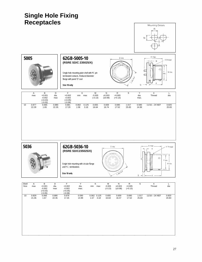
Single Hole Fixing Receptacles
5005 62GB-5005-10 (RSRE SD/C 235025/X)
Single hole mounting plain shell with PC pin terminated contacts. Reduced diameter flange with panel 'O' seal Size 10 only
A max
B +0.001 -0.002 (+0.03) (-0.03)
D dia. max
F +0.002 -0.003 (+0.05) (-0.08)
K min max
M -0.005 (-0.13)
N ±0.003 (±0.08)
R +0.005 (+0.13)
S Y dia. max.
X Thread
L dia
10 0.877 0.065 0.880 0.681 0.062 0.125 0.655 0.659 0.690 1.017 0.590 11/16 – 24 NEF 0.820 22.28 1.65 22.35 17.29 1.58 3.18 16.64 16.74 17.52 25.83 14.99 20.83
5036 62GB-5036-10 (RSRE SD/C235025/X)
Single hole mounting with circular flange and P.C. terminations Size 10 only
Shell Size
A max
B +0.001 -0.002 (+0.03) (-0.05)
D dia. max
F +0.002 -0.003 (+0.05) (-0.08)
Y dia. max.
K min max
M -0.005 (-0.13)
N ±0.003 (±0.08)
R +0.005 (+0.13)
S X Thread
L dia
10 0.829 0.066 0.880 0.679 0.590 0.062 0.125 0.655 0.659 0.690 1.017 11/16 – 24 NEF 0.820 21.06 1.67 22.35 17.25 14.99 1.57 3.18 16.63 16.47 17.52 25.83 20.83

28
Single Hole Fixing Receptacles
5016 62GB-5016-10 (RSRE SD/C 235025/X)
Single hole mounting plain shell for direct wiring to exposed solder buckets. Reduced diameter flange with panel 'O' ring seal Solder bucket: Size 10 only
Shell Size
A max
B +0.002 -0.001 (+0.05) (-0.03)
D dia. max
F + 0.003 - 0.002 (+ 0.08) (- 0.05)
K min max
M - 0.010 (- 0.25)
N ± 0.005 (± 0.13)
R + 0.005 (+ 0.13)
S Y dia. max.
X Thread
10 0.902 0.064 0.880 0.678 0.062 0.125 0.655 0.665 0.697 1.359 0.590 11/16 – 24 NEF 22.91 1.62 22.35 17.21 1.58 3.18 16.63 16.89 17.70 34.52 14.99
5024 62GB-5024 (RSRE SD/C 35077/X) Single hole mounting plain shell for direct wiring to exposed solder buckets. Reduced diameter flange with panel 'O' ring seal Solder buckets: Size 8, 12 and 14 only
Shell Size
A max
B ± 0.005 ( ± 0.13)
D dia. max
F ± 0.005 ( ± 0.13)
K min max
M - 0.005 (- 0.13)
N R ± 0.005 ±0.005 (± 0.13) (± 0.13)
S min
Y dia. max
X Thread
0.978 0.117 0.830 0.706 0.062 0.125 0.527 0.540 0.572 1.250 0.473 08 24.84 2.97 21.08 17.93 1.58 3.18 13.3 13.72 14.53 31.75 12.03 9/16 - 24 NEF
0.978 0.117 1.130 0.706 0.062 0.125 0.815 0.828 0.885 1.531 0.750 12 24.84 2.97 28.70 17.93 1.58 3.18 20.70 21.03 22.48 38.89 19.05 7/8 - 20 UNEF
0.978 0.117 1.260 0.706 0.062 0.125 0.939 0.952 1.010 1.656 0.875 14 24.84 2.97 32.00 17.93 1.58 3.18 23.85 24.18 25.65 42.06 22.23 1 -20 UNEF

29
Single Hole Fixing Receptacles
5052 62GB-5052-10
Single hole fixing with circular flange and back end thread - solder termination Size 10 only
Shell Size
A max
B (± 0.05) (± 0.03)
C max. sq.
F + 0.003 - 0.002 (+ 0.08) (- 0.05)
K min max
L M - 0.005 (- 0.13)
N ± 0.005 (± 0.13)
R ± 0.005 (± 0.13)
S ± 0.005 (± 0.13)
X Thread
10 0.947 0.062 0.880 0.677 0.062 0.125 0.820 0.650 5/8 – 24 UNEF 0.697 1.359 5/8 – 24 NEF 24.06 1.58 22.35 17.19 1.58 3.18 20.83 16.51 17.70 34.52
5030 62GB-5030
Bulkhead mounting receptacle with solder terminations
Shell Size
A max
B ± 0.005 (± 0.13)
C ± 0.010 (± 0.25)
F ± 0.005 (± 0.13)
L N Thread
0.978 0.094 0.812 0.415 0.563 08 24.85 2.39 20.63 10.54 14.30 7/16 - 28 UNEF
0.978 0.094 0.937 0.415 0.680 10 24.85 2.39 23.80 10.54 17.28 9/16 - 24 NEF
0.978 0.094 1.031 0.415 0.859 12 24.85 2.39 26.19 10.54 21.82 11 /16 - 24 NEF
0.978 0.094 1.125 0.415 0.984 14 24.85 2.39 28.58 10.54 25.00 13/16 - 20 UNEF
0.978 0.094 1.218 0.415 1.108 16 24.85 2.39 30.94 10.54 28.15 15/16 - 20 UNEF
0.978 0.094 1.3121 0.415 1.233 18 24.85 2.39 33.33 10.54 31.32 1.1/16 - 18NEF
1.048 0.102 1.437 0.535 1.358 20 26.62 2.59 36.50 13.59 34.50 1.3/16 -18NEF
1.048 0.102 1.562 0.535 1.483 22 26.62 2.59 39.68 13.59 37.67 1.5/16 - 18 NEF
1.048 0.102 1.687 0.572 1.610 24 26.62 2.59 42.85 14.53 40.90 1.7/16 - 18 NEF
30
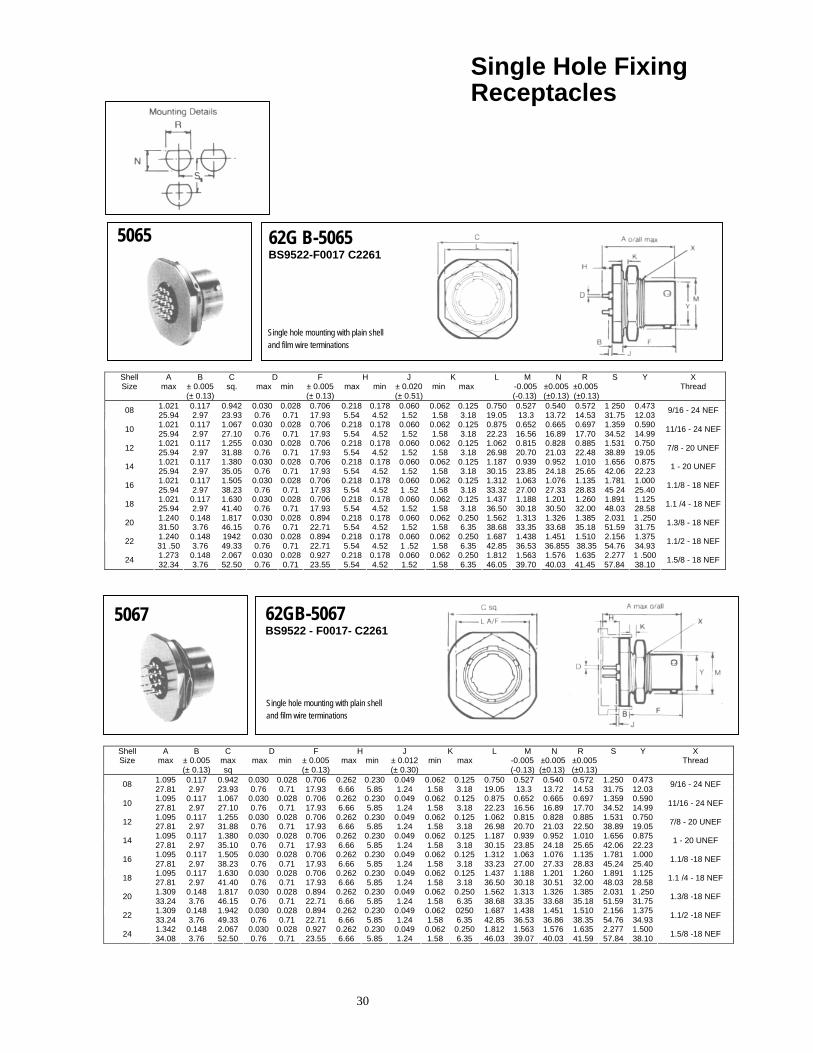
Single Hole Fixing Receptacles
5065 62G B-5065 BS9522-F0017 C2261
Single hole mounting with plain shell and film wire terminations
Shell Size
A max
B ± 0.005 (± 0.13)
C sq.
D max min
F ± 0.005(± 0.13)
H max min
J ± 0.020(± 0.51)
K min max
L M N R -0.005 ±0.005 ±0.005 (-0.13) (±0.13) (±0.13)
S Y X Thread
1.021 0.117 0.942 0.030 0.028 0.706 0.218 0.178 0.060 0.062 0.125 0.750 0.527 0.540 0.572 1 250 0.473 08 25.94 2.97 23.93 0.76 0.71 17.93 5.54 4.52 1.52 1.58 3.18 19.05 13.3 13.72 14.53 31.75 12.03 9/16 - 24 NEF
1.021 0.117 1.067 0.030 0.028 0.706 0.218 0.178 0.060 0.062 0.125 0.875 0.652 0.665 0.697 1.359 0.590 10 25.94 2.97 27.10 0.76 0.71 17.93 5.54 4.52 1.52 1.58 3.18 22.23 16.56 16.89 17.70 34.52 14.99 11/16 - 24 NEF
1.021 0.117 1.255 0.030 0.028 0.706 0.218 0.178 0.060 0.062 0.125 1.062 0.815 0.828 0.885 1.531 0.750 12 25.94 2.97 31.88 0.76 0.71 17.93 5.54 4.52 1.52 1.58 3.18 26.98 20.70 21.03 22.48 38.89 19.05 7/8 - 20 UNEF
1.021 0.117 1.380 0.030 0.028 0.706 0.218 0.178 0.060 0.062 0.125 1.187 0.939 0.952 1.010 1.656 0.875 14 25.94 2.97 35.05 0.76 0.71 17.93 5.54 4.52 1.52 1.58 3.18 30.15 23.85 24.18 25.65 42.06 22.23 1 - 20 UNEF
1.021 0.117 1.505 0.030 0.028 0.706 0.218 0.178 0.060 0.062 0.125 1.312 1.063 1.076 1.135 1.781 1.000 16 25.94 2.97 38.23 0.76 0.71 17.93 5.54 4.52 1 .52 1.58 3.18 33.32 27.00 27.33 28.83 45 24 25.40 1.1/8 - 18 NEF
1.021 0.117 1.630 0.030 0.028 0.706 0.218 0.178 0.060 0.062 0.125 1.437 1.188 1.201 1.260 1.891 1.125 18 25.94 2.97 41.40 0.76 0.71 17.93 5.54 4.52 1.52 1.58 3.18 36.50 30.18 30.50 32.00 48.03 28.58 1.1 /4 - 18 NEF
1.240 0.148 1.817 0.030 0.028 0.894 0.218 0.178 0.060 0.062 0.250 1.562 1.313 1.326 1.385 2.031 1 .25020 31.50 3.76 46.15 0.76 0.71 22.71 5.54 4.52 1.52 1.58 6.35 38.68 33.35 33.68 35.18 51.59 31.75 1.3/8 - 18 NEF
1.240 0.148 1942 0.030 0.028 0.894 0.218 0.178 0.060 0.062 0.250 1.687 1.438 1.451 1.510 2.156 1.375 22 31 .50 3.76 49.33 0.76 0.71 22.71 5.54 4.52 1 .52 1.58 6.35 42.85 36.53 36.855 38.35 54.76 34.93 1.1/2 - 18 NEF
1.273 0.148 2.067 0.030 0.028 0.927 0.218 0.178 0.060 0.062 0.250 1.812 1.563 1.576 1.635 2.277 1 .50024 32.34 3.76 52.50 0.76 0.71 23.55 5.54 4.52 1.52 1.58 6.35 46.05 39.70 40.03 41.45 57.84 38.10 1.5/8 - 18 NEF
5067 62GB-5067 BS9522 - F0017- C2261
Single hole mounting with plain shell and film wire terminations
Shell Size
A max
B ± 0.005 (± 0.13)
C max sq
D max min
F ± 0.005(± 0.13)
H max min
J ± 0.012(± 0.30)
K min max
L M N R -0.005 ±0.005 ±0.005 (-0.13) (±0.13) (±0.13)
S Y X Thread
1.095 0.117 0.942 0.030 0.028 0.706 0.262 0.230 0.049 0.062 0.125 0.750 0.527 0.540 0.572 1.250 0.473 08 27.81 2.97 23.93 0.76 0.71 17.93 6.66 5.85 1.24 1.58 3.18 19.05 13.3 13.72 14.53 31.75 12.03 9/16 - 24 NEF
1.095 0.117 1.067 0.030 0.028 0.706 0.262 0.230 0.049 0.062 0.125 0.875 0.652 0.665 0.697 1.359 0.590 10 27.81 2.97 27.10 0.76 0.71 17.93 6.66 5.85 1.24 1.58 3.18 22.23 16.56 16.89 17.70 34.52 14.99 11/16 - 24 NEF
1.095 0.117 1.255 0.030 0.028 0.706 0.262 0.230 0.049 0.062 0.125 1.062 0.815 0.828 0.885 1.531 0.750 12 27.81 2.97 31.88 0.76 0.71 17.93 6.66 5.85 1.24 1.58 3.18 26.98 20.70 21.03 22.50 38.89 19.05 7/8 - 20 UNEF
1.095 0.117 1.380 0.030 0.028 0.706 0.262 0.230 0.049 0.062 0.125 1.187 0.939 0.952 1.010 1.656 0.875 14 27.81 2.97 35.10 0.76 0.71 17.93 6.66 5.85 1.24 1.58 3.18 30.15 23.85 24.18 25.65 42.06 22.23 1 - 20 UNEF
1.095 0.117 1.505 0.030 0.028 0.706 0.262 0.230 0.049 0.062 0.125 1.312 1.063 1.076 1.135 1.781 1.000 16 27.81 2.97 38.23 0.76 0.71 17.93 6.66 5.85 1.24 1.58 3.18 33.23 27.00 27.33 28.83 45.24 25.40 1.1/8 -18 NEF
1.095 0.117 1.630 0.030 0.028 0.706 0.262 0.230 0.049 0.062 0.125 1.437 1.188 1.201 1.260 1.891 1.125 18 27.81 2.97 41.40 0.76 0.71 17.93 6.66 5.85 1.24 1.58 3.18 36.50 30.18 30.51 32.00 48.03 28.58 1.1 /4 - 18 NEF
1.309 0.148 1.817 0.030 0.028 0.894 0.262 0.230 0.049 0.062 0.250 1.562 1.313 1.326 1.385 2.031 1 .25020 33.24 3.76 46.15 0.76 0.71 22.71 6.66 5.85 1.24 1.58 6.35 38.68 33.35 33.68 35.18 51.59 31.75 1.3/8 -18 NEF
1.309 0.148 1.942 0.030 0.028 0.894 0.262 0.230 0.049 0.062 0250 1.687 1.438 1.451 1.510 2.156 1.375 22 33.24 3.76 49.33 0.76 0.71 22.71 6.66 5.85 1.24 1.58 6.35 42.85 36.53 36.86 38.35 54.76 34.93 1.1/2 -18 NEF
1.342 0.148 2.067 0.030 0.028 0.927 0.262 0.230 0.049 0.062 0.250 1.812 1.563 1.576 1.635 2.277 1.500 24 34.08 3.76 52.50 0.76 0.71 23.55 6.66 5.85 1.24 1.58 6.35 46.03 39.07 40.03 41.59 57.84 38.10 1.5/8 -18 NEF
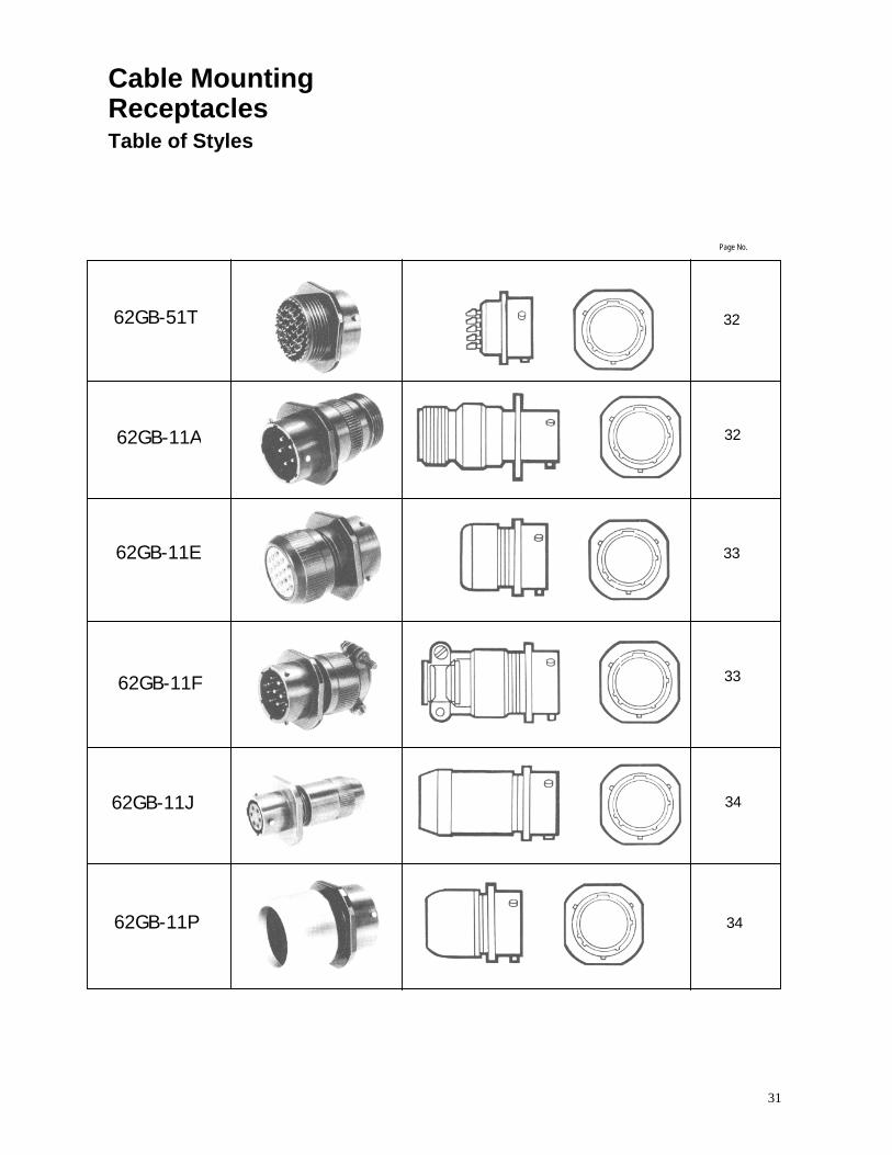
31
Cable Mounting Receptacles Table of Styles
62GB-51T
62GB-11A
62GB-11E
62GB-11F
62GB-11J
62GB-11P
Page No.
32
32
33
33
34
34

32
Cable Mounting Receptacles
51T 62GB-51T BS9522-F0017-C2101
Basic cable mounting receptacle with threaded shell to accept standard cable accessories.
Shell Size
A max
B ± 0.005 (± 0.13)
C max sq
F ± 0.005 (± 0.13)
Y dia max
X Thread
0.978 0.094 0.817 0.415 0.473 08 24.84 2.39 20.75 10.54 12.03 7/16 - 28 UNEF
0.978 0.094 0.942 0.415 0.590 10 24.84 2.39 23.93 10.54 14.99 9/16 - 24 NEF
0.978 0.094 1.036 0.415 0.750 12 24.84 2.39 26.32 10.54 19.05 11 /16 - 24 NEF
0.978 0.094 1.130 0.415 0.875 14 24.84 2.39 28.70 10.54 22.23 13/16 - 20 UNEF
0.978 0 094 1.223 0.415 1.000 16 24.84 2.39 31.07 10.54 25.40 15/16 - 20 UNEF
0.978 0.094 1.317 0.415 1.125 18 24.84 2.39 33.45 10.54 28.58 1.1/16 -18 NEF
1.048 0.102 1.442 0.535 1.250 20 26 62 2.59 36.63 13.59 31.75 1 .3/16 -18 NEF
1.048 0.102 1.567 0.535 1.375 22 26.62 2.59 39.80 13.59 34.93 1.5/16 -18 NEF
1.048 0.102 1.692 0.560 / 0.574 1.500 24 26.62 2.59 42.98 14.23 / 14.58 38.10 1.7/16 -18 NEF
11A 62GB-11A
Cable mounting receptacle with general duty back shell. No grommet supplied.
Shell Size
A max
B ± 0 005 (± 0.13)
C max sq
F ± 0.005 (± 0.13)
G dia
max
Y Dia max
M Thread
1.624 0.094 0.817 0.415 0.561 0.473 08 41.25 2.39 20.75 10.54 14.25 12.03 1/2 - 28 UNEF
1 .624 0.094 0.942 0.415 0.686 0.590 10 41.25 2.39 23.93 10.54 17.43 14.99 5/8 - 24 NEF
1.624 0.094 1.036 0.415 0.811 0.750 12 41.25 2.39 26.32 10.54 20.60 19.05 3/4 - 20 UNEF
1.624 0.094 1.130 0.415 0.936 0.875 14 41.25 2.39 28.70 10.54 23.78 22.23 7/8 - 20 UNEF
1.624 0.094 1.223 0.415 1.061 1.000 16 41.25 2.39 31.07 10 54 26.95 25.40 1 – 20 UNEF
1.624 0.094 1.317 0.415 1.186 1.125 18 41.25 2.39 33.45 10.54 30.13 28.58 1.3/16 – 18 NEF
1.687 0 104 / 0.100 1.442 0.535 1.311 1.250 20 42.85 2.64 / 2.55 36.63 13.59 33.30 31.75 1 3/16 -18 NEF
1.687 0.104 / 0.100 1.567 0.535 1.436 1.375 22 42.85 2.64 / 2.55 39.80 13.59 36.75 34.93 1.7/16 -18 NEF
1.730 0.104 / 0.100 1.692 0.569 / 0.574 1.561 1.500 24 43.94 2.64 / 2.55 42.98 14.45 / 14.58 39.65 38.10 1.7/16 -18 NEF

33
Cable Mounting Receptacles
11E 62GB-11E MIL-C-26482 MS3111E
Cable mounting receptacle with grommet and grommet nut
Shell Size
A max
B ± 0.005 (± 0.13)
C max sq
F ± 0.005 (± 0.13)
G dia max
Y dia max
1.281 0.094 0.817 0.415 0.561 0.473 08 32.54 2.39 20.75 10.54 14.25 12.031.281 0.094 0.942 0.415 0.686 0.590 10 32.54 2.39 23.93 10.54 17.43 14.99 1.281 0.094 1.036 0.415 0.811 0.750 12 32.54 2.39 26.32 10.54 20.60 19.05 1.281 0.094 1.130 0.415 0.936 0.875 14 32.54 2.39 28.70 10.54 23.78 22.231.281 0.094 1.223 0.415 1.061 1.000 16 32.54 2.39 31.07 10.54 26.95 25.401.281 0.094 1.317 0.415 1.186 1.125 18 32.54 2.39 33.45 10.54 3013 28.58 1.383 0.102 1.442 0.535 1.311 1.250 20 35.13 2.59 36.63 13.59 33.30 31.751.383 0.102 1.567 0.535 1.436 1.375 22 35.13 2.59 39.80 13.59 36.75 34.931.383 0.102 1.692 0.569 / 0.574 1.561 1.500 24 35.13 2.59 42.98 14.45 / 14.58 39.65 38.10
62GB-11F MIL-C-26482 MS3111F
Cable mounting receptacle with grommet and grommet nut fitted with integral strain relief clamp
Shell Size
A max
B ± 0.005 (± 0.13)
C max sq
F ± 0.005 (± 013)
G dia max
H ± 0.005 (± 0.13)
Y dia max
08 1.762 0.094 0.817 0.415 0.828 0.156 0.473 44.75 2.39 20.75 10.54 21.03 3.96 12.03
10 1.762 0.094 0.942 0 415 0.891 0.188 0.590 44.75 2.39 23.93 10.54 22.63 4.78 14.99
12 1.762 0.094 1.036 0.415 1.016 0.312 0.750 44.75 2.39 26.32 10.54 25.81 7.93 19.05
14 1.736 0.094 1.130 0.415 1.141 0.375 0.875 44.10 2.39 28.70 10.54 28.97 9.53 22.23
16 1.876 0.094 1.223 0.415 1.203 0.500 1.000 47.65 2.39 31.07 10.54 30.56 12.7 25.40
18 1.876 0.094 1.317 0.415 1.426 0.625 1.125 47.65 2.39 33.45 10.54 36.22 15.88 28.58
20 2.118 0.104 / 0.100 1.442 0.535 1 .426 0.625 1.250 53.80 2.64 / 2.55 36.63 13.59 36.22 15.88 31.75
22 2.118 0.104 / 0.100 1.567 0.535 1.567 0.750 1.375 53.80 2.64 / 2.55 39.80 13.59 39.80 19.05 34.93
24 2.250 0.104 / 0.100 1.692 0.569 / 0.574 1.735 0.800 1.500 57.15 2.64 / 2.55 42.98 14.45 / 14.58 44.07 20.32 38.10
11F
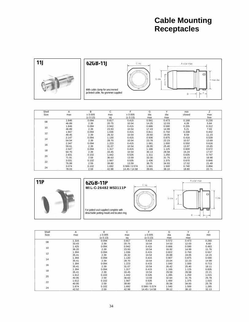
34
Cable Mounting Receptacles
11J 62GB-11J
With cable clamp for unscreened jacketed cable. No grommet supplied
Shell Size
A max
B ± 0.005 (± 0.13)
C max sq
F ± 0.005 (± 0.13)
G dia max
Y dia
max
min closed
Z max free
1.846 0.094 0.817 0.415 0.561 0.473 0.168 0.230 08 46.89 2.39 20.75 10.54 14.25 12.03 4.28 5.841.846 0.094 0.942 0.415 0.686 0.590 0.205 0.312 10 46.89 2.39 23.93 10.54 17.43 14.99 5.21 7.93 1.947 0.094 1.036 0.415 0.811 0.750 0.338 0.442 12 49.45 2.39 26.32 10.54 20.60 19.05 8.59 11.23 2.147 0.094 1.130 0.415 0.936 0.875 0.416 0.539 14 54.54 2.39 28.70 10.54 23.78 22.23 10.57 13.692.347 0.094 1.223 0.415 1.061 1.000 0.550 0.616 16 59.61 2.39 31.07 10.54 26.95 25.40 13.97 15.652.547 0.094 1.317 0.415 1.186 1.125 0.600 0.672 18 64.70 2.39 33.45 10.54 30.13 28.58 15.24 17.07 2.831 0.102 1.442 0.535 1.311 1.250 0.635 0.747 20 71.91 2.59 36.63 13.59 33.30 31.75 16.13 18.98 3.031 0.102 1.567 0.535 1.436 1.375 0.670 0.846 22 76.99 2.59 39.80 13.59 36.75 34.93 17.02 21.493.074 0.102 1.692 0.569 / 0.574 1.561 1.500 0.740 0.894 24 78.03 2.59 42.98 14.45 / 14.58 39.65 38.10 18.80 22.71
11P 62GB-11P MIL-C-26482 MS3111P
For potted seal supplied complete with detachable potting mould and location ring
Shell Size
A max
8 ± 0.005 (± 0.13)
C max sq
F ± 0.005 (± 0.13)
G dia max
Y dia max
Z min
1.316 0.094 0.817 0.415 0.572 0.473 0.260 08 33.43 2.39 20.75 10.54 14.53 12.03 6.601.425 0.094 0.942 0.415 0.666 0.590 0.463 10 36.20 2.39 23.93 10.54 16.92 14.99 11.76 1.394 0.094 1.036 0.415 0.822 0.750 0.557 12 35.41 2.39 26.32 10.54 20.88 19.05 14.15 1.394 0.094 1.130 0.415 0.907 0.875 0.590 14 35.41 2.39 28.70 10.54 23.04 22.23 14.991.394 0.094 1.223 0.415 1.040 1.000 0.713 16 35.41 2.39 31.07 10.54 26.42 25.40 18.111.394 0.094 1.317 0.415 1.165 1.125 0.835 18 35.41 2.39 33.45 10.54 29.59 28.58 22.21 1.612 0.102 1.442 0.535 1.285 1.250 1.015 20 40.95 2.59 36.63 13.59 32.64 31.75 25.781.612 0.102 1.567 0.535 1.400 1.375 1.015 22 40.95 2.59 39.80 13.59 35.56 34.93 25.781.674 0.102 1.692 0.569 / 0.574 1.540 1.500 1.265 24 42.52 2.59 42.98 14.45 / 14.58 39.12 38.10 32.13
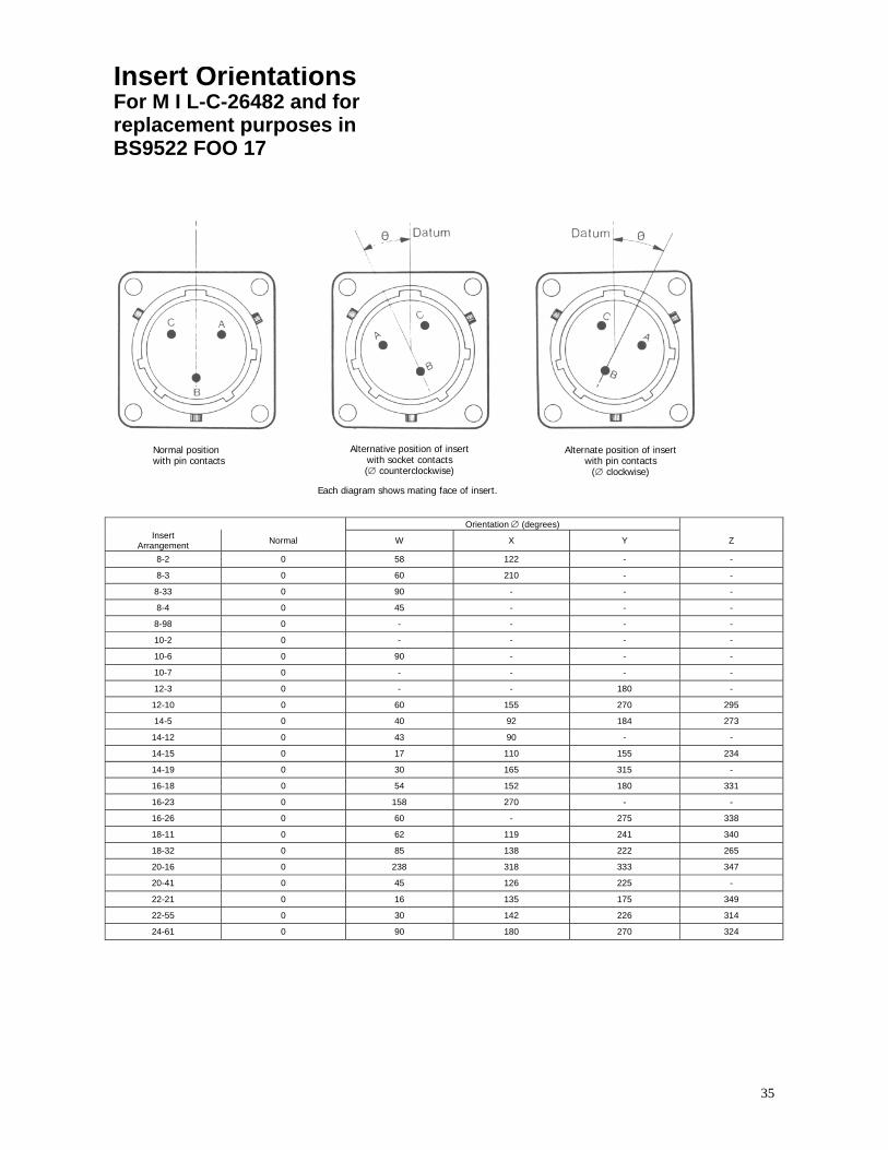
35
Insert Orientations For M I L-C-26482 and for replacement purposes in BS9522 FOO 17
Normal position with pin contacts
Alternative position of insertwith socket contacts (∅ counterclockwise)
Each diagram shows mating face of insert.
Alternate position of insert with pin contacts
(∅ clockwise)
Orientation ∅ (degrees) Insert
Arrangement Normal W X Y Z
8-2 0 58 122 - -
8-3 0 60 210 - -
8-33 0 90 - - -
8-4 0 45 - - -
8-98 0 - - - -
10-2 0 - - - -
10-6 0 90 - - -
10-7 0 - - - -
12-3 0 - - 180 -
12-10 0 60 155 270 295
14-5 0 40 92 184 273
14-12 0 43 90 - -
14-15 0 17 110 155 234
14-19 0 30 165 315 -
16-18 0 54 152 180 331
16-23 0 158 270 - -
16-26 0 60 - 275 338
18-11 0 62 119 241 340
18-32 0 85 138 222 265
20-16 0 238 318 333 347
20-41 0 45 126 225 -
22-21 0 16 135 175 349
22-55 0 30 142 226 314
24-61 0 90 180 270 324

36
Key/Keyway Orientations For BS9522 F0017
Datum is always taken from major key or keyway. In receptacles the major keyway always remains fixed in relation to the mounting flange. For the A',B,C,D',E and F orientations, the three bayonet locations and associated minor keyways are rotated complete, in accordance with the table below.
N.B.- The accompanying diagram shows a receptacle shell, with keyways. Corresponding key orientations for a mating plug shell are therefore always clockwise.
Shell Size Values for ∝
(degrees) Values for θ (degrees) Values for β
(degrees)
N A* B C D* E F N A* B C D* E F N A* B C D* E F 8 105 92 - - 118 118 82 35 35 - - 35 30 50 75 75' - - 75 100 75
10 105 95 85 125 115 115 85 35 35 35 35 35 30 50 75 75 75 75 75 100 75 12 105 97 89 121 113 115 85 35 35 35 35 35 30 50 75 75 75 75 75 100 75 14 105 98 91 119 112 75 120 35 35 35 35 35 30 50 75 75 75 75 75 100 75 16 105 99 93 117 111 75 120 35 35 35 35 35 30 50 75 75 75 75 75 100 75 18 105 100 95 115 110 75 120 35 35 35 35 35 30 50 75 75 75 75 75 100 75 20 105 100 95 115 110 75 120 35 35 35 35 35 30 50 75 75 75 75 75 100 75 22 105 101 97 113 109 7S 120 35 35 35 35 35 30 50 75 75 75 100 75 75 75 24 105 101 97 113 109 75 120 35 35 35 35 35 30 50 75 75 75 75 75 100 75
Shell Size
Values for ϕ (degrees) Orientation
Values for ω (degrees) Orientation
N A* B C D* E F N A* B C D* E F 8 50 50 50 50 50 30 45 60 47 - - 73 73 47 10 50 50 50 50 50 30 45 60 50 40 80 70 70 50 12 50 50 50 50 50 30 45 60 52 44 76 68 70 50 14 50 50 50 50 50 30 35 60 53 46 74 67 30 75 16 50 50 50 50 50 30 35 60 54 48 72 66 30 75 18 50 50 50 50 50 30 35 60 55 50 70 65 30 75 20 50 50 50 50 50 30 35 60 55 50 70 65 30 75 22 50 50 50 50 50 30 35 60 56 52 68 64 30 75 24 50 50 50 50 50 30 35 60 56 52 68 64 30 75
* now inactive for new designs but available for replacement purposes. Superseded in BS9522 F0017 by orientations E and F.

37
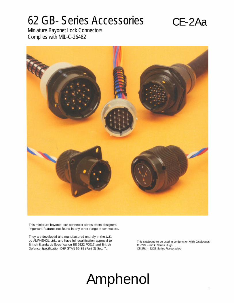
1
62 GB- Series Accessories Miniature Bayonet Lock Connectors Complies with MIL-C-26482
CE-2Aa
This miniature bayonet lock connector series offers designers important features not found in any other range of connectors. They are developed and manufactured entirely in the U.K. by AMPHENOL Ltd., and have full qualification approval to British Standards Specification BS 9522 F0017 and British Defence Specification DEF STAN 59-35 (Part 3) Sec. 7.
Amphenol
This catalogue to be used in conjunction with Catalogues: CE-2Pa – 62GB Series Plugs CE-2Ra – 62GB Series Receptacles

CONTENTS Page Amphenol 62GB Solder Connectors 3
Schedule of Tests 4-5
Accessories - Table of Styles 6-7
Accessories 8-14
Cable Accessories - Table of Styles 15-16
Cable Accessories 17-21
3
Amphenol ® 62GB solder connectors
This miniature bayonet lock connector series offers designers important features not found in any other range of connectors. The range has full qualification approval to British Standards Specification BS 9522 FOO 17 and British Defence Specification DEF STAN 59-35 (Part 3) Sec. 7.
62GB Series connectors - developed and manufactured
entirely in the United Kingdom by Amphenol Limited. They are the first and only British connectors to have achieved this. A doubly strong position which Amphenol are well geared to handle. The manufacturing facilities of the Whitstable plant have been cited as exemplary in Europe. Certainly the layout is extensive and extremely efficient; safety awards have been attained every time returns have been submitted to the British Safety Council.
62GB Series connectors have been well established with
Government authorities on an international scale and users can be found in Sweden, Denmark, Norway, Finland, Germany, Spain, Holland, India, Canada and Italy.
Derating
Connectors must be derated under the following operating conditions:
1. At elevated ambient temperatures, the current ratings
are reduced so that total maximum hot spot temperature of 125°C is not exceeded.
2. At high altitudes, revised voltage ratings become
effective as shown on page 7. 3. When connectors to different specifications are
intermated (e.g. BS 9522 FOO 17 and MIL-C26482), the combination must not be operated under conditions more severe than the less stringent clause of either specification.
Amphenol 62GB connectors are designed to meet the most stringent requirements of both specifications.
Military Specifications
British Standards Specification BS 9522 FOO 17 closely corresponds to the United States Military Specification MIL-C-26482 solder terminations. Certain differences exist between the schedules which can be seen on pages 2 and 3.
Approved gauges are used to check interchangeability of 62GB series with other connectors manufactured to BS 9522 FOO 17 or MIL-C-26482.
Basic Construction 62GB Series can be supplied in brass or stainless steel. The normal shell finish used, which has a high resistance to corrosion, is zinc cobalt olive drab. Other finishes may be supplied to special order, such as cadmium plate which is available by adding deviation (714) to the end of part number. Inserts are of polychloroprene rubber compounded to an Amphenol specification. Operating temperature range is -55°C to 125°C, and the connectors have gold-plated contacts designed for soldered connections. Configurations for size 20 contacts range between 2 contacts in the size 8 12.7mm (0.5in diameter) shell up to a maximum of 61 contacts in the size 2436.1 mm (1.5in diameter) shell. Intermediate sizes, and contact data for heavier current ratings are shown in the insert availability chart on page 6 and 7.
Hermetic connectors with glass sealed dialectric are manufactured with mild steel shells and nickel iron contacts plated tin over copper.
* Other finishes are available on request. Protection Against Mis-Mating or Cross-Plugging
In BS 9522 FOO 17 positive shell-to-shell keying is provided with keys and keyways in a choice of either the normal (N) or any of the four preferred alternate positions: B, C, E and F. This prevents mismating between shells of different orientations and overcomes the difficulties associated with rotated inserts and a standard key-keyway orientation. In the latter system, damage to the inserts or contacts can result if excessive force is used to engage non-mating pairs.
Rotated inserts are, however, permissible in BS 9522 FOO 17 connectors if required to mate with or replace units to MIL-C-26482 mounted in existing equipment. Connectors have normal orientations manufactured to BS 9522 FOO 17 or MIL-C-26482 are fully intermateable as also are connectors with inserts in positions W, X, Y or Z.
This catalogue to be used in conjunction with Catalogues: CE-2Pa – 62GB Series Plugs CE-2Ra – 62GB Series Receptacles

4
Schedule of Tests Required for Qualification Approval
Tests
Visual Examination Dimensions, outline mass(including contacts) Compatability Gauging procedure Polarization Engaging and separating force, connector Contact Holding Force Sealing (air pressure) Sealing Hermetic Contact Resistance Housing (Shell) Continuity Insulation Resistance Voltage Proof Soldering Bumping Vibration Shock Acceleration (Steady State) Rapid Change of Temperature Climatic Sequence Flammability Damp Heat (Steady State)
Brief Description
Engagement max: 0,90 Nm (8.0 lbf.in.) to 4,97 Nm (44 lbf.in.) according to shell size. Separation min: 0,22 Nm (2.0 lbf.in.) to 1,58 Nm (14.0 lbf.in.) according to shell size. 0,21 N (0.047 lbf) min.size 20 0,56 N (0.126 lbf)min. size 16 Max leakage 28,53 uNm/s (1 cm3/h), 1 bar (14.5 p.s.i.) differential. Hermetic receptacles have a max leak of 0.1 micron cubic foot per hour (1 x 10⁻⁶Cm3/s) 5 milliohms max. 200 milliohms max. 5 milliohms max. grounding spring styles. 5,000 Megaohms at 500 - 50 V d.c. See page 7. Duration 1 minute As BS 9520: 1974, Clause 1.2.6.6, Method 2. As BS 9520: 1974, Clause 1.2.6.1. 4,000 -10 bumps / 390m / s2 (40 gn). As BS 9520: 1974, Clause 1.2.6.2.1. Procedure A. 10 Hz to 5000 Hz, 0.75 mm / 10 gn. As BS 9520: 1974, Clause 1.2.6.3. 981 m/s2 (100 g n). As BS 9520: 1974, Clause 1.2.6.4. 490 m/s2 (50 gn). As BS 9520: 1974, Clause 1.2.6.7. -550 C to - 1250 C. As BS 9520: 1974, Clause 1.2.6.11. Severity 55/125/56. As BS 9520: 1974, Clause 1.2.6.8. Direct flame applied, duration 1 minute. As BS 9520: 1974, Clause 1.2.6.14. Severity 56 days.

5
Schedules of Tests Required for Qualification Approval
Tests Brief Description
Immersion (at low air pressure) Mechanical Endurance High Temperature Endurance Mould Growth Salt Mist Dust Robustness of Terminations Contact Retention (in insert) Insert Retention (in shell) Test Prod Damage Impact Grounding Spring Holding Force Plugs with grounding springs only. Fluid Resistance Compass Safe Distance
3 cycles at 30 mins each cycle, total immersion in water at pressure 44 m bar. 500 operations minimum Long term: 1,000 hrs. at 850C ambient carrying the specified current. Short term: 250 hrs at 1250 C, no current. As BS 9520: 1983, Clause 1.2.6.16. 28 days duration. As BS 9520: 1983, Clause 1.2.6.17. Severity 1. As BS 9520: 1983, Clause 1.2.6.18 Exposure 30 minutes. 44,5 N (101bf) size 16 22,2 N (5 lbf) size 20 67,0 N (15 lbf) min. size 20 112,0 N (25 lbf) min. size 16 517 KN1m2 (751bf/in2) min. Moment: 0,056 Nm (0.5 lbf in) size 20 0,225 Nm (2 lbf in) size 16 Five impacts, drop height 1 m (3ft.3 in.). 1,17 N (0.263 lbf) to 2,74 N (0.616 lbf) according to size. Immersion in 4 solvents and 9 fluids including aircraft fuels, lubricating oils and hydraulic fluids. As BS 9520: 1974, Clause 1.2.5.11. 127 mm (5.0 in) min.

6
Accessories Table of Styles
62GB-738
62GB-812
62GB-813
Page No.
42
42
43
43
44
44
45
62GB-737
62GB-736
62GB-742
62GB-810
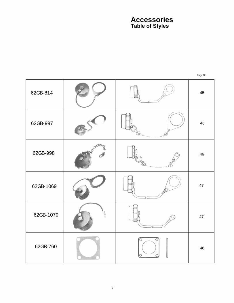
7
Accessories Table of Styles
62GB-814
62GB-997
62GB-998
62GB-1069
62GB-1070
62GB-760
Page No.
45
46
46
47
47
48

8
Accessories
736 62GB-736
Caps and chains for single hole mounting receptacles
Shell Size
A ± 0.25
(± 6.35)
B ± 0.005 (± 0.13)
C dia max
J ± 0.005
(± 0,127) 3.0 0.521 0.734 0.578 08 76.2 13.23 18.64 14.683.0 0.521 0.859 0.703 10 76.2 13.23 21.82 17.863.5 0.521 1.000 0.891 12 88.9 13.23 25.4 22.63 3.5 0.521 1.125 1.016 14 88.9 13.23 28.57 25.81 3.5 0.521 1.250 1.141 16 88.9 13.23 31.75 29.393.5 0.521 1.375 1.266 18 88.9 13.23 34.92 32.16 4.0 0.521 1.500 1.391 20 101.6 13.23 38, 1 35.33 4.0 0.521 1.625 1.516 22 101.6 13.23 41.27 38.51 4.0 0.556 1.750 1 .641 24 101.6 14.12 44.45 41.68
737 62GB-737
Caps and chains for cable mounting receptacles.
Shell Size
A ± 0.25
(± 6.35)
B ± 0.005 ( ± 0.13)
C dia max
J ± 0.005
(± 0.127) 3.0 0.521 0.734 0.458 08 76.2 13.23 18.64 11.63 3.0 0.521 0.859 0.583 10 76.2 13.23 21.82 14.813.5 0.521 1.000 0.708 12 88.9 13.23 25.4 17.98 3.5 0.521 1.125 0.896 14 88.9 13.23 28.57 22.76 3.5 0.521 1.250 1.021 16 88.9 13.23 31.75 25.933.5 0.521 1.375 1.146 18 88.9 13.23 34.92 29.114.0 0.521 1.500 1.271 20 101.6 13.23 38.1 32.28 4.0 0.521 1.625 1.396 22 101.6 13.23 41.27 35.46 4.0 0.556 1.750 1.521 24 101.6 14.12 44.45 38.63
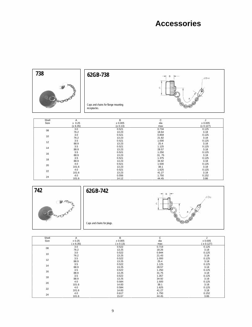
9
Accessories
738 62GB-738
Caps and chains for flange mounting receptacles.
Shell Size
A ± 0.25 (± 6.35)
B ± 0.005 (± 0.13)
C dia max
J ± 0.005
(± 0.127) 3.0 0.521 0.734 0.125 08 76.2 13.23 18.64 3.183.0 0.521 0.859 0.125 10 76.2 13.23 21.82 3.18 3.5 0.521 1.000 0.125 12 88.9 13.23 25.4 3.18 3.5 0.521 1.125 0.125 14 88.9 13.23 28.57 3.183.5 0.521 1.250 0.125 16 88.9 13.23 31. 75 3.183.5 0.521 1.375 0.125 18 88.9 13.23 34.92 3.18 4.0 0.521 1.500 0.125 20 101.6 13.23 38.1 3.18 4.0 0.521 1.625 0.125 22 101.6 13.23 41.27 3.184.0 0.556 1.750 0.152 24 101.6 14.12 44.45 3.86
742 62GB-742
Caps and chains for plugs.
Shell Size
A ± 0.25
( ± 6.35)
B ± 0.005 ( ± 0.13)
C dia max
J ± 0.005
( ± 0.127) 3.0 0.522 0.719 0.125 08 76.2 13.25 18.26 3.183.0 0.522 0.844 0.125 10 76.2 13.25 21.43 3.18 3.5 0.522 1.000 0.125 12 88.9 13.25 25.4 3.18 3.5 0.522 1.125 0.125 14 88.9 13.25 28.57 3.183.5 0.522 1.250 0.125 16 88.9 13.25 31.75 3.18 3.5 0.522 1.357 0.125 18 88.9 13.25 34.92 3.18 4.0 0.584 1.500 0.125 20 101.6 14.83 38.1 3.184.0 0.584 1.625 0.125 22 101.6 14.83 41.27 3.184.0 0.617 1.750 0.152 24 101.6 15.67 44.45 3.86
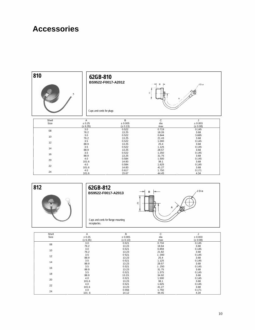
10
Accessories
810 62GB-810 BS9522-F0017-A2012
Caps and cords for plugs
Shell Size
A ± 0.25
(± 6.35)
B ± 0.005 (± 0.13)
C dia max
J ± 0.003 (± 0.08)
3.0 0.522 0.719 0.145 08 76.2 13.25 18.26 3.68 3.0 0.522 0.844 3.685 10 76.2 13.25 21.43 3.68 3.5 0.522 1.000 0.145 12 88.9 13.25 25.4 3.68 3.5 0.522 1.125 0.145 14 88.9 13.25 28.57 3.68 3.5 0.522 1.250 0.145 16 88.9 13.25 31.75 3.68 4.0 0.584 1.500 0.145 20 101.6 14.83 38.1 3.68 4.0 0.584 1.625 0.145 22 101.6 14.83 41.27 3.68 4.0 0.617 1.750 0.171 24 101.6 15.67 44.45 4.34
812 62GB-812 BS9522-F0017-A2013
Caps and cords for flange mounting receptacles.
Shell Size
A ± 0.25
(± 6.35)
B ± 0.005 (± 0.13)
C dia
max
J ± 0.003 (± 0.08)
3.0 0.521 0.734 0.145 08 76.2 13.23 18.64 3.68 3.0 0.521 0.859 0.145 10 76.2 13.23 21.82 3.68 3.5 0 521 1 .000 0.145 12 88.9 13.23 25.4 3.68 3.5 0.521 1.125 0.145 14 88.9 13.23 28.57 3.68 3.5 0.521 1 .250 0.145 16 88.9 13.23 31.75 3.68 3.5 0.521 1.375 0.145 18 88.9 13.23. 34.92 3.68 4.0 0.521 1.500 0.145 20 101.6 13.23 38.1 3.68 4,0 0.521 1.625 0.145 22 101.6 13.23 41.27 3.68 4.0 0.556 1.750 0.171 24 101 .6 14.12 44.45 4.34

11
Accessories
813 62GB-813 BS9522-F0017 A2014
Caps and cords for single hole mounting receptacles.
Shell Size
A ± 0.25
(± 6.35)
B ± 0.005 (± 0.13)
C max
J + 0.010 (+ 0.25)
3.0 0.521 0.734 0.578 08 76.2 13.23 18.64 14.68 3.0 0.521 0.859 0.703 10 76.2 13.23 21.82 17.86 3.5 0.521 1.000 0.891 12 88.9 13.23 25.4 22.633.5 0.521 1.125 1.016 14 88.9 13.23 28.57 25.813.5 0.521 1.250 1.141 16 88.9 13.23 31.75 29.39 3.5 0.521 1.375 1.266 18 88.9 13.23 34.92 32.164.0 0.521 1.500 1.391 20 101.0 13.23 38.1 35.334.0 0.521 1.625 1.516 22 101.6 13.23 41.27 38.56 4.0 0.556 1.750 1.641 24 101.6 14.12 44.45 41.68
814 62GB-814
Caps and cords for cable mounting receptacles.
Shell Size
A ± 0.25
( ± 6.35)
B ± 0.005 ( ± 0.13)
C max
J +0.010
( + 0.25) 3.0 0.521 0.734 0.453 08 76.2 13.23 18.64 11.50 3.0 0.521 0.859 0.578 10 76.2 13.23 21.82 14.643.5 0.521 1.000 0.703 12 88.9 13.23 25.4 17.853.5 0.521 1.125 0.891 14 88.9 13.23 28.57 22.63 3.5 0.521 1.250 1.016 16 88.9 13.23 31.75 25.80 3.5 0.521 1.375 1.141 18 88.9 13.23 34.92 28.984.0 0.521 1.500 1.266 20 101.6 13.23 38.1 32.15 4.0 0.521 1.625 1.391 22 101.6 13.23 41.27 35.33 4.0 0.556 1.750 1.516 24 101.6 14.12 44.45 38.50
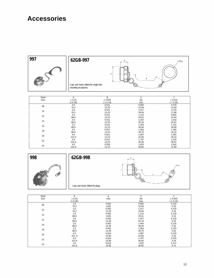
12
Accessories
997 62GB-997
Caps and chains ribbed for single hole mounting receptacles.
Shell Size
A ± 0.25
(± 6.35)
B ± 0.005 ( ± 0.13)
C dia max
J + 0.010 ( + 0.25)
3.0 0.521 0.892 0.578 08 76.2 13.23 22.66 14.693.0 0.521 1.017 0.703 10 76.2 13.23 26.84 17.86 3.5 0.521 1.142 0.891 12 88.9 13.23 29.01 22.64 3.5 0.521 1.267 1.016 14 88.9 13.23 32.19 25.813.5 0.521 1.454 1.141 16 88.9 13.23 36.94 28.993.5 0.521 1.563 1.266 18 88.9 13.23 39.70 32.16 4.0 0.521 1.687 1.391 20 101.6 13.23 42.85 35.34 4.0 0.521 1.797 1.516 22 101.6 13.23 45.65 38.514.0 0.556 1.922 1.641 24 101.6 14.12 48.82 41.69
998 62GB-998
Caps and chains ribbed for plugs.
Shell Size
A ± 0.25
(± 6.35)
g max
C dia max
J ± 0.005 ( ± 0.13)
3.0 0.562 0.892 0.125 08 76.2 1428 22.66 3.18 3.0 0.562 1.017 0.125 10 76.2 14.28 25.84 3.18 3.5 0.562 1.142 0.125 12 88.9 1428 29.01 3.183.5 0.562 1.267 0.125 14 88.9 14.28 32.19 3.18 3.5 0.562 1.454 0.125 16 88.9 14.28 36.94 3.18 3.5 0.562 1.563 0.125 18 88.9 14.28 39.70 3.18 4.0 0.624 1.687 0.125 20 101 .6 15.85 42.85 3.184.0 0.624 1.797 0.125 22 101.6 15.85 45.65 3.18 4.0 0.624 1.922 0.147 24 101.6 15.85 48.82 3.74
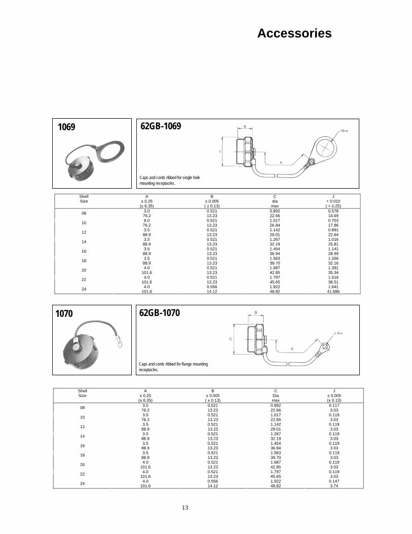
13
Accessories
1069 62GB-1069
Caps and cords ribbed for single hole mounting receptacles.
Shell Size
A ± 0.25
(± 6.35)
B ±.0.005 ( ± 0.13)
C dia max
J + 0.010 ( + 0.25)
3.0 0.521 0.892 0.578 08 76.2 13.23 22.66 14.69 8.0 0.521 1.017 0.703 10 76.2 13.23 26.84 17.863.5 0.521 1.142 0.891 12 88.9 13.23 29.01 22.643.5 0.521 1.267 1.016 14 88.9 13.23 32.19 25.81 3.5 0.521 1.454 1.141 16 88.9 13.23 36.94 28.99 3.5 0.521 1.563 1.266 18 88.9 13.23 39.70 32.164.0 0.521 1.687 1.391 20 101.6 13.23 42.85 35.34 4.0 0.521 1.797 1.516 22 101.6 13.23 45.65 38.51 4.0 0.556 1.922 1.641 24 101.6 14.12 48.82 41.686
1070 62GB-1070
Caps and cords ribbed for flange mounting receptacles.
Shell Size
A ± 0.25
(± 6.35)
B ± 0.005 ( ± 0.13)
C Dia max
J ± 0.005 (± 0.13)
3.0 0.521 0.892 0.117 08 76.2 13.23 22.66 3.03 3.0 0.521 1.017 0.119 10 76.2 13.23 22.66 3.03 3.5 0.521 1.142 0.119 12 88.9 13.23 29.01 3.033.5 0.521 1.267 0.119 14 88.9 13.23 32.19 3.03 3.5 0.521 1.454 0.119 16 88.9 13.23 36.94 3 03 3.5 0.521 1.563 0.119 18 88.9 13.23 39.70 3.034.0 0.521 1.687 0.119 20 101.6 13.23 42.85 3.034.0 0.521 1.797 0.119 22 101.6 13.23 45.65 3.03 4.0 0.556 1.922 0.147 24 101.6 14.12 48.82 3.74

14
Accessories
760 62GB-760
Flange mounting gasket for box mounting and hermetic receptacles.
Shell Size
0 ± 0.010
(± 0.254)
E ± 0.010
(± 0.254)
F ± 0.008 (± 0.20)
G + 0.010
(+ 0.254)
H
0.812 0.594 0.508 0.130 0.042 / 0.016 08 20.62 15.08 12.90 3.30 1.06 / 0.40 0.938 0.719 0.633 0.130 0.042 / 0.016 10 23.82 18.26 16.07 3.30 1.06 / 0.40 1.031 0.813 0.758 0.130 0.042 / 0.016 12 26.18 20.65 19.25 3.30 1.06 / 0.401.125 0.906 0.883 0.130 0.042 / 0.016 14 28.57 23.01 22.42 3.30 1.06 / 0.401.219 0.969 1.008 0.130 0.042 / 0.016 16 30.96 24.61 25.60 3.30 1.06 / 0.40 1.312 1.063 1.133 0.130 0.042 / 0.016 18 33.32 27.00 28.77 3.30 1.06 / 0.40 1.438 1.156 1.258 0.130 0.042 / 0.016 20 36.52 29.36 31.95 3.30 1.06 / 0.401.563 1.250 1.383 0.130 0.042 / 0.016 22 39.70 31.75 35.13 3.30 1.06 / 0.40 1.688 1.375 1.508 0.156 0.042 / 0.016 24 42.87 34.92 38.30 3.96 1.06 / 0.40

15
Cable AccessoriesTable of Styles
62GB-584
62GB-585
62GB-586
62GB-587
62GB-711
62GB-720
62GB-776
Page No.
51
51
52
52
53
53
54

16
Cable Accessories Table of Styles
62GB-1225
62GB-5028
Page No.
54
55

17
Cable Accessories
584 62GB - 584 - XX - XXS or P BS 9522 FOO 17 A2102
Grommet seal and nut. Provides an environmental seal for the exposed solder buckets in the openback class T shells.
Suffix XX - XXS or P enables grommet to be matched to the insert arrangement.
Shell Size
A G max
0.545 0.561 08 13.84 14.25 0.545 0.686 10 13.84 17.43 0.545 0.811 12 13.84 20.60 0.545 0.936 14 13.84 23.78 0.545 1.061 16 13.84 26.95 0.545 1.186 18 13.84 30.13 0.545 1.311 20 13.84 33.30 0.545 1.436 22 13.84 36.75 0.501 1.561 24 12.73 39.65
585 62G B - 585 - XX - XXS or P BS9522 FOO 17 A2103
Grommet and nut with strain relief clamp. The clamp prevents the flexing of the wires in the immediate vicinity of the risers, so avoiding the risk of leaks. Suffix XX - XXS or P enables grommet to be matched to the insert
arrangement.
Shell Sine
A max
G max
max
0.991 0 828 0.161 08 25.17 21.03 4.090.991 0.891 0.193 10 25.17 22.63 4.90 0 991 1.016 0.317 12 25.17 25.81 8.05 0.965 1.141 0.380 14 24.51 28.98 9.651.105 1.203 0.505 16 28.07 30.56 12.83 1.105 1.426 0.630 18 28.07 36.22 16.00 1.285 1.426 0.630 20 32.64 36.22 16.001.285 1.567 0.755 22 32.64 39.80 19.181.373 1.735 0.805 24 34.88 44.07 20.45

18
Cable Accessories
586 62G B - 586 - XX
Potting mould and ring, supplied together as a set.
Suffix XX specifies shell size.
Shell Size
A max
G max
Z min
0.644 0.585 0.260 08 16.36 14.85 6.600.753 0.679 0.463 10 19.13 17.24 11.760.722 0.835 0.557 12 18.34 21.20 14.14 0.722 0.913 0.590 14 18.34 23.19 14.98 0.722 1.038 0.713 16 18.34 26.36 18.110.722 1.163 0.835 18 18.34 29.54 21.200 877 1.288 1.015 20 22 30 32.71 25.78 0.877 1.413 1.015 22 22.30 35.89 25.780.896 1.538 1.263 24 22.76 39.06 32.08
587 62G B - 587 - XX - XXS or P
Clamp for screened jacketed cable. 62 Series only with grommet. Effective sealing is provided over the range of cables covered by DEF 10(Pattern C) and DEF STAN 61-12 port (see table). These are supplied to separate order only for use with style T shells. Suffix XX-XXS or P enables grommet to be matched to the
insert arrangement.
Shell Size
length Including
plug
A Max
length Including
receptacle
B max
G max
2.732 2.742 0.676 0.775 08 69.39 69.64 17.17 19.682.742 2.752 0.676 0.902 10 69.64 69.90 17.17 22.913.152 3162 0.812 1.030 12 80.06 80.31 20.62 2616 3.152 3.162 0.926 1.157 14 80.06 80.31 23.52 29.393.272 3 282 1.051 1.284 16 83.10 83.36 26.67 32.61
- - - - 18 - - - - 3.272 3.345 1.280 1.539 20 83.10 84.96 32.51 39.09
- - - - 22 - - - - 3.696 3.768 1.620 1.783 24 93.87 95.70 41.15 45.29

19
Cable Accessories
711 62G B - 711 - XX - XXS or P
Grommet and nut with right angled strain relief clamp. The clamp prevents flexing of the wires in the immediate vicinity of the risers, so avoiding the risk of leaks (these are supplied to separate order only for use with style T shells).
Suffix XX - XXS or P enables grommet to be matched to the insert arrangement.
Shell Size
A max
G max
H ± 0.005 ± 0.13
Q max
1.5/32 0.828 0.161 0.733 08 21.03 4.09 18.62 1.3/16 0.891 0.193 0.795 10 22.63 4.90 20.19 1.7/32 1.016 0.317 0.858 12 25.81 8.05 21.79 1.1/4 1.141 0.380 0.915 14 28.98 9.65 23.24 1.5/16 1.203 0.505 1.010 16 30.56 12.83 25.65 1.3/8 1.426 0.630 1.070 18 36.22 16.00 27.18 1.3/8 1.426 0 630 1.140 20 36.22 16.00 28.96
1.29/64 1.567 0.755 1.170 22 39.80 19.18 29.72 1.15/32 1.735 0.805 1.260 24 44.07 20.45 32.00
720 62G B - 720 - XX
Clamp for unscreened jacketed cable. No grommet is supplied, for use with 50T, 51T and 56T styles. Suffix XX specifies shell size.
Shell Size
A max
G max
Z closed
Z free
1.085 0.561 0 168 0 230 08 27.56 14.25 4.28 5.84 1.060 0.686 0.205 0.312 10 26.92 17.43 5.21 7.93 1.160 0.81 1 0 338 0.442 12 29.46 20.60 8.59 1 1.23 1.360 0.936 0.416 0.539 1 14 34.54 23.78 10.57 13.69 1.585 1.061 0.550 0.616 16 40.26 26.95 13.97 15.65 1.785 1.186 0.600 0.672 18 45.34 30.13 15.24 17.57 1.981 1.311 0.635 0.747 20 50.32 33 30 16.13 18.98 2.181 1.436 0.670 0.846 22 55.39 36.75 17.02 21.49 2.216 1.561 0.740 0.894 24 56.28 39.65 18.80 22.71

20
Cable Accessories
776 62GB - 776
General duty shell to accept conduit, AN 3057 or MS 3057 A cable clamps and heat shrink sleeves.
Shell Size
A max M
Thread
0.937 1/2 - 28 UNEF 08 23.80 0.937 5/8 - 24 NEF 10 23.80 0.937 3/4 - 20 UNEF 12 23.80 0.937 7/8 – 20 UNEF 14 23.80 0.937 1 - 20 UNEF 16 23.80 0.937 1.3/16 - 18 NEF 18 23.80 0.937 1.3/16 - 18 NEF 20 23.80 0.937 1.7/16 - 18 NEF 22 23.80 0.937 1.7/16 - 18 NEF 24 23.80
1225 62GB - 1225
900 clamp for screened jacketed cable. These are supplied to separate order only for use with style T shells.
Shell Size
A max
B max
C max
D max
0.942 0.821 1.160 0.636 08 23.93 20.85 29.46 16.15 0.883 0.821 1.160 0.636 10 22.43 20.85 29.46 16.15 0.704 0.821 1.160 0.636 12 17,88 20.85 29.46 16.15 1.119 0.937 1.160 0.636 14 28.42 23.80 29.46 16.15

21
Cable Accessories
5028 62G B - 5028 - XX - XXS or P
75% Clamp for screened jacketed cable with grommet. Effective sealing is provided over the range of cables covered by DEF 10 (Pattern C) and DEF STAN 61 - 12 part 5 (see table). These are supplied to separate order only and are intended for use with style T shells.
Suffix XX-XXS or P enables grommet to be matched to the insert arrangement.
Shell Size
length including
receptacle
A Max
length including
plug
B max
G max
max
2.416 2.375 0.676 0.775 1.750 08 61.37 60.24 17.17 19.68 44.45 2.573 2.532 0.676 0.902 1.875 10 65.35 64.39 17.17 22.91 47.63 2.666 2.625 0.812 1.030 2.125 12 67.72 66.68 20.62 26.16 53.98 2.760 2.719 0.926 1.157 2.125 14 70.10 69.04 23.52 29.39 53.98 2.790 2.750 1.051 1.284 2.062 16 70.87 69.80 26.70 32.61 52.38 - - - - - 18 - - - - - 3.312 3.250 1.280 1 539 2.062 20 84.13 82.55 32.51 39 09 52.38 - - - - - 22 - - - - - 3.500 3.375 1.620 1.783 2.187 24 88.90 85.73 41.15 45.29 55.55

22