AMOS III Design Report RIT Multi-Disciplinary … Institute of Technology.pdfAMOS III Design Report...
16
AMOS III Design Report RIT Multi-Disciplinary Robotics Club Team Members John Greenslade, James Letendre, Jared Raby Faculty Advisor Dr. Farat Sahin
Transcript of AMOS III Design Report RIT Multi-Disciplinary … Institute of Technology.pdfAMOS III Design Report...

AMOS III Design ReportRIT Multi-Disciplinary Robotics Club
Team MembersJohn Greenslade, James Letendre, Jared Raby
Faculty AdvisorDr. Farat Sahin

Contents
1 Introduction 2
2 Innovations 2
3 Team Organization 23.1 Design Process . . . . . . . . . . . . . . . . . . . . . . . . . . . . . . . . . . . . 33.2 Training . . . . . . . . . . . . . . . . . . . . . . . . . . . . . . . . . . . . . . . . 33.3 Planning . . . . . . . . . . . . . . . . . . . . . . . . . . . . . . . . . . . . . . . . 33.4 Implementation . . . . . . . . . . . . . . . . . . . . . . . . . . . . . . . . . . . . 33.5 Testing and Integration . . . . . . . . . . . . . . . . . . . . . . . . . . . . . . . 4
4 Mechanical Design 44.1 Modularity . . . . . . . . . . . . . . . . . . . . . . . . . . . . . . . . . . . . . . 44.2 Ruggedness . . . . . . . . . . . . . . . . . . . . . . . . . . . . . . . . . . . . . . 5
5 Electrical Design 55.1 Power System . . . . . . . . . . . . . . . . . . . . . . . . . . . . . . . . . . . . . 55.2 Computer System . . . . . . . . . . . . . . . . . . . . . . . . . . . . . . . . . . 55.3 Emergency Stop System . . . . . . . . . . . . . . . . . . . . . . . . . . . . . . . 75.4 Motor Controller . . . . . . . . . . . . . . . . . . . . . . . . . . . . . . . . . . . 85.5 LIDAR . . . . . . . . . . . . . . . . . . . . . . . . . . . . . . . . . . . . . . . . 95.6 dGPS . . . . . . . . . . . . . . . . . . . . . . . . . . . . . . . . . . . . . . . . . 95.7 Compass . . . . . . . . . . . . . . . . . . . . . . . . . . . . . . . . . . . . . . . . 95.8 IMU . . . . . . . . . . . . . . . . . . . . . . . . . . . . . . . . . . . . . . . . . . 95.9 Webcams . . . . . . . . . . . . . . . . . . . . . . . . . . . . . . . . . . . . . . . 10
6 Software 106.1 Overview: ROS-based System . . . . . . . . . . . . . . . . . . . . . . . . . . . . 106.2 Position . . . . . . . . . . . . . . . . . . . . . . . . . . . . . . . . . . . . . . . . 106.3 SLaM . . . . . . . . . . . . . . . . . . . . . . . . . . . . . . . . . . . . . . . . . 106.4 Global Path Planning . . . . . . . . . . . . . . . . . . . . . . . . . . . . . . . . 116.5 Local Path Planning . . . . . . . . . . . . . . . . . . . . . . . . . . . . . . . . . 116.6 Vision . . . . . . . . . . . . . . . . . . . . . . . . . . . . . . . . . . . . . . . . . 11
7 Conclusion 147.1 Performance Analysis . . . . . . . . . . . . . . . . . . . . . . . . . . . . . . . . 147.2 Cost Analysis . . . . . . . . . . . . . . . . . . . . . . . . . . . . . . . . . . . . . 14
1
1 Introduction
The Rochester Institute of Technology (RIT) Multi-Disciplinary Robotics Club (MDRC) is
pleased to announce that we will be returning to the 21st annual IGVC competition. As with
previous years, we will be using our AMOS III competition platform. We have added several
new hardware and software innovations, including a revamped vision algorithm.
2 Innovations
ROS
As a continutation from our entry last year, we have developed and improved upon the ROS
control system that was implemented to last year. ROS is a powerful tool which simplifies the
integration process of sensors and software. Communication between nodes in ROS is greatly
simplified over the interface of systems used in the past. Also, because all ROS nodes run as
separate processes, a crash in any one node will not bring the whole system down.
Simpler Vision Algorithm
In previous years, our line detection algorithm has always been the weak spot in our robot’s
algorithms. Generally, our vision code ended up being quite complex and difficult to manage.
This year our vision algorithm is simple, easy to tune for different conditions, and works quite
well.
3 Team Organization
MDRC is a small, highly focused team of motivated students. Since the organization is multi-
disciplinary, each team member brings their own unique perspectives and talents. Tasks are
distributed to the team members most passionate about working with or learning about them
so that each member had a vested interest in the robot’s success. This way they remain
passionate and productive even through the most arduous tasks.
To ensure that each team member’s work became integrated with the collective effort,
work periods were organized in which team members were encouraged to coordinate individual
2

efforts into their larger modules, discuss design decisions, and to generate and receive feedback
on new ideas.
3.1 Design Process
Initial designs focused on making each system modular to allow changes to any portion of the
robot without requiring additional modifications in related areas. The hardware design was
laid out using AutoCAD software to provide intuitive organization by function and to optimize
it for space. Electronics are also arranged to keep wiring efficient while still having easy access
to individual components. Once the operation of individual systems has been confirmed they
are then tested with the rest of the robot in comprehensive field tests.
3.2 Training
Our main method for training less experienced members is to encourage them to participate
in the collaborative work sessions we hold to design and debug the robot. We strive to main-
tain thorough documentation that is accessible to all members. This makes a strong starting
point, enabling work on current issues and helping to provide insight on our design and trou-
bleshooting processes. It also gives practical experience on how individual modules operate
and interact with one another. From there, they can begin to provide their unique perspective
to help overcome obstacles as they become more acquainted with the systems.
3.3 Planning
An overall project leader provides guidance throughout the months of development leading up
to the competition by setting goals and deadlines for various subsystems. A clear goal for each
subsystem is stated and consequent deadlines are set based on achieving this goal in time for
testing. This year, our goals focused on simplicity in design and robust operation under widely
varied conditions.
3.4 Implementation
Once tasks are assigned to the individual or group most interested in working on it, a Trac
system is used to set milestones and assign due dates for the individual tasks. Trac is an online
3
project management system designed to keep software projects on target. Trac integrates with
our subversion code repository and allows code check-ins to reference tickets with progress
reports as work is being done. This makes it easy to make sure all tasks are progressing as
planned, and to add man power to tasks which are falling behind.
3.5 Testing and Integration
The AMOS platform has undergone rigorous testing from individual hardware and software
components, up to full navigation system testing. All algorithms were first tested in ROS
sandboxes to assess their reliability.
Testing was performed throughout the building stage. This allowed each new subsystem to
be tested when it reached a point of minimal functionality. Once any bugs found were worked
out, more features were added and subsequently tested in the same manner. This helps to
reduce testing and debugging time by helping bugs to be found early in the development cycle
and minimizing the number of changes that could have caused the bug. Once all systems were
tested and verified to be functioning correctly, system testing was performed to ensure all the
modules function correctly with one another.
4 Mechanical Design
4.1 Modularity
The upper frame was specifically designed with modularity in mind: the upper layers can be
easily reconfigured for different purposes. For example, if the payload was to increase in height,
we would only have to unscrew 4 bolts and move it up a few inches on the graduated support
poles. The lower chassis was designed with a slightly more rigid framework in mind as the
components from the motor layer are rarely changed.
The LIDAR mount is also modular in that it can be moved vertically and tilted with simple
tools. We have used this ability to tweak the trade-off between range (by adjusting the angle)
and angular resolution at small distances (by adjusting height).
The upper and lower layers have the ability to be separated, which greatly facilitates
transportation in vehicles. The only communications connection between the lower motor
layer and the above layers is a USB cable, which uses a highly noise immune differential signal.
4
The benefit of minimizing interfaces between these layers is that it allows simple physical
disconnection as well as an abstracted, reusable motor layer for other projects.
4.2 Ruggedness
The AMOS chassis was custom built directly to accommodate our design needs. It is made
of aluminum square stock and steel angle stock, with diagonal elements to reduce flexing and
custom slots specifically designed for our batteries and motors. Despite heavy rain, rough
terrain, and extensive test runs, the platform has remained solid and functional for many
years.
5 Electrical Design
5.1 Power System
The power subsystem is extremely simple and self-contained by design: it consists of four
batteries, fuses, a relay for the E-Stop, and two switches controlling the computer and motor
layer power. All battery charging is done off-board; this ensures we can quickly swap out
batteries with freshly charged ones. All batteries are enclosed in the motor layer, pushing the
center of gravity down towards the ground.
Four batteries are used to power the robot: two are used for driving the motors and two
are used for the top computing layers. Each battery is a Genesis 12V 28Ah.
See the Performance Analysis section for battery life estimates.
5.2 Computer System
Maximizing computing performance was crucial for a highly responsive system. As our AMOS
platform expands and matures, many design requirements need to be fulfilled for the present
and future systems. The table below summarizes the design criteria for buying the main
computer:
Requirement Satisfied By Advantage Disadvantage
5

Requirement Satisfied By Advantage Disadvantage
High performance
CPU
Intel Core 2 Quad
Q8200
• Excellent performance,
multiple cores.
• Facilitates multi-threaded
nature of ROS.
Comparatively high power
consumption
High speed mem-
ory access
4 GB of DDR2
SDRAM (in four
separate sticks)
Fills all four motherboard
RAM slots, allowing simulta-
neous memory access
None
More than one
USB bus
Motherboard
with 3 USB buses
• High I/O count mother-
board
• Meets USB requirements
• Form factor is within shelv-
ing space
Comparatively expensive
motherboard
Shock and vibra-
tion resistance
32 GB Solid state
drive
• Unaffected by heavy vibra-
tion and shock
• Extremely fast read and
write speeds compared to
conventional hard drive
Much higher cost per GB than
conventional hard drives
High efficiency
power conversion
High efficiency
250W DC-to-DC
converter
• Small
• No need to convert from AC
back to DC within the sup-
ply
None
Additionally, a laptop is connected to the top layer of the robot to act as a debug terminal.
This debug terminal can be used to see data in real-time to help track down and fix errors as
well as initialize the robot through ROS.
6
5.3 Emergency Stop System
Our E-stop system was custom designed in a previous year, some minor changes to the system
were performed this year.
Due to the similarities between the remote and local E-stop modules, a single PCB design
is used in both. Both modules also share the same ATMega168 microcontroller and XBee-
PRO 900 radio modem. The remote module (handheld unit) is powered by a rechargeable RC
battery which will last for approximately 4 hours of continuous use, while the local module is
powered by the 12V power-rail from the robot’s computer battery. Both units have a pair of
LEDs for monitoring current state and observing error conditions.
When turned on, the remote immediately begins broadcasting the state of the E-Stop
button many times per second. The XBee radio modem transmits these messages to the robot
using a Frequency Hopping Spread Spectrum algorithm. Upon receiving these broadcasts, the
robot checks the CRC provided by the XBee to ensure a complete message. If the message
passes the CRC check, it notes the current time and checks the contents of the message. If
the message contains the ”STOP” command, or no valid message has been received for more
than the 2.1 times the inter-broadcast delay, the robot will immediately disable the motors
bringing it to a halt. Once halted, the robot will not re-enable itself until it has received the
”GO” signal for more than 5 seconds straight without error.
The communication protocol used in our implementation is unidirectional, and as such the
status display on both devices can only show the current ”expected” state of the robot, rather
than the actual state of the E-Stop relays.
In some of our implementations from previous year’s we used standard XBee-PRO modules
which worked fine around our college campus, but failed on the competition grounds. After
evaluating those failures, we identified several key features that must be present in our choice
of radio-modem. The XBee-PRO 900 meets every one of our design requirements:
• Operates in a non 2.4GHz spectrum
• Provides good resistance to nearby signals and EM noise
• Reliable data-transport
The XBee-PRO 900, as the name suggests, operates in the 900MHz ISM band and keeps
us out of the Wi-Fi frequency range. Unlike most of the rest of the product line, this model
7
employs a frequency-hopping spread-spectrum algorithm which allows it to use a more powerful
transmitter due to limited use of each individual frequency. This also provides a reasonable level
of protection against noise in specific frequencies. Finally, the XBee-PRO 900 also provides an
API which includes a checksum for all transmitted and received data, which allows the local
module to trust every bit in the received message.
Some small improvements were made to this existing E-stop system. Previously, the custom
PCB which was designed for the E-stop had a direct connection between the external antenna
which provided our extended range capabilities and the Xbee. In our last competition, having
the antenna connected to the Xbee resulted in a crack in the Xbee board after a few days of
competition use, rendering our E-stop almost ineffective, except for a between runs repair. This
year, the hand-held board was modified so that a flex connector could be inserted between the
Xbee and the external antenna. This helps to ensure that any torque on the external antenna
isnt transferred to directly to the Xbee.
5.4 Motor Controller
An in-house motor controller was created to abstract the low-level control of the robot’s move-
ment. Closed loop motor control is accomplished using PID and high resolution optical en-
coders on both wheels.
This controller, along with motors and control circuitry is located in the lowest section of
the robot. In keeping with the hardware layer isolation approach, the only connection between
the motor layer and the above layers is a USB cable. The benefit of minimizing interfaces
between these layers is that it allows simple physical disconnection as well as an abstracted,
reusable motor layer for many projects.
Experience has shown that high resolution encoders provide much smoother PID control
when properly tuned. Low speeds can cause problems with low resolution encoders due to lack
of data while the robot is slowly rolling. Our new encoder selection offers very high precision:
• Direct Angular Resolution: 180 ticks / revolution
• Linear Resolution: 5mm / tick
Though much of the linear precision is lost due to slippage on the terrain or slack in the
motor assembly, the high direct angular resolution is beneficial for our control system.
8

The motor controller is based on the Stellaris Launchpad (with the Arm Cortex M4 micro-
controller running at 80 MHz). This controller was chosen as a replacement to the old arduino
based controller for the added I/O capabilities, faster clock speed, and cheaper price. ROS
also has support for treating the Stellaris as a node in the system, allowing it to be controlled
using the same message passing system as the rest of the robot.
5.5 LIDAR
For near-field obstacle detection and avoidance we make use of a Light Detecting and Ranging
module, made by SICK. A spinning mirror inside the device directs the laser over a 360 degree
path (180 of which actually visible through the device’s shield). At each finite degree, the
distance the laser travels is measured and the angle plus distance is returned as part of a
sweep. This is done many times per second to produce a horizontal line of points out to a
distance of 8 meters.
5.6 dGPS
For absolute positioning, AMOS uses a differential GPS made by Trimble. It receives signals
from the standard GPS satellites, as well as differential corrections from ground towers and
satellites. Using the differential corrections, the AgGPS132 can achieve sub-meter accuracy
anywhere in the continental United States.
5.7 Compass
For steering toward specific headings, AMOS has a small digital compass from Robotics Con-
nection. The CMPS03 is an I2C peripheral which provides the current heading in tenths of
degrees.
5.8 IMU
An ArduIMU v2 is used to help correct issues with the lack of tilt compensation with the
CMPS03 compass module, as well as report on the orientation of the robot.
9

5.9 Webcams
AMOS is outfitted with a single commercial USB webcam. This camera setup utilizes a high
quality webcam to provide detailed frontal images for use in mapping. The webcam is used to
get the images which are processed in order to detect the lines of the course.
6 Software
6.1 Overview: ROS-based System
Our code base uses the open source ROS software. ROS is an arbitrated peer-to-peer archi-
tecture, this allows us to run algorithms on separate processes or even separate machines to
offload computations as needed. Using already designed and built software allows the software
team to focus on the algorithms involved with solving the challenges. Separate ROS programs
are organized into packages, collections of related packages are organized into stacks.
6.2 Position
The ROS tf package is used to provide frame transforms for the robot. To allow for SLaM,
and both local and global positions, four main frames are used: world, map, odom, and amos.
World is a stationary frame placed at the global origin. Map is the origin of the SLaM map
and is placed at the starting position of the robot, the local origin. Odom is modified by map
to perform localization, it is the origin of the positioning by the encoders. Finally, amos is the
position of the robot.
By asking for the transform from world → amos, the global position of the robot can be
obtained. Similarly, by asking for the transform from map → amos the local position with
localization is obtained. Finally, by asking for the transform from odom → amos the raw
encoder orientation is obtained.
6.3 SLaM
A ROS stack called gmapping was used to provide the SLaM capabilities of the system. The
slam gmapping package takes the lidar output along with the robots odom → amos frame
transformation to build the map.
10

Localization is performed by gmapping by finding what the new map→ amos frame trans-
formation should be, and knowing odom → amos, it can find the transform from map →
odom.
6.4 Global Path Planning
The global path planning system for the GPS portion of the course utilizes A* along with an
exploded version of the SLaM map build by gmapping. The exploded map contains proba-
bilities that ramp down from 1 → 0 as you move away from the obstacles. The obstacles are
also expanded so that in the new map the robot can be treated as a point to simplify the A*
algorithm.
6.5 Local Path Planning
For more reactive path planning, a potential field approach is used. This approach allows
input from various sensors to be accumulated easily. The algorithm uses obstacles to repel the
robot from them, while the robot has a desire to drive toward a GPS waypoint, or to return to
its starting position in the final leg of the course. The robot will drive close to the mid-point
between obstacles because this is the point of equilibrium in the current view. The local path
planning allows the robot to react to obstacles not yet present on the map which are missed
by the global planner. It also allows the robot to react to a changing environment.
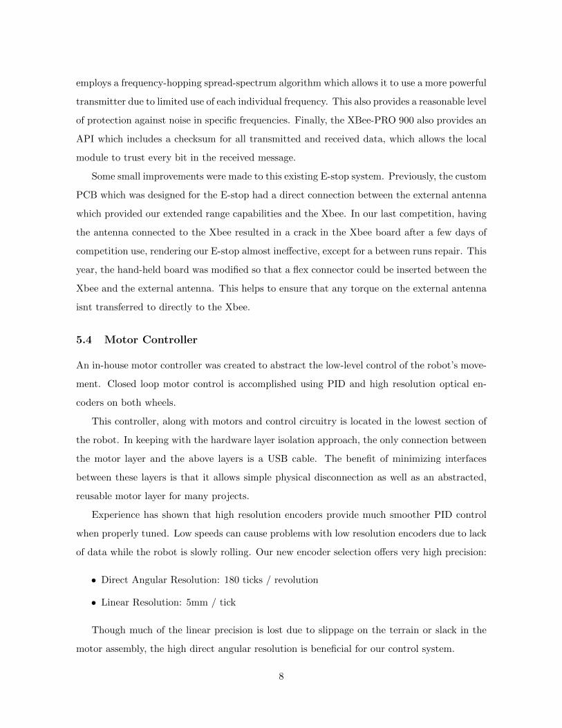
6.6 Vision
A new vision algorithm was used this year. It is based of the very simple concept of combining
different color channels into one gray-scale image. The gray-scale image is constructed as
follows:
grayij = 2 ∗ blueij − greenij + hueij
The gray-scale image is then normalized to the range [0, 1].
The combination of the blue and green color channels allows for robust detection of the
lines in the course. However, it lacked the ability to differentiate between the speed bump and
the lines, the addition of the hue channel helps to alleviate this issue, because the hue of the
white line and the yellow speed bump are quite different.
11
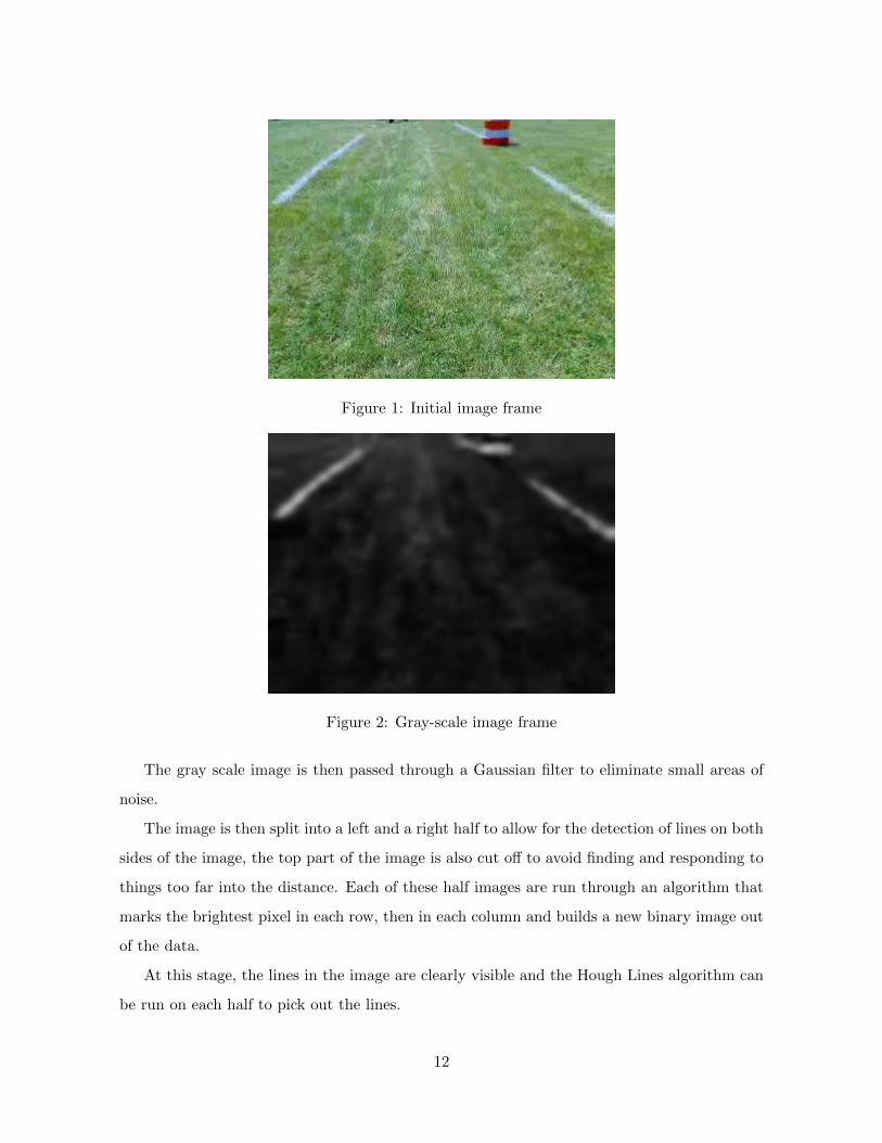
Figure 1: Initial image frame
Figure 2: Gray-scale image frame
The gray scale image is then passed through a Gaussian filter to eliminate small areas of
noise.
The image is then split into a left and a right half to allow for the detection of lines on both
sides of the image, the top part of the image is also cut off to avoid finding and responding to
things too far into the distance. Each of these half images are run through an algorithm that
marks the brightest pixel in each row, then in each column and builds a new binary image out
of the data.
At this stage, the lines in the image are clearly visible and the Hough Lines algorithm can
be run on each half to pick out the lines.
12

Figure 3: Left and Right halves of the image
Figure 4: Initial frame with lines drawn
13

Finally, these lines are converted into a format usable by the local navigation system and
SLaM and passed out to the rest of the system as a ROS message.
7 Conclusion
7.1 Performance Analysis
Attribute Design Goal Final Product
Speed 5 mph 4.5 mph
Reaction Time Near Instantaneous 100 ms
Battery Life 2 Hours (normal operation) 2 Hours
Obstacle detection distance 8 meters 8 meters
Vehicle performance with obstacles Perfect Near Perfect
Navigation point accuracy .2 meter 1 meter
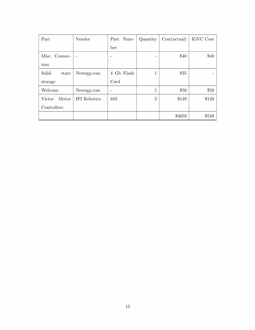
7.2 Cost Analysis
Part Vendor Part Num-
ber
Quantity Cost(actual) IGVC Cost
Frame Materi-
als(Steel)
Metal Super-
market
- 30ft $100 $100
Frame Materi-
als(Aluminum)
Metal Super-
market
- 15ft $75 $75
Misc. Mechan-
ical
- - - $75 $75
LIDAR SICK LMS-291 1 $3000 -
DGPS AgGPS132 1 1 $500 -
Digital Com-
pass
- CMPS03 1 $60 $60
Motors - - 2 $500 -
Main-board EPIA MII 1 $150 -
14
Part Vendor Part Num-
ber
Quantity Cost(actual) IGVC Cost
Misc. Connec-
tors
- - - $40 $40
Solid state
storage
Newegg.com 4 Gb Flash
Card
1 $35 -
Webcam Newegg.com - 1 $50 $50
Victor Motor
Controllers
IFI Robotics 883 2 $149 $149
$4659 $549
15