AMOS - aspectimaging.com · AMOS MRI & NMR spectrometer The AMOS Spectrometer is a highly modular...
8
AMOS MRI & NMR spectrometer The AMOS Spectrometer is a highly modular and flexible unit that provides the ability to customize synchronized configurations for preclinical and clinical MR applications. The AMOS Spectrometer has an exceptional robust and flexible configuration, allowing the addition of RF Tx / RF Rx / Gradient channels to an existing unit, or the addition of fully synchronized units. The AMOS Spectrometer utilizes innovative, state-of-the-art Analog and Digital technologies to provide the highest performance on the market today. This advanced unit features unique capabilities and can be fitted as an upgrade to any existing MRI or NMR system to enhance its performance and features.
Transcript of AMOS - aspectimaging.com · AMOS MRI & NMR spectrometer The AMOS Spectrometer is a highly modular...
AMOSMRI & NMR spectrometer
The AMOS Spectrometer is a highly modular and flexible unit that provides the ability to customize synchronized configurations for preclinical and clinical MR applications. The AMOS Spectrometer has an exceptional robust and flexible configuration, allowing the addition of RF Tx / RF Rx / Gradient channels to an existing unit, or the addition of fully synchronized units. The AMOS Spectrometer utilizes innovative, state-of-the-art Analog and Digital technologies to provide the highest performance on the market today.
This advanced unit features unique capabilities and can be fitted as an upgrade to any existing MRI or NMR system to enhance its performance and features.
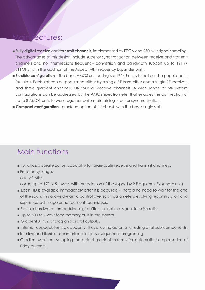
Main functions
■ Full chassis parallelization capability for large-scale receive and transmit channels.■ Frequency range:
o 4 - 86 MHzo And up to 12T (> 511MHz, with the addition of the Aspect MR Frequency Expander unit)
■ Each FID is available immediately after it is acquired - There is no need to wait for the end of the scan. This allows dynamic control over scan parameters, evolving reconstruction and sophisticated image enhancement techniques.
■ Flexible hardware - embedded digital filters for optimal signal to noise ratio.■ Up to 500 MB waveform memory built in the system.■ Gradient X, Y, Z analog and digital outputs.■ Internal loopback testing capability, thus allowing automatic testing of all sub-components. ■ Intuitive and flexible user interface for pulse sequences programing. ■ Gradient Monitor - sampling the actual gradient currents for automatic compensation of
Eddy currents.
Main features:
■ Fully digital receive and transmit channels, implemented by FPGA and 250 MHz signal sampling. The advantages of this design include superior synchronization between receive and transmit channels and no intermediate frequency conversion and bandwidth support up to 12T (> 511MHz, with the addition of the Aspect MR Frequency Expander unit).
■ Flexible configuration – The basic AMOS unit casing is a 19" 4U chassis that can be populated in four slots. Each slot can be populated either by a single RF transmitter and a single RF receiver, and three gradient channels, OR four RF Receive channels. A wide range of MR system configurations can be addressed by the AMOS Spectrometer that enables the connection of up to 8 AMOS units to work together while maintaining superior synchronization.
■ Compact configuration - a unique option of 1U chassis with the basic single slot.
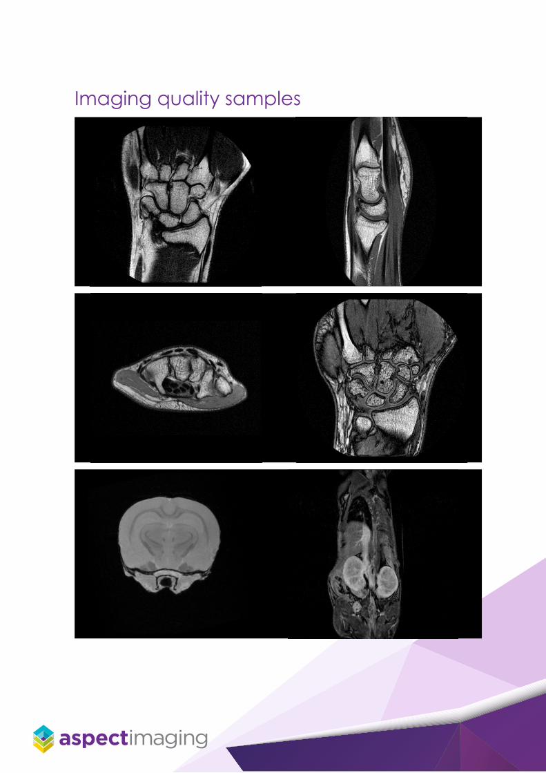
Imaging quality samples
Open source pulse programming
Open source pulse programming language and hardware support the following:■ C# programming with debugging capability - allows minimal start-up time for pulse sequence
programmers■ Arbitrary number of nested loops - provides programming flexibility■ Branching - provides program flexibility■ Real-time capability - scan parameters can be dynamically changed during the scan thus
allowing compensation for frequency drift in magnets■ Rollback of loop indices - prevents perturbations originating from intermittent interferences by
rescanning lines in K-space which were affected by the interferenceSequences are visualized - using a uniform physical time scale to simplify reviewing the pulse sequence
Main modules (boards) and configuration:
■ Tx board First type of Analog front end board supporting single RF transmitter, single RF receiver, three
gradient controls, and three gradient monitor channels. o Transmitter - Converts the pulse sequence digital signal into Analog RF signals at frequencies
of 4MHz to 86MHz (and > 511MHz, with the addition of the Aspect MR Frequency Expander unit)
o Receiver – Amplifies the analog RF signals coming from the MRI system Pre-Amplifier in the frequency band of 4MHz to 86MHz (and > 511MHz, with the addition of the Aspect MR Frequency Expander unit) and then convert them to a digital data stream with minimal distortion and degradation of SNR
o Gradients Control - Converts the digital Gradient Amplifier demand signal into an analog signal
o Gradients Monitor - Converts the Gradient output analog sample signal into a digital stream ■ 4Rx board Second type of Analog board supporting four RF receiver channels. The 4Rx board amplifies
the four analog RF signals coming from the MRI system Pre-Amplifier, in the frequency band of 4MHz to 86MHz (and > 511MHz, with the addition of the Aspect MR Frequency Expander unit) and converts them to a digital data stream with minimal distortion and degradation of SNR.
Ethernet capabilities
The AMOS Spectrometer has two physical ports for communicating with a Host Computer: • Gigabit Ethernet over copper• Gigabit Ethernet over fiber
Triggering
Various inputs and outputs of trigger signals are supported by the AMOS Spectrometer, used for Scan synchronization.
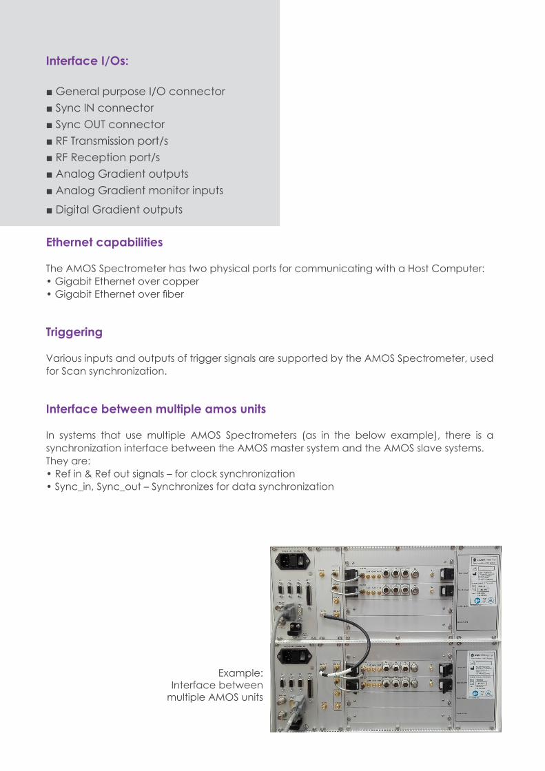
Interface between multiple amos units
In systems that use multiple AMOS Spectrometers (as in the below example), there is a synchronization interface between the AMOS master system and the AMOS slave systems.They are:• Ref in & Ref out signals – for clock synchronization• Sync_in, Sync_out – Synchronizes for data synchronization
Interface I/Os:
■ General purpose I/O connector■ Sync IN connector■ Sync OUT connector■ RF Transmission port/s■ RF Reception port/s■ Analog Gradient outputs■ Analog Gradient monitor inputs
■ Digital Gradient outputs
Example:Interface between
multiple AMOS units
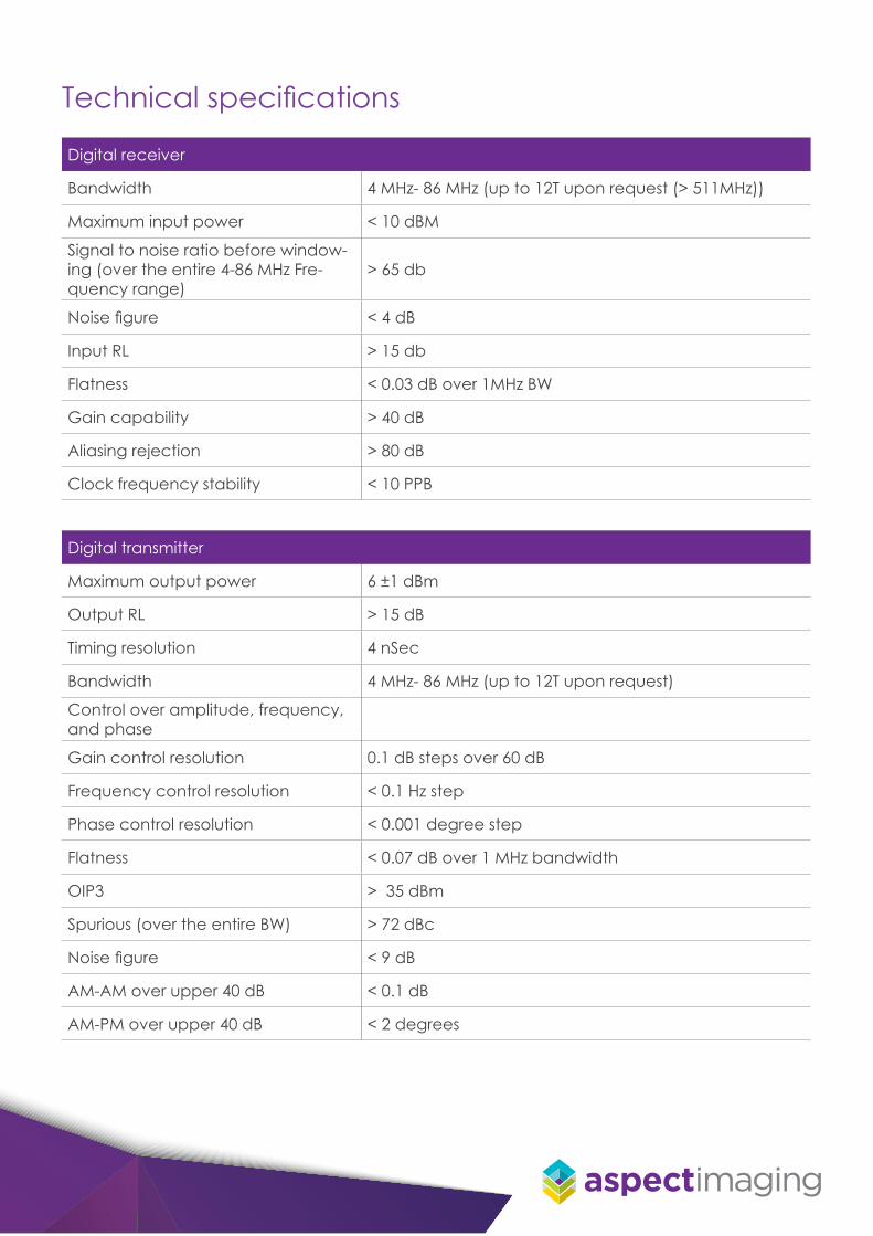
Digital receiver
Bandwidth 4 MHz- 86 MHz (up to 12T upon request (> 511MHz))
Maximum input power < 10 dBM
Signal to noise ratio before window-ing (over the entire 4-86 MHz Fre-quency range)
> 65 db
Noise figure < 4 dB
Input RL > 15 db
Flatness < 0.03 dB over 1MHz BW
Gain capability > 40 dB
Aliasing rejection > 80 dB
Clock frequency stability < 10 PPB
Digital transmitter
Maximum output power 6 ±1 dBm
Output RL > 15 dB
Timing resolution 4 nSec
Bandwidth 4 MHz- 86 MHz (up to 12T upon request)
Control over amplitude, frequency, and phase
Gain control resolution 0.1 dB steps over 60 dB
Frequency control resolution < 0.1 Hz step
Phase control resolution < 0.001 degree step
Flatness < 0.07 dB over 1 MHz bandwidth
OIP3 > 35 dBm
Spurious (over the entire BW) > 72 dBc
Noise figure < 9 dB
AM-AM over upper 40 dB < 0.1 dB
AM-PM over upper 40 dB < 2 degrees
Technical specifications
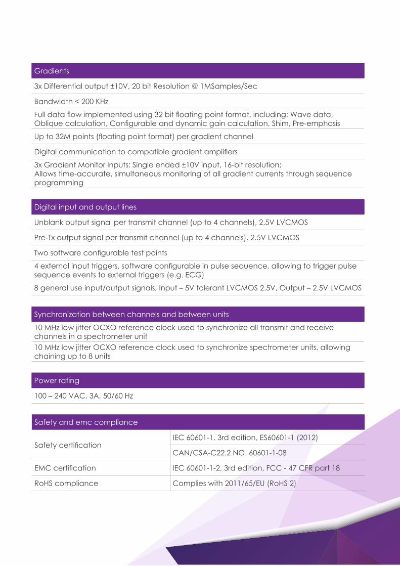
Gradients
3x Differential output ±10V, 20 bit Resolution @ 1MSamples/Sec
Bandwidth < 200 KHz
Full data flow implemented using 32 bit floating point format, including: Wave data, Oblique calculation, Configurable and dynamic gain calculation, Shim, Pre-emphasis
Up to 32M points (floating point format) per gradient channel
Digital communication to compatible gradient amplifiers
3x Gradient Monitor Inputs: Single ended ±10V input, 16-bit resolution; Allows time-accurate, simultaneous monitoring of all gradient currents through sequence programming
Digital input and output lines
Unblank output signal per transmit channel (up to 4 channels), 2.5V LVCMOS
Pre-Tx output signal per transmit channel (up to 4 channels), 2.5V LVCMOS
Two software configurable test points
4 external input triggers, software configurable in pulse sequence, allowing to trigger pulse sequence events to external triggers (e.g. ECG)
8 general use input/output signals, Input – 5V tolerant LVCMOS 2.5V, Output – 2.5V LVCMOS
Synchronization between channels and between units
10 MHz low jitter OCXO reference clock used to synchronize all transmit and receive channels in a spectrometer unit10 MHz low jitter OCXO reference clock used to synchronize spectrometer units, allowing chaining up to 8 units
Power rating
100 – 240 VAC, 3A, 50/60 Hz
Safety and emc compliance
Safety certificationIEC 60601-1, 3rd edition, ES60601-1 (2012)
CAN/CSA-C22.2 NO. 60601-1-08
EMC certification IEC 60601-1-2, 3rd edition, FCC - 47 CFR part 18
RoHS compliance Complies with 2011/65/EU (RoHS 2)

Specifications are subject to change without notice.
DO
C10001043 Rev.1
© Aspect Imaging 2016.