AMKASYN Servo Drives KE/KW Compact, powerful, … · servo drives. The intelligent servo drives...
22
AMKASYN Servo Drives KE/KW Compact, powerful, modular.
Transcript of AMKASYN Servo Drives KE/KW Compact, powerful, … · servo drives. The intelligent servo drives...
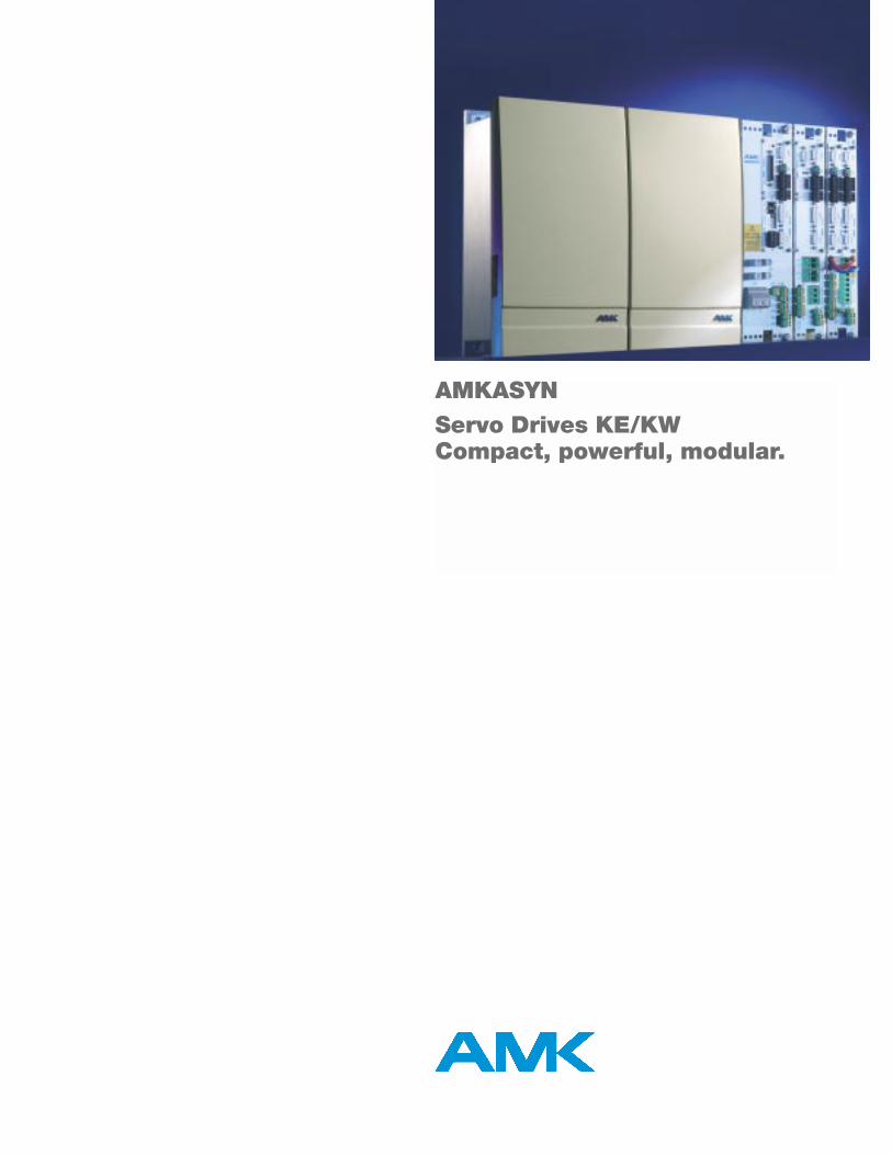
AMKASYNServo Drives KE/KWCompact, powerful, modular.
The most compactservo drives.
The intelligent servo drives KE/KW openup new dimensions of power density.With these drives, control cabinets can bebuilt extremely compact. In some casesthey can even be integrated directly intothe machine. This saves space and alsoreduces costs. The innovative coolingsystem with cold plate technology gua-rantees optimum heat dissipation andincreases service life.
Harmonized individual components inter-act seamlessly to provide customizedsolutions: whether centralized or decen-tralized. The utilization of those modulesthat are actually needed, equipped withthe functions that are actually required,paves the way for optimum cost effectiveness.
All types of synchronous or asynchronousservo-motors, high-torque or linearmotors with various encoder systems canbe operated in a highly dynamic and pre-cise manner. Using the ACC system bus,any required number of axes can be inter-connected hardware synchronous with ajitter of less than 1µs.
Programming in compliance with IEC61131-3 coupled with the function blocksof the AMK library greatly simplify the uti-lization of AMK's PLC and Motion Controltechnology. Programming takes placeindependent of the AMK hardware plat-form that is being used. The basis forvisualization already exists.
The drives not only offer the highestdegree of AMK standard functions, theyalso offer maximum and intrinsic safety:locking to protect against accidentalmotor start-up takes place without exter-nal components in compliance with Safe-ty Category 4, the highest safety levelunder EN 954-1.
3
Features
• Power ratings up to 120 kVA
• Modular structure
• Extremely flexible module arrangement
• The number of servo axes per supply module is only limited by the rated power output
• Cooling in cold plate technology
• Line regenerative braking optional
• Various encoder technologies available: standard feedback inputs for resolver, square-wave encoder, sine-wave encoder, EnDat®, Hiperface®
• Pulse transmission
• Multifunctional interconnection via efficient ACC bus
• PLC functionality optional
• Field busses
– SERCOS
– Profibus DP
– CAN - Ethernet
Standard functions • Torque control
• Speed control
• Position control
• Machine homing routines in many variations
• Synchronous control
• Electronic line shafting
• Brake control
Applications In all areas of machine design incl.
• injection molding machines
• printing presses
• packaging machines
• tobacco processing machines
• paper machines
• machine tools
• handling systems
ACC bus
DC bus
24V DC
3x400V…480V AV
Cold plate
KE xx: Supply moduleKW xx: Servo drive module KWD x: Double servo drive module KWF x: Double v/ƒ inverter module KW-Rxx: CPU card O1, O2: Option slots
KE xx KW xx KW xx KW xx KWD x KWF x
01K
W-R
xx02
01K
W-R
xx02
01K
W-R
xx02 KW
-Rxx
(A
)K
W-R
xx (
B)
Interface overview KE/KW
A B A B
The most importantadvantages at a glance
• Compact components reduce control cabinet space
• Cost savings through possible integration of the control cabinet as a part of the machine
• Cost-optimized solutions due to modular system structure
• Design of complex, interconnected machines utilizing AMK's real-time synchronization
• Simple implementation of Motion Control functions through the integratable PLC
• Integrated safety function in compliance with Safety Category 4
The compact supply modules KEgenerate the DC bus voltage for allconnected drive modules
Features:
• Power ratings up to 120 kW• Cooling in cold plate technology• Line regenerative braking optional• Braking chopper integrated• Protective functions
– Overtemperature – Power failure– Input current– Short circuit protected– DC bus overcurrent
• Function control and diagnostics via ACC bus
• Control and monitoring of charging process
• Main contactor control
Compact supply module KE Maximum power in minimum space.
5
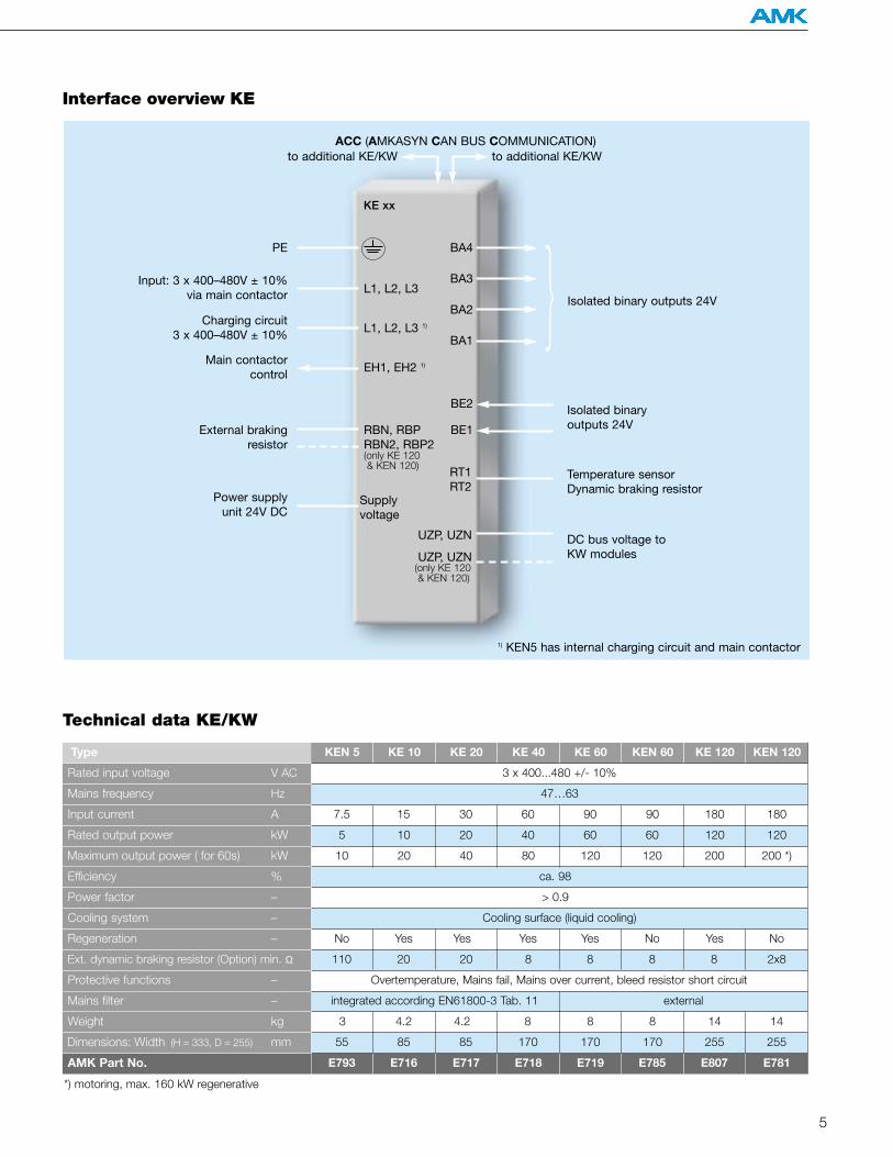
Interface overview KE
Type KE 10
Rated input voltage V AC 3 x 400...480 +/- 10%
integrated according EN61800-3 Tab. 11 external
E716 E717 E718 E719 E785 E807 E781
3 4.2 4.2 8 8 8 14 14
90Input current A
Rated output power kW
Maximum output power ( for 60s) kW
Power factor –
Cooling system –
Regeneration –
Ext. dynamic braking resistor (Option) min. Ω
Protective functions –
Mains filter –
Weight kg
Dimensions: Width (H = 333, D = 255) mm
AMK Part No.
Efficiency %
Technical data KE/KW
KE 60 KEN 60 KE 120 KEN 120
ca. 98
> 0.9
Cooling surface (liquid cooling)
KE 20 KE 40
47…63Mains frequency Hz
15
KEN 5
Overtemperature, Mains fail, Mains over current, bleed resistor short circuit
55 85 85 170 170 170 255 255
E793
110 20 20 8 8 8 8 2x8
No Yes Yes Yes Yes No Yes No
7.5 30 60 180 180
60105
10 20 40 80 120
90
60
120 200 200 *)
20 40 120 120
*) motoring, max. 160 kW regenerative
Isolated binary outputs 24V
Isolated binary outputs 24V
Temperature sensorDynamic braking resistor
PE BA4
BA3
BA2
BA1
L1, L2, L3
L1, L2, L3 1)
EH1, EH2 1)
1) KEN5 has internal charging circuit and main contactor
BE2
BE1
RT1RT2
Input: 3 x 400–480V ± 10% via main contactor
Charging circuit 3 x 400–480V ± 10%
Main contactor control
External brakingresistor
RBN, RBPRBN2, RBP2(only KE 120 & KEN 120)
DC bus voltage to KW modules
UZP, UZN
UZP, UZN(only KE 120 & KEN 120)
Power supply unit 24V DC
Supply voltage
ACC (AMKASYN CAN BUS COMMUNICATION)
KE xx
to additional KE/KWto additional KE/KW
Inverter module KW Excellent dynamic response and precision.With intrinsic safety.
The digital compact servo drive modu-les KW control the motors in 4-qua-drant mode precisely and with highdynamic response. A multifunctionalconnection to a higher-level controlunit via the internal ACC bus or viavarious field busses is possible.
Features:
• Power ratings up to 100 kVA• Cooling in cold plate technology• Precise and highly dynamic control of
all three-phase motors (synchronous, asynchronous, torque, spindle motor, linear or rotary)
• Safeguarding to protect against undesired motor start-up (Safety Category 4) via output stage enable (EF) handshakes.
• Accommodates 1 CPU card (KW-R03, KW-R03P or KW-R04) and up to 2 option cards (CPU cards and option cards must be ordered separately)
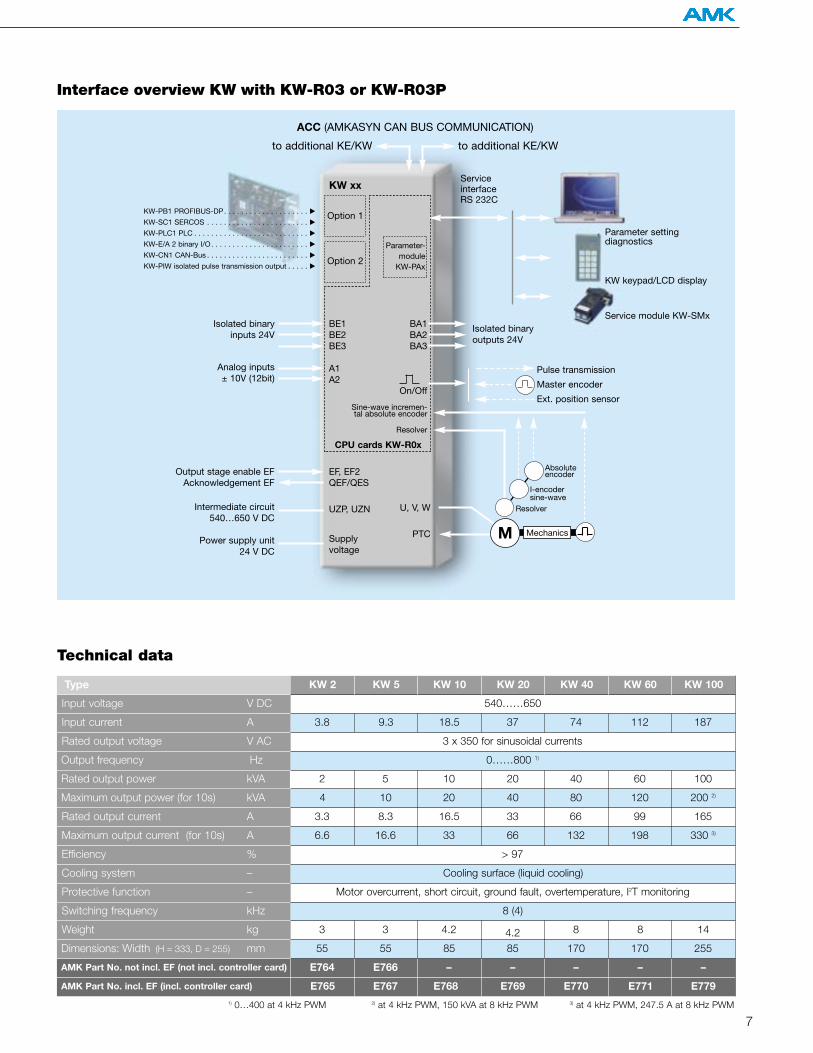
7
Technical data
Interface overview KW with KW-R03 or KW-R03P
1) 0…400 at 4 kHz PWM 2) at 4 kHz PWM, 150 kVA at 8 kHz PWM 3) at 4 kHz PWM, 247.5 A at 8 kHz PWM
Type KW 5
Input voltage V DC 540……650
Input current A
Rated output voltage V AC
Rated output power kVA
Output frequency Hz
Rated output current A
Maximum output current (for 10s) A
Efficiency %
Cooling system –
Protective function –
Switching frequency kHz
Weight kg
Dimensions: Width (H = 333, D = 255) mm
AMK Part No. incl. EF (incl. controller card)
Maximum output power (for 10s) kVA
KW 40 KW 60 KW 100
4 10 20 40 80 120 200 2)
3.3 8.3 16.5 33 66 99 165
6.6 16.6 33 66 132 198 330 3)
KW 10 KW 20
3.8 9.3 18.5 37 74 112 187
KW 2
Motor overcurrent, short circuit, ground fault, overtemperature, I2T monitoring
Cooling surface (liquid cooling)
> 97
3 x 350 for sinusoidal currents
0……800 1)
2 5 10 20 40 60 100
E767 E768 E769 E770 E771 E779
8 (4)
55 55 85 85 170 170 255
3 3 4.2 4.2 8 8 14
E765
AMK Part No. not incl. EF (not incl. controller card) E766 – – – – –E764
to additional KE/KW
Output stage enable EFAcknowledgement EF
Intermediate circuit540…650 V DC
Power supply unit 24 V DC
EF, EF2QEF/QES
UZP, UZN
Supply voltage
U, V, W
PTC
KW-PB1 PROFIBUS-DP. . . . . . . . . . . . . . . . . . . . KW-SC1 SERCOS . . . . . . . . . . . . . . . . . . . . . . . . KW-PLC1 PLC . . . . . . . . . . . . . . . . . . . . . . . . . . . KW-E/A 2 binary I/O. . . . . . . . . . . . . . . . . . . . . . . KW-CN1 CAN-Bus . . . . . . . . . . . . . . . . . . . . . . . . KW-PIW isolated pulse transmission output . . . . .
Option 1
Option 2
Parameter setting diagnostics
KW keypad/LCD display
Service module KW-SMx
Pulse transmission
Master encoder
Ext. position sensor
Resolver
I-encodersine-wave
Absoluteencoder
ServiceinterfaceRS 232C
to additional KE/KW
ACC (AMKASYN CAN BUS COMMUNICATION)
BE1BE2BE3
A1A2
Isolated binaryinputs 24V
Analog inputs ± 10V (12bit)
Isolated binary outputs 24V
CPU cards KW-R0x
KW xx
BA1BA2BA3
On/Off
Sine-wave incremen-tal absolute encoder
Resolver
Parameter-module
KW-PAx
M Mechanics
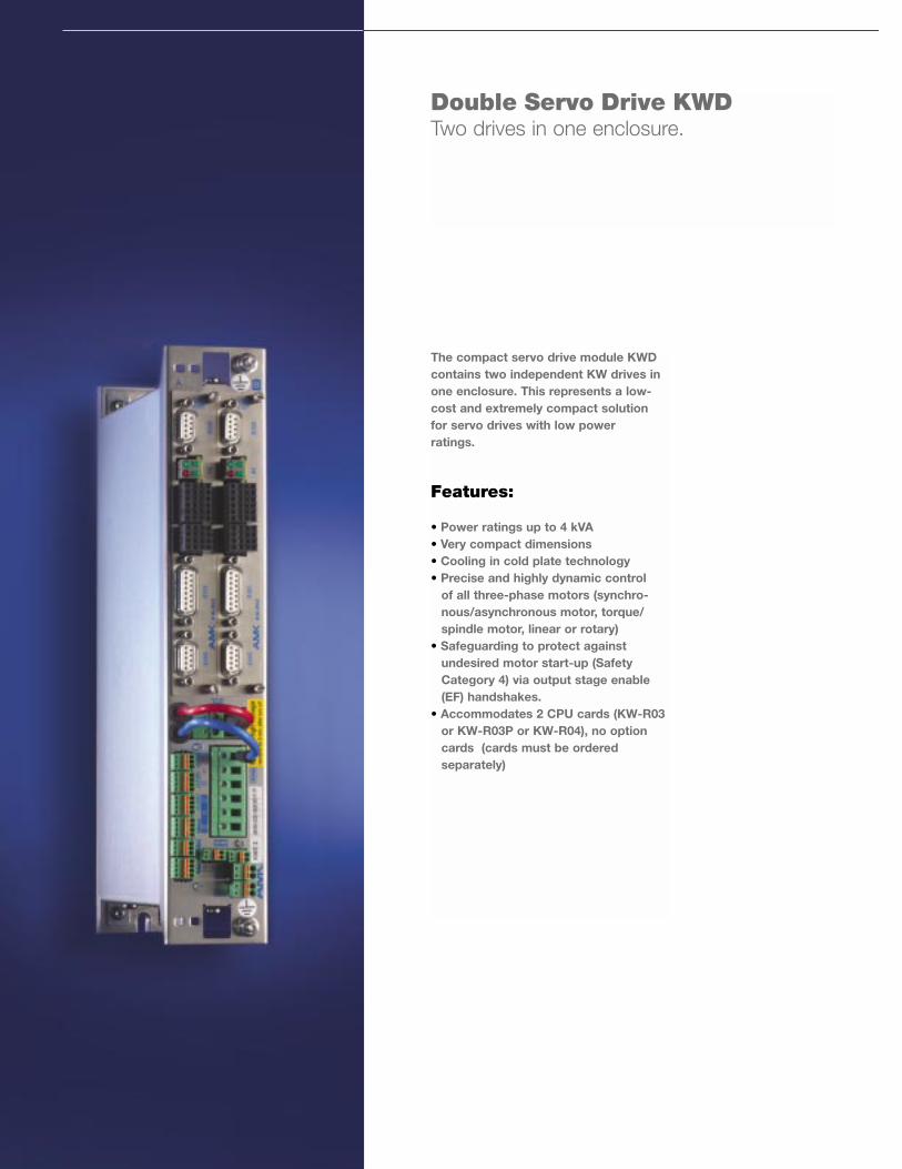
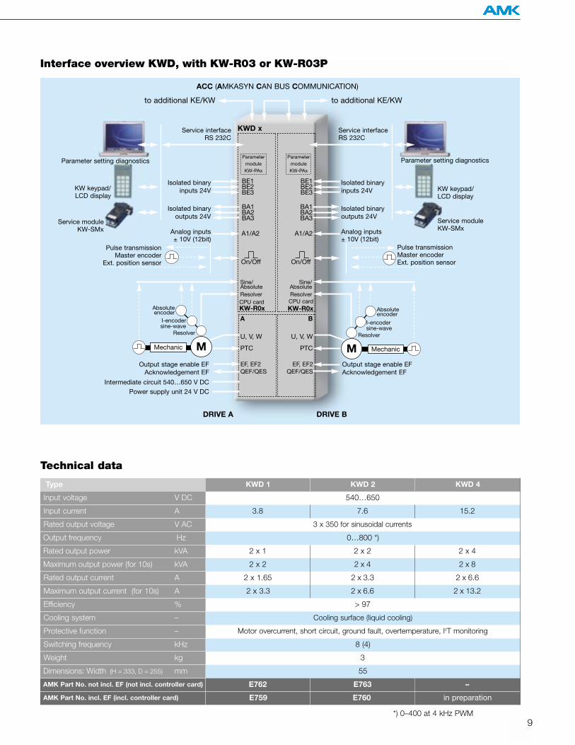
The compact servo drive module KWDcontains two independent KW drives inone enclosure. This represents a low-cost and extremely compact solutionfor servo drives with low powerratings.
Features:
• Power ratings up to 4 kVA• Very compact dimensions• Cooling in cold plate technology• Precise and highly dynamic control
of all three-phase motors (synchro-nous/asynchronous motor, torque/ spindle motor, linear or rotary)
• Safeguarding to protect against undesired motor start-up (Safety Category 4) via output stage enable (EF) handshakes.
• Accommodates 2 CPU cards (KW-R03 or KW-R03P or KW-R04), no option cards (cards must be ordered separately)
Double Servo Drive KWD Two drives in one enclosure.
Type
Input voltage V DC
Input current A
Rated output voltage V AC
Rated output power kVA
Output frequency Hz
Rated output current A
Maximum output current (for 10s) A
Efficiency %
Cooling system –
Protective function –
Switching frequency kHz
Weight kg
Dimensions: Width (H = 333, D = 255) mm
AMK Part No. incl. EF (incl. controller card)
Maximum output power (for 10s) kVA
AMK Part No. not incl. EF (not incl. controller card)
9
Interface overview KWD, with KW-R03 or KW-R03P
to additional KE/KW
Output stage enable EFAcknowledgement EF
Output stage enable EFAcknowledgement EF
Intermediate circuit 540…650 V DCPower supply unit 24 V DC
Parameter setting diagnostics
KW keypad/LCD display
Service moduleKW-SMx
Parameter setting diagnostics
KW keypad/LCD display
Service moduleKW-SMx
Pulse transmission Master encoder Ext. position sensor
Service interfaceRS 232C
Service interfaceRS 232C
to additional KE/KW
ACC (AMKASYN CAN BUS COMMUNICATION)
DRIVE A DRIVE B
Analog inputs ± 10V (12bit)
KWD x
CPU cardKW-R0x
CPU cardKW-R0x
A B
BE1BE2BE3
BA1BA2BA3
A1/A2
Isolated binaryinputs 24V
Isolated binary outputs 24V
Analog inputs ± 10V (12bit)
Isolated binaryinputs 24V
Isolated binary outputs 24V
On/Off
BE1BE2BE3
BA1BA2BA3
A1/A2
ParametermoduleKW-PAx
ParametermoduleKW-PAx
Pulse transmission Master encoder
Ext. position sensor
KWD 2
540…650
8 (4)
E760
3
Technical data
3.8 7.6
KWD 1
Motor overcurrent, short circuit, ground fault, overtemperature, I2T monitoring
55
E759
E763E762
Cooling surface (liquid cooling)
> 97
3 x 350 for sinusoidal currents
0…800 *)
2 x 1 2 x 2 2 x 4
2 x 2 2 x 4
2 x 1.65 2 x 3.3
2 x 3.3 2 x 6.6
KWD 4
in preparation
15.2
–
2 x 8
2 x 6.6
2 x 13.2
*) 0–400 at 4 kHz PWM
EF, EF2QEF/QES
U, V, W
PTC
EF, EF2QEF/QES
U, V, W
PTC
On/Off
Sine/AbsoluteResolver
Sine/AbsoluteResolver
Resolver
I-encodersine-wave
Absoluteencoder
MechanicMechanic
Resolver
I-encodersine-wave
Absoluteencoder
MM
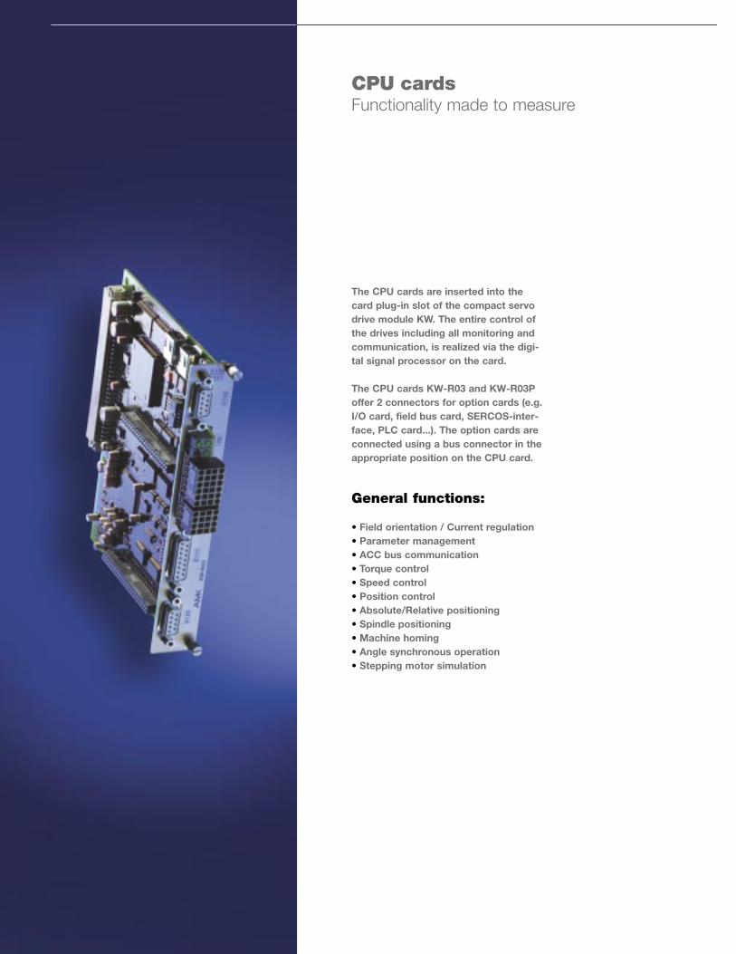
The CPU cards are inserted into thecard plug-in slot of the compact servodrive module KW. The entire control ofthe drives including all monitoring andcommunication, is realized via the digi-tal signal processor on the card.
The CPU cards KW-R03 and KW-R03Poffer 2 connectors for option cards (e.g.I/O card, field bus card, SERCOS-inter-face, PLC card...). The option cards areconnected using a bus connector in theappropriate position on the CPU card.
General functions:
• Field orientation / Current regulation• Parameter management• ACC bus communication• Torque control• Speed control• Position control• Absolute/Relative positioning • Spindle positioning• Machine homing• Angle synchronous operation • Stepping motor simulation
CPU cardsFunctionality made to measure
11
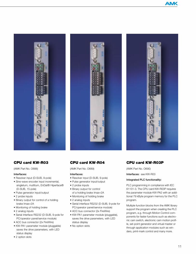
CPU card KW-R03
(AMK Part No. O688)
Interfaces: • Resolver input (D-SUB, 9-pole)• Sine-wave encoder input incremental,
singleturn, multiturn, EnDat® Hiperface® (D-SUB, 15-pole)
• Pulse generator input/output• 2 probe inputs• Binary output for control of a holding
brake Imax=2A• Monitoring of holding brake• 2 analog inputs• Serial interface RS232 (D-SUB, 9-pole for
PC/operator panel/service module)• ACC bus connector (2x FireWire)• KW-PA1 parameter module (pluggable)
saves the drive parameters, with LED status display
• 2 option slots
CPU card KW-R04
(AMK Part No. O689)
Interfaces: • Resolver input (D-SUB, 9-pole)• Pulse generator input/output • 2 probe inputs• Binary output for control
of a holding brake Imax=2A• Monitoring of holding brake• 2 analog inputs• Serial interface RS232 (D-SUB, 9-pole for
PC/operator panel/service module)• ACC bus connector (2x FireWire)• KW-PA1 parameter module (pluggable),
saves the drive parameters, with LED status display
• No option slots
CPU card KW-R03P
(AMK Part No. O690)
Interfaces: see KW-R03
Integrated PLC functionality:
PLC programming in compliance with IEC61131-3. The CPU card KW-R03P requiresthe parameter module KW-PA2 with an addi-tional 79 kByte program memory for the PLCprogram.
Multiple function blocks from the AMK librarysupport the program when creating the PLCprogram, e.g. through Motion Control com-ponents for faster functions such as electro-nic cam switch, electronic cam motion profi-le, set-point generator and virtual master orthrough application modules such as win-ders, print-mark control and many more.
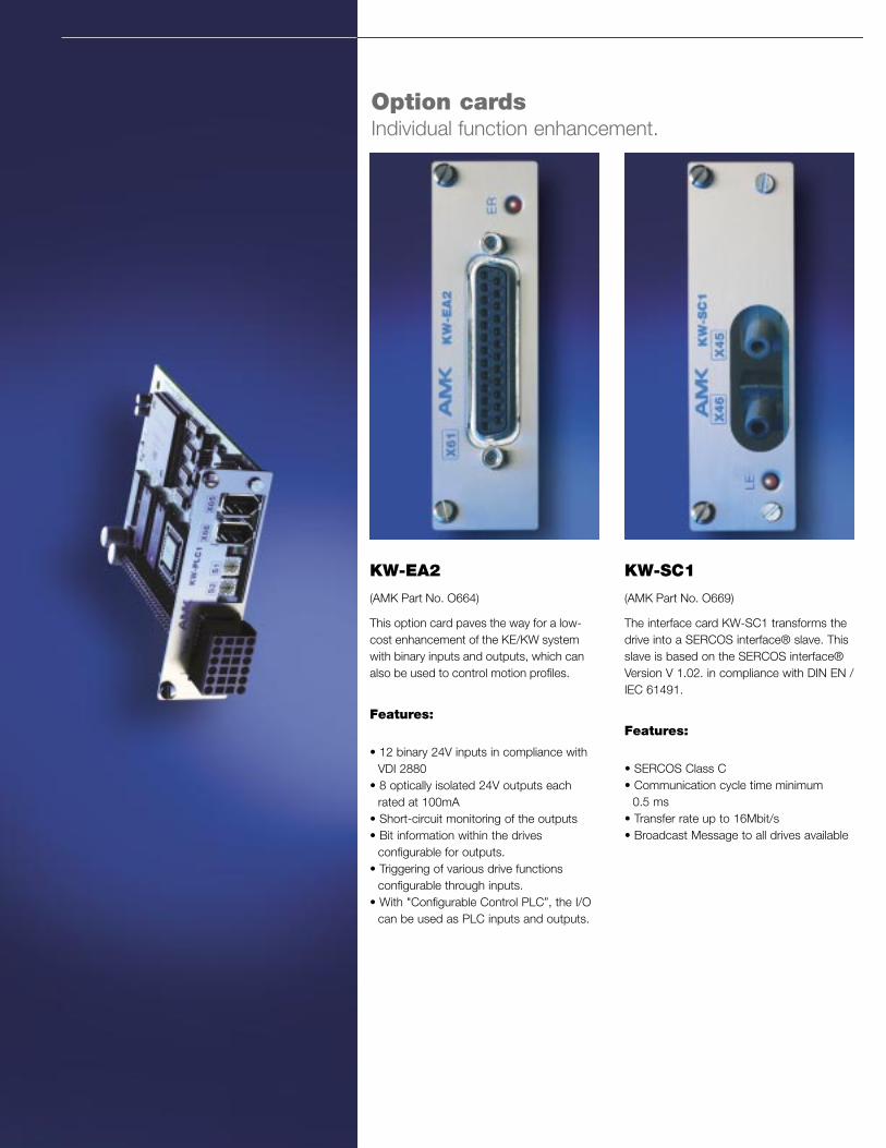
KW-EA2
(AMK Part No. O664)
This option card paves the way for a low-cost enhancement of the KE/KW systemwith binary inputs and outputs, which canalso be used to control motion profiles.
Features:
• 12 binary 24V inputs in compliance with VDI 2880
• 8 optically isolated 24V outputs each rated at 100mA
• Short-circuit monitoring of the outputs• Bit information within the drives
configurable for outputs. • Triggering of various drive functions
configurable through inputs.• With "Configurable Control PLC”, the I/O
can be used as PLC inputs and outputs.
KW-SC1
(AMK Part No. O669)
The interface card KW-SC1 transforms thedrive into a SERCOS interface® slave. Thisslave is based on the SERCOS interface®Version V 1.02. in compliance with DIN EN /IEC 61491.
Features:
• SERCOS Class C• Communication cycle time minimum
0.5 ms• Transfer rate up to 16Mbit/s• Broadcast Message to all drives available
Option cardsIndividual function enhancement.
13
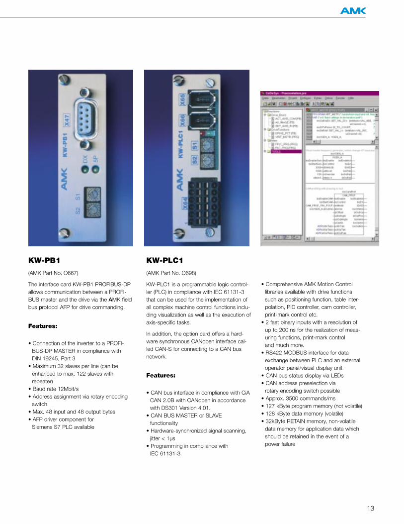
KW-PLC1
(AMK Part No. O698)
KW-PLC1 is a programmable logic control-ler (PLC) in compliance with IEC 61131-3that can be used for the implementation ofall complex machine control functions inclu-ding visualization as well as the execution ofaxis-specific tasks.
In addition, the option card offers a hard-ware synchronous CANopen interface cal-led CAN-S for connecting to a CAN busnetwork.
Features:
• CAN bus interface in compliance with CiA CAN 2.0B with CANopen in accordance with DS301 Version 4.01.
• CAN BUS MASTER or SLAVE functionality
• Hardware-synchronized signal scanning, jitter < 1µs
• Programming in compliance with IEC 61131-3
KW-PB1
(AMK Part No. O667)
The interface card KW-PB1 PROFIBUS-DPallows communication between a PROFI-BUS master and the drive via the AMK fieldbus protocol AFP for drive commanding.
Features:
• Connection of the inverter to a PROFI-BUS-DP MASTER in compliance with DIN 19245, Part 3
• Maximum 32 slaves per line (can be enhanced to max. 122 slaves with repeater)
• Baud rate 12Mbit/s• Address assignment via rotary encoding
switch• Max. 48 input and 48 output bytes• AFP driver component for
Siemens S7 PLC available
• Comprehensive AMK Motion Control libraries available with drive functions such as positioning function, table inter-polation, PID controller, cam controller, print-mark control etc.
• 2 fast binary inputs with a resolution of up to 200 ns for the realization of meas-uring functions, print-mark control and much more.
• RS422 MODBUS interface for data exchange between PLC and an external operator panel/visual display unit
• CAN bus status display via LEDs• CAN address preselection via
rotary encoding switch possible• Approx. 3500 commands/ms• 127 kByte program memory (not volatile)• 128 kByte data memory (volatile)• 32kByte RETAIN memory, non-volatile
data memory for application data which should be retained in the event of a power failure
14
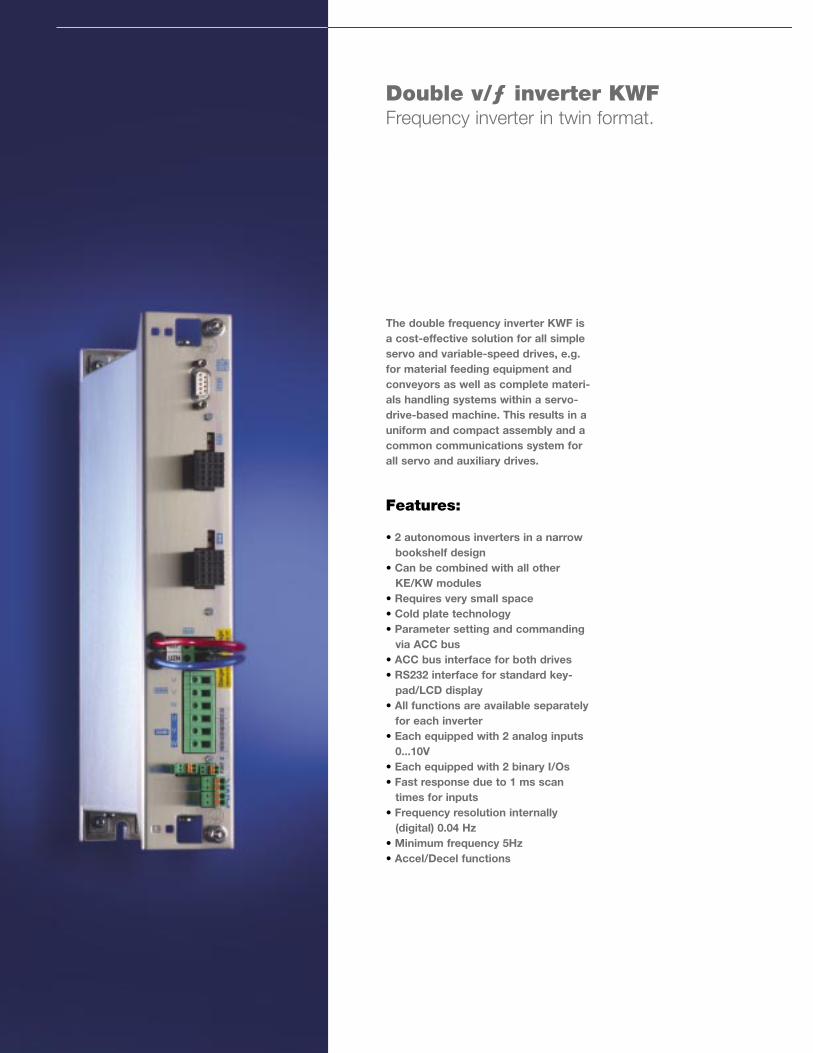
The double frequency inverter KWF isa cost-effective solution for all simpleservo and variable-speed drives, e.g.for material feeding equipment andconveyors as well as complete materi-als handling systems within a servo-drive-based machine. This results in auniform and compact assembly and acommon communications system forall servo and auxiliary drives.
Features:
• 2 autonomous inverters in a narrow bookshelf design
• Can be combined with all other KE/KW modules
• Requires very small space• Cold plate technology• Parameter setting and commanding
via ACC bus• ACC bus interface for both drives• RS232 interface for standard key-
pad/LCD display• All functions are available separately
for each inverter• Each equipped with 2 analog inputs
0...10V• Each equipped with 2 binary I/Os• Fast response due to 1 ms scan
times for inputs• Frequency resolution internally
(digital) 0.04 Hz• Minimum frequency 5Hz• Accel/Decel functions
Double v/ƒ inverter KWFFrequency inverter in twin format.
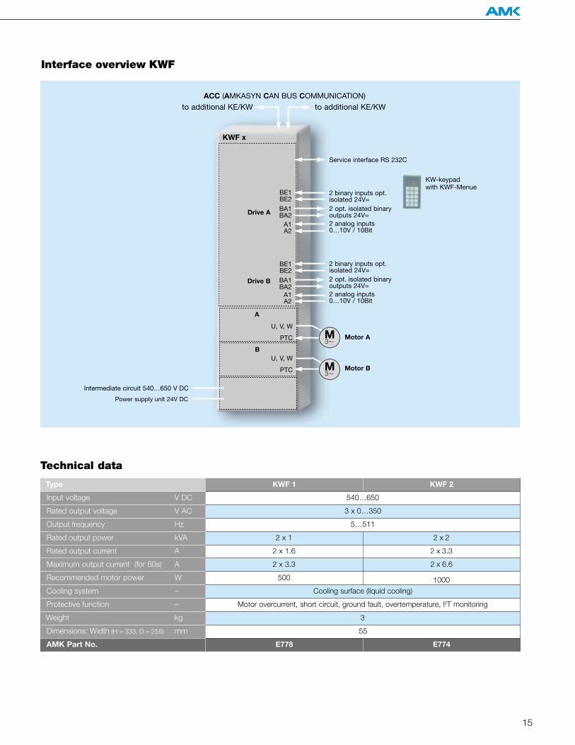
15
Type KWF 2
Input voltage V DC 540…650
3
Rated output voltage V AC
Output frequency Hz
Rated output power kVA
Rated output current A
Maximum output current (for 60s) A
Recommended motor power W
Cooling system –
Protective function –
Weight kg
Dimensions: Width (H = 333, D = 255) mm
Technical data
KWF 1
Motor overcurrent, short circuit, ground fault, overtemperature, I2T monitoring
55
AMK Part No. E778 E774
Cooling surface (liquid cooling)
500 1000
3 x 0…350
5…511
2 x 1 2 x 2
2 x 1.6 2 x 3.3
2 x 3.3 2 x 6.6
to additional KE/KWto additional KE/KW
Intermediate circuit 540…650 V DC
Power supply unit 24V DC
KW-keypad with KWF-Menue
Service interface RS 232C
ACC (AMKASYN CAN BUS COMMUNICATION)
2 analog inputs0…10V / 10Bit
KWF x
A
Drive A
Drive B
B
BE1BE2
BA1BA2
A1A2
BE1BE2
BA1BA2
A1A2
2 binary inputs opt.isolated 24V= 2 opt. isolated binaryoutputs 24V=
2 analog inputs0…10V / 10Bit
2 binary inputs opt.isolated 24V= 2 opt. isolated binaryoutputs 24V=
Interface overview KWF
M3
Motor A
M3
Motor B
U, V, W
PTC
U, V, W
PTC

161616
AIPEX Start-up and parameter setting. Fast, simple, intelligent.
With AIPEX, even a complex KE/KWsystem can easily be configured and putinto operation using a standard PC.
AIPEX also allows full access to all thedevices within the machine via the ACCbus master. The number of individualdevices in the machine is not limited.
AIPEX can handle all combinations ofKE, KW, KWD, KWF and KU devices.
17
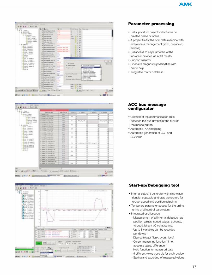
Parameter processing
• Full support for projects which can be created online or offline
• A project file for the complete machine with simple data management (save, duplicate, archive)
• Full access to all parameters of the individual devices via ACC master
• Support wizards• Extensive diagnostic possibilities with
online help • Integrated motor database
ACC bus message configurator
• Creation of the communication links between the bus devices at the click of the mouse button
• Automatic PDO mapping• Automatic generation of CCF and
CCB files
Start-up/Debugging tool
• Internal setpoint generator with sine-wave, triangle, trapezoid and step generators for torque, speed and position setpoints
• Temporary parameter access for the online tuning of all control parameters
• Integrated oscilloscope- Measurement of all internal data such as
position values, speed values, currents, torques, binary I/O voltages etc.
- Up to 8 variables can be recorded per device
- Diverse trigger (flank, event, level) - Cursor measuring function (time,
absolute value, difference)- Hold function for measured data- 4 different views possible for each device- Saving and exporting of measured values
18
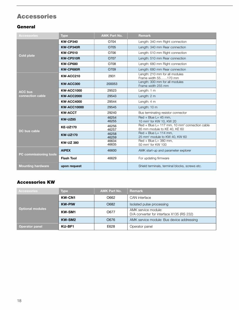
Accessories
AMK Part No. RemarkAccessories Type
Cold plate
ACC bus connection cable
DC bus cable
PC commissioning tools
Mounting hardware
KW-CP340
KW-CP340R
KW-CP510
KW-CP510R
KW-CP680
KW-CP680R
O704
O705
O706
O707
O708
O709
Length: 340 mm Right connection
Length: 340 mm Rear connection
Length: 510 mm Right connection
Length: 510 mm Rear connection
Length: 680 mm Right connection
KW-ACC210 2931Length: 210 mm for all modulesFrame width 55……170 mm
KW-ACC300 200053Length: 300 mm for all modules Frame width 255 mm
KW-ACC1000 29523 Length: 1 m
KW-ACC2000 29543 Length: 2 m
KW-ACC4000 29544 Length: 4 m
KW-ACC10000 29545 Length: 10 m
KW-ACCT 29240 Bus terminating resistor connector
KW-UZ85 4625446255
Red + Blue L= 45 mm, 10 mm2 for KW 10, KW 20
KE-UZ170 4625646257
Red + Blue L= 117 mm, 10 mm2 connection cable85 mm module to KE 40, KE 60
KW-UZ170 4625846259
Red + Blue L= 114 mm,25 mm2 module to KW 40, KW 60
KW-UZ 380 4663446635
Red + Blue L= 380 mm, 50 mm2 for KW 100
AIPEX 46600 AMK start-up and parameter explorer
Flash Tool 46629 For updating firmware
upon request Shield terminals, terminal blocks, screws etc.
Length: 680 mm Rear connection
AMK Part No. RemarkAccessories Type
Optional modules
Operator panel
KW-CN1
KW-PIW
O662
O682
CAN interface
Isolated pulse processing
KW-SM1 O677AMK service module: D/A converter for interface X135 (RS 232)
KW-SM2 O676 AMK service module: Bus device addressing
KU-BF1 E628 Operator panel
Accessories KW
General
19
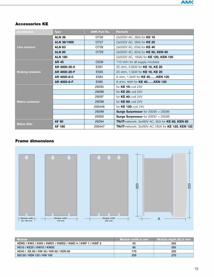
AMK Part No. RemarkAccessories Type
Line reactors
Braking resistors
Mains contactor
Mains filter
ALN 36 O726 (3x500V AC, 36A) for KE 10
ALN 36/1000 O727 (3x500V AC, 36A) for KE 20
ALN 63 O728 (3x500V AC, 63A) for KE 40
ALN 85 O729 (3x500V AC, 85A) for KE 60, KEN 60
ALN 180 (3x500V AC, 180A) for KE 120, KEN 120
AR 4000-20-0 E591 20 ohm, 0.6kW for KE 10, KE 20
AR 45 O536 110 ohm for all supply modules
AR 4000-20-F E593 20 ohm, 1.5kW for KE 10, KE 20
AR 4000-8-0 E584 8 ohm, 1.5kW for KE 40……KEN 120
AR 4000-8-F E585 8 ohm, 4kW for KE 40……KEN 120
29295 for KE 10: coil 24V
29296 for KE 20: coil 24V
29297 for KE 40: coil 24V
29298 for KE 60: coil 24V
200446 for KE 120: coil 24V
29299 Surge Surpressor for 29295 + 29296
29300 Surge Surpressor for 29297 + 29298
AF 90 29294 TN/IT-network: 3x480V AC, 90A for KE 60, KEN 60
AF 180 200447 TN/IT-network: 3x480V AC,180A for KE 120, KEN 120
Accessories KE
Frame dimensions
Module width 55 / 85 mm
320
333
Module width 170 mm
Module width 255 mm
A
ModuleKEN5 / KW2 / KW5 / KWD1 / KWD2 / KWD 4 / KWF 1 / KWF 2 55
KE40 / KE 60 / KW 40 / KW 60 / KEN 60KE120 / KEN 120 / KW 100
Module width in mm
170255
255KE10 / KE20 / KW10 / KW20 85 255
Module depth (A) in mm
255270

Directives and standards
• Low Voltage Directive 73/23/EEC and 93/68/EEC
• EN 50178 "Electronic equipment for use in power installations"
• EN 61800-2 "Adjustable speed electrical power drive systems - Part 2: General"
• EN 61800-3 "Adjustable speed electrical power drive systems, EMC product standard"
• UL 508C "Power Conversion Equipment"• CSA C22.2 "Industrial Control Equipment"
Machine standards:
• Machine Directive 89/392/EEC• EMC Directive 89/336/EEC• EN 60204 "Electrical equipment of
machines".

General technical data
Input to network KE: 3 x 400V...480V ± 10%, 47... 63 HzGeneral operating requirements in compliance with 61800-2 Chap. 4.1.1 andEN 60204-1 Chap. 4.3
• Symmetrical three-phase input voltage, max. permitted voltage asymmetry 3% TN- and TT-network, grounded neutral
• Suitable for IT networks
Reference potential: PE, circuit GND of low voltage circuit isconnected internally with the frame ground.
Power supply unit for supply voltage 24V DC ± 15%, ripple max. 5%, with integrated starting current limitation.
Limit values for radio interference volta-ge in compliance with EN 61800-3: (2000)in accordance with Section 6.3.2 Tab. 11and Tab.12 (external filter required from KE60 upwards)
Ambient conditions
Protection type in compliance with EN60529: IP 20, contamination level 2
Storage / transport temperature: -25°C to +75°C
Ambient temperature: +5°C to +40°C
Cold plate temperature: max. 40°C
Relative humidity: 5% to 85 %, without condensation
Setup height: Up to 1000 m above sea level. In the caseof altitudes over 1000 m up to max. 2000m, the ratings must be reduced by 1% per100 m.
Shock resistance: 15 g for 11ms in compliance with EN60068-2-27
Vibration stress: 1g at 10...150Hz in compliance with EN60068-2-6

Arnold Müller GmbH & Co. KGAntriebs- und Steuerungstechnik
Postfach 13 55D-73221 Kirchheim/Teck
Gaußstraße 37–39D-73230 Kirchheim/Teck
Telefon: 0 70 21/50 05-0Telefax: 0 70 21/50 [email protected]
AMK Drives and Controls Inc.5631 South Laburnum AvenueRichmond, Virginia 23231USAPhone: 804-222-0323Telefax: 804-222-0339 A
ltera
tions
rese
rved
! 05
H04
Control your Motion.
Intelligent Motion Control Technology
Multi-axis controller
CNC controller
Linear-motion drives
Geared motors
Built-in motors
Custom-designed special motors
Frequency inverters