Ameron Conducte Transport, Industrial & Tubing - Prezentare 2006
Upload
abdul-hakam-mohamed-yusofCategory
view
582download
12description

AMERON CORROSION-RESISTANT FIBERGLASS PIPING SYSTEMS

Ameron fiberglass pipe can withstand highertemperatures and pressures than ordinarythermoplastic materials. That, together withits corrosion and chemical resistance, makesit particularly well-suited for general industrialservice and chemical processing applications.Fiberglass pipe also provides environmentalprotection benefits. In applications such assecondary containment and waste handling,it can eliminate the ground-water contaminationcaused by corroded metal piping. BondstrandLD large-diameter piping is available in diame-ters through 144 inches (3600 mm).
Together, Ameron and its subsidiary CentronInternational offer a full line of fiberglass oilfieldline pipe, tubing, casing and sand-control wellscreens. Piping is available in diameters from1 to 40 inches, with service pressures as highas 4000 psi and operating temperatures up to302°F (150°C), depending on specifications.Centron® GRE well screens, which cost abouthalf as much as metal screens, come in 11⁄2to 8-inch sizes and in single and pre-packedversions. Bondstrand SSL (steel strip Laminate)for demanding oil and gas service, includingsubsea, provides both high pressure perfor-mance and corrosion resistance.
Ameron fuel handling systems provide pipingsolutions for service stations, truck stops andterminals. Rigid Dualoy 3000/L single-wall orcontained piping and the unique Dualoy3000/LCX* coaxial design have proven them-selves superior in performance and longevity toboth metallic and flexible alternatives. Each isUnderwriters Laboratories Listed for use in allfuels, including methanol, ethanol and alcoholblends. Dualoy products can be continuouslymonitored with brine, vacuum or pressuresystems. Dualoy 3000/MCX piping isdesigned for use at marinas.
*U.S. Patent No. 6,026,862, No. 5,725,920
Ameron International, a worldwide supplier of corrosion-resistantfiberglass piping systems, provides comprehensive solutions for abroad spectrum of applications.
Bondstrand® Industrial, Militaryand Environmental Systems
Oilfield Line Pipe, Tubularsand Well Screens Dualoy® Fuel Handling Systems

Ameron supplies tough, lightweight, corrosion-resistant, fiberglass-reinforced piping solutionsfor a wide range of applications on offshoredrilling rigs and production platforms. Forfire water systems, new Bondstrand PSX®
polysiloxane-phenolic resin piping usingAmeron’s patented technology† providesexceptional fire protection with very low smokeand toxicity emissions. Other Bondstrandproducts are used in a vari-ety of platformapplications, such as drain lines, process linesand ballast piping. Electrical conductivityavailable for all services.
†U.S. Patent #5,736,619
The corrosion resistance of Bondstrandfiberglass piping makes it an excellentsolution for the problems presented byhighly aggressive marine environments.Durable, lightweight Bondstrand marinepiping is used on vessels ranging fromsuper tankers to cruise ships to work boatsto FPSO’s for handling everything from potablewater to seawater to steam condensate.Products are Type Approved by ABS, theUSCG and other regulatory agenciesworldwide.
Bondstrand Offshore Systems Bondstrand Marine Systems
Bondstrand, Dualoy and PSX are registered trademarks of Ameron International. Centron is a registered trademark of Centron International Inc.

Rated Rated NominalPressure Temperature Diameter Range
Series (psig) (bar) (°F) (°C) (in.) (mm) Specific Applications
2000 to 450 to 30 250 120 1–16 25–400 Chemicals,foodstuffs, jet fuel (MIL-P-29206A)2000MP 125 8.5 250 120 2–10 50–250 Condensate return, district heating (MIL-P-28584B)3000A to 450 to 30 210 99 2–16 50–400 Chilled water, drainage, hot water (AWWA C950)3200 200 14 150 66 2–16 50–400 Class 200 fire protection (FM, UL)3300 300 20 150 66 8–12 200–300 High-pressure general industrial service4000 to 450 to 30 250 120 2–16 50–400 Nonoxidizing acids, slurries, solvents5000 to 450 to 30 200 93 2–16 50–400 Highly corrosive chemicals, oxidizing acids7000 150 10 210 99 2–16 50–400 Antistatic piping for refined hydrocarbonsBondstrand II 150 10 200 93 2–12 50–300 Contained lines: pipe within a pipeBondstrand•CX (Physical properties based on piping series used) Integral coaxial containment systemBondstrand LD to 150 to 10 to 250 to 120 18–144 450–3600 Large-diameter general industrial service
Bondstrand II and Bondstrand•CX systems are designed to meet the requirements of governing regulations, such as CERCLA, 40 CFR 264/5 and 40 CFR 280 RCRA.
IJ line pipe to 800 55 to 200 93 2–4 50–100 Low-to-medium-pressure line pipe serviceSP to 3500 241 to 200 93 11⁄2–6 40–150 High-pressure line pipe applicationsTubing to 4000 276 to 200 93 11⁄2–41⁄2 40–114 Injection, production, disposal wellsCasing to 2500 172 to 200 93 41⁄2–95⁄8 114–246 Corrosion-resistant casing applicationsWell screen – – – – 11⁄2–6 40–150 Oil, gas, water wells, cased or open hole150/200/300 to 300 20 to 210 99 8–16 200–400 Salt water transfer, gas gathering, trunk lines2400 to 1100 to 75 200 93 2–40 50–1000 Potable water, crude oil, salt water service3400 to 1100 to 75 200 93 2–40 50–1000 Fire protection, crude oil, salt water, pipelinesSSL (Steel Strip Laminate)* to 5769 397.9 to 200 93 8-40 200-1000 All of the above applications* Available for onshore and/or subsea applications
Dualoy 3000/L to 300 20 150 66 2–6 50–150Single wall or contained primary pipePetroleum, alcohol or blends (UL, ULC)
Dualoy 3000/Lto 100 to 7 150 66 3–4 80–100 Containment system for Dualoy 3000/L - all fuels (UL, ULC)secondary containment
Dualoy 3000/LCX to 300 to 20 150 66 2–4 50–100 Coaxial design - integral containment (UL, ULC)Dualoy 3000/MCX to 300 to 20 150 66 2-4 50-100 Fuel piping at marina docks or above groundStationWare™ 3000 Layout and costed materials software
Dualoy® Fuel Handling Systems
Group Headquarters P.O. Box 801148 Houston, Texas 77280 Tel: (713) 690-7777 Fax: (713) 690-2842 www.ameron.com
Fiberglass PipeDivision–Asia/Pacific Ameron (Pte) Ltd. No. 7A, Tuas Avenue 3 Singapore 639407 Tel: 65 861 6118 Fax: 65 862 1302
65 861 7834
Fiberglass PipeDivision–Europe Ameron B.V. J. F. Kennedylaan 74191 MZ GeldermalsenThe Netherlands Tel: +31 345 587-587 Fax: +31 345 587-561
Fiberglass PipeDivision–Americas P.O. Box 878 1004 Ameron RoadBurkburnett, Texas 76354 Tel: (940) 569-1471 Fax: (940) 569-2764
Fiberglass PipeDivision–Americas Centron International Inc.P.O. Box 490Mineral Wells, Texas 76068Tel: (800) 535-8017
(940) 325-1341Fax: (940) 325-9681www.centrongre.com
FIBERGLASS COMPOSITE PIPE GROUP
Important noticeThis literature and the information and recommendations it contains are based on data reasonably believed to be reliable. However, such factors as variations in environment, application or installation, changes inoperating procedures, or extrapolation of data may cause different results. Ameron makes no representation or warranty, express or implied, including warranties of merchantability or fitness for purpose, as to theaccuracy, adequacy or completeness of the recommendations or information contained herein. Ameron assumes no liability whatsoever in connection with this literature or the information or recommendations it contains.
For further information on specific products, see product data sheets available from Ameron.
2000M 150/225 10/15 200 93 1–40 25–1000 Ballast, potable, general marine service 2000M-FP 150/225 10/15 250 120 1–16 25–400 Intumescent coated for enhanced fire resistance7000M 150/225 10/15 210 99 1–40 25–1000 Electrically conductive for hazardous locationsBondstrand PSX•L3 (C) to 225 15 250 120 1–16 25–400 Polysiloxane-phenolic piping for wet service
Bondstrand PSX•JF (C) to 225 15 250 120 1–16 25–400Polysiloxane-phenolic piping for normally dry (deluge)service. (C) - conductive available
Bondstrand Marine/Offshore Systems
Oilfield Line Pipe, Tubulars and Well Screens
Bondstrand® Industrial, Military and Environmental Systems
© 1998 Ameron • Printed in U.S.A. FP213L (08/03) • 7.5M [4/C]

Series Resin Temp Size Length Liner Q/L T/T P/L P/L II K/L Flg. (°F) (in) (ft) (mil)(°C) (mm) (m) (mm)
2000 E 250 1 - 16 10,20, 30 20 � �121 25-400 3.0, 6.1, 9.1 0.5 (N/S)
2400/3400 E 200 2 - 40 20, 40 20 � � �93 50-1000 6.1, 12.2 0.5
2000MP E 250 2 - 10 20, 30 20 � �121 50-250 6.1, 9.1 0.5
3000A E 210 2 - 6 20, 40 – � � �99 50-150 6.1, 12.2 –
E 210 8- 16 20, 40 20 � � �99 200-400 6.1, 12.2 0.5
3200A E 210 2 - 6 20, 40 – � � �99 50-150 6.1, 12.2 –
E 210 8- 16 20, 40 20 � � �99 200-400 6.1, 12.2 0.5
3300A E 210 8 - 12 20, 40 20 � � �99 200-300 6.1, 12.2 0.5
4000 E 250 1 - 16 10, 20, 30 50 � �121 25-400 3.0, 6.1, 9.1 1.3 (N/S)
5000/5100 VE 200/250 1 - 16 10, 20, 30 50/100 � �93/121 25-400 3.0, 6.1, 9.1 1.3/2.5 (N/S)
7000 ECE 210 1 - 16 10, 20, 30 � � �99 25-400 3.0, 6.1, 9.1
Bondstrand LD � 250 18 - 144 20, 40 20 � �121 450-3600 6.1, 12.2 0.5
Bondstrand II CL E/VE � 2 - 6 30 � � �50-150 9.1
Bondstrand II QL E/VE � 2 - 12 20, 30 � �50-300 6.1, 9.1
Bondstrand CX � � 2 - 72 20, 40 � � � �50-1800 6.1, 12.2
Bondstrand PSX•JF & PSX 250 1-16 10, 20, 30 – � � �Bondstrand PSX•L3, 121 25-400 3.0, 6.1, 9.1 –
Bondstrand Product Line
Key: Resin:E = epoxyVE = vinyl esterECE = electrically conductive epoxy� = various systems available
Variations:� = temperature capability, liner
specification and joining systemdepend on type of primary pipeused
� = optional¨
Joining systems:Q/L = Quick-Lock®
T/T = taper/taper� = butt & wrap� =taper/taper for
12" -16" for 225 psi ratingP/L = Pronto-Lock®
K/L = Key-Lock®
Flg = flange
FP 300J (7/00)
2-6
2-6
2-6

Quick-Lock adhesive jointMolded and filament-wound
fittings and flanges250°F/150 psi system rating1- through 16-inch (25-400 mm)
diameters20 mil reinforced resin-rich liner2- through 6-inch does not require
shaving
Jet fuelFoodstuffsMild corrosivesBrine and waste waterChemical process linesHot water and steam condensate
ASTM-RTRP 11FEUSFDA 21 CFR 175.105/177.2280ASTM D5677Ameron's standard adhesive-bonded piping for chemical processapplications to 250°FAromatic amine-cured epoxyconstruction
Series 2000
Quick-Lock adhesive jointFilament-wound fittings and flanges250°F/125 psi system rating2- through 10-inch diameters20 mil reinforced resin-rich liner
Hot waterChilled waterDistrict heatingSteam condensate
ASTM D5686Ameron’s standard adhesive-bondedmil-spec piping for steam condensateand hot waterAromatic amine-cured epoxyconstruction
Series 2000MP
Pronto-Lock mechanical jointTaper/taper adhesive joint210°F/150 - 450 psi system rating2- through 16-inch diametersReinforced resin-rich liner in
8- through 16-inch diameters
Cooling waterPotable waterBoiler feedwaterElectroplating solutionsSteel piping replacementWater mains and water treatment
ASTM-RTRP 11AX/FXASTM D5677Ameron’s standard adhesive-bonded or mechanically-joinedpiping for moderate temperatures;employs aromatic amine-curedepoxy resins
Series 3000A
Pronto-Lock mechanical jointTaper/taper adhesive joint210°F/200 psi system rating2- through 16-inch diametersResin-rich liner reinforced
in 8- through 16-inch diameters
Fire mainsMunicipal wasteClass 200 service (2 - 12 inch)Class 175 service (14 - 16 inch)Solutions pH 1 - 12Steel piping replacementBrine and brackish water
ASTM-RTRP 11AE/FENFPA #24For underground fire protectionsystems requiring UL or FM-listedpipingEmploys aromatic-amine cured epoxy resins
Series 3200A
Pronto-Lock mechanical jointTaper/taper adhesive joint210°F/300 psi system rating8- through 12-inch diameters20 mil reinforced resin-rich liner
Class 300 serviceSolutions pH 1 - 12Steel piping replacementGeneral industrial serviceSaltwater and brackish water
ASTM-RTRP 11FEGeneral 300-psi industrial serviceEmploys aromatic amine-cured epoxyresins
Series 3300A
Key-Lock mechanical joint200°F/150 - 950 psi system rating2- through 40-inch diameters20 mil reinforced resin-rich liner
available
DrainageFire protectionOilfield reinjection linesSaltwater and seawaterGeneral industrial serviceWaste water and sewage
ASTM-RTRP 11FELarge-diameter, high pressure,mechanically-joined line pipe foroilfield service and fire protectionsystems; employs amine-curedepoxy resins
Series 2400/3400
Quick-Lock adhesive jointFilament-wound fittings and flanges250°F/150 psi system rating1- through 16-inch diameters50 mil reinforced resin-rich epoxy
liner2- through 6-inch does not require
shaving
AlkaliesIndustrial wasteModerate corrosivesNonoxidizing acidsSolvents and slurriesGeneral industrial service
ASTM-RTRP 11FEExtra thick 50-mil liner for corrosiveand erosive mediaEmploys aromatic amine-cured epoxy resins
Series 4000
Bondstrand Product Series

Available with most IndustrialProduct Series
Low profile, integral coaxial jacket onpipe & fittings
Mechanical closure 2”-4” diametersBonded closure 6” and larger sizes
Secondary Containment Systems
Bondstrand II
Jet fuelGasolinesDiesel fuelHazardous wasteChemical processingHeavy-metal effluentsGroundwater remediationEnvironmentally sensitive installations
CERCLA40 CFR 264/5 40 CFR 280 RCRAThree secondary joining options simplify system design to match -project needs:
CL: two-piece clam-shell closureand fittings
QL: bell x spigot adhesive joint
Epoxy or vinyl ester construction250°F/150 psi primary ratingQuick-Lock adhesive primary jointTaper/taper joint optionPrimary sizes:
2 through 12-inchSecondary sizes:
3 through 16-inch
Bondstrand CX
Quick-Lock adhesive jointFilament-wound flanges200°F/250°F &150 psi system rating1- through 16-inch diameters50 mil nexus and C-veil reinforced
resin-rich liner (to 100 mil for 5100)2- through 6-inch does not require
shaving
DrainsOxidizing acidsStrong corrosivesChemical process linesSewer and waste treatmentBleach and chlorine solutions
ASTM-RTRP 12EDUSFDAVinyl ester construction for severelycorrosive services; high-performance Novalac-based vinylester resins and 100-mil liner onspecial order
Series 5000/5100
Quick-Lock adhesive jointFilament-wound flanges210°F/150 psi system rating1- through 16-inch diametersStandard piping constructed without
liner for enhanced static control
Jet fuelGasolinesDiesel fuelShipboard serviceRefined hydrocarbons Primary lines in contained systems
ASTM D5677Meets pending ASTM requirements
for conductive pipingIncludes conductive filamentreinforcement to dissipate staticcharges in refined fuel lines; employsaromatic amine-cured epoxy resins
Series 7000
Quick Lock® adhesive jointFilament wound fittings and flanges250°F/225 psi system rating1- through 16-inch diametersPSX•JF piping constructed with
integral fire protection jacket
Offshore and above ground fireprotection
Cooling waterBrine and seawaterIndustrial piping at risk to fire
exposure
ASTM F1173IMO Level 3UKOOA jet fire rating for PSX•JF pipePSX•JF jacket includes sacrificialthermoplastic tape layers for fire andheat protectionEmploys proprietary polysiloxanephenolic resin
Bondstrand PSX™•L3/PSX•JF Piping
Gasketed stab jointButt and wrap jointup to 250°F/150 psi system rating18- through 108-inch diametersChoice of four different resin systems
Acid drainsPlant effluentsBrine and seawaterCooling tower waterChemical waste streams
ASTM D 2996Cycloaliphatic-amine cured epoxy (EPX),High-temperature vinyl ester (HVE),Standard vinyl ester (SVE) or Isophthalic acid polyester (IAP) resins
Bondstrand LD
Bondstrand Product Series

CompositesP.O. Box 7137011 McBride StreetNewnan, Georgia 30263Tel: (770) 253-2000Fax: (770) 253-9234
FIBERGLASS - COMPOSITE PIPE GROUP - HEADQUARTERS
P.O. Box 801148 • Houston, TX 77280 • Tel: (713) 690-7777 • Fax: (713) 690-2842 • http://www.ameron.com
EuropeAmeron B.V.J.F. Kennedylaan 74191 MZ GeldermalsenThe NetherlandsTel: +31 345 587 587Fax: +31 345 587 [email protected]
AmericasP.O. Box 878Burkburnett, TX 76354Tel: (940) 569-1471Fax: (940) 569-2764
Centron InternationalP.O. Box 490600 FM 1195 SouthMineral Wells, Texas 76068Tel: (940) 325-1341Fax: (940) 325-9681http://www.centrongre.com
AsiaAmeron (Pte) Ltd.No. 7A, Tuas Avenue 3Singapore 639407Tel: 65 861 6118Fax: 65 862 1302/861 [email protected]
This literature and the information and recommendations it contains are based on data reasonably believedto be reliable. However, such factors as variations in environment, application or installation, changes inoperating procedures, or extrapolation of data may cause different results. Ameron makes no represen-tation or warranty, express or implied, including warranties of merchantability or fitness for purpose, as tothe accuracy, adequacy or completeness of the recommendations or information contained herein. Ameronassumes no liability whatsoever in connection with this literature or the information or recommendations itcontains. Product specifications are subject to change.
Important Notice
Pronto-Lock® A self-restrained threadedmechanical joint employing Acmethreads for make-up and thrustrestraint and an O-ring seal. Pronto-Lock offers rapid installation under allweather conditions with the highestreliability. For 2- through 6-inch (50 through 150 mm) piping systems.
Pronto-Lock II Pronto-Lock II utilizes a threadedcollar for make-up and thrust restrainteliminating the need to rotate thepipe during assembly. Pronto-Lock IIhas a 2° deflection capability. For 8-through 16-inch (200 through 400 mm)piping systems.
Two-pieceflanges
Bondstrand systems offer theconvenience of van Stone flangeswith movable flange rings in sizes to24 inches (600 mm).
One-pieceflanges
One-piece flanges are available forBondstrand systems in all sizes withANSI, ISO or JIS bolt hole patterns.
Taper/taper An adhesive-bonded joint withmatching tapered joining surfacesoffering a controlled adhesivethickness for both low and highpressure applications.
Quick-Lock® An adhesive-bonded joint with straightspigot and tapered bell. The integralpipe stop in the Quick-Lock bellinsures accurate laying lengths inclose-tolerance piping.
Key-Lock® A self-restrained mechanical jointoffering quick assembly by means oflocking keys inserted between bell andspigot. Available with single or doublelocking keys depending on pressurerequirements. Key-Lock employs anO-ring seal. For 2- through 40-inch (50through 1000 mm) piping systems.
Bondstrand II CL Bondstrand II CL systems employclam-shell type fittings in thesecondary and Quick-Lock or taper/-taper joining in the primary. For 2through 6-inch (50 through 150 mm)primary systems.
Bondstrand II QL systems employthe Quick-Lock joint in bothprimary and secondary. For 2-through 12-inch (50 through 300 mm)primary systems.
Bondstrand II QL
Bondstrand CX pipe and fittingsprovide containment in thesmallest space possible at aneconomical price.
Bondstrand CX
© 1987 Ameron • Printed in U.S.A. • FP300J (7/00) supersedes FP300I (10/98) • 5M[3005]
Bondstrand Joining Systems
CERTIFICATED FIRM

FP739A(10/99)
Uses and applications DuctDrain lines
Waste linesVent lines
Performance Bondstrand 100 is designed for use in non-pressure, gravity flow and vent applications.Rigid fiberglass pipe and fittings are resistant to petroleum products, road salts andwater. UV exposure will not induce structural embrittlement of fiberglass epoxy piping asit ages. Bondstrand 100 is resistant to temperatures to 150°F (65°C). Light weightfiberglass piping requires no heavy lifting equipment or special tools to install. Fittingscomply with U.S. Department of Commerce NBS PS 15-69 dimensions.
Bondstrand®100 Fiberglass Pipe and Fittingsnon-metallic piping for non-pressure,gravity or vent applications in corrosiveenvironments
FIBERGLASS PIPE GROUP
Bondstrand® Product Data
ISO-9001
CERTIFICATED FIRM
Composition Pipe: Filament-wound "E" type fiberglass reinforced thermosetting epoxy with exteriorUV resistant coating. Pipe is manufactured in accordance with ASTM D2996 and meetscell limits: RTRP 11FQ1-2331.
Fittings: Manufactured specifically for bridge drain and duct work applications inaccordance with PS 15-69 dimensions.
Adhesive: Ameron PSX™•34 ambient-cure, two-part epoxy for all services.
Kits per BondShipping KitKit size Weight Nominal pipe size (in/mm)
(oz) (lb./kg) 4/100 6/150 8/200 10/250 12/300 14/350 16/400
8 1.3/.59 1 1 2 2 3 4 4
Joining system Bondstrand 100 Stick Clip (SC)* adhesive bonded joint and bonded bell x spigot.
*Patent applied for
Pipe lengths Random length 40 feet (34 feet to 42 feet)

Fittings Sweep 90° elbows Repair coupling Tee saddles with portSweep 45° elbows Cross, standard Expansion jointTees Cross, Reducer Clean-outsLaterals Conc. Reducer 1-2 step FlangesScupper drain External sleeve Internal sleeveCombo Y Eccentric Reducer
Typical pipe dimensions and weights
Nominal Pipe Unit PipePipe Size O.D. I.D Total Wall Volume Weight
( in.) ( in.) (gal/ft ) (lb/ft)
4 4.43 4.33 0.050 0.77 0.6
6 6.50 6.40 0.050 1.67 0.9
8 8.51 8.30 0.105 2.81 2.2
10 10.62 10.41 0.105 4.42 2.7
12 12.53 12.30 0.115 6.17 3.5
14 14.24 14.01 0.115 8.01 4.0
16 16.24 16.01 0.115 10.46 4.6
Nominal Pipe Unit PipePipe Size O.D. I.D Total Wall Volume Weight
(mm.) (mm) (l/m) (kg/m)
100 113 110 1.27 9.6 .9
150 165 163 1.27 20.7 1.3
200 216 212 2.67 34.9 3.3
250 270 264 2.67 54.8 4.0
300 218 312 2.92 76.5 5.2
350 362 356 2.92 99.3 6.0
400 412 407 2.92 129.7 6.9
Nominal Support Spacings MinimumPipe Size at 0.5"(13 mm) Deflection Bending Radius
(in) (mm) (ft) (m) ((ft) (m)
4 100 17.6 5.4 150 46
6 150 19.9 6.1 200 61
8 200 23.5 7.2 300 92
10 250 24.6 7.5 350 107
12 300 26.9 8.2 400 122
14 350 27.8 8.5 450 137
16 400 28.8 8.8 500 153
Typical pipe properties
2

Internal sleeve
2"
Bondstrand 100 pipe
External expansion joint sleeve
Piping detailsExternal coating
Structure
Liner
Right:Bondstrand 100 pipe wall detail
Below:Bondstrand 100expansion joint detail
Right bottom:Bondstrand 100expansion joint external sleeve(two required)
Left bottom:Bondstrand 100 internal sleeve
.33sawcutout
sawcut
sand inside
sand outside
2 x diameter
2 x diameter
3
1 x dia. +1"
Note: saw cut lines for internal and external sleeves should be positioned at least 90° apart.
90° min.
90° min.
Internal sleeve
Bondstrand Pipe
External sleeve
External sleeve
End View

© 1997 Ameron FP739A (10/99) Supercedes FP739 (9/97) Printed in U.S.A (9/97). 5M
Method Pipe Property1 Units Value ASTM ATM1
Linear thermal expansion 10-6 in/in/°F 6.78 D696 2110-6 cm/cm/°C 15.3
Axial tensile modulus1 106 psi 3.14 D2105 161104 MPa 2.17
Tensile strengthCircumferential 103 psi 30.0 D1599 151
MPa 206.8
Compressive strengthLongitudinal 103 psi 32.5 D695
MPa 224
Beam bending stress1 103 psi 1.3 D2925 –MPa 9.136
1) Ameron test method.
Typical pipe properties(cont'd.)
Guide Specifications All fiberglass components of the system shall be supplied by the same manufacturerand shall be assembled in accordance with the manufacturer's instructions. Thefiberglass pipe shall be filament-wound epoxy per requirements of ASTM D2996 RTRP11 FQ1-2331 and furnished in random 40' (34'-42') lengths.
Fittings will be manufactured to NBS PS 15-69 dimensions. Elbows shall have a smoothinterior with a minimum centerline radius of 1.5 times the pipe diameter. All fiberglasspiping system components shall be the same color and contain a UV resistant material.
Ameron CompositesP.O. Box 7137011 McBride StreetNewnan, Georgia 30263Tel: (770) 253-2000Fax: (770) 253-9234
GROUP HEADQUARTERS
P.O. Box 801148 • Houston, TX 77280 • Tel: (713) 690-7777 • Fax: (713) 690-2842 • http://www.ameron.com
Fiberglass Pipe DivisionEuropeAmeron B.V.J.F. Kennedylaan 74191 MZ GeldermalsenThe NetherlandsTel: +31 345 587 587Fax: +31 345 587 561Telex: 40257 bonds nl
Fiberglass Pipe DivisionAmericasP.O. Box 878Burkburnett, TX 76354Tel: (940) 569-1471Fax: (940) 569-2764
Fiberglass Pipe DivisionCentron InternationalP.O. Box 490600 FM 1195 SouthMineral Wells, Texas 76068Tel: (940) 325-1341Fax: (940) 325-9681
FIBERGLASS PIPE GROUP
Fiberglass Pipe Division AsiaAmeron (Pte) Ltd.No. 7A, Tuas Avenue 3Singapore 639407Tel: 65 861 6118Fax: 65 862 1302/861 7834
Important Notice This literature and the information and recommendations it contains are based on datareasonably believed to be reliable. However, such factors as variations in environment,application or installation, changes in operating procedures, or extrapolation of datamay cause different results. Ameron makes no representation or warranty, express orimplied, including warranties of merchantability or fitness for purpose, as to theaccuracy, adequacy or completeness of the recommendations or information containedherein. Ameron assumes no liability whatsoever in connection with this literature or theinformation or recommendations it contains. Product specifications are subject tochange.
Installation Procedures Bondstrand 100 Stick Clip joining instructions
Using sandpaper, clean the inside of the pipe surfaces and the outside of the insert to bebonded. Remove the dust. Apply a liberal quantity of adhesive to the inside of both pipejoints to be assembled and to half of the internal sleeve. Be sure the cut ends of both thepipe and the insert are coated. Insert the coated half of the insert into the end of onepipe. Mark the location of the gap on the O.D. of the pipe. Apply adhesive to the outsideof the rest of the insert section. Push the next pipe onto the insert section. If necessary,should pipe ends not be cut perfectly square, rotate pipe in order to assure that pipeends butt together over saw cut in insert. Clip one external sleeve over the excessadhesive squeezed between the pipe ends. Clip a second external sleeve over the firstto close the remaining adhesive. The saw cuts of the sleeves are to be at least 90° fromeach other. Follow the PSX•34 installation instructions (and Product Data Sheet, FP735)for curing the adhesive. Clamp ends of sleeves with hose clamps to hold in place whileadhesive cures.

FP163F (11/99)
Series 2000 FiberglassPipe and Fittingsfor general industrial service,maintenance and repair2” - 6” installs with no shaving required
Uses and applications Chemical process pipingCooling water pipingDeionized water systemsDrainage systemsFood processing plant pipingJet engine air start systemsJet fuel and liquid petroleum pipingPiping systems for alkalis and nonoxidizing chemicalsPotable water linesWaste water and sewage systemsGeneral industrial service for moderately corrosive liquids
Listings Mil-P-29206A for jet fuel and petroleum liquids
U.S. Federal Regulations 21CFR175.105 and 21CFR177.2280 for conveyingfoodstuffs when joined with Bondstrand RP6B epoxy adhesive.
Performance Pipe designs to 450 psi (3.1 MPa) using an 8000 psi (41.2 MPa) hydrostatic designstress in accordance with ASTM D2992 (B).
Continuous operating temperatures to 250°F (121°C).
Excellent corrosion resistance over a wide temperature range. See most recentrelease of Bondstrand Corrosion Guide (FP132) for specific applications.
Weighs 1⁄6th as much as Sch. 40 steel.
Does not require thrust blocks at ambient temperatures when properly installed inmost soils.
Smooth inner liner (Hazen-Williams C = 150) produces extremely low frictional lossfor greater discharge and reduced pumping costs.
Low thermal conductivity (1⁄100th of steel) minimizes heat losses.
Individual system components may not have the same ratings as the pipe. Referto the detailed product information for the specific components to determine thepressure rating for the system as a whole.
Bondstrand® Product DataFIBERGLASS PIPE GROUP
with guide specification

Composition Pipe
Filament-wound fiberglass-reinforced epoxy resin pipe with integral resin-richreinforced liner of 20 mil (0.5 mm) nominal thickness.
Filament-wound fittings
Furnished with 50 mil (1.3 mm) reinforced liner using same materials as the pipe.
Tees Flanges*90° and 45° elbows Nipples and couplingsCrosses Tapered body reducers45° laterals Saddles**No liner.
Molded fittings
Tees90° and 45° elbowsReducing flangesPlugs and end-capsReducer bushingsBlind flanges
Flanged fittings
2-12 inch filament-wound flanged fittings match ANSI B16.1 and ANSI B16.5 bolthole pattern and face-to-face dimensions for 150 lb flanges.
1-16 inch flanges match ANSI B16.1 and ANSI B16.5 bolt hole pattern for 150 lbflanges.
Other flange drilling patterns such as DIN, ISO, JIS, ANSI B16.5 300 lb. etc.,available on special request.
Thermosetting adhesives
PSX™•34 two-part epoxy adhesive for general industrial service.
RP6B two-part epoxy adhesive for service in compliance with U.S. FederalRegulations 21CFR175.105 and 21CFR177.2280.
Pipe lengths
Joining systems Quick-Lock® straight/taper adhesive-bonded joint. 2”-6” pipe outside diameter iswithin tolerance for reliable bonding without shaving. Integral pipe stop in socketfeatured for predictable, precise laying lengths.
Flanges and flanged fittings.
Bondstrand Series 2000filament-wound fittings, pipeand adhesive provide acontinuous liner throughoutthe piping system.
2
Nominal RandomPipe Size Lengths1
(in) (mm) (ft) (m)
1-11⁄2 25-40 10 3
2-6 50-150 20 or 40 6 or 12
8 200 20 or 30 6 or 910-16 250-400 20 6
1) Other lengths and exact lengths available on special request.

Typical pipe dimensionsand weights
Nominal Pipe Nominal Wall Average PipePipe Size ID Thickness1 Sectional Area2 Weight(in) (mm) (in) (mm) (in) (mm) (in2) (mm2) (lb/ft) (kg/m)
1 25 1.07 27 .140 3.6 0.50 323 0.4 0.611⁄2 40 1.67 42 .140 3.6 0.80 516 0.7 1.0
23 50 2.10 53 .123 3.7 .73 730 0.7 1.333 80 3.21 82 .126 3.7 1.07 1100 1.1 1.843 100 4.14 105 .151 3.8 1.78 1760 1.7 3.063 150 6.19 159 .181 4.6 3.22 2620 2.6 4.58 200 8.22 209 .226 5.7 5.83 3760 4.3 6.4
10 250 10.35 263 .226 5.7 7.31 4720 5.4 8.012 300 12.35 314 .226 5.7 8.69 5610 6.4 9.514 350 13.56 344 .250 6.4 10.32 6660 7.4 11.016 400 15.50 394 .269 6.8 13.33 8600 9.5 14.1
1) Minimum wall thickness shall not be less than 87.5% of nominal wall thickness in accordance withASTM D2996.
2) Use these values for calculating longitudinal thrust.3) No-shave pipe.
Typical pipe performance Nominal Internal CollapsePipe Size Pressure Rating1 Pressure Rating2 Designation
(in) (mm) (psig) (MPa) (psig) (MPa) (per ASTM D2996)1 25 450 3.10 945 6.52 RTRP-11FE-1112
11⁄2 40 450 3.10 280 1.93 RTRP-11FE-111423 50 450 3.10 260 1.80 11FW-223233 80 450 3.10 80 0.55 11FW-223243 100 450 3.10 70 0.48 11FW-223263 150 375 2.59 50 0.34 11FW-22328 200 250 1.72 30 0.21 RTRP-11FE-1114
10 250 200 1.38 14 0.097 RTRP-11FE-111412 300 170 1.17 8 0.055 RTRP-11FE-111414 350 165 1.14 8 0.055 RTRP-11FE-111516 400 165 1.14 8 0.055 RTRP-11FE-1116
1) At 200°F (94°C) using Bondstrand type PSX™•34 adhesive. For sustained service above 200°F, reduceratings linearly to 50% from 200°F to 250°F (121°C).
2) At 70°F (21°C). Reduce linearly to 90% at 150°F (66°C), 80% at 200°F (94°C), and 65% at 230°F (110°C).3) No-shave pipe.
3

Bending Maximum Allowable TurningNominal Radius1 Deflection, H, for 100-ft AnglePipe Size (R) (30 m) Bending Length, S (�)
(in) (mm) (ft) (m) (ft) (m) (deg)1 25 45.2 13.8 24.9 7.6 127
11⁄2 40 66.4 20.2 17.9 5.5 8622 50 75 22.9 15.9 4.8 7632 80 100 30.5 12.1 3.7 5742 100 200 70.0 6.4 2.0 2962 150 250 76.2 5.0 1.5 238 200 304 93 4.1 1.2 19
10 250 379 116 3.3 1.0 1512 300 450 137 2.8 0.85 1314 350 494 151 2.5 0.76 1216 400 564 172 2.2 0.67 10
1) Do not bend pipe until adhesive has cured. At rated pressure sharper bends may create excessive stress concentrations.
2) No-shave pipe.
Bending radius
α
α
H
S
cL
NominalPipe Size Laterals Crosses Reducer Bushings(in) (mm) (psig) (MPa) (psig) (MPa) (psig) (MPa)1 25 - - - - 50 .35
11⁄2 40 - - - - 50 .3522 50 275 1.90 150 1.03 50 .3532 80 250 1.72 150 1.03 50 .3542 100 200 1.38 150 1.03 50 .3562 150 150 1.03 100 0.69 50 .358 200 150 1.03 100 0.69 50 .35
10 250 150 1.03 100 0.69 50 .3512 300 150 1.03 100 0.69 50 .3514 350 150 1.03 100 0.69 50 .3516 400 150 1.03 100 0.69 50 .35
1) Reducer bushings bonded into flanges will have the same rating as the flange. Otherwise, rated asshown.
2) No-shave pipe.
Fittings pressure ratings Nominal Elbows & Tees Tapered Body Blind Flanges &Pipe Size Filament-Wound Molded Reducers & Flanges Bushed Saddles2
(in) (mm) (psig) (MPa) (psig) (MPa) (psig) (MPa) (psig) (MPa)1 25 300 2.07 - - 600 4.14 150 1.03
11⁄2 40 300 2.07 - - 550 3.79 150 1.0323 50 375 2.59 300 2.07 450 3.10 150 1.0333 80 325 2.24 225 1.55 350 2.41 150 1.0343 100 300 2.07 175 1.21 350 2.41 150 1.0363 150 225 1.55 150 1.03 250 1.72 150 1.038 200 225 1.55 - - 225 1.55 150 1.03
10 250 200 1.38 - - 175 1.21 150 1.0312 300 175 1.21 - - 150 1.03 150 1.0314 350 150 1.03 - - 150 1.03 - -16 400 150 1.03 - - 150 1.03 - -
1) Refer to FP282 for fittings dimensions.2) With 316 stainless steel outlet. Other outlet materials available on special order.3) No-shave pipe.
4

Typical mechanicalproperties
Nominal Stiffness Pipe Beam MomentPipe Size Factor1 Stiffness of Inertia2
(in) (mm) (lb•in) (N•m) (psi) (MPa) (in4) (106 mm4)1 25 770 87 26400 182 0.09 0.037
11⁄2 40 1610 182 17200 119 0.36 0.15023 50 265 30 1350 9.3 0.46 0.19133 80 285 32 550 3.80 1.57 0.65343 100 500 56 335 2.30 4.13 1.7263 150 925 104 200 1.40 16.5 6.878 200 1890 214 170 1.17 45.1 18.8
10 250 1890 214 86 0.59 88.6 36.912 300 1890 214 51 0.35 149.0 62.014 350 2230 252 46 0.32 208.0 86.616 400 3250 367 45 0.31 353.0 147.0
1) Per ASTM D2412.2) Use these values to calculate permissible spans.3) No-shave pipe.
Typical physicalproperties
Pipe Property Units Value ASTM Method
Nominal Pipe Size 1”, 11/2” 2”-6”8”-16”
Thermal conductivityPipe wall Btu•in/(hr•ft2•°F) 2.00 1.70 C177
W/m•°C 0.29 10.25Thermal expansion
Linear 10-6 in/in/°F 10.00 8.50 D69610-6 mm/mm°C 18.00 15.30
Flow coefficient Hazen-Williams 150.00 150.00 _Absolute roughness 10-6 ft 17.40 17.40 _
10-6 m 5.30 3.30Specific gravity - 1.80 1.80 D792Density lb/in3 0.07 0.07
g/cm3 1.80 1.80
5
70°F 200°F ASTMPipe Property Units 21°C 93°C Method
Nominal Pipe Size 1”, 11/2” 2”-6” 1”, 11/2” 2”-6”8”-16” 8”-16”
Circumferential
Tensile stress at weeping 103 psi 24.00 32.00 - - D1599MPa 165.00 22.00 - -
Tensile modulus 106 psi 3.65 4.20 3.20 3.70GPa 25.20 29.00 22.10 25.50
Poisson’s ratio 0.56 0.26 0.70 0.32 D2105
LongitudinalTensile strength 103 psi 8.50 16.00 6.90 13.00 D2105
MPa 58.60 110.00 47.60 90.00
Tensile modulus 106 psi 1.60 3.00 1.24 2.40 D2105GPa 11.00 20.70 8.50 16.50
Poisson’s ratio 0.37 0.16 0.41 0.20 D2105
Beam apparentElastic modulus 106 psi 1.70 2.40 1.00 1.77 D2925
GPa 11.70 16.60 6.90 12.20
Hydrostatic designbasis (cyclic) 103 psi 6.001 16.001,2 - - D2992
MPa 41.40 110.00 - -1) At 150°F (66°C).2) Static

Buried installations Thrust blocksMost installations at ambient operating temperatures do not require thrust blocks.Consult Ameron for information regarding blocking of buried pipelines for yourspecific application.
Live loads
Bondstrand 2000 will carry H20 wheel loadings of at least 16,000 lb (7250 kg) peraxle when properly bedded in compacted sand in stable soils and provided with atleast 3 ft (1 m) of cover.
Earth loads on buried pipe
Nominal Maximum Earth Cover1
Pipe Size 100 psi 0.69 MPa 125 psi 0.86 MPa 150 psi 1.03 MPa
(in) (mm) (ft) (m) (ft) (m) (ft) (m)1 25 30 9 30 9 30 9
11⁄2 40 30 9 30 9 30 9 22 50 30 9 30 9 30 9 32 80 30 9 30 9 30 9 42 100 30 9 30 9 30 9 62 150 30 9 24 7 23 7 8 200 23 7 22 6 21 6
10 250 23 7 21 6 19 5 12 300 23 7 21 6 18 5 14 350 23 7 21 6 17 5 16 400 23 7 20 6 16 5
1) Based on a 120 lb/ft3 (1925 kg/m3) soil density and 1000 psi (6.9 MPa) modulus of soil reaction.2) No-shave pipe.
Span lengths Recommended maximum support spacings for Bondstrand Series 2000 pipe atvarious operating temperatures. Values based on 0.5-inch (12 mm) deflection atmidspan for fluid specific gravity = 1.0.
Field testing Bondstrand 2000 piping systems are designed for hydrostatic field testing at 150%of rated operating pressure. Pneumatic testing is not recommended.
NominalPipe Size Continuous Spans (ft) Simple Spans (ft)(in) (mm) 100°F 150°F 200°F 250°F 100°F 150°F 200°F 250°F
1 25 11.7 11.1 10.3 9.3 7.3 7.4 6.7 6.2
11⁄2 40 13.8 13.0 12.1 11.0 9.2 8.7 8.1 7.3
24 50 14.3 13.5 12.6 11.4 9.5 9.0 8.4 7.634 80 16.2 15.4 14.3 12.9 10.8 10.2 9.5 8.644 100 18.5 17.5 16.3 14.7 12.3 11.7 10.9 9.864 150 20.7 19.6 18.2 16.5 13.8 13.1 12.1 11.08 200 22.9 21.7 20.2 18.2 15.3 14.5 13.5 12.2
10 250 24.3 23.0 21.4 19.3 16.2 15.3 14.3 12.912 300 25.5 24.1 22.4 20.3 17.0 16.1 15.0 13.514 350 26.5 25.0 23.3 21.1 17.6 16.7 15.5 14.016 400 28.2 26.7 24.9 22.5 18.9 17.8 16.6 15.0
1) Span recommendations include no provision for weights (fittings, valves, flanges, etc.) or thrusts (branches,turns, etc.). Fittings, valves, flanges and other appurtenances must be supported separately.
2) Span recommendations are calculated for a maximum long-term deflection of 1/2 inch to ensure goodappearance and adequate drainage.
3) Continuous spans are defined as interior (not end) spans that are uniform in length and free from structuralrotation at the supports. Simple spans are supported only at the ends and are hinged or free to rotate atthe supports.
4) No-shave pipe.
6

Pipe construction The structural wall of fiberglass pipe shall have continuous glass fibers in a matrix ofaromatic amine cured epoxy resin.
The integral, reinforced resin-rich liner shall consist of C-glass and a resin/hardenersystem identical to that of the structural wall, and shall have a 20 mil nominalthickness. Non-reinforced pure resin-type corrosion barriers (liners) shall not beallowed due to their potential for severe fracturing during transportation, installationand operation of the pipe.
Pipe in 1 through 16-inch sizes shall be rated for a minimum of 165 psig at 250°F. In1 through 6-inch sizes the pipe shall have full vacuum capability at 70°F, wheninstalled above ground with a safety factor of 3:1.
Pipe shall be manufactured according to ASTM D2996 specification for filament-wound Reinforced Thermosetting Resin Pipe (RTRP). When classified underASTM D2310, the pipe shall meet Type 1, Grade 1 and Class F (RTRP-11FE or W)cell limits in 1 through 16-inch nominal pipe sizes.
Filament-wound epoxy fiberglass pipe shall be translucent to allow for inspection ofdamage.
Pipe in 2 through 8-inch sizes shall be furnished in 30 or 40-ft. length to minimizethe number of field-bonded joints for rapid installation.
Standard fittingsconstruction
Fittings in 1 through 16-inch sizes shall be filament wound with a reinforced resin-rich liner of 50 mil minimum thickness and of the same glass and resin type as thepipe. Pipe, filament-wound fittings and adhesive shall, as an assembly, provide acontinuous liner throughout the system.
Compression-molded fittings in 2, 3, 4 and 6-inch nominal sizes may also beallowed upon agreement between purchaser and manufacturer.
Contact-molded, spray-up or hand-layup fittings shall not be allowed. Pipe andfittings shall be joined using a straight spigot by socket with a 0.5° taper angle and apipe stop inside the socket to allow precise makeup.
Workmanship The pipe and fittings shall be free from all defects, including delaminations,indentations, pinholes, foreign inclusions, bubbles and resin-starved areas which,due to their nature, degree or extent, detrimentally affect the strength andserviceability of the pipe or fittings. The pipe and fittings shall be as uniform ascommercially practicable in color, density and other physical properties.
Testing Samples of pipe and couplings shall be tested at random, based on standardquality control practices to determine conformance of the materials to AmericanSociety for Testing and Materials guidelines for testing fiberglass pipe products:ASTM D1599, D2105, D2925, D2992A or D2992B.
Test samples may be hydrostatically tested by the manufacturer to 1.5 times thepressure rating for signs of leakage.
Bondstrand® Guide Specification
7

Ameron CompositesP.O. Box 7137011 McBride StreetNewnan, Georgia 30263Tel: (770) 253-2000Fax: (770) 253-9234
GROUP HEADQUARTERS
P.O. Box 801148 • Houston, TX 77280 • Tel: (713) 690-7777 • Fax: (713) 690-2842 • http://www.ameron.com
Fiberglass Pipe DivisionEuropeAmeron B.V.J.F. Kennedylaan 74191 MZ GeldermalsenThe NetherlandsTel: +31 345 587 587Fax: +31 345 587 561
Fiberglass Pipe DivisionAmericasP.O. Box 878Burkburnett, TX 76354Tel: (940) 569-1471Fax: (940) 569-2764
Fiberglass Pipe DivisionCentron InternationalP.O. Box 490600 FM 1195 SouthMineral Wells, Texas 76068Tel: (940) 325-1341Fax: (940) 325-9681
FIBERGLASS PIPE GROUP
Fiberglass Pipe Division AsiaAmeron (Pte) Ltd.No. 7A, Tuas Avenue 3Singapore 639407Tel: 65 861 6118Fax: 65 862 1302/861 7834
This literature and the information and recommendations it contains are based on datareasonably believed to be reliable. However, such factors as variations in environment,application or installation, changes in operating procedures, or extrapolation of data maycause different results. Ameron makes no representation or warranty, express or implied,including warranties of merchantability or fitness for purpose, as to the accuracy,adequacy or completeness of the recommendations or information contained herein.Ameron assumes no liability whatsoever in connection with this literature or theinformation or recommendations it contains. Product specifications are subject tochange.
Important notice
1 psi = 6895 Pa = 0.07031 kg/cm2
1 bar = 105 Pa = 14.5 psi = 1.02 kg/cm2
1 MPa = 106 Pa = 145 psi = 10.2 kg/cm2
1 GPa = 109 Pa = 145,000 psi = 10,200 kg/cm2
1 in = 25.4 mm1 ft = 0.3048 m1 lb•in = 0.113 N•m1 in4 = 4.162 x 10⁻⁷m4
°C = 5/9 (°F - 32)
© 1988 • Ameron Printed in U.S.A. • FP163F (11/99) supersedes FP163E (4/95) • 7.5M.[186]
Conversions

Bondstrand 2000 Pipe & FittingsFiberglass reinforced thermosetting epoxyresin pipe for plant piping in general service
Scope This specification defines the reinforced thermosetting resin (RTR) piping system tobe used in those sections of Plant Piping–General Services calling for fiberglasspiping systems.
References, Quality Assurance
References are made to other standards and tests which are a part of this section asmodified. Where conflict exists between the requirements of this specification and listedreferences, the specification shall prevail.
Physical and Mechanical Properties
FP693B (2/00)
Bondstrand® Guide Specification
ISO-9001
CERTIFICATED FIRM
Thermal conductivityPipe wall Btu•in/(hr•ft2•°F) 2.00 1.70 - - C177
W/m•°C 0.29 10.25 - -Thermal expansion
Linear 10-6 in/in/°F 10.00 8.50 - - D69610-6 mm/mm°C 18.00 15.30 - -
Flow coefficient Hazen-Williams 150.00 150.00 - - -Absolute roughness 10-6 ft 17.40 17.40 - - -
10-6 m 5.30 3.30Specific gravity - 1.80 1.80 - - D792Density lb/in3 0.07 0.07 - -
g/cm3 1.80 1.801) At 150°F (66°C).2) Static
70°F 200°F ASTMPipe Property Units 21°C 93°C Method
Nominal Pipe Size 1”, 11/2” 2”-6” 1”, 11/2” 2”-6”8”-16” 8”-16”
CircumferentialTensile stress at 103 psi 24.00 32.00 - - D1599weeping MPa 165.00 22.00 - -Tensile modulus 106 psi 3.65 4.20 3.20 3.70
GPa 25.20 29.00 22.10 25.50Poisson’s ratio 0.56 0.26 0.70 0.32 D2105
LongitudinalTensile strength 103 psi 8.50 16.00 6.90 13.00 D2105
MPa 58.60 110.00 47.60 90.00Tensile modulus 106 psi 1.60 3.00 1.24 2.40 D2105
GPa 11.00 20.70 8.50 16.50Poisson’s ratio 0.37 0.16 0.41 0.20 D2105
Beam apparentElastic modulus 106 psi 1.70 2.40 1.00 1.77 D2925
GPa 11.70 16.60 6.90 12.20Hydrostatic designbasis (cyclic) 103 psi 6.001 16.001,2 - - D2992
MPa 41.40 110.00 - -
PerformanceRequirements
The pipe in sizes 1” through 16” must comply with U.S. Federal Regulations 21CFR 175.105 and21CFR 177.2280 for conveying foodstuffs when joined with RP6B epoxy adhesive. Pipe shall belisted under NSF Standard 61-Drinking Water System Components. Piping must meet or exceedthe requirements of MIL-P-29206A and ASTM D5677-95 when used in aviation fuel service.Fittings will be manufactured according to ASTM D5685. Piping will be manufactured according toASTM D2996 for RTRP. When classified under ASTM D2310, the pipe shall meet Type I, Grade Iand Class F (RTRP-11FE) cell limits in 1” through 16” nominal pipe sizes.
FIBERGLASS - COMPOSITE PIPE GROUP
CompositesP.O. Box 7137011 McBride StreetNewnan, Georgia 30263Tel: (770) 253-2000Fax: (770) 253-9234
FIBERGLASS - COMPOSITE PIPE GROUP - GROUP HEADQUARTERS
P.O. Box 801148 • Houston, TX 77280 • Tel: (713) 690-7777 • Fax: (713) 690-2842 • http://www.ameron.com
EuropeAmeron B.V.J.F. Kennedylaan 74191 MZ GeldermalsenThe NetherlandsTel: +31 345 587 587Fax: +31 345 587 561
AmericasP.O. Box 878Burkburnett, TX 76354Tel: (940) 569-1471Fax: (940) 569-2764
Centron InternationalP.O. Box 490600 FM 1195 SouthMineral Wells, Texas 76068Tel: (940) 325-1341Fax: (940) 325-9681
AsiaAmeron (Pte) Ltd.No. 7A, Tuas Avenue 3Singapore 639407Tel: 65 861 6118Fax: 65 862 1302/861 7834
Installation procedures and techniques as well as system design criteria includingburial, anchoring, guiding and supporting shall be in accordance with manufac-turer’s recommendations.
Piping system installers and fitters will be trained by a direct factory employee of the pipingsystem manufacturer and certified by the trainer prior to system assembly in the field.
Installation
Inspection and testingInspection and testing of the piping will be performed in accordance with the requirementsof ASME B31.1. Hydrostatic testing of all installed piping shall be performed with water at11⁄2 times the design pressure of the lowest rated piping system component.
Test and repair proceduresThe RTRP manufacturer will provide test and repair procedures in the event fieldrepairs are required.
Testing
Fittings
Pipe end preparation optionsThe piping manufacturer willprovide 20’ or 40’ RL joints if thecontractor requests them in sizes 2”through 6” to reduce field labor timein those sections of the systemwhere longer lengths may beemployed. Additionally, the pipemanufacturer will provide pipe joints with the spigot ends already prepared to reducefield labor time on all pipe sizes (2” - 16”).
Pressure ratingAromatic amine cured epoxy resin piping shall be rated for a minimum of 165 psi at200°F in sizes through 16”. Pressure ratings reduce linearly to 50% at 250°F.
It is important to maintain compatibility of fittings, piping and adhesives to ensurethat the system performs as specified. Pipe, fittings and adhesive shall be suppliedby the same manufacturer.
Filament-wound fittingsFittings in 1” through 16” sizes shall be filament-wound with a reinforced resin-richliner of equal or greater thickness than the pipe liner and shall be manufactured withthe same resin type as the pipe.
Compression-molded fittingsCompression molded fittings in sizes 2” through 6” may be used in services at orbelow 200°F. Where fast closure of valves may produce surges (water hammer),filament-wound fittings will be used.
Contact molded, spray up or hand lay-up fittings shall not be allowed.
Structural wallThe pipe shall have the followingnominal wall thickness:
Pipe Diameterinches
1 11⁄22346810121416
.140
.140
.123
.126
.151
.181
.226
.226
.226
.250
.269
3.53.53.13.23.84.65.75.75.76.46.8
Nominal Wall Thicknessinches mm
This literature and the information and recommendations it contains are based on data reasonablybelieved to be reliable. However, such factors as variations in environment, application or installation,changes in operating procedures, or extrapolation of data may cause different results. Ameron makes norepresentation or warranty, expressed or implied, including warranties of merchantability or fitness forpurpose, as to the accuracy, adequacy or completeness of the recommendations or informationcontained herein. Ameron assumes no liability whatsoever in connection with this literature or theinformation or recommendations it contains.
Important notice
© 1996 Ameron • FP693B (2/00) supercedes FP693A (9/96) • Printed in USA • 5M[472]
Materials Pipe ConstructionFilament-wound fiberglass reinforced epoxy resin pipe shall be Bondstrand2000 as manufac-tured by Ameron International Fiberglass Pipe Group, or approved equal. The integral reinforcedcorrosion barrier shall have a nominal 20 mil thickness, and be constructed with the same epoxyresin as the pipe structural wall. Non-reinforced liners, or corrosion barriers, shall not be alloweddue to potential for fracturing during lower temperatures, transportation and installation.

Wastewater Treatment Plant Pipingusing Bondstrand pipe with Quick-Lock®
adhesive joint and flanged fittings
Marina, CaliforniaLocation
City of Monterey, CaliforniaClient
Application Process lines carrying sewage sludge, sludge gases and methane.
Pipe system Approximately 15,000 feet of Bondstrand Series 2000 fiberglass pipe in 3 through12-inch diameters and a total of over 3000 Series 2000 adhesive joined fittings andANSI flanged fittings.
FP312E (11/96)
Bondstrand® Case HistoryFIBERGLASS PIPE GROUP
ISO-9001
CERTIFICATED FIRM
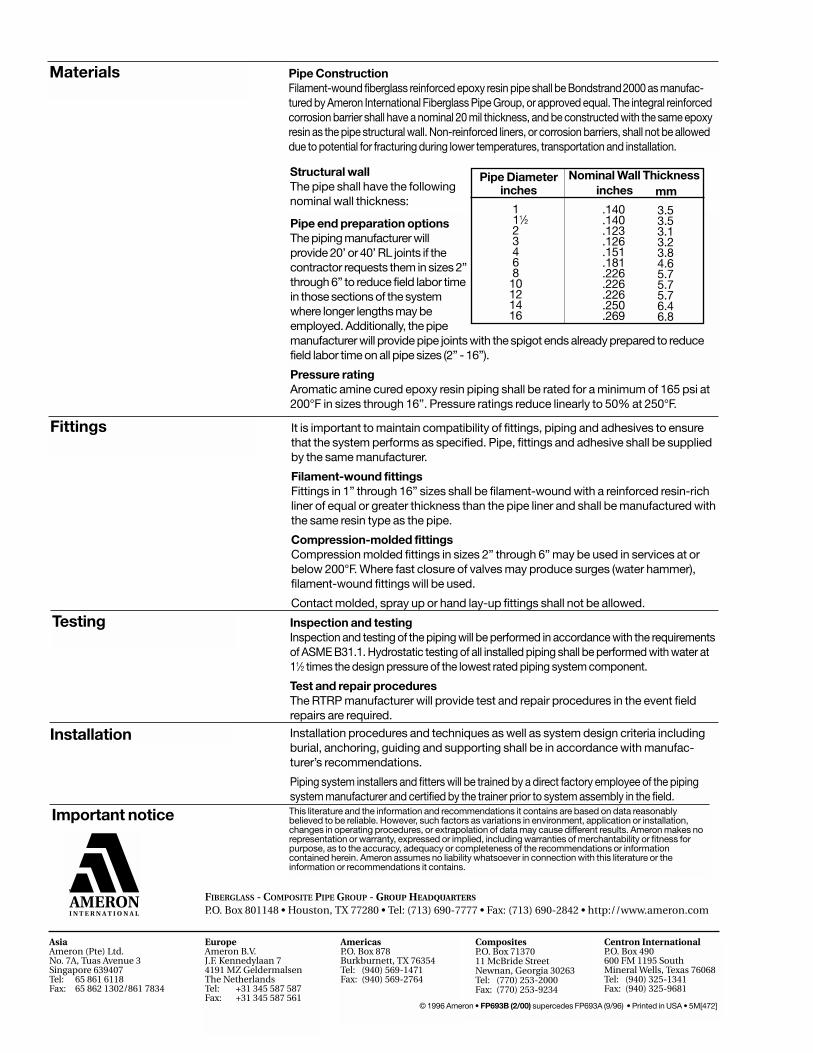
Advantages The contract provisions of this project left it to the contractor’s discretion to choose themost suitable system meeting the operating requirements. Contractor determined thatthe Bondstrand system would be more cost effective than the other principalalternative: a combined system of glass-lined cast iron and unlined cast iron.
Ease of assembly Because of the ease with which Bondstrand fiberglass flanges can be mounted onpipe and fittings, contractor assembled ANSI-dimensioned fittings and pipe spoolsin his own on-site fabrication shop.
© 1992 Ameron • FP312E (11/96) supersedes FP312D (10/95) • Printed in U.S.A. • 5M [021]
Fiberglass Pipe Division-AsiaNo. 7A, Tuas Avenue 3Singapore 2263Tel: 65 862 1301Fax: 65 862-1302
Fiberglass Pipe Division-EuropeJ.F. Kennedylaan 74191 MZ GeldermalsenThe NetherlandsTel: +31 345 573-341Fax: +31 345 575 254Telex: 40257 bonds nl
Fiberglass Pipe Division-U.S.A.P.O. Box 878Burkburnett, Texas 76354Tel: (817) 569-1471Fax: (817) 569-4012
Group HeadquartersP.O. Box 801148 Houston TX 77280Tel: (713) 690-7777Fax: (713) 690-2842
FIBERGLASS PIPE GROUP

Condensate Return Lines Retrofitfor Nashville Generating Plantsliplining with Bondstrand Series 2000 fiberglass pipe and filament wound fittings
Location Nashville, Tennessee
Client Nashville Thermal Transfer Corporation
Application Condensate return lines, average working pressure of 25 psi (2 bar) at 180°F (82°C)
Bondstrand Series 2000 pipe, filament wound fittings, 4” (100 mm)Product
FP736 (3/97)
Bondstrand® Case History
ISO-9001
CERTIFICATED FIRM
FIBERGLASS - COMPOSITE PIPE GROUP

CompositesP.O. Box 7137011 McBride StreetNewnan, Georgia 30263Tel: (770) 253-2000Fax: (770) 253-9234
FIBERGLASS - COMPOSITE PIPE GROUP - GROUP HEADQUARTERS
P.O. Box 801148 • Houston, TX 77280 • Tel: (713) 690-7777 • Fax: (713) 690-2842 • http://www.ameron.com
EuropeAmeron B.V.J.F. Kennedylaan 74191 MZ GeldermalsenThe NetherlandsTel: +31 345 587 587Fax: +31 345 587 561
AmericasP.O. Box 878Burkburnett, TX 76354Tel: (940) 569-1471Fax: (940) 569-2764
Centron InternationalP.O. Box 490600 FM 1195 SouthMineral Wells, Texas 76068Tel: (940) 325-1341Fax: (940) 325-9681
AsiaAmeron (Pte) Ltd.No. 7A, Tuas Avenue 3Singapore 639407Tel: 65 861 6118Fax: 65 862 1302/861 7834
Corrosion resistance - Bondstrand is inherently resistant to corrosion and scalebuild up. It exhibits excellent flow characteristics with a Hazen Williams rating of 150.
Ease of installation - With light weight fiberglass no heavy lifting equipment wasneeded. The pipe was easily lowered into the small trench, bonded in the ditch andslipped through the old piping system.
Cost savings - Using Bondstrand minimized the extensive digging needed toreplace the ductile iron, resulting in savings of time, money and disruption.
Approximately 1100 feet (350 m) of 4-inch diameter, Bondstrand Series 2000 pipeand filament-wound fittings were installed beneath the busy streets of downtownNashville, Tennessee. Bondstrand 2000 replaces 6-inch ductile iron pipe incondensate return lines. The failing ductile iron pipe had been in service for only threeyears. The piping system will supply heat produced by a trash burning generatingplant to 39 major buildings in downtown Nashville. The existing ductile iron pipe hasdeteriorated due to corrosion and scale build up. Digging costs to replace themetallic piping with the same material would be prohibitive and extremely disruptivebecause of its location in the congested downtown area. The problem was solved bysliplining the ductile iron with Bondstrand 2000, taking advantage of Bondstrand’slight weight and ease of installation.
With Bondstrand, the contractor was able to dig a small trench, assemble lengthsof pipe in the ditch and slip the 4-inch fiberglass pipe inside the 6-inch ductile iron.Pipe was installed between 6:00 pm and 6:00 am to minimize the disruption to citytraffic.
Technical support At job start-up, Ameron Technical Service provided installation training and certifi-cation of crew members. This ensured that the proper techniques were utilizedduring installation to provide a successful application in the least amount of time.
Advantages
Pipe system
© 1997 Ameron • Printed in U.S.A. • FP736 (3/97) • 10M[021]
" In the trench, installeruses a flapper sanderto prepare pipe endfor adhesive joint.
" Lengths of Bondstrand 2000 are bonded in the trenchand slipped inside the existing ductile iron pipe.

Desalination Facilityusing Bondstrand Series 2000fiberglass pipe and fittings
Location Al-Khobar, Saudi Arabia
Client Saline Water Conversion Corporation (SWCC)
Application Water reject piping in third stage ejector condensers in ten desalination units.
FP401C (8/96)
Bondstrand® Case History
ISO-9001
CERTIFICATED FIRM
FIBERGLASS - COMPOSITE PIPE GROUP

Corrosion resistance - Pipe and fittings easily withstand the acidity of themedium. Bondstand replacement piping has already served nearly twice aslong as original metallic piping without showing any signs of corrosion.
Ease of installation - System was easily field fabricated by an installationcrew from Ameron. The crew was able to complete the installation for eachunit in only one day.
After approximately two years of service, the existing 100 mm and 150 mm Cu-Ni (90/10) piping had begun to fail in this service. The medium, seawaterat 50°C containing dissolved gases including chlorine, air and carbon dioxide,was sufficiently acidic (pH 5.8-6.2) to cause severe internal corrosion to themetallic piping, resulting in heavy leakage in general and collapse when thepiping was subjected to vacuum.
Bondstrand Series 2000 fiberglass reinforced pipe was chosen to replace theold Cu-Ni lines due to its corrosion resistance and ease of installation.
Technical support Ameron provided technical support to the client during all phases of the project.
Advantages
Pipe system
© 1989 Ameron • Printed in U.S.A. • FP401C (8/96) supersedes FP401B (8/96) • 5M[021]
The previously installed Cu-Ni pipe (left)experienced severe corrosion failure,
especially at welds. Bondstrand corrosionresistant piping systems (right) include a wide
variety of fittings, including reducers, lateraltees and elbows in many angular configura-
tions.
CompositesP.O. Box 7137011 McBride StreetNewnan, Georgia 30263Tel: (770) 253-2000Fax: (770) 253-9234
FIBERGLASS - COMPOSITE PIPE GROUP - GROUP HEADQUARTERS
P.O. Box 801148 • Houston, TX 77280 • Tel: (713) 690-7777 • Fax: (713) 690-2842 • http://www.ameron.com
EuropeAmeron B.V.J.F. Kennedylaan 74191 MZ GeldermalsenThe NetherlandsTel: +31 345 587 587Fax: +31 345 587 561
AmericasP.O. Box 878Burkburnett, TX 76354Tel: (940) 569-1471Fax: (940) 569-2764
Centron InternationalP.O. Box 490600 FM 1195 SouthMineral Wells, Texas 76068Tel: (940) 325-1341Fax: (940) 325-9681
AsiaAmeron (Pte) Ltd.No. 7A, Tuas Avenue 3Singapore 639407Tel: 65 861 6118Fax: 65 862 1302/861 7834

Ft. KhamehameaWastewater Treatment Plantusing Bondstrand Series 2000fiberglass pipe, filament wound fittings and flanges
Location Hickham AFB, Hawaii
Client United States Air Force
Application Process lines transporting sludge and sludge gases
Bondstrand Series 2000 pipe, filament wound fittings and flangesProduct
FP727 (11/96)
Bondstrand® Case History FIBERGLASS PIPE GROUP
ISO-9001
CERTIFICATED FIRM

Chemical resistance - Bondstrand withstands the rigors of aggressive chemicals.The corrosion resistance also provides excellent weatherability.
Ease of installation - Epoxy bonded joining system saves time and money. ANSIflanged fittings provide a familiar joining system and simple joining to traditionalequipment and materials. Lightweight fiberglass, approximately 1⁄5 the weight oftraditional materials, can be moved without heavy lifting equipment.
Cost savings - Bondstrand Series 2000 pipe and fittings provide the lifeexpectancy required at about 20% less cost than glass-lined cast iron andapproximately 30% less cost than stainless steel.
Bondstrand Series 2000 pipe and filament-wound fittings and flanges in 2- to 14-inch diameters are used for process lines in this wastewater treatment plant. Thepiping systems are used for sludge, digester gas, methane gas, chlorine gasvacuum and solution, alum, foul air and aeration air. Bondstrand's resistance toboth external and internal corrosion made it an excellent choice to handle theseservices in this marine environment.
Bondstrand was selected over other materials such as glass-lined cast iron or316L Schedule 40 stainless steel. In addition to providing an economical materialsolution for carrying corrosive media, its light weight and easy assembly reducedinstallation costs over these other piping materials.
Technical support At job start-up, Ameron Technical Service provided installation training and certifi-cation of crew members. This ensured that the proper techniques were utilizedduring installation to provide a successful application in the least amount of time.
Advantages
Pipe system
© 1996 Ameron • Printed in U.S.A. • FP727 (11/96) • 10M[021]
Far right and below: Process piping lines carrysludge and gases at wastewater treatment
plant.
Fiberglass Pipe Division-AsiaNo. 7A, Tuas Avenue 3Singapore 2263Tel: 65-862-1301Fax: 65-862-1302
Fiberglass Pipe Division-EuropeJ.F. Kennedylaan 74191 MZ GeldermalsenThe NetherlandsTel: +31 345 573-341Fax: +31 345 575 254Telex: 40257 bonds nl
Fiberglass Pipe Division-U.S.A.P.O. Box 878Burkburnett, Texas 76354Tel: (817) 569-1471Fax: (817) 569-4012
Group HeadquartersP.O. Box 801148 Houston TX 77280Tel: (713) 690-7777Fax: (713) 690-2842http://www.ameron-net.com
FIBERGLASS PIPE GROUP

Puente Hills LandfillFlare Station Yard Pipingusing Bondstrand Series 2000fiberglass pipe and fittings
Location Whittier, California
Client County Sanitation Districts of Los Angeles County
Application LFG at 125 psi and 160°F operating temperature
FP720 (9/96)
ISO-9001
CERTIFICATED FIRM
Bondstrand® Case History FIBERGLASS - COMPOSITE PIPE GROUP

CompositesP.O. Box 7137011 McBride StreetNewnan, Georgia 30263Tel: (770) 253-2000Fax: (770) 253-9234
FIBERGLASS - COMPOSITE PIPE GROUP - GROUP HEADQUARTERS
P.O. Box 801148 • Houston, TX 77280 • Tel: (713) 690-7777 • Fax: (713) 690-2842 • http://www.ameron.com
EuropeAmeron B.V.J.F. Kennedylaan 74191 MZ GeldermalsenThe NetherlandsTel: +31 345 587 587Fax: +31 345 587 561
AmericasP.O. Box 878Burkburnett, TX 76354Tel: (940) 569-1471Fax: (940) 569-2764
Centron InternationalP.O. Box 490600 FM 1195 SouthMineral Wells, Texas 76068Tel: (940) 325-1341Fax: (940) 325-9681
AsiaAmeron (Pte) Ltd.No. 7A, Tuas Avenue 3Singapore 639407Tel: 65 861 6118Fax: 65 862 1302/861 7834
Chemical resistance - Bondstrand withstands the rigors of aggressive chemicals.The corrosion resistance also provides excellent weatherability.
Ease of installation - Epoxy bonded joining system saved time and money. Theinstallation was completed in four days, eliminating the difficult and costly weldingrequired for stainless steel. Lightweight fiberglass can be moved without heavylifting equipment.
Cost savings - Bondstrand 2000 pipe and fittings provided the life expectancyrequired at 1⁄4 the material cost of stainless steel. Installed cost was 1⁄6 the cost ofstainless steel.
Bondstrand Series 2000 pipe and filament-wound fittings, prefabricated in 6- to12-inch diameters were used. Landfill gas contains methane and high concentra-tions of hydrogen sulfite (H2S), and water at 150° to 170°F. The H2S mixes withwater vapor, forming strong sulfuric acid in the piping system. Carbon steel cansurvive only 3 to 4 years in this service. Plastic piping (PVC, CPVC and HDPE)was eliminated as a choice for this application due to temperature and pressurelimitations around 140°F. Fiberglass pipe also provides better UV resistance thanPVC or CPVC.
While Schedule 10 or 20 304L stainless steel can provide the desired 30-year lifeexpectancy in this service, its material cost is about four times that of fiberglassand the installed cost would be approximately six times that of fiberglass.
Ameron Bondstrand 2000 also saved installation time. The difficult weldingprocess of stainless steel takes 3-4 times longer than epoxy bonding of fiberglass.As a result the installation took less than four days. The system was then fieldtested at 225 psig for 10 cycles.
Technical support Ameron provided installation training and technical support to the client.
Advantages
Pipe system
© 1996 Ameron • Printed in U.S.A. • FP720 (9/96) • 10M[021]
Far right: High speed blower moves landfill gasthrough Bondstrand pipe into leachate collection
tank, below concrete slab.
Near right: Flanged Bondstrand pipe at end of runpermits future expansion as need arises.
Below: Moisture separator removesleachate from gas.

Petro-chemical Refinery Pipingwith Bondstrand Series 2000 fiberglass pipe and filament wound fittings
Location El Tablazo, Estado Zulia, Venezuela
Client PDVSA Oil & Gas
Application Demineralized water lines
8” (200 mm) Bondstrand Series 2000 pipe, filament wound fittings, Quick-Lock®
joining systemProduct
FP304 (4/98)
Bondstrand® Case History
ISO-9001
CERTIFICATED FIRM
FIBERGLASS - COMPOSITE PIPE GROUP
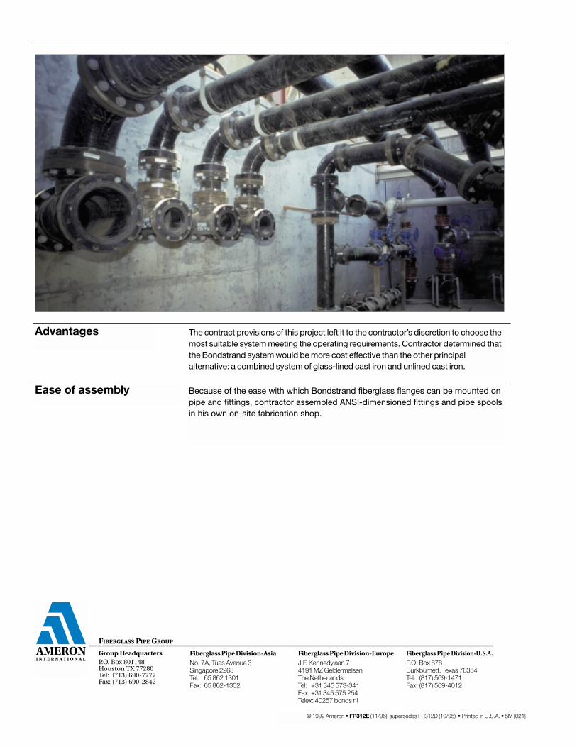
Corrosion resistance - Bondstrand is inherently resistant to corrosion and scalebuild up. It exhibits excellent flow characteristics with a Hazen Williams rating of 150.
Ease of installation -Light weight fiberglass is easy to handle and install.
Approximately 4900 feet (1500 m) of 8-inch diameter, Bondstrand Series 2000 pipeand filament-wound fittings were installed in this petrochemical complex inVenezuela. The piping transports demineralized water to the entire complex. Installedin 1974, the Bondstrand piping system has provided trouble-free service for 24 years.
Advantages
Pipe system
© 1997 Ameron • Printed in U.S.A. • FP304 (4/98) • 10M[021]
" Far right, 8" (200 mm) Bondstrand2000 in service for 24years.
" Right, lengths of Bondstrand2000 supply demineralizedwater.
CompositesP.O. Box 7137011 McBride StreetNewnan, Georgia 30263Tel: (770) 253-2000Fax: (770) 253-9234
FIBERGLASS - COMPOSITE PIPE GROUP - GROUP HEADQUARTERS
P.O. Box 801148 • Houston, TX 77280 • Tel: (713) 690-7777 • Fax: (713) 690-2842 • http://www.ameron.com
EuropeAmeron B.V.J.F. Kennedylaan 74191 MZ GeldermalsenThe NetherlandsTel: +31 345 587 587Fax: +31 345 587 561
AmericasP.O. Box 878Burkburnett, TX 76354Tel: (940) 569-1471Fax: (940) 569-2764
Centron InternationalP.O. Box 490600 FM 1195 SouthMineral Wells, Texas 76068Tel: (940) 325-1341Fax: (940) 325-9681
AsiaAmeron (Pte) Ltd.No. 7A, Tuas Avenue 3Singapore 639407Tel: 65 861 6118Fax: 65 862 1302/861 7834

Series 2000MP FiberglassPipe and Fittingscertified to Specification MIL-P-28584B
Chilled waterCondensate returnDomestic hot waterHeating waterPumped hot water
Uses and applications
MIL-P-28584B for pipe and fittings conveying water at pressures to 125 psig andtemperatures to 250°F.
Listings
Excellent corrosion resistance over a wide temperature range.
Weighs 1⁄6th as much as steel.
Does not require thrust blocks at ambient temperatures when properly installed.
Smooth inner liner produces extremely low frictional loss (Hazen-Williams C = 150) forgreater discharge and reduced pumping costs.
Low thermal conductivity (1⁄100th of steel) minimizes heat losses.
Performance
PipeFilament-wound fiberglass reinforced epoxy resin pipe with nominal 0.020-inch (0.5 mm)resin-rich reinforced liner.
Continuous operating temperatures to 250°F (121°C).
Filament-wound fittingsFurnished with reinforced liner using same materials as pipe.
Tees 45° elbows90° elbows CouplingsFlanges NipplesSaddles Tapered body reducers
Flanged fittings
Flanges match bolt-hole pattern for ANSI B16.5 150 lb flanges, ANSI B16.1 for 125 lbcast iron flanges and ISO Standard 2229.
Thermosetting adhesivesPSX™•34 two-part epoxy adhesive for field fabrication.
Composition
FP467C (7/00)
Bondstrand® Product DataFIBERGLASS - COMPOSITE PIPE GROUP

2- to 6-inch: 20-ft random lengths.
8- to 10-inch: 20-ft random lengths.
Pipe lengths
Fittings
70°F 150°F 200°F 250°F TestPipe Property1 Units 21°C 66°C 93°C 121°C Method
CircumferentialTensile stress at weeping 103 psi 024.0 00- 00- 00- D1599
MPa 16500- 00- 00-Tensile modulus 106 psi 003.65 03.44 03.20 02.98
GPa 025.2 23.7 22.1 20.5Poisson’s ratio - 000.56 00.60 00.70 00.79 Ameron
LongitudinalTensile strength 103 psi 008.50 07.80 06.90 05.80 D2105
MPa 058.6 53.8 47.6 40.0Tensile modulus 106 psi 001.60 01.35 01.24 01.10 D2105
GPa 011.0 09.3 08.5 07.6Poisson’s ratio - 000.37 00.39 00.41 00.43 D2105
Beam apparentElastic modulus 106 psi 001.70 01.30 01.00 - D2925
GPa 011.7 09.0 06.9 -Hydrostatic design
basis 103 psi 006.0 - - - D2992MPa 041.4 -- -
Mechanical properties1
Quick-Lock® straight/taper adhesive-bonded joint featuring integral pipe stop in bell forpredictable, precise laying lengths.
Flanges and flanged fittings.
Joining systems
Elbows
Tees
Flanges, blind flanges and reducing flanges
Plugs and end-caps
Nipples and couplings
Tapered body reducers
Tapered body reducers, tees and 90° and 45° elbows are available with any combinationof Quick-Lock female and filament-wound flange ends.
Laying lengths of filament-wound fittings with Quick-Lock ends match those of ANSIB16.9 steel buttwelding fittings. Flanged ends match ANSI B16.1 and B16.5 center-to-face and face-to-face dimensions.
2

Nominal Laying Overall ApproxPipe Size Length A Length B Weight
(in) (mm) (in) (mm) (in) (mm) (lb) (kg)
3 x 2 80 x 50 2.13 54 5.75 146 1.1 .54 x 2 100 x 50 3.00 76 6.63 168 2.1 .94 x 3 100 x 80 2.88 73 6.50 165 2.2 1.06 x 3 150 x 80 3.81 97 7.88 200 3.9 1.86 x 4 150 x 100 3.69 95 7.75 197 3.5 1.68 x 4 200 x 100 5.44 138 10.19 259 7.1 3.28 x 6 200 x 150 3.88 99 8.63 219 6.6 3.0
10 x 6 250 x 150 4.63 118 9.63 245 8.4 3.810 x 8 250 x 200 4.12 105 9.37 238 8.0 3.6
See Quick-Lock bell and spigot dimension table on page 5 for bell depth, ds
Nominal Bolt Outside ThicknessPipe Size Circle BC Diameter D At Face E
(in) (mm) (in) (mm) (in) (mm) (in) (mm)
2 50 4.75 121 6.00 152 2.00 51 3 80 6.00 152 7.50 190 2.00 51 4 100 7.50 190 9.00 229 2.00 51 6 150 9.50 241 11.00 279 2.38 608 200 11.75 298 13.50 343 2.63 67
10 250 14.25 362 16.00 406 2.88 73
Nominal Bolt Hole Bolt ApproxPipe Size Count Size F Size Weight
(in) (mm) (in) (mm) (in) (mm) (lb) (kg)
2 50 4 0.75 19.1 0.63 16 3.0 1.43 80 4 0.75 19.1 0.63 16 4.1 1.94 100 8 0.75 19.1 0.63 16 6.1 2.86 150 8 0.88 22.4 0.75 19 9.4 4.38 200 8 0.88 22.4 0.75 19 14.9 6.8
10 250 12 1.00 25.4 0.88 22 20.5 9.3See Quick-Lock bell and spigot dimension table on page 5 for bell depth, ds
Flanges
Reducers
Laying length = .125 [3.2 mm]
EF
B
BC
Dds
dsds A
7

Nominal Overall Approx WeightPipe Size Length B Nipple Saddle*
(in) (mm) (in) (mm) (lb) (kg) (lb/in) (g/mm)
2 50 3.75 95 0.2 .09 0.2 43 80 3.75 95 0.3 .14 0.3 54 100 3.75 95 0.5 .23 0.4 76 150 4.63 118 0.9 .41 0.5 98 200 5.13 130 1.4 .64 0.6 11
10 250 5.63 143 1.9 .86 0.8 14
* Saddles are used to protect pipe at supports and clamps and are available in lengths to 18 inches(500mm).
Nominal Overall Outside ApproxPipe Size Length B Diameter D Weight
(in) (mm) (in) (mm) (in) (mm) (lb) (kg)
2 50 4.00 102 2.81 71 0.6 .33 80 4.00 102 3.94 100 0.9 .4 4 100 4.00 102 5.06 129 1.4 .66 150 4.88 124 7.19 183 2.4 1.18 200 5.38 137 9.25 235 3.8 1.7
10 250 5.88 149 11.38 289 5.2 2.4See Quick-Lock bell and spigot dimension table on page 5 for bell depth, ds
Nominal Laying Overall ApproxPipe Size Length A Length B Weight
(in) (mm) (in) (mm) (in) (mm) (lb) (kg)
2 50 2.50 64 4.31 109 2.1 1.03 80 3.38 86 5.19 132 4.1 1.94 100 4.13 105 5.94 151 5.0 2.36 150 5.63 143 7.88 200 11 5.08 200 7.00 178 9.50 241 18 8.2
10 250 14.50 368 17.25 438 38 17.3See Quick-Lock bell and spigot dimension table on page 5 for bell depth, ds
Tees
Couplings
Nipples and supportsaddles
Laying length = .375 [9.5 mm]
Laying length = .125 [3.2 mm]
ds
ds
D
B
A
B
B
Length
180°
.56 [14mm]
6

Nominal Pipe Nominal Wall Average** PipePipe Size ID Thickness* Sectional Area Weight(in) (mm) (in) (mm) (in) (mm) (in) (mm) (lb/ft) (kg/m)
2 50 2.10 53 .157 4.0 1.13 730 0.9 1.53 80 3.22 82 .157 4.0 1.70 1100 1.2 1.84 100 4.14 105 .203 5.2 2.73 1760 2.0 3.06 150 6.26 159 .203 5.2 4.06 2620 3.0 4.58 200 8.22 209 .226 5.7 5.83 3760 4.3 6.4
10 250 10.35 263 .226 5.7 7.31 4710 5.4 8.1
* Minimum wall thickness is 87.5% of nominal wall thickness.**Use these values for calculating longitudinal thrust.
Nominal Internal External Pipe Size Pressure Rating* Pressure Rating*(in) (mm) (psig) (MPa) (psig) (MPa)
2 50 125 0.86 210 1.453 80 125 0.86 135 0.934 100 125 0.86 150 1.036 150 125 0.86 45 0.318 200 125 0.86 30 0.21
10 250 125 0.86 14 0.097
* At 250°F (121°C) using Bondstrand RP34C adhesive.**At 70°F. Reduce linearly to 90% at 150°F and 80% at 210°F.
Nominal Stiffness Pipe Beam MomentPipe Size Factor* Stiffness* of Inertia**(in) (mm) (lb·in) (N·m) (psi) (MPa) (in4) (106mm4)
2 50 620 70 2900 20.0 0.59 0.2463 80 620 70 860 5.93 1.99 0.8284 100 1360 154 890 6.14 5.50 2.296 150 1360 154 270 1.86 18.1 7.538 200 1890 214 175 1.17 45.1 18.8
10 250 1890 214 86 0.59 88.6 36.9
* Per ASTM D2412.**Use these values to calculate permissible spans.
Typical pipe performance
Pipe Property Units Value Method
Thermal conductivityPipe wall Btu·in/(hr·ft2·°F) 002.3 Ameron
W/m·K 000.33Thermal expansion
Linear 10-6 in/in/°F 010 Ameron10-6 mm/mm°C 018
Flow coefficient Hazen-Williams 150 _Absolute roughness 10-6 ft 017.4 _
10-6 m 005.3Density lb/in3 001.8 _
g/cm3 000.065
Physical properties
Typical pipe dimensions and weights
3

Thrust blocksMost properly bedded Bondstrand 2000MP installations do not require thrust blocks.Consult Ameron for recommendations for systems operating at elevated temperatures.
Live loadsBondstrand 2000MP will carry H20 wheel loadings of at least 16,000 lb (7250 kg) whenproperly bedded in compacted sand in stable soils and provided with at least 3 ft (1 m) ofcover.
Nominal Maximum Earth CoverPipe Size 100 psi 0.69 MPa 125 psi 0.86 MPa
(in) (mm) (ft) (m) (ft) (m)
2 50 30 9.1 30 9.13 80 22 6.7 22 6.74 100 24 7.3 23 7.06 150 21 6.4 20 6.18 200 21 6.4 20 6.1
10 250 22 6.7 19 5.8
* Based on a 120 lb/ft3 (1925 kg/m3) soil density and 1000 psi (6.9 MPa) modulus of soil reaction.**Internal operating pressure, psi (MPa).
Buried installations
Recommended maximum support spacing for Bondstrand 2000MP pipe at variousoperating temperatures. Span recommendations are valid for normal horizontal pipingsupport arrangements, a compromise between continuous spans and simple spans, butinclude no provision for weights such as fittings, flanges, etc. or thrust from branches,turns, etc. Span recommendations are calculated for a maximum long-term deflection of1⁄2 inch to ensure good appearance and adequate drainage. Values are based on 1⁄2 inchdeflection at midspan for fluid specific gravity = 1.0. For continuous spans, increasevalues by 20%. For end or single spans, decrease values by 20%.
Nominal Span (feet or meters)Pipe Size Temperature
(in) (mm) 100°F 37°C 150°F 66°C 200°F 99°C 250°F 122°C
2 50 13.0 3.9 11.7 3.6 10.4 3.2 9.2 2.83 80 14.6 4.5 13.3 4.1 12.0 3.7 10.7 3.34 100 16.8 5.1 15.0 4.6 13.2 4.0 11.4 3.56 150 18.7 5.7 17.0 5.2 15.2 4.6 13.5 4.18 200 21.2 6.5 19.2 5.9 17.2 5.2 15.2 4.6
10 250 22.3 6.8 20.3 6.2 18.4 5.6 16.4 5.0
Support spacing
4

Nominal Laying Overall ApproxPipe Size Length A Length B Weight
(in) (mm) (in) (mm) (in) (mm) (lb) (kg)
2 50 1.38 35 3.19 81 0.9 .43 80 2.00 51 3.81 97 1.7 .64 100 2.50 64 4.31 109 2.5 1.16 150 3.75 95 6.00 152 5.2 2.48 200 5.00 127 7.50 191 9.3 4.2
10 250 6.25 159 9.00 229 16 7.3See Quick-Lock bell and spigot dimension table on page 5 for bell depth, ds
Nominal Laying Overall ApproxPipe Size Length A Length B Weight
(in) (mm) (in) (mm) (in) (mm) (lb) (kg)
2 50 3.00 76 4.81 122 1.1 .53 80 4.50 114 6.31 160 2.4 1.14 100 6.00 152 7.81 198 3.5 1.66 150 9.00 229 11.25 286 7.9 3.68 200 12.00 305 14.50 368 15 6.8
10 250 15.00 381 17.75 451 25 11.4See Quick-Lock bell and spigot dimension table on page 5 for bell depth, ds
Quick-Lock Spigot Bell Spigot DiameterJoint Size Length L Depth ds Minimum Maximum
(in) (mm) (in) (mm) (in) (mm) (in) (mm) (in) (mm)
2 50 2.000 50.8 1.812 46.0 2.330 59.2 2.346 59.63 80 2.000 50.8 1.812 46.0 3.450 87.6 3.466 88.04 100 2.000 50.8 1.812 46.0 4.430 112.5 4.446 112.96 150 2.375 60.3 2.250 57.1 6.544 166.2 6.560 166.68 200 2.375 60.3 2.500 63.5 8.544 217.0 8.560 217.4
10 250 2.875 60.3 2.750 69.8 10.680 271.3 10.696 271.7
Maximum AllowableNominal Bending Deflection, H, for 100-ft TurningPipe Size Radius, R* (30 m) Bending Length Angle, α(in) (mm) (ft) (m) (ft) (m) (deg)
2 50 83 26 14.6 4.5 693 80 123 38 10.1 3.1 474 100 158 46 7.9 2.4 366 150 233 71 5.4 1.6 258 200 304 93 4.1 1.3 19
10 250 379 116 3.3 1.0 15
C
45° Elbows
90° Elbows
Quick-Lock bell andspigot dimensions
Bending radius
H
S
α
α
R
ds
ds
B
L
A
ds
B
A
5

© 1988 Ameron FP467C (7/00) supersedes FP467B (7/97) Printed in U.S.A. 5M [186]
1 psi = 6895 Pa = 0.07031 kg/cm2
1 bar = 105 Pa = 14.5 psi = 1.02 kg/cm2
1 MPa = 106 Pa = 145 psi = 10.2 kg/cm2
1 GPa = 109 Pa = 145,000 psi = 10,200 kg/cm2
1 in = 25.4 mm1 ft = 0.3048 m1 lb·in = 0.113 N·m1 in4 = 4.162 x 10⁻⁷m4
°C = 5/9 (°F - 32)
Conversions
CompositesP.O. Box 7137011 McBride StreetNewnan, Georgia 30263Tel: (770) 253-2000Fax: (770) 253-9234
FIBERGLASS - COMPOSITE PIPE GROUP - HEADQUARTERS
P.O. Box 801148 • Houston, TX 77280 • Tel: (713) 690-7777 • Fax: (713) 690-2842 • http://www.ameron.com
EuropeAmeron B.V.J.F. Kennedylaan 74191 MZ GeldermalsenThe NetherlandsTel: +31 345 587 587Fax: +31 345 587 [email protected]
AmericasP.O. Box 878Burkburnett, TX 76354Tel: (940) 569-1471Fax: (940) 569-2764
Centron InternationalP.O. Box 490600 FM 1195 SouthMineral Wells, Texas 76068Tel: (940) 325-1341Fax: (940) 325-9681http://www.centrongre.com
AsiaAmeron (Pte) Ltd.No. 7A, Tuas Avenue 3Singapore 639407Tel: 65 861 6118Fax: 65 862 1302/861 [email protected]
Important Notice This literature and the information and recommendations it contains are based on data reasonably believed to bereliable. However, such factors as variations in environment, application or installation, changes in operatingprocedures, or extrapolation of data may cause different results. Ameron makes no representation or warranty,express or implied, including warranties of merchantability or fitness for purpose, as to the accuracy, adequacy orcompleteness of the recommendations or information contained herein. Ameron assumes no liability whatsoeverin connection with this literature or the information or recommendations it contains. Product specifications aresubject to change.

Physical and Mechanical Properties
Thermal conductivityPipe wall Btu•in/(hr•ft2•°F) 1.70 1.70 - - C177
W/m•°C 0.25 0.25 - -Thermal expansion
Linear 10-6 in/in/°F 8.50 10.00 - - D69610-6 mm/mm°C 15.30 18.00 - -
Flow coefficient Hazen-Williams 150.00 150.00 - - -Absolute roughness 10-6 ft 17.40 17.40 - - -
10-6 m 3.30 5.30Specific gravity - 1.80 1.80 - - D792Density lb/in3 0.07 0.07 - -
g/cm3 1.80 1.801) At 150°F (66°C). 2) Static
70°F 200°F ASTMPipe Property Units 21°C 93°C MethodNominal Pipe Size 2”-6” 8”-10” 2”-6” 8”-10”CircumferentialTensile stress at 103 psi 32.00 24.00 - - D1599weeping MPa 22.00 165.00 - -Tensile modulus 106 psi 4.20 3.65 3.70 3.20
GPa 29.00 25.20 25.50 22.10Poisson’s ratio 0.26 0.56 0.32 0.70 D2105
LongitudinalTensile strength 103 psi 16.00 8.50 13.00 6.90 D2105
MPa 110.00 58.60 90.00 47.60Tensile modulus 106 psi 3.00 1.60 2.40 1.24 D2105
GPa 20.70 11.00 16.50 8.50Poisson’s ratio 0.16 0.37 0.20 0.41 D2105
Beam apparentElastic modulus 106 psi 2.40 1.70 1.77 1.00 D2925
GPa 16.60 11.70 12.20 6.90Hydrostatic designbasis (cyclic) 103 psi 16.001,2 6.001 - - D2992
MPa 110.00 41.40 - -
Bondstrand 2000 MPPipe and FittingsFiberglass reinforced thermosetting epoxy resinpipe for plant piping hot water, chilled water, andcondensate return services
Scope This specification defines the reinforced thermosetting resin (RTR) piping system tobe used in those sections of Plant Piping–hot water, chilled water and condensatereturn services calling for fiberglass piping systems.
References, Quality Assurance
References are made to other standards and tests which are a part of this section asmodified. Where conflict exists between the requirements of this specification and listedreferences, the specification shall prevail.
PerformanceRequirements
The piping system in sizes 2” through 10” must comply with MIL-P-28584B and U.S.Federal Regulations 21CFR 175.105 and 21CFR 177.2280. Piping will be manufacturedaccording to ASTM D2996 for RTRP. When classified under ASTM D2310, the pipe shallmeet Type I, Grade I and Class F (RTRP-11FE) cell limits in 2” through 10” nominal pipesizes. Piping shall be listed for “Commercial Hot” service by NSF under Standard 61 -Drinking Water System Components.
FP695B (6/00)
Bondstrand® Guide Specification
ISO-9001
CERTIFICATED FIRM
FIBERGLASS - COMPOSITE PIPE GROUP

Pipe ConstructionFilament-wound fiberglass reinforced epoxy resin pipe shall be Bondstrand® 2000 MPas manufactured by Ameron Fiberglass Pipe Group, or approved equal. The integralreinforced corrosion barrier shall have a nominal 20 mil thickness, and be constructedwith the same epoxy resin as the pipe structural wall. Non-reinforced corrosion barriersshall not be allowed due to potential for fracturing during lower temperatures, trans-portation and installation.
CompositesP.O. Box 7137011 McBride StreetNewnan, Georgia 30263Tel: (770) 253-2000Fax: (770) 253-9234
FIBERGLASS - COMPOSITE PIPE GROUP - HEADQUARTERS
P.O. Box 801148 • Houston, TX 77280 • Tel: (713) 690-7777 • Fax: (713) 690-2842 • http://www.ameron.com
EuropeAmeron B.V.J.F. Kennedylaan 74191 MZ GeldermalsenThe NetherlandsTel: +31 345 587 587Fax: +31 345 587 561
AmericasP.O. Box 878Burkburnett, TX 76354Tel: (940) 569-1471Fax: (940) 569-2764
Centron InternationalP.O. Box 490600 FM 1195 SouthMineral Wells, Texas 76068Tel: (940) 325-1341Fax: (940) 325-9681
AsiaAmeron (Pte) Ltd.No. 7A, Tuas Avenue 3Singapore 639407Tel: 65 861 6118Fax: 65 862 1302/861 7834
Important Notice
Installation procedures and techniques as well as system design criteria includingburial, anchoring, guiding and supporting shall be in accordance with manufacturer’srecommendations.
Piping system installers and fitters will be trained by a direct factory employee of thepiping system manufacturer and certified by the trainer prior to system assembly inthe field.
Installation
Inspection and testingInspection and testing of the piping will be performed in accordance with the require-ments of ANSI B31.1. Hydrostatic testing of all installed piping shall be performed withwater at 11⁄2 times the design pressure of the lowest rated piping system component.
Test and repair proceduresThe RTRP manufacturer will provide test and repair procedures in the event field repairsare required.
Testing
Materials
Fittings
Pipe end preparation optionsThe piping manufacturer will provide20’ or 40’ RL joints if the installerrequests them in sizes 2” through 6”to reduce field labor assembly time in those sections of the system where longer pipejoints may be employed. Additionally, the pipe manufacturer will provide pipe joints withthe spigot ends already prepared to reduce field labor time.
Pressure ratingAromatic amine cured epoxy resin piping shall be suitable for use at 125 psi up to 250°F.
It is important to maintain compatibility of fittings, piping and adhesives to ensure thatthe system performs as specified. Therefore, the pipe, fittings and adhesive shall besupplied by the same manufacturer.
Filament-wound fittingsFittings in 2” through 10” sizes shall be filament-wound with a reinforced resin-rich linerof equal or greater thickness than the pipe liner and shall be manufactured with thesame resin type as the pipe.
Only filament-wound fittings and flanges will be used. Compression molded, contactmolded, spray up or hand lay-up fittings shall not be allowed.
Structural wallThe pipe shall have the followingnominal wall thickness:
Pipe Diameter(inches)
23468
10
.123
.126
.151
.181
.226
.226
3.13.23.84.65.75.7
Nominal Wall Thicknessinches mm
© 1996 Ameron • FP695B (6/00) supercedes FP695A (10/96) • Printed in USA • 5M[472]
This literature and the information and recommendations it contains are based on data reasonably believed to bereliable. However, such factors as variations in environment, application or installation, changes in operatingprocedures, or extrapolation of data may cause different results. Ameron makes no representation or warranty,express or implied, including warranties of merchantability or fitness for purpose, as to the accuracy, adequacy orcompleteness of the recommendations or information contained herein. Ameron assumes no liability whatsoeverin connection with this literature or the information or recommendations it contains. Product specifications aresubject to change.

Series 3000A FiberglassPipe and Fittingsfor general industrial service
FP516B (10/97)
Uses and applications Alcohol solutionsBoiler feed waterBridge, roof and floor drainsBrine and brackish waterChemical process pipingCooling waterDemineralized waterElectroplatingFuel oil pipingGeneral service pipingJet fuel piping
Mild chemicalsMunicipal wastePotable waterPower plant, steel mill and industrial
plant pipingSewer lines and sewer force mainsSource and recycle waterSump dischargeVent linesWater mainsWater treatment
Performance Working pressure to 450 psig depending on pipe size.
No thrust blocks are required at rated system pressure for most buried pipingconfigurations and most soil conditions. Thrust blocks may be required for 14 and16-inch Bondstrand 3000A. For above-ground use, consult Ameron Fiberglass PipeDivision.
Temperatures to 210°F (99°C) maximum.
Full vacuum capabilities when buried and properly backfilled. For above-ground use,refer to collapse pressures listed below under pipe pressure performance.
Recommended burial depth: 3 to 25 feet.
Recommended for water, waste water (pH 1 to 12), moderately corrosive liquids andmild chemicals. Consult Ameron corrosion guide FP132 or Ameron ApplicationsEngineering for recommendations for your particular application.
Bondstrand Series 3000A is available with the patented Pronto-Lock® andPronto-Lock II mechanical joining systems and may be used to temperatures ashigh as 210°F (99°C).
Individual system components may not have the same ratings as the pipe. Referto the detailed product information for the specific components to determine thepressure rating for the system as a whole.
Listings MIL-P-29206A for jet fuels and petroleum liquids.
Bondstrand® Product DataFIBERGLASS PIPE GROUP
ISO-9001
CERTIFICATED FIRM

Composition Pipe
Filament-wound fiberglass reinforced epoxy pipe with integral epoxy liner andexterior coating.
NominalPipe Size ASTM Designation
(in) (mm) (D2310) (D2996)2 - 6 50 - 150 RTRP 11FX RTRP 11FX-54308 - 16 200 - 400 RTRP 11FX RTRP 11FX-3210
Fittings
2 to 6-inchCompression-molded fiberglass reinforced epoxy elbows and teesFilament-wound and/or mitered crosses, wyes, laterals and reducers
8 to 16-inchFilament-wound fiberglass reinforced epoxy elbowsFilament-wound and/or mitered crosses, wyes, and lateralsContact-molded reducers
Flanges
Flange rings:Molded or filament-wound fiberglass
Stub ends:Molded or centrifugally cast fiberglass
Blind flanges
Compression-molded fiberglass or epoxy-coated cast iron or steel.
O-rings
Buna-N standard.Other materials available on request.
Adhesive
Ameron two-part epoxy adhesive for field fabrication.(consult Ameron for specifications)
Standard 20 and 39-ft random lengths.
Other lengths available on request.
Pipe lengths
Joining systems 2 to 6-inchPronto-Lock mechanical coupling.U.S. Patent No. 3,784,239.
8 to 16-inchPronto-Lock II mechanical coupling.U.S. Patent No. 4,014,568.
2 to 16-inchBell and spigot taper/taper adhesive-bonded joint.
2

UltimateNominal Static Ultimate Collapse Pressure2
Pipe Size Pressure Rating Internal Pressure1 80°F 27°C 210°F 99°C(in) (mm) (psig) (bar) (psig) (bar) (psig) (bar) (psig) (bar)2 50 450 30 3200 215 145 10.0 125 8.63 80 450 30 2400 160 50 3.4 45 3.14 100 375 25 2000 135 40 2.8 35 2.46 150 300 20 2000 135 35 2.4 30 2.18 200 150 10 900 60 25 1.7 21 1.410 250 150 10 900 60 18 1.2 12 0.812 300 150 10 900 60 12 0.8 9 0.614 350 150 10 900 60 10 0.7 7.5 0.516 400 150 10 900 60 10 0.7 7.5 0.5
1) Quality control minimum2) For vacuum service above ground in sizes 8 inches and above consult Ameron.
Nominal Pipe Outside Pipe Inside Wall ThicknessPipe Size Diameter1 Diameter Total Structural(in) (mm) (in) (mm) (in) (mm) (in) (mm) (in) (mm)2 50 2.38 60 2.21 56 0.072 1.8 0.064 1.63 80 3.50 90 3.32 84 0.081 2.1 0.071 1.84 100 4.50 114 4.33 110 0.086 2.2 0.074 1.96 150 6.63 168 6.39 162 0.119 3.0 0.105 2.78 200 8.63 219 8.30 211 0.150 3.8 0.125 3.2
10 250 10.75 273 10.41 264 0.175 4.4 0.150 3.812 300 12.75 324 12.30 312 0.200 5.1 0.175 4.414 350 14.44 367 14.01 356 0.215 5.4 0.190 4.816 400 16.50 419 16.02 407 0.235 6.0 0.210 5.3
1) Typical outside diameters of 2 through 12-inch pipe are within API, ASTM and ANSI fiberglass and steel pipe dimensions.
Nominal Taper Taper PipePipe Size Angle Length Weight(in) (mm) (deg) (in) (mm) (lb/ft) (kg/m)2 50 1.75 1.5 38 0.5 .753 80 1.75 1.7 43 0.7 1.054 100 1.75 1.9 48 1.0 1.506 150 1.75 2.8 71 1.9 2.858 200 2.00 2.6 66 3.1 4.60
10 250 2.00 3.1 79 4.5 6.7012 300 2.00 3.6 91 6.1 9.1014 350 2.00 4.2 107 7.5 11.1516 400 2.00 4.7 119 9.4 14.00
3
Typical pipedimensions andweights
Typical pipeperformance

Typical physicalproperties
Method Pipe Property Units Value ASTM ATM1
Thermal conductivity Btu•in/(hr•ft2•°F) 1.7 C177 23W/m•°C 0.25
Coefficient of thermalexpansion (linear) D696 21(2 - 6 inch) 10-6 in/in/°F 8.5
10-6 m/m/°C 15.3(8 - 16 inch) 10-6 in/in/°F 12.0
10-6 m/m/°C 21.6
Flow coefficient Hazen-Williams 150 — 156
Absolute roughness 10-6 ft 50 — —10-6 m 15
Specific gravity —- 1.81 D792 —
Barcol Hardness Impressor 934-1 65 D2583 —1) Ameron test method.
4
Nominal Laterals, WyesPipe Size Adapters and Crosses Saddles(in) (mm) (psig) (bar) (psig) (bar) (psig) (bar)2 50 450 30 200 13 300 203 80 375 25 200 13 300 204 100 300 20 200 13 200 136 150 300 20 200 13 150 108 200 150 10 150 10 150 10
10 250 - - 150 10 100 812 300 - - 150 10 75 514 350 - - 150 10 50 316 400 - - 150 10 50 3
Fittings pressure ratings NominalPipe Size Elbows and Tees Flanges Blind Flanges(in) (mm) (psig) (bar) (psig) (bar) (psig) (bar)2 50 450 30 450 30 450 303 80 450 30 400 30 450 304 100 375 25 375 25 375 256 150 300 20 300 20 300 208 200 150 10 150 10 150 10
10 250 150 10 150 10 150 1012 300 150 10 150 10 125 814 350 150 10 150 10 75 516 400 150 10 150 10 75 5
1) Ratings shown are for 90° and 45° elbows. Ratings in 8 to 16-inch sizes are alsoapplicable to elbows of other angles.

5
Typical mechanicalproperties
Value Method Pipe Property1 Units (2 - 6 in) (8 - 16 in) ASTM ATM2
Tensile strengthLongitudinal 103 psi 35.0 20.0 D2105 161
MPa 240 138Circumferential 103 psi 70.0 40.0 D1599 151
MPa 480 275
Tensile modulusLongitudinal 106 psi 3.0 1.5 D2105 161
GPa 20.6 10.3Circumferential 106 psi 4.2 2.3 — —
GPa 29.0 15.9
Compressive strengthLongitudinal 103 psi 35.0 20.0 — 142
MPa 240 138
Compressive modulusLongitudinal 106 psi 3.0 1.5 — 142
GPa 20.6 10.3
Long-term hydrostatic design basisStatic 103 psi 21 21 D2992(B) —
MPa 145 145Cyclic 103 psi 8 — D2992(A) —
MPa 55 —
Poisson’s ratio3
νyx — 0.16 0.11 — —νxy — 0.26 0.19 — —
1) Based on structural wall thickness.2) Ameron test method.3) The first subscript denotes the direction of contraction and the second that of the applied stress.
x denotes longitudinal direction.y denotes circumferential direction.
Nominal Change in Length StiffnessPipe Size Due to Pressure1 Factor2
(in) (mm) (in/100 ft/100 psi) (mm/m/bar) (lb•in3/in2) (N•m)2 50 .284 343 42 4.73 80 .394 476 75 8.54 100 .477 576 60 6.86 150 .493 596 275 31.18 200 1.14 1376 500 56.5
10 250 1.19 1437 750 8512 300 1.20 1450 1250 14014 350 1.26 1523 1600 18016 400 1.31 1583 2000 225
1) In an unrestrained system due to pressure effects alone.2) At 5% deflection.

6
Support spacing Values are based on a 1⁄2-inch (12 mm) deflection at midspan.
Nominal Single Span1 Continuous Span2
Pipe Size Gases 1.003 1.25 Gases 1.00 1.25(in) (mm) (ft) (m) (ft) (m) (ft) (m) (ft) (m) (ft) (m) (ft) (m)
2 50 14.4 4.4 9.7 3.0 9.3 2.8 21.5 6.6 14.5 4.4 13.9 4.23 80 17.7 5.4 11.1 3.4 10.6 3.2 26.4 8.0 16.6 5.1 15.8 4.84 100 20.0 6.1 12.1 3.7 11.5 3.5 29.9 9.1 18.1 5.5 17.2 5.26 150 24.9 7.6 14.6 4.5 13.9 4.2 37.2 11.3 21.9 6.7 20.8 6.38 200 23.8 7.3 13.9 4.2 13.2 4.0 35.6 10.9 20.8 6.3 19.7 6.0
10 250 26.9 8.2 15.4 4.7 14.6 4.5 40.2 12.3 23.0 7.0 21.9 6.712 300 29.3 8.9 16.7 5.1 15.9 4.8 43.8 13.4 25.0 7.6 23.7 7.214 350 31.3 9.5 17.6 5.4 16.7 5.1 46.8 14.3 26.3 8.0 25.0 7.616 400 33.5 10.2 18.7 5.7 17.8 5.4 50.1 15.3 27.9 8.5 26.6 8.1
1) For fluid temperatures above 78°F (25°C), the span lengths decrease by 0.2 in/°F (9 mm/°C). 2) For intermediate spans. End spans may be calculated by multiplying the single span length by 1.8.3) Fluid specific gravity.
Minimum Maximum MinimumNominal Bending Deflection Length RequiredPipe Size Radius1 per 39-ft Joint for 10° Change(in) (mm) (ft) (m) (deg) (ft) (m)2 50 75 23 302 132 43 80 100 30 20 20 64 100 150 46 15 27 86 150 200 61 10 40 128 200 300 91 7 + 2 = 93 57 - 13 = 444 12
10 250 350 107 6 + 2 = 8 67 - 13 = 54 1612 300 400 123 5 + 2 = 7 80 - 13 = 67 2014 350 450 137 4 + 2 = 6 100 - 13 = 87 2716 400 500 152 3 + 2 = 5 133 - 13 = 120 37
1) At rated pressure. Sharper bends may create excessive stress concentrations. Do not bend pipe untiladhesive has cured.
2) 2 - 6 inch: pipe only.3) 8 - 16 inch: pipe deflection plus 2° Pronto-Lock II coupling deflection.4) 8 - 16 inch: pipe minimum minus 13-ft (4 m) effect of Pronto-Lock II coupling deflection.
Bending radius

7
Pipe construction Pipe—The structural wall of fiberglass pipe in 2 through 16-inch nominal pipe sizesshall be constructed of continuous glass fibers wound in a matrix of aromatic aminecured epoxy resin in a dual angle pattern that takes optimum advantage of thetensile strength of the filaments. Pipe produced by filament-winding shall have asmooth outer surface with an outside diametral tolerance not exceeding ±1.0%. Thepipe shall incorporate an integral liner with a nominal thickness of 0.010 ±0.005 inches for 2 through 6-inch nominal sizes and 0.020 ± 0.005 inches for8 through 16-inch nominal sizes. The pipe shall be manufactured in accordance withASTM Standard D2996 for filament-wound reinforced thermosetting resin pipe(RTRP). When classified under ASTM Standard D2310, the pipe shall be Type 1,Grade 1, and Class F for 2 through 16-inch nominal pipe sizes.
Pipe shall be provided in standard lengths up to 40 feet, and shall be available in 60-ft lengths on special request to minimize the number of field joints for rapidinstallation.
Pressure rating—Pipe in 2 through 16-inch sizes shall be rated for a minimuminternal pressure of 150 psig at 210°F. In 2 through 10-inch sizes the pipe shall havea full vacuum capability at 80°F when installed above ground.
Physical andmechanicalrequirements
Values for physical and mechanical properties shall be no less than 95% of thoseshown tabulated above under TYPICAL PHYSICAL PROPERTIES and TYPICAL MECHANICAL
PROPERTIES.
Fittings construction Fittings in 8 through 16-inch nominal sizes shall be filament wound and incorporate aresin-rich liner of equal or greater thickness than the pipe liner and shall beconstructed of the same glass and resin type for corrosion and abrasion resistanceequal to that of the pipe. Fittings in 2 through 6-inch nominal sizes may becompression molded from glass and resins similar to those used in the pipe.Contact-molded, sprayed-up or hand laid-up fittings shall not be permitted.
Pipe and fittings shall be joined using bell and spigot taper/taper adhesive-bondedjoints or mechanical screw-on type joints with O-ring seals inside the bell for rapidinstallation.
Workmanship The pipe and fittings shall be free from all defects, including delaminations,indentations, pinholes, foreign inclusions, bubbles and resin-starved areas which,due to their nature, degree or extent, detrimentally affect the strength andserviceability of the pipe or fittings. Pigments or dyes may be used in the resin aslong as the product is sufficiently translucent to verify the structural integrity of thestructural wall. The pipe and fittings shall be as uniform as commercially practicablein color, density and other physical properties.
Testing Quality control testing—Samples of pipe and fittings shall be tested at randombased on standard quality control practices to determine conformance of thematerials to the following ASTM guidelines for testing fiberglass pipe products:ASTM D1599, D2105, D2925, D2992A or D2992B. Test samples may behydrostatically tested by the manufacturer to 1.5 times the pressure rating for signsof leakage.
Marking Each component shall be marked to show the following
Manufacturer’s name and addressNominal pipe sizeHydrostatic test pressure (if so ordered)Date and shift of manufacture (pipe only)
Bondstrand® Guide Specification

© 1993 Ameron • FP516B (10/97) supersedes FP516A (4/95) • Printed in U.S.A. • 5M[186]
1 psi = 6895 Pa = 0.07031 kg/cm2
1 bar = 105 Pa = 14.5 psi = 1.02 kg/cm2
1 MPa = 106 Pa = 145 psi = 10.2 kg/cm2
1 GPa = 109 Pa = 145,000 psi = 10,200 kg/cm2
1 in = 25.4 mm1 ft = 0.3048 m1 lb•in = 0.113 N•m1 in4 = 4.162 x 10⁻⁷m4
°C = 5/9 (°F - 32)
Conversions
Ameron CompositesP.O. Box 7137011 McBride StreetNewnan, Georgia 30263Tel: (770) 253-2000Fax: (770) 253-9234
GROUP HEADQUARTERS
P.O. Box 801148 • Houston, TX 77280 • Tel: (713) 690-7777 • Fax: (713) 690-2842 • http://www.ameron.com
Fiberglass Pipe DivisionEuropeAmeron B.V.J.F. Kennedylaan 74191 MZ GeldermalsenThe NetherlandsTel: +31 345 587 587Fax: +31 345 587 561
Fiberglass Pipe DivisionAmericasP.O. Box 878Burkburnett, TX 76354Tel: (940) 569-1471Fax: (940) 569-2764
Fiberglass Pipe DivisionCentron InternationalP.O. Box 490600 FM 1195 SouthMineral Wells, Texas 76068Tel: (940) 325-1341Fax: (940) 325-9681
FIBERGLASS PIPE GROUP
Fiberglass Pipe Division AsiaAmeron (Pte) Ltd.No. 7A, Tuas Avenue 3Singapore 639407Tel: 65 861 6118Fax: 65 862 1302/861 7834
Important Notice This literature and the information and recommendations it contains are based on data reasonably believed to bereliable. However, such factors as variations in environment, application or installation, changes in operatingprocedures, or extrapolation of data may cause different results. Ameron makes no representation or warranty,express or implied, including warranties of merchantability or fitness for purpose, as to the accuracy, adequacy orcompleteness of the recommendations or information contained herein. Ameron assumes no liability whatsoeverin connection with this literature or the information or recommendations it contains. Product specifications aresubject to change.

Bondstrand 3000APipe and FittingsFiberglass reinforced thermosetting epoxy resin pipe for plant piping general services
Scope This specification defines the reinforced thermosetting resin (RTR) piping systemto be used in those sections of Plant Piping General Services calling for fiberglasspiping systems.
References, Quality Assurance
References are made to other standards and tests which are a part of this section asmodified. Where conflict exists between the requirements of this specification andlisted references, the specification shall prevail.
PerformanceRequirements
The pipe shall be manufactured in accordance with ASTM D2996 Specification forRTRP. When classified under ASTM D2310, the pipe shall be Type I, Grade I and Class F for 2” through 16” nominal pipe sizes.The piping must meet or exceed therequirements of MIL-P-29206A and ASTM D5677-95. The pipe shall be rated for aminimum internal pressure of 150 psig at 210°F in sizes 2” through 16” and have a fullvacuum capability at 80°F when buried and properly backfilled.
TypicalPipe Property
Tensile Strength Longitudinal
Circumferential Strength
Tensile Modulus Longitudinal
Tensile Modulus Circumferential
Compressive Strength LongitudinalCompressive Modulus LongitudinalHydrostatic Design Basis (cyclic)
Coefficient of Thermal Expansion (linear)Flow Coefficient
35.0240.070.0
480.03.0
20.64.2
29.035.0
240.03.0
20.68.0
55.08.5
12.0
20.0138.040.0
275.01.5
10.32.3
15.920.0
138.01.5
10.3
15.321.6
D2105
D1599
D2105
D2992(A)
UnitsValue
(2”-6”) (8”-16”)ASTM
MethodPhysical and Mechanical Properties
Materials Pipe ConstructionFilament-wound fiberglass reinforced epoxy resin pipe shall be Bondstrand 3000A asmanufactured by Ameron Fiberglass Pipe Group, or approved equal. The pipe shallhave an integral corrosion barrier constructed with the same epoxy resin as the pipestructural wall. RTR piping without a corrosion barrier shall not be allowed.
FP700A (9/96)
103 psiMPa103 psiMPa106 psiGPa103 psiGPa103 psiMPa106 psiGPa103 psiMPa106in./in./°F10-6mm/mm/°CHazenWilliams 150
ISO-9001
CERTIFICATED FIRM
FIBERGLASS PIPE GROUP
Bondstrand® Guide Specification

Installation procedures and techniques as well as system design criteria includingburial, anchoring, guiding and supporting shall be in accordance with manufac-turer’s recommendations.
Piping system installers and fitters will be trained by a direct factory employee ofthe piping system manufacturer and certified by the trainer prior to systemassembly in the field.
Installation
The manufacturer will test samples of pipe and fittings at random, based onstandard quality control practices to determine conformance with ASTM D1599,D2105, D2925, D2992A or D2992B, and D5677-95. The installed piping systemshall be hydrostatic tested with water at 11⁄2 times the design pressure of the lowestrated piping system component.
Test and repair proceduresThe RTRP manufacturer will provide test and repair procedures in the event fieldrepairs are required.
Testing
Materials (cont’d)
Fittings
Pipe end preparation optionsThe piping manufacturer will providestandard pipe joint lengths up to 39feet RL to reduce field laborassembly time. The piping systemshall be suitable to be joined with abell and spigot taper/taper adhesive bonded joint, or with a mechanical joint notrequiring adhesive.
It is important to maintain compatibility of fittings, piping and adhesives to ensurethat the system performs as specified. Therefore, the pipe, fittings and adhesiveshall be supplied by the same manufacturer.
Compression Molded FittingsFittings in 2” through 6”nominal sizes may be compression molded using thesame resin type as used in the pipe.
Filament-wound fittingsElbows in 8” through 16” nominal sizes shall be filament-wound incorporating areinforced resin-rich corrosion barrier.
Contact molded, spray up or hand lay-up fittings shall not be allowed.
Structural wallThe pipe shall have the followingnominal reinforced wall thickness:
Pipe Diameter(inches)
2346810121416
.064
.071
.074
.105
.125
.150
.175
.190
.210
1.61.81.92.73.23.84.44.85.3
Nominal Wall Thicknessinches mm
This literature and the information and recommendations it contains are based on data reasonablybelieved to be reliable. However, such factors as variations in environment, application or installation,changes in operating procedures, or extrapolation of data may cause different results. Ameron makes norepresentation or warranty, expressed or implied, including warranties of merchantability or fitness forpurpose, as to the accuracy, adequacy or completeness of the recommendations or informationcontained herein. Ameron assumes no liability whatsoever in connection with this literature or theinformation or recommendations it contains.
Important notice
© 1996 Ameron • FP700A (9/96) supercedes FP700 (4/96) • Printed in USA • 5M[472]
Fiberglass Pipe Division-AsiaNo. 7A, Tuas Avenue 3Singapore 2263Tel: 862-1301Fax: 862-1302
Fiberglass Pipe Division-EuropeJ.F. Kennedylaan 74191 MZ GeldermalsenThe NetherlandsTel: +31 345 573-341Fax: +31 345 575 254Telex: 40257 bonds nl
Fiberglass Pipe Division-U.S.A.P.O. Box 878Burkburnett, Texas 76354Tel: (817) 569-1471Fax: (817) 569-4012
Group HeadquartersP.O. Box 801148 Houston TX 77280Tel: (713) 690-7777Fax: (713) 690-2842
FIBERGLASS PIPE GROUP

Moss Landing steam generating unit, CaliforniaLocation
Pacific Gas & ElectricClient
Application Underground water and foam lines surrounding crude oil tanks, and water storagetank make-up lines carrying water at ambient temperatures and at 100 psi.
Fire Water Lines atSteam Gathering Facilityusing Bondstrand Series 3000
FP292B (10/97)
Bondstrand® Case History
ISO-9001
CERTIFICATED FIRM
FIBERGLASS - COMPOSITE PIPE GROUP

CompositesP.O. Box 7137011 McBride StreetNewnan, Georgia 30263Tel: (770) 253-2000Fax: (770) 253-9234
FIBERGLASS - COMPOSITE PIPE GROUP - GROUP HEADQUARTERS
P.O. Box 801148 • Houston, TX 77280 • Tel: (713) 690-7777 • Fax: (713) 690-2842 • http://www.ameron.com
EuropeAmeron B.V.J.F. Kennedylaan 74191 MZ GeldermalsenThe NetherlandsTel: +31 345 587 587Fax: +31 345 587 561
AmericasP.O. Box 878Burkburnett, TX 76354Tel: (940) 569-1471Fax: (940) 569-2764
Centron InternationalP.O. Box 490600 FM 1195 SouthMineral Wells, Texas 76068Tel: (940) 325-1341Fax: (940) 325-9681
AsiaAmeron (Pte) Ltd.No. 7A, Tuas Avenue 3Singapore 639407Tel: 65 861 6118Fax: 65 862 1302/861 7834
Advantages Corrosion resistance
Bondstrand Series 3000 resists internal and external corrosion from water, foam and soil.
Ease of installation
The light weight of the pipe and the mechanical joining system significantly reduced theinstallation time. A small crew was able to complete the installation rapidly.
Cost savings
Small crews and reduced installation time translated into cost savings. Installed costwas approximately 80 percent of other piping options.
Ameron provided a complete package including stock pipe and fittings, installation toolsand technical assistance.
Pipe system Over 60,000 feet of Bondstrand Series 3000 fiberglass pipe with Pronto-Lock® andPronto-Lock II mechanical joining systems were used for water, foam and waterstorage make-up lines. Six, eight and ten inch diameters of pipe were installed.
© 1985 Ameron• FP292B (10/97) supersedes FP292A (12/93) • Printed in U.S.A. • 5M [021]

Hartford, Connecticut; Connecticut RiverLocation
Hartford Metropolitan District Commission; Bureau of Public WorksClient
Application Transfer of 100,000 gallons of sewage sludge per day from East Hartford pollutioncontrol plant 15,000 feet over land and 1000 feet underwater to a pollution treatmentand sludge disposal plant in Hartford.
Underwater Force Mainusing Bondstrand Series 3000 pipewith Pronto-Lock® mechanical joint
FP293C (10/97)
Blakesee, Arpaia, Chapman, Inc.Contractor
Bondstrand® Case History
ISO-9001
CERTIFICATED FIRM
FIBERGLASS - COMPOSITE PIPE GROUP

CompositesP.O. Box 7137011 McBride StreetNewnan, Georgia 30263Tel: (770) 253-2000Fax: (770) 253-9234
FIBERGLASS - COMPOSITE PIPE GROUP - GROUP HEADQUARTERS
P.O. Box 801148 • Houston, TX 77280 • Tel: (713) 690-7777 • Fax: (713) 690-2842 • http://www.ameron.com
EuropeAmeron B.V.J.F. Kennedylaan 74191 MZ GeldermalsenThe NetherlandsTel: +31 345 587 587Fax: +31 345 587 561
AmericasP.O. Box 878Burkburnett, TX 76354Tel: (940) 569-1471Fax: (940) 569-2764
Centron InternationalP.O. Box 490600 FM 1195 SouthMineral Wells, Texas 76068Tel: (940) 325-1341Fax: (940) 325-9681
AsiaAmeron (Pte) Ltd.No. 7A, Tuas Avenue 3Singapore 639407Tel: 65 861 6118Fax: 65 862 1302/861 7834
Advantages Corrosion resistance
Bondstrand Series 3000 resists internal acidic attack as well as external electrolyticcorrosion.
Ease of installation
Pronto-Lock II mechanical joining system could be made up in minutes and lightweightpipe was easily pulled under the river.
All-weather installation
Because neither welding nor adhesive were required, pipe could be installed in rain,snow and cold.
Cost savings
Contractor estimated that Bondstrand Series 3000 installation with Pronto-Lock IIjoining system cut total installation cost by one third in comparison with steel or conven-tional fiberglass pipe.
Pipe system Eight- and ten-inch diameter Bondstrand Series 3000 fiberglass pipe with Pronto-Lock II mechanical joining system. Eight-inch pipe was placed inside the ten-inchcasing. Pipe sections were joined onshore and pulled through a trench that hadbeen dug in the riverbed. Total time for underwater installation: 90 minutes.
© 1985 Ameron• FP293C (10/97) supersedes FP293B (10/95) • Printed in U.S.A. • 5M [021]

Water Handling FacilityHeader Systemusing Bondstrand Series 3000 fiberglass pipe
Location Luling, Texas
Client Water Handling Facility
Application Handling 40,000 barrels per day of oil, gas and salt water produced by 50 wells.
FP408C (10/96)
Bondstrand® Case History 408FIBERGLASS - COMPOSITE PIPE GROUP

CompositesP.O. Box 7137011 McBride StreetNewnan, Georgia 30263Tel: (770) 253-2000Fax: (770) 253-9234
FIBERGLASS - COMPOSITE PIPE GROUP - GROUP HEADQUARTERS
P.O. Box 801148 • Houston, TX 77280 • Tel: (713) 690-7777 • Fax: (713) 690-2842 • http://www.ameron.com
EuropeAmeron B.V.J.F. Kennedylaan 74191 MZ GeldermalsenThe NetherlandsTel: +31 345 587 587Fax: +31 345 587 561
AmericasP.O. Box 878Burkburnett, TX 76354Tel: (940) 569-1471Fax: (940) 569-2764
Centron InternationalP.O. Box 490600 FM 1195 SouthMineral Wells, Texas 76068Tel: (940) 325-1341Fax: (940) 325-9681
AsiaAmeron (Pte) Ltd.No. 7A, Tuas Avenue 3Singapore 639407Tel: 65 861 6118Fax: 65 862 1302/861 7834
Two 60-foot long, ten-inch diameter header sections with two and three-inchflanged pipe outlets. In total, 120 two and three-inch fittings and 360 two andthree-inch flanges were supplied to build up the system which operates atapproximately 125 psi.
Pipe system
Advantages Corrosion-resistant piping materials — Pipe and fittings withstand the acidity ofthe sour crude produced by these wells.
Ease of installation — System was easily field fabricated. Nipples were cut frompipe in the field, tapered with tools available from Ameron and bonded to teesand elbows with epoxy adhesive.
© 1989 Ameron • Printed in U.S.A. • FP408C (10/96) supersedes FP408B (2/95) • 5M[021]

Wastewater Clarifier Inletsusing Bondstrand Series 3000 pipe
FP172D (1/97)
Location Detroit, Michigan
Client City of Detroit
Application Bondstrand pipe was used to modify over 1500 inlets in the City of Detroit Waste WaterTreatment Plant. Modifications involved elevating the level at which mixed liquor entersthe clarifier and reducing the turbulence of the incoming liquor. To do so, a system whichcould connect to existing lines was designed. Elliptical baffles to reduce turbulence werefitted to 12-foot lengths of 16-inch Bondstrand Series 3000 fiberglass pipe, while theother ends were fitted with flanges.
Bondstrand® Case History
ISO-9001
CERTIFICATED FIRM
FIBERGLASS - COMPOSITE PIPE GROUP

CompositesP.O. Box 7137011 McBride StreetNewnan, Georgia 30263Tel: (770) 253-2000Fax: (770) 253-9234
FIBERGLASS - COMPOSITE PIPE GROUP - GROUP HEADQUARTERS
P.O. Box 801148 • Houston, TX 77280 • Tel: (713) 690-7777 • Fax: (713) 690-2842 • http://www.ameron.com
EuropeAmeron B.V.J.F. Kennedylaan 74191 MZ GeldermalsenThe NetherlandsTel: +31 345 587 587Fax: +31 345 587 561
AmericasP.O. Box 878Burkburnett, TX 76354Tel: (940) 569-1471Fax: (940) 569-2764
Centron InternationalP.O. Box 490600 FM 1195 SouthMineral Wells, Texas 76068Tel: (940) 325-1341Fax: (940) 325-9681
AsiaAmeron (Pte) Ltd.No. 7A, Tuas Avenue 3Singapore 639407Tel: 65 861 6118Fax: 65 862 1302/861 7834
Piping system Sixteen-inch diameter Bondstrand Series 3000
© 1985 Ameron • FP172D (1/97) supersedes FP172C (4/95) • Printed in U.S.A. • 5M[021]
Advantages Modification may have saved the City of Detroit over $27 million by raising the efficiencyof the clarifiers as much as 30% and by eliminating the need for additional clarifiers to bebuilt. The pipe itself was also instrumental in reducing costs. Its light weight helped keepthe overall weight of the modified inlets down. As a result, major structural modificationsin the clarifiers to support the inlets were not necessary. Fiberglass epoxy resin piperesists corrosion from mixed liquor and has an indefinite service life.


Underground Chilled Water Linesusing Bondstrand® Series 3000 pipe
Location Spring, Texas
Client Compaq Computer Corporation
Application Underground lines carrying chilled water at 150 psi. The client had originallyspecified a competing brand of fiberglass pipe which used an adhesive joint.However, the competitor’s adhesive joint could not pass the required pressuretest. The client then turned to Ameron, who was able to offer quick delivery of amechanically-joined system. Moreover, Ameron’s specialty fittings shop inBurkburnett, Texas worked directly with the contractor to speed custom fabri-cation of a number of unusual spool assemblies.
FP450B (3/96)
® Bondstrand® Case History 126
ISO-9001
CERTIFICATED FIRM

Quick Installation - The speed of delivery of the pipe from the plant, its lightweight and the rapid joining offered by the Pronto-Lock and Pronto-Lock IImechanical joints were of particular importance as the client turned to Ameronlate in the project.
Light Weight - Pipe could be handled manually without using cranes or heavylifting equipment: sixteen-inch diameter Bondstrand 3000 weighs under 10 lb./ft.compared to 83 lb./ft. for Schedule 40 steel.
Predictable Joining - Pronto-Lock and Pronto-Lock II offer positive, predictable,mechanical joining without reliance on field-cured adhesives. Joints can be madeup in minutes.
Versatility - The Pronto-Lock II joint accommodates up to 2° deflection, allowingflexibility in piping system layout.
Bondstrand Series 3000 using Pronto-Lock mechanical joint in 3- and 6-inch sizesand Pronto-Lock II mechanical jont in 10-, 12- and 16-inch sizes.
Flanged spools and fittings with flanged reducing outlets were also used. Totalinstalled length of the piping was approximately 5,000 feet.
Advantages
Pipe system
®
Fiberglass Pipe DivisionAsiaNo. 7A, Tuas Avenue 3Singapore 2263Tel: 862-1301Telex: 38960 AMERON RSFax: 862-1302
Fiberglass Pipe DivisionEuropeJ.F. Kennedylaan 74191 MZ GeldermalsenThe NetherlandsTel: +31 345 573 341Fax: +31 345 575 254Telex: 40257 bonds nl
Fiberglass Pipe DivisionThe AmericasP.O. Box 878Burkburnett, Texas 76354Tel: (817) 569-1471Fax: (817) 569-4012
P.O. Box 801148 • Houston TX 77280 • Tel: (713) 690-7777 • Fax: (713) 690-2842
© 1990 Ameron • Printed in U.S.A. • FP450B (3/96) supersedes FP450A (1990) • 5M [021]
Fittings for Bondstrand Series 3000are manufactured in an extremely
wide variety of configurations. Seenhere are 16-inch tees with 6-inch
flanged branches, 45° elbows withPronto-Lock II ends, and a 4-foot
long nipple with Pronto-Lock II ends.
Fiberglass Pipe Group


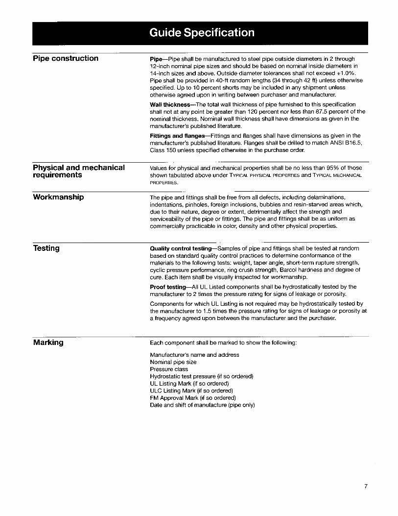


Series 3200 FiberglassPipe and Fittingsfor Class 200 fire protection andgeneral industrial service
FP267C (3/99)
Installation details andrecommendations
General considerations Fiberglass pipe is lightweight, corrosion resistant, economical and has excellenthydraulic characteristics. A very significant advantage of Bondstrand Series 3200 pipesystems is the elimination of the need for concrete thrust block or mechanical tie rodassemblies with the single exception of CIPE crossovers which are covered belowunder HYDRANT CONNECTIONS.
Fiberglass pipe is somewhat sensitive to impact and should not be subjected to pointloadings. It is important that pipe be inspected for impact damage to both the pipe andthe end prior to installation.
Specific instruction regarding the assembly of adhesive-bonded joints in 2 through8 inch sizes and Pronto-Lock® II joints in 8-inch sizes and above are contained in theappropriate publications.
Burial recommendations Design
The structural design of a buried conduit requires calculations of the probablemaximum load, determination of the inherent strength of the pipe and selection offield bedding and backfill conditions that insure that the supporting strength of theinstalled pipe will be adequate.
Bondstrand pipe is considered as a flexible conduit having the ability to deflect asit is loaded, thereby transmitting the load to the side fill in the same manner ascorrugated metal pipe. The load-carrying capacity of Bondstrand Series 3200 pipeis exceptional because of its ability to redistribute crush, shear and beam loadsthrough deflection.
The following table lists recommended cover heights for Bondstrand Series 3200pipe installed in a trench under conditions as noted.
Bondstrand Series 3200 is used for buried fire protection lines and generalindustrial service. It is available with a Listing Mark from Underwriters Laboratories,Inc. and Underwriters’ Laboratories of Canada and has been approved by FactoryMutual. When UL-Listed or FM-approved product is desired, designate it as suchby identifying it as “Bondstrand Series 3200/L” or “Bondstrand Series 3200/FM.”For Listed service, the installation must be done in accordance with National FireProtection Association No. 24, “Private Fire Service Mains.” NFPA No. 24 coversthe general details of yard piping for fire protection systems. The installation detailsand recommendations contained in this publication are intended to supplementthose of NFPA No. 24 with which both the design and installation must comply.
UL®
mn
UnderwritersLaboratories Inc.®
ULC
Bondstrand® Installation GuideFIBERGLASS PIPE GROUP
ISO-9001
CERTIFICATED FIRM

Burial recommendations(cont.)
As a practical measure, it is recommended that a minimum earth cover of 3 feetwith H-20 live loads be observed. For special installations outside these limits,consult Ameron Fiberglass Systems. Sleeving details are covered underMISCELLANEOUS DETAILS.
Excavation
1) The excavation shall be made to allow the pipe to be laid to the grades andalignments shown on the plans.
2) The narrowest practical trench width that will allow proper densification of thepipe zone backfill shall be maintained with vertical sidewalls from the foundation toat least the top of the pipe, except that a minimum trench width equal to the insidediameter of the pipe plus twelve (12) inches shall be maintained. The maximumtrench width from the foundation to the top of the pipe shall be the inside diameterof the pipe plus twenty-four (24) inches.
3) Beneath vehicular traffic, the height of earth cover over the top of the installedpipe shall not be less than three (3) feet unless suitable methods are used toprotect the pipe.
4) Foundations shall be firm, but not hard, and shall consist of sound earth1 orgranular soil2, free from stones or lumps exceeding one (1) inch in greatestdimension that might bear against the pipe. Suitable foundations may be preparedby overexcavating the trench for not less than one (1) inch and backfilling tosubgrade with loose bank run material, graded uniformly in one plane for the fulllength of the pipe. Slight overexcavation should be provided at the location of eachbell so that the pipe barrel rests on the bottom of the trench. Foundations shallprovide uniform support under the haunches of the pipe along the full length ofeach pipe section.
5) When the excavation is in soft or wet, unstable soils that will not providesufficient support for the pipe, the trench shall be overexcavated at least six(6) inches and backfilled to one (1) inch below subgrade with solid granular soilcompacted to at least 85-95% Proctor (40-70% relative density). The subgradeshall then be completed as described in §4. The method described in NFPA No. 24§8-4.3 under “Exception” is not acceptable for fiberglass pipe.
6) When solid rock, hardpan or other hard foundation is encountered duringexcavation, the trench shall be overexcavated at least six (6) inches and backfilledto one (1) inch below subgrade with solid granular soil compacted to at least85-95% Proctor (40-70% relative density). The subgrade shall then be completedas described in §4.
1) Most native soils, with the exception of highly organic, spongy soils and fat, highly plastic expansive clays.2) Sand with a maximum particle size of 1⁄4 inch or gravel with a minimum grain size of 1⁄4 inch, or pea gravel or
crushed rock mixed with sand.
2
Nominal Earth Cover Nominal PipePipe Size H (ft) Stiffness Factor(in) (mm) (max) (min) (lb•in2⁄in)— — — — — 2 50 25 3 403 80 25 3 504 100 25 3 1006 150 25 3 250
Nominal Earth Cover Nominal PipePipe Size H (ft) Stiffness Factor(in) (mm) (max) (min) (lb•in2⁄in)8 200 25 3 500
10 250 25 3 75012 300 25 3 100014 350 25 3 140016 400 25 3 1650
Recommended Earth Cover Heights for Pipe with Sidesoil Compaction 85-95% Proctor
1) These values are based on obtaining 85% minimum compaction of the side fill material prior to backfillingthe remainder of the trench.
2) Modulus of soil reaction (E') using sound earth or granular soils compacted to 85-95% Proctor, 40-70%relative density is 1000 psi.

3
Burial recommendations(cont.)
Pipe laying
Assemble the pipe in accordance with the appropriate instructions for the joiningsystem being used.
On grades exceeding 10%, the pipe should be laid uphill.
In order to insure against line movement in the ditch, place a small quantity of selectbackfill (no rocks or heavy clods) carefully around the pipe after each joint is laid andtamp it thoroughly around the bottom of the pipe. Wear leather gloves when making upthe threads by hand. Although the parts are carefully deflashed in the plant, somesharp, undressed edges may remain.
When work is not in progress, cap the pipe ends to prevent entry of debris, rodents andthe like.
Thrust blocks
As noted under GENERAL CONSIDERATIONS, Bondstrand Series 3200 pipe systems do notrequire thrust blocking or tie rod harnesses as all of the pipe and fitting connections arecapable of taking the full axial load imposed by internal pressure with a minimum safetyfactor 4:1. Prudence, however, dictates that, where a change in direction occurs closeto a large positive displacement pump, the fitting be thrust blocked to prevent rackingof the line when the pump cycles. In every case, the design, location and placement ofthrust blocks must comply with NFPA No. 24 and any local authority having juris-diction. Typical thrust block details are shown in Figure 1.
Backfill
1) Backfill materials shall be so placed that the pipe will not be displaced or damaged.Materials placed as pipe zone backfill shall be free of stones or lumps exceeding one(1) inch in greatest dimension, and shall be so placed as to prevent the formation ofvoids.
2) Pipe zone backfill preparation shall be specified along the entire reach of thepipeline as shown on the plans and the drawings. Pipe zone backfill shall consist ofsound earth or granular soil free of vegetation that might leave voids upon decompo-sition. Pipe zone backfill shall be carefully packed and compacted to the applicabledimensions and relative compactions specified.
The requirements for pipe zone backfill preparation shall be determined on the basis ofthe local native soil conditions and earth and traffic load magnitudes at the pipe zonedepth so that vertical ring deflection will be limited to 5% of the nominal pipe diameter.
In general, the pipe zone backfill shall be placed immediately after laying the pipe,provided the pipe is true to line and grade.
Temporary thrust blocking consisting offloor jacks and wooden timber shouldbe used during hydrotesting to preventexcessive pipe movement and possible
shear or bending failures. Pointloadings on pipe or fittings should beavoided by means of wooden blockcontoured to bear on pipe or fittings.
Fig. 1. Thrust blocking at fittings
Concrete thrustblock Concrete thrust block

Air testing
Low pressure (5-10 psi) air testing has been used successfully as a low cost preliminarytest to determine joint integrity. Pinched or missing O-rings will normally result inaudible leakage at these pressures.
It should be pointed out that an air test is not considered a substitute for the finalhydrostatic test; it is merely an expedient means to evaluate the seating of the O-ringsthat may eliminate the need for costly cleanup and/or Line drainage should repairs benecessary.
Hydrotesting
It is advantageous to test a pipe line in short sections of about 1,000 feet. This is partic-ularly true at the beginning of an installation as it gives the contractor and all concerneda check of the initial installation methods. Additionally, testing in short sections permitsone section to be backfilled to grade while the installation continues on to the nextsection. Installing a system in its entirety before testing may allow errors to be carriedthrough the whole job with the result that corrective repairs may be very expensive andtime consuming.
Venting air from the line is of major importance. As the pipeline is filled with water, theturbulent flow of the rushing water causes air to become entrained. As the watersettles, the air collects at high points and becomes entrapped in the pipeline. This airmust be allowed to escape by using an air vent at the highest part of the line. Lost airmust be replaced by more water so that the line is completely filled with water before itis pressurized.
The line should be filled with water 24 hours before testing and should be held at anominal pressure (30 to 50 psi) during this period. At this time, the Pronto-Lock IIconnections should be inspected for leakage as any pinched or missing O-rings willleak at this pressure. Note that a pinched O-ring will often seal at 250 psi, but leak at30 psi. Before the line is brought up to total test pressure, all air vents should be openedand any remaining air purged from the system.
Pressure testing
Burial recommendations(cont.)
4
3) The backfill shall be blended sufficiently to secure the best practicable degree ofcompaction and stability.
Compaction may be performed by mechanical or hand tamping methods or byhydraulic methods, except in the following cases:
a) Where soils are clayey or silty and would impede free drainage, hydraulicmethods shall not be used.
b) Free-draining granular soils may be compacted by hydraulic methods with orwithout the aid of surface or internal vibration as required to achieve specificcompactions.
Care shall be taken during compaction to prevent displacement of the pipe due tofloating or shifting, and to prevent hydrostatic or impact damage to the pipe andfoundation. Avoid using heavy mechanical tamping or rolIing equipment directly overthe top of the pipe as this might cause excessive reduction of the vertical diameter ofthe installed pipe until a minimum of twenty-four (24) inches of earth cover has beenplaced.
4) Backfill above the pipe zone backfill1 shall not be placed until conformance withspecified relative compactions of pipe zone backfill materials has been confirmed.
1) Shall comprise that portion of the backfill surrounding the installed pipe extending after compact ion fromthe foundation to a level six (6) inches above the top of the pipe.
Attention is drawn to §8-9.2 of NFPA No. 24. Pipe between joints must be covered witha minimum of 24 inches of earth cover leaving the pipe joints and fittings exposed until
after hydrotesting.
Air testing at any pressure can be dangerous and should be conducted carefully withexperienced personnel only. High pressure air (compressed gas) testing is extremelydangerous and should never be used. Flammable or explosive gases should never be
used for pressure testing.

Water pits and manholes
Where “water pits” are used, pipe penetrations will be necessary though the concretewall of the water pit. Figure 2 shows a typical wall penetration. Where differentialsettling may occur, a Pronto-Lock II joint should be located within 2 to 3 feet of thepenetration. Severe applications should leave a second Pronto-Lock II joint as close tothe first as possible. The 2° deflection capability of the joints will enable them tofunction as limited flexible connectors. As a guide to sizing the penetration opening,Pronto-Lock II coupling dimensions are given on the next page.
Pressure testing(cont.)
Miscellaneous details
Bondstrand Series 3200 piping systems should be tested in accordance with NFPANo. 24.
1) The following paragraphs defining permitted leakage are reproduced from NFPANo. 24, Section 8-9.3.
a) (§8-9.3.1*) All new yard piping shall be tested hydrostatically at not less than 200pounds per square inch (13.8 bars) pressure for two hours, or at 50 pounds persquare inch (3.4 bars) in excess of the maximum static pressure when the maximumstatic pressure is in excess of 150 pounds per square inch (10.3 bars). (See A-8-9.8.1)
b) (§8-9.3.2*) The amount of leakage in piping shall be measured at the specified testpressure by pumping from a calibrated contained, For new pipe, the amount ofleakage at the joints shall not exceed two quarts per hour (1.89l/h) per 100 gaskets orjoints irrespective of pipe diameter.
c) (§8-9.3.3) The amount of allowable leakage specified in 8-9.3.2 may be increased byone fluid ounce per inch valve diameter per hour (30ml/25mm/h) for each metalseated valve isolating the test section. If dry barrel hydrants are tested with the mainvalve open causing the hydrants to be under pressure, an additional five ounces perminute (150ml/min) leakage is permitted for each hydrant.
2) New pipe laid with rubber gasketed joints should, if the workmanship is satisfactory,have no leakage at the joints. Unsatisfactory amounts of leakage usually result fromtwisted, pinched or cut gaskets. However, some leakage might result from smallamounts of grit or small gasket imperfections. The amount of leakage at the jointsshould not exceed two quarts per hour per 100 joints, irrespective of pipe diameter.The leakage should be distributed over all joints. If such leakage occurs at a few joints,the installation should be considered unsatisfactory and necessary repairs made.
3) Tests shall be made by the contractor in the presence of the inspector of theauthority having jurisdiction or of the representative of the owner. If the completedsystems fail, the following check points may be helpful in locating leaks:
a) A hydrant valve held open by a piece of rag, wood or some other foreign matter. Whenthe valve is held slightly open, line pressure will be relieved through a hydrant drain.
b) Dirt or foreign material in the O-ring groove.c) Pipe not sufficiently covered in the trench.d) Fittings and valves in the test section not sufficiently blocked.e) Air in line (no relief valve).f) Leakage through valve at the end of test section.g) Valve bonnet leaking.h) Packing on valves and wet-barrel hydrants leaking.i) Test pump leaking, check valves as well as gate valve.j) Curves not sufficiently covered in the trench.k) Testing overly long sections of pipeline.l) Insufficient saturation time (less than 24 hours).m) Ruptured pipe that has cracked or blown out.n) Broken fittings.o) Faulty accessory equipment such as valves, fittings, hydrants, saddles, relief valves.p) Faulty test gauge.q) Test pump suction line drawing air.
5

6
Miscellaneous details
Fig. 2. Typical wall penetration. The wallthickness of the fiberglass pipe may be
increased by bonding split pipe sections tothe pipe. The split sections should extend
2 to 3 inches beyond the penetration.
Valves
Valves in water pits or manholes should not bear on the pipe. Figure 3 shows a typicalsupport at a flange.
Where steel flanges are used, they must be flat-faced or a spacer ring must be used.Flange bolts must always use flat washers under the bolt head and nut. Flat gasketsshall be elastomeric with a Shore A Durometer hardness of 70±5. Flange bolts shouldbe tightened uniformly to the bolt torque shown below.
Fig. 3. Pipe support at flanges
Steel pipe sleeve
Fiberglass pipe
Elastomeric caulking2-in min. thickness
Pronto-Lock II Coupling Dimensions
Nominal Maximum O.D.Pipe Size Male End Female End(in) (mm) (in) (in)8 200 10.00 10.75
10 250 12.25 13.25 12 300 14.25 15.25 14 350 16.25 17.2516 400 18.50 19.50

Miscellaneous details(cont.)
Sleeved road crossings
Fiberglass pipe should be sleeved at all railroad crossings. As noted under BURIAL
RECOMMENDATIONS. Bondstrand Series 3200 pipe is designed for H-20 live loads with3-ft cover. However, where frequent heavy truck traffic can be expected, it may beprudent to sleeve the pipe. Yard piping under crossroads does not require sleeving.Pipe should be protected against excessive beam deflection by means of centralizersand from bearing against the end of the casing with Link-Seal* or other elastomericbearing materials. Where differential settling may occur, the same steps as describedunder WATER PITS may be followed. Figure 4 below shows typical sleeving details.* Registered trademark of The Thunderline Corporation.
All fiberglass blind flanges mustemploy steel back-up flanges.
Hydrant connectionsHydrant connections may be made by means of flanges (where permitted) or byBondstrand Series 3200 cast iron pipe crossovers. CIPE crossovers will connect togasketed bell or mechanical joint cast iron pipe and must always be restrained.CIPE crossovers are available for adhesive-bonded pipe in 6-inch sizes and below.
7
Casing seal
Elastomeric bearing material
Cast iron pipe (or fittings)with slip-on bell end or
mechanical jointWear saddle
CIPE crossover
Standard CIP retainingclamps (2)
Fiberglass pipeor fitting
Fig. 5. Cast iron pIpe to fiberglass pipetransition. For 8-16 inch CIPE
crossovers, a 360° saddle made fromsplit pipe sections must be placed
between the fiberglass pipe and theretaining clamp; the clamp must be
tightened only to a snug fit. The clampmust not grip the pipe, but only bear
against the Pronto-Lock II bell. For 3-6inch CIPE crossovers, a 360° saddle isnot necessary. Here, too, the retaining
clamp should be tightened only to asnug fit and should bear against the
raised shoulder of the crossover thathas been adhesive-bonded to the
fiberglass pipe.
Fig. 4. Typical sleeving detailsCentralizer
Link-Seal or equivalent
Nominal MaximumPipe Size Bolt Torque(in) (mm) (ft•lbs) (N•m)— — — — 2 50 35 483 80 50 684 100 50 686 150 50 68
Nominal MaximumPipe Size Bolt Torque(in) (mm) (ft•lbs) (N•m)8 200 60 81
10 250 70 9512 300 80 10814 350 100 13616 400 100 136

Written comments regarding this document are invited. Please write EngineeringManager, Ameron Fiberglass Pipe Division.
© 1991 Ameron • FP267C (3/99) supersedes FP267B (5/95) • Printed in U.S.A. • 5M [472]
This literature and the information and recommendations it contains are based on datareasonably believed to be reliable. However, such factors as variations in environment,application or installation, changes in operating procedures, or extrapolation of datamay cause different results. Ameron makes no representation or warranty, express orimplied, including warranties of merchantability or fitness for purpose, as to theaccuracy, adequacy or completeness of the recommendations or informationcontained herein. Ameron assumes no liability whatsoever in connection with thisliterature or the information or recommendations it contains. Product specifications aresubject to change.
Important notice
Bending
Bondstrand Series 3200 pipe is somewhat flexible. Gradual changes in directionmay be made as long as the minimum bending radius is not exceeded. In8 through 16-inch sizes, the 2° deflection capability of the Pronto-Lock II jointdecreases the distance required for a given change in direction. The guidelinesshown below should be followed for making gradual changes in direction.
Miscellaneous details(cont.)
Minimum Maximum MinimumNominal Bending Deflection Length RequiredPipe Size Radius1 per 39-ft Joint for 10° Change(in) (mm) (ft) (m) (deg) (ft) (m)2 50 75 23 30.2 13.2 43 80 100 30 20 20 64 100 150 46 15 27 86 150 200 61 1 40 128 200 300 91 7 + 2 = 9.3 57 - 13 = 444 12
10 250 350 107 6 + 2 = 8 67 - 13 = 54 1612 300 400 123 5 + 2 = 7 80 - 13 = 67 2014 350 450 137 4 + 2 = 6 100 - 13 = 87 2716 400 500 152 3 + 2 = 5 133 - 13 =120 37
1) At rated pressure. Sharper bends may create excessive stress concentrations. Do not bend pipe untiladhesive has cured.
2) 2 - 6 inch: pipe deflection only.3) 8 - 16 inch: pipe deflection plus 2° Pronto-Lock II coupling deflection.4) 8 - 16 inch: pipe minimum length minus 13-ft (4 m) effect of Pronto-Lock II coupling deflection.
Ameron CompositesP.O. Box 7137011 McBride StreetNewnan, Georgia 30263Tel: (770) 253-2000Fax: (770) 253-9234
GROUP HEADQUARTERS
P.O. Box 801148 • Houston, TX 77280 • Tel: (713) 690-7777 • Fax: (713) 690-2842 • http://www.ameron.com
Fiberglass Pipe DivisionEuropeAmeron B.V.J.F. Kennedylaan 74191 MZ GeldermalsenThe NetherlandsTel: +31 345 587 587Fax: +31 345 587 561Telex: 40257 bonds nl
Fiberglass Pipe DivisionAmericasP.O. Box 878Burkburnett, TX 76354Tel: (940) 569-1471Fax: (940) 569-2764
Fiberglass Pipe DivisionCentron InternationalP.O. Box 490600 FM 1195 SouthMineral Wells, Texas 76068Tel: (940) 325-1341Fax: (940) 325-9681
FIBERGLASS PIPE GROUP
Fiberglass Pipe Division AsiaAmeron (Pte) Ltd.No. 7A, Tuas Avenue 3Singapore 639407Tel: 65 861 6118Fax: 65 862 1302/861 7834

Lubricant Plant Lines ConveyLubricants from Dock to Plantwith Bondstrand Series 3200 fiberglass pipe and filament wound fittings
Location Mamonal, Colombia
Client Texaco/Colombia
Application Conveying lubricants from dock to plant
12" Bondstrand Series 3200 pipe with Pronto-Lock® II joining system.Product
FP263 (10/98)
Bondstrand® Case History FIBERGLASS PIPE GROUP
ISO-9001
CERTIFICATED FIRM

Ameron CompositesP.O. Box 7137011 McBride StreetNewnan, Georgia 30263Tel: (770) 253-2000Fax: (770) 253-9234
GROUP HEADQUARTERS
P.O. Box 801148 • Houston, TX 77280 • Tel: (713) 690-7777 • Fax: (713) 690-2842 • http://www.ameron.com
Fiberglass Pipe DivisionEuropeAmeron B.V.J.F. Kennedylaan 74191 MZ GeldermalsenThe NetherlandsTel: +31 345 587 587Fax: +31 345 587 561Telex: 40257 bonds nl
Fiberglass Pipe DivisionAmericasP.O. Box 878Burkburnett, TX 76354Tel: (940) 569-1471Fax: (940) 569-2764
Fiberglass Pipe DivisionCentron InternationalP.O. Box 490600 FM 1195 SouthMineral Wells, Texas 76068Tel: (940) 325-1341Fax: (940) 325-9681
FIBERGLASS PIPE GROUP
Fiberglass Pipe Division AsiaAmeron (Pte) Ltd.No. 7A, Tuas Avenue 3Singapore 639407Tel: 65 861 6118Fax: 65 862 1302/861 7834
Corrosion resistance - Bondstrand is inherently resistant to corrosion and UVdegradation.
Cost savings - Using Bondstrand eliminated the need for costly replacement andmaintenance which would have been needed for comparable metallic products.
Approximately 5000 feet (1600 m) of 12-inch diameter, Bondstrand Series 3200 pipewith Pronto-Lock® II joining system was installed in 1979 at this lubricant plant inColombia. The piping conveys lubricants from the dock to the plant.
The pipe is installed in a highly corrosive environment subject to heavy tropical rainsduring most of the year. The twin pipelines are installed above ground and exposedto constant bio-corrosion and UV.
The pipeline has experienced trouble-free service for approximately 20 years,exceeding the life expectancy of comparable metallic products.
Advantages
Pipe system
© 1998 Ameron • Printed in U.S.A. • FP263 (10/98) • 10M[021]
" Twin pipelines convey lubricants from dock toplant.
# Bondstrand 3200 has provided trouble-free service forover 25 years.


Salt Lake City, UtahLocation
AmocoClient
Application Total of 8000 feet of fire protection piping for oil refinery.
Refinery Fire Protection Linesusing Bondstrand Series 3200 pipe
FP174C (10/95)
Bondstrand® Case History
ISO-9001
CERTIFICATED FIRM
FIBERGLASS - COMPOSITE PIPE GROUP

CompositesP.O. Box 7137011 McBride StreetNewnan, Georgia 30263Tel: (770) 253-2000Fax: (770) 253-9234
FIBERGLASS - COMPOSITE PIPE GROUP - GROUP HEADQUARTERS
P.O. Box 801148 • Houston, TX 77280 • Tel: (713) 690-7777 • Fax: (713) 690-2842 • http://www.ameron.com
EuropeAmeron B.V.J.F. Kennedylaan 74191 MZ GeldermalsenThe NetherlandsTel: +31 345 587 587Fax: +31 345 587 561
AmericasP.O. Box 878Burkburnett, TX 76354Tel: (940) 569-1471Fax: (940) 569-2764
Centron InternationalP.O. Box 490600 FM 1195 SouthMineral Wells, Texas 76068Tel: (940) 325-1341Fax: (940) 325-9681
AsiaAmeron (Pte) Ltd.No. 7A, Tuas Avenue 3Singapore 639407Tel: 65 861 6118Fax: 65 862 1302/861 7834
Advantages Corrosion resistance: The high water table, combined with the high soil concentra-tion of salt, caused an average of one failure per month in the existing cast iron pipe.
Reduced thrust block requirements: Thrust blocks were needed only for tying intoexisting pipelines.
UL listing: Listed by Underwriters Laboratories for 200 psi fire protection service.
Non-conductive, non-metallic construction: No cathodic protection required.
Pipe system Eight-inch Bondstrand Series 3200 with Pronto-Lock® II mechanical joiningsystem.
© 1985 Ameron • FP174C (10/95) supersedes FP174B (6/94) • Printed in U.S.A. • 5M [021]

Adnoc-Ruwais Refinery, Abu Dhabi, United Arab EmiratesLocation
Abu Dhabi National Oil CompanyClient
Application Underground transport of potable water across 12,700 m (41,700 ft); maximumoperating pressure 16 bar (232 psi) and maximum temperature 50°C (122°F).
Potable Water Linein Abu Dhabiusing Bondstrand Series 3200 piping
Bondstrand® Case History
FP175B (8/96)
FIBERGLASS PIPE GROUP
ISO-9001
CERTIFICATED FIRM

Ameron CompositesP.O. Box 7137011 McBride StreetNewnan, Georgia 30263Tel: (770) 253-2000Fax: (770) 253-9234
GROUP HEADQUARTERS
P.O. Box 801148 • Houston, TX 77280 • Tel: (713) 690-7777 • Fax: (713) 690-2842 • http://www.ameron.com
Fiberglass Pipe DivisionEuropeAmeron B.V.J.F. Kennedylaan 74191 MZ GeldermalsenThe NetherlandsTel: +31 345 587 587Fax: +31 345 587 561Telex: 40257 bonds nl
Fiberglass Pipe DivisionAmericasP.O. Box 878Burkburnett, TX 76354Tel: (940) 569-1471Fax: (940) 569-2764
Fiberglass Pipe DivisionCentron InternationalP.O. Box 490600 FM 1195 SouthMineral Wells, Texas 76068Tel: (940) 325-1341Fax: (940) 325-9681
FIBERGLASS PIPE GROUP
Fiberglass Pipe Division AsiaAmeron (Pte) Ltd.No. 7A, Tuas Avenue 3Singapore 639407Tel: 65 861 6118Fax: 65 862 1302/861 7834
Advantages Corrosion resistance: Bondstrand Series 3200 is able to resist corrosion due to ground salts.
Potable water approval: Bondstrand Series 3200 is approved for use as potable water lines.
© 1985 Ameron • FP175B (8/96) supersedes FP175A (12/94) • Printed in U.S.A. • 5M [021]
Pipe System Twelve-inch diameter Bondstrand Series 3200 with Pronto-Lock® IImechanical joining system.

FP159D (4/99)
Series 3400 FiberglassPipe and Fittingsusing Key-Lock® mechanical or taper/taper adhesive bonded joint
Uses and applications Brackish water lines Crude oil transmission pipelinesDrainage systems Electrical conduit Fire protection systems Highly corrosive crude oil pipelinesPotable water lines Oil field reinjection systems
Saltwater and seawater lines Seawater intake and discharge linesSewage systems Submerged pipelinesTemporary pipelines Waste water lines General industrial service for mildlycorrosive liquids
Description Filament-wound fiberglass reinforced epoxy pipe with Key-Lock male and femalemechanical joining system or matching taper adhesive-bonded joint.
Pipe designs from 150 to 725 psig using a 7200 psi hydrostatic design basis (cyclic)with a 1.0 service factor, or 21,500 psi HDB Static and SF=0.5.
Cycloaliphatic amine cured resin construction for operating temperatures to 200°F.
Manufactured per ASTM D2996. ASTM D2310 classification: RTRP-11AX, RTRP-11 FX (including 20-mil liner on request).
System designed to provide 4:1 safety factor for static applications in accordancewith ASTM D1599.
Individual system components may not have the same ratings as the pipe. Referto the detailed product information for the specific components to determine thepressure rating for the system as a whole.
The information in this document is available in metric format: request Product DataSheet FP452, revision C or later.
Joining systems Key-Lock male and female mechanical joint assembled with locking keys in inte-grally wound male and female ends. Systems in larger diameters and higher pres-sure ratings are provided with dual locking keys. Key-Lock joined systems employelastomeric O-rings for hydrostatic seal.
Taper/taper for adhesive-bonded joint using integrally wound bells and spigots.
Nominal Pipe Size Random Length
(in) (mm) (ft) (m)
2-6 50-150 20 6.1
8-24 200-600 20, 40 6.1, 12.228-40 700-1000 40 11.8
Pipe lengths
Bondstrand® Product DataFIBERGLASS PIPE GROUP

2
Typical pipe pressureperformance
Nominal Internal Ultimate Collapse Pressure (psig)3
Pipe Size Pressure Rating 34101 3412 3414 3416 3420 3425(in) (mm) (psig) 1502 180 200 230 290 360
2 50 180 to 725 368 368 368 368 368 3683 80 180 725 98 98 98 98 98 115
4 100 180 725 46 46 46 35 35 1096 150 180 725 18 24 28 36 56 908 200 150 725 18 18 22 27 43 92
10 250 150 725 14 14 17 28 40 8312 300 150 725 12 14 16 27 42 85
14 350 150 580 10 14 19 26 39 9116 400 150 580 9 12 17 26 41 8918 450 150 580 8 14 17 27 40 87
20 500 150 580 10 14 18 27 39 8724 600 150 460 8 13 16 26 41 88
28 700 150 230 7 10 16 27 — —30 750 150 230 7 10 17 27 — —32 800 150 230 6 10 17 27 — —
36 900 150 230 5 9 16 26 — —40 1000 150 230 5 9 17 26 — —
Typical pipe dimensions Nominal Pipe Minimum Total Wall Thickness1 (in)Pipe Size ID 3410 3412 3414 3416 3420 3425 3432 3440 3450(in) (mm) (in) 150 180 200 230 290 360 460 580 7252 50 2.10 .091 .091 .091 .091 .091 .091 .091 .098 .1103 80 3.22 .091 .091 .091 .091 .091 .094 .102 .126 .153
4 100 4.14 .091 .091 .091 .098 .098 .114 .126 .157 .1976 150 6.26 .098 .106 .110 .118 .134 .154 .181 .228 .2838 200 8.22 .122 .122 .130 .138 .157 .197 .232 .095 .366
10 250 10.35 .138 .138 .146 .169 .189 .236 .287 .366 .45312 300 12.35 .154 .161 .169 .197 .224 .280 .339 .429 .535
14 350 13.56 .161 .177 .193 .213 .240 .311 .370 .472 —16 400 15.50 .173 .189 .209 .240 .276 .350 .421 .535 —18 450 17.08 .181 .217 .228 .264 .299 .382 .461 .551 —
20 500 18.98 .213 .236 .256 .291 .327 .421 .512 .650 —24 600 22.78 .236 .276 .296 .343 .398 .504 .610 — —
28 700 27.56 .276 .299 .354 .413 — — — — —30 750 29.52 .283 .319 .382 .441 — — — — —32 800 31.50 .291 .339 .406 .469 — — — — —
36 900 35.43 .311 .378 .449 .524 — — — — —40 1000 39.37 .338 .417 .500 .579 — — — — —
Pipe weight Nominal Minimum Weight of Empty Pipe (lb/ft)Pipe Size 3410 3412 3414 3416 3420 3425 3432 3440 3450(in) (mm) 150 180 200 230 290 360 460 580 7252 50 .47 .47 .47 .47 .47 .47 .47 .47 .543 80 .67 .67 .67 .67 .67 .74 .81 1.01 1.21
4 100 .87 .87 .87 .94 .94 1.15 1.28 1.62 2.026 150 1.42 1.55 1.62 1.75 2.02 2.29 2.76 3.57 4.458 200 2.36 2.36 2.56 2.70 3.10 3.98 4.72 6.07 7.62
10 250 3.37 3.37 3.57 4.25 4.72 6.00 7.35 9.5 11.912 300 4.52 4.79 5.00 5.86 6.74 8.49 10.4 13.3 16.8
14 350 5.26 5.80 6.34 7.01 7.95 10.4 12.5 16.1 —16 400 6.40 7.08 7.82 9.03 10.4 13.4 16.2 20.9 —18 450 7.41 8.96 9.44 11.0 12.5 16.1 19.6 25.2 —
20 500 14.4 10.9 11.8 13.5 15.2 19.8 24.2 31.1 —24 600 13.0 15.2 16.4 19.1 22.3 28.5 34.7 — —
28 700 18.4 20.1 24.1 28.0 — — — — —30 750 20.3 22.9 27.6 32.0 — — — — —32 800 22.2 26.0 31.3 36.3 — — — — —
36 900 26.8 32.7 39.0 45.7 — — — — —40 1000 32.4 40.2 48.4 56.2 — — — — —
1) Pipe series designation: final two dig-its indicate metric pressure class: e.g.3425 is rated at 25 bar.
2) Pressure class (psig)
3) Ultimate collapse pressures for higherpressure classes exceed tabulatedvalues.
4) Italicized bold-face entries indicatedual locking key design.
1) Total wall thickness includes 20-milliner thickness.

Typical mechanicalproperties
70°F 200°F ASTM Pipe Property Units (21°C) (93°C) Method
CircumferentialTensile stress at weeping 103 psi 18.6 - D1599
MPa 128 -
Tensile modulus 106 psi 3.67 3.19GPa 25.3 22.0
Poisson’s ratio 0.50 0.65 D2105
LongitudinalTensile strength 103 psi 9.43 7.25 D2105
MPa 65 50
Tensile modulus 106 psi 1.45 1.13 D2105GPa 10.0 7.80
Poisson’s ratio 0.40 0.45 D2105
Beam apparentElastic modulus 106 psi 1.33 1.02 D2925
GPa 9.2 7.0
Hydrostatic design basis Static 103 psi 21.41 - D2992B
MPa 148 -Cyclic 103 psi 7.31 - D2992A
MPa 50 -1) At 150°F.
Recommended spanlengths
Nominal Recommended Span Lengths for Horizontal Support @ 70°F1 (ft)Pipe Size 3410 3412 3414 3416 3420 3425 3432 3440 3450(in) (mm) 150 180 200 230 290 360 460 580 7252 50 10 10 10 10 10 10 10 10 103 80 11 11 11 11 11 11 12 12 13
4 100 12 12 12 12 12 13 13 14 156 150 14 14 14 15 15 16 16 17 188 200 16 16 16 16 17 18 19 20 21
10 250 17 17 18 18 19 20 21 22 2312 300 19 19 19 20 21 22 23 24 25
14 350 20 20 20 21 21 23 24 25 —16 400 20 21 21 22 23 25 26 27 —18 450 21 22 23 23 24 26 27 29 —
20 500 23 23 24 25 25 27 29 30 —24 600 25 26 26 27 28 30 31 — —
28 700 27 28 29 30 — — — — —30 750 28 29 30 31 — — — — —32 800 28 30 31 32 — — — — —
36 900 30 31 33 34 — — — — —40 1000 31 33 35 36 — — — — —
1) Span recommendations are based on pipe filled with fresh water (S.G. = 1.0) and include no provisionfor weight from valves, flanges, or other heavy objects. Span recommendations are calculated for amaximum long-term deflection of 1⁄2 inch to ensure good appearance and adequate drainage. Fully continuous spans may be used with support spacing up to 20% greater for this deflection: in simplespans, support spacing should be 20% less.
Typical physicalproperties
Pipe Property Units Value ASTM MethodThermal conductivity
Pipe wall Btu•in/(hr•ft2•°F) 2.3 C177W/m•°C 0.33
Thermal expansion linearAxial 10-6 in/in/°F 10 D696
10-6 mm/mm°C 18Circumferential 10-6 in/in/°F 6 D696
10-6 mm/mm°C 10.8Flow coefficient Hazen-Williams 150 _Absolute roughness 10-6 ft 17.4 _
10-6 m 5.3Density lb/in3 0.065 D792
g/cm3 1.8
3

Ameron CompositesP.O. Box 7137011 McBride StreetNewnan, Georgia 30263Tel: (770) 253-2000Fax: (770) 253-9234
GROUP HEADQUARTERS
P.O. Box 801148 • Houston, TX 77280 • Tel: (713) 690-7777 • Fax: (713) 690-2842 • http://www.ameron.com
Fiberglass Pipe DivisionEuropeAmeron B.V.J.F. Kennedylaan 74191 MZ GeldermalsenThe NetherlandsTel: +31 345 587 587Fax: +31 345 587 561
Fiberglass Pipe DivisionAmericasP.O. Box 878Burkburnett, TX 76354Tel: (940) 569-1471Fax: (940) 569-2764
Fiberglass Pipe DivisionCentron InternationalP.O. Box 490600 FM 1195 SouthMineral Wells, Texas 76068Tel: (940) 325-1341Fax: (940) 325-9681
FIBERGLASS PIPE GROUP
Fiberglass Pipe Division AsiaAmeron (Pte) Ltd.No. 7A, Tuas Avenue 3Singapore 639407Tel: 65 861 6118Fax: 65 862 1302/861 7834
1 psi = 6895 Pa = 0.07031 kg/cm2
1 bar = 105 Pa = 14.5 psi = 1.02 kg/cm2
1 MPa = 145 psi = 10.2 kg/cm2
1 GPa = 145,000 psi = 10,200 kg/cm2
1 in = 25.4 mm
1 ft = 0.3048 m1 lb•in = 0.113 N•m1 in4 = 4.162 x 10⁻⁷m4
°C = 5/9 (°F - 32)
© 1988 Ameron • Printed in U.S.A. • FP159D (4/99) 5M[186]
Conversions
Field testing Bondstrand 3400 piping systems are designed for hydrostatic testing at 150% ofrated operating pressure. Pneumatic testing is not recommended.
Minimum bending radius Nominal Minimum Allowable Bending Radius @ 70°F (ft)Pipe Size 3410 3412 3414 3416 3420 3425 3432 3440 3450(in) (mm) 150 180 200 230 290 360 460 580 7252 50 30 30 30 30 40 40 60 70 903 80 50 50 55 60 75 105 165 150 150
4 100 70 75 85 90 125 140 210 185 1756 150 125 135 160 175 205 245 305 280 2758 200 165 205 240 275 335 310 390 355 355
10 250 230 300 375 340 455 425 490 445 46012 300 285 355 450 410 515 495 584 545 545
14 350 335 380 430 460 600 515 640 585 —16 400 415 490 550 525 644 595 640 675 —18 450 495 490 600 570 740 670 810 475 —
20 500 485 550 640 630 855 745 880 830 —24 600 655 670 820 775 940 885 1060 — —
28 700 925 1050 985 915 — — — — —30 750 1050 1130 1130 990 — — — — —32 800 1180 1210 1100 1060 — — — — —
36 900 1460 1370 1270 1190 — — — — —40 1000 1710 1520 1390 1339 — — — — —
Important Notice This literature and the information and recommendations it contains are based on data reasonably believed to bereliable. However, such factors as variations in environment, application or installation, changes in operatingprocedures, or extrapolation of data may cause different results. Ameron makes no representation or warranty,express or implied, including warranties of merchantability or fitness for purpose, as to the accuracy, adequacy orcompleteness of the recommendations or information contained herein. Ameron assumes no liability whatsoeverin connection with this literature or the information or recommendations it contains. Product specifications aresubject to change.

FP215E (11/99)
Series 4000 FiberglassPipe and Fittingsfor corrosive industrial service2”-6” installs with no shaving required
Uses and applications Acid drainsChemical process pipingCorrosive slurriesFood processing GeothermalNonoxidizing chemicals and acids
Listings Meets USFDA requirements for food processing piping under Federal Regulations21CFR175.105 and 21CFR177.2280 when bonded using Bondstrand RP6Badhesive.
Performance Working pressure from 150 to 300 psig (1.0 to 2.0 MPa) depending on pipe size.
Operating temperatures to 250°F (120°C), depending on fluid. Subzerotemperatures will not adversely affect mechanical properties.
Excellent corrosion resistance over a wide temperature range. See most recentrelease of Bondstrand Corrosion Guide (FP132) for specific applications.
Does not require thrust blocks at ambient temperatures when properly installed inmost soils.
Smooth inner liner (Hazen-Williams C = 150) produces extremely low frictional lossfor greater discharge and reduced pumping costs.
Individual system components may not have the same ratings as the pipe. Referto the detailed product information for the specific components to determinethe pressure rating for the system as a whole.
Joining systems Quick-Lock® straight/taper adhesive-bonded joint. 2” through 6” pipe outsidediameter is within tolerance for reliable bonding without shaving. Integral pipe stopin socket featured for predictable, precise laying length.
Flanges and flanged fittings.
Bondstrand® Product DataFIBERGLASS PIPE GROUP
with guide specification

2
Composition Pipe
Filament-wound fiberglass reinforced epoxy pipe with nominal 0.050-inch (1.3 mm)resin-rich reinforced liner.
NominalPipe Size ASTM Designation
(in) (mm) (D2996)2-3 50-75 RTRP 11FW-22214-6 100-150 RTRP 11FW-2222
8-16 200-400 RTRP 11FE-1113
Filament-wound fittings
Furnished with reinforced liner using same materials as pipe.
Tees 90° and 45° elbowsCrosses Nipples and couplings45° laterals Tapered body reducersSaddles (no liner) Threaded adapters (2 to 6 inch)Victaulic adapters (2 to 6 inch)
Molded fittings (General Service only)
Tees 90° and 45° elbowsReducing flanges Reducer bushingsEndcaps Plugs
Flanges
2 to 16-inch flanges match ANSI B16.5 bolt hole pattern for Cl 150 lb flanges.
Other flange drilling patterns such as DIN, ISO, JIS, ANSI B16.5 Cl 300, etc.available on special request.
Flanged fittings
2 to 12-inch filament-wound flanged fittings match ANSI B16.1 and ANSI B16.5bolt hole pattern and laying length dimensions. ANSI 90° elbows must be specifiedas being either ‘long’ or ‘short’ when ordering.
Thermosetting adhesives
Bondstrand type PSX™•34 two-part epoxy adhesive for field fabrication.
Nominal RandomPipe Size Length
(in) (mm) (ft) (m)
2- 6 50-150 20 or 40 6 or 128 200 20 or 30 6 or 9
10-16 250-400 20 6
Pipe lengths
Bondstrand Series 4000filament-wound fittings, pipeand adhesive provide acontinuous liner throughout the piping system.

3
Typical pipe dimensionsand weights
Nominal Pipe Nominal Wall Average PipePipe Size ID Thickness1 Sectional Area2 Weight(in) (mm) (in) (mm) (in) (mm) (in2) (mm2) (lb/ft) (kg/m)
2 50 2.10 53 .123 3.1 0.52 335 0.7 1.13 80 3.21 82 .126 3.2 0.81 525 1.0 1.54 100 4.14 105 .151 3.8 1.38 890 1.6 2.46 150 6.19 157 .181 4.6 2.63 1700 2.5 3.78 200 8.22 209 .229 5.8 5.83 3760 4.1 6.1
10 250 10.35 263 .229 5.8 7.31 4720 5.1 7.712 300 12.35 314 .229 5.8 8.69 5610 6.1 9.114 350 13.56 344 .250 6.3 10.40 6710 7.4 11.016 400 15.50 394 .286 7.3 13.40 8650 9.6 14.0
1) The minimum wall thickness shall not be less than 87.5% of nominal wall thickness in accordance with ASTM D2996.
2) Use these values for calculating longitudinal thrust.
Typical pipe performance Nominal Internal Ultimate CollapsePipe Size Pressure Rating1 Pressure
(in) (mm) (psig) (MPa) (psig) (MPa)2 50 300 3.10 215 1.463 80 300 2.21 61 0.404 100 300 2.41 100 0.566 150 300 1.72 68 0.178 200 220 1.52 16 0.11
10 250 175 1.21 8 0.0612 300 150 1.03 5 0.0314 350 150 1.03 5 0.0316 400 150 1.03 6 0.04
1) At 200°F (93°C) using Bondstrand type PSX™•34 adhesive. For sustained serviceabove 200°F, reduce rating linearly from tabulated 200°F values to 50% of thosevalues at 250°F (121°C). Above 250°F, reduce ratings linearly to 0 at 300°F (149°C).
2) At 70°F (21°C). Reduce linearly to 90% at 150°F (66°C), 80% at 200°F and 65% at230°F (110°C).

4
Nominal Blind FlangesPipe Size Laterals Crosses & Saddles(in) (mm) (psig) (MPa) (psig) (MPa) (psig) (MPa)2 50 275 1.90 150 1.03 150 1.033 80 250 1.72 150 1.03 150 1.034 100 200 1.38 150 1.03 150 1.036 150 150 1.03 100 0.69 150 1.038 200 150 1.03 100 0.69 150 1.03
10 250 150 1.03 100 0.69 150 1.0312 300 150 1.03 100 0.69 150 1.0314 350 150 1.03 - - 150 1.0316 400 150 1.03 - - 150 1.03
1) All pressure ratings valid from room temperature to 225°F (107°C) using Ameron epoxy adhesives.For service above 225°F, reduce the ratings shown linearly by 50% from 225°F to 250°F (121°C).
Fittings pressureratings
Nominal Filament-Wound Molded Tapered BodyPipe Size Elbows & Tees Elbows & Tees Reducers & Flanges(in) (mm) (psig) (MPa) (psig) (MPa) (psig) (MPa)2 50 375 2.59 300 2.07 450 3.103 80 325 2.24 225 1.55 350 2.414 100 300 2.07 175 1.21 350 2.416 150 225 1.55 150 1.03 250 1.728 200 225 1.55 - - 225 1.55
10 250 200 1.38 - - 175 1.2112 300 175 1.21 - - 150 1.0314 350 150 1.03 - - 150 1.0316 400 150 1.03 - - 150 1.03
Typical physicalproperties
Pipe Property Units Value ASTM MethodNominal Pipe Size 2”-6” 8”-16”Thermal conductivity
Pipe wall Btu•in/(hr•ft2•°F) 1.70 1.70 C177W/m•°C 0.25 0.25
Thermal expansionLinear 10-6 in/in/°F 8.50 10.00 D696
10-6 mm/mm°C 15.30 18.00Flow coefficient Hazen-Williams 150.00 150.00 -Absolute roughness 10-6 ft 17.40 17.40 -
10-6 m 5.30 5.30Specific gravity - 1.80 1.80 D792Density lb/in3 0.07 0.07

70°F 200°F ASTMPipe Property Units 21°C 93°C Method
Nominal Pipe Size 1”, 11/2” 2”-6” 1”, 11/2” 2”-6”8”-16” 8”-16”
Circumferential
Tensile stress at weeping 103 psi 18.50 32.00 - - D1599MPa 128.00 220.00 - -
Tensile modulus 106 psi 3.65 4.20 3.20 3.70GPa 25.20 29.00 22.10 25.50
Poisson’s ratio 0.56 0.26 0.68 0.32 D2105
LongitudinalTensile strength 103 psi 8.50 16.00 6.90 13.00 D2105
MPa 58.60 110.00 47.60 90.00
Tensile modulus 106 psi 1.60 3.00 1.24 2.40 D2105GPa 11.10 20.70 8.60 16.50
Poisson’s ratio 0.37 0.16 0.41 0.20 D2105
Beam apparentElastic modulus 106 psi 1.70 2.40 1.08 1.77 D2925
GPa 11.70 16.60 6.90 12.20
Hydrostatic designbasis (cyclic) 103 psi 6.00 16.001 - - D2992
MPa 41.40 110.00 - -1) Static
5
Bending Maximum Allowable TurningNominal Radius1 Deflection, H, for 100-ft AnglePipe Size (R) (30 m) Bending Length (α)
(in) (mm) (ft) (m) (ft) (m) (deg)2 50 75 22.9 15.9 4.8 763 80 100 30.5 12.1 3.7 574 100 200 70.0 6.4 2.0 296 150 250 76.2 5.0 1.5 238 200 304 93.0 4.1 1.3 19
10 250 379 116.0 3.3 1.0 1512 300 450 137.0 2.8 0.85 1314 350 494 151.0 2.5 0.76 1216 400 564 172.0 2.2 0.67 10
1) Do not bend pipe until adhesive has cured. At rated pressure sharper bends may create excessive stress concentrations.
Typical mechanicalproperties
Nominal Stiffness Pipe Beam MomentPipe Size Factor3 Stiffness3 of Inertia4
(in) (mm) (lb•in) (N•m) (psi) (MPa) (in4) (106 mm4)2 50 95 10.7 420 2.90 0.38 0.163 80 105 11.9 200 1.40 1.16 0.484 100 230 26.9 155 1.10 3.25 1.356 150 500 56.5 110 0.76 13.60 5.668 200 1288 146.0 114 0.78 40.10 16.70
10 250 1288 146.0 68 0.40 78.60 32.7012 300 1288 146.0 35 0.24 132.00 55.0014 350 1759 199.0 36 0.25 194.00 80.9016 400 2761 312.0 38 0.26 338.00 141.00
1) Based on structural wall thickness.2) At 150°F (66°C).3) Per ASTM D2412.4) Use these values to calculate permissible spans.
Bending radius
α
α
H
S
cL

6
Buried installations Thrust blocks: most properly bedded installations do not require thrust blocks atambient operating temperatures. Consult Ameron for information regardingblocking of buried pipelines for your specific application.
Live loads: when properly bedded in compacted sand in stable soils and providedwith at least 3 ft (1 m) of cover, Bondstrand 4000 will carry H20 wheel loadings ofat least 16,000 lb (7250 kg) per axle.
Field testing Bondstrand 4000 piping systems are designed for hydrostatic testing at 150% ofrated operating pressure. Pneumatic testing is not recommended.
Span lengths Recommended maximum support spacings for Bondstrand Series 4000 pipe atvarious operating temperatures. Values based on 0.5-inch (12 mm) deflection atmidspan for fluid specific gravity = 1.0.
NominalPipe Size Continuous Spans (ft) Single Spans (ft)(in) (mm) 100°F 150°F 200°F 250°F 100°F 150°F 200°F 250°F
2 50 13.6 12.9 12.0 10.8 9.1 8.6 8.0 7.23 80 15.6 14.7 13.7 12.4 10.4 9.8 9.1 8.34 100 17.9 17.0 15.8 14.3 12.0 11.3 10.5 9.56 150 20.0 18.9 17.6 15.9 13.4 12.6 11.8 10.68 200 22.3 21.1 19.6 17.7 14.8 14.0 13.1 11.8
10 250 23.6 22.3 20.8 18.8 15.7 14.9 13.8 12.512 300 24.7 23.4 21.8 19.7 16.5 15.6 14.4 13.114 350 26.0 24.6 22.9 20.7 17.3 16.4 15.3 13.816 400 28.0 26.5 24.6 22.2 18.6 12.6 16.4 14.8
1) Span recommendations include no provision for weights (fittings,valves, flanges, etc.) or thrusts (branches,turns, etc.).
2) Span recommendations are calculated for a maximum long-term deflection of 1/2 inch to ensure goodappearance and adequate drainage.
3) Continuous spans are defined as interior (not end) spans that are uniform in length and free from structuralrotation at the supports. Single spans are supported only at the ends and are hinged or free to rotate at thesupports.

7
Pipe construction The structural wall of Bondstrand 4000 pipe in 2 through 16-inch sizes shall havecontinuous glass fibers wound in a matrix of aromatic amine cured epoxy resin.The integral reinforced resin-rich liner shall consist of C-glass and a resin/hardenersystem identical to that of the structural wall, and shall have a 50-mil nominalthickness. Non-reinforced pure resin-type corrosion barriers (liners) shall not beallowed due to their potential for severe fracturing during transportation, installationand operation of the pipe.
Pipe in 2 through 16-inch sizes shall be rated for a minimum of 150 psig at 200°F.In 2 through 6-inch sizes the pipe shall have full vacuum capability at 70°F.
Pipe shall be manufactured according to ASTM D2996 Specification for filament-wound Reinforced Thermosetting Resin Pipe (RTRP). When classified underASTM D2310, the pipe shall meet Type 1, Grade 1 and Class F (RTRP-11FE or-11FW) cell limits in 2 through 16-inch nominal pipe sizes.
Filament-wound epoxy fiberglass pipe shall be translucent to allow for inspection ofdamage.
Pipe in 2 through 8-inch sizes shall be furnished in 30 or 40-ft random lengths tominimize the number of field-bonded joints for rapid installation.
Standard fittingsconstruction
Fittings in 2 through 16-inch sizes shall be filament wound with a reinforced resin-rich liner of 50-mil nominal thickness and of the same glass and resin type as thepipe. When properly installed with Ameron adhesive and lined filament-woundBondstrand fittings, Series 4000 piping systems shall provide the equivalent of acontinuous resin-rich liner throughout.
Compression-molded fittings in 2, 3, 4 and 6-inch nominal sizes may also beallowed upon agreement between purchaser and manufacturer. Contact-molded,spray-up or hand-layup fittings shall not be allowed.
Pipe and fittings shall be joined using a bell x straight spigot joint with a 0.5° taperand pipe stop inside the bell to allow precise makeup.
Workmanship The pipe and fittings shall be free from all defects, including delaminations,indentations, pinholes, foreign inclusions, bubbles and resin-starved areas which,due to their nature, degree or extent, detrimentally affect the strength andserviceability of the pipe or fittings. The pipe and fittings shall be as uniform ascommercially practicable in color, density and other physical properties.
Testing Samples of pipe and couplings shall be tested at random, based on standardquality control practices to determine conformance of the materials to AmericanSociety for Testing and Materials guidelines for testing fiberglass pipe products:ASTM D1599, D2105, D2925, D2992A or D2992B.
Test samples may be hydrostatically tested by the manufacturer to 1.5 times thepressure rating for signs of leakage.
Bondstrand® Guide Specification

Important Notice This literature and the information and recommendations it contains are based on data reasonably believed to bereliable. However, such factors as variations in environment, application or installation, changes in operatingprocedures, or extrapolation of data may cause different results. Ameron makes no representation or warranty,express or implied, including warranties of merchantability or fitness for purpose, as to the accuracy, adequacy orcompleteness of the recommendations or information contained herein. Ameron assumes no liability whatsoeverin connection with this literature or the information or recommendations it contains. Product specifications aresubject to change.
Ameron CompositesP.O. Box 7137011 McBride StreetNewnan, Georgia 30263Tel: (770) 253-2000Fax: (770) 253-9234
GROUP HEADQUARTERS
P.O. Box 801148 • Houston, TX 77280 • Tel: (713) 690-7777 • Fax: (713) 690-2842 • http://www.ameron.com
Fiberglass Pipe DivisionEuropeAmeron B.V.J.F. Kennedylaan 74191 MZ GeldermalsenThe NetherlandsTel: +31 345 587 587Fax: +31 345 587 561
Fiberglass Pipe DivisionAmericasP.O. Box 878Burkburnett, TX 76354Tel: (940) 569-1471Fax: (940) 569-2764
Fiberglass Pipe DivisionCentron InternationalP.O. Box 490600 FM 1195 SouthMineral Wells, Texas 76068Tel: (940) 325-1341Fax: (940) 325-9681
FIBERGLASS PIPE GROUP
Fiberglass Pipe Division AsiaAmeron (Pte) Ltd.No. 7A, Tuas Avenue 3Singapore 639407Tel: 65 861 6118Fax: 65 862 1302/861 7834
1 psi = 6895 Pa = 0.07031 kg/cm2
1 bar = 105 Pa = 14.5 psi = 1.02 kg/cm2
1 MPa = 106 Pa = 145 psi = 10.2 kg/cm2
1 GPa = 109 Pa = 145,000 psi = 10,200 kg/cm2
1 in = 25.4 mm1 ft = 0.3048 m1 lb•in = 0.113 N•m1 in4 = 4.162 x 10⁻⁷m4
°C = 5/9 (°F - 32)
© 1988 Ameron • Printed in U.S.A. • FP215E (11/99) supersedes FP215D • (5/95) 5M[186]
Conversions

PerformanceRequirements
Pipe shall be manufactured according to ASTM D2996 Specification for RTRP. Whenclassified under ASTM D2310, the pipe shall meet Type I, Grade I and Class F (RTRP11FE) cell limits in 2” through 16” nominal pipe sizes.
The piping system must meet USFDA requirements for food processing piping underFederal Regulations 21CFR 175.105 and 21CFR 177.242 when bonded with RP6Badhesive.
Bondstrand 4000 Pipe & FittingsFiberglass reinforced thermosetting epoxyresin pipe for plant piping in general service
Scope This specification defines the reinforced thermosetting resin (RTR) piping system to be usedin those sections of Plant Piping–General Services calling for fiberglass piping systems.
References, Quality Assurance
References are made to other standards and tests which are a part of this section asmodified. Where conflict exists between the requirements of this specification and listedreferences, the specification shall prevail.
FP694A (2/00)
ISO-9001
CERTIFICATED FIRM
Bondstrand® Guide Specification
Physical and Mechanical Properties
70°F 200°F ASTMPipe Property Units 21°C 93°C Method
Nominal Pipe Size 1”, 11/2” 2”-6” 1”, 11/2” 2”-6”8”-16” 8”-16”
Circumferential
Tensile stress at 103 psi 18.50 32.00 - - D1599weeping MPa 128.00 220.00 - -Tensile modulus 106 psi 3.65 4.20 3.20 3.70
GPa 25.20 29.00 22.10 25.50Poisson’s ratio 0.56 0.26 0.68 0.32 D2105
LongitudinalTensile strength 103 psi 8.50 16.00 6.90 13.00 D2105
MPa 58.60 110.00 47.60 90.00Tensile modulus 106 psi 1.60 3.00 1.24 2.40 D2105
GPa 11.10 20.70 8.60 16.50Poisson’s ratio 0.37 0.16 0.41 0.20 D2105
Beam apparentElastic modulus 106 psi 1.70 2.40 1.08 1.77 D2925
GPa 11.70 16.60 6.90 12.20Hydrostatic design
basis (cyclic) 103 psi 6.00 16.001 - - D2992MPa 41.40 110.00 - -
1) Static
Thermal conductivityPipe wall Btu•in/(hr•ft2•°F) 1.70 1.70 - - C177
W/m•°C 0.25 0.25 - -Thermal expansion
Linear 10-6 in/in/°F 8.50 10.00 - - D69610-6 mm/mm°C 15.30 18.00 - -
Flow coefficient Hazen-Williams 150.00 150.00 - -Absolute roughness 10-6 ft 17.40 17.40 - -
10-6 m 5.30 5.30Specific gravity - 1.80 1.80 - - D792Density lb/in3 0.07 0.07 - -
FIBERGLASS - COMPOSITE PIPE GROUP

CompositesP.O. Box 7137011 McBride StreetNewnan, Georgia 30263Tel: (770) 253-2000Fax: (770) 253-9234
FIBERGLASS - COMPOSITE PIPE GROUP - GROUP HEADQUARTERS
P.O. Box 801148 • Houston, TX 77280 • Tel: (713) 690-7777 • Fax: (713) 690-2842 • http://www.ameron.com
EuropeAmeron B.V.J.F. Kennedylaan 74191 MZ GeldermalsenThe NetherlandsTel: +31 345 587 587Fax: +31 345 587 561
AmericasP.O. Box 878Burkburnett, TX 76354Tel: (940) 569-1471Fax: (940) 569-2764
Centron InternationalP.O. Box 490600 FM 1195 SouthMineral Wells, Texas 76068Tel: (940) 325-1341Fax: (940) 325-9681
AsiaAmeron (Pte) Ltd.No. 7A, Tuas Avenue 3Singapore 639407Tel: 65 861 6118Fax: 65 862 1302/861 7834
Important Notice This literature and the information and recommendations it contains are based on data reasonably believed to bereliable. However, such factors as variations in environment, application or installation, changes in operatingprocedures, or extrapolation of data may cause different results. Ameron makes no representation or warranty,express or implied, including warranties of merchantability or fitness for purpose, as to the accuracy, adequacy orcompleteness of the recommendations or information contained herein. Ameron assumes no liability whatsoeverin connection with this literature or the information or recommendations it contains. Product specifications aresubject to change.
Installation procedures and techniques as well as system design criteria including burial,anchoring, guiding and supporting shall be in accordance with manufacturer’s recommendations.
Piping system installers and fitters will be trained by a direct factory employee of the piping systemmanufacturer and certified by the trainer prior to system assembly in the field.
Installation
Fittings
Structural wallThe pipe shall have the following nominal wall thickness:
Pipe end preparation optionsThe piping manufacturer will provide 20’ or 40’ RLjoints if the contractor requests them in sizes 2”through 6” to reduce field labor time in thosesections of the system where longer lengths may beemployed. Additionally, the pipe manufacturer willprovide pipe joints with the spigot ends alreadyprepared for adhesive application to reduce fieldlabor time on all pipe sizes (2” – 16”).
Pressure ratingAromatic amine cured epoxy resin piping shall be rated for a minimum of 150 psi at 200°F in sizesthrough 16”.
It is important to maintain compatibility of fittings, piping and adhesives to ensure that the systemperforms as specified. Pipe, fittings and adhesive shall be supplied by the same manufacturer.
Filament-wound fittingsFittings in 1” through 16” sizes shall be filament-wound with a reinforced resin-rich liner of equal orgreater thickness than the pipe liner and shall be manufactured with the same resin type as thepipe.
Compression-molded fittingsCompression molded fittings in sizes 2” through 6” may be used in some services, contact manufac-turer. Where fast closure of valves may produce surges (water hammer), filament-wound fittings will beused. Contact molded, spray up or hand lay-up fittings shall not be allowed.
© 1996 Ameron • FP694A (2/00) supercedes FP694 (9/96) • Printed in USA • 5M[472]
Materials Pipe ConstructionFilament-wound fiberglass reinforced epoxy resin pipe shall be Bondstrand® 4000 as manufac-tured by Ameron International Fiberglass Pipe Group, or approved equal. The integral reinforcedcorrosion barrier shall have a nominal 50 mil thickness and be constructed with the same epoxyresin as the pipe structural wall. Non-reinforced liners, or corrosion barriers, shall not be alloweddue to potential for fracturing during lower temperatures, transportation and installation.
Pipe Diameter(inches)
2346810121416
.123
.126
.151
.181
.226
.226
.226
.250
.269
3.13.23.84.65.75.75.76.46.8
Nom. Wall Thicknessinches mm
Inspection and testingInspection and testing of the piping will be performed in accordance with the requirements of ANSIB31.1. Hydrostatic testing of all installed piping shall be performed with water at 11⁄2 times thedesign pressure of the lowest rated piping system component.
Test and repair proceduresThe RTRP manufacturer will provide test and repair procedures in the event field repairs arerequired.
Testing

FP216F (9/97)
Series 5000 Fiberg l a s sPipe and Fittingsfor severely corrosive i n d u s t rial serv i c e
Uses and applications Acid drainsBleach processingChemical process pipingChlorinated waterChlorineCorrosive slurriesFood processing plantOrganic chemicalsOxidizing chemicals and acidsPhosphoric acidGeneral industrial service for severely corrosive liquids
Listings Meets USFDA requirements for food processing piping under Federal Regulations21CFR175.105 and 21CFR177.2420 when assembled with RP-105B vinyl esteradhesive.
Performance Working pressure from 150 to 450 psig (1 to 3.1 MPa) depending on pipe size.
Operating temperatures to 200°F (93°C). Subzero temperatures will not adverselyaffect mechanical properties.
Excellent corrosion resistance over a wide temperature range. See most recentrelease of Bondstrand Corrosion Guide (FP132) for specific applications.
Does not require thrust blocks at ambient temperatures when properly installed inmost soils.
Smooth inner liner (Hazen-Williams C = 150) produces extremely low frictional lossfor greater discharge and reduced pumping costs.
Low thermal conductivity minimizes heat losses.
Individual system components may not have the same ratings as the pipe. Refer tothe detailed product information for the specific components to determine thepressure rating for the system as a whole.
B o n d s t r a n d® P roduct DataFI B E RG LA S S PI PE GRO U P
ISO-9001
CERTIFICATED FIRM

Bending Maximum Allowable TurningNominal Radius1 Deflection, H, for 100-ft AnglePipe Size (R) (30 m) Bending Length, S (a)
(in) (mm) (ft) (m) (ft) (m) (deg)2 50 69.4 21 17.5 5.3 843 80 101.1 31 12.1 3.7 574 100 129.9 40 9.5 2.9 446 150 191.8 58 6.5 1.9 308 200 250 76 5.0 1.5 23
10 250 312 95 4.0 1.2 1812 300 370 113 3.4 1.0 1514 350 410 125 3.2 0.9 1416 400 410 143 2.7 0.8 12
1) Do not bend pipe until adhesive has cured. At rated pressure sharper bends may create excessive stress concentrations.
Typical mechanicalproperties
70°F 100°F 170°F 200°F ASTM Pipe Property1 Units 21°C 38°C 77°C 93°C Method
CircumferentialTensile stress at weeping 103 psi 18.5 - - - D1599
MPa 128 - - -
Tensile modulus 106 psi 3.13 2.79 2.32 1.25GPa 21.6 19.2 16.0 8.62
Poisson’s ratio 0.45 0.45 0.66 1.03 D2105
LongitudinalTensile strength 103 psi 7.00 6.50 5.50 4.00 D2105
MPa 48.3 44.8 37.9 27.6
Tensile modulus 106 psi 1.45 1.31 1.00 0.52 D2105GPa 10.1 9.03 6.89 3.59
Poisson’s ratio 0.35 0.35 0.43 - D2105
Beam apparentElastic modulus 106 psi 1.40 0.78 0.44 0.18 D2925
GPa 9.65 5.40 3.00 1.24
Hydrostatic designbasis (cyclic)2 103 psi - 6.0 - - D2992
MPa - 41.4 - -
Nominal Stiffness Pipe Beam MomentPipe Size Factor3 Stiffness3 of Inertia4
(in) (mm) (lb•in) (N•m) (psi) (MPa) (in4) (106 mm4)2 50 340 38.4 1540 10.6 0.48 0.203 80 340 38.4 460 3.2 1.61 0.674 100 820 92.6 530 3.7 4.7 1.966 150 820 92.6 160 1.1 15.5 6.408 200 1180 133.3 105 .72 39 16.3
10 250 1180 133.3 53 .37 77 3212 300 1180 133.3 31 .23 129 5414 350 1330 150.2 36 .25 209 8816 400 2190 247.4 38 .26 368 154
1) Based on structural wall thickness.2) At 150°F (66°C).3) Per ASTM D2412.4) Use these values to calculate permissible spans.
Bending radius
2α
α
L

4
NominalPipe Size Laterals Crosses Reducer Bushings(in) (mm) (psig) (MPa) (psig) (MPa) (psig) (MPa)2 50 275 1.90 150 1.03 50 .353 80 250 1.72 150 1.03 50 .354 100 200 1.38 150 1.03 50 .356 150 150 1.03 100 0.69 50 .358 200 150 1.03 100 0.69 50 .35
10 250 150 1.03 100 0.69 50 .3512 300 150 1.03 100 0.69 50 .3514 350 150 1.03 100 0.69 50 .3516 400 150 1.03 100 0.69 50 .35
1) Reducer bushings bonded into flanges will have the same rating as the flange. Otherwise, rated asshown.
Fittings pressure ratings Nominal Elbows & Tees Tapered Body Blind Flanges &Pipe Size Filament-Wound Molded Reducers & Flanges Bushed Saddles1
(in) (mm) (psig) (MPa) (psig) (MPa) (psig) (MPa) (psig) (MPa)2 50 300 2.07 200 1.38 450 3.10 150 1.033 80 275 1.89 150 1.03 350 2.41 150 1.034 100 200 1.38 150 1.03 350 2.41 150 1.036 150 175 1.21 150 1.03 250 1.72 150 1.038 200 225 1.03 - - 225 1.55 150 1.03
10 250 150 1.03 - - 175 1.21 150 1.0312 300 150 1.03 - - 150 1.03 150 1.0314 350 150 1.03 - - 150 1.03 150 1.0316 400 150 1.03 - - 150 1.03 150 1.03
1) Use Bondstrand Series 2000 epoxy saddles with 316 stainless steel outlet. Other outlet materialsavailable on special order.
Typical physicalproperties
Pipe Property Units Value ASTM MethodThermal conductivity
Pipe wall Btu•in/(hr•ft2•°F) 2.0 C177W/m•°C 0.28
Thermal expansionLinear 10-6 in/in/°F 10 D696
10-6 mm/mm°C 18Flow coefficient Hazen-Williams 150 _Absolute roughness 10-6 ft 17.4 _
10-6 m 5.3Specific gravity - 1.8 D792Density lb/in3 0.07

3
Typical pipe dimensionsand weights
Nominal Pipe Nominal Wall Average PipePipe Size1 ID Thickness2 Sectional Area3 Weight(in) (mm) (in) (mm) (in) (mm) (in2) (mm2) (lb/ft) (kg/m)
2 50 2.10 53 .157 4.0 1.13 730 1.0 1.53 80 3.22 82 .157 4.0 1.70 1100 1.5 2.34 100 4.14 105 .203 5.2 2.73 1760 2.4 3.56 150 6.20 159 .203 5.2 4.06 2620 3.5 5.28 200 8.22 209 .226 5.7 5.83 3760 5.0 7.4
10 250 10.35 263 .226 5.7 7.31 4710 6.2 9.312 300 12.35 314 .226 5.7 8.69 5600 7.4 11.014 350 13.56 344 .250 6.4 10.85 7000 8.7 14.716 400 15.50 394 .286 7.3 14.18 9150 11.2 19.0
1) For availability of1, 11⁄2, 14 and 16-inch (25, 40, 350 and 400 mm) sizes, consult your Ameronrepresentative.
2) Minimum wall thickness shall not be less than 87.5% of nominal wall thickness in accordance withASTM D2996.
3) Use these values for calculating longitudinal thrust.
Typical pipeperformance
Nominal Internal CollapsePipe Size Pressure Rating Pressure Rating1
(in) (mm) (psig) (MPa) (psig) (MPa)2 50 450 3.10 580 4.003 80 350 2.41 160 1.104 100 350 2.41 225 1.556 150 250 1.76 65 0.458 200 225 1.55 45 0.31
10 250 175 1.21 22 0.1512 300 150 1.03 13 0.0914 350 150 1.02 11 0.0816 400 150 1.02 11 0.08
1) At 70°F (21°C). Reduce linearly to 84% at 140°F (60°C), 76% at 170°F and 50% at200°F (93°C).

6
Buried installations Live loadsBondstrand 5000 will carry H20 wheel loadings of at least 16,000 lb (7250 kg) peraxle when properly bedded in compacted sand in stable soils and provided with atleast 3 ft (1 m) of cover,
Thrust blocksMost properly bedded installations do not require thrust blocks. Consult Ameron forrecommendations for systems operating at elevated temperatures.
Earth loads on buried pipe
Nominal Maximum Earth Cover1
Pipe Size 100 psi 0.69 MPa 125 psi 0.86 MPa 150 psi 1.03 MPa
(in) (mm) (ft) (m) (ft) (m) (ft) (m)2 50 30 9.14 30 9.14 30 9.143 80 30 9.14 30 9.14 30 9.144 100 30 9.14 30 9.14 30 9.146 150 30 9.14 24 7.32 23 7.018 200 23 7.01 22 6.71 21 6.40
10 250 23 7.01 21 6.40 19 5.7912 300 23 7.01 21 6.40 18 5.4914 350 23 7.01 21 6.40 17 5.1816 400 23 7.01 20 6.10 16 4.88
1) Based on a 120 lb/ft3 (1925 kg/m3) soil density and 1000 psi (6.9 MPa) modulus of soil reaction.
Span lengths Recommended maximum support spacings for Bondstrand 5000 vinyl ester pipe atvarious operating temperatures. Values based on 0.5-inch (12 mm) deflection atmidspan for fluid specific gravity = 1.0. For fully continuous spans, values may beincreased up to 20%. Decrease values by 20% for single spans.
Field testing Bondstrand 5000 piping systems are designed for hydrostatic field testing at 150%of rated operating pressure. Pneumatic testing is not recommended.
NominalPipe Size Span (ft)(in) (mm) 100°F 140°F 170°F 200°F
2 50 12.1 10.8 9.4 7.53 80 13.7 12.3 10.7 8.64 100 16.1 14.5 12.6 10.06 150 18.1 16.1 14.2 11.28 200 20.1 18.1 15.5 12.6
10 250 21.4 19.2 16.6 13.512 300 22.3 20.2 17.5 13.914 350 23.1 20.7 18.1 14.416 400 24.3 21.6 18.9 15.0
1) Span recommendations are intended for normal horizontal piping supportarrangements (a compromise between continuous spans and simplespans), but include no provision for weights (fittings,valves, flanges, etc.)or thrusts (branches, turns, etc.).
2) Span recommendations are calculated for a maximum long-termdeflection of 1/2 inch to ensure good appearance and adequate drainage.
3) Fully continuous spans may be used with support spacing up to 20%greater for this deflection: in simple spans, support spacing should be20% less.

7
B o n d s t r a n d® Guide Specification
Pipe construction The structural wall of fiberglass pipe in 2 through 16-inch sizes shall have continuousglass fibers wound at a 543/4 helical angle in a matrix of premium vinyl ester resin.
The integral, reinforced resin-rich liner shall consist of Nexus veil and aresin/hardener system identical to that of the structural wall, and shall have a 50-milnominal thickness. Non-reinforced pure resin-type corrosion barriers (liners) shall notbe allowed due to their potential for severe fracturing during transportation,installation and operation of the pipe.
Pipe in 2 through 16-inch sizes shall be rated for a minimum of 150 psig at 200°F. In2 through 8-inch sizes the pipe shall have full vacuum capability at 70°F, wheninstalled above ground with a safety factor of 3:1.
Pipe shall be manufactured according to ASTM D2996 specification for filament-wound Reinforced Thermosetting Resin Pipe (RTRP). When classified under ASTMD2310, the pipe shall meet Type 1, Grade 2 and Class E (RTRP-12ED) cell limits in2 through 16-inch nominal pipe sizes.
Filament-wound vinyl ester fiberglass pipe shall be gray.
Pipe in 2 through 8-inch sizes shall be furnished in 30-ft length to minimize thenumber of field-bonded joints for rapid installation.
Standard fittingsconstruction
Fittings in 2 through 16-inch sizes shall be filament wound with a reinforced resin-richliner of equal or greater thickness than the pipe liner and of the same glass and resintype as the pipe.
Compression-molded fittings in 2, 3, 4 and 6-inch nominal sizes may also be allowedupon agreement between purchaser and manufacturer.
Contact-molded, spray-up or hand-layup fittings shall not be allowed. Pipe and fittingsshall be joined using a straight spigot by socket with a 0.5° taper angle and a pipestop inside the socket to allow precise makeup.
Workmanship The pipe and fittings shall be free from all defects, including delaminations,indentations, pinholes, foreign inclusions, bubbles and resin-starved areas which,due to their nature, degree or extent, detrimentally affect the strength andserviceability of the pipe or fittings. The pipe and fittings shall be as uniform ascommercially practicable in color, density and other physical properties.
Testing Samples of pipe and couplings shall be tested at random, based on standard qualitycontrol practices to determine conformance of the materials to American Society forTesting of Materials guidelines for testing fiberglass pipe products: ASTM D1599,D2105, D2925, D2992A or D2992B.
Test samples may be hydrostatically tested by the manufacturer to 1.5 times thepressure rating for signs of leakage.

2
Composition Pipe
Filament-wound fiberglass-reinforced vinyl ester pipe with integral 0.050-inch(1.3 mm) resin-rich reinforced liner.
NominalPipe Size ASTM Designation
(in) (mm) (D2996)2-6 50-150 RTRP 12ED-10128-16 200-400 RTRP 12ED-1013
Filament-wound fittings
Tees90° and 45° elbowsCrossesNipples and couplings45° lateralsTapered body reducers
Molded fittings
Tees (2 to 6 inch only)90° and 45° elbows (2 to 6 inch only)Reducing flangesPlugs and end-caps
Flanges
Filament-wound or molded flanges with ANSI B16.1 and ANSI B16.5 drilling Moldedreducing and blind flanges
Thermosetting adhesives
RP105B two-part vinyl esterRP34C two-part epoxy adhesive.
ElbowsTeesFlanges, blind flanges and reducing flangesPlugs and end-capsCrossesNipples and couplings45° lateralsTapered body reducers
Tapered body reducers, tees and 90° and 45° elbows are available with anycombination of Quick-Lock female and filament-wound or molded flange ends.
Laying lengths of filament-wound fittings with Quick-Lock ends match those of ANSIB16.9 steel buttwelding fittings. Flanged ends match ANSI B16.1 and B16.5 center-to-face and face-to-face dimensions.
Nominal RandomPipe Size Lengths
(in) (mm) (ft) (m)
2-8 50-200 30 910-16 250-400 20 6
Pipe lengths
Joining systems Quick-Lock® straight/taper adhesive-bonded joint featuring integral pipe stop in bellfor predictable, precise laying lengths.
Flanges and flanged fittings.

This literature and the information and recommendations it contains are based on datareasonably believed to be reliable. However, such factors as variations in environment,application or installation, changes in operating procedures, or extrapolation of data maycause different results. Ameron makes no representation or warranty, express or implied,including warranties of merchantability or fitness for purpose, as to the accuracy,adequacy or completeness of the recommendations or information contained herein.Ameron assumes no liability whatsoever in connection with this literature or theinformation or recommendations it contains.
I m p o rtant notice
1 psi = 6895 Pa = 0.07031 kg/cm2
1 bar = 105 Pa = 14.5 psi = 1.02 kg/cm2
1 MPa = 106 Pa = 145 psi = 10.2 kg/cm2
1 GPa = 109 Pa = 145,000 psi = 10,200 kg/cm2
1 in = 25.4 mm1 ft = 0.3048 m1 lb•in = 0.113 N•m1 in4 = 4.162 x 10⁻⁷m4
°C = 5/9 (°F - 32)
© 1988 • Ameron Printed in U.S.A. • FP216F (9/97) supersedes FP216E (2/95) • 5M. • [186]
Conversions
Fiberglass Pipe Div.-Asia/PacificAmeron (Pte) Ltd.No. 7A, Tuas Avenue 3Singapore 639407Tel: 65 861 6118Fax: 65 862 1302/861 7834
Fiberglass Pipe Division-EuropeAmeron B.V.J.F. Kennedylaan 74191 MZ GeldermalsenThe NetherlandsTel: +31 345 573-341Fax: +31 345 575 254Telex: 40257 bonds nl
Fiberglass Pipe Division-A m e r i c a sP.O. Box 878Burkburnett, Texas 76354Tel: (940) 569-1471Fax: (940) 569-2764
Group HeadquartersP.O. Box 801148 Houston TX 77280Tel: (713) 690-7777Fax: (713) 690-2842http://www.ameron-net.com
FIBERGLASS PIPE GROUP

Bondstrand 5000Pipe and FittingsVinylester reinforced thermosetting resin pipefor plant piping fiberglass piping systems
Scope This specification defines the reinforced thermosetting resin (RTR) piping systemto be used in those sections of Plant Piping General Services calling for fiberglasspiping systems.
References, Quality Assurance
References are made to other standards and tests which are a part of this section.Where conflict exists between the requirements of this specification and listedreferences, the specification shall prevail.
PerformanceRequirements
The pipe shall be manufactured in accordance with ASTM D2996 Specification forRTRP. When classified under ASTM D2310, the pipe shall meet Type I, Grade 2 and Class E (RTRP-12ED) for 2” through 16” nominal pipe sizes.
Pipe shall be rated for a minimum internal pressure of 150 psig at 200°F in sizes 1”through 16” and shall have full vacuum capability at 80°F in sizes 1” through 10” wheninstalled above ground.
Physical and Mechanical Properties
FP706A (6/00)
ISO-9001
CERTIFICATED FIRM
Bondstrand® Guide SpecificationsFIBERGLASS - COMPOSITE PIPE GROUP
70°F 170°F ASTMPipe Property Units 21°C 77°C Method
Nominal Pipe Size 2”-6” 8”-16” 2”-6” 8”-16”Circumferential
Tensile stress at 103 psi 24.00 24.00 - - D1599weeping MPa 138.00 138.00 - -Tensile modulus 106 psi 3.70 3.13 2.90 2.32
GPa 25.50 21.60 20.00 16.00Poisson’s ratio 0.28 0.45 0.35 0.66 D2105
LongitudinalTensile strength 103 psi 12.00 7.00 8.00 5.50 D2105
MPa 82.70 48.30 55.20 37.90Tensile modulus 106 psi 2.00 1.45 1.40 1.00 D2105
GPa 13.80 10.00 9.70 6.89Poisson’s ratio 0.20 0.35 0.26 0.43 D2105
Beam apparentElastic modulus 106 psi 1.70 1.40 1.45 .44 D2925
GPa 11.70 9.65 10.10 3.00Hydrostatic design
basis (cyclic) 103 psi 8.00 6.00 - - D2992MPa 55.20 41.40 - -
Thermal conductivityPipe wall Btu•in/(hr•ft2•°F) 2.00 2.00 - - C177
W/m•°C 0.28 0.28 - -Thermal expansion
Linear 10-6 in/in/°F 10.00 10.00 - - D69610-6 mm/mm°C 18.00 18.00 - -
Flow coefficient Hazen-Williams 150.00 150.00 - -Absolute roughness 10-6 ft 17.40 17.40 - -
10-6 m 5.30 5.30Specific gravity - 1.80 1.80 - - D792Density lb/in3 0.07 0.07 - -

Pipe ConstructionFilament-wound fiberglass reinforced vinylester resin pipe shall be Bondstrand 5000 asmanufactured by Ameron International Fiberglass Pipe Group, or approved equal. Thepipe shall have an integral corrosion barrier, nominally 50 mils thick, constructed withthe same vinylester resin as the pipe structural wall. Non-reinforced liners or corrosionbarriers shall not be allowed due to potential for fracturing during lower temperature,transportation, and installation.
CompositesP.O. Box 7137011 McBride StreetNewnan, Georgia 30263Tel: (770) 253-2000Fax: (770) 253-9234
FIBERGLASS - COMPOSITE PIPE GROUP - HEADQUARTERS
P.O. Box 801148 • Houston, TX 77280 • Tel: (713) 690-7777 • Fax: (713) 690-2842 • http://www.ameron.com
EuropeAmeron B.V.J.F. Kennedylaan 74191 MZ GeldermalsenThe NetherlandsTel: +31 345 587 587Fax: +31 345 587 561
AmericasP.O. Box 878Burkburnett, TX 76354Tel: (940) 569-1471Fax: (940) 569-2764
Centron InternationalP.O. Box 490600 FM 1195 SouthMineral Wells, Texas 76068Tel: (940) 325-1341Fax: (940) 325-9681
AsiaAmeron (Pte) Ltd.No. 7A, Tuas Avenue 3Singapore 639407Tel: 65 861 6118Fax: 65 862 1302/861 7834
Pipe end preparation optionsThe piping manufacturer will provide20’ or 40’ RL joints, if the contractorrequests them, in sizes 2" through 6" to reduce field labor assemblytime in those sections of the systemwhere longer joint lengths may beemployed. In addition, the pipemanufacturer will provide pipe joints with the spigot ends already prepared foradhesive application to reduce field labor time on all pipe sizes (1”-16”) along withfactory installed bells or couplings.
Structural wallThe pipe shall have the followingnominal wall thickness:
Pipe Diameterinches
.140
.140
.123
.126
.151
.181
.226
.226
.226
.250
.269
3.53.53.13.23.84.65.75.75.76.46.8
Nominal Wall Thicknessinches mm
11.52346810121416
Inspection and testing of the piping will be performed in accordance with the require-ments of ANSI B31.1. Hydrostatic testing of all installed piping shall be performed withwater at 11⁄2 times the design pressure of the lowest rated piping system component.
Test and repair proceduresThe RTRP manufacturer will provide test and repair procedures in the event field repairsare required.
Testing
Fittings It is important to maintain compatibility of fittings, piping and adhesives to ensure thatthe system performs as specified. Pipe, fittings and adhesive shall be supplied by thesame manufacturer.
Filament-wound fittingsFittings in 1” through 16” nominal sizes shall be filament-wound with a reinforced resin-rich liner of equal or greater thickness than the pipe liner and shall be manufactured withthe same resin type as the pipe.
Compression Molded FittingsCompression molded fittings in sizes 2" through 6” nominal sizes may be used inservices at or below 150°F. Where fast closure of valves may produce surges (waterhammer), filament wound fittings will be used.
Contact molded, spray up or hand lay-up fittings shall not be allowed.
Installation procedures and techniques as well as system design criteria includingburial, anchoring, guiding and supporting the pipe shall be in accordance withmanufacturer’s recommendations.
Piping system installers and fitters will be trained by a direct factory employee of thepiping system manufacturer and certified by the trainer prior to system assembly inthe field.
Installation
Materials
© 1996 Ameron • FP706A (6/00) supercedes FP706 (9/96) • Printed in USA • 5M[472]
Important Notice This literature and the information and recommendations it contains are based on data reasonably believedto be reliable. However, such factors as variations in environment, application or installation, changes inoperating procedures, or extrapolation of data may cause different results. Ameron makes no represen-tation or warranty, express or implied, including warranties of merchantability or fitness for purpose, as tothe accuracy, adequacy or completeness of the recommendations or information contained herein. Ameronassumes no liability whatsoever in connection with this literature or the information or recommendations itcontains. Product specifications are subject to change.

866 U.N. Plaza, NYCSalt Water Cooling Systemusing Bondstrand Series 5000fiberglass pipe and fittings
Location New York City, New York
Client 866 U.N. Plaza
Application Salt water cooling system
FP709 (7/96)
Bondstrand® Case History FIBERGLASS PIPE GROUP
ISO-9001
CERTIFICATED FIRM

Corrosion resistance - Bondstrand pipe and fittings were chosen for excellentresistance to salt water corrosion both inside and outside of the pipe.
Ease of installation - The light weight of Bondstrand piping saved on supportsneeded and made installation possible in tight spaces in the New York Citybuilding. No-weld installation was a significant advantage in the tight, enclosedspace of the basement.
Increased flow rates result in cost savings - Bondstrand piping provided higherflow rates than the rubber lined steel material it replaced. The higher flow rates, inconjunction with the high efficiencies of the chillers, reduced the costs of runningthe machines.
Bondstrand Series 5000 pipe and filament-wound fittings in 10-, 12-, and 14-inchdiameters replaced rubber lined carbon steel pipe in the salt water cooling watersystem. The original system, in place 10 years, showed evidence of bad exteriorcorrosion. The installation of more efficient chillers required higher flow rates. Theengineers took the opportunity to replace the existing rubber-lined piping withAmeron fiberglass pipe.
Ameron fiberglass pipe also afforded no-weld installation. In the tight spaces ofthe enclosed basement, this provided a significant advantage.
The developer and engineer are very satisfied with the Bondstrand pipe.
Technical support Ameron provided installation training and technical support to the client.
Advantages
Pipe system
© 1996 Ameron • Printed in U.S.A. • FP709 (7/96) • 10M[021]
No-weld installation and light weight madeBondstrand Series 5000 pipe the ideal
choice for this tight installation in thebasement of a New York City office building.
Using Bondstrand reduced the number ofsupports needed and lifting equipment
required to get the pipe in place.
Fiberglass Pipe Division-AsiaNo. 7A, Tuas Avenue 3Singapore 2263Tel: 862-1301Telex: 38960 AMERON RSFax: 862-1302
Fiberglass Pipe Division-EuropeJ.F. Kennedylaan 74191 MZ GeldermalsenThe NetherlandsTel: +31 345 573-341Fax: +31 345 575 254Telex: 40257 bonds nl
Fiberglass Pipe Division-U.S.A.P.O. Box 878Burkburnett, Texas 76354Tel: (817) 569-1471Fax: (817) 569-4012
Group HeadquartersP.O. Box 801148 Houston TX 77280Tel: (713) 690-7777Fax: (713) 690-2842
FIBERGLASS PIPE GROUP

HVAC Cooling Tower PipingFor Aircraft Assembly Hangersusing Bondstrand Series 5000 fiberglasspipe and filament wound fittings
Location Long Beach, California
Client McDonnell Douglas Long Beach Facility
Application Condensate and chilled water piping operating at 75 psi (.52 MPa) and 104°F (40°C)
Bondstrand Series 5000 pipe, filament wound fittings, prefabricated 6" to 12",Bondstrand LD SVE in 18" to 24”, prefabricated
Product
FP728 (2/97)
Bondstrand® Case History
ISO-9001
CERTIFICATED FIRM
FIBERGLASS - COMPOSITE PIPE GROUP

CompositesP.O. Box 7137011 McBride StreetNewnan, Georgia 30263Tel: (770) 253-2000Fax: (770) 253-9234
FIBERGLASS - COMPOSITE PIPE GROUP - GROUP HEADQUARTERS
P.O. Box 801148 • Houston, TX 77280 • Tel: (713) 690-7777 • Fax: (713) 690-2842 • http://www.ameron.com
EuropeAmeron B.V.J.F. Kennedylaan 74191 MZ GeldermalsenThe NetherlandsTel: +31 345 587 587Fax: +31 345 587 561
AmericasP.O. Box 878Burkburnett, TX 76354Tel: (940) 569-1471Fax: (940) 569-2764
Centron InternationalP.O. Box 490600 FM 1195 SouthMineral Wells, Texas 76068Tel: (940) 325-1341Fax: (940) 325-9681
AsiaAmeron (Pte) Ltd.No. 7A, Tuas Avenue 3Singapore 639407Tel: 65 861 6118Fax: 65 862 1302/861 7834
Chemical resistance - Bondstrand withstands the chemical agents used toprevent scale build-up in the piping.
Ease of installation - Epoxy bonded joining system saves time and money.Prefabricated spools expedited installation. Lightweight fiberglass, approximately 1⁄5the weight of traditional materials, can be moved without heavy lifting equipment.
Cost savings - Bondstrand Series 5000 pipe and fittings eliminated the costlywelding process necessary for 304L stainless steel. Prefabricated fiberglass spoolsreduced installation time.
Bondstrand Series 5000 pipe and filament-wound fittings in 6- to 12-inch diametersand Bondstrand LD in 18- to 24-inch diameters are used for the HVAC coolingtower piping in these aircraft assembly hangers. To prevent scale build up insidesuch HVAC equipment as boilers, chillers and heat exchangers, various scaleremoving chemical agents are added to the HVAC water circulation. The chemicalswhich attack metallic oxides and other scaling minerals in the process also attacktraditional metallic piping, such as carbon steel, causing rapid deterioration.
Higher priced exotic materials, such as 304L stainless steel, would prove prohibitively expensive–up to 4 times the cost–in a project such as this where pipesizes up to 24" in diameter are used. Delivery time was also a factor. The 304Lstainless steel delivery time would run approximately four to five months versus thenormal four to five week delivery of Bondstrand.
Technical support At job start-up, Ameron Technical Service provided installation training and certifi-cation of crew members. This ensured that the proper techniques were utilizedduring installation to provide a successful application in the least amount of time.
Advantages
Pipe system
© 1996 Ameron • Printed in U.S.A. • FP728 (2/97) • 10M[021]
" Cooling water blow down system
Flanged Bondstrand piping with butterfly valve and actuator #

Camden Aquarium WaterCirculation System Piping with Bondstrand Series 3000A epoxy andSeries 5000 vinyl ester fiberglass-reinforcedpipe and filament wound fittings
Location Camden, New Jersey
Client Camden Aquarium, Camden, New Jersey
Application Salt and fresh water lines for circulation system between tanks; ozone life supportsystem, working pressure of 40 psi (3 bar) at ambient temperature
Bondstrand Series 3000A and Series 5000 pipe, filament woundand molded fittings, 4” to 12" (100 mm to 300 mm)
ProductFP849 (2/00)
Bondstrand® Case History
ISO-9001
CERTIFICATED FIRM
FIBERGLASS - COMPOSITE PIPE GROUP

CompositesP.O. Box 7137011 McBride StreetNewnan, Georgia 30263Tel: (770) 253-2000Fax: (770) 253-9234
FIBERGLASS - COMPOSITE PIPE GROUP - GROUP HEADQUARTERS
P.O. Box 801148 • Houston, TX 77280 • Tel: (713) 690-7777 • Fax: (713) 690-2842 • http://www.ameron.com
EuropeAmeron B.V.J.F. Kennedylaan 74191 MZ GeldermalsenThe NetherlandsTel: +31 345 587 587Fax: +31 345 587 561
AmericasP.O. Box 878Burkburnett, TX 76354Tel: (940) 569-1471Fax: (940) 569-2764
Centron InternationalP.O. Box 490600 FM 1195 SouthMineral Wells, Texas 76068Tel: (940) 325-1341Fax: (940) 325-9681
AsiaAmeron (Pte) Ltd.No. 7A, Tuas Avenue 3Singapore 639407Tel: 65 861 6118Fax: 65 862 1302/861 7834
Corrosion resistance - Bondstrand is inherently resistant to corrosion and scalebuild up. It exhibits excellent flow characteristics with a Hazen Williams rating of 150.
Ease of installation - With light weight fiberglass no heavy lifting equipment wasneeded. The pipe was installed easily.
Cost savings - Using Bondstrand minimizes the disruption and cost of frequentpiping system replacement.
In 1991, over 2000 feet (600 m) of 4- through 12-inch diameter, Bondstrand Series3000A pipe and filament-wound fittings were installed in the Camden Aquarium,Camden, New Jersey. The piping is used in the salt and fresh water circulationsystem between tanks. In 1997, the ozone life support system was piped usingBondstrand Series 5000 pipe and fittings.
The aquarium has been operating since February 1991 without interruption, enter-taining tourist and visitors daily.
Technical support At job start-up, Ameron Technical Service provided installation training and certifi-cation of crew members. This ensured that the proper techniques were utilizedduring installation to provide a successful application in the least amount of time.
Advantages
Pipe system
© 1997 Ameron • Printed in U.S.A. • FP849 (2/00) • 5M[021]

Q u i ck - L o ck straight/taper adhesive-bonded joint fe a t u ring integral pipe stop in bell fo rprecise laying lengths.
One-piece flanges in hubbed (standard) and hubless (heavy duty) configura t i o n .
All pipe is shipped ready for assembly with Quick - L o ck bell x shaved spigot.
B o n d s t r a n d® P roduct Data
Uses and applications A b ove ground jet fuel lines
D o u ble-contained jet fuel lines
G e n e ral industrial service where static electrical charge build-up is possibl e
Joining systems
C o m p o s i t i o n Pipe: Filament-wound fiberglass reinforced epoxy resin pipe with conductive filaments inthe pipe wa l l .
Fittings: Wide range of filament-wound epoxy resin fittings reinforced with fiberglasss t rands and conductive veils employing Quick - L o ck® a d h e s i ve joint or flanged ends.
Flanges: Filament-wound epoxy reinforced with fiberglass strands and conductivef i l a m e n t s.
Blind flanges: Injection molded nonconductive epoxy in 2 through 12-inch (50 to3 0 0 mm) size s.
Grounding saddles: Filament-wound fiberglass with stainless steel grounding cabl e.
A d h e s i ve: RP60B two - p a rt thermosetting electrically conductive epox y.
P e rf o rm a n c e B o n d s t rand Series 7000 fiberglass pipe, fittings and flanges incorp o rate high-strengthc o n d u c t i ve filaments to prevent accumulation of potentially dangerous levels of statice l e c t rical charges caused by the flow of liquids such as refined petroleum products.S e ries 7000 piping systems are made electrically continuous by using a conductivea d h e s i ve in the adhesive-bonded joint and for mounting flanges. Accumulated chargesare drained from the fiberglass pipe system by stainless steel cables embedded infiberglass grounding saddles. The grounding saddles are adhesive bonded to the pipe atc o nvenient locations.
System rating of 150 psig at 210°F (10 bar at 99°C).
Individual system components may not have the same ratings as the pipe. Refer tothe detailed product information for the specific components to determine thepressure rating for the system as a whole.
Listings and appro v a l s MIL-P-29206A for jet fuels and petroleum liquids
Bondstrand Series 7000Antistatic Fiberg l a s sPipe and Fittingsfor industrial serv i c e
FP305C (1/95)

S e ries 7000 pipe dimensions confo rm to Iron Pipe Size (IPS) outside diameters.
N o m i n a l P i p e Nominal Wa l l S h i p p i n gPipe Size Inside Diameter T h i ck n e s s We i g h t( i n ) ( m m ) ( i n ) ( m m ) ( i n ) ( m m ) ( l b / f t ) ( k g / m )
2 05 0 2 . 0 9 53 . 1 6 4 . 1 1 . 0 1 . 53 08 0 3 . 2 2 82 . 1 6 4 . 1 1 . 5 2 . 34 1 0 0 4 . 1 4 105 . 2 0 5 . 2 2 . 4 3 . 56 1 5 0 6 . 2 6 159 . 2 0 5 . 2 3 . 5 5 . 28 2 0 0 8 . 2 2 209 . 2 5 6 . 5 5 . 0 7 . 4
1 00 2 5 0 1 0 . 3 5 263 . 3 2 8 . 1 6 . 2 9 . 31 20 3 0 0 1 2 . 3 5 314 . 3 8 9 . 6 7 . 4 1 1 . 01 40 3 5 0 1 3 . 5 6 344 . 4 1 1 0 . 5 8 . 7 1 4 . 71 60 4 0 0 1 5 . 5 0 394 . 4 7 1 1 . 9 1 1 . 2 1 9 . 0
Typical pipe dimensionsand weights
Static electricity generationand accumulation
Static electricity accumulation is most likely to be a problem in pipes conveying nonpolarfluids at high ve l o c i t i e s. Measura ble amounts of electricity can be generated when thef l ow velocity exceeds 9 ft/sec in fiberglass pipe and 20 ft/sec in metallic systems.F i l t ration units and va l ves typically ex p e rience the highest rate of static electri c i t ya c c u mulation when high flow rates occur. Charge densities are affected by the conduc-tivity of the fluid, the pipe and the filter media. Depending on the media, flow throughfilters generally tends to give rise to charge densities 5 to 1000 times greater than flowthrough unrestricted pipes.
Pipe lengths B o n d s t rand pipe is producedin different lengths dependingon pipe size and location ofm a nu fa c t u r e. Pipe can be cutto specified lengths at thefa c t o ry. Consult your Ameronr e p r e s e n t a t i ve.
Nominal Pipe Size L e n g t h( i n ) ( m m ) ( f t ) ( m )
2 - 6 5 0 - 1 5 0 20, 30* 6.1, 9.1*8 2 0 0 20, 30* 6.1, 9.1*
1 0 - 1 6 2 5 0 - 4 0 0 2 0 * 6 . 1 ** S t a n d a rd lengths
Fittings and flanges 90° and 45° elbow s
Tees and reducing tees
R e d u c e r s
Reducing saddles furnished with Q u i ck - L o ck spigot outletFlanged outletMetallic bushing outlet
Grounding saddles
45° Latera l s
C r o s s e s
Nipples and couplings
Flanges are produced with ANSI B16.5C l . 150 dri l l i n g .
Other dri l l i n g s, as well as undri l l e df l a n g e s, are ava i l a bl e.
Typical pipe perf o rm a n c e N o m i n a l I n t e rn a l U l t i m a t e D e s i g n a t i o nPipe Size Pressure Rating* Collapse Pressure** per ASTM D2996( i n ) ( m m ) ( p s i g ) ( M Pa ) ( p s i g ) ( M Pa )
2 50 450 3.10 210 1.45 RT R P - 1 1 F E - 1 1 1 23 80 425 2.93 135 0.93 RT R P - 1 1 F E - 1 1 1 24 100 400 2.76 150 1.03 RT R P - 1 1 F E - 1 1 1 36 150 300 2.07 45 0.31 RT R P - 1 1 F E - 1 1 1 38 200 250 1.72 30 0.21 RT R P - 1 1 F E - 1 1 1 4
10 250 200 1.38 14 0.10 RT R P - 1 1 F E - 1 1 1 412 300 170 1.17 8 0.06 RT R P - 1 1 F E - 1 1 1 414 350 165 1.14 8 0.06 RT R P - 1 1 F E - 1 1 1 516 400 165 1.14 8 0 . 0 6 RT R P - 1 1 F E - 1 1 1 6
* At 210°F (99°C) using Bondstrand RP60B adhesive. * * At 70°F (21°C). Reduce linearly to 90% at 150°F (66°C) and 80% at 200°F (93°C).

N o m i n a l S t i f f n e s s P i p e Beam MomentPipe Size Fa c t o r * S t i f f n e s s of Inert i a * *
( i n ) ( m m ) ( l b · i n ) ( N · m ) ( p s i ) ( M Pa ) ( i n4) ( 1 06 m m4)
2 50 620 70 2900 20.0 0.59 0 . 2 53 80 620 70 860 5.93 1.99 0 . 8 34 100 1360 154 890 6.14 5.50 2 . 2 96 150 1360 154 270 1.86 18.10 7 . 5 38 200 1890 214 170 1.17 45.10 1 8 . 8
10 250 1890 214 86 0.59 88.60 3 6 . 912 300 1890 214 51 0.35 149 6 2 . 014 350 2230 252 46 0.32 208 8 6 . 616 400 3250 367 0 045 0.31 3 5 3. 1 4 7
* Per ASTM D2412.* * Use these values to calculate perm i s s i ble spans.
Pipe Propert y U n i t s Va l u e M e t h o d
T h e rmal conductivityPipe wa l l B t u ? i n / ( h r ? f t2? ° F ) 2 . 3 Ameron
W / m ? ° C 0 . 3 3
T h e rmal ex p a n s i o nL i n e a r 1 0- 6 i n / i n / ° F 10 A m e r o n
1 0- 6 m m / m m / ° C 1 8
F l ow coefficient H a ze n - W i l l i a m s 1 5 0
Absolute roughness 1 0- 6 f t 1 7 . 4 –1 0- 6 m 5 . 3 –
Specific grav i t y – 1 . 7 9 D 7 9 2
D e n s i t y l b / i n3 0 . 0 7
Grounding resistance @ 1500 vo l t s 1 06 o h m s 1 . 0 *
Shielding capability vo l t s 1 0 0 ** M a x i mum values when measured in accordance with Annexes 2 and 3 of proposed ASTM standard fo r
m a rine antistatic pipe.
Typical physical pro p e rt i e s
Typical pipe perf o rm a n c e
Typical mechanical pro p e rt i e s 70°F 200°FPipe Property Units (21°C) (93°C) Method
CircumferentialTensile stress at weeping 103 psi 24.0 18.5 ASTM D1599
MPa 165 128
Tensile modulus 106 psi 3.65 3.20GPa 25.2 22.1 Ameron
Poisson’s ratio 0.56 0.70 Ameron
LongitudinalTensile strength 103 psi 8.50 6.90 ASTM D2105
MPa 59.0 44.6
Tensile modulus 106 psi 1.60 1.24 ASTM D2105GPa 11.1 8.50
Beam apparentelastic modulus 106 psi 1.70 1.00 ASTM D2925
GPa 11.7 6.90
Hydrostatic designbasis (cyclic)* 103 psi 6.0 — ASTM D2992A
MPa 41.4 —* At 150°F (66°C).

Recommended maximum support spacing for Bondstrand Series 7000 pipe at va ri o u so p e rating tempera t u r e s. Values based on 0.5-inch (12 mm) deflection at midspan fo rfluid specific gravity = 1.0.
N o m i n a l Span in Feet (m)*Pipe Size Te m p e rature in °F (°C)
( i n ) ( m m ) 1 0 0 ( 3 8 ) 1 5 0 ( 6 6 ) 2 0 0 ( 9 3 )
2 50 11.8 3.6 11.2 3.4 10.4 3 . 23 80 13.6 4.1 12.8 3.9 11.9 3 . 64 100 15.4 4.7 14.6 4.5 13.6 4 . 16 150 17.2 5.2 16.4 5.0 15.1 4 . 68 200 19.2 5.9 18.1 5.5 16.9 5 . 2
10 250 20.3 6.2 19.2 5.9 17.9 5 . 512 300 21.3 6.5 20.1 6.1 18.7 5 . 714 350 22.3 6.8 21.2 6.5 19.6 6 . 016 400 23.3 7.1 22.3 6.8 20.5 6 . 2* Span recommendations are intended for normal hori zontal piping support arra n g e m e n t s, a compromise
b e t ween continuous spans and simple spans, but include no provision for weight such as fittings, va l ve s,f l a n g e s, etc. or thrust from branches and turn s. Fully continuous spans may be installed with support spacingup to 20% greater than values shown for this deflection; for simple spans the support spacing should bereduced by 20% from tabulated va l u e s.
S u p p o rt spacing
Technical support Consult Ameron for further recommendations concerning the use of Bondstrand pipes y s t e m s. For more info rmation regarding static electricity in fuel pipelines, requestAmeron Fiberglass Pipe Division publication EB-43.
This literature and the info rmation and recommendations it contains are based on data reasonabl yb e l i eved to be reliabl e. Howeve r, such factors as va riations in environment, application or instal-lation, changes in operating procedures, or ex t rapolation of data may cause different results.Ameron makes no representation or wa r ra n t y, express or implied, including wa r ranties ofmerchantability or fitness for purp o s e, as to the accura c y, adequacy or completeness of the recom-mendations or info rmation contained herein. Ameron assumes no liability whatsoever in connectionwith this literature or the info rmation or recommendations it contains.
I m p o rtant notice
W ritten comments regarding this document are invited. Please write Engineering Manager,Ameron Fiberglass Pipe Division.
© 1991 Amer o n• FP305C ( 1 / 9 5 )supersedes FP 305B (8/93)• Printed in U.S .A. • 5M [186]
Manufacturing plants: Burkburnett, Texas; Spartanburg, South Carolina; Geldermalsen, The Netherlandsand Singapore. Bondstrand pipe is also manufactured in Japan and Saudi Arabia.
F i b e rglass Pipe DivisionA s i aN o. 7A, Tuas Ave nue 3Singapore 2263Tel: 862-1301Te l ex: 38960 AMERON RSFax: 862-1302
F i b e rglass Pipe DivisionE u ro p eJ. F. Kennedylaan 74191 MZ Gelderm a l s e nThe Netherl a n d sTel: 03455-73341Te l ex: 40257 BONDS NLFax: 03455-75254
Fiberglass Pipe D i v i s i o nThe AmericasP. O. Box 878B u rk bu rnett, Texas 76354Tel: (817) 569-1471Fax: (817) 569-4012
ss Pipe Group • P.O. Box 801148 • Houston TX 77280 • Tel: (713) 690-7777 • Fax: (713) 690-2842

Bondstrand 7000 Pipe and FittingsFiberglass reinforced thermosetting epoxy resin pipe for anti-static applications
Scope This specification defines the reinforced thermosetting resin (RTR) piping systemto be used in those services that may produce a dangerous build-up of staticelectrical charges. Such services include above-ground jet fuel lines, double-contained jet fuel lines, and transmission of refined petroleum products, gases,or non-polar fluids at high velocities.
References, Quality Assurance
References are made to other standards and tests which are a part of this section asmodified. Where conflict exists between the requirements of this specification andlisted references, the specification shall prevail.
PerformanceRequirements
The pipe shall meet or exceed the requirements of MIL-P-29206A and ASTM D5677-95. Pipe dimensions must conform to Iron Pipe Size (IPS) outside diameters. Insizes 2” through 16” the piping must be rated for a minimum internal pressure rating of165 psig at 200°F. In 2” through 16” sizes the pipe shall have full vacuum capabilities at70°F when installed above ground.
Pipe shall be manufactured in accordance with ASTM D2996 Specifications for RTRP,with designations as follows:
TypicalPipe PropertyCircumferential Tensile Stressat WeepingCircumferential Tensile Modulus
Circumferential Poisson’s Ratio
Longitudinal Tensile Strength
Longitudinal Tensile Modulus
Longitudinal Poisson’s Ratio
Hydrostatic Design Basis (cyclic)[at 150°F(66°C)]
Beam Apparent Elastic Modulus
Flow Coefficient
Thermal Conductivity Pipe Wall
Grounding Resistance at 1500 voltsCoefficient of ThermalExpansion, Linear
103 psiMPa106 psiGPa
–
103 psiMPa106 psiGPa
–
103 psiMPa106 psiGPa
Hazen Williams 150BTU-in./(hr. ft.2 °F)W/M °C106 ohms10-6in./in./°F10-6mm/mm/°C
24.0165.0
3.6525.5
.56
8.5059.01.6
11.0.37
6.041.41.7
11.7
2.3.33
1.0 max.
1018
––3.20
22.1.70
6.9044.61.248.5.41
1.06.9
D1599
D2105
D2105
D2992(A)
D2925
D696
Units70°F21°C
200°F93°C
ASTMMethod
Physical and Mechanical Properties
FP701A (6/00)
2”, 3” RTRP-11AE-1112 8”, 10”,12” RTRP-11AE-11144”, 6” RTRP-11AE-1113 14” RTRP-11AE-1115
16” RTRP-11AE-1116
Value
Bondstrand® Guide Specification
ISO-9001
CERTIFICATED FIRM
FIBERGLASS - COMPOSITE PIPE GROUP

Fittings It is important to maintain compatibility of fittings, piping and adhesives to ensure thatthe system performs as specified. Pipe, fittings and adhesive shall be supplied by thesame manufacturer.
Fittings will be constructed with epoxy resin and conductive material, filament wound tospecific dimensions. Flanges will be filament wound with epoxy resin and conductivefilaments.
Spray up or hand lay-up fittings shall not be allowed.
CompositesP.O. Box 7137011 McBride StreetNewnan, Georgia 30263Tel: (770) 253-2000Fax: (770) 253-9234
FIBERGLASS - COMPOSITE PIPE GROUP - HEADQUARTERS
P.O. Box 801148 • Houston, TX 77280 • Tel: (713) 690-7777 • Fax: (713) 690-2842 • http://www.ameron.com
EuropeAmeron B.V.J.F. Kennedylaan 74191 MZ GeldermalsenThe NetherlandsTel: +31 345 587 587Fax: +31 345 587 561
AmericasP.O. Box 878Burkburnett, TX 76354Tel: (940) 569-1471Fax: (940) 569-2764
Centron InternationalP.O. Box 490600 FM 1195 SouthMineral Wells, Texas 76068Tel: (940) 325-1341Fax: (940) 325-9681
AsiaAmeron (Pte) Ltd.No. 7A, Tuas Avenue 3Singapore 639407Tel: 65 861 6118Fax: 65 862 1302/861 7834
Installation procedures and techniques as well as system design criteria includingburial, anchoring, guiding and supporting shall be in accordance with manufacturer’srecommendations.
Piping system installers and fitters will be trained by a direct factory employee of thepiping system manufacturer and certified by the trainer prior to system assembly inthe field.
Installation
The RTRP manufacturer will provide test and repair procedures in the event field repairsare required. The installed piping shall be hydrostatically tested with water at 11⁄2 timesthe design pressure of the lowest rated piping system component.
Hydrostatic and conductivity testing of buried systems will be completed prior to backfill.
Testing
© 1996 Ameron • FP701A (6/00) supercedes FP701 (9/96) • Printed in USA • 5M[472]
Materials Pipe Construction
The conductive filament wound fiberglass reinforced epoxy resin pipe shall beBondstrand 7000 as manufactured by Ameron Fiberglass Pipe Group or approvedequal. The piping system will be made electrically continuous by using conductivefilaments in the pipe wall, conductive adhesive in the bonded joints, and may begrounded by use of filament wound fiberglass saddles with stainless steel groundingcable. External or field installed techniques such as conductive wire or mesh, forachieving conductivity along the length of the pipe shall not be allowed.
Structural wall
The pipe shall have the following nominalwall thickness:
Pipe end preparation options
The piping manufacturer will providestandard pipe joint lengths up to 30 feetRL in sizes 2” through 8” to reduce fieldlabor assembly time The pipe manufac-turer will prepare the bell end and thespigot end of each joint in the factory to reduce field labor assembly time.
Pipe Diameter(inches)
2346810121416
.16
.16
.20
.20
.25
.32
.38
.41
.47
4.14.15.25.26.38.19.6
10.411.9
Nominal Wall Thicknessinches mm
Important Notice This literature and the information and recommendations it contains are based on data reasonably believed to bereliable. However, such factors as variations in environment, application or installation, changes in operatingprocedures, or extrapolation of data may cause different results. Ameron makes no representation or warranty,express or implied, including warranties of merchantability or fitness for purpose, as to the accuracy, adequacy orcompleteness of the recommendations or information contained herein. Ameron assumes no liability whatsoeverin connection with this literature or the information or recommendations it contains. Product specifications aresubject to change.

Bondstrand PSXTM•L3 and PSXTM•JFPolysiloxane-phenolic Fire-resistant Fiberglass Pipe and FittingsFor offshore platforms, marine and onshore service
Uses and applications • Offshore fire water lines
• Piping in offshore living quarters
• Offshore general services
• Onshore fire water lines• Refinery and petrochemical general
applications
FP721C (4/01)
Description Bondstrand PSX•JF and PSX•L3 fiberglass reinforced polysiloxane-phenolic pipingsystems may be used for offshore platforms and onshore services where fire-resistantpiping with low smoke emissions and low toxicity are required. Bondstrand PSX•JF andPSX•L3 products are designed for use in dry and wet deluge systems where low weight,corrosion resistance and fire-resistance are desired. The polysiloxane-phenolic (PSX™)resin is a revolutionary technological breakthrough developed through extensive researchand testing by Ameron. The product is designed to withstand hydrocarbon fire includingjet fire at over 300 KW/m2 heat flux from 0.3 kg/sec., high velocity impinging propaneflame. Low smoke and toxicity emission, and low flame spread make it suitable for use inenclosed space and critical service areas.
Approvals PSX•L3 and PSX•JF have Type Approval from ABS (Certificate No. 98-HS24317-X forSteel Vessel Rules (1997)) Section 4/6.14, MODU Rules (1997) Section 4/2.17, IMOResolution A.753(18)-Level 3 Fire Endurance Test.
PSX•L3 and PSX•L3C (conductive) have U.S. Coast Guard Type Approval per IMOResolution A.753 (18) and PFM 1-98 (Certificates 164.141/5/0 and 164.141/6/0, respec-tively.)
Performance PSX•JF pipe has proved capable of maintaining rated service pressure with no leak afterexposure to impinging jet fire for a period of 5 minutes with the pipe empty, followed byinjection of water at 150 psi (10 bar) and a flow rate of less than 73 liters/minute for anadditional 15 minutes. After the heat was removed, the piping was pressurized for anadditional 60 minutes at 150 psi (10 bar), then 60 minutes at 225 psi (15 bar), followed by 5minutes at 350 psi (24 bar). No passive fire protection is needed on the joints.
PSX•L3 pipe is capable of maintaining rated service pressure after 30 minutes stagnantwet exposure to 1100°C fire and 113.5 kW/m2 heat flux. PSX•L3 pipe and fittings meetIMO Level 3 fire test requirements even with the smallest diameter (1") pipe and Quick-Lock® joint with no passive fire protection needed on the joint.
Pipe and fittings are designed to operate at up to 225 psi system pressure.
Bondstrand® Product Data
ISO-9001
CERTIFICATED FIRM
FIBERGLASS - COMPOSITE PIPE GROUP

Characteristics PipePSX•L3: Filament-wound fiberglass reinforced polysiloxane-phenolic resin with factory-prepared Quick-Lock spigot ends.
PSX•JF: Bondstrand PSX•L3 pipe with layers of thermoplastic tape and filament-woundpolysiloxane-phenolic resin to form an integral fire protection jacket.
Fittings — Filament-wound fiberglass-reinforced polysiloxane-phenolic resin withintegral Quick-Lock bell ends.
Flanges — Filament-wound fiberglass-reinforced polysiloxane-phenolic resin Quick-Lock bell and flanged ends drilled to ANSI Class 150. Flanges conforming to otherstandards such as ANSI Class 300, JIS, DIN or ISO are available upon request.
Joining systems — Quick-Lock straight/taper adhesive bonded joint, with integral pipestop in bell for predictable, precise laying lengths. The pipe is shipped with Quick-Lockbell x shaved spigot end configurations. Matching taper adhesive bonded joint availablefor 12- through 16-inch sizes for 225 psi (15 MPa) rating.
Adhesive — Bondstrand PSX•34 epoxy siloxane adhesive for bonding joints. For moreinformation, consult product data sheet FP698. It is available in 3 oz., 5 oz. or 8 oz. singlekits or 6-packs.
Pipe lengths — Pipe is manufactured and shipped in the following standard lengths.
2
Nominal Pipe Size Length(in) (mm) (ft) (m)
1 - 11⁄2 25 - 40 10' 3.02 - 8 50 - 200 20' & 30' 6.1 & 9.1
10 - 16 250 - 400 20' 6.1
Typical Physical Properties
Installation The installation procedures for Bondstrand PSX pipe are identical to those for Series2000M. For complete instructions refer to Ameron installation guide, QUICK-LOCK
ADHESIVE-BONDED BELL AND SPIGOT JOINTS FOR BONDSTRAND FIBERGLASS PIPING SYSTEMS,FP170.
Testing and standards Bondstrand products are manufactured to meet the highest standard of quality inaccordance with ISO 9001. The products are designed to meet ANSI and ASTMstandards. Bondstrand PSX•L3 and PSX•JF piping meet all applicable requirements ofASTM F1173 for fiberglass-reinforced resin pipe and fittings.
Testing for IMO Level 3 fire endurance has been performed by independent laboratoriesand witnessed by third parties. Det Norske Veritas has certified that PSX•L3 pipe systemsmeet the requirements for IMO Level 3. The United States Coast Guard has acceptedPSX•L3 products for applications requiring IMO Level 3 performance in 8-inch andsmaller diameters.
PSX•JF products have been tested by SINTEF Energy for performance in jet fireconditions in accordance with UKOOA guidelines. The PSX•JF system meets the require-ments for fire endurance in a hydrocarbon jet fire, certified by SINTEF.
Pipe Property Unit Value Test MethodThermal Conductivity Btu•in./(hr.•ft.2•°F) 2.3 AmeronPipe Wall W/m°K 0.33Thermal Expansion, Linear 10-6 in./in./°F 8.0 ASTM D696
10-6 mm/mm/°C 18.0Flow Coefficient Hazen-Williams 150Density lb./in.3 .069
g/cm3 1.93Degree of Cure Tg 188°C

Nominal Minimum Maximum Deflection TurningPipe Size Bending Radius for 100 ft. length Angle
in. mm ft. m ft. m deg.
Nominal Pipe Size 150°F 66°C 200°F 93°Cin. mm ft. m ft. m.
Nominal Pipe Size 150°F 66°C 200°F 93°Cin. mm ft. m ft. m.
3
Support Spacing forBondstrand PSX•L3
Recommended maximum support spacing for Bondstrand PSX•L3 pipe whencarrying liquid with a specific gravity of 1.0 at various operating temperatures.
111⁄2
23468
10121416
25405080
100150200250300350400
9.710.911.813.515.317.219.822.124.125.026.7
3.03.33.64.14.75.16.06.77.37.68.1
8.29.2
10.011.413.014.616.818.720.421.222.6
2.52.83.13.54.04.25.15.76.26.56.9
Support Spacing forBondstrand PSX•JF
Recommended maximum support spacing for Bondstrand PSX•JF pipe whencarrying liquid with a specific gravity of 1.0.
111⁄2
23468
10121416
25405080
100150200250300350400
10.711.713.014.916.718.921.223.525.526.328.0
3.33.84.04.55.15.76.57.27.88.08.5
9.09.9
11.012.614.216.017.919.921.622.323.7
2.83.03.43.84.34.95.56.16.66.87.2
Allowable BendingRadius forBondstrand PSX•L3 atRated Pressure
111⁄2
23468
10121416
25405080
100150200250300350400
5883
101148190278366460548590674
17.725.130.745.057.884.8
111.5140.1167.0179.7205.4
28.716.913.38.76.74.53.42.72.32.11.9
8.75.14.02.72.01.41.00.80.70.60.6
1197559403121161210109
Typical MechanicalProperties
Pipe Property Unit 73°F/21°C 200°F/93°C Test MethodBi-axial
Short term hoop tensile strength at weeping
CircumferentialTensile strength
Tensile Modulus
Poisson's ratio *Longitudinal
Tensile strength
Tensile Modulus
Poisson's ratio **
psiMPa
psiMPapsi
GPa
psiMPapsi
GPa
32,000220
21,900151
3.48 x 10⁶
24.00.54
7,68053
1.35 x 10⁶
9.3.39
19,100131
2.59 x 10⁶
17.80.81
4,87033
0.73 x 10⁶
5.0.44
ASTM D1599
ASTM D1599
Ameron
ASTM D2105
ASTM D2105
Note: Physical and Mechanical Properties shown above are for Bondstrand PSX•L3. Since PSX•L3 forms thecore of PSX•JF pipe, these properties will apply to both systems.
* Circumferential change due to longitudinal applied stress.** Longitudinal change due to circumferential applied stress.
Note: Do not bend pipe until adhesive has cured.

© 1997 Ameron • FP721C (4/01) supercedes FP721B (4/00) • Printed in U.S.A. • 5M [186]
Technical support Consult Ameron for further recommendations concerning the shoreside or offshoreuse of Bondstrand piping systems.
This literature and the information and recommendations it contains are based on datareasonably believed to be reliable. However, such factors as variations in environment,application or installation, changes in operating procedures, or extrapolation of data maycause different results. Ameron makes no representation or warranty, expressed orimplied, including warranties of merchantability or fitness for purpose, as to the accuracy,adequacy or completeness of the recommendations or information contained herein.Ameron assumes no liability whatsoever in connection with this literature or theinformation or recommendations it contains. Product specifications are subject tochange.
Important notice
Typical dimensions and weights for Bondstrand PSX•L3Jacketed pipe
Nominal Pipe Inside Nominal Wall Pipe O.D. Shipping WeightPipe Size Diameter Thickness* (approx)(in) (mm) (in) (mm) (in) (mm) (in) (mm) (lb/ft) (kg/m)
1 25 1.07 27 .143 3.6 1.61 41 0.9 1.311⁄2 40 1.66 42 .143 3.6 2.20 56 1.6 2.4
2 50 2.10 53 .147 3.7 2.64 67 1.7 2.53 80 3.22 82 .150 3.8 3.77 96 2.6 3.84 100 4.14 105 .197 5.0 4.78 121 3.6 5.36 150 6.27 159 .195 4.9 6.92 176 5.7 8.48 200 8.23 209 .216 5.5 8.91 226 7.8 11.6
10 250 10.35 263 .243 6.2 11.09 282 10.3 15.312 300 12.35 314 .287 7.3 13.17 335 12.9 19.114 350 13.56 344 .305 7.8 14.42 366 14.4 21.416 400 15.50 394 .351 8.9 16.45 418 18.1 26.9
Typical dimensions and weights for Bondstrand PSX•JF pipe
Nominal Pipe Inside Nominal Wall Pipe O.D. Shipping WeightPipe Size Diameter Thickness* including jacket (approx)(in) (mm) (in) (mm) (in) (mm) (in) (mm) (lb/ft) (kg/m)
1 25 1.07 27 .143 3.6 1.86 47 1.3 2.011⁄2 40 1.66 42 .143 3.6 2.45 62 2.4 3.6
2 50 2.10 53 .147 3.7 2.89 74 2.5 3.83 80 3.22 82 .150 3.8 4.02 102 3.7 5.54 100 4.14 105 .197 5.0 5.03 128 4.9 7.36 150 6.27 159 .195 4.9 7.17 182 7.8 11.58 200 8.23 209 .216 5.5 9.16 233 11.1 16.5
10 250 10.35 263 .243 6.2 11.34 288 13.8 20.512 300 12.35 314 .287 7.3 13.42 341 17.0 25.414 350 13.56 344 .305 7.8 14.67 373 18.9 28.116 400 15.50 394 .351 8.9 16.70 424 23.2 34.5
* Structural wall thickness of pipe. Does not include nominal .250” thick jacket.
* Structural wall thickness of pipe. Does not include nominal .125” thick jacket.
FIBERGLASS - COMPOSITE PIPE GROUP - GROUP HEADQUARTERS
P.O. Box 801148 • Houston, TX 77280 • Tel: (713) 690-7777 • Fax: (713) 690-2842 • http://www.ameron.com
EuropeAmeron B.V.J.F. Kennedylaan 74191 MZ GeldermalsenThe NetherlandsTel: +31 345 587 587Fax: +31 345 587 561
AmericasP.O. Box 878Burkburnett, TX 76354Tel: (940) 569-1471Fax: (940) 569-2764
Centron InternationalP.O. Box 490600 FM 1195 SouthMineral Wells, Texas 76068Tel: (940) 325-1341Fax: (940) 325-9681
AsiaAmeron (Pte) Ltd.No. 7A, Tuas Avenue 3Singapore 639407Tel: 65 861 6118Fax: 65 862 1302/861 7834

Bondstrand® Product DataFIBERGLASS-COMPOSITE PIPE GROUP
ISO-9001
CERTIFICATED FIRM
FP733A (5/01)
Bondstrand PSX•L3 and PSX•JF Fittings
for marine, offshore and onshore service
Quick-Lock® 90° elbows...................................................02Quick-Lock 45° elbows.....................................................02Quick-Lock 22.5° elbows..................................................02Quick-Lock tees................................................................03Quick-Lock reducing tees.................................................03Quick-Lock 45° laterals.....................................................03Quick-Lock crosses ..........................................................04Quick-Lock reducers ........................................................04Quick-Lock couplings.......................................................04Quick-Lock nipples ...........................................................05Quick-Lock socket depths................................................05Flanged 90° long radius elbows ........................................05Flanged 45° elbows...........................................................06Flanged tees......................................................................06Flanged reducers ..............................................................06Flanged reducing tees.......................................................07Deluge couplings..............................................................07Reducing saddle with fiberglass bushed outlet ................07Reducing saddle with Quick-Lock socket outlet ..............08Reducing saddle with flanged outlet .................................09ANSI B16.5 Cl. 150 Common flange dimensions..............10ANSI B16.5 Cl. 150 Bolt lengths........................................10ANSI B16.5 Cl. 150 Bolt torques .......................................10ANSI B16.5 Cl. 150 Nuts and washers ..............................11ANSI B16.5 Cl. 150 Heavy duty flanges ............................11ANSI B16.5 Cl. 150 Blind flanges ......................................11ANSI B16.5 Cl. 300 Common flange dimensions..............12ANSI B16.5 Cl. 300 Heavy duty and Van Stone flanges ....12ANSI B16.5 Cl. 300 Bolt torques .......................................12Important notice................................................................12
Table of contents

2
Quick-Lock 90° elbows
PSX•L3 PSX•JFNominal Size (in/mm) L (in/mm) Wt.(lb/kg) Wt.(lb/kg)
1 25 2.56 65 0.6 0.3 1.5 0.71.5 40 3.19 81 1.1 0.5 2.6 1.22 50 3.00 76 1.4 0.6 3.7 1.73 80 4.50 114 2.5 1.1 6.0 2.74 100 6.00 152 4.0 1.8 9.6 4.46 150 9.00 229 13.6 6.2 30.6 13.98 200 12.00 305 32.6 14.8 51.4 23.310 250 15.00 381 48.4 22.0 76.5 34.712 300 18.00 457 75.6 34.3 119.5 54.2
Filament-wound 90° elbows with Quick-Lock adhesive-bonded joints. ConsultQuick-Lock socket depth table for the dimension, Ds.
Quick-Lock 45° elbows
PSX•L3 PSX•JFNominal Size (in/mm) L (in/mm) Wt.(lb/kg) Wt.(lb/kg)
1 25 .88 22 0.6 0.3 1.4 0.71.5 40 1.12 29 0.9 0.4 2.2 1.02 50 1.38 35 1.1 0.5 2.4 1.13 80 2.00 51 2.1 0.9 4.3 1.94 100 2.50 64 3.1 1.4 6.4 2.96 150 3.75 95 8.6 3.9 17.1 7.88 200 5.00 127 18.6 8.4 27.9 12.710 250 6.25 159 34.8 15.8 52.2 23.712 300 7.50 191 52.9 24.0 79.3 36.0
Filament-wound 45° elbows with Quick-Lock adhesive-bonded joints. ConsultQuick-Lock socket depth table for the dimension, Ds.
Quick-Lock 22.5° elbows
PSX•L3 PSX•JFNominal Size (in/mm) L (in/mm) Wt.(lb/kg) Wt.(lb/kg)
1 25 0.38 9 0.3 0.1 0.6 0.31.5 40 0.38 9 0.5 0.2 1.3 0.62 50 0.31 8 0.8 0.4 1.9 0.93 80 0.63 16 1.6 0.7 3.8 1.74 100 0.93 24 2.3 1.1 5.7 2.66 150 1.69 43 4.7 2.1 11.3 5.18 200 2.00 51 8.3 3.8 13.2 6.010 250 2.00 51 15.2 6.9 24.4 11.112 300 3.00 76 18.9 8.5 30.2 13.7
Filament-wound 22.5° (special angle) elbows with Quick-Lock adhesive-bondedjoints. Special angle elbows are made to order and can be supplied in any specifiedangle from about 15° to 85°. Consult Quick-Lock socket depth table for the dimension, Ds.
L
DS
LDS
L
DS

3
Quick-Lock tees
PSX•L3 PSX•JFNominal Size (in/mm) L (in/mm) Wt.(lb/kg) Wt.(lb/kg)
1 25 1.06 27 1.1 0.5 2.1 1.01.5 40 1.19 30 1.6 0.7 2.7 1.22 50 2.50 64 3.7 1.7 5.9 2.73 80 3.38 86 6.4 2.9 9.6 4.34 100 4.12 105 10.5 4.7 14.7 6.76 150 5.62 143 25.3 11.5 35.0 15.98 200 7.00 178 42.2 19.2 48.9 22.210 250 8.50 216 76.2 34.6 88.4 40.112 300 10.00 254 119.6 54.3 138.8 53.0
Filament-wound tees with Quick-Lock adhesive-bonded joints. Consult Quick-Locksocket depth table for the dimension, Ds.
Quick-Lock reducing tees
PSX•L3 PSX•JFNominal Size (in/mm) L1 (in/mm) L2 (in/mm) Wt.(lb/kg) Wt.(lb/kg)
2x2x1 50x50x25 2.52 64 2.25 57 2.9 1.3 4.9 2.22x2x1.5 50x50x40 2.52 64 3.50 89 3.3 1.5 5.6 2.63x3x1.5 80x80x40 5.20 132 4.25 108 3.3 1.5 5.6 2.6
3x3x2 80x80x50 3.38 86 3.00 76 5.1 2.3 8.6 3.94x4x2 100x100x50 4.12 105 3.50 89 9.5 4.3 16.2 7.34x4x3 100x100x80 4.12 105 3.88 99 11.0 5.0 18.7 8.56x6x2 150x150x50 5.62 143 4.50 114 17.0 7.7 23.9 10.86x6x3 150x150x80 5.62 143 4.88 124 19.9 9.0 28.1 12.86x6x4 150x150x100 5.62 143 5.12 130 22.0 10.0 31.0 14.18x8x3 200x200x80 7.00 178 5.88 149 30.8 14.0 36.9 16.88x8x4 200x200x100 7.00 178 6.12 155 33.3 15.1 40.0 18.18x8x6 200x200x150 7.00 178 6.62 168 37.5 17.0 45.0 20.4
10x10x4 250x250x100 8.50 216 7.25 184 41.6 18.9 50.0 22.710x10x6 250x250x150 8.50 216 7.62 194 53.8 24.4 54.6 29.310x10x8 250x250x200 8.50 216 8.00 203 62.5 28.4 74.9 34.012x12x4 300x300x100 10.00 254 8.12 206 68.4 31.1 82.1 37.312x12x6 300x300x150 10.00 254 8.62 219 73.2 33.2 87.8 39.912x12x8 300x300x200 10.00 254 9.00 229 79.9 36.3 95.9 43.5
12x12x10 300x300x250 10.00 254 9.50 241 92.8 42.1 111.4 50.6
Filament-wound reducing tees with Quick-Lock adhesive-bonded joints.
Quick-Lock 45° laterals
Nominal Size (in/mm) L1 (in/mm) L2 (in/mm) Wt.(lb/kg)
1 25 2.50 64 8.00 203 3.6 1.61.5 40 3.00 76 10.00 254 6.6 3.02 50 2.50 64 8.00 203 3.6 1.63 80 3.00 76 10.00 254 6.6 3.04 100 3.00 76 12.00 305 8.7 3.96 150 3.50 89 14.50 368 15.0 6.88 200 4.50 114 17.50 445 27.0 12.010 250 5.00 127 20.50 521 47.0 21.012 300 5.50 140 24.50 622 67.0 30.0
Filament-wound 45° laterals with Quick-Lock adhesive-bonded joints are rated to thesame pressures as crosses of the corresponding size. Available in BondstrandPSX•L3 only.Consult Quick-Lock socket depth table for the dimension, Ds. ConsultAmeron for availability of reducing laterals.
L
DS
L1
DS1
DS2
L2
DS
L2
L2
L1

4
Quick-Lock crosses
Nominal Size (in/mm) L (in/mm) Rating (psi/bar) Wt.(lb/kg)2 50 2.50 64 150 10 2.8 1.33 80 3.38 86 150 10 5.5 2.54 100 4.12 105 150 10 7.0 3.26 150 5.62 143 150 10 13.0 5.98 200 7.00 178 100 6.8 23.0 10.010 250 8.50 216 100 6.8 37.0 16.012 300 10.00 254 100 6.8 61.0 27.0
Filament-wound crosses with Quick-Lock adhesive-bonded joints. Available inBondstrand PSX•L3 only.Consult Quick-Lock socket depth table for the dimen-sion, Ds.
Quick-Lock reducers
PSX•L3 PSX•JFNominal Size (in/mm) L (in/mm) Wt.(lb/kg) Wt.(lb/kg)
11⁄2 x1 40x25 1.25 32 0.5 0.2 0.9 0.42x1 50x25 2.50 64 0.8 0.4 1.3 0.62x11⁄2 50x40 1.25 32 1.3 0.6 2.2 1.03x11⁄2 80x40 3.00 76 1.6 0.7 2.6 1.23x2 80x50 2.12 54 3.0 1.4 5.1 2.34x2 100x50 3.00 76 3.2 1.4 4.5 2.04x3 100x80 2.88 73 3.2 1.5 4.5 2.16x3 150x80 3.81 97 5.2 2.4 7.4 3.36x4 150x100 3.69 94 8.6 3.9 10.4 4.78x4 200x100 5.44 138 12.2 5.5 14.6 6.68x6 200x150 3.88 98 14.1 6.4 17.0 7.710x6 250x150 4.62 117 15.5 7.0 18.5 8.410x8 250x200 4.12 105 20.7 9.4 24.9 11.312x8 300x200 5.88 149 23.0 10.4 27.6 12.512x10 300x250 5.38 137 24.3 11.1 29.2 13.3
Filament-wound tapered body reducers with Quick-Lock adhesive-bonded joints.Consult Quick-Lock socket depth table for the dimension, Ds.
Quick-Lock couplings
Nominal Size PSX•L3 PSX•JF(in/mm) L1 (in/mm) t (in/mm) Wt.(lb/kg) Wt.(lb/kg)
1 25 2.50 64 0.38 9 0.3 0.1 0.6 0.31.5 40 3.00 76 0.38 9 0.6 0.3 1.2 0.52 50 2.50 64 0.38 9 0.7 0.3 1.5 0.73 80 3.00 76 0.38 9 1.3 0.6 2.7 1.24 100 3.00 76 0.38 9 1.7 0.8 3.6 1.66 150 3.50 89 0.38 9 2.6 1.2 5.5 2.58 200 4.50 114 0.38 9 3.9 1.8 5.8 2.610 250 5.00 127 0.38 9 6.1 2.8 9.1 4.212 300 5.50 140 0.38 9 8.0 3.7 12.1 5.5
Filament-wound couplings with Quick-Lock adhesive-bonded joints. Consult Quick-Lock socket depth table for the dimension, Ds.
Ds
t
L
DS
L
DS1
DS2

5
Quick-Lock nipples
Nominal Size (in/mm) B (in/mm) Wt.(lb/kg)1 25 2.25 57 0.3 0.1
1.5 40 2.63 67 0.3 0.22 50 3.77 96 0.4 0.23 80 3.77 96 0.4 0.24 100 3.77 96 0.5 0.26 150 4.63 117 1.0 0.58 200 5.13 130 1.6 0.710 250 5.63 143 2.3 1.112 300 6.13 156 2.8 1.3
Filament-wound nipples to fit Quick-Lock socket. The same nipples are used forPSX•L3 and PSX•JF pipe.
Quick-Lock socket depths
Nominal Size (in/mm) Ds (in/mm)
1 25 1.06 271.5 40 1.25 322 50 1.82 463 80 1.82 464 100 1.82 466 150 2.25 578 200 2.50 6410 250 2.75 7012 300 3.00 76
Socket depths, Ds, for all pipe and fittings using the Quick-Lock adhesive-bondedjoint are the same for a given diameter
B
Flanged 90°long radius elbows
Nominal Size PSX•L3 PSX•JF(in/mm) L (in/mm) Wt.(lb/kg) Wt.(lb/kg)
1 25 5.00 127 3.2 1.4 4.0 1.81.5 40 6.00 152 5.0 2.3 6.5 2.92 50 6.94 175 9.1 6.0 11.4 5.23 80 8.44 214 13.1 3.6 16.6 7.54 100 9.94 252 18.8 8.5 24.4 11.16 150 13.75 349 36.1 16.4 53.1 24.18 200 17.25 438 66.8 30.3 85.5 38.810 250 20.75 527 96.4 43.7 124.4 56.512 300 24.25 616 147.9 67.1 191.8 87.0
Flanged 90° elbows with filament-wound flanges. For flange thicknesses, T* seeBondstrand Series 2000M and 7000M Flanges Product Data, FP168, ANSI B16.5 C1.150 flanges.
DS
L
T*

6
Flanged 45° elbows
Nominal Size PSX•L3 PSX•JF(in/mm) L (in/mm) Wt.(lb/kg) Wt.(lb/kg)
1 25 3.25 83 3.1 1.4 4.0 1.81.5 40 3.88 98 4.8 2.2 6.1 2.82 50 5.31 135 8.9 4.0 10.1 4.63 80 5.94 151 12.7 5.8 14.9 6.84 100 6.44 164 17.9 8.1 21.2 9.66 150 8.50 216 31.0 14.1 39.6 18.08 200 10.25 260 52.7 23.9 62.0 28.210 250 12.00 305 82.7 37.6 100.1 45.512 300 13.75 349 125.1 56.8 151.6 68.8
Flanged 90° elbows with filament-wound flanges. For flange thicknesses, T* seeBondstrand Series 2000M and 7000M Flanges Product Data, FP168, ANSI B16.5 C1.150 flanges.
Flanged tees
Nominal Size PSX•L3 PSX•JF(in/mm) L (in/mm) Wt.(lb/kg) Wt.(lb/kg)
1 25 3.50 89 5.0 2.2 5.9 2.71.5 40 4.00 102 7.5 3.4 8.6 3.92 50 6.44 164 15.3 6.9 17.4 7.93 80 7.31 186 22.4 10.1 25.5 11.64 100 8.06 205 32.6 14.8 36.9 16.76 150 10.38 264 59.0 26.8 68.7 31.28 200 12.25 311 93.4 42.4 100.1 45.510 250 14.25 362 148.1 67.2 160.3 72.812 300 16.25 413 228.0 103.5 247.2 112.2
Flanged tees with filament-wound flanges. For flange thicknesses, T* seeBondstrand Series 2000M and 7000M Flanges Product Data, FP168, ANSI B16.5 C1.150 flanges.
Flanged reducers
Nominal Size PSX•L3 PSX•JF(in/mm) L (in/mm) Wt.(lb/kg) Wt.(lb/kg)
11⁄2 x1 40x25 6.50 165 3.7 1.7 4.1 1.92x1 50x25 8.88 225 5.9 2.7 6.4 2.92x11⁄2 50x40 8.00 203 7.1 3.2 8.0 3.63x11⁄2 80x40 9.75 248 8.8 4.0 9.9 4.53x2 80x50 10.00 254 12.2 5.5 14.3 6.54x2 100x50 10.88 276 14.4 6.5 15.7 7.14x3 100x80 10.75 273 15.9 7.2 17.2 7.86x3 150x80 12.50 317 21.8 9.9 23.9 10.86x4 150x100 12.38 314 27.3 12.4 29.0 13.28x4 200x100 14.62 371 36.6 16.6 39.0 17.78x6 200x150 13.88 352 42.4 19.3 45.3 20.510x6 250x150 15.12 384 50.7 23.0 53.8 24.410x8 250x200 15.12 384 61.8 28.1 66.0 29.912x8 300x200 17.38 441 76.2 34.6 80.8 36.712x10 300x250 17.38 441 84.5 38.3 89.3 40.5
Flanged reducers with filament-wound flanges. For flange thicknesses, T* seeBondstrand Series 2000M and 7000M Flanges Product Data, FP168, ANSI B16.5C1. 150 flanges.
L
T*
LT*
L
T*

7
Flanged reducing tees
Nominal Size PSX•L3 PSX•JF(in/mm) L (in/mm) Wt.(lb/kg) Wt.(lb/kg)
2x2x1 50x50x25 11.8 5.4 11.4 5.22x2x1.5 50x50x40 13.0 5.9 11.4 5.2
3x3x2 80x80x50 7.31 186 19.5 8.9 15.1 6.94x4x2 100x100x50 8.06 205 28.1 12.8 16.6 7.64x4x3 100x100x80 8.06 205 31.1 14.1 24.4 11.16x6x2 150x150x50 10.38 264 43.3 19.6 26.4 12.06x6x3 150x150x80 10.38 264 47.7 21.7 29.0 13.26x6x4 150x150x100 10.38 264 51.9 23.5 39.6 18.08x8x3 200x200x80 12.25 311 70.3 31.9 42.2 19.28x8x4 200x200x100 12.25 311 74.8 34.0 47.1 21.48x8x6 200x200x150 12.25 311 82.9 37.6 56.2 25.6
10x10x4 250x250x100 14.25 362 97.0 44.0 63.1 28.710x10x6 250x250x150 14.25 362 113.0 51.3 123.8 56.210x10x8 250x250x200 14.25 362 127.5 57.9 140.0 63.512x12x4 300x300x100 16.25 413 148.1 67.2 161.7 73.412x12x6 300x300x150 16.25 413 156.7 71.1 171.3 77.812x12x8 300x300x200 16.25 413 169.3 76.8 185.3 84.112x12x10 300x300x250 16.25 413 189.1 85.8 207.7 94.3
Flanged reducing tees with filament-wound flanges. For flange thicknesses, seeBondstrand Series 2000M and 7000M Flanges Product Data, FP168, ANSI B16.5C1. 150 flanges.
Deluge Coupling
Nominal Size PSX•L3 PSX•JF(in/mm) B (in/mm) Wt.(lb/kg) Wt.(lb/kg)
2 50 6.00 152 7.1 3.2 8.0 3.63 80 6.00 152 8.8 4.0 9.9 4.54 100 6.00 152 12.2 5.5 14.3 6.56 150 6.89 174 14.4 6.5 15.7 7.1
Outlet is available with 1/2 ”, 3/4”, 1” NPT threads. Threaded portion available in brassor stainless steel.
B
Reducing saddles withfiberglass bushed outlet(IPS) (1, 11⁄4 and 11⁄2 inch)
Nominal Size (in/mm) � (deg.) PSX•L3 Saddle Wt.(lb/kg)
3x11⁄2 80x40 180 1.3 0.64x11⁄2 100x40 180 1.8 0.86x11⁄2 150x40 90 1.0 0.58x11⁄2 200x40 90 1.3 0.6
10x11⁄2 250x40 45 0.8 0.412x11⁄2 300x40 45 1.5 0.7
Note 1: For bushed 1 and 11⁄2-inch outlets, use above 11⁄2-inch fiberglassbushed outlet fitted with stainless steel reducing bushing.
Note 2: All components connected to 11⁄2-inch fiberglass bushed outletsto be grounded.
Note 3: All above saddles are 6-inches in length.
L
T*
�

8
PSX•L3Nominal Size (in/mm) �(deg.) L (in/mm) B (in/mm) Wt.(lb/kg)
3x1 80x25 180 5.50 140 6.00 152 2.2 1.03x11⁄2 80x40 180 5.50 140 6.00 152 2.5 1.13x2 80x50 180 5.50 140 6.00 152 2.8 1.34x1 100x25 180 6.25 159 6.00 152 3.8 1.74x11⁄2 100x40 180 6.25 159 6.00 152 4.0 1.84x2 100x50 180 6.25 159 6.00 152 4.3 2.04x3 100x80 180 6.25 159 9.50 241 6.8 3.16x1 150x25 180 7.62 194 6.00 152 6.6 3.06x11⁄2 150x40 180 7.62 194 6.00 152 6.9 3.16x2 150x50 180 7.62 194 6.00 152 7.2 3.36x3 150x80 180 7.62 194 9.50 241 11.4 5.26x4 150x100 180 7.62 194 12.00 305 14.8 6.78x1 200x25 90 8.38 213 6.00 152 10.3 4.78x11⁄2 200x40 90 8.38 213 6.00 152 10.6 4.88x2 200x50 90 8.38 213 6.00 152 10.9 4.98x3 200x80 180 8.38 213 9.50 241 17.2 7.88x4 200x100 180 8.88 226 12.00 305 22.2 10.18x6 200x150 180 9.25 235 17.00 432 32.2 14.610x1 250x25 90 9.38 238 6.00 152 12.4 5.610x11⁄2 250x40 90 9.38 238 6.00 152 12.6 5.710x2 250x50 90 9.38 238 6.00 152 13.0 5.910x3 250x80 90 9.38 238 9.50 241 20.5 9.310x4 250x100 180 9.88 251 12.00 305 26.4 12.010x6 250x150 180 10.38 264 17.00 432 38.2 17.312x1 300x25 90 10.62 270 6.00 152 14.4 6.512x11⁄2 300x40 90 10.62 270 6.00 152 14.6 6.612x2 300x50 90 10.62 270 6.00 152 14.9 6.812x3 300x80 90 10.62 270 9.50 241 23.7 10.712x4 300x100 90 10.62 270 12.00 305 30.3 13.712x6 300x150 180 10.62 270 17.00 432 43.6 19.8
Reducing saddles withQuick-Lock socket outlet (IPS)
Available in Bondstrand PSX•L3 only.
L
B
DS
�

9
Length (axial) PSX•L3Nominal Size (in/mm) �(deg.) L (in/mm) B (in/mm) Wt.(lb/kg)
3x1 80x25 180 5.25 133 6.00 152 3.3 1.53x11⁄2 80x40 180 5.25 133 6.00 152 3.9 1.83x2 80x50 180 5.25 133 6.00 152 4.7 2.14x1 100x25 180 6.00 152 6.00 152 4.8 2.24x11⁄2 100x40 180 6.00 152 6.00 152 5.4 2.44x2 100x50 180 6.00 152 6.00 152 6.2 2.84x3 100x80 180 6.00 152 9.50 241 9.5 4.36x1 150x25 180 7.38 187 6.00 152 7.7 3.56x11⁄2 150x40 180 7.38 187 6.00 152 8.3 3.86x2 150x50 180 7.38 187 6.00 152 9.1 4.16x3 150x80 180 7.38 187 9.50 241 14.1 6.46x4 150x100 180 7.38 187 12.00 305 18.8 8.68x1 200x25 90 8.12 206 6.00 152 11.3 5.28x11⁄2 200x40 90 8.12 206 6.00 152 11.9 5.48x2 200x50 90 8.12 206 6.00 152 12.8 5.88x3 200x80 180 8.12 206 9.50 241 19.9 9.08x4 200x100 180 8.62 219 12.00 305 26.3 11.98x6 200x150 180 9.00 229 17.00 432 39.4 17.910x1 250x25 90 9.12 232 6.00 152 13.4 6.110x11⁄2 250x40 90 9.12 232 6.00 152 14.0 6.410x2 250x50 90 9.12 232 6.00 152 14.8 6.710x3 250x80 90 9.12 232 9.50 241 23.2 10.510x4 250x100 180 9.62 244 12.00 305 30.4 13.810x6 250x150 180 10.12 257 17.00 432 45.3 20.612x1 300x25 90 10.38 264 6.00 152 15.4 7.012x11⁄2 300x40 90 10.38 264 6.00 152 16.0 7.312x2 300x50 90 10.38 264 6.00 152 16.8 7.612x3 300x80 90 10.38 264 9.50 241 26.4 12.012x4 300x100 90 10.38 264 12.00 305 34.3 15.612x6 300x150 180 11.12 282 17.00 432 50.9 23.1
Reducing saddles withflanged outlet (IPS)
Available in Bondstrand PSX•L3 only.
L
T*
�

10
Bolt torques for standard (hubbed) and heavy duty (hubless) flanges with ANSIB16.5 Cl. 150 drilling.
Bolt torques for van Stone flanges with ANSI B16.5 Cl. 150 drilling.
ANSI B16.5 Cl. 150Bolt torques
Size Range Torque Increments Final Torque(in) (mm) (ft•lb) (N•m) (ft•lb) (N•m)
1 - 4 25 - 100 5 7 20 286 - 12 150 - 300 10 14 30 42
Size Range Torque Increments Final Torque(in) (mm) (ft•lb) (N•m) (ft•lb) (N•m)
1 - 2 25 - 50 10 14 20 283 - 4 80 - 100 10 14 40 566 - 8 150 - 200 20 28 60 84
10 - 12 250 - 300 20 28 80 112
NominalPipe Size Hubbed HD van Stone Steel(in) (mm) (in) (mm) (in) (mm) (in) (mm) (in) (mm)1 25 .— — 3.50 88.9 .— — 3.00 76.2
11⁄2 40 .— — 4.00 101.6 .— — 3.50 88.92 50 3.25 82.6 5.25 133.4 4.50 114.3 4.00 101.63 80 3.50 88.9 5.25 133.4 4.50 114.3 4.25 108.04 100 3.50 88.9 5.25 133.4 4.50 114.3 4.25 108.06 150 4.75 120.7 6.50 165.1 5.25 133.4 5.00 127.08 200 5.25 133.4 7.00 177.8 6.25 158.8 5.50 139.7
10 250 5.25 133.4 7.50 190.5 6.25 158.8 5.50 139.712 300 5.75 146.1 8.00 203.2 6.75 171.5 6.00 152.4
ANSI B16.5 Cl. 150Bolt lengths
Recommended bolts lengths for flanges with ANSI B16.5 Cl. 150 drilling.
Flange Bolt Overall Bolt Hole Bolt Bolt Nominal OD Circle Thickness Diameter Size CountPipe Size A BC D F — —(in) (mm) (in) (mm) (in) (mm) (in) (mm) (in) (mm) (in) (mm) qty.1 25 4.88 124.0 3.12 79.3 1.12 28.4 .62 15.8 .50 12.7 4
11⁄2 40 6.12 155.4 3.88 98.6 1.38 35.1 .62 15.8 .50 12.7 42 50 6.00 152.4 2.00 50.8 .75 19.1 .62 15.8 .50 12.7 43 80 7.50 190.5 6.00 152.4 2.00 50.8 .75 19.1 .62 15.8 44 100 9.00 228.6 7.50 190.5 2.00 50.8 .75 19.1 .62 15.8 86 150 11.00 279.4 9.50 241.3 2.38 60.4 .88 22.4 .75 19.1 88 200 13.50 342.9 11.75 298.5 2.62 66.6 .88 22.4 .75 19.1 8
10 250 16.00 406.4 14.25 361.9 2.88 73.2 1.00 25.4 .88 22.4 1212 300 19.00 482.6 17.00 431.8 3.12 79.3 1.00 25.4 .88 22.4 12
ANSI B16.5 Cl. 150Common flange dimensions
F
L
D
ABC
Ds

11
ANSI B16.5 Cl. 150Nuts and washers
Recommended nut and washer sizes.
Bolt Nut Washer WasherSize Thickness Thickness OD
(in) (mm) (in) (mm) (in) (mm) (in) (mm).50 12.7 .46 11.7 .12 3.0 1.06 26.9.62 15.8 .56 14.2 .12 3.0 1.31 33.3.75 19.1 .64 16.3 .16 4.1 1.47 37.3.88 22.4 .75 19.1 .16 4.1 1.75 44.5
1.00 25.4 .86 21.8 .16 4.1 2.00 50.81.12 28.5 .97 24.6 .16 4.1 2.25 57.21.25 31.7 1.06 26.9 .16 4.1 2.50 63.51.38 35.1 1.18 30.0 .16 4.1 2.75 69.81.50 38.1 1.28 32.5 .16 4.1 3.00 76.21.62 41.1 1.59 40.4 .16 4.1 3.50 88.9
NominalPipe Size Thickness (D) Wt. (Hubbed Flange) Wt. (HD Flange)(in) (mm) (in) (mm) (lb) (kg) (lb) (kg)1 25 .— — .— — 1.1 .50
11⁄2 40 .— — .— — 2.3. 1.042 50 1.00 25.4 1.6 .72 2.9. 1.313 40 1.12 28.5 2.5 1.13 4.0 1.804 100 1.25 31.8 3.9 1.78 6.1 2.706 150 1.75 44.4 6.4 2.88 10.0. 4.508 200 2.00 50.8 10.0 4.50 11.0. 5.00
10 250 2.00 50.8 14.0 6.30 21.0 9.5012 300 2.12 53.9 23.0 10.40 32.0. 14.40
ANSI B16.5 Cl. 150hubbed and heavy-duty(HD) flanges
F
L
D
ABC
Ds
Flange Bolt Overall Bolt Hole Bolt Bolt Nominal OD Circle Thickness Diameter Size CountPipe Size A BC D F — —(in) (mm) (in) (mm) (in) (mm) (in) (mm) (in) (mm) (in) (mm) qty.1 25 4.25 108.0 3.13 79.4 0.98 25 0.63 15.9 0.50 12.7 4
11⁄2 40 5.00 127.0 3.87 98.4 0.98 25 0.63 15.9 0.50 12.7 4
2 50 6.00 152.4 4.75 120.7 1.18 30 0.75 19.1 0.50 12.7 4
3 40 7.50 190.5 6.00 152.4 1.18 30 0.75 19.1 0.62 15.8 4
4 100 9.00 228.6 7.50 190.5 1.38 35 0.75 19.1 0.62 15.8 8
6 150 11.00 279.4 9.50 241.3 1.58 40 0.87 22.2 0.75 19.1 8
8 200 13.50 342.9 11.75 298.5 1.77 45 0.87 22.2 0.75 19.1 8
10 250 16.00 406.4 14.25 362.0 1.97 50 1.00 25.4 0.88 22.6 12
12 300 19.00 482.6 17.00 431.8 2.36 60 1.00 25.4 0.88 22.6 12
ANSI B16.5 Cl. 150Blind flanges
F
D
ABC

12
Important notice
ANSI B16.5 Cl. 300Heavy-duty flanges andvan Stone flanges
Loose ring (van Stone) flanges for Bondstrand Series 2000M IPS pipe and hubless(heavy-duty) flanges.
van Stone Flange Hubless FlangeNominal Thickness Setback Weight WeightPipe Size E G — —(in) (mm) (in) (mm) (in) (mm) (lb) (kg) (lb) (kg)1 25 — — — 1.5 0.64
11⁄2 40 — — — 2.3 1.042 50 0.75 19.05 0.38 9.65 1.6 0.73 3.7 1.683 80 0.88 22.35 0.38 9.65 2.8 1.27 5.7 2.584 100 0.88 22.35 0.38 9.65 5.1 2.31 8.1 3.676 150 1.00 25.40 0.50 12.70 7.0 3.18 14.0 6.358 200 1.12 28.45 0.87 22.10 12.0 5.44 20.0 9.07
10 250 1.31 33.27 1.00 25.40 16.0 7.26 28.0 12.7012 300 1.50 38.10 1.12 28.45 26.0 11.79 41.0 18.60
Flange Bolt Overall Bolt Hole Bolt Bolt Nominal OD Circle Thickness Diameter Size CountPipe Size A BC D F — —
(in) (mm) (in) (mm) (in) (mm) (in) (mm) (in) (mm) (in) (mm) qty.1 25 4.88 124.0 3.50 88.9 1.10 27.9 .75 19.1 .32 8.1 4
11⁄2 40 6.12 155.5 4.50 114.3 1.38 35.1 .88 22.4 .75 19.1 42 50 6.00 152.4 5.00 127.0 2.00 50.8 .75 19.1 .62 15.7 83 80 8.25 209.6 6.62 168.1 2.00 50.8 .88 22.4 .75 19.1 84 100 10.00 254.0 7.88 200.2 2.00 50.8 .88 22.4 .75 19.1 86 150 12.50 317.5 10.62 269.8 2.38 60.5 .88 22.4 .75 19.1 128 200 15.00 381.0 13.00 330.2 2.62 66.6 1.00 25.4 .88 22.4 12
10 250 17.50 444.5 15.25 387.4 2.88 73.2 1.12 28.5 1.00 25.4 1612 300 20.50 520.7 17.75 450.9 3.12 79.3 1.25 31.8 1.12 28.5 16
Appropriate bolt lengths for ANSI B16.5 Cl. 300 flanges may be found in the ANSI B16.5 Cl. 150 bolt lengthtable under the heavy-duty and heavy-duty van Stone entries.
ANSI B16.5 Cl. 300Common flange dimensions
F
L
D
ABC
Ds
Bolt torques for van Stone flanges with ANSI B16.5 Cl. 300 drilling. For hubless (heavy-duty)ANSI B16.5 Cl. 300 flanges, use bolt torques for ANSI B16.5 Cl. 150 van Stone flanges.
Size Range Torque Increments Final Torque(in) (mm) (ft•lb) (N•m) (ft•lb) (N•m)
2 50 10 14 30 423 - 4 80 - 100 10 14 40 56
6 150 20 28 60 848 - 10 200 - 250 20 28 80 112
12 300 20 28 100 136
ANSI B16.5 Cl. 300Bolt torques
This literature and the information and recommendations it contains are based on data reasonably believed tobe reliable. However, such factors as variations in environment, application or installation, changes in operat-ing procedures, or extrapolation of data may cause different results. Ameron makes no representation or war-ranty, express or implied, including warranties of merchantability or fitness for purpose, as to the accuracy,adequacy or completeness of the recommendations or information contained herein. Ameron assumes no lia-bility whatsoever in connection with this literature or the information or recommendations it contains.
L
Ds
G
ABC
D
FIBERGLASS - COMPOSITE PIPE GROUP — HEADQUARTERS
P.O. Box 801148 • Houston, TX 77280 • Tel: (713) 690-7777 • Fax: (713) 690-2842 • http://www.ameron.com
EuropeAmeron B.V.J.F. Kennedylaan 74191 MZ GeldermalsenThe NetherlandsTel: +31 345 587 587Fax: +31 345 587 561
AmericasP.O. Box 878Burkburnett, TX 76354Tel: (940) 569-1471Fax: (940) 569-2764
Centron InternationalP.O. Box 490600 FM 1195 SouthMineral Wells, Texas 76068Tel: (940) 325-1341Fax: (940) 325-9681
AsiaAmeron (Pte) Ltd.No. 7A, Tuas Avenue 3Singapore 639407Tel: 65 861 6118Fax: 65 862 1302/861 7834
© 1997 Ameron Printed in U.S.A. FP733A (5/01) •5M[186]

Suspended Fire Protection Systemin Commissary Buildingwith Bondstrand PSX™•L3 polysiloxane-phenolic fiberglass pipe and filament-wound fittings
Location La Salina, Estado Zulia, Venezuela
Client PDVSA Oil & Gas
Application Fire water system
Bondstrand PSX•L3 pipe and fittings in 2" & 4"; Bondstrand 3000AProduct
FP261 (3/98)
Bondstrand® Case History FIBERGLASS PIPE GROUP

These factors provide an advantage for Bondstrand over steel pipe.
Corrosion resistance - Bondstrand is inherently resistant to corrosion and scalebuild up. It exhibits excellent flow characteristics with a Hazen Williams rating of 150.
Bondstrand also provides excellent protection against external corrosion in thismarine environment. It will not require frequent replacement due to corrosion.
Ease of installation - Light weight fiberglass is easy to handle and install. Ameron-trained crews completed the installation.
Fire resistance - Bondstrand PSX•L3 provides excellent fire resistance coupled withlow smoke density and toxic emissions.
PDVSA looked to Bondstrand PSX•L3 piping to provide a high measure of safety forthe fire protection system in its commissary in Venezuela. This marks the firstonshore use of Bondstrand PSX piping. Extensive testing of Ameron's patentedpolysiloxane resin system has demonstrated not only its superior fire resistance, butalso, very low smoke density and low toxic emissions.
Approximately 1100 meters (3600 feet) of 2- and 4-inch diameter BondstrandPSX•L3 and Bondstrand 3000A pipe and fittings were installed in the fire protectionsystem of this commissary. Bondstrand 3000A transports water from the main waterpipeline to the fire water system. The PSX•L3 piping is installed above the ceiling aspart of the sprinkler system.
Technical support Ameron Technical Service provided installation training. This ensured that the propertechniques were utilized during installation.
Advantages
Pipe system
© 1997 Ameron • Printed in U.S.A. • FP261 (3/98) • 10M[021]
" Bondstrand PSX•L3 pipe and fittings provide protection not only from fire,but also from dense smoke and toxic emissions in the event of a fire.
# Bondstrand PSX•L3 pipe and fittings installed abovethe ceiling in commissary building.
Fiberglass Pipe Division-AsiaAmeron Pte. Ltd.No. 7A, Tuas Avenue 3Singapore 2263Tel: 65-861 6118Fax: 65-862 1302/861 7834
Fiberglass Pipe Division-EuropeAmeron B.V.J.F. Kennedylaan 74191 MZ GeldermalsenThe NetherlandsTel: +31 345 587-587Fax: +31 345 587 561Telex: 40257 bonds nl
Fiberglass Pipe Division-U.S.A.P.O. Box 878Burkburnett, Texas 76354Tel: (817) 569-1471Fax: (817) 569-2764
Group HeadquartersP.O. Box 801148 Houston TX 77280Tel: (713) 690-7777Fax: (713) 690-2842http://www.ameron-net.com
FIBERGLASS PIPE GROUP

Double containmentwithout doubling
the cost.
Bondstrand®•CX:one-piece design,
featuring integral containment layer,reduces installation time and labor costs.
Ameron’s Bondstrand•CX features a proprietary double-wall,coaxial design that provides integral containment of a wide variety of chemicals. Between the primary pipe and the protective fiber-
glass outer wall is a porous layer of inert granular material that creates atight interstitial space. Should a leak occur in the primary system, only aminimal volume of liquid would set off detection sensors.
This one-piece design needs no centralizers, and its slim profile oftenallows replacement of existing single-wall systems in the same pipe racksor trenches without extensive modification or expansion.
Bondstrand •CX is very lightweight: a 6" double-wall system weighs 50%less than a conventional 10" over 6" system and 30% less than a minimal8" over 6" double-wall system. The pipe is easy to install using standardAmeron procedures: once the primary has been tested, you merely applyadhesive to the secondary closures, snap them in place and allow themto cure.
These features add up to real cost savings. Now there’s no need tocompromise with cheaper materials that may not do the job. You can
have all the strength and reliability of fiberglass and save money.
Bondstrand•CX saves time, saves spaceand saves your budget.
Fiberglass Pipe Group
5300 Hollister•Suite 111, Houston, Texas 77040713/690-7777•Fax 713/690-2842• www.ameron-net.com

Bondstrand•CX is a one-piece double wall rigid fiberglass double containment system.The pipe and fittings are filament-wound fiberglass reinforced thermosetting resin. Thedouble wall design provides exceptional impact resistance, making Bondstrand•CXsuitable for corrosion and abuse prone applications where single wall fiberglass pipewould not be suitable.
Bondstrand•CX™*
Rigid Fiberglass CoaxialDouble Containment Pipe & Fittingsfor hazardous or corrosive chemicals inburied or aboveground installations
Description
Uses and applications Chemical process pipingDrain systemsWaste lines
Hazardous wasteHeavy-metal effluents
Bondstrand® Product DataFIBERGLASS PIPE GROUP
ISO-9001
CERTIFICATED FIRM
FP741B (7/00)
EXTERIOR COATING
SECONDARY CONTAINMENT
SEAL
POROUS LAYER
EXT. COATING
PRIMARYLINER
Figure 1.
Between the primary pipe and the secondary pipe is a porous layer of inert granularmaterial. This small interstitial space affords rapid leak detection with a minimal amountof fluid.
*Patent applied for

Description (cont’d)
Clamshell fittings are available in 2-through 4-inch sizes in 90° elbow, 45° elbow, tee,coupling and termination configurations. 2-piece fittings are bonded in place afterprimary testing is complete.
Bondstrand•CX is available in all Bondstrand piping systems. Diameters range from 1- to 16-inches (25 to 400 mm).
EXTERIOR COATING
SECONDARY CONTAINMENT
SEAL
POROUS LAYER
EXT. COATING
PRIMARY FITTING
Figure 2.
Figure 3.
90° Elbow45° Elbow
Closure
TeeCoupling
For filament wound fittings, coaxial fittings maintain the same type of interstitial spaceas on the pipe. Separate, easy to install closure pieces permit visual inspection of theprimary bond during testing. The closures are then set in place and bonded to securelyclose the containment piping.
2

Fittings are filament wound unless otherwise indicated. Weights aredependent upon materials used in piping.
Centerline Laying SocketNominal to Face Length Depth
Size B L1 Ds(in/mm) (in/mm) (in/mm) (in/mm)
1 25 3.62 91.95 2.56 65.02 1.06 26.921.5 40 4.44 112.78 3.19 81.03 1.25 31.752 50 4.82 122.43 3.00 76.20 1.82 46.233 80 6.32 160.53 4.50 114.30 1.82 46.234 100 7.82 198.63 6.00 152.40 1.82 46.236 150 11.25 285.75 9.00 228.60 2.25 57.158 200 14.50 368.30 12.00 304.80 2.50 63.50
10 250 17.75 450.85 15.00 381.00 2.75 69.8512 300 21.00 533.40 18.00 457.20 3.00 76.2014 350 17.62 447.55 14.12 358.65 3.50 88.9016 400 19.62 498.35 15.62 396.75 4.00 101.60
1 Primary Piping System
90° elbows
B
LDs
Advantages • Dual wall design yields high impact resistance.
• One-piece design is more economical to install than traditional containment systems
• Small interstitial space provides rapid leak detection. Only a small volume of leakedfluid is needed to reach a detection point to trigger an alarm.
• Pipe and fittings are lighter weight than standard double containment piping.
• Secondary closure pieces are adhesive-bonded in minutes. Double contained pipingsystem can be installed in significantly less time than a traditional containment system.
• Integral containment layer produces a small profile. Bondstrand•CX is ideal for closetolerance installations.
• Fittings laying length is identical to that of a single wall fitting of the primary diameter.Fittings can be placed in close proximity.
• Pipe and fittings are fiberglass reinforced thermosetting resin for outstandingresistance to corrosion.
• Full range of fittings
• Available in all Bondstrand pipe series
• Bill of materials determined in same manner as single pipe system.
Piping series information Specific information on the service capabilities of the primary system piping may befound in the product data sheet (PDS) for the individual series:
Bondstrand PDS Resin Temp Press Liner ServiceSeries No. System (°F/°C) (psi/bar) (mil)
2000 FP163 epoxy 250/120 150/10 20 Moderately corrosivemedia
3000A FP516 epoxy 210/99 150/10 20-25 General industrial3200 FP99 epoxy 150/68 200/14 20-25 General industrial4000 FP215 epoxy 250/120 150/10 50 Severely corrosive
media5000 FP216 vinyl ester 200/92 150/10 50 Severely corrosive
media7000 FP305 electrically 210/99 150/10 — Antistatic piping
conductive for refined hydrocarbons and jet fuel
3

Ds
Tees Fittings are filament wound unless otherwise indicated. Weights aredependent upon materials used in piping.
Centerline Laying SocketNominal to Face Length Depth
Size B L1 Ds(in/mm) (in/mm) (in/mm) (in/mm)
1 25 2.12 53.85 1.06 26.92 1.06 26.921.5 40 2.44 61.98 1.19 30.23 1.25 31.752 50 3.81 96.77 2.50 63.50 1.82 46.233 80 4.50 114.30 3.38 85.85 1.82 46.234 100 5.50 139.70 4.12 104.65 1.82 46.236 150 7.50 190.50 5.62 142.75 2.25 57.158 200 9.50 241.30 7.00 177.80 2.50 63.50
10 250 11.25 285.75 8.50 215.90 2.75 69.8512 300 13.00 330.20 10.00 254.00 3.00 76.2014 350 14.00 355.60 10.50 266.70 3.50 88.9016 400 15.50 393.70 11.50 292.10 4.00 101.60
1 Primary Piping System
L
B
45° elbows Fittings are filament wound unless otherwise indicated. Weights aredependent upon materials used in piping.
Centerline Laying SocketNominal to Face Length Depth
Size B L1 Ds(in/mm) (in/mm) (in/mm) (in/mm)
1 25 1.94 49.28 0.88 22.35 1.06 26.921.5 40 2.37 60.20 1.12 28.45 1.25 31.752 50 3.20 81.28 1.38 35.05 1.82 46.233 80 3.82 97.03 2.00 50.80 1.82 46.234 100 4.32 109.73 2.50 63.50 1.82 46.236 150 6.00 152.40 3.75 95.25 2.25 57.158 200 7.50 190.50 5.00 127.00 2.50 63.50
10 250 9.00 228.60 6.25 158.75 2.75 69.8512 300 10.50 266.70 7.50 190.50 3.00 76.2014 350 8.19 208.03 4.69 119.13 3.50 88.9016 400 9.38 238.25 5.38 136.65 4.00 101.60
1 Primary Piping System
L
B
Ds
4

t
Couplings Fittings are filament wound unless otherwise indicated. Weights aredependent upon materials used in piping.
Face Pipe SocketNominal to Face Stop Depth
Size A t Ds(in/mm) (in/mm) (in/mm) (in/mm)
1 25 2.50 63.50 0.38 9.65 1.06 26.921.5 40 2.88 73.15 0.38 9.65 1.25 31.752 50 4.00 101.60 0.38 9.65 1.82 46.233 80 4.00 101.60 0.38 9.65 1.82 46.234 100 4.00 101.60 0.38 9.65 1.82 46.236 150 4.88 123.95 0.38 9.65 2.25 57.158 200 5.38 136.65 0.38 9.65 2.50 63.50
10 250 5.88 149.35 0.38 9.65 2.75 69.8512 300 6.38 162.05 0.38 9.65 3.00 76.2014 350 7.75 196.85 0.75 19.04 3.50 88.9016 400 8.75 222.25 0.75 19.04 4.00 101.60
A
Ds
45° laterals Fittings are filament wound unless otherwise indicated. Weights aredependent upon materials used in piping.
Laying Laying SocketNominal Length Length Depth
Size L11 L2
1 Ds(in/mm) (in/mm) (in/mm) (in/mm)
2 50 2.50 63.50 8.00 203.20 1.82 46.233 80 3.00 76.20 10.00 254.00 1.82 46.234 100 3.00 76.20 12.00 304.80 1.82 46.236 150 3.50 88.90 14.50 368.30 2.25 57.158 200 4.50 114.30 17.50 444.50 2.50 63.50
10 250 5.00 127.00 20.50 520.70 2.75 69.8512 300 5.50 139.70 24.50 622.30 3.00 76.2014 350 5.50 139.70 24.50 622.30 3.50 88.9016 400 5.50 139.70 24.50 622.30 4.00 101.60
1 Primary Piping System
L1Ds
L2
5

Quick-Lock® Reducing Tees Fittings are filament wound unless otherwise indicated. Weights are dependent uponmaterials used in piping.
Laying Laying Socket SocketNominal Length Length Depth Depth
Size L1 L2 Ds1 Ds2(in/mm) (in/mm) (in/mm) (in/mm) (in/mm)
3x3x2 80x80x50 3.38 85.85 3.00 76 1.82 46 1.82 464x4x2 100x100x50 4.12 105 3.50 89 1.82 46 1.82 464x4x3 100x100x80 4.12 105 3.88 98 1.82 46 1.82 466x6x2 150x150x50 5.62 143 4.50 114 2.25 57 1.82 466x6x3 150x150x80 5.62 143 4.88 124 2.25 57 1.82 466x6x4 150x150x100 5.62 143 5.12 130 2.25 57 1.82 468x8x3 200x200x80 7.00 178 5.88 149 2.50 63 1.82 468x8x4 200x200x100 7.00 178 6.38 162 2.50 63 1.82 468x8x6 200x200x150 7.00 178 6.62 168 2.50 63 2.25 57
10x10x4 250x250x100 8.50 216 7.25 184 2.75 69 1.82 4610x10x6 250x250x150 8.50 216 7.62 194 2.75 69 2.25 5710x10x8 250x250x200 8.50 216 8.00 203 2.75 69 2.50 6312x12x4 300x300x100 10.00 254 8.12 206 3.00 76 1.82 4612x12x6 300x300x150 10.00 254 8.62 219 3.00 76 2.25 5712x12x8 300x300x200 10.00 254 9.00 229 3.00 76 2.50 6312x12x10 300x300x250 10.00 254 9.50 241 3.00 76 2.75 6914x14x6 350x350x150 10.50 267 9.62 244 3.50 89 2.25 5714x14x8 350x350x200 10.50 267 10.00 254 3.50 89 2.50 6314x14x10 350x350x250 10.50 267 10.50 267 3.50 89 2.75 6914x14x12 350x350x300 10.50 267 11.00 279 3.50 89 3.00 7616x16x6 400x400x150 11.50 292 10.38 264 4.00 101 2.25 5716x16x8 400x400x200 11.50 292 10.75 273 4.00 101 2.50 6316x16x10 400x400x250 11.50 292 11.12 283 4.00 101 2.75 6916x16x12 400x400x300 11.50 292 11.62 295 4.00 101 3.00 7616x16x14 400x400x350 11.50 292 11.50 292 4.00 101 3.50 89
Ds1
Ds2
Tapered Body Reducers Fittings are filament wound unless otherwise indicated. Weights aredependent upon materials used in piping.
Laying Socket SocketNominal Length Depth Depth
Size L Ds1 Ds2(in/mm) (in/mm) (in/mm) (in/mm)
1.5x1 40x25 1.25 31.75 1.06 26.92 1.25 31.752x1 50x25 2.50 63.50 1.06 26.92 1.82 46.232x1.5 50x40 1.25 31.75 1.12 28.45 1.82 46.233x1.5 80x40 3.00 76.20 1.25 31.75 1.82 46.233x2 80x50 2.12 53.85 1.82 46.23 1.82 46.234x2 100x50 3.00 76.20 1.82 46.23 1.82 46.234x3 100x80 2.88 73.15 1.82 46.23 1.82 46.236x3 150x80 3.81 96.77 1.82 46.23 2.25 57.156x4 150x100 3.69 93.73 1.82 46.23 2.25 57.158x4 200x100 5.44 138.18 1.82 46.23 2.50 63.508x6 200x150 3.88 98.55 2.25 57.15 2.50 63.50
10x6 250x150 4.62 117.35 2.25 57.15 2.75 69.8510x8 250x200 4.12 104.65 2.50 63.50 2.75 69.8512x8 300x200 5.88 149.35 2.50 63.50 3.00 76.2012x10 300x250 5.38 136.65 2.75 69.85 3.00 76.2014x10 350x250 7.25 184.15 2.75 69.85 3.50 88.9014x12 350x300 7.00 177.80 3.00 76.20 3.50 88.9016x12 400x300 6.50 165.10 3.00 76.20 4.00 101.6016x14 400x350 6.00 152.40 3.50 88.90 4.00 101.60
L
Ds1
Ds2
L1
L2
6

Vinyl ester molded clamshell.
Face Laying Min. InsertionNominal to Face Length Depth
Size A L C(in/mm) (in/mm) (in/mm) (in/mm)2 50 3.75 95 1.05 27 1.35 343 80 3.75 95 1.05 27 1.35 344 100 3.75 95 1.05 27 1.35 346 150
Note: This Clamshell is available with standard air valve for testing thesecondary containment.
Terminator
L
C
Vinyl ester molded clamshell.
Face Laying Min. Insertion Face toNominal to Face Length Depth End of Taper
Size A L C E(in/mm) (in/mm) (in/mm) (in/mm) (in/mm)2 50 12.75 324 7.25 184 1.35 34 2.76 703 80 12.81 325 7.81 198 1.35 34 2.54 644 100 12.25 311 5.38 136 1.35 34 3.44 876 150
Coupling
L
C
E
A
A
Vinyl ester molded clamshell.
Min. Insertion Face toNominal Length Depth End of Taper
Size L C E(in/mm) (in/mm) (in/mm) (in/mm)2 50 6.51 165 1.35 34 2.76 703 80 7.79 198 1.35 34 2.54 644 100 8.75 222 1.35 34 3.44 876 150
Clamshell Fittings
90° Elbow
L
C
E
Vinyl ester molded clamshell.
Min. Insertion Face toNominal Length Depth End of Taper
Size L C E(in/mm) (in/mm) (in/mm) (in/mm)2 50 5.88 149 1.35 34 2.76 703 80 7.01 178 1.35 34 2.54 644 100 7.48 190 1.35 34 3.44 876 15045° Elbow
L
C
E
Vinyl ester molded clamshell.
Min. Insertion Face toNominal Length Depth End of Taper
Size L C E(in/mm) (in/mm) (in/mm) (in/mm)2 50 6.51 165 1.35 34 2.76 703 80 7.79 198 1.35 34 2.54 644 100 8.75 222 1.35 34 3.44 876 150Tee
L
C
E
7

Drains Floor drains are sized to fit 8-inch Quick-Lock bell ends in the secondary andcontainment and either 4 or 6-inch Quick-Lock spigot ends in the primary. Smallerprimary line sizes can be accommodated by using Quick-Lock reducer bushings.Refer to BONDSTRAND FITTINGS PRODUCT DATA SHEET, FP282, for bushing dimensions.
Fits 8-inch QL bell
Fits 4-inchQL spigot
Fits 6-inchQL spigot
DsDs
5.00
1.501.50
9.878.75
5.00
4.00
8.756.00
9.87
Fits 8-inch QL bell
Nominal BellPipe DepthSize Ds(in) (in)
2 1.823 1.824 1.826 2.258 2.50
© 1997 Ameron • FP741B (7/00) supercedes FP741 (8/99) • 5M [186]
This literature and the information and recommendations it contains are based on datareasonably believed to be reliable. However, such factors as variations in environment,application or installation, changes in operating procedures, or extrapolation of data maycause different results. Ameron makes no representation or warranty, express or implied,including warranties of merchantability or fitness for purpose, as to the accuracy,adequacy or completeness of the recommendations or information contained herein.Ameron assumes no liability whatsoever in connection with this literature or theinformation or recommendations it contains. Product specifications are subject tochange.
Important notice
Ameron CompositesP.O. Box 7137011 McBride StreetNewnan, Georgia 30263Tel: (770) 253-2000Fax: (770) 253-9234
GROUP HEADQUARTERS
P.O. Box 801148 • Houston, TX 77280 • Tel: (713) 690-7777 • Fax: (713) 690-2842 • http://www.ameron.com
Fiberglass Pipe DivisionEuropeAmeron B.V.J.F. Kennedylaan 74191 MZ GeldermalsenThe NetherlandsTel: +31 345 587 587Fax: +31 345 587 561Telex: 40257 bonds nl
Fiberglass Pipe DivisionAmericasP.O. Box 878Burkburnett, TX 76354Tel: (940) 569-1471Fax: (940) 569-2764
Fiberglass Pipe DivisionCentron InternationalP.O. Box 490600 FM 1195 SouthMineral Wells, Texas 76068Tel: (940) 325-1341Fax: (940) 325-9681
FIBERGLASS PIPE GROUP
Fiberglass Pipe Division AsiaAmeron (Pte) Ltd.No. 7A, Tuas Avenue 3Singapore 639407Tel: 65 861 6118Fax: 65 862 1302/861 7834

MEK Floor Drain Lines with Bondstrand® CX™ 2000 no shave fiberglass pipe fittings
Location Tuscon, Arizona
Client Immations
Application MEK Floor Drain Lines
FP842 (11/99)
Bondstrand® Case History FIBERGLASS PIPE GROUP

Ameron CompositesP.O. Box 7137011 McBride StreetNewnan, Georgia 30263Tel: (770) 253-2000Fax: (770) 253-9234
GROUP HEADQUARTERS
P.O. Box 801148 • Houston, TX 77280 • Tel: (713) 690-7777 • Fax: (713) 690-2842 • http://www.ameron.com
Fiberglass Pipe DivisionEuropeAmeron B.V.J.F. Kennedylaan 74191 MZ GeldermalsenThe NetherlandsTel: +31 345 587 587Fax: +31 345 587 561
Fiberglass Pipe DivisionAmericasP.O. Box 878Burkburnett, TX 76354Tel: (940) 569-1471Fax: (940) 569-2764
Fiberglass Pipe DivisionCentron InternationalP.O. Box 490600 FM 1195 SouthMineral Wells, Texas 76068Tel: (940) 325-1341Fax: (940) 325-9681
FIBERGLASS PIPE GROUP
Fiberglass Pipe Division AsiaAmeron (Pte) Ltd.No. 7A, Tuas Avenue 3Singapore 639407Tel: 65 861 6118Fax: 65 862 1302/861 7834
Corrosion resistance - Bondstrand is inherently resistant to corrosion and scalebuild up. It exhibits excellent flow characteristics with a Hazen Williams rating of 150.
CX Pipe allows faster leak detection through the small interstitial space.
CX Pipe has a greater impact resistance than single wall piping.
Installation time was cut by over 50%.
No Shave pipe requires no shaving tools.
Uses same dependable QL design.
CX Fittings have same laying length as primary, allowing fittings to be assembled inclose proximity.
Approximately 200 feet 3 thru 6-inch diameter, Bondstrand® CX™ Series 2000 noshave pipe and filament-wound fittings with secondary closures were installed.
Advantages
Pipe system
© 1999 Ameron • Printed in U.S.A. • FP842 (11/99) • 5M[021]
Comments from theinstalling contractorestimated over 50%
reduction in installationtime when compared to
double wall steel.
No shaving tools wererequired to install the
system. The secondarysystem was closed using
a two piece, filament-wound closure.
Note the compactassembly allowed by
coaxial design of fittings.


Large Diameter Pipe in Refinery Fire Protection Pipingwith Bondstrand Series 3400 fiberglass pipe& fittings with Key-Lock® joining system
Location Cartagena, Colombia
Client Ecopetrol
Application Fire protection piping
Bondstrand Series 3400 pipe, filament wound Key-Lock fittings, up to 36” (900 mm); Series 3200L, 4" through 16" (100 mm-400 mm) withPronto-Lock II joining system
Product
FP346 (4/98)
Bondstrand® Case History FIBERGLASS - COMPOSITE PIPE GROUP

Corrosion resistance - Bondstrand is inherently resistant to corrosion and scalebuild up. It exhibits excellent flow characteristics with a Hazen Williams rating of 150.
Ease of installation - Using a mechanical joining system eliminated the need forwelding or complicated joining systems requiring highly-trained crews.
Cost savings - Bondstrand reduced the installationcost by about 60%
Over 50,000 feet (15,250 m) of 4- through 36-inch diameter, Bondstrand Series 3400pipe with Key-Lock fittings and Series 3200L with Pronto-Lock joining system wereinstalled in the fire protection system of this refinery in Colombia.
The refinery is located in a subtropical region and close to the Caribbean Ocean.The highly corrosive marine environment, combined with a high water table in thearea caused the original steel line to corrode and fail.
Ameron's FM-approved and UL Listed Bondstrand fiberglass piping systems areinherently resistant to external corrosion. Bondstrand, used successfully in a varietyof marine applications, is able to withstand the harsh marine climate.
The mechanical joining systems lowered installation costs by about 60%. Nocathodic protection was required.
Advantages
Pipe system
© 1997 Ameron • Printed in U.S.A. • FP346 (4/98) • 10M[021]
" Right, 16"Bondstrand 3200Lprovides fireprotection line torefinery plant.
" Far right, workerinspects 36"BondstrandSeries 3400 priorto installation.
CompositesP.O. Box 7137011 McBride StreetNewnan, Georgia 30263Tel: (770) 253-2000Fax: (770) 253-9234
FIBERGLASS - COMPOSITE PIPE GROUP - GROUP HEADQUARTERS
P.O. Box 801148 • Houston, TX 77280 • Tel: (713) 690-7777 • Fax: (713) 690-2842 • http://www.ameron.com
EuropeAmeron B.V.J.F. Kennedylaan 74191 MZ GeldermalsenThe NetherlandsTel: +31 345 587 587Fax: +31 345 587 561
AmericasP.O. Box 878Burkburnett, TX 76354Tel: (940) 569-1471Fax: (940) 569-2764
Centron InternationalP.O. Box 490600 FM 1195 SouthMineral Wells, Texas 76068Tel: (940) 325-1341Fax: (940) 325-9681
AsiaAmeron (Pte) Ltd.No. 7A, Tuas Avenue 3Singapore 639407Tel: 65 861 6118Fax: 65 862 1302/861 7834

Crooked Creek Reclamation Facility
Installed By: Alcon Associates
Crooked Creek Odor ControlReclamation Facilityusing Bondstrand Large DiameterVinyl Ester fiberglass pipe and fittings
Location Gwinett County, Georgia
Client
Bondstrand® LD Case HistoryFIBERGLASS - COMPOSITE PIPE GROUP
36-, 42- and 60-inch Vinyl Ester DuctProduct
EuropeAmeron B.V.J.F. Kennedylaan 74191 MZ GeldermalsenThe NetherlandsTel: +31 345 587 587Fax: +31 345 587 [email protected]
AmericasP.O. Box 878Burkburnett, TX 76354Tel: (940) 569-1471Fax: (940) 569-2764
Centron InternationalP.O. Box 490600 FM 1195 SouthMineral Wells, Texas 76068Tel: (940) 325-1341Fax: (940) 325-9681http://www.centrongre.com
AsiaAmeron (Pte) Ltd.No. 7A, Tuas Avenue 3Singapore 639407Tel: 65 861 6118Fax: 65 862 1302/861 [email protected]
Fiberglass - Composite PipeGroup - HeadquartersP.O. Box 801148 Houston, TX 77280 Tel: (713) 690-7777 Fax: (713) 690-2842http://www.ameron.com
FP867 (11/00)© 1998 Ameron • Printed in U.S.A. • FP867 (11/00) • 5M[021]

Deer Island Waste Water Treatment Plant, Batteries C & D
Installed by: Worcester Air Conditioning
Odor Control FRP Ductusing Bondstrand Large DiameterVinyl Ester fiberglass pipe and fittings
Location Deer Island, Massachusetts
Client
Bondstrand® LD Case HistoryFIBERGLASS - COMPOSITE PIPE GROUP
14 through 66-inch Vinyl Ester DuctProduct
EuropeAmeron B.V.J.F. Kennedylaan 74191 MZ GeldermalsenThe NetherlandsTel: +31 345 587 587Fax: +31 345 587 [email protected]
AmericasP.O. Box 878Burkburnett, TX 76354Tel: (940) 569-1471Fax: (940) 569-2764
Centron InternationalP.O. Box 490600 FM 1195 SouthMineral Wells, Texas 76068Tel: (940) 325-1341Fax: (940) 325-9681http://www.centrongre.com
AsiaAmeron (Pte) Ltd.No. 7A, Tuas Avenue 3Singapore 639407Tel: 65 861 6118Fax: 65 862 1302/861 [email protected]
Fiberglass - CompositePipe Group - HeadquartersP.O. Box 801148 Houston, TX 77280 Tel: (713) 690-7777 Fax: (713) 690-2842http://www.ameron.com
FP868 (11/00)© 1998 Ameron • Printed in U.S.A. • FP868 (11/00) • 5M[021]

Geismar Olefin Plant
Installed by: Union Texas Petrochemical Co.
Cooling Tower Distribution Headerusing Bondstrand Large DiameterVinyl Ester fiberglass pipe and fittings
Location Geismar, Louisiana
Client
Bondstrand® LD Case HistoryFIBERGLASS - COMPOSITE PIPE GROUP
Large Diameter Vinyl Ester DuctProduct
EuropeAmeron B.V.J.F. Kennedylaan 74191 MZ GeldermalsenThe NetherlandsTel: +31 345 587 587Fax: +31 345 587 [email protected]
AmericasP.O. Box 878Burkburnett, TX 76354Tel: (940) 569-1471Fax: (940) 569-2764
Centron InternationalP.O. Box 490600 FM 1195 SouthMineral Wells, Texas 76068Tel: (940) 325-1341Fax: (940) 325-9681http://www.centrongre.com
AsiaAmeron (Pte) Ltd.No. 7A, Tuas Avenue 3Singapore 639407Tel: 65 861 6118Fax: 65 862 1302/861 [email protected]
Fiberglass - CompositePipe Group - HeadquartersP.O. Box 801148 Houston, TX 77280 Tel: (713) 690-7777 Fax: (713) 690-2842http://www.ameron.com
© 1998 Ameron • Printed in U.S.A. • FP869 (11/00) • 5M[021] FP869 (11/00)

Buckhead MARTA Station
Installed by: Kenneth Haire
FRP Elevator Castings forBuckhead MARTA Stationusing Bondstrand Large DiameterVinyl Ester fiberglass pipe and fittings
Location Atlanta, Georgia
Client
Bondstrand® LD Case HistoryFIBERGLASS - COMPOSITE PIPE GROUP
24-inch Vinyl Ester Elevator CastingsProduct
EuropeAmeron B.V.J.F. Kennedylaan 74191 MZ GeldermalsenThe NetherlandsTel: +31 345 587 587Fax: +31 345 587 [email protected]
AmericasP.O. Box 878Burkburnett, TX 76354Tel: (940) 569-1471Fax: (940) 569-2764
Centron InternationalP.O. Box 490600 FM 1195 SouthMineral Wells, Texas 76068Tel: (940) 325-1341Fax: (940) 325-9681http://www.centrongre.com
AsiaAmeron (Pte) Ltd.No. 7A, Tuas Avenue 3Singapore 639407Tel: 65 861 6118Fax: 65 862 1302/861 [email protected]
Fiberglass - Composite PipeGroup - HeadquartersP.O. Box 801148 Houston, TX 77280 Tel: (713) 690-7777 Fax: (713) 690-2842http://www.ameron.com
FP870 (11/00)© 1998 Ameron • Printed in U.S.A. • FP870 (11/00) • 5M[021]

Englehard Chemical Company
Installed by: Davis Mechanical Contractors, Inc.
FRP Duct for Scrubbers inPrecious Metals Recoveryusing Bondstrand Large DiameterVinyl Ester fiberglass pipe and fittings
Location Seneca, South Carolina
Client
FP871 (11/00)
Bondstrand® LD Case HistoryFIBERGLASS - COMPOSITE PIPE GROUP
4- through 48-inch Vinyl Ester DuctProduct
© 1998 Ameron • Printed in U.S.A. • FP871 (11/00) • 5M[021]
EuropeAmeron B.V.J.F. Kennedylaan 74191 MZ GeldermalsenThe NetherlandsTel: +31 345 587 587Fax: +31 345 587 [email protected]
AmericasP.O. Box 878Burkburnett, TX 76354Tel: (940) 569-1471Fax: (940) 569-2764
Centron InternationalP.O. Box 490600 FM 1195 SouthMineral Wells, Texas 76068Tel: (940) 325-1341Fax: (940) 325-9681http://www.centrongre.com
AsiaAmeron (Pte) Ltd.No. 7A, Tuas Avenue 3Singapore 639407Tel: 65 861 6118Fax: 65 862 1302/861 [email protected]
Fiberglass - Composite PipeGroup - HeadquartersP.O. Box 801148 Houston, TX 77280 Tel: (713) 690-7777 Fax: (713) 690-2842http://www.ameron.com

Fittings Dimensions for Bondstrand Series 2000, 4000, 5000,and 7000 fiberglass piping systems in 1 through 16-inch sizes
Introduction.......................................................................02Manufacturing methods ...................................................02Assembly instructions ......................................................0290° elbows.........................................................................0390° flanged elbows............................................................0390° combination elbows ...................................................0445° elbows.........................................................................0445° flanged elbows............................................................0545° combination elbows ...................................................05221/2° elbows .....................................................................05Tees ...................................................................................06Reducing tees ...................................................................06Flanged tees......................................................................07Combination tees..............................................................07Flanged reducing tees.......................................................0845° laterals.........................................................................0845° flanged laterals............................................................09Tapered body reducers .....................................................09Flanged tapered body reducers........................................10Combination reducers (flanged small end)........................10Combination reducers (flanged large end) ........................11Pipe nipples.......................................................................11Couplings and end caps ...................................................12Crosses .............................................................................12Flanges..............................................................................13Reducing flanges ..............................................................13Blind flanges......................................................................14Heavy-duty flanges ...........................................................14Orifice flanges ...................................................................14Maintenance couplings.....................................................15Adapters (threaded and Victaulic) .....................................15Molded plugs ....................................................................15Molded reducer bushings .................................................16Blank saddles....................................................................16Reducing saddles (flanged and Quick-Lock® outlets) .......17Reducing saddles (bushed outlets)...................................18Pressure ratings for fittings................................................19Important note...................................................................20
Table of contents
FP 282A (5/98)
ISO-9001
CERTIFICATED FIRM
Bondstrand® Product DataFIBERGLASS PIPE GROUP

Tolerance for centerline-to-face dimensions on fittings with flanged ends is ±1/8
inch; for centerline-to-face dimensions with bell-end fittings ±1⁄16 inch: and forangular measures is ±1°.
Shipping weights are approximate.
The Quick-Lock bell end has a 1/2° taper and is the standard end configuration.All other end configurations, including size reductions, are made to order.Flanges are drilled in accordance with ANSI B16.5, Class 150. Other drillingsspecifications are available upon request. For pressure and temperature ratings;refer to product data sheet for specific series.
Introduction
Consult the following publications for installation details regardingBondstrand Series 2000, 4000, 5000, 5020 and 7000 piping systems:
Quick-Lock Adhesive-bonded Bell and Spigot Joints, FP170. Containsinstructions for preparing the Quick-Lock adhesive joint, using end preparationtools, applying and curing adhesives and mounting Bondstrand flanges onfiberglass pipe. Usage instructions for the various Bondstrand adhesives areincluded in the adhesive kits.
Assembly Instructions for Bondstrand fiberglass flanges, FP196. Containsinformation pertinent to selection of gaskets, nuts, washers, and bolts whenjoining Bondstrand fiberglass flanges to fiberglass flanges and to flanges ofother materials. Includes recommended bolt torques and bolt tighteningsequence diagrams.
Maintenance Coupling Assembly for butt-end joints, FP199. Assemblyinstructions for the Bondstrand maintenance coupling.
Assembly instructions
Material Applicable Fittings
Filament winding · Epoxy resin · Elbows, tees, couplings· Vinylester resin · Flanges, laterals, nipples· Glass fibers · Saddles, crosses, reducers
· Maintenance couplings· Special angle fittings
Compression molding · Epoxy resin · Flanges, bushings, plugs· Vinylester resin · Caps, blind flanges· Discontinuous · Elbows, 45°, 90°; tees
glass fibers · Eccentric reducers·
Machining · 316 stainless steel · Orifice flanges· Saddles for reductions
Manufacturing methods
2

Fittings are filament wound unless otherwise indicated. Fittings marked with anasterisk (*) are molded.
Nom Laying Overall Socket ApproxPipe Length Length Depth WtSize (L) (B) (Ds)in. mm in. mm in. mm in. mm lb. kg
01 25 2.56 65 3.62 92 1.06 27 1 0.511⁄2 40 03.19 81 04.44 113 1.25 32 1 0.502 50 03.00 76 04.82 122 1.82 46 1 0.5
02.01* 51 03.83 97 1.82 46 1 0.503 80 04.50 114 06.32 161 1.82 46 3 1.4
02.61* 66 04.43 113 1.82 46 2 0.904 100 06.00 152 07.82 199 1.82 46 4 1.8
03.69* 94 05.51 140 1.82 46 3 1.406 150 09.00 229 11.25 286 2.25 57 8 3.6
05.25* 133 07.50 191 2.25 57 7 3.208 200 12.00 305 14.50 368 2.50 64 15 6.810 250 15.00 381 17.75 451 2.75 70 25 11.312 300 18.00 457 21.00 533 3.00 76 41 18.614 350 14.12 359 17.62 448 3.50 89 37 16.816 400 15.62 397 19.62 498 4.00 102 68 30.8
90° elbows
Flanged 90° elbows feature filament-wound bodies and filament-wound (f/w) ormolded (m) flanges. They are available in ANSI short-radius (s/r) or long-radius(l/r) laying lengths. Flanged short-radius elbows meeting ANSI laying lengths arenot available in 1, 11/2, 14 or 16 inch sizes. Fittings marked with two asterisks (**)are available only with filament-wound flanges.
Nom Radius Laying Flange Thickness Approx WtPipe Type Length At Face At Hub Flange TypeSize (L) (t) (D) (m) (f/w)
in. mm in. mm in. mm in. mm lb. kg lb. kg
1 25 l/r 5.00** 127** 1.13 29 1.13 29 – – 1 0.511⁄2 40 l/r 6.00** 152 1.38 35 1.38 35 – – 1 0.52 50 s/r 4.50 114 1.00 25 2.00 51 5 2.3 4 1.8
l/r 6.50 165 1.00 25 2.00 51 5 2.3 5 2.33 80 s/r 5.50 140 1.13 29 2.00 51 8 3.6 7 3.2
l/r 7.75 197 1.13 29 2.00 51 9 4.1 8 3.64 100 s/r 6.50 165 1.25 32 2.00 51 11 5.0 10 4.5
l/r 9.00 229 1.25 32 2.00 51 13 5.9 12 5.46 150 s/r 8.00 203 1.75 44 2.38 60 22 10.0 18 8.2
l/r 11.50 292 1.75 44 2.38 60 26 11.8 22 10.08 200 s/r 9.00 229 2.00 51 2.63 67 35 15.9 29 13.2
l/r 14.00 356 2.00 51 2.63 67 41 18.6 37 16.810 250 s/r 11.00 279 2.00 51 2.88 73 50 22.7 43 19.5
l/r 16.50 419 2.00 51 2.88 73 57 25.9 54 24.512 300 s/r 12.00 305 2.13 54 3.13 80 82 37.2 77 34.9
l/r 19.00 483 2.13 54 3.13 80 91 41.3 86 39.014 350 l/r 21.50** 546 2.81 71 3.81 97 – – 150 68.016 400 l/r 12.00** 305 3.25 83 4.25 108 – – 180 81.6
90° flanged elbows
41
DS
L
t
D
3

Nom Radius Laying Flange Thickness Overall Laying Socket Approx WtPipe Type Length At Face At Hub Length Length Depth Flange TypeSize (A) (t) (D) (B) (L) (Ds) (m) (f/w)
in. mm in. mm in. mm in. mm in. mm in. mm in. mm lb. kg lb. kg
01 25 l/r 5.00 127 1.13** 29 1.13 29 3.37 86 2.31 59 1.06 27 – – 2 0.9011⁄2 40 l/r 6.00 152 1.38** 35 1.38 35 4.44 113 3.19 81 1.25 32 – – 3 1.402 50 s/r 4.50 114 1.00 25 2.00 51 6.56 167 4.75 121 1.81 46 4 1.8 3 1.4
l/r 6.50 165 1.00 25 2.00 51 8.56 217 6.75 171 1.81 46 4 1.8 4 1.803 80 s/r 5.50 140 1.13 29 2.00 51 7.56 192 5.75 146 1.81 46 6 2.7 5 2.3
l/r 7.75 197 1.13 29 2.00 51 9.81 249 8.00 203 1.81 46 6 2.7 6 2.704 100 s/r 6.50 165 1.25 32 2.00 51 8.56 217 6.75 171 1.81 46 8 3.6 8 3.6
l/r 9.00 229 1.25 32 2.00 51 11.31 287 9.25 235 2.06 52 10 4.5 10 4.506 150 s/r 8.00 203 1.75 44 2.38 60 10.50 267 8.25 210 2.25 57 16 7.3 14 6.4
l/r 11.50 292 1.75 44 2.38 60 14.00 356 11.75 298 2.25 57 20 9.1 18 8.208 200 s/r 9.00 229 2.00 51 2.63 67 11.75 298 9.25 235 2.50 64 26 11.8 23 10.4
l/r 14.00 356 2.00 51 2.63 67 16.75 425 14.25 362 2.50 64 32 14.5 31 14.110 250 s/r 11.00 279 2.00 51 2.88 73 14.00 356 11.25 286 2.75 70 38 17.2 34 15.4
l/r 16.50 419 2.00 51 2.88 73 19.50 495 16.75 425 2.75 70 45 20.4 45 20.412 300 s/r 12.00 305 2.13 54 3.13 80 15.25 387 12.25 311 3.00 76 61 27.7 61 27.7
l/r 19.00 483 2.13 54 3.13 80 22.25 565 19.25 489 3.00 76 70 31.8 70 31.814 350 l/r 21.50 546 2.88** 73 3.75 95 17.62 448 14.12 359 3.50 89 – – 85 38.616 400 l/r 24.00 610 3.25** 83 4.25 108 19.62 498 15.62 397 4.00 102 – – 104 47.2
90° combination elbows
Fittings are filament wound unless otherwise designated. Fittings marked withan asterisk (*) are molded.
Nominal Laying Overall Socket ApproxPipe Length Length Depth WtSize (L) (B) (Ds)
in. mm in. mm in. mm in. mm lb. kg
01 25 0.88 22 1.94 49 1.06 27 1 0.5011⁄2 40 1.12 28 2.37 60 1.25 32 1 0.502 50 1.38 35 3.20 81 1.82 46 1 0.5
1.38* 35 3.20 81 1.82 46 1 0.503 80 2.00 51 3.82 97 1.82 46 2 0.9
1.62* 41 3.43 87 1.82 46 2 0.904 100 2.50 64 4.32 110 1.82 46 3 1.4
2.42* 61 4.23 107 1.82 46 3 1.406 150 3.75 95 6.00 152 2.25 57 5 2.3
3.31* 84 5.56 141 2.25 57 8 3.608 200 5.00 127 7.50 191 2.50 64 9 4.110 250 6.25 159 9.00 229 2.75 70 16 7.312 300 7.50 191 10.50 267 3.00 76 26 11.814 350 4.69 119 8.19 208 3.50 89 38 17.216 400 5.38 137 9.38 238 4.00 102 45 20.4
45° elbows
4
Only center-to-flange-face dimensions correspond to ANSI laying lengths. Thefitting body is filament wound; flanges are available in molded (m) or filament-wound (f/w) variants. Dimensions marked with an asterisk (*) indicate moldedflanges. Fittings marked with two asterisks (**) are available only with filament-wound flanges.

Flanges are filament wound unless otherwise designated. Fittings marked withan asterisk (*) have molded flanges. Laying lengths meet ANSI criteria.
Nominal Laying Flange Thickness ApproxPipe Length At Face At Hub WtSize (L) (t) (D) (m) (f/w)
in. mm in. mm in. mm in. mm lb. kg lb. kg
02 50 2.50 64 1.00 25 2.00 51 5 2.3 04 1.803 80 3.00 76 1.13 29 2.00 51 7 3.2 06 2.704 100 4.00 102 1.25 32 2.00 51 10 4.5 10 4.506 150 5.00 127 1.75 44 2.38 60 21 9.5 17 7.708 200 5.50 140 2.00 51 2.63 67 32 14.5 29 13.210 250 6.50 165 2.00 51 2.88 73 50 22.7 47 21.312 300 7.50 191 2.13 54 3.13 80 76 34.5 70 31.814 350 12.25** 311 2.81 71 3.81 97 – –. 59 26.816 400 13.94** 354 3.25 83 4.25 108 – – 77 34.9
45° flanged elbows
Flanges are available in molded (m) or filament-wound (f/w) construction.Dimensions marked with an asterisk (*) indicate molded flanges.
Nom Laying Flange Thickness Overall Laying Socket Approx WtPipe Length At Face At Hub Length Length Depth Flange Type
Size (A) (t) (D ) (B) (L) (Ds) (m) (f/w)in. mm in. mm in. mm in. mm in. mm in. mm in. mm lb. kg lb. k
*2 50 2.50 64 1.00 25 2.00 51 4.56 116 2.75 70 1.82 46 3 1.4 *3 1.4*3 80 3.00 76 1.13 29 2.00 51 5.06 129 3.25 83 1.82 46 5 2.3 *4 1.8*4 100 4.00 102 1.25 32 2.00 51 6.06 154 4.25 108 1.82 46 7 3.2 7 3.2*6 150 5.00 127 1.75 44 2.38 60 7.50 191 5.25 133 2.25 57 15 6.8 13 5.9*8 200 5.50 140 2.00 51 2.63 67 8.25 210 5.75 146 2.50 64 23 10.4 23 10.410 250 6.50 165 2.00 51 2.88 73 9.50 241 6.75 171 2.75 70 38 17.2 38 17.212 300 7.50 191 2.13 54 3.13 80 10.75 273 7.75 197 3.00 76 55 24.9 54 24.514 350 12.25** 311 2.81 71 3.81 97 16.00* 406 12.50** 318 3.50 89 63 28.6 60 27.216 400 13.94** 354 3.25 83 4.25 108 18.20* 462 14.20** 361 4.00 102 69 31.3 66 29.9
45° combination elbows
Fittings feature filament-wound Quick-Lock bell ends. Elbows with angles suchas 111/4°, 30°, 60° and 75° and other special angles are available. Consult yourAmeron representative.
221/2 ° elbows
Nom Laying Overall Socket ApproxPipe Length Length Depth WtSize (L) (B) (Ds)
in. mm in. mm in. mm in. mm lb. kg
1 25 0.38 10 1.44 37 1.06 27 0.3 0.111⁄2 40 0.38 10 1.63 41 1.25 32 0.5 0.22 50 0.81 21 2.62 67 1.82 46 0.7 0.33 80 1.00 25 2.81 71 1.82 46 1.3 0.64 100 1.12 28 2.94 75 1.82 46 2.0 0.96 150 1.12 28 3.38 86 2.25 57 4.0 1.88 200 2.25 57 4.63 118 2.50 64 7.0 3.210 250 2.62 67 5.38 137 2.75 70 13.0 5.912 300 3.00 76 6.00 152 3.00 76 16.0 7.314 350 3.25 83 6.75 171 3.50 89 26.0 11.816 400 3.50 89 7.50 191 4.00 102 30.0 13.6
5

Tees
Nom Laying Laying Overall Overall Socket Socket ApproxPipe Length Length Length Length Depth Depth WtSize (L1) (L2) (B1) (B2) (Ds1) (Ds2)
in. mm in. mm in. mm in. mm in. mm in. mm in. mm lb. kg
2x2x1 50x50x25 2.50 64 2.25 57 4.31 109 3.31 84 1.81 46 1.06 27 3 1.43x3x2 80x80x50 3.38 86 3.00 76 5.19 132 4.81 122 1.81 46 1.82 46 4 1.84x4x2 100x100x50 4.12 105 3.50 89 5.93 151 5.31 135 1.81 46 1.82 46 5 2.34x4x3 100x100x80 4.12 105 3.88 99 5.93 151 5.68 144 1.81 46 1.82 46 5 2.36x6x2 150x150x50 5.62 143 4.50 114 7.87 200 6.31 160 2.25 57 1.82 46 8 3.66x6x3 150x150x80 5.62 143 4.88 124 7.87 200 6.69 170 2.25 57 1.82 46 9 4.16x6x4 150x150x100 5.62 143 5.12 130 7.87 200 6.93 176 2.25 57 1.82 46 10 4.58x8x3 200x200x80 7.00 178 5.88 149 9.50 241 7.69 195 2.50 64 1.82 46 14 6.48x8x4 200x200x100 7.00 178 6.12 155 9.50 241 7.94 202 2.50 64 1.82 46 15 6.88x8x6 200x200x150 7.00 178 6.62 168 9.50 241 8.87 225 2.50 64 2.25 57 17 7.7
10x10x4 250x250x100 8.50 216 7.25 184 11.25 286 9.06 230 2.75 70 1.81 46 20 9.110x10x6 250x250x150 8.50 216 7.62 194 11.25 286 9.87 251 2.75 70 2.25 57 24 10.910x10x8 250x250x200 8.50 216 8.00 203 11.25 286 10.50 267 2.75 70 2.50 64 28 12.712x12x4 300x300x100 10.00 254 8.12 206 13.00 330 9.93 252 3.00 76 1.81 46 30 13.612x12x6 300x300x150 10.00 254 8.62 219 13.00 330 10.87 276 3.00 76 2.25 57 34 15.412x12x8 300x300x200 10.00 254 9.00 229 13.00 330 11.50 292 3.00 76 2.50 64 38 17.2
12x12x10 300x300x250 10.00 254 9.50 241 13.00 330 12.25 311 3.00 76 2.75 70 42 19.114x14x6 350x350x150 10.50 267 9.62 244 14.00 356 11.87 301 3.50 89 2.25 57 45 20.414x14x8 350x350x200 10.50 267 10.00 254 14.00 356 12.50 318 3.50 89 2.50 64 50 22.7
14x14x10 350x350x250 10.50 267 10.50 267 14.00 356 13.25 337 3.50 89 2.75 70 55 24.914x14x12 350x350x300 10.50 267 11.00 279 14.00 356 14.00 356 3.50 89 3.00 76 60 27.216x16x6 400x400x150 11.50 292 10.38 264 15.50 394 12.63 321 4.00 102 2.25 57 70 31.816x16x8 400x400x200 11.50 292 10.75 273 15.50 394 13.25 337 4.00 102 2.50 64 75 34.0
16x16x10 400x400x250 11.50 292 11.12 282 15.50 394 13.87 352 4.00 102 2.75 70 80 36.316x16x12 400x400x300 11.50 292 11.62 295 15.50 394 14.62 371 4.00 102 3.00 76 85 38.616x16x14 400x400x350 11.50 292 11.50 292 15.50 394 15.00 381 4.00 102 3.50 89 90 40.8
Reducing tees
Fittings are filament wound unless otherwise noted. Molded fittings areindicated with an asterisk (*).
Nom Laying Overall Socket ApproxPipe Length Length Depth WtSize (L) (B) (Ds)
in. mm in. mm in. mm in. mm lb. kg
1 25 1.06 27 2.12 54 1.06 27 1 0.511⁄2 40 1.19 30 2.44 62 1.25 32 1 0.52 50 2.00* 51 3.81 97 1.82 46 3 1.4
2.50 64 4.32 110 1.82 46 2 0.93 80 2.69* 68 4.50 114 1.82 46 5 2.3
3.38 86 5.20 132 1.82 46 4 1.84 100 3.69* 94 5.50 140 1.82 46 7 3.2
4.12 105 5.94 151 1.82 46 5 2.36 150 5.25* 133 7.50 191 2.25 57 14 6.4
5.62 143 7.87 200 2.25 57 11 5.08 200 7.00 178 9.50 241 2.50 64 18 8.210 250 8.50 216 11.25 286 2.75 70 32 14.512 300 10.00 254 13.00 330 3.00 76 46 20.914 350 10.50 267 14.00 356 3.50 89 65 29.516 400 11.50 292 15.50 394 4.00 102 97 44.0
6
Fittings are filament wound

Nom Laying Flange Thickness ApproxPipe Length At Face At Hub WtSize (L) (t) (D)
in. mm in. mm in. mm in. mm lb. kg
1 25 3.50 89 1.13 29 1.13 29 2 0.911⁄2 40 4.00 102 1.38 35 1.38 35 3 1.42 50 4.50 114 1.00 25 2.00 51 7 3.23 80 5.50 140 . 1.13 29 2.00 51 11 5.04 100 6.50 165 1.25 32 2.00 51 17 7.7
6.50 165 1.56** 40 – – 17 7.76 150 8.00 203 1.75 44 2.38 60 32 14.58 200 9.00 229 2.00 51 2.63 67 47 21.310 250 11.00 279 2.00 51 2.88 73 70 31.812 300 12.00 305 2.13 54 3.13 80 114 51.714 350 18.00* 457 2.81 71 3.81 97 220 99.816 400 20.00* 508 3.25 83 4.25 108 280 127.0
Flanged tees
Nom Laying Laying Flange Thickness Approx WtPipe Length Length At Face At Hub 1 cplg 2 cplgSize (A) (B) (t) (D) 2 flgs 1 flgin. mm in. mmin mm in. mm in. mm lb. kg lb. kg
1 25 3.50 89 1.06 27 1.13 29 1.13 29 3 1.4 3 1.411⁄2 40 4.07 103 1.19 30 1.38 35 1.38 35 4 1.8 4 1.82 50 4.50 114 4.75 121 1.00 25 2.00 51 6 2.7 5 2.33 80 5.50 140 5.75 146 1.13 29 2.00 51 10 4.5 8 3.64 100 6.50 165 6.75 171 1.25 32 2.00 51 14 6.4 12 5.46 150 8.00 203 8.25 210 1.75 44 2.38 60 28 12.7 24 10.98 200 9.00 229 9.25 235 2.00 51 2.63 67 41 18.6 35 15.910 250 11.00 279 11.25 286 2.00 51 2.88 73 61 27.7 52 23.612 300 12.00 305 12.25 311 2.13 54 3.13 80 98 44.5 82 37.214 350 18.00* 457 10.50 267 2.81 71 3.81 97 130 59.0 120 54.416 400 20.00* 508 11.50 292 3.25 83 4.25 108 145 65.8 130 59.0
Combination tees
7
Flanges are filament wound unless otherwise noted. Molded flanges availablein 2- through 12-inch sizes. Fittings noted with with asterisk (*) do not meetANSI laying lengths. Flange thickness with double asterisk (**) representsmolded flange dimension.
Flanges are filament wound unless otherwise noted. Molded flanges areavailable in 2- through 12-inch sizes. Any combination of flanged or Quick-Lock ends is available. Fittings noted with an asterisk (*) do not match ANSIlaying length dimensions. Quick-Lock bell ends in 14- and 16-inch sizes areintegrally wound.

Nom Laying Laying Flange Thickness Flange Thickness ApproxPipe Length Length At Face At Hub At Face At Hub WtSize (L1) (L2) (t1) (D1) (t2) (D2)
in. mm in. mm in. mm in. mm in. mm in. mm in. mm lb. kg
3x3x2 80x80x50 5.50 140 5.50 140 1.13 29 2.00 51 1.00 25 2.00 51 10 4.54x4x2 100x100x50 6.50 165 6.50 165 1.25 32 2.00 51 1.00 25 2.00 51 15 6.8
6.50 165 6.50 165 1.56** 40 2.00 51 1.00 25 2.00 51 15 6.84x4x3 100x100x80 6.50 165 6.50 165 1.25 32 2.00 51 1.13 29 2.00 51 16 7.3
6.50 165 6.50 165 1.56** 40 2.00 51 1.13 29 2.00 51 16 7.36x6x2 150x150x50 8.00 203 8.00 203 1.75 44 2.38 60 1.00 25 2.00 51 25 11.36x6x3 150x150x80 8.00 203 8.00 203 1.75 44 2.38 60 1.13 29 2.00 51 27 12.26x6x4 150x150x100 8.00 203 8.00 203 1.75 44 2.38 60 1.25 32 2.00 51 29 13.2
8.00 203 8.00 203 1.75 44 2.38 60 1.56** 40 2.00 51 29 13.28x8x3 200x200x80 9.00 229 9.00 229 2.00 51 2.63 67 1.13 29 2.00 51 32 14.58x8x4 200x200x100 9.00 229 9.00 229 2.00 51 2.63 67 1.25 32 2.00 51 37 16.88x8x6 200x200x150 9.00 229 9.00 229 2.00 51 2.63 67 1.75 44 2.38 60 42 19.1
9.00 229 9.00 229 2.00 51 2.63 67 1.56** 40 2.00 51 43 19.510x10x4 250x250x100 11.00 279 11.00 279 2.00 51 2.88 73 1.25 32 2.00 51 50 22.7
11.00 279 11.00 279 2.00 51 2.88 73 1.56** 40 2.00 51 50 22.710x10x6 250x250x150 11.00 279 11.00 279 2.00 51 2.88 73 1.75 44 2.38 60 57 25.910x10x8 250x250x200 11.00 279 11.00 279 2.00 51 2.88 73 2.00 51 2.00 51 64 29.012x12x4 300x300x100 12.00 305 12.00 305 2.13 54 3.13 80 1.25 32 2.00 51 75 34.0
12.00 305 12.00 305 2.13 54 3.13 80 1.56** 40 2.00 51 75 34.012x12x6 300x300x150 12.00 305 12.00 305 2.13 54 3.13 80 1.75 44 2.38 60 85 38.612x12x8 300x300x200 12.00 305 12.00 305 2.13 54 3.13 80 2.00 51 2.63 67 95 43.1
12x12x10 300x300x250 12.00 305 12.00 305 2.13 54 3.13 80 2.00 51 2.88 73 105 47.614x14x6 350x350x150 18.00* 457 14.39 366 2.81 71 3.81 97 1.75 44 2.38 60 155 70.314x14x8 350x350x200 18.00* 457 15.25 387 2.81 71 3.81 97 2.00 51 2.63 67 170 77.1
14x14x10 350x350x250 18.00* 457 16.25 413 2.81 71 3.81 97 2.00 51 2.88 73 185 83.914x14x12 350x350x300 18.00* 457 17.25 438 2.81 71 3.81 97 2.13 54 3.13 80 200 90.716x16x6 400x400x150 20.00* 508 15.12 384 3.25 83 4.25 108 1.75 44 2.38 60 200 90.716x16x8 400x400x200 20.00* 508 16.00 406 3.25 83 4.25 108 2.00 51 2.63 67 215 97.5
16x16x10 400x400x250 20.00* 508 16.88 429 3.25 83 4.25 108 2.00 51 2.88 73 230 104.316x16x12 400x400x300 20.00* 508 17.88 454 3.25 83 4.25 108 2.13 54 3.13 80 245 111.116x16x14 400x400x350 *20.00* 508 19.06 484 3.25 83 4.25 108 2.81 71 3.81 97 260 117.9
Flanged reducing tees
Nom Laying Laying Socket ApproxPipe Length Length Depth WtSize (L1) (L2) (Ds)
in. mm in. mm in. mm in. mm lb. kg
2 50 2.50 64 8.00 203 1.82 46 4 1.83 80 3.00 76 10.00 254 1.82 46 7 3.24 100 3.00 76 12.00 305 1.82 46 9 4.16 150 3.50 89 14.50 368 2.25 57 15 6.88 200 4.50 114 17.50 445 2.50 64 27 12.2
10 250 5.00 127 20.50 521 2.75 70 47 21.312 300 5.50 140 24.50 622 3.00 76 67 30.414 350 5.50 140 24.50 622 3.50 89 87 39.516 400 5.50 140 24.50 622 4.00 102 110 49.9
45° laterals
8
Flanges are filament wound unless otherwise noted. Molded flanges availablein 2- through 12-inch sizes. Fittings with asterisk (*) do not meet ANSI layinglengths. Flange thicknesses with double asterisk (**) represent molded flangedimensions.

Flanges are filament wound and meet ANSI B16.5 Cl 150 requirements. Nominal Laying Laying Flange Thickness Approx
Pipe Length Length At Face At Hub WtSize (L1) (L2) (t) (D)
in. mm in. mm in. mm in. mm in. mm lb. kg
2 50 6.44 164 11.94 303 1.00 25 2.00 51 9 4.13 80 6.94 176 13.94 354 1.13 29 2.00 51 14 6.44 100 6.94 176 15.94 405 1.25 32 2.00 51 20 9.16 150 8.25 210 19.25 489 1.75 44 2.38 60 34 15.48 200 9.76 248 22.75 578 2.00 51 2.63 67 57 25.9
10 250 10.75 273 26.25 667 2.00 51 2.88 73 89 40.412 300 11.75 298 30.75 781 2.13 54 3.13 80 136 61.714 350 13.06 332 32.00 813 2.81 71 3.81 97 201 91.216 400 14.00 356 33.00 838 3.25 83 4.25 108 269 122.0
45° flanged laterals
Nom Overall Laying Socket Socket ApproxPipe Length Length Depth Depth WtSize (L) (L) (Ds1) (Ds2)
in. mm in. mmin mm in. mm in. mm lb. kg
11⁄2x1 40x25 3.56 90 1.25 32 1.06 27 1.25 32 0.4 0.22x1 50x25 5.38 137 2.50 64 1.06 27 1.82 46 0.6 0.3
2x11⁄2 20x40 4.32 110 1.25 32 1.25 32 1.82 46 1.0 0.53x2 80x50 5.75 146 2.12 54 1.82 46 1.82 46 1.4 0.64x2 100x50 6.62 168 3.00 76 1.82 46 1.82 46 2.0 0.94x3 100x80 6.50 165 2.88 73 1.82 46 1.82 46 2.0 0.96x3 150x80 7.88 200 3.81 97 1.82 46 2.25 57 4.0 1.86x4 150x100 7.75 197 3.69 94 1.82 46 2.25 57 4.0 1.88x4 200x100 9.75 248 5.44 138 1.82 46 2.50 64 7.0 3.28x6 200x150 8.63 219 3.88 99 2.25 57 2.50 64 7.0 3.2
10x6 250x150 9.62 244 4.62 117 2.25 57 2.75 70 9.0 4.110x8 250x200 9.37 238 4.12 105 2.50 64 2.75 70 8.0 3.612x8 300x200 11.38 289 5.88 149 2.50 64 3.00 76 14.0 6.4
12x10 300x250 11.12 282 5.38 137 2.75 70 3.00 76 13.0 5.914x10 350x250 13.50 343 7.25 184 2.75 70 3.50 89 36 .0 16.314x12 350x300 13.50 343 7.00 178 3.00 76 3.50 89 37.0 16.816x12 400x300 13.50 343 6.50 165 3.00 76 4.00 102 54.0 24.516x14 400x350 13.50 343 6.00 152 3.50 89 4.00 102 57.0 25.9
Tapered body reducers
9

Nominal Laying Flange Thickness Flange Thickness ApproxPipe Length At Face At Hub At Face At Hub WtSize (L) (t1) (D1) (t2) (D2)
in. mm in. mm in. mm in. mm in. mm in. mm lb. kg
11⁄2x1 40x25 6.50 165 1.38 35 1.38 35 1.13 29 1.13 29 4 1.82x1 50x25 8.75 222 1.00 25 2.00 51 1.13 29 1.13 29 5 2.3
2x11⁄2 20x40 8.00 203 1.00 25 2.00 51 1.38 35 1.38 35 6 2.73x2* 80x50 6.00 152 1.13 29 2.00 51 1.00 25 2.00 51 9 4.14x2* 100x50 7.00 178 1.25 32 2.00 51 1.00 25 2.00 51 10 4.54x3* 100x80 7.00 178 1.25 32 2.00 51 1.13 29 2.00 51 11 5.06x3* 150x80 9.00 229 1.75 44 2.38 60 1.13 29 2.00 51 15 6.86x4* 150x100 9.00 229 1.75 44 2.38 60 1.25 32 2.00 51 17 7.78x4* 200x100 11.00 279 2.00 51 2.63 67 1.25 32 2.00 51 21 9.58x6* 200x150 11.00 279 2.00 51 2.63 67 1.75 44 2.38 60 23 10.4
10x6* 250x150 12.00 305 2.00 51 2.88 73 1.75 44 2.38 60 28 12.710x8* 250x200 12.00 305 2.00 51 2.88 73 2.00 51 2.63 67 35 15.912x8* 300x200 14.00 356 2.13 54 3.13 80 2.00 51 2.63 67 45 20.4
12x10* 300x250 14.00 356 2.13 54 3.13 80 2.00 51 2.88 73 50 22.714x10* 350x250 16.00 406 2.81 71 3.81 97 2.00 51 2.88 73 73 33.114x12* 350x300 16.00 406 2.81 71 3.81 97 2.13 54 3.13 80 84 38.116x12* 400x300 18.00 457 3.25 83 4.25 108 2.13 54 3.13 80 100 45.416x14* 400x350 18.00 457 3.25 83 4.25 108 2.81 71 3.81 97 115 52.2
Flanged tapered bodyreducers
Nom Laying Overall Flange Thickness ApproxPipe Length* Length At Face At Hub WtSize (L) (B) (t) (D)
in. mm in. mm in. mm in. mm in. mm lb. kg
3x2 80x50 6.25 159 8.06 205 1.13 29 2.00 51 8 3.64x2 100x50 7.25 184 9.06 230 1.25 32 2.00 51 9 4.14x3 100x80 7.25 184 11.06 281 1.25 32 2.00 51 10 4.56x3 150x80 9.25 235 11.06 281 1.75 44 2.38 60 13 5.96x4 150x100 9.25 235 11.06 281 1.75 44 2.38 60 14 6.48x4 200x100 11.25 286 13.06 332 2.00 51 2.63 67 18 8.28x6 200x150 11.25 286 13.50 343 2.00 51 2.63 67 19 8.6
10x6 250x150 12.25 311 14.50 368 2.00 51 2.88 73 24 10.910x8 250x200 12.25 311 14.75 375 2.00 51 2.88 73 29 13.212x8 300x200 14.25 362 16.75 425 2.13 54 3.13 80 39 17.7
12x10 300x250 14.25 362 17.00 432 2.13 54 3.13 80 41 18.614x10 350x250 16.13 410 19.88 505 2.82 72 3.81 97 59 26.814x12 350x300 16.13 410 19.13 486 2.82 72 3.81 97 56 25.416x12 400x300 18.13 461 21.13 537 3.25 83 4.25 108 78 35.416x14 400x350 18.38 467 21.88 556 3.25 83 4.25 108 82 37.2
* Laying length is measured from contact surface to pipe stop in Quick Lock bell.
Combination reducers(flanged small end)
10
Flanges are filament wound. Flanges in 2-, 3- and 4-inch sizes are available onlyin heavy-duty (hubless) configuration. Molded flanges available in 2- through 12-inch sizes. Fittings with asterisk (*) meet ANSI laying lengths.
Flanges are filament wound with tapered body. Molded flanges available in 2- through 12-inch sizes.

Nom Laying Overall Flange Thickness ApproxPipe Length* Length At Face At Hub WtSize (A) (B) (t) (D)
in. mm in. mm in. mm in. mm in. mm lb. kg
3x2 80x50 06.25 159 08.06 205 1.00 25 2.00 51 07 3.24x2 100x50 07.25 184 09.06 230 1.00 25 2.00 51 08 3.64x3 100x80 07.25 184 09.06 230 1.13 29 2.00 51 09 4.16x3 150x80 09.25 235 11.25 286 1.13 29 2.00 51 11 5.06x4 150x100 09.25 235 11.25 286 1.25 32 2.00 51 13 5.98x4 200x100 11.25 286 13.75 349 1.25 32 2.00 51 15 6.88x6 200x150 11.25 286 13.75 349 1.75 44 2.38 60 17 7.7
10x6 250x150 12.25 311 15.00 381 1.75 44 2.38 60 19 8.610x8 250x200 12.25 311 15.00 381 2.00 51 2.63 67 26 11.812x8 300x200 14.25 362 17.25 438 2.00 51 2.63 67 29 13.2
12x10 300x250 14.25 362 17.25 438 2.00 51 2.88 73 34 15.414x10 350x250 16.13 410 19.88 505 2.00 51 2.88 73 39 17.714x12 350x300 16.13 410 19.88 505 2.13 54 3.81 97 47 21.316x12 400x300 18.13 461 22.38 568 2.13 54 4.25 108 54 24.516x14 400x350 18.38 467 22.38 568 2.81 71 4.25 108 66 29.9
* Laying length is measured from contact surface to pipe stop in Quick Lock bell.
Nom Overall ApproxPipe Length WtSize (A)
in. mm in. mm lb. kg
1 25 2.25 57 0.1 0.011⁄2 40 2.62 67 0.2 0.12 50 3.75 95 0.2 0.13 80 3.75 95 0.3 0.14 100 3.75 95 0.5 0.26 150 4.62 117 0.9 0.48 200 5.12 130 1.4 0.610 250 5.62 143 1.9 0.912 300 6.12 155 2.4 1.114 350 7.25 184 6.7 3.016 400 8.25 210 9.7 4.4
Pipe nipples
Combination reducers (flanged large end)
11
Standard flanges are filament wound. Molded flanges available in 2- through12-inch sizes.
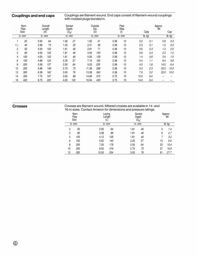
Crosses Crosses are filament wound. Mitered crosses are available in 14- and 16-in sizes. Contact Ameron for dimensions and pressure ratings.
Nom Laying Socket ApproxPipe Length Depth WtSize (L) (Ds)
in. mm in. mm in. mm lb. kg
2 50 2.50 64 1.81 46 3 1.43 80 3.38 86 1.81 46 6 2.74 100 4.12 105 1.81 46 7 3.26 150 5.62 143 2.25 57 13 5.98 200 7.00 178 2.50 64 23 10.4
10 250 8.50 216 2.75 70 37 16.812 300 10.00 254 3.00 76 61 27.7
Nom Overall Socket Outside Pipe ApproxPipe Length Depth Dia Stop WtSize (A) (Ds) (D) (t) Cplg Cap
in. mm in. mm in. mm in. mm in. mm lb. kg lb. kg
1 25 2.50 64 1.06 27 1.62 41 0.38 10 0.2 0.1 0.9 0.411⁄2 40 2.88 73 1.25 32 2.31 59 0.38 10 0.3 0.1 1.0 0.5
2 50 4.00 102 1.81 46 2.81 71 0.38 10 0.6 0.3 1.2 0.53 80 4.00 102 1.81 46 3.94 100 0.38 10 0.9 0.4 2.2 1.04 100 4.00 102 1.81 46 5.06 129 0.38 10 1.4 0.6 3.4 1.56 150 4.88 124 2.25 57 7.19 183 0.38 10 2.4 1.1 8.4 3.88 200 5.38 137 2.50 64 9.25 235 0.38 10 4.0 1.8 14.0 6.4
10 250 5.88 149 2.75 70 11.38 289 0.38 10 5.0 2.3 22.0 10.012 300 6.38 162 3.00 76 13.38 340 0.38 10 7.0 3.2 22.0 10.014 350 7.75 197 3.50 89 14.69 373 0.75 19 12.0 5.4 – –16 400 8.75 222 4.00 102 16.94 430 0.75 19 14.0 6.4 – –
Couplings and end caps
12
Couplings are filament wound. End caps consist of filament-wound couplingswith molded plugs bonded in.

Nom Flange Bolt Laying Flange Thickness Socket Hole Hole Bolt ApproxPipe Dia Circle Length At Hub At Face Depth Count Dia Dia WtSize (A) (BC) (L) (D) (t) (Ds) in. mm in. mm in. mm in. mm in. mm in. mm in. mm in. mm in. mm lb. kg
1 25 4.25 108 3.13 80 0.063 2 – – – – 1.06 27 4 0.63 16 0.50 13 1 0.511⁄2 40 5.00 127 3.88 99 0.125 3 – – – – 1.25 32 4 0.63 16 0.50 13 2 0.92 50 6.00 152 4.75 121 0.188 5 2.00 51 1.00 25 1.82 46 4 0.75 19 0.63 16 2 0.9
6.00* 152 4.75 121 0.188 5 2.00 51 1.00 25 1.82 46 4 0.75 19 0.63 16 2 0.93 80 7.50 191 6.00 152 0.188 5 2.00 51 1.13 29 1.82 46 4 0.75 19 0.63 16 3 1.4
7.50* 191 6.00 152 0.188 5 2.00 51 1.13 29 1.82 46 4 0.75 19 0.63 16 3. 1.44 100 9.00 229 7.50 191 0.188 5 2.00 51 1.25 32 1.82 46 8 0.75 19 0.63 16 4 1.8
9.00* 229 7.50 191 0.188 5 2.00 51 1.56 40 1.82 46 8 0.75 19 0.63 16 4 1.86 150 11.00 279 9.50 241 0.125 3 2.38 60 1.75 44 2.25 57 8 0.88 22 0.75 19 7 3.2
11.00* 279 9.50 241 0.125 3 2.38 60 1.75 44 2.25 57 8 0.88 22 0.75 19 7 3.28 200 13.50 343 11.75 298 0.125 3 2.63 67 2.00 51 2.50 64 8 0.88 22 0.75 19 10 4.5
13.50* 343 11.75 298 0.125 3 2.63 67 2.00 51 2.50 64 8 0.88 22 0.75 19 12 5.410 250 16.00 406 14.25 362 0.125 3 2.88 73 2.00 51 2.75 70 12 1.00 25 0.88 22 14 6.4
16.00* 406 14.25 362 0.125 3 2.88 73 2.00 51 2.75 70 12 1.00 25 0.88 22 16 7.312 300 19.00 483 17.00 432 0.125 3 3.13 80 2.13 54 3.00 76 12 1.00 25 0.88 22 22 10.0
19.00* 483 17.00 432 0.125 3 3.13 80 2.13 54 3.00 76 12 1.00 25 0.88 22 27 12.214 350 21.00 533 18.75 476 0.312 8 3.81 97 2.81 71 3.50 89 12 1.12 28 1.00 25 37 16.816 400 23.50 597 21.25 540 0.250 6 4.25 108 3.25 83 4.00 102 16 1.12 28 1.00 25 53 24.0
Flanges
Nom Flange Bolt Laying Flange Thickness Hole Hole Socket Bolt ApproxPipe Dia Circle Length At Hub At Face Dia Count Depth Dia WtSize (A) (BC) (L) (D) (t) (F) (Ds)
in. mm in. mm in. mm in. mm in. mm in. mm in. mm in. mm in. mm lb. kg
2x11⁄2 50x40 5.00 127 3.88 99 0.50 13 2.38 60 2.38 60 1.88 48 4 0.63 16 0.50 13 2 0.93x2 80x50 7.50 191 6.00 152 0.12 3. 1.93 49 1.12 28 1.81 46 4 0.75 19 0.63 16 3 1.44x2 100x50 9.00 229 7.50 191 0.12 3 1.93 49 1.25 32 1.81 46 8 0.75 19 0.63 16 6 2.74x3 100x80 9.00 229 7.50 191 0.12 3 1.93 49 1.25 32 1.81 46 8 0.75 19 0.63 16 5 2.36x3 150x80 11.00 279 9.50 241 0.69 18 2.50 64 1.75 44 1.81 46 8 0.88 22 0.75 19 12 5.46x4 150x100 11.00 279 9.50 241 0.69 18 2.50 64 1.75 44 1.81 46 8 0.88 22 0.75 19 11 5.08x4 200x100 13.50 343 11.75 298 0.94 24 2.75 70 2.00 51 1.81 46 8 0.88 22 0.75 19 21 9.58x6 200x150 13.50 343 11.75 298 0.50 13 2.75 70 2.00 51 2.25 57 8 0.88 22 0.75 19 17 7.7
10x6 250x150 16.00 406 14.25 362 0.75 19 3.00 76 2.00 51 2.25 57 12 1.00 25 0.88 22 29 13.210x8 250x200 16.00 406 14.25 362 0.50 13 3.00 76 2.00 51 2.50 64 12 1.00 25 0.88 22 24 10.912x8 300x200 19.00 483 17.00 432 0.75 19 3.25 83 2.12 54 3.00 76 12 1.00 25 0.88 22 43 19.5
12x10 300x250 19.00 483 17.00 432 0.50 13 3.25 83 2.12 54 3.00 76 12 1.00 25 0.88 22 36 16.3
Reducing flanges
13
Filament-wound and molded flanges correspond to ANSI B16.5 Cl. 150 classifi-cation. Sealing ring thicknesses for 1- and 11/2-inch flanges are 0.035; for 2- through 8-inch flanges, 0.047; and for 10- through 16-inch flanges, 0.060, respectively. Molded flanges are indicated with an asterisk (*).SeeAssembly Instructions for Bondstrand fiberglass flanges, FP196, forrecommendations on gasket selection, nut and washer dimensions, boltlengths and torques, and tightening sequences.
Reducing flanges are of molded construction. See assembly instructions forbolting and gasket recommendations. Use 1⁄2-inch drive to avoid wrench socketto flange hub interference while torquing bolts.

Nom Flange Bolt Flange Thickness Hole Hole Bolt ApproxPipe Dia Circle At Face At Holes Count Dia Dia WtSize (A) (BC) (D) (t) (F)in. mm in. mm in. mm in. mm in. mm in. mm in. mm lb. kg
2 50 6.00 152 4.75 121 1.18 30 1.00 25 4 0.75 19 0.63 16 3 1.43 80 7.50 191 6.00 152 1.25 32 1.13 29 4 0.75 19 0.63 16 4 1.84 100 9.00 229 7.50 191 1.43 36 1.25 32 8 0.75 19 0.63 16 6 2.76 150 11.00 279 9.50 241 2.50 64 1.75 44 8 0.88 22 0.75 19 14 6.48 200 13.50 343 11.75 298 2.75 70 2.00 51 8 0.88 22 0.75 19 23 10.4
10 250 16.00 406 14.25 362 3.00 76 2.00 51 12 1.00 25 0.88 22 35 15.912 300 19.00 438 17.00 432 3.25 83 2.13 54 12 1.00 25 0.88 22 55 24.9
Blind flanges
Nom Flange Bolt Laying Flange Socket Hole Hole Bolt ApproxPipe Dia Circle Length Thickness Depth Count Dia Dia WtSize (A) (BC) (L) (D) (Ds) (F)in. mm in. mm in. mm in. mm in. mm in. mm in. mm in. mm lb. kg
1 25 4.25 108 3.13 80 0.06 2 1.13 29 1.06 27 4 0.63 16 0.50 13 1 0.511⁄2 40 5.00 127 3.88 99 0.13 3. 1.38 35 1.25 32 4 0.63 16 0.50 13 2 0.9
2 50 6.00 152 4.75 121 0.19 5 1.94 49 1.82 46 4 0.75 19 0.63 16 3 1.43 80 7.50 191 6.00 152 0.19 5 1.94 49 1.82 46 4 0.75 19 0.63 16 4 1.84 100 9.00 229 7.50 191 0.19 5 1.94 49 1.82 46 8 0.75 19 0.63 16 6 2.76 150 11.00 279 9.50 241 0.13 3 2.38 60 2.25 57 8 0.88 22 0.75 19 10 4.58 200 13.50 343 11.75 298 0.13 3 2.63 67 2.50 64 8 0.88 22 0.75 19 14 6.4
10 250 16.00 406 14.25 362 0.13 3 2.88 73 2.75 70 12 1.00 25 0.88 22 21 9.512 300 19.00 483 17.00 432 0.13 3 3.13 80 3.00 76 12 1.00 25 0.88 22 32 14.514 350 21.00 533 18.75 476 0.31 8 3.81 97 3.50 89 12 1.12 28 1.00 25 45 20.416 400 23.50 597 21.25 540 0.25 6 4.25 108 4.00 102 16 1.12 28 1.00 25 59 26.8
Heavy-duty flanges
Nom Flange Bolt Laying Flange Thickness Socket Hole Hole Bolt ApproxPipe Dia Circle Length Maximum Minimum Depth Count Dia Dia WtSize (A) (BC) (L) (D) (F) (Ds)
in. mm in. mm in. mm in. mm in. mm in. mm in. mm in. mm in. mm lb. kg
2 50 6.00 152 4.75 121 0.19 5 3.38 86 2.38 60 1.82 46 4 0.75 19 0.63 16 3 1.43 80 7.50 191 6.00 152 0.19 5 3.38 86 2.50 64 1.82 46 4 0.75 19 0.63 16 5 2.34 100 9.00 229 7.50 191 0.19 5 3.38 86 2.63 67 1.82 46 8 0.75 19 0.63 16 7 3.26 150 11.00 279 9.50 241 0.13 3 3.75 95 2.94 75 2.25 57 8 0.88 22 0.75 19 11 5.08 200 13.50 343 11.75 298 0.13 3 4.00 102 3.19 81 2.50 64 8 0.88 22 0.75 19 17 7.7
10 250 16.00 406 14.25 362 0.13 3 4.25 108 3.25 83 2.75 70 12 1.00 25 0.88 22 24 10.912 300 19.00 483 17.00 432 0.13 3 4.50 114 3.50 89 3.00 76 12 1.00 25 0.88 22 36 16.314 350 21.00 533 18.75 476 0.31 8 5.00 127 4.00 102 3.50 89 12 1.12 28 1.00 25 49 22.216 400 23.50 597 21.25 540 0.25 6 5.50 140 4.50 114 4.00 102 16 1.12 28 1.00 25 57 25.9
Orifice flanges
14
Blind flanges are molded.
Heavy-duty (hubless) flanges are filament-wound.
Orifice flanges are filament-wound.

Nom Pipe Overall Pressure Adhesive KitsSize Length Rating Required
in. mm in. mm psi. N/m2 6 oz.
1 25 2.50 64 150 1.03x10⁶ 1⁄211⁄2 40 3.00 76 150 1.03x10⁶ 12 50 4.00 102 150 1.03x10⁶ 13 80 4.00 102 150 1.03x10⁶ 14 100 4.00 102 150 1.03x10⁶ 26 150 4.88 124 150 1.03x10⁶ 28 200 5.38 137 150 1.03x10⁶ 310 250 5.88 149 150 1.03x10⁶ 412 300 6.38 162 150 1.03x10⁶ 414 350 7.38 187 150 1.03x10⁶ 616 400 8.38 213 150 1.03x10⁶ 8
Maintenance couplings
Nom End Overall Socket Inside ApproxPipe Type Length Depth Dia WtSize (A) (Ds) (B)
in. mm in. mm in. mm in. mm lb. kg
1 25 M 2.38 60 0.87 22 0.76 19 0.3 0.111⁄2 40 M 2.81 71 1.37 35 1.43 36 0.4 0.22 50 M 3.57 91 1.81 46 1.89 48 0.6 0.3
V 4.16 106 1.81 46 1.89 48 0.6 0.33 80 M 4.36 111 1.81 46 2.80 71 1.2 0.5
V 5.00 127 1.81 46 2.80 71 1.2 0.54 100 M 4.63 118 1.81 46 3.89 99 1.6 0.7
V 5.19 132 1.81 46 3.89 99 1.6 0.76 150 M 4.67 119 2.25 57 5.90 150 2.6 1.2
V 6.00 152 2.25 57 5.90 150 2.6 1.2
Adapters (threaded andVictaulic)
Nom Total ApproxPipe Thickness WtSize (A)in. mm in. mm lb. kg
2 50 1.94 49 0.6 0.33 80 1.94 49 1.3 0.64 100 1.94 49 2.0 0.96 150 2.38 60 6.0 2.78 200 2.63 67 10.0 4.5
10 250 2.88 73 17.0 7.712 300 3.13 80 27.0 12.2
Molded plugs
15
Bondstrand maintenance coupling kits include inner and outer sections, hose clamp(s), and instructions for assembly (Bondstrand InstallationMaintenance Coupling, FP199). Adhesive must be ordered separately.
Filament-wound adapters are available in Quick-Lock bell x NPT threaded male(M), and Quick-Lock bell x Victaulic male end (V) configurations.
50 psi maximum

Nom Pipe Approx Adhesive KitsSize Wt Required
in•mm lb/in•kg/mm (3 oz ) (6 oz )
1 25 0.1 0.05 111⁄2 40 0.2 0.09 12 50 0.2 0.09 13 80 0.3 0.14 14 100 0.4 0.18 16 150 0.5 0.23 18 200 0.6 0.27 110 250 0.8 0.36 11⁄212 300 1.0 0.45 11⁄214 350 1.1 0.50 216 400 1.2 0.54 2
Blank saddles
16
Nom Overall Pipe Eccentricity ApproxPipe Length Stop WtSize (A) (L) (E)
in. mm in. mm in. mm in. mm lb. kg
3x2 80X50 1.94 49 0.13 3 0.25 6 0.7 0.34x2 100x50 1.94 49 0.13 3 0.75 19 1.5 0.74x3 100x80 1.94 49 0.13 3 0.13 3 0.8 0.46x3 150x80 2.38 60 0.56 14 1.25 32 4.1 1.96x4 150x100 2.38 60 0.56 14 0.63 16 3.1 1.48x4 200x100 2.63 67 0.81 21 1.63 41 8.0 3.68x6 200x150 2.63 67 0.38 10 0.63 16 5.0 2.3
10x6 250x150 2.88 73 0.63 16 1.63 41 12.0 5.410x8 250x200 2.88 73 0.38 10 0.63 16 7.0 3.212x8 300x200 3.13 80 0.63 16 1.63 41 15.0 6.8
12x10 300x250 3.13 80 0.38 10 0.63 16 8.0 3.6
Molded reducer bushings
Blank saddles are filament wound and are used for pipe support and restraint. Thickness for all saddles is 0.56 inches. Available in same lengths as reducing saddles.

Outlet Laying Nominal SaddleNom Nom Length Thickness Length Girth Approx Wt AdhesiveSize Size (L) (t) (B) (a) (Flg) (Q/L) Kits Required
in.•mm in.•mm in.•mm in.• mm in.•mm degrees lb.•kg lb.•kg 3 oz. 6 oz.
03 80 1,11⁄2, 2 25, 40, 50 5.25 133 0.56 14 6.00 152 180 4 1.8 3 1.4 1-
04 100 1,11⁄2, 2 25, 40, 50 6.00 152 0.81 21 6.00 152 180 7 3.2 5 2.3 1-3 80 6.00 152 0.81 21 9.50 241 180 7 3.2 5 2.3 1-
06 150 1,11⁄2, 2 25, 40, 50 7.38 187 1.06 27 6.00 152 180 18 8.2 14 6.4 13 80 7.38 187 1.06 27 9.50 241 180 18 8.2 14 6.4 14 100 7.38 187 1.06 27 12.00 305 180 18 8.2 14 6.4 1
08 200 1,11⁄2, 2 25, 40, 50 8.13 207 1.31 33 6.00 152 90 14 6.4 11 5.0 13 80 8.13 207 1.31 33 9.50 241 180 17 7.7 13 5.9 14 100 8.63 219 1.31 33 12.00 305 180 22 10.0 16 7.3 1 16 150 9.00 229 1.31 33 17.00 432 180 30 13.6 21 9.5 1 1
10 250 1,11⁄2, 2 25, 40, 50 9.13 232 1.31 33 6.00 152 90 17 7.7 14 6.4 23 80 9.13 232 1.31 33 9.50 241 90 17 7.7 14 6.4 24 100 9.63 245 1.31 33 12.00 305 180 31 14.1 27 12.2 1 26 150 10.13 257 1.31 33 17.00 432 180 40 18.1 35 15.9 3
12 300 1,11⁄2, 2 25, 40, 50 10.38 264 1.31 33 6.00 152 90 27 12.2 23 10.4 1 23 80 10.38 264 1.31 33 9.50 241 90 27 12.2 23 10.4 1 24 100 10.38 264 1.31 33 12.00 305 90 27 12.2 23 10.4 1 26 150 11.13 283 1.31 33 17.00 432 180 53 24.0 46 20.9 3
14 350 1,11⁄2, 2 25, 40, 50 11.00 279 1.31 33 6.00 152 90 37 16.8 35 15.9 33 80 11.00 279 1.31 33 9.50 241 90 37 16.8 35 15.9 34 100 11.00 279 1.31 33 12.00 305 90 37 16.8 35 15.9 36 150 11.75 298 1.31 33 17.00 432 180 64 29.0 49 22.2 4
16 400 1,11⁄2, 2 25, 40, 50 12.00 305 1.31 33 6.00 152 90 53 24.0 41 18.6 23 80 12.00 305 1.31 33 9.50 241 90 53 24.0 41 18.6 24 100 12.00 305 1.31 33 12.00 305 90 53 24.0 41 18.6 26 150 12.75 324 1.31 33 17.00 432 180 75 34.0 67 30.4 5
Reducing saddles with flanged and Quick-Lock outlets
17
Both filament-wound and molded flanges are available. Saddles are filamentwound. See Quick-Lock coupling table for socket depth, Ds. See Quick-Lockflange table for flange thickness.

NomPipe Filament-wound Molded Size Quick-Lock Flanged Quick-Lock Flanged
in. mm psi bar psi bar psi bar psi bar
1 25 300 21 300 21 – – – – 11⁄2 40 300 21 300 21 – – – – 2 50 375 26 375 26 300 21 300 21
300* 21* 300* 21* 200* 14* 200* 14*3 80 325 22 325 22 225 16 225 16
275* 19* 275* 19* 150* 10* 150* 10*4 100 300 21 300 21 175 12 175 12
200* 14* 200* 14* 125* 9* 125* 9*6 150 225 16 225 16 150 10 150 10
175* 12* 175* 12* 100* 7* 100* 7*8 200 225 16 225 16 – – – –
150* 10* 150* 10* – – – – 10 250 200 14 200 14 – – – –
150* 10* 150* 10* – – – – 12 300 175 12 150 10 – – – –
150* 10* 150* 10* – – – – 14 350 150 10 150 10 – – – – 16 400 150 10 150 10 – – – – *Note: Pressure ratings for Series5000 are lower than for other pipe series.
• 45° elbows, bell end• 90° elbows, bell end• 45° elbows, flanged• 90° elbows, flanged• Tees, bell end• Tees, flanged
18
Outlet SaddleNom Nom Length Girth Approx AdhesiveSize Size (B) (a) Wt Kits Required
in.•mm in.•mm in.•mm degrees lb.•kg 3 oz. 6 oz.
2 50 1⁄4, 3⁄8, 1⁄2, 3⁄4 6, 9, 13, 19 4.00 102 180 1.0 0.5 1-
1 25 6.00 152 180 2.0 0.9 1-
3 80 1⁄4 6 4.00 102 90 1.6 0.7 1-1⁄4, 3⁄8, 1⁄2, 3⁄4 6, 9, 13, 19 4.00 102 180 1.6 0.7 1-
1,11⁄4, 11⁄2 25, 30, 40 6.00 152 180 3.9 1.8 1-
4 100 1⁄4, 3⁄8 6, 9 4.00 102 90 2.0 0.9 1-1⁄4, 3⁄8, 1⁄2, 3⁄4 6, 9, 13, 19 4.00 102 180 2.0 0.9 1-1,11⁄4, 11⁄2 25, 30, 40 6.00 152 180 4.0 1.8 1-
6 150 1⁄4, 3⁄8, 1⁄2 6, 9, 13 4.00 102 180 2.4 1.1 1-1⁄4, 3⁄8, 1⁄2, 3⁄4 6, 9, 13, 19 4.00 102 180 2.4 1.1 1
1,11⁄4, 11⁄2 25, 30, 40 6.00 152 180 4.6 2.1 1
8 200 1⁄4, 3⁄8, 1⁄2, 3⁄4 6, 9, 13, 19 4.00 102 90 2.8 1.3 1-1,11⁄4, 11⁄2 25, 30, 40 6.00 152 180 5.2 2.4 1
10 250 1⁄4, 3⁄8, 1⁄2 6, 9, 13 4.00 102 45 3.8 1.7 13⁄4 19 4.00 102 90 3.8 1.7 1
1,11⁄4, 11⁄2 25, 30, 40 6.00 152 90 6.3 2.9 112 300 1⁄4, 3⁄8, 1⁄2, 3⁄4 6, 9, 13, 19 4.00 102 45 4.2 1.9 1
1,11⁄4, 11⁄2 25, 30, 40 6.00 152 90 7.4 3.4 114 350 1⁄4, 3⁄8, 1⁄2, 3⁄4 6, 9, 13, 19 4.00 102 45 4.2 1.9 2
1,11⁄4, 11⁄2 25, 30, 40 6.00 152 90 7.4 3.4 216 400 1⁄4, 3⁄8, 1⁄2, 3⁄4 6, 9, 13, 19 4.00 102 45 4.2 1.9 2
1,11⁄4, 11⁄2 25, 30, 40 6.00 152 45 7.4 3.4 2
Reducing saddles (bushed outlets)
Standard reducing saddles come with 11 /2-in NPT plastic bushing. All smallerbushings are 316 stainless steel. Other materials available on special order.Saddles are filament wound.
Fittings Pressure Ratings Bondstrand Series 2000, 4000, 5000 and 7000 fittings

19
Fittings Pressure Ratings(cont’d.)
Bondstrand Series 2000, 4000, 5000 and 7000 fittings
Nom Tapered body reducers Saddles, bell end Crosses, bell end End capsPipe Tapered body reducers, flanged Saddles, flanged Crosses, flanged Reducer bushingsSize Flanges Blind Flanges
in. mm psi bar psi bar psi bar psi bar
1 25 600 41 150 10 – – 50 3 11⁄2 40 550 38 150 10 – – 50 3 2 50 450 31 150 10 150 10 50 3 3 80 350 24 150 10 150 10 50 3 4 100 350 24 150 10 150 10 50 3 6 150 250 17 150 10 100 7 50 3 8 200 225 16 150 10 100 7 50 3 10 250 175 12 150 10 100 7 50 3 12 300 150 10 150 10 100 7 50 3 14 350 150 10 150 10 – – 50 3 16 400 150 10 150 10 – – 50 3
• Tapered body reducers• Tapered body reducers, flanged• Flanges• Flanges, blind• Saddles, bell end• Crosses, bell end• Crossed, flanged* End caps• Reducer bushings
Nom pipe Laterals, bell end Sleeve couplings Adapters, threadedSize Laterals, flanged Adapters, grooved
in. mm psi bar psi bar psi bar
1 25 – – 450 31 – – 11⁄2 40 – – 450 31 – –2 50 150 10 450 31 200 14
150 * 10* 450 31 150* 10* 3 80 150 10 425 29 200 14
150* 10* 350* 24* 150* 10*4 100 150 10 400 28 150 10
150* 10* 350 24* 100* 7*6 150 100 7 300 21 150 10
100* 7* 250 17* 100* 7*8 200 100 7 250 17 – –
100* 7* 225* 16* – –10 250 100 7 200 14 – –
100* 7* 175* 12* – –12 300 100 7 170 12 – –
100* 7* 150* 10* – –14 350 – – 165 11 – –
– – 150* 10* – –16 400 – – 165 11 – –
– – 150* 10* – – *Note: Pressure ratings for Series5000 are lower than for other pipe series.
• Laterals, bell end• Laterals, flanged• Sleeve couplings• Adapters, threaded• Adapters, grooved

This literature and the information and recommendations it contains are basedon data reasonably believed to be reliable. However, such factors as variationsin environment, application or installation, changes in operating procedures, orextrapolation of data may cause different results. Ameron makes no represen-tation or warranty, express or implied, including warranties of merchantability orfitness for purpose, as to the accuracy, adequacy or completeness of therecommendations or information contained herein. Ameron assumes no liabilitywhatsoever in connection with this literature or the information or recommenda-tions it contains.
Important notice
Fiberglass Pipe Division-AsiaAmeron (Pte) Ltd.No. 7A, Tuas Avenue 3Singapore 639407Tel: 65 861 6118Fax: 65 862 1302/861 7834
Fiberglass Pipe Division-EuropeAmeron B.V.J.F. Kennedylaan 74191 MZ GeldermalsenThe NetherlandsTel: +31 345 587 587Fax: +31 345 587 561Telex: 40257 bonds nl
Fiberglass Pipe Division-AmericasP.O. Box 878Burkburnett, Texas 76354Tel: (940) 569-1471Fax: (940) 569-2764
Fiberglass Pipe Division-Centron InternationalP.O. Box 490600 FM 1195 SouthMineral Wells, Texas 76068Tel: (817) 325-1341Fax: (817) 325-9681
Group HeadquartersP.O. Box 801148 Houston TX 77280Tel: (713) 690-7777Fax: (713) 690-2842http://www.ameron.com
FIBERGLASS PIPE GROUP
© 1991 Ameron FP282A (5/98) supersedes FP282 (9/91) Printed in U.S.A. 5M[186]


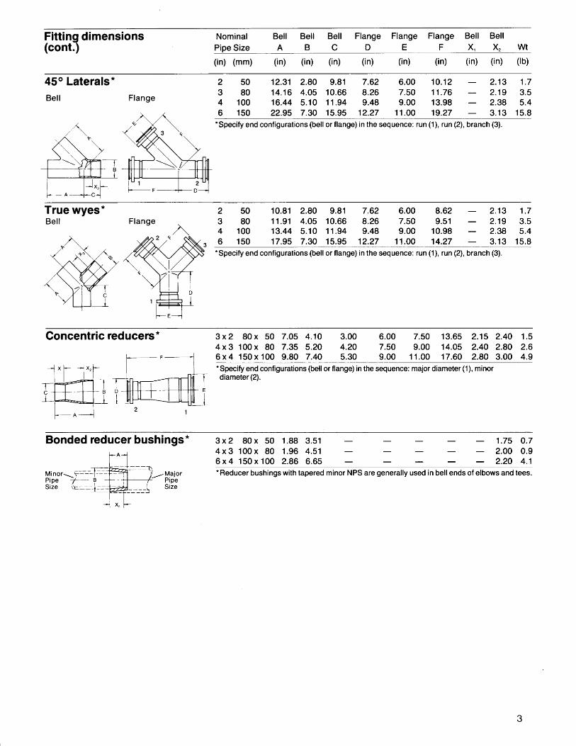


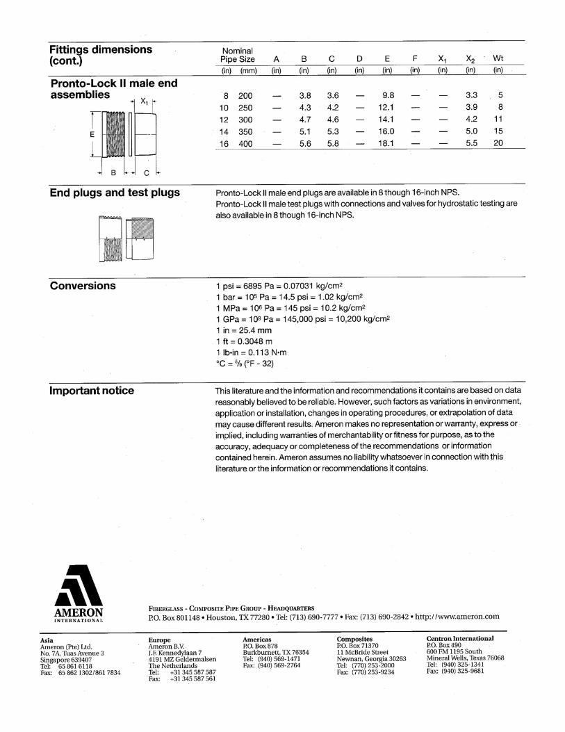

Bondstrand® Product Data®
Pronto-Lock®
heavy-duty mechanical coupling system
Introduction Pronto-Lock* is a heavy-duty threaded coupling system with a positive seal O-ring thatprovides a fast, simple, rugged and reliable means to install fiberglass pipe. Theversatility of Pronto-Lock permits inexperienced crews to install pipe in all weatherconditions and types of services.
FP128D (1/95
User benefits Lower, more predictable installation costs because the pipe is installed quickly under allweather conditions.
Specially trained crews are unnecessary since no special techniques or tools arerequired.
Immediate reusability permits handling, testing and backfilling without waiting foradhesives to cure.
Reusability of the mechanical joint permits use on temporary lines.
Construction Pronto-Lock is made of fiberglass reinforced thermosetting resin with pressure,temperature and corrosion resistance equal to or greater than the pipe ratings. Thethreads and the O-ring grooves are molded; the female end is filament wound for extrastrength. Male and female ends are bonded onto the the pipe and the O-ring is placedin the groove at the plant. The pipe comes ready for assembly.
Features Large, fast-advance Acme type thread: Rugged molded fiberglass threads thatprevent galling and will not crossthread.
Standard size O-ring: Use the standard Buna-N O-ring or choose from the broadselection available on special order.
Molded O-ring groove: Precisely positioned O-ring insures positive sealing andprevents movement, assuring pressure integrity.
Tapered sealing surfaces: During assembly, tapered surfaces precompress the O-ringfor a positive seal—even in vacuum service.
Installation savings Specifying engineers recognize the total cost in getting today’s pipe in service forprofitable, uninterrupted service in the future. Material cost, corrosion protection andwelding mean labor, time and money.
Thousands of miles of proven experience installing Bondstrand pipe is testimony to theeconomic advantages and dependability of reinforced thermosetting resin pipe (RTRP).Now Pronto-Lock goes one step further than the adhesive joining system with areduction in labor of 25% and reduction in joint installation time of 50%.
In normal conditions, a 3-man crew can install 1800 feet of 2-inch Bondstrand pipe withPronto-Lock every hour. Pipe crossings, ditch water, rain, cold weather and marshlandsare no problem. Pipe with Pronto-Lock can be put into service immediately.* U.S. Patent No. 3,784,239

© 1985 Ameron • FP128D (1/95) supersedes FP128C (12/93) • Printed in U.S.A. • 5M
Relative installation costand time requirements
Ease of installation Bondstrand pipe with the Pronto-Lock joint installs twice as fast as pipe with adhesivejoints, even by unskilled crews. Simply lubricate and insert the threaded male end intothe female end and turn the pipe until the connection is firm. Tighten the joint with astrap wrench on the female end to insure full makeup. No adhesive. No welding. Thejoint makes up pronto!
Crossovers and tools Crossover pieces to make transitions to steel and crossovers with a choice of specialend connections (grooved ends, NPT threads or flanged ends) are available on specialorder.
Areas of application Buried lines. Pronto-Lock allows immediate placement in the ditch, testing andbackfilling—greatly reducing open ditch time.
Overhead lines. Pronto-Lock on lightweight Bondstrand fiberglass pipe allows safe,quick assembly on overhead pipe racks.
Surface lines. Bondstrand fiberglass pipe can be installed above ground.
Temporary lines. Pronto-Lock can be reused. The molded threads, when lubricated,prevent galling and facilitate reuse.
Individual system components may not have the same ratings as the pipe. Refer tothe detailed product information for the specific components to determine thepressure rating for the system as a whole.
This literature and the information and recommendations it contains are based on data reasonablybelieved to be reliable. However, such factors as variations in environment, application or instal-lation, changes in operating procedures, or extrapolation of data may cause different results.Ameron makes no representation or warranty, express or implied, including warranties ofmerchantability or fitness for purpose, as to the accuracy, adequacy or completeness of therecommendations or information contained herein. Ameron assumes no liability whatsoever inconnection with this literature or the information or recommendations it contains.
Important notice
Written comments regarding this document are invited. Please write Engineering Manager,Ameron Fiberglass Pipe Group.
3-man Crew 3-man CrewNominal 4-man Crew 30-ft RTRP 40-ft Ameron RTRP
Pipe 40-ft Steel Pipe Bell x Spigot Pronto-LockSize Welded Adhesive Bonded Mechanical Joint
(in) (mm) (ft/8 hours) (ft/8 hours) (ft/8 hours)2 50 3000 6000 150003 80 2400 5000 125004 100 1800 4200 108006 150 1300 3400 7200
Manufacturing plants: Burkburnett, Texas; Spartanburg, South Carolina; Geldermalsen, The Netherlandsand Singapore. Bondstrand pipe is also manufactured in Japan and Saudi Arabia.
®
Fiberglass Pipe DivisionAsiaNo. 7A, Tuas Avenue 3Singapore 2263Tel: 862-1301Telex: 38960 AMERON RSFax: 862-1302
Fiberglass Pipe DivisionEuropeJ.F. Kennedylaan 74191 MZ GeldermalsenThe NetherlandsTel: 03455-73341Telex: 40257 BONDS NLFax: 03455-75254
Fiberglass Pipe DivisionThe AmericasP.O. Box 878Burkburnett, Texas 76354Tel: (817) 569-1471Fax: (817) 569-4012
Fiberglass Pipe Group • P.O. Box 801148 • Houston TX 77280 • Tel: (713) 690-7777 • Fax: (713) 690-2842

Bondstrand® Product Data®
Pronto-Lock® IIheavy-duty mechanical coupling systemfor fiberglass pipe
Introduction Recognizing the need for a simple, reliable coupling system in the 8 to 16-inch nominalpipe sizes, Ameron Fiberglass Pipe Division designed Pronto-Lock II* so that only themale threaded portion of the coupling has to turn in order to lock the joint. This featureallows for limited axial movement and also permits the incorporation of a 2° angulardeflection capability that is unavailable in steel and conventional adhesive-bondedfiberglass piping systems. The angular deflection capability allows the pipeline toconform much more readily to changes in terrain and minimizes the number of elbowsrequired. The deflection capabilities of the Pronto-Lock II coupling do not affect theintegrity of the O-ring seal. Pronto-Lock II employs a tapered male end which, afterbeing lubricated, is inserted into the female end, compressing the O-ring, thusproviding a leakproof connection. The locking sleeve is then spun into place, positivelylocking the joint into position.
The female end of Pronto-Lock II is fiberglass-reinforced epoxy and is filament woundonto the pipe in the factory. The male end is machined and attached in the factory byadhesive bonding. The male end and the locking sleeve are made of centrifugally castchopped fiberglass reinforcement and epoxy resins. The resilient bearing ring isBuna-N. The O-ring material is selected to be compatible with the system fluid. Buna-Nis standard, but other materials such as EPR and Viton A are available. ConsultBONDSTRAND CORROSION GUIDE, FP132, or Ameron Fiberglass Pipe Division for selectionof the proper O-ring material.
* U.S. Patent No. 4,014,568
FP125E (1/95)
User benefits Lower, more predictable installation costs because the pipe is installed quickly under allweather conditions.
Specially trained crews are unnecessary since no special techniques or tools arerequired.
Immediate usability permits handling, testing and backfilling without waiting foradhesives to cure.
Reusability of the mechanical coupling permits use on temporary lines.

Angular deflection The Pronto-Lock II coupling can accommodate up to 2° angular deflection off thecenterline when properly made up.
Fig.1. The Pronto-Lock II coupling prior toinsertion of the male end into the female end.
Fig.2. After insertion, an effective seal is made.The two ends are joined in a leak-tight assembly,
but are free to separate as long as the pipingremains axially unrestrained.
Fig.3. The Pronto-Lock II coupling completelymade up: axial restraint of the joint by the
threaded locking sleeve assures that the pipeends cannot pull apart.
Fig.4. The positions of the mating surfaces in thestraight run (nondeflected) configuration.
Fig.5. The mating surfaces in the maximum2° angular deflection condition.
Operation
22°

Expansion/contraction The Pronto-Lock II coupling can accommodate both tensile and compressive axialloads. When the joint is made, the O-ring is compressed against the male end andmaintains leak-tight integrity of the coupling under tensile, neutral and compressiveaxial load conditions. Although the no-load position cannot be determined exactly in anassembled coupling, the total capacity for axial movement is about 3⁄8 inch.
Fittings Ameron manufactures a complete line of fittings in the 8 to 16-inch nominal pipe sizerange. All are available with the Pronto-Lock II coupling system that provides a union-type connection at every joint. The concept can be applied to all fittings, providing atotally mechanical, all-fiberglass system that forgives the minor angular or dimensionalvariations that occur in all complex piping arrangements. The standard fitting comesequipped with Pronto-Lock II female ends. Pronto-Lock II male ends are also available.
Prefabrication Special layouts and fittings can be factory prefabricated from shop drawings byAmeron and then shipped to the job ready for assembly. Where piping must betailored to special alignments for a specific job, the pipe can be cut and tapered andthe Pronto-Lock male ends bonded onto the pipe under controlled factoryconditions. Thus, field assembly and installation can be carried out regardless ofweather conditions.
Fig.6. The joint with no axial loading.
Fig.7. The joint under tensile axial load:movement is limited such that the free space
between the bearing ring and the lockingsleeve is taken up and the bearing ring iscompressed. The joint is restrained from
pulling apart by the locking sleeve.
Fig.8. The joint under compressive axial load:the coupling slides together until the male end
wedges inside the female end.
Only a light torque is needed to make up the locking sleeve. Owing to the limited threadmake-up of the sleeve into the female end, excess torque will not advance the threadsto compress the bearing ring on a properly inserted joint.
Since there is a mechanical interference at both ends of the axial travel, axial travelcannot accumulate and cause the joint to separate. No tightening is necessary after thejoint has been put into operation. The coupling can be disassembled, if necessary.However, about 10 inches of axial clearance is required to separate a disassembledPronto-Lock II joint.

Reusability The mechanical joining of Pronto-Lock II also enables the user to recover and reusepipe and fittings. Piping systems can be modified and relocated without having to scrapusable fittings.
© Ameron 1991 • FP125E (1/95) supersedes FP125D (3/94) • Printed in U.S.A.• 5M • [186]
This literature and the information and recommendations it contains are based on datareasonably believed to be reliable. However, such factors as variations in environment,application or installation, changes in operating procedures, or extrapolation of datamay cause different results. Ameron makes no representation or warranty, express orimplied, including warranties of merchantability or fitness for purpose, as to theaccuracy, adequacy or completeness of the recommendations or informationcontained herein. Ameron assumes no liability whatsoever in connection with thisliterature or the information or recommendations it contains.
Important notice
Written comments regarding this document are invited. Please write EngineeringManager, Ameron Fiberglass Pipe Division.
Ease of installation
30-ft Fiberglass Pipe 40-ft Fiberglass Pipe40-ft Steel Pipe Bell and Spigot Pronto-Lock II
Nominal Welded Joint Adhesive Joint Mechanical JointPipe Size 4-man Crew 3-man Crew 3-man Crew(in) (mm) (ft/8 hr shift) (ft/8 hr shift) (ft/8 hr shift)
8 200 1000 2400 660010 250 800 2100 600012 300 600 1800 540014 350 420 1500 420016 400 300 1200 3600
Since make-up of the Pronto-Lock II joint does not depend on curing adhesives,welding metals or favorable weather conditions, significant reductions in labor andinstallation time are realized. The following table gives typical installation rates forwelded-steel pipelines and for fiberglass pipelines employing adhesive-bonded belland spigot joints and the Pronto-Lock II coupling system, respectively. Large pipe sizesrequire larger crews and additional equipment.
With lightweight fiberglass pipe these needs range from 25 to 50% less than steel pipe.
Manufacturing plants: Burkburnett, Texas; Spartanburg, South Carolina; Geldermalsen, The Netherlandsand Singapore. Bondstrand pipe is also manufactured in Japan and Saudi Arabia.
®
Fiberglass Pipe DivisionAsiaNo. 7A, Tuas Avenue 3Singapore 2263Tel: 862-1301Telex: 38960 AMERON RSFax: 862-1302
Fiberglass Pipe DivisionEuropeJ.F. Kennedylaan 74191 MZ GeldermalsenThe NetherlandsTel: 03455-73341Telex: 40257 BONDS NLFax: 03455-75254
Fiberglass Pipe DivisionThe AmericasP.O. Box 878Burkburnett, Texas 76354Tel: (817) 569-1471Fax: (817) 569-4012
Fiberglass Pipe Group • P.O. Box 801148 • Houston TX 77280 • Tel: (713) 690-7777 • Fax: (713) 690-2842
Individual system components may not have the same ratings as the pipe. Referto the detailed product information for the specific components to determinethe pressure rating for the system as a whole.
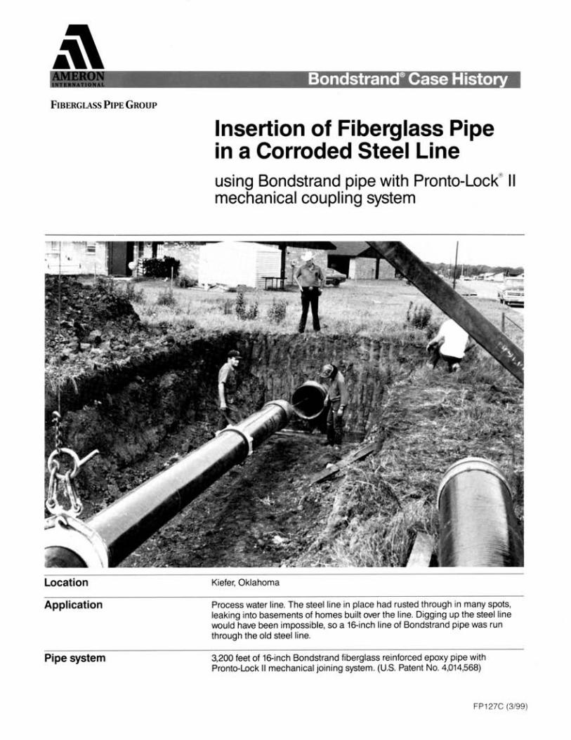


Bondstrand® Product DataFIBERGLASS-COMPOSITE PIPE GROUP
U.S. Patent No. 4250074, 4257645
PSXTM•20 Adhesive KitEpoxy siloxane adhesive for bonding fiberglass
pipe and fittings with tapered joints.
Description PSX•20 adhesive is a patented two-part epoxy siloxane adhesive designed forpermanently joining fiberglass pipe and fittings with taper/taper joints. PSX•20 is anon-flowing thixotropic paste offered in easy-to-use kits. The PSX•20 epoxy adhesivekit contains an adhesive resin, hardener, mixing spatula, brush and assembly instruc-tions. The adhesive resin is a dark red paste with sand, The adhesive hardener is awhite paste. The mixed adhesive color is red. PSX•20 can be used to connect epoxy,vinyl ester or phenolic systems.
Preparation ofbonding surface
Using the sandpaper supplied in the adhesive kit, clean both surfaces thoroughly toremove all dirt, grease and foreign materials. Make sure the bonding surfaces are freeof moisture.Do not touch the bonding surfaces with bare hands, dirty or greasy gloves or ragsafter cleaning them.
Mixing the adhesive In cold weather it is necessary to warm the resin to 50°F (10°C) to permit good mixingand easier application.Open both resin and hardener containers. Using the stick supplied, put all of thehardener into the resin container. Never split a kit.
At 77°F (25°C) the pot life of PSX•20 adhesive is 20 to 30 minutes. The pot lifedecreases with rising temperatures:
Pot life and Cure time
Adhesive Minimum JointTemperature Pot Life (min.) Cure Time(°F) (°C) (minutes) (hours)50 10 70 1265 18 40 675 24 25 495 35 10 3
In extremely cold or windy conditions, use insulation to prevent rapid dissipation ofheat from the cure reaction. Cap the ends of the piping to prevent the passage of coldair. In severe cold conditions, warm air may be blown through the interior of the pipe.A heat cure is recommended for installations with service temperatures above 180°F(82°C) or operating pressures over 300 psi. For ambient temperature conditions below50°F (10°C), an external heat cure must be used. A minimum heat cure time of at least30 minutes is recommended for 2- through 6-inch pipe. Even after the adhesive hasturned solid at ambient temperatures, heat curing will promote chemical cross-linkingof the adhesive, thus increasing its strength, temperature resistance and corrosionresistance. A single Chem Cure Pak may be applied or an Ameron-approved electricheat blanket may be used. The heat cure may be applied at any time after the bond ismade and before the pipe has been tested or put into service.
FP698A (5/01)
Listings and approvals Ameron PSX•20 adhesive is Listed by Underwriters Laboratories (UL) under File MH9162 for use in Nonmetallic Underground Piping for Flammable Liquids. PSX•20adhesive is particularly suited for piping systems conveying petroleum productsincluding diesel fuels, kerosene, etc., alcohols and alcohol-gasoline mixtures, oroxygenated fuels. It is also approved by Underwriters Laboratories for use withMTBE fluids.
UL®
m n
UnderwritersLaboratories Inc.®

Toxicity Hardener: The hardener is irritating to the skin, eyes and respiratory tract. It is toxicorally and may cause sensitization.Resin: The resin is irritating to skin and eyes and may cause sensitization.
Storage Do not store kits in areas above 100˚ (38˚C) or below 32˚F (0˚C), or in the directsunlight in warm weather. In cold weather warm the resin to at least 60˚F (16˚C) butnot above 100˚F (38˚C) to permit good mixing and easier application. Do not useadhesive past its expiration date.
Shear StrengthComparison
Polysiloxane-epoxy adhesive demonstrates a significant improvement in bondingcapabilities over conventional epoxy adhesives. When cured at room temperature,PSX•20 achieves 15 to 20% greater shear strength than conventional epoxyadhesives. With elevated temperature cures, lap shear strength increases to 20 to 35% over standard epoxy adhesives. PSX•20 also offers significant improvementsover conventional epoxy adhesives when bonding phenolic based laminates. Whenapplied according to manufacturer’s instructions, PSX•20 yields a secure bond forDualoy®, Bondstrand® and Bondstrand PSX products.
First aid In case of contactEyes: Immediately flush eyes with plenty of water for at least 15 minutes.
Call a physician.
Skin: Wash skin with water and soap, if available.
Clothing:Remove contaminated clothing and wash before reuse.
Inhalation: Remove to fresh air. Give oxygen or artificial respiration if necessary.Ingestion: If patient is conscious, give 1 to 2 glasses of water to dilute. Do not induce
vomiting. Call a physician immediately.
Handling precautions Hardener: Do not get in eyes, on skin or clothing. Avoid breathing vapor; use cautionwhen opening can. Wear rubber gloves and apron and NIOSH-approved respirator.Wash thoroughly after handling.Resin: Avoid contact with eyes, skin or clothing. Wear rubber gloves and eyeprotection. Wash thoroughly after handling.
FOR CHEMICAL EMERGENCYSPILL, LEAK, FIRE, EXPOSURE OR ACCIDENT
CALL CHEMTRECDAY OR NIGHT
1-800-424-9300Toll-free in the continental U.S.
483-7616 in District of Columbia
For calls originating outside the continental U.S.
202-483-7616 Washington D.C. collect
ALL CALLS ARE RECORDED
Important Notice This literature and the information and recommendations it contains are based on data reasonably believed tobe reliable. However, such factors as variations in environment, application or installation, changes in operatingprocedures, or extrapolation of data may cause different results. Ameron makes no representation or warranty,expressed or implied, including warranties of merchantability or fitness for purpose, as to the accuracy,adequacy or completeness of the recommendations or information contained herein. Ameron assumes noliability whatsoever in connection with this literature or the information or recommendations it contains.
FIBERGLASS-COMPOSITE PIPE GROUP - HEADQUARTERSP.O. Box 801148 • Houston, TX 77280 • Tel: (713) 690-7777 • Fax: (713) 690-2842 • http://www.ameron.com
Fiberglass Pipe DivisionEuropeAmeron B.V.J.F. Kennedylaan 74191 MZ GeldermalsenThe NetherlandsTel: +31 345 587 587Fax: +31 345 587 561Telex: 40257 bonds nl
Fiberglass Pipe DivisionAmericasP.O. Box 878Burkburnett, TX 76354Tel: (940) 569-1471Fax: (940) 569-2764
Fiberglass Pipe DivisionCentron InternationalP.O. Box 490600 FM 1195 SouthMineral Wells, Texas 76068Tel: (940) 325-1341Fax: (940) 325-9681
Fiberglass Pipe Division AsiaAmeron (Pte) Ltd.No. 7A, Tuas Avenue 3Singapore 639407Tel: 65 861 6118Fax: 65 862 1302/861 7834
© 1996 Ameron • FP698A (5/01) supersedes FP698 (4/96) • Printed in U.S.A. [186]2.5M
Adhesive kits are available in 3-, 5- and 8-oz. sizes. The table below indicates thenumber of bonds per kit for each pipe size. Values in the table are based on thequantity of adhesive required by an experienced crew working at a temperature of75°F (24°C) with a 30 minute adhesive pot life.
Kit sizes andbonds per kit
Kit size Bonds per kit per pipe size(oz.) 2 3 4 6 8 10 12 14 16
3 7 5 4 2 1 1 — — —5 12 8 6 3 2 2 1 1 —8 — 14 9 4 3 3 2 2 1

Prior to handling, read all Toxicity, Precaution and First Aid information below. Before mix-ing the adhesive, insure that the bonding surfaces are correctly prepared and are cleanand dry. Open the resin and hardener containers. Using the mixing spatula, scrape all ofthe hardener into the resin container. Mix the resin and the hardener with the spatula forat least 60 seconds. Scrape the sides, bottom and lid of the resin container occasional-ly to get all of the hardener into the mix. Never attempt to split a kit. The resin and thehardener have been packaged at the correct ratio for optimum adhesive performance.
Apply a uniform coat of the mixed adhesive to both bonding surfaces and draw theparts firmly together. Detailed joint assembly instructions may be found in QUICK-LOCK
INSTALLATION INSTRUCTIONS, FP170.
Instructions
Listings and approvals
For installations with service temperatures below 180°F (82°C) and pressures below150 psi (1.03 MPa), PSX•34 bonds can be put into service with ambient temperaturecures as indicated in the table (See page 2 of this section.). However, it is highly rec-ommended that an external heat source be used to force cure the adhesive. Theadhesive and bonding surfaces should be warmed to 70°F (21°C) prior to mixing andapplying the adhesive. Adhesive may be force cured using an Ameron-approved heat-ing blanket. The table also indicates the pot life (working time) of the adhesive at var-ious temperatures. The pot life is the time from the initial mixing of the resin and hard-ener until the adhesive in the container begins to thicken and is no longer usable.
For systems with anticipated service temperatures above 180°F (82°C) or operatingpressures over 150 psi (1.03 MPa), or when installing any system at ambient temper-atures below 40°F (5°C), the adhesive joint must be cured with an external heatsource. A heat cure using an Ameron-approved electric heating blanket is recom-mended. The heat cure may be applied at any time after the bond is made and beforethe line is tested or put into service. The heat may be applied immediately after mak-ing the bond while the adhesive is still liquid or after it has gelled to a solid.
Minimum cure times of 30 minutes for 1- through 6-inch pipe and 45 minutes for 8- through 16-inch lines are recommended. Even after the adhesive has solidified at ambi-ent temperatures, heat curing will enhance the chemical cross-linking of the adhesive,increasing the strength, temperature resistance and corrosion resistance of the adhesive.
When used in fire protection service all joints must be force-cured with an externalheat source regardless of ambient temperature.
Pot life and cure time
The PSX•34 epoxy adhesive kit contains an adhesive resin, hardener, mixing spatula,brush and assembly instructions. The adhesive resin is a dark red paste with sand.The adhesive hardener is a white paste. The mixed adhesive color is red. PSX•34 is atwo-part epoxy siloxane adhesive formulated for permanently bonding Quick-Lock®
joints on Ameron fiberglass-reinforced pipe and fittings. PSX•34 can be used to con-nect all epoxy and phenolic piping systems, and most vinyl ester systems.
Description
PSX®•34 AdhesiveKitEpoxy siloxane adhesive for bonding fiberglass pipe and fittings
Bondstrand® Product Data
ISO-9001
CERTIFICATED FIRM
U.S. Patent No. 4250074, 4257645FP735D (7/01)
UL®
n
UnderwritersLaboratories Inc.®
Ameron PSX•34 adhesive is listed by Underwriters Laboratories (UL) under File MH9162 for use in Nonmetallic Underground Piping for Flammable Liquids and withUnderwriters’ Laboratories of Canada under File CMH 715. PSX•34 adhesive isListed by the National Sanitation Foundation under NSF Standard 61 - Drinking WaterSystem Components - Health Effects for use in Potable Water Service andCommercial Hot Water Applications.ULC
FIBERGLASS - COMPOSITE PIPE GROUP

FIBERGLASS - COMPOSITE PIPE GROUP - HEADQUARTERS
P.O. Box 801148 • Houston, TX 77280 • Tel: (713) 690-7777 • Fax: (713) 690-2842 • http://www.ameron.com
EuropeAmeron B.V.J.F. Kennedylaan 74191 MZ GeldermalsenThe NetherlandsTel: +31 345 587 587Fax: +31 345 587 561
AmericasP.O. Box 878Burkburnett, TX 76354Tel: (940) 569-1471Fax: (940) 569-2764
Centron InternationalP.O. Box 490600 FM 1195 SouthMineral Wells, Texas 76068Tel: (940) 325-1341Fax: (940) 325-9681
AsiaAmeron (Pte) Ltd.No. 7A, Tuas Avenue 3Singapore 639407Tel: 65 861 6118Fax: 65 862 1302/861 7834
Ambient Adhesive Minimum Joint Minimum TimeTemperature1 Pot Life Cure Time2 to Move2
(°F) (°C) (minutes) (hours) (hours)
40 5 70 12 1160 16 40 7 670 21 30 5 480 27 20 4 3
100 38 8 3 21) At temperatures below 40°F (5°C), an external heat source must be used to force cure the adhesive. The
adhesive and the bonding surfaces should be warmed to 70°F (21°C) before mixing and applying the adhe-sive. Adhesive may be force cured using an Ameron-approved electric heating blanket. When using adhesiveat ambient temperatures above 100°F (38°C), make provisions to keep adhesive cool to extend pot life.
2) Times indicate when cure is sufficient to permit moving the bonded joint. The minimum joint cure time mustelapse prior to hydrotesting.
Important Notice This literature and the information and recommendations it contains are based on data reasonably believed to bereliable. However, such factors as variations in environment, application or installation, changes in operatingprocedures, or extrapolation of data may cause different results. Ameron makes no representation or warranty,express or implied, including warranties of merchantability or fitness for purpose, as to the accuracy, adequacy orcompleteness of the recommendations or information contained herein. Ameron assumes no liability whatsoeverin connection with this literature or the information or recommendations it contains. Product specifications aresubject to change.
Do not store kits in areas above 100°F (38°C) or below 32°F (0°C), or in the direct sun-light in warm weather. In cold weather warm the resin to at least 60°F (16°C) but notabove 100°F (38°C) to permit good mixing and easier application. Do not use adhe-sive past its expiration date.
Storage
Hardener: The hardener is irritating to skin, eyes and respiratory tract. It is toxic oral-ly and may cause sensitization. Avoid contact with eyes, skin or clothing. Avoidbreathing vapors. Wear rubber gloves, protective apron and NIOSH-approved respi-rator. Wash thoroughly after handling.Resin: The resin may be mildly irritating to skin, eyes and respiratory tract. Avoid con-tact with eyes, skin or clothing. Avoid breathing vapors. Wear rubber gloves and eyeprotection. Wash thoroughly after handling.
Toxicity and precautions
In case of contact
Eyes: Immediately flush eyes with plenty ofwater for at least 15 minutes. Call a physician.
Skin: Wash skin with soap and water.
Clothing: Remove contaminated clothing andwash before reuse.
Inhalation: Remove to fresh air. Give oxygenor artificial respiration if necessary.
Ingestion: If catalyst is swallowed and personis conscious, give plenty of water or milk todrink. Do not induce vomiting. Call a physi-cian. If resin is swallowed, give 100 grams (about 1⁄4 lb) activated charcoal slurry inwater. Do not induce vomiting. Call a physician.
First aidFOR CHEMICAL EMERGENCY
SPILL, LEAK, FIRE, EXPOSURE ORACCIDENT
CALL CHEMTREC - DAY OR NIGHT
1-800-424-9300
Toll-free in the continental U.S.
483-7616 in District of Columbia
For calls originating outside the continental U.S.
202-483-7616 -Washington D.C. collect
ALL CALLS ARE RECORDED
PSX•34 adhesive kits are available in 3 oz., 5 oz. and 8 oz. sizes. The values in thistable are based on the quantity of adhesive required by an experienced crew work-ing at a temperature of 80°F (27°C). All sizes available in 6-packs.
Adhesive kit sizes and bonds per kit
KitSize Nominal Pipe Size (in/mm)(fl oz) 1/25 1.5/40 2/50 3/80 4/100 5/125 6/150 8/200 10/250 12/300 14/350 16/400
3 10 6 4 3 2 1 1 1⁄2 1⁄2 1⁄2 – –5 – 10 7 5 3 2 1 1 1 1 1⁄2 1⁄28 – – 10 8 6 5 3 2 2 1 1 1
© 1997 Ameron • FP735D (7/01) supercedes FP735C (4/00) • Printed in U.S.A. • 5M [186]
Pot life and cure time(cont'd.)
Quick-Lock® Joints
Bonds per Kit

For installations with service temperatures below 180°F (82°C) and pressures below150 psi (1.03 MPa), PSX•60 bonds can be put into service with ambient temperaturecures as indicated in the table (See page 2 of this section.). However, it is highly rec-ommended that an external heat source be used to force cure the adhesive. Theadhesive and bonding surfaces should be warmed to 70°F (21°C) prior to mixing andapplying the adhesive. Adhesive may be force cured using an Ameron-approved heat-ing blanket. The table also indicates the pot life (working time) of the adhesive at var-ious temperatures. The pot life is the time from the initial mixing of the resin and hard-ener until the adhesive in the container begins to thicken and is no longer usable.
For systems with anticipated service temperatures above 180°F (82°C) or operatingpressures over 150 psi (1.03 MPa), or when installing any system at ambient temper-atures below 40°F (5°C), the adhesive joint must be cured with an external heatsource. A heat cure using an Ameron-approved electric heating blanket is recom-mended. The heat cure may be applied at any time after the bond is made and beforethe line is tested or put into service. The heat may be applied immediately after mak-ing the bond while the adhesive is still liquid or after it has gelled to a solid.
Minimum cure times of 30 minutes for 1- through 6-inch pipe and 45 minutes for 8- through 16-inch lines are recommended. Even after the adhesive has solidified atambient temperatures, heat curing will enhance the chemical cross-linking of theadhesive, increasing the strength, temperature resistance and corrosion resistance ofthe adhesive.
When used in fire protection service all joints must be force-cured with an externalheat source regardless of ambient temperature.
Pot life and cure time
Prior to handling, read all Toxicity, Precaution and First Aid information below. Beforemixing the adhesive, insure that the bonding surfaces are correctly prepared and areclean and dry. Open the resin and hardener containers. Using the mixing spatula,scrape all of the hardener into the resin container. Mix the resin and the hardener withthe spatula for at least 60 seconds. Scrape the sides, bottom and lid of the resin con-tainer occasionally to get all of the hardener into the mix. Never attempt to split akit. The resin and the hardener have been packaged at the correct ratio for optimumadhesive performance.
Apply a uniform coat of the mixed adhesive to both bonding surfaces and draw theparts firmly together. Detailed joint assembly instructions may be found in QUICK-LOCK
INSTALLATION INSTRUCTIONS, FP170 and BELL X SPIGOT JOINTS, FP807.
Instructions
The PSX•60 epoxy adhesive kit contains an adhesive resin, hardener, mixing spatulaand assembly instructions. The adhesive resin is a red paste with sand filler. The adhe-sive hardener is a white paste. The mixed adhesive color is red. PSX•60 is a two-partepoxy siloxane adhesive formulated for permanently bonding Quick-Lock® or taper-taper joints on Ameron fiberglass-reinforced pipe and fittings. PSX•60 can be used toconnect most epoxy, vinyl ester and phenolic piping systems.
Description
PSX®•60 Structural AdhesiveKitEpoxy siloxane electrically conductiveadhesive for bondingfiberglass pipe and fittings
Bondstrand® Product DataFIBERGLASS PIPE GROUP
ISO-9001
CERTIFICATED FIRM
U.S. Patent No. 4250074, 4257645FP827 (6/99)

Ambient Adhesive Minimum Joint Minimum TimeTemperature1 Pot Life Cure Time2 to Move2
(°F) (°C) (minutes) (hours) (hours)
40 5 70 12 1160 16 40 7 670 21 30 5 480 27 20 4 3
100 38 8 3 21) At temperatures below 40°F (5°C), an external heat source must be used to force cure the adhesive. The
adhesive and the bonding surfaces should be warmed to 70°F (21°C) before mixing and applying the adhe-sive. Adhesive may be force cured using an Ameron-approved electric heating blanket. When using adhesiveat ambient temperatures above 100°F (38°C), make provisions to keep adhesive cool to extend pot life.
2) Times indicate when cure is sufficient to permit moving the bonded joint. The minimum joint cure time mustelapse prior to hydrotesting.
Do not store kits in areas above 100°F (38°C) or below 32°F (0°C), or in the direct sun-light in warm weather. In cold weather warm the resin to at least 60°F (16°C) but notabove 100°F (38°C) to permit good mixing and easier application. Do not use adhe-sive past its expiration date.
Storage
Hardener: The hardener is irritating to skin, eyes and respiratory tract. It is toxic oral-ly and may cause sensitization. Avoid contact with eyes, skin or clothing. Avoidbreathing vapors. Wear rubber gloves, protective apron and NIOSH-approved respi-rator. Wash thoroughly after handling.Resin: The resin may be mildly irritating to skin, eyes and respiratory tract. Avoid con-tact with eyes, skin or clothing. Avoid breathing vapors. Wear rubber gloves and eyeprotection. Wash thoroughly after handling.
Toxicity and precautions
Important Notice This literature and the information and recommendations it contains are based on data reasonably believed to bereliable. However, such factors as variations in environment, application or installation, changes in operatingprocedures, or extrapolation of data may cause different results. Ameron makes no representation or warranty,expressed or implied, including warranties of merchantability or fitness for purpose, as to the accuracy, adequacyor completeness of the recommendations or information contained herein. Ameron assumes no liabilitywhatsoever in connection with this literature or the information or recommendations it contains.
In case of contact
Eyes: Immediately flush eyes with plenty ofwater for at least 15 minutes. Call a physician.
Skin: Wash skin with soap and water.
Clothing: Remove contaminated clothing andwash before reuse.
Inhalation: Remove to fresh air. Give oxygenor artificial respiration if necessary.
Ingestion: If catalyst is swallowed and personis conscious, give plenty of water or milk todrink. Do not induce vomiting. Call a physi-cian. If resin is swallowed, give 100 grams (about 1⁄4 lb) activated charcoal slurry inwater. Do not induce vomiting. Call a physician.
First aidFOR CHEMICAL EMERGENCY
SPILL, LEAK, FIRE, EXPOSURE ORACCIDENT
CALL CHEMTREC - DAY OR NIGHT
1-800-424-9300
Toll-free in the continental U.S.
483-7616 in District of Columbia
For calls originating outside the continental U.S.
202-483-7616 -Washington D.C. collect
ALL CALLS ARE RECORDED
Ameron CompositesP.O. Box 7137011 McBride StreetNewnan, Georgia 30263Tel: (770) 253-2000Fax: (770) 253-9234
GROUP HEADQUARTERS
P.O. Box 801148 • Houston, TX 77280 • Tel: (713) 690-7777 • Fax: (713) 690-2842 • http://www.ameron.com
Fiberglass Pipe DivisionEuropeAmeron B.V.J.F. Kennedylaan 74191 MZ GeldermalsenThe NetherlandsTel: +31 345 587 587Fax: +31 345 587 561Telex: 40257 bonds nl
Fiberglass Pipe DivisionAmericasP.O. Box 878Burkburnett, TX 76354Tel: (940) 569-1471Fax: (940) 569-2764
Fiberglass Pipe DivisionCentron InternationalP.O. Box 490600 FM 1195 SouthMineral Wells, Texas 76068Tel: (940) 325-1341Fax: (940) 325-9681
FIBERGLASS PIPE GROUP
Fiberglass Pipe Division AsiaAmeron (Pte) Ltd.No. 7A, Tuas Avenue 3Singapore 639407Tel: 65 861 6118Fax: 65 862 1302/861 7834
PSX•60 adhesive kits are available in 3 fluid oz., 5 fluid oz. and 8 fluid oz. sizes. Thevalues in this table are based on the quantity of adhesive required by an experi-enced crew working at a temperature of 80°F (27°C).
Adhesive kit sizes and bonds per kit
Bonds per KitKit
Size Nominal Pipe Size (in/mm)(fl oz) 1/25 1.5/40 2/50 3/80 4/100 5/125 6/150 8/200 10/250 12/300 14/350 16/400
3 10 6 4 3 2 1 1 1⁄2 1⁄2 1⁄2 – –5 – 10 7 5 3 2 1 1 1 1 1⁄2 1⁄28 – – 10 8 6 5 3 2 2 1 1 1
© 1997 Ameron • FP827 (6/99) • Printed in U.S.A. • 5M [186]
Pot life and cure time(cont'd.)
Quick-Lock® Joints

An external heat source must be used toforce cure the adhesive. The adhesive andbonding surfaces should be warmed to70°F (21°C) prior to mixing and applying theadhesive. Adhesive may be force curedusing an Ameron-approved heating blanket.
After insuring that the bonding surfaces are dry and clean, completely mix all of thecatalyst (hardener) with the resin. Never split a kit. Apply a uniform coat to both bondingsurfaces and draw both parts firmly together. Required cure times must be observed. Forservice temperatures up to 150ºF (66°C), a minimum cure of 30 minutes is recommendedfor joining pipe and mounting flanges and a minimum cure of 45 minutes for joiningfittings. For service temperatures above 150ºF(66°C), increase the cure times to 60 and75 minutes, respectively. Detailed joint assembly instructions may be found in QUICK-LOCK INSTALLATION INSTRUCTIONS, FP170.
Instructions
RP6B is a two-part amine-cured epoxy resin system formulated for bonding permanentQuick-Lock joints on Ameron fiberglass-reinforced epoxy pipe and fittings. RP6B is FDA-approved for use in potable water and food lines. The RP6B adhesive kit contains resin,hardener, mixing spatula, paper towels and assembly instructions. A heat cure is requiredbefore joints are tested or put into service. The resin is a white paste with sand filler. Thehardener is a black paste. The mixed adhesive is dark grey.
Description
Pot life
Adhesive kit sizes andbonds per kit
The values in this table are based on the quantity of adhesive required by anexperienced crew working at a temperature of 80°F (27°C).
Pot Life and Cure Time (minutes)°F/°C 70/21 80/27 90/32 100/38
3-oz kit 50 30 20 96-oz kit 45 25 15 71) Pot life is measured from when resin and hardener
are first mixed until the adhesive starts to thickenand harden and can no longer be used.
FP460E (12/98)
RP6B is a gap-filling adhesive designedto fill the space between the straight
spigot and the slightly tapered bell (3) inthe Quick-Lock joint. For proper adhesivedistribution (2), apply a generous layer ofadhesive to the outside of the spigot and
a thin layer to the inside of the bell (1).
❶
❷
❸
Bondstrand RP6BAdhesive Kitepoxy adhesive for bondingfiberglass pipe and fittings in potable water and food service
Bondstrand® Product Datawith assembly instructions
FIBERGLASS PIPE GROUP
ISO-9001
CERTIFICATED FIRM
Important: Be aware of the working time available after the adhesive has been mixed. It may not be possible toachieve the listed number of bonds in the smaller sizes because of the available working time (pot life) of theadhesive. See the adhesive kit package for approximate working times.
Kit Total Bonds per KitSize Pkg Wt Nominal Pipe Size (in/mm)
(fl oz) (lb) 1/25 1.5/40 2/50 3/80 4/100 5/125 6/150 8/200 10/250 12/300 14/350 16/400
3 1⁄4 10 6 4 3 2 1 1 1⁄2 1⁄2 1⁄2 1⁄4 1⁄46 1⁄2 – – – 4 2 2 1 1 1⁄2 1⁄2 1⁄2

Hardener — The hardener is irritating to skin, eyes and respiratory tract. It is toxic orallyand may cause sensitization. Avoid contact with eyes, skin or clothing. Avoid breathingvapors. Wear rubber gloves and apron and NIOSH-approved respirator. Wash thoroughlyafter handling.
Resin — The resin may be mildly irritating to skin, eyes and respiratory tract. Avoidcontact with eyes, skin or clothing. Avoid breathing vapors. Wear rubber gloves and eyeprotection. Wash thoroughly after handling.
Toxicity and precautions
In case of contact
Eyes — Immediately flush eyes with plenty of water for at least 15 minutes. Call aphysician.
Skin — Wash skin with soap and water.
Clothing — Remove contaminated clothing and wash before reuse.
Inhalation — Remove to fresh air. Give oxygen or artificial respiration if necessary.
Ingestion — If catalyst is swallowed and person is conscious, give plenty of water or milkto drink. Do not induce vomiting. Call a physician. If resin is swallowed, give 100 grams(about 1⁄4 lb) activated charcoal slurry in water. Do not induce vomiting.Call a physician.
First aid
© 1990 Ameron • FP460E (12/98) supersedes FP460D (1/97) • Printed in U.S.A • 5M[186]
FOR CHEMICAL EMERGENCYSPILL, LEAK, FIRE, EXPOSURE OR ACCIDENT
CALL CHEMTREC - DAY OR NIGHT: 1-800-424-9300Toll-free in the continental U.S.
483-7616 in District of ColumbiaFor calls originating outside the continental U.S.: 202-483-7616 -
Washington, D.C., collectALL CALLS ARE RECORDED
Fiberglass Pipe Division-AsiaAmeron (Pte) Ltd.No. 7A, Tuas Avenue 3Singapore 2263Tel: 65 861 6118Fax: 65 862 1302/861 7834
Fiberglass Pipe Division-EuropeAmeron B.V.J.F. Kennedylaan 74191 MZ GeldermalsenThe NetherlandsTel: +31 345 573-341Fax: +31 345 575 254Telex: 40257 bonds nl
Fiberglass Pipe Division-U.S.A.P.O. Box 878Burkburnett, Texas 76354Tel: (817) 569-1471Fax: (817) 569-2764
Group HeadquartersP.O. Box 801148 Houston TX 77280Tel: (713) 690-7777Fax: (713) 690-2842http://www.ameron-net.com
FIBERGLASS PIPE GROUP
Important Notice This literature and the information and recommendations it contains are based on data reasonably believed to bereliable. However, such factors as variations in environment, application or installation, changes in operatingprocedures, or extrapolation of data may cause different results. Ameron makes no representation or warranty,expressed or implied, including warranties of merchantability or fitness for purpose, as to the accuracy, adequacyor completeness of the recommendations or information contained herein. Ameron assumes no liabilitywhatsoever in connection with this literature or the information or recommendations it contains.

Bondstrand RP105BAdhesive Kitvinyl ester adhesive for bonding fiberglass pipe and fittings
Instructions After insuring that the bonding surfaces are dry and clean, completely mix all of thecatalyst with the resin. Never split a kit. Apply adhesive to both bonding surfaces anddraw both parts firmly together. Required cure times must be observed. Detailed jointassembly instructions may be found in Quick-Lock Installation Instructions, FP170.
FP421E (11/96)
Adhesive kit sizes and bonds per kit
The values in this table are based on the quantity of adhesive required by an experiencedcrew working at a temperature of 80°F (27°C).
Kit Total Bonds per KitSize Pkg Wt Nominal Pipe Size (in/mm)(fl oz) (lb) 1/25 11⁄2/40 2/50 3/75 4/100 6/150 8/200 10/250 12/300 14/350 16/400
3 1⁄4 10 6 4 3 2 1 1⁄2 1⁄2 1⁄2 1⁄4 1⁄46 1⁄2 – – – 6 4 2 1 1 1⁄2 1⁄2 1⁄2
1) RP105B adhesive kits are available in 3 fluid ounce (90 ml) and 6 fluid ounce (180 ml) sizes.
Pot life RP105B will cure within 3 hours at ambient temperatures above 60°F. Below 60°F, orto accelerate cure, an external heat source must be used. If ambient temperatureis below 60°F, or a more rapid cure is required below 80°F, use an Ameron approvedelectric heat blanket to supply external heat following the procedure in Steps A and B.Joint surfaces should be warmed to 70°F prior to application of adhesive whenambient temperature is below 60°F.
A) Turn the heat blanket on for 15 minutes, then turn it off.B) Allow the bond to set an additional 15-20 minutes before moving.
Pot Life and Cure Time°F/°C 60/16 70/21 80/27 90/32
Pot life (min) 25 15 10 8Cure time (hr) 3 2 1 1
Description The RP105B vinyl ester adhesive kit contains a paste resin, liquid catalyst, mixing spatulaand assembly instructions. The resin contains aluminum oxide grit and is off-white incolor with black specks. The catalyst is a white liquid. The mixed adhesive is light gray.RP105B is formulated for bonding permanent Quick-Lock joints on Ameron fiberglass-reinforced vinyl ester pipe and fittings.
RP105B is a gap-filling adhesivedesigned to fill the space between thestraight spigot and the slightly tapered
bell (3) in the Quick-Lock joint. For properadhesive distribution (2), apply a
generous layer of adhesive to the outsideof the spigot and a thin layer to the inside
of the bell (1).
❶
❷
❸
Bondstrand® Product Data with assembly instructions
FIBERGLASS PIPE GROUP
ISO-9001
CERTIFICATED FIRM

Toxicity and precautions Resin: The resin contains styrene and should be used only in good ventilation. In theabsence of good ventilation, a NIOSH-approved organic vapor respirator should beused. The resin may be irritating to the skin and eyes and may cause sensitization.Avoid breathing vapors. Avoid contact with eyes, skin or clothing. Wash thoroughlyafter handling.
Catalyst: The catalyst is a liquid dispersion containing benzoyl peroxide in dibutyl-phthalate. Do not heat above 110°F before using. Avoid contact with eyes, skin orclothing. Wash thoroughly after handling.
First aid In case of contact
Eyes: Immediately flush eyes with lots of water for at least 15 minutes. Call a physician.
Skin: Wash skin with soap and water.
Clothing: Remove contaminated clothing and wash before reuse.
Inhalation: Remove to fresh air. Give oxygen or artificial respiration if necessary.
Ingestion: If catalyst is swallowed and person is conscious, give plenty of water or milkto drink. Do not induce vomiting. Call a physician. If resin is swallowed, give 100 grams(about 1/4 lb) activated charcoal slurry in water. Do not induce vomiting. Call aphysician.
© 1990 Ameron • FP421E (11/96 ) supersedes FP421D (5/95) • Printed in U.S.A. • 5M[186]
FOR CHEMICAL EMERGENCY
SPILL, LEAK, FIRE, EXPOSURE OR ACCIDENT
CALL CHEMTREC - DAY OR NIGHT1-800-424-9300
Toll-free in the continental U.S.
483-7616 in District of ColumbiaFor calls originating outside the continental U.S.
202-483-7616 -Washington D.C. collect
ALL CALLS ARE RECORDED
Important notice This literature and the information and recommendations it contains are based on datareasonably believed to be reliable. However, such factors as variations in environment,application or installation, changes in operating procedures, or extrapolation of datamay cause different results. Ameron makes no representation or warranty, express orimplied, including warranties of merchantability or fitness for purpose, as to theaccuracy, adequacy or completeness of the recommendations or information containedherein. Ameron assumes no liability whatsoever in connection with this literature or theinformation or recommendations it contains. Product specifications are subject tochange.
Ameron CompositesP.O. Box 7137011 McBride StreetNewnan, Georgia 30263Tel: (770) 253-2000Fax: (770) 253-9234
GROUP HEADQUARTERS
P.O. Box 801148 • Houston, TX 77280 • Tel: (713) 690-7777 • Fax: (713) 690-2842 • http://www.ameron.com
Fiberglass Pipe DivisionEuropeAmeron B.V.J.F. Kennedylaan 74191 MZ GeldermalsenThe NetherlandsTel: +31 345 587 587Fax: +31 345 587 561
Fiberglass Pipe DivisionAmericasP.O. Box 878Burkburnett, TX 76354Tel: (940) 569-1471Fax: (940) 569-2764
Fiberglass Pipe DivisionCentron InternationalP.O. Box 490600 FM 1195 SouthMineral Wells, Texas 76068Tel: (940) 325-1341Fax: (940) 325-9681
FIBERGLASS PIPE GROUP
Fiberglass Pipe Division AsiaAmeron (Pte) Ltd.No. 7A, Tuas Avenue 3Singapore 639407Tel: 65 861 6118Fax: 65 862 1302/861 7834

Bondstrand Fiberglass Pipeand Fittingsfor industrial, marine, offshore, and military applications
How to use this guide Bondstrand pipe and fittings are suitable for the applications listed up to the maximumrecommended temperature. However, due to variations in actual service conditions, thiscorrosion guide should be considered only a recommendation and not a guarantee.Note that combinations of chemical solutions are often far more aggressive than theindividual components. For applications not listed, contact Ameron ApplicationsEngineering.
For service designated CM, consult manufacturer (Ameron) for possible limitations.When no concentration is shown, recommendations apply to any concentration to100% or to saturation.
FP132I (1/01)
2000 Series pipingsystems
Series 2000 — A lined epoxy system using the Quick-Lock joint for continuousoperating temperatures to 250°F (121°C) generally and to 300°F (149°C) for selectedsubstances.
Series 2000M — A lined epoxy system for marine and offshore applications withchemical resistance properties similar to Series 2000, but with greater resistance toexternal collapse for in-tank operation under vacuum.
Series 2000M-FP — A lined epoxy system with the same service capabilities andchemical resistance as Series 2000M for marine and offshore fire protection systems;incorporates an external intumescent coating which greatly enhances the fire resistanceproperties of the system.
Service considerations The recommendations in this guide are based on continuous operating conditions.Temperature ratings are usually higher for cyclic or occasional exposure. ContactAmeron Applications Engineering for recommendations concerning systems with:
• Cyclic chemical exposure• Temperature and concentration excursions exceeding those listed• Waste streams or solutions containing mixtures of materials listed herein or
containing traces of materials with CM rating• Solutions containing materials not listed herein• Secondary containment piping.
Ameron will also provide complimentary service analysis, piping recommendations andvalue engineering.
FIBERGLASS PIPE GROUP
Bondstrand® Corrosion Guide

4000 Series pipingsystems
Series 4000 — A lined epoxy system similar to Series 2000 in temperature capabilities,but with a thicker liner for even greater corrosion and erosion resistance.
Fittings — Filament-wound epoxy.
Adhesives — Type 34 for most applications; Type 6 for foodstuffs.
5000 Series pipingsystems
Series 5000 — A vinyl ester system for severely corrosive services at temperatures to200°F (93°C).
Fittings — Filament-wound or molded vinyl ester.
Adhesives — Type 105
7000 Series pipingsystems
Series 7000 — An unlined epoxy system incorporating high-strength conductivecarbon filaments in the wall of pipe and fittings that, when properly installed andgrounded, prevent the accumulation of static electrical charges. Joined using eitherthe Quick-Lock adhesive joint or flanges.
Series 7000M — A marine variant of Series 7000 with resistance to external collapsesimilar to that of Series 2000M. Series 7000M is widely used on vessels transportingrefined petroleum products.
Fittings — Filament-wound epoxy with electrically conductive filament reinforcement.
Adhesive — Type 60
3000(A) Series pipingsystems
Series 3000A — A lined epoxy system for operating temperatures to 210°F (99°C).Designed for water/wastewater applications requiring less wall thickness or lesstemperature resistance than Series 2000.
Series 3200 — A lined epoxy system designed to meet Underwriters’ Laboratoriesrequirements for underground fire protection systems. All Series 3200 pipe and fittingsare rated to 200 psig at 150°F (14 bar at 66°C). Contact Ameron for recommendationsregarding corrosion resistance.
Series 3300 — A lined epoxy system rated to temperatures to 150°F (66°C) andpressures to 300 psig (21 bar) in 8 through 12-inch sizes. Corrosion resistanceproperties of Series 3300 are identical to those of Series 3200.
Fittings — Molded epoxy (2 to 6 inches); filament-wound epoxy (8 to 16 inches).
Adhesive — Type 34
Key-Lock® (K/L) joinedpiping systems
Series 2400 — A lined epoxy system for operating temperatures to 200°F (93°C) whenemploying the Key-Lock mechanical joint or 250°F (121°C) when using a taper/taperadhesive-bonded joint. See Series 2000 for corrosion resistance properties.
Series 3400 — An unlined epoxy system with joining identical to those of Series 2400.Also available in a lined variant upon request. Consult Ameron for specific corrosionresistance properties.
2
2000 Series pipingsystems (cont.)
Series 2000MP — A lined epoxy system rated to 250°F (121°C) and 125 psig (8.5 bar)meeting MIL-P-28584B requirements for steam condensate, hot water, district heatingand similar piping applications with chemical resistance properties similar toSeries 2000.
Fittings — Filament-wound epoxy.
Adhesives — Type 34 for most applications; Type 6 for foodstuffs.
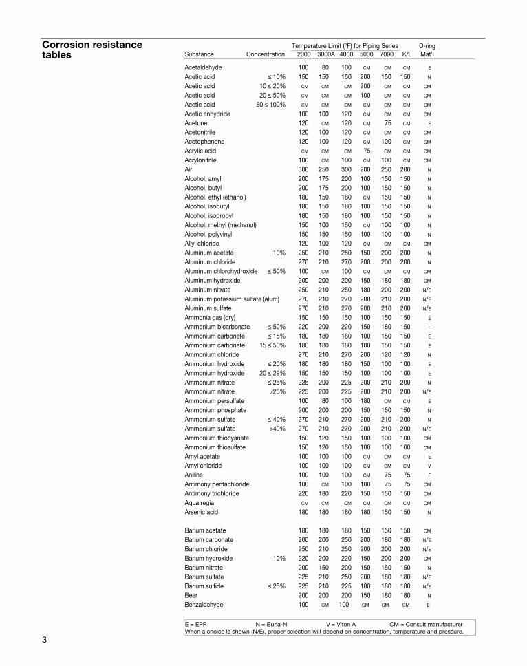
Corrosion resistancetables
E = EPR N = Buna-N V = Viton A CM = Consult manufacturerWhen a choice is shown (N/E), proper selection will depend on concentration, temperature and pressure.
Temperature Limit (°F) for Piping Series O-ringSubstance Concentration 2000 3000A 4000 5000 7000 K/L Mat’l
Acetaldehyde 100 80 100 CM CM CM E
Acetic acid ≤ 10% 150 150 150 200 150 150 N
Acetic acid 10 ≤ 20% CM CM CM 200 CM CM CM
Acetic acid 20 ≤ 50% CM CM CM 100 CM CM CM
Acetic acid 50 ≤ 100% CM CM CM CM CM CM CM
Acetic anhydride 100 100 120 CM CM CM CM
Acetone 120 CM 120 CM 75 CM E
Acetonitrile 120 100 120 CM CM CM CM
Acetophenone 120 100 120 CM 100 CM CM
Acrylic acid CM CM CM 75 CM CM CM
Acrylonitrile 100 CM 100 CM 100 CM CM
Air 300 250 300 200 250 200 N
Alcohol, amyl 200 175 200 100 150 150 N
Alcohol, butyl 200 175 200 100 150 150 N
Alcohol, ethyl (ethanol) 180 150 180 CM 150 150 N
Alcohol, isobutyl 180 150 180 100 150 150 N
Alcohol, isopropyl 180 150 180 100 150 150 N
Alcohol, methyl (methanol) 150 100 150 CM 100 100 N
Alcohol, polyvinyl 150 150 150 100 100 100 N
Allyl chloride 120 100 120 CM CM CM CM
Aluminum acetate 10% 250 210 250 150 200 200 N
Aluminum chloride 270 210 270 200 200 200 N
Aluminum chlorohydroxide ≤ 50% 100 CM 100 CM CM CM CM
Aluminum hydroxide 200 200 200 150 180 180 CM
Aluminum nitrate 250 210 250 180 200 200 N/E
Aluminum potassium sulfate (alum) 270 210 270 200 210 200 N/E
Aluminum sulfate 270 210 270 200 210 200 N/E
Ammonia gas (dry) 150 150 150 100 150 150 E
Ammonium bicarbonate ≤ 50% 220 200 220 150 180 150 -Ammonium carbonate ≤ 15% 180 180 180 100 150 150 E
Ammonium carbonate 15 ≤ 50% 180 180 180 100 150 150 E
Ammonium chloride 270 210 270 200 120 120 N
Ammonium hydroxide ≤ 20% 180 180 180 150 100 100 E
Ammonium hydroxide 20 ≤ 29% 150 150 150 100 100 100 E
Ammonium nitrate ≤ 25% 225 200 225 200 210 200 N
Ammonium nitrate >25% 225 200 225 200 210 200 N/E
Ammonium persulfate 100 80 100 180 CM CM E
Ammonium phosphate 200 200 200 150 150 150 N
Ammonium sulfate ≤ 40% 270 210 270 200 210 200 N
Ammonium sulfate >40% 270 210 270 200 210 200 N/E
Ammonium thiocyanate 150 120 150 100 100 100 CM
Ammonium thiosulfate 150 120 150 100 100 100 CM
Amyl acetate 100 100 100 CM CM CM E
Amyl chloride 100 100 100 CM CM CM vAniline 100 100 100 CM 75 75 E
Antimony pentachloride 100 CM 100 100 75 75 CM
Antimony trichloride 220 180 220 150 150 150 CM
Aqua regia CM CM CM CM CM CM CM
Arsenic acid 180 180 180 180 150 150 N
Barium acetate 180 180 180 150 150 150 CM
Barium carbonate 200 200 250 200 180 180 N/E
Barium chloride 250 210 250 200 200 200 N/E
Barium hydroxide 10% 220 200 220 150 200 200 CM
Barium nitrate 200 150 200 150 150 150 N
Barium sulfate 225 210 250 200 180 180 N/E
Barium sulfide ≤ 25% 225 210 225 180 180 180 N/E
Beer 200 200 200 150 180 180 N
Benzaldehyde 100 CM 100 CM CM CM E
3

Corrosion resistancetables
Temperature Limit (°F) for Piping Series O-ringSubstance Concentration 2000 3000A 4000 5000 7000 K/L Mat’l
Temperature Conversions °F 75 100 125 150 180 200 210 225 250 270 300°C = 5⁄9(°F - 32) °C 24 38 52 66 82 93 99 107 121 132 149
Benzene 150 125 150 CM 120 120 vBenzene sulfonic acid 220 200 220 200 180 180 vBenzoic acid 220 200 220 200 200 180 vBlack liquor 150 125 200 150 150 150 vBorax 250 210 250 200 200 200 N
Boric acid ≤ 4% 225 200 225 200 200 200 N/E
Boric acid 4 ≤ 20% 225 200 225 200 200 200 E
Boric acid >20% 225 200 225 200 200 200 E
Brine (< 20% salts) 250 190 250 200 210 200 N/E
Bromine (dry) CM CM CM CM CM CM CM
Bromine (liquid) CM CM CM CM CM CM CM
Bromine water ≤ 4% 150 100 150 CM 150 150 E
Bromine (wet) CM CM CM CM CM CM CM
Butadiene 150 150 150 100 120 120 vButane 150 150 150 100 120 120 N
Butyl acetate 150 150 150 CM 100 100 CM
Butyl cellosolve 150 150 150 CM 100 100 E
Butyraldehyde 150 120 150 CM CM CM E
Butyric acid 200 150 200 180 150 150 v
Calcium bisulfate 270 210 270 200 200 200 N
Calcium bisulfite 270 210 270 200 200 200 N
Calcium carbonate 270 210 270 200 200 200 N
Calcium chlorate 150 125 150 200 100 100 CM
Calcium chloride 270 210 270 200 210 200 N
Calcium hydroxide 200 180 200 180 CM 150 N
Calcium hypochlorite < 20% 150 120 150 200 150 150 E
Calcium hypochlorite ≥ 20% 150 120 150 100 150 150 E
Calcium nitrate 250 210 250 200 200 200 N/E
Calcium phosphate 250 210 250 200 200 200 N
Calcium sulfate 250 210 250 200 200 200 N
Caprylic acid 150 150 150 150 120 120 CM
Carbon dioxide (dry) 250 210 250 200 200 200 N/E
Carbon disulfide 75 CM 75 CM 75 75 N
Carbonic acid 180 175 180 180 150 150 N
Carbon monoxide 200 200 200 200 150 150 N
Carbon tetrachloride 150 125 150 CM 150 150 vCastor oil 220 210 220 200 200 200 N
Chloride dioxide (wet) CM CM CM 150 CM CM CM
Chlorine gas (dry) CM CM CM 200 CM CM CM
Chlorine gas (wet) CM CM CM 200 CM CM CM
Chloroacetic acid ≤ 10% 100 CM 100 200 75 75 vChloroacetic acid 10 ≤ 25% 100 CM 100 200 CM CM vChloroacetic acid 25 ≤ 50% CM CM CM 150 CM CM vChlorobenzene 100 CM 100 CM 75 75 vChloroform CM CM CM CM CM CM CM
Chlorosulfonic acid CM CM CM CM CM CM CM
Chromic acid ≤ 5% CM CM CM 200 CM CM CM
Chromic acid 5 ≤ 20% CM CM CM 100 CM CM CM
Chromic acid 20 ≤ 30% CM CM CM CM CM CM CM
Chrome alum 200 180 200 200 150 150 N
Citric acid 250 210 250 200 210 200 N
Copper acetate 180 150 180 180 150 150 E
Copper chloride 250 210 250 200 200 200 N
Copper cyanide 220 210 220 200 180 180 N
Copper nitrate 250 210 250 200 200 200 N
Copper sulfate 220 210 220 220 210 200 N
Corn syrup 220 210 220 180 200 200 N
Cresylic acid CM CM CM CM CM CM CM
4

Crude oil (sweet or sour) 250 210 250 200 210 200 N/E
Cupric fluoride 200 200 250 200 150 200 N/V
Cupric nitrate 220 200 250 200 180 180 N
Cupric sulfate 220 200 250 200 180 180 N
Cyclohexane 150 150 150 120 120 120 N/V
Cyclohexanol 150 150 150 CM 100 100 N/V
Detergents 180 180 180 150 120 120 N/V
Diallyl phthalate 180 180 180 150 120 120 CM
Dibutyl phthalate 180 180 180 180 120 120 E
Diacetone alcohol CM CM CM CM CM CM CM
Dicalcium phosphate 150 125 150 120 100 100 CM
Dichloroacetaldehyde CM CM CM CM CM CM CM
Dichlorobenzene 150 150 150 CM 100 CM vDichloroethylene CM CM CM CM CM CM CM
Diesel fuel 250 210 250 150 200 200 N/V
Diethanolamine CM CM CM CM CM CM CM
Diethyl ketone CM CM CM CM CM CM CM
Diethyl ether 100 80 100 CM CM CM CM
Diethylene glycol 200 150 200 180 180 180 N/V
Diethylene triamine CM CM CM CM CM CM CM
Dimethylamine CM CM CM CM CM CM CM
Dimethyl formamide CM CM CM CM CM CM CM
Dimethyl phthalate 100 100 100 100 CM CM vDiphenyl ether 120 100 120 CM 100 100 vDipropylene glycol 200 175 200 150 150 150 vDisodium methyl arsenate 220 200 220 100 200 200 N
Ethyl acetate 150 125 150 CM 120 120 E
Ethyl acrylate 120 100 120 CM 120 120 E
Ethyl alcohol → alcohol, ethylEthyl benzene 150 125 150 CM 100 100 vEthyl cellosolve 150 100 150 CM 120 120 E
Ethyl chloride CM CM CM CM CM CM CM
Ethyl ether 100 CM 100 CM 100 100 CM
Ethyl tert-butyl ether (ETBE) 120 CM 120 CM 100 200 CM
Ethylene chlorohydrin 150 125 150 100 100 100 vEthylene diamine CM CM CM CM CM CM CM
Ethylene dichloride CM CM CM CM CM CM vEthylene glycol (aq.) 270 210 270 200 210 200 N/E
Fatty acids 225 210 225 200 100 100 vFerric acetate 200 180 200 180 200 200 N
Ferric chloride ≤ 20% 220 210 220 200 170 170 N
Ferric chloride 20 ≤ 40% 205 210 205 200 150 150 N
Ferric chloride 40 ≤ 60% 205 210 205 200 150 150 N
Ferric nitrate 200 200 200 200 150 150 N
Ferric sulfate 225 210 225 200 210 160 N
Ferrous chloride 220 210 220 200 200 200 N
Ferrous nitrate 220 210 220 200 200 200 N
Ferrous sulfate 220 210 220 200 200 200 N
Fire Fighting Foam* ATC 3 or 6% 150 CM 150 CM CM CM N
Fire Fighting Foam* AFFF 3 or 6% 150 CM 150 CM CM CM N
Fluoboric acid 200 150 200 200 150 150 CM
Fluorine CM CM CM CM CM CM CM
Fluosilicic acid ≤ 10% CM CM 150 200 CM CM CM
Fluosilicic acid 10 ≤ 25% CM CM CM 100 CM CM CM
Formaldehyde ≤ 40% 150 100 150 150 75 75 N
Formic acid ≤ 10% CM CM CM 150 CM CM CM
Corrosion resistancetables
* Fire Fighting Foam (FFF)& PSX Series Pipe
Temp. (°F) Limitfor Piping Series
PSX PSX O -ringFFF Type Conc. L3 Jetfire Mat’l
ATC 3 or 6% 150 150 N
AFFF 3 or 6% 150 150 N
E = EPR N = Buna-N V = Viton A CM = Consult manufacturerWhen a choice is shown (N/E), proper selection will depend on concentration, temperature and pressure.
Temperature Limit (°F) for Piping Series O-ringSubstance Concentration 2000 3000A 4000 5000 7000 K/L Mat’l
5

Corrosion resistancetables
Temperature Limit (°F) for Piping Series O-ringSubstance Concentration 2000 3000A 4000 5000 7000 K/L Mat’l
Temperature Conversions °F 75 100 125 150 180 200 210 225 250 270 300°C = 5⁄9(°F - 32) °C 24 38 52 66 82 93 99 107 121 132 149
Formic acid 10 ≤25% CM CM CM 100 CM CM CM
Freon CM CM CM CM CM CM CM
Fuel oil 220 210 220 180 210 200 N
Furfural CM CM CM CM CM CM CM
Gasoline 225 210 225 150 150 150 N
Gluconic acid ≤ 50% 180 150 180 100 150 120 CM
Glucose 220 210 250 200 200 200 N
Glycerine (aq.) 300 210 300 200 210 200 N/E
Glycerine 100% 300 210 300 200 210 200 N/E
Glyoxal ≤ 30% 120 120 120 CM CM CM CM
Green liquor 180 150 200 CM 100 100 CM
Heptane 200 175 200 180 150 150 N
Hexane 150 150 150 120 100 100 N
Hydraulic oils 250 210 250 200 200 200 N
Hydrazine CM CM CM CM CM CM CM
Hydrobromic acid ≤ 10% 100 CM 120 120 CM CM E
Hydrobromic acid 10 ≤48% 100 CM 120 120 CM CM E
Hydrochloric acid ≤ 1% 150 125 200 200 75 75 E
Hydrochloric acid 1 ≤ 10% 150 125 200 200 CM CM vHydrochloric acid 10 ≤ 20% 120 100 200 200 CM CM vHydrochloric acid 20 ≤ 37% CM CM 180 150 CM CM CM
Hydrofluoric acid ≤ 5% CM CM CM 150 CM CM CM
Hydrogen chloride gas (dry) 150 150 150 150 150 150 vHydrogen peroxide ≤ 30% CM CM CM 150 CM CM vHydrogen sulfide (dry) 250 200 250 180 150 150 E
Hydrogen sulfide (wet) 180 175 180 180 100 100 E
Hydrochlorous acid 10% 120 100 150 180 CM CM E
Iodine 120 80 120 100 120 120 vn-Isopropyl acetate 150 125 150 CM 120 120 E
Jet fuel (JP-A, JP-8 …) 250 210 250 180 200 200 N/E
Juice, orange 250 210 250 180 200 200 N/E
Kerosene 250 210 250 200 210 200 N
Lactic acid 225 210 225 200 170 170 N/E
Latex 225 210 225 120 210 160 CM
Lauric acid 220 210 220 200 200 200 N/E
n-Lauryl alcohol 220 200 250 200 200 200 E/V
Lead acetate 250 210 250 200 200 200 E
Lead nitrate 220 210 220 200 170 170 N/E
Levulinic acid 220 210 220 200 200 200 N/E
Lime 200 200 220 180 180 180 N/V
Linseed oil 250 210 250 200 200 200 N/V
Lithium chloride 225 210 225 200 210 160 N
Lithium hydroxide 150 150 150 120 150 150 CM
Lube oil 250 210 250 200 200 200 N
Magnesium carbonate 220 210 220 200 170 170 N/E
Magnesium chloride 270 210 270 200 210 200 N/E
Magnesium hydroxide 270 210 270 150 210 200 E/V
Magnesium nitrate 250 210 250 200 200 200 N/E
Magnesium sulfate 270 210 270 200 210 120 N/E
Maleic acid ≤ 5% 220 200 220 200 170 120 vMaleic acid 5 ≤ 35% 220 200 220 200 170 120 v
6

Corrosion resistancetables
E = EPR N = Buna-N V = Viton A CM = Consult manufacturerWhen a choice is shown (N/E), proper selection will depend on concentration, temperature and pressure.
Temperature Limit (°F) for Piping Series O-ringSubstance Concentration 2000 3000A 4000 5000 7000 K/L Mat’l
Maleic acid > 35% 220 200 220 200 150 100 vMaleic anhydride 150 150 150 120 150 150 vMercuric chloride 220 210 220 200 200 200 N
Mercurous chloride 220 210 220 200 200 200 N
Mercury 270 210 270 200 200 200 N
Methacrylic acid CM CM CM CM CM CM CM
Methyl chloride CM CM CM CM CM CM CM
Methyl ethyl ketone 100 80 100 CM 100 100 E
Methyl isobutyl alcohol 180 170 180 120 150 150 CM
Methyl isobutyl carbitol 120 100 120 CM CM CM CM
Methyl isobutyl ketone 150 125 150 CM 100 100 CM
Methyl methacrylate 100 75 100 CM CM CM CM
Methyl sulfonic acid CM CM CM NR CM CM CM
Methyl tert-butyl ether (MTBE) 120 CM 120 CM 100 200 CM
Methylene chloride CM CM CM CM CM CM CM
Mineral oil 270 210 270 200 210 200 N/E
Naphtha 225 210 225 180 210 200 vNaphthalene 200 200 200 200 150 150 vNatural gas 250 210 250 200 210 200 N/V
Nickel chloride 270 210 270 200 210 160 N/V
Nickel nitrate 220 210 220 200 180 180 N
Nickel sulfate 225 210 225 200 210 160 N
Nitric acid ≤ 1% 120 75 120 150 CM 75 E
Nitric acid 1 ≤ 5% 75 75 75 150 CM CM CM
Nitric acid 5 ≤10% 75 75 75 100 CM CM CM
Nitric acid 10 ≤ 20% CM CM CM 100 CM CM CM
Nitrogen solutions 150 125 150 100 CM CM CM
Oil, sour crude 250 210 250 200 210 200 N
Oil, diesel 250 210 250 180 200 200 N
Oil, lubricating 220 210 220 180 200 200 N
Oleic acid 220 200 220 200 200 200 vOleum CM CM CM CM CM CM vOlive oil 220 200 250 200 200 200 N/V
Oxalic acid ≤ 10% 150 150 150 200 150 150 N/V
Oxalic acid 10 ≤ 20% CM CM CM 200 CM CM N/V
Oxalic acid 20 ≤ 50% CM CM CM CM CM CM N/V
Palmitic acid 220 210 220 200 200 200 N/V
Perchloric acid CM CM CM CM CM CM vPerchloroethylene 120 100 120 CM 100 100 vPetroleum ether 100 100 100 CM CM CM CM
Phenol ≤ 1% 100 CM 100 CM 75 75 vPhenol 1 ≤ 5% 100 CM 100 CM CM CM vPhenol 5 ≤ 100% CM CM CM CM CM CM CM
Phosphoric acid ≤ 2% 100 100 100 200 100 100 E
Phosphoric acid 2 ≤ 10% 100 100 100 200 75 75 E
Phosphoric acid 10 ≤ 50% 100 75 100 200 75 75 E
Phosphoric acid 50 ≤ 85% 100 CM 100 200 CM CM E
Phosphorous oxychloride CM CM CM CM CM CM CM
Phthalic anhydride 220 200 220 200 200 200 CM
Pickling acid (5% H2SO4, 0.25% coalcoal tar inhibitor, water) 100 80 180 200 CM CM v
Picric acid 100 100 100 100 CM CM N/V
Pine oil 150 125 150 150 150 150 v
7

Corrosion resistancetables
Temperature Limit (°F) for Piping Series O-ringSubstance Concentration 2000 3000A 4000 5000 7000 K/L Mat’l
Temperature Conversions °F 75 100 125 150 180 200 210 225 250 270 300°C = 5⁄9(°F - 32) °C 24 38 52 66 82 93 99 107 121 132 149
Plating solution (17% NiSO4, 5% NiCl2, 30% H3BO3, water) 220 210 220 180 120 120 E
Polyvinyl acetate emulsion 150 150 150 100 100 100 E
Polyethylene glycol (E-200) 150 120 180 150 150 150 N
Polyethylene glycol (P-400) 150 210 180 150 150 150 N
Potassium bicarbonate 220 200 270 150 100 100 N
Potassium bromide 220 200 220 200 200 200 N/E
Potassium carbonate ≤ 50% 100 100 100 150 CM CM N
Potassium chloride 270 210 270 200 210 200 N/E
Potassium cyanide 225 210 225 180 210 200 N/E
Potassium dichromate ≤ 10% 200 180 200 200 150 150 N/E
Potassium ferricyanide 220 200 220 200 200 200 N
Potassium ferrocyanide 220 200 220 200 200 200 N
Potassium fluoride ≤ 30% 200 200 220 150 150 150 N
Potassium hydroxide ≤ 25% 150 150 180 120 100 100 E
Potassium hydroxide 25 ≤ 50% 150 150 180 100 100 100 E
Potassium hydroxide 50 ≤ 75% 150 150 180 100 CM CM E
Potassium nitrate 270 210 270 200 210 200 N/E
Potassium permanganate ≤ 10% CM CM CM 150 CM CM N
Potassium persulfate CM CM CM 180 CM CM CM
Potassium phosphate 180 150 180 100 150 150 N/E
Potassium sulfate 250 210 270 180 210 200 N/E
Propane 150 125 150 100 100 100 N
Propylene glycol 270 210 270 200 210 200 N/E
Quatenary ammonium salts 120 120 120 100 100 100 CM
Silver nitrate 220 200 220 200 200 200 E/V
Sodium acetate 220 200 220 200 200 200 E
Sodium aluminum sulfate 220 200 250 200 200 200 N
Sodium benzoate 200 200 200 180 180 180 CM
Sodium bicarbonate ≤ 10% 250 210 250 180 180 180 N/V
Sodium bicarbonate 10 ≤ 20% 250 210 250 150 180 180 N/V
Sodium bisulfate 250 210 250 200 200 200 N/E
Sodium bisulfite 220 200 220 200 200 200 N/E
Sodium bromate 150 125 180 140 150 150 N
Sodium bromide 250 210 250 200 210 200 N
Sodium carbonate < 10% 200 210 200 150 210 200 N
Sodium carbonate 10% 100 150 200 150 150 150 N
Sodium chlorate ≤ 50% 250 200 250 180 210 200 CM
Sodium chloride 270 210 270 200 210 200 N/E
Sodium cyanide < 6% 225 210 225 200 210 200 N/E
Sodium cyanide 6% 225 210 225 200 200 200 N/E
Sodium dichromate ≤ 10% 200 180 200 200 180 180 E
Sodium ferricyanide 270 210 270 200 200 200 E
Sodium ferrocyanide 270 210 270 200 200 200 E
Sodium hydrosulfide 120 100 120 100 CM CM CM
Sodium hydroxide ≤ 10% 150 150 180 100 100 100 E
Sodium hydroxide 10 ≤ 40% 150 150 180 100 CM CM E
Sodium hydroxide 40 ≤ 50% 150 150 180 150 CM CM CM
Sodium hypochlorite ≤ 51⁄4% CM CM CM 150 CM CM vSodium hypochlorite (stable) ≤ 10% CM CM CM CM CM CM vSodium hypochlorite (stable) 11 ≤ 18% CM CM CM CM CM CM vSodium nitrate 270 210 270 200 210 200 N/E
Sodium nitrite 250 210 250 200 200 200 E
Sodium silicate 220 210 220 200 200 200 N/E
Sodium sulfate 270 210 270 200 210 200 N/E
Sodium sulfide ≤ 10% 200 200 200 150 200 200 N
Sodium sulfite 200 200 200 200 200 200 N
Sodium thiocyanate 200 200 200 180 200 200 v
8

Temperature Limit (°F) for Piping Series O-ringSubstance Concentration 2000 3000A 4000 5000 7000 K/L Mat’l
Corrosion resistancetables
9
E = EPR N = Buna-N V = Viton A CM = Consult manufacturerWhen a choice is shown (N/E), proper selection will depend on concentration, temperature and pressure.
Sodium thiosulfate 150 125 150 200 120 120 vStannic chloride 250 210 270 200 200 200 N
Stannic sulfate 250 210 270 200 200 200 N
Stannous chloride 220 210 220 200 200 200 N/E
Stearic acid 220 210 220 200 200 200 N/V
Strontium chloride 200 200 200 200 200 200 N
Styrene 100 100 100 100 75 75 vSugar solutions 220 210 250 180 200 200 N/V
Sulfamic acid < 25% 100 100 100 180 100 100 N
Sulfite liquors 150 125 150 200 100 100 vSulfur chloride CM CM CM CM CM CM vSulfur dioxide gas (dry) 180 150 200 200 150 120 E
Sulfur trioxide 150 150 180 160 100 100 vSulfuric acid ≤ 2% 150 100 180 200 75 75 vSulfuric acid 2 ≤ 5% 125 80 180 200 CM CM vSulfuric acid 5 ≤ 10% 100 CM 180 200 CM CM vSulfuric acid 10 ≤ 20% 100 CM 180 200 CM CM vSulfuric acid 20 ≤ 25% 100 CM 150 180 CM CM vSulfuric acid 25 ≤ 50% 100 CM 150 180 CM CM vSulfuric acid 50 ≤ 70% 100 CM 100 120 CM CM vSulfuric acid > 70% CM CM CM CM CM CM CM
Sulfurous acid 200 180 200 200 120 120 v
Tall oil 200 200 200 200 200 200 N
Tannic acid 225 210 225 200 210 200 N/E
tert-Amyl methyl ether (TAME) 100 CM 100 CM 100 100 CM
Tetrachloroethylene 180 150 180 CM CM CM vTetraethyl lead 120 120 120 100 100 100 vThionyl chloride CM CM CM CM CM CM CM
Toluene 150 125 150 CM 100 100 vTransformer oil 300 210 300 200 210 210 N/V
1,1,1 Trichloroethane 150 CM 150 CM CM 150 V
Trichloroethylene 120 100 120 CM CM CM vTriethanolamine 150 150 150 CM 150 150 E
Triethylamine 100 100 100 CM CM CM CM
Triphenyl phosphite 120 120 120 120 100 100 CM
Trisodium phosphate 25% 200 200 200 150 150 150 CM
Turpentine 150 125 150 CM 120 120 N/V
Urea 200 150 200 150 150 150 CM
Vinegar 200 150 200 200 150 150 E/V
Vinyl acetate 150 120 150 CM 100 100 CM
Water, chlorinated ≤ 50 ppm 150 150 150 180 120 120 N
Water, chlorinated 50 ≤ 500 ppm 125 125 125 150 110 110 N
Water, chlorinated 500 ≤ 2000 ppm 100 100 100 110 100 100 N
Water, chlorinated 2000 ≤ 3500 ppm CM CM CM 110 CM CM N
Water, chlorinated brine 120 120 120 150 CM CM N
Water, deionized 250 210 250 180 210 200 N/E
Water, demineralized 250 210 250 200 210 200 N/E
Water, distilled 250 210 250 200 210 200 N/E
Water, fresh 250 210 250 200 210 200 N/E
Water, salt 270 210 270 200 210 200 N/E
Water, sea 270 210 270 200 210 200 N/E
Water, steam condensate 250 210 250 200 210 200 N/E
White liquor 150 150 200 150 CM CM N/E
Xylene 150 125 150 CM 150 150 v
Zinc acetate 180 150 180 180 150 150 E

Temperature Limit (°F) for Piping Series O-ringSubstance Concentration 2000 3000A 4000 5000 7000 K/L Mat’l
Corrosion resistancetables
Fittings Filament-wound fittings — Compatible with, and equivalent in corrosion resistance tothe premium corrosion resistant epoxy or vinyl ester piping systems offered by Ameron(i.e. Series 4000 and Series 5000). These fittings also may be used with Series 2000 wherehigher strength, greater impact resistance, etc., are desired.
Molded fittings — Offer an economical alternative to filament-wound fittings withcorrosion performance equivalent to Series 2000 or Series 3000A.
Mechanical joiningsystems
Pronto-Lock and Pronto-Lock II — Available on all 3000A Series products. These jointsutilize an O-ring seal with locking threads.
Key-Lock (K/L) — Available for Series 2400 and 3400 in diameters from 2 to 40 inches .The Key-Lock joint utilizes an O-ring seal with locking keys.
Key-Lock and Pronto-LockO-ring Selection Guide
Temperature Range
Code Polymer °F °C
N Buna-N (Nitrile) -30 to +225 -5 to +105
E Ethylene propylene rubber (EPR) -65 to +250 -55 to +125
V Fluorocarbon (Viton A) -15 to +375 -25 to +190Where a choice of materials is shown (i.e. N/E), the proper material selection will depend on the concentration,temperature and pressure of the system.
Bondstrand adhesives Joint Areas Pipe Resin Temperature
Type Type Primary Use of Use System °F °C
6 Q/L Foodstuffs All Epoxy 300 149
34 Q/L or T/T General Service All Epoxy 300 149
60 Q/L Antistatic piping All Epoxy 250 121
105 Q/L Resistance to acids All Vinyl ester 200 93
10
Zinc chloride 250 210 250 200 200 200 N/E
Zinc phosphate 180 150 180 200 150 150 CM
Zinc sulfate 200 210 250 200 200 200 N/E

Subhead
FOR CHEMICAL EMERGENCY
SPILL, LEAK, FIRE, EXPOSURE OR ACCIDENT
CALL CHEMTREC - DAY OR NIGHT1-800-424-9300
Toll-free in the continental U.S.
483-7616 in District of ColumbiaFor calls originating outside the continental U.S.
202-483-7616 -Washington D.C. collect
ALL CALLS ARE RECORDED
11

Important Notice This literature and the information and recommendations it contains are based on data reasonably believed to bereliable. However, such factors as variations in environment, application or installation, changes in operatingprocedures, or extrapolation of data may cause different results. Ameron makes no representation or warranty,express or implied, including warranties of merchantability or fitness for purpose, as to the accuracy, adequacy orcompleteness of the recommendations or information contained herein. Ameron assumes no liability whatsoeverin connection with this literature or the information or recommendations it contains. Product specifications aresubject to change.
GROUP HEADQUARTERS
P.O. Box 801148 • Houston, TX 77280 • Tel: (713) 690-7777 • Fax: (713) 690-2842 • http://www.ameron.com
Fiberglass Pipe DivisionEuropeAmeron B.V.J.F. Kennedylaan 74191 MZ GeldermalsenThe NetherlandsTel: +31 345 587 587Fax: +31 345 587 561
Fiberglass Pipe DivisionAmericasP.O. Box 878Burkburnett, TX 76354Tel: (940) 569-1471Fax: (940) 569-2764
Fiberglass Pipe DivisionCentron InternationalP.O. Box 490600 FM 1195 SouthMineral Wells, Texas 76068Tel: (940) 325-1341Fax: (940) 325-9681
FIBERGLASS PIPE GROUP
Fiberglass Pipe Division AsiaAmeron (Pte) Ltd.No. 7A, Tuas Avenue 3Singapore 639407Tel: 65 861 6118Fax: 65 862 1302/861 7834
© 1986 Ameron • Printed in U.S.A. • FP132I (1/01) supersedes FP132H (11/99) •10M • [369]

Quick-Lock®
Adhesive-bonded Bell and Spigot Jointsfor Bondstrand fiberglass piping systems
Bondstrand® Installation
Introduction Follow these instructions to make the Quick-Lock bell and spigot joint for Bondstrandpipe and fittings using Ameron epoxy or vinylester adhesives. The instructions showyou how to cut the pipe, prepare the pipe ends, mix and apply the adhesive, make thejoint and cure the adhesive.
To determine the appropriate Bondstrand adhesive for your installation, consultBondstrand Chemical Resistance Guide, FP132. FP132 is available from Ameron oryour Bondstrand supplier.
Complete usage instructions for the adhesives are contained in each adhesive kit. Storeadhesives at temperatures below 100°F (38°C). Use adhesives before the datestamped on the adhesive kit package.
FP170E (8/00)
The Quick-Lock joint has been usedsuccessfully in Bondstrand fiberglasspiping systems throughout the world
for over thirty-five years. Typical ofBondstrand installations is this vacuum
unit drain piping in a Saudi Arabiandesalination plant.
ISO-9001
CERTIFICATED FIRM
FIBERGLASS - COMPOSITE PIPE GROUP

Cutting pipe Measure the desired length and scribe the pipe using a pipefitter’s wraparound orheating blanket. When holding the pipe in a vise, use a 1⁄4-inch (6 mm) thick rubber pad(or equal) to protect the pipe from damage. Use a hacksaw or power saw with abrasivewheel to cut the pipe. Check the squareness of cut. Pipe up to 4 inches (100 mm)should be square to within 1⁄16 inch (1.5 mm); larger pipe to within 1⁄8 inch (3 mm). Use adisc grinder or file to correct squareness.
Danger! Do not inhale dust produced by cutting and grinding. Provide adequateventilation or wear OSHA-approved dust mask.
Scribe the pipe with chalk or a whitemarker to assure squareness of cut(top). Bondstrand pipe may be cut
using a fine-tooth hacksaw or a powersaw with abrasive wheel (bottom). See
FP811 AMERON RECOMMENDED SAFETY
PRACTICES for proper personalprotective equipment.
End preparation Use the Bondstrand B-1 end preparation tool for 2 through 8-inch sizes. For 10-inchpipe and larger, several shavers are available from Ameron and are referenced in theequipment list at the end of these instructions. Instructions for adjusting and operatingthe end preparation tools are provided with the tools. The instructions may also beobtained from your local Bondstrand representative.
2

End preparation(continued)
End preparation tools can be used manually, but a portable power drive is advisable ifpreparing a number of joints. Check the OD of the prepared end with a Pi Tape to ensurethe following dimensions are obtained:
The B-1 tool (top) requires no adjustmentand is used to prepare pipe ends in sizes to8 inches. Pipe ends in 10 and 12 inch sizes
are prepared with the M74 tool. The M80 tool(not shown) is used for larger sizes.
Nominal Prepared Spigot DiameterPipe Size maximum minimum(in) (mm) (in) (mm) (in) (mm)1 25 1.29 32.9 1.28 32.51.5 40 1.88 47.8 1.87 47.52 50 2.35 59.6 2.33 59.23 80 3.47 88.0 3.45 87.64 100 4.45 112.9 4.43 112.55 125 5.51 139.9 5.49 139.56 150 6.56 166.6 6.54 166.28 200 8.56 217.4 8.54 217.0
10 250 10.70 271.7 10.68 271.312 300 12.70 322.6 12.68 322.214 350 13.95 354.2 13.93 353.816 400 15.93 404.5 15.91 404.1
3
The cutter wheels on the B-1 tool aredesigned to cut when the tool is
rotating in the clockwise direction.Attempts to cut with the tool in
counterclockwise rotation will bendthe cutter wheels and reduce theeffectiveness of the tool. Similarly,when withdrawing the tool after
completing a cut, stop the drill motorand simply pull the tool out of the
pipe. Do not reverse the drill rotationwhen withdrawing as this will also
tend to bend the cutter wheels.
All bonding surfaces must be clean and dry and must be sanded within two hours ofassembly. Sand the bonding surfaces with a 1⁄4-inch drill motor and flapper sander.See the equipment list at the end of these instructions for drill motor and flappersander specifications. Sanded surfaces should show a dull, fresh finish, not apolished look. Don’t forget to sand the end of the spigot.

End preparation(continued)
Wipe the sanded surfaces thoroughly with a clean, dry cloth, or use a duster brush toremove dust particles. If surfaces become wet, warm with Bondstrand heating blanketor hot air gun until dry, then resand. Protect the bonding surfaces from moisture duringbad weather by tenting over the working area. Do not touch the prepared surfaces withbare hands or soiled gloves that would leave an oily film.
Caution: Clean and dry sanded surfaces are required for proper bonding.
Check the outside diameter of the preparedpipe end with a Pi Tape (left). Permissiblediameter ranges are marked on the tape
and must conform to the values tabulatedon the previous page. Sand all bonding
surfaces within two hours of applyingadhesive: the inside of the fitting (top right),
the cut end of the pipe(center left), and the outside of the spigot
(bottom left). Remove dust from all sandedsurfaces with a clean rag (bottom right).
4
When using pneumatic tools, theair supply must be dry andoil-free as moisture or oil on
bonding surfaces will interferewith the adhesive.

Spigot insertion depthsand diameters
Measure back from the end of the spigot the distance shown in the following table andscribe a line using a white grease pencil or soapstone. When the spigot is bottomed tothe pipe stop in the bell, the scribed line will be 1 inch (25 mm) from the end of the bell.
Alignment of fittings To ensure proper alignment of fittings, matchmark the mating pieces before applyingadhesive. Taking care to avoid contaminating the bonding surfaces, dry fit the pieces,then mark each piece for subsequent realignment.
Before applying adhesive, put aninsertion depth reference mark on the
spigot by measuring back from the pipeend by the amount tabulated above.
After joining, the reference mark shouldbe 1 inch from the end of the bell.
Assure proper alignment offittings by matchmarking the
mating pieces while dry fitting.
5
Nominal Mark in fromPipe Size spigot end(in) (mm) (in) (mm)1 25 2 1⁄16 521.5 40 2.
1⁄4 572 50 2.
13⁄16 713 80 2.
13⁄16 714 100 2.
13⁄16 715 125 3.
1⁄4 826 150 3.
1⁄4 828 200 3.
1⁄2 8910 250 3.
3⁄4 9512 300 4. 10114 350 4.
1⁄2 11416 400 5. 127

Applying the adhesive Select the adhesive kit per the following table:
When the joint is ready to be bonded, add the curing agent to the resin. Stir thoroughlyfor at least one minute or until no streaks are visible. Apply the mixed adhesive to thebonding surfaces immediately.
Use the disposable spatula supplied in the kit to apply a thin layer (1⁄32 inch or 1 mm) ofadhesive to the surface of the bell including the pipe stop. Excess adhesive in the bellwill restrict flow inside the joint. Apply adhesive liberally to the entire spigot surface anda thin layer to the cut end of the pipe. Excess adhesive on the spigot surface will beforced out when the bell and the spigot are joined.
Important: Be aware of the working time available after the adhesive has been mixed. It may not be possible to achieve the listed number of bonds in the smallersizes because of the available working time (pot life) of the adhesive. Seethe adhesive kit package for the approximate working times.
If the mix has started to gel in the container, discard and start a new kit. Appearance of gelled or lumpy material indicates that the mix has started to cure.
Add all of the hardener to the resin (left).After mixing thoroughly, apply a thin layer
to the inside of the bell (right).
6
KitSize Nominal Pipe Size (in/mm)(fl oz) 1/25 1.5/40 2/50 3/80 4/100 5/125 6/150 8/200 10/250 12/300 14/350 16/400
3 10 6 4 3 2 1 1 1⁄2 1⁄2 1⁄2 – –5 – 10 7 5 3 2 1 1 1 1 1⁄2 1⁄28 – – 10 8 6 5 3 2 2 1 1 1
Bonds per Kit

Proper adhesive application In a properly made joint, the adhesive applied to the bell is pushed to the inside of thejoint where it forms a bead that protects the cut edge of the pipe. Excess adhesiveapplied to the pipe spigot is pushed to the outside of the joint and can be easilyremoved.
Too much adhesive in the bell may restrict flow through the pipe.
Joint assembly Without rotating the spigot, insert it into the bell until it rests firmly against the pipe stop.For 6-inch (150 mm) pipe and larger, use a comealong to seat the joint and hold it inplace. Support the bands on wooden blocks on each side of the joint so the comealongcan remain snug while the heating blanket is wrapped around the joint and the joint iscured. Joints 6 inches or less in size may be made by tapping on a wooden blockplaced over pipe end to seat the spigot in bell.
Apply a generous layer of adhesive to theoutside of the spigot (left). In addition,
apply a thin layer of adhesive to the cutend of the pipe (right).
When the joint is assembled, some of theadhesive in the bell is pushed to the inside
by the end of the spigot. When correctlyapplied, a thin layer of adhesive in the bell
(center) forms a small bead that willprotect the cut end of the pipe.
Too much adhesive in the bell may restrictflow inside the pipe (bottom).
Before joining the pipe, align the faces ofthe bell and spigot parallel with one
another (left). When making large-diameter joints, use a comealong to join
the pipe (right) and to hold the jointtogether during the cure.
Correct
Incorrect
7

Joint assembly(continued)
Join fittings to pipe using one of the two methods described above. It may benecessary to back up an elbow, tee, lateral, etc., with a sandbag or similar shockabsorber while tapping pipe spigots into fittings.
Align flanges, tees and other fittings to the matchmarks as you make the joint to avoidrotating the part while assembling. Check rotational alignment of flange bolt holes andsquareness of flange faces. Flanges with bolt holes more than 1⁄16 inch (1.5 mm) out ofrotational alignment, or faces more than 1⁄16 inch out of square across the flange face, orany angular errors of more than 1⁄2° in the axial or rotational alignment of bell and spigotare likely to cause subsequent assembly problems. If the joint is misaligned, pull itapart, remove adhesive from the pipe stop area, reapply adhesive and rejoin beforeadhesive starts to set up.
Caution: Never use a metal hammer directly on Bondstrand pipe or fittings.
Joints in the small diameters can be madeup with a rubber mallet (or equal) and a
block of wood (left). Never strike pipe orfittings directly with a hammer or mallet.
Check the insertion depth after making thejoint (right). The reference mark should be 1
inch from the end of the bell.
When mounting a flange, make sure thatthe vertical (center left) and rotational
alignment (bottom right) meet therequirements stated in the text.
Remove excess adhesive for goodappearance (second from top
left). Sand the inside of the flangebefore applying adhesive (second
from bottom left). Clean excessadhesive where the flange lipcontacts the spigot to avoidcontamination of the flange
face (bottom left).
8

Caution: Do not move, vibrate, or
Position the heating blanket withthe thermostat facing out (left).
Wrap the loose end of the blanket overthe thermostat and secure with an
electrically nonconductive tie (right).
Mark the starting time for the cure on thepipe (center right). If the temperature
might drop below 40°F (4°C), insulatethe blanket with fiberglass insulation
backed with aluminum foil or theequivalent (bottom right).
Force curing adhesive joints When force curing the adhesive, place the thermostat end of the Bondstrand heatingblanket against the assembled joint with the thermostat side facing out. Wrap theremainder of the blanket around the joint so that any overlap covers the thermostat. Tiethe blanket in place with any nonconducting tie.
In general, Ameron recommends the use of insulation around the heating blanket. Thisis essential when the air temperature is below 40°F (4°C). Fiberglass insulation backedwith aluminum foil generally works well. Insulation should overlap the blanket sidesabout 4 inches (100 mm) each way and be tied down near the edges to trap the heat.
Turn on the heating blanket and mark the starting time on the pipe. Check the blanketafter a short period to assure it is heating.
A 30-minute cure is recommended for joining pipe and mounting flanges and a45-minute cure for joining fittings.
9

Force curing flanges Flange mounting requires a special blanket wrap. Lay the blanket flat with thethermostat down and, starting at the thermostat end, roll it up. Insert the rolled blanketinto the pipe end to the depth of the fresh joint, leaving the cord and part of the blanketexposed as shown. Fill the space inside the rolled blanket with fiberglass insulation toensure that the blanket remains snugly against the inside joint surface.
Equipment list The following tools are recommended for installing Bondstrand pipe:
(a) B-1 end preparation tool (1 to 8 inch) (FP376 B-1 TOOL INSTALLATION GUIDE)M80 pipe shaver and arbors (10 to 16 inch) (FP515 M80 PIPE SHAVER INSTRUCTIONS)Note: M74 pipe shaver can be used for (2 to 12 inch)
(b) Hacksaw or power saw with abrasive wheel
(c) Half-inch heavy-duty drill operating at 450 to 600 rpm; preferably with pistol grip,spade grip and side handles (Black and Decker Model 1321)
(d) Pipe vise (Pilot No. 20) and 1⁄4-inch (6 mm) thick elastomeric pads
(e) Flapper wheel sander (available from Ameron) with electric or air drill motor with1⁄4-inch (6 mm) drive, 1700-2200 rpm (faster drills will produce a polished surface)
(f) Rubber mallet, 2 lb (1 kg), Shore Durometer A 70-80, 21⁄2 to 3 inch diameter
(g) Comealong for 6-inch (150 mm) pipe and larger, Dayton No. 2Z614
(h) Heating blankets (four sizes available from Ameron)
(i) Pipefitter’s wraparound, level and white grease pencil or soapstone
(j) Duster brush and clean rags
(k) Dust mask, eye protection and gloves
(l) Folding rule, 10 ft (3 m)
(m) Tape , 50 ft (15 m)
(n) Portable power drive, Ridgid® No. 700 or Amaz-O-Thred® 181D for M74 and M80pipe shavers
(o) Pi Tape® measuring tape
(p) Disc grinder or file (optional)
When curing a flange, place the heatingblanket inside the pipe so that the
thermostat faces the center of the pipe.Insulate the space inside the blanket.
10
When using pneumatic tools, theair supply must be dry andoil-free as moisture or oil on
bonding surfaces will interferewith the adhesive.
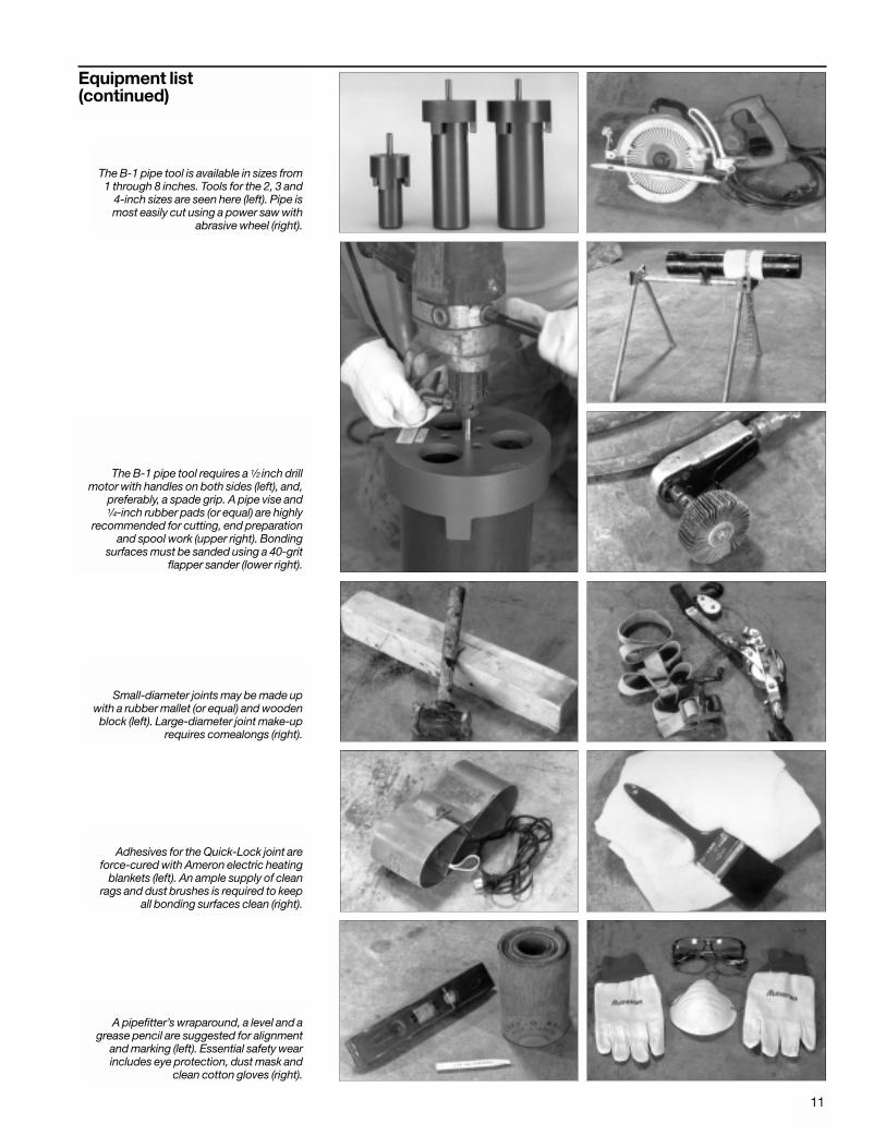
Equipment list(continued)
The B-1 pipe tool is available in sizes from1 through 8 inches. Tools for the 2, 3 and
4-inch sizes are seen here (left). Pipe ismost easily cut using a power saw with
abrasive wheel (right).
The B-1 pipe tool requires a 1⁄2 inch drillmotor with handles on both sides (left), and,
preferably, a spade grip. A pipe vise and1⁄4-inch rubber pads (or equal) are highly
recommended for cutting, end preparationand spool work (upper right). Bonding
surfaces must be sanded using a 40-gritflapper sander (lower right).
Small-diameter joints may be made upwith a rubber mallet (or equal) and woodenblock (left). Large-diameter joint make-up
requires comealongs (right).
Adhesives for the Quick-Lock joint areforce-cured with Ameron electric heating
blankets (left). An ample supply of cleanrags and dust brushes is required to keep
all bonding surfaces clean (right).
A pipefitter’s wraparound, a level and agrease pencil are suggested for alignment
and marking (left). Essential safety wearincludes eye protection, dust mask and
clean cotton gloves (right).
11

© 1982 Ameron • FP170E (8/00) supersedes FP170D (9/96) • Printed in U.S.A. • 7.5M • [124]
1 psi = 6895 Pa = 0.07031 kg/cm2
1 bar = 105 Pa = 14.5 psi = 1.02 kg/cm2
1 MPa = 106 Pa = 145 psi = 10.2 kg/cm2
1 GPa = 109 Pa = 145,000 psi = 10,200 kg/cm2
1 in = 25.4 mm1 ft = 0.3048 m1 lb•in = 0.113 N•m1 in4 = 4.162 x 10⁻⁷m4
°C = 5/9 (°F - 32)
Conversions
CompositesP.O. Box 7137011 McBride StreetNewnan, Georgia 30263Tel: (770) 253-2000Fax: (770) 253-9234
FIBERGLASS - COMPOSITE PIPE GROUP - HEADQUARTERS
P.O. Box 801148 • Houston, TX 77280 • Tel: (713) 690-7777 • Fax: (713) 690-2842 • http://www.ameron.com
EuropeAmeron B.V.J.F. Kennedylaan 74191 MZ GeldermalsenThe NetherlandsTel: +31 345 587 587Fax: +31 345 587 [email protected]
AmericasP.O. Box 878Burkburnett, TX 76354Tel: (940) 569-1471Fax: (940) 569-2764
Centron InternationalP.O. Box 490600 FM 1195 SouthMineral Wells, Texas 76068Tel: (940) 325-1341Fax: (940) 325-9681http://www.centrongre.com
AsiaAmeron (Pte) Ltd.No. 7A, Tuas Avenue 3Singapore 639407Tel: 65 861 6118Fax: 65 862 1302/861 [email protected]
Important Notice This literature and the information and recommendations it contains are based on data reasonably believed to bereliable. However, such factors as variations in environment, application or installation, changes in operatingprocedures, or extrapolation of data may cause different results. Ameron makes no representation or warranty,express or implied, including warranties of merchantability or fitness for purpose, as to the accuracy, adequacyor completeness of the recommendations or information contained herein. Ameron assumes no liabilitywhatsoever in connection with this literature or the information or recommendations it contains. Product specifi-cations are subject to change.

Adhesive-bonded Bell and Spigot Jointsfor Bondstrand no-shave pipe
Bondstrand® Installation
Installation 1. Cut pipe to length as shown in FP170D QUICK-LOCK® ADHESIVE-BONDED BELL
AND SPIGOT JOINTS.
2. Using 40 to 120 grit sandpaper, sand the first 2” to 3” of the end of pipe and theQuick-Lock® socket of the fitting to be bonded. Don’t forget to sand the end ofthe pipe. There should be no glossy areas left on the bond area of the pipe.
Note: DO NOT USE TRADITIONAL SHAVING TOOLS FOR SANDING THE PIPE. FLAPPER SANDERS ARE ACCEPTABLE
3. All bonding surfaces must be clean and dry and must be sanded within twohours of assembly. Sanded surfaces should show a dull, fresh finish, not apolished look.
4. Wipe the sanded surfaces thoroughly with a clean, dry cloth, or use a dusterbrush to remove dust particles. If surfaces become wet, warm with aBondstrand® heating blanket or hot air gun until dry, then resand. Protect thebonding surfaces from moisture during bad weather by tenting over theworking area. Do not touch the prepared surfaces with bare hands or soiledgloves that would leave an oily film.
5. Mark spigot insertion depth according to FP170D QUICK-LOCK® ADHESIVE-BONDED BELL AND SPIGOT JOINTS and follow the remaining instructions foralignment, adhesive application, joint assembly and force curing.
FP170 Addendum (10/99)
FIBERGLASS PIPE GROUP
ISO-9001
CERTIFICATED FIRM

Scope This procedure is used in addition to Ameron Literature FP170D (Quick Lock®
Installation Procedure). For Ameron Literature see your local Bondstrand® provider orcall Ameron International, Fiberglass Pipe Division.
Introduction These instructions are intended to be used for the Installation of Bondstrand® CX™
Piping. To determine the proper adhesive for the installation see Bondstrand®
Chemical Resistance guide, FP132. PSX™•34 adhesive will be suitable for mostservices. PSX•34 adhesive is Listed by the National Sanitation Foundation under NSFStandard 61 - Drinking Water System Components - Health Effects for use in PotableWater Service and Commercial Hot Water Applications. Use PSX•34 unless the guiderecommends RP105, or if electrical conductivity is required (RP-60). Complete usageinstructions for the adhesive is provided in each kit. Use the adhesive before the datestamped on the adhesive kit package.
End Preparation Use the Jacket Cutter to cut the jacket to the specified length (see table 1 on left).
Set the depth of the wheel to cut the outer wall only. DO NOT CUT THE PRIMARYWALL. Make sure the grinding wheel does not grind into the sand. Cut only to thewhite tape that separates the secondary pipe wall from the sand. Cutting into the sandwill reduce the life of the wheel.
When cutting the jacket, there should only be one longitudinal cut. Use this same cutpath to pull out the jacket cutter. This will save wear on the cutter wheel. Start the cut bypushing tool on to the pipe until the tool bottoms out. Rotate the pipe or tool to part thejacket. Pull tool out along the same longitudinal cut.
Once the jacket is cut, use a utility knife to cut through the remaining tape. Use a bluntend object to remove the wall of the jacket. Be careful not to damage primary pipe wall.
Use the standard spigot cutting tool to shave the spigot on the primary pipe, if necessary.
Note: For no-shave pipe, no spigot shaving tools are necessary for primary orsecondary pipe. If outside diameter (O.D.) is slightly large, use flapper sander toreduce O.D.
Note: B-1F tools are used for 2”-8”. M80 shavers are used for 10”-16”. See theQuick Lock® procedure FP170 for spigot lengths and diameters.
Installation Practicesfor Bondstrand® CX™ Pipe
ISO-9001
CERTIFICATED FIRM
Bondstrand® Installation Guide
Jacket Removal Length
Size Length(in) (in)2 21/2
3 21/2
4 21/2
6 27/8
8 33/4
10 33/4
12 33/4
14 33/4
16 33/4
Table 1.
FP821B (7/00)
Secondary Spigot Use the Unique Taper Tool (Model 010), with the modified 3” cutter blade, to shavespigot on outer wall for 2-6 inch pipe diameters. Use M-80 tool (adjusted) to shavesecondary spigot on 8-16 inch pipe. For no-shave pipe, sand the outer wall of the pipe tothe length of the secondary spigot. Ensure that all glossy surfaces are removed frombonding area. Follow Ameron Literature FP667 for basic operating instructions of theUnique Taper Tool. Follow Ameron Literature FP515 for basic operating instructions onthe M-80 shaver. Use Table 2 for length and O.D. of the spigot on the secondary wall. Angleis 0˚ on spigot.
Note: To set length of spigot, using the unique taper tool, the insertion depth ofthe collet on the taper tool should be adjusted. Measure from end of secondarywall to tip of cutting blade. Use the modified (3” long) cutter to cut spigot onsecondary piping.
FIBERGLASS - COMPOSITE PIPE GROUP

CompositesP.O. Box 7137011 McBride StreetNewnan, Georgia 30263Tel: (770) 253-2000Fax: (770) 253-9234
FIBERGLASS - COMPOSITE PIPE GROUP - HEADQUARTERS
P.O. Box 801148 • Houston, TX 77280 • Tel: (713) 690-7777 • Fax: (713) 690-2842 • http://www.ameron.com
EuropeAmeron B.V.J.F. Kennedylaan 74191 MZ GeldermalsenThe NetherlandsTel: +31 345 587 587Fax: +31 345 587 [email protected]
AmericasP.O. Box 878Burkburnett, TX 76354Tel: (940) 569-1471Fax: (940) 569-2764
Centron InternationalP.O. Box 490600 FM 1195 SouthMineral Wells, Texas 76068Tel: (940) 325-1341Fax: (940) 325-9681http://www.centrongre.com
AsiaAmeron (Pte) Ltd.No. 7A, Tuas Avenue 3Singapore 639407Tel: 65 861 6118Fax: 65 862 1302/861 [email protected]
(1) Or length of no-shave pipe which needs to be completely sanded prior to bonding.
Important Notice This literature and the information and recommendations it contains are based on data reasonably believed to bereliable. However, such factors as variations in environment, application or installation, changes in operatingprocedures, or extrapolation of data may cause different results. Ameron makes no representation or warranty,express or implied, including warranties of merchantability or fitness for purpose, as to the accuracy, adequacy orcompleteness of the recommendations or information contained herein. Ameron assumes no liability whatsoeverin connection with this literature or the information or recommendations it contains. Product specifications aresubject to change.
Bonding Primary PipingSee Literature FP170D for proper bonding techniques. Leave secondary spigots asclean as possible while bonding primary as this will save time when ready to bondsecondary closures.
Secondary PipingTest Primary piping before assembly of secondary closures (see below). Sand allbonding surfaces before bonding. Use the matched closures and bond acrossspigots on pipe wall and female component. Be careful not to cover the sand layerwith adhesive. Use a hose clamp to secure closures until bond has set. Do not allowthe closures to move while curing. Do not test until full cure has been obtained.
Each end of the secondary piping must be closed if containment is to be pressure tested.Reference FP822 TERMINATION FIELD WELD KITS for Bondstrand® CX Pipe for guidance.
Testing Primary PipingTest primary pipe before assembly of secondary closures. During testing, inspect alljoints and monitor the cut ends of the containment piping (jacket). If a leak occurs inthe primary piping, it will be visible at this point. Note: If the primary pipe is beingtested pneumatically, a soapy water solution can be used over the cut end of thejacket to show integrity. This provides 100% inspection of the primary system.
Secondary PipingOnce cure is complete, remove the clamps and test using the test ports in theclosures at either end of the pipe system. Regulate air pressure going into the testassembly. The secondary space is small which allows pressure to build very quickly.Not using a regulator may cause damage to the test gauge. Note: Two sets ofclosures with test ports should be used for testing each line or section of line (ifpipe is separated into zones). Use one of these closures near each end of theline or section. This will show communication from one end to the other andassure the line has been pressurized along its full length.
Test the secondary at required pressure. Net pressure on outside of primary not toexceed the external pressure rating of the pipe.
Secondary Spigot(cont’d)
O.D. & Length of Spigot on the Secondary Wall
Nominal Spigot O.D. ± .015 Spigot Length(1)
Pipe Size Standard Pipe No-Shave Pipe ± 1/16(in) (in) (in) (in)2 2.657 2.585 11⁄83 3.782 3.700 11⁄84 4.866 4.700 11⁄86 6.992 6.820 11⁄88 9.007 — 15⁄810 11.185 — 15⁄812 13.185 — 15⁄814 14.439 — 15⁄816 16.487 — 15⁄8
Table 2.
Angle on spigot is 0˚.
©2000 Ameron • Printed in U.S.A. • FP821B (7/00) • 5M[124]

Installation Preparation
Adhesive-bondedBell x Spigot Jointsfor Series 3000A & 3200A
General The bell and spigot joint is made by the adhesive bonding of a tapered spigot into atapered bell. The tapers machined in the bell and on the spigot end are “matchingtapers” of a pre-determined angle, 13/4˚ (2”-6”) and 2˚ (8”-16”). Each length of bell andspigot pipe will have a factory-tapered spigot on one end and a tapered bell attachedto the other end. Fittings are manufactured to accept the tapered spigot end of thepipe.
FP807 (11/98)
Installation GuideFIBERGLASS PIPE GROUP
Factory orfield taper
Factoryinstalled bell
a. String the pipe along the right-of-way.
b. After insuring that the tapered bell & spigot end are clean and dry, the endcaps should be replaced until the joint is ready to be made.
c. Make a thorough inspection of the pipe wall and tapered spigot end for anysigns of cracking or impact damage.
ISO-9001
CERTIFICATED FIRM

2”-6” Pipe The spigot end should be inserted without rotation until contact of the matching taperin the bell is felt. At this point, the spigot end should be rotated while applying force tothe joint. A slight reverse twist (1/4 turn) will “lock” the joint. The rotation of the spigotend will redistribute the adhesive evenly and work any air out of the joint.
Adhesive Mixing& Application
a. Insure that the taper and bonding surfaces are clean. If the surfaces are oily orgreasy, they should be cleaned by sanding or with cleaner (not supplied). It isimperative that the bonding surfaces be clean and dry before adhesiveapplication. A light sanding to “freshen” the surfaces should be done.
b. Mix adhesive according to directions taking careful notice of the working life.Please review adhesive kit instructions prior to mixing.
c. Apply a thin coating of adhesive to both spigot and bell bonding surfaces.Enough adhesive should be used to form a bead surrounding the pipe wheninsertion has been completed. Only enough adhesive to wet the surfaces isneeded. More is not better.
2

8”-16” Pipe a. Insert dry, then measure and mark the insertion depth of the spigot end onthe exterior pipe wall. (See Tables 1, 2 & 3 for insertion depths in pipe andfittings, respectively.)
b. Remove the exterior gloss up to the recorded insertion depth using a flappersander or sandpaper. A light sanding of the spigot (if factory made) shouldalso be done.
3

4
c. A second mark, 3 inches past the original measurement, should be made inorder to double check the insertion depth upon final joint makeup.
d. Buff up the interior of the bell and remove any rough edges using a flappersander or sandpaper.
8”-16” Pipe (cont’d)
e. Align the mating surfaces so that they may be brought together in a straight,even line.

f. Apply properly mixed adhesive to both the bell and spigot bonding surfaces.8”-16” Pipe (cont’d)
5
g. The spigot end should be inserted in an uncocked position without rotation.After initial insertion has been made, a come-a-long should be used to insurethat the proper insertion depth has been obtained. Use 5/8” (16mm) or largermanila rope with the come-a-long, taking careful notice to protect pipe withpadding where the come-a-long is fastened. Take up the come-a-long slowlyand work joint together taking care to maintain alignment. Tap a woodenblock held against the next bell end of the pipe, to be sure the spigot end hasbeen fully inserted. Never do this against a pipe spigot.

a. Do not use excessive force. Over insertion should be avoided because it cancrack the spigot end and result in a faulty joint.
b. After proper insertion has been accomplished, check for possible backout atthe joint, by momentarily reducing tightness of come-along.
c. If joint separates more than 1/8 inch, too much adhesive has been used. Jointshould be disassembled, cleaned and reassembled using proper amount ofadhesive.
d. If temperature is below 40˚F (5˚C), heat assist methods such as a heat blanketmust be used in order for the adhesive to cure.
e. Do not pressurize the line until adhesive has fully cured. Curing time atvarious temperatures are shown in the adhesive kit instructions.
6
General Considerations
Engineering Controls:
• A fabrication area should be set up in which to perform as much of thefabrication work as is practical or possible.
• Ventilation of the work area should be controlled. This can be done by meansof fans or dust collectors.
• Work area should be kept clean, including floor or other horizontal surfaces.Rinsing with water or sweeping with brushes or brooms (using floor sweep) isrecommended. Never use compressed air to clean area or to remove dust forpersonal cleaning. Brushes should be used to remove residue from shavedsurfaces.
Personal Protection:
• Barrier creme should be applied to the skin in areas which may be exposed toshavings prior to beginning work.
• Clean clothes should be worn each day. Do not wear clothing that has notbeen laundered to begin a work shift. More frequent changing may be requiredby conditions.
• Long sleeved shirts or worksuits should be used. Tape should be used atsleeve opening.
• Cotton or flannel shirts under workshirts may be worn to prevent rubbing ofskin at opening of worksuit.
• Gloves with elastic cuff should be worn at all times. Replace worn or contami-nated gloves as necessary. Gloves with flared, stiff cuffs act as a gatheringfunnel for shavings.
• Pant legs should be worn outside work boots. If necessary for safetypurposes, the pant legs can be taped to fit closely to the boot. Over-the-calfsocks can be used to prevent chafing of the boot on the skin.
• Wristbands and watches should be removed to prevent rubbing or accumu-lation of particles on skin underneath the band.
• Dust masks and face shields should be used as necessary and practical.Contact points with the skin should be kept free of dust to prevent dust frombeing imbedded into skin from movement of the mask during normal use.
Personal Hygiene:
• Wash exposed skin with soap solution (liquid soap preferred) and cool water.
• Use washcloth with “brushing” motion to remove dust or fibers. Do not scrubthe skin. This could result in the fibers being imbedded into the skin.
• Rinse thoroughly with clean, cold water.
• Apply lotion or creme to skin (non-detergent formulas such as baby lotion) tosoothe irritation or prevent further immediate irritation.
Safety Recommendations

7
Insertion Depths The following tables outline the recommended centerline to centerline measurementprocedure for Bell x Spigot pipe. The dimension values are subject to manufacturingtolerance and should be double-checked to insure an exact fit.
Table 1. Bell & Spigot Elbows Centerline to Centerline 2”-6”Pipe Size O (90˚) O (45˚) P Q(inches) (inches) (inches) (inches) (inches)
2 33/4 31/8 23/8 1/8
3 53/4 43/4 37/8 1/8
4 7 53/4 41/2 1/8
6 9 71/8 51/2 1/4
Bell & Spigot Elbows Centerline to Centerline 8”-16”
Pipe Size O (90˚) O (60˚) O (45˚) O (30˚) O (221/2˚) O (111/4˚) P Q(inches) (inches) (inches) (inches) (inches) (inches) (inches) (inches) (inches)
8 13 93/4 81/4 7 61/2 53/4 43/4 1/4
10 151/2 11 91/4 73/4 7 6 5 1/4
12 173/4 121/2 101/2 83/4 8 63/4 51/4 1/4
14 203/4 143/4 121/2 101/2 91/2 81/4 61/2 3/8
16 23 161/4 133/4 111/4 101/4 81/2 63/4 3/8
Table 3.
Bell & Spigot Face to Face Centerline to Centerline 2”-16”
Pipe Size S T X(inches) (inches) (inches) (inches)
2 2.05 1/8 11/2
3 2.32 1/8 13/4
4 3.15 1/8 2
6 4.00 1/4 23/4
8 5.00 1/4 25/8
10 5.00 1/4 31/4
12 5.55 1/4 33/4
14 6.80 3/8 41/2
16 7.00 3/8 5
Table 2.
N = Centerline to Centerline DimensionO = Centerline to Face of Fittings
P = Dry Insertion DepthQ = Lubrication Factor
Formula: N - (O+O) + (P+P) + (Q+Q) = Length of Pipe to Cut

Important Notice This literature and the information and recommendations it contains are based on data reasonably believed to bereliable. However, such factors as variations in environment, application or installation, changes in operatingprocedures, or extrapolation of data may cause different results. Ameron makes no representation or warranty,expressed or implied, including warranties of merchantability or fitness for purpose, as to the accuracy, adequacyor completeness of the recommendations or information contained herein. Ameron assumes no liabilitywhatsoever in connection with this literature or the information or recommendations it contains.
©1998 Ameron• FP807 (11/98) • Printed in U.S.A. • 5M[124]
Ameron CompositesP.O. Box 7137011 McBride StreetNewnan, Georgia 30263Tel: (770) 253-2000Fax: (770) 253-9234
GROUP HEADQUARTERS
P.O. Box 801148 • Houston, TX 77280 • Tel: (713) 690-7777 • Fax: (713) 690-2842 • http://www.ameron.com
Fiberglass Pipe DivisionEuropeAmeron B.V.J.F. Kennedylaan 74191 MZ GeldermalsenThe NetherlandsTel: +31 345 587 587Fax: +31 345 587 561Telex: 40257 bonds nl
Fiberglass Pipe DivisionAmericasP.O. Box 878Burkburnett, TX 76354Tel: (940) 569-1471Fax: (940) 569-2764
Fiberglass Pipe DivisionCentron InternationalP.O. Box 490600 FM 1195 SouthMineral Wells, Texas 76068Tel: (940) 325-1341Fax: (940) 325-9681
FIBERGLASS PIPE GROUP
Fiberglass Pipe Division AsiaAmeron (Pte) Ltd.No. 7A, Tuas Avenue 3Singapore 639407Tel: 65 861 6118Fax: 65 862 1302/861 7834
The following tools are recommended for installing Bonsdtrand pipe Series 3000A & 3200A:
Equipment List
a. Unique Tool® or Taper Tool® IIb. Hacksaw or power saw with
abrasive wheelc. Pipe vise (Pilot No. 20) and
1/4” (6 mm) thick elastomericpads
d. Flapper wheel sander(available from Ameron) withelectric or air drill motor with1/4” (6 mm) drive, 1700-2200rpm (faster drills will produce apolished surface
e. Rubber mallet, 2 lb. (1 kg),Shore Durometer A 70-80, 21/2
to 3” diameter
f. Comealong for 6” (150 mm)pipe and larger, Dayton No.2Z614
g. Heating blankets or ChemCure Paks®
h. Pipefitter’s wraparound, leveland white grease pencil orsoapstone
i. Duster brush and clean ragsj. Dust mask, eye protection
and glovesk. Folding rule, 10 ft. (3 m)l. Tape, 50 ft. (15 m)m. Disc grinder or file (optional)
When using pneumatic tools, theair supply must be dry andoil-free as moisture or oil on
bonding surfaces will interferewith the adhesive.
Small-diameter joints may be made upwith a rubber mallet (or equal) and
wooden block (left). Large-diameter jointmake-up requires comealongs (right).
Adhesives for the Bell x Spigot taperedjoint can be force-cured with Ameron
electric heating blankets (left) or ChemCure Paks® (2”-6”). An ample supply of
clean rags and dust brushes is required tokeep all bonding surfaces clean (right).
A pipefitter’s wraparound, a level and agrease pencil are suggested for
alignment and marking (left). Essentialsafety wear includes eye protection, dust
mask and clean cotton gloves (right).

Lubricants In order to minimize installation effort and permit disassembly when necessary, it isrecommended that a lubricant be used on all Pronto-Lock® joints. In general,lubricants such as motor oil, ethylene glycol, petroleum jelly, lard or vegetableshortening may be used. Liquid detergent is also very effective and is the preferredlubricant for potable water lines. Lubricants containing granular fillers or solid particlesshould not be used because these may prevent the O-ring from properly sealing.Those lubricants containing powdered or flaked metal or hardening type thread dopesshould not be used.
A major consideration regarding all types of lubricants is that they will catch and holdany dirt, dust or sand which might come in contact with the joint, this possibly mightcontaminate the O-ring or gall the threads and cause problems. For this reason, it isnecessary to emphasize cleanliness and care on the part of the installation crew.
Pronto-Lock®
Mechanical Jointsfor Series 3000A & 3200A in 2”-6” diameters
General The Ameron Pronto-Lock® mechanical joining system, U.S. Patent No. 3784239,utilizes an O-ring seal and is designed to provide a fast, simple, rugged and reliablemethod of installing pipe. The O-ring fits in a groove in the female end of the joint andis installed in the factory. The sealing surface is the smooth tapered section of themale end of the joint. Any irregularity, discontinuity or foreign material either on thissurface, in the groove or on the O-ring itself may prevent the joint from properlysealing upon make-up. The heavy duty molded ACME type threads in this joint starteasily and make-up quickly with minimum danger of cross threading or jamming.
Installation GuideFIBERGLASS PIPE GROUP
Pronto-Lock®
O-ring JointAcme threads
for make-up andthrust restraint
Elastomeric“O”-ring
U.S. Patent No. 3784239 FP808 (11/98)
ISO-9001
CERTIFICATED FIRM

Strap Wrenches Standard strap wrenches, or chain tongs may be used to make up the Pronto-Lock®
(2”-6”) joint. When using one of the accepted wrenches, the following rules must befollowed:
a. Always apply wrenches to the straight section of the Pronto-Lock® femaleend. Never apply any kind of wrench directly on the pipe wall.
b. Never use a tool or “Cheater” with a longer than 24” handle. The joints willturn and make up easily if they are clean, lubricated and properly aligned. Anydifficulties encountered are usually the result of misalignment. Whenresistance is felt, the joint should be either backed off and cleaned or thealignment should be checked.
Installation Procedure a. String the pipe along the right-of-way.
b. Inspect the pipe wall for any sign of cracking or impact damage.
c. Remove the protector from the female end of one length of pipe.
d. Inspect the female end to be sure it is free of dirt, sand or any foreign particleswhich could prevent complete make-up of the joint.
e. Check the O-ring to be sure it is properly seated in the O-ring groove.
f. Support the female end from falling into the dirt by placing the strap wrench(or other acceptable wrench) around the collar in the back-up position.Note: Do not use any wrenches on the pipe wall itself.
g. Inspect the second length of pipe for any sign of cracking or impact damage.
h. Remove the protective end cap from the male end of the adjacent length ofpipe.
i. Insure that the sealing surface is clean and free from any roughness or foreignmaterial which might prevent the O-ring from sealing.
j. Insure that the threads are clean and free of any foreign material which mightprevent comlete joint make-up.
k. Lubricate the male end and the O-ring with the appropriate lubricant asdiscussed in Section “Lubricants”.
2

Installation Procedure(cont’d)
l. Insert the male end of the second length into the female end of the first lengthas far as possible and begin turning clockwise so that the threads engage.
m. Apply a strap wrench or chain tong to the female end of the second length ofpipe and tighten. Use the strap wrench on the straight section of the Pronto-Lock® female ends only. Do not use wrenches on the pipe wall.
Note: It is not necessary to apply excessive pressure on the wrench to“insure a seal”. These are not sealing threads.
Variations inJoint Make-Up
Due to make-up tolerances, some joints wil make-up flush while some will stand off3/8” or more. This standoff does not affect performance because it is the O-ring whichprovides the seal, not the threads. Attempts to make all the joints flush or deeper mayresult in damage to the pipe. Experience with joint make-up will dictate the amount oftorque necessary to insure complete make-up. In no case is a lever arm greater than24” to be used in making up the joints. “Cheater” extensions of existing tools are alsonot to be used.
O-rings The standard O-rings recommended by Ameron for use with the Pronto-Lock® jointsare listed in the table below. Use of O-rings other than these without formal approval isnot recommended and performance cannot be guaranteed.
3
O-Ring and Dimensional Data (2”-6”)Supplier Compound Part
Number Number2” 3” 4” 6”
Hercules 7446-70 231 240 352 365
Parker N103-70 231 240 352 365
National B-46 NS-231 NS-240 NS-352 NS-365
Standard Dimensions in Inches
O-Ring I.D. 25/8 33/4 47/8 7
O-Ring O.D. 27/8 4 51/4 73/8
O-Ring Width 1/8 1/8 3/16 3/16

Important Notice This literature and the information and recommendations it contains are based on data reasonably believed to bereliable. However, such factors as variations in environment, application or installation, changes in operatingprocedures, or extrapolation of data may cause different results. Ameron makes no representation or warranty,expressed or implied, including warranties of merchantability or fitness for purpose, as to the accuracy, adequacyor completeness of the recommendations or information contained herein. Ameron assumes no liabilitywhatsoever in connection with this literature or the information or recommendations it contains.
©1998 Ameron• FP808 (11/98) • Printed in U.S.A. • 5M[124]
Ameron CompositesP.O. Box 7137011 McBride StreetNewnan, Georgia 30263Tel: (770) 253-2000Fax: (770) 253-9234
GROUP HEADQUARTERS
P.O. Box 801148 • Houston, TX 77280 • Tel: (713) 690-7777 • Fax: (713) 690-2842 • http://www.ameron.com
Fiberglass Pipe DivisionEuropeAmeron B.V.J.F. Kennedylaan 74191 MZ GeldermalsenThe NetherlandsTel: +31 345 587 587Fax: +31 345 587 561Telex: 40257 bonds nl
Fiberglass Pipe DivisionAmericasP.O. Box 878Burkburnett, TX 76354Tel: (940) 569-1471Fax: (940) 569-2764
Fiberglass Pipe DivisionCentron InternationalP.O. Box 490600 FM 1195 SouthMineral Wells, Texas 76068Tel: (940) 325-1341Fax: (940) 325-9681
FIBERGLASS PIPE GROUP
Fiberglass Pipe Division AsiaAmeron (Pte) Ltd.No. 7A, Tuas Avenue 3Singapore 639407Tel: 65 861 6118Fax: 65 862 1302/861 7834
The following tools are recommended for installing Bonsdtrand pipe Series 3000A & 3200A:
Equipment List
a. Unique Tool®
b. Hacksaw or power saw withabrasive wheel
c. Pipe vise (Pilot No. 20) and1/4” (6 mm) thick elastomericpads
d. Flapper wheel sander(available from Ameron) withelectric or air drill motor with1/4” (6 mm) drive, 1700-2200rpm (faster drills will produce apolished surface
e. Rubber mallet, 2 lb. (1 kg),Shore Durometer A 70-80, 21/2
to 3” diameter
f. Comealong for 6” (150 mm)pipe Dayton No. 2Z614
g. Heating blanketsh. Chem Cure Paks®
i. Pipefitter’s wraparound, leveland white grease pencil orsoapstone
j. Duster brush and clean ragsk. Dust mask, eye protection
and glovesl. Folding rule, 10 ft. (3 m)m. Tape, 50 ft. (15 m)n. Disc grinder or file (optional)
When using pneumatic tools, theair supply must be dry andoil-free as moisture or oil on
bonding surfaces will interferewith the adhesive.
Small-diameter joints may be made upwith a rubber mallet (or equal) and
wooden block (left). Large-diameter jointmake-up requires comealongs (right).
Adhesives for the Pronto-Lock® joint canbe force-cured with Ameron electricheating blankets (left) or Chem Cure
Paks®. An ample supply of clean rags anddust brushes is required to keep all
bonding surfaces clean (right).
A pipefitter’s wraparound, a level and agrease pencil are suggested for
alignment and marking (left). Essentialsafety wear includes eye protection, dust
mask and clean cotton gloves (right).

General The Ameron Pronto-Lock® II mechanical joining system, U.S. Patent No. 4014568,utilizes an O-ring seal and is designed to provide a fast, simple, rugged and reliablemethod of installing pipe. The O-ring fits in a groove in the box (female) end and isinstalled in the field. The male portion of the Pronto-Lock® II joint is a combination pinend (male) and sliding threaded sleeve, separated by a bearing ring. The threadedsleeve enables complete joint make-up without rotating the pipe. The pin end istapered at two distinct angles which gives the Pronto-Lock® II joint the capability of a 2degree angular deflection so that installed pipe has the ability to conform much morereadily to changes in terrain.
Installation GuideFIBERGLASS PIPE GROUP
Pronto-Lock® IIO-ring Joint
Elastomericbearing ring
Threaded nutfor make-upand thrust restraint
Elastomeric“O”-ring Pin End
(Bonded to pipe)
U.S. Patent No. 4014568 FP809 (11/98)
Lubricants In order to minimize installation effort and permit disassembly when necessary, it isrecommended that a lubricant be used on all Pronto-Lock® joints. In general,lubricants such as motor oil, ethylene glycol, petroleum jelly, lard or vegetableshortening may be used. Liquid detergent is also very effective and is the preferredlubricant for potable water lines. Lubricants containing granular fillers or solid particlesshould not be used because these may prevent the O-ring from properly sealing.Those lubricants containing powdered or flaked metal or hardening type thread dopesshould not be used.
A major consideration regarding all types of lubricants is that they will catch and holdany dirt, dust or sand which might come in contact with the joint, this possibly mightcontaminate the O-ring or gall the threads and cause problems. For this reason, it isnecessary to emphasize cleanliness and care on the part of the installation crew.
Pronto-Lock® IIMechanical Jointsfor Series 3000A & 3200A in 8”-16” diametersand 3300A in 8”-12” diameters
ISO-9001
CERTIFICATED FIRM

b. For 8”-12” pipe, it may be preferred to carefully hand lower lengths of pipeinto the ditch.
c. For 14” and 16” pipe, it is easier to lower the pipe into position with theassistance of a front-end loader or equivalent. The pipe should be lifted withthe use of a nylon strap fastened at the middle of a length of pipe. Whenhandling 60 ft. lengths, a two point supporting system with a spreader barshould be incorporated.
d. Inspect the pipe wall for damage.
Installation Procedure a. String the pipe along the right-of-way.
2

Installation Procedure(cont’d)
e. Remove the protector from the box (female) end of one length of pipe.
f. Inspect the box end, especially the O-ring groove to be sure it is free of dirt,sand or any foreign particles which would prevent proper sealing of the O-ringor complete make-up of the joint. In order to keep the box free of grit, it isadvisable to elevate the box from the ditch bed with a 4”x4”.
g. Install a lubricated O-ring into the clean O-ring groove using the correctlubricant as discussed in the section “Lubricants”. The O-ring is larger thanthe circumference of the O-ring groove and the final portion needs to bepinched into place. Smooth out any twist in the O-ring once installation hasbeen completed.
h. Lubricate the entire installed O-ring and its surrounding area.
i. Inspect the pipe wall of the section to be joined for damage.
j. Remove the protective end cap from the pin end of the adjacent length of pipe.
k. Insure that the sealing surface is clean and free from any roughness or foreignmaterial which might prevent the O-ring from sealing.
3

Installation Procedure(cont’d)
l. Install the square bearing ring between the pin end and the threaded sleeve.
4
m. Lubricate the pin end of the second length of pipe.

n. Insure that the adjacent length of pipe is correctly aligned.
o. Stab the lubricated pin end firmly into the box using a battering ram type ofmotion. Straight insertion is required to avoid pinching the O-ring out of theO-ring groove.
p. Slide the threaded sleeve into position and turn to the right. When the joint isproperly aligned, the threads can be made up by hand.
Installation Procedure(cont’d)
5

q. Snug-up the threaded sleeve with the spanner wrench.Installation Procedure(cont’d)
r. For 14” and 16” pipe, stabbing is easier with the assistance of a front-endloader or equivalent. Position the machinery so that the pipe ends to be joinedoverlap by approximately 12”. With this positioning, the installer will not befighting the cable when inserting the pipe. Pull back on the suspended pipeand lower it into position so that both lengths of pipe are directly aligned. Stabthe lubricated pin end firmly into the box using a battering ram type motion andcomplete the joint make-up following steps “p.” and “q.”.
6

The installer must only use the O-rings supplied by Ameron with the Pronto-Lock® IIjoint. The use of O-rings other than these without formal approval is not recommendedand performance cannot be guaranteed.
O-Rings
Installation Procedure(cont’d)
Pronto-Lock® II pin (male) ends are available and may be bonded on tapered pipe forfield fabrication by the procedure outlined in the “Bell & Spigot Joints” brochure (FP807).The Pronto-Lock® II joint is available for 8”-16” fittings.
Pronto-Lock® IIPin Ends & Fittings
7

Important Notice This literature and the information and recommendations it contains are based on data reasonably believed to bereliable. However, such factors as variations in environment, application or installation, changes in operatingprocedures, or extrapolation of data may cause different results. Ameron makes no representation or warranty,expressed or implied, including warranties of merchantability or fitness for purpose, as to the accuracy, adequacyor completeness of the recommendations or information contained herein. Ameron assumes no liabilitywhatsoever in connection with this literature or the information or recommendations it contains.
©1998 Ameron• FP809 (11/98) • Printed in U.S.A. • 5M[124]
Ameron CompositesP.O. Box 7137011 McBride StreetNewnan, Georgia 30263Tel: (770) 253-2000Fax: (770) 253-9234
GROUP HEADQUARTERS
P.O. Box 801148 • Houston, TX 77280 • Tel: (713) 690-7777 • Fax: (713) 690-2842 • http://www.ameron.com
Fiberglass Pipe DivisionEuropeAmeron B.V.J.F. Kennedylaan 74191 MZ GeldermalsenThe NetherlandsTel: +31 345 587 587Fax: +31 345 587 561Telex: 40257 bonds nl
Fiberglass Pipe DivisionAmericasP.O. Box 878Burkburnett, TX 76354Tel: (940) 569-1471Fax: (940) 569-2764
Fiberglass Pipe DivisionCentron InternationalP.O. Box 490600 FM 1195 SouthMineral Wells, Texas 76068Tel: (940) 325-1341Fax: (940) 325-9681
FIBERGLASS PIPE GROUP
Fiberglass Pipe Division AsiaAmeron (Pte) Ltd.No. 7A, Tuas Avenue 3Singapore 639407Tel: 65 861 6118Fax: 65 862 1302/861 7834
The following tools are recommended for installing Bonsdtrand pipe Series 3000A & 3200A:
Equipment List
a. Taper Tool® IIb. Hacksaw or power saw with
abrasive wheelc. Pipe vise (Pilot No. 20) and
1/4” (6 mm) thick elastomericpads
d. Flapper wheel sander(available from Ameron) withelectric or air drill motor with1/4” (6 mm) drive, 1700-2200rpm (faster drills will produce apolished surface
e. Rubber mallet, 2 lb. (1 kg),Shore Durometer A 70-80, 21/2
to 3” diameter
f. Comealong Dayton No.2Z614g. Heating blanketsh. Pipefitter’s wraparound, level
and white grease pencil orsoapstone
i. Duster brush and clean ragsj. Dust mask, eye protection
and glovesk. Folding rule, 10 ft. (3 m)l. Tape, 50 ft. (15 m)m. Disc grinder or file (optional)
When using pneumatic tools, theair supply must be dry andoil-free as moisture or oil on
bonding surfaces will interferewith the adhesive.
Small-diameter joints may be made upwith a rubber mallet (or equal) and
wooden block (left). Large-diameter jointmake-up requires comealongs (right).
Adhesives for the Pronto-Lock® II jointcan be force-cured with Ameron electric
heating blankets (left). An ample supply ofclean rags and dust brushes is required to
keep all bonding surfaces clean (right).
A pipefitter’s wraparound, a level and agrease pencil are suggested for
alignment and marking (left). Essentialsafety wear includes eye protection, dust
mask and clean cotton gloves (right).

Precut Strips
Application
Cross section afterentrapped air is rolled out
Fig.1 Fig.2 Fig.3
All butt welds are to be made in accordance with NBS Specification PS 15-69.The actual procedure will be performed as follows:
1. Measure off length of pipe (or duct) required and using a marker andstraight edge, draw a line completely around surface to be cut (Fig.1).
2. Cut pipe (or duct) with a saber saw using a fine toothed blade or acircular saw with an abrasive blade. Cut ends will be coated with resinso as to cover any exposed fibers (Fig. 2).
3. Pipe ends to be joined will be sanded back four inches beyond therequired weld dimension. (Fig. 3)
Each weld kit is supplied with a premeasured quantity of glass strips for making the butt and strap joint for a particular pipe sizewith a desired pressure rating. Therefore, it is extremely important that all materials be properly applied to the joint to insure thatthe finished product will have the required wall thickness and pressure rating of the pieces that are joined.
Tools
• Power disc sander,with 12-24 or 24-36 gritgrinding discs
• Saber saw,with 24 tooth metal-cutting blade ortungsten carbide blade
• 10”scissors or retractable razor knife
• Serrated aluminum or teflon rollers,1”diameter x3”wide
• Wrap-a-round or straight-edged gasket material
Supplies
• Dust brushes or clean rags to remove dust fromsanded surfaces
• 3”wide stiff bristle brushes or paint roller, forwetting out glass strips
• Cellophane,mylar film or unwaxed paper, forpre-wetting glass strips
• Mixing sticks (wooden tongue depressors)
• Paper or plastic mixing cups
• Milliliter graduates for measuring resin andcatalyst
• Safety goggles or glasses
• Protective gloves,neoprene or polyethylene
• Dust masks
Instructionsfor Butt andStrap Joints
Continued on back...

4. Pipe will be placed in the position in which they are to be welded. A catalyzed thixotrophicpolyester paste will be applied to the joint seam. This will eliminate resin flow through thecrack as the actual weld is applied. (Fig. 4) Make certain work area and surfaces are cleanand dry.
5. The precut fiberglass kit is then saturated with catalyzed resin along side of joint area (Fig. 5).
6. The saturated weld is then picked up like a bandage and wrapped around the joint(Fig. 6).
7. A serrated roller is then used to smooth the weld and remove any air bubbles thatmay have been trapped beneath the weld when applied (Fig.7).
8. The joint should be made in steps not to exceed 9 layers in thickness. The outersurface of each strip should be lightly sanded prior to the next being applied.
9. An inside weld, consisting of 2 layers of chopped strand mat plus C-veil may beused in larger diameter pipe.
10. A final gel coat is applied after the weld has taken its initial cure (Fig. 8).
Instructionsfor Butt andStrap Joints
Fig.4 Fig.5 Fig.6
Fig.7 Fig.8
Legend
Example C = C-veil 4C = 4” C-veilM = Mat 4M = 4” MatR = Woven Roving 4R = 4” Wove Roving
Note: (Reference item 9) For all pipe 20” diameter and over,there are several important variations from the normalsequence of weld construction, these are:
1. The Base C-veil strip and strips No. 1 and No. 2 are to be
applied INSIDE THE PIPE.2. The Base strip is to be applied over the other two inside
strips instead of the against the pipe as usual.3. Once the inside portion of the weld is constructed, the
remaining strips (from Strip #3) are applied in the ordinary manner on the outside of the pipe.
FP-0101
Ameron InternationalFiberglass - Composite Pipe Group
5301 Hollister, Suite 200Houston, TX 77040
Phone: 713.690.7777 • Fax: 713.690.2842www.ameronfpd.com
12 14 16 18 20 24 30 36
4 C 4 C 4 C 4 C 4 C 4 C 4 C 4 C2 M 2 M 2 M 2 M 2 M 2 M 2 M 2 M3 M 3 M 3 M 3 M 3 M 3 M 3 M 3 M4 M 4 M 4 M 4 M 4 M 3 R 3 R 4 M
4 R 4 R 4 R 4 R 4 R 4 M 4 M 4 R5 M 5 M 5 M 5 M 5 M 4 R 4 R 5 M5 R 5 R 5 R 5 R 5 R 5 M 5 M 5 R6 M 6 M 6 M 6 M 6 M 5 R 5 R 6 M6 R 6 R 6 R 6 R 6 R 6 M 6 M 6 R7 M 7 M 7 M 7 M 7 M 6 R 7 R 7 M
7 R 7 R 7 R 7 R 7 R 7 M 8 M 7 R8 M 8 M 8 M 8 M 8 M 7 R 8 R 8 M8 R 8 R 8 R 8 R 8 R 8 M 9 M 8 R9 M 9 M 9 M 9 M 9 M 8 R 9 R 9 M10 M 10 M 10 M 10 M 10 M 9 R 10 R 10 M
10 R 10 R 10 R 10 R 10 M 1 M 10 R12 M 11 M 11 M 11 M 10 R 11 R 11 M12 M 12 M 11 R 11 R 11 M 2 M 11 R
12 M 12 M 12 M 11 R 12 R 12M12R 12 R 12 M 3 M 12 R13R 13 M 12 R 13 R 13 M14 M 13 R 13 M 4 M 13 R14 M 14 M 13 R 14 R 14 M
15 M 14 M 5 M 14 R
15 M 14 R 15 R 15 M15 M 6 M 15 R15 R 16 R 16 M16 M 8 M 16 R
18 R 18 M19 M 18 R19 R 20 M20 M 20 R
22 M22 R24 M24 R26 M
Stage150 psi PressurePipe Diameter Inches
6 LayersMaximum
3rd Stage
1st Stage
Up to 9Layers
Maximum
2nd Stage
Up to 9Layers
Maximum
4 LayersMaximum
4th Stage
CAUTION: Welding Resin is combustible. Keep away from heat and open flame. Usewith adequate ventilation. Avoid prolonged breathing of vapor. Avoid prolonged andrepeated contact with skin. In tanks and other confined areas, observe the followingprecautions to prevent hazards of fire or explosion or damage to health: (1) circulateadequate fresh air continuously during application and curing; (2) use fresh air masksand explosion-proof equipment; (3) prohibit all flames, sparks, welding and smoking.See application instructions included with shipment for equipment and methodsrecommended for safe application procedure.
Butt and Wrap Layers vs. Pipe sizeUse the following table to determine the types, widths and sequenceof reinforcement strips to be used in making a weld onBondstrand® pipe. To find the type and size of reinforcement stripfor each weld layer, simply perform the following steps.
(1) On the table below, find the diameter of the pipe to be welded. (Diameter are shown across the top of the table.
(2) Read straight down the column under your pipes diameter. Numbers in each box give, in order of application, the width and type of reinforcement for that particular weld strip.

Assembly Instructionsfor Bondstrand fiberglass flanges
Bondstrand® Installation®
Scope These instructions present Ameron’s recommendations for the proper use ofBondstrand fiberglass flanges in the following pipe series:
Series 2000 2000M 2000MP 2000MFP4000 5000 7000 7000M
The mounting of flanges on pipe and fittings is addressed by the assembly instructionsfor the particular Bondstrand adhesive used.
FP196A (2/95)
Gaskets Use full-face gaskets of an elastomer suitable for the service pressure and temperatureand fluids in the system. Gaskets should be 1⁄8 inch thick (3 mm) thick with a Shoredurometer hardness between 55 and 65. Refer to ASTM D1330 Specification for SheetRubber Gaskets, Grade I or II, to establish minimum physical property requirements foruse with water, except specify a Shore A durometer hardness of 60 ± 5. For dimensionsother than thickness, refer to Table 5 of ANSI B16.21-1978 for Class 150 full-facegaskets.
Assembly First, finger tighten all nuts. Bolt threads must be clean and lubricated to attain propertorque. Use lubricated washers under both nuts and bolt heads to protect flange back-facing.
Tighten all nuts following the sequences shown under TIGHTENING SEQUENCE. Do notexceed the torque increments given in RECOMMENDED BOLT TORQUES. After all bolts havebeen tightened to the recommended torque, recheck the torque on each bolt in thesame sequence, since previously tightened bolts may have relaxed.
Caution: Excess torque can prevent sealing and can damage flanges.
Sealing against valvesand other flanges
Always follow these instructions carefully when joining Bondstrand flanges to raised-face steel flanges, flanges on lined pipe and fittings, and wafer valves of all types.Molded flanges should not be connected to wafer valves or raised-face steel flanges.Valves are frequently supplied with sealing details built into the flange facing. Unlessthese details are known to seal against Bondstrand flanges, use the usual full-face,1⁄8 inch thick elastomeric gasket.
Safety factors Standard black or solid gray molded flanges in 4 through 12-inch sizes have a safetyfactor to failure torque of 1.5 or greater when joined to another Bondstrand flange or anyflat-face flange in accordance with these instructions. All other Bondstrand flangeshave a safety factor to failure of 1.5 or greater when joined to a raised-face steel flangeor a valve in accordance with these instructions.

Nut Plain WasherFlange Size Thickness OD Thickness
(in) (mm) (in) (mm (in) (mm) (in) (mm)1-11⁄2 25-40 .44 11 1.06 30 .12 32-4 50-100 .55 14 1.31 33 .12 36-8 150-200 .64 15 1.47 37 .16 4
10-12 250-300 .75 19 1.75 44 .16 414-16 350-400 1.00 25 2.00 51 .16 418-20 450-500 1.00 25 2.25 57 .16 424-30 600-750 1.06 27 2.50 64 .16 432-36 800-900 1.28 33 3.00 76 .16 4
1) Nuts and washers should conform to requirements of ANSI B18.2.2-1972(R1983) Regular Hex Nuts and ANSI B18.22.1-1966 (R1981) Type A, Plain,Narrow Series, respectively. Washer dimensions agree with “SAE Standard” and ANSI/ASTM Specification F436.
2) Consult Ameron Applications Engineering for availability of flanges in 22, 26, 28,34, 40 and 48-inch sizes.
Nuts and washers
Torque Recommended Torque forFlange Size Increments Full Pressure Seal(in) (mm) (ft•lb) (N•m) (ft•lb) (N•m)1-4 25-100 5 7 20 276-12 150-300 10 14 30 41
14-16 350-400 10 14 50 6818-20 450-500 20 27 60 8124-36 600-900 25 34 75 102
1) All flanges for the Bondstrand pipe series listed above in Scope mate with otherBondstrand flanges or with flat-face steel flanges using these bolt torques.
2) Consult Ameron Applications Engineering for availability of flanges in 22, 26, 28,34, 40 and 48-inch sizes.
Recommended bolt torques
Tightening sequence
1
2
15
7
11
3
13
10
6
14
4
8
916
5
2420
19
18
2512
21
23
22
17
28
26
28
1
215
7
11
3
13
10
6
14
4
8916
5
24
20
19
18
17
12
21
23
22
1
2
15
7
11
3
13
10
6
14
4
8
9
16
5
1220
19
18
17
1
2 157
11
3
13
10
6
14
4
8 916
512
1
2
7
11
3
10
6
4
8
9
5
12
1
2
7
3
6
4
8
5
1
2
3
4
1
2 15
7
11
3
13
10
6
14
4
89
16
5
24
20
19
18
25
12 21
23
22
1728
26
3229
27
3130
Prevent unnecessary stresses on fiberglass flanges by tightening the bolts in astaggered sequence as indicated below. Bring the bolts down in steps.
2

Bolt lengths Recommended hex head bolt lengths for flanges with ANSI B16.5 Cl. 150 drilling aretabulated below. Stud bolt lengths may be determined by adding the thickness of a nutplus three threads to the tabulated lengths. For orifice flange assemblies, add anadditional 11⁄2 inches (40 mm). ALWAYS use washers under both nuts and bolts toprotect the back-facing of fiberglass flanges.
Filament-wound flanges
Flange Bolt Bolt Flange Combination1
Size Diameter Count FW x FW FW x S HDFW x HDFW HDFW x S(in) (mm) (in) (mm) (in) (mm) (in) (mm) (in) (mm) (in) (mm)1 25 0.500 13 4 — — — — 3.50 89 3.00 76
11⁄2 40 0.500 13 4 — — — — 4.00 102 3.50 892 50 0.625 16 4 3.25 83 3.00 76 5.25 133 4.00 1023 80.2 0.625 16 4 3.50 89 3.25 83 5.25 133 4.25 1084 100.2 0.625 16 8 3.75 95 3.50 89 5.25 133 4.25 1086 150.2 0.750 19 8 5.00 127 4.25 108 6.50 165 5.00 1278 200 0.750 19 8 5.50 140 4.50 114 7.00 178 5.50 140
10 250 0.875 22 12 5.50 140 4.75 121 7.50 191 5.50 14012 300 0.875 22 12 5.75 146 5.00 127 8.00 203 6.00 15214 350 1.000 25 12 7.25 184 5.75 146 9.50 241 7.00 17816 400 1.000 25 16 8.00 203 6.25 159 10.00 254 7.50 19118 450 1.125 29 16 9.00 229 7.00 178 11.00 279 8.00 20320 500 1.125 29 20 9.50 242 7.50 191 11.50 292 8.50 21624 600 1.250 32 20 11.00 279 8.50 216 13.00 330 9.50 24230 750 1.250 32 28 11.50 292 9.50 242 16.00 406 12.00 30532 800 1.500 38 28 13.00 330 10.50 267 18.00 457 13.00 33036 900 1.500 38 32 14.00 356 11.50 292 20.00 508 15.00 381
1) Consult Ameron Applications Engineering for availability of flanges in 22, 26, 28, 34, 40 and 48-inch sizes.
Molded flanges
Flange Bolt Bolt Flange Combination1
Size Diameter Count M x M M x S.3
(in) (mm) (in) (mm) (in) (mm) (in) (mm)11⁄2 40.4 0.500 13 4 — — 4.50 1142 50 0.625 16 4 3.25 83 — —3 80 0.625 16 4 3.75 95 — —4 100 0.625 16 8 4.25 108 — —6 150 0.750 19 8 5.00 127 4.25 1088 200 0.750 19 8 5.50 140 4.50 114
10 250 0.875 22 12 5.50 140 4.75 12112 300 0.875 22 12 5.75 146 5.00 127
1) FW = Filament-woundS = SteelM = Molded
HDFW = Heavy-duty filament-woundBolt lengths are determined using ASTM Standard Practice F704 and Annex “F” of ANSI StandardB16.5-1981 and include provision for washer under bolt heads and nuts abutting filament-wound ormolded flanges. Bolts should conform to requirements of ANSI B18.2.1-1972 Regular Hex Head Bolts.
2 Maintain bolt end point clearance on inside radius of 2 through 4-inch flanged ANSI 45° Bondstrand elbowsby using additional washers or shims under bolt heads as required.
3) Flat-face steel flanges.4) Available only in 2 x 11⁄2-inch reducing configuration. Connect only to 11⁄2-inch steel flanges.
3

This literature and the information and recommendations it contains are based on datareasonably believed to be reliable. However, such factors as variations in environment,application or installation, changes in operating procedures, or extrapolation of datamay cause different results. Ameron makes no representation or warranty, express orimplied, including warranties of merchantability or fitness for purpose, as to theaccuracy, adequacy or completeness of the recommendations or informationcontained herein. Ameron assumes no liability whatsoever in connection with thisliterature or the information or recommendations it contains.
Written comments regarding this document are invited. Please write EngineeringManager, Ameron Fiberglass Pipe Division.
Important notice
Trouble shooting If assembled joint leaks, loosen and remove all bolts, nuts, washers and gaskets.
Check for alignment of assembly. Rebuild to correct alignment as required.
Check the gasket for damage. If damaged, discard and replace with new, undamagedgasket.
Check flanges for seal ring damage. In particular, check the condition of the inner sealrings. Flanges with damaged inner seal rings must be removed and new, undamagedflanges installed.
If leaks occur as a result of deficiencies in non-fiberglass components of the pipingsystem, consult the manufacturer of the defective components for recommendedcorrective procedures.
Clean and lubricate old threads and washers before rejoining. Repeat the joiningprocedure outlined above.
After corrective action has been taken, retest the joint to see if a seal has been made.
© 1987 Ameron • FP196A (2/95) supersedes FP196 (2/87) • Printed in U.S.A. • [174]
Manufacturing plants: Burkburnett, Texas; Spartanburg, South Carolina; Geldermalsen, The Netherlandsand Singapore. Bondstrand pipe is also manufactured in Japan and Saudi Arabia.
®
Fiberglass Pipe DivisionAsiaNo. 7A, Tuas Avenue 3Singapore 2263Tel: 862-1301Telex: 38960 AMERON RSFax: 862-1302
Fiberglass Pipe DivisionEuropeJ.F. Kennedylaan 74191 MZ GeldermalsenThe NetherlandsTel: 03455-73341Telex: 40257 BONDS NLFax: 03455-75254
Fiberglass Pipe DivisionThe AmericasP.O. Box 878Burkburnett, Texas 76354Tel: (817) 569-1471Fax: (817) 569-4012
Fiberglass Pipe Group • P.O. Box 801148 • Houston TX 77280 • Tel: (713) 690-7777 • Fax: (713) 690-2842

Saddlesfor Bondstrand fiberglass piping systems
Installation The following saddle installation procedures should be observed in order to insuremaximum performance.
a. Sand with rough sandpaper or flapper sander all surface gloss from the pipewall where the saddle is to be bonded.
b. Locate the saddle on the pipe and trace the hole to cut and the saddle’souter perimeter.
c. Cut a hole of the desired size using a pilot drill and a circular hole saw. Acarbide tipped or diamond hole saw is recommended. Do not force thecutter or it will fray the edges of the hole.
ISO-9001
CERTIFICATED FIRM
Installation GuideFIBERGLASS PIPE GROUP
FP813 (11/98)

Important Notice This literature and the information and recommendations it contains are based on data reasonably believed to bereliable. However, such factors as variations in environment, application or installation, changes in operatingprocedures, or extrapolation of data may cause different results. Ameron makes no representation or warranty,expressed or implied, including warranties of merchantability or fitness for purpose, as to the accuracy, adequacyor completeness of the recommendations or information contained herein. Ameron assumes no liabilitywhatsoever in connection with this literature or the information or recommendations it contains.
©1998 Ameron• FP813 (11/98) • Printed in U.S.A. • 5M[124]
Ameron CompositesP.O. Box 7137011 McBride StreetNewnan, Georgia 30263Tel: (770) 253-2000Fax: (770) 253-9234
GROUP HEADQUARTERS
P.O. Box 801148 • Houston, TX 77280 • Tel: (713) 690-7777 • Fax: (713) 690-2842 • http://www.ameron.com
Fiberglass Pipe DivisionEuropeAmeron B.V.J.F. Kennedylaan 74191 MZ GeldermalsenThe NetherlandsTel: +31 345 587 587Fax: +31 345 587 561Telex: 40257 bonds nl
Fiberglass Pipe DivisionAmericasP.O. Box 878Burkburnett, TX 76354Tel: (940) 569-1471Fax: (940) 569-2764
Fiberglass Pipe DivisionCentron InternationalP.O. Box 490600 FM 1195 SouthMineral Wells, Texas 76068Tel: (940) 325-1341Fax: (940) 325-9681
FIBERGLASS PIPE GROUP
Fiberglass Pipe Division AsiaAmeron (Pte) Ltd.No. 7A, Tuas Avenue 3Singapore 639407Tel: 65 861 6118Fax: 65 862 1302/861 7834
g. Align the saddle over the hole and clamp to pipe with two hose clamps.
h. Tighten the clamps alternately until secure and an adhesive bead surroundsthe saddle.
i. If the temperature is below 40˚F, heat assist methods such as the HeatBlanket must be used in order for the adhesive to cure.
j. Do not pressurize the line until the adhesive has fully cured. Please checkindividual series product data sheets for saddle pressure ratings. It must beremembered that a pipe system’s lowest rated component is the system’scontrolling pressure capacity. If the required pressure rating for a particularservice exceeds the capacity of a saddle, an alternate fitting such as a teeshould be installed.
Installation d. Insure that the bonding surfaces are clean. If the surfaces are oily or greasy,they may be cleaned with additional sanding or solvent (not supplied). It isimperative that all surfaces be clean and dry before applying adhesive.
e. Mix adhesive according to directions, taking careful notice of the workinglife, approximately 20 minutes at 75˚F.
f. Apply adhesive to the pipe wall, interior of the saddle and the edges of thepipe wall exposed by the hole.

Maintenance CouplingAssembly instructions for butt-end joints and repair
Instructions 1. Cutting the pipe — Before cutting the replacement length of pipe, allow thetemperature of the existing system to stabilize to avoid length changes throughexpansion or contraction. Measure the replacement piece carefully so that the spacebetween its ends and the ends of the pipe in the existing system will be no morethan 1⁄8 inch.
2. Positioning the coupling — Center the maintenance coupling over the joint andmark the lap length on the pipe ends. Sand the pipe ends with a belt sander usingbelts with a 40-grit abrasive. Sand inaccessible areas with a flapper sander or byhand using a “shoeshine” method. Sand until all gloss is removed from surfaces tobe bonded. Sand the cut ends of the pipe as well.
3. Checking for snugness of fit — Fit the parts together dry before final sanding.The 180° inner sections placed around the pipe ends should, when held in contacton one side, show from 0 to 1⁄8 inch separation on the opposite side. If, with zeroseparation, the inner sections are not snug against the pipe surfaces, file back anedge as required to get a snug fit. If the sections, when fitted snugly, show aseparation of more than 1⁄8 inch, correct any misalignment of pipe ends and sand tofit. The outer sections of the coupling should show 1⁄8 inch or more of separation.
4. Final sanding — All mating surfaces must be clean and dry and must be sandedwithin two hours of assembly. Sand using a 1⁄4-inch drill motor at 1700-2000 rpm anda flapper type sander with a 40- 50 grit aluminum oxide abrasive, available fromAmeron. After sanding, bonding surfaces should show a dull fresh finish, not apolished look.
Use special care in handling parts to avoid contamination. Handle the parts with newgloves which are used only for this purpose or with clean, dry cotton cloths.
If the bonding surfaces are wet, warm them with a Bondstrand heating blanket untildry, then resand. Protect the bonding surfaces from moisture during wet weatherwith tenting over the work area.
5. Selecting the adhesive — Unless the project specifications or the BondstrandCorrosion Guide (FP132) recommends a special adhesive for your particular service,use Bondstrand PSX™34 epoxy adhesive. Instructions for mixing and using theadhesive are in the adhesive kit.
Larger couplings are more difficult to handle and assemble; once the adhesive hasbeen mixed, the time available for assembly is limited by the adhesive pot life. Acrew of two or three is suggested when assembling 8- through 16-inch couplings.
FP199D (7/99)
Areas to be sanded andadhesive applied
Hose Clamp
Outer sections (2)
Inner sections (2)
Bondstrand® InstallationFIBERGLASS PIPE GROUP

Ameron CompositesP.O. Box 7137011 McBride StreetNewnan, Georgia 30263Tel: (770) 253-2000Fax: (770) 253-9234
GROUP HEADQUARTERS
P.O. Box 801148 • Houston, TX 77280 • Tel: (713) 690-7777 • Fax: (713) 690-2842 • http://www.ameron.com
Fiberglass Pipe DivisionEuropeAmeron B.V.J.F. Kennedylaan 74191 MZ GeldermalsenThe NetherlandsTel: +31 345 587 587Fax: +31 345 587 561Telex: 40257 bonds nl
Fiberglass Pipe DivisionAmericasP.O. Box 878Burkburnett, TX 76354Tel: (940) 569-1471Fax: (940) 569-2764
Fiberglass Pipe DivisionCentron InternationalP.O. Box 490600 FM 1195 SouthMineral Wells, Texas 76068Tel: (940) 325-1341Fax: (940) 325-9681
FIBERGLASS PIPE GROUP
Fiberglass Pipe Division AsiaAmeron (Pte) Ltd.No. 7A, Tuas Avenue 3Singapore 639407Tel: 65 861 6118Fax: 65 862 1302/861 7834
This literature and the information and recommendations it contains are based on datareasonably believed to be reliable. However, such factors as variations in environment, appli-cation or installation, changes in operating procedures, or extrapolation of data may causedifferent results. Ameron makes no representation or warranty, express or implied, includingwarranties of merchantability or fitness for purpose, as to the accuracy, adequacy orcompleteness of the recommendations or information contained herein. Ameron assumes noliability whatsoever in connection with this literature or the information or recommendations itcontains. Product specifications are subject to change.
Important notice
Instructions (cont.) 6. Applying the adhesive — With the spatula supplied in the adhesive kit, applyadhesive to completely cover the cut pipe edges, the prepared pipe ends and theinner surfaces of the two inner sections of the coupling. Use enough adhesive sothat any excess will be forced to flow to the edges of the sections when assembledaround the pipe ends. Assemble these two inner half sections by centering themaround the butted ends of the pipe. If the potlife of the adhesive is now more thanhalf expired, it may be necessary to defer further assembly and cure the innersections. If so, clamp the sections and cure according to the instructions provided inthe adhesive kit. After curing, let the parts cool completely, remove the clamps,resand the remaining mating surfaces, mix a new batch of adhesive and proceed asfollows.
Apply adhesive to cover completely the outer surfaces of the inner sections.Assemble the two outer sections with the split line about 90° away from the split linein the inner sections. Place the hose clamps around the assembly and draw themtight. Remove excess adhesive for a workmanlike appearance.
7. Curing the adhesive — Heat-cure the adhesive using Ameron heating blankets.Cure time is 1 hour and 15 minutes for all diameters. Apply the heating blankets inaccordance with the instructions provided with the blanket, making certain that anyoverlap of the blanket covers the thermostat. It is always a good idea to insulatearound the heating blanket and to close the ends of the piping system to preventmovement of cold air inside the pipe while the adhesive is curing.
Maintenance coupling kit
© 1976 Ameron • FP199D (7/99) supersedes FP199C (11/96) • Printed in U.S.A. • 5M[124]
Kit includes inner and outer sections, hose clamps and assembly instructions.Adhesive must be ordered separately.Pipe Coupling Adhesive Pipe Coupling AdhesiveSize Code Length Usage1,2 Size Code Length Usage1,2
(in) (in) (kits) (in) (in) (kits)
— — — — 8 80400801 5.38 32 20400801 4.00 1 10 A0400801 5.88 43 30400801 4.00 1 12 B0400801 6.38 44 40400801 4.00 2 14 C0400801 7.38 66 60400801 4.88 2 16 D0400801 8.38 8
1) Approximate number of 5-ounce adhesive kits required per maintenance coupling. Maintenancecoupling kits do not include adhesive.
2) Rated hydrostatic pressure for maintenance coupling is 150 psi at 70°F. Pressure rating is reduced by50% if RP105B adhesive is substituted for PSX™34.

Ameron B-1F Pipe EndPreparation Toolfor Quick-Lock® bell x spigot joints in 1- through 8-inch diameters
Operating instructions 1) Clean the inside of the pipe to remove all dirt, sand or foreign objects. Clean tool ofany large particles or shavings from previous use.
2) Inspect the cutter on tool. If worn, remove and rotate for new cutting edge; replace ifall edges are worn. If cutter is loose, tighten with an Allen wrench.
Bondstrand® Installation
Introduction The B-1F pipe end tool is used to prepare the straight spigot end on Bondstrandfiberglass pipe employing the Quick-Lock adhesive-bonded joint. The tool is availablefor all Bondstrand pipe sizes from 1 through 8 inches in diameter. The tool is designed sothat all critical dimensions such as spigot length and spigot outside diameter are preset.
The 1- through 4-inch tools are designed to cut Bondstrand PSX™•JF pipe in two stages. Thetools are delivered with only one cutting insert located on the arm marked Spigot.
FP376E (6/99)
Advantages The B-1F tool offers the following advantages over previous end preparation tools fromAmeron and end preparation methods offered by competitive manufacturers:• Requires no adjustment: spigot length and diameter preset to Ameron tolerances• Requires no special tools: uses ordinary power drills with 1⁄2-inch chuck• Compact: can use on installed buried pipe with minimal excavation• Reduces field labor time• Requires minimal set-up• Light weight for ease of use: 4-inch tool weighs only 9 pounds
The B-1F tool is available in 1 though8-inch sizes for preparing spigot endsfor the Quick-Lock joint. Spigot lengthand diameter are preset for each pipe
size. To use the tool, one need only makesure that the inside of the pipe is clean
(left) and then insert the tool (right).
ISO-9001
CERTIFICATED FIRM
FIBERGLASS PIPE GROUP

Ameron CompositesP.O. Box 7137011 McBride StreetNewnan, Georgia 30263Tel: (770) 253-2000Fax: (770) 253-9234
GROUP HEADQUARTERS
P.O. Box 801148 • Houston, TX 77280 • Tel: (713) 690-7777 • Fax: (713) 690-2842 • http://www.ameron.com
Fiberglass Pipe DivisionEuropeAmeron B.V.J.F. Kennedylaan 74191 MZ GeldermalsenThe NetherlandsTel: +31 345 587 587Fax: +31 345 587 561Telex: 40257 bonds nl
Fiberglass Pipe DivisionAmericasP.O. Box 878Burkburnett, TX 76354Tel: (940) 569-1471Fax: (940) 569-2764
Fiberglass Pipe DivisionCentron InternationalP.O. Box 490600 FM 1195 SouthMineral Wells, Texas 76068Tel: (940) 325-1341Fax: (940) 325-9681
FIBERGLASS PIPE GROUP
Fiberglass Pipe Division AsiaAmeron (Pte) Ltd.No. 7A, Tuas Avenue 3Singapore 639407Tel: 65 861 6118Fax: 65 862 1302/861 7834
Operating instructions(cont.)
© 1992 Ameron • FP376E (6/99) supersedes FP376D (12/97) • Printed in U.S.A. • 5 M [124]
This literature and the information and recommendations it contains are based on data reasonablybelieved to be reliable. However, such factors as variations in environment, application or instal-lation, changes in operating procedures, or extrapolation of data may cause different results.Ameron makes no representation or warranty, expressed or implied, including warranties ofmerchantability or fitness for purpose, as to the accuracy, adequacy or completeness of the recom-mendations or information contained herein. Ameron assumes no liability whatsoever in connectionwith this literature or the information or recommendations it contains.
Important notice
The cutter on the B-1F tool is designed to cut when the tool is rotating in the clockwisedirection. Attempts to cut with the tool in counterclockwise rotation will bend the cutter
and reduce the effectiveness of the tool. Similarly, when withdrawing the tool aftercompleting a cut, stop the drill motor and simply pull the tool out of the pipe. Do notreverse the drill rotation when withdrawing as this will also tend to bend the cutter.
3) For preparing Bondstrand PSX™•JF, first remove the cutter from the area markedSpigot with an Allen wrench and place it on the arm marked Jacket.The cutter in thisposition will remove the external jacket.
4) Mount tool in chuck of 1⁄2-inch drill motor and tighten chuck securely. For best resultsuse a drill motor with side handles and a spade grip. Important: The shaft on the B-1F tool is round without flats. The round shaft allows the chuck to rotate on theshaft if the cutters bind. This safety feature should not be modified.
5) Except when working on installed pipe, hold the pipe securely, preferably in a pipevise. Use a 1/4-inch thick rubber pad between the clamps and the pipe to protectthe pipe. Warning: Avoid inhaling dust produced by cutting. Wear an OSHA-approved dust mask.
6) Insert the spindle of the tool into the pipe so that the cutter remains away from theend of the pipe. Grip the drill motor firmly and switch to on. Slowly feed the tool intothe pipe until the tool bottoms. Too fast a feed (on the final spigot cut) can producehigh and low spots. Remove the tool from the pipe.
7) For Bondstrand PSX™•JF, once the jacket is removed, place the cutter on the arm marked Spigot for the final cut. See note below.
8) Inspect the cut surface to determine that all ‘glazed’ or resin-covered areas havebeen removed. If such areas remain, sand by hand until the entire surface is without aresin gloss.
Note: If several spigots are to be made, it may be more efficient to shave all the jacketsfirst, then shave all the spigots. Two separate tools, one with the cutter on Jacket andone with the cutter on Spigot may also be used for large installations.

Bondstrand M80 Pipe Shaverfor Quick-Lock® bell x spigot joints in 8- through 16-inch diameters
Operating instructions 1) Check your shaver – If this is your first use of the M80 pipe shaver, check tosee that all parts are included or available. The following parts are included with theM80 pipe shaver and case:
a) Shaving tool complete with two cutting tool assemblies.
b) Pipe shaver gauge (BB) with 0.015-inch feeler gauge attached.
c) Two turning handles (U) and attaching cap screws (AD). These are not needed ifa power drive is used.
d) Six Allen wrenches, sizes 3⁄32, 5⁄32, 3⁄16, 1⁄4, 5⁄16 and 3⁄8 inch.
e) Arbors (Q) complete with O-rings are available separately (See drawing on page 3).
f) In addition, you will need the equipment listed in the Bondstrand Quick-LockAssembly Instructions, FP170. A wrench fitting a 11⁄8 inch hex head will also berequired. A portable power drive is not required but it makes the job mucheasier. Contact the manufacturers or their representatives for information on thefollowing portable power drives:
Introduction The M80 pipe shaver is designed to prepare Quick-Lock spigot ends onBondstrand pipe as described in the Bondstrand Assembly Instructions, FP170.Pipe is shipped from the factory with prepared spigot ends, but pipe cut to lengthon the jobsite must be provided with a new spigot end before assembly. Spigotends can be prepared on 10 through 16-inch pipe of any Bondstrand series withthe Quick-Lock joint using the M80 tool. The M80 tool can also be used to shave 8-inch Quick-Lock spigots and is to be preferred to the B-1 tool when preparing 8-inch Bondstrand Series 2000M and 7000M marine pipe that have greater wallthicknesses than Bondstrand industrial pipe.
The M80 pipe shaver requires a different arbor for each pipe size. The expandingarbor slips into the pipe and the O-rings expand to grip the inside pipe surfacewhen the tie bar is tightened. As the frame is rotated around the feed tube, thecutting tools advance and shave a cylindrical surface (spigot) on the pipe. Whenadjusted and used as described in these instructions, the shaver prepares anexcellent bonding surface with a controlled diametral tolerance.
This unit can be rotated by hand or with a portable power drive such as is used forthreading 1⁄2 to 2-inch steel pipe. A key in the portable power drive engages akeyway in the power drive seat to rotate the unit.
FP515B (9/96)
FIBERGLASS PIPE GROUP
Bondstrand® Installation
ISO-9001
CERTIFICATED FIRM

Operating instructions(cont.)
Before handling the shaver,engage knurled slide sleeve (G)by sliding it fully forward underthe power drive seat. Handling
the shaver with slide sleevedisengaged may cause injury.
The shaver is a precision tooland must be handled with care.
Caution: Do not reverse power driveto return cutting head to starting
position. Do not use power drive toadvance cutting head beyond
maximum pointer depth(about 3 inches). Shaver will jam at
end of travel, possibly causing injury.When using shaver to make nipples,
avoid possible injury whenadvancing cutting head by turning
shaver manually.
These tools fit a power drive seat 3.62 inches (91.9 millimeters) in diameter.
2) Locate cutting tool assemblies
Locate cutting tool assemblies in the appropriate slots in frame B for the desired pipesize, and assemble slide plate ( K), washer (T) and socket head cap screw (AE) on eachassembly, and tighten screws (AE) with 3⁄8-inch Allen wrench.
3) Adjust cutting edges
a) Disengage slide sleeve (G) by sliding it fully out from under the power drive seat anddraw tie bar (D) back so that feed tube (C) is fully back into frame (B), and reengageslide sleeve (G). Remove nut (H) from tie bar (D), remove arbor (Q) if one is on tie bar,and slip pipe shaver gauge (BB) onto feed tube (C).
b) With the 5⁄16-inch Allen wrench, slightly loosen socket head cap screw (AG) on onecutting tool assembly. Adjust form tool (P) in toward or out from pipe shaver gauge(BB) with adjusting screw (AA) until cutting insert (W) is separated from pipe shavergauge (BB) by the thickness of the 0.015-inch feeler gauge. Lock form tool (P) inplace by tightening socket head cap screw (AG). Recheck position of cutting insert(W) after the form tool (P) is locked in place, and readjust if necessary. Repeatprocedure to set second form tool (P).
c) Remove gauge (BB) and slip arbor (Q) over feed tube (C). Turn nut (H) onto tie bar (D)so that key on nut (H) will engage slot in arbor (Q). Nut (H) will be tightened later.
4) Mount shaver in end of pipe
With the Bondstrand pipe cut to length and firmly held in position (See photos ofpadded vise in the Bondstrand Assembly Instructions), you are now ready to mount theshaver on the end of the pipe. Disengage slide sleeve (G) and slide arbor (Q) and feedtube (C) forward, away from frame (B) and re-engage slide sleeve (G). Slip arbor (Q) intoBondstrand pipe until the end of arbor (Q) nearest to frame (B) is flush with end of pipe.Now with a 11⁄8-inch wrench, tighten tie bar (D) (looking toward frame [B], turn hex headclockwise) so that arbor (Q) is locked firmly inside pipe. Again disengage the slidesleeve (G), slide frame (B) toward pipe until cutting inserts (W) are nearly touching theend of pipe, and re-engage the slide sleeve.
5) Shave the spigot
If a portable power drive is used, slide the drive onto the power drive seat. If you aregoing to turn the shaver by hand, attach handles (U). Begin turning shaver frameclockwise (looking toward pipe), and continue turning and shaving pipe surface untildesired spigot length is cut (See table on page 4).
6) Check shaved diameter
a) After shaving one inch of the first spigot, you will need to check the shaveddiameter. First, disengage the slide sleeve (G), slide frame (B) away from pipe untilcutting inserts (W) are at the starting position, and re-engage the slide sleeve (G).With the arbor (Q) still firmly in place, measure the shaved diameter of the newspigot using a circumferential wrap tape such as a Pi Tape® with a vernier reading to0.001 inch (0.02 millimeter) on diameter. See table on page 4 for tolerance range onspigot diameters. If your measured diameter falls well within this tolerance range,you may proceed to Step 7.
Porta-Thread Greenlee Tool Co. Model 440 120 VACRockford, IL
Amaz-O-Thread Collins Machinery Corp. PN13800 120 VACMonterey Park, CA PN14300 Compressed air
Ridgid Ridgid Tool Co. Model 700 120 VACElyria, OH
Port-A-Pony Curtis Tools PN24446 120 VACSt. Louis, MO. PN24445 240 VAC
PN20690 Compressed air90 psi @ 100 cfm
2

b) If the diameter measured in Step 6a was borderline or outside the recommendedtolerance range, a slight adjustment of the two form tools (P) is required. Loosensocket head cap screw (AG) slightly and adjust screw (AA) as required on both tools.A quarter turn of adjusting screw (AA) will change the diameter of spigot by0.020 inch (0.50 millimeter).
c) If the spigot is too small, go to Step 7 and cut off and discard the shaved spigot.Reposition arbor (Q) in pipe end and shave new spigot after adjustment, repeatingSteps 4, 5 and 6 until the proper diameter is obtained.
d) Spigot too large—after adjustment, repeat Step 6 until proper diameter is obtained.
7) Remove shaver from pipe
To remove arbor (Q) from pipe, loosen tie bar (D) using a 11⁄8 inch wrench (looking towardframe [B], turn hex head counterclockwise). With slide sleeve (G) engaged, slide arbor(Q) out of the pipe.
8) Recheck adjustment for wear or abuse
Once the shaver has been properly adjusted for a given pipe size, you will usually needto check spigot diameters only at the beginning and middle of each shift, provided the
Shaving a spigot in one passproduces a slightly larger diameterthan is produced by shaving thin
cuts on repeated passes. To shaveacceptable diameters on one pass,
you must adjust the shaver based onmeasurements of spigots made in a
single pass.
B FrameC Feed tubeD Tie barE Half nutF Half nut detail (2)G Slide sleeveH NutI Tool retainer (2)K Slide plate (2)N) IndicatorP) Form tool (2)T) 1⁄2 Standard flat washer (2)
U) Carr Lane No. CL-2-SH steel handlewith 3⁄8-16 NC thread (2)
V) McMaster Carr No. 9641P16 compspring - cut to length (4)
W) Kennametal No. RD8P K-11 cuttinginsert (2)
X) Tool retainer clamp (2)Y) 5⁄16-18 NC x 11⁄4 long socket head cap
screwZ) No. 10-24 NC x 1⁄4 long Nylok socket
head cap screwAA) Adjusting screw (2)
AB) 11⁄4 -28 NF x 1⁄2 long socket head capscrew (2)
AC) 1⁄4 Standard flat washer (2)AE) 1⁄2-20 NF x 11⁄2 long socket head cap
screw (2)AF) No. 4-40 NC x 3⁄8 long socket head cap
screw (2)AG) 3⁄8-16 NC x 11⁄4 long socket head cap
screw (2)AJ) 3⁄8 S.A.E. flat washer (2)AK) Carr Lane No. CL-4-FW hardened flat
washerBB) Pipe shaver gauge
Item Description Item Description Item Description
Operating instructions(cont.)
Cutting Tool Assembly
AA
X
AF
Q(See Table Page 4)
H V
W
WP
AJ
AG
N K
T AE
Y
F
V
Z D
GAKE
Power Drive Seat
Shaver Rotation B
UJ
BB
0.015
11⁄8 Hex Head
J
AC AB
ADU
3

© 1976 Ameron • FP515B (9/96) supersedes FP515A (6/95) • Printed in U.S.A. • 5 M [124]
shaver is handled with care at all times, and not dropped, hit or abused in any way thatmight cause a change in setting. After extensive use, the cutting inserts (W) may get dullor show wear. Simply loosen socket head cap screws (AF) using 3⁄32 inch Allen wrenchand rotate both inserts 90° to obtain a new pair of cutting edges. Readjust to obtaincorrect shaving diameters. Ameron stocks replacement cutting inserts (W) for yourconvenience: simply order Ameron Commodity Code 00250400.
9) Reset for different pipe diameter
You will have to repeat these steps each time a change in pipe diameter is made.Minimizing the number of diameter changes made on the shaver will expedite yourproject.
Store the shaver in a dry location, protected from moisture, as you would any machinetool.
Nominal Shaved Diameter Shaved LengthPipe Size Inches Millimeters Inches Millimeters(in) (mm) (min) (max) (min) (max) (min) (max) (min) (max)
8 200 8.547 8.563 217.0 217.4 2 1⁄2 2 5⁄8 64 6710 250 10.682 10.698 271.3 271.7 2 3⁄4 2 7⁄8 70 7212 300 12.684 12.700 322.2 322.6 3 3 1⁄8 75 7914 350 13.929 13.945 353.8 354.2 3 1⁄2 3 5⁄8 89 9216 400 15.909 15.925 404.1 404.5 4 4 1⁄8 102 105
NominalPipe Size Item Q - M80 Pipe Tool Arbors(in) (mm) Arbor Part Number1 O-Ring Model O-Ring Part Number Quantity
8 200 80220401 AN6227-70 80020400 210 250 A0220401 AN6227-75 A0020400 212 300 B0220401 AN6227-79 B0020400 214 2 350 C0220401 AN6227-82 C0020400 216 2 400 D0220401 AN6227-85 D0020400 21) Arbor includes two (2) O-rings.2) Consult Ameron for availability of arbors for shaving 14 and 16-inch Bondstrand marine pipe.
Standard spigot dimensions
Shaved spigot length
Pipe stop Shaved spigot diameter
Quick-Lock socket
Operating instructions(cont.)
Ameron CompositesP.O. Box 7137011 McBride StreetNewnan, Georgia 30263Tel: (770) 253-2000Fax: (770) 253-9234
GROUP HEADQUARTERS
P.O. Box 801148 • Houston, TX 77280 • Tel: (713) 690-7777 • Fax: (713) 690-2842 • http://www.ameron.com
Fiberglass Pipe DivisionEuropeAmeron B.V.J.F. Kennedylaan 74191 MZ GeldermalsenThe NetherlandsTel: +31 345 587 587Fax: +31 345 587 561
Fiberglass Pipe DivisionAmericasP.O. Box 878Burkburnett, TX 76354Tel: (940) 569-1471Fax: (940) 569-2764
Fiberglass Pipe DivisionCentron InternationalP.O. Box 490600 FM 1195 SouthMineral Wells, Texas 76068Tel: (940) 325-1341Fax: (940) 325-9681
FIBERGLASS PIPE GROUP
Fiberglass Pipe Division AsiaAmeron (Pte) Ltd.No. 7A, Tuas Avenue 3Singapore 639407Tel: 65 861 6118Fax: 65 862 1302/861 7834
Important Notice This literature and the information and recommendations it contains are based on data reasonably believed to bereliable. However, such factors as variations in environment, application or installation, changes in operatingprocedures, or extrapolation of data may cause different results. Ameron makes no representation or warranty,express or implied, including warranties of merchantability or fitness for purpose, as to the accuracy, adequacy orcompleteness of the recommendations or information contained herein. Ameron assumes no liability whatsoeverin connection with this literature or the information or recommendations it contains. Product specifications aresubject to change.

Taper-Tool® IIfor 8”-16” pipe, Bondstrand® Series 3000A & 3200A
General Taper-Tool II is a precisely engineered tapering machine designed to accurately grinda taper which will mate perfectly with the other system components for 8”-16” pipe,Bondstrand Series 3000A and 3200A. The original model Taper-Tool II has the motormounted on the grinding drum while the newer Taper-Tool II has the motor separatefrom the grinding drum. The high speed motor (120v AC/DC) and diamond surfacedgrinding drum assure a smooth and uniform taper for maximum bond strength.
As with all precision equipment, care during use and proper storage are veryimportant in order to maintain the equipment in good working order. The Taper-Tool IIis designed to give many years of service when maintained properly.Note: Reference Safety Recommendations on the back of this brochure.
FP806 (1/99)
ISO-9001
CERTIFICATED FIRM
Installation GuideFIBERGLASS PIPE GROUP
Taper-Tool II: Fixed Motor Model
Taper-Tool II: Remote Motor Model

Preparation In the process of field fabrication, proper cutting and tapering is essential for correctinstallation and performance.
1. For all cutting and tapering, the pipe must be held securely with a strapwrench, saw guide/clamp assembly or a chain vise. When a chain vise isused to hold the pipe, always wrap the pipe with protective material (rubber)to prevent damage to the outer surface.
2. Cutting 8”-16” pipe should be done with a power driven circular abrasive cut-off wheel. Note: Reference Safety Recommendations on the back of thisbrochure.
3. The cut made on a pipe must be as straight as possible to insure a propertapering. Saw guides are recommended, but when not available, a wrap-around may be used to scribe or mark a cutting guideline. See Table 1, page 6.
a. The tool comes packaged with nine 8” Extension Pins (refer to numericalidentification key Figure 1, Part 9) installed in the two Spiders (1 &10). Thereare pins for each of the pipe sizes, 8”, 10”, 12”, 14” and 16”. The tool will notfit into the storage case with any size pins larger than 8” installed. The 8” pinsare slotted to be tightened or loosened with a coin, not a screwdriver. Theother sizes are knurled to be hand tightened only. Install appropriate sizeextension pins into the spiders. Check that the mating surfaces of the pinsand spiders are clean prior to installing different pins. It may be necessary toreposition the grinding drum to install different sized pins. Adjustment ismade by loosening the Allen Screw (54) and sliding Sleeve (55) and Housing(48) down the shaft.
2
Taper Tool® II Set-Up
Refer to numericalidentification key
Figure 1 on page 10for references to part
numbers.

d. Motor assembly of the remote motor model Taper-Tool® II should beperformed as follows:
1. Remove dust covers from Flexible Drive Shaft Ends (57).
2. Push on the male hexagonal end of the drive shaft to extend the femaleend beyond the drive shaft housing.
3. Rotate motor shaft so the flat side is facing up.
4. Insert the female end of the drive shaft over the male end of the motor shaft.
5. Through hole in motor housing, lock the set screw very tightly on the flatof the motor shaft.
6. Screw the outer flexible drive shaft housing to motor.
Motor Connection
Preparation (cont’d) b. Be sure the pointer, on the Degree Plate (59), is set at 2 degrees for standardAmeron pipe tapers. Loosen bolts (44) to adjust taper angle, and thenretighten. Dropping the tool will result in knocking the set angle off ordamaging the tool. Do not drop.
c. Set rear spider at the end of the Extension Tube (3). Loosen screw (2) ifnecessary to move spider. Next, retract the extension pins fully by turning theExtension Pin Adjusting Knob (22) counterclockwise until it stops.
3
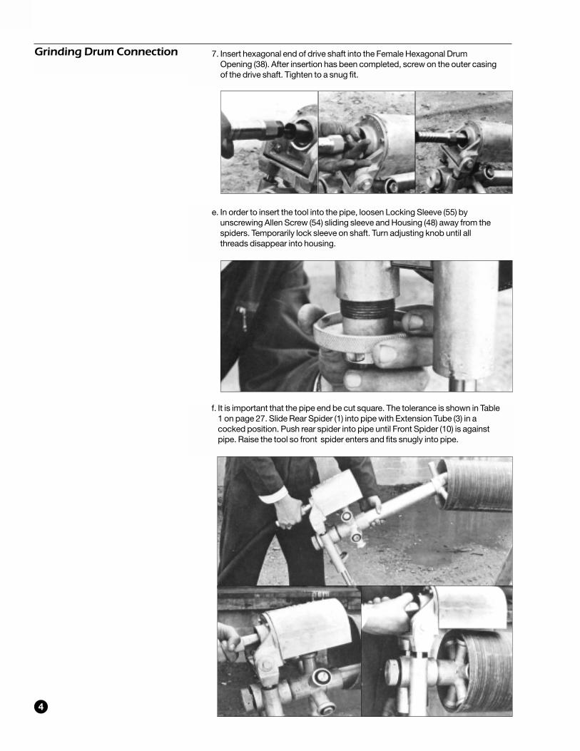
Grinding Drum Connection 7. Insert hexagonal end of drive shaft into the Female Hexagonal DrumOpening (38). After insertion has been completed, screw on the outer casingof the drive shaft. Tighten to a snug fit.
e. In order to insert the tool into the pipe, loosen Locking Sleeve (55) byunscrewing Allen Screw (54) sliding sleeve and Housing (48) away from thespiders. Temporarily lock sleeve on shaft. Turn adjusting knob until allthreads disappear into housing.
f. It is important that the pipe end be cut square. The tolerance is shown in Table1 on page 27. Slide Rear Spider (1) into pipe with Extension Tube (3) in acocked position. Push rear spider into pipe until Front Spider (10) is againstpipe. Raise the tool so front spider enters and fits snugly into pipe.
4

g. Slide the tool until the pipe and the grinding drum are in the proper position.For the original model Taper-Tool® II, set pipe within 1/4” of fully depressedbrake button. In the case of the newer Taper-Tool II, set the pipe 1/4” from thebottom lip of the Grinding Drum Guard (23).
Grinding Drum Connection(cont’d)
h. Turn Extension Pin Adjusting Knob (22) clockwise by hand until the toolcannot slip or turn in the pipe. Do Not Overtighten! The pipe can bedeformed and an improper taper, or damage to the tool can result.
5
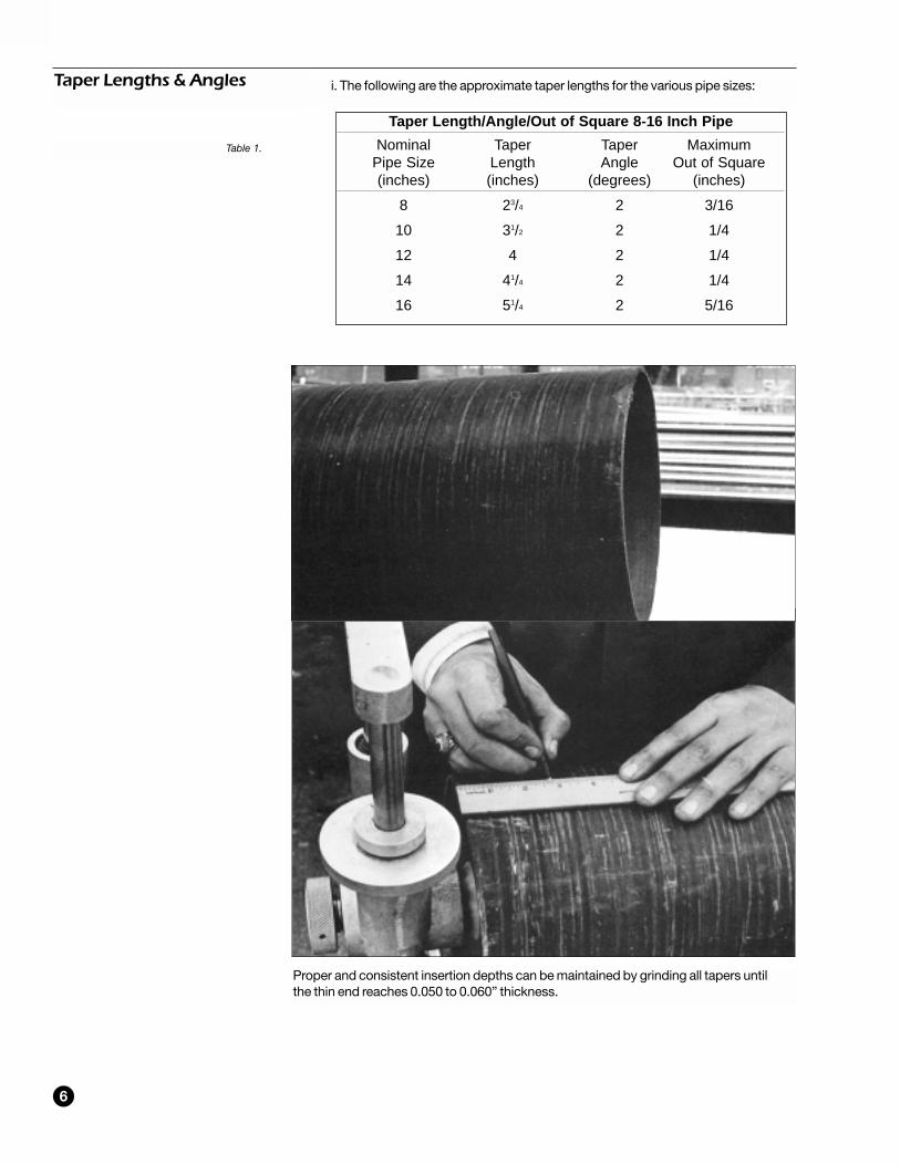
Taper Lengths & Angles
Proper and consistent insertion depths can be maintained by grinding all tapers untilthe thin end reaches 0.050 to 0.060” thickness.
6
i. The following are the approximate taper lengths for the various pipe sizes:
Table 1.
Taper Length/Angle/Out of Square 8-16 Inch Pipe
Nominal Taper Taper Maximum Pipe Size Length Angle Out of Square(inches) (inches) (degrees) (inches)
8 23/4 2 3/16
10 31/2 2 1/4
12 4 2 1/4
14 41/4 2 1/4
16 51/4 2 5/16

c. Rotate the fixed motor Taper-Tool II by turning handle clockwise. (A one-wayinternal clutch prevents turning the wrong way). Caution should be exercisedto avoid twisting of electric cord. The preferred method of accomplishing thisis to use pipe rollers and keep tool stationary. A two man crew, one to turn thepipe and one to operate the tool, would be necessary. For the remote motormodel Taper-Tool II, grasp the drive shaft and rotate the tool clockwisearound the pipe taking care not to twist the grinding drum thereby changingthe taper angle.
d. Rotation should be continuous and uniform. After one complete turn of thetool, repeat procedure of turning taper depth adjusting knob and rotating tooluntil proper taper length is obtained. Avoid heavy cuts that slow motor downdrastically. Be sure tool vibration does not loosen the extension pin adjustingknob. Observe the taper while it is being ground. If there are six high (or low)spots, this is an indication that the extension pins are too tight and aredeforming the pipe. Loosen the extension pins until a smooth taper is beingground. Rotate the pipe during tapering to eliminate the effects of high andlow grinding.
7
a. Plug the electric cord into either a 115 volt AC power source. Test the tool forsmooth operation. There should be no vibration. Caution: The motor turns at20,000 RPM and tapering pipe causes large volumes of dust. Wear a dustmask and goggles.
b. Turn on motor switch. Carefully turn Taper Depth Adjusting Knob (53)counterclockwise until the grinding drum comes in contact with the pipe.Note: Use caution in keeping hands away from the motor, blades andany of the moving pieces.
Taper Tool® II Operation

8
e. To stop the tool after proper taper length has been obtained, turn the taperdepth adjusting knob three complete turns clockwise to clear the grindingdrum from the pipe. Turn motor off and stop the grinding drum by depressingthe brake button (old style only).
f. Remove by turning extension pin adjusting knob counterclockwise until itstops and pull tool out of pipe. Be sure threads on adjusting knob are cleanedthoroughly.
Taper Tool® II Operation(cont’d)
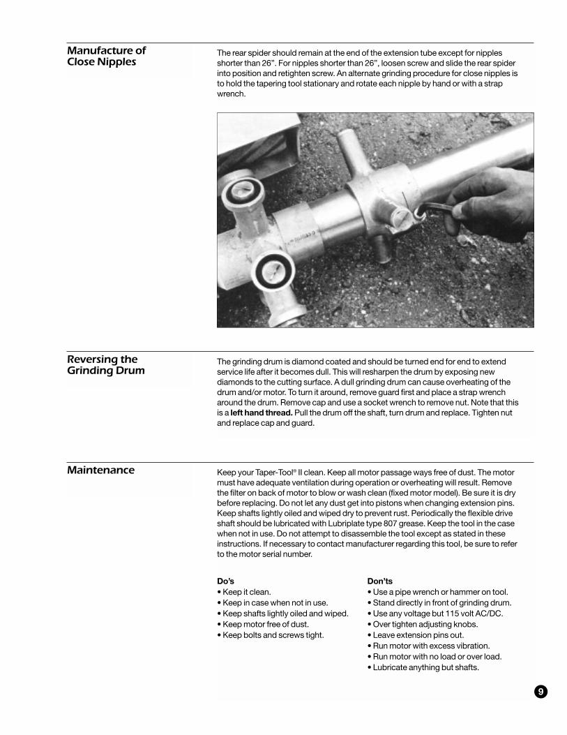
Manufacture ofClose Nipples
The rear spider should remain at the end of the extension tube except for nipplesshorter than 26”. For nipples shorter than 26”, loosen screw and slide the rear spiderinto position and retighten screw. An alternate grinding procedure for close nipples isto hold the tapering tool stationary and rotate each nipple by hand or with a strapwrench.
Reversing theGrinding Drum
The grinding drum is diamond coated and should be turned end for end to extendservice life after it becomes dull. This will resharpen the drum by exposing newdiamonds to the cutting surface. A dull grinding drum can cause overheating of thedrum and/or motor. To turn it around, remove guard first and place a strap wrencharound the drum. Remove cap and use a socket wrench to remove nut. Note that thisis a left hand thread. Pull the drum off the shaft, turn drum and replace. Tighten nutand replace cap and guard.
Maintenance Keep your Taper-Tool® II clean. Keep all motor passage ways free of dust. The motormust have adequate ventilation during operation or overheating will result. Removethe filter on back of motor to blow or wash clean (fixed motor model). Be sure it is drybefore replacing. Do not let any dust get into pistons when changing extension pins.Keep shafts lightly oiled and wiped dry to prevent rust. Periodically the flexible driveshaft should be lubricated with Lubriplate type 807 grease. Keep the tool in the casewhen not in use. Do not attempt to disassemble the tool except as stated in theseinstructions. If necessary to contact manufacturer regarding this tool, be sure to referto the motor serial number.
Do’s Don’ts• Keep it clean. • Use a pipe wrench or hammer on tool.• Keep in case when not in use. • Stand directly in front of grinding drum.• Keep shafts lightly oiled and wiped. • Use any voltage but 115 volt AC/DC.• Keep motor free of dust. • Over tighten adjusting knobs.• Keep bolts and screws tight. • Leave extension pins out.
• Run motor with excess vibration.• Run motor with no load or over load.• Lubricate anything but shafts.
9

Figure 1. Parts List
10
(Alternate Position)

Figure 1. Parts List
Item Description Item Description1 Rear Spider (TRP 24) 31 National Snap Ring
2 Screw 3/8”-16 N.C., S.H. x 11/2” Long (Plated) 32 N.D. Bearing
3 Tube Extension 34 Screws 1/4”-20 N.C., S.H. x 3/4” Long (Plated)
4 Roll Pin, 1/8” x 11/2” 35 National Snap Ring
5 Spring, Lane (Factory Plated) 36 N.D. Bearing
6 Pistons 37 National Snap Ring
7 Roll pin, 1/8” x 1” 38 Female Adapter, Hex Drive
8 Thompson Seals 39 Adapter, Flexible Shaft
9 Extension Pins (8-16” Pipe) 40 Nut 1/2”-20 N.F. Hex. (Plated)
10 Front Spider & Bearing Shaft (TRP 23) 41 Housing, Wheel Bearing (TRP-46)
11 Wedge, Screw 42 Bracket, Pivot Mounting (TRP-48)
13 Nut, 1/2”-13 N.C. 43 Flat Washer 1/2” (Plated)
14 Spacer 44 Screw 1/2”-20 N.F. H.H. x 11/2” Long (Plated)
15 Screw, 10-24 x 3/8” (Factory Plated) 45 Thompson Seals
16 Collar, Locking 46 Thompson Linear Bearings
17 Fafnir Bearing 47 Shaft, Bearing Slide (Thompson)
18 Schatz Bearing 48 Housing, Adjustment Bearing (TRP 25)
19 National Snap Ring 49 Lock Nut
20 Screw, Clamping 50 Screw, 8-32 N.C., S.H. x 5/8” Long
21 Roll Pin, 1/8” x 11/4” 51 Washer
22 Extension Pins Knob, Adjustment 52 National O-ring
23 Grinding Drum Guard 53 Nut, Cut-Depth Adjustment (Plated)
24 Wheel, Diamond Grinding 54 Screw, 1/4-28 N.V. S.H. x 5/8” Long (Plated)
25 Cap, Grinding Wheel 55 Sleeve, Locking (Plated)
26 Shaft, Grinding Wheel 56 Cross Bar (TRP-47)
27 Nut, 3/4-16 (Left Hand) 57 Wyco Flexible Shaft
28 Washer, Wheel Shaft 58 Wyco Double Insulated Motor
29 Spacer, Wheel Shaft 59 Degree Plate
30 Spacer, Wheel Shaft Bearing 60 Plate, Serial No. & Name
61 Morse Ramp Clutch
11
Engineering Controls:
• A fabrication area should be set up in which to perform as much of thefabrication work as is practical or possible.
• Local exhaust ventilation should be provided at areas of cutting and/ortapering to remove airborne dust and fibers. General dilution ventilationshould be provided as necessary to keep airborne dust and fibers below theapplicable exposure limits and guidelines. The need for ventilation systemsshould be evaluated by a professional industrial hygienist.
• Work area should be kept clean, including floor or other horizontal surfaces.Rinsing with water or sweeping with brushes or brooms (using floor sweep) isrecommended. Never use compressed air to clean area or to remove dust forpersonal cleaning. Brushes should be used to remove residue from shavedsurfaces.
Recommended Practicesto Minimize Exposure &Effects of Shavings FromFiberglass Pipe

Personal Protection:
• Always refer to the Material Safety Data Sheet (MSDS) prior to working withunfamiliar materials or if there are questions concerning the contents of thefiberglass pipe.
• OSHA regulates glasswool (fiberglass) under the Hazard CommunicationStandard and as a chemical hazard in laboratories. OSHA classifies glasswoolfiber as a “Particulate Not Otherwise Regulated”, with a workplacepermissible exposure limit (PEL) of 5.0 mg/m3 for respirable dust and 15.0mg/m3 for total dust. These limits are identical to those OSHA requires forconstruction workers exposed to fibrous glass, which were adopted from the1970 Threshold Limit Values (TLVs) of the American Conference ofGovernmental Industrial Hygienists (ACGIH).
• Barrier creme should be applied to the skin in areas which may be exposed toshavings prior to beginning work.
• Clean clothes should be worn each day. Do not wear clothing that has notbeen laundered to begin a work shift. More frequent changing may be requiredby conditions.
• Long sleeved shirts or worksuits should be used. Tape should be used atsleeve opening.
• Cotton or flannel shirts under workshirts may be worn to prevent rubbing ofskin at opening of worksuit.
• Gloves with elastic cuffs should be worn at all times. Replace worn or contam-inated gloves as necessary. Gloves with flared, stiff cuffs act as a gatheringfunnel for shavings.
• Pant legs should be worn outside work boots. If necessary for safetypurposes, the pant legs can be taped to fit closely to the boot. Over-the-calfsocks can be used to prevent chafing of the boot on the skin.
• Wristbands and watches should be removed to prevent rubbing or accumu-lation of particles on skin underneath the band.
• A respirator should be used if ventilation is unavailable, or is inadequate forkeeping dust and fiber levels below the applicable exposure limits. To protectagainst dust and fibers, use a NIOSH-certified disposable or reusableparticulate respirator with an efficiency rating of N95 or higher (42 CFR 84)when working with this product. For exposures up to five times theestablished exposure limits use a quarter-mask respirator, rated N95 orhigher; and for exposures up to ten times the established exposure limits usea half-mask respirator (e.g., MSA’s DM-11, Racal’s Delta N95, 3M’s 8210),rated N95 or higher. Operations such as sawing, blowing, tear out andspraying may generate airborne fiber concentrations requiring a higher level ofrespiratory protection. For exposures up to 50 times the established exposurelimits use a full-face respirator, rated N99 or higher.
Personal Hygiene:
• Wash exposed skin with soap solution (liquid soap preferred) and cool water.• Use washcloth with “brushing” motion to remove dust or fibers. Do not scrub
the skin. This could result in the fibers being imbedded into the skin.• Rinse thoroughly with clean, cold water.• Apply lotion or creme to skin (non-detergent formulas such as baby lotion) to
soothe irritation or prevent further immediate irritation.
Recommended Practicesto Minimize Exposure &Effects of Shavings FromFiberglass Pipe (cont’d)
Important Notice This literature and the information and recommendations it contains are based on data reasonably believed to bereliable. However, such factors as variations in environment, application or installation, changes in operatingprocedures, or extrapolation of data may cause different results. Ameron makes no representation or warranty,expressed or implied, including warranties of merchantability or fitness for purpose, as to the accuracy, adequacyor completeness of the recommendations or information contained herein. Ameron assumes no liabilitywhatsoever in connection with this literature or the information or recommendations it contains.
©1998 Ameron• FP806 (1/99) • Printed in U.S.A. • 5M[124]
Ameron CompositesP.O. Box 7137011 McBride StreetNewnan, Georgia 30263Tel: (770) 253-2000Fax: (770) 253-9234
GROUP HEADQUARTERS
P.O. Box 801148 • Houston, TX 77280 • Tel: (713) 690-7777 • Fax: (713) 690-2842 • http://www.ameron.com
Fiberglass Pipe DivisionEuropeAmeron B.V.J.F. Kennedylaan 74191 MZ GeldermalsenThe NetherlandsTel: +31 345 587 587Fax: +31 345 587 561Telex: 40257 bonds nl
Fiberglass Pipe DivisionAmericasP.O. Box 878Burkburnett, TX 76354Tel: (940) 569-1471Fax: (940) 569-2764
Fiberglass Pipe DivisionCentron InternationalP.O. Box 490600 FM 1195 SouthMineral Wells, Texas 76068Tel: (940) 325-1341Fax: (940) 325-9681
FIBERGLASS PIPE GROUP
Fiberglass Pipe Division AsiaAmeron (Pte) Ltd.No. 7A, Tuas Avenue 3Singapore 639407Tel: 65 861 6118Fax: 65 862 1302/861 7834

Sizes and Voltages for Bondstrand Heat Blankets
For Pipe Sizes Volts Width Length
(mm) (in) (ac) (mm) (in) (mm) (in)
25-50 1-2 120 50 2 305 1250-100 2-4 120 102 4 508 20
150-200 6-8 120 124 47/8 813 32250-300 10-12 120 149 57/8 1270 50350-400 14-16 120 175 67/8 1651 6550-100 2-4 220 102 4 508 20
150-200 6-8 220 124 47/8 813 32250-300 10-12 220 149 57/8 1270 50350-400 14-16 220 175 67/8 1651 65
Heat Blanketsfor heat-curing adhesive joints in Bondstrand®
pipe and fittings.
General Bondstrand heating blankets are specially designed to heat-cure adhesive joints inBondstrand pipe and fittings. Requiring either 120-volt or 220-volt alternating current,the blankets are quickly and easily applied. They provide thermostatically controlledheat, helping to assure maximum joint strength and reliability.
Blankets are available in five sizes and two voltages as follow:
FP805A (12/98)
Using the Blanket Place the thermostat end of your Bondstrand heating blanket against the assembledjoint with the thermostat side facing out from the joint. Wrap the remainder of theblanket around the joint so that overlap, if any, will cover the thermostat. Tie theblanket in place with any nonconducting tie.
ISO-9001
CERTIFICATED FIRM
Installation GuideFIBERGLASS PIPE GROUP

Insulation It is always a good idea to insulate around the heating blanket and to close the pipeends. This is essential when it is windy or when air temperature is below 40° F.Fiberglass insulation backed with aluminum foil generally works well. Insulationshould overwrap the blanket sides about 4 inches (100 mm) each way and be tieddown near the edges to trap the heat. Caution: Joint must not be moved, vibrated orotherwise distributed during cure of adhesive.
Flange Mounting Flange mounting requires a special wrap. Lay the blanket flat with the thermostatdown and, starting at the thermostat end, roll up the blanket. Insert the rolled blanketinto the pipe end only to the depth of the fresh joint, leaving the cord and part of theblanket exposed as shown. Fill the space inside the rolled blanket with fiberglassinsulation or some other heat-resistant material to ensure that the blanket remainssnugly against the inside joint surface.
Curing the Joint Determine the required cure time from the Bondstrand assembly instructions found inthe adhesive kit.
Warning: Before applying power, inspect the blanket and cord for loose wireconnections and bare wires. Do not plug cord into live power source whenstanding in water or on wet surfaces.
Apply alternate current (ac) at the voltage marked on the heating blanket. Do not usedirect current (dc) power supply. Mark the start-up and disconnect time on the pipewith a white grease pencil and you will have a record of cure for each joint in thesystem. Be sure all electrical connections are good and that the blanket actuallyheats up each time.
Important Notice This literature and the information and recommendations it contains are based on data reasonably believed to bereliable. However, such factors as variations in environment, application or installation, changes in operatingprocedures, or extrapolation of data may cause different results. Ameron makes no representation or warranty,expressed or implied, including warranties of merchantability or fitness for purpose, as to the accuracy, adequacyor completeness of the recommendations or information contained herein. Ameron assumes no liabilitywhatsoever in connection with this literature or the information or recommendations it contains.
©1991 Ameron• FP805 (10/98) • Printed in U.S.A. • 5M[124]
Ameron CompositesP.O. Box 7137011 McBride StreetNewnan, Georgia 30263Tel: (770) 253-2000Fax: (770) 253-9234
GROUP HEADQUARTERS
P.O. Box 801148 • Houston, TX 77280 • Tel: (713) 690-7777 • Fax: (713) 690-2842 • http://www.ameron.com
Fiberglass Pipe DivisionEuropeAmeron B.V.J.F. Kennedylaan 74191 MZ GeldermalsenThe NetherlandsTel: +31 345 587 587Fax: +31 345 587 561Telex: 40257 bonds nl
Fiberglass Pipe DivisionAmericasP.O. Box 878Burkburnett, TX 76354Tel: (940) 569-1471Fax: (940) 569-2764
Fiberglass Pipe DivisionCentron InternationalP.O. Box 490600 FM 1195 SouthMineral Wells, Texas 76068Tel: (940) 325-1341Fax: (940) 325-9681
FIBERGLASS PIPE GROUP
Fiberglass Pipe Division AsiaAmeron (Pte) Ltd.No. 7A, Tuas Avenue 3Singapore 639407Tel: 65 861 6118Fax: 65 862 1302/861 7834

Introduction Bondstrand pipe is manufactured from fiberglass reinforced epoxy or vinyl ester resins.When properly handled and installed, fiberglass pipe and fittings result in amaintenance-free, high-performance piping system. Fiberglass reinforced pipe andfittings are impact sensitive and must be handled with a reasonable amount of care.
Shipping, Handling,Storage and Inspectionof Bondstrand Fiberglass Pipe
ISO-9001
CERTIFICATED FIRM
Installation GuideFIBERGLASS PIPE GROUP
FP167D (12/98)
Handling Transportation
a. Let the factory arrangement of the pipe be your guide for correct supportingand spacing when rearranging for transport. Do not let pipe or fittings rest onthe bed of the truck where nails, studs and other objects might damage them.Whenever pipe or fittings come in contact with wood or metal, padding suchas excelsior, carpet or foam should be used.
b. The pipe should be securely fastened directly over the dunnage with tiedownsconsisting of nylon straps or manila rope. Avoid overtightening which maycause excessive localized deformation in the pipe. Straps and ropes shouldbe retightened every 50 miles while in transit. Rope ties should be usedbetween standards to prevent the load from spreading.
c. Do not allow the pipe to extend more than 3 feet beyond the truck or trailerbed as permanent damage can result from excessive flexing. Pronto-Lock®
pipe should always be loaded with the female ends even. Spacers usedduring transportation should be padded.
d. Bondstrand pipe is a light load, particularly with larger diameter pipe.Therefore, reduce speed on rough roads to minimize bouncing.
Properly loaded pipe. Rope ties shouldbe used between standards to prevent
the load from spreading (left). Straps andropes should be retightened every
50 miles while in transit (right).

2
H a n d l i n g( c o n t . )
Loading and unloading
a . Pipe and fittings should never be thrown or dropped under any circ u m s t a n c e s .
b . If the pipe load is properly separated and supported, forklifts can be used.Forklifts should have at least a 6-foot carriage (distance between the forks). Alls u rfaces that come in contact with the pipe should be padded.
c . Never jam or spear forks into a load of fiberglass pipe except where spacers ofat least 2-inch thickness are located.
d . If load is irregular and cannot be reliably moved by fork truck, or pro p e requipment is not available, the pipe should be carefully loaded and unloaded byhand one length at a time. The nominal weights for each respective pipe lengthcan be found under PI P E WE I G H T.
Pipe weight Tabulated values are in U.S. Customary units (lb/ft of pipe) and include couplings.
Nominal Pipe Size (in)
Bondstrand Pipe Series 2 3 4 6 8 10 12 14 1 6
3000A/3200A 0 . 5 0 . 7 1 . 0 1 . 9 3 . 2 4 . 6 6 . 2 7 . 5 9 . 4
2000/4000/7000 0 . 8 1 . 2 2 . 0 3 . 0 4 . 3 5 . 4 6 . 4 7 . 4 9 . 5
2 0 0 0 M 0 . 9 1 . 3 2 . 1 3 . 1 5 . 2 8 . 1 1 1 . 0 1 5 . 0 1 9 . 0
5 0 0 0 / 5 1 0 0 1 . 0 1 . 5 2 . 5 3 . 5 5 . 0 6 . 7 7 . 4 8 . 7 1 1 . 2
C o rrect unloading and stackingp ro c e d u re. The pipe should be care f u l l y
loaded and unloaded by hand onelength at a time.
If proper loading equipment is notavailable, do not roll pipe off trailer.
S t o r a g e Bondstrand pipe may be safely stored outside for extended periods provided thefollowing pro c e d u res are observ e d :
a . S u p p o rts should be spaced in maximum 10-ft intervals and approximately 6 feetf rom each end. The supports should have a minimum 4-in wide bearing surf a c e .

3
Storage (cont’d)
b . A pipe stack should not exceed 10 feet in height and should have side support sor blocks to prevent rolling or slipping in the stack.
c . Spacers should be utilized every 3 feet if the pipe will be reloaded by forklift.
d . Tie downs should consist of nylon straps or manila rope. Avoid overt i g h t e n i n gwhich may cause excessive localized deformation in the pipe.
e . If it is necessary to stack pipe directly on the ground, make sure that the gro u n ds u rface is level, soft and free of rocks or sharp objects.
f . P rotective end coverings should be left in place until time of installation top rotect the pipe ends and to prevent dirt or other materials from entering thep i p e .
g . Fittings, adhesives and tools should be stored in their shipping boxes undercover and protected from water, mud and extreme heat or cold.

I m p o rtant Notice This literature and the information and recommendations it contains are based on data reasonably believed to bereliable. However, such factors as variations in environment, application or installation, changes in operatingp ro c e d u res, or extrapolation of data may cause diff e rent results. Ameron makes no re p resentation or warr a n t y,e x p ressed or implied, including warranties of merchantability or fitness for purpose, as to the accuracy, adequacyor completeness of the recommendations or information contained herein. Ameron assumes no liabilitywhatsoever in connection with this literature or the information or recommendations it contains.
© 1987 Amero n • FP167D (12/98) supersedes FP 167C (12/94) • Printed in U.S.A • 5M [472]
Ameron CompositesP.O. Box 7137011 McBride StreetNewnan, Georgia 30263Tel: (770) 253-2000Fax: (770) 253-9234
GROUP HEADQUARTERS
P.O. Box 801148 • Houston, TX 77280 • Tel: (713) 690-7777 • Fax: (713) 690-2842 • http://www.ameron.com
Fiberglass Pipe DivisionEuropeAmeron B.V.J.F. Kennedylaan 74191 MZ GeldermalsenThe NetherlandsTel: +31 345 587 587Fax: +31 345 587 561Telex: 40257 bonds nl
Fiberglass Pipe DivisionAmericasP.O. Box 878Burkburnett, TX 76354Tel: (940) 569-1471Fax: (940) 569-2764
Fiberglass Pipe DivisionCentron InternationalP.O. Box 490600 FM 1195 SouthMineral Wells, Texas 76068Tel: (940) 325-1341Fax: (940) 325-9681
FIBERGLASS PIPE GROUP
Fiberglass Pipe Division AsiaAmeron (Pte) Ltd.No. 7A, Tuas Avenue 3Singapore 639407Tel: 65 861 6118Fax: 65 862 1302/861 7834
I n s p e c t i o n Since pipe and fittings may be subjected to rough treatment during transport a t i o n ,storage and handling, it is imperative that they be fully inspected for possible impactdamage, cracking or manufacturing defects. If the outside surface of the pipe has beengouged or exhibits a depression, it is likely that the impact has also caused damage tothe liner. Impact damage on translucent pipe can usually be detected by a localized colord i ff e rence in the pipe.
The color diff e rence may be as small as 1⁄2 inch in diameter or as large as 4 inches indiameter depending on the intensity of the impact. Inspection of pipe and fittings shouldbe undertaken upon delivery and just prior to installation. At delivery, check the loadc a re f u l l y. If pipe or fittings are delivered damaged, the following pro c e d u re should beo b s e rv e d :
End Users and Distributors:Accept all damaged material.Note damage on freight bill and bill of lading. Notify theshipper immediately. Depending on the origin of shipment, call the Bondstranddistributor in your area, or, in the case of direct shipments, call Ameron Fiberglass PipeS y s t e m s .
During inspection, isolate any damaged sections immediately to avoid any chance ofdamaged material being installed. All damage on pipe must be cut out and re p a i re d .Inspection plays a major role in the ultimate success of an installed pipeline. If damagedor defective pipe or fittings can be detected prior to installation, the installer will avoidf rustration and delays caused by necessary rework. All parties involved will benefit fro mc a reful and thorough inspection.

FP288A (1/97)
Installation of SuspendedBondstrand Pipe
1 General. . . . . . . . . . . . . . . . . . . . . . . . . . . . . . . . . . . . . . 2Designing the Bondstrand system . . . . . . . . . . . . 2Selecting Bondstrand pipe, fittings and adhesives . . . . . . . 2Filament-wound versus molded products . . . . . . . . . . 2Energy savings . . . . . . . . . . . . . . . . . 3Insulated systems . . . . . . . . . . . . . . . . 3Other application information . . . . . . . . . . . . . 3
2 Designing for expansion and contraction . . . . . . . . . . . . . . . . . . . 3General principles . . . . . . . . . . . . . . . . 3Length change due to temperature . . . . . . . . . . . 4Length change due to pressure . . . . . . . . . . . . 4Anchoring for branches and valves . . . . . . . . . . . 4Using expansion loops . . . . . . . . . . . . . . . 5Expansion joints . . . . . . . . . . . . . . . . 6
3 Designing for restrained systems . . . . . . . . . . . . . . . . . . . . . . . 7General principles . . . . . . . . . . . . . . . . 7Thrust due to temperature . . . . . . . . . . . . . . 7Thrust due to pressure . . . . . . . . . . . . . . . 8Use of guides for Alignment Control . . . . . . . . . . . 8
4 Spans and support locations. . . . . . . . . . . . . . . . . . . . . . . . . . 11Span recommendations . . . . . . . . . . . . . . 11Support spacings for special conditions . . . . . . . . . . 11Loads on hangers and supports . . . . . . . . . . . . 12Support locations . . . . . . . . . . . . . . . . 12Supports for vertical runs . . . . . . . . . . . . . . 12
5 Connections to other materials . . . . . . . . . . . . . . . . . . . . . . . . 13Connections to other piping . . . . . . . . . . . . . 13Small-diameter metallic connection . . . . . . . . . . . 13Gravity flow connections . . . . . . . . . . . . . . 13
6 Connections to equipment . . . . . . . . . . . . . . . . . . . . . . . . . . . 13Equipment vibration . . . . . . . . . . . . . . . 13Connections to tanks . . . . . . . . . . . . . . . 13
7 Other design considerations . . . . . . . . . . . . . . . . . . . . . . . . . . 14Coating Bondstrand . . . . . . . . . . . . . . . 14Electrical properties . . . . . . . . . . . . . . . 14Entrapped gases . . . . . . . . . . . . . . . . 14Steam condensate . . . . . . . . . . . . . . . . 14Heat tracing . . . . . . . . . . . . . . . . . 14
8 Detailing the supports . . . . . . . . . . . . . . 15Clamping forces . . . . . . . . . . . . . . . . 15Space between pipe . . . . . . . . . . . . . . . 15Supports permitting pipe movement . . . . . . . . . . . 15Supports that anchor pipe . . . . . . . . . . . . . . 16
9 Appendices . . . . . . . . . . . . . . . . . . . . . . . . . . . . . . . . . . . 18A: Calculating length change . . . . . . . . . . . . . 18B: Calculating thrust . . . . . . . . . . . . . . . 19C: Calculating support spacings for uniformly distributed loads . . . . 20
10 Health and safety information . . . . . . . . . . . . . . . . . . . . . . . . . 24Toxicity of adhesive . . . . . . . . . . . . . . . 24Handling precautions for adhesive . . . . . . . . . . . . 24First aid for adhesive users . . . . . . . . . . . . . . 24
Table of Contents
Bondstrand® InstallationFIBERGLASS PIPE GROUP

Designing the Bondstrand system
This guide contains general information for designing suspended Bondstrand pipingsystems. This information, in conjunction with good general engineering practiceand the designer’s good judgment, must all be applied to complete a successfuland economical piping system.
The guide considers the following:
• Criteria for selecting Bondstrand products for a given application
• Expansion and contraction
• Span between supports and support location
• Connections to other materials and equipment
• Coating Bondstrand products
• Suggested details for guides, supports and anchors
While Bondstrand performs in many applications just like metallic systems, thedesigner must recognize some important differences:
• Bondstrand pipe weighs only about 1⁄7 as much as Schedule 40 carbon steelpipe. This means that pipe and piping assemblies even in 16-inch diameterscan be lifted into place using any light lifting equipment. In the smaller diame-ters, no lifting equipment is necessary. This reduces on-site installation costs.
• The longitudinal modulus of Bondstrand is much less than that of carbon steelpipe — a characteristic that limits spans where deflection is important but alsoreduces thrust due to temperature change.
• Thermal expansion is 60% greater than for carbon steel. However, by takingadvantage of the Bondstrand’s flexibility, you can provide for this expansioneconomically, often without using expansion joints.
• Bondstrand fiberglass pipe requires protection against potential external abra-sion or crushing at points where steel supports are located. Such protection iseasy and economical.
• Effective modulus values vary with temperature. Recommended spans andestimated thrusts are given to help the designer detail his project for long-timeoperation at ambient and elevated temperatures.
Recognition of these and other differences dealt with in this guide is the key tosuccessful installations. While this information is likely to prove most helpful tothose designing Bondstrand systems for the first time, experienced Bondstrandcustomers will also find new and useful information.
Be aware that the reinforced thermosetting resin piping products offered by othermanufacturers may differ significantly from Bondstrand. Resin systems, manu-facturing processes and joining systems are important variables affecting themechanical and physical properties of these products. The recommendationsand suggestions given are based on Ameron’s test and field experience andshould be applied only to Bondstrand products.
Selecting Bondstrand pipe, fittings and adhesives
A choice of either epoxy or vinyl ester Bondstrand products is available for differentchemical and thermal environments. For information to guide your selection, refer tothe Bondstrand Corrosion Guide, FP132. This publication provides recommenda-tions for different chemicals and other fluid materials, including food products, aswell as guidance for selecting the appropriate Bondstrand adhesive.
Filament-wound versus molded products
In smaller pipe sizes, you have a choice between molded and filament-woundfittings. In general, filament-wound fittings should be used in applications wherefittings in loops, turns or branches are intended to flex, where temperature changesexceed 100°F in restrained or blocked systems, or where the system is exposed tomechanical vibration or hydraulic surge. Filament wound fittings would be used,also, in systems where a liner is required. Some sizes and types of fittings are notavailable in both molded and filament-wound styles, so check the BondstrandFittings Dimensions, FP282, for availability when making your choice.
1 General
2

1 General (cont)Energy savings
Remember when selecting pipe diameter that Bondstrand's low frictional values(Hazen-Williams C = 150) will reduce your pumping energy requirements comparedto those for carbon steel pipe. In most systems these low frictional values will bemaintained for the life of the system.
Note also that the slightly larger inside diameter of Bondstrand pipe compared toSchedule 40 or 80 carbon steel pipe, will further reduce your pumping costs. Handycharts in the Bondstrand engineering guides show the head loss expected for bothpipe and fittings.
Insulated systems
Bondstrand may be insulated in the field. Bondstrand pipe is also available frommany pipe insulators with efficient built-in insulation. If you use insulatedBondstrand, be sure to check your support spacings for the operating temperatureto accommodate the added weight of the insulation and jacket.
Series 2000M-FP is manufactured with a factory applied, reinforced coating whichprovides impact resistance and thermal insulation in addition to its fire protectionproperties. Unless indicated otherwise, values presented in the tables for Series2000 can be used for Series 2000M-FP.
Other application information
Where containment is required for your piping system, Ameron can supplyBondstrand II pipe with a variety of joining and performance options.
Ameron has prepared a number of publications with valuable information pertainingto specific types of service, including marine applications, fire protection systemsand steam condensate returns. Just call your local Bondstrand distributor or yournearest Ameron sales office, and let us know your application. Give us the temper-ature, pressure, liquid or gas to be carried, and other pertinent conditions.
In addition, Ameron has computer programs for deflection and stress analysis ofBondstrand systems. For a nominal fee, Ameron Engineering Department will bepleased to utilize one of these programs to analyze your specific systems.Experience shows, however, that such analysis is required only for the moredemanding or complicated conditions and that the generalized procedures presentedherein will usually suffice.
2 Designing forexpansion andcontraction
General principles
Suspended pipe generally performs best where it is permitted to move freely. Inthese systems, anchors serve only to keep the pipe properly positioned betweenloops and turns. Center the anchor in the run between loops if possible. An anchorshould be placed between loops and between loops and turns. Except for the oneanchor per run, supports should carry the pipe and maintain the intended drainageslope but should not restrain the pipe against axial movement. At turns, thesupports should also permit lateral movement. Supports should not fall directly onfittings.
If the piping system cannot be designed to move freely, see next section onDESIGNING FOR RESTRAINED SYSTEMS.
Pipe changes length in a free system as a result of changes in temperature andpressure. Since both can increase or decrease concurrently, the resulting changesin length must be combined for loop design. Length-change formulas and examplesappear in Appendix A, but the following paragraphs will provide all you need formost pipeline designs.
3

Length increase due to a 100psi (7 bar) internal pressure inan unrestrained system.
Values given for Series 2000, 2000M-FP and4000 are valid to 250°F (121°C). Values forSeries 3000A, 3200A, 5000, 5100 and 7000are valid to 200°F (93°C).
Table 1
4
Length change due to temperature
Tests show that the amount of linear expansion varies directly with temperature.Figure 1 shows the length change for Series 2000, 3000A, 3200A, 4000, 5000, 5100 and7000 Bondstrand pipe.
Length change due to pressure
The amount of length change occurring because of internal pressure depends onwall thickness, diameter, Poisson’s ratio and the effective modulus of elasticity inboth axial and circumferential directions at the operating temperature. InBondstrand pipe, some of these factors tend to cancel each other, and the correc-tion becomes relatively simple. For each 100 feet in a straight, freely supported runof Bondstrand pipe (Table 1) provides length changes which are suitable throughoutthe indicated range of temperatures. You need only correct this value for the pres-sure of your system by using a direct pressure-ratio correction.
Anchoring for branches and valves
Both vertical and horizontal branches can add complexity to a system intended tomove freely. Unless a branch can move both axially and laterally, such as a shortstub-out to a nozzle or flexible hose connection, it will require special considerationto avoid undue bending stresses. Sometimes the best solution is to anchor both thebranch and the run at the tee, accommodating the pipe length changes at turns orloops in each of the three connecting lines. For example, a vertical branchconnecting to buried pipe may include a Z-loop; the tee may be rotated 90° topermit an L-loop; or the vertical l ine may be treated as a restrained pipe asdescribed in Designing for Restrained Systems.
Valves should be anchored and supported directly, especially in diameters sixinches and larger. Valve weight in the larger sizes and torque on valve handles in allsizes are the primary concerns. Generally, butterfly valves with manual lever handleactuators do not require separate supports. Other types of actuators can add toomuch torque or weight if they are not separately supported.
2 Designing forexpansion andcontraction (cont’d)
Inches per 100 feet of pipe (mm per 100 m of pipe) from 100 psi (1 MPa) internal pressure
Series 2000 Series 3000A Series 3200A Series 4000 Series 5000, 5100 Series 7000 Series 2000M-FP
in. mm in. mm in. mm in. mm in. mm in. mm in. mm
NominalDiameterin. mm
1 251.5 402 503 804 1005 1256 1508 200
10 25012 30014 35016 400
0.1 110.1 180.2 230.3 360.3 350.4 440.4 540.5 630.7 800.8 960.8 1000.8 100
– –– –0.2 270.3 390.4 49– –0.4 531.3 1581.4 1651.4 1681.5 1761.5 182
– –– –0.2 270.3 390.4 49– –0.4 530.5 660.6 690.6 700.6 740.6 76
0.1 140.2 230.2 290.4 460.3 420.4 530.5 640.6 740.8 940.9 1120.9 1070.9 107
0.1 100.1 160.2 200.3 320.3 320.3 400.4 490.4 480.4 490.4 490.4 500.4 50
0.1 110.1 180.2 230.3 360.3 350.4 440.4 540.4 520.4 520.4 520.4 520.4 52
0.3 370.5 600.6 771.0 1220.9 1101.2 1401.4 1701.6 1952.0 2472.4 2952.3 2822.3 281
Length changes forBondstrand Series 2000,2000M-FP, 4000, 5000, 5100,7000, 3000A, and 3200A
Figure 1
Temperature Change (°F)

Expansion loop design:Length of loop leg required toaccommodate listed lengthchanges
Table 2
Using expansion loops
Loops are recommended for relieving longitudinal stress between anchors in asuspended pipeline. Table 2 gives minimum expansion loop dimensions for allBondstrand pipe series. First, determine how much total length change due totemperature and pressure must be absorbed. Use the appropriate table for the pipeseries you are using. Select the pipe diameter and total length change to determinethe required leg length for a U-loop design. As an example, assume that a Series2000 eight-inch line is installed and will change a total of two inches in length. Table2 for Series 2000 and Series 4000 shows that the length of loop leg required toaccommodate the length change is 9 feet (2.8m).
Loops should be horizontal whenever possible to avoid entrapping air or sedimentand to facilitate drainage.
• For upward loops, air relief valves aid air removal and improve flow. In pres-sure systems, air removal for both pressure testing and normal operation isrequired for safety as well.
• For downward loops, air pressure equalizing lines may be necessary to permitdrainage.
• In both cases, special taps are necessary for complete drainage.
Loops using 90° elbows absorb length change better than those using 45° elbows.Unlike a 90° turn, a 45° turn carries a thrust component through the turn which canadd axial stress to the usual bending stress in the pipe and fittings. Alignment anddeflection are also directly affected by the angular displacement at 45° turns anddemand special attention for support design and location.
A 45° elbow at a free turn with the same increment of length change in each leg willbe displaced 86% more than a 90° elbow. The relative displacement in the plane ofa loop is also more of a problem. Figure 2 illustrates the geometry involved. Designinformation is not provided because it is beyond the scope of this manual and loopswith 45° elbos are generally not recommended. Consult Ameron if a situationrequires the use of 45° elbows.
2 Designing forexpansion andcontraction(cont’d)
Series 2000 and Series 4000 length change (in./mm)
1.0/25 2.0/50 3.0/75 4.0/100 5.0/125
ft m ft. m ft. m ft. m ft. m
NominalPipe Sizein. mm
1 251.5 402 503 804 1005 1256 1508 200
10 25012 30014 35016 400
6 1.97 2.27 2.29 2.8
10 3.111 3.412 3.713 4.015 4.616 4.917 5.218 5.5
5 1.66 1.97 2.28 2.59 2.8
10 3.110 3.112 3.713 4.014 4.315 4.616 4.9
4 1.35 1.66 1.97 2.28 2.58 2.59 2.8
10 3.112 3.712 3.713 4.014 4.3
4 1.34 1.35 1.66 1.96 1.97 2.28 2.59 2.89 2.8
10 3.111 3.411 3.4
3 1.03 1.04 1.34 1.35 1.65 1.65 1.66 1.97 2.27 2.28 2.58 2.5
Series 5000 and 5100 length change (in./mm)
1.0/25 2.0/50 3.0/75 4.0/100 5.0/125
ft m ft. m ft. m ft. m ft. m
NominalPipe Sizein. mm
1 251.5 402 503 804 1005 1256 1508 200
10 25012 30014 35016 400
5 1.66 1.96 1.97 2.28 2.59 2.8
10 3.111 3.413 4.014 4.314 4.315 4.6
4 1.35 1.66 1.97 2.28 2.58 2.59 2.8
10 3.111 3.412 3.713 4.014 4.3
4 1.35 1.65 1.66 1.97 2.27 2.28 2.59 2.8
10 3.111 3.411 3.412 3.7
3 1.04 1.34 1.35 1.65 1.66 1.97 2.27 2.28 2.59 2.89 2.8
10 3.1
2 0.73 1.03 1.04 1.34 1.34 1.35 1.65 1.66 1.96 1.97 2.27 2.2
Figure 2
90° elbow
a a
aa
aa
a
a
aa
1.4a2.6a
45° elbow
a: Relative displacement of elbowspermitted to move freely in a pipe run.
Comparison of displacement in90° vs. 45° elbows caused by a unit length change
5

2 Designing forexpansion andcontraction(cont’d)
Series 3000A length change (in./mm)
1.0/25 2.0/50 3.0/75 4.0/100 5.0/125
ft m ft. m ft. m ft. m ft. m
NominalPipe Sizein. mm
1 251.5 402 503 804 1005 1256 1508 200
10 25012 30014 35016 400
– –– –5 1.66 1.97 2.2– –8 2.59 2.8
10 3.110 3.111 3.412 3.7
– –– –5 1.65 1.66 1.9– –7 2.28 2.59 2.89 2.8
10 3.111 3.4
– –– –4 1.35 1.65 1.6– –6 1.97 2.28 2.58 2.59 2.89 2.8
– –– –3 1.04 1.35 1.6– –5 1.66 1.96 1.97 2.27 2.28 2.5
– –– –3 1.03 1.03 1.0– –4 1.34 1.35 1.65 1.65 1.66 1.9
Expansion loop design:Length of loop leg required toaccommodate listed lengthchanges
Table 2
Series 3200A length change (in./mm)
1.0/25 2.0/50 3.0/75 4.0/100 5.0/125
ft m ft. m ft. m ft. m ft. m
NominalPipe Sizein. mm
1 251.5 402 503 804 1005 1256 1508 200
10 25012 30014 35016 400
– –– –5 1.66 1.97 2.2– –8 2.59 2.8
10 3.111 3.412 3.713 4.0
– –– –5 1.65 1.66 1.9– –7 2.28 2.59 2.8
10 3.111 3.411 3.4
– –– –4 1.35 1.65 1.6– –6 1.97 2.28 2.59 2.89 2.8
10 3.1
– –– –3 1.04 1.35 1.6– –5 1.66 1.97 2.27 2.28 2.58 2.5
– –– –3 1.03 1.03 1.0– –4 1.34 1.35 1.65 1.66 1.96 1.9
Expansion joints
Instead of a loop, an expansion joint may be used to relieve longitudinal stress. Thetype selected must be fairly flexible, such as a Teflon bellows which is activated by thethrust of low modulus materials (see Note , Table 3).
Supports for expansion joints must be carefully designed and placed to maintaincontrolled deflection. Besides adding weight, most of these joints act as partial struc-tural hinges which afford only limited transfer of moment and shear. Where theexpansion joint relies on elastomers or thermoplastics for strength, the structuraldiscontinuity or hinging effect at the joint increases with increases in temperature.
When using an expansion joint in a pipeline carrying solids, consider the possibility thatit may stiffen or fail to function due to sedimentation in the expansion joint. Failure ofthe expansion joint may cause excessive pipe deflection.
Series 2000M-FP and Series 7000 length change (in./mm)
1.0/25 2.0/50 3.0/75 4.0/100 5.0/125
ft m ft. m ft. m ft. m ft. m
NominalPipe Sizein. mm
1 251.5 402 503 804 1005 1256 1508 200
10 25012 30014 35016 400
6 1.97 2.27 2.29 2.8
10 3.111 3.412 3.713 4.015 4.616 4.917 5.218 5.5
5 1.66 1.97 2.28 2.59 2.8
10 3.110 3.112 3.713 4.015 4.615 4.616 4.9
4 1.35 1.66 1.97 2.28 2.58 2.59 2.8
10 3.112 3.713 4.013 4.014 4.3
4 1.34 1.35 1.66 1.96 1.97 2.28 2.59 2.8
10 3.110 3.111 3.412 3.7
3 1.03 1.04 1.34 1.35 1.65 1.65 1.66 1.97 2.28 2.58 2.58 2.5
6

3 Designing forrestrained systems
General principles
The layout of a system occasionally makes it impossible to allow the pipe to “movefreely.” Sometimes it may be necessary to block certain runs of an otherwise freesystem. In a fully restrained pipe (blocked against movement at both ends), thedesigner must deal with thrust rather than length change. Both temperature andpressure produce thrust which must be resisted at turns, branches, reducers andends. Knowing the magnitude of this thrust enables the designer to select satisfac-tory anchors . Remember that axial thrust on anchors is independent of anchorspacing. Formulas and examples are found in Appendix B.
In practice, the largest compressive thrust is normally developed on the first positivetemperature cycle. Subsequently, the pipe develops both compressive and tensileloads as it is subjected to temperature and pressure cycles. Neither compressivenor tensile loads, however, are expected to exceed the thrust on the first cycleunless the ranges of the temperature and pressure change.
Thrust due to temperature
In a fully restrained Bondstrand pipe, length changes induced by temperaturechange are resisted at the anchors and converted to thrust. The thrust developeddepends on the thermal coefficient of expansion, the cross-sectional area, themodulus of elasticity and the temperature change, ∆t. Table 3 gives the maximumaxial thrust in anchored lines for each series of Bondstrand pipe at three elevatedtemperatures. The table assumes a fully relaxed initial pipe length at 60°F, withshort-time modulus of elasticity values as shown.
Initial temperature-inducedthrusts (pounds-force) in fullyrestrained Bondstrand pipe atvarious operating temperatures
Table 3
Note: in tables above, thrusts are calculated assuming a fully relaxed initial length at 60°F (16°C) and short term modulus of elasticity values as follows.For 2 - 6 inch Series 3000A, use modulus of elasticity values from Series 3200A.Coefficient of thermal expansion is 10 x 10-6 in./in./°F (18 x 10-6 mm/mm/°C) for all but Series 3000A and 3200A which are 8.5 x 10⁻⁶ in./in./°F (15.3 x 10⁻⁶ mm/mm/°C) for 2 - 6 inch Series 3000A and all Series 3200A sizes, and 12 x 10-6 in./in./°F (21.6 x 10⁻⁶ mm/mm/°C) for 8 - 16 inch Series3000A.
7
Caution: In restrained systems, pipefittings can be damaged by faulty
anchoring or by untimely release ofanchors. Damage to fittings in service can
be caused by bending or slipping of animproperly designed or installed anchor.Also, length changes due to creep areinduced by high pressures or tempera-
tures while pipe is in service. Whenanchors must later be released, especiallyin long pipe runs, temporary anchors maybe required to avoid excessive displace-
ment and overstress of fittings.
Initial Temperature Induced Thrusts (pounds-force) in a Fully Restrained Bondstrand Pipe at Various Operating Temperatures
Series 2000 Series 2000M-FP & Series 7000 Series 3000A Series 3200A Series 4000 Series 5000 & 5100
150°F 200°F 250°F 150°F 200°F 250°F 200°F 200°F 150°F 200°F 250°F 140°F 170°F 200°F
NominalDiameterin. mm
1 251.5 402 503 804 1005 1256 1508 200
10 25012 30014 35016 400
880 1070 12101300 1560 17801610 1940 22002390 2890 32903980 4800 54704940 5950 67805920 7130 81208600 10370 11800
10760 12970 1476012780 15410 1754014770 17810 2027019090 23020 26200
880 1070 12101300 1560 17801610 1940 22002390 2890 32903980 4800 54704940 5950 67805920 7130 8120
10430 12570 1431016250 19590 2230022850 27540 3135026450 31880 3629034590 41700 47470
––
185028903800
–74208160
12030163502006025140
––
185028903800
–7420
1000014750200402460030820
730 880 10001060 1280 14601310 1580 18001950 2350 26703410 4110 46804220 5090 58005060 6100 69407480 9010 102609340 11260 12820
11100 13380 1523013880 16730 1904018000 21700 24700
490 560 370710 810 540870 1000 660
1300 1490 9802270 2610 17302820 3230 21403370 3860 25604980 5710 37806230 7140 47207400 8480 56109250 10600 7020
12000 13750 9100
Initial Temperature Induced Thrusts (Newtons) in a Fully Restrained Bondstrand Pipe at Various Operating Temperatures
Series 2000 Series 2000M-FP & Series 7000 Series 3000A Series 3200A Series 4000 Series 5000 & 5100
65°C 93°C 121°C 65°C 93°C 121°C 93°C 93°C 65°C 93°C 121°C 60°C 77°C 93°C
NominalDiameterin. mm
1 251.5 402 503 804 1005 1256 1508 200
10 25012 30014 35016 400
3890 4720 53905710 6930 79107070 8580 9800
10540 12800 1461017540 21290 2430021740 26390 3013026050 31610 3609037880 45970 5248047360 57480 6561056280 68310 7798065040 78940 9011084070 102030 116470
3890 4720 53905710 6930 79107070 8580 9800
10540 12800 1461017540 21290 2430021740 26390 3013026050 31610 3609045900 55710 6360071570 86860 99150
100590 122080 139370116440 141320 161330152320 184850 211030
––
82001279016860
–3291036170533607251089000
111520
––
82001279016860
–32910443306539088870
109080136670
3210 3900 44504680 5680 64905780 7010 80008580 10410 11880
15020 18230 2082018600 22570 2577022260 27020 3084032920 39950 4561041130 49920 5699048860 59300 6769061110 74160 8466079250 96180 109800
2170 2500 16403160 3640 23903900 4490 29405790 6670 4370
10140 11680 766012550 14460 948015020 17300 1134022220 25590 1678027760 31970 2096032970 37980 2490041240 47490 3114053480 61590 40380
Modulus of Elasticity
Series 2000 Series 2000M-FP & Series 7000 Series 3000A Series 3200A Series 4000 Series 5000 & 5100
106 psi
GPa
1.6 1.2 1.0
11.03 8.55 7.17
1.6 1.2 1.0
11.03 8.55 7.17
1.3
8.97
2.3
15.52
1.6 1.2 1.0
11.03 8.55 7.17
1.2 1.0 0.5
8.28 6.90 3.59

Using guides for alignment control
A suspended line which is restrained from movement may need extra supports orguides to maintain alignment, especially when the pipeline is exposed to a widetemperature range. Guides as shown in Figure 6 may permit the pipe to move axiallybut not laterally. Without guides, restrained pipe may not deflect uniformly and, insome cases, may deflect excessively. Tables 5 to 9 (Tables 10 to 14 for metric) giverecommended guide spacing to avoid buckling deflection between anchors.
Supplying this lateral support by using guides at the normal support locations oreven at every other support is often sufficient, especially in the larger diameters. Tocheck, compare the recommended span for your operating temperature as deter-mined from the section entitled SU P P O R T LO C A T I O N S A N D SP A N S with the guidespacings from Tables 5 to 9 (Tables 10 to 14, metric). Be sure that guide andsupport spacing meet both requirements.
As an example for determining guide spacing, assume that a three-inch BondstrandSeries 2000 line is installed at 70°F and is to operate at 250°F (∆T = 180°F). Table 5shows that guides should be installed at intervals of 7 feet.
Notes:
1. Pipe anchors (A) such as shown in figure 8, Section 8 are used in restrainedsystems at each end of a run and justbefore a change in direction, and mustresist the tabulated thrusts.
2. Pipe anchors (B) such as shown in figure 7, Section 8 are light-duty in-lineanchors usually located between two pipeanchors (A) or midway between loops orturns in systems not restrained.
3. Pipe anchors (A and B) at elbows andbranches should be located a distance offive to ten times the pipe diameter fromthe bend. Other anchor locations mayrequire a flexibility analysis.
4. No appreciable thrust on anchors isdeveloped due to internal pressure in thepipe at in-line reducers.
Thrust at anchors due to 100 psi (690 kPa) internal pres-sure in restrained Bondstrandsystems
Table 4
Thrust due to pressure
Thrust due to internal pressure in a suspended but restrained system is theoreticallymore complicated. This is because in straight, restrained pipelines with all jointsbonded, the Poisson effect produces considerable tension in the pipe wall. Asinternal pressure is applied, the pipe expands circumferentially and at the sametime contracts longitudinally. This tensile force is important because it acts toreduce the hydrostatic thrust on anchors at turns.
For the designer of a restrained Bondstrand pipeline, however, the problem can begreatly simplified. Table 4 provides the recommended design thrusts and locationsfor anchors at various fittings.
Thrust at Anchors Due to 100 psi (690 kPa) Internal Pressure in Restrained Bondstrand Systems
Series 2000/4000/7000 Series 5000/5100 Series 3000A/3200A
lb-force N lb-force N lb-force N
NominalPipe Sizein. mm1 251.5 402 503 804 1005 1256 1508 200
10 25012 30014 35016 400
50 225115 515180 810420 1865695 3085
1080 48051565 69552680 119254220 187805990 266457215 321009425 41935
45 170115 440190 725460 1755755 2900
1200 46051765 67603035 117104830 186456890 266408305 32105
10855 41965
– –– –
240 1060540 2400915 4070
– –2000 88954045 119956365 283208890 39545
11535 5132015070 67035
90° Elbow
Tee
45° Lateral
A
A
A
A
B
B
AA
45° Elbow
3 Designing forrestrained systems(cont'd.)
8

Maximum guide spacing (ft.)required for temperature change(°F)
Bondstrand Series 2000 & 4000
Table 5 Nominal Pipe Size
in. mm
Degrees of Temperature Change (°F)
10 20 30 40 50 60 70 80 90 100 110 120 130 140 150 160 170 180 190
1 251.5 402 503 804 1005 1256 1508 200
10 25012 30014 35016 400
11 7 6 5 5 4 4 4 4 3 3 3 3 3 3 3 3 2 216 11 9 8 7 6 6 6 5 5 5 5 4 4 4 4 4 4 419 14 11 10 9 8 7 7 6 6 6 6 5 5 5 5 5 5 429 21 17 15 13 12 11 10 10 9 9 8 8 8 8 7 7 7 738 27 22 19 17 15 14 13 13 12 11 11 10 10 10 9 9 9 947 33 27 23 21 19 18 17 16 15 14 14 13 13 12 12 11 11 1156 40 32 28 25 23 21 20 19 18 17 16 16 15 15 14 14 13 1374 52 43 37 33 30 28 26 25 23 22 21 20 20 19 18 18 17 1792 65 53 46 41 38 35 33 31 29 28 27 26 25 24 23 22 22 21
110 78 63 55 49 45 41 39 37 35 33 32 30 29 28 27 27 26 25120 85 70 60 54 49 46 43 40 38 36 35 33 32 31 30 29 28 28138 98 80 69 62 56 52 49 46 44 42 40 38 37 36 35 33 33 32
3 Designing forrestrained systems(cont'd.)
Maximum guide spacing (ft.)required for temperature change(°F)
Bondstrand Series 5000 & 5100
Table 6 Nominal Pipe Size
in. mm
Degrees of Temperature Change (°F)
10 20 30 40 50 60 70 80 90 100 110 120 130 140 150 160 170 180 190
1 251.5 402 503 804 1005 1256 1508 200
10 25012 30014 35016 400
10 7 6 5 5 4 4 4 3 3 3 3 3 3 3 3 2 2 215 11 9 8 7 6 6 5 5 5 5 4 4 4 4 4 4 4 319 13 11 9 8 8 7 7 6 6 6 5 5 5 5 5 5 4 428 20 16 14 13 12 11 10 9 9 9 8 8 8 7 7 7 7 636 26 21 18 16 15 14 13 12 12 11 11 10 10 9 9 9 9 845 32 26 23 20 18 17 16 15 14 14 13 13 12 12 11 11 11 1054 38 31 27 24 22 21 19 18 17 16 16 15 15 14 14 13 13 1271 50 41 36 32 29 27 25 24 22 21 21 20 19 18 18 17 17 1689 63 51 44 40 36 34 31 30 28 27 26 25 24 23 22 22 21 20
106 75 61 53 47 43 40 37 35 33 32 31 29 28 27 26 26 25 24116 82 67 58 52 47 44 41 39 37 35 34 32 31 30 29 28 27 27133 94 77 66 59 54 50 47 44 42 40 38 37 36 34 33 32 31 31
Maximum guide spacing (ft.)required for temperature change(°F)
Bondstrand Series 2000M-FP &7000
Table 7 Nominal Pipe Size
in. mm
Degrees of Temperature Change (°F)
10 20 30 40 50 60 70 80 90 100 110 120 130 140 150 160 170 180 190
1 251.5 402 503 804 1005 1256 1508 200
10 25012 30014 35016 400
11 8 6 6 5 5 4 4 4 3 3 3 3 3 3 3 3 3 316 12 9 8 7 7 6 6 5 5 5 5 5 4 4 4 4 4 420 14 12 10 9 8 8 7 7 6 6 6 6 5 5 5 5 5 531 22 18 15 14 13 12 11 10 10 9 9 8 8 8 8 7 7 740 28 23 20 18 16 15 14 13 13 12 11 11 11 10 10 10 9 947 33 27 23 21 19 18 17 16 15 14 14 13 13 12 12 11 11 1159 42 34 30 27 24 22 21 20 19 18 17 16 16 15 15 14 14 1479 56 45 39 35 32 30 28 26 25 24 23 22 21 20 20 19 19 1899 70 57 50 44 41 38 35 33 31 30 29 28 27 26 25 24 23 23
119 84 69 59 53 49 45 42 40 38 36 34 33 32 31 30 29 28 27128 91 74 64 57 52 48 45 43 40 39 37 36 34 33 32 31 30 29146 104 85 73 65 60 55 52 49 46 44 42 41 39 38 37 36 35 34
Maximum guide spacing (ft.)required for temperature change(°F)
Bondstrand Series 3000A
Table 8 Nominal Pipe Size
in. mm
Degrees of Temperature Change (°F)
10 20 30 40 50 60 70 80 90 100 110 120 130 140 150 160 170 180 190
1 251.5 402 503 804 1005 1256 1508 200
10 25012 30014 35016 400
– – – – – – – – – – – – – – – – – – –– – – – – – – – – – – – – – – – – – –
21 15 12 10 9 8 8 7 7 6 6 6 6 5 5 5 5 5 531 22 18 15 14 12 12 11 10 10 9 9 8 8 8 8 7 7 740 28 23 20 18 16 15 14 13 13 12 11 11 11 10 10 10 9 9
– – – – – – – – – – – – – – – – – – –59 42 34 30 26 24 22 21 20 19 18 17 16 16 15 15 14 14 1464 45 37 32 29 26 24 23 21 20 19 18 18 17 16 16 15 15 1581 57 47 40 36 33 30 28 27 25 24 23 22 22 21 20 20 19 1896 68 55 48 43 39 36 34 32 30 29 28 27 26 25 24 23 23 22
109 77 63 55 49 45 41 39 36 34 33 31 30 29 28 27 26 26 25125 88 72 62 56 51 47 44 42 39 38 36 35 33 32 31 30 29 29
Maximum guide spacing (ft.)required for temperature change(°F)
Bondstrand Series 3200A
Table 9 Nominal Pipe Size
in. mm
Degrees of Temperature Change (°F)
10 20 30 40 50 60 70 80 90 100 110 120 130 140 150 160 170 180 190
1 251.5 402 503 804 1005 1256 1508 200
10 25012 30014 35016 400
– – – – – – – – – – – – – – – – – – –– – – – – – – – – – – – – – – – – – –
21 15 12 10 9 8 8 7 7 6 6 6 6 5 5 5 5 5 531 22 18 15 14 12 12 11 10 10 9 9 8 8 8 8 7 7 740 28 23 20 18 16 15 14 13 13 12 11 11 11 10 10 10 9 9
– – – – – – – – – – – – – – – – – – –59 42 34 30 26 24 22 21 20 19 18 17 16 16 15 15 14 14 1476 54 44 38 34 31 29 27 25 24 23 22 21 20 20 19 18 18 1796 68 55 48 43 39 36 34 32 30 29 28 27 26 25 24 23 23 22
114 80 66 57 51 46 43 40 38 36 34 33 32 30 29 28 28 27 26130 92 75 65 58 53 49 46 43 41 39 37 36 35 33 32 31 31 30148 105 86 74 66 61 56 52 49 47 45 43 41 40 38 37 36 35 34
9

Maximum guide spacing (m)required for temperature change(°C)
Bondstrand Series 2000 & 4000
Table 10 Nominal Pipe Size
in. mm
Degrees of Temperature Change (°C)
5 10 15 20 25 30 35 40 45 50 55 60 65 70 75 80 85 90 95
1 251.5 402 503 804 1005 1256 1508 200
10 25012 30014 35016 400
3.2 2.2 1.8 1.5 1.5 1.2 1.2 1.0 1.0 1.0 1.0 0.8 0.8 0.8 0.8 0.8 0.8 0.8 0.85.0 3.5 2.8 2.5 2.0 2.0 1.8 1.8 1.5 1.5 1.5 1.2 1.2 1.2 1.2 1.2 1.0 1.0 1.06.2 4.2 3.5 3.0 2.8 2.5 2.2 2.0 2.0 1.8 1.8 1.8 1.5 1.5 1.5 1.5 1.5 1.2 1.29.2 6.5 5.2 4.5 4.0 3.8 3.5 3.2 3.0 2.8 2.8 2.5 2.5 2.5 2.2 2.2 2.2 2.0 2.0
12.0 8.5 7.0 6.0 5.2 4.8 4.5 4.2 4.0 3.8 3.5 3.5 3.2 3.0 3.0 3.0 2.8 2.8 2.815.0 10.5 8.5 7.5 6.5 6.0 5.5 5.2 5.0 4.8 4.5 4.2 4.0 4.0 3.8 3.8 3.5 3.5 3.218.0 12.8 10.2 9.0 8.0 7.2 6.8 6.2 6.0 5.5 5.2 5.0 5.0 4.8 4.5 4.5 4.2 4.2 4.023.5 16.5 13.5 11.8 10.5 9.5 8.8 8.2 7.8 7.2 7.0 6.8 6.5 6.2 6.0 5.8 5.5 5.5 5.229.5 20.8 17.0 14.8 13.2 12.0 11.0 10.2 9.8 9.2 8.8 8.5 8.0 7.8 7.5 7.2 7.0 6.8 6.835.2 24.8 20.2 17.5 15.8 14.2 13.2 12.2 11.8 11.0 10.5 10.0 9.8 9.2 9.0 8.8 8.5 8.2 8.038.5 27.2 22.2 19.2 17.2 15.8 14.5 13.5 12.8 12.0 11.5 11.0 10.5 10.2 9.8 9.5 9.2 9.0 8.844.2 31.2 25.5 22.0 19.8 18.0 16.8 15.5 14.8 14.0 13.2 12.8 12.2 11.8 11.2 11.0 10.8 10.2 10.0
3 Designing forrestrained systems(cont'd.)
Maximum guide spacing (m)required for temperature change(°C)
Bondstrand Series 5000 & 5100
Table 11 Nominal Pipe Size
in. mm
Degrees of Temperature Change (°C)
5 10 15 20 25 30 35 40 45 50 55 60 65 70 75 80 85 90 95
1 251.5 402 503 804 1005 1256 1508 200
10 25012 30014 35016 400
3.2 2.2 1.8 1.5 1.2 1.2 1.2 1.0 1.0 1.0 0.8 0.8 0.8 0.8 0.8 0.8 0.8 0.8 0.84.8 3.2 2.8 2.2 2.0 1.8 1.8 1.5 1.5 1.5 1.2 1.2 1.2 1.2 1.2 1.0 1.0 1.0 1.06.0 4.2 3.5 3.0 2.5 2.2 2.2 2.0 2.0 1.8 1.8 1.8 1.5 1.5 1.5 1.5 1.2 1.2 1.29.0 6.2 5.0 4.5 4.0 3.5 3.2 3.0 3.0 2.8 2.5 2.5 2.5 2.2 2.2 2.2 2.0 2.0 2.0
11.5 8.2 6.8 5.8 5.0 4.8 4.2 4.0 3.8 3.5 3.5 3.2 3.2 3.0 3.0 2.8 2.8 2.8 2.514.5 10.2 8.2 7.2 6.5 5.8 5.5 5.0 4.8 4.5 4.2 4.0 4.0 3.8 3.8 3.5 3.5 3.2 3.217.2 12.2 10.0 8.5 7.8 7.0 6.5 6.0 5.8 5.5 5.2 5.0 4.8 4.5 4.5 4.2 4.0 4.0 4.022.8 16.0 13.0 11.2 10.0 9.2 8.5 8.0 7.5 7.0 6.8 6.5 6.2 6.0 5.8 5.5 5.5 5.2 5.028.5 20.0 16.2 14.2 12.8 11.5 10.8 10.0 9.5 9.0 8.5 8.0 7.8 7.5 7.2 7.0 6.8 6.5 6.533.8 24.0 19.5 16.8 15.0 13.8 12.8 12.0 11.2 10.5 10.0 9.8 9.2 9.0 8.8 8.2 8.0 8.0 7.837.2 26.2 21.5 18.5 16.5 15.2 14.0 13.0 12.2 11.8 11.2 10.8 10.2 9.8 9.5 9.2 9.0 8.8 8.542.5 30.0 24.5 21.2 19.0 17.2 16.0 15.0 14.0 13.5 12.8 12.2 11.8 11.2 11.0 10.5 10.2 10.0 9.8
Maximum guide spacing (m) required for temperature change(°C)
Bondstrand Series 2000M-FP &7000
Table 12 Nominal Pipe Size
in. mm
Degrees of Temperature Change (°C)
5 10 15 20 25 30 35 40 45 50 55 60 65 70 75 80 85 90 95
1 251.5 402 503 804 1005 1256 1508 200
10 25012 30014 35016 400
3.5 2.5 2.0 1.8 1.5 1.2 1.2 1.2 1.0 1.0 1.0 1.0 0.8 0.8 0.8 0.8 0.8 0.8 0.85.2 3.5 3.0 2.5 2.2 2.0 1.8 1.8 1.8 1.5 1.5 1.5 1.2 1.2 1.2 1.2 1.2 1.0 1.06.5 4.5 3.8 3.2 2.8 2.5 2.2 2.2 2.0 2.0 1.8 1.8 1.8 1.8 1.5 1.5 1.5 1.5 1.59.8 6.8 5.5 4.8 4.2 4.0 3.5 3.2 3.2 3.0 2.8 2.8 2.5 2.5 2.5 2.2 2.2 2.2 2.2
12.8 9.0 7.2 6.2 5.5 5.0 4.8 4.5 4.2 4.0 3.8 3.5 3.5 3.2 3.2 3.0 3.0 3.0 2.815.0 10.5 8.5 7.5 6.5 6.0 5.5 5.2 5.0 4.8 4.5 4.2 4.0 4.0 3.8 3.8 3.5 3.5 3.219.0 13.2 11.0 9.5 8.5 7.8 7.0 6.5 6.2 6.0 5.5 5.5 5.2 5.0 4.8 4.8 4.5 4.2 4.225.2 17.8 14.5 12.5 11.2 10.2 9.5 8.8 8.2 7.8 7.5 7.2 7.0 6.5 6.5 6.2 6.0 5.8 5.831.8 22.5 18.2 15.8 14.2 13.0 12.0 11.2 10.5 10.0 9.5 9.0 8.8 8.5 8.0 7.8 7.5 7.5 7.238.0 27.0 22.0 19.0 17.0 15.5 14.2 13.5 12.5 12.0 11.5 11.0 10.5 10.0 9.8 9.5 9.2 9.0 8.841.0 29.0 23.8 20.5 18.2 16.8 15.5 14.5 13.5 13.0 12.2 11.8 11.2 11.0 10.5 10.2 9.8 9.5 9.247.0 33.2 27.0 23.5 21.0 19.0 17.8 16.5 15.5 14.8 14.0 13.5 13.0 12.5 12.0 11.8 11.2 11.0 10.8
Maximum guide spacing (m)required for temperature change(°C)
Bondstrand Series 3000A
Table 13 Nominal Pipe Size
in. mm
Degrees of Temperature Change (°C)
5 10 15 20 25 30 35 40 45 50 55 60 65 70 75 80 85 90 95
1 251.5 402 503 804 1005 1256 1508 200
10 25012 30014 35016 400
– – – – – – – – – – – – – – – – – – –– – – – – – – – – – – – – – – – – – –6.5 4.5 3.8 3.2 2.8 2.5 2.2 2.2 2.0 2.0 1.8 1.8 1.8 1.8 1.5 1.5 1.5 1.5 1.59.8 6.8 5.5 4.8 4.2 4.0 3.5 3.2 3.2 3.0 2.8 2.8 2.5 2.5 2.5 2.2 2.2 2.2 2.2
12.5 9.0 7.2 6.2 5.5 5.0 4.8 4.5 4.0 4.0 3.8 3.5 3.5 3.2 3.2 3.0 3.0 3.0 2.8– – – – – – – – – – – – – – – – – – –
19.0 13.2 10.8 9.5 8.5 7.8 7.0 6.5 6.2 6.0 5.5 5.2 5.2 5.0 4.8 4.8 4.5 4.2 4.220.5 14.5 11.8 10.2 9.0 8.2 7.8 7.2 6.8 6.2 6.0 5.8 5.5 5.2 5.2 5.0 4.8 4.8 4.525.8 18.2 14.8 12.8 11.5 10.5 9.8 9.0 8.5 8.0 7.8 7.2 7.0 6.8 6.5 6.2 6.2 6.0 5.830.5 21.5 17.5 15.2 13.5 12.5 11.5 10.8 10.0 9.5 9.2 8.8 8.5 8.0 7.8 7.5 7.2 7.0 7.035.0 24.8 20.0 17.5 15.5 14.2 13.0 12.2 11.5 11.0 10.5 10.0 9.5 9.2 9.0 8.8 8.2 8.2 8.040.0 28.2 23.0 20.0 17.8 16.2 15.0 14.0 13.2 12.5 12.0 11.5 11.0 10.5 10.2 10.0 9.5 9.2 9.0
Maximum guide spacing (m)required for temperature change(°C)
Bondstrand Series 3200A
Table 14 Nominal Pipe Size
in. mm
Degrees of Temperature Change (°C)
5 10 15 20 25 30 35 40 45 50 55 60 65 70 75 80 85 90 95
1 251.5 402 503 804 1005 1256 1508 200
10 25012 30014 35016 400
– – – – – – – – – – – – – – – – – – –– – – – – – – – – – – – – – – – – – –6.5 4.5 3.8 3.2 2.8 2.5 2.2 2.2 2.0 2.0 1.8 1.8 1.8 1.8 1.5 1.5 1.5 1.5 1.59.8 6.8 5.5 4.8 4.2 4.0 3.5 3.2 3.2 3.0 2.8 2.8 2.5 2.5 2.5 2.2 2.2 2.2 2.2
12.5 9.0 7.2 6.2 5.5 5.0 4.8 4.5 4.0 4.0 3.8 3.5 3.5 3.2 3.2 3.0 3.0 3.0 2.8– – – – – – – – – – – – – – – – – – –
19.0 13.2 10.8 9.5 8.5 7.8 7.0 6.5 6.2 6.0 5.5 5.2 5.2 5.0 4.8 4.8 4.5 4.2 4.224.2 17.2 14.0 12.0 10.8 9.8 9.0 8.5 8.0 7.5 7.2 7.0 6.8 6.5 6.2 6.0 5.8 5.8 5.530.8 21.8 17.8 15.2 13.8 12.5 11.5 10.8 10.2 9.5 9.2 8.8 8.5 8.0 7.8 7.5 7.2 7.2 7.036.5 25.8 21.0 18.2 16.2 14.8 13.8 12.8 12.0 11.5 11.0 10.5 10.0 9.8 9.2 9.0 8.8 8.5 8.241.5 29.2 24.0 20.8 18.5 16.8 15.5 14.5 13.8 13.0 12.5 12.0 11.5 11.0 10.8 10.2 10.0 9.8 9.547.5 33.5 27.5 23.8 21.2 19.2 18.0 16.8 15.8 15.0 14.2 13.8 13.0 12.5 12.2 11.8 11.5 11.0 10.8
10

Span recommendations
Recommended maximum spans for Bondstrand pipe at various operating tempera-tures are given in Table 15. These spans are intended for normal horizontal pipingarrangements, i.e., those which have no fittings, valves, vertical runs, etc., but whichmay include flanges and non-uniform support spacings. The tabular values repre-sent a compromise between continuous and simple spans. When installed at thesupport spacings indicated in Table 15, the weight of the pipe full of water willproduce a long-time deflection of about 1⁄2 inch, which is usually acceptable forappearance and adequate drainage.
Fully continuous spans may be used with support spacings up to 20 percent greaterthan those shown in Table 15; in simple spans, support spacings should be 20percent less than those shown in Table 15.
For this purpose, continuous spans are defined as interior spans (not end spans),which are uniform in length and free from structural rotation at supports. Simplespans are supported only at the ends and are hinged or free to rotate at thesupports. Special conditions described below are not covered.
The pipe is assumed to be free to move axially. Suspended piping, which isrestrained or anchored against longitudinal movement, represents a special caseand guides may be required as discussed under the previous section, Use of Guidesfor Alignment .
Support spacings for special conditions
Piping designers may calculate deflections or determine support spacings for theirown particular geometry and loadings using the effective beam stiffness factorsgiven in Appendix C. In such an analysis, the effects of non-uniform spacing, turnsand branches, vertical or inclined runs, special joints which may act as a hinge,heavy liquids, external loads such as insulation, thrust in restrained lines anddynamic loads may be considered, often using a computer program.
4 Spans and supportlocations
Recommended maximumsupport spacings in feet forBondstrand pipe at variousoperating temperatures (fluidspecific gravity=1.0)
Table 15
Series 2000 Series 2000M-FP Series 4000 Series 5000
NominalPipe Size
in. mm
1 251.5 402 503 804 1005 1256 1508 200
10 25012 30014 35016 400
ft. m ft. m ft. m ft. m ft. m ft. m ft. m ft. m
10.2 3.1 8.9 2.711.4 3.5 10.0 3.012.2 3.7 10.7 3.213.9 4.2 12.2 3.715.8 4.8 13.8 4.216.8 5.1 14.7 4.517.7 5.4 15.5 4.719.6 6.0 17.2 5.220.8 6.4 18.2 5.621.8 6.7 19.1 5.822.7 6.9 19.9 6.124.2 7.4 21.2 6.5
8.7 2.7 7.6 2.310.4 3.2 9.1 2.811.1 3.4 9.7 3.012.9 3.9 11.3 3.414.9 4.5 13.0 4.015.9 4.9 14.0 4.316.9 5.2 14.8 4.519.8 6.0 17.3 5.322.3 6.8 19.5 6.024.5 7.5 21.5 6.525.5 7.8 22.3 6.827.2 8.3 23.8 7.3
9.7 3.0 8.7 2.710.8 3.3 9.7 2.911.5 3.5 10.3 3.113.1 4.0 11.7 3.615.2 4.6 13.6 4.116.1 4.9 14.4 4.417.0 5.2 15.2 4.618.9 5.8 16.9 5.120.1 6.1 17.9 5.521.0 6.4 18.8 5.722.3 6.8 19.9 6.123.8 7.3 21.3 6.5
9.4 2.9 5.6 1.710.4 3.2 6.2 1.911.0 3.4 6.6 2.012.5 3.8 7.5 2.314.4 4.4 8.6 2.615.5 4.7 9.3 2.816.2 4.9 9.7 3.018.0 5.5 10.8 3.319.2 5.8 11.5 3.520.1 6.1 12.0 3.721.3 6.5 12.8 3.922.7 6.9 13.6 4.2
up to up to 151°F to 67°C to up to up to 151°F to 67°C to up to up to 151°F to 67°C to up to up to 151°F to 67°C to150°F 66°C 250°F 121°C 150°F 66°C 250°F 121°C 150°F 66°C 250°F 121°C 150°F 66°C 200°F 93°C
Series 5100 Series 7000 Series 3000A Series 3200A
NominalPipe Size
in. mm
1 251.5 402 503 804 1005 1256 1508 200
10 25012 30014 35016 400
ft. m ft. m ft. m ft. m ft. m ft. m ft. m ft. m
10.1 3.1 8.9 2.711.4 3.5 9.9 3.012.4 3.8 10.8 3.314.3 4.4 12.5 3.816.2 4.9 14.2 4.317.2 5.2 15.1 4.618.2 5.5 15.9 4.820.8 6.4 18.3 5.623.3 7.1 20.4 6.225.3 7.7 22.2 6.826.2 8.0 23.0 7.028.0 8.5 24.6 7.5
8.1 2.5 5.6 1.79.0 2.7 6.2 1.99.5 2.9 6.6 2.0
10.8 3.3 7.5 2.312.4 3.8 8.6 2.613.4 4.1 9.3 2.814.0 4.3 9.7 3.015.6 4.7 10.8 3.316.6 5.1 11.5 3.517.4 5.3 12.0 3.718.4 5.6 12.8 3.919.6 6.0 13.6 4.2
– – – –– – – –
12.8 3.9 11.9 3.614.5 4.4 13.5 4.115.6 4.8 14.6 4.4
– – – –18.7 5.7 17.4 5.316.8 5.1 15.7 4.818.6 5.7 17.3 5.320.2 6.2 18.8 5.721.3 6.5 19.8 6.022.6 6.9 21.0 6.4
– – – –– – – –
12.8 3.9 11.9 3.614.5 4.4 13.5 4.115.6 4.8 14.6 4.4
– – – –18.7 5.7 17.4 5.320.0 6.1 18.6 5.722.2 6.8 20.6 6.324.0 7.3 22.3 6.825.3 7.7 23.6 7.226.8 8.2 25.0 7.6
up to up to 151°F to 67°C to up to up to 151°F to 67°C to up to up to 151°F to 67°C to up to up to 151°F to 67°C to150°F 66°C 250°F 121°C 150°F 66°C 250°F 121°C 150°F 66°C 250°F 99°C 150°F 66°C 210°F 99°C
11

4 Spans and supportlocations (cont’d)
Loads on hangers and supports
Table 16 gives maximum service loads for horizontal piping on hangers andsupports. Do not exceed the total support or hanger load given in the table forsustained operation.
Support locations
Supports that permit pipe movement are usually under pipe, not under fittings. Besure that pipe movement is not obstructed either axially or laterally by a flange orfitting near the support. In general, supports may be located at convenient nearbystructures, just as for steel pipe, provided the support spacings indicated in Table15 are not exceeded.
Anchors on pipe are indicated in Table 4 for restrained piping. Except at flangedconnections, above-ground anchors are usually found on pipe rather than fittings.Anchors in lines free to move should be located where necessary to control move-ment into loops or turns. See Figures 7 through 10 for typical anchor details.
Supports for vertical runs
Install a single support anywhere along the length of a vertical pipe run more thanabout ten feet long. See Figure 10 for suggested details. If the run is supported nearits base, use loose collars as guides as shown in Figure 10b, spaced as recom-mended in Table 17.
Vertical runs lessthan ten feet long may usually be supported as part of the horizontal piping. Ineither case be sure the layout makes sufficient provision for horizontal and verticalmovement at the top and bottom turns.
Accommodate length changes in vertical pipe runs by allowing free movement offittings at either top, bottom or both. For each 1/8 inch of anticipated vertical lengthchange, provide 2 feet of horizontal pipe between the elbow and the first support,but not less than 6 feet nor more than 20 feet of horizontal pipe.
Treat columns more than 100 feet high (either hanging or standing) as specialdesigns. Support and provision for length change are important. The installer shouldbe especially careful to avoid movement due to wind or support vibration whilejoints are curing.
Minimum guide spacing (feet) forvertical runs supported from thebottom
Table 17 Pipe Diameter
Inches
1, 1.52, 3, 4, 56, 8, 10, 12, 14, 162, 3, 4, 6, 8, 10, 12, 14, 16
1, 1.52, 3, 4, 56, 8, 10, 12, 14, 16
Series Fluid Temperature (°F)
100 150 200 250
† not recommended
12
2000
4000
3000A3200A
50005100
}}
}
20 15 10 1025 20 15 1030 25 20 1525 20 15 †35 30 25 †
20 15 10 †25 20 10 †30 25 15 †
Permissible service loads aslimited by hanger and supportdetails, horizontal piping
Table 16
100100100100100100130200340400650800
100120160200200200330600
1050143017202320
NominalDiameterin. mm
Load on Support Fitted to Lower 180° (lbs)
Maximum per linear inch Maximum per support
1 251.5 402 503 804 1005 1256 1508 200
10 25012 30014 35016 400

Equipment vibration
Bondstrand pipe will safely absorb vibration from pumping or other conditions if (1 )stresses are controlled within reasonable limits, and (2) pipe is protected fromexternal abrasion by saddles or sleeves where it contacts supports and otherobjects. In general, pipeline vibration is severe only when the generating frequencyis at, or near, the natural resonance frequency of the pipeline. This frequency is afunction of the support system, layout geometry, temperature, mass, and pipe stiff-ness, and is often difficult to predict.
There are two principal ways to control stress caused by vibration. You can usuallyobserve the stability of the system during initial operation and add restraints orsupports as required to reduce effects of equipment vibration. Where necessary,guides illustrated in Figure 6 will effectively hold pipe from lifting or moving laterally.
In special cases where source vibration is excessive (such as that resulting frompumps running unbalanced), an elastomeric expansion joint or other vibrationabsorber should be considered. If an expansion joint is considered, refer toEXPANSION JOINTS.
Connections to tanks
The wall flexure of a tank as it is filled and emptied produces movements at nozzleswhich must be accommodated in the design. These movements can be absorbedby a loop or turn, or by an expansion joint. Avoid direct, straight-line connectionsbetween tanks.
6 Connections toequipment
Connections to other piping
Where possible, connect Bondstrand to either metallic or thermoplastic piping usingflanges drilled to the 150 psi standards of ANSI B16.5. Bondstrand filament-woundepoxy flanges and Bondstrand heavy-duty molded flanges may be bolted directlyagainst raised-face steel flanges These flanges also seal well against lined steelconfigurations. All flanges, including Bondstrand standard molded flanges, epoxyand vinyl ester, provide sealing against flat-faced flanges. Use a full-faced 1/8-inchthick elastomer with a Shore A hardness of 60 ±5 for best results .
Flanged valves and other equipment are frequently supplied with different flangefacings. The configuration of these facings may vary widely. Unless it has beendemonstrated that these facings are compatible with the face of Bondstrandflanges, consult Ameron Fiberglass Pipe Group Engineering Department.
Where Bondstrand is connected to metallic pipe, securely anchor the metallic pipeat the point of connection so that expansion and contraction or weight of the metalline is not transferred to the Bondstrand line.
Small-diameter metallic connections
Outlets for instrumentation are best made using orifice flanges with 1⁄2-inch orifices.Threaded reducer bushings mounted in saddles, blind flanges and fittings plugsoffer connections up to 11⁄2-inches in diameter for a wide range of applications. Themost commonly used metal bushing material is Type 316 stainless steel, butAmeron can furnish other materials on special order.
Gravity flow connections
There are different ways to make gravity-flow connections to floor drains, cast ironpipe, etc. For example, a four-inch by six-inch tapered body reducer will enlarge thereceiving end of a Bondstrand four-inch pipe and serve as a packing chamber forthe cast iron end of a floor drain or other fitting.
Conversely, Bondstrand pipe can be packed and sealed into a cast iron bell. In anycase, avoid packing materials which must be applied at temperatures above 200°F.Mechanical couplings are available through other manufacturers to connectBondstrand to clay, concrete, cast iron or other non-metallic pipe.
5 Connections toother materials
13

High-velocity flow of fluids having low electrical conductivity, such as petroleumdistillates, can generate significant amounts of static electricity. In buried pipe thesecharges are slowly dissipated. Be sure to ground projections or metal appurte-nances, especially near discharge nozzles, filters, valves and other areas of highturbulence. Use saddles instead of elastomeric pads at supports to obtain bettergrounding.
Bondstrand Series 7000 pipe includes electrically conductive elements in the pipewall which, when properly grounded, prevent accumulation on the exterior of thepipe of dangerous levels of static electricity produced by the flow of fluids inside thepipe.
Entrapped gases
As in all piping systems, high points in the system will trap air or other gases.Trapped gases may create a hazard during test and operation of the system, andmay restrict flow or drainage. It is recommended that air release valves be used athigh points to permit bleeding out trapped air or other gases. See SMALL-DIAMETER
METALLIC CONNECTIONS for suggested method of mounting.
Steam condensate
Good drainage helps avoid water hammer in steam condensate lines. For furtherinformation, see our Bondstrand Guide for Steam Condensate, FP468, availablefrom your local distributor.
Heat tracing
Heat tracing may be needed to prevent freezing in cold weather or to maintain flowof viscous fluids at ambient temperature.
Wrap heat tracing helically to avoid the pipe deflection caused by heating one sideof the pipe. Heat tracing should be directly on the pipe and within the insulation. Donot exceed maximum trace temperatures of 250°F for epoxy products or 200°F forvinyl ester products, and use the maximum trace temperature for the design of thepiping system.
Coating Bondstrand
Exposure to direct sunlight will eventually degrade the surface of Bondstrandpiping. Although no failures are known to have resulted from this superficial degra-dation, it does cause a dull, grey appearance which many users wish to avoid.
Ameron products are available to prevent or arrest this effect, or for color coding.Based on studies at the factory, a five-mil single coat of Ameron Amershield® singlecoat polyurethane protective coating will provide suitable protection for either epoxyor vinyl ester pipe and fittings.
Adhesion of the coating is improved by delaying the application until the pipesurface has begun to weather. Pipe must be thoroughly cleaned before applying thecoating.
For further information on chemical resistance, coverage rates, equipment andapplication procedures for coatings, contact Ameron's Protective Coatings Division.
Electrical properties
Bondstrand pipe offers high resistance to stray electrical currents, a common causeof corrosion around valves and pumps. Table 18 gives the results of tests onBondstrand pipe in a clean, as manufactured, condition at room temperature.Obviously, electrical properties, especially surface resistivity, are greatly affected bycontamination and atmospheric conditions .
7 Other design considerations
Electrical properties ofBondstrand Series 2000, 3000A,3200A, 4000, 5000 and 5100 pipe
Table 18
Dielectric constant, at 1 KHz for a 0.22-inch thicknessDissipation factor, at 1 KHz for a 0.22 inch thicknessDielectric strength, by the short-time test using 1⁄4-inch elec-trodes in oil for a 0.23-inch thickness, volts per milDielectric breakdown voltage, by the short-time test using 1⁄4-inch electrodes in oil for a 0.23-inch thickness, kvSurface resistivity, ohmsVolume resistivity, for a 0.22-inch thickness
ASTM
Test MethodValue
5.9
0.016 - 0.021
>230
>53.41010 to 1012
1014 to 1015
D150D150
D149
D149D257D257
Property
Note: All material was tested as manufactured and at room temperature.
14

Clamping forces
Support styles that clamp the pipe, are generally not recommended to ensure thatclamping forces do not crush the pipe. Local crushing could result from a poor fit,and all-around crushing could result from over-tightening .
Where the pipe must be held tightly at the support, mount a pair of 180° supportsaddles between clamp and pipe for the ultimate in strength and long life. In somecases with Bondstrand 2000 or 4000, a 1⁄4-inch thick elastomeric pad (Shore Adurometer hardness 60 ± 5) placed between clamp and pipe is a suitable alternative.
Space between pipe
In multiple runs, allow clearance for flanges and other fittings having a diametergreater than the pipe. Table 20 shows the outside radius of standard Bondstrandproducts. Add space between pipe runs to accommodate length changes at loopsand turns. Insulate as necessary to avoid direct exposure to hot pipe or other heat sources.
8 Detailing thesupports
The following paragraphs describe and illustrate the different methods and devicesused to support Bondstrand pipe and fittings in a suspended system.
Because outside diameters of Bondstrand pipe are the same as those for iron pipesize (IPS) standards, standard pipe supports and hangers often may be used forBondstrand piping systems. Occasionally, larger supports as given in Table 19 arerequired to fit over elastomeric pads or saddles, especially at anchors.
Recommended nominal hangersizes for Bondstrand pipe
Table 19
2 502 502 503 754 1005 1256 1508 200
10 25012 30014 35016 400
– –– –3 754 1005 1256 150
(77⁄8) (200)(97⁄8) (251)(12) (300)(14) (350)
(151⁄2) (394)(171⁄2) (445)
Nominal Diameter
in. mm
Bare Pipe or with Sheet Metal
Wrapper
With Elastomeric Pad
With TwoBondstrand 180°Support Saddles
Note: Dimensions shown in paren-theses are recommended insidediameters of anchoring device orsupport, and provide for a 1⁄ 4-inchelastomeric pad thickness or a 9⁄16-inch Bondstrand saddle thickness.
Supports permitting pipe movement
Supports allowing pipe to move with relative freedom include:
• hangers which are free to move laterally or longitudinally with the pipe,
• fixed supports over which pipe must slide, allowing longitudinal movementand often lateral movement, and
• guides which permit longitudinal movement of the pipe but restrain lateralmovement.
Hangers are free to move on their hanger rods and allow considerable longitudinaland lateral movement. Hanger types include band, ring or clevis type (Figure 3), orroller types (Figure 4) with the roller either suspended freely or held rigidly in a frame.
Fixed supports permit the pipe to move longitudinally and, in some cases, laterally.An ordinary pipe rack made of steel angle is a typical fixed support permitting bothlongitudinal and lateral movement. Figure 5 shows some typical types of fixedsupport. Pipe resting in fixed supports requires protection from external abrasion, asdescribed below.
G u i d e s (Figure 6) restrict translational movement but may permit longitudinal androtational movement. Guides are recommended for lines which are subject to side-loads or uplift. Examples include lines subjected to pressure surges, lines emptiedand filled during operation, and lines (especially when empty) which can be lifted ormoved by wind or other external loadings. Use guides on vertical runs (see Table 17).
Radius for determining pipingclearance requirements formultiple runs
Table 20
11⁄4 3211⁄2 3813⁄4 4421⁄4 5723⁄4 7031⁄4 8333⁄4 9543⁄4 12161⁄4 15973⁄4 1979 229
101⁄ 2 267
21⁄2 6423⁄4 703 7633⁄4 9541⁄2 11443⁄4 12151⁄2 14063⁄4 1718 20391⁄2 24111 27913 330
Nominal diameter
in. mm
Fittings Radius, R
in. mm
Flanges Radius, R
in. mm
Notes:
1. Provide additional clearancebetween pipe runs to accom-modate length changes at loopsand turns.
2. Provide additional clearancewhere Bondstrand saddles areused for branching, or whereBondstrand maintenancecouplings or other specialjoining systems are used.
Provide Clearance
R
R
15
1 251.5 402 503 804 1005 1256 1508 200
10 25012 30014 35016 400
– –– –
21⁄2 63.531⁄2 88.9(5) (125)(6) (150)
(71⁄8) (181)(91⁄8) (232)
(111⁄4) (286)(131⁄4) (337)(143⁄4) (375)(163⁄4) (425)
1 251.5 402 503 804 1005 1256 1508 200
10 25012 30014 35016 400
in. mm in. mm in. mm

Though no significant longitudinal movement is involved, guides are normallyrequired for restrained systems at spacings given in Table 5 through 14. An inex-pensive guide for most applications is a light-duty U-bolt, double-nutted to restricthorizontal and vertical movement but which permits free longitudinal movement.
Abrasion protection must be provided to protect the pipe where it slides through afixed support or guide. Choose a material compatible with the service environmentand budget. Some recommended protective methods include:
• Bondstrand saddles, which provide a clean, corrosion-free surface acting as a stiffening saddle for the pipe. Saddles are bonded to the pipe. In eight-inch pipe and larger, light-duty abrasion protection can be provided bybonding a half section of the same pipe to the line pipe.
• elastomeric material such as rubber or neoprene. This material may beeither bonded in place or held by the clamping force of the support device.
• galvanized sheet metal, bonded or banded to the pipe, where the environ-ment is not too corrosive. Recommended minimum metal gauge is:
2- through 6-in. pipe: 16 gauge (0.0598)
8- through 16-in. pipe: 10 gauge (0.1345)
Abrasion protection must be firmly bonded or banded to the pipe wherever move-ment is possible between the pipe and the support.
Supports that anchor pipe
Pipe in a straight run is usually anchored by clamps or split rings. Light anchorsintended only to hold pipe in position between loops or turns in a free system maybe fixed supports, as shown in Figure 7.
Supports required to resist length changes in restrained systems generally requirethe use of saddles. Saddles are recommended where pipe is to be held by ringclamps (Figure 8). Bonded saddles also may be used as a shear key along with aloose anchoring ring.
Valves and pumps in Bondstrand lines must be supported independently. Figure 9shows how supports may be bolted to a flange to support weight, to resist thrustand torque, and to provide electrical grounding.
Vertical pipe runs are usually anchored using bonded saddles or flanges resting ona suitably reinforced and mounted guide or riser clamp (Figure 10).
16
8 Detailing thesupports (cont’d)
Figure 3
Figure 4
Figure 5
Pipe hangersclevis, band, and ring type
Pipe hangers
Typical types of fixed supports
roller type

figure 10
17
8 Detailing the supports(cont’d)
Valve support and anchorNote:
1. Increase 45° angle to 60° toinclude 4 bolts on sizes 10 to 16 inches.
Support for vertical pipe runs
a. base support for flanged column
b. support for hanging column
c. support for standing column:pipe guided by steel support forloose fit
Figure 9
a.
b c.
Figure 6
a. pipe collar, loose fit
b. pipe clamp, loose fit
c. U-bolt, double nutted, loose fit
d. portable
notes:
1. Elastomeric pads are suitable inrestrained systems wheremovement is negligible.
2. Bondstrand saddles or metalwrappers are suitable if pipecan move longitudinally as invertical runs.
Figure 7
Figure 8
Supporting and guiding pipe
a. anchor chair
b. split ring anchor
c. strap anchor
Light duty anchors for freesystems shown with two 180°Bondstrand saddles
1 Two 180° Bondstrand saddleseach side of clamp
2 Elastomeric pad
3 One 180° Bondstrand saddleeach side of clamp
Anchors for restrained pipe
a.
b. c.
d.
a.
1
2
1
b.c.
2
3
3


21
Effective beam stiffnessvalues for use in calculatingsupport spacings
Table C2
Values for use in calculatingsupport spacings
Table C1
9 Appendix C(cont’d)
Series 2000 Series 2000M-FP Series 4000 Series 5000NominalPipe Size
in. mm
1 251.5 402 503 804 1005 1256 1508 200
10 25012 30014 35016 400
0.16 0.46 0.09 0.270.52 1.5 0.30 0.871.0 2.8 0.58 1.73.3 9.5 1.9 5.69.2 26 5.4 1618 51 10 3030 87 18 5176 217 45 128
148 426 87 251250 716 147 421348 999 205 587590 1693 347 996
0.16 0.46 0.09 0.270.52 1.48 0.30 0.87
1.0 2.8 0.58 1.73.3 9.5 1.9 5.69.2 26 5.4 1618 51 10 3030 87 18 5193 268 55 158
231 664 136 391465 1334 273 784624 1790 367 1053
1066 3061 627 1800
0.13 0.38 0.08 0.240.42 1.21 0.27 0.770.80 2.3 0.51 1.52.7 7.6 1.7 4.87.8 22 5.0 1415 43 9.5 2726 74 16 4765 187 41 119
128 366 81 233214 615 136 391325 934 207 593554 1590 352 1010
.011 0.33 0.01 0.040.36 1.04 0.05 0.130.69 2.0 0.09 0.25
2.3 6.6 0.29 0.856.7 19 0.86 2.513 37 1.6 4.722 63 2.8 8.155 159 7.1 20
109 312 14 40182 523 23 67276 791 35 102468 1342 60 173
up to 67°C to 151°F to 67°C to up to up to 151°F to 67°C to up to up to 151°F to 67°C to up to up to 151°F to 67°C to150°F 121°C 250°F 121°C 150°F 66°C 250°F 121°C 150°F 66°C 250°F 121°C 150°F 66°C 200°F 93°C
Series 5100 Series 7000 Series 3000A Series 3200A
NominalPipe Size
in. mm
1 251.5 402 503 804 1005 1256 1508 200
10 25012 30014 35016 400
ft. m ft. m ft. m ft. m ft. m ft. m ft. m ft. m
0.18 0.50 0.10 0.300.57 1.6 0.34 0.971.1 3.2 0.65 1.93.7 11 2.2 6.310 29 5.9 1719 56 11 3333 96 20 56
100 288 59 169245 704 144 414488 1400 287 824653 1873 384 1102
1110 3185 653 1873
– – – –– – – –
1.1 3.1 0.81 2.33.8 11 2.8 8.18.3 24 6.2 18
– – – –36 104 27 7840 115 30 8694 270 70 202
180 516 135 387287 824 215 618471 1353 354 1015
– – – –– – – –
1.1 3.1 0.81 2.33.8 11 2.8 8.18.3 24 6.2 18
– – – –36 104 27 7880 230 60 173
188 539 141 404360 1032 270 774574 1648 431 1236943 2706 707 2030
up to up to 151°F to 67°C to up to up to 151°F to 67°C to up to up to 151°F to 67°C to up to up to 151°F to 67°C to150°F 66°C 250°F 121°C 150°F 66°C 250°F 121°C 150°F 66°C 250°F 99°C 150°F 66°C 210°F 99°C
Series 2000/4000 2000M-FP 5000 7000 3000A/3200A
NominalPipe Size
in. mm
1 251.5 402 503 804 1005 1256 1508 200
10 25012 30014 35016 400
lb/in N/m lb/in N/m lb/in N/m lb/in N/m lb/in N/m
0.03 5.8 0.04 7.30.06 10 0.08 130.08 15 0.08 150.13 22 0.10 180.20 35 0.17 290.22 38 0.22 380.29 51 0.25 440.42 73 0.43 760.52 90 0.68 1180.62 108 0.92 1600.73 127 1.08 1900.93 163 1.42 248
0.03 5.8 0.09 160.06 10 0.12 200.08 13 0.17 290.10 18 0.24 420.17 29 0.35 610.22 38 0.44 770.25 44 0.53 920.36 63 0.78 1360.45 79 1.10 1930.53 93 1.38 2410.62 108 1.52 2660.79 139 2.13 372
– –– –
0.04 7.30.06 100.08 15
– –0.16 280.26 450.38 660.51 890.63 1090.78 137
Uniform Weight of Pipe
S.G.=1.0 S.G.=1.3 S.G.=1.6NominalPipe Size
in. mm
1 251.5 402 503 804 1005 1256 1508 200
10 25012 30014 35016 400
lb/in N/m lb/in N/m lb/in N/m
0.04 7.30.10 180.16 280.38 670.63 1110.99 174
1.4 2532.5 4373.9 6915.6 9856.8 11878.9 1551
0.3 5.60.8 14
0.12 220.29 510.49 850.76 134
1.1 1951.9 3363.0 5324.3 7575.2 9136.8 1193
0.05 9.00.12 220.20 350.47 820.78 1361.2 2141.8 3123.1 5374.9 8516.9 12128.3 1461
10.9 1909
Uniform Weight of Fluid
Effective Beam Stiffness Factor, EI (million lb in2)•EI (kN m2)
.011 0.33 0.01 0.040.36 1.04 0.05 0.130.69 2.0 0.09 0.25
2.3 6.6 0.29 0.856.7 19 0.86 2.513 37 1.6 4.722 63 2.8 8.155 159 7.1 20
109 312 14 40182 523 23 67276 791 35 102468 1342 60 173

22
Notes

23
Notes

11 Health and safetyinformation
Toxicity of adhesiveHardener: Irritating to the skin, eyes and respiratory tract: toxic orally; may
cause sensitization.
Resin: . May be mildly irritating to skin and eyes; may cause sensitization.
Handling precautions for adhesiveHardener: Do not get in eyes, on skin or clothing. Avoid breathing vapor.
Wash thoroughly after handling. When handling in the field, weargloves and eye protection. When handling in bulk quantities, wearrubber gloves, rubber apron and NIOSH approved respirator.
Resin: Avoid contact with eyes, skin or clothing. When handlingin the field, wear gloves and eye protection. Wash thor-oughly after handling.
First aid for adhesive users
In case of contact
Eyes: Immediately flush with plenty of water for at least 15 minutes. Calla physician.
Skin: Wash with water and soap if available.
Clothing: Remove contaminated clothing and wash before reuse.
Inhalation: Remove to fresh air. Give oxygen or artificial respiration if neces-sary.
Ingestion: If hardener is swallowed and person is conscious, give plenty ofwater or milk to drink. Do not induce vomiting. Call a physician.
This literature and the information and recommendations it contains are based on data reasonably believedto be reliable. However, such factors as variations in environment, application or installation, changes inoperating procedures, or extrapolation of data may cause different results. Ameron makes no representationor warranty, express or implied, including warranties of merchantability or fitness for purpose, as to the accu-racy, adequacy or completeness of the recommendations or information contained herein. Ameron assumesno liability whatsoever in connection with this literature or the information or recommendations it contains.
Important notice
© 1978 Ameron Printed in U.S.A. FP288A (1/97) supersedes FP288 (1/87) 10M[124]
FOR CHEMICAL EMERGENCYSPILL, LEAK, FIRE, EXPOSURE OR
ACCIDENT
CALL CHEMTREC - DAY OR NIGHT
1-800-424-9300Toll-free in the continental U.S.
483-7616 in District of ColumbiaFor calls originating outside
the continental U.S.202-483-7616 -Washington D.C.
collect
Fiberglass Pipe Division-AsiaAmeron (Pte.) Ltd.No. 7A, Tuas Avenue 3Singapore 2263Tel: 65 861 6118Fax: 65 862-1302/861-7834
Fiberglass Pipe Division-EuropeAmeron B.V.J.F. Kennedylaan 74191 MZ GeldermalsenThe NetherlandsTel: +31 345 573-341Fax: +31 345 575 254Telex: 40257 bonds nl
Fiberglass Pipe Division-U . S . A .P.O. Box 878Burkburnett, Texas 76354Tel: (817) 569-1471Fax: (817) 569-4012
Group HeadquartersP.O. Box 801148 Houston TX 77280Tel: (713) 690-7777Fax: (713) 690-2842http://www.ameron-net.com
FIBERGLASS PIPE GROUP
Installation of Buried Bondstrand Pipe
Introduction To ensure long life and trouble-free service from a Bondstrand piping system, theprinciples of excavation, joint make-up, bedding, backfilling and field testing must beproperly applied. These principles must be reflected in the phrasing of contractdocuments and must be enforced through inspection. Be sure that contractorpersonnel have been thoroughly trained in Bondstrand assembly procedures by acertified Ameron field representative.
These recommendations for installing buried Bondstrand pipe are based on twoprinciples:
• Follow Ameron's recommendations for assembling pipe sections and curing thejoints carefully.
• Provide evenly distributed support for each section of pipe rather than concentratingthe support at points or short stretches of the pipe bottom. Evenly distributedsupport is achieved through proper bedding.
FP278C (10/96)
1 Receiving, storing andhandling fiberglass pipe
Bondstrand pipe is manufactured from fiberglass reinforced epoxy or vinyl ester resins.When properly handled and installed, fiberglass pipe and fittings will provide amaintenance-free, high-performance piping system. Fiberglass reinforced pipe andfittings are impact sensitive and must be handled with a reasonable amount of care.Refer to the Ameron publication SHIPPING, HANDLING, STORAGE AND INSPECTION OF
BONDSTRAND FIBERGLASS PIPE, FP167 for pertinent guidelines and a table of pipe weights.
2 Trench design andexcavation
1) The excavation must allow the pipe to be laid to the grades and alignments shownon the plans.
2) Provide the narrowest practical trench width that will allow proper compaction of thepipe zone backfill. The trench must have vertical sidewalls from the foundation to atleast the top of the pipe. Maintain a minimum trench width equal to the inside diameterof the pipe plus 12 inches (300 mm). The maximum trench width from the foundation tothe top of the pipe must not exceed the inside diameter of the pipe plus 24 inches (600 mm).
3) Beneath vehicular traffic, the height of earth cover over the top of the installedpipe must be no less than 3 feet (.91 m) unless suitable methods are used toprotect the pipe. See ROADWAY CROSSINGS below.
4) Provide firm, but not hard foundations consisting of sound earth1 or granularsoil2, and free from stones or lumps exceeding one inch (25 mm) in greatestdimension that might bear against the pipe. Prepare suitable foundations byoverexcavating the trench for not less than 4 inches (100 mm) and backfilling
Bondstrand® InstallationFIBERGLASS PIPE GROUP
ISO-9001
CERTIFICATED FIRM

4 Placing pipe in trench 1) Cure the joints fully before lowering the pipe into the trench. Any vibration ormovement of partially cured joints will increase the risk of joint failure.
2) When the joints have cured, raise the pipe slightly to remove the timber supports,using rope or webbed sling to lift the pipe. Do not use chains. Lower the pipe into thetrench gradually. Do not drop the pipe. When working manually, use at least two menfor 6-inch (150 mm) pipe and four men for 8 and 10-inch (200 and 250 mm) pipe. Installlarger pipe with lifting equipment. Do not lift pipe over 10 inches (250 mm) in diameter or30 feet (9 m) in length at a single point: use a spreader bar.
2
Fig.2. Pipe zone backfill should consist ofsound earth or granular material free of
stones or lumps exceeding 1 inch ( 25 mm)in diameter. The material should not contain
vegetation or debris that could leave voidsupon decomposition. Granular materials
such as sand, gravel or crushed rock yieldhigh densities with a minimum of
compaction effort and have proven ideal forthe pipe zone backfill. Granular materials
should pass a 3⁄8-inch screen and no morethan 15% should pass a No. 200 sieve.
100'(30m)Mid-ordinate
Bending radius
2 inches (50 mm) to subgrade with loose bank run material, graded uniformly inone plane for the full length of the pipe. Overexcavate at each bell so that the pipebarrel rests on the bottom of the trench. Foundations must provide uniformsupport under the haunches of the pipe along the full length of each pipe section.
5) When the excavation is in softor wet, unstable soils that will notprovide sufficient support for thepipe, overexcavated the trench atleast 6 inches (150 mm) andbackfill to 2 inches (50 mm) belowsubgrade with solid granular soilcompacted to at least 85-95%Proctor (40-70% relative density).Then complete the subgrade asdescribed in section 5. Themethod described in NFPA No. 24section 8-4.3 under “Exception” isnot acceptable for fiberglass pipe.
6) When solid rock, hardpan orother hard foundation isencountered during excavation, overexcavate the trench at least 6 inches (150 mm)and backfill to 2 inches (50 mm) below subgrade with solid granular soilcompacted to at least 85-95% Proctor (40-70% relative density). Then completethe subgrade as described in section 5.
1) Most native soils, with the exception of highly organic, spongy soils and fat, highly plastic expansive clays.2) Sand with a maximum particle size of 1⁄4 inch (6 mm) or gravel with a minimum grain size of 1⁄4 inch (6 mm), or
pea gravel or crushed rock mixed with sand.
Pipe Mid-Ordinate to 100-ft Chord Bending RadiusDiameter 2000 Series 3000 Series 2000 Series 3000 Series (in) (mm) (ft) (m) (ft) (m) (ft) (m) (ft) (m)2 50 16.5 5.0 19.1 6.0 85 25 75 233 80 10.5 3.2 13.4 4.7 125 38 100 304 100 8.1 2.5 8.6 2.7 160 48 150 466 150 5.3 1.6 6.4 2.0 235 71 200 608 200 4.1 1.2 4.0 1.3 305 93 320 98
10 250 3.2 0.9 3.3 1.0 380 116 375 11412 300 2.7 0.8 2.8 0.9 450 138 450 13814 350 2.5 0.8 2.2 0.7 495 150 560 17016 400 2.2 0.7 1.7 0.5 565 172 750 230
1) Curvature may be vertical, horizontal, or a combination. Restraints, if required foralignment control, shall each bear along at least 4 inches (100 mm) of pipe surface.
3 Assembling pipe andfittings
1) Prepare and assemble Bondstrand Quick-Lock joints in accordance with the recom-mendations contained in Ameron publication, FP170. For taper/taper joints to 6 inches(150 mm), consult Ameron publication FP104.
2) Position pipe on 4 x 4 timbers across the trench. Block pipe to hold alignment andprevent lateral movement during cure. For larger diameters, use of come-alongs forjoint assembly.
2 Trench design andexcavation
Trench Width
Min = ID + 12” (300mm)Max = ID + 24”(600mm)
Min Bedding =2”(50mm)
Min Foundation=6”(150mm)
SecondaryBackfill
All units ininches(mm)
SecondaryPipeZone
PrimaryPipeZone
Foundationrequired forunstable soil

Where live loads are less than the conventional H20-S16 loading, the burial depthmeasured from the top of pipe should be at least 3 feet (.91 m) for all diameters. At roadcrossings where the loading exceeds H20-S16, bury the pipe deeper or use casingpipe and collars or sleeves to protect the pipe. Ameron will make recommendations onincreased depth of burial upon request provided complete loading and soil conditionsare submitted for an engineering analysis.
5 Bedding and backfill 1) Grade the trench bottom accurately and bed with sand to provide uniform bearingand support along the entire length of each pipe section. Provide a shallow depressionfor bells and couplings. The grade should not exhibit abrupt changes in direction orslope except at fittings.
2) Do not cover pipe joints until all pressure tests have been performed.
3) Compact the backfill uniformly around the pipe giving particular care to the beddingbeneath the haunches of the pipe. Compaction may be done with water if the native soilis free draining. If the native soil is not free draining, bedding with damp sand willfacilitate compaction. Extend backfill at least 6 inches (150 mm) above the pipe.
4) Place backfill in 6-inch (150 mm) maximum lifts to a point at least 2 feet (.6 m) abovethe top of the pipe. Do not use mechanical compactors directly over the pipe until atleast 12 inches (300 mm) of fill have been placed over the pipe, or at least 24 inches (600 mm) if heavy compaction equipment is used. Compact each lift to 85% ofmaximum density as determined in accordance with ASTM D1557 for cohesive soils, orto 70% relative density in accordance with ASTM D2049 for cohesionless soils whichfail to produce a well-defined, moisture-density relationship when tested in accordancewith ASTM D1557. Avoid damage to pipe wall during compaction. Place the remainingbackfill as directed by the engineer. Make in-place tests of soil density in accordancewith ASTM D1556 or ASTM D2167. Contact Ameron Applications Engineering forspecific information on ASTM specifications.
6 Roadway crossings
Fill the pipeline with water or useother appropriate means to prevent
buried pipe from floating duringcompaction with water in
cohesionless soils.
Mechanical compactors may be used provided harmful shock loads are nottransmitted to the pipe. Maintain at least 12 inches (300 mm) between tamping feet
and pipe wall to avoid damage to the pipe.
Roadwaycompaction zone
Roadway surface
Casing
Centralizer
H-20 loadLink-Seal or equal
Elastomericbearing material
Extend casing 2 ft(50 mm) beyondcompaction zone
10 ft (3 m)maximumspacing
Bondstrand piping
Sand bedding free of sharp objects
3) Should the depth of the trench measured from the top of the supports upon whichthe pipe is assembled to the trench bottom exceed 5 feet (1.5 m), do not lower the pipeby the method outlined in section 4 as it may overstress the pipe. It is the customer'sresponsibility to submit specific laying conditions (trench depth, handling equipment,pipe diameter, etc.) to Ameron for recommendations for trench depths in excess of5 feet (1.5 m).
4) Pipe may be installed in curved trenches provided the curvature is uniform and doesnot exceed the tabulated values.
4 Placing pipe in trench

7 Hydrostatic thrust 1) It is the responsibility of the engineer to evaluate the need for thrust blocks. Acomplete evaluation must consider singly and in combination the effects oftemperature changes, internal pressure surges and pipeline geometry.
2) Temperature changes produce stress in buried pipe that is restrained by (1) frictionof the surrounding bedding, (2) passive soil pressure at fittings, or (3) thrust blocks.Forces developed at fittings in fully restrained pipe are tabulated in Section 8 below.
3) Hydrostatic thrust at fittings is a function of the degree of restraint of the adjacentpipe. The magnitude of the hydrostatic thrust experienced by a Bondstrand pipingsystem is also a function of the method of construction of the pipe: different valuesmust be used for systems employing reciprocally wound pipe (Series 2000, 2400,3400, 4000, 5000, 5100 and 7000) and pipe made by the continuous winding process(Series 3000, 3000A, 3200, 3300 and adhesive-bonded oilfield line pipe such asBondstrand 200, 300, etc). In a fully restrained reciprocally wound Bondstrandfiberglass pipe (i.e., blocked against movement at both ends) with all joints bonded, thePoisson effect produces considerable tension in the pipe wall: as the internal pressureincreases, the pipe expands circumferentially and at the same time tries to contractlongitudinally. The resulting tensile force in the pipe wall acts to reduce the axialhydrostatic thrust on the fitting by about 50% compared to the thrust experienced in asystem using continuously wound Bondstrand pipe.
The thrust forces acting on a bend are defined as follows:
T = 2PA sin θ2 whereT = Thrust at fitting (lbf)P = Hydrostatic pressure (psi)A = Flow area of pipe (in2)θ = Angle of bend (deg)
Use this formula for determining thrust in systems employing Series 3000 and relatedcontinuously-wound products. To determine hydrostatic thrust in pipe usingSeries 2000 and related reciprocally-wound piping, use one half the value given by theabove formula. Hydrostatic thrusts at fittings in fully restrained systems at 100 psi (7 bar) are tabulated in Appendix A. Thrusts at other pressure may be determined by ratio.
4) Valves should normally be blocked as indicated in section 9.8 (fig. 9.2) to supporttheir own weight, resist thrust and to prevent excessive torque loads on the pipeconnections.
5) Thrust blocks are required at hydrants and at 6-inch (150 mm) or larger diameter tees andelbows for firewater mains regulated by Factory Mutual Research Corporation.
4
Thrust at Fittings for a 140° ∆Τ in 2000 Series PipingPipe Tees or 90° 45°Dia Ends Elbows Elbows
(in) (mm) (lbf) (kN) (lbf) (kN) (lbf) (kN)2 50 1,880 8.4 2,660 11.9 1,440 6.43 80 2,830 12.6 4,000 17.8 2,170 9.74 100 4,550 20.3 6,430 28.7 3,480 15.56 150 6,760 30.2 9,560 42.6 5,170 23.18 200 9,710 43.3 13,700 61.1 7,430 33.1
10 250 12,200 54.4 17,300 77.2 9,340 28.312 300 14,500 64.7 20,500 91.4 11,100 49.514 350 17,400 77.6 24,200 108.0 13,200 58.916 400 22,000 98.1 27,800 123.6 15,100 67.4
1) Initial temperature = 60°F (15°C) Operating temperature = 200°F(93°C)
8 Thrust due to thermalexpansion
Thrust forces arising from thermal expansion of the pipe wall in Series 2000 and relatedproducts are tabulated below. The effects of thermal expansion will generally be less insystems employing Series 3000 and related piping since the pipe wall thickness ofthese latter systems is less than for Series 2000 products.

5
9 Thrust block designand construction
1) Once the anticipated thrusts have been determined, thrust block design mustconsider soil strength, soil stability and location of the water table. Blocks must (a) haveadequate bearing area to resist the soil thrust, (b) bear against undisturbed soil and(c) be so designed that the resultant thrust vector passes perpendicularly through thecenter of the bearing surface (except for valves as in section 9.8). Should the soil beunstable or the installation below the water table, the engineer must make provisions toensure stability such as driving piles to anchor to deeper layers of soil. Note that anyconnecting metallic pipe must be anchored at the point of connection to the fiberglasspipe to prevent transfer of excessive stress.
2) Safe bearing pressures for common soil type are tabulated below.
3) The required bearing area is computed using the formula:
TAb = — wherePp
Ab = Bearing area of thrust block (ft2)T = Thrust (lbf)Pp = Allowable soil bearing pressure (lbf /ft2)
Allowable Soil Bearing Pressure PpSoil Description (lbf /ft2) MPaRock, hard thick layers 400,000 19.2Rock, ≈ good masonry 50,000 2.39Rock, ≈ best brick 30,000 1.44Rock, ≈ poor brick 10,000 0.48Clay, always dry 8,000 0.38Clay, fairly dry 4,000 0.19Clay, soft 2,000 0.10Gravel, coarse sand, firm 16,000 0.77Sand, compact, firm 8,000 0.38Sand, clean, dry 4,000 0.19Quicksand, alluvial soil1 - -
1) Piles or tie rods may be required in loose or soft soils, particularly when belowthe water table.
ReductionExisting Condition Factor, RGeneral construction 2⁄3
backfill soils compactedto critical void ratio
Well-compacted backfill 3⁄4and select backfillto critical void ratio
Fig. 9-1 Thrust blocks should be castwith the bearing area against
undisturbed native soil.
Section A-A
Fp
θ
Fp
A
A
Pp
Hb
h
Hc
PA
T
T
PA
A = Cross sectional area of pipe (in2)Ab = Block bearing area (ft2)b = Width of block bearing area (ft)Cs = Soil cohesion factorD = Pipe OD (ft)fs = Safety factorFp = Soil thrust (lbf)h = Height of block bearing area (ft)H = Depth of cover (ft)Hc = Burial depth of pipe (ft)Hb = Depth of block base (ft)P = Operating plus surge pressure (psi)Pp = Passive soil pressure (lbf/ft
2)R = Soil weight reduction factorT = Thrust force on bend (lbf)w = Unit soil weight (lbf/ft
3)W = Soil weight/ft of pipe (lbf/ft)θ = Pipe bend (deg)φ = Soil friction angle (deg)
Formulas:T = 2PA sinθ
2 (lbf)

6
9 Thrust block designand construction
4) Thrust blocks for Bondstrand pipe systems should be poured after hydrostatictesting to allow for clear visual inspection of all fitting joints during the test. To retainpipe in proper alignment while testing, placement of sand bedding and backfill persection 5 may be required. Joints should be left exposed for observation during testing.
5) Thrust blocks should beshaped with the “designedbearing area” against nativesoil of the trench wall. Smallerblocks using a dry mix may beshaped by hand but largerblocks (2 ft2 or greater) requireformwork.
6) Unless otherwise specifiedby the engineer, use aconcrete mix consisting of1 part Portland cement,2 parts washed sand and3 parts washed gravel withenough water for a relatively adry mix. A dry mix is stronger and is easier to shape.
7) Work the concrete thoroughly around the fittings to maximize surface contact. Theentire area between the fittings and the freshly cut trench wall must be filled withconcrete and be void free. Maintain at least a 2-inch (50 mm) space between concretevibrators and pipe or fittings as even indirect contact through the concrete aggregatemay produce excessive impact loads on the fiberglass pipe.
8) Valve blocks should incorporate the steel necessary to support the weight of thevalve and resist any torque loads caused by opening and closing the valve.
9) Thrust blocks should encapsulate crossovers with at least six inches (150 mm) ofconcrete between fittings and native soil.
Fig. 9-2. Valves must be independentlysupported to prevent transfer of torque loads
to the fiberglass piping.
Figure 9-3. Provide encapsulating thrustblocks for crossovers.
Concrete thrustblock
Native soil
Friction Angle, φ Cohesion, CsSoil Description (deg) (lbf /ft2)Well-graded sand
dry 44.5 0saturated 39.0 0
Silt (passing 200 sieve)dry 40 0saturated 32 0
Cohesive granular soilwet to moist 13-22 385-920
Claywet to moist at max compaction 11.5-16.5 460-1175
10 Manhole penetrationsand connections
1) When making penetrations through concrete walls, run Bondstrand pipe throughmetal pipe sleeves at least two sizes larger in diameter than the pipe. Caulk the spacebetween the sleeve and the pipe with a waterproof compound that dries to a firm butpliable mass.
2) Assemble flanged connections in accordance with the recommendations inASSEMBLY INSTRUCTIONS FOR
BONDSTRAND FIBERGLASS FLANGES,FP196.
3) When connecting fiberglasspiping to metallic piping,anchor the metallic line to avoidstress transfer to the fiberglass.
4) Support valves indepen-dently of fiberglass piping.
Fig. 10. Typical wall penetration. Thefiberglass pipe passes though a metal sleevetwo pipe sizes larger than the pipe diameter.
The space between pipe and sleeve issealed with an elastomeric caulking
compound.
Steel pipe sleeve
Fiberglass pipe
Elastomeric caulking2-in(50mm) min.
thickness

7
11 Field testing
A Appendix
1) Pneumatic testing is not recommended for reasons of safety.
2) Use weights on pipe and wood blocking at bends to restrain pipe during test.
3) Displace all free air in the Bondstrand piping system with the test fluid. Provide tapsfor air and vapor release at all high points in the system.
4) Increase pressure in increments of no more than 50 psi/minute (3 bar/min.).
Hydrostatic Thrust at Reducers at 100 psi1 in 2000Series Piping Systems2
Reducer Size Thrust Reducer Size Thrust (in x in) (mm x mm) (lbf) (kN) (in x in) (mm x mm) (lbf) (kN)3 x 11⁄2 80 x 40 ,___ ,___ ,10 x 6 250 x 150 2,650 11.83 x 2 80 x 50 ,240 ,1.0 10 x 8 250 x 200 1,550 6.94 x 2 100 x 50 ,510 ,2.3 ,12 x 8 300 x 200 3,350 15.04 x 3 100 x 80 ,270 1.2 12 x 10 300 x 250 1,800 8.06 x 3 150 x 80 1,150 5.1 14 x 10 350 x 250 6,000 26.86 x 4 150 x 100 ,880 3.9 14 x 12 350 x 300 2,500 11.28 x 4 200 x 100 1,980 8.8 16 x 12 400 x 300 7,000 31.28 x 6 200 x 150 1,100 4.9 16 x 14 400 x 350 4,500 20.1
1) In a fully restrained system.2) Includes Series 2000, 2400, 3400, 4000, 5000, 5100 and 7000.
Hydrostatic Thrust at Reducers at 100 psi1 in 3000Series Piping Systems2
Reducer Size Thrust Reducer Size Thrust (in x in) (mm x mm) (lbf) (N) (in x in) (mm x mm) (lbf) (N)3 x 11⁄2 80 x 40 ,___ ,___ 10 x 6 250 x 150 5,300 23.63 x 2 80 x 50 ,470 2.1 10 x 8 250 x 200 3,100 13.84 x 2 100 x 50 1,010 4.5 12 x 8 300 x 200 6,700 29.94 x 3 100 x 80 ,540 2.4 12 x 10 300 x 250 3,600 16.16 x 3 150 x 80 2,300 10.3 14 x 10 350 x 250 12,000 53.56 x 4 150 x 100 1,750 7.8 14 x 12 350 x 300 5,000 22.38 x 4 200 x 100 3,950 17.6 16 x 12 400 x 300 14,000 62.48 x 6 200 x 150 2,200 9.8 16 x 14 400 x 350 9,000 40.1
1) In a fully restrained system.2) Includes Series 3000, 3000A, 3200, 3300, Bondstrand 150, 200, 300, 450 and 800.
Thrust at Fittings at 100 psi1 in 2000Series Piping Systems2
Pipe Tees or 90° 45°Dia 45° Laterals Elbows Elbows
(in) (mm) (lbf) (kN) (lbf) (kN) (lbf) (kN)2 50 170 .8 245 1.1 130 .63 80 405 1.8 575 2.6 310 1.4 4 100 675 3.0 950 4.3 515 2.3 6 150 1,550 6.9 2,200 9.8 1,200 5.4 8 200 2,650 11.8 3,750 16.7 2,050 9.1
10 250 4,200 18.7 5,950 26.5 3,300 37.0 12 300 6,000 26.8 8,450 37.7 4,600 20.5 14 350 7,300 32.6 10,200 45.5 5,500 24.5 16 400 9,500 42.4 13,300 59.3 7,200 32.1
1) In a fully restrained system.2) Includes Series 2000, 2400, 3400, 4000, 5000, 5100 and 7000.
Thrust at Fittings at 100 psi1 in 3000Series Piping Systems2
Pipe Tees or 90° 45°Dia 45° Laterals Elbows Elbows
(in) (mm) (lbf) (kN) (lbf) (kN) (lbf) (kN)2 50 340 1.5 490 2.2 260 1.2 3 80 810 3.6 1,150 5.1 620 2.8 4 100 1,350 6.0 1,900 8.5 1,030 4.6 6 150 3,100 13.8 4,400 19.6 2,400 10.7 8 200 5,300 23.6 7,500 33.5 4,100 18.3
10 250 8,400 37.5 11,900 53.1 6,600 29.4 12 300 12,000 53.5 16,900 75.4 9,200 41.0 14 350 14,600 65.1 20,400 91.0 11,000 49.1 16 400 19,000 84.7 26,600 118.6 14,400 64.2
1) In a fully restrained system.2) Includes Series 3000, 3000A, 3200, 3300, Bondstrand 150, 200, 300, 450 and 800.

© 1972 Ameron • FP278C (10/96) supersedes FP278A (12/93) • Printed in U.S.A. • 10M [472]
This literature and the information and recommendations it contains are based on data reasonably believed to bereliable. However, such factors as variations in environment, application or installation, changes in operatingprocedures, or extrapolation of data may cause different results. Ameron makes no representation or warranty,expressed or implied, including warranties of merchantability or fitness for purpose, as to the accuracy,adequacy or completeness of the recommendations or information contained herein. Ameron assumes noliability whatsoever in connection with this literature or the information or recommendations it contains.
Important notice
Fiberglass Pipe Division-AsiaNo. 7A, Tuas Avenue 3Singapore 2263Tel: 65 862 1301Fax: 65 862-1302
Fiberglass Pipe Division-EuropeJ.F. Kennedylaan 74191 MZ GeldermalsenThe NetherlandsTel: +31 345 573-341Fax: +31 345 575 254Telex: 40257 bonds nl
Fiberglass Pipe Division-U.S.A.P.O. Box 878Burkburnett, Texas 76354Tel: (817) 569-1471Fax: (817) 569-4012
Group HeadquartersP.O. Box 801148 Houston TX 77280Tel: (713) 690-7777Fax: (713) 690-2842
FIBERGLASS PIPE GROUP

Bondstrand® Installation Guide
FP468B (7/00)
Guide for Steam Condensateand Hot Water Service
This guide provides specific information about the material requirements, designcriteria, assembly and testing methods recommended to assure a successful steamcondensate return line or a hot water line such as for district heating or geothermalapplications using Bondstrand pipe and fittings.
Bondstrand Series 2000 pipe and fittings are suitable for steam condensate returnservice.1,2 Joined using Bondstrand RP-34 or PSX™•34, this piping carries hot water safelyat temperatures up to 250°F (121°C) when the system is properly designed and installed.
The BONDSTRAND FITTINGS AND ENGINEERING GUIDE3 provides details on parts certified inaccordance with Military Specification MIL-P-28584,4 an RTRP specification writtenespecially for steam condensate return service. Certificates are available on request.5
Another military specification offers guidance on design and installation.6
In choosing parts for your system, Ameron suggests that you consider also thefollowing:
1. Heavy-duty, filament-wound flanges are recommended in 2-, 3-, and 4-inch (50,80, and 100 mm) diameter, particularly when systems are blocked or buried. Inlarger diameters, standard filament-wound flanges provide the necessarystrength for this service.
2. As an exception to the use of filament-wound products, molded blind flangesare suitable for steam condensate service and are found on the approved list.6
3. For reductions in pipe diameter, Bondstrand filament-wound tapered bodyreducers are recommended over molded reducer bushings.
4. Tees are recommended for branching. Saddles for branching to eitherBondstrand or steel lines are not recommended for steam condensate. Ofcourse, saddles are excellent for supports and for in-line anchor details.7
5. Gaskets for both Bondstrand-to-Bondstrand and Bondstrand-to-steel flangedconnections should be 1/8-inch (3 mm) thick full-faced gaskets using a suitableelastomer such as ethylene propylene rubber with a Shore A hardness of 60±5.
6. Connections to metal condensate piping are always made using flanges. Metalpipe should be blocked at points of connection to Bondstrand pipe to preventmetal pipe loads from being transferred to the Bondstrand pipe. This applies todrip leg connections as well as condensate lines.
7. Metal piping within manholes may facilitate positive anchoring and provideimproved resistance to vibration, torque loads on valves and physical abuse.
8. Bondstrand maintenance couplings are recommended for repair of damagedlines where the ends cannot be separated enough to make a bell and spigotjoint. (See Field Repairs.)
General
Material
FIBERGLASS - COMPOSITE PIPE GROUP

Bondstrand piping performs best in systems designed to carry condensate only in theliquid phase. In these systems, a vented receiver tank or “hot well” collects thecondensate from the steam traps. From the tank, Bondstrand piping returns thecondensate to the boiler by gravity flow if elevations permit or by a pump arrangementas in Figure 1. These systems are free of steam-induced water hammer and have beenshown to perform for up to 20 years without evidence of significant deterioration.
Systems ProtectedAgainst Live Steam
Systems Exposedto Live Steam
2
Fig. 1. Typical Hot Well for PumpedCondensate Return
Fig. 2. Detail for Typical In-line SteamDissipation Chamber at a Trap
Discharge Connection
Where hot wells are not feasible, other means of dissipating the energy in the dripdischarge must be used. Except where possible to design steam transmission lineswithout steam traps,8 it will be necessary to remove the condensate from the steam lineat drip legs between the boiler and the equipment. Here complete protection against livesteam exposure may not be possible, but must be kept to a minimum. Steam flashingwithin the lines tends to degrade the pipe liner over a period of time, particularly when thisflashing also produces water hammer.
Water hammer occurs in lines filled or partially filled with condensate. When a hightemperature (>212°F or 100°C) condensate discharge from a trap is released into theselines, a portion of it flashes to steam. At the instant of release the pressure is nearly that inthe steam line. The flash steam immediately formed at the new lower pressure expandsgreatly, even explosively, and a high-velocity pressure wave moves through the line.
In an empty condensate line, the positive pressure wave would move rapidly through theline, and then, on cooling , collapse back to its original water volume, producing a similarnegative pressure wave. With the line full or partially full of condensate, the high-velocitysteam pressure wave may become a slug of water which is then slammed through thepipe in a manner destructive to both pipe and equipment. As the steam rapidly cools andrecondenses, a reverse wave can develop.
The following steam properties outline the extent of this expansion and contraction. Oneounce (28 grams) of steam occupying over 2900 cubic inches at 212°F (47,500 cc at 100°C)and atmospheric pressure will occupy only 1.8 cubic inches (30 cc) after condensing. Theflash steam formed on discharge to atmospheric pressure of condensate at 25 psi (1.7 bar)is 5.7 percent by weight, and at 50 psi (3.4 bar) it is 9.0 percent.
Where some exposure to flash steam is unavoidable, special precautions can be taken toalleviate the problem (see below). Remember, these precautions for systems with someexposure to live steam are not necessary for systems fully protected against live steam-that is, where the condensate temperature is below the boiling point and there are no dripleg connections.

1. Take care to assure a uniform grade line in the condensate lines. A gradient ofnot less than one inch drop in 40 feet (2 mm per m) in the direction of flow isrecommended for both buried and suspended systems. Be aware that water-filled low points in the line, particularly those near steam traps, can greatlyaggravate water hammer problems.
2. Select suitable traps and develop a program of regular maintenance. Features oftrap design to consider should include:
• minimizing the amount of condensate dumped per trap operation,
• mode of failure, open or closed, and,
• selection of the minimum workable size.
Avoid the temptation to install bypasses; While maintaining traps, valve off the drip line.
3. Provide a dissipator at the steam trap from drip leg connections as shown inFigure-2. Developed by Mr. Bill Stevenson, an engineer with the GeneralServices Administration, these widely used devices serve to absorb the initialshock of the steam flash as well as to quickly dissipate some of the heat energy.They are used in steel as well as RTRP condensate lines.
4. Do not undersize the return piping. Larger sizes dramatically reduce the velocityof the surge wave within the pipe and its potential for damage.
Where a corrosion inhibitor is required to prevent attack on steel components of thepiping system, morpholine is recommended. Other amine additives such as cyclo-hexylamine, may cause degradation of the pipe liner if used in concentrations in excessof 1000 parts per million.
Buried condensate and hot water systems operate at temperatures that normallyrequire anchor blocks at valves, turns and branches. The temperature-induced stressin the blocked Bondstrand pipe will be absorbed in the pipe.9,10 For lines beddeddirectly in soil, the designer should not expect that expansion will be absorbed asmovement at turns, by expansion loops or by expansion joints.
At lower temperatures (<180°F or 82°C) for short runs (<10 ft. or 3 m) from anchor tofitting, and in poor soils (<1000 psf or 48 kN/m2), anchor blocks may not be required.However, these are special cases and should be carefully analyzed before the decisionis made to install the lines without anchor blocks.11
In certain locations it may be necessary to place equipment such as pumps, valves orsteam dissipation chambers in restrained lines. Equipment replacement or repair, orflange gasket replacement, will then be necessary from time to time. On heat-up,normal thermal expansion produces a compressive longitudinal load in the restrainedBondstrand pipe. Over a period of time this causes a shortening of the pipe such that,unless the flanges are anchored, flanged joints often separate an inch or more whencooled down and disassembled. This makes reassembly potentially difficult.
Reassembly will be much easier if the Bondstrand inlet and outlet lines are suitablyanchored at manhole and building wall penetrations. This can be done using an in-lineanchor block outside the wall as shown in Figure 3 or a steel anchor inside the wall asshown in Figure 4. Good soil compaction under the lines around the manholes isnecessary so that excessive settlements cannot damage the pipe.
In some locations the stability of the soil under the pipe at penetrations cannot beassured. Soil movements can produce excessive shearing loads on the pipe at theinterface to the fixed penetration. Here the anchor should be moved three to five feetfrom the penetration and the penetration itself sleeved and sealed around the pipe.12
As an alternative to sealing between the pipe and sleeve with a “firm but pliable mass, “ aLink-Seal* provides an elastomeric seal by means of a preformed modular unit which isbolted into place. These units may also be used to seal pipeline casings at road crossings.
The detail of Figure 3 must not be used to resist the expansion and thrust of restrainedsteel lines. Connecting steel lines should be both anchored and supported to avoidtransferring excessive loads to the Bondstrand pipe.
Refer to Ameron literature11, 12, 13 for helpful information on the design and placement ofanchor blocks at buried fittings. The properties of Bondstrand pipe at elevatedtemperatures are such that thrust blocks must be designed to resist both tensile andcompressive loads.
Corrosion Inhibitors
Layout of the BuriedSystem
Systems Exposedto Live Steam(cont’d)
3
Fig. 3. In-Line Anchor
Fig. 4. Anchor Inside Manhole orWall Penetration

Repairs of leaking pipe, whatever the cause, should be made by removing the faulty sectionor a short length containing the fault, not by overwrapping the fault with any type of patch orother material. If a joint is damaged during the laying operation, it should be cut off and acoupling bonded to the cut-off end and laid in the line as a normal pipe.
If the damage occurs to an installed pipe which is blocked or otherwise restrained frommovement, the section to be repaired is cut out of the existing system and replaced byinserting a length of new pipe or a new fitting or assembly in place of the damaged part.The required buttend joint may be made using a Bondstrand maintenance coupling.
Field Repairs
Field Test Simple hydrostatic testing of installed Bondstrand pipe and fittings to 150 psi (10 bar) or to1.5 times working pressure for four hours is usually sufficient to assure proper performance.Testing of a buried system is best accomplished prior to placing backfill and blocking.
In every installation operating at an elevated temperature, maximum reliability is served byheating the system slowly the first time. A temperature rise of not more than 20°F (11°C) per halfhour generally will relax fabrication stresses and ensure optimum pipe and joint performance.
1. Lawson, Donald F., “Plastic Pipe: It Beats the Cost Problem,” Air Force Civil Engineer, August 1973.
2. Andersen, H. O., “Fiberglass Reinforced Pipe in Underground Condensate Return Service,” Proceeding ofConference on Underground Central Heating and Cooling Distribution Systems, Washington, D.C.,November 1973.
3. “Bondstrand Fittings Engineering Guide,” FP282, Ameron.
4. Military Specification MIL-P-28584, “Pipe and Pipe Fittings, Glass Fiber Reinforced Plastic, For CondensateReturn Lines”, U.S. Government Printing Office, April 15, 1975.
5. “Certification to MIL-P-28584,” Engineering Bulletin EB-17(1), Ameron, April, 1980.
6. NAVFAC Guide Specification NFGS-15707, “(Factory Insulated) Glass Fiber Reinforced Plastic (FRP) PipeCondensate Return System”, Naval Facilities Engineering Command, June, 1981.
7. “Bondstrand Engineering Guide for Suspended Pipe,” FP288, Ameron.
8. Mikasinovic, Mileta, and Dautovich, David R., “Designing Steam Transmission Lines Without Steam Traps,”Chemical Engineering, March 14, 1977.
9. “Temperature-Induced Loads in Buried Bondstrand Pipe”, Engineering Bulletin EB-2, Ameron.
10. Schadel, O. et al., “Untersuchung der Einsatzmöglichkeiten von GFK-Rohren für die örtliche Verteilund unddie Unterverteilung von Fernwärme”, (Investigation of the suitability of RTR-Pipe for Local and SecondaryDistribution of District Heat), Research Report ET 5069A, Technischer Überwachungs-Verein Bayern e.V,Munich, March, 1980.
11. “The Need for Blocking of Buried Pipe”, Engineering Bulletin EB-24, Ameron.
12. “Bondstrand Guide for Installing Buried Pipe”, FP278, Ameron.
13. “Bondstrand Series 2000 Pipe Engineering Guide”, BEG-2, Ameron.
References
Important Notice This literature and the information and recommendations it contains are based on data reasonably believed to bereliable. However, such factors as variations in environment, application or installation, changes in operatingprocedures, or extrapolation of data may cause different results. Ameron makes no representation or warranty,express or implied, including warranties of merchantability or fitness for purpose, as to the accuracy, adequacyor completeness of the recommendations or information contained herein. Ameron assumes no liabilitywhatsoever in connection with this literature or the information or recommendations it contains. Product specifi-cations are subject to change.
© 1987 Ameron , Printed in U.S.A. FP468B 7/00 supersedes FP468A (12/93) 7.5M[354]
CompositesP.O. Box 7137011 McBride StreetNewnan, Georgia 30263Tel: (770) 253-2000Fax: (770) 253-9234
FIBERGLASS - COMPOSITE PIPE GROUP - HEADQUARTERS
P.O. Box 801148 • Houston, TX 77280 • Tel: (713) 690-7777 • Fax: (713) 690-2842 • http://www.ameron.com
EuropeAmeron B.V.J.F. Kennedylaan 74191 MZ GeldermalsenThe NetherlandsTel: +31 345 587 587Fax: +31 345 587 561
AmericasP.O. Box 878Burkburnett, TX 76354Tel: (940) 569-1471Fax: (940) 569-2764
Centron InternationalP.O. Box 490600 FM 1195 SouthMineral Wells, Texas 76068Tel: (940) 325-1341Fax: (940) 325-9681
AsiaAmeron (Pte) Ltd.No. 7A, Tuas Avenue 3Singapore 639407Tel: 65 861 6118Fax: 65 862 1302/861 7834
Suspended systems are generally designed using expansion loops rather than thrustblocks, in part because the required supports are more economical when the pipe isallowed to move freely.7 Anchors between the loops are required, of course, to controlthe position of the runs.
Some layouts are simply too restricted to permit the use of loops.Large diametercasings or tunnels are examples. The line may have to be blocked and guided to keep itfrom “snaking,” or expansion joints may be used.
Layout of theSuspended System
Bondstrand pipe, fittings and flanges in condensate and hot water systems should beassembled in accordance with Bondstrand assembly instructions and heat blanketcure times should be 60 minutes for pipe joints and flange mountings, and 75 minutesfor joints or fittings.
Assembly

The information in this bulletin may be helpful in estimating construction costs whereBondstrand products will be used. The tables estimate man-hours for making variousBondstrand joints. The estimates are based on timed tests under ideal conditions: anexperienced person with all necessary materials at hand. Times do not include jigging,measuring, planning, and other activities normally associated with piping joint fabrication.Actual times may vary due to environmental conditions, skill and experience of the fabri-cator, and the equipment available. These times are based on the assumption that thecrew received limited training from an Ameron Certified Technician and they are familiarwith basic installation procedures as recommended in standard Ameron literature. Oncethe crew gains familiarity with the procedure, total time may be reduced as much as50%. The estimates are given using tools that are new or in perfect operating condition.The cutting blades are sharp and suitable for cutting glass fibers and resin materials.
Table 1 estimates installation of taper/taper adhesive joints and Pronto-Lock/Pronto-LockII mechanical joints. (Series 3000A, 3200 and 3300 Series)
Table 2 estimates installation of Quick-Lock adhesive bonded joints.(Series 2000, 2000M,2000M-FP, 4000, 5000, 7000 and PSX Series)
Table 3 estimates man-hours required for field fabrication of piping using both Quick-Lockand Key-Lock joints. Key-Lock joint assembly times are based on a single key joining of amale end of a pipe to a coupling already mounted on a pipe end fitting. For comparison,man-hours for fabricating welded joints in selected types of metallic piping are included.
Assemblers will be experienced after a few hours of training. This gives the contractor theoption to use less skilled (and less expensive) labor than certified welders. The assemblyof Bondstrand piping generally does not require heavy lifting equipment, reducing the set-up and assembly time and eliminating the need for skilled equipment operators.
Marketing BulletinFIBERGLASS PIPE GROUP EstimatedMan-hours for
Assemblyof Bondstrand®Systemsmatching taper/taper and Quick-Lock® adhesive joints;Pronto-Lock®/Pronto-Lock II, and Key-Lock™
mechanical joints
General
Taper/taper andPronto-Lock/Pronto-Lock II
Key-Lock and Quick-Lock
Quick-Lock
ISO-9001
CERTIFICATED FIRM
Table 1 Estimated Man-hours to Assemble Taper/Taper or Pronto-Lock/Pronto Lock II Joint
Pipe Diameter (in•mm)2•50 3•75 4•100 6•150 8•200 10•250 12•300 14•350 16•400Step # Operation
Cutting: 1.1 Hand saw1
1.2 Power saw1
Tapering: 2.1 Hand tool22.2 Power tool2
Surface preparation
Mix & apply adhesive:
Joint make-up:5.1 Adhesive T/T bell x spigot35.2 Pronto-Lock/Pronto-Lock II
Total joint completion time:6.1 Field prepared T/T bell x spigot6.2 Factory prepared T/T bell x spigot6.3 Pronto-Lock/Pronto-Lock II4
1
2
3
4
5
6
0.03 0.05 0.07 0.07 – – – – –0.01 0.01 0.02 0.02 0.03 0.03 0.03 0.04 0.05
0.08 0.12 0.14 0.20 – – – – –0.05 0.08 0.09 0.12 0.17 0.20 0.25 0.27 0.350.05 0.08 0.10 0.14 0.15 0.18 0.22 0.26 0.300.03 0.03 0.03 0.04 0.05 0.05 0.06 0.07 0.08
0.02 0.03 0.04 0.05 0.06 0.06 0.07 0.08 0.090.02 0.02 0.03 0.04 0.05 0.06 0.06 0.07 0.08
0.14 0.19 0.23 0.30 0.39 0.43 0.52 0.59 0.720.10 0.14 0.17 0.23 0.26 0.29 0.35 0.41 0.470.02 0.02 0.03 0.04 0.05 0.06 0.06 0.07 0.08
1 Using a pipe cutting hacksaw blade with 26 or more teeth for 2" through 6"; pipe cutting circular saw has abrasive wheel for 8" through16" Tripod pipe vise or strap-down fixture is used to hold pipe in place.
2 For 2"-6", using Ameron Unique tool set; for 8"-16", using Taper Tool II set3 For 6" diameters and above, a comealong is used to pull the joint together during joint make up.4 Field installation of Pronto-Lock or Pronto-Lock II male assemblies requires approximately 75% of the times shown in Step 6.1.
Note: Recommended minimum number of crew for 2"-4", 6"-12" and 14"-16" is two, three and four respectively.FP674B (11/99)

This literature and the information and recommendations it contains are based on data reasonably believed to bereliable. However, such factors as variations in environment, application or installation, changes in operatingprocedures, or extrapolation of data may cause different results. Ameron makes no representation or warranty,express or implied, including warranties of merchantability or fitness for purpose, as to the accuracy, adequacy orcompleteness of the recommendations or information contained herein. Ameron assumes no liability whatsoeverin connection with this literature or the information or recommendations it contains. Product specifications aresubject to change.
Important Notice
© 1996 Ameron • FP674B (11/99) supercedes FP674A (11/97) • Printed in U.S.A. • 5M [3005]
Table 3 Estimated Man-hours Required to Fabricate Piping Assemblies
Pipe Diameter (in•mm)2•50 3•75 4•100 6•150 8•200 10•250 12•300 14•350 16•400Operation
Quick-Lock:1
Assembly of bell & spigot joint withfield shaving of spigot
Key-Lock:2
Joining pipe sections with Key-Lock male/female ends
Metallic Alternatives:3
Welded Joints:
Schedule 40 carbon steel
Schedule 80 carbon steel
Schedule 10S stainless steel
Schedule 40 copper-nickel
0.4 0.5 0.7 0.8 0.9 1.1 1.2 1.6 1.9
0.3 0.3 0.4 0.5 0.6 0.8 1.0 1.1 1.3
1.0 1.3 1.5 2.0 2.6 3.1 4.1 5.0 6.6
1.0 1.4 1.8 2.5 3.3 5.1 6.6 9.6 12.41.4 1.9 2.4 3.3 4.5 5.6 6.7 8.3 10.0
1.5 2.1 2.4 3.3 4.5 5.7 8.0 10.0 14.2
1 Joining includes operations described in Table 2 plus time for various routine aligning and measuringoperations discussed in text.
2 Joining includes cleaning, lubricating, and placing O-ring and single locking key.3 Values are from: Page, John,S., and james G. Nation, Estimator's Piping Man Hour Manual, 3rd edition,
Gulf Publishing Co., Houston, 1979. Estimated man-hours do not include cutting and beveling, preheating,stress relieving, coating, or wrapping the joint.
Table 2 Estimated Man-hours to Assemble Quick-Lock Joint
Pipe Diameter (in•mm)2•50 3•75 4•100 6•150 8•200 10•250 12•300 14•350 16•400Step # Operation
Sand socket1
Sand spigot1
Mark pipe & cut to length2
Shave Spigot3
Mix & apply adhesive
Assemble joint, remove excessadhesive and attach heat blanket
Total preparation time for socket &spigot joint with factory-made spigot(sum of steps 1, 2, 5 & 6)
Total for preparing socket & spigotjoint requiring shaving of spigot (sumof steps 1, 3, 4, 5 & 6)
1
2
3
4
5
6
7
8
0.03 0.05 0.06 0.08 0.10 0.12 0.13 0.15 0.17
0.03 0.05 0.06 0.08 0.10 0.12 0.13 0.15 0.170.06 0.06 0.07 0.07 0.11 0.15 0.19 0.23 0.2
0.04 0.04 0.04 0.05 0.05 0.05 0.06 0.16 0.180.05 0.06 0.06 0.07 0.08 0.09 0.10 0.16 0.200.02 0.03 0.03 0.04 0.05 0.05 0.06 0.07 0.08
0.13 0.19 0.21 0.27 0.33 0.38 0.42 0.53 0.62
0.20 0.24 0.26 0.31 0.39 0.46 0.54 0.77 0.89
1 Using a flapper type sanding wheel. Time may be less, depending on length of time pipe has been weathered.2 Hand hacksaw cutting. Time required may be reduced if an abrasive wheel or sabre saw is used.3 For sizes 2" through 12" based on using a standard pipe threading drive motor at 20 rpm with an M74 pipe shaver. Shaving can be done
by hand at about the same speed but worker will tire. For 14" and 16" sizes, based on use of large diameter shaver (M80) at 12 rpm.Time can be reduced on 1" through 8" sizes by using a B1 shaver and 1⁄2" electric drill.
Ameron CompositesP.O. Box 7137011 McBride StreetNewnan, Georgia 30263Tel: (770) 253-2000Fax: (770) 253-9234
GROUP HEADQUARTERS
P.O. Box 801148 • Houston, TX 77280 • Tel: (713) 690-7777 • Fax: (713) 690-2842 • http://www.ameron.com
Fiberglass Pipe DivisionEuropeAmeron B.V.J.F. Kennedylaan 74191 MZ GeldermalsenThe NetherlandsTel: +31 345 587 587Fax: +31 345 587 561Telex: 40257 bonds nl
Fiberglass Pipe DivisionAmericasP.O. Box 878Burkburnett, TX 76354Tel: (940) 569-1471Fax: (940) 569-2764
Fiberglass Pipe DivisionCentron InternationalP.O. Box 490600 FM 1195 SouthMineral Wells, Texas 76068Tel: (940) 325-1341Fax: (940) 325-9681
FIBERGLASS PIPE GROUP
Fiberglass Pipe Division AsiaAmeron (Pte) Ltd.No. 7A, Tuas Avenue 3Singapore 639407Tel: 65 861 6118Fax: 65 862 1302/861 7834

Bondstrand engineering services group is fully staffed toaccommodate the most demanding design problems.The following services are available by contactingAmeron International Fiberglass - Composite Pipe Group.
FRP SystemRecommendation
• Buried/Above groundInstallation
• Chemical Compatibility
• Pressure-Temperature
• Mechanical/Bonded joint
Piping System Design
Advanced Computerized Pipe Stress Analysis
• Pipe layout diagrams
• Buried and above groundsystems
• Single or double containmentpiping, including coaxial
• Pressure surge (waterhammer)
• Complete stress analysisreport based on wind, thermaland pressure loadingconditions
Value Engineering • Complete review of requirements
• Special FRP product designand manufacture for largeprojects
• Cost reduction measures upto 25%
• Priority scheduling of materialshipment to eliminate anydelays
Bill-of-Materials Take-off
• Free estimated materialstake-off
• Prefabricated and/or loosebills-of-material
• StationWare 3000™
• Review of material lists fromcontractors
• Conversion of non-FRPmaterial list to Bondstrandsystem
Spool Prefabrication • Portions or entire pipingsystems are made infabricated pieces to reduceon-site installation time
• Spool drawings are providedto ease field assembly
World Wide Field Service • Contractor crew field training
• Technicians can be mobilizedfrom three U.S. locations
• Follow up technician visits ifrequired
• Supervision of entirefiberglass pipe installation
FP710A (4/00)©1996 Ameron• Printed in USA•10M[3005]
For more information, contact:
Ameron International Fiberglass Pipe Division1004 Ameron Road, Burkburnett, Texas 76354
(940)569-1471 • (940)569-2764
Bondstrand Engineering Services
Bondstrand® Marketing Bulletin
ISO-9001
CERTIFICATED FIRM
FIBERGLASS - COMPOSITE PIPE GROUP

The major reasons why rodents are not attracted to FRP are as follows:
1. When fully cured, the thermosetting epoxy and vinyl ester resins used in Ameronpipe and fittings are tasteless and odorless, thus offering no attraction for rodents.
2. The surface of fiberglass pipe and fittings is very hard and difficult to dent. There isno place for a rodent to begin gnawing.
The experience of Ameron and other pipe manufacturers bears out these statements.
Rodent and Bacteria Attack on fiberglass-reinforced piping systems
Product Notes
Rodents are attracted to thermoplastics for two reasons:
1. The plasticisers in some thermoplastics (especially PVC) taste and smell good tomany rodents. It has even been reported that “some thermoplastics have a nutritivevalue for rodents… [the thermoplastics are] good for them.”
2. Rodents need to chew and gnaw. Nature provides them with teeth that continuallygrow in length and which they need to pare down to a manageable size. Hence, they willgnaw at almost anything they can fracture with their jaws.
Rodents and thermoplastics
Attacks by rodents on the protective coatings on metallic piping, electrical insulation andthermoplastic piping occur with some frequency and are well documented. Theseincidents, all involving conventional thermoplastics, naturally give rise to questions aboutthe performance of fiberglass piping under the same conditions. In the case of rodentattack, fiberglass-reinforced piping can be exposed to rodents without any detrimentaleffects whatever.
Introduction
Rodents and thermosets
Microbial attack
FP466B (8/96)
FIBERGLASS PIPE GROUP
The components of fiberglass piping systems do not provide an environment whichsupports bacterial growth. The material by itself will not induce such growth nor wouldit be affected by it. Ameron fiberglass pipe has been installed in diverse climactic andsoil conditions both below and above ground for many years. It has been exposed to abroad spectrum of the world’s known bacterial strains without a documented case ofbacterial attack.

This literature and the information and recommendations it contains are based on datareasonably believed to be reliable. However, such factors as variations in environment,application or installation, changes in operating procedures, or extrapolation of datamay cause different results. Ameron makes no representation or warranty, expressed orimplied, including warranties of merchantability or fitness for purpose, as to theaccuracy, adequacy or completeness of the recommendations or information containedherein. Ameron assumes no liability whatsoever in connection with this literature or theinformation or recommendations it contains.
Important notice
© 1990 Ameron • FP466B (8/96) supersedes FP466A (5/95) • Printed in U.S.A • 5M[3005]
Fiberglass Pipe Division-AsiaNo. 7A, Tuas Avenue 3Singapore 2263Tel: 862-1301Telex: 38960 AMERON RSFax: 862-1302
Fiberglass Pipe Division-EuropeJ.F. Kennedylaan 74191 MZ GeldermalsenThe NetherlandsTel: +31 345 573-341Fax: +31 345 575 254Telex: 40257 bonds nl
Fiberglass Pipe Division-U.S.A.P.O. Box 878Burkburnett, Texas 76354Tel: (817) 569-1471Fax: (817) 569-4012
Group HeadquartersP.O. Box 801148 Houston TX 77280Tel: (713) 690-7777Fax: (713) 690-2842
FIBERGLASS PIPE GROUP

Weathering & UV Resistance ofFiberglass Piping Systems
General All thermosetting and thermoplastic materials are susceptible to ultraviolet (UV)degradation upon prolonged exposure to sunlight. The degree of UV degradationvaries depending on the chemical composition of the materials, however, thebreakdown is primarily a surface phenomenon. The rate at which degradation mayoccur varies based on the availability of air, water, oxygen and other oxidizing agents.
Numerous antioxidants and UV absorbers can be added to materials of high resincontent to retard UV degradation. Currently, no means exist to totally eliminate thisphenomenon.
The major concern regarding UV attack on fiberglass pipe is the loss of physical strengththrough degradation of the resin-glass bond. Since UV degradation is a surfacephenomenon, the most efficient means of prolonging the integrity of the reinforcement isto place a resin-rich protective layer between the structural fiberglass and the outersurface. The thicker the surface coating, the better the weathering characteristics. Theuse of pigments, dyes or fillers in the resin system will also improve weathering charac-teristics by helping to screen out the ultraviolet light.
Ameron employs a combination of techniques to protect the fiberglass bond fromUV attack. All fiberglass pipe produced by Ameron is manufactured on rotating mandrels.This continuous motion results in a uniform resin-rich coating on the pipe exterior whichenhances its weather resistance. Pigments or dyes are incorporated into the resin systemto act as a further barrier to UV penetration into the laminate. Certain piping products mayalso be overwrapped with an organic veil layer to provide even greater UV resistance.Even if dry fiberglass appears on the outer surface, independent testing has shown it tohave no measurable effect on performance. If aesthetics are important, fiberglass pipe canbe covered with a high-grade acrylic or epoxy based coating.
FP473F (9/00)
Warranty Ameron warrants its standard products against reduction of performance or corrosionratings due to UV exposure for a period of 15 years from date of purchase.
ISO-9001
CERTIFICATED FIRM
Product NotesFIBERGLASS - COMPOSITE PIPE GROUP

CompositesP.O. Box 7137011 McBride StreetNewnan, Georgia 30263Tel: (770) 253-2000Fax: (770) 253-9234
FIBERGLASS - COMPOSITE PIPE GROUP - HEADQUARTERS
P.O. Box 801148 • Houston, TX 77280 • Tel: (713) 690-7777 • Fax: (713) 690-2842 • http://www.ameron.com
EuropeAmeron B.V.J.F. Kennedylaan 74191 MZ GeldermalsenThe NetherlandsTel: +31 345 587 587Fax: +31 345 587 [email protected]
AmericasP.O. Box 878Burkburnett, TX 76354Tel: (940) 569-1471Fax: (940) 569-2764
Centron InternationalP.O. Box 490600 FM 1195 SouthMineral Wells, Texas 76068Tel: (940) 325-1341Fax: (940) 325-9681http://www.centrongre.com
AsiaAmeron (Pte) Ltd.No. 7A, Tuas Avenue 3Singapore 639407Tel: 65 861 6118Fax: 65 862 1302/861 [email protected]
Enhancing UV Resistance
© 1991 Ameron • FP473F (8/00) supersedes FP473E (11/97) • Printed in U.S.A. • 5M[3005]
Selected Bondstrand products areprovided with supplemental UV
protection consisting of anoverwrap of organic veil tape and a
layer of epoxy resin.
Important Notice This literature and the information and recommendations it contains are based on data reasonably believed to bereliable. However, such factors as variations in environment, application or installation, changes in operatingprocedures, or extrapolation of data may cause different results. Ameron makes no representation or warranty,express or implied, including warranties of merchantability or fitness for purpose, as to the accuracy, adequacy orcompleteness of the recommendations or information contained herein. Ameron assumes no liability whatsoeverin connection with this literature or the information or recommendations it contains. Product specifications aresubject to change.

Safety RecommendationsRecommended practices to minimize exposureand effects of shavings from fiberglass pipe.
Engineering Controls • A fabrication area should be set up in which to perform as much of thefabrication work as is practical or possible.
• Local exhaust ventilation should be provided at areas of cutting and/ortapering to remove airborne dust and fibers. General dilution ventilationshould be provided as necessary to keep airborne dust and fibers belowthe applicable exposure limits and guidelines. The need for ventilationsystems should be evaluated by a professional industrial hygienist.
• Work area should be kept clean, including floor or other horizontal surfaces.Rinsing with water or sweeping with brushes or brooms (using floor sweep)is recommended. Never use compressed air to clean area or to removedust for personal cleaning. Brushes should be used to remove residue fromshaved surfaces.
Personal Protection • Always refer to the Material Safety Data Sheet (MSDS) prior to working withunfamiliar materials or if there are questions concerning the contents of thefiberglass pipe.
• OSHA regulates glasswool (fiberglass) under the Hazard CommunicationStandard and as a chemical hazard in laboratories. OSHA classifiesglasswool fiber as a “Particulate Not Otherwise Regulated,” with aworkplace permissible exposure limit (PEL) of 5.0 mg/m3 for respirable dustand 15.0 mg/m3 for total dust. These limits are identical to those OSHArequires for construction workers exposed to fibrous glass, which wereadopted from the 1970 Threshold Limit Values (TLVs) of the AmericanConference of Governmental Industrial Hygienists (ACGIH).
• Barrier creme should be applied to the skin in areas which may be exposedto shavings prior to beginning work.
• Clean clothes should be worn each day. Do not wear clothing that has notbeen laundered to begin a work shift. More frequent changing may berequired by conditions.
• Long sleeved shirts or worksuits should be used. Tape should be used atsleeve opening.
• Cotton or flannel shirts under workshirts may be worn to prevent rubbing ofskin at opening of worksuit.
• Gloves with elastic cuffs should be worn at all times. Replace worn orcontaminated gloves as necessary. Gloves with flared, stiff cuffs act as agathering funnel for shavings.
• Pant legs should be worn outside work boots. If necessary for safetypurposes, the pant legs can be taped to fit closely to the boot. Over-the-calfsocks can be used to prevent chafing of the boot on the skin.
FP811 (7/00)
Bondstrand® Marketing Bulletin
ISO-9001
CERTIFICATED FIRM
Essential safety wear includeseye protection, dust mask and
clean cotton gloves (right).
FIBERGLASS - COMPOSITE PIPE GROUP

CompositesP.O. Box 7137011 McBride StreetNewnan, Georgia 30263Tel: (770) 253-2000Fax: (770) 253-9234
FIBERGLASS - COMPOSITE PIPE GROUP - HEADQUARTERS
P.O. Box 801148 • Houston, TX 77280 • Tel: (713) 690-7777 • Fax: (713) 690-2842 • http://www.ameron.com
EuropeAmeron B.V.J.F. Kennedylaan 74191 MZ GeldermalsenThe NetherlandsTel: +31 345 587 587Fax: +31 345 587 561
AmericasP.O. Box 878Burkburnett, TX 76354Tel: (940) 569-1471Fax: (940) 569-2764
Centron InternationalP.O. Box 490600 FM 1195 SouthMineral Wells, Texas 76068Tel: (940) 325-1341Fax: (940) 325-9681
AsiaAmeron (Pte) Ltd.No. 7A, Tuas Avenue 3Singapore 639407Tel: 65 861 6118Fax: 65 862 1302/861 7834
Personal Protection(cont’d)
• Wristbands and watches should be removed to prevent rubbing oraccumulation of particles on skin underneath the band.
• A respirator should be used if ventilation is unavailable, or is inadequate forkeeping dust and fiber levels below the applicable exposure limits. Toprotect against dust and fibers, use a NIOSH-certified disposable orreusable particulate respirator with an efficiency rating of N95 or higher (42CFR 84) when working with this product. For exposures up to five times theestablished exposure limits use a quarter-mask respirator, rated N95 orhigher; and for exposures up to ten times the established exposure limitsuse a half-mask respirator (e.g., MSA’s DM-11, Racal’s Delta N95, 3M’s8210), rated N95 or higher. Operations such as sawing, blowing, tear outand spraying may generate airborne fiber concentrations requiring a higherlevel of respiratory protection. For exposures up to 50 times theestablished exposure limits use a full-face respirator, rated N99 or higher.
•Special Consideration for Repair/Maintenance of Contaminated Equipment: Use personal protective equipment asdiscussed above. Where possible, vacuum equipment beforerepair/maintenance to remove excessive dust and loose fibers.
Personal Hygiene • Wash exposed skin with soap solution (liquid soap preferred) and coolwater.
• Use washcloth with “brushing” motion to remove dust or fibers. Do notscrub the skin. This could result in the fibers being imbedded into the skin.
• Rinse thoroughly with clean, cold water.
• Apply lotion or creme to skin (non-detergent formulas such as baby lotion)to soothe irritation or prevent further immediate irritation.
For more information, contact:
Ameron International Fiberglass Pipe Division1004 Ameron Road, Burkburnett, Texas 76354
(940)569-1471 • (940)569-2764
©1998 Ameron• FP811 (7/00) • Printed in U.S.A. • 5M[124]
Important Notice This literature and the information and recommendations it contains are based on data reasonably believed to bereliable. However, such factors as variations in environment, application or installation, changes in operatingprocedures, or extrapolation of data may cause different results. Ameron makes no representation or warranty,express or implied, including warranties of merchantability or fitness for purpose, as to the accuracy, adequacyor completeness of the recommendations or information contained herein. Ameron assumes no liabilitywhatsoever in connection with this literature or the information or recommendations it contains. Product specifi-cations are subject to change.