AmericanRadioHistoryamericanradiohistory.com/Archive-Audio/40s/Audio-1948-Aug.pdfEARS OF LEADERSHIP...
44
AmericanRadioHistory.Com
Transcript of AmericanRadioHistoryamericanradiohistory.com/Archive-Audio/40s/Audio-1948-Aug.pdfEARS OF LEADERSHIP...

AmericanRadioHistory.Com

EARS OF LEADERSHIP Ten 'ears go the first AUD ODISC was manufactured ... manufactured
by a perteited P recision -machine process, which produced the finest recording disc known.
Duri -ig this decade AUDIODISCS have been rated first in every field of so rid recording . . . radio broadcasting, commercial recording studios, the phonograph record industry. motion picture studios, educational institu- tions, hone recording, research laEc atories and governmental agencies. In every :ountry throughout the wo -kl, AUDIODISCS are regarded as the trt.e stancard o= recording quality.
At fist the output of AUDIODISCS was measured in tens of thousands, then in hundreds of thousands and crter in millions per year. Today this highest rcte of production is being maintained and the quality is the finest yet anieved.
AUDIO DEVICES, INC., 444 Madison Avenue, New York 22, N.Y. Expert Department: Rocke International Corp., 13 E. 40th Street, New York 16, N. Y.
Audiodiscs are manufactured in the U.S.A. unárr exclusive license from PYRAL, S.A.R.L., Paris
AmericanRadioHistory.Com

You would find it hard to set a requirement on Arnold magnets that is not already exceeded in our regular production procedure.
All Arnold products are made on a basis of 100% quality -control at every step of manufacture. These rigidly maintained standards cover all physi- cal, magnetic and metallurgical characteristics.. .
you can place complete confidence in the uniform- ity and dependability of Arnold Permanent Mag- nets, and their resultant performance in your assemblies.
Remember, too, that Arnold's service covers all types of permanent magnet materials, any size
or shape of unit, and any field of application. Our engineers are at your command-write us direct or ask any Allegheny Ludlum representative.
rDln
THE ARNOLD) ENGINEERING COMPANY Subsidiary of
ALLEGHENY LUDLUM STEEL CORPORATION 147 East Ontario Street, Chicago 11, Illinois
Specialists and Leaders in the Design, Engineering and Manufacture of PERMANENT MAGNETS
AUDIO ENGINEERING AUGUST, 1948
AmericanRadioHistory.Com

Many people realize and take advantage of the fact that "the tough ones go to UTC." Many of these "tough ones," while requiring laboratory preci- sion, Gee actually production in quantity. To take .care of such special re- quirements, the UTC Laboratories have a. special section which -develops and produces production test equipment of laboratory accuracy. The few illus- trations below indicate some of these tests as applied to a group of units used by one of our customers in one productic a i? m of equipment:
The component being checked here is o dual saturable reactor where the test and adjusting conditions necessitate uniformity of the complete slope of the saturation curve. The precision of this equipment permits measuring five widely separated points on the saturation curve with saturating DC controllable to .5% and inductance to .5%.
Servomechanisms and similar apparatus depend, to a considerable degree, on phase angle opeation. The transformer adjusted in this operation requires an accuracy of .05 degrees phase angle calibration under the resonant condition of application. With wide change in voltage and temperature range from -40 to +85 degrees C., the phase angle deviation cannot exceed .2 degree. To effect this type of stability, specific temperature cycling and aging methods have been developed so that permanent stability is effected.
This test position involves two practical problems in a precision inductor. The unit shown is adjusted to an inductance accuracy of .3%, with precise (high) O limits. It is then oriented in its case, using a test setup which simulates the actual final equipment so that minimum inductive coupling will result when installed in the final equipment.
The hermetic sealing of transformers Involves considerable precision in manufac- turing processes and materials. To assure consistent performance, continuous sam- pling of production is ruj through fully automatic temperature and humidity cycling apparatus. It is this type of continual production check that brings the bulk of hermetic sealed transformers to UTC.
150 VARICK STREET 11,, NEW YORK 13. N. Y.
EXPORT DIVISION: 13 EAST 40th STREE{., NEWYORK 16, N.Y., CABLES.
AmericanRadioHistory.Com
Member of Audit Bureau of Circulation
'AUDI ENGINEERING
Successor to
John H. Potts, Editor
C. G. McProud, Managing Editor
Lawrence LeKashman, Asst. Editor
Louisa B. Dresser, Edit. Prod. Mgr.
Sanford R. Cowan, Publisher
S. L. Cahn, Adv. Director
H. N. Reizes, Adv. Mgr.
Jerome S. Harris, Circ. Mgr.
Editorial Advisory Board
Howard A. Chinn
John D. Colv.in
Paul A. de Mars
C. J. LeBel
J. P. Maxfield
George M. Nixon
S. Young White
Representatives
James C. Galloway 816 W. 5th St., Los Angeles 13, Calif.
Dale International Publications, Ltd. 105 Bolsover St.
London W. I, England
Harris & Floyd 297 Swanston St., Melbourne
C. 1, Victoria, Australia
Established 1 9 I 7 CONTENTS AUGUST, 1948 Vol. 32, No. 8
4 Letters
Editor's Report 6
TECHNICANA: Bridge and Ring Modulators 10
A Practical Impedance Bridge-John Winslow... 13
Electron Tube Phonograph Pickup-H. F. Olson and J. Preston 17
Speech Recording in the Classroom-William J. Temple 21
Simplified Dynamic Noise Suppressor-C. G. .11cProud 22
Columbia LP Microgroove Records. 24
Record Revue-Edward Tatnall Canby 25
Heater Supplies for Amplifier Hum Reduction-Frederick W. Smith 26.
Experimental Germanium Crystal Amplifier-S. Young White 28
New Products 30
Professional Directory 30
Advertising Index 40
COVER
Acoustic treatment of one of the studios at KSL, Salt Lake City, Utah.
AUDIO ENGINEERING (title registered U. S. Pat. Off.) is published monthly at New York, N.Y., by Radio Magazines, Inc., J. H. Potts, President;
S. R. Cowan, Sec'y-Treas. Executive and Editorial Offices at 342 Madison Avenue, New York 17, N. Y. Subscription rates-United States, U. S.
Possessions and Canada, $3.00 for 1 year, $5.00 for 2 years; elsewhere $4.00 per year. Single copies 35c. Printed in U. S. A. All rights reserved.
Entire contents copyright 1948 by Radio Magazines, Inc. Entered as Second Class Matter at the Post Office, New York, N. Y., under the Act of March
AUDIO ENGINEERING AUGUST, 1948 3
AmericanRadioHistory.Com

For Unusual and Difficult Requirements
Research
Models
USE
TRANSFORMERS Research Models Testing
STEEL When a steel company en- gineer was presented with a problem of testing steel with an application of variable frequency, an oscillator out- put impedance as low as 0.01 ohms was required over a wide Frequency range.
Through the aid of ADC engineers and the use of special ADC designed transformers a regular oscillator was equipped to perform she test satisfac- torily with great savings in time and money to the steel company. Remem- ber ADC as a transformer source for unusual and difficult assignments as well as for high quality and depend- able production transformers.
Development
/ 1-4.71(U O _17_73
-.7U O
4.700)J/\ /l
COMMUNICATIONS To. day a large utility company has a sat- isfactory communication system be- tween its central location and its mobile units because ADC engineers worked out technical transformer ap- plications for the maker of a power line carrier telephone. From model stage to production this company de- pended upon the skill of ADC trans- former design and production. You, too, will find ADC helpful in all un- usual model work as well as produc- tion.
ENGINEERING The devel- opment of a computer to check the muzzle velocity of a cannon with greater accuracy required many spe- cial transformer applications. This job is typical of scores of development tasks presented to ADC engineers from university laboratories, com- munication developments, guided missile programs and developmental engineers everywhere. ADC supplies transformer "know how" with excel- lent transformer production to assure you a reliable source of dependable transformers.
Have an ADC catalog in your file for ready reference. Write us about your special problems.
Foreign Inquiries Solicited. Cable address: AUDEVCO MINNEAPOLIS
;Ada DEVELOPMENT CO. "Audio Develops the Finest"
2833 13th AVE. SOUTH MINNEAPOLIS 7, MINN.
0112.82Aó.. - More On "Toward a New Audio" Sir:
Isn't it time I made some reply to the numerous comments resulting from my letter "Toward A New Audio" in the April issue? I have received some 30 letters to say nothing of phone calls and personal visits. I particularly enjoyed reading the letter of Samuel Weissman in the June issue. This was written with much charm, and the mellowness of the letter indicated that Mr. Weissman perhaps felt I wrote with tongue in cheek.
Mr. Weissman considers it presump- tous that I should suggest a reinter- pretation of the composition as intend- ed by the composer. What was behind the propositions in my letter was that the listener to a perfectly linear re- producing system in no way hears the composition as the composer intended. And this I shall explain shortly :
If high-fidelity reproduction could recreate music as the composer intend- ed, the whole art of reproduction would surely have attained an ultimate point of development. But, unfortunately, this is not possible. I do not believe there is a single reproducing system in the world where the listener may hear a composition as the composer intended and annotated his script. Mu- sic in its reproduced form reaches the listener only after much artistic and physical intervention, so much so that absolute identity to the original as conceived by the composer is impossi- ble. By this is meant that in addition to the notations of the composer on the score:
1. An arranger may have a hand. 2. A conductor or band leader inter-
venes. 3. Individual interpretation by each
member of the orchestra. 4. The acoustics of the concert hall. 5. Temperature variation at time of per-
formance affecting pitch of instru- ments.
6. The quality of the transmission or recording system.
7. The placement of the microphone at the pick-up source.
8. The engineer at the monitoring con- trols.
9. The limitations in dynamic range of transmission.
10. The limitations of the reproducing equipment.
So who can say what the original should have been? After all this, who can deny the listener his part in the rendition? Radio music is therefore so much conditioned by the mechanics that make it possible, that I plead for one more link, that of final listener satisfaction final coupling to the
[Continued on page 8]
AUDIO ENGINEERING AUGUST, 1948
AmericanRadioHistory.Com

CATHODE RAY -'
NULL OETEOTOR *wr 7.01-1k tgwm.. w. nw FOCUS GENERAL RADIO CO.
.rs*wat rub u s.....
TUNING
SWEEP AMPLITUDE
IMPROVED NULL DETECTOR for a -c Impedance Bridges
SENSITIVE RUGGED CONVENIENT TO OPERATE
THE G -R hype 707-A Null Detector is designed for use as a visual null indicator for balancing bridges,
and for other null -detector measurements at power -line and audio frequencies. It contains a one -inch
cathode-ray tube in a non -inductive degenerative amplifier circuit, with tuning and phashing networks and
sweep and sensitivity controls. As a null detector on any a -c impedance bridge its advantages over
other types of detectors are numerous and include:
1-Operation in noisy locations 7-Shows immediately any drift of either or both
components
2-Not affected by strong magnetic fields 9-Provides positive indication of the direction of off -
balance for either component, as selected
3-May be used at frequencies up to 2 kilocycles, and
higher as an untuned amplifier 9-Can be calibrated to show the degree of unbalance
4-Separately indicates balance of the resistive and
reactive components
5-Makes possible precise balancing of either component with only moderate close balance of the other
6-Precise measurement of the steady component can be
made while the other varies erratically
19-Can be used at all times at maximum sensitivity even
with the bridge far off -balance
11-Supplies instantaneous response
12-Will withstand any overload caused by marked off -
balance, and is instantaneous in recovery
The input impedance of the detector is one megohm. Its sensitivity is 150 microvolts at 60 cycles and 200 to 300
microvolts at 1.000 cycles. Its selectivity is 40 db against the second harmonic. Plug-in units (sold separately) tune the
amplifier to any operating frequency between 20 and 2,000 cycles with a continuous tuning range of plus -minus 5% for each
unit. For operation at any frequency below 400 cycles a phasing unit (sold separately) is required.
TYPE 707-A CATHODE-RAY NULL DETECTOR ... $285.00
GENERAL RADIO COMPANY 90 West St., New York 6
Cambridge 39, Massachusetts
920 S. Michigan Ave., Chicago S 950 N. Highland Ave., Los Angeles 38
AUDIO ENGINEERING AUGUST, 1948 5
AmericanRadioHistory.Com
EDITOR'S REPORT
MAKING CRYSTALS AMPLIFY
LAST MONTH we had just put our issue peacefully to bed when Bell Labs announced the Transistor, a germanium crystal amplifier/oscillator which we consider one of the most important developments in this field during the past decade. Those of us who have played around with crystal detectors have often wondered if some means of making them oscillate dr amplify would ever be discovered. And many of us did a little unsuc- cessful experimenting on our own hook. But not until Drs. John Bardeen and Walter Brattain of Bell Labs learned the secret, could anyone do the trick.
In view of the importance of this new development, it behooved your editor to publish as quickly as possible technical data on this device. We could break it into the July issue by pulling out our editorial and a column of letters, but we found that Bell Labs wouldn't release any data on the theory of operation, and very little on the design of the device. But with such technical details as they did supply, Winston Wells got busy in his lab- oratory and built the unit described last month, working night and day over the long Fourth -of -July weekend. He produced a unit which had somewhat greater power out- put than the Transistor, at decreased gain. Above all, he worked out a theory of operation, and plotted characteristic curves, which will guide others who wish to experiment along these lines. Thus, we are able to present to you information on this new development that can be obtained nowhere else at the present time.
In the current issue, S. Young White has taken over the continuation of this series of articles on the ger- manium crystal amplifier, with practical working models and construction details in this issue. Because of the minute spacing (.002 to .005 inch) between the crystal contacts, much of White's work had to be done under a medium -power microscope. A jeweler's loupe wasn't quite strong enough.
Future articles on this device will deal with its appli- cations. There are many jobs which it can do better than electron tubes, others where it is far inferior. It con-
sumes power in its input circuit, which has low imped- ance (100 to 1000 ohms) at all frequencies, and its out- put power is normally of the order of 35 milliwatts, at impedances of the order of 10,000 to 15,000 ohms. There are enormous variations in impedances between units, which indicates that one of the first steps in the commercial development of the new device will be care- ful control of the amount and distribution of impurities in the raw germanium crystal, as well as in the spacing of the contacts, etc. But the field is wide open for the experimenter, as well as for research workers in com- munications and nuclear physics.
NAVY NEEDS ENGINEERS
WE have just received a letter from the Chief of the employment operations division of the Navy De- partment requesting that we bring to the attention of our readers information regarding position vacancies in Washington. Engineers and scientists in practically all fields are needed, as well as mathematicians and phy- sicists. Salaries range up to $10,330 per annum. Appli- cations should be made on Standard Form 57, available at any first or second-class Post Office, and should be mailed to Code 612, Room 1213, Main Navy Building, 17th and Constitution Ave., Washington, D. C.
WITH OUR AUTHORS
A complete series of articles on the design and appli- cations of acoustical test equipment will start soon. Had lunch with J. A. Maurer, sound -on -film authority, who is also preparing a number of articles, on his specialty. Now that the tone -warning device for telephone recording has been approved, E. W. Savage will continue his series on telephone recording. W. W. Wetzel of Minnesota Mining has three interesting stories on magnetic record- ing, including a special method of making duplicates from recording tape. McProud is- working on an extra- ordinary preamplifier, to be built into a mike, using the new germanium crystal amplifier units. -J. H. P.
6 AUDIO ENGINEERING AUGUST, 1948
AmericanRadioHistory.Com

TRANSFORMERS
meet every test... ENT FREQUENCY RESPONSE
V EXCELLENT TION V
LOW p15TO GE INDUCTANCE
1/ LOW LEAKAGE SHIFT
V MINIMUM pENgITY
V LOW FLUX INDUCTANCE
,f/ HIGH PRIMARY CAPACITY
LOW R DISTORTION
LOW INTNIDISTRIBUTED ER
Stancor High Fidelity output transformers are high
quality units of moderate power handling capability
suitable for the most exacting needs of the professional audio designer, engineer and enthusiast.
They have a flat frequency response of +1.5 DB from
30 to 15,000 C.P.S. and are designed to insure an ex-
tremely low percentage of intermodulation distortion over the entire frequency range and at any power level
within the rating of the transformer. Designed to match the most popular types of out-
put tubes to speaker or line impedances, Stancor High
Fidelity transformers will augment the performance of the best amplifier circuits, pickups, microphones and
speakers available. Ten stock types are listed in the table
at right. Your sound equipment can be only as good as its compo-
nent parts. Stancor's superior design, advanced engineer-
ing and rigid inspection insure a product of highest
quality and dependability. For a transformer you can
depend upon, specify Stancor High Fidelity.
standardize on STANCOR STANDARD TRANSFORMER CORPORATION 3590 ELSTON AVENUE CHICAGO 18, ILLINOIS
AUDIO ENGINEERING AUGUST, 1948 7
Part No.
A-8050
Pri Z
C. T. Ohms
1500
Sec. Z
in in
8, 16
Type of
Tubes
Class of Opera-
tion
Max. Pri. D. C.
Per Side
Max. Audio Watts
P.P. Par. 2A3's
AB 80 50
A-8051 2500 8, 16 P.P. Par. 6L6's
A 150 50
A-8052 3000 8, 16 P.P. 2A3's
AB 75 25
A-8053 v
5000 8,16 P.P. 6L6's
or P.P. 2A3's
A 75 25
A-8054 9000 8, 16 P.P. 6L6's
AB1 75 25
A-8060 1500 500 P.P. Par. 2A3's
AB 80 50
A-8061 2500 500 P.P. Par. 6L6's
A 150 50
A-8062 3000 500 P.P. 2A3's
AB 75 25
A-8063 5000 500 P.P. 6L6's
or P.P. 2A3's
A 75 25
A-8064 9000 500 P.P. 6L6's
AB1 75 25
*Where more than one secondary impedance is shown, only one
value is to be used at any time.
Write for your copy of the new Stancor Catalog 140H, listing over 400 stock items with complete specifications, in- cluding audio and power transformers, reactors, power packs, voltage adjust- ers and radio transmitters.
TRANSFORMERS
AmericanRadioHistory.Com

6048 1T11pi.Eh 6038 làUl. ï I CElF. 6008 DIA -CONE 40 DIA -CONE
CLEARLY THE "NUMBER ONE" LINE
IN THE HIGH QUALITY FIELD Quality -conscious engineers in every field have now found out, in actual use, the remarkable efficiency, the amazing. smoothness of frequency response, and the clearly superior performance of the new, improved 1948 Altec Lansing speakers.
This complete, all-purpose line, fun- damentally re -engineered and incorpo- rating new scientific discoveries result-
ing from original Altec Lansing re- search, offers the highest obtainable quality now available in the electronic industry.
The clear superiority of Altec Lan- sing speakers is substantiated by fre- quency response curves, made on meas- urement equipment that has earned the approval of conservative, unbiased au- dio scientists.
An illustrated brochure, fully describing the 1948 Altec Lansing line, containing frequency response curves for each speaker, will be sent on request. Write to address nearest you.
161 Sixth Avenue,
New York City 13, N. Y.
1161 N. Vine St.
Hollywood 38, Calif.
CINEMA'S NEW SWITCHBOARD KEYS
This series of keys is designed especially for
audio switching and control circuits where the
requirements call for long, dependable service
with no maintenance. The type 1041 is ideally
suited for microphone input circuits.
The springs are constructed of heavy nickel
silver and exceptionally large, pure silver contacts are used to provide low and constant contact resistance for noise -free operation.
The keys mount on the panel through a half
inch hole. The panel may be of any thickness
up to one half inch. The following spring com-
binations are available on the keys:-two makes,
two breaks, two make -breaks or two make -before - break.
Prices upon request.
Tyre 1041 Rotary Cam -O. crated
Type 1042 Rotary Cam -O erated
Type 1043 ^n.h-Button r Non -I ockinz
CINEMA ENGINEERING COMPANY <`7:y>
1510 W. Verdugo Ave. Burbank, Calif. Cable Address: CINENG BURBANK
o7A.itºJtd. - [from page 4]
peculiar esthetic urge and capabilities of that listener.
That a home listener should select his own frequency intensity is as nat- ural as his request when attending a concert, that he ask for a seat in front of the tympani or the. viol section. Consider how haphazard are the listen- ing circumstances of the concert -goer, because each area in the hall has its own acoustics; where the time differ- ence between him and either end of the stage may be an appreciable time difference; where certain weak solo in- struments may be practically inaudible during pianissimo passages; and where acoustic phase interference may exist because of differences in path length relative to the listener and two identi- cal instruments. Surely, the radio or phonograph owner has the inalienable right to say, "I'm going to listen to my music in any darn way I please." This is not a crude, uncultured atti- tude. It is actually recognition of ra- dio's inadequacy. It is an unconscious desire to play a greater esthetic part in the program. It is the same inner compulsion that causes us to tap rhy- thm in the presence of a pleasing tune.
In view of the above, it is dark in- dolence to consider our audio systems only as reproducers. They must be exploited as a combination of repro- ducer and a new instrument. Without this, the owner is only a mechanized listener. But with our new audio sys- tem, music will undergo a manifest alteration under the hand of the listen- er. Some people will object that it is not traditionally proper to give this freedom indiscriminately to the lay- man. But such a reaction is not im- portant. It is important that our non - live music, (viz, radio, phono) shall be conceived of in terms of the new audio resources.
Radio has given music currency and circulation. The next stage of devel- opment is upon us, and must be to unstandardize it, to re -animate it in the privacy of our homes. The old form, technical linearity, will co -exist with the new form, the intimate, per- sonal and readapted form.
Saul J. White
c/o University Loudspeakers, Inc. 80 S. Kensico Ave.,
White Plains, N. Y.
8 AUDIO ENGINEERING AUGUST, 1948
AmericanRadioHistory.Com

File this under
CTwo new Presto AmPlifiers1
Presto Peak Limiting Amplifier (Type 41A)
DESIGNED to control program peaks, Type 41A removes the cause of over -
cutting and distortion in recording and over -modulation in broadcasting. Proper de- gree of peak limiting permits an appreciable increase of the average signal with conse- quent improvement of signal to noise ratio. Serves simultaneously as a line amplifier; its 60 db gain adequately compensates for line losses due to pads, equalizers, etc.
Engineers will welcome these
two new additions to the PRESTO
line of superior equipment.
Type 41A. Chassis construction is for vertical mounting in standard racks. Removable front panel gives access to all
circuits. Meter and selector switch indicate amount of limit- ing taking place and current readings of all tubes.
Type 89A. Chassis construction is for vertical rack mount- ing. Removable front panel for easy access to all circuits. Meter and selector switch provide convenient indication of output level at 1000 cps and current readings of all tubes.
FULL SPECIFICATIONS OF THESE TWO NEW
AMPLIFIERS WILL BE SENT ON REQUEST.
Presto Power Amplifier (Type 89A)
Fon recording, or monitoring use, 89A is the perfect high fidelity, medium power
unit. 25 -watt output, it fills the need for an amplifier between Presto 10 -watt and 60 -watt units. All stages are push-pull and sufficient feedback is provided to produce a low output impedance and general performance of the type 807 tubes which is superior to that of triodes.
RECORDING CORPORATION Paramus, New Jersey
Moiling Address: P.O. Box 500, Hackensack, N. J.
In Canada: WALTER P. DOWNS, Ltd., Dominion Sq. Bldg., Montreal
WORLD'S LARGEST MANUFACTURER OF INSTANTANEOUS SOUND RECORDING EQUIPMENT & DISCS
AUDIO ENGINEERING AUGUST, 1948 9
AmericanRadioHistory.Com

PICKEßING ..
NEW LOW PRICES
DICKERING reproducers have always been built to the highest standards of the critical listener willing to pay a premium for
excellence in record reproduction.
The growing demand for Pickering quality and the resulting in- crease in production have made possible substantial price reduc- tions.
Revised manufacturing techniques have enabled us to actually im- prove quality and lower prices at the same time.
We take great pleasure in giving our customers the benefit of lower production costs.
Model S -120M with .0027" Sapphire Stylus
Former List Price-$25.00 Now $16.50
Model D -120M with .0025" Diamond Stylus
Former List Price-$60.00 Now $41.50
to the line of Pickering Cartridge Repro- ducers is the Model D -140S for the new long
playing, MICROGROOVE type disc recordings. The D-1405 has a diamond stylus of .001" radius, tracks with a pressure of 5 grams and, like all Pickering Cartridges, in- corporates all of the known requirements for perfect track- ing, minimum record and stylus wear, and distortion -free
reproduction. l -:-lee* Model D -140S with .001" Dia-
mond Stylus $60.00 List
Oceanside, Long Island, N. Y.
32.chnicana. Bridge and Ring Modulators
The "Linear Theory of Bridge and Ring Modulator Circuits" using copper oxide or other fixed -type rectifiers is discussed from a practical viewpoint in an article under that title by Vitold Belevitch in Electrical Communications for March. Most information on this subject heretofore available has been essentially theoretical, and this reduc- tion to more practical terms is welcome.
The author shows, by a series of as- sumptions of conditions and the solution of the resulting formulas, that the bridge rectifier shown in Fig. 1 is ca -
Fig. I. Bridge rectifier schematic
pable of improved performance if the terminating resistance R2 is chosen correctly for a given source impedance Ri. The optimum value of Ri for operation with an ideal filter in the out- put circuit is approximately 1.73 Vr.r., r. and r. being the short -and - open circuit resistances, respectively, of the rectifier. The optimum value for R2 is approximately 0.87v/r.r..
When filters are used in the input and output circuits, the optimum value for Ri and R2 is shown to be 0.39 r.. How- ever, this circuit is of high impedance, and is usually not practical. If, there- fore, Zi is taken as a pure resistance Ri at frequency f, and infinite at other fre- quencies, and Z2 is a constant resistance R2 except at frequency f, where it is infinite. Then it may be shown that the optimum value for Ri and R2 is Vr.r..
With bridge circuits, the requirements differ somewhat, and it is shown that Rl should lie between 0.65 Vr.r., and Vr.r., while R2 should lie between Vr.r. and 1.57 Vr.r.. Experimental results shows reasonable correlation with the theory.
10 AUDIO ENGINEERING AUGUST, 1948
AmericanRadioHistory.Com

LOOKING FOR
HIGH FIDELITY
IN
AUDIO COMPONENTS?
1111111111111111111111111 11 _- ==aail- --,. .,,1- iiii
- M
-I _-1r-+-i1 -_- iii- -l' F REfr .+
INPUT TRANSFORMERS
Catalog No.
Application Impedance
Primary-Secondary Max. Power
Level
BI -1
BI -2
BI -3
BI -4
BI -5
BI -b
Line to Single or P.P. Grids
Line to Single or P.P. Grids
Line bridging to P.P. Grids
Line to line
Line to line Interstage-P.P. Plates to
Single or P.P. Grids
*Pri.-600/150 ohms CT *Sec. -50,000 ohms CT.... *Pri.-600/150 ohms CT *Sec. -50,000 ohms CT.... *Pri.-8,000/6,000 ohms CT *Sec. -50,000 ohms CT.... *Pd. -600/150 ohms CT *Sec. -600/150 ohms CT.. 'Pri.-600/150 ohms CT *Sec. -600/150 ohms CT.. *Pri.-20,000 ohms CT *Sec. -50,000 ohms CT....
+20 dbm.
+20 dbm.
+20 dbm.
+20dbm.
+30 dbm.
+20 dbm.
OUTPUT TRANSFORMERS
Catalog No.
ADPI ation Impedance
Primary-Secondary Max. Power
Level
B0-1
B0-2
B0-3
280.4
BO.5
Single Plate to Line
P.P. Plates to Line
P.P. Plates to Line
P.P. Plates to Line
P.P. Plates to Line
Pri.-15,000 ohms at 0 to 10 ma d -c
*Sec. -600/150 ohms CT *Pri. -20,000 ohms CT *Sec. -600/150 ohms CT Pri.-5,000 ohms CT
*Sec. ---600/150 ohms CT Pri.-7,500 ohms CT
'Sec. -600'150 ohms CT; Pri. -10,000 ohms CT
*Sec. -600/150 ohms CT; 16/8/4 ohms
+20 dbm.
+30 dbm.
+40 dbm.
+43 dbm.
+37 dbm.
as tertiary winding to provide 15 % inverse feedback. *Split and balanced windings.
Characteristic of W. l. ß New Full
Frequency Range Input and Output Transformers They provide response within ±1/2 db over the full range from
30 to 15,000 cycles ... and response within ±1 db up to 20,000
cycles. That's tested performance ... not just a curve. Their percentage of distortion is exceptionally low over the
full range ... at low as well as high frequencies. They're Sealed in Steel to protect the delicate, fine wire
coil windings against corrosion by atmospheric moisture. The drawn steel cases are compact and streamlined ... help achieve a clean, uncluttered appearance for any gear.
Input units have hum -bucking core construction and addi- tional inner cases of special alloy for hum shielding of -70 dbm or better.
For 250 -watt, 1 -KW, and 5 -KW Transmitters Matched sets of Driver and Modulation Transformers, and Modulation Reactors, Response within ±1 db over the Full Frequency Range of 30 to 15,000 cycles. Distortion very low ... well within FCC limits for transmitters.
Distributorships for this new stock line ore now being established. For full information, see your radio parts jobber or write direct.
C HI 'GO TRANSFORME DIVISION OF ESSEX WIRE CORPORATION AWL
kr t --r 3501 ADDISON STREET CHICAGO .1 8, ILLINOIS
AUDIO ENGINEERING AUGUST, 1948
AmericanRadioHistory.Com

i mmediate Delivery!
... on 757A LOUDSPEAKERS for superlative reproduction!
Finest quality, high efficiency, 30 -watt power capacity, fre- quency response from 60 to 15,000 cycles-that's the unequaled combination of features you get in the Western Electric 757A. It's ideal for the finest audio systems, for broadcasting or sound distribution.
For immediate delivery, order today from your local Graybar Representative or write Graybar Electric Co., 420 Lexington Avenue, New York 17, N. Y.
Western Electric QUALITY COUNTS
DISTRIBUTORS: IN THE u. s. A.-Graybar Electric Company. IN CANADA AND NEWFOUNDLAND -Northern Electric Co., Ltd.
12 AUDIO ENGINEERING AUGUST, 1948
AmericanRadioHistory.Com

Completed bridge in its cabinet.
A Practical
Impedance Bridge
JOHN WINSLOW
Complete constructional details for a desirable addition
to the test equipment complement of the audio engineer
or experimenter.
IN AUDIO WORK-as in all other branches of electronics-it is neces- sary to make various kinds of meas-
urements. In addition to the more com-
mon quantities such as voltage, current, signal, frequency response, and gain, it is often necessary-or at least desirable -to be able to make measurements of inductance and capacitance, and to make accurate measurements of resis- tance. While deflection -type circuits, re-
sembling the ordinary ohmmeter, will serve for many of these measurements, the accuracy is usually not adequate for critical applications.
The logical device for determining these values is the impedance bridge, which may be used in a number of common configurations for measure- ment of inductance and capacitance, as well as their related values of Q
and dissipation factor, and for accu- rate measurement of resistance.
The general principle of the bridge
R3
R4
is doubtless familiar to most readers, but a brief review may not be amiss. Consider the circuit of Fig. 1, which includes four resistances, Ri, R2, R3,
and R4, a galvanometer, G, and the battery, B. If all four resistances are equal, point X will have a potential exactly half way between the extremes of the battery voltage, and point Y
will have the same potential. There- fore, with no potential difference be-
tween the galvanometer terminals, no current will flow through the galvano- meter. However, let any one of the four resistances be changed and the poten- tials at X and Y are no longer iden- tical, so current will flow through the galvanometer. If both R2 and R4 are changed by the same amount, the bal- ance remains, and again no current flows. Thus the bridge is balanced, as evidenced by the null or no -current condition, when R1 :R2=R3 :R4, or when R1:Ra=R2:Ra.
Fig. I (left). Basic principle of a bridge depends on ratios of various "arms" com- prising the network.
Fig. 2 (right). Simple resistance bridge, shown in usual form and with accepted
symbols.
IMPEOAMf,F.BMIJG[
Accepted bridge nomenclature and symbolism calls for different notation; for the four arms, and for a particular form of portraying the bridge struc- ture. In Fig. 2, therefore, the same electrical arrangement is shown in a
different physical configuration. The N arm is variable, the P arm is the unknown, and the A and B arms usually have decimal ratios to facili- tate the measurements. With the N arm calibrated accurately, it is seen that the unknown value is equal to NB/A, where all values are in ohms.
Usual practice is to employ a decade box, for N when good accuracy is de- sired, but measurements within five per cent may be made readily with a poten- tiometer for N provided the dial is carefully calibrated. The ratio arms may be obtained as a separate unir, with easily selected decimal ratios, or they may be composed of a number of .epara.te resistances. Capacitance Measurement
If an a -c source is substituted for the battery of Fig. 2, the same bridge may be used for measurement of quan- tities which offer reactance to an al- ternating current, provided another reactance is substituted for one of the ratio arms. For convenience, the most suitable reactances to use for standards are capacitors, since condensers may be obtained in accurately known values, and are not affected by nor do they create external fields, and their re- actance does not change with varia -
AUDIO ENGINEERING AUGUST, 1948 13
AmericanRadioHistory.Com

tions in applied voltage, as of most types of inductors.
Since the reactance of a capacitor is inversely proportional to its capaci- tance, the B and P arms are effective- ly reversed, with the B arm becoming the unknown and the P arm becom- ing the standard. When so arranged, the calibration of the N dial may be read directly when a multiplier de- pending on the value of the A and N arms is applied. The configuration of the resulting bridge is then as shown in Fig. 3. When using an a -c source, the galvanometer is no longer of value as a null indicator, and a pair of phones is generally used. An ampli- fier and an output meter may be used, if desired, but for less stringent re- quirements than those of a laboratory, phones are quite suitable. Inductance Measurements
Since the reactance of an inductor varies directly with the inductance, the bridge arrangement for these measurements can be similar to the resistance bridge if the standard used is also an inductance. But, for reasons
does that
Fig. 3 (left). Sub- stitution of a ca- pacitor for one arm of the bridge permits measure- ment of capacit-
ance values. Fig. 4 (right). Re- arrangement of arms permits use of a standard capacitor f o r measurement of
inductance.
mentioned above, it is not especially desirable to use inductors as standards. By interchanging the positions of the various bridge arms, however, a capa- citor may be used fcr this purpose. The circuit for such an inductance bridge is shown in Fig. 4. Note that the in- ductance and the capacitance are in opposite arms, so that an increase in the reactance of one arm is compen- sated by a decrease in the opposite arm, and the ratio of the two reactan- ces is given by the ratio of the N and B arms.
In addition to pure inductance and capacitance, components have losses which must be considered in the meas- urement of their characteristics. These losses have the same effect as a resis- tance in series with the inductance or capacitance. On account of these losses, a true null point is difficult to obtain in the phones due to a phase difference in the reactive arms of the bridge. This may be compensated for by the addition of a variable resistance in series with the standard capacitor, so that the phase shifts in the two
Bottom view of bridge chassis. Microphone hummer is mounted on a bracket supported from the
panel.
arms may be equalized, thus permitting the user to obtain a better null indica- tion. This additional resistance also indicates the efficiency of the unknown capacitor or inductor, and gives a num- erical value to the Dissipation Factor, D, of the former, or the Energy Factor, Q. of the latter.
The compensating resistance is used in two ways. For measuring capacitors, it is inserted in series with the stand- ard, and to facilitate measurements, is in two ranges to cover a wire varia- tion in dissipation factor. For measure- ments of inductance, the same two resistance ranges may be used, with the lower range connected in series with the standard capacitor for values of Q in excess of 10, or with the higher range connected across the standard for lower values of Q. The first of these circuits is known as Hay's bridge, while the latter is known as Max- well's bridge.
The Practical Impedance Bridge The combination of these five cir-
cuits into a single instrument furn- ishes a compact means for measuring fundamental properties of components, and the completed unit will be found practically indispensable. It provides for the measurement of resistance val- ues from 0.1 ohm to 1 megohm, of inductance values from 1 microhenry to 10 henries, and of capacitance val- ues from 10 if to 100 µf. To make these reactance measurements, only one standard capacitor is used, with a value of 0.01 µf. Eight accurate fixed resistors are required, and the N arm is composed of a 10,000 -ohm poten- tiometer. The two resistors used for D and Q measurements are a standard dual potentiometer, and they may be calibrated by the resistance bridge after the instrument is completed.
Inspection of the complete circuit, Fig. 5, will show that the instrument is very similar to the General Radio 050-A Impedance Bridge, a popular laboratory instrument. However, the commercial model is somewhat more costly than the average experimenter can afford, and it is often desirable to assemble an instrument from more or less standard parts. The circuit configurations for the five positions of the selector switch are shown in Fig. 6.
The bridge shown is constructed on a %-inch Bakelite panel, 5%x8gs in.. this being the size required to fit the case from another bridge of different manufacture. This bridge had been irreparably damaged, and the case was available. During the construction, the entire panel was shielded by a thin sheet of coke tin, with sufficient clearance for the terminals. The lever-
AmericanRadioHistory.Com
ff R ,OCC
C2
R
ND
T
R12 IOO+t
8 o O o
o sWl
o
R
0.5 ml
W
z 4
R
/ IOn á OJ/
R 100
VVv' ' R610000
R7 100,000^
DO
LO O
SW2 Q SELECTOR
O O
Q
O
O
L=C
LOW
CI
50,000-1%
/ m1 (1%)
10,000 «ei / l _
" a o -¢ Y
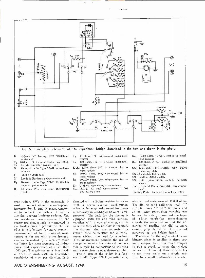
Fig. 5. Complete schematic of
B 4/ -volt "C" battery, RCA VS -030 or equivalent
C1 0.01 µf, 1 %, General Radio Type 505-L C2 0.5 µf, generator bypass type G General Radio, Type 572-B microphone
hummer J Mallory 702B jack M Leeds & Northrup galvanometer unit R1 General Radio Type 371-T, 10,000 -ohm
tapered potentiometer R2 LO ohm, 1%, wire -wound instrument
resistor
the impedance bridge described in the text and shown in the photos.
R3 10 ohms, 1%, wire -wound instrument resistor
R4 100 ohms, 1%, wire -wound instrument resistor
R5,Rs 1,000 ohms, 1%, wire -wound instru- ment resistor
R6 10,000 ohms, 1%, wire -wound instru- ment resistor
R7 100,000 ohms, 1%, wire -wound instru- ment resistor
R9 2 ohms, wire -wound strip resistor R10 IRC 61-1623 dual potentiometer, 10,000
and 50,000 ohms
R11 10,000 ohms, / watt, carbon or metal- lized resistor
R,2 100 ohms, / watt, carbon or metallized resistor
1 Centralab 1454 switch, with P1760 mounting plate
W2 Centralab 1415 switch SW3 Mallory 3226J switch SW4 H&H push-button switch, normally
closed Dial General Radio Type 703, (any gradua-
tion) Binding Posts General Radio Type 138-V
SW
S
type switch, SW1 in the schematic, is used to connect either the microphone hummer for L and C measurements, or to connect the battery through a 100 -ohm current limiting resistor, R21, for resistance measurements. In the center position, a jack is connected to the bridge circuit, permitting the use of a 45 -volt battery for more accurate measurement of high values of resis- tance; or for use with other frequen- cies as furnished by a separate audio oscillator for measurements of induc- tance and capacitance at other than 1000 cps. The galvanometer is a Leeds & Northrup unit, with an unshunted sensitivity of 4 µa per division. It is
shunted with à 2 -ohm resistor in series with a normally -closed push-button switch which may be depressed for great- er accuracy in reading as balance is ap- proached. The jack for the phones is equipped with tip and ring springs, together with a normal spring, and is so wired that when no plug is inserted, the tip and ring are connected to- gether, thus connecting the galvano- meter without the need for a switch. This arrangement permits the use of the galvanometer for external connec- tion simply by connecting to the ring and sleeve circuits of a three-way plug.
The N arm of the bridge is a Gen- eral Radio Type 371-T potentiometer,
with a total resistance of 10,000 ohms. The dial is hand calibrated with "1" at 1,000 ohms, "2" at 2,000 ohms, and so on. Any 10,000 -ohm variable can be used for this purpose, but the taper of this particular potentiometer spreads the scale out so that the ac- curacy of reading the dial is more closely proportional to the inherent 2ccuracy of the bridge itself.
The scale for the DC control is ar- bitrary, since it applies to three sep- arate ranges, and it is much simpler to plot a graph to show the various values of D and Q than it is to try to get three scales on a single con-
trol. In a small instrument it is also
AUDIO ENGINEERING AUGUST, 1948 15
AmericanRadioHistory.Com

more convenient to mark the range dial with numbers, referring to a table for the actual multiplying factor for the various ranges.
From the photo of the underside of this bridge, it will be noted that the microphone hummer is mounted on a bracket supported from the panel. The 0.5 µf capacitor C2, used to improve the waveform of the hummer, is mounted directly on the base of the hummer. To avoid acoustic transmission of the 1000 -cps tone from the hummer to the panel, it is desirable to isolate the for- mer from its bracket by live rubber grommets, using flexible wire for the connecting leads. In the case used for this instrument, the battery connections to the panel were made through the brackets supporting the panel, but this is only a constructional feature which would be of interest if the same type of case were available. In general, it would be much simpler to provide a three -wire cable and a plug to connect to the battery and the external gen- erator jack. The "J" binding post shown in the photo is used on the General Radio bridge, and accordingly was placed on this instrument, but to date no use has been found for it. It is sug- gested that it be omitted. Calibration
The main calibration problem is that
the standard is given by the formula
D=.000628 R where R is the measured resistance of the DQ potentiometer. This applies to both the CD and Cn@ positions of the selector switch, and both should be plotted.
The values of Q for the Ln@ position of the selector switch are identical with those of D for the CD@ position. Thus the one curve suffices for both CD@ and Lixe positions. For the L@ position, the value for Q is given by the formula
16,000
R
so a third curve is necessary for this position of the switch.
For this type of bridge, satisfactory values for the two sections of the DQ potentiometer would be 5,000 and 50,000 ohms, respectively. However, while even this is a compromise, no such dual po- tentiometer is regularly listed by any manufacturer. The nearest is the IRC 61-1623, which consists of 10,000 and 50,000 -ohm units. To limit the maxi- mum value of the 10,000 -ohm section to 5,000 ohms, it is shunted by a 10,000 - ohm fixed resistor, which should be in place when the resistance measurement is made.
[Continued on page 35]
Fig. 6. Actual circuits in use for the five positions of the selector switch.
of the N dial. To do this accurately re- quires the use of a resistance bridge which is of itself accurate, for it is upon this calibration that the over-all accuracy of the completed bridge de- pends. The calibration of this dial may be done after the construction is fin- ished. Place the selector switch in the R position, insert an open plug into the phone jack, and disconnect the bat- tery. The dial may then be calibrated by means of the other bridge, and the dial marked suitably. In this particular instrument the dial plate was turned over and calibration han 1 engraved, al- though a simple paper scale would suf- fice. After the N dial is calibrated, the data for the DQ dial may be obtained. using the instrument itself for the measurements. Reconnect the battery, remove the plug from the phone jack. and connect the high R binding post to the undergrounded terminal of one of the DQ potentiometers. Check the resis- tance value at each calibrated point on the scale, making a chart of the values. Then do the same with the other section of the dual potentiometer.
Having these values, it is then desir- able to make a series of curves such as those shown in the cover of the case. The value for D, based on the use of a 1000 -cps microphone hummer for the n -c source and a 0.01-µf capacitor for
16 AUDIO ENGINEERING AUGUST, 1948
AmericanRadioHistory.Com

eoe
ec#
pube Phonograph Pickup H. F. OLSON* and J. PRESTON*
,erformance characteristics of a new
m- st- as - for ing
sect in- m- nd
t a ped, that
to con- pur-
n elec- in which
the anode of .t the variations
eam correspond to rn the record.
:ironic Transducers ,Mode type of mechano-elec-
transducer, a voltage is de- ed by the motion of the anode.
ne mechano-electronic transducer pos- sesses the following fundamental ad- vantages; namely, the vibrating ele- ment can be made very small with a
correspondingly low mechanical im- pedance because the electrical power output is not derived from the actuat- ing force but from the power supply, there is no reaction of the electrical system into the vibrating system and the electrical impedance appears as a resistance and therefore does not vary with frequency.
The question arises as to the reason why a mechano-electronic transducer has not been developed. The funda- mental problem is the transfer of con- trolled vibrations through a vacuum - tight shell. There must be a vacuum on the inside of the shell and ambient air pressure on the outside. The dif- ferential in pressure is 15 pounds per square inch. One specific problem is to design a vacuum -tight link that can be actuated by force of less than a
millionth of a pound and still with- stand 15 pounds per square inch static pressure.
During the past few years the pro -
*RCA Laboratories, Princeton, N. 1.
gress that has been made in the development of mechanical and acousti- cal vibrating systems is primarily attributed to fundamental experimen- tal and theoretical investigations that have been made in these fields. As a
result of this work, it appeared possible to develop a link of the type outlined above. The progress in the develop- ment of all types of metal electron tubes, metal -to -glass seals, and minia- ture tubes are other factors which make the mechano-electronic transducer a
possibility. The essential elements of a diode
mechano-electronic transducer are shown in Fig. 1. The movable elec-
Fig. P. The elements of a diode mechano-electronic transducer.
trode passes through a thin diaphragm in the envelope of the tube which per- mits movement of the anode with re- spect to the cathode. In the diode mechano-electronic transducer, a varia- tion in the current or voltage output is obtained by varying the distance be-
tween the anode and the cathode by moving the anode rod.
Under normal operation of the diode mechano-electronic transducer, the plate potential and the spacing may be
considered to be fixed with the plate
voltage and the deflection varying about these fixed values. For these conditions the plate current in a diode type mechano-electronic transducer may be expressed as
type of pickup
30
.O
ao x u
IA
\\\\NNN.%%%%«..*
,.- -. MRNGE
IN A PICKUP
6. D 03 -.Ol á .01 .G D) DEFLECTION IN RADIANS
Fig. 2. Experimentally determined cur-
rent deflection characteristic of a
diode mechano-electronic transducer.
The coefficients are a function of the operating point Eop, X0.
A typical experimental current de-
flection characteristic for a diode with constant plate voltage is shown in Fig. 2. Unlike the conventional vacuum tube, in which the operation extends over the major portion of the tolerable operating range, the mechano-electron- ic transducer operates over a small portion of the tolerable operating range when employed in phonograph pickups and microphones. The maximum de-
flection, in actual use in a phonograph pickup or microphone, is about .07
radian. For this condition the higher order components in Eq. (1) are neg- ligible and the plate current for a
constant plate potential may be ex-
pressed by
i= io+ao,x (2) The alternating plate current may be
expressed by
i*e:aaxae (3) It can be shown that a further reduc- tion in higher order components occurs
i=f {Ero+e,Xa+x aNxleTx" =f (EPo,4+o,oe+ao,x+o2Oe2+aexta02x2+...,
where 1 bm+^ f (Evo, Xo)
o^^ m: n:
Ep=plate potential, X=spacing between the anode and cathode, e=voltage variation from Eºo, and x=deflection variation from Xo.
6m EP b^ X (i)
when the plate load is an electrical resistance.
AUDIO ENGINEERING AUGUST, 1948 17
AmericanRadioHistory.Com

Construction of Mechono-Electronic Transducers
The diode type of electronic trans- ducer employing a small metal shell one -quarter of an inch in diameter and one inch in length was developed by G. M. Rose of the Tube Department of the RCA Victor Division. A sectional view of the mechano-electronic trans- ducer is shown in Fig. 3. The cathode
DIAPFRAGM
Z ANODE ROD
% N , /.
,,,aa,
CATHODE LEAD
GLASS HEADER
C
Fig. 3. Sectional view of a diode mechano-electronic transducer.
lead and the two heater leads are brought out through a glass seal at one end. At the other end a flexible metal diaphragm permits transferring extern- al motion to a movable electrode with- in the tube. The anode rod is made conical in shape. The use of a conical anode rod instead of a cylindrical rod reduces the effective mass by a factor of 166 to 1. The ratio of effective masses of cylindrical and conical bars is so tremendous that the use of a tapered bar in a mechano-electronic transducer is almost imperative, par- ticularly where a low mechanical im- pedance is desirable, as for example, in a phonograph pickup. Electron Tube Phonograph Pickup
A phonograph pickup is an electro- mechanical transducer actuated by a phonograph record and delivering ener- gy to an electrical system, the electri- cal current having frequency compon- ents corresponding to those of the wave in the record.
An electronic phonograph pickup em- ploying the mechano-electronic trans- ducer is depicted in the schematic view of Fig. 4. The mechanical network of the vibrating system is also shown in Fig. 4.
The response frequency characteristic may be determined from the mechani- cal network of Fig. 4. The amplitude of the mass m2 is given by
XS =
where
fM ZM2 ZM4
co A
u.) = 211'f, f = frequency
ZM1 - JWm1
(4)
mi=mass of the stylus and the stylus arm, rant=mechanieal resistance of the stylus arm, CM1=compliance of the stylus arm, m2=mass of the internal part of the bar, rM2_=tnechanical resistance of the internal
part of the bar, CM2=compliance of the internal part of the
bar, m3=mass of the diaphragm, rM3=mechanical resistance of the diaphragm, CM3=compliance of the diaphragm, m4=mass of the tone arm, and rM4=mechanical resistance of the pivot.
The amplitude of the tone arm is
X3 fM 43 ZM2 (44+ ZM5 )
u) (r)44+icilm4)A (5)
'l'he amplitude of the anode with re- spect to the cathode is the difference between the amplitude of the mass m2 and the mass of the tone arm as follows,
X, =- X2-X3
the force, fm, is given by
(6)
fm = ZMR ZMP X/ZMR + ZMP , (7)
where .r = velocity of the record groove, ZMR = mechanical impedance of the rec- ord, ánd ZMF = mechanical impedance of the pickup at the stylus.
Z -y SECTIONAL VIEW
MECHANICAL NETWORK
Fig. 4. Sectional view and mechanical network of an electronic phonograph pickup. In the mechanical network: Z II; the mechanical impedance of the record, mi, the mass of the stylus and the stylus arm and Csn, the mechanical resistance and compliance of the stylus arm. ma, r'u and Cma the mass, mechanical resistance, and compliance of the diaphragm. m r.'+_, and Cm-, the mass, mechanical resistance, and compliance of the anode rod. r'++, the mechanical re-
sistance at the tone arm pivot.
WIRE ee js Z[1
11/ 8 e VISCOLOID-
P VP Ì
lÒ a `
a
p1
t I I the record meat considerable part of of the record will be the record. This cont., excessive record wear, cessive noise produced by of the pickup and record.
The system shown in Fib matic and depicts the eleme. vibrating system. In actual tube pickups, the tube is moun subassembly as shown in Fig. photograph of the subassembly is in Fig. 6. A photograph of an ploded view of the elements of subassembly is shown in Fig. 7. T. stylus arm is fitted with either ,
sapphire or diamond stylus. The other end is soldered to the anode rod of the mechano-electronic transducer at the mid -point, .055 inch. One end of a steel wire is soldered to a brass plate which is fastened to the bakelite block of the subassembly while the other end is soldered at the mid -point of the stylus arm. In this way, the mid -point 11f the stylus arm is constrained in a 7-GUARD
t
ZM2- rM1+ WG ZM3= JWm3+
J M1
rM4+JWm4+rM3+ 1
JWCM3
(rM4+JWm4) rM3+ JWtCM3
t
ZM4 - rM2 + ZMS - JWm2 JWCM2
A - 2M1 ( zur + ZM3 ) ( ZM4 + ZM5 ) + ZM4 ZMS ( ZM1 + ZM2 ) + ZM2 ZM3 ( ZM4 + ZM5 )
0 BRASS PLATE
.ba . 2
Fig. 5. Meth\ mounted in
;1~9 ? º -i i+i
iI t 1
__--
- ju)m3 + 443 ,
Fig. 8. Subassembly mounted in the tone
arm.
o
18 AUDIO ENGINEERING AUGUST, 1948
AmericanRadioHistory.Com

Fig. 6 (left). Subassembly of the pickup.
Fig. 7 (right). Components of the subassembly.
vertical direction. Under these con- ditions, the vertical stiffness is supplied by the vertical compliance of the stylus arm. Since the vertical wire is slender and subject to many resonances within the audio -frequency range, it is damped with viscoloid so that the deleterious
effects of these resonances are negli- gible. This is the only damping in the system. Aside from supplying the ver- tical stiffness, the vertical wire and viscoloid do not influence the response.
The subassembly is mounted in the tone arm as shown in Fig. 8.
s
o
CO
-y o
A photograph of the long tone arm suitable for the reproduction of tran- scription records is shown in Fig. 9.
A photograph of a short tone arm suitable for the reproduction of smal- ler records (home type, 10 and 12 inch) is shown in Fig. 10.
Fig. 9 (top). Long tone arm for tran-
u.ription records.
Fig. IO (bottom). Short tone arm for smaller records (home type, IO and
12 inch).
In the case of a frequency record used for obtaining response -frequency characteristics of pickups, the general procedure is to cut the record so that the amplitude is constant below 500- 800 cycles and the velocity constant above this transfer frequency region.
8 ú -IS >
2d
2 530 bD 1000PER
IN CYCLES PER SECOND Is000
-.J
The velocity response -frequency char- acteristic of an ideal frequency record is shown in Fig. 11.
The voltage output characteristic may be determined from the mechani- cal network, Fig. 4, the above equa- tions, and the response -frequency char- acteristic of the record of Fig. 11. In general, the mechanical impedance ZMR of the record is considered to be infinite.
The electrical circuit diagrams for use with electron tube phonograph pickups are shown in Fig. 12. The plate current should be about 2.5 mil- liamperes. The average plate potential under these conditions is about 22 volts. The plate potential may be supplied either by a high voltage source and a resistor or a low voltage source and an inductance or a transformer as shown in Fig. 12. The effective plate impedance of the electronic pickup is 5000 ohms. The heater current is 150 milliamperes. The heater potential is 6.3 volts. The output with standard records is about 0.4 volt with circuits A or C of Fig. 12. An output of 2 volts may be obtained with circuit B of Fig. 12.
A schematic diagram of the apparat- us for obtaining the response -frequen- cy characteristic of a phonograph pick- up is shown in Fig 13. An automatic recorder is synchronized with the pho- nograph turntable. If the frequency
C
Fig. I I (left). Velocity -response -frequency characteristic of an ideal frequency test record.
Fig. 12 (above). Electrical circuit diagrams for use with the electronic pickup.
AUDIO ENGINEERING AUGUST, 1948 19
AmericanRadioHistory.Com
RECORD
OSCLLATOR
PICKUP
A PLIFIER-* RECORDER
PEN 1 RESPONSE )J
CHARACTERISTIC
DRUM)
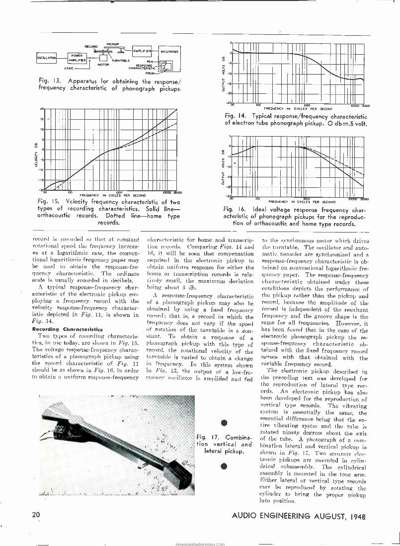
Fig. 13. Apparatus For obtaining the response/ frequency characteristic of phonograph pickups.
20
15
IO
3
° o
g
IO
-15
POWER
AMPLIFIER TURNTABLE MOTOR
II7AC
r
100 000 FREQUENCY IN CYCLES PER SECOND
Fig. IS. Velocity frequency characteristic of two types of recording characteristics. Solid line- orthacoustic records. Dotted line-home type
records.
100:10 L5003
o
m 0
f
5
J Q 10
I-
á IS
ó
O
20
253o 100 1000
FREQUENCY N CYCLES PER SECOND 10000 I
Fig. 14. Typical response/frequency characteristic of electron tube phonograph pickup. O db-.5 volt.
o
5
=II11111II1111II1 ..II1111111111111II 111111111111111I11\`1MII
1111III111III111iIlII IIIIIInIIIIIIma111111 11111 . . v...
FREQUENCY IN CYCLES PER SECOND
Fig. 16. Ideal voltage response frequency char- acteristic of phonograph pickups for the reproduc-
tion of orthacoustic and home type records.
record is recorded so that at constant rotational speed the frequency increas- es at a logarithmic rate, the conven- tional logarithmic frequency paper may be used to obtain the response -fre- quency characteristic. The ordinate scale is usually recorded in decibels.
A typical response -frequency char- acteristic of the electronic pickup em- ploying a frequency record with the velocity response -frequency character- istic depicted in Fig. 11, is shown in Fig. 14.
Recording Characteristics Two types of recording characteris-
tics, in use today, are shown in Fig. 15. The voltage response -frequency charac- teristics of a phonograph pickup using the record characteristic of Fig. 11 should be as shown in Fig. 16. in order to obtain a uniform response -frequency
characteristic for home and transcrip- tion records. Comparing Figs. 14 and 16, it will be seen that compensation required in the electronic pickup to obtain uniform response for either the home or transcription records is rela- tively small, the maximum deviation being about 5 db.
A response -frequency characteristic of a phonograph pickup may also be obtained by using a fixed frequency record; that is, a record in which the frequency does not vary if the speed of rotation of the turntable is a con- stant. To obtain a response of a phonograph pickup with this type of record, the rotational velocity of the turntable is varied to obtain a change in frequency. In this system shown in Fig. 13, the output of a low -fre- quency oscillator is amplified and fed
Fig. 17. Combina- tion vertical and
lateral pickup.
to the synchronous motor which drives the turntable. The oscillator and auto- matic recorder are synchronized and a response -frequency characteristic is ob- tained on conventional logarithmic fre- quency paper. The response -frequency characteristic obtained under these conditions depicts the performance of the pickup rather than the pickup and record, because the amplitude of the record is independent of the resultant frequency and the groove shape is the same for all frequencies. However, it has been found that in the case of the electronic phonograph pickup the re- sponse -frequency characteristic ob- tained with the fixed frequency record agrees with that obtained with the variable frequency record.
The electronic pickup described in the preceding text was developed for the reproduction of lateral type rec- ords. An electronic pickup has also been developed for the reproduction of vertical type records. The vibrating system is essentially the same, the essential difference being that the en- tire vibrating systm and the tube is rotated ninety degrees about the axis of the tube. A photograph of a com- bination lateral and vertical pickup is shown in Fig. 17. Two separate elec- tronic pickups are mounted in cylin- drical subassembly. The cylindrical assembly is mounted in the tone arm. Either lateral or vertical type records may be reproduced by rotating the cylinder to bring the proper pickup into position.
20 AUDIO ENGINEERING AUGUST, 1948
AmericanRadioHistory.Com

Speech Recording in the Classroom
IT IS THE PURPOSE of this brief note to present in general terms the argument that satisfactory record-
ing of speech for classroom purposes can not be done with inferior equip- ment, and to express the hope that when engineers and manufacturers fully understand the requirements of classroom recording they will be able to produce equipment suited to educa- tional uses. The writer is a teacher of speech, and consequently the il- lustrative problems to be described are drawn from that field, but it should be understood that the problems of in- struction in foreign languages have close similarities.
Speaking habits, like table manners, are highly personal. Most people, in- cluding students, are inclined to re- sent personal criticism. It is a tactful and persuasive teacher, indeed, who can tell a student in front of his classmates that he lisps, mumbles, whines, drawls, or talks baby -talk without arousing feelings of resentment and personal affront strong enough to strangle any desire to remedy the faulty habits.
A recording machine makes no judg- ments. It simply furnishes a tran- scription, faithful within its limita- tions, of the sounds which the student produced. The student must choose either to believe what he hears or to deny that the record is a faithful transcription of his speech. For fifty years, speech teachers have been wait- ing for a practical classroom recording (and reproducing) machine that doesn't lisp so badly itself that it is useless in a speech -improvement class for stud- ents who lisp.
Even the most primitive instantan- eous recording machines gave adequate reproduction of some of the important aspects of speech, and serious students and teachers of speech and languages were using them as early as the turn of the century. Classroom recording has been discussed in the professional journals of speech education for many years.
In a typical article,1 published nearly thirty-five years ago, a teacher of pub -
Associate Professor of Speech, Brooklyn College Brooklyn 10, New York.
WILLIAM J. TEMPLE*
Recording equipment require- ments for teaching speech in
school classrooms.
lic speaking says, "I have found the phonograph so useful in my own classes that I mean to make it a permanent part of my classroom equipment," al- though he admits with seeming reluct- ance, "that while force, pitch and time are recorded with absolute precision, there often seems to be a failure in recording quality." Both his enthus- iasm and his criticism have a familiar sound, even in 1948.
For several reasons, the enthusiasm for recording as a teaching aid which most such articles express has not led to universal adoption and systematic daily use of the available machines in all speech and language classrooms. (A notable exception to this statement is in the record of the armed services during the late war. In the military classrooms for instruction in languages and communications skills, some kind of recording device was considered in- dispensable.)
One of the reasons has been the cost of recording equipment and the never- ending expense of blank records. But a more important reason is that the quality of classroom recordings, made by amateur operators with the equip- ment available to them, has too often been disappointing after the novelty has worn off. The appearance of a
recording machine in the classroom stimulates students and teachers at first, but a critical attitude replaces the first enthusiasm as soon as recording becomes a familiar routine. Magnetic recording devices present advantages over other types in respect to both these objections. The magnetic re- cording material can be used over and over again, and the fidelity of magnetic recordings does not depend nearly so
much on the operator's skill, since the
'Newcomb, Charles M., The Phonograph as an Aid to Classroom Work. The Public Speaking Review, Vol. III., No. 7, March 1914.
AUDIO ENGINEERING AUGUST, 1948
operator is not required to make any critical mechanical adjustments, such as those for stylus angle and depth of cut.
Fidelity The fidelity required in the classroom
recording of speech depends on the objectives of the instruction. It is well known that mere intelligibility of speech survives an astonishing amount of mutilation and distortion. The pitch patterns of sentences, the rate and rhythm of speech, and the stress and pronunciation of words are suffi-
ciently well reproduced by even an old- fashioned acoustic dictating machine to enable a listener to recognize the speaking mannerisms of friends and acquaintances, or familiar public speak- ers and radio personalities. If it were possible for the teacher and students to limit their instructional objectives to such matters as these, almost any old recording machine would suffice.
[Continued on page 33]
Remounted Brush Soundmirror, Brook- lyn College Department of Speech.
AmericanRadioHistory.Com

Fig. I. Equalizer -suppressor amplifier as built on surplus preamplifier chassis.
Simplified Dynamic Noise Suppressor C. G. McPROUD*
A three -tube preamplifier combining low -frequency equalization and a new type of dynamic noise suppressor for use with magnetic pickups.
ONE of the most outstanding cir- cuit developments in the audio field to be publicized during the
last few years is that of the dynamic noise suppressor. While its perform- ance is a definite improvement in record reproduction over fixed filter circuits, it cannot be denied that the circuits are somewhat complicated, and considered by many to be beyond their capabilities 'for construction.
In attempting to simplify the noise suppressor problem so that the advan- tages might be enjoyed by more record users, the writer listed a variety of partially related facts and assump- tions, from which the circuit to be described was derived. 1) To reduce noise, it is desirable to employ
a low-pass filter. 2) To avoid degradation of musical quality -i.e., a reduction of high -frequency
response --the cutoff frequency should be adjustable.
3) For convenience, it is desirable to have the cutoff frequency varied automatically by the signal itself.
4) Constant -k filters usually "sound" better than filters with a sharper cutoff.
5) The qualities of a hich-quality magnetic pickup that provide a wider range of
'Managing Editor, AUDIO ENGINEERING.
signal frequencies also cause the repro- duction of a higher needle scratch level.
6) Magnetic pickups are low-level devices. and require both amplification and low - frequency equalization for use with con- ventional radio-, phonograph amplifiers.
7) Since a magnetic pickup is effectively a generator having an internal impedance which is essentially an inductance, a reasonably sharp cutoff can be obtained solely by the use of a shunt capacitor.
Having these basic premises listed, how can the problem be solved in the simplest manner? Design
The use of a magnetic pickup de- mands a low -frequency equalizer and additional amplification, so the first step in the solution is to set down such a circuit. The high -frequency cutoff may be provided by a shunt ca- pacitor, with the cutoff frequency being varied by changing its capacitance.1 Suppose, therefore, that the shunt ca- pacitance is supplied by a reactance tube. By varying its grid bias, the cutoff frequency can be changed at will. To make the variation of capa- citance automatic requires a side amp- lifier and rectifier, together with some form of manual control.
Putting these separate elements to-
gether, the equalizer -suppressor ampli- fier is now seen to consist of three sections - the equalized preamplifier, the reactance tube across the input, and a control tube consisting of an amplifier and a rectifier. From this point, then, it is possible to design a wide variety of circuits to perform all of these functions.
One such circuit is shown in the schematic of Fig. 2. Built as an acces- sory unit, it employs a series heater string, a dropping resistor, and a sele- nium rectifier and filter capacitor, thus operating the heaters from the 115 -volt a -c line to avoid overloading the fila- ment windings of the amplifier to which it is connected. Plate current is obtained from a convenient 200-300 volt point in the amplifier to which it is connected.
The equalized preamplifier consists of the two sections of V1, a 12SL7, connected in cascade, and employing a feedback circuit to provide the low - frequency boost. The voltage amplifi- cation of this two -stage amplifier is approximately 25 at 1,000 cps, with a low -frequency boost of nearly 6 db per octave below a transition frequency of
22 AUDIO ENGINEERING AUGUST, 1948
AmericanRadioHistory.Com
500 cps. This results in a fair com- promise for various types of phono- graph record characteristics, since the bass tone control on a conventional radio phonograph or amplifier should suffice to make the finer adjustments. However, if desired, C2 can be made adjustable by a separate switch, using a value of 0.005 µf for a 300 -cps turn- over, and 0.0015 µf for 800 cps turnover.
The reactance tube Vi is connected in shunt across the input terminals, isolated by a 0.1-µf capacitor C to keep d -c voltage off of the pickup. The effective capacitance of V2 is a func- tion of Co and the mu of the tube. Therefore, with a given set of operat- ing voltages on this tube, CG controls the static cutoff frequency. A value of 750 N.µf provides a cutoff that is down, 3 db at 4,000 cps with the Pickering Cartridge. This value should be in- creased to 0.001 µf when used with the General Electric variable reluct- ance pickup. Without going into the operation of a reactance tube circuit, suffice to say that an increase in the negative bias voltage applied to the control grid causes a reduction in the mu of the tube, with a consequent de- crease in the effective capacitance of the tube.
From the chart shown in the pre- viously cited references, it is noted that for a 4,000 -cps cutoff, the shunt capacitance must be of the order of 0.02 pf for the Pickering, or 0.03 ,sf
for the GE. The effective capacitance of the tube is in series with C5, so it is necessary that Cs be relatively large, as shown. Since the maximum plate voltage is applied across C5, its voltage rating must be at least 400 volts. Any
1"High Frequency Equalization for Magnetic Pickups," C. G. McProud, AUDIO ENGINEER- ING, September, 1947.
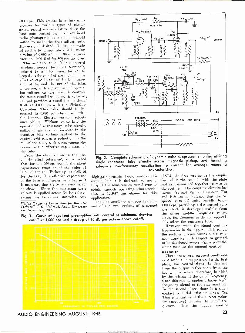
Fig. 3. Curve of equalized preamplifier with control at minimum, showing
cutoff at 4,000 cps and a droop of 15 db per octave above cutoff.
INPUT
N o
R17
0.12 MEG
C2\002 ñn 0:12 MEG
CI
o
o o N
K
f 2ó
04 .002
Vlb 1/2 12SL7
.01 ¡^
05 0.1
G61 TESEEXT
V3 R15 2SG7 r 0.1 MEG
R16 39,000
010-.- 01
ª2l
012
Z N
C9 .05 0.25
C3 05 OUTPUT
R9 66,000/1
-----^// 013 '2'-
8/ 450T V2a
I2SL7 d212SL7
. ; C6 'S00p
f N o
G
N o
Z
aö
a,
07
500 ppt
VI V2 V3 FEDERAL 40402795 820 560 /1 LINE CORD
C13T0 150
66/1 (2 M)
e+
115 V
Fig. 2. Complete schematic of dynamic noise suppressor amplifier utilizing
single reactance tube directly across magnetic pickup, and furnishing
adequate low -frequency equalization to correct for average recording characteristics.
high -gain pentode should work in this circuit, but it is desirable to use a
tube of the semi -remote cutoff type to obtain smooth operating characteris- tics. A 12SG7 was chosen for this application.
The side amplifier and rectifier con- sist of the two sections of a second
12SL7, the first serving as the ampli- fier, while the second-with the plate and grid connected together-serves as the rectifier. The coupling circuits be- tween VIb and V2a and between V2a
and V2b are so designed that the re- sponse cuts off quite rapidly below 1,000 cps, providing a d -c control volt- age which is developed mainly from the upper middle frequency range. Thus, low frequencies do not appreci- ably affect the reactance tube.
However, when the signal contains frequencies in the upper middle range, the rectifier circuit causes a d -c volt- age, negative with respect to ground, to be developed across R13, a potentio- meter used as the manual control. Operation
There are several unusual conditions existing in this suppressor. In the first place, the control signal is obtained from the output rather than from the input. The action, therefore, is aided by the raising of the cutoff frequency, since this raising applies a larger high - frequency signal to the side amplifier. In the second place, there is a small contact potential existing across R13.
This potential is of the correct polar- ity (negative) to raise the cutoff fre- quency. Thus the manual control
AUDIO ENGINEERING AUGUST, 1948 23
AmericanRadioHistory.Com

varies the cutoff frequency gradually at the same time that it increases the sensitivity of the automatic control circuits.
In operation, the equalizer -suppress- or. amplifier is connected between a magnetic pickup and the usual phono- graph input jack. If this connection is followed by the usual RC network to compensate for the high -frequency droop of crystal pickups, this network should be removed. In the schematic, C4 is used to compensate for the high - frequency boost present in most re- cordings. The value shown is suitable when the following amplifier and the speaker system is flat. For optimum results, it may be desirable to increase or decrease this capacitance.
When the control R13 is in the max- imum clockwise position, the response of the equalizer -suppressor is essenti- ally flat from normal records, with no high -frequency cutoff. This is the re- sult of (1) the contact potential across
R13, and (2) the d -c voltage developed as a result of the residual scratch. Thus, there is sufficient negative bias applied to the 12SG7 to reduce its gain, and consequently to reduce the effective capacitance shunted across the pickup. If the scratch is objection- able, the control may be rotated count- erclockwise until the best balance is obtained between musical quality and noise. In the intermediate positions of the control, it will be noted that the noise is reduced during low level passages, but that the noise appears to increase when high level passages- containing high frequencies-are re- produced. The more the control is turned counterclockwise, the greater the reduction of noise. Two actions take place simultaneously as the con- trol is turned: (1) the cutoff is low- ered gradually, and (2) the sensitivity of the automatic action is reduced. This results in a single smooth range of control from no cutoff at all to a
fixed filter with a cutoff at 4,000 cps, with a gradual increase in dynamic action over the range of the control. Construction
The experimental version of this amplifier, shown in Fig. 1, was built on a chassis available as a surplus item. However, the amplifier is not limited to such a construction, and any suitable small chassis is suggested. If there is an adequate supply of heat- er voltage, or if the unit is being con- structed as a section of a complete amplifier, 6.3 -volt tubes should be used instead of the 12 -volt types, and their supply obtained in the usual manner from the power transformer. How- ever, if the equalizer -suppressor ampli- fier is to be added to an existing radio phonograph, it is advisable to provide a separate heater supply, as shown in the schematic. The connections shown are for use with a 560 -ohm line cord and a 200 -ma selenium rectifier, fur -
[Continued on page 32]
Cdwn4ia o7P fl qornz 4fD/tÁd ENGINEERS and music lovers
alike are enthused over the recent announcement by Columbia Re-
cords, Inc. of a new library of record- ed music. This library consists of long-playing Microgroove records, al- ready available in over a hundred sep- arate discs. The advantages are nu- merous: the records are pressed on vinylite, with a consequent reduction of needle scratch; a single 12 -inch disc plays for as long as 45 minutes on the two sides, making it possible to record a complete symphony on one disc, simplifying the storage problem, and what is also of great importance, the recording characteristic is uniform throughout the entire library.
40
10
J m 0
W ri
-l0
-20
While the music lover is especially interested in the subject material of the library, engineers are more curious about the technical characteristics of the recordings themselves. We are in- debted to Dr. Peter C. Goldmark, CBS Director of Engineering Research, for this information. Characteristics
The new LP records are recorded with the characteristic shown by the solid curve of Fig. 1. This curve is similar to the NAB characteristic for lateral transcriptions, shown by the dotted line, except for the low -frequen- cy end, the level being approximately 3 db higher at 100 cps on the LP records. Therefore, these new records
z
Li
R1
Columbia
LP
i NAB
RI
20 goo ,030
FREQUENCY IN CYCLES PER SECOND loam 70000
may be reproduced quite satisfactorily by a NAB -equalized channel, if played with a 6 -gram pickup having a .001 - inch stylus. The characteristic may be equalized perfectly with simple RC networks.
The curve itself is identical with that of the network shown in the in- sert on the curve, when
R2 4R1
- 100 p sec
R = 1590 p seC
1
Stylus velocity for full modulation is stated to be 3.5 cm/sec., which is ap- proximately 4 db below standard 78 rpm phonograph records. Using the Astatic crystal cartridge developed for the new system, the output is of the order of one-half volt. Groove Shape
The groove shape is that made by a stylus having an included angle of 87°, plus or minus 3°, and a tip radius of less than .0002 in. The width of the groove is from .0027 to .003 in. As is generally known, the rotational speed is 33-1/3 rpm, and the records are made in 10- and 12 -in diameters.
Each record plays up to 22-1/2 min - [Continued on page 32]
L1
R1 + R2
L1 + L2
24 AUDIO ENGINEERING AUGUST, 1948
AmericanRadioHistory.Com

THE MICROGROOVE recording is officially announced-yet at this date of writing a hiatus exists
between that announcement and the first actual appearance of the new de-
velopment. Silence reigns-and it seems a fine time, therefore, to do a
little tall speculating as to -what Micro- groove may be expected to involve.
First, two axioms: If Microgroove recording is to survive commercially, it must spread throughout the indus- try until it is in effect co -standard with present recording. If not, then the whole experiment will either collapse or lead to a suicidal war between rival systems within the industry. That be-
ing unthinkable, let us assume that Microgroove recording is going to stick.
It is also clear-axiom two-that though other systems can give as good results as Columbia's, the die is now cast; for the Microgroove system not only works amazingly well (far better than a lot of rumor I've run into might suggest) but, more important, the vital and enormously complex processes of .commercial mass production and dis- tribution have been worked out and set in motion. A recording method that merely works is a far cry from one that is actually adapted for mass production. By virtue of this alone, Columbia's system is way out in front.
So, with Microgroove a fact, let us speculate: 1) The player. At present there is only one pickup, available in one play- er, or in several lines of home combin- ation machines. The next steps to ex- pect must be the appearance of (a) complete players from other concerns, (b) Microgroove -equipped machines from most of the dozens of present phonograph manufacturers. How long will this take? 2) Separate pickups, motors. Three
*279 W. 4th St., New York 14; N. Y.
EDWARD TATNALL CANBY*
stages of development to come soon, we hope: (a) The present pickup be- comes available separately. (b) Other pickup assemblies appear, from various manufacturers, in differing types cor- responding to those obtainable for standard records. There should be ex-
citing developments here. (e) Micro- groove cartridges, arms sold separately. (The present Philco-Columbia cart- ridge is replaceable, as is its stylus.) When all these stages have been reach- ed, Microgroove playing will be sub- stantially on a plane with present recording. It is likely that dual pur- pose pickups for playing both standard and microgroove records will appear. Experimental models of this type of cartridge are already being used, with two styli mounted in this same cart- ridge.
As to motors, we can expect cheap and satisfactory adaptations of the present low-priced phono motors, in two types, (a) single speed, long-play- ing only, as in the present Philco player, and (b) two -speed motors. Most will be of the smallest and lightest types, with S- or 10 -inch tables. Judg- ing from performance of present mo- dels, I don't see any need for fancier equipment, even for professional pur- poses; however, inevitably some fancy small -size precision two -speeders will appear, at a good high price. Compact- ness will be a virtue. Note that the present Microgroove pickup arm is too small for use on a 16 -inch table. 3) Recording equipment. It's obvious that if Microgroove is here to stay, both "home" and professional instant- aneous recording equipment are ne- cessities, and quiek. No doubt every manufacturer is hot on the trail now,
exploring possibilities. No doubt too, the basic idea of recording at such - and -such a groove size and pitch and speed is free for all concerned. Wheth- er Columbia's particular equipment and method gets around depends on their licensing arrangements, but if not, then alternative equipment can surely be developed to accord with the basic standards as set up by Columbia.
Note well that instantaneous type Microgroove recording is likely to make its own minor revolution. 22 minutes on a 12 -inch side, proportionately more if the process is applied to professional 16 -inch recording, will tend to over- throw all sorts of existing procedures. The present field of wire and tape re- cording may be re -invaded by this alternative long-playing system. Above all, the need for dual recording ma- chines is very much reduced, in most cases eliminated. This has been the biggest headache for the small user of instantaneous equipment and one of the main reasons for the success of wire and tape, where one machine is sufficient. Whether Microgroove re- cording will be easier to manage than standard recording, especially in re- spect to the bothersome problem of the chip, is not yet answered. In any case, there should be exciting develop- ments in this field-if, as we are as- suming, Microgroove takes hold.
4) Microgroove records from other manufacturers. This is the crucial matter for the future. Either the oth- ers go along with Columbia, or the Microgroove is done for. At the mo- ment of writing there is an ominous silence. Without any doubt, no matter how superior the new process may be, other manufacturers will force it out if they can. The big freeze is unques- tionably already on. Its success can not be measured for a good while, but
[Continued on page 36]
AUDIO ENGINEERING AUGUST, 1948 25
AmericanRadioHistory.Com
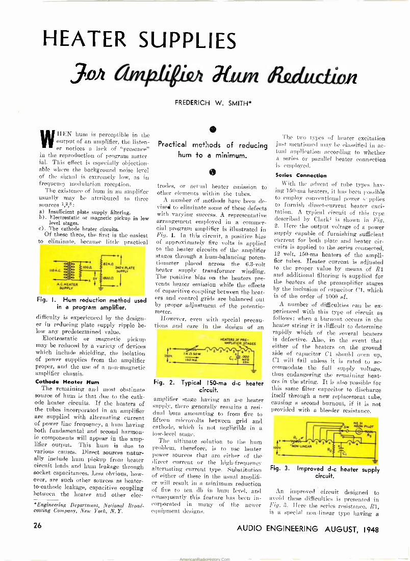
HEATER SUPPLIES
,inn &dudlion
WHEN hum is perceptible in the output of an amplifier, the listen- er notices a lack of "presence"
in the reproduction of program mater- ial. This effect is especially objection- able where the background noise level of the signal is extremely low, as in frequency modulation reception.
The existence of hum in an amplifier usually may be attributed to three sources 1,2,3:
a) Insufficient plate supply filtering. b). Electrostatic or magnetic pickup in low
level stages. c). The cathode heater circuits.
Of these three, the first is the easiest to eliminate, because little practical
IIOA.C. loon
A.C.H EATER SUPPLY
5v
82 nn 240e PLATE SUPPLY
180012 I
Fig. I. Hum reduction method used in a program amplifier.
difficulty is experienced by the design- er in reducing plate supply ripple be- low any predetermined value.
Electrostatic or magnetic pickup may be reduced by a variety of devices which include shielding, the isolation of power supplies from the amplifier proper, and the use of a non-magnetic amplifier chassis. Cathode Heater Hum
The remaining and most obstinate source of hum is that due to the cath- ode heater circuits. If the heaters of the tubes incorporated in an amplifier are supplied with alternating current of power line frequency, a hum having both fundamental and second harmon- ic components will appear in the amp- lifier output. This hum is due to various causes. Direct sources natur- ally include hum pickup from heater circuit leads and hum leakage through socket capacitances. Less obvious, how- ever, are such other sources as heater - to -cathode leakage, capacitive coupling between the heater and other elec-
'Engineering Department, National Broad- casting Company, New York, N. Y.
FREDERICH W. SMITH*
0 Practical met'ìods of reducing
hum to a minimum.
to
trodes, or actual heater emission to other elements within the tubes.
A number of methods have been de- vised to eliminate some of these defects with varying success. A representative arrangement employed in a commer- cial program amplifier is illustrated in Fig. 1. In this circuit, a positive bias of approximately five volts is applied to the heater circuits of the amplifier stages through a hum -balancing poten- tiometer placed across the 6.3 -volt heater supply transformer winding. The positive bias on the heaters pre- vents heater emission while the effects of capacitive coupling between the heat- ers and control grids are balanced out by proper adjustment of the potentio- meter.
However, even with special precau- tions and care in the design of an
t+
250V.
T25
HEATERS JF PRE- 4MPLIFIER STAGES
I 2 3 4 5 6's" IHreSOW
000 150 MA.
Fig. 2. Typical 150 -ma d -c heater circuit.
amplifier stage having an a -c heater supply, there generally remains a resi- dual hum amounting to from five to fifteen microvolts between grid and cathode, which is not negligible in a low-level stage.
The ultimate solution to the hum problem, therefore, is to use heater power sources that are either of the direct current or the high -frequency alternating current type. Substitution of either of these in the usual amplifi- er will result in a minimum reduction of five to ten db in hum level, and consequently this feature has been in- corporated in many of the newer equipment designs.
The two types of heater excitation just mentioned may be classified in ac- tual application according to whether a series or parallel heater connection is employed.
Series Connection With the advent of tube types hav-
ing 150 -ma heaters, it has been possible to employ conventional power s'applies to furnish direct -current heater exci- tation. A typical circuit of this type described by Clark4 is shown in Fig. 2. Here the output voltage of a power supply capable of furnishing sufficient current for both plate and heater cir- cuits is applied to the series connected, 12 volt, 150 -ma heaters of the ampli- fier tubes. Heater current is adjusted to the proper value by means of RI and additional filtering is supplied for the heaters of the preamplifier stages by the inclusion of capacitor Cl, which is of the order of 1000 gif.
A number of difficulties can be ex- perienced with this type of circuit as follows: when a burnout occurs in the heater string it is difficult to determine rapidly which of the several heaters is defective. Also, in the event that either of the heaters on the ground side of capacitor Cl should oren up, Cl will fail unless it is rated to ac- commodate the full supply voltage, thus endangering the remaining heat- ers in the string. It is also possible for this same filter capacitor to discharge itself through a new replacement tube, causing a second burnout, if it is not provided with a bleeder resistance.
}+ 1ooV.
Fig. 3. Improved d -c heater supply circuit.
An improved circuit designed to avoid these difficulties is presented in Fig. 3. Here the series resistance, R1, is a special non-linear type having a
26 AUDIO ENGINEERING AUGUST, 1948
AmericanRadioHistory.Com

negative temperature coefficient such that initial current surges during the warmup period are eliminated. Non- linear resistors designed for this appli- cation are obtainable either from the Keystone Carbon Co. (Type 701) or the Carborundum Corp. (Type F). A typical unit suitable for this purpose has a resistance of approximately 1400
ohms at room temperature and 200
ohms at its normal operating temper- ature of about 300° F5. The filter capacitor for the preamplifier stages, Cl, is rated to accommodate the full supply voltage and is furnished a dis- charge path through R2. Finally, a
simple voltmeter circuit consisting of a neon pilot lamp in series with a
current -limiting resistor, R3, has been included to facilitate rapid checking of heater circuit operation. Should an "open" occur, the lamp will give no indication when switched to the ground side of the defective tube and will indicate the full supply voltage on the other.
Parallel Connection The excitation of parallel -connected
heater circuits naturally poses a prob- lem in low voltage, high -current, pow- er supply design. The heater current requirements of even a' modest ampli- fier may be from 3 to 5 amperes, and only a rectifier of the selenium type can handle such a load efficiently. A suitable circuit employed by the auth- or to eliminate hum in a recording amplifier is shown in Fig. 4. The out -
SELENIUM l BRIDGE RECTIFIER
.17v Ati
wog MFD. 12 V.
Fig. 4. Hum -free heater supply for parallel heaters.
put of a 10 volt rms filament trans- former is applied to a bridge -type se-
lenium rectifier, producing sufficient current in this case to excite all heat- ers except those of the power amplifier tubes. If the power supply and power amplifier are located on a chassis separ- ate from the lower level stages, it is advisable not to employ a common ground return for both the heater and signal circuits, because any remaining hum component in the heater current will introduce a hum voltage in series with the signal which appears at the input of the power amplifier stage. H -F Heater Supply
Because of space requirements, the type of supply just discussed may not be very convenient to install in exist- ing equipment. A much neater solu-
tion to the problem of equipment modification for hum reduction may be found in the high -frequency alter- nating current type of heater supply. Such a supply may be compactly in- stalled in a chassis space of 2" by 2"
and requires but 40 ma of plate cur- rent and .45 amperes of heater current.
The circuit itself, as illustrated in Fig. 5, is based on the high -frequency
rbV. 1
3oT060 KC/SEC.
.C1
MFD.
.01MF
CI
WIRE OR TAPE RECORDER
ERASE AND BIAS OSCILLATOR
COI L
OUTPUT TRANS-
FORMER SECONDARY
OPEN
Fig. 5. High -frequency power supply for heater excitation.
oscillator circuits currently employed in magnetic tape or wire recorders to supply supersonic bias and erase cur- rent. Such a supply will furnish up to two amperes at six volts, depending on the plate voltage applied to the os- cillator, and generally operates at a
frequency of from 30 to 40 kc/sec. Best results will be obtained if Cl,
the oscillator tank capacitor, is of the mica variety, and it should be empha- sized that the cathode bypass, C2, must not be omitted, since the resulting de- generation will make the oscillator difficult to start and cause its regula- tion to be poor. The waveform pro- duced by this type of circuit tends to be rather impure, and some difficulties with harmonic radiation may be ex-
perienced where such a stage is install- ed near or on a radio receiver or video amplifier chassis.
Regulated Supplies
In a number of specialized applica- tions, not only is it necessary to em- ploy d -c heater supplies, but in addi- tion, all heater voltages must be closely regulated. Such instances arise in the design of the direct -coupled amplifiers associated with certain types of elec- troencephalographs, spectrophotometers, and apparatus for nerve potential studies.
In these cases, regulation of heater potentials serves to eliminate cathode drift resulting from the variation of electron emission velocities with ca- thode temperature. The necessity for regulation in these applications can be
appreciated from the fact that for a
typical tube type, the heater voltage must be held constant within 1% if an effective voltage fluctuation of 10
millivolts in the cathode circuit is to be avoided.6
The heater circuits employed may again be either series or parallel, de- pending upon the type of regulated source which is available.
For the series arrangement, the con- ventional voltage regulated power sup- ply which has been fully discussed elsewhere7 may be employed. In this type of supply, a single 6AS7G1, used as the series regulating tube, will de- liver sufficient output to supply not only 150 ma. of heater current but plate currents as well. It may be noted that in certain of these units, where a highly regulated output is achieved through the use of a large loop gain, the heaters of the control amplifiers are themselves placed across the out- put of the supply.
If a parallel connection of the heat- ers is desired, a regulated supply based on the circuit illustrated in Fig. 6 may be used. Here, regulation of the rec- tifier unit is achieved by amplifying the voltage variations appearing across the load and applying them to the d -c control winding of a saturable reactor in the primary circuit in such a man- ner as to cause a compensating change in the a -c line voltage applied to the rectifier.
Fig. 6. Regulated d -c heater supply.
A six -volt power supply of this type designed by the authors, exhibited a change in output voltage of .05 volts with a change in load current from zero to 15 amperes, and negligible va- riation in output was observed for line voltages ranging from 105 to 140 volts.
References 1. F. Langford Smith, "The Radiotron
Designer's Handbook", Third Ed., Part 3, Chap. 24, Distributed by R.C.A. Victor Div., Camden, N.J.
2. F. E. Terman, "Radio Engineers' Hand- book", Sec. 5 and 8, McGraw-Hill Book Co. New York, N.Y. 1943.
3. L. B. Arguimbau, "Vacuum Tube Cir- Cuits", Chap. 3, J. Wiley and Sons, New York, 1948.
4. D. L. Clark, "A Flexible Decade Ampli- fier", Audio Engineering, Jan. 1948
5. R. P. Glover, "Surge Protection of Pilot and Heater Circuits", Electronics, August, 1947.
[Continued on page 35]
AUDIO ENGINEERING AUGUST, 1948 27
AmericanRadioHistory.Com

Photo of germanium crystal unit.
HE ANNOUNCEMENT1 of the amplifying properties of german- ium and silicon crystals offers an
extraordinary opportunity that has not occurred for years. With only a few batteries and a universal test me- ter we can make a set-up to investigate fully the characteristics of those crys- tals readily available to the public.
After working with the devices for a week or so, the writer strongly ad- vises that the first set-up be in effect for curve drawing, although usually only one point on the curve be taken. If an amplifying set-up is the first one undertaken the extreme variability of the crystals leads to very confusing re- sults, so it is necessary to build up some data and acquire the feel of the fascinating problem of how to locate an active spot or spots. Selecting the Crystal
The most generally available type is the Sylvania germanium type 1N34, with 1% inch wire leads. It is a good idea also to obtain several silicon type 1N21s or similar. The germaniums are about $1.25, and some 1N21s are needed to supply the tungsten cat - whiskers, which will hereafter be call- ed the "points", as they are longer and have more spring.
Since crystals vary in resistance with applied voltage, they should not be checked with an ohmmeter, as the resistance indicated will vary in ac- cordance with the scale used on the ohmmeter, which changes the applied voltage. You will need a one -volt source of d.c. anyway, so it is well to acquire a large dry cell and a 10 -ohm wire -wound, adjustable 10 -watt resis- tor, for test purposes. You can set the slider to give one volt, and at this stage
*Consulting Engineer, 52-12 Van Horn St., Elmhurst, L.!., N.Y. 1"Experimental Germanium Crystal Ampli- fier," by Winston Wells, AUDIO ENGINEERING, July, 1948.
Experimental Germanium
Crystal Amplifier S. YOUNG WHITE*
Constructional data on the germanium crystal amplifier.
of the experiment it is useless to have a more accurate source.
Also, a 40 -volt negative source of d.c. is necessary, which can be a tap on a power supply. The regulation should be good for a ten -mil drain, so a bleeder of at least 50 mils is needed.
An alternative source is a 22% -volt B battery with several 7Ys-volt "C" batteries added so as to give 1% -volt steps in the vicinity of 40 volts. This can be done by bucking the batteries at times.
Now check the crystals you have ac- quired by putting 1 volt positive to them. This positive bias current will range from 2 to 5 mils. The second
Fig. I. Method of adjusting point separation.
test is reverse current at minus 40 volts. This will often lie between 2 and 200 microamps. This is interest- ing, as these crystals have been adjust- ed for maximum rectifying action on low-level signals, and the reverse cur- rent is very low. As we put this crys- tal to work in amplification we must find spots whose reverse current runs 2 to 10 milliamperes, or else our "gm" will be too low. .This emphasizes the fact that we are dealing with a phe- nomenon entirely different from rectification of low-level signals, at least. While we are on the subject, it is obvious that the present crystals are too highly variable in all their charac- teristics to offer too much promise for a stable commercial product, as for the new requirement they have too few
active spots, too widely distributed. Since they were developed for an en- tirely different purpose, however, any future development in the body of the crystals should show marked improve- ment in amplifying action and stability. Crystal Disassembly
Tlie end caps on the 1N34 seem to be for the purpose of isolating the heat of the soldering iron from the crystal itself. They are 17/64ths inch diame- ter, and in general should be removed. One way that avoids later damage to the crystal is to hold them gently in a vise and make a longitudinal slot in both at once. They can then be peeled off like opening a sardine can, using a small pair of pliers.
You will then find that you have ex- posed two brass end pieces 0.250 inch in diameter. These are screwed into the ceramic body of the device, and the assembly locked with glyptal or some- thing similar. By chucking these in a collet in the lathe, or even a drill press chuck, they can be unscrewed in turn. The crystal will be found on the end marked "plus". At this time clean off the glyptal with solvent, using great care to remove all of it, as otherwise it will interfere with subsequent sol- dering.
Under a glass the crystal will be found to be about .060" diameter and about .040" long. Sometimes they are dead flat and lapped true on the end, but also they come quite rough and with a slanting end.
The crystal is actually mounted on a 0.073 brass rod which is given a rough taper down to the crystal diameter of 60 mils. This rod is slightly over a quarter inch long, and is a loose press fit into the large end piece. It is held in place by a small screw which can be removed with a jeweler's screw- driver with a 1/16th inch blade. Be- cause it is locked with glyptal, take that off first.
28 AUDIO ENGINEERING AUGUST, 1948
AmericanRadioHistory.Com
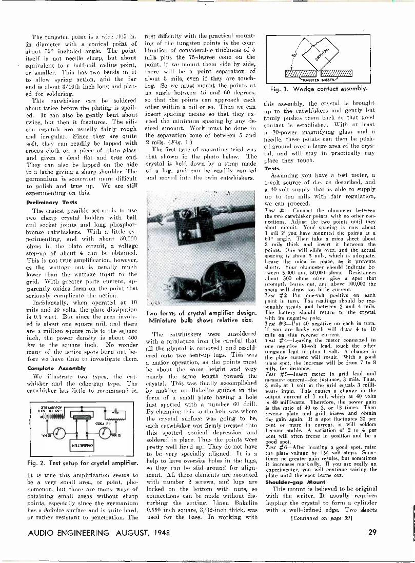
-. _ _ ee.. _ _ .. . .
The tungsten point is a wiry .005 in. in diameter with a conical point of about 75° included angle. The point itself is not needle sharp, but about equivalent to a half -mil radius point, or smaller. This has two bends in it to allow spring action, and the far end is about 3/16th inch long and plat- ed for soldering.
This catwhisker can be soldered about twice before the plating is spoil- ed. It can also be gently bent about twice, but then it fractures. The sili- con crystals are usually fairly rough and irregular. Since they are quite soft, they can readily be lapped with crocus cloth on a piece of plate glass and given a dead flat and true end. They can also be lapped on the side in a lathe giving a sharp shoulder. The germanium is somewhat more difficult to polish and true up. We are still experimenting on this.
Preliminary Tests
The easiest possible set-up is to use two cheap crystal holders with ball and socket joints and long phosphor - bronze catwhiskers. With a little ex- perimenting, and with about 50.000 ohms in the plate circuit, a voltage step-up of about 4 can be obtained. This is not true amplification, however, as the wattage out is usually much lower than the wattage input to the grid. With greater plate current, ap- parently oxides form on the point that seriously complicate the action.
Incidentally, when operated at 10
mils and 40 volts, the plate dissipation is 0.4 watt. But since the area involv- ed is about one square mil, and there are a million square mils to the square inch, the power density is about 400 kw to the square inch. No wonder many of the active spots burn out be- fore we have time to investigate them. Complete Assembly
We illustrate two types, the cat - whisker and the edge -gap type. The catwhisker has little to recommend it.
Fig. 2. Test setup for crystal amplifier.
It is true this amplification seems to be a very small area, or point, phe- nomenon, but there are many ways of obtaining small areas without sharp points, especially since the germanium has a definite surface and is quite hard, or rather resistant to penetration. The
first difficulty with the practical mount- ing of the tungsten points is the com- bination of considerable thickness of 5
mil* plus the 75 -degree cone on the point, if we mount them side by side, there will be a point separation of about 5 mils, even if they are touch- ing. So we must mount the points at an angle between 45 and 60 degrees, so that the points can approach each other within a mil or so. Then we can insert spacing means so that they ex- ceed the minimum spacing by any de- sired amount. Work must be done in the separation zone of between 5 and 2 mils. (Fig. 1.)
The first type of mounting tried was that shown in the photo below. The crystal is held down by a strap made of a lug, and can be readily rotated and moved into the twin catwhiskers.
Two forms of crystal amplifier design. Miniature bulb shows relative size.
The catwhiskers were unsoldered with a miniature iron (be careful that all the glyptal is removed) and resold- ered onto two bent -up lugs. This was a major operation, as the points must be about the same height and very nearly the same length toward the crystal. This was finally accomplished by making up Bakelite guides in the form of a small plate having a hole just spotted with a number 60 drill. By clamping this so the hole was where the crystal surface was going to be, each catwhisker was firmly pressed into this spotted conical depression and soldered in place. Thus the points were pretty well lined up. They do not have to be very specially aligned. It is a help to have oversize holes in the lugs, so they can be slid around for align- ment. All three elements are mounted with number 2 screws, and lugs are locked on the bottom with nuts, so connections can be made without dis- turbing the setting. Linen Bakelite 0.550 inch square, 3/32 -inch thick, was used for the base. In working with
/ 4e
A. V/ TUNGSTEN SHEET
Fig. 3. Wedge contact assembly.
this assembly, the crystal is brought up to the catwhiskers and gently but firmly pushes them back so that good contact is established. With at least a 20 -power magnifying glass and a
needle, these points can then be push- e 1 around over a large area of the crys- tal, and will stay in practically any place they touch. Tests
Assuming you have a test meter, a 1 -volt source of d.c. as described, and a 44) -volt supply that is able to supply up to ten mils with fair regulation, we can proceed. Test #1-Connect the ohmmeter between the two catwhisker points, with no other con- nections. Adjust the two points until they short circuit. Your spacing is now about 1 mil if you have mounted the points at a 60° angle. Then take a mica sheet about 2 mils thick and insert it between the points. One will slide over, and the actual spacing is about 3 mils, which is adequate. Leave the mica in place, as it prevents shorts. Your ohmmeter should indicate be- tween 5,000 and 50,000 ohms. Resistances about 500 ohms often give a spot that promptly burns out, and above 100,000 the spots will draw too little current. Test #2-Put one -volt positive on each point in turn. The readings should be rea- sonably steady and between 2 and 4 mils. The battery should return to the crystal with its negative pole. Test #3-Put 40 negative on each in turn. If you are lucky each will draw 4 to 10 mils on this reverse current. Test #4-Leaving the meter connected in one negative 40 -volt lead, touch the other tungsten lead to plus 1 volt. A change in the plate current will result. With a good plate spot, the increase will be from 7 to 8 mils, for instance. Test #5-Insert meter in grid lead and measure current-for instance, 3 mils. Thus, 3 mils at 1 volt in the grid equals 3 milli - watts input. This causes a change in the output current of 1 mil, which at 40 volts is 40 milliwatts. Therefore, the power gain is the ratio of 40 to 3, or 13 times. Then reverse plate and grid biases and obtain the gain again. If a spot fluctuates 20 per cent or more in current, it will seldom become stable. A variation of 2 to 4 per cent will often freeze in position and be a good spot. Test #6-After locating a good spot, raise the plate voltage by 1/ volt steps. Some- times no greater gain results, but sometimes it increases markedly. 1f you are really an experimenter, you will continue raising the plate until the spot burns out. Shoulder -gap Mount
This mount is believed to be original with the writer. It usually requires lapping the crystal to form a cylinder with a well-defined edge. Two sheets
[Continued on page 39]
AUDIO ENGINEERING AUGUST, 1948 29
AmericanRadioHistory.Com

NEW PRODUCTS RANGERTONE RECORDER
MR -3 Rangertone Magnetic Tape Re- corder. Self-contained unit with recording, playback, erase and power supplies all self- contained. 30" or 18" per second tape speed. At 30" speed, frequency response 30 to 12,000 cycles plus or minus 2 db. Signal to noise, 57 db. Minus 10 dbm input, 600 ohms,
125 ohms; minus 10 db output, 600 ohms, 125 ohms. Monitor switch connects volt meter across input, output, bias or erase voltages. Heigth 36", Depth 26". High speed rewind controls provided which work smooth- ly in either direction to expedite editing. A tape indicator gives minutes of playing time. Recording head is readily adjustable as to vertical alignment. The machine operates throughout by push button control setting up relays. All relays are in a plug-in chassis which may be readily removed for servicing.
This equipment represents the accumu- lated experience of these equipments in the field for the past six months, and provides a very smooth operating, rugged equipment which requires very little operational ex- perience to obtain excellent results.
For further information, address Ranger - tone, Inc., 73 Winthrop St., Newark 4, N.J. WIDE RANGE SPEAKERS
A new series of Concrrt-tv pe Wide Range Speakers has been announced by Utah Radio Products, Huntington, Indiana. These speak- ers are thoroughly tested and proved. They provide high quality sound reproduction up to 10,000 cps.
Designed and built for high-fidelity sound applications, Utah's Wide Range Series is excellent for monitoring in broadcasting sta- tions and for special laboratory uses as well as in the home. Speakers are designed for use in either AM or FM sets.
At present two sizes are being produced.
Eight and 12 inches in size, they are the SP8JW and SP12LW. They are finished in gold hammered lacquer. Immediate delivery is offered.
For further data, please write the manu- facturer.
STANCOR CATALOG The publication of a new 24 -page catalog
(140-H) has been announced by Standard Transformer Corp. Listed are over 400 Stan - cor stock items, including audio and power transformers and reactors, power packs, volt adjusters, radio transmitter kits and tele- vision components. Also included are charts on transmitting tubes, driver -modulator com- binations, and matched power supplies. Cata- log 140-H is available at no cost from Standard Transformer Corp., Dept. P, Elston Kedzie and Addison Sts., Chicago, Ill.
POCKET-SIZE SOUND LEVEL METER Utilizing subminiature tubes and new
circuit techniques, the Type 410-A Sound Level Meter manufactured by Herman Hos- mer Scott, Inc., Dept. AE, 385 Putnam Ave., Cambridge 39, Mass., . represents the first light, pocket-size instrument of its kind. De- signed by engineers responsible for the most successful of previous designs, this new instrument features improved stability and dependability, simplicity of operation, and accuracy, in addition to the obvious ad- vantages resulting. from its surprisingly small size and weight.
This sound level meter covers the range from 34 to 140 db above the standard ASA re- ference level, in- cludes all three standard ASA weighting charac- teristics to duplicate the response of the ear at various levels, has a two -speed meter, provision for using extension cable, optional types of microphones, vi- bration pickups. etc., and analyzers
C. J. LEBEL AUDIO CONSULTANT
or filters. The unit is 10%" long, 2%" in dia- meter, and weighs only slightly over two pounds including batteries.
FM -AM TUNER
Browning Laboratories, Inc. of Winchester, Mass. announces a quality fm -am Tuner, Model RJ-12A.
The separate f -m and a -m circuits which are employed throughout allow designing for
maximum performance. An rf amplifier is us- ed in both f -m and a -m sections. The audio - frequency response of the f -m section is flat from 10 to 15,000 cycles, ±1/ db. A drift - compensating network eliminates drift after a two -minute warmup period. Less than 10 microvolts is required to produce 30 db noise reduction. This is accomplished by dual limiters in the Armstrong circuit. The a -m section employs recently developed triple -tuned i -f transformers and a high fre- quency extending network so that the audio response is flat from 20 to 6600 cycles ±3 db. Sensitivity is 5 microvolts.
A connector in the rear of the chassis for phono input allows the volume control to be employed when playing records. A front panel switch selects a -m, f -m, or phono. The fm antenna input is 300 ohms balanced to ground and connected so that the entire fm antenna and feeder system also functions as the am antenna. The large 8" x 4" glass edge -lit slide rule dial is easily read.
Complete performance curves on fm and am sections are available on request from the Browning Laboratories, Inc., 750 Main St., Winchester, Mass.
PROFESSIONAL DIRECTORY
370 RIVERSIDE DRIVE NEW YORK 25. N. Y.
® V © PRODUCT DESIGN INSTRUMENTATION PSYCHO ACOUSTICS SOUND RECORDING ELECTROMED:CAL SUBMINIATURE AUDIO
Custom -Built Equipment
U. S. Recording Co. 1121 Vermont Ave., Washington 5, D. C.
District 1640
Winston Wells Designer and Consultant
Acoustical and Electronic Research
307 East 44th St. MU 4.-3487
New York 17, N. Y.
30 AUDIO ENGINEERING AUGUST, 1948
AmericanRadioHistory.Com
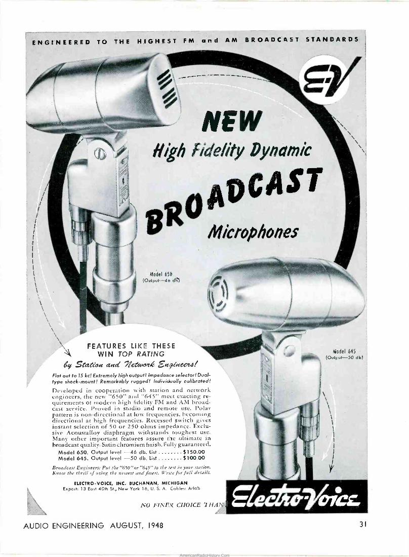
ENGINEERED TO THE HIGHEST FM and AM BROADCRST STANDARDS
\\
FEATURES LIKE THESE WIN TOP RATING
4 state c acrd eteec E94teetil Flat out to 15 kc! Extremely high output! Impedance selector! Dual- type shock -mount! Remarkably rugged! Individually calibrated!
Developed in cooperation with station and network engineers, the new "650" and "645" meet exacting re- quirements of modern high fidelity FM and AM broad- cast service. Proved in studio and remote use. Polar pattern is non -directional at low frequencies, becoming directional at high frequencies. Recessed switch gives instant selection of 50 or 250 ohms impedance. Exclu- sive Acoustalloy diaphragm withstands toughest use. Many other important features assure the ultimate in broadcast quality. Satin chromium finish. Fully guaranteed.
Model 650. Output level -46 db. List $150.00 Model 645. Output level -50 db. List $100.00
Broadcast Engineers: Put the "650"or "645" to the test in your station. Know the thrill of using the newest and finest. Wr,Je for full details.
ELECTRO -VOICE, INC. BUCHANAN, MICHIGAN Export: 13 East 40th St., New York 16, U. S. A. Cables: Arlab
NO FINER CHOICE THAN
Model 645 (Outrut-50 db)
AUDIO ENGINEERING AUGUST, 1948 3)
AmericanRadioHistory.Com

Microgroove Records [from page 241
utes, so there is little reason to employ a changer, particularly since the drop - type changers would not play the records in sequence. Dispelling doubts about the playability on equipment that was not perfectly level, the standard player was operated at a 30° tilt with no noticeable change in operation, and without any tendency for the stylus to slide out of the grooves. Since the groove pitch varies from 230 to 300
lines per inch, depending upon the length of the selection, this question has arisen in the minds of some en- gineers.
A completely revised quality check system is in operation to ensure that all LP records come up to the stand- ards set for them. When played with the recommended pickup weight and stylus radius, no degradation is discern- ible on a high-fidelity system after 250 playings. With ordinary home equipment, it is doubtful if any change could be detected after 500 or more playings. This represents considerable
Now being used by RCA - - NBC
CBS & DuMont Video Stations
Sturdily supports TV camera on tripod, also cameraman. Assembles quickly without tools. Collapses into carrying case 1' sq. by 6' long. Ideal for Studio & Lo-
cation TV work.
This Dolly made by special- ists in custom-built TV and motion picture equipment. Representatives for Houston Developing Machines; Auricon SS camera & record- ing equipment; Bardwell & McAlister lighting equipment; Moviola and Micro Engineering editing equipment. Rentals, Sales & Repairs of all types 16mm and 35mm cameras, and editing equipment.
FRANK C. ZUCKER
CAMERA EQUIPmEI1TC. 1600 BRCRCWRY MEW YORE CITY
Complete staff of trained technicians available for consultation.
use of any record, with only 250 play- ings lasting for 5 years with one play- ing per week.
While a special player has been de- veloped by Columbia Records and Philco working together, a number of other manufacturers have already an- nounced equipment to accommodate the LP records, some such instruments being combination units with 78 rpm changer facilities, and an additional pickup arm and speed change feature for the new records. Separate crystal pickup arms will be ready for users by the time the records themselves are in general distribution. Some record shops in larger cities are already stocked with the new library.
C. G. McP.
Noise Suppressor [¡rom page 24]
nishing a 150 -ma d -c supply for the three 12 -volt heaters in series. Since no signal voltage appears across the control potentiometer, it may be mounted on the front panel or the phonograph motor board in a conve- niant location. Input and output con- nections should be shielded. The unit shown in Fig. 1 was built with a switch to cut in or out the suppressor section, but this, was found to be unnecessary. The single control is adequate for all operation.
Parts Hints The voltage rating of C9 and C12
need not be over 150 volts, so hearing - aid type capacitors can be used to con- serve space. The product of R14 and C12 controls the attack time, which should be short enough to permit oper- ation without appreciable delay, yet long enough to prevent opening the filter circuits on "pops" or "ticks." As shown, the delay is only 5 milliseconds. The release time is the sum of the products of R13 -C9 and R14 -C12, 255 milliseconds in this instance. It ap- pears satisfactory in subjective tests, and since there are no accepted stand- ards for these values, such tests must be relied upon for determination of optimum values. The potentiometer 13 is linear.
Operation 'Under normal operating conditions, the voltage on the plate of V3 is ap- proximately 15 volts with no signal and with the control at the maximum counterclockwise position; 40 volts at the maximum clockwise position. In the presence of high -frequency signals with the control at the clockwise posi -
32 AUDIO ENGINEERING AUGUST, 1948
AmericanRadioHistory.Com
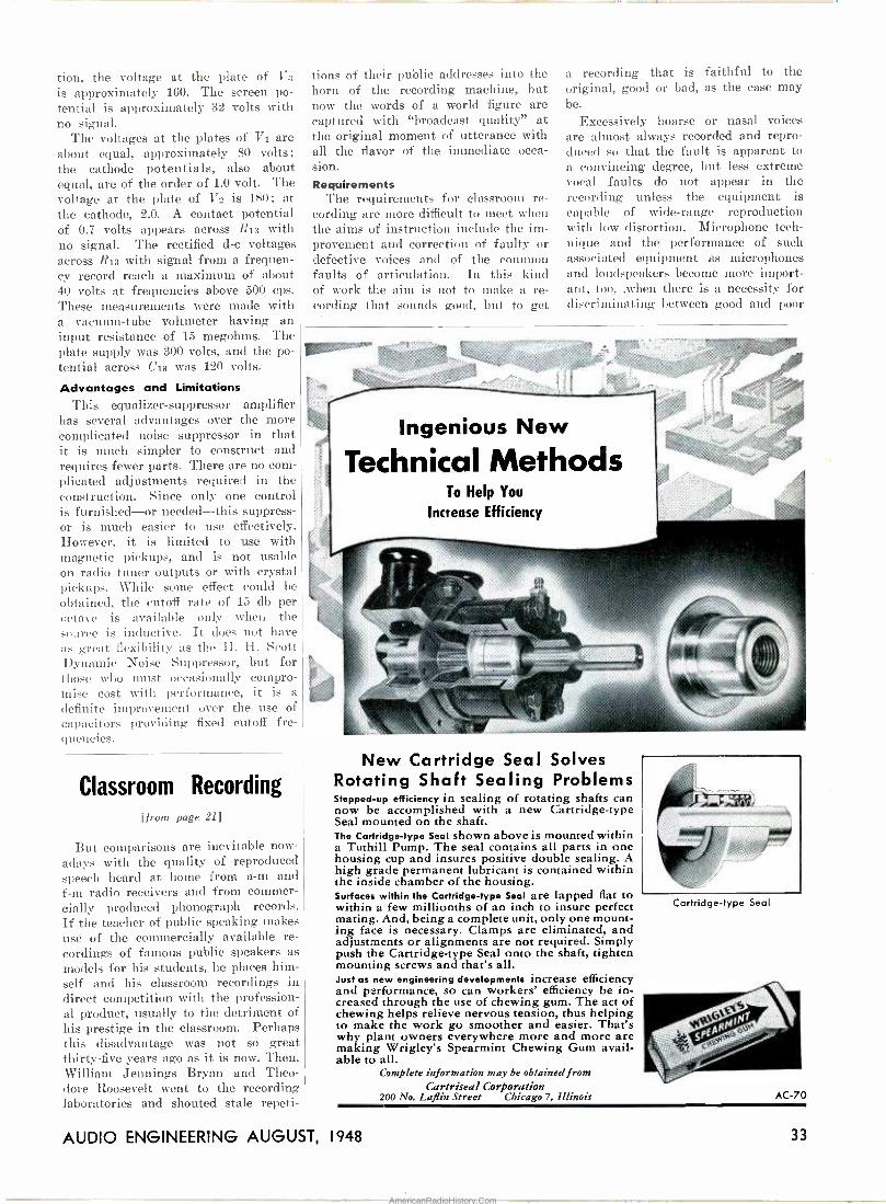
tion, the voltage at the plate of 173
is approximately 160. The screen po- tential is approximately 32 volts with no signal.
The voltages at the plates of V1 are about equal, approximately 80 volts; the cathode potentials, also about equal, are of the order of 1.0 volt. The voltage at the plate of V2 is 180; at the cathode, 2.0. A contact potential of 0.7 volts appears across R13 with no signal. The rectified d -c voltages across R13 with signal from a frequen- cy record reach a maximum of about 40 volts at frequencies above 500 cps. These measurements were made with a vacuum -tube voltmeter having an input resistance of 15 megohms. The plate supply was 300 volts, and the po- tential across C13 was 120 volts.
Advantages and Limitations This equalizer -suppressor amplifier
has several advantages over the more complicated noise suppressor in that it is much simpler to construct and requires fewer parts. There are no com- plicated adjustments required in the construction. Since only one control is furnished-or needed-this suppress- or is much easier to use effectively. However, it is limited to use with magnetic pickups, and is not usable on radio tuner outputs or with crystal pickups. While some effect could be obtained, the cutoff rate of 15 db per octave is available only when the source is inductive. It does not have as great flexibility as the H. H. Scott Dynamic Noise Suppressor, but for those who must occasionally compro- mise cost with performance, it is a
definite improvement over the use of capacitors providing fixed cutoff fre- quencies.
Classroom Recording [from page 211
But comparisons are inevitable now- adays with the quality of reproduced speech heard at home from a -m and f -m radio receivers and from commer- cially produced phonograph records. If the teacher of public speaking makes use of the commercially available re- cordings of famous public speakers as models for his students, he places him- self and his classroom recordings in direct competition with the profession- al product, usually to the detriment of his prestige in the classroom. Perhaps this disadvantage was not so great thirty-five years ago as it is now. Then, William Jennings Bryan and Theo- dore Roosevelt went to the recording laboratories and shouted stale repeti-
tions of their public addresses into the horn of the recording machine, but now the words of a world figure are captured with "broadcast quality" at the original moment of utterance with all the flavor of the immediate occa- sion. Requirements
The requirements for classroom re- cording are more difficult to meet when the aims of instruction include the im- provement and correction of faulty or defective voices and of the common faults of articulation. In this kind of work the aim is not to make a re- cording that sounds good, but to get
a recording that is faithful to the original, good or bad, as the case may be.
Excessively hoarse or nasal voices are almost always recorded and repro- duced so that the fault is apparent to a convincing degree, but less extreme vocal faults do not appear in the recording unless the equipment is capable of wide -range reproduction with low distortion. Microphone tech- nique and the performance of such associated equipment as microphones and loudspeakers become more import- ant, too, ,when there is a necessity for di-criminating between good and poor
New Cartridge Seal Solves Rotating Shaft Sealing Problems Stepped -up efficiency in sealing of rotating shafts can now be accomplished with a new Cartridge -type Seal mounted on the shaft. The Cartridge -type Seal shown above is mounted within a Tuthill Pump. The seal contains all parts in one housing cup and insures positive double sealing. A high grade permanent lubricant is contained within the inside chamber of the housing. Surfaces within the Cartridge -type Seal are lapped flat to within a few millionths of an inch to insure perfect mating. And, being a complete unit, only one mount- ing face is necessary. Clamps are eliminated, and adjustments or alignments are not required. Simply push the Cartridge -type Seal onto the shaft, tighten mounting screws and that's all. Just as new engineering developments increase efficiency and performance, so can workers' efficiency be in- creased through the use of chewing gum. The act of chewing helps relieve nervous tension, thus helping to make the work go smoother and easier. That's why plant owners everywhere more and more are making Wrigley's Spearmint Chewing Gum avail- able to all.
Complete information may be obtainedfrom Cartriseal Corporation
200 No. Laflin Street Chicago 7, Illinois
Cartridge -type Seal
AC -70
AUDIO ENGINEERING AUGUST, 1948 33
AmericanRadioHistory.Com

FOR FINER LATERAL REPRODUCTION (and other benefits explained in Bulletin No. 3)
COLUMBIA BROADCASTING SYSTEM and
AMERICAN BROADCASTING COMPANY (as well as hundreds of independent stations)
have placed
GRAY TRANSCRIPTION ARMS and EQUALIZERS on every transcription table
Ideal for the New Long Playing Micro -Groove Records The Gray Transcription Arm gives you improved quality of reproduction, greatly extended life of stylus and recordings, economical operation, as well as low first cost. Due to such features as adjustable stylus pressure, frictionless motion, self -leveling base and the accommodation of any standard cartridge, arm obsolescence is precluded. Arm, less cartridge, $35.00
The Gray # 601 4 -position Equalizer for GE Cartridge, finest performance and workmanship, ideal response curves. Matches pickup to microphone channel. Complete, $42.50
Write for our Bulletin No. 5 on Selected GE Reproducers, with Di- amond Styli for al- most unlimited life.
GRAY RESEARCH & DEVELOPMENT COMPANY, Inc. Factory: Hartford, Conn. Sales: 565 FIFTH AVENUE, NEW YORK 17
ACCLAIMED
BY EXPERTS! The H. H. Scott *Dynamic Noise
Suppressor has been acclaimed by acknowledged experts the world around. Manufacturers of the fin- est records and the finest phono- graphs have joined music critics and leading broadcasters in enthu- siastic endorsement of the perform- ance of this major advance in the reproduction of fine recorded music.
Now you can have the full beau- ty and realism from your records. For the Type 210-A Amplifier with *Dynamic Noise Suppressor pro- vides all the electronic equipment for distortionless, low -noise -level record playing in a single compact unit.
If you are a lover of fine music and want all the quality that was originally recorded on your records, you should have one of the Type 210-A Amplifiers. On sale now at leading radio parts and equipment distributors. Write for detailed specifications and list of distribut- ors in your locality.
*Licensed under U. S. and
Price: $460.00 list; $276.00 net, tax included. Immediate Delivery.
SAYS A MAKER OF FAMOUS RECORDS,: "Before this new invention all attempts at full
sound frequency reproduction were handicapped by needle scratch at one end of the scale and by rum- ble at the other end, both of which are eliminated by the Scott system while permitting the full range and quality of musical reproduction."
-Sir Ernest Fisk, Managing Director of Electric and Musical Industries, Ltd., England
(This company owns the Gramophone Company, Ltd. (His Master's Voice), the Columbia Gramophone Company, Ltd., and other companies in the phono- graph field. Trade names include His Master's Voice, Columbia, Marconiphone, Parlophone, Odeon, Pathe and Regal-Zonophone.)
y Dept. AE -8
Foreign patents pending and issued.
NOSMER SCOT T, INC. PACKAGED ENG/NEERING"
385 PUTNAM AVE. CAMBRIDGE 39, MASS.
voices. With most of the available equipment, especially in the portable and table -model forms, a good voice may be penalized and a poor voice flattered in the reproduction. Inci- dentally, there is an almost uncon- querable tendency to play back a weak and breathy voice at a level higher than that of the original performance, so that the reproduction is a strength- ened and enhanced version of the ori- ginal. If such a recording happens to give a glamor -struck bobby-soxer the idea that her hoarse little voice makes her sound like Lauren Bacall, the speech teacher might as well give up at once.
The accurate reproduction of con- sonant sounds makes the most string- ent demands on recording and repro - or the production of the over -stressed sibilant and explosive consonants such as is often heard from speakers who come from a foreign -language environ- ment require really good recording for clarity. Crandall2 showed many years ago that "s" sounds contain character- istic components as high as 8000 c.p.s. Fletcher3 points out that "s" is recog- nized only 50 per cent of the time (which is pure guessing) when the frequencies above 4000 c.p.s. are sup- pressed. Obviously, in dealing with a case of lisping, speech correctionists cannot count on much help from re- cording devices which do not record or reproduce the full frequency range of these sounds.
What is required is not merely a reproduction of the normal "s" sound that can be distinguished from an "f" or a "th", but reproduction that shows unmistakably the difference between the defective "s" and an acceptable "s". Here again correct microphone technique is required because of the directional emission of the high -fre- quency components in the fricative sounds. It is not difficult to provide a barrier to prevent talking too close. and a target for the student to face as he speaks, but such measures are not worth the trouble if the associated equipment is not capable of passing the required frequency band.
In short, the classroom teacher needs equipment equal to the best, but simpler to operate and cheaper to buy and maintain in use. All we ask is the impossible. We hope it may be just around the corner.
2Cranda 1, I. B., The Sounds of Speech. Bell System Technical Journal, Vol. IV., pp. 586-626, Oct. 1925.
3Fletcher, Harvey, Speech and Hearing. D. Van Nostrand Company, New York, 1929.
34 AUDIO ENGINEERING AUGUST, 1948
AmericanRadioHistory.Com

Heater Supplies for
Hum Reduction [from page 27]
6. S. E. Miller, "Sensitive D.C. Amplifier with A.C. Operation," Electronics, Nov- ember, 1947.
7. L. Mautner, "Voltage Regulated Power Supplies," Electrical Engineering, Sep- tember, 1947.
8. F. W. Smith and M. C. Thienpont, "Low Voltage Regulated Power Sup- plies," Communications, July, 1947.
6. V. O. Knudsen, "Architectural Acous- tics," John Wiley and Sons, Inc., New York, 1932, p. 354.
7. W. C. Sabine, "Collected Papers in Acoustics," Harvard University Press, Cambridge, Mass., 1923.
8. Acoustic Materials Association, Bulletin IX, 205 West Monroe Street, Chicago, Illinois, 1947.
9. National Bureau of Standards, Letter Circular LC870, Washington, D.C., 1947.
10. C. F. Eyring, "Reverberation Time in `Dead' Rooms," Journal of the Acous- tical Society of America, Vol. I, No. 2, p. 217, January, 1930.
11. A symposium of six papers on "Audi- tory Perspective," Electrical Engineer- ing, Vol. LIII, No. 4, p. 239, April, 1934.
12. H. Fletcher, "Transmission and Repro- duction of Speech and Music in Audi- tory Perspective," Journal of the Society of Motion Picture Engineers, Vol. 22, No. 5, p. 314, May, 1934.
13. A symposium of five papers on "Audi- tory Perspective," Journal of the So. ciety of Motion Picture Engineers, Vol. 13, No. 2, p. 89, October, 1941.
14. D. K. Gannett and I. Kerney, "The Discernibility of Changes in Program Band -Width," Bell System Technical Journal, Vol. 23, No. 1, p. 1, January, 1944.
15. Jensen Technical Monograph No. 4, "The Effective Reproduction of Speech," Jensen Radio Manufacturing Company, Chicago, Illinois, 1946, p. 8.
16. V. O. Knudsen, "The Propagation of Sound in the Atmosphere-Attenuation and Fluctuations," Journal of the Acoustical Society of America, Vol. 18, No. 1, p. 90, July, 1946.
Impedance Bridge [from page 16]
Use of Bridge In use, this bridge is simple and
rapid. For resistance measurements, the unknown resistor is connected to the R binding posts, the selector switch placed in the R position, and the lever switch thrown to DC. Then rotate the range switch to the position where the gal- vanometer swings from one extreme to the other. Adjustment of the N dial should then be made to reduce the gal- vanometer deflection to zero. As this balance is approached, the push button
is depressed to increase the galvano- meter sensitivity by removing the shunt. This will permit greater accuracy in setting the N dial.
For capacitance measurements, place the selector switch in the Cog position, connect the unknown component to the LC binding posts, and throw the lever switch to 1 kc. Plug a pair of phones into the jack, and adjust the range switch and the N dial together to ob- tain a minimum sound in the phones. As the null is approached, it will be found that a perfect balance can be obtained only at a specific position of the DQ dial. High -quality capacitors,
such as mica and oil -filled paper units, may require the use of the Ce position of the selector switch to obtain a satis- factory null point.
Inductance measurements are some- what more difficult, but only until some experience is obtained in the use of the bridge. Using the LiQ position of the selector switch in the CiQ position, at 5, rotate the range switch until some indication is obtained of the proximity of a null. This may require some ad- justment of the DQ knob in the various positions of the range switch in order to obtain any such indication. Once the correct position of the range switch is
RESISIORS EOSTArs
`'a4 e eerier., ad .Seocá Zbe to ANSWERS EVERYDAY NEEDS ECONOMICALLY
Relays are available from stock in general-purpose, industrial, and radio amateur types for continuous or inter- mittent duty.
Vitrohm wire -wound Fixed Resist- ors are available in 8 stock sizes from 5 to 200 watts. Adjustohms in 7 stock sizes from 10 to 200 watts. Plaque Resistors in 3 sizes from 20 to 125 warts. Discohms in 18 watts. Strip- ohmn in 5 stock sizes from 30 watts to 75 watts. Ring -type close control Rheostats in 4 stock sizes from 25 to I5C watts. (Plate Type Rheostats rec- ommended for larger sizes.) Wide variety of Resistance Values. AUTHORIZED DISTRIBUTORS EVERYWHERE
WARD LEONARD ELECTRIC COMPANY
Radi:) & Electronic Distributor Division 53-R West Jackson Blvd., Chicago 4. U.S.A.
SEND FOR HELPFUL CATALOGS Catalog D-30 gives complete data and listings on stock units available in Resistors, Rheostats and Radio Amateur Relays. Catalog D-20 lists In- dustr al and General -Purpose Relays. Write for them today!
11t11 tt0iAt1 -..
Basic 3R's in Current Contro/
tllglüU¡r>tltl¡t!!t'lllHlUJl1
AUDIO ENGINEERING AUGUST, 1948 35
AmericanRadioHistory.Com

quality at a
price Taking full advantage of the notably superior Altec Lansing design principles and engineer- ing know-how, the new Peerless "20-20 Line" offers input, output, interstage, and special purpose transformers within price range that meets the realities of present-day manufactur- ing and replacement markets.
The NEW Peerless
"20-20 LINE"
of Audio Transformers
Transportation prepaid anywhere in the United States, on orders totaling 100 pounds or mort. Write to Dept. V for new catalogue.
PEERLESS ELECTRICAL PRODUCTS
DIVISION
¿J.TEC
6920 McKinley Avenue Los Angeles 1, Calif. Fr & Hansen, Ltd., 301 Clay St., San Francisco 11, exclusive export agent
determined, adjust the N dial and the DQ knob simultaneously to obtain a null in which any change of either shows an increase in the signal in the phones. When a good balance is ob- tained, the passage of the potentio- meter arm over the individual turns of wire can be detected readily. After some experience in the use of the bridge, it will be found that this null determina- tion becomes relatively simple.
When constructed in accordance with Fig. 5, the values for L, C, and R are equal to the setting of the N dial mul- tiplied by the values shown by the fol- io wint table:
TABLE I
Range
MULTIPLIER
L
FOR N DIAL
O R 1 10 µh 10 µf 1 ohm 2 100 µh 100 if 10 ohms 3 1mh .1 µf 100 ohms 4 10 mh .01 µf 1,000 ohms 5 100 m .001 µf 10,000 ohms 6 1 by 100 µµf 100,000 ohms
This table should be placed on the curve sheet where it is readily visible while using the bridge. Precautions
This bridge is not directly suitable for the measurement of electrolytic cap- acitors of high value. Such measure- ments require a polarizingvoltage. How- ever, an approxisraate value may be ob- tained by subjecting the capacitor to its normal operating voltage for a few minutes before making the measure- ment, discharging it just before con- necting it to the bridge terminals. The indication is only approximate, and should not be considered as absolute. When making measurements on capa- citors of low value, it is desirable to determine the residual capacitance of the bridge itself. This may be done by obtaining a balance with no leads con- nected to the binding posts. With care- ful construction, the residual capaci- tance should be found in the vicinity of 20-30 µµf. This value should be sub- tracted from the indicated value of small capacitors up to about 500 µµf. From the bottom view of the bridge, it will be observed that most of the wiring is of bus -bar type to reduce stray capacitance as much as possible.
While any good 0.01-µl' capacitor can be used as a standard, it is suggested that the specified unit be selected, since it has a low value of D, and is accurate in capacitance value. In the author's bridge, a Sangamo mica capacitor was employed, but its capacitance was checked on another bridge of excellent accuracy. Such a substitution is satis- factory provided it is possible to obtain a capacitor of accurate value.
Record Revue
[from page 251
we can bet our bottom dollar it is there-unless Columbia manages to rig up a full-scale bandwagon to stam- pede the industry. It would be a good thing, but I doubt if it occurs. Points to speculate upon:
a) Big Companies. The larger con pallies can, if they will, very easily tool up for microgroove recording (and re- recording) and for record manufactur- ing. The adoption of the whole Mi- crogroove set up, from start to finish, is therefore more a matter of policy with the big companies than one of technology. They have the power and the means to do what they will. Can Columbia persuade them to go along with Microgroove? That's the biggest question of all. Perhaps it'll be answer- ed by the time this is in print.
b) The small companies are another matter altogether. They will need Microgroove recording equipment for their studios (if they have any), but this is a relatively minor item. These concerns will depend for their very existence on the availability of Micro- groove record pressing facilities. Few small outfits own their own pressing plants and so the searchlight turns up- on the major commercial record press- ing plants. Will Microgroove pressing be available to them either through Columbia or via some other develop- ment? Apparently it is not simply a mere substitution of a different mas- ter; there are tremendous new prob- lems of precision, of absolute control of airborne dust, etc. With details unavailable, it is still obvious that Microgroove pressing must require higher standards of manufacturing ac- curacy than may be practicable for smaller pressing concerns. What, then, will happen to the small record com- panies?
My own feeling is that Microgroove recording cannot be called a perman- ent success until the smallest compan- ies are able to make and press Micro- groove records on a budget comparable to their present one. I would hate to see Microgroove an exclusive feature of big -company operations, forcing the small companies to exist precariously if at all, on the old-style records. It will be intensely interesting to see what happens here.
5) Problem of Contractual Relation- ships. A whole slew of interesting minor problems occur to me here, and many more will pop up as time march- es on. For example. how about record
36 AUDIO ENGINEERING AUGUST, 1948
AmericanRadioHistory.Com

royalties? Roughly speaking, six
standard records equal one micro- groove, same size. Will recording ses-
sions continue as four -minute or three - minute slices, to be patched together later (as are the present Microgrooves from Columbia) or will "long playing" sessions be instituted, with new rules and regulations?
(b) This introduces a potentially major problem-the Musician's Union. Nothing so far. But-remember that ban on AM -FM duplication? What are the comparable problems involved in standard -Microgroove duplication, if any? One wonders, will Columbia and/or the union consider the present duplication irrelevant? To my specu- lative mind it would seem it is re- markably like the AM -FM duplication. The same opposing arguments apply that were used as bargaining points in the AM -FM controversy: 1) Micro- groove opens up new sales territory and therefore should be considered as
a widening of the audience, or 2) every Microgroove buyer gained is a stand- ard -record buyer lost, and thus the balance is not changed. That argu- ment was settled indirectly, as part of
a larger settlement in radio; it seems likely that this question will have to
be included in the settlement that will
eventually come between the record companies and the union.
e) Manufacturing contractual rela- tionships. Here, we on the outside can merely wonder what agreements Co- lumbia and others may have signed, what sort of licensing arrangements are available, how much the present set-up is actually protected.
It's pretty safe to guess that in the long run it will not be the technical feasibilities of Microgroove recording, but rather these relationships - per- former -composer agreements, union re- lationships, and manufacturing agree- ments-that will determine the future course of Microgroove development. 6) Obsolescence. What aspects of re- cording will be discarded because of Microgroove? What of the record al- bum, the record changer, the phono- graph needle-already well on the way out? What about untold acres of ex- pensive shelf space in a thousand re- cord stores? What about a hundred complex publicity routines, album dis- play racks and so on, that are now obsolescent? (I hate to think what has been going on at headquarters of the recently announced 200 -record auto- matic player with the traveling crane pickup!) Speculate as you will, but it is evident that on the one hand there will be a sullen pressure against Mi- crogroove recording, both from manu-
pStPt Q;1'DCIC Weed FIRST Drin
with MICROPHONES
and PHONOGRAPH PICKUPS
Employing the AMAZING PIEZOELECTRIC
CERAMIC ELEMENTS Asiatic again assumes a pioneer role . . . in making available, for the first time, the unique physical advantages of the amazing, piezoelectric ceramic element, in a microphone and phonograph pickup cartridge of advanced quality and fidelity. Unaffected by heat, moisture or dryness, they can go virtually anywhere ... pro- vide transcription quality reproduction, troublefree service, in
tropical climates, under exposure to direct sunlight, heat from klieg lichts or automotive interiors, when subjected to the many other conditions that threaten damage or impaired performance to other type instruments. These, plus other important advantages, combine to assure an immediate, enthusiastic reception for Asiatic ceramic devices.
NOW AVAILABLE Astatic has incorporated ceramic element~ in two of its most popular product designs-the convertible "Velvet Voice" Microphone and the "Quiet Talk" series pickup cartridges. Now moving through Astatic production lines, they are immediately available.
Write for prices, specifications
CORPORATION CONNEA U r, ONIO
.r...., <...a...,,.,K,,. ,...,,....,.e
1 ; 1; FIRS v! ToSiNOW
ON ALL
ATTENUATORS ND
POTENTIOMETERS
Silver Alloy Contacts)
SILVER ALLOY
1ME I 1 !UVAIrAII
INSULATION COPPER RIVET
tES, INC.e
New Silver Alloy contacts make possible improved Attenuators and Switches in smaller sizes.
1
2
4 5
Greater Creepage Distance-thus better insulation.
No silver migration.
Greater silver surface to carry current.
Lower contact resistance.
Better mechanical operation of switch.
6 Less capacity between contacts- better frequency '
characteristics.
7 Better clearance to ground.
TYPE 800 UNIT with new contacts
Manufacturers of Precision Electrical Resistance Instruments
337 CENTRAL AVE. JERSEY CITY Z N. J.
AUDIO ENGINEERING AUGUST, 1948 37
AmericanRadioHistory.Com
facturers out on a limb and from the record dealers, to whom every new de- velopment is just another headache when it first appears. And on the other hand there will be, as always, some
Houston 16mm Processors
43ir y - MODEL 11B
Prompt Delivery on New Model 11B Develops Positive, Negative & Reversal. Has refrigeration, drybox, replenishment & overflow containers; individual clutch on each roller shaft. Speeds up to 1200' per hour. New $5450 FOB factory (plus 25%, tax) Rebuilt Houston KIA Film Processors Similar to Model 11, takes positive, negative. reversal. The standard army model 3495 brought up to date. FOB West Coast S.O.S. EXTRA SPECIALS of the Month
B & H Type Unit Eye Shuttle $ 650.00 B & H Automatic 16 /35mm Hot Splicer 795.00 Auricon 16mm Single System Complete Outfit with 4 lenses; tripod; 9' mike boom; power supplies, etc. Worth 82250 1695.00 Preview Shadow Box Screens, for broad daylight 44.50 ArriSez Motorized Newsreel Camera, 4 lenses, complete 895.00 Cinephon Motorized Newsreel Camera, 4 lenses, complete 1485.00 Bodde Translucent Process Screens, sq. ft 2.40 STUDIO, CUTTING ROOM & LABORATORY AIDS-Lights, Mikes, Rooms, Dollies, Lenses, Background Process, Noviolas, etc. Send for Catalogue Sturelah 7-thousands of good buys.
S. O. S. CINEMA SUPPLY CORP. Dept. AE 602 West 52nd St., New York 19
enterprising concerns that will quickly jump on the looming bandwagon. Re- sistance to change will depend, rather picturesquely, on the personalities of those in charge of the various concerns -die-hards will die hard, progressives will move enthusiastically into the Microgroove field. In any case, much money will be spent, perforce, and many existing plants will be expen- sively junked. 7) What about the problems of dual and "triple" playing? Two speeds, two stylus sizes, now, plus the usual vari- ance of record characteristics. Will we use separate equipment or some form of combination? Tendencies are well indicated in (a) the new Philco line with standard record changer, two - speed motor, and separate Microgroove pickup. The separate arm is less in- convenient than might be expected be- cause of its small size and inconspicu- ousness. (b) The dual cartridge, already developed, with two styli in one head, which turns around to play either sized groove. Given proper out- side equalization, this has much prom- ise but such problems occur as the different out -puts due to different de- grees of lateral excursion in the two groove -types, and of course, the prob- lem of weight and lateral friction in the arm; the dual pickup will first have to satisfy the Microgroove require- ment. A three-way pickup, for both speeds, standard groove (to 16 inches), and for Microgroove, might be possible, but a compromise in the arm would be necessary since the ideal Micro- groove arm is too short for transcrip- tion use. The longer arm would intro -
RAD EN.ECTRON\C
This new silver mica capacitor is avail- able in 2 to 500 mmf. With a D.C. work- ing voltage of 500, the CM15 line has tolerances of±20% to 1%. Conveniently color -coded in accordance with Joint Army -Navy Standard Specifications JAN - C -5 for fixed mica dielectric capacitors.
Outstanding for Performance En- durance Range - the new CM15 line is a worthy addition to the prominent House of El-Menco. Write for catalog.
THE ELECTRO MOTIVE MFG. CO., INC. WILLIMANTIC, CONNECTICUT
duce more counterbalancing and iner- tia-unless we take to Balsa wood!
Such are my somewhat aimless spec- ulations at this point, written in the country, in a fine informational vacu- um. These are not so much fanciful predictions as they are possibilities on which you, are reader, consumer, manu- facturer, may carry on your own fur- ther speculations ad lib. When both Microgroove equipment and records
RECORD LIBRARY In this spot a continuing list of rec-
ords of interest will be presented. This list specifically does not suggest "the" best recordings or versions. It will draw predominantly but not entirely from postwar releases. All records are theo- retically available, directly or on order; if trouble is experienced in finding them AUDIO ENGINEERING will be glad to co- operate. Records are recommended on a composite of musical values, perfor- mance, engineering; sometimes one, sometimes another predominates but records unusually lacking in any of the three will not be considered. Number of records in album is in parenthesis.
Symphonies and concertos of Brahms, Beethoven-with an eye to the sound man's "high fidelity" equipment. Beethoven, Symphony No. 2. Pittsburgh Symph., Reiner.
Columbia MM 597 (4) Beethoven, Symphony No. 3, Boston Symphony, Koussevitsky.
RCA Victor DV 8 (5 pl.) Beethoven, Symphony No, 4. Cleveland Orch., Szell.
Columbia MM 705 (4) Beethoven, Symphony No. 6. Philadelphia Orch., Walter.
Columbia MM 631 (4) Beethoven, Symphony No. 9. Philadelphia Orch., Westminster Choir, Or- mandy.
Columbia MM 591 (8) Beethoven, Piano Concerto No. 2. Kapell; NBC Symphony, Golschmann.
RCA Victor DM 1132 (4) Beethoven, Violin Concerto. Szigeti; N. Y. Philharmonic, Walter.
Columbia MM 697 (5) Brahms, Symphony No. I. N. Y. Philharmonic, Rodzinski.
Columbia MM 621 (5) Brahms, Symphony No. 2. N. Y. Philharmonic, Rodzinski.
Columbia MM 725 (5) Brahms, Symphony No. 3. Philadelphia Orch., Ormandy.
Columbia MM 443 (5) Brahms, Symphony No. 4. Philadelphia Orch., Ormandy.
Columbia MM 567 (5) Brahms, Piano Concerto No. 1. Curzon; National (British) Symph., Jorda.
London Decca EDA 47 (6) Brahms, Piano Concerto No. 2. Serkin; Philadelphia Orch., Ormandy.
Columbia MM 603 (5) Brahms, Violin Concerto. Szigeti; Philadelphia Orchestra, Ormandy.
Columbia MM 603 (5)
38 AUDIO ENGINEERING AUGUST, 1948
AmericanRadioHistory.Com
are finally available-not at this date -I will report more factually on things as they are, rather than as they may or might be.
Recent Recordings Brahms, A German Requiem. a) Robert Shaw. RCA Victor Chorale and
Orch. Eleanor Steber, James Pease. RCA Victor DM 1236 (9)
b) Vienna Gesellschaft der Musikfreunde, Vienna Philharmonic, Karajan. Eliza- beth Schwartzkopf, Hans Hotter.
Columbia MM 755 (10) (2 vols.) After twenty years with no recording at
all of this well known work of Brahms (sung by every chorus in this country that can manage a large-scale work)-suddenly there are twins. Strange coincidence, and not the first by any means. Both recordings are excellent jobs, musically and technically. Robert Shaw's American version is the most accurate, the most controlled musically; technically it has the most clarity of detail. The Viennese version, though, full of inac- curate singing on the part of the chorus, is a more profound, 'more moving intrepre- tation and has therefore been the choice of many critics already. The Viennese record- ing is in the old European tradition, very live, mikes at a considerable distance, much detail lost in pleasant blur of sound. Many people prefer this type recording in spite of loss of detail. The two soloists in the Viennese version outrank Shaw's soloists by far. Elizabeth Schwartzkopf's one piece (number 5) is worth the whole album's price. Both these recordings do a remark- able job in compassing the huge climaxes of chorus and orchestra that must be cram- med into the dynamic range of the record- ing process. Ravel, La Valse; Debussy (orch. Ravel), Danse. Pittsburgh Symphony, Reiner.
Columbia MX 296 (2) Another major Ravel work to add to the
three reviewed last month, but not quite as successful. Musically, Reiner is a bit too cold and calculating for the white hot mu- sic in this score. It's all there, but it doesn't overheat, and it should. Technically, the recording matches Reiner's cold energy-it us ultra -clear, wide range, but on the steely, dead side, not overly good for Ravel. How- ever if you want perfection in the mere mechanics of reproducing the tremendous brass and percussion sounds in this music, try this on your wide -range equipment. Without a doubt it gets more of the actual music to your ear than any previous record- ing of the work. Stravinsky, Baiser de la Fée (The Fairy's Kiss); Divertimento. (1928) RCA Victor Orch.,, Stravinsky.
RCA Victor DM 1202 ((3) An interesting ballet piece, in which
Stravinsky incorporates a number of Tchai- kowsky themes into his own style of writ- ing. This is a good work to try as an introduction to the more recent Stravinsky music. The Tchaikowsky influence makes it more mellow, easier listening, than other works of same period. Some really enter- taining Swiss Dance music, full of yodels and the like, somewhat reminiscent of Pe- trouchka. Recording is excellent acoustical- ly, but a wider audible tonal range would have made it even better. With the com- poser conducting, this is a top-notch inter- pretation. Kabalevsky, The Comedians New York Philharmonic, Kurtz.
Columbia MX 295 (2) A companion recording (probably same'
recording session) to the two Khatchaturian
"Gayne" suite albums. Technically it is just as good as the famous First Gayne Suite, the original killer-diller among noisy wide -range show records! The first side of this features the same fancy orchestral col-
ors as the Khatchaturian. But Kabalevsky's music, 100% derivative, is milder that K's, less pretentious, more melodic, and as far as I'm concerned, a good deal better. It imitates everybody and anybody-you'll hear bits of Offenbach, Tchaikowsky, Prokofieff, Johann Strauss-almost any composer ex-
cept a modern one! For high-fidelity dem-
onstration (especially if the "Gayne" records drive you nuts) try this.
CRYSTAL AMPLIFIER [from page 29]
of tungsten .005 thick or so (not cri-
tical) are fastened to a Bakelite plate. By inserting a thickness gauge they
can be adjusted to a desired spacing, for instance, three mils, and locked up.
(Fig. 3.) The crystal is jammed into the gap
with its end held at 45 degrees. It will be found that this occurs easily, as the crystal shoulder falls naturally into the gap as it is slid over it. On some crys- tals, very considerable pressure must be used.. New spots are presented as
the crystal is rotated. Sometimes it is
well to dull the too -sharp edge of the tungsten sheets with a rubber eraser bearing an abrasive. Very small spher- ical crystals could be used with this gap. Since only the edges of the sheet are used, they could actually be re- placed with say two to four -mil round wire laying in a depressed trough in a
ceramic piece. This assembly is extremely stable and
easy to work with, and much easier to make. Unfortunately, tungsten sheet is difficult to procure, hut the wire can be obtained by breaking a straight fila- ment tungsten lamp. These filaments contain a little thorium on the sur- face that might give difficulty.
Conclusion We have here a Class C triode, with
practically all the circuit elements pres- ent. So we have power gain, low im- pedance, feedback both positive and negative, and also overloads and burn- outs. The crystals available to the experimenter seldom exceed a power gain of 25 or so, and every spot on every crystal has somewhat different characteristics. Until we have a large number of experiments we cannot well talk of impedance and gain values. Twenty points were investigated with catwhiskers. Seven were too erratic to use, about seven drew too little cur- rent, three had little gain, and three spots were good, the best giving a gain of about 30 on too high plate voltage.
his from just one crystal picked at random.
'text Is
`AS SO NO AT
RASC p,FO
On land or Sea Atlas Sound is . Wherever can count used, you faithful °n unblemished, a decade For bedn de Atlas Sound has noted for better
Sovnd Equipment .. now tra Alnico V Plus the ex - gives extra clarify, feature power, extra y, extra
long -life.
1445 39th STREET
BROOKLYN 18, N. Y.
AUDIO ENGINEERING AUGUST, 1948 39
AmericanRadioHistory.Com

SPECIAL PROBLEMS demand
SPECIAL TREATMENT
Engineering judgment is often the most important ingredient in the design and construction of apparatus for your specific needs. We specialize in - - one -of -a -kind instru- ments for electronic or electro -acoustic measure- ments -recording or reproduc- ing systems with special characteristics - subminiature audio
for Laboratory, Production Testing, Broadcast Station, Recording Studio, or Discriminating Home
Andio Instrument Company 1947 Broadway, New York 23, N. Y.
Introducing
íp, r#hler l
,p . t R Y 1 x e,.
9 '
9A-and v RACON
rr ,:r=i;
HIGH FIDELITY reproducer that sets a new standard of efficiency
in electro -acoustical conversion. Size I Irrxl I"xl5" small enough to fit info the home console. Sound output ample for studio and industrial requirements. Has 120° horizontal sound angle. Special type cone speaker for low reproduction, and cellular speaker for wide angle cov- erage and high frequency response, and many other exclusive features. Frequency range 50 to 12,000 cps.
Write for free catalog
RACON ELECTRIC CO., INC. 52 E. 19th St. N. Y. 3, N. Y.
ADVERTISING INDEX
Altec Lansing Corp. 8 Amplifier Corp. of America 40 Arnold Engineering Co. 1
Astatic Corp., The 37 Atlas Sound Corp. 39 Audio Development Co. 4 Audio Devices, Inc. Cover 2 Audio Instrument Co. 40 Camera Equipment Co. , 32 Chicago Transformer Corp. 11 Cinema Engineering Co. 8 Daven Co., The Cover 3 Electro Motive Mfg. Co.,
Inc. 38 Electro -Voice, Inc. . 31 General Radio Company 5 Gray Research & Dev. Co. 34 Hollywood Sound Institute 40 LeBel, C. J. 30 Peerless Transformer 36 Pickering & Co., Inc. ....10, 40 Presto Recording Corp 9 Professional Directory 30 Racon Electric Co., Inc. 40 Radio Corp. of America
(Broadcast Equip. Div.) Cover 4
Scott, H. H. Inc. 34 S.O.S. Cinema Supply Corp. 38 Standard Transformer Corp. 7
Tech Laboratories 37 United Transformer Corp 2 Universal Recording Corp. 40 U. S. Recording Co, 30 Vibration Systems, Inc. 40 Ward Leonard Electric Co. 35 Wells, Winston 30 Western Electric Co. 12 Wrigley, Wm. Jr. Co 33
AUDIO ENGINEERING SCHOOL A practical 9 months' course in Sound Funda- mentals, Recording, and Sound Transmission measurements ; in a laboratory containing transmission sets, oscillators, square wave generator and intermodulation analyzer, and other equipment. Complete recording studios assimilating broadcast, motion picture and commercial sound recording.
For information write H. M. Trentaine, Director
HOLLYWOOD SOUND INSTITUTE, Inc. 1040-E No. Kenmore, Hollywood 27, Calif.
FULL HOUR CONTINUOUS PLAY
WITH THIS MAGNETIC TAPE
TWIN -TRAX*
CHASSIS E,perimenter', $8950
f v NET PRICE a
CHECK THESE EXCLUSIVE FEATURES ONE HOUR continuous play on 7" reel at 71/2" per second tape speed. Attainable Frequency Response 50 to 9,000 cycles
3 db. Cuts tape cost in half. No other recorder matches this economy. ' Easy to thread. Threads directly from one reel to the other. Heavy Dufy Balanced Recording Motor prevents over- heating High traction between capstan and tape. No tape. slippage. Twin Electronic Erase Heads for complete Supersonic or DC erasure.
e Constant tape speed precision drive minimizes flutter and wow. Can be used for twin.channel 3 -dimensional stereo- phonic recording. No rewinding necessary. Plays continuously during for- ward and reverse. Unique design prevents development of eccentricities in capstan drive. One tape channel can be used for compression.expan- sion control. No belts to loosen or pulleys to slip. Unbelievably quiet operation. Automatic switch and solenoid instantaneously reverse tape travel. Minor changes in any amplifier permit recording and playback. Radio -phono and microphone inputs may be mixed or faded.
ISupplied with 72 page instruction book con- taining circuit diagrams and construction data
Send your order today for prompt delivery 0
AMPLIFIER CORP. OF AMERICA
398-4 Broadway New York 13, N. Y.
PRECISE AUDIO MEASUREMENTS
Pickering and Company, Inc., leaders in the audio field, make available to the industry their specialized facilities for audio measurements.
We are prepared to make guaranteed measurements on any type of audio equipment for manufacturers, dealers, or consumers.
PICKERING & CO. Inc. Oceanside, N. Y.
VERTICAL LATERAL REPRODUCERS RECONDITIONED
types 9-A, 9-B, D-93306, MI -4856, MI -4875-G Complete Stock of New Replacement Parts
for All Types This service is being used by leading radio stations and wired music companies from coast to coast. Factory prices prevail.
VIBRATION SYSTEMS, INC. 1040 W. Fort St. Detroit 26, Michigan
NEW VINYLITE FREQUENCY RECORD 33 1/3 & 78 RPM ; 50 to 10,000 CPS ; voice announcements; unmodulated grooves for checking rumble content. Available your local jobber or
UNIVERSAL RECORDING CORP. 20 North Wacker Drive Chicago 6. illinoi..
40 AUDIO ENGINEERING AUGUST, 1948
AmericanRadioHistory.Com

SEPTEMBER 1948
GEN r7-9AL LiE3Ri cierria histittr.e of Toch,
1[4\i v\At AmericanRadioHistory.Com
PRICES AND AUDIODISCS
Sictiormni ün Phic.f2
As of September 1st, aluminum prices are again increased. This means higher cost for the principal raw material used in the manufacture of AUDIODISCS. In fact, the cost of the aluminum base has always been the main item in the cost of production. Thus, any increase in aluminum prices is of major importance.
But beyond the cost of raw materials and labor there is a basic factor which determines the cost of manufacturing professional recording discs. This factor is the extent to which the particular process of manufacture enables the producer to turn out a large proportion of first quality discs. There are several methods of production used. None of these will give anything like a 100'Jo yield. It is, however, obvious that as the percentage of yield increases there is a resulting drop in the average cost of aluminum, lacquer and labor.
Fortunately, our patented, precision -machine process-now used for over a decade and con- tinuously improved-gives a more consistent yield of high quality discs than any method of production now used. And we have tested every other process in use.
So our position with respect to the present increase in aluminum prices is this: 1. We are not increasing prices of AUDIODISCS as of September Ist. 2. We shall make every effort to absorb this new aluminum price raise and thus continue our prices at the present level. Our calculations indicate that with some improved efficiency, now under way, and continued large volume production, we shall be successful in this hold - the -price effort.
Audiodiscs are manufactured in the U.S.A. under exclusive license from PYRAL, S.A.R.L., Paris. Audio Devices, Inc., 444 Madison Ave., N.Y. C.
EXPORT DEPT: ROCKE INTERNATIONAL, 13 EAST 40TH STREET, NEW YORK 16, N. Y.
AmericanRadioHistory.Com