AMERICAN NATIONAL STANDARD - Triodyne, Inc.triodyne.com/Stein/ansi_a_1264_1_2007.pdf · American...
31
ANSI/ASSE A1264.1-2007 ANSI/ASSE A1264.1-2007 ANSI/ASSE A1264.1-2007 Safety Requirements for Workplace Walking/Working Surfaces and Their Access; Workplace, Floor, Wall and Roof Openings; Stairs and Guardrails Systems AMERICAN SOCIETY OF SAFETY ENGINEERS AMERICAN NATIONAL STANDARD A S S E Licensed to Triodyne/John Kristelli ANSI Store order #X361558 Downloaded: 6/5/2007 3:15:58 PM ET Single user license only. Copying and networking prohibited.
Transcript of AMERICAN NATIONAL STANDARD - Triodyne, Inc.triodyne.com/Stein/ansi_a_1264_1_2007.pdf · American...

ANSI/ASSE A1264.1-2007AN
SI/A
SSE
A126
4.1-
2007
ANSI/ASSE A1264.1-2007Safety Requirements for WorkplaceWalking/WorkingSurfaces and Their Access; Workplace,Floor, Wall and Roof Openings; Stairsand Guardrails Systems
AMERICAN SOCIETY OF
SAFETY ENGINEERS
AMERICAN NATIONAL STANDARD
A S
S E
Licensed to Triodyne/John KristelliANSI Store order #X361558 Downloaded: 6/5/2007 3:15:58 PM ETSingle user license only. Copying and networking prohibited.

The information and materials contained in this publication have been developed from sources believed to be reliable. However, the American Society of Safety Engineers (ASSE) as secretariat of the ANSI accredited A1264 Committee or individual committee members accept no legal responsibility for the correctness or completeness of this material or its application to specific factual situations. By publication of this standard, ASSE or the A1264 Committee does not ensure that adherence to these recommendations will protect the safety or health of any persons, or preserve property.
Licensed to Triodyne/John KristelliANSI Store order #X361558 Downloaded: 6/5/2007 3:15:58 PM ETSingle user license only. Copying and networking prohibited.
ANSI®
ANSI A1264.1 – 2007
American National Standard
Safety Requirements for Workplace Walking/Working Surfaces and Their Access; Workplace, Floor, Wall and
Roof Openings; Stairs and Guardrails Systems
Secretariat American Society of Safety Engineers 1800 East Oakton Street Des Plaines, Illinois 60018-2187 Approved January 18, 2007 American National Standards Institute, Inc.
Licensed to Triodyne/John KristelliANSI Store order #X361558 Downloaded: 6/5/2007 3:15:58 PM ETSingle user license only. Copying and networking prohibited.
Approval of an American National Standard requires verification by ANSI that the requirements for due process, consensus, and other criteria for approval have been met by the standards developer. Consensus is established when, in the judgment of the ANSI Board of Standards Review, substantial agreement has been reached by directly and materially affected interests. Substantial agreement means much more than a simple majority, but not necessarily unanimity. Consensus requires that all views and objections be considered, and that a concerted effort be made toward their resolution. The use of American National Standards is completely voluntary; their existence does not in any respect preclude anyone, whether he/she has approved the standards or not, from manufacturing, marketing, purchasing, or using products, processes, or procedures not conforming to the standards. The American National Standards Institute does not develop standards and will in no circumstance give an interpretation of any American National Standard. Moreover, no person shall have the right or authority to issue an interpretation of an American National Standard in the name of the American National Standards Institute. Requests for interpretation should be addressed to the secretariat or sponsor whose name appears on the title page of this standard. Caution Notice: This American National Standard may be revised or withdrawn at any time. The procedures of the American National Standards Institute require that action be taken periodically to reaffirm, revise, or withdraw this standard. Purchasers of American National Standards may receive current information on all standards by calling or writing the American National Standards Institute.
Published April 1, 2007 by: American Society of Safety Engineers 1800 East Oakton Street Des Plaines, Illinois 60018-2187 (847) 699-2929 • www.asse.org Copyright ©2007 by American Society of Safety Engineers All Rights Reserved. No part of this publication may be reproduced in any form, in an electronic retrieval system or otherwise, without the prior written permission of the publisher. Printed in the United States of America
American National Standard
Licensed to Triodyne/John KristelliANSI Store order #X361558 Downloaded: 6/5/2007 3:15:58 PM ETSingle user license only. Copying and networking prohibited.
Foreword (This Foreword is not a part of American National Standard A1264.1 – 2007.)
This standard was developed by an American National Standards Committee, national in scope,
functioning under the procedures of the American National Standards Institute with the
American Society of Safety Engineers (ASSE) as Secretariat. This standard establishes minimum safety requirements for workplace floor and wall openings, stairs and railing systems.
It is intended that the procedures and performance requirements detailed herein will be adopted by every employer whose operations fall within the scope and purpose of the standard.
Neither the standards committee, nor the Secretariat, feel that this standard is perfect or in its ultimate form. It is recognized that new developments are to be expected, and that revisions of
the standard will be necessary as the art progresses and further experience is gained. It is felt,
however, that uniform requirements are very much needed and that the standard in its present
form provides for the minimum performance requirements necessary for the protection of personnel regarding workplace floor and wall openings, stairs and railing systems.
In addition to technical improvements, this revision contains two new definitions and four new illustrations to help clarify text in the standard.
Suggestions for improvements of this standard will be welcome. They should be sent to the
American Society of Safety Engineers, 1800 East Oakton Street, Des Plaines, Illinois 60018.
Licensed to Triodyne/John KristelliANSI Store order #X361558 Downloaded: 6/5/2007 3:15:58 PM ETSingle user license only. Copying and networking prohibited.

This standard was processed and approved for submittal to ANSI by American National Standards Committee A1264. Committee approval of the standard does not necessarily imply that all committee members voted for its approval. At the time it approved this standard, the A1264 Committee had the following members:
Keith Vidal, P.E., Chairperson Lawrence E. Oldendorf, P.E., Vice Chairperson Timothy R. Fisher, CSP, ARM, CPEA, Secretary Jennie Dalesandro, Administrative Technical Support Organization Represented Name of Representative American Institute of Steel Construction Tom Schlafly American Society of Safety Engineers Lawrence E. Oldendorf, P.E. Arthur J. Gallagher & Co. James D. Smith, CSP Association for Manufacturing Technology David Felinski Bayer MaterialScience, LLC Terry L. Ketchum Bay Nets Safety Systems Robert Martin Dynamic Scientific Controls J. Nigel Ellis, Ph.D., P.E., CSP, CPE ESIS Risk Control Services Steve Di Pilla International Association of Bridge, Structural, Ornamental & Reinforcing Iron Workers Frank Migliaccio Kleen-Tex Industries Leslie Schwartz William Marletta Safety Consultants William Marletta, Ph.D., CSP Muirfield Underwriters, Ltd. Robert Majeski National Association of Government Labor Officials Earl Everett National Elevator Industry, Inc. Edward A. Donoghue, CPCA Frederick J. Wilt, CIH, CSP National Fire Protection Association Ron Coté, P.E. National Ornamental and Miscellaneous Metals Association J. Todd Daniel Northrop Grumman Corporation Emory Knowles, III, CSP, CIH Railworks Corporation Jeffrey Meddin, CSP, CHCM Safety Through Engineering Mike C. Wright Roger L. Grant, Jr., P.E. St. Paul Travelers David Bondor David Underwood David Underwood, Ph.D. U.S. Department of Labor – OSHA Ginny Fitzner U.S. Postal Service John H. Bridges, III, REM, CHMM, CSHM, CPEA United Auto Workers John Rupp, Jr. John Shepard Vidal Engineering, LLC Keith Vidal, P.E. Westar Energy Inc. Patrick E. Bush, CUSA
Licensed to Triodyne/John KristelliANSI Store order #X361558 Downloaded: 6/5/2007 3:15:58 PM ETSingle user license only. Copying and networking prohibited.
Contents SECTION..................................................................................................................PAGE
1. Scope, Purpose, and Application.........................................................................8
1.1 Scope............................................................................................................8 1.2 Purpose ........................................................................................................8 1.3 Application....................................................................................................8
2. Definitions ..............................................................................................................9 3. Protection of Floor Openings and Floor Holes, Roof Openings and Roof Holes.....................................................................................................14
3.1 Stairway Floor Opening..............................................................................14 3.2 Ladderway Floor Opening..........................................................................14 3.3 Hatchway and Chute Floor Opening .........................................................14 3.4 Skylight ........................................................................................................15 3.5 Floor Opening or Hole ................................................................................15 3.6 Pit, Trap-Door, and Manhole Floor Opening ............................................16 3.7 Pit Safety Nets ............................................................................................16 3.8 Floor Opening or Hole ................................................................................17
4. Protection of Wall Openings and Wall Holes .....................................................17 4.1 Wall Opening...............................................................................................17 4.2 Chute Wall Opening ...................................................................................18 4.3 Window Wall Opening ................................................................................18 4.4 Temporary Wall Opening ...........................................................................18 4.5 Wall Hole .....................................................................................................18
5. Protection of Open-Sided Floors, Platforms, Runways, and Ramps ...............18 5.1 Open-Sided Floor and Platform.................................................................18 5.2 Runway........................................................................................................19 5.3 Hazardous Location....................................................................................19 5.4 Guardrail System ........................................................................................19 5.5 Stair Railing System ...................................................................................20 5.6 Railing System Design Requirements.......................................................20 5.7 Toeboard .....................................................................................................21 5.8 Handrail .......................................................................................................21 5.9 Clearance ....................................................................................................22 5.10 Floor Opening Cover ..................................................................................22 5.11 Skylight Screen ...........................................................................................22 5.12 Barrier for Wall Opening.............................................................................22
6. Requirements for Fixed Stairs.............................................................................22 6.1 Fixed Stairs for Access...............................................................................22 6.2 Load Criteria................................................................................................24 6.3 Clearance ....................................................................................................24 6.4 Slope............................................................................................................24 6.5 Tread Depth and Riser Height ...................................................................24 6.6 Nosing .........................................................................................................25 6.7 Slip Resistance ...........................................................................................25 6.8 Uniformity of Risers and Treads ................................................................25 6.9 Long Flight of Stairs....................................................................................25 6.10 Stair Landing ...............................................................................................25 6.11 Door and Gate Openings ...........................................................................25 6.12 Vertical Clearance ......................................................................................26 6.13 Open Risers ................................................................................................26
7. Requirements for Use of Railing Systems, Rails, and Handrails .....................26 7.1 Provision and Design .................................................................................26 7.2 Stair-Railing System/Handrail Required Use............................................26
8. References ...........................................................................................................28
Licensed to Triodyne/John KristelliANSI Store order #X361558 Downloaded: 6/5/2007 3:15:58 PM ETSingle user license only. Copying and networking prohibited.
Explanation of Standard
American National Standard A1264.1 uses a two-column format to provide both specific requirements and supporting information. The left column, designated “Standard Requirements,” is confined solely to these requirements. Where supporting photographs or sketches are required, they are designated as “figures.” The right column, designated “Explanatory Information,” contains only information that is intended to clarify the standards. This column is not a part of the standard. Operating rules (safe practices) are not included in either column, unless they are of such a nature as to be vital safety requirements, equal in weight to other requirements, or guides to assist in compliance with the standard.
Licensed to Triodyne/John KristelliANSI Store order #X361558 Downloaded: 6/5/2007 3:15:58 PM ETSingle user license only. Copying and networking prohibited.

AMERICAN NATIONAL STANDARD A1264.1 – 2007
8
AMERICAN NATIONAL STANDARD A1264.1
SAFETY REQUIREMENTS FOR WORKPLACE WALKING/WORKING SURFACES AND THEIR ACCESS; WORKPLACE, FLOOR, WALL AND
ROOF OPENINGS; STAIRS AND GUARDRAILS SYSTEMS
STANDARD REQUIREMENTS EXPLANATORY INFORMATION
(Not part of American National
Standard A1264.1)
1. SCOPE, PURPOSE, AND APPLI-
CATION
1.1 Scope. This standard sets forth
safety requirements in industrial and
workplace situations for protecting persons
in areas/places where danger exists of persons or objects falling through floor, roof
or wall openings, or from platforms,
runways, ramps, and fixed stairs, or roof edges in normal, temporary, and emergency
conditions.
1.1.1 Excluded from this standard are:
private residences; escalators; moving
walks; stairs or ramps serving floating roof
tanks; floor openings occupied by elevators, manlifts, dumbwaiters, conveyors, machin-
ery, containers; the loading and unloading
areas of truck, railroad, and marine docks; self-propelled motorized mobile equipment;
platforms; scaffolds; and construction work
areas.
E1.1.1 Recognizing that the special safety
requirements necessary for stages, orches-
tra pits, churches, school auditoriums, and
athletic assembly occupancies may not be adequately covered by other codes or
standards, this standard may provide the
minimum safety performance requirements to protect the occupants. See ANSI/ASSE
A10.18, Safety Requirements for Temporary
Floors, Holes, Wall Openings, Stairways and Other Unprotected Edges in
Construction and Demolition Operations.
1.2 Purpose. The purpose of this standard is to establish minimum safety
requirements for working and walking areas
to provide reasonable safety of persons pursuing their foreseeable duties.
1.3 Application.
1.3.1 The requirements of this standard
apply to new and existing installations and
workplace exposures to fall hazards.
E1.3.1 The requirements of this standard
can be effectively applied during alterations
of existing facilities or when major changes are made to work areas.
Licensed to Triodyne/John KristelliANSI Store order #X361558 Downloaded: 6/5/2007 3:15:58 PM ETSingle user license only. Copying and networking prohibited.

AMERICAN NATIONAL STANDARD A1264.1 – 2007
9
2. DEFINITIONS
2.1 Alternating Tread Type Stair.
Series of treads usually attached to a center
support in an alternating manner so that a
user of the stair normally does not have both feet on the same level (see Figure 2.1:A and
Figure 2.1:B).
E2.1 For more information please
review Figures 2.1:A and 2.1:B.
Figures 2.1:A and 2.1:B
2.2 Deflection, Maximum Allowable.
Deflection of whole system at design load.
2.3 Failure. Excessive or permanent
deformation or breakage.
2.4 Floor Hole/Opening. Floor hole/ opening measuring over two inches (51mm)
in any direction of a walking/working surface
which persons may trip or fall into or where objects may fall to the level below.
E2.4 Skylights located in floors or roofs are considered floor or roof hole/openings.
2.5 Gate. A swinging or portable member, which acts as a safety barrier. It is
commonly used at roof openings, floor
openings, ladder openings, and hatchways,
through which people might fall. (See Figures 2.5:A and 2.5:B.)
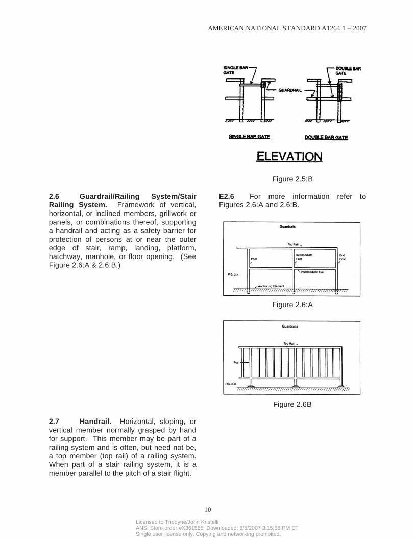
E2.5 For more information refer to Figures 2.5:A and 2.5:B.
Figure 2.5:A
Licensed to Triodyne/John KristelliANSI Store order #X361558 Downloaded: 6/5/2007 3:15:58 PM ETSingle user license only. Copying and networking prohibited.
AMERICAN NATIONAL STANDARD A1264.1 – 2007
10
Figure 2.5:B
2.6 Guardrail/Railing System/Stair Railing System. Framework of vertical,
horizontal, or inclined members, grillwork or
panels, or combinations thereof, supporting
a handrail and acting as a safety barrier for protection of persons at or near the outer
edge of stair, ramp, landing, platform,
hatchway, manhole, or floor opening. (See Figure 2.6:A & 2.6:B.)
E2.6 For more information refer to Figures 2.6:A and 2.6:B.
Figure 2.6:A
Figure 2.6B
2.7 Handrail. Horizontal, sloping, or
vertical member normally grasped by hand
for support. This member may be part of a
railing system and is often, but need not be, a top member (top rail) of a railing system.
When part of a stair railing system, it is a
member parallel to the pitch of a stair flight.
Licensed to Triodyne/John KristelliANSI Store order #X361558 Downloaded: 6/5/2007 3:15:58 PM ETSingle user license only. Copying and networking prohibited.
AMERICAN NATIONAL STANDARD A1264.1 – 2007
11
2.8 Landing. Platform between runs
of stairs.
2.9 Load Bearing Element. Com-
ponent or surface designed to support twice
the anticipated load, including dynamic effects. Safety factors shall be applied
based on the anticipated use and consistent
with engineering methodologies or other related requirements.
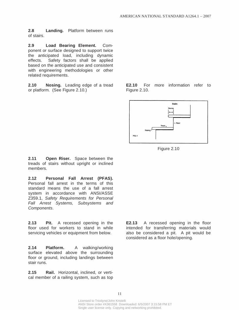
2.10 Nosing. Leading edge of a tread or platform. (See Figure 2.10.)
E2.10 For more information refer to Figure 2.10.
Figure 2.10
2.11 Open Riser. Space between the
treads of stairs without upright or inclined members.
2.12 Personal Fall Arrest (PFAS).
Personal fall arrest in the terms of this standard means the use of a fall arrest
system in accordance with ANSI/ASSE
Z359.1, Safety Requirements for Personal Fall Arrest Systems, Subsystems and
Components.
2.13 Pit. A recessed opening in the
floor used for workers to stand in while
servicing vehicles or equipment from below.
E2.13 A recessed opening in the floor
intended for transferring materials would
also be considered a pit. A pit would be considered as a floor hole/opening.
2.14 Platform. A walking/working surface elevated above the surrounding
floor or ground, including landings between
stair runs.
2.15 Rail. Horizontal, inclined, or verti-
cal member of a railing system, such as top
Licensed to Triodyne/John KristelliANSI Store order #X361558 Downloaded: 6/5/2007 3:15:58 PM ETSingle user license only. Copying and networking prohibited.
AMERICAN NATIONAL STANDARD A1264.1 – 2007
12
rail, intermediate rail, or bottom rail.
2.16 Ramp. Sloped walking surface for
access from one level to another.
E2.16 Ramps generally are any walking
surface with a slope greater than 1:20.
2.17 Riser. Vertical or inclined member or distance between the top of one tread or
platform and the adjacent tread or platform/
landing.
2.18 Roof Hole/Opening. Roof hole/
openings measuring over two inches (51mm) in any direction of walking/working
surface, which persons may trip or fall or
where objects may fall to the level below.
2.19 Runway. Elevated passageway/
walking surface, such as a catwalk or
walkway between buildings.
2.20 Shall. Denotes mandatory item.
2.21 Should. Denotes advisory item.
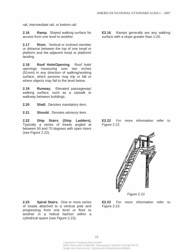
2.22 Ship Stairs (Ship Ladders).
Typically a series of treads angled at between 50 and 70 degrees with open risers
(see Figure 2.22).
E2.22 For more information refer to
Figure 2.22.
Figure 2.22
2.23 Spiral Stairs. One or more series
of treads attached to a vertical pole and progressing from one level or floor to
another in a helical fashion within a
cylindrical space (see Figure 2.23).
E2.23 For more information refer to
Figure 2.23.
Licensed to Triodyne/John KristelliANSI Store order #X361558 Downloaded: 6/5/2007 3:15:58 PM ETSingle user license only. Copying and networking prohibited.

AMERICAN NATIONAL STANDARD A1264.1 – 2007
13
Figure 2.23
2.24 Stairway. One or more flights of
stairs, either exterior or interior, with the
necessary landings and platforms connecting them, to form a continuous and
uninterrupted passage from one level to
another.
E2.24 Scaffolds, ladders and other like
devices are not considered stairs.
2.25 Toeboard. (Also referred to as
Toeplate or Kickplate.) Vertical barrier at
floor level, erected along exposed edges of a floor or wall opening, platform/landing,
runway, or ramp to prevent objects from
falling over the edge.
2.26 Tread. Horizontal member of a
stair on which a person steps.
2.27 Tread Depth. The distance
measured horizontally between the vertical
planes of the foremost projection of adjacent treads and at a right angle to the tread’s
leading edge, but excluding beveled or
rounded tread surfaces that slope more than 20 degrees (a slope of 1 in 2.75).
2.28 Walking/Working Surface. Any
surface (including roofs) walked on by persons or used to gain access to a work
area.
E2.28 An example would be a mainte-
nance/inspection surface related to the facility or any equipment installed on roofs.
2.29 Wall Opening. An opening at
least 30 inches (762mm) high and 18 inches
Licensed to Triodyne/John KristelliANSI Store order #X361558 Downloaded: 6/5/2007 3:15:58 PM ETSingle user license only. Copying and networking prohibited.

AMERICAN NATIONAL STANDARD A1264.1 – 2007
14
(457mm) wide, in any wall or partition,
through which persons may fall; such as a yardarm doorway or chute opening.
2.30 Wall Hole. An opening less than
30 inches (762mm), but more than one inch (25mm) high, of unrestricted width, in any
wall or partition; such as a ventilation hole or
drainage scupper.
2.31 Winder. A tapered tread used to
change the direction of stair runs.
2.32 Winding Stair/Curved Stair. One
or more series of treads which follow the
curvature of a tank or similar rounded structure at least five feet (1.5m) in
diameter.
3. PROTECTION OF FLOOR OPEN-
INGS AND FLOOR HOLES, ROOF
OPENINGS AND ROOF HOLES
3.1 Stairway Floor Opening. Every
stairway floor opening shall be guarded by a
guardrail system as specified in Section 5.4. The guardrail shall be provided on all
exposed sides, except at entrance to
stairway.
E3.1 A load bearing cover or guardrail
system is required over infrequently used
stairways which are located in passageways (such as aisle spaces). The guardrail
system would then require the use of
removable railing systems on all exposed sides, except at entrance to stairways. The
removable railing system should be hinged
or otherwise mounted so as to come into
position automatically with the opening of the cover.
3.2 Ladderway Floor Opening. Every ladderway floor opening or platform
shall be guarded by a guardrail system with
toeboards on all exposed sides, except at entrance to opening. The entrance way
shall be guarded so that a person cannot
walk directly into the opening.
E3.2 Methods of guarding may be offsetting the opening through use of a
guardrail system or by a self closing gate
swinging in the direction away from the ladder.
3.3 Hatchway and Chute Floor
Opening. Every hatchway and chute floor
opening shall be guarded by one of the following:
3.3.1 A load bearing cover and per-manently attached railing system guarding
the opening with only one side left exposed.
Licensed to Triodyne/John KristelliANSI Store order #X361558 Downloaded: 6/5/2007 3:15:58 PM ETSingle user license only. Copying and networking prohibited.

AMERICAN NATIONAL STANDARD A1264.1 – 2007
15
When the opening is not in use, the cover
shall be closed or the exposed side shall be guarded at both top and intermediate
position by removable railing system.
3.3.2 A removable guardrail system with toeboard along all sides of the opening as
required by usage and a fixed railing system
with toeboards on all other exposed sides. The removable guardrail systems shall be
kept in place when the opening is not in use.
3.3.3 Where operating conditions require
the feeding of material into a hatchway or
chute opening, protection shall be provided
to prevent a person from falling through the opening.
E3.3.3 Types of protection to consider
may include PPE (adequately installed fall
arrest or restraint) or barrier protection for
protection from falling
3.4 Skylight. Non-load-bearing sky-lights shall be guarded by a load-bearing
skylight screen, cover, or a railing system
along all exposed sides.
E3.4 The durability of light-transmitting plastic panels and smoke vents should be
equivalent to the durability of similarly sized
tempered glass glazing. The A1264 ASC suggests that skylights be tested to provide
reasonable durability. ASTM E661,
Standard Test Method for Performance of
Wood and Wood-Based Floor and Roof Sheathing Under Concentrated Static and
Impact Loads, provides some guidance to
testing of skylight materials, but compliance with this standard may not prevent a person
from falling through a skylight.
The A1264 ASC also suggests that skylights in new construction be tested in accordance
with the ASTM E695, Standard Method for
Measuring Relative Resistance of Wall, Floor, and Roof Construction to Impact
Loading.
3.4.1 Warning labeling shall comply with
requirements set forth in ANSI Z535, Safety
Color Code, and shall be tested for durability
in expected environmental conditions. Labels identifying the manufacturer, date of
manufacturer shall be placed on all
skylights, so as to be readable when installed.
E3.4.1 Warning labels should be legible
for the life of the product and remain
attached unless forcibly removed.
There is a Z535 family of American National
Standards addressing signs and symbols.
Please refer to the series for the appropriate standard to use.
3.5 Floor Opening or Hole. Every roof, floor opening, or hole into which
persons can accidentally walk, shall be
Licensed to Triodyne/John KristelliANSI Store order #X361558 Downloaded: 6/5/2007 3:15:58 PM ETSingle user license only. Copying and networking prohibited.

AMERICAN NATIONAL STANDARD A1264.1 – 2007
16
guarded by either a railing system with
toeboards along all exposed sides or a load-bearing cover. When the cover is not in
place, the roof, floor opening, or hole shall
be protected by a removable guard railing
system or shall be attended when the guarding system has been removed.
3.5.1 Every roof, floor opening, or hole into which persons cannot accidentally walk
(e.g. because of pipes, fixed machinery,
equipment, or walls) shall be protected by a securely fastened cover or toeboards that
leave no openings which permit tools or
objects from passing through.
3.6 Pit, Trap Door, and Manhole
Floor Opening. Every pit, trap door, and
manhole floor opening shall be guarded by a secure load-bearing cover. When the cover
is not in place, the pit, trap or manhole
openings shall be protected along the exposed perimeter by a removable railing
system.
E3.6 The load-bearing cover should not
create a tripping hazard. Consideration
should be given as to the ease of unintended displacement of a load bearing
cover, depending on its securement
method. The opening would require attendance until the protection system is
installed. When a removable railing is not
practical somebody should be constantly
attending the opening with the intent of preventing somebody from falling in.
3.7 Pit Safety Nets. Pit safety nets are acceptable alternatives when other
protective systems included in this standard
are not feasible or practical for use. The
safety net system shall be installed per the manufacturers installation instructions.
Pit safety nets included in this standard shall comply with:
CFR 1926.502(c), Safety Net Systems (as applicable).
This may not cover all of the safety
considerations under all applications or environment. However, the following
requirements include, but are not limited to:
E3.7 It is important for users to follow the manufacturer’s instructions. Periodic
visual inspections are needed to guard
against fraying, ripping, or degradation of pit
safety nets and the hardware.
For more information please review:
CFR 1926.502(c)(4)(i), Safety Net Systems
3.7.1 The safety net system shall be
resistant to chemicals and exposure to other
foreseeable degradation sources.
3.7.2 When the pit is not in use, the pit
Licensed to Triodyne/John KristelliANSI Store order #X361558 Downloaded: 6/5/2007 3:15:58 PM ETSingle user license only. Copying and networking prohibited.

AMERICAN NATIONAL STANDARD A1264.1 – 2007
17
shall be protected completely by either the
net system or by other means covered in this standard.
3.7.3 The color of the net shall be in a
contrasting color with the surroundings.
3.7.4 The safety net system shall be
inspected at least once per week for wear, damage, or other deterioration. Defective
components shall be removed from service.
3.7.5 The safety net system shall be
inspected after any occurrence, which could
affect the integrity of the safety net system.
3.8 Floor Opening or Hole. Every
roof opening, floor opening, or hole into
which persons can accidentally walk, shall be guarded by either a railing system with
toeboards along all exposed sides or with a
load-bearing cover secured in place. When the cover is not in place, the roof opening,
floor opening, or hole shall be protected by a
removable guard railing system or shall be
attended when guarding system has been removed.
E3.8 The provision of administrative
controls, such as providing an attendant,
should not be used in lieu of proper engineering controls such as railings, covers
or other methods discussed in this standard.
Attendance at a floor opening is only intended to provide an oral warning by the
attendant to stay a safe distance
(preferably) from the opening until a barrier
or cover has been placed in position to adequately secure the opening from fall
through hazards. Floor openings designed
into restricted walkways such as catwalks should not be placed so as to obstruct the
walking surface.
4. PROTECTION OF WALL OPEN-INGS AND WALL HOLES
4.1 Wall Opening. Every wall opening from which there is a drop of more than four
feet (1.22m) shall be guarded by a:
4.1.1 Wall-opening barrier in accordance
with Section 5.1. Where there is a potential
of exposure to falling objects, a removable
toeboard or its equivalent shall be provided. When the opening is not in use for handling
objects, the guardrail system shall be kept in
position even if there is a door at the opening.
E4.1.1 The guardrail system may be
removable, but should preferably be hinged
or otherwise mounted so as to be
conveniently put back in service.
4.1.2 When there is a platform extension onto which objects can be hoisted for
handling, such a platform extension shall
Licensed to Triodyne/John KristelliANSI Store order #X361558 Downloaded: 6/5/2007 3:15:58 PM ETSingle user license only. Copying and networking prohibited.

AMERICAN NATIONAL STANDARD A1264.1 – 2007
18
have a guardrail system or appropriate fall
protection shall be used.
4.2 Chute Wall Opening. Every chute
wall opening from which there is a drop of
more than four feet (1.22m) shall be guarded by one or more of the barriers
specified in 4.1 or as required by prevailing
conditions.
4.3 Window Wall Opening. Every
window wall opening at a stairway landing, from which there is a drop of more than four
feet (1.22m), and where the bottom of the
opening is less than 43 inches (1.1m) above
the platform or landing, shall be guarded as specified in 5.12 & 5.13, or by a guardrail
system or other equivalent protection.
4.3.1 Toeboard Required. Where the
window opening is less than four inches
(102mm) above the landing, floor or platform, a toeboard shall be provided.
4.4 Temporary Wall Opening. Every
temporary wall opening shall be guarded as required in 4.1 or shall be attended.
4.5 Wall Hole. Where there is a hazard of persons or objects falling through
a wall hole and the lower edge of the near
side of the hole is less than four inches
(102mm) above the floor, and the far side of the hole is more than four feet (1.22m)
above the next lower level, the hole shall be
protected by a toeboard or an enclosing screen either of solid construction or as
specified in Section 5.13.
5. PROTECTION OF OPEN-SIDED
FLOORS, PLATFORMS, RUNWAYS, AND
RAMPS
5.1 Open-Sided Floor and Platform.
Every open-sided floor or platform four feet
(1.22m) or more above adjacent floor or ground level shall be guarded by a railing
system (or equivalent as specified in 5.6)
along all open sides, except where excluded as specified in 1.2 or where there is
entrance to a ramp, stairway or fixed ladder.
Licensed to Triodyne/John KristelliANSI Store order #X361558 Downloaded: 6/5/2007 3:15:58 PM ETSingle user license only. Copying and networking prohibited.

AMERICAN NATIONAL STANDARD A1264.1 – 2007
19
The railing system shall be provided with a
toeboard wherever, beneath the open sides, (1) persons can pass, (2) there is moving
machinery, or (3) there is equipment with
which falling objects could create a hazard.
5.2 Runway. Every runway shall be
guarded by a railing system (or the
equivalent as specified in Section 5.6) along all open sides four feet (1.22m) or more
above floor or ground level. Wherever tools,
machine parts or objects are likely to be used on the runway, a toeboard shall also
be provided along each exposed side.
Runways used exclusively for special
purposes may have the railing on one side omitted where operating conditions
necessitate such omission provided the
falling hazard is minimized by using a runway of not less than 18 inches (457mm)
in width. In such situations persons shall be
required to use an appropriate fall arrest system.
E5.2 For more information about fall
arrest please review ANSI/ASSE Z359.1,
Safety Requirements for Personal Fall Arrest Systems, Sub-Systems, and
Components.
5.3 Hazardous Location. Regardless
of height, open sided floors, walkways, platforms, or runways above or adjacent to
dangerous equipment, pickling or galvan-
izing tanks, degreasing unit, and similar hazards, such as regular work space at the
edge of roofs, shall be guarded with a railing
system and toeboard. Where routine access
is required, a removable railing system shall be provided and persons shall be required
to use an appropriate fall arrest system.
E5.3 For more information about fall
protection please review ANSI/ASSE Z359.1, Safety Requirements for Personal
Fall Arrest Systems, Sub-Systems, and
Components.
5.4 Guardrail System. A railing
system shall consist of top rail, intermediate
rail or equivalent protection, and posts, and shall have a minimum vertical height of 42
inches (1.1m) from upper surface of top rail
to floor, platform, runway, stair landing, or
ramp level. The top rail shall be smooth surfaced throughout the length of the railing.
The intermediate rail shall be approximately
halfway between the top rail and the floor, platform, runway, stair, or ramp. The ends
of the rails shall not overhang the terminal
posts, except where such overhang does not constitute a projection hazard. Spacing
between guardrail system(s) and adjacent
E5.4 Generally speaking, guardrails are
42 inches to 45 inches in height. However,
guardrails that are higher than 42 inches may need additional horizontal intermediate
rails. Guardrail systems are for guarding
open-sided floors, platforms, ramps,
runways, and stair landings.
Where vertical or horizontal barriers are not
effective a personal fall arrest system should be considered.
Licensed to Triodyne/John KristelliANSI Store order #X361558 Downloaded: 6/5/2007 3:15:58 PM ETSingle user license only. Copying and networking prohibited.

AMERICAN NATIONAL STANDARD A1264.1 – 2007
20
structure(s) shall not exceed two inches
(51mm), where a fall hazard exists.
5.5 Stair Railing System. A stair
railing system shall be of construction
similar to a guardrail system except it shall be made from round pipe for the graspable
handrail sections, but the vertical height
shall be not more than 42 inches (1067mm) or less than 34 inches (864mm) from the
upper surface of the top rail to the surface of
the tread in line with the face of the riser at the forward edge of the tread.
E5.5 On open-sided stairs the stair
railing system is also the guardrail and
generally is not more than 42 inches in height. A separate handrail may be
required depending on the width of the
stairway.
5.6 Railing System Design Require-
ments. Minimum requirements for railing systems are as specified in the following
subsections.
5.6.1 The anchorage of posts and
framing members for railing systems of all
types shall be designed using standard engineering practices and safety factors.
The completed railing systems shall be
designed using standard engineering
practices and safety factors. The completed railing systems shall be designed and
constructed for its intended use to preclude
system failure. As a minimum, it shall withstand a concentrated load of 200
pounds (90.7kg) applied in any direction,
except upward, at the midpoint between
posts without exceeding maximum allowable deflection. The intermediate rail shall be
capable of withstanding a horizontal load of
160 pounds force applied perpendicularly at midpoint and midheight without exceeding
the maximum allowable deflection of three
inches (76mm). The end or terminal post shall be capable of withstanding a load of
200 pounds (90.7kg) applied in any direction
at the top of the post. The above loads are
not additive.
E5.6.1 For more information please
reference ASTM E985-00e1, Standard
Specification for Permanent Metal Railing Systems and Rails for Buildings, Section 6,
for metal railings.
Horizontal test would be applied at potentially weakest point of ornamental
railing systems.
From a safety viewpoint, a residual
deflection in excess of one half inch may
indicate potential failure.
5.6.2 A removable railing system
constructed of a flexible material, chain, or wire rope, shall be anchored by rigid
supports spaced no more than eight feet
(2.44m) apart. The maximum deflection of the flexible barrier, prior to the load
application, shall be three inches (76mm).
E5.6.2 Reference ASTM E985-00e1,
Standard Specification for Permanent Metal Railing Systems and Rails for Buildings,
Section 6.2, for deflection criteria.
Once the horizontal flexible material is
properly attached and anchored to
Licensed to Triodyne/John KristelliANSI Store order #X361558 Downloaded: 6/5/2007 3:15:58 PM ETSingle user license only. Copying and networking prohibited.

AMERICAN NATIONAL STANDARD A1264.1 – 2007
21
All members shall be capable of
withstanding a concentrated load of 200 pounds (90.7kg) applied at any point, in any
direction except upward.
withstand forces noted in Section 5.6.1, the
sag at midpoint should be maintained at less than three inches (76mm). Rope,
chain, or cable are acceptable materials in
certain applications where deflection
requirements are meet.
5.6.3 Overhang of rail ends shall be
eliminated unless such overhang does not constitute a hazard, such as in the case of
baluster railings, scrollwork railings, and
panel railings.
5.7 Toeboard. A toeboard shall be a
minimum three and one-half inches (89mm)
in height and securely fastened in place, with not more than one-fourth inch (6mm)
clearance above floor level. Toeboards
shall be made of a substantial material, either solid or with openings not over one
inch (25mm) in their greatest dimension.
The height of the toeboard shall be
increased if materials are stored adjacent to
the railing and additional protection is
required. Additional toeboards shall be added above the required unit, or metal
screening of at least 18-gauge thickness
shall be installed between the floor and the intermediate or upper rail.
E5.7 A curb may be used in lieu of a
toeboard. Toeboards are used with guard-
rails to reasonably help prevent debris, tools, nuts, and bolts, etc. from falling to a
lower level and provide protection to
workers below.
5.8 Handrail. A handrail shall consist
of a lengthwise member mounted directly on a wall or partition by means of brackets
attached so as to offer no obstruction to the
smooth surface along the top and both sides of the handrail. The handrail shall be
rounded with cross sectional design that
furnishes an adequate handhold for any one grasping it to avoid falling. The ends of the
handrail shall be turned into the supporting
wall or partition or otherwise arranged so as
not to constitute a projection hazard. The height of handrails shall be not more than 38
inches (965mm) or less than 34 inches
(864mm) as measured vertically from the upper surface of the handrail to the surface
of the tread in line with the face of the riser
or to the surface of the ramp. Handrails shall be continuously graspable along their
entire length. Handrails shall extend
E5.8 Handrails should be continuous.
However, obstructions and other building appurtenances may not permit construction
of uninterrupted continuous handrails.
Handrail cross sections should be one and
one-fourth to two inches (32 to 51mm) in
diameter for circular shapes. For handrails of other than circular cross section, the
perimeter dimension should not be less than
four inches (10.2cm) and not more than six
and one-fourth inches (15.9cm). The largest cross-sectional dimension should not
be more than two and one-fourth inch
(5.7cm), and all edges should be rounded so as to provide a radius of not less than
one-eighth inch (0.3cm) (See NFPA 101®,
Life Safety Code® for more information).
Licensed to Triodyne/John KristelliANSI Store order #X361558 Downloaded: 6/5/2007 3:15:58 PM ETSingle user license only. Copying and networking prohibited.

AMERICAN NATIONAL STANDARD A1264.1 – 2007
22
horizontally, at the required height, not less
than 12 inches (305mm) beyond the top riser, and continue to slope for a depth of
one tread beyond the bottom riser.
5.9 Clearance. All handrails and stair railing systems shall be provided with a
clearance of not less than two and one-
fourth inches (57mm) between the handrail or railing and any other object.
5.10 Floor Opening Cover. Floor opening covers shall be of any material that
meets the strength requirements of the
surrounding floor.
5.11 Skylight Screen. Skylight screens
shall be of such construction and mounting
that they are capable of withstanding a concentrated load of at least 200 pounds
(90.7kg) applied perpendicular to any one
area of one square foot dimension of the screen. They shall also be of such
construction and mounting that, under
ordinary loads or impacts, they will not
deflect downward sufficiently to break the skylight or glass below them.
E5.11 The skylight construction may be
of grillwork with openings not more than four
inches (102mm), or of slat work with openings not more than two inches (51mm)
wide, with length unrestricted. The screen
should be tested by the manufacturer to show its capacity meets the requirements of
the application.
5.12 Barrier for Wall Opening. Wall opening barriers shall be of such
construction and mounting that, when in
place at the opening, the barrier is capable
of withstanding a load, as specified in 5.6.1.
6. REQUIREMENTS FOR FIXED
STAIRS
6.1 Fixed Stairs for Access. Fixed
stairs shall be provided for access from one level to another where operations
necessitate normal travel between levels,
and for access to operating platforms for
any equipment that requires routine attention. Changes in level (elevation) of
less than 21 inches (533mm) shall be
achieved either by a ramp or stair. Stairs serving as a required means of egress for
life safety (evacuation) shall comply with
NFPA 101, Life Safety Code, the International Building Code (IBC), and/or
applicable building codes, regulations,
E6.1 Single risers and flights of three
risers or less (short flights) are considered stairs and should meet all requirements for
stairs. Treads of short flights should not be
less than 13 inches (330mm) of tread depth,
and their presence and location should be facilitated to improve step identification
through the use of visual cues, which
include: handrails; delineated nosing edges; tactile cues; warning signs; contrast in
surface colors; and accent lighting.
Licensed to Triodyne/John KristelliANSI Store order #X361558 Downloaded: 6/5/2007 3:15:58 PM ETSingle user license only. Copying and networking prohibited.

AMERICAN NATIONAL STANDARD A1264.1 – 2007
23
standards, or ordinances, or all of these.
6.1.1 Spiral stairs, ship ladders, or
alternating tread devices shall not be
permitted in new construction, unless space
limitations make it unfeasible to use conventional stair designs.
Exception: For special limited usage and secondary access situations where it is not
practical to provide a conventional stairway,
spiral stairs, ship ladders, or alternating tread devices are permitted (see Figures
6.1.1:A, 6.1.1:B, and 6.1.1:C).
E6.1.1 Three point contact should be
used at all times when ascending or
descending spiral stairs, ship stairs or
alternating tread stairs. Some alternating tread stairs are built to be descended facing
away from the stair, making three point
contact a necessity. Three point contact means that either both hands and one foot,
or both feet and one hand are in contact
with the climbing device at all times.
For more information refer to Figures
6.1.1:A, 6.1.1:B, and 6.1.1:C.
Figure 6.1.1:A
Figure 6.1.1:B
Licensed to Triodyne/John KristelliANSI Store order #X361558 Downloaded: 6/5/2007 3:15:58 PM ETSingle user license only. Copying and networking prohibited.

AMERICAN NATIONAL STANDARD A1264.1 – 2007
24
Figure 6.1.1:C
6.2 Load Criteria. Fixed stairs shall be designed and constructed to carry a load
of five times the normal anticipated live load,
but never less than a concentrated load of
1,000 pounds (453.6kg) applied at any point.
6.3 Clearance. Fixed stairs shall have a minimum clear width of 22 inches
(559mm).
6.4 Slope. Fixed stairs shall be installed, depending upon their type, at
angles to the horizontal of thirty and seventy
degrees.
E6.4 The preferred slope for a stairway is 30 to 35 degrees from the horizontal (see
Figure 6.4). The International Building Code
(IBC), and/or applicable building codes, regulations, standards or ordinances should
also be considered.
Figure 6.4
6.5 Tread Depth and Riser Height. Any uniform combination of tread-riser
dimensions shall be used that results in a
E6.5 Depending on the stair type, certain riser and tread dimensions could be
limited. The International Building Code
Licensed to Triodyne/John KristelliANSI Store order #X361558 Downloaded: 6/5/2007 3:15:58 PM ETSingle user license only. Copying and networking prohibited.

AMERICAN NATIONAL STANDARD A1264.1 – 2007
25
stairway at an angle to the horizontal within
the permissible range; but minimum tread depth and maximum riser height shall be
nine and one-half inches (241mm).
(IBC), NFPA 101, Life Safety Code, OSHA
regulations, and/or building codes, regula-tions, standards or ordinances should also
be considered.
6.6 Nosing. Nosings shall have an even leading edge and not extend more
than one and one-half inches (38mm)
beyond the face of the lower riser.
E6.6 Any add-on nosings should be of construction as to be adequately secured
and maintained so that it does not present
tripping or falling hazards. Any add-on nosings should be of a contrasting color or
its equivalent to make the edge of the stair
clearly visible. The International Building Code (IBC), NFPA 101, Life Safety Code,
OSHA regulations, building codes,
regulations, standards or ordinances should
also be considered.
6.7 Slip Resistance. All treads and
nosings shall be of slip resistant material.
E6.7 For more information about slip
resistance please review ANSI/ASSE A1264.2, Standard for the Provision of Slip
Resistance on Walking/Working Surfaces.
The International Building Code (IBC), NFPA 101, Life Safety Code, OSHA
regulations, building codes, regulations,
standards or ordinances should also be
considered.
6.8 Uniformity of Risers and Treads.
Riser height and tread depth shall be uniform throughout any flight of stairs
including any foundation structure used as
one or more treads of the stairs.
E6.8 Variation in excess of 3/16 inches
(4.8 mm) in the depth of adjacent treads or in the height of adjacent risers should be
avoided. The tolerance between the largest
and smallest riser or between the largest
and smallest tread should not exceed 3/8 inches (9.5 mm) in any flight.
6.9 Long Flight of Stairs. Flights of stairs, uninterrupted by landings, or
intermediate platforms shall be avoided.
E6.9 Flights (runs) of stairs are generally 12 feet (3.66m) vertical between
landing, but not more than 15 feet (4.5m).
The International Building Code (IBC), NFPA 101, Life Safety Code, building
codes, regulations, standards or ordinances
should also be considered.
6.10 Stair Landing. Stair landings shall
be no less than the width of the stair and a
minimum of 30 inches (762mm) in length measured in the direction of travel along the
centerline of the landing (see Section 6.11).
6.11 Door and Gate Openings. Stairs
shall have landings at door openings and
E6.11 For more information please
review Figure 6.11.
Licensed to Triodyne/John KristelliANSI Store order #X361558 Downloaded: 6/5/2007 3:15:58 PM ETSingle user license only. Copying and networking prohibited.

AMERICAN NATIONAL STANDARD A1264.1 – 2007
26
gate openings. During its swing, the door
shall leave not less than one-half of the required width of the landing unobstructed.
The door shall project not more than seven
inches (180mm) into the required width of
the landing when the door is fully open.
Figure 6.11
6.12 Vertical Clearance. Vertical
clearance (headroom) above any stair shall
be at least 80 inches (2032mm) measured vertically from the edge of the nosing to the
overhead obstruction. The vertical clear-
ance shall be continuous above the stairway
to the point where the line intersects the landing below, one tread depth beyond the
bottom riser. The clearance shall be
maintained the full width of the stairway and landing.
6.13 Open Risers. Spiral stairs, ship ladders, or alternating tread devices having
tread depth of less than nine and one-half
inches (241mm) shall have open risers.
E6.13 Open risers are needed on certain narrow tread and steep angled stair systems
and exterior structures. Spiral stairs, ship
ladders, and alternating tread devices are
permissible by Section 6.1.1 under certain conditions.
7. REQUIREMENTS FOR USE OF RAILING SYSTEMS, RAILS AND HAND-
RAILS
7.1 Provision and Design. Railing systems as specified in this standard, shall
be provided on all open sides of all exposed
stairways, stair landings and platforms. Railing systems shall be designed and
installed in accordance with 5.5 and 5.6.
7.2 Stair Railing System/Handrail
Required Use. Every flight of stairs shall be
equipped with a handrail system as
specified in 7.2.1 through 7.2.6. Stair width, for the purposes of applying the provisions
of this section shall be nominal width of the
stair.
E7.2 Single risers and flights of three
risers or less (short flights) are considered
stairs and should meet all requirements for
stairs. Treads of short flights should not be less than 13 inches (330mm), and their
presence and location should be facilitated
to improve step identification through the use of visual cues, which include: handrails;
Licensed to Triodyne/John KristelliANSI Store order #X361558 Downloaded: 6/5/2007 3:15:58 PM ETSingle user license only. Copying and networking prohibited.
AMERICAN NATIONAL STANDARD A1264.1 – 2007
27
delineated nosing edges; tactile cues;
warning signs; contrast in surface colors; and accent lighting.
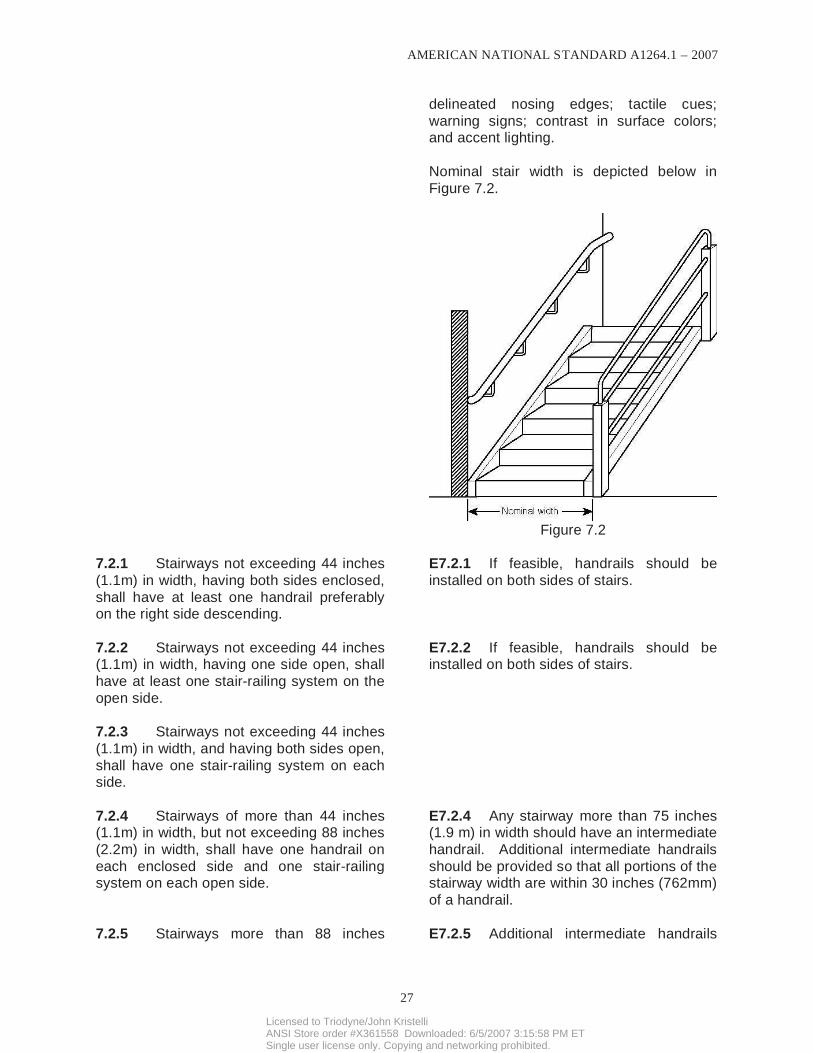
Nominal stair width is depicted below in
Figure 7.2.
Figure 7.2
7.2.1 Stairways not exceeding 44 inches
(1.1m) in width, having both sides enclosed,
shall have at least one handrail preferably on the right side descending.
E7.2.1 If feasible, handrails should be
installed on both sides of stairs.
7.2.2 Stairways not exceeding 44 inches (1.1m) in width, having one side open, shall
have at least one stair-railing system on the
open side.
E7.2.2 If feasible, handrails should be installed on both sides of stairs.
7.2.3 Stairways not exceeding 44 inches
(1.1m) in width, and having both sides open,
shall have one stair-railing system on each side.
7.2.4 Stairways of more than 44 inches (1.1m) in width, but not exceeding 88 inches
(2.2m) in width, shall have one handrail on
each enclosed side and one stair-railing system on each open side.
E7.2.4 Any stairway more than 75 inches (1.9 m) in width should have an intermediate
handrail. Additional intermediate handrails
should be provided so that all portions of the stairway width are within 30 inches (762mm)
of a handrail.
7.2.5 Stairways more than 88 inches E7.2.5 Additional intermediate handrails
Licensed to Triodyne/John KristelliANSI Store order #X361558 Downloaded: 6/5/2007 3:15:58 PM ETSingle user license only. Copying and networking prohibited.
AMERICAN NATIONAL STANDARD A1264.1 – 2007
28
(2.2m) in width, shall have one handrail on
each enclosed side, one stair-railing system on each open side, and one intermediate
stair-railing system located approximately
midway of the width of the stairway.
should be provided so that all portions of the
stairway width are within 30 inches (762mm) of a handrail.
7.2.6 Exterior stairways that have earth
built up on both sides shall have a railing
system on both sides.
E7.2.6 Additional intermediate handrails
should be provided so that all portions of the
stairway width are within 30 inches (762mm) of a handrail.
8. REFERENCES. The following standards and documents can be reviewed
as supporting documents for this standard.
It is recommended that the most current
version of the standard cited below be used:
ANSI/ASSE A10.18, Safety Requirements
for Temporary Floors, Holes, Wall Openings, Stairways and Other Unprotected
Edges in Construction and Demolition
Operations.
ANSI/ASSE A1264.2, Provision of Slip
Resistance on Walking/Working Surfaces
ANSI/ASSE Z490.1, Accepted Practices for
Safety, Health, and Environmental Training
ANSI/ASSE Z359.1, Safety Requirements
for Personal Fall Arrest Systems, Sub-
systems, and Components
ASTM E661, Standard Test Method for
Performance of Wood and Wood-Based
Floor and Roof Sheathing Under Concen-trated Static and Impact Loads
ASTM E695, Standard Method for Measuring Relative Resistance of Wall,
Floor, and Roof Construction to Impact
Loading
ASTM E985, Standard Specification for
Permanent Metal Railing Systems and Rails
for Buildings
ASTM F1637, Standard Practice for Safe
Walking Surfaces
E8. Readers often ask for information regarding construction and demolition sites
since the standard excludes them from
A1264.1. Those with an interest from the
construction and demolition perspective should review A10.18.
Readers of the standards interested in walking/working surfaces should review
A1264.2 for more information. The scope of
the A1264.2 is: “Scope. This standard sets forth provisions for protecting persons
where there is potential for slips and falls as
a result of surface characteristics or
conditions.”
The 1264 ASC believes that training is a
critical component of a safety and health program. Writing such programs is outside
the scope of the A1264 ASC. As an
alternative, a reference is being made to
ANSI/ASSE Z490.1.
The A1264 ASC believes that floor
maintenance is a critical issue. Writing such programs is outside the scope of the A1264
ASC. As an alternative, a reference is being
made to ASTM F1637-02e1.
The A1264 ASC believes safety manage-
ment is a critical issue. Writing such
programs is outside the scope of the A1264 ASC. As an alternative, a reference is being
made to ANSI/AIHA Z10.
Licensed to Triodyne/John KristelliANSI Store order #X361558 Downloaded: 6/5/2007 3:15:58 PM ETSingle user license only. Copying and networking prohibited.

AMERICAN NATIONAL STANDARD A1264.1 – 2007
29
ANSI/AIHA Z10, American National
Standard for Occupational Health and Safety Management Systems
NFPA 101®, Life Safety Code®
ANSI Z535.1, Safety Color Code
ANSI Z535.2, Environmental and Facility Safety Signs
CFR 1926.502(c)(4)(i), Safety Net Systems
IBC, International Building Code
Licensed to Triodyne/John KristelliANSI Store order #X361558 Downloaded: 6/5/2007 3:15:58 PM ETSingle user license only. Copying and networking prohibited.

A S
S E
Licensed to Triodyne/John KristelliANSI Store order #X361558 Downloaded: 6/5/2007 3:15:58 PM ETSingle user license only. Copying and networking prohibited.