[American Institute of Aeronautics and Astronautics 54th International Astronautical Congress of the...
13
1 PRORA USV – TECH CRYOTANK PROJECT: APPLICABILITY OF CFRP TO TANK MANUFACTURING FOR CRYOGENIC LIQUID PROPULSION L. Scatteia, G. Tomassetti, M. Kivel Mazuy, S. Cantoni. CIRA – Italian Aerospace Research Centre Via Maiorise 81043 CAPUA (CE) – ITALY Contact: [email protected] ABSTRACT Liquid propulsion based on LH2/LOX or LHC/LOX coupling is expected to be the standard for next generation of reusable launchers. Actually, liquid propulsion fulfils reusability requirement and provide a more powerful and efficient thrust system with respect to solid propulsion. Given the low density of hydrogen and oxygen, even in their liquid phase, LH2 and LOX tanks have far greater volume than solid propellant cases and constitute a considerable part of the whole launcher dry mass. At this regard, lightweight composite materials can potentially assure significant mass and cost reduction: they took advantage of an high specific strength and of the possibility to be employed in automated manufacturing processes (i.e. filament winding) far less expensive than conventional techniques used with metal alloys. This paper describes the activities performed within the Italian Unmanned Space Vehicle (USV)-CRYOTANK project. Aim of the project is to study the applicability of polymer based composites to lightweight reusable liquid propellant tanks with the final objective to design, manufacture and test a scaled demonstrator composite tank. The current state of the research work is presented and the preliminary results (which includes requirements settings, material screening, scaling criteria definition and permeability characterisation definition) are listed and described. FRAME: THE USV PROJECT The aerospace USV program, conducted by CIRA in the framework of the Italian Aerospace Research Program (PROPRA) funded by the Research Ministry, aims to develope and validate, up to flight tests, key technologies for the next generation of reusable space transportation vehicles (aero-space-planes). Five main areas of focus have been identified in the USV-Tech program, in which a number of research projects are currently in progress: • Aerothermodynamics • Structures and Materials • Propulsion • Guidance, Navigation, and Control • Health Management In parallel to the R&D activities, the development of a family of experimental vehicles (FTB-Flight Test Bed) is scheduled. These vehicles will allow to perform four specific flight missions of increasing complexity, referred to as: • DTFT, Dropped Transonic Flight Test • SRT, Sub-orbital Re-entry Test • HFT, Hypersonic Flight Test • ORT, Orbital Re-entry Test Each mission is conceived to allow the test of the developed technologies in real flight re-entry conditions. The USV-Tech Cryotank project is focused on the HFT-LP (Liquid Propulsion) mission. HFT is subdivided in two flights scheduled in 2007 (HFT-0) and 2008 (HFT-LP), and will perform, in a two stage launch configuration (Balloon-2 + FTB-2), an horizontal sustained hypersonic flight, with the aim to demonstrate the capability to fly in hypersonic steady conditions. Moreover, the flying platform will be used to 54th International Astronautical Congress of the International Astronautical Federation, the International Academy of Astronautics, and the International Institute of Space Law 29 September - 3 October 2003, Bremen, Germany IAC-03-I.3.08 Copyright © 2003 by the International Astronautical Federation. All rights reserved. Downloaded by Universitaetsbibliothek Erlangen-Nuernberg on March 10, 2014 | http://arc.aiaa.org | DOI: 10.2514/6.IAC-03-I.3.08
Transcript of [American Institute of Aeronautics and Astronautics 54th International Astronautical Congress of the...

1
PRORA USV – TECH CRYOTANK PROJECT: APPLICABILITY OF CFRP TO TANK MANUFACTURING FOR CRYOGENIC
LIQUID PROPULSION
L. Scatteia, G. Tomassetti, M. Kivel Mazuy, S. Cantoni. CIRA – Italian Aerospace Research Centre
Via Maiorise 81043 CAPUA (CE) – ITALY Contact: [email protected]
ABSTRACT Liquid propulsion based on LH2/LOX or LHC/LOX coupling is expected to be the standard for next generation of reusable launchers. Actually, liquid propulsion fulfils reusability requirement and provide a more powerful and efficient thrust system with respect to solid propulsion. Given the low density of hydrogen and oxygen, even in their liquid phase, LH2 and LOX tanks have far greater volume than solid propellant cases and constitute a considerable part of the whole launcher dry mass. At this regard, lightweight composite materials can potentially assure significant mass and cost reduction: they took advantage of an high specific strength and of the possibility to be employed in automated manufacturing processes (i.e. filament winding) far less expensive than conventional techniques used with metal alloys. This paper describes the activities performed within the Italian Unmanned Space Vehicle (USV)-CRYOTANK project. Aim of the project is to study the applicability of polymer based composites to lightweight reusable liquid propellant tanks with the final objective to design, manufacture and test a scaled demonstrator composite tank. The current state of the research work is presented and the preliminary results (which includes requirements settings, material screening, scaling criteria definition and permeability characterisation definition) are listed and described. FRAME: THE USV PROJECT
The aerospace USV program, conducted by CIRA in the framework of the Italian Aerospace
Research Program (PROPRA) funded by the Research Ministry, aims to develope and validate, up to flight tests, key technologies for the next generation of reusable space transportation vehicles (aero-space-planes). Five main areas of focus have been identified in the USV-Tech program, in which a number of research projects are currently in progress:
• Aerothermodynamics • Structures and Materials • Propulsion • Guidance, Navigation, and Control • Health Management
In parallel to the R&D activities, the development of a family of experimental vehicles (FTB-Flight Test Bed) is scheduled. These vehicles will allow to perform four specific flight missions of increasing complexity, referred to as:
• DTFT, Dropped Transonic Flight Test • SRT, Sub-orbital Re-entry Test • HFT, Hypersonic Flight Test • ORT, Orbital Re-entry Test
Each mission is conceived to allow the test of the developed technologies in real flight re-entry conditions. The USV-Tech Cryotank project is focused on the HFT-LP (Liquid Propulsion) mission. HFT is subdivided in two flights scheduled in 2007 (HFT-0) and 2008 (HFT-LP), and will perform, in a two stage launch configuration (Balloon-2 + FTB-2), an horizontal sustained hypersonic flight, with the aim to demonstrate the capability to fly in hypersonic steady conditions. Moreover, the flying platform will be used to
54th International Astronautical Congress of the International Astronautical Federation,the International Academy of Astronautics, and the International Institute of Space Law29 September - 3 October 2003, Bremen, Germany
IAC-03-I.3.08
Copyright © 2003 by the International Astronautical Federation. All rights reserved.
Dow
nloa
ded
by U
nive
rsita
etsb
iblio
thek
Erl
ange
n-N
uern
berg
on
Mar
ch 1
0, 2
014
| http
://ar
c.ai
aa.o
rg |
DO
I: 1
0.25
14/6
.IA
C-0
3-I.
3.08
2
perform in-flight demonstration tests for Aerotermodynamics, GNC and Liquid Propulsion technologies. The Cryotank project final product is just focused to be flown and tested on HFT-LP, by envisaging an enhanced version of the FTB-2 vehicle equipped with a LOX/LHC propulsion system.
INTRODUCTION
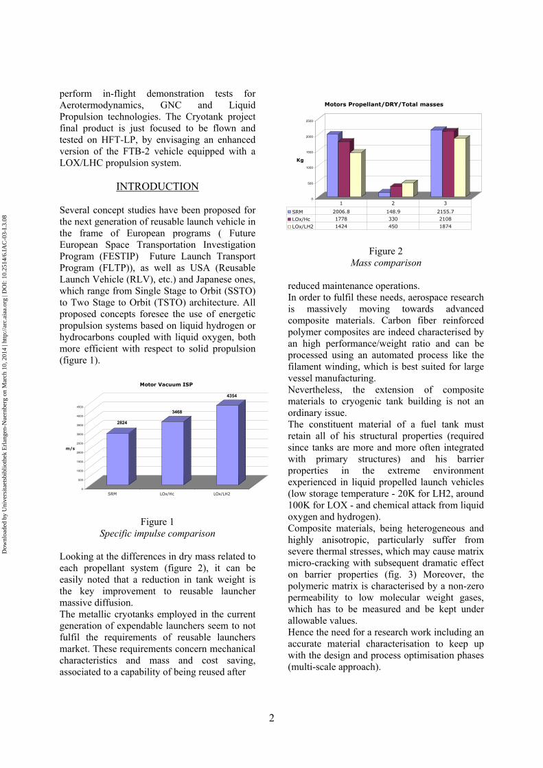
Several concept studies have been proposed for the next generation of reusable launch vehicle in the frame of European programs ( Future European Space Transportation Investigation Program (FESTIP) Future Launch Transport Program (FLTP)), as well as USA (Reusable Launch Vehicle (RLV), etc.) and Japanese ones, which range from Single Stage to Orbit (SSTO) to Two Stage to Orbit (TSTO) architecture. All proposed concepts foresee the use of energetic propulsion systems based on liquid hydrogen or hydrocarbons coupled with liquid oxygen, both more efficient with respect to solid propulsion (figure 1).
Figure 1 Specific Impulse Comparison
Figure 1 Specific impulse comparison
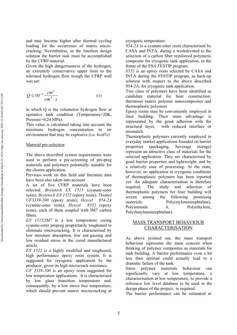
Looking at the differences in dry mass related to each propellant system (figure 2), it can be easily noted that a reduction in tank weight is the key improvement to reusable launcher massive diffusion. The metallic cryotanks employed in the current generation of expendable launchers seem to not fulfil the requirements of reusable launchers market. These requirements concern mechanical characteristics and mass and cost saving, associated to a capability of being reused after
Figure 2
Mass comparison reduced maintenance operations. In order to fulfil these needs, aerospace research is massively moving towards advanced composite materials. Carbon fiber reinforced polymer composites are indeed characterised by an high performance/weight ratio and can be processed using an automated process like the filament winding, which is best suited for large vessel manufacturing. Nevertheless, the extension of composite materials to cryogenic tank building is not an ordinary issue. The constituent material of a fuel tank must retain all of his structural properties (required since tanks are more and more often integrated with primary structures) and his barrier properties in the extreme environment experienced in liquid propelled launch vehicles (low storage temperature - 20K for LH2, around 100K for LOX - and chemical attack from liquid oxygen and hydrogen). Composite materials, being heterogeneous and highly anisotropic, particularly suffer from severe thermal stresses, which may cause matrix micro-cracking with subsequent dramatic effect on barrier properties (fig. 3) Moreover, the polymeric matrix is characterised by a non-zero permeability to low molecular weight gases, which has to be measured and be kept under allowable values. Hence the need for a research work including an accurate material characterisation to keep up with the design and process optimisation phases (multi-scale approach).
2824
3468
4354
0
500
1000
1500
2000
2500
3000
3500
4000
4500
m/s
SRM LOx/Hc LOx/LH2
Motor Vacuum ISP
0
500
1000
1500
2000
2500
Kg
Motors Propellant/DRY/Total masses
SRM 2006.8 148.9 2155.7
LOx/Hc 1778 330 2108
LOx/LH2 1424 450 1874
1 2 3
Dow
nloa
ded
by U
nive
rsita
etsb
iblio
thek
Erl
ange
n-N
uern
berg
on
Mar
ch 1
0, 2
014
| http
://ar
c.ai
aa.o
rg |
DO
I: 1
0.25
14/6
.IA
C-0
3-I.
3.08

3
Coping with this technical needs the activities proposed in the USV-CRYOTANK project are directed to the optimisation, in terms of performances/weight ratio of the propellant and combustive agent tanks. The project aims to investigate the possibility to employ carbon fiber reinforced plastics as main materials in the manufacturing of large cryogenic tanks using the filament winding process. Particular relevance in the project has been granted to the barrier performance characterisation, in which a multi-scale approach has been adopted: macroscopic leakage, polymer matrix permeability, solubility and sorption tests were planned. Moreover the project includes the development of thermoset polymer nanocomposites, with the aim to obtain barrier properties and microcrack resistance optimised materials and the test of their application to cryogenic tank building.
SYSTEM REQUIREMENTS AND
MATERIAL PRE-SCREENING
Design solutions Two architectural solutions were considered: the first one is a linerless filament wound tank; the other one foresees the use of a polymeric internal liner, to which are demanded all functional properties (barrier and chemical resistance) leaving the structural ones to the filament wound composite shell. The choice of the architectural solution heavily affects the design of the tank. In a linerless tank the composite walls have to be sized in transverse direction, in order to prevent from microcrackings, (not acceptable for the negative effect on barrier properties). The result is an oversize of the walls for mechanical loads. In a linered tank, microcrackings are acceptable, so the walls are sized in fiber directions for mechanical loads, leading to overall mass reduction. The drawbacks of a liner are represented by the critical interface with the composite shell, manufacturing, increased global complexity and costs of the tank, together with the fact that at the state no cryogenic polymeric liner has yet been demonstrated.
The possibility to improve matrix behaviour at cryogenic temperature as well as the understanding of the inference that winding and curing parameters have on Carbon Fibre Reinforced Plastic (CFRP) cryogenic performances could allow the designers to push the use of the material avoiding the sizing in transverse direction in a linerless design solution.
Figure 3
Macroscopic permeation trough cracking Tank requirements The main requirements of the tank to be used as base-line for the CRYOTANK program were defined. A cylindrical tank (5.4 meter diameter) with 2 lateral domes, whose shape will be well defined during the design optimisation phase (an isotensoid will be selected as first attempt), has been selected as reference tank. An hypothetical mission profile was assumed in order to define the most critical loads for tank dimensioning. Acceleration along x and z reference axis (see picture) have been assumed as mechanical loads, with a 1.25 ultimate factor. A MEOP of 0.24 MPa for the LH2 tank, and 0.55 MPa for the LOx tank have been assumed as pressure loads. These values were set taking into account the boil-off effect. Actually, due to
Dow
nloa
ded
by U
nive
rsita
etsb
iblio
thek
Erl
ange
n-N
uern
berg
on
Mar
ch 1
0, 2
014
| http
://ar
c.ai
aa.o
rg |
DO
I: 1
0.25
14/6
.IA
C-0
3-I.
3.08

4
the unavoidable evaporation of the stored liquid, the tank pressure increases in time. Since the tank weight increases with design pressure, a pressure relief valve is provided with every cryogenic liquid container to prevent an overpressure and a consequent explosion. The propellant lost,when the relief valve releases the pressure, is referred to as boil-off loss. In order to reduce the boil-off loss an extra pressure dimensioning, with respect to the 1,013 bar (0.1MPa) pressure of the liquid propellant at 20K (H2) and 90K (O2), was fixed. Material requirements Reference physic and mechanical properties, processing requirements (related to the filament winding), and a reusability requirement were assessed. Worst conditions, referring to LH2 or LOX, were assumed in order to define a comprehensive set of requirements: thermal loads and permeability allowable referred to LH2; chemical compatibility and resistance are referred to LOx.
Thermal loads The LH2 is stored at a temperature of ≈ 20K. This is the temperature value set in the CFRP after LH2 filling procedure. This value is taken assuming that an appropriate thermal insulation is provided on tankexternal wall to keep the CFRP isotherm. The empty tank before LH2 filling is at room temperature, i.e.:
KTT ambientlaunchpadfillingbeforeCFRP 320___ ≅= supposing a direct sunlight exposure of the vehicle on the launch-pad, where the filling is performed. During the filling procedure and the burning phase the most severe temperature gradient take place in the CFRP, in both transversal (along the thickness) and longitudinal (along the length of the tank) direction. The maximum reachable temperature is set equal to Tmax 400 K. This temperature is reached in the re-entry
phase of the launcher flight, when the tank is no longer filled with LH2. In that phase the temperature in the CFRP tank may be considered uniform. It is worth to notice that the Tmax value provided may not match the actual temperature incidence in re-entry condition, i.e. the temperature may reach higher values. In this case an appropriate TPS must be provided to keep the temperature on the CFRP tank lower. This topic is anyway out of the scope of the USV-Cryotank Project.
Cure temperature
A critical issue in the material selection is represented by the minimum cure temperature required to obtain the expected structural properties. During the curing process, and the cooling to room temperature, residual stresses are induced in a composite material. They are the result of cure shrinkage and differences in the coefficient of thermal expansion between the fibers and matrix. A Stress Free Temperature (SFT) of the composite may be defined as the temperature at which no residual stress exists. The SFT is usually located above the maximum processing temperature due to dimensional changes in the matrix during cure. The amount of stress in a composite increases as the temperature deviates from the SFT; as can be argued, it may became critical at cryogenic temperature, giving rise to delamination and/or microcracking. Therefore, given the extremely low temperatures reached in a cryogenic tank and the high thermal stress involved, it is recommended to have a low temperature curing resin. If this option is not available, the time of curing must be tuned in order to keep the cure temperature as lower as possible in order to minimize micro-cracking occurrence.
Permeability allowable
The main disadvantage given from the adoption of CFRPs in tank manufacturing is represented by their non-zero gas permeability. The low temperature gas permeation is mainly due to the presence of voids (formed during the manufacturing process) in the polymeric matrix
Dow
nloa
ded
by U
nive
rsita
etsb
iblio
thek
Erl
ange
n-N
uern
berg
on
Mar
ch 1
0, 2
014
| http
://ar
c.ai
aa.o
rg |
DO
I: 1
0.25
14/6
.IA
C-0
3-I.
3.08
5
and may become higher after thermal cycling loading for the occurrence of matrix micro-cracking. Nevertheless, in the linerless design solution the barrier task must be accomplished by the CFRP material. Given the high dangerousness of the hydrogen, an extremely conservative upper limit to the tolerated hydrogen flow trough the CFRP wall was set:
scmcmQ
⋅≤ −
2
3410 (1)
in which Q is the volumetric hydrogen flow at operative tank condition (Temperature=20K, Pressure=0,24 MPa). This value is calculated taking into account the minimum hydrogen concentration in air environment that may be explosive (i.e. 4vol%) Material pre-selection The above described system requirements were used to perform a pre-screening of pre-preg materials and polymers potentially suitable for the chosen application. Previous work on this field and literature data have been also taken into account A set of five CFRP materials have been selected: Brytetech EX 1515 (cyanate-ester resin); Brytetech EX 1522 (epoxy resin); Thiokol UF3339-100 (epoxy resin); Hexcel 954-2A (cyanate-ester resin); Hexcel 8552 (epoxy resin); each of them coupled with IM7 carbon fibers. EX 1515/IM7 is a low temperature curing cyanate-ester prepreg proprietarily toughened to eliminate microcracking. It is characterised by low moisture absorption, low out-gassing and low residual stress in the cured manufactured article. EX 1522 is a highly modified and toughened, high performance epoxy resin system. It is suggested for cryogenic application by the producer, given its high microcrack resistance. UF 3339-100 is an epoxy resin suggested for low temperature applications. It is characterised by low glass transition temperature and, consequently, by a low stress free temperature, which should prevent matrix microcracking at
cryogenic temperature. 954-2A is a cyanate-ester resin characterised by CASA and INTA, during a workdevoted to the selection of a carbon fiber reinforced polymeric composite for cryogenic tank application, in the frame of the ESA FESTIP program. 8552 is an epoxy resin selected by CASA and INTA during the FESTIP program, as back-up solution with respect to the above described 954-2A, for cryogenic tank application. Two class of polymers have been identified as candidate material for liner construction: thermoset matrix polymer nanocomposites and thermoplastic polymers Epoxy resins may be conveniently employed in liner building. Their main advantage is represented by the good adhesion with the structural layer, with reduced interface or mismatch. Thermoplastic polymers currently employed in everyday market applications founded on barrier properties (packaging, beverage storage) represent an attractive class of materials for the selected application. They are characterised by good barrier properties and lightweight, and by a relatively ease of processing. At the state, however, no application in cryogenic conditions of thermoplastic polymers has been reported yet. An adequate characterisation is therefore required. The study and selection of thermoplastic polymers for liner building will screen among the following promising materials: Poly(etyleneterephtalate), Polyammide 6, Polyethylene, Poly(butyleneterephtalate).
MASS TRANSPORT BEHAVIOUR CHARACTERISATION
As above pointed out, the mass transport behaviour represents the main concern when thinking of polymer composites as materials for tank building. A barrier performance even a bit less than optimal could actually lead to a dramatic failure of the tank. Since polymer materials behaviour can significantly vary at low temperature, a characterisation at low temperature, to provide a reference low level database to be used in the design phase of the project, is required. The barrier performance can be estimated at
Dow
nloa
ded
by U
nive
rsita
etsb
iblio
thek
Erl
ange
n-N
uern
berg
on
Mar
ch 1
0, 2
014
| http
://ar
c.ai
aa.o
rg |
DO
I: 1
0.25
14/6
.IA
C-0
3-I.
3.08

6
three different level ranging from the macroscopic behaviour to the intrinsic material-related phenomena (multi-scale approach): leakage phenomena, permeability behaviour and sorption and solubility behaviour. Leakage Typically, the leakage evaluation is carried out by filling with liquid helium a cylindrical or bottle-like test article, and detecting with a mass spectrometer the amount of He passing through the cylinder wall in a fixed amount of time. With this test, the leakage phenomenon as a whole is investigated: the effects of intrinsic permeability, defects formed during the manufacturing process and microcracking arising from thermal cycling load are merged. This test is necessary as it recreates the operative conditions of the actual tank, and serves as an evaluation tool for the effectiveness of both material and process parameters. For this reason, this test will be conducted in the final steps of the USV-tech Cryotank project, on wound cylinder and closed dome test article reproducing the same lamination sequence of the final tank. On the other hand, this test alone could not exactly address the leakage sources, that is permeability or wrong lamination sequence effects (micro-cracking). Permeability The permeation through a polymer is a thermodynamic process involving the solubility of the gas or liquid on the surface of the polymer, its diffusion within the polymer matrix and the following dissolution from the polymer (see figure 4): the driving force of the process is a concentration, or pressure, gradient of the gas between the two sides of the polymer. The permeability coefficient P is defined by the following relationship:
l
∆pPJ = (2)
where J is the mass flow, ∆P the pressure gap and l is the thickness.
Every amorphous or semi-cristalline polymer exhibits a non-zero permeability to low molecular weight gases. Therefore, a permeability evaluation on the polymer matrix is required to fix the polymer-bound performance and to relate them to composite barrier performances.
Figure 4 Permeation process
Such an evaluation is performed using a permeation test apparatus which measures the amount of mass permeating through a polymeric membrane when a pressure gradient is applied on it. The main constituents of the apparatus are the measurement cell in which the polymeric membrane is allocated, the pressurized upstream lung and the downstream lung, which is kept under vacuum before test. Since the downstream lung is linked to the pressurized lung by the polymeric membrane only, a macroscopic mass balance on the system leads to:
dt(t)dQ
A1J dl= (3)
in which J is the mass flow, Qdl is the mass registered in the downstream lung and A is the membrane area. Once measured, the flow J can be easily related to the permeability of the polymer-gas system by mean of the relation (2) reported above. To avoid turbulence occurrence, the two lungs and the measuring cell must be kept at the same
Dow
nloa
ded
by U
nive
rsita
etsb
iblio
thek
Erl
ange
n-N
uern
berg
on
Mar
ch 1
0, 2
014
| http
://ar
c.ai
aa.o
rg |
DO
I: 1
0.25
14/6
.IA
C-0
3-I.
3.08
7
temperature: they are usually put in a climatic chamber to guarantee the uniformity of the temperature.
Figure 5
Permeability test equipment It’s hard to obtain a reliable measurement at cryogenic temperature with a system as above described for a couple of main reasons. First of all, the measurement cell and the two lungs must be cooled down at the same temperature, and this is not easily accessible, as they constitute a considerable volume. Then, it is not easy to avoid temperature induced cracks in the polymeric membrane, once it is grafted to the measurement cell and cooled down. Sorption The extreme environment related to the cryogenic liquid propellant storage application requires an in-depth characterisation of the constituent material in terms of its interactions with the stored liquid. The main characterisation required concerns the sorption behaviour of the polymer matrix. Sorption behaviour is critical as polymer mechanical behaviour can be significantly altered by the adsorbed gas. Besides, the sorption can affect the capability of the CFRP tank of being reused: high level of gas
sorption at low temperature may actually result in matrix foaming at increasing temperature (after the burning phase of the cryogenic propellant), with consequent permanent damage. Sorption behaviour may be described evaluating the solubility, which dictate thermodynamic equilibrium and the diffusivity, which regulate the kinetic of the process. The sorption of a permeating agent along the polymer surface is a thermodynamic phenomena which take place till the equilibrium is reached, i.e. until the chemical potentials µ outside and inside of the polymer became equal:
inout µµ = (5) The activity a is defined as:
adRTd ln⋅=µ (6) So, if we choose the same standard potential for the inside and the outside phase, the equilibrium condition (4) became:
inout aa = (7) The solubility coefficient S can then be defined as:
ac
ac
acS inout === (8)
in which c is the gas concentration in the polymer once the equilibrium is reached. The diffusion process in a binary system (whose component are A and B), in which may be considered valid the hypothesis of ideal mixing, is described by the well known Fick’s law:
∂∂
∂∂
=∂
∂z
CDzt
C AAB
A (9)
in which CA is the concentration of the component A, t is the time, z is the axial coordinate, DAB is the mutual diffusion coefficient. The equation (8), solved with the proper contour conditions, provide the ratio between the
Dow
nloa
ded
by U
nive
rsita
etsb
iblio
thek
Erl
ange
n-N
uern
berg
on
Mar
ch 1
0, 2
014
| http
://ar
c.ai
aa.o
rg |
DO
I: 1
0.25
14/6
.IA
C-0
3-I.
3.08

8
adsorbed mass at the time t, m(t), and the adsorbed mass at the equilibrium, m∞. Two analytical solution are available:
−+
= ∑
∞
=∞ 15.05.02 )(2
)1(214)(n AB
nAB
tDnlierfc
ltD
mtm
π
(10)
∑∞
=∞
+−
+−=
02
2222 )12(exp
)12(81)(
n
AB
ltDn
nmtm π
π
(11) in which DAB is the diffusivity coefficient, l is the thickness of the sample and t the time. The first solution is accurate for m(t)/m∞<0.6, i.e. for short time, while the second one is generally used for long times (m(t)/ m∞ > 0.6) Sorption measurements are usually conducted evaluating the weight change of the sample, exposed to the permeating gas, due to mass sorption. The mass m(t) and its equilibrium value m∞ are recorded. The plot containing the equilibrium values of the concentration versus the activity, at a fixed temperature is indicated as sorption isothermal curve. The diffusivity coefficient is obtained as the slope of the linear part of the m(t)/ m∞ vs. t1/2/l curve. The solubility is obtained as the ratio between equilibrium concentration and equilibrium activity. The test equipments usually employed to perform sorption measurements are high precision balance which may be mechanical (spring based) or magnetic suspension balance. Temperature and stress-status dependance of P, D and S. Solubility, diffusion and permeability in polymers are temperature-activated processes: they exhibit an Arrhenius-type temperature dependence. Therefore measurements of these parameters performed at room temperature may be
considered overestimated and consequently, conservative. This is generally true for polymers in temperature range [-30°C÷ 200°C]. Some deviations from this trend may arise at low temperature, in particular for which concern the solubility behaviour, that is not easily predictable for the possible occurrence of strong polymer-liquid interactions. The diffusivity, and therefore, the permeability in a polymer are also strongly influenced by the stress status experienced by the material. The mechanism by which the stress affects these parameters is not currently completely clear, and is generally attributed to a change in the polymer free volume under stress. Test plan Being the USV-Cryotank a technology-aimed project, a compromise between low level material research and engineering research has been fixed. As already stated above, the leakage test is almost necessary to evaluate the effectiveness of composites processing techniques during the course of the project, and to perform the acceptance of the final technological demonstrator (the scaled tank). For this reason, a leakage detection apparatus has been equipped, and in-house measurements will be carried out at CIRA. Given the high difficulties to perform permeability measurements in cryogenic conditions, it was decided to perform the tests at room temperature, and then to derive the polymer behaviour at cryogenic temperature. Diffusivity measurements at room temperature (conservative) will be performed using a magnetic suspension balance. Since a solubility evaluation performed at room temperature may be not conservative with respect to a cryogenic environment, an alternate path to perform solubility estimate at cryogenic temperature is currently under evaluation. The mass transport characterisation test plan is summarised in table 1.
Dow
nloa
ded
by U
nive
rsita
etsb
iblio
thek
Erl
ange
n-N
uern
berg
on
Mar
ch 1
0, 2
014
| http
://ar
c.ai
aa.o
rg |
DO
I: 1
0.25
14/6
.IA
C-0
3-I.
3.08

9
RT Cryogenic
Macro- behaviour
Leakage o
Permeability o Conservative? Micro-
behaviour Diffusivity o Conservative!
Solubility o o
Table 1 Mass transport characterisation test plan
LOAD SCALING CRITERIA To fulfil one of the main goal of the project, the prototype composite tank has to be sufficiently impermeable to the cryogenic fuel stored in as well as the real size tank (meaning with this capable to fulfill to the permeability requirement). In order to assure this the tank permeability performance parameter must be kept unchanged, from the real size to the scaled tank. Being the permeability of the material strongly influenced by its stress status, because of micro crack occurrence and changes in the diffusivity of the permeating material through the composite wall, the previous statement means that the same stress level, between the real size and the scaled tank, should be assured. Two tanks are taken into consideration: the full scale tank of axial length (cylindrical height) L1 and diameter (cylindrical external diameter) D1 and thickness t1 and the scaled one of dimensions L2 and D2 and t2. Both tanks are subjected to the following loads: internal pressure; axial inertial load; lateral inertial load. In the evaluation of inertial loads both the structure mass and the fluid mass inside the tank are considered. A parametric study of the loads, based on scaled tank geometrical dimensions L and t, was performed. This study will allow, once defined the scaled tank dimensions, the identification of the related load spectrum. The following assumptions and restrictions were introduced:
• the thermal flux across the wall is neglected;
• full size tank dimensions L1, D1 and t1 have been defined;
• the presence of forward and back domes and all the related effects are represented merely by a second smaller cylinder of axial length t and the same diameter of the main body, attached to one side of the tank;
• both full size and scaled tank are filled up with the same fluid.
• the following physical data will be assumed for the propellants
LH2 density = 73.8 [kg/m3] LOX density = 1080 [kg/m3]
• the diameter of the scaled tank is obtained as:
1
212 L
LDD ⋅=
(12) Mechanical loads Under the previously introduced assumptions, the stress state inside the structure can be summarised by an axial stress σaxial and a hoop one σhoop. Both are composed of the contribution of various loads. The first is given by the contribution of:
• internal pressure σpress, axial, • inertial lateral load factor σflex and the
compressive inertial load σcompress generated by the inertial axial load factor.
compressflexaxialpressaxial σσσσ ++= ,
(13)
The second is given by the contribution of:
• internal pressure with σpress, hoop • the inertial load due to the presence of a
fluid inside the tank acting as a sort of hydrostatic load σhydro
hydrohooppresshoop σσσ += , (14)
Dow
nloa
ded
by U
nive
rsita
etsb
iblio
thek
Erl
ange
n-N
uern
berg
on
Mar
ch 1
0, 2
014
| http
://ar
c.ai
aa.o
rg |
DO
I: 1
0.25
14/6
.IA
C-0
3-I.
3.08

10
Internal pressure loads scaling The stress level in the hoop and in the longitudinal direction of a tank, due to its internal pressure, is given, by Mariotte law, by:
tRP
axialpress ⋅⋅
=2,σ (15)
tRP
hooppress⋅
=,σ (16)
where P and R are respectively the pressure and the average radius of the tank. So, the same pressure-induced state of stress, in the real size tank and in the scaled one, can be achieved if:
τλ
=⋅=⋅=1
2
2
1
1
2
2
1
1
2
tt
LL
tt
RR
PP
(17)
where λ represents the ratio L1/ L2 and τ is t1/ t2. Axial loads scaling Axial acceleration induces a compressive stress inside the wall of the tank caused by both the weight of the cylindrical main body and of the smaller cylinder representing the dome. This stress can be expressed as follows:
=⋅⋅⋅⋅⋅⋅
⋅⋅+⋅⋅⋅⋅= axialcompress ng
tRtRLtR ρ
πππσ
22 2
axialngRL ⋅⋅⋅
+= ρ
2 (18)
where ρ is the tank material density, L is the axial length of the tank, g the acceleration of gravity and naxial the axial load factor. To induce the same compressive stress in the full size and scaled tank the following condition must be respected:
λ==2
1
1,
2,
LL
nn
axial
axial (19)
So, the same compressive stress can be
produced if the ratio between axial load factors equals the ratio between lengths regardless the thickness ratio. Axial acceleration also induces a hoop stress inside the wall of the tank because of the increase of the pseudo- hydrostatic pressure of the fluid contained inside the tank. This stress increases linearly from the top to the bottom of the tank reaching the maximum value of:
LgnP fluidaxial ⋅⋅⋅= ρmax (20)
where ρfluid is the fluid density. The hoop stress at the bottom of the tank can then be written as:
tRLgn
tRP fluidaxial
hydro⋅⋅⋅⋅
=⋅
=ρ
σ max
(21) Then, the same state of stress is obtained if the following condition is performed:
τλ2
1
22
2
1
1,
2, =⋅
=
tt
LL
nn
axial
axial (22)
Lateral loads scaling In order to evaluate the state of stress induced by the lateral inertial load, a simple cantilever beam model is used. The tank can be considered as a cantilever beam fixed on one end and free on the other having an annular cross sectional area. In this idealization of the tank, the constant lateral load and the free-end concentrated load (produced by the smaller cylinder inertial load) induce an axial stress. This reaches the maximum value at the constrained side and at the maximum distance from the neutral axis. So the scaling criterion can be focused on the following expression of σflex:
eflex RI
M⋅=σ (23)
where M is the flexural moment, I is the momentum of inertia and Re the external radius of the cylinder. Under the assumption of thin
Dow
nloa
ded
by U
nive
rsita
etsb
iblio
thek
Erl
ange
n-N
uern
berg
on
Mar
ch 1
0, 2
014
| http
://ar
c.ai
aa.o
rg |
DO
I: 1
0.25
14/6
.IA
C-0
3-I.
3.08
11
wall, the flexural moment can be written as:
[ ]{ }⋅⋅⋅−⋅⋅+⋅⋅−−⋅⋅= ∫L
lateralefluidlateralee gntRgntRRM0
222 )()( πρπρ
≅⋅⋅⋅⋅⋅⋅+⋅ gnLtRxdx laterale
2πρ
( )tRRtRgLn fluidlateral ⋅⋅⋅+⋅⋅+⋅⋅⋅⋅⋅⋅⋅≅ 222
22
πρπρπρ
(24) Thanks to the additivity property, the momentum of inertia for the annular section can be easily obtained as the difference of that of the external circle and that of the inner circle. Under the assumption of thin wall, we obtain:
( )[ ] tRtRRI ⋅⋅≅−−⋅= 344
4ππ (25)
Then σflex can be written as:
( )=
⋅⋅
⋅⋅⋅+⋅⋅+⋅⋅⋅⋅⋅⋅≅
tR
tRRtgLn fluidlateral
flex π
πρπρπρσ
22
2
( )
tRgnLLRRLt lateral
fluid ⋅⋅⋅⋅
⋅
⋅⋅++⋅⋅=
42ρρ (26)
So, the same value of σflex for the full size and the scaled tank is obtained if:
( )
( )=
⋅⋅
⋅⋅
⋅⋅++⋅⋅
⋅⋅++⋅⋅=
2
22
11
1
22222
11111
1,
2,
2
2L
tRtR
LLRRLt
LRRLt
nn
fluid
fluid
lateral
lateral
ρρ
ρρ
1
2
1
2
2
1
11
22
1
22
1
2
1
11
1
1
2
12
tt
RR
LL
RLRL
LRL
Rt
LRL
Rt
fluid
fluid ⋅⋅⋅
⋅⋅
++
⋅⋅⋅
++
⋅⋅⋅
=
ρρ
ρρ
(27) Now the following considerations can be done: the ratio ρ/ρfluid varies from about one to about twenty respectively in the case of tank filled with LOX or LH2. The ratios t1/ R1 and t2/ R1 are
about zero under the assumption of thin wall structure while the ratio (L1+ R1)/ L1 is about one and (L2+ R2)/ L1 is about 1/λ. So:
τλ2
1,
2, →lateral
lateral
nn (28)
In order to be sure that the permeability behaviour of the real size tank and the scaled one are the same, even if their geometries are different, it’s mandatory that the selected process leads to the same quality process material regardless of the length, radius and thickness. If we consider the filament winding process, selected as the preference process for tank production, it’s known (by industrial experience) that the thickness limit for a good manufacture is around 30 or 40 mm. Tanks with a wall thickness less than 30 mm should be all of the same quality and, as a consequence, of the same intrinsic properties. Starting from this assumption geometrical scaling factor λ and τ can be imposed with no limitations, apart from manufacturing equipment dimension ones. For this they will be selected in order to avoid extremely high load scaling factor. FUTURE WORK One of the recently started activities in the project concern the development of thermoset polymer nanocomposites, with the aim to obtain barrier properties and microcrack resistance optimised materials and the test of their application to cryogenic tank building. Polymer-layered silicate nanocomposites represent a promising new class of polymeric composites with outstanding mechanical, thermal, optical and physic-chemical properties, obtained with a rather low filler loading. They are produced promoting the intercalation of the polymer chains, or of a subsequently polymerized precursor, within the galleries of layered host crystals. The filler employed are typically common micro-grain sized clays treated with organic cations to improve their affinity with the hydrophobic polymer chains. Bi-layered hydroxides (commonly referred as anionic
Dow
nloa
ded
by U
nive
rsita
etsb
iblio
thek
Erl
ange
n-N
uern
berg
on
Mar
ch 1
0, 2
014
| http
://ar
c.ai
aa.o
rg |
DO
I: 1
0.25
14/6
.IA
C-0
3-I.
3.08

12
clays) recently have proven to be an attractive alternative to cationic clays, as they can assure comparable property enhancement without the undesidered increase of resin zero-shear viscosity, thanks to their lower aspect ratio. Polymer-clay nanocomposites, with respect to the neat matrixes, presents an increased stiffness and toughness, improved barrier properties, flame resistance, and improved chemical resistance to aggressive environments. Nanocomposite matrixes, coupled with carbon fiber reinforcement, employed in liquid propellant storage could provide increased stability by preventing chemical degradation in aggressive liquid hydrogen and oxygen fuel environments. The increased gas barrier properties could allow a linerless design. Moreover nanocomposite matrixes will also reduce the coefficient of thermal expansion (CTE) mismatch between the matrix and reinforcing fibers, and, consequently lower the stress free temperature of the composite. The increased modulus in nanocomposites will also provide a stronger matrix with better tensile and compressive properties. Finally, the rigid particulate toughened nanocomposite matrix will provide for a tougher tank that is more resistant to cracking at cryogenic temperatures. All these features make the nanocomposites very attractive for cryogenic tank manufacturing. It has also to be considered that, apart from their use as base material for the CFRP of the tank wall, thermoset nanocomposites may be applied to the realization of an internal liner, thanks to their improved barrier properties. ACKNOWLEDGEMENTS The authors wish to thank Prof. G.Mensitieri, from the University of Naples “Federico II” (Material and Production Engineering Department) Italy, for his useful advises on mass transport characterization of polymers.
REFERENCES [1] Yoshiki Morino, Tetsuya Morimoto, Stefania Cantoni, Gandolfo Di Vita, Giancarlo Totaro, Applicability of Filament Winding Technology to Cryogenic Composite Tanks for Liquid Propulsion, IAF 2000, 51st International Astronautical Congress, Rio de Janeiro, Brasil, October 2000. [2] S. Cantoni, G. Di Vita, F. Betti, ARIANNA: A Code for Integrated Technological Design of Composite Solid Rocket Motor Cases, 2nd European Conference on Launcher Technology, Roma, Italy, November 2000. [3] S. Cantoni, G. Di Vita, G. Totaro, T. Shimoda, T. Morimoto, Y. Morino, Cryogenic Composite Tanks for Liquid Propulsion, 2nd International Symposium Atmospheric Re-entry Vehicles and Systems, Arcachon (France) – 26-29 March 2001 [4] Takayuki Shimoda, Yoshiki Morino, Takashi Ishikawa, Tetsuya Morimoto, Stefania Cantoni, Study of CFRP Application to Cryogenic Fuel Tank for RLV, SAMPE Japan, November 2001 Tokyo [5] Giuseppe Mensitieri, Salvatore Cotugno, Pellegrino Musto, Giuseppe Ragosta and Luigi Nicolais, Transport of water in high Tg polymers: a comparison between interacting and non-interacting systems, Polyimides and Other High Temperature polymers, Ed. K. L. Mittal, 2, 1-19, (2003). [6] R. Barboni, G. Tomassetti, M. de Benedetti, Optimisation of Fibre Arrangement of Filament Wound Liquid Oxygen Composite Tanks, Proceedings of the Ninth International Conference on Civil and Structural Engineering Computing, B.H.V. Topping, (Editor), Civil-Comp Press, Stirling, United Kingdom, paper 97, 2003. [7] M. Zarrelli, A.A. Skordos, I.K. Partridge, Investigation of cure induced shrinkage in unreinforced epoxy resin, Journal of Rubber,
Dow
nloa
ded
by U
nive
rsita
etsb
iblio
thek
Erl
ange
n-N
uern
berg
on
Mar
ch 1
0, 2
014
| http
://ar
c.ai
aa.o
rg |
DO
I: 1
0.25
14/6
.IA
C-0
3-I.
3.08

13
Plastic and Composites, 2002, 31, n.9, pp. 377-384. [8] J. P. Bonnafè, D. Gabard, E. Grosjean, Aluminium lithium alloys application for reusable future launchers cryogenic metallic tanks, 3rd European Conference on Launcher Technology, December 11-14 2001. [9] Y. Solana, Y. Prel, ARIANE 5: Overview and evolution of ARIANE Tanks, 3rd European Conference on Launcher Technology, December 11-14 2001. [10] V. Peypoudat, ANGEL program – Liquid hydrogen composite tank for reusable launch vehicle, 3rd European Conference on Launcher Technology, December 11-14 2001. [11] Technology development in materials for reusable launch vehicles, FESTIP SLICE C report, 31-07-1998 [12] J. Gauthier, Low cost liner applied on helium high pressurant tanks, 3rd European Conference on Launcher Technology, December 11-14 2001. [13] B. W. Grimsley, R. J. Cano, N. J. Johnson, Hybrid composites for LH2 tank structure, 33rd International SAMPE Technical Conference, November 5-8-2001. [14] M. C. Li, B. H. Jones, The design of composites pressurized tanks with and without liners for use in space applications, 33rd International SAMPE Technical Conference, November 5-8-2001. [15] J. F. Timmerman, B. S. Hayes, J. C. Seferis, Cryogenic cycling of polymeric composite materials: effects of cure conditions on microcracking, 33rd International SAMPE Technical Conference, November 5-8-2001. [16] H. Bansemir, O. Haider, Fibre composite structures for space applications – recent and future developments, Cryogenics 38, 1998, 51-59.
[17] ASM International Engineered Material Handbook Volume 1: COMPOSITES, 504-505. [18] Structural and Thermal Design Report Slice C, FESTIP SLICE C report, July 31 1998. [19] C. Leguyader, F. Marteau, Static dimensioning of ARIANE 5 oxygen tank bulkhead in plastic domain, 3rd European Conference on Launcher Technology, December 11-14 2001. [20] V. Detremmerie, Loading introduction and joining techniques in large reusable composite pressurized tank, 3rd European Conference on Launcher Technology, December 11-14 2001. [21] J. Fougeras, A Limam, Upon the buckling of large pressurized structures under bending loads, 3rd European Conference on Launcher Technology, December 11-14 2001. [22] A. Limam, J.F. Pelliccia, F. Barbier, Effects of local reinforcements on the buckling of cylindrical shells subjected to internal pressure and bending, 3rd European Conference on Launcher Technology, December 11-14 2001.
Dow
nloa
ded
by U
nive
rsita
etsb
iblio
thek
Erl
ange
n-N
uern
berg
on
Mar
ch 1
0, 2
014
| http
://ar
c.ai
aa.o
rg |
DO
I: 1
0.25
14/6
.IA
C-0
3-I.
3.08