Generators (generators.html) Generators Open-type DG Set ...
4211-145 06-25-10
AK 17, 20, 30, 3K20, 3K24, 3K28 & 3K36System Installation and Service Instructions Page 1
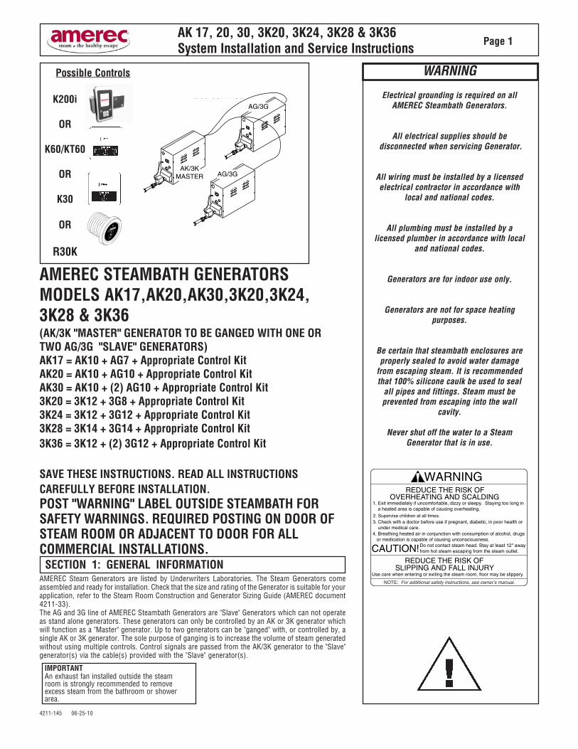
AMEREC STEAMBATH GENERATORSMODELS AK17,AK20,AK30,3K20,3K24,3K28 & 3K36(AK/3K "MASTER" GENERATOR TO BE GANGED WITH ONE ORTWO AG/3G "SLAVE" GENERATORS)AK17 = AK10 + AG7 + Appropriate Control KitAK20 = AK10 + AG10 + Appropriate Control KitAK30 = AK10 + (2) AG10 + Appropriate Control Kit3K20 = 3K12 + 3G8 + Appropriate Control Kit3K24 = 3K12 + 3G12 + Appropriate Control Kit3K28 = 3K14 + 3G14 + Appropriate Control Kit3K36 = 3K12 + (2) 3G12 + Appropriate Control Kit
SAVE THESE INSTRUCTIONS. READ ALL INSTRUCTIONSCAREFULLY BEFORE INSTALLATION.POST "WARNING" LABEL OUTSIDE STEAMBATH FORSAFETY WARNINGS. REQUIRED POSTING ON DOOR OFSTEAM ROOM OR ADJACENT TO DOOR FOR ALLCOMMERCIAL INSTALLATIONS.
AMEREC Steam Generators are listed by Underwriters Laboratories. The Steam Generators comeassembled and ready for installation. Check that the size and rating of the Generator is suitable for yourapplication, refer to the Steam Room Construction and Generator Sizing Guide (AMEREC document4211-33).The AG and 3G line of AMEREC Steambath Generators are "Slave" Generators which can not operateas stand alone generators. These generators can only be controlled by an AK or 3K generator whichwill function as a "Master" generator. Up to two generators can be "ganged" with, or controlled by, asingle AK or 3K generator. The sole purpose of ganging is to increase the volume of steam generatedwithout using multiple controls. Control signals are passed from the AK/3K generator to the "Slave"generator(s) via the cable(s) provided with the "Slave" generator(s).
Electrical grounding is required on allAMEREC Steambath Generators.
All electrical supplies should be disconnected when servicing Generator.
All wiring must be installed by a licensedelectrical contractor in accordance with
local and national codes.
All plumbing must be installed by alicensed plumber in accordance with local
and national codes.
Generators are for indoor use only.
Generators are not for space heatingpurposes.
Be certain that steambath enclosures areproperly sealed to avoid water damage
from escaping steam. It is recommendedthat 100% silicone caulk be used to seal
all pipes and fittings. Steam must beprevented from escaping into the wall
cavity.
Never shut off the water to a SteamGenerator that is in use.
REDUCE THE RISK OF
1. Exit immediately if uncomfortable, dizzy or sleepy. Staying too long in a heated area is capable of causing overheating.
REDUCE THE RISK OF
Use care when entering or exiting the steam room, floor may be slippery.
NOTE: For additional safety instructions, see owner’s manual.
CAUTION! Do not contact steam head. Stay at least 12" awayfrom hot steam escaping from the steam outlet.
OVERHEATING AND SCALDING
2. Supervise children at all times.3. Check with a doctor before use if pregnant, diabetic, in poor health or under medical care.4. Breathing heated air in conjunction with consumption of alcohol, drugs or medication is capable of causing unconsciousness.
SLIPPING AND FALL INJURY
WARNING
SECTION 1: GENERAL INFORMATION
IMPORTANTAn exhaust fan installed outside the steamroom is strongly recommended to removeexcess steam from the bathroom or showerarea.
WARNING
K200i
OR
K60/KT60
OR
K30
OR
R30K
Possible Controls
AK/3KMASTER
AG/3G
AG/3GCONTROL
CABLE 25 ft
AG/3G
AG/3G CONTROL CABLE 25 ft
4211-145 06-25-10
AK 17, 20, 30, 3K20, 3K24, 3K28 & 3K36System Installation and Service Instructions Page 2
IMPORTANT SAFETY INSTRUCTIONS
1. READ AND FOLLOW ALL INSTRUCTIONS.
2. WARNING - To reduce the risk of injury, do not permit children to use thisproduct unless they are closely supervised at all times.
3. WARNING - To reduce the risk of injury:a. The wet surfaces of steam enclosures may be slippery. Use care whenentering or leaving.
b. The steam head is hot. Do not touch the steam head and avoid thesteam near the steam head.
c. Prolonged use of the steam system can raise excessively the internalhuman body temperature and impair the body’s ability to regulate itsinternal temperature (hyperthermia). Limit your use of steam to 10 - 15minutes until you are certain of your body’s reaction.
d. Excessive temperatures have a high potential for causing fetal damageduring the early months of pregnancy. Pregnant or possibly pregnantwomen should consult a physician regarding correct exposure.
e. Obese persons and persons with a history of heart disease, low or highblood pressure, circulatory system problems, or diabetes should consulta physician before using a steambath.
f. Persons using medication should consult a physician before using asteambath since some medication may induce drowsiness while othermedications may affect heart rate, blood pressure and circulation.
4. WARNING - Hyperthermia occurs when the internal temperature of the bodyreaches a level several degrees above the normal body temperature of 98.6degrees F. The symptoms of hyperthermia include an increase in the internaltemperature of the body, dizziness, lethargy, drowsiness and fainting. The effectof hyperthermia include:a. Failure to perceive heat:b. Failure to recognize the need to exit the steambath:c. Unawareness of impending risk:d. Fetal damage in pregnant women:e. Physical inability to exit the steambath: andf. Unconsciousness.
WARNING - The use of alcohol, drugs or medication can greatly increase therisk of hyperthermia.
SAVE THESE INSTRUCTIONS

4211-145 06-25-10
AK 17, 20, 30, 3K20, 3K24, 3K28 & 3K36System Installation and Service Instructions Page 3
SECTION 2: SELECT MOUNTING LOCATION
IMPORTANTPrior to making a decision on the mountinglocation, please read through this Installationand Service Instructions Manual completelyand take a careful look at all the diagrams.
The AMEREC Steam Generator can be hung on a wallor set on its base.
The best mounting location will satisfy all or most ofthe following:
1. The steam line must slope to allow condensationto drain. Condensation should drain into the steamroom.
2. The steam line should be less than twenty (20) feetlong. Ten (10) feet is preferred. Steam lines overtwenty (20) feet long should be insulated.
3. The mounting location should minimize the num-ber of bends and elbows in the steam line.
4. The steam line should enter the room 18" above thefloor or at least 12" above a tub rim or ledge. SeeDiagram 13.
5. No steam head shall be more than thirty (30)inches above the floor.
6. The steam outlet should be located to avoidpotential user contact.
7. The Generator(s) should be installed in a dry, wellventilated area. The space provided should be a least:
7 cu ft for one Generator,17 cu ft for two Generators and27 cu ft for three Generators.
IMPORTANT:- Insulate all steam lines and drain lines within
the enclosed space.- Each Generator must be provided with at
least four (4) inches ventilation and controlwiring access at the control end.
- Each Generator must be provided with atleast twelve (12) inches clearance in FRONTof the louvered front cover.
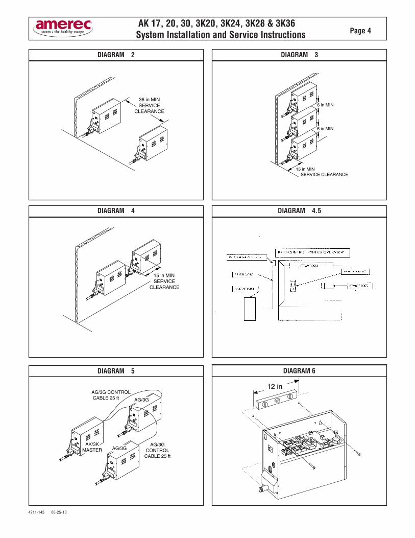
- There should be at least thirty-six (36) inchesin front of each Generator for service access.
Suggested locations are under a vanity, in a closet,attic, crawl space or basement. Preferably in thesame room. ( Not Subject to Freezing)
8. For minimum distance between Steam Genera-tors, see Diagram 1, 2, 3 & 4.
9. The mounting location must be within a cablelength of the Master Generator. See Diagram 5.
NOTE:Longer Slave control cables are available. CallAMEREC Service Department at1-800-331-0349
10. The location should provide clearance for serviceand element removal. See Diagrams 1, 2, 3 & 4.
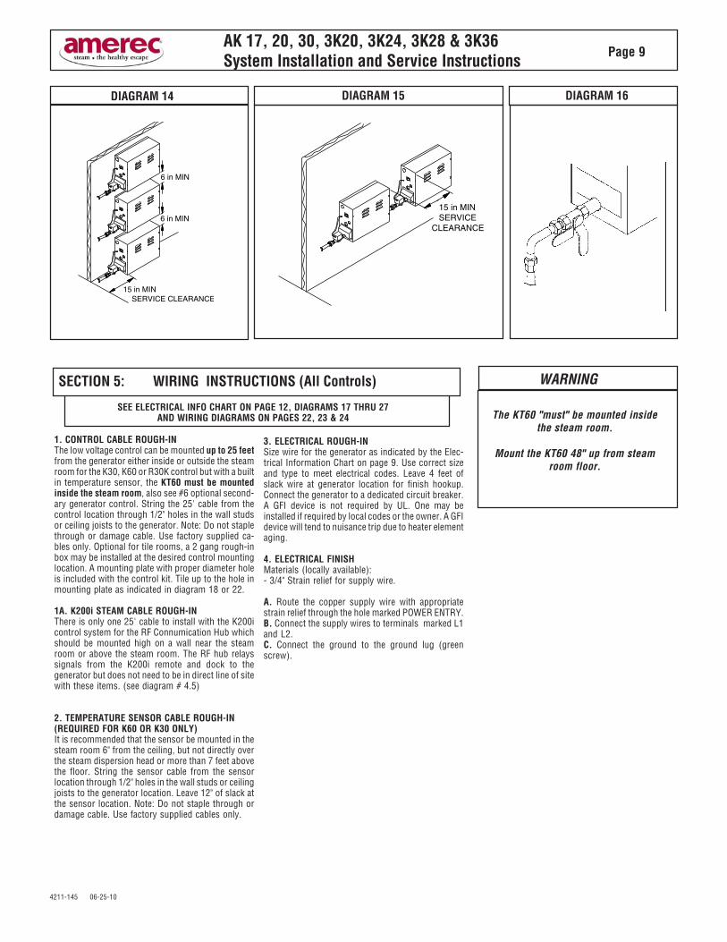
11. There should be no more than three (3) 90°bends and ten feet of pipe between any Generator'sdrain outlet and its drain valve inlet. See Diagram 15.
12. The generator should NOT be mounted wherefreezing may occur.
SEE THE PREFERRED DIAGRAM 1 & DIAGRAMS 2, 3, 4 & 5
DIAGRAM 1: PREFERRED INSTALLATION
WARNING
Do not mount outdoors.Protect from freezing.
To reduce the risk of explosion, donot interconnect steam outlets. A
separate steam line must beprovided for each steam outlet.
Units must be located as to allowaccess for service.
IMPORTANT
An exhaust fan installed outside thesteam room is strongly
recommended in order to removeexcess steam from the bathroom or
shower area.
It is strongly recommended that noexhaust fan be installed inside the
steam room, doing so will result in aloss of heat and steam through the
exhaust fan and port.
OPTIONAL FILTER(NOT PROVIDED)
4211-145 06-25-10
AK 17, 20, 30, 3K20, 3K24, 3K28 & 3K36System Installation and Service Instructions Page 4
DIAGRAM 5
DIAGRAM 4
DIAGRAM 2 DIAGRAM 3
DIAGRAM 6
DIAGRAM 4.5
36 in MINSERVICE
CLEARANCE6 in MIN
6 in MIN
15 in MIN SERVICE CLEARANCE
15 in MIN SERVICE CLEARANCE
AK/3KMASTER
AG/3G
AG/3GCONTROL
CABLE 25 ft
AG/3G
AG/3G CONTROL CABLE 25 ft
12 in
4211-145 06-25-10
AK 17, 20, 30, 3K20, 3K24, 3K28 & 3K36System Installation and Service Instructions Page 5
Wall Mounting:1. Note the location of the mounting holes on the back of the Generator. Thescrews must set directly into studs or equivalent supports. Drill pilot holes on 12"centers and install the two #10 1-1/2 inch screws provided. See Diagram 6.
2. Carefully hang the Generator on two screws. Tighten the screws. Replace thefront cover. Secure the front cover with six (6) screws.
3. Mounting should be level.
Floor Mounting:1. In general the width of the unit allows it to sit on a shelf, across the ceiling joistsor on a floor. The Generator must be restrained from moving. Normally the pipingwill provide adequate support. If not, additional support must be provided.
2. All floor installed Generators must have provision for routine draining of thetank.
3. Mounting should be level.
SECTION 3: MOUNTING THE GENERATOR
All plumbing shall be installed by a licensed plumberand conform with local & national codes.
Materials (locally available):-3/8 inch O.D. copper tube for the water supply tothe Generator.-3/8 inch water supply shut-off valve.-3/8 inch supply housing and filter (optional, de-pending on local water conditions).-3/8 inch O.D. compression to 3/8 inch maleNPT adapter.-3/8 inch O.D. union-1/2 inch copper sweat unions (2).-1/2 inch male NPT sweat adapter (2).
-1/2 inch copper pipe for the tank drain.-1/2 inch copper pipe and 1/2 inch male NPTsweat adapter (5) for the steam line between theGenerator and the Steam Room, and the drain linebetween the Generator and the drain.-3/4 inch copper pipe, 3/4 inch male NPTsweat adapter, and a sweat union for the PressureRelief Valve drain.- Tube DAP 100% silicone caulk.- Rectorseal No. 5 pipe compound.
NOTE:Additional materials may be required.
SECTION 4: PLUMBING INSTRUCTIONS
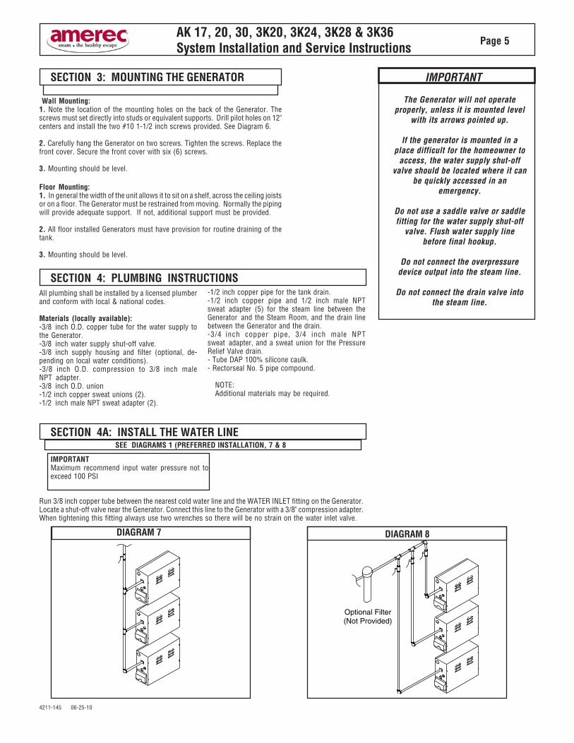
Run 3/8 inch copper tube between the nearest cold water line and the WATER INLET fitting on the Generator.Locate a shut-off valve near the Generator. Connect this line to the Generator with a 3/8" compression adapter.When tightening this fitting always use two wrenches so there will be no strain on the water inlet valve.
SEE DIAGRAMS 1 (PREFERRED INSTALLATION, 7 & 8SECTION 4A: INSTALL THE WATER LINE
IMPORTANTMaximum recommend input water pressure not toexceed 100 PSI
IMPORTANT
The Generator will not operateproperly, unless it is mounted level
with its arrows pointed up.
If the generator is mounted in aplace difficult for the homeowner to
access, the water supply shut-offvalve should be located where it can
be quickly accessed in anemergency.
Do not use a saddle valve or saddlefitting for the water supply shut-off
valve. Flush water supply linebefore final hookup.
Do not connect the overpressuredevice output into the steam line.
Do not connect the drain valve intothe steam line.
DIAGRAM 7 DIAGRAM 8
Optional Filter(Not Provided)
4211-145 06-25-10
AK 17, 20, 30, 3K20, 3K24, 3K28 & 3K36System Installation and Service Instructions Page 6
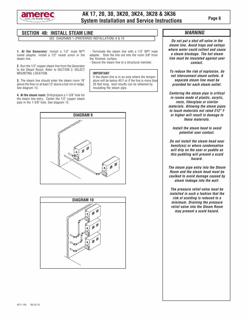
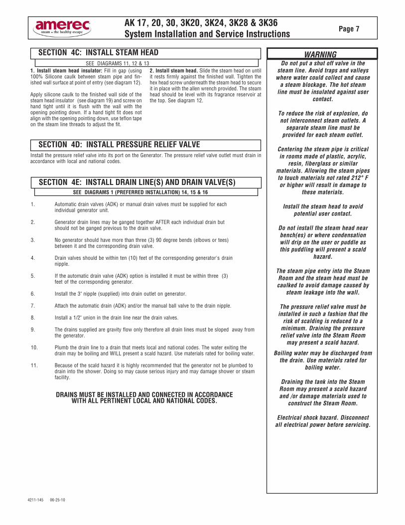
1. At the Generator: Install a 1/2" male NPTsweat adapter. Install a 1/2" sweat union in thesteam line.
2. Run the 1/2" copper steam line from the Generatorto the Steam Room. Refer to SECTION 2: SELECTMOUNTING LOCATION.
3. The steam line should enter the steam room 18"above the floor or at least 12" above a tub rim or ledge.See diagram 13.
4. At the steam room: Drill/prepare a 1-3/8" hole forthe steam line entry. Center the 1/2" copper steampipe in the 1-3/8" hole. See diagram 12.
- Terminate the steam line with a 1/2" NPT maleadapter. Stub the line out into the room 3/8" fromthe finished surface.- Secure the steam line to a structural member.
IMPORTANTIf the steam line is in an area where the temper-ature will be below 40 F or if the line is more than20 feet long, best results can be obtained byinsulating the steam pipe.
DIAGRAM 10
DIAGRAM 9
SECTION 4B: INSTALL STEAM LINESEE DIAGRAMS 1 (PREFERRED INSTALLATION) 9 & 10
Do not put a shut off valve in thesteam line. Avoid traps and valleys
where water could collect and causea steam blockage. The hot steam
line must be insulated against usercontact.
To reduce the risk of explosion, donot interconnect steam outlets. A
separate steam line must beprovided for each steam outlet.
Centering the steam pipe is criticalin rooms made of plastic, acrylic,
resin, fiberglass or similarmaterials. Allowing the steam pipesto touch materials not rated 212° For higher will result in damage to
these materials.
Install the steam head to avoidpotential user contact.
Do not install the steam head nearbench(es) or where condensationwill drip on the user or puddle asthis puddling will present a scald
hazard.
The steam pipe entry into the SteamRoom and the steam head must becaulked to avoid damage caused by
steam leakage into the wall.
The pressure relief valve must beinstalled in such a fashion that the
risk of scalding is reduced to aminimum. Draining the pressurerelief valve into the Steam Room
may present a scald hazard.
WARNING
4211-145 06-25-10
AK 17, 20, 30, 3K20, 3K24, 3K28 & 3K36System Installation and Service Instructions Page 7
Boiling water may be discharged fromthe drain. Use materials rated for
boiling water.
Draining the tank into the SteamRoom may present a scald hazardand /or damage materials used to
construct the Steam Room.
Electrical shock hazard. Disconnectall electrical power before servicing.
Do not put a shut off valve in thesteam line. Avoid traps and valleys
where water could collect and causea steam blockage. The hot steam
line must be insulated against usercontact.
To reduce the risk of explosion, donot interconnect steam outlets. A
separate steam line must beprovided for each steam outlet.
Centering the steam pipe is criticalin rooms made of plastic, acrylic,
resin, fiberglass or similarmaterials. Allowing the steam pipesto touch materials not rated 212° For higher will result in damage to
these materials.
Install the steam head to avoidpotential user contact.
Do not install the steam head nearbench(es) or where condensationwill drip on the user or puddle asthis puddling will present a scald
hazard.
The steam pipe entry into the SteamRoom and the steam head must becaulked to avoid damage caused by
steam leakage into the wall.
The pressure relief valve must beinstalled in such a fashion that the
risk of scalding is reduced to aminimum. Draining the pressurerelief valve into the Steam Room
may present a scald hazard.
WARNING
1. Install steam head insulator: Fill in gap (using100% Silicone caulk between steam pipe and fin-ished wall surface at point of entry (see diagram 12).
Apply silicone caulk to the finished wall side of thesteam head insulator (see diagram 19) and screw onhand tight until it is flush with the wall with theopening pointing down. If a hand tight fit does notalign with the opening pointing down, use teflon tapeon the steam line threads to adjust the fit.
2. Install steam head. Slide the steam head on untilit rests firmly against the finished wall. Tighten thehex head screw underneath the steam head to secureit in place with the allen wrench provided. The steamhead should be level with its fragrance reservoir atthe top. See diagram 12.
SEE DIAGRAMS 11, 12 & 13
SECTION 4C: INSTALL STEAM HEAD
SECTION 4D: INSTALL PRESSURE RELIEF VALVE
SEE DIAGRAMS 1 (PREFERRED INSTALLATION) 14, 15 & 16
SECTION 4E: INSTALL DRAIN LINE(S) AND DRAIN VALVE(S)
1. Automatic drain valves (ADK) or manual drain valves must be supplied for eachindividual generator unit.
2. Generator drain lines may be ganged together AFTER each individual drain butshould not be ganged previous to the drain valve.
3. No generator should have more than three (3) 90 degree bends (elbows or tees)between it and the corresponding drain valve.
4. Drain valves should be within ten (10) feet of the corresponding generator's drainnipple.
5. If the automatic drain valve (ADK) option is installed it must be within three (3)feet of the corresponding generator.
6. Install the 3" nipple (supplied) into drain outlet on generator.
7. Attach the automatic drain (ADK) and/or the manual ball valve to the drain nipple.
8. Install a 1/2" union in the drain line near the drain valves.
9. The drains supplied are gravity flow only therefore all drain lines must be sloped away fromthe generator.
10. Plumb the drain line to a drain that meets local and national codes. The water exiting thedrain may be boiling and WILL present a scald hazard. Use materials rated for boiling water.
11. Because of the scald hazard it is highly recommended that the generator not be plumbed todrain into the shower. Doing so may cause serious injury and may damage shower or steamfacility.
DRAINS MUST BE INSTALLED AND CONNECTED IN ACCORDANCEWITH ALL PERTINENT LOCAL AND NATIONAL CODES.
Install the pressure relief valve into its port on the Generator. The pressure relief valve outlet must drain inaccordance with local and national codes.

4211-145 06-25-10
AK 17, 20, 30, 3K20, 3K24, 3K28 & 3K36System Installation and Service Instructions Page 8
1/2"NPT
Sweat
Centerin
1/4"
1/4" 1-3/8"Diameter
SPACER STUD
DIAGRAM 11 DIAGRAM 12
SECTION 4F: Water Quality Requirements
The nature of a boiler or steambath generator requires testing of the feedwater to avoid potential high concentrations of impurities which cancause a deposit or scale to form on the internal surfaces. This deposit or scale can interfere with the equipments proper operation and evencause premature boiler or generator failure. Concentration of impurities is generally controlled by treating the feedwater and or "blowing down"the generator or boiler when it is not heating. The "blow down" process involves removing a portion of the tank water with high solid concentra-tion and replacing it with makeup water.
To insure proper operation, the water supply should be tested prior to operating the equipment. There are several treatment processes which canbe used if you have a problem with hard water. A local reliable water treatment company can recommend the appropriate treatment if required.The recommended feedwater quality is listed below.
Feedwater Quality
Hardness, ppm 10 - 30 (.5 - 1.75 gpg)T-Alkalinity, ppm 150 - 700 (8.75 - 40.8 gpg)Silica Range, ppm 15 - 25 (1.28 - 1.45 gpg)PH (strength of alkalinity) 10.5 - 11.5
DIAGRAM 13
9"min
9"min
12"min
from topof tub or
18"from floor
5"min
9"min
5"min
5"min
5"min
3/8" FROM WALL
STEAM HEAD INSULATOR
STEAMHEAD FACE
FRAGRANCERESERVOIR
1-3/8" DIAMETER HOLE
1/2" NPT FITTING
FILL IN GAP USING100% SILICONE CAULK
4211-145 06-25-10
AK 17, 20, 30, 3K20, 3K24, 3K28 & 3K36System Installation and Service Instructions Page 9
DIAGRAM 14 DIAGRAM 15 DIAGRAM 16
SECTION 5: WIRING INSTRUCTIONS (All Controls)
SEE ELECTRICAL INFO CHART ON PAGE 12, DIAGRAMS 17 THRU 27AND WIRING DIAGRAMS ON PAGES 22, 23 & 24
WARNING
The KT60 "must" be mounted insidethe steam room.
Mount the KT60 48" up from steamroom floor.
1. CONTROL CABLE ROUGH-INThe low voltage control can be mounted up to 25 feetfrom the generator either inside or outside the steamroom for the K30, K60 or R30K control but with a builtin temperature sensor, the KT60 must be mountedinside the steam room, also see #6 optional second-ary generator control. String the 25' cable from thecontrol location through 1/2" holes in the wall studsor ceiling joists to the generator. Note: Do not staplethrough or damage cable. Use factory supplied ca-bles only. Optional for tile rooms, a 2 gang rough-inbox may be installed at the desired control mountinglocation. A mounting plate with proper diameter holeis included with the control kit. Tile up to the hole inmounting plate as indicated in diagram 18 or 22.
1A. K200i STEAM CABLE ROUGH-INThere is only one 25' cable to install with the K200icontrol system for the RF Connumication Hub whichshould be mounted high on a wall near the steamroom or above the steam room. The RF hub relayssignals from the K200i remote and dock to thegenerator but does not need to be in direct line of sitewith these items. (see diagram # 4.5)
2. TEMPERATURE SENSOR CABLE ROUGH-IN(REQUIRED FOR K60 OR K30 ONLY)It is recommended that the sensor be mounted in thesteam room 6" from the ceiling, but not directly overthe steam dispersion head or more than 7 feet abovethe floor. String the sensor cable from the sensorlocation through 1/2" holes in the wall studs or ceilingjoists to the generator location. Leave 12" of slack atthe sensor location. Note: Do not staple through ordamage cable. Use factory supplied cables only.
3. ELECTRICAL ROUGH-INSize wire for the generator as indicated by the Elec-trical Information Chart on page 9. Use correct sizeand type to meet electrical codes. Leave 4 feet ofslack wire at generator location for finish hookup.Connect the generator to a dedicated circuit breaker.A GFI device is not required by UL. One may beinstalled if required by local codes or the owner. A GFIdevice will tend to nuisance trip due to heater elementaging.
4. ELECTRICAL FINISHMaterials (locally available):- 3/4" Strain relief for supply wire.
A. Route the copper supply wire with appropriatestrain relief through the hole marked POWER ENTRY.B. Connect the supply wires to terminals marked L1and L2.C. Connect the ground to the ground lug (greenscrew).
6 in MIN
6 in MIN
15 in MIN SERVICE CLEARANCE
15 in MIN SERVICE CLEARANCE
4211-145 06-25-10
AK 17, 20, 30, 3K20, 3K24, 3K28 & 3K36System Installation and Service Instructions Page 10
6. OPTIONAL SECONDARY GENERATOR CONTROLAs an option, a second K60 control can be installedwith an AK generator to provide ON/OFF control bothinside and outside the steam room. The secondcontrol should be installed as described in para-graphs 1 & 5, with the second control cable pluggedinto connector S60B for the K60 Control on theprinted circuit board assembly. See diagram 20.
1. DO YOUR BREAKER AND WIRE SIZES MATCH FACTORY/UL SPECS AS PER CHART ON PAGE 9?
2. IF GENERATOR REQUIRES A TEMPERATURE SENSOR, IS THE SENSOR INSTALLED?
3. ARE YOUR CONTROL(S) PLUGGED INTO THE CORRECT JACK(S) ON THE CIRCUIT BOARD?
4. IS POWER SUPPLIED TO ALL CIRCUITS OF STEAMER? (SOME REQUIRE TWO FEEDS)
5. WAS POWER OFF AT THE BREAKER/DISCONNECT WHEN THE CONTROL(S) WERE INSTALLED?
6. IS WATER SUPPLIED TO GENERATOR?
7. IS STEAM LINE PLUMBED TO STEAM ROOM?
8. IS THE AUTOMATIC DRAIN VALVE INSTALLED IN DRAIN OUTLET LINE OR THE BALL VALVE INSTALLED IN A CLOSED POSITION?
QUICK INSTALLATION CHECK LIST
WARNING
The KT60 "must" be mounted insidethe steam room.
Mount the KT60 48" up from steamroom floor.
5. INSTALL GENERATOR CONTROL (K30,K60,KT60)The low voltage controls can be mounted directly to a finished wall eitherinside or outside the steam room with the exception of the KT60 controlwhich must be mounted inside the steam room. Using a 2" hole saw, drilla hole in the finished wall where the control is to be mounted (the controlcable should already be roughed-in to this location). With the decorativecover removed from the control switch assembly, insert the two controlmounting screws through the control housing (may need to punchthrough skinned holes) and screw 1/4" into the mounting bracket. Locatethe control cable and plug it into the back of the control housing. Seediagram 18. Run a bead of 100% silicon caulk in-between the 2 ridgesaround the perimeter on the back of the control housing. See diagram 19.Insert the mounting bracket into the wall cavity by first pushing with thecontrol housing and then with a hard flat surface on the control housingmounting screws which extend out through the control face. Once themounting bracket has been inserted into the finished wall, center thecontrol and tighten the mounting screws to draw the control housingsecurely against the finished wall. Do not over tighten the mountingscrews. Install the decorative cover plate by sliding the top of the coverplate over the tab on the top of the control housing and pushing on thebottom of the cover plate to complete the snap fit. See diagram 23. Routethe generator end of the control cable through the generator hole markedCONTROL WIRING ENTRY using the strain relief provided. Plug thecontrol cable into the connector on the printed circuit board assembly.Insert cable into connector S30 if a K30 control is used or connector S60Aif a K60 or KT60 control is used. See diagram 20.
5A. INSTALL GENERATOR CONTROL (R30K)The low voltage control can be mounted directly to a finished wall eitherinside or outside the steam room. Using a 1-3/4" hole saw, drill a hole inthe finished wall where the control is to be mounted (the control cableshould already be roughed-in to this location). Locate the control cable,pull it out through the1-3/4" hole and plug the connector on the back of the control housing. Runa bead of 100% silicone caulk around the perimeter on the back of thecontrol housing. See diagram 22. Insert the control into the wall cavity.
7. INSTALL TEMPERATURE SENSOR(REQUIRED FOR K60 OR K30 ONLY)The temperature sensor should be mounted 6" below the ceiling, inside the steam room,but not directly over the steam dispersion head or more than 7 feet above the floor. Usinga 7/8" hole saw, drill a hole in the finished wall where the sensor is to be mounted (thesensor cable should already be roughed-in to this location). Locate the sensor cable, pullit out through the hole and plug it into the temperature sensor. It is best to tape the sensorand cable connection together to avoid disconnection inside the wall. Apply silicon caulkas shown in diagram 24 and insert the sensor in the hole. Make sure that the sensorprobe is pointing down once installed. Tape the sensor in place while the siliconehardens. Route the generator end of the sensor cable through the generator hole markedCONTROL WIRING ENTRY using the control cable strain relief. Plug the sensor cable intothe connector marked J4 on the printed circuit board assembly. See diagram 20
8. OPTIONAL CELSIUS OR 24 HOUR OPERATION.For installations with K60 or KT60 controls, the operation can be changed fro Fahrenheitto Celsius or 60 minute operation to 24 hours operation by setting the jumpers as shownbelow on the generator printed circuit board.
PLACE JUMPER�ON BOTH PINSIF OPTION IS
NOT INSTALLED
PLACE JUMPER ON ONE PINFOR NORMAL OPERATION
PLACE JUMPER ON BOTH PINSFOR USE WITH A TIMER
CONNECTED TO TB1
PLACE JUMPER�ON ONE PINIF OPTION
IS INSTALLED
PLACE ON BOTH PINS FOR
PLACE ON ONE PIN FORBATH TIME DISPLAY
60 MIN
24 HR �C
�F

4211-145 06-25-10
AK 17, 20, 30, 3K20, 3K24, 3K28 & 3K36System Installation and Service Instructions Page 11
DIAGRAM 18 (K30 & K60 Controls)
DIAGRAM 19 (K30 & K60 Controls & Steam Head Insulator) DIAGRAM 20 (K30 & K60 Controls)
STEAMCONTROL(4 feet up not directly over steamhead)
TEMPERATURESENSOR CABLE(K60 or K30 only)
TEMPERATURESENSOR(K60 or K30 only)
CONTROLCABLE
6" MIN -
7'MAX
DIAGRAM 17 (K30 & K60 Controls)
CONTROLHOUSING
DECORATIVE CONTROLCOVER PLATE
CONTROL HOUSINGMOUNTING SCREWS
2" DIAMETERHOLE IN FINISHEDWALL
MOUNTINGBRACKET
(DO NOT OVERTIGHTEN)
J4
SK1
TB2
SK4SK3
G2G1STEAM
CONTROL
OPTIONAL AUTOMATICDRAIN CONNECTION
TEMPERATURE SENSOR PLUG (J4)
STEAM CONTROL PLUGR30K (S30)K30 PRIMARY (S30)KT60/K60 PRIMARY (S60A)KT60/K60 SECONDARY (S60B)
TEMPERATURESENSOR
(K60 or K30 only)
DIAGRAM 21 (R30K Control)
R30KSTEAMCONTROL
CONTROLCABLE
DIAGRAM 22 (R30K Control)
APPLY SEALANT(100% SILICONE CAULK)
TILE UP TO 1-3/4"DIAMETER HOLE INFINISHED WALL
(OPTIONAL NUT IF BACK OFWALL IS ACCESSIBLE)
S30S60A
S60B
R30KROUGH-IN
CONTROL
SEALANT(MUST FILLGROUT LINE FORTILE WALLS
SEALANT(MUST FILLGROUT LINE FORTILE WALLS
STEAM HEAD INSULATOR
K30 & K60 Control

4211-145 06-25-10
AK 17, 20, 30, 3K20, 3K24, 3K28 & 3K36System Installation and Service Instructions Page 12
DIAGRAM 23
CONTROLHOUSING
(BUILT-IN SENSORON KT60 CONTROL
ONLY)
WALL
DECORATIVECONTROL COVERPLATE
DIAGRAM 24
SILICONECAULK
TEMPERATURESENSOR
WALL
7/8" HOLE
SENSORCABLE
PIGTAILPROBE MUST BEPOINTED DOWN
DIAGRAM 25
2 GANG ROUGH-IN BOX
K30, K60, KT60ROUGH-IN
TILE UP TO2" DIAMETER HOLEIN FINISHED WALL
S T E A M G E N E R AT O R M O D E LN O . A K 1 0 A G 7 A G 1 0 3 K 1 2 3 K 1 4 3 G 8 3 G 1 2 3 G 1 4
A C V O LTA G E 20 8 / 2 40 2 0 8 / 2 40 20 8 / 24 0 20 8 2 08 20 8 2 08 2 0 8
P H A S E 1 1 1 3 3 3 3 3
N O M IN A L WAT TA G E @ 2 0 8@ 2 4 0
7 50 01 00 00
5 25 07 0 0 0
7 5 001 00 00
1 20 0 0N /A
1 4 00 0N /A
80 0 0N /A
1 2 00 0N / A
14 0 00N /A
N O M IN A L A M P E R A G E @ 2 0 8@ 2 4 0
3 6 . 14 1 . 5
25 .329 .0
36 .14 1 . 5
3 3 .3N /A
4 0 .1N /A
2 1 .9N /A
33 .3N / A
40 .1N /A
U L R E C O M M E N D E DP R O T E C T IV E D E V IC E
@ 2 0 8@ 2 4 0
5 06 0
3540
5060
50N /A
6 0N /A
3 0N /A
50N / A
6 0N /A
R E C O M M E N D E D M IN .C O P P E R S U P P LY W IR E *
@ 2 0 8@ 2 4 0
8 -2 W /G6 -2 W /G
8 -2 W /G8 -2 W /G
8 -2 W /G6 -2 W /G
8 -3 W /GN /A
6 -3 W /GN /A
1 0-3 W /GN /A
8-3 W /GN / A
6-3 W /GN /A
*Observe wire sizes for 208 VAC installations. 208 VAC wired units must be supplied with a minimum of 195 VAC while operating (heating). Unit israted for copper wire only. All wire is UL approved 300V 75° deg., minimum unless otherwise specified. LISTED WIRE SIZES ARE MINIMUM FOR
REFERENCE ONLY. REFER TO NEC AND LOCAL CODES FOR YOUR INSTALLATION.
ELECTRICAL INFORMATION CHART
DIAGRAM 26: 3G or AG SLAVE GENERATOR DIAGRAM 27: 3K or AK MASTER GENERATOR
To Master PCAFrom 2nd Slave PCA
From 1st Slave PCA
J14 J13

4211-145 06-25-10
AK 17, 20, 30, 3K20, 3K24, 3K28 & 3K36System Installation and Service Instructions Page 13
Electrical shock hazard - Disconnectall electrical power before servicingthe Generator. All wiring should be
installed by a licensed electricalcontractor in accordance with local
and national codes.
The Generator is designed forhookup with copper wire only
User Shock Hazard! Installer mustmaintain control wiring segregation.All control wiring must be restrainedin the "Control Area" designated in
Diagrams 26 & 27.
Protect the AG cable per localcodes if it is routed in:
Areas exposed to weather;Chemical or hazardous
atmospheres; Areas that may exceedtheir temperature ratings or... if
routed adjacent to wires withvoltage above 240V.
SECTION 5B: WIRING INSTRUCTIONS (SLAVE GENERATORS) WARNING
or more depending on its power rating. It’s normal forthe flow of steam out the steam head to slow for upto 10 seconds each time the unit calls for water.
7. The unit will shut down automatically in 30 min-utes if the R30K or K30 Control is used, or up to 60minutes if the K60 or KT60 Control is used. When thetime runs out the steam will stop and there should notbe any water flow. The control should not be lit.
8. If the unit does not operate as described above,refer to SECTION 8: TROUBLESHOOTING GUIDE.
THE UNIT IS NOW READY FOR OPERATION.
1. Assure power and water are on.
2. Press the ON/OFF. The control should light-up.
3. Allow 10 minutes for the steam to start.
4. Once the steam starts, press the ON/OFF. Thesteam should stop; there shouldn't be any water flow.The control should not be lit-up.
5. Press the ON/OFF. The control should light up.
6. Within one minute the unit should again producesteam. It should call for water once every two minutes
SECTION 6: OPERATIONAL TEST
1. ELECTRICAL ROUGH-INSize wire for the Generator as indicated by the Elec-trical Information Chart on page 12. Use correct sizeand type to meet electrical codes. Leave 4 feet ofslack wire at Generator location for finish hookup.Connect the Generator to a dedicated circuit breaker.A GFCI device is not required by UL. One may beinstalled if required by local codes or the owner. AGFCI may nuisance trip due to heater element aging.
2. ELECTRICAL FINISHMaterials (locally available): - 3/4" Strain relief for supply wire. - Circuit breaker per Electrical Information Chart.
a. Route the copper supply wire with appropriatestrain relief through the hole marked POWER ENTRY.b. Connect the supply wires to the terminal blockmarked L1 and L2.
c. Connect the ground wire to the ground lug (greenscrew on junction compartment wall).
3. INSTALL SLAVE CONTROL CABLEa. Route one end of the slave control cable throughthe Generator hole marked "Control Wiring Entry".Use the strain relief provided. Plug the slave controlcable into the connector J1 on the slave PCA. SeeDiagram 26.b. Connect the other end of the slave control cable tothe Master Generator. See Diagram 27.
SEE ELECTRICAL INFO CHART ON PAGE 12 DIAGRAMS 26 & 27 AND THE WIRING DIAGRAM ON PAGE 22
4211-145 06-25-10
AK 17, 20, 30, 3K20, 3K24, 3K28 & 3K36System Installation and Service Instructions Page 14
1. DESCRIPTION OF AMEREC (SLAVE) SERIES GEN-ERATORThe AG Slave is controlled by an "AK or 3K" MasterGenerator. Control signals are transmitted to theSlave from the Master via the 8 wire slave controlcable provided.
The AK or 3K Printed Circuit Assembly provides theinterface circuitry between the AK Master and theSlave Printed Circuit Assembly. The Slave PCA pro-vides the basic functions necessary to produce steam.It controls makeup water, provides a water levelpermissive for powering the elements and providesraw DC power for the system.
2.MAINTENANCE OF GENERATOR
VISUAL INSPECTION - Whenever the Generator isopened inspect for any evidence of water leaks.Inspect the wiring for any evidence of overheating.Check all electrical connections for tightness.
FLUSH TANK - Flush monthly, or more often, de-pending on local water conditions.
1. The Generator should be cool
2. Press th ON/OFF. The control should light
3. Open the manual drain valve
4. The unit will drain without heating the water
5. Allow the water to run for a full 10 minutes, thenpress the ON/OFF. The control light should turn off
6. Allow the unit to drain completely. When the waterstops, close the drain valve
3. REPAIR OF GENERATOR
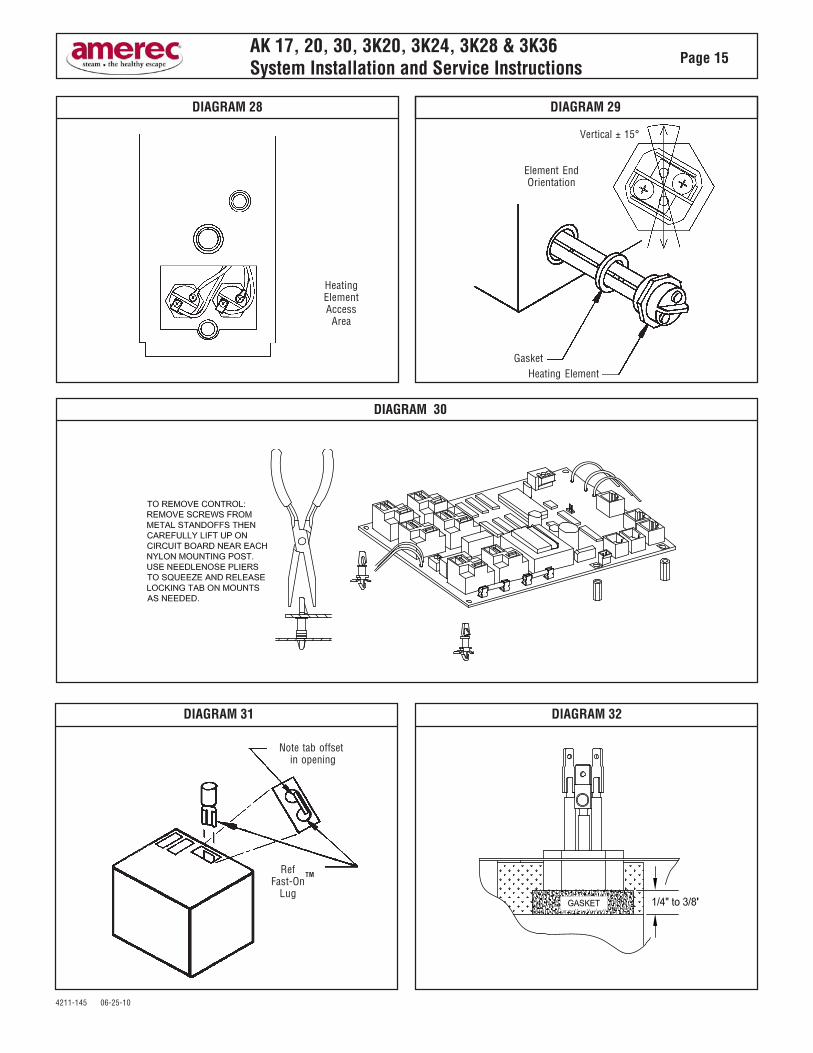
a. ELEMENT REPLACEMENTDisconnect power from the unit. Drain the tank. Openthe front and HEATING ELEMENT ACCESS covers.Note the wire connections. See Diagram 28. Removethe element wires. Using a hot water element socket,remove the element. To install a new element, mounta new element gasket on the element. Clean theelement port and add a light coat of Rectorseal No. 5pipe thread compound to the threads. Insert andhand tighten the element-gasket combination. Noticethe element end orientation as shown in Diagram 29.Tighten the element until the orientation is the sameas Diagram 29, ± 15°. The gasket should be set andtight but not deformed to a rounded or bulbousappearance. If the drain valve was removed reinstallit. Reconnect the wiring. Test the unit per SECTION 6:OPERATIONAL TEST. Check for leaks at the element.Replace the front cover and the HEATING ELEMENTACCESS cover.
b. PRINTED CIRCUIT REPLACEMENTPrinted circuit assembly (PCA) removal and replace-ment must be performed in the sequence describedbelow. Any other method can damage the PCA’s.
IMPORTANTThe PCA’s contain static sensitive devices.Static electricity may damage PCA’s. Handleaccordingly.
To remove the PCA: Disconnect power from the unit.Note and tag the positions of all wires that plug intothe printed circuit assembly mounted relays. Removeall the wires from the relays. When removing thesewires, pull on the connector, not the wire. Disconnectall three (3) wires from the water level probe. Nextslide these wires out by slightly bending the wireclamp retaining these wires. Disconnect the two (2)blue wires from the water solenoid valve. Five (5) orseven (7) stand offs hold the board in place. Removeall the stand offs by pinching the tops. When it iscompletely disconnected, it may be lifted out of theenclosure. See Diagram 30. To install the board,reverse this procedure. Test the unit per SECTION 6:OPERATIONAL TEST.
IMPORTANTThe blue wire connected to “L” and “P3” on thePCA must be connected to the shortest of thethree level probes.
c. WATER SOLENOID REPLACEMENT:Disconnect power from the unit. Turn the watersupply OFF. Disconnect the water supply from thewater solenoid valve. Remove the front cover. Re-move the two blue wires from the water solenoidvalve. Rotate the self-tightening hose clamp so it canbe loosened with a pair of pliers. Squeeze the clampand move it down towards the shelf and off the valveoutlet tube. Remove the two 1/4" - 20 hex head boltsand lock washers that attach the valve to the chassis.Pull the valve off the rubber fill hose. To install thevalve, reverse these instructions. Test the unit perSECTION 6: OPERATIONAL TEST.
d. LEVEL PROBE REPLACEMENT:Disconnect power from the unit. Remove the frontcover. Disconnect all three (3) wires from the waterlevel probe. Using a 1-1/4" box wrench, remove thelevel probe. Install a new level probe. Tighten until thebottom of the plastic nut is 1/8" to 3/8" inch above thetop of the port. See Diagram 32. Reattach the three(3) wires. Test the unit per SECTION 6: OPERATION-AL TEST.
IMPORTANTThe blue wire connected to “L” and “P3” on thePCA must be connected to the shortest of thethree level probes.
IMPORTANTThe level probe may be extremely tight. Damageto the insulation or chassis may result unlessthe tank is properly blocked or supportedduring probe removal or installation. It may benecessary to completely disconnect anddisassemble the Generator.
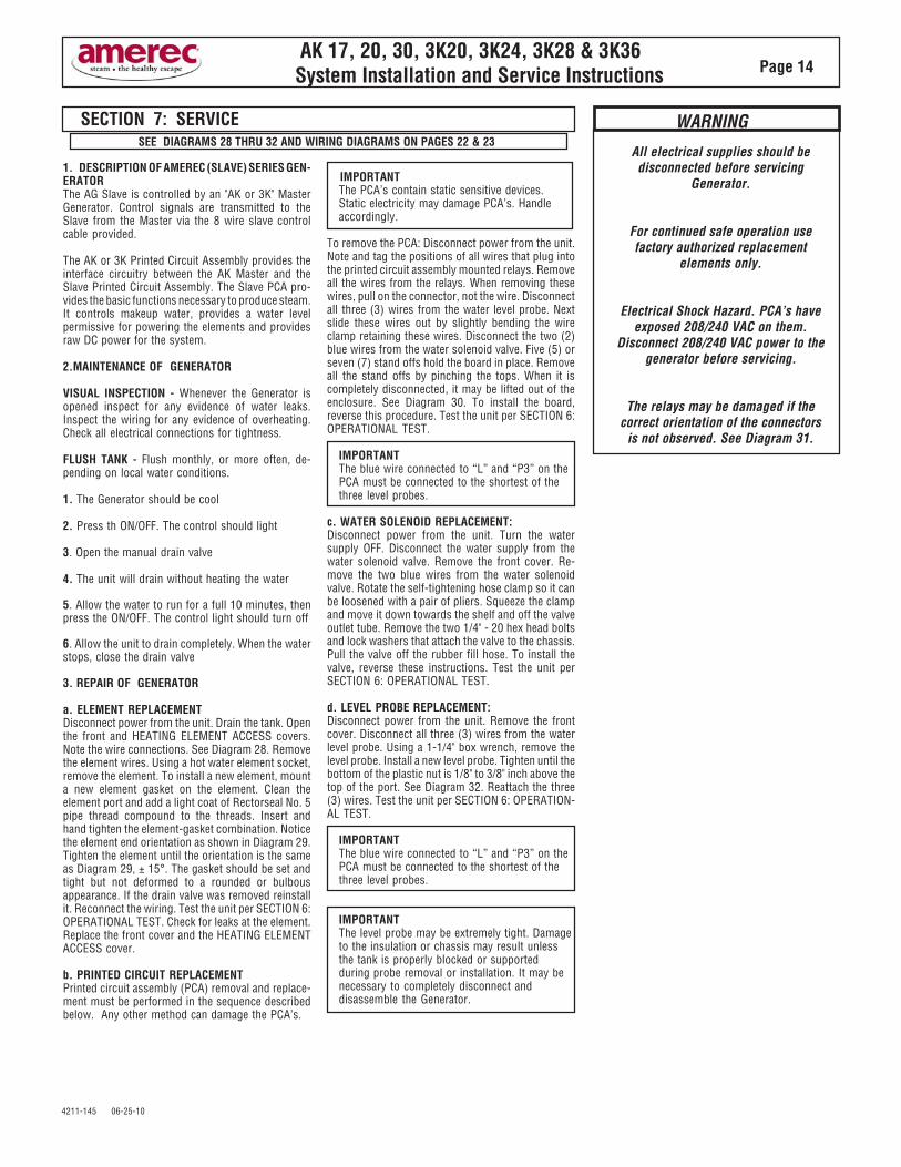
SECTION 7: SERVICESEE DIAGRAMS 28 THRU 32 AND WIRING DIAGRAMS ON PAGES 22 & 23
All electrical supplies should bedisconnected before servicing
Generator.
For continued safe operation usefactory authorized replacement
elements only.
Electrical Shock Hazard. PCA’s haveexposed 208/240 VAC on them.
Disconnect 208/240 VAC power to thegenerator before servicing.
The relays may be damaged if thecorrect orientation of the connectors
is not observed. See Diagram 31.
WARNING
4211-145 06-25-10
AK 17, 20, 30, 3K20, 3K24, 3K28 & 3K36System Installation and Service Instructions Page 15
DIAGRAM 29DIAGRAM 28
HeatingElementAccess
Area
Vertical ± 15°
Element EndOrientation
GasketHeating Element
DIAGRAM 30
DIAGRAM 31
Note tab offset in opening
RefFast-On
Lug
TM
DIAGRAM 32

4211-145 06-25-10
AK 17, 20, 30, 3K20, 3K24, 3K28 & 3K36System Installation and Service Instructions Page 16
SECTION 8: TROUBLESHOOTING GUIDEThere are no user serviceable parts in the Generator. All repair should be performed by a qualified service person. For additional assistance or the factory authorizedservice person nearest you call,Steam Technical Support at 1-800-363-0251. The Troubleshooting Guide below is meant as a general aid only. Follow ACTION TOBE TAKEN in order until the problem is resolved. Where replacements or repairs are indicated, see the appropriate paragraph of SECTION: 7 SERVICE.
Control wont turn "On"(Control light off)
KT60, K60, K30, R30K& R30i Controls
Note: Control Cables must becorrectly plugged in before
power is turned on.
Improper power supplied.or
Control improperly connected.or
AK or 3K Master PCA is faulty.or
Control cable is faulty.or
Control is faulty.
1. a. Make sure circuit breaker is “ON” and that 208V/240V is supplied. b. Using a voltmeter, check the voltage across the two fuses on the“PCA”printed circuit assembly. Voltage should be 208V/240V whenmeasured fuse to fuse on left ends and fuse to fuse on right ends. fuseon left ends and fuse to fuse on right ends. If proper voltage is presentacross left ends but not right ends, one or more fuse is blown. c. Turn off Power to generator. Check fuses on the PCA. If the fuse(s)are blown, replace with 100mA SLO-Blow (F1) or 1A FAST-Blow (F2) Ifthe fuse(s) blows again - Call Steam Technical Support.2. a. Turn off Power to generator. b. Check control(s) installed per Section 6. Re-apply power and testoperation.3. Replace Master PCA - Call Steam Technical Support.4. Replace control cable - Call Steam Technical Support.5. Replace the control - Call Steam Technical Support.
1. Follow preceding “ACTION TO BE TAKEN” steps 1. thru 2.2. Turn off Power to generator.. Check to make sure hub cable is pluggedinto Pca J9 port labeled “Wireless Hub” and Hub is mounted withincommunication range of Dock & Remote Control (See Hub Mountinginstructions) located in the K200i Control Installation & Owners Manualfor AK & 3K Generators.Turn on power to generator, wait 3 minutes for communication to beestablished. If Red “X” is no longer present, communication has beenestablished. Test for proper operation.3. Replace Hub cable.4. See K200i Control Installation & Owners Manual for AK & 3KGenerators (Section 4 RF Hub Mounting)5. Call Steam Technical Support
Improper power suppliedor
Hub or Hub Cable not properly connected.or
Hub cable is faulty.or
K200i Communication System hasexperienced “Communication
Interference”or
K200i Communication System is faulty.
K200i Remote will not turn“SteamBath On"
Remote “On” Icon selected andRemote displays Red “X” (over
5mins.)and
K200i Dock will not turn“SteamBath On” Dock On/Off
button pushed. Dock lightcomes “On” while button
pushed but light does not beginblinking within 5 minutes after
button is realeased.
1. Turn off power to generator. If the water stops, go to step 3.2. a. Remove the water solenoid valve, disassemble, clean, re-assemble,and check for proper operation.b. Replace water solenoid valve - Call Steam Technical Support.3. Replace the “PCA” printed circuit assembly - Call Steam TechnicalSupport.
Water solenoid valve is stuck openor
“PCA” printed circuit assembly is faulty.
Control “Off”Water won’t shut off and runs
out steam head.
1. Check that the blue & white wires are properly attached to the waterlevel probe. Blue wire attaches to the shortest level probe, white to thehighest probes.2. Remove the blue wire from the water level (shortest) probe.Momentarily ground the blue probe wire to the steamer chassis and listenfor a click. If the click noise is heard and the water valve shuts off, clean orreplace the water level probe.Note: Also inspect the tank and baffle area for potential cleaning. CallSteam Technical Support.3. If the click is not heard replace the “PCA” printed circuitassembly. Call Steam Technical Support.
Connection between the blue water levelprobe wire and the water level probe is
faulty.or
Water Level Probes may need cleaning..or
Tank and Baffle may be clogged with scaleand need cleaning.
or“PCA” printed circuit assembly is faulty
Control “On”Water won’t shut off and runs
out steam head.
1. Check that drain valve is installed on the drain outlet and in the closedposition.2. Check that electric Auto drain valve is installed on the drain outlet.and valve wires are connected to drain terminal block on PCA in steam.3. Check for 208V/240V to electric drain valve from PCA.4. If voltage is not present then Call Steam Technical Support.
Control “On”Water won’t shut off and runs
out drain.
Drain valve not installed or not closed.or
Auto drain valve not closing.
No water supplied (turned off )or
Plugged water solenoid valveor
Water solenoid valve is faultyor
“PCA” printed circuit assembly is faultyor
Level probe is faulty.
Control “On”Unit won’t fill with water.
Tank drained.
SYMPTOMS PROBABLE CAUSES ACTION TO BE TAKEN
1. Check for proper water supply (Supply valve “On”).Note: Drain valve must be closed to allow tank to remain full.2. Remove the blue wire from the level probe. If the unit fills clean orreplace the level probe.3. Turn power off to generator.4. At the water valve solenoid, slide back the blue connector enough toget the voltmeter probes on the solenoid terminals. Turn power &control back on. Measure the voltage across the solenoid terminals. If itis not 208V/240V, replace the printed circuit assembly. If 208V/240V isfound proceed with steps 4 & 5.5. Remove the water solenoid valve; disassemble, clean, reassemble,and check for proper operation.6. Replace the water solenoid valve - Call Steam Technical Support.

4211-145 06-25-10
AK 17, 20, 30, 3K20, 3K24, 3K28 & 3K36System Installation and Service Instructions Page 17
1. a. Turn the control “Off”. b. Open the drain valve allowing tank to drain completely. c. Close the drain valve. d. Turn the control “On”. e. Unit will begin filling, listen for a click noise. Within 20 secondsafter click noise is heard , the water fill will shut off. This will indicate thetank is full. If the tank does not fill - See SYMPTOMS: “Unit won’t fill up”.2. If the tank filled but the relay click was not heard, momentarily groundthe two white water level probe wires to the steamer chassis. If the clicknoise is heard as probe wires are grounded, clean or replace the levelprobe. If the click is not heard replace the “PCA” printed circuit assembly.3. After it has been determined that the tank was filled and the click noisewas heard, remove the heating element access panel then Using avoltmeter, check the voltage between the two wires on each heatingelement or between the two element wires on each set of relays Thevoltage should be 208V/240V. If proper voltage is found, replace heatingelements.Note: Also inspect the tank and baffle area for potential cleaning. CallSteam Technical Support. If proper voltage is not found, Call SteamTechnical Support.
Unit has not filled completely.
or
Heating elements burnt out.
or
Level probe faulty.
or
“PCA printed circuit assembly is faulty.
Control “On” Unit won’t steam.Note: Steam lit steadily on K30
orTime/Temp. properly displayed
on K60/KT60or
K200i Remote and Dock in “On”state with proper temperature
displayed.
Temperature sensor not connected.or
KT60 Faulty
1. Check that the sensor cable is connected to J4 on the “PCA” printedcircuit assembly.2. Check the cable connection to the temperature sensor.3. Replace sensor and/or cable - call Steam Technical Support.4. Replace KT60 Call Steam Technical Support.
Temperature sensor.or
Sensor cable shorted.or
KT60 Faulty
1. Check the sensor cable for damage from nail/staple puncture.2. Check for moisture at sensor cable connections.3. Check sensor cable ends for frayed/exposed wire strands.4. Replace sensor and/or cable - Call Steam Technical Support.5. Replace KT60 Call Steam Technical Support.
Control “On”KT60 / K60 displays “E001”
Control “On”KT60 / K60 displays “E002”
Control “On”KT60 / K60 displays “>>>” or
“E055”
Steambath temperature over 130degs.or
Sensor/cable faulty.or
“PCA” printed circuit assembly is faulty.
1. If bath is too hot, shut off circuit breaker - Call Steam TechnicalSupport.2. Treat as “E002” fault above.3. Call Steam Technical Support.
Call Steam Technical Support.
Tank getting too hot.or
Warm Start Temp. Sensor failure.or
PCA failure
Control “On”KT60 / K60 displays “E044”
andWarm Start Control Flashes
1. Check to make sure that warm start sensor is firmly plugged into J5,located along the back edge of the PCA to the left of the green (3position) terminal block.2. Call Steam Technical Support.
Open Warm Start sensor.
Control “On”KT60 / K60 displays “E007”
andWarm Start Control Flashes
Control “On"KT60 / K60 displays “E008”
andWarm Start Control Flashes
Shorted Warm Start sensor Call Steam Technical Support.
Control “ON”K30 light blinking.
Control improperly connectedor
Sensor/cable faulty.or
Control Faulty.
1. Check that the control cable is properly plugged in at the control andat the generator. K30 to S30 connector on the PCA. Turn off powersupply. Wait one (1) minute then turn back on. Check for properoperation. If K30 is still “blinking”, turn off power supply and Call SteamTechnical Support.2. Check sensor/cable as with K60 “E001” and “E002”.3. Replace the control - Call Steam Technical Support.1. Replace the control. Call Steam Technical Support.2. Turn off the power to the generator, replace printed circuit assembly -Call Steam Technical Support.
1. Replace the control. Call Steam Technical Support.
2.Replace PCA - Call Steam Technical Support.
Control is faulty.or
”PCA” printed circuit assembly is faulty.
Control faulty.or”
PCA” printed circuit assembly is faulty.
Control/Steamer won’t turn “Off.KT60,K60, K30 R30K & R30i
Controls.
Unable to adjust Time or Tempsetting.
K60/KT60 Controls.
SYMPTOMS PROBABLE CAUSES ACTION TO BE TAKEN
4211-145 06-25-10
AK 17, 20, 30, 3K20, 3K24, 3K28 & 3K36System Installation and Service Instructions Page 18
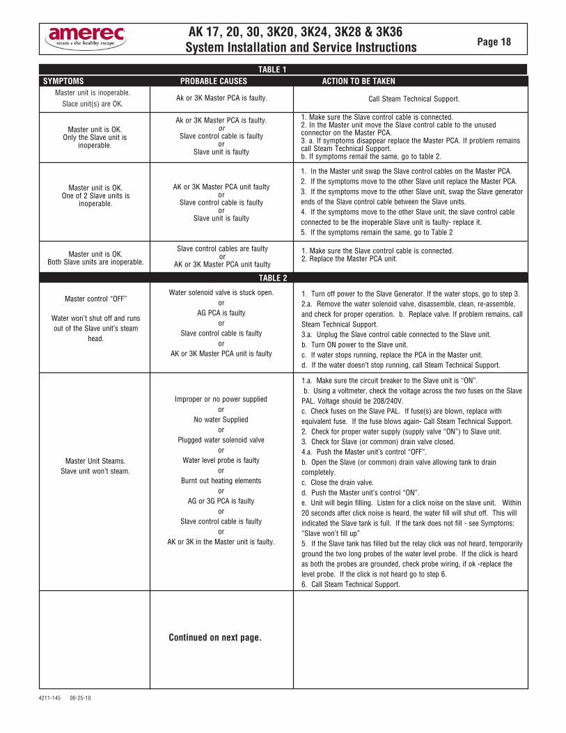
Master unit is inoperable.Slace unit(s) are OK.
Ak or 3K Master PCA is faulty. Call Steam Technical Support.
1. Make sure the Slave control cable is connected.2. In the Master unit move the Slave control cable to the unusedconnector on the Master PCA.3. a. If symptoms disappear replace the Master PCA. If problem remainscall Steam Technical Support.b. If symptoms remail the same, go to table 2.
Ak or 3K Master PCA is faulty.or
Slave control cable is faultyor
Slave unit is faulty
Master unit is OK.Only the Slave unit is
inoperable.
1. In the Master unit swap the Slave control cables on the Master PCA.2. If the symptoms move to the other Slave unit replace the Master PCA.3. If the symptoms move to the other Slave unit, swap the Slave generatorends of the Slave control cable between the Slave units.4. If the symptoms move to the other Slave unit, the slave control cableconnected to be the inoperable Slave unit is faulty- replace it.5. If the symptoms remain the same, go to Table 2
AK or 3K Master PCA unit faultyor
Slave control cable is faultyor
Slave unit is faulty
Master unit is OK.One of 2 Slave units is
inoperable.
SYMPTOMS PROBABLE CAUSES ACTION TO BE TAKEN
Master unit is OK.Both Slave units are inoperable.
Slave control cables are faultyor
AK or 3K Master PCA unit faulty
1. Make sure the Slave control cable is connected.2. Replace the Master PCA unit.
TABLE 2
TABLE 1
Master control “OFF”
Water won’t shut off and runsout of the Slave unit’s steam
head.
Water solenoid valve is stuck open.or
AG PCA is faultyor
Slave control cable is faultyor
AK or 3K Master PCA unit is faulty
1. Turn off power to the Slave Generator. If the water stops, go to step 3.2.a. Remove the water solenoid valve, disassemble, clean, re-assemble,and check for proper operation. b. Replace valve. If problem remains, callSteam Technical Support.3.a. Unplug the Slave control cable connected to the Slave unit.b. Turn ON power to the Slave unit.c. If water stops running, replace the PCA in the Master unit.d. If the water doesn’t stop running, call Steam Technical Support.
Master Unit Steams.Slave unit won’t steam.
Improper or no power suppliedor
No water Suppliedor
Plugged water solenoid valveor
Water level probe is faultyor
Burnt out heating elementsor
AG or 3G PCA is faultyor
Slave control cable is faultyor
AK or 3K in the Master unit is faulty.
1.a. Make sure the circuit breaker to the Slave unit is “ON”. b. Using a voltmeter, check the voltage across the two fuses on the SlavePAL. Voltage should be 208/240V.c. Check fuses on the Slave PAL. If fuse(s) are blown, replace withequivalent fuse. If the fuse blows again- Call Steam Technical Support.2. Check for proper water supply (supply valve “ON”) to Slave unit.3. Check for Slave (or common) drain valve closed.4.a. Push the Master unit’s control “OFF”.b. Open the Slave (or common) drain valve allowing tank to draincompletely.c. Close the drain valve.d. Push the Master unit’s control “ON”.e. Unit will begin filling. Listen for a click noise on the slave unit. Within20 seconds after click noise is heard, the water fill will shut off. This willindicated the Slave tank is full. If the tank does not fill - see Symptoms:“Slave won’t fill up”5. If the Slave tank has filled but the relay click was not heard, temporarilyground the two long probes of the water level probe. If the click is heardas both the probes are grounded, check probe wiring, if ok -replace thelevel probe. If the click is not heard go to step 6.6. Call Steam Technical Support.
Continued on next page.
4211-145 06-25-10
AK 17, 20, 30, 3K20, 3K24, 3K28 & 3K36System Installation and Service Instructions Page 19
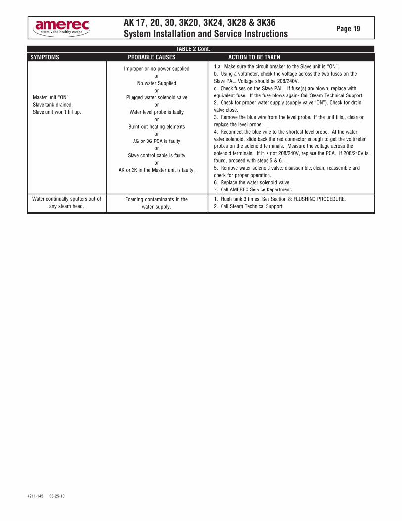
SYMPTOMS PROBABLE CAUSES ACTION TO BE TAKENTABLE 2 Cont.
Master unit “ON”Slave tank drained.Slave unit won’t fill up.
Improper or no power suppliedor
No water Suppliedor
Plugged water solenoid valveor
Water level probe is faultyor
Burnt out heating elementsor
AG or 3G PCA is faultyor
Slave control cable is faultyor
AK or 3K in the Master unit is faulty.
1.a. Make sure the circuit breaker to the Slave unit is “ON”.b. Using a voltmeter, check the voltage across the two fuses on theSlave PAL. Voltage should be 208/240V.c. Check fuses on the Slave PAL. If fuse(s) are blown, replace withequivalent fuse. If the fuse blows again- Call Steam Technical Support.2. Check for proper water supply (supply valve “ON”). Check for drainvalve close.3. Remove the blue wire from the level probe. If the unit fills,, clean orreplace the level probe.4. Reconnect the blue wire to the shortest level probe. At the watervalve solenoid, slide back the red connector enough to get the voltmeterprobes on the solenoid terminals. Measure the voltage across thesolenoid terminals. If it is not 208/240V, replace the PCA. If 208/240V isfound, proceed with steps 5 & 6.5. Remove water solenoid valve: disassemble, clean, reassemble andcheck for proper operation.6. Replace the water solenoid valve.7. Call AMEREC Service Department.
Water continually sputters out ofany steam head.
Foaming contaminants in thewater supply.
1. Flush tank 3 times. See Section 8: FLUSHING PROCEDURE.2. Call Steam Technical Support.

4211-145 06-25-10
AK 17, 20, 30, 3K20, 3K24, 3K28 & 3K36System Installation and Service Instructions Page 20
DIAGRAM 33 (AK/3K GENERATOR)
1
28
12
4
43
29
15
24
23
2
16
7
8
22
19
5
18
17
20
14
6
13
3
39
33
44
21
34
9
3536
11
50
45
13
OR
47
46

4211-145 06-25-10
AK 17, 20, 30, 3K20, 3K24, 3K28 & 3K36System Installation and Service Instructions Page 21
PARTS LIST (AK GENERATOR)
• For assistance or parts ordering, pleasecontact your local AMEREC Dealer orAMEREC at 1-800-331-0349. Please helpus to serve you better by:
1. Identifying the problem by using thetroubleshooting guide in this manual.
2. Read Number 12, the UL Ratings La-bel, to obtain your unit's model and codenumber.
3. When ordering parts, please providethe number, description and quantityneeded. When ordering wires or wireassemblies, please describe the wires bycolor, location and / or their connectionpoints.
4. Do not return any material toAMEREC without first contactingAMEREC for a Return Authorization Num-ber. Freight must be prepaid to AMEREC.
PARTS AND/OR RETURNSNUMBER PART NAME DESCRIPTION1 FRAME CHASSIS2 TERMINAL POWER INPUT TERMINAL BLOCK3 COVER FRONT WITH WD LABEL4 COVER ELEMENT ACCESS5 TANK TWO ELEMENTS6 INSULATION BLANKET7 BRACKET L BRACKET8 NIPPLE DRAIN NIPPLE 9 TERMINAL OPTIONAL AUTO FLUSH TERMINAL BLOCK11 CAP CAP, THREAD PROTECTOR12 LABEL MODEL AND RATINGS13 PROBE TRIPLE LEVEL14 ELEMENT REPLACEMENT ELEMENT15 VALVE WATER INLET16 CLAMP SELF-TIGHTENING17 HOSE WATER INLET18 CLAMP AUGER19 VALVE MANUAL DRAIN20 GASKET ELEMENT ACCESS21 BRACKET MOUNTING BRACKET22 VALVE PRESSURE RELIEF23 PCA PRINTED CIRCUIT ASSEMBLY, AK24 LUG GROUND28 BOLT 1/4-20 x 1/2"29 WASHER 1/4" LOCK33 CONTROL CONTROL HOUSING
HOUSING34 CABLE CONTROL CABLE35 SENSOR TEMPERATURE SENSOR (K30 & K60 ONLY)36 CABLE TEMPERATURE SENSOR CABLE (K30 & K60 ONLY)37 STEAM HEAD DISPERSION HEAD (NOT SHOWN)38 PLACARD SAFETY (NOT SHOWN)39 LABEL WIRE DIAGRAM40 FUSES SLO-BLO (NOT-SHOWN)41 FUSES 1A NON TIME DELAY43 STANDOFF STAND OFF44 COVERPLATE DECORATIVE CONTROL COVER PLATE45 CONTROL R30K CONTROL46 REMOTE CONTROL K200i REMOTE CONTROL47 REMOTE CONTROL REMOTE CONTROL DOCK
DOCK

4211-145 06-25-10
AK 17, 20, 30, 3K20, 3K24, 3K28 & 3K36System Installation and Service Instructions Page 22
1
28
12
4
43
29
15
24
23
2
16
7
8
22
19
5
18
17
20
14
6
13
3
39
911
DIAGRAM 34 (AG/3G GENERATOR)

4211-145 06-25-10
AK 17, 20, 30, 3K20, 3K24, 3K28 & 3K36System Installation and Service Instructions Page 23
• For assistance or parts ordering, pleasecontact your local AMEREC Dealer orAMEREC at 1-800-331-0349. Please helpus to serve you better by:
1. Identifying the problem by using thetroubleshooting guide in this manual.
2. Read Number 12, the UL Ratings La-bel, to obtain your unit's model and codenumber.
3. When ordering parts, please providethe number, description and quantityneeded. When ordering wires or wireassemblies, please describe the wires bycolor, location and / or their connectionpoints.
4. Do not return any material toAMEREC without first contactingAMEREC for a Return Authorization Num-ber. Freight must be prepaid to AMEREC.
PARTS LIST (AG GENERATOR) PARTS AND/OR RETURNSNUMBER PART NAME DESCRIPTION1 FRAME CHASSIS2 TERMINAL POWER INPUT TERMINAL BLOCK3 COVER FRONT WITH WD LABEL4 COVER ELEMENT ACCESS5 TANK TWO ELEMENTS6 INSULATION BLANKET7 BRACKET L BRACKET8 NIPPLE DRAIN NIPPLE 9 TERMINAL OPTIONAL AUTO FLUSH TERMINAL BLOCK11 CAP CAP, THREAD PROTECTOR12 LABEL MODEL & RATINGS13 PROBE TRIPLE LEVEL14 ELEMENT REPLACEMENT ELEMENT15 VALVE WATER INLET16 CLAMP SELF-TIGHTENING17 HOSE WATER INLET18 CLAMP AUGER19 VALVE MANUAL DRAIN20 GASKET ELEMENT ACCESS21 BRACKET MOUNTING BRACKET22 VALVE PRESSURE RELIEF23 PCA PRINTED CIRCUIT ASSEMBLY, AG24 LUG GROUND28 BOLT 1/4-20 x 1/2"29 WASHER 1/4" LOCK37 STEAM HEAD DISPERSION HEAD (NOT SHOWN)38 PLACARD SAFETY (NOT SHOWN)39 LABEL WIRE DIAGRAM40 FUSES 100 MA TIME DELAY41 FUSES 1A NON TIME DELAY43 STANDOFF STAND OFF44 CABLE SLAVE CONTROL CABLE (NOT SHOWN)

4211-145 06-25-10
AK 17, 20, 30, 3K20, 3K24, 3K28 & 3K36System Installation and Service Instructions Page 24
tttt
tt
t
t

4211-145 06-25-10
AK 17, 20, 30, 3K20, 3K24, 3K28 & 3K36System Installation and Service Instructions Page 25
t
t
t
t
4211-145 06-25-10
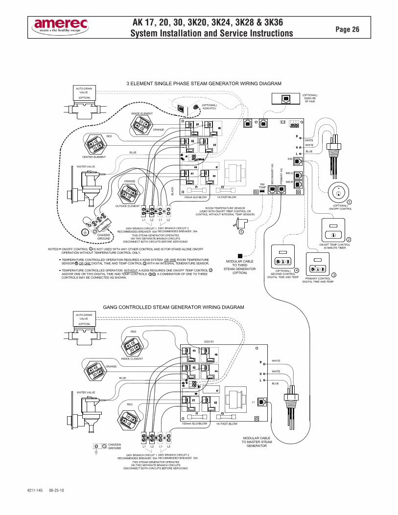
AK 17, 20, 30, 3K20, 3K24, 3K28 & 3K36System Installation and Service Instructions Page 26
tt
t
t
t


![Book, The Electric Generators Handbook Synchronous Generators[1]](https://static.fdocuments.in/doc/165x107/552a938b55034689428b46a1/book-the-electric-generators-handbook-synchronous-generators1.jpg)