AMC2 Wiegand Extension
54
AMC2 Wiegand Extension AMC2-4WE en Installation manual
Transcript of AMC2 Wiegand Extension

AMC2 Wiegand ExtensionAMC2-4WE
en Installation manual


Table of contents
1 Safety Instructions 51.1 Important Safety Notes 51.2 Safety Precautions 71.3 Unpacking 9
2 Important Information 102.1 Explanation of symbols in this document 102.2 Internet 11
3 Introduction 123.1 Description 123.2 Equipment Configuration 143.3 Performance Characteristics 163.4 System Overview 16
4 Installing 194.1 Mounting 194.2 Unmounting 204.3 Opening the Case 214.4 Closing the Case 224.5 Cabling 234.5.1 Conductor data 234.6 Grounding and Shielding 254.6.1 Grounding for Extension Interface 264.7 Connecting Power Supply 274.7.1 Direct Power Supply 274.7.2 Power Supply via RS-485 Interface 284.7.3 Overview - Power supply/consumption 294.8 RS-485 for extension modules 324.9 Wiegand Interface for Card Readers 334.10 Connecting Relay Outputs 344.11 Connecting Analog Input Devices 384.12 Tamper Protection 41
5 Operating 425.1 Status Display of the AMC2 42
AMC2 WiegandExtension
Table of Contents | en 3
Bosch Sicherheitssysteme GmbH 2016-11 | AMC2-4WE |

6 Technical Data 447 Appendices 487.1 Connecting Diagrams 48
Index 51
4 en | Table of ContentsAMC2 Wiegand
Extension
2016-11 | AMC2-4WE | Bosch Sicherheitssysteme GmbH

Safety Instructions
Important Safety Notes1. Read, follow, and retain instructions - All safety and
operating instructions must be read and followed properlybefore putting the unit into operation. Retain instructionsfor future reference.
2. Do not ignore warnings - Adhere to all warnings on the unitand in the operating instructions.
3. Accessories - Use only accessories recommended by themanufacturer or those sold with the product. Accessoriesnot recommended by the manufacturer must not be used,as they may cause hazards.
4. Installation precautions - Do not place this unit on anunstable stand, tripod, bracket, or mount. The unit may fall,causing serious injury to persons and damage to the unit.Mount the unit according to the manufacturer’sinstructions.
5. Service - Do not attempt to service this unit by yourself.Opening or removing covers may expose you to dangerousvoltages or other hazards. Refer all servicing to qualifiedservice personnel.
6. Damage which requires service - Disconnect the unit fromthe main AC or DC power source and refer servicing toqualified service personnel under the following conditions:– If the power supply cord or plug is damaged.– If liquid has been spilled or an object has fallen into
the unit.– If the unit has been exposed to water and/or inclement
weather (rain, snow, etc.).– If the unit does not operate normally when following
the operating instructions. Adjust only those controlsspecified in the operating instructions. Improper
1
1.1
AMC2 WiegandExtension
Safety Instructions | en 5
Bosch Sicherheitssysteme GmbH 2016-11 | AMC2-4WE |

adjustment of other controls may result in damage,and require extensive work by a qualified technician torestore the unit to normal operation.
– If the unit has been dropped or the cabinet damaged.– If the unit exhibits a distinct change in performance.
7. Replacement parts - If replacement parts are required, theservice technician must use only replacement parts that arespecified by the manufacturer. Unauthorized replacementsmay result in fire, electrical shock or other hazards.
8. Safety check - Upon completion of service or repair workon the unit, ask the service technician to perform safetychecks to ensure that the unit operates properly
9. Power sources - Operate the unit only from the type ofpower source indicated on the label. If unsure of the typeof power supply to use, contact your dealer
10. Lightning - For added protection during electrical stormsexternal lightning conductors can be installed. Thisprevents power surges from damaging the unit.
11. The units should be installed in locations with restrictedaccess.
6 en | Safety InstructionsAMC2 Wiegand
Extension
2016-11 | AMC2-4WE | Bosch Sicherheitssysteme GmbH

Safety PrecautionsRead instructions!Before working with the AMC2 device, read these instructionscarefully. Make sure you have understood all informationdescribed in this document.
!
Warning!
Risk of electric shock
External power supplies must be installed and put into service
by qualified personnel.
Ensure compliance with the relevant regulations.
Ground the controller.
Disconnect both AC and battery power supply before working
on the controller.
!
Warning!
Risk of fire
Installation of the AMC2 device must comply with any local fire,
health, and safety regulations. A secured door that may be part
of an escape route from an area must be installed with:
Install a fail-safe lock (A), so that the door will be released if
power fails. Ideally, use a magnetic lock.
Install a normally-closed break glass or a manual pull (B) in the
lock supply wiring, so that in an emergency the fail-safe lock
can be immediately powered down.
1.2
AMC2 WiegandExtension
Safety Instructions | en 7
Bosch Sicherheitssysteme GmbH 2016-11 | AMC2-4WE |

!
Warning!
Risk of explosion of Lithium battery
The battery can explode if it is replaced incorrectly.
Replace only with the same type as recommended by the
manufacturer.
Dispose used batteries according to the battery manufacturer’s
instructions.
Notice!
Risk of damage to equipment
Protect the hardware from electrostatic discharge by observing
ESD instructions before unpacking of touching connectors of
electronics.
Always switch off power of the AMC2 device before modifying
the installation.
Do not connect or disconnect plug connectors, data cables, or
screw connectors while power is on.
Rules and ConditionsThere are no specific requirements as for selling and delivery. Asfor storage and safe operation, the environmental temperatureshould not exceed the range of 0°C to 50°C.DisposalYour Bosch product is designed and manufactured with high-quality materials and components which can be recycled andreused.
8 en | Safety InstructionsAMC2 Wiegand
Extension
2016-11 | AMC2-4WE | Bosch Sicherheitssysteme GmbH

This symbol means that electrical and electronic equipment, attheir end-of-life, should be disposed of separately from yourhousehold waste.In the European Union, there are separate collection systems forused electrical and electronic products. Please dispose of thisequipment at your local community waste collection/recyclingcenter.
UnpackingCheck the packaging for visible damage. If anything has beendamaged during transport, please inform the transport agency.Unpack the unit carefully. This is an electronic device that mustbe handled with care to avoid damage. Do not attempt to putthe unit into operation if components are damaged.If any parts are missing, inform your customer servicerepresentative or a Bosch Security Systems salesperson. Theshipping carton is the safest transport container for the unit.Store it and the other packaging material for future use. If theunit has to be sent back, use the original packaging.
1.3
AMC2 WiegandExtension
Safety Instructions | en 9
Bosch Sicherheitssysteme GmbH 2016-11 | AMC2-4WE |
Important InformationRemarksThis hardware is part of a security system. Access should belimited to authorized persons only.Some states do not allow the exclusion or limitation of impliedwarranties, or limitation of liability for incidental orconsequential damages, hence the above limitation or exclusionmight not apply to you.Bosch Security Systems retains all rights not expressly granted.Nothing in this license constitutes a waiver of Bosch’s rightsunder the U.S. Copyright laws or any other federal or state law.If you have any questions concerning this license, please, writeto: Bosch Sicherheitssysteme GmbHRobert-Bosch-Ring 585630 GrasbrunnGermany.
Explanation of symbols in this documentThroughout this document, warning messages, important notes,and helpful tips are presented for the reader. These appear asfollows:
Danger!
Cause of Hazard
Indicates a hazardous situation, which, if not avoided, will result
in death or serious injury.
!
Warning!
Cause of Hazard
Indicates a hazardous situation, which, if not avoided, could
result in death or serious injury.
2
2.1
10 en | Important InformationAMC2 Wiegand
Extension
2016-11 | AMC2-4WE | Bosch Sicherheitssysteme GmbH

!
Caution!
Cause of Hazard
Indicates a hazardous situation, which, if not avoided, could
result in minor or moderate injury.
Notice!
Cause of Hazard
Important Notes that must be followed to avoid damage to the
equipment or environment, and to ensure successful operation
and programming.
Tips and shortcuts may also be included in such notes.
InternetIf you are interested in further information on this product orinformation on other products, please consult our website athttp://www.boschsecurity.com.
2.2
AMC2 WiegandExtension
Important Information | en 11
Bosch Sicherheitssysteme GmbH 2016-11 | AMC2-4WE |

Introduction
DescriptionThe extension module AMC2-4WE is equipped with fourWiegand type reader-interfaces plus eight inputs and eightoutputs. Hence with the AMC2-4WE it is possible to double thenumber of readers on an AMC2-4W from 4 to 8.
Figure 3.1: The extension module AMC2-4WE
The AMC2-4WE can not be deployed as an independentcontroller but only as an extension module for the AMC2-4W.Control and access decisions and bookings are carried out bythe AMC2-4W alone.
Notice!
The AMC2-4WE can only be used with AMC2-4W. As it provides
Wiegand interfaces it cannot be coupled with an AMC2-4R4.
The AMC2-4W can be extended by a maximum of oneAMC2-4WE plus a maximum of three I/O extension modules. TheI/O extension modules AMC2-8IOE, AMC2-16IOE, or AMC2-16IE(in any combination) are, like the AMC2-4WE, connected via theAMC2-4W’s extension interface.
3
3.1
12 en | IntroductionAMC2 Wiegand
Extension
2016-11 | AMC2-4WE | Bosch Sicherheitssysteme GmbH

Notice!
The AMC2-4WE has no display. The information about the input
and outputs will be shown on special pages of the AMC2
display.
As the extension modules contain neither memory nor displaythey are controlled and monitored entirely by the AMC2-4W.The AMC2-4W can have an additional interface extensionmodule AMC2-4WE, so that the number of inputs and outputscan grow up to 64.
Notice!
An AMC2-4WE provides signals only to the AMC2 to which it is
connected. Signal transfer to another AMC2 is not possible.
The signal settings and parametrization of the readersconnected to the extension module, are carried out by theconfiguration applications in the access control system and bythe AMC2-4W to which it belongs.
AMC2 WiegandExtension
Introduction | en 13
Bosch Sicherheitssysteme GmbH 2016-11 | AMC2-4WE |

Equipment Configuration
Figure 3.2: Overview - Interfaces
1 RS-485 extension module bus
2 External tamper contact
3 Connector for power supply
4 Wiegand interfaces for up to 4 card readers
5 Connectors for eight analog inputs
6 Connectors for eight relay outputs
3.2
14 en | IntroductionAMC2 Wiegand
Extension
2016-11 | AMC2-4WE | Bosch Sicherheitssysteme GmbH

Figure 3.3: Jumpers at the bottom side
7 Jumper for setting either voltage free relay output (“dry”mode) or looped-in voltage from the AMC2 internalpower supply (“wet” mode).
8 Jumper: Equalization of potential between differentsystems and earth ground (shield) for the extensioninterface.
AMC2 WiegandExtension
Introduction | en 15
Bosch Sicherheitssysteme GmbH 2016-11 | AMC2-4WE |

Performance Characteristics– Controlled by an AMC2 via RS-485– Reader interfaces
– four Wiegand interfaces– Eight relay outputs
– voltage free, power is supplied externally (dry mode)– powered by internal power supply (wet mode)
– Eight analog inputs with internal power supply– Transfer rate to the extension interface: 9,6 kBit/s– Self regulating transmit/receive switching– Power supply:
– 10V - 30Vdc - max. 5 A– or over the RS-485 host connector
– Information about the inputs and outputs on the display ofthe AMC2 controller
– Tamper contact for external covers
Notice!
If an external power supply is used, this should also guarantee
an uninterruptable power supply (UPS). Example: Bosch power
supply APS-PSU-60 (F.01U.282.970).
System OverviewThe AMC2-4WE is connected between the access controllerAMC2-4W and the various peripheral devices.
3.3
3.4
16 en | IntroductionAMC2 Wiegand
Extension
2016-11 | AMC2-4WE | Bosch Sicherheitssysteme GmbH

Figure 3.4: System overview
1 = Host
2 = AMC2-4W
3 = Card reader
4 = Communication and power supply
5 = AMC2-4WE
System configurations for Access Control applications.– The minimum configuration consists of:
– one PC with system software,– one AMC2 controller,– one AMC power supply,– one AMC enclosure.
– The maximum configuration depends on the systemsoftware,
AMC2 WiegandExtension
Introduction | en 17
Bosch Sicherheitssysteme GmbH 2016-11 | AMC2-4WE |

– Each AMC2-4W controller can be extended with anAMC2-4WE extension module.
The using of AMC2-4WE modules has no influence on the limit ofthe maximum of controllers in one system, because it is anextension to an AMC2-4W and not a controller.Using Wiegand reader interfaces, up to four peripheral devicescan be connected to each AMC2-4WE. The interfaces are point-to-point connections, meaning that only one reader can beconnected to one interface.
18 en | IntroductionAMC2 Wiegand
Extension
2016-11 | AMC2-4WE | Bosch Sicherheitssysteme GmbH

InstallingNotice!
To build an UL approved system refer the documentation
contained in the folder titled "_UL" on the delivered CD.
MountingThe AMC2-4WE can be attached on a standard 35 mm(1.377 in.) mounting rail using a snap-in mechanism. Attach theAMC2-4WE into the upper edge of the mounting rail [1], thenpush down the device and snap it onto the rail by pushing ittowards the back [2].
Figure 4.1: Mounting the AMC2 device on a mounting rail
4
4.1
AMC2 WiegandExtension
Installing | en 19
Bosch Sicherheitssysteme GmbH 2016-11 | AMC2-4WE |

Unmounting
Notice!
To remove the AMC2-4WE from a mounting rail, first remove all
pluggable connectors.
Push down the AMC2-4WE until the lower edge snaps out of themounting rail [1]. Pull the lower end of the AMC2-4WE from themounting rail [2].
Figure 4.2: Unmounting the AMC2 device from a mounting rail
4.2
20 en | InstallingAMC2 Wiegand
Extension
2016-11 | AMC2-4WE | Bosch Sicherheitssysteme GmbH

Opening the Case
Notice!
To open the AMC2-4WE, first remove all pluggable connectors.
The AMC2-4WE case consists of a top cover mounted with atwo-point snap-in closure on a chassis. To open the case, pushdown the two snap-ins with a screwdriver, then swing the coverdown.
Figure 4.3: Opening the AMC2-4WE case
4.3
AMC2 WiegandExtension
Installing | en 21
Bosch Sicherheitssysteme GmbH 2016-11 | AMC2-4WE |

Closing the CaseBefore aligning the covers, unplug any pluggable screwconnectors. Insert the hooks on the lower edge of the frontcover into the lugs on lower edge of the plastic back cover [1].Please ensure that the BOSCH logo is not upside-down. Theupper edge of the front cover now aligns with the two-pointsnap-in closures on the upper edge of the back cover [2], andmay thus be clicked gently into place.Hence the closing process is the reverse of the opening process.
Figure 4.4: Closing the extension case
4.4
22 en | InstallingAMC2 Wiegand
Extension
2016-11 | AMC2-4WE | Bosch Sicherheitssysteme GmbH

Notice!
Risk of damage to equipment
If excessive force is required to close the front cover then it is
probably incorrectly hooked into the back cover. In such cases
the display ’Dialog’ button in the front cover will be misaligned
and will not function correctly.
Cabling
Notice!
Risk of malfunction
The cables used in the AMC2-4WE access control system are
not prone to electrical interference. However, you should avoid
routing cables close to heavy load switching cables and
equipment. If this is unavoidable, cross the cable at right angles
every 1 to 2 m (3 to 6 ft) to reduce interference.
Conductor dataWith the calculation below you can find out which cable typemust be used. If you connect the power supply and the AMC-device with the delivered cable set from the enclosure thecalculation is not necessary.For distances below 25 m (75 ft) use AWG18 conductors(1mm²). For longer distances, install an additional power supplyclose to the AMC2 controller.Please, calculate the voltage drop by checking the conductorspecifications for characteristic resistance values. The voltagedrop shall not exceed 2 V.Example:Length = 100 m/328 ftU = 12V, I = 1A, maximum UDrop = 2V
4.5
4.5.1
AMC2 WiegandExtension
Installing | en 23
Bosch Sicherheitssysteme GmbH 2016-11 | AMC2-4WE |

i.e. RAWG18 (acc. specs) = 6.385 or 20,948
UDrop = 20,948 x 0.1 km x 1A = 2.1V
UDrop = 6.385 x 328 ft x 1A = 2.1V
Critical condition! Install the power supply closer to thecontroller.
Notice!
These specifications apply to power supply, readers, relay
outputs, and extension interface.
Regarding inputs, specific voltage-drop values need to be taken
into account. Refer to Connecting Analog Input Devices, page
38.
24 en | InstallingAMC2 Wiegand
Extension
2016-11 | AMC2-4WE | Bosch Sicherheitssysteme GmbH

Grounding and ShieldingThe AMC2 controller allows you to create a central ground orshielding point, simply by setting certain jumpers. Set thesejumpers only if grounding or shielding is not achieved by othermeans.1. If the AMC2-4WE has its own power - as in the third
example in Overview - Power supply/consumption, page 29- the shield will be connected to pin 2 of the power supplyconnector - see Connecting Diagrams, page 48.
2. If the extension module is powered from the AMC2controller - as in the second example in Overview - Powersupply/consumption, page 29 - the connection should bemade as in the RS-485 for extension modules, page 32diagram.
3. If more than one extension module is to be connected to anAMC2 controller, and all of them to receive power from it aswell, then use the RS-485 extension interface for theconnection.
Notice!
In the second and third case the jumper on the bottom side of
the AMC2-controller must to be set - see the installation manual
of the AMC2-4W.
The jumper A of the extension boards will not be set.
Notice!
Risk of malfunction
Ensure that no ground loops are formed.
4.6
AMC2 WiegandExtension
Installing | en 25
Bosch Sicherheitssysteme GmbH 2016-11 | AMC2-4WE |

Notice!
In general the following apply:
If the devices have their own power supplies, the shielding is
applied to one side only. The free end should be insulated to
avoid inadvertent connections.
If one device is fed power by another, the cable shielding
should be applied to both sides.
Grounding for Extension Interface
Figure 4.5: Location of ground jumper bottom side
The jumper setting A1 shows the factory settings.Jumper connects the internal ground of the AMC2-4WE to theground of the RS-485 slave interface. Set Jumper A2 only at thefirst AMC2-4WE of a party line - like example four in Overview -Power supply/consumption, page 29.
4.6.1
26 en | InstallingAMC2 Wiegand
Extension
2016-11 | AMC2-4WE | Bosch Sicherheitssysteme GmbH

Connecting Power Supply
Direct Power SupplyConnect the power supply to the POWER 7-pin pluggable screwconnector. Refer to Connecting Diagrams, page 48 for acomplete diagram.
Figure 4.6: Location of the power supply connector
Connect an external power supply (10 - 30 Vdc) for AMC2-4WEat pin 1 (positive) and pin 3 (0 V) of the pluggable screwconnector. If an uninterruptible power supply (UPS) is used, the relayoutput for power good signals from the UPS is connected to thefollowing pins:– pin 4 and 7 for power good AC– pin 5 and 7 for power good Battery– pin 6 and 7 for power good DCOtherwise these pins must be short-circuited.
4.7
4.7.1
AMC2 WiegandExtension
Installing | en 27
Bosch Sicherheitssysteme GmbH 2016-11 | AMC2-4WE |

Power Supply via RS-485 InterfaceThe power can also be supplied by the AMC2-4W. In this casepower pins 1 and 2 should be connected, as well as data lineson pins 3 - 6.
Figure 4.7: Interface for internal power supply
4.7.2
28 en | InstallingAMC2 Wiegand
Extension
2016-11 | AMC2-4WE | Bosch Sicherheitssysteme GmbH

Overview - Power supply/consumption
Figure 4.8: Example configurations
a = AMC2-4WE
b = AMC2 I/O Extension board
line = Power supply
broken line = Data line
4.7.3
AMC2 WiegandExtension
Installing | en 29
Bosch Sicherheitssysteme GmbH 2016-11 | AMC2-4WE |

Example Components used Output power Consumptio
n
Available Constant
load
1 PS + AMC2-4W 60VA 5VA 55VA 25VA
2 PS + AMC2-4W +AMC2-4WE
60VA 2 x 5VA 50VA 20VA
PS + AMC2-4W +AMC2-4WE +Extension
60VA 3 x 5VA 45VA 15VA
3 PS + AMC2-4WandPS + AMC2-4WE
60VA+60VA
5VA+5VA
55VA+55VA
25VA+25VA
PS + AMC2-4WandPS + AMC2-4WE +Extension
60VA+60VA
5VA+2 x 5VA
55VA+50VA
25VA+20VA
4 PS + AMC2-4W +ExtensionandPS + AMC2-4WE
60VA +60VA
2 x 5VA +2 x 5VA
50VA +50VA
20VA +20VA
Table 4.1: Overview - power supply and power consumption
Explanations for the table columns:
Output power Power provided by the power supply.
Own usage Power used by AMC2 device
Available Power remaining for external devices
30 en | InstallingAMC2 Wiegand
Extension
2016-11 | AMC2-4WE | Bosch Sicherheitssysteme GmbH
Constant load Amount of the available power that canbe drawn constantly.
Hence Example 1 can be read as follows:Of the total incoming power (60VA) 5VA will be drawn by theAMC2 itself . This leaves 55VA to support external devices.25VA of these 55VA can be used for constant load (e.g. a cardreader) leaving 30VA for occasional peak usage (e.g. a dooropener).
AMC2 WiegandExtension
Installing | en 31
Bosch Sicherheitssysteme GmbH 2016-11 | AMC2-4WE |

RS-485 for extension modulesThe AMC2-4WE is connected to the AMC2 controller using theRS-485 extension interface. This interface will also be used toconnect further extension modules.
Figure 4.9: Location of the RS-485 extension module bus
Figure 4.10: Connection of an extension module to an AMC2
4.8
32 en | InstallingAMC2 Wiegand
Extension
2016-11 | AMC2-4WE | Bosch Sicherheitssysteme GmbH

Wiegand Interface for Card Readers
Notice!
If your reader requires a voltage other than 12V or is the power
consumption more than 200 mA then it will require an external
power supply.
The AMC2-4WE provides four ports for connecting a maximumof 4 readers with Wiegand interfaces. Each interface isconnected using a 10-pin pluggable screw connector (S2, S7,S14, and S19) - refer to Connecting Diagrams, page 48.
Figure 4.11: Location of the Wiegand interfaces for external devices
These interfaces are point-to-point connections, and each cansupport only a single reader with a maximum cable length of90 m (300 ft) for 24 AWG or 150 m (500 ft) for 22 AWG. Readersare addressed according to their respective interface numbers.
4.9
AMC2 WiegandExtension
Installing | en 33
Bosch Sicherheitssysteme GmbH 2016-11 | AMC2-4WE |

Refer to Connecting Diagrams, page 48 for a complete wiringdiagram of the Wiegand reader interface .
Connecting Relay OutputsTo operate locks or alarm systems, the AMC2-4WE has eight form C relay outputs. The outputs will be connected to the 3-pinpluggable screw connectors S5, S6, S10, S11, S17, S18, S22,and S23 - refer to Connecting Diagrams, page 48.
Figure 4.12: Location of the relay output connectors
Each relay output can operate in ‘wet’ mode, using theAMC2-4WE's internal 12/24 Vdc power supply for externaldevices or ‘dry’ mode with potential free contacts for externallypowered systems.
4.10
34 en | InstallingAMC2 Wiegand
Extension
2016-11 | AMC2-4WE | Bosch Sicherheitssysteme GmbH

Figure 4.13: Wet mode and dry mode of the AMC2 relay outputs
Notice!
Risk of damage to equipment
To prevent damage to the relays note the following
specifications.
– the maximum switching current is 1.25 A– the maximum switching voltage is 30 Vdc– only ohm resistive load can be connected to the relay– inductive loads have to be short circuited using recovery
diodes, see image below. These diodes (1N4004) aresupplied with every AMC2-4WE package.
– If you need higher voltage for special applications you canconnect external relays to the outputs. Recommended,depending on the power supply mode, are the relay typesfrom the Wieland company:– Flare move 12DC1W10A– Flare move 24DC1W16A
If using locally manufactured products, please ensure that thespecifications of the product are identical with the those listedabove.
AMC2 WiegandExtension
Installing | en 35
Bosch Sicherheitssysteme GmbH 2016-11 | AMC2-4WE |
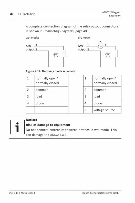
A complete connection diagram of the relay output connectorsis shown in Connecting Diagrams, page 48.
Figure 4.14: Recovery diode schematic
1 normally open/normally closed
1 normally open/normally closed
2 common 2 common
3 load 3 load
4 diode 4 diode
5 voltage source
Notice!
Risk of damage to equipment
Do not connect externally powered devices in wet mode. This
can damage the AMC2-4WE.
36 en | InstallingAMC2 Wiegand
Extension
2016-11 | AMC2-4WE | Bosch Sicherheitssysteme GmbH

Each relay output has a separate jumper setting on theunderside of the circuit board to select dry (D 1) or wet (D 2)mode.
Figure 4.15: Location of relay output jumpers (bottom side)
Notice!
The positions of the jumpers 1 and 2 are interchanged related
to the corresponding interfaces.
AMC2 WiegandExtension
Installing | en 37
Bosch Sicherheitssysteme GmbH 2016-11 | AMC2-4WE |

Connecting Analog Input DevicesThe AMC2-4WE has 8 analog inputs, for example, for potential-free lock mechanisms, or to detect whether a lock is closed oropen. The inputs will be connected to the 2-pin pluggable screwconnectors: S3, S4, S8, S9, S15, S16, S20 and S21 - refer toConnecting Diagrams, page 48.
Notice!
Risk of damage to equipment
Do not connect external power supply to the AMC2 inputs.
When connecting a relay output to an AMC2 input use dry mode
with potential-free contact - refer to Connecting Relay Outputs,
page 34.
Figure 4.16: Location of the analog input connectors
The AMC2-4WE can also detect the wiring conditions ‘shortcircuit’ and ‘broken’, and hence trigger an alarm if theappropriate devices are connected.
4.11
38 en | InstallingAMC2 Wiegand
Extension
2016-11 | AMC2-4WE | Bosch Sicherheitssysteme GmbH

1. Door open: RS + RP
2. Door closed: RS
3. Open wire: RS + RP = ∞
4. Short circuit: RS + RP = 0
The resistor values can vary and depend on the used locksystem. The extension package includes 2,2 kΩ resistors which can beused to replace RS and RP resistor.
To detect the four states, the voltage drop in the connectingcable may not exceed special values. The following table showsthe maximum values of permissible cable resistance dependingon the used resistor combination.
AMC2 WiegandExtension
Installing | en 39
Bosch Sicherheitssysteme GmbH 2016-11 | AMC2-4WE |

RP 1k
1k2
1k5
1k8
2k2
2k7
3k3
3k9
4k7
5k6
6k8
8k2
RS
1k 220 220 220 210 200
1k2 260 270 270 270 260 240
1k5 310 330 340 350 350 340 310 280
1k8 340 380 390 410 410 410 400 370 330 290 200
2k2 430 460 490 510 520 510 500 460 420 340 240
2k7 490 540 570 620 630 640 640 620 580 510 420
3k3 610 650 700 740 770 780 770 750 700 620
3k9 720 790 850 890 910 910 910 880 810
4k7 880 960 960 970 1100 1100 1050 1050
5k6 1050 1100 1200 1200 1300 1300 1250
6k8 1300 1400 1500 1500 1500 1500
8k2 1500 1650 1700 1800 1900
Table 4.2: Maximum values of cable resistance per used resistor combination in Ohm
Notice!
We recommend using serial resistors (RS) no higher than 5K6 in
order to obtain clear measurements.
40 en | InstallingAMC2 Wiegand
Extension
2016-11 | AMC2-4WE | Bosch Sicherheitssysteme GmbH

Tamper ProtectionTo protect the AMC2-4WE against unauthorized access and soprevent tampering with sensitive data, the AMC2-4WE providesan additional interface to connect external tamper contacts.This interface is a potential-free 2-pin pluggable screwconnector marked with T. When not in use this tamper contactshould be shorted.
Figure 4.17: Location of the tamper protection contact
4.12
AMC2 WiegandExtension
Installing | en 41
Bosch Sicherheitssysteme GmbH 2016-11 | AMC2-4WE |

Operating
Status Display of the AMC2Because the AMC2-4WE has no display of its own, the AMC2controller displays status information about the input andoutput settings of the AMC2-4WE. The selected display mode remains set until the next time thebutton is pressed. The order of the display pages is shown inthe following table. Display pages 3a to 3c include theinformation about the I/O-Boards’ signals. For each I/O-Boardconnected there is a separate display page.
Push Display (Example) Description
0 V01.00 02.03.07
Software versions and date ofthe firmware.
1a S/N1: 0910019212 BOSCH serial number
1b S/N2: 00000001
2 02.06 15:35:15 (S) Current date and time(S) = Summer; (W) = Winter
3 Dig. IO: :::::::::::::::: Display of the digital contacts:the input signals set will beshown with an extension above- output signals with anextension below. The first eightsigns show the signals of theAMC2-4W and the second eightthe signals of the AMC2-4WE.
3a Dig. I1: :::::::::::::::: If there are I/O-Boardsconnected the signals will beshown on separate pages.
3b Dig. I2: ::::::::::::::::
5
5.1
42 en | OperatingAMC2 Wiegand
Extension
2016-11 | AMC2-4WE | Bosch Sicherheitssysteme GmbH

Push Display (Example) Description
3c Dig. I3: ::::::::::::::::
4 MAC 0010174C8A0C Network device address (MAC)
5 N AMC-1234-5678 Network name of the AMC2
6 I 192.168.10.18 IP-address of the AMC2
7 G 192.168.10.255 IP-address of the gateway(Version V 00.44 or higher)
8 M 255.255.255.0 Subnetmask(Version V 00.44 or higher)
9 H 192.168.10.10 IP-address of the hostcomputer
10 DHCP 1 DHCP-status:1 = on0 = off
11 D 192.168.10.1 IP-address of the DNS server
12 Host: + "C" Host activity:+ = online- = offline"C" = Counter of the receiveddata packages from the hostinterface.RS 485 Bus connection:A = Address 1 … H = Address 8
AMC2 WiegandExtension
Operating | en 43
Bosch Sicherheitssysteme GmbH 2016-11 | AMC2-4WE |

Technical Data– Four Wiegand interfaces for up to four card readers
(Output rating: 280 mA)– Eight relay outputs
– maximum ratings (wet and dry):switching voltage: 30 Vdcswitching current: 1,25 A
– operating ratings (wet and dry):1,25 A @ 30 Vdc2 A @ 12 Vdc1,5 A @ 24 Vdc
– Eight analog inputs with tamper detection; only connect drycontacts
– RS-485 extension interface: Transfer rate: 9,6 kBit/s, no parity, 8 bit, 2 stop bit
– Tamper contact for external enclosures Power supply10 to 30 Vdcor via the AMC2-4W Power consumptionAMC: 5 VAPeripheral devices: using the PSU-60– up to 55 VA– constant load: 25 VA ConnectorsPluggable screw connectors Protection classIP30
6
44 en | Technical DataAMC2 Wiegand
Extension
2016-11 | AMC2-4WE | Bosch Sicherheitssysteme GmbH

Environment temperature0° C to 50°C (32° F to 122°F) HumidityUp to 95%, without condensation Housing materialABS with OC (UL 94 V-0) Dimensions(W/H/D) 232 x 90 x 46mm (8.9 x 3.5 x 1.8 in) Weightapprox. 0.4kg (0.9lb)
Notice!
The voltage drop from the power supply to the AMC2-4WE
affects the AMC interfaces. The total drop must not exceed 2V!
Notice!
To determine the environmental impact of an installation, take
into account the most extreme values of all participating
devices.
To determine the vulnerability of an installation, take into
account the most restrictive values of all participating devices.
AMC2 WiegandExtension
Technical Data | en 45
Bosch Sicherheitssysteme GmbH 2016-11 | AMC2-4WE |

46 en | Technical DataAMC2 Wiegand
Extension
2016-11 | AMC2-4WE | Bosch Sicherheitssysteme GmbH

AMC2 WiegandExtension
Technical Data | en 47
Bosch Sicherheitssysteme GmbH 2016-11 | AMC2-4WE |

Appendices
Connecting Diagrams
Figure 7.1: Connector blocks of the AMC2-4WE
7
7.1
48 en | AppendicesAMC2 Wiegand
Extension
2016-11 | AMC2-4WE | Bosch Sicherheitssysteme GmbH

1 Power supply, DC positive (10V - 30V)
2 Shield
3 Power supply (0V)
4 UPS (power good signal) - AC
5 UPS (power good signal) - Battery
6 UPS (power good signal) - DC
7 UPS (power good signal) - Common
Table 7.1: Power supply
1 red Reader Supply (12V)
2 black Reader Supply (0V)
3 green Data 0
4 white Data 1
5 drain Shield
6 orange green LED
7 brown red LED
8 yellow Beeper
9 blue Hold
10 violet Card Present
Table 7.2: Wiegand interface AMC
Notice!
For reader settings refer to the respective reader manual.
AMC2 WiegandExtension
Appendices | en 49
Bosch Sicherheitssysteme GmbH 2016-11 | AMC2-4WE |

1 Analog Input, in
2 Analog Input, out
Table 7.3: Analog input
1 Relay Output, normally open
2 Relay Output, common
3 Relay Output, normally closed
Table 7.4: Relay output
1 Power supply for external devices (10V -30V)
2 Power supply for external devices (0V)
3 Shield
4 Data RxTx+
5 Data RxTx-
6 Ground (PAG)
Table 7.5: Host / Extension interface
1 Tamper Contact, in
2 Tamper Contact, out
Table 7.6: External tamper contact
50 en | AppendicesAMC2 Wiegand
Extension
2016-11 | AMC2-4WE | Bosch Sicherheitssysteme GmbH

IndexCcabling, 23
Eextension interface, 44
Iinputs, 14, 16, 38interfaces
extension, 44reader, 16, 33, 44
Mmounting, 19
Oopening, 21outputs, 14, 16, 34, 44
Ppower supply, 23, 27
Rreader interfaces, 16, 33, 44
Wiegand, 33resistor, 38
Ttamper, 41
Uunmounting, 20
AMC2 WiegandExtension
Index | en 51
Bosch Sicherheitssysteme GmbH 2016-11 | AMC2-4WE |


Bosch Sicherheitssysteme GmbHRobert-Bosch-Ring 585630 GrasbrunnGermanywww.boschsecurity.com© Bosch Sicherheitssysteme GmbH,2016