Ambry: LinkedIn’s Scalable Geo-Distributed Object...
13
Ambry: LinkedIn’s Scalable Geo-Distributed Object Store Shadi A. Noghabi 1 , Sriram Subramanian 2 , Priyesh Narayanan 2 Sivabalan Narayanan 2 , Gopalakrishna Holla 2 , Mammad Zadeh 2 , Tianwei Li 2 Indranil Gupta 1 , Roy H. Campbell 1 1 University of Illinois at Urbana-Champaign, 2 LinkedIn Corp. {abdolla2, indy, rhc}@illinois.edu {srsubramanian, pnarayanan, snarayanan, gholla, mzadeh, tili}@linkedin.com ABSTRACT The infrastructure beneath a worldwide social network has to continually serve billions of variable-sized media objects such as photos, videos, and audio clips. These objects must be stored and served with low latency and high through- put by a system that is geo-distributed, highly scalable, and load-balanced. Existing file systems and object stores face several challenges when serving such large objects. We present Ambry, a production-quality system for storing large immutable data (called blobs). Ambry is designed in a decentralized way and leverages techniques such as logical blob grouping, asynchronous replication, rebalancing mech- anisms, zero-cost failure detection, and OS caching. Am- bry has been running in LinkedIn’s production environment for the past 2 years, serving up to 10K requests per second across more than 400 million users. Our experimental eval- uation reveals that Ambry offers high efficiency (utilizing up to 88% of the network bandwidth), low latency (less than 50 ms latency for a 1 MB object), and load balancing (im- proving imbalance of request rate among disks by 8x-10x). Keywords Object Store, Geographically Distributed, Scalable, Load Balancing 1. INTRODUCTION During the past decade, social networks have become pop- ular communication channels worldwide. Hundreds of mil- lions of users continually upload and view billions of diverse massive media objects, from photos and videos to docu- ments. These large media objects, called blobs, are up- loaded once, frequently accessed from all around the world, never modified, and rarely deleted. LinkedIn, as a global large-scale social network company, has faced the need for a geographically distributed system that stores and retrieves these read-heavy blobs in an efficient and scalable manner. Handling blobs poses a number of unique challenges. First, due to diversity in media types, blob sizes vary significantly from tens of KBs (e.g., profile pictures) to a few GBs (e.g., videos). The system needs to store both massive blobs and Permission to make digital or hard copies of all or part of this work for personal or classroom use is granted without fee provided that copies are not made or distributed for profit or commercial advantage and that copies bear this notice and the full citation on the first page. Copyrights for components of this work owned by others than the author(s) must be honored. Abstracting with credit is permitted. To copy otherwise, or republish, to post on servers or to redistribute to lists, requires prior specific permission and/or a fee. Request permissions from [email protected]. SIGMOD’16, June 26-July 01, 2016, San Francisco, CA, USA c 2016 Copyright held by the owner/author(s). Publication rights licensed to ACM. ISBN 978-1-4503-3531-7/16/06. . . $15.00 DOI: http://dx.doi.org/10.1145/2882903.2903738 a large number of small blobs efficiently. Second, there is an ever-growing number of blobs that need to be stored and served. Currently, LinkedIn serves more than 800 million put and get operations per day (over 120 TB in size). In the past 12 months, the request rate has almost doubled, from 5k requests/s to 9.5k requests/s. This rapid growth in requests magnifies the necessity for a linearly scalable sys- tem (with low overhead). Third, the variability in workload and cluster expansions can create unbalanced load, degrad- ing the latency and throughput of the system. This creates a need for load-balancing. Finally, users expect the upload- ing process to be fast, durable, and highly available. When a user uploads a blob, all his/her friends from all around the globe should be able to see the blob with very low latency, even if parts of the internal infrastructure fail. To provide these properties, data has to be reliably replicated across the globe in multiple datacenters, while maintaining low latency for each request. LinkedIn had its own home-grown solution called Media Server, built using network attached storage filers (for file storage), Oracle database (for metadata), and Solaris boxes. Media Server had multiple drawbacks. It faced CPU and IO spikes caused by numerous metadata operations for small objects, was not horizontally scalable, and was very expen- sive. Given that LinkedIn was scaling rapidly and the future web content will be largely dominated by media, we needed to find a replacement. Several systems have been designed for handling a large amount of data, but none of them satisfactorily meet the re- quirements and scale LinkedIn needs. There has been exten- sive research into distributed file systems [10, 16, 22, 24, 28]. These systems have a number of limitations when used for storing blobs, as pointed out by [3, 11]. For instance, the hierarchical directory structure and rich metadata are an overkill for a blob store and impose unnecessary additional overhead. Many key value stores [2,5,8,14] have also been designed for storing a large number of objects. Although these sys- tems can handle many small objects, they are not optimized for storing large objects (tens of MBs to GBs). Further, they impose extra overhead for providing consistency guar- antees while these are typically not needed for immutable data. Some examples of these overheads include using vec- tor clocks, conflict resolution mechanism, logging, and cen- tral coordinators. A few systems have been designed specifically for large immutable objects including Facebook’s Haystack [3] along with f4 [18] and Twitter’s Blob Store [27]. However, these systems do not resolve load imbalance, especially when clus- ter expansions occur. In this paper we present Ambry, a production-quality sys- tem designed specifically for diverse large and small im-
Transcript of Ambry: LinkedIn’s Scalable Geo-Distributed Object...

Ambry: LinkedIn’s Scalable Geo-Distributed Object Store
Shadi A. Noghabi1, Sriram Subramanian2, Priyesh Narayanan2
Sivabalan Narayanan2, Gopalakrishna Holla2, Mammad Zadeh2, Tianwei Li2Indranil Gupta1, Roy H. Campbell1
1University of Illinois at Urbana-Champaign, 2LinkedIn Corp.{abdolla2, indy, rhc}@illinois.edu
{srsubramanian, pnarayanan, snarayanan, gholla, mzadeh, tili}@linkedin.com
ABSTRACTThe infrastructure beneath a worldwide social network hasto continually serve billions of variable-sized media objectssuch as photos, videos, and audio clips. These objects mustbe stored and served with low latency and high through-put by a system that is geo-distributed, highly scalable,and load-balanced. Existing file systems and object storesface several challenges when serving such large objects. Wepresent Ambry, a production-quality system for storing largeimmutable data (called blobs). Ambry is designed in adecentralized way and leverages techniques such as logicalblob grouping, asynchronous replication, rebalancing mech-anisms, zero-cost failure detection, and OS caching. Am-bry has been running in LinkedIn’s production environmentfor the past 2 years, serving up to 10K requests per secondacross more than 400 million users. Our experimental eval-uation reveals that Ambry offers high efficiency (utilizing upto 88% of the network bandwidth), low latency (less than50 ms latency for a 1 MB object), and load balancing (im-proving imbalance of request rate among disks by 8x-10x).
KeywordsObject Store, Geographically Distributed, Scalable, LoadBalancing
1. INTRODUCTIONDuring the past decade, social networks have become pop-
ular communication channels worldwide. Hundreds of mil-lions of users continually upload and view billions of diversemassive media objects, from photos and videos to docu-ments. These large media objects, called blobs, are up-loaded once, frequently accessed from all around the world,never modified, and rarely deleted. LinkedIn, as a globallarge-scale social network company, has faced the need for ageographically distributed system that stores and retrievesthese read-heavy blobs in an efficient and scalable manner.
Handling blobs poses a number of unique challenges. First,due to diversity in media types, blob sizes vary significantlyfrom tens of KBs (e.g., profile pictures) to a few GBs (e.g.,videos). The system needs to store both massive blobs and
Permission to make digital or hard copies of all or part of this work for personal orclassroom use is granted without fee provided that copies are not made or distributedfor profit or commercial advantage and that copies bear this notice and the full citationon the first page. Copyrights for components of this work owned by others than theauthor(s) must be honored. Abstracting with credit is permitted. To copy otherwise, orrepublish, to post on servers or to redistribute to lists, requires prior specific permissionand/or a fee. Request permissions from [email protected].
SIGMOD’16, June 26-July 01, 2016, San Francisco, CA, USAc© 2016 Copyright held by the owner/author(s). Publication rights licensed to ACM.
ISBN 978-1-4503-3531-7/16/06. . . $15.00
DOI: http://dx.doi.org/10.1145/2882903.2903738
a large number of small blobs efficiently. Second, there isan ever-growing number of blobs that need to be stored andserved. Currently, LinkedIn serves more than 800 millionput and get operations per day (over 120 TB in size). Inthe past 12 months, the request rate has almost doubled,from 5k requests/s to 9.5k requests/s. This rapid growth inrequests magnifies the necessity for a linearly scalable sys-tem (with low overhead). Third, the variability in workloadand cluster expansions can create unbalanced load, degrad-ing the latency and throughput of the system. This createsa need for load-balancing. Finally, users expect the upload-ing process to be fast, durable, and highly available. Whena user uploads a blob, all his/her friends from all around theglobe should be able to see the blob with very low latency,even if parts of the internal infrastructure fail. To providethese properties, data has to be reliably replicated across theglobe in multiple datacenters, while maintaining low latencyfor each request.
LinkedIn had its own home-grown solution called MediaServer, built using network attached storage filers (for filestorage), Oracle database (for metadata), and Solaris boxes.Media Server had multiple drawbacks. It faced CPU and IOspikes caused by numerous metadata operations for smallobjects, was not horizontally scalable, and was very expen-sive. Given that LinkedIn was scaling rapidly and the futureweb content will be largely dominated by media, we neededto find a replacement.
Several systems have been designed for handling a largeamount of data, but none of them satisfactorily meet the re-quirements and scale LinkedIn needs. There has been exten-sive research into distributed file systems [10, 16, 22, 24, 28].These systems have a number of limitations when used forstoring blobs, as pointed out by [3, 11]. For instance, thehierarchical directory structure and rich metadata are anoverkill for a blob store and impose unnecessary additionaloverhead.
Many key value stores [2,5,8,14] have also been designedfor storing a large number of objects. Although these sys-tems can handle many small objects, they are not optimizedfor storing large objects (tens of MBs to GBs). Further,they impose extra overhead for providing consistency guar-antees while these are typically not needed for immutabledata. Some examples of these overheads include using vec-tor clocks, conflict resolution mechanism, logging, and cen-tral coordinators.
A few systems have been designed specifically for largeimmutable objects including Facebook’s Haystack [3] alongwith f4 [18] and Twitter’s Blob Store [27]. However, thesesystems do not resolve load imbalance, especially when clus-ter expansions occur.
In this paper we present Ambry, a production-quality sys-tem designed specifically for diverse large and small im-

mutable data with read-heavy traffic, where data is writtenonce, and read many times (>95% read traffic). Ambry isdesigned with four main goals in mind:1) Low Latency and High Throughput: The systemneeds to serve a large number of requests per second in atimely fashion, while working on cheap commodity hard-ware (e.g., HDDs). In order to reach this goal, Ambry uti-lizes a number of techniques including exploiting the OScache, using zero copy when reading data from disk to net-work, chunking data along with retrieving/storing chunks inparallel from multiple nodes, providing configurable policesfor the number of replicas to write and read, and zero-costfailure detection mechanisms (Sections 2.3, 4.2, and 4.3).2) Geo-Distributed Operation: Blobs have to be repli-cated in other geographically distributed datacenters for highdurability and availability, even in the presence of failures.To achieve low latency and high throughput in this geo-distributed setting, Ambry is designed as a decentralizedmulti-master system where data can be written to or readfrom any of the replicas. Additionally, it uses asynchronouswrites that write data to the closest datacenter and asyn-chronously replicate to other datacenter(s). Also, for higheravailability, it uses proxy requests that forward requests toother datacenters when the data is not replicated in the cur-rent datacenter yet (Sections 2.3 and 4.2).3) Scalability: With the ever-growing amount of data, thesystem has to scale out efficiently with low overhead. Toachieve this goal, Ambry makes three main design choices.First, Ambry separates the logical placement of blobs fromtheir physical placement, allowing it to change the physicalplacement transparently from the logical placement. Sec-ond, Ambry is designed as a completely decentralized sys-tem, with no manager/master. Third, Ambry uses on-disksegmented indexing along with Bloom filters and an in-memory cache of the latest segment, allowing for scalableand efficient indexing of blobs. (Section 4.3).4) Load Balancing: The system has to stay balanced inspite of growth. Ambry uses chunking of large blobs alongwith a random selection approach to remain balanced in astatic cluster, and a re-balancing mechanism to return to abalanced state whenever cluster expansion occurs (Section3).
Ambry has successfully been in production for the last 24months, across four datacenters, serving more than 400 mil-lion users. Our experimental results show that Ambry reach-es high throughput (reaching up to 88% of the network band-width) and low latency (serving 1 MB blobs in less than 50ms), works efficiently across multiple geo-distributed data-centers, and improves the imbalance among disks by a factorof 8x-10x while moving minimal data.
2. SYSTEM OVERVIEWIn this section we discuss the overall design of Ambry in-
cluding the high-level architecture of the system (Section2.1), the notion of partition (Section 2.2), and supportedoperations (Section 2.3).
2.1 ArchitectureAmbry is designed as a completely decentralized multi-
tenant system across geographically distributed data cen-ters. The overall architecture of Ambry is shown in Fig-ure 1. The system is composed of three main components:Frontends that receive and route requests, Datanodes thatstore the actual data, and Cluster Managers that maintainthe state of the cluster. Each datacenter owns and runs itsown set of these components in a decentralized fashion. TheFrontends and Datanodes are completely independent of oneanother, and the Cluster Managers are synchronized using
Clu
ster
Man
ager
Replication
Clu
ster
Man
ager
frontend nodefrontend node
CDN
Data Center 1
frontend node
Frontend Layer
frontend nodeFrontend Node
Client
Clu
ster
Man
ager
http
Data Layer
...Disk 1 Disk k
Datanode
...Router Library
Clu
ster
Man
ager
Clu
ster
Man
ager
frontend nodefrontend node
CDN
Data Center n
frontend node
Frontend Layer
frontend nodeFrontend Node
Client
Clu
ster
Man
ager
http
Data Layer
...Disk 1 Disk k
Datanode
Router Library
Figure 1: Architecture of Ambry.
… blobentry
blobentry
0 size
blob contentheader blob
propertiesuser
metadatablob
idput blob
header delete flagblob id
delete blob
blobentry
Figure 2: Partition and Blob layout.
Zookeeper [12]. We provide an overview of each componentbelow (details in Section 4).
Cluster Manager: Ambry organizes its data in virtualunits called partitions (Section 2.2). A partition is a logicalgrouping of a number of blobs, implemented as a large repli-cated file. On creation, partitions are read-write, i.e., im-mutable blobs are read and new blobs can be added. When alogical partition reaches its capacity, it turns read-only. TheCluster Manager keeps track of the state (read-write/read-only) and location of each partition replica, along with thephysical layout of the cluster (nodes and disk placement).
Frontend: The Frontends are in charge of receiving androuting requests in a multi-tenant environment. The sys-tem serves three request types: put, get, and delete. Popu-lar data is handled by a Content Delivery Network (CDN)layer above Ambry. Frontends receive requests directly fromclients or through the CDN (if the data is cached). TheFrontends forward a request to the corresponding Datan-ode(s) and return the response to the client/CDN originat-ing the request.
Datanode: Datanodes store and retrieve the actual data.Each Datanode manages a number of disks. For better per-formance, Datanodes maintain a number of additional datastructures including: indexing of blobs, journals and Bloomfilters (Section 4.3).
2.2 PartitionInstead of directly mapping blobs to physical machines,
e.g., Chord [26] and CRUSH [29], Ambry randomly groupsblobs together into virtual units called partitions. The phys-ical placement of partitions on machines is done in a separateprocedure. This decoupling of the logical and physical place-ment enables transparent data movement (necessary for re-balancing) and avoids immediate rehashing of data duringcluster expansion.

A partition is implemented as an append-only log in a pre-allocated large file. Currently, partitions are fixed-size dur-ing the life-time of the system 1. The partition size shouldbe large enough that the overhead of partitions, i.e., theadditional data structures maintained per partition such asindexing, journals, and Bloom filters (Section 4.3), are neg-ligible. On the other hand, the failure recovery and rebuildtime should be small. We use 100 GB partitions in ourclusters. Since rebuilding is done in parallel from multiplereplicas, we found that even 100 GB partitions can be rebuiltin a few minutes.
Blobs are sequentially written to partitions as put anddelete entries (Figure 2). Both entries contain a header(storing the offsets of fields in the entry) and a blob id. Theblob id is a unique identifier, generated by the Frontendduring a put operation, and used during get/delete opera-tions for locating the blob. This id consists of the partitionid in which the blob is placed (8 Bytes), followed by a 32Byte universally unique id (UUID) for the blob. Collisionsin blob ids are possible, but very unlikely (the probability is< 2−320). For a collision to occur, two put operations haveto generate equal UUIDs and chose similar partitions for theblob. Collisions are handled at the Datanodes by failing thelate put request.
Put entries also include predefined properties including:blob size, time-to-live, creation time, and content type. Also,there is an optional map of user defined properties followedby the blob.
In order to offer high availability and fault-tolerance, eachpartition is replicated on multiple Datanodes. For replicaplacement, Ambry uses a greedy approach based on diskspaces. This algorithm chooses the disk with the most un-allocated space while ensuring constraints such as: 1) nothaving more than one replica per Datanode and 2) havingreplicas in multiple data centers. Currently, the number ofreplicas per partition is configurable by the system adminis-trator. As part of future work, we plan to adaptively changethe number of replicas based on the popularity of the par-tition, and use erasure coding for cold data to even furtherreduce the replication factor.
On creation, partitions are read-write, serving all opera-tions (put, get and delete). When the partition hits its upperthreshold on size (capacity threshold) it becomes read-only,thereafter serving only get and delete operations.
The capacity threshold should be slightly less than themax capacity (80-90%) of the partition for two reasons.First, after becoming read-only, replicas might not be com-pletely in-sync and need free space to catch-up later (be-cause of asynchronous writes). Second, delete requests stillappend delete entries.
Deletes are similar to put operations, but on an exist-ing blob. By default, deletes result in appending a deleteentry (with the delete flag set) for the blob (soft delete).Deleted blobs are periodically cleaned up using an in-placecompaction mechanism. After compaction, read-only parti-tions can become read-write if enough space is freed-up. Inthe rest of the paper we mainly focus on puts, due to thesimilarity of delete and put operations.
2.3 OperationsAmbry has a lightweight API supporting only 3 opera-
tions: put, get, and delete. The request handling proce-dure is shown in Figure 3. On receiving a request, theFrontend optionally conducts some security checks on therequest. Then, using the Router Library (that contains thecore logic of operation handling) it chooses a partition, com-
1As part of future work we plan to investigate potentialimprovements by using variable-size partitions.
…
FrontendRouter Library
Client
…Data node i
Disk Disk ...
Data node k
Disk Disk ...
3 3
1
3
p
Data node j
Disk Disk ...
44
5
2: Choose
4
Figure 3: Steps in processing an operation.
municates with the Datanode(s) in charge, and serves therequest. In the put operation, the partition is chosen ran-domly (for data balancing purposes), and in the get/deleteoperation the partition is extracted from the blob id.
Operations are handled in a multi-master design whereoperations can be served by any of the replicas. The de-cision of how many replicas to contact is based on user-defined policies. These policies are similar to consistencylevels in Cassandra [14], where they control how many (one,k, majority, all) replicas to involve in an operation. Forputs (or deletes), the request is forwarded to all replicas,and policies define the number of acknowledgments neededfor a success (trade-off between durability and latency). Forgets, policies determine how many randomly selected repli-cas to contact for the operation (trade-off between resourcesusage and latency). In practice, we found that for all opera-tions the k = 2 replica policy gives us the balance we desire.Stricter polices (involving more replicas) can be used to pro-vide stronger consistency guarantees.
Additionally, performing write operations to all replicasplaced in multiple geo-distributed datacenters in a synchron-ous fashion can affect the latency and throughput. In or-der to alleviate this issue, Ambry uses asynchronous writeswhere puts are performed synchronously only in the localdatacenter, i.e., the datacenter in which the Frontend re-ceiving the request is located. The request is counted assuccessfully finished at this point. Later on, the blob isreplicated to other datacenters using a lightweight replica-tion algorithm (Section 5).
In order to provide read-after-write consistency in a data-center which a blob has not been replicated yet (e.g., writingto one datacenter and reading from another), Ambry usesproxy requests. If the Frontend cannot retrieve a blob fromits local datacenter, it proxies the request to another data-center and returns the result from there. Although a proxyrequest is expensive, in practice we found that proxy re-quests happen infrequently (less than 0.001 % of the time).
3. LOAD BALANCINGSkewed workloads, massively large blobs, and cluster ex-
pansions create load imbalance and impact the throughputand latency of the system. Ambry achieves load balancing(in terms of disk usage and request rates) in both static anddynamic (scale-out) clusters.
Static Cluster: Splitting large blobs into multiple smallchunks (Section 4.2.1) as well as routing put operations torandom partitions, achieves balance in partition sizes. Addi-tionally, using fairly large partition sizes along with relyingon CDNs to handle very popular data significantly decreasethe likelihood of hot partitions. Using these techniques the

load imbalance of request rates and partition sizes in pro-duction gets to as low as 5% amongst Datanodes.
Dynamic Cluster: In practice, read-write partitions re-ceive all the write traffic and also the majority of the readtraffic (due to popularity). Since partitions grow in a semi-balanced manner, the number of read-write partitions be-comes the main factor of load imbalance. After cluster ex-pansion, new Datanodes contain only read-write partitions,while older Datanodes contain mostly read-only partitions.This skewed distribution of read-write partitions creates alarge imbalance in the system. In our initial version, the av-erage request rates of new Datanodes were up to 100x higherthan old Datanodes and 10x higher than the average-agedones.
To alleviate this issue, Ambry employs a rebalancing mech-anism that returns the cluster to a semi-balanced state (interms of disk usage and request rate) with minimal datamovement. The rebalancing approach reduces request rateand disk usage imbalance by 6-10x and 9-10x respectively.
Ambry defines the ideal (load balanced) state as a triplet(idealRW, idealRO, idealUsed) representing the ideal num-ber of read-write partitions, ideal number of read-only parti-tions and ideal disk usage each disk should have. This idealstate (idealRW, idealRO, idealUsed) is computed by divid-ing the total number of read-write/read-only partitions andtotal used disk space by the number of disks in the cluster,respectively. A disk is considered above (or below) ideal ifit has more (or less) read-write/read-only partitions or diskusage than the ideal state.
The rebalancing algorithm attempts to reach this idealstate. This is done by moving partitions from disks aboveideal to disks below ideal using a 2 phase approach, as shownin the pseudo-code below.
Algorithm 1 Rebalancing Algorithm
1: // Compute ideal state.2: idealRW=totalNumRW / numDisks3: idealRO=totalNumRO / numDisks4: idealUsed=totalUsed / numDisks
5: // Phase1: move extra partitions into a partition pool.6: partitionPool = {}7: for each disk d do8: // Move extra read-write partitions.9: while d.NumRW > idealRW do
10: partitionPool += chooseMinimumUsedRW (d)
11: // Move extra read-only partitions.12: while d.NumRO > idealRO & d.used > idealUsed do13: partitionPool += chooseRandomRO(d)
14: // Phase2: Move partitions to disks needing partitions.15: placePartitions(read-write)16: placePartitions(read-only)
17: function placePartitions(Type t)18: while partitionPool contains partitions type t do19: D=shuffleDisksBelowIdeal()20: for disk d in D and partition p in pool do21: d.addPartition(p)22: partitionPool.remove(p)
Phase1 - Move to Partition Pool: In this phase, Am-bry moves partitions from disks above ideal into a pool,called partitionPool (Lines 6-13). At the end of this phaseno disk should remain above ideal, unless removing any par-tition would cause it to fall below ideal.
Ambry starts from read-write partitions (which are themain factor), and moves extra ones solely based on idealRWthreshold. The same process is repeated for read-only par-
Datacenter Datanode Disk Size Status
DC 1 Datanode 1
disk 1 4 TB UP... ... ...
disk k 4 TB UP
DC 1 Datanode 2disk 1 4 TB DOWN
... ... ...disk k′ 4 TB UP
... ... ... ...
DC n Datanode jdisk 1 1 TB DOWN
... ... ...disk k′′ 1 TB UP
Table 1: Hardware layout in Cluster Manager.
titions, but with considering both idealRO and idealUsedwhen moving partitions. The strategy of choosing whichpartition to move is based on minimizing data movement.For read-write partitions, the one with the minimum usedcapacity is chosen, while for read-only partitions, a randomone is chosen since all such partitions are full.
Phase2 - Place Partitions on Disks: In this phase,Ambry places partitions from the partition pool on disksbelow ideal (Lines 14-16), starting from read-write parti-tions and then read-only ones. Partitions are placed usinga random round-robin approach (Line 17-22). Ambry findsall disks below ideal, shuffles them, and assigns partitions tothem in a round-robin fashion. This procedure is repeateduntil the pool becomes empty.
After finding the the new placement, replicas are seam-lessly moved by: 1) creating a new replica in the destination,2) syncing the new replica with old ones using the replica-tion protocol while serving new writes in all replicas, and 3)deleting the old replica after syncing.
4. COMPONENTS IN DETAILIn this section we further discuss the main components of
Ambry. We describe the detailed state stored by the ClusterManager (Section 4.1), extra responsibilities of Frontendsincluding chunking and failure detection (Section 4.2), andadditional structures maintained by the Datanodes (Section4.3).
4.1 Cluster ManagerThe Cluster Manager is in charge of maintaining the state
of the cluster. Each datacenter has its local Cluster Managerinstance(s) kept in-sync with others using Zookeeper. Thestate stored by the Cluster Manager is very small (less thana few MBs in total), consisting of a hardware and logicallayout.
4.1.1 Hardware LayoutThe hardware layout includes information about the phys-
ical structure of the cluster, i.e., the arrangement of data-centers, Datanodes, and disks. It also maintains the rawcapacity and status, i.e., healthy (UP) or failed (DOWN),for each disk. An example hardware layout is shown in Table1. As shown, Ambry works in a heterogeneous environmentwith different hardware and configuration used inside andacross different datacenters.
4.1.2 Logical LayoutThe logical layout maintains the physical location of par-
tition replicas, and the state (read-only/read-write) of eachpartition. In order to find the state of a partition, the Clus-ter Manager periodically contacts the Datanodes, and re-quests the state of their partitions. This layout is used forchoosing a partition to write a new blob to (put operation),and locating the Datanode in charge of a given replica (all
Partition id State Placement
partition 1 read-write
DC 1: Datanode 1: disk 1DC 1: Datanode 4: disk 5
...DC 3: Datanode 7: disk 2
... ... ...
partition p read-onlyDC 1: Datanode 1: disk 1
...DC 4: Datanode 5: disk 2
Table 2: Logical Layout in Cluster Manager.
operations). An example of this layout is shown in Table 2.As shown, replicas of a partition can be placed on multipleDatanodes in one datacenter, and/or in different datacen-ters. Additionally, one disk (e.g., DC 1: Datanode 1: disk1) can contain replicas of distinct partitions, where some areread-only and some are read-write. Partitions are added byupdating the logical layout stored in the Cluster Managerinstances2.
4.2 Frontend LayerThe Frontend is the entry point to Ambry for external re-
quests. Each datacenter has its own set of Frontends. Fron-tends are decentralized involving no master or coordination,identically performing the same task, and stateless with allstate stored in the Cluster Manager (which is periodicallypulled). This design enhances scalability (new Frontendscan be added without much performance penalty), fault-tolerance (requests can be forwarded to any Frontend), andfailure recovery (failed Frontends can quickly be replaced)for Frontends. Frontends have three main responsibilities:
1. Request Handling: This involves receiving requests,routing them to the corresponding Datanode(s) usingthe Router Library (Section 4.2.1), and sending backthe response.
2. Security Checks: Optionally performing security checks,such as virus scanning and authentication on requests.
3. Capturing Operations: Pushing events to a changecapture system out of Ambry for further offline analy-sis, such as finding request patterns of the system. Weuse Kafka [13] as our change-capture system due to thehigh durability, high throughput, and low overhead itprovides.
4.2.1 Router LibraryThe Router Library contains all the core logic of han-
dling requests and communicating with Datanodes. Fron-tends simply embed and use this library. Clients can bypassFrontends by embedding this library and directly servingrequests. This library includes four main procedures: 1)policy-based routing, 2) chunking large blobs, 3) failure de-tection, and 4) proxy requests.
Policy Based Routing: On receiving a request, the librarydecides which partition to involve (randomly chosen for putsand extracted from blob id for gets/deletes). Then, based onthe policy used ({one, k, majority, all} discussed in Section2.3), it communicates with the corresponding replica(s) untilthe request is served/failed.
Chunking: Extremely large blobs (e.g., videos) create loadimbalance, block smaller blobs, and inherently have high
2Currently, the system administrator manually adds par-titions in order to prevent unwanted and rapid clustergrowths. However, this can easily be automated.
# ChunksChunkId1
partitionId UUID
ChunkIdk
partitionId UUID...
Figure 4: Content of the metadata blob used forchunked blobs.
available
wait period
temp downtemp
available
wait period
temp downtemp
available available
Figure 5: Failure detection algorithm with maxi-mum tolerance of 2 consecutive failed responses.
latency. To mitigate these issues, Ambry splits large blobsinto smaller equal-size units called chunks. A large chunksize does not fully resolve the large blob challenges and asmall chunk size adds too much overhead. Based on ourcurrent large blob size distribution, we found the sweet spotfor the chunk size to be in the range of 4 to 8 MB3.
During a put operation, a blob b is split into k chunks{c1, c2, ..., ck}, each treated as an independent blob. Eachchunk goes through the same steps as a normal put blob op-eration (Section 2.3), most likely being placed on a differentpartition. It is also assigned a unique chunk id with the sameformat as a blob id. In order to be able to retrieve b Am-bry creates a metadata blob bmetadata for b. bmetadata storesthe number of chunks and chunk ids in order, as shown inFigure 4. This metadata blob is then put into Ambry as anormal blob and the blob id of bmetadata is returned to theuser as the blob id of b. If the put fails before writing allchunks, the system will issue deletes for written chunks andthe operation has to be redone.
During a get, the metadata blob is retrieved and chunk idsare extracted from it. Then, Ambry uses a sliding buffer ofsize s to retrieve the blob. Ambry queries the first s chunksof the blob independently and in parallel (since they aremost likely written on unique partitions placed on separateDatanodes). When the first chunk in the buffer is retrieved,Ambry slides the buffer to the next chunk, and so on. Thewhole blob starts being returned to the user the moment thefirst chunk of the blob is retrieved.
Although an extra put/get is needed in this chunkingmechanism (for the metadata blob), overall, our approachimproves latency since multiple chunks are written and re-trieved in parallel.
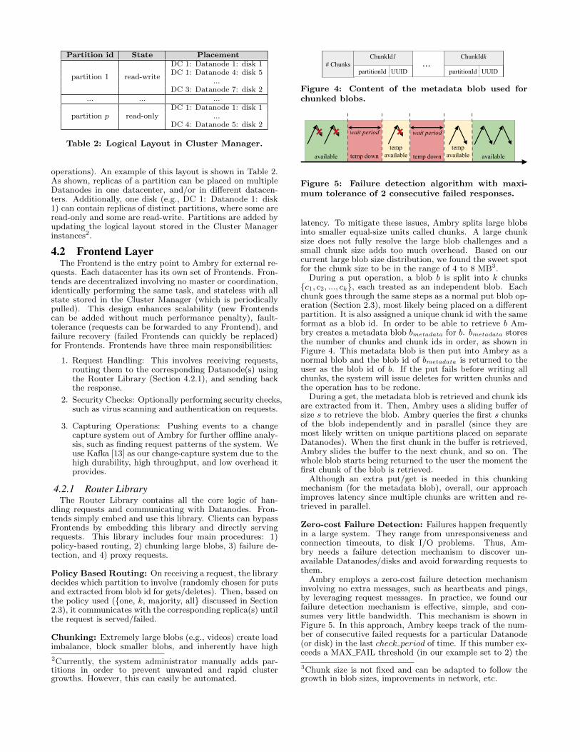
Zero-cost Failure Detection: Failures happen frequentlyin a large system. They range from unresponsiveness andconnection timeouts, to disk I/O problems. Thus, Am-bry needs a failure detection mechanism to discover un-available Datanodes/disks and avoid forwarding requests tothem.
Ambry employs a zero-cost failure detection mechanisminvolving no extra messages, such as heartbeats and pings,by leveraging request messages. In practice, we found ourfailure detection mechanism is effective, simple, and con-sumes very little bandwidth. This mechanism is shown inFigure 5. In this approach, Ambry keeps track of the num-ber of consecutive failed requests for a particular Datanode(or disk) in the last check period of time. If this number ex-ceeds a MAX FAIL threshold (in our example set to 2) the
3Chunk size is not fixed and can be adapted to follow thegrowth in blob sizes, improvements in network, etc.

Datanode is marked as temporarily down for a wait periodof time. In this state all queued requests for this Datanodewill eventually time out and need to be reattempted by theuser. After the wait period has passed, the Datanode be-comes temporarily available. When a Datanode is in thetemporarily available phase, if the next request sent to thatDatanode fails, it will move to the temporarily down phaseagain. Otherwise, it will be marked as available, working asnormal again.
Proxy Requests: As described in Section 2.3, Ambry usesproxy requests to reach higher availability and read-after-write consistency in remote datacenters. When a blob hasnot been replicated in the local datacenter yet, requests forthat blob are forwarded to other datacenters and servedthere (proxy requests). However, datacenter partitions cancause unavailability of unreplicated data until the partitionis healed and replicas converge.
Proxy requests are handled by the Router Library, trans-parently from the user issuing the request. In practice, wefound proxy requests occur less than 0.001% of the time,thus minimally affecting the user experience.
4.3 Datanode LayerDatanodes are in charge of maintaining the actual data.
Each Datanode manages a number of disks, and responds torequests for partition replicas placed on its disks. Puts arehandled by writing to the end of the partition file. Gets canbe more time-consuming, especially since the location of theblob in the partition is not known. To minimize both readand write latencies, Datanodes employ a few techniques:
• Indexing blobs: Ambry stores an index of blob off-sets per partition replica to prevent sequential sweepsfor finding blobs (Section 4.3.1).
• Exploiting OS cache: Ambry utilizes OS caching toserve most reads from the RAM, by limiting the RAMusage of other components (Section 4.3.2).
• Batched writes, with a single disk seek: Am-bry batches writes for a particular partition togetherand periodically flushes the writes to disk. Thus, itincurs at most one disk seek for a batch of sequentialwrites. The flush period is configurable and trades offlatency for durability. Although, batching can intro-duce overheads of flushing, dirty buffers, and tuning,the benefits outweigh these overheads.
• Keeping all file handles open: Since partitions aretypically very large (100 GB in our setting), the num-ber of partition replicas placed on a Datanode is small(a few hundred). Thus, Ambry keeps all file handlesopen at all times.
• Zero copy gets: When reading a blob, Ambry utilizesa zero copy [25] mechanism, i.e., the kernel directlycopies data from disk to the network buffer withoutgoing through the application. This is feasible sincethe Datanodes do not perform any computation onthe data at get operations.
4.3.1 IndexingTo find the location of a blob in a partition replica with low
latency, the Datanode maintains a light-weight in-memoryindexing per replica, as shown in Figure 6. The indexing issorted by blob id, mapping the blob id to the start offset ofthe blob entry. The indexing is updated in an online fashionwhenever blobs are put (e.g., blob 60) or deleted (e.g., blob20).
Similar to SSTables [5], Ambry limits the size of the indexby splitting it into segments, storing old segments on disk,
blobid 40…
850 9000 100 GB
Partition
blob id 20
200
blobid 60
980
…
end offset
blobid 20
1040
blobid 70
Index segment 1
Index segment 2
Index segment 3
Start offset: 700End offset: 1020
blob id offset flags TTL
20 980 del -
40 850 - ∞
60 900 - ∞
70 700 - 1/2/2017
700
Index
start offset of current index segment
Figure 6: Indexing of blob offsets in a partitionreplica. When blobs are put (blob 60) or deleted(blob 20) the indexing stucture is updated.
and maintaining a Bloom filter for each on-disk segment(Section 4.3.2).
The indexing also stores a flag indicating if a blob hasbeen deleted and optionally a time-to-live (TTL). Duringget operations, if the blob has expired or been deleted, anerror will be returned before reading the actual data.
Note that the indexing does not contain any additionalinformation affecting the correctness of the system, and justimproves performance. If a Datanode fails, the whole index-ing can be reconstructed from the partition.
4.3.2 Exploiting The OS CacheRecently written data, which is the popular data as well, is
automatically cached without any extra overhead (by the op-erating system). By exploiting this feature, many reads canbe served from memory, which significantly improves per-formance. Thus, Ambry limits the memory usage of otherdata structures in the Datanode. Ambry bounds the in-dexing by splitting it into segments, with only the latestsegment remaining in-memory (Figure 6). New entries areadded to the in-memory segment of the indexing. When thein-memory segment exceeds a maximum size it is flushed todisk as a read-only segment. This design also helps towardfailure recovery since only the in-memory segment needs tobe reconstructed. Looking up blob offsets is done in reversechronological order, starting with the latest segment (in-memory segment). Thus, a delete entry will be found beforea put entry when reading a blob. This ensures deleted blobsare not retrievable.Bloom Filters: To reduce lookup latency for on-disk seg-ments, Ambry maintains an in-memory Bloom filter for eachsegment, containing the blob ids in that index segment. Us-ing Bloom filters, Ambry quickly filters out which on-disksegment to load. Thus, with high probability, it incurs onlyone disk seek. However, due to our skewed workload a ma-jority of reads just hit the in-memory segment, without anydisk seeks.
5. REPLICATIONReplicas belonging to the same partition can become out
of sync due to either failures, or asynchronous writes thatwrite to only one datacenter. In order to fix inconsistent

offset blob id
700 70
850 40
900 60
980 20
offset blob id
600 30
670 55
750 40
800 70
950 90
Journal of partition p, replica r1
Journal of partition p, replica r2
latestOffset r2 = 600
1. get blob ids after 600
2. ids ={55, 40, 70, 90}
3. filter out missing blobs4. get blobs {55, 90}
5. blob 55 and blob 90
6. write blobs and set latestOffset r2 = 950
Figure 7: Journals for two replicas of the same par-tition and an example of the replication algorithm.
replicas, Ambry uses an asynchronous replication algorithmthat periodically synchronizes replicas. This algorithm iscompletely decentralized. In this procedure each replica in-dividually acts as a master and syncs-up with other repli-cas, in an all-to-all fashion. Synchronization is done usingan asynchronous two-phase replication protocol as follows.This protocol is a pull-based approach where each replica in-dependently requests for missing blobs from other replicas.
• First Phase: This phase finds missing blobs since thelast synchronization point. This is done by requestingblob ids of all blobs written since the latest syncingoffset and then filtering the ones missing locally.
• Second Phase: This phase replicates missing blobs.A request for only the missing blobs is sent. Then,the missing blobs are transferred and appended to thereplica.
In order to find the recently written blobs quickly, thereplication algorithm maintains an additional data struc-ture per replica, called a journal. The journal is an in-memory cache of recent blobs ordered by their offset. Figure7 shows example journals of two replicas (r1 and r2) and thetwo phase replication procedure for r1 syncing with r2 fromlatestOffset 600. In the first phase, r1 requests all recentlyadded blobs in r2 after latestOffset; using the journal r2 re-turns a list B ={55, 40, 70, 90} of blob ids; and r1 filters outthe missing blobs (blob 55 and 90). In the second phase, r1receives the missing blobs, appends the blobs to the end ofthe replica, and updates the journal, indexing and latestOff-set.
To provide improved efficiency and scalability of the sys-tem, the replication algorithm employs a number of furtheroptimizations:
• Using separate thread pools for inter- and intra-data-center replication with different periods.
• Batching requests between common partition replicasof two Datanodes, and batching blobs transferred acrossdatacenters.
• Prioritizing lagging replicas to catch up at a faster rate(by using dedicated threads for lagging replicas).
6. EXPERIMENTAL RESULTSWe perform three kinds of experiments: small cluster
(Section 6.1), production cluster (Section 6.2), and simu-lations (Section 6.3).
6.1 Throughput and LatencyIn this section we measure the latency and throughput
of the system using a micro-benchmark that stress-tests the
system (Section 6.1.1), under read-only, write-only and read-write workloads.
6.1.1 Micro-BenchmarkWe first measure the peak throughput. We designed a
micro-benchmark that linearly adds load to the system (byadding more clients), until the saturation point where nomore requests can be handled. Each client sends requestsone at a time with the next request sent right after a re-sponse.
This benchmark has three modes: Write, Read, and Read-Write. In Write mode, random byte array blobs are put withvarying number of clients. In Read mode, first blobs arewritten at saturation rate for a write-period of time. Then,randomly chosen blobs are read from the written blobs4. Inmost experiments we set the write-period long enough thatmost read requests (>80%) are served by disk, rather thanRAM. Read-Write is a similar to Read, but serving 50%reads and 50% writes after the write-period.
Since latency and throughput are highly correlated withblob size, we use fixed-size blobs in each run, but vary theblob size.
6.1.2 Experimental SetupWe deployed Ambry with a single Datanode. The Datan-
ode was running on a 24 core CPU with 64 GB of RAM, 141TB HDD disks, and a full-duplex 1 Gb/s Ethernet network.4 GB of the RAM was set aside for the Datanode’s internaluse and the rest was left to be used as Linux Cache. We cre-ated 8 single-replica 100 GB partitions on each disk, with atotal of 122 partitions. Using 14 disks with a 1 Gb/s networkmight look like an overkill. However, disk seeks are the dom-inant latency factor for small blobs. Since a large portionof blobs are small (< 50 KB), we need the parallelism cre-ated by using multiple disks (more detail in Section 6.1.4).Note that Ambry is designed as a cost-effective system usingcheap HDD disks.
Clients send requests from a few machines located in thesame datacenter as the Datanode. These clients, that areacting as Frontends, directly send requests to the Datan-ode. The micro-benchmark discussed above was used withvarying blob sizes {25 KB, 50 KB, 100 KB, 250 KB, 500KB, 1 MB, 5 MB}. We did not go above 5 MB since blobsare chunked beyond that point.
6.1.3 Effect of Number of ClientsWe ran the micro-benchmark with varying blob sizes, while
linearly increasing the number of clients. For Read mode,the write-period was set such that 6 times the RAM size, wasfirst written. Figure 8a shows the throughput in terms ofMB/s served by the system. Adding clients proportionallyincreases the throughput until the saturation point. Satura-tion occurs at 75%-88% of the network bandwidth. The onlyexception is reading small blobs due to frequent disk seeks(discussed in Section 6.1.4). Saturation is reached quickly(usually ≤ 6 clients) since clients send requests as fast aspossible in the benchmark.
Figure 8b shows the latency normalized by blob size (i.e.,average latency divided by blob size). Latency stays al-most constant before reaching saturation point, and thenincreases linearly beyond the throughput saturation point.The linear increase in latency after saturation indicates thesystem does not add additional overhead beyond requestserving.
4The random strategy gives a lower bound on the system’sperformance since real-world access patterns are skewed to-ward recent data.

0
20
40
60
80
100
120
140
0 5 10 15 20
Thro
ughput (M
B/s
)
Number of Clients
5MB-Write500KB-Write50KB-Write
5MB-Read500KB-Read50KB-Read
Network BW
(a) Throughput
0
0.1
0.2
0.3
0.4
0.5
0.6
0.7
0.8
0 2 4 6 8 10 12 14 16 18 20
No
rma
lize
d L
ate
ncy (
ms)
Number of Clients
Write 5MBWrite 500KB
Write 50KBRead 5MB
Read 500KBRead 50KB
(b) Latency normalized by blob size
Figure 8: Throughput and latency of read and writerequests with varying number of clients on differentblob sizes. These results were gathered on a singleDatanode deployment.
6.1.4 Effect of Blob SizeIn Figures 9a and 9b we analyzed the maximum through-
put (with 20 clients) under different blob sizes and work-loads. For large objects (>200 KB), the maximum through-put (in MB/s) stays constant and close to maximum net-work bandwidth across all blob sizes. Similarly, throughputin terms of requests/s scales proportionally.
However, for Read and Read-Write, the read throughputin terms of MB/s drops linearly for smaller sizes. This dropis because our micro-benchmark reads blobs randomly, in-curring frequent disk seeks. The effect of disk seeks is am-plified for smaller blobs. By further profiling the disk usingBonnie++ [1] (an IO benchmark for measuring disk per-formance), we confirmed that disk seeks are the dominantsource of latency for small blobs. For example, when readinga 50 KB blob, more than 94% of latency is due to disk seek(6.49 ms for disk seek, and 0.4 ms for reading the data).
Read and Write workload mostly utilize only the out-bound and inbound link on the Datanode, respectively. How-ever, Read-Write workload has a better mix and evenly uti-lizes both links reaching higher throughput. Therefore, inour full-duplex network infrastructure the Read-Write modeis able to saturate both links reaching almost double the
Average Max Min StdDevDisk Reads 17 ms 67 ms 1.6 ms 9 ms
Cached Reads 3 ms 5 ms 1.6 ms 0.4 msImprovement 5.5x 13x 0 23x
Table 3: Comparision of get request latency whenmost of requests (83%) are served by disk (DiskReads) and when all requests are served by linuxcache (Cached Reads) for 50 KB blobs.
network bandwidth (' 1.7 Gb/s in total out of the 2 Gb/savailable). For smaller size objects it reaches twice the Readthroughput, since Read-Write is a 50-50 workload with readsbeing the limiting factor.
Figure 9c demonstrates the trend in latency under vari-ous blob sizes. These results are before the saturation pointwith 2 clients. Similar to throughput, latency grows linearlyexcept for reading small blobs. The higher latency in Readis because most read requests incur a disk seek, while writerequests are batched and written together. The Read-Writelatency falls halfway between Read and Write latency be-cause of its mixed workload.
6.1.5 Variance in LatencyThe tail and variance in request latencies are important.
Figure 10 shows the CDFs of Write, Read, and Read-Writemode experiments with 2 clients. The CDF of Read andWrite mode is very close to a vertical line, with a shorttail and a majority of values close to the median. Thejump around 0.15 in Read mode (for 50 KB blob size) isbecause a small fraction of requests are served using theLinux cache which is orders of magnitudes faster than disk(Section 6.1.6). The Read-Write mode is a mixture of theRead and Write CDF with a change around 0.5, followingthe 50% read - 50% write workload pattern.
6.1.6 Effect of Linux CacheWe ran the micro-benchmark on 50 KB blobs and 2 clients
in two configurations: 1) writing 6 times more than the RAMsize before reading, so that most requests (83 %) are servedby disk (Disk Read), and 2) writing data equal to the RAMsize to keep all data in RAM (Cached Read). Table 3 com-pares these two modes.
The Cached Read experiment performed more than 2100requests/s (104 MB/s reaching 79% network bandwidth)matching the maximum write throughput (Section 6.1.3),compared to 540 requests/s for Disk Reads. We also mea-sured the average, maximum, minimum, and standard devi-ation of latency, shown in Table 3. In both cases, the min-imum is equal to reading from the Linux Cache. However,the Cached Read case improves the average and max latencyby 5.5x and 13x, respectively. This shows the significance ofexploiting the Linux Cache (Section 4.3.2).
6.2 Geo-distributed OptimizationsWe analyzed our replication algorithm among 3 differ-
ent datacenters at LinkedIn {DC1, DC2, DC3}, located allacross the US. All experiments in this section are from pro-duction workloads.
6.2.1 Replication LagWe define replication lag between a pair of replicas (r1,
r2) as the difference of r2’s highest used offset and r1’s lat-est synced offset with r2. Note that not all data in thereplication lag needs to be transfered to r1, since it couldreceive the missing blobs from other replicas as well.
We measured the replication lag among all replicas of agiven Datanode and the rest of the cluster, and found that

10
100
1000
10 100 1000 10000
Ma
x T
hro
ug
hp
ut
(MB
/s)
Blob Size (KB)
WriteRead
Read-WriteNetwork
(a) Throughput (MB/s)
10
100
1000
10000
10 100 1000 10000
Re
qu
ests
Pe
r S
eco
nd
Blob Size (KB)
WriteRead
Read-WriteNetwork
(b) Throughput (requests/s)
1
10
100
10 100 1000 10000
Ave
rag
e L
ate
ncy (
ms)
Blob Size (KB)
WriteRead
Read-Write
(c) Latency
Figure 9: Effect of blob size on maximum throughput, both in terms of MB/s and requests/s, and latency.Results were gathered on a write-only, read-only, and mixed (50%-50%) workload. Reads for small blob sizes(<200 KB) are slowed down by frequent disk seeks, while other requests saturate the network link.
0
0.2
0.4
0.6
0.8
1
0.1 1 10 100 1000
CD
F
Latency (ms)
Write-50KBRead-50KB
Read-Write-50KB
Write-5MBRead-5MB
Read-Write-5MB
Figure 10: CDF of read and write latency with 2clients for various blob sizes. Read-Write falls inthe middle with change around 0.5 due to the 50-50mixed workload.
more than 85% of the values were 0. Figure 11 shows theCDF of non-zero values grouped by datacenter. The 95thpercentile is less than 1 KB for 100 GB partitions (in alldatacenters), with slightly worse lag in datacenter 3 since itis placed farther apart from others.
6.2.2 Replication BandwidthAmbry relies on background replication to write data to
other datacenters. We measured the aggregate network band-width used for inter-datacenter replication during a 24 hourperiod, shown in Figure 12. The aggregate bandwidth issmall (< 10 MB/s), similar across all datacenters, and cor-related to request rates with a diurnal pattern. This value issmall because we batch replication between common replicasand due to the read-heavy nature of the workload.
Figure 13 demonstrates the CDF of average replicationbandwidth per Datanode, for both intra- and inter-datacenterreplication. Intra-datacenter bandwidth is minimal (< 200B/s at 95th percentile), especially compared to inter-datace-nter with 150-200 KB/s at 95th percentile (1000x larger).
0.88
0.9
0.92
0.94
0.96
0.98
1
1 10 100 1000 10000 100000 1x10⁶
CD
F
Lag (Bytes)
DC1DC2DC3
Figure 11: CDF of Replication Lag among replicapairs of a given Datanode and the rest of the cluster.Most values were zero, and are omitted from thegraph.
The higher value for inter-datacenter is because of asyn-chronous writes. However, the inter-datacenter bandwidthis still negligible (≈ 0.2% of a 1 Gb/s link). The small differ-ence among the 3 datacenters is due to the different requestrates they receive.
Figure 14 shows a zoomed in graph of only inter-datacenterbandwidth. Inter-datacenter replication has a short tail withthe 95th to 5th percentile ratio of about 3x. This shorttail is because of the load-balanced design in Ambry. Intra-datacenter replication has a longer tail, as well as many zerovalues (omitted from the graph). Thus, replication eitheruses almost zero bandwidth (intra-datacenter) or almost bal-anced bandwidth (inter-datacenter).
6.2.3 Replication LatencyWe define replication latency as the time spent in one it-
eration of the replication protocol, i.e., Tmissing blobs received
minus Treplication initiated. Figure 15 demonstrates the CDFof average replication latency for intra- and inter-datacenter,in our production workload.
Inter-datacenter replication latency is low with a medianof less than 150 ms, and a very short tail. Although this la-

1000
2000
3000
4000
5000
6000
7000
8000
9000
10000
11000
0 200 400 600 800 1000 1200 1400 1600
Ag
gre
ga
te R
ep
lica
tion
Ba
nd
wid
th (
KB
/s)
Time (minutes)
DC1DC2DC3
Figure 12: Aggregate network bandwidth used forinter-datacenter replication during a 24 hour periodin production.
0
0.1
0.2
0.3
0.4
0.5
0.6
0.7
0.8
0.9
1
1 10 100 1000 10000 100000 1x10⁶
CD
F
Average Replication Bandwidth per Datanode (B/s)
DC1-intraDC2-intra
DC3-intraDC1-inter
DC2-interDC3-inter
Figure 13: CDF of average network bandwidth usedper Datanode for intra- and inter-datacenter repli-cation over a 24 hour period in production.
tency might appear to be high, the number of proxy requestsremain near-zero (< 0.001%). This is because users usuallyread data from the same local datacenter to which they haverecently written. Therefore, replication has a minimal effecton user experience.
Surprisingly, intra-datacenter replication latency is rela-tively high (6x more than inter-datacenter) and with littlevariance. This pattern is because of a pre-existing and pre-fixed artificial added delay of 1 second, intended to preventincorrect blob collision detections. If a blob is replicatedin a datacenter faster than the Datanode receives the ini-tial put request (which is possible with less strict policies),the Datanode might consider the put as a blob collision andfail the request. The artificial delay is used to prevent thisissue in intra-datacenter replication. This relatively smalldelay does not have a significant impact on durability oravailability of data since intra-replication is only used to fixfailed/slow Datanodes, which rarely occurs.
6.3 Load BalancingSince cluster growth occurs infrequently (every few months
at most), we implemented a simulator to show the behaviorof Ambry over a long period of time (several years), and atlarge scale (hundreds of Datanodes). We tried a workloadthat is based on production workloads. All results in thissection are gathered using the simulator.
0
0.1
0.2
0.3
0.4
0.5
0.6
0.7
0.8
0.9
1
0 50000 100000 150000 200000 250000
CD
F
Average Replication Bandwidth per Datanode (B/s)
DC1-interDC2-interDC3-inter
Figure 14: CDF of average inter-datacenter networkbandwidth used per Datanode over a 24 hour periodin production.
0
0.1
0.2
0.3
0.4
0.5
0.6
0.7
0.8
0.9
1
1000 1005 1010 1015
CD
F
Replication Latency (ms)
DC1DC2DC3
(a) Intra Datacenter
0
0.1
0.2
0.3
0.4
0.5
0.6
0.7
0.8
0.9
1
60 80 100 120 140 160 180 200
CD
F
Replication Latency (ms)
DC1DC2DC3
(b) Inter Datacenter
Figure 15: CDF of average replication latency (i.e.,time spent to recieve missing blobs) for intra- andinter-datacenter in production environment.
6.3.1 Simulator DesignThe simulator’s design resembles Ambry’s architecture and
requests are served using the same path. However, there areno real physical disks. For handling requests, only the meta-data (blob id and size) is stored/retrieved, and the effect ofrequests are reflected (e.g., disk space increase).Workload: We use a synthetic workload closely resemblingthe real-world traffic at LinkedIn. This workload preservesthe rate of each type of request (read, write, and delete),the blob size distribution, and the access pattern of blobs(based on age).Cluster Expansion: The simulator starts with an initialset of Datanodes, disks, and partitions in one datacenter.Over time, when partitions reach the capacity threshold, anew batch of partitions are added using the replica place-ment strategy from Section 2.2. If partitions cannot beadded (e.g., if there is not enough unallocated space ondisks), a batch of new Datanodes are added.
6.3.2 Experiment SetupThe simulation is run in a single datacenter, with 10 Fron-
tend nodes. The experiment starts with 15 Datanodes, eachwith 10 4TB disks, and 1200 100GB partitions with 3 repli-cas. At each partition and Datanode addition point, a batchof 600 partitions and 15 Datanodes are added, respectively.The simulation is run over 400 weeks (almost 8 years) and

0
200
400
600
800
1000
1200
0 50 100 150 200 250 300 350 400
Read R
ate
(K
B/s
)
Time (weeks)
Average StdDev Max Min
(a) Without rebalancing
0
200
400
600
800
1000
1200
0 50 100 150 200 250 300 350 400
Read R
ate
(K
B/s
)
Time (weeks)
Average StdDev Max Min
(b) With rebalancing
Figure 16: Average, standard deviation, maximumand minimum of average read rate (KB/s) amongdisks over a 400 week interval. The system is boot-strapping in the first few weeks, and the results areomitted.
up to 240 Datanodes. The simulation is run with and with-out rebalancing with the exact same configuration, whilemeasuring request rates, disk usage, and data movement.
6.3.3 Request RateWe measured the read rate (KB/s) for each disk at any
point of time. Figure 16 demonstrates the average, standarddeviation, maximum and minimum among these values, forthe system with and without rebalancing. The results forwrite rates were similar and removed due to lack of space.
The average, which is also the ideal, is a dropping stepfunction. The drops are points where new Datanodes wereadded to the cluster. In case of no rebalancing, a majorityof the disks are old read-only disks with almost zero traf-fic, while a few disks receive most of the request. Thus, theminimum is close to zero. Also, the maximum and stan-dard deviation are significant (3x-7x and 1x-2x larger thanthe average, respectively). When rebalancing is added, theminimum and maximum move close to the average, and thestandard deviation drops close to zero. We conclude thatAmbry’s load balancing is effective.
6.3.4 Disk UsageWe analyzed the disk usage ratio, i.e., used space divided
by total space among disks, with and without rebalancing.As seen in Figure 17, without rebalancing, the maximumstays at the capacity threshold since some disks become andremain full, while the minimum drops to zero whenever new
0
0.2
0.4
0.6
0.8
1
0 50 100 150 200 250 300 350 400
Dis
k U
sa
ge
Ra
tio
Time (weeks)
Average StdDev Max Min
(a) Without rebalancing
0
0.2
0.4
0.6
0.8
1
0 50 100 150 200 250 300 350 400
Dis
k U
sa
ge
Ra
tio
Time (weeks)
Average StdDev Max Min
(b) With rebalancing
Figure 17: Average, standard deviation, maximumand minimum of disk usage ratio (i.e., used spacedivided by total space) over a 400 week interval.
Datanodes are added. With rebalancing, the maximum andminimum move closer to the average with temporary dropsin the minimum until rebalancing is completed. Addition-ally, the standard deviation drops significantly, becomingalmost zero with temporary spikes on Datanode additionpoints.
6.3.5 Evaluation Over TimeWe evaluated the improvement over time by measuring
the integral of range (max-min) and standard deviation forrequest rate and disk usage over the 400 week interval. Asshown in Table 4, rebalancing has a prominent effect improv-ing the range and standard deviation by 6x-9x and 8x-10x,respectively.
6.3.6 Data MovementWhenever rebalancing is triggered, we measure the min-
imum data movement needed to reach an ideal state andthe data movement caused by rebalancing. We calculatethe minimum data movement by adding the difference be-tween ideal and current disk usage among all disks aboveideal disk usage. This value is a lower bound on the feasibleminimum data movement since data is moved in granularityof partitions. As shown in Figure 18, the data movementof rebalancing is very close and always below the minimum.This is because the rebalancing algorithms trades off perfectbalance (ideal state) for less data movement. Specifically,the rebalancing algorithm usually does not remove (or add)

Integral over400 weeks
WriteAvg
ReadAvg
DiskUsage
Range w/o RB 63,000 340,000 200Range w/ RB 8,500 52,000 22Improvement 7.5x 6x 9xStdDev w/o RB 21,00 112,000 67StdDev w/ RB 2500 11,000 6.7Improvement 8x 10x 10x
Table 4: Improvement of range (max-min) and stan-dard deviation of request rates and disk usage overa 400 week interval. Results are from the systemwith rebalancing (w/ RB) and without rebalancing(w/o RB).
100
150
200
250
300
350
400
450
0 2 4 6 8 10 12 14
Data
Movem
ent (T
B)
Rebalancing Points
MinimumRebalancer
Figure 18: Data movement of the rebalancing algo-rithm at each rebalancing point (i.e., whenever newDatanodes are added) over a 400 week interval.
a partition from a disk if it would go below (or above) theideal state, even if this were to cause slight imbalance.
7. RELATED WORKFile Systems: The design of Ambry is inspired by log-
structure file systems (LFS) [21, 23]. These file systems areoptimized for write throughput by sequentially writing inlog-like data structures and relying on the OS cache forreads. Although these single machine file systems suffer fromfragmentation issues and cleaning overhead, the core ideasare very relevant, especially since blobs are immutable. Themain differences are the skewed data access pattern in ourworkload and additional optimization such as segmented in-dexing and Bloom filters used in Ambry.
There has been work on handling metadata and small filesmore efficiently. Some of these techniques include reducingdisk seeks [9], using a combination of log-structured file sys-tems (for metadata and small data) and fast file systems(for large data) [30], and storing the initial segment of datain the index block [17]. Our system resolves this issue byusing in-memory segmented indexing plus Bloom filters andbatching techniques.
Distributed File Systems: Due to the extremely largeamount of data and data sharing needs, many distributed filesystems such as NFS [22] and AFS [16], and even more reli-able ones handling failures, such as GFS, HDFS, and Ceph[10, 24, 28] have emerged. However, all these systems sufferfrom the high metadata overhead and additional capabili-ties (e.g., nested directories, permissions, etc.) unnecessaryfor a simple blob store. In many of these systems (e.g.,HDFS, GFS, and NFS) the metadata overhead is magnifiedby having a separate single metadata server. This server
adds an extra hub in each request, becomes a single pointof failure, and limits scalability beyond a point. Recent re-search has addressed this problem by either distributing themetadata [28] or caching it [20]. Although these systems al-leviate accessing metadata, each small object still has a largemetadata (usually stored on disk), decreasing the effectivethroughput of the system.
Distributed Data Stores: Many key-value stores, suchas [2, 5, 8, 14], have been designed to handle a large numberof requests per second. However, these systems cannot han-dle massively large objects (tens of MBs to GBs) efficiently,and add unnecessary overhead to provide consistency. Also,some systems [2,8,14] hash data to machines, creating largedata movement whenever nodes are added/deleted.
PNUTS [6] and Spanner [7] are scalable geographicallydistributed systems, where PNUTS maintains load balanceas well. However, both systems provide more features andstronger guarantees than needed in a simple immutable blobstore.
Blob Stores: A similar concept to partitions in Am-bry has been used in other systems. Haystack uses logicalvolumes [3], Twitter’s blob store uses virtual buckets [27],and Petal file system introduces virtual disks [15]. Ambry isamenable to some optimizations in these systems such as theadditional internal caching in Haystack. However, neitherHaystack nor Twitter’s blob store tackle the problem of load-imbalance. Additionally, Haystack uses synchronous writesacross all replicas impacting efficiency in a geo-distributedsetting.
Facebook has also designed f4 [18], a blob store using era-sure coding to reduce replication factor of old data (that hasbecome cold). Despite the novel ideas in this system, whichpotentially can be included in Ambry, our main focus is onboth new and old data. Oracle’s Database [19] and WindowsAzure Storage (WAS) [4] also store mutable blobs, and WASis even optimized for a geo-distributed environment. How-ever, they both provide additional functionalities such assupport for many data types other than blobs, strong con-sistency guarantees, and modification to blobs, that are notneeded in our use case.
8. CONCLUSIONThis paper described Ambry, a distributed storage sys-
tem designed specifically for storing large immutable mediaobjects, called blobs. We designed Ambry to serve requestsin a geographically distributed environment of multiple dat-acenters while maintaining low latency and high through-put. Using a decentralized design, rebalancing mechanism,chunking, and logical blob grouping, we provide load bal-ancing and horizontal scalability to meet the rapid growthat LinkedIn.
As part of future work we plan to adaptively change thereplication factor of data based on the popularity, and useerasure coding mechanisms for cold data. We also plan toinvestigate using compression mechanisms and its costs andbenefits. Additionally, we are working on improving thesecurity of Ambry, especially for cross-datacenter traffic.
9. ACKNOWLEDGMENTSWe wish to thank the following people for their invaluable
contributions towards the development and deployment ofAmbry: our site reliability engineers, Tofig Suleymanov, Ar-jun Shenoy and Dmitry Nikiforov; our alumni Jay Wylie; ourinterns Tong Wei and Sarath Sreedharan; and our newestmember Ming Xia for his valuable review comments.

10. REFERENCES[1] Bonnie++. http://www.coker.com.au/bonnie++/,
2001 (accessed Mar, 2016).[2] A. Auradkar, C. Botev, S. Das, D. De Maagd,
A. Feinberg, P. Ganti, L. Gao, B. Ghosh,K. Gopalakrishna, et al. Data infrastructure atLinkedIn. In Proceeding of the IEEE InternationalConference on Data Engineering (ICDE), 2012.
[3] D. Beaver, S. Kumar, H. C. Li, J. Sobel, andP. Vajgel. Finding a needle in Haystack: Facebook’sphoto storage. In Proceeding of the USENIXSymposium on Operating Systems Design andImplementation (OSDI), 2010.
[4] B. Calder, J. Wang, A. Ogus, N. Nilakantan,A. Skjolsvold, S. McKelvie, Y. Xu, S. Srivastav,J. Wu, et al. Windows Azure storage: A highlyavailable cloud storage service with strong consistency.In Proceeding of the ACM Symposium on OperatingSystems Principles (SOSP), 2011.
[5] F. Chang, J. Dean, S. Ghemawat, W. C. Hsieh, D. A.Wallach, M. Burrows, T. Chandra, A. Fikes, and R. E.Gruber. Bigtable: A distributed storage system forstructured data. ACM Transactions on ComputerSystems (TOCS), 26(2), 2008.
[6] B. F. Cooper, R. Ramakrishnan, U. Srivastava,A. Silberstein, P. Bohannon, A. Jacobsen, N. Puz,D. Weaver, and R. Yerneni. Pnuts: Yahoo!’s hosteddata serving platform. In Proceeding of the Very LargeData Bases Endowment (VLDB), 1(2), 2008.
[7] J. C. Corbett, J. Dean, M. Epstein, A. Fikes, C. Frost,J. J. Furman, S. Ghemawat, A. Gubarev, C. Heiser,et al. Spanner: Google’s globally-distributed database.In Proceeding of the USENIX Symposium on OperatingSystems Design and Implementation (OSDI), 2012.
[8] G. DeCandia, D. Hastorun, M. Jampani,G. Kakulapati, A. Lakshman, A. Pilchin,S. Sivasubramanian, P. Vosshall, and W. Vogels.Dynamo: Amazon’s highly available key-value store.In Proceeding of the ACM SIGOPS Operating SystemsReview (OSR), 2007.
[9] G. R. Ganger and M. F. Kaashoek. Embedded inodesand explicit grouping: Exploiting disk bandwidth forsmall files. In Proceeding of the USENIX AnnualTechnical Conference (ATC), 1997.
[10] S. Ghemawat, H. Gobioff, and S.-T. Leung. TheGoogle File System. In Proceeding of the ACMSIGOPS Operating Systems Review (OSR), 2003.
[11] Hortonworks. Ozone: An object store in HDFS. http://hortonworks.com/blog/ozone-object-store-hdfs/,2014 (accessed Mar, 2016).
[12] P. Hunt, M. Konar, F. P. Junqueira, and B. Reed.Zookeeper: Wait-free coordination for internet-scalesystems. In Proceeding of the USENIX AnnualTechnical Conference (ATC), 2010.
[13] J. Kreps, N. Narkhede, J. Rao, et al. Kafka: Adistributed messaging system for log processing. InProceeding of the USENIX Networking MeetsDatabases Workshop (NetDB), 2011.
[14] A. Lakshman and P. Malik. Cassandra: Adecentralized structured storage system. In Proceedingof the ACM SIGOPS Operating Systems Review(OSR), number 2, 2010.
[15] E. K. Lee and C. A. Thekkath. Petal: Distributedvirtual disks. In Proceeding of the ACM Architectural
Support for Programming Languages and OperatingSystems (ASPLOS), 1996.
[16] J. H. Morris, M. Satyanarayanan, M. H. Conner, J. H.Howard, D. S. Rosenthal, and F. D. Smith. Andrew:A distributed personal computing environment.Communications of the ACM (CACM), 29(3), 1986.
[17] S. J. Mullender and A. S. Tanenbaum. Immediatefiles. Software: Practice and Experience, 14(4), 1984.
[18] S. Muralidhar, W. Lloyd, S. Roy, C. Hill, E. Lin,W. Liu, S. Pan, S. Shankar, V. Sivakumar, et al. F4:Facebook’s warm blob storage system. In Proceedingof the USENIX Symposium on Operating SystemsDesign and Implementation (OSDI), 2014.
[19] Oracle. Database securefiles and large objectsdeveloper’s guide. https://docs.oracle.com/database/121/ADLOB/toc.htm,2011(accessed Mar, 2016).
[20] K. Ren, Q. Zheng, S. Patil, and G. Gibson. Indexfs:Scaling file system metadata performance withstateless caching and bulk insertion. In Proceeding ofthe IEEE High Performance Computing, Networking,Storage and Analysis (SC), 2014.
[21] M. Rosenblum and J. K. Ousterhout. The design andimplementation of a log-structured file system. ACMTransactions on Computer Systems (TOCS), 10(1),1992.
[22] R. Sandberg, D. Goldberg, S. Kleiman, D. Walsh, andB. Lyon. Design and implementation of the Sunnetwork file system. In Proceeding of the USENIXSummer Technical Conference, 1985.
[23] M. Seltzer, K. Bostic, M. K. Mckusick, and C. Staelin.An implementation of a log-structured file system forUNIX. In Proceeding of the USENIX Winter TechnicalConference, 1993.
[24] K. Shvachko, H. Kuang, S. Radia, and R. Chansler.The Hadoop Distributed File System. In Proceeding ofthe IEEE Mass Storage Systems and Technologies(MSST), 2010.
[25] D. Stancevic. Zero copy I: User-mode perspective.Linux Journal, 2003(105), 2003.
[26] I. Stoica, R. Morris, D. Karger, M. F. Kaashoek, andH. Balakrishnan. Chord: A scalable peer-to-peerlookup service for Internet applications. In Proceedingof the ACM Special Interest Group on DataCommunication (SIGCOMM), 2001.
[27] Twitter. Blobstore: Twitter’s in-house photo storagesystem. https://blog.twitter.com/2012/blobstore-twitter-s-in-house-photo-storage-system,2011 (accessed Mar, 2016).
[28] S. A. Weil, S. A. Brandt, E. L. Miller, D. D. Long,and C. Maltzahn. Ceph: A scalable, high-performancedistributed file system. In Proceeding of the USENIXSymposium on Operating Systems Design andImplementation (OSDI), 2006.
[29] S. A. Weil, S. A. Brandt, E. L. Miller, andC. Maltzahn. CRUSH: Controlled, scalable,decentralized placement of replicated data. InProceeding of the IEEE High Performance Computing,Networking, Storage and Analysis (SC), 2006.
[30] Z. Zhang and K. Ghose. hFS: A hybrid file systemprototype for improving small file and metadataperformance. In Proceeding of the ACM EuropeanConference on Computer Systems (EuroSys), 2007.