amBIent vIBratIon tests on energY productIon and ... · 252. GNGTS 2015. s. essione. 2.3. amBIent...
7
252 GNGTS 2015 SESSIONE 2.3 AMBIENT VIBRATION TESTS ON ENERGY PRODUCTION AND DISTRIBUTION FACILITIES: THREE CASE STUDIES G. Massolino, D. Sandron, A. Rebez, M. Mucciarelli OGS - Istituto Nazionale di Oceanografia e di Geofisica Sperimentale, Trieste, Italy Introduction. In this study the ambient noise tests performed on three different kinds of energy related industrial structures are described: a concrete dam, an oil tank and a hangar. Since the failure of these structures could induce serious damage to people, property and the environment, it is fundamental to perform their dynamic characterization and operational monitoring. In fact, boundary conditions, geometrical and material properties may be different from the design characteristics, due to structure exposure or even to construction mistakes. The modal tests that can be performed on a structure for the determination of dynamic parameters, such as natural frequencies and damping, are of two kinds: forced vibration or ambient vibration. The former is very expensive and complicated, especially on big constructions, but (being the input known) has the advantage of allowing the determination of force response relationships, leading to more accurate modal proprieties definition (Bukenya et al., 2012). The latter, on the contrary, is cost-effective, non-destructive, quick and easy to perform, since it doesn’t require any artificial source. Between these non-invasive techniques for damage detection and monitoring of structural performance of existing structures, there are the “Operational Modal Analysis” (OMA) or “Noise Input Modal Analysis” (NIMA), consisting in the estimation of natural frequencies, mode shapes and damping ratios using only the ambient noise as source input (Sevim et al., 2013). Since the vibration amplitudes are small (Ivanović et al., 2000), ambient vibration tests can describe only the linear behavior of structures. However, it can be an effective way to have a high degree of confidence that the structure’s model used is a realistic representation of the physical structure (Ventura et al., 2005). Therefore, in this work the test results were compared, when possible, to theoretical formulations and Finite Element Models (FEM). Usually, ambient vibration tests are applied to the determination of dynamic characteristics of existing civil buildings but it can be a powerful tool also for industrial facilities related to the production and distribution of energy. In fact, in this case, it is fundamental to avoid interference on the operability. Moreover, a crucial application of the technique is the possibility to make a comparative analysis between the modal frequencies under different load conditions and before and after an earthquake. As a consequence, if a large number of strategical structures were characterized in this way, immediately after the occurrence of an earthquake it could be possible to estimate the damage entity and plan a safety intervention. Ambient vibration can be used also to detect asymmetries or rotation plans in structures. In fact, in this work it is shown how it is possible to determine the azimuthal and tilt angle of the rocking rotational direction for the dam, or the stiffness centre and torsional component for the hangar. Unfortunately, it won’t be possible to give detailed characteristics of the analyzed structures because of industrial confidentiality. Methods. The ambient noise surveys have been performed with tri-axial digital high resolution tromograph Tromino, Micromed ® . The horizontal axes were always orientated in accordance to the structural axes: in the direction of the curvature radius for the dam, tangential to the border for the tank and parallel to the main planar dimension for the hangar. Due to limited availability of instruments (3 Tromino stations), measures were not synchronized, although all the measures have been referred to an ambient noise measure on bedrock or free-field. Ambient noise was recorded for 12 minutes on the structures and 30 minutes on free-field soil, at a sampling rate of 128 Hz. In the analysis, the smoothing was fixed to 3% for the measures on structures, 10% for those on free-field soil. Results. Dam. The estimation of the actual dynamic response to loads in the case of dams is quite complicated, as it depends on several factors, such as design input, interaction with the
Transcript of amBIent vIBratIon tests on energY productIon and ... · 252. GNGTS 2015. s. essione. 2.3. amBIent...
252
GNGTS 2015 sessione 2.3
amBIent vIBratIon tests on energY productIon and dIstrIButIonFacIlItIes: three case studIes G. Massolino, D. Sandron, A. Rebez, M. MucciarelliOGS - Istituto Nazionale di Oceanografia e di Geofisica Sperimentale, Trieste, Italy
Introduction. In this study the ambient noise tests performed on three different kinds of energy related industrial structures are described: a concrete dam, an oil tank and a hangar. Since the failure of these structures could induce serious damage to people, property and the environment, it is fundamental to perform their dynamic characterization and operational monitoring. In fact, boundary conditions, geometrical and material properties may be different from the design characteristics, due to structure exposure or even to construction mistakes.
The modal tests that can be performed on a structure for the determination of dynamic parameters, such as natural frequencies and damping, are of two kinds: forced vibration or ambient vibration. The former is very expensive and complicated, especially on big constructions, but (being the input known) has the advantage of allowing the determination of force response relationships, leading to more accurate modal proprieties definition (Bukenya et al., 2012). The latter, on the contrary, is cost-effective, non-destructive, quick and easy to perform, since it doesn’t require any artificial source. Between these non-invasive techniques for damage detection and monitoring of structural performance of existing structures, there are the “Operational Modal Analysis” (OMA) or “Noise Input Modal Analysis” (NIMA), consisting in the estimation of natural frequencies, mode shapes and damping ratios using only the ambient noise as source input (Sevim et al., 2013). Since the vibration amplitudes are small (Ivanović et al., 2000), ambient vibration tests can describe only the linear behavior of structures. However, it can be an effective way to have a high degree of confidence that the structure’s model used is a realistic representation of the physical structure (Ventura et al., 2005). Therefore, in this work the test results were compared, when possible, to theoretical formulations and Finite Element Models (FEM).
Usually, ambient vibration tests are applied to the determination of dynamic characteristics of existing civil buildings but it can be a powerful tool also for industrial facilities related to the production and distribution of energy. In fact, in this case, it is fundamental to avoid interference on the operability. Moreover, a crucial application of the technique is the possibility to make a comparative analysis between the modal frequencies under different load conditions and before and after an earthquake. As a consequence, if a large number of strategical structures were characterized in this way, immediately after the occurrence of an earthquake it could be possible to estimate the damage entity and plan a safety intervention.
Ambient vibration can be used also to detect asymmetries or rotation plans in structures. In fact, in this work it is shown how it is possible to determine the azimuthal and tilt angle of the rocking rotational direction for the dam, or the stiffness centre and torsional component for the hangar.
Unfortunately, it won’t be possible to give detailed characteristics of the analyzed structures because of industrial confidentiality.
Methods. The ambient noise surveys have been performed with tri-axial digital high resolution tromograph Tromino, Micromed®. The horizontal axes were always orientated in accordance to the structural axes: in the direction of the curvature radius for the dam, tangential to the border for the tank and parallel to the main planar dimension for the hangar. Due to limited availability of instruments (3 Tromino stations), measures were not synchronized, although all the measures have been referred to an ambient noise measure on bedrock or free-field. Ambient noise was recorded for 12 minutes on the structures and 30 minutes on free-field soil, at a sampling rate of 128 Hz. In the analysis, the smoothing was fixed to 3% for the measures on structures, 10% for those on free-field soil.
Results. Dam. The estimation of the actual dynamic response to loads in the case of dams is quite complicated, as it depends on several factors, such as design input, interaction with the
GNGTS 2015 sessione 2.3
253
foundation and reservoir water level (Calcina et al., 2014). Experimental methods can be used to have a control over general dynamic parameters calculated through dynamic analysis; ambient vibration tests can save a considerable amount of money in comparison to other techniques, such as those performed with mechanical vibrodyne. In the past many ambient vibration tests have been performed on arch concrete dams, but the pertinence of such tests on dams with more complex or mixed structural behavior (as in this case) have not been validated yet. The dam analyzed in this work, in fact, presents a mixed structure: arch and gravity. The ambient vibration test was performed on 7 points on the crest and inside the three internal galleries. All the measures were referred to the one made on a bedrock outcrop at the side of the dam. Unfortunately, even though the measures were executed on a short time (4 hours) in order to avoid changing in the conditions throughout the testing period, a strong wind raised in the middle of the survey, probably influencing it.
Considering the Eq. 1 proposed by Priscu et al. (1985):
(1)
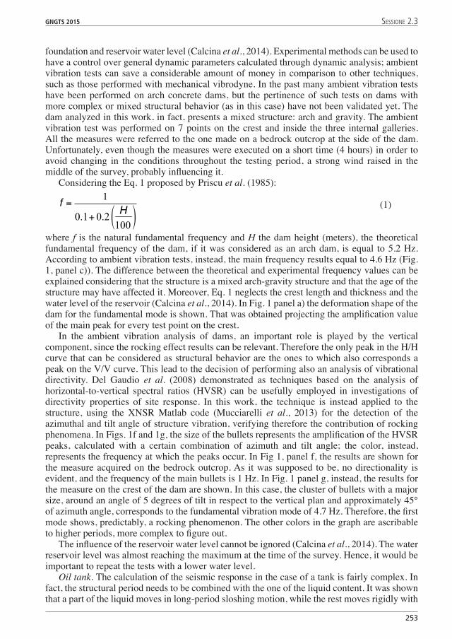
where f is the natural fundamental frequency and H the dam height (meters), the theoretical fundamental frequency of the dam, if it was considered as an arch dam, is equal to 5.2 Hz. According to ambient vibration tests, instead, the main frequency results equal to 4.6 Hz (Fig. 1, panel c)). The difference between the theoretical and experimental frequency values can be explained considering that the structure is a mixed arch-gravity structure and that the age of the structure may have affected it. Moreover, Eq. 1 neglects the crest length and thickness and the water level of the reservoir (Calcina et al., 2014). In Fig. 1 panel a) the deformation shape of the dam for the fundamental mode is shown. That was obtained projecting the amplification value of the main peak for every test point on the crest.
In the ambient vibration analysis of dams, an important role is played by the vertical component, since the rocking effect results can be relevant. Therefore the only peak in the H/H curve that can be considered as structural behavior are the ones to which also corresponds a peak on the V/V curve. This lead to the decision of performing also an analysis of vibrational directivity. Del Gaudio et al. (2008) demonstrated as techniques based on the analysis of horizontal-to-vertical spectral ratios (HVSR) can be usefully employed in investigations of directivity properties of site response. In this work, the technique is instead applied to the structure, using the XNSR Matlab code (Mucciarelli et al., 2013) for the detection of the azimuthal and tilt angle of structure vibration, verifying therefore the contribution of rocking phenomena. In Figs. 1f and 1g, the size of the bullets represents the amplification of the HVSR peaks, calculated with a certain combination of azimuth and tilt angle; the color, instead, represents the frequency at which the peaks occur. In Fig 1, panel f, the results are shown for the measure acquired on the bedrock outcrop. As it was supposed to be, no directionality is evident, and the frequency of the main bullets is 1 Hz. In Fig. 1 panel g, instead, the results for the measure on the crest of the dam are shown. In this case, the cluster of bullets with a major size, around an angle of 5 degrees of tilt in respect to the vertical plan and approximately 45° of azimuth angle, corresponds to the fundamental vibration mode of 4.7 Hz. Therefore, the first mode shows, predictably, a rocking phenomenon. The other colors in the graph are ascribable to higher periods, more complex to figure out.
The influence of the reservoir water level cannot be ignored (Calcina et al., 2014). The water reservoir level was almost reaching the maximum at the time of the survey. Hence, it would be important to repeat the tests with a lower water level.
Oil tank. The calculation of the seismic response in the case of a tank is fairly complex. In fact, the structural period needs to be combined with the one of the liquid content. It was shown that a part of the liquid moves in long-period sloshing motion, while the rest moves rigidly with
254
GNGTS 2015 sessione 2.3
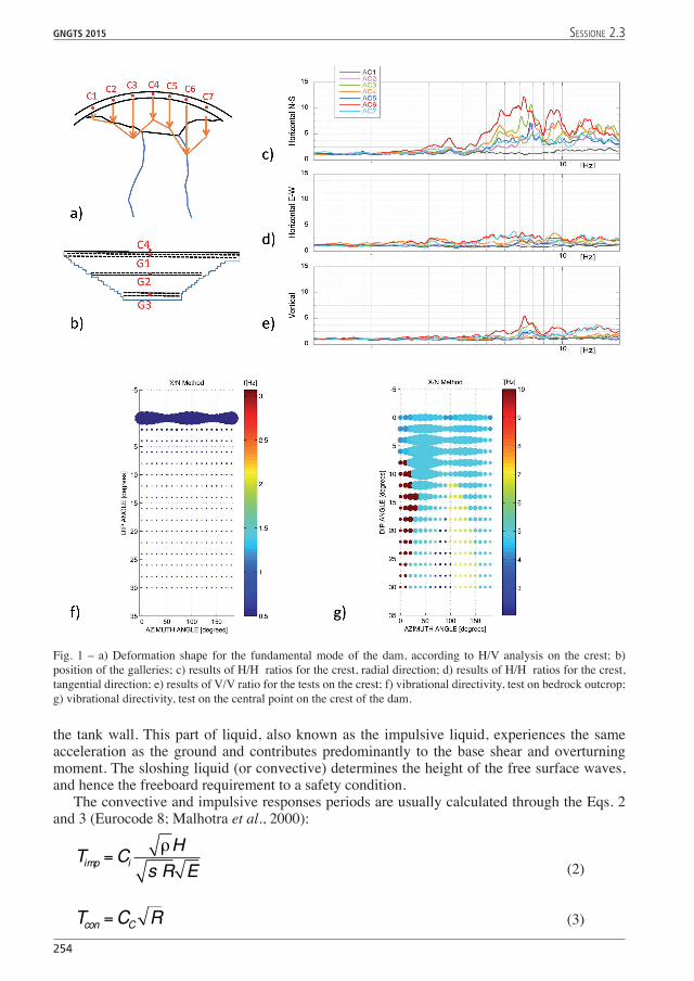
the tank wall. This part of liquid, also known as the impulsive liquid, experiences the same acceleration as the ground and contributes predominantly to the base shear and overturning moment. The sloshing liquid (or convective) determines the height of the free surface waves, and hence the freeboard requirement to a safety condition.
The convective and impulsive responses periods are usually calculated through the Eqs. 2 and 3 (Eurocode 8; Malhotra et al., 2000):
(2)
(3)
Fig. 1 – a) Deformation shape for the fundamental mode of the dam, according to H/V analysis on the crest; b) position of the galleries; c) results of H/H ratios for the crest, radial direction; d) results of H/H ratios for the crest, tangential direction; e) results of V/V ratio for the tests on the crest; f) vibrational directivity, test on bedrock outcrop; g) vibrational directivity, test on the central point on the crest of the dam.
GNGTS 2015 sessione 2.3
255
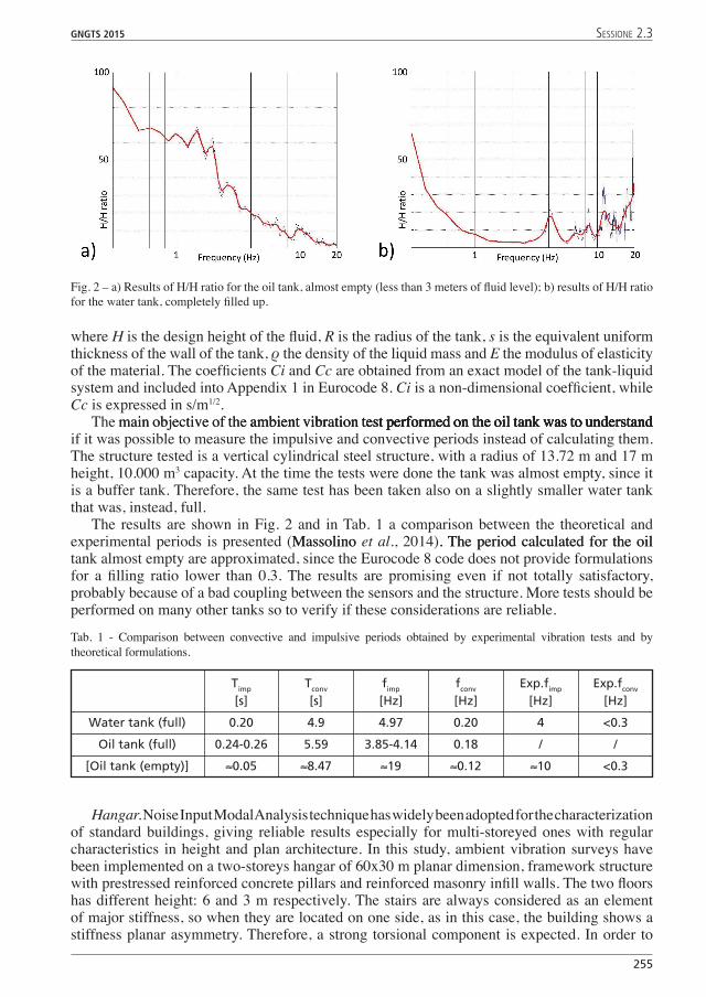
where H is the design height of the fluid, R is the radius of the tank, s is the equivalent uniform thickness of the wall of the tank, ρ the density of the liquid mass and E the modulus of elasticity of the material. The coefficients Ci and Cc are obtained from an exact model of the tank-liquid system and included into Appendix 1 in Eurocode 8. Ci is a non-dimensional coefficient, while Cc is expressed in s/m1/2.
The main objective of the ambient vibration test performed on the oil tank was to understandmain objective of the ambient vibration test performed on the oil tank was to understandambient vibration test performed on the oil tank was to understandtest performed on the oil tank was to understandperformed on the oil tank was to understandwas to understand if it was possible to measure the impulsive and convective periods instead of calculating them. The structure tested is a vertical cylindrical steel structure, with a radius of 13.72 m and 17 m height, 10.000 m3 capacity. At the time the tests were done the tank was almost empty, since it is a buffer tank. Therefore, the same test has been taken also on a slightly smaller water tank that was, instead, full.
The results are shown in Fig. 2 and in Tab. 1 a comparison between the theoretical and experimental periods is presented (MassolinoMassolino et al., 2014). The period calculated for the oil. The period calculated for the oil tank almost empty are approximated, since the Eurocode 8 code does not provide formulations for a filling ratio lower than 0.3. The results are promising even if not totally satisfactory, probably because of a bad coupling between the sensors and the structure. More tests should be performed on many other tanks so to verify if these considerations are reliable.
Fig. 2 – a) Results of H/H ratio for the oil tank, almost empty (less than 3 meters of fluid level); b) results of H/H ratio for the water tank, completely filled up.
Tab. 1 - Comparison between convective and impulsive periods obtained by experimental vibration tests and by theoretical formulations.
Timp Tconv fimp fconv Exp.fimp Exp.fconv [s] [s] [Hz] [Hz] [Hz] [Hz]
Water tank (full) 0.20 4.9 4.97 0.20 4 <0.3
Oil tank (full) 0.24-0.26 5.59 3.85-4.14 0.18 / /
[Oil tank (empty)] ≈0.05 ≈8.47 ≈19 ≈0.12 ≈10 <0.3
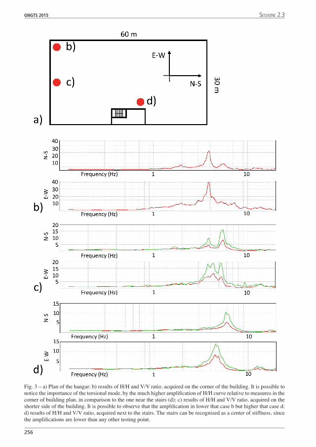
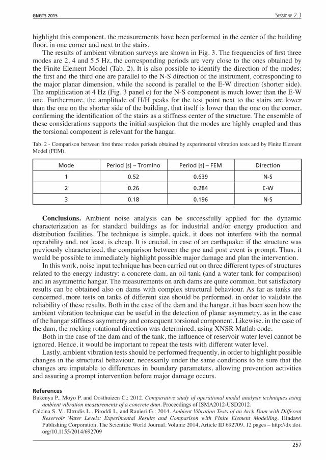
Hangar. Noise Input Modal Analysis technique has widely been adopted for the characterization of standard buildings, giving reliable results especially for multi-storeyed ones with regular characteristics in height and plan architecture. In this study, ambient vibration surveys have been implemented on a two-storeys hangar of 60x30 m planar dimension, framework structure with prestressed reinforced concrete pillars and reinforced masonry infill walls. The two floors has different height: 6 and 3 m respectively. The stairs are always considered as an element of major stiffness, so when they are located on one side, as in this case, the building shows a stiffness planar asymmetry. Therefore, a strong torsional component is expected. In order to
256
GNGTS 2015 sessione 2.3
Fig. 3 – a) Plan of the hangar; b) results of H/H and V/V ratio, acquired on the corner of the building. It is possible to notice the importance of the torsional mode, by the much higher amplification of H/H curve relative to measures in the corner of building plan, in comparison to the one near the stairs (d); c) results of H/H and V/V ratio, acquired on the shorter side of the building. It is possible to observe that the amplification in lower that case b but higher that case d; d) results of H/H and V/V ratio, acquired next to the stairs. The stairs can be recognized as a center of stiffness, since the amplifications are lower than any other testing point.
GNGTS 2015 sessione 2.3
257
highlight this component, the measurements have been performed in the center of the building floor, in one corner and next to the stairs.
The results of ambient vibration surveys are shown in Fig. 3. The frequencies of first three modes are 2, 4 and 5.5 Hz, the corresponding periods are very close to the ones obtained by the Finite Element Model (Tab. 2). It is also possible to identify the direction of the modes: the first and the third one are parallel to the N-S direction of the instrument, corresponding to the major planar dimension, while the second is parallel to the E-W direction (shorter side). The amplification at 4 Hz (Fig. 3 panel c) for the N-S component is much lower than the E-W one. Furthermore, the amplitude of H/H peaks for the test point next to the stairs are lower than the one on the shorter side of the building, that itself is lower than the one on the corner, confirming the identification of the stairs as a stiffness center of the structure. The ensemble of these considerations supports the initial suspicion that the modes are highly coupled and thus the torsional component is relevant for the hangar.
Tab. 2 - Comparison between first three modes periods obtained by experimental vibration tests and by Finite Element Model (FEM).
Mode Period [s] – Tromino Period [s] – FEM Direction
1 0.52 0.639 N-S
2 0.26 0.284 E-W
3 0.18 0.196 N-S
Conclusions. Ambient noise analysis can be successfully applied for the dynamic characterization as for standard buildings as for industrial and/or energy production and distribution facilities. The technique is simple, quick, it does not interfere with the normal operability and, not least, is cheap. It is crucial, in case of an earthquake: if the structure was previously characterized, the comparison between the pre and post event is prompt. Thus, it would be possible to immediately highlight possible major damage and plan the intervention.
In this work, noise input technique has been carried out on three different types of structures related to the energy industry: a concrete dam, an oil tank (and a water tank for comparison) and an asymmetric hangar. The measurements on arch dams are quite common, but satisfactory results can be obtained also on dams with complex structural behaviour. As far as tanks are concerned, more tests on tanks of different size should be performed, in order to validate the reliability of these results. Both in the case of the dam and the hangar, it has been seen how the ambient vibration technique can be useful in the detection of planar asymmetry, as in the case of the hangar stiffness asymmetry and consequent torsional component. Likewise, in the case of the dam, the rocking rotational direction was determined, using XNSR Matlab code.
Both in the case of the dam and of the tank, the influence of reservoir water level cannot be ignored. Hence, it would be important to repeat the tests with different water level.
Lastly, ambient vibration tests should be performed frequently, in order to highlight possible changes in the structural behaviour, necessarily under the same conditions to be sure that the changes are imputable to differences in boundary parameters, allowing prevention activities and assuring a prompt intervention before major damage occurs.
ReferencesBukenya P., Moyo P. and Oosthuizen C.; 2012. Comparative study of operational modal analysis techniques using
ambient vibration measurements of a concrete dam. Proceedings of ISMA2012-USD2012.Calcina S. V., Eltrudis L., Piroddi L. and Ranieri G.; 2014. Ambient Vibration Tests of an Arch Dam with Different
Reservoir Water Levels: Experimental Results and Comparison with Finite Element Modelling. Hindawi Publishing Corporation, The Scientific World Journal, Volume 2014, Article ID 692709, 12 pages – http://dx.doi.org/10.1155/2014/692709
258
GNGTS 2015 sessione 2.3
Del Gaudio V., Coccia S., Wasowski J., Gallipoli M.R. and Mucciarelli M.; 2008. Detection of directivity in seismic site response from mictrotremor spectral analysis. Nat. Hazards Earth Syst. Sci., 8, 751-762. www.nat-hazards-earth-syst-sci.net/8/751/2008
Eurocode 8; 2006. Design of structure for earthquake resistance. UNI EN 1998-4:2006 Part 4: Silos, tanks and pipelines.
Ivanović S.S., Trifunac M.D. and Todorovska M.I.; 2000. Ambient vibration tests of structures – a review. ISET Journal of Earthquake Technology, Paper NO. 407, Vol. 37, No. 4, December 2000, pp. 165-197.
Malhotra P. K., Wenk T. and Wieland M.; 2000. Simple procedure for seismic analysis of liquid-storage tanks. Structural Engineering International, 3/2000.
Massolino G., Barnaba C., Forchiassin S., Romeo R., Sandron D., Santulin M. and Tamaro A.; 2014. Preliminary seismic vulnerability assessment of a steel oil storage tank: geophysical analysis and design spectra definition. 33° Congresso Nazionale GNGTS – Bologna, 25-27 November 2014.GNGTS – Bologna, 25-27 November 2014.
Mucciarelli M., Stabile T.A., Gallipoli M.R., Zuliani D.; (2013). XNSR – un diverso approccio ai rapporti spettrali da stazione singola, (presentazione). 32° Congresso Nazionale GNGTS – Trieste Stazione Marittima, 19-21 November 2013.
Priscu R., Popovici A., Stematiu D. and Stere C.; 1985. Earthquake Engineering for Large Dams. John and Wiley Sons, Romania.
Sevim B., Altunisik A.C. and Bayraktar A., Abrahamson, N. A.; 2013. Structural identification of concrete arch dams by ambient vibration tests. In: Advances in Concrete Construction, Vol. 1, No.3 (2013) 227-237. DOI: http://dx.doi.org/10.12989/acc2013.1.3.227.
Ventura C.E., Lord J.F., Turek M., Brincker R., Andersen P. And Dascotte E.; 2005. FEM Updating of Tall Building using Ambient Vibration Data. In C. Soize & G.I. Schuëller (Eds.), Structural Dynamics EURODYN 2005: Proceedings of 6th International Conference on Structural Dynamics, Paris, France, 4-7 September 2005 (pp. 237 – 242). Millpress.