
Amateur Radio Guide - Fedora Documentation Radio Guide ... communications in the popular PSK31...
64
1 Fedora 16 Amateur Radio Guide A guide for users of Fedora amateur radio software The Fedora Documentation Project Copyright © 2010-2012 Fedora Project Contributors. The text of and illustrations in this document are licensed by Red Hat under a Creative Commons Attribution–Share Alike 3.0 Unported license ("CC-BY-SA"). An explanation of CC-BY-SA is available at http://creativecommons.org/licenses/by-sa/3.0/. The original authors of this document, and Red Hat, designate the Fedora Project as the "Attribution Party" for purposes of CC-BY-SA. In accordance with CC-BY-SA, if you distribute this document or an adaptation of it, you must provide the URL for the original version. Red Hat, as the licensor of this document, waives the right to enforce, and agrees not to assert, Section 4d of CC-BY-SA to the fullest extent permitted by applicable law. Red Hat, Red Hat Enterprise Linux, the Shadowman logo, JBoss, MetaMatrix, Fedora, the Infinity Logo, and RHCE are trademarks of Red Hat, Inc., registered in the United States and other countries. For guidelines on the permitted uses of the Fedora trademarks, refer to https:// fedoraproject.org/wiki/Legal:Trademark_guidelines. Linux® is the registered trademark of Linus Torvalds in the United States and other countries. Java® is a registered trademark of Oracle and/or its affiliates. XFS® is a trademark of Silicon Graphics International Corp. or its subsidiaries in the United States and/or other countries. MySQL® is a registered trademark of MySQL AB in the United States, the European Union and other countries. All other trademarks are the property of their respective owners. Abstract Fedora includes a wide range of applications relevant to amateur radio operators. This guide describes the use of some of those applications 1. Introduction ............................................................................................................................. 2
-
Upload
nguyennguyet -
Category
Documents
-
view
234 -
download
4
Transcript of Amateur Radio Guide - Fedora Documentation Radio Guide ... communications in the popular PSK31...

1
Fedora 16Amateur Radio Guide
A guide for users of Fedora amateur radio software
The Fedora Documentation ProjectCopyright © 2010-2012 Fedora Project Contributors.
The text of and illustrations in this document are licensed by Red Hat under a CreativeCommons Attribution–Share Alike 3.0 Unported license ("CC-BY-SA"). An explanationof CC-BY-SA is available at http://creativecommons.org/licenses/by-sa/3.0/. Theoriginal authors of this document, and Red Hat, designate the Fedora Project asthe "Attribution Party" for purposes of CC-BY-SA. In accordance with CC-BY-SA, ifyou distribute this document or an adaptation of it, you must provide the URL for theoriginal version.
Red Hat, as the licensor of this document, waives the right to enforce, and agrees notto assert, Section 4d of CC-BY-SA to the fullest extent permitted by applicable law.
Red Hat, Red Hat Enterprise Linux, the Shadowman logo, JBoss, MetaMatrix, Fedora,the Infinity Logo, and RHCE are trademarks of Red Hat, Inc., registered in the UnitedStates and other countries.
For guidelines on the permitted uses of the Fedora trademarks, refer to https://fedoraproject.org/wiki/Legal:Trademark_guidelines.
Linux® is the registered trademark of Linus Torvalds in the United States and othercountries.
Java® is a registered trademark of Oracle and/or its affiliates.
XFS® is a trademark of Silicon Graphics International Corp. or its subsidiaries in theUnited States and/or other countries.
MySQL® is a registered trademark of MySQL AB in the United States, the EuropeanUnion and other countries.
All other trademarks are the property of their respective owners.
AbstractFedora includes a wide range of applications relevant to amateur radio operators. This guidedescribes the use of some of those applications
1. Introduction ............................................................................................................................. 2

Amateur Radio Guide
2
2. Sound Card Modes ................................................................................................................. 22.1. linpsk ........................................................................................................................... 22.2. lpsk31 .......................................................................................................................... 32.3. fldigi ............................................................................................................................ 3
3. Rig Control ............................................................................................................................. 43.1. Chirp ........................................................................................................................... 43.2. grig .............................................................................................................................. 8
4. Logging and related applications .............................................................................................. 84.1. qle ............................................................................................................................... 84.2. xlog ........................................................................................................................... 17
5. Antenna and Propagation Modeling ........................................................................................ 185.1. splat .......................................................................................................................... 185.2. xnec2c ....................................................................................................................... 22
6. Packet and APRS ................................................................................................................. 266.1. colrdx ......................................................................................................................... 276.2. xconvers .................................................................................................................... 276.3. xastir ......................................................................................................................... 28
7. Circuit Design and Simulation ................................................................................................ 367.1. gEDA ......................................................................................................................... 367.2. gerbv ......................................................................................................................... 377.3. pcb ............................................................................................................................ 387.4. gspiceui ..................................................................................................................... 39
8. Miscellaneous Applications .................................................................................................... 398.1. CuteCW ..................................................................................................................... 398.2. dxcc ........................................................................................................................... 408.3. gpredict ...................................................................................................................... 428.4. gresistor ..................................................................................................................... 448.5. ibp ............................................................................................................................. 458.6. rcrpanel ..................................................................................................................... 478.7. xgridloc ...................................................................................................................... 538.8. xwota ......................................................................................................................... 55
A. Installing Software on Fedora 57A.1. Installing Software with the GUI .................................................................................. 57A.2. Installing Software with yum ....................................................................................... 60
A.2.1. Searching for Software .................................................................................... 62
B. Revision History 62
1. IntroductionAmateur radio and Linux go hand-in-hand. Both allow users to experiment to the extent of theirknowledge and to learn more along the way. With new digital technologies being used everyday opensource software is the best way to stay cutting e dge in this ever-changing hobby.
Fedora has packaged dozens of software to make it easy for Fedora users to obtain and setup. Withinseconds any user w ill be able to have the tools they to enhance their amateur radio experience.
2. Sound Card ModesThis section describes the sound card modes.
2.1. linpskyum info as placeholder:
lpsk31
3
Description: LinPsk is a program for operating on digital modes running on : Linux. LinPsk supports BPSK, QPSK and RTTY at the moment. : Main features are: : * the simultaneous decoding of up to four channels. : * The different digital modes may be mixed : * You can define a trigger on each channel to be notified if a text : of your choice is detected. : * You can log each received channel at a file. : * For easy qso'ing you can define macros and for larger texts to be : send you can use two files. : * You can view the signal as spectrum or in a waterfall display. : Both are scalable in the frequency domain. : At the Moment RTTY only supports 45 baud and 1.5 stopbits.
2.2. lpsk31yum info as placeholder
Description: lpsk31 is a ncurses console application for ham radio : communications in the popular PSK31 digital mode. lpsk31 uses only : integer arithmetic for both signal detection and audio tone : synthesis, so that it needs no floating point calculations for its : operation. lpsk31 can keep a log of QSO's in text and ADIF format : as well as a raw log of all that is typed in the transmit window or : displayed in the receive window.
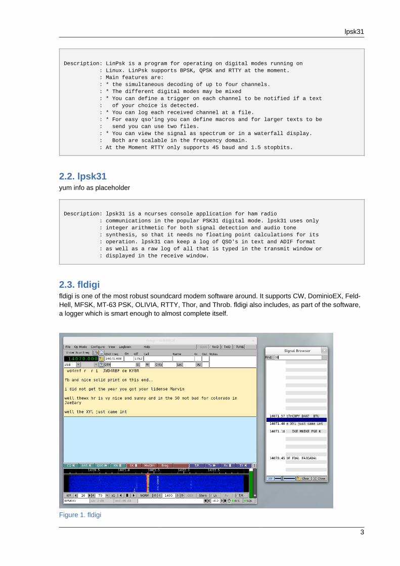
2.3. fldigifldigi is one of the most robust soundcard modem software around. It supports CW, DominioEX, Feld-Hell, MFSK, MT-63 PSK, OLIVIA, RTTY, Thor, and Throb. fldigi also includes, as part of the software,a logger which is smart enough to almost complete itself.
Figure 1. fldigi

Amateur Radio Guide
4
3. Rig ControlThis section describes rig control applications.
3.1. Chirpchirp is an application that allows programming of radios from a number of vendors. Chirp assumesthat the appropriate cable is available and connected. Data may be saved to a .csv file formanipulation by other applications, as well as transferred between radios, even radios from differentmanufacturers.
chirp is started by clicking the chirp icon.
Figure 2. Chirp icon
This will present a rather uninteresting blank screen.
In most cases, the user will wish to begin by selecting Download from Radio from the Radio menu.This will launch a dialog requesting some basic information such as the desired serial port, radiovendor and model. Note that the selected serial port must permit read/write access.
Figure 3. Chirp Radio Dialog
Clicking the OK button will begin reading the radio's memory.
Chirp
5
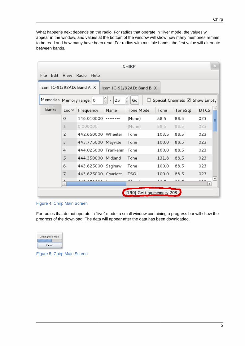
What happens next depends on the radio. For radios that operate in "live" mode, the values willappear in the window, and values at the bottom of the window will show how many memories remainto be read and how many have been read. For radios with multiple bands, the first value will alternatebetween bands.
Figure 4. Chirp Main Screen
For radios that do not operate in "live" mode, a small window containing a progress bar will show theprogress of the download. The data will appear after the data has been downloaded.
Figure 5. Chirp Main Screen
Amateur Radio Guide
6
To change a value, simply click on the field and begin typing.
Figure 6. Changing a memory location
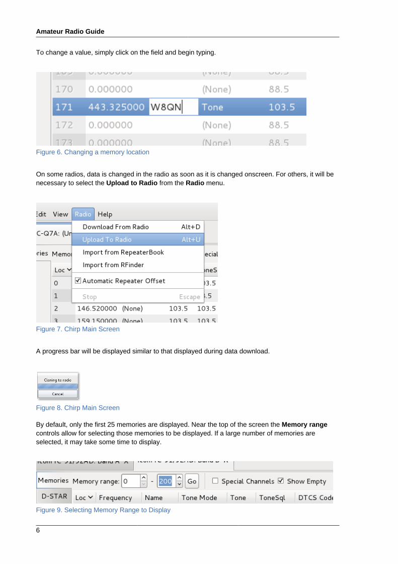
On some radios, data is changed in the radio as soon as it is changed onscreen. For others, it will benecessary to select the Upload to Radio from the Radio menu.
Figure 7. Chirp Main Screen
A progress bar will be displayed similar to that displayed during data download.
Figure 8. Chirp Main Screen
By default, only the first 25 memories are displayed. Near the top of the screen the Memory rangecontrols allow for selecting those memories to be displayed. If a large number of memories areselected, it may take some time to display.
Figure 9. Selecting Memory Range to Display
Chirp
7
Depending on the radio, there may be quite a few columns to display, so maximizing the window couldbe helpful.
Figure 10. Large Display
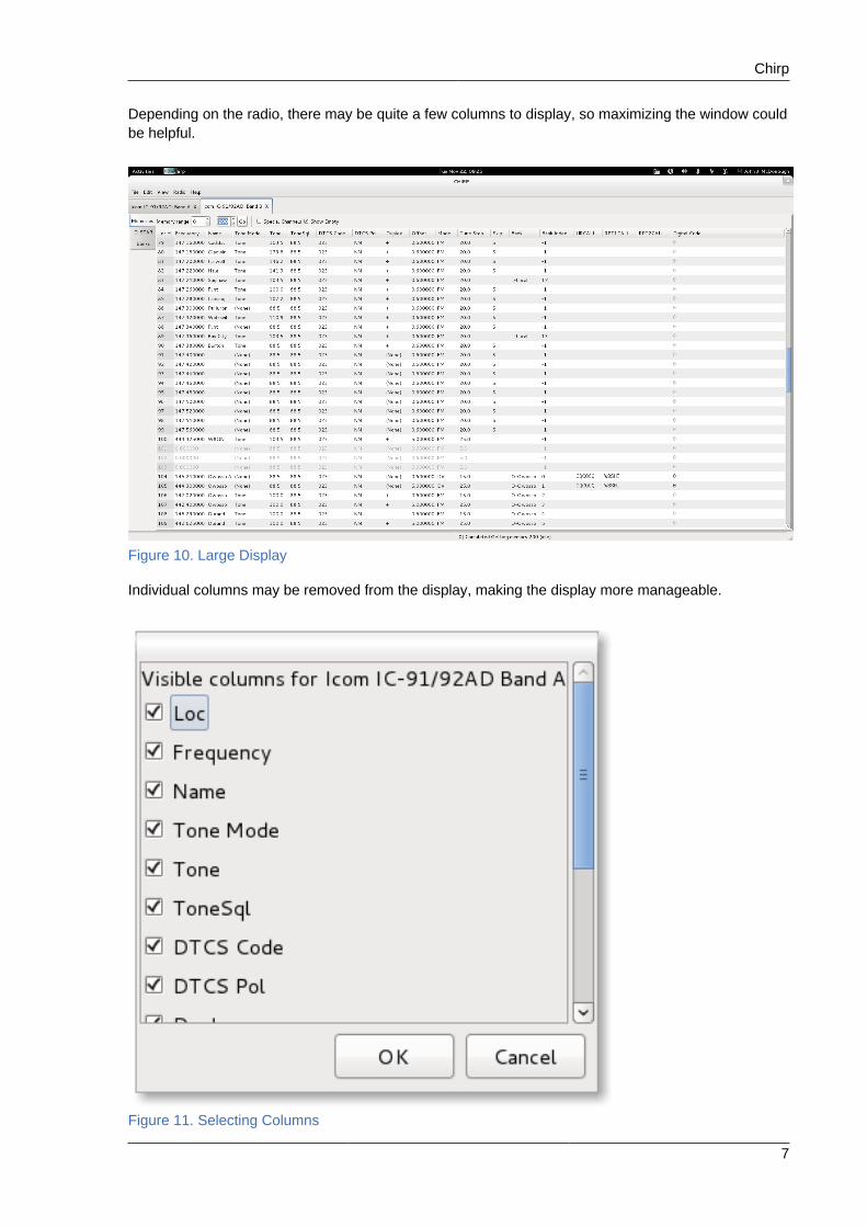
Individual columns may be removed from the display, making the display more manageable.
Figure 11. Selecting Columns

Amateur Radio Guide
8
3.2. grig
grig is a simple front panel for a radio controlled by hamlib. Before using grig the user should firstconfigure hamlib.
To start grig, click the grig icon:
Figure 12. grig icon
The main window allows for control over most of the actions accessible from a typical radio frontpanel. Frequency may be increased or decreased by left or right clicking the appropriate digit in thefrequency display. Other controls are more or less self-explanatory.
Figure 13. grig main window
4. Logging and related applications.
4.1. qleqle stands for QSO Logger and Editor. It is a simple yet flexible logging program. qle uses alightweight sqlite database that can be manipulated using standard tools. The application is easilycustomized, so you can have the logging program behave the way you want. It also interfaces withhamlib, so information may be automatically retrieved from your rig with the appropriate hardware.
4.1.1. Installing qleqle can be installed with yum like any other package:
sudo yum install qle
However, qle requires some initial setup before it may be used.
qle
9
4.1.2. Configuring qleThe install process creates a configuration file /etc/qle/qle.conf which must be edited. This canbe done with your favorite text editor, however, the file is protected against writing by a non-adminuser. The file might be edited with something like:
sudo gedit /etc/qle/qle.conf &
There are two lines that must be changed. At line 63 of the file, you will find the lines:
#debug = 0#myCall = N0CAL#
Be sure that the debug line is set to zero and change the myCall line to reflect your callsign.
The second line that must be changed is at line 75 where you will find:
# Filename of SQLite DB with full path.# This file requires sufficient RW access for the DB to work...#db = foo3.db## Name of the table that you want to log into.# Is probably case-sensitive:#tableName = mycall#
You must change the name of the database to your desired name and location.
qle is set up for a single user system, so all users share the same database. You must place thedatabase in a location where it can be accessed by any users requiring it. If you always log on withthe same usercode, you might choose to put it in a hidden subdirectory off your logon directory,for example, ~/.qle. This is the simplest approach, but in some circumstances, you may prefer amore "global" location, for example, /etc/qle. In this case, you need to take care to give the fileappropriate protections.
For simplicity, we will assume that qle will only ever be run from a single usercode and we will put thedatabase there. Reflect that location and name in qle.conf, for example:
db = /home/usercode/.qle/qle.sqlite
Note that you cannot use the tilde (~) within the config file, you must enter the entire path.
There are many things you may wish to change. For example, at line 101:
#useRig = 1#
Amateur Radio Guide
10
determines whether you want to use the rig control library, hamlib, which can be a great convenience ifyou have the appropriate hardware.
At line 225:
#noCwDaemon = 0#
determines whether you wish qle to have the capability of keying the transmitter.
To avoid describing hamlib settings and hardware setup, we will assume these are both disabled fornow, that is, useRig=0 and noCwDaemon=1.
After editing qle.conf, you need to create the database. There is a sample database in /usr/share/qle so we can copy that to the location we have specified for our database:
cp /usr/share/qle/foo3.db ~/.qle/qle.sqlite
This file has some test data which we will delete after some initial testing.
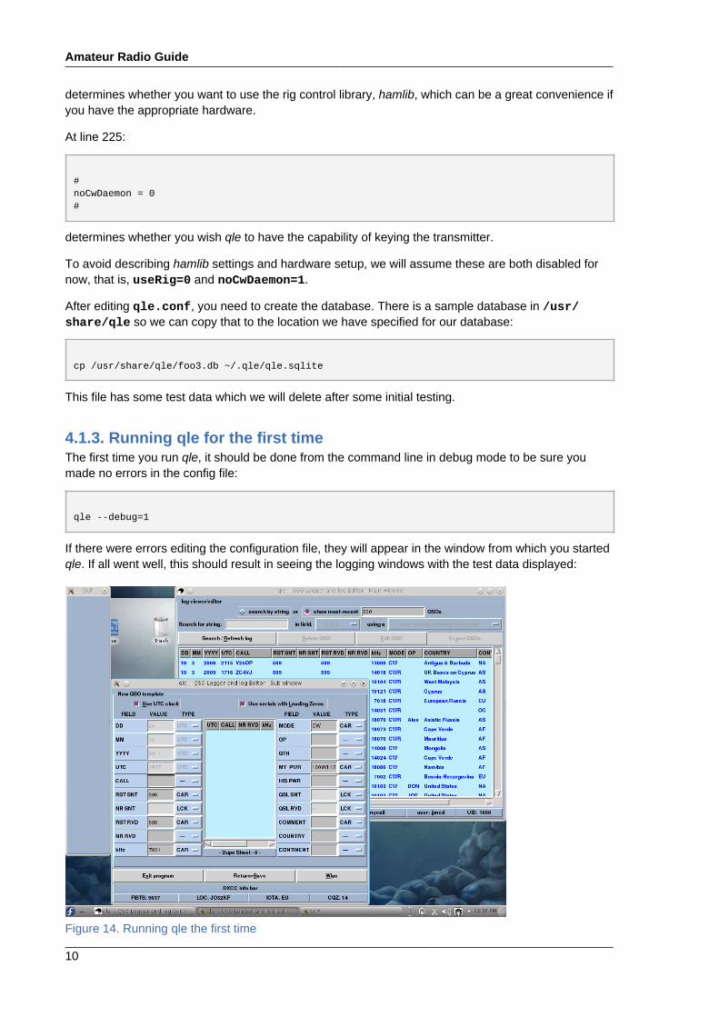
4.1.3. Running qle for the first timeThe first time you run qle, it should be done from the command line in debug mode to be sure youmade no errors in the config file:
qle --debug=1
If there were errors editing the configuration file, they will appear in the window from which you startedqle. If all went well, this should result in seeing the logging windows with the test data displayed:
Figure 14. Running qle the first time
qle
11
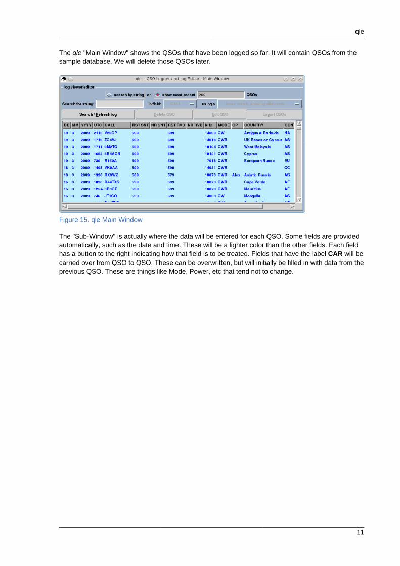
The qle "Main Window" shows the QSOs that have been logged so far. It will contain QSOs from thesample database. We will delete those QSOs later.
Figure 15. qle Main Window
The "Sub-Window" is actually where the data will be entered for each QSO. Some fields are providedautomatically, such as the date and time. These will be a lighter color than the other fields. Each fieldhas a button to the right indicating how that field is to be treated. Fields that have the label CAR will becarried over from QSO to QSO. These can be overwritten, but will initially be filled in with data from theprevious QSO. These are things like Mode, Power, etc that tend not to change.

Amateur Radio Guide
12
Figure 16. qle Data Entry Window
If you wish to change the data in a field that has the label LCK, you may simply click on LCK andselect another choice from the dropdown. Normally, you might choose --, but if you are contesting, theNR SENT field includes a +1 choice.`
Figure 17. Changing Field Attributes
qle
13
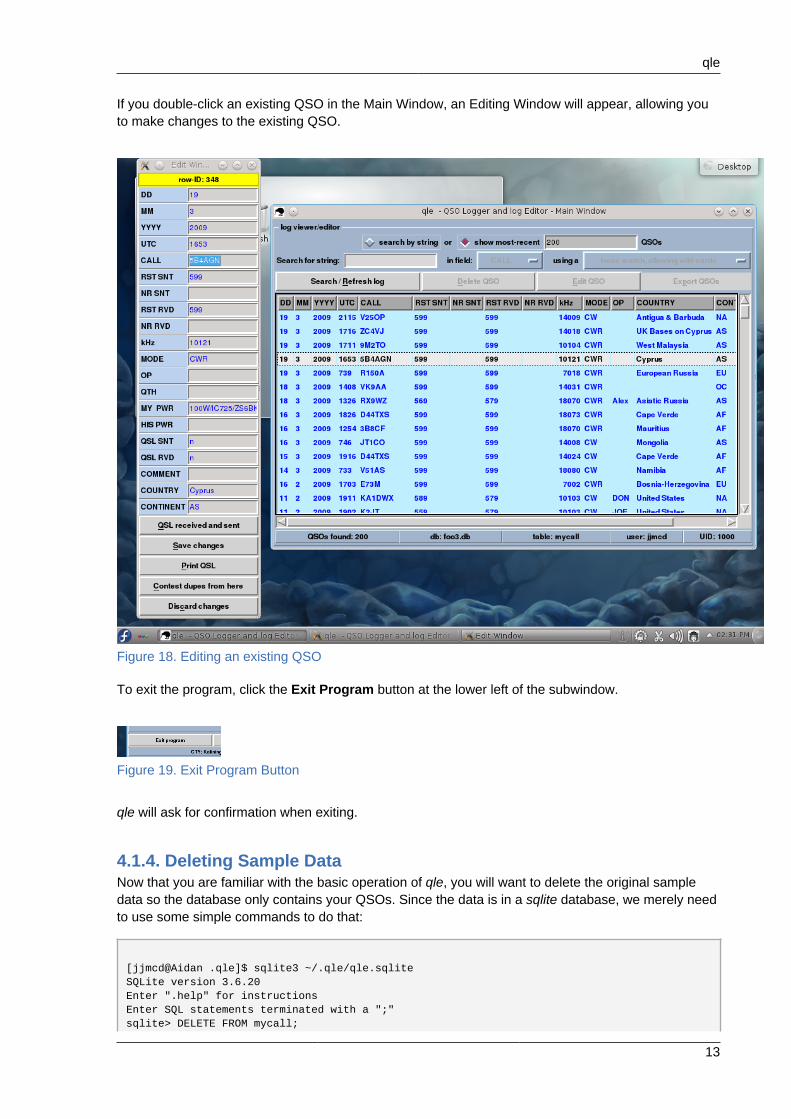
If you double-click an existing QSO in the Main Window, an Editing Window will appear, allowing youto make changes to the existing QSO.
Figure 18. Editing an existing QSO
To exit the program, click the Exit Program button at the lower left of the subwindow.
Figure 19. Exit Program Button
qle will ask for confirmation when exiting.
4.1.4. Deleting Sample DataNow that you are familiar with the basic operation of qle, you will want to delete the original sampledata so the database only contains your QSOs. Since the data is in a sqlite database, we merely needto use some simple commands to do that:
[jjmcd@Aidan .qle]$ sqlite3 ~/.qle/qle.sqliteSQLite version 3.6.20Enter ".help" for instructionsEnter SQL statements terminated with a ";"sqlite> DELETE FROM mycall;

Amateur Radio Guide
14
sqlite> .quit[jjmcd@Aidan .qle]$
If you are familiar with SQL, you can also use sqlite to make other changes and queries.
You are now ready to begin using qle. Click on the qle icon, typically found in the "Internet" group.
Figure 20. qle icon
qle
15
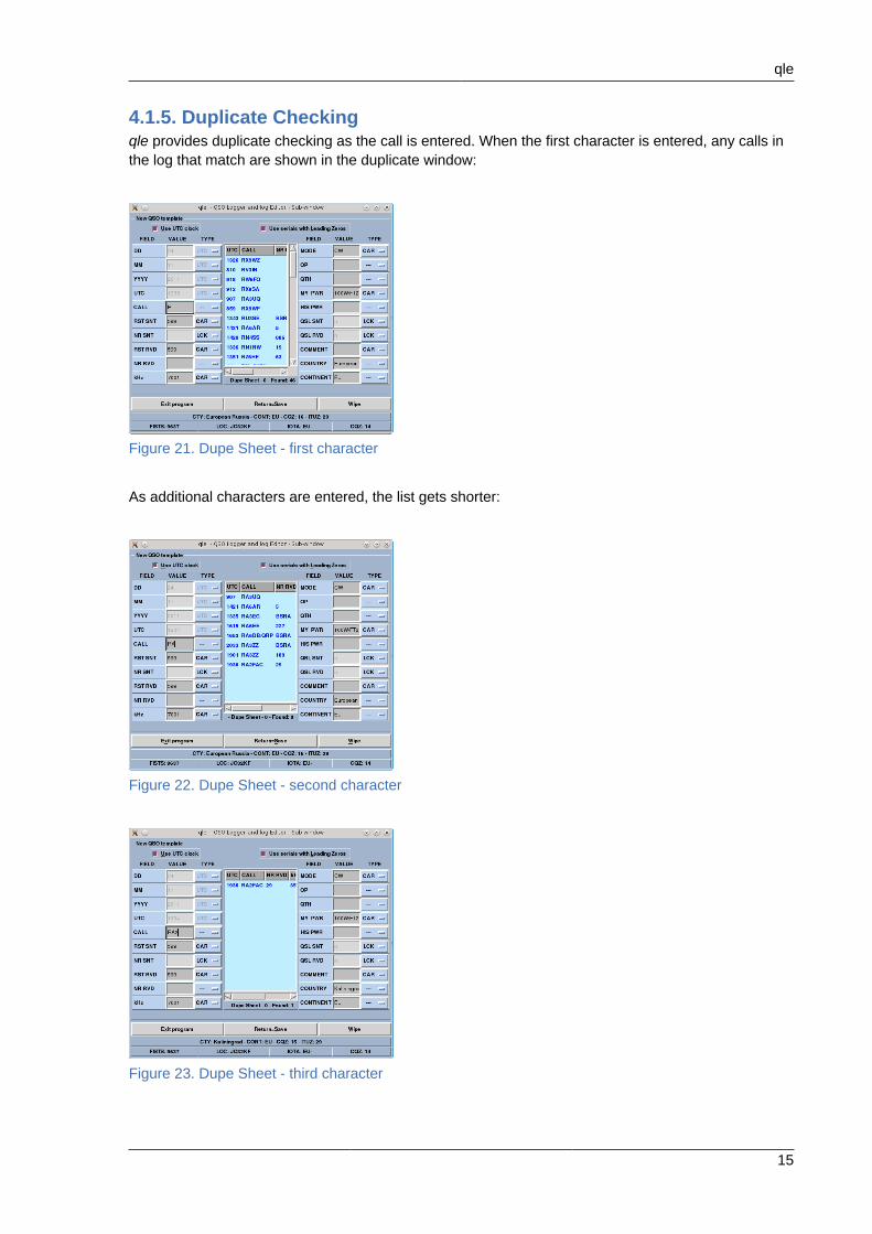
4.1.5. Duplicate Checkingqle provides duplicate checking as the call is entered. When the first character is entered, any calls inthe log that match are shown in the duplicate window:
Figure 21. Dupe Sheet - first character
As additional characters are entered, the list gets shorter:
Figure 22. Dupe Sheet - second character
Figure 23. Dupe Sheet - third character
Amateur Radio Guide
16
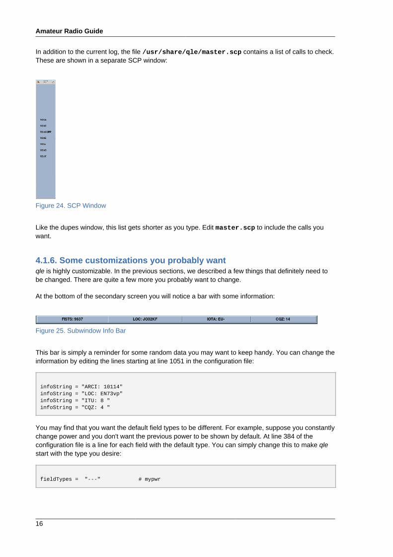
In addition to the current log, the file /usr/share/qle/master.scp contains a list of calls to check.These are shown in a separate SCP window:
Figure 24. SCP Window
Like the dupes window, this list gets shorter as you type. Edit master.scp to include the calls youwant.
4.1.6. Some customizations you probably wantqle is highly customizable. In the previous sections, we described a few things that definitely need tobe changed. There are quite a few more you probably want to change.
At the bottom of the secondary screen you will notice a bar with some information:
Figure 25. Subwindow Info Bar
This bar is simply a reminder for some random data you may want to keep handy. You can change theinformation by editing the lines starting at line 1051 in the configuration file:
infoString = "ARCI: 10114"infoString = "LOC: EN73vp"infoString = "ITU: 8 "infoString = "CQZ: 4 "
You may find that you want the default field types to be different. For example, suppose you constantlychange power and you don't want the previous power to be shown by default. At line 384 of theconfiguration file is a line for each field with the default type. You can simply change this to make qlestart with the type you desire:
fieldTypes = "---" # mypwr
xlog
17
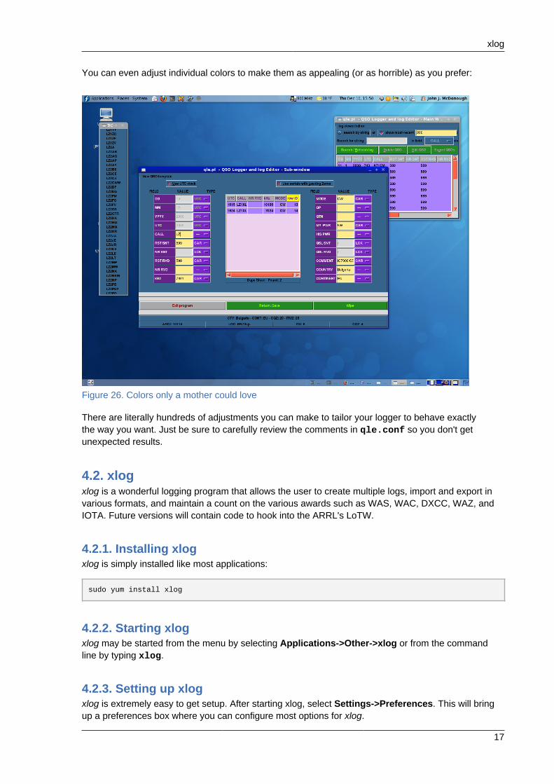
You can even adjust individual colors to make them as appealing (or as horrible) as you prefer:
Figure 26. Colors only a mother could love
There are literally hundreds of adjustments you can make to tailor your logger to behave exactlythe way you want. Just be sure to carefully review the comments in qle.conf so you don't getunexpected results.
4.2. xlogxlog is a wonderful logging program that allows the user to create multiple logs, import and export invarious formats, and maintain a count on the various awards such as WAS, WAC, DXCC, WAZ, andIOTA. Future versions will contain code to hook into the ARRL's LoTW.
4.2.1. Installing xlogxlog is simply installed like most applications:
sudo yum install xlog
4.2.2. Starting xlogxlog may be started from the menu by selecting Applications->Other->xlog or from the commandline by typing xlog.
4.2.3. Setting up xlogxlog is extremely easy to get setup. After starting xlog, select Settings->Preferences. This will bringup a preferences box where you can configure most options for xlog.
Amateur Radio Guide
18
The General tab contains basic information on how the log will be setup including the modes andbands you operate. You can change these at anytime but it is good to go ahead and add or removethe modes and bands you don't operate to simplify the operation of the logging later. You can alsoenable the clock on the status bar and recording of azimuth and distance when you enter in thelocation of the station. You can also control out data from external programs, such as gmfsk andktrack, are handled.
The Info tab contains information on your station and preference to miles or kilometers and whereyou want the software to look up a callsign. It is recommended that you enter your callsign and yourcoordinates into the fields located on this tab so the log can appropriately annotate your callsignwhere necessary and can provide azimuth and distance to a station upon entry of the state or grid. Ifyou don't know your latitude and longitude you can just enter your grid locator and the software willpopulate a rough location for your station.
The Hamlib tab allows you to setup xlog to read your radio so your log will automatically record thefrequency and mode. xlog will also display the S-meter on the status bar for your convinence.
The Logs tab allow you to setup the logs themselves. This includes where to store the logs, whichlogs to start automatically upon starting xlog, when to save the log, and the font. By default, xlogstores your logs in ~/.xlog. This can be changed by providing the appropriate path. If you have multiplelogs you can type in the names of each log separated by a comma in the next field and xlog will loadthose logs each time using tabs at the top of the main screen. The next field asks if you want xlog tosave the log whenever you write a log entry or every x minutes. You can also establish a backup ofyour logs in a separate directory which you can provide in the backup entry. The last field is used toselect the font you would like to use for your logs.
5. Antenna and Propagation Modeling.
5.1. splatsplat is a Surface Path Length And Terrain analysis application which can perform path losscalculations as well as generate coverage maps. Primarily intended for VHF/UHF, it can help planrepeater coverage or plan emergency communications strategies.
5.1.1. Installation and setupInstalling splat is straightforward:
su -c 'yum install splat'
5.1.1.1. Obtaining Terrain FilesBefore it can be useful, splat requires files that describe the terrain around the station to bemodelled. First, determine the latitude and longitude of the station. Then download the nine terrainfiles centered on that latitude and longitude from http://e0srp01u.ecs.nasa.gov/srtm/version2/SRTM3/.
Unzip the nine files and convert them from hgt files to sdf with the srtm2sdf utility. For example:
srtm2sdf N41W082.hgt
splat
19
Do this for each of the nine files. Those files can now be placed in a directory where you wish to storeterrain files, or they can be placed in the directory where you wish to work with splat
If you will be modelling stations over a wide geographic area, you may wish to download and convertadditional files. splat will select those files it requires for a particular calculation.
5.1.1.2. Obtaining cartographic boundary filessplat will work with just the terrain files. However, for path loss maps, the resulting maps canbe more useful if they are marked with political boundaries and names of towns and cities. Forthe United States, county outlines can be downloaded from http://www.census.gov/geo/www/cob/co2000.html#ascii and 'census designated areas' from http://www.census.gov/geo/www/cob/pl2000.html#ascii.
For each of these, there are two files, an xxyy_d00.dat and xxyy_d00a.dat, where xx is 'co' forcounty and 'pl' for place, and yy is a state number. A file of place names can be generated from the 'a'file with the citydecoder utility. For example:
citydecoder pl37 >cities.dat
The cities.dat file is simply a list of names followed by latitude and longitude. You may edit the filewith a text editor to insert additional places which will be marked on the map with a red dot.
5.1.2. Using SPLAT!splat can perform calculations for a particular path, or generate a map showing path loss orsignal strength over a region. In any case splat needs at least one file identifying the transmitterlocation. For a specific path, it needs an identical file for the receiver. If you would like signal strengthcalculations, you will need another file with more details about the transmitter.
5.1.2.1. The QTH fileYou tell splat about a particular station (transmitter or receiver) with a qth file. This file has fourlines:1. The name of the station
2. The latitude of the station
3. The longitude of the station
4. The antenna height above ground
Here is an example qth file:
W8KEA-4 43 38 05 84 15 41 124.0
The qth file should be named for the station. The name of the file in the above example would beW8KEA-4.qth.
By default, splat uses British units; heights are in feet, distances are in miles. However, invokingsplat with the -metric switch will cause it to use metric units.
Amateur Radio Guide
20
5.1.2.2. The LRP fileIf you would like splat to calculate signal strengths, it needs to know a little more about thetransmitter. You provide this information in a file whose name matches that of the qth file but has anextension of lrp.
The lrp file has 9 lines:1. Earth Dielectric Constant. If you do not have measured data available, the splat man page has a
table that can help you estimate a value.
2. Earth Conductivity
3. Atmospheric Bending Constant
4. Frequency
5. Radio Climate. This is a code describing the terrain. See the table in the man page
6. Polarization
7. Fraction of situations. This and the following line reflect how the Longley-Rice calculations are tobe carried out. In the example below, splat will calculate the maximum path loss experienced50% of the time in 50% of the situations.
8. Fraction of time
9. Effective radiated power - power out less feedline loss times antenna gain
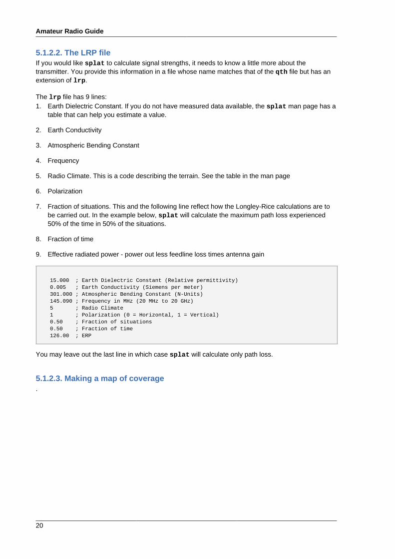
15.000 ; Earth Dielectric Constant (Relative permittivity) 0.005 ; Earth Conductivity (Siemens per meter) 301.000 ; Atmospheric Bending Constant (N-Units) 145.090 ; Frequency in MHz (20 MHz to 20 GHz) 5 ; Radio Climate 1 ; Polarization (0 = Horizontal, 1 = Vertical) 0.50 ; Fraction of situations 0.50 ; Fraction of time 126.00 ; ERP
You may leave out the last line in which case splat will calculate only path loss.
5.1.2.3. Making a map of coverage.
splat
21
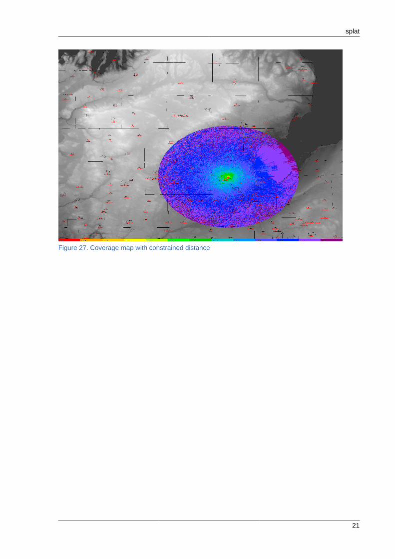
Figure 27. Coverage map with constrained distance
Amateur Radio Guide
22
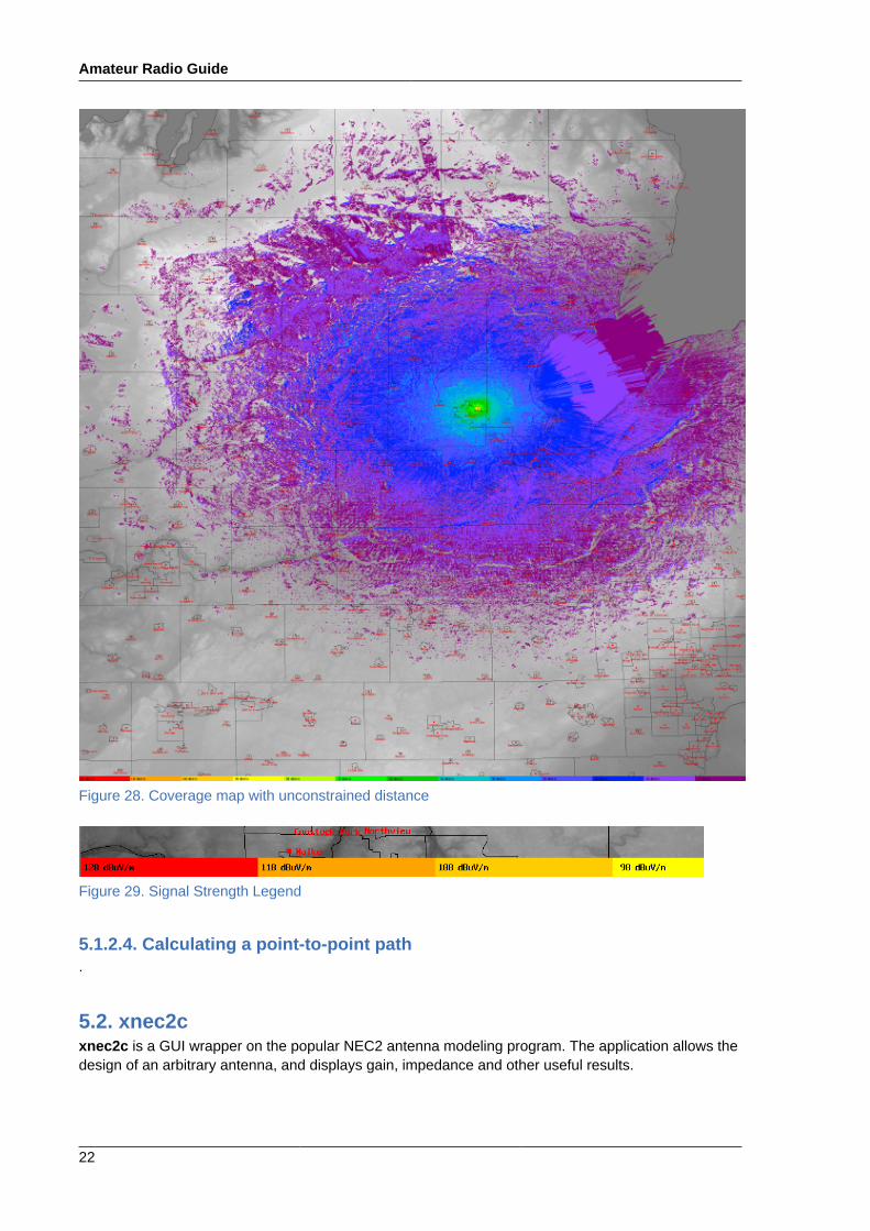
Figure 28. Coverage map with unconstrained distance
Figure 29. Signal Strength Legend
5.1.2.4. Calculating a point-to-point path.
5.2. xnec2cxnec2c is a GUI wrapper on the popular NEC2 antenna modeling program. The application allows thedesign of an arbitrary antenna, and displays gain, impedance and other useful results.

xnec2c
23
Figure 30. xnec2c - yagi
Amateur Radio Guide
24
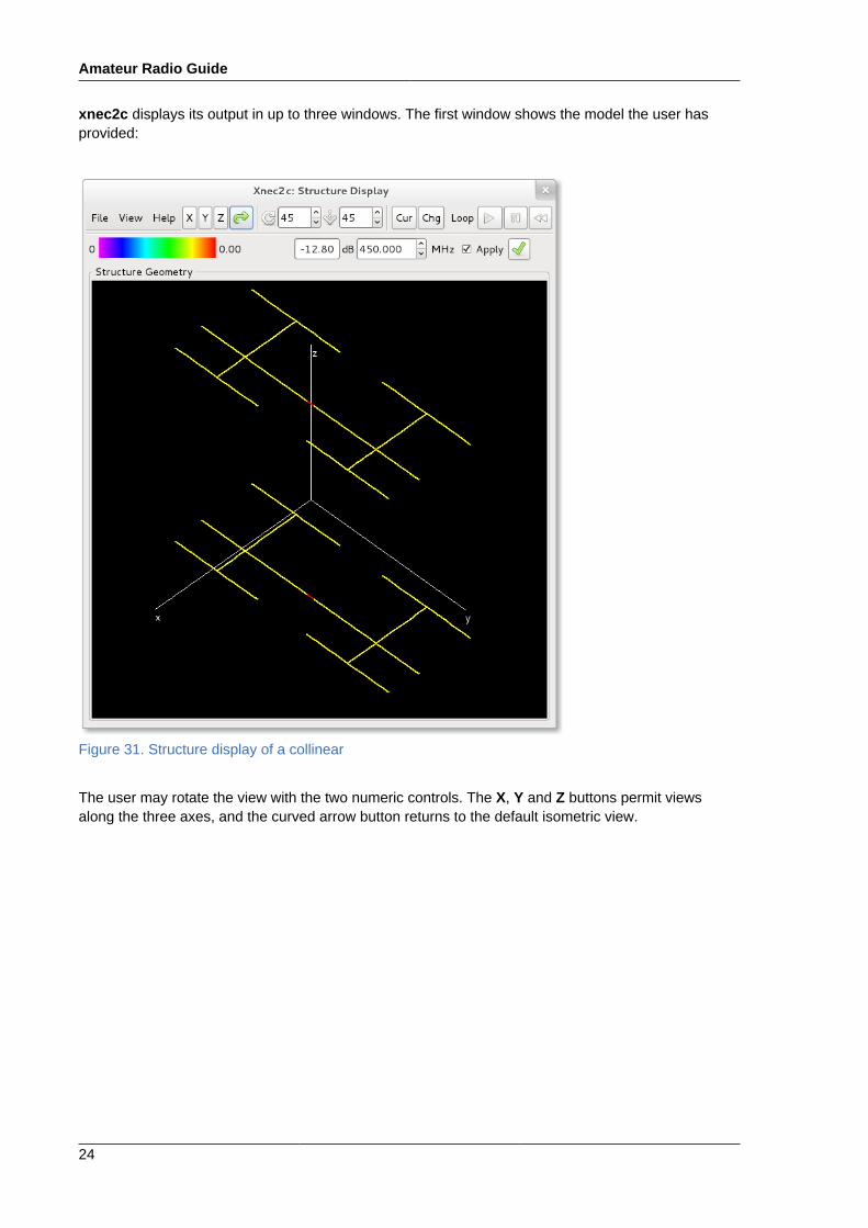
xnec2c displays its output in up to three windows. The first window shows the model the user hasprovided:
Figure 31. Structure display of a collinear
The user may rotate the view with the two numeric controls. The X, Y and Z buttons permit viewsalong the three axes, and the curved arrow button returns to the default isometric view.

xnec2c
25
Selecting Radiation Pattern from the View menu opens the radiation pattern window (Figure 32,“Radiation Pattern Display”). The view may be rotated in the same manner as the structure window.Buttons at the top allow for selection of the radiation pattern or the field pattern display.
Figure 32. Radiation Pattern Display
The dB / MHz controls allow for specifying the precise frequency at which the gain is to be displayed.
Amateur Radio Guide
26
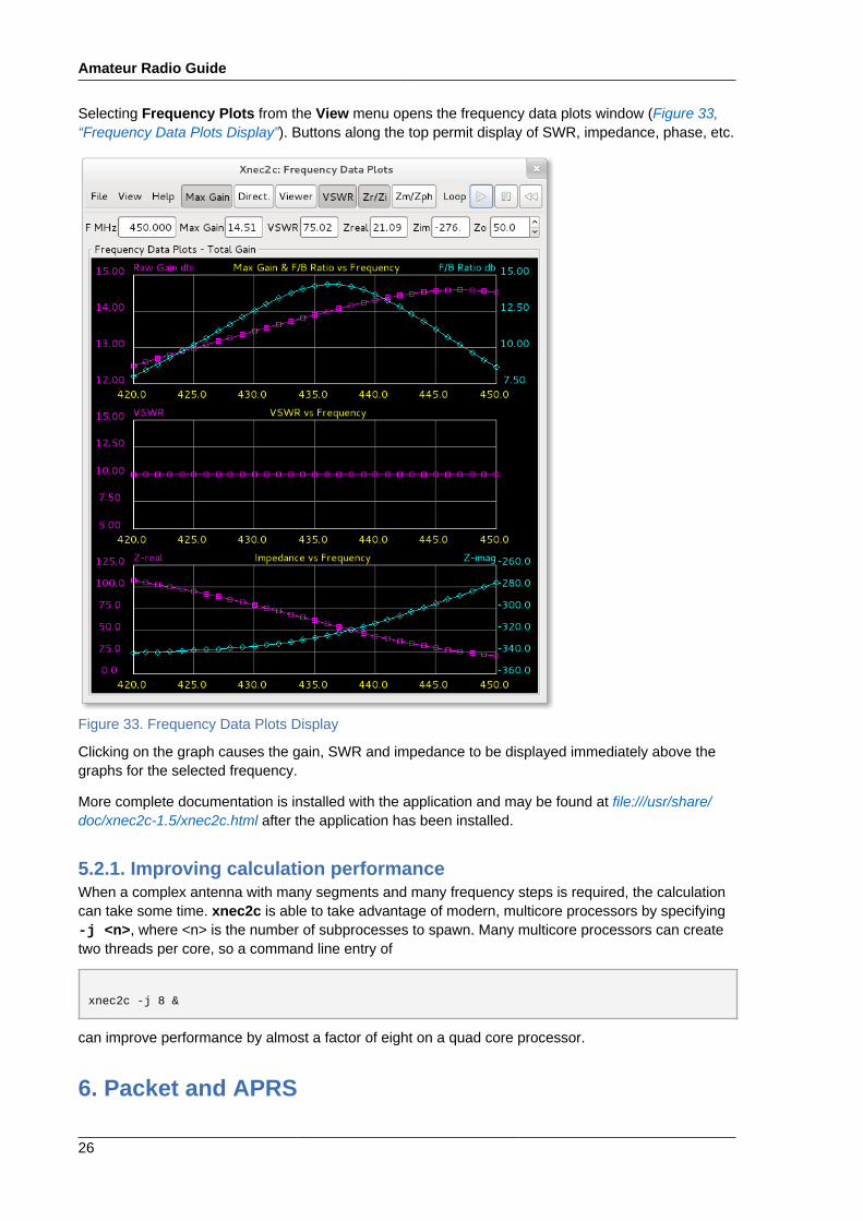
Selecting Frequency Plots from the View menu opens the frequency data plots window (Figure 33,“Frequency Data Plots Display”). Buttons along the top permit display of SWR, impedance, phase, etc.
Figure 33. Frequency Data Plots Display
Clicking on the graph causes the gain, SWR and impedance to be displayed immediately above thegraphs for the selected frequency.
More complete documentation is installed with the application and may be found at file:///usr/share/doc/xnec2c-1.5/xnec2c.html after the application has been installed.
5.2.1. Improving calculation performanceWhen a complex antenna with many segments and many frequency steps is required, the calculationcan take some time. xnec2c is able to take advantage of modern, multicore processors by specifying-j <n>, where <n> is the number of subprocesses to spawn. Many multicore processors can createtwo threads per core, so a command line entry of
xnec2c -j 8 &
can improve performance by almost a factor of eight on a quad core processor.
6. Packet and APRS
colrdx
27
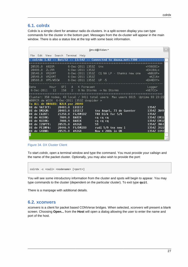
6.1. colrdxColrdx is a simple client for amateur radio dx-clusters. In a split-screen display you can typecommands for the cluster in the bottom part. Messages from the dx-cluster will appear in the mainwindow. There is also a status line at the top with some basic information.
Figure 34. DX Cluster Client
To start colrdx, open a terminal window and type the command. You must provide your callsign andthe name of the packet cluster. Optionally, you may also wish to provide the port:
colrdx -c <call> <nodename> [<port>]
You will see some introductory information from the cluster and spots will begin to appear. You maytype commands to the cluster (dependent on the particular cluster). To exit type quit.
There is a manpage with additional details.
6.2. xconversxconvers is a client for packet based CONVerse bridges. When selected, xconvers will present a blankscreen. Choosing Open... from the Host will open a dialog allowing the user to enter the name andport of the host.
Amateur Radio Guide
28
Figure 35. Host open dialog
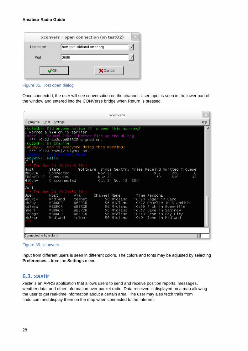
Once connected, the user will see conversation on the channel. User input is seen in the lower part ofthe window and entered into the CONVerse bridge when Return is pressed.
Figure 36. xconvers
Input from different users is seen in different colors. The colors and fonts may be adjusted by selectingPreferences... from the Settings menu.
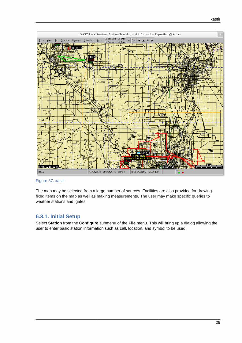
6.3. xastirxastir is an APRS application that allows users to send and receive position reports, messages,weather data, and other information over packet radio. Data received is displayed on a map allowingthe user to get real-time information about a certain area. The user may also fetch trails fromfindu.com and display them on the map when connected to the Internet.
xastir
29
Figure 37. xastir
The map may be selected from a large number of sources. Facilities are also provided for drawingfixed items on the map as well as making measurements. The user may make specific queries toweather stations and Igates.
6.3.1. Initial SetupSelect Station from the Configure submenu of the File menu. This will bring up a dialog allowing theuser to enter basic station information such as call, location, and symbol to be used.
Amateur Radio Guide
30
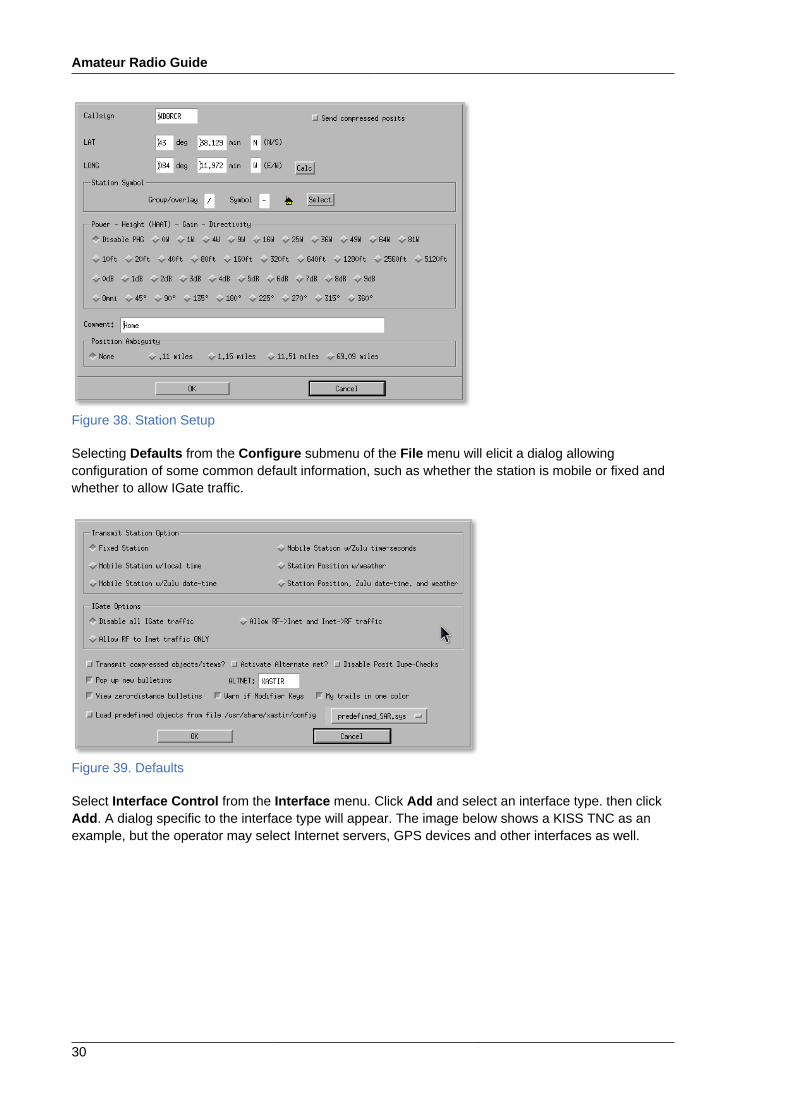
Figure 38. Station Setup
Selecting Defaults from the Configure submenu of the File menu will elicit a dialog allowingconfiguration of some common default information, such as whether the station is mobile or fixed andwhether to allow IGate traffic.
Figure 39. Defaults
Select Interface Control from the Interface menu. Click Add and select an interface type. then clickAdd. A dialog specific to the interface type will appear. The image below shows a KISS TNC as anexample, but the operator may select Internet servers, GPS devices and other interfaces as well.

xastir
31
Figure 40. Setting up a TNC
Once interfaces are configured, some small symbols will appear in the status bar toward the lowerright of the window. The upper semi-circles represent the various interfaces; different types are shownas different colors. The bottom symbol represents the interface status; green for active, empty forinactive, and red for an error. Between these two symbols an arrow will appear briefly whenever datais being transferred.
Figure 41. Interface Status
6.3.2. Setting up mapsxastir comes configured for a number of online map sources, and the documentation includes pointersto many online map sources. Maps may be vector maps or raster maps, and they may be provided ina number of different formats. In general, maps downloaded and stored locally will be retrieved fasterthan those retrieved online.
Although raster maps often look better, vector maps typically offer better flexibility and performance.You may select a number of maps and raster maps may be overlaid on other maps. You could, forexample, select a satellite image background, overlay it with a vector map of roads, and overlay thatwith weather radar.
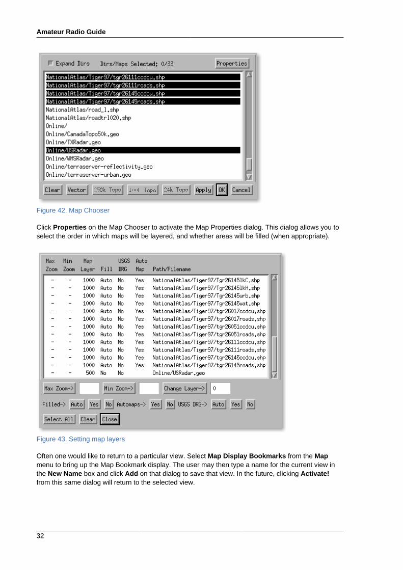
Select Map Chooser from the Map menu. Highlight those maps desired and click Apply to activatethe maps.
Amateur Radio Guide
32
Figure 42. Map Chooser
Click Properties on the Map Chooser to activate the Map Properties dialog. This dialog allows you toselect the order in which maps will be layered, and whether areas will be filled (when appropriate).
Figure 43. Setting map layers
Often one would like to return to a particular view. Select Map Display Bookmarks from the Mapmenu to bring up the Map Bookmark display. The user may then type a name for the current view inthe New Name box and click Add on that dialog to save that view. In the future, clicking Activate!from this same dialog will return to the selected view.

xastir
33
Figure 44. Bookmarks
The user may select a background color from the Background Color submenu of the Configuresubmenu of the Map menu. Note that raster maps or filled areas will cover the background color.
Figure 45. Light Background
Notice that if a light color is selected as a background on a vector map, the stations can sometimes bedifficult to see.
Amateur Radio Guide
34
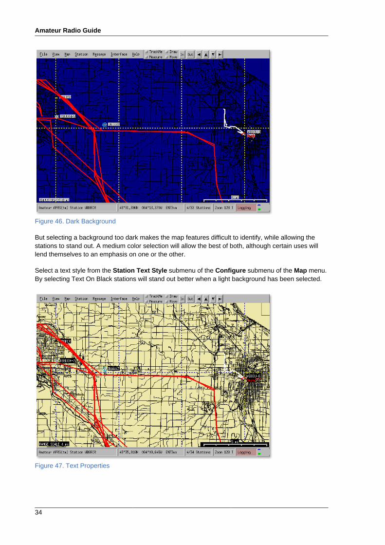
Figure 46. Dark Background
But selecting a background too dark makes the map features difficult to identify, while allowing thestations to stand out. A medium color selection will allow the best of both, although certain uses willlend themselves to an emphasis on one or the other.
Select a text style from the Station Text Style submenu of the Configure submenu of the Map menu.By selecting Text On Black stations will stand out better when a light background has been selected.
Figure 47. Text Properties

xastir
35
6.3.3. Tracking StationsSelect Track Station from the Station menu. A dialog will appear allowing the call of a station to beentered. When this station is seen to move, a track will be drawn on the map showing the station'spast positions.
Figure 48. Tracking a station
If a station which is moving has not been heard from in a while, xastir will use "dead reckoning" topredict where it might be, if dead reckoning has been enabled. Dead reckoning is enabled in theFilter Display submenu of the Station menu. "A while" is configured in the Timing menu item of theConfigure submenu of the File menu.
Figure 49. Dead Reckoning
Historical tracks may also be downloaded from the findu website. Select Fetch Findu Trail from theStation menu.
Amateur Radio Guide
36
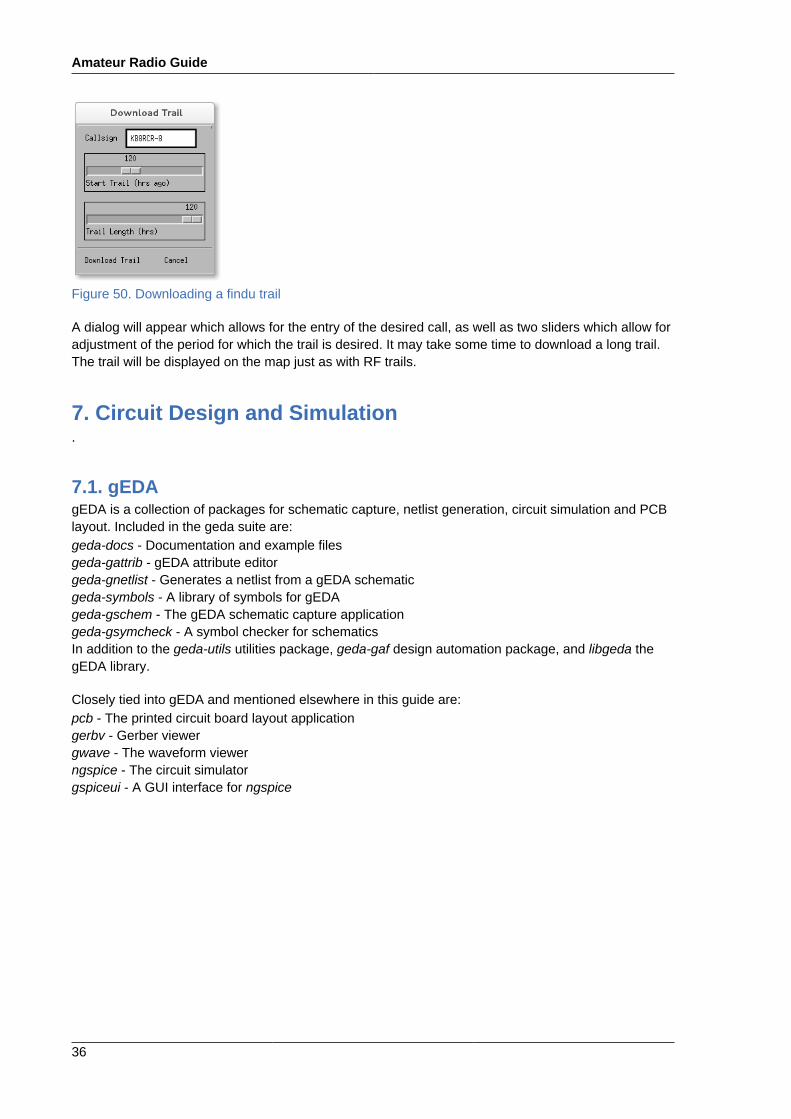
Figure 50. Downloading a findu trail
A dialog will appear which allows for the entry of the desired call, as well as two sliders which allow foradjustment of the period for which the trail is desired. It may take some time to download a long trail.The trail will be displayed on the map just as with RF trails.
7. Circuit Design and Simulation.
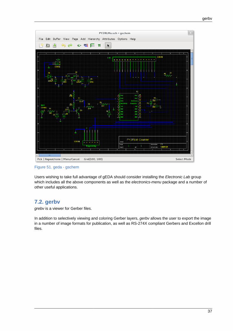
7.1. gEDAgEDA is a collection of packages for schematic capture, netlist generation, circuit simulation and PCBlayout. Included in the geda suite are:geda-docs - Documentation and example filesgeda-gattrib - gEDA attribute editorgeda-gnetlist - Generates a netlist from a gEDA schematicgeda-symbols - A library of symbols for gEDAgeda-gschem - The gEDA schematic capture applicationgeda-gsymcheck - A symbol checker for schematicsIn addition to the geda-utils utilities package, geda-gaf design automation package, and libgeda thegEDA library.
Closely tied into gEDA and mentioned elsewhere in this guide are:pcb - The printed circuit board layout applicationgerbv - Gerber viewergwave - The waveform viewerngspice - The circuit simulatorgspiceui - A GUI interface for ngspice
gerbv
37
Figure 51. geda - gschem
Users wishing to take full advantage of gEDA should consider installing the Electronic Lab groupwhich includes all the above components as well as the electronics-menu package and a number ofother useful applications.
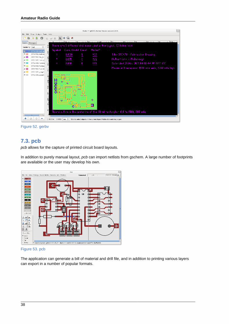
7.2. gerbvgrebv is a viewer for Gerber files.
In addition to selectively viewing and coloring Gerber layers, gerbv allows the user to export the imagein a number of image formats for publication, as well as RS-274X compliant Gerbers and Excellon drillfiles.
Amateur Radio Guide
38
Figure 52. gerbv
7.3. pcbpcb allows for the capture of printed circuit board layouts.
In addition to purely manual layout, pcb can import netlists from gschem. A large number of footprintsare available or the user may develop his own.
Figure 53. pcb
The application can generate a bill of material and drill file, and in addition to printing various layerscan export in a number of popular formats.

gspiceui
39
7.4. gspiceuigspiceui is a frontend to a SPICE simulation. The user may choose between the gnucap or ng-spicebackends.
Figure 54. gspiceui
gspiceui can open a netlist produced by gnetlist and run the SPICE simulation without having toknow the various SPICE commands.
8. Miscellaneous Applications.
8.1. CuteCWCuteCW is a Morse code training program that not only trains the user in decyphering morse code butalso provides methods for increasing their comprehension speed. CuteCW will also sound Morse codeout of the computer speakers and will read text out as Morse code.
8.1.1. Installing CuteCWCuteCW is simply installed like most applications:
sudo yum install cutecw
8.1.2. Starting CuteCWCuteCW may be started from the menu by selecting Applications->Education->CuteCW or from thecommand line by typing cutecw.
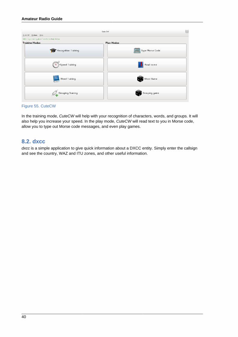
8.1.3. Using CuteCWCuteCW is quite easy to use. Eight choices are given to help with your learning experience.
Amateur Radio Guide
40
Figure 55. CuteCW
In the training mode, CuteCW will help with your recognition of characters, words, and groups. It willalso help you increase your speed. In the play mode, CuteCW will read text to you in Morse code,allow you to type out Morse code messages, and even play games.
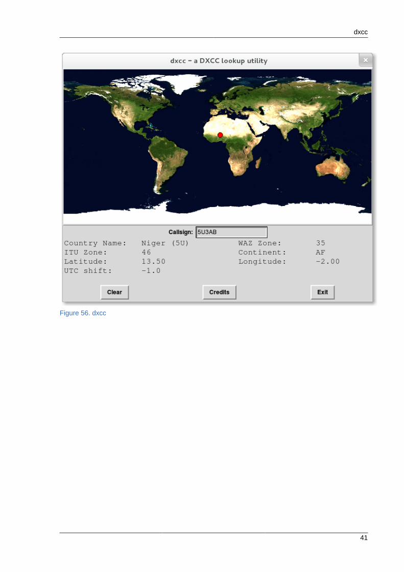
8.2. dxccdxcc is a simple application to give quick information about a DXCC entity. Simply enter the callsignand see the country, WAZ and ITU zones, and other useful information.
dxcc
41
Figure 56. dxcc
Amateur Radio Guide
42
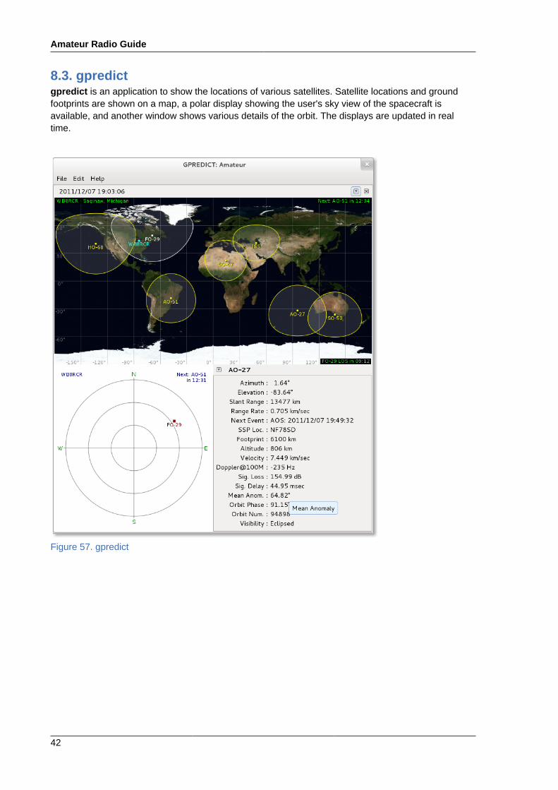
8.3. gpredictgpredict is an application to show the locations of various satellites. Satellite locations and groundfootprints are shown on a map, a polar display showing the user's sky view of the spacecraft isavailable, and another window shows various details of the orbit. The displays are updated in realtime.
Figure 57. gpredict

gpredict
43
Before using gpredict, the user should select Preferences from the Edit menu and set up stationlocation and display name. (Refer to Figure 58, “Select Ground Station”.)
Figure 58. Select Ground Station
First, select the Ground Stations tab and click Add New.
A dialog will pop up (Figure 59, “Ground Station Settings”) which will permit entering the stationdetails. Note that by clicking the Select button, the location may be chosen from a list.
Figure 59. Ground Station Settings
When complete, be sure to check that the desired station is selected as the Default so it will bedisplayed on the map (the right column in Figure 58, “Select Ground Station”).
Amateur Radio Guide
44
Next, the user should update orbital parameters by selecting Update TLE from the Edit menu.Downloading these values may take a few moments.
By default, a few amateur satellites are shown. The lower portion of the display will show details forthe spacecraft currently in view. Orbital parameters for another satellite may be selected from thedropdown to the left of the satellite name.
There are a number of other displays available, and additional groups of satellites may be configuredwhich may be shown in tabs (File -> New module). Clicking on the small downward triangle to theright of the window (Figure 60, “Module Menu”) brings up a menu which permits editing an existingmodule.
Figure 60. Module Menu
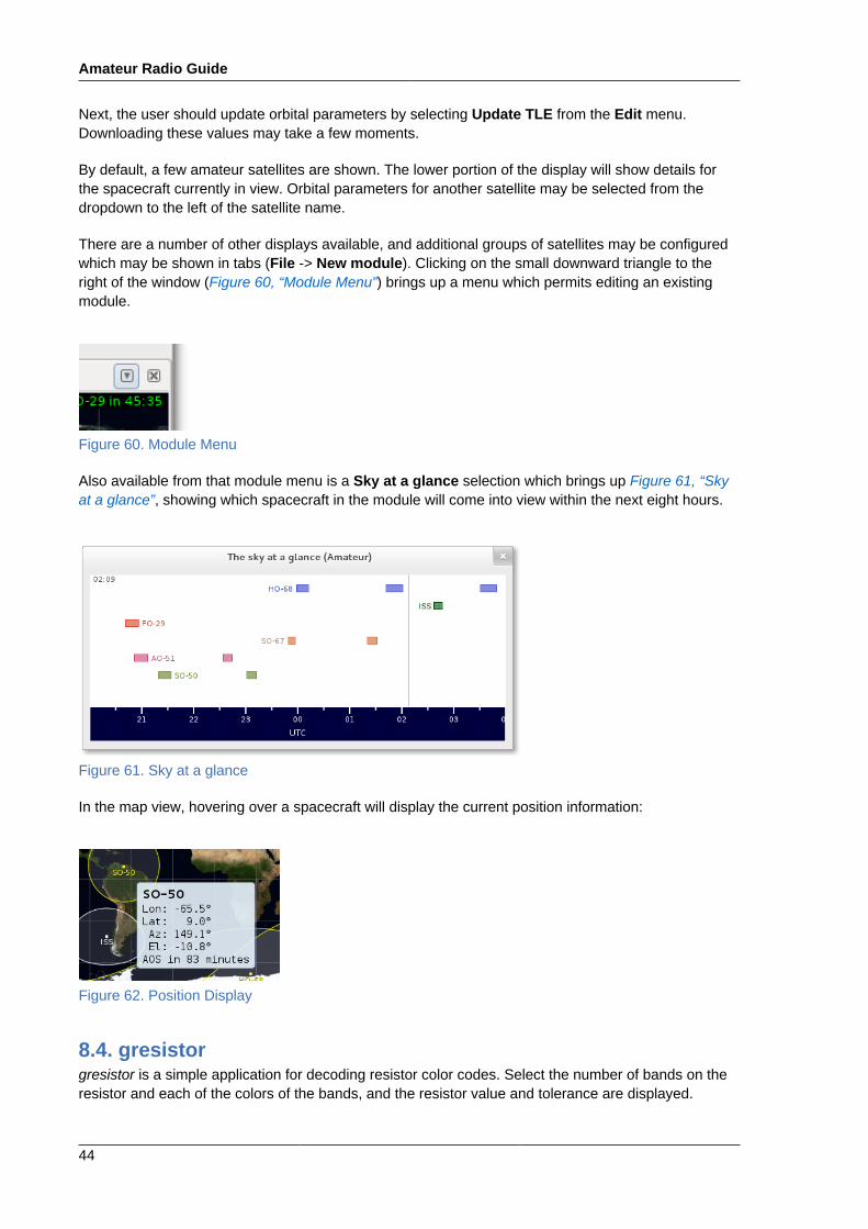
Also available from that module menu is a Sky at a glance selection which brings up Figure 61, “Skyat a glance”, showing which spacecraft in the module will come into view within the next eight hours.
Figure 61. Sky at a glance
In the map view, hovering over a spacecraft will display the current position information:
Figure 62. Position Display
8.4. gresistorgresistor is a simple application for decoding resistor color codes. Select the number of bands on theresistor and each of the colors of the bands, and the resistor value and tolerance are displayed.

ibp
45
Figure 63. gresistor
8.5. ibpibp is a simple application that shows beacons which are part of the International Beacon Project. Anumber of beacons around the world transmit at predetermined times. The ibp application shows youwhich beacons are currently transmitting.
8.5.1. Installing ibpibp is simply installed like most applications:
sudo yum install ibp
No additional configuration is required, however, ibp expects that the time on the system is correct.Synchronizing your system with one of the many timeservers is recommended.
8.5.2. Starting ibpibp may be started from the menu by selecting Applications->Other->ibp or from the command lineby typing ibp.
Amateur Radio Guide
46
When ibp is started, by default, two windows will open. The first is a simple text screen showing a listof beacons with the currently transmitting beacons highlighted:
Figure 64. ibp - text screen
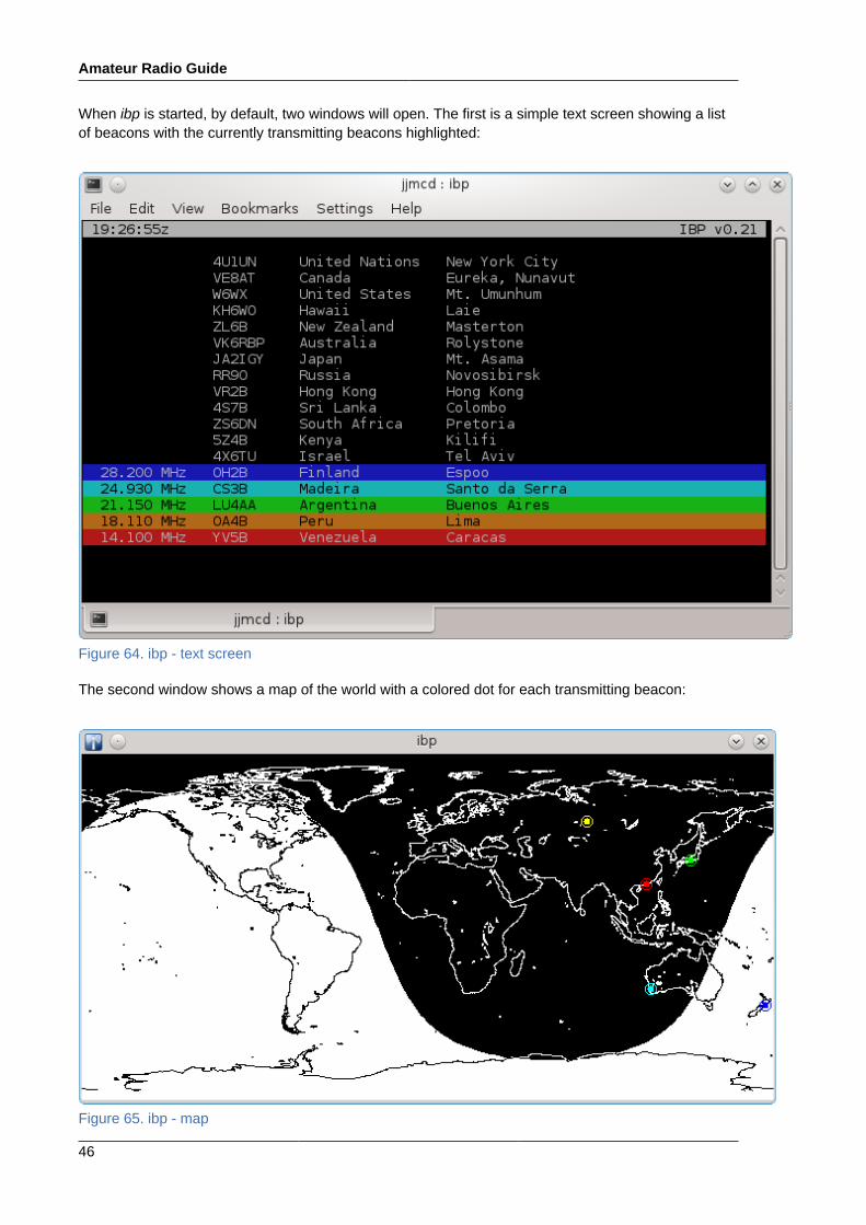
The second window shows a map of the world with a colored dot for each transmitting beacon:
Figure 65. ibp - map
rcrpanel
47
There are a number of arguments you may specify to affect how ibp behaves when it is started fromthe command line:• -c, --nocolor - causes the text window to be displayed only in monochrome. The graph window
is still in color.
• -m, --morse - In single beacon mode, causes the callsign of the transmitting beacon to bedisplayed at the bottom of the text window in Morse.
• -x, --nograph - Don't display the map window.
8.5.3. Running ibpWhile ibp is running, the highlighted lines on the text display and the dots on the map will periodicallychange as different beacons take on the transmitting task.
There are several commands you can enter into the text screen to affect the behavior of ibp:• digits 1 through 5 - causes only one band to be displayed. Since one is normally only monitoring a
single band at a time this can lead to faster identification of the beacon of interest. This is also usefulfor visually challenged operators.
• M - toggles between single band and multi band mode. If a single band was displayed, typing M willcause all five bands to be displayed. If five bands were displayed, the previously selected singleband will be displayed.
• Q - causes ibp to exit.
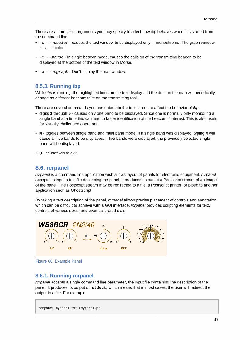
8.6. rcrpanelrcrpanel is a command line application wich allows layout of panels for electronic equipment. rcrpanelaccepts as input a text file describing the panel. It produces as output a Postscript stream of an imageof the panel. The Postscript stream may be redirected to a file, a Postscript printer, or piped to anotherapplication such as Ghostscript.
By taking a text description of the panel, rcrpanel allows precise placement of controls and annotation,which can be difficult to achieve with a GUI interface. rcrpanel provides scripting elements for text,controls of various sizes, and even calibrated dials.
Figure 66. Example Panel
8.6.1. Running rcrpanelrcrpanel accepts a single command line parameter, the input file containing the description of thepanel. It produces its output on stdout, which means that in most cases, the user will redirect theoutput to a file. For example:
rcrpanel mypanel.txt >mypanel.ps
Amateur Radio Guide
48
There are no command line switches available.
The output image will be centered on a standard size page. The smallest page on which the panel willfit is selected from the following list, in order:216x179 mm - U.S. Letter210x297 mm - A4216x279 mm - U.S. Legal297x420 mm - A3279x432 mm - Tabloid594x841 mm - A1559x894 mm - D841x1189 mm - A01000X1414 mm - B0
8.6.2. The Input FileThe input file contains lines describing the various controls. Most lines are of the form
Command = something
where the spaces around the equal sign are significant, and the command itself is case-sensitive.
Measurements are in units of millimeters. Angles are in degrees. Colors are given as 24 bit C styleintegers where each byte represents the amount of red, green, or blue.
In general, the order of commands makes no difference. However, the Text command must beimmediately followed by a line containing the text to be displayed, and those commands affecting theappearance of a Dial affect the preceding Dial command.
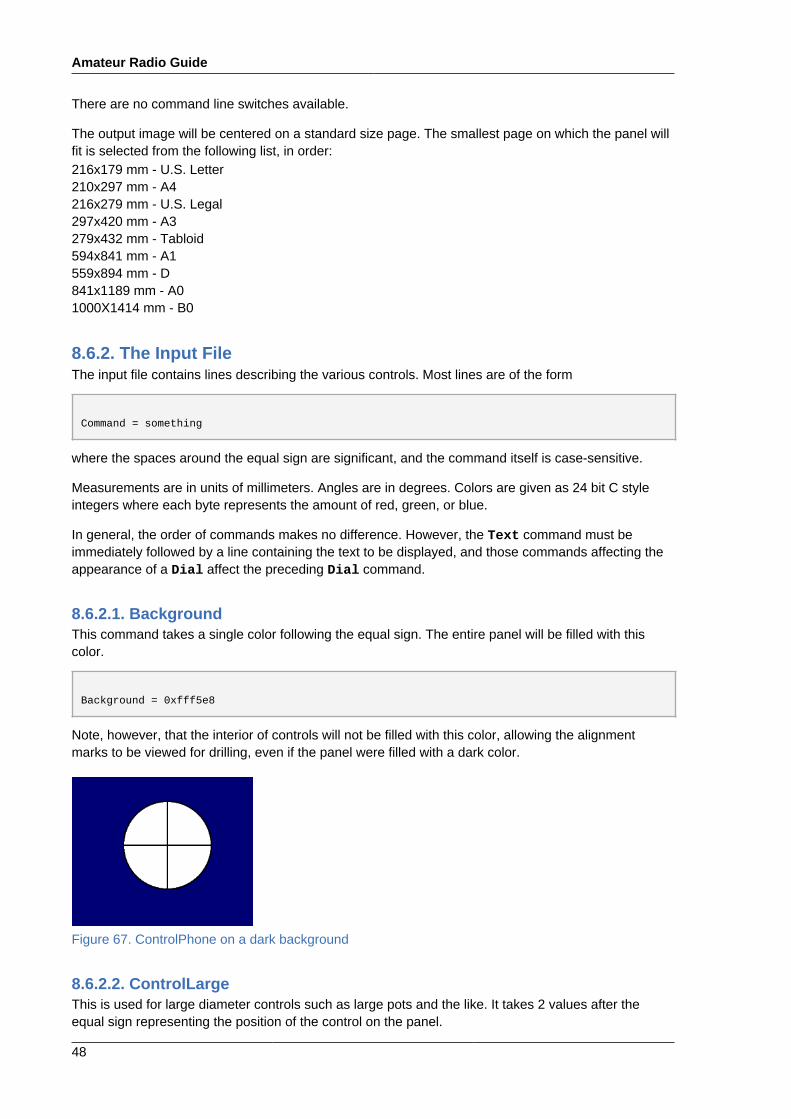
8.6.2.1. BackgroundThis command takes a single color following the equal sign. The entire panel will be filled with thiscolor.
Background = 0xfff5e8
Note, however, that the interior of controls will not be filled with this color, allowing the alignmentmarks to be viewed for drilling, even if the panel were filled with a dark color.
Figure 67. ControlPhone on a dark background
8.6.2.2. ControlLargeThis is used for large diameter controls such as large pots and the like. It takes 2 values after theequal sign representing the position of the control on the panel.
rcrpanel
49
ControlLarge = 23.0 30.0
8.6.2.3. ControlLEDThis command generates an outline for a 5 mm LED. Like the other control commands, it takes 2values, the X and Y positions on the panel of the center of the LED.
8.6.2.4. ControlPhoneThis is used for 1/4" phone jacks and similar controls. The 2 values after the equal sign represent theposition on the panel.
8.6.2.5. ControlSmallThis command generates an outline for a 3.5 mm phone jack. The two values are the X and Ypositions of the jack on the panel.
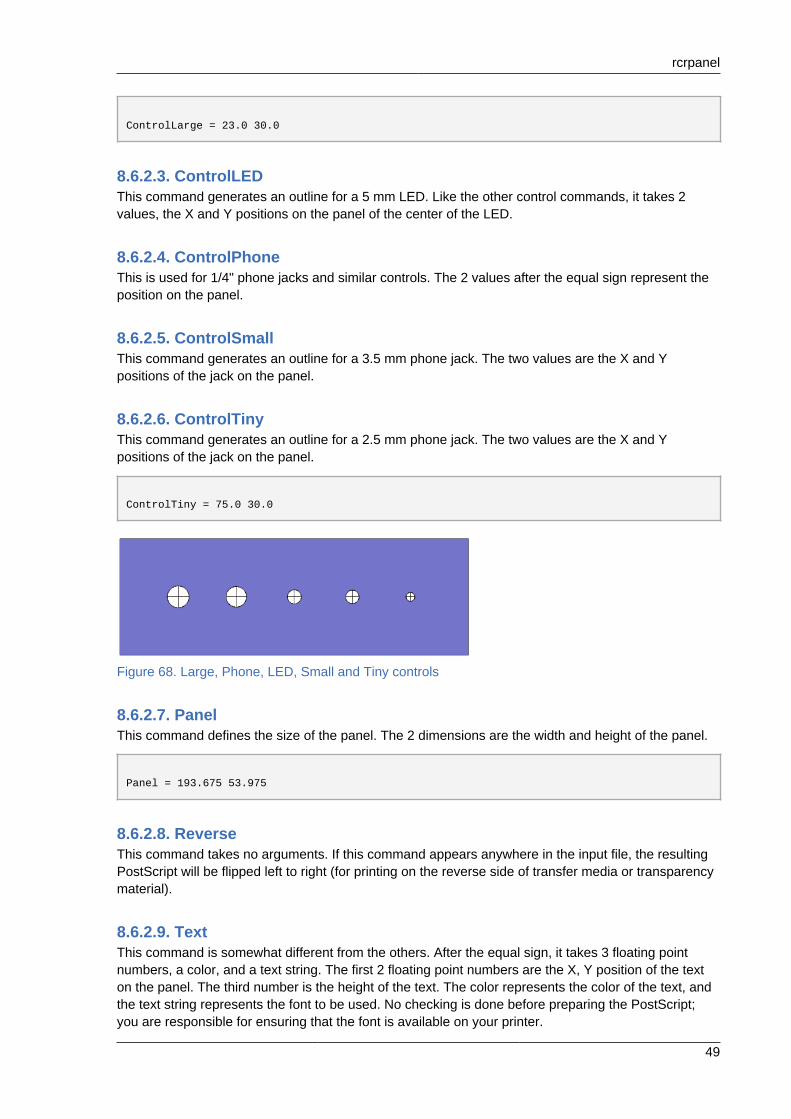
8.6.2.6. ControlTinyThis command generates an outline for a 2.5 mm phone jack. The two values are the X and Ypositions of the jack on the panel.
ControlTiny = 75.0 30.0
Figure 68. Large, Phone, LED, Small and Tiny controls
8.6.2.7. PanelThis command defines the size of the panel. The 2 dimensions are the width and height of the panel.
Panel = 193.675 53.975
8.6.2.8. ReverseThis command takes no arguments. If this command appears anywhere in the input file, the resultingPostScript will be flipped left to right (for printing on the reverse side of transfer media or transparencymaterial).
8.6.2.9. TextThis command is somewhat different from the others. After the equal sign, it takes 3 floating pointnumbers, a color, and a text string. The first 2 floating point numbers are the X, Y position of the texton the panel. The third number is the height of the text. The color represents the color of the text, andthe text string represents the font to be used. No checking is done before preparing the PostScript;you are responsible for ensuring that the font is available on your printer.
Amateur Radio Guide
50
This command is then followed by another line containing the text to be displayed.
Text = 100.0 10.0 5.0 0x7f4f00 Times-Roman-BoldFilter
8.6.2.10. DialThis command introduces a new dial. The Dial command describes the X,Y center of the dial. Thefollowing commands then further refine the details of this particular dial. This relationship between theDial command and it's successors is the only place where the order of the commands within the filematters.
Dial = 170.0 30.0
8.6.2.11. RadiusThis command takes a single value which is the radius of the circle which forms the inside of the tickmarks. This command refers to the current Dial command.
Radius = 7.0
8.6.2.12. SpanThis command describes the angle over which the control may operate. Typically, this would be270 for a potentiometer and 180 for a variable capacitor. This command refers to the current Dialcommand.
8.6.2.13. NumTicksThis command describes the total number of tick marks, large and small, to be drawn. This is usuallyan odd number since the starting and ending values are counted. Typically this will be 11, 101, or asimilar number. This command refers to the current Dial command.
NumTicks = 101
8.6.2.14. BigPerThis command tells the program how many small tick marks there are per large tick mark. Thiscommand refers to the current Dial command.
BigPer = 10
8.6.2.15. SizeTicksThis command describes the length of the small tick marks. This command refers to the current Dialcommand.
SizeTicks = 6.5
rcrpanel
51
8.6.2.16. SizeBigThis command describes the length of the large tick marks. This command refers to the current Dialcommand.
SizeBig = 7.5
8.6.2.17. StartingIndicatorThis command describes the value to be placed on the furthest counterclockwise large tick mark. Thiscommand refers to the current Dial command.
8.6.2.18. IncrementPerBigTickThis command tells rcrpanel how much to increment the value in StartingIndicator for eachsucceeding large tick mark. This command refers to the current Dial command.
8.6.2.19. SizeFontThis command describes how large to make the annotation on the ticks. This command refers to thecurrent Dial command.
8.6.2.20. ColorCircleThis command takes a single color as an argument, which is used to draw the inner circle. Thiscommand refers to the current Dial command.
8.6.2.21. ColorTickMarksThis command permits setting the color to draw the small tick marks. This command refers to thecurrent Dial command.
8.6.2.22. ColorBigTickMarksThis command permits setting the color to draw the large tick marks. This command refers to thecurrent Dial command.
8.6.2.23. ColorTextThis command accepts a single color which will be used for the annotation. This command refers tothe current Dial command.
8.6.2.24. StartAngleBy default, rcrpanel arranges dials so the dead spot on the control is straight down. This is the desiredbehavior in almost all cases. However, sometimes you may want to rotate a control to some otherorientation. The single argument to StartAngle is the number of degrees clockwise to rotate thecontrol. This command refers to the current Dial command.
8.6.3. Example Dials
8.6.3.1. Frequency Markings for a VCO
Amateur Radio Guide
52
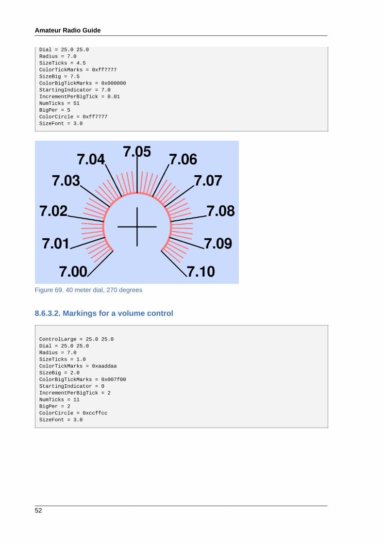
Dial = 25.0 25.0Radius = 7.0SizeTicks = 4.5ColorTickMarks = 0xff7777SizeBig = 7.5ColorBigTickMarks = 0x000000StartingIndicator = 7.0IncrementPerBigTick = 0.01NumTicks = 51BigPer = 5ColorCircle = 0xff7777SizeFont = 3.0
Figure 69. 40 meter dial, 270 degrees
8.6.3.2. Markings for a volume control
ControlLarge = 25.0 25.0Dial = 25.0 25.0Radius = 7.0SizeTicks = 1.0ColorTickMarks = 0xaaddaaSizeBig = 2.0ColorBigTickMarks = 0x007f00StartingIndicator = 0IncrementPerBigTick = 2NumTicks = 11BigPer = 2ColorCircle = 0xccffccSizeFont = 3.0
xgridloc
53
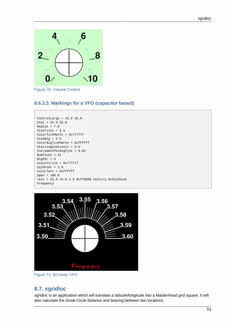
Figure 70. Volume Control
8.6.3.3. Markings for a VFO (capacitor based)
ControlLarge = 25.0 25.0Dial = 25.0 25.0Radius = 7.0SizeTicks = 3.5ColorTickMarks = 0x777777SizeBig = 5.5ColorBigTickMarks = 0xffffffStartingIndicator = 3.5IncrementPerBigTick = 0.01NumTicks = 41BigPer = 4ColorCircle = 0x777777SizeFont = 2.0ColorText = 0xffffffSpan = 180.0Text = 25.0 15.0 2.0 0xff0000 Century-SchoolbookFrequency
Figure 71. 80 meter VFO
8.7. xgridlocxgridloc is an application which will translate a latitude/longitude into a Maidenhead grid square. It willalso calculate the Great Circle distance and bearing between two locations.

Amateur Radio Guide
54
8.7.1. Installing xgridlocxgridloc is installed like most applications in Fedora:
sudo yum install xgridloc
8.7.2. Setting up xgridlocxgridloc uses a small configuration file, ~/.xgridlocrc. Before using xgridloc you should replacethe default location in the file with your station location using your favorite text editor:
######### Runtime config file for 'xgridloc' ######### # ### Blank lines and those starting with a # are ignored ### # # The 'Home' location's position. # (East Longitude and North Latitude) # Format is "East/ddd:mm:ss North/dd:mm:ss" West/084:11:59 North/43:38:06 # # The name of the 'Home' location Midland #
8.7.3. Using xgridlocxgridloc may be started by selecting item xgridloc icon (usually found in the Internet group) or byissuing the xgridloc command from the command line.
Clicking the Default Home Position button will cause the top location to be filled in with the locationyou specified in the configuration file.
xwota
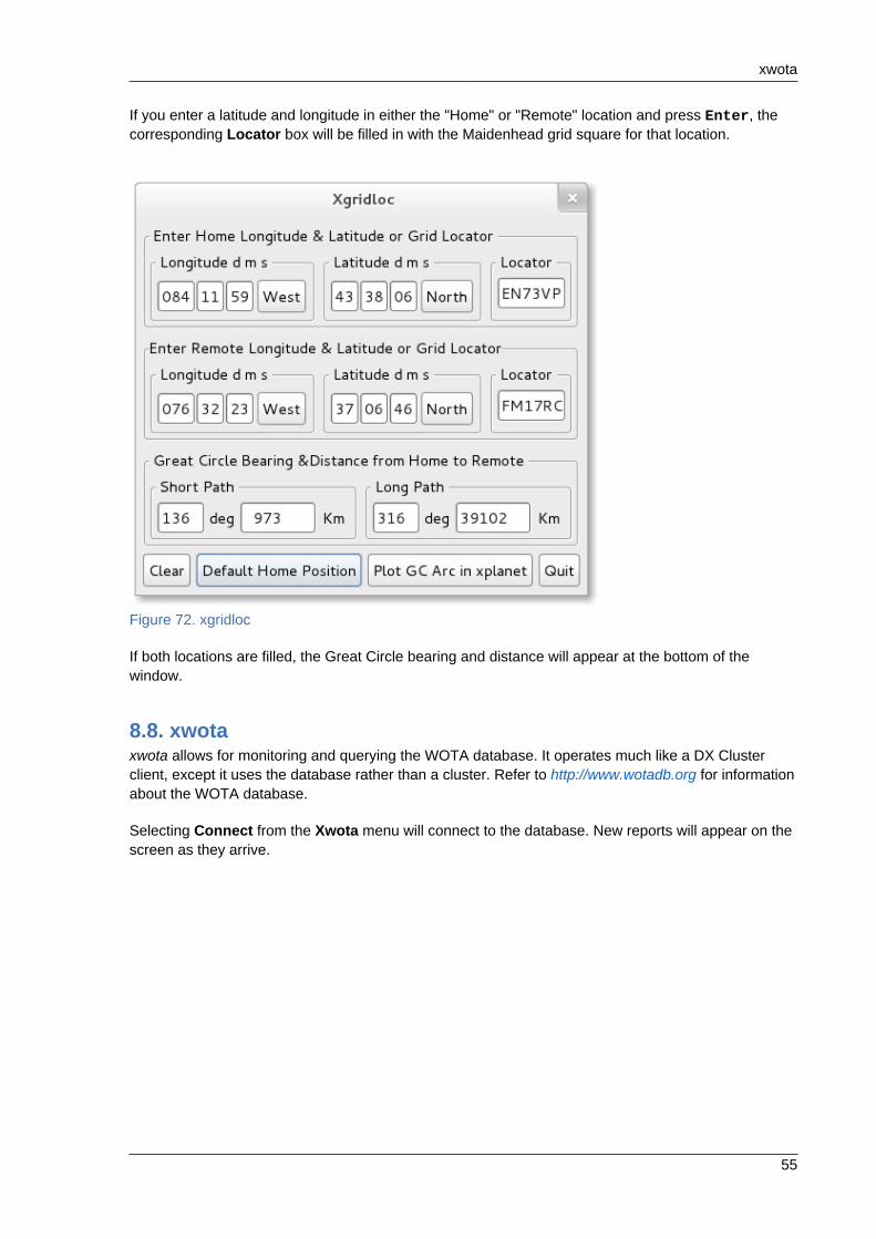
55
If you enter a latitude and longitude in either the "Home" or "Remote" location and press Enter, thecorresponding Locator box will be filled in with the Maidenhead grid square for that location.
Figure 72. xgridloc
If both locations are filled, the Great Circle bearing and distance will appear at the bottom of thewindow.
8.8. xwotaxwota allows for monitoring and querying the WOTA database. It operates much like a DX Clusterclient, except it uses the database rather than a cluster. Refer to http://www.wotadb.org for informationabout the WOTA database.
Selecting Connect from the Xwota menu will connect to the database. New reports will appear on thescreen as they arrive.

Amateur Radio Guide
56
Figure 73. Who is on the air
The user may also query the database by selecting Query from the Show menu. A dialog will appearallowing the user to enter specific location, frequency, and/or call to be searched for. Clicking Sendwill then cause the results to be returned at the bottom of the main window.
Figure 74. Xwota query window
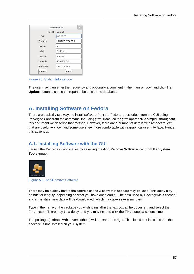
The user may also enter his own report. Before doing this, station information should be entered byselecting Station Info from the Settings menu and filling in the dialog:
Installing Software on Fedora
57
Figure 75. Station Info window
The user may then enter the frequency and optionally a comment in the main window, and click theUpdate button to cause the report to be sent to the database.
A. Installing Software on FedoraThere are basically two ways to install software from the Fedora repositories; from the GUI usingPackageKit and from the command line using yum. Because the yum approach is simpler, throughoutthis document we describe that method. However, there are a number of details with respect to yumthat are useful to know, and some users feel more comfortable with a graphical user interface. Hence,this appendix.
A.1. Installing Software with the GUILaunch the PackageKit application by selecting the Add/Remove Software icon from the SystemTools group.
Figure A.1. Add/Remove Software
There may be a delay before the controls on the window that appears may be used. This delay maybe brief or lengthy, depending on what you have done earlier. The data used by PackageKit is cached,and if it is stale, new data will be downloaded, which may take several minutes.
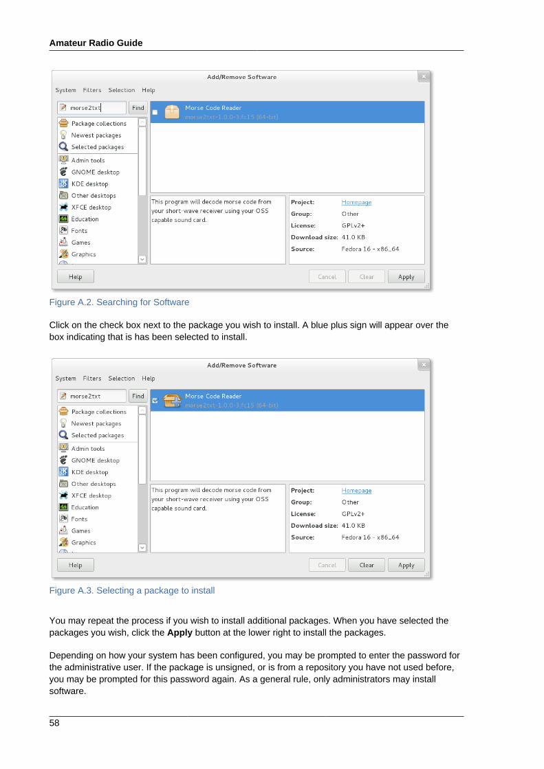
Type in the name of the package you wish to install in the text box at the upper left, and select theFind button. There may be a delay, and you may need to click the Find button a second time.
The package (perhaps with several others) will appear to the right. The closed box indicates that thepackage is not installed on your system.
Amateur Radio Guide
58
Figure A.2. Searching for Software
Click on the check box next to the package you wish to install. A blue plus sign will appear over thebox indicating that is has been selected to install.
Figure A.3. Selecting a package to install
You may repeat the process if you wish to install additional packages. When you have selected thepackages you wish, click the Apply button at the lower right to install the packages.
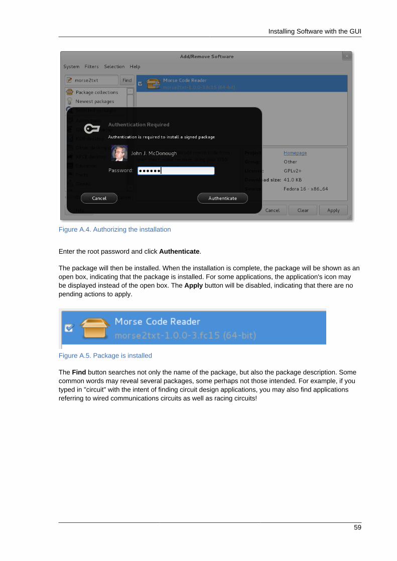
Depending on how your system has been configured, you may be prompted to enter the password forthe administrative user. If the package is unsigned, or is from a repository you have not used before,you may be prompted for this password again. As a general rule, only administrators may installsoftware.
Installing Software with the GUI
59
Figure A.4. Authorizing the installation
Enter the root password and click Authenticate.
The package will then be installed. When the installation is complete, the package will be shown as anopen box, indicating that the package is installed. For some applications, the application's icon maybe displayed instead of the open box. The Apply button will be disabled, indicating that there are nopending actions to apply.
Figure A.5. Package is installed
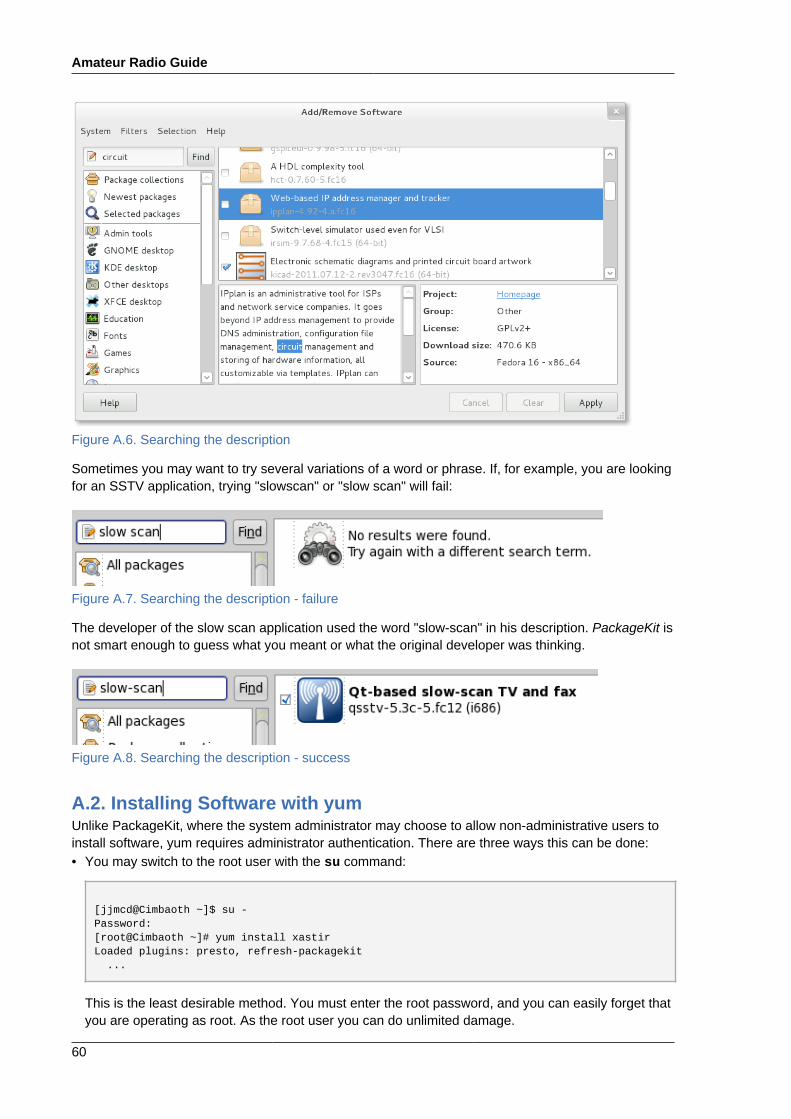
The Find button searches not only the name of the package, but also the package description. Somecommon words may reveal several packages, some perhaps not those intended. For example, if youtyped in "circuit" with the intent of finding circuit design applications, you may also find applicationsreferring to wired communications circuits as well as racing circuits!
Amateur Radio Guide
60
Figure A.6. Searching the description
Sometimes you may want to try several variations of a word or phrase. If, for example, you are lookingfor an SSTV application, trying "slowscan" or "slow scan" will fail:
Figure A.7. Searching the description - failure
The developer of the slow scan application used the word "slow-scan" in his description. PackageKit isnot smart enough to guess what you meant or what the original developer was thinking.
Figure A.8. Searching the description - success
A.2. Installing Software with yumUnlike PackageKit, where the system administrator may choose to allow non-administrative users toinstall software, yum requires administrator authentication. There are three ways this can be done:• You may switch to the root user with the su command:
[jjmcd@Cimbaoth ~]$ su -Password: [root@Cimbaoth ~]# yum install xastirLoaded plugins: presto, refresh-packagekit ...
This is the least desirable method. You must enter the root password, and you can easily forget thatyou are operating as root. As the root user you can do unlimited damage.
Installing Software with yum
61
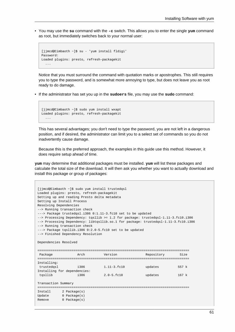
• You may use the su command with the -c switch. This allows you to enter the single yum commandas root, but immediately switches back to your normal user:
[jjmcd@Cimbaoth ~]$ su - 'yum install fldigi'Password: Loaded plugins: presto, refresh-packagekit ...
Notice that you must surround the command with quotation marks or apostrophes. This still requiresyou to type the password, and is somewhat more annoying to type, but does not leave you as rootready to do damage.
• If the administrator has set you up in the sudoers file, you may use the sudo command:
[jjmcd@Cimbaoth ~]$ sudo yum install wxaptLoaded plugins: presto, refresh-packagekit ...
This has several advantages; you don't need to type the password, you are not left in a dangerousposition, and if desired, the administrator can limit you to a select set of commands so you do notinadvertently cause damage.
Because this is the preferred approach, the examples in this guide use this method. However, itdoes require setup ahead of time.
yum may determine that additional packages must be installed. yum will list these packages andcalculate the total size of the download. It will then ask you whether you want to actually download andinstall this package or group of packages:
[jjmcd@Cimbaoth ~]$ sudo yum install trustedqslLoaded plugins: presto, refresh-packagekitSetting up and reading Presto delta metadataSetting up Install ProcessResolving Dependencies--> Running transaction check---> Package trustedqsl.i386 0:1.11-3.fc10 set to be updated--> Processing Dependency: tqsllib >= 1.2 for package: trustedqsl-1.11-3.fc10.i386--> Processing Dependency: libtqsllib.so.1 for package: trustedqsl-1.11-3.fc10.i386--> Running transaction check---> Package tqsllib.i386 0:2.0-5.fc10 set to be updated--> Finished Dependency Resolution
Dependencies Resolved
================================================================================ Package Arch Version Repository Size================================================================================Installing: trustedqsl i386 1.11-3.fc10 updates 557 kInstalling for dependencies: tqsllib i386 2.0-5.fc10 updates 167 k
Transaction Summary================================================================================Install 2 Package(s) Update 0 Package(s) Remove 0 Package(s)
Amateur Radio Guide
62
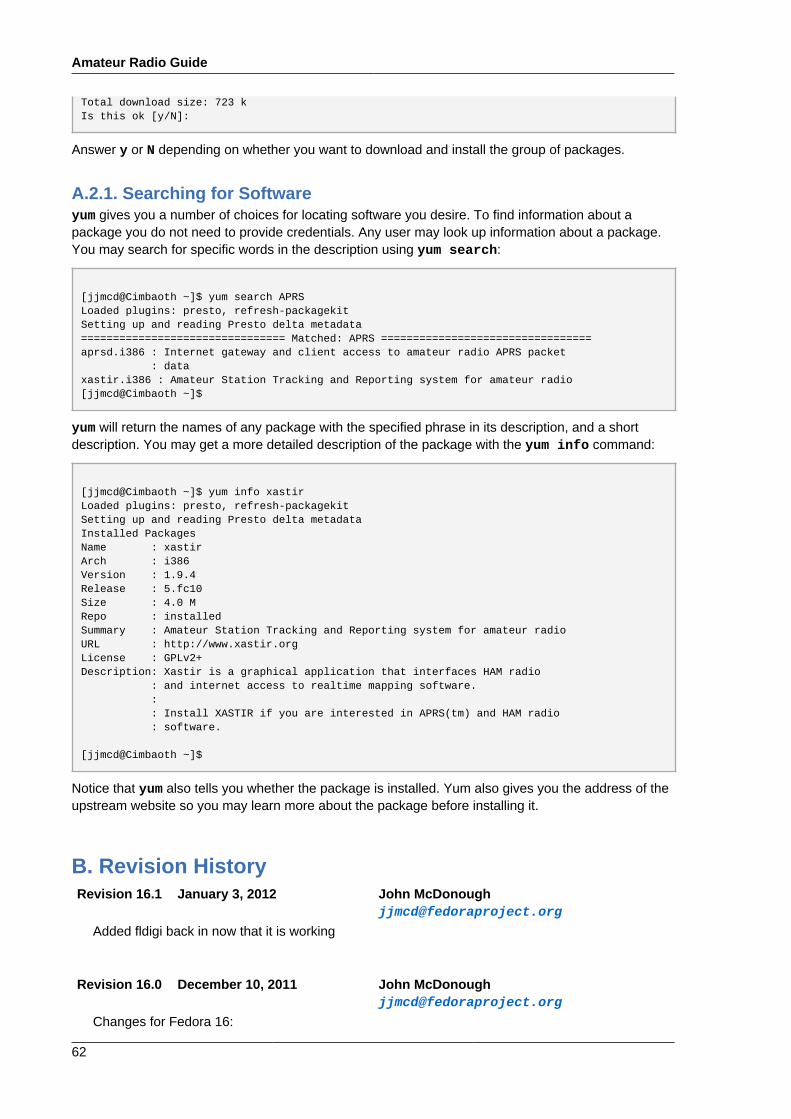
Total download size: 723 kIs this ok [y/N]:
Answer y or N depending on whether you want to download and install the group of packages.
A.2.1. Searching for Softwareyum gives you a number of choices for locating software you desire. To find information about apackage you do not need to provide credentials. Any user may look up information about a package.You may search for specific words in the description using yum search:
[jjmcd@Cimbaoth ~]$ yum search APRSLoaded plugins: presto, refresh-packagekitSetting up and reading Presto delta metadata================================ Matched: APRS =================================aprsd.i386 : Internet gateway and client access to amateur radio APRS packet : dataxastir.i386 : Amateur Station Tracking and Reporting system for amateur radio[jjmcd@Cimbaoth ~]$
yum will return the names of any package with the specified phrase in its description, and a shortdescription. You may get a more detailed description of the package with the yum info command:
[jjmcd@Cimbaoth ~]$ yum info xastirLoaded plugins: presto, refresh-packagekitSetting up and reading Presto delta metadataInstalled PackagesName : xastirArch : i386Version : 1.9.4Release : 5.fc10Size : 4.0 MRepo : installedSummary : Amateur Station Tracking and Reporting system for amateur radioURL : http://www.xastir.orgLicense : GPLv2+Description: Xastir is a graphical application that interfaces HAM radio : and internet access to realtime mapping software. : : Install XASTIR if you are interested in APRS(tm) and HAM radio : software.
[jjmcd@Cimbaoth ~]$
Notice that yum also tells you whether the package is installed. Yum also gives you the address of theupstream website so you may learn more about the package before installing it.
B. Revision HistoryRevision 16.1 January 3, 2012 John McDonough
Added fldigi back in now that it is working
Revision 16.0 December 10, 2011 John [email protected]
Changes for Fedora 16:

Revision History
63
- New screenshots for F16- Remove fldigi (not working on 16 yet)- Updates to installation procedures- Remove references to old GNOME menu- Add documentation for xnec2c- Add documentation fr gspiceui- Add documentation for gpredict- Correct error in xgridloc documentation- Add documentation for gerbv- Add documentation for pcb- Other mostly minor touch-ups
Revision15.90
November 23, 2011 John [email protected]
Remove xdx, obsoleted in Fedora 16Documentation for Chirp
Revision 0.9 November 9, 2010 John [email protected]
Documentation for dxccDocumentation for gresistorDocumentation for callgitCorrect typo in colrdxCorrect typos in xwota
Revision 0.8 November 7, 2010 John [email protected]
Documentation for rcrpanelDocumentation for colrdxDocumentation for xconversDocumentation for xdxDocumentation for xastirDocumentation for gEDADocumentation for gerbvDocumentation for pcbDocumentation for xwota
Revision 0.7 November 20, 2009 John [email protected]
Installing Software appendix
Revision 0.7 October 31, 2009 Eric [email protected]
Added xlog installation and setup procedures.
Amateur Radio Guide
64
Revision 0.6 October 29, 2009 John [email protected]
ibp
Revision 0.5 October 29, 2009 Randy Berry [email protected]
Revision 0.4 October 28, 2009 Eric [email protected]
xlog screenshotAdditional info on fldigi
Revision 0.3 October 6, 2009 John [email protected]
xgridloc
Revision 0.2 October 4, 2009 John [email protected]
Beginning of SPLAT! instructions
Revision 0.1 October 1, 2009 John [email protected]
Document skeleton