![TF1600 Manual Rev0[1]](https://static.fdocuments.in/doc/165x107/551244174a7959df028b48a6/tf1600-manual-rev01.jpg)
AM2847 Communications Standards Rev0 13 Nov 2020
40
Communications Standards Document Number AM 2847
Transcript of AM2847 Communications Standards Rev0 13 Nov 2020

Communications Standards
Document Number AM 2847

13 November 2020 Page 1 of 40
Contents
1. General Requirements 4
1.1 Acronyms and Abbreviations 4
1.2 Scope 5
1.3 Standards 6
1.4 Quality of Workmanship 6
1.5 Materials, Equipment and Component 6
1.6 Drawings 6
1.7 Pre-Construction Submissions 7
1.8 Drawing Integration 7
2. Installation Requirements 7
3. Data Networks 7
3.1 General 7
3.1.1 Spare Capacity ...........................................................................................7
3.1.2 Topology ....................................................................................................8
3.1.3 Switch Configuration ..................................................................................8
3.1.4 Communications Infrastructure ...................................................................9
3.1.5 Public Communications Infrastructure ........................................................9
3.1.6 Wireless Devices ........................................................................................9
3.1.7 Network Device Security .......................................................................... 10
3.2 19 Inch Server Racks 10
3.2.1 19 Inch Rack Locations and layout ........................................................... 10
3.2.2 19 inch Rack Network Switch Power supplies .......................................... 10
3.3 Control Panels Network Equipment 11
3.3.1 Indoor ....................................................................................................... 11
3.3.2 Outdoor .................................................................................................... 11
3.3.3 Cabinet or Panel Network Switch Power supplies .................................... 11
3.4 Documentation 11
3.5 Installation Requirements 12
3.5.1 General .................................................................................................... 12
3.5.2 Removal of Redundant Network Related Equipment ................................ 12
3.5.3 Identification ............................................................................................. 12
3.6 Fibre Optic 13
3.6.1 Fibre Optic Cable ..................................................................................... 13
3.6.2 Fibre Optic Patch Leads ........................................................................... 13
3.6.3 Fibre Optic Cable Identification ................................................................. 13
3.6.4 Fibre Optic Testing ................................................................................... 14
13 November 2020 Page 2 of 40
3.7 Copper 14
3.7.1 Copper Cable ........................................................................................... 14
3.7.2 Copper Patch Leads ................................................................................. 14
3.7.3 Copper Cat 6 Cable Identification ............................................................. 14
3.7.4 Copper Testing ......................................................................................... 15
Appendix A – Equipment Identification equipment label. 16
Appendix B - Data Networks 17
Table A: Fibre Optic Numbers and Colours 17
Table B: Fibre Optic Patch Lead Colours & Types 17
Table C: Copper Patch Lead Colours & Types 17
Table D: Lead Labels 18
Table E: Naming Conventions 18
Table F: Server Rack Layout 19
3.8 Fibre Optic Testing 20
3.8.1 Minimum Requirements ............................................................................ 20
3.8.2 Quality Assurance .................................................................................... 21
3.8.3 Submittals ................................................................................................ 22
3.8.4 Acceptance of Test Results ...................................................................... 22
3.8.5 Optical Fibre Testers ................................................................................ 24
3.8.6 Identification ............................................................................................. 26
3.8.7 Administration .......................................................................................... 26
3.8.8 General .................................................................................................... 26
3.8.9 Optical Fibre Testing ................................................................................ 26
3.8.10 Identification ............................................................................................. 28
3.8.11 Administration .......................................................................................... 28
3.9 Copper CAT 6 Testing 29
3.9.1 Minimum Requirements ............................................................................ 29
3.9.2 Quality Assurance .................................................................................... 30
3.9.3 Submittals ................................................................................................ 30
3.9.4 Acceptance of Test Results ...................................................................... 31
3.9.5 Balanced Twisted Pair Cable Testers ....................................................... 31
3.9.6 Identification ............................................................................................. 32
3.9.7 Administration .......................................................................................... 32
3.9.8 General .................................................................................................... 33
3.9.9 Balanced Twisted Pair Cable Testing ....................................................... 33
3.9.10 Administration .......................................................................................... 38

AM2847- Communications Standards
13 November 2020 Page 3 of 40
Document Control
Rev Date Revision Details Clause Author Approved
0 13/08/20 The EIC committee had reviewed various sections of this Standard on 5 occasions. We have set revision to rev 0.
We have decided to segregate the original AM2714 into separate standards, namely:
AM2714 – Electrical Standards
AM2832 – Instrumentation & Controls Standards
AM2847 – Communications Standards (this document)
AM2851 – EIC Inspection, Testing & Completion Standards
AM2848 – Approved EIC Equipment List
All EIC Committee
A. Gabriel
C. Paxman

AM2847- Communications Standards
13 November 2020 Page 4 of 40
1. General Requirements
1.1 Acronyms and Abbreviations
All abbreviations and acronyms used in additional documentation, shall follow the conventions used through this and other related project documents.
Acronym Description
3G 4G Cellular Communications Service
ABS Acrylonitrile Butadiene Styrene
AD Active Directory
AI Analogue Input
AO Analogue Output
ATS Auto Transfer Switch
COTS Commercial Off The Shelf
CT Current Transformer
Cu Copper
DI Digital Input
DIN German Institute for Standards (Deutsches Institut für Normung)
DNP3 Distributed Network Protocol (version 3)
DO Digital Output
ELV Extra Low Voltage
EMC Electromagnetic Compatibility
FAT Factory Acceptance Test
FDS Functional Description Specification
FOBOT Fibre Optic Break Out Tray
HMI Human Machine Interface
IEC International Electrotechnical Commission
ICS Industrial Control system
iLO Integrated Lights Out
IO Input Output
IP Ingress Protection
IR Insulation Resistance
IT Information Technology
ITP Inspection Test Plan
LCD Liquid Crystal Display
LED Light Emitting Diode
LV Low Voltage

AM2847- Communications Standards
13 November 2020 Page 5 of 40
mAHD Metre Australian Height Datum
NTP Network Time Protocol
OTDR Optical Time Domain Reflectometer
P&ID Process & Instrumentation Diagram
PC Personal Computer
PLC Programmable Logic Controller
PSU Power Supply Unit
PTC Positive Temperature Coefficient
PVC Polyvinyl Chloride
RCD Residual Current Device
RTU Remote Telemetry Unit
SAL Site Alarm List
SAT Site Acceptance Test
SCADA Supervisory Control And Data Acquisition
SDM System Design Matrix
SEW South East Water
SFP Small Form Pluggable
STP Sewage Treatment Plant
TBA To be advised
TBC To Be Confirmed
TFT Thin Film Transistor
TTP Tertiary Treatment Plant
UF Ultra Filtration
UPS Uninterruptable Power Supply
UPVC Unplasticised Polyvinyl Chloride
UV Ultra Violet
VLAN Virtual Local Area Network
VPN Virtual Private Network
VSD Variable Speed Drive
WAN Wide Area Network
1.2 Scope
This specification outlines South East Water’s minimum standards for the selection, fabrication, delivery, installation and testing of communications equipment and associated items used at new or renewed water and sewerage infrastructure sites.
Excluded from the scope of this specification are:
a. South East Water assets not containing water and sewerage infrastructure (eg: WatersEdge office, depots)

AM2847- Communications Standards
13 November 2020 Page 6 of 40
b. Functional or operational requirements relating to electrical assets. c. Monitoring, protection, control and communication system design, configuration and
programming. This is covered by other South East Water standards such as AM2779_Treatment Plant Monitoring and Control Specification.
d. Civil, mechanical arrangements, pump selection, pump performance or hydraulic assessment.
e. Work practices associated with the management of electrical risks during construction and installation works.
1.3 Standards
The following standards shall apply in the given order of preference:
a) Australian Standards or its IEC/ISO equivalent b) OH&S Regulations 2017 (Victoria) c) Electricity Safety (Installations) Regulations (Victoria) d) Victorian Service & Installation Rules e) Essential Services Commission Electricity Distribution Code f) Requirements of the Electricity Distribution Company g) Electricity Safety Act (Victoria) h) Manufacturer’s Guidelines i) Water Industry Standards, including:
i. WSA04 Sewage Pumping Station Code Of Australia ii. South East Water supplementary manual to WSA04 iii. South East Water Standard Electrical Drawings iv. AM2779_Treatment Plant Monitoring and Control Specification (SEW) v. AM2717_Generator Specification (SEW) vi. AM2522_O&M Manual Specification (SEW) vii. AM2755_Testing, Commissioning and Handover Plan (SEW) viii. AM2739_Corrosion Mitigation Specification (SEW) ix. AM2727_Covers for Underground Structures (SEW) x. AM 2758_Noise Specification (SEW) xi. AM2775_Watershed Collection Details (SEW) xii. AM2776.3_Air Treatment Unit Specification and Commissioning (SEW) xiii. AM2488_2D and 3D Drafting
The order of precedence of documents shall be as follows:
a) Legislated requirements b) Project specific specifications c) Project specific drawings d) South East Water standards e) South East Water standard drawings f) Water Industry Standards (WSAA)
1.4 Quality of Workmanship
Please refer to AM2714.
1.5 Materials, Equipment and Component
Please refer to AM2714.
1.6 Drawings
Please refer to AM2714.

AM2847- Communications Standards
13 November 2020 Page 7 of 40
1.7 Pre-Construction Submissions
Please refer to AM2714.
1.8 Drawing Integration
Please refer to AM2714.
2. Installation Requirements
Please refer to AM2714.
3. Data Networks
3.1 General
3.1.1 Spare Capacity
The data networks shall be designed to cater for future expansion of the plant. Future expansion is integral to allow for plant modifications during the design process, modifications during commissioning, allowance for future plant upgrades and provision for future control system renewals.
Item Requirement
Fibre Cores Number of fibre cores shall be 12 cores per fibre type (i.e. for both fibre types of Single-Mode and Multi-Mode)
Spare Fibre Cores 50% spare fibre cores and spare conduit capacity. Spare cores shall be spliced/terminated.
Subnet & Programming Ports
1 port per switch on the network shall be allocated for programming use
[Note: Switches shall be preconfigured by BTS – check if existing in other document]
Spare Network Switch Ports
25% minimum spare ports per switch (Total ports used includes ports allocated for programming)
Minimum Fibre Cores Minimum number of fibre cores shall be 12 cores per fibre type (i.e. for both fibre types of Single-Mode and Multi-Mode)
Minimum Spare Fibre Cores
50% minimum spare fibre cores
Minimum Copper Cables Minimum number of Cat 6 structured cables between points shall be 4 If practical
e.g. 1 Cat 6 cable used run 4
2 Cat 6 cables used run 4

AM2847- Communications Standards
13 November 2020 Page 8 of 40
3 Cat 6 cables used run 6
Structured Cabling
50% minimum spare – If practical – Cat 6 structured cabling should be blue
Network switch ports Cisco IE4000 switch ports 1 to 4 are to be reserved for fibre SFPs – South East Water approval to use for other.
Cisco IE4000 switch ports 5 to 8 are to be reserved for PoE devices - South East Water approval to use for other.
All other Cisco IE4000 switch ports to be used as assigned by South East Water.
Dust caps must be fitted to all spare or unused ports.
Cisco IE4010 Ports 12 and 24 are allocated for ether-channelling (Treatment Plant)
If more than 12 fibre cores are required to cover spares or initial requirements another 12 core fibre cable shall be run.
3.1.2 Topology
Fibre optic ring topology shall be designed to ensure a redundant physical path is taken for each section of the ring.
To achieve this all fibre optic cables must form part of a ring topology and no other fibre optic cables in the ring shall be run through the same physical route. The redundant paths shall be in separate conduits with at least 2 metres separation up to the termination points. South East Water allows the following exceptions to be on spurs or non-redundant physical rings.
Cameras
Weather Stations
Temporary Construction Site Offices
Any other exceptions including secondary rings shall be approved by South East Water.
See Appendix B Data Networks Topology Terms Examples section for a diagram showing examples of a main fibre ring, secondary fibre ring and a fibre spur.
Fibre optic patch panels shall match the type of fibre cable used (OM1 for OM1, OM4 for OM4).
3.1.3 Switch Configuration
The South East Water supplied network switches that will be deployed around the treatment plant will have multiple VLANs.
ICS VLAN
HMI VLAN
Corporate VLAN
Profinet VLAN
VoIP VLAN
IO VLAN
South East Water will configure the network switches and provide IP addresses where required. When available network switch alarm contact shall be wired to the PLC (Closed contact equals OK).
Cisco switch alarm contact shall close on power up if alarm conditions are OK and open if alarm condition exists.

AM2847- Communications Standards
13 November 2020 Page 9 of 40
3.1.4 Communications Infrastructure
Daisy chaining of Ethernet devices is not permitted e.g. between variable speed drives.
The design should incorporate fibre optic cabling between Ethernet switches. The Contractor will be required to supply and install the fibre network interface modules in these switches (LC SFPs) see approved equipment schedule in Appendix A for details. The LANs shall include an optical fibre self-healing ring topology consisting of components that are industrially hardened.
The fibre ring LAN, including cables, components and switches shall be capable of full duplex 1000 Mbps. Copper network cables for communication between racks and peripheral equipment shall be Cat 6, structured cabling.
Ethernet switches mounted in control panels shall be Cisco industrial DIN rail mounted
switching as per standard network equipment list in Appendix A.
Ethernet switches mounted in server racks shall be Cisco 19 inch as per standard network
equipment list in Appendix A.
Any OEM equipment which has non-standard switches shall be replaced with structured cabling
to the closest ICS network switch or replaced with a switch as per standard network equipment
list in Appendix A. Structured cabling runs shall be only used when run is less than 20 metres
and inside the same building.
The contractor will be responsible to supply and install the FOBOT’s in the rack unit as required in various locations around the treatment plant, see approved equipment schedule in Appendix A. The FOBOT shall use LC connectors and terminate all of the cores of the fibre optic cable.
The design of the fibre optic network shall minimise the potential for physical damage, in particular damage caused to unprotected cables in pits during maintenance activities. The design shall incorporate some type of physical protection or segregation to provide protection.
Within the plant, heavy-duty PVC conduits shall be used for buried connections between pits and conform to relevant Australian standards.
Fibre optic cables running underground shall have termite and rodent proof sheaths. The use of steel wire armoured or similar fibre optic cables such as e.g. external underground loose tube all dielectric rodent proof optical cable from Prysmian Australia PTY LTD. Patch panels shall be compatible with cable used. Patch panels shall be DIN mount in cabinets or control panels and 1RU 19 inch mount in server cabinets.
3.1.5 Public Communications Infrastructure
Public communication infrastructure, e.g. Telstra NextG, maybe required to provide interlocks to remote assets or plant. South East Water will provide the IPWAN and IT infrastructure equipment and South East Water will configure the devices. If required, this equipment will be detailed in the job specific specification.
3.1.6 Wireless Devices
Due to the security implications of license free wireless networks, the SCADA system shall not employ any form of license free wireless connectivity other than wireless devices such as Bluetooth keyboards and mice.

AM2847- Communications Standards
13 November 2020 Page 10 of 40
3.1.7 Network Device Security
All unused services and ports on any installed network devices shall be disabled e.g. the FTP service on port 21 of a new PLC CPU device Ethernet LAN RJ45 port should be disabled if not used).
All default user name and/or passwords in devices shall be changed from factory settings to ones assigned by South East Water.
User names and/or passwords for devices and services will be provided by South East Water with the assigned IP addresses.
Security checks will be completed for new devices by South East Water on handover.
3.2 19 Inch Server Racks
19 inch racks and associated equipment shall be selected from the approved equipment schedule
in AM2848_Approved EIC Equipment List. All 19 inch racks shall have at least 50% spare space
when installed. Server room grade racks shall be appropriately selected. The depth of the racks
shall be suitably considered.
3.2.1 19 Inch Rack Locations and layout
19 inch racks shall be located in an air-conditioned room and shall have thermostatically
controlled ventilation fan(s) installed in the top.
On a new install, dedicated temperature and dust controlled room shall be utilised and not the
switchboard room.
When deciding the location of a 19 inch rack, the noise generated by equipment shall be
considered (avoid placing the racks in areas that people spend long periods working in close
proximity to the racks, e.g. offices or labs).
Layout and connection of equipment in 19 inch racks shall be as shown in Appendix E server rack
layout
There shall be a dedicated server/communications room separate from control room. Any racks
in switchroom shall not in impede in space calculations. The biggest size rack (1200mm deep)
shall be in the admin building/dedicated comms room and the smaller size rack (800mm deep)
shall be in the switchroom.
Please refer to AM2714 for space consideration.
3.2.2 19 inch Rack Network Switch Power supplies
Rack mounted network switches in19 inch cabinets shall have 2 separate power supplies.
1 x 240VAC Non UPS Based and 1 x 240VAC UPS based.
Power supplies shall be selected from the approved equipment schedule in Appendix A.

AM2847- Communications Standards
13 November 2020 Page 11 of 40
3.3 Control Panels Network Equipment
3.3.1 Indoor
Cabinet or panel shall have a filtered vent and thermostatically controlled fan.
Cabinet or panel shall have a condensation heater with thermostat control.
Cabinet or panel shall be lockable with a standard South East Water cabinet lock.
Network equipment shall be DIN rail mounted.
Cabinet shall be ground mounted or at a maximum height of 2 metres.
3.3.2 Outdoor
Cabinet or panel shall have a filtered vent and thermostatically controlled fan.
Cabinet or panel shall have a condensation heater with thermostat control.
Cabinet or panel shall be stainless steel and have a double skinned roof if outdoors (preferable the whole cabinet or panel is double skinned).
Cabinet or panel shall be lockable with a South East Water padlock if outdoors.
Network equipment shall be DIN rail mounted.
Cabinet shall be ground mounted or at a maximum height of 2 metres.
3.3.3 Cabinet or Panel Network Switch Power supplies
Network switches in cabinets or control panels where practicable shall have 2 separate power supplies.
Din mounted switches in control panels shall have:
1 x 48VDC Non UPS based
1 x 24VDC UPS based.
The 24 VDC power supply to switches where practicable shall be battery or UPS backed.
48 volt DC power supplies are backup and to allow the Cisco switches to provide power for existing or future PoE (Power over Ethernet) devices.
Power supplies shall be selected from the AM2848 – Approved EIC Equipment List.
48 VDC power supplies shall have 50% spare capacity and be a minimum of 5 amps on the DC secondary side.
3.4 Documentation
Below is a list of some of the documents that will need to be updated / provided to South East Water. The format shall be as per AM2714 – Electrical Standards.
South East Water will provide a list of existing drawings and documents that will be required to be updated.
Pit fibre route drawings reference (CAD and PDF).
Network topology drawings (CAD and PDF).
Single line drawings for network device power supplies (CAD and PDF).
PLC IO drawings for network device digital alarms (CAD and PDF).
IT Topology overview Visio drawing.
SEW shall provide the IP addresses for the field devices.

AM2847- Communications Standards
13 November 2020 Page 12 of 40
Note: CISCO managed networks shall be in consultation with the BTS Department.
Unmanaged networks shall be in consultation with the OT Department.
Fibre optic AND Copper cabling test sheets.
Data sheets located at the end of SCADA standards document - South East Water
Treatment Plant PLC SCADA Standard Specification Master.
Equipment manuals – operation and maintenance.
Recommended spare parts list.
Software.
South East Water network checklist in Appendix B.
3.5 Installation Requirements
3.5.1 General
Installation of all cables shall follow installation standards in this document (AM2714_Electrical Standards).
The order of precedence of documents shall be as follows;
Legislative and AS/NZS Standards
Job specific specifications
Job specific drawings
Standard South East Water specifications (This document)
Other standard South East Water specifications
Standard drawings
Fibre optic cables and structured copper cabling shall be terminated in a patch panel located either in an existing 19 inch server rack or control cabinet / panel.
South East Water IT approval is required for any new racks cabinets or patch panels
3.5.2 Removal of Redundant Network Related Equipment
All redundant cables and network equipment shall be removed if replaced.
e.g.
Fibre optic and copper cables.
Fibre optic and copper patch leads and patch panels.
Network switches.
Redundant power supplies, fuses, circuit breakers and wiring.
3.5.3 Identification
All equipment and cables shall be identified by means of labels.
Label types shall follow standards in this document.
Building name used on labels shall match the buildings external label.
Cabinet or Control panel name used on labels shall match the label on the outside of the cabinet or control panel.
Patch panel name used on labels shall match the label on the patch panel.

AM2847- Communications Standards
13 November 2020 Page 13 of 40
See information below and Appendix B Tables D and E for labelling conventions to be used.
First patch panel in each cabinet or control panel should be labelled Patch Panel A.
Next patch panel would be Patch Panel B then C etc.
Each new cabinet or control panel would start at Patch Panel A again.
3.6 Fibre Optic
3.6.1 Fibre Optic Cable
All fibre optic network cable routes must be submitted to South East Water for written approval.
Fibre optic cable shall be either a multimode fibre of minimum OM4 capacity or a OS1/2
For fibre optic cable runs less than 500 metres multimode OM4 should be used if suitable for the application.
For fibre optic cable runs greater than 500 metres single mode fibre must be used if suitable for the application.
All terminations of the fibre shall be “LC” type. All fibres including spares in a fibre optic cable shall be terminated at each end in the patch panel. Boots shall cover the unused fibres at the patch panel. Fibre optic cables shall be rodent proof such as e.g. external underground loose tube all dielectric rodent proof optical cable from Prysmian Australia PTY LTD.
3.6.2 Fibre Optic Patch Leads
Fibre optic patch leads shall be selected to match colour standards for grade of fibre Appendix B Table C. When patching directly between 2 fibre cable patch panels, the patch lead shall be labelled with original source and destination building and cabinet. All fibre optic patch leads in cabinets are to be run free inside existing ducting and follow manufacturer prescribed recommendations and minimum bend radius. Patch leads shall be installed to the closest metre in length – minimum amount laying in ducts or tied up. If patch leads need to be cable tied, it shall be done loosely with Velcro straps. Fibre optic patch leads that are run between cabinets need to be labelled with destination Cabinet or Control Panel Name – Patch Panel Name.
Patch leads that are run between cabinets shall also be protected by PVC fixed / flexible conduit for vermin and physical protection or fibre patch leads used shall be stainless steel armoured type. Installation standards in this document shall be followed.
Fibre optic patch leads shall be LC duplex connector at the network switch or patch panel.
Connector at the device if possible should also be LC.
See Table C in Appendix E for patch lead colour standards and selection.
Patch cables to devices within cabinets shall be labelled at each end with the same label, as shown in appendix E table D
3.6.3 Fibre Optic Cable Identification
Fibre optic cables (FOC) termination points (patch panels) shall be labelled at each end with the cable destination.
Example labelling of source and destination FOC at patch panel termination points.
E.G. Cable Number – To Building Name – Cabinet or Control Panel Name – Patch Panel Name
E.G. Cable from RWTP Building - Network Cabinet - Patch Panel A to Blower Building - PLC 102 Control Panel - Patch Panel A.

AM2847- Communications Standards
13 November 2020 Page 14 of 40
(At the RWTP End) Label E.G. FOC 12 - To Blower Building - PLC 102 Control Panel - Patch Panel A
(At the Blower End) Label E.G. FOC 12 - To RWTP Building - Network Cabinet - Patch Panel A
Fibre optic cable (FOC) number labels shall also be applied on the inside and outside any panel or cabinet at the cable entry point.
E.G. FOC 12 for Fibre Optic Cable 12.
Fibre optic cables shall also be clearly labelled in each pit with the Cable number.
E.G. FOC 12 for Fibre Optic Cable 12.
3.6.4 Fibre Optic Testing
See Appendix E Fibre Optic Testing for details on fibre test requirements.
South East Water network checklist must also be completed for handover.
3.7 Copper
3.7.1 Copper Cable
All copper network cable routes must be submitted to South East Water for written approval.
Where copper Cat 6 structured cables exit a building, gel filled poly Cat 6 shall be run and lightning arrestors installed at each end.
Any terminations of structured cabling within a pole e.g. a galvanised tilt pole to mount CCTV/lighting equipment, shall use an IP rated waterproof coupler to connect to the patch lead from the pole mounted device/s. Equipment selection as per standard network equipment list in AM2714.
Any copper cables running between panels shall be Cat 6 and terminated at each end in a South East Water approved patch panel. See standard network equipment list in Appendix A for South East Water approved patch panel types. Cable colour for Cat 6 structured cabling should be blue.
Terminations at patch panels shall be to TIA568A.
Patch panels shall be labelled with the source and destination. See Cat 6 patch lead labelling Appendix B Table D.
3.7.2 Copper Patch Leads
All Cat 6 patch leads are to be run free inside existing ducting and follow manufacturer prescribed minimum bend radius. Patch leads shall be installed to the closest metre in length – minimum amount laying in ducts or tied up. If patch leads need to be cable tied, it shall be done loosely with Velcro straps. Copper patch leads should not exit the cabinet or be run between cabinets. Structured Cat 6 cabling shall be run to the closest managed network switch and equipment location and terminated in a patch panel at both ends. Cat 6 patch leads shall be selected to match colour standards for network type as per Appendix B table D. Patch cables to devices within cabinets shall be labelled at each end with the same label, as shown in Appendix B Table D.
3.7.3 Copper Cat 6 Cable Identification
RJ45 Cat 6 copper termination points (patch panels) shall be labelled at each end with the cable destination.
AM2847- Communications Standards
13 November 2020 Page 15 of 40
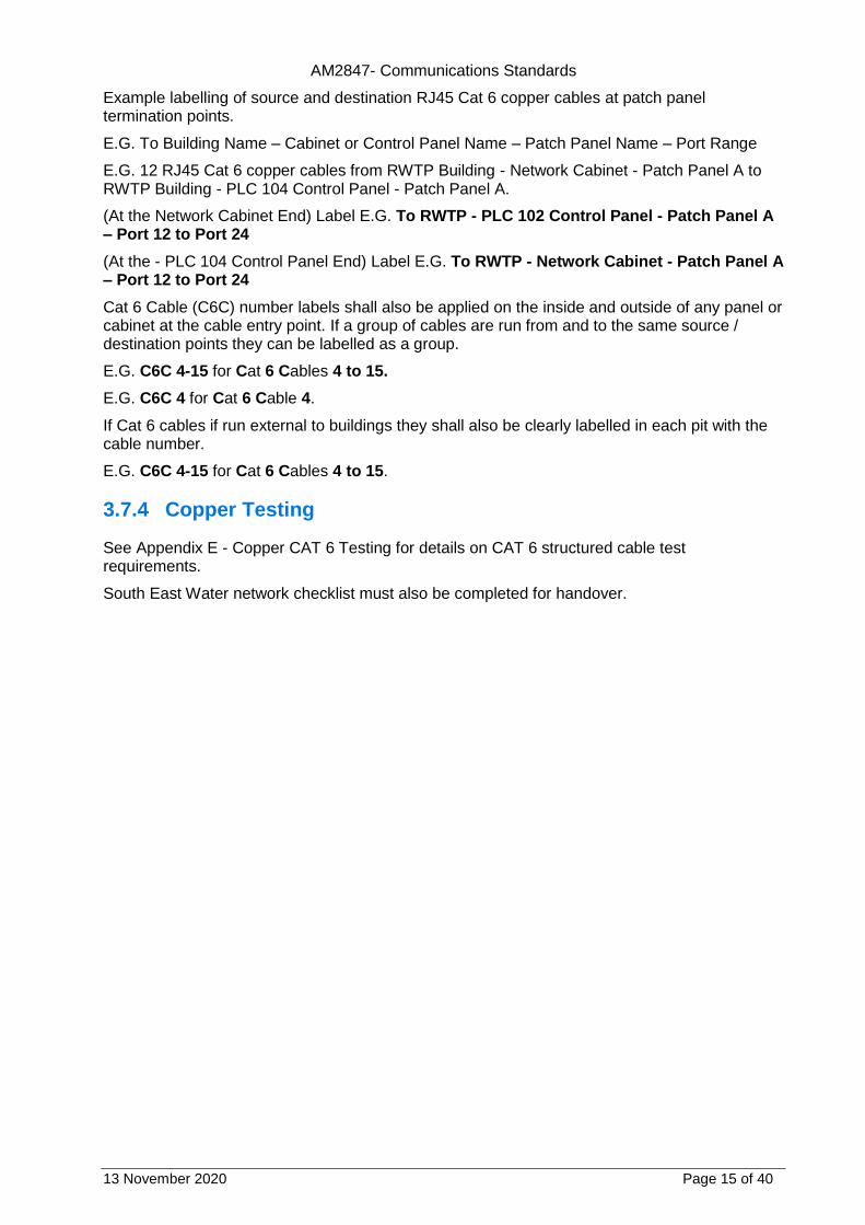
Example labelling of source and destination RJ45 Cat 6 copper cables at patch panel termination points.
E.G. To Building Name – Cabinet or Control Panel Name – Patch Panel Name – Port Range
E.G. 12 RJ45 Cat 6 copper cables from RWTP Building - Network Cabinet - Patch Panel A to RWTP Building - PLC 104 Control Panel - Patch Panel A.
(At the Network Cabinet End) Label E.G. To RWTP - PLC 102 Control Panel - Patch Panel A – Port 12 to Port 24
(At the - PLC 104 Control Panel End) Label E.G. To RWTP - Network Cabinet - Patch Panel A – Port 12 to Port 24
Cat 6 Cable (C6C) number labels shall also be applied on the inside and outside of any panel or cabinet at the cable entry point. If a group of cables are run from and to the same source / destination points they can be labelled as a group.
E.G. C6C 4-15 for Cat 6 Cables 4 to 15.
E.G. C6C 4 for Cat 6 Cable 4.
If Cat 6 cables if run external to buildings they shall also be clearly labelled in each pit with the cable number.
E.G. C6C 4-15 for Cat 6 Cables 4 to 15.
3.7.4 Copper Testing
See Appendix E - Copper CAT 6 Testing for details on CAT 6 structured cable test requirements.
South East Water network checklist must also be completed for handover.

AM2847- Communications Standards
13 November 2020 Page 16 of 40
Appendix A – Equipment Identification equipment label.
Please refer to AM2714.

AM2847- Communications Standards
13 November 2020 Page 17 of 40
Appendix B - Data Networks
Table A: Fibre Optic Numbers and Colours
Table B: Fibre Optic Patch Lead Colours & Types
Fibre Optic Patch Lead Colours and Type
Fibre Patch Cable Type and Colour OM1 or 2 Orange
Fibre Patch Cable Type and Colour OM3 or 4 Aqua
Fibre Patch Cable Type and Colour Single Mode OS1 OS2 Yellow
Table C: Copper Patch Lead Colours & Types
Copper Cat 6 Patch Lead Colour Standards
Controls (PLC SCADA related devices) Cat 6 Grey
IO and Profinet (Remote IO and Profinet devices) Cat 6 Green
Security devices (Cameras) Cat 6 Pink
IT devices (Office PCs and IP phones) Cat 6 Blue
Fibre Optic Cable Core Individual Fibre Number and Colour Standards
Fibre number and colour 1 Blue
Fibre number and colour 2 Orange
Fibre number and colour 3 Green
Fibre number and colour 4 Brown
Fibre number and colour 5 Slate
Fibre number and colour 6 White
Fibre number and colour 7 Red
Fibre number and colour 8 Black
Fibre number and colour 9 Yellow
Fibre number and colour 10 Violet
Fibre number and colour 11 Rose
Fibre number and colour 12 Aqua
AM2847- Communications Standards
13 November 2020 Page 18 of 40
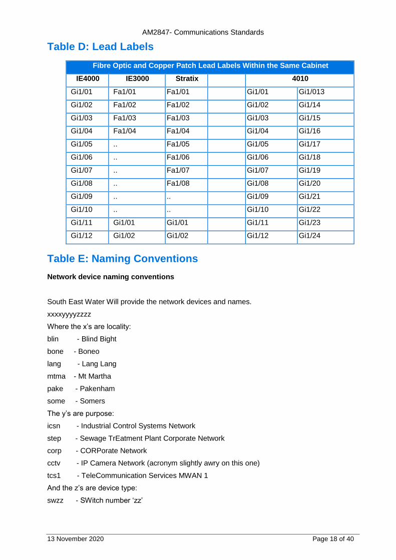
Table D: Lead Labels
Fibre Optic and Copper Patch Lead Labels Within the Same Cabinet
IE4000 IE3000 Stratix 4010
Gi1/01 Fa1/01 Fa1/01 Gi1/01 Gi1/013
Gi1/02 Fa1/02 Fa1/02 Gi1/02 Gi1/14
Gi1/03 Fa1/03 Fa1/03 Gi1/03 Gi1/15
Gi1/04 Fa1/04 Fa1/04 Gi1/04 Gi1/16
Gi1/05 .. Fa1/05 Gi1/05 Gi1/17
Gi1/06 .. Fa1/06 Gi1/06 Gi1/18
Gi1/07 .. Fa1/07 Gi1/07 Gi1/19
Gi1/08 .. Fa1/08 Gi1/08 Gi1/20
Gi1/09 .. .. Gi1/09 Gi1/21
Gi1/10 .. .. Gi1/10 Gi1/22
Gi1/11 Gi1/01 Gi1/01 Gi1/11 Gi1/23
Gi1/12 Gi1/02 Gi1/02 Gi1/12 Gi1/24
Table E: Naming Conventions
Network device naming conventions
South East Water Will provide the network devices and names.
xxxxyyyyzzzz
Where the x’s are locality:
blin - Blind Bight
bone - Boneo
lang - Lang Lang
mtma - Mt Martha
pake - Pakenham
some - Somers
The y’s are purpose:
icsn - Industrial Control Systems Network
step - Sewage TrEatment Plant Corporate Network
corp - CORPorate Network
cctv - IP Camera Network (acronym slightly awry on this one)
tcs1 - TeleCommunication Services MWAN 1
And the z’s are device type:
swzz - SWitch number ‘zz’

AM2847- Communications Standards
13 November 2020 Page 19 of 40
stkz - Switch STacK number ‘z’
fwgz - FireWall Gateway number ‘z’
rtrz - Router number ‘z’
1.1 Topology Terms Examples
Table F: Server Rack Layout
Main Power Isolators must be located on top of the cabinet on the same side as the supplied power rail.
All network connections to be at the rear and rear facing.
Servers to be at the front and front facing.
The view below is of a typical layout shown from the front
Isolator Isolator
Power Rail Non
UPS at Rear
TOP Fans
Power Rail UPS at Rear
RU42 Spare RU41 Spare RU40 RJ45 Patch x 24 RU39 Cable Management RU38 RU37 Blank Plate RU36 Cisco Switch RU35 Blank Plate RU34 Cable Management
RU33

AM2847- Communications Standards
13 November 2020 Page 20 of 40
RU32 Fibre Patch 2 x 12 Future RU31 Cable Management RU30 RU29 Spare RU28 Spare RU27 Spare RU26 Spare RU25 Spare RU24 Spare RU23 Spare RU22 Spare RU21 Spare RU20 Spare RU19 Spare RU18 Spare RU17 Spare RU16 Spare RU15 Spare RU14 Spare RU13 Spare RU12 Spare RU11 Spare RU10 Spare RU09 Spare
RU08 Spare RU07
SCADA Server
RU06 RU05 RU04 RU03 RU02 RU01
3.8 Fibre Optic Testing
3.8.1 Minimum Requirements
A. This Section includes the minimum requirements for the test certification, identification and administration of backbone and horizontal optical fibre cabling.
B. This Section includes minimum requirements for:
1. Fibre optic test instruments
2. Fibre optic testing
3. Identification
a) Labels and labelling
4. Administration
a) Test results documentation
b) As-built drawings
C. Testing shall be carried out in accordance with this document. This includes testing the attenuation and polarity of the installed cable plant with an optical loss test set (OLTS) and the installed condition of the cabling system and its components with an optical time domain reflectometer (OTDR). The condition of the fibre end faces shall also be verified.
D. Testing shall be performed on each cabling link (connector to connector).

AM2847- Communications Standards
13 November 2020 Page 21 of 40
E. Testing shall be performed on each cabling channel (equipment to equipment) that is identified by the owner.
1. Testing shall not include any active devices or passive devices within the link or channel other than cable, connectors, and splices, i.e. link attenuation does not include such devices as optical bypass switches, couplers, repeaters, or optical amplifiers.
F. All tests shall be documented including OLTS dual wavelength attenuation measurements and OTDR traces with event tables as well as OTDR maps.
1. Optionally, documentation shall also include optical length measurements and pictures of the connector end face.
3.8.2 Quality Assurance
A. All testing procedures and field-test instruments shall comply with applicable requirements of:
1. ANSI Z136.2, ANS For Safe Use Of Optical Fibre Communication Systems Utilizing Laser Diode And LED Sources
2. ANSI/TIA-526-14-C, Optical Power Loss Measurement of Installed Multimode Fibre Cable Plant with full OTDR descriptions
3. ANSI/TIA-526-7-A, Measurement of Optical Power Loss of Installed Single-Mode Fibre Cable Plant
4. TIA-TSB-4979, Practical Considerations for Implementation of Multimode Launch Conditions in the Field
5. ANSI/TIA-568-C.0, Generic Telecommunications Cabling for Customer Premises
6. ANSI/TIA-568.3-D, Optical Fibre Cabling and Components Standard
7. ANSI/TIA-606-B, Administration Standard for Commercial Telecommunications Infrastructure, including the requirements specified by the customer, unless the customer specifies their own labelling requirements
B. Trained technicians who have successfully attended an appropriate training program, which includes testing with an OLTS and an OTDR and have obtained a certificate as proof thereof shall execute the tests. These certificates may have been issued by any of the following organizations or an equivalent organization:
1. Manufacturer of the fibre optic cable and/or the fibre optic connectors.
2. Manufacturer of the test equipment used for the field certification or representative.
3. Training organization.
C. South East Water or their representative shall be invited to witness and/or review field-testing.
1. South East Water or their representative shall be notified of the start date of the testing phase five (5) business days before testing commences.
2. South East Water or their representative will select a random sample of 5% of the installed links and shall test these randomly selected links and the results are to be stored in accordance with Part 3 of this document. The results obtained shall be compared to the data provided by the installation contractor. If more than 2% of the sample results differ in terms of the pass/fail determination, the installation contractor under supervision of the representative shall repeat 100% testing at no cost to South East Water.

AM2847- Communications Standards
13 November 2020 Page 22 of 40
3.8.3 Submittals
A. Manufacturer’s catalogue sheets and specifications for fibre optic field-test instruments including optical loss test sets (OLTS; power meter and source), optical time domain reflectometer (OTDR) and video microscope.
B. A schedule (list) of all optical fibres to be tested.
C. Sample test reports.
3.8.4 Acceptance of Test Results
A. Unless otherwise specified by South East Water or their representative, each cabling link shall be in compliance with the following test limits:
1. Optical Loss Testing
a) Multimode and Singlemode links
1) The link attenuation shall be calculated by the following formulas as specified in ANSI/TIA-568.3-D.
(i) Link Attenuation (dB) = Cable_Attn (dB) + Connector_Attn (dB) + Splice_Attn (dB)
(ii) Cable_Attn (dB) = Attenuation_Coefficient (dB/km) * Length (Km)
(iii) Connector_Attn (dB) = number_of_connector_pairs * connector_loss (dB)
(iv) Maximum allowable connector_loss = 0.75 dB
Check your application, may need to reduce the allowable connector loss.
(v) Use of Reference Grade connectors in Test Reference Cords.
(vi) Test Reference Cords shall use Reference Grade connectors and the mated loss budget value (first and last) for these cords for Multimode shall be 0.30 dB and for Single-Mode shall be 0.50 dB.
(vii) Splice_Attn (dB) = number_of_splices * splice_loss (dB)
(viii) Maximum allowable splice_loss = 0.3 dB Check application limits, may need to reduce the allowable connector loss.
(ix) The values for the Attenuation_Coefficient (dB/km) are listed in the table below: Cable may perform better than this, check the datasheet from the vendor and insert values here if desired

AM2847- Communications Standards
13 November 2020 Page 23 of 40
Type of Optical Fibre
Wavelength (nm)
Attenuation coefficient (dB/km)
Wavelength (nm)
Attenuation coefficient (dB/km)
Multimode 62.5/125 µm
850 3.5 1300 1.5
Multimode 50/125 µm
850 3.0 1300 1.5
Single-mode (Inside plant)
1310 1.0 1550 1.0
Single-mode (Outside
plant)
1310 0.5 1550 0.5
2. OTDR Testing
a) Reflective events (connections) shall not exceed: Check application limits, may need to reduce the allowable connector loss/reflectance.
1) 0.75 dB in optical loss when bi-directionally averaged
2) -35 dB Reflectance for multimode connections
3) -40 dB reflectance for UPC singlemode connections
4) -55 dB reflectance for APC singlemode connections
b) Non-reflective events (splices) shall not exceed 0.3 dB. Check application limits, may need to reduce the allowable splice loss
3. Magnified end face inspection
a) Fibre connections shall be visually inspected to IEC 61300-3-35 Edition 1.0 for end face quality.
b) Scratched, pitted or dirty connectors shall be diagnosed and corrected.
B. All installed cabling links and channels shall be field-tested and pass the test requirements and analysis as described in Part 3. Any link or channel that fails these requirements shall be diagnosed and corrected. Any corrective action that must take place shall be documented and followed with a new test to prove that the corrected link or channel meets performance requirements. The final and passing result of the tests for all links and channels shall be provided in the test results documentation in accordance with Part 3.
C. Acceptance of the test results shall be given in writing after the project is fully completed and tested in accordance with Contract Documents and to the satisfaction of South East Water.
Note: High Bandwidth applications such as 10GBASE-SR, FC1200, and 40GBASE-SR4 impose stringent channel loss limits. Where practical, certification should consider loss length limits that
meet maximum channel (transmitter to receiver) loss. 0.75 dB per connector pair loss may not support the intended application.
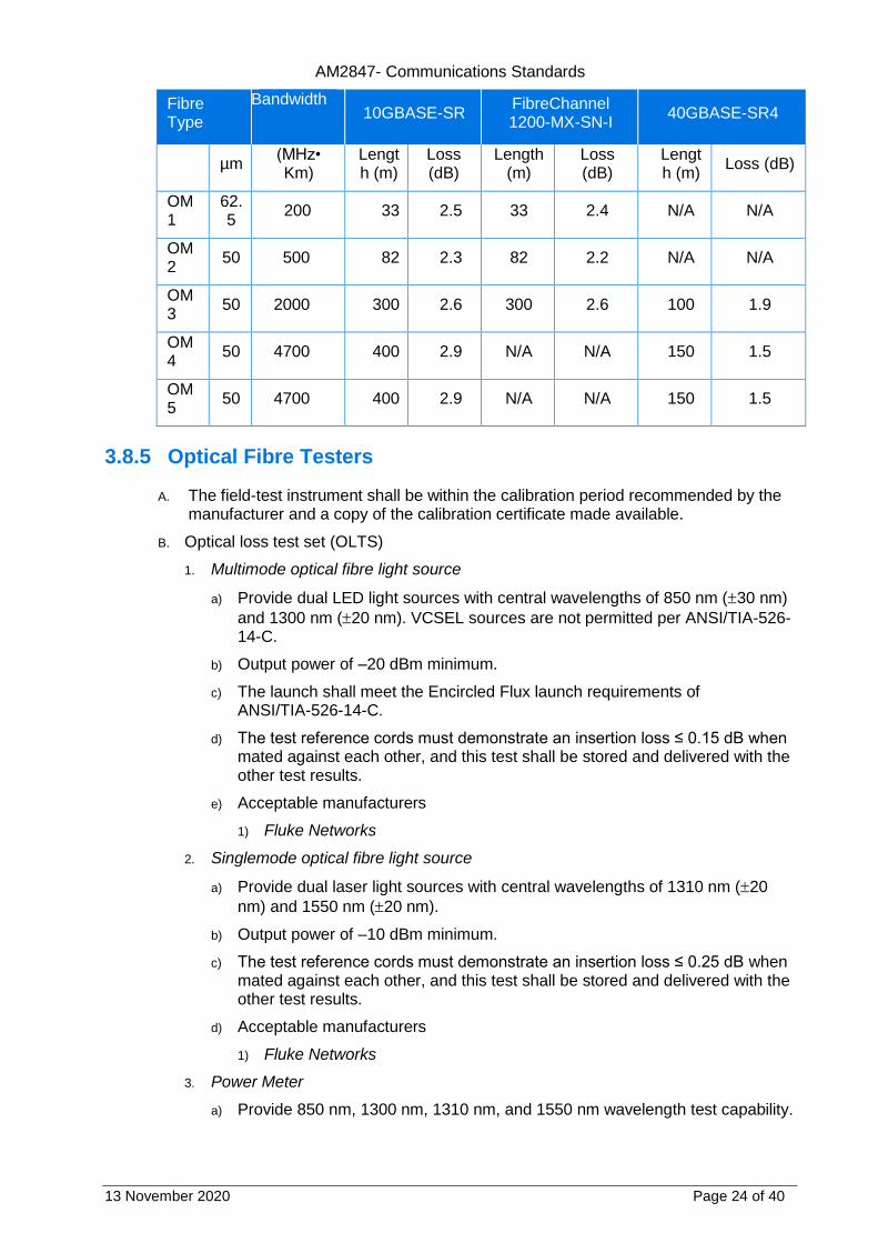
D. Performance specification for multimode fibre links at 850 nm.
AM2847- Communications Standards
13 November 2020 Page 24 of 40
Fibre Type
Bandwidth
10GBASE-SR
FibreChannel 1200-MX-SN-I
40GBASE-SR4
µm (MHz• Km)
Length (m)
Loss (dB)
Length (m)
Loss (dB)
Length (m)
Loss (dB)
OM1
62.5
200 33 2.5 33 2.4 N/A N/A
OM2
50 500 82 2.3 82 2.2 N/A N/A
OM3
50 2000 300 2.6 300 2.6 100 1.9
OM4
50 4700 400 2.9 N/A N/A 150 1.5
OM5
50 4700 400 2.9 N/A N/A 150 1.5
3.8.5 Optical Fibre Testers
A. The field-test instrument shall be within the calibration period recommended by the manufacturer and a copy of the calibration certificate made available.
B. Optical loss test set (OLTS)
1. Multimode optical fibre light source
a) Provide dual LED light sources with central wavelengths of 850 nm (30 nm)
and 1300 nm (20 nm). VCSEL sources are not permitted per ANSI/TIA-526-14-C.
b) Output power of –20 dBm minimum.
c) The launch shall meet the Encircled Flux launch requirements of ANSI/TIA-526-14-C.
d) The test reference cords must demonstrate an insertion loss ≤ 0.15 dB when mated against each other, and this test shall be stored and delivered with the other test results.
e) Acceptable manufacturers
1) Fluke Networks
2. Singlemode optical fibre light source
a) Provide dual laser light sources with central wavelengths of 1310 nm (20
nm) and 1550 nm (20 nm).
b) Output power of –10 dBm minimum.
c) The test reference cords must demonstrate an insertion loss ≤ 0.25 dB when mated against each other, and this test shall be stored and delivered with the other test results.
d) Acceptable manufacturers
1) Fluke Networks
3. Power Meter
a) Provide 850 nm, 1300 nm, 1310 nm, and 1550 nm wavelength test capability.

AM2847- Communications Standards
13 November 2020 Page 25 of 40
b) Power measurement uncertainty of 0.25 dB.
c) Store reference power measurements.
d) Save at least 10,000 results to internal memory.
e) PC interface (USB).
f) Acceptable manufacturers
1) Fluke Networks
4. Optional length measurement
a) It is preferable to use an OLTS that is capable of measuring the optical length of the fibre using time-of-flight techniques.
C. Optical Time Domain Reflectometer (OTDR)
1. Shall have a bright, colour LCD display with backlight.
2. Shall have rechargeable Li-Ion battery for 8 hours of normal operation.
3. Weight with battery and module of not more than 4.5 lb and volume of not more 200 in³.
4. Internal non-volatile memory with capacity for storing at least 2,000 OTDR bi-directionally tested fibre links.
5. USB port to transfer data to a PC or thumb drive/memory stick.
6. Multimode OTDR
a) Wavelengths of 850 nm ( 10 nm) and 1300 nm (+ 35 nm / - 15 nm).
b) Event dead zones not to exceed 0.7 m at 850 nm and 1300 nm.
c) Attenuation dead zones not to exceed 2.5 m at 850 nm and 4.5 m at 1300 nm.
d) Distance range not less than 9,000 m.
e) Dynamic range at least 28 dB for 850 nm and 30 dB at 1300 nm.
f) Allow bi-directional testing without moving the OTDR to the far end.
g) Perform on-board bi-directional averaging.
7. Singlemode OTDR
a) Wavelengths of 1310 nm ( 25 nm) and 1550 nm ( 30 nm).
b) Event dead zones not to exceed 0.6 m at 1310 nm and 1550 nm.
c) Attenuation dead zones not to exceed 3.7 m at 1310 nm and 1550 nm.
d) Distance range not less than 80 km at 1310 nm and 130 km at 1550 nm.
e) Dynamic range at least 32 dB for 1310 nm and 30 dB at 1550 nm.
f) Allow bi-directional testing without moving the OTDR to the far end.
g) Perform on-board bi-directional averaging.
8. Acceptable manufacturers
a) Fluke Networks
D. Fibre Microscope
1. Field of view 420 µm x 320 µm
a) Video camera systems are preferred.

AM2847- Communications Standards
13 November 2020 Page 26 of 40
b) Camera probe tips that permit inspection through adapters are required.
c) Test equipment shall be capable of saving and reporting the end face image to IEC 613003-3-35.
2. Acceptable manufacturers
a) Fluke Networks
E. Integrated OLTS, OTDR and fibre microscope
1. Test equipment that combines into one instrument an OLTS, an OTDR and a fibre microscope may be used.
2. Acceptable manufacturers
a) Fluke Networks
3.8.6 Identification
A. Labels
1. As per South East Water Electrical Equipment and Installation Specification AM2714
3.8.7 Administration
A. Administration of the documentation shall include test results of each fibre link and channel.
B. The test result information for each link shall be recorded in the memory of the field-test instrument upon completion of the test.
C. The test result records saved within the field-test instrument shall be transferred into a Windows™-based and/or cloud-based database utility that allows for the maintenance, inspection and archiving of these test records
3.8.8 General
A. All tests performed on optical fibre cabling that use a laser or LED in a test set shall be carried out with safety precautions in accordance with ANSI Z136.2.
B. All outlets, cables, patch panels and associated components shall be fully assembled and labelled prior to field-testing. Any testing performed on incomplete systems shall be redone on completion of the work.
3.8.9 Optical Fibre Testing
A. Field-test instruments shall have the latest software and firmware installed.
B. Link and channel test results from the OLTS and OTDR shall be recorded in the test instrument upon completion of each test for subsequent uploading to a PC and/or a cloud-based service in which the administrative documentation (reports) may be generated.
C. Fibre end faces shall be inspected using a video scope with a field of view not less than 425 µm x 320 µm.
1. It is preferable that the end face images be recorded in the memory of the test instrument for subsequent uploading to a PC and reporting.

AM2847- Communications Standards
13 November 2020 Page 27 of 40
D. Testing shall be performed on each cabling segment (connector to connector).
E. Testing shall be performed on each cabling channel (equipment to equipment) that is planned for use per the owner’s instructions.
F. Testing of the cabling shall be performed using high-quality test reference cords of the same core size as the cabling under test, terminated with reference grade connectors. Reference grade connectors are defined as having a loss not exceeding 0.1 dB for multimode and 0.2 dB for singlemode. The test reference cords for OLTS testing shall be between 2 m and 5 m in length. The length of the launch and tail fibres for multimode OTDR testing shall be at a least 100 m (328 ft.). For singlemode, the length of the launch and tail fibres will depend on the link under test. As a guide, the following table can be used for determining the length of the launch and tail fibres.
Maximum Length of Link (km) Typical Pulse
Width (ns)
Minimum Launch and Tail Cord
Length (m) 1310 nm 1550 nm only
0 to 35 0 to 50 ≤ 1,000 130
35 to 45 50 to 65 3,000 400
45 to 50 65 to 75 10,000 1,000
≥ 50 ≥ 75 20,000 2400
G. Optical loss testing
1. Horizontal/Backbone link
a) Multimode links shall be tested in one direction at 850 nm and 1300 nm in accordance with ANSI/TIA-526-14-C, one-cord reference method, with an Encircled Flux compliant launch.
b) Singlemode backbone links shall be tested in one direction at 1310 nm and 1550 nm in accordance with ANSI/TIA-526-7-A, Method A.1 (One-cord reference method).
c) Link attenuation does not include any active devices or passive devices other than cable, connectors, and splices, i.e. link attenuation does not include such devices as optical bypass switches, couplers, repeaters, or optical amplifiers.
H. OTDR Testing
1. Fibre links shall be tested at these wavelengths for anomalies and to ensure uniformity of cable attenuation, connector insertion loss and reflectance.
a) Multimode: 850 nm and 1300 nm.
b) Singlemode: 1310 nm and 1550 nm.
2. Each fibre link and channel shall be tested in both directions.
a) The launch and tail fibres shall remain in place for the measurement in the opposite direction – failing to do so will result in an increase in measurement uncertainty.
b) The use of a loop back fibre at the far end with a tail fibre at the near end on the adjacent fibre is permitted for bi-directional testing, so long as the OTDR is able to split the trace automatically into two traces for the two fibres under test.
3. A launch cable shall be installed between the OTDR and the first link connection.
4. A tail cable shall be installed after the last link connection.
AM2847- Communications Standards
13 November 2020 Page 28 of 40
I. Magnified End face Inspection
1. Fibres shall be inspected using a video scope with a minimum field of view 425 µm x 320 µm to IEC 61300-3-35 Edition 1.0. The following test limits shall be used:
a) Multimode connectors; Table 6 of IEC 61300-3-35 Edition 1.0
b) Singlemode field polished connectors; Table 5 of IEC 61300-3-35 Edition 1.0
c) Singlemode factory polished connectors; Table 3 of IEC 61300-3-35 Edition 1.0
d) Angled Physical Contact (APC) connectors; Table 4 of IEC 61300-3-35 Edition 1.0
J. Length Measurement
1. The length of each fibre shall be recorded.
2. It is preferable that the optical length be measured using an OLTS or OTDR.
K. Polarity Testing
1. Paired duplex fibres in multi-fibre cables shall be tested to verify polarity in accordance with Clause E.5.3 of ANSI/TIA-568.3-D. The polarity of the paired duplex fibres shall be verified using an OLTS.
3.8.10 Identification
A. Labelling
1. Labelling shall conform to the requirements specified by the South East Water AM2714_Electrical Standards
3.8.11 Administration
A. Test results documentation
1. Test results saved within the field-test instrument shall be transferred into a Windows™-based and/or cloud-based database utility that allows for the maintenance, inspection and archiving of the test records. These test records shall be uploaded to the PC or cloud unaltered, i.e., “as saved in the field-test instrument”. The following formats do not provide adequate protection of these records and shall not be used.
a) Portable document format (PDF)
b) Word (.doc & .docx)
c) Comma separated values (.csv)
d) Excel separated values (.xls & .xlsx)
e) Text (.txt)
2. The test results documentation shall be available for inspection by South East Water or their representative during the installation period and shall be passed to the South East Water or their representative within 5 working days of completion of tests on cabling served by a telecommunications room or of backbone cabling. The installer shall retain a copy to aid preparation of as-built information.
3. The database for the complete project, including twisted-pair copper cabling links, if applicable, shall be stored and delivered in an electronic format, prior to Owner acceptance of the building in the original format used by the cabling vendors’ software.

AM2847- Communications Standards
13 November 2020 Page 29 of 40
4. Circuit IDs reported by the test instrument should match the specified label ID (see of this Section).
5. The detailed test results documentation data is to be provided in an electronic database for each tested optical fibre and shall contain the following information
a) The identification of the customer site as specified by the end-user.
b) The name of the test limit selected to execute the stored test results.
c) The name of the personnel performing the test.
d) The date and time the test results were saved in the memory of the tester.
e) The manufacturer, model and serial number of the field-test instrument.
f) The version of the test software and the version of the test limit database held within the test instrument.
g) The fibre identification number.
h) The length for each optical fibre.
i) The index of refraction used for length calculation when using length capable OLTS.
j) The backscatter coefficient of the fibre under test when using an OTDR.
k) Test results to include OLTS attenuation link and channel measurements at the appropriate wavelength(s) and the margin (difference between the measured attenuation and the test limit value).
l) Test results to include OTDR link and channel traces, event tables at the appropriate wavelength(s) and a map of the link tested.
m) The length for each optical fibre as calculated by the OTDR.
n) The overall Pass/Fail evaluation of the link-under-test for OLTS and OTDR measurements
o) Optional
1) A picture or image of each fibre end-face
2) A pass/fail status of the end-face using IEC 61300-3-35 Edition 1.0
B. Record copy and as-built drawings
1. Provide record copy drawings periodically throughout the project as requested by the South East Water Project Manager, and at end of the project in format as specified in South East Water Electrical Equipment and Installation Specification AM2714.
3.9 Copper CAT 6 Testing
3.9.1 Minimum Requirements
A. This Section includes the minimum requirements for the test certification, identification and administration of horizontal balanced twisted pair cabling.
B. This Section includes minimum requirements for:
1. Copper cabling test instruments
2. Copper cabling testing
3. Identification

AM2847- Communications Standards
13 November 2020 Page 30 of 40
a) Labels and labelling
4. Administration
a) Test results documentation
b) As-built drawings
C. Testing shall be carried out in accordance with this document.
D. Testing shall be performed on each cabling link. (100% testing)
E. All tests shall be documented.
3.9.2 Quality Assurance
A. All testing procedures and field-test instruments shall comply with applicable requirements of:
1. ANSI/TIA-1152, Requirements for Field Test Instruments and Measurements for Balanced Twisted-Pair Cabling
2. ANSI/TIA-568-C.0, Generic Telecommunications Cabling for Customer Premises.
3. ANSI/TIA-568-C.1, Commercial Building Telecommunications Cabling Standard
4. ANSI/TIA-568-C.2, Balanced Twisted-Pair Telecommunications Cabling and Components Standards.
5. ANSI/TIA-606-B, Administration Standard for Commercial Telecommunications Infrastructure, including the requirements specified by the customer, unless the customer specifies their own labelling requirements.
B. Trained technicians who have successfully attended an appropriate training program and have obtained a certificate as proof thereof shall execute the tests. These certificates may have been issued by any of the following organizations or an equivalent organization:
1. Manufacturer of the connectors or cable.
2. Manufacturer of the test equipment used for the field certification.
3. Training organizations.
C. The South East Water or their representative shall be invited to witness and/or review field-testing.
1. South East Water or their representative shall be notified of the start date of the testing phase five (5) business days before testing commences.
2. South East Water or their representative will select a random sample of 5% of the installed links. South East Water or their representative shall test these randomly selected links and the results are to be stored in accordance with Part 3 of this document. The results obtained shall be compared to the data provided by the installation contractor. If more than 2% of the sample results differ in terms of the pass/fail determination, the installation contractor under supervision of the representative shall repeat 100% testing at no cost to the Owner.
3.9.3 Submittals
A. Manufacturers catalogue sheets and specifications for the test equipment.
B. A schedule (list) of all balanced twisted-pair copper links to be tested.
C. Sample test reports.

AM2847- Communications Standards
13 November 2020 Page 31 of 40
3.9.4 Acceptance of Test Results
A. Unless otherwise specified by the Owner or the Owners representative, each cabling link shall be tested for:
1. Wire Map
2. Length
3. Propagation Delay
4. Delay Skew
5. DC Loop Resistance – recorded for information only
6. DC Resistance Unbalance – recorded for information only
7. Insertion Loss
8. NEXT (Near-End Crosstalk)
9. PS NEXT (Power Sum Near-End Crosstalk)
10. ACR-N (Attenuation to Crosstalk Ratio Near-End) – recorded for information only
11. PS ACR-N (Power Sum Attenuation to Crosstalk Ratio Near-End) – recorded for information only
12. ACR-F (Attenuation to Crosstalk Ratio Far-End)
13. PS ACR-F (Power Sum Attenuation to Crosstalk Ratio Far-End)
14. Return Loss
15. TCL (Transverse Conversion Loss) – recorded for information only
16. ELTCTL (Equal Level Transverse Conversion Transfer Loss) – recorded for information only
B. All installed cabling Permanent Links shall be field-tested and pass the test requirements and analysis as described in Part 3. Any Permanent Link that fails these requirements shall be diagnosed and corrected. Any corrective action that must take place shall be documented and followed with a new test to prove that the corrected Permanent Link meets performance requirements. The final and passing result of the tests for all Permanent Links shall be provided in the test results documentation in accordance with Part 3.
C. Acceptance of the test results shall be given in writing after the project is fully completed and tested in accordance with Contract Documents and to the satisfaction of South East Water or their representative.
3.9.5 Balanced Twisted Pair Cable Testers
A. The field-test instrument shall be within the calibration period recommended by the manufacturer, typically 12 months.
B. Certification tester
1. Accuracy
a) Level III accuracy in accordance with ANSI/TIA-1152
b) Independent verification of accuracy
2. Permanent Link Adapters
a) RJ45 plug must meet the requirements for NEXT, FEXT and Return Loss in accordance with ANSI/TIA-568-C.2 Annex C

AM2847- Communications Standards
13 November 2020 Page 32 of 40
b) Twisted pair Category 5e, 6, 6A, 7 or 7A cords are not permitted as their performance degrades with use and can cause false Return Loss failures
3. Results Storage
a) Must be capable of storing > 10,000 results for all measurements found in 2.1.B.4 below
4. Measurement capabilities
a) Wire Map
b) Length
c) Propagation Delay
d) Delay Skew
e) DC Loop Resistance
f) DC Resistance Unbalance
g) Insertion Loss
h) NEXT (Near-End Crosstalk)
i) PS NEXT (Power Sum Near-End Crosstalk)
j) ACR-N (Attenuation to Crosstalk Ratio Near-End)
k) PS ACR-N (Power Sum Attenuation to Crosstalk Ratio Near-End)
l) ACR-F (Attenuation to Crosstalk Ratio Far-End)
m) PS ACR-F (Power Sum Attenuation to Crosstalk Ratio Far-End)
n) Return Loss
o) TCL (Transverse Conversion Loss)
p) ELTCTL (Equal Level Transverse Conversion Transfer Loss)
q) Time Domain Reflectometer
r) Time Domain Xtalk Analyzer
C. PC Software
1. Windows® based.
2. Must show when 3 dB and 4 dB rules are applied
3. Re-certification capability, where results must have their Cable IDs suffixed with (RC).
4. Built in PDF export – no additional third party software permitted.
5. Built-in statistical analysis.
3.9.6 Identification
A. Labels
1. As per AM2714_Electrical Standards.
3.9.7 Administration
A. Administration of the documentation shall include test results of each Permanent Link.

AM2847- Communications Standards
13 November 2020 Page 33 of 40
B. The test result information for each link shall be recorded in the memory of the field-test instrument upon completion of the test.
C. The test result records saved within the field-test instrument shall be transferred into a Windows® -based database utility that allows for the maintenance, inspection and archiving of these test records.
3.9.8 General
A. All outlets, cables, patch panels and associated components shall be fully assembled and labelled prior to field-testing. Any testing performed on incomplete systems shall be redone on completion of the work.
3.9.9 Balanced Twisted Pair Cable Testing
A. Field-test instruments shall have the latest software and firmware installed.
B. Permanent Link test results including the individual frequency measurements from the tester shall be recorded in the test instrument upon completion of each test for subsequent uploading to a PC in which the administrative documentation (reports) may be generated.
C. Testing shall be performed on each cabling segment (connector to connector). Sampling is not acceptable.
D. Permanent Link adapters made from twisted pair Category 5e, 6, 6A, 7 or 7A cords are not permitted as their performance degrades with use and can cause false Return Loss failures.
E. The installer shall build a reference link. All components shall be anchored so it is not possible to disturb them. The technician is to conduct a Category 6 Permanent Link test each day before use to ensure no degradation of the tester or its Permanent Link adapters.
F. Wire Map Measurement
1. The wire map test is intended to verify pin-to-pin termination at each end and check for installation connectivity errors. For each of the 8 conductors in the cabling, the wire map indicates:
a) Continuity to the remote end
b) Shorts between any two or more conductors
c) Reversed pairs
d) Split pairs
e) Transposed pairs
f) Distance to open on shield
g) Any other miss-wiring
2. The correct connectivity of telecommunications outlets/connectors is defined in ANSI/TIA-568-C.2. T568A scheme is to be used. The field tester shall document colour scheme used. Examples are given below:

AM2847- Communications Standards
13 November 2020 Page 34 of 40
G. Length Measurement
1. The length of each balanced twisted pair shall be recorded.
2. Since physical length is determined from electrical length, the physical length of the link calculated using the pair with the shortest electrical delay shall be reported and used for making the pass or fail determination.
3. The pass or fail criteria is based on the maximum length allowed for the Permanent Link as specified in ANSI/TIA-568-C.2 plus the nominal velocity of propagation (NVP) uncertainty of 10%. For a Permanent Link, the length measurement can be 325 ft. (99 m) before a fail is reported.
H. Propagation Delay measurement
1. Is the time it takes for a signal to reach the end of the link.
2. The measurement shall be made at 10 MHz per ANSI/TIA-1152.
3. The propagation delay of each balanced twisted pair shall be recorded.
4. Is not to exceed 498 ns per ANSI/TIA-568-C.2 Section 6.3.18.
I. Delay Skew measurement
1. Is the difference in propagation delay @ 10 MHz between the shortest delay and the delays of the other wire pairs.
2. The delay skew of each balanced twisted pair shall be recorded.
3. Is not to exceed 44 ns per ANSI/TIA-568-C.2 Section 6.3.19.
J. DC Resistance
1. Often reported as Resistance, is the loop resistance of both conductors in the pair.
2. Is not specified in ANSI/TIA-1152, but shall be recorded for all four pairs.
K. DC Resistance Unbalance
1. Often reported as Resistance Unbalance, is the difference in resistance of the two wires within the pair.

AM2847- Communications Standards
13 November 2020 Page 35 of 40
2. Is not specified in ANSI/TIA-1152 for a Permanent Link, but shall be recorded for all four pairs.
L. Insertion Loss
1. Is the loss of signal strength over the cabling (in dB).
2. The frequency resolution shall be:
a) 1 – 31.25 MHz: 150 kHz
b) 31.25 – 100 MHz: 250 kHz
c) 100 – 250 MHz: 500 kHz
3. Worst case shall be reported for all four pairs in one direction only.
4. Reported margins found to be within the accuracy of the field tester shall be marked with an asterisk (*).
5. Is not to exceed the Category 6 Permanent Link limits found in ANSI/TIA-568-C.2 Section 6.3.7.
M. NEXT (Near-End Crosstalk)
1. Is the difference in amplitude (in dB) between a transmitted signal and the crosstalk received on other wire pairs at the same end of the cabling.
2. The frequency resolution shall be:
a) 1 – 31.25 MHz: 150 kHz
b) 31.25 – 100 MHz: 250 kHz
c) 100 – 250 MHz: 500 kHz
3. Shall be measured in both directions. (12 pair to pair possible combinations)
4. Both worst case and worst margins shall be reported.
5. Is not to exceed the Category 6 Permanent Link limits found in ANSI/TIA-568-C.2 Section 6.3.8.
6. Reported margins found to be within the accuracy of the field tester shall be marked with an asterisk (*).
7. The Time Domain Xtalk data shall be stored for any marginal or failing NEXT results.
N. PS NEXT (Power Sum Near-End Crosstalk)
1. Is the difference (in dB) between the test signal and the crosstalk from the other pairs received at the same end of the cabling.
2. The frequency resolution shall be:
a) 1 – 31.25 MHz: 150 kHz
b) 31.25 – 100 MHz: 250 kHz
c) 100 – 250 MHz: 500 kHz
3. Shall be measured in both directions. (8 pair possible combinations)
4. Both worst case and worst margins shall be reported.
5. Is not to exceed the Category 6 Permanent Link limits found in ANSI/TIA-568-C.2 Section 6.3.9.
6. Reported margins found to be within the accuracy of the field tester shall be marked with an asterisk (*).

AM2847- Communications Standards
13 November 2020 Page 36 of 40
7. The Time Domain Xtalk data shall be stored for any marginal or failing PS NEXT results.
O. ACR-N (Attenuation Crosstalk Ratio Near-End)
1. Is a calculation of NEXT minus Insertion Loss of the disturbed pair in dB.
2. The frequency resolution shall be:
a) 1 – 31.25 MHz: 150 kHz
b) 31.25 – 100 MHz: 250 kHz
c) 100 – 250 MHz: 500 kHz
3. Shall be calculated in both directions.
4. Is not specified in ANSI/TIA-1152, but shall be recorded for all 12 possible combinations.
P. PS ACR-N (Power Sum Attenuation Crosstalk Ratio Near-End)
1. Is a calculation of PS NEXT minus Insertion Loss of the disturbed pair in dB.
2. The frequency resolution shall be:
a) 1 – 31.25 MHz: 150 kHz
b) 31.25 – 100 MHz: 250 kHz
c) 100 – 250 MHz: 500 kHz
3. Shall be calculated in both directions.
4. Is not specified in ANSI/TIA-1152, but shall be recorded for all 8 possible combinations.
Q. ACR-F (Attenuation Crosstalk Ratio Far-End)
1. Is a calculation of FEXT minus Insertion Loss of the disturbed pair in dB.
2. The frequency resolution shall be:
a) 1 – 31.25 MHz: 150 kHz
b) 31.25 – 100 MHz: 250 kHz
c) 100 – 250 MHz: 500 kHz
3. Shall be measured in both directions. (24 pair to pair possible combinations)
4. Both worst case and worst margins shall be reported.
5. Is not to exceed the Category 6 Permanent Link limits found in ANSI/TIA-568-C.2 Section 6.3.11.
6. Reported margins found to be within the accuracy of the field tester shall be marked with an asterisk (*).
R. PS ACR-F (Power Sum Attenuation Crosstalk Ratio Far-End)
1. Is a calculation of PS FEXT minus Insertion Loss of the disturbed pair in dB.
2. The frequency resolution shall be:
a) 1 – 31.25 MHz: 150 kHz
b) 31.25 – 100 MHz: 250 kHz
c) 100 – 250 MHz: 500 kHz
3. Shall be measured in both directions. (8 pair possible combinations)
4. Both worst case and worst margins shall be reported.

AM2847- Communications Standards
13 November 2020 Page 37 of 40
5. Is not to exceed the Category 6 Permanent Link limits found in ANSI/TIA-568-C.2 Section 6.3.13.
6. Reported margins found to be within the accuracy of the field tester shall be marked with an asterisk (*).
S. Return Loss
1. Is the difference (in dB) between the power of a transmitted signal and the power of the signals reflected back.
2. The frequency resolution shall be:
a) 1 – 31.25 MHz: 150 kHz
b) 31.25 – 100 MHz: 250 kHz
c) 100 – 250 MHz: 500 kHz
3. Shall be measured in both directions. (8 pair possible combinations)
4. Both worst case and worst margins shall be reported.
5. Shall be ignored at all frequencies where the Insertion Loss is less than 3 dB for that pair.
6. Is not to exceed the Category 6 Permanent Link limits found in ANSI/TIA-568-C.2 Section 6.3.6.
7. Reported margins found to be within the accuracy of the field tester shall be marked with an asterisk (*).
8. The Time Domain Reflectometer data shall be stored for any marginal or failing Return Loss results.
T. TCL (Transverse Conversion Loss)
1. Is the ratio (in dB) between a differential mode signal inject at the near-end and the common-mode signal measured at the near-end on the same wire pair.
2. The frequency resolution shall be:
a) 1 – 31.25 MHz: 150 kHz
b) 31.25 – 100 MHz: 250 kHz
c) 100 – 250 MHz: 500 kHz
3. Shall be measured in both directions.
4. Is not specified in ANSI/TIA-1152 for a Permanent Link, but shall be recorded for all 8 possible combinations.
U. ELTCTL (Equal Level Transverse Conversion Transfer Loss)
1. Is the ratio (in dB) between a differential mode signal inject at the near-end and the common-mode signal measured at the far end on the same wire pair minus the Insertion Loss of that pair.
2. The frequency resolution shall be:
a) 1 – 31.25 MHz: 150 kHz
b) 31.25 – 100 MHz: 250 kHz
c) 100 – 250 MHz: 500 kHz
3. Shall be measured in both directions.
4. Is not specified in ANSI/TIA-1152 for a Permanent Link, but shall be recorded for all 8 possible combinations.

AM2847- Communications Standards
13 November 2020 Page 38 of 40
3.9.10 Administration
A. Test results documentation
1. Test results saved within the field-test instrument shall be transferred into a Windows™-based database utility that allows for the maintenance, inspection and archiving of the test records. These test records shall be uploaded to the PC unaltered, i.e., “as saved in the field-test instrument”. The file format, CSV (comma separated value), does not provide adequate protection of these records and shall not be used.
2. The test results documentation shall be available for inspection by South East Water or their representative during the installation period and shall be passed to the Owner's representative within 5 working days of completion of tests. The installer shall retain a copy to aid preparation of as-built information.
3. The database for the complete project, including twisted-pair copper cabling links, if applicable, shall be stored and delivered in electronic format prior to South East Water acceptance. This electronic format media shall include the software tools required to view, inspect, and print any selection of the test reports.
4. Circuit IDs reported by the test instrument should match the specified label ID.
5. The detailed test results documentation data is to be provided in an electronic database for each tested balance twisted-pair and shall contain the following information
a) The overall Pass/Fail evaluation of the link-under-test
b) The date and time the test results were saved in the memory of the tester
c) The identification of the customer site as specified by the end-user
d) The name of the test limit selected to execute the stored test results
e) The name of the personnel performing the test
f) The version of the test software and the version of the test limit database held within the test instrument
g) The manufacturer, model and serial number of the field-test instrument
h) The adapters used
i) The factory calibration date
j) Wire Map
k) Propagation Delay values, for all four pairs
l) Delay Skew values, for all four pairs
m) DC Resistance values, for all four pairs
n) DC Resistance Unbalance, values for all four pairs
o) Insertion Loss, worst case values for all four pairs
p) NEXT, worst case margin and worst case values, both directions
q) PS NEXT, worst case margin and worst case values, both directions
r) ACR-F, worst case margin and worst case values, both directions
s) PS ACR-F, worst case margin and worst case values, both directions
t) Return Loss, worst case margin and worst case values, both directions

AM2847- Communications Standards
13 November 2020 Page 39 of 40
u) TCL, worst case values both directions
v) ELTCTL, worst case values, both directions.
w) Time Domain Crosstalk data if the link is marginal or fails
x) Time Domain Reflectometer data if the link is marginal or fails