
Altivar Process 900 - PROFINET Manual - VW3A3627 -...
126
NHA80943.01 www.schneider-electric.com Altivar Process 900 NHA80943 07/2015 Altivar Process 900 PROFINET Manual - VW3A3627 07/2015
Transcript of Altivar Process 900 - PROFINET Manual - VW3A3627 -...

Altivar Process 900
NHA80943 07/2015
NH
A80
943.
01
www.schneider-electric.com
Altivar Process 900PROFINET Manual - VW3A3627
07/2015

The information provided in this documentation contains general descriptions and/or technical character-istics of the performance of the products contained herein. This documentation is not intended as a substitute for and is not to be used for determining suitability or reliability of these products for specific user applications. It is the duty of any such user or integrator to perform the appropriate and complete risk analysis, evaluation and testing of the products with respect to the relevant specific application or use thereof. Neither Schneider Electric nor any of its affiliates or subsidiaries shall be responsible or liable for misuse of the information contained herein. If you have any suggestions for improvements or amendments or have found errors in this publication, please notify us.
No part of this document may be reproduced in any form or by any means, electronic or mechanical, including photocopying, without express written permission of Schneider Electric.
All pertinent state, regional, and local safety regulations must be observed when installing and using this product. For reasons of safety and to help ensure compliance with documented system data, only the manufacturer should perform repairs to components.
When devices are used for applications with technical safety requirements, the relevant instructions must be followed.
Failure to use Schneider Electric software or approved software with our hardware products may result in injury, harm, or improper operating results.
Failure to observe this information can result in injury or equipment damage.
© 2015 Schneider Electric. All rights reserved.
2 NHA80943 07/2015

Table of Contents
Safety Information . . . . . . . . . . . . . . . . . . . . . . . . . . . . . . . . . . . . . . . . . . . 5About the Book. . . . . . . . . . . . . . . . . . . . . . . . . . . . . . . . . . . . . . . . . . . . . . 9
Chapter 1 Presentation . . . . . . . . . . . . . . . . . . . . . . . . . . . . . . . . . . . . . . . . . . . . . . . . 13Hardware Overview . . . . . . . . . . . . . . . . . . . . . . . . . . . . . . . . . . . . . . . . . . . . . . . . . . . . . . . . 14Software Overview . . . . . . . . . . . . . . . . . . . . . . . . . . . . . . . . . . . . . . . . . . . . . . . . . . . . . . . . 15
Chapter 2 Basics . . . . . . . . . . . . . . . . . . . . . . . . . . . . . . . . . . . . . . . . . . . . . . . . . . . . . 172.1 Introduction . . . . . . . . . . . . . . . . . . . . . . . . . . . . . . . . . . . . . . . . . . . . . . . . . . . . . . . . . . . . . . 18
Introduction . . . . . . . . . . . . . . . . . . . . . . . . . . . . . . . . . . . . . . . . . . . . . . . . . . . . . . . . . . . . . . 182.2 Common Additional Features . . . . . . . . . . . . . . . . . . . . . . . . . . . . . . . . . . . . . . . . . . . . . . . . 19
Identification and Maintenance Data . . . . . . . . . . . . . . . . . . . . . . . . . . . . . . . . . . . . . . . . . . . 20I&M Record . . . . . . . . . . . . . . . . . . . . . . . . . . . . . . . . . . . . . . . . . . . . . . . . . . . . . . . . . . . . . . 21
2.3 PROFIdrive Parameters Channel . . . . . . . . . . . . . . . . . . . . . . . . . . . . . . . . . . . . . . . . . . . . . 22PROFIdrive Profile. . . . . . . . . . . . . . . . . . . . . . . . . . . . . . . . . . . . . . . . . . . . . . . . . . . . . . . . . 23Parameter Structure . . . . . . . . . . . . . . . . . . . . . . . . . . . . . . . . . . . . . . . . . . . . . . . . . . . . . . . 24PROFIdrive Parameters . . . . . . . . . . . . . . . . . . . . . . . . . . . . . . . . . . . . . . . . . . . . . . . . . . . . 25PROFIdrive Parameter Access . . . . . . . . . . . . . . . . . . . . . . . . . . . . . . . . . . . . . . . . . . . . . . . 26
2.4 iPar Service . . . . . . . . . . . . . . . . . . . . . . . . . . . . . . . . . . . . . . . . . . . . . . . . . . . . . . . . . . . . . . 28iPar Service . . . . . . . . . . . . . . . . . . . . . . . . . . . . . . . . . . . . . . . . . . . . . . . . . . . . . . . . . . . . . . 28
Chapter 3 Hardware Setup . . . . . . . . . . . . . . . . . . . . . . . . . . . . . . . . . . . . . . . . . . . . . 31Hardware Presentation . . . . . . . . . . . . . . . . . . . . . . . . . . . . . . . . . . . . . . . . . . . . . . . . . . . . . 32Firmware and Description File. . . . . . . . . . . . . . . . . . . . . . . . . . . . . . . . . . . . . . . . . . . . . . . . 33Installation of the Module. . . . . . . . . . . . . . . . . . . . . . . . . . . . . . . . . . . . . . . . . . . . . . . . . . . . 34Electrical Installation . . . . . . . . . . . . . . . . . . . . . . . . . . . . . . . . . . . . . . . . . . . . . . . . . . . . . . . 35Cable Routing Practices . . . . . . . . . . . . . . . . . . . . . . . . . . . . . . . . . . . . . . . . . . . . . . . . . . . . 36
Chapter 4 Software Setup . . . . . . . . . . . . . . . . . . . . . . . . . . . . . . . . . . . . . . . . . . . . . . 374.1 Basic Settings . . . . . . . . . . . . . . . . . . . . . . . . . . . . . . . . . . . . . . . . . . . . . . . . . . . . . . . . . . . . 38
Introduction . . . . . . . . . . . . . . . . . . . . . . . . . . . . . . . . . . . . . . . . . . . . . . . . . . . . . . . . . . . . . . 39[DEVICE NAME] (PAn-) . . . . . . . . . . . . . . . . . . . . . . . . . . . . . . . . . . . . . . . . . . . . . . . . . . 40[IP mode] (IpM) . . . . . . . . . . . . . . . . . . . . . . . . . . . . . . . . . . . . . . . . . . . . . . . . . . . . . . . . . 41[IP Module] (IPC) (IPC1) (IPC2) (IPC3) (IPC4) . . . . . . . . . . . . . . . . . . . . . . . 42[IP Mask] (IPM) (IPM1) (IPM2) (IPM3) (IPM4) . . . . . . . . . . . . . . . . . . . . . . . . . 43[IP Gate] (IPG) (IPG1) (IPG2) (IPG3) (IPG4) . . . . . . . . . . . . . . . . . . . . . . . . . 44[Actual IP] ( ) ( ) ( ) ( )IPA1 IPA2 IPA3 IPA4 . . . . . . . . . . . . . . . . . . . . . . . . . . . 45[Actual mask] ( ) ( ) ( ) ( )IPS1 IPS2 IPS3 IPS4 . . . . . . . . . . . . . . . . . . . . . . . . 46[Actual gate.] ( ) ( ) ( ) ( )IPt1 IPt2 IPt3 IPt4 . . . . . . . . . . . . . . . . . . . . . . . 47[Ethernet Error Code] (Err) . . . . . . . . . . . . . . . . . . . . . . . . . . . . . . . . . . . . . . . . . . . . . . . 48[EnableWebserver] (EWE) . . . . . . . . . . . . . . . . . . . . . . . . . . . . . . . . . . . . . . . . . . . . . . . . . 49[PPO profile used] (PrFL) . . . . . . . . . . . . . . . . . . . . . . . . . . . . . . . . . . . . . . . . . . . . . . . . 50[MAC @] (MAC). . . . . . . . . . . . . . . . . . . . . . . . . . . . . . . . . . . . . . . . . . . . . . . . . . . . . . . . . . 51IP Parameter Settings . . . . . . . . . . . . . . . . . . . . . . . . . . . . . . . . . . . . . . . . . . . . . . . . . . . . . . 52
4.2 Additional Settings. . . . . . . . . . . . . . . . . . . . . . . . . . . . . . . . . . . . . . . . . . . . . . . . . . . . . . . . . 53Introduction . . . . . . . . . . . . . . . . . . . . . . . . . . . . . . . . . . . . . . . . . . . . . . . . . . . . . . . . . . . . . . 54[iPar Activation](IPAU) . . . . . . . . . . . . . . . . . . . . . . . . . . . . . . . . . . . . . . . . . . . . . . . . . . 55[iPar Autosave Act] (IPAS) . . . . . . . . . . . . . . . . . . . . . . . . . . . . . . . . . . . . . . . . . . . . . . . 56[iPar Autosave Timer] (IPAt) . . . . . . . . . . . . . . . . . . . . . . . . . . . . . . . . . . . . . . . . . . . . . 57[iPar Error Response] (IPAF) . . . . . . . . . . . . . . . . . . . . . . . . . . . . . . . . . . . . . . . . . . . . . 58[iPar Local Conf] (ICFG) . . . . . . . . . . . . . . . . . . . . . . . . . . . . . . . . . . . . . . . . . . . . . . . . . 59[iPar Status] (IPAE) . . . . . . . . . . . . . . . . . . . . . . . . . . . . . . . . . . . . . . . . . . . . . . . . . . . . . 60[iPar Error Code] (IPAd) . . . . . . . . . . . . . . . . . . . . . . . . . . . . . . . . . . . . . . . . . . . . . . . . . 61
NHA80943 07/2015 3

4.3 Embedded Web Server . . . . . . . . . . . . . . . . . . . . . . . . . . . . . . . . . . . . . . . . . . . . . . . . . . . . . 62Embedded Web Server . . . . . . . . . . . . . . . . . . . . . . . . . . . . . . . . . . . . . . . . . . . . . . . . . . . . . 63Home Page . . . . . . . . . . . . . . . . . . . . . . . . . . . . . . . . . . . . . . . . . . . . . . . . . . . . . . . . . . . . . . 64Display . . . . . . . . . . . . . . . . . . . . . . . . . . . . . . . . . . . . . . . . . . . . . . . . . . . . . . . . . . . . . . . . . . 65Network Setup . . . . . . . . . . . . . . . . . . . . . . . . . . . . . . . . . . . . . . . . . . . . . . . . . . . . . . . . . . . . 68Diagnostics. . . . . . . . . . . . . . . . . . . . . . . . . . . . . . . . . . . . . . . . . . . . . . . . . . . . . . . . . . . . . . . 70
4.4 Communication Profile . . . . . . . . . . . . . . . . . . . . . . . . . . . . . . . . . . . . . . . . . . . . . . . . . . . . . . 71Definition of a Profile . . . . . . . . . . . . . . . . . . . . . . . . . . . . . . . . . . . . . . . . . . . . . . . . . . . . . . . 72Functional Profiles Supported by the Drive . . . . . . . . . . . . . . . . . . . . . . . . . . . . . . . . . . . . . . 73Functional Description . . . . . . . . . . . . . . . . . . . . . . . . . . . . . . . . . . . . . . . . . . . . . . . . . . . . . . 74CIA402 Operating State Diagram . . . . . . . . . . . . . . . . . . . . . . . . . . . . . . . . . . . . . . . . . . . . . 75Description of Operating States . . . . . . . . . . . . . . . . . . . . . . . . . . . . . . . . . . . . . . . . . . . . . . . 76Summary . . . . . . . . . . . . . . . . . . . . . . . . . . . . . . . . . . . . . . . . . . . . . . . . . . . . . . . . . . . . . . . . 78Cmd Register ( )CMd . . . . . . . . . . . . . . . . . . . . . . . . . . . . . . . . . . . . . . . . . . . . . . . . . . . . . . 79Stop Commands . . . . . . . . . . . . . . . . . . . . . . . . . . . . . . . . . . . . . . . . . . . . . . . . . . . . . . . . . . 80Assigning Control Word Bits . . . . . . . . . . . . . . . . . . . . . . . . . . . . . . . . . . . . . . . . . . . . . . . . . 81[CIA402 State Reg] ( )EtA . . . . . . . . . . . . . . . . . . . . . . . . . . . . . . . . . . . . . . . . . . . . . . . . . 82Starting Sequence . . . . . . . . . . . . . . . . . . . . . . . . . . . . . . . . . . . . . . . . . . . . . . . . . . . . . . . . . 83Sequence for a Drive Powered by the Power Stage Supply . . . . . . . . . . . . . . . . . . . . . . . . . 84Sequence for a Drive with Separate Control Stage . . . . . . . . . . . . . . . . . . . . . . . . . . . . . . . . 85Sequence for a Drive with Mains Contactor Control . . . . . . . . . . . . . . . . . . . . . . . . . . . . . . . 87Telegram 100, 101, 102, 106, 107 . . . . . . . . . . . . . . . . . . . . . . . . . . . . . . . . . . . . . . . . . . . . . 88Configuring Drive with a Siemens© S7-300. . . . . . . . . . . . . . . . . . . . . . . . . . . . . . . . . . . . . . 91Configuration of Drive with the Telegram 100 . . . . . . . . . . . . . . . . . . . . . . . . . . . . . . . . . . . . 92Configuring a Drive with the Telegram 101, 102, 106, or 107 . . . . . . . . . . . . . . . . . . . . . . . . 93Parameters Management with the Telegram 100, 101, 102, 106, 107 . . . . . . . . . . . . . . . . . 94Telegram 1 . . . . . . . . . . . . . . . . . . . . . . . . . . . . . . . . . . . . . . . . . . . . . . . . . . . . . . . . . . . . . . . 95State Diagram . . . . . . . . . . . . . . . . . . . . . . . . . . . . . . . . . . . . . . . . . . . . . . . . . . . . . . . . . . . . 96Command Word and Operating State Word . . . . . . . . . . . . . . . . . . . . . . . . . . . . . . . . . . . . . 97Reference Frequency. . . . . . . . . . . . . . . . . . . . . . . . . . . . . . . . . . . . . . . . . . . . . . . . . . . . . . . 100
4.5 Fieldbus Integration Tutorial. . . . . . . . . . . . . . . . . . . . . . . . . . . . . . . . . . . . . . . . . . . . . . . . . . 101Fieldbus Integration Tutorial. . . . . . . . . . . . . . . . . . . . . . . . . . . . . . . . . . . . . . . . . . . . . . . . . . 101
Chapter 5 Operation . . . . . . . . . . . . . . . . . . . . . . . . . . . . . . . . . . . . . . . . . . . . . . . . . . 1055.1 Operating States . . . . . . . . . . . . . . . . . . . . . . . . . . . . . . . . . . . . . . . . . . . . . . . . . . . . . . . . . . 106
Configuring Communication Error Response. . . . . . . . . . . . . . . . . . . . . . . . . . . . . . . . . . . . . 1065.2 Operating Modes . . . . . . . . . . . . . . . . . . . . . . . . . . . . . . . . . . . . . . . . . . . . . . . . . . . . . . . . . . 107
Configuring the Control Channel . . . . . . . . . . . . . . . . . . . . . . . . . . . . . . . . . . . . . . . . . . . . . . 108Configuration of the Drive for Operation in I/O Profile . . . . . . . . . . . . . . . . . . . . . . . . . . . . . . 109Configuration of the Drive for Operation with CiA 402 Profile in Combined Mode. . . . . . . . . 110Configuration of the Drive for Operation with CiA 402 Profile in Separate Mode. . . . . . . . . . 111
Chapter 6 Diagnostic and Troubleshooting . . . . . . . . . . . . . . . . . . . . . . . . . . . . . . . 113Fieldbus Status LEDs. . . . . . . . . . . . . . . . . . . . . . . . . . . . . . . . . . . . . . . . . . . . . . . . . . . . . . . 114Connection for Fieldbus Mode . . . . . . . . . . . . . . . . . . . . . . . . . . . . . . . . . . . . . . . . . . . . . . . . 116Fieldbus Function Test. . . . . . . . . . . . . . . . . . . . . . . . . . . . . . . . . . . . . . . . . . . . . . . . . . . . . . 117Communication Interruption . . . . . . . . . . . . . . . . . . . . . . . . . . . . . . . . . . . . . . . . . . . . . . . . . . 118Monitoring of Communication Channel . . . . . . . . . . . . . . . . . . . . . . . . . . . . . . . . . . . . . . . . . 120Control-Signal Diagnostics. . . . . . . . . . . . . . . . . . . . . . . . . . . . . . . . . . . . . . . . . . . . . . . . . . . 122
Glossary . . . . . . . . . . . . . . . . . . . . . . . . . . . . . . . . . . . . . . . . . . . . . . . . . . . . . . 123
4 NHA80943 07/2015

Safety Information
Important Information
NOTICERead these instructions carefully, and look at the equipment to become familiar with the device before trying to install, operate, or maintain it. The following special messages may appear throughout this documentation or on the equipment to warn of potential hazards or to call attention to information that clarifies or simplifies a procedure.
PLEASE NOTEElectrical equipment should be installed, operated, serviced, and maintained only by qualified personnel. No responsibility is assumed by Schneider Electric for any consequences arising out of the use of this material.
A qualified person is one who has skills and knowledge related to the construction and operation of electrical equipment and its installation, and has received safety training to recognize and avoid the hazards involved.
Qualification Of PersonnelOnly appropriately trained persons who are familiar with and understand the contents of this manual and all other pertinent product documentation are authorized to work on and with this product. In addition, these persons must have received safety training to recognize and avoid hazards involved. These persons must have sufficient technical training, knowledge and experience and be able to foresee and detect potential hazards that may be caused by using the product, by changing the settings and by the mechanical, electrical and electronic equipment of the entire system in which the product is used. All persons working on and with the product must be fully familiar with all applicable standards, directives, and accident prevention regulations when performing such work.
NHA80943 07/2015 5

Intended UseThis product is a drive for three-phase synchronous and asynchronous motors and intended for industrial use according to this manual.The product may only be used in compliance with all applicable safety regulations and directives, the specified requirements and the technical data.Prior to using the product, you must perform a risk assessment in view of the planned application. Based on the results, the appropriate safety measures must be implemented.Since the product is used as a component in an entire system, you must ensure the safety of persons by means of the design of this entire system (for example, machine design). Any use other than the use explicitly permitted is prohibited and can result in hazards. Electrical equipment should be installed, operated, serviced, and maintained only by qualified personnel.
Product Related InformationRead and understand these instructions before performing any procedure with this drive.
Damaged products or accessories may cause electric shock or unanticipated equipment operation.
DANGERHAZARD OF ELECTRIC SHOCK, EXPLOSION OR ARC FLASH
Only appropriately trained persons who are familiar with and understand the contents of this manual and all other pertinent product documentation and who have received safety training to recognize and avoid hazards involved are authorized to work on and with this drive system. Installation, adjustment, repair and maintenance must be performed by qualified personnel.The system integrator is responsible for compliance with all local and national electrical code requirements as well as all other applicable regulations with respect to grounding of all equipment.Many components of the product, including the printed circuit boards, operate with mains voltage. Do not touch. Use only electrically insulated tools.Do not touch unshielded components or terminals with voltage present.Motors can generate voltage when the shaft is rotated. Prior to performing any type of work on the drive system, block the motor shaft to prevent rotation.AC voltage can couple voltage to unused conductors in the motor cable. Insulate both ends of unused conductors of the motor cable.Do not short across the DC bus terminals or the DC bus capacitors or the braking resistor terminals.Before performing work on the drive system:
Disconnect all power, including external control power that may be present.Place a Do Not Turn On label on all power switches.Lock all power switches in the open position. Wait 15 minutes to allow the DC bus capacitors to discharge. The DC bus LED is not an indicator of the absence of DC bus voltage that can exceed 800 Vdc.Measure the voltage on the DC bus between the DC bus terminals (PA/+, PC/-) using a properly rated voltmeter to verify that the voltage is <42 VdcIf the DC bus capacitors do not discharge properly, contact your local Schneider Electric represen-tative. Do not repair or operate the product.
Install and close all covers before applying voltage.
Failure to follow these instructions will result in death or serious injury.
WARNINGUNEXPECTED MOVEMENTDrive systems may perform unexpected movements because of incorrect wiring, incorrect settings, incorrect data or other errors.
Carefully install the wiring in accordance with the EMC requirements.Do not operate the product with unknown or unsuitable settings or data.Perform a comprehensive commissioning test.
Failure to follow these instructions can result in death, serious injury, or equipment damage.
6 NHA80943 07/2015

Contact your local Schneider Electric sales office if you detect any damage whatsoever.
(1) For USA: Additional information, refer to NEMA ICS 1.1 (latest edition), Safety Guidelines for the Application, Installation, and Maintenance of Solid State Control and to NEMA ICS 7.1 (latest edition), Safety Standards for Construction and Guide for Selection, Installation and Operation of Adjustable-Speed Drive Systems.
DANGERELECTRIC SHOCK OR UNANTICIPATED EQUIPMENT OPERATIONDo not use damaged products or accessories.
Failure to follow these instructions will result in death or serious injury.
WARNINGLOSS OF CONTROL
The designer of any control scheme must consider the potential failure modes of control paths and, for critical control functions, provide a means to achieve a safe state during and after a path failure. Examples of critical control functions are emergency stop, overtravel stop, power outage and restart.Separate or redundant control paths must be provided for critical control functions.System control paths may include communication links. Consideration must be given to the implications of unanticipated transmission delays or failures of the link.Observe all accident prevention regulations and local safety guidelines (1).Each implementation of the product must be individually and thoroughly tested for proper operation before being placed into service.
Failure to follow these instructions can result in death, serious injury, or equipment damage.
NOTICEDESTRUCTION DUE TO INCORRECT MAINS VOLTAGEBefore switching on and configuring the product, verify that it is approved for the mains voltage
Failure to follow these instructions can result in equipment damage.
NHA80943 07/2015 7

8 NHA80943 07/2015

About the Book
At a Glance
Document ScopeThe purpose of this document is to:
Show you how to install the PROFINET fieldbus module on the drive. Show you how to configure the drive to use PROFINET fieldbus.
NOTE: Read and understand this document and all related documents (see below) before installing,operating, or maintaining the drive.
Validity NoteThis documentation is valid for the Altivar Process drives.
The technical characteristics of the devices described in this document also appear online. To access this information online:
The characteristics that are presented in this manual should be the same as those characteristics that appear online. In line with our policy of constant improvement, we may revise content over time to improve clarity and accuracy. If you see a difference between the manual and online information, use the online information as your reference.
Step Action
1 Go to the Schneider Electric home page www.schneider-electric.com.
2 In the Search box type the reference of a product or the name of a product range.Do not include blank spaces in the reference or product range.To get information on grouping similar modules, use asterisks (*).
3 If you entered a reference, go to the Product Datasheets search results and click on the reference that interests you.If you entered the name of a product range, go to the Product Ranges search results and click on the product range that interests you.
4 If more than one reference appears in the Products search results, click on the reference that interests you.
5 Depending on the size of your screen, you may need to scroll down to see the data sheet.
6 To save or print a data sheet as a .pdf file, click Download XXX product datasheet.
NHA80943 07/2015 9

Related DocumentsUse your tablet or your PC to quickly access detailed and comprehensive information on all our products on www.schneider-electric.com
The internet site provides the information you need for products and solutionsThe whole catalog for detailed characteristics and selection guidesThe CAD files to help design your installation, available in over 20 different file formatsAll software and firmware to maintain your installation up to dateA large quantity of White Papers, Environment documents, Application solutions, Specifications... to gain a better understanding of our electrical systems and equipment or automationAnd finally all the User Guides related to your drive, listed below:
You can download these technical publications and other technical information from our website at www.schneider-electric.com.
Title of Documentation Reference Number
Altivar Process ATV900 Getting Started NHA61578 (English), NHA61579 (French), NHA61580 (German), NHA61581 (Spanish), EAV61724 (Italian), NHA61583 (Chinese)
Altivar Process ATV900 Getting Started Annex (SCCR) NHA61584 (English)
Altivar Process ATV930, ATV950 Installation Manual NHA80932 (English), NHA80933 (French), NHA80934 (German), NHA80935 (Spanish), NHA80936 (Italian), NHA80937 (Chinese)
Altivar Process ATV930, ATV950, ATV960, ATV980 Programming Manual
NHA80757 (English), NHA80758 (French), NHA80759 (German), NHA80760 (Spanish), NHA80761 (Italian), NHA80762 (Chinese)
Altivar Process ATV900 Modbus SL Manual (Embedded) NHA80939 (English)
Altivar Process ATV900 Ethernet Manual (Embedded) NHA80940 (English)
Altivar Process ATV900 PROFIBUS DP manual (VW3A3607) NHA80941 (English)
Altivar Process ATV900 DeviceNet manual (VW3A3609) NHA80942 (English)
Altivar Process ATV900 PROFINET manual (VW3A3627) NHA80943 (English)
Altivar Process ATV900 CANopen Manual (VW3A3608, 618, 628) NHA80945 (English)
Altivar Process ATV900 EtherCAT manual - (VW3A3601) NHA80946 (English)
Altivar Process ATV900 Communication Parameters NHA80944 (English)
Altivar Process ATV900 Service Instructions NHA80954 (English)
Altivar Process ATV900 Safety Functions Manual NHA80947 (English), NHA80948 (French), NHA80949 (German), NHA80950 (Spanish), NHA80951 (Italian), NHA80953 (Chinese)
Altivar Process Drive Systems – Installation Manual NHA37118 (German), NHA37119 (English), NHA37121 (French), NHA37122 (Spanish), NHA37123 (Italian), NHA37124 (Dutch), NHA37126 (Polish), NHA37127 (Portuguese), NHA37128 (Russian), NHA37129 (Turkish), NHA37130 (Chinese)
10 NHA80943 07/2015

TerminologyThe technical terms, terminology, and the corresponding descriptions in this manual normally use the terms or definitions in the relevant standards.
In the area of drive systems this includes, but is not limited to, terms such as error, error message, failure, fault, fault reset, protection, safe state, safety function, warning, warning message, and so on.
Among others, these standards include:IEC 61800 series: Adjustable speed electrical power drive systemsIEC 61508 Ed.2 series: Functional safety of electrical/electronic/programmable electronic safety-relatedEN 954-1 Safety of machinery - Safety related parts of control systemsEN ISO 13849-1 & 2 Safety of machinery - Safety related parts of control systems.IEC 61158 series: Industrial communication networks - Fieldbus specificationsIEC 61784 series: Industrial communication networks - ProfilesIEC 60204-1: Safety of machinery - Electrical equipment of machines – Part 1: General requirements
In addition, the term zone of operation is used in conjunction with the description of specific hazards, and is defined as it is for a hazard zone or danger zone in the EC Machinery Directive (2006/42/EC) and in ISO 12100-1.
Also see the glossary at the end of this manual.
NHA80943 07/2015 11

12 NHA80943 07/2015

Altivar Process 900PresentationNHA80943 07/2015
Presentation
Chapter 1Presentation
What Is in This Chapter?This chapter contains the following topics:
Topic Page
Hardware Overview 14
Software Overview 15
NHA80943 07/2015 13

Presentation
Hardware Overview
GeneralThe VW3A3627 is a dual port PROFINET fieldbus module that can be used in a PROFINET industrial fieldbus. The VW3A3627 also offers an embedded Web server (in five languages) which offers comfortable displaying and commissioning functions directly from a standard web browser.
The figure shows the hardware presentation of the VW3A3627 dual port PROFINET fieldbus module:
14 NHA80943 07/2015

Presentation
Software Overview
Simplified TCP/IP ModelThe table provides the basic software overview according to the simplified TCP/IP model:
PROFINET Fieldbus Module Features Overview
Application Transport Network Link
PROFINET / IP services TCP/UDP IP Ethernet
PROFINET RT − − Ethernet
NHA80943 07/2015 15

Presentation
16 NHA80943 07/2015

Altivar Process 900BasicsNHA80943 07/2015
Basics
Chapter 2Basics
What Is in This Chapter?This chapter contains the following sections:
Section Topic Page
2.1 Introduction 18
2.2 Common Additional Features 19
2.3 PROFIdrive Parameters Channel 22
2.4 iPar Service 28
NHA80943 07/2015 17

Basics
Introduction
Section 2.1Introduction
Introduction
PROFINETPROFINET RT extends Ethernet by an advanced industrial protocol management as an application layer for automation applications. In this way, Ethernet protocol is suited for industrial control.PROFINET relies on TCP and UDP for non-RT information.Products from different manufacturers can be networked by using a PROFINET-compliant switch.
Modbus TCPThe Modbus application layer is standard. Many of the manufacturers are already implementing this protocol. Many have already developed a Modbus TCP/IP connection and numerous products are currently available. With the simplicity of its protocol and the fast Ethernet throughput data rate of 100 Mbit/s, Modbus TCP/IP achieves excellent performance.
PROFINET and Ethernet FeaturesThe product supports the following functions:
Automatic IP address assignment via DHCP and DCPSupport of MRP (Media Redundancy Protocol)Automatic configuration data via iPar-ServerCommissioning via DTM-based PC softwareSupport of LLDP (Link Layer Discovery Protocol)Diagnostics and configuration via integrated Web server
Web ServerThe standard Web server provides access to the following pages:
Drive monitorData viewer/editorSave and restore configurationNetwork parametersiPar client settingsAdministrationTCP/IP statisticsModbus statistics
18 NHA80943 07/2015

Basics
Common Additional Features
Section 2.2Common Additional Features
What Is in This Section?This section contains the following topics:
Topic Page
Identification and Maintenance Data 20
I&M Record 21
NHA80943 07/2015 19

Basics
Identification and Maintenance Data
OverviewIdentification & maintenance (I&M) is established through PNO
Supports the user during various scenarios of the device life cycle, such as:ConfigurationCommissioningRepair and updateOperation and visualization
NOTE: These fields are read only (index AFF0 hex).
The access to the identification & maintenance data can be achieved using the PROFINET mechanisms (IEC 611458-6).
20 NHA80943 07/2015

Basics
I&M Record
DescriptionThe table provides the details of I&M record:
Champ Number of Bytes
Value Description
HEADER_MANUF_SPEC 10 bytes (string) Manufacturer-specific field
MANUFACTURER_ID 2 bytes 01 hex, 29 hex 129 hex: Schneider Electric
ORDER_ID 20 bytes Identification object ID 1 Commercial name of the drive
SERIAL_NUMBER 16 bytes Serial number C1P1, C1P2, C1P3, C1P4
HARDWARE_REVISION 2 bytes 10 hex, 00 hex −
SOFTWARE_REVISION 4 bytes ’V’, A, B, C A = MSB of software versionB = LSB of software versionC = MSB of software revision
REVISION_COUNTER 2 bytes xx hex, yy hex Rev xy
PROFILE_ID 2 bytes − Defined by the PNO (3A00...3AFF, PROFIdrive)
PROFILE_SPECIFIC_TYPE 2 bytes − Profile specific number
IM_VERSION 2 bytes 01 hex, 02 hex Version I&M: 1.2
IM_SUPPORTED 2 bytes 00 hex, 01 hex Managed index I&M → I&M0
NHA80943 07/2015 21

Basics
PROFIdrive Parameters Channel
Section 2.3PROFIdrive Parameters Channel
What Is in This Section?This section contains the following topics:
Topic Page
PROFIdrive Profile 23
Parameter Structure 24
PROFIdrive Parameters 25
PROFIdrive Parameter Access 26
22 NHA80943 07/2015

Basics
PROFIdrive Profile
OverviewWhen operated with the PROFIdrive profile, the drive parameters are organized as defined by PNU numbering and addressing modes. However, for people who are familiar with the Altivar parameters, this addressing mode keeps the native structure of the device (based on Modbus addressing). PNU is numbered from 0...65535 and each PNU represents a parameter (from single type as words to complex data structure or arrays). PROFIdrive parameters from PNU 900 ...PNU 999 are standardized, they are described below. All others PNUs are manufacturer-specific.
In the case of this drive, parameters can be separated in two groups:Standardized PNUs (900...999)Drive parameters which are gathered in a single PNU entry point: PNU1000 and Modbus address as subindex. It is also possible to access the parameters using the Modbus address as PNU for each parameter (1001...59999) and 0 as subindex.
PROFIdrive Based on PROFINETWhen the drive is operated in PROFIdrive profile, the parameter management takes benefit of the PROFINET acyclic messaging features. With PROFINET, it is possible to exchange messages of variable length between the controller and the supervisor. These messages come in addition of the periodic data exchange.
NHA80943 07/2015 23

Basics
Parameter Structure
PROFIdrive TelegramThe table describes the PROFIdrive header:
PROFIdrive Parameter StructureA parameter is defined with its PNU number from 1...65535.
Each parameter consists of 3 main areas:PWE: the valuePBE: describes the parameter attributesText area
The access to the 3 different areas of a parameter is specified by the attribute field of the parameter request.
The following diagram summarizes the parameter model (For more information, refer to the profile drive technology V4 standard).
The parameters and their sub parts are identified as follows:
Detail of the PBE AttributeThe diagram describes the PBE attribute:
Drive ParametersEach drive parameter can be represented according to the PNU standard structure. Drive parameters are part of the PNU 1000 or can be accessed using the Modbus address as PNU number.
The table provides the possible values of a parameter according to the PNU properties:
DU Byte Nr Request
Function code 0 −
Slot_num 1 0: global parameters
Index 2 47: Reserved for PROFIdrive
Length 3 Length of PROFIdrive parameter channel frame
Data 4...5 PROFIdrive parameter channel frame: check
PNU number + attribute 10 hex PWE + Sub index
20 hex PBE + Sub index
30 hex Text + Sub index
Parameter Property Drive Implementation Example
PNU number 1000 −
Sub index Modbus address CMD address: 8501
PWE Value of the parameter 0...65535 −
PBE Describes an array of 65535 words Constant
Text − Drive parameter
24 NHA80943 07/2015

Basics
PROFIdrive Parameters
PROFIdrive Standard ParametersParameters 900 to 999 are defined in accordance with the PROFIdrive profile.
The table describes the required parameters:
PNU Sub -ID Definition Data Type R/W Comments
900 − Controller > DO PNU900 contains the cyclical frame if supervisor handles the DO
− R Control telegram.Image of PZD
907 − Controller < DO PNU900 contains the cyclical frame if supervisor handles the DO
− R Status telegram. Image of PZD
922 − Telegram selection UINT R 1,100,101,102,106,107
927 − Operation priority UINT R/W Enables control
928 − Control priority UINT R =1
930 − Operating mode UINT R =1
944 − Error message counter UINT R The value of PNU944 is incremented each time an error is detected (+1 for each new detected error)
947 − Error number UINT R This parameter contains the error code value (error code = error number) of an error detected by the drive.
963 − Actual baud rate UNIT R Current baud rate
964 − Drive unit identification
0 Manufacturer ID − R Defined by PNO (PROFIBUS organization)
1 Drive unit String R This UNIT contains the value xx commercial catalog number (character string)
2 Version (drive) − R This parameter contains the firmware version of the host drive XXyy version, IE
3 Firmware date (year) INT R −
4 Firmware date (day/month) INT R This parameter contains the firmware date (day/month)
Sub index 5 and 6 are not available.
965 − Profile identification number
UINT R Profile identification numbers:Byte 1 = 03: PROFIdriveByte 2 = 40: V4.01
980...989 − Number list of defined parameter (mandatory parameter + PNU1000)
UINT R −
NHA80943 07/2015 25

Basics
PROFIdrive Parameter Access
Parameters RequestsThere are 2 types of request:
Request parameter (parameters are PNU number, attribute, and sub index)Change parameter (parameters are PNU number, attribute, and sub index)
These requests are able to manage one or more parameters or several attributes of one parameter. In order to access to a specific attribute of a parameter, the request header contains: the PNU, the sub index, and an attribute. This attribute defines whether the request mentions the value, the description area, or the text area.
Parameter ReadingRequest
Response
NOTE: byte 41 hex, word 42 hex, standard integer 03 hex, double word 43 hex.
Parameter WritingRequest
Response
Byte n+1 Byte n
Request data Request reference = 01 Request ID = 01
Axis = 01 hex Number of parameters = 01
Attribute = 10 hex * Number of elements = 01
PNU number = 3E8 hex
Sub index = C81 hex (3201) ETA Modbus address
*refers to field value (PWE), 20 hex refers to the description field (PBE) and 30 hex to the text field.
Byte n+1 Byte n
Response header Request reference = 01 Request ID = 01
Axis = 01 hex Number of parameters = 01
Response data Format = 42 hex * Number of elements = 01
PNU value = xxxx hex (value of ETA)
*format 42 hex specified that the returned value is a WORD.
Byte n+1 Byte n
Request header Request reference = 01 Request ID = 02
Axis = 01 hex Number of parameters = 01
Parameter number Attribute = 10 hex * Number of elements = 01
PNU number = 3E8 hex
Sub index = 2329 hex (9001) ACC Modbus address
Parameter value Format = 42 hex Amount values = 01
Value = 50 (ACC is set to 5 s)
*refers to field value (PWE), 20 hex refers to the description field (PBE) and 30 hex to the text field.
Byte n+1 Byte n
Response header Request reference = 01 Request ID = 02
Axis = 01 hex Number of parameters = 01
26 NHA80943 07/2015

Basics
Request for Negative ResponseThe table lists the items of a negative response:
With the sub index in addition to the detected error value, the total length of the answer is 10 bytes.
Byte n+1 Byte n
Request header Request reference = 01 Request ID = 82*
Axis = 01 hex Number of parameters = 01
Parameter number Format = error 44 hex * Number of values
Value 0x00: Impermissible PNU0x01: Cannot change value0x02: Low or high limit exceeded + sub index0x03: Sub index detected error + sub index0x04: No array0x05: Incorrect data type0x06: Setting not permitted + sub index0x07: Cannot change description + sub index0x09: No description0x0B: No operation priority0x0F: No text array available0x11: Cannot execute the request. Reason not specified0x14: Value impermissible0x15: Response too long0x16: Parameter address impermissible0x17: Illegal format0x18: Number of values inconsistent0x19: Axis/DO nonexistent0x20: Cannot change text0x65: Invalid request reference0x66: Invalid request ID0x67: Invalid axis number / DO-ID0x68: Invalid number of parameters0x69: Invalid attribute0x6B: Request too short
*for all negative responses the ID equals to response code or 80 hex.
NHA80943 07/2015 27

Basics
iPar Service
Section 2.4iPar Service
iPar Service
DescriptionThe PROFINET fieldbus module is compliant with iPar server function.
This is managed by the function block FB24 IPARSERV.
The purpose of this function is to save (upload) the parameters (iParameter) of any PROFIBUS DP slave, PROFINET I/O device, or module within the same host controller that is maintaining the GSD-based parameters and diagnosis messages.
This allows, for example, fast device replacement due to maintenance or repair.
The function block can restore (download) the iParameter set to the component upon its request.
The figure shows the universal-Parameter-Server principle.
Per upload request, the function block reads the data record with the iParameter out of the drive, creates a data block, and stores the data record therein.
Per download request, the function block uses the data block and writes down a data record to the drive.
The FB is instantiated once per component. It must be started within OB1 and additionally in OB 100 (the start-up OB).
With PROFINET I/O, a device sends a request to save or restore iParameter set to the host controller via a new alarm, called upload & retrieval (User structure identifier = 0x8201).
With a PROFINET I/O device, the function block FB 24 must additionally be started within OB 56 (the update alarm OB).
To configure the iPar function, it is necessary to use the diagnostic address of the slot 0 present on the device.
28 NHA80943 07/2015

Basics
Select Support device replacement without exchangeable medium to activate the iPar function.
The answer of the iPar request is stored in a data block. The size of the array shall be set to 8192.
Modbus TCP SettingsThe Modbus channel is only used for commissioning tools and for the embedded Web server (Unit ID 251: Fieldbus module, unit ID 248: Variable speed drive).
Function Name Code Description Comments
Dec Hex
Read Multiple Register 03 03 hex Read multiple register Maximum PDU length: 63 words
Write Single Register 06 06 hex Write single register −
Diagnostic 08 08 hex Diagnostic −
Write multiple register 16 10 hex Write multiple register Maximum PDU length: 63 words
Read device Identification 43 2B hex Schneider identification (subfunction 14/0E hex)See the table below
NHA80943 07/2015 29

Basics
The following table provides the details of device identification
Byte(s) Meaning With the VW3A3627 PROFINET Module
0 Function code = 2B hex 2B hex
1 Type of MEI 0E hex
2 ReadDeviceId code 01 hex
3 Degree of conformity 02 hex
4 Number of additional frames 00 hex
5 Next object ID 00 hex
6 Number of objects 3 for basic4 for regular or extended
7 Object 1 ID 00
8 Length of object 1 (A) 13
9...21 Value of object 1 (A ASCII character) Schneider Electric
22 Object 2 ID 01 hex = Product Code
23 Length of object 2 (B) 11 (for the following example only)
24...23+B Value of object 2 (B ASCII characters) (1) Example: ATVxxxxxxxx
24+B Object 3 ID 02 hex = Major.Minor revision
25+B Length of object 3 (C) 4
26+B...29+B Value of object 3 (C ASCII characters) Example: 0201 for version 2.1
30+B Object 4 ID 06 hex = Application name(2) For regular and extended31+B Length of object 4 (D) 8 (for the following example only)
32+B...31+B+D Value of object 4 (D ASCII characters)(1) Example: Machine 4
(1) The length of this field is variable. Use the Length of object X field associated with it to determine the length.(2) In the case of the drive, this data item corresponds to [DEVICE NAME].The response to a drive identification request does not cause an exception response
30 NHA80943 07/2015

Altivar Process 900Hardware SetupNHA80943 07/2015
Hardware Setup
Chapter 3Hardware Setup
What Is in This Chapter?This chapter contains the following topics:
Topic Page
Hardware Presentation 32
Firmware and Description File 33
Installation of the Module 34
Electrical Installation 35
Cable Routing Practices 36
NHA80943 07/2015 31

Hardware Setup
Hardware Presentation
PROFINET Fieldbus ModuleThe figure shows a PROFINET fieldbus module with 2 RJ45 connectors:
Item Description Comment
A Port A RJ45 connector
B Port B RJ45 connector
32 NHA80943 07/2015

Hardware Setup
Firmware and Description File
CompatibilityThe VW3A3627 option module version 1.4 and higher is compliant with all Altivar process product range.
The associated GSDML is named as the following example:
GSDML-V2.3-Schneider-ATV9x0-20150422.xml
The files are available on www.schneider-electric.com.
NHA80943 07/2015 33

Hardware Setup
Installation of the Module
Before StartingCheck that the module catalog number marked on the label is the same as that on the delivery note corresponding to the purchase order.
Remove the fieldbus module from its packaging and check that it has not been damaged in transit.
Insertion of the Fieldbus ModuleThe table provides the procedure for insertion of the PROFINET option module in the drive:
1 Slot A
Removal of the Fieldbus ModuleThe table provides the procedure for removal of the PROFINET option module from the drive:
Step Action
1 Ensure that the power is off.
2 Locate the fieldbus module slot (A) on the bottom of the control part.
3 Add the corresponding sticker on the LED front panel of the drive.
4 Insert the module.
5 Check that the module is correctly inserted and locked mechanically in the drive.
Step Action
1 Ensure that the power is off.
2 Press the strip.
3 Remove the module while maintaining the strip pressed,
34 NHA80943 07/2015

Hardware Setup
Electrical Installation
Pin LayoutThe VW3A3627 option module is equipped with 2 RJ45 female sockets for the PROFINET connection.
The table provides the pin out details of each RJ45 connector:
Cable SpecificationCable specifications are as follows:
Minimum Cat 5e,Use equipotential bonding conductors (100 BASE-TX, category 5e or industrial Ethernet fast connect)Connector RJ45, no crossover cableShield: both ends groundedTwisted-pair cableVerify that wiring, cables, and connected interfaces meet the PELV requirements.Maximum cable length per segment = 100 m (328 ft) / 6 plugs
Pin Signal Meaning
1 Tx+ Ethernet transmit line +
2 Tx- Ethernet transmit line –
3 Rx+ Ethernet receive line +
4 − −
5 − −
6 Rx- Ethernet receive line –
7 − −
8 − −
NHA80943 07/2015 35

Hardware Setup
Cable Routing Practices
Installation TopologyThe VW3A3627 option module, with its 2 RJ45 connector, enables several wiring solutions:
Daisy chain and/or Star topology
Ring topology
The ring topology can only be used with a media redundancy protocol (MRP) capable managed device. The bus watchdog shall be increased when using MRP function in order to avoid triggering untimely [Fieldbus Com Interrupt] ( )CnF .
36 NHA80943 07/2015

Altivar Process 900Software SetupNHA80943 07/2015
Software Setup
Chapter 4Software Setup
What Is in This Chapter?This chapter contains the following sections:
Section Topic Page
4.1 Basic Settings 38
4.2 Additional Settings 53
4.3 Embedded Web Server 62
4.4 Communication Profile 71
4.5 Fieldbus Integration Tutorial 101
NHA80943 07/2015 37

Software Setup
Basic Settings
Section 4.1Basic Settings
What Is in This Section?This section contains the following topics:
Topic Page
Introduction 39
[DEVICE NAME] (PAn-) 40
[IP mode] (IpM) 41
[IP Module] (IPC) (IPC1) (IPC2) (IPC3) (IPC4) 42
[IP Mask] (IPM) (IPM1) (IPM2) (IPM3) (IPM4) 43
[IP Gate] (IPG) (IPG1) (IPG2) (IPG3) (IPG4) 44
[Actual IP] ( ) ( ) ( ) ( )IPA1 IPA2 IPA3 IPA4 45
[Actual mask] ( ) ( ) ( ) ( )IPS1 IPS2 IPS3 IPS4 46
[Actual gate.] ( ) ( ) ( ) ( )IPt1 IPt2 IPt3 IPt4 47
[Ethernet Error Code] (Err) 48
[EnableWebserver] (EWE) 49
[PPO profile used] (PrFL) 50
[MAC @] (MAC) 51
IP Parameter Settings 52
38 NHA80943 07/2015

Software Setup
Introduction
OverviewThe parameters are described according to the graphic display terminal. These settings are also possible from commissioning software or from the PROFINET embedded Web server.
AccessThe parameters are accessible in the [Communication] (COM-)/[Comm Parameters] (CMP-), [Profinet] (PnC-) menu.
NHA80943 07/2015 39

Software Setup
[DEVICE NAME] (PAn-)
About This ParameterThis parameter defines the name of the device.
AccessThis is a read/write parameter
The parameter numbers are from 3340...3347
Possible SettingsThe table presents the parameter settings:
Settings Code Value Description
− − − Maximum 16 characters
40 NHA80943 07/2015

Software Setup
[IP mode] (IpM)
About This ParameterThis parameter is used to select the IP address assignment method.
AccessThis is a read/write parameter
The parameter number is 64250.
Possible SettingsThe table presents the parameter settings:
Settings Code Value Description
[Fixed][DHCP][DCP]
MAnU
dHCP
dCP
023
Manually type the IP address.Automatically gets the IP address from the DHCP server.Automatically gets the IP address from the DCP server.
NHA80943 07/2015 41

Software Setup
[IP Module] (IPC) (IPC1) (IPC2) (IPC3) (IPC4)
About This ParameterThis parameter can be edited only when IP mode is set to fixed address.
AccessThis is a read/write parameter
The parameter number for IPC1 is 64212
The parameter number for IPC2 is 64213
The parameter number for IPC3 is 64214
The parameter number for IPC4 is 64215
Possible SettingsThe table presents the parameter settings:
Settings Code Value Description
[0.0.0.0] IPC1
IPC2
IPC3
IPC4
0...2550...2550...2550...255
First byte of IP address.Second byte of IP addressThird byte of IP addressFourth byte of IP addressFactory setting: 0.0.0.0
42 NHA80943 07/2015

Software Setup
[IP Mask] (IPM) (IPM1) (IPM2) (IPM3) (IPM4)
About This ParameterThis parameter can be edited only when IP mode is set to fixed address.
AccessThis is a read/write parameter
The parameter number for IPM1 is 64216
The parameter number for IPM2 is 64217
The parameter number for IPM3 is 64218
The parameter number for IPM4 is 64219
Possible SettingsThe table presents the parameter settings:
Settings Code Value Description
[255.255.254.0] IPM1
IPM2
IPM3
IPM4
0...2550...2550...2550...255
First byte of IP mask.Second byte of IP mask.Third byte of IP mask.Fourth byte of IP mask.Factory setting: 0.0.0.0
NHA80943 07/2015 43

Software Setup
[IP Gate] (IPG) (IPG1) (IPG2) (IPG3) (IPG4)
About This ParameterThis parameter can be edited only when IP mode is set to fixed address.
AccessThis is a read/write parameter
The parameter number for IPG1 is 64220
The parameter number for IPG2 is 64221
The parameter number for IPG3 is 64222
The parameter number for IPG4 is 64223
Possible SettingsThe table presents the parameter settings:
Settings Code Value Description
[0.0.0.0] IPG1
IPG2
IPG3
IPG4
0...2550...2550...2550...255
First byte of IP gatewaySecond byte of IP gatewayThird byte of IP gatewayFourth byte of IP gatewayFactory setting: 0.0.0.0
44 NHA80943 07/2015

Software Setup
[Actual IP] ( ) ( ) ( ) ( )IPA1 IPA2 IPA3 IPA4
About This ParameterThis parameter can be accessed only when IP mode is set to fixed address.
This is the current IP setting taken into account by the drive.
AccessThis is a read-only parameter
The parameter number for IPA1 is 64252
The parameter number for IPA2 is 64253
The parameter number for IPA3 is 64254
The parameter number for IPA4 is 64255
Possible SettingsThe table presents the parameter settings:
Settings Code Value Description
[0.0.0.0] IPA1
IPA2
IPA3
IPA4
0...2550...2550...2550...255
First byte of IP addressSecond byte of IP addressThird byte of IP addressFourth byte of IP addressFactory setting: 0.0.0.0
NHA80943 07/2015 45

Software Setup
[Actual mask] ( ) ( ) ( ) ( )IPS1 IPS2 IPS3 IPS4
About This ParameterThis parameter can be accessed only when IP mode is set to fixed address.
This is the current IP setting taken into account by the drive.
AccessThis is a read-only parameter
The parameter number for IPS1 is 64256
The parameter number for IPS2 is 64257
The parameter number for IPS3 is 64258
The parameter number for IPS4 is 64259
Possible SettingsThe table presents the parameter settings:
Settings Code Value Description
[0.0.0.0] IPS1
IPS2
IPS3
IPS4
0...2550...2550...2550...255
First byte of IP maskSecond byte of IP maskThird byte of IP maskFourth byte of IP maskFactory setting: 0.0.0.0
46 NHA80943 07/2015

Software Setup
[Actual gate.] ( ) ( ) ( ) ( )IPt1 IPt2 IPt3 IPt4
About This ParameterThis parameter can be accessed only when IP mode is set to fixed address.
This is the current IP setting taken into account by the drive.
AccessThis is a read-only parameter
The parameter number for IPT1 is 64260
The parameter number for IPT2 is 64261
The parameter number for IPT3 is 64262
The parameter number for IPT4 is 64263
Possible SettingsThe table presents the parameter settings:
Settings Code Value Description
[0.0.0.0] IPt1
IPt2
IPt3
IPt4
0...2550...2550...2550...255
First byte of IP gatewaySecond byte of IP gatewayThird byte of IP gatewayFourth byte of IP gatewayFactory setting: 0.0.0.0
NHA80943 07/2015 47

Software Setup
[Ethernet Error Code] (Err)
About This ParameterThis parameter displays the Ethernet error codes. This parameter can be accessed in [Display] (MOn-
), [Communication map] (CMM-), [PROFINET DIAG] (Prn-) menu
AccessThis is a read-only parameter
The parameter number is 64270
Possible SettingsThe table presents the parameter settings:
Settings Code Value Description
− − 0123910121317
No error detectedPROFINET I/O timeoutNetwork overloadLoss of Ethernet carrierDuplicated IP address.No valid IP.IPAR unconfigured stateIPAR unrecoverable error detectedApplication I/O configuration error detected
48 NHA80943 07/2015

Software Setup
[EnableWebserver] (EWE)
About This ParameterThis parameter is used to enable Web services.
AccessThis is a read/write parameter.
The parameter number is 64264.
Possible SettingsThe table presents the parameter settings:
Settings Code Value Description
− − 01
No Web services.Web server enabledFactory setting: 1
NHA80943 07/2015 49

Software Setup
[PPO profile used] (PrFL)
About This ParameterThis parameter is used to select the actual profile for the device.
AccessThis is a read parameter.
The parameter number is 6665.
Possible SettingsThe table presents the parameter settings:
Settings Code Value Description
[UnCG][1][100][101][102][106][107]
unCG
1
100
101
102
106
107
01100101102106107
UNCFGProfidriveDevice specificDevice specificDevice specificDevice specificDevice specificFactory setting: 0
50 NHA80943 07/2015

Software Setup
[MAC @] (MAC)
About This ParameterThis parameter displays the MAC address of the device.
AccessThis is a read-only parameter
Possible SettingsThe table presents the parameter settings:
Settings Code Value Description
[xx-xx-xx-XX-XX-XX] − xx-xx-xx-XX-XX-XX Left port MAC address is +1.Right port MAC address is + 2.
NHA80943 07/2015 51

Software Setup
IP Parameter Settings
Assigning IP ParametersThe drive needs three IP parameters:
The drive IP address.The subnet mask.The gateway IP address.
When the [IP mode] (IPM) is set to [Fixed] (MAnU), you can directly type the IP address using the graphic display terminal or using the commissioning software.
When the [IP mode] (IPM) is set to [DHCP] (DHCP), you can get IP address from a DHCP server (correspondence between the device name and the IP addresses
When the [IP mode] (IPM) is set to [DCP] (DCP), you can use DCP (Discovery control protocol) protocol to discover PROFINET devices.
Entering IP Parameters in the TerminalIn the [Communication] (COM-)/[Comm Parameters] (CMp-)/, [Profinet] (PnC-) menu, enter the following IP parameters:
[IP Module] (IPC1) (IPC2) (IPC3) (IPC4)[IP Mask] (IPM1) (IPM2) (IPM3) (IPM4),[IP Gate] (IPG1) (IPG2) (IPG3) (IPG4).
Turn off the drive and then back on again (control voltage if a separate power supply is being used), otherwise the IP parameters are not taken into account.
If this address is modified, the new IP address entered is displayed. This IP address will be effective the next time the drive is turned on.
Case of Manual Switching of [IP mode] (IPM)When switching [IP mode] (IPM) to [DCP] (dCP)
IP settings are no longer editableTurn off the drive supply and then back on again, including the control voltage if a separate power supply is being usedThe new configuration is applied, the device is waiting for IP settings from the PROFINET controller
When switching [IP mode] (IPM) to [Fixed] (Manu)IP settings become editableSet IP settings with valid valuesTurn off the drive and then back on again, including the control voltage if a separate power supply is being usedThe new configuration is applied
NOTE: If the IP settings are not valid, the drive triggers [Fieldbus Error] (EPF2) after the next power-on.
When switching [ IP mode] (IPM) to [DHCP] (dHCP)IP settings are no longer editable.Set the device name with a valid value.Turn off the drive and then back on again, including the control voltage if a separate power supply is being used.The new configuration is applied, the device is waiting for IP settings from DHCP server.
NOTE: If the device name is not valid, the drive triggers [Fieldbus Error] (EPF2) after the next power-on.
Case of Automatic Switching of [IP Mode] (IPM) to [DCP] (dCP)The following condition should be fulfilled:
The device has a station name configured and validatedThe device is connected to a PROFINET controllerThe PROFINET controller has the station name in its own configurationThe settings are in local configuration of the PROFINET controller
If the all above mentioned conditions are fulfilled:[IP mode] (IPM) is automatically set to [DCP] (dCP)IP settings are replaced by the one set in local PROFINET controllerThe new configuration is applied immediately
52 NHA80943 07/2015

Software Setup
Additional Settings
Section 4.2Additional Settings
What Is in This Section?This section contains the following topics:
Topic Page
Introduction 54
[iPar Activation](IPAU) 55
[iPar Autosave Act] (IPAS) 56
[iPar Autosave Timer] (IPAt) 57
[iPar Error Response] (IPAF) 58
[iPar Local Conf] (ICFG) 59
[iPar Status] (IPAE) 60
[iPar Error Code] (IPAd) 61
NHA80943 07/2015 53

Software Setup
Introduction
OverviewThe parameters are described according to the graphic display terminal. These settings are also possible from commissioning software or from the PROFINET embedded Web server.
AccessThe parameters are accessible in the [Communication] (COM-)/[Comm Parameters] (CMP-), [Profinet] (PnC-) menu.
54 NHA80943 07/2015

Software Setup
[iPar Activation](IPAU)
About This ParameterThis parameter is used to enable the iPar service.
AccessThis is a read/write parameter
The parameter number is 64274.
Possible SettingsThe table presents the parameter settings:
Settings Code Value Description
[No][Yes]
nO
YES
01
Indicates that the iPar service is disabled.Indicates that the iPar service is enabled.
NHA80943 07/2015 55

Software Setup
[iPar Autosave Act] (IPAS)
About This ParameterThis parameter is used to enable the iPar autosave service.
AccessThis is a read/write parameter
The parameter number is 64275.
Possible SettingsThe table presents the parameter settings:
Settings Code Value Description
[No][Yes]
nO
YES
01
Indicates that the iPar autosave service is disabledIndicates that the iPar autosave service is enabledFactory setting: 0
56 NHA80943 07/2015

Software Setup
[iPar Autosave Timer] (IPAt)
About This ParameterThis parameter is used to set the interval for periodic saving of the iPar service.
AccessThis is a read/write parameter
The parameter number is 64278.
Possible SettingsThe table presents the parameter settings:
Settings Code Value Description
− − 01...9999 min
No autosaveiPar service is saved after specified interval of time.Factory setting: 10 min
NHA80943 07/2015 57

Software Setup
[iPar Error Response] (IPAF)
About This ParameterThis parameter is used to enable the iPar error handling.
AccessThis is a read/write parameter
The parameter number is 64277.
Possible SettingsThe table presents the parameter settings:
Settings Code Value Description
[No][Yes]
nO
YES
01
Indicates that the iPar error handling is disabledIndicates that the iPar error handling is enabledFactory setting: 1
58 NHA80943 07/2015

Software Setup
[iPar Local Conf] (ICFG)
About This ParameterThis parameter is used to select local or server configuration.
AccessThis is a read/write parameter
The parameter number is 64276.
Possible SettingsThe table presents the parameter settings:
Settings Code Value Description
[No][Yes]
nO
YES
01
Indicates that the drive configuration is downloaded from the iPar server at power-on of the drive.Indicates that the drive configuration is available locally in the drive.Factory setting: 0
NHA80943 07/2015 59

Software Setup
[iPar Status] (IPAE)
About This ParameterThis parameter displays the iPar service status. This parameter can be accessed in [Display] (MOn-), [Communication map] (CMM-), [PROFINET DIAG] (Prn-) menu.
AccessThis is a read-only parameter
The parameter number is 64279.
Possible SettingsThe table presents the parameter settings:
Settings Code Value Description
[Idle State][Init][Configuration][Ready][Operational][Not Configured][Unrecoverable Error]
(IdLE)(INIt)(CONF)(rdY)(OPE)(UCFG)(UrEC)
0123456
Idle stateInitializationConfigurationReadyOperationalNot configuredUnrecoverable error state
60 NHA80943 07/2015

Software Setup
[iPar Error Code] (IPAd)
About This ParameterThis parameter displays the error code. This parameter can be accessed in [Display] (MOn-), [Communication map] (CMM-), [PROFINET DIAG] (Prn-) menu.
AccessThis is a read-only parameter
The parameter number is 64280.
Possible SettingsThe table presents the parameter settings:
Settings Code Value Description
[0][1][2]
[3][4]
(0)(1)(2)
(3)(4)
012
34
No errorStored configuration is not okNo configuration file on the IPAR server or configuration is not compatible. (Served configuration is not ok)Connection error to the IPAR configuration file on the server.Writing error the configuration file to the server.Factory settings: 0
NHA80943 07/2015 61

Software Setup
Embedded Web Server
Section 4.3Embedded Web Server
What Is in This Section?This section contains the following topics:
Topic Page
Embedded Web Server 63
Home Page 64
Display 65
Network Setup 68
Diagnostics 70
62 NHA80943 07/2015

Software Setup
Embedded Web Server
OverviewThe VW3A3627 provides an integrated Web server which allows several functions like: displaying, parameter settings, and diagnostics. This chapter describes the services provided by this Web server.
The Web server can be accessed from standard browsers like Internet Explorer or Firefox.
Connection to the Web ServerIn the following example, the drive has received the IP address 10.0.0.5:
First connect the computer to the drive by typing http:// followed by the drive IP address. You have to enter the User Name and a Password.
The factory setting for the user name is USER and the password is also USER .
Once connected, the Web server home page is displayed.
Access Rights - Password and User NamesWeb read password: Access to the different pages requires a user access level. This is the first level of password, you can display and access to all the pages of the Web server, but not modify data.
User name: USER (factory setting)Password: USER (factory setting)
Web write password: Access to data or settings change, an administrator access level is required.Password: USER (factory setting)
Web Server Site MapIt contains:
Home Monitoring Drive monitor Data Viewer/EditorSave and restore
Network setup Network parametersiPar client settingsAdministration
Diagnostics TCP/IP statisticsModbus statistics
NHA80943 07/2015 63

Software Setup
Home Page
OverviewThe home page or Home menu includes a Languages submenu that contains a link to the different available language page.
Each link in the Languages submenu sends the user to the home page in the chosen language and configures the web browser to open the HTML pages located in the corresponding directory. (example: the http://10.0.0.5 directory becomes the standard directory in the case of English).
Note About Java AppletsThe Web server downloads java programs called applets to your computer. These applets communicate with the drive using Modbus services (on port 502), establishing one or more connections between the computer and the drive. Until an applet has been fully transmitted from the drive to the browser, a gray rectangle appears in the place reserved for it in the page.
The applet associated with the web pages displays the communication with the drive. When the drive no longer responds to requests to update the data, the message “Link down” is displayed in one field and all the other field contents are emptied.
The description of each page indicates the data refresh period requested by the applet loaded on the computer. The refresh period actually observed depends on:
The performance of the computer on which the web browser is running,The communication system response time,The amount of data to be refreshed on the page.
64 NHA80943 07/2015

Software Setup
Display
Monitoring MenuThe Monitoring menu contains the following items:
Drive MonitorData viewer/editorSave and restore configuration
Drive Monitor PageThe figure shows the Drive Monitor page:
The state displayed in the Altivar Status field corresponds to the display on the graphic display terminal. A delay may be noticed between the displays on the Web server and the display terminal. This delay depends on the performance of the computer used to display the pages using a web browser and the communication system performance.
The motor speed displayed on the Motor Speed (RPM) gauge is calibrated according to the drive and motor settings.
The LI... Gives the state of the drive terminalDI1...DI6, DI11...DI16: Logical inputsR1...R6: Relay outputs AI1...AI5: Analog inputsDO11...DO12: Analog/digital output
Green LED indicates that the logical input is active.
Red LED indicates that logical output is active
NHA80943 07/2015 65

Software Setup
Data Viewer/ Editor PageThe figure shows the Data viewer/editor page:
This page is used to display the drive parameters and to modify their values.
The parameters are arranged in groups, and are consistent with the keypad and user manuals.
The display mode for each value depends on the nature of the parameter:The unit for the physical values is displayed in the Unit column.The registers (bit fields) are displayed in hexadecimal format (xxxx hex).Signed values are displayed as such.
To display the values, click the Start animation button.
To modify the parameter value, click the Write value if selected row button then select the parameter to modify.
It is only possible to modify the parameter values after entering the Write password, for details, refer to Access Rights - Password and User Name (see page 63).
Click the Password button to enter this password. An entry field then appears in the parameter table, and also a Cancel button, for canceling the password entry. After entering the password, press the Enter key so that it is taken into account by the web browser.
When the value of a parameter cannot be modified, the following window appears:
66 NHA80943 07/2015

Software Setup
Save and Restore Configuration PageThe figure shows the Save and restore configuration page:
This page is used to save on the local computer (save Backup.cfg file) and restore from the local computer the drive parameters by using the embedded Web server. Restore operation is possible when the motor is stopped.
NHA80943 07/2015 67

Software Setup
Network Setup
Network Setup MenuThe Network Setup menu contains the following items:
Network ParametersiPar Client SettingsAdministration
Network Parameters PageThe figure shows the Network Parameters page:
IPar Client Settings PageThis page displays the main parameters used by the VW3A3627 PROFINET module iPar function and is used to configure these parameters.
The figure shows iPar Client Settings page:
68 NHA80943 07/2015

Software Setup
Administration PageThis page is used to modify the Web read and the Web write password, for details, refer to Access Rights - Password and User Name (see page 63).
The figure shows the Administration page:
NHA80943 07/2015 69

Software Setup
Diagnostics
Diagnostic MenuThe Diagnostics Menu contains the following items:
TCP/IP StatisticsModbus Statistics
TCP/IP Statistics PageThis page gives detailed information about the Ethernet status and settings.
The figure shows the TCP/IP Statistics page:
Modbus StatisticsThis page gives detailed information about the Modbus server.
The figure shows the Modbus Statistics page:
70 NHA80943 07/2015

Software Setup
Communication Profile
Section 4.4Communication Profile
What Is in This Section?This section contains the following topics:
Topic Page
Definition of a Profile 72
Functional Profiles Supported by the Drive 73
Functional Description 74
CIA402 Operating State Diagram 75
Description of Operating States 76
Summary 78
Cmd Register ( )CMd 79
Stop Commands 80
Assigning Control Word Bits 81
[CIA402 State Reg] ( )EtA 82
Starting Sequence 83
Sequence for a Drive Powered by the Power Stage Supply 84
Sequence for a Drive with Separate Control Stage 85
Sequence for a Drive with Mains Contactor Control 87
Telegram 100, 101, 102, 106, 107 88
Configuring Drive with a Siemens© S7-300 91
Configuration of Drive with the Telegram 100 92
Configuring a Drive with the Telegram 101, 102, 106, or 107 93
Parameters Management with the Telegram 100, 101, 102, 106, 107 94
Telegram 1 95
State Diagram 96
Command Word and Operating State Word 97
Reference Frequency 100
NHA80943 07/2015 71

Software Setup
Definition of a Profile
Types of ProfilesThere are 3 types of profile:
Communication profilesFunctional profilesApplication profiles
Communication ProfileA communication profile describes the characteristics of a bus or network:
CablesConnectorsElectrical characteristicsAccess protocolAddressing systemPeriodic exchange serviceMessaging service...
A communication profile is unique to a type of fieldbus (such as Modbus, PROFIBUS DP, and so on) and is used by different types of devices.
Functional ProfileA functional profile describes the behavior of a type of device:
FunctionsParameters (such as name, format, unit, type, and so on.)Periodic I/O variablesState chart...
A functional profile is common to all members of a device family (such as variable speed drives, encoders, I/O modules, displays, and so on).
They can feature common or similar parts. The standardized (IEC 61800-7) functional profiles of variable speed drives are:
CiA402PROFIDRIVECIP
DRIVECOM has been available since 1991.
CiA402 device profile for drives and motion control represents the next stage of this standard development and is now part of the IEC 61800-7 standard.
Some protocols also support the Open DeviceNet Vendor Association profile (ODVA).
Application ProfileApplication profile defines the services to be provided by the devices on a machine. For example, CiA DSP 417-2 V 1.01 part 2: CANopen application profile for lift control systems - virtual device definitions.
InterchangeabilityThe aim of communication and functional profiles is to achieve interchangeability of the devices connected via the fieldbus.
72 NHA80943 07/2015

Software Setup
Functional Profiles Supported by the Drive
I/O ProfileUsing the I/O profile simplifies PLC programming.
The I/O profile mirrors the use of the terminal strip for control by utilizing 1 bit to control a function.
The I/O profile for the drive can also be used when controlling via a fieldbus.The drive starts up as soon as the run command is sent.15 bits of the control word (bits 1...15) can be assigned to a specific function.
This profile can be developed for simultaneous control of the drive via:The terminalsThe Modbus control wordThe CANopen control wordEtherNet/IP embeddedThe fieldbus module control word
The I/O profile is supported by the drive itself and therefore in turn by all the communication ports (integrated Modbus, CANopen, Ethernet, PROFIBUS DP, PROFINET, and DeviceNet fieldbus modules).
CiA402 ProfileThe drive only starts up following a command sequence.
The control word is standardized.
5 bits of the control word (bits 11...15) can be assigned to a function.
The CiA402 profile is supported by the drive itself and therefore by all the communication ports (Modbus, CANopen, Ethernet, PROFIBUS DP, PROFINET, and DeviceNet).
The drive supports the velocity mode of CiA402 profile.
In the CiA402 profile, there are two modes that are specific to the drive and characterize commands and references value management:
Separate [Separate] (SEP)Not separate [Not separ.] (SIM),
NHA80943 07/2015 73

Software Setup
Functional Description
IntroductionDrive operation involves two main functions, which are illustrated in the diagrams below.
CiA402The main parameters are shown with their CiA402 name and their CiA402/Drivecom index (the values in brackets are the CANopen addresses of the parameter).
The following figure shows the control diagram for drive operation:
Simplified diagram for speed control in Velocity mode:
Altivar DriveThese diagrams translate as follows for the Altivar drive.
The following figure shows the control diagram for drive operation:
Simplified diagram for speed control in Velocity mode:
74 NHA80943 07/2015
Software Setup
CIA402 Operating State Diagram
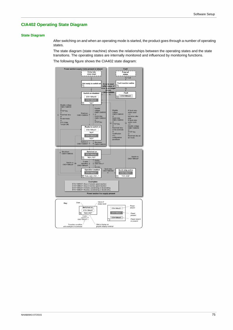
State DiagramAfter switching on and when an operating mode is started, the product goes through a number of operating states.
The state diagram (state machine) shows the relationships between the operating states and the state transitions. The operating states are internally monitored and influenced by monitoring functions.
The following figure shows the CIA402 state diagram:
NHA80943 07/2015 75

Software Setup
Description of Operating States
Drive Operating StateThe operating state of the drive changes depending on whether the control word [Cmd Register] ( )CMd , is sent or an event occurs (an error detection, for example).
The drive operating state can be identified by the value of the status word [CIA402 State Reg] ( )EtA .
Operating State Description
1 - Not ready to switch on
Initialization starts. This is a transient state invisible to the communication network.
2 - Switch on disabled The power stage is not ready to switch on.The drive is locked, no power is supplied to the motor.For a separate control stage, it is not necessary to supply the power.For a separate control stage with mains contactor, the contactor is not closed.The configuration and adjustment parameters can be modified.
3 - Ready to switch on The power stage is ready to switch on and awaiting power stage supply mains.For a separate control stage, it is not necessary to supply the power stage, but the system expects it in order to change to state 4 - Switched on.For a separate control stage with mains contactor, the contactor is not closed.The drive is locked, no power is supplied to the motor.The configuration and adjustment parameters can be modified.
4 - Switched on Power stage is switched on.For a separate control stage, the power stage must be supplied.For a separate control stage with mains contactor, the contactor is closed.The drive is locked, no power is supplied to the motor.The power stage of the drive is ready to operate, but voltage has not yet been applied to the output.The adjustment parameters can be modified.If a configuration parameter is modified, the drive returns to the state 2 - Switch on disable .
5 - Operation enabled Power stage is enabled. The drive is in running stateFor a separate control stage, the power stage must be supplied.For a separate control stage with mains contactor, the contactor is closed.The drive is unlocked, power is supplied to the motor.The drive functions are activated and voltage is applied to the motor terminals.If the reference value is zero or the Halt command is applied, no power is supplied to the motor and no torque is applied. To perform [Auto tuning] ( )tUn , the drive must be in state 5 - Operation enabled. The adjustment parameters can be modified.The configuration parameters cannot be modified.
NOTE: The command 4 - Enable operation must be taken into consideration only if the channel is valid. In particular, if the channel is involved in the command and the reference value, transition 4 is possible only after the reference value has been received once.
The reaction of the drive to a Disable operation command depends on the value of the [SwitchOnDisable Stp] ( )dOtd parameter:
If the [SwitchOnDisable Stp] ( )dOtd parameter is set to 0, the drive changes to operating state 4 - Switched on and stops in freewheel stop.If the [SwitchOnDisable Stp] ( )dOtd parameter is set to 1, the drive stops on ramp and then changes to operating state 4 - Switched on.
76 NHA80943 07/2015

Software Setup
6 - Quick stop active The drive performs a fast stop and remains locked in the operating state 6-Quick stop active. Before restarting the motor, it is required to go to the operating state 2-switch on disabled.During fast stop, the drive is unlocked and power is supplied to the motor.The configuration parameters cannot be modified.The condition for transition 12 to state 2 - Switch on disabled depends on the value of the parameterQuick stop mode (QStd):If the Quick stop mode parameter has the value FST2, the drive stops according to the fast stop ramp and then changes to state 2 - Switch on disabled .If the Quick stop mode parameter has the value FST6, the drive stops according to the fast stop ramp and then remains in state 6 - Quick stop active until:
A Disable voltage command is received orThe STOP key is pressed orA freewheel stop command via the digital input of the terminal.
7 - Fault reaction active
Transient state during which the drive performs an action corresponding to the selected error response.
8 - Fault Error response terminated. Power stage is disabled.The drive is locked, no power is supplied to the motor.
Operating State Description
NHA80943 07/2015 77

Software Setup
Summary
Device Status Summary
Operating State Power Stage Supply for Separate Control Stage
Power Supplied to Motor
Modification of Configuration Parameters
1 - Not ready to switch on
Not required No Yes
2 - Switch on disabled
Not required No Yes
3 - Ready to switch on
Not required No Yes
4 - Switched on Required No Yes, return to 2 - Switch on disabled operating state
5 - Operation enabled
Required Yes No
6 - Quick stop active
Required Yes, during fast stop No
7 - Fault reaction active
Depends on error response configuration
Depends on error response configuration
−
8 - Fault Not required No Yes
78 NHA80943 07/2015

Software Setup
Cmd Register ( )CMd
Bit Mapping of the Control Word
Bit 7 Bit 6 Bit 5 Bit 4 Bit 3 Bit 2 Bit 1 Bit 0
Fault reset Reserved (=0)
Reserved (=0)
Reserved (=0)
Enable operation
Quick stop Enable voltage
Switch on
0 to 1 transition = Error is reset (after cause of error is no longer active)
1 = Run command
0 = Quick stop active
Authorization to supply AC power
Mains contactor control
Bit 15 Bit 14 Bit 13 Bit 12 Bit 11 Bit 10 Bit 9 Bit 8
Manufacturer specific assignable
Manufacturer specific assignable
Manufacturer specific assignable
Manufacturer specific assignable
Manufacturer specific
Reserved (=0)
Reserved (=0)
Halt
0 = Forward direction asked 1= Reverse direction asked
Halt
Command State Transition
Final Operating State
Bit 4 Bit 3 Bit 2 Bit 1 Bit 0 Example ValueFault
ResetEnable Operation
Quick Stop
Enable Voltage
Switch On
Shutdown 2, 6, 8 3 - Ready to switch on
X X 1 1 0 0006 hex
Switch on 3 4 - Switched on
X X 1 1 1 0007 hex
Enable operation
4 5 - Operation enabled
X 1 1 1 1 000F hex
Disable operation
5 4 - Switched on
X 0 1 1 1 0007 hex
Disable voltage
7, 9, 10, 12 2 - Switch on disabled
X X X 0 X 0000 hex
Quick stop 11 6 - Quick stop active
X X 0 1 X 0002 hex
7, 10 2 - Switch on disabled
Fault reset
15 2 - Switch on disabled
0 → 1 X X X X 0080 hex
X: Value is of no significance for this command.0[gs56] 1: Command on rising edge.
NHA80943 07/2015 79

Software Setup
Stop Commands
Halt CommandThe Halt command enables movement to be interrupted without having to leave the 5 - Operation enabled state. The stop is performed in accordance with the [Type of stop] ( )Stt parameter.
If the Halt command is active, no power is supplied to the motor and no torque is applied.
Regardless of the assignment of the [Type of stop] ( )Stt parameter [Fast stop Assign] ( )FSt , [Ramp stop] ( )rMP , [Freewheel Stop] ( )nSt , or [DC Injection Assign] ( )dCI , the drive remains in the 5 - Operation enabled state.
Fast Stop CommandA Fast Stop command at the terminals or using a bit of the control word assigned to Fast Stop causes a change to the 4 - Switched on
Freewheel CommandA Freewheel Stop command using a digital input of the terminal or a bit of the control word assigned to Freewheel Stop causes a change to operating state 2 - Switch on disabled.
80 NHA80943 07/2015

Software Setup
Assigning Control Word Bits
Function CodesIn the CiA402 profile, fixed assignment of a function input is possible using the following codes:
For example, to assign the DC injection braking to bit13 of the fieldbus module, simply configure the [DC Injection Assign] ( )dCI parameter with the [C313] ( ) C313 value.
Bit 11 is assigned by default to the operating direction command [Reverse Assign] ( )rrS .
Bit Fieldbus Module
Bit 11 C311
Bit 12 C312
Bit 13 C313
Bit 14 C314
Bit 15 C315
NHA80943 07/2015 81

Software Setup
[CIA402 State Reg] ( )EtA
Bit Mapping of the Status Word
Bit 7 Bit 6 Bit 5 Bit 4 Bit 3 Bit 2 Bit 1 Bit 0
Warning Switch on disabled
Quick stop Voltage enabled
Fault Operation enabled
Switched on Ready to switch on
A warning is active
Power stage supply disabled
0 = Quick stop is active
Power stage supply present
Error detected
Running Ready 1 = Awaiting power Stage supply
Bit 15 Bit 14 Bit 13 Bit 12 Bit 11 Bit 10 Bit 9 Bit 8
Manufacturer-specific Direction of rotation
Manufacturer-specific Stop via STOP key
Reserved (=0)
Reserved (=0)
Internal limit active
Target reached
Remote Reserved (=0)
Reference value outside limits
Reference value reached
Command or reference value via fieldbus
Operating State
Bit 6 Bit 5 Bit 4 Bit 3 Bit 2 Bit 1 Bit 0 ETA Masked by 006F H (1)
Switch On Disabled
Quick Stop
Voltage Enabled
Fault Operation Enabled
Switched On
Ready to Switch On
1 -Not ready to switch on
0 X X 0 0 0 0 −
2 -Switch on disabled
1 X X 0 0 0 0 0040 hex
3 -Ready to switch on
0 1 X 0 0 0 1 0021 hex
4 -Switched on
0 1 1 0 0 1 1 0023 hex
5 -Operation enabled
0 1 11 0 1 1 1 0027 hex
6 -Quick stop active
0 0 0 1 1 1 0007 hex
7 -Fault reaction active
0 X X 1 1 1 1 −
8 -Fault 0 X X 1 0 0 0 0008 hex(2)...0028 hex
(1) This mask can be used by the PLC program to test the diagram state.(2) detected error following operating state 6 - Quick stop active.X: In this state, the value of the bit can be 0 or 1.
82 NHA80943 07/2015

Software Setup
Starting Sequence
DescriptionThe command sequence in the state diagram depends on how power is being supplied to the drive.
There are 3 possible scenarios:
Power stage supply
Direct Direct Mains contactor controlled by the drive
Control stage supply
Not separate (1) Separate Separate
(1) The power stage supplies the control stage.
NHA80943 07/2015 83

Software Setup
Sequence for a Drive Powered by the Power Stage Supply
DescriptionBoth the power and control stages are powered by the power stage supply.
If power is supplied to the control stage, it has to be supplied to the power stage as well.
The following sequence must be applied:
Step 1Apply the 2 - Shut down command
Step 2Check that the drive is in the operating state 3 - Ready to switch on.Then apply the 4 - Enable operation command.The motor can be controlled (send a reference value not equal to zero).
NOTE: It is possible, but not necessary to apply the 3 - Switch on command followed by the 4 - Enable Operation command to switch successively into the operating states 3 - Ready to Switch on, 4 - Switched on and then 5 - Operation Enabled. The 4 - Enable operation command is sufficient.
84 NHA80943 07/2015

Software Setup
Sequence for a Drive with Separate Control Stage
DescriptionPower is supplied separately to the power and control stages.
If power is supplied to the control stage, it does not have to be supplied to the power stage as well.
The following sequence must be applied:
Step 1The power stage supply is not necessarily present.Apply the 2 - Shut down command
NHA80943 07/2015 85

Software Setup
Step 2Check that the drive is in the operating state 3 - Ready to switch on.Check that the power stage supply is present (Voltage enabled of the status word).
Apply the 3 - Switch on command
Step 3Check that the drive is in the operating state 4 - Switched on.Then apply the 4 - Enable operation command.The motor can be controlled (send a reference value not equal to zero).If the power stage supply is still not present in the operating state 4 - Switched on after a time delay [Mains V. time out] ( )LCt , the drive triggers an error [Input Contactor] ( )LCF .
Power Stage Supply Terminal Display Status Word
Absent nLP 21 hex
Present rdY 31 hex
86 NHA80943 07/2015

Software Setup
Sequence for a Drive with Mains Contactor Control
DescriptionPower is supplied separately to the power and control stages.
If power is supplied to the control stage, it does not have to be supplied to the power stage as well. The drive controls the mains contactor.
The following sequence must be applied:
Step 1The power stage supply is not present as the mains contactor is not being controlled.Apply the 2 - Shutdown command.
Step 2Check that the drive is in the operating state 3 - Ready to switch on.Apply the 3 - Switch on command, which closes the mains contactor and switch on the power stage supply.
NHA80943 07/2015 87

Software Setup
Telegram 100, 101, 102, 106, 107
OverviewThe following diagram shows the native modes for telegram 100:
The native mode of the PROFINET VW3A3627 is used when telegram 100 is used.
The PKW area of telegram 100, which is used for a simple parameter management, is compliant with the PKW mechanism used with the PROFINET option module of the Altivar 32, 61, 71.
NOTE: After switching from one telegram to another, the drive shall be restarted to validate the new configuration.
The following diagram shows the native modes for telegram 101, 106, 107:
88 NHA80943 07/2015

Software Setup
The following diagram shows the native modes for telegram 102:
Periodic ExchangesThe following table provides the details of telegram 100, 101, and 102
Telegram 100 Telegram 101 Telegram 102
PLC>VSD VSD>PLC PLC>VSD VSD>PLC PLC>VSD VSD>PLC
PKW 1 PKE PKE PKE PKE −
PKW 2 R/W R/W R/W R/W
PKW 3 PWE PWE PWE PWE
PKW 4 PWE PWE PWE PWE
Cyclic data 1 OCA1 address of CMD =8501*
OMA1 address of ETA =3201*
OCA1 address of CMD =8501*
OMA1 address of ETA =3201*
OCA1 address of CMD =8501*
OMA1 address of ETA =3201*
Cyclic data 2 OCA2 address of LFRD =8602*
OMA2 address of RFRD =8604*
OCA2 address of LFRD =8602*
OMA2 address of RFRD =8604*
OCA2 address of LFRD =8602*
OMA2 address of RFRD =8604*
Cyclic data 3 OCA3 default =0
OMA3 default =0
OCA3 default =0
OMA3 default =0
Cyclic data 4 OCA4 default =0
OMA4 default =0
OCA4 default =0
OMA4 default =0
Cyclic data 5 OCA5 default =0
OMA5 default =0
OCA5 default =0
OMA5 default =0
Cyclic data 6 OCA6 default =0
OMA6 default =0
OCA6 default =0
OMA6 default =0
*:default Modbus address.
NHA80943 07/2015 89

Software Setup
The following table provides the details of telegram 106 and 107
The configuration of the cyclic data is made with the PROFINET IO-Controller configuration tool. The Modbus address of the parameter linked to each cyclic data must be defined as in the following example with the HW configuration software:
Input cyclic data 1/2 and output cyclic data 1/2 are already preconfigured to (CMd) (8501) and (LFrd) (8602); (EtA) (3201) and (rFrd) (8604).
If a null address Modbus is entered, no link between the related cyclic data and the drive is established. In any case, the 6 cyclic data are not disabled and the 6 cyclic data takes place in the I/O memory image of the controller.
1 Modbus address is entered in this field2 Data type is entered in this field
Telegram 106 Telegram 107
PLC>VSD VSD>PLC PLC>VSD VSD>PLC
PKW 1 PKE PKE PKE PKE
PKW 2 R/W R/W R/W R/W
PKW 3 PWE PWE PWE PWE
PKW 4 PWE PWE PWE PWE
Cyclic data 1 OCA1 address of CMD =8501*
OMA1 address of ETA =3201*
OCA1 address of CMD =8501*
OMA1 address of ETA =3201*
Cyclic data 2 OCA2 address of LFRD =8602*
OMA2 address of RFRD =8604*
OCA2 address of LFRD =8602*
OMA2 address of RFRD =8604*
Cyclic data 3 OCA3 default =0 OMA3 default =0 OCA3 default =0 OMA3 default =0
Cyclic data 4 OCA4 default =0 OMA4 default =0 OCA4 default =0 OMA4 default =0
Cyclic data 5 OCA5 default =0 OMA5 default =0 OCA5 default =0 OMA5 default =0
Cyclic data 6 OCA6 default =0 OMA6 default =0 OCA6 default =0 OMA6 default =0
Cyclic data 7 OCA7 default =0 OMA7 default =0 OCA7 default =0 OCA7 default =0
Cyclic data 8 OCA8 default =0 OMA8 default =0 OCA8 default =0 OCA8 default =0
Cyclic data 9 OCA9 default =0 OCA9 default =0
Cyclic data 10 OCA10 default =0 OCA10 default =0
Cyclic data 11 OCA11 default =0 OCA11 default =0
Cyclic data 12 OCA12 default =0 OCA12 default =0
Cyclic data 13 OCA13 default =0 OCA13 default =0
Cyclic data 14 OCA14 default =0 OCA14 default =0
Cyclic data 15 OCA15 default =0 OCA15 default =0
Cyclic data 16 OCA16 default =0 OCA16 default =0
*:default Modbus address.
90 NHA80943 07/2015

Software Setup
Configuring Drive with a Siemens© S7-300
GSDML InstallationFirst download, and install the GSDML file of the drive in the hardware configuration tool of the SIMATIC STEP7® software.
You can find the GSDML file and its associated picture on www.schneider-electric.com.
From the menu > Options > Install GSD File...
Once installed you can see the drive, in the library, as follow:
NHA80943 07/2015 91

Software Setup
Configuration of Drive with the Telegram 100
DescriptionWith this telegram, the drive is controlled with two process data.
Configure the PLC and its PROFINET network. Then select and place the drive from the library to the bus:
Define the addresses of the cyclic data and PKW data in the PLC periphery:
By default, the process data are linked to (CMd), (LFrd), (EtA) and (rFrd) (native CiA 402 profile of the drive).
You can check that the exchanges are working properly with the Monitor/Modify function of the configuration tool:
92 NHA80943 07/2015

Software Setup
Configuring a Drive with the Telegram 101, 102, 106, or 107
Configuring the Drive Communication ScannerThe configuration of the fieldbus module is defined by the master, by default the 2 first read and write are linked to the default parameters: (CMd), (LFrd), (EtA) and (rFrd). The 4 next read or write parameters are not configured.
To add new parameters or modify the default configuration of the communication scanner, open the properties dialog box of the slave device and configure the OCA/OMA values in the parameter assignment tab.
1 Internal Modbus address2 Data type is entered in this field
New parameters are added or modified by entering the drive Modbus address.
For example: (OMA3) is configured to read the value of (ACC), which Modbus address is 9001.
NHA80943 07/2015 93

Software Setup
Parameters Management with the Telegram 100, 101, 102, 106, 107
DescriptionIn native modes several accesses to the drive parameters are possible:
The standard acyclic requests from PROFIdrive, for more information see PROFIdrive Parameters Channel (see page 22).PKW mechanisms – consistent with Altivar 32,61, and 71 for 16-bit data.
Parameter Management Through the PKW AreaWith telegram 100, 101, 106, 107 you can read or write any drive parameter by using this PKW area. (This addressing format is identical to the PKW mechanism of the Altivar 32,61, and 71).
NOTE: The management of the parameters (compatibility with series 1 product) is Schneider Electric specific. Actually, previous versions of PROFIdrive also specified parameter management thought PKW, are not compatible with Schneider Electric method. In recent versions, parameters are managed with acyclic messages, and the PNO PKW method is obsolete.
The PKW area is made of four input words and four output words.
The table lists the controller-to-drive parameters in the input PKW area:
The table lists the drive-to-controller parameters in the output PKW area:
PKW Number PKE Name Description
PKW1 PKE The Modbus address of the parameter is detailed here.
PKW2 R/W Request code:0: no request1: read2: write (16 bit)3: write (32 bit)
PKW3 PWE Parameter is used when PKW2 = 3
PKW4 PWE Parameter value in case of write request
PKW Number PKE Name Description
PKW1 PKE Copy of the input PKE
PKW2 R/W Response code:0: no request1: read done (16 bit)2: write done (16 bit)3: request in progress4: read done (32 bit)5: write done (32 bit)7: read or write error
PKW3 PWE Parameter is used when PKW2 = 4 or 5
PKW4 PWE If the request is successful, the parameter value is copied here.
94 NHA80943 07/2015

Software Setup
Telegram 1
OverviewThe following diagram shows the operating modes:
The following section describes how the VW3A3627 is operated when configured in PROFIdrive mode (telegram 1).
The selection of this mode is done while configuring the device with the PROFINET network configuration tool. It is out of the scope of this document to describe how to use such tool. However, you can find in the examples (see Configuring the Drive With a Siemens© S7-300 (see page 91)) how to configure the module for the Schneider PLCs and for the SIMATIC® S7 PLCs.
Periodic ExchangesThe periodic exchanges, with PROFIdrive application class 1 profile consists of:
16-bit command word (STW1) and 16-bit reference word (NSOLL_A),16-bit operating state word (ZSW1) and 16-bit actual velocity word (NIST_A).
The mapping of these words is automatically done when you select telegram 1 during the configuration of the device.
NOTE: After switching from one telegram to another, restart the controller to validate the new configuration.
NHA80943 07/2015 95

Software Setup
State Diagram
DescriptionThe following state diagram shows the PROFIdrive state machine for the application class 1. The diagram also describes the command word and operating state word.
96 NHA80943 07/2015

Software Setup
Command Word and Operating State Word
OverviewThe table lists the command wording from PROFIdrive application profile class 1:
The table lists the status from PROFIdrive application profile class 1:
STW1
Bit 7 Bit 6 Bit 5 Bit 4 Bit 3 Bit 2 Bit 1 Bit 0
Fault reset − − − Enable operation
Quick stop Coast stop ON/OFF
Bit 15 Bit 14 Bit 13 Bit 12 Bit 11 Bit 10 Bit 9 Bit 8
− − − − − Control and reference by PLC
− −
ZSW1
Bit 7 Bit 6 Bit 5 Bit 4 Bit 3 Bit 2 Bit 1 Bit 0
Warning Switching inhibited
Quick stop not activated
Coast stop not activated
Error detected
Operation enabled
Ready to operate
Ready to switch ON
Bit 15 Bit 14 Bit 13 Bit 12 Bit 11 Bit 10 Bit 9 Bit 8
− Reserved Reserved Reserved Reserved F or n reached or exceeded
Control requested
Speed error found within tolerance range
NHA80943 07/2015 97

Software Setup
Command Word Details
STW1
Bit 0 ON 1 Switched on operating state; voltage at the power converters, indicates that the power voltage is enabled.
OFF(OFF 1)
0 The drive is ramped-down along the ramp (RFG) or along the current limit or along the voltage limit of the d.c. Link if standstill is detected and power is disabled when deceleration bit 1 of ZSW1 is still set. An OFF command is interruptible (the drive returns to the ready for switching on operating state).
Bit 1 No coast stop 1 Coast Stop (OFF2) not active.
Coast stop (OFF 2) 0 Power voltage disabled..The drive goes into the Switching On Inhibited Power voltage is disabled; the motor coasts down to a standstill.
Bit 2 No quick stop 1 Quick Stop (OFF3) not active.
Quick stop (OFF 3) 0 Quick stop; if required, withdraw the operating enable, the drive is decelerated as fast as possible. For example, along the current limit or at the voltage limit of the d.c. Link, at n / f = 0; if the rectifier pulses are disabled, the power voltage is disabled (the contact is opened) and the drive goes into the Switching On Inhibited operating state.A Quick Stop command is not interruptible.
Bit 3 Enable operation 1 Enable electronics and pulses.The drive then runs-up to the reference frequency.
Disable operation 0 The drive coasts down to a standstill (ramp-function generator to 0 or tracking) and goes into the Switched on operating state (refer to control word 1, bit 0).
Bit 4 Reserved
Bit 5 Reserved
Bit 6 Not used
Bit 7 Fault reset 1 The fault reset function is active with a positive edge; the drive error response depends on the type of detected error. If the error response has isolated the voltage, the drive then goes into the Switching On Inhibited operating state.
Bit 8 Not used
Bit 9 Not used
Bit 10 Control by fieldbus 1 Channel for the reference frequency and the command from the bus are active.
No control by fieldbus
0 Channel for the reference frequency and the command from the bus are not active.
Bit 11 Reserved
Bit 12 Reserved
Bit 13 Reserved
Bit 14 Reserved
Bit 15 Reserved
98 NHA80943 07/2015

Software Setup
Operating State Word
ZSW1
Bit 0 Ready to switch ON
1 Mains power supply is switched on, electronics are initialized, pulses are inhibited.
Not ready to switch ON
0 −
Bit 1 Ready to operate 1 Refer to control word 1, bit 0.
Not ready to operate
0 −
Bit 2 Operation enabled 1 Drive follows a reference frequency. This means that:The electronic and the power stage are enabled (Refer to control word 1, bit 3),The drive is in running state.
Operation disabled 0 Either the power stage is disabled or the drive does not follow the reference frequency.
Bit 3 Error detected 1 An error has been detected. The drive error response depends on the type of detected error. The Fault Reset function may only be successfully used if the detected error cause has disappeared or has been removed. If the detected error response has disabled the power stage, the drive goes into the Switching On Inhibited operating state, otherwise the drive returns to operation is a state.
No error detected 0 −
Bit 4 Coast stop not activated
1 −
Coast stop activated
0 Coast stop (OFF 2) command is present.
Bit 5 Quick stop not activated
1 −
Quick stop activated
0 Quick Stop (OFF 3) command is present.
Bit 6 Switching inhibited 1 The drive is in Switching on inhibited operating state.
Switching not inhibited
0 −
Bit 7 Warning present 1 Warning information present in the service/maintenance parameter; acknowledgement required.
No warning 0 −
Bit 8 Speed feedback within tolerance range
1 Actual value is within a tolerance band; dynamic speed discrepancies are permissible.
Speed feedback out of tolerance range
0 −
Bit 9 Control requested 1 The automation system controls the drive.
No control requested
0 Control by the automation system is not possible, only possible at the device level, by another interface or the drive is controlled from a supervisor (Master class 2).
Bit 10 Reference frequency reached or exceeded
1 Actual output frequency ≥ reference frequency which may be set via the parameter number.
Reference frequency not reached
0 −
Bit 11 Reserved
Bit 12 Reserved
Bit 13 Reserved
Bit 14 Reserved
Bit 15 Reserved
NHA80943 07/2015 99

Software Setup
Reference Frequency
Channel for Reference FrequencyThe reference frequency, written in NSOLL_A is defined by the following formula:
Reference frequency in Hz = (NSOLL_A x [Max Frequency] (tFr)) /4000 HEX
Reference Frequency RangeThe table lists the different values for the reference frequency and the correspondence for the drive:
PROFIdrive / Acyclic MessagingFor more information, see PROFIdrive Parameters Channel (see page 22).
Value Reference Frequency Used by the Drive
0x0000 0
0x4000 100% of [Max Frequency] (tFr)
0xC000 –100% of [Max Frequency] (tFr)
100 NHA80943 07/2015

Software Setup
Fieldbus Integration Tutorial
Section 4.5Fieldbus Integration Tutorial
Fieldbus Integration Tutorial
Simple LAD Language FC (Controlling the Drive in CiA 402 Mode)The following example shows a simple LAD language FC for controlling the drive in CiA402 mode
NHA80943 07/2015 101

Software Setup
102 NHA80943 07/2015

Software Setup
NHA80943 07/2015 103

Software Setup
104 NHA80943 07/2015

Altivar Process 900OperationNHA80943 07/2015
Operation
Chapter 5Operation
What Is in This Chapter?This chapter contains the following sections:
Section Topic Page
5.1 Operating States 106
5.2 Operating Modes 107
NHA80943 07/2015 105

Operation
Operating States
Section 5.1Operating States
Configuring Communication Error Response
DescriptionThe response of the drive in the event of communication interruption can be configured. Configuration can be performed using the display terminal from the [Complete settings] (CSt-), [Error/Warning handling] (CSWM-) menu, [Communication Module] ( )COMO- [Fieldbus Interrupt Resp] submenu, via the ( )CLL parameter.
The values of the parameter, which triggers a transition to the operating state faults are:
The values of the parameter, which does not trigger a transition to the operating state faults are:
The fallback speed can be configured in the [Complete settings] (CSt-), [Error/Warning handling] (CSWM-) menu, [Fallback speed] ( )LFF- submenu, using the [FallbackSpeed] (LFF) parameter.
Value Meaning
[Freewheel Stop] (YES) Freewheel stop (factory setting)
[Ramp stop] (rMP) Stop on ramp
[Fast stop] ( )FSt Fast stop
[DC injection] ( )dCI DC injection stop
Value Meaning
[Ignore] (nO) Detected error ignored
[Per STT] (Stt) Stop according to configuration of [Type of stop] (Stt)
[Fallback Speed] (LFF) Change to fallback speed, maintained as long as the detected error persists and the run command has not been removed
[Speed maintained] (rLS) The drive maintains the speed at the time the detected error occurred, as long as the detected error persists, and the run command has not been removed
WARNINGLOSS OF CONTROLIf this parameter is set to nO, fieldbus communication monitoring is disabled.
Only use this setting after a thorough risk assessment in compliance with all regulations and standards that apply to the device and to the application.Only use this setting for tests during commissioning.Verify that communication monitoring has been re-enabled before completing the commissioning procedure and performing the final commissioning test.
Failure to follow these instructions can result in death, serious injury, or equipment damage.
106 NHA80943 07/2015

Operation
Operating Modes
Section 5.2Operating Modes
What Is in This Section?This section contains the following topics:
Topic Page
Configuring the Control Channel 108
Configuration of the Drive for Operation in I/O Profile 109
Configuration of the Drive for Operation with CiA 402 Profile in Combined Mode 110
Configuration of the Drive for Operation with CiA 402 Profile in Separate Mode 111
NHA80943 07/2015 107

Operation
Configuring the Control Channel
OverviewThis chapter explains how to configure the drive for operation from the communication network through three following examples.
I/O mode - a simple command word (based on forward, reverse, and reset binary commands).Combined mode (with native profile CiA 402) - Both reference value and command word come from the communication network.Separate (with native profile CiA 402) - reference value and command word come from separate sources: for example, the command word (in CiA 402) comes from the communication network and the reference value from the HMI.
108 NHA80943 07/2015

Operation
Configuration of the Drive for Operation in I/O Profile
DescriptionFor the I/O profile, here is a simple example, which can be extended with additional features. The command word is made of run forward (bit 0 of CMd), run reverse (bit 1 of CMd), and the function fault reset (bit 7 of CMd).
The settings are the following:
The bits of the command word can now be configured.
In the [Command and Reference] ( )CrP- menu configure:
In the [Error/Warning handling] ( )CSWM- menu, [Fault reset] ( ) rSt- submenu, configure:
[Ref Freq 1 Config] (Fr1) [HMI] (HMI)
[Control Mode] (CHCF) [I/O profile] IO
[Command switching] (CCS) Default
[Cmd channel 1] (Cd1) [Com. Module] (nEt)
[Reverse Assign] (rrS) [CD01] (Cd01)
[Fault Reset Assign] (rSF) [CD07] (Cd07)
NHA80943 07/2015 109

Operation
Configuration of the Drive for Operation with CiA 402 Profile in Combined Mode
DescriptionThis section describes how to configure the settings of the drive if it is controlled in CiA 402 mode. The example focuses on the not separate mode. Additional modes are detailed in the drive programming manual.
In the [Complete settings] (CSt-) menu, [Command and Reference] (CrP-) submenu:[Ref Freq 1 Config] (Fr1): is set on according to the communication source you can choose in the following table:
[Freq Switch Assign] (rFC) is set to default value ([Ref Freq 1 Config] (Fr1)).[Control Mode] (CHCF): defines if the drive operates in combined mode (reference and command from the same channel).
For the current example, [Control Mode] (CHCF) is adjusted to [Not separ.] (SIM) as reference and control are originated from the communication network:
Origin of the Control Ref1 Channel Setting
PROFINET [Ref. Freq-Com. Module] (nEt)
Profile Ref1 Channel setting
CiA 402 combined mode [Not separ.] (SIM)
CiA 402 separate mode [Separate] (SEp)
I/O profile [I/O profile] (IO)
110 NHA80943 07/2015

Operation
Configuration of the Drive for Operation with CiA 402 Profile in Separate Mode
DescriptionAlternate combinations are possible, see the drive programming manual for the list of possible settings.
For example:
The drive is controlled from the fieldbus (PROFINET) but the reference is adjusted on the controller terminal. The control word comes from the controller and is written according to CiA 402 profile.
The settings are as shown in the table:
[Ref Freq 1 Config] (Fr1) [AI1] (AI1)
[Control Mode] (CHCF) [Separate] (SEp)
[Cmd channel 1] (Cd1) [Com. Module] (nEt)
[Freq Switch Assign] (rFC) Factory setting
NHA80943 07/2015 111

Operation
112 NHA80943 07/2015

Altivar Process 900Diagnostic and TroubleshootingNHA80943 07/2015
Diagnostic and Troubleshooting
Chapter 6Diagnostic and Troubleshooting
What Is in This Chapter?This chapter contains the following topics:
Topic Page
Fieldbus Status LEDs 114
Connection for Fieldbus Mode 116
Fieldbus Function Test 117
Communication Interruption 118
Monitoring of Communication Channel 120
Control-Signal Diagnostics 122
NHA80943 07/2015 113

Diagnostic and Troubleshooting
Fieldbus Status LEDs
LED IndicatorsThe following figure describes the LEDs status module:
LED Description
Module StatusThis LED indicates the module status:
Item LED Description
1 RUN/BF Module status
2 STS/SF Network status
3 LNK1 Port A activity
4 LNK2 Port B activity
Color & Status Description
OFF The device is powered off
Red ON The device has detected an ILF error
Green ON The device is ready and operational
Red flickering The device has detected a communication interruption / wrong configuration or a PROFINET controller at Stop state.
Green flickering In combination with other LEDs: DCP manual identification phase / DCP flash mode
Green/Red blinking Power up testing
Red single flash No connection to the PROFINET controller
114 NHA80943 07/2015

Diagnostic and Troubleshooting
Network Error Status
NOTE: If the fieldbus module operates as a Modbus TCP server only, LED 1 and 2 have another behavior.
LNK1 and LNK2These LEDs indicate the status of the Ethernet port A (1) and Ethernet port B (4):
LED behavior
Color & Status Description
OFF The device does not have an IP address or is powered off
RED ON Error detected on the module
Green ON At least a port is connected and has a valid IP address.
Green flickering In combination with other LEDs: DCP manual identification phase / DCP flash mode or as long as the iPar-Client did not accomplish transfer (backup or restore) its parameters
Green/Red blinking Power-up testing
Green flashing 3 times All ports are unplugged, but the module has an IP address
Green flashing 4 times Error detected: duplicate IP address
Green flashing 5 times The module is performing a DHCP sequence
Color & Status Description
OFF No link
Green ON Link established at 100 Mbit/s
Green blinking Network activity at 100 Mbit/s
Yellow ON Link established at 10 Mbit/s
Yellow blinking Network activity at 10 Mbit/s
NHA80943 07/2015 115

Diagnostic and Troubleshooting
Connection for Fieldbus Mode
DescriptionIf the product cannot be addressed via the fieldbus, first check the connections. The product manual contains the technical data of the device and information on network and device installation. Check the following:
Power connections to the deviceFieldbus cable and fieldbus wiringNetwork connection to the device
116 NHA80943 07/2015

Diagnostic and Troubleshooting
Fieldbus Function Test
DescriptionIf the connections are correct, check the settings for the fieldbus addresses. After correct configuration of the transmission data, test the fieldbus mode.
In addition to the controller that knows the device via the data in the GSDML file and its address, a bus monitor should be installed. As a passive device, it can display messages.
Switch off or on the supply voltage of the drive system.Observe the network messages shortly after switching on the drive system. A bus monitor can be used to record the elapsed time between telegrams and the relevant information in the telegram.
Possible Errors: Addressing, Parameterization, ConfigurationIf it is impossible to connect to a device, check the following:
Addressing: The address of the network device must be a valid IP address. Each network device must have a unique address.Parameterization: The parameterized Ident number and the user parameters must match the values stored in the GSDML file.
NHA80943 07/2015 117

Diagnostic and Troubleshooting
Communication Interruption
DescriptionThe drive triggers an error [Internal Link Error] (ILF) when the following events occur:
Hardware error is detected on the PROFINET moduleCommunication interruption between the PROFINET module and the drive
The response of the drive in the event of an [Internal Link Error] (ILF) error cannot be configured, and the drive stops in freewheel. This detected error requires a power reset.
The diagnostic parameter can be used to obtain more detailed information about the origin of the [Internal Link Error] (ILF) ([InterCom Error1] (ILF1) if the detected error has occurred on option module in slot A).
The [InterCom Error1] (ILF1) parameter can be accessed on the graphic display terminal in the [Communication map] (CMM-) menu, [PROFINET DIAG] (pRN-) submenu.
Diagnostic (PROFINET Service)PROFINET diagnostic is associated with specific data which can be helpful during maintenance:
The error code, if a detected error is present,The value of ETA operating state word,The value of the output frequency.
This data report and gives an indication on the drive status when the diagnostic event was triggered
Value Description of the values of the [InterCom Error1] (ILF1) parameter
0 No error detected
1 Internal communication interruption with the drive
2 Hardware error detected
3 Error found in the EEPROM checksum
4 EEPROM
5 Flash memory
6 RAM memory
7 NVRAM memory
101 Unknown module
102 Communication interruption on the drive internal bus
103 Time out on the drive internal bus (500 ms)
Byte Description
1...28 Header information Header information with interrupts from PROFINET IO in case of manufacturer-specific diagnostic.
29 Ext_Diag_Data External diagnostic data length = 6
30 IF ETA.bit 3 = 1: ADL LFT LSBOtherwise: 0
31 ADL ETA LSB
32 ADL ETA MSB
33 LSB of the last value of the output speed
34 MSB of the last value of the output speed
118 NHA80943 07/2015

Diagnostic and Troubleshooting
Enabling DiagnosticsBy default, alarm diagnostics function is enabled. It can be modified during the configuration phase as shown below:
NHA80943 07/2015 119

Diagnostic and Troubleshooting
Monitoring of Communication Channel
Channel for Command and Reference FrequencyAll the drive commands and reference value parameters are managed on a channel-by-channel basis.
Network Monitoring CriteriaThe table provides the details of the detected errors
Parameter Name Parameter Code
Taken Into Account by the Drive
Modbus Serial
CANopen Fieldbus Module Ethernet Embedded
Control word ( )CMd ( )CMd1 ( )CMd2 ( )CMd3 ( )CMd5
Extended control word ( )CMI ( )CMI1 ( )CMI2 ( )CMI3 ( )CMI5
Reference speed (rpm) ( )LFd ( )LFd1 ( )LFd2 ( )LFd3 ( )LFd5
Reference frequency (0.1 Hz)
( )LFr ( )LFr1 ( )LFr2 ( )LFr3 ( )LFr5
Reference value for torque control mode (0.1% of the nominal
torque)(1)
( )LTR ( )LTR1 ( )LTR2 ( )LTR3 ( )LTR5
Reference value supplied by PI controller
( )PISP ( )PIr1 ( )PIr2 ( )PIr3 ( )PIr5
Reference value supplied by analog multiplier function
( )MFr ( )MFr1 ( )MFr2 ( )MFr3 ( )MFr5
(1): If available
Protocol Criteria Error Code
PROFINET module 10: No valid IP [Fieldbus Error] ( )EPF2
9: Duplicated IP address
12: iPar unconfigured
13: iPar unrecoverable error detected
0:No error detected [Fieldbus Com Interrupt] ( )CnF
1: Network timeout (configurable timeout) for received requests destined for the drive
2: Network overload
3: Loss of Ethernet Carrier
EEPROM detected error [Internal Link Error] ( )ILF
120 NHA80943 07/2015

Diagnostic and Troubleshooting
Monitoring of Communication ChannelsCommunication channels are monitored if they are involved in one of the following parameters:
The control word ([Cmd Register] ( )CMd ) from the active command channelThe control word containing the command switch (bit configured on [Cmd switching] ( )CCS )The control word containing the switch for reference value 1’1B (bit configured on [Ref 1B switching] ( )rCb )The control word containing the switch for reference value 1’2 (bit configured on [Freq Switch Assign] ( )rFC )The reference frequency or reference speed ([Ref Frequency] ( )LFr or LFRD: Nominal speed value) from the active channel for reference valueSumming reference frequency or reference speed ([Ref Frequency] ( )LFr or LFRD: Nominal speed value) 2 (assigned to [Summing Input 2] ( )SA2 )Summing reference frequency or reference speed ([Ref Frequency] ( )LFr or LFRD: Nominal speed value) 3 (assigned to [Summing Input 3] ( )SA3 )Subtracting reference frequency or reference speed ([Ref Frequency] ( )LFr or LFRD: Nominal speed value) 2 (assigned to [Subtract Ref Freq 2] ( )dA2 )Subtracting reference frequency or reference speed ([Ref Frequency] ( )LFr or LFRD: Nominal speed value) 3 (assigned to [Subtract Ref Freq 3] ( )dA3 )The reference value given by the PID controller (PISP)The PID controller feedback ([AI Virtual 1] ( )AIU1 )The multiplication coefficient of the reference values ([Multiplying coeff.] ( )MFr ) 2 (assigned to [Ref Freq 2 Multiply] ( )MA2 )The multiplication coefficient of the reference values ([Multiplying coeff.] ( )MFr ) 3 (assigned to [Ref Freq 3 Multiply] ( )MA3 )
As soon as one of these parameters has been written once to a communication channel, it activates monitoring for that channel.
If a communication warning is sent (in accordance with the protocol criteria) by a monitored port or fieldbus module, the drive triggers a communication interruption.
The drive reacts according to the communication interruption configuration (operating state Fault, maintenance, fallback, and so on)
If a communication warning occurs on a channel that is not being monitored, the drive does not trigger a communication interruption.
Enabling of Communication ChannelsA communication channel is enabled once all the parameters involved have been written at least one time.The drive is only able to start if all channels involved in command and reference are enabled.
For example:
A drive in DSP402 profile is connected to an active communication channel.
It is mandatory to write at least 1 time the reference and the command in order to switch from 4-Switched on to 5-Operation enabled state.
A communication channel is disabled:In the event of a communication alarm.In forced local mode.NOTE: On exiting forced local mode:
The drive copies the run commands, the direction, and the forced local reference to the active channel (maintained).Monitoring of the active command and reference channels resumes following a time delay [Time-out forc. local] ( )FLOt .Drive control only takes effect once the drive has received the reference and the command from the active channel.
NHA80943 07/2015 121

Diagnostic and Troubleshooting
Control-Signal Diagnostics
IntroductionOn the display terminal, the [Display] ( )MON- , [Communication map] ( )CMM- submenu can be used to display control-signal diagnostic information between the drive and the controller:
Active command channel [Command Channel] ( )CMdC
Value of the control word [Cmd Register] ( )CMd from the active command channel [Command Channel] ( )CMdC
Active reference frequency channel [Ref Freq Channel] ( )rFCC
Value of the reference frequency [Pre-Ramp Ref Freq] ( )FrH from the active target channel [Ref Freq Channel] ( )rFCC
Value of the operating state word [CIA402 State Reg] ( )EtA
Specific data for all available fieldbus are in dedicated submenus.In the [Command word image] ( )CWI- submenu: control words from all channelsIn the [Freq. ref. word map] ( )rWI- submenu: reference frequency values produced by all channels
Control Word DisplayThe [Command Channel] ( )CMdC parameter indicates the active command channel.
The [Cmd Register] ( )CMd parameter indicates the hexadecimal value of the control word (CMD) used to control the drive.
The [Command word image] ( )CWI- submenu ([COM. Module cmd.] ( )CMd3 ) parameter is used to display the hexadecimal value of the control word from the fieldbus module.
Reference Frequency DisplayThe [Ref Freq Channel] ( )rFCC parameter indicates the active channel for reference frequency.
The [Ref Frequency] ( )LFr parameter indicates the value (in 0.1 Hz units) of the reference frequency used to control the drive.
The [Freq. ref. word map] ( )rWI- submenu ([Com Module Ref Freq] ( )LFr3 parameter is used to display the value (in 0.1 Hz units) of the reference frequency from the fieldbus.
Operating State Word DisplayThe [CIA402 State Reg] ( )EtA parameter gives the value of the operating state word (ETA).
The table provides the bit details of ETA parameter:
Bit Description
DRIVECOM Status word
Bit0 = 1 Ready to switch on
Bit1 = 1 Switched on
Bit2 = 1 Operation enabled
Bit3 = 1 Operating state fault
Bit4 = 1 Power stage is switched on
Bit5 = 0 Quick stop
Bit6 = 1 Switch on disabled
Bit7 = 1 Warning
Bit8 = 1 Drivecom reserved
Bit9 = 0 Forced local mode in progress
Bit10 = 1 Reference value reached (steady state)
Bit11 = 1 Reference value exceeded (< LSP or > HSP)
Bit12 Reserved
Bit13 Reserved
Bit14 = 1 Stop imposed via STOP key
Bit15 = 0 Motor rotation in forward direction (or stopped)
122 NHA80943 07/2015

Altivar Process 900GlossaryNHA80943 07/2015
Glossary
AAbbreviations
Req. = Required
Opt. = Optional
DDisplay terminal
The display terminal menus are shown in square brackets.
For example: [Communication]The codes are shown in round brackets.
For example: (COM-)
Parameter names are displayed on the display terminal in square brackets.
For example: [Fallback Speed]Parameter codes are displayed in round brackets.
For example: (LFF)
DPDecentralized Periphery
EError
Discrepancy between a detected (computed, measured, or signaled) value or condition and the specified or theoretically correct value or condition.
FFactory setting
Factory settings when the product is shipped
FaultFault is an operating state. If the monitoring functions detect an error, a transition to this operating state is triggered, depending on the error class. A "Fault reset" is required to exit this operating state after the cause of the detected error has been removed. Further information can be found in the pertinent standards such as IEC 61800-7, ODVA Common Industrial Protocol (CIP).
Fault ResetA function used to restore the drive to an operational state after a detected error is cleared by removing the cause of the error so that the error is no longer active.
MMonitoring function
Monitoring functions acquire a value continuously or cyclically (for example, by measuring) in order to check whether it is within permissible limits. Monitoring functions are used for error detection.
MS0, MS1Number of a master in the network.
PParameter
Device data and values that can be read and set (to a certain extent) by the user.
NHA80943 07/2015 123

Glossary
PELVProtective Extra Low Voltage, low voltage with isolation. For more information: IEC 60364-4-41
PLCProgrammable logic controller
PNOPROFIBUS Nutzerorganisation e.V. (PROFIBUS User organization).
Power stageThe power stage controls the motor. The power stage generates current for controlling the motor.
QQuick Stop
The quick Stop function can be used for fast deceleration of a movement as a response to a detected error or via a command.
WWarning
If the term is used outside the context of safety instructions, a warning alerts to a potential problem that was detected by a monitoring function. A warning does not cause a transition of the operating state.
124 NHA80943 07/2015


Altivar_Process_900_Profinet_Manual_EN_NHA80943_0107/2015