ALTERNATOR INSTALLATION AND OPERATION … ALTERNATOR MOUNTING STYLES Due to the large number of...
16
Page INTRODUCTION Thank you for choosing a Balmar high-output alternator. This alternator is uniquely designed to provide the finest performance and durability for your vessel. When used with a Balmar multi-stage regulator, your alternator can provide even greater efficiency when charging deep-cycle flooded, standard flooded, gel, AGM, Optima and other marine battery technologies. When preset for your battery type, the smart regulator will guide your alternator through a charging program that’s tailored to provide your batteries with the best care possible. SAFETY CONSIDERATIONS Before installing your new alternator, please take a moment to consider the following guidelines for safe alternator installation and operation. Failure to follow these guidelines could result in injury or damage to your vessel’s electrical system. 1. Always disconnect your batteries and turn your battery switches to their “OFF” positions prior to installing your al- ternator. 2. Remove any loose fitting clothing or jewelry which could become entangled in your motor or other machinery. 3. Wear ANSI-approved safety glasses or eye wear. 4. Ensure that the engine has cooled sufficiently before begin- ning installation. 5. DO NOT install your high-output alternator without ensuring that system wiring is sufficient to handle increased amper- age loads. 6. Be sure that your work area is properly ventilated and that no fuels or solvents are present in and around your work area. 7. DO NOT operate your charging system without proper fus- ing. Failure to do so could result in severe injury and/or damage or loss of your vessel. DON’T take chances with fusing. 8. DO NOT attempt installation while using alcohol or medica- tions which could impair your judgement or reaction time. 9. Use the right tool for the job. Use of improper tools could result in damage or injury. 10. Take time to read the manual. Equipment damage and possible injury may result from an incomplete understand- ing of the proper installation and use of the alternator. CAUTION: The following instructions are intended for use by experienced marine electrical installers. If you are not suffi- ciently experienced with marine electrical systems, we recom- mend a qualified electrician be used for installation. ALTERNATOR INSTALLATION AND OPERATION MANUAL CONTENTS INTRODUCTION ................................................1 SAFETY CONSIDERATIONS ..............................1 ALTERNATOR MOUNTING STYLES ..................2 ALTERNATOR INSTALLATION ISSUES .............2 SIZING BATTERY CABLES ................................3 BELT SIZE REQUIREMENTS .............................3 BELT TENSION ..................................................3 FAN ROTATION ..................................................3 GROUNDING ......................................................3 PULLEYS ...........................................................4 ALTERNATOR HEAT ..........................................4 FUSING ..............................................................4 ALTERNATOR-TO-BATTERY RATIOS.................4 MULTIPLE BANK CHARGING OPTIONS ............5 BATTERY SWITCHES ........................................5 BATTERY COMBINERS/SOLENOIDS .................5 BATTERY ISOLATOR .........................................5 DIGITAL DUO CHARGE......................................6 TWO ALTERNATORS-SINGLE ENGINE ..............6 TWIN ENGINE ISSUES ......................................7 CENTERFIELDER...............................................7 INSTALLATION ISSUES BY ALTERNATOR........8 6-SERIES ALTERNATORS ...............................8-9 AT-SERIES ALTERNATORS ..............................10 94 & 94LY-SERIES ALTERNATORS .................11 95-SERIES ALTERNATORS ..............................11 97-SERIES ALTERNATORS ..............................12 97EHD-SERIES ALTERNATORS .......................12 98-SERIES ALTERNATORS ..............................13 SYSTEM TROUBLESHOOTING ...................14-15 WARRANTY .....................................................16 1
Transcript of ALTERNATOR INSTALLATION AND OPERATION … ALTERNATOR MOUNTING STYLES Due to the large number of...

Page
INTRODUCTIONThank you for choosing a Balmar high-output alternator. This alternator is uniquely designed to provide the finest performance and durability for your vessel. When used with a Balmar multi-stage regulator, your alternator can provide even greater efficiency when charging deep-cycle flooded, standard flooded, gel, AGM, Optima and other marine battery technologies. When preset for your battery type, the smart regulator will guide your alternator through a charging program that’s tailored to provide your batteries with the best care possible.
SAFETY CONSIDERATIONSBefore installing your new alternator, please take a moment to consider the following guidelines for safe alternator installation and operation. Failure to follow these guidelines could result in injury or damage to your vessel’s electrical system.
1. Always disconnect your batteries and turn your battery switches to their “OFF” positions prior to installing your al-ternator.
2. Remove any loose fitting clothing or jewelry which could become entangled in your motor or other machinery.
3. Wear ANSI-approved safety glasses or eye wear.4. Ensure that the engine has cooled sufficiently before begin-
ning installation.
5. DO NOT install your high-output alternator without ensuring that system wiring is sufficient to handle increased amper-age loads.
6. Be sure that your work area is properly ventilated and that no fuels or solvents are present in and around your work area.
7. DO NOT operate your charging system without proper fus-ing. Failure to do so could result in severe injury and/or damage or loss of your vessel. DON’T take chances with fusing.
8. DO NOT attempt installation while using alcohol or medica-tions which could impair your judgement or reaction time.
9. Use the right tool for the job. Use of improper tools could result in damage or injury.
10. Take time to read the manual. Equipment damage and possible injury may result from an incomplete understand-ing of the proper installation and use of the alternator.
CAUTION: The following instructions are intended for use by experienced marine electrical installers. If you are not suffi-ciently experienced with marine electrical systems, we recom-mend a qualified electrician be used for installation.
ALTERNATOR INSTALLATIONAND OPERATION MANUAL
CONTENTSINTRODUCTION ................................................1SAFETY CONSIDERATIONS ..............................1ALTERNATOR MOUNTING STYLES ..................2ALTERNATOR INSTALLATION ISSUES .............2SIZING BATTERY CABLES ................................3BELT SIZE REQUIREMENTS .............................3BELT TENSION ..................................................3FAN ROTATION ..................................................3GROUNDING ......................................................3PULLEYS ...........................................................4ALTERNATOR HEAT ..........................................4FUSING ..............................................................4ALTERNATOR-TO-BATTERY RATIOS .................4MULTIPLE BANK CHARGING OPTIONS ............5BATTERY SWITCHES ........................................5BATTERY COMBINERS/SOLENOIDS .................5BATTERY ISOLATOR .........................................5DIGITAL DUO CHARGE ......................................6TWO ALTERNATORS-SINGLE ENGINE ..............6TWIN ENGINE ISSUES ......................................7CENTERFIELDER ...............................................7INSTALLATION ISSUES BY ALTERNATOR ........86-SERIES ALTERNATORS ...............................8-9AT-SERIES ALTERNATORS ..............................1094 & 94LY-SERIES ALTERNATORS .................1195-SERIES ALTERNATORS ..............................1197-SERIES ALTERNATORS ..............................1297EHD-SERIES ALTERNATORS .......................1298-SERIES ALTERNATORS ..............................13SYSTEM TROUBLESHOOTING ...................14-15WARRANTY .....................................................16
1
Page
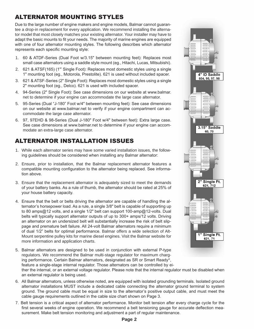
ALTERNATOR MOUNTING STYLESDue to the large number of engine makers and engine models, Balmar cannot guaran-tee a drop-in replacement for every application. We recommend installing the alterna-tor model that most closely matches your existing alternator. Your installer may have to adapt the basic mounts to fit your needs. The majority of marine engines are equipped with one of four alternator mounting styles. The following describes which alternator represents each specific mounting style:
1. 60 & ATDF-Series (Dual Foot w/3.15" between mounting feet): Replaces most small case alternators using a saddle style mount (eg., Hitachi, Lucas, Mitsubishi).
2. 621 & ATSF(165) (1"’ Single Foot): Replaces most domestic styles using a single 1" mounting foot (eg., Motorola, Prestolite). 621 is used without included spacer.
3. 621 & ATSF-Series (2" Single Foot): Replaces most domestic styles using a single 2" mounting foot (eg., Delco). 621 is used with included spacer.
4. 94-Series (2" Single Foot): See case dimensions on our website at www.balmar.net to determine if your engine can accommodate the large case alternator.
5. 95-Series (Dual “J-180” Foot w/4" between mounting feet): See case dimensions on our website at www.balmar.net to verify if your engine compartment can ac-commodate the large case alternator.
6. 97, 97EHD & 98-Series (Dual J-180" Foot w/4" between feet): Extra large case. See case dimensions at www.balmar.net to determine if your engine can accom-modate an extra-large case alternator.
ALTERNATOR INSTALLATION ISSUES1. While each alternator series may have some varied installation issues, the follow-
ing guidelines should be considered when installing any Balmar alternator:
2. Ensure, prior to installation, that the Balmar replacement alternator features a compatible mounting configuration to the alternator being replaced. See informa-tion above.
3. Ensure that the replacement alternator is adequately sized to meet the demands of your battery banks. As a rule of thumb, the alternator should be rated at 25% of your house battery capacity.
4. Ensure that the belt or belts driving the alternator are capable of handling the al-ternator’s horsepower load. As a rule, a single 3/8" belt is capable of supporting up to 80 amps@12 volts, and a single 1/2" belt can support 100-amp@12-volts. Dual belts will typically support alternator outputs of up to 300+ amps/12 volts. Driving an alternator on an undersized belt will substantially increase the risk of belt slip-page and premature belt failure. All 24-volt Balmar alternators require a minimum of dual 1/2” belts for optimal performance. Balmar offers a wide selection of Alt-Mount serpentine pulley kits for marine diesel engines. Visit the Balmar website for more information and application charts.
5. Balmar alternators are designed to be used in conjunction with external P-type regulators. We recommend the Balmar multi-stage regulator for maximum charg-ing performance. Certain Balmar alternators, designated as SR or Smart Ready®, feature a single-stage internal regulator. Those alternators can be controlled by ei-ther the internal, or an external voltage regulator. Please note that the internal regulator must be disabled when an external regulator is being used.
6. All Balmar alternators, unless otherwise noted, are equipped with isolated grounding terminals. Isolated ground alternator installations MUST include a dedicated cable connecting the alternator ground terminal to system ground. The ground cable must be equal in size to the alternator’s positive output cable, and must meet the cable gauge requirements outlined in the cable size chart shown on Page 3.
7. Belt tension is a critical aspect of alternator performance. Monitor belt tension after every charge cycle for the first several weeks of engine operation. We recommend a belt tensioning gauge for accurate deflection mea-surement. Make belt tension monitoring and adjustment a part of regular maintenance.
2
Page
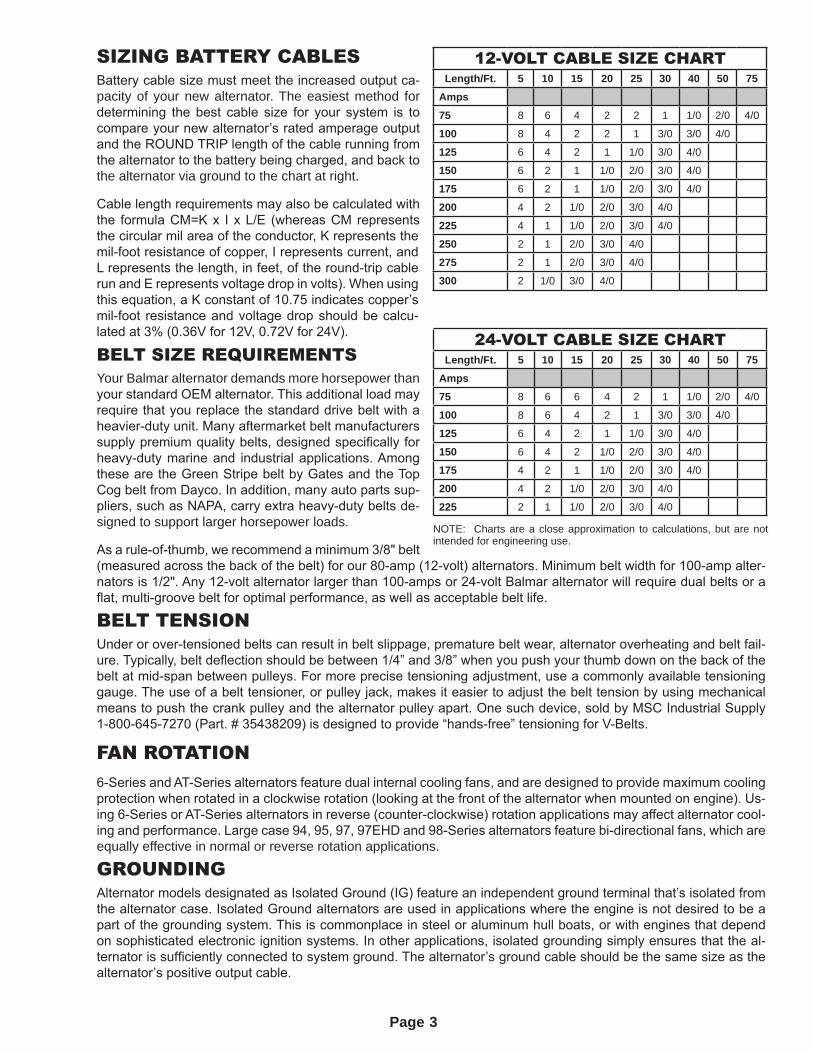
SIZING BATTERY CABLESBattery cable size must meet the increased output ca-pacity of your new alternator. The easiest method for determining the best cable size for your system is to compare your new alternator’s rated amperage output and the ROUND TRIP length of the cable running from the alternator to the battery being charged, and back to the alternator via ground to the chart at right.
Cable length requirements may also be calculated with the formula CM=K x I x L/E (whereas CM represents the circular mil area of the conductor, K represents the mil-foot resistance of copper, I represents current, and L represents the length, in feet, of the round-trip cable run and E represents voltage drop in volts). When using this equation, a K constant of 10.75 indicates copper’s mil-foot resistance and voltage drop should be calcu-lated at 3% (0.36V for 12V, 0.72V for 24V).
BELT SIZE REQUIREMENTSYour Balmar alternator demands more horsepower than your standard OEM alternator. This additional load may require that you replace the standard drive belt with a heavier-duty unit. Many aftermarket belt manufacturers supply premium quality belts, designed specifically for heavy-duty marine and industrial applications. Among these are the Green Stripe belt by Gates and the Top Cog belt from Dayco. In addition, many auto parts sup-pliers, such as NAPA, carry extra heavy-duty belts de-signed to support larger horsepower loads.
As a rule-of-thumb, we recommend a minimum 3/8" belt (measured across the back of the belt) for our 80-amp (12-volt) alternators. Minimum belt width for 100-amp alter-nators is 1/2". Any 12-volt alternator larger than 100-amps or 24-volt Balmar alternator will require dual belts or a flat, multi-groove belt for optimal performance, as well as acceptable belt life.
BELT TENSIONUnder or over-tensioned belts can result in belt slippage, premature belt wear, alternator overheating and belt fail-ure. Typically, belt deflection should be between 1/4” and 3/8” when you push your thumb down on the back of the belt at mid-span between pulleys. For more precise tensioning adjustment, use a commonly available tensioning gauge. The use of a belt tensioner, or pulley jack, makes it easier to adjust the belt tension by using mechanical means to push the crank pulley and the alternator pulley apart. One such device, sold by MSC Industrial Supply 1-800-645-7270 (Part. # 35438209) is designed to provide “hands-free” tensioning for V-Belts.
FAN ROTATION6-Series and AT-Series alternators feature dual internal cooling fans, and are designed to provide maximum cooling protection when rotated in a clockwise rotation (looking at the front of the alternator when mounted on engine). Us-ing 6-Series or AT-Series alternators in reverse (counter-clockwise) rotation applications may affect alternator cool-ing and performance. Large case 94, 95, 97, 97EHD and 98-Series alternators feature bi-directional fans, which are equally effective in normal or reverse rotation applications.
GROUNDINGAlternator models designated as Isolated Ground (IG) feature an independent ground terminal that’s isolated from the alternator case. Isolated Ground alternators are used in applications where the engine is not desired to be a part of the grounding system. This is commonplace in steel or aluminum hull boats, or with engines that depend on sophisticated electronic ignition systems. In other applications, isolated grounding simply ensures that the al-ternator is sufficiently connected to system ground. The alternator’s ground cable should be the same size as the alternator’s positive output cable.
12-VOLT CABLE SIZE CHARTLength/Ft. 5 10 15 20 25 30 40 50 75
Amps
75 8 6 4 2 2 1 1/0 2/0 4/0
100 8 4 2 2 1 3/0 3/0 4/0
125 6 4 2 1 1/0 3/0 4/0
150 6 2 1 1/0 2/0 3/0 4/0
175 6 2 1 1/0 2/0 3/0 4/0
200 4 2 1/0 2/0 3/0 4/0
225 4 1 1/0 2/0 3/0 4/0
250 2 1 2/0 3/0 4/0
275 2 1 2/0 3/0 4/0
300 2 1/0 3/0 4/0
24-VOLT CABLE SIZE CHARTLength/Ft. 5 10 15 20 25 30 40 50 75
Amps
75 8 6 6 4 2 1 1/0 2/0 4/0
100 8 6 4 2 1 3/0 3/0 4/0
125 6 4 2 1 1/0 3/0 4/0
150 6 4 2 1/0 2/0 3/0 4/0
175 4 2 1 1/0 2/0 3/0 4/0
200 4 2 1/0 2/0 3/0 4/0
225 2 1 1/0 2/0 3/0 4/0
NOTE: Charts are a close approximation to calculations, but are not intended for engineering use.
3
Page
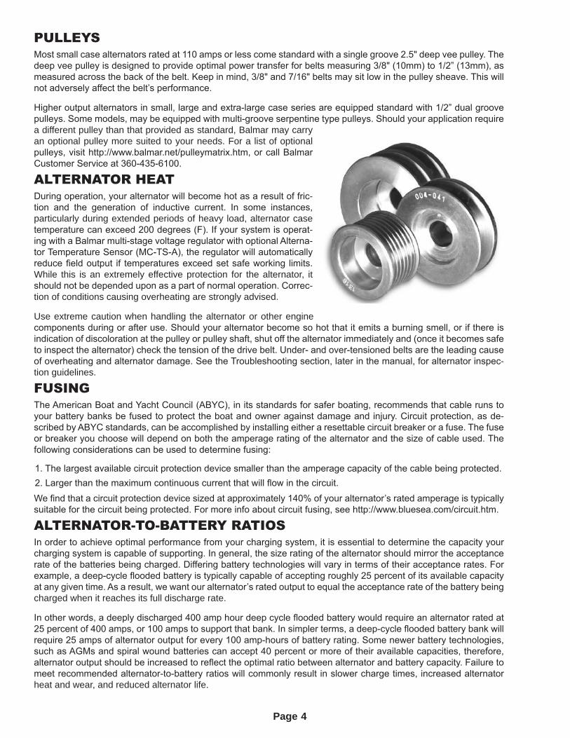
PULLEYSMost small case alternators rated at 110 amps or less come standard with a single groove 2.5" deep vee pulley. The deep vee pulley is designed to provide optimal power transfer for belts measuring 3/8" (10mm) to 1/2” (13mm), as measured across the back of the belt. Keep in mind, 3/8" and 7/16" belts may sit low in the pulley sheave. This will not adversely affect the belt’s performance.
Higher output alternators in small, large and extra-large case series are equipped standard with 1/2” dual groove pulleys. Some models, may be equipped with multi-groove serpentine type pulleys. Should your application require a different pulley than that provided as standard, Balmar may carry an optional pulley more suited to your needs. For a list of optional pulleys, visit http://www.balmar.net/pulleymatrix.htm, or call Balmar Customer Service at 360-435-6100.
ALTERNATOR HEATDuring operation, your alternator will become hot as a result of fric-tion and the generation of inductive current. In some instances, particularly during extended periods of heavy load, alternator case temperature can exceed 200 degrees (F). If your system is operat-ing with a Balmar multi-stage voltage regulator with optional Alterna-tor Temperature Sensor (MC-TS-A), the regulator will automatically reduce field output if temperatures exceed set safe working limits. While this is an extremely effective protection for the alternator, it should not be depended upon as a part of normal operation. Correc-tion of conditions causing overheating are strongly advised.
Use extreme caution when handling the alternator or other engine components during or after use. Should your alternator become so hot that it emits a burning smell, or if there is indication of discoloration at the pulley or pulley shaft, shut off the alternator immediately and (once it becomes safe to inspect the alternator) check the tension of the drive belt. Under- and over-tensioned belts are the leading cause of overheating and alternator damage. See the Troubleshooting section, later in the manual, for alternator inspec-tion guidelines.
FUSINGThe American Boat and Yacht Council (ABYC), in its standards for safer boating, recommends that cable runs to your battery banks be fused to protect the boat and owner against damage and injury. Circuit protection, as de-scribed by ABYC standards, can be accomplished by installing either a resettable circuit breaker or a fuse. The fuse or breaker you choose will depend on both the amperage rating of the alternator and the size of cable used. The following considerations can be used to determine fusing:
1. The largest available circuit protection device smaller than the amperage capacity of the cable being protected.2. Larger than the maximum continuous current that will flow in the circuit.We find that a circuit protection device sized at approximately 140% of your alternator’s rated amperage is typically suitable for the circuit being protected. For more info about circuit fusing, see http://www.bluesea.com/circuit.htm.
ALTERNATOR-TO-BATTERY RATIOSIn order to achieve optimal performance from your charging system, it is essential to determine the capacity your charging system is capable of supporting. In general, the size rating of the alternator should mirror the acceptance rate of the batteries being charged. Differing battery technologies will vary in terms of their acceptance rates. For example, a deep-cycle flooded battery is typically capable of accepting roughly 25 percent of its available capacity at any given time. As a result, we want our alternator’s rated output to equal the acceptance rate of the battery being charged when it reaches its full discharge rate.
In other words, a deeply discharged 400 amp hour deep cycle flooded battery would require an alternator rated at 25 percent of 400 amps, or 100 amps to support that bank. In simpler terms, a deep-cycle flooded battery bank will require 25 amps of alternator output for every 100 amp-hours of battery rating. Some newer battery technologies, such as AGMs and spiral wound batteries can accept 40 percent or more of their available capacities, therefore, alternator output should be increased to reflect the optimal ratio between alternator and battery capacity. Failure to meet recommended alternator-to-battery ratios will commonly result in slower charge times, increased alternator heat and wear, and reduced alternator life.
4
Page
MULTIPLE BANK CHARGING OPTIONSWhen charging a single starting battery, the alternator can be connected to the battery directly, or via an ON/OFF switch. More typically, in a marine system, the alternator will be supporting a smaller starting battery and larger house battery bank -- or a starting battery, along with multiple banks for house loads, inverter loads, windlass or thruster.
Many methods of multi-bank charge control are available, ranging from manual switches to products like Balmar’s Digital Duo Charge (which automatically provides charging current to the starting battery whenever charging volt-age is present at the house battery). The following section outlines many of the most commonly used options for multiple-bank battery management:
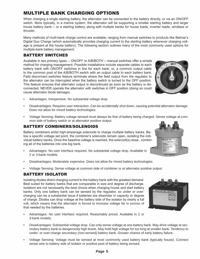
BATTERY SWITCHESAvailable in two primary types -- ON/OFF or A/B/BOTH -- manual switches offer a simple method for charging management. Possible installations include separate cables to each battery bank with ON/OFF switches in line for each bank, or, a common output cable to the common post of the A/B/BOTH switch with an output cable to each battery bank. Field disconnect switches feature terminals where the field output from the regulator to the alternator can be interrupted when the battery switch is turned to the OFF position. This feature ensures that alternator output is discontinued as soon as the battery is dis-connected. NEVER operate the alternator with switches in OFF position (doing so could cause alternator diode damage).
• Advantages: Inexpensive. No substantial voltage drop.
• Disadvantages: Requires user interaction. Can be accidentally shut down, causing potential alternator damage. Does not allow for mixed battery technologies.
• Voltage Sensing: Battery voltage sensed must always be that of battery being charged. Sense voltage at com-mon side of battery switch or at alternator positive output.
BATTERY COMBINERS/SOLENOIDSBattery combiners enlist high-amperage solenoids to charge multiple battery banks. Be-low a specific voltage set point, the combiner’s solenoids remain open, isolating the indi-vidual battery banks. Once the baseline voltage is reached, the solenoid(s) close , combin-ing all of the batteries into one big bank.
• Advantages: No user interface required. No substantial voltage drop. Available in 2 or 3-bank models.
• Disadvantages: Moderately expensive. Does not allow for mixed battery technologies.
• Voltage Sensing: Sense voltage at common side of combiner or at alternator positive output.
BATTERY ISOLATORIsolating diodes direct charging current to the battery bank with the greatest demand. Best suited for battery banks that are comparable in size and degree of discharge. Isolators are not necessarily the best choice when charging house and start battery banks. Only one battery bank can be sensed by the regulator, so under or over-charging can be a substantial issue if batteries are dissimilar in capacity or degree of charge. Diodes can drop voltage at the battery side of the isolator by nearly a full volt, which means that the alternator is forced to increase voltage far in excess of that needed by the batteries.
• Advantages: No user interface required. Reasonably priced. Available in 2 or 3-bank models.
• Disadvantages: Substantial voltage drop. Can only sense voltage at one battery bank. May drive voltage at sec-ondary battery bank to dangerously high levels. May hold high voltage for too long at smaller bank. Tendency to under- or over-charge secondary (non-sensed) battery bank. Greater chance of early battery failure.
• Voltage Sensing: Voltage must be sensed at most commonly used battery bank (typically house). Connect sense wire to battery side of isolator or positive post of battery being sensed.
5
Page
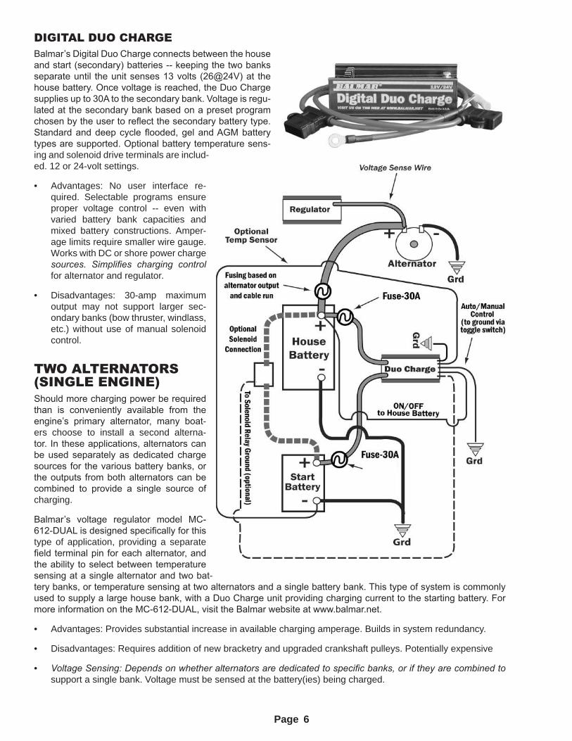
DIGITAL DUO CHARGEBalmar’s Digital Duo Charge connects between the house and start (secondary) batteries -- keeping the two banks separate until the unit senses 13 volts (26@24V) at the house battery. Once voltage is reached, the Duo Charge supplies up to 30A to the secondary bank. Voltage is regu-lated at the secondary bank based on a preset program chosen by the user to reflect the secondary battery type. Standard and deep cycle flooded, gel and AGM battery types are supported. Optional battery temperature sens-ing and solenoid drive terminals are includ-ed. 12 or 24-volt settings.
• Advantages: No user interface re-quired. Selectable programs ensure proper voltage control -- even with varied battery bank capacities and mixed battery constructions. Amper-age limits require smaller wire gauge. Works with DC or shore power charge sources. Simplifies charging control for alternator and regulator.
• Disadvantages: 30-amp maximum output may not support larger sec-ondary banks (bow thruster, windlass, etc.) without use of manual solenoid control.
TWO ALTERNATORS (SINGLE ENGINE)Should more charging power be required than is conveniently available from the engine’s primary alternator, many boat-ers choose to install a second alterna-tor. In these applications, alternators can be used separately as dedicated charge sources for the various battery banks, or the outputs from both alternators can be combined to provide a single source of charging.
Balmar’s voltage regulator model MC-612-DUAL is designed specifically for this type of application, providing a separate field terminal pin for each alternator, and the ability to select between temperature sensing at a single alternator and two bat-tery banks, or temperature sensing at two alternators and a single battery bank. This type of system is commonly used to supply a large house bank, with a Duo Charge unit providing charging current to the starting battery. For more information on the MC-612-DUAL, visit the Balmar website at www.balmar.net.
• Advantages: Provides substantial increase in available charging amperage. Builds in system redundancy.
• Disadvantages: Requires addition of new bracketry and upgraded crankshaft pulleys. Potentially expensive
• Voltage Sensing: Depends on whether alternators are dedicated to specific banks, or if they are combined to support a single bank. Voltage must be sensed at the battery(ies) being charged.
6
Page
TWIN ENGINE ISSUESTwin engine applications pose some unique challenges in addressing battery needs. Some primary charging con-figurations are as follows:
1. Dedicate Alternator #1 to charge engine starting batteries. Dedicate Alternator #2 to the house battery bank.2. Combine outputs from Alternator #1 and Alternator #2 to provide increased charging amperage for the main
(house) battery bank, and supply the engine (and other secondary) batteries via Digital Duo Charges or com-biners. Combining the output from two alternators on two engines will require the use of Balmar’s Centerfielder (described below).
This configuration will require that both alternators are equipped with Max Charge regulators, which are designed to provide sufficient field current to drive two alternators. For additional information, download the Centerfielder instructional manual from the Balmar website; www.balmar.net.
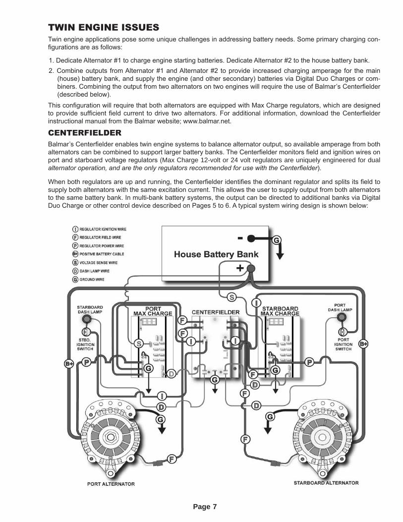
CENTERFIELDERBalmar’s Centerfielder enables twin engine systems to balance alternator output, so available amperage from both alternators can be combined to support larger battery banks. The Centerfielder monitors field and ignition wires on port and starboard voltage regulators (Max Charge 12-volt or 24 volt regulators are uniquely engineered for dual alternator operation, and are the only regulators recommended for use with the Centerfielder).
When both regulators are up and running, the Centerfielder identifies the dominant regulator and splits its field to supply both alternators with the same excitation current. This allows the user to supply output from both alternators to the same battery bank. In multi-bank battery systems, the output can be directed to additional banks via Digital Duo Charge or other control device described on Pages 5 to 6. A typical system wiring design is shown below:
7
Page
INSTALLATION ISSUES BY ALTERNATOR SERIES6-SERIES ALTERNATORSSix-Series models are among the most frequently installed Balmar alternators. Designed to replace a wide range of OEM alternators on most common marine gasoline or diesel engines, 6-Series alternators feature three mounting styles;
• 60-Series models, which feature a saddle mount with a 3.15" space between front and rear mounting feet.
• 621-Series models, which feature a single-foot (spindle) mount. These alternators include a 1" mounting foot for Motorola-style engine applications, and a bushed 1" spacer, which allows the 621-Series to be installed on engines requiring a 2" (Delco-style) single foot mount.
• 604-Series models, which feature a J-180, saddle mount with a 4" space between front and rear mounting feet.
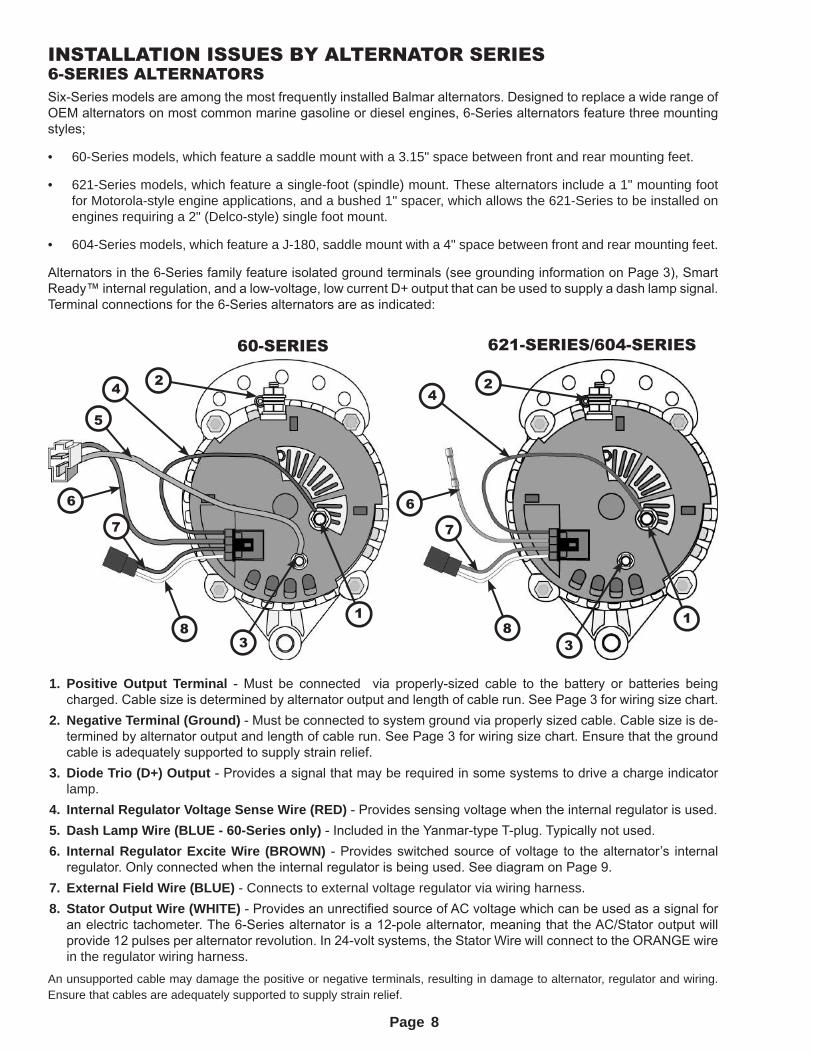
Alternators in the 6-Series family feature isolated ground terminals (see grounding information on Page 3), Smart Ready™ internal regulation, and a low-voltage, low current D+ output that can be used to supply a dash lamp signal. Terminal connections for the 6-Series alternators are as indicated:
60-SERIES 621-SERIES/604-SERIES
4 4
88
7
5
766
33
2 2
11
1. Positive Output Terminal - Must be connected via properly-sized cable to the battery or batteries being charged. Cable size is determined by alternator output and length of cable run. See Page 3 for wiring size chart.
2. Negative Terminal (Ground) - Must be connected to system ground via properly sized cable. Cable size is de-termined by alternator output and length of cable run. See Page 3 for wiring size chart. Ensure that the ground cable is adequately supported to supply strain relief.
3. Diode Trio (D+) Output - Provides a signal that may be required in some systems to drive a charge indicator lamp.
4. Internal Regulator Voltage Sense Wire (RED) - Provides sensing voltage when the internal regulator is used.5. Dash Lamp Wire (BLUE - 60-Series only) - Included in the Yanmar-type T-plug. Typically not used.6. Internal Regulator Excite Wire (BROWN) - Provides switched source of voltage to the alternator’s internal
regulator. Only connected when the internal regulator is being used. See diagram on Page 9.7. External Field Wire (BLUE) - Connects to external voltage regulator via wiring harness.
8. Stator Output Wire (WHITE) - Provides an unrectified source of AC voltage which can be used as a signal for an electric tachometer. The 6-Series alternator is a 12-pole alternator, meaning that the AC/Stator output will provide 12 pulses per alternator revolution. In 24-volt systems, the Stator Wire will connect to the ORANGE wire in the regulator wiring harness.
An unsupported cable may damage the positive or negative terminals, resulting in damage to alternator, regulator and wiring. Ensure that cables are adequately supported to supply strain relief.
8
Page
USING THE SMARTREADY®
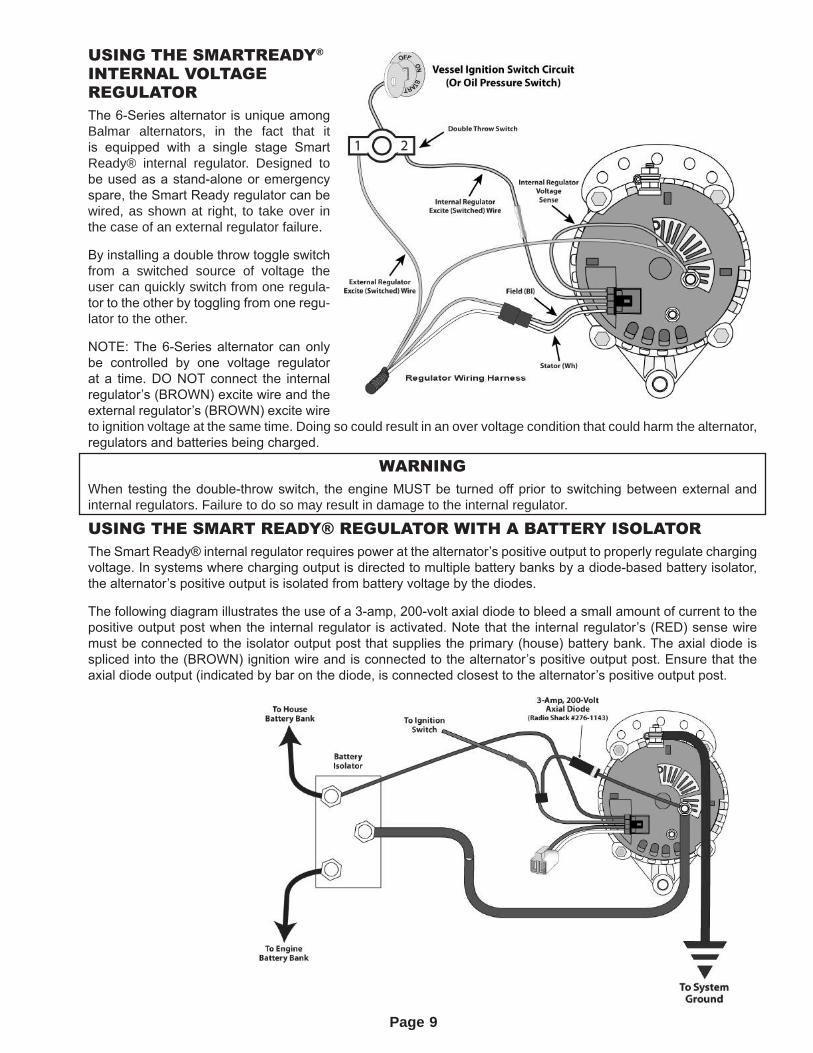
INTERNAL VOLTAGE REGULATORThe 6-Series alternator is unique among Balmar alternators, in the fact that it is equipped with a single stage Smart Ready® internal regulator. Designed to be used as a stand-alone or emergency spare, the Smart Ready regulator can be wired, as shown at right, to take over in the case of an external regulator failure.
By installing a double throw toggle switch from a switched source of voltage the user can quickly switch from one regula-tor to the other by toggling from one regu-lator to the other.
NOTE: The 6-Series alternator can only be controlled by one voltage regulator at a time. DO NOT connect the internal regulator’s (BROWN) excite wire and the external regulator’s (BROWN) excite wire to ignition voltage at the same time. Doing so could result in an over voltage condition that could harm the alternator, regulators and batteries being charged.
WARNINGWhen testing the double-throw switch, the engine MUST be turned off prior to switching between external and internal regulators. Failure to do so may result in damage to the internal regulator.
USING THE SMART READY® REGULATOR WITH A BATTERY ISOLATORThe Smart Ready® internal regulator requires power at the alternator’s positive output to properly regulate charging voltage. In systems where charging output is directed to multiple battery banks by a diode-based battery isolator, the alternator’s positive output is isolated from battery voltage by the diodes.
The following diagram illustrates the use of a 3-amp, 200-volt axial diode to bleed a small amount of current to the positive output post when the internal regulator is activated. Note that the internal regulator’s (RED) sense wire must be connected to the isolator output post that supplies the primary (house) battery bank. The axial diode is spliced into the (BROWN) ignition wire and is connected to the alternator’s positive output post. Ensure that the axial diode output (indicated by bar on the diode, is connected closest to the alternator’s positive output post.
9
Page
AT-SERIES ALTERNATORS – 165AAdvanced Technology (AT-Series) alternators are available in three mounting configurations:
• SF models: 1" or 2" single foot.
• DF models: 3.15” ID saddle mount
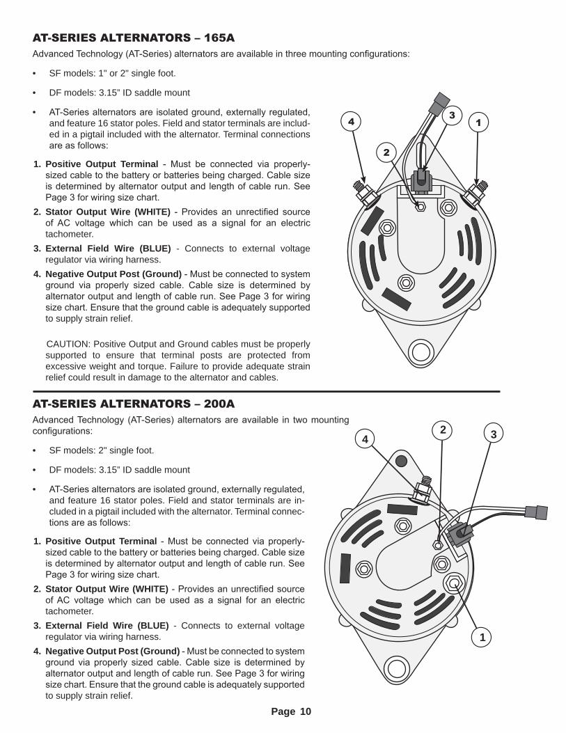
• AT-Series alternators are isolated ground, externally regulated, and feature 16 stator poles. Field and stator terminals are includ-ed in a pigtail included with the alternator. Terminal connections are as follows:
1. Positive Output Terminal - Must be connected via properly-sized cable to the battery or batteries being charged. Cable size is determined by alternator output and length of cable run. See Page 3 for wiring size chart.
2. Stator Output Wire (WHITE) - Provides an unrectified source of AC voltage which can be used as a signal for an electric tachometer.
3. External Field Wire (BLUE) - Connects to external voltage regulator via wiring harness.
4. Negative Output Post (Ground) - Must be connected to system ground via properly sized cable. Cable size is determined by alternator output and length of cable run. See Page 3 for wiring size chart. Ensure that the ground cable is adequately supported to supply strain relief.
CAUTION: Positive Output and Ground cables must be properly supported to ensure that terminal posts are protected from excessive weight and torque. Failure to provide adequate strain relief could result in damage to the alternator and cables.
AT-SERIES ALTERNATORS – 200AAdvanced Technology (AT-Series) alternators are available in two mounting configurations:
• SF models: 2" single foot.
• DF models: 3.15” ID saddle mount
• AT-Series alternators are isolated ground, externally regulated, and feature 16 stator poles. Field and stator terminals are in-cluded in a pigtail included with the alternator. Terminal connec-tions are as follows:
1. Positive Output Terminal - Must be connected via properly-sized cable to the battery or batteries being charged. Cable size is determined by alternator output and length of cable run. See Page 3 for wiring size chart.
2. Stator Output Wire (WHITE) - Provides an unrectified source of AC voltage which can be used as a signal for an electric tachometer.
3. External Field Wire (BLUE) - Connects to external voltage regulator via wiring harness.
4. Negative Output Post (Ground) - Must be connected to system ground via properly sized cable. Cable size is determined by alternator output and length of cable run. See Page 3 for wiring size chart. Ensure that the ground cable is adequately supported to supply strain relief.
4 1
2
3
1
2 34
10
Page
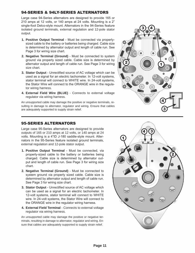
94-SERIES & 94LY-SERIES ALTERNATORSLarge case 94-Series alternators are designed to provide 165 or 210 amps at 12 volts, or 140 amps at 24 volts. Mounting is a 2” single-foot Delco-style mount. Alternators in the 94-Series feature isolated ground terminals, external regulation and 12-pole stator output.
1. Positive Output Terminal - Must be connected via properly-sized cable to the battery or batteries being charged. Cable size is determined by alternator output and length of cable run. See Page 3 for wiring size chart.
2. Negative Terminal (Ground) - Must be connected to system ground via properly sized cable. Cable size is determined by alternator output and length of cable run. See Page 3 for wiring size chart.
3. Stator Output - Unrectified source of AC voltage which can be used as a signal for an electric tachometer. In 12-volt systems, stator terminal will connect to WHITE wire. In 24-volt systems, the Stator Wire will connect to the ORANGE wire in the regula-tor wiring harness.
4. External Field Wire (BLUE) - Connects to external voltage regulator via wiring harness.
An unsupported cable may damage the positive or negative terminals, re-sulting in damage to alternator, regulator and wiring. Ensure that cables are adequately supported to supply strain relief.
2 1
3 4
3
4
95-SERIES ALTERNATORSLarge case 95-Series alternators are designed to provide outputs of 165 or 210 amps at 12 volts, or 140 amps at 24 volts. Mounting is a 4”ID J-180 saddle-style mount. Alter-nators in the 95-Series feature isolated ground terminals, external regulation and 12-pole stator output.
1. Positive Output Terminal - Must be connected, via properly-sized cable to the battery or batteries being charged. Cable size is determined by alternator out-put and length of cable run. See Page 3 for wiring size chart.
2. Negative Terminal (Ground) - Must be connected to system ground via properly sized cable. Cable size is determined by alternator output and length of cable run. See Page 3 for wiring size chart.
3. Stator Output - Unrectified source of AC voltage which can be used as a signal for an electric tachometer. In 12-volt systems, stator terminal will connect to WHITE wire. In 24-volt systems, the Stator Wire will connect to the ORANGE wire in the regulator wiring harness.
4. External Field Terminal - Connects to external voltage regulator via wiring harness.
An unsupported cable may damage the positive or negative ter-minals, resulting in damage to alternator, regulator and wiring. En-sure that cables are adequately supported to supply strain relief.
4 3
2
1
11
Page
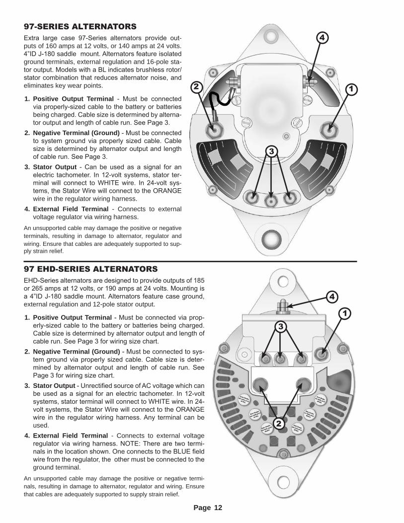
97-SERIES ALTERNATORSExtra large case 97-Series alternators provide out-puts of 160 amps at 12 volts, or 140 amps at 24 volts. 4”ID J-180 saddle mount. Alternators feature isolated ground terminals, external regulation and 16-pole sta-tor output. Models with a BL indicates brushless rotor/stator combination that reduces alternator noise, and eliminates key wear points.
1. Positive Output Terminal - Must be connected via properly-sized cable to the battery or batteries being charged. Cable size is determined by alterna-tor output and length of cable run. See Page 3.
2. Negative Terminal (Ground) - Must be connected to system ground via properly sized cable. Cable size is determined by alternator output and length of cable run. See Page 3.
3. Stator Output - Can be used as a signal for an electric tachometer. In 12-volt systems, stator ter-minal will connect to WHITE wire. In 24-volt sys-tems, the Stator Wire will connect to the ORANGE wire in the regulator wiring harness.
4. External Field Terminal - Connects to external voltage regulator via wiring harness.
An unsupported cable may damage the positive or negative terminals, resulting in damage to alternator, regulator and wiring. Ensure that cables are adequately supported to sup-ply strain relief.
97 EHD-SERIES ALTERNATORSEHD-Series alternators are designed to provide outputs of 185 or 265 amps at 12 volts, or 190 amps at 24 volts. Mounting is a 4”ID J-180 saddle mount. Alternators feature case ground, external regulation and 12-pole stator output.
1. Positive Output Terminal - Must be connected via prop-erly-sized cable to the battery or batteries being charged. Cable size is determined by alternator output and length of cable run. See Page 3 for wiring size chart.
2. Negative Terminal (Ground) - Must be connected to sys-tem ground via properly sized cable. Cable size is deter-mined by alternator output and length of cable run. See Page 3 for wiring size chart.
3. Stator Output - Unrectified source of AC voltage which can be used as a signal for an electric tachometer. In 12-volt systems, stator terminal will connect to WHITE wire. In 24-volt systems, the Stator Wire will connect to the ORANGE wire in the regulator wiring harness. Any terminal can be used.
4. External Field Terminal - Connects to external voltage regulator via wiring harness. NOTE: There are two termi-nals in the location shown. One connects to the BLUE field wire from the regulator, the other must be connected to the ground terminal.
An unsupported cable may damage the positive or negative termi-nals, resulting in damage to alternator, regulator and wiring. Ensure that cables are adequately supported to supply strain relief.
4
3
12
4
3
2
1
12
Page 13
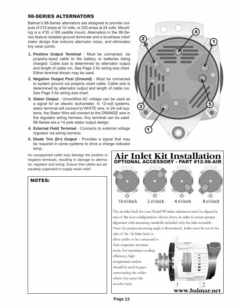
98-SERIES ALTERNATORSBalmar’s 98-Series alternators are designed to provide out-puts of 310 amps at 12 volts, or 220 amps at 24 volts. Mount-ing is a 4”ID J-180 saddle mount. Alternators in the 98-Se-ries feature isolated ground terminals and a brushless rotor/stator design that reduces alternator noise, and eliminates key wear points.
1. Positive Output Terminal - Must be connected, via properly-sized cable to the battery or batteries being charged. Cable size is determined by alternator output and length of cable run. See Page 3 for wiring size chart. Either terminal shown may be used.
2. Negative Output Post (Ground) - Must be connected to system ground via properly sized cable. Cable size is determined by alternator output and length of cable run. See Page 3 for wiring size chart.
3. Stator Output - Unrectified AC voltage can be used as a signal for an electric tachometer. In 12-volt systems, stator terminal will connect to WHITE wire. In 24-volt sys-tems, the Stator Wire will connect to the ORANGE wire in the regulator wiring harness. Any terminal can be used. 98-Series are a 14 pole stator output design.
4. External Field Terminal - Connects to external voltage regulator via wiring harness.
5. Diode Trio (D+) Output - Provides a signal that may be required in some systems to drive a charge indicator lamp.
An unsupported cable may damage the positive or negative terminals, resulting in damage to alterna-tor, regulator and wiring. Ensure that cables are ad-equately supported to supply strain relief.
5
4
3
2 1
1
NOTES:
OPTIONAL ACCESSORY - PART #12-98-AIR
Page
SYSTEM TROUBLESHOOTINGDetermining the causes of failures in an electrical system is a “step by step” process. Before you begin your search to determine if the failure can be attributed to the alternator or the voltage regulator, we recommend you inspect and clean all system electrical connections. Most charging system problems will be corrected by performing the following steps:
1. Remove and clean all charging system electrical connections from the alternator, the batteries and wire runs (this includes the ground side). Also, check the voltage regulator’s harness for resistance. Wires and terminals can and will become corroded and may need to be cleaned or replaced. Check all fusing in the regulator harness and alternator output cables.
2. Charge all batteries to their proper fully charged state and determine if they are serviceable. If your batteries are flooded-type, use your hydrometer to determine their condition.
3. Check and tighten alternator belt. If the belt shows signs of wear or damage, replace the belt or belts. Always replace existing belts with the finest quality replacements available. In applications where dual belts are used, always try to replace both belts at the same time with matched belts.
After determining that your batteries and wiring are in suitable condition, use the following tests to determine if charging problems are a result of a faulty alternator or regulator.
These tests provide an opportunity to isolate the alternator, regulator and wiring harness in order to determine which component may be malfunctioning. In order to perform these tests, you will need a simple test lamp (available at most auto parts or marine hardware stores). A digital handheld multimeter can also be helpful in checking for voltage drop and resistance in wiring and terminal connections. A clamp-type DC Amp meter may be useful in diagnosing amperage issues. A 10’ long, 14-gauge wire with insulated alligator clips at each end provides the ability to take measurements with your test lamp or multi-meter with a centralized ground point. NOTE: Regulator tests may vary by model. Refer to your regulator model’s manual for specific troubleshooting instructions.
VOLTAGE REGULATOR DIAGNOSISThe failure of the voltage regulator to provide field current to the alternator will cause the charging system to fail. To begin the voltage regulator tests, check to see that the regulator display is lit when the engine is running. If the regulator display fails to light after the engine is started:
1. Connect your ground extension wire (as described above) to your second ground terminal at the regulator. Con-nect the other end of the extension to the ground probe of the test light. Turn your ignition switch to the ON posi-tion -- if the regulator’s brown (ignition) wire is connected to an oil pressure switch, connect a jump wire across the oil pressure switch.
2. Apply the test light’s positive probe to the red (power) wire in regulator’s black 4-wire plug. If the test light does not illuminate, follow the red (power) wire to its source (at the battery, alternator output or common side of the battery switch) and test for power there.
3. If the red (power) wire has power at that location, replace the 10-amp fuse in the red (power) wire and re-check for power at the regulator wiring plug. If the wire has no power at the regulator end, inspect for damage along the length of the wire and repair/replace as needed.
4. If the red (power) wire lights the test lamp, but the regulator display remains unlit, apply the positive probe of the tester to the brown (ignition) wire. If the test lamp remains unlit, follow the brown (ignition) wire to its source and test the source with your test lamp. If the source illuminates the test lamp, repair or replace any damaged wire or connectors needed until the test lamp indicates current at the regulator end of the brown (ignition) wire.
5. If the regulator is a Max Charge with an independent Positive Battery Sense wire, check that wire as well. Repair/replace damaged wire, connectors or fusing, if no voltage is recorded on that wire.
If the regulator display is illuminated, yet charging is not occurring (be sure to wait beyond the 45-second delay before taking test readings):
1. Apply the test lamp’s positive probe to the blue wire in the regulator’s black 4-wire plug (with negative probe connected to the regulator ground). If the test lamp does not illuminate, the regulator may be damaged. If the regulator is within the warranty period call our Customer Service Department at 360-435-6100.
2. If the test lamp is illuminated, the regulator is providing field current, and the charging problem is likely elsewhere in the charging system.
3. Follow the field wire to its connection at the alternator. Disconnect from the alternator and apply the test lamp to the wire. If the lamp illuminates, the regulator and wiring harness are likely to be good.
14
Page
ALTERNATOR DIAGNOSISOnce the regulator and harness are tested and proven good, disconnect the negative probe of the test lamp from the regulator ground and connect the negative probe to the field terminal of the alternator. Connect the positive probe to the blue (field) wire coming from the regulator.
1. Monitor the test lamp. If the lamp does not illuminate, the alternator may not be completing the connection to ground. Check the ground connections at the alternator to system ground. If you know how, you can use your multimeter to check for resistance between the alternator and ground.
2. If the meter indicates substantial amount of resistance between the alternator and the system ground, a wiring or terminal connection issue is indicated. Re-check system ground cabling and wiring.
3. If an internal fault is indicated as a result of testing, remove the alternator and contact Balmar Customer Service or your local alternator shop for recommendations.
4. If the test lamp is illuminated when connected in series with the regulator field wire and the alternator field termi-nal, place a metallic object (a screwdriver blade works well) near the front of the alternator pulley shaft or the rear bearing cover of the alternator. If the screwdriver blade is magnetically drawn to the alternator, the alternator’s internal components appear to be functioning correctly.
5. If the test lamp is lit and magnetism is detected, you can remove the test lamp, re-connect the blue (field) wire and start the engine. Once the engine is started and the regulator’s initial start delay is complete, voltage should climb to levels set by the regulator.
ALTERNATOR DIAGNOSIS - INDEPENDENT OF REGULATORThe alternator can be tested independently of the regulator and wiring harness by connecting the alternator’s field terminal directly to battery voltage. Once connected to battery voltage, the alternator’s pulley shaft and rear bearing cover should generate a substantial magnetic pull. If no pull is present, an internal wire or positive/negative brush connection may be at fault. To test the alternator only:
1. Connect one side of the test lamp to a source of positive battery voltage. Connect the other to the alternator’s field terminal. If the test lamp illuminates and the alternator indicates magnetic current, start the engine. This is known as full fielding the alternator.
2. With the lamp connected and the engine on, voltage at the alternator’s positive output terminal should steadily climb. The Lamp will act as an in-line resistor, so voltage rise should be moderately controlled. Once charging voltage is indicated (check output voltage with your multi-meter), the engine can be shut down. A steadily climb-ing voltage at the alternator output indicates good alternator functionality.
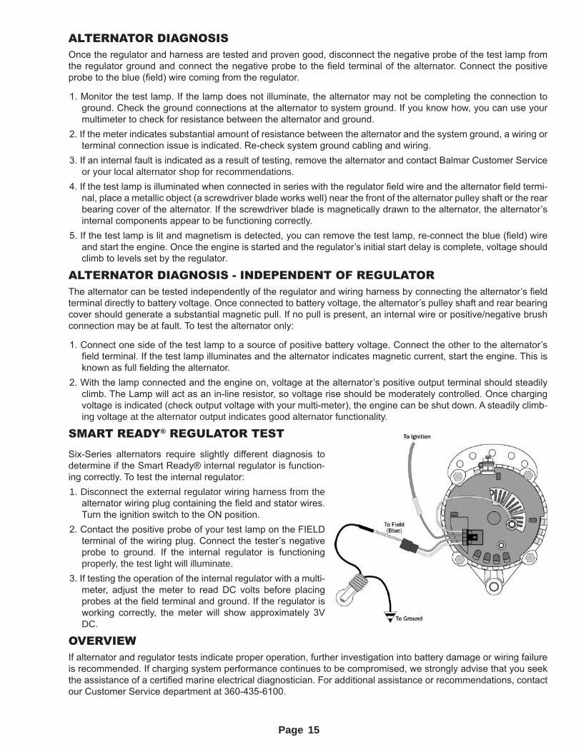
SMART READY® REGULATOR TEST
Six-Series alternators require slightly different diagnosis to determine if the Smart Ready® internal regulator is function-ing correctly. To test the internal regulator:1. Disconnect the external regulator wiring harness from the
alternator wiring plug containing the field and stator wires. Turn the ignition switch to the ON position.
2. Contact the positive probe of your test lamp on the FIELD terminal of the wiring plug. Connect the tester’s negative probe to ground. If the internal regulator is functioning properly, the test light will illuminate.
3. If testing the operation of the internal regulator with a multi-meter, adjust the meter to read DC volts before placing probes at the field terminal and ground. If the regulator is working correctly, the meter will show approximately 3V DC.
OVERVIEWIf alternator and regulator tests indicate proper operation, further investigation into battery damage or wiring failure is recommended. If charging system performance continues to be compromised, we strongly advise that you seek the assistance of a certified marine electrical diagnostician. For additional assistance or recommendations, contact our Customer Service department at 360-435-6100.
15
Page
LIMITED PRODUCT WARRANTYBALMAR warrants to the original consumer/purchaser the product is free from any defects in material or workmanship for a period of one year from the date of purchase. If any such defect is discovered within the warranty period, BALMAR will repair or replace the product free of charge, subject to verification of the defect or malfunction upon delivery or shipping prepaid to BALMAR.
This warranty DOES NOT apply to defects or physical damage resulting from abuse, neglect, accident, improper repair, alteration, modification, or unreasonable use of the products resulting in breakdown, cracked or broken cases nor are parts damaged by fire, water, freezing, collision, theft, explosion, rust, corrosion or items damaged in shipment in route to BALMAR for repair. BALMAR assumes no responsibility for consequential damage or loss or expense arising from these products or any labor required for service or repair.
BALMAR WILL NOT repair or be held responsible for any product sent without proper identification and return address or Return Authorization number clearly marked on the package. You must include proof of date and place of purchase (photocopy of purchase invoice) or we cannot be responsible for repairs or replacement. In order to expedite warranty claims more efficiently, BALMAR asks that prior to returning a defective product for repair, you call their customer service department for a warranty Return Authorization number.
If factory service is required, you can contact our BALMAR Customer Service Department Monday through Thursday, 7:30 AM to 5:30 PM, (PST) 1-360-435-6100 extension “3”. Material required for the repair or replacement for the defective part or product is to be supplied free of charge upon delivery of the defective product to BALMAR, 18930 59th Ave. NE, Arlington, WA 98223. Customer is responsible for all return transportation charges and any air, international or rush delivery expense. BALMAR reserves the right to determine whether to repair or replace defective components.
THE ABOVE LIMITATIONS MAY NOT APPLY TO YOU. SOME STATES DO NOT ALLOW
LIMITATIONS ON HOW LONG AN IMPLIED WARRANTY LASTS. NO PERSON, AGENT, DEALER
IS AUTHORIZED TO GIVE ANY WARRANTY.
BALMAR 353 James Record Rd, Huntsville, AL 35824 Ph: (360) 435-6100, Fax; (360) 435-3210
E-mail: [email protected], Web: www.balmar.net
© 2015 Ballard Commercial Industries, Inc. Unauthorized reproduction of part or all of this manual is forbidden. All of the in-
formation contained in this manual is believed to be accurate as of publication. Balmar retains the right to make changes to any and all products without prior notice, and may not be held responsible for resulting inconsistencies in this manual. Installers are encouraged to visit the Balmar website for the latest product information and service bulletins.
Balmar archives a comprehensive library of instructional manuals for nearly all current and out-of-production products on its website. Visit www.balmar.net and click on “Product Manuals” to see the full list of available documents online.
SUP-0207 | REV A
16