Alternatives to Traditional Manifolds - DADCO · Sectional Mounting Systems SMS® and SMS-i®...
12
Sectional Mounting Systems SMS ® and SMS-i ® ® Alternativ to Tradi tional Ma nifolds PED 2014/68/EU COMPLIANT Catalog No. C13106C
Transcript of Alternatives to Traditional Manifolds - DADCO · Sectional Mounting Systems SMS® and SMS-i®...
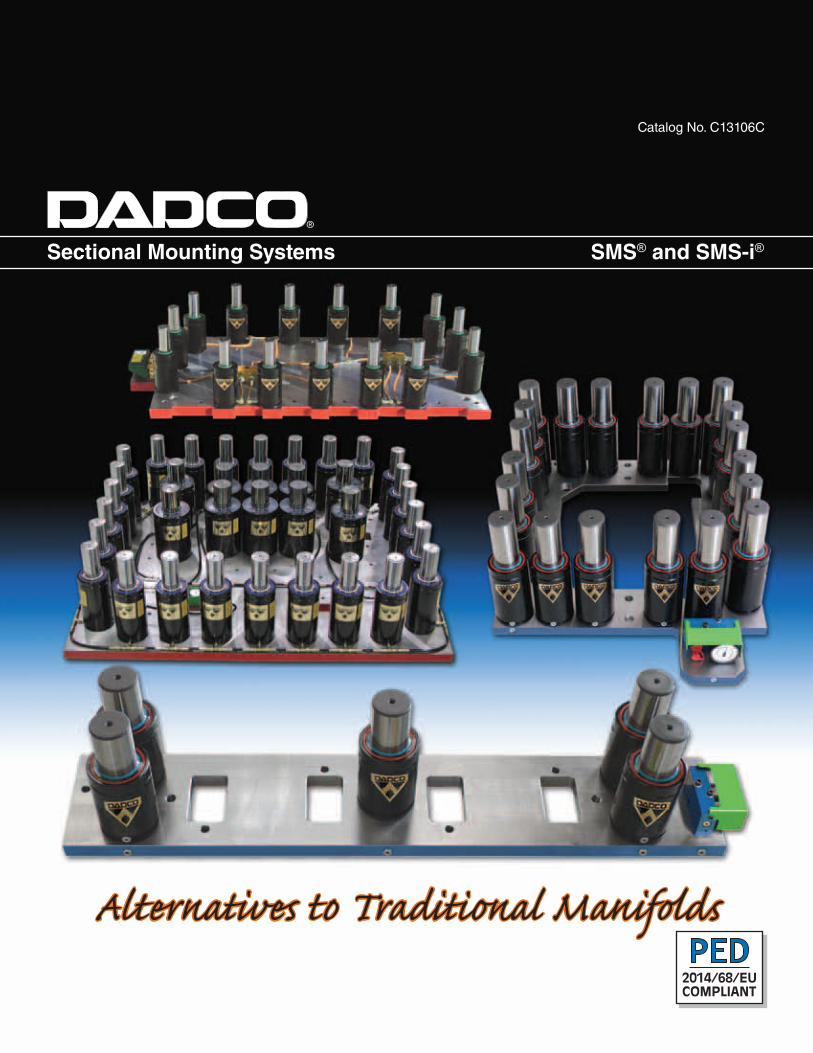
Sectional Mounting Systems SMS® and SMS-i®
®
Alternatives to Traditional ManifoldsPED
2014/68/EUCOMPLIANT
Catalog No. C13106C
SMS® and SMS-i®
1.734.207.1100 • 800.DADCO.USA • fax 1.734.207.2222 • www.dadco.net
®
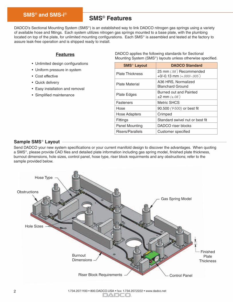
Hole Sizes
Burnout Dimensions
Control Panel
Gas Spring Model
Finished Plate
Thickness
Riser Block Requirements
Obstructions
Hose Type
DADCO’s Sectional Mounting System (SMS®) is an established way to link DADCO nitrogen gas springs using a variety of available hose and fittings. Each system utilizes nitrogen gas springs mounted to a base plate, with the plumbing located on top of the plate, for unlimited mounting configurations. Each SMS® is assembled and tested at the factory to assure leak-free operation and is shipped ready to install.
Sample SMS® Layout
• Unlimited design configurations
• Uniform pressure in system
• Cost effective
• Quick delivery
• Easy installation and removal
• Simplified maintenance
Features
Send DADCO your new system specifications or your current manifold design to discover the advantages. When quoting a SMS®, please provide CAD files and detailed plate information including gas spring model, finished plate thickness, burnout dimensions, hole sizes, control panel, hose type, riser block requirments and any obstructions; refer to the sample provided below.
SMS® Layout DADCO Standard
Plate Thickness25 mm (.98) Recommended+0/-0.13 mm (+.000/-.005)
Plate MaterialA36 HRS, Normalized Blanchard Ground
Plate EdgesBurned out and Painted±2 mm (±.08)
Fasteners Metric SHCS
Hose 90.500 (Y-500) or best fit
Hose Adapters Crimped
Fittings Standard swivel nut or best fit
Panel Mounting DADCO riser blocks
Risers/Parallels Customer specified
SMS® Features
DADCO applies the following standards for Sectional Mounting System (SMS®) layouts unless otherwise specified.
2

SMS® and SMS-i®
1.734.207.1100 • 800.DADCO.USA • fax 1.734.207.2222 • www.dadco.net
®
SMS® Component Selection
Gas Springs with G 1/8 Port:U.4600 − U.20000
UH SeriesUX Series
90.8 Series90.10.00500 − 90.10.10000
SCL.01000 − SCL.18300
G 1/8 Large Port
O-Ring Face Seal (ORFS) (9/16-18)
D-24 Tapered(M12 x 1.5)
90.400 (Y-400) Hose90.500 (Y-500) Hose
Compatible Fitting Styles
Port Style
Zip (CNOMO) (S12.65 x 1.5)
DADCO Gas Springs are grouped by two main classifications: Mini Springs with a M6 Port and Large Springs with a G 1/8 BSPP Port. DADCO recommends choosing control panels, fittings and hose type based on port style and application requirements. Refer to the Linked System Components Catalog for more information. To determine the force and pressure rise for your system use the DADCO Force Calculator from our website at www.dadco.net.
M6 Mini Port
DADCO MINILink®
(M8 x 1)
Gas Springs with M6 Port:U.0400 − U.2600LJ and L Series
SCR Series90.10.00170
Control Panels
Distribution Blocks
Tools
Surge Tanks
SMS® Preferred
90.700 (Y-700) Hose90.705 (Y-705) Hose
SMS® Preferred
Hose System
3
SMS® and SMS-i®
1.734.207.1100 • 800.DADCO.USA • fax 1.734.207.2222 • www.dadco.net
®
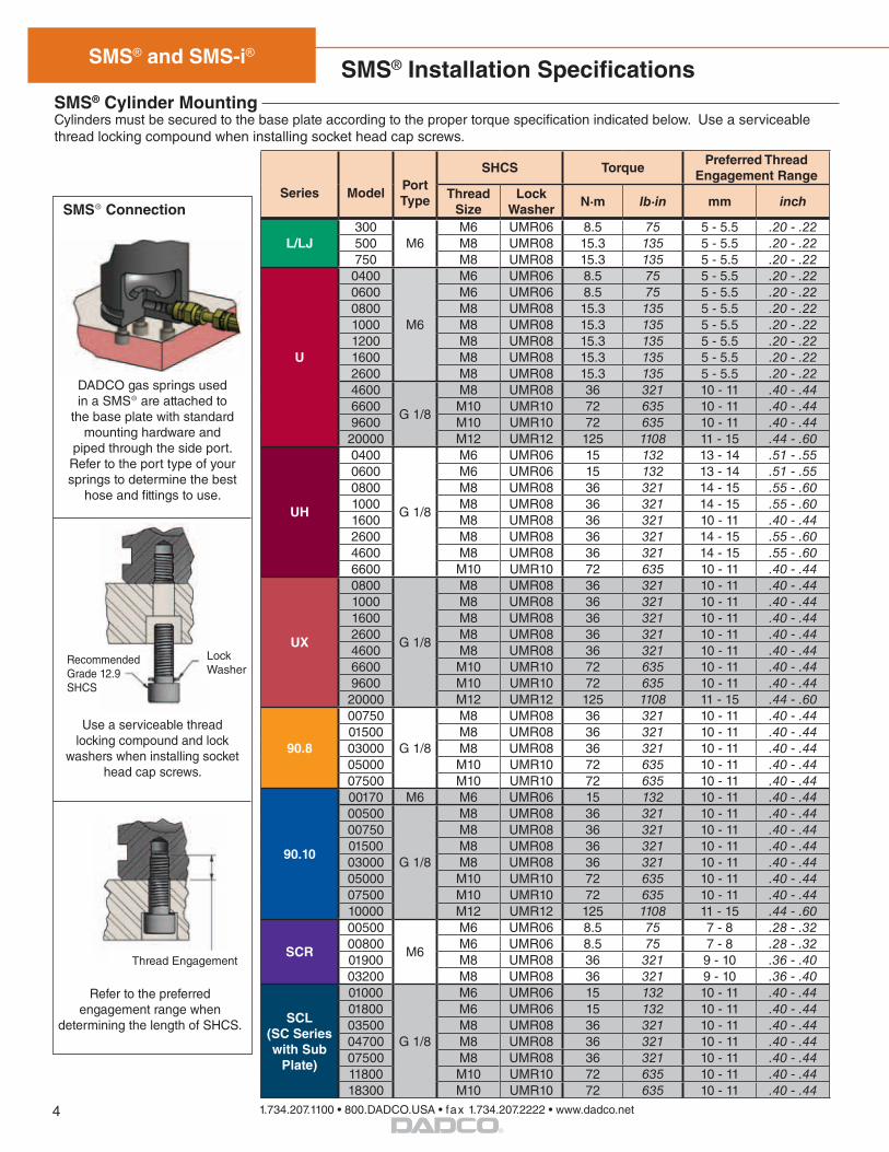
SMS® Installation SpecificationsSMS® Cylinder MountingCylinders must be secured to the base plate according to the proper torque specification indicated below. Use a serviceable thread locking compound when installing socket head cap screws.
LockWasher
Thread Engagement
Recommended Grade 12.9 SHCS
SMS® Connection
DADCO gas springs used in a SMS® are attached to
the base plate with standard mounting hardware and
piped through the side port. Refer to the port type of your springs to determine the best
hose and fittings to use.
Series ModelPort Type
SHCS TorquePreferred Thread
Engagement RangeThread
SizeLock
WasherN·m lb·in mm inch
L/LJ300
M6M6 UMR06 8.5 75 5 - 5.5 .20 - .22
500 M8 UMR08 15.3 135 5 - 5.5 .20 - .22750 M8 UMR08 15.3 135 5 - 5.5 .20 - .22
U
0400
M6
M6 UMR06 8.5 75 5 - 5.5 .20 - .220600 M6 UMR06 8.5 75 5 - 5.5 .20 - .220800 M8 UMR08 15.3 135 5 - 5.5 .20 - .221000 M8 UMR08 15.3 135 5 - 5.5 .20 - .221200 M8 UMR08 15.3 135 5 - 5.5 .20 - .221600 M8 UMR08 15.3 135 5 - 5.5 .20 - .222600 M8 UMR08 15.3 135 5 - 5.5 .20 - .224600
G 1/8
M8 UMR08 36 321 10 - 11 .40 - .446600 M10 UMR10 72 635 10 - 11 .40 - .449600 M10 UMR10 72 635 10 - 11 .40 - .44
20000 M12 UMR12 125 1108 11 - 15 .44 - .60
UH
0400
G 1/8
M6 UMR06 15 132 13 - 14 .51 - .550600 M6 UMR06 15 132 13 - 14 .51 - .550800 M8 UMR08 36 321 14 - 15 .55 - .601000 M8 UMR08 36 321 14 - 15 .55 - .601600 M8 UMR08 36 321 10 - 11 .40 - .442600 M8 UMR08 36 321 14 - 15 .55 - .604600 M8 UMR08 36 321 14 - 15 .55 - .606600 M10 UMR10 72 635 10 - 11 .40 - .44
UX
0800
G 1/8
M8 UMR08 36 321 10 - 11 .40 - .441000 M8 UMR08 36 321 10 - 11 .40 - .441600 M8 UMR08 36 321 10 - 11 .40 - .442600 M8 UMR08 36 321 10 - 11 .40 - .444600 M8 UMR08 36 321 10 - 11 .40 - .446600 M10 UMR10 72 635 10 - 11 .40 - .449600 M10 UMR10 72 635 10 - 11 .40 - .44
20000 M12 UMR12 125 1108 11 - 15 .44 - .60
90.8
00750
G 1/8
M8 UMR08 36 321 10 - 11 .40 - .4401500 M8 UMR08 36 321 10 - 11 .40 - .4403000 M8 UMR08 36 321 10 - 11 .40 - .4405000 M10 UMR10 72 635 10 - 11 .40 - .4407500 M10 UMR10 72 635 10 - 11 .40 - .44
90.10
00170 M6 M6 UMR06 15 132 10 - 11 .40 - .4400500
G 1/8
M8 UMR08 36 321 10 - 11 .40 - .4400750 M8 UMR08 36 321 10 - 11 .40 - .4401500 M8 UMR08 36 321 10 - 11 .40 - .4403000 M8 UMR08 36 321 10 - 11 .40 - .4405000 M10 UMR10 72 635 10 - 11 .40 - .4407500 M10 UMR10 72 635 10 - 11 .40 - .4410000 M12 UMR12 125 1108 11 - 15 .44 - .60
SCR
00500
M6
M6 UMR06 8.5 75 7 - 8 .28 - .3200800 M6 UMR06 8.5 75 7 - 8 .28 - .3201900 M8 UMR08 36 321 9 - 10 .36 - .4003200 M8 UMR08 36 321 9 - 10 .36 - .40
SCL (SC Series with Sub
Plate)
01000
G 1/8
M6 UMR06 15 132 10 - 11 .40 - .4401800 M6 UMR06 15 132 10 - 11 .40 - .4403500 M8 UMR08 36 321 10 - 11 .40 - .4404700 M8 UMR08 36 321 10 - 11 .40 - .4407500 M8 UMR08 36 321 10 - 11 .40 - .4411800 M10 UMR10 72 635 10 - 11 .40 - .4418300 M10 UMR10 72 635 10 - 11 .40 - .44
Use a serviceable thread locking compound and lock
washers when installing socket head cap screws.
Refer to the preferred engagement range when
determining the length of SHCS.
4
SMS® and SMS-i®
1.734.207.1100 • 800.DADCO.USA • fax 1.734.207.2222 • www.dadco.net
®
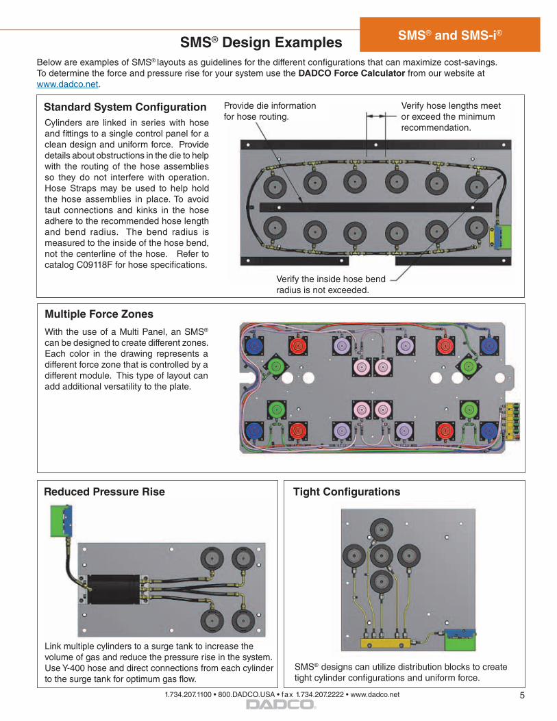
Below are examples of SMS® layouts as guidelines for the different configurations that can maximize cost-savings. To determine the force and pressure rise for your system use the DADCO Force Calculator from our website at www.dadco.net.
SMS® Design Examples
SMS® designs can utilize distribution blocks to create tight cylinder configurations and uniform force.
With the use of a Multi Panel, an SMS®
can be designed to create different zones. Each color in the drawing represents a different force zone that is controlled by a different module. This type of layout can add additional versatility to the plate.
Cylinders are linked in series with hose and fittings to a single control panel for a clean design and uniform force. Provide details about obstructions in the die to help with the routing of the hose assemblies so they do not interfere with operation. Hose Straps may be used to help hold the hose assemblies in place. To avoid taut connections and kinks in the hose adhere to the recommended hose length and bend radius. The bend radius is measured to the inside of the hose bend, not the centerline of the hose. Refer to catalog C09118F for hose specifications.
Provide die information for hose routing.
Verify hose lengths meet or exceed the minimum recommendation.
Verify the inside hose bend radius is not exceeded.
Standard System Configuration
Multiple Force Zones
Reduced Pressure Rise Tight Configurations
Link multiple cylinders to a surge tank to increase the volume of gas and reduce the pressure rise in the system. Use Y-400 hose and direct connections from each cylinder to the surge tank for optimum gas flow.
5
SMS® and SMS-i®
1.734.207.1100 • 800.DADCO.USA • fax 1.734.207.2222 • www.dadco.net
®
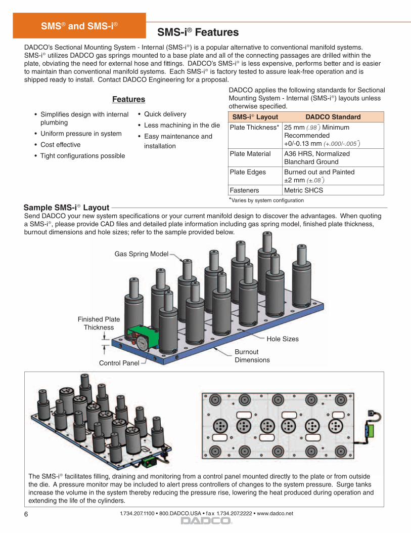
DADCO’s Sectional Mounting System - Internal (SMS-i®) is a popular alternative to conventional manifold systems. SMS-i® utilizes DADCO gas springs mounted to a base plate and all of the connecting passages are drilled within the plate, obviating the need for external hose and fittings. DADCO’s SMS-i® is less expensive, performs better and is easier to maintain than conventional manifold systems. Each SMS-i® is factory tested to assure leak-free operation and is shipped ready to install. Contact DADCO Engineering for a proposal.
Hole Sizes
Burnout DimensionsControl Panel
Gas Spring Model
Finished Plate Thickness
Sample SMS-i® Layout
• Simplifies design with internal plumbing
• Uniform pressure in system
• Cost effective
• Tight configurations possible
DADCO applies the following standards for Sectional Mounting System - Internal (SMS-i®) layouts unless otherwise specified.
• Quick delivery
• Less machining in the die
• Easy maintenance and installation
Features
*Varies by system configuration
SMS-i® Features
SMS-i® Layout DADCO Standard
Plate Thickness* 25 mm (.98) Minimum Recommended+0/-0.13 mm (+.000/-.005)
Plate Material A36 HRS, Normalized Blanchard Ground
Plate Edges Burned out and Painted±2 mm (±.08)
Fasteners Metric SHCS
Send DADCO your new system specifications or your current manifold design to discover the advantages. When quoting a SMS-i®, please provide CAD files and detailed plate information including gas spring model, finished plate thickness, burnout dimensions and hole sizes; refer to the sample provided below.
The SMS-i® facilitates filling, draining and monitoring from a control panel mounted directly to the plate or from outside the die. A pressure monitor may be included to alert press controllers of changes to the system pressure. Surge tanks increase the volume in the system thereby reducing the pressure rise, lowering the heat produced during operation and extending the life of the cylinders.
6

SMS® and SMS-i®
1.734.207.1100 • 800.DADCO.USA • fax 1.734.207.2222 • www.dadco.net
®
DADCO recommends following the guidelines below when designing SMS-i® layouts to maximize cost-savings. To determine the force and pressure rise for your system use the DADCO Force Calculator from our website at www.dadco.net.
Items that Increase the Complexity of SMS-i® Machining
Blind Holes Avoid drilling G 1/8 ports as blind holes since it makes clean-up and deburring difficult.
Recommended Layout
Control Panel Location Refrain from isolating a control panel to its own G 1/8 port to minimize cost and complexity.
Thru-Hole / Feature Placement Avoid interior burnouts, thru-holes and cylinder mounting holes where there is not adequate clearance around G 1/8 ports.
Machining on Plate Sides Adding G 1/8 ports to all four sides of the plate is costly. Plates must be machined on every edge that contains a G 1/8 port.
Gas Spring Arrangement Avoid offset placement of gas springs. It requires individual G 1/8 ports, increasing cost and complexity.
Control Panel Location Mount the control panel to the plate using an existing port.
Thru-Hole / Feature Placement Make sure thru-holes and other plate features are clear of nitrogen ports.
Drill Location Drills should run completely through the plate or intersect another drilled port.
Gas Spring Arrangement Align gas springs where possible so they share G 1/8 ports.
Machining on Plate Sides Place ports on as few sides of the plate as possible to reduce machining requirements.
Plates must be machined on every edge that contains a G 1/8 port.
Additional Recommendations
Plate Thickness 25 mm (0.98˝) Minimum Recommended
Maximum Drill Depth for G 1/8 Ports 42˝ per port (NOTE: For two G 1/8 ports drilled from opposite ends that meet in the middle, the combined port length becomes 84˝.)
Control Panel Location Control panels can be mounted to a plate or pipedexternally using hose and fittings.
Long Stroke Gas SpringsChoose longer stroke gas springs mounted directly to the plate (over increased plate thickness) to achieve the desired contact point and to gain more volume in the system.
SMS-i® Design Recommendations
7

SMS® and SMS-i®
1.734.207.1100 • 800.DADCO.USA • fax 1.734.207.2222 • www.dadco.net
®
SMS-i® Cylinder MountingCylinders must be secured to the base plate according to the proper torque specification indicated below. Use a serviceable thread locking compound when installing socket head cap screws. Contact DADCO for information on gas springs not listed below.
Part Number: Includes Series, Model and Stroke Length.
Mount Option: TO = Basic Model or TG = Additional Mounting Holes (U.0600-U.1200 only).
Fitting Connection:M = SMS-i® (bottom port + sealing component).M1 = SMS-i® (larger bottom port for increased flow + sealing component).Reference the laser mark on the cylinder when ordering replacment springs.
90.10.00750.025. TO. MReplacement SMS-i® Gas Spring Ordering Example:
Sealing Washer
LockWasher
Thread Engagement
Sealing Washer is installed between the bottom port and
the SMS-i® Plate.
Use a serviceable thread locking compound and lock
washers when installing socket head cap screws.
Refer to the preferred engagement range when
determining the length of SHCS.
Recommended Grade 12.9SHCS
SMS-i® Connection
DADCO gas springs used in a SMS-i® have a bottom port and are attached to the base plate with a sealing washer
and mounting holes.
SMS-i® Installation Specifications
U Series Mount Pattern for SMS-i® Gas SpringsDADCO’s U.0600-U.1200 gas springs installed in a SMS-i® have additonal bottom mounting holes used to attach to the base plate. Replacement springs ordered with the ‘TG’ mount option will have this mounting pattern.
U.0600.__.TG U.0800.__.TG U.1000.__.TG / U.1200.__.TG
4 x M66 deep
.24
4 x M86 deep
.24
4 x M86 deep
.24
17.7.696 20
.78725
.984
Series Model
SHCS TorquePreferred Thread
Engagement Range
SMS-i® Plate Sealing Component
Thread Size
Lock Washer
N·m lb·in mm inch M M1
UH 0400 M6 UMR06 15 132 13 - 14 .51 - .55 90.252 EZ451441
U
0600 M6 UMR06 8.5 75 5 - 5.5 .20 - .22 90.252 EZ451441 0800 M8 UMR08 15.3 135 5 - 5.5 .20 - .22 90.252 EZ451441 1000 M8 UMR08 15.3 135 5 - 5.5 .20 - .22 90.252 EZ451441 1200 M8 UMR08 15.3 135 5 - 5.5 .20 - .22 90.252 EZ4514411600 M8 UMR08 15.3 135 5 - 5.5 .20 - .22 90.252 EZ4514412600 M8 UMR08 15.3 135 5 - 5.5 .20 - .22 EZ451443 EZ4514414600 M8 UMR08 36 321 10 - 11 .40 - .44 EZ451443 EZ4572386600 M10 UMR10 72 635 10 - 11 .40 - .44 EZ451443 EZ4572389600 M10 UMR10 72 635 10 - 11 .40 - .44 EZ451443 EZ45723820000 M12 UMR12 125 1108 11 - 15 .44 - .60 EZ451443 EZ457238
UX
0800 M8 UMR08 36 321 10 - 11 .40 - .44 90.252 EZ4514411000 M8 UMR08 36 321 10 - 11 .40 - .44 90.252 EZ4514411600 M8 UMR08 36 321 10 - 11 .40 - .44 EZ451443 EZ4514412600 M8 UMR08 36 321 10 - 11 .40 - .44 EZ451443 EZ4514414600 M8 UMR08 36 321 10 - 11 .40 - .44 EZ451443 EZ4572386600 M10 UMR10 72 635 10 - 11 .40 - .44 EZ451443 EZ4572389600 M10 UMR10 72 635 10 - 11 .40 - .44 EZ451443 EZ45723820000 M12 UMR12 125 1108 11 - 15 .44 - .60 EZ451443 EZ457238
90.10
00500 M8 UMR08 36 321 10 - 11 .40 - .44 90.252 EZ45144100750 M8 UMR08 36 321 10 - 11 .40 - .44 90.252 EZ45144101500 M8 UMR08 36 321 10 - 11 .40 - .44 EZ451443 EZ45144103000 M8 UMR08 36 321 10 - 11 .40 - .44 EZ451443 EZ45723805000 M10 UMR10 72 635 10 - 11 .40 - .44 EZ451443 EZ45723807500 M10 UMR10 72 635 10 - 11 .40 - .44 EZ451443 EZ45723810000 M12 UMR12 125 1108 11 - 15 .44 - .60 EZ451443 EZ457238
SC
03500 M8 UMR08 15.3 135 7 - 8 .28 - .32 90.270 N/A04700 M8 UMR08 15.3 135 6 - 7 .24 - .28 90.270 N/A07500 M8 UMR08 15.3 135 6 - 7 .24 - .28 90.270 N/A11800 M10 UMR10 72 635 8 - 9 .32 - .36 90.270 N/A
8
SMS® and SMS-i®
1.734.207.1100 • 800.DADCO.USA • fax 1.734.207.2222 • www.dadco.net
®
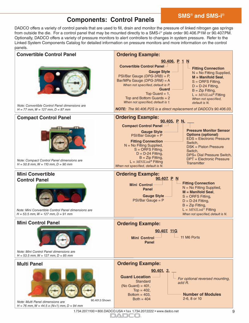
Components: Control Panels
Convertible Control Panel 90.406. P 1 N
Convertible Control Panel Fitting ConnectionN = No Fitting Supplied,M = Manifold Seal, S = ORFS Fitting, D = D-24 Fitting, B = Zip Fitting,L = MINILink® FittingWhen not specified, default is N.
Ordering Example:
Gauge StylePSI/Bar Gauge (DPG-3RB) = P,
Bar/MPa Gauge (DPG-3RM) = AWhen not specified, default is P.
GuardTop Guard = 1,
Top and Bottom Guards = 2When not specified, default is 1.
DADCO offers a variety of control panels that are used to fill, drain and monitor the pressure of linked nitrogen gas springs from outside the die. For a control panel that may be mounted directly to a SMS-i® plate order 90.406.P1M or 90.407.PM. Optionally, DADCO offers a variety of pressure monitors to alert controllers to changes in system pressure. Refer to the Linked System Components Catalog for detailed information on pressure monitors and more information on the control panels.
NOTE: The 90.406.P2S is a direct replacement of DADCO’s 90.406.03.Note: Convertible Control Panel dimensions are H = 77 mm, W = 127 mm, D = 87 mm
Compact Control Panel
Fitting Connection N = No Fitting Supplied,
S = ORFS Fitting, D = D-24 Fitting,
B = Zip Fitting,L = MINILink® Fitting
When not specified, default is N.
Ordering Example:
Gauge StylePSI/Bar Gauge = P
Compact Control Panel
Note: Compact Control Panel dimensions are H = 50.8 mm, W = 110 mm, D = 90 mm
90.407. P N
Mini Control Panel
Fitting Connection N = No Fitting Supplied,M = Manifold Seal,S = ORFS Fitting, D = D-24 Fitting, B = Zip Fitting, L = MINILink® FittingWhen not specified, default is N.
Ordering Example:
Gauge StylePSI/Bar Gauge = P
Mini Convertible Control Panel
Note: Mini Convertible Control Panel dimensions are H = 53.5 mm, W = 127 mm, D = 91 mm
Ordering Example:
Guard LocationStandard
(No Guard) = 401, Top = 402,
Bottom = 403, Both = 404
For optional reversed mounting, add R.
90.401. 3.
Number of Modules 2-6, 8 or 10
Multi Panel
90.401.3 Shown Note: Multi Panel dimensions are H = 76 mm, W = 44.5 x (N+1) mm, D = 94 mm
Mini Control Panel
Note: Mini Control Panel dimensions are H = 53.5 mm, W = 127 mm, D = 85 mm
90.407. 11G
Ordering Example:
11 M6 PortsMini Control Panel
Pressure Monitor Sensor Options (optional)EDS = Electronic Pressure Switch, DSK = Piston Pressure Switch, DPS= Dial Pressure Switch, DPT = Electronic Pressure Transmitter
90.405. P N. ___
9
SMS® and SMS-i®
1.734.207.1100 • 800.DADCO.USA • fax 1.734.207.2222 • www.dadco.net
®
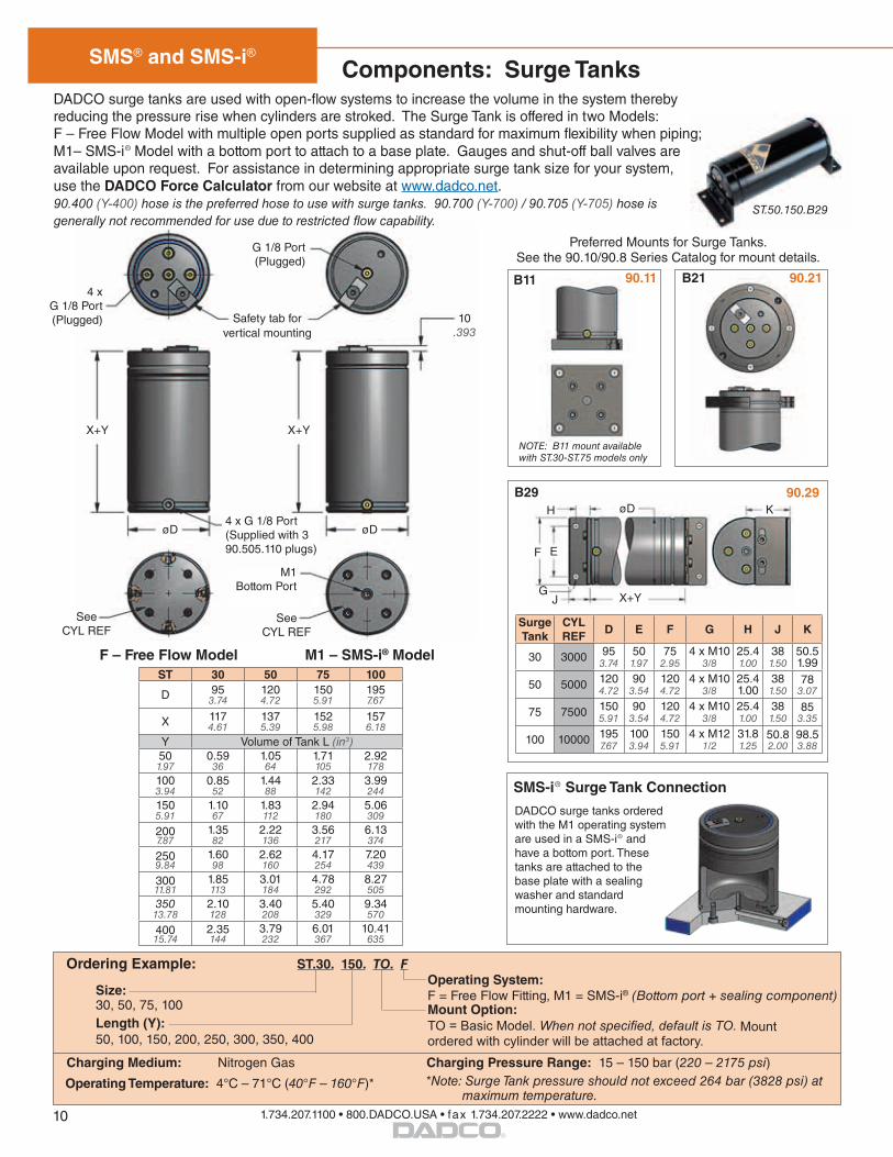
DADCO surge tanks are used with open-flow systems to increase the volume in the system thereby reducing the pressure rise when cylinders are stroked. The Surge Tank is offered in two Models: F – Free Flow Model with multiple open ports supplied as standard for maximum flexibility when piping; M1– SMS-i® Model with a bottom port to attach to a base plate. Gauges and shut-off ball valves are available upon request. For assistance in determining appropriate surge tank size for your system, use the DADCO Force Calculator from our website at www.dadco.net. 90.400 (Y-400) hose is the preferred hose to use with surge tanks. 90.700 (Y-700) / 90.705 (Y-705) hose is generally not recommended for use due to restricted flow capability.
B11 90.11 B21 90.21
B29 90.29H
G
øD
J
EF
X+Y
X+Y
øD 4 x G 1/8 Port (Supplied with 3 90.505.110 plugs)
See CYL REF
F – Free Flow Model
Preferred Mounts for Surge Tanks. See the 90.10/90.8 Series Catalog for mount details.
ST.50.150.B29
Components: Surge Tanks
NOTE: B11 mount available with ST.30-ST.75 models only
K
ST 30 50 75 100
D 953.74
1204.72
1505.91
1957.67
X 1174.61
1375.39
1525.98
1576.18
Y Volume of Tank L (in3)501.97
0.59 36
1.0564
1.71 105
2.92 178
1003.94
0.8552
1.4488
2.33142
3.99244
1505.91
1.1067
1.83112
2.94180
5.06309
2007.87
1.3582
2.22136
3.56217
6.13374
2509.84
1.6098
2.62160
4.17254
7.20439
30011.81
1.85113
3.01184
4.78292
8.27505
35013.78
2.10128
3.40208
5.40329
9.34570
40015.74
2.35144
3.79232
6.01367
10.41635
M1 – SMS-i® Model
Surge Tank
CYL REF
D E F G H J K
30 3000 953.74
501.97
752.95
4 x M103/8
25.41.00
381.50
50.51.99
50 5000 1204.72
903.54
1204.72
4 x M103/8
25.41.00
381.50
783.07
75 7500 1505.91
903.54
1204.72
4 x M103/8
25.41.00
381.50
853.35
100 10000 1957.67
1003.94
1505.91
4 x M121/2
31.81.25
50.82.00
98.53.88
X+Y
øD
See CYL REF
M1 Bottom Port
Safety tab for vertical mounting
G 1/8 Port (Plugged)
4 x G 1/8 Port (Plugged)
SMS-i® Surge Tank Connection
DADCO surge tanks ordered with the M1 operating system are used in a SMS-i® and have a bottom port. These tanks are attached to the base plate with a sealing washer and standard mounting hardware.
10.393
Ordering Example: ST.30. 150. TO. F
Size: 30, 50, 75, 100Length (Y):50, 100, 150, 200, 250, 300, 350, 400
Mount Option: TO = Basic Model. When not specified, default is TO. Mount ordered with cylinder will be attached at factory.
Operating System:F = Free Flow Fitting, M1 = SMS-i® (Bottom port + sealing component)
Charging Medium: Nitrogen Gas Charging Pressure Range: 15 – 150 bar (220 – 2175 psi)
Operating Temperature: 4°C – 71°C (40°F – 160°F)* *Note: Surge Tank pressure should not exceed 264 bar (3828 psi) at
maximum temperature.
10

SMS® and SMS-i®
1.734.207.1100 • 800.DADCO.USA • fax 1.734.207.2222 • www.dadco.net
®
Accessories
Quick Disconnect Charging Assembly
Use the DADCO Quick Disconnect Charging Assembly, 90.310.040, with the 90.310.143 or 90.310.111 Charging Nipple or the 90.315.5 Pressure Analyzer to charge self-contained gas springs. The 90.310.040 can also be used with a DADCO control panel to charge linked systems.
The 90.310.044 Quick Disconnect Filling Assembly with self-venting capabilities releases residual pressure after charging self-contained or linked nitrogen gas spring systems for easy decoupling between the filling assembly and charging nipple or filler valve.
DADCO recommends using the 90.310.041 High Pressure Charging Assembly to charge SCR Series and U.0400 nitrogen gas springs to maximum pressure.
Pressure Regulator90.310.201
Quick Disconnect Filling Assembly - 90.310.338
Hose Assembly90.310.2523 m / 10 ft
Safety Plates for SMS® & SMS-i®
DADCO supplies a safety plate with every SMS® and SMS-i® to ensure proper handling of the cylinders. For information on the different plates available or to order a replacment refer to bulletin B01103B.
Shut-Off Valve MV-3GDADCO’s Shut-off Valve (MV-3G) is used with SMS-i® allowing for cut-off of nitrogen gas from the control panel while enabling the SMS-i® to remain charged. For more information refer to bulletin B14136.
Compact Nitrogen Gas BoosterDGB.100
DADCO’s Compact Nitrogen Gas Booster System, DGB.100, is a lightweight, cost-effective way to extend the life of your nitrogen supply tanks. Using the DGB.100, tanks with low pressure can be boosted to a higher pressure suitable for gas spring charging. For more information refer to bulletin B13105.
Nitrogen Gas Booster SystemDGB.150
DADCO’s Nitrogen Gas Booster System, DGB-150, is an all-in-one solution to the problems of low pressure supply tanks and lost nitrogen gas during discharge. For more information on the booster, refer to bulletin B07101.
Pressure Monitors
DADCO offers a variety of pressure monitor options to alert press controllers to changes in system pressure. Some models, including the 90.421.2D, are capable of shutting the press down if it drops below the minimum operating pressure. The new electronic pressure monitors are available in several configurations with different cable, base and fitting options to best suit the application. For more information refer to catalog C09118F.
Quick Disconnect Filling Assembly - 90.310.340*
90.310.044
90.310.040
(Self-Venting)
*Not recommended with 90.416.A2B or 90.406.421
Hose Assembly90.310.2523 m / 10 ft
Pressure Regulator90.310.205
Operating Temperature: 4°C – 71°C (40°F – 160°F)*
11
Printed in USA ©DADCO, Inc. 2017 • All Rights Reserved
43850 Plymouth Oaks Blvd. • Plymouth, Michigan • 48170 • USA734.207.1100 • 800.DADCO.USA • fax 734.207.2222 • www.dadco.net®
The global leader in nitrogen gas spring technology
Product changes may occur during the life of this catalog without prior notice, but products supplied will remain functionally interchangeable.