ALTERNATIVES AND SYSTE FUTURE ISSION OPTIONS
256
ALTERNATIVES AND SYSTE FUTURE ISSION OPTIONS JET PROPULSION LABORATORY PASADENA, CALIFORNIA CONTRACT NUMBER ,952000 . a COPYjNO. 55 I/: MCDONNELL ASTRd
Transcript of ALTERNATIVES AND SYSTE FUTURE ISSION OPTIONS

ALTERNATIVES AND SYSTE FUTURE ISSION OPTIONS
JET PROPULSION LABORATORY PASADENA, CALIFORNIA CONTRACT NUMBER ,952000
.
a COPYjNO. 55
I/:
MCDONNELL ASTRd

REPORT ORGANIZATION
- VOYAGER PHASE B FINAL REPORT
The r e s u l t s of t h e Phase B VOYAGER F l i g h t Capsule s tudy are organized i n t o
several volumes. These are:
Volume I Summary
Volume I1 Capsule Bus System
Volume I11 Surface Laboratory System
Volume I V Entry Science Package
Volume V System I n t e r f a c e s
Volume V I Implement a t ion
This volume, Volume I V , descr ibes t h e McDonnell Douglas s e l e c t e d design f o r
t h e Entry Science Package. It is arranged i n 11 p a r t s , A through K , and bound i n
4 sepa ra t e documents, as noted below.
P a r t A In t roduct ion and Summary
P a r t B Object ives and Requirements
P a r t C Design Criteria and Cons t ra in ts 1 Document
P a r t D Selected Design Concept
P a r t E Al te rna t ives and Systems Analysis
P a r t F Future Mission Options 1 Document
P a r t G Subsystem Equipment 3. Document
P a r t H R e l i a b i l i t y
P a r t I Plane tary Quarantine
P a r t J Operat ional Support Equipment 1 Document
P a r t K I n t e r f a c e Alternatives
I n o rde r t o assist the reader i n f ind ing s p e c i f i c material r e l a t i n g t o t he
Entry Science Package, Figure 1 cross indexes broadly s e l e c t e d sub jec t matter , a t
t he system and subsystem level, through a l l volumes.
i
i
REPORT F694 0 VOLUME I V 0 PART E e 31 AUGUST 1967
MCDONNELL ASTRONAUTICS d

TABLE OF CONTENTS
PART E ALTERNATIVES AND SYSTEMS ANALYSIS Page
1-1 1-1 2-1
2-1
2- 1 2-2
2-9 2-10
3- 1
3- 2 3-2
3- 7
3-17 3-20 3-22
3-35 3-39 3-42 3-42
3-42
3-42
3-42
SECTION
1.1 SECTION
2.1
2.2
SECTION
3.1
3.2
SECTION
4.1 4.2
4.3
4.4
4.5
1 PRINCIPAL ALTERNATIVES AND SELECTION FACTORS Configuration and Interface
2 EXPERIMENT ANALYSIS Atmospheric Properties Reconstruction 2.1.1 Alternatives
2.1.2 Comparison of Alternatives
2.1.3 Results
Entry TV Observations
3 SCIENCE INSTRUMENTS
Atmospheric Properties Instruments
3.1.1 3.1.2
3.1.3 3.1.4
3.1.5 3.1.6
3.1.7
Entry 3.2.1
3.2.2
3.2.3
3.2.4
Pressure
Direct Density Measurements
Temperature Composition Determination by Mars Spectrometer Composition Determination by Absorption Methods
Acceleration
Capsule Bus Sensor Data TV
Constraints
Alternatives
Comparison
Selection 4 ENTRY SCIENCE PACKAGE - SUPPORTING SUBSYSTEMS Electrical Power
Telecommunications
4.2.1 Propagation Analysis
4.2.2 Telemetry Subsystem
4.2.3 Radio Subsys tem
4.2.4 Antenna Subsystem Analysis 4.2.5 Data Storage Subsystem
4.2.6 Interconnection with Capsule Bus
Structural/Mechanical Subsystem
Packaging and Cabling
Thermal Control
4-14 4-14 4-43
4-59 4-64
4-74
4-79
4-29
4-100 4-104
REPORTlF694 0 VOLUME IV e PART E,F 0 31 AUGUST 1967
MCDONNELL ASTRONAUllCS

SECTION 5 CAPSULE BUS/ENTRY SCIENCE
5 . 1 T r a j ec t o r i e s
5.2 De-Orbit
5.3 Aeroshel l P rope r t i e s
5 .4 Capsule Mequencing
5 .5 Aeroshel l Separa t ion
5.6 A t t i t u d e Control
5.7 Radar A l t i m e t e r
5.8 Pos t Touchdown Operation
PART F FUTURE MISSION OPTIONS
This Document Cons is t s of t h e Following Pages:
Page
5- 1
5-1
5-2
5-5
5-23
5-25
5-26
5-36
5-39
1
T i t l e Page
i through i v
PART E: 1
1-1 through 1-9
2-1 through 2-40
3-1 through 3-47
4-1 through 4-107
5-1 through 5-40
PART F: 1 through 3
i v
REPORT F694.b VOLUME IV 0 PART E,F e 31 AUGUST 1967
MCDONNELL ASTRONAUTICS

PART E
ALTERNATIVES AND SYSTEMS ANALYSIS
This p a r t f i r s t summarizes important a l t e r n a t i v e s and s e l e c t i o n cons ide ra t ions ,
and then d i scusses conf igura t ion a l t e r n a t i v e s . ,The discuss ions of e n t r y sc ience ,
ins t rumenta t ion , and suppor t ing subsystems follow. These may be supplemented by
reading t h e material presented on t h e s e l e c t e d design concept i n P a r t D, and the
f u n c t i o n a l d e s c r i p t i o n s a p p l i c a b l e t o t h e s e l e c t e d concept, given i n P a r t G.
1
REPORT Fq94 e VOLUME I V e PART E e 31 AUGUST 1967
MCDONNELL ASTRONAUTICS

VOLUME IV CROSS REFERENCE INDEX
Denotes that t!ie pari or sect ion generally appl ies to the topic. d Denotes that the topic is distributed throughout the part or sect ion.
Figure 1
ii -/
Sec. 2.0 1.2 6.1 1.2.1 1.1 4.0 2.2 2.1 2.2 I
I 4.3.2.4 I 3.2 6.0 I 5.3.2.6
2.0 1.1 6.2 1.2.2 1.1 4.0 2.0 2.1 6.0 4.0-d 3.1
I I I I 5.0-d - - - I Figure3.0-1 I F igure 4.24
1 I I I 4.2.2.2 - 2.5.3 4.2.5 6.0 -
3.2.1
3.2 5.7 - 6.3 2.5.3 4.2
5.2 - 6.3 2.5.1 4.1 3.1
I I I I
- I - I 4.0 I 2.5.4 I 4.3 3.3
5.0 2.5.1 4.4 6.3 3.4
5.3 - 6.3 2.5.7 4.5 3.5
- -
REPORT F$94 0 VOLUME IV 0 PART E 0 31 AUGUST 1967
MCDONNELL ASTRONAUTICS

ILLUSTRATIVE ALTERNATIVES AND SELECTION CONSIDERATIONS
ITEMS) AFFECTED
istruments
ieroshe II
)e-Orbit
4ttitude Contrc Intry
iador Altimete
tapsule Bus lnertiol Sensor
Data Handling
ATMOSPHERIC PROPERTIES DETERMINATION IMAGING
ALTERNATIVES
0 Mass Spectrometer Use At High Altitude in Addition to Below Mach 5
0 Additionol Instruments UV and Xray Absorbtian
y Backscatter
Sphericol Nose Differ- ' entia1 Pressure Sensors
High Altitude (Molecular Flow Region) Pressure Measurement
Accelerometer Location
0 Accelerometer Sampling Rate High (10 Samples/Secand) or Low (2 Somples/Second)
0 Sensor Location (Pressure,
0 Aeroshell Ports
Temperature and Composition)
1. Flush Mounted at Stog- notion Point or Side Location
2. Extended Ports at Stagnation Point or Side Location Using Either Fixed or Flush Ports Copable of Extension
0 Base Region Ports
0 AV Monitoring For Orbit Improvement -Trolectory Improvement vs Diagonistic Data
0 Rate Damping
or
Uncontrolled Rates
0 Initiate Measurement at 200,000 feet or
Initiate Meosurement at 30,000 feet
0 IMU Attitude Rate Output A t 2 Sample/Second far Diagnostic Measurement
IMU Attitude Rate at Output 4 to 12 Sample/Second for Oscillation History
0 Mass Spectrometer and Stagnation Temperature Flow Measurements on A l l the Time, ar
Mass Spectrometer and Stagnation Temperature Blocked Until 15 to 40 Second After Peak Pressure
SELECTION CONSIDERATION
Molecular Leak, Sample Porting and Volving Design
B Contribution to Density Altitude Function and Specific Atmos- phere Constitutents
0 Direct Free Stream Density Measurement Value; Handling Problems
@Value of Redundant Source for Dynamic Pressure
0 External Location or Additional Large Port
0 Accelerometer Data Correction for Accelerometer Location
0 Use of Accelerometer Doto To Construct Angle of Attock Time History
0 Amount of Dota Transmitted
0 Acceleration Correction for Frequency and Amplitudes due to Aeroelastic Vibrotion
0 Flow Field Relationships for Sensor Data Interpretation
8 Angle of Attock Excursions
0 Pressure Coefficient Behovior
0 Ablative Products Entering and
0 Design of Extensible Ports
Base Region Location Meosure- ment after Aeroshell Separotion
Recondensing on Sensor Elements
0 Data Enhancement - Atmospheric Property Reconstruction
0 a E x c u r s i o n Limit
0 Aerodynamic Coefficients Accuracy Enhancement
0 Accelerometer Correction Accuracy Enhancement
0 Instrument Placement to Avoid
0 Traiectory Reconstruction
Contamination
Accuracy Effects
0 Entry Condition for Prediction Accuracy Improvements
0 Altimeter Accomodation Cons iderati ons
0 Attitude Oscillations
0 Accuracy of Vehicle Oscillations Reconstruction Using Accelerometer and Aerodynamic Information Only
0 Molecular Leak and Valving Design
0 Thermal Design of Temperature Sensor
0 Internal Blockage of Sensors due to Recondensation of Cantaminaments
ITEM(S) AFFECTED
nstrument
ieroshell
Attitude Control Entry
Data Handling
ALTERNATIVES
0 Camera Installation Location with Respect to
Aeroshe I I 0 Mechanical Design 0 Optical Coverage/ Re5
0 Design for Avoidance I 0 Retoin Camera to Impact or Elect prior to Touchdown f Interference
0 High Resolution Image
Door Cover or Exposed, Multiple or Single Glazing; Recessed Cavity or Flush; Location; Removable Outer Pane ar not
Cover 0 Design and Operation <
movable Outer Pane 0 Sequencing Door for H
' Low Altitude Images 0 Temperature History
0 Nose Cap 0 Outgassing of Ablator
Products on Window 0 Thermol Heating 0 Imaging Periods and lr
Quality Uncertointy
0 Exposure Time and Re Lass due to Image Sme
0 Rate Monitoring to Cor I ma gery
0 Monitor Attitude
0 Roll Stobliration
Image Sequence Value
0 Spacecraft Data Storage and Transmiss
0 SLS Imaging Backup
or For an Additional C
ENTRY SCIENCE PACKAGE SUPPORTING SUBSYSTEMS
Power Interface
Interface I 1. Interface Complexity DATAHANDLINGANDTELEMETRY
Figure 1-1
1-2
REPORT F694 0 VOLUME N 0 PART , E 0 31 AUGUST 1967 d
MCDONNELL ASTRONAUTICS

,- AccelerQrneter SELECTED ENTRY SCIENCE PACKAGE INSTALLATION
REPORT F694 VOLUME IV m PART E m 31 AUGUST 1967
MCDONNELL. ASTRONAUTICS 1
Entry T V Unit
Figure 1-2
1-3~- /

Gas L ine
/-
P celerometer
ESP Principal Uni t /-
Mass Spectrometer Gas Vent
Pressure Transducer
\I Gas Vent
Base Pressure
UHF Antenna-/ 7 ESP Principal Uni t 1
IH F Antenna
1 Temperature Sampling Port

Figure 1-3
1-4 REPORT F694b VOLUME IV e PART E e 31 AUGUST 1967
MCDONNELL ASTRONAUTlCS

t c
nc 0 L L
Figure 1-4
1-5
REPORT F69-j 0 VOLUME IV 0 PART E 0 31 AUGUST 1967
MCDONNELL ASTRONAUTICS

G L t- U Z rr w
U Z 0 0 w K
!i
-
5 _.
I- U Z t3 U t;;
Z !2
Figure 1-5
1-6
R E P O R T F69jfo VOLUME I V 0 P A R T E 0 31 AUGUST 1967
MCDONNZlL ASPTRONAUTIGS

Attempts t o i nco rpora t e t h e science instruments i n t h e ESP p r i n c i p a l u n i t posed
s e v e r a l problems which l e d t o t h e s e l e c t i o n of e x t e r n a l s c i ence instruments as t h e
p r e f e r r e d approach. Incorpora t ing the senso r s i n t o t h e p r i n c i p a l u n i t as shown i n
Figure 1-3 poses two immediate problems.
a. Access i s denied t o t h e s t agna t ion reg ion f o r t h e t o t a l temperature t r ans-
ducer , t h e m a s s spectrometer i n l e t tube , and t h e forebody p re s su re po r t .
b. The e n t r y TV cameras cannot be loca t ed as c l o s e t o t h e Aeroshel l as would
be d e s i r a b l e .
The s t agna t ion region of t h e Aeroshel l i s a very d e s i r a b l e measurement area
f o r atmospheric parameter d a t a because t h e entry- induced in f luences on these para-
meters are b e t t e r def ined i n t h i s region. .Sc ience instruments l oca t ed i n t h e ESP
p r i n c i p a l u n i t would r e q u i r e t h a t t h e atmospheric access p o r t s be loca t ed some 4 t o
5 f e e t from t h e nominal s t a g n a t i o n po in t . I n t h i s area t h e e f f e c t s of varying angle-
of- a t tack , Mach number, a t t i t u d e rates, etc. , are much more d i f f i c u l t t o accommodate
than they are i n t h e s t a g n a t i o n region.
l o c a t i o n i s t h a t t h e r e is a h igher p r o b a b i l i t y of a b l a t i o n product contamination o r
blockage of t h e atmospheric access po r t s .
A f u r t h e r problem wi th t h e of f- s tagnat ion
TV camera l o c a t i o n i n t he ESP p r i n c i p a l u n i t r equ i r e s t h a t t h e s t r u c t u r e be
designed t o p l ace t h e o p t i c s of t h e cameras as nea r as poss ib l e t o t he i n s i d e sur-
f a c e of t h e Aeroshel l . I f t h e cameras are no t mounted c l o s e enough t o t h e Aeroshel l ,
t h r e e undes i rab le condi t ions present themselves. (1) The camera window s i z e and
weight w i l l b e excess ive i n o rde r t o accommodate t h e 50' field-of-view. (2) The
window s i z e may be l a r g e r than the space between Aeroshel l s t r u c t u r a l r i n g s thus
r equ i r ing a l o c a l redesign i n Aeroshel l wi th an a d d i t i o n a l weight penal ty. (3) And,
l o c a t i o n of t h e viewing window at any p l ace o the r than i n o r ad jacent t o t h e non-
a b l a t i v e po r t ion of t h e Aeroshe l l r equ i r e s another weight i nc rease due t o rep lac ing
a d d i t i o n a l a b l a t i v e material w i t h non- ablative. The weight pena l ty i n t h i s i n s t a n c e
is d i c t a t e d by t h e 1 .2 : l dens i ty r a t i o f o r t h e non- ablative t o a b l a t i v e material and
t h e requirement t o avoid a b l a t i o n product ,deposi t ion on t h e viewing window.
I n summary, t h e design and ope ra t iona l complexity and increased weight pena l ty
of accommodating t h e senso r s i n t o t h e ESP p r i n c i p a l u n i t l e d t o t h e s e l e c t i o n of ,
e x t e r n a l s enso r s w i t h t h e p r i n c i p a l u n i t as t h e p re fe r r ed design.
1-7
REPORT F694 0 VOLUME I V 0 PART E 0 31 AUGUST 1967
MCDONNELL ASTRONAUTICS

1.1.2 Addi t iona l Instruments and Locations - Severa l instruments o r f e a t u r e s i n
a d d i t i o n t o those s e l e c t e d i n t h e p re fe r r ed approach could be used advantageously
i n t h e ESP. These include:
a.
b.
C.
d.
e.
Facsimile camera f o r s u r f a c e imaging by t h e ESP
Gamma backsca t t e r densi tometer
X-ray and UV d e t e c t o r s
Wal l / s tagnat ion d i f f e r e n t i a l p re s su re t ransducer
Separa te mass spectrometer i n l e t tube.
Figure 1-4 i l l u s t r a t e s t h e l o c a t i o n of t h e instruments i n t h e Capsule Bus
and emphasizes some of t h e i r prominent f ea tu re s . The f acs imi l e camera i s shown i n
i t s e rec t ed conf igura t ion . It w i l l be stowed i n s i d e t h e ESP u n t i l a f t e r touchdown.
This camera could be used t o ob ta in a panoramic scan of t h e l o c a l Martian su r f ace i n
t h e f i r s t few minutes a f t e r touchdown. The information obtained from t h i s i n s t r u-
ment could s e r v e two func t ions :
a. Provide an e a r l y survey of t h e landing s i te t e r r a i n f o r use i n determining
a d v i s a b i l i t y of deploying SL instruments , and
b. Provide func t iona l redundancy f o r t h e SL cameras pre-programmed panoramic
scans. I n t h e event t h a t e i t h e r SL f ac s imi l e f a i l s , t h e ESP f acs imi l e
would provide t h e d a t a requi red f o r s t e r eoscop ic images of t h e landing
s i te .
The gamma b a c k s c a t t e r densi tometer c o n s i s t s of two sepa ra t e u n i t s . One con-
t a i n s t he atmospheric backsca t t e r d e t e c t o r and a sou rce /de t ec to r system f o r sensing
a b l a t o r th ickness whi le t h e o t h e r conta ins a main source and an a b l a t o r th ickness
de t ec to r . The a b l a t o r th ickness d e t e c t o r s are requi red t o determine t h e percent
l o s s i n both t h e source and t h e backsca t te red gammas s o t h a t t he d a t a can be
co r r ec t ed t o y i e l d t h e a c t u a l count on atmospherical ly backsca t te red gammas.
Figure 1-4 a l s o i l l u s t r a t e s an important requirement imposed on t h i s instrument .
The source and d e t e c t o r f i e l d s of view must i n t e r s e c t ahead of t h e shock wave i n
o rde r t o ob.tain t r u e f r e e stream dens i ty measurements because t h e dens i ty behind
t h e shock wave i s g r e a t e r than t h e free- stream dens i ty .
approaches 1.0 t h e shock wave moves f a r t h e r and f a r t h e r ahead of t h e CB, s o t h e r e
would be a s m a l l per iod dur ing t h e e n t r y where dens i ty d a t a would n o t be i n t e r-
A s t h e Mach number
p r e t a b l e due t o t h e shock wave being i n t h e sou rce /de t ec to r i n t e r s e c t i o n zone.
Below Mach 1.0 t h e r e i s no shock s o t h e d a t a w i l l once aga in be i n t e r p r e t a b l e .
1-8
REPORT F694 0 VOLUME I V e PART E 0 31 AUGUST 1967
MCDONNELL ASTRONAUTlCS

The X-ray and UV d e t e c t o r s are mounted on t h e a f t end of t h e ESP and are used
t o :
a. Determine t h e number dens i ty and a l t i t u d e d i s t r i b u t i o n of CO 2’ 03’ N2 and/
o r A i n t h e Martian atmosphere, and
Determine the s o l a r f l u x of b i o l o g i c a l l y s i g n i f i c a n t W r a d i a t i o n reaching
t h e su r f ace .
b.
The ins t ruments measure t h e s o l a r cons tan t a t t h e top of t h e Martian atmosphere
i n each band of i n t e r e s t and then measure t h e a t t e n u a t i o n u n t i l e i t h e r t h e instrument
t h re sho ld is reached o r t h e CB lands on t h e Mart ian sur face . The d e t e c t o r s have view-
ing areas corresponding t o those shown i n F i g u r e l - 4 and s u f f i c i e n t q u a n t i t i e s of
each sensor band are used t o i n s u r e t h a t t h e Sun remains i n t h e sensor f i e l d of view
during the e n t i r e en t ry .
The add i t i on of a wa l l / s t agna t ion d i f f e r e n t i a l p re s su re t ransducer would permit
a determinat ion of f r e e stream dens i ty independent of f r e e stream pressure .
i s loca t ed j u s t ahead of t h e sphere/cone tangency po in t and uses a p o r t f l u s h wi th
t h e Aeroshel l s u r f a c e t o sense t h e w a l l p ressure .
The u n i t
U s e of a s e p a r a t e i n l e t tube f o r t h e m a s s spectrometer permits t h e m a s s spectro-
m e t e r and t h e t o t a l temperature s enso r at t h e s t agna t ion reg ion t o ope ra t e i n non-
simultaneous opera t ing per iods and reduces t h e p o s s i b i l i t y of temperature t ransducer
outgassing products being seen by t h e m a s s spectrometer .
1.1.3 Stagnat ion Region Al t e rna t ives - The p re fe r r ed approach f o r t h e s t agna t ion
reg ion sensors i s t h e non-deployable, f l u s h p o r t u n i t mounted i n t h e non- ablative
nose s e c t i o n of t h e Aeroshell .
shown along wi th t h e p re fe r r ed approach i n Figure 1-5.
Two o t h e r arrangements w e r e considered and they are
The deployable u n i t w a s considered as a means of p r o t e c t i n g the assembly from
peak hea t ing condi t ion during en t ry .
The pro t ruding assembly w a s considered as a means of overcoming t h e p o t e n t i a l .
a b l a t i o n produce contamination and/or blockage problem.
The f l u s h p o r t mounted i n t h e non- ablat ive Aeroshel l nose s e c t i o n , w i th a
downstream valve t o i n h i b i t flow through t h e s t agna t ion temperature t ransducer
vent tube w a s s e l e c t e d as the b e s t means of ob ta in ing s t agna t ion p re s su re and
temperature, measurements and atmosphere gas samples during en t ry .
Ref. 1-1 1973 VOYAGER Capsule System Cons t ra in ts and Requirements Document (Rev.
No. 2 ) . JPL SE 003 BB 002-2821, 1 2 June 1967
1-9
REPORT F694 0 VOLUME I V 0 PART E 0 31 AUGUST 1967 MCDONNlELL ASTRONAUTnCS

SECTION 2
EXPERIMENT ANALYSIS
This s e c t i o n desc r ibes t h e s e l e c t i o n of t h e p re fe r r ed approach f o r t he e n t r y
experiment inc luding (1) a d i scuss ion of t h e p re fe r r ed maximum l ike l ihood technique
f o r c a l c u l a t i n g t h e atmospheric p r o p e r t i e s from t h e e n t r y measurements, (2) a d i s-
cuss ion of t h e f a c t o r s a f f e c t i n g t h e e n t r y TV observa t ions , (3) t h e s e l e c t i o n of
t h e two TV f i e l d s of view, 8" and 50", ( 4 ) t h e s e l e c t i o n of a TV window, and (5)
t h e s e l e c t i o n of a non- ablat ive s e c t i o n of t h e hea t s h i e l d t o o b t a i n a continuous
sequence of photographs over a wide range of a l t i t u d e during en t ry . The d i scuss ion
of t h e s e l e c t i o n of t h e p re fe r r ed instruments i s d iscussed i n Sec t ion 3.
2.1 ATMOSPHERIC PROPERTIES RECONSTRUCTION - This s e c t i o n d i scusses t he pos t
f l i g h t c a l c u l a t i o n of t h e atmospheric p r o f i l e from t h e e n t r y measurements. An
eva lua t ion of t h e p re fe r r ed atmospheric r econs t ruc t ion method depends upon t h e
accuracy and a p p l i c a b i l i t y of t h e r e s u l t s obtained by t h i s method, as compared
wi th t h e d e s i r e d r e s u l t s and those ob ta inab le from a l t e r n a t i v e r econs t ruc t ion
methods. The p re fe r r ed r econs t ruc t ion method i s a maximum l ike l ihood es t imator
which w a s s e l e c t e d because i t u t i l i z e s a l l t h e d a t a i n an optimum manner and b e s t
p r e d i c t s v a r i a t i o n s i n t h e Martian atmospheric p r o f i l e .
Resul t s presented i n t h i s s e c t i o n i n d i c a t e t h e f e a s i b i l i t y of t h e genera l com-
p u t a t i o n a l procedure programmed ( IBM 360-50/75 used) . However, t h e f i n a l recon-
s t r u c t i o n program has no t been completed.
The most important r e s u l t des i sed from t h e e n t r y experiment i s a d e t a i l e d
d e n s i t y v s a l t i t u d e p r o f i l e .
of t h i s determinat ion.
Pressure and temperature p r o f i l e s are a by-product
The d e n s i t y i n t h e v i c i n i t y of maximum dynamic p re s su re i s important f o r use
i n e n t r y capsule design f o r later missions and f o r planning t h e descent sequences
f o r t h e second capsule i n 1973 while t h e d e n s i t y a t h igh a l t i t u d e s is important
i n determining o r b i t e r l i f e t i m e .
Determination of t h e atmospheric p r o p e r t i e s a t a l t i t u d e s below t h a t a t which
t h e aerodynamic d e c e l e r a t o r i s deployed i s d i f f i c u l t because of t h e unce r t a in
t r a j e c t o r y sensi t ivi t ies .
states t h a t l i e on oppos i te s i d e s of t h e p o i n t of aerodynamic d e c e l e r a t o r deployment.
For t h i s reason, measurements taken a f t e r deployment are va luable f o r complete
de te rmina t ion of t h e p r o f i l e .
2.1.1 A l t e rna t ives - A v a r i a t i o n of t h e proposed maximum l ike l ihood method is
p o s s i b l e which w i l l conserve computer s to rage requirements and circumvent much of
These s e n s i t i v i t i e s relate measurements and t r a j e c t o r y
2- 1
REPORT F694 0 VOLUME Iv 0 PART E a 31 AUGUST 1967
MCDONNELL. ASTRONAUTICS

t h e computation e r r o r s .
records are taken over long enough t i m e i n t e r v a l s so t h a t p a r t s of t h e s o l u t i o n of
t h e optimum f i l t e r can be represented as s o l u t i o n s of i n t e g r a l equat ions.
approach seems t o b e more real is t ic than a method which would r e q u i r e grouping of
t h e accelerometer da ta .
add t h e dens i ty h i s t o r y as a state v a r i a b l e r a t h e r than acce l e ra t ion .
a t t ract ive from a t h e o r e t i c a l po in t of view since d e n s i t y is t h e real unknown.
The de r iva t ion of t h e optimal estimater becomes somewhat more complicated, however.
These alternatives are summarized i n F igure 2.1-1,
This method makes the assumption t h a t t h e a c c e l e r a t i o n
This
A v a r i a t i o n of t h e p re fe r r ed de termina t ion scheme i s t o
This is more
Alternatives ex is t also i n t h e types of measured q u a n t i t i e s which e n t e r i n t o
t h e determinat ion. P o s s i b i l i t i e s exist in the u s e of such ESP a l t e r n a t i v e s as
descent imaging and gamma ray backsca t t e r f o r d i r e c t determinat ion of dens i ty .
Monitoring t h e de- orbi t maneuver may reduce t h e a p r i o r i u n c e r t a i n t i e s a t en t ry .
Doppler rate sens ing between capsule and spacec ra f t may a l s o reduce t h e s e uncer-
t a i n t i e s .
An added f e a t u r e which may b e included i n t h e es t imat ion procedure is t h e
es t imat ion of Martian s u r f a c e v a r i a t i o n s along t h e sub- tra jec tory path.
be accomplished by appending t h e su r f ace a l t i t u d e vs t i m e t o t h e dynamical s ta te
vec tor .
t h e es t imator .
2.1.2 Comparison of A l t e rna t ives - A p i l o t computer program has been implemented
which processes measurements and p r e d i c t s t h e t r a j e c t o r y and atmospheric p r o f i l e .
The equat ions presented i n P a r t D, Sec t ion 2.2.2 of t h i s r e p o r t were used i n t h i s
implementation. A s tudy i l l u s t r a t i n g t h e ope ra t ion of t h i s program w a s performed
i n order t o i n v e s t i g a t e t h e e f f ec t iveness of t h e determinat ion method and t h e
e f f ec t iveness of t h e var ious measurement procedures which might a c t u a l l y be per-
formed. The r e fe rence case chosen f o r t h e s tudy incorpora tes a c c e l e r a t i o n d a t a ,
a l t i t u d e da t a , s t agna t ion p re s su re and temperature d a t a and an a p r i o r i e s t ima t ion .
of t h e e n t r y condi t ions .
random numbers r ep re sen t ing t h e expected measurement e r r o r s and e n t r y cond i t i on
e r r o r s .
This can
Assumed statistics of v a r i a t i o n s of t h e s u r f a c e must be incorporated i n t o
The measurements used were generated by t h e sampling of
Figures 2.1-2 and 2.1-3 show t h e a c t u a l dens i ty and ambient p re s su re , respec t-
i v e l y , which were assumed (corresponding t o t h e VM-10 atmosphere) t oge the r wi th t h e
es t imated dens i ty and p re s su re p r o f i l e s .
of a p a r t i c u l a r sampling of t h e measurement e r r o r s .
which vary from t h e a c t u a l i n t h e oppos i te way depending i n p a r t i c u l a r upon t h e
The i l l u s t r a t i o n given shows t h e r e s u l t
Another sample may g ive r e s u l t s
2-2
REPORT F674 0 VOLUME IV e PART E 0 31 AUGUST 1967
MCDONNELL ASTRONAUTICS

t v1
Q m
W 0 0 0
z t 0
Figure 2.1-1
2-3 REPORT F694 0 VOLUME IV 0 PART E 0 31 AUGUST 1967
MCDONNELL ASTRONAUTICS d

ATMOSPHERIC PROPERTIES ESTIMATION
Nomina 1 Measurement Program Acceleration 2/sec OA = 3.22 ft/sec2 a > 59
OA = .537 ft/sec2 a < 59 0 Altitude 1/9 sec from 200,000 f t to 18,000 ft
OH = 1/3% (Depends on H) 0 Pressure Vsec from 0.05 psi to 18,000 ft
up = 4.32 Ib/ft2 o Temperature l/sec from M = 5 to 18,000 f t
0- Actual 0- - Estimated
10-2 10-1 100 101 1 02 11 Pressure - Ib/ft 2
Figure 2.1-3
Figures 2.1-2, 2.1 - 2-47
REPORT F694 0 VOLUME IV 0 PART E 0 31 AUGUST 1967
MCDONNELL ASTRONAUTlCS

2.1-2
3, 2.1-4 2-4
Figure 2.1-4

sampling for the entry condition errors. The curves shown are for the same normal- ized random sample so that the parametric variations are indicative of the effects
produced in general. If the bulk of the altimeter data is deleted from the estimation, then the
results are less accurate as can be seen from Figure 2.1-4. terminal altitude measurement, The terminal measurement is by far the most import-
ant in the reconstruction of the trajectory since it is very instrumental in re-
ducing large entry altitude errors.
These cases include a
, -
All of the cases so far discussed assume that the entry conditions employed in the trajectory computation are based upon monitoring of the magnitudes and
direction of the de-orbit maneuver and that the initial attitude reference error
has been reduced by monitoring of the Spacecraft attitude at the time of Capsule
Bus reference alignment. Examination of Figure 2.1-5 shows that the improvement
due to monitoring is not significant. Doppler velocity between the Capsule Bus and the Spacecraft taken prior to
entry may reduce the entry velocity errors to about one third and entry angle uncertainty to about half of the values attainable without such tracking. The
improvement in atmospheric determination resulting from this added data is shown in Figure 2.1-6.
The importance to be attached to the accuracy of the accelerometer data can be seen from examination of Figure 2.1-7 which shows the result of increasing the
sample rate by a factor of five and also the result of increasing the instrument standard deviation by a factor of ten.
The importance of the temperature data can be seen from Figure 2.1-8 which shows the estimation for two situations differing only in the accuracy of the
temperature data. In these cases the altimeter data was deleted in order to more
clearly show the effects of the temperature accuracy variations.
A similar variation in the pressure data failed to give comparable results since the trajectory estimation seemed to be less sensitive to pressure and the
computational inaccuracies involved in the inversion of high order matrices.
errors together with large residuals can produce erroneous results unless the
a priori trajectory is quite close to the actual trajectory.
These
Follow on studies to alleviate the computational error problem contemplate using a partly sequential estimation which incorporates the terminal altitude
measurement and perhaps a few other very influential measurements to improve the a priori entry conditions and then employ an estimator of the integral equation
2-5
REPORT F69f 0 VOLUME IV 0 PART E 0 31 AUGUST 1967
MCDONNELL ASTRONAUTICS

ATMOSPHERIC PROPERTIES ESTIMATION (Continued)
t Y
c3 0 c
I Q) -u 3 + t .- -
. Q
t Y
n E!
I Q)
-0 f c t .- - Q
1-5
Figure 2.1-7
#+&-6--/ Figures 2.1-5, 2.1-6, :
REPORT F694 0 VOLUME IV 0 PART E 0 31 AUGUST 1967 ;
MCDONNELL AST'RONAUNCS

Density - slugs/ft3 Figure 2,.1-6 14C
12c
1oc
t Y
m 8C 2 I 0
-0 .s 60 Q c -
40
20
0 I 1 1
10-8 10-7 10-6 10-5 1 0-4 Density - slugs/ft 3
Figure 2.1-8 2 -4-2- 1-7, 2.1-8
2-6

variety to utilize the remaining data.
A separate estimation accuracy study was performed which did not depend upon
the existence of a specific pilot program but merely provides the covariance
matrices for the determination accuracy. The primary concern was to develop
trade-off results required for the specification of a radar altimeter. discussed in detail in Part D, Section 4 of this report. An example of the results
for density determination is reproduced in Figure 2.1-9. These results do not include the effects of the acceleration data statistics upon the trajectory or
. upon the atmospheric profile determination whereas these effects are included in
These are
the more general profile reconstruction program.
The acceleration coupling effects are not significant due to the large amounts of altitude data involved.
One area of major importance is that of determining the effect of de-orbit monitoring upon the atmospheric determination.
For no monitoring of the attitude during de-orbit a pointing uncertainty of
as much as 0.772 deg is possible. This is mostly an initial alignment uncertainty
and an uncertainty due to the 2 0.25 deg deadband of the attitude control system.
If monitoring is used to determine the side of the deadband to which the attitude is driven during de-orbit thrusting, then the uncertainty in pointing is reduced
to 0.75 deg. If, in addition, spacecraft attitude is monitored at the time the capsule reference is established, then the spacecraft deadband of - + 0.5 deg can be removed, resulting in a pointing uncertainty of 0.532 deg.
The uncertainty in de-orbit L V is primarily due to the uncertainty in predic-
tion of the thrust tail off characteristics. This is expBcted to amount to as much as 0.472 ft./sec. in the uncertainty in the value of.kY as recorded by the
integrated output of an accelerometer. If the total integrated output of the accelerometer during de-orbit is monitored, the A V uncertainty is reduced to 0.25 ft./sec.
These de-orbit uncertainties must be related to uncertainties in the entry
conditions for purposes of atmospheric determination. The corresponding entry
dispersions are as follows :
NQ Monitoring of Monitoring Monitoring Spacecraft
Entry Altitude Uncertainty 5 0 .89x lo5 Ft. .843 x 105 Ft. .616 x 105 Ft.
Entry Anomaly Uncertainty 30 1.4 deg 1.32 deg .963 deg
2-7
REPORT F494 e VOLUME IV e PART E e 31 AUGUST 1967
MCDONNELL ASTRONAUTICS

ATMOSPHERIC DENSITY ESTIMATION ACCURACY (3up/p) AS A FUNCTION OF ALTIMETER ACCURACY ( 3 0 ~ ) AND DISTANCE OF FIRST ALTITUDE MEASUREMENT
0 - 3oH= 3% Altimeter Accuracy, *300,000 ft., No Blackout
A- 3 0 ~ = 1% Altimeter Accuracy, * 100,000 ft., N o Blackout
0- 3 0 ~ = 1% Altimeter Accuracy, *300,000 ft., No Blackout
0- 30H = 1% Altimeter Accuracy, * ~ O , O o O ft., No Blackout
"Highest Altitude Measured
100 200 300 400 500 600 700 800 Altitude - 1000 ft.
Figure 2.1-9
2-8 REPORT F69p 0 VOLUME IV 0 PART E 0 31 AUGUST 1967
MCDONNELL ASTRONAUTICS

No Monitoring of Monitorinp Monitoring Spacecraft
Entry Velocity Uncertainty 3 d 65.3 Ft./Sec. 61.3 Ft /Sec. 44.8 Ft/ Sec. Entry Flight Path Uncertainty 3a .605 deg .567 deg .415 deg
If, in addition, capsule spacecraft doppler data is taken during descent to entry, then the velocity uncertainties can be reduced to within about 3 Ft./Sec.
2.1.3 Results - A maximum likelihood method for trajectory/atmospheric recon- struction, with the acceleration history appended to the dynamical state vector,
has been programmed and run to show the feasibility of the specific concept.
Results achieved, using VM-10 atmospheres, are believed less sensitive to varia- tions in data sources, than some at the other atmospheres may be. Remaining
problems due to inversionof high-order, ill-conditioned matrices may be circum- vented by the device of integral equation aproximation of parts of the estima-
tion procedure.
2-9
REPORT F694 0 VOLUME I V 0 PART E 0 31 AUGUST 1967
MCDONNELL ASTRONAUTICS

2.2 ENTRY TV OBSERVATIONS - The a n a l y s i s which l eads t o (1) t h e s e l e c t i o n of t h e
TV camera f i e l d of v i e w , 8' and 50°, (2) the use of a window, and (3) a non- ablative
s e c t i o n i n t he h e a t s h i e l d is discussed i n t h i s s ec t ion .
The o b j e c t i v e s of t h e Entry TV experiment are t o :
a. Accurately l o c a t e t h e landing s i te .
b . Obtain d e t a i l e d p i c t u r e s of Che l o c a l su r f ace ,
c . Survey t h e genera l Martian t e r r a i n ; from s t e r e o images ob ta in p r o f i l e s of
s u r f a c e e l eva t ion .
d. Photometr ical ly eva lua t e s g r f a c e r e f l e c t i v i t y .
e. Measure atmospheric a t t e n u a t i o n , e s p e c i a l l y t h a t due t o s c a t t e r i n g by
dus t and clouds.
f , Image limb clouds.
g. Generate supplementary d a t a f o r t h e co r r ec t ion of anomalies i n t he
f l i g h t p r o f i l e .
A t least the f i r s t two ob jec t ives must be m e t t o c o n s t i t u t e succes fu l imaging.
Dual v id i cons , viewing throiigh a fused s i l i c a window i n t h e non- ablative por-
t i o n of t h e Aeroshel l , ga ther both t h e wide angle and h igh r e s o l u t i o n imagery
needed t o accomplish these ob jec t ives .
Documentation i n t he JPL r e p o r t , PD606-4, c a l l s ou t t he dua l v id icon tele-
v i s i o n (TV) i n s t a l l a t i o n and e s t a b l i s h e s a ground r e s o l u t i o n requirement ranging
from a match of t h e O r b i t e r TV r e s o l u t i o n t o a 1 meter te rmina l r e so lu t ion . It
w a s assumed t h a t t he 1 meter r e s o l u t i o n r e f e r s t o t h e r e s o l u t i o n of t h e l a s t frame
t ransmi t ted before impact i f t h e te rmina l dece l e ra t ion f a i l s . Normally the reso-
l u t i o n of the l as t frame i s much b e t t e r than 1 meter. A 0.44 i nch v id icon format
and 200 x 200 l i n e , slow-scan opera t ion se rves t o de f ine the b a s i c ins t rumenta t ion
re ference condi t ions . The r e s t r i c t i o n s i n combination wi th environmental and
ope ra t iona l l i m i t a t i o n s are t h e descent TV c o n s t r a i n t s .
Environmental Limi ta t ions - Two important f a c t o r s e n t e r i n t o the environ-
mental cons idera t ions . The f i r s t relates t o whether o r no t t h e landing s i t e is i n
t h e f i e l d of view.
50,000 and 200,000 f e e t .
s a t i s f y most of t h e s c i e n t i f i c ob jec t ives .
region where t h e CBS is p i t c h i n g over from i ts nea r ly h o r i z o n t a l e a r l y f l i g h t tra-
j e c t o r y t o a more vert ical descent . This change i n a t t i t u d e is r ap id and s t rong ly
dependent on t h e type of l i a r t i a n atmosphere encountered.
s i t e i n t h e f i e l d of view under t hese condi t ions , a camera wi th 50 t o 6 0 degree
The b e s t l anding s i t e imagery occurs a t a l t i t u d e s between
Here coverage is good and r e so lu t ions are adequate t o
These a l t i t u d e s , however, f a l l i n t h e
To inc lude t h e landing
2-10
REPORT k694 VOLUME Iv a PART E 0 31 AUGUST 1967
MCDONNELL ASTRONAUTICS

viewing cones should be employed, r e f e rence Figure 2.2-1. This r e l a t i v e l y wide
angular coverage is a l s o va luab le a t a l t i t u d e s below 25,000 f e e t where t h e CBS
i s undergoing i t s b r a k i n g , where d e c e l e r a t i o n maneuvers and angular rates aga in
tend t o be high.
Entry i s a l s o accompanied by self- luminous gas emission, and/or genera t ion of
a b l a t i v e products .
t i o n of t h e lower t r a j e c t o r y e i t h e r by obscuring t h e viewing window o r by b lacking
out t h e communications. This f a c t argues f o r imagery e i t h e r a t very h igh a l t i t u d e s
be fo re environmental i n t e r f e r e n c e becomes seve re , o r late i n t h e f l i g h t when con-
d i t i o n s have improved.
These two e f f e c t s could i n h i b i t imagery f o r a cons iderable por-
Operat ional Limi ta t ions - Landing s i t e imaging should, f o r o p t i c a l reasons ,
be obta ined around 100,000 f e e t a l t i t u d e where coverage and r e so lv ing power al low
optimum i d e n t i f i c a t i o n of ground ob jec t s . Surface d e t a i l , t h e second o b j e c t i v e ,
is b e s t procured a t a l t i t u d e s less than 5,000 f e e t . This l a t t e r cons idera t ion
avoids t h e need f o r extremely h igh r e so lv ing powers wi th t h e i r r e s u l t i n g d i f f i -
c u l t i e s i n po in t ing and s u s c e p t i b i l i t y t o image smear.
Light level, angular r e so lv ing power, and p la t form s t a b i l i t y , d i c t a t e exposure,
coverage, r e s o l u t i o n , and d a t a rate requirements. Figures 2.2-2 and 2.2-3 desc r ibe
the expected l i g h t i n g condi t ions and Figure 2.2-4 shows t h e t rade- offs used t o set
perfonnance parameters. Descent rates are normally adequate t o provide a number
of u s e f u l p i c t u r e s . However, if t h e te rmina l propulsion f a i l s , descent rate w i l l
i nc rease t o 500 t o 750 f e e t p e r second and these h ighe r rates w i l l res t r ic t low
a l t i t u d e imaging as shown i n Figure 2.2-5.
I n o rde r t o achieve adequate t ransmission t i m e and the requi red 1 m e t e r reso-
l u t i o n ( f o r t h e case of t e rmina l d e c e l e r a t i o n f a i l u r e ) above 3300 f t . a l t i t u d e , t h e
f i e l d of view must be (us ing a K e l l f a c t o r of 0 .7) :
0.7 ;;ioft x 57.3"/radian x 200 l i n e s = 8"
For some e n t r y condi t ions t h e impact v e l o c i t y i s approximately 900 f t / s e c .
o b t a i n a 1 meter r e s o l u t i o n wi th t h i s v e l o c i t y , a 6.7" f i e l d of view would be
requi red .
To
Las t ly , t h e image w i l l degrade as the o b j e c t i v e d i s t a n c e decreases . Cameras
which are optimized f o r high a l t i t u d e landing s i te observa t ion show an inc rease i n
image d i s t a n c e a t low a l t i t u d e s which cause defocus an.d increased s e n s i t i v i t y t o
motion. Typical l o s s e f f e c t s are presented i n F igure 2.2-6.
Alternatives - Design opt ions are e s t a b l i s h e d more by neces s i ty than by a
2-1 1
REPORT Fb94 0 VOLUME IV e PART E 0 31 AUGUST 1967
MCDONNELL ASlRONAUllCS

200
160
u' 8 120 2
I
a
5 80 8
-0 4- 1-
40
0
'LANDING SITE VISIBILIIY
Capsule Look Angle 0 (Degrees)
Figure 2.2-1
2-12
REPORT Fd694 0 VOLUME I v 0 PART E 0 31 AUGUST 1967
MCDONNELL ASTRONAUTICS

REPORT $694 e VOLUME IV e PART E 0 31 AUGUST 1967
MCDONNELL ASTRONAUTICS
Figure 2.2-2
2-13

1.0
0.9
SU RF ACE REFL ECTl VI TY AND ATMOSPHERIC
Notes: 1. Extrapolation for b0.6 Micron
suggested by earth atmospheric transmission data. H 2. Extrapolation for X < 0.4 Micron
-
TRANSMISSION OF MARS
Wavelength, A - Microns
REPORT P694 0 VOLUME IV 0 PART E 0 31 AUGUST 1967
)lor Zenith Angle + = O 0
4 = 200 4 = 40'
4 = 60'
Figure 2.2-3
2-14
MCDONNELL ASTRONAUTICS

1 .o .E .c
.i
.2 v3 0
X
al
- t
5 . 1 ' .oe = .Ok
l4? .04
al m
.02
.01
100 80
60
40 U Q VI
i! 20 Ir 2: o n
L 10 5 8 2 6
4
E
0
(J,
2
1
THE INTERACTION OF RANGE, FOCAL LENGTH, FIELD OF VIEW, ANGULAR MOTION AND EXPOSURE TIME IN DESCENT IMAGING
\o 2 X
al al
I 0 m S 0
t
Y
tY
1 .I .8 .6
A
.2
.1 .08
* 06
.04
. 02
.o 1
Focal Length - inches
Focal Length - inches
Field-of-View - deg
100 80 60
40 U al
5 al
-O 20 I al 0 t
IY 0' 10
g 8 6
4
- d
2
1
Field-of-View - deq
IO
10 - Figure 2.2-4
2-15
REPORT i"694 VOLUME Iv o PART E o 31 AUGUST 1967
MCDONNELL ASTRONAUTICS

IMAGING DATA HANDLING REQUIREMENTS IN THE EVENT’ OF TERMINAL DECELERATOR FAILURE
70(
501 t Y
I a 7J 3 t t .- -
3 01 4
10
Time for Picture Readout - sec
Assumed Information Content of Picture a t 240,000 Bits and Transmission Rate of 48,000 bits/sec
IMAGE DEGRADATION AT TERMINAL ALTITUDES
I / I -Geometrical Resolution
Angular Resolving Power a - 0.001 radians - Hyperfocal Distance H.D - 500 ft
Moderate Re so I ut i on a - 0.02 radians
1 .o 2.0 Ground Resolution - ft
Figure 2.2-5
0 Figure 2.2-6
Figure2.2-5,2.2-6
2-16
REPORT g694 VOLUME IV o PART E o 31 AUGUST 1967
MCDONNELL ASTRONAUTICS

luxury of having a wide s e l e c t i o n of a l t e r n a t i v e s .
approach tries f o r good landing s i t e p i c t u r e s a t 100,000 f e e t and backs t h i s up
wi th degraded, ob l ique imagery above 500,000 f e e t . De ta i l ed s u r f a c e imaging is
procured i n t h e te rmina l phases of descent as a n a t u r a l ex tens ion of t h e h igh
a l t i t u d e o p t i c a l techniques. This method provides not only good landing s i te
i d e n t i f i c a t i o n and d e t a i l e d s u r f a c e images, bu t a l s o supp l i e s t h e oppor tuni ty t o
achieve t h e secondary s c i e n t i f i c ob jec t ives .
The most l o g i c a l design
One alternative on t h i s b a s i c approach is t o use obl ique ly viewing cameras.
It can be concluded from t h e look angle s h i f t i n Figures 2.2-7, 2.2-8 t h a t o f f s e t
po in t ing would improve coverage.
t he landing s i t e represented by the gro-md i n t e r c e p t p o i n t zero i s always w i t h i n
the f i e l d of view because t h e ground i n t e r c e p t p o i n t zero remains between the p lus
and minus 30 degree curves. This is no t t h e case f o r smaller f i e l d s of v i e w .
Note t h a t t he negat ive look angle i n t e r c e p t s are n o t as d i s t a n t from t h e zero
ground i n t e r c e p t po in t as t h e p o s i t i v e look angle i n t e r c e p t s . A b i a s o r an
obl ique mounting would al low t h e camera t o view the landing s i t e wi th a minimum
f i e l d of view. This o f f s e t po in t ing does, however, complicate te rmina l imaging as
t h e landing i m p a c t p o i n t w i l l always f a l l o f f t o one s i d e of t h e p i c t u r e under
t hese near vertical descent conditfLons.
For a 60 degree f i e l d of view and VM-3 atmosphere,
Two less d e s i r a b l e imaging approaches are a l s o poss ib l e . These involve pic-
t u r e s e i t h e r a t very high a l t i t u d e s before environmental e f f e c t s become a problem,
o r a t very low a l t i t u d e s a f t e r t hese e f f e c t s .
observe t h e landing s i t e , b u t high magnif icat ions are requi red t o do use fu l work.
With a 0.44 inch v id icon format t h i s means s m a l l angular f i e l d s which are d i f f i -
c u l t t o poin t , . It is a l s o a p r a c t i c a l i m p o s s i b i l i t y t o achieve 1 meter ground
r e s o l u t i o n wi th ch is type of system be fo re t h e onse t of communications blackout .
Low a l t i t u d e imaging s u f f e r s from i n f e r i o r coverage (o r l a r g e d i s t o r t i o n and poor
r e s o l u t i o n wi th very Lqide angle o p t i c s ) , poor viewing pe r spec t ive , and ope ra t ion
during a tiine of high CBS ac t iv i t -y . The v e h i c l e a c t i v i t y , i .e . , parachute deploy-
ment, Aeroshe l l s epa ra t ion , and descent engine i g n i t i o n , can lead t o temporary
obscurat ions and l a r g e o s c i l l a t i o n s .
The h igh a l t i t u d e imaging can
O r b i t e r match and 1 meter r e s o l u t i o n i s
p o s s i b l e h e r e , b u t a d d i t i o n a l u n c e r t a i n t i e s i n such q u a n t i t i e s as descent engine
exhaust gas absorp t ion make i t an u n a t t r a c t i v e candidate . Both t h e low and very
h igh a l t i t u d e approaches a l s o , cannot accomplish many of t he secondary s c i e n t i f i c
ob jec t ives .
2-17
REPORT P694 0 VOLUME IV 0 PART E 0 31 AUGUST 1967
MCDONNELL ASTRONAUTICS

GROUND INTERCEPTS FOR VARIOUS LOOK-ANGLES
30 0
250
200
150
c) 0 .-
t 100 Y
I t C .- 2 50 t a P)
t i f O
s -0 C
0 a
- 50
-100
-150
-200
VM-3 Atmosphere Ve = 15,000 ft-sec-’ he = 760,000 f t M/CDA = 0.25
ye = -20 deg
- Time
rom Entr) (set) 120 140 160 180 1 90 200 220 240 260 280 300 320
-
-
- \It itude (kft)
200 142 109 89 80 74 60 50 38 26 15 5
-
-
- Range (kft) - 704 489 336 226 170 145 92 63 42 27 15 5 -
. 100 150 200 250 300 350 Time from 760,000 f t - sec
Figure 2.2-7
2-18
REPORT $694 0 VOLUME IV 0 PART E 0 31 AUGUST 1967
MCDONNELL ASTRONAUTICS

GROUND INTERCEPTS FOR VARIOUS LOOK-ANGLES
VM-8 Atmosphere Ve = 15,000 ft-sec- 1
he E 760,000 ft
M/CDA = 0.25
ye = -20 deg
Time From 760,000 ft - sec
Figure 2.2-8
2-19
REPORT $694 a VOLUME IV a PART E a 31 AUGUST 1967
MCDONNELL ASIRONAUTICS

Comparison of A l t e r n a t i v e s - The o p t i c a l parameters of coverage and r e s o l u t i o n
may be t raded o f f i n o rde r t o b e n e f i t one a l t i t u d e regime a t t h e expense of
another . It i s f e l t t h a t t h e f i r s t concept, i .e . , p i c t u r e s over t he t o t a l descent
p r o f i l e provides t h e b e s t balance and h ighes t p r o b a b i l i t y of success .
encountered he re are a l s o t y p i c a l of those encountered i n any o t h e r approach.
The problems
a. Flow F i e l d E f f e c t s - Opt i ca l l o s s e s can come from a self- luminous flow f i e l d ,
from s m a l l p a r t i c l e s c a t t e r i n g , from l i g h t absorp t ion , and from a breakup of t he
o p t i c a l wavefronts. The f i r s t two e f f e c t s mask and s o f t e n the b r igh tnes s changes
which ca r ry d e t a i l i n t h e ground scene. Absorption reduces t h e amount of energy
a v a i l a b l e f o r image forming, sometimes t o che po in t where p i c t u r e recording is
impossible , Wavefront degradat ion g ives t h e impression of viewing through a
ground g l a s s ; everything is washed ou t .
Work a t t he Vidya Corporation ( r e fe rence Vidya Rpt. #37, 26 A p r i l 1960 t o
26 January 1961) has shown t h a t , even f o r e a r t h atmospheric d e n s i t i e s , luminosi ty
due t o the atmospheric gases i s down s e v e r a l o rde r s of magnitude from where i t
could cause problems. Ablat ion products , on t h e o t h e r hand, always genera te
d e t e c t a b l e luminosi ty . For example, t h e f i r s t photographic measurements on the
Gemini program w e r e d i r e c t e d a t recording t h e luminous wake during r een t ry .
Evaluat ion of one r:f t h e photographs from GT-2 ( re ference NASA-MSC Houston photo
No. 5-65-13171) i n d i c a t e s t h a r t h e wake b r igh tnes s w a s g r e a t e r than 400 f o o t
lamberts. The atmospheric p re s su re and temperature condi t ions a t t he t i m e t h e
photo w a s taken are of t h e same o rde r of magnitude as those encountered during a
Martian e n t r y and i t is concluded t h a t t h e GT-2 wake b r igh tnes s i s a conserva t ive
approximation f o r t h e Martian case,
Ablat ion products , i n a d d i t i o n t o being self- luminous, tend t o adhere t o t he
t e l e v i s i o n viewing window and scatter and d i f f u s e the l i g h t . Figure 2.2-9 shows
t h e magnitude of <.his e f f e c t f o r t y p i c a l a b l a t o r s when t h e window is i l luminated
by t h e sun a t an angle t h e t a from the window normal. These numbers are f o r Earth
condi t ions roughly equiva len t t o t h a t of Mars and g raph ica l ly i l l u s t r a t e t h e mag-
n i tude of t h e problem. I n a l l cases, except t h a t of t e f l o n , luminance numbers can
run up as h igh as a few thousand f o o t lamberts . Teflon cannot be used because of
t h e problems it in t roduces i n o t h e r phases of t h e design. Adhering p a r t i c l e s can
a l s o a t t e n u a t e l i g h t by absorpt ion. This absorp t ion fo rces a s h i f t i n t he sens ing
c h a r a c t e r i s t i c s of t he t e l e v i s i o n . When Automatic Gain Control (AGC) is a v a i l a b l e ,
t h e exposure t i m e f o r each p i c t u r e can be increased t o compensate f o r t he l i g h t
loss. This compensation is l i m i t e d , however, f o r soon t h e motion e f f e c t s begin
2-20
REPORT Fd94 0 VOLUME I V 0 PART E 0 31 AUGUST 1967
MCDONNELL ASTRONAUrHCS

10,00(
1001
ln
P) A
-J
I
+ L
6 t Y
h
E -I
a- ln 101 Q
..!= 0,
t
.- L m
?! + C
0 e 8
Solar Incidence Angle - 6 deg
Figure 2.2-9
2-21
LIGHT SCATTERING FROM A WINDOW CONTAMINATED BY ABLATION DEPOSITION PRODUCTS
REPORT Fh94 0 VOLUME IV 0 PART E 0 31 AUGUST 1967
MCDONNELL ASTRONAUTICS

t o become n o t i c e a b l e as image smear.
beyond t h i s po in t .
tube in t roduces an apparent l o s s of performance.
u s e f u l low l i g h t s i g n a l level t o approach t h e n o i s e level of t h e tube u n t i l
eventua l ly t h e signal i s obscured.
t o convey d e t a i l and t h e p i c t u r e s s u f f e r .
Exposure t i m e cannot u s e f u l l y b e increased
When AGC i s no t used t h e l i m i t e d dynamic range of t h e v id i con
Inc reas ing absorp t ion causes t h e
Only t h e b r i g h t e s t o b j e c t s i n t h e scene remain
I f a b l a t i v e depos i t i s severe enough it can change t h e amplitude and phase
c h a r a c t e r i s t i c s of t h e incoming l i g h t waves.
p a r t i c l e s o r roughening of t h e window s u r f a c e w i l l b reak up t h e o rde r i n t h e l i g h t
bundle and des t roy t h e image forming c a p a b i l i t y .
A coarse , random d i s t r i b u t i o n of
A q u a n t i t a t i v e estimate of each of t h e s e e f f e c t s is presented i n F igure 2.2-10.
Opt ica l r e s o l u t i o n f o r a ground scene 200,000 f e e t away is evaluated as a func t ion
of background luminance and window t ransmi t tance . The f i e l d of view i s 50 degrees
and t h e inhe ren t c o n t r a s t r a t i o of t h e ob jec t scene is assumed t o be 1 O : l .
F igure 2.2-10A i n d i c a t e s how a b l a t i o n product absorp t ion restricts window
t ransmi t tance . A t t h e onse t of a b l a t i o n reduced t ransmi t tance has no in f luence
on o p t i c a l performance, however, at s u f f i c i e n t l y low va lues of t ransmi t tance
ground r e s o l u t i o n begins t o d e t e r i o r a t e . These va lues are 30 and 15 percent t r ans-
mittance depending upon whether AGC is used o r no t used.
image motion is t h e l o s s mechanism. With no AGC, exposure reduct ion accounts f o r
t h e lo s ses . The magnitude of t h e o p t i c a l l o s s is obtained by p ro j ec t ing t h e t r ans-
mi t tance va lues down i n t o Figure 2.2-1OC. A family of l o s s curves r e s u l t s , t y p i c a l
of which are those shown f o r po in t s 1, 2, and 3 . The choice of o the r r e f e rence
po in t s would l ead t o a d i f f e r e n t set of curves i n F igure 2.2-1OC.
I f AGC is a v a i l a b l e ,
When a v e i l i n g background i s p re sen t , t h e inherent c o n t r a s t is reduced and an
apparent c o n t r a s t C r e s u l t s ( r e f e rence H a l l , Photographic Considerat ions f o r Aero-
space, I t e k Gorp. 1965). For a r e p r e s e n t a t i v e case (2000 f o o t lamberts h i g h l i g h t ,
200 f o o t lamberts lowl ight ) t h i s apparent c o n t r a s t is given as
a
2000 + background luminance a 200 + background luminance e
The range of background luminances which s a t i s f y t h i s equat ion and which could be
present dur ing a Martian e n t r y are shown on Figure 2.2-10B. I f t h e apparent con-
trast is known, then t h e angular r e s o l u t i o n , and consequently t h e ground resolu-
t i o n of t h e camera system can b e ca l cu la t ed through r e fe rence t o t h e s i g n a l
response curve of t h e vidicon.
t h e s o l i d curve 1 on Figure 2.2-10C.
c =
The p re fe r r ed design has t h e performance shown by
2-22
REPORT F684 0 VOLUME I V e PART E 0 31 AUGUST 1967
MCDONNELL ASTRONAUTICS

METHODS TO COMPUTE GROUND RESOLUTION IN THE CASES OF ASLATIVE ABSORPTION AND LUMINANCE
- AGC* plus 4’/sec Attitude Control Deadband --- No AGC” 30:l Vidicon Dynamic Rarlge
40
30
20
10
0
as a Function of Apparent Contrast &L
Ground Scene Resolution - 200,000 ft Altitude - 4 milliradian Resolving
Power Camera I - f t )
Background Luminance Caused by Ablation Products
( - ft Lamberts) “B”
1 . . I
‘IC” “AGC - Automatic Gain Control
Figure 2.2-10
2-23
REPORT #694 0 VOLUME Iv 0 PART E 0 31 AUGUST 1967
MCDONNELL ASTRONAUTICS

To c l a r i f y t hese i d e a s , cons ider t h e examples i l l u s t r a t e d on Figure 2.2-10.
Figures 2.2-10A and B i l l u s t r a t e t h e o p t i c a l degradat ion produced by 93 percent
a b l a t i v e absorp t ion .
i n d i c a t e s t h a t ground o b j e c t s t h e s i z e of 1600 f e e t can be de tec ted i f they have a
c o n t r a s t r a t i o of 2.0 t o one o r b e t t e r .
decreases wi th decreas ing c o n t r a s t . I f AGC is employed, curve 3 (along wi th
po in t 3 ) must be used, and the r e s u l t i n g image smear w i l l l i m i t ground r e s o l u t i o n
t o 3200 f e e t f o r 1O:l c o n t r a s t . A r e s o l u t i o n of 6000 f e e t can be achieved f o r scene
wi th a c o n t r a s t r a t i o of 5:l.
I n a camera system wi th no AGC, p o i n t 2 p ro j ec t ed onto C
Ground r e s o l u t i o n (as eva lua ted by curve 2)
Figures 2.2-10B and C are used t o compute t h e e f f e c t of GT-2 luminance l e v e l s .
The 400 f o o t lambert va lues , t oge the r wi th a 1O:l i nhe ren t c o n t r a s t , and t h e no
absorp t ion curve 1 of graph C determine a ground r e s o l u t i o n va lue of 2000 f e e t .
A series of l abo ra to ry tests where conducted t o t n v e s t i g a t e thEse a b l a t i v e
o p t i c a l e f f e c t s . The tes t s e tup , wi th the h e a t f l u x levels and materials s t u d i e d
is shown i n Figure 2.2-11. Abla t ive depos i t i on from these tests on qua r t z window
samples i s i l l u s t r a t e d i n Figure 2.2-12. To emphasize t h e magnitude and v a r i a t i o n
of t h e s e test runs, en larged p i c t u r e s of views through two of t h e sample windows
are presented. Figure 2.2-13 shows t h e type of absorp t ion experienced and Figure
2.2-14 i n d i c a t e s t h e breakup of t h e o u t e r o p t i c a l su r f ace .
Nose Cap Se lec t ion - It can be seen from the previous d iscuss ion t h a t even t h e b. conserva t ive GT-2 c a l c u l a t i o n s v i o l a t e the b a s i c o b j e c t i v e of achieving a ground reso-
l u t i o n of a t l eas t 1000 f e e t . The conclusion is t h a t a b l a t i v e products can s e r i o u s l y
res t r ic t t e l e v i s i o n performance and have t h e p o t e n t i a l t o negate i t completely.
Any design employing a completely a b l a t i v e nose cap r i s k s t h i s l o s s . A t o t a l l y
non- ablative nose cap i s un feas ib l e because of i t s weight.
t hese alternatives, t h e window has been loca t ed c lose t o t he r o l l a x i s , and a non-
a b l a t i v e nose cap i s provided f o r Aeroshel l areas forward of t he window.
A s a compromise between
c.Camera Compartment Heat ing - Heat t ransmission i n t o t h e instrument compartment
i s q u i t e e f f e c t i v e as t h e back s u r f a c e of o p t i c a l window w i l l reach temperatures as
h igh as 600°C.
are :
The a l t e r n a t i v e methods of h e a t p r o t e c t i o n t h a t have been considered
a. Provide a window t h a t is capable of absorbing h igh thermal pu l se s without
overheat ing.
U s e recessed c a v i t y and separa ted flow techniques. b .
c. Provide active cool ing.
d. Provide no p r o t e c t i o n and accept t he r e s u l t i n g image degradat ion.
2-24
REPORT Fd94 0 VOLUME I V e PART E 0 31 AUGUST 1967
MCDONNELI ASTRONAUTlCS

KEY FOR LABORATORY ABLATIVE DEPOSITION TESTS A. EXPERIMENTAL TEST SETUP
Heat Shietd Sample and Holder “Series B”
imple
-Extended Heat Shield Sample Holder “Series A’* 2” dia
- RUN NO. -
1-A 2-A 3 4 5-A 6-A 7-A a-A 9-A
10-A 22 23 -
Martian Atmosphere
Plasma Generator Nozzle Exi t
Ablative Sample Location
Window L o t at ion-
Movable Support Arm ] %acuurn Chamber Wedge Sample Holder
B. EXPERIMENTAL RESULTS
FLUX LEVEL
12 Btu/ftZ-sec. 12 12 12 12 12 12 12 15.4 12 15.4
MATERIAL TYPE
1004 1030- 1 1030-2 NASA 603 S-6 s-10 s-20 S-20T S-20 (High Angle of Attack) S-20T (Low Density Honeycomb) S-20T (Low Density Honeycomb)
Figure 2.2-11
2-25
REPORT F694 VOLUME IV o PART E 31 AUGUST 1967
MCDONNELL ASTRONAUTICS

ABLATIVE PRODUCTS DEPOSITION ___- ON TV WINDOW
rn W
m cy
cy cy
Figure 2.2- 12
2-26
REPORT F694 4 VOLUME IV PART E e 31 AUGUST 1967
MCD0NNEL.L. AStRONAUrICS

LOW TRANSMISSION DUE TO ABLATION PRODUCTS DEPOSITION
Figure 2.2-13
2-27
REPORT P694 e VOLUME IV 0 PART E e 31 AUGUST 1967 MCDONNELL ASTRONAUTlCS

DISTORTION DUE TO WlNDOW SOFTENING
Figure 2.2-14
2-28
REPORTiF694 0 VOLUME IV 0 PART E 0 31 AUGUST 1967
MCDONNELL ASTRONAUTICS

An i n v e s t i g a t i o n of a l l t h e f a c t o r s i nd ica t ed t h a t t h e s i n g l e pane window
which is capable of absorbing t h e thermal p u l s e is t h e b e s t choice. This window
w i l l become h o t enough t o genera te cons iderable r a d i a t i o n .
s p e c t r a l l y selective o p t i c a l coa t ings , h e a t levels can be brought t o w i th in
acceptab le limits. These coa t ings t ransmi t v i s i b l e l i g h t bu t t o t a l l y r e f l e c t ther-
m a l r ad i a t ion .
on t h e back of t h e window sur face .
Through t h e use of
They can b e placed on t h e o u t e r s u r f a c e of t h e camera o p t i c s o r
d. Communications Blackout - Another i t e m of major i n t e r e s t relates t o t h e loss
The imaging system w i l l be opera- of information during communications blackout.
t ive during t h i s t i m e and ground scenes w i l l be de tec ted . However, t hese do not
g e t t r a n s f e r r e d back t o t h e Orb i t e r . The e x t e n t of blackout depends heavi ly on
t h e type of atmosphere encountered and t h e descent technique employed. Limit ing
va lues are summarized as fol lows:
Entry Angle Veloci ty Atmosphere (degrees) ( f t / s e c ) S t a r t F i n i s h Comments
VM- 9 -10.4 13,000 462,000 250 , 000 Earliest Emergence VM- 2 -10.4 13,000 170 , 500 93 , 000 Shor t e s t A l t i t u d e
VM- 8 -20 15 , 000 167 , 500 59 , 000 Latest Emergence VM- 3 - 20 15 , 000 435 , 000 130,000 Longest A l t i t u d e
I n t e r v a l
I n t e r v a l
The a l t e r n a t i v e s are t o ob ta in u s e f u l imagery only a t t i m e s o t h e r than during
blackout o r t o provide d a t a s to rage dur ing blackout . For f i v e second i n t e r v a l s
between images from a l t e r n a t e cameras, d a t a i s generated a t 50,000 b i t s / second.
It is p o s s i b l e t o accumulate 7.5 m i l l i o n b i t s f o r a 150 second blackout per iod.
U s e of an endless b e l t t ape recorder and t ransmission of both new and s t o r e d
information a t 100,000 b i t s / s econd could be accomplished f o r about 40 pounds
a d d i t i o n a l weight f o r recorder , more powerful t r a n s m i t t e r s and f o r b a t t e r i e s . This
seems a high p r i c e t o pay f o r t h e a d d i t i o n a l images.
e. Post-Landing Imagery - It is poss ib l e t o t ake p i c t u r e s a f t e r touchdown because
t h e camera equipment is a v a i l a b l e and t h e h igh d a t a rate channel is s t i l l open as
long as t h e O r b i t e r is i n v i e w .
of t h e l o c a l surroundings.
due p r imar i ly t o weight cons idera t ions .
They would provide a real t i m e panoramic survey
This concept i s no t included i n t he s e l e c t e d design
2-29
REPORT F6Si4 0 VOLUME I V 0 PART E 0 31 AUGUST 1967
MCDONNELL ASTRONAUTICS

Se lec t ion of P re fe r r ed Approach - The imaging system descr ibed i n Figure 2.2-15
has been s e l e c t e d as t h e p re fe r r ed design concept.
and s u p p l i e s a r e l i a b l e , comprehensive s o l u t i o n t o t he imaging problem.
It s a t i s f i e s t h e c o n s t r a i n t s
Both cameras start wi th a f i v e second spac ing a t 800,000 f e e t a l t i t u d e . A
c o n t r a s t enchancement f i l t e r i s introduced a l t e r n a t e l y wi th a clear f i l t e r , bu t
out of phase between cameras, i n o rde r t o s ecu re a balanced s p e c t r a l sampling wi th
a l t i t u d e . A t 500,000 f e e t , t h e ground r e s o l u t i o n n e a r t h e landing s i t e from camera 1
w i l l approximate t h a t of the O r b i t e r , which has been assumed t o be 1000 f e e t .
Framing w i l l con t ine through blackout . No convenient , r e l i a b l e method e x i s t s
t o temporari ly shu t t h e camera down, and bes ides , t h i s imagery may b e qua l i t a-
t i v e l y va luable i n t h e p r e d i c t i o n of t h e i n t e r a c t i o n condi t ions . Communication
blackout can end as e a r l y as 250,000 f e e t a l lowing camera 2 t o start a high q u a l i t y
i n v e s t i g a t i o n of t he s i te loca t ion . B e s t imagery h e r e w i l l t ake p l ace below
100,000 f e e t where ground r e s o l u t i o n s of 500 f e e t are poss ib l e .
During parachute deployment and Aeroshel l s epa ra t ion , imagery w i l l b e
degraded by motion o r occula ted by s t r u c t u r e .
a f t e r descent engine i g n i t i o n a t 5,000 f e e t becuase of engine plume and v i b r a t i o n
e f f e c t s and more s o below 200 feet when defocusing becomes a problem. These
angular l o s s e s w i l l be o f f s e t i n p a r t by the decrease i n ob jec t d i s t a n c e and thus
te rmina l r e s o l u t i o n s on t h e o rde r of inches should be expected from both cameras.
Descent imaging is terminated by camera e j e c t i o n a t 90 f e e t t o avoid damaging
t h e impacting SLS.
Image q u a l i t y w i l l tend t o decrease
The performance of t h e p re fe r r ed design, inc luding a d e s c r i p t i o n of coverage,
r e so lu t ion , and l o s s of b r igh tnes s is summarized i n Figure 2-2-16, The r e s o l u t i o n
t h a t i s a v a i l a b l e is p l o t t e d as a func t ion of a l t i t u d e f o r s i x s p e c i f i c trajec-
t o r i e s , i n Figures 2.2-17 through 2.2-22. These f i g u r e s inc lude examples f o r fou r
atmosphere models.
keeping t h e exac t landing l o c a t i o n i n v i e w throughout descent wi th a narrow f i e l d
of view.
l a t e d , bu t continuous observa t ion of t h e a c t u a l s i te is o f t e n lacking , p a r t i c u l a r l y
a t h igh r e so lu t ion .
imaging concept i s requi red t o achieve more optimum r e s u l t s .
The main po in t t o no te i n t hese f i u g r e s is t h e imposs ib i l i t y of
Ce r t a in ly , imagery of t h e surrounding area is well-documented and cor re-
A b e t t e r d e f i n i t i o n of t h e atmosphere o r a more s o p h i s t i c a t e d
For t y p i c a l extremes of e n t r y condi t ions , a VM-8 atmosphere and i n i t i a l e n t r y
angle (y) of -20" and -10.4", Figure 2.2-23, shows t h e ground and sky po r t ions of
t h t t o t a l field-of-view (FOV) f o r t h e 50" FOV and 8" FOV cameras as a func t ion of
2-30
REPORT F694 0 VOLUME I V 0 PART E 0 31 AUGUST 1967
MCDONNELL ASTRONAUTfCS

PREFERRED DESCENT IMAGING SYSTEM
CAMERA 1 CAMERA 2
Purpose: ____________________________High resolution pictures for very Wide angular coverage to main- tain viewing and establish identif ication of the landing site at moderate to low altitudes.
high altitude site identif ication and detailed surface evaluation in the terminal descent phase.
Detector: __ _ _ _ _ _ _ _ _ _ _ _ _ _ _ _ _ _ _ _ _ _ _ _ _ _S l o w Scan Vidicon, 200 x 200 line, 0.44 inch format
Optics: Focal Length _ _ _ _ _ _ _ _ _ _ _ _ _ 3.2 inches F ie ld of View ._____________ 8'
(Unvignetted) Angular Resolution _ _ _ _ _ _ _ _ _ 0.0007 radians
Focal Ratio _ _ _ _ _ _ _ _ _ _ _ _ _ _ _ FA.5
0.5 inches 8'
0.004 radians F A
Sequencing: Exposure Time_-,___-.lO milliseconds 5 milliseconds 10 seconds Cycle Time _ _ _ _ _ _ _ _ _ _ _ 10 seconds
Phasing .______________ Alternating operation - out of phase f i r ing every other 5 seconds.
Data: Init iation _ _ _ _ _ _ _ _ _ _ _ _ _ _ _ _ _ _ _ F i r s t picture taken at 800,000 feet Picture Content.____,,_____- 240,000 Bi ts per picture (6 bi t amplitude resolution) Readout _ _ _ _ _ _ _ _ _ _ _ _ _ _ _ _ _ _ _ _ 50,000 B i ts per second, continuous for combined system Termination ___ __ ____ ____ ___Camera system forcibily removed from CBS at 90 f t Altitude.
Installation: . _____"__________ .______ CBS impact pad mounting, window on aeroshell 40 in. off the ro l l axis
Thermal Protection:----_---,-_---_. Single glazing Si02 window and non-ablative nose cap extending out
Special Features:
and pointing parallel to it.
to window.
Spectral ______________, One contrast enhancement f i l ter possible in addition to clear. AGC __ _ _ _ _ _ _ _ _ _ _ _ _ _ _ _ _. G a i n control used t o optimize exposure.
Figure 2.2- 15
2-31
REPORT F694 VOLUME I- 0 PART E e 31 AUGUST 1967
MCDONNELL ASTRONAUTICS

PERFORMANCE CAPABILITIES FOR A DESCENT TELEVISION SYSTEM. VM-3 (-10.4) 13 kft/sec
VM-7 (-13.6') 15 VM-7(-209 15
View of Landing Site Lost by Narrow F ie ld Camera VM-8 (-20') 13
VM-9 (-20') 15 VM-9 (-10.4) 13
VM-3 (- 10.4') 13 kft/sec
VM-7 (-13.6') 15 Communications Blackout
VM-7 (-20') 15
vM-a (-200) 13 VM-9 (-20') 15 VM-9 (-10.4') 13
700 500 300 100 0 0
100
300
500
700 h t Y
8 900 9 - v
Q)
F 1100 fY
1300
1500
1700
1900 2000
700 500 300 100 0 1000 2000 3000 4000 5000 6000 7000 8000
Alt i tude - 1000 ft Ground Resolution - 1000 f t
013 110 Camera 1 (8' Field) *
0 110 Camera 2 (50' Field) 970 Linear Coverage in Direction of F l ight Path - nautical miles
1 1
Figure 2.2- 16
2-32
REPORT F694 0 VOLUME IV 0 PART E 0 31 AUGUST 1967
MCDONNELL ASTRONAUTICS >

.
l- 0 u)
u) h
I !
0 0 c
10 2
3 5'
3 3- -4
3 -I-
Figure 2.2-17
2-33
REPORT Fd94 0 VOLUME IV 0 PART E 0 31 AUGUST 1967
MCDONNELL ASTRONAUTICS

v) I- W U
w I- Z
> I- I- Z W U w
n
-
v)
n
Figure 2.2-18
2-34 REPORT F694 VOLUME IV PART E e 31 AUGUST 1967
MCDONNELL ASTRONAUTICS

0 0
0 0 N
0 ul N
U
VI
I >. C 0
+
E ? L
m E .- c
Figure 2.2- 19
2-35
REPORT F69d 0 VOLUME IV 0 PART E 0 31 AUGUST 1967
MCDONNELl ASTRONAUTICS

I I 0 0 0 N 0
i
C “ r
C
r
C If r
C C F-
0 ul m
0 0 -3
0 0 10
0 v) u)
Figure 2.2-20
2-36 REPORT F694 0 VOLUME IV 0 PART E 0 31 AUGUST 1967
MCDONNELL ASTRONAUTICS

# I-
U L P U I- 2
> I- I- 2 U L U. a
n
-
v
~ c
‘~ N 0 0
0, a8 U
v)
, N > 0 0
7 7
I 0 0
F?
0 0 v)
0 v) -J
0 0 .;f
3 “7 -l
3
3 v
3
3 2
a
>
0 2
0 0 N
0 m - u
I YI
x C 0
L +
E 2 .& I
0 .- ol- m
c) rl
-7
3
U
3 0
3
D
3 D
REPORT F69’4 0 VOLUME IV 0 PART E 0 31 AUGUST 1967
MCDONNELL ASTRONAUTICS
Figure 2.2-21
2-37

m I-
W
W I-
> I-
n
# z
I- Z
h
I >
0 0 N 0 0 0
I 0 0 N
I
Figure 2.2-22
2-38 REPORT F694 0 VOLUME IV 0 PART E 0 31 AUGUST 1967
MCDONNELL ASTRONAUTICS

GROUND AND SKY COVERAGE DURING ENTRY IMAGING (ANGLE-OF-ATTACK = 0')
Time from Entry - sec
1 I I I I J 760 540 350 205 100 40
Altitude - ft x 10 3
0) al -0
I C 0 N
0
al > 0
.- L
r
n <
m al -0
I C a .- L 0 I
8 - al m
Time from Entry - sec - 760 280 15
Altitude - ft x lo3
Figure 2.2-23
2-39
REPORT F6$4 0 VOLUME IV , 0 PART E 0 31 AUGUST 1967
MCDONNELL. ASTRONAUTICS

t i m e from e n t r y and a l t i t u d e .
a "worst case" s i t u a t i o n i n which a maximum amount of sky and minimum amount of
s u r f a c e are imaged. Figure 2.2-23, minimum e n t r y ang le cond i t i on (y = -10.4"),
shows t h a t t h e 50" FOV camera images about 50% sky and 50% ground from e n t r y t o an
a l t i t u d e of 70,000 f e e t .
a t which p o i n t t h e s u r f a c e f e a t u r e s start t o appear i n t h e FOV.
extreme, a maximum e n t r y ang le (y = -20") shows t h a t both cameras r e t a i n ground
f e a t u r e s w i t h i n t h e i r FOV's.
coverage from e n t r y a t 760,000 f e e t down t o about 40,000. A t t h i s po in t ground
f e a t u r e s s tar t t o appear more prominently i n t h e FOV.
extremely good coverage below 520,000 f e e t .
A VM-8 atmosphere w a s chosen because i t r ep resen t s
The 8' FOV camera images sky only down t o 125,000 f e e t
The o t h e r e n t r y
The wide FOV camera has a 50% sky and 50% ground
The narrow FOV camera has
The p r e f e r r e d design concept d i r e c t e d at landing s i te i d e n t i f i c a t i o n and
d e t a i l e d s u r f a c e imaging a l s o o f f e r s cons iderable promise i n f u l f i l l i n g t h e less
prominent in format iona l requirements. I n p a r t i c u l a r , s t e roscop ic comparisons w i l l
be poss ib l e on a frame-to-frame b a s i s , e s p e c i a l l y a t t h e lower a l t i t u d e s due t o
t h e s i z e a b l e over lap i n coverage.
t e n t . Wide angle, two c o l o r viewing which inc ludes t h e Martian limb i n t h e i n i t i a l
frames w i l l provide t h e b a s i s f o r photometric and atmospheric a t t e n u a t i o n evalua-
t i o n s .
genera te p i c t u r e s f o r photogrammetric mosaic t o a i d i n a s se s s ing a l t i t u d e p r o f i l e s .
Thus, al l t h e ing red ien t s are present which provide f o r completely succes s fu l
information c o l l e c t i o n .
This w i l l g r e a t l y improve t h e information con-
Continuous 50 degree coverage over major po r t ions of t h e t r a j e c t o r y w i l l
2-40
REPORT F69a 0 VOLUME I V 0 PART E 0 31 AUGUST 1967
MCDONNELL ASTRONAUTICS

SECTION 3
SCIENCE INSTRUMENTS
The a n a l y s i s , cons idera t ions and assumptions used t o de f ine the c h a r a c t e r i s t i c s
of t he p r e f e r r e d ins t ruments , inc luding i n v e s t i g a t i o n s of alternate techniques f o r
t he ESP measurements are d iscussed i n t h i s s ec t ion .
Our p re fe r r ed Entry Package uses t h e t y p i c a l instruments as descr ibed i n t he
JPL Cons t ra in ts Document. Addi t iona l d e t a i l c h a r a c t e r i s t i c s n o t def ined i n t he
Cons t ra in ts Document were s e l e c t e d f o r use i n def in ing t h e ope ra t iona l sequence and
t h e support subsystems.
Our p r e f e r r e d ESP sc i ence instruments inc lude : 1) TV cameras which t ake photo-
graphs every 5 s e c from a l t e r n a t e cameras s t a r t i n g a t 300 seconds p r i o r t o a p re-
d i c t e d 800,000 f t a l t i t u d e , 2 ) diaphragm capac i tance p re s su re t ransducers which
provide s t agna t ion and base pressure measurements, 3 ) platinum r e s i s t a n c e thermom-
eters ( t h e gas flow over t h e s t agna t ion temperature sensor i s r e s t r i c t e d p r i o r t o
Mach 5 t o prevent excessive sensor temperatures) , 4 ) a inass spectrometer wi th a
molecular l eak connected t o t he i n l e t p o r t , and 5) a t r i a x i s accelerometer w i th
dua l range f o r t h e long i tud ina l a x i s (0 t o 30 g and 0 t o 5 g) and a s i n g l e range
f o r t h e o the r two axes (2 2 g) .
an increased measurement c a p a b i l i t y inc ludes instruments f o r d i r e c t dens i ty mea-
surements by gamma backsca t t e r , a f acs imi l e camera f o r pos t touchdown imaging
(backup t o s u r f a c e l a b camera), and an atmospheric composition determinat ion by
s o l a r UV and X-ray absorp t ion as l i s t e d i n Figure 3-1.
An alternate higher-weight-payload which provides
Pressure
Temperature
Accelerat ion
Science Instrument Payloads
Se lec ted Science Instruments Payload
Weight, l b s
2 (2 sensors )
1 (2 sensors )
2
Mass Spectrometer 8
Vidicon Cameras 1 4
Backsca t te r Densitometer
Solar Absorption Detector
Aerosol Impact Detec tor
Facsimile C a m e r a
T o t a l 27 l b s
A l t e rna t e Science Instrument Payload
Weight, l b s
4 ( 4 sensors )
1 (2 sensors )
2
8
14 5
2
2
8
46 l b s Figure 3-1
3- 1
REPORT F694'0 VOLUME IV o PART E 0 31 AUGUST 1967
MCDONNELL ASTRONAUTICS

3.1
measured depends on t h e e n t r y condi t ions employed and t h e atmosphere encountered.
Maximum a c c e l e r a t i o n s , p re s su re s and temperatures w i l l occur f o r t h e f a s t e s t ,
s t e e p e s t e n t r y condi t ion which is:
ATMOSPHERIC PROPERTIES INSTRUMENTS - The t i m e h i s t o r y of t h e a u a n t i t i e s t o be
0 VE = 15,000 f t / s e c
0 yE = -20. degrees
Much of t h e e n t r y w i l l occur a t hypersonic Mach numbers where high temperature gas
d i s s o c i a t i o n , i o n i z a t i o n , and chemical r e l a x a t i o n phenomena occur. I f measurements
are made a t lower supersonic Mach numbers (M < 5 ) , t h e e f f e c t s of chemistry on t h e
measurement of gas p r o p e r t i e s w i l l be reduced. For a Mach number less than 5 , t h e
supersonic equat ions desc r ib ing t h e flow about t h e v e h i c l e w i l l be v a l i d and can
be employed t o e x t r a p o l a t e measurements made i n t h e flow f i e l d t o t h e ambient f r e e
stream prope r t i e s . Contamination from t h e hea t s h i e l d which is s t i l l hot from
t h e hypersonic e n t r y must be avoided.
The TV window could be completely covered wi th a b l a t i o n products depos i t i on
which would prevent t h e TV from obta in ing clear views of t h e su r f ace during the
descent phase fol lowing peak hea t ing u n t i l t h e Aeroshel l is separa ted .
t h e atmospheric composition measurement could be a f f ec t ed by t h e contamination
products of t h e a b l a t i n g h e a t s h i e l d .
I n add i t i on ,
The ceramic hea t s h i e l d (hardened Fiber f rax) of our p re fe r r ed design w a s
t h e r e f o r e s e l e c t e d t o e l imina te contamination due t o v e h i c l e outgassing and abla-
t i o n products and thus s i g n i f i c a n t l y improve t h e q u a l i t y of d a t a t o be gathered.
Clear TV views of t h e su r f ace are obtained during the e n t i r e e n t r y and descent and
composition measurements f r e e of a b l a t i o n products are obtained by using t h e non-
a b l a t i v e hea t s h i e l d s e c t i o n .
3.1.1 Pressure - The purpose of t h e s e instruments i s t o o b t a i n pressure measure-
ments f o r use i n atmospheric p r o f i l e r econs t ruc t ions over t h e maximum poss ib l e
po r t ion of t h e en t ry . Figure 3.1.1-1 p resen t s a t y p i c a l s t agna t ion p re s su re pro-
f i l e and Figure 3.1.1-2 p re sen t s a t y p i c a l free- stream pressure p r o f i l e f o r e n t r y
i n t o t h e Martian atmosphere.
The p re fe r r ed approach is t o u se two diaphragm capac i tance p re s su re t rans-
ducers , one loca ted i n t h e s t agna t ion reg ion and t h e o the r loca ted i n t h e base
region.
3.1.1.1 Cons t ra in ts - Se lec t ion of t h e p re s su re measurement technique is con-
s t r a i n e d by t h e fol lowing:
3-2

-t
2 - I
E
E 3 In v)
a C 0
0 C m 0
.- t
ji
b
io
! 1 hE = 760,000 ft
VE = 15,000 ft/sec
M/CDA p: 0.30 slvg/ft2 Y E Y 20.0 deg
0- Mach 5 ,
Figure 3.1.1-1
3-3
1 o2
10
loo
10-1 0 50 100 150 200 250 300
Time From Entry - sec
REPORT F694-L VOLUME IV 0 P A R T E 0 31 AUGUST 19157
MCD031WNELb AST'RGVRIAUBICS

T i m e from Entry - Sec
Figure 3.1.1-2
3 -4 REPORT F694e VGLUME IV b PART E b 31 AUGUST 1967
MCDOIWNELL ASTnONAU7lrlCS

Measurement technique must not be based on observing temperature phenomena.
Response time of the instrument must be compatible with pressure profile
being measured. Acceleration sensitivity must be small.
Measurements must be made at an area whose pressure coefficient behavior is
known so that sensed pressures can be related to free stream pressures.
Proof pressure must be at least 23 psia to survive the thermal steriliza-
tion cycle without performance degradation.
Knowledge of the atmospheric composition must not be required to permit
data interpretation. Requirements of interfacing subsystems must be met.
The maximum stagnation pressure is 375 lbs/ft2 (VM-8) 3.1.1.2
dates for making the pressure measurements described above.
phragm potentiometer type, the diaphraqm capacitance tyoe, the thermocouple vacuum
gauge type, and the ~ribrating diaphragm type. Considerations affecting the choice of one instrument over the others were sensitivity to composition and temperature,
size, weight, power, and accuracy.
Alternatives - Four types of pressure tranducers were considered as candi- ~ - - They were the dia-
After the transducer type was selected, further alternatives which affect the
design of the sensor were considered. They included: 0
0
0
3 . 1 . 1 . 3
Location(s) of transducer to obtain the most accurate data over the entire
entry profile, especially the subsonic portions.
Input power level and regulation requirements. Output signal characteristics.
Comparison - Instrument insensitivity to composition is a prime consider- ation in the selection of the transducer for obtaining these measurements. This
consideration is important because of ou: lack of knowledge about the Martian atmosphere compositf-on.
knowledge of composition for accurate data interpretation reduces the probability of obtaining accurate free-stream pressure profiles since two instruments must
function properly; the pressure transducer and the composition determination in-
strument. O f the four transducer candidates listed, both the vibrating diaphragm
type and the thermocouple vacuum gauge require composition knowledge for data
interpretation.
The selection of an instrument which depends upon a
High temperature sensitivity is another undesirable characteristic.
the above four candidate' instruments have temperature coefficients which are
All of
3-5 REPORT F694 a VGLUME IV a PART E o 31 AUGUST 1967
MGDONNELL W S T E ?

acceptable f o r t h e purposes of t h i s experiment.
The s i z e , weight , and power requirements of a l l fou r t ransducer candida tes
appear t o be compatible wi th ESP s i z e , weight , and power c o n s t r a i n t s i f minor de-
velopment e f f o r t s are undertaken.
The accuracy requirement can be m e t by a l l t h e t ransducer candida tes except
t h e diaphragm potent iometer type which has i nc reas ing ly poorer accuracy as f u l l
range p re s su res decrease.
S e l e c t i o n of t h e t ransducer l eaves t h e l o c a t i o n s of t h e t ransducers on the
Aeroshel l unresolved. Three genera l areas and combinations thereof are considered.
General areas f o r t ransducer l o c a t i o n are t h e s t agna t ion reg ion , t h e w a l l r eg ion
near t h e sphere cone tangency po in t , and t h e base region. The s t agna t ion reg ion
i s a h ighly d e s i r a b l e l o c a t i o n because t h e p re s su re c o e f f i c i e n t behavior i n t h i s
region i s w e l l known as long as angle- of- attack excursions remain withzn 4 20 de-
grees . Pressure obtained from t h i s t ransducer i s r e l a t e d t o free- stream p res su re
by t h e r e l a t i o n :
ps = Cpsq+ P0.a
where P, = s t agna t ion p re s su re
s t agna t ion p re s su re c o e f f i c i e n t which v a r i e s wi th Mach number and angle of a t t a c k
(dynamic pressure) ,v2 2
f r e e stream pres su re
The w a l l p r e s su re is r e l a t e d t o t h e free- stream p res su re by t h e r e l a t i o n :
where Et, = w a l l p r e s su re
CRnr = w a l l p ressure c o e f f i c i e n t which i s a func t ion of Mach number . and angle of a t t a c k
I f t h e s t agna t ion and w a l l l o c a t i o n s w e r e s e l e c t e d as t h e two choices , a
This would d e n s i t y p r o f i l e determinat ion can be made which i s independent of Poo . be achieved by sub t r ac t ing Pw from P s r e s u l t i n g i n t h e fol lowing:
P s - 'pw = (Cps-CpJ q
I f we use a d i f f e r e n t i a l type t ransducer f o r t h e w a l l measurement, t h e Ps-F&
i s measured d i r e c t l y , thus reducing t h e measurement e r r o r which would be p re sen t
i f two instruments were used. Thus, w e wodd have a measured d a t a po in t (AP):
3 -6
REPORT F696'a VGLUME IV e PART E e 31 AUGUST 1967
TYCS

Ap = (cps - c \ , q w h e r e AP = Ps - Pw pw
Cps and C
va lue f o r q generated by t h e above r e l a t i o n is then used i n t h e r e l a t i o n :
are known from c a l i b r a t i o n d a t a so t h a t only q is unknown. A numerical PW
PV2 9 = 2
This provides a d e n s i t y p r o f i l e determinat ion which is dependent upon know-
ledge of only q and v e l o c i t y .
ou tput . However, use of t h e s e two ins t ruments , both of vh ich are mounted on t h e
Aeroshel l would preclude t ak ing p re s su re measurements below t h e Areoshel l sepa::a-
t i o n a l t i t u d e .
Veloci ty w i l l be obtained from t h e ESP accelerometer
The t h i r d reg ion f o r l o c a t i o n of a t ransducer is t h e CB base reg ion . This
t ransducer would be mounted on t h e a f t end of t h e ESP wi th ci i rect access t o t h e CB
base region. This instrument would remain wi th t h e CB throughout t h e en t ry .
Compatibi l i ty wi th input vo l tage levels of t h e Power Subsystem d i c t a t e s selee-
t i o n of e i t h e r a 2 8 . 5 - + 5 vdc o r 5.00 5 .05 vdc power l e v e l while compa t ib i l i t y
wi th t h e Telemetry Subsystem r e q u i r e s s e l e c t i o n of a 0 t o 5 vdc, single-ended out-
put , a 0 t o 40 mvdc double-ended ou tpu t ; o r a d i g i t a l ou tput .
3.1.1.4
t ransducers , one loca t ed i n t h e s t agna t ion reg ion and t h e o the r l oca t ed i n t he
base region. This arrangement provides coverage over t h e e n t i r e p r o f i l e wi th t h e
a d d i t i o n a l advantage of tak ing p re s su re d a t a on t h e su r f ace of Mars p r i o r t o ter-
minat ing ESP opera t ions .
It i s considered d e s i r a b l e t o inc lude a d d i t i o n a l t ransducers a t t he sphere-cone
tangency po in t t o s ense s t agna t ion /wa l l d i f f e r e n t i a l p ressure . would provide d a t a f o r dens i ty p r o f i l e determinat ion independent of free- stream
p res su re , and provide backup t ransducers f o r t he one i n t he s t agna t ion region.
Se l ec t ion - The s e l e c t e d approach is two diaphragm capaci tance p re s su re
These t ransducers
3 . 1 . 2 Direc t Density - Measurements - One of t h e most important atmospheric proper-
t ies is the dens i ty and i t s v a r i a t i o n wi th a l t i t u d e . It is va luable t o t h e
VOYAGER program t o inco rpora t e an instrument which w i l l d i r e c t l y measure t h e
dens i ty and be independent of r e s u l t s ca l cu la t ed from p res su re , temperature,
composition and accelerometer r e s u l t s .
backsca t t e r ing densi tometer .
3.1.2.1
ment i s t h a t , during a supersonic e n t r y , a shock wave is b u i l t up around t h e
v e h i c l e and t h e r e i s no d i r e c t contac t between t h e v e h i c l e and a sample of t h e
The p re fe r r ed ins t rumenta t ion is a gamma
Cons t ra in ts - The most d i f f i c u l t problem wi th a d i r e c t dens i ty measure-
3-7
REPORT F69d 0 VGLUME Iv 0 PART E m 31 AUGUST 1967
MC826NNELL A S P W O

atmosphere wi th f r e e stream p r o p e r t i e s .
3.1.2.2 A l t e r n a t i v e s - Ins t rumenta t ion s t u d i e s have shown t h a t t h e use of r ad i a-
t i o n is a powerful technique f o r d e n s i t y determinat ion.
t h a t could be used are a lpha and b e t a p a r t i c l e r a d i a t i o n , and X-ray o r gamma radia-
t ion.
3.1.2.3 Comparison - P a r t i c l e r a d i a t i o n (a lpha o r beta) i s no t u s e f u l s i n c e i t i s
e a s i l y stopped. This leaves X-rays o r gamma r a d i a t i o n . A convent ional X-ray tube
r equ i r e s l a r g e amounts of weight and power, and when i t is used cont inuously some
means of cool ing must be provided. The use of a r ad io i so tope source i s t h e r e f o r e
ind ica ted .
energy source would be more s u i t a b l e .
3.1.2.4
t a i n i n g a d i r e c t f r e e stream dens i ty measurement during supersonic en t ry . An
instrument of t h i s type has been designed by Giannini Controls Corporation f o r
NASA (Contract Number NAS1-5341) and has performed w e l l on upper atmosphere f l i g h t
tests.
The types of r a d i a t i o n
Since h igh energy gamma r a d i a t i o n r equ i r e s heavy s h i e l d i n g , a low
--- Se lec t ion - A gamma backsca t te r ing densi tometer i s t h e only means of ob-
A schematic r ep re sen ta t ion of t h i s instrument is given i n Figure 3 .1 .2- 1 . A
col l imated gamma source d i r e c t s r a d i a t i o n through t h e hea t s h i e l d . A col l imated
d e t e c t o r i s arranged s o t h a t i t s cone of acceptance i n t e r s e c t s t h e cone of gamma
r a d i a t i o n beyond t h e shock wave. There are no s p e c i a l windows i n t h e h e a t s h i e l d
requi red f o r e i t h e r source of d e t e c t o r . Since t h e hea t s h i e l d w i l l s c a t t e r as
much as 40 percent of t h e gamma rays out of t h e beam, i t i s necessary t o continu-
ous ly monitor t h e h e a t s h i e l d th ickness .
Source - The source used is Gadolinium - 153 (Gd 153) which has an average gamma
energy of 100 Kev. The source s t r e n g t h i s 490 cu r i e s . It is mounted on a tantalum
col l imator and i s covered wi th ZUI a b l a t o r t o p r o t e c t i t i n case of a f i r e b a l l
acc ident on t h e launch pad.
Main Detector System - A func t iona l block diagram of t h e main d e t e c t o r system i s
given i n Figure 3.1.2-2. A t e l l u r ium doped sodium iod ide s c i n t i l l a t i o n c r y s t a l
is o p t i c a l l y coupled t o a photomul t ip l ie r tube , whose output pu l se s are propor-
t i o n a l t o t h e energy of t h e de t ec t ed gamma rays . The photomul t ip l ie r tube used
by Giannini i s a ruggedized design b u i l t t o withstand s t e r i l i z a t i o n and a high
opera t ing temperature (15OOC). The output pu l se s are amplif ied and fed i n t o a
d i sc r imina to r which rejects a l l t h e pu l se s o u t s i d e t h e energy range of t h e back-
s c a t t e r e d gamma rays (70-80 Kev). These pu l se s a r e then i n t e g r a t e d , g iv ing a 0-5
vdc analog s i g n a l which i s p ropor t iona l t o t h e i n t e n s i t y of t h e gamma rays de tec ted .
3-8
REPORT F694i e VOLUME IV a PART E Q 31 AUGUST 1967
IwC=13OWIVELL. 4 S T W

GAMMA BACKSCATTERING DENSITOMETER SCHEMATIC REPRESENTATION
Figure 3.1.2-1
3-9
REPORT F694 0 VOLUME IV e PART E 0 31 AUGUST 1967
MCBONINELL ASTWCBNAUBNCS

GAMMA BACKSCATTERING DENSITOMETER MAIN DETECTOR SYSTEM BLOCK DIAGRAM
Photo-
Tube Multiplier f--
Y-rays
f
PMT Power
Supply
< I .
Automatic Gain Control
Discriminator
Integrator
I + 0 to 5 vdc To Telemetry
Figure 3.1.2-2
3-10
REFORT F6PJ 0 VOLLlME I V r) PART E 0 31 AlJGUST 1067
MCDONNELI ASSTIPOtWAUTICS

An automatic gain control circuit controls the photomultiplier tube power supply. It uses a small Cesium-137 (Cs137) gamma source (662 Kev) located next to the scin- tillation crystal for a calibration point.
Ablation Gage System - Gamma backscattering can also be used to monitor the heat shield thickness.
in Figure 3.1.2-3. A collimated proportional counter is placed next to the main source.
the output is a 0-5 Vdc analog signal. used for the ablation gage near the main detector.
Power Supply - The instrument contains its own regulated power supply.
5 watts at 28.5 Ifi 5 vdc. Physical Characteristics - The overall configuration is shown in Figure 3.1.2-4. There are two units, one with the main sources and the passive ablation sensor, and the other with the main detector, active ablation sensor and the remaining
electronics. The characteristics are tabulated in Figure 3.1.2-5. Performance Objectives - In the worst postulated VM model atmosphere the gamma
backscattering densitometer should give the density at 100 K ft. to within 10% and to within 5% at the surface of the planet.
A functional block diagram of the ablation gage system is given
Its output is handled in the same manner as the main detection system and A separate Americium-241 (Am241) source is
It requires
Interface Definition - An interface block diagram is given in Figure 3.1.2-6. instrument requires 5 watts of power from the 28.5 5 vdc power supply. The
telemetry subsystem reads the three analog signals once per second from the start
of the entry. These go to seven bit analog to digital converters and are telem- etered. Since the maximum operating time is 700 sec, the maximum required bit capacity is 14,700 bits. Reliability and Safety Consideration - The gamma backscattering densitometer offers redundancy for the other entry atmospheric properties experiments. failure of one or both of the ablation gages, the accuracy before separation of
The
In case of
the heat shield would be degraded. result in a complete failure.
A failure of the main detector system would
Although radiation safety is not a serious problem due to the low energy of the gamma rays, some simple precautions must be taken.
0.1 microcuries , mounted in a capsule.
during assembly. the collimator during assembly and a 1.5 cm thick lead shield over the part of the heat shield which is adjacent to the main source prior to launch.
The Cs137 source, which is
poses no health hazard. The 100 millicurie Am241 source is
A temporary tantalum shield is used over the collimator
The main Gd153 source requires a 1 cm thick tantalum shield over
3-1 1
REPORT F@4 e VCiLUME IV e PART E e 31 AUGUST 1967
IMCDOMWELL A s r m a
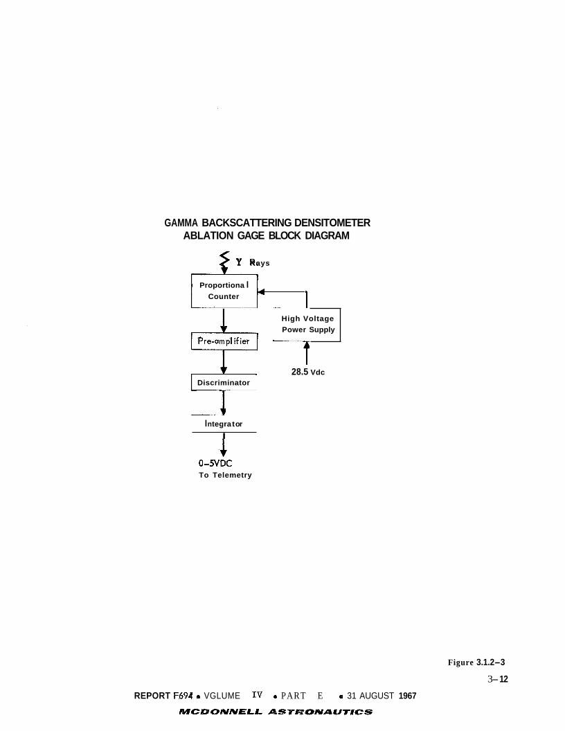
GAMMA BACKSCATTERING DENSITOMETER ABLATION GAGE BLOCK DIAGRAM
Y Rays I Proportiona I
Counter 1 High Voltage Power Supply
28.5 Vdc Discriminator
I n tegra t or
I
0-SVDC To Telemetry
Figure 3.1.2-3
3- 12
REPORT F694 e VGLUME IV 0 PART E e 31 AUGUST 1967
MCDQAfAlELL ASTKWBNAUT#CS

GAMMA BACKSCATTERING DENSITOMETER CON FlGU RATION
Ablation Sensor
Figure 3.1.2-4
3-13 REPORT F6941. VOLUME IV 0 PART E e 31 AUGUST 1967
MCDONNELL A S T W B N A W T E C S

TABLE OF CHARACTERISTICS
3 Size _ _ _ _ _ _ _ _ _ _ _ _ _ _ _ _ 97 in
Weight _ _ _ _ _ _ _ _ _ _ _ _ _ _ 5 Ibs
Power -_____________ 5 watts
Energy (Maxim urn)- _ 2.5 watt-hr
Accuracy _" _ - _ _ _ _ _ _ _ _ _ 10% a t 100 kft 5% at surface
* Worst Case Atmosphere
Figure 3.1.2-5
3-14
REPORT F694 0 VOLUME 0 PART E 0 31 AUGUST 1967
MCDONNELL ASTRONAUTICS

GAMMA BACKSCATTERJNG DENSITOMETER INTERFACE BLOCK DIAGRAM
r - - - - - - - - - - - - -I
Gamma Backscattering Densitometer
REPORT F694b VOLUME IV 0 PART E 0 31 AUGUST 1967
MCDONNELL ASTRONAUTICS
Figure 3.1.2-6
3-15

T e s t Requirements - The fol lowing p r e f l i g h t c a l i b r a t i o n tests must be performed.
o Obtain count rate versus dens i ty r e l a t i o n s h i p wi th and without h e a t
s h i e l d i n a vacuum chamber.
o Repeat wi th varying th ickness of h e a t s h i e l d wi th a b l a t i o n gages i n
place.
o By means of heavy s h i e l d i n g , measure a l l d i r e c t t ransmission between
the three sources and the t h r e e de t ec to r s .
Using the complete dens i ty sensor , measure the mul t ip l e s c a t t e r i n g e f f e c t s
w i th in t h e hea t s h i e l d and shock wave as a func t ion of atmospheric
p re s su re us ing a s imulated shock, vacuum chamber and mul t i l aye r h e a t
s h i e l d .
o
Development Requirements - This instrument is very c lose t o present s ta te- of- the-
ar t c a p a b i l i t i e s .
s i r e d accuracy f o r t he s i z e , weight and power required.
Normal development should produce an instrument with t h e de-
3-16
REPORT F6'& 0 VOLUME IV 0 PART E 0 31 AUGUST 1967
MCDONNELL ASTRONAUNCS

3.1.3
atmospheric p r o f i l e .
Mach 5 . C u n t i l ESP ope ra t ions are t e m i n a t e d SOWE 120 seconds o r more a f t e r to tch-
down. F igure 3.1.3-1 p re sen t s t y p i c a l s t agna t ion tempersture prc . f i les and Figure
3.1.3-2 p re sen t s t y p i c a l f ree- stream t enpe ra tu re p r o f i l e s f o r a ncnii.na1 e n t r y i n t o
t h e Martizn atmosphere.
and t h e base r eg i cn is t h e s e l e c t e d approach.
3.1.3.1
t h e o b j e c t i v e l i s t e d above i s constrairled by t h e fol lowing:
Temperature - Temperature is one of t h e q u a n t i t i e s needea t o r e c o n s t r a c t t h e
Measlirements w i l l b e nade f r o n an a l t i t u d e correspording t o
To ta l temperature measurement a t both t h e StZlgTiatiGI? F G i n t
Cons t ra in ts - Se lec t ion c f t h e ter ,perature neasurement technique t o acb.ieve
c The s e m i n g elements must be p ro t ec t ed from t h e pesk hes t ing loads enconnter-
ed p r i o r t G Ma.cki 5.c opera t ion .
o Ablat ion prcducts mnst no t i n h i k i t flow thrcugh t h e serisor when the. v~i lve
i s opeced a t Mach 5.0.
The CB design excursion a l lowawes on angles of a t t a c k m u s t be accomncdatecl
without performance degradat ion.
o
o The response t i m e of t h e instrument mst be sho r t encugh t o permit tenper-
a t u r e pro f i 1 e t r zcki cg . o Access t o t t e tct~iospbere a t a pcir. t where t b e sensed temperature can be re-
l a t e d t o t t e f ree- stream t empera twe is requi red .
G Measurements a r e requi red both before and a f t e r I?eroshell separa t ion .
c h t e r f a c i n g subsysten requ.iren?ents must be s a t i s f i e d .
o The m a x i m u m stsgIzation reg ion t m p e r a t u r e is 4 5 G C O K (W-9).
3.1.3.2 Alternat-ixcs - The t o t a l teq?E:rnture measurement approach is the: r ie tFcd
employed f o r ob ta in ing t h e d e s i r e d da ta . T h e l o c a t i o n of t h e instruments is t h e
prime cons idera t ion . Candidate l o c a t i o n s are: t h e s t agna t ion region, t h e w a l l
r eg ion , t h e base reg ion , and combinations of t h e s e loca t ions .
The t o t a l temperature sensor can be designed t o t o l e r a t e hea t loads over t h e .
e n t i r e p r o f i l e . However, o t h e r cons idera t ions may i n d i c a t e designs which do not
have t o t o l e r a t e such temperature extremes. The sensor flow can be u n r e s t r i c t e d
during t h e e n t i r e e n t r y r e s u l t i n g i n high temperature design requirements, o r flow
can be i n h i b i t e d during peak beat po r t ions of t h e e n t r y t o reduce t h e thermal de-
s i g n requirements.
3.1.3.3 Comparison - Location of t h e sensor at t h e s t agna t ion reg ion normal t o
t h e pitch-yaw plane permits t h e f low a t zero angle- of- attack t o e n t e r t h e probe
d i r e c t l y , and al lows t h e p o r t t o be f l u s h wi th t h e Aeroshel l mold l i n e .
A second p o s s i b i l i t y f o r l o c a t i o n i s on t h e w a l l of t h e a e r o s h e l l near t h e
3-17
REPORT F694 0 VOLUME IV e PART E 0 31 AUGUST 1967

STAGNATION TEMPERATURE PROFILES
hE = 760,000 ft
VE = 15,000 ft/sec
Y E = -20 deg
2 M/CDA = 0.30 slugs/ft
Time From Entry - Sec
Figure 3.1.3-1
3-18

FREE STREAM TEMPERATURE PROFILES
300
VE = 15,000 ft/sec Y 0
1
g 200 e & E E $3 100
c
c
IJY
(0
LL 2
0 100 200 300 400 Time from Entry - sec
0
Figure 3.1.3-2
3-19
REPORT F6d4 0 VOLUME IV 0 PART E 31 AUGUST 1967
MCDONNELL ASlPlWONA W r 8 C S

sphere/cone tangency po in t .
s i n c e flow is more nea r ly p a r a l l e l t o t h e a e r o s h e l l contour t han perpendicular t o i t .
A f u r t h e r disadvantage t o t h i s l o c a t i o n is t h a t t h e angle- of- attack excursions
coupled wi th t h e r o l l rates w i l l provide gas flow d i r e c t i o n a l changes which are ex-
tremely hard t o accommodate.
Location a t t h i s po in t r e q u i r e s a pro t ruding assembly
The t h i r d l o c a t i o n p o s s i b i l i t y i s i n t h e base reg ion of t h e CB. Location of a
sensor he re provides one immediately obvious advantage over t h e o t h e r two poss ib i l-
i t i e s :
being separa ted wi th t h e Aeroshel l as w i l l t h e o the r two.
a s soc i a t ed wi th ob ta in ing non-ambiguous d a t a i n t h e base reg ion are numerous.
f i e l d cons ide ra t ions are much more complex i n t h e base region.
must be evaluated f o r use of a temperature t ransducer l oca t ed i n t h e base reg ion
inc lude :
t h e t ransducer w i l l be w i t h t h e ESP throughout i t s opera t ion r a t h e r than
However, t h e problems
Flow
Other f a c t o r s which
o Thermal propulsion e f f e c t s
o Parachute e f f e c t s
o Flow v e l o c i t y must be determined f o r both t h e CB e n t r y and te rmina l descent
conf igura t ions
Temperatures a t t h e s t agna t ion region can approach 4500°K as shown i n F igure
Design of a temperature t ransducer t h a t can t o l e r a t e t hese temperatures 3.1.3-1.
would r e q u i r e p r o t e c t i v e coa t ings f o r t h e sens ing elements. Any coa t ing on t h e
element s e rves t o i nc rease t h e response t i m e and f o r some cases t h e response t i m e
would poss ib ly be increased beyond d e s i r a b l e l i m i t s .
3.1.3.4
l oca t ed a t t h e s t agna t ion reg ion and t h e o the r l oca t ed i n t h e base region.
Se l ec t ion - The p re fe r r ed approach i s two t o t a l temperature probes - one
Flow through
t h e s t agna t ion poin t probe w i l l b e r e s t r i c t e d during t h e peak hea t ing per iod .
This arrangement provides coverage over t h e ent ire en t ry p r o f i l e w i th t h e a d d i t i o n a l
advantage of making temperature measurements on t h e s u r f a c e of Mars ,pr ior t o ESP
ope ra t ion te rmina t ion , by us ing t h e base reg ion temperature sensor .
3.1.4
composition measurement is t o determine atmospheric c o n s t i t u e n t s from an a l t i t u d e
corresponding t o Mach 5.0 u n t i l ESP opera t ions are terminated a no'llinal 120 seconds
a f t e r touchdown.
Composition Determination by Mass Spectrometer - The purpose of t h e ESP
The p re fe r r ed approach i s t o u se a m a s s spectrometer ob ta in ing
samples from t h e s t agna t ion region.
3.1.4.1 Cons t ra in ts - The s e l e c t i o n of t h e instrument f o r making atmospheric compo-
s i t i o n measurements is l imi t ed t o a quadrupole o r magnetic s e c t o r m a s s spectrometer .
I n add i t i on , t h e atmosphere samples must not be contaminated by hea t s h i e l d a b l a t i o n
3-20 REPORT F694'0 VGLUME IV 4 PART E 0 31 AUGUST 1957

products. 3.1.4.2 Alternatives - The alternatives for this experiment include alternatives in type of instrument and sampling technique. natives include the following:
The mass spectrometer instrument alter-
o quadrupole o double - focusing magnetic o single - focusing magnetic
The sampling alternatives include:
o base region sampling port
o stagnation region sampling port o wall region sampling port
1 '
3.1.4.3 Comparison - The quadrupole and double-focusing magnetic sector instruments have approximately the same weight, power, and size characteristics. The single-
focusing magnetic deflection instrument if designed to measure only four or five species, would be significantly lighter and smaller and would require less data
transmission. It would, however, be able to measure only the major constituents of the atmosphere.
All of the various types of mass spectrometers offer their own advantages and
some have disadvantages which preclude their selection for the Voyager mission. monopole mass spectrometer for example, is mechanically simpler than the magnetic
deflection and quadrupole types and is inherently more rugged. However, the mono- pole mass filter is a weak-focusing instrument and gives poorer results at the low
mass numbers of interest for this atmospheric analysis. spectrometer is mechanically the simplest of all, and unlike the others, has no
critical alignment requirements. However, the time-of-flight instrument requires
precise timing circuits, the stability of which, for a many-month mission, would be
difficult to maintain reliably. Since one of the possible significant constituents of the Martian atmosphere is Argon, all of the instruments share a common problem
which is the low pumping capacity of small getter-ion pumps for the noble gases.
The
The time-of-flight mass
Of the various sampling alternatives the stagnation region sampling port in the
non-ablative section of the heat shield can most easily meet the requirement of ob-
taining atmospheric samples uncontaminated by ablation products. 3.1.4.4
considerable current development is taking place, and the optimum instrumentation
Selection - The ESP composition measurement experiment is one in which
3-21 REPQRT Fb94 0 VOLUME IV 0 PART E 0 31 AUGUST 1967
MCDONNELL AST'WOMAUrRCS

i s not obvious from among the several p o s s i b l e approaches.
r ep re sen t s a conserva t ive choice.
The quadrupole instrument ,
The quadrupole m a s s spectrometer is a s t rong focusing type of instrument . It
can be designed such t h a t nea r ly a l l of t h e ions of a g iven m a s s w i l l pass through
t h e quadrupole f i l t e r f o r a s p e c i f i c range of vo l t ages appl ied t o t h e e l ec t rodes .
The quadrupole mass spectrometer can be operated i n a continuous sweep o r scan mode
where i t is necessary t o sweep t h e app l i ed vo l t ages and t o mark t h e t i m e s cor res-
ponding t o passage of each mass. It a l s o can be opera ted i n a s tepped mode where
t h e app l i ed vo l t ages are stepped i n increments corresponding t o changes of 1 atomic
mass u n i t .
vo l t age s t e p s and, because t h e vo l t ages are stepped t h e d e t e c t o r cu r r en t and appl ied
vo l t ages c o r r e l a t i o n is somewhat s i m p l i f i e d f o r t h i s mode of instrument opera t ion .
However, due t o t i m e requirements f o r t r a n s i e n t damping it may not be p o s s i b l e t o
scan t h e e n t i r e mass range of 1 0 t o 60 i n 2 seconds i n t h e s tepping mode.
p re sen t t h e quadrupole i s assumed t o be opera ted i n a continuous scan mode.
There are no s t r i n g e n t s t a b i l i t y o r p r e c i s i o n requirements on t h e
For t h e
The s t a g n a t i o n temperature sensor o u t l e t tube main ta ins a continuous stream
of atmospheric gas flowing from t h e s t a g n a t i o n po in t t o t h e base reg ion from Mach
5.0 t o Aeroshel l separa t ion . Routing of t h i s tube p a s t t h e mass spectrometer
e l imina te s t h e need f o r a s e p a r a t e po r t and tube f o r mass spectrometer sampling.
By us ing a sepa ra t ion technique t h a t i n s u r e s continuous gas flow through t h e tube
a f t e r Aeroshel l s epa ra t ion , t h e tube can cont inue t o provide f r e s h gas samples
a l l t h e way t o touchdown. The r e l a t i v e l y l a r g e s t agna t ion temperature o u t l e t tube
volume and t h e s m a l l pumping capac i ty of t h e m a s s spectrometer ion pump r e q u i r e s
t h a t t h e m a s s spectrometer i n l e t be switched t o a smaller c a p i l l a r y tube t o i n s u r e
t h a t f r e s h atmosphere samples are obtained during t h e s h o r t ope ra t iona l per iod
a f t e r touchdown.
en t e r ing t h e s t agna t ion reg ion sampling p o r t s throughout t h e e n t i r e e n t r y and de-
Use of a ceramic nose cap prevents a b l a t i o n product gases from
.
scen t opera t ions .
p re s su re sensors and f o r m a s s spectrometer sampling f r e e from a b l a t i o n product
i n t e r f e r e n c e is thus a v a i l a b l e f o r a l l p o s s i b l e des i r ed s t a g n a t i o n reg ion sampling
schemes.
3.1.5
p l e t e l y provides atmospheric composition d a t a over a t o t a l e n t r y p r o f i l e as each
method i s bese t w i th i ts own l i m i t a t i o n s .
t i o n s may s e v e r l y l i m i t m a s s spectrometer opera t ions .
t o cons ider absorp t ion spectroscopy as a supplement o r a l t e r n a t e t o t h e mass spec t -
The op t ion f o r s e p a r a t e p o r t s f o r s t agna t ion temperature and
Composition Determination by Absorption Methods - No s i n g l e technique com-
For example, t h e Argon pumping l i m i t a -
I n t h i s l i g h t it i s use fu l
3-22 REPORT +694 e VOLUME I V e PART E e 31 AUGUST 1967
MCDONNELI ASTRONAUNCS

rometer technique a l r eady discussed.
ment ou t l i ned below weighs approximately 2 l b s . and r e q u i r e s less than 1.5 watts of
electrical power.
S c i e n t i f i c Objec t ives and Approach - The s c i e n t i f i c o b j e c t i v e s of t h i s experiment
The equipment needed t o perform t h e experi-
The t o t a l d a t a output dur ing e n t r y and descent is 6240 b i t s .
are :
P r i n c i p a l Object ives:
o To determine t h e
N 2 , and A i n t he
o To determine t h e
d e n s i t y and a l t i t u d e d i s t r i b u t i o n of COZY 03,
Martian atmosphere.
s o l a r f l u x of b i o l o g i c a l l y s i g n i f i c a n t u l t r a v i o l e t
r a d i a t i o n reaching t h e su r f ace .
Addi t iona l Object ives:
o To determine t h e atmospheric s c a t t e r i n g p r o p e r t i e s (molecular and
a e r o s o l ) , and hence o b t a i n information about t h e ae roso l ccn ten t
and p r o f i l e .
To measure t h e abso lu t e s o l a r f l u x a t t h e top of t h e atmosphere and
t h e atmospheric albedo.
o
Measurements of t h e a t t e n u a t i o n of s o l a r u l t r a v i o l e t r a d i a t i o n i n t h r e e wave-
leng th bands and of s o l a r x- rays i n one band can s a t i s f y t h e s e ob jec t ives .
fou r bands are chosen so as t o permit t h e maximum of information about t h e atmos-
phere cons i s t en t wi th t h e s i m p l i c i t y of t h e experiment. The genera l i d e a i s t o
measure t h e s o l a r cons tan t a t t h e top of t h e Martian atmosphere i n each band of
The
i n t e r e s t , then measure t h e a t t e n u a t i o n , i f p o s s i b l e t o e x t i n c t i o n (occurs only
i n f a r W and X-ray measurements, "ext inct ion" being t h e threshold f l u x of t h e
s e n s o r s ) , as t h e o p t i c a l th ickness of t h e atmosphere inc reases i n t h e descent t o
t h e sur face . e 0
Two bands, 2200-3000 A and 3000-4000 A, f u r n i s h information on molecular
dens i ty , a e r o s o l con ten t , and ozone, i f p r e sen t , i n t h e atmosphere below 15-25 km.
These bands may a l s o d e t e c t h igh a l t i t u d e a e r o s o l layers. e? 0 0 0
2-8 A and 1050-1350 A ( o r 1225-1350 A , o r 1425-1480 A ) , f u r n i s h information on
CO number d e n s i t y and t o t a l number dens i ty i n t h e upper atmosphere.
Upper Atmosphere Measurements:
VM-7 and VM-8, are considered f o r purposes of d i scuss ion .
they r ep resen t probable extremes i n terms of atmospheric composition and scale
he igh t .
of 20% C 0 2 and 80% N2 w i th a mean scale he igh t of 14.2 km;, VM-8 assumes 100%
CO wi th a scale he ight of 5 km. VM-8 is t h e r e f o r e considerably c l o s e r t o cu r r en t
The o t h e r two bands,
2 0 0
1050-1350 A and 2-8 A Bands - Two model atmospheres
These w e r e chosen s i n c e
Both models assume a s u r f a c e p re s su re of 5 mb. VM-7 assumes a composition
2
3-23 REPORT F894 e VOLUME IV a PART E a 31 AUGUST 1967
MCDONNELL ASTRONAUTICS

estimates than i s VM-7.
Absorption i n t h e 1050-1350 A Band - The i n t e n s i t y of r a d i a t i o n i s given by 0
I log - = -) o .n dx i i IO o i
and i f CJ i s independent of pa th l eng th
- - E o i Ni I
IO i log - -
where L = pa th l e n g t h , I = i n t e n s i t y of r a d i a t i o n at x = L , I
r a d i a t i o n a t x = 0 , 0 = absorp t ion c r o s s s e c t i o n ( c m ) , n = number dens i ty of
molecules (cm ), and N = number of molecules pe r u n i t column (cm >.
= i n t e n s i t y of 0 2
-3 -2
The i n t e n s i t y of s o l a r r a d i a t i o n a t a l t i t u d e z i n a p l ane ta ry atmosphere i s
given by
and f o r an isothermal atmosphere t h i s reduces t o
I -z/H l og - = - HC oino e 1
IO i ( 4 )
where H is t h e s c a l e he ight . 0
Almost a l l absorp t ion i n t h e 1050-1350 A band atmosphere w i l l be by CO The 0 2'
absorp t ion c ros s s e c t i o n f o r CO a t 1216 A is about 7 x cm2 (Reference 1 ) and
t h i s , combined wi th i ts number dens i ty , provides a t o t a l absorp t ion which is o rde r s
of magnitude l a r g e r than t h a t of any o t h e r p o s s i b l e atmospheric cons t i t uen t .
number of molecules of CO per u n i t column, ca l cu la t ed from equat ion 1, that w i l l .
absorb l o % , 50%, and 90% of t h e inc iden t s o l a r r a d i a t i o n is:
2
The
2
Percent Absorption N (cm-2)
10 1.5 x 10
50 9.9 x 1 0
18
18
90 33 x 10l8
The a l t i t u d e a t which N molecules-cm-2 w i l l be between t h e sensor and t h e Sun
depends on t h e atmospheric s t r u c t u r e and on t h e z e n i t h angle , 8 . For z e n i t h
angles up t o about 75", N varies as approximately sec 8 . For l a r g e r z e n i t h angles
3-24 REPORT F644 0 VOLiiME IV e PART E e 31 AUGUST 1967
NCDUNNELL AST'RONAUTBCS

sec 8 must be rep laced by t h e Chapman func t ion .
Equations (2) and ( 4 ) are de r ived on t h e asarrption t h a t cr is independent of
-3 pa th l eng th (e.g. p re s su re ) .
because Q is independent of p re s su re over t h e e n t i r e p re s su re range (2.7 x 1 0
t o 133 mb) inves t iga t ed i n Reference 1.
This is a good assumption f o r t h e Mart ian atmosphere
The abso rp t ion c ros s s e c t i o n , a , and the s o l a r cons tan t are func t ions of
wavelength.
energy i n t h e band of i n t e r e s t ,
mation. I n gene ra l , t h e s p e c t r a l v a r i a t i o n of t h e s o l a r cons tan t , and t h e d e t e c t o r
e f f i c i e n c y can be taken i n t o account by
However because t h e s o l a r Lyman-a l i n e c o n t r i b u t e s most of t h e 0
cr a t 1216 A serves as a s a t i s f a c t o r y approxi-
= s o l a r cons tan t i n wave- A IO
where E, = d e t e c t i o n e f f i c i e n c y a t wavelength A , l eng th i n t e r v a l Ah , and
t h e d e t e c t o r and t h e Sun.
Absorption i n t h e 2-8 A Band - The abso rp t ion of X-rays is given by:
A
n(x)dx = N , t h e number of molecules per cm2 between 0
0
where Ix = i n t e n s i t y of r a d i a t i o n a t z = L , Io
z = 0, L = pa th l eng th , l . ~ = m a s s absorp t ion c o e f f i c i e n t , n = number of atoms
pe r cm , A = atomic weight, and N' = Avogadro's number.
= i n t e n s i t y of r a d i a t i o n a t X
3
I f t h e gas is of uniform composition (complete mixing), (6) can be w r i t t e n
CvifiAi -3 where ii = -- , p(z) = d e n s i t y i n g-cm = C n.A and f i = f r a c t i o n Cf2k, 1 i'
~ of t o t a l numb%iof atoms.
Absorption of s o l a r X-rays i n a p l ane ta ry atmosphere i s given by (again,
assuming complete mixing)
3-25 REPORT F69d 0 VOLUME IV PART E 0 31 AUGUST 1967
MCDONNhELL ASTRONAUTICS

and for an isothermal atmosphere
X - -z/H I log - = - Hpoe
X IO
The actual situation is not quite as simple as outlined because of the variability of the parameters involved in the 2-8 A range. of the atomic species concerned vary by about two orders of magnitude; the number
e The mass absorption coefficients
of solar photons
depending on the detector depends
a given distance
of a given energy varies by a few too many orders of magnitude
temperature of the emitting regions; and the efficiency of the upon wavelength. Hence, the actual number of photons transmitted
through a single atomic species is given by
where c h
per wavelength interval at x = 0, and Ah = wavelength interval, This equation
must be summed over all atomic species.
= efficiency of detector at wavelength A , Io = number of photons A
0 For purposes of illustration we may take 1-I at 5.5 A as representative and
assume Io to be constant. A
With these simplifying assumptions, we determine the number of molecules per
2; unit column required for lo%, 50%, and 90% absorption of X-rays in a pure CO
and 80% C02 20% N2; a 50% C02 50% N2; and a 20% CO 2 are : NUMBER OF MOLECULES
80% N2 atmosphere. The results
Percent 100% co2 80% C02 20% N2 50% C02 50% N2 20% C02 80% N2 Absorption
18 19 20
6.0 x 10 4.0 x 10 1 . 3 x 10
18 19 20
4.9 x 10 3.2 x 10 1.1 x 10
18 19
19
10 3.5 x 10 l8 4.1 x 10 50 2 . 3 x 10 l9 2 . 7 x 10
90 7.7 x 10 9.0 x 10 Altitude Range of Measurement - The altitude range of measurement depends upon the surface pressure; it is shifted upward for a given atmospheric structure as surface
pressure is increased. In addition, differences in composition, e.g. an increase
of N2, result in an upward shift of the X-ray measurement range with respect to the
1050-1350 A measurement range. The altitudes at which 10% and 90% absorption occur for the VM-7 and VM-8 atmospheres, and for zenith angle 8 = 0 are:
0
3-26
REPORT F%94 0 VOLUMEIV 0 PART E 0 31 AUGUST 1967
4WCIC)ONNEL.L ASTRONAUT#CS

Per cen t VM-8 - VM-7 Absorption -
x-Ray 1 0 148 km 60 km 90 104 km 45 km
Lyman-do 104 km 65 km 90 73 km 49 km
The p r i n c i p a l d i f f e r e n c e between t h e two atmospheres is i n t h e i r d i f f e r e n t scale
he igh t s (5 km i n t h e VM-8; and 14.2 km mean, 10 km f o r C02 , i n t h e VM-7).
is p a r t i a l l y o f f s e t f o r t h e 1050-1350 A absorp t ion by t h e smaller amount of CO
t h e VM-7 atmosphere.
This
2 0
i n
The e f f e c t of a non-zero z e n i t h ang le f o r t h e Sun on the a l t i t u d e a t which
absorp t ion is a given va lue is e a s i l y evaluated.
i so thermal atmosphere, by
This effect i s given, f o r an
z - e z = H log ( sec e) V
where z e = a l t i t u d e f o r 8 = 0, and z = a l t i t u d e f o r 8 = 0. V
Hence, even f o r a z e n i t h ang le of 75O, t h e a l t i t u d e f o r a given absorp t ion is
s h i f t e d upward only about 0.6 €3 o r 3 km f o r t h e VM-8 and 6-8 km f o r t h e VM-7
atmosphere.
Data Analysis - This s e c t i o n o u t l i n e s t h e a n a l y s i s of d a t a fol lowing t h e s t e p where
t h e d a t a have been reduced t o g ive percentage absorp t ion vs a l t i t u d e . 0 0
1050-1350 A - CO is almost c e r t a i n l y t h e dominent absorber of 1050-1350 A 2 r a d i a t i o n i n t h e Martian atmosphere. Hence, each d a t a po in t g iv ing t h e
amount of abso rp t ion a t a given a l t i t u d e can be used t o c a l c u l a t e d i r e c t l y
t h e number of molecules of CO p e r u n i t column between t h e d e t e c t o r and t h e
Sun by means of equat ion (5 ) .
of CO a t t h e s e a l t i t u d e s t o be ca l cu la t ed .
2-8 A - For i l l u s t r a t i v e purposes, t h e s imp l i f i ed equat ion (8) i s used he re
r a t h e r t han t h e exact equat ion (10).
2 Two o r more d a t a p o i n t s enable t h e scale he ight
02
Equation (8 ) , f o r X-ray absorp t ion , can be w r i t t e n as T
where N ' = Avogardo's number, % = atomic weight, and Nk = number of atoms pe r u n i t
column of spec i e s k. If s u b s t i t u t i o n of t h e s e va lues and t h e observed X-ray a t t e n u a t i o n i n t o t h e above
0 Measurements in t h e 1050-1350 A band w i l l g ive NC and No.
equat ion produces e q u a l i t y between both s i d e s , then t h e atmosphere must be composed
3-27
REPORT Fob4 e VOLUME IV e PART E e 31 AUGUST 1967
MCDONNELL A-STROfUAWr#CS

almost e n t i r e l y of CO I f e q u a l i t y is no t ob ta ined , then one o r more a d d i t i o n a l
gases are p re sen t i n app rec i ab le amounts, most probably N
s u b s t i t u t i o n of N and N
2’ and/or A. I n t h i s case , 2
i n t o t h e above equat ion w i l l permit c a l c u l a t i o n of t h e C 0 sum of t h e N and A con t r ibu t ions , i .e., 2
C = p A N + v A A A N A N N N I f , i n add i t i on , t h e t o t a l atmospheric dens i ty , o r mass p e r u n i t column (m),
i s measured independently
w i l l be knowg. Equations (12) and (13) can then be S O ~ W - I f o r t h e two unknowns,
N
t h a t a l t i t u d e . Measurements a t two o r more a l t i t u d e s permit t h e s c a l e he igh t s
of N and A t o b e determined.
and NAY hence determining t h e numbers of N N 2 and A presen t i n t h e atmosphere a t
2 0
Poss ib l e S u b s t i t u t e Bands f o r 1050-1350 A - The type of a b l a t o r used f o r an
en t ry probe may a f f e c t t h e 1050-1350 A measurements. I f t he a b l a t o r conta ins an
apprec iab le amount of o rgan ic material, atomic hydrogen can be emit ted and t h i s
w i l l r esonant ly scatter t h e s o l a r Lyman-a.
poss ib l e s u b s t i t u t e bands i s d e s i r a b l e , These are: 1225-1350 and 1425-1480 1. The 1225-1350
CaF window is used in s t ead of a LiF window f o r t h e low wavelength c u t o f f . The
1425-1480 A d e t e c t o r is a n i o n chamber wi th a sapphi re window.
c ros s s e c t i o n of C02 i n both t h e 1225-1350
about 7 x lo-’’ c m , o r a n o rde r o r magnitude g r e a t e r than a t t h e Lyman-a wave-
length . For an exponent ia l atmosphere, t h e a l t i t u d e z a t which absorp t ion is a
g iven percentage i s given by
0
For t h i s case, t h e use of one of two
d e t e c t o r i s similar t o t he 1050-1350 ;I d e t e c t o r except t h a t a
2 0
The absorb t ion
band and t h e 1425-1480 1 band i s 2
1216 + 2*3H z = z
= a l t i t u d e a t which Lyman-a absorp t ion i s t h e given percentage. 1216 where z
Hence, a l l a l t i t u d e s f o r CO absorp t ion i n t he VM-7 atmosphere must be increased .
by about 23 km and a l l a l t i t u d e s i n t h e VM-8 by about 12 km. 2
0
The 1425-1480 A reg ion is a continuum region of s o l a r r a d i a t i o n , and t h e
CO absorp t ion c ros s s e c t i o n is about t h e s a m e throughout t h e region. This
s i m p l i f i e s t h e d a t a ana lys i s ; however, t h e 1225-1350 A reg ion i s one of prominent
s o l a r emission l i n e s , t h e s t ronges t being t h e 01 t r i p l e t a t 1302.2, 1304.9, and
1306.0
absorp t ion c ros s s e c t i o n i s q u i t e v a r i a b l e i n t h i s s p e c t r a l region. This compli-
cates t h e d a t a ana lys i s .
2 0
and t h e C I1 doublet a t 1334.5 and 1335.7 1. I n add i t i on , t h e C02
3-28
REPORT F294 o VOLUME IV 0 PART E 0 31 AUGUST 1967
MCDONNELL ASTRONAUTICS

There is one final consideration. Fjelbdo et at. (Reference 2) believe that 01
may be a major constituent of the Martian atmosphere above about 70 km. The
absorption cross section of 01 at the 01 triplet resonance is about 3 x cm
(Reference 3 ) .
it will absorb strongly only at the center of the sclar 01 lines. A preliminary calculation indicates that although the amount of 01 suggested by Fjelbdo et al. would completely absorb radiation at the line centers, absorption over the entire
line widths would be less than 5% and hence, less than about 1% of the solar radiation in the entire 1225-1350 A band. If, on a more detailed analysis, the 01
absorption should prove to be measureable, it would provide at least a quantitative
measurement of 01. At the same time, it would not conipromise the CO measurement
because virtually all 01 absorption would have occurred before measurable CO
absorption commenced.
2
If the temperature of the 01 is 100 O K at Fjelbdo's estimate, then
0
2 2
0 0
Lower Atmosphere Measurements: 2200-3000 A and 3000-4000 A Bands - The
same model atmospheres are considered as those for the upper atmosphere. 0 0
2200 to 3000 A Band - In this region of the spectrum, the solar radiation ia attenuated by: l), perhaps ozone absorption, 2) scattering by the
molecular atmosphere; and 3) scattering by aerosol particles. These have
been discussed in detail in References 4 and 5, and hence the phenomena
will only be outlined here. The calculations show that with the Sun at
the zenith, the attenuation due to molecular scattering is about l o % , the maximum due to ozone absorption is about s Z > 2nd that due to aerosol
scattering is about 15%. For a 70" solar zenith angle, these values change to 25%, 12%,and 40%, respecti~7ely. In addition, the scattered
radiation comprises about 10% of the direct solar radiation at the planet's
surface for the Sun at zenith, and about 50% for an 84" zenith angle. This wavelength band serves to determine the atmospheric ozone content, if large
enough to be measureable, and combined with measurements in the 3000-
4000 A band, the molecular and aerosol scattering contributions. The
atmospheric aerosol content can be determined once the aerosol scattering contribution is known (References 4 and 5). Additionally, this band serves to delineate the flux of biological importance which reaches the surface.
3000 to 4000 A Band - In this band, attenuation is due almost entirely to molecular and aerosol scattering. Details are discussed in References
4 and 5 . With the Sun at the zenith, the molecular scattering contribu- tion should be about 3% and that of aerosols 12%. These figures roughly
0
0
3-29
R E P O R T F6b4 VOLUME IV PART E 31 AUGUST 1967
MCDQNNELL ASTRONAUTICS

double f o r a 70" s o l a r z e n i t h angle.
3000 A b a d , serves t o s e p a r a t e t h e molecular and ae roso l s c a t t e r i n g
con t r ibu t ions t o t h e a t t enua t ion .
This band, combined wi th t h e 2200- 0
o A l t i t u d e Range of Measurement - I n t h e 2200-3000 band, 10% a t t e n u a t i o n w i l l
have occurred a t a he ight of about 12-25 km depending upon t h e s o l a r z e n i t h
angle. Therefore, un le s s t h e r e is some unforseen s t rong , high- level
absorber o r scatterer, a l l d a t a i n t h i s channel w i l l be obta ined below
about 15-25 km. I n t h e 3000-4000 1 10% a t t e n u a t i o n w i l l have occurred
a t a he ight of about 14 la.
o Data Analysis - Data a n a l y s i s is d e t a i l e d i n References 4 and 5.
Experimental Approach - An important f a c t i s t h a t t h e hardware f o r t h i s
experiment a l r eady e x i s t s , and has a proven record of performance i n rocke t
and sa te l l i t e experiments s i n c e 1949.
o Ins t rumenta t ion - The experiment package c o n s i s t s of from f i v e t o
twelve s m a l l sensors , ( inc luding s o l a r aspec t sensors i f such are not
a l ready on board) and t h e a s soc i a t ed e l e c t r o n i c s . The exac t number of
sensors requi red depends upon t h e p a r t i c u l a r mission c o n s t r a i n t s . I f
a complete o r p a r t i a l l o c k onto t h e Sun can be made during e n t r y , such
t h a t t h e sensors see t h e Sun throughout t h e descent , only f i v e senso r s
are requi red : one f o r each band and one s o l a r a spec t sensor . I f t h e
e n t r y v e h i c l e r o t a t e s a t least 60 rpm, only f i v e sensors are needed.
Any s p i n rate less than 60 rpm r e q u i r e s a d d i t i o n a l sensors , a t least
t e n (two i n each band), t o provide a s u f f i c i e n t amount of da t a .
t h e r e is no s o l a r lock-on and no sp in , a minimum of twelve sensors i s
requi red : two each i n t h e X-ray and f a r W bands, t h r e e each i n t h e
middle and near UV, and two s o l a r aspec t sensors . The requi red equip-
ment f o r t h e 12 sensor case is l i s t e d below:
I f
- I t e m Quan t i t y 0
Sof t X-ray Geiger counter 2-8 A 2
Far W ion chamber 1050-1350 A 2
3
3
2
0
Middle W diode phototube 2200-3000 1 Near W diode phototube 3000-4000 1 Sola r a spec t sensor - v i s i b l e
The viewing cone of t h e s o f t X-ray and f a r W senso r s is 2 li s t e r a d i a n s ,
f o r t h e middle W and t h r e e of t h e near W senso r s , i t i s li/2 s t e r a d i a n s ,
and f o r t h e s o l a r a spec t sensors i t is 2 IT s t e r ad ians .
3-30 1
REPORT F694 0 VOLUME I V 0 PART E 0 31 AUGUST 1967
MCDONNELL ASTRONAUTICS

The s i z e , weight and power of t h e u n i t s , inc luding t h e i r e l e c t r o n i c s ,
are :
- Unit S ize (in.) . Weight (02) - Power (Watts)
S o f t X-ray (2) 3 6.4 .05
Far W (2) 2.4 3 0 * 002
Middle W (3) 3 1.5 0.001
Near W ( 3 ) 3 1.5 0.001
Sola r Aspect sensors (2)
E lec t ron ic s
10
1 2
4 .
1 5 .
31.4 Oz.
0.56
0.8
A l l of t h e above equipment can m e e t s t e r i l i z a t i o n requirements.
opera t ing temperatures are a l l less than 50°C.
A l l s enso r s are chosen and provided wi th app ropr i a t e ampl i f i ca t ion t o
i ove r t h e i r range of measurement adequately. A conserva t ive minimum
cur ren t of 10"' amperes i s e s t a b l i s h e d f o r a l l t h e W senso r s , wi th -7 maximum cur ren t c a p a b i l i t y t o 10 being a v a i l a b l e ; small c u r r e n t s can
be measured. Each sensor d i f f e r s i n i t s quantum e f f i c i ency . The
Geiger counter measures 1 t o 10 photonslsec ( e f f i c i e n c y i s loo%) , there- 4 f o r e 1 t o 10 counts/sec.
t h e i r a s soc i a t ed e l e c t r o n i c s , however, t h e fol lowing po in t ing c o n s t r a i n t s
The
4
A l l sensors can be placed independently of
apply: a. A t least one of each type of sensor must be placed t o have t h e Sun i n
view a t t h e time of en t ry . I f t h e v e h i c l e r o l l s sensors must be
poin ted w i t h z e n i t h angles which al low continuous measurement during
descent.
b. The p a i r s of f a r W, X-ray and s o l a r aspec t sensors must be placed back
t o back t o e s t a b l i s h a viewing cone of 4 T s t e r a d i a n s f o r each band as
a pa i r .
c. The t h r e e middle and t h r e e near W senso r s , having a zen i th ang le t h e
same as t h e Sun, must be separa ted by 120" i n t h e ho r i zon ta l p lane from
each o the r , one r e fe rence sensor of each group of t h r e e being a l igned
wi th t h e viewing cone axis of one r e fe rence s o l a r aspec t sensor .
o A l l s enso r s are h ighly rugged ceramic-metal photosens i tve tubes wi th a
proven h i s t o r y i n previous rocket and s a t e l l i t e f l i g h t s . The s o f t
X-ray sensor is a Geiger counter w i th a 0.005" beryl l ium window, t r ans-
3-3 1 .i
R E P O R T F694 VOLUME IV e PART E e 31 AUGUST 1967
MCDONNELL ASTRONAUT#CS

0
m i t t i n g t h e 2-8 A band, responding t o s i n g l e photons by ion- pair product ion
i n t h e f i l l gas. It measures t h e a t t e n u a t i o n of s o l a r f l u x i n t h i s band
from a l l atmospheric conse i tuents .
responding t o Lyman-a (1215.7 i) as t h e p r i n c i p a l s o l a r f l u x i n i ts
passband (1050-1350 b). atmospheric CO The middle W sensor i s a s o l a r b l i n d rubidium tell-
u r i d e diode phototube wi th a vycor window, responding t o s o l a r f l u x i n
t h e 2200-3000 band. Attenuat ion i n t h i s band i s due t o 0 absorp t ion
and molecular and a e r o s o l s c a t t e r i n g .
response s o l a r b l i n d cesium t e l l u r i d e diode phototube wi th a pyrex
window, responding t o s o l a r f l u x i n t h e 3000-4000 H band.
s o l a r f l u x a t t e n u a t i o n due t o molecular and ae roso l s c a t t e r i n g .
Control and Data T i m e H i s t o r i e s - The commands requi red f o r instrument
ope ra t ion are simply turn-on a f t e r s epa ra t ion and turn- off a f t e r
touchdown. The t o t a l d a t a output is 6240 b i t s , wi th a breakdown as
fol lows .
The f a r UV sensor is a n i o n chamber
It measures s o l a r f l u x a t t e n u a t i o n due t o
2'
3 The near W Sensor is an extended
It measures
o
o So la r Ca l ib ra t ion Data - ( P r i o r t o en t ry)
(5 samples) x (12 sensors ) x (8 b i t s / s e n s o r ) = 480 b i t s
o Entry Measurements Data
(60 samples) x (12 sensors ) x ( 8 b i t s / s e n s o r ) = 5760 b i t s
o A l l sensors are scanned as c l o s e l y toge ther as p o s s i b l e during each
sampling.
Sample Requirements - The prime o b j e c t i v e should be t o minimize con-
taminat ion of t h e atmosphere by e i t h e r r e t ro rocke t o r a b l a t o r materials
during t h e measurement per iod.
o
o Viewing Requirements - All sensors must have an unobstructed view of t h e
Sun w i t h i n t h e i r viewing cone. Since they are a l l mounted on t h e i r
app ropr i a t e support s t r u c t u r e , placement o r i n t e g r a t i o n of t h e package
should be such as t o achieve t h i s requirement and t h i s should be regarded
as of prime importance t o t h e success of t h e experiment.
o T e s t , Checkout and Development Requirements
a. Design/Development Sequence - The sequence i s (1) a pro to type package
is f a b r i c a t e d f o r op t imiza t ion of a l l e l e c t r i c a l performance ob jec t ives ,
(2) a simulated environmental test i s made t o e s t a b l i s h accuracy of
measurement wi th change of i r r a d i a t i o n source angle , and (3) a f i n a l
design package i s f ab r i ca t ed and t e s t ed .
3-32
REPORT F6d4. VOLUME I V n PART E 0 31 AUGUST 1967
MCDONNELL ASTRONAUTICS

b.
C.
d.
e.
0
0
F l i g h t Tes t ing - A l l hardware t o be used on f l i g h t v e h i c l e s would be
sub jec t ed t o a q u a l i f i c a t i o n test.
checked f o r f u n c t i o n a l ope ra t ion and c a l i b r a t e d .
P r i o r t o i n s t a l l a t i o n , each u n i t is
- Af te r i n s t a l l a t i o n , a p r e- s t e r i l i z a t i o n and
p o s t - s t e r i l i z a t i o n checkout are made t o v e r i f y no degradat ion of
performance . Pre-Launch T e s t - A l l electrical c i r c u i t s are checked.
Post-Launch Monitoring and Pre- Separation Tests - A schedule of moni-
Coring i s not required. Checkout of c i r c u i t s p r i o r t o s epa ra t ion
w i l l be made t o v e r i f y opera t ion .
Cons t r a in t s on Capsule Design - No s p e c i a l c o n s t r a i n t i s imposed o the r
t han t h a t t he s enso r s receive a minimum of s o l a r e lectromagnet ic rad ia-
t i o n during i n t e r p l a n e t a r y t r a v e l .
Er ror Analysis - Proper t reatment of t h i s s u b j e c t r equ i r e s f i r s t t h e
a n a l y s i s of contamination of t h e atmosphere from re t ro rocke t and a b l a t o r
gases . I n gene ra l , a high accuracy of r e l a t i v e measurements t o about
1% i s poss ib l e . Accuracy of a b s o l u t e measurements can be expected t o
be around 20-30%.
t ive contamination (Reference 6) p r imar i ly because of t h e presence of
atomic hydrogen i n t h e gas envelope.
i n t h e 1225-1350 A o r 1425-1480 A reg ions without an apprec iab le s a c r i -
f i c e i n performance.
gas envelope absorp t ion and emission during e n t r y f o r t h e NASA Ames
The 1050-1350 i band appears most s e n s i t i v e t o abla-
Measurements he re can be conducted 0 0
A s an example of how each sensor w a s a f f e c t e d by
h igh v e l o c i t y
S p e c t r a l Band
2-8 8 1050-1350 i
0
2200-30008
e n t r y probe, t h e fol lowing r e s u l t s are given:
Viewing Cone Absorp t ion Emission
100 O unaffected unaffected
100" atomic hydrogen from unaf fec ted i n VM8, a b l a t o r can s e r i o u s l y degrade measur emen t phere due t o H , 0 , N, due t o resonance C, S i emission. Band absorp t ion of s o l a r Lyman-a: Band can 1425-1480 A t o avoid be s h i f t e d t o 1425- 1480 t o avoid problem
degraded i n VM7 atmos-
can be 5hi:"erl t o
pro b 1 em.
60 O unaffec ted i n a l t i t u d e range of i n t e r e s t
unaffected i n a l t i t u d e range of i n t e r e s t . Any unce r t a in ty can be min- imized by s h i f t i n g
3-33
REPORT F6$4 e VOLUME I V e PART E e 31 AUGUST 1967
MCDONNELL ASTRONAUTICS

Viewing S p e c t r a l Band Cone Ab so r p t ion
3300-4000
Emission
bands t o 2200-2700 i, avoiding CO eF i s s ion , o r 2200-2400 A, avoid- ing C and CO emission
--
60 O unaffec ted i n unaf fec ted i n a l t i t u d e a l t i t u d e range of range of i n t e r e s t . Any i n t e r e s t unce r t a in ty can be min-
imized by s h i f t i n go
band t o 3550-3800 A, avoiding CO and CN emission
The e f f e c t of r e t r o r o c k e t gases f o r t h e VOYAGER e n t r y would have t o be
s i m i l a r l y assessed . Unless t h e source of contaminants can be modified
t o opt imize measuring condi t ions f o r t h e experiments, t h e experiment
can be adapted by appropr i a t e u l t r a v i o l e t band changes, f o r example,
1225-1350 1, 1425-1480 1, 2200-2400 1 and 3550
thereby minimizing e r r o r s from contaminant absorp t ion and emission.
Likewise, t h e r e are a number of p o s s i b l e s u b s t i t u t e X-ray bands avail-
a b l e , such as 8-20 ; and 44-60 1. experiment is s u f f i c i e n t l y f l e x i b l e t o avoid contamination problems
under a wide range of condi t ions .
and 3550-3800 1.
The important po in t is t h a t t he
3-34
REPORT F694 o VOLUME IV 0 PART E a 31 AUGUST 1967
MGDONNELL ASBRBWAUTICS

3.1.6 Accelera t ion - The purpose of t h e ESP accelerometer is t o measure a c c e l e r a t i o n s
along t h r e e or thogonal axes &ring t h e e n t i r e e n t r y p r o f i l e s t a r t i n g wi th turn-on
300 seconds p r i o r t o reaching t h e e n t r y a l t i t u d e of 800,000 f e e t , and te rmina t ing a t
touchdown. Typical ca l cu la t ed a c c e l e r a t i o n p r o f i l e s f o r t h e r o l l axis a t zero
angle- of- attack are shown as Figure 3.1.6-1 and t h e corresponding a c c e l e r a t i o n rates
of change are presented as Figure 3.1.6-2.
se rvo fo rce balance accelerometer.
The s e l e c t e d instrument is a tri-axis
3.1.6.1 Cons t ra in ts - Se lec t ion of an accelerometer is cons t ra ined by t h e following:
o The instrument must have h igh accuracy i n o rde r t o permit accu ra t e dens i ty
and temperature p r o f i l e determinat ions.
o The maximum a c c e l e r a t i o n w i l l be 21 g OIM-8) Ear th measure.
o The range and frequency response must be compatible with t h e a c c e l e r a t i o n
p r o f i l e s encountered during en t ry .
o A d i g i t a l ou tput is requi red because t h e accuracy requirements are more
s t r i n g e n t than can be accommodated by t h e Telemetry Subsystem analog-to-
d i g i t a l converter .
o The requirements of i n t e r f a c i n g subsystems must be m e t .
3.1.6.2
These are:
Al t e rna t ives - Two ways of measuring a c c e l e r a t i o n have been considered.
o A tri-axis accelerometer .
o Three s i n g l e a x i s accelerometers .
A s tudy of t h e t y p i c a l a c c e l e r a t i o n p r o f i l e presented i n F igure 3.1.6-1
coupled wi th a requirement f o r high accuracy, p re sen t s a second se t of a l t e rna-
t i v e s - t h e r o l l axis accelerometer could be e i t h e r s i n g l e range o r dua l range.
Two b a s i c types of accelerometers are considered - t h e servo fo rce balance
Choice of one over t he o t h e r is d i c t a t e d p r i- type and t h e p i e z o e l e c t r i c type.
mar i ly by frequency response requi red .
Other a l t e r n a t i v e s are inpu t vo l t age level, l o c a t i o n wi th respec t t o both
CB e n t r y and te rmina l descent conf igura t ions , and Telemetry Subsystem sampling
rate.
3.1.6.3 Comparison - The t r i - a x i s u n i t appears more d e s i r a b l e than the s i n g l e
a x i s u n i t s because:
o Weight, volume, and power sav ings can be achieved.
o A tri-axis u n i t i s procured wi th the i n t e r n a l axes a l ready a l igned , thus
s impl i fy ing t h e i n s t a l l a t i o n and alignment procedures.
o A l l t h r e e u n i t s can be mounted c l o s e r t o t h e c .g. because of t h e reduced
volume.
3-35
REPORT F694 VOLUME IV PART E e 31 AUGUST 1967
MCDONNELL ASTRONAUTICS

ACCELERATION PROFILES - 1000
- 100 c.l U 6) v)
Y I , -10
: Y
C 0 .- t
- Q, -1.0 U
-0.1
-0.01 0 50 100 150 200 250 300 350
. Time From Entry - sec
Figure 3.1.6-1
3-36 REPORT F694 0 VOLUME IV 0 PART E 0 31 AUGUST 1967
MCDONNELL ASTRONAUTICS

ACCELERATION RATE PROFILES
Figure 3.1.6-2
3-37 REPORT F694 0 VOLUME IV 0 PART E 0 31 AUGUST 1967
MCDONNELL ASVRONAUNCS

o Mounting and wir ing i n t e r f a c e s are s i m p l i f i e d because one connector and
one mount w i l l accommodate t h e instrument r a t h e r than t h r e e of each.
Figure 3.1.6-1 i n d i c a t e s t h a t a c c e l e r a t i o n s w i l l range from less than -.01 2 2 f t . / s e c . t o approximately -700 f t . / s e c . during a nominal en t ry . I n o rde r t o
o b t a i n high accuracy, i t may be d e s i r a b l e t o use a dua l range i n t h e r o l l axis.
A 0 t o 30 Ear th g range w i l l accommodate any peak but wi th a 10 b i t d i g i t a l ou tput ,
t h e output quan t i za t ion of t h e u n i t i s l i m i t e d t o -.03 g which means t h a t acceler-
a t i o n s might no t be de t ec t ed u n t i l more than 100 seconds a f t e r t h e nominal e n t r y
he igh t of 800,000 f e e t i s passed.
would provide a quan t i za t ion c a p a b i l i t y of .005g f o r most of t h e e n t r y p r o f i l e .
The only a d d i t i o n t o t h e accelerometer i s an output c i r c u i t change and an auto-
matic range s e l e c t i o n c i r c u i t . The d u a l range output i s f e a s i b l e i f t h e accel-
erometer r e s o l u t i o n is .005g o r b e t t e r and t h i s poses no problem.
The a c c e l e r a t i o n rate as shown i n Figure 3.1.6-2 i n d i c a t e s t h a t a servo fo rce
Se l ec t ion of a second range of 0 t o 5 Ear th g ' s
balance type is p re fe r r ed over t h e p i e z o e l e c t r i c type s i n c e t h e p i e z o e l e c t r i c types
perform r a t h e r poorly a t very low f requencies .
The power levels a v a i l a b l e f o r t he accelerometer from t h e Power Subsystem are
28.5+5 Vdc and 5.00 2 .05 Vdc. The 28.525 Vdc vol tage leve l is s e l e c t e d and any
o the r r egu la t ion o r l e v e l changing requi red w i l l b e handled by t h e accelerometer
e l e c t r o n i c s . Input s i g n a l s t o t h e Telemetry Subsystem must be d i g i t a l s i n c e t h e
ana log- to- dig i ta l conver te r i n t h e Telemetry Subsystem does no t have a long enough
word l eng th t o accommodate t he accelerometer accuracy requirements.
The d e s i r a b l e l o c a t i o n f o r t he accelerometer is a t t h e c.g. of t h e CB. How-
ever, two i t e m s prevent t h i s from being poss ib l e f o r t h i s accelerometer:
The c.g. is i n s i d e t h e SL and an ESP/SL i n t e r f a c e is n o t allowed.
During the en t ry , t h e r e w i l l be many c.g. s h i f t s . The most prominent ones are:
o Parachute deployment, and
o Aeroshel l s epa ra t ion .
Therefore, t he accelerometer l o c a t i o n s e l e c t e d is i n t h e CB j u s t ahead of t h e SL
and on t h e r o l l a x i s .
Refer r ing aga in t o Figure 3.1.6-2, it can be seen t h a t t he a c c e l e r a t i o n rate
changes a maximum of 26.5 pe rcen t pe r second from i ts previous reading i n t h e case
o f e n t r y i n t o the VM-8 atmosphere. Therefore, i t appears t h a t a sampling rate of
2 p e r second would be an adequate choice.
a c c e l e r a t i o n p r o f i l e very w e l l , and whi le higher sample rates would provide d a t a
improvements p ropor t iona l t o t he increased Telemetry Subsystem c o s t s , t h e costs
Lower sampling rates w i l l n o t t r a c k t h e
3-38
REPORT F694 e VOLUME IV e PART E e 31 AUGUST 1967
MCDONNELL ASlrRONAUNCS

are too h igh t o accommodate a h igher sampling rate.
3.1.6.4 S e l e c t i o n - The p re fe r r ed approach f o r t h e accelerometer is a t r i - a x i s
se rvo f o r c e balance accelerometer which provides a 10 b i t d i g i t a l ou tput word f o r
each a x i s . The r o l l a x i s u n i t w i l l be dua l range. The te lemet ry subsystem sample
rate is 2 samples pe r second on each axis and t h e input vo l tage l e v e l s e l e c t e d i s
28.525 Vdc.
3.1.7 Capsule Bus Sensor Data - The r ada r altimeter and t h e guidance and c o n t r o l
subsystem process d a t a t h a t desc r ibe t h e dynamics of t h e Capsule Bus. These d a t a
may be used t o augment Entry Science Package measurements.
3.1.7.1 Radar A l t i m e t e r - The range alt imeter, which is p a r t of t h e Landing
Radar subsystem, c o n s i s t s of an e l e c t r o n i c s package, w i th an i n t e g r a l d i p o l e
secondary antenna mounted on t h e main ground plane, a primary con ica l monopole
antenna which is p a r t of t h e Aeroshel l nose cap, and an in te rconnect ing RF cable .
The alt imeter provides a l t i t u d e measurements from 200,000 f t . t o 50 f t . by pulse-
r ada r ranging techniques. This d a t a which i s s e n t t o t he TCM subsystem a t a
1 sample p e r second rate f o r te lemeter ing back t o Ear th , c o n s i s t s of 14 b i t b inary
coded d i g i t a l words.
p h e r i c measurements and f o r TV imaging. Addit ional d a t a on backsca t t e r ing c ros s
s e c t i o n of the s u r f a c e can be der ived from rada r r e t u r n s i g n a l s t r eng th . Trans-
m i t t e r forward and r e f l e c t e d power i s measured and w i l l provide some information
on t h e electr ical p r o p e r t i e s of the plasma shea th .
3.1.7.2 I n e r t i a l Sensor Data - The Guidance and Control Subsystem (GCS) inc ludes
t h e I n e r t i a l Measuring Unit (IMU) and the d i g i t a l Guidance and Control Computer
(GCC).
a t t i t u d e r o t a t i o n s , and a Z-axis accelerometer. These i n e r t i a l sensors are pu l se
rebalanced so t h a t t h e i r ou tputs are pu l se t r a i n s . Each gyro output pu l se repre-
s e n t s an incremental r o t a t i o n of the Capsule Bus about one of i t s body axes.
accelerometer ou tput i s a pu l se t r a i n i n which one pu l se r ep re sen t s a s m a l l change
i n capsule v e l o c i t y along t h e Z-axis. A l l four sensor s i g n a l s go t o the GCC f o r
processing i n t o a t t i t u d e and t h r u s t c o n t r o l commands. Severa l computed q u a n t i t i e s
are sampled and telemetered. These te lemetered d a t a are: body rate about each of
t h r e e axes, t h r e e a t t i t u d e e r r o r s measured wi th respect t o a computed re ference
frame, and Z-axis acce l e ra t ion . The d i r e c t i n e r t i a l sensor outputs are not t e l e -
metered. Typical formats and ranges of t h e te lemetered d a t a words are l i s t e d i n
Figure 3 .1 . 7-1.
s t a t u s d a t a r e q u i r e s a rate of 35 b i t s p e r second, which added t o t h e d a t a rate,
These provide a l t i t u d e c o r r e l a t i o n f o r e n t r y sc i ence atmos-
The IMU conta ins t h r e e or thogonal rate i n t e g r a t i n g gyroscopes t h a t sense
The .
These words are telemetered a t a rate of 91 b i t s pe r second. GCS
3-39
REPORT F694 0 VOLUME I V * PART E 0 31 AUGUST 1967
MCDONNELL ASTRONAUTICS

GCS SENSOR DATA TELEMETERED DURING ENTRY
Pitch Attitude Error
Yaw Attitude Error
Roll Body Rate
Pitch Body Rate
Yaw Body Rate
Z-Ax i s Acceleration
B I T RATE (BITS PER SECOND)
7
7
7
7
14
14
35
Figure 3.1.7-1
3-40
REPORT F694 VOLUME IV PART E a 31 AUGUST 1967
MCDONNELL. AStRONAUNCS

makes a t o t a l GCS b i t rate of 126 bits per second, and occupies 21 percent of t he
t o t a l CB te lemet ry channel capac i ty . Any s i g n i f t c a n t i nc rease i n t h e use of GCS
d a t a over t h a t l i s t e d i n Figure 3.1.7-1 would have t o be accommodated by t h e ESP
te lemet ry channel.
REPORT F6% 0 VOLUME IV .PART E 031 AUGUST 1967
3-4 1
MCDONNELL ASTRONAUTICS

3.2
with the resolution and coverage requirements through the proper choice of optics,
and to package the system in a form compatible with the CB.
strumentation is a slow scan vidicon similar to those used on Rangers 3 , 4 and 5.
3.2.1 Constraints - The instrument description for the entry science experiment
is the Phase B Constraints Document (JPL Rpt PD 606-4) specified dual vidicons with 200 x 200 picture elements, 6 bit amplitude sensitivity, a 0.44 inch format, camera axis parallel to the capsule roll axis, and resolufion
Orbiter down to 1 meter per line pair. least 240,000 bits of data 200 by 200 elements at 6 bits/element. 3.2.2 Alternatives - Three types of instruments initially seem suitable for
entry imagery. These are: conventional photographic cameras with on-board film processing and electro-optical film readout similar to that used on Lunar Orbiter,
conventional vidicon TV, and slow scan vidicon TV. 3.2.3 Comparison - The photographic electro-optical conversion technique can be
eliminated immediately on the basis that the equipment would weigh more than 100 lbs, be complex, and have an access tine on the order of minutes. Photographic
emulsions must be shielded from raddation during the interplanetary transit.
ENTRY TV - Emphasis has been given to matching the specified detectors
The preferred in-
matched to the
Each television frame will contain at
Conventional fast readout vidicons retain their charge pattern for no longer
than 0.2 seconds. To readout the desired 240,000 bits of data in this short length of time requires a telemetry channel with a capacity of 1.2 million bits/second, or buffer storage, neither of which is practicable.
The slow scan vidicon has an internal storage time of 20 seconds, and can fulfill all instrumentation requirements. exposed in a few milliseconds, read obt in 2 to 5 seconds, erased in another 5 seconds,
and be ready to recycle. Two of these cameras used In an alternating sequence with 10 second cycle time, provides a system that is compatible with both the 50,000 bit/second telemetry channel and the operational imaging requirements. RCA has developed a suitable antimony-sulfide-oxy-sulfide (ASOS) vidicon photoconductor which can be sterilized without photocathode deterioration (reference JPL Space Program
Summary 37-43, Vol. IVY pages 273 and 264.)
In normal operation these tubes can be
Figure 3.2-1 lists the physical and performance characteristics of eight
vidicon cameras that have been used on previous space programs.
3.2.4 Selection - The preferred design is a slow scan vidicon, and is most similar to those used on Rangers 3, 4, and 5. The Ranger units correlate especially well
with the weight (14 pounds), power (20 watts), and volume (700 cubic inches) called
3-42
REPORT F694 0 VOLUME 1
IV 0 PART E 0 31 AUGUST 1967
MCDONNELL ASTRONAUTICS

Figure 3.2-1
3-43
REPORT F694 0 VOLUME IV 0 PART E 0 31 AUGUST 1967
MCDONNELL ASTRONAUTICS 1

out by the Constraints Document. The VOYAGER optics, packaging, and programming
will differ from that used on Ranger but not so much as to appreciably change the basic design concept.
3.2.4.1 Operational Considerations - An investigation of the lighting conditions shows that on the average 200-2000 foot lamberts can be expected from the Martian
surface.
0.35 albedo range, and early morning and late afternoon imaging. Referencing these
numbers to a 0.01 foot candle seconds limiting phototube sensitivity and a conserva-
tive optical filter transmission of 0.4, gives optical focal ratios around f/l or
f/2 and exposure times of 5-10 milliseconds.
and coverage required to meet the mission objectives.
This follows from a 5600 foot candle maximum illumination, a 0.05-
Section 2.2 defines the resolution
These requirements can be fulfilled by selecting focal lengths
8' and 50' and angular resolving powers of 0.0007 radians and 0.004 radians, respectively. These numbers in turn define rate stabilization tolerances as shown as Figure 3.2-2.
which provide fields on the order of
In order to minimize losses due to image motion it is necessary to:
a. Keep exposure times as short as possible, use enhancement filters to optimize visual contrast, employ Automatic Gain Control (optical and
electronic), and cycle rapidly. This approach counteracts variations in
brightness, image smear, and momentary losses in imagery. Installation - This equipment will be mounted close to the Aeroshell in 3.2.4.2
a fixed position. The necessity to get the optics close to the window in order to minimize the wrlndow size places a serious constraint on attempts at any other
mounting location. This is particularly true when one considers that the windclw location on the Aeroshell is determined in part by the thermal condffiions at the peak decelerations and in part by the type of nose cap design. The second positioning consideration relates to integration with the Aeroshell structure,
the descent engine nozzles, and the descent radar. Finally consideration must be .
given to a structural arrangement that is stable and rigid during imagery, but
easily removable before impact to prevent its interferring with the crushable
attenuator.
3.2.4.3
reference ambient pose serious operational problems. packaged in a radiantly reflective shell that is thermally isolated from external
Thermal Protection - Temperatures greater than 20°C measured from a Therefore the TV must be
heat source6 or sinks. can be minimized by the use of infrared reflective but visual transmittdng, inter-
Radiative heat inputs through the optical entrance pupil
3-44
REPORT F694 0 VOLUME Iv .PART E 0 31 AUGUST 1967
MCDONNELL ASTRONAUTICS d

TV RESOLUTION EFFECT O F DESCENT IMAGERY, EXPOSURE
AND STABILIZATION ON RESOLUTION
.1 -15 .2 .25 .3 -4 .5 .6 .7 .8 . 9 1.0 1.5 2 2.5 3 4 5 6 7 8 9 10 Resolution - Milliradians
Figure 3.2-2
3-45
REPORT F694 0 VOLUME Iv 0 PART E e 31 AUGUST 1967
MCDONNELL ASTRONAUTICS 1

ference coatings.
3.2.4.4
correlated, and shutdown.
Utilization - The system must be warmed up, calibrated, turned on, cycled, The best way to implement this process is to secure
. a good baseline checkout of the system, noting bias levels, synchronization,
stability, and internal temperatures, just prior to release from the Orbiter and
while a favorable environment still exists.
eliminate any transient phenomena.
check of critical voltages and temperatures should be made so that any abnormalities
in performance can be detected and corrected. This correction could be as serious
as instrument shutdown during flight or as simple as a renormalization of the data during theimage reconstruction phase.
system must be monitored continuously during this phase to insure image correlation.
Cycle rates are determined by the image overlap requirements.
could cycle simultaneously thus providing a tight correlation between
the two types of pictures. Because of the uncertainties of the environment, it is
felt that an alternating sequence gives a better pictorial profile with altitude and maximizes the number of useful images. A constant cycle rate should be used because it is the most direct, reliable technique and at the same time produces
some data redundancy at camera separation from the CB. 3.2.4.5
A highly desirable one is to generate a picture of a test pattern. a check on the optical as well as the electro-mechanical performance of the design.
However, to avoid Contamination of the optical surfaces from outgassing produced
Warmup should be long enough to At the start of the imaging run, a constant
In addition, the CB attitude control
The two cameras
Testing - Camera testing after sterilization offers several alternatives. This gives
by sterilization, the surface must be protected by coverings and baffles.
opaque elements stay in,place until the sterilization canister is separated from
the CB prior to entry.
These
To provide an optical test requires;
a. a collimator built-in as part of the television system, b. an external, laboratory collimator projetting through a window in the
sterilization canister, or
c. extensive qualification testing of the television subsystem before CB sterilization; only electro-mechanical testing following it.
Approach (a) is'impracticle and unreliable. Method (b) is very good, but requires
special. canister design. Approach (c) is the best compromise.
e
3-46
R E P O R T F6p4 0 VOLUMEIV e P A R T E 0 31 AUGUST 1967 d
MCDONNELL ASTRONAUTICS

REFERENCES
1. Watanabe, K. , M. Ze l iko f f , and E.C.Y. Inn, Absorption Coef f i c i en t s of Severa l
Atmospheric Gases. AFCRL Technical Report 53-23, da ted June 1953.
2 . Fjelbdo, G . , W. C. Fjelbdo, and V. R. Eshleman, "Models f o r t h e Atmosphere of
Mars based on t h e Mariner 4 Occulat ion Experiment," J. Geophys. R e s . , 71,
2307-2316 (1966).
3. Morse, F. A., and F. Kaufman, "Determination of Ground S t a t e 0, N , and H by
Light Absorption and Measurements of O s c i l l a t o r S t rengths ," J. Chem Phys.,
- 42, 1785-1790 (1965).
4. Proposal t o Determine Martian Atmospheric P rope r t i e s Through So la r U l t r a v i o l e t
and X-Ray At t en tua t ion Measurements. Douglas Report No. SM-5200SP, dated
Mar. 1966.
S i rounian , V . , U l t r a v i o l e t Radiat ion i n t he Martian Atmosphere., Douglas Report
DAC-59033, da ted Feb. 1967.
5 .
6. Mukherjee, N. R. and H. G. Gross, E f f e c t s of F l i g h t Dynamics and the G a s Envelope
of an Entry Probe on So la r UV and X-Ray Measurements i n t h e Martian Atmosphere,
Douglas Report DAC-60628, dated Apr i l 1967.
3-47
REPORT F694 0 VOLUME I V 0 PART E 0 31 AUGUST 1967
MCDONNELL ASTRONAUTICS

SECTION 4 ENTRY SCIENCE PACKAGE - SUPPORTING SUBSYSTEMS
4.1
power requirements of the Entry Science Package (ESP) and minimize i t s electr ical
i n t e r f a c e wi th t h e Capsule Bus and Surface Laboratory.
requirements of t h e Entry Science Package equipment are shown i n F igure 4.4-1.
The power subsystem must provide 223 w a t t hours of e lectr ical energy and a
peak power l e v e l of about 345 w a t t s .
s e a l e d , s i lver zinc b a t t e r y during descent t o t h e s u r f a c e of Mars.
i s f l o a t charged during c r u i s e and provides power f o r equipment opera t ion when
FSC power is no t ava i l ab l e .
ELECTRICAL POWER - The Electrical Power Subsystem must m e e t t h e electrical
The electrical power
Power i s provided from a s t e r i l i z a b l e ,
This b a t t e r y
The power sources considered f o r t h e Entry Science Package, t h e s e l e c t e d
source , t h e s t a t u s of development of t h i s source, methods of s t o r a g e during
c r u i s e , and c o n s t r a i n t s imposed on te rmina l F l i g h t Capsule s t e r i l i z a t i o n by i ts .
use are discussed i n t h e fol lowing paragraphs. I n add i t i on , t h i s s e c t i o n
d iscusses alternate methods of providing power source redundancy f o r t h e ESP , t h e
power grounding concept, and compares t h e p r e f e r r e d approach of providing
unregulated power from t h e b a t t e r y t o t he ESP equipment w i th providing c e n t r a l
power r egu la t ion w i t h i n t h e power subsystem.
4 .1 .1
cal power and energy requirements of t h e Entry Science Package inc lude t h e
fol lowing :
Power Source Se lec t ion - Candidate power sources f o r providing t h e electri-
a. Sealed AgZn Ba t t e ry
b. Automatically Act ivated AgZn Ba t t e ry
c. Hydrazine Powered Turbine Al t e rna to r
d. Silver Cadmiun Ba t t e ry
e. Nickel Cadmium Ba t t e ry
The es t imated c h a r a c t e r i s t i c s of t hese energy sources s i z e d t o m e e t t h e ESP require-
ments are shown i n Figure 4.4-2. The sea l ed s i lver z i n c b a t t e r y w a s s e l e c t e d
because of i ts h igh energy d e n s i t y , low volume and because i t r e s u l t s i n a
minimum power i n t e r f a c e between the Capsule Bus and Entry Science Package.
The most attractive alternate t o t h e s e a l e d s i lver z i n c b a t t e r y is t h e
au tomat ica l ly a c t i v a t e d b a t t e r y .
rate requirement makes t h e use of t h i s device very attractive. Operation of t h e
The s h o r t opera t ing t i m e and high d ischarge
4- 1
4 o VOLUME Iv o PART E o 31 AUGUST 1967
MCDONNELL ASTRONAUTICS

ENTRY SCIENCE PACKAGE ELECTRICAL POWER REQUIREMENTS
EQUl PMENT
Radio
Telemetry
Instrumentation
Data Storage
Descent Vidicons
Pressure Transducers
Accelerometers
Temperature Pro be s
Mass Spectrometer
Power Switching & Logic Uni t
Battery Charger
Electr ical Heater
L ine Losses (6%)
Total
-~
CRUISE-WATTS
2
3
2 5 3 0.9
15.9
MARS DESCENT
WATTS
270 2 1.7 3 7 8
20 1 2 0.2 7 2
3 19.5
346.4
TIME (m1n)
27 450
27 450 . 27
27 27 27 27 27 27
450
450
Figure 4.4-1
4-2
REPORT F a 4 0 VOLUME IV 0 PART E 0 31 AUGUST 1967
MCDONNELL ASTRONAUTICS

COMPARISON OF POWER SOURCES FOR ENTRY SCIENCE PACKAGE
POWER SOURCE
PAR AM ET E R
Watt Hours/ Pound
Watt Hours/Cu In.
Vo I t age Reg u loti on
Storage Li fe
Heat Steri I izable
Surface Contamination
Power Available During FSC Midcourse Corrections
MANUALLY ACTIVATED
AgZn BATTERY
15-20
1.5
1.25 to 1.86 vo I t s/ce I I
1 Yr
Yes
No
Yes
AUTOMATI CALL' ACTIVATED
AgZn BATTERY
10-15
1 .o
1.25 t o 1.6 volts/cell
3 Yr
Yes
No
No Derive from capsule bus
SILVER CADMIUM BATTERY
12-15
1.5
1.9 to 1.4 1 0 It s/ce I I
2 Yr
Yes
No
Yes
NICKEL CADMIUM BATTERY
8-10
1.3
1.0 to 1.4 volts/ce I I
5 Yr
Yes
No
Yes
HYDRAZINE
TURBINE ALTERNATOR
POWERED
1 1 A
1 .O
28V DC +1%
> 1 Yr
Yes
Yes
No Derive from capsule bus
*Selected System
Alncludes f iGd:weight fuel & tankage
Figure 4.4-2
4-3
REPORT F a 4 e VOLUME Iv PART E 31 AUGUST 1967
MCD0NNPL.L ASTRONAUTICS

Entry Science Package equipment dur ing c r u i s e per iods when F l i g h t Spacecraf t power
is n o t a v a i l a b l e t o t h e F l i g h t Capsule makes e i t h e r a manually a c t i v a t e d system
necessary i n t h e Entry Science Package, o r r equ i r e s t h a t t he Capsule B u s main
power d i s t r i b u t i o n bus provide power t o t h e Entry Science Package.
requirement i s n o t considered t o be c o n s i s t e n t w i t h t h e c o n s t r a i n t of making
t h e F l i g h t Capsule elements (CB, ESP, SL) mutual ly independent and se l f- suppor t ing
t o t h e maximum e x t e n t p r a c t i c a l .
-
The latter
Si lver- Zinc Bat te ry Development - Review of development work on sea l ed ,
s t e r i l i z a b l e , long w e t l i f e , AgZn b a t t e r i e s i n d i c a t e s t h a t s i g n i f i c a n t advances
have been made i n t h i s technology.
f o r s i z i n g t h e Entry Science Package b a t t e r y are conserva t ive ly es t imated on the
b a s i s of accomplishments of t h r e e b a t t e r y development programs. These are: (1) a
program conducted by t h e Electric Storage Bat te ry Company t o develop a b a t t e r y
using an organic s epa ra to r material, (2) a program conducted by t h e Eagle P icher
Company t o develop a b a t t e r y using an organic s epa ra to r material, and (3) a
program conducted by t h e Douglas Astropower Laboratory of t h e McDonnell Douglas
Corporation t o develop a b a t t e r y using an ino rgan ic s epa ra to r material. All of
t h e s e development programs have shown promising r e s u l t s .
types have been h e a t s t e r i l i z e d a t 135°C f o r approximately one VOYAGER s t e r i l i z a -
t i o n t i m e per iod and given s a t i s f a c t o r y performance af terward.
parameters of t h e cells which were sub jec t ed t o h e a t s t e r i l i z a t i o n t e s t i n g are
The design and performance parameters used
C e l l s of a l l t h r e e
The design
. shown i n Figure 4.4-3. A summary of t h e h e a t s t e r i l i z a t i o n and w e t s t and
tests is shown i n F igure 4.4-4.
are shown i n F igure 4.4-5 cel ls u t i l i z i n g new sepa ra to r materials, DE(F), g iv ing s i g n i f i c a n t l y h igher
performance c a p a b i l i t y .
process a t Douglas Astropower Laboratory.
of t h e a b i l i t y t o s t e r i l i z e AgZn b a t t e r i e s .
of discharging almost completely a t t h e 0.6 hour rate (C/0.6) which w i l l
r e q u i r e t h e use of a t h i n p l a t e b a t t e r y .
nesses on t h e o r d e r of 10 m i l s o r less have been used i n o the r app l i ca t ions .
Recent work by t h e Electric Storage Bat te ry Company on a 9 ampere hour cel l
capable of being discharged a t t h e one hour rate, i n d i c a t e s t h a t a b a t t e r y of t h i s
type can be made s t e r i l i z a b l e . This b a t t e r y uses a new sepa ra to r material which
i s d i f f e r e n t than the material used i n t h e cells of Figure 4.4-4.
P o l a r i z a t i o n curves f o r t h e s e cel ls
along wi th p o l a r i z a t i o n curves of Douglas Astropower
Tes t ing of cells us ing these sepa ra to r s i s now i n
These test r e s u l t s , provide evidence
The ESP b a t t e r y must be capable
.
S i l v e r z i n c b a t t e r i e s wi th p l a t e thick-
It is expected
4-4
REPORT F694 0 VOLUME IV e PART E 0 31 AUGUST 1967
MCDONNElL ASTRONAUTICS

DESIGN PARAMETERS OF STERILIZABLE CELLS TESTED
DESIGN
Capacity
Separator
Cell Case
Type of ce l l
Battery Case
Cells/Battery
No. of Cells Tested
Operating Temp
ESB MODEL 334
40 amp hr
5-RA1-116
Poly phenyl en e oxide
Sealed
- - 7
8OoF
I
DOUGLAS ASTROPOWER I EAGLE PICHER
8 amp hr
4 Parnion -307
Polypropo lene
Sealed - pressure relief
Magnes ium-sealed
6
12
75OF
2 amp hr
Inorganic - Z (8)
Polyphenylene oxide
Sealed
- 16
77OF
Figure 4.4-3
SUMMARY OF STERILIZABLE AgZn CELL AND BATTERY TESTS
Steri I i rat ion Environmen
Wet Stand Time
Wet Stand Condition
Discharge Rate
Energy Density
Cycle L i f e Following Wet Stand (100% Depth)
ESB MODEL 334
4 h
135°C-120 hr-1 cycle
II rate to 1.3 v/c then 8 hr rate to 1.3 v/ceII
31.5 wh/lb
EAGLE PICHER CO
1 45OC -36
10 months
Discharged
4 hr rate to 1.25 v/cell
30 wh/lb
2
-3 cycles
10 months
Charged
4 hr rate to 1.25 v/ce I I
38 wh/lb
16
DOUGLAS ASTROPOWER
145OC-36 hr-3 cycles
5 months-4 cells, 3 months-4 cells, 2 months-4 cells, 1 month-4 cells
Charged
7 hr rate for 1 hr then 2.7 hr rote to 1.0 v/cell
20.5 wh/lb*
2 +
*Projected for optimized battery design
Figure 4.4-4
4-5
REPORT F694 a VOLUME a PART E a 31 AUGUST 1967
MCDONNZLL. ASTRONAUTICS

1.5
1.4
ul + - 9 1.3
I - - 6 L Q, a Q, 0 3 - 2 1.2 9
1.1
1 .o 0.3 0.4 0.5 0.6 0 0.1 0.2
Current Density - amp/sq in.
Figure 4.4-5
4-6 REPORT F6b4 0 VOLUME IV 0 PART E 0 31 AUGUST 1967
MCDONNELL ASTRONAUTICS

t h a t a b a t t e r y energy d e n s i t y of 15 t o 20 w a t t hours p e r pound can be achieved i n
t h i s type of b a t t e r y .
assumed f o r t h e purpose of t h e subsystem design.
A conserva t ive f i g u r e of 15 w a t t hours p e r pound w a s
Cons t ra in ts on Terminal F l i g h t Capsule S t e r i l i z a t i o n - The b a s e l i n e
Electrical Power Subsystem design descr ibed i n P a r t G, Sec t ion 7.0 p o i n t s ou t
t h a t charge/discharge cyc l ing of t h e b a t t e r y p r i o r t o h e a t s t e r i l i z a t i o n is n o t
p re sen t ly planned.
by t h e Electric Storage Bat te ry Company.
b a t t e r y p r i o r t o s t e r i l i z a t i o n might r e s u l t in z i n c m e t a l remaining i n t h e
negat ive p l a t e a f t e r complete d ischarge causing excess ive hydrogen formation and
consequent overpressure of t h e cells. This l i m i t a t i o n is considered t o be a
major r e s t r i c t i o n on t h e s t e r i l i z a t i o n and pre- launch opera t ion , because no b a t t e r y
performance checks are p o s s i b l e p r i o r t o t e rmina l F l i g h t Capsule h e a t s t e r i l i z a -
t i on . Discovery t h a t t h e b a t t e r y does no t g ive s a t i s f a c t o r y performance a f t e r
s t e r i l i z a t i o n would r e q u i r e t h a t t h e e n t i r e F l i g h t Capsule be subjec ted t o a
second cyc le of te rmina l h e a t s t e r i l i z a t i o n wi th a new b a t t e r y .
on t h e Eagle P icher b a t t e r y by t h e General Electric Company demonstrated t h a t
t h i s b a t t e r y can su rv ive t h e h e a t s t e r i l i z a t i o n a f t e r charge/discharge cycl ing.
Depending on f u t u r e developments i n t h i s area, t h i s r e s t r i c t i o n may be removed
a t a la ter t i m e , however t h e p re sen t design concept i s cons t ra ined t o a s su re
b a t t e r y s t e r i l i z a t i o n p r i o r t o formation charge.
This is due to t h e l i m i t a t i o n s on t h e ce l l being developed
It i s p o s s i b l e t h a t use of t h e
Work performed
An alternate approach t o s e a l e d AgZn b a t t e r y w e t hea t s t e r i l i z a t i o n i s t o be
i n v e s t i g a t e d by the McDonnell Douglas Corporation under con t r ac t NAS8-21114 t o
t h e NASA Marshal l Space F l i g h t Center.
demonstrate dry h e a t s t e r i l i z a t i o n of t he b a t t e r y pack, and f i l l i n g and s e a l i n g
The o b j e c t i v e of t h i s work is t o
of t h e cells i n a steri le environment. This
t o w e t h e a t s t e r i l i z a t i o n al though p re sen t ly
c o n s t r a i n t s of JPL SE003BB002-2A21. The use
cool ing of t h e b a t t e r y during F l i g h t Capsule
decontamination of t he b a t t e r y case by ETO.
concept may o f f e r an a l t e r n a t i v e
t h e approach does n o t m e e t t h e
of t h i s approach would r e q u i r e
te rmina l h e a t s t e r i l i z a t i o n and
Only the equiva len t of one cyc le (120 hours) of hea t s t e r i l i z a t i o n a t the
type approval test temperature of 135°C o r above has been demonstrated.
c a p a b i l i t y of t hese systems t o su rv ive longer per iods a t t h e type approval
The
temperature is n o t known a t t h i s t i m e and w i l l r e q u i r e f u r t h e r t e s t i n g . It is
p re sen t ly planned f o r t h e f l i g h t b a t t e r i e s t o be i n s t a l l e d a t t h e launch f a c i l i t y
4-7
REPORT F69h 0 VOLUME IV 0 PART E 0 31 AUGUST 1967
MCDONNELL ASTRONAUTICS

prior to Flight Capsule terminal sterilizatfon, and the design of the Capsule Bus
will allow easy access to the battery locations.
Capsule equipment during or after terminal heat sterilization which necessitates
a second heat sterilization cycle, may also require battery replacement depending
upon what further battery development and testing indicates.
Failure of any Flight
Battery Storage During Cruise - Selection of the preferred approach to battery
storage during the cruise phase of the mission requires additional wet stand test-
ing on AgZn cells. the General Electric Company (Eagle Picher Batteries of Figure 4.4-4) survived 10 month wet stand period after sterilization and then were cycled. Ln a discharged condition yielded 98% of its initial capacity after the wet stand
period, and has survived 11 additional cycles to date. ed condition, after replacing the capacity loss, delivered 75% of its initial capa-
city after the wet stand period but failed to accept a charge after the second
discharge. Analysis of the cell indicates that failure was due to dehydration
of the electrolyte caused by loss of hermetic seal. centration is belived to have resulted in accelerated oxidation of the separator.
These tests indicate that a battery of this construction, on long wet stand in a dischaged condition, has a high probability of survival.
desirable, however, to compare cell degradation in a charged open circuit con-
dition, discharged condition, and stand on float charge.
Eagle Picher cells assembled into 6 cell batteries and tested by
The battery stored
The battery stored in a charg-
Increased electrolyte con-
Testing is considered
Maintaining the battery on continuous charge during cruise was selected as
the preferred approach for the following reasons:
a.
, b.
C.
d.
It is a lighter weight approach than open circuit charged stand since the battery need not be oversized to allow a 4 to 12 percent per month
expected loss of capacity. It is preferred over standing in a discharged condition, since the battery .
is independent of the battery charger, insofar as partial mission success
is concerned.
Internal power must be provided within the Entry Science Package during
periods when FSC power is not available for cruise commutator operation.
The power dissipated in the battery charger serves the same purpose as electrical heaters.
4.1.2 Battery Charager Selection - A two step float charge method of battery
charging was selected based upon work performed by the Goddard Space Flight Center, using this type of charger in tests of long cycle life AgZn batteries. This type
4-a
REPORT F694 0 VOLUME IV 0 PART E 0 31 AUGUST 1967
MCDONNELL ASTRONAUTICS

of charger appears t o o f f e r a reduct ion i n t h e ce l l degradat ion processes of
z i n c d e n d r i t e p e n e t r a t i o n of t he cel l s e p a r a t o r s and silver migra t ion through
t h e sepa ra to r s .
4.1.3 I n t e r f a c e s - The electrical power subsystem has i n t e r f a c e s w i th a l l
o t h e r subsystems i n the Entry Science Package, an i n t e r f a c e wi th t h e Capsule Bus,
and an i n t e r f a c e wi th t h e Surface Laboratory i n t he b a s e l i n e design concept.
The t r a d e s t u d i e s requi red t o proper ly design t h e s e i n t e r f a c e s are the following:
a. A l t e rna t e methods of providing a redundant power source f o r the Entry
Science Package.
A l t e rna t e approaches t o providing power t o t h e ESP e l e c t r o n i c s equipment
(unregulated b a t t e r y vo l t age , regula ted DC power, regula ted AC power)
which r e s u l t s i n a minimum weight approach wi th acceptab le p r o b a b i l i t y
of p a r t i a l as w e l l as t o t a l mission success .
Comparison of providing power t o t h e ESP equipment from t h e CB ve r sus
t h e use of t he ESP b a t t e r y .
A l t e rna t e approaches t o t h e design of a primary power ground re ference
system.
b.
c.
d.
Capsule Bus Main Battery Redundancy - The two approaches considered f o r pro-
vid ing redundant b a t t e r y capac i ty t o t h e ESP are (1) providing t h i s redundancy
from t h e Surface Laboratory and (2) providing t h i s redundancy wi th in t h e ESP.
The f i r s t approach i s the p re fe r r ed approach. S tandard iza t ion of t h e ESP is n o t
a f f e c t e d as later missions w i l l u t i l i z e a long t e r m power source wi th secondary
b a t t e r i e s , and p ro j ec t ed l a te r mission requirements i n d i c a t e t h a t s u f f i c i e n t
power and energy should b e a v a i l a b l e from t h e Surface Laboratory t o act as a
backup f o r t h e ESP b a t t e r y during descent .
t h e p re fe r r ed approach are shown i n Figure 4.4-6.
The f a c t o r s considered i n s e l e c t i n g
U s e of Capsule Bus Power by t h e ESP - Two approaches w e r e considered f o r
providing power t o t h e ESP. These are (1) i n t e g r a t i n g t h e ESP Electrical Power
Subsystem wi th t h e Capsule Bus Electrical Power Subsystem such t h a t t h e Capsule
Bus main b a t t e r y provides t h e requirements of t h e ESP, and (2) t h e s e l e c t e d approach
of having a s e p a r a t e b a t t e r y i n t h e ESP.
t he requirement t o make t h e v e h i c l e s independent t o t h e maximum e x t e n t p r a c t i c a l .
The f a c t o r s considered i n t h e comparison are shown i n Figure 4.4-7.
The s e l e c t e d approach r e s u l t e d from
4-9
REPORT F6& e VOLUME I V e PART E s 31 AUGUST 1967
MCDONNELL ASTRONAUNCS

% W W I I- O I-
l- Z U Z 2
W K
a
a
- > 0 K n Qc 0 LL
0 a i n K
U LL 0
c
-c U 0
Q 2
9
(v
-c U 0 0
Y 0
(v 'd m 2
A
X 0 Q
+ .- - E s al U 0
0 c
Y L
t - Pi -=i
.- 9 > 0 VI
2 0) .- Y 0 al v) a 0 U al n I
x U 0
Q 2
9 -0 al U Q al v) *
t
-
Figure 4.4-6
4-10
REPORT F694i. VOLUME Iv .PART E e 31 AUGUST 1967 MCDONNELL ASTRONAUTICS

Q? w 3 0 n n
I n
n
v) w c3
- > 0 tK
tK 0 LL
w I W U 0 Q?
< LL 0 Z
v)
n n
2 - e U =E 0 W
n c
cy A2 U 0
a !! 2
cy -c U D !! a 2
VI C 0
U Q C L C Q
.- t
t t a
! % e
c m - u W
Y 0
u) C 0
D
P 0
.- t
t rn V C 0 " 3
C Q
-0 C a, P Q W
v) W v) Q
Y 0 E Q
3 0 v)
t
a
:
f 3
rn 0 a
U Q U C v) .- . t C .- e t u) c 0 U
x
I rn
L U 0 : 2 -0 Q U Q Q v) c
t
-
Figure 4.4-7
4-1 1 REPORT F694 e VOLUME IV e PART E e 31 AUGUST 1967
MCDONNELL ASTRONAUTICS

Primary Power Ground Reference - Three approaches to the design of a
ground reference system were considered.
trade-offs involved, in Volume 11, Part B, paragraph 5.6. The preferred design
uses a dc-dc converter/regulator (located in the Adapter) to provide regulation
of the raw dc power obtained from the Spacecraft, and to provide isolation
between the Spacecraft and Flight Capsule electrical/electronic systems.
addition, the preferred concept requires that the Flight Capsule's primary power
return circuit be referenced to ground by a single connection to the Surface Laboratory's central ground point (CGP).
4.1.4 Entry Science Package equipment during descent are (1) provision of unregulated power from the main battery to the ESP equipment with a voltage regulator of 23.5
to 33.5 volts dc, (2) use of a central regulator in the power subsystem providing
an output voltage regulated to within 1%, (3) use of a central inverter in the
power subsystem providing a square wave ac output with voltage regulation in the
range of 1%, and ( 4 ) use of a central power supply in the power subsystem to pro-
vide the particular outputs required by the ESP equipment. The primary advantage
of the first approach, which was selected, is that no catastrophic failure mode
exists whirh can terminate the entire mission. and experiment equipment contain power supplies to provide the precise voltage
required. An additional advantage of the approach in that it provides maximum flexibility, in that design modification to subsystems can be managed within the
equipment and do not affect the power subsystem design.
These are discussed, along with the
In
Power Distribution - Alternate approaches to distributing power to the
In this concept the telecommunication
The use of a central regulator within the power subsystem approach requires
This redundancy does not eliminate the possibility the use of block redundancy. of a failure of the redundant regulator because it is subjected to the same en-
vironmental conditions as the primary regulator. Also this technique does not
eliminate the need for transformer coupled power supplies in the Entry Science Package equipment, which are necessary for signal and power ground isolation as well as
for conversion to voltage level's required for subsystem equipment operation. It does, however, in some cases eliminate the need for regulation in the ESP
equipment. The overall weight of this approach does not indicate a reduction over
.
the selected approach. This approach is not considered as attractive as alternate 3 ,
Approach 3 is the most attractive alternate to the selected approach. Here the use of a central inverter in the power subsystem does eliminate the need for
4-12
REPORT F694 0 VOLUME IV a PART E 0 31 AUGUST 1967
MCDONNELL ASTRONAUTICS

inversion in the equipment power supplies and some weight saving may be
afforded.
outputs required from the equipment power supplies which are not known at this
time.
the primary inverter in the event of a failure. fall time of the square wave creates a broad spectrum of interference which
is difficult to remove from susceptable circuits.
An exact weight comparison requires detailed knowledge of the
This concept does require block redundance and switching to replace
In addition, the short rise and
Approach 4 is not considered attractive. Circuit redundancy within the
power supply would be used instead of block redundancy which would result in
complex switching.
distribution.
from including superfluous vs power conditioning and to require early, accurate defini-
tions of all subsystem power requirements. tions, yields an inadequate or delayed power conditioner design due to the
inflexibility of the method after completion of the hardware design.
The wiring weight is increased because of multiple voltage
Considerable integration is required to preclude subsystem design
Any deficiency of the early defini-
The approach of placing the conversion and regulation equipment required into the ESP power using equipment was selected because it does not create a
single failure possibility which can result in complete loss of ESP data, and
it provides flexibility in allowing design modification to be managed Githin
the subsystem and experiment equipment.
4-13
REPORT F694 0 VOLUME IV 0 PART E 0 31 AUGUST 1967
MCDONNELL ASTRONAUTICS

4.2
factors, multipath and entry ionization. difficult because of the large uncertainties in the Martian environment, and the wide' range of orbits and entry trajectories which must be accommodated.
TELECOMMUNICATIONS - The ESP telecommunications design was dominated by two The analyses of these two factors are
To resolve these questions we examined the entire spectrum of orbits/entry
trajectories/atmospheres, candidate modulations, antenna patterns, data storage - retransmission techniques, ablator effects upon the wake ionization and diversity transmission approaches.
and simulations which were employed to solve the Martian entry telecommunications
questions.
requirements and constraints.
Figure 4.2-1 is a summary of the computer programs, tests
Our design provides a maximum return of entry data within the design
The solutions derived for the multipath and entry ionization questions in-
dicated that a significant increase in low frequency science data retrieval prob-
abilities could be achieved by cross-strapping the Capsule Bus and ESP packages prior to transmission. This cross-strapping is achieved with minimum interference
to the ESP. 4.2.1
340-400 MHz relay link to the spacecraft.
Propagation Analysis - The capsule link propagation analysis is based upon a
The frequency range-from 150 to 500 MHz was investigated in detail. Frequencies
below 150 MHz were excluded because of galactic noise and antenna size limitations. Frequencies above 500 MHz were excluded because of the higher space loss incurred when the antenna beamwidths must be held constant.
cated that the total vehicle weight was minimized at a 350 MHz transmission fre-
quency. The two specific frequencies for the preferred design are required to be
60 MHz apart in order to minimize the equipment complexity in the spacecraft, see Paragraph 5.5.3. 400 MHz was chosen to be compatible with the space research and
telemetry bands, and 60 MHz below it, 340 MKz.
The results of the study indi-
A relay, rather than a direct to Earth link was chosen primarily because the
necessary high gain steerable antenna for a direct link is not compatible with
the entry geometry. The heart of the propagation analysis is the design control table, Figure 4.2-2.
The transmitter power, forty watts, is a design parameter which must be adjusted
to provide an adequate signal margin under the most severe propagation conditions. The transmitting circuit losses are an engineering estimate based upon the cable
routing within the vehicle configuration.
design space loss are predicated upon the allowable envelope of Spacecraft/Capsule
The transmitting antenna gain and
4-14
REPORT F694 0 VOLUME IV 0 PART E 0 31 AUGUST 1967
MCDONNELL ASTRONAUTICS

PROPAGATION COMPUTER PROGRAMS AND SIMULATIONS
*Plasma Programs
COM PU T E R TE STI’SI M- PROGRAM I ULATION
KA1 F - -
Bit sync sim- u la ti on
Test
T-684 T-785 T-299
T-805 T-687
T-689
T-666
Test
D F SCR I P TI ON
Computation o f a l l o f the geometric parameters required for the multipath problem
Solutions to the complex stat ist ical functions necessary to evaluate FSK i nv l rnultipath environment
Simulation of the multipath environmental effects upon candidate b i t synchronizer designs
Chemical equilibrium program for hot gas mixtures
Mixing and diffusion program for any gases*
Ray trace program - electromagnetic prof i le*
Sulfur hexaflouride seeding tests with an RF plasma generator
Pointed cone - aerodynamics
Shear layer - aerodynamics
Method of characteristics - aerodynamics
Entropy layer patch - aerodynamics
Charring ablation program - thermodynamics
Laminar boundary layer with mass addition - thermodynamics
Chemical equilibrium composition o f gas - thermodynamics
Antenna pattern Pattern Development Tests
Figure 4.2-1
4-15
REPORT F6940 VOLUME IV 0 PART E 0 31 AUGUST 1967
MCDONNELL ASTRONAUTICS

REPORT F694jo VOLUME IV 0 PART E 0 31 AUGUST 1967
MCDONNELL ASTRONAUTICS
Figure 4.2-2
4- 16

positions at the time of entry.
first part of the multipath analysis.
The derivation of this envelope is given in the
The transmitting antenna gain figure includes ' the efficiency of the candidate antenna , reference Paragraph 5.5.4. Polarization
loss in the left hand circularly polarized antenna subsystem is principally due to the "loss" of circularity off-axis. The degree of off-axis look angle required is
given in the first part of the multipath analysis, while the antenna ellipticity is
discussed in the antenna analysis section. The receiving antenna design gain is based upon the allowable envelope of
spacecraft - capsule look angle variations, discussed in the multipath section, together with the envelope of orbit orientations with respect to the sun and Canopus
discussed in Paragraph 4.2.4. The gain includes the receiving antenna efficiency.
The receiving circuit loss, as was the transmitting circuit loss, is an estimation
based upon the vehicle configuration.
Paragraph 4.2.3.
The noise temperature analysis is given in
The ESP rate of 55,860 bps is derived from formatting the instrumentation requirements given in Figure 4.2-3. presented in Paragraph 4.2.2, while the actual formats are given in the Entry Science Package Telemetry Subsystem functional description, Volume IV, Part G , Section 4.
The sum of the adverse tolerances is 5.3dB, thus with a power margin to just
The formatting techniques and trades are
overcome the adverse tolerances, a "threshold" signal energy to noise density ratio
of 13.4 decibels is established. From the bit error histories illustrated in
Paragraph 4.2.1.1 this signal level would result in an average probability of bit error of 5.2 x
4.2.1.1 corrupted by an "indirect" transmission path reflected off the surface of the planet.
This analysis is concerned with identifying the degree of this interference.
problem is divided into three parts; geometry, modulation, and effects. The geometric consideration identifies those parameters which are concerned with the direct and
indirect path lengths, antenna look angles, entry trajectories, reflectivity models,
etc.
for the preferred design in the worst case atmosphere-trajectory.
Multipath Analysis - The Capsule to Spacecraft communications link will be
The
The modulation consideration identifies the gross effects of multipath upon
4-17
REPORT F694 p VOLUME IV 0 PART E 0 31 AUGUST 1967
MCDONNELL. ASTRONAUTICS

l N 3 3 S 3 a 1VN I W t13 1
81 0 At I lN3 W
c ln0>133H:
NOIIVt1Vd3S32ld
3 d A l
W
$2 2
t139WtlN a313 WVt1 Vd
- -1- - u ) u ) u ) u ) w u ) u ) u ) - - - - q ? ? 0 0 0 0 0 9 0 0 0 0 0 0 0 0 09
? ? 0 0 0 9 9 0 0 9 0 9 0 0 0 0 0 00 7 - u) u)u)u)u)u)u)u)u)-- - - 7 -
- 7 - - 00 0 0 E; E; ;;;; 00 9 0 0 0 0 0
LL 0 0 2 0
O u) m
.I-
U 0 0 u u
W
0 u) E E > >: 2 >
> O e m > o o m 0 I - v v 1 u ) v u)v u) I I l u ) l I I I m 2 000-0 0 00
LL 0 0 0 U. - u o 0 -00 c > c ! , O y? 0 co
- 0 2 I - 0 1
h
N
Figure 4.2-3
REPORT F694 e VOLUME IV e PART E e 31 AUGUST 1967
MCDONNELL ASTRONAUTRCS
4-18

00000000 m m m m m m m m LLLLLLLL
m v ) m .c- .c- .t n n n r o r o N
m m m m m m
O Q Q Q Q a , Q a , Q a , a , Q ,
m m m m m m c c c c c c w w w w w w
.f .-c .E .E .f .E
.f .E .E .E .f .f
L L L L L L
v) :I a, P
N I
W > -
c C a, > a,
- a ,
- a ,
- E > !?'.r= a m I I
-1 a m

var ious modulation schemes, i .e . , coherent vs noncoherent, wideband v s narrowband,
d i v e r s i t y , etc. The f i n a l p a r t of t h e a n a l y s i s combines t h e previous s e c t i o n s t o
provide b i t e r r o r " h i s t o r i e s " dur ing en t ry .
The r e s u l t s of t h i s a n a l y s i s i n d i c a t e t h a t , (1) mul t ipa th is most severe i n t h e
period near t h e end of plasma blackout and (2) a noncoherent wideband 2FSK frequency
d i v e r s i t y system w i l l provide t h e bes t performance i n t h e Mart ian mul t ipa th e n t r y
environment.
Geometric Considerat ions - The e n t r y geometry problem appears a t f i r s t t o be
The major t r a j e c t o r y parameters are o r b i t s i z e , de- undimensional and unbounded.
o r b i t anomaly, de- orbit d e l t a v e l o c i t y , de- orbi t d e f l e c t i o n angle , atmosphere, e n t r y
ang le and a t t i t u d e . In o rde r t o bound t h e problem t h i r t y- f o u r t r a j e c t o r y cases have
been examined f o r t h e per iod from de- orbit t h r u s t t o 100 k i l o f e e t .
range over de- orbit anomalies from 170 t o 300 degrees, e n t r y angles of -20 and -14
degrees, and both l a r g e (4400 X 23400 km) and s m a l l (4900 X 13400 km) o r b i t s . The
envelope of t h e s e cases is given i n Figure 4.2-4.
added t o g i v e t h e required antenna p a t t e r n .
optimal p a t t e r n would be squinted 25' o f f t h e r o l l a x i s .
no t a v a i l a b l e during e n t r y , thus t h e p a t t e r n must be symmetrical about t h e r o l l ax i s .
I n o rde r t o provide an adequate e f f e c t i v e r a d i a t e d power (ga in x t r a n s m i t t e r power)
a t t h e extreme view angles where t h e gauss ian antenna p a t t e r n ga in is low, t h e "on-
axis" gain provides a range c a p a b i l i t y g r e a t e r than t h a t experienced on any t r a j e c-
tory .
p a t t e r n about t h e r o l l a x i s .
The relative Spacecraf t p o s i t i o n a t t h e t i m e of capsu le e n t r y as "seen" from
Superlmposing t h e p a t t e r n requirement from
These cases
A t e n degree ang le uncer ta in ty is
Assuming a gaussian shaped p a t t e r n ; t h e
However, r o l l c o n t r o l is
This range is des ignated t h e "design range" and i s 104 km f o r a symmetrical
t h e Capsule is shown i n Figure 4.2-5.
Figure 4.2-5; and al lowing both a * 20' e n t r y a t t i t u d e t o l e r a n c e and a 3 d e c i b e l
e n t r y range to le rance , an envelope of "allowable" s p a c e c r a f t p o s i t i o n s may be com-
puted. This i s given i n Figure 4 -2 -6 .
l i m i t . This i s computed by assuming t h a t t h e r e l a t i v e Spacecraft /Capsule l ead ang le
is constant during e n t r y , and assures t h a t t h e Spacecraft w i l l no t f a l l below 34' of
t h e t r a i l i n g horizon.
A aecond Eoundary is t h e t r a i l i n g horizon
From t h e envelope of a l lowable Spacecraft /Capsule p o s i t i o n s (and t h e e n t r y tra-
j e c t o r y c o n s t r a i n t s d iscussed i n Volume I1 - P a r t B - Sect ion 2.3.), two bounding
cases are chosen; t h e f i r s t a t 313' S/C anomaly, 9' F/C l ead f o r VM-9, and t h e second
a t 300' S/C anomaly, 27" F/C lead f o r VM-8.
4-19
REPORT F694 VOLUME I V o PART E 31 AUGUST 1967
MCDONNELL ASTRONAUNCS
.I

20.0
10.0
8.0
6.0
4.0
4 2.0 m 0
I - al 0) c
1.0
.8
.6
.4
.2
1
DESCENT TRAJECTORY GEOMETRY - - -
EFFECTSONCBANTENNAPATTERN SHAPE
~
Bounding Multipath Atmospheric Entries \
- 10' Angle
- Trajectory Envelope
I '
. I
-40 -20 0 20 40 60 80 100 Angle Off Roll Axis - deg
Figure 4.2-4
4-20
REPORT F094 0 VOLUME IV 0 PART E 0 31 AUGUST 1967
blCD0NNEL.b ASTRONAUTlCS d

ANTENNA PATTERN LIMITS 0 3dB Range Margin
0 f 20° Attitude Margin
0 Situation at Entrv
Normalized Angle Off Roll Axis in Degrees
Figure 4.2-5
4-21
REPORT F694,o VOLUME IV 0 PART E e 31 AUGUST 1967
MCDONNElL ASTRONAUTICS d

60
40
20
0
b) TELECOMMUNICATIONS MULTlPATH/VIEW BOUNDARY FOR THE -20' ENTRIES. 1500 km x 20,000 km Orbii
1500 x 20,000 Orbit
I I I I I I I I I I
260 280 3 00 320 340
Spacecraft Anomaly at Capsule Entry - deg
Figure 4.2-6
4-22 REPORT F094 0 VOLUME IV 0 PART E 0 31 AUGUST 1967
llvllCD0NNEL.L ASTRONAUTICS 4

Measurements of Mars in 1965 (see References 4.2- 2 and 3 ) have indicated that
the average power reflectivity is 3 to 10% (P = .17 to . 3 2 ) at 10 to 20' latitude.
However, one measurement produced a reflectivity of 13% (p = . 3 6 ) and greater values would certainly have been measured if greater resolution were available.
measurements, a pure sine wave was transmitted at S-band, but because of rotational
Doppler the echo spanned a frequency of 7 . 6 kHz. contained in a band of only 450 Hz, corresponding to reflections from a disk about 250 miles wide.
tendency for high values of radar reflectivity to be associated with the dark region
on Mars.
In these
Most of the reflected power was
The Arecibo measurements (Reference 4 . 2- 3 ) noted that there is a
The measurements substantiate a reflectivity assumption of p = 0 . 3 at normal
incidence, i.e., poor ground. is a probability of about 0.05 of experiencing a mean reflectivity of approximately
0 . 4 over an extended area (greater than 250 miles wide). tivity is equally probable at any latitude, there is a significant probability ( 0.05)
that the Capsule relay will operate over this area for essentially its entire descent. The Arecibo measurements give a mean square reflectivity ( p 2 ) of 0 . 0 6 with a
From the Arecibo measurements it is evident that there
Assuming that this reflec-
variance of about 0.03, assuming a normal distribution of reflectivity. If the same ratio of variance to mean square applies to the higher mean square of 0.13, then the
variance would be 0 . 0 6 .
a given reflectivity in the "worst-case" reflectivity zones.
This would yield the following probabilities of experiencing
:p2 P Po .13 .36 .5
.19 .44 . 2
The fact that most power was reflected in a band of 450 Hz implies that a re- flection with a specular component can be expected.
4 . 2 - 4 , surface roughness cannot be ignored and results in a Rayleigh-distributed scatter reflection component.
consist of a specular plus scatter component.
As pointed out by RCA, Reference .
Hence the reflection can, in general, be expected to
Given the bounding orbits, the antenna characteristics, and the surface reflec-
tion coefficients, the direct (D) to indirect (J) path geometry ratios may be defined. The D/J ratio is the summation of the delta free space loss (A FS), the delta antenna
gains (A AG) and the surface reflectivity (A RC). D/J histories.
Figure 4.2- 7 gives the bounding
Note that the most severe multipath (lowest D/J) occurs immediately
4-23
REPORT F694 0 VOLUME IV 0 PART E 0 31 AUGUST 1967 lWCD0NNEL.L ASTR0NAUI;ICS
d

>- K 0
I W t3 U I- Z < > U
E
n >- ce I- W =E 0 W t3
Figure 4.2-7
4-24
REPORT F69f VOLUME Iv .PART E e 31 AUGUST 1967
MCDONNELL ASTRONAUTICS

a f t e r plasma blackout. This is t h e per iod when t h e most s i g n i f i c a n t e n t r y package
d a t a occurs , and where t h e spacecra f t borne b i t synchronizer must r eacqu i re synchro-
n i z a t i o n . This i s a l s o t h e t i m e dur ing which t h e blacked ou t delayed s t o r a g e b i t s
are t ransmi t t ed .
Modulation Se lec t ion - Several modulation techniques w e r e considered f o r use on
Entry Science Package r e l a y l i n k . t h e
nontracking r e c e i v e r w a s s e l e c t e d because of i t s s i m p l i c i t y and p r e d i c t a b l e perfor-
mance i n a mul t ipa th environment.
Noncoherent FSK opera t ing wi th a wideband
Five b a s i c judgements w e r e made i n t h e s e l e c t i o n of a modulation technique f o r
t h e capsule bus l i n k , as fol lows:
a. Coherent o r non-coherent modulation
b.
c. Choice of s p e c i f i c modulation technique
d. B i t synchroniza t ion techniques
e. U s e of d i v e r s i t y
Coherent modulation techniques are approximately 2 t o 3 dB more e f f i c i e n t than
Wideband o r narrow-band t r a c k i n g r e c e i v e r
non-coherent i n a non-fading environment. However, several o t h e r f a c t o r s negate t h i s
e f f i c i e n c y advantage i n a mul t ipa th environment.
The most c r i t i c a l per iod of opera t ion f o r t h e l i n k w i l l be immediately a f t e r
te rminat ion of r a d i o black-out during en t ry . A t t h i s t i m e , t h e s t r e n g t h of t h e
i n t e r f e r i n g s i g n a l received via p lane t r e f l e c t i o n w i l l be s t r o n g e s t due t o a disad-
vantageous a t t i t u d e of t h e capsule. A t t h e same t i m e t h e r e c e i v e r must a c q u i r e f r e-
quency and t i m e synchroniza t ion wi th t h e s i g n a l . The r e f l e c t i o n w i l l be o f f s e t 3 t o
5 kHz i n frequency. A s it i s l i k e l y t h a t t h e r e f l e c t e d s i g n a l w i l l con ta in a s t rong
specu la r component, t h e r e i s a p o s s i b i l i t y t h a t a phase- lock receiver would acqu i re
t h e r e f l e c t i o n i n s t e a d of t h e d i r e c t s i g n a l . It is conceivable t h a t a n t i - i n t e r f e r -
ence lock c i r c u i t s could be designed, but t h e s e c i r c u i t s would add an o b j e c t i o n a b l e .
amount of complexity and might i n t e r f e r e wi th t h e a c q u i s i t i o n of t h e d i r e c t s i g n a l .
I n summary, phase coherent methods such as PSK and PSK/F'M have been r u l e d ou t
because of t h e p o s s i b i l i t y of locking t o a s t r o n g r e f l e c t i o n s i g n a l a t t h e c r i t i c a l
i n s t a n t of a c q u i s i t i o n a f t e r black-out ends.
p re fe r red f o r r e l i a b i l i t y and r a p i d i t y of a c q u i s i t i o n a t t h i s c r i t i c a l t i m e .
non-coherent FSK o r MFSK is pre fe r red .
set by t h e a d d i t i o n a l weight of o s c i l l a t o r s .
complex wi th a d i f f e r e n t b i t sync regenera t ion method required .
A non-frequency t r ack ing r e c e i v e r i s
Hence
The b a t t e r y weight savings f o r 4 FSK is of f-
I n a d d i t i o n , t h e r e c e i v e r would be more
For an M g r e a t e r
4-25
REPORT F494 0 VOLUME I V 0 PART E 0 31 AUGUST 1967
MCDONNELL ASTRONAUTICS
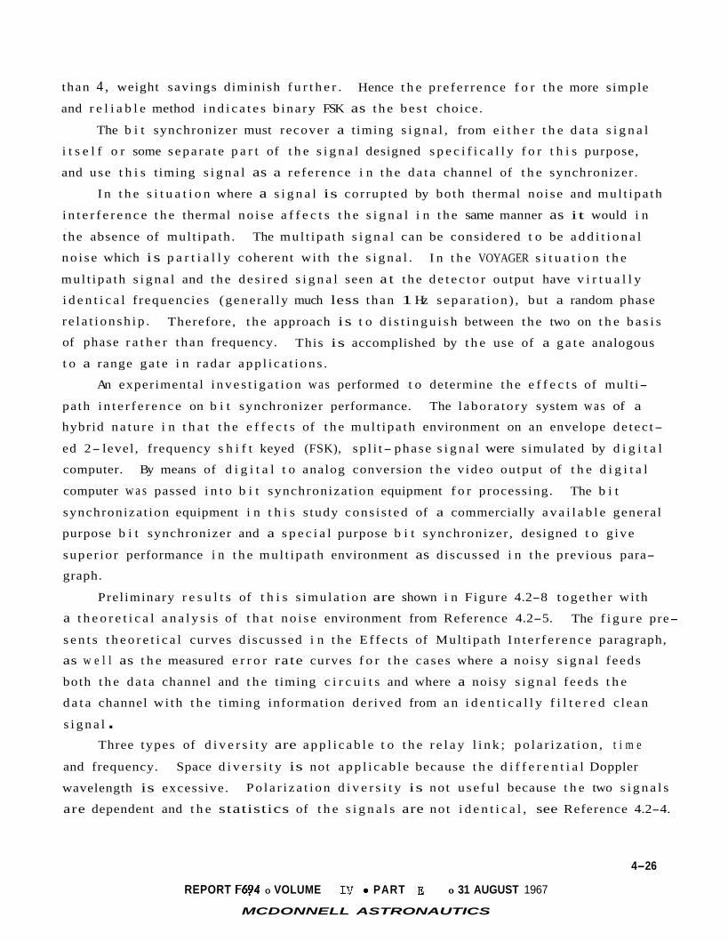
than 4 , weight savings diminish f u r t h e r .
and r e l i a b l e method i n d i c a t e s b ina ry FSK as t h e b e s t choice.
Hence t h e p re fe r rence f o r t h e more simple
The b i t synchronizer must recover a t iming s i g n a l , from e i t h e r t h e d a t a s i g n a l
i t s e l f o r some s e p a r a t e p a r t of t h e s i g n a l designed s p e c i f i c a l l y f o r t h i s purpose,
and use t h i s timing s i g n a l as a re fe rence i n t h e d a t a channel of t h e synchronizer .
I n t h e s i t u a t i o n where a s i g n a l is corrupted by both thermal no i se and mul t ipa th
i n t e r f e r e n c e t h e thermal n o i s e a f f e c t s t h e s i g n a l i n t h e same manner as it would i n
the absence of mul t ipa th .
n o i s e which i s p a r t i a l l y coherent wi th t h e s i g n a l .
mul t ipa th s i g n a l and t h e d e s i r e d s i g n a l seen a t t h e d e t e c t o r output have v i r t u a l l y
i d e n t i c a l f requencies (genera l ly much less than 1 Hz s e p a r a t i o n ) , but a random phase
r e l a t i o n s h i p .
of phase r a t h e r than frequency.
t o a range g a t e i n r adar a p p l i c a t i o n s .
The mul t ipa th s i g n a l can be considered t o be a d d i t i o n a l
I n t h e VOYAGER s i t u a t i o n t h e
Therefore, t h e approach is t o d i s t i n g u i s h between t h e two on t h e b a s i s
This is accomplished by t h e use of a g a t e analogous
An experimental i n v e s t i g a t i o n w a s performed t o determine t h e e f f e c t s of mult i-
path i n t e r f e r e n c e on b i t synchronizer performance.
hybrid n a t u r e i n t h a t t h e e f f e c t s of t h e mul t ipa th environment on an envelope de tec t-
ed 2- level , frequency s h i f t keyed (FSK), sp l i t- phase s i g n a l were simulated by d i g i t a l
computer.
computer w a s passed i n t o b i t synchroniza t ion equipment f o r processing.
synchroniza t ion equipment i n t h i s s tudy cons i s t ed of a commercially a v a i l a b l e genera l
purpose b i t synchronizer and a s p e c i a l purpose b i t synchronizer , designed t o g ive
super io r performance i n t h e mul t ipa th environment as discussed i n t h e previous para-
graph.
The l abora to ry system w a s of a
By means of d i g i t a l t o analog conversion t h e v ideo output of t h e d i g i t a l
The b i t
Prel iminary r e s u l t s of t h i s s imula t ion are shown i n Figure 4.2-8 toge the r wi th
a t h e o r e t i c a l a n a l y s i s of t h a t n o i s e environment from Reference 4.2-5.
s e n t s t h e o r e t i c a l curves d iscussed i n t h e E f f e c t s of Mul t ipa th I n t e r f e r e n c e paragraph,
as w e l l as t h e measured e r r o r rate curves f o r t h e cases where a noisy s i g n a l f eeds
both t h e d a t a channel and t h e timing c i r c u i t s and where a noisy s i g n a l f eeds t h e
d a t a channel wi th t h e t iming information der ived from a n i d e n t i c a l l y f i l t e r e d c lean
s i g n a l .
The f i g u r e pre-
Three types of d i v e r s i t y are a p p l i c a b l e t o t h e r e l a y l i n k ; p o l a r i z a t i o n , t i m e
Space d i v e r s i t y is not a p p l i c a b l e because t h e d i f f e r e n t i a l Doppler and frequency.
wavelength is excessive.
are dependent and t h e statistics of t h e s i g n a l s are not i d e n t i c a l , see Reference 4.2-4.
P o l a r i z a t i o n d i v e r s i t y is not u s e f u l because t h e two s i g n a l s
4-26
REPORT F694 0 VOLUME I V 0 PART E 0 31 AUGUST 1967
MCDONNELL ASTRONAUTICS

-1 10
L
2 L
W
m 0 x
c .- Y
+. .- - .- n n 0 -2 2 10 a
-3 10
MULTIPATH SIMULATION DATA 0 Single Channel 0 No Doppler
0 Rayleigh Jamming r
4 8 12 16 20 D/J Ratio in Deciloels
Figure 4.2-8
4-27
REPORT F694 0 VOLUME Iv 0 P A R T E e 31 AUGUST 1967
MCD0NNEL.L. ASTRONAUTICS

P o l a r i z a t i o n s e l e c t i v i t y w i l l be u s e f u l , but t h i s would r e q u i r e a p r i o r i knowledge
of t h e r e f l e c t i o n c o e f f i c i e n t h i s t o r y .
due t o t h e wide range of p o s s i b l e atmospheres.
This knowledge i s not a v a i l a b l e , p a r t i c u l a r l y
T ime d i v e r s i t y is not employed ss, as a long time delay is being employed
t o combat t h e e n t r y i o n i z a t i o n blackout.
e f f e c t i v e d i v e r s i t y system, t h e real t i m e b i t s must be s t o r e d and combined wi th t h e
delayed b i t s p r i o r t o b i t de tec t ion .
plasma blackout and t h e assoc ia ted d i f f e r e n t i a l Doppler, e f f e c t i v e use of t i m e d i-
v e r s i t y is not poss ib le .
however. Since each b i t i s t r ansmi t t ed 3 t i m e s , except those absorbed dur ing black-
Out9 t h e t i m e s between t h e s e t ransmiss ions (50 sec and 100 sec ) are s u f f i c i e n t l y
long t h a t fading can be considered independent.
t h e 3 b i t s corresponding t o a given information b i t may be ex t rac ted and a major i ty
dec i s ion r u l e may be used, thus decreas ing t h e r e s u l t a n t e f f e c t i v e e r r o r p r o b a b i l i t y
I n order t o use t h i s plasma delay as an
Due t o t h e long t i m e de lay inheren t i n t h e
A non-optimum usage of t h e dual de lay s t o r a g e is p r a c t i c a l
Af te r b i t decoding on t h e ground,
Frequency d i v e r s i t y is an appealing cons ide ra t ion , p a r t i c u l a r l y s i n c e an "extra"
t r a n s m i t t e r a l s o adds t o t h e r e l i a b i l i t y of t h e l i n k i n a d d i t i o n t o combatting mult i-
pa th i n t e r f e r e n c e .
Ef fec t of Mult ipath I n t e r f e r e n c e - The f i r s t s e c t i o n of t h e mul t ipa th a n a l y s i s
i d e n t i f i e d t h e charac te r of t h e geometry problem, and descr ibed how bounds were drawn
about it.
a modulation technique.
t o i d e n t i f y t h e s p e c i f i c e f f e c t s of t h e mul t ipa th geometry upon t h e candidate modula-
The second s e c t i o n d iscussed t h e f a c t o r s s i g n i f i c a n t i n t h e s e l e c t i o n of
This s e c t i o n se rves A non-coherent FSK system w a s chosen,
t i o n system, and f i n a l l y t o formula te b i t e r r o r h i s t o r i e s .
Three approaches have been taken t o i d e n t i f y t h e e f f e c t of t h e mul t ipa th i n t e r-
fe rence upon t h e modulation; they are compared i n Figure 4.2-9.
is a pure ly s i g n a l s t r e n g t h approach and is adequately documented i n References
4.2-4 and 4.2-6.
l a c k of d i r e c t f e e l i n g f o r t h e e r r o r h i s t o r y , and an in-depth d e s c r i p t i o n of t h e
in f luence of t h e i n t e r f e r e n c e upon t h e modulation technique.
The f i r s t approach
A s e r i o u s disadvantage t o t h e signal- strength- only a n a l y s i s is a
The second approach is an extens ion of t h e techniques of References 4.2-7 and
4.2-8 and is documented i n Reference 4.2-9.
mul t ipa th environment may be termed f a s t fading which r e s u l t s i n intersymbol i n t e r-
ference . The rate of fading of t h e i n d i r e c t pa th is c l a s s i c a l l y slow r e l a t i v e t o a
b i t per iod, however t h e d i f f e r e n t i a l pa th l e n g t h is g r e a t , thus t h e received i n d i r e c t
pa th s i g n a l may change b i t state "independent" of t h e received d i r e c t pa th s i g n a l .
The s i g n i f i c a n t c h a r a c t e r of t h e Martian
4-28
REPORT r694 0 VOLUME IV 0 PART E 0 31 AUGUST 1967
MCDONNELIC. ASTRONAUNCS

A COMPARISON OF APPROACHES
FSK
Figure 4.2-9
4-29
REPORT Ff94 0 VOLUME 0 PART 0 31 AUGUST 1967
MCDONNELL ASTRONAUTICS IV E

The t h i r d , and most s o p h i s t i c a t e d approach, is documented i n Reference 4.2-10.
Two channel models are s tud ied .
pa th l eng th relative t o t h e d a t a b i t is s m a l l so t h a t , except f o r producing a phase
v a r i a t i o n , such a delay can be ignored, i.e., a mark-mark s i t u a t i o n (Pel).
second model assumes t h e delay i n t h e i n d i r e c t p a t h l e n g t h relative t o t h e d a t a rate
is g r e a t e r than one b i t so t h a t it i s reasonable t o assume t h e d i r e c t and r e f l e c t e d
The f i r s t assumes t h a t t h e delay i n t h e i n d i r e c t
The
path t ransmiss ions are uncor re la ted , i.e., a mark-space s i t u a t i o n (Pez).
of t h e performance f o r both channel models bounds t h e performance of t h e real
channel f o r t h e t o t a l t i m e t h a t t h e r e l a y is i n opera t ion.
Evaluat ion
Figures 4.2-10 and 4.2-11 combine t h e D/J h i s t o r i e s developed i n t h e geometry
s e c t i o n wi th t h e b i t e r r o r degradat ions of t h i s s e c t i o n and r e s u l t i n a b i t e r r o r
h i s t o r y .
It is seen t h a t t h e use of d i v e r s i t y "gains" approximately 25% of t o t a l
b a t t e r y power.
4 dB less than t h e non- diversi ty counterpar t t o achieve t h e s a m e e r r o r rate.
The requ i red t r a n s m i t t e r i n t h e frequency d i v e r s i t y case is then
4-30
REPORT F494 0 VOLUME IV e PART E 0 31 AUGUST 1967
MCDONNELL. ASTRONAUTICS

BIT ERROR HISTORY LEGEND: - - Mark-Space
- Mark-Mark Interference
Interference
NO DIVERSITY 1 I
SPACECRAFT & ENTRY CONDITIONS
FSC Anomaly 300, MI 270 VM-8, Vc - 15,000 fps, )’e - -13.6’,
lo-’
lo-:
L
2
a
L W t .- Y 0 x t z 10-
2 -
.- 11 0 11
a
lo-‘
0 0
0 * /
/
‘ I
Time From Entry - Seconds Figure 4.2-10
4-31
REPORT F494 0 VOLUME 0 PART 0 31 AUGUST 1967 d I V E MCDONNELL ASTRONAUTHCS

BIT ERROR HISTORY
10-1
10-2
10-3
10-4
- SPACECRAFT & ENTRY CONDITIONS - VM-8, V, = 15,000, = - 13.6' -S/C Anomaly = 300°, Mt = 27O -
I DIVERSITY
0 100 200 10-5
LEGEND: - - - - Mark- Space l n t e r f e r e n c e ~ f
F 2
-\
\ 7
\ \
c S T B / N , = 12dB 4
\ \ 1 d
1 >500
Time From Entry -Seconds
Figure 4.2- 11
4- 32
REPORT F494 e VOLUME Iv * P A R T E 0 31 AUGUST 1967
MCDONNELL ASTRONAUTICS

4.2.1.2
f o r Martian e n t r y has been performed, i n which t h e p e r t i n e n t parameters a f f e c t i n g
t h e flow f i e l d p r e d i c t i o n and t h e r e s u l t i n g telecommunication degradat ion have been
examined.
Entry I o n i z a t i o n Analysis - The f i r s t phase of a d e t a i l e d blackout a n a l y s i s
The a n a l y s i s included p r e d i c t i o n s of blackout cond i t ions due t o atmos-
pher ic gases f o r t h e model atmospheres, a worst case sample c a l c u l a t i o n accounting
f o r t h e e f f e c t of a b l a t i o n gases , and an estimate of t h e c o s t t o minimize t h e black-
ou t times.
Conclusions drawn from t h i s Phase B VOYAGER s tudy on e n t r y blackout are:
a. The maximum blackout t i m e is less than 1 5 ~ seconds; t h e minimum t i m e from
end of blackout t o impact (without te rminal propulsion) i s more than 60
seconds.
Atmospheric gases i n t h e model atmospheres which con ta in n i t rogen w i l l
i o n i z e e a s i l y and cause atmospheric blackout; atmospheres devoid of n i t r o-
gen w i l l only cause s h o r t blackout per iods and then only f o r f a s t s t e e p
e n t r i e s .
Ablat ion products w i l l cause blackout f o r v e l o c i t i e s and a l t i t u d e s where
blackout does no t exist due t o t h e atmospheric gases and worsen t h e black-
b.
c.
out caused by atmospheric gases.
material cause t h e h igh a b l a t i o n gas i o n i z a t i o n l e v e l s .
The metall ic elements i n t h e hea t s h i e l d
d. An S-band te lemetry system w i l l have much s h o r t e r blackout times than a
VHF system.
Seeding wi th sulphur hexaf luor ide i n a quan t i ty of less than one percent can c u t t h e a b l a t i o n i o n i z a t i o n f i f t y percent .
e.
Martian Atmospheric Blackout - Maximum blackout du ra t ion e x i s t s between t h e
t i m e of shock formation and t h e t i m e t h e v e h i c l e v e l o c i t y drops below a v e l o c i t y i n
t h e v i c i n i t y of 10,000 f p s .
depend upon t h e t r a n s m i t t i n g frequency and t h e atmospheric composition, which are
analyzed i n t h i s sec t ion .
The a c t u a l t i m e s of beginning and ending blackout
The 100% C 0 2 of model atmospheres VM-2 and VM-8 do no t ronrze as- eas4ly as
a i r , and thus blackout i s no t as probable f o r those atmospheres. I n a i r , i o n i z a t i o n
i s p r i n c i p a l l y due t o t h e r eac t ion . + N + O = N O + e -
This same r e a c t i o n exis ts f o r Martian atmosphere models i n which n i t rogen and oxygen
are present .
r e a c t i o n s involving CO' and O+, which r e q u i r e more energy than NO
But t h e o the r model atmospheres depend p r imar i ly on t h e ion iz ing + t o form; conse-
quent ly , t h e plasma sheath is q u i t e tenuous f o r t h e s e atmospheres.
4-33
REPORT Fp94 0 VOLUME I V 0 PART E 0 31 AUGUST 1967
MCDONNELL ASTRONAUTICS

The i o n i z a t i o n i n t h e wake region is found by expanding t h e Capsule Bus e l e c t r o n
concen t ra t ion from t h e s t a g n a t i o n d e n s i t y t o t h e f r e e stream d e n s i t y .
f rozen f a r wake approximation.
This i s t h e
Since t h e c o l l i s i o n f requencies are low, t h e plasma f o r b lun t body e n t r y
v e h i c l e s is a high pass f i l t e r t o t h e t ransmiss ion waves from t h e e n t r y v e h i c l e .
E f f e c t s of Abla t ion Products on Wake Condit ions - The e f f e c t of a b l a t i o n gases
upon t h e wake i o n i z a t i o n is an important cons ide ra t ion f o r a plasma blackout analy-
sis.
s t e e p e n t r y i n t o t h e VM-3 atmosphere l i s t e d i n Figure 4.2-12 because t h i s p resen t s
t h e trajectory- atmosphere condi t ion f o r t h e g r e a t e s t hea t ing rate. The f a c t o r s i n
t h i s a n a l y s i s are:
The a n a l y s i s presented h e r e i s based on t h e maximum hea t ing condi t ion - t h e
a. The hea t ing rate d i s t r i b u t i o n and t h e r e s u l t i n g t o t a l a b l a t i o n mass l o s s
rate f o r a t y p i c a l s i l i c o n e elastomer a b l a t o r .
b. The shock shape and i n v i s c i d flow p r o p e r t i e s on t h e heat s h i e l d .
c . The boundary l a y e r temperature a b l a t i o n m a s s f r a c t i o n , and t h e equi l ibr ium
ion concentrated p r o f i l e s .
d. The shear l a y e r l o c a t i o n and i t s d e n s i t y and temperature p r o f i l e s .
e. The e l e c t r o n concen t ra t ion i n the wake r e s u l t i n g from t h e boundary l a y e r
and shear l a y e r condi t ions .
The VOYAGER antenna system is mounted on t h e base of t h e v e h i c l e . I n t h i s
p o s i t i o n , t h e antenna experiences minimum heat ing. The t r ansmi t t ed s i g n a l s are
d i r e c t e d i n t o t h e wake, where they are less l i k e l y t o be blacked ou t , as t h e f low
f i e l d geometry, Figure 4.2-12 i l l u s t r a t e s . The boundary l a y e r gases , which con ta in
t h e a b l a t i o n products , expand r a p i d l y as they pass t h e base of t h e v e h i c l e and feed
the shear l a y e r . It is i n t h e shear l a y e r t h a t a b l a t i o n products i n t e r f e r e wi th
communications.
The f i r s t s t e p i n t h e a n a l y s i s w a s t o c a l c u l a t e hea t ing and a b l a t i o n rates.
For t h e GE ESM 1004X pre fe r red a b l a t o r , peak heat ing and peak a b l a t i o n occurs a t an
a l t i t u d e of 200,000 f e e t and a v e l o c i t y of 23,000 f t / s e c ; a b l a t i o n occurs €or
about 80 seconds, ceas ing a t an a l t i t u d e of about 110,000 f e e t . A l l t h e candidate
4-34
REPORT F494 0 VOLUME I V 0 PART E 0 31 AUGUST 1967
MCDONNELL. ASTRONAUTlCS

WORST CASE CALCULATION CONSIDERATIONS
Entry Conditions
Atmosphere VM-3
Angle -20
Velocity 15,000 ft/sec
Altitude 800,000 ft
Traiectorv Point
Time
AI ti tude Velocity
120 seconds
200,000 ft 13,000 ft/sec
FLOW FIELD GEOMETRY
Outer Edge of Shear Layer lnneredge of Shear Layer
10 Free Stream1 ine
Dividing Stream I ine
I I I I I I I I I I I I I I I I
3 4 5 6 7 8 9 10 11 12 13 14 15 J
0 1 2 feet
Figure 4.2-12
4-3s
REPORT F69j4 0 VOLUME IV 0 PART E 0 31 AUGUST 1967
MCDONNELL ASTRONAUTICS

a b l a t o r materials are composed of a s i l i c o n e elastomer base; so t h e hea t ing rate
d i s t r i b u t i o n , ca l cu la t ed by Ecke r t ' s r e f e rence en tha lpy method, and t h e a b l a t i o n
rates, by a McDonnell computer program f o r t h e GE a b l a t o r are considered t y p i c a l .
The second s t e p w a s t o c a l c u l a t e t h e i n v i s c i d flow f i e l d by a stream tube
The shock shape w a s taken as a s p h e r i c a l bow shock method (Reference 4.2-11).
merging i n t o a con ica l shock.
generated by t h e s p h e r i c a l shock are merged wi th t h e boundary l a y e r .
flow p r o p e r t i e s are cons t an t and equal t o t h e p r o p e r t i e s of a VM-3 atmosphere ac ros s
a con ica l ob l ique shock.
A t t h e base of t h e v e h i c l e , t h e entropy l a y e r gases
The i n v i s c i d
Step t h r e e w a s t o employ t h e a b l a t i o n rate d a t a and t h e i n v i s c i d flow p r o p e r t i e s
t o c a l c u l a t e t h e boundary l a y e r c h a r a c t e r i s t i c s .
ca l cu la t ed f o r a mixture of a b l a t i o n and atmospheric gas . Near t h e w a l l t h e ab la-
t i o n concent ra t ion and temperature vary widely and approach t h e i n v i s c i d flow con-
d i t i o n s about 1.0 inch from t h e w a l l .
The boundary l a y e r p r o p e r t i e s were
From t h e temperature, mass f r a c t i o n , and p re s su re t h e multicomponent e q u i l i -
brium composition p r o f i l e s w e r e ca l cu la t ed f o r some 70 gas spec ies .
of t h e a b l a t i o n gas w a s ca l cu la t ed from non-charred ( v i r g i n ) material compositions
tak ing i n t o account t h e d a t a on p r e f e r e n t i a l elements l o s s from MDC 5-3 material
tests (Reference 4.2-12).
f o r t h e MDC S-3 and GE a b l a t o r s are derived from tests presented i n F igure 4.2-13
The aluminum i n t h e GE material determined t h e e l e c t r o n concent ra t ion i n t h e boundary
l a y e r as seen from t h e f i g u r e f o r t h e cond i t i ons used.
The f o u r t h s t e p i n t h e wake flow f i e l d a n a l y s i s w a s t o determine t h e gas pro-
The l o c a t i o n of t h e shear l a y e r was determined by t h e
The composition
The non-charred material and t h e a b l a t i o n gas composition
t
p e r t i e s i n t h e shear l a y e r .
method of c h a r a c t e r i s t i c s .
The expansion w a s made from t h e i n v i s c i d flow p r o p e r t i e s (which w e r e cons tan t
from t h e boundary l a y e r edge t o t h e shock) t o a wake base pressure of two l b s . per
square f o o t (which w a s es t imated from experimental d a t a on o the r b lun t shapes) .
The ca l cu la t ed f r e e s t reaml ine where t h e p re s su re equals t h e base p re s su re w a s used
as a r e fe rence cond i t i on i n t h e shear l a y e r ana lys i s .
The shear l a y e r p r o p e r t i e s were ca l cu la t ed by t h e method of Dennison and Baum
(Reference 4.2-13).
t h e boundary l a y e r gases t o t h e shear l a y e r above t h e d iv id ing s t reaml ine . Thus,
a l l t h e boundary l a y e r gases passed d i r e c t l y i n t o t h e neck of t h e wake. The pro-
f i l e s of temperature and d e n s i t y a t d i f f e r e n t s t a t i o n s along t h e d iv id ing stream-
l i n e are shown i n Figure 4.2-14.
The e f f e c t of t h e r e c i r c u l a t i n g flow w a s neglected by l i m i t i n g
The f i g u r e shows t h a t n e i t h e r t h e d e n s i t y nor t h e
4-36
REPORT F594 0 VOLUME IV a PART E 0 31 AUGUST 1967
MCDONNELL ASTRONAUTICS

ELEMENT
Si I icon Car bon Hydrogen Oxygen Magnesium Boron Aluminum Potassium Calcium Titanium
ABLATOR CONFIGURATION (% By Wei!
MDC 5-3 MATERIAL
VIRGIN ABLATOR GAS
26.82 19,355 25.63 50.57 1 5.80 14,705 34.802 1 1.296 0.5 4 .473 Od2 0.142 0.56 0.74 1.14 0.768 0.058 0.01 7 4.23 1.933
4IRGIN
37.6 2 8.6 7.12 23.92
-
- 2.76 - - -
G.E. MATERIAL
4BLATOR GAS (EST.)
26.65 40.64 19.9 8.55 - - 4.26 - - I
0 .5 1 .o 1.5 2.0 Boundary Layer Position - in.
. Figure 4.2-13 4-37
REPORT F614 0 VOLUME IV e PART E ' 0 31 AUGUST 1967
MCDONNELL ASTRONAUTICS

VOYAGER SHEAR LAYER DENSITY PROFILES Base Pressure = 2.0 Ib/ft2
1.5
1 .o
.5
0
1 .o
.5
0 - 0 ?.8 2.9 3.0 3.1 3.2 3.3 3.4 3.5
Density (1 0-7 Slugs/Ft 3,
VOYAGER SHEAR LAYER TEMPERATURE PROFILES
Temperature O K
50
Figure 4.2- 14
4-38 REPORT F694 0 VOLUME IV e PART E 0 31 AUGUST 1967
MCDONNELL ASTRONAUNCS 1

tempera turevardes apprec iab ly a c r o s s the shea r l ayer .
The f i n a l s t e p w a s t o c a l c u l a t e t h e plasma p r o p e r t i e s i n t h e wake. The charac-
t e r i s t i c r e a c t i o n l eng ths i n d i c a t e t h a t t h e aluminum recombination r e a c t i o n i n t h e
wake is f rozen, because i t r e q u i r e s a t h r e e body mechanism. On t h e o t h e r hand, t h e
n i t r i c oxide ion , because it i s a two body recombination mechanism, is almost i n
equil ibrium.
f o r t h e boundary l a y e r .
This c a l c u l a t i o n a l s o shows t h a t equi l ibr ium is a good assumption
Since t h e r e a c t i o n rate of t h e p r i n c i p a l ion source i s f rozen, t h e i o n i z a t i o n
l e v e l s decrease as they pas s through t h e wake due t o expansion and d i f f u s i o n .
4.2-15 gives e l e c t r o n concen t ra t ion p r o f i l e s i n t h e boundary l a y e r and a t s e v e r a l
p o s i t i o n s i n t h e wake.
e l e c t r o n s pe r cm
t h e e f f e c t s of t h e a b l a t i o n gases and higher recombination rates f o r t h e NO' i on , 9 3 t h e atmospheric i o n concentra t ion minimum is only about 7 x 10
Figure
12 The peak e l e c t r o n concen t ra t ion decreases from 9 x 10 3 a t t h e capsule base t o 3 x 10l1 i n t h e neck of t h e wake. Neglecting
e l e c t r o n s pe r c m . This d e t a i l e d wake e l e c t r o n concentra t ion c a l c u l a t i o n shows t h a t t h e a b l a t i o n
gases cause a minimum plasma frequency of 4 . 9 GHZ which w i l l cause blackout and
f requencies below C-band. Neglecting t h e e f f e c t of a b l a t i o n gases t h e minimum
plasma frequency i s only 750 MHz, causing VHF but no t S-band blackout. From t h i s
c a l c u l a t i o n i t is seen t h a t t h e f rozen f a r wake approximation p r e d i c t s a s l i g h t l y
higher plasma frequency (1250 MHz) f o r t h e atmospheric gases . The e f f e c t of a b l a t i o n
is s u f f i c i e n t t o cause blackout f o r cond i t ions which are no t normally blacked out
f o r atmospheric gases , e .g. f o r worst case trajectory- atmosphere inves t iga ted t h e 1 2 a b l a t i o n products inc rease the e l e c t r o n d e n s i t y from 1.7 x 10" e/cm. to 7 x 10
e / c m 3
A l l e v i a t i o n - When t h e a b l a t i o n products cause t h e blackout a promising techni-
que f o r reducing t h e e l e c t r o n concentra t ion i n t h e VOYAGER wake i s t h e use of
seedants. For e f f e c t i v e n e s s , they must be de l ive red t o t h e wake reg ions of h ighes t
e l e c t r o n concentra t ion . When t h e blackout is due t o atmospheric gases , t h e i n v i s c i d
flow con ta ins t h e peak e l e c t r o n concentra t ions and seedants are not e f f e c t i v e i n
reducing t h i s ion iza t ion .
Experiments w e r e performed t o determine t h e e f f e c t of va r ious chemical seedants
i n reducing e l e c t r o n concentra t ion . Water and sulphur hexaf lour ide were each eval-
uated i n a r a d i o frequency generated CO
with less than 1.0 percent of sulphur hexaf lour ide (SF ) reduces t h e e l e c t r o n con-
c e n t r a t i o n by 40 percent .
i c a n t l y reduce t h e e l e c t r o n concentra t ion .
plasma. The experiment shows t h a t seeding 2
6 Further inc reas ing t h e amount of seedant does not s i g n i f-
4-39 REPORT F6,94 e VOLUME Iv e PART E e 31 AUGUST 1967
MCDQNNELL ASTRONAUTICS

PLASMA PROFILES IN THE WAKE
Ablator Type - Silicone Elastomer Metallic Content - 9.26% of Aluminum by Weight
X is Distance Downstream Measured
20 40 60 80 100 120 140
Cross Stream Position (cm)
Figure 4.2-15
4-40
REPORT F684 0 VOLUME rJ 0 PART E 0 31 AUGUST 1967
MCDONNELL ASTRONAUTICS

Sulphur hexaf luor ide a t t a c k s f r e e e l e c t r o n s . This r e a c t i o n is f a s t so t h a t t h e
seedant would be e f f e c t i v e i n reducing t h e e l e c t r o n concent ra t ion on t h e VOYAGER
wake even though the combination r e a c t i o n s are f rozen.
i n e l e c t r o n concent ra t ion i s needed t o r e s t o r e communications, seeding can be e f fec-
t ive i n c r e a t i n g a window through t h e plasma.
I f only a small r educ t ion
Summary - During the descent s t a g e s of t h e VOYAGER mission, t h e communications
The black- between t h e ESP and t h e S/C w i l l be blacked ou t f o r a s i g n i f i c a n t t i m e .
o u t t i m e depends on t h e Mart ian atmospheric composition, t h e i n i t i a l t r a j e c t o r y con-
d i t i o n s , t h e t ransmiss ion frequency, and the hea t s h i e l d material used. A blackout
t i m e i s predic ted f o r each of t h e 10 atmospheres, f o r each of t h e four l i m i t i n g
e n t r y t r a j e c t o r i e s under t h e fol lowing assumptions:
o Blackout w i l l begin under worst case cond i t ions a t t h e a l t i t u d e where
v iscous hea t ing begins i n t h e boundary l a y e r of t h e shock.
Blackout w i l l t y p i c a l l y end by t h e time t h e e n t r y v e h i c l e slows t o 10,000 o
fps .
These assumptions g ive a worst case es t ima t ion of t h e blackout t i m e , t abu la t ed
i n Figure 4.2-16.
c a t i o n s system must re- t ransmi t t h e blackout d a t a p r i o r t o impact. (This t i m e i s
assumed f o r t h e case wi th no te rminal d e c e l e r a t i o n ) .
The pos t blackout t i m e is a l s o shown, during which t h e communi-
The maximum blackout t i m e i s 145.9 seconds, t hus t h e maximum i n t e r l e a v i n g
de lay must be a t least 145.9 seconds.
blackout view t i m e i s 67 seconds, thus i f a 145.9 second de lay were used, a l l of
t h e d a t a would not be played back f o r t h i s t r a j e c t o r y . A "tap" i s employed then
a t a maximum of 67 seconds, i .e . a "second" delayed d a t a b i t s t r eam is requi red t o
i n s u r e t h a t - a l l of t h e blacked out d a t a is played back.
(See Sect ion 4.2.2.1). The minimum pos t
It would a l s o be advantageous t o "minimize" t h e t ap l eng th t o achieve an o rde r
of t i m e d i v e r s i t y during t h e worst case mul t ipa th cond i t ion , i . e . , pos t blackout .
I n o the r words, t h e mul t ipa th time may be s a i d t o "reduce" t h e pos t blackout t i m e .
The minimum t a p l eng th i s set by t h e 27.2 second blackout condi t ion , however, a
maximal de lay playback of 145.9 seconds would " m i s s" t h i s po in t .
(rounding o f f ) maximum delay i s then 150 seconds wi th a 50 second t ap .
e f f e c t of t h e atmospheric and a b l a t i o n gases causes a blackout i n each model atmos-
The des ign
The combined
phere.
during t h e e n t r y mode.
The t i m e de lay des ign w i l l a l low a l l d a t a t o be rece ived a t least one t i m e
4-41
REPORT 5694 a VOLUME I V 0 PART E 0 31 AUGUST 1967
MCDONNELL ASTRONAUTICS

BLACKOUT COMPUTATIONS (FROM TRAJECTORIES)
TRAJECTORY IDENTIFICATION
1. VM-1, 15,000 fps, -20°, 0.3 2. VM-1, 15,000 fps, -13.6', 0.3
4. VM-1, 13,000 fps, -10.4', 0.3
6. VM-2, 15,000 fps, -13.6', 0.3 7. VM-2, 13,000 fps, -20°, 0.3 8. VM-2, 13,000 fps, -10.4', 0.3 9. VM-3, 15,000 fps, -20°, 0.3
10. VM-3, 15,000 fps, -13.6', 0.3 11. VM-3, 13,000 fps, -20°, 0.3 12. VM-3, 13,000 fps, -10.4', 0.3 13. VM-4, 15,000 fps, -20°, 0.3 14. VM-4, 15,000 fps, -13.6', 0.3 15. VM-4, 13,000 fps, -20°, 0.3 16. VM-4, 13,000 fps, -10.4', 0.3 17. VM-5, 15,000 fps, -20°, 0.3 18. VM-5, 15,00Ofps, -13.6', 0.3 19. VM-5, 13,000 fps, -20°, 0.3 20. VM-5, 13,000 fps, -10.4', 0.3 21. VM-6, 15,000 fps, -20°, 0.3 22. VM-6, 15,000 fps, -13.6', 0.3 23. VM-6, 13,000 fps, -20°, 0.3 24. VM-6, 13,00Ofps, -10.4', 0.3 25. VM-7, 15,000 fps, -20°, 0.3 26. VM-7, 15,000 fps, -13.6', 0.3 27. VM-7, 13,000 fps, -20°, 0.3 28. VM-7, 13,000 fps, -10.4', 0.3 29. VM-8, 15,000 fps, -20 , 0.3 30. VM-8, 15,000 fps, -13.6', 0.3 31. VM-8, 13,000 fps, -20°, 0.3 32. VM-8, 13,000 fps, -10.4', 0.3 33. VM-9, 15,000 fps, -20°, 0.3 34. VM-9, 15,000 fps, -13.6', 0.3 35. VM-9, 13,000 fps, -20°, 0.3 36. VM-9, 13,00Ofps, -10.4', 0.3 37. VM-10, 15,000 fps, -20°, 0.3 38. VM-10, 15,00Ofps, -13.6', 0.3 39. VM-10, 13,000 fps, -20°, 0.3
3. VM-1, 13,000 fps, -20°, 0.3
5. VM-2, 15,000 fps, -20°, 0.3
40. VM-10, 13,000 fps, -10.4, 0.3
( i 1 TIME FIRST
BEGIN DECREASE VELOCITY
69.2 109.0 77.8
163.1 124.7 221.4 136.9 330.4 66.0
104.3 74.3
154.9 121.7 213.8 133.8 319.3 61.6 96.2 69.7
144.0 112.6 193.2 124.3 289.5
72.6 115.0 81.6
164.9 125.4 222.8 137.7 332.2 60.2 93.8 67.9
140.1 103.8 173.1 115.0 259.3
(ii) TIME AT 10 Kfps
(SEC)
__I
139 226 144 309 152 283 163 407 133 217 140 295 150 285 161 403 129 209 136 283 149 262 157 372 140 234 144 307 153 288 163 412 125 200 132 272 140 250 150 355 -
REPORT F694 e VOLUME IV a PART E d
( i i i ) TIME OF IMPACT (SEC)
280 444 286 553 248.5 446 255 587 310 466 316 573 269 46 1 277 599 343 493 348 595 302 482 308.8 615 257 429 260 54 1 220 435 236 580 385 528 392 630 345.8 515 353 64 1 c
(iv) (i - i i )
9.0. TIME (SEC)
69.8 117.0 66.2
145.9 27.3 61.6 26.1 76.6 67.0
112.7 65.7
140.1 18.3 71.2 27.2 83.7 67.4
112.8 66.3
139.0 36.4 68.8 32.7 82.5 67.4
119.0 62.4
142.1 27.6 65.2 25.3 71.8 64.8
106.2 64.1
131.9 36.2 76.9 35.0 95.7
-
I
a 31 AUGUST 1967
(v) ( i i - i i i )
>OST 9.0. TIME (NO TERMINAL )ECE LERAT lob
(SEC)
141 218 142 244
96.5 163 92
180 177 249 176 278 119 1 76 116 196 214 284 212 312 153 220 151.8 243 117 195 116 234 67
147 73
168 260 328 260 358 205.8 265 203 286
Figure 4.2- 16
4-42
MCDQNNELL ASTRONAUTICS

4.2.2
system des ign i s presented i n t h i s s e c t i o n inc luding commutation, d a t a format,
r e l i a b i l i t y a n a l y s i s , and ins t rumenta t ion .
4.2.2.1
involves d a t a sampling ( d i g i t a l , analog and b i- leve l ) and analog t o d i g i t a l
conversion. This s e c t i o n p re sen t s a summary of t h e a l t e r n a t e mul t ip lex ing
techniques considered f o r u se i n t h e ESP te lemet ry subsystem, and t h e a n a l y s i s
used t o opt imize t h e g a t e t r ee ing .
inc ludes t h e func t iona l ope ra t ions of ga t ing and channel sequencing (programming).
Both whole number and modified pulse-width analog conver te rs were considered.
Telemetry Subsystem - The most s i g n i f i c a n t a n a l y s i s of t h e te lemet ry sub-
Commutation - The Commutator p o r t i o n of t h e te lemet ry subsystem
A s used i n t h i s s e c t i o n t h e t e r m , mul t ip lex ing ,
The whole number conver te r w a s chosen f o r reasons of both d a t a source i n t e r f a c e
and mul t ip l exe r programmer s imp l i c i ty .
The b a s i c mu l t ip l exe r con f igu ra t ions w e r e compared i n a t r a d e s tudy t o
determine t h e b e s t conf igura t ion f o r t h e ESP te lemet ry subsystem. Mult iplexer
con f igu ra t ions s i m i l a r t o previous Mariner telecommunications systems are
cha rac t e r i zed as "hardwired" conf igu ra t ions i n t h i s study. The al ternate con-
f i g u r a t i o n s tud ied is t h e stored-program conf igu ra t ion which uses e l e c t r i c a l l y
a l t e r a b l e memory f o r mu l t ip l exe r programming.
are i n s e n s i t i v e t o t h e type of whole-number conver te r chosen, so t h e conver te r
des ign is not a parameter of t h e study.
The mul t ip lexer con f igu ra t ions
Since t h e r e are numerous ways of mechanizing each type of conf igura t ion ,
a t tempts t o opt imize each conf igura t ion were made during t h e s tudy t o achieve
maximum trade- off e f f ec t iveness . Accomplishing t h i s goa l requi red d e t a i l e d
ana lyses of analog and d i g i t a l c i r c u i t devices and memory techniques.
device eva lua t ion ind ica t ed t h a t b ipo la r i n t e g r a t e d c i r c u i t s ( IC's) should be
used f o r a l l d i g i t a l a p p l i c a t i o n s and hybrfd o r MOSFET I C ' s f o r analog ( l i n e a r )
c i r c u i t s . The s t o r a g e devices t r a d e s tudy concluded t h a t co re o r plated-wire
memories are p re fe r r ed f o r medium-size s t o r a g e a p p l i c a t i o n s such as t h e s to red
programmer memory.
The
Mul t ip lexer Configurat ion Trade Study - Criteria used t o compare t h e hardwire
and stored-program mul t ip l exe r s included r e l i a b i l i t y , phys ica l , v e r s a t i l i t y , and
program management cons idera t ions .
hours i s used as t h e measure of r e l i a b i l i t y i n t h i s t r a d e study. Because of i ts
d i r e c t e f f e c t on t h e mission p r o b a b i l i t y of success , r e l i a b i l i t y w a s assigned t h e
h ighes t r e l a t i v e weighting va lue of 0.4.
The f a i l u r e rate i n percent per 1000
Phys ica l cons ide ra t ions included weight, power requirements and t h e number of
4-43
REPORT F494 e VOLUME Iv e PART E e 31 AUGUST 1967
MCDONNELL ASTRONAUTICS

w i r e s requi red t o c r o s s t h e CB/ESP i n t e r f a c e ; t h e i r relat ive importance i s
r e f l e c t e d i n an assigned weighting va lue of 0 .3 .
compute a s i n g l e va lue f o r system performance inc luding t h e m u l t i p l e cons ide ra t ions
w a s as follows:
The methodology employed t o
(1) Compute a relative performance va lue i n terms of:
(b) power and (c) i n t e r f a c e w i r e s .
Average t h e t h r e e performance va lues computed i n (1) above t o achieve
a s i n g l e value.
(a) weight,
(2)
V e r s a t i l i t y w a s assigned a va lue weight of 0.2; t h e two bas i c cons ide ra t ions
were system a b i l i t y t o accept des ign changes wi th minimum hardware modi f ica t ion
and l imi t ed re-programming p r i o r t o s epa ra t ion from t h e S/C.
Program management cons ide ra t ions such as cos t and development r i s k are
important bu t no t considered a p p l i c a b l e t o t h i s t r a d e s tudy since n e i t h e r
system appears t o have a n advantage over t h e o the r .
A summary c h a r t f o r t h e mul t ip l exe r con f igu ra t ion t r a d e s tudy i s presented
The stored-program mul t ip lexer con f igu ra t ion i s s e l e c t e d i n F igure 4.2-17.
from t h e t r a d e s tudy r e s u l t s .
Mult iplexer Techniques Trade Study - Since t h e mul t ip lexer con f igu ra t ion
t r a d e s tudy r e s u l t e d i n t h e s e l e c t i o n of t h e stored-program conf igura t ion
f o r t h e b a s e l i n e system, only t h e mul t ip lexer t r a d e s tudy f o r t h e hardwired
conf igu ra t ion is summarized, w i th t h e major emphasis placed on t h e s to red
program Configuration.
Hardwired Mul t ip lexer - Three mul t ip lex ing techniques were evaluated f o r
t h e hardwired conf igura t ion : r i n g counter , mat r ix programming and i n t e r l a c e d
tube. The r i n g counter and matrix programming techniques have been used i n p a s t
and present systems. The i n t e r l a c e d tube programming method, a r e l a t i v e l y
new technique, is descr ibed i n t h e next s ec t ion .
Criteria used f o r hardwired mul t ip lexer eva lua t ion , i n order of decreas ing
importance, are r e l i a b i l i t y , phys ica l parameters ( s i z e , weight, power, etc.),
performance and f l e x i b i l i t y . The t r a d e s tudy ind ica t ed t h a t t h e mat r ix
programmer w a s b e s t i n a l l ca t egor i e s except performance, where t h e i n t e r l a c e d
tube method provides a somewhat b e t t e r sample e f f i c i ency .
method ranked lowest i n a l l ca t egor i e s .
f o r u se wi th t h e hardwired system.
The r i n g counter
The mat r ix programmer w a s s e l e c t e d
Stored Program Mult iplexer - I n t h e stored-program conf igu ra t ion t h e
mul t ip lexer programmer i s a s to red program sequencing u n i t . A s a r e s u l t of an
4-44
REPORT F69qa VOLUME IV e PART E a 31 AUGUST 1967
MCDONNELL ASTRONAUTICS

ESP TRADE STUDY SUMMARY, MULTIPLEXER SELECTION (EP ALTERNATE 3b)
I MATRIX OF DESIGN APPROACHES Functional and Technical Design Requirements: Sampling, ADC and Data
Interleaving I 1 - Hardwire
I Trade Considerations
Re1 iabi I i t y Weight = 0.4
h (%/lo00 hrs) = 11.0 1 I Physical Considerations
Weight = 0.3
Number of wires = 4 Weight = 3. l b s Power = 4.4 w
Versati l i ty e Reprogramming involves hardware modifications.
Weight = 0.2 o No in-fl ight programming poss i b le
2 - Stored Program
h (%/lo00 hrs) = 9.42
Number of Wires = 1 1 Weight = 4.2 Ibs Power = 3 . 4 ~
I-? o Some software repro-
gramming possible. o Some in-fl ight pro-
gramming possible.
Selected Approach:
No. 2
2- 1
1- 2
2 - 1
Total 0.78 0.8 1
Figure 4.2- 17
4-4s
REPORT F694 0 VOLUME IV 0 PART E 0 31 AUGUST 1967
MCDONNELL ASTRONAUTICS

optimization study, random-select FET analog gates were selected for use with the stored-program Sequencing. Therefore, the difference between the techniques
discussed below is confined to memory and channel address logic. The three
programming techniques evaluated for the stored-program telemetry configuration
are multiple access, table look-up and interlaced tube. Multiple-Access Program - The multiple-access programming technique has been
used predominately in stored-program decommutator stations and recently has been
adopted for the Titan I11 and Poseidon PCM telemetry systems. easily implemented and efficient in core utilization. terminology is derived from the need t o access memory two or more times for all
subcommutation frames (i.e., first-level subframes required two memory accesses;
second-level sub-subframes required three memory accesses, etc.).
The technique is
The multiple-access
One additional flag bit per memory word is required to indicate when the
content represents a subframe memory location rather than a channel address. A special memory-position index number is used at the end of each frame to reset
the subframe instruction in the appropriate higher-level frame. Some scratch pad is required for storage of the pointers for each rate group. Core memory
programming is easily accomplished by listing channel addresses and index number in order of sequence and sampling frequency.
Look-Up Table Program - In terms of logic operations, the look-up table program technique is the simplest form of stored program sequencing but
it requires large memory capacity. all channel addresses in order of major frame sequencing, repeating channel
numbers as required until the major frame is complete.
Programming is achieved simply by listing
Storage capacity is determined by the length of the major frame which is the product of the maximum frame lengths within each commutation level, assuming
that all frames within a given subcommutation level are even multiples of the
longest frame within that level. If this condition is not met, it will be
necessary to take the product of all frame lengths within the multiplexing pattern.
duration of the lowest rate subframe. the ESP multiplexing is extremely large using this technique.
Under such conditions, the major frame length can exceed the time
In any case, memory required to satisfy
Interlaced T.ube Propram - The interlaced tube programming technique is similar to the multiple-access programming technique described above since it also requires scratchpad and special index instructions.
an example of an arbitrary multiplexing format produced by the interlaced tube.
Figure 4.2-18 is
4-46
REPORT F694 0 VOLUME IV 0 PART E 0 31 AUGUST 1967
MCDONNELL ASTRONAUTICS

5 SPS
INTERLACED TUBE FORMAT EXAMPLE
2 5 - 50 - 100 A 500
0.05 SPS
1 SPS
S,f = 9000 Samples/Maior Frame
Spf = Smf
500 18 Samples/Prime Frame
Sample Rate = 18 x 5 : 90 SPS
Figure 4.2-18
4-47
REPORT ~ 6 ~ 4 . VOLUME rv . PART E .3 i AUGUST 1967
MCDONNELL ASTRONAUTRCS

The construction simplicity of these formats is clear.
description, a major frame represents the total number of samples required to
sequence through all data sources and a prime frame is the least number of samples
required before a data source is repeated (determined by the highest sampling frequency within the data ensemble).
For purposes of this
The interlaced-tube format is constructed by first listing all measurements
in groups (tubes) of descending sampling frequency as shown in Figure 4.2.-18. The number of major frame samples, Smf, is determined by:
where: ~ r = sampling rate of a given rate group. th
Nr = number of samples in the r r = lowest sampling frequency. min r = highest sampling frequency.. max
The number of prime frame samples, S
rate group, and
Pf , is:
s - r r
Pf - 'mf min max
The system sample rate in sps is, of course, S (r >. If the prime frame pf max is not an integer number of samples, spare channels must be added in any
desired combination to meet this requirement. similar to other multiplexing technqiues, it should be noted that the interlaced- tube procedure generally requires fewer spares, resulting in greater sampling
efficiency. Under no condition will it result in reduced efficiency over the
other techniques considered.
Although this constraint is
The channel sequence format produced by the tube method shown in Figure
4.2-18 is generated as follows: During the first prime frame, the two 5-sps plus the first sixteen 1-sps
channels are sampled. pins 17 and 32 of the 1-sps channels are sampled. During the fifth minor
frame, the two 5-sps and last nine pins of the 1-sps plus the first seven
pins of the 0.1-sps channels are sampled.
be identical to the above sequence except that pins 8 through 14 of the 0.1-sps tube will be sampled during the tenth frame.
During the second prime frame, the two 5-sps plus
The next five prime frames will
This procedure
4-48
REPORT F694 0 VOLUME IV 0 PART E 0 31 AUGUST 1967
MCDONNELL ASTRONAUTICS
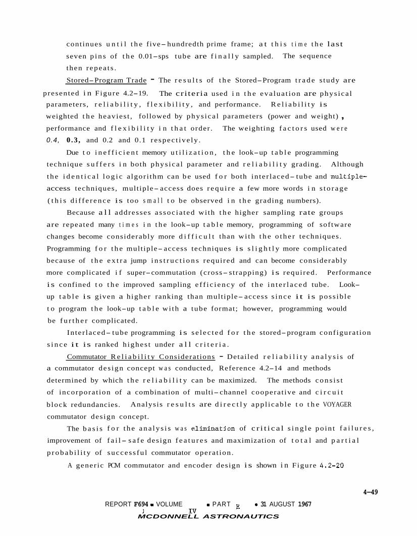
continues u n t i l t h e five- hundredth prime frame; a t t h i s t i m e t h e last
seven p i n s of t h e 0.01-sps tube are f i n a l l y sampled.
then r epea t s .
Stored-Program Trade - The r e s u l t s of t h e Stored-Program t r a d e s tudy are
The sequence
presented i n Figure 4.2-19. The cri teria used i n t h e eva lua t ion are phys i ca l parameters, r e l i a b i l i t y , f l e x i b i l i t y , and performance. R e l i a b i l i t y is
weighted t h e heavies t , followed by phys i ca l parameters (power and weight) , performance and f l e x i b i l i t y i n t h a t order .
0.4, 0.3 , and 0.2 and 0.1 r e spec t ive ly .
The weighting f a c t o r s used w e r e
Due t o i n e f f i c i e n t memory u t i l i z a t i o n , t h e look-up t a b l e programming
technique s u f f e r s i n both phys i ca l parameter and r e l i a b i l i t y grading. Although
t h e i d e n t i c a l l o g i c a lgor i thm can b e used f o r both in te r laced- tube and mult iple-
access techniques, mult iple- access does r e q u i r e a few more words i n s t o r a g e
( t h i s d i f f e r e n c e is too s m a l l t o be observed i n t h e grading numbers).
Because a l l addresses a s soc i a t ed wi th t h e higher sampling rate groups
are repeated many t i m e s i n t h e look-up t a b l e memory, programming of sof tware
changes become considerably more d i f f i c u l t than wi th t h e o t h e r techniques.
Programming f o r t h e mult iple- access techniques is s l i g h t l y more complicated
because of t h e e x t r a jump i n s t r u c t i o n s requi red and can become considerably
more complicated i f super-commutation (cross- strapping) i s requi red . Performance
i s confined t o t h e improved sampling e f f i c i e n c y of t h e i n t e r l a c e d tube. Look-
up t a b l e i s given a h igher ranking than mult iple- access s i n c e i t i s poss ib l e
t o program t h e look-up t a b l e w i th a tube format; however, programming would
be f u r t h e r complicated.
In te r laced- tube programming i s s e l e c t e d f o r t h e stored-program conf igura t ion
s i n c e i t is ranked h ighes t under a l l c r i t e r i a .
Commutator R e l i a b i l i t y Considerat ions - Detai led r e l i a b i l i t y a n a l y s i s of
a commutator des ign concept w a s conducted, Reference 4.2-14 and methods
determined by which t h e r e l i a b i l i t y can be maximized. The methods c o n s i s t
of incorpora t ion of a combination of multi- channel coopera t ive and c i r c u i t
b lock redundancies.
commutator des ign concept.
Analysis r e s u l t s are d i r e c t l y app l i cab le t o t h e VOYAGER
The b a s i s f o r t h e a n a l y s i s w a s e. l iminatjon of c r i t i c a l s i n g l e po in t f a i l u r e s ,
improvement of f a i l - s a f e des ign f e a t u r e s and maximization of t o t a l and p a r t i a l
p r o b a b i l i t y of succes s fu l commutator opera t ion .
A gener ic PCM commutator and encoder design i s shown i n F igure 4.2-20
4-49
REPORT F694 0 VOLUME PART E 0 31 AUGUST 1967 l IV
MCDONNELL ASTRONAUTICS

TRADE STUDY SUMMARY, HYBRID MULTIPLEXER
I I MATRIX OF DESIGN APPROACHES I CRITERIA LOOK-UP TABLE
r
Physical Power, 11.5 Watts Weight - ''3 Weight, 10 Ib
19 Re1 i abi I i t y Index Weight - 0.4
Flex ib i l i ty Weight - 0.1
software modi f i c a- t ion t o accommodate single measurement change.
tube format used.
Total Grading 0.49
NO. 2 NO. 3 INTERLACED TUBE MULTIPLE ACCESS
Power, 2.4 Watts 13 Weight, 1.5 Ib
Power, 2.4 Watts Weight, 1.5 Ib 1 28
Easy to change. More d i f f icu l t program- ming required i f cross- strapping i s used.
Simplest to change
Good sample eff iciency
Low sample eff iciency
SELECT I ON 2
2-3- 1
2-3-1
2-3- 1
I
1 .o I 0.89
Figure 4.2-19
4-50
2- 1-3
REPORT F494 0 VOLUME IV 0 PART E 0 31 AUGUST 1967 MCDdNNELL ASTRONAUTICS
d

Y Y Y Y Y Y Y Y Y Y Y Y Y Y Y Y Y Q,
m o v ) v c y c y - - = - - 0 0 u) 0 u) 0 v) - 0 0 h v) u) cy- cy 9 -
c y - - 7
I U OL 0 U
Y V 0
5
rn
n OL W
0 V Z W
Z U e 0 t- U t- 3 =E =E 0 V =E V
V OL W Z W 0
n
a -
L
1
I - t E 5 L, 0) 0
Q L
r I ,
Figure 4-2-20
4-51
REPORT Fj694 a VOLUME Iv a PART E a 31 AUGUST 1967
MCDONNELL ASTRONAUllCS

which contains the basic elements for operation and handling of High Level (HL), Low Level (LL), BiLevel (BL) and Digital (D) groups of input data signals. The
generic design assumes a standard time division multiplexing method of sampling and gathering input data signals for presentation to a transmitter modulator.
data switches were assumed to be Junction Field Effect Transistors (JFET).
All
In the analysis, the 120 HL analog data channel group was analyzed and design-
The reliability of this design was estimated for re- ed as shown in Figure 4.2-21.
trieval of total data, a subgroup (deck) of data and for an individual data channel.
A detailed reliability analysis of the generic design was conducted to optimize the design reliability and is shown in Figure 4.2-22, which is the optimum arrangement of data channels which inherently contains multi-channel cooperative redundancy and
maximized probability of partial data retrieval.
analysis results are as follows:
rate (f). some multiple of (f).
comparative reliability was estimated for each arrangement. Results are shown in Figure 4.2-23.
The basis for the analysis and
The basic JFET data switch was assigned a failure
All other elements were assigned an effective failure rate expressed as Different data channel arrangements were analyzed and the
Limited circuit block redundancy was added in the most critical switching
decks, namely decks F5, T5 and S5 in that order as shown in Figure 4.2-24.
addition optimizes total data retrieval probability at minimum expense of part in-
creases.
This
The reliability of a PCM Commutator data channel group has been maximized by incorporation of multi-channel-cooperative and limited block redundancy and is the
recommended design approach for the telemetry commutator. The multi-channel coop-
erative redundancy feature essentially decentralizes the first level of analog data
switches for optimum reliability and data switch independence in event of any switch
failure. probability of partial and total data channel retrieval for the 120 data channels
considered.
Further decentralization from that shown in Figure 4.2-24 however reduces .
4-52
REPORT F694jo VOLUME IV 0 PART E o 31 AUGUST 1967
MCDONNELL ASTRONAUTICS

HIGH L E V E L ANALOG SIGNAL GROUP
1SD2j 0
0
[WI
To Analog - Digital Converter --P- Notes: 1 . H10 - First Level Switch Deck (Subgroup) containing 10 Analog Switches. 2. S10 - Second Level Switch Deck containing 10 Analog Switches. 3. SD1 (Switch Driver) Drives all switches in Subgroup HIO. 4 . Another SD1 drives the first position switch in Deck S10.
Figure 4.2-2 1
4-53
REPORT F694,o VOLUME IV 0 PART E 0 31 AUGUST 1967
MCDONNE66 ASTRONAUTICS d

0 c! Y
e e e
e
Lrl e e
~-
e e
~- n
E Figure 4.2-22
4-54
REPORT F6p4 0 VOLUME IV 0 PART E 0 31 AUGUST 1967
MCDONNELL ASlRONAUNCS

5 E a
f
2
?
.- t
0 Q,
t c
0 Q L
-0 C 0
Q, > o 3
.- t
- 5 U
? 0 ln C 0 .- t z 3 m .- Y C 0 U
C m ln 0 -0
Q,
I -
? f t ln 0 -
ln .- t x i L - F
.. w
REPORT F674 0 VOLUME IV 0 PART E 31 AUGUST 1967
MCDONNELL ASTRONAUTICS
Figure 4.2-23
4-55

Control Gate (Timing
Control (Timing
COMPARISON OF BASIC AND REDUNDANT CIRCUITRY
Pu I se)
(a) JFET ANALOG SWITCH AND SWITCH DRIVER Analog Data Out
Note: JFET - Junction Field Effect Transistor
- - -
(b) REDUNDANT JFET ANALOG SWITCHES AND REDUNDANT SWITCH DRIVERS
~~~
Acalog Data In
I < <
s ~ D
G G
Gate Pulse)
Analog Data Out
Figure 4.2-24
4-56
REPORT F694 0 VOLUME IV 0 PART E a 31 AUGUST 1967
MCDONNELL ASTRONAUTICS A

4.2.2.2 Instrumentation - The term "Instrumentation Equipment" is used to designate the engineering measurement portion of the ESP telemetry system, where the engineer-
ing data signals are sensed and conditioned to outputs compatible with the PCM en- coders.
associated power supply. strumentation requirements are reviewed.
Temperature Measurements - Preliminary requirements for 21 ESP temperature measure- ments have been established.
-150°F to a high of 500°F in four separate ranges as follows:
This equipment consists of temperature sensors, signal conditioners and an
Specific feasible equipment that can fulfill the ESP in-
The required temperature ranges are from a low of
0 Temperature Range
25 to 150°F 0 to 120°F
-50 to 200°F
-150 to 500°F
No. Measurements 4 1 8 8 21 -
All the temperature monitoring points are located on equipment, components, or
structures and require surface type temperature sensors that can be attached to a
variety of surface contours. Thermistors, platinum resistance thermometers and thermocouples are likely candidates. Platinum resistance thermometers in a con-
ventional Wheatstone bridge arrangement are the preferred choice and were selected for the following reasons:
a. Superior R-T characteristics for wide temperature span. (Typical span is -436'F to 1000°F).
b. Excellent stability of calibration. (The interpolation instrument that is used from -182.97OC to 630.5OC on the International Temperature Scale
is the platinum resistance thermometer).
Higher output voltage than thermocouples. c. d. Output, voltage/degree, exactly as desired over wide temperature limits. .
(This is achieved by adjusting excitation current or bridge design). e. Reference junction not required.
f. Ease of calibration. (Only a small number of calibration points are required).
Alternate bridge designs were also investigated. These were the full bridge, the
half bridge, and the Mariner C,singfe ended configuration (Ref. Figure 4.2-25). The full bridge method is preferred because common mode noise signals backed up by the lead
wires are rejected by the idffernetial amplifier in the low level commutator and
4-57
REPORT F494 VOLUME IV 0 PART E 31 AUGUST 1967
MCDONNELL ASTRONAUTICS

TEMPERATURE MEASUREMENT METHODS
--- - Commutator -
Switches FULL BRIDGE METHOD
2.5 Vdc
F- 2.5Vdc
0 I -1
Common
Corn mutator Switches
P Am pl i f i er
- - HALF BRIDGE METHOD
Figure 4.2-25
4-5%
REPORT Ff94 0 VOLUME IV 0 PART E 0 31 AUGUST 1967
MCDONNELL ASTRONAUTlCS

l e ad w i r e vo l t age drop e r r o r s are minimized.
Computer c a l c u l a t i o n s f o r a br idge des ign f o r a t y p i c a l ESP temperature range
w e r e con t r ibu ted by Rosemount Engineering Company and appear i n Figure 4 . 2 - 2 6 .
main cons idera t ion i n designing t h e br idge is t o provide minimum power consumption
and l i n e a r 0- 40 mV output us ing a sensing element R
ou t in t roduc ing s e l f- hea t ing e r r o r .
sensors .
5 ppm/Co, and r e s u l t i n n e g l i g i b l e temperature c o e f f i c i e n t e r r o r f o r t h e ranges in-
vo lved . Signa l Conditioners - The ESP s i g n a l condi t ion ing requi red inc ludes dc cu r r en t and
vo l t age monitors.
The
va lue as high as p r a c t i c a l with- 0
Power consumption is under 4 mW f o r a l l range
The br idge completion r e s i s t o r s are low temperature c o e f f i c i e n t w i r e wound,
o
now required i n t h e ESP power subsystem.
dc cu r r en t w e r e c a l i b r a t e d shunts wi th amp l i f i c a t i on by t h e te lemetry low l e v e l dc
ampl i f i e r and i nd iv idua l magnetic amp l i f i e r s f o r each measurement.
r e s u l t s i n a savings i n weight and o v e r a l l power consumption. The disadvantage is
poor accuracy near t h e zero po in t . To a lesser degree, t h i s is a l s o t r u e of t he
magnetic ampl i f i e r s . Shunt monitoring is capable of meeting t h e accuracy requi re-
ment and w i l l be used f o r t h e b a t t e r y load cu r r en t measurement. A magnetic ampli-
f i e r type c i r c u i t w i l l be used f o r t h e b a t t e r y charge c u r r e n t measurement where
g r e a t e r accuracy near t h e zero po in t and c i r c u i t i s o l a t i o n is requi red .
and power savings of us ing a shunt i n t h i s i n s t ance as compared t o an i nd iv idua l
magnetic amp l i f i e r i s approximately 6 oz. and 0 . 5 w a t t s .
Current Monitoring - Two dc cu r r en t measurements, ranges 0-2A and 0-6A, are
The two methods considered f o r monitoring
The shunt method
The weight
o Voltage Monitoring - Three expanded scale dc vo l t age measurements are now
requi red i n t h e ESP.
u t i l i z e ope ra t i ona l amp l i f i e r s t h a t are w e l l known t o t h e i ndus t ry and have been
used by McDonnell i n many previous aerospace app l i ca t i ons .
4.2.3 Radio Subsystem - The most important r ad io subsystem t r a d e areas are d is- .
cussed i n t h i s s ec t i on .
4 . 2 . 3 . 1
were considered.
s i s t o r s and hybrid combiners; t h e o the r uses a s i n g l e one c a v i t y vacuum tube
(ML-2789) ampl i f i e r . The r e s u l t s of a t r a d e study Figure 4.2- 27 show t h a t t h e
most s i g n i f i c a n t d i f f e r e n c e s exist i n t h e r e l a t i v e s i m p l i c i t y and r e l i a b i l i t y .
The c i r c u i t s needed t o perform t h e s e vo l tage measurements
Transmit ter Power Amplifier Design - Two types of 45 w a t t t r a n s m i t t e r s
One uses an a l l s o l i d- s t a t e power ampl i f i e r containing 4 t rans-
4-59
REPORT 5694 a VOLUME I V e PART E a 31 AUGUST 1967
MCDONNELL ASTRONAUTICS

TEMPERATURE SENSOR CALCULATIONS
Schematic Diagram
- + Input
- + output
-- output
- - Input
Input Required: 5 Volts
Output: 0-40 MV
Figure 4.2-26
4-60
REPORT F894 0 VOLUME IV 0 PART E 0 31 AUGUST 1967
MCDONNELL ASTRONAUTICS

ENTRY SCIENCE PACKAGE RF POWER AMPLIFIER CONFIGURATION
TIONAL & CAL DESIGN UIREMENTS
TRANSISTOR DESIGN VACUUMTUBE
DESIGN SELECTION
Amplify 400 MHz or 340 MHz RF to Obtain 50 Watt Output
REQl I I I I
2N5017 (2 1 Cavity
2N5017 ML-7289
(2)
Complex Simple Simple Complex
+ RF Drive Required 15 w 5 w
Simp I i c i t y a. Amplifier
VI b. Power Supply S 0 .- :
-D
S 0
*; Efficiency 60% 52% 90% 80%
a. Amplifier b. Power Supply 1; . Weight 18 Ib 1.3 Ib
I- Sire 30 cu in. 35 cu in.
Reliability More Reliable ' Less Reliable
I (Including Power Supply)
1
2 1
2
1 1
2 1
1
Figure 4.2-27
4-6 1
REPORT F694 0 VOLUME IV e PART E 0 31 AUGUST 1967
MCDONNELL ASTRONAUTICS f

The use of the hybrid technique in the four-transistor amplifier permits con-
Tests of a servative derating of each transistor and better thermal distribution.
breadboard model of this transmitter, including the hybrid combiners, show a 0.1 dB variation in unbalanced power over a temperature range of -16 to +lOO°C.
The other principal factor associated with simplicity and reliability, is the
difference in dc voltage levels required.
of relatively simple design and provides a regulated 28 volt output. hand, the vacuum tube amplifier must utilize high voltage diodes and high voltage
transformers to develop the 1000 volts required. This design is subject to higher stress and possible failure due to voltage breakdown and corona discharge.
4.2.3.2 in the CB and ESP within the exclusive 399.9 to 402 MHz band to simplify the fre-
quency allocation problem. Assuming that a single antenna is shared by two trans- mitters (one from the CB and one from the ESP) separated by 1.3 MHz at 400 MHz and specifying a diplexer loss of 0.5 dB, the unloaded Q of the displexer resonators would be 7200. Such a requirement is impractical in diplexer design for space
applications. Using separate antennas sufficient isolation can be provided. The isolation requirement between antennas is based on the assumption that the maximum
allowable interference signal level is approximately -30 dB from the desired signal. The required antenna isolation,
The transistor amplifier power supply is
On the other
Antenna Configuration - It is desired to operate one of the two transmitters
is 'ant + 10 log 'ESP, or 'CB = 30 - 'ant
'CB - 10 log 'ESP, whichever is greater 'ESP = 30 - 'ant
CB Where ICB = dB isolation of CB transmitter = 20 dB
= dB isolation of ESP transmitter = 0 dB 'ESP = ESP transmitter power in watts = 40 watts 'ESP
PCB = CB transmitter power in watts = 5 watts Therefore, the isolation between antennas shall be 20 dB minimum. However, when
isolators are used in the transmitters, 10 dB isolation between antennas should be sufficient. This isolation requirement is met by employing opposite sense polar- ization on the CB and ESP antennas. For this reason, separate antennas for the CB
and ESP were chosen for the preferred system. 4.2.3.3
in the Link Power Budget is 555", + 25O, -80OK. herein.
Receiver System Noise Temperature - The receiving noise temperature used This derivation is summarized
4-62
REPORT Fq94 0 VOLUME IV 0 PART E 0 31 AUGUST 1967
MCDONNELL ASTRONAUTICS

Antenna Noise Temperature - The antenna temperature i s determined by n o i s e sources
w i t h i n t h e beam of t h e s p a c e c r a f t r e l a y l i n k rece iv ing antenna.
sources are g a l a c t i c n o i s e and Mart ian s u r f a c e r a d i a t i o n .
The p r i n c i p a l
The worst case occurs when t h e beam is completely f i l l e d by t h e p lane t . This
may occur under c e r t a i n t r a j e c t o r y and landing s i t e condi t ions .
worst case of 283°K i s used f o r t h e l i n k c a l c u l a t i o n s .
Therefore, t h e
For t h e q u i e t sun cond i t ions i n 1973-75, t h e average incremental rece ived no i se
is es t imated at 2'K. So la r n o i s e is thus ignored.
yea r s t h i s w i l l no t be t h e case , Reference 4.2-15, and s o l a r n o i s e w i l l be a f a c t o r .
Receiver Noise Temperature - The receiver RF preamp u t i l i z e s a s t a t e- o f- a r t , low
n o i s e s i l i c o n t r a n s i s t o r , w i th a n o i s e f i g u r e of less than 3 dB. (290°K)
Receiving System Noise Temperature - A l i n e p l u s d i p l e x e r loss of 1.5 dB between
During t h e 1977-79 noisy sun
t h e antenna and p reampl i f i e r inpu t is predic ted .
of 50"C, and a n antenna temperature of 283"C, t h e rece iv ing system no i se temper-
a t u r e is 555°K.
4.2.3.4
p loys frequency d i v e r s i t y t o combat mul t ipa th degradation.
channels must be proper ly combined i n order t o r e a l i z e t h e d i v e r s i t y improvement.
The combiner may be e i t h e r a pre- detec t ion o r pos t- detec t ion device.
Assuming an ambient temperature
The to le rances were est imated based on previous experience.
Receiver Divers i ty Combining Method - The ESP S/C communications l i n k em-
The two d i v e r s i t y
Pre- detect ion combining is more complex than pos t- detec t ion combining because
the received s i g n a l s must be mul t ip l i ed by a s i g n a l which is a funct ion of t h e re-
ceived s i g n a l s . This n e c e s s i t a t e s complex measurement c i r c u i t y , e.g. d i f f e r e n t i a l
phase c a n c e l l a t i o n . Furthermore, theory p r e d i c t s (Reference 4.2-16) t h a t an equal
ga in square-law post- detec t ion combiner is e s s e n t i a l l y optimum f o r t h i s environment.
4.2.3.5 ESP-CB Signal Compat ib i l i ty - Since t h e ESP and CB c a r r i e r s are separa ted
by 1 .3 MHz, and t h e ESP r e c e i v e r input bandwidth is g r e a t e r than 4 MHz (because of
s t a b i l i t y requirement i n f i l t e r des ign) , i t i s unavoidable t h a t t h e ESP and CB
r a d i o s i g n a l s can simultaneously e n t e r t h e ESP r e c e i v e r f r o n t end and mixer. The ~
s i g n i f i c a n t c r o s s products are, however, o u t s i d e t h e IF band and t h e r e f o r e no c ross
t a l k between CB and ESP s i g n a l s w i l l be de tec ted .
4.2.3.6 Receiver Gain S t a b i l i t y Requirement - Since equal ga in dua l frequency
d i v e r s i t y i s employed, t h e e f f e c t of ga in v a r i a t i o n s between t h e two receivers
w a s b r i e f l y inves t iga ted .
From Lindsey's work (Reference 4.2-16), t h e d i f f e r e n c e between t h e s i n g l e
channel (zero r e c e i v e r ga in i n one channel) and dual-channel (both r e c e i v e r s wi th
equal gain) l i n k s is approximately 4 dB. This is based on a b i t e r r o r p r o b a b i l i t y
4-63
REPORT F994 0 VOLUME IV 0 PART E 0 31 AUGUST 1967
MCDONNELI ASTRONAUTICS

of
Rayleigh (d i f fu se ) .
when t h e s igna l- to- in te r fe rence r a t i o is 9 dB. The i n t e r f e r e n c e i s pure
An a n a l y s i s based on a s imp l i f i ed non-fading model p red ic ted a l o s s i n l i n k
performance of 0.3 dB when t h e d i f f e r e n t i a l r e c e i v e r ga in i s 3 dB.
mismatch margins are wi th in t h e c a p a b i l i t i e s of t h e b a s e l i n e design.
4.2.3.7
c e i v e r due t o t h e frequency d i v e r s i t y requirement.
s e l e c t s a common l o c a l o s c i l l a t o r frequency such t h a t i t l ies midway between t h e
two ope ra t i ng f requencies . This con f igu ra t i on o f f e r s the following advantages:
These r ece ive r
Receiver IF/LO Configurat ion - Two IF channels are requi red i n t h e ESP re-
The p re f e r r ed con f igu ra t i on
o I d e n t i c a l I F a m p l i f i e r s are used f o r both receivers which would f a c i l i t a t e
ga in matching between t h e two d i v e r s i t y r ece ive r s .
I d e n t i c a l LO/IF des ign reduces cos t .
Standard 30 MHz I F frequency s i m p l i f i e s test equipment set-up and test
procedure.
o
o
I n t h i s conf igura t ion , one r ece ive r i s opera t ing on t h e image frequency of t h e o the r .
Consequently i n t e r f e r ences would occur i f no p r e s e l e c t o r s are used. The frequency
d ip l exe r , however, se rves as a means of channeling t h e d i v e r s i t y s i g n a l power from
t h e antenna i n t o t h e d i v e r s i t y r ece ive r s as w e l l as providing frequency i s o l a t i o n .
The d ip l exe r can provide a t least 60 dB i s o l a t i o n between channels , which i s more
than s u f f i c i e n t t o avoid i n t e r channe l c r o s s t a l k .
4.2.4
each end of t h e l i n k are requi red which not only provide adequate coverage but a l s o
optimize t h e gain. I n t h i s s e c t i o n , t h e antenna coverage requirements f o r t h e ESP
t r ansmi t t i ng and rece iv ing antennas are developed from t h e geometry of t h e r e l a y
l i n k . The r a t i o n a l e f o r t h e s e l e c t i o n of s p e c i f i c designs i s included.
4.2.4.1
p a t t e r n coverage only dur ing t h e e n t r y and te rmina l descent phases of t h e mission.
This paragraph d i s cus se s t h e p a t t e r n requirements and t h e r e s u l t s of a r a d i a t i o n
p a t t e r n s tudy undertaken t o determine antenna conf igura t ion .
Requirements - The r a d i a t i o n pattern coverage requirements are determined by t h e
view angles and t h e range from t h e CB t o FSC during t h e miss ion phase of i n t e r c e p t .
I f a l l pos s ib l e de- orbi t and e n t r y condi t ions are considered, a large v a r i a t i o n of
FSC/CB geometry r e s u l t s . This geometry is cons t ra ined by t h e mul t ipa th considera-
t i o n s as d i scussed i n Sec t ion 4.2.1.1. I n that a n a l y s i s t h i r t y- fou r p o s s i b l e de-
scent t r a j e c t o r i e s have been analyzed t o determine t h e v i e w angles and range from
CB t o FSC a t t h e t i m e of en t ry . Four t y p i c a l t r a j e c t o r i e s , shown i n Figure 4.2-4
Antenna Subsystem Analysis - To optimize t h e r e l a y l i n k des ign , antennas a t
ESP Antenna Subsystem - The ESP antenna subsystem must provide r a d i a t i o n
.
4-64
REPORT F634 0 VOLUME I V e PART E m 31 AUGUST 1967
MCDONNELL ASTRONAUTICS

i n d i c a t e t h a t t h e v i e w ang le a t t h i s t i m e can be as l a r g e as 60 degrees from t h e
negat ive r o l l a x i s . This r e q u i r e s t h a t t h e antenna provide a t least 160 degrees
of coverage, assuming a 4 20 degree a t t i t u d e uncer ta in ty , because t h e CB i s no t
r o l l s t a b i l i z e d .
I n t h e mul t ipa th a n a l y s i s a gauss ian shaped p a t t e r n w a s s e l e c t e d because shap-
i n g t h e p a t t e r n a t angles g r e a t e r than 50 degrees o f f t h e r o l l axis is d e s i r a b l e
t o make t h e antenna ga in i n t h e d i r e c t pa th g r e a t e r than t h a t i n t h e i n d i r e c t path.
The gauss ian p a t t e r n , shown i n Figure 4.2-4 is cen te red on t h e r o l l axis t o provide
t h e required coverage. I n t h i s a n a l y s i s , two mul t ipa th l i m i t i n g e n t r y t r a j e c t o r i e s
w e r e analyzed i n d e t a i l .
derived from t h e s e t r a j e c t o r i e s .
The antenna coverage requirements dur ing e n t r y have been
The v i e w angles change r a p i d l y dur ing e n t r y and become as l a r g e as 50 degrees
o f f t h e r o l l a x i s a t landing f o r t h e worst case t r a j e c t o r y . For t h e VM-8 worst-
case t r a j e c t o r y a t t h e t i m e of parachute deployment, t h e CB t o FSC view ang le i s
less than 14 degrees o f f t h e r o l l a x i s . The CB r o l l a x i s w i l l be nea r ly a l igned
wi th t h e l o c a l v e r t i c a l during t h i s phase except f o r h igh wind gus t condi t ions .
However, t h e view ang le i n t h e VM-9 worse case t r a j e c t o r y i s 12 degrees from t h e
r o l l a x i s a t t h i s t i m e and t h e gauss ian p a t t e r n provides 15 dB of "range" margin
at t h i s angle. A wind gus t would e f f e c t i v e l y s h i f t t h e p a t t e r n , and consider ing
t h e "range" margin a v a i l a b l e , a l a r g e angular r o t a t i o n of t h e p a t t e r n could be
t o l e r a t e d .
Antenna P a t t e r n Study - The a n a l y s i s presented i n Sect ion 4.2.1.1 made use of
antenna p a t t e r n shaping t o m i t i g a t e t h e e f f e c t s of mul t ipa th r a d i a t i o n from t h e
ESP t r a n s m i t t i n g antenna.
beamwidth is des i red .
of t h e CB, w i th a 90" beamwidth i n a l l p lanes conta in ing t h e -Z a x i s .
t h a t such a p a t t e r n d i d s a t i s f y t h e mul t ipa th c o n s t r a i n t s .
A broad p a t t e r n wi th sharp r o l l o f f o u t s i d e t h e requ i red
The p a t t e r n w a s assumed gauss ian , centered on t h e -Z a x i s
It w a s shown
The gauss ian p a t t e r n
a l s o provides adequate coverage when v a r i a t i o n s of CB a t t i t u d e are considered.
Therefore, a test program has been conducted t o achieve t h e des i red p a t t e r n wi th
a r e a l i z a b l e antenna. The test program goals w e r e t o i d e n t i f y t h e antenna which
b e s t m e e t s t h e fol lowing requirements:
o Ci rcu la r p o l a r i z a t i o n
o Low a x i a l r a t i o wi th in t h e beamwidth
o 90" beamwidth
o Approximate gaussian p a t t e r n
o Low backlobes
4-65
REPORT F694 0 VOLUME Iv e PART E 0 31 AUGUST 1967
MCDONNELL ASlRONAUTlCS

o Approximately 20% bandwidth
Three major types of antennas were investigated; conical spirals, flat equi-
angular spirals and cavity backed Archimedes spirals. Testing was at one-third
scale, with various configurations of each antenna type considered. The general
results may be summarized as follows: o The conical spiral which satisfies the pattern requirements is too large
at UHF for realistic installation. The flat equiangular spiral of reasonable dimensions provides an axial ratio which is too large.
An Archimedes spiral mounted above a cavity (some separation between cavity and spiral) provided the best total radiation characteristics.
o
o
Figure 4.2-28 presents the measured pattern of the Archimedes spiral, with the anal-y-
tical gaussian pattern shown for comparison.
off axis, showing a variation of approximately 1.5 dB.
Also shown is a conic section at 55" This coverage satisfies the
ESP transmitting antenna requirements. Pertinent characteristics of the antenna selected are as follows:
o Beamwidth - 95" o Gain at 70" off axis - 7.5 dB below maximum
o Rolloff between 70" and 90" - 0.73 dB per degree
o On axis axial ratio - <1 dB o Backlobe level. - >26 dB below maximum
4-66
REPORT F684 0 VOLUME IV 0 PART E 0 31 AUGUST 1967 MCDONNELL ASTRONAUTICS

ENTRY SCIENCE PACKAGE TRANSMITTING ANTENNA CONIC SECTION 550 OFF AXIS
(1/3 SCALE MODEL)
RADIATION PATTERN (1/3 SCALE MODEL)
Figure 4.2-28
4-67
REPORT F694 0 VOLUME IV 0 PART E 0 31 AUGUST 1967 MCDONNELL ASTRONAUTICS

4.2.4.2 Spacecraf t Antenna
Antenna Requirements - P a t t e r n coverage requirements f o r t h e FSC mounted ESP
rece iv ing antenna are governed by FSC a t t i t u d e , p o s s i b l e CB dynamics a f t e r separa-
t i o n , and landing s i te s e l e c t i o n .
o t h e r l i n k ga ins and l o s s e s i n o rde r t o l i m i t t h e ESP Radio Subsystem power con-
sumption and weight.
based on t h e above.
e f f i c i e n c y e f f e c t s .
Antenna ga in requirements are cons t ra ined by
The antenna p a t t e r n i s requi red t o be a t least 50" x 45"
Maximum p o s s i b l e ga in f o r such coverage is 12.7 dB, less
Analysis - The ESP rece iv ing antenna subsystem must main ta in p a t t e r n coverage
t o t h e CB dur ing t h e per iod from e n t r y u n t i l landing. The relative FSC/CB dynamics
dur ing t h i s per iod are dependent on t h e Mart ian atmospheric p r o p e r t i e s , t h e select-
ed CB a t t i t u d e and v e l o c i t y , and t h e choice of de- orbi t condi t ions . The l i n e of
s i g h t re ferenced t o t h e FSC coord ina tes is dependent on the above, t h e choice of
landing s i t e (morning o r evening) , and t h e ca lendar d a t e s i n c e t h e FSC is f i x e d
i n a t t i t u d e wi th r e spec t t o t h e Sun and Canopus l ines- of- s ight . The bounds f o r
clock and cone angles from FSC t o CB, during t h e interval from en t ry u n t i l landing,
are shown i n F igures 4.2-29 and -30. The f i r s t f i g u r e a p p l i e s t o a landing near
t h e morning te rmina tor ,
t o r .
e n t r y v e l o c i t y of 15,000 f p s , e n t r y angle , -13.6", FSC anomaly, 312", CB anomaly
318".
l i n e of s i g h t v a r i a t i o n between t h e FSC and CB f o r t h i r t y- f o u r cases of deorb i t-
to- entry dynamics and then p l ac ing t h e dynamic e n t r y cases on t h e above.
landing near t h e morning te rmina tor , F igure 4.2-29 shows a requirement f o r p a t t e r n
coverage of approximately 65" x l o " , t o i n c l u a e a l l p o s s i b l e e n t r y cases.
most dynamic s i n g l e case r e q u i r e s coverage of approximately 45" x 10".
e f f e c t s of PSC a t t i t u d e unce r t a in ty and p o s s i b l e out of p lane e n t r y are included,
t h e most dynamic case requirements become approximately 50" x 45" .
t e rmina tor landing r e q u i r e s t h e same magnitude of coverage, bu t i n a completely
d i f f e r e n t s e c t o r of t h e FSC coord ina t e system. I f both t h e morning and evening
te rmina tor landings are covered by a s i n g l e f i x e d p a t t e r n , t h e requi red coverage
is approximately 200" x 45 " .
is 6.0 dB. The maximum ga in from a 50" x 45" p a t t e r n is 12.7 dB.
mounted antenna i s pointed on t h e b a s i s of s e l e c t e d landing site, t h e h igher
ga in p a t t e r n may be employed.
and t h e second a p p l i e s t o landing near t h e evening termina-
The most dynamic e n t r y occurs under t h e fol lowing condi t ions ; VM-9 atmosphere,
The c lock and cone ang le requirements w e r e e s t ab l i shed by computing t h e
For a
The
When t h e
An evening
The maximum p o s s i b l e ga in of 200" x 45" p a t t e r n
If t h e FSC
4-68
REPORT Ftj94 0 VOLUME IV 0 PART E 0 31 AUGUST 1967
MCDONNELL. ASTRONAUTICS

c s .o 2 .E .5
2s .t .t ee 00
t t 0 0
u w --
0 0 00 m a
I I I
B O 0 0 0 0 m ! S ! 2 -
-
-
I -
- 0 > o > a
6ap - a l 6 u ~ auo3
Figure 4.2-29
4-69
REPORT Ff94 e VOLUME IV e PART E e 31 AUGUST 1967
MCDONNELL ASTRONAUTICS

>- E l- Z Lu
t .- -E 0 0 0 m
0 2
0 ;sr.
0 2
6ap - a l 6 u ~ auo3
Figure 4.2-30
4-70
REPORT F694 0 VOLUME IV 0 PART E 0 31 AUGUST 1967
MCDONNELL ASTRONAUT8CS d

A l l l i n e of s i g h t cases considered are approximately perpendicular t o a FSC coord ina te
r ad ius v e c t o r descr ibed by a cone angle of 50 degrees and a c lock angle of 320
degrees.
may be r o t a t e d about t h e v e c t o r t o provide coverage f o r a l l cases.
r o t a t i o n i s no t employed, coverage must be obta ined through t h e use of a lower
ga in antenna p a t t e r n , o r antenna switching.
p o l a r i z a t i o n due t o v a r i a t i o n s i n t h e relative a t t i t u d e s of t h e CB and FSC.
t h e requi red coverage precludes t h e use of a f i x e d ESP r ece iv ing antenna loca t ed
wi th in t h e capsule adapter .
Thus, an antenna wi th a p a t t e r n perpendicular t o t h e above r ad ius v e c t o r
I f mechanical
Any method employed must u se c i r c u l a r
Also,
Alternatives - Two b a s i c approaches are considered f o r s a t i s f y i n g t h e FSC
mounted ESP r ece iv ing antenna coverage requirements:
45" p a t t e r n ; and second, employ a s t e e r a b l e 50' x 45" p a t t e r n . Two implementations
of t h e s t e e r a b l e p a t t e r n are considered. Figure 4.2-31 summarizes t h e p e r t i n e n t
f e a t u r e s of each approach, us ing antenna conf igu ra t ions which provide t h e c l o s e s t
approximation t o t h e des i r ed p a t t e r n s .
f i r s t , employ a f ixed 200' x
Se l ec t ion - A s shown, a l l approaches employ antennas mounted on t h e FSC. This
placement is t h e only p o s s i b l e choice f o r t h e body mounted switched a r r a y , consid-
ing t h e FSC geometry and t h e requi red l ine- of- s ight v a r i a t i o n .
antennas a t t ached t o t h e FSC may be deployed be fo re CB s epa ra t ion , providing t i m e
f o r te lemet ry monitoring and backup commands i n case of malfunction.
ed antenna stowed i n t h e capsule adap te r could n o t be deployed u n t i l a f t e r CB
s epa ra t ion , wi th t h e a t t endan t t i m e de lay i n s t a t u s v e r i f i c a t i o n .
Mast mounted
A m a s t mount-
The RF switched a r r a y p a t t e r n coverage is l i m i t e d t o two d i s c r e t e s e c t o r s .
More complete coverage r e q u i r e s more antennas and switches.
approach provides t o t a l coverage of 360' i n one plane.
antennas are se l ec t ed .
E i t h e r m a s t mounted
Therefore, m a s t mounted
The r o t a t i n g m a s t implementation provides a ga in advantage of g r e a t e r than 7 dB, reducing ESP Radio Subsystem power and weight requirements.
o f f s e t s t h e increased m a s t e r e c t i o n mechanism complexity. Also, as d iscussed i n
Volume 11, P a r t B, t h e FSC mounted antenna f o r t h e Capsule Bus antenna subsystem
must be mounted on a m a s t .
coverage requirements overlap. The s e l e c t e d approach is, the re fo re , t h e FSC
mounted antenna which may be poin ted t o accommodate a morning o r evening
te rmina tor landing.
coverage requi red .
This advantage ~
Both subsystems may employ a common m a s t , s i n c e t h e
A h e l i x mounted as shown ir, F igure 4.2-32 provides t h e
4-7 1
REPORT 5694 e VOLUME IV e PART E e 31 AUGUST 1967
MCDONNELl ASTRONAUTICS

N
m a -0
.- 7
m -0
!2
X
a, I
.- -
v) 0 K C a, C 0
O
t
.I- - v)
-0 a, v) v)
U 2
; I-
x X a, Q
.I- .- - 5 U
Figure 4.2-31
4-72
REPORT F694 a VOLUME IV a PART E 31 AUGUST 1967
MCDONNELL ASPIRONAUPIICS

ENTRY SCIENCE RECEIVING ANTENNA ORIENTATION
t Y Sun
To Capsule Lander, Morning Landing
/ Helix; CA = 1, LA 1
Figure 4.2-32
4-73
REPORT r694 0 VOLUME IV 0 PART E 0 31 AUGUST 1967
MCDONNELL. ASTRONAUTICS d

4.2.5
telecommunications system because of shock induced i o n i z a t i o n blackout . The du ra t ion
of t h i s blackout per iod w i l l b e a maximum of 150 seconds.
4.2.5.1 Conf i rura t ion Trade - Two s t o r a g e conf igura t ions w e r e considered. One
u t i l i z e d e x t e r n a l commands from t h e Capsule Bus Sequencer and T i m e r o r e x t e r n a l sen-
s o r s (such as an accelerometer) t o steer t h e input d a t a t o a d a t a s t o r e immediately
p r i o r t o blackout.
t h e s to red d a t a i n t e r l eaved o r mult iplexed wi th real t i m e da ta .
a t i o n w a s recommended f o r a hard landing probe (Reference 4.2-17).
c a t i o n an extremely s h o r t t i m e per iod between end of blackout and landing w a s a n t i c i -
pated. Af t e r blackout , s t o r e d d a t a w a s t ransmi t ted a t a f a s t e r rate than it w a s
accumulated wi th t h e quan t i t y of real t i m e d a t a reduced t o accommodate t h e s t o r e d
d a t a t ransmission.
Data Storage Subsystem - Storage is requi red i n t h e Entry Science Package
(See Sec t ion 4.2.1.2).
The s t o r e is read out a f t e r blackout p r i o r t o touchdown, wi th
This s a m e configur-
I n t h i s appl i-
For VOYAGER, t h e t i m e between end of blackout and touchdown w i l l be g r e a t e r
than t h e blackout per iod.
blackout does not decrease (Sec t ion 4.2.2). A simpler (than t h e referenced) de lay
s t o r a g e implementation has been se l ec t ed . While r e l i a b i l i t y w a s t h e major consider-
a t i o n of t h i s a n a l y s i s , t h e a v a i l a b i l i t y of redundant b i t s obtained by t r ansmi t t i ng
t h e s t o r e d d a t a throughout t h e e n t i r e opera t ion ( sepa ra t ion t o touchdown) can provide
a d d i t i o n a l p r o t e c t i o n aga ins t mul t ipa th in t e r f e rence . The fad ing c o r r e l a t i o n between
two po in t s i n t i m e separa ted by t h e de lay s t o r e t i m e (150 seconds) is normally expected
t o be q u i t e s m a l l ( see Sec t ion 4.2.1.1). Therefore, redundant b i t s may be i d e n t i f i e d
on t h e ground and used i n connection with a d d i t i o n a l redundant b i t s obtained via t h e
Capsule Bus (Sec t ion 4.2.6) t o implement a major i ty dec i s ion algori thm i n t h e Mission
Dependent Equipment (MDE).
Furthermore, t h e real t i m e d a t a rate requirement a f t e r
The b a s e l i n e conf igura t ion incorpora tes a dual de lay s t o r a g e which inc ludes t h e
Capsule Bus in te rconnect ion as recommended i n Sec t ion 4.2.6.
4.2 5.2 Funct iona l & Technical Requirements - The ESP Storage Subsystem requ i r e s 50
second and 150 second s t o r a g e devices opera t ing as de lay l i n e s .
and c h a r a c t e r i s t i c s are l i s t e d below:
Required performance
o
o
Input d a t a NRZ d a t a a t a b i t rate of 910 bps
Output d a t a - NRZ d a t a
Input d a t a delayed 50 seconds
Input d a t a delayed 150 seconds
4-74
REPORT E694 0 VOLUME I V 0 PART E 0 31 AUGUST 1967
MCDONNELL ASTRONAUTICS

Input and both outputs must be synchronized on a bit by bit basis
Total storage requirements ------ 150 seconds x 910 bps -136,500 bits
Delay Time Tolerance - No tolerance can be allowed, i.e, - the storage capacity must be invariant for all conditions (variation of memory
parameters with time, temperature, etc.)
Meet environmental requirements including sterilization temperature and
radiation. Weight, volume and power should be minimized without compromising
reliability.
The chosen storage devices should be state-of-the art, preferably with
flight proven history. Candidate Storage Devices - Because of the large requirement of 136,500 bits
P
of storage, semiconductor devices are not considered. Although many storage
techniques have large packing factors (resulting in low weight and volume) the only techniques at development status are magnetic core memories, plated wire
memories and magnetic tape memories. as 2, 3 or 2-1/2 dimensional. The magnetic tape memories may be'coplaner (reel to
reel), coaxial (reel to reel) or endless loop.
The magneitc core memories may be organized
O Magnetic Core Memories - Magnetic core memories consist of individual dis- crete toroidal magnetic cores strung on conductive wires to form planar arrays. The wires threading the cores supply the selection of the desired
core as well as the capability for writing into and reading out of the particular core.
There are three major core memory organization arrangements and are referred to as 2D, 3D, and 2-1/2D. The first of these, the 2D memory, is characterized by
the simplest conductor threading pattern. threaded through the cores so that a core encloses every crossing point of the .
wires. These wire sets are commonly referred to as the X and Y wires. The 2D
memory is also known as a word organized memory since all of the bits in a single word are included in a single row of cores within the core plane.
is included in the X and Y dimension, giving rise to the 2D (for 2-dimensional) designation.
circuitry and thus the 2D memory requires more ejectronics than the other two
types.
speed.
A pair of orthogonal wire sets are
Thus all memory
All of the selection logic is supplied by the associated electronic
The advantage of the 2D system lies in its comparatively high operating
This is brought about by the minimization of the inductive and capacitive
4-75 REPORT F694 0 VOLUME IV 0 PART E 0 31 AUGUST 1967
MCD0NNlEL.l ASTRONAUTICS 4

e f f e c t s s i n c e only t h e minimum of two conductors p e r co re is necessary. A l s o ,
speed i s advantageously a f f e c t e d by t h e h ighe r , noncoincident d r i v e c u r r e n t s t h a t
are u t i l i z e d .
The 3D memory is cha rac t e r i zed by a l a r g e r number of conductors th reading
each core and is d i s t i n c t i v e l y d i f f e r e n t from t h e 2D memory i n t h a t each b i t i n a
p a r t i c u l a r word l ies w i t h i n a s e p a r a t e core p lane of X , Y dimension. The number of
b i t s r equ i r ed i n t h e d a t a word then d i c t a t e s t h e number of p lanes requi red i n t h e Z
axis d i r e c t i o n . Hence, t h e des igna t ion of 3D o r 3-dimensional o rgan iza t ion i s
appropr i a t e .
The 2-1/2D organiza t ion a t tempts t o combine t h e b e s t f e a t u r e s of both t h e 2D
and 3D memories.
s i m i l a r t o t h e 3D and a l i n e a r select w r i t e system found i n t h e 2D memory.
co inc ident cu r r en t read provides a level of l o g i c decoding w i t h i n t h e core mat r ix
i t s e l f , thus reducing c o s t of e x t e r n a l e l e c t r o n i c decoding, while t he l i n e a r s e l e c t
w r i t e provides h igh d r i v e c u r r e n t s f o r f a s t core switching. I n add i t i on , t h e word
capac i ty i s normally doubled by t h e expedient of doubling the number of core planes
w i th only a s m a l l i nc rease i n t h e a s soc i a t ed e l e c t r o n i c s .
t h e use of a phasing technique f o r one dimension of d r i v e cu r r en t .
E s s e n t i a l l y t h e 2-1/2D uses a co inc iden t c u r r e n t read which i s
The
This is accomplished by
The s e l e c t i o n of a p a r t i c u l a r type of core memory i s based on volume, weight
and power vs t o t a l b i t capac i ty . The 3D memory is t h e b e s t choice as i t r equ i r e s
much less power and weight than t h e o the r two organiza t ions .
o Magnetic Tape Recorders - Tape recorders are a w e l l known s t o r a g e media i n
s p a c e c r a f t a p p l i c a t i o n s . The amount of s t o r a g e requi red f o r t h i s appl ica-
t i o n ca l l s f o r an endless- loop type of recorder .
P l a t ed Wire Memories - A more r ecen t development than t h e magnetic core
memory is t h e p l a t e d w i r e memory. The b a s i c memory element c o n s i s t s of an
elemental segment of p l a t e d magnetic material surrounding a conductive w i r e .
A continuous w i r e p l a t i n g process r e s u l t s i n a continuum of these memory.
elements along t h e l eng th of t h e wire. During t h e manufacturing process , a
o
p o l a r i z i n g magnetic f i e l d is e s t ab l i shed s o t h a t t he magnetic domains are
l i n e d up c i r cumfe ren t i a l l y around the w i r e s u b s t r a t e . Thus, t h e magnetic
f i l m may b e e a s i l y magnetized i n e i t h e r r o t a t i v e d i r e c t i o n c i rcumferent ia l -
l y , b u t n o t s o e a s i l y along the l eng th of t he w i r e .
The p l a t e d w i r e s are arranged i n p a r a l l e l i n a s i n g l e plane; another se t of
p a r a l l e l w i r e s , wi thout a magnetic coa t ing , are interwoven orthogonal ly. Inform-
a t i o n i s read i n t o t h e magnetic f i l m by applying c u r r e n t s of proper d i r e c t i o n and
4-76
REPORT F694 0 VOLUME I V 0 PART E 0 31 AUGUST 1967
MCDONNELL ASTRONAUTICS d

amplitude t o t h e or thogonal w i r e sets.
t o only t h e noncoated w i r e , wh i l e t h e coated w i r e provides t h e second func t ion of
a c t i n g as an output sense winding.
organized memory u t i l i z i n g magnetic cores .
Readout i s accomplished by applying c u r r e n t
The memory p lane is thus similar t o a 2D word
0 - Figure 4.2- 33 presen t s
a summary of t h e parameters a s soc i a t ed wi th each memory type cons ider ing
t h e requirements l i s t e d under func t iona l and t e c h n i c a l requirements. Based
on t h e s e requirements magnetic cores have been chosen f o r t h i s app l i ca t ion .
Both t h e 3D core and p l a t e d w i r e memories are i d e a l l y matched t o t h e de lay
s t o r a g e requirements of synchronous read and w r i t e opera t ion and a non-
v a r i a n t and p r e d i c t a b l e delay l i n e . The end le s s loop magnetic t ape cannot
m e e t t he se requirements due t o t he j i t t e r c h a r a c t e r i s t i c s . A disadvantage
of t h e p l a t e d w i r e memory is i ts s e n s i t i v i t y t o shock and v i b r a t i o n t h a t
would tend t o d i s q u a l i f y i t from space a p p l i c a t i o n s a t t h i s t i m e , pending
f u r t h e r development.
4-77
REPORT F694 a VOLUME Iv a PART E a 31 AUGUST 1967 MCDONNELL ASlRONAUTlCS

w a t. I- t. E 0 z W z -
0 0 0 0 0 0 9 - u)
Figure 4.2-33
4-78
REPORT Fj694 e VOLUME Iv e PART E e 31 AUGUST 1967
MCDONNELL ASTRONAUTICS

4.2.6
Bus are operated simultaneously during the last 10 minutes prior to touchdown, encompassing the critical entry and landing phases. A significant gain in reli-
ability can be achieved by transmitting in parallel the narrow band (non TV) ESP data over the CB link during this period. Therefore, the CB link has been sized
to accommodate this additional data (Vol. 11) in order to take advantage of this
functional redundancy for the ESP low rate experiments.
connection of the CB and ESP data links is that additional protection against
multipath interference is provided during the period when it is most severe (Sec- tion 4.2.1.1).
ground, when disagreement occurs, the link with the strongest received signal at
the Spacecraft (as indicated by telemetered AGC voltages) may be selected.
more, additional redundant bits transmitted in non-real time via entry storage may
be available. A majority decision logic may then be implemented on the ground to
generate the correct bit stream. The data path through the CB link allows opera-
Interconnection with Capsule Bus - The Entry Science Package and the Capsule
Another reason for inter-
Since corresponding bits from the two links may be compared on the
Further-
tional flexibility for the start-up of the ESP link. This may be useful since the
low rate ESP data is significant from the start of entry mode, while entry tele- vision may not be required until much lower altitudes are reached.
A trade study was performed on several integrated CB/ESP telemetry subsystem
configurations.
4.2.6.1
figurations were considered.
face between the CB and ESP telemetry subsystems (Alternate 1); an abbreviated flow
These are summarized in the following paragraphs.
Design Approaches - Three alternate CB/ESP telemetry signal-flow con- The first configuration assumes no common inter-
diagram of this configuration is depicted in Figure 4.2-34.
this configuration are as follows: Characteristics of
o CB standardization is assured.
o Failure in one system cannot degrade performance of the other nor is there mutual assistance.
o Duplication of entry data storage systems, clocks, multiplexer programmers
and data compressors impose physical penalties and possibly cost penalties as well.
o Pre-assembly checkout is simpler in terms of support hardware. o No multipath improvement is provided.
The second configuration (Alternate 2) provides for partial integration of
the CB and ESP telemetry subsystems; a simplified block diagram of this config- uration is presented in Figure 4.2-35. It should be noted that the telemetry
4-79
REPORT t694 m VOLUME IV e PART E e 31 AUGUST 1967
MCDONNELL ASTRONAUNCS
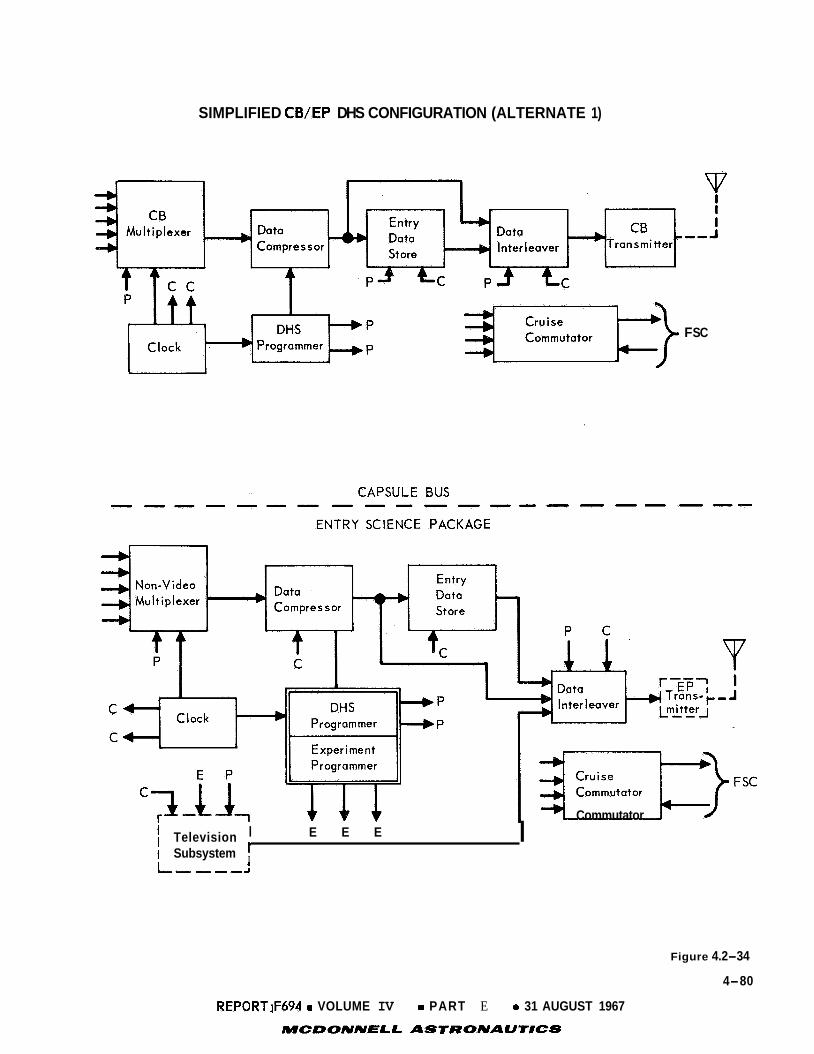
SIMPLIFIED CB/EP DHS CONFIGURATION (ALTERNATE 1)
F SC
I E E E
I I Subsystem ' L--.---I
Television I ~ } F s c Commutator
Figure 4.2-34
4-80
REPORTiF694 0 VOLUME IV 0 PART E 0 31 AUGUST 1967
MCDONNlELL ASlRONAUllCS

SIMPLIFIED CB/EP DHS CONFIGURATION (ALTERNATE 2)
I Vata Inter leaver
Data Store .111111+
L D U U T U I
Multiplexer Compressor *
I P
C
h E E E
CAPSULE BUS
ENTRY PACKAGE ----
I I I
r---- 1 I CB k-J
L,-,,J Transmitter
FSC Commutator L
L r u i s e
A J
1
r----I J
EP c ran sm itter ----
I I .
,J
Figure 4.2-35
4-8 1
REPORT w94 0 VOLUME IV 0 PART E 0 31 AUGUST 1967
MCDONNELL ASTRONAUTICS

programmer has no t been a s s i g r e d t o e i t h e r t h e CB o r ESP.
programmer loca t ed i n t h e CB o r dua l programmers wi th sync provided by the CB u n i t ,
could b e used.
E i t h e r a s i n g l e , common
C h a r a c t e r i s t i c s of A l t e r n a t e 2 are as fol lows:
o A l l low- rate ESP d a t a and CB d a t a are t r ansmi t t ed over independent com-
munication l i n k s , thereby minimizing mul t ipa th degradat ion.
A s i n g l e e n t r y d a t a s t o r a g e u n i t i s requi red .
No ESP te lemet ry i n t e r f a c e i s requi red wi th t h e spacec ra f t .
o
o
o Severa l s ing le- poin t f a i l u r e modes can occur , r e s u l t i n g i n simultaneous
loss of CB and low- rate ESP da t a .
o CB s t anda rd iza t ion i s reduced.
o Pre-assembly checkout may r equ i r e supplying t h e ESP manufacturer w i th an
e x t e r n a l c lock and programmer.
The t h i r d conf igura t ion (Alternate 3) provides a h ighe r degree of i n t e g r a t i o n
than Al t e rna t e 2 :
Figure 4.2-36.
e i t h e r t h e CB o r ESP.
fol lows :
a s i m p l i f i e d block diagram of t h i s conf igura t ion is presented i n
Again, t h e te lemetry subsystem programmer has no t been ass igned t o
C h a r a c t e r i s t i c s of t h e Al t e rna t e 3 conf igura t ion are as
o Low-rate ESP and CB d a t a are t r ansmi t t ed over independent communication
l i n k s , thereby minimizing mul t ipa th degradat ion.
o A s i n g l e e n t r y d a t a s t o r a g e u n i t is requi red ; f a i l u r e of t h i s u n i t may
r e s u l t i n loss of a l l blackout da ta .
o N o ESP te lemet ry i n t e r f a c e i s requi red wi th t h e Spacecraf t .
o Maximum number of alternate pa ths f o r CB and low-rate ESP d a t a are
a t t a ined .
o CB s t anda rd iza t ion is reduced.
o Pre-assembly checkout may r e q u i r e supplying t h e ESP manufacturer w i th an .
e x t e r n a l c lock and programmer.
Single- point f a i l u r e modes r e s u l t i n g i n l o s s of both real-time CB and
low- rate ESP d a t a are minimized.
o
4.2.6.2
t i o n s are: p r o b a b i l i t y of mission success , subsystem performance, v e r s a t i l i t y and
program management a spec t s .
c r i ter ia i s presented i n t h e fol lowing paragraphs.
Se l ec t ion Criteria - Criteria used t o eva lua t e t h e a l t e r n a t e configura-
The weight ing a s soc i a t ed wi th each of t hese four
Mission success € o r t h e CB/ESP te lemet ry subsystem can be defined i n terms
of t h e percentage of t o t a l d a t a expected t h a t can be succes s fu l ly acquired,
4-82
REPORT F494 0 VOLUME IV 0 PART E 0 31 AUGUST 1967
MCDONNELL ASCTRONAUNCS

SIMPLIFIED CB/EP DHS CONFIGURATION (ALTERNATE 3)
P =C
I
‘;9 I
---
Cruise I Commutator
m
sc
-
r---- i I E+ -- - - - -1 I I + Mass
Inter leaver
-1 I
E 4- - - - - - pd Televis ion I
I Subsystem ’ 1
Figure 4.2-36
4-83
REPORT 5694 e VOLUME IV 0 PART E 0 31 AUGUST 1967
MCDONN€LL ASTRONAUTICS

processed and de l ive red t o t h e t r a n s m i t t e r s o r Spacecraf t support system.
many f a c t o r s which can a f f e c t mission success , r e l i a b i l i t y w a s considered t h e most
s i g n i f i c a n t and w a s ass igned a weight ing c o e f f i c i e n t of 0.45.
s i d e r a t i o n s inc lude p r o b a b i l i t y of component s u r v i v a l , g r ace fu l degradat ion capa-
b i l i t i e s and a l t e r n a t e f u n c t i o n a l pa th a v a i l a b i l i t y . )
Of t h e
( R e l i a b i l i t y con-
The most important f a c t o r s i n subsystem performance inc lude weight , power and
d a t a t ransmiss ion rate requirements.
weight ing c o e f f i c i e n t of 0 .3 .
These f a c t o r s w e r e assigned a combined
The major v e r s a t i l i t y des ign cons idera t ions inc lude t h e ease of accommodating
changing requirements (both in t ra- miss ion and in te r- miss ion) , and t h e a b i l i t y t o
assist o t h e r subsystems i n performance of t h e i r ass igned t a sks . The v e r s a t i l i t y
c r i t e r i o n w a s assigned a weight ing c o e f f i c i e n t of 0.15.
Program management cons idera t ions w e r e l i m i t e d p r imar i ly t o cos t and develop-
ment r i s k comparisons. Because a l l candidate conf igura t ions use e x i s t i n g state-
of- the- art techniques and c i r c u i t r y , t h e development r i sk comparison i s based on
CB/ESP i n t e r f a c e complexity.
lowest weight ing c o e f f i c i e n t of 0.1.
4.2.6.3
t he p r o b a b i l i t y t h a t a s p e c i f i e d quan t i t y and type of d a t a can be succes s fu l ly
de l ive red t o a use r subsystem.
of d e t a i l e d ana lyses of t he candida te systems.
i n g d a t a w a s weighted h i g h e s t , 0 .4 .
less important ( 0 . 3 ) than the CB d a t a because some atmospheric d a t a can be obta ined
by t h e CB and SLS. Although t h e e n t r y t e l e v i s i o n d a t a is s i g n i f i c a n t , i t is r a t e d
less important (0.2) than t h e CB engineer ing d a t a and ESP low rate measurements.
The lowest weight ing c o e f f i c i e n t w a s assigned t o mass spectrometer d a t a (0.1)
because t h e SLS may provide some back-up c a p a b i l i t y f o r t h i s experiment.
1 Program management cons idera t ions w e r e ass igned t h e
Evaluat ion - The r e l i a b i l i t y of t h e candida te conf igura t ions is based on
. This p r o b a b i l i t y is determined using t h e r e s u l t s
I n t he eva lua t ion the CB engineer-
ESP low rate measurements were r a t e d s l i g h t l y
The r e l i a b i l i t y a n a l y s i s i n d i c a t e s t h a t t h e a l t e r n a t e func t iona l pa th config-
u r a t i o n s do n o t o f f e r t h e h ighes t p r o b a b i l i t y of succes s fu l d a t a acqu i s i t i on .
However, t h e i n t e g r a t e d systems provide b e t t e r g race fu l degradat ion c h a r a c t e r i s t i c s ,
r e s u l t i n g i n h ighe r o v e r a l l r e l i a b i l i t y eva lua t ion , s i n c e p r o b a b i l i t y of succes s fu l
d a t a a c q u i s i t i o n and g race fu l degradat ion were weighted equal ly i n t he eva lua t ion .
A summary of t he weight , power and d a t a t ransmission requirements of each
candidate conf igura t ion i s presented i n Figure 4.2- 37.
weight ings t o each of these parameters , a composite va lue f o r subsystem perform-
ance w a s der ived , The ass igned va lues are 0 . 4 , 0.4 and 0.2 f o r weight , power and
By ass igning relative va lue
4-84
REPORT F,694 0 VOLUME I V 0 PART E e 31 AUGUST 1967
MCDONNELL ASTRONAUNCS 4

v) w I U 6 0 CY a a 6 Z 2 n v, w
LL 0 x CY I- 6 I
-
tn
U
I-
Figure 4.2-37
4-85
REPORT Ffi94 VOLUME IV o PART E o 31 AUGUST 1967
MCDONNELL ASTRONAUTICS

t ransmiss ion requirements , r e spec t ive ly . Included i n t h e weight cons ide ra t ions is
t h e inhe ren t redundancy which minimizes t h e need f o r more weight t o e l i m i n a t e
s ingle- point f a i l u r e s .
V e r s a t i l i t y has been provided i n a l l of t h e candidate conf igura t ions by a
s t o r e d program c o n t r o l which permi ts l i m i t e d modif ica t ion during f l i g h t .
complex systems have g r e a t e r v e r s a t i l i t y because t h e m u l t i p l e pa th c a p a b i l i t y
r e s u l t s i n a g r e a t e r chance t o f i n d and i n i t i a t e , by command, a l t e r n a t e d a t a pa ths
i n t h e event of an i n- f l i g h t pre- separa t ion f a i l u r e .
The more
Perhaps t h e most important v e r s a t i l i t y a spec t provided i n t h e i n t e r l a c e d CB/
ESP System is t h e reduct ion of RF mult i- path i n t e r f e r e n c e through use of frequency
d i v e r s i t y techniques.
Cost d i f f e r e n c e s between conf igura t ions should be s l i g h t . None of t h e candi-
d a t e conf igura t ions involve h igh r i s k i t e m s . However, t h e more complex systems
may be s l i g h t l y more expensive t o produce and have a somewhat g r e a t e r p o s s i b i l i t y
of schedule s l ippage .
The comparative eva lua t ion of candidate conf igura t ions is summarized i n t h e
comparison matrix of F igure 4.2-38. This t a b l e i n d i c a t e s t h a t A l t e rna te 3 is t h e
p re fe r red conf igura t ion .
4.2.6.4 Selec ted Configurat ion - A l t e r n a t e 3 w a s s e l e c t e d as t h e b a s e l i n e func-
t i o n a l conf igura t ion on t h e b a s i s of t h e r e s u l t s summarized i n t h e comparison
matr ix of F igure 4.2-38.
Bus o r s e p a r a t e programmers f o r t h e CB and ESP were considered. Separa te pro-
grammers f o r t h e CB and ESP, wi th CB programmer sync provided t o t h e ESP u n i t ,
w e r e s e l e c t e d because of t h e g r e a t e r r e l i a b i l i t y provided and fewer i n t e r f a c e s
required.
missions i n which t h e ESP is no t included. These f a c t o r s outweigh t h e s m a l l
i nc rease i n power (3.1W) and weight (4.2 l b . ) r e l a t i v e t o t h e t o t a l CB/ESP power-
weight requirements.
The use of a common programmer loca ted i n t h e Capsule
Fewer i n t e r f a c e s f a c i l i t a t e t h e s t anda rd iza t ion of t h e CB f o r f u t u r e
The b a s e l i n e system inc ludes an e n t r y d a t a s t o r e i n t h e ESP i n add i t ion t o
t h e e n t r y d a t a s t o r e i n t h e Capsule Bus.
l a t e d during blackout is provided, ( see Sect ion 4.2.1.2), and l o s s of blackout d a t a
due t o c a t a s t r o p h i c f a i l u r e of an e n t r y d a t a s t o r e i s precluded. Dual t i m e delay
s t o r a g e is used i n t h e b a s e l i n e system i n s t e a d of t h e s i n g l e de lay assumed i n t h e
t r a d e study.
unaffec ted
Thus an a l t e r n a t e pa th f o r d a t a accumu-
However, t h e v a l i d i t y and conclus ians of t h e t r a d e s tudy are
4-86
REPORT F694 0 VOLUME IV 0 PART E 0 31 AUGUST 1967
.MCDONNEL.L ASTRONAUTICS

m W I V 6 0 CY a a 4 Z
m W
LL 0 X CY I-
I
r-3
n
- a
z 0 I- V w -1 W m
-
C)
w I- < Z CY W I- -1 a
N
w I- < Z CY W I- -1 <
- W I- < Z cy: W I- -1 a
I-
C)
a, 0
a,
t
J E !! - 8 4
c
v)
E t v) x m
a C)
x t .- - .- t 0 v) L
P
t c a,
$
9 (5, 0 C
- Figure 4.2-38
4-87
REPORT 5694 0 VOLUME IV e PART E e 31 AUGUST 1967
MCDONNELL. ASTRONAUTICS

4.2.6.5 I n t e r l e a v i n g - Figure 4.2-39 shows t h e equipment requi red t o i n t e r l e a v e
t h e CBS and ESP da ta . The purpose of t h i s a n a l y s i s is t o determine what t ype ( s )
of d a t a i n t e r l e a v i n g w i l l b e most s a t i s f a c t o r y from a synchronizat ion viewpoint.
Three types of i n t e r l e a v i n g w i l l be considered: frame, word, and b i t i n t e r-
leaving. Frame i n t e r l e a v i n g uses t h e s imples t l o g i c a t t h e receiver t o de-inter-
leave t h e d a t a stream, r equ i r ing only t h e sens ing of t h e frame sync word i n con-
s e c u t i v e b i t s t o steer t h e d a t a frame t o t h e c o r r e c t l o c a t i o n f o r decoding. It
w i l l normally r e q u i r e s t o r a g e p r i o r t o i n t e r l eav ing .
B i t i n t e r l e a v i n g does no t r e q u i r e s t o r a g e p r i o r t o i n t e r l e a v i n g , bu t t h e de-
i n t e r l e a v i n g l o g i c is gene ra l ly more complex.
i .e . , t h e de- in ter leaving l o g i c i s t r i v i a l ; bu t t h e genera l case of n b i t s of one
b i t stream t o m b i t s of t h e o t h e r r equ i r e s t h e search f o r t h e r e spec t ive frame
sync words t o take p lace over non-consecutive b i t s of t h e d a t a stream. Given
t h a t a t least one of t h e frame sync words is i n t h e decommutation s h i f t r e g i s t e r ,
t h e s h i f t r e g i s t e r l eng th , L , i s def ined between
The "one-one" case i s degenerate ,
(x/n - 1) (m + n) + n < - - L < (3 ( m + n )
f o r (x/n y/m>
(where x i s t h e sync
guarantee a long enough s h i f t r e g i s t e r t o f i n d e i t h e r sync
word l eng th i n n d a t a stream and y is t h e m sync word), t o
word.
Word i n t e r l e a v i n g r e q u i r e s some s t o r a g e but no t n e a r l y as much as frame i n t e r -
leaving. Tke l o g i c requirements f o r de- in ter leaving are much t h e same as f o r b i t
i n t e r l e a v i n g ; frame sync sea rch must always examine non-consecutive b i t s of t h e
d a t a stream.
I n t e r l e a v e r s 3 and 4 of F igure 4.2-39 are designated b i t i n t e r l e a v e r s because
t h e d a t a is i n t h e r a t i o 1:l:l; i n f a c t , t h e d a t a streams are i d e n t i c a l except f o r
r e l a t i v e t iming delays.
w i l l be s impler l o g i c i n t h e i n t e r l e a v e r than f o r t h e word o r frame type.
leaver 5 is shown as a frame i n t e r l e a v e r because t h e r e l a t i v e d a t a rates of t h e
t h r e e d a t a streams is (a = c ) / b N 1/200, which would cause t h e s h i f t r e g i s t e r
l eng ths (and a s soc i a t ed l o g i c ) f o r e i t h e r t h e b i t o r word types t o be excessive.
I n t e r l e a v e r s 1 and 2 are a l s o t h e b i t type because t h e r e
I n t e r- .
The des igna t ion , frame i n t e r l e a v e r , covers several v a r i a t i o n s . One v a r i a t i o n
i s t o have d e f i n i t e l o c a t i o n s wi th in t h e t e l e v i s i o n frame f o r d a t a from d a t a
streams a and c.
adequate address b i t s f o r de- in ter leaving purposes. S t i l l another approach i s t o
i n t e r l e a v e complete frames of d a t a from each b i t stream.
A second approach is t o i d e n t i f y d a t a from a l l streams with
The f i r s t approach would
4-88
REPORT I5594 0 VOLUME I V a PART E e 31 AUGUST 1967
MCDONNELL ASTRONAUTICS

TELECOMMUNICATIONS EQUIPMENTS - DESCENT PHASES
1. 3.
To Transmitter (Low Rate)
To Transmitter
(High Rate)
Figure 4.2-39
4-89
REPORT P694 0 VOLUME IV 0 PART E 0 31 AUGUST 1967
MCDONNELL ASTRONAUTICS

n o t add any b i t s t o t h e d a t a stream (and t h e r e f o r e does n o t i nc rease the t r ans-
mission rate), b u t w i l l b e i n f l e x i b l e t o f u t u r e changes i n t he system. The second
wi l l --p rovide g r e a t f l e x i b i l i t y f o r t h e f u t u r e a t t h e c o s t of t h e address b i t s , b u t
w i l l no t create any problems on frame sync o r t iming, as t h e t h i r d approach w i l l .
4.2.7 Use of Data Compression - W e have s t u d i e d t h e f e a s i b i l i t y of us ing d a t a
compression both t o reduce requi red communication rates by e l imina t ing u s e l e s s o r
redundant d a t a and t o enhance subsystem performance by providing a h ighe r t o l e rance
t o t h e e f f e c t s of unce r t a in environmental f a c t o r s . The r e s u l t s of both t h e redun-
dancy reduct ion and " al ias ing" compression s t u d i e s i n d i c a t e t h a t d a t a compression
is u s e f u l f o r a l l t h e experiments, s t r i c t l y from a compression viewpoint. More-
over , most of t h e compression algori thms considered have f a m i l i a r c i r c u i t imple-
mentations which are easy t o i n t e g r a t e i n t o t h e d a t a system. But readin- readout
power requirements due t o t h e h igh d a t a rate w i l l be excessive. Therefore, d a t a
compression i s no t included i n t h e ESP b a s e l i n e design.
Cons t ra in ts - To eva lua t e d a t a compression f e a s i b i l i t y f o r t h e VOYAGER mission,
s e v e r a l c o n s t r a i n t s concerning system opera t ion and mission du ra t ion w e r e considered:
a. The m a x i m u m d a t a e n t r y occurs when e n t e r i n g VM-9 a t graze (600 second
Entry - 60 second Terminal Descent).
b. The minimum d a t a e n t r y occurs when e n t e r i n g VM-8 a t -20° (230 second
Entry - 50 second Terminal Descent).
c. The Entry Telev is ion starts opera t ions a t 800,000 f e e t .
d. Transmission rates of compressed d a t a w e r e c a l cu la t ed a f t e r a l lowing f o r
p o s s i b l e e s t ima t ion e r r o r s on the amount of compressed d a t a (10% allowance).
Compression r a t i o s c a l c u l a t i o n s inc lude forced outputs used f o r "confidence
measurements"
e.
In t roduc t ion - S p e c i f i c d a t a compression methods can be c l a s s i f i e d e i t h e r as
d e s t r u c t i v e o r nondes t ruc t ive . The d e s t r u c t i v e (o r user- oriented) type of d a t a
compression is s o named because a t i m e h i s t o r y Gf t h e d a t a cannot be recons t ruc ted ,
whereas t h e nondes t ruc t ive (o r source- oriented) type al lows recons t ruc t ion .
Parameter e x t r a c t i o n i s almost synonymous wi th d e s t r u c t i v e d a t a compression.
The information ( i n t h e communications sense) i s def ined us ing i r r e v e r s i b l e t rans-
formations.
commensurate wi th t h e information they convey. Redundancy reduct ion i s equiva len t
t o adapt ive sampling except t h a t t h e d a t a i s sampled a t a uniform rate b u t only
those samples which are s i g n i f i c a n t are t ransmi t ted . Ezlcodinp techniques at tempt
t o reduce t h e d a t a by naming t h e da t a elements d i f f e r e n t l y .
Adaptive sampling means t h a t t h e d a t a channels are sampled a t a rate
Adaptive sampling,
4-90
REPORT F694 e VOLUME I V e PART E e 31 AUGUST 1967
MCDONNELL ASTRONAUTICS

redundancy reduct ion , and encoding a l l make a t i m e r econs t ruc t ion poss ib l e , and s o ,
are c l a s sed as nondes t ruc t ive techniques (See F igure 4.2-40)
Under each of t h e s e c l a s s i f i c a t i o n s are several techniques which have been
thoroughly t e s t e d by s imula t ions i n t h e labora tory .
From a compression viewpoint, each d a t a output should b e matched t o several
of t h e more l i k e l y candida te techniques as i n Reference 4.2-17. The comparison
cri teria - expected compression, implementation complexity, and b u f f e r reduct ions - give enough information t o choose t h e b e s t compression a lgor i thm f o r each experi-
ment, as i l l u s t r a t e d i n t h e fol lowing examples.
Entry Telev is ion - The assumed purpose of t h e Entry Telev is ion (o r Descent
Imaging) experiment is t o o b t a i n p i c t u r e s of Mars t o i d e n t i f y gross p r o p e r t i e s of
t h e atmosphere and d e t a i l e d information about t h e landing si te.
t e l e v i s i o n system s tud ied has a 200 l ines / f rame, 200 e lements / l ine , 6 b i t s / e l emen t
(24 x.10 b i t s / f r ame) d a t a p re sen ta t ion . It a l s o a l t e r n a t e s frames between wide
f i e l d images and narrow f i e l d images. The wide f i e l d images he lp l o c a t e t h e landing
s i te l o c a t i o n i n O r b i t e r TV p i c t u r e s , whi le t h e narrow f i e l d images g ive d e t a i l e d
information about t he t e r r a i n .
The candida te
4
The candida te compression techniques are: Rober t ' s Modulation; Firs t- Order
I n t e r p o l a t o r ; and Elastic Encoder. For d e s c r i p t i o n s of t hese da t a compression
techniques , see Reference 4.2-18. Figure 4.2-41, t h e Trade Study Summary Sheet,
shows t h a t t h e E las t ic Encoder is t h e b e s t compression approach, wi th a computed
compression r a t i o of 8.0:l. Mass Spectrometer - The purpose of t h e Mass Spectrometer experiment is t o
i d e n t i f y t h e atmospheric composition as a func t ion of a l t i t u d e .
has an i o n i z a t i o n chamber f o r t h e gas sample. The ion ized gas i s focused i n t o a
beam and i s d i r e e t e d by a varying e l e c t r o s t a t i c f i e l d onto a sensor .
ions are success ive ly s t e e r e d onto t h e sensor as t h e f i e l d changes.
cu r r en t is p ropor t iona l t o t h e amount of c o n s t i t u e n t i n t h e atmosphere; t h e t i m e '
t h e c u r r e n t peak occurs i d e n t i f i e s t h e c o n s t i t u e n t s . These two i t e m s are important
and w i l l always be t ransmi t ted .
The instrument
D i f f e r e n t
The sensor
As i n d i c a t e d on the Trade Study Summary on Figure 4.2-42, t he b e s t candida te
technique is t h e "Unusual Event" method (computed compression r a t i o = 2.5:l).
The present sampling scheme, which i s termed t h e " Per iodica l ly Sampled Output"
method, i s t h e only o t h e r candida te approach.
"Aliasing" Compression - "Aliasing" d a t a compression would no t be used t o
reduce communication rates, but t o enhanck system performance by guarding a g a i n s t
4-9 1
REPORX F694 e VOLUME I V e PART E 0 31 AUGUST 1967
MCDONNELL ASTRONAUTICS

U
v) n 0 I i- W I z z v) m W K
=E 0 U a i- 4
LL 0 Z 0 i- a U LL
a
n
- - - m v) a 1 U
4-1 t aJ -
n
.- t 0
l n c
Figure 4.2-40
4-92
REPORT FQ94 0 VOLUME IV PART E 0 31 AUGUST 1967 MCDONNELL ASTRONAUTJCS

L
VI C 0 .- t e P- a,
VI C s
Figure 4.2-41
4-93
REPORTjF694 e VOLUME IV e PART E e 31 AUGUST 1967
MCDONNELL ASTRONAUTHCS

K W I- W =E 0 pc I- V W a v) v) v) U =E
I >. -I t m - 2
s
a
W u, Z
v) v) W K
=E 0 U U I-
P a
m W I V Q 0 lY Q Q Q Z (3
n
x
v) W
U 0
lY I-
3
F
I N
@ @
c.( I
7
. 0
m C 0 .- .I- e P- al
VI C s L
Y Y al
3 CO
Figure 4.2-42
4-94
REPORT F694:. VOLUME PJ e PART E e 31 AUGUST 1967
MCDONNELL ASTRONAUTICS

aliasing errors.
the highest frequency present in the channel, thus causing the channels freauency spectra to overlap. False output waveforms will be returned if aliasing is present.
System design and operation can be described as follows: A typical instrumentation list defines the sample rate requirements based on
Aliasing occurs whenever a channel is sampled at less than twice
expected vehicle performance in an assumed environment. requirements are underestimated, significant measurement errors may be introduced;
on the other hand, if the sample rate requirements are adequate, sampling at higher rates would result in unnecessary data transmission.
If these sample rate
In the ESP TM, multiplexer sampling rates would be increased to about ten times the required rate. The data compressor will accept this data, separate those samples which would have been provided by a lower-speed multiplexer, and output
them without modification. In addition, an appropriate compression algorithm
(probably a First-Order Interpolator) will be applied to the remaining samples.
If the original sample rate requirements are adequate, the compressor will produce no additional samples of excessively active channels for subsequent transmission.
By increasing the communication link capability about lo%, the data compressor out- put frame format would include all required data samples, followed by an additional
10% of compressed data samples.
For example, if the required sample rate were 100 sps, the compressor output would be 110 sps (the first 100 time slots being the required samples and the last 10 containing any excess samples produced by the compression algorithm). Thus, if
the highest per channel sample rate required were 1 sps, at least ten channels could be adaptively increased to 2 sps; similarly one channel could be sampled at 10 sps.
If the excessive activity duration is limited or the channel activity is not too excessive, even greater adaptivity can be expected.
Summary - Data compression generally is useful because it allows more "information" to be transmitted with the same number of bits, or allows the same "information" to be transmitted in a smaller number of bits. This study illustrates
the second possibility because there are a definite number of baseline experiments to be performed. However, the way is open, after employing data compression on
these experiments, to increase the amount of "information" from these experiments to add other experiments up to the original transmission rates.
The earlier studies indicated that data compression will require a slightly larger memory, but will gain 16 dB of additional margin. compressor failure rate will be about 2.81%/1000 hours, based on the parts count
for existing ground data compressors capable of performing similar operation.
Also, the calculated data
4-95
REPORT F694 0 VOLUME IV 0 PART E 0 31 AUGUST 1967
MCDONNELL ASTRONAUTICS

Obviously, this reliability figure can vary as a function of the compressed data
store (buffer) capacity, but the compressor is not likely to become a poor risk
item.
rates and an order of magnitude faster, the data compressor could be by-passed by
ground command any time prior to CB separation.
If the multiplexer is designed to operate at both the required sample
Conclusions - Data compression is beneficial on the ESP for both tasks from a compression viewpoint. a tolerance to the environmental unpredictability.
line system because it is not flight proven and because the high data rates on the
ESP will make the readin-readout power consumption in the logic memory (core) excessive.
It will eliminate redundant data and it will provide It is not included in the base-
4-96
REPORT F6Q4 e VOLUME IV o PART E 31 AUGUST 1967- MCDONNELL ASTRONAUTICS

REFERENCES
SECTION 4.2
4.2-1
4.2-2
4.2-3
4.2-4
4.2-5
4.2-6
4.2-7
4.2-8
4 .2.-9
4.2-10
4.2-11
4.2-12
4.2-13
Private Communication wi th D. Schweizer, Department 613-1 of SRS Philco-
Ford a t LARS, Cape Kennedy.
R. M. Golds te in and W. F. Gillmore, "Radar Observations of Mars", Science,
Vol. 141, pp 1171-1172, 20 Sept. 1963.
R. B. Dyce, "Recent Arecibo Observations of Mars and Jup i t e r , ' ' Radio
Science, Vol. 69D, pp 1628-1629, December 1965.
Selec ted S tudies of VHF/UHF Communications f o r P lane tary (Mars/Venus)
Relay Links, F i n a l Report, prepared by Astro- Electronics Div is ion , Defense
E lec t ron ic Products , Radio Corporation of A m e r i c a , P r ince ton , N e w J e r s e y ,
under Contract No. NAS 2-3772, AED R-3091; January 15, 1967.
G, Schroeder,"Noncoherent Binary FSK i n Slow FadingYrf
Corp; I . O . M . 413-AT-70820, August 10, 1967.
A. B. Glenn and G. Lieberman, "Effect of Propagat ion Fading and Antenna
F luc tua t ions on Communication Systems i n a Jamming Environment," IRE
Transact ions on Communications Systems, March 1962.
G . L . Turin, "Error P r o b a b i l i t i e s f o r Binary Symmetric I d e a l Reception
Through Nonselect ive Slow Fading and Noise." Proc. of I R E , September 1958.
W. C . Lindsey, "Error P r o b a b i l i t i e s f o r Ricean Fading Multichannel
Reception of Binary and N-ary Signals ," IEEE Transact ions on Information
Theory, October 1964, pp 339-350.
C. A. Hinr ichs , "Martian Entry Fading," McDonnell Douglas Corp.,
VN-11.2.1-4 (DELS), A p r i l 29, 1967.
L, Schuchman," Wideband Detect ion of MFSK Transmission i n a Two-Path/
Mult ipath Channel," Ph i l co Ford TM 119, J u l y 14, 1967.
J. C. South, "Program Descr ip t ion of Appropriate Solu t ion f o r Supersonic
Flow P a s t Blunt Bodies w i th Sharp Sonic Corners," Langley Working Paper
McDonnell Douglas
NWF-240, JulV 12, 1966.
C. D. Joerger , H. J. F i v e l , G. G . Grose, J . F. Fox, "The Ef fec t of
Abla t ive Products on Gemini Reentry Communications," F i n a l Report
Contract No. NASw-1209, A p r i l 1966. M. R. Denison and E. Baum, "Compressible F ree Sheer Layer wi th F i n i t e
I n i t i a l Thickness," AIAA Jou rna l , February 1963.
4-97
REPORT F694 0 VOLUME I V 0 PART E 0 31 AUGUST 1967
MCDONNELL ASTRONAUTICS

4.2-14 VOYAGER Technical Memo 4.1-19 (LQ), dated 5 J u l y 1967
4.2-15 "A F e a s i b i l i t y Study of an Experiment f o r Determining t h e P rope r t i e s of t h e
Mars Atmosphere," Vol. 111, Book 1, AVCO Corporat ion, September 1, 1966.
4.2-16 W. C. Lindsey, "Error P r o b a b i l i t i e s f o r Ricean Multichannel Reception of
Binary and N-ary Signals ,"
October 1964.
IEEE Transact ions of Information Theory,
4.2-17 VOYAGER Note VN 11.2.1-37 (LM), "Application of Data Compression t o VOYAGER
Experiments ," J u l y 19, 1967.
4.2-18 VOYAGER Note VN 11.2.1-3 (L) , "Data Compression Techniques," A p r i l 20, 1967.
4-98
REPORT F a 4 e VOLUME I V e PART E e 31 AUGUST 1967
MCDONNELL ASTRONAUTICS

4 . 3
tural/mechanical subsystem, the philosophy of keeping the design simple, utilizing
flight demonstrated practices, and selecting designs which are within the state-of-
the-art and adaptable to familiar analyses was followed.
requirements imposed on this subsystem do not pose unusual design problems. most challenging problems were the stagnation point port and the mounting for the
entry television cameras. For mounting the accelerometer, an existing major struc-
tural element which is rigid and possesses a convenient machined surface was utilized.
STRUCTURAL/MECHANICAL SUBSYSTEM - In selecting the configuration for the struc-
The constraints and
The
A typical torque box type of structure was selected for the ESP equipment con-
tainer. Pin-jointed members which provide ease of installation and minimum thermal paths were selected to support the UHF antenna. The similarity of functional loca- tion requirements indicated locating the base region port near the UHF antenna; therefore, the mounting provisions for the port tube were incorporated into the
antenna support bracket.
Entry Television Camera Mounting - The location of the camera container requires that it be ejected prior to impact. To reduce the probability of recontacting the Capsule after its release, ejection to the side away from the Capsule Lander is indicated.
the container was considered, but the pyrotechnic thruster is lighter and easier to install and was therefore selected. The compression struts provide adjustment
capability and dynamic stability necessary to provide and maintain camera alignment.
The use of springs to supply the ejection force for the separation of
Stagnation Point Port - The design of the fitting which provides the port at the stagnation point is determined to a great extent by the thermal protection
system selected. The constraints and requirements which affect the selection of the
thermal protection system are:
o
o
o No contaminants in gas samples for mass spectrometer
Stagnation point temperature of 2300°F Limiting the temperature of the compartment behind the apex fitting to 325°F
Ablative-type thermal protection systems could not be used because of their inherent
characteristic of releasing contaminants. Teflon-coated and ceramic-coated struc- tures were considered but they, too, give off products which could contaminate the
gas samples. The use of a metal-surfaced thermal protection system was indicated. The material selected is beryllium because of its high melting point, high heat
capacity at elevated temperatures, low density, and strength characteristics. A
single fitting incorporating the necessary ports fulfills the structural and non-
contaminating inlet requirements. Thermal protection for the compartment is provided
4-99
REPORT F694 0 VOLUME IV e PART E e 31 AUGUST 1967 MCDONNELL ASTRONAUTICS

by utilizing the fitting as a heat sink.
4.4 fabrication, assembly and installation techniques to determine the most effective
packaging and cabling for the Entry Science Package. in the following paragraphs.
4.4.1 Cable Studies - Efficient cabling interconnection requires integration with the structure, equipment form factors, and equipment installation. The preferred
wire and harnessing techniques provide the necessary integration with a reliable
lightweight design.
and indicates the preferred approach.
"Kapton" wire in round bundles. Sleeving is applied in areas where abrasion may
occur and wire terminations are potted to provide environmental sealing and wire support . 4.4.2 Connector Studies - The cabling study was complemented by an evaluation of connectors.
reliable connector was not available. summarizes the characteristics and parameters of each connector, and notes the selection for standardization of interconnects. The preferred MIL-C-38999 connector
is circular, employs rear entry crimp contacts, has a quarter turn bayonet coupJing,
is environmentally sealed and has provision for potting.
4.4.3 ESP equipment, several considerations dominated. These were: (A) recognition that
some elements were constrained to specific locations while others could be grouped, (B) that weight and volume were to be minimized, (C) that simplicity, accessibility
and ease of deletion be maximized.
PACKAGING AND CABLING - Studies were conducted on materials and components,
These studies are summarized
Figure 4.4-1 lists the various materials and techniques studied, The preferred wire is MIL-W-8138 1/1 (7 mil)
In some cases alternate cabling techniques were discarded because a Figure 4.4-2 lists the connectors studied,
Equipment Packaging - In assessing various approaches to packaging of the
The form factor evaluation considered those science and support items which
could be grouped and treated as one assembly. ment packaging consisted of standardized subassemblies, structurally integrated
subassemblies and black box elements. The standardized subassembly was discarded on the basis of the random form factors essential to certain items (for example, the long mass spectrometer with its small cross sectional area). The structurally
integrated subassembly concept was considered too complex for the limited-use appli- cation of the Entry Science Package. The black box approach, in which each assembly
is fabricated as a separate device for the intended installation, was selected. The volumes required by subassemblies are constrained to specified physical dimen-
sions to ensure integration with the other subassemblies, permit adequate mounting
The techniques evaluated for equip-
4-100
REPORT F694 0 VOLUME IV 0 PART E 0 31 AUGUST 1967 MCDONNELL ASTRONAUTICS
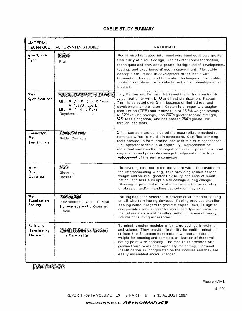
I .
CABLE STUDY SUMMARY
{LTERNATES STUDIED
'i
F la t
MIL-W-81381dl (7 mil) Kapton
MIL-W-813811 (5 mi l ) Kapton MIL-W-16878 Type E MIL-W-8104413 Kynar Raychem Thermorad
Solder Contacts
SI e ev i ng Jacket
Environmental Grommet Seal Non-environmental Grommet
Seal
Terminal Junction Modules
Stud Terminal Strips
RATIONALE
Round wire fabricated into round wire bundles al lows greater f l ex ib i l i t y of c i rcu i t design, use of established fabrication, techniques and provides a greater background of development, testing, and experience of use i n space f l ight. F l a t cable concepts are l imited i n development of the basic wire, terminating devices, and fabrication techniques. F l a t cable l imits circui t design i n a vehicle test and/or developmental program.
3nly Kapton and Teflon (TFE) meet the in i t ia l constraints D f compatibil i ty with ET0 and heat steri l ization. Kapton 7 mil i s selected over 5 mil because of l imited test and development on the latter. Kapton i s stronger and tougher than Teflon (TFE) and realizes up to 15.5% weight savings, to 12% volume savings, has 267% greater tensi le strength, 87% less elongation, and has passed 284% greater cut through load tests.
Zrimp contacts are considered the most rel iable method to terminate wires in mult i -pin connectors. Cert i f ied crimping tools provide uniform terminations with minimum dependence Jpon operator technique or capabil ity. Replacement of individual wires and/or damaged contacts i s possible without degradation and possible damage to adjacent contacts or *eplacement of the entire connector.
No covering external to the individual wires i s provided for the interconnecting wiring, thus providing cables of less weight and volume, greater f lex ib i l i ty and ease of modifi- cation, and less susceptible to damage during change. Sleeving i s provided in local areas where the poss ib i l i ty of abrasion and/or handling degradation may exist.
Pott ing has been selected to provide environmental sealing on a l l wire terminating devices. Potting provides excellent sealing without regard to grommet capabil it ies, i s l ighter and provides wire support for increased dynamic environ- mental resistance and handling without the use of heavy. volume consuming accessories.
Terminal junction modules offer large savings in weight and volume. They provide f lex ib i l i ty for multiterminations of from 2 to 8 common terminations without additional weight for bussing and complete ut i l izat ion of the termi- nating point wire capacity. The module i s provided with grommet wire seals and capabil ity for potting. Terminal identif ication i s incorporated on the modules and they are easi ly assembled and/or changed.
Figure 4.4-1
4-101
REPORT! F694 0 VOLUME XV e PART E 31 AUGUST 1967
MCDONNELL

CONNECTOR CHARACTERISTICS SUMMARY
D R E 126 SR 348
Deutsch Amphenol Bendix Microdo MI L-C-C
Su bmi nil Circular
Threade
7 to 61
r12, 16
PUS h- P I
-85°F t
Dial ly l
Silicone Ring an ing Insc Gromme
Gemini
Amphenol MIL-C-81511
Subminiature Circular Bayonet
Cannon, Cinch MIL-C-8384B
Subm i n iature Rectangular Friction
Standard Rectangular Friction
Subm in ioture Rectangular Allen Hex Jackscrew
Miniature Rectangu I ar Spring Loaded
9 to 50 26 to 91 4 to 57 4 to 85 12 to 100
#22 Crimp
-65" F to +300" F
#12, 16, 20 Solder
-85" F to +185" F
#20 Solder or Crimp
-65" F to +300" F
#22 Crimp
-67" F to +302" F
#4, 8, 16, 20 Solder
-67°F to +257" F
Dial ly l Phthalate Glass Fibre Fi l led Monobloc, Closed Entry Sockets,
Grommet Seal or Potted
Hard Plastic Sockets, Silicone Inter- face and Rear Seal, Glass with Si I icone Interface- Hermetic s
Dial ly l Phthalote Asbestos Filled, Potted Seal.
Resilient Insert, 16 & 20 Contacts Closed En try Sockets, Potted Seal.
Retention Disc ond Locking Nut Grommet Seal.
ASS ET Mariner
F4
Yes None Yes Yes None
Rack and Panel
Yes
Rear Entry, Shape 8, Size
High Density, Rear Entry, Space & Weight, Environmental Seal, High Temperature, many Contacts
Rack and Panel High Density, High Temperature
High Dt
Mounting
Only rt22 Gage Contacts, Limited Development
Solder Limitations, Heavy and Large, Interface Sealing Difficult, No Her- metic Class.
Only #22 Gage Contacts, Limited Development.
Many A Parts
Temperature L im i - tations, Only Solder Terminations, Inter- face Sealing Diffi- cult, No Hermetic Class.
Only #20 Gage Contacts, Mounting and Alignment Difficult Interface Sealing Difficult.
D Al l Hermetic Classes - Solder Type Only. = = 3 Prefered Connector
Figure 4.4-2
4-102 -1 REPORT F694 0 VOLUME IV 0 PART E 0 31 AUGUST 1967
MCDONNELL ASrRONAUTlCS

- 7---- DBA JC I JT I PV RTK PT
lendix I Bendix I Deutsch PH-2245-0300-B I MIL-C-38999 I NAS 1599
lo yonet I Bayonet I Threaded, Boyonet
! to 61 I 3 to 128 I 3 t o 6 1
16, #20 Solder
I
I I
I
I I I
I or Push-Pull
I #16, 20, 22, 22M I Solder or Crimp
I -67" F to +302" F I (392°F Crimp)
I #12 thru # 20 Crimp
-67" F to +257" F I -100" F to +392" F
S i I icone I Epoxy Resin ' Hard Plastic Nut & Grommet,or I Goskets & Inter- I Sockets, Silicone Potting Seal. I face Seals, I Pin interface,
I Silicone Rubber I Grommet Seol Closed Entry I Closed Entry Sockei
I Raised "Donut" Raised "Donut" I Pins, I Pins, I Nut & Grommet, or I Silicone Inter- I Potting Seal. ! face and Rear
I Seal, I Grommet Seal I
I
I 1 I 1 I I I I
I I BGRV
I I
None 5 Yes i Yes
Thermal I High Density I Rear Entry, Sterilization, Rear Entry, Envi ronmenta I Extreme Vibro- ' Space & Weight ' Seal, High tion, Stringent I Low Silhouette, 1 Temperature Inspection, I Environmental I and Ethylene I Temperature Oxide Gas
Only Solder Terminotions, $22 Gage
32 hrs @ 240" F I Seal, High I I
I ' #22 Goge
I I Contacts not I
Contacts not I Available I I
Bendix MI L-C-26482
Win ioture tirculor Bayonet
Cannon NAS 1599
Miniature Circular Bayonet
Deutsch MIL-C-26482
Subminiature Circular Push-Pul I Bayonet
7 to 85 1 t o 6 1 3 to 61
#16, #20 Solder or Crimp
-65" F to +257" F
Y16, #20 Crimp
-67" F to +392" F
22 Crimp
257" F
ff22 Crimp
-67" F to +300" F
holote,
1'' loot-
?Ol
Resiliont Silicone Raised "Donut" Pins, Closed Entry Sockets, Silicone Inter- face and Rear Seal, Grommet Seol
Resi I iant Neoprene, Nut & Grommet, or Potting Seal.
Thermosetting Plostic or Gloss, Raised "Donut" Pins, Closed Entry Sockets,
Grommet Seol
BGRV F -4 ASSET BGRV Mariner Mercury Gemini
Yes Yes Yes
i ty High Density, Rear Entry, Environmental Seol, High Temperature
Proven Space Usage
Rear Entry, Environmental Seal, High Temperature
mbly
-
Low Voltoge and Dielectric Rating, Limited Development
#22 Goge Contacts not Avai la ble
#22 Goge Contocts noi Available

provis ions , and a s s u r e rou t ing space f o r t h e in te rconnect ing cab le s . The subassem-
b l i e s of t h e Entry Science Package P r i n c i p a l Unit are mounted w i t h i n a l igh tweight
s t r u c t u r a l l y supported and thermally in su la t ed enclosure.
4 . 4 . 4 e l e c t r o n i c equipment r e q u i r e s s e l e c t i o n of equipment s u p p l i e r s on t h e b a s i s of
proven c a p a b i l i t y and favor ing , i n s o f a r as poss ib l e , each vendor 's p a r t i c u l a r area
of des ign and product ion competence. Fu r the r , a wide v a r i e t y of i n t e r n a l packaging
concepts have succes s fu l ly performed i n space a p p l i c a t i o n s , bu t none has evolved
as a n i d e a l approach; t h e r e f o r e , no s i n g l e i n t e r n a l packaging concept warran ts a
p re fe r r ed approach connotat ion.
I n t e r n a l PackaRing - The succes s fu l management approach t o a s s u r e r e l i a b l e
From experience, we know t h a t p a r t i c u l a r a t t e n t i o n must be devoted t o i n t e r n a l
packaging s p e c i f i c a t i o n s wi th s p e c i a l emphasis devoted t o t hose areas where a
cr i t ical ope ra t ion o r process can degrade t h e r e l i a b i l i t y of a given packaging
technique. Typica l ly , t h e fol lowing broad approaches are recommended and considered
appropr i a t e t o VOYAGER designs.
o C i r c u i t Board Modules - C i r c u i t board modules are p r imar i ly app l i cab le t o
i n t e g r a t e d c i r c u i t modules u t i l i z i n g e i t h e r series o r p a r a l l e l gap welding
o r r e s i s t a n c e so lde r re f low f o r component in te rconnect ion . For both
techniques t h e process must be c l o s e l y monitored and h igh level of c l e a n l i-
ness maintained. I f welding is employed, weld schedules must be c r i t i c a l l y
e s t ab l i shed and p e r i o d i c a l l y v e r i f i e d . I n e i t h e r case, t h e use of s i n g l e
o r double s ided c i r c u i t boards and conformal coa t ing wi th o r without embed-
ment is p re fe r r ed .
o Embedded (Cordwood) Modules - The u s e of embedded cordwood modules i s app l i-
cab le t o e i t h e r i n t e g r a t e d c i r c u i t , d i s c r e t e component o r combinations of
t h e s e components. This approach can be s a t i s f a c t o r i l y appl ied by s e v e r a l
techniques. The p re fe r r ed in te rconnect ion method is by welding, e i t h e r t o
comb o r r ibbon in te rconnects . Critical a t t e n t i o n t o embedment materials,
thermally induced stresses and r igo rous process c o n t r o l s are necessary.
S a t i s f a c t o r y hea t s ink ing is a design complication r equ i r ing a t t e n t i o n .
o Modular In te rconnect ion of Modules - Minimization of t h e u s e of f r i c t i o n
c o n t a c t s i s des i r ed t o o b t a i n maximum in terconnect ion r e l i a b i l i t y . Thus,
e i t h e r f a b r i c a t e d mul t i l aye r boards (continuous conductors and risers, o r
risers welded o r conductors) o r matrix in te rconnects are p re fe r r ed as t h e
modular in te rconnect technique. Module t o board connect ions can be e i t h e r
welded o r w i r e wrapped. The w i r e wrap technique has t h e advantage of easier
4-103
REPORT F&94 0 VOLUME I V 0 PART E e 31 AUGUST 1967
MCDQNNELL ASTRONAUTICS

module replacement and i t s disadvantage of r equ i r ing more space is mi t iga ted
by t h e requirement t o i nco rpora t e a d d i t i o n a l space f o r a second weld i f
module replacement is necessary.
Radio Frequency Packaging - The p re fe r r ed approach t o packaging r a d i o
frequency equipment i s t o u t i l i z e f u n c t i o n a l elements i n s e r t e d i n t o a
metall ic compartmentized chass i s .
f o r test and thecompartments f a c i l i t a t e sh i e ld ing .
o
This permits i n d i v i d u a l module ope ra t ion
4.5 THERMAL CONTROL - The ESP thermal environment w i l l be maintained wi th in t h e
temperature c o n s t r a i n t s imposed by t h e var ious equipment and instruments by use of
a f ib rous i n s u l a t i o n b l anke t coated wi th l o w emis s iv i ty overcoat ing i n conjunct ion
wi th e lec t r ic hea t e r s . This thermal c o n t r o l approach i s b e s t s u i t e d f o r t h e ESP,
based on cons idera t ion of o v e r a l l system performance, s i m p l i c i t y of opera t ion ,
conta iner r e l i a b i l i t y and ease of i n s t a l l a t i o n .
l oca t ed on t h e lander , two subsystems loca t ed i n t h e nose cap assembly are a l s o
considered: t h e en t ry TV cameras, and s t agna t ion p re s su re t ransducer .
4.5.1
is r equ i r ed t o maintain t h e equipment temperatures w i th in t h e i r a l lowable l i m i t s
throughout a l l mission phases. Considering t h e temperature l i m i t a t i o n s on t h e
var ious equipments, t he b a t t e r y temperature requirements are most restrictive.
The primary ESP thermal c o n t r o l requirements are summarized i n F igure 4.5-1.
4.5.2
mary opposing f a c t o r s must be considered:
I n a d d i t i o n t o t h e ESP equipment
Requirements and Cons t ra in ts - The thermal c o n t r o l subsystem f o r t h e ESP
Thermal Control Approach - I n s e l e c t i n g t h e thermal c o n t r o l system, two p r i-
a. Provide hea t r e t e n t i o n during t h e long c r u i s e phase without excess ive
h e a t e r power o r i n s u l a t i o n weight.
Prevent overheat ing from equipment opera t ion , and hea t ing from t h e base
region wake and ad jacent Aeroshel l s t r u c t u r e during en t ry .
b.
The following t a b l e summarizes t h e matrix of thermal c o n t r o l combinations considered
f o r t h i s a p p l i c a t i o n :
Thermal Control Combinations Pass ive Element Active Element
A I n s u l a t i o n and I ~ T None emit tance s u r f a c e coa t ings
B Low emit tance H e a t e rs s u r f a c e coa t ing
4-104
REPORT F664 e VOLUME I V e PART E 0 31 AUGUST 1967
MCDONNELL ASTRONAUTBCS

ESP INSTRUMENT THERMAL CONTROL REQUIREMENTS
NON-OPERAT ING OPE RATING TEMPERATURE TEMPERATURE
LIMITS ( O F ) LIMITS (OF)
INSTRUMENT COMPONENT
ESP Equip. Container 0 t o 60 50 to 120
Batteries
Entry T V - 4 to 140 - 4 to 104
Vidicons
Atmospheric Properties Instruments -328 to 250 -328 to 250 Transducer (pressure)
Figure 4.5-1
4- 105
REPORT F694 0 VOLUME IV 0 PART E 0 31 AUGUST 1967
MCDQNNELL ASTRONAUTICS

(Selected) C I n s u l a t i o n and Heaters low emittance su r f ace coa t ings
D I n s u l a t i o n Heaters and Change of, Phase Materials
E I n s u l a t i o n Semipassive device - e.g. louvers
4.5 .3 Thermal Control System Evaluat ion - The environment external t o t h e ESP
Equipment Container is inf luenced by t h e Aeroshel l , S t e r i l i z a t i o n Canis te r and Surface
Laboratory temperatures during c r u i s e and en t ry .
Aeroshal l and canister temperatures w i l l b e maintained above - 140°F by t h e Capsule
Bus Thermal Control Subsystem. The equipment i n t h e ESP Equipment Container i s i n a non-operating mode during t h i s pe r iod , except f o r b a t t e r y charging and c r u i s e
te lemetry. This provides about s i x w a t t s of waste hea t . The t rade- off t o determine
whether a d d i t i o n a l e l e c t r i c a l h e a t e r power i s needed w a s made and t h e r e s u l t s are
shown i n Figure 4.5-2.
would be excessive considering t h a t only a t o t a l of 200 w a t t s i s a v a i l a b l e t o t h e
en t i r e capsule during c r u i s e ; t h e r e f o r e , t he s e l e c t e d combination included h e a t e r s
wi th i n s u l a t i o n and. low emit tance gold coat ings.
i n s u l a t i o n th ickness of 0.75 inch and h e a t e r power of two watts have been s e l e c t e d
as t h e design po in t which r equ i r e s 3.5 pounds of i n s u l a t i o n f o r t h e ESP Equipment
Container. The i n s u l a t i o n material used he re i s a low d e n s i t y f i b e r g l a s s f i b e r
bonded wi th s i l i c o n e .
During t h e c r u i s e per iod t h e
It i s ev ident t h a t t he power requirements f o r no i n s u l a t i o n
To al low some contingency, an
Figure 4.5-2 a l s o shows t h e insu la t ianrpower t radeoff f o r t h e e n t r y TV camera
For t h i s subsystem one inch of i n s u l a t i o n (weighing 1 .0 l b ) e l e c t r o n i c s subsystem.
coated wi th a low emit tance gold coa t ing and t h r e e w a t t s of h e a t e r power are s e l e c - -
t e d . The i n s u l a t i o n th ickness of one inch i s a l s o s u f f i c i e n t t o maintain t h e en-
t r y - TV camera wi th in
P a r t E , Volume I1 shows t h a t t h e hea t ing from t h e camera window exposed t o en t ry
hea t ing is 60 BTU/ft2, and the r e s u l t i n g temperature rise of t h e en t ry TV l e n s is
less than 40°F.
100°F dur ing en t ry phase. Analysis made i n Sect ion 5.4
For the s t agna t ion p re s su re t ransducer , one inch i n s u l a t i o n (weighting 0.4 l b )
wi th a low emit tance gold coa t ing w a s s e l ec t ed . A s in the e n t r y TV camera, one inch
i n s u l a t i o n is s u f f i c i e n t t o maintain the t ransducer w i th in 200°F during e n t r y heat ing.
During e n t r y hea t ing t h e t ransducer receive about 50 BTU/ft
from the backface of the bery l l ium atmospheric measurements probe.
2 of r a d i a t i o n hea t ing
4- 106 REPORT F6910 VOLUME I V 0 PART E 0 31 AUGUST 1967
MCDONNELL ASTRONAUTICS

INSULATION-POWER TRADEOFF FOR ESP THERMAL CONTROL
\
Continuous
.a I
5OoFA I
Aeroshell Temperature = - Insulation Properties:
k = .001 Btu/ft-hr-'F p = 4 Ib/ft3
Insulation Descent Weight-
4
I I 1.5
Insulation Thickness - inch 2.5 3 I
Figure 4.5-2
4-107
REPORT F684 0 VOLUME IV a PART E 0 31 AUGUST 1967
MCDONNELL ASTRONAUTICS

SECTION 5
CAPSULE BUS/ENTRY SCIENCE INTERFACES
The fol lowing paragraphs d i scuss t h e a l t e r n a t i v e des igns of t h e Capsule Bus
and Entry Science and t h e i r e f f e c t on each o the r . Fac to r s lead ing t o s e l e c t i o n of
t h e p re fe r r ed Entry Science conf.iguration are a l s o presented .
5 .1 TRAJECTORIES - Atmospheric r econs t ruc t ion depends on t h e measurement accuracy
of t h e e n t r y experiments. I f t h e spread of f l i g h t cond i t i ons can be narrowed - by
reducing t h e range of atmospheric models o r t h e spread of t r a j e c t o r i e s - then t h e
opera t ing range of several of t h e instruments can be reduced. Instruments with a
narrower measurement range are more accu ra t e and t h i s w i l l be r e f l e c t e d i n t h e
r econs t ruc t ion of t h e Capsule t r a j e c t o r y .
A t p r e sen t , t h e Entry Science Package ins t rumenta t ion must be designed t o cope
wi th a range of atmospheric models and a spread of Capsule t r a j e c t o r i e s .
a d d i t i o n a l d a t a and a n a l y s i s of t h e atmosphere p r i o r t o t h e 1973 f l i g h t may i n d i c a t e
Eowever,
a narrower band of expected atmospheres. Also, i f a narrow band of o r b i t s i z e s is def ined f o r t h e Spacecraf t opera t ion , t h e poss ib l e range of Capsule de- orbi t en t ry
and landing condi t ions are reduced.
narrowed o r b i t band would reduce t h e extremes of e n t r y f l i g h q a n d thus t h e maximum
measurement range f o r t h e acce lerometers , temperature, and pressure sensors could be
reduced, dependent upon t h e change i n t h e e n t r y c o r r i d o r .
The smaller e n t r y c o r r i d o r compatible wi th a
A t h i r d type of f l i g h t v a r i a t i o n , which is dependent upon t h e p re fe r r ed Capsule
Bus design, is t h e d e c e l e r a t i o n technique. The choice of aerodynamic d e c e l e r a t o r ,
inc luding deployment a l t i t u d e , w i l l i nc rease o r sho r t en t h e a v a i l a b l e f l i g h t t i m e ,
p a r t i c u l a r l y a t speeds less than Mach 5. Separat ion of t heAeroshe l1 te rmina tes
t h e measurement of t h e s t agna t ion flow c h a r a c t e r i s t i c s . I g n i t i o n of t h e te rmina l
propulsion a l s o degrades t h e atmospheric and f l i g h t measurements. This i n t e r p l a y
of measurement t i m e and t r a j e c t o r y events are dependent on t h e Capsule Bus design.
One f a c t o r which has n o t been used t o restr ict t h e e n t r y t r a j e c t o r y but could
be used t o enhance t h e ESP d a t a i s t h e v i e w of t h e su r f ace as seen by t h e descent
TV.
h ieh r e s o l u t i o n , narrow f i e l d of v i e w camera t o view more of t h e area near t h e
landing s i t e .
r e s o l u t i o n camera view of t h e landing s i t e bu t i t s longer f l i g h t t i m e does provide
t h e opportuni ty f o r more images.
a l t i t u d e view from p lane t limb t o a poin t s h o r t of t h e landing s i te , depending upon
Within t h e a v a i l a b l e range of e n t r y ang le s , t h e s t e e p angle w i l l permit t h e
A shallow e n t r y ang le w i l l no t o b t a i n t h e higher a l t i t u d e h igh
The lower r e s o l u t i o n camera w i l l ob t a in a h igh
5-i
REPORT F694 i VOLUME 11' PART a 31 AUGUST 1967
MCDONNELL ASTRONAUTICS

e n t r y a t t i t u d e c o n t r o l and accuracy, even f o r t h e shal low e n t r y ang le s . However,
cons idera t ion of t h e des i r ed t i m e ve r sus view could w e l l be a secondary f a c t o r i n
t h e s e l e c t i o n of t h e p re fe r r ed e n t r y ang le as w e l l as e n t r y a t t i t u d e .
5.2 DE-ORBIT - The success of t h e Atmospheric P r o p e r t i e s Determination Experiment
i s s t rong ly dependent upon t h e accuracy of t h e t r a j e c t o r y r econs t ruc t ion , which i n
t u r n depends upon t h e p rec i s ion wi th which t h e e n t r y condi t ions are known.
Since t h e e n t r y condi t ions and t h e i r u n c e r t a i n t i e s depend d i r e c t l y upon t h e
de- orbi t condi t ions and t h e i r u n c e r t a i n t i e s , an examination of t he
implementation of t h e de- orbi t func t ions would i n d i c a t e means of minimizing uncer-
t a i n t i e s i n t h e de- orbi t condi t ions .
5 .2 .1 P re fe r r ed Design and Al t e rna t ives - The p re fe r r ed design and implementation
f o r t h e Capsule Bus de- orbi t phase w a s descr ibed i n d e t a i l i n P a r t D , Sec t ion 4 . 2 ;
i n t h i s s ec t ion , t h e a l t e r n a t i v e des igns and implementations are examined.
P re fe r r ed Design - The Capsule Bus gyros are caged and spun-up p r i o r t o
s epa ra t ion from t h e F l i g h t Spacecraf t . When uncaged, t h e Capsule Bus gyros are no t
s laved t o t h e F l i g h t Spacecraf t gyros, which produces an i n i t i a l alignment e r r o r of
mapnitude less than o r equal t o t h e deadband of t h e P lane ta ry Vehicle a t t i t u d e
con t ro l system (0.5"). This e r r o r , however, is removed i n t h e p o s t f l i g h t a n a l y s i s
by reduct ion of t h e monitored outputs of t h e FS gyros.
During t h e approximately 20 minute coas t from sepa ra t ion t o de- orbi t , t h e
Capsule Bus guidance and c o n t r o l computer maintains an a t t i t u d e r e fe rence (a
" v i r t u a l platform") by Euler angle processing of t h e strapdown gyro outputs .
A t t i t u d e is con t ro l l ed by t h e r e a c t i o n c o n t r o l system (RCS) with a 2" deadband.
During de- orbi t t h r u s t i n g , t h e RCS holds t h e Capsule a t t i t u d e aga ins t t h e
Monitoring of gyro and RCS t h r u s t misalignment torque wi th a n 0.25" deadband.
s i g n a l s during t h r u s t i n g determines which s i d e of t h e yaw and p i t c h deadbands t h e
Capsule i s holding on.
of t h e body-mounted guidance and c o n t r o l accelerometer .
ou tput of t h i s accelerometer determines t h e " t a i l o f f " v e l o c i t y increment.
Thrust te rmina t ion is commanded on t h e in t eg ra t ed output
Monitoring t h e i n t e g r a t e d
Al t e rna t ives and Operat ional Var ia t ions - Alternative mechanizations of t h e
a t t i t u d e r e fe rence func t ion are (1) s t a b l e platform and (2) strapdown gyros wi th
s i m p l e r a t e- i n t e g r a t i o n (analog o r d i g i t a l ) .
nated from content ion on t h e b a s i s of weight and r e l i a b i l i t y .
a l t e r n a t i v e s w e r e compared on t h e b a s i s of t h e i r e r r o r growth rates.
simple strapdown system would exceed t h e design e r r o r budget of 0.86" a f t e r only
13 minutes, and de- orbi t o r i e n t a t i o n maneuvers are programed t o t a k e 10 minu tes ,
The s t a b l e platform has been e l i m i -
The remaining
Since t h e
5-2
REPORT F694 i VOLUME IV II PART o 31 AUGUST 1967
MCDONNELL AST

t h i s approach w a s a l s o e l imina ted .
f i e d e r r o r l i m i t f o r up t o 29 min of coas t ing .
The p r e f e r r e d design remains w i t h i n t h e speci-
At t i tude- cont ro l a l t e r n a t i v e s f o r t h e per iod ofde-orbit thrusting are t h e
va r ious methods of t h r u s t v e c t o r c o n t r o l (TVC): f l u i d i n j e c t i o n , gimballed nozz le ,
and j e t vanes. F lu id i n j e c t i o n s u f f e r s from weight and complexity, and i s e l i m i -
nated on t h a t b a s i s , Any of t h e TVC systems cause some i n t e r f e r e n c e wi th t h e
p re fe r r ed t h r u s t t e rmina t ion method of nozz le b lowoff ibut , s i n c e t h e r e are t h r u s t -
t e rmina t ion a l t e r n a t i v e s , t h i s should n o t be taken as dec i s ive .
A l t e rna t ive thrus t- termina t ion methods are (1) c u t o f f on burn t i m e , computed
on t h e b a s i s of a nominal burning rate h i s t o r y , and (2) motor burnout , achieving
t h e des i r ed e n t r y condi t ions by varying de- orbi t anomaly and a t t i t u d e .
The p re fe r r ed mode of de- orbi tmoni tor ing begins wi th monitoring of t h e F l i g h t
Spacecraf t gyros, be fo re Capsule Bus sepa ra t ion . Under t h e p r i o r i t y of communica-
t i o n s c o n s t r a i n t s , however, de- orbi t monitoring may have t o b e l i m i t e d t o t h e per-
iod of r e t r o f i r e only, o r b e e l imina ted e n t i r e l y .
5.2.2 E f fec t s on Er ro r s a t De-Orbit 1 The de- orbi t po in t ing angle and v e l o c i t y
u n c e r t a i n t i e s f o r t h e va r ious a t t i t u d e c o n t r o l , t h r u s t t e rmina t ion and de- orbi t
monitoring a l t e r n a t i v e s may now be computed. Resul t s of t hese t o p i c s u b j e c t s
are summarized i n F igure 5.2-1.
A t t i t u d e Control - The dominant component of t h e r e t r o f i r e d is turbance i s a
s teady torque, due t o t h r u s t misalignment and c.g. o f f s e t u n c e r t a i n t i e s . The
o s c i l l a t o r y component, due t o asymmetric burning, i s n e g l i g i b l e . Under such condi-
t i o n s , t h e TVC systems normally g ive s u p e r i o r performance t o RCS con t ro l . Thrust
vec to r c o n t r o l acts as a damped l i n e a r system; a f t e r an i n i t i a l l i g h t u p t r a n s i e n t ,
t h e system removes t h e t h r u s t misalignment e r r o r , converging t o a s teady- sta te
( torque- free) condi t ion i n which t h e t h r u s t vec to r passes through t h e Capsule c.g.
The r e s i d u a l po in t ing e r r o r i s due only t o c.g. o f f s e t uncer ta in ty . The magnitude
of t h i s e r r o r is determined by t h e r a t i o of t h e c.g. o f f s e t unce r t a in ty and t h e
d i s t a n c e from t h e c.g. t o t h e e f f e c t i v e c e n t e r of r o t a t i o n of t h e t h r u s t vec to r .
For a 3 0 c.g. o f f s e t unce r t a in ty of 0.26 inches , t h i s e r r o r w i l l b e 0.27" f o r a
gimballed nozz le TVC, and 0.21' f o r a jet- vane TVC (using 55 and 7 1 inches f o r t h e
d i s t ances t o t h e nozz le t h r o a t and e x i t p lane , r e s p e c t i v e l y ) .
RCS a t t i t u d e c o n t r o l r e s u l t s i n o s c i l l a t o r y l i m i t cyc l e behavior on one s i d e
of t h e deadband.
po in t ing e r r o r of 0.35'.
The deadband is 0.25' pe r axis i n p i t c h and yaw, g iv ing an rss
5-3 REPORT F694 0 VOLUME Iv 0 PART E 0 31 AUGUST 1967
MCDONNELL ASTRONAUTICS

DE-ORBIT ERRORS (3a) FOR VARIOUS ALTERNATIVES
OBJECTIVE
Retrofire Termination
Attitude Control
De-Orbit Monitoring
ALTERNATIVES
AV Cutoff * Time Cutoff Burnout
Reaction Jets* Jet Vanes Gimballed Nozzle
From Separation* Retrofire Only No Monitoring
ASSOC I AT I >OINTING, DEG
-- -- -- 0.35 0.27 0.2 1
0.53 0.73 0.77
1 ERRORS JELOCITY. FT’SEC
0.4 1.5 4.0 -- -- -- .25 .25 .47
+Preferred design
Figure 5.2-1
5-4
REPORT F694 0 VOLUME IV e PART E 0 31 AUGUST 1967
MCDONNELI ASTRONAUTICS

Thrust Termination - For t h e p r e f e r r e d des ign , u n c e r t a i n t i e s i n burn h i s t o r y ,
accelerometer b i a s and cu tof f l a g s c o n t r i b u t e a cu tof f e r r o r (30) of 24 lb- sec
impulse, o r less than 0.2 f t / s e c f o r a 4180-lb de- orbi t weight.
I f cu tof f is determined.by burn t i m e , a non-nominal burning- rate h i s t o r y can
c o n t r i b u t e 200 t o 400 lb- sec depending upon t h e nominal burn length .
u n c e r t a i n t i e s c o n t r i b u t e 21 lb- sec more, f o r a 35 rss e r r o r of 201 t o 401 lb- sec
f o r t h e time-cutoff method, g iv ing a A V unce r t a in ty of 1.5 t o 3.1 f t / s e c .
Cutoff- lag
I f t h e motor i s allowed t o burn o u t , t h e t o t a l impulse w i l l be 172,000 lb- sec
- + 0.3% (30) , g iv ing an impulse unce r t a in ty of 516 lb- sec, o r 4.0 f t / s e c .
De-Orbit Monitoring - Monitoring during r e t r o f i r e removes t h e po in t ing e r r o r
con t r ibu t ion due t o t h e RCS deadband (0.25O), and t h e A V con t r ibu t ion due t o cut-
o f f l a g s (0.4 f t / s e c ) . Addi t iona l pre- separat ion monitoring removes t h e i n i t i a l
alignment e r r o r due t o t h e FS a t t i t u d e con t ro l deadband (0.5O).
5.2.3
Figure 5.2-1 may be mapped onto e r r o r s i n e n t r y condi t ions , us ing
t i v i t y c o e f f i c i e n t s .
nominal de- orbi t condi t ions , two t a b l e s are given (Figures 5.2-2 and 5.2-3), using
en t ry s e n s i t i v i t e s f o r de- orbi t anomalies of 180" and 225", r e spec t ive ly . For both
of t hese f i g u r e s t h e propagation is c a r r i e d t o t h e nominal e n t r y a l t i t u d e (800 K f t ) ,
r a t h e r than t o nominal e n t r y t i m e .
p o s i t i o n and v e l o c i t y e r r o r s f o r a l l ac t iv i t ies which are commanded on an elapsed-
t i m e b a s i s .
5 .3 AEROSHELL PROPERTIES - The a l t e r n a t i v e s f o r s c i ence sensor l oca t ions depend
upon t h e aerodynamic and o the r c h a r a c t e r i s t i c s of t h e Aeroshel l and e f f e c t t h e
q u a l i t y and quan t i t y of s c i ence da t a .
determine t h e placement of t h e sensor and t h e type of h e a t p r o t e c t i o n system t o be
used i n t he Aeroshel l .
design and i ts in f luences on ESP sc i ence measurements.
5.3.1 Aerodynamic P rope r t i e s of Capsule f o r A l t e rna t ive Measurements
5.3.1.1
experienced by t h e extended probe a l t e r n a t i v e , f o r s t agna t ion composition and temper-
a t u r e measurement, r equ i r e s a s t agna t ion po in t probe extending beyond the l o c a l
boundary l a y e r th ickness b u t no t extending beyond t h e bow shock d i s t ance . This
in t roduces two new problems no t d i scussed previous ly :
E f f e c t s on Er ro r s a t Entry - The po in t ing e r r o r and v e l o c i t y e r r o r va lues of
computed sens i-
To i l l u s t r a t e t h e f u r t h e r v a r i a t i o n of en t ry e r r o r s wi th
The arr ival t i m e e r r o r s i n t u r n l e a d t o l a r g e
The requirements of t h e sc i ence measurements
The fol lowing s e c t i o n d iscusses t he a l t e r n a t i v e Aeroshel l
Composition and Temperature - The h igh s t agna t ion po in t temperatures t o be
o Ablat ion products given o f f during a major po r t ion of t h e e n t r y f l i g h t
phase may i n t e r f e r e wi th proposed experiments a t angle of a t t a c k f o r
5-5
REPORT F694ao VOLUME I V 0 PART E 0 31 AUGUST 1967
MCDONNELL ASTRONAUTICS

ENTRY ERRORS (30) FOR VARIOUS DEORBIT ALTERNATIVES (DE-ORBIT ERRORS PROPAGATED TO ENTRY ALTITUDE)
DE-ORBIT ANOMALY = 180'
ALTER N AT I V ES
* Preferred Design
Figure 5.2-2
ENTRY ERRORS (30) FOR VARIOUS DE-ORBIT ALTERNATIVES (DE-ORBIT ERRORS PROPAGATED TO ENTRY ALTITUDE)
DE-ORBIT ANOMALY = 225'
+Preferred Design Figure 5.2-3
5-6
REPORT F694X VOLUME IV a PART E a 31 AUGUST 1967
MCDONNELL ASTRONAUTICS

small probe ex tens ions
Real gas e f f e c t s caused by t h e high temperatures i n v a l i d a t e t h e p e r f e c t
gas equat ion
o
- %TAG = = 1 + @ r M 2 T
which relates s t agna t ion po in t and f rees t ream temperatures .
Composition Sensor - The a b l a t i o n products w i l l no t i n t e r f e r e wi th t h e com-
p o s i t i o n sensor as long as t h e sensor p o r t l ies ou t s ide t h e a e r o s h e l l boundary
l a v e r .
S tagnat ion Temperature - The r e l a t i o n between s t agna t ion temperature and
f r e e stream temperature given by equat ion (1) i s not v a l i d i n t h e h igh Mach num-
b e r f l i g h t regime. S tagnat ion po in t temperature ca l cu la t ed t o account f o r t he
equi l ibr ium chemistry of t h e VM atmospheric models has been compared with equa-
t i o n (1) i n f i g u r e 5.3-1. Agreement i s e x c e l l e n t a f t e r 150 seconds from e n t r y
which corresponds t o Mach numbers below 5. Above Mach 5 t h e two methods d i f f e r
due t o t h e real gas e f f e c t s . For t h e h igher Mach number regime t h e p e r f e c t g a s
r e l a t i o n i s unsu i t ab l e and t h e equi l ibr ium chemistry of t h e gas must be accounted
f o r .
5.3.1.2
p e r h e n t a l p re s su re d i s t r i b u t i o n s on t h e p re fe r r ed VOYAGER conf igura t ion .
d a t a shows t h a t t h e Newtonian pressure p r e d i c t i o n a t t h e sphere-cone junc t ion is
i n e r r o r by as much as 30 percent a t zero degree angle of a t t a c k wi th c l o s e r
agreement at increas ing ang le of a t t a c k . A s i nd i ca t ed i n Sect ion 4.3.1 of P a r t D ,
t h e one s t r i p method of i n t e g r a l r e l a t i o n s and c o r r e l a t i o n s of experimental d a t a
can be used t o b e t t e r d e f i n e t h e p re s su re levels a t t he s p h e r e c o n e junc t ion as a
func t ion of angle of a t t a c k , Mach number and Reynolds number.
- Pressure __._- Measurements - Figure 4.3- 4 of P a r t D, Sec t ion 4 presented ex-
This
The ex tens ion of t h e s t agna t ion p re s su re sensor beyond t h e a e r o s h e l l i s per-
Figure 5.3-2 pre- miss ib l e as long as its l eng th remains wi th in t h e shock l aye r .
s e n t s t h e shock s tandoff d i s t a n c e which can be used t o d e f i n e t h i s c o n s t r a i n t s .
Using t h e d a t a of t h i s f i g u r e t h e maximum sensor l eng th should no t exceed approxi-
mately 2.5 inches.
5.3.1.3
shock s tandoff d i s t a n c e and t h e bow shock wave shape a t low supersonic and hyper-
son ic Mach numbers. E s t i m a t e s of t h e s tandoff d i s t ance normalized by t h e base
rad ius are presented i n Figure 5.3-2.
of shadowgraphs of shock shape about OUT VOYAGER conf igu ra t ion which w a s t e s t e d
Gamma-Ray Backsca t te r ing - This experiment r equ i r e s a d e f i n i t i o n of t h e
These d a t a w e r e obtained from a n a l y s i s
5-7
REPORT F694 il VOLUME Iv 0 PART E 0 31 AUGUST 1967
MCDONNELL ASTRONAUTICS

COMPARISON OF STAGNATION TEMPERATURE CALCULATION
* * * * * T S = T [ 1 + . 5 ( y - 1 ) r M 2 I I t I I I 1
50 100 150 200 250 300 350 Time From Entry - sec
0 Figure 5.3-1
5-8
REPORT F694 0 VOLUME 0 PART E 0 31 AUGUST 1967
MCDONNELL ASTRONAUTICS

SHOCK STANDOFF DISTANCE FOR A 120' SPHERE-CONE
+* I aJ U c 0 VI + .- n Y Y
0 73 c 0 In Y U 0 II In 73 e, N
0
0
+
.- - E z
.5
.4
. C
r .L
. 1
C
7 R B
! -b
I 0 McDonneil Wind Tunnel
Test No. 195
10 15 20 25 Mach Number
COMPARISON OF THEORETICAL AND EXPERIMENTAL SHOCK WAVE SHAPE
-Method of Integral Relations
M = 4.87 0 Wind Tunnel Test No. 195
3
X
RB
REPORT F69# 0 VOLUME IV 0 PART E o 31 AUGUST 1967
MCDONNELL ASTRONAUTICS
Figure 5.3-2
5-9

i n the McDonnell wind tunnel f a c i l i t y . Beyond a Mach number of 4.87 t h e d a t a is
ex t r apo la t ed by us ing c a l c u l a t i o n s f o r s tandoff d i s t a n c e about a sphere and flow
f i e l d c a l c u l a t i o n s about a 120" sphere cone. The bow shock wave shape d e f i n i t i o n
a t lower Mach numbers can b e s t be provided a n a l y t i c a l l y by t h e method of i n t e g r a l
r e l a t i o n s descr ibed earlier.
wi th experimental d a t a and, as shown, t h e agreement i s good. Though t h e d a t a i s
f ron tests performed i n a i r , t h e computations can be done f o r o t h e r gas composi-
t i o n s by varying t h e s p e c i f i c h e a t r a t i o . For t h e VM atmospheres, t h e s p e c i f i c
hea t r a t i o has l i t t l e e f f e c t on t h e s tandoff d i s t a n c e over t h e Mach range of in-
terest.
5.3.2
a l o w dens i ty hardened P i b e r f a x f o r t h e nose gap sec t ion , and a l o w dens i ty
General Electr ic ESM 1004. s i l i c o n e e las tomer ic a b l a t o r f o r t h e con ica l s e c t i o n .
Se l ec t ion of hardened F ige r f r ax w a s made a f t e r our s t u d i e s and tests ind ica t ed
t h a t t h e r e a c t i o n products from an a b l a t i v e nose cap would i n t e r f e r e with t h e ESP
atmospheric composition measurements and degrade t h e TV window o p t i c s (as des-
cr ibed i n Sec t ion 5.3.2, Volume IV). The G.E. ESM 1004X w a s s e l e c t e d f o r t h e
hea t s h i e l d f o r t h e con ica l s e c t i o n because i t showed t h e b e s t o v e r a l l material
performance.
5 .3.2.1
F igure 5.3-2 p re sen t s a comparison of t h i s method
Heat P ro tec t ion System - The Aeroshel l h e a t p r o t e c t i o n system c o n s i s t s of
Nose Cap Heat Shie ld Requirements - The b a s i c requirement f o r t h e nose
cap h e a t s h i e l d is t o thermally p r o t e c t t he Aeroshell subs t ruc tu re . I n additLon,
r e a c t i o n products of t h e h e a t s h i e l d must n o t contaminate t h e atmosphere measure-
ments o r degrade t h e TV window o p t i c s . The f u l l nose cap conf igura t ion inc luding
hea t s h i e l d , adhesive and backup s t r u c t u r e must be RF t ransmiss ive f o r t h e r ada r
a1 t i m e t er . 5.3.2.2 Entry HeatinLEnvironment -I- I- - Because of t h e r e l a t i v e l y low e n t r y velo-
c i t i e s (13,000 t o 15,000 f t / s e c ) i n t o t h e low dens i ty Martian atmosphere, a rela-
t i v e l y mild hea t ing environment w i l l b e experienced by t h e nose cap region. The . f l i g h t parameters which a f f e c t t h e magnitude of hea t ing f o r a f ixed geometric con-
f i g u r a t i o n are e n t r y v e l o c i t y , i n i t i a l e n t r y pa th angle , atmospheric model, and
b a l l i s t i c c o e f f i c i e n t .
The manner i n which t h e s e parameters i n f luence t h e s t agna t ion poin t
hea t ing rate and t o t a l hea t load i s shown i n parametr ic form i n Figure 5.3-3. Be-
cause of t h e l a r g e nose r ad ius and cons idera t ion of poss ib ly a t 20 @ v a r i a t i o n
i n angle- of- attack throughout e n t r y (RCS system malfunct ion) , t h e e n t i r e nose cap
can be considered as being subjec ted t o t h e s t agna t ion po in t hea t ing rate value.
5-1 0
REPORT F69# 0 VOLUME IV 0 PART E 0 31 AUGUST 1967
MCDONNELL. ASTRONAUTICS

; 40 v)
-4-
m
Y , 3 +
1 30 0 0
rY
c
L
0 Y
v) c z 20
I- t 0 0 I c F
.!2 10 c 0
0 c rr, 0
.- c
s o
STAGNATION POINT TOTAL HEAT
VM-3 Atmosphere Bluntness Ratio = .5 Base Dia = 19 ft (RN = 4.75 ft)
'E
L i m i t
STAGNATlON POINT HEAT TRANSFER RATE
VM-8 Atmosphere Bluntness Ratio 7 .5 Base Dia 7 19 ft (RN - 4.75 ft) )' - -2OO
E 4 K- 5.1 1 10-9 ~ ~ 3 . 1 3
)'E Graze Li m i t
Figure 5.3-3
5-1 1
REPORT F694p VOLUME IV 0 PART E 0 31 AUGUST 1967
MCDONNELL ASTRONAUTRCS

For in s t ance , a t maximum angle of a t t a c k , t h e tangency l i n e l o c a l hea t ing rate
is 94% of s t a g n a t i o n poin t value. Although a l a r g e number of t r a j e c t o r i e s are
poss ib l e , f o r t h e thermal a n a l y s i s i t w i l l s u f f i c e t o i n v e s t i g a t e t h e h ighes t
peak hea t ing rate t r a j e c t o r y which causes t h e h ighes t s u r f a c e temperature,
VE = 15,000 f t / s e c
Y =-2O"
VM-8 a t m
m/CDA = .30 s l u g / f t
E
2
. and h ighes t t o t a l hea t load t r a j e c t o r y , which causes t h e h ighes t bondline tempera-
t u r e ,
VE = 15,000 f t / s e c
YE = -14.07"
VM-3 a t m
m/CDA = .30 s l u g / f t 2
as shown i n Figure 5.3- 4.
5 .3 .2 .3 (_I____ Abla t ive Nose Ca~~Heat Shie ld - Use of t h e a b l a t i v e material over t h e
nose cap area i s t h e s imples t design and manufacturing approach t o t h e thermal
p ro t ec t ion problem. However i n o rde r t o use an a b l a t i v e s h i e l d , a means t o alle-
v i a t e t h e contamination of stream gas by t h e a b l a t i o n products i s necessary t o
m e e t t h e ESP subsystem requirements. Existence of t h e a b l a t i o n products i n t h e
boundary l a y e r i n t e r f e r e s wi th t h e atmospheric composition measurement and, t h e
TV camera window o p t i c s by condensing and otherwise coa t ing t h e window. H i s t o r i e s
of s t agna t ion po in t a b l a t i o n rates f o r t h e h ighes t peaking hea t ing ( s t eep en t ry )
and t h e h ighes t t o t a l hea t load (shallow en t ry ) t r a j e c t o r i e s are shown i n Figure
5.3-4.
One way of e l imina t ing t h e a b l a t i o n product contaminants from t h e atmospheric
measurement i s t o provide a pro t ruding sampler probe which w i l l extend beyond
t h e boundary l aye r .
l a y e r th ickness i s less than one inch t h i c k most of t h e t i m e during e n t r y , while
t he minimum shock standoff d i s t a n c e is on t h e order of 2.5 inches . Thus protrud-
ing t h e probe about two inches would ensure aga ins t picking up any a b l a t i o n pro-
ducts from t h e boundary l a y e r a t least f o r t h e low angle of a t t a c k case.
probe would n o t s i g n i f i c a n t l y a f f e c t t h e Capsule aerodynamic c h a r a c t e r i s t i c s .
Our s t u d i e s show t h a t i n t h e nose cap reg ion t h e bolindary
A s m a l l
Prevent ion of a b l a t i o n product depos i t i on on t h e TV window is more d i f f i c u l t .
It has been shown i n our a b l a t i o n test programs and i n t h e G e m i n i f l i g h t s (as
5-12
REPORT F694 e VOLUME Iv e PART E e 31 AUGUST 1967
MCDONNELL ASTRONAUTICS

HIGHEST PEAK HEATING TRAJECTORY
HIGHEST TOTAL HEAT LOAD TRAJECTORY
Time (From 800k feet) - seconds
Figure 5.3-4
5-13
REPORT F694p VOLUME Iv 0 PART e 31 AUGUST 1967
MCDONNELL. ASTRONAUTICS E

descr ibed i n Sec t ion 2.2, P a r t E, Volume I V ) , as w e l l as by o t h e r s , t h a t ab-
l a t i o n products d e f i n i t e l y depos i t on a g l a s s window downstream from an a b l a t i v e
hea t s h i e l d .
T o maintain adequate TV coverage during t h e e n t r y phase wi th an a b l a t i v e
nose cap would r e q u i r e e i t h e r t he use of m u l t i p l e l a y e r windows which are removed
a t certain i n t e r v a l s o r blocking of t h e a b l a t i o n products by i n j e c t i n g a c l ean
gas froTn t h e forward edge of t h e recessed window during en t ry .
r e q u i r e s accu ra t e techniques f o r sens ing and execut ing t h e opera t ion . Also remo-
v a l of t h e window can damage t h e a b l a t i v e h e a t s h i e l d as t h e window pane i s blown
o f f rearward.
The f i r s t method
The second method is s impler than t h e f i r s t i n execut ing t h e requi red opera-
t ion .
complicated and weight pena l iz ing .
5 .3 .2 .4
nose cap without in t roducing a d d i t i o n a l hardware design w i l l prevent having good
ESP atmospheric measurements and TV coverage, our b a s e l i n e approach is t o u se a non- ablating material f o r t h e s p h e r i c a l cap areas i n f r o n t of t h e TV window.
However, t h e a d d i t i o n a l hardware requi red f o r t h e second method i s q u i t e
-_I__ Non-Ablative Nose Cap H e a t Shie ld - Since u t i l i z a t i o n of an a b l a t i v e
A material eva lua t ion program w a s conducted t o select a material which meets
t h e following requirements :
No outgassing a t t h e Capsule e n t r y temperatures
o Transmissive t o t h e al t imeter r ada r UHF frequency
o Good thermal - s t r u c t u r a l e f f i c i e n c y
o Not a f f e c t e d by ET0 s t e r i l i z a t i o n , long du ra t ion hard vacuum, and low
temper a t ure
State o f t h e art material, and a simple e x i s t i n g f a b r i c a t i o n process
a v a i l a b l e f o r t h e l a r g e scale production.
Using t h e s e s e l e c t i o n f a c t o r s as gu ide l ines , t h e fol lowing composite materials
o
w e r e evaluated.
o Hardened F ibe r f r ax - low dens i ty composite of a luminos i l i ca t e f i b e r
cemented wi th an inorganic binder
Foamed alumina coated w i t h a high dens i ty alumina s u r f a c e
Honeycomb sandwich s t r u c t u r e f a b r i c a t e d from aluminum phosphate and fused
quar tz f a b r i c reinforcement.
o
o
Cer t a in ceramic materials such as boron n i t r i d e , fused s i l i ca , and Pyroceram
w e r e e l imina ted because of high dens i ty and complicated f a b r i c a t i o n techniques.
5-14
REPORT F694 9 VOLUME Iv 0 PART E 0 31 AUGUST 1967
MCDONNELL ASTRONAUTHCS

The s e l e c t e d material is hardened F ibe r f r ax because i t is s a t i s f i e d a l l of
t h e nose cap requirements and has a simple f a b r i c a t e d method f o r l a r g e scale con-
s t r u c t i o n .
5.3.2.5
s h i e l d material, hardened F ibe r f r ax , t h e remaining t a s k i s t o determine t h e re-
qui red hea t s h i e l d th ickness t o maintain the backup s t r u c t u r e temperature a t o r below
design l i m i t s . As shown i n Figure 5.3-3, t h e backup s t r u c t u r e i s a phenolic f i b e r-
g l a s s sandwich t h a t i s bonded t o t he hardened F ibe r f r ax s h i e l d wi th HT-435 high
temperature adhesive.
Nose Cap Heat Shie ld Design - Having s e l e c t e d t h e p re fe r r ed nose cap hea t
A maximum design temperature of 735" w a s s e l e c t e d f o r t h e
backup s t r u c t u r e based on thermal- s t ress cons ide ra t ions , To account f o r uncer ta in-
ties i n t h e material q u a l i t y c o n t r o l and hea t s h i e l d a n a l y s i s a s a f e t y f a c t o r of
1.15 i s appl ied t o t h e design temperature rise. Thus, t he nose cap s h i e l d i s s i zed
t o l i m i t t h e bondline (between t h e hardened F ibe r f r ax and t h e backup s t r u c t u r e )
temperature t o 640°F f o r t h e spectrum of e n t r y hea t ing condi t ions poss ib l e due t o
t he e n t r y c o r r i d o r and va r ious atmospheric models.
5.3.2.5.1 Thermal Analysis and Material Requirement - Pred ic t ion of t h e tempera-
t u r e response of a pass ive (non- ablating) hea t s h i e l d system, such as t h e p re fe r r ed
hardened Fiber f rax hose cap material , i s r a t h e r s t r a igh t fo rward , e s p e c i a l l y with
t h e a i d of h igh speed d i g i t a l computers. The thermal a n a l y s i s repor ted he re in is
based on one-dimensional hea t conduction theory f o r a mul t ip l e s l a b model exposed
t o r a d i a t i v e and convect ive su r f ace hea t ings . V e r i f i c a t i o n of t h e a n a l y t i c a l ap-
proach is shown i n Figure 5.3-6, which shows a c lose c o r r e l a t i o n between t h e p re-
d i c t e d and measured bondline temperature responses f o r t h e thermal performance
tests. The t e s t d a t a c o r r e l a t e d thermal p r o p e r t i e s f o r hardened F ibe r f r ax used i n
t h e ana lys i s are l i s t e d below.
Density 25 l b / f t 3
S p e c i f i c Heat 0.22 Btu/lb-"F
Thermal Conductivity 0.025 Btu/ft-hr"F a t 100°F 0.080 Btu/f t -hr"F a t 1000°F 0.0140 Btu/f t -hr"F a t 2500°F
Emissivi ty 0.8
Based on the forementioned thermal ana lys i s and property d a t a , t h e trade- off be-
tween u n i t hea t s h i e l d weight (dens i ty x th ickness) and maximum bondline tempera-
t u r e i s made and t h e r e s u l t s are shown i n Figure 5.3-5 f o r t h e h ighes t hea t load e n t r y
t r a j e c t o r y .
r equ i r e s 0.67 l b / f t of hardened F ibe r f r ax material. Since t h e e n t i r e nose cap
area experiences approximately t h e same magnitude of hea t ing , a constand th i ckness
It is shown t h a t t o l i m i t t h e bondline temperature rise t o 640"F, i t 2
5-15
REPORT F694 VOLUME Iv 0 PART E 0 31 AUGUST 1967
MCDONNELL ASTRONAUTICS

MAXIMUM BONDLINE TEMPERATURE vs CERAMIC NOSE CAP WEIGHT THERMALMODEL
200
0
I
I I
In i t ia l Temp - O°F I
Trai ectory
- VE 15,000 ft/sec ).E -14.07O VM-3 Atmosphere M/CDA .3 Slug/Ft2
I
1.32 in.
Nose Cap Unit Weight - (W/A) Lb/Ft2 1 I I I I I I i 0 .1 .2 .3 .4 .5 .6
Thickness - Inch
Figure 5.3-5
5-16
REPORT F694'. VOLUME IV 0 PART E 31 AUGUST 1967
MCDONNELL ASTRONAUTICS

. ..
iZ 800 0, L e 600
I- a 400
3 4-
al Q
E c D c
.- -
4 200
0
- 800
2 i? 600
U 0 u
: Q E
r-" 400 Q, c
-0 .- - 6 200 m
0
THERMALPERFORMANCEOF HARDENED FIBERFRAX OXY-ACETYLENE TORCH FACILITY - First Test Data
.-------- Second Test Data 0 Computed Resul ts
Fiberfrax - 466 Density = 19.0 Lb/Ft3 W/A = 0.604 Lb/Ft2 qcw = 12 Btu/Ft2- Sec
0 100 200 300 400 500 600
Time (Seconds)
Fiberfrax - 61-835 Density = 29.0 Lb/Ft3 W/A = 1.26 Lb/Ft2 qcw = 12 B t d F t 2 - Sec
0 100 200 300 400 500 600
Time (Seconds)
Fiberfrax - 466-B40 Density = 44.0 Lb/Ft3
qcw = 12 Btu/Ft2 - Sec W/A = 1.1 1 Lb/Ft2
Z 800 0, 2 ,D 600 3 +
Q, Q
5 I- 400 (I) c
-0 c .- -
m" 200
0 0 100 200 300 400 500 600
Time (Seconds)
Figure 5.3-6
5-17
REPORT F694 .'VOLUME IV 0 PART E 0 31 AUGUST 1967
MCDONNELL ASTRONAUTICS

nose cap is recommended.
h i s t o r i e s are shown i n Figure 5.3-7 f o r t h e s t e e p and shal low e n t r i e s .
The F ibe r f r ax su r f ace , midpoint and bondline temperature
Although t h e shal low e n t r y t r a j e c t o r y provides t h e h ighes t backface tempera-
t u r e , due t o t h e long h e a t soak per iod , t h e s t e e p e n t r y r e s u l t s i n t h e h ighes t
s u r f a c e temperature.
t h e s t e e p e n t r y condi t ion , bu t a l s o no te t h a t t h e su r f ace temperature i s above
1600°F f o r only 20 seconds.
a maximun of 70" F/sec, t h e s t e e p e n t r y w i l l provide t h e g r e a t e s t thermal shock
A peak temperature of 2100°F is shown i n Figure 5.3-7 f o r
Because of t h e r ap id change i n s u r f a c e temperatures ,
problem. N o i n d i c a t i o n of thermal shock e f f e c t s , such as su r f ace c raz ing , were
ev ident i n any of t h e thermal performance tests.
exposed t o an ins tan taneous square hea t pu l se which is more severe , wi th r e spec t
t o thermal shock, than t h e a n t i c i p a t e d s i n u s o i d a l e n t r y h e a t pu lse .
5.3.6
serves as both an o p t i c a l and thermal cover f o r t h e TV camera.
capable of withstanding both t h e hea t ing and p re s su re loads encountered during
e n t r y , and a t t h e s a m e t i m e minimizing backface r a d i a t i o n hea t ing t o t h e TV cam-
era o p t i c s .
I n t h e s e tests t h e material w a s
-- TV Window - The TV window, loca t ed near t h e sphere-cone tangency l i n e ,
Thus, i t must be
The p re fe r r ed window material i s Corning 7940 fused s i l i c a manufactured by
t h e Corning Glass Company.
c a p a b i l i t y and good o p t i c a l p r o p e r t i e s a t high temperatures.
i s o p t i c a l l y good t o 2000°F and s t r u c t u a l l y adequate t o 2500°F.
t i o n h e a t t r a n s f e r t o t h e i n t e r n a l o p t i c s , t h e backface i s coated wi th a hea t con-
t r o l f i l t e r cons i s t i ng of z i n c s u l f i d e and s i l i c o n oxide. The f i l t e r i s o p t i c a l l y
t r anspa ren t and can r e f l e c t a l a r g e po r t ion of t h e i n f r a r e d component of t h e ra-
d i a t i o n back t o t h e source , and i s s t a b l e t o 2000°F.
A one-dimensional hea t conduction a n a l y s i s , s i m i l a r t o t h a t used on t h e pas-
It w a s s e l e c t e d on t h e b a s i s of adequate temperature
The window material
To reduce rad ia-
s i v e nose cap, w a s performed t o determine t h e peak temperatures expected during
e n t r y and a l s o t h e window th ickness requi red t o minimize backface r a d i a t i o n heat-
ing. The fol lowing thermal p r o p e r t i e s of fused s i l i ca were used i n t h e ana lys i s .
Density 165 l b / f t 3
Spec i f i c Heat
Thermal Conductivity
Emis.sivity 0.6
0.16 Btu/lb-OF a t 0°F 0.25 Btdlb-OF a t 1500°F
0.765 Btu/ft-hr-OF a t 0°F 1.150 Btu/ft-hr-OF a t 1500°F
5-18
REPORT F694;m VOLUME IV m PART E 0 31 AUGUST 1967
MCDONNELL ASTRONAUTICS

NOSECAPMATERIALPERFORMANCE
U- 0
I
E 3 4-
Time (From 800k Feet) - Seconds
Time (From 800K Feet) - Seconds
Figure 5.3-7
5-19
REPORT F694 0 VOLUME IV e PART E 0 31 AUGUST 1967
MCDQNNELL ASTRONAUVRGS

The temperature response from both t h e h ighes t peak hea t ing and h ighes t t o t a l hea t
t r a j e c t o r y w e r e i nves t iga t ed .
The v a r i a t i o n s of su r f ace and hackface temperatures wi th window thick-
ness i s shown i n Figure 5.3-8. A window th ickness of 0.375 inch w a s s e l e c t e d t o
provide enough support f o r t h e p re s su re loads and t o prevent excess ive tempera-
t u r e rise a t t h e backface. I n Figure 5.3-9 t h e temperature response a t t h e sur-
face, midpoint and backface i s shown f o r t h e two l i m i t i n g trajectories. Note
t h a t t h e peak temperature is only 1050°F and occurs f o r t h e shallow e n t r y case
in s t ead of f o r t h e peak hea t ing t r a j e c t o r y . This apparent anomaly i s due t o t h e
r e l a t i v e l y high thermal conduct iv i ty of g l a s s which reduces t h e su r f ace tempera-
t u r e g rad ien t s f o r t h e s h o r t s t e e p en t ry .
To minimize t h e r a d i a t i o n hea t ing t o t h e i n t e r n a l TV o p t i c s , a hea t con t ro l
f i l t e r i s appl ied on both t h e window backface and t h e TV camera l e n s .
en t ry h e a t loads t h e est imated hea t t r a n s f e r t o t h e l e n s is reduced t o 60 BTU/ft . This r e s u l t s i n a temperature rise of less than 50 F which is wi th in t h e to l e rance
l i m i t of t h e l e n s .
5.2.2.7
t h e atmospheric probe, l oca t ed a t t h e apex of t h e nose cap, se rves as a hea t s i n k
material and s t r u c t u r a l support f o r t h e probe. Thus i t must be capable of with-
s tanding both hea t ing and p re s su re loads encountered during en t ry . Also i t must
minimize the backface hea t ing t o t h e i n t e r i o r so t h a t t h e temperature rise of t h e
p re s su re t ransducer and c o n i c a l monopole antenna can be kept a t reasonable levels
during t h e e n t r y phase. From a wide v a r i e t y of materials screened, beryl l ium w a s
s e l e c t e d because of high thermal capac i tance , good s t r u c t u r a l p r o p e r t i e s and
f l i g h t proven h i s t o r y .
For t h e 2
0
-- Heat Sink - - - - - Plug .- f o r Atmospheric Measurement Probe - The hea t s ink plug f o r
A one-dimensional hea t conduction a n a l y s i s , s i m i l a r t o t h a t used on t h e nose
cap, w a s performed t o determine t h e teinperature responses expected during e n t r y
and the th ickness requi red t o maintain t h e backface temperaturt: below 400°F.
This backface temperature l i m i t a t i o n w a s necessary because t h e hea t s i n k plug
i s a t tached t o t h e con ica l monopole antenna (of altimeter r ada r ) whose maximum de-
s i g n temperature i s 350°F.
The r e s u l t s of t h e a n a l y s i s i n d i c a t e t h a t a material th ickness of 0.5 inch
w i l l support t h e p re s su re loads and w i l l l i m i t t h e backface t o 400°F f o r t h e worst
hea t ing e n t r y condit ion.
5-20
REPORT F694 e VOLUME IV 0 PART E 0 31 AUGUST 1967
MCDONNELL ASTRONAUTICS

1600
," 1400 I
E 2 1200 e Q 0.
j 1000 0 U 0 Y
+j 800 m
6 600
0
73
0 U 0 Y L
2 400
'2 200 E
2 E
0
TV WINDOW DESIGN
I I .1 .2 .3 .4 .5 .6
Window Thickness - Inch
Figure 5.3-8
5-21
REPORT F684 0 VOLUME IV e PART E 31 AUGUST 1967
MCDONNELL AS1K?+ONAU?TICS
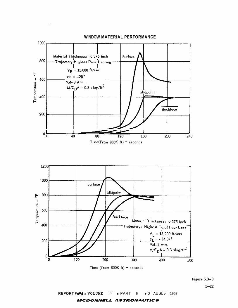
WINDOW MATERIAL PERFORMANCE
VE = 15,000 f t /sec
1 i 1 0 0 - - 40 80 1 20 160 200 240
Time(From 800K ft) - seconds
1200
Time (From 800K ft) - seconds
Figure 5.3-9
5-22
REPORT F69yl a VOLUME I V a PART E a 3’1 AUGilST 1967
MCDONNELR- ASTR’8MAUTfCS

5.4
Flight Capsule, coupled with the uncertainties of atmosphere and the time of at-
mospheric entry, create a wide range of operating conditions for the Entry Science
Package (ESP). However, regardless of the atmosphere encountered or the descent
trajectory design selected, the sequence of events for the ESP remain unchanged. The time spans of various Capsule events vary, thus changing the quantity of ESP
data obtained during a particular phase, but the sequence remains unaltered.
CAPSULE SEQUENCING - The sequencing and trajectory design alternatives of the
The Flight Capsule, by definition, starts entry at a reference altitude of
800,000 feet. (altimeter), and the uncertainty of indirect measurement (time from deorbit) is
about - 60 seconds. relay link is desired before actual data is obtained. To allow for entry time un-
certainties and equipment warm-up, ESP operations are started 300 seconds prior to
theoretical point of atmospheric entry.
360 seconds after the start of ESP operation, thus allowing a minimum warm-up
The 800,000 foot point cannot be determined by direct measurement '
+ In addition, warm-up of the instruments and both ends of the
Actual entry will occur between 240 to
period of four minutes.
To this point we have been discussing the initial start of ESP operations.
Some of the ESP's measurements must be performed from, or near, the point of en- try through landing. Descent imaging and entry deceleration fall into this cate-
gory. Other measurements, such as for stagnation temperature and atmospheric composition are performed below about Mach 5 after the temperature sensor outlet
bleed line is opened. However the power, instrument electronics, and telecommuni- cation channels for all ESP measurements are started at the same time because it
simplifies the data handling and sequencing with no significant penalties either in power, data transmission, data buffer storage o r instrument damage.
The alternatives of Capsule sequencing are constrained by the necessity to soft land the Capsule Bus and Surface Laboratory, on the surface. These con-
straints dictate a virtually inflexible Capsule sequence once the basic elements of the terminal descent are selected. .By basic elements we mean parachutes, aero-
shell separation after decelerator deployment, "fire-in-the-hole", "fire through the hole", or other terminal thrust alternative.
we have selected the combination of parachute and terminal propulsion descent.
sequence of events for this design in the extremes of atmospheric models is shown in Figure 5.4-1.
alternatives is discussed below:
For our preferred Capsule design The
The relative inflexibility of the Capsule sequence for typical
5-23
REPORT F694 OJVOLUME IV 0 PART E 0 31 AUGUST 1967
MCDONNELL ASTRONAUTICS

ENTRY AND LANDING PHASE TIME LINE
Events Notes: 1. Orbit Size - 4400 x 23,400 km 2. enn = i9i0 0 Deceleration = .05g
@ Mach 5
@ H = 23 kft (Chute Deploy)
@ H = 5 kft (Start-Terminal Descent)
@ Touchdown
@ End of F/C-S/C View, 34' Gnd. Slopes
vu
3. VE = 15,000 ft/sec
5. Deflection Angle (6) Adjusted to Meet Muhipath Considerations
6. Time from Parachute Deployment to Capsule Bus Separation from Aeroshell = 12 sec.
4. M/CDA = .3 j lugs/f t 2
0 1 2 3 4 5 6 7 8 9 10 Time From 800,000 f t - lo2 sec
5 . Figure 5.4-1
5-24
REPORT F694p VOLUME 1- 0 PART E 0 31 AUGUST 1967
MCDONNELL ASIRQNAUTRCS

Parachute - -. Deployment- - The parachute is p resen t ly deployed a t an a l t i t u d e
23,000 f e e t .
Mach number c a p a b i l i t y of t h e parachute; deployment a t lower a l t i t u d e s
would no t a l low s u f f i c i e n t t i m e f o r t h e Aeroshel l t o impact p r i o r t o t h e
ope ra t ion of t h e landing r ada r , thus o f f e r i n g t h e p o s s i b i l i t y of t h e
landing r a d a r t r ack ing t h e descending Aeroshel l .
Terminal Descent - Terminal descent i s i n i t i a t e d a t 5000 f e e t . I n i t i a t i o n
of t h e te rmina l descent mode a t a lower a l t i t u d e runs t h e r i s k of impact-
Deployment a t h igher a l t i t u d e s would s u b s t a n t i a l l y exceed t h e
ing , prematurely, on a p l a t eau , mountain o r h i l l ; h igher a l t i t u d e s r e q u i r e
more f u e l f o r te rmina l propuls ion , and a l a r g e r and heav ie r parachute.
I n summary, t h e opt imiza t ion of t h e a u x i l i a r y aerodynamic d e c e l e r a t o r and ter-
minal descent propuls ion subsystems has made t h e a l t e r n a t i v e s of Capsule sequenc-
ing f o r t h e b e n e f i t of t h e ESP, v i r t u a l l y non- existent . The quan t i t y and q u a l i t y
of d a t a obtained during a p a r t i c u l a r phase of t h e atmospheric descent w i l l vary
as a func t ion of t h e atmosphere encountered, and the e n t r y angle and v e l o c i t y used.
5.5 AEROSHELL SEPARATION - The method s e l e c t e d f o r s epa ra t ing t h e Aeroshel l and
t h e Lander i n t h e Martian atmosphere has a d i s t i n c t e f f e c t on the quan t i t y and
q u a l i t y of e n t r y sc ience d a t a acquired. Separa t ion a l t e r n a t i v e s and reasons f o r
s e l e c t i o n are described below.
5.5.1 Separat ion Al t e rna t ives - The p re fe r r ed concept f o r Aeroshel l s epa ra t ion
w a s s e l e c t e d from four high va lue candida tes which are b r i e f l y descr ibed below.
D i f f e r e n t i a l Drag: This w a s t h e s e l e c t e d concept and c o n s i s t s of an
a u x i l i a r y aerodynamic d e c e l e r a t o r (parachute) which i s deployed a t 23,000
f t .
slower moving Lander/parachute combination.
Fire-In-Hole: The te rmina l propulsion system, cons i s t i ng of m u l t i p l e
t h r o t t l e a b l e rocket engines, i s used t o d e c e l e r a t e t h e Lander i n r e t ro-
grade d i r e c t i o n by f i r i n g a t t h e a f t s i d e of t h e Aeroshel l , t hus s epa ra t-
ing t h e Aeroshel l and t h e Lander.
Fire-Through-Hole: The te rmina l propulsion rocket engines f i r e through
p o r t s i n t h e Aeroshel l thus slowing t h e Aeroshell/Lander combination.
Actual s epa ra t ion i s delayed t o a very low a l t i t u d e (50 t o 100 f t ) .
aerodynamic d e c e l e r a t o r i s used with t h i s concept.
Segmented Aeroshel l : The Aeroshel l i s s p l i t (pyro technica l ly o r mechani-
ca l1y ) in to t h r e e o r more segments which open up and are he ld open.
Lander i s r e l eased and drops out . The Aeroshell. is c a r r i e d away above
The Aeroshel l i s r e l eased 1 2 seconds la ter and f a l l s away from t h e
No
The
5-25 REPORT F694 #VOLUME IV 0 PART E 0 31 AUGUST 1967
MCDONNELL ASTRONAUTlCS

t h e l ande r by t h e aerodynamic dece l e ra to r .
Comparison --- of Separa t ion ---- A l t e r n a t i v e s - Each of t h e four s epa ra t ion al ter- 5.5.2
n a t i v e s has some disadvantages i n t e r m s of t h e quan t i t y and/or q u a l i t y of Entry
Science d a t a t o be obtained us ing t h a t p a r t i c u l a r system. Figure 5.5-1 shows a
comparison of t h e disadvantages of each.
5.5.3
r a t i o n w a s made as a r e s u l t of a major i n t e r d i s c i p l i n a r y t r a d e s tudy which is
d e t a i l e d i n Sec t ion 4.6 , P a r t B , Volume I1 of t h i s r e p o r t . While many f a c t o r s
were considered i n making t h e s e l e c t i o n , t h e e f f e c t of t h e s e l e c t i o n on Entry
Science, both d i r e c t l y and i n d i r e c t l y , w a s an important element i n t h e f i n a l
--- Se lec t ion Reasoning - Se lec t ion of t h e p re fe r r ed concept of Aeroshel l sepa-
choice. For example, t h e contamination e f f e c t s on TV l enses o f t h e Fire-In-Hole
sepa ra t ion counted heavi ly aga ins t i t .
degraded sc ience d a t a due t o exhaust gas flowback were important i n deciding aga ins t
t h e Fire-Through-Hole separa t ion .
t i o n d id no t have many disadvantages from a sc ience s t andpo in t , t h e l o s s of TCM lock
a f t e r s epa ra t ion d id count a g a i n s t i t somewhat.
p re fe r r ed concept i s the o s c i l l a t i o n s induced by parachute deployment and t h i s
problem e x i s t s i n t h r e e out of t h e four concepts.
t he lowest r a t e d f o r both Entry Science and o t h e r non-science f a c t o r s .
5.6
e rence and a t t i t u d e con t ro l mechanizations f o r t h e var ious phases of t h e VOYAGER
mission. This s e c t i o n d iscusses a l t e r n a t i v e mechanizations and t h e i r performance.
5 .6.1 De-orbit - Reduction of t h e po in t ing angle unce r t a in ty during de- orbit t h rus t-
ing is d e s i r a b l e t o reduce unce r t a in ty i n t he i n i t i a l e n t r y cond i t i ons , and t h e r e f o r e
improve the accuracy of t h e t r a j e c t o r y recons t ruc t ion .
o r b i t t h r u s t i n g i s t h e r e s u l t of t he e f f e c t s of t h r e e d i s t i n c t e r r o r sources:
(1) i n i t i a l alignment of t h e a t t i t u d e re ference before CB/FS sepa ra t ion , (2) r e f-
erence d r i f t during pre-de-orbit coas t , and ( 3 ) a t t i t u d e c o n t r o l system response t o
de- orbit d i s turbances .
t h e r e f o r e equal ly important during de- orbi t .
Complicated aerodynamic c h a r a c t e r i s t i c s and
While t h e segmented Aeroshel l method of separa-
The only known disadvantage of t h e
The Fire-Through-Hole concept was
ATTITUDE CONTROL - Sect ion 4.5 of P a r t D de sc r ibes the p re fe r r ed a t t i t u d e ref-
The t o t a l e r r o r during de-
A t t i t u d e re ference and a t t i t u d e c o n t r o l performance are
The a l t e r n a t i v e a t t i t u d e re ference systems considered are:
S tab le platform
O Strapdown gyros wi th Euler angle processing ( t h e p re fe r r ed design) O
At t i t ude re ference a l t e r n a t i v e s w e r e discussed i n Sec t ion 5.2. The s t a b l e
Strapdown gyros wi th simple rate i n t e g r a t i o n
platform is heav ie r , more expensive and less r e l i a b l e than t h e p re fe r r ed design,
5-26
REPORT F694k VOLUME I V e PART E e 31 AUGUST 1967
MCDONNELL ASTRONAUTICS

- K * =E 0 W
a
w -I 0
S 0 3 0 CY S
W
LL
T
t E
-
W -I 0 T z E W
LL
e
-0 0 .- t Q
e e
e e
-0 c 0 VI
> 0 U
0
P) 3
-0
t
t
Ci, c U c 0 3 0- a VI
.-
In U 3
-0 0
c
L
Q .
c 0 .- t
e a 0 P) VI
VI
E c U
0 .-
e e e e
Figure 5.5-1
5-27
REPORT F694 0 VOLUME IV e PART E a 31 AUGUST 1967
~~~~~~~~~ AST

and was therefore eliminated.
drift rate than the preferred design, due to "coning" effects (kinematical coupling
of angular rate about one body axis into Euler-angle rates about other axes).
ference drift therefore would exceed the design error budget in 13 minutes, as against 29 minutes for the preferred design. coast time forces execution of the deorbit orientation maneuvers, with proportion-
ate increase in attitude fuel expenditure. The simple strapdown concept is there- fore eliminated.
The simple rate-integration scheme has a higher
Re-
Such a reduction in the pre-deorbit
A single ring reaction control system (RCS), sized for maximum
deorbit-motor disturbance torque (preferred design).
Dual-ring RCS, each ring sized for the maximum deorbit disturbance, and firing on different deadbands.
Thrust vector control (TVC) gimballed nozzle, jet vanes or fluid injection, plus a single RCS ring, sized for coast and/or entry attitude control.
The dual-ring RCS need not be discussed from a performance viewpoint in this subsection; for if the jets are properly sized, the backup ring will never firs,
except in the event of a malfunction in the primary ring. A s far as deorbit is concerned, then, the single/dual ring comparison is a weight and reliability ques-
tion, and is discussed as such in Vol. IIC 15.7. Dual-ring performance with regard to atmospheric disturbances is discussed below.
The RCS versus TVC comparison made in Section 5.2 favored TVC, with pointing
angle errors of 0.21, 0.27 and 0.35 degrees for gimballed nozzle, jet vanes, and RCS respectively. Installation of TVC, however, conflicts with the preferred me-
thod of thrust termination, nozzle blowoff. Although other method of solid rocket
thrust termination are known, they are not considered sufficiently well-proven for
VOYAGER. A TVC-plus-RCS system is also obviously more complicated than RCS alone. 5.6.2
alternatives for this phase is the requirement to minimize power consumption dur- ing the six hours before entry. This calls for shutdown of the computer, resulting
in selection of the simplest strapdown mechanization.
Pre-Entsy Coast - The dominant consideration in comparing attitude reference
Attitude control during pre-entry coast is accomplished by the RCS, as modi- Selection of the attitude dead- fied by the previously mentioned considerations.
band is a compromise between reference drift and impulse expenditure.
selected 2.0 degree deadband, attitude uncertainty at entry is 15 degrees and im-
pulse expenditure is 125 lb-sec. For an 0.5 degree deadband, attitude uncertainty at entry is reduced to 5 degrees, but impulse expenditure is increased to 320 lb -
sec.
With the
5-28
REPORT F644 0 VOLUME IV 0 PART E 0 31 AUGUST 1967
MCDONNELL ASTRONAUTICS

5.6.3
e s s e n t i a l l y an ex tens ion of t h e pre- entry coas t . e
(1.61 f t / s e c ) i s sensed by t h e axial g-switch (o r t h e accelerometer backup), t h e
RCS remains i n a n , i n e r t i a l hold mode, wi th t h e 2 deg deadband.
d i s c r e t e commands a mode change t o three- axis rate damping, wi th a 3 deg/sec dead-
band.
Entry and Atmospheric F l i g h t - The e a r l y po r t ion of t h e e n t r y phase i s
U n t i l an a c c e l e r a t i o n of 0.05g 2
The g- threshold
I n e r t i a l Hold -- - R e g i m e - The angular r e f e rence d i r e c t i o n f o r t h e i n e r t i a l hold
phase i s set s h o r t l y a f t e r d e o r b i t . It i s assumed t h a t t h i s i n e r t i a l o r i e n t a t i o n
w i l l be s e l e c t e d t o minimize t h e angle of a t t a c k at t h e i n i t i a t i o n of t h e e n t r y
rate damping. Because of t h e wide spread i n atmospherdc condi t ions , an angle must
be s e l e c t e d t h a t r ep re sen t s t h e average f l i g h t pa th o r i e n t a t i o n between t h e .05g
po in t i n t h e high d e n s i t y atmosphere extreme and t h e corresponding po in t i n t h e low
dens i ty extreme.
e n t r y f l i g h t pa th . I l l u s t r a t i v e c a l c u l a t i o n s have been made f o r two extreme atmos-
pheres , VM-8 and VM-9, and two extremes of e n t r y t r a j e c t o r y ( Y e = -20'). The
t a b l e below lists t h e angle of a t t a c k 01 and view angle ( AB) occuring a t 800K f t
a l t i t u d e and t h e .05g p o i n t s of t h e two atmospheres assuming t h e i n e r t i a l or ien-
t a t i o n of t h e Capsule i s he ld t o t h e average f l i g h t pa th and no re ference uncer-
t a i n t y . The view angle is def ined as t h e angle between t h e camera ( r o l l ) a x i s and
t h e l i n e of s i g h t t o t h e Martian horizon. The s i g n convention f o r both 01 and
i s p o s i t i v e upward, e .g . , a p o s i t i v e A B l eads t o more "sky" i n t h e p i c t u r e s .
The average angle w i l l of course depend on t h e s e l e c t e d i n i t i a l
A B
800 KFT .05g .05g
VE = 15,000 f t / s e c O1 (Deg.1
y E = -20 deg AB (Deg.)
VM-8 1.5 - VM-9
-1.7 -- ALT
-4.3
-3.2 -2.9 -4.6
V = 13,000 f t / s e c a (Deg.1 -13 -5.4 5.4
= -10.9 deg AB (Den.) -2.8 1.9 12.0 Y E
E
Hence, f o r t h e above condi t ions , t h e camera sees more of t h e Martian su r f ace , than
sky a t a l l t i m e s except at t h e .05g poin t f o r e i t h e r graze t r a j e c t o r y . Angle of +
a t t a c k a t e n t r y i n t o t h e s e n s i b l e atmosphere ( . 05g ) is wi th in -6 degrees f o r t h e
cases shown. The 3 0
assumed t o be 2 10.6 deg e r r o r i n p i t c h and yaw.
camera view angles t h a t g ive less "sky" than those previous ly shown, then t h e
average i n e r t i a l o r i e n t a t i o n can be b iased down 10.6 deg.
RSS re fe rence unce r t a in ty is est imated as 15degrees, which can b e
I f i t is des i r ed t o maintain
However, t h e a c t u a l
5-29
REPORT F6980 VOLUME IV 0 PART E 0 31 AUGUST 1967
MCDONNELL ASTlWQNAU71CS

p i t c h e r r o r may a l s o be downward, i nc reas ing t h e "sky" seen by t h e camera.
This would r e s u l t i n t h e fol lowing view angles and i n i t i a l ang le of a t t a c k d isp lace-
ments : 800 KFT .05g .05g VM-8 - ALT . VM-9
VE = 15 ,000 f t / s e c (Deg.) -25.2 -22.9 -19.7
Y E = 20 AB (Deg.) -24.4 -24.1 -25.8
VE = 13,000 f t / s e c Q (Dea.1 -34.2 -26.6 -15.8
Y E = 10.9" AB (Deg.) -24. -19.3 -9.2
For t h i s assumed worst case condi t ion , t h e wide angle camera ( 5 0 de? f i e l d af
view) would b a r e l y see t h e horizon f o r t h e Y = -20" e n t r y condi t ions and t h e
angles of a t t a c k are a l l r e l a t i v e l y l a r g e which r e s u l t s i n a d d i t i o n a l f u e l con-
sumption. The above examples,however, i l l u s t r a t e one approach. Other a l t e r n a-
t i v e s have a l s o been considered which would reduce t h e boundary extremes.
are :
E
These
" Avoid graze e n t r i e s .
Steep t r a j e c t o r i e s not only have smaller angular increments, bu t a l s o a
smaller i n i t i a l angle of a t t a c k ( smal le r d i f f e r e n c e between depression
angle and f l i g h t pa th angle a t 800 K f t ) .
vored on t h e b a s i s of o t h e r mission cons idera t ions - reduced mul t ipa th
problems on t h e CB/FS te lemet ry l i n k , reduced thermal loads , and smaller
l and ing- s i t e d i spe r s ions .
Decrease t h e a t t i t u d e deadband i n t h e coas t phase.
A s mentioned above, an 0.5" deadband reduces t h e "coning" re fe rence
d r i f t t o 5" rss, o r 3.5" i n p i t c h . This reduces t h e downward b i a s which
must be added t o compensate f o r r e f e rence unce r t a in ty , and a l s o reduces
t h e consequences of having an a c t u a l e r r o r oppos i te t o t h e assumed e r r o r .
The f u e l pena l ty of 200 lb- sec i n t h e coas t phase may be more than o f f s e t
by reduced f u e l c.onsumption during en t ry .
Steep t r a j e c t o r i e s are a l s o fa-
O
" Decrease t h e mode-switching g- leve l , t o .03 o r even .01 g. However, t h i s
proves t o be a s m a l l r educt ion , i .e . , t h e view angle spread between .01 g
and - 0 5 g is a maximum of 1.5 deg.
5.6.4 Rate-Damping Regime - According t o t h e most r ecen t wind tunnel d a t a ava i l-
a b l e , t h e s e l e c t e d VOYAGER conf igura t ion has s t a b l e p i t c h damping d e r i v a t i v e s a t
a l l l.fach numbers below 12.5. I n considering a t t i t u d e c o n t r o l a l t e r n a t i v e s f o r
t h e e n t r y phase, t he re fo re , t h e primary dec i s ion i s whether RCS damping is
5-30
REPORT F69d;e VOLUME IIJ e PART E 0 31 AUGUST 1967

necessary a t a l l . I f RCS damping is s e l e c t e d , subs id i a ry choices involve
Jet o r i e n t a t i o n
" Je t s i z i n g
" Sing le o r dua l r i n g
" Rate deadband v a l u e ( s ) .
Figure 5.6-1 compares a t t i t u d e envelopes wi th and without a c t i v e damping, f o r
VM-8 and VM-10 atmospheres, i n a spectrum of wind condi t ions . For a l l runs shown
= -20") w a s used. The i n i t i a l 'e i n t h i s t a b l e , a s t e e p e n t r y (V = 15 Kf t / sec , E angle of a t t a c k displacement i s 5" i n a l l cases. With t h e s e e n t r y cond i t i ons , i n a
VM-8 model atmosphere, Mach number remains above 12.5 u n t i l an a l t i t u d e of 52 K f t ,
which i s below both the wind onse t a l t i t u d e (90 Kft) and t h e a l t i t u d e a t which
m a x i m u m dynamic p re s su re occurs (60 Kft). This expla ins t h e l a r g e rate- envelope
va lues shown f o r VM-8 runs a t 100 Kft and 50 Kf t , without RCS damping. A t t i t u d e
and rate envelopes converge r ap id ly t h e r e a f t e r . I n c o n t r a s t , t h e VM-10 model with
t h e above e n t r y condi t ions h i t s m a x i m u m dynamic p re s su re a t 108 K f t , drops below
Mach number 12.5 a t 100 Kf t , and is t h e r e f o r e s t a b l e throughout t h e wind regime,
from 90 Kft on down. Corresponding no- jet rate envelopes f o r VM-10 a t high
a l t i t u d e s are t h e r e f o r e smaller than f o r t h e VM-8 model. I n no case , however, are
t h e rate envelopes a t 100 Kft acceptab le f o r TV imaging (4"/sec o r l e s s ) .
immediate conclusion i s t h a t RCS damping i s required.
The
With t h e need f o r RCS damping demonstrated, t h e subs id i a ry ques t ions may be
taken up.
Or i en ta t ion - The p r e f e r r e d RCS conf igura t ion p l aces t h e pitch/yaw je t s i n
an a f t - f i r i n g o r i e n t a t i o n ( s l i g h t l y canted) , s i n c e forward f i r i n g would r e q u i r e
p o r t s i n t h e Aeroshel l , and outward f i r i n g would sharp ly reduce t h e c o n t r o l torque.
S i z i n g - The p re fe r r ed j e t s i z e is 22 pounds, which n e e t s t h e d e o r b i t torque
requirement wi th a 50% reserve. This torque level i s q u i t e generous f o r c o n t r o l
of mean and shear wind p r o f i l e s . I n a VM-10 shea r- pro f i l e crosswind, f o r example,
decreasing t h e j e t s i z e t o 10 pounds only increases t h e maximum ang le of a t t a c k
envelope from 1.8" t o 2.2".
For c o n t r o l of t r a n s i e n t wind d is turbances ( s t e p s and g u s t s ) , however, l a r g e
j e t s are d e s i r a b l e , t o sho r t en t h e per iod of v i o l e n t o s c i l l a t i o n (during whi-ch
much of t h e ESP d a t a is degraded). Sample d a t a i l l u s t r a t i n g t h e dependence of
5-31
REPORT F694 h VOLUME Iv 0 PART E 0 31 AUGUST 1967
MCDONNELL ASTRONAUTICS

> M I- z W Y
Figure 5.6-1
5-32 REPORT F694p VOLUME IV 0 PART E 0 31 AUGUST 1967
MCDONNELL ASPIRONAUPIICS

gus t response upon j e t s i z e
Thrust Max. Angle
10.0 l b . 28.1 deg.
16.5 27.2
30.0 25.1
45.0 22.9
60.0 20.7
are g iven i n t h e t a b l e
Max. R a t e
66.7 deglsec
63.4
56.1
48.0
39.7
below:
S e t t l i n g T i m e
50.0 sec.
17.6
8.4
5.0
3.8
Addi t iona l wind t r a n s i e n t r e s u l t s are shown i n Figure 5.6-2, which covers a
range of a l t i t u d e s , atmospheres, wind forms and azimuth angles , f o r a f ixed j e t
s i z e . For a few runs i n t h i s t a b l e , a p o s i t i v e (uns tab le) damping d e r i v a t i v e va-
l u e w a s used; f o r a l l o t h e r s , t h e damping d e r i v a t i v e w a s assumed zero ( n e u t r a l
dynamic s t a b i l i t y ) .
noted by a maximum angle of "90+".
Capsule tumbling, which i s regarded as c a t a s t r o p h i c , i s de-
Dual Ring - Although h igh t h r u s t l e v e l s are des i r ed f o r c o n t r o l of severe
t r a n s i e n t s , i nc reas ing j e t s i z e i nc reases f u e l consumption i n less severe wind
condi t ions (e .g. , i nc reas ing j e t t h r u s t from 10 t o 16.5 pounds on a VM-10 shea r ,
crosswind run r a i s e d impulse expenditure from 319 t o 342 lb- sec) .
RCS, t h e r e f o r e , seems a t t r a c t i v e . The f i r s t r i n g would f i r e on t h e normal dead-
band, t h e second would f i r e on a h igher deadband, and thus respond only t o se-
vere d is turbances .
s i e n t response and f u e l economy. However, system weight i s an over- riding con-
s i d e r a t i o n and t h e r e f o r e t h e s ingle- r ing RCS (which is 46 pounds l i g h t e r than t h e
dua l r i ng ) w a s s e l e c t e d as t h e p re fe r r ed design.
A dual- ring
Such a conf igura t ion should g ive t h e b e s t combination of t r an-
Varying Deadband (s) - Decreasing t h e RCS rate deadband (two deadbands f o r
dual- ring RCS) n a t u r a l l y tends t o decrease t h e o s c i l l a t i o n envelope
inc rease t h e impulse expenditure a d i sp ropor t iona te s o u n t .
VM-10 shear crosswind runs are:
but may
Sample d a t a f o r t h e
Deadband Max. Envelope Impulse Expended
4 deglsec 2.4 degrees 305 lb- sec
3 2.2 319
1 1.2 1453
Using a 4 deglsec deadband, however, is crowding t h e TV smear boundary, which
i s est imated as 4 deg/sec f o r t h e narrow f i e l d camera. The design va lue of 3
deglsec deadband keeps rates w e l l below 4 deglsec under a l l condi t ions except
t r a n s i e n t winds, and inc reases f u e l consumption very l i t t l e over 4 deglsec
band.
dead-
5- 33
REPORT F694,o VOLUME I V m PART E 0 31 AUGUST 1967 MCDONNELL ASTRONAUTRCS

- ATMO-
SPHERE VM-
8
-
10
RESPONSE TO LOW-ALTITUDE WIND TRANSIENTS: SHARP-EDGED STEPS AND SHARP-EDGED RESONANT GUSTS
(ENTRY CONDITIONS: V = 15kft/sec, y = -20° AT 800 kft; 16.5-lb RCS)
- hW
kft
30 30
20 20 20 20 20 20 20 30 30 30 20 20 20 20 20
-
-
WIND CONDITIONS
VW ft/sec
200 200
200 200 200 2 00 200 200 200 100 100 100 100 100 100 100 100
- TYPE
G G
S S G G G G G G G G S G G G G
AZIMUTH
Head Cross Head Cross Head Head Cross Cross Cross Head Head Cross Head Head Head Head Head
-
AERO. DAMP I NG
0 0 0 0 0 0.5 0 0.3 0.5 0 0.3 0 0 0 0.1 0.2 0.3
omax
deg - 2.64 9.47 3.25 8.98 6.14 6.40
16.84 29.89 90 t 23.29 24.2 1 24.69 14.51 26.84 27.15 27.61 90 t
SYSTEM RESPONSE
'ma, deg/sec
18.3 66.4 13.0 38.0 25.4 27.9 73.8 83.7
54.2 58.7 56.8 34.7 61.8 63.4 65.3
-
-
TC sec
3.5 13.4 2.4 7.3 5.4 8.8
14.5
-
- -
11.5 36.0 12.3 7.0
13.3 17.4 27.8 -
' c Ib-sec -
52.5 215.7 37.2
117.3 85.0
140.0 234.3 - -
197.9 586.8 211.2 112.2 2 19.3 289.9 452.3 -
Notation - h, = Wind Altitude V,= Wind Velocity S = Sharp-Edged Step G = Sharp-Edged Resonant Gust AerqDamping = C or Cnrl as appropriate (positive values are unstable) mq
e 8 T, = Time to Control io 3 deg/sec
= a or 6, as Appropriate = q or rr as Appropriate
- 1, = Impulse to Control to 3 deg/sec
Figure 5.6-2
5-34
REPORT F694,o VOLUME IV 0 PART E 0 31 AUGUST 1967
MCQONNELL ASTRONAUTICS

Addi t iona l d i scuss ion of entry-phase a t t i t u d e dynamics may be found i n
Volume 11, P a r t B, Sec t ion 2.3.4.
5.6.5
f o r RCS shutdown a t parachute deployment, and sepa ra t ion of t h e RCS wi th t h e Aero-
s h e l l 12 seconds later.
t h e Aeroshel l , t e rmina t ing t h a t experiment.
Parachute Deployment - The p re fe r r ed design and ope ra t iona l sequence calls
The s tagnat ion- pressure sensor w i l l a l s o s e p a r a t e wi th
Continuat ion of RCS damping during parachute descent has been considered but
does no t appear f e a s i b l e f o r two reasons:
The a f t - f i r i n g yaw/pitch t h r u s t e r s provide very l i t t l e c o n t r o l torque
about t he primary c e n t e r of r o t a t i o n , l oca t ed high i n t h e parachute canopy.
The e n t i r e system parachute r i gg ing and Capsule Lander - behaves as a
compound pendulum. The o s c i l l a t o r y motion is t h e r e f o r e q u i t e complex
and i t is d i f f i c u l t t o s ay whether a simple rate-damping c o n t r o l l a w
would i n f a c t be s t a b i l i z i n g .
The parachute and r igg ing provide some damping of t h e primary mode (gross
o s c i l l a t i o n of t h e canopy), bu t l i t t l e damping of t h e secondary mode ( o s c i l l a t i o n
of t h e Capsule Lander about suspension po in t ) .
r a t i o n i s very t a l l (over 125 f e e t ) and is thus q u i t e s e n s i t i v e t o broadside
gus t s . For t hese reasons, t h e parachute descent phase is l i k e l y t o be a per iod
of l a r g e o s c i l l a t i o n s and high angular rates, which w i l l degrade most ESP da ta .
Radar altimeter readings w i l l become t h e dominant da t a source f o r t h e t r a j e c t o r y
r econs t ruc t ion , due t o t h e h igh n o i s e level i n t he a c c e l e r a t i o n da ta .
I n add i t i on , t h e e n t i r e configu-
Parachute dynamics are descr ibed i n d e t a i l i n Volume I1 B 5.10.
5.6.6
5000 f e e t a l t i t u d e , wi th i g n i t i o n of t h e fou r 1620-pound b ip rope l l an t te rmina l
descent engines. Parachute s e p a r a t i o n occurs s h o r t l y t h e r e a f t e r . These engines
are t h r o t t e a b l e over a 1 O : l range, which provides both v e l o c i t y and a t t i t u d e con-
t r o l during t h e per iod from parachute s epa ra t ion t o f i n a l c u t o f f , a t an a l t i t u d e
of 10 f e e t and a f i n a l v e l o c i t y less than 10 f t / s e c .
t h r o t t l i n g c o n t r o l l a w and t h e r e s u l t a n t system response are given i n Volume 11,
P a r t B, Sec t ion 2.3.6.
Terminal Descent - The p re fe r r ed te rmina l descent sequence begins a t about
Deta i led desc r ip t ions of t h e
An a l t e r n a t i v e a l l- propuls ive mechanization, which e l imina te s t h e parachute,
has a l s o been considered. For t h i s scheme, t h e engine t h r u s t would be increased
t o 2000 pounds, i g n i t i o n a l t i t u d e increased t o 15,000 f e e t , and the engines would
f i r e through p o r t s i n t h e Aeroshell .
5-35
REPORT F694,o VOLUME Iv 0 PART E e 31 AUGUST 1967
MCDONNELL ASTRONAUTICS

This would eliminate the high oscillations and uncertain dynamics of the
parachute phase, and would be advantageous for imaging and acceleration data. degree of degradation of TV image quality by rocket plumes would depend upon the
relative location of the TV window and the rocket ports. tional image degradation will be caused by engine-induced vibrations of the struc-
ture. With the Aeroshell in place, there will be very little intrusion of exhaust
gases into the base-region atmospheric measurement aparatus, but the stagnation-
pressure measurements will be somewhat degraded by engine plumes.
The
A small amount of addi-
The choice between all-propulsive and aerodynamic decelerator-plus-propulsion, as well as the selection of the four-engine configuration from various other pos-
sibilities, is based upon tradeoff studies too complex to describe here (See Volume 11, Part B, Section 4.5 for details).
5.7
surement for Entry Science data correlation. This altimeter has been described
previously in Volume 11, Part B,Section 5.9 "Analysis" and Volume 11,Part C, Sec- tion 10.1 "Functional Description" as part of the Capsule Bus equipment.
mary of the factors influencing altimeter selection are discussed below.
5.7.1
ferred Capsule Bus design for minimum complexity and maximum reliability subjected
the altimeter design to the major constraints listed in Figure 5.7-1. Design al- ternatives which conform to these constraints are also listed.
5.7.2 Performance Alternatives - Maximum and minimum altitudes of operation will be set by the importance of the data at these altitudes and the increase in size,
weight and power which can be tolerated. Altimeter accuracy must also be set by the subsystems dependent on the altimeter data and must consider weight and power
increases for altimeter accuracy increases. as 10 feet and up to l o 6 feet over the expected Martian surface could be ob-
+ tained. Accuracies of better than 1%, - 5 feet are possible. 5.7.3 Selection of Preferred Design - Altimeter selection was influenced by the overall landing and mission constraints plus the altitude and accuracy required for Entry Science data correlation.
5.7.3.1 Constraint Design Alternatives - Switched fan beam antennas, steered narrow beams and single element antennas were candidates for providing the
required coverage. because of weight, complexity or development risk aspects.
tenna providing an approximation to the desired coverage is the lightest and most
RADAR ALTIMETER - A radar altimeter is required to provide an altitude mea-
A sum-
Constraints and Associated Design Alternatives - Development of the pre-
Altitudes of operation from as low
Antenna switching and electronic beam steering were eliminated
A single element an-
5-36 REPORT F694,e VOLUME IV e PART E e 31 AUGUST 1967
MCDONNPLL. ASTRBNAUTHCS

ALTIMETER DESIGN CONSTRAINTS'
not have preferred ro l l
2. Perform required function
b) Electronic beam steering
a) Delectr ic insulation around components subjected
b) Use low power, low voltage techniques c) Complete system pressurization
a) Provide RF window, primary and secondary antennas b) Use section of Aeroshell and secondary antenna c) Use two separate altimeters
a) Blank near returns while searching for surface b) Use loop tracking logic to unlock from opening targets c) Prevent altimeter operation unt i l Aeroshell i s
at pressures causing electrical breakdown
to high voltage gradients
3. Operate before and after Aeroshell release
4. D i scrim i nate between Aeroshell and ground
sufficient distance away.
Figure 5.7-1
5-37
REPORT F69$e VOLUME IV a PART E e 31 AUGUST 1967
MCDONNELL ASTRONAUT#CS

reliable. However, the low gain of this antenna increases the possibility of
electrical breakdown. Elimination of breakdown can be most reliably obtained by
covering the sections where high voltage gradients exist with a dielectric, such
as teflon or silicon based materials, to exclude atmosphere.
The alternatives for operation before and after aeroshell release are (1) use of separate altimeters and antennas or (2) one altimeter and two antennas. The
single altimeter-two antenna concept was selected from weight and antenna placement considerations. Use of the Aeroshell as an asymetrical dipole to provide the de-
. sired coverage was eliminated based on the mechanical design of the Aeroshell,
antenna fabrication, installation and checkout difficulties. A conical monopole
antenna operating through an RF window in the Aeroshell nose cap provided the best coverage and most compatible installation.
Operation after Aeroshell release requires the altimeter to discriminate
against the Aeroshell as a target. Methods of discrimination, such as built-in
tracking loop logic which rejects opening targets such as the Aeroshell, require
an excessively complex mechanization. shell is a sufficient distance away would compromise the remainder of the mission.
Near return blanking, such as that performed by pulsed radar systems, is the
simplest and most reliable and has been selected as the preferred design.
5.7.3.2 Performance Required - Maximum altitude of operation was selected to be 200,000 ft., since studies show that Entry Science data correlation and iterative
extrapolation back to 800,000 ft. could still be made accurately. Operation at
higher altitudes required penetration of possible blackout plasmas, o r operation
at 500,000 to 600,000 ft., before blackout occurred. Operation down to 50 feet
is desired to provide a functional backup to the Landing Radar range beam.
tion at altitudes lower than 50 ft. requires increased complexity with attendant un- reliability and two separate antennas. An accuracy of 1% 2 400 feet for Entry
Science atmospheric data correlation was selected as an optimum compromise based
on a computer study which determined degradations in Entry Science data accuracy
as a function of altimeter accuracy and altitude. 5.7.3.3 Frequency and Modulation Selection - An operating frequency selection im- posed certain considerations on the modulation techniques available. From a maxi- mum returned power criteria, when using omnidirectional antenna coverage, a fre-
Delaying operation until after the Aero-
Opera-
quency from 10 to 500 MHz appeared best.
however, constrained the frequency to be 1 GHz o r higher.
pulse, frequency modulated/continuous wave (FM/CW), FM/CW Bessel Sideband,
Selection of the conical monopole, Simple non-coherent
5-38
REPORT F694jo VOLUME IV 0 PART E 0 31 AUGUST 1967
MCDONNELL ASTRONAUTICS

Interrupted Continuous Wave (ICW) and Pseudo Random Code were the modulation techni- ques considered.
que was based on obtaining the best performance for the least complexity (see defi-
niton of ratings given in Section 5.9, Part B, Volume 11).
5.7.4
and space proven equipment. a usable system.
protection must be performed during Phase C development.
5.8 period of time is available after touchdown during which the orbiting Spacecraft
is in view of the landed Capsule. The entry and landing phase operations time
line diagram contained in Section 5.5 (Figure 5.5-1) indicates that the CBS low
rate UHF communications link with the SC will be available for a minimum of 100 seconds t o a maximum of 600 seconds after touchdown for the baseline orbit size and de-orbit anomaly, and worst entry velocity conditions.
cations link with the SC is designed to maintain an adequate signal margin at
least to touchdown for the worst case combination of entry and atmosphere condi-
tions. Since the low rate data from the ESP is interleaved on the CBS UHF link, surface atmosphere properties can be obtained from the ESP base region pressure and temperature sensors quite easily and involves simply not turning these instru-
ments o f f .
ments.
without any dynamic pressure, pumping is required for fresh samples. small pumping capacity of the mass spectrometer, a small time constant associated
with obtaining fresh samples requires an alternate small diameter, short tube.
Thus, in the interest of obtaining fresh atmosphere samples after touchdown, the
mass spectrometer molecular leak inltet will be switched to a small capillary
s amp ling tube .
Selection of the 5 microsecond single non-coherent pulse techni-
Problems and Options - The present altimeter selection uses simple techniques No state-of-the-art advances will be required to obtain
Design development to insure sufficient electrical breakdown
POST TOUCHDOWN OPERATION - Mission profile study results indicate that a
The ESP VHF communi-
Composition data can also be obtained from mass spectrometer measure- The sample is obtained in a different manner than during descent since,
Due to the
5-39
REPORT F694 o~VOLUME IV 0 PART E 0 31 AUGUST 1967
MCDONNELL ASTRONAUTICS

-I w WJ In
w n m z
z a 3 2 Y m UWJ
u. 0 E Lu N
U I
3- \
L L
m m
m
-
3
m
111
Figure 5.7-2
5-40
REPORT F694,o VOLUME IV e PART E e 31 AUGUST 1967
MCDONNELL ASTRONAUTlCS

FUTURE MISSION OPTIONS
The d e s i r a b i l i t y of car ry ing out e n t r y sc i ence measurements and observa t ions
on t h e later missions s t e m s p r imar i ly from:
a.
b. The new ques t ions r a i s e d by previous r e s u l t s ,
c.
The new p l a c e and t i m e of each success ive landing ,
The oppor tuni ty f o r improved performance based on a proven range of
u n c e r t a i n t i e s , b e t t e r i d e n t i f i c a t i o n of i n t e r f e r i n g d i f f i c u l t i e s , and
engineering monitoring d a t a on equipment performance,
d. The ex ten t t o which t h e ESP measurements can supplement t h e Orb i t e r and
Surface Laboratory r e s u l t s of each mission,
e. The number of important measurements and observa t ions not included i n
t h e f i r s t ESP because of weight and p r i o r i t y cons idera t ions .
The e n t r y TV observa t ions of t he new landing sites w i l l be u s e f u l i n def in ing
t h e area around t h e l ande r ; t h e atmospheric p r o f i l e can be determined f o r a d i f f e r -
e n t t i m e of day, season, and l o c a t i o n ; and a d d i t i o n a l instruments and measurements
can be added based on t h e e a r l y mission r e s u l t s .
The r e s u l t s of t h e 1973 e n t r y composition measurements w i l l no doubt have
s i g n i f i c a n t e f f e c t on t h e des i r ed f u t u r e mission sampling technique and a l s o on t h e
instruments mass ranges and accurac ies des i red . Also, s i n c e t h e dens i ty p r o f i l e
is expected t o undergo l a r g e d i u r n a l v a r i a t i o n s , t h e measurement of t h e dens i ty
p r o f i l e a t a d i f f e r e n t t i m e during t h e day f o r t h e later missions w i l l provide fur-
t h e r information leading t o a p r e c i s e d e f i n i t i o n of t h e atmosphere.
The prime ob jec t ives f o r descent TV on f u t u r e missions w i l l s t i l l be landing
s i t e i d e n t i f i c a t i o n and d e t a i l p i c t u r e s of t h e s u r f a c e area around t h i s site.
However, t h e methods employed t o procure t h e s e p i c t u r e s w i l l d i f f e r somewhat s i n c e
w e w i l l have a b e t t e r i d e a on the p r o p e r t i e s of t h e atmosphere. W e w i l l know when
t h e communications blackout and peak hea t ing occur and t h i s w i l l p r e c i s e l y d e f i n e
when the p i c t u r e s can be taken. Planning can the re fo re , be d i r e c t e d a t i n su r ing
optimum coverage and r e s o l u t i o n s using t h e b e s t descent p r o f i l e , a high bandwidth
d a t a recorder employed, and h igh dens i ty sampling conducted a t a l t i t u d e s where i t
w i l l g ive t h e most d e s i r a b l e p i c t u r e s . Reduced s u r f a c e condi t ion u n c e r t a i n t i e s
and/or a s m a l l weight increment can permit imaging t o examine s m a l l d e t a i l down t o
*
1
REPORT F69f e VOLUME I V b PART F e 31 AUGUST 1967
MCDONNELL ASrRONAUNCS

w i t h i n a few f e e t of t h e su r f ace , without having t o worry about t h e camera system
i n t e r f e r i n g wi th capsule landing mechanisms. For f u t u r e missions wi th a mobile
l abo ra to ry , t h e descent images can back up those obta ined from t h e l abo ra to ry f o r
purposes of de r iv ing i n i t i a l displacement v e c t o r commands. For f u t u r e miss ions
wi th a s t a t i o n a r y l abo ra to ry , t h e descent images promise t o i nc rease t h e i n t e r-
p r e t a b i l i t y of t hose obtained from t h e sur face .
s u r f a c e r e f l e c t i v i t y can be optimized, p a r t i c u l a r l y wi th regard t o a b e t t e r s p e c t r a l
evaluat ion.
atmospheric a t t enua t ion .
The photometric measurements of
The same statement can be made concerning s p e c t r a l i n v e s t i g a t i o n s of
These jobs can be accomplished wi th s m a l l v a r i a t i o n s on t h e s e l e c t e d approach.
A l t e rna t e ly , it may be f e a s i b l e t o reduce t h e instrument package t o only a s i n g l e
v id icon . O r a two v id icon system could be employed wi th one camera ga ther ing descent
information whi le t h e second i s reserved f o r a r ap id post- landing, panoramic scan of
t he surroundings.
panoramic scan j u s t p r i o r t o touchdown.
with images taken i n a very s h o r t per iod and immediately t ransmi t ted t o t h e Orb i t e r .
S t i l l another choice would b e t o perform t h i s h igh d a t a rate
A wide angle o p t i c a l system would be used
Of t h e p r io r i t y- add i t i on experiments discussed i n P a r t s A, D, and E , those
which could most e a s i l y be worked i n t o t h e s e l e c t e d des ign a t minimum weight and
maximum confidence i n obta in ing useful r e s u l t s include: a ) t h e W and X-ray
absorp t ion experiment, and b) t h e d i f f e r e n t i a l nose p re s su re measurement. Confi-
dence i n g e t t i n g u s e f u l r e s u l t s wi th t h e m a s s spectrometer arranged t o y i e l d d a t a
from t h e beginning of continuum flow t o pos t touchdown i s r e a l i s t i c a l l y somewhat less,
but s t i l l high.
considerably s i m p l i f i e s t h e problem, and i n s t a l l a t i o n is straight- forward.
S imi la r ly , t h e i n s t a l l a t i o n of y backsca t t e r ins t rumenta t ion (5 l b s ) is s t ra ight forward .
For t h e h ighly d e s i r a b l e pos t touchdown imaging, spacec ra f t ESP r ece iv ing antenna
pos i t i on ing and t h e weight of an 8 pocnd f acs imi l e camera, p l u s i n s t a l l a t i o n ,
r ep re sen t somewhat more of a problem. However, t h i s c a p a b i l i t y u t i l i z i n g t h e ESP .
UHF Spacecraf t- relay communications l i n k is a h ighly d e s i r a b l e backup t o Surface
Laboratory imaging.
However, t h e ceramic nose cap of t h e s e l e c t e d des ign concept
Addi t iona l experiments o r ESP accommodations f o r f u t u r e ESP missions are
i l l u s t r a t e d by, a) composition measurements i n t h e molecular flow regime, b) radio-
meters f o r u s e during parachute descent , c) c a p a b i l i t y f o r recording and r e t r a n s-
m i t t i n g images obtained during blackout , wi th maintenance of s u i t a b l e imaging
i n t e r v a l , and d ) c a p a b i l i t y t o handle accelerometer d a t a during touchdown, f o r
2
REPORT F694 0 VOLUME IV e PART J? e 31 AUGUST 1967 i
MCDONNELL ASTRONAUTICS

supplemental soil mechanics information.
The selected ESP design concept is amendable to either deletion or modification
and retention for future missions (or retention without modification). Retention
of the TV and telecommunications system as basic items, with affordable flexibility
for modification and addition of other measurements, is desirable.
3
REPORT F694 0 VOLUME IV 0 PART F o 31 AUGUST 1967
MCDONNELL ASTRONAUTICS a