Altera PLC+HMI Development Kit User Manual
40
Altera PLC+HMI Development Kit User Manual UM0012 (v1.4) – 4 Apr 2016 User Manual: The reproduction, transmission or use of this document or its contents is not permitted without express written authority. Offenders will be liable for damages. All rights, including rights created by patent grant or registration of a utility model or design, are reserved. Technical data subject to change. All trademarks and trade names appearing in this document are property of their respective owners. Copyright © 2015 Exor International SpA-Verona-Italy, All Rights Reserved. Disclaimer Exor International SpA is providing this design, code, or information "as is." basis, without warranty of any kind, either expressed or implied, including, without limitation, warranties that the covered code is free of defects, merchantable, fit for a particular purpose or non-infringing. Each party bears the entire risk as to the quality and performance of the original code, upgraded code, and modifications, to the extent originating with and provided by such party. Should any covered code prove defective in any respect, you assume the cost of any resulting damages, necessary servicing, repair or correction. This disclaimer of warranty constitutes an essential part of this license. No use of any covered code is authorized hereunder except subject to this disclaimer. UM0012 (v1.4) – 4 Apr 2016 User Manual www.exorembedded.net Overview This document will guide user through the installation and usage of Linux Yocto BSP for Altera uSOM and JMobile portable runtime.
Transcript of Altera PLC+HMI Development Kit User Manual
Altera PLC+HMI Development Kit User Manual
UM0012 (v1.4) – 4 Apr 2016 User Manual:
The reproduction, transmission or use of this document or its contents is not permitted without express written authority. Of fenders will be liable for damages.
All rights, including rights created by patent grant or registration of a utility model or design, are reserved. Technical data subject to change. All trademarks and trade names appearing in this document are property of their respective owners. Copyright © 2015 Exor International SpA-Verona-Italy, All Rights Reserved. Disclaimer Exor International SpA is providing this design, code, or information "as is." basis, without warranty of any kind, either expressed or implied,
including, without limitation, warranties that the covered code is free of defects, merchantable, fit for a particular purpose or non-infringing. Each party bears the entire risk as to the quality and performance of the original code, upgraded code, and modifications, to the extent originating with and provided by such party.
Should any covered code prove defective in any respect, you assume the cost of any resulting damages, necessary servicing, repair or correction. This disclaimer of warranty constitutes an essential part of this license. No use of any covered code is authorized hereunder except subject to this disclaimer.
UM0012 (v1.4) – 4 Apr 2016
User Manual
www.exorembedded.net
Overview
This document will guide user through the installation and usage of Linux Yocto BSP for Altera uSOM and JMobile portable runtime.
Altera PLC+HMI Development Kit User Manual
UM0012 (v1.4) – 4 Apr 2016 www.exorembedded.net 2/40
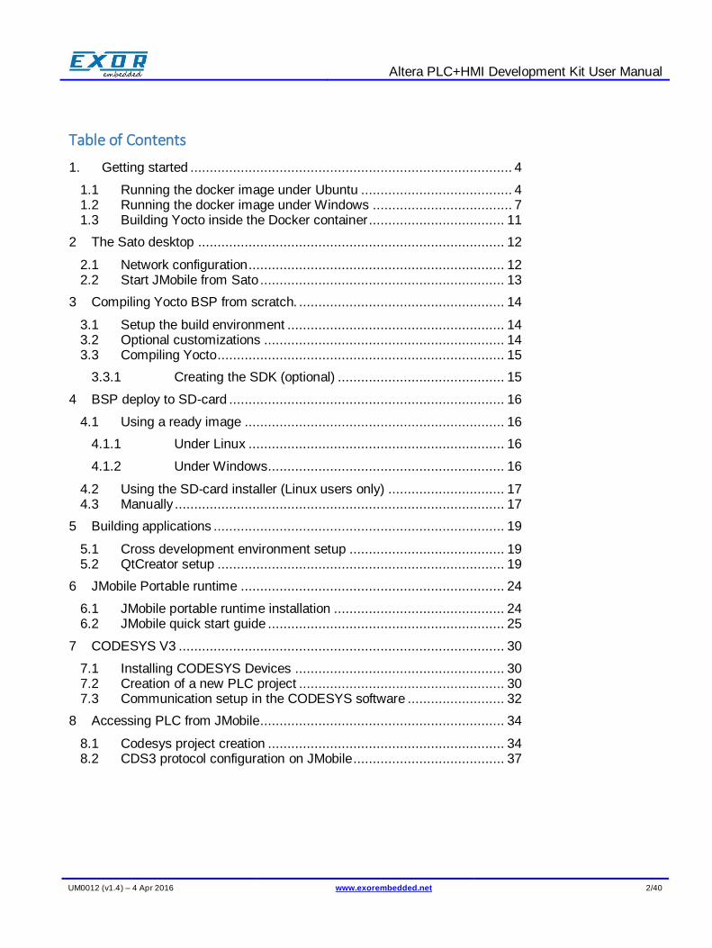
Table of Contents
1. Getting started ................................................................................... 4
1.1 Running the docker image under Ubuntu ....................................... 4 1.2 Running the docker image under Windows .................................... 7 1.3 Building Yocto inside the Docker container ................................... 11
2 The Sato desktop ............................................................................... 12
2.1 Network configuration .................................................................. 12 2.2 Start JMobile from Sato ............................................................... 13
3 Compiling Yocto BSP from scratch. ..................................................... 14
3.1 Setup the build environment ........................................................ 14 3.2 Optional customizations .............................................................. 14 3.3 Compiling Yocto .......................................................................... 15
3.3.1 Creating the SDK (optional) ........................................... 15
4 BSP deploy to SD-card ....................................................................... 16
4.1 Using a ready image ................................................................... 16
4.1.1 Under Linux .................................................................. 16
4.1.2 Under Windows ............................................................. 16
4.2 Using the SD-card installer (Linux users only) .............................. 17 4.3 Manually ..................................................................................... 17
5 Building applications ........................................................................... 19
5.1 Cross development environment setup ........................................ 19 5.2 QtCreator setup .......................................................................... 19
6 JMobile Portable runtime .................................................................... 24
6.1 JMobile portable runtime installation ............................................ 24 6.2 JMobile quick start guide ............................................................. 25
7 CODESYS V3 .................................................................................... 30
7.1 Installing CODESYS Devices ...................................................... 30 7.2 Creation of a new PLC project ..................................................... 30 7.3 Communication setup in the CODESYS software ......................... 32
8 Accessing PLC from JMobile............................................................... 34
8.1 Codesys project creation ............................................................. 34 8.2 CDS3 protocol configuration on JMobile ....................................... 37
Altera PLC+HMI Development Kit User Manual
UM0012 (v1.4) – 4 Apr 2016 www.exorembedded.net 3/40
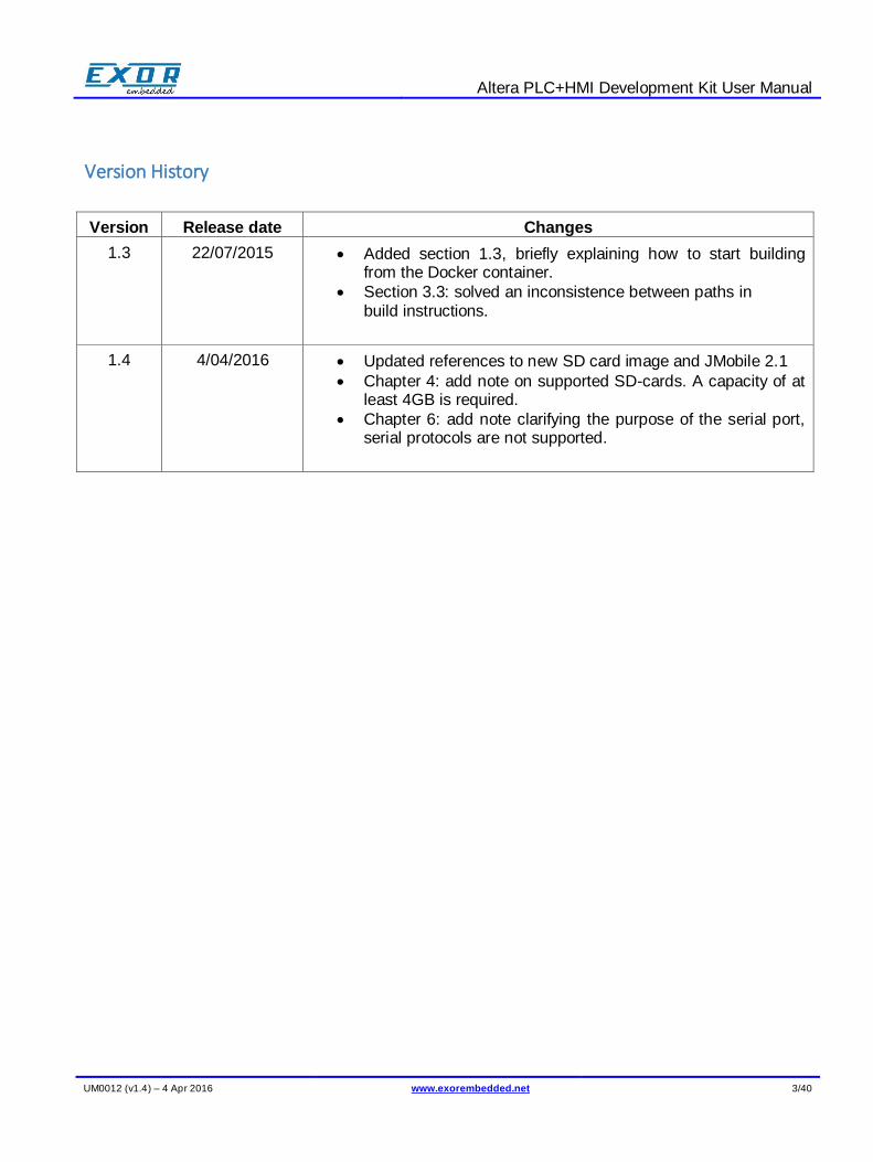
Version History
Version Release date Changes
1.3 22/07/2015 Added section 1.3, briefly explaining how to start building from the Docker container.
Section 3.3: solved an inconsistence between paths in build instructions.
1.4 4/04/2016 Updated references to new SD card image and JMobile 2.1
Chapter 4: add note on supported SD-cards. A capacity of at least 4GB is required.
Chapter 6: add note clarifying the purpose of the serial port, serial protocols are not supported.
Altera PLC+HMI Development Kit User Manual
UM0012 (v1.4) – 4 Apr 2016 www.exorembedded.net 4/40
1. Getting started
The simplest way to get started is using our Docker image exorembedded/docker-us02-32bit, which is publicly available from docker hub. The image is preconfigured with:
Yocto repositories
Build scripts
The SDK to quick start hacking on the development kit Docker supports many operating systems and Linux distributions. For more details or for installation on a different OS/Linux distribution, please refer to https://docs.docker.com/installation/. In particular
1.1 Running the docker image under Ubuntu
You can use apt-get to install docker in Ubuntu 14.04:
$ sudo apt-get install docker.io
In order to use docker as standard user:
$ sudo usermod -aG docker <your_user_name>
You need to logout/login to apply the above changes. Download the image from docker hub using the following command:
$ docker pull exorembedded/docker-us02-32bit
(alternatively you can also build the docker-us02 image from Dockerfile in Github). Run the docker image you have to create a dedicated container with the following command:
$ docker run --name us02 --net host -v ~/:/home/user/share -ti exorembedded/docker-us02-
32bit
The run command creates a new docker container with us02 name.
Note that the docker run command is used only once to setup the container.
Docker will automatically pull the image data from docker hub registry. Alternatively you can manually pull it with command docker pull exorembedded/docker-us02-32bit or compile from github sources with command docker build –t exorembedded/docker-us02-32bit ..
Altera PLC+HMI Development Kit User Manual
UM0012 (v1.4) – 4 Apr 2016 www.exorembedded.net 5/40
The option –v ~/:/home/user/share binds your current home folder to the container folder /home/user/share so it is possible to share data between the container and the host environment. The option –-net host is required if you want to benefit development kit hostname resolution.
To resolve development kit hostname you also have to be connected either directly or via a switch to the development kit.
If you are using a Linux virtual machine, please make sure the network interface you use to reach the development kit is bridged with the actual physical interface.
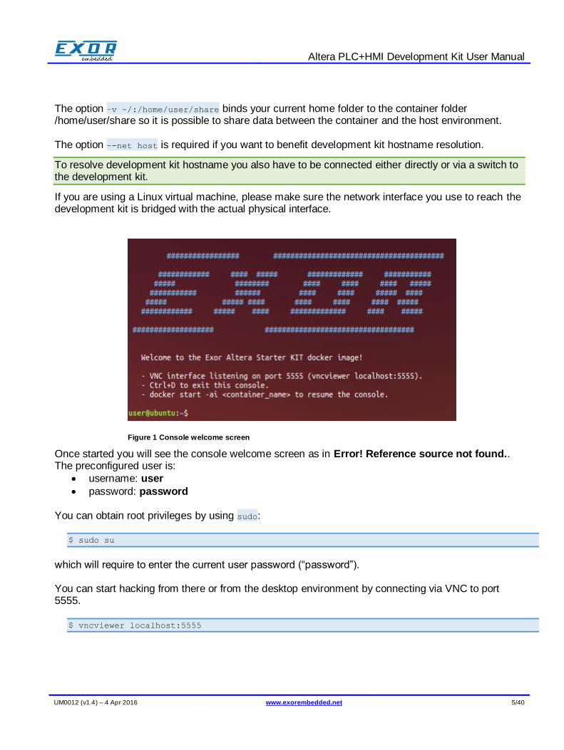
Once started you will see the console welcome screen as in Error! Reference source not found.. The preconfigured user is:
username: user
password: password You can obtain root privileges by using sudo:
$ sudo su
which will require to enter the current user password (“password”). You can start hacking from there or from the desktop environment by connecting via VNC to port 5555.
$ vncviewer localhost:5555
Figure 1 Console welcome screen
Altera PLC+HMI Development Kit User Manual
UM0012 (v1.4) – 4 Apr 2016 www.exorembedded.net 6/40
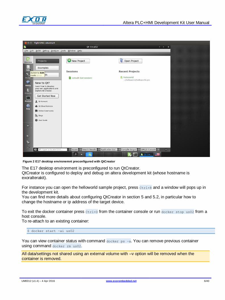
The E17 desktop environment is preconfigured to run QtCreator. QtCreator is configured to deploy and debug on altera development kit (whose hostname is exoralterakit). For instance you can open the helloworld sample project, press Ctrl+R and a window will pops up in the development kit. You can find more details about configuring QtCreator in section 5 and 5.2, in particular how to change the hostname or ip address of the target device. To exit the docker container press Ctrl+D from the container console or run docker stop us02 from a host console. To re-attach to an existing container:
$ docker start –ai us02
You can view container status with command docker ps –a. You can remove previous container using command docker rm us02.
All data/settings not shared using an external volume with –v option will be removed when the container is removed.
Figure 2 E17 desktop environemnt preconfigured with QtCreator
Altera PLC+HMI Development Kit User Manual
UM0012 (v1.4) – 4 Apr 2016 www.exorembedded.net 7/40
If you want to expose to host a container folder, the home folder for instance, and make it persistent across container removal you can use the following command line to initialize the container : docker run –v /home/user .... The shared folder can be accessed from the host environment. The host folder name can be resolved inspecting the container docker inspect
us02 | grep /home/user/ | grep vfs. The volume folders are typically put inside /var/lib/docker/vfs/dir/.
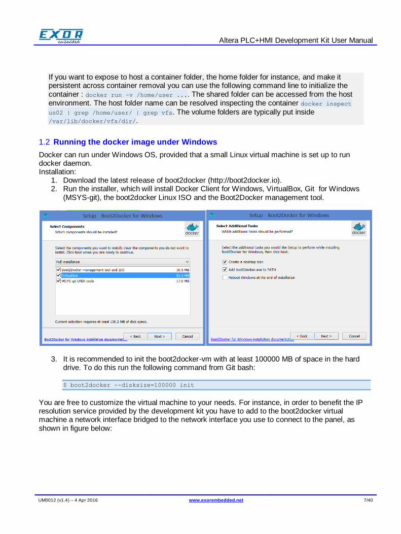
1.2 Running the docker image under Windows
Docker can run under Windows OS, provided that a small Linux virtual machine is set up to run docker daemon. Installation:
1. Download the latest release of boot2docker (http://boot2docker.io). 2. Run the installer, which will install Docker Client for Windows, VirtualBox, Git for Windows
(MSYS-git), the boot2docker Linux ISO and the Boot2Docker management tool.
3. It is recommended to init the boot2docker-vm with at least 100000 MB of space in the hard drive. To do this run the following command from Git bash:
$ boot2docker --disksize=100000 init
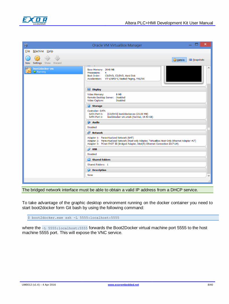
You are free to customize the virtual machine to your needs. For instance, in order to benefit the IP resolution service provided by the development kit you have to add to the boot2docker virtual machine a network interface bridged to the network interface you use to connect to the panel, as shown in figure below:
Altera PLC+HMI Development Kit User Manual
UM0012 (v1.4) – 4 Apr 2016 www.exorembedded.net 8/40
The bridged network interface must be able to obtain a valid IP address from a DHCP service.
To take advantage of the graphic desktop environment running on the docker container you need to start boot2docker form Git bash by using the following command:
$ boot2docker.exe ssh -L 5555:localhost:5555
where the –L 5555:localhost:5555 forwards the Boot2Docker virtual machine port 5555 to the host machine 5555 port. This will expose the VNC service.
Altera PLC+HMI Development Kit User Manual
UM0012 (v1.4) – 4 Apr 2016 www.exorembedded.net 9/40
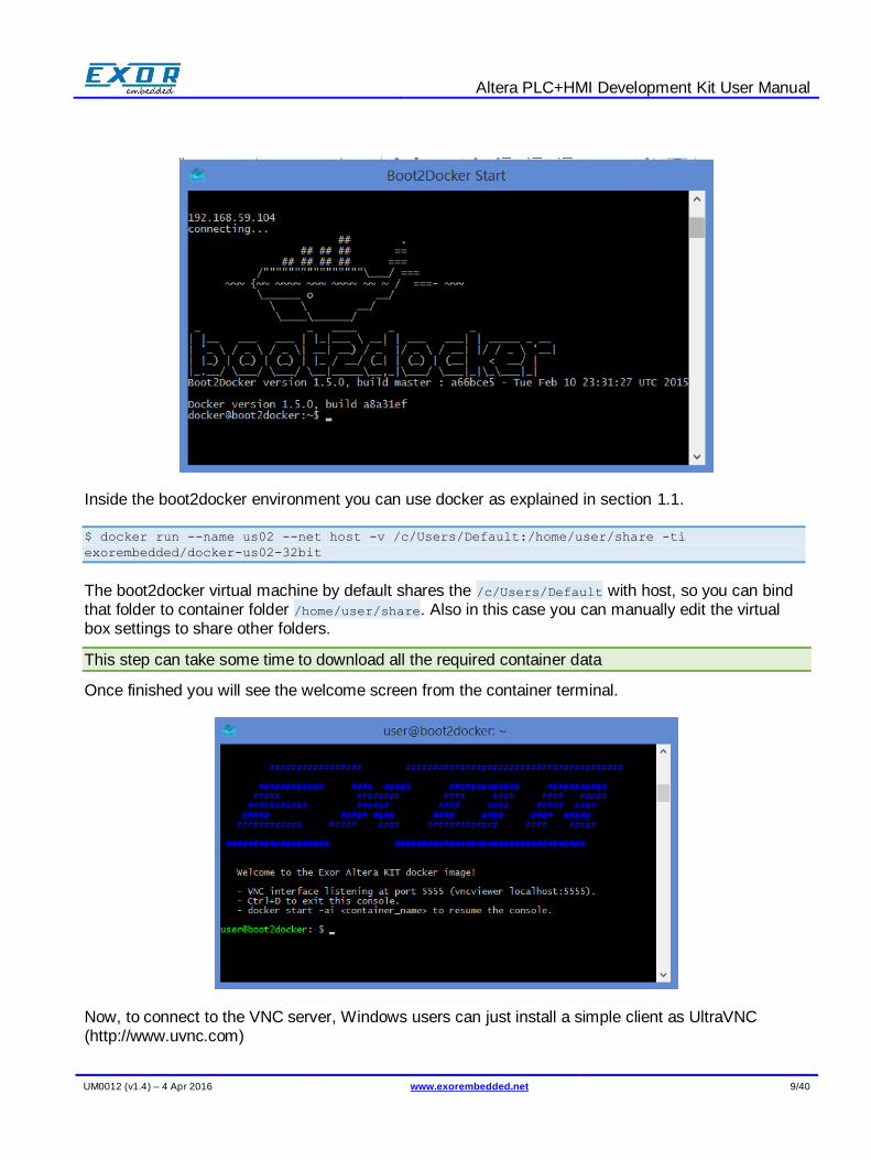
Inside the boot2docker environment you can use docker as explained in section 1.1.
$ docker run --name us02 --net host -v /c/Users/Default:/home/user/share -ti
exorembedded/docker-us02-32bit
The boot2docker virtual machine by default shares the /c/Users/Default with host, so you can bind that folder to container folder /home/user/share. Also in this case you can manually edit the virtual box settings to share other folders.
This step can take some time to download all the required container data
Once finished you will see the welcome screen from the container terminal.
Now, to connect to the VNC server, Windows users can just install a simple client as UltraVNC (http://www.uvnc.com)
Altera PLC+HMI Development Kit User Manual
UM0012 (v1.4) – 4 Apr 2016 www.exorembedded.net 10/40
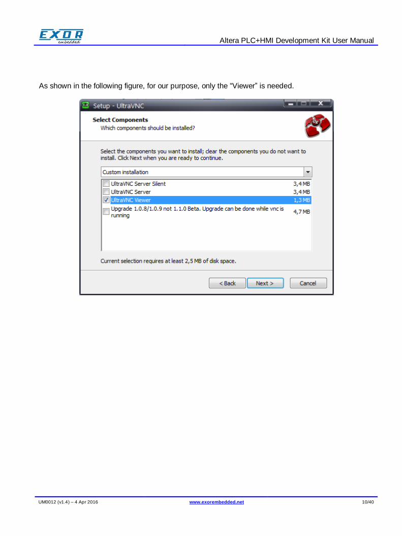
As shown in the following figure, for our purpose, only the “Viewer” is needed.
Altera PLC+HMI Development Kit User Manual
UM0012 (v1.4) – 4 Apr 2016 www.exorembedded.net 11/40
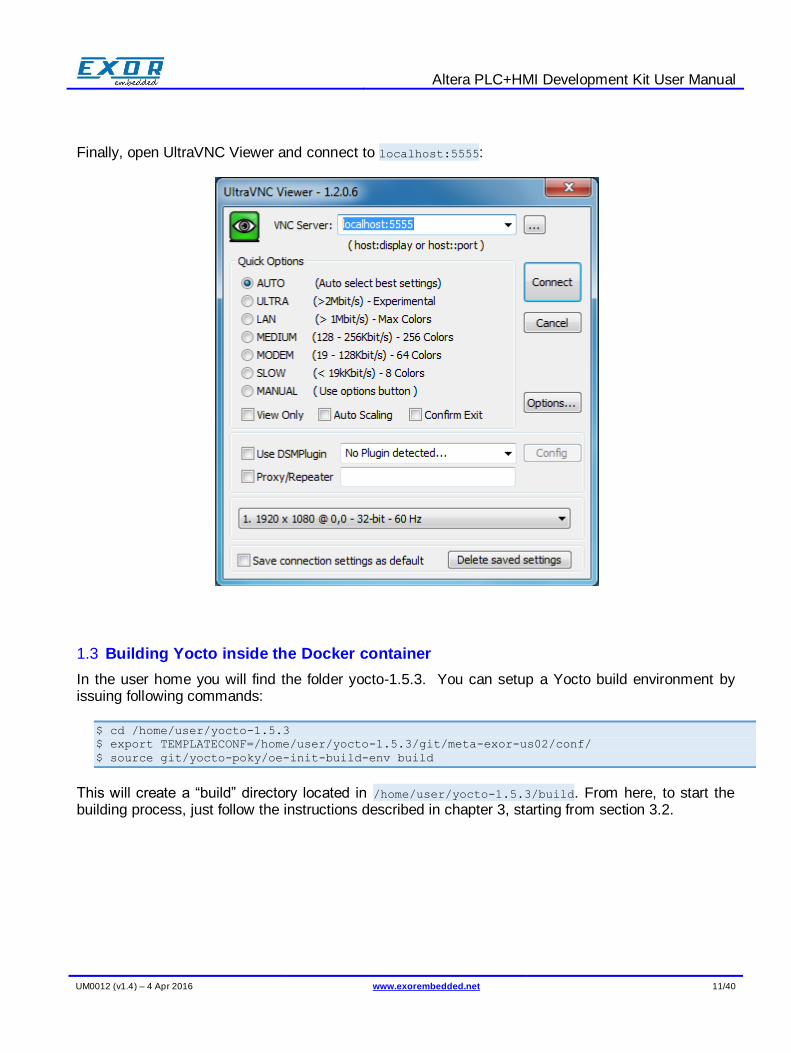
Finally, open UltraVNC Viewer and connect to localhost:5555:
1.3 Building Yocto inside the Docker container
In the user home you will find the folder yocto-1.5.3. You can setup a Yocto build environment by issuing following commands:
$ cd /home/user/yocto-1.5.3
$ export TEMPLATECONF=/home/user/yocto-1.5.3/git/meta-exor-us02/conf/
$ source git/yocto-poky/oe-init-build-env build
This will create a “build” directory located in /home/user/yocto-1.5.3/build. From here, to start the building process, just follow the instructions described in chapter 3, starting from section 3.2.
Altera PLC+HMI Development Kit User Manual
UM0012 (v1.4) – 4 Apr 2016 www.exorembedded.net 12/40
2 The Sato desktop
The development kit will boot with the default Yocto SATO interface. The machine is configured to run as root user and an empty password
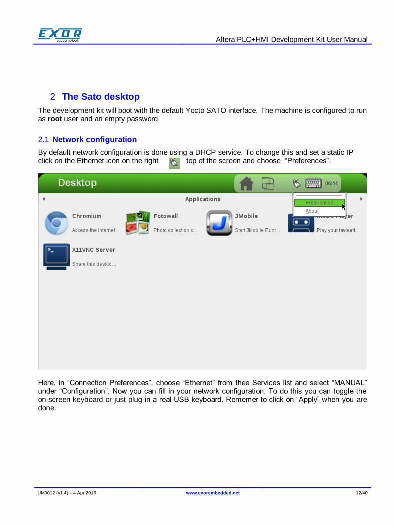
2.1 Network configuration
By default network configuration is done using a DHCP service. To change this and set a static IP click on the Ethernet icon on the right top of the screen and choose “Preferences”.
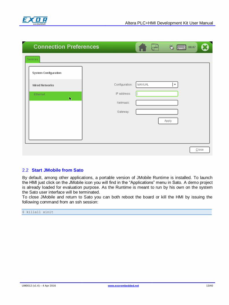
Here, in “Connection Preferences”, choose “Ethernet” from thee Services list and select “MANUAL” under “Configuration”. Now you can fill in your network configuration. To do this you can toggle the on-screen keyboard or just plug-in a real USB keyboard. Rememer to click on “Apply” when you are done.
Altera PLC+HMI Development Kit User Manual
UM0012 (v1.4) – 4 Apr 2016 www.exorembedded.net 13/40
2.2 Start JMobile from Sato
By default, among other applications, a portable version of JMobile Runtime is installed. To launch the HMI just click on the JMobile icon you will find in the “Applications” menu in Sato. A demo project is already loaded for evaluation purpose. As the Runtime is meant to run by his own on the system the Sato user interface will be terminated. To close JMobile and return to Sato you can both reboot the board or kill the HMI by issuing the following command from an ssh session:
$ killall xinit

Altera PLC+HMI Development Kit User Manual
UM0012 (v1.4) – 4 Apr 2016 www.exorembedded.net 14/40
3 Compiling Yocto BSP from scratch.
3.1 Setup the build environment
This section can be skipped when using the Docker container
1. Create a workspace directory structure:
$ mkdir -p exor/git
$ cd exor/git
2. Get the source code from github repositories:
$ git clone -b exorint http://github.com/ExorEmbedded/yocto-poky
$ git clone -b exorint http://github.com/ExorEmbedded/yocto-meta-openembedded
$ git clone -b dora http://github.com/ExorEmbedded/meta-browser
$ git clone -b master http://github.com/ExorEmbedded/meta-exor-us02
3. Setup yocto environment:
$ source yocto-poky/oe-init-build-env ../build
You should now find yourself in a newly created “build” directory located in exor/build.
4. Configure Yocto, by copying the provided sample base configuration files. From the “build” directory:
$ cp ../git/meta-exor-us02/conf/bblayers.conf.sample conf/bblayers.conf
$ cp ../git/meta-exor-us02/conf/local.conf.sample conf/local.conf
You are now ready to build Yocto.
3.2 Optional customizations
Here are some customizations you may be interested in:
You can force Yocto to build a 32-bit SDK uncommenting the following line in the build/conf/local.conf file:
#SDKMACHINE ?= "i686"
If you are using our Docker container you will find this line already uncommented.
Uncomment following lines in the build/conf/local.conf file to be able to set the number of threads and CPU cores you want to use for the build process:
Altera PLC+HMI Development Kit User Manual
UM0012 (v1.4) – 4 Apr 2016 www.exorembedded.net 15/40
#BB_NUMBER_THREADS ?= "4"
#PARALLEL_MAKE ?= "-j 4"
To include Qt library on the board uncomment this line in git/meta-exor-us02/recipes-sato/images/core-image-sato.bbappend:
#IMAGE_INSTALL += "packagegroup-core-qt-demoapps packagegroup-qt-toolchain-target"
To compile chromium web browser add the following line to build/conf/local.conf:
LICENSE_FLAGS_WHITELIST="commercial"
Then uncomment this line in git/meta-exor-us02/recipes-sato/images/core-image-sato.bbappend
#CORE_IMAGE_EXTRA_INSTALL += "chromium"
3.3 Compiling Yocto
Make sure to run following commands from your “build” folder:
1. Compile the bootloader:
$ bitbake bootloader
2. The Linux kernel:
$ bitbake linux
3. And finally the rootfs:
$ bitbake core-image-sato
At the end of these operations you will find build output files in
build/tmp/deploy/images/usom02:
us02-uboot.tar.gz Contains the U-Boot raw image
us02-kernel.tar.gz Contains the kernel zImage and the dtb
core-image-sato-usom02-[...].rootfs.tar.gz Sato rootfs
3.3.1 Creating the SDK (optional)
$ bitbake core-sdk-exorint
The SDK installer can be found in build/tmp/deploy/sdk/exor-alterakit-sdk.sh.
Altera PLC+HMI Development Kit User Manual
UM0012 (v1.4) – 4 Apr 2016 www.exorembedded.net 16/40
4 BSP deploy to SD-card
This section describes how to prepare a bootable SD-card for the evaluation kit, for this remember that only SD-cards with at least 4GB of space are supported.
Also note that following operations can be dangerous, harm your system or cause loss of data. Do not blindly execute these operations if you don’t know what they actually do.
For Linux users we will assume the SD-card device is /dev/mmcblk1.
4.1 Using a ready image
We provide a full working 4GB image to let you start using the kit in no time. Note that by using this option, even with a more capable SD, only ~4GB of space will be available to the system.
4.1.1 Under Linux
Download the latest disk image (v1.1) from https://www.dropbox.com/sh/mdgny9r4kadu0gp/AABInH0xr_y7M8Fs0os0wvKka Then,
# unzip SDcard-image-4gb-v1.1.zip
# dd if=SDcard-image-4gb-v1.1.img of=/dev/mmcblk1 bs=64k-v1.1.zip
# sync
Your SD is now ready to be used on the development kit.
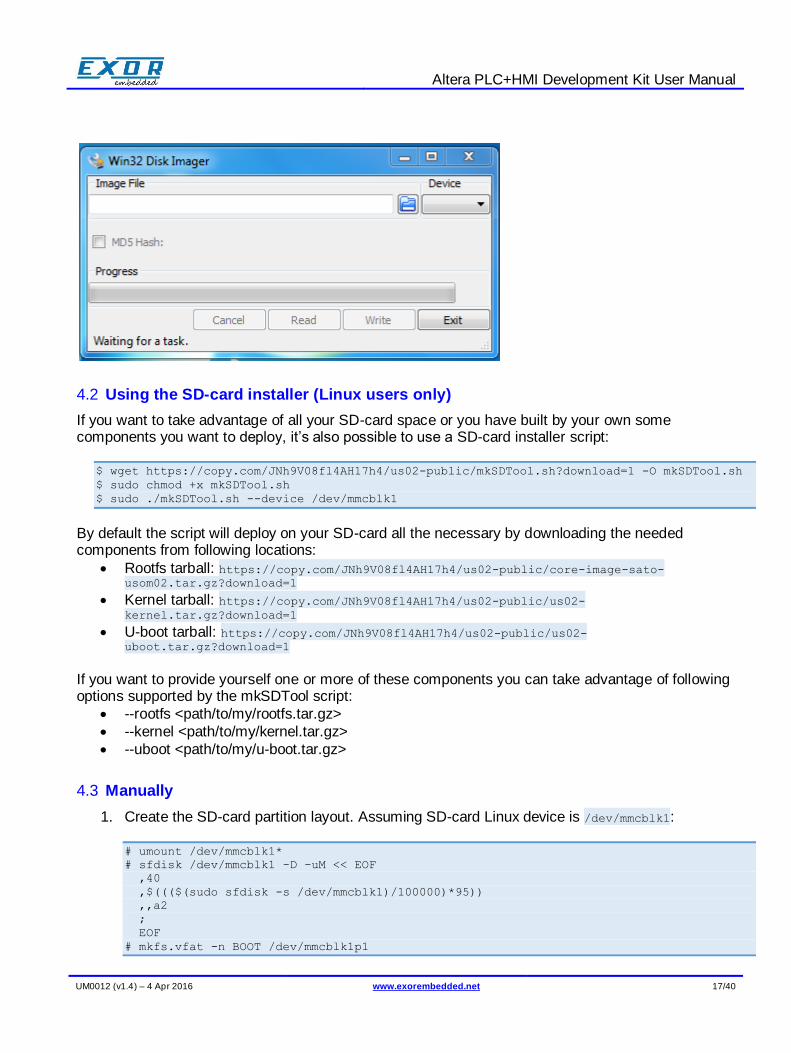
4.1.2 Under Windows
Download Win32DiskImager from http://sourceforge.net/projects/win32diskimager/ and the disk image from https://www.dropbox.com/sh/mdgny9r4kadu0gp/AABInH0xr_y7M8Fs0os0wvKka. By extracting the zip file you will get the .img file. From the user interface of Win32DiskImager select the .img image file and the SD-card drive and press “Write”.
Altera PLC+HMI Development Kit User Manual
UM0012 (v1.4) – 4 Apr 2016 www.exorembedded.net 17/40
4.2 Using the SD-card installer (Linux users only)
If you want to take advantage of all your SD-card space or you have built by your own some components you want to deploy, it’s also possible to use a SD-card installer script:
$ wget https://copy.com/JNh9V08fl4AH17h4/us02-public/mkSDTool.sh?download=1 -O mkSDTool.sh
$ sudo chmod +x mkSDTool.sh
$ sudo ./mkSDTool.sh --device /dev/mmcblk1
By default the script will deploy on your SD-card all the necessary by downloading the needed components from following locations:
Rootfs tarball: https://copy.com/JNh9V08fl4AH17h4/us02-public/core-image-sato-usom02.tar.gz?download=1
Kernel tarball: https://copy.com/JNh9V08fl4AH17h4/us02-public/us02-kernel.tar.gz?download=1
U-boot tarball: https://copy.com/JNh9V08fl4AH17h4/us02-public/us02-uboot.tar.gz?download=1
If you want to provide yourself one or more of these components you can take advantage of following options supported by the mkSDTool script:
--rootfs <path/to/my/rootfs.tar.gz>
--kernel <path/to/my/kernel.tar.gz>
--uboot <path/to/my/u-boot.tar.gz>
4.3 Manually
1. Create the SD-card partition layout. Assuming SD-card Linux device is /dev/mmcblk1:
# umount /dev/mmcblk1*
# sfdisk /dev/mmcblk1 -D -uM << EOF
,40
,$((($(sudo sfdisk -s /dev/mmcblk1)/100000)*95))
,,a2
;
EOF
# mkfs.vfat -n BOOT /dev/mmcblk1p1
Altera PLC+HMI Development Kit User Manual
UM0012 (v1.4) – 4 Apr 2016 www.exorembedded.net 18/40
# mkfs.ext2 -L ROOT /dev/mmcblk1p2
2. Install files into SD-card. Execute following operations:
// Mount partitions if not already mounted
# mkdir /media/BOOT
# mount /dev/mmcblk1p1 /media/BOOT
# mkdir /media/ROOT
# mount /dev/mmcblk1p2 /media/ROOT
// Deploy files to SD-card
# tar xzvf us02-kernel.tar.gz -C /media/BOOT
# tar xzvf core-image-sato-usom02-[...].rootfs.tar.gz -C /media/ROOT
# tar xzvf us02-uboot.tar.gz
# dd if=u-boot.img of=/dev/mmcblk1p3 bs=64k seek=4
# sync
Altera PLC+HMI Development Kit User Manual
UM0012 (v1.4) – 4 Apr 2016 www.exorembedded.net 19/40
5 Building applications
5.1 Cross development environment setup
This section can be skipped when using the docker container and QtCreator
Put the SDK installation file exor-alterakit-sdk.sh in folder /opt (requires admin privileges). Run it:
$ cd /opt
$ sudo chmod a+x ./exor-alterakit-sdk.sh
$ sudo ./exor-alterakit-sdk.sh
Answer yes to all questions (in particular don’t change the SDK target folder). Once the SDK is installed you will find it in folder /opt/poky/1.5.3. To setup the cross development environment in current shell:
$ source /opt/poky/1.5.3/environment-setup-cortexa9hf-vfp-neon-poky-linux-gnueabi
To build a simple hello world application use the arm cross compiler that should now be reachable from your PATH:
$ arm-poky-linux-gnueabi-gcc main.c -o hello_world
5.2 QtCreator setup
You can skip this section when running the docker container
You can get latest QtCreator package from DIGIA here (http://download.qt.io/official_releases/qtcreator/3.3/3.3.2/qt-creator-opensource-linux-x86-3.3.2.run). Install it in your build machine:
$ sudo chmod a+x ./qt-creator-opensource-linux-x86-3.3.2.run
$./qt-creator-opensource-linux-x86-3.3.2.run
You will find qtcreator installed in ~/qtcreator-3.3.2. Start it:
$ ~/qtcreator-3.3.2/bin/qtcreator
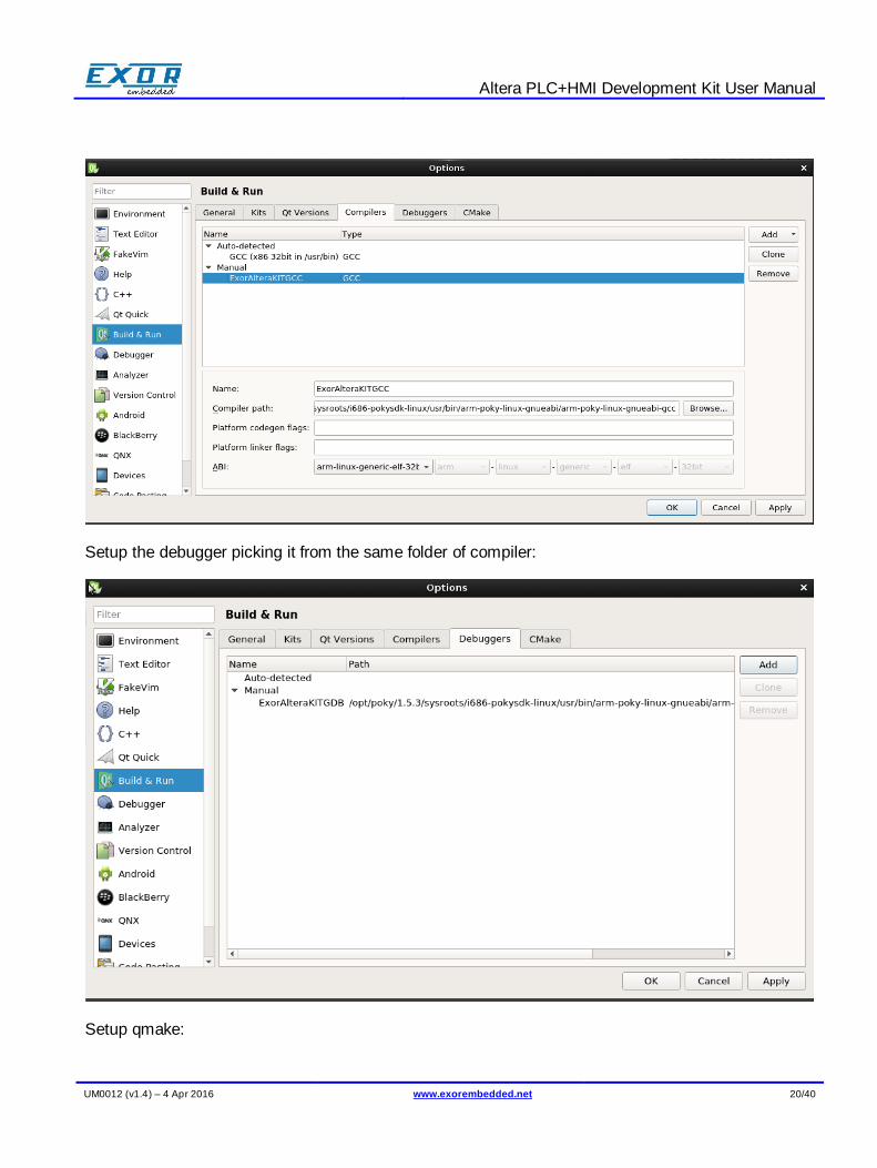
We are now going to setup the QtCreator build kit for the altera-sdk target. From Tools menu select Options -> Build & Run. Add the cross compiler, selecting it in the SDK installation folder /opt/poky/1.5.3/sysroots/i686-pokysdk-linux/usr/bin/arm-poky-linux-gnueabi/arm-poky-linux-gnueabi-gcc):
Altera PLC+HMI Development Kit User Manual
UM0012 (v1.4) – 4 Apr 2016 www.exorembedded.net 20/40
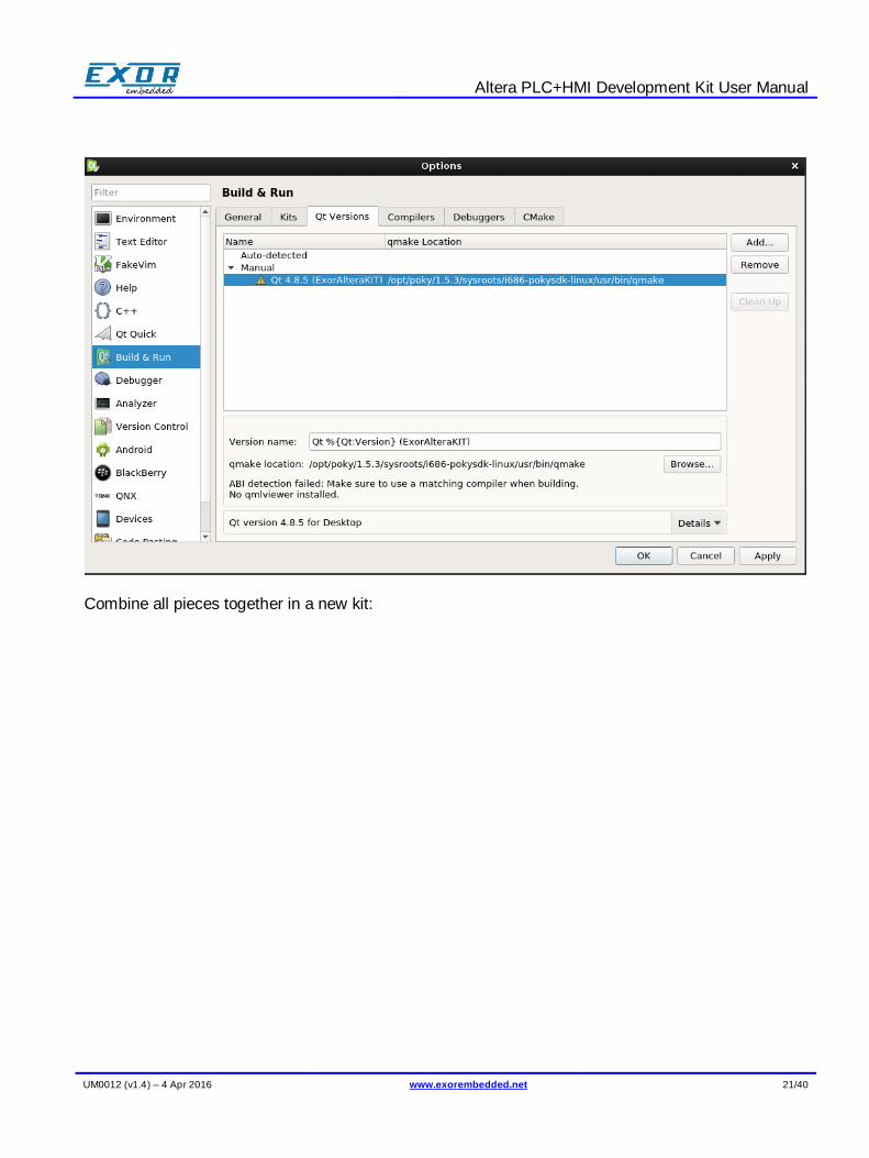
Setup the debugger picking it from the same folder of compiler:
Setup qmake:
Altera PLC+HMI Development Kit User Manual
UM0012 (v1.4) – 4 Apr 2016 www.exorembedded.net 21/40
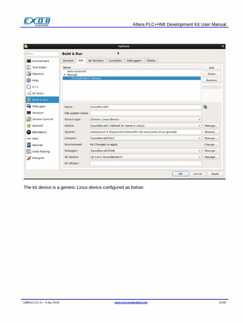
Combine all pieces together in a new kit:
Altera PLC+HMI Development Kit User Manual
UM0012 (v1.4) – 4 Apr 2016 www.exorembedded.net 22/40
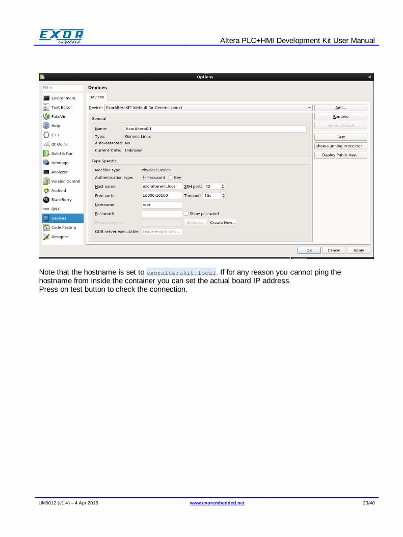
The kit device is a generic Linux device configured as below:
Altera PLC+HMI Development Kit User Manual
UM0012 (v1.4) – 4 Apr 2016 www.exorembedded.net 23/40
Note that the hostname is set to exoralterakit.local. If for any reason you cannot ping the hostname from inside the container you can set the actual board IP address. Press on test button to check the connection.
Altera PLC+HMI Development Kit User Manual
UM0012 (v1.4) – 4 Apr 2016 www.exorembedded.net 24/40
6 JMobile Portable runtime
JMobile is a software suite designed to offer a complete HMI solution with client-server architecture. It is made of several software components, integrated into a unique application. JMobile applies the latest available technology developed for HMI in industrial automation to every situation where a user interface is required. The suite includes commissioning tools, to allow easy maintenance and configuration of multiple remote units, and both desktop and runtime engineering software for application development. The portable version of JMobile is a standard Linux JMobile runtime provided as a chroot-based container designed to run under Linux 32bit ARM Cortex A8 and above platforms.
The portable JMobile runtime is provided for rapid prototyping and evaluation purposes and contains a subset (Codesys V2/, Modbus and the internal variables protocol) of the available protocols. In particular serial protocols are not supported, the serial port on the evaluation kit is only meant for debugging purpose.
A closer integration with the final target system and access to the complete set of protocols can be achieved on demand during the product engineering phase.
6.1 JMobile portable runtime installation
By default JMobile in preinstalled on both the standard SD image and the rootfs generated by our standard yocto recipes. However here is how to get started with the JMobile runtime on the AlteraKit from scratch:
1. Get JMobile and copy it into the kit
$ wget https://copy.com/JNh9V08fl4AH17h4/us02-
public/jmobile2.01_portable_alterakit_cds3.tar.gz?download=1 -O
jmobile2.01_portable_alterakit_cds3.tar.gz
$ scp jmobile2.01_portable_alterakit_cds3.tar.gz [email protected]:~
2. Connect to the kit
$ ssh [email protected]
3. Now, from the remote shell, untar the package in a folder with write permissions (e.g. /home/root)
$ cd /home/root/
$ tar xzpf jmobile2.01_portable_alterakit_cds3.tar.gz
$ rm –rf jmobile2.01_portable_alterakit_cds3.tar.gz
4. Make sure X11 is not running:
# /etc/init.d/xserver-nodm stop

Altera PLC+HMI Development Kit User Manual
UM0012 (v1.4) – 4 Apr 2016 www.exorembedded.net 25/40
5. start JMobile:
# /home/root/portable/run.sh
If you wish JMobile runtime to start automatically at boot, do the following. Remove the script xserver-nodm:
# update-rc.d –f xserver-nodm remove
and add a new script to the init sequence:
# echo “/home/root/portable/run.sh &” > /etc/init.d/jmobile
# chmod a+x /etc/init.d/jmobile
# update-rc.d jmobile defaults 99
6.2 JMobile quick start guide
Download JMobile Studio from the “Downloads” section that can be found here: http://www.exorembedded.net/webpage?ReadForm&wPageName=products&t=Product&p=uS02%20microSOM
%20Altera%20CV%20SoC%20evaluation%20kit Choose the version of JMobile Suite that matches the runtime currently installed on the machine. If unsure, the runtime version can be found as follows:
1. Start the JMobile runtime by using its icon on the sato desktop. 2. Once fully started, touch the screen and hold until the context menu appears. 3. Choose “About…”
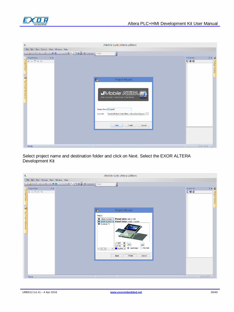
After installation, create a new project in Studio for Altera Cyclone V target:
Altera PLC+HMI Development Kit User Manual
UM0012 (v1.4) – 4 Apr 2016 www.exorembedded.net 26/40
Select project name and destination folder and click on Next. Select the EXOR ALTERA Development Kit
Altera PLC+HMI Development Kit User Manual
UM0012 (v1.4) – 4 Apr 2016 www.exorembedded.net 27/40
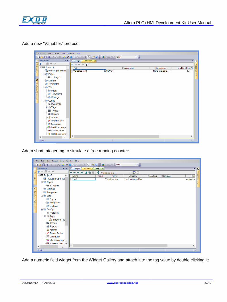
Add a new “Variables” protocol:
Add a short integer tag to simulate a free running counter:
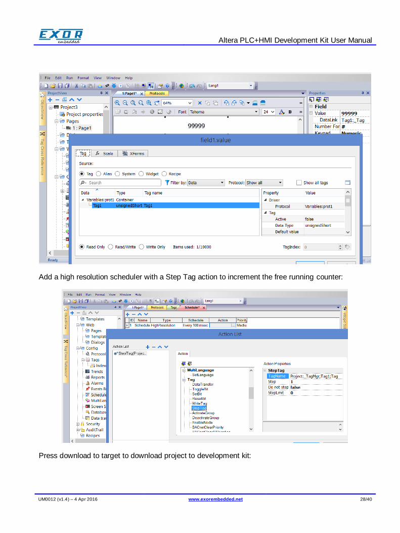
Add a numeric field widget from the Widget Gallery and attach it to the tag value by double clicking it:
Altera PLC+HMI Development Kit User Manual
UM0012 (v1.4) – 4 Apr 2016 www.exorembedded.net 28/40
Add a high resolution scheduler with a Step Tag action to increment the free running counter:
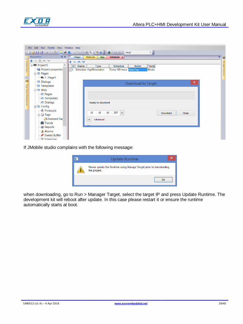
Press download to target to download project to development kit:
Altera PLC+HMI Development Kit User Manual
UM0012 (v1.4) – 4 Apr 2016 www.exorembedded.net 29/40
If JMobile studio complains with the following message:
when downloading, go to Run > Manager Target, select the target IP and press Update Runtime. The development kit will reboot after update. In this case please restart it or ensure the runtime automatically starts at boot.
Altera PLC+HMI Development Kit User Manual
UM0012 (v1.4) – 4 Apr 2016 www.exorembedded.net 30/40
7 CODESYS V3
The CODESYS V3 programming software can be downloaded for free from the CODESYS web site at www.codesys.com/download.html You need to register before you can download the software.
7.1 Installing CODESYS Devices
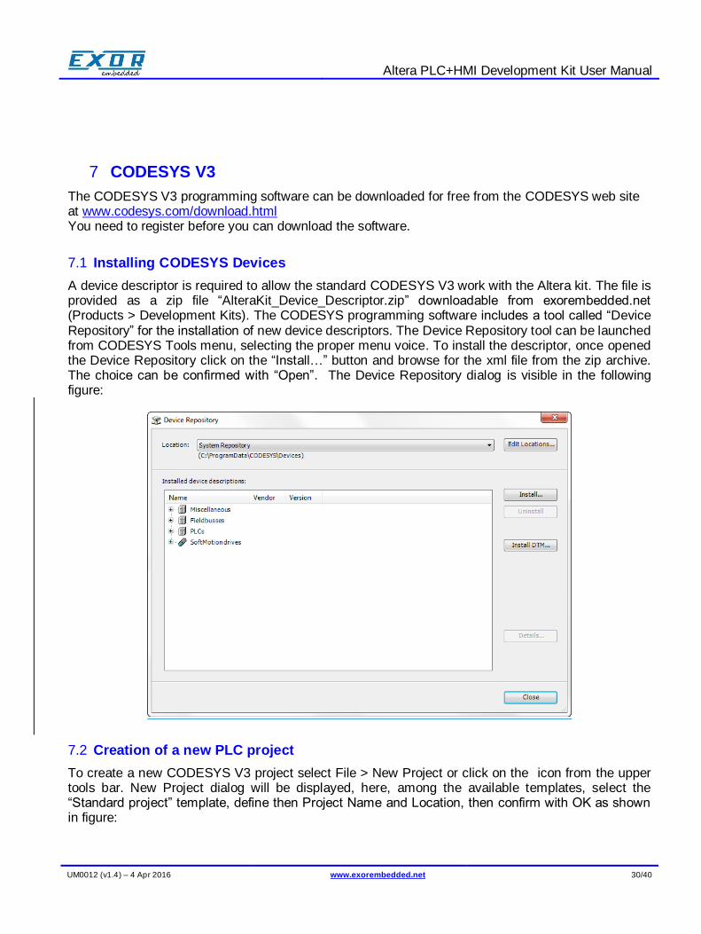
A device descriptor is required to allow the standard CODESYS V3 work with the Altera kit. The file is provided as a zip file “AlteraKit_Device_Descriptor.zip” downloadable from exorembedded.net (Products > Development Kits). The CODESYS programming software includes a tool called “Device Repository” for the installation of new device descriptors. The Device Repository tool can be launched from CODESYS Tools menu, selecting the proper menu voice. To install the descriptor, once opened the Device Repository click on the “Install…” button and browse for the xml file from the zip archive. The choice can be confirmed with “Open”. The Device Repository dialog is visible in the following figure:
7.2 Creation of a new PLC project
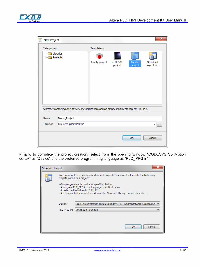
To create a new CODESYS V3 project select File > New Project or click on the icon from the upper tools bar. New Project dialog will be displayed, here, among the available templates, select the “Standard project” template, define then Project Name and Location, then confirm with OK as shown in figure:
Altera PLC+HMI Development Kit User Manual
UM0012 (v1.4) – 4 Apr 2016 www.exorembedded.net 31/40
Finally, to complete the project creation, select from the opening window “CODESYS SoftMotion cortex” as “Device” and the preferred programming language as “PLC_PRG in”.
Altera PLC+HMI Development Kit User Manual
UM0012 (v1.4) – 4 Apr 2016 www.exorembedded.net 32/40
7.3 Communication setup in the CODESYS software
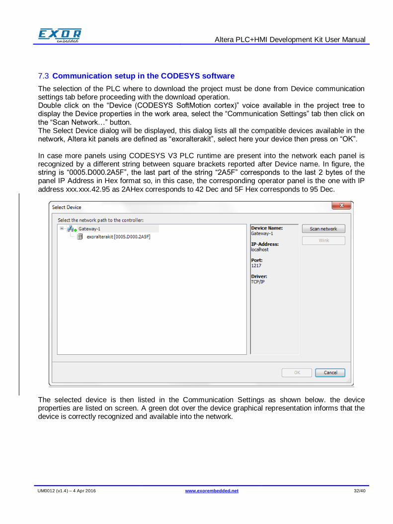
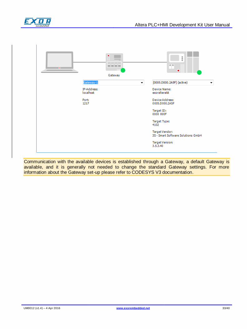
The selection of the PLC where to download the project must be done from Device communication settings tab before proceeding with the download operation. Double click on the “Device (CODESYS SoftMotion cortex)” voice available in the project tree to display the Device properties in the work area, select the “Communication Settings” tab then click on the “Scan Network…” button. The Select Device dialog will be displayed, this dialog lists all the compatible devices available in the network, Altera kit panels are defined as “exoralterakit”, select here your device then press on “OK”. In case more panels using CODESYS V3 PLC runtime are present into the network each panel is recognized by a different string between square brackets reported after Device name. In figure, the string is “0005.D000.2A5F”, the last part of the string “2A5F” corresponds to the last 2 bytes of the panel IP Address in Hex format so, in this case, the corresponding operator panel is the one with IP address xxx.xxx.42.95 as 2AHex corresponds to 42 Dec and 5F Hex corresponds to 95 Dec.
The selected device is then listed in the Communication Settings as shown below. the device properties are listed on screen. A green dot over the device graphical representation informs that the device is correctly recognized and available into the network.
Altera PLC+HMI Development Kit User Manual
UM0012 (v1.4) – 4 Apr 2016 www.exorembedded.net 33/40
Communication with the available devices is established through a Gateway, a default Gateway is available, and it is generally not needed to change the standard Gateway settings. For more information about the Gateway set-up please refer to CODESYS V3 documentation.
Altera PLC+HMI Development Kit User Manual
UM0012 (v1.4) – 4 Apr 2016 www.exorembedded.net 34/40
8 Accessing PLC from JMobile
JMobile and CODESYS projects discussed in this section are included in the “JMobile_CDS_demo” folder from the demo projects package “Demo_Projects.zip”, downloadable from exorembedded.net (Products > Development Kits).
The JMobile Portable Altera edition contains also a demo version of CODESYS v3 runtime which is started along with JMobile runtime. Here is presented an example in wich JMobile will be able to access variable values from the PLC.
8.1 Codesys project creation
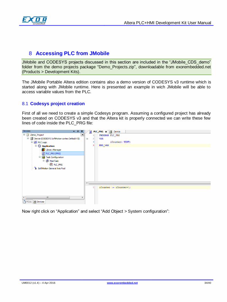
First of all we need to create a simple Codesys program. Assuming a configured project has already been created on CODESYS v3 and that the Altera kit is properly connected we can write these few lines of code inside the PLC_PRG file:
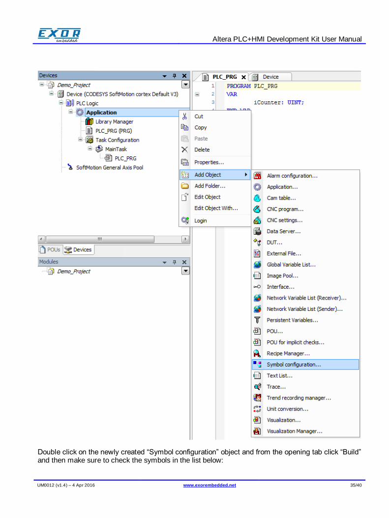
Now right click on “Application” and select “Add Object > System configuration”:
Altera PLC+HMI Development Kit User Manual
UM0012 (v1.4) – 4 Apr 2016 www.exorembedded.net 35/40
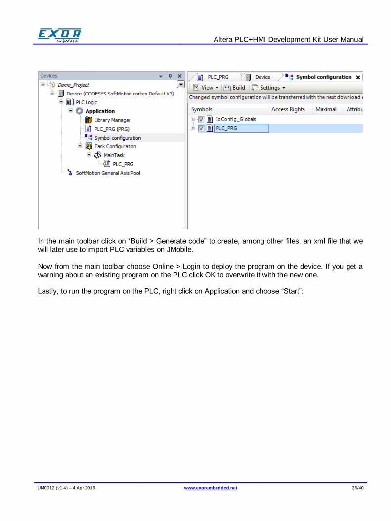
Double click on the newly created “Symbol configuration” object and from the opening tab click “Build” and then make sure to check the symbols in the list below:
Altera PLC+HMI Development Kit User Manual
UM0012 (v1.4) – 4 Apr 2016 www.exorembedded.net 36/40
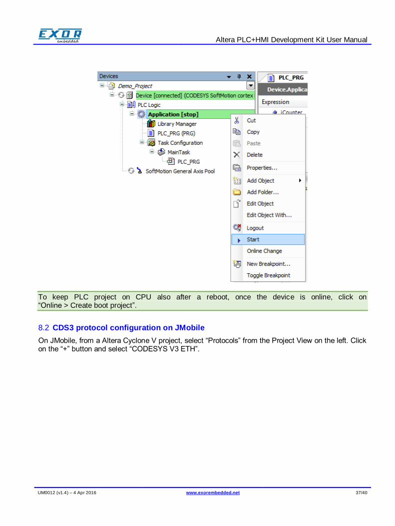
In the main toolbar click on “Build > Generate code” to create, among other files, an xml file that we will later use to import PLC variables on JMobile. Now from the main toolbar choose Online > Login to deploy the program on the device. If you get a warning about an existing program on the PLC click OK to overwrite it with the new one. Lastly, to run the program on the PLC, right click on Application and choose “Start”:
Altera PLC+HMI Development Kit User Manual
UM0012 (v1.4) – 4 Apr 2016 www.exorembedded.net 37/40
To keep PLC project on CPU also after a reboot, once the device is online, click on “Online > Create boot project”.
8.2 CDS3 protocol configuration on JMobile
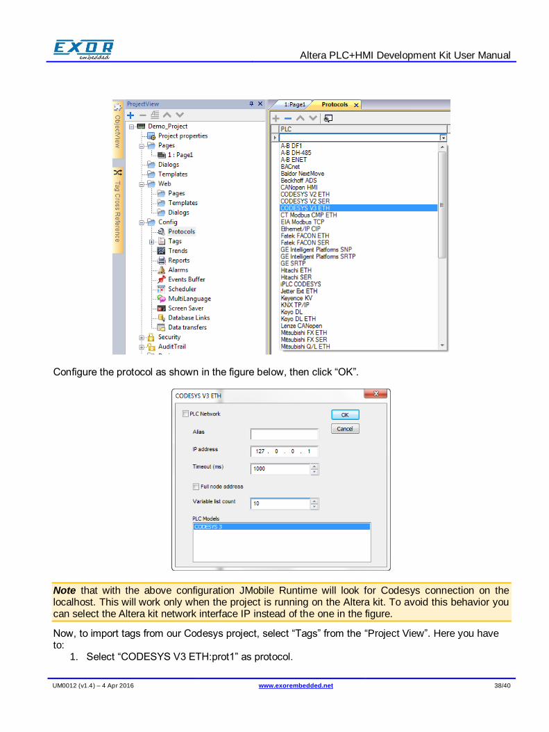
On JMobile, from a Altera Cyclone V project, select “Protocols” from the Project View on the left. Click on the “+” button and select “CODESYS V3 ETH”.
Altera PLC+HMI Development Kit User Manual
UM0012 (v1.4) – 4 Apr 2016 www.exorembedded.net 38/40
Configure the protocol as shown in the figure below, then click “OK”.
Note that with the above configuration JMobile Runtime will look for Codesys connection on the localhost. This will work only when the project is running on the Altera kit. To avoid this behavior you can select the Altera kit network interface IP instead of the one in the figure.
Now, to import tags from our Codesys project, select “Tags” from the “Project View”. Here you have to:
1. Select “CODESYS V3 ETH:prot1” as protocol.
Altera PLC+HMI Development Kit User Manual
UM0012 (v1.4) – 4 Apr 2016 www.exorembedded.net 39/40
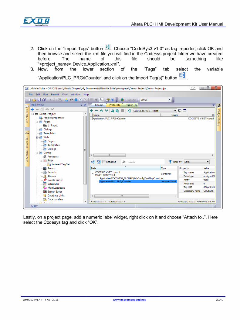
2. Click on the “Import Tags” button . Choose “CodeSys3 v1.0” as tag importer, click OK and then browse and select the xml file you will find in the Codesys project folder we have created before. The name of this file should be something like “<project_name>.Device.Application.xml”.
3. Now, from the lower section of the “Tags” tab select the variable
“Application/PLC_PRG/iCounter” and click on the Import Tag(s)” button .
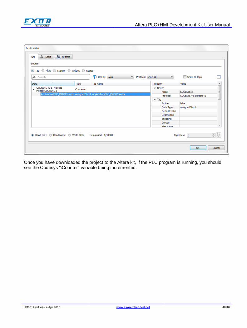
Lastly, on a project page, add a numeric label widget, right click on it and choose “Attach to..”. Here select the Codesys tag and click “OK”.
Altera PLC+HMI Development Kit User Manual
UM0012 (v1.4) – 4 Apr 2016 www.exorembedded.net 40/40
Once you have downloaded the project to the Altera kit, if the PLC program is running, you should see the Codesys “iCounter” variable being incremented.