ALTAIR - TurbineTracker Operators Handbook1.pdf · ALTAIR AVIONICS CORP CUST-T-400-1 Operators...
78
ALTAIR AVIONICS CORP CUST-T-400-1 Operators Handbook 6 October 2006 ALTAIR OPERATORS HANDBOOK All of the information in this handbook is to be used only as a reference guide to help you understand the methods and concepts required to accomplish successful operation of your Altair Avionics monitoring system. You must use your current ICA for all troubleshooting Any deviation from the procedures described within your Instructions for Continued Airworthiness document could result in a failure of the product to perform properly and could possibly result in damage to other systems of the aircraft. Basic Engine Monitoring Tasks Processor is configured and calibrated with MLP Configuration created and maintained in TurbineTracker Flight Data collected by processor and stored as log data Log Data is retrieved and uploaded into TurbineTracker™ using MLP or the DTU Raw data NOTE: MLP can only view logs in raw format Log Data can be viewed in TurbineTracker™ Raw data parsed into user friendly tables Copyright © 2006 ALTAIR AVIONICS CORPORATION - All rights reserved 1
-
Upload
phamkhuong -
Category
Documents
-
view
219 -
download
0
Transcript of ALTAIR - TurbineTracker Operators Handbook1.pdf · ALTAIR AVIONICS CORP CUST-T-400-1 Operators...

ALTAIR AVIONICS CORP CUST-T-400-1 Operators Handbook 6 October 2006
ALTAIR
OPERATORS HANDBOOK
All of the information in this handbook is to be used only as a reference guide to help you understand the methods and concepts required to accomplish successful
operation of your Altair Avionics monitoring system.
You must use your current ICA for all troubleshooting Any deviation from the procedures described within your Instructions for Continued
Airworthiness document could result in a failure of the product to perform properly and could possibly result in damage to other systems of the aircraft.
Basic Engine Monitoring Tasks
Processor is configured and calibrated with MLP Configuration created and maintained in TurbineTracker Flight Data collected by processor and stored as log data Log Data is retrieved and uploaded into TurbineTracker™ using MLP or the DTU
Raw data
NOTE: MLP can only view logs in raw format Log Data can be viewed in TurbineTracker™
Raw data parsed into user friendly tables
Copyright © 2006 ALTAIR AVIONICS CORPORATION - All rights reserved 1

ALTAIR AVIONICS CORP CUST-T-400-1 Operators Handbook 6 October 2006
Checklist Index TurbineTracker™ Related Date Page CUST-T-401-1 Create Config from Existing Config 21 NOV 05 3 CUST-T-402-1 Create Config from System Template 31 OCT 05 5 CUST-T-403-1 Download Config File from TTS 06 NOV 05 7 CUST-T-404-1 Engine Administration Checklist 31 OCT 05 8 CUST-T-405-1 Upload Config (.cal) File to TTS 31 OCT 05 14 CUST-T-406-1 Upload Log File to TTS 21 NOV 05 15 CUST-T-407-1 Verify Uploaded Logs 23 JUL 06 17 MLP Related CUST-T-408-1 USB Download Cable Driver Installation 24 MAR 06 24 CUST-T-409-1 Calibration 31 OCT 05 32 CUST-T-410-1 Establish MLP Connection 21 NOV 05 44 CUST-T-411-1 Load Configuration File 06 NOV 05 45 CUST-T-412-1 Retrieve Log Data 01 NOV 05 47 CUST-T-413-1 Synchronize Checklist 23 JAN 06 49 CUST-T-414-1 MLP Troubleshooting 14 SEP 06 51 CUST-T-415-1 DTU Configuration Load Checklist 23 JAN 06 59 CUST-T-416-1 View Live Data 06 NOV 05 60 CUST-T-417-1 Download MLP Checklist 31 AUG 06 61 CUST-T-418-1 View MLP Session Log Checklist 31 AUG 06 64 CUST-T-419-1 Expert Mode – Config File Generation 31 AUG 06 67 System Related CUST-T-420-1 System Validation Checklist 05 JUL 06 70 CUST-T-421-1 Replace DTU 17 OCT 06 74
How to Contact Customer Service? 78 NOTE: All of our updated Installation Manuals, Instructions for Continued Airworthiness, User Guides and Checklist are available for download in TurbineTracker™ under the “Support” tab. User’s Manuals GSS-T-301-1 MLP User’s Guide 17 APR 06 GSS-T-300-2 TurbineTracker User’s Guide Gen 2 & 3 09 JUN 06 GSS-T-300-3 DAC User’s Guide No Monitor 09 JUN 06 GSS-T-300-1 TurbineTracker User’s Guide All 10 MAR 00
Copyright © 2006 ALTAIR AVIONICS CORPORATION - All rights reserved 2
ALTAIR AVIONICS CORP CUST-T-400-1 Operators Handbook 6 October 2006
CUST–T-401-1 Create Configuration File from an Existing Configuration 21 NOV 2005 Page 1 of 2
Create Configuration File from an Existing Configuration Create Configuration File within TurbineTracker™ 1. Log on to TurbineTracker using your User ID and Password. 2. Upon successful log on, click the “Configuration” Tab. Note: Use the engine pool administration to add engines and create engine tags for your configuration. 3. Select “New Config” from button on the left hand side of the screen. 4. Select “I wish to create a new configuration based on an existing configuration”. 5. Click “Next” 6. Click on the appropriate configuration by clicking on the hyperlinked text. 7. Enter a description of the install and the airframe S/N in the appropriate text fields.* 8. Select “Keep These Values” and wait for the page to refresh. ** 9. (Optional) Select the “Tags” button from the left hand side of the screen. 10. (Optional) Select the “Add a new tag” hyper text. 11. (Optional) Create a new tag called (Name of Tag) in the Tag Name field.
Copyright © 2006 ALTAIR AVIONICS CORPORATION - All rights reserved 3

ALTAIR AVIONICS CORP CUST-T-400-1 Operators Handbook 6 October 2006
CUST-T-401-1 Create Configuration File from an Existing Configuration Page 2 of 2 12. (Optional) Enter the desired information in the Tag Value field. 13. Select “Keep These Values” button at the bottom of the screen. 14. Select the “Save This Configuration” hyper text. Note: Your configuration file has been created, but you should click on the Configuration tab on the top of the web page then select the List Configs button from the left hand side of the screen to verify that the file is listed in your active configuration list. * Be sure that the processor type, aircraft type and the serial number range, where appropriate, all match. ** Always select the Keep These Values while modifying the configuration until all the changes have been made. Only after you have finished modifying all the parameters of the file should you select Save This Configuration, by doing this you increase the version of the config by one. Every time you select Save This Configuration it will increase the version by one.
Copyright © 2006 ALTAIR AVIONICS CORPORATION - All rights reserved 4
ALTAIR AVIONICS CORP CUST-T-400-1 Operators Handbook 6 October 2006
CUST-T-402-1 Create Configuration File from a System Template 31 OCTOBER 2005 Page 1 of 2
Create Configuration File from a System Template Create Configuration File within TurbineTracker™ 1. Log on to TurbineTracker™ using your User ID and Password. 2. Upon successful log on, click the “Configuration” Tab. 3. Select “New Config” from button on the left hand side of the screen. 4. Select “I wish to create a new configuration from a system template.” 5. Click “Next” 6. Click on the appropriate template by clicking on the hyperlinked text.* If the desired template is not available, exit this checklist and contact Customer Support. Otherwise, continue. Install Details shall be accomplished first. 7. Enter a description of the install and the airframe S/N in the appropriate text fields. 8. Select “Keep These Values” and wait for the page to refresh. ** 9. (Optional) Select the “Tags” button from the left hand side of the screen. 10. (Optional) Select the “Add a new tag” hyper text. 11. (Optional) Create a new tag called Processor Serial Number in the Tag Name field.
Copyright © 2006 ALTAIR AVIONICS CORPORATION - All rights reserved 5

ALTAIR AVIONICS CORP CUST-T-400-1 Operators Handbook 6 October 2006
CUST-T-402-1 Create Configuration File from a System Template Page 2 of 2 12. (Optional) Enter the processor serial number in the Tag Value field. 13. Select “Keep These Values” button at the bottom of the screen. 14. Select the “Save This Configuration” hyper text. Note: Your configuration file has been created, but you should click on the Configuration tab on the top of the web page then select the List Configs button from the left hand side of the screen to verify that the file is listed in your active configuration list. * Be sure that the processor type, aircraft type and the serial number range , where appropriate, all match. ** Always select the Keep These Values while modifying the configuration until all the changes have been made. Only after you have finished modifying all the parameters of the file should you select Save This Configuration, by doing this you increase the version of the config by one. Every time you select Save This Configuration it will increase the version by one.
Copyright © 2006 ALTAIR AVIONICS CORPORATION - All rights reserved 6

ALTAIR AVIONICS CORP CUST-T-400-1 Operators Handbook 6 October 2006
CUST-T-403-1 Download Configuration File 6 NOVEMBER 2005 Page 1 of 1
Download Configuration File Turbine Tracker™ to Computer NOTE: The preferred method of downloading your configuration is to use the Synch to TurbineTracker™ feature in the Monitor Link Program (See Checklist CUST-T- 413-1). 1. Log on to TurbineTracker™ using your User ID and Password. 2. Upon successful log on, click the “File Transfer” Tab for an engine trend monitor configuration or “DTU” tab for a DTU configuration. 3. Click “Download Config.” 4. Select the file to download by clicking on the desired version. NOTE: A File Download Box Will Appear. 5. Save the File onto your computer. TIPS AND TRICKS: Although the File may be saved anywhere on the computer, it is recommended that you save the File in the “c:\mlp\cfg” folder. This folder is the default folder that the Monitor Link Program (MLP) uses to find configuration files for transfer. NOTE: The File Download box will disappear when download is complete. 6. Log off from Turbine Tracker if no longer needed. 7. End
Copyright © 2006 ALTAIR AVIONICS CORPORATION - All rights reserved 7

ALTAIR AVIONICS CORP CUST-T-400-1 Operators Handbook 6 October 2006
CUST-T-404-1 Engine Administration Checklist 31 OCT 05 Page 1 of 6
ENGINE ADMINISTRATION
Action Page Creating an Engine 1 Cycle Tags -Add New Engine Tag(s) 2 Copy Engine Tag(s) 3 Engine Installation 4 Engine Removal 5 Engine Deletion from Pool 6
TIPS AND TRICKS: All of the functions of engine administration are embedded TurbineTracker™ routines. Changes, additions or deletions will not modify the monitor configuration file version.
Creating an Engine
Log in to TurbineTracker™
Select Configuration tab on the top of the web page
Select Engine Admin from buttons on the left hand side of the screen
Select Add Engine to pool
Select Engine Type from the drop down menu
In the text field enter engine information (serial number and dates if known) *
Click Submit
Click OK on Add Engine Success Page
* If dates are not known, they can be edited at a later date.
Copyright © 2006 ALTAIR AVIONICS CORPORATION - All rights reserved 8

ALTAIR AVIONICS CORP CUST-T-400-1 Operators Handbook 6 October 2006
CUST-T-404-1 Engine Administration Checklist Page 2 of 6
Cycle Tags Add New Engine Tag(s) ***Alternative method is to copy tags from existing engines. See below for the process on how to copy engine tags***
Log into TurbineTracker™
Select Configuration tab on the top of the web page
Select Engine Admin from buttons on the left hand side of the screen
Select Add/Edit Engine Tags from buttons on the left hand side of the screen
The Add/Edit Engine Tags radio button is already selected, click Submit
Select Engine Serial Number from the drop down menu
Click Submit
Click the Add a new tag hyperlink
Enter a Tag Name in the Engine Tag Name Field
Choose a type of cycle from the drop down menu *
Click Save
Click OK on Engine Tag Creation Success Page
* The cycle types are: None, Incremental, Duration, Cumulative, Peak, and RHL. None: Not associated with any sensors. Incremental: Counts each time a condition occurs. Duration: Measures the amount of time a condition exists. Cumulative: Determine the lowest value for a sensor when it drops below a value threshold and then returns above the threshold. Peak: Determine the highest value above a threshold during flight. RHL: As described in Honeywell SB T53-L-703-0020 and SB T53-L-13B-0020.
Copyright © 2006 ALTAIR AVIONICS CORPORATION - All rights reserved 9
ALTAIR AVIONICS CORP CUST-T-400-1 Operators Handbook 6 October 2006
CUST-T-404-1 Engine Administration Checklist Page 3 of 6 Cycle Tags Copy Engine Tag(s)
Log into TurbineTracker™
Select Configuration tab on the top of the web page
Select Engine Admin from buttons on the left hand side of the screen
Select Add/Edit Engine Tags from buttons on the left hand side of the screen
Select the Copy Engine Tags radio button
Click Submit
Select Engine Serial Number from the drop down menu (Engine to copy tags from)
After the page reloads, check all the engine tags to be copied to the new engine
Click Next
Select Engine Serial Number from the drop down menu (Engine to copy tags to)
Click Copy Tags
On the confirmation screen, if the information is correct, click Confirm Tag Copy
Click OK on Tag Copy Completed Screen
Copyright © 2006 ALTAIR AVIONICS CORPORATION - All rights reserved 10

ALTAIR AVIONICS CORP CUST-T-400-1 Operators Handbook 6 October 2006
CUST-T-404-1 Engine Administration Checklist Page 4 of 6
Engine Installation
Log into TurbineTracker™
Select Configuration tab on the top of the web page
Select Engine Admin from buttons on the left hand side of the screen
Select Install Engine from buttons on the left hand side of the screen
Select Aircraft Configuration from the drop down menu
Click Submit
Select Engine Serial Number from the drop down menu
Select Engine Position from the drop down menu
Enter Date of Engine Install*
Click Submit
Click OK on Install Engine Confirmation Page
Cycle Mapping page pops up
Choose appropriate configuration cycle to associate engine tag(s) with
Click Submit
Update tag information (some value must be entered) *
Click Submit
Click OK on Install Engine Success Page
* If dates and current tag information are not known, enter zeros (0) and actual values can
be edited at a later date.
Copyright © 2006 ALTAIR AVIONICS CORPORATION - All rights reserved 11
ALTAIR AVIONICS CORP CUST-T-400-1 Operators Handbook 6 October 2006
CUST-T-404-1 Engine Administration Checklist Page 5 of 6
Engine Removal
Log into TurbineTracker™
Select Configuration on the top of the web page
Select Engine Admin from buttons on the left hand side of the screen
Select Remove Engine from buttons on the left hand side of the screen
Select Aircraft Configuration from the drop down menu
Click Submit
Select Engine Position from the drop down menu
Enter Date and time of Engine Removal
Click Remove
Click OK on Remove Engine Confirmation Page
Click OK on Remove Engine Success Page
Copyright © 2006 ALTAIR AVIONICS CORPORATION - All rights reserved 12

ALTAIR AVIONICS CORP CUST-T-400-1 Operators Handbook 6 October 2006
CUST-T-404-1 Engine Administration Checklist Page 6 of 6
Engine Deletion from Pool
Log into TurbineTracker™
Select Configuration on the top of the web page
Select Engine Admin from buttons on the left hand side of the screen
Select Delete Engine From Pool from buttons on the left hand side of the screen
Select Engine Serial Number from the drop down menu
Click Delete
Click OK on Delete Engine Confirmation Page
Click OK on Delete Engine Success Page
Copyright © 2006 ALTAIR AVIONICS CORPORATION - All rights reserved 13

ALTAIR AVIONICS CORP CUST-T-400-1 Operators Handbook 6 October 2006
CUST-T-405-1 Upload Configuration File 31 October 2005 Page 1 of 1
Upload Configuration (.cal) File Computer to TurbineTracker™ NOTE: The preferred method of uploading your configuration is to use the Synch to TurbineTracker™ feature in the Monitor Link Program (See Checklist CUST-T- 413-1). 1. Log on to TurbineTracker™ using your User ID and Password. 2. Upon successful log on, click the “File Transfer” Tab. 3. Click “Upload Config”. 4. Click “Browse” to find the File when the Choose File Box appears, if necessary. NOTE: You no longer upload the entire configuration file, only the calibration file as denoted by the .cal extension. The .cal files are the only file types that should be uploaded into TurbineTracker™ as configurations. 5. Select the File and click “Open.” NOTE: The File and its path shall appear in the text box. (c:\mlp\sync\cfg\tx\filename) 6. Ensure that the File selected is the correct file. 7. Click “Upload File” Button below the text box. NOTE: A successful upload is denoted by the following - Upload Okay Loaded Successfully: Install ID (a number), Version (a number) If the upload is unsuccessful or occurs with errors, exit this procedure and accomplish troubleshooting in accordance with the TurbineTracker™ User’s Guide. NOTE: If you are uploading an updated configuration file (e.g. due to calibration), the version number of the configuration file shall increment to a higher version. 9. End
Copyright © 2006 ALTAIR AVIONICS CORPORATION - All rights reserved 14

ALTAIR AVIONICS CORP CUST-T-400-1 Operators Handbook 6 October 2006
CUST-T-406-1 Upload Log File 21 NOV 2005 Page 1 of 2
Upload Log File Computer to Turbine Tracker™ NOTE: For logs generated from Altair Processors the preferred method of uploading your log is to use the current version of the Monitor Link Program (MLP) and automatically transfer all files using the Synch to TurbineTracker™ feature (See Checklist CUST-T- 413-1). 1. Log on to Turbine Tracker using your User ID and Password. 2. Upon successful log on, click the “File Transfer” Tab. 3. Click “Upload Log.” 4. Click “Browse” to find the File when the Choose File Box appears, if necessary. NOTE: Only log files of the following types can be uploaded through the TurbineTracker™ file transfer tab. .BIN binary log files of G3 systems with version 3.2 or higher software .LOG log files from any Altair unit .GZ compressed DTU system or ACS binary log files .BRC, .BRD, .BLC, .BOI, .BEC PW30X files .V01, .STD, .DAT standard files .KVD Shadin data log files (only after conversion) .TXT SAGEM ATR files .SAS standard files from SAS 5. Select the File and click “Open.” NOTE: The File and its path shall appear in the text box. 6. Ensure that the File selected is the correct file.
Copyright © 2006 ALTAIR AVIONICS CORPORATION - All rights reserved 15

ALTAIR AVIONICS CORP CUST-T-400-1 Operators Handbook 6 October 2006
CUST-T-406-1 Upload Log File Page 2 of 2 7. Click “Upload File” Button below the text box. NOTE: A successful upload is denoted by the following - Thank You – Your monitors log file has been transferred to TurbineTrackerTM. TurbineTrackerTM will begin processing all files received momentarily. . Tips and Tricks: You can view your Account Status in Your Hanger Tab to verify successful upload or read error information. 8. End
Copyright © 2006 ALTAIR AVIONICS CORPORATION - All rights reserved 16

ALTAIR AVIONICS CORP CUST-T-400-1 Operators Handbook 6 October 2006
CUST-T-407-1 Verify Uploaded Logs Verify Uploaded Logs 23 JUL 2006 Page 1 of 7 How to access your data
1) Checking your Account Status a. Loaded Successfully b. Loaded With Errors
2) Viewing your Uploaded Log Data a. Last upload b. Last Engine Run
Check Sensor Values c. Last Trend
Check Sensor Values d. Last Event e. Last Flag f. Last Fault
3) Viewing Uploaded DTU Logs a. Last Transmission Success
Checking your Account Status
• Shows you what has happened recently with your account in terms of data log and configuration uploads.
• Accessed via the Hangar page • Provides detailed information about an upload
– Number of engine runs, exceedences, auto-trends etc.
After you log in to TurbineTracker you will be presented with:
Hyperlink to your present Account Status
Copyright © 2006 ALTAIR AVIONICS CORPORATION - All rights reserved 17
ALTAIR AVIONICS CORP CUST-T-400-1 Operators Handbook 6 October 2006
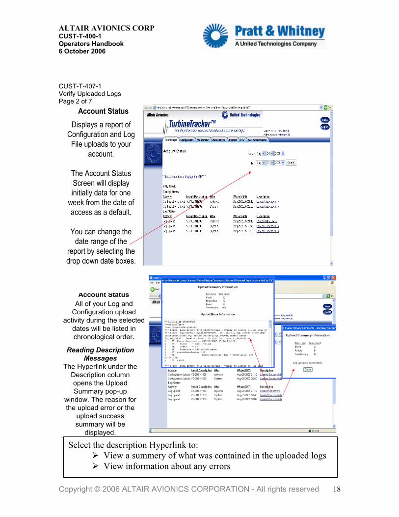
CUST-T-407-1 Verify Uploaded Logs Page 2 of 7
Account StatusDisplays a report of
Configuration and Log File uploads to your
account.
The Account Status Screen will display initially data for one
week from the date of access as a default.
You can change the date range of the
report by selecting the drop down date boxes.
pyright © 2006 ALTAIR AVIONICS COPORATION All ights reserved
Your Hanger TabAccount Status
All of your Log and Configuration upload
activity during the selected dates will be listed in chronological order.
Reading Description Messages
The Hyperlink under the Description column opens the Upload Summary pop-up
window. The reason for the upload error or the
upload success summary will be
displayed.
Co
r
Select the description Hyperlink to: View a summery of what was contained in the uploaded logs View information about any errors
Copyright © 2006 ALTAIR AVIONICS CORPORATION - All rights reserved 18

ALTAIR AVIONICS CORP CUST-T-400-1 Operators Handbook 6 October 2006
CUST-T-407-1 Verify Uploaded Logs Page 3 of 7
Viewing your Uploaded Log Data
After selecting the Data Analysis tab on top, select the View Log Data button on the left. You will be presented with the Summary Data View table.
You can also filter the table view by Airframe, Engine Type, Unit
Type and Date You can easily View Log Data from the entire
fleet by selecting the desired
Hyperlink in the table
The date of Last Upload that was successful will be listed.
Copyri
Click on the Number of Engine Runs Hyperlink to display achronologic list of the engine run logs for the selected Install
ght © 2006 ALTAIR AVIONICS CORPORATION - All rights reserved 19

ALTAIR AVIONICS CORP CUST-T-400-1 Operators Handbook 6 October 2006
CUST-T-407-1 Verify Uploaded Logs Page 4 of 7
Selecting the Sensor Number Hyperlink displaysthe maximum value recorded during the selected run
Selecting the Cycle Number Hyperlinkdisplays the total cycles recorded during the selected run
NOTE: You should periodically analyze the sensor values and cycle counts of your run logs to help you insure that your system is functioning correctly and that the displayed values are reasonable and correctly calibrated.
All thesame
Enginerun
0.9700 is to short for a start. Starting the engine while in config mode then
switching to run mode (Run/Conf switch). Switching between run and config mode to view
live data (Run/Conf switch). Applying power to the monitor while the engine is
running (buss and/or battery)
Deselect the check mark and this engine run will not be included in reports
Copyright © 2006 ALTAIR AVIONICS CORPORATION - All rights reserved 20
ALTAIR AVIONICS CORP CUST-T-400-1 Operators Handbook 6 October 2006
CUST-T-407-1 Verify Uploaded Logs Page 5 of 7
22
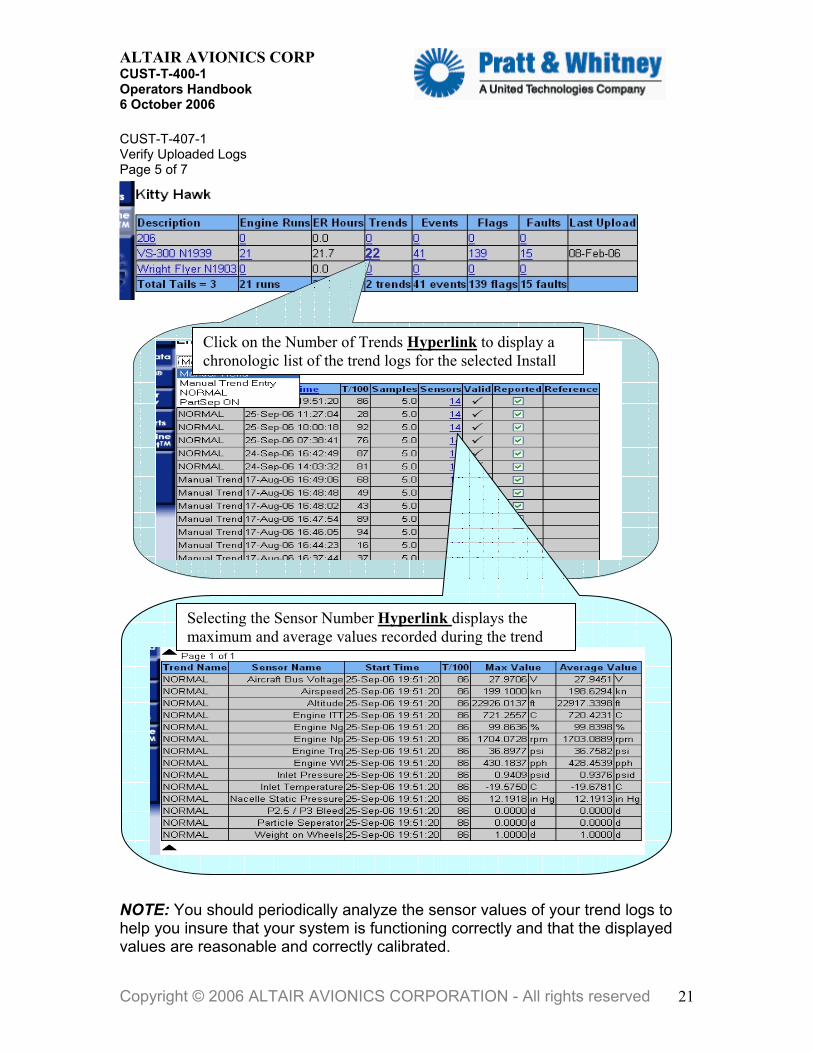
Click on the Number of Trends Hyperlink to display a chronologic list of the trend logs for the selected Install
Selecting the Sensor Number Hyperlink displays the maximum and average values recorded during the trend
NOTE: You should periodically analyze the sensor values of your trend logs to help you insure that your system is functioning correctly and that the displayed values are reasonable and correctly calibrated.
Copyright © 2006 ALTAIR AVIONICS CORPORATION - All rights reserved 21

ALTAIR AVIONICS CORP CUST-T-400-1 Operators Handbook 6 October 2006
CUST-T-407-1 Verify Uploaded Logs Page 6 of 7
Event, Flag and Fault logs are also displayed in chronological order by selecting the desired Hyperlink.
NOTE: You should periodically analyze the event, flag and fault logs to help you insure that your system is functioning correctly and that the displayed values are reasonable and correctly calibrated. Viewing your uploaded DTU Logs After selecting the DTU tab on top, select the DTU Logs button on the left. You will be presented with the DTU selection page.
Copyright © 2006 ALTAIR AVIONICS CORPORATI
You can select: DTU (usually tail number)Date range to review Type of log to review
ON - All rights reserved 22

ALTAIR AVIONICS CORP CUST-T-400-1 Operators Handbook 6 October 2006
CUST-T-407-1 Verify Uploaded Logs Page 7 of 7
Select the (More…) Hyperlink to open a pop-up window and display any additional information that may be contained or associated with the DTU log.
Copyright © 2006 ALTAIR AVIONICS CORPORATION - All rights reserved 23

ALTAIR AVIONICS CORP CUST-T-400-1 Operators Handbook 6 October 2006
CUST-T- 408 -1 USB Download Cable Driver Installation 13 Sep 2006 Page 1 of 8
USB Download Cable Adapter Installation Checklist
Caution: Only for use with the ADAS-C-053-1 USB Download Cable
Overview 1) Download Diver information from TurbineTracker™ 2) Install the USB to Serial converter driver on your laptop 3) Install the communications port driver on your laptop
NOTE: Ensure you have the current version of the Monitor Link Program (MLP) installed on your computer before attempting to download the USB drivers.
The current version is available from the TurbineTracker™ website under the “Support Tab” by selecting the “Systems Update” button on the left and following the on screen instructions (See Checklist CUST-T- 417-1).
1. DOWNLOAD DRIVERS - Log in to TurbineTracker™ website with the Lap
top you will be using the USB Download Cable on and download the <ADAS-C-053 DRIVER.zip> file located under the “Support Tab” by selecting the “Systems Update” button on the left and clicking on the ADAS-C-053 DRIVER.exe hyperlink.
NOTE: ADAS-C-053 DRIVER.exe is a Self – Extracting WinZip file that contains the compressed USB driver information.
Copyright © 2006 ALTAIR AVIONICS CORPORATION - All rights reserved 24

ALTAIR AVIONICS CORP CUST-T-400-1 Operators Handbook 6 October 2006
CUST-T-408 -1 USB Download Cable Driver Installation Page 2 of 8
If you get the File Download - Security Warning select Run
If you get the Internet Explorer - Security Warning select Run
When the WinZip Self – Extractor pop-up opens, select the Unzip button.
NOTE: The Self – Extractor should default to the recommended c:\mlp\bin\usb folder on your computer, but the advanced user has the option to select a different folder.
Copyright © 2006 ALTAIR AVIONICS CORPORATION - All rights reserved 25

ALTAIR AVIONICS CORP CUST-T-400-1 Operators Handbook 6 October 2006
CUST-T-408 -1 USB Download Cable Driver Installation Page 3 of 8
After the download completes you should receive the WinZip pop-up message “14 files unzipped successfully”. After clicking on “OK” when the files are done extracting. Click on “Close” to close the WinZip Self – Extractor window.
Now that you have downloaded the USB Download Cable Drivers to the c:\mlp\bin\usb folder on your PC, there are two steps to completing the driver installation.
First, the USB Converter will be installed. Second, the Communications Port will be installed.
The installation is not complete until both pieces are in place on your computer.
NOTE: You must complete the driver installation for the adaptor and the instructions need to be followed specifically in order for it to be recognized. Some operators experience problems that require them to manually edit their systems communication port settings; especially if the computer was used previously to communicate with other devices i.e. PDA & Active-synch (turn off other programs or devices that may be using comm. port resources).
2. Install the USB to Serial converter driver - Insert the USB cable into your PC’s USB port. The computer should detect the hardware automatically. This first step will install the USB Converter on your PC.
Copyright © 2006 ALTAIR AVIONICS CORPORATION - All rights reserved 26

ALTAIR AVIONICS CORP CUST-T-400-1 Operators Handbook 6 October 2006
CUST-T-408 -1 USB Download Cable Driver Installation Page 4 of 8
The “Found New Hardware Wizard” screen should automatically pop up on your computer. Select “Install from a list or specific location (advanced)” in the wizard and then select “Next”.
Note: Windows defaults to install the software automatically and will not be able the find the correct drivers unless you manually select the “Install from a list or specific location (advanced)” option
Select “Include this location in the search” and you can also de-select “Search removable media”. Click Browse and navigate to c:\mlp\bin\usb then click OK. After you insure the correct path is displayed, click “Next”.
.
Copyright © 2006 ALTAIR AVIONICS CORPORATION - All rights reserved 27
ALTAIR AVIONICS CORP CUST-T-400-1 Operators Handbook 6 October 2006
CUST-T-408 -1 USB Download Cable Driver Installation Page 5 of 8
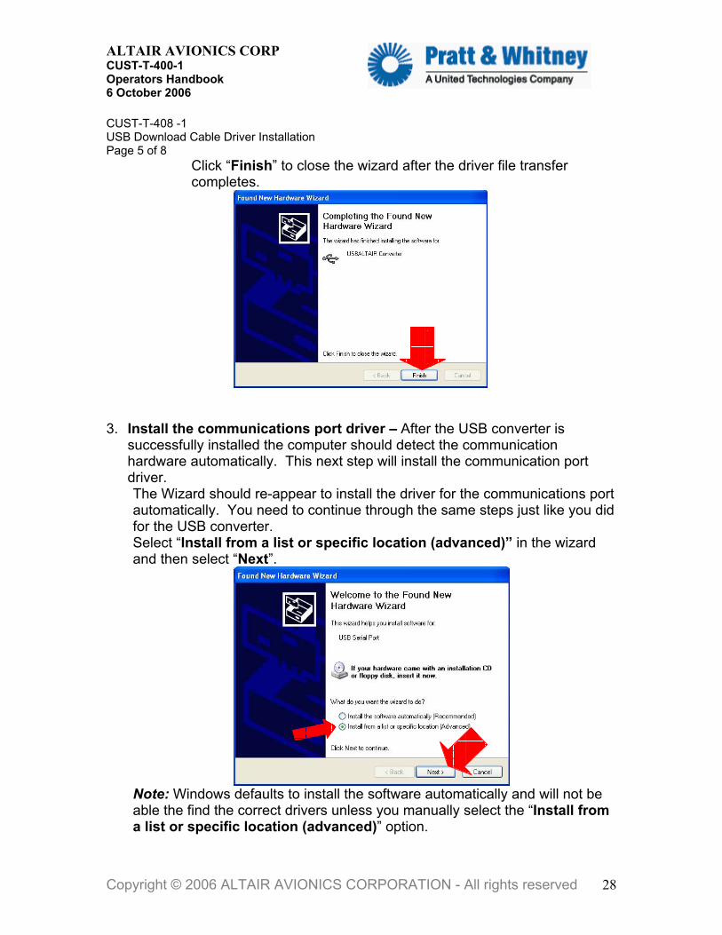
Click “Finish” to close the wizard after the driver file transfer completes.
Install the communications port driver – After the USB converter is successfully installed the computer should detect the communication hardware automatically. This next step will install the communication port driver.
3.
The Wizard should re-appear to install the driver for the communications port automatically. You need to continue through the same steps just like you did for the USB converter. Select “Install from a list or specific location (advanced)” in the wizard and then select “Next”.
Note: Windows defaults to install the software automatically and will not be able the find the correct drivers unless you manually select the “Install from a list or specific location (advanced)” option.
Copyright © 2006 ALTAIR AVIONICS CORPORATION - All rights reserved 28

ALTAIR AVIONICS CORP CUST-T-400-1 Operators Handbook 6 October 2006
CUST-T-408 -1 USB Download Cable Driver Installation Page 6 of 8
• Make sure that the selections are the same as those you made when installing the USB driver. If they are not, repeat those steps from above, and then click “Next”.
• Click “Finish” to close the wizard after it completes.
You have now installed the USB driver and the new communications port on your PC/Laptop. MLP will be able to auto-detect this port when you run MLP and follow the standard procedure for connecting to your monitor, as described in the MLP Manual. If you have trouble connecting to your monitor with MLP, remember to check your Windows hardware settings and that you may have to manually edit comm. port settings.
Copyright © 2006 ALTAIR AVIONICS CORPORATION - All rights reserved 29

ALTAIR AVIONICS CORP CUST-T-400-1 Operators Handbook 6 October 2006
CUST-T-408 -1 USB Download Cable Driver Installation Page 7 of 8
If MLP can not establish a connection with Autodetect: MLP will ask you to check common errors
NOTE: If you have a Download Cable connected to a Generation 3 Monitor the Run/Conf switch should cause the Trend Lamp to illuminate when placed in the conf position. DTU USERS: If you are trying connected to a DTU, the Download Cables Run/Conf switch has no function and should allow you to establish a connection in either position.
Communication Baud Rates of Altair Monitors
Generation I Generation II Generation III DTU & ADASd CrossCheck HUMS 1022 HUMS 1122 Fixed Baud Rate 9600
TrendCheck ADAS SmartCycle SmartCycle Twin
Fixed Baud Rate 19,200
IntelliStart+ SmartCycle+ IntelliStart+ BA TrendCheck+ ADAS+ ADAS+ Upgrade Configurable Baud Rate 19,200 On Reset 57,600 Maximum
DTU ADASd Configurable Baud Rate 57,600 On Reset 57,600 Maximum
Copyright © 2006 ALTAIR AVIONICS CORPORATION - All rights reserved 30
ALTAIR AVIONICS CORP CUST-T-400-1 Operators Handbook 6 October 2006
CUST-T-408 -1 USB Download Cable Driver Installation Page 8 of 8
Trouble Shooting Tips
TIPS AND TRICKS: An easy way to verify successful connection
between MLP and your Processor is to accomplish “MLU Status” under the MLU Menu.
Receiving the “MLU Status Processing Complete” prompt and the display of the processors status indicates a connection has been established between the computer and the processor.
Unable to Communicate with Processor Most common communication failures:
Processor not powered on. Insure completion of successful Power-
On BIT Test.
Down-load cable Run/Conf Switch (in run). Switch to config position to allow MLP to send commands and receive replies from the monitor.
Note: Except for DTU’s the Trend Lamp should illuminate solid when the Down-load Cable Switch is in Conf position.
Faulty ConXall plug and Communication Port wiring installation. Check comm. port IAW Instructions for Continued Airworthiness.
Computer setup: o Communications port not available. Check your Windows
Device Manager. o Communications port being used by other Devices or
Software. Stop other applications like Active Synch, Camera programs, Serial Mouse & etc.
o USB to serial adapter drivers not correctly installed. Re-install Drivers.
o USB hardware incompatible with RS 485. Use Altair recommended adapter or Download Cable.
o Firewall and Security settings blocking MLP. Insure MLP can operate through your Firewall and write files to your C:\ Hard Drive.
NOTE: All of our updated Manuals, User's Guides and Checklist are available free of charge for TurbineTracker™ users under the “Support Tab” by selecting the “Documents” button.
Copyright © 2006 ALTAIR AVIONICS CORPORATION - All rights reserved 31

ALTAIR AVIONICS CORP CUST-T-400-1 Operators Handbook 6 October 2006
CUST-T-409-1 Calibration 31 OCTOBER 2005 Page 1 of 12
Calibration Calibrating Your Processor
CAUTION: Ensure you have the current version of the Monitor Link Program (MLP). The current version is available from Turbine Tracker under the “Support Tab” and “Systems Update” button. (See Checklist CUST-T- 417-1) NOTE: Calibration is usually required to analog type sensors due to the variance in harness resistance between aircraft. During the initial installation it is recommended to calibrate sensors in parallel to the aircraft instrumentation to determine that the aircraft and monitor are both correct and within tolerance. METHODS OF CALIBRATION: There are basically two means for calibrating sensors. 1) With a calibration tool, such as a Barfield temp calibrator, deadweight pressure calibrator, or by referenced to the aircraft instrumentation. 2) Calibration to the aircraft can be accomplished real-time (while flying) or after the flight using “manual sensor calibration” described below. NOTE: The following (and ONLY the following) shall be calibrated: Engine Temperature (T4, T4.5, TOT, EGT, MGT, ITT, Etc.) for all processors OAT, Engine Torque, Airspeed, Altitude for all processors Accelerometer for the ADAS processor only Engine Oil Temperature for the SmartCycle Plus processor only NOTE: The examples shown within this checklist use a combination of monitors with one processor and monitors with two processors. Calibration is accomplished for each processor. When calibrating monitors with two processors, you must choose the processor AND sensor to be calibrated. TIPS AND TRICKS: Processor 1 within the ADAS is called the ADAS Master. Processor 2 is called the ADAS Slave. NOTE: Calibrating the Altitude Sensor also calibrates the Static Pressure Sensor. A separate Static Pressure calibration is not required. NOTE: Calibrating the Airspeed Sensor also calibrates the Pitot Pressure Sensor. A separate Pitot Pressure calibration is not required.
Copyright © 2006 ALTAIR AVIONICS CORPORATION - All rights reserved 32
ALTAIR AVIONICS CORP CUST-T-400-1 Operators Handbook 6 October 2006
CUST-T-409-1 Calibration Page 2 of 12 NOTE: Calibrating either processors ambient sensors (OAT, Airspeed, Altitude) for the ADAS monitor will calibrate the other processor at the same time. NOTE: A Barfield (or equivalent) should be used to calibrate the “Engine Temperatures.” If a Barfield is not available, an engine run must be accomplished to generate the required values for calibration. NOTE: A deadweight tester or pressure calibrator should be used to calibrate Engine Torque. If a deadweight tester is not available, an engine run must be accomplished to generate the required values for calibration. NOTE: A pitot static test set should be used to calibrate Airspeed (and Altitude for ADAS). If a pitot static test set is not available, the airspeed (and altitude for ADAS) shall be calibrated while the aircraft is in flight to generate the required values. NOTE: Calibration will increase the configuration version number in your processor and configuration file. The new configuration .cal file must be uploaded to TurbineTracker™ once calibration is complete. NOTE: The configuration version will only increment one step while you remain in MLP regardless of how many sensors you calibrate. Care should be taken to not close and open MLP during the process or the configuration version could increment more than one level. TYPES OF CALIBRATION TWO POINT: The two-point calibration is the most accurate and recommended whenever you can supply two separate calibration points. The two-point calibration will require a low and high calibration value. Using these values the MLP program will calculate a new P1 (Slope) and P2 (Offset) value for the sensor. ONE POINT SLOPE: The one-point slope calibration can be used to calibrate the sensor to match the aircraft instrument at a high value. The one-point calibration will require a high calibration value. Using this value the MLP program will calculate a new P1 (Slope) value for the sensor.
Copyright © 2006 ALTAIR AVIONICS CORPORATION - All rights reserved 33

ALTAIR AVIONICS CORP CUST-T-400-1 Operators Handbook 6 October 2006
CUST-T-409-1 Calibration Page 3 of 12 ONE POINT OFFSET: The one-point offset calibration can be used to calibrate the sensor to match the aircraft instrument at a low value. The one-point calibration will require a low calibration value. Using this value the MLP program will calculate a new P2 (Offset) value for the sensor. TIPS AND TRICKS: Accomplish a Two Point Calibration if you can generate two values widely different from each other (e.g. Torque at 20% then at 80%), if directed by this checklist, OR if directed by Customer Support. TIPS AND TRICKS: Accomplish a One Point Calibration ONLY if a two point cannot be accomplished, if directed by this checklist, OR if directed by Customer Support. Recommended Types of Calibration SENSOR CALIBRATION EQUIPMENT CALIBRATION TYPE “Engine Temperatures” (T4, T4.5, TOT, EGT, MGT, ITT) Barfield (or Equivalent) Two Point OAT Aircraft OAT Sensor One Point Offset Engine Torque Dead Weight Tester Two Point Airspeed Pitot Static Test Set Two Point Altitude (for all processors except ADAS)Aircraft Altimeter * One Point Offset Altitude (for the ADAS only) Pitot Static Test Set Two Point Accelerometer (for the ADAS only) Gravity (+/- 1g) ** Two Point Engine Oil Temperature None *** Manual Sensor Calibration * Refer to Addendum 1 for calibration. ** Refer to Addendum 2 for calibration. *** Refer to Addendum 3 for calibration. LESSONS LEARNED: Prior to attempting calibration accomplish the Retrieve Data Log Procedure. Calibration cannot be accomplished with log data present in the processor. LESSONS LEARNED: During the initial installation of the product it is advisable to view “live data” with MLP (see view live data checklist). This will allow you to
Copyright © 2006 ALTAIR AVIONICS CORPORATION - All rights reserved 34

ALTAIR AVIONICS CORP CUST-T-400-1 Operators Handbook 6 October 2006
CUST-T-409-1 Calibration Page 4 of 12 perform a sanity check against the aircraft prior to calibration. Operators often attempt to calibrate a sensor that is not working correctly. If the processor is displaying all 9s for a sensor, this indicates a sensor failure. CANCEL out of the calibration and accomplish System Troubleshooting IAW the Instruction for Continued Airworthiness. TIPS AND TRICKS: If you feel that the sensor readings on the processor are close enough to the aircraft gages, you may decide that calibration is not required for that sensor. LESSONS LEARNED: If the sensor readings are considerably off from the aircraft gages, contact Customer Support. CALIBRATION CHECKLIST – TWO POINT For this example Engine Temperature, using a barfield temperature calibrator, will be used. 1. Ensure the RUN/CONF switch on the serial cable is set to “CONF” (Skip this step for HUMS 1122 and CrossCheck) or enter TRANSPARENT MODE if using the DTU. 2. Select “MLU” then “Sensor Calibration.” NOTE: The MLP will collect all sensors able to be calibrated through the “Select Sensor for Calibration” Dialog Box. 3. Select “Engine T4.5” from the drop down list. 4. Select “Two Point” from the Calibration Type. 5. Click “OK” NOTE: The Two Point Sensor Calibration Dialog Box appears with two sets of (grayed out) numbers cycling on the left and two sets of white text boxes labeled “Enter a value” on the right. Use Set Point 1 for the low point and Set Point 2 for the high point. 6. Generate the low point value for the sensor (e.g. Engine T4.5 at 300o C) and wait for the sensor reading on the processor to stabilize. 7. Check the value on the aircraft gauge. VALUE __________________. (If the aircraft value is not within tolerance of the calibrated input, pause here and investigate. If the aircraft value is acceptable, continue). 8. Enter the value from the aircraft gauge in the upper white text box. 9. Click “Set Point 1” ONCE and note the grayed number on the left stops cycling.
Copyright © 2006 ALTAIR AVIONICS CORPORATION - All rights reserved 35

ALTAIR AVIONICS CORP CUST-T-400-1 Operators Handbook 6 October 2006
CUST-T-409-1 Calibration Page 5 of 12 LESSONS LEARNED: Clicking a “Set Point” button more than once will cause the calibration value to be rejected. If this occurs, the number on the left will continue to cycle. Re-accomplish the step and remember to click the “Set Point” button once and only once. 10. Generate the high point value for the sensor (e.g. . Engine T4.5 at 900o C) and wait for the sensor reading on the processor to stabilize. 11. Check the value on the aircraft gauge. VALUE__________________. (If the aircraft value is not within tolerance of the calibrated, pause here and investigate. If the aircraft value is acceptable, continue). 12. Enter the value from the aircraft gauge in the lower white text box. 13. Click “Set Point 2” ONCE and note the grayed number on the left stops cycling. 14. Click “OK” 15. The new configuration file values shall be displayed in a new dialog box. Click “Yes” to accept the new values. TIPS AND TRICKS: If you feel a mistake has been made, click “No” and proceed through the dialog boxes. When the “Select Sensor for Calibration” Dialog Box appears, go to step 3. NOTE: When you accept new calibration values, MLP automatically creates a .cal file in the MLP sync directory (C:\mlp\sync\cfg\tx) that will need to be loaded to TurbineTracker™ after completion of calibration. NOTE: The preferred method to upload a .cal file is to synchronize MLP to TurbineTracker™ which well automatically transfer all files. If you can not connect MLP directly to TurbineTracker™ (firewall) you can manually upload the config .cal file using the websites File Transfer Tab. 16. Click “Yes” to review the sensor’s calibration or “No” not to review the sensor’s calibration. TIPS AND TRICKS: Click “Yes” in step 16 to view the results of calibration. The Calibration Review Dialog Box will display the processor reading resulting from calibration. Compare that value to the aircraft gauge value to verify accuracy. 17. If you clicked “Yes” for step 16, click “Done.” (If you have completed calibration, select No. Otherwise, select Yes to calibrate another sensor).
Copyright © 2006 ALTAIR AVIONICS CORPORATION - All rights reserved 36

ALTAIR AVIONICS CORP CUST-T-400-1 Operators Handbook 6 October 2006
CUST-T-409-1 Calibration Page 6 of 12 CALIBRATION CHECKLIST – ONE POINT SLOPE For this example Airspeed, matched against the aircraft instrument, will be used. 1. Ensure the RUN/CONF switch on the serial cable is set to “CONF” (Skip this step for HUMS 1122 and CrossCheck) or enter TRANSPARENT MODE if using the DTU. 2. Select “MLU” then “Sensor Calibration.” NOTE: The MLP will collect all sensors able to be calibrated through the “Select Sensor for Calibration” Dialog Box. 3. Select “Airspeed” from the drop down list. 4. Select “One Point Slope” from the Calibration Type. 5. Click “OK” NOTE: The One Point Sensor Calibration Dialog Box appears with one (grayed out) number cycling on the left and one white text boxes labeled “Calibrate to value” on the right. 6. Check the value on the aircraft gauge. VALUE __________________. 7. Enter the value from the aircraft gauge in the white text box. 8. Click “Set Point” ONCE and note the grayed number on the left stops cycling. LESSONS LEARNED: Clicking a “Set Point” button more than once will cause the calibration value to be rejected. If this occurs, the number on the left will continue to cycle. Re-accomplish the step and remember to click the “Set Point” button once and only once. 9. Click “OK” 10. The new configuration file values shall be displayed in a new dialog box. Click “Yes” to accept the new values. TIPS AND TRICKS: If you feel a mistake has been made, click “No” and proceed through the dialog boxes. When the “Select Sensor for Calibration” Dialog Box appears, go to step 3. NOTE: When you accept new calibration values, MLP automatically creates a .cal file in the MLP sync directory (C:\mlp\sync\cfg\tx) that will need to be loaded to TurbineTracker™ after completion of calibration. NOTE: The preferred method to upload a .cal file is to synchronize MLP to TurbineTracker™ which well automatically transfer all files. If you can not connect MLP directly to TurbineTracker™ (firewall) you can manually upload the config .cal file using the websites File Transfer Tab.
Copyright © 2006 ALTAIR AVIONICS CORPORATION - All rights reserved 37

ALTAIR AVIONICS CORP CUST-T-400-1 Operators Handbook 6 October 2006
CUST-T-409-1 Calibration Page 7 of 12 11. Click “Yes” to review the sensor’s calibration or “No” not to review the sensor’s calibration. TIPS AND TRICKS: Click “Yes” in step 11 to view the results of calibration. The Calibration Review Dialog Box will display the processor reading resulting from calibration. Compare that value to the aircraft gauge value to verify accuracy. 12. If you clicked “Yes” for step 11, click “Done.” (If you have completed calibration, select No. Otherwise, select Yes to calibrate another sensor). CALIBRATION CHECKLIST – ONE POINT OFFSET For this example OAT, matched against the aircraft OAT probe, will be used. 1. Ensure the RUN/CONF switch on the serial cable is set to “CONF” (Skip this step for HUMS 1122 and CrossCheck) or enter TRANSPARENT MODE if using the DTU. 2. Select “MLU” then “Sensor Calibration.” NOTE: The MLP will collect all sensors able to be calibrated through the “Select Sensor for Calibration” Dialog Box. 3. Select “OAT” from the drop down list. 4. Select “One Point Offset” from the Calibration Type. 5. Click “OK” NOTE: The One Point Sensor Calibration Dialog Box appears with one (grayed out) number cycling on the left and one white text boxes labeled “Calibrate to value” on the right. 6. Check the value on the aircraft gauge. VALUE __________________. 7. Enter the value from the aircraft gauge in the white text box. 8. Click “Set Point” ONCE and note the grayed number on the left stops cycling. LESSONS LEARNED: Clicking a “Set Point” button more than once will cause the calibration value to be rejected. If this occurs, the number on the left will continue to cycle. Re-accomplish the step and remember to click the “Set Point” button once and only once. 9. Click “OK” 10. The new configuration file values shall be displayed in a new dialog box. Click “Yes” to accept the new values.
Copyright © 2006 ALTAIR AVIONICS CORPORATION - All rights reserved 38

ALTAIR AVIONICS CORP CUST-T-400-1 Operators Handbook 6 October 2006
CUST-T-005-1 Calibration Page 8 of 12 TIPS AND TRICKS: If you feel a mistake has been made, click “No” and proceed through the dialog boxes. When the “Select Sensor for Calibration” Dialog Box appears, go to step 3. NOTE: When you accept new calibration values, MLP automatically creates a .cal file in the MLP sync directory (C:\mlp\sync\cfg\tx) that will need to be loaded to TurbineTracker™ after completion of calibration. NOTE: The preferred method to upload a .cal file is to synchronize MLP to TurbineTracker™ which well automatically transfer all files. If you can not connect MLP directly to TurbineTracker™ (firewall) you can manually upload the config .cal file using the websites File Transfer Tab. 11. Click “Yes” to review the sensor’s calibration or “No” not to review the sensor’s calibration. TIPS AND TRICKS: Click “Yes” in step 11 to view the results of calibration. The Calibration Review Dialog Box will display the processor reading resulting from calibration. Compare that value to the aircraft gauge value to verify accuracy. If you clicked “Yes” for step 11, click “Done.” If you have completed calibration, select No. Otherwise, select Yes to calibrate another sensor. CALIBRATION CHECKLIST – MANUAL SENSOR CALIBRATION NOTE: The manual sensor calibration can be used to match the processor to the aircraft. Prior to performing this type of calibration the operator will need to collect operational (flight) data from the aircraft and monitor. A suggested method is to have the pilot or crew start the engine and record engine values (to match sensors needing calibration) at idle. At the same time the processor trend button should be pressed to capture the same data. Fly the aircraft and perform the same process (collecting written and trend data) in cruise flight. These two samples from the aircraft and engine monitor will be used to complete the following manual sensor calibration. For this example Altitude (ADAS) will be used. 1. Ensure the RUN/CONF switch on the serial cable is set to “CONF.” (Skip this step for HUMS 1122 and CrossCheck) or enter TRANSPARENT MODE if using the DTU.
Copyright © 2006 ALTAIR AVIONICS CORPORATION - All rights reserved 39

ALTAIR AVIONICS CORP CUST-T-400-1 Operators Handbook 6 October 2006
CUST-T-409-1 Calibration Page 9 of 12 2. Select “Expert Mode” then “Manual Sensor Calibration.” NOTE: The MLP will collect all sensors able to be calibrated through the “Select Sensor for Calibration” Dialog Box. 3. Select “Processor 1 Altitude” from the drop down list. 4. Select “Two Point” from the Calibration Type. 5. Click “OK” NOTE: The Manual Two Point Sensor Calibration Dialog Box appears with two sets of numbers on the left (both processor one and two for ambient channels) and two sets of white text boxes labeled “Enter a value” on the right. NOTE: The ADAS is represented here with dual processors. Other monitors would be identical with the exception of the second (slave) processor. 6. Using the collected ground and flight data, input the processor one reading for low (ground idle) and high (flight cruise) under the “Master Values”. 7. Using the collected ground and flight data, input the processor two reading for low (ground idle) and high (flight cruise) under the “Slave Values”. 8. Using the collected ground and flight data, input the aircraft reading for low (ground idle) and high (flight cruise) under the “Calibrate To Values”. 9. Click “OK” 10. The new configuration file values shall be displayed in a new dialog box. Click “Yes” to accept the new values. TIPS AND TRICKS: If you feel a mistake has been made, click “No” and proceed through the dialog boxes. When the “Select Sensor for Calibration” Dialog Box appears, go to step 3. NOTE: When you accept new calibration values, MLP automatically creates a .cal file in the MLP sync directory (C:\mlp\sync\cfg\tx) that will need to be loaded to TurbineTracker™ after completion of calibration. NOTE: The preferred method to upload a .cal file is to synchronize MLP to TurbineTracker™ which well automatically transfer all files. If you can not connect MLP directly to TurbineTracker™ (firewall) you can manually upload the config .cal file using the websites File Transfer Tab. 11. Click “Yes” to review the sensor’s calibration or “No” not to review the sensor’s calibration. TIPS AND TRICKS: Click “Yes” in step 11 to view the results of calibration. The Calibration Review Dialog Box will display the processor reading resulting from calibration. Compare that value to the aircraft gauge value to verify accuracy.
Copyright © 2006 ALTAIR AVIONICS CORPORATION - All rights reserved 40

ALTAIR AVIONICS CORP CUST-T-400-1 Operators Handbook 6 October 2006
CUST-T-409-1 Calibration Page 10 of 12 If you clicked “Yes” for step 11, click “Done.” If you have completed calibration, select No. Otherwise, select Yes to calibrate another sensor. ADDENDUM 1 CALIBRATION CHECKLIST – ALTITUDE (for all processors except ADAS, HUMS 1122, and Crosscheck) NOTE: Use the Calibration Checklist – One Point Offset to calibrate Altitude. THIS ADDENDUM DOES NOT REPLACE THE ONE POINT OFFSET. This addendum simply elaborates on what to do specifically for Altitude. 1. Ensure the RUN/CONF switch on the serial cable is set to “CONF” or enter TRANSPARENT MODE if using the DTU. 2. Select “MLU” then “Sensor Calibration.” NOTE: The MLP will collect all sensors able to be calibrated through the “Select Sensor for Calibration” Dialog Box. 3. Select “Altitude” from the drop down list. 4. Select “One Point Offset” from the Calibration Type. 5. Click “OK” 6. Dial 29.92 inHg (1013 mbar) on the Pressure Gage within the Altimeter. NOTE: All engine monitoring systems represent Altitude as Pressure Altitude. Using 29.92 inHg (1013 mbar) in the Aircraft Altimeter will make the altimeter show Pressure Altitude. Go to Step 6 of the CALIBRATION CHECKLIST – ONE POINT OFFSET . ADDENDUM 2 CALIBRATION CHECKLIST – ACCELEROMETER (for ADAS processor only) NOTE: Use the Calibration Checklist – Two Point to calibrate the Accelerometer. THIS ADDENDUM DOES NOT REPLACE THE TWO POINT. This addendum simply elaborates on what to do specifically for the Accelerometer. 1. Ensure the RUN/CONF switch on the serial cable is set to “CONF” or enter TRANSPARENT MODE if using the DTU.
Copyright © 2006 ALTAIR AVIONICS CORPORATION - All rights reserved 41

ALTAIR AVIONICS CORP CUST-T-400-1 Operators Handbook 6 October 2006
CUST-T-409-1 Calibration Page 11 of 12 2. Select “MLU” then “Sensor Calibration.” NOTE: The MLP will collect all sensors able to be calibrated through the “Select Sensor for Calibration” Dialog Box. 3. Select “Accelerometer” from the drop down list. 4. Select “Two Point” from the Calibration Type. 5. Click “OK” NOTE: The Two Point Sensor Calibration Dialog Box appears with two sets of (grayed out) numbers cycling on the left and two sets of white text boxes labeled “Enter a value” on the right. It is recommended that you use Set Point 1 for the low point and Set Point 2 for the high point. 6. Invert the accelerometer and note the upper grayed out number becomes negative. 7. Enter –1 in the upper white text box. 8. Click “Set Point 1” ONCE and note the grayed number on the left stops cycling. LESSONS LEARNED: Clicking a “Set Point” button more than once will cause the calibration value to be rejected. If this occurs, the number on the left will continue to cycle. Re-accomplish the step and remember to click the “Set Point” button once and only once. 9. Turn the accelerometer right side up and note the lower grayed out number becomes positive. 10. Enter 1 in the lower white text box. 11. Click “Set Point 2” ONCE and note the grayed number on the left stops cycling. 12. Click “OK” Go to Step 15 of the CALIBRATION CHECKLIST – TWO POINT. ADDENDUM 3 CALIBRATION CHECKLIST – Engine Oil Temperature (For Smartcycle Plus Only) NOTE: Use the Calibration Checklist – Manual Sensor Calibration to calibrate Engine Oil Temperature. THIS ADDENDUM DOES NOT REPLACE THE MANUAL SENSOR CALIBRATION CHECKLIST. This addendum simply elaborates on what to do specifically for Engine Oil Temperature. Collect the first set of data as follows.
Copyright © 2006 ALTAIR AVIONICS CORPORATION - All rights reserved 42

ALTAIR AVIONICS CORP CUST-T-400-1 Operators Handbook 6 October 2006
CUST-T-409-1 Calibration Page 12 of 12 1. Start the Aircraft engine. 2. Wait for the engine oil temperature to stabilize at idle. 3. Record the engine oil temperature value from the aircraft gauge. 4. Press the Trend Button Collect the second set of data as follows. 5. Run up the aircraft to a high power setting to increase oil temperature. 6. Wait for the engine oil temperature to stabilize at the high power setting. 7. Record the engine oil temperature value from the aircraft gauge. 8. Press the Trend Button Go to Step 1 of the CALIBRATION CHECKLIST – MANUAL SENSOR CALIBRATION using the collected values above as input.
Copyright © 2006 ALTAIR AVIONICS CORPORATION - All rights reserved 43

ALTAIR AVIONICS CORP CUST-T-400-1 Operators Handbook 6 October 2006
CUST-T-410-1 Establish MLP Connection 21 NOVEMBER 2005 Page 1 of 1
Establish MLP Connection Connecting to the Processor with MLP NOTE: Ensure you have the current version of the Monitor Link Program (MLP). The current version is available from Turbine Tracker under the “Support Tab” and “Systems Update” button. (See Checklist CUST-T- 417-1) 1. Apply Bus AND Battery Power to the Aircraft and ensure system bootup is successful, if not previously accomplished. NOTE: System Bootup cannot be verified if aircraft does not have a Cockpit Lamp Assembly. 2. If you have the Cockpit Download Port Assembly Interface, connect your computer to the Download Port using the Serial or USB Cable. If you do NOT have the Cockpit Download Port Assembly Interface, connect the computer to the processor directly using the Serial or USB Cable. NOTE: (Cockpit Indicator Light Present with No DTU) the fault lamp will be on solid when the Run/Conf switch of the serial or USB cable is set to “Conf.” 3. Ensure the RUN/CONF switch on the download cable is set to “CONF” (Skip this step for HUMS 1122, CrossCheck and DTU) 4. Open MLP, Select “Edit,” then “Communication Port,” then “Autodetect.” If you are unable to establish communication, exit this checklist and proceed to the “MLP Troubleshooting” checklist. NOTE: The MLP defaults to the last used MLU when initially started.
TIPS AND TRICKS: Accomplish a “MLU Status” under the MLU Menu. Receiving a response and a “MLU Status Processing Complete” prompt indicates a connection has been established between the computer and the processor.
Copyright © 2006 ALTAIR AVIONICS CORPORATION - All rights reserved 44
ALTAIR AVIONICS CORP CUST-T-400-1 Operators Handbook 6 October 2006
4.
CUST-T-411-1 Load Configuration File 6 NOVEMBER 2005 Page 1 of 2
Load Configuration File Computer to Processor NOTE: Ensure you have the current version of the Monitor Link Program (MLP). The current version is available from Turbine Tracker under the “Support Tab” and “Systems Update” button (See Checklist CUST-T- 417-1). NOTE: The preferred method of updating your configuration is to use the Synch to Aircraft feature. NOTE: If using a DTU it must be configured and in Transparent Mode first. 1. Establish connection to the processor using MLP. If unable to establish connection, accomplish MLP Troubleshooting Procedure. TIPS AND TRICKS: Accomplish a “MLU Status” under the MLU Menu. Receiving a response and a “MLU Status Processing Complete” prompt indicates a connection has been established between the computer and the processor. 2. Select “Configure Unit” under the MLU Menu. 3. Browse to find the File when the Select Configuration Box appears, if necessary. NOTE: Configuration Files are denoted by the .cfg and .bfg extension. .cfg and .bfg files are the only file types that are loaded into the processor. TIPS AND TRICKS: The default directory for the File is the “c:\mlp\cfg” folder. It is recommended that you place all of your Configuration Files in this directory for easy access.
Select the File and click “Open”
NOTE: If you are prompted to retrieve the Log File, accomplish “Retrieve Log Data from Processor” checklist and re-enter this checklist at Step 2.
Copyright © 2006 ALTAIR AVIONICS CORPORATION - All rights reserved 45

ALTAIR AVIONICS CORP CUST-T-400-1 Operators Handbook 6 October 2006
5.
CUST-T-003-1 Load Configuration File Page 2 of 2 NOTE: Configuration File load may approximately take 4 to 6 minutes. NOTE: If you are prompted that configuration errors occurred, go to the MLP Troubleshooting Checklist. NOTE: A completed configuration file load will be noted by a “Configuration Complete” prompt. TIPS AND TRICKS: Accomplish a “MLU Status” under the MLU Menu to verify your config version (serial B = config version) Altair Avionics
Accomplish the Calibration Checklist, if required.
NOTE: Calibration is required on all sensors specified in the Calibration Checklist if this is the initial configuration file load (new installation and configuration file not previously loaded). NOTE: Calibration is required for a particular sensor if the configuration file sensor values on an existing configuration were changed; processor parts, aircraft/engine parts, or cockpit instruments are changed. For example, if you change a TOT gauge, you may have to re-calibrate TOT. 6. End
Copyright © 2006 ALTAIR AVIONICS CORPORATION - All rights reserved 46

ALTAIR AVIONICS CORP CUST-T-400-1 Operators Handbook 6 October 2006
CUST-T-412-1 Retrieve Log Data 1 November 2005 Page 1 of 2
Retrieve Log Data From Processor to Computer NOTE: Ensure you have the current version of the Monitor Link Program (MLP). The current version is available from Turbine Tracker under the “Support Tab” and “Systems Update” button (See Checklist CUST-T- 417-1). NOTE: You should always Synchronize to TurbineTracker™ first to ensure you have any available configuration updates loaded into MLP. 1. Ensure the RUN/CONF switch on the serial cable is set to “CONF” (Skip this step for HUMS 1122 and CrossCheck) or enter TRANSPARENT MODE if using the DTU and retrieving a log from a monitor. 2. Establish connection to the processor that you wish to retrieve the log from using MLP. If unable to establish connection, accomplish MLP Troubleshooting Procedure. TIPS AND TRICKS: Accomplish a “MLU Status” under the MLU Menu. Receiving a response and a “MLU Status Processing Complete” prompt indicates a connection has been established between the computer and the processor. 3. Select “Aircraft” under the dropdown Synchronize menu in MLP. The Synchronize feature will automatically retrieve the unit’s data log and prompt you to reset the log. After you reset the log any new configuration files will then be transferred automatically. NOTE: The Reset Log Box appears when the upload is complete. TIPS AND TRICKS: Resetting the Log means to clear the log data from the processor after uploading the data into your computer. If you do not Reset the Log, the log data shall remain in the processor and log data generated from that point on will be appended to the existing log data. Altair Avionics
Copyright © 2006 ALTAIR AVIONICS CORPORATION - All rights reserved 47

ALTAIR AVIONICS CORP CUST-T-400-1 Operators Handbook 6 October 2006
CUST-T-412-1 Retrieve Log Data Page 2 of 2 CAUTION: If you do not Reset the Log for a long period of time, the processor’s memory may become full. If the processor’s memory fills up, the processor will stop recording data. TIPS AND TRICKS: It is impossible to say how often the log should be retrieved. It is recommended that when you initially deploy your processor, you should retrieve it at the two week point. If you determine that you can wait longer, then retrieve it once a month. You will need to decide the best interval for retrieval based on your operations and needs. NOTE: Expert user’s can perform log retrieval as follows.
1. Select MLU then “Retrieve Unit’s Data Log.”
NOTE: Destination of Log File Box appears. 2. Select a file name to store the log data.
TIPS AND TRICKS: Choose a file name that is easily recognizable. The file shall be saved in the c:\mlp\log directory.
3. Click “Save” Depending upon the size of the log data, a binary file upload may occur. If a binary upload occurs, follow the prompts. Although slightly different from a non-binary upload, the result is the same. NOTE: The Reset Log Box appears when the upload is complete.
4. Select “Yes” or “No” on whether or not to reset the log. 5. End
Copyright © 2006 ALTAIR AVIONICS CORPORATION - All rights reserved 48
ALTAIR AVIONICS CORP CUST-T-400-1 Operators Handbook 6 October 2006
6.
CUST-T-413-1 Synchronize Checklist Synchronize 23 January 2006 Page 1 of 2
The proper method of using the SYNCHRONIZE function is this: Sync to TurbineTracker™
Sync to Aircraft. Sync to TurbineTracker™
NOTE: Ensure you have the current version of the Monitor Link Program (MLP). The current version is available from Turbine Tracker under the “Support Tab” and “Systems Update” button (See Checklist CUST-T- 417-1). 1. Establish connection to the internet with the laptop computer to be used for loading and retrieving files to and from the processor in the aircraft. 2. Open the MLP.exe program. 3. Select “TurbineTracker™” under the Synchronize tab dropdown menu. NOTE: This method requires the user to enter login ID and password. 4. Enter your login information when prompted. NOTE: Once the computer has completed the Synchronization process the following message will appear in the status bar at the top of the MLP window: “TTS Synchronization Process Complete” NOTE: If MLP can not establish a connection through your firewall you may need to configure MLP to logon with correct account name through a proxy to enable the “Synchronize to TurbineTracker™” feature. Refer to the MLP User’s Guide for instructions on how to configure MLP with your user account information. 5. After synchronizing to TurbineTracker™ take the laptop computer to the aircraft and connect the computer to the processor using the download cable. Ensure the RUN/CONF switch on the cable is set to “CONF” (Switch position does not matter for HUMS 1122, CrossCheck and DTU) and apply aircraft power.
Select “Aircraft” under the dropdown Synchronize menu in MLP.
Copyright © 2006 ALTAIR AVIONICS CORPORATION - All rights reserved 49

ALTAIR AVIONICS CORP CUST-T-400-1 Operators Handbook 6 October 2006
CUST-T-413-1 Synchronize Checklist Page 2 of 2 NOTE: If you are not able to establish a connection, accomplish the MLP Troubleshooting Procedure. TIPS and TRICKS: Accomplish a “MLU Status” under the MLU Menu. Receiving a response and a “MLU Status Processing Complete” prompt indicates a connection has been established between the computer and the aircraft processor. 7. DTU users select “All” for your Sync Option from the pop-up window. Note: The Synchronize feature will automatically retrieve the unit’s data log and prompt you to reset the log. After you reset the log any new configuration files will then be transferred automatically. NOTE: The Reset Log Box appears when the upload is complete. Select “Yes”. TIPS AND TRICKS: Resetting the Log means to clear the log data from the processor after uploading the data into your computer. If you do not reset the Log, the log data shall remain in the processor and log data generated from that point on will be appended to the existing log data. Altair Avionics CAUTION: If you do not reset the Log for a long period of time, the processor’s memory may become full. If the processor’s memory fills up, the processor will stop recording data. NOTE: Once the computer has completed the Synchronization process the following message will appear: “TTS Synchronization Process Complete” 8. Transfer your log data to TurbineTracker™ by performing steps 1 though 4 from page one. NOTE: If you have calibrated your monitor your configuration .cal file will be automatically uploaded as well.
Copyright © 2006 ALTAIR AVIONICS CORPORATION - All rights reserved 50
ALTAIR AVIONICS CORP CUST-T-400-1 Operators Handbook 6 October 2006
CUST-T-414-1 MLP Troubleshooting 14 Sep 2006 Page 1 of 8
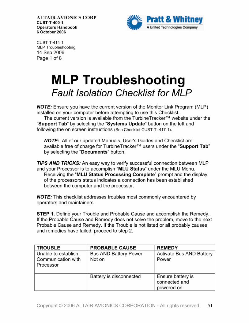
MLP Troubleshooting Fault Isolation Checklist for MLP
NOTE: Ensure you have the current version of the Monitor Link Program (MLP) installed on your computer before attempting to use this Checklist.
The current version is available from the TurbineTracker™ website under the “Support Tab” by selecting the “Systems Update” button on the left and following the on screen instructions (See Checklist CUST-T- 417-1).
NOTE: All of our updated Manuals, User's Guides and Checklist are available free of charge for TurbineTracker™ users under the “Support Tab” by selecting the “Documents” button.
TIPS AND TRICKS: An easy way to verify successful connection between MLP and your Processor is to accomplish “MLU Status” under the MLU Menu.
Receiving the “MLU Status Processing Complete” prompt and the display of the processors status indicates a connection has been established between the computer and the processor.
NOTE: This checklist addresses troubles most commonly encountered by operators and maintainers. STEP 1. Define your Trouble and Probable Cause and accomplish the Remedy. If the Probable Cause and Remedy does not solve the problem, move to the next Probable Cause and Remedy. If the Trouble is not listed or all probably causes and remedies have failed, proceed to step 2. TROUBLE PROBABLE CAUSE REMEDY Unable to establish Communication with Processor
Bus AND Battery Power Not on
Activate Bus AND Battery Power
Battery is disconnected Ensure battery is connected and powered on
Copyright © 2006 ALTAIR AVIONICS CORPORATION - All rights reserved 51

ALTAIR AVIONICS CORP CUST-T-400-1 Operators Handbook 6 October 2006
TROUBLE PROBABLE CAUSE REMEDY Unable to establish Communication with Processor (continued)
System Power Up (Loopback Test) not successful
Accomplish Tests in accordance with the Instructions for Continued Airworthiness - If still fails Go to Step 2
RS 485 Cable not connected
Connect RS 485 Cable from your computer to Cockpit Download Port
RS 485 Cable not set to CONF (Configuration)
Set RS 485 Cable to CONF
Laptop Communication port is not avalable
Check your Windows Device Manager for installed port
Communications port being used by other Devices or Software
Stop other applications like Active Synch, Camera programs, Serial Mouse & etc
USB adapter drivers not correctly installed
Re-install Drivers
USB hardware incompatible with RS 485
Use Altair recommended adapter or Download Cable
Firewall or Security settings blocking MLP
Insure MLP can operate through your Firewall and write files to your C:\ Hard Drive
Improper .mlu loaded Accomplish Auto Detect.
ConXall Connector behind the Cockpit Download Port assembly is wired incorrectly or is loose
Ensure ConXall connector wired in accordance with the Installation Manual or ICA
Download Port of processor is not functioning correctly
Accomplish Download Port Test in accordance with the ICA - If still fails Go to Step 2
Copyright © 2006 ALTAIR AVIONICS CORPORATION - All rights reserved 52

ALTAIR AVIONICS CORP CUST-T-400-1 Operators Handbook 6 October 2006
TROUBLE PROBABLE CAUSE REMEDY Unable to establish Communication with Processor (continued)
Processor is not functioning correctly
Accomplish Processor Test in accordance with the ICA - If it still fails Go to Step 2
After establishing a connection repeated message “Hit OK after ensuring the Unit is in configuration Mode”
RS 485 Cable no longer connected
Connect RS 485 Cable from your computer to Cockpit Download Port
RS 485 Cable not set to CONF (Configuration)
Set RS 485 Cable to CONF
Power was Removed Ensure Bus AND Battery Power are still activated
Configuration File Loaded with Errors - Temporary Fault occurred while loading configuration file
Accomplish “MLP manual load config into processor” checklist
After selecting “Reset Log” the “Unable to Verify Log is Reset” Message
Temporary Fault occurred while retrieving log data
Accomplish “MLP manual retrieve log data” checklist
MLP aborts or freezes during log retrieval
Power Manager, Screen Saver or other process interrupted MLP
Disable Power Manager or Screen Saver accomplish “MLP manual retrieve log data” checklist
Sensor Values display 9999.9999 in the log data or while viewing live data Is it the TOT sensor? If no, move to next sensor below
Alumel/Chromel wired backwards
Wire Alumel/Chromel in accordance with the Installation Manual, if OK Go to Probable Cause for All Other Sensors
Copyright © 2006 ALTAIR AVIONICS CORPORATION - All rights reserved 53

ALTAIR AVIONICS CORP CUST-T-400-1 Operators Handbook 6 October 2006
TROUBLE PROBABLE CAUSE REMEDY All Other Sensors Sensor Values display 9999.9999 in the log data or while viewing live data
Wire(s) not prepared nor connected properly
Ensure wire(s) is/are properly prepared and connected per the Installation Manual
Sensors not functioning nor powered properly
Accomplish Sensor Tests in accordance with the Instructions for Continued Airworthiness
Sensor Values are NOT displaying 9999.9999 but are displaying unexpected values in the log data or while viewing live data Is it the Airspeed and Altitude Values? If no, move to next sensor.
NOTE: Airspeed and Altitude are not sensors but are calculated values from pitot and static sensors, respectively Airspeed displaying 345 Knots and Altitude displaying 145,000 Ft indicates Pitot and Static Sensors are wired backwards
Wire the Pitot Sensor and the Static Sensor in accordance with the Installation Manual Go to Probable Cause for All Other “Analog” Sensors (choose applicable trouble depending upon if calibration was previously done or not)
All Other Sensors (Analog Sensor Not Previously Calibrated)
Sensor not calibrated correctly
Accomplish Calibration Checklist
Wire(s) not prepared nor connected properly
Ensure wire(s) is/are properly prepared and connected per the Installation Manual
Sensors not functioning nor powered properly
Accomplish Sensor Tests in accordance with the Instructions for Continued Airworthiness
All Other Sensors (Speed Signal or Digital Sensors)
Wire(s) not prepared nor connected properly
Ensure wire(s) is/are properly prepared and connected per the Installation Manual
Copyright © 2006 ALTAIR AVIONICS CORPORATION - All rights reserved 54
ALTAIR AVIONICS CORP CUST-T-400-1 Operators Handbook 6 October 2006
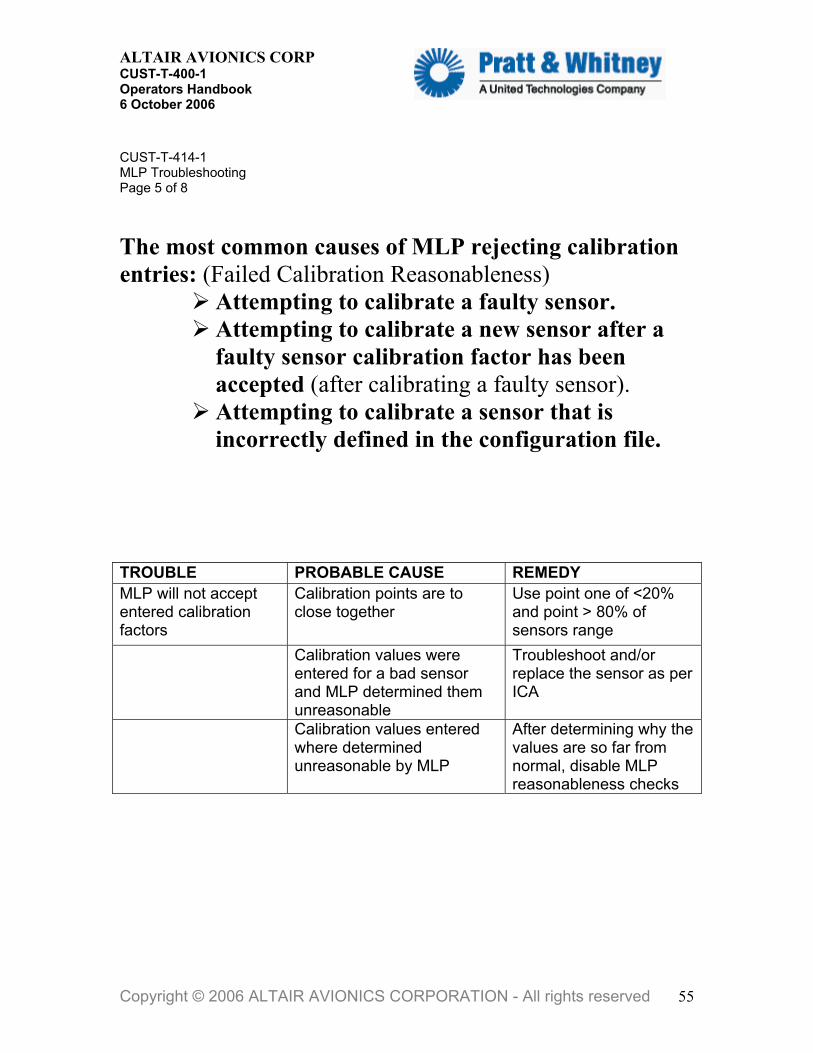
CUST-T-414-1 MLP Troubleshooting Page 5 of 8 The most common causes of MLP rejecting calibration entries: (Failed Calibration Reasonableness)
Attempting to calibrate a faulty sensor. Attempting to calibrate a new sensor after a faulty sensor calibration factor has been accepted (after calibrating a faulty sensor). Attempting to calibrate a sensor that is incorrectly defined in the configuration file.
TROUBLE PROBABLE CAUSE REMEDY MLP will not accept entered calibration factors
Calibration points are to close together
Use point one of <20% and point > 80% of sensors range
Calibration values were entered for a bad sensor and MLP determined them unreasonable
Troubleshoot and/or replace the sensor as per ICA
Calibration values entered where determined unreasonable by MLP
After determining why the values are so far from normal, disable MLP reasonableness checks
Copyright © 2006 ALTAIR AVIONICS CORPORATION - All rights reserved 55

ALTAIR AVIONICS CORP CUST-T-400-1 Operators Handbook 6 October 2006
CUST-T-414-1 MLP Troubleshooting Page 6 of 8
User Entry Requirements for CALIBRATION (Input
Validation)
CUSTOMER CHECKLIST
in
MLP has built-in checks, which may be disabled (reasonableness) to ensure minimally acceptable values are supplied during calibration.
Refer to the Calibration Checklist that can be
downloaded from TurbineTracker by
selecting the Documents button under the Support
tab
Copyright © 2006 ALTAIR AVIONICS CORPORATION - All rights reserved 56
ALTAIR AVIONICS CORP CUST-T-400-1 Operators Handbook 6 October 2006
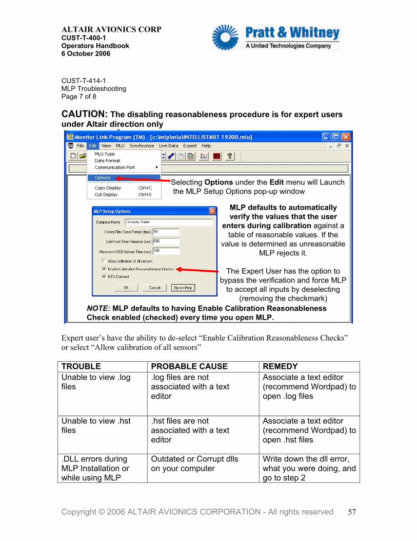
CUST-T-414-1 MLP Troubleshooting Page 7 of 8 CAUTION: The disabling reasonableness procedure is for expert users under Altair direction only
Selecting Options under the Edit menu will Launchthe MLP Setup Options pop-up window
MLP defaults to automatically verify the values that the user
enters during calibration against a table of reasonable values. If the
value is determined as unreasonable MLP rejects it.
The Expert User has the option to bypass the verification and force MLP
to accept all inputs by deselecting (removing the checkmark)
NOTE: MLP defaults to having Enable Calibration Reasonableness Check enabled (checked) every time you open MLP.
Expert user’s have the ability to de-select “Enable Calibration Reasonableness Checks” or select “Allow calibration of all sensors” TROUBLE PROBABLE CAUSE REMEDY Unable to view .log files
.log files are not associated with a text editor
Associate a text editor (recommend Wordpad) to open .log files
Unable to view .hst files
.hst files are not associated with a text editor
Associate a text editor (recommend Wordpad) to open .hst files
.DLL errors during MLP Installation or while using MLP
Outdated or Corrupt dlls on your computer
Write down the dll error, what you were doing, and go to step 2
Copyright © 2006 ALTAIR AVIONICS CORPORATION - All rights reserved 57
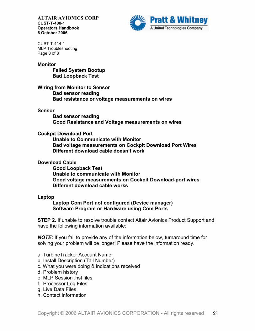
ALTAIR AVIONICS CORP CUST-T-400-1 Operators Handbook 6 October 2006
CUST-T-414-1 MLP Troubleshooting Page 8 of 8 Monitor Failed System Bootup
Bad Loopback Test Wiring from Monitor to Sensor
Bad sensor reading Bad resistance or voltage measurements on wires
Sensor Bad sensor reading
Good Resistance and Voltage measurements on wires Cockpit Download Port
Unable to Communicate with Monitor Bad voltage measurements on Cockpit Download Port Wires Different download cable doesn’t work
Download Cable Good Loopback Test Unable to communicate with Monitor Good voltage measurements on Cockpit Download-port wires Different download cable works Laptop Laptop Com Port not configured (Device manager) Software Program or Hardware using Com Ports STEP 2. If unable to resolve trouble contact Altair Avionics Product Support and have the following information available: NOTE: If you fail to provide any of the information below, turnaround time for solving your problem will be longer! Please have the information ready. a. TurbineTracker Account Name b. Install Description (Tail Number) c. What you were doing & indications received d. Problem history e. MLP Session .hst files f. Processor Log Files g. Live Data Files h. Contact information
Copyright © 2006 ALTAIR AVIONICS CORPORATION - All rights reserved 58
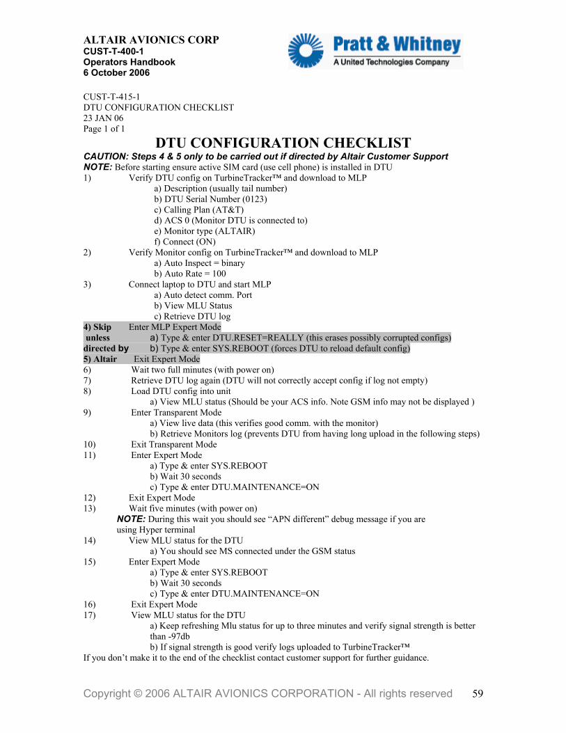
ALTAIR AVIONICS CORP CUST-T-400-1 Operators Handbook 6 October 2006
CUST-T-415-1 DTU CONFIGURATION CHECKLIST 23 JAN 06 Page 1 of 1
DTU CONFIGURATION CHECKLIST CAUTION: Steps 4 & 5 only to be carried out if directed by Altair Customer Support NOTE: Before starting ensure active SIM card (use cell phone) is installed in DTU 1) � Verify DTU config on TurbineTracker™ and download to MLP
a) Description (usually tail number) b) DTU Serial Number (0123) c) Calling Plan (AT&T) d) ACS 0 (Monitor DTU is connected to) e) Monitor type (ALTAIR) f) Connect (ON)
2) � Verify Monitor config on TurbineTracker™ and download to MLP a) Auto Inspect = binary b) Auto Rate = 100
3) � Connect laptop to DTU and start MLP a) Auto detect comm. Port b) View MLU Status c) Retrieve DTU log
4) Skip � Enter MLP Expert Mode unless a) Type & enter DTU.RESET=REALLY (this erases possibly corrupted configs) directed by b) Type & enter SYS.REBOOT (forces DTU to reload default config) 5) Altair � Exit Expert Mode 6) � Wait two full minutes (with power on) 7) � Retrieve DTU log again (DTU will not correctly accept config if log not empty) 8) � Load DTU config into unit
a) View MLU status (Should be your ACS info. Note GSM info may not be displayed ) 9) � Enter Transparent Mode
a) View live data (this verifies good comm. with the monitor) b) Retrieve Monitors log (prevents DTU from having long upload in the following steps)
10) � Exit Transparent Mode 11) � Enter Expert Mode
a) Type & enter SYS.REBOOT b) Wait 30 seconds c) Type & enter DTU.MAINTENANCE=ON
12) � Exit Expert Mode 13) � Wait five minutes (with power on) NOTE: During this wait you should see “APN different” debug message if you are
using Hyper terminal 14) � View MLU status for the DTU
a) You should see MS connected under the GSM status 15) � Enter Expert Mode
a) Type & enter SYS.REBOOT b) Wait 30 seconds c) Type & enter DTU.MAINTENANCE=ON
16) � Exit Expert Mode 17) � View MLU status for the DTU
a) Keep refreshing Mlu status for up to three minutes and verify signal strength is better than -97db b) If signal strength is good verify logs uploaded to TurbineTracker™
If you don’t make it to the end of the checklist contact customer support for further guidance.
Copyright © 2006 ALTAIR AVIONICS CORPORATION - All rights reserved 59

ALTAIR AVIONICS CORP CUST-T-400-1 Operators Handbook 6 October 2006
CUST-T-416-1 View Live Data 6 NOVEMBER 2000 Change 2 – 4 August 2001 Page 1 of 1
View Live Data MLP viewing live data from Processor 1. Establish an MLP connection to the monitor. 2. If connected to a DTU enter “Transparent Mode” 3. Select “Live Data” then “Text View.”
NOTE: Although the data will be viewed in near real time, the data is stored on a file for future reference as a .tab file in the c:\mlp\log\livedata folder. 4. Choose a file name and click “Save.” 5. When prompted place the Run/Conf switch in the “Run” position and click “OK.” Note: DTU users will not get prompted NOTE: It takes a while for sensor information to load, this is normal. The Live Data Screen appears displaying the real time values of the processor’s sensors. Numbers will update once per second. NOTE: Sensors that display “9999.9999” type values are faulted. If there are sensors displaying unexpected values, accomplish MLP Troubleshooting AFTER completing this checklist. 6. Click “Stop Live Data” to stop viewing live data. 7. When prompted place the Run/Conf switch in the “Conf” position and click “OK.” Note: DTU users will not get prompted 8. End Altair Avionics Note: Please send the Live Data .tab file from the c:\mlp\log\livedata folder when requested.
Copyright © 2006 ALTAIR AVIONICS CORPORATION - All rights reserved 60

ALTAIR AVIONICS CORP CUST-T-400-1 Operators Handbook 6 October 2006
CUST-T-417-1 Download MLP Download MLP Checklist 31 Aug 2006 Page 1 of 3 Please do the following to download and save the MLP: NOTE: This is a two step installation in which the second step (update to MLP V6.7.2) is automatically installed when the user performs the Synchronize to TurbineTracker™ process with MLP V6.7.
OVERVIEW 1. Create the folder c:\mlp 2. Create the folder c:\mlp\bin 3. Retrieve the MLP from TurbineTracker™ and save it in the c:\mlp\bin folder. 4. Create a shortcut to the MLP on your desktop. 5. Run MLP and perform Synchronize to TurbineTracker™.
1) CREATE MLP FOLDER on the laptop (C:\mlp) a) Open the My Computer icon on your desktop b) Double Click on the C: drive so that it opens for you c) Click the RIGHT button on the mouse, a list should appear d) Highlight NEW, another list will open e) Click Folder f) Name this folder MLP
2) CREATE MLP BIN FOLDER on the laptop (C:\mlp\bin) g) Double Click the folder to open the MLP folder h) Click the RIGHT button on the mouse, a list should appear i) Highlight NEW, another list will open j) Click Folder k) Name this folder Bin
3) Download MLP VERSION 6.7
l) Log onto TurbineTracker™ *** m) Click the Support tab at the top of the screen n) Click System Update on the left hand side of the screen o) Click on the MLP.exe link in blue p) Click Save q) Select the folder C:\mlp\bin r) Click Save
***If you do not have a TurbineTracker™ subscription and Login you will need to contact: Altair Avionics Corp - Sales Department 63 Nahatan Street Norwood, Ma 02062 Phone 781-762-8600 Fax 781-762-2287
Copyright © 2006 ALTAIR AVIONICS CORPORATION - All rights reserved 61

ALTAIR AVIONICS CORP CUST-T-400-1 Operators Handbook 6 October 2006
CUST-T-417-1 Download MLP Page 2 of 3
Copyright © 2006 ALTAIR AVIONICS COPORATION - All rights reserved
Download from TurbineTracker™
Support Tab
Go toSystemUpdatesButton
Click on mlp.exe link
Save mlp.exe to your C:\mlp\bin folder
When asked, download the file to your computers C:\MLP\BIN folder.
Most users create a shortcut
to MLP for the Desktop
NOTE: For new users you will need to create the C:\MLP\BIN folder first
4) After it downloads: CREATE DESKTOP SHORTCUT
a) Open the My Computer icon on your desktop b) Double Click on the C: drive so that it opens for you c) Double Click on the MLP folder so it opens for you d) Double Click on the Bin folder so it opens for you, there should be a file
mlp.exe in there e) Click on it with the RIGHT button on the mouse, a list should appear f) Click on Create Shortcut, another file will appear that says “Shortcut to
mlp.exe” g) Click the shortcut with the RIGHT button on the mouse, a list should appear h) Click Cut or copy i) Close the window and place the mouse pointer back on the desktop j) Click the RIGHT button on the mouse, a list should appear k) Click Paste, the shortcut is now copied on your desktop
Copyright © 2006 ALTAIR AVIONICS CORPORATION - All rights reserved 62

ALTAIR AVIONICS CORP CUST-T-400-1 Operators Handbook 6 October 2006
CUST-T-417-1 Download MLP Page 3 of 3
If you open the new MLP Windows desktop shortcut, MLP will open for you.
5) SYNCHRONIZE TO TURBINETRACKER First thing you should do with MLP 6.7 is Synchronize MLP to TurbineTracker to get the update to the newest version (6.7.2) of MLP. NOTE: This may take a few minutes depending on your connection speed. Click Synchronize and select TurbineTracker™ from the dropdown list.
Copyright © 2006 ALTAIR AVIONICS COPORATION - All rights reserved
After selecting Synchronize and TurbineTracker
You will be prompted to enter your TurbineTracker User ID
and Password
After you enter your login ID and password and select OK, MLP automatically performs the functions of:
a) Connecting to TurbineTracker™, b) Uploading the configuration (.cal) files c) Uploading the log files d) Determining if there are any new configurations, and downloading those
configurations to the local computer. e) MLP will also load any available software updates to automatically bring MLP
up to the current version.
When MLP is done, the display will show “TTS Synchronization Process Complete
The updated MLP User’s Guide, User Checklist and Current System Manuals are all available free of charge for TurbineTracker™ users under the TurbineTracker™ Support Tab by selecting the blue Documents button and navigating to the desired document.
Copyright © 2006 ALTAIR AVIONICS CORPORATION - All rights reserved 63

ALTAIR AVIONICS CORP CUST-T-400-1 Operators Handbook 6 October 2006
CUST-T-418-1 View Session Log View MLP Session Log Checklist 31 Aug 2006 Page 1 of 3
A session log keeps track of all of the activities performed by MLP, the user, and the monitor. It also tracks the commands and responses in communicating with the monitor.
A new MLP Session Log is automatically created and stored in the computers MLP folder every time the MLP program is started (c:\mlp)
a) Session logs have the .hst file extension b) Session logs are listed in chronological order c) Session logs can be viewed with MLP d) Session logs can be viewed with any standard Windows text editor program such as Note Pad e) Session Logs can be viewed in MLP without connecting to the aircraft
Copyright © 2006 ALTAIR AVIONICS CORPORATION - All rights reserved 64

ALTAIR AVIONICS CORP CUST-T-400-1 Operators Handbook 6 October 2006
CUST-T-418-1 View Session Log Page 2 of 3 NOTE: Ensure you have the current version of the Monitor Link Program (MLP).
The current version is available from the TurbineTracker™ website under the “Support Tab” by selecting the “Systems Update” button on the left and following
the on screen instructions.
Open MLP and Select the following from the drop down menu at the top of MLP: a) View to open the selection menu b) Session Log to open the Filter Options pop-up
MLP automatically defaults to work with the current open MLP session. To view a different MLP session, click the Browse button in the upper right corner of the options window and select the session history file (.hst) that you want to see.
To view a parsed list of the User Actions, Action Group or Errors* in the selected MLP session, choose the desired filter from Filter Types and click OK to open the file. *User Actions, Action Group or Errors are explained below.
Copyright © 2006 ALTAIR AVIONICS CORPORATION - All rights reserved 65

ALTAIR AVIONICS CORP CUST-T-400-1 Operators Handbook 6 October 2006
CUS
g
ssion Log viewed with MLP
SESSION LOGS AND U
In a session log view, a use f the activities that occur
ach user action is prefaced by a “---“. “>>>”.
n action group includes everything after single user action, and before the next
ction groups make it easier to find information of interest in a long history fic
NOTE: All of our updated Manuals, User's Guides and Checklist are available free of charge for TurbineTracker™ users under the Support Tab.
T-T-418-1 View Session LoPage 3 of 3
Se
SER ACTION GROUPSr action group is a list of all o
in the system as a result of your performing a single action in MLP. ESystem activity is prefaced by a “-v-” or aEach detected error is prefaced by a “***”. Auser action (graphically, between one “---“and the next “---“). There may be several lines of system activity (-v- or blank), or an error (***) between them. Asession. First view the list of user actions available, and then view the speciaction group you want to see in detail.
Copyright © 2006 ALTAIR AVIONICS CORPORATION - All rights reserved 66

ALTAIR AVIONICS CORP CUST-T-400-1 Operators Handbook 6 October 2006
67
CUST-Config 31 Aug 2006 Page 1 of 3
version is available from the TurbineTracker™ website under the
b” by selecting the “Systems Update” button on the left and following the on screen instructions.
1.
Ensure the RUN/CONF sw to “CONF” (Skip this step for HUMS 1122 and CrossCheck) o enter TRANSPARENT MODE if using
Communication Port c. Autodetect
T-419-1 generation Expert Mode - Configuration file generation
NOTE: Ensure you have the current version of the Monitor Link Program (MLP).
The current“Support Ta
Open MLP and establish a connection to the aircraft processor
itch on the serial cable is set
r the DTU.
Select the following from the drop down menu at the top of MLP: a. Edit b.
Copyright © 2006 ALTAIR AVIONICS CORPORATION - All rights reserved
TIPS AND TRICKS: Accomplish a “MLU Status” under the MLU Menu. Receiving the “MLU Status Processing Complete” prompt indicates a connection has been established
between the computer and the processor.

ALTAIR AVIONICS CORP CUST-T-400-1 Operators Handbook 6 October 2006
CUST-T-41 Config gene tion Page 2 of 3
2. Once the “Successfully Detected Comm Port” message is displayed, foll wing from the drop down menu at the top of MLP
NOTE: MLP can not
9-1ra
select the o generate a config from a DTU.
b. File Operations
NOTE: Configuration files generated from the monitor can only be used as text files. They
a. Expert
c. Generate config file
can not be uploaded to TurbineTracker™ or loaded as a configuration to a monitor. in
Copyright © 2006 ALTAIR AVIONICS CORPORATION - All rights reserved 68

ALTAIR AVIONICS CORP CUST-T-400-1 Operators Handbook 6 October 2006
CUST-T-419-1 Config generation Page 3 of 3 This should give you the standard Windows prompt asking you to select a location to save the file and a name for the file. It is best to name the file with the tail number of the aircraft for ease of keeping track.
MLP defaults to saving the file in the C:\mlp\cfg folder, but the user has the
a d ferent location.
fter MLP has completed the configuration file saving process you have the o view
available free of charge for TurbineTracker™ users under the Support Tab.
option to choose if Aoption to use MLP or any standard text editing program such as Note Pad tit.
NOTE: All of our updated Manuals, User's Guides and Checklist are
Copyright © 2006 ALTAIR AVIONICS CORPORATION - All rights reserved 69

ALTAIR AVIONICS CORP CUST-T-400-1 Operators Handbook 6 October 2006
CUST-T-420-1 System Validation System Validation Checklist 5 July 2006 Page 1 of 4 Overview of recommended steps:
1) Update MLP 2) Verify the wiring installation 3) Power on, troubleshoot and calibrate the systems as required 4) Collect trend data 5) Review data for accuracy
Normally it takes one avionics tech to handle MLP while working with a mechanic for calibration. If you can get the systems working and taking the manual trends elow, you will get a good estimate of the condition of the systems as well as
1) Check your laptop for MLP version 6.7 or higher. If you have a lower e
first thing you should do after insuring that you have MLP version 6.7 or higher is to Synchronize MLP to TurbineTracker to get the newest
load
2) Now that you have MLP updated and the current aircraft configuration files loaded, the next step is to start with continuity checks on the wiring, paying particular attention to the power and com ports before applying power to the monitor.
NOTE: This is a very important step since we have found from previous experience that initially ringing out and double checking all of the wiring before applying power can prevent monitor damage and save you time later during system calibration and operation.
on status (described be LP Synchronize MLP to the aircraft. This will retrieve any stored logs the monitor (if prompted to reset the logs, select yes). After the
te disconnect the download cable r lamp status.
bpossible Manual Calibration without opening the systems.
version then 6.7 you will need to download the updated version from thSupport Tab in TurbineTracker™ following the on screen instructions. The
version. This may take a few minutes to download and will also downyour current configuration files for all of the aircraft in your account.
3) Apply power to the system making sure to note the system power
low) then establish communication with Mlampand fromSynch to Aircraft process is compleand recycle power again noting you
Copyright © 2006 ALTAIR AVIONICS CORPORATION - All rights reserved 70

ALTAIR AVIONICS CORP CUST-T-400-1 Operators Handbook 6 October 2006
CUST-TSystemPage 2
unicate or the Trend Lamp does not
id (Fault Mode) -
uble
e if all
or
4) Entr
l
with the engine(s) at idle.
g
until the system has een validated as operational.
he collected data after a few days of operation. Most operators
eve logs weekly. e. f. g. data from the monitor to the pilot
corded written trends for accuracy and needed trouble shooting
e personnel be included in the review.
-420-1 Validation of 4
Note: If unable to commdisplay a system condition after the boot up test refer to your ICA for trouble shooting steps.
a. If Trend Lamp flashes 3-5 sec then continues a steady flash(Maintenance, Caution mode) or remains solYou will need to review the log to determine the cause and troshooting needed.
Note: A monitor that has no configuration file loaded will have config fault logs and be in Fault Mode (lamp solid) due to the default config mismatch.
b. If Trend Lamp flashes 3-5 sec then remains extinguished
(Normal Mode) – You should View Live Data with MLP to seof the sensor values look reasonable and troubleshoot or calibrate as needed. Don’t forget to Synchronize MLP to TurbineTracker™ when completed. This will upload the log and/calibration files.
Next you should collect data during aircraft operation using the Manual y Form on page 4 of this checklist.
c. Idle Trend - Once during every flight have the pilot take a ManuaTrend (push the Trend Lamp/Switch) one time and at the same time write down time & gauge readings
d. Cruise Trend - Once for every flight have the pilot take a ManualTrend (push the Trend Lamp/Switch) one time and at the same time write down time & gauge readings during stabile cruise.
NOTE: If your configurations are set to illuminate the lamps durinflight for Exceedence and Events you should tell the pilots to disregard them (or cover the lamp with tape)b
5) Review tretri
Synchronize MLP to the Aircraft to retrieve the logs. Synchronize MLP to TurbineTracker™ to upload the trend data. Compare the Manual Trendreor calibration. Note: It is recommended that both the pilots and the maintenanc
Copyright © 2006 ALTAIR AVIONICS CORPORATION - All rights reserved 71

ALTAIR AVIONICS CORP CUST-T-400-1 Operators Handbook 6 October 2006
CUST-T-420-1 System ValidatioPage 3 of
NOTE: This s and written records on the ground and in the air obtai al Sensor Calibration will be performed in this
pro ure ted,
1) Note the timeAt the same tim 2) Note the timeAt the sam tim from Cockpit Instruments (USER 2) 3)T 4) Estab
n 4
Manual Sensor Calibration procedure requires both trendn instrument readings. A Manuto
ced . The calibrations are accomplished with MLP AFTER the values are collecnot during.
and take a Manual Trend at stable idle (TREND1) e record the reading from Cockpit Instruments (USER 1)
and take a Manual Trend at stable cruise (TREND2) e record the reading e
After engine shutdown, review your monitors log data and enter the recorded Trend1 & rend2 values from the times noted earlier.
lish a connection to the monitor with MLP and perform a Manual Sensor Calibration.
Sensor Calibration” under Expert Menu. Only the following sensors Select “Manualshould b liAccomplish a Two
NOTE: You will see four empty boxes for each cal
Enter the sensor vin TREND 1 in thebox (Unit’s Value Col n, Top RoEnter thin TREND hebox (Unit’ ue,
Enter the vUSER 1 in the upp(Calibrate ValueRow)Enter the gauge v
right hand box olumn,
Bottom Row)
e ca brated: Engine Temperature, OAT, Engine Torque, Airspeed, and Altitude.Point Calibration
ibration
alues collected upper left hand
umw)
e sensor values collected 2 in t lower left hand s Val Bottom Row)
gauge alues collected in er right hand box
to s Column, Top
alues collected in USER 2 in the lower
Values C(Calibrate to
5 nt
y
C
TE: Do not re-calibrate a sensor that is reading correctlNO
) SynchNOTE: Uploading a calibration session will i configuration file version by one. Any umber of sensors may be calibrated in multiple sessions prior to uploading without increasing
ronize to TurbineTracker to upload the monitor’s updated calibration (.cal) file.
ncrement the
he version number further.
opyright © 2006 ALTAIR AVIONICS CORPORATION - All rights reserved 72
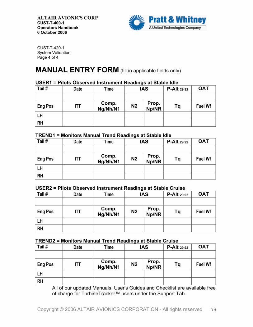
ALTAIR AVIONICS CORP CUST-T-400-1 Operators Handbook 6 October 2006
C ST-T-420-1 SP
M (fill in applicable fields only) UTail # Date Time IAS P-Alt 29.92 OAT
Uystem Validation age 4 of 4
ANUAL ENTRY FORM
SER1 = Pilots Observed Instrument Readings at Stable Idle
Eng Pos ITT Comp. Ng/Nh/N1 N2 Prop.
Np/NR Tq Fuel Wf
LH RH
TREND1 = Monitors Manual Trend Readings at Stable Idle Tail # Date Time IAS P-Alt 29.92 OAT
Eng Pos ITT Comp. Ng/Nh/N1 N2 Prop.
Np/NR Tq Fuel Wf
LH RH
USER2 = Pilots Observed Instrument Readings at Stable Cruise Tail # Date Time IAS P-Alt 29.92 OAT
Eng Pos ITT Comp. N2 Prop. Ng/Nh/N1 Np/NR
H
Tq Fuel Wf
LRH
REND2 = Monitors Manual Trend Readings at Stable Cruise ail #
TDate Time IAS P-Alt 29.92 OAT T
Eng Pos ITT Comp. Ng/Nh/N1 N2 Prop.
Np/NR Tq Fuel Wf
LH RH
All of our updated Manuals, User's Guides and Checklist are available free of charge for TurbineTracker™ users under the Support Tab.
Copyright © 2006 ALTAIR AVIONICS CORPORATION - All rights reserved 73

ALTAIR AVIONICS CORP CUST-T-400-1 Operators Handbook 6 October 2006
T-421 -1
eplace DTU 7 October 2006
4
Replace DTU Checklist
er to the FAA Approved Instructions for Continued Airworthiness for Maintenance Instructions applicable to your aircraft.
ore installing the DTU you will need to manually downloa curren gurfile from the TurbineTracker™ website.
VERV Download DT Confi from urbineTracker Load DTU Config into Processor
Verify Installation DTU & ACS
NOTE: ACS (Aircraft Component System) refers to the system connected
the DTU could be lliStar DA AS+, rtCyc third pa onito
wnload DTU Config rati n Fil
. Log on to Turbine Tracker using your User ID and Password.
success g on, cl TU” .
lick “Download Config” butto on the lef
4. Sele
File onto your computer.
on the compu p\cfg” folder. ram (MLP) uses to find configuration files for transfer. NOTE: The File Download box will disappear when download is complete.
CUST- R1Page 1 of
Ref
NOTE: MLP can not Synchronize DTU config files. Befd the t DTU confi ation
O IEWU g T
Ve Data smissiorify Tran n
toor
. It rty m
an Inters.
t+, A Sd, AD Sma le+ and
Do u o eTurbineTracker to Computer 1
2. Upon ful lo ick the “D Tab
3. C n t.
ct the file to download by clicking on the desired version. NOTE: A File Download Box Will Appear.
5. Save the
TIPS AND TRICKS: Although the File may be saved anywhere ter, it is recommended that you save the File in the “c:\ml This folder is the default folder that the Monitor Link Prog
Copyright © 2006 ALTAIR AVIONICS CORPORATION - All rights reserved 74

ALTAIR AVIONICS CORP CUST-T-400-1 Operators Handbook 6 October 2006
LoaCom
u have the current version of the Monitor Link Program t version is available from Turbine Tracker under the
rd (cell phone) into
1. Usin MLP to the processor (DTU). If unable to establish connection, accomplish MLP Troubleshooting Procedure.
s a connection has been established between the omputer and the processor.
s can
set the log, select “Yes”.
. Browse to find the File when the Select Configuration Box appears, if
NOTE: Configuration Files are denoted by the .cfg and extension. .cfg files to the processor.
long as 4 minutes. completed configuration file load will be noted by the MLP
pt. TIPS AND TRICKS: Accomplish “MLU Status” of the DTU again under the MLU
VerView
have verified the configuration is complete (verify with MLU Status),
P and Enter DTU ommunication with the
CUST-T-421-1 Replace DTU Page 2 of 4
d DTU Configuration File uter to DTU Processor p
NOTE: Ensure yo(MLP). The curren“Support Tab” and “Systems Update” button. CAUTION: Ensure you have installed an active SIM cathe DTU. g , Autodetect to establish a connection
TIPS AND TRICKS: Accomplish “MLU Status” under the MLU Menu to insure you are connected to the DTU (red button).Receiving a response and the “MLU Status Processing Complete” prompt indicatec
2. Under the Synchronize dropdown select “Aircraft” or Expert User’manually “Retrieve Unit’s Data Log”.
NOTE: If you are prompted to “Re
3. Select “Configure Unit” under the MLU dropdown Menu. 4necessary.
are the only file types that are loaded in
5. Select the File and click “Open” NOTE: Configuration File load may take asA“Configuration Complete” prom
Menu to verify your config has been loaded.
ify Installation Live Data with MLP
6. After you Recycle aircraft power. 7. After power on BIT test, establish a connection with ML
s to verify proper ctransparent Mode (green button). This iACS.
Copyright © 2006 ALTAIR AVIONICS CORPORATION - All rights reserved 75

ALTAIR AVIONICS CORP CUST-T-400-1 Operators Handbook 6 October 2006
CUST-TReplacePage 3
Processing Complete” prompt indicates a connection has been established etween the computer and the processor.
are being the en
“{X^” instead of “c” for Celsius units. If you see something other then % or
9. Stop10. Exit DTU Transparent Mode (red button).
DTU 11. Under the Synchronize dropdown select “Aircraft”, then select “All” to retrieve
e the
et the log, select “Yes”. Maintenance Mode Transmission 12. Enter DTU Maintenance Mode by pressing and holding the RF/Fault Lamp
al minutes for the DTU to load the data and during the data transmission.
3. Check TurbineTracker™ for successful uploading of the DTU and ACS logs
up to several minutes for logs to be displayed after
matic Transmission
: It can take up to several minutes for the DTU to load the data and RF Lamp begins to flash during the data transmission.
13. Ch s (Your Log Data Button)
-421-1 DTU of 4 TIPS AND TRICKS: Accomplish “MLU Status” of the IntelliStart+ under the MLU Menu to verify you are connected the ACS (IntelliStart+). Receiving the response and a “MLU Status b
8. View live Data from the ACS using “Text View”. This is to verify all Sensors
displayed correctly (no scrambled symbols) paying particular attention togine off state sensors N1 & TOT. NOTE: “Scrambled symbols are like “X&*” instead of “%” for percent or
c contact Altair Support.
viewing Live Data.
Verify Data Transmission to TurbineTracker
the log file from the ACS & DTU. NOTE: Retrieving any log data from the ACS & DTU will reducupload time in step 12 NOTE: If you are prompted to “Res
Switch for longer then 5 seconds. NOTE: It can take up to severthe RF Lamp begins to flash
1(Your Hanger - Account Status hyperlink and the DTU Tab – Log Data Button)
NOTE: It can taketransmission.
Auto14. Conduct a normal engine run and shutdown.
NOTEthe eck TurbineTracker™ for successful uploading of the DTU and ACS logHanger - Account Status hyperlink and the Data Analysis Tab – View
Copyright © 2006 ALTAIR AVIONICS CORPORATION - All rights reserved 76

ALTAIR AVIONICS CORP CUST-T-400-1 Operators Handbook 6 October 2006
Copyright © 2006 ALTAIR AVIONICS CORPORATION - All rights reserved 77
NOTE: It can take up to several minutes for logs to be displayed after transmission. If the DTU fails to transmit logs to TurbineTracker
Can MLP communicatewith the DTU
g pTrouble shoot DTU
Power up and comm. port
Verify Logs in DTUwith MLP (MLU Status)
NO
YES
NOLOGS NO
Trouble shoot ACS Power and comm. Port to DTUand Run/Config wiring
YES YES
Verify Logs in ACSwith MLP (ACS MLU Status)
NOTrouble shoot ACS
Power up BIT, comm. Portand Run/Config wiring
YES
Verify DTU config ACS fieldcorrect with MLP (DTU MLU Status)
NO Reload DTU Config
Verify DTU config valuesfor SIM card and ACS
are correct withMLP (MLU Status)
YES
Reload DTU Config
NOYES
Verify comm. With ACSthru the DTU using MLP
Transparent Mode
Repair wiring
Verify good Aircraft on Ground signal
NO
YES
Perform forced maintenance modeDTU Lamp/Switch pressed >5 seconds
and verify RF lamp flashes withinseveral minutes
NO
YES
Verify your SIM card & Cell tower
availability
Normal operation, perform anengine run and verify the RF lamp Flashes after normal shut down
NOTE: You can verify the DTU SIM card connection status with MLP using the MLU status screen if you
refresh it during RF transmission
Note: Version 3.2 Firmware at completion of the engine run you should see the ACS lamp illuminate as the DTU
switches it into Config Mode to retrieve its engine run log (this can be very quick for one run). Then a few moments
later the DTU RF lamp should begin to flash as it transmits the logs to TurbineTracker™
NOTEIf your results are not asexpected in this trouble
shooting tree contact AltairAvionics Corp. Customer
Support
NOTE: You can poll the DTU for the current state of the AOG signal with MLP using EXPERT COMMAND MODE
by typing the following command:Firmware v111 “sys.get.mem.b.1192a1” Firmware v113 “sys.get.mem.b.1192a1”
Then hit enter to receive the four digit status:0x01 =GROUND or 0x00 =AIR
jbrooks
jbrooks
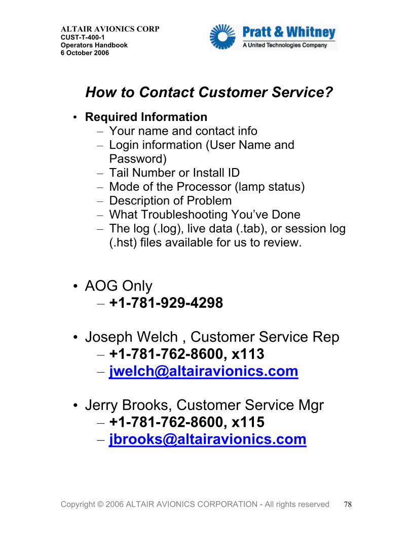
ALTAIR AVIONICS CORP CUST-T-400-1 Operators Handbook 6 October 2006
How to Contact Customer Service?
• Required Information – Your name and contact info – Login information (User Name and
Password) – Tail Number or Install ID – Mode of the Processor (lamp status) – Description of Problem – What Troubleshooting You’ve Done – The log (.log), live data (.tab), or session log
(.hst) files available for us to review.
• AOG Only – +1-781-929-4298
• Joseph Welch , Customer Service Rep – +1-781-762-8600, x113 – [email protected]
• Jerry Brooks, Customer Service Mgr – +1-781-762-8600, x115 – [email protected]
Copyright © 2006 ALTAIR AVIONICS CORPORATION - All rights reserved 78