
Alpheus AA product description - ESEP Milieutechniek B.V. · Type AA Product description ......
24
08-2016-02-ALPHEUS Type AA Product description ESEP Product Manual Rainwater - Subject to change without notice- February 2016 08-2016-02-ALPHEUS Type AA Product description Rev. 0 Page 1 of 24 ALPHEUS FLOW LIMITER AUTOMATIC TYPE (AA) Automatic de-blocking!!! Product description
Transcript of Alpheus AA product description - ESEP Milieutechniek B.V. · Type AA Product description ......

08-2016-02-ALPHEUS Type AA Product description
ESEP Product Manual Rainwater - Subject to change without notice- February 2016
08-2016-02-ALPHEUS Type AA Product description Rev. 0 Page 1 of 24
ALPHEUS FLOW LIMITER
AUTOMATIC TYPE (AA)
Automatic de-blocking!!!
Product description

08-2016-02-ALPHEUS Type AA Product description
ESEP Product Manual Rainwater - Subject to change without notice- February 2016
08-2016-02-ALPHEUS Type AA Product description Rev. 0 Page 2 of 24
Table of contents:
The task of a flow limiter 3
Advantages over the ALPHEUS STANDARD Model 3
Operational description 3
Dry weather operation 4
Storm Flow operation 4
Operational description of the AUTOMATIC de-blocking device 5
Manual pull device for flushing the sewer 7
Design flow 8
Change in the flow design value 8
Different control concepts 9
An overview of dimensions and weights 10
Minimum manhole dimensions and installed dimensions 11
Emergency draining of the ALPHEUS Chamber 12
Discharge opening / wall opening / outgoing pipes 13
Profiling the inlet to the ALPHEUS 13
Installation in a rectengular chamber 14
Installation in a circular chamber 16
Optional components 18
DAPT TYPE adapter for circular chambers 18
TYPE SZ integrated bypass facility (spindle lifting system) 19
Adapter with integrated emergency bypass facility TYPE ADAPT – NE 20
Adapter with integrated emergency bypass facility and emergency overflowTYPE ADAPT – NE - NÜ
21
Integrated gate valve TYPE INT - FS 22
Additional equipment for remote monitoring 23
Recording the controller position 23
Electronic recording of the regulating position 23
Electronic recording of blockages 23
Incorporating the ALPHEUS FLOW LIMITER into the design 23
Advatages of the ALPHEUS FLOW LIMITER – AUTOMATIC TYPE 24

08-2016-02-ALPHEUS Type AA Product description
ESEP Product Manual Rainwater - Subject to change without notice- February 2016
08-2016-02-ALPHEUS Type AA Product description Rev. 0 Page 3 of 24
The task of a flow limiter
A combined storm/sewerage network provides common carriage for storm water and sewage. Depending on the catchment size this will consist of a number of collection systems all eventually discharging into the principle main sewer leading to a wastewater treatment facility. The design of the sewerage system is governed by the capacity of the receiving wastewater treatment facility. In order not to swamp the works a system of regulating or storing excess storm flows is required.
In the past flow control has been achieved through simple orifice plates or restricted pipe dimensions. However in order to make today’s systems as effective as possible accurate flow regulation is required. Therefore high accuracy flow restricting devices are required to precisely restrict the discharge rate from a combined sewerage network – irrespective of the head of water – to allow a pre-designed flow of wastewater to be constantly discharged.
As many sewerage network storage systems do not have a power supply, ESEP has developed the ALPHEUS FLOW LIMITER, which runs without external power and with the same reliability as electrically actuated regulators.
Advantages over the ALPHEUS STANDARD Model
Due to the presence of sewage related debris it is possible for the standard version of the ALPHEUS FLOW LIMITER to suffer from blockages. These can be overcome by operating personnel using a manual pulling device. However, several hours or even days can pass between the blockage occurring and its detection/removal, as tank checks are mostly carried out at set intervals. For this reason, ESEP has developed the ALPHEUS AUTOMATIC. The flow regulation of the ALPHEUS AUTOMATIC TYPE is identical to that of the ALPHEUS STANDARD TYPE. However in addition to the manual pulling device, the AUTOMATIC TYPE has a system, which automatically detects and removes a blockage. This TYPE should be given preference, particularly in combined water systems and for low pass forward flow rates (<10 l/s).
Operational description
When no power supply is available, the ALPHEUS FLOW LIMITER is the correct regulator for the job. Installed in front of the discharge orifice of a sewerage system in a wet chamber installation, the designed discharge rate is accurately controlled – irrespective of the water level in the tank.
Accurate control, irrespective of head, is achieved with the help of a float, which is located inside the ALPHEUS’ housing. The key design feature is that the housing is designed as a submersible bell: I.e. it is open at the bottom but is otherwise hermetically sealed. Consequently air is trapped within the housing and the water level inside the bell rises less than the level in the storm water tank because of the air pocket.
The benefit of the differential pressure is that the unit is smaller as we need less travel to achieve full regulation.
This reduced travel action enables a very compact unit design, which allows the ALPHEUS FLOW LIMITER to be installed even in very confined conditions. A further important advantage of the submersible bell housing over other designs is that the control mechanism lies inside the air zone, i.e. outside the wastewater and the risk of ragging is therefore prevented.

08-2016-02-ALPHEUS Type AA Product description
ESEP Product Manual Rainwater - Subject to change without notice- February 2016
08-2016-02-ALPHEUS Type AA Product description Rev. 0 Page 4 of 24
Dry weather operation
During dry weather flow the orifice plate of the ALPHEUS FLOW LIMITER is in its rest position and the orifice opening is completely free of obstruction. The float located underneath the ALPHEUS’ hood is also in its rest position above the unrestricted orifice.
Storm Flow operation
When wastewater flows into the storage system under storm conditions flow passes through the Alpheus but due to the higher volume, the level in the chamber rises. As it does so the level will rise within the Alpheus unit itself, if the level reaches the float in the Alpheus housing the control mechanism commences.
As the float rises it causes the orifice plate to lower over the outlet thereby reducing the cross sectional area.
The mechanism that transfers the upward momentum of the float to a downward movement of the orifice plate is located above the water level and is therefore free from ragging up. As the movement of the orifice plate is not matched to the upward movement of the float, it is controlled via a radial cam.

08-2016-02-ALPHEUS Type AA Product description
ESEP Product Manual Rainwater - Subject to change without notice- February 2016
08-2016-02-ALPHEUS Type AA Product description Rev. 0 Page 5 of 24
The gate disk, which is permanently connected to the float, has a radial cam in which a cam follower is guided. The cam follower is attached to a slide rod that in turn is attached to the orifice plate. The upward movement of the float is therefore converted into a downward movement of the slide rod thereby restricting the orifice.
The float beneath the hood does not need to travel the same distance as the water level in the tank itself. This is because of the air trapped under the bell housing that provides downward pressure on the float. This enable the Alpheus unit to fit into a smaller chamber than would otherwise be required if the float level always had to be the same level as the water in the tank.
Operational description of the AUTOMATIC de-blocking device
An additional AUTOMATIC device enables the ALPHEUS to automatically identify a blockage and to open the outlet orifice.
Provided that the components of the blockage are smaller than the outlet cross-section, they are flushed through the discharge outlet by the increased head of water.
On the orifice plate there is a sensor, which is designed as an open pipe socket. During regulation the water flow passes the sensor with a high velocity and generates a partial vacuum. A valve in the trigger device is actuated by the partial vacuum. The tank water passes through the valve via the filler pipe into the auxiliary float. The air in the auxiliary float escapes via the ventilation pipe into the open air. The auxiliary float is weighted down by the inlet flow and remains in the lower end position.
If a blockage occurs in the discharge outlet during regulation, the partial vacuum disappears and the valve switches back into the home position. The water flows out of the auxiliary float through the valve and through the ALPHEUS housing into the sewer. Air passes through the ventilation pipe into the emptying auxiliary float. The auxiliary float becomes buoyant and pulls the control float located beneath the housing by means of a pulley system, against the buoyancy of the water. This opens the orifice plate to increase the outlet opening.

08-2016-02-ALPHEUS Type AA Product description
ESEP Product Manual Rainwater - Subject to change without notice- February 2016
08-2016-02-ALPHEUS Type AA Product description Rev. 0 Page 6 of 24
The water pressure flushes the blockage through the discharge outlet and the normal flow arte returns. With the reinstated partial vacuum the valve switches via the membrane and the auxiliary float fills with water and sinks back into the lower end position. The control float beneath the hood is released and moves the orifice plate back in front of the discharge outlet, so that the ALPHEUS can continue to regulate.

08-2016-02-ALPHEUS Type AA Product description
ESEP Product Manual Rainwater - Subject to change without notice- February 2016
08-2016-02-ALPHEUS Type AA Product description Rev. 0 Page 7 of 24
Manual pull device for flushing the sewer
In addition to the automatic de-blocking system, the ALPHEUS AUTOMATIC also has a manual trigger, which can be actuated during storm conditions to flush the sewer. When the manual pulling device is actuated (stainless steel cable with operating handle and wall fixing) the effect of the float is cancelled and the discharge opening is almost fully opened.
This opening process takes place as long as the manual pull system is operated. The orifice plate then automatically returns to the regulating position – without any further action. The operating handle of the manual pull system is located so that the personnel can easily access and use it. A road cap located above the controller is recommended for below ground units. In the case of tanks at ground level, the handle of the pulling rope can be located in an easily accessible position near to an access opening and above the maximum top water level. In both situations, it is important to ensure the cable is guided vertically as far as possible. If vertical guiding is not possible, ESEP can supply the necessary guide roller.
The manual pulling device does not replace the emergency draining (bypass) device required in accordance with ATV Standard A 166.
Situation 1:
Alpheus Automatic
Situation 2 : Situation 3:
Buriedretention tank
Ground levelretention tank
Pull rope with idler pulley
Operating handlewith wall bracket
Pull rope
(Stainless steel)
Alpheus
Road cap
Flow limiter
Flat slide valve
08-2016-02-ALPHEUS Type AA Product description
ESEP Product Manual Rainwater - Subject to change without notice- February 2016
08-2016-02-ALPHEUS Type AA Product description Rev. 0 Page 8 of 24
Design flow
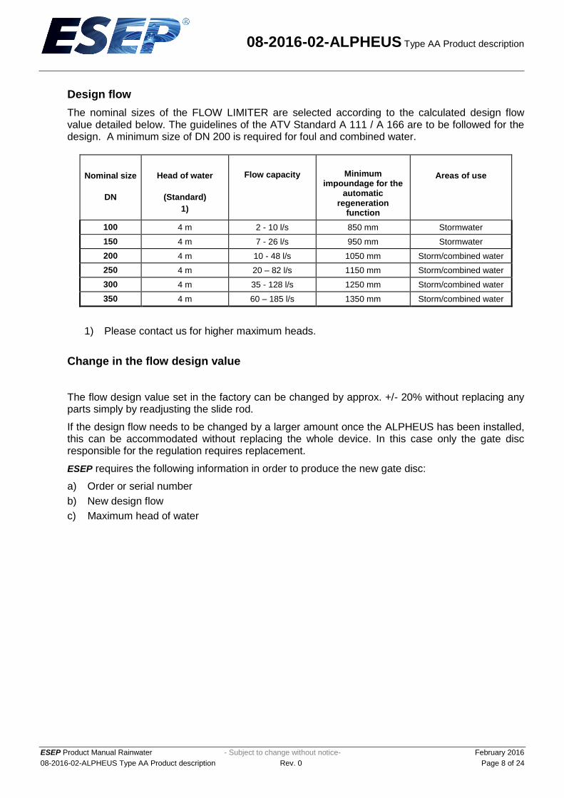
The nominal sizes of the FLOW LIMITER are selected according to the calculated design flow value detailed below. The guidelines of the ATV Standard A 111 / A 166 are to be followed for the design. A minimum size of DN 200 is required for foul and combined water.
Nominal size
DN
Head of water
(Standard)
1)
Flow capacity
Minimum impoundage for the
automatic regeneration
function
Areas of use
100 4 m 2 - 10 l/s 850 mm Stormwater
150 4 m 7 - 26 l/s 950 mm Stormwater
200 4 m 10 - 48 l/s 1050 mm Storm/combined water
250 4 m 20 – 82 l/s 1150 mm Storm/combined water
300 4 m 35 - 128 l/s 1250 mm Storm/combined water
350 4 m 60 – 185 l/s 1350 mm Storm/combined water
1) Please contact us for higher maximum heads.
Change in the flow design value
The flow design value set in the factory can be changed by approx. +/- 20% without replacing any parts simply by readjusting the slide rod.
If the design flow needs to be changed by a larger amount once the ALPHEUS has been installed, this can be accommodated without replacing the whole device. In this case only the gate disc responsible for the regulation requires replacement.
ESEP requires the following information in order to produce the new gate disc:
a) Order or serial number
b) New design flow
c) Maximum head of water

08-2016-02-ALPHEUS Type AA Product description
ESEP Product Manual Rainwater - Subject to change without notice- February 2016
08-2016-02-ALPHEUS Type AA Product description Rev. 0 Page 9 of 24
Different control concepts
The ALPHEUS FLOW LIMITER is available with two different control concepts:
a) Unit design with first flush b) Unit design without first flush
(with orifice restriction)
The standard ALPHEUS FLOW LIMITER is supplied with the "First flush" option. In this version regulation does not begin until the head is approx. 5 cm above the crown of the orifice outlet.
Until this point has been reached the water flows uncontrolled through the ALPHEUS, this causes a surge flush (first flush). The duration of this flushing surge depends on the incoming flow rate.
The advantage of the flushing surge is that the solids carried along with the initial storm event can flow through the full opening of the ALPHEUS and the risk of blockage is minimised.
The disadvantage of the flushing surge is, however, that the sewer systems and facilities downstream of the ALPHEUS are exposed to higher hydraulic loads than they are during the actual flow control.
If these downstream areas cannot withstand such hydraulic overloads even for a sort time (e.g. small wastewater treatment works or smaller inlet works), a pre-restriction must be made to the ALPHEUS. The prerestriction reduces the original outlet orifice cross-section. If a storm event now occurs, the Alpheus unit will regulate immediately.
The prerestriction however, has the disadvantage that the smaller cross-sectional area of outlet orifice flow is more susceptible to blockages.

08-2016-02-ALPHEUS Type AA Product description
ESEP Product Manual Rainwater - Subject to change without notice- February 2016
08-2016-02-ALPHEUS Type AA Product description Rev. 0 Page 10 of 24
An overview of dimensions and weights
T
B
H
M1
T
H
M
K
H
B L
T
Nominal size
DN
H
Standard
mm
1)
H
min.
mm
B
mm
2)
T
Mm
K
mm
M
mm
M1
mm
L
mm
G
(Kg)
100 1230 690 482 434 500 877 829 420 99
150 1280 840 482 434 500 877 829 420 99
200 1330 990 482 434 500 877 829 420 102
250 1580 1140 532 508 555 927 903 420 133
300 1830 1290 582 583 620 1027 1028 470 154
350 2080 1440 632 657 736 1077 1102 470 185
1) If the structure/chamber has a lower height dimension, it is possible to produce the
ALPHEUS with a smaller unit height. The max. head of water should be no more than 2 x
unit height.
2) Width of the unit is without hood fixing angle.

08-2016-02-ALPHEUS Type AA Product description
ESEP Product Manual Rainwater - Subject to change without notice- February 2016
08-2016-02-ALPHEUS Type AA Product description Rev. 0 Page 11 of 24
Minimum manhole dimensions and installed dimensions
L
Ø
Bmin
Ø
E
C
Hm
in
T
Nominal size
DN
H min
Structure height
1) mm
H min
Structure height
2) mm
B min
Structure width
mm
E min
Axis centre spacing
3) mm
min
Installation opening
4) mm
min
Installation opening
4) mm
C min
Opening width
5) mm
L min
Opening length
5) mm
T min
Opening depth below pipe invert
mm
100 1450 1210 1500 500 500 x 450 610 500 500 30
150 1550 1290 1500 500 500 x 450 610 500 500 30
200 1700 1410 1500 500 500 x 450 610 500 500 30
250 1750 1490 1550 550 550 x 525 700 550 550 30
300 1850 1590 1700 550 600 x 600 800 600 600 30
350 2000 1690 1750 600 660 x 710 1000 650 650 30
1) The minimum structure height given only applies:
- if there is no manhole access directly above the unit. - for FLOW LIMITERS with the standard unit height - for FLOW LIMITERS with reduced unit height Please contact us if you require any special dimensions. If it is possible, an installation opening should be provided above the unit.
A special version with a hood that can be removed from the front can be selected if the clear structure height is inadequate, or if a sufficiently sized manhole opening is not available above the ALPHEUS.
2) The minimum structure height stated only applies to FLOW LIMITERS with a reduced unit height

08-2016-02-ALPHEUS Type AA Product description
ESEP Product Manual Rainwater - Subject to change without notice- February 2016
08-2016-02-ALPHEUS Type AA Product description Rev. 0 Page 12 of 24
3) The axis centre spacing applies in combination with an emergency draining slide valve DN 200 4) Installation opening without steps.
If the minimum installation openings are selected, the AUTOMATIC components must be removed before they are located in the structure and then refitted once inside the structure. In this case ESEP or its approved installer must carry out the installation.
In many cases, it helps to briefly lift the tapered section of the access manhole during the installation period, so that the full manhole cross-section is available during installation.
5) An opening in the profiling concrete only has to be provided if the profiling concrete is to be placed before the FLOW LIMITER is installed.
The dimensions given are only valid if the nominal size of the FLOW LIMITER corresponds to the nominal size of the discharge opening. Please contact us if the discharge openings are larger. If the profiling concrete is to be placed higher than shown in the drawing examples, the opening on the side where the AUTOMATIC components are located must be wider.
Emergency draining of the Alpheus chamber
In accordance with ATV Standard A 166, a higher emergency bypass pipe with a minimum diameter of DN 200 is to be provided parallel to each Alpheus device, through which the wastewater can be drained by gravity in the event of a blockage.
Although the ALPHEUS Standard TYPE has a manual pull device and the ALPHEUS AUTOMATIC TYPE has an automatic de-blocking system, in extreme cases a large blockage of the regulator can occur, which cannot be resolved by either of the de-blocking systems. In cases such as these, the upstream sewer network including the storage chambers may have to be pumped out, unless a bypass arrangement is installed. For this reason, we always recommend the installation of an emergency draining facility.
ESEP supplies several emergency drainage options for use with our regulating devices:
a) For the simplest arrangement, we recommend the ESEP gate valve, which can be bolted by the side of the ALPHEUS to provide an emergency bypass. Depending on the manhole arrangement, the emergency bypass may require additional pipework downstream to return the flow into the existing sewer.
b) If it is not possible to use a gate valve for space reasons, e.g. structure too narrow or a bypass pipe cannot be laid (e.g. in case of retrofitting), it is possible to use an integrated emergency draining facility, TYPE SZ or the adapter with an integrated emergency draining facility, TYPE ADAPT-NE. Further details of these two options are detailed in the following chapter, optional components.
NOTE: The slide valves of flow restrictor devices and bypass pipes in “wet” and “semi-dry” structures are to be equipped with slide rods or spindle extensions in accordance with ATV Standard A 166 for safety reasons, so that they can be operated without entering the structures or tanks.

08-2016-02-ALPHEUS Type AA Product description
ESEP Product Manual Rainwater - Subject to change without notice- February 2016
08-2016-02-ALPHEUS Type AA Product description Rev. 0 Page 13 of 24
Discharge opening / wall opening / outgoing pipes
The diameter of the discharge opening must be at least the same size as the diameter of the ALPHEUS FLOW LIMITER. Larger discharge openings are of course possible, but the base plate design of the FLOW LIMITER will need to be made larger to accommodate such an arrangement.
Profiling the inlet to the ALPHEUS
The dry weather channel must be constructed with a half-pipe or one-third pipe, so that a smooth dry weather flume is achieved. The flow velocity across the chamber should be high enough to prevent settlement. Care needs to be taken with the invert levels to ensure that there are no steps. The Alpheus unit has a pre-fabricated base plate and when installed this should exactly match the level of the DWF flume to prevent deposition of solids.
The transition from the profiling concrete to the base plate must be made without a step so that solids cannot catch and accumulate.
The sliding diaphragm and its guiding area must not be inhibited by the profiling concrete

08-2016-02-ALPHEUS Type AA Product description
ESEP Product Manual Rainwater - Subject to change without notice- February 2016
08-2016-02-ALPHEUS Type AA Product description Rev. 0 Page 14 of 24
Installation in a rectangular chamber
A vertical installation surface is required for installation of the ALPHEUS FLOW LIMITER. The bottom of the unit is fixed to the wall via the base plate with four wall plugs and bolts in front of the outlet orifice and to the wall using the two fixing angle brackets mounted on the housing.
ALPHEUS AUTOMATIC with “right-hand” auxiliary float and separate emergency bypass using a slide valve.
ALPHEUS AUTOMATIC with “front mounted” auxiliary float and separate emergency bypass slide valve.

08-2016-02-ALPHEUS Type AA Product description
ESEP Product Manual Rainwater - Subject to change without notice- February 2016
08-2016-02-ALPHEUS Type AA Product description Rev. 0 Page 15 of 24
Spanner
Alpheus Automatic
DN 200
Emergency drainage spindle
Shut-off slide valve spindle
Alpheus pull rope
Ventilation hose
Adapter with emergency drainage
10% slope
ALPHEUS AUTOMATIC with separate emergency bypass slide valve.
ALPHEUS AUTOMATIC with an integral Adapter incorporating an emergency bypass facility and gate valve.

08-2016-02-ALPHEUS Type AA Product description
ESEP Product Manual Rainwater - Subject to change without notice- February 2016
08-2016-02-ALPHEUS Type AA Product description Rev. 0 Page 16 of 24
Installation in circular chambers
ALPHEUS FLOW LIMITERS can be installed in suitably dimensioned circular chambers. A flat and vertical installation surface (concrete surface) is required for the ALPHEUS unit to be fixed correctly.
If a flat and vertical installation surface is not available, ESEP can supply an adapter, which balances out the radius of the shaft (see the following optional components).
The following diagram shows the installation of an ALPHEUS AUTOMATIC DN 200 together with an adapter with integrated emergency bypass facility in a DN 1500 chamber.
ALPHEUS AUTOMATIC DN 200 with front end mounted auxiliary float and adapter with integrated emergency draining facility in a circular DN 1500 chamber.

08-2016-02-ALPHEUS Type AA Product description
ESEP Product Manual Rainwater - Subject to change without notice- February 2016
08-2016-02-ALPHEUS Type AA Product description Rev. 0 Page 17 of 24
FS 200
DN250
DN250
AA 200
DN800
DN400penstock
emergency
bypass
ALPHEUS AUTOMATIC with separate emergency bypass slide valve in a circular chamber split by a weir.
ALPHEUS AUTOMATIC with reduced overall height and with an adapter with integrated bypass facility in a circular chamber.

08-2016-02-ALPHEUS Type AA Product description
ESEP Product Manual Rainwater - Subject to change without notice- February 2016
08-2016-02-ALPHEUS Type AA Product description Rev. 0 Page 18 of 24
Optional components
ADAPT TYPE adapter for circular chambers
An adapter manufactured from stainless steel enables the ALPHEUS FLOW LIMITER to be directly fixed to a circular chamber saving time-consuming and expensive site work to create a flat and vertical installation surface in front of the outlet.
Road cap
Access andinstallation opening Ø800
Alpheus Automatic
Alpheus Automatic
Adapter
ALPHEUS AUTOMATIC with adapter

08-2016-02-ALPHEUS Type AA Product description
ESEP Product Manual Rainwater - Subject to change without notice- February 2016
08-2016-02-ALPHEUS Type AA Product description Rev. 0 Page 19 of 24
TYPE SZ integrated bypass facility (spindle lifting system)
With the "SZ" device, the complete ALPHEUS FLOW LIMITER can be lifted up with the help of the spindle. Any coarse materials causing a blockage in front of the discharge opening are then punched through the larger cross-sectional area of the outlet, so that the chamber can be drained. Any remaining coarse material can then be removed from the tank so that the ALPHEUS FLOW LIMITER can be replaced in its working position. Use of the ALPHEUS TYPE "SZ" is dependent on the geometry of the stormwater tank. Where new storage systems are to be built, the facility can be easily accommodated within the design and realised at a low cost and minimal effort. Where a retro fit is required due consideration must be given to the ease and practicality of installing the lifting device.
Alpheus in
Installation opening Ø800
control position
Installation opening Ø800
Alpheus pulled up
by means of the
SZ device
DN200 opening
DN300 opening
ALPHEUS AUTOMATIC DN 200 with SZ device

08-2016-02-ALPHEUS Type AA Product description
ESEP Product Manual Rainwater - Subject to change without notice- February 2016
08-2016-02-ALPHEUS Type AA Product description Rev. 0 Page 20 of 24
Adapter with integrated emergency bypass facility TYPE ADAPT-NE
Many chambers often only have one discharge outlet. To realize the emergency bypass facility required to meet standards such as ATV Standard A166 a separate bypass system must be installed at great expense due to the additional pipework required to return the flow form the bypass back into the continuation flow. The Alpheus integrated adapter provides an emergency bypass facility in an easier and more cost effective method.
AlpheusAutomatic
AutomaticAlpheus
Adapter
Ø2000
Ø625
Road cap
Flat slide valve
Flat slide valveIntegratedshut-off slide valve
Access and
installation opening
Adapter with emergency bypass facility for a circular chamber
Adapter with emergency bypass facility for a rectangular chamber

08-2016-02-ALPHEUS Type AA Product description
ESEP Product Manual Rainwater - Subject to change without notice- February 2016
08-2016-02-ALPHEUS Type AA Product description Rev. 0 Page 21 of 24
Adapter with integrated bypass facility and emergency overflow TYPE ADAPT-NE-NÜ
This adapter provides three additional functions, it is a very compact system, and is available for installation in a rectangular or circular chambers. Function 1: Squares the radius
Time-consuming construction of a concrete installation surface is eliminated.
Function 2: Emergency bypass facility This allows an emergency bypass facility that does not require any additional holes to be cut into the chamber.
Function 3: Emergency overflow Removes the need to construct an overflow form the bypass back to the continuation flow sewer.
Emergency drainage
Alpheus Automatic
Adapter
Emergency overflow
Alpheus Automatic
penstock
Alpheus Automatic
emergency
roadcap
Adapter
openinginstallation
penstock
overflow
emergencybypass
emergencyoverflow

08-2016-02-ALPHEUS Type AA Product description
ESEP Product Manual Rainwater - Subject to change without notice- February 2016
08-2016-02-ALPHEUS Type AA Product description Rev. 0 Page 22 of 24
Integrated gate valve TYPE INT-FS
According to the ATV Standard A 166, all stormwater tanks should have a flow restricting gate valve regardless of the type of flow restrictor used. The gate valve is required for the trial run, for tests according to the EKVO, for maintenance and repair work to the sewer network and for using the retention tank as an emergency storage tank.
AlpheusAutomatic
AutomaticAlpheus
Adapter
Ø2000
Ø625
Road cap
Flat slide valve
installation opening
Access and
Flat slide valveIntegratedshut-off slide valve
ALPHEUS AUTOMATIC with integrated gate valve
ALPHEUS AUTOMATIC in combination with an adapter with integrated emergency bypass facility and an integral gate valve.

08-2016-02-ALPHEUS Type AA Product description
ESEP Product Manual Rainwater - Subject to change without notice- February 2016
08-2016-02-ALPHEUS Type AA Product description Rev. 0 Page 23 of 24
Additional equipment for remote monitoring.
ALPHEUS FLOW LIMITERS can be equipped with sensors and measuring devices, which enable the operating status and faults to be recorded and forwarded to a central control system.
Recording the controller position
Limit switch for registering the regulation position for display and registration of the neutral position / regulating position in a control cabinet / data recording system.
Electronic recording of the regulating position
Ultrasonic measuring system with signal output 4-20 mA for connection to a data recording system for display and registration of the float position and the slide valve position incl. supply of the data for preparation of a characteristic flow curve. Designed as a compact ultrasonic measuring device (Ex protected), installed in an additional stainless steel housing beneath the hood of the ALPHEUS FLOW LIMITER.
Electronic recording of blockages
Sensor for detection of a flow restrictor blockage for remote connection to a control system / data recording system. Vacuum switch for use in potentially explosive (Ex) areas. The vacuum switch is installed in an additional stainless steel housing beneath the hood of the ALPHEUS FLOW LIMITER. In addition, the regulator position must also be recorded for evaluation.
Incorporating the ALPHEUS FLOW LIMITER into the design
The surest method to avoid misunderstandings when incorporating the ALPHEUS FLOW LIMITER into your design is to contact ESEP directly - we are always pleased to help!
Send us a drawing of your chamber and a few brief explanations of your design requirements – we will then check the installation and comment on the most practical design.

08-2016-02-ALPHEUS Type AA Product description
ESEP Product Manual Rainwater - Subject to change without notice- February 2016
08-2016-02-ALPHEUS Type AA Product description Rev. 0 Page 24 of 24
Advantages of the ALPHEUS FLOW LIMITER - AUTOMATIC TYPE
Automatic de-blocking
An additional structure is not required for the installation of the ALPHEUS. The compact housing can be located in a small space, without any special design requirements for the chambers discharge arrangements. No step is required in the chamber base.
Active surface water controlled restricting device in accordance with ATV Standard A111 / A 166
The ALPHEUS is renowned for its precise regulation capabilities. The TÜV (German Technical Inspectorate) Rheinland determined a practically vertical Q/H line (test certificate dated 22.01. 90).
The control mechanism does not come into direct contact with the wastewater and is therefore protected against ragging and jamming.
The additional manual pull device enables the downstream sewer to be flushed during a storm event.
The ALPHEUS operates without any external power. Electrical connection, compressed air, etc. are not required.
The ALPHEUS, including all fixing materials, are manufactured in stainless steel. The risk of corrosion, generally associated with wastewater, is therefore minimised.
The costs of the ALPHEUS FLOW LIMITER are particularly favourable compared to its benefits. Despite the high quality, the unit prices are favourable. In addition, the costs for installation are also low.
ESEP Milieutechniek
Celciusstraat 20
6000 GB Weert / Netherlands
Tel.: +31 495-543430
Fax: +31 495-532135
www.esep.nl


![UCP Training & Management in Nursing II International Congressportal.esenf.pt/www/pk_menus_ficheiros.ver_fichei... · Abel Paiva e Silva [ESEP - Head of Technical & Research Board]](https://static.fdocuments.in/doc/165x107/5f70b1cf8e441376ac7f9e63/ucp-training-management-in-nursing-ii-international-abel-paiva-e-silva-esep.jpg)