Alpha CD25C/28C/35C - FREE BOILER MANUALS · Installation and Servicing Instructions Alpha...
40
Installation and Servicing Instructions Alpha CD25C/28C/35C Range of Wall Mounted, Fan Assisted, Room Sealed, Gas Fired, High Efficiency Condensing Combination Boilers Alpha CD25C G.C. No. 47 532 31 Alpha CD28C G.C. No. 47 532 33 Alpha CD35C G.C. No. 47 532 35 British Gas Service Listed For use with Natural Gas only Leave these instructions with the User Nepicar House, London Road, Wrotham Heath, Sevenoaks, Kent TN15 7RS For Technical help or for Service call ... ALPHA HELPLINE Tel: 0870 3001964 0051
Transcript of Alpha CD25C/28C/35C - FREE BOILER MANUALS · Installation and Servicing Instructions Alpha...

Installation and ServicingInstructions
Alpha CD25C/28C/35CRange of Wall Mounted, Fan Assisted, Room Sealed,
Gas Fired, High Efficiency Condensing Combination Boilers
Alpha CD25C G.C. No. 47 532 31Alpha CD28C G.C. No. 47 532 33Alpha CD35C G.C. No. 47 532 35
British GasService Listed
For use with Natural Gas only
Leave these instructions with the User
Nepicar House, London Road,Wrotham Heath, Sevenoaks,
Kent TN15 7RS
For Technical help or for Service call ...ALPHA HELPLINETel: 0870 3001964
0051

2 Alpha CD25C/28C/35C - Contents/Introduction
CONTENTS
1 Introduction ....................................... 2
2 Technical data ................................... 3
3 General boiler information .................. 7
4 Installation ......................................... 13
5 Commissioning ................................. 19
6 Boiler operation ................................. 22
7 Routine servicing ............................... 23
8 Component replacement ................... 25
9 Wiring diagrams ................................ 31
10 Fault finding ...................................... 33
11 Short parts list ................................... 37
12 Benchmark Checklist ........................ 38
13 Service record ................................... 39
The Alpha CD range of high efficiency condensing boilers are wall mounted, fan assisted room-sealed combination boilers.The burner is lit electronically and the heat output is controlled by a modulating fan and gas valve.
The CD25C, CD28C and CD35C are combination boilers providing both central heating and domestic hot water at mainspressure.
The boilers are supplied with a pump, pressure relief valve, expansion vessel and pressure gauge fully assembled and tested.They are designed for use with a fully pumped, sealed and pressurised central heating system using only Natural gas.
The CD25C boiler is suitable for central heating loads of between 5.5 and 19.5 kW (18 766 and 66 550 Btu/h).
The CD28C boiler is suitable for central heating loads of between 6.3 and 25.9 kw (21 496 and 88 400 Btu/h).
The CD35C boiler is suitable for central heating loads of between 7.8 and 30.3 kw (26 614 and 103 400 Btu/h).
The maximum output available for domestic hot water is 24.3 kW (84 800 Btu/h), capable of providing 9.6 litres/min for the AlphaCD25C boiler, 28.7 kW (97 900 Btu/h), providing 11.4 litres/min for the Alpha CD28C boiler and 34.6 kW (118 100 Btu/h), providing14.2 litres/min for the Alpha CD35C boiler, all with a temperature rise of 35°C.
IMPORTANT
It is the law that all gas appliances are installed by a competent person, ie CORGI registered personnel, in accordance withthe following recommendations:-
Current Gas Safety (Installation and Use) Regulations
All current Building Regulations issued by the Department of the Environment, i.e. Approved Document L1.
Building Standards (Scotland) (Consolidation) Regulations issued by the Scottish Development Department
UK Water Regulations/Byelaws (Scotland)
Health & Safety Document No. 635 (The Electricity At Work Regulations 1989)
The installation should also be in accordance with the following British Standard Codes of Practice:-
BS 5440:1:2000 FluesBS 5449:1990 Forced circulation hot water systemsBS 5546:2000 Installation of hot water supplies for domestic purposesBS 6700:1997 Design, installation, testing and maintenance of services supplying waterBS 6798:2000 Installation of gas fired hot water boilersBS 6891:1998 Gas installationBS 7593:1992 Code of Practice for treatment of water in heating systemsBS 7671:2001 Requirements for electrical installations, IEE Wiring Regulations
Reference should be made to DEFRA document 'Guide to condensing boiler installation assessment procedures for dwellings'.
If installation is in a timber framed building, refer to the Institute of Gas Engineers document IGE/UP/7.
This appliance meets the requirements of IPX4D, ie degree of protection against moisture.
Failure to install this appliance correctly could lead to prosecution. It is in your own interest and that of safety to ensure that thelaw is complied with.
Manufacturer's instructions must NOT be taken in anyway as over-riding statutory obligations.
Notes: 1. Ensure that the Benchmark Checklist has been completed after the boiler has been installed and commissioned.
2. It is the law that all boiler installations are registered by the installer through the CORGI Gas Work NotificationScheme.
3. The boiler must only be used with Alpha CD condensing flue components.
1 INTRODUCTION

3
2.1 PERFORMANCE - NATURAL GAS (CAT: I2H 2H - G20 - 20 mbar)
2 TECHNICAL DATA
Alpha CD25C/28C/35C - Technical Data
Alpha CD25C
MAX.
20.4
69 600
18.4
62 780
19.5
66 550
18.0
61 420
2.82
1.13
1.94
68.5
MIN.
6.4
21 960
5.8
19 780
6.1
20 820
5.5
18 780
0.40
0.16
0.61
21.5
Room sealedchamber panelfitted
Central Heating
Heat Input (Hs) kW
(Gross) Btu/h
Heat Input (Hi) kW
(Net) Btu/h
Heat Output (Hs condensing) kW
(50°C/30°C) Btu/h
Heat Output (Hi non-condensing) kW
(80°C/60°C) Btu/h
Differential Burner mbar
Pressure in wg
Gas Rate m³/h
ft³/h
9.6
2.2
11.2
2.5
MAX.
26.7
91 100
24.1
82 200
24.3
84 800
5.49
2.20
2.55
90.0
MIN.
6.4
21 960
5.8
19 780
5.5
18 780
0.40
0.16
0.61
21.5
Domestic Hot Water
Heat Input (Hs) kW
(Gross) Btu/h
Heat Input (Hi) kW
(Net) Btu/h
Output to Water (Hs) kW
(modulating) Btu/h
Differential Burner mbar
Pressure in wg
Gas Rate m³/h
ft³/h
Flow Rate at 35°C Rise L/min
gal/minSpecific Flow Rate (D) at 30°C Rise L/min
(Flow rate @ 30K to EN625) gal/min
Room sealedchamber panelfitted
Alpha CD25C
MAX.
27.1
92 400
24.4
83 250
25.9
88 400
24.0
81 900
5.73
2.29
2.59
91.4
MIN.
7.3
24 900
6.6
21 500
6.9
23 500
6.3
21 500
0.52
0.21
0.70
24.7
Room sealedchamber panelfitted
Central Heating
Heat Input (Hs) kW
(Gross) Btu/h
Heat Input (Hi) kW
(Net) Btu/h
Heat Output (Hs condensing) kW
(50°C/30°C) Btu/h
Heat Output (Hi non-condensing) kW
(80°C/60°C) Btu/h
Differential Burner mbar
Pressure in wg
Gas Rate m³/h
ft³/h
Alpha CD28C
11.4
2.5
13.3
2.9
Domestic Hot Water
Heat Input (Hs) kW
(Gross) Btu/h
Heat Input (Hi) kW
(Net) Btu/h
Output to Water (Hs) kW
(modulating) Btu/h
Differential Burner mbar
Pressure in wg
Gas Rate m³/h
ft³/h
Flow Rate at 35°C Rise L/min
gal/minSpecific Flow Rate (D) at 30°C Rise L/min
(Flow rate @ 30K to EN625) gal/min
Room sealedchamber panelfitted
Alpha CD28C
MIN.
7.3
24 900
6.6
22 500
6.3
21 500
0.52
0.21
0.70
24.7
MAX.
31.6
107 900
28.5
97 200
28.7
97 900
7.47
2.98
3.02
106.6
MAX.
31.6
107 800
28.5
97 200
30.3
103 400
28.0
95 550
2.01
0.80
3.02
106.6
MIN.
8.9
30 600
8.1
27 600
8.5
29 000
7.8
26 600
0.25
0.10
0.86
30.4
Room sealedchamber panelfitted
Central Heating
Heat Input (Hs) kW
(Gross) Btu/h
Heat Input (Hi) kW
(Net) Btu/h
Heat Output (Hs condensing) kW
(50°C/30°C) Btu/h
Heat Output (Hi non-condensing) kW
(80°C/60°C) Btu/h
Differential Burner mbar
Pressure in wg
Gas Rate m³/h
ft³/h
Alpha CD35C
14.2
3.13
15.6
3.44
Domestic Hot Water
Heat Input (Hs) kW
(Gross) Btu/h
Heat Input (Hi) kW
(Net) Btu/h
Output to Water (Hs) kW
(modulating) Btu/h
Differential Burner mbar
Pressure in wg
Gas Rate m³/h
ft³/h
Flow Rate at 35°C Rise L/min
gal/minSpecific Flow Rate (D) at 30°C Rise L/min
(Flow rate @ 30K to EN625) gal/min
Room sealedchamber panelfitted
Alpha CD35C
MIN.
8.9
30 600
8.1
27 600
8.0
27 300
0.25
0.10
0.86
30.4
MAX.
38.0
129 600
34.3
117 000
34.6
118 100
3.07
1.23
3.64
128.5
Note: The above appliances are fully modulating and are not range rated.

4
720 mm
440 mm
300 mm
340 mm
22 mm
2.5 L
2.8 L
3.2 L
100 mm
60 mm
Case Dimensions Height
Width
Depth
Depth (with Jig)
Gas Connection
Primary Water Content CD25C
CD28C
CD35C
Air Duct Diameter
Flue Duct Diameter
2.6 GENERAL
Min. Clearances for Servicing Top
(from casing) Bottom
Sides
Front
Flue Terminal Size
Flue Terminal Protruding
Hole Size Required For Flue Assy.
Lift Weight CD25C
CD28C
CD35C
2.5 INSTALLATION
235 mm
250 mm
5 mm
450 mm
100 mm Dia.
100 mm
110 mm Dia.
43 kg
44 kg
45 kg
Central Heating (Sealed System)
Max. Working System Pressure
Min. System Pressure
Max. System temperature
Pressure Relief Valve Setting
Expansion Vessel Size (pre-charge press.)
Flow Connection
Return Connection
Relief Valve Connection
Recommended System Pressure (cold)
CH Water Temp. (Approx. max.)
2.5 bar
0.5 bar
82°C
3 bar (44 PSI)
8 L at 0.8 bar
22 mm
22 mm
15 mm
1.0 bar
82°C (180°F)
Domestic Hot Water
Max. Mains Inlet Water Pressure
Min. Mains Water Pressure
Min. DHW Flow Rate
Mains Inlet Connection
DHW Outlet Connection
DHW Water Content CD25C
CD28C
CD35C
Outlet Water Temp. (Approx. max.)
8 bar
0.2 bar
2.5 l/min
15 mm
15 mm
0.2 L
0.26 L
0.32 L
62°C (144°F)
2.2 SYSTEM
Burner
Main Heat exchanger
DHW Heat Exchanger
Main Burner Injector CD25C
CD28C
CD35C
Flue - Outer Duct
Flue - Inner Duct
Stainless steel
Stainless steel
Stainless Steel
5.2 mm
5.4 mm
8.5 mm
White
Plastic
2.3 COMPONENTS 2.4 ELECTRICAL
Supply
External Fuse
Power Consumption
Internal Fuse
Electrode Spark GapElectrical Enclosure Degree of Moisture Protection
230/240 V ~ 50 Hz
3 A
130 W
F2 A
3 - 4 mm
IPX4D
Alpha CD25C/28C/35C - Technical Data
2.7 PERFORMANCE
Band 'A'
5
SEDBUK Rating
NOx Classification
Boiler Model
CD25C
CD28C
CD35C
%CO2 content (± 0.2%)
Natural Gas
Min.
9.0
9.1
9.0
CH Max.
9.4
9.3
9.3
DHW Max.
9.4
9.3
9.3

5Alpha CD25C/28C/35C - Technical Data
Fig. 1
2.8 FLUE LENGTHS
CD Easy-Flue 500 mm with terminal and 90° bend. A CD Easy-Flue 1000 mm with terminal and 90° bend is also available.
CD 750 mm and 1000 mm flue extensions are available.
Length of Flue Required:-
Rear Flue = wall thickness + 140 mm (includes terminal). This is without back frame, add 40 mm if the wall jig is used.
Side Flue = wall thickness + distance between wall and side of boiler + 225 mm (includes terminal)
Vertical Flue = distance from top of boiler side panel to required roof position minus 1 m for vertical terminal assembly
Maximum horizontal flue length = 12 m.
Maximum vertical flue length including terminal is 15 m.
Each additional CD 90° Bend is equivalent to 1.3 m of flue length.
Each CD 45° Bend is equivalent to 0.9 m of flue length.
The CD Vertical Flue terminal assembly is equivalent to 1 m of flue length.
2.9 AVAILABLE PUMP HEAD FOR CENTRAL HEATING
gal/min
3.7
2.8
2.3
1.8
0.7
Btu/h
86 700
64 000
53 000
42 200
18 100
kW
25.40
18.70
15.60
12.35
5.30
Output (50/30°C) Available pump head
metres
2.3
3.5
3.8
4.0
4.6
feet
7.6
11.6
12.6
13.2
15.2
litre/min
16.6
12.6
10.5
8.3
3.2
20°C 20°C
Flow rate
This information is based on 20°C system design temperature difference.Note: For outputs upto 28 kW refer to Section 3.7.
2.10 ELECTRICAL CONNECTIONSNote: This Appliance Must Be EarthedAn optional integral single channel Clock kit is available if required.Note: Only use the Alpha single channel clock. Do not fit any two channel clocks.
Boiler terminal blockClock connections
1. Ensure wires are connectedcorrectly
2. Only fit the Alpha recommendedsingle channel clock. Otherclocks could cause damage.
WARNING
BlueWire
BrownWire
RedWire
12345Internal Clock Terminals
RedWire
NotUsed

6
2.11 BOILER SCHEMATIC
1 - Seasonality valve
2 - DHW flow switch and filter
3 - Diverter valve
4 - Gas valve
5 - Primary temperature sensor
6 - DHW heat exchanger
7 - Main burner
8 - Primary/condensing heat exchanger
9 - Room sealed chamber
10 - Fan
11 - Pressure differential test points
12 - Flue hood
Fig. 2
13 - Overheat thermostat
14 - Expansion vessel
15 - Automatic air vent
16 - Pump
17 - Drain point
18 - Pressure relief valve
19 - Primary pressure switch
20 - Ignition electrodes
21 - Flame sensing electrode
22 - DHW temperature sensor
23 - Flue sampling point
24 - Gas service cock
25 - Mains inlet on/off valve
26 - On/off valve (2 off)
27 - Automatic by-pass
28 - Cyclone separator (if applicable)
29 - Condensate trap
30 - Injector
31 - Venturi
32 - Venturi negative point
33 - Venturi positive point
34 - Flue thermostat
35 - Diverter valve motor
Alpha CD25C/28C/35C - Technical Data
Gas
Condensatedischarge
PrimaryHeatingreturn Primary
Heatingflow
24
4
23
-
-
+
+
9
10
29
35
11
34
5
13
20
14
32
33
15
16
17
18
27
28
26
Domestichot water
outlet
Cold mainswater inlet
1
2
3
6
19
22
25
12
8
721
31
30

7
3.1 GAS SUPPLY
The Alpha CD25C boiler requires a gas rate of 2.55 m³/h (90.1 ft³/h).
The Alpha CD28C boiler requires a gas rate of 3.02 m³/h (106.7 ft³/h).
The Alpha CD35C boiler requires a gas rate of 3.64 m³/h (128.5 ft³/h).
The meter and supply pipes must be capable of delivering this quantity of gas in addition to the demand from any otherappliances in the house. The boiler requires at least a 22 mm gas supply pipe.
The complete installation, including the meter, must be tested for gas soundness and purged as described in BS 6891.
3.2 ELECTRICAL SUPPLY
The boiler requires a 230/240 V ~ 50 Hz mains supply, fused at 3 A
The boiler must be earthed.
There must only be one common isolator, providing complete electrical isolation, for the boiler and any external controls.
This boiler has been fitted with a supply cable, however, if it is necessary to fit a cable use PVC insulated cable not less than0.75 mm² (24 x 0.2 mm) to BS 6500 Table 16. The boiler should be connected to a fused three pin plug and unswitchedshuttered socket outlet (both complying with BS 1363), or a fused double pole switch with a contact separation of at least 3 mmin both poles.
Wiring external to the boiler must be in accordance with the current IEE Wiring Regulations (BS 7671).
Note: If a room thermostat is fitted, it must be suitable for 230/240 V switching.
3.3 AIR SUPPLY
The boiler does not require any air vents for cooling in the room in which it is installed or when installed in a cupboard orcompartment. The minimum clearances for servicing must always be maintained.
Note: A cupboard or compartment used to enclose the boiler must be designed and constructed specifically for the purpose,i.e. comply with the Building Regulations.
3.4 FLUE SYSTEM - Fig. 3
The flue system must be installed in accordance with BS 5440:1.
For horizontal flues ensure the Easy Flue assembly is horizontal and the inner duct is sloping downwards towards the boiler.
When additional flue extensions are used, ensure the flue slopes downwards towards the boiler by a minimum of 25 - 30 mmper metre of flue.
Flue components are available as follows:-
CD Easy-Flue 500 mm (includes 90° bend and terminal) - Part No. 6.2000500.CD Easy-Flue 1000 mm (includes 90° bend and terminal) - Part No. 6.2001000.CD 750 mm flue extension - Part No. 6.2000750.CD 1000 mm flue extension - Part No. 6.2001050CD 90° bend - Part No. 6.2000590.CD 45° bend - Part No. 6.2000545.CD Vertical flue terminal assembly. Refer to the separate installation instructions supplied with the assembly.
The following methods determine the correct length of flue required.
For rear exit flue (including terminal) L = B + 140 mm (180 mm if wall jig is used)
For side exit flue (including terminal) L = B + C + 225 mm (min. side clearance required is 5 mm)
For vertical flue L = H minus 1000 mm for vertical terminal assembly
Where L = Required flue length
B = Finished wall thickness
C = Distance from the inside wall to the side of the boiler
H = Distance from top of boiler side panel to roof position
Note: 1. If an extra 90° bend is used, this reduces the maximum flue length by 1.3 m. Each 45° bend used reduces the maximumflue length by 0.9 m.
2. Under no circumstances must the flue length (including allowances for extra bends) exceed 12 metres horizontally andonly 15 metres vertically.
3. Failure to use Alpha CD flue components with the boiler will invalidate the boilers CE approval, guarantee and may beunsafe.
3 GENERAL BOILER INFORMATION
Alpha CD25C/28C/35C - General Boiler Information

8
HORIZONTAL FLUE OPTIONS - Lmax = 12 metres
L = B + C + E + 225 mm
Alpha CD25C/28C/35C - General Boiler Information
L = B + C + 225 mm
CB
E
CB
E
B
F
B
C
L = B + E + F + 225 mm + (90° bend = 1.3 metre)(add 40 mm to 'F' if a jig is used)
L = B + C + 225 mm + (2 x 45° bends = 1.8 metre)
Fig. 3
VERTICAL FLUE OPTIONS
Not less than300 mm
Not less than300 mm
H
Hmax = 15 m
Not less than300 mm
Not less than300 mm
H
Hmax = 13.2 m

9
3.5 FLUE TERMINAL LOCATION - Fig. 4
Note: In certain weather conditions the terminal will emit a plume of steam. If possible avoid positioning the terminal where this maycause a nuisance, i.e. positions A, D, G, H, J or M.The flue terminal must be exposed to the external air and the position must allow the free passage of air across it at all times.A terminal must not be sited below 2.1 m where people have access to, such as public footpaths, access routes, patios etc.However, If the terminal is fitted less than 2.1 m above a surface where there is no public access, the terminal must beprotected by a terminal guard. A suitable guard is available from Alpha Therm Ltd.
3.6 BOILER LOCATION
The boiler is not suitable for external installation unless it is installed within a purpose designed weatherproof building.The boiler must be installed on a flat vertical wall which is capable of supporting the weight of the boiler. The boiler can be fittedto or adjacent to a wall comprising of a combustible material without the need for a special thermal insulation barrier.If the boiler is to be fitted in a timber framed building, it should be fitted in accordance with the Institute of Gas Engineers 'Guidefor Gas Installations in Timber Frame Housing', reference IGE/UP/7.The boiler may be installed in any room or internal space, although particular attention is drawn to the requirements of thecurrent IEE Wiring (BS7671) Regulations, and in Scotland, the electrical provisions of the Building Regulations applicable inScotland, with respect to the installation of the boiler in a room or internal space containing a bath or shower. Where a room-sealed boiler is installed in a room containing a bath or shower, it must not be possible for a person using the bath or showerto touch any electrical switch or boiler control utilising mains electricity.The boiler may be installed in a cupboard or compartment, provided it is correctly designed for that purpose, i.e. complies withthe Building Regulations and the requirements of BS 6798.
Alpha CD25C/28C/35C - General Boiler Information
Notes: 1. In addition, the terminal should not be nearerthan 150 mm to the framework of anopening into the buiding, i.e. a windowsurround or door surround.
2. This clearance may be reduced to 25 mmwithout effecting the performance of theboiler. However, to ensure the condensateplume does not affect adjacent surfaces aclearance of 300 mm is preferable.
3. These clearances may be reduced to 25 mmwithout effecting the performance of the boiler.However, to ensure the condensate plumedoes not affect adjacent surfaces the terminalcan be extended beyond gutters, pipes, eaves,balconies etc. by upto 500 mm. If the flue isextended more than 500 mm outside, it shouldbe boxed and insulated.
4. To reduce the possibility of nuisance toneighbouring buildings etc. it isrecommended the terminal shouild not beless than 2500 mm from car parking spaces,building boundary walls, fences etc.
Note: A terminal must not be sited under a car port roof
A Directly below an opening, air brick, windows, etc.
B Below gutters, soil pipes or drain pipes
C Below eaves
D Below balconies
E From a vertical drain pipe or soil pipe
F From an internal or external corner
G Above ground, roof or balcony level
H From a surface or boundary facing the terminal
I From a terminal facing the terminal
J Above an opening, air brick, window etc.
K Vertically from a terminal on the same wall
L Horizontally from a terminal on the same wall
M Horizontally from an opening, air brick, window etc.
N Minimum protrusion through a roof
O From a vertical obstruction
P From an openable window
Q From an adjacent vertical terminal
Min. distance (mm)Terminal position
300 (See Note 1)
75 (See Note 3)
200 (See Note 3)
200 (See Note 3)
150 (See Note 3)
300 (See Note 2)
300
600 (See Note 4)
1200 mm
300 (See Note 1)
1500 mm
300 mm
300 mm (See Note 1)
300 mm
300 mm
600 mm
600 mm
J
D
G
H I
Q
Boundary
O P
N
Fig. 4

10
3.7 CENTRAL HEATING SYSTEM - Fig. 5
The boiler is designed for use in a sealed central heating system in accordance with the requirements of BS 5449 and BS 6798.The system should be designed to operate with flow temperatures of up to 82°C. When designing the system, the pump head, expansionvessel size, mean radiator temperature, etc. must all be taken into account. Refer to the pump performance table for guidelines.System volume - The expansion vessel incorporated into the boiler is suitable for a sealed heating system with a maximumwater content of 80 litres (18 gal). Above 80 litres, consideration should be given to fitting an additional expansion vessel fittedin the position shown in Fig. 5. To check correct operation of the expansion vessel(s) the system pressure should not be morethan 2.5 bar when the system is at maximum operating temperature (for further guidance refer to BS 7074:1).The boiler is supplied with the following components built in:-Pressure relief valve - complying with BS 6759 and set to operate at 3 bar. The discharge pipe must be routed clear of theboiler and terminated in such a manner that it can be seen, but cannot cause injury to persons or property.Pressure gauge - To indicate the system pressure to be maintained.Expansion vessel - Conforming to BS 4814 with a capacity of 8 litres and pre-charged to a pressure of 0.8 bar.By-pass - The boiler incorporates an automatic by-pass, therefore an automatic by-pass is not required for the system.Cyclone - This is a device fitted in the heating return within the optional wall jig to remove any foreign or solid matter etc. fromthe system.
Alpha CD25C/28C/35C - General Boiler Information
3.8 FILLING THE CENTRAL HEATING SYSTEM - Figs. 6, 7
The system design pressure (cold) should be set to 1.0 bar. This pressure is equivalent to a static head (see Fig. 5) of 10.2 metres of water.Provision should be made to replace water lost from the system. This can be by manual or automatic means, as shown in Figs.6 and 7. The position for connecting an automatic make-up vessel is indicated in Fig. 5. A double check valve assembly mustbe used, as shown in Fig. 7.Filling of the system must be carried out in a manner approved by the local Water Undertaking. Where allowed, the systemmay be filled via a temporary connection as shown in Fig. 6. After filling, always disconnect the flexible hose of the filling loop.All fittings used in the system must be able to withstand pressures up to 3 bar.Drain taps (to BS 2879) must be used to allow the system to be completely drained.
Note: A drain tap should be installed at the lowestpoint of the heating circuit and beneath the appliance.
Systemdrain tap
Note: If the mains is fitted with watermeter, check valves or loose jumper stopcock, then a DHW expansion device mustbe fitted.
Static head of system
Make up vessel
DHW outlet
Mains water inlet
Additional expansionvessel (if required)
Automaticair vent
Boilercasing
Heating flow
Heating return
Filling point
Double check valve assy.
Fig. 5
Fig. 6 Fig. 7
Filling looptemporarily connected
Heating circuitreturn
MainswatersupplyStop
valve
Hoseunions
Stopvalve
Double checkvalve assembly
Test cock
Feed cistern to belocated above highestpoint in the system
Mainswatersupply
Stopvalve
Test cock
Double checkvalve assembly
Overflow
Heating circuitreturn
11Alpha CD25C/28C/35C - General Boiler Information
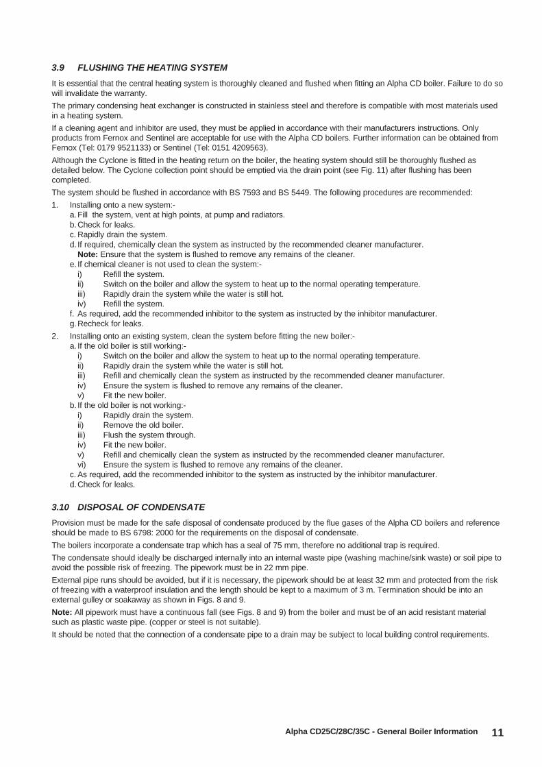
3.9 FLUSHING THE HEATING SYSTEM
It is essential that the central heating system is thoroughly cleaned and flushed when fitting an Alpha CD boiler. Failure to do sowill invalidate the warranty.
The primary condensing heat exchanger is constructed in stainless steel and therefore is compatible with most materials usedin a heating system.
If a cleaning agent and inhibitor are used, they must be applied in accordance with their manufacturers instructions. Onlyproducts from Fernox and Sentinel are acceptable for use with the Alpha CD boilers. Further information can be obtained fromFernox (Tel: 0179 9521133) or Sentinel (Tel: 0151 4209563).
Although the Cyclone is fitted in the heating return on the boiler, the heating system should still be thoroughly flushed asdetailed below. The Cyclone collection point should be emptied via the drain point (see Fig. 11) after flushing has beencompleted.
The system should be flushed in accordance with BS 7593 and BS 5449. The following procedures are recommended:
1. Installing onto a new system:-a.Fill the system, vent at high points, at pump and radiators.b.Check for leaks.c. Rapidly drain the system.d. If required, chemically clean the system as instructed by the recommended cleaner manufacturer.
Note: Ensure that the system is flushed to remove any remains of the cleaner.e. If chemical cleaner is not used to clean the system:-
i) Refill the system.ii) Switch on the boiler and allow the system to heat up to the normal operating temperature.iii) Rapidly drain the system while the water is still hot.iv) Refill the system.
f. As required, add the recommended inhibitor to the system as instructed by the inhibitor manufacturer.g.Recheck for leaks.
2. Installing onto an existing system, clean the system before fitting the new boiler:-a. If the old boiler is still working:-
i) Switch on the boiler and allow the system to heat up to the normal operating temperature.ii) Rapidly drain the system while the water is still hot.iii) Refill and chemically clean the system as instructed by the recommended cleaner manufacturer.iv) Ensure the system is flushed to remove any remains of the cleaner.v) Fit the new boiler.
b. If the old boiler is not working:-i) Rapidly drain the system.ii) Remove the old boiler.iii) Flush the system through.iv) Fit the new boiler.v) Refill and chemically clean the system as instructed by the recommended cleaner manufacturer.vi) Ensure the system is flushed to remove any remains of the cleaner.
c. As required, add the recommended inhibitor to the system as instructed by the inhibitor manufacturer.d.Check for leaks.
3.10 DISPOSAL OF CONDENSATE
Provision must be made for the safe disposal of condensate produced by the flue gases of the Alpha CD boilers and referenceshould be made to BS 6798: 2000 for the requirements on the disposal of condensate.
The boilers incorporate a condensate trap which has a seal of 75 mm, therefore no additional trap is required.
The condensate should ideally be discharged internally into an internal waste pipe (washing machine/sink waste) or soil pipe toavoid the possible risk of freezing. The pipework must be in 22 mm pipe.
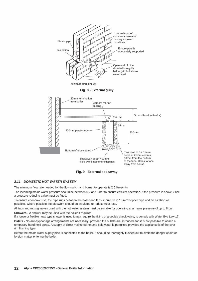
External pipe runs should be avoided, but if it is necessary, the pipework should be at least 32 mm and protected from the riskof freezing with a waterproof insulation and the length should be kept to a maximum of 3 m. Termination should be into anexternal gulley or soakaway as shown in Figs. 8 and 9.
Note: All pipework must have a continuous fall (see Figs. 8 and 9) from the boiler and must be of an acid resistant materialsuch as plastic waste pipe. (copper or steel is not suitable).
It should be noted that the connection of a condensate pipe to a drain may be subject to local building control requirements.
12 Alpha CD25C/28C/35C - General Boiler Information
Fig. 9 - External soakaway
3.11 DOMESTIC HOT WATER SYSTEM
The minimum flow rate needed for the flow switch and burner to operate is 2.5 litres/min.
The incoming mains water pressure should be between 0.2 and 8 bar to ensure efficient operation. If the pressure is above 7 bara pressure reducing valve must be fitted.
To ensure economic use, the pipe runs between the boiler and taps should be in 15 mm copper pipe and be as short aspossible. Where possible the pipework should be insulated to reduce heat loss.
All taps and mixing valves used with the hot water system must be suitable for operating at a mains pressure of up to 8 bar.
Showers - A shower may be used with the boiler if required.If a loose or flexible head type shower is used it may require the fitting of a double check valve, to comply with Water Bye Law 17.
Bidets - No anti-syphonage arrangements are necessary, provided the outlets are shrouded and it is not possible to attach atemporary hand held spray. A supply of direct mains fed hot and cold water is permitted provided the appliance is of the over-rim flushing type.
Before the mains water supply pipe is connected to the boiler, it should be thoroughly flushed out to avoid the danger of dirt orforeign matter entering the boiler.
Fig. 8 - External gully
13Alpha CD25C/28C/35C - Installation
4 INSTALLATION
4.1 UNPACKING
1. The boxes required when the boiler is installed with a horizontal flue are as follows:-
Box 1 ............................. Cased boiler fitted with water and gas valves, filling loop, seasonality valve, union bends and washersMounting bracket plus screws and wall plugsCondensate discharge pipeLiterature pack and Wall template
Box 2 ............................. CD Easy-Flue 500 mm or CD Easy-Flue 1000 mm. Both include 90° bend and horizontal flue terminalNote: NOT required for vertical flue
Notes: a. All flues must be suitable for CD condensing boilers.
b. CD 750 mm and 1000 mm flue extensions are available, if required.
Box 3 (if applicable) ....... Premier Pack includes: wall mounting jig with template, cyclone, bottom tray,earth bonding plate,spacers, pressure relief pipe terminal, split flow and return union bends, screw pack and fittinginstructions.
2. Unpack boiler and remove the loose items packs and mounting bracket.
Note: The boiler can be stood in an upright position, (to allow this, the union bends have been turned upwards so that theydo not protrude beneath the bottom - check this before standing the boiler upright).
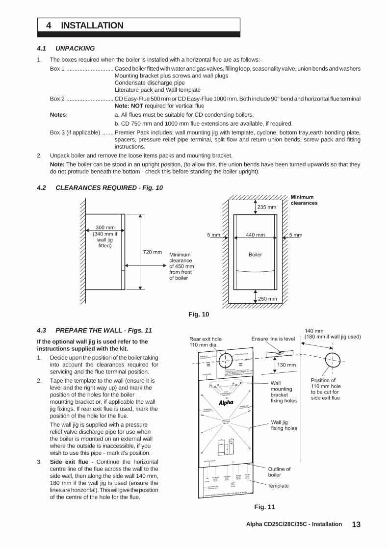
4.2 CLEARANCES REQUIRED - Fig. 10
Fig. 10
4.3 PREPARE THE WALL - Figs. 11
If the optional wall jig is used refer to theinstructions supplied with the kit.
1. Decide upon the position of the boiler takinginto account the clearances required forservicing and the flue terminal position.
2. Tape the template to the wall (ensure it islevel and the right way up) and mark theposition of the holes for the boilermounting bracket or, if applicable the walljig fixings. If rear exit flue is used, mark theposition of the hole for the flue.
The wall jig is supplied with a pressurerelief valve discharge pipe for use whenthe boiler is mounted on an external wallwhere the outside is inaccessible, if youwish to use this pipe - mark it's position.
3. Side exit flue - Continue the horizontalcentre line of the flue across the wall to theside wall, then along the side wall 140 mm,180 mm if the wall jig is used (ensure thelines are horizontal). This will give the positionof the centre of the hole for the flue.
Fig. 11
720 mm
300 mm
Minimumclearanceof 450 mmfrom frontof boiler
440 mm
235 mm
250 mm
5 mm 5 mm
Boiler
Minimumclearances
(340 mm ifwall jigfitted)
Template
Outline ofboiler
Wallmountingbracketfixing holes
Wall jigfixing holes
140 mm(180 mm if wall jig used)Ensure line is levelRear exit hole
110 mm dia.
Position of110 mm holeto be cut forside exit flue
130 mm= =
14
4. Cut the 110 mm diameter hole (or use a 107 mm core drill) in the wall for the flue.Notes: 1. Ensure the hole is horizontal.
2. For internal fitting of the flue, using the flue sealing collar supplied, cut a 130 mm dia. flue hole using a 127 mmcore drill.
5. Drill the fixing holes (10 mm dia.) to accept the No.10 plugs supplied. Using the screws supplied, fit the mounting bracket orwall jig if used. If applicable drill a 22 mm dia. hole for the pressure relief valve discharge pipe terminal supplied with the jig.
IMPORTANT: If the wall jig is used, follow the instructions supplied with the Premier Pack to fit the jig,mount the boiler and connect the pipework.
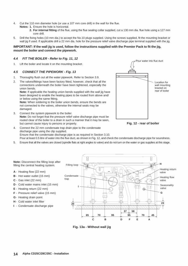
4.4 FIT THE BOILER - Refer to Fig. 11, 12
1. Lift the boiler and locate it on the mounting bracket.
4.5 CONNECT THE PIPEWORK - Fig. 13
1. Thoroughly flush out all the water pipework. Refer to Section 3.9.
2. The valves/fittings have been factory fitted, however, check that all theconnections underneath the boiler have been tightened, especially theunion bends.Note: If applicable the heating union bends supplied with the wall jig havebeen designed to enable the heating pipes to be routed from above and/or below using the same fitting.Note: When soldering to the boiler union bends, ensure the bends arenot connected to the valves, otherwise the internal seals may bedamaged.
3. Connect the system pipework to the boiler.Note: Do not forget that the pressure relief valve discharge pipe must berouted clear of the boiler to a drain in such a manner that it may be seen,but cannot cause injury to persons or property.
4. Connect the 22 mm condensate trap drain pipe to the condensatedischarge pipe using the clip supplied.Ensure that the condensate discharge pipe is as required in Section 3.10.Pour at least 0.5 litre of water into the flue duct, as shown in Fig. 12, and check the condensate discharge pipe for soundness.
5. Ensure that all the valves are closed (spindle flats at right angles to valve) and do not turn on the water or gas supplies at this stage.
Alpha CD25C/28C/35C - Installation
Fig. 12 - rear of boiler
Location forwall mountingbracket onrear of boiler
Pour water into flue duct
Fig. 13a - Without wall jig
A - Heating flow (22 mm)
B - Hot water outlet (15 mm)
C - Gas inlet (22 mm)
D - Cold water mains inlet (15 mm)
E - Heating return (22 mm)
F - Pressure relief valve (15 mm)
G - Heating drain point
H - Cold water inlet filter
I - Condensate discharge pipe
Note: Disconnect the filling loop afterfilling the central heating system.
Heating returnvalve
Filling loop
G
H
Condensatetrap
20 23
65 70 95 95 70 45
C B D F E A
Heating flowvalve
I
37 58
Seasonalityvalve
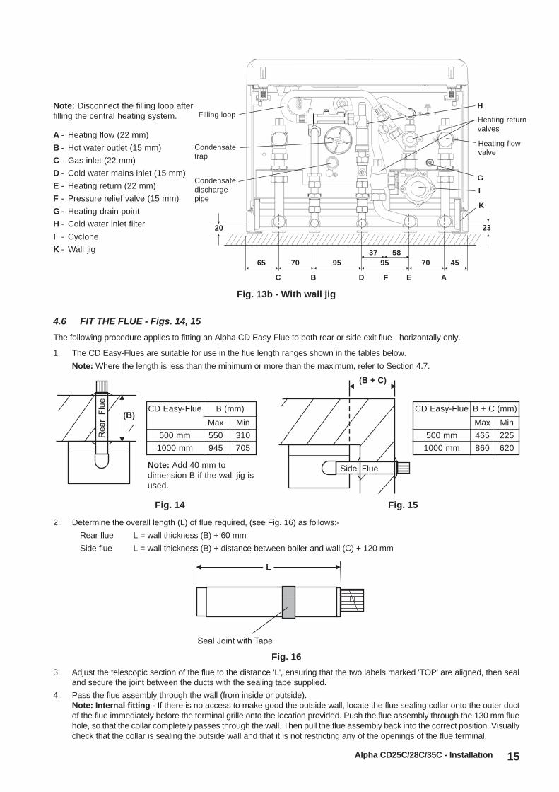
15
2. Determine the overall length (L) of flue required, (see Fig. 16) as follows:-
Rear flue L = wall thickness (B) + 60 mm
Side flue L = wall thickness (B) + distance between boiler and wall (C) + 120 mm
Fig. 16
3. Adjust the telescopic section of the flue to the distance 'L', ensuring that the two labels marked 'TOP' are aligned, then sealand secure the joint between the ducts with the sealing tape supplied.
4. Pass the flue assembly through the wall (from inside or outside).Note: Internal fitting - If there is no access to make good the outside wall, locate the flue sealing collar onto the outer ductof the flue immediately before the terminal grille onto the location provided. Push the flue assembly through the 130 mm fluehole, so that the collar completely passes through the wall. Then pull the flue assembly back into the correct position. Visuallycheck that the collar is sealing the outside wall and that it is not restricting any of the openings of the flue terminal.
4.6 FIT THE FLUE - Figs. 14, 15
The following procedure applies to fitting an Alpha CD Easy-Flue to both rear or side exit flue - horizontally only.
1. The CD Easy-Flues are suitable for use in the flue length ranges shown in the tables below.
Note: Where the length is less than the minimum or more than the maximum, refer to Section 4.7.
Alpha CD25C/28C/35C - Installation
Fig. 14 Fig. 15
CD Easy-Flue
500 mm
1000 mm
B (mm)
Max
550
945
Min
310
705
CD Easy-Flue
500 mm
1000 mm
Max
465
860
Min
225
620
B + C (mm)
Note: Add 40 mm todimension B if the wall jig isused.
Heating returnvalves
Heating flowvalve
Fig. 13b - With wall jig
A - Heating flow (22 mm)
B - Hot water outlet (15 mm)
C - Gas inlet (22 mm)
D - Cold water mains inlet (15 mm)
E - Heating return (22 mm)
F - Pressure relief valve (15 mm)
G - Heating drain point
H - Cold water inlet filter
I - Cyclone
K - Wall jig
Note: Disconnect the filling loop afterfilling the central heating system. Filling loop
G
H
Condensatetrap
20 23
65 70 95 95 70 45
C B D F E A
I
37 58
K
Condensatedischargepipe

16
5. Position the seal and clamp (two screws) supplied, over the bend. Fit the bend to the boiler and rotate to the correct position.Secure in position using the seal and clamp, ensuring the seal is located centrally over both the bend and boiler adaptor.
6. Fit the inside flue sealing collar over the Easy-Flue. Fit the outside flue sealing collar onto the flue immediately before theterminal grille onto the location provided.
7. Slide the clamp (three screws) over the outer duct and pull the flue assembly towards the bend, locating the inner duct intothe seal joint on the bend. Ensure the labels marked 'TOP' are positioned at the top before securing the flue assembly tothe bend with the clamp (three screws) located centrally over the joint.
Note: Check the flue terminal protrudes 100 mm out of the wall and the inner duct of the terminal is positioned correctly(see Fig. 18).
8. Make good the inside wall by pushing the inside flue sealing collar upto the wall.
Alpha CD25C/28C/35C - Installation
Fig. 18 - Rear flue
Flue Length
Up to maximum:-
Between:-
Between:-
Between:-
Less than:-
Rear Flue (B)
11.86 m
705 mm and 945 mm
550 mm and 705 mm
310 mm and 550 mm
310 mm
Side Flue (B + C)
11.775 m
620 mm and 860 mm
465 mm and 620 mm
225 mm and 465 mm
225 mm
Comments
Alpha CD 750 mm or 1000 mm flue extension(Part No. 6.2000750 or 6.2001050) is required toextend the range of telescopic flue.Refer to Section 4.7 paragraph 2 for instructionson how to extend the flue.Note: A 130 mm flue hole (127 mm core drill) isrequired in the wall.
Within the standard Easy-Flue 1000 mm(Part No. 6.20001000) telescopic range.
Use an Easy-Flue 1000 mm (Part No. 6.20001000)and the terminal may protrude somewhat from theoutside wall.
Within standard Easy-Flue 500 mm(Part No. 6.2000500) telescopic range.
Terminal may protrude somewhat from the outsidewall.
Note: Subtract 40 mm to dimension B if the wall jig is used.
40 (80 if wall jig used)
140
(180 if wall jig used)
90
Outer duct clamp
Inner duct seal joint
Inner duct seal joint
90° bend
Terminal
Flue sealing collar
Note: Ensure the outer flue duct is horizontal
Boiler side
CD Easy-Flue
Ensure the inner duct withinthe terminal is at the top.
The inner duct mustbe positioned to slope towardsthe boiler
Note:
4.7 EXTENDING THE FLUE - Fig. 19Note: The maximum horizontal flue assembly length must not exceed a length of 12 metres.
1. When the flue length required is more than the maximum or less than the minimum stated in Section 4.6, paragraph 1,refer to the table below.
Fig. 17 - Fitting the flue from inside

17Alpha CD25C/28C/35C - Installation
2. Use the template (supplied with the boiler) to mark the required flue position and cut a 130 mm diameter hole for the flue(use a 127 mm core drill). The size of the hole provides sufficient clearance for the clamps on the flue extension to passthrough the hole.
3. Determine the overall flue length as described in Section 4.6, paragraph 2 to determine the number of Alpha CD 750/1000 mmflue extensions required.
4. Assemble the flue extensions together by locating the inner duct into the seal joint and secure each extension togetherwith the clamps supplied (three screws). Ensure that the clamps are positioned centrally over the joints.
Note: If it is required to cut an extension, DO NOT cut the end of the inner duct that incorporates the seal joint. Ensure theinner duct end without the seal joint is cut so that it is 15 mm longer than the outer duct.
5. Adjust the telescopic section of the Easy-Flue to the required length and secure the Easy-Flue with the sealing tapesupplied. Fit the Easy-Flue to the extensions by locating the inner duct into the seal joint and secure with the clamp (threescrews), ensuring it is located centrally over the joint.
6. Mark the end of the flue assembly 'TOP' where it is connected to the boiler,so that the 'TOP' of the flue terminal is alignedwith the 'TOP' at the boiler end of the flue assembly.
7. Pass the complete flue assembly through the wall.
8. Position the seal and clamp (two screws) supplied, over the bend. Fit the bend to the boiler and rotate to the correctposition and secure in position using the seal and clamp, ensuring that the seal is positioned centrally over both the bendand adaptor.
9. Slide the clamp (three screws) over the outer duct and pull the flue assembly towards the bend, locating the inner duct intothe seal joint on the bend.
10. Secure the flue assembly to the bend with the clamp (three screws) ensuring it is positioned centrally over the joint,ensuring the 'TOP' marked on the outer duct is positioned at the top.
Note: Check the flue terminal protrudes 100 mm out of the wall and that the inner duct of the terminal is positionedcorrectly, i.e. the inner duct within the terminal is at the top. See Fig. 19.
11. Make good the outside wall by fitting a flue sealing collar onto the location provided immediately behind the flue terminalgrille. Make good the inside wall as required.
Note: If flue sealing collars are being used to make good the inside wall, then they will need to be fitted before assemblingthe flue.
Fig. 19 - Side flue
90
25
220 220
125
Note: Ensure the flue extension slopesdownwards towards the boiler by a minimumof 25 - 30 mm per metre Boiler front
Outer duct clamp
Inner seal joint
Inner seal joint
Flue length (L)
Clampand seal
90° bend
Seal joint
CD Easy-Flue
CD Flue extension
Flue sealingcollar
Flueterminal
Ensure the inner duct withinthe terminal is at the top.
The inner duct mustbe positioned to slope towardsthe boiler
Note:
18
Fig. 21
Alpha CD25C/28C/35C - Installation
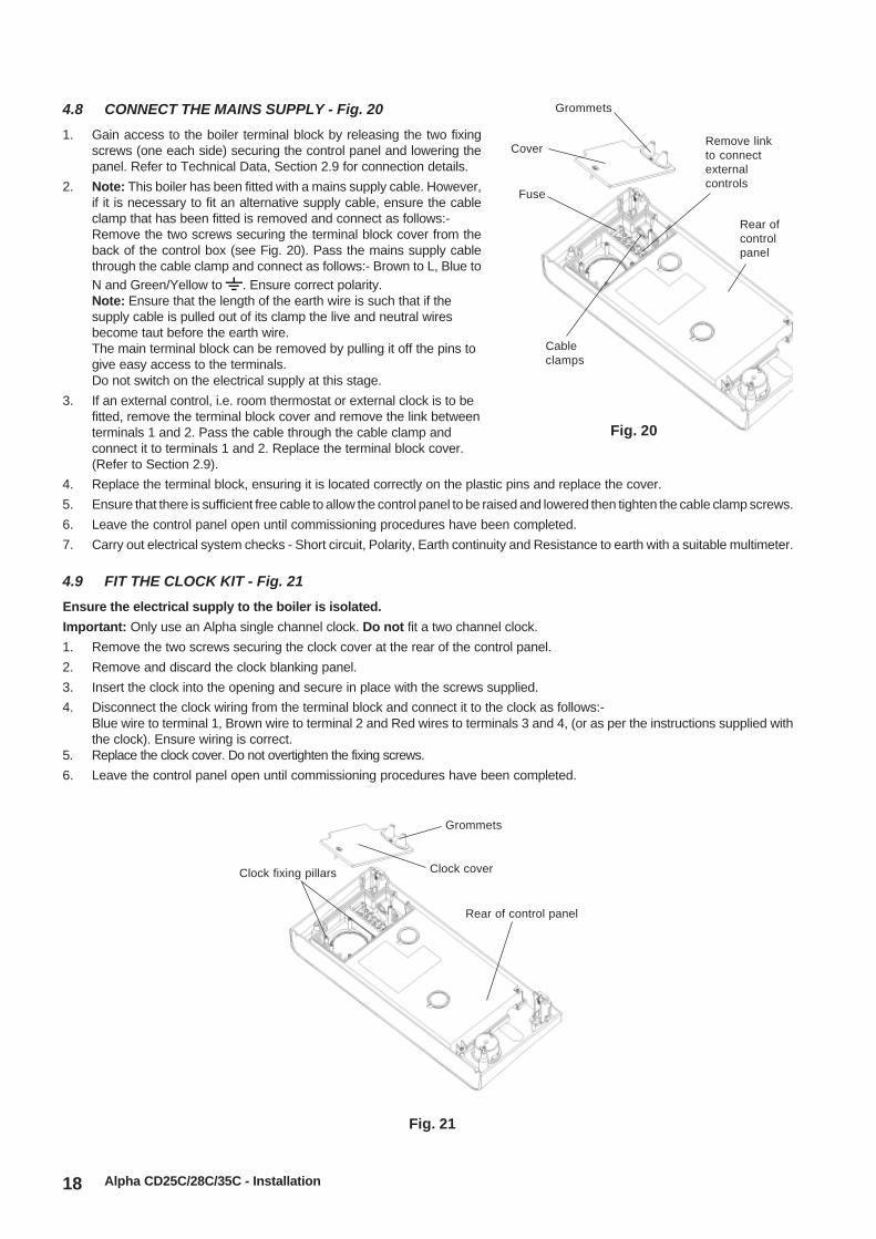
4.8 CONNECT THE MAINS SUPPLY - Fig. 20
1. Gain access to the boiler terminal block by releasing the two fixingscrews (one each side) securing the control panel and lowering thepanel. Refer to Technical Data, Section 2.9 for connection details.
2. Note: This boiler has been fitted with a mains supply cable. However,if it is necessary to fit an alternative supply cable, ensure the cableclamp that has been fitted is removed and connect as follows:-Remove the two screws securing the terminal block cover from theback of the control box (see Fig. 20). Pass the mains supply cablethrough the cable clamp and connect as follows:- Brown to L, Blue toN and Green/Yellow to . Ensure correct polarity.Note: Ensure that the length of the earth wire is such that if thesupply cable is pulled out of its clamp the live and neutral wiresbecome taut before the earth wire.The main terminal block can be removed by pulling it off the pins togive easy access to the terminals.Do not switch on the electrical supply at this stage.
3. If an external control, i.e. room thermostat or external clock is to befitted, remove the terminal block cover and remove the link betweenterminals 1 and 2. Pass the cable through the cable clamp andconnect it to terminals 1 and 2. Replace the terminal block cover.(Refer to Section 2.9).
4. Replace the terminal block, ensuring it is located correctly on the plastic pins and replace the cover.
5. Ensure that there is sufficient free cable to allow the control panel to be raised and lowered then tighten the cable clamp screws.
6. Leave the control panel open until commissioning procedures have been completed.
7. Carry out electrical system checks - Short circuit, Polarity, Earth continuity and Resistance to earth with a suitable multimeter.
4.9 FIT THE CLOCK KIT - Fig. 21
Ensure the electrical supply to the boiler is isolated.
Important: Only use an Alpha single channel clock. Do not fit a two channel clock.
1. Remove the two screws securing the clock cover at the rear of the control panel.
2. Remove and discard the clock blanking panel.
3. Insert the clock into the opening and secure in place with the screws supplied.
4. Disconnect the clock wiring from the terminal block and connect it to the clock as follows:-Blue wire to terminal 1, Brown wire to terminal 2 and Red wires to terminals 3 and 4, (or as per the instructions supplied withthe clock). Ensure wiring is correct.
5. Replace the clock cover. Do not overtighten the fixing screws.
6. Leave the control panel open until commissioning procedures have been completed.
Rear ofcontrolpanel
Cover
Grommets
Cableclamps
Fuse
Remove linkto connectexternalcontrols
Fig. 20
Rear of control panel
Clock cover
Grommets
Clock fixing pillars
19Alpha CD25C/28C/35C - Commissioning
5 COMMISSIONING
When commissioning the boiler, ensure the Benchmark Checklist is completed.
5.1 FILL THE SYSTEM
1. The boiler is fitted with an automatic air vent positioned on the pump (see Fig. 2), ensure that the vent is always open.
2. Open the central heating flow and return valves (slot in-line with valve) (see Fig. 13).
3. Open the fill point valve on the filling loop until water is heard to flow. To aid venting, the boiler drain point (see Fig. 2) maybe opened until water flows out. Close the drain point as soon as water appears.
4. To remove the air - Vent each radiator in turn, starting with the lowest in the system.
5. It is important that the pump is properly vented to avoid it running dry and damaging its bearings. Unscrew and remove the capfrom the centre of the pump. Using a suitable screwdriver rotate the exposed spindle about half a turn, then replace the cap.
6. Check the operation of the pressure relief valve (see Fig. 2) by turning the head anti-clockwise until it clicks. The click isthe valve lifting off its seat allowing water to escape from the system - check that this is actually happening.
7. Continue to fill the system until the pressure gauge indicates 1.0 bar. Close the fill point valve and check the system forwater soundness, rectifying where necessary. Disconnect the filling loop from the mains supply.Water may be released from the system by manually operating the drain point (see Fig. 2) until the system designpressure is obtained. The system design pressure (cold) should be between 0.75 and 1.25 bar.Refer to Sections 3.7 and 3.8. System volume, Flushing and Filling the system.
8. Open the mains water inlet valve (see Fig. 13). Turn on all hot water taps and allow water to flow until no air is present.Turn off taps.
9. Ensure that the condensate trap has been filled with water. Refer to Section 4.5, paragraph 4.
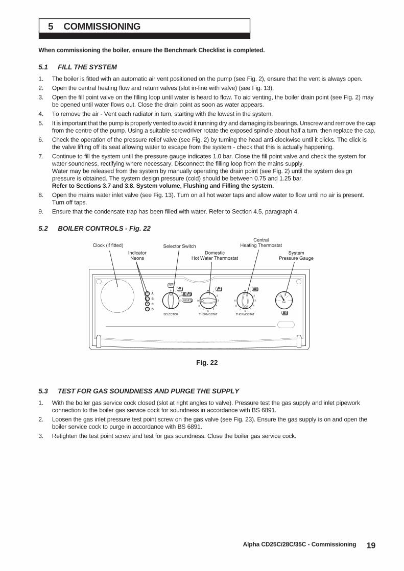
5.2 BOILER CONTROLS - Fig. 22
Fig. 22
0 1
2
3
1
2
3
4
56
7
8
9
1
2
3
4
56
7
8
9bar
0 4
3
2
1
RESET
A
D
B
C
SELECTOR THERMOSTAT THERMOSTAT
OFF
Clock (if fitted)
IndicatorNeons
Selector Switch
DomesticHot Water Thermostat
CentralHeating Thermostat
SystemPressure Gauge
5.3 TEST FOR GAS SOUNDNESS AND PURGE THE SUPPLY
1. With the boiler gas service cock closed (slot at right angles to valve). Pressure test the gas supply and inlet pipeworkconnection to the boiler gas service cock for soundness in accordance with BS 6891.
2. Loosen the gas inlet pressure test point screw on the gas valve (see Fig. 23). Ensure the gas supply is on and open theboiler service cock to purge in accordance with BS 6891.
3. Retighten the test point screw and test for gas soundness. Close the boiler gas service cock.

20
5.4 INITIAL LIGHTING - Refer to Fig. 22
1. Ensure that the gas and electrical supplies to the boiler are off and that the mains water inlet valve and the central heatingflow and return valves are open.
2. Turn on the gas and electrical supplies to the boiler.
3. Ensure all external controls are calling for heat.
If the optional Clock is fitted, refer to the User's instructions, set the time and ensure the Clock is in an 'on' mode.
4. Set the hot water and central heating thermostats to maximum.
5. Set the selector switch to (DHW only). Open a hot water tap, the main burner will light and the boiler will provide hotwater. Close the tap and the burner will go out.
6. Set the selector switch to (CH and DHW). The boiler will now run in the central heating mode. The pump will start,the fan will start and the main gas valve solenoid will open allowing the main burner to light.
5.5 CHECK THE BURNER PRESSURES - Figs. 23, 24
Turn the boiler off. Remove the two pressure test point screws at the top of the boiler andconnect a differential pressure gauge to P1 and P2 as shown in Fig 24. Allow the boiler torun for 10 minutes and check the differential burner pressures.
Hot water mode
1. Set the selector switch to (DHW only) and fully open a hot water tap.
2. The burner will light at the ignition rate and the burner pressure will increase tomaximum.
3. Gradually close the hot tap and check that the burner pressure decreases to its minimum.Fully open the tap and check that the burner pressure increases. Close the tap and checkthat the burner goes off.Note: The burner pressure settings have been factory set and do not requireadjusting. If incorrect, check that the inlet gas pressure is 20 mbar.If the inlet gas pressure is not 20 mbar, either the pipework is toosmall or the gas supply to the house is insufficient, in which casecontact your gas supplier.
Central heating mode
1. Set the selector switch to (DHW and CH).
2. The burner will light at the ignition rate and will increase to thefactory pre-set maximum output after 1 minute.
3. Turn off the boiler. Disconnect the pressure gauge and tightenthe test point screws.
Test for gas soundness using suitable leak detection fluid.
Note: Refer to Technical Data, Section 2.1 for the requireddifferential burner pressures.
5.6 FINAL COMMISSIONING
1. Allow the heating system to heat up, then balance the system to achieve the necessary temperature difference across theheating flow and return pipes at the boiler and check the system volume and pressure. (Refer to Technical Data, Sections2.2 and 2.8).
2. Turn off the boiler.3. Thoroughly flush out the water pipework (refer to Section 3.9) and with no pressure in the boiler heating circuit, empty the cyclone
(if applicable) at it's drain point (see Fig. 13) of any debris. Clean the mains water inlet filter (see Fig. 13).
4. Re-pressurise the system as described in Section 5.1.
Alpha CD25C/28C/35C - Commissioning
Fig. 23
Do notconnecthere
Do not connect here
Inlet gaspressuretest point
Fig. 24
++
-
-P1P2
Flue samplepoint (marked 'F')
- +

21Alpha CD25C/28C/35C - Commissioning
5.7 FINAL ASSEMBLY
1. Raise the control panel and secure in position with the screws provided.Note: If the wall jig is used, fit the bottom tray over the base of the boiler.
2. If the boiler is to be left in service with the User, set the controls, clock (if fitted, see User's Operating manual) and roomthermostat (if fitted) to the User's requirements.
3. If the boiler is not to be handed over immediately, close the boiler gas service cock and switch off the electrical supply.4. If there is any possibility of the boiler being left during frost conditions, then the boiler and system should be drained (refer to Section
8.2). It is recommended that a label is attached to the boiler drawing attention to the fact that the system has been drained.
5. Complete the details of the installation in the Benchmark Checklist on page 38.
5.8 USER INFORMATION
The User must be advised (and demonstrated if necessary) of the following important points:-
1. How to light and turn off the boiler and how to operate the system controls.
2. The importance of annual servicing of the boiler to ensure safe and efficient operation.
3. That any servicing or replacement of parts must only be carried out by CORGI registered personnel.
4. Ensure that the boiler controls and room thermostat (if fitted) are set to the User's requirements.5. Tell the User about the sealed system pressure.
6. Tell the User that if the electrical supply is on and the boiler has not operated for 24 hours for heating or hot water, thepump will automatically operate for 5 minutes.
7. Explain to the User that an internal frost thermostat is fitted in the boiler, and that the electrical supply to the boiler must beleft on for the thermostat to operate.
8. Explain to the User that in certain weather conditions the terminal will emit a plume of steam, i.e. water vapour. This is safeand quite normal.
9. Show the User the position of the pressure relief valve and condensate discharge pipes.
10. Hand the User's instructions to the User.
11. Ensure the Benchmark Checklist in Section 12 on page 38 has been completed after the boiler has been installed andcommissioned.
Note: It is a requirement that the installation is registered by the installer through the CORGI Gas Work NotificationScheme.
12. Leave these Installation and Servicing instructions with the User for use on future calls.

22
The boiler operating mode is controlled by the selector switch on the facia panel.
When set to , the boiler will only operate in the Domestic Hot Water mode. When set to , it will operate in theDomestic Hot Water and Central Heating mode.Note: The clock (if fitted) only controls the operating times of the central heating, not domestic hot water - DHW is available continuously.
Domestic hot water supply always takes priority over central heating. If a demand for hot water is required during a centralheating period, the boiler will automatically switch to the hot water mode until the demand is satisfied. This interruption in thecentral heating is only when the demand for hot water is present and should not be noticed by the User.
6.1 CENTRAL HEATING MODE
If there is a call for heat, the pump will start to circulate the central heating water. The fan will run and the pre-mix burner will light.The burner output then automatically adjusts to suit the system demand; as the temperature of the water in the boiler approachesthat set by the adjustable temperature thermostat, the burner output is reduced. When the set temperature is reached, the burneris turned off. The fan continues to run for 50 seconds and the pump continues to run until the temperature within the boiler reducesto the set temperature before allowing the burner to relight. If the primary sensor has not registered the pre-set temperature but theroom thermostat is satisfied the burner is turned off. The fan continues to run for 50 seconds and the pump continues to run for 60seconds. In this instance there is no delay before the burner will relight.
If there is a demand for DHW during the burner delay, the boiler will operate to provide DHW until the tap is closed; the boilerwill then immediately revert to provide CH if there is a demand.
Note: If the system pressure is very low, the primary pressure switch will prevent the boiler from operating.
6.2 DOMESTIC HOT WATER MODE
When a demand for hot water (by opening a hot tap, etc.) is sensed by the flow switch, the pump starts and the burner lights,increasing immediately to its maximum output. Water in the boiler is then diverted from the central heating system to thedomestic hot water heat exchanger, heating the incoming mains water. The burner output is varied to maintain the temperatureof the hot water as that set by the adjustable temperature selector. When the flow switch senses that hot water is no longerrequired the burner is turned off and the boiler immediately returns to the central heating mode.
When the burner is turned off, the fan will continue to run for 50 seconds and the pump will stop immediately if the selector isset for hot water only.
In both modes the fan modulates according to the output required.
6.3 FROST THERMOSTAT
The boiler incorporates a built in frost thermostat which automatically turns on the boiler and pump if the water in the boiler falls
below 8°C, providing the electrical supply is on and the selector switch is set to position 1 ( ) or position 2 ( ). The boilerwill operate until the water temperature in the system reaches approximately 40°C.
6.4 PUMP
If the electrical supply is on and the boiler has not operated for 24 hours for heating or hot water, the pump will operateautomatically for five minutes every 24 hours.
6.5 INDICATOR NEONS
When neons A (red), B (red), C (yellow), D (green) are illuminated, the following conditions apply:-
NeonD Illuminated continuously - Electricity supply to the boiler is on.
C Illuminated continuously - Burner is alight.
A Flashing on and off - Temperature sensor fault.
B Flashing on and off - Overheat thermostat has operated. Rotate selector switch to the reset position (3) to reset.
B Illuminated continuously - Burner has failed to light. Rotate selector switch to the reset position (3) and the ignitionsequence will restart after a delay of about 30 seconds.
A and B Flashing on and off at the same time - Blocked flue or fan fault.
A and B Flashing on and off alternatively - System pressure is very low and re-pressurisation is required.
A Flashing and B Illuminated continuously - Pump fault or restricted flow.
Note: Do not hold the selector switch in the reset position (3) for more than 2 to 3 seconds.
Alpha CD25C/28C/35C - Boiler Operation
6 BOILER OPERATION
23
To ensure efficient operation of the boiler it is recommended that it is checked and serviced as necessary at regular intervals.The frequency of servicing will depend upon the particular installation conditions and usage, but in general once per yearshould be adequate.
It is the law that any service work must be carried out by a competent person, i.e. CORGI registered personnel.
Warning: Before servicing the boiler, isolate the electrical supply and close the boiler gas service cock. Allow the boiler to cool.
The data label is positioned on the inside of the left hand side panel.
Always test for gas soundness after servicing any gas carrying components.
Always carry out electrical system checks i.e. Eart Continuity, Resistance to Earth, Short Circuit and Polarity with a suitablemeter after servicing.
Notes: 1. Prior to servicing, it is recommended that a flue gas analyser is used to measure the performance of the boiler (referto Fig. 2 for the position of the flue sampling point). If the CO/CO2 ratio measured is greater than 0.002 or whenother checks and comments from the customer have indicated that there may be problems, cleaning of the heatexchanger will be necessary. All Sections 7.1, 7.2, 7.3 and 7.4 must be carried out. Repeat the flue gas analysertest after reassembling the boiler and check that the CO/CO2 ratio is less than 0.002.
2. If the CO/CO2 ratio measured is less than 0.002 and other checks and comments from the customer suggest thereare no problems then only Section 7.1 and Section 7.2 paragraphs 1, 2 and 3 need to be carried out to allow avisual check of the components within the room sealed chamber.
3. If a flue gas analyser is not available, then all Sections 7.1, 7.2, 7.3 and 7.4 must be carried out.
7.1 IMPORTANT NOTES PRIOR TO SERVICING
1. Check the flue terminal outside and ensure it is not blocked.
2. Run the boiler and check the operation of its controls.
3. Refer to Fig. 2 for location of flue sampling point.
4. Ensure that all system connections and fittings are sound. Remake any joints and check the tightness of any fittings thatmay be leaking.
5. It is recommended that the operation of the safety valve is checked by turning the head anti-clockwise until it clicks. Theclick is the safety valve lifting off its seat allowing water to escape from the system - check that this is actually happening.
6. Refill, vent and re-pressurise the system as necessary. (Refer to Commissioning, Section 5.1).If the system pressure exceeds 2.5 bar when operating at maximum temperature, the heating expansion vessel should bechecked and re-pressurised, if necessary.Notes: 1. Check the expansion vessel charge only when the system pressure is zero.
2. The expansion vessel pressure test point is accessible from inside the boiler at the top.
7. Check that the condensate trap drain pipe is connected and all joints are sound.
8. Record details of the service in the Service Record Section on page 39.
Alpha CD25C/28C/35C - Routine Servicing
7 ROUTINE SERVICING
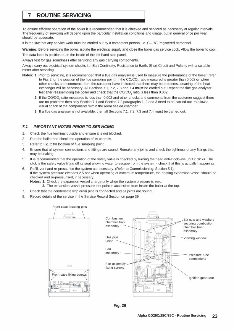
Fig. 26
Front case locating pins
Front case fixing screws
Six nuts and washerssecuring combustionchamber frontassembly
Gas pipeunion
Pressure tubeconnections
Fan assemblyfixing screws
Ignition generator
Fanassembly
Combustionchamber frontassembly
Viewing window

24
7.2 PREPARE FOR SERVICING - Fig. 26
1. Ensure the electrical supply is isolated and the gassupply is off.
2. Unscrew the two screws securing the control paneland lower the panel.
3. Remove the four screws securing the front case. Liftthe case up and forwards to remove.
4. Disconnect the gas supply pipe union.
5. Remove the two screws securing the fan assembly tothe combustion chamber front.
6. Remove the two pressure tubes, noting theirpositions.
7. Disconnect the electrode lead from the ignitiongenerator and the in-line connector to the flamesensing electrode.
8. Remove the six nuts and washers securing thecombustion chamber front assembly and remove theassembly.
7.3 CLEANING THE BOILER
1. Remove any deposits from heat exchanger using a suitable soft brush. Do not use a brush with metallic bristles.
2. Check the condition of the combustion chamber insulation panels. Any damaged panels must be replaced. (Refer toComponent Replacement, Section 8.18).
3. Check the condition of the burner injector on the combustion chamber front assembly, carefully clean them with a softbrush if necessary.Do not use a brush with metallic bristles as this might damage the injector.
4. Remove any deposits from the heat exchanger coils. This can be done by suction or water sprayed onto the coils. Ensureall electrical components are protected from water. Any water used to clean the heat exchanger will drain to thecondensate trap.
5. Unscrew and replace the injector should it appear damaged.
6. Remove the four screws securing the burner (see Fig. 27) and remove the burner. Clean the burner with a soft brush andcheck that the flame ports are clear. Blockages may be removed with a stiffer brush. Tap the burner, open end down, toremove any deposits from inside.
7. Check the condition of the electrodes.
9. Check the spark gap, positioning and height of the electrodes. See Fig. 27.
10. Unscrew the condensate trap drain cap to remove any deposits.Note: Before removing the cap, ensure that the water released from the trap can be contained to avoid spillage.The trap will contain no more than 200 cc of condensate water. Replace the drain cap.
7.4 RE-ASSEMBLE THE BOILER
1. Replace the burner, ensuring it is located correctly and secure it in position using the four screws previously removed.
Important: Before replacing the combustion chamber front assembly, pour at least 200 cc of water into the coils of theheat exchanger. This is to ensure the condensate trap is full of water before operating the boiler.
2. Replace the combustion chamber front assembly, ensuring it is correctly located.
3. Ensure the electrode lead is connected and the seal is in position in the bottom of the room sealed chamber.
4. Test the connections for gas soundness and re-commission, Sections 5.4 and 5.5.
5. Place the front case panel in position and secure in position with the four screws previously removed, see Fig. 26.
6. Raise the control panel and secure in position with the two screws provided.
7. Check the operation of the boiler. (Refer to Boiler Operation, Section 6).
8. Return all controls to their original settings.
Alpha CD25C/28C/35C - Routine Servicing
Fig. 27
Flame sensingelectrode
Gap 16 mm (CD25C 12 mm)
Ignition electrodes
Gap 3 - 4 mm
Burner
Combustion chamberfront assembly
Front insulationpanel
25
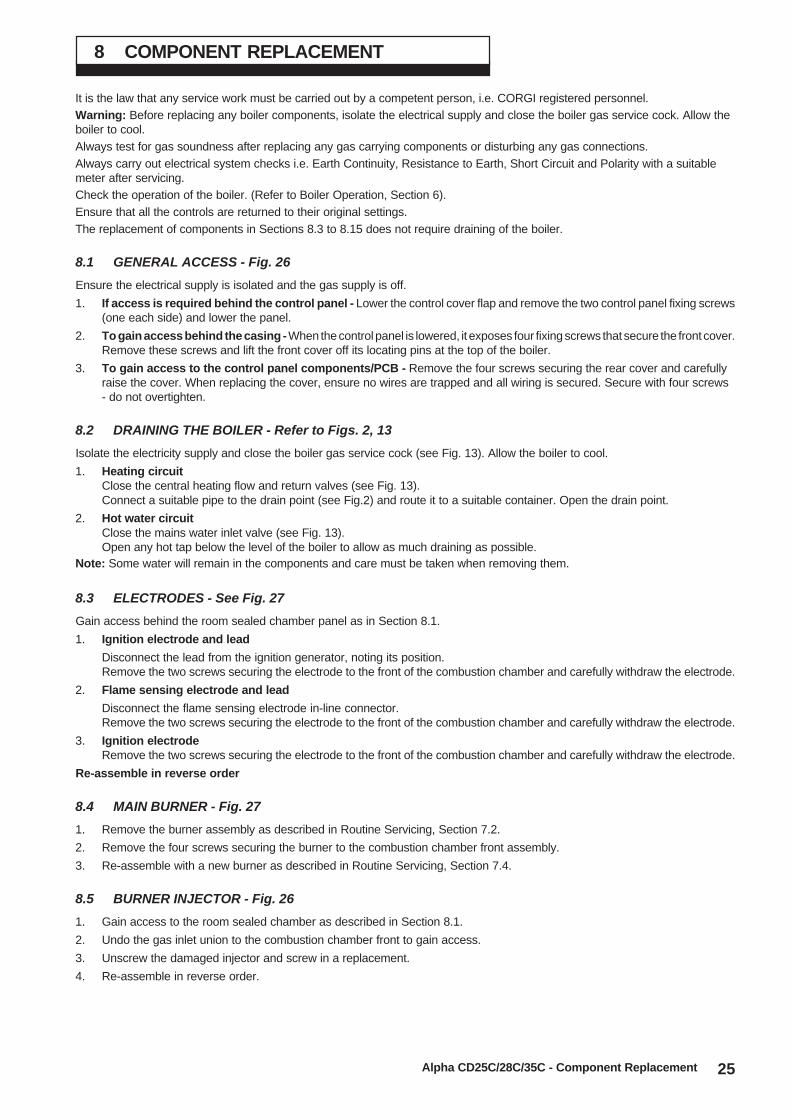
8 COMPONENT REPLACEMENT
Alpha CD25C/28C/35C - Component Replacement
It is the law that any service work must be carried out by a competent person, i.e. CORGI registered personnel.Warning: Before replacing any boiler components, isolate the electrical supply and close the boiler gas service cock. Allow theboiler to cool.Always test for gas soundness after replacing any gas carrying components or disturbing any gas connections.Always carry out electrical system checks i.e. Earth Continuity, Resistance to Earth, Short Circuit and Polarity with a suitablemeter after servicing.Check the operation of the boiler. (Refer to Boiler Operation, Section 6).Ensure that all the controls are returned to their original settings.The replacement of components in Sections 8.3 to 8.15 does not require draining of the boiler.
8.1 GENERAL ACCESS - Fig. 26
Ensure the electrical supply is isolated and the gas supply is off.
1. If access is required behind the control panel - Lower the control cover flap and remove the two control panel fixing screws(one each side) and lower the panel.
2. To gain access behind the casing - When the control panel is lowered, it exposes four fixing screws that secure the front cover.Remove these screws and lift the front cover off its locating pins at the top of the boiler.
3. To gain access to the control panel components/PCB - Remove the four screws securing the rear cover and carefullyraise the cover. When replacing the cover, ensure no wires are trapped and all wiring is secured. Secure with four screws- do not overtighten.
8.2 DRAINING THE BOILER - Refer to Figs. 2, 13
Isolate the electricity supply and close the boiler gas service cock (see Fig. 13). Allow the boiler to cool.
1. Heating circuitClose the central heating flow and return valves (see Fig. 13).Connect a suitable pipe to the drain point (see Fig.2) and route it to a suitable container. Open the drain point.
2. Hot water circuitClose the mains water inlet valve (see Fig. 13).Open any hot tap below the level of the boiler to allow as much draining as possible.
Note: Some water will remain in the components and care must be taken when removing them.
8.3 ELECTRODES - See Fig. 27
Gain access behind the room sealed chamber panel as in Section 8.1.
1. Ignition electrode and lead
Disconnect the lead from the ignition generator, noting its position.Remove the two screws securing the electrode to the front of the combustion chamber and carefully withdraw the electrode.
2. Flame sensing electrode and lead
Disconnect the flame sensing electrode in-line connector.Remove the two screws securing the electrode to the front of the combustion chamber and carefully withdraw the electrode.
3. Ignition electrodeRemove the two screws securing the electrode to the front of the combustion chamber and carefully withdraw the electrode.
Re-assemble in reverse order
8.4 MAIN BURNER - Fig. 27
1. Remove the burner assembly as described in Routine Servicing, Section 7.2.
2. Remove the four screws securing the burner to the combustion chamber front assembly.
3. Re-assemble with a new burner as described in Routine Servicing, Section 7.4.
8.5 BURNER INJECTOR - Fig. 26
1. Gain access to the room sealed chamber as described in Section 8.1.
2. Undo the gas inlet union to the combustion chamber front to gain access.
3. Unscrew the damaged injector and screw in a replacement.
4. Re-assemble in reverse order.
26
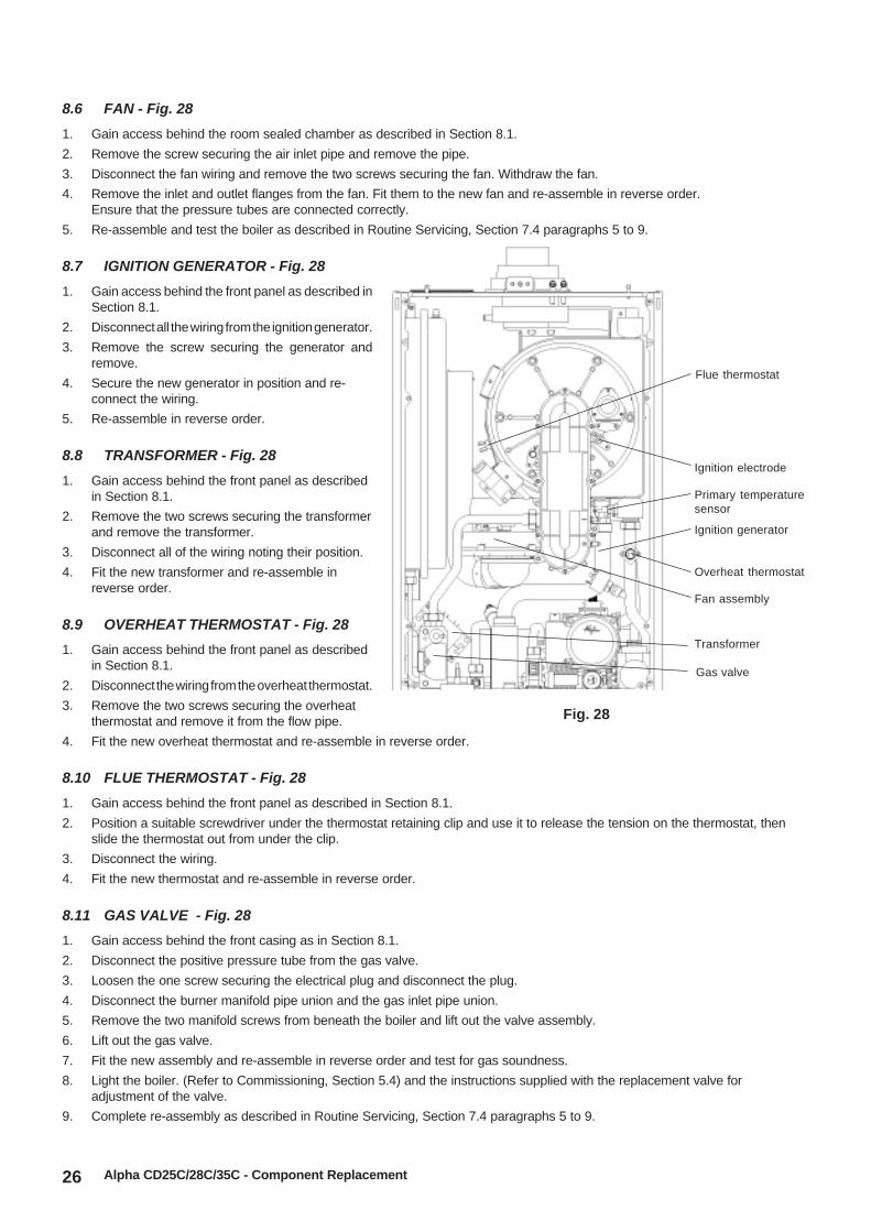
8.6 FAN - Fig. 28
1. Gain access behind the room sealed chamber as described in Section 8.1.
2. Remove the screw securing the air inlet pipe and remove the pipe.
3. Disconnect the fan wiring and remove the two screws securing the fan. Withdraw the fan.
4. Remove the inlet and outlet flanges from the fan. Fit them to the new fan and re-assemble in reverse order.Ensure that the pressure tubes are connected correctly.
5. Re-assemble and test the boiler as described in Routine Servicing, Section 7.4 paragraphs 5 to 9.
8.7 IGNITION GENERATOR - Fig. 28
1. Gain access behind the front panel as described inSection 8.1.
2. Disconnect all the wiring from the ignition generator.
3. Remove the screw securing the generator andremove.
4. Secure the new generator in position and re-connect the wiring.
5. Re-assemble in reverse order.
8.8 TRANSFORMER - Fig. 28
1. Gain access behind the front panel as describedin Section 8.1.
2. Remove the two screws securing the transformerand remove the transformer.
3. Disconnect all of the wiring noting their position.
4. Fit the new transformer and re-assemble inreverse order.
8.9 OVERHEAT THERMOSTAT - Fig. 28
1. Gain access behind the front panel as describedin Section 8.1.
2. Disconnect the wiring from the overheat thermostat.
3. Remove the two screws securing the overheatthermostat and remove it from the flow pipe.
4. Fit the new overheat thermostat and re-assemble in reverse order.
8.10 FLUE THERMOSTAT - Fig. 28
1. Gain access behind the front panel as described in Section 8.1.
2. Position a suitable screwdriver under the thermostat retaining clip and use it to release the tension on the thermostat, thenslide the thermostat out from under the clip.
3. Disconnect the wiring.
4. Fit the new thermostat and re-assemble in reverse order.
8.11 GAS VALVE - Fig. 28
1. Gain access behind the front casing as in Section 8.1.
2. Disconnect the positive pressure tube from the gas valve.
3. Loosen the one screw securing the electrical plug and disconnect the plug.
4. Disconnect the burner manifold pipe union and the gas inlet pipe union.
5. Remove the two manifold screws from beneath the boiler and lift out the valve assembly.
6. Lift out the gas valve.
7. Fit the new assembly and re-assemble in reverse order and test for gas soundness.
8. Light the boiler. (Refer to Commissioning, Section 5.4) and the instructions supplied with the replacement valve foradjustment of the valve.
9. Complete re-assembly as described in Routine Servicing, Section 7.4 paragraphs 5 to 9.
Alpha CD25C/28C/35C - Component Replacement
Fig. 28
Flue thermostat
Primary temperaturesensor
Overheat thermostat
Ignition electrode
Fan assembly
Ignition generator
Transformer
Gas valve

27
8.12 TERMINAL BLOCK FUSE - Refer to Fig. 20
The fuse is located in the boiler terminal block.
1. Gain access as described in Installation, Section 4.8.
2. Lift out the fuse holder and remove the fuse. Fit a fast blow 2 A fuse as a replacement, ensuring that the holder snaps into position.
Note: A spare fuse is supplied in the terminal compartment.
3. Re-assemble in reverse order, ensuring the terminal block is located correctly on the plastic pins.
8.13 PCB - Fig. 29
1. Gain access behind the control panel as described in Section 8.1.
2. Disconnect all the wiring connectors from the PCB.
3. Remove the four fixing screws and carefully withdraw the board from the switch spindles.
4. Re-assemble in reverse order. Refer to the wiring diagram in Section 9.1 for connections.
5. Light the boiler and adjust the PCB as described in the instructions supplied with the replacement PCB.
Alpha CD25C/28C/35C - Component Replacement
8.14 DIVERTER VALVE MOTOR ASSEMBLY - Fig. 33
1. Gain access behind the front casing as described in Section 8.1.
2. Remove the diverter valve motor head by unplugging its electrical connection and removing the retaining clip from theback of the motor.
3. Withdraw the motor forwards from the valve body.
4. Re-assemble in reverse order with a new motor.
8.15 CLOCK (if fitted) - Refer to Fig. 21
Note: For replacement only use an Alpha single channel clock. Do not fit a two channel clock.
1. Gain access behind the control panel as described in Section 8.1.
2. Remove the two screws securing the clock cover at the rear of the control panel.
3. Disconnect the wiring from the clock.
4. Remove the clock retaining screws and withdraw the clock from the control panel.
5. Fit the new clock, and connect the wires as follows:-Blue to terminal 1, Brown to terminal 2 and Red wires to terminals 3 and 4, (or as per the instructions supplied with the clock).
6. Re-assemble in reverse order. Refer to the User's instructions and the boiler's control cover to set the clock.
8.16 DHW FLOW SWITCH - Fig. 30
1. Gain access behind the front casing as described in Section 8.1.
2. Isolate the mains water supply and open all hot taps to drain any water from the boiler.
3. Disconnect the wires from the switch.
4. Undo the nuts at the inlet and outlet of the switch and undo the retaining nut at the bottom. Lift out the switch.
5. Fit the new switch and re-assemble in reverse order.
Fig. 29 Fig. 30
PCB FusePCB
DHW flow switchRetaining nut

28
8.17 PRIMARY HEAT EXCHANGER - See Fig. 31
1. Gain access behind the room sealed chamber panel as describedin Section 8.1 and drain the boiler heating circuit as described inSection 8.2.
2. Disconnect the gas inlet union from the combustion chamber front.
3. Remove the two screws and six nuts and washers securing thecombustion chamber front burner assembly and remove.
4. Remove the overheat thermostat (Section 8.9), flue thermostat(Section 8.10) and the primary temperature sensor (Section 8.20).
5. Disconnect the condensate drain union by pulling out the clip.
6. Undo the two nuts from the heat exchanger flow and return pipes.
7. Remove the four screws securing the heat exchanger retainingbrackets. Two on the front left and two at the rear to the right.
8. Lift up the heat exchanger off the pipes and remove it by carefullywithdrawing it out of the boiler.
9. Re-assemble in reverse order, ensuring that new seals are used.Lubricating the seals with the grease supplied will aid assembly.
10. Refill and pressurise the system. (Refer to Commissioning,Section 5.1).
8.18 COMBUSTION CHAMBER INSULATION
Gain access to the combustion chamber as described in Section 8.1.
Front insulation - see Fig. 27
1. Remove the electrodes from the combustion chamber front as described in Section 8.3.
2. Remove the four screws securing the burner.
3. Carefully remove the insulation.
Back insulation - see Fig. 31
1. Remove the combustion chamber front/burner assembly.
2. Remove the centre screw retaining the insulation.
3. Carefully remove the insulation, suction applied to the centre of the insulation will aid this.
Fit a new panel and re-assemble in reverse order.
Refill and pressurise the system. (Refer to Commissioning, Section 5.1).
8.19 PRESSURE GAUGE - Fig. 32
1. Gain access behind the casing and drain the boiler heating circuit as described in Sections 8.1 and 8.2.
2. Remove the circlip securing the pressure gauge sensor and withdraw the sensor.
3. Remove the main cable grommet in the bottom panel and remove the sensor tube.
4. Depress the two lugs on the pressure gauge and push it out of the control panel.
5. Fit the new gauge using a new 'O' ring on the manifold connection if necessary.
6. Refill and pressurise the system. (Refer to Commissioning, Section 5.1).
Fig. 32
Fig. 31
Primary pressure switch
Automatic air vent
Pump
Pressure relief valve
Pressure gauge
Alpha CD25C/28C/35C - Component Replacement
DHW sensor
Diverter valve
Back insulation panel
Two screws securingheat exchanger
Two screwssecuring heatexchanger

29
8.20 TEMPERATURE SENSORS - Refer to Fig. 28 and 32
Note that both sensors are the same.
1. Gain access as described in Section 8.1 and drain (heating circuit for primary sensor or hot water circuit for DHW sensor)as described in Section 8.2.
2. Primary Sensor - The primary sensor is positioned on the bottom right hand side of the heat exchanger, see Fig. 28.Disconnect the wiring and unscrew the sensor. Re-assemble in reverse order with a new sensor and sealing washer.
2a. DHW Sensor - The DHW sensor is positioned in the hot water outlet pipe, see Fig. 32. Close the mains cold water inlet valveand open the lowest hot water tap to drain the DHW system. Disconnect the wiring and unscrew the sensor from the hot wateroutlet pipe. Re-assemble in reverse order with a new sensor, replacing the sealing washer if necessary.
8.21 AUTOMATIC AIR VENT - Fig. 32
1. Gain access behind the front casing and drain the boiler heating circuit as described in Sections 8.1 and 8.2.
2. Remove the retaining clip from the manifold and lift out the automatic air vent. Fit a new one using a new 'O' ring.
3. Refill and pressurise the system. (Refer to Commissioning, Section 5.1).
8.22 PUMP - Refer to Fig. 32
Gain access behind the front casing and drain the boiler heating circuit as described in Sections 8.1 and 8.2.
Pump head
1. Using a 5 mm Allen key remove the four socket head screws securing the pump head to the body. Withdraw the head,remove the wiring cover and disconnect the plug.
2. Connect the plug to the new head. Ensure the pump is set to maximum (3) and re-assemble in reverse order.
3. Refill and pressurise the system. (Refer to Commissioning, Section 5.1).
8.23 PRIMARY PRESSURE SWITCH - Fig. 32
1. Gain access behind the front casing and drain the boiler heating circuit as described in Sections 8.1 and 8.2.
2. Disconnect the wiring from the pressure switch.
3. Unscrew the switch from the primary flow pipe.
4. Using the new washer supplied, re-assemble in reverse order.
When connecting the wiring to the new switch the polarity of the wires is not important.
8.24 PRESSURE RELIEF VALVE - Fig. 32
1. Gain access behind the front casing and drain the boiler heating circuit as described in Sections 8.1 and 8.2.
2. Disconnect the pressure relief valve outlet fitting.
3. Release the two screws and the retaining clip securing the pressure relief valve and pull out the valve.
4. Re-assemble in reverse order.
5. Refill and pressurise the system. (Refer to Commissioning, Section 5.1).
8.25 DHW HEAT EXCHANGER
1. Gain access behind the front casing and drain the boiler heating and hot water circuits as described in Sections 8.1 and 8.2.
2. Release the nut securing the condensate pipe and remove the flexible condensate pipe from the condensate trap. Rotatethe pipe to clear.
3. Remove the diverter valve motor as described in Section 8.14.
4. Using a 4 mm Allen key unscrew the two socket head capscrews securing the DHW heat exchanger and withdraw theheat exchanger from the boiler, lifting it upwards and tip it forwards to remove.Note: Be careful not to allow water to drip onto any electrical components.
5. Re-assemble in reverse order making sure that the words on the heat exchanger are at the top when fitted and that theseals are in position in the manifold.
6. Refill and pressurise the system. (Refer to Commissioning, Section 5.1).
Alpha CD25C/28C/35C - Component Replacement

30
8.26 MAINS WATER INLET FILTER
1. The mains water inlet filter is located in the body of the DHW flow switch. Refer to Section 8.14 to remove the flow switch.
2. The filter can be removed using a small screwdriver.
3. Clean the filter and re-assemble in reverse order.
8.27 DIVERTER VALVE ASSEMBLY - Fig. 33
1. Gain access behind the front casing and drain the boiler heating circuit as described in Sections 8.1 and 8.2.
2. Remove the diverter valve motor as described in Section 8.14.
3. Unplug the overheat thermostat connections.
4. Remove the heating flow pipe retaining clip from the diverter valve and undo the pipe connection at the heat exchanger.Rotate the pipe to the left and lift upward to remove it from the diverter valve.
5. Remove the heating return pipe retaining clip from the pump housing and undo the pipe connection at the heat exchanger.Pull the pipe from the pump housing and remove.
6. Remove the DHW outlet pipe retaining clip from the diverter valve and undo the nut connecting the other end to the DHWswitch housing and remove the pipe.
7. Using a 4 mm Allen key, undo the two cap head bolts securing the DHW heat exchanger and remove the heat exchanger.
8. Remove the heating flow valve from the bottom of the boiler and undo the return valve from its boiler connection.
9. Remove the four screws at the bottom of the boiler, either side of the flow and return connections and the two screw eitherside of the expansion relief pipe.
10. Remove the securing screws at the front top and bottom corners of the right hand side panel. This will provide somesideways movement to allow more room to release the valve.
11. Lift the assembly up slightly and pull the diverter valve to the right and off the automatic by-pass.
12. Re-assemble in reverse order using new seals and washers.
13. Refill and pressurise the system. (Refer to Commissioning, Section 5.1).
8.28 EXPANSION VESSEL - Fig. 12
1. Gain access behind the front casing and drain the boiler heating circuit as described in Sections 8.1 and 8.2.
2. Disconnect the pipe from the expansion vessel.
3. Remove the screw securing the top support bracket.
4. Lift the expansion vessel out of the boiler.
5. When replacing the vessel, ensure that the connection is towards the left of the boiler and re-assemble in reverse orderusing new seals as necessary.
6. Refill and pressurise the system. (Refer to Commissioning, Section 5.1).
8.29 CYCLONE (if wall jig is fitted) - Fig. 13
1. Remove the bottom tray and close the isolating valves either side of the cyclone.
2. Disconnect the unions from the cyclone. Remove the two screws securing the support bracket and remove the cyclone.Re-assemble with a new cyclone.
3. Pressurise the system. (Refer to Commissioning, Section 5.1).
8.30 CONDENSATE TRAP - Fig. 13
1. Gain access behind the front casing as described in Section 8.1.
2. Disconnect the top and drain connection of the condensate trap.
3. Place a container under the boiler and unscrew the bowl at the bottom of the trap, see Fig. 13. Some water will spill from thetrap.
4. Remove the screw securing the trap to the bottom of the boiler casing and lift out the trap.
5. Fit the new trap in reverse order.
Note: Fill the new trap with water once installed.
Alpha CD25C/28C/35C - Component Replacement
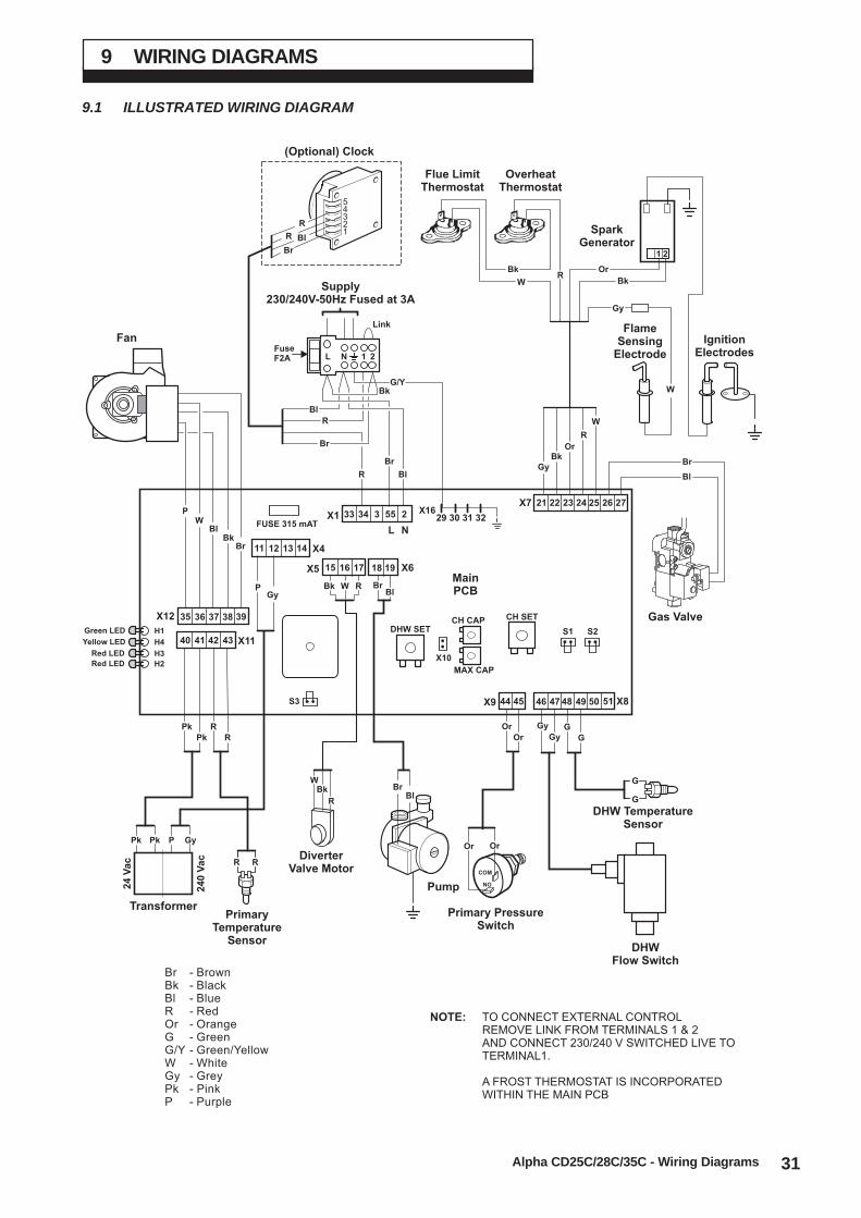
31Alpha CD25C/28C/35C - Wiring Diagrams
9.1 ILLUSTRATED WIRING DIAGRAM
9 WIRING DIAGRAMS
Br - BrownBk - BlackBl - BlueR - RedOr - OrangeG - GreenG/Y - Green/YellowW - WhiteGy - GreyPk - PinkP - Purple
NOTE: TO CONNECT EXTERNAL CONTROLREMOVE LINK FROM TERMINALS 1 & 2AND CONNECT 230/240 V SWITCHED LIVE TOTERMINAL1.
A FROST THERMOSTAT IS INCORPORATEDWITHIN THE MAIN PCB
Gas Valve
G/Y
Gy
BkOr
R
W
Pump
PrimaryTemperature
Sensor
Transformer
RR
DHW TemperatureSensor
DHWFlow Switch
G
G
FuseF2A
Link
Supply230/240V-50Hz Fused at 3A
2
21
1NL
X9S3
S1 S2
X10
X8
L N
X16X7
X1
MainPCB
CH SET
DHW SET
FUSE 315 mAT
CH CAP
MAX CAP
X11
X12
X4
H1Green LED
H4Yellow LED
H3Red LED
H2Red LED
Br
Bl
29 30 31 32
R
R
Br
Br
Bl
Bk
Bl
G
G
GyOr
GyOr
Primary PressureSwitch
Br
Br
R
Bl
Bl
R
Pk
Pk P
Gy
Pk
Pk Gy
P
R
R
Bk
Bk
PW
W
W
BlBk
Br
Or Or
FanFlame
SensingElectrode
Flue LimitThermostat
OverheatThermostat
Or
Bk
Bk
WR
W
Gy
SparkGenerator
IgnitionElectrodes
40
3635
11
41
37
12
42
44 45
38
13
X618 19X5 15 16 17
43
39
14
3433 3 55 2
24
49
26
51
25
50
22
47
23
48
2721
46
R
54321
Br
R Bl
(Optional) Clock
24
0V
ac
24
Va
c
NO
COM
DiverterValve Motor

32
9.2 FUNCTIONAL FLOW WIRING DIAGRAM
Alpha CD25C/28C/35C - Wiring Diagrams
X9S3
S1 S2
X10
X8
L N
X16X7
X1
MainPCB
CH SETDHW SET
FUSE 315 mAT
CH CAP
MAX CAP
X11
X12
X4
H1Green LED
H4Yellow LED
H3Red LED
H2Red LED
29 30 31 32
40
3635
11
41
37
12
42
44 45
38
13
43
39
14
3433 3 55 2
24
49
26
51
25
50
22
47
23
48
2721
46
Clock(Optional)
1
2
34
Pump
Fan
Gas Valve
PrimaryTemperatureSensor
DHW Switch
PrimaryPressureSwitch
NOCOM
OverheatThermostat
SparkGenerator
Flue LimitThermostat
FuseF2A
2
1
230/240V ~ 50HzFuse 3A
Remove link to connectexternal control
N
N
Note: Main Terminal Block
N
L L
DHWTemperature
Sensor
Transformer
N
L
N
TO CONNECT EXTERNAL CONTROL REMOVE LINKFROM TERMINALS 1 AND 2 AND CONNECT 240 VSWITCHED LIVE TO TERMINAL 1.
240
Vac
24
Vac
DiverterValve Motor
X618 19X5 15 16 17

33
10 FAULT FINDING
10.1 CARRY OUT INITIAL FAULT FINDING CHECKS
1. Check that gas, water and electrical supplies are available at the boiler.i.e. Inlet gas pressure = 20 mbar
Electrical supply = 230/240 V ~ 50 HzCH water system pressurised to between 0.75 and 1.25 barDHW flow rate is more than 2.5 litre/min
2. Carry out electrical system checks, i.e. Earth Continuity, Resistance to Earth, Short Circuit and Polarity with a suitable meter.Note: These checks must be repeated after any servicing or fault finding.
3. Ensure all external controls are calling for heat and check all external and internal fuses.
4. Check that the gas and water pipework has been connected to the correct connections on the boiler and all valves are open.
However, before any servicing or replacement of parts ensure the gas and electrical supplies are isolated.
10.2 CENTRAL HEATING - Follow operational sequence
Alpha CD25C/28C/35C - Fault Finding
Turn thermostat to max. External controls
not calling for heat
If fitted, internal
clock calling for heat
240 V across main
terminal block,
terminals 1 and N
YES
YES
NO
Turn selector to
Go to section ' ', page 35A
YES YES
(BUT)
Pump runs and
fan runs
Go to section ' ', page 36I
YES
Go to section ' ', page 35D
Burner output modulates until
set temperature is reached
Burner goes out
NO
YES
Operation sequence successful
Pump continues to run until temperature
reduces to set temperature
YES
Go to section ' ', page 35D
Fan stops after 50 seconds
Check gas valve adjustment
CH system pressure
too low. Re-pressurise
to 1.0 bar
Primary/DHW
temperature sensor
faulty
NO
NO
Go to section ' ', page 36JNeon A and B
flashing alternately
Neon B illuminated cont.
Neon A flashing
Neon A and B
flashing at the same time
Neon A flashing Go to section ' ', page 35CYES
YES
YES
YES YES
Fan or
flue fault
Neon B illuminated
continuously
YES
(BUT)
Go to section ' ', page 36GBurner does not stay
alight after 10 seconds
Spark at ignition electrodes
for upto 10 seconds
YES
Burner lights
Neon C illuminated
YES
YES
NO Reset by rotating
selector switch
Reset by rotating
selector switch
Overheat thermostat
operated
Neon B illuminated
continuously
YES Reset by rotating
selector switch
Neon B illuminated
continuously
Neon B flashing
NO
YES
If still no spark
Go to section ' ', page 36F
Go to section ' ', page 36E
If still illuminated,
Go to section ' ', page 36H
Neon D illuminated continuously
Pump fault or primary
flow restrictedGo to section ' ', page 35B

34
10.3 DOMESTIC HOT WATER- Follow operational sequence
Alpha CD25C/28C/35C - Fault Finding
Turn thermostat to max.
Open DHW tap fully
DHW flow rate more
than 2.5 L/min.
DHW switch/diverter
valve fault
YES
YES
Turn selector to
Primary water is diverted from
CH system to DHW heat
exchanger.
DHW switch operated
Pump runs and
fan runs
Is mains
filter clean
YES
NONO
NO
YES
YES
Go to section ' ', page 35A
Neons A and B flashing
at the same timeGo to section ' ', page 35D
Burner output modulates
to maintain temperature
set at thermostat
NO
YES
DHW temp. sensor
and DHW heat
exchanger are clean
Reduce DHW flow rate
from 10 to 5 L/min.
Burner modulates
NO
YES
Close DHW tap
YES
DHW flow valve senses no
flow. Primary water diverted
to CH system.
DHW flow switch released (off)
Diverter valve/DHW switch faultNO
YES
YES
Burner goes out Fan stops after 50 secondsYES
Operation sequence successful
Pump stops
YES
Go to section ' ', page 35D
YES
CH system pressure
too low. Re-pressurise
to 1.0 bar
Flue or
faulty fan
Primary/DHW
temperature sensor
fault
NO Pump fault or primary
flow restrictedGo to section ' ', page 35B
Go to section ' ', page 36K
Go to section ' ', page 36JNeon A and B
flashing alternately
Neon A flashing Go to section ' ', page 35CYES
YES
YES
Check gas valve
adjustment
Neon D illuminated continuously
Neon B illuminated cont.
Neon A flashing
Spark at ignition electrodes
for upto 10 seconds
YES
Burner lights
Neon C illuminated
YES
YES
NO Reset by rotating
selector switch
Reset by rotating
selector switch
Overheat thermostat
operated
Neon B illuminated
continuously
YES Reset by rotating
selector switch
Neon B illuminated
continuously
Neon B flashing
NO
YES
If still no spark
Go to section ' ', page 36F
Go to section ' ', page 36E
If still illuminated,
Go to section ' ', page 36H
Neon B illuminated
continuously
YES
(BUT)
Go to section ' ', page 36GBurner does not stay
alight after 10 seconds
YES
(BUT)

35Alpha CD25C/28C/35C - Fault Finding
10.4 FAULT FINDING SOLUTIONS A to D
NOYESPump If pump jammed, release
Replace PCBNO
PCB - X6 connector, terminals 18, 19
B Replace pump1.
2.
240 V ac at:-
Replace PCB
Replace PCB
Replace PCB
Replace transformer
NO
NO
NO
NO
YES
NO
NO
NO
Main terminals L and N Check electrical supply
Replace fuse
Check wiring
Main terminal fuse
PCB - X1 connector, terminals 55, N
Neon D
illuminated continuously
A240 V ac at:-
1.
2.
3.
NO
YES
Replace fuse Neon D illuminated contiuously
Is 240 V ac across
PCB X4 connector terminals 11,12
Is 26 V ac across
PCB X11 connector terminals 40,41
PCB fuse4.
C
DHW/Primary temp. sensor faulty. Cold resistance approx.
12-14 k ohms (resistance reduces with increase in temp.
i.e. when hot, resistance is approximately 3 k ohms)
Check and correct connections/wiring at sensor and PCB
2.
1. YES
YES
Check resistance throughout
the range from cold to hot
DHW temperature sensor faulty
i.e. heating OK. Hot water operates
but does not modulate
Primary temperature sensor faulty
i.e. no heating or hot water
Replace sensor
Boiler cycles on and off
Remove the motor from the diverter valve.
Does the piston move in and out when
operating the boiler between CH and DHW
In CH mode. PCB - X5 connector, is 240 V across terminals 15, 16
In DHW mode. PCB - X5 connector, is 240 V across terminals 15, 17
YES
YESNO
Replace leadCheck continuity of plug and lead
NO
NO
NO
YES
YES
Is diverter valve spindle sticking
DCheck and correct:-
1. Electrical connections
2. Restriction in flue
Neon A and B flashing
at the same time
YES
YES
(BUT)
1.
Replace PCB
Ensure by-pass slot is in horizontal position
and that the valve is not stuck open
Replace diverter valve
Replace PCB
Replace PCB
Replace motor
YES
NO
NO
2.
3.
3.
Fan connections correct at fan and PCB connector X12
Fan runs at maximum speed
PCB connector, is 36 V dc across terminals 39 and 37 or 38 Fan jammed or faulty winding
Is dc volts at PCB, X12 connector:-
across terminals 35 and 37 - 34 V dc
across terminals 36 and 37 - 4 V dc
YES
YES
YES
Replace fan
Replace fan

36 Alpha CD25C/28C/35C - Fault Finding
10.5 FAULT FINDING SOLUTIONS E to K
YES
Check and correct:-
1. Ignition electrode and lead
2. Electrode connections
3. Spark gap and position
4. Connections at ignition generator and PCB connector X7
5. Blocked flue
F
Is spark generator (T2)
making a clicking noise
PCB, X7 connector is 200V ac
across terminals 22, 23 during ignition
Replace PCB
Replace ignition
generator
NO
NO
YES
HReplace pump
Allow to cool. Continuity across thermostat terminals Replace overheat thermostatNO
YES
Vent air, clear blockageYESAir in main heat exchanger, blocked heat exchanger/pipework
or pump not circulating water
NO
YES
240V at internal clock
terminals 1 and 2I 240V at PCB - X1 connector,
terminals 55 and 2
240V at PCB - X1 connector, terminals 34 and 2
Wiring between clock
and PCB is correct
YES
YESNO
YES
Continuity across
clock terminals 3 and 4
Internal clock calling for heat
Wiring between clock
and PCB is correct
Replace clock
Check external controls
are calling for heat
YES
YES
NO
JReplace primary pressure switch
Replace PCBContinuity across primary
pressure switch terminals
36 V DC at PCB across
X9 connector terminal 45
and X8 connector terminal 46
YES
NO
NO
YES
YES YES
YES
YES
YES
Replace PCB
Replace PCB
Replace lead
Replace motor
Replace valve
Replace DHW flow switchContinuity across DHW
flow switch (hot tap on)
Diverter valve spindle operating
Check DHW heat exchanger for blockage Check by-pass valve is not stuck open
36 V DC at PCB across X8 connector terminals 46, 47
240 V AC at PCB across X5 connector terminals 15, 17
Remove the diverter valve motor, is the brass piston
fully extended (flush with plastic housing)
Flow rate above 2.5l/minCheck mains supply.
Clean mains inlet filter
Check continuity of
motor plug and lead
NO
NO
YES
NO
NO
NO
NO
NO
NO
K
G Check and correct:-
1. Pressure tubes are connected and not blocked
2. If explosive ignition, check wiring to ignition generator is correct
E Check pressure tubes are connected
PCB - X7 connector, is 240 V across terminals 26, 27YES NO
Gas at burner
Replace gas valveAdjust gas valve
NO
NO
Ensure gas is on and purged
Replace PCB

37
11 SHORT PARTS LIST
Reference
Burner - CD25
Burner - CD28
Burner - CD35
Main injector 5.2 mm - CD25
Main injector 5.4 mm - CD28
Main injector 8.5 mm - CD35
Primary heat exchanger - CD25
Primary heat exchanger - CD28
Primary heat exchanger - CD35
DHW heat exchanger - CD25
DHW heat exchanger - CD28
DHW heat exchanger - CD35
Gas valve
Pump
Fan assembly
Primary pressure switch
DHW flow switch
PCB
Flue thermostat 105°C
Ignition generator
Transformer
Temperature sensor
Fuse F2A
PCB fuse F315mA
Overheat thermostat 100°C
Expansion vessel 8 Litre
Pressure relief valve 3 bar
Automatic air vent
Pressure gauge
Ignition electrode and lead
Ignition electrode
Flame sensing electrode and lead
Diverter valve motor assembly
Diverter valve assembly
By-pass assembly
Combustion chamber insulation panel front
Condensate trap
Description British Gas GC No.
E94-407
E96-565
H28-395
E57-666
E96-569
E76-320
E94-414
E94-415
E76-317
E76-378
E96-571
E57-702
E57-710
E94-417
E94-418
E94-420
Alpha Pt. No.
1.023999
1.019622
1.023979
1.024374
1.024388
1.024391
1.023638
1.023564
1.023674
1.022220
1.022221
1.022222
1.023673
1.024097
1.021206
1.021715
1.020831
1.024022
1.016870
1.022297
1.019189
1.021762
1.6098
1.013931
1.012067
1.023560
1.023565
1.022102
1.023551
3.018304
1.016779
1.019293
1.018064
3.015562
3.017174
1.014732
3.017281
Qty.
1
1
1
1
1
1
1
1
1
1
1
1
1
1
1
1
1
1
1
1
1
2
1
1
1
1
1
1
1
1
1
1
1
1
1
1
1
Fig. 27
Fig. 27
Fig. 27
Fig. 2, item 30
Fig. 2, item 30
Fig. 2, item 30
Fig. 31
Fig. 31
Fig. 31
Fig. 2, item 6
Fig. 2, item 6
Fig. 2, item 6
Fig. 24
Fig. 32
Fig. 28
Fig. 32
Fig. 30
Fig. 29
Fig. 28
Fig. 28
Fig. 28
Figs. 28 and 33
Fig. 20
Fig. 29
Fig. 28
Fig. 2, item 14
Fig. 32
Fig. 32
Fig. 32
Fig. 28
Fig. 28
Fig. 28
Fig. 30
Fig. 30
Fig. 2, item 27
Fig. 27
Fig. 2, item 29
Alpha CD25C/28C/35C - Short Parts List

38 Alpha CD25C/28C/35C - Benchmark Checklist
12 CHECKLIST
Ensure the following is completed after the boiler has been installed and commissioned:-
BOILER SERIAL No. ......................................................... NOTIFICATION No. ..........................................................
CONTROLS To comply with the Building Regulations, each section must have a tick in one or other of the boxes
Time & temperature control to heating
Time & temperature control to hot water
Heating zone valves
Hot water zone valves
Thermostatic radiator valves
Automatic by-pass to system
FOR ALL BOILERS CONFIRM THE FOLLOWING:
The system has been flushed in accordance with the boiler manufacturer's instructions? Yes No
The system cleaner used ....................................................................................................................
The inhibitor used ................................................................................................................................
FOR CENTRAL HEATING MODE, MEASURE AND RECORD THE FOLLOWING:
Gas rate m³/hr ft³/hr
Burner operating pressure (if applicable) N/A mbar
Central heating flow temperature °C
Central heating return temperature °C
FOR COMBINATION BOILERS ONLY
Has a water scale reducer been fitted? Yes No
What type of scale reducer has been fitted? ......................................................................................
FOR DOMESTIC HOT WATER MODE, MEASURE AND RECORD THE FOLLOWING:
Gas rate m³/hr ft³/hr
Maximum burner operating pressure (if applicable) N/A mbar
Cold water inlet temperature °C
Hot water outlet temperature °C
Water flow rate lts/min
FOR CONDENSING BOILERS ONLY CONFIRM THE FOLLOWING:
The condensate drain has been installed in accordance with the manufacturer's instructions? Yes
FOR ALL INSTALLATIONS CONFIRM THE FOLLOWING:
The heating and hot water system complies with current Building Regulations Yes
The appliance and associated equipment has been installed and commissionedin accordance with the manufacturer's instructions Yes
If required by the manufacturer, have you recorded a CO/CO2 ratio reading N/A Yes CO/CO2 ratio
The operation of the appliance and system controls have been demonstrated to the customer Yes
The manufacturer's literature has been left with the customer Yes
COMMISSIONING ENG'S NAME:
Print ...................................................................... CORGI ID No. ..................................................
Sign ...................................................................... Date .................................................................
room t/stat & programmer/timer
cylinder t/stat & programmer/timer
Fitted
Fitted
Fitted
Fitted
Programmable roomstat
Combi boiler
Not required
Not required
Not required

39
13 SERVICE RECORD
It is recommended that your heating system is serviced regularly and that you complete the appropriate Service Interval Recordbelow.
Service Provider: Before cpmpleting the appropriate Service Interval Record below, please ensure you have carried out theservice as described in this instruction manual. Always use the manufacturer's specified spare parts when replacing all controls.
SERVICE 1: Date .......................................................................Engineers Name .........................................................................Company Name ..........................................................................Telephone No. .............................................................................CORGI ID card serial No. ...........................................................Comments ........................................................................................................................................................................................
Signature .....................................................................................
SERVICE 2: Date .......................................................................Engineers Name .........................................................................Company Name ..........................................................................Telephone No. .............................................................................CORGI ID card serial No. ...........................................................Comments ........................................................................................................................................................................................Signature .....................................................................................
SERVICE 3: Date .......................................................................Engineers Name .........................................................................Company Name ..........................................................................Telephone No. .............................................................................CORGI ID card serial No. ...........................................................Comments ........................................................................................................................................................................................
Signature .....................................................................................
SERVICE 4: Date .......................................................................Engineers Name .........................................................................Company Name ..........................................................................Telephone No. .............................................................................CORGI ID card serial No. ...........................................................Comments ........................................................................................................................................................................................Signature .....................................................................................
SERVICE 5: Date .......................................................................Engineers Name .........................................................................Company Name ..........................................................................Telephone No. .............................................................................CORGI ID card serial No. ...........................................................Comments ........................................................................................................................................................................................
Signature .....................................................................................
SERVICE 6: Date .......................................................................Engineers Name .........................................................................Company Name ..........................................................................Telephone No. .............................................................................CORGI ID card serial No. ...........................................................Comments ........................................................................................................................................................................................Signature .....................................................................................
SERVICE 7: Date .......................................................................Engineers Name .........................................................................Company Name ..........................................................................Telephone No. .............................................................................CORGI ID card serial No. ...........................................................Comments ........................................................................................................................................................................................
Signature .....................................................................................
SERVICE 8: Date .......................................................................Engineers Name .........................................................................Company Name ..........................................................................Telephone No. .............................................................................CORGI ID card serial No. ...........................................................Comments ........................................................................................................................................................................................Signature .....................................................................................
SERVICE 9: Date .......................................................................Engineers Name .........................................................................Company Name ..........................................................................Telephone No. .............................................................................CORGI ID card serial No. ...........................................................Comments ........................................................................................................................................................................................
Signature .....................................................................................
SERVICE 10: Date .....................................................................Engineers Name .........................................................................Company Name ..........................................................................Telephone No. .............................................................................CORGI ID card serial No. ...........................................................Comments ........................................................................................................................................................................................Signature .....................................................................................
Alpha CD25C/28C/35C - Service Record

Manual compiled and designed by Publications 2000 - Tel: (01670) 356211 12/06/D199
Part No. 1.024380 Rev 15.023819/000
These instructions have been carefully prepared but we reserve the right toalter the specification at any time in the interest of product improvement.© Alpha Therm Limited 2006.
Alpha Therm Limited.Nepicar House, London Road, Wrotham Heath,Sevenoaks, Kent TN15 7RSTel: 0870 3001964
email: [email protected]: www.alpha-boilers.com