ALOS-2/PALSAR-2 Product Format Description … · ALOS-2 Product Format Description GeoTIFF Level...
37
ALOS-2/PALSAR-2 Level 1.1/1.5/2.1/3.1 GeoTIFF Product Format Description December 28, 2012 JAXA
Transcript of ALOS-2/PALSAR-2 Product Format Description … · ALOS-2 Product Format Description GeoTIFF Level...
ALOS-2/PALSAR-2
Level 1.1/1.5/2.1/3.1 GeoTIFF Product
Format Description
December 28, 2012
JAXA
PALSAR-2
Level 1.1/1.5/3.1 GeoTIFF Product
Format Description
JAXA

ALOS-2 Product Format Description
GeoTIFF Level 1.1/1.5/3.1 Revision History (1/1)
Rev. Date Revision Contents Remark
NC 2012/12/28 First Edition
ALOS-2 Product format Description
(GeoTIFF Level 1.1/1.5/3.1)
Table of Contents
1. Overview...........................................................................................................................................1
2. Product Specifications ......................................................................................................................2
2.1. Outline of GeoTIFF Standard ....................................................................................................2
2.2. Composition of Product .............................................................................................................2
2.3. Filename.....................................................................................................................................3
3. Format...............................................................................................................................................5
3.1. GeoTIFF File .............................................................................................................................5
3.1.1. Common TIFF Tag..............................................................................................................5
3.1.2. GeoTIFF tag of Level 1.1 Product ......................................................................................8
3.1.3. GeoTIFF tag of level 1.5 and level 3.1 Product ................................................................11
3.2. Look Up Table .........................................................................................................................16
i
1. Overview
This document describes the format specifications for ALOS-2 GeoTIFF Level 1.1/1.5/3.1
products which are generated with ALOS-2 Data Processing System.
1
2. Product Specifications
2.1. Outline of GeoTIFF Standard
GeoTIFF is a metadata standard, which allows geometric information to be embedded within
Aldus-Adobe’s raster Tagged Image File Format (TIFF) file.
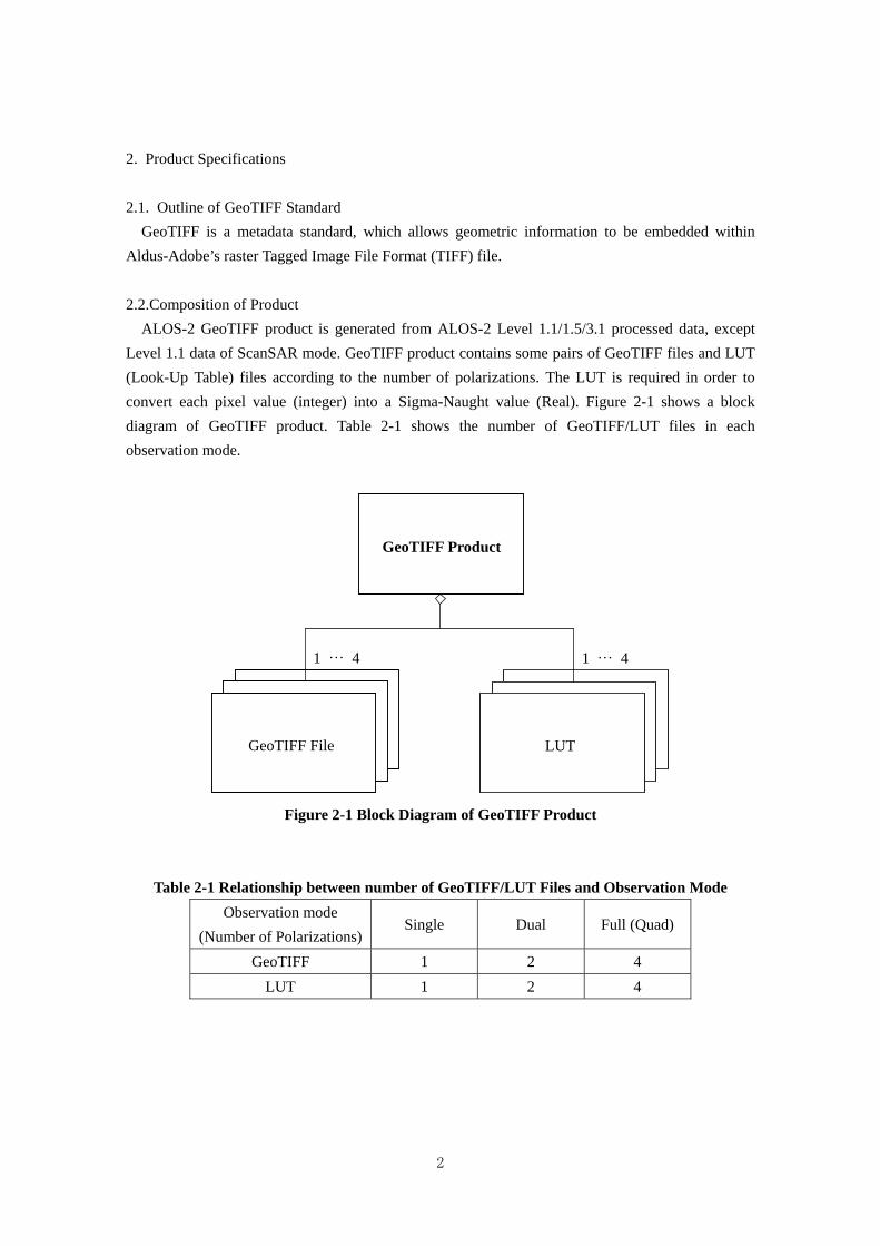
2.2.Composition of Product
ALOS-2 GeoTIFF product is generated from ALOS-2 Level 1.1/1.5/3.1 processed data, except
Level 1.1 data of ScanSAR mode. GeoTIFF product contains some pairs of GeoTIFF files and LUT
(Look-Up Table) files according to the number of polarizations. The LUT is required in order to
convert each pixel value (integer) into a Sigma-Naught value (Real). Figure 2-1 shows a block
diagram of GeoTIFF product. Table 2-1 shows the number of GeoTIFF/LUT files in each
observation mode.
GeoTIFF Product
GeoTIFF File
1 … 4
LUT
1 … 4
Figure 2-1 Block Diagram of GeoTIFF Product
Table 2-1 Relationship between number of GeoTIFF/LUT Files and Observation Mode
Observation mode Single Dual
(Number of Polarizations) Full (Quad)
GeoTIFF 1 2 4
LUT 1 2 4
2
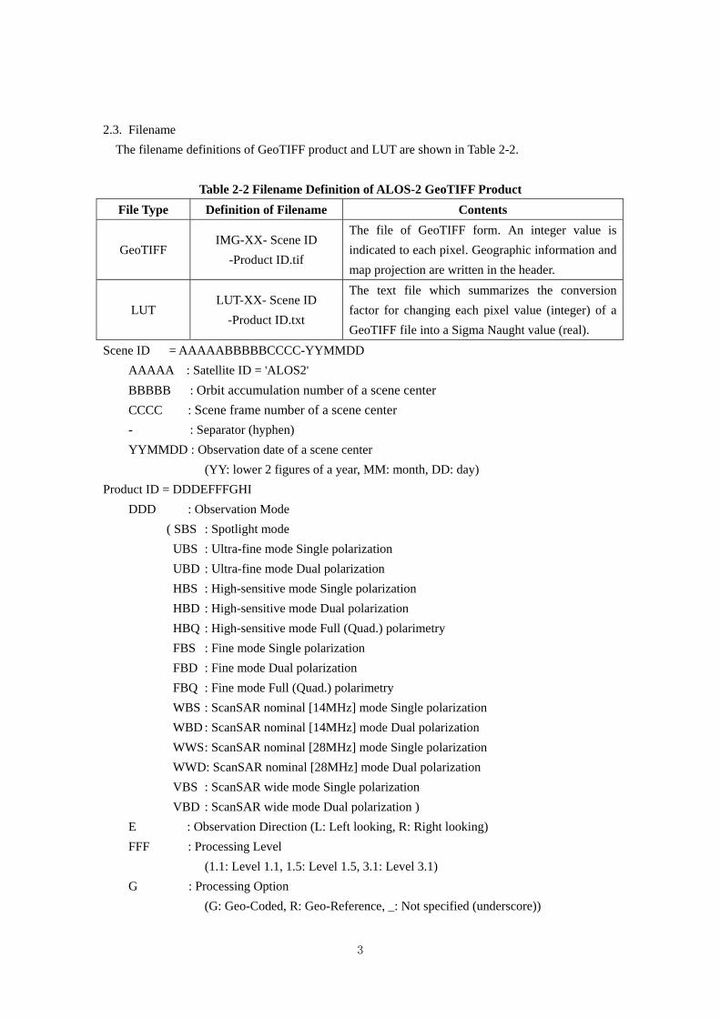
2.3. Filename
The filename definitions of GeoTIFF product and LUT are shown in Table 2-2.
Table 2-2 Filename Definition of ALOS-2 GeoTIFF Product
File Type Definition of Filename Contents
The file of GeoTIFF form. An integer value is
indicated to each pixel. Geographic information and
map projection are written in the header.
GeoTIFF IMG-XX- Scene ID
-Product ID.tif
The text file which summarizes the conversion
factor for changing each pixel value (integer) of a
GeoTIFF file into a Sigma Naught value (real).
LUT LUT-XX- Scene ID
-Product ID.txt
Scene ID = AAAAABBBBBCCCC-YYMMDD
AAAAA : Satellite ID = 'ALOS2'
BBBBB : Orbit accumulation number of a scene center
CCCC : Scene frame number of a scene center
- : Separator (hyphen)
YYMMDD : Observation date of a scene center
(YY: lower 2 figures of a year, MM: month, DD: day)
Product ID = DDDEFFFGHI
DDD : Observation Mode
( SBS : Spotlight mode
UBS : Ultra-fine mode Single polarization
UBD : Ultra-fine mode Dual polarization
HBS : High-sensitive mode Single polarization
HBD : High-sensitive mode Dual polarization
HBQ : High-sensitive mode Full (Quad.) polarimetry
FBS : Fine mode Single polarization
FBD : Fine mode Dual polarization
FBQ : Fine mode Full (Quad.) polarimetry
WBS : ScanSAR nominal [14MHz] mode Single polarization
WBD : ScanSAR nominal [14MHz] mode Dual polarization
WWS : ScanSAR nominal [28MHz] mode Single polarization
WWD: ScanSAR nominal [28MHz] mode Dual polarization
VBS : ScanSAR wide mode Single polarization
VBD : ScanSAR wide mode Dual polarization )
E : Observation Direction (L: Left looking, R: Right looking)
FFF : Processing Level
(1.1: Level 1.1, 1.5: Level 1.5, 3.1: Level 3.1)
G : Processing Option
(G: Geo-Coded, R: Geo-Reference, _: Not specified (underscore))
3
4
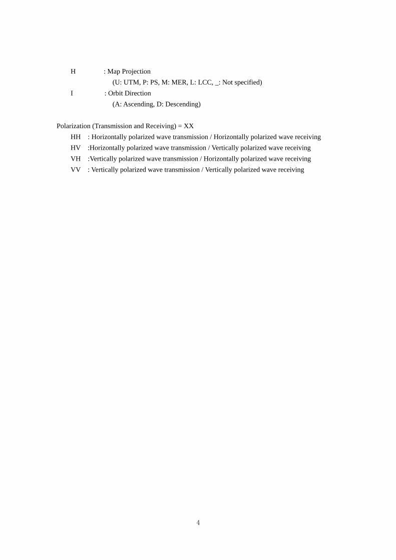
H : Map Projection
(U: UTM, P: PS, M: MER, L: LCC, _: Not specified)
I : Orbit Direction
(A: Ascending, D: Descending)
Polarization (Transmission and Receiving) = XX
HH : Horizontally polarized wave transmission / Horizontally polarized wave receiving
HV :Horizontally polarized wave transmission / Vertically polarized wave receiving
VH :Vertically polarized wave transmission / Horizontally polarized wave receiving
VV : Vertically polarized wave transmission / Vertically polarized wave receiving
3. Format
3.1. GeoTIFF File
GeoTIFF is a metadata standard which allows geometric information to be embedded within a
TIFF image file. In ALOS-2 GeoTIFF products, GeoTIFF files are generated in TIFF-Strip format,
and some GeoTIFF-tags (identifiers) are different in each processing level. All TIFF files and
GeoTIFF-tags are based on TIFF Revision 6.0 and GeoTIFF Revision 1.0 standard, and image data
is recorded in little endian.
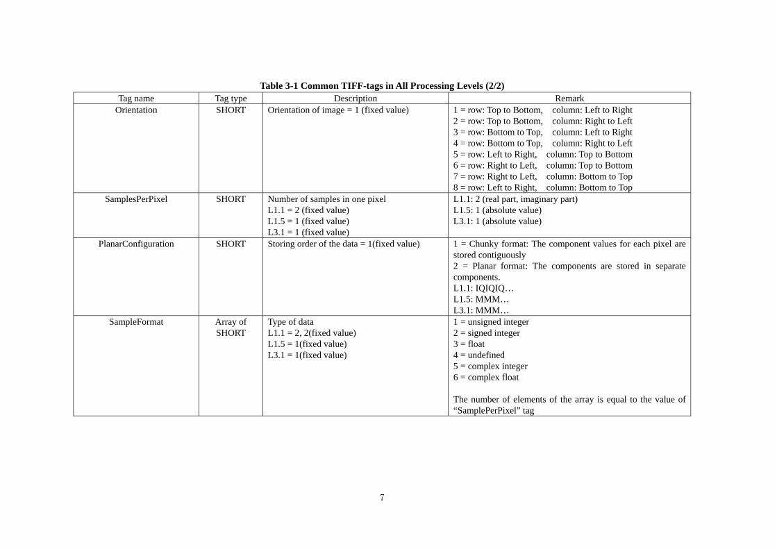
3.1.1. Common TIFF Tag
Some TIFF-tags common to all processing levels are shown in Table 3-1.
5
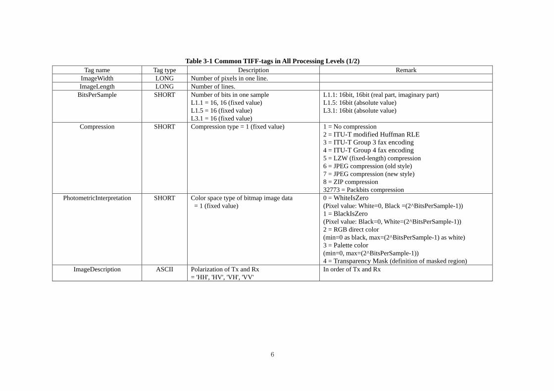
Table 3-1 Common TIFF-tags in All Processing Levels (1/2) Tag name Tag type Description Remark
ImageWidth LONG Number of pixels in one line. ImageLength LONG Number of lines.
BitsPerSample SHORT Number of bits in one sample L1.1 = 16, 16 (fixed value) L1.5 = 16 (fixed value) L3.1 = 16 (fixed value)
L1.1: 16bit, 16bit (real part, imaginary part) L1.5: 16bit (absolute value) L3.1: 16bit (absolute value)
Compression SHORT Compression type = 1 (fixed value) 1 = No compression 2 = ITU-T modified Huffman RLE 3 = ITU-T Group 3 fax encoding 4 = ITU-T Group 4 fax encoding 5 = LZW (fixed-length) compression 6 = JPEG compression (old style) 7 = JPEG compression (new style) 8 = ZIP compression 32773 = Packbits compression
PhotometricInterpretation SHORT Color space type of bitmap image data = 1 (fixed value)
0 = WhiteIsZero (Pixel value: White=0, Black =(2^BitsPerSample-1)) 1 = BlackIsZero (Pixel value: Black=0, White=(2^BitsPerSample-1)) 2 = RGB direct color (min=0 as black, max=(2^BitsPerSample-1) as white) 3 = Palette color (min=0, max=(2^BitsPerSample-1)) 4 = Transparency Mask (definition of masked region)
ImageDescription ASCII Polarization of Tx and Rx = 'HH', 'HV', 'VH', 'VV'
In order of Tx and Rx
6
7
Table 3-1 Common TIFF-tags in All Processing Levels (2/2) Tag name Tag type Description Remark
Orientation SHORT Orientation of image = 1 (fixed value) 1 = row: Top to Bottom, column: Left to Right 2 = row: Top to Bottom, column: Right to Left 3 = row: Bottom to Top, column: Left to Right 4 = row: Bottom to Top, column: Right to Left 5 = row: Left to Right, column: Top to Bottom 6 = row: Right to Left, column: Top to Bottom 7 = row: Right to Left, column: Bottom to Top 8 = row: Left to Right, column: Bottom to Top
SamplesPerPixel SHORT Number of samples in one pixel L1.1 = 2 (fixed value) L1.5 = 1 (fixed value) L3.1 = 1 (fixed value)
L1.1: 2 (real part, imaginary part) L1.5: 1 (absolute value) L3.1: 1 (absolute value)
PlanarConfiguration SHORT Storing order of the data = 1(fixed value) 1 = Chunky format: The component values for each pixel are stored contiguously 2 = Planar format: The components are stored in separate components. L1.1: IQIQIQ… L1.5: MMM… L3.1: MMM…
SampleFormat Array of SHORT
Type of data L1.1 = 2, 2(fixed value) L1.5 = 1(fixed value) L3.1 = 1(fixed value)
1 = unsigned integer 2 = signed integer 3 = float 4 = undefined 5 = complex integer 6 = complex float The number of elements of the array is equal to the value of “SamplePerPixel” tag
3.1.2. GeoTIFF tag of Level 1.1 Product
GeoTIFF tags of ALOS-2 Level 1.1 processed GeoTIFF product are shown in Table 3-2.
8
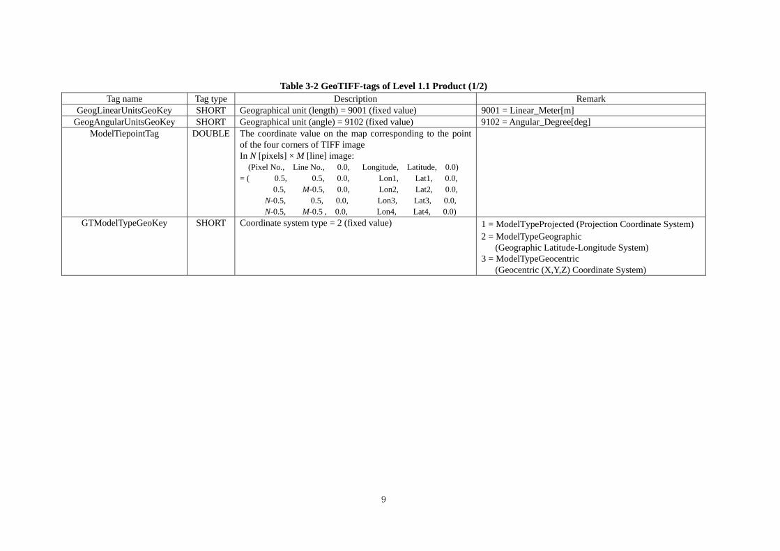
Table 3-2 GeoTIFF-tags of Level 1.1 Product (1/2) Tag name Tag type Description Remark
GeogLinearUnitsGeoKey SHORT Geographical unit (length) = 9001 (fixed value) 9001 = Linear_Meter[m] GeogAngularUnitsGeoKey SHORT Geographical unit (angle) = 9102 (fixed value) 9102 = Angular_Degree[deg]
ModelTiepointTag DOUBLE The coordinate value on the map corresponding to the point of the four corners of TIFF image In N [pixels] × M [line] image: (Pixel No., Line No., 0.0, Longitude, Latitude, 0.0) = ( 0.5, 0.5, 0.0, Lon1, Lat1, 0.0,
0.5, M-0.5, 0.0, Lon2, Lat2, 0.0, N-0.5, 0.5, 0.0, Lon3, Lat3, 0.0, N-0.5, M-0.5 , 0.0, Lon4, Lat4, 0.0)
GTModelTypeGeoKey SHORT Coordinate system type = 2 (fixed value) 1 = ModelTypeProjected (Projection Coordinate System) 2 = ModelTypeGeographic
(Geographic Latitude-Longitude System) 3 = ModelTypeGeocentric
(Geocentric (X,Y,Z) Coordinate System)
9
10
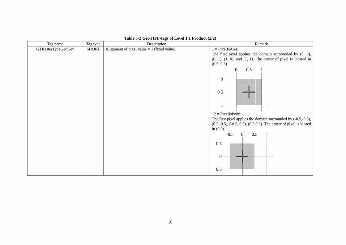
Table 3-2 GeoTIFF-tags of Level 1.1 Product (2/2) Tag name Tag type Description Remark
GTRasterTypeGeoKey SHORT Alignment of pixel value = 1 (fixed value) 1 = PixelIsArea The first pixel applies the domain surrounded by (0, 0), (0, 1), (1, 0), and (1, 1). The center of pixel is located in (0.5, 0.5).
0 0.5 1
0
0.5
1
2 = PixelIsPoint The first pixel applies the domain surrounded by (-0.5,-0.5), (0.5,-0.5), (-0.5, 0.5), (0.5,0.5). The center of pixel is locaed in (0,0).
-0.5 0 0.5 1
-0.5
0
0.5
3.1.3. GeoTIFF tag of level 1.5 and level 3.1 Product
GeoTIFF tags of ALOS-2 Level 1.5/3.1 processed GeoTIFF products are shown in Table 3-3.
11
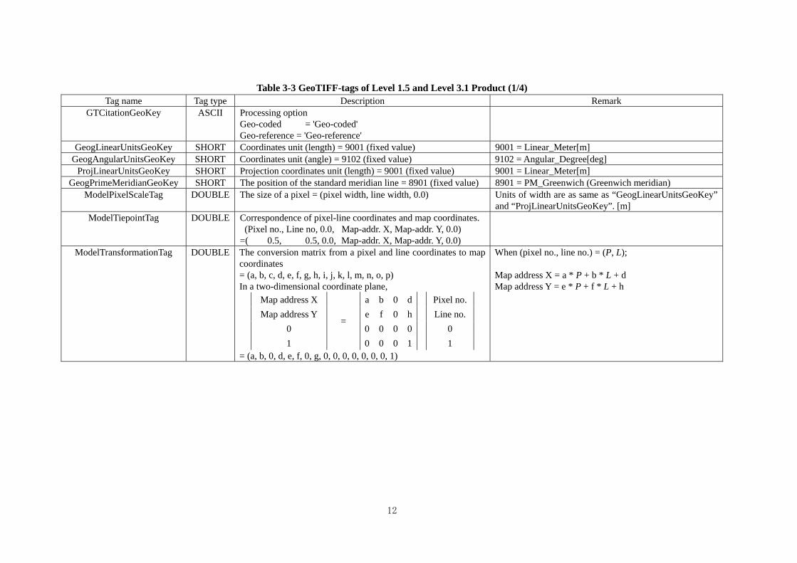
Table 3-3 GeoTIFF-tags of Level 1.5 and Level 3.1 Product (1/4) Tag name Tag type Description Remark
GTCitationGeoKey ASCII Processing option Geo-coded = 'Geo-coded' Geo-reference = 'Geo-reference'
GeogLinearUnitsGeoKey SHORT Coordinates unit (length) = 9001 (fixed value) 9001 = Linear_Meter[m] GeogAngularUnitsGeoKey SHORT Coordinates unit (angle) = 9102 (fixed value) 9102 = Angular_Degree[deg]
ProjLinearUnitsGeoKey SHORT Projection coordinates unit (length) = 9001 (fixed value) 9001 = Linear_Meter[m] GeogPrimeMeridianGeoKey SHORT The position of the standard meridian line = 8901 (fixed value) 8901 = PM_Greenwich (Greenwich meridian)
ModelPixelScaleTag DOUBLE The size of a pixel = (pixel width, line width, 0.0) Units of width are as same as “GeogLinearUnitsGeoKey” and “ProjLinearUnitsGeoKey”. [m]
ModelTiepointTag DOUBLE Correspondence of pixel-line coordinates and map coordinates. (Pixel no., Line no, 0.0, Map-addr. X, Map-addr. Y, 0.0)
=( 0.5, 0.5, 0.0, Map-addr. X, Map-addr. Y, 0.0)
ModelTransformationTag DOUBLE The conversion matrix from a pixel and line coordinates to map coordinates = (a, b, c, d, e, f, g, h, i, j, k, l, m, n, o, p) In a two-dimensional coordinate plane,
Map address X a b 0 d Pixel no.
Map address Y e f 0 h Line no.
0 =
0 0 0 0 0
1 0 0 0 1 1 = (a, b, 0, d, e, f, 0, g, 0, 0, 0, 0, 0, 0, 0, 1)
When (pixel no., line no.) = (P, L); Map address X = a * P + b * L + d Map address Y = e * P + f * L + h
12
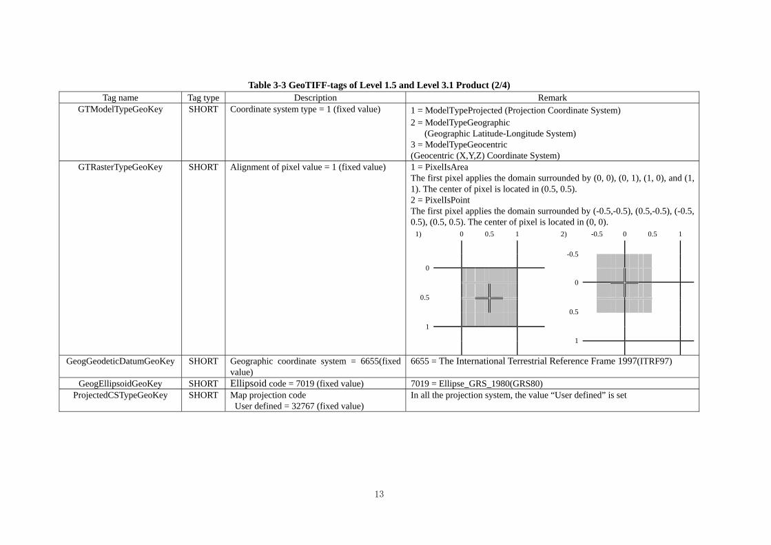
Table 3-3 GeoTIFF-tags of Level 1.5 and Level 3.1 Product (2/4) Tag name Tag type Description Remark
GTModelTypeGeoKey SHORT Coordinate system type = 1 (fixed value) 1 = ModelTypeProjected (Projection Coordinate System) 2 = ModelTypeGeographic
(Geographic Latitude-Longitude System) 3 = ModelTypeGeocentric (Geocentric (X,Y,Z) Coordinate System)
GTRasterTypeGeoKey SHORT Alignment of pixel value = 1 (fixed value) 1 = PixelIsArea The first pixel applies the domain surrounded by (0, 0), (0, 1), (1, 0), and (1, 1). The center of pixel is located in (0.5, 0.5). 2 = PixelIsPoint The first pixel applies the domain surrounded by (-0.5,-0.5), (0.5,-0.5), (-0.5, 0.5), (0.5, 0.5). The center of pixel is located in (0, 0).
1) 0 0.5 1 2) -0.5 0 0.5 1
-0.5
0
0
0.5
0.5
1
1
GeogGeodeticDatumGeoKey SHORT Geographic coordinate system = 6655(fixed
value) 6655 = The International Terrestrial Reference Frame 1997(ITRF97)
GeogEllipsoidGeoKey SHORT Ellipsoid code = 7019 (fixed value) 7019 = Ellipse_GRS_1980(GRS80) ProjectedCSTypeGeoKey SHORT Map projection code
User defined = 32767 (fixed value) In all the projection system, the value “User defined” is set
13
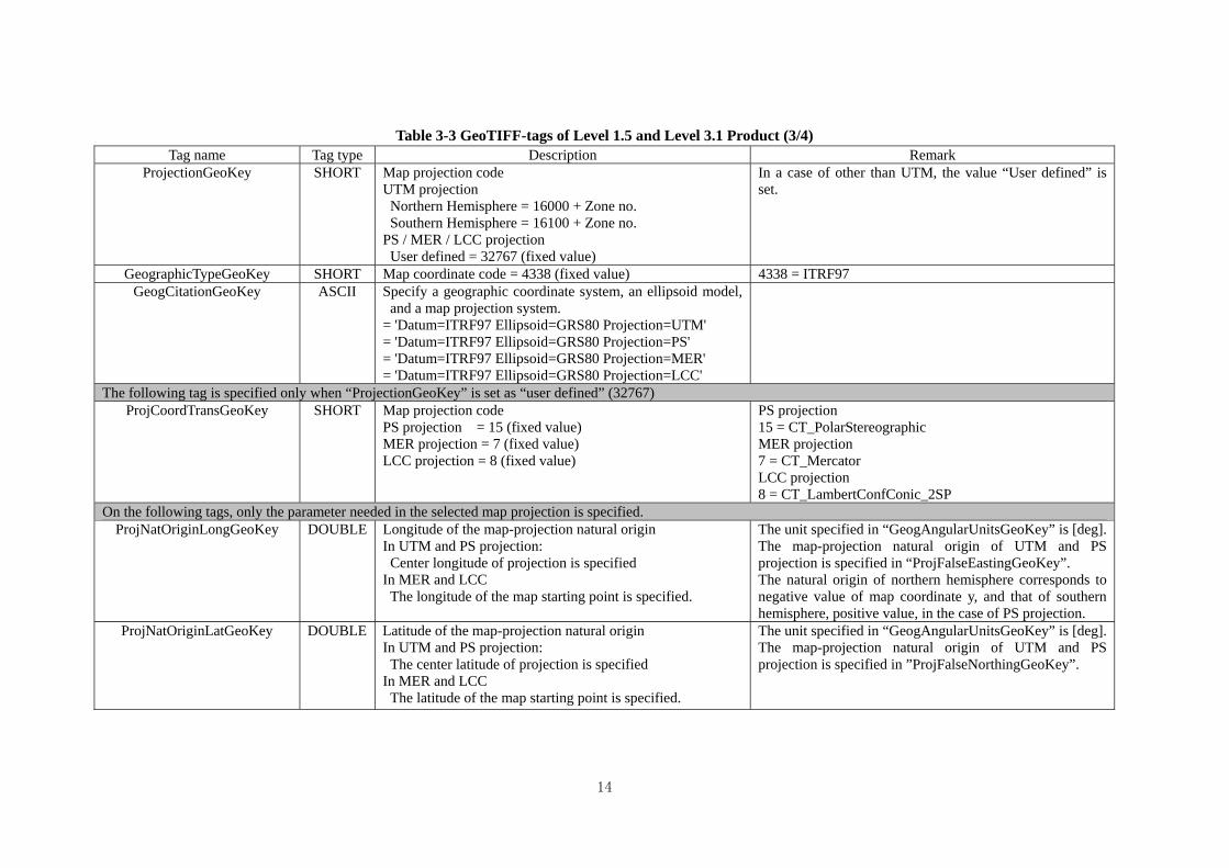
Table 3-3 GeoTIFF-tags of Level 1.5 and Level 3.1 Product (3/4) Tag name Tag type Description Remark
ProjectionGeoKey SHORT Map projection code UTM projection Northern Hemisphere = 16000 + Zone no. Southern Hemisphere = 16100 + Zone no.
PS / MER / LCC projection User defined = 32767 (fixed value)
In a case of other than UTM, the value “User defined” is set.
GeographicTypeGeoKey SHORT Map coordinate code = 4338 (fixed value) 4338 = ITRF97 GeogCitationGeoKey ASCII Specify a geographic coordinate system, an ellipsoid model,
and a map projection system. = 'Datum=ITRF97 Ellipsoid=GRS80 Projection=UTM' = 'Datum=ITRF97 Ellipsoid=GRS80 Projection=PS' = 'Datum=ITRF97 Ellipsoid=GRS80 Projection=MER' = 'Datum=ITRF97 Ellipsoid=GRS80 Projection=LCC'
The following tag is specified only when “ProjectionGeoKey” is set as “user defined” (32767) ProjCoordTransGeoKey SHORT Map projection code
PS projection = 15 (fixed value) MER projection = 7 (fixed value) LCC projection = 8 (fixed value)
PS projection 15 = CT_PolarStereographic MER projection 7 = CT_Mercator LCC projection 8 = CT_LambertConfConic_2SP
On the following tags, only the parameter needed in the selected map projection is specified. ProjNatOriginLongGeoKey DOUBLE Longitude of the map-projection natural origin
In UTM and PS projection: Center longitude of projection is specified In MER and LCC The longitude of the map starting point is specified.
The unit specified in “GeogAngularUnitsGeoKey” is [deg]. The map-projection natural origin of UTM and PS projection is specified in “ProjFalseEastingGeoKey”. The natural origin of northern hemisphere corresponds to negative value of map coordinate y, and that of southern hemisphere, positive value, in the case of PS projection.
ProjNatOriginLatGeoKey DOUBLE Latitude of the map-projection natural origin In UTM and PS projection: The center latitude of projection is specified In MER and LCC The latitude of the map starting point is specified.
The unit specified in “GeogAngularUnitsGeoKey” is [deg]. The map-projection natural origin of UTM and PS projection is specified in ”ProjFalseNorthingGeoKey”.
14

15
Table 3-3 GeoTIFF-tags of Level 1.5 and Level 3.1 Product (4/4) Tag name Tag type Description Remark
On the following tags, only the parameter needed in the selected map projection is specified. ProjFalseEastingGeoKey DOUBLE The easting value from the map-projection natural origin (to
determine the map natural origin). It is specified only in the case of UTM projection. = 500000.0 (fixed value)
The unit specified in “ProjLinearUnitsGeoKey” is used [m]
ProjFalseNorthingGeoKey DOUBLE The northing value from the map-projection natural origin (to determine the map natural origin). It is specified only in the case of UTM projection. Northern Hemisphere = 0 (fixed value)
Southern Hemisphere = 10000000.0 (fixed value)
The unit specified in “ProjLinearUnitsGeoKey” is used [m]
ProjStdParallel1GeoKey DOUBLE Latitude of primary standard parallel. It is specified only in the case of LCC projection
The unit specified in “GeogAngularUnitsGeoKey” is used [deg]
ProjStdParallel2GeoKey DOUBLE Latitude of second standard parallel. It is specified only in the case of LCC projection
The unit specified in “GeogAngularUnitsGeoKey” is used [deg]
ProjScaleAtNatOriginGeoKey DOUBLE Scale factor at natural origin It is specified only in the cases of UTM and PS projection. UTM = 0.9996 (fixed value) PS = 1.0 (fixed value)
non-dimension
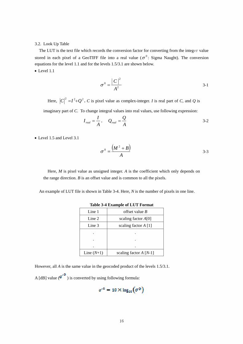
3.2. Look Up Table
The LUT is the text file which records the conversion factor for converting from the integer value
stored in each pixel of a GeoTIFF file into a real value ( : Sigma Naught). The conversion
equations for the level 1.1 and for the levels 1.5/3.1 are shown below.
0
Level 1.1
2
2
0
AC
3-1
Here, 222 QIC . C is pixel value as complex-integer. I is real part of C, and Q is
imaginary part of C. To change integral values into real values, use following expression:
AII real ,
AQQreal 3-2
Level 1.5 and Level 3.1
A
BM
20 3-3
Here, M is pixel value as unsigned integer. A is the coefficient which only depends on
the range direction. B is an offset value and is common to all the pixels.
An example of LUT file is shown in Table 3-4. Here, N is the number of pixels in one line.
Table 3-4 Example of LUT Format
offset value B Line 1
scaling factor A[0] Line 2
scaling factor A [1] Line 3
. .
.
.
.
.
Line (N+1) scaling factor A [N-1]
However, all A is the same value in the geocoded product of the levels 1.5/3.1.
A [dB] value ( ) is converted by using following formula:
16
PALSAR-2
Level 2.1 GeoTIFF Product
Format Description
JAXA

ALOS-2 Product Format Description
GeoTIFF Level 2.1 Revision History (1/1)
Rev. Date Revision Contents Remark
NC 2012/12/28 First Edition
ALOS-2 Product Format Description
(GeoTIFF Level 2.1)
Table of Contents
1. Overview...........................................................................................................................................1
2. Product Specifications ......................................................................................................................2
2.1. Outline of GeoTIFF Standard ....................................................................................................2
2.2. Composition of Product .............................................................................................................2
2.3. Filename.....................................................................................................................................3
3. Format...............................................................................................................................................5
3.1. GeoTIFF File .............................................................................................................................5
3.1.1. Common TIFF Tag..............................................................................................................5
3.1.2. GeoTIFF tag of level 2.1 Product .......................................................................................8
3.2. Look Up Table .........................................................................................................................13
i

1. Overview
This document describes the format specifications for ALOS-2 GeoTIFF Level 2.1 products
which are generated with ALOS-2 Data Processing System.
1
2. Product Specifications
2.1. Outline of GeoTIFF Standard
GeoTIFF is a metadata standard, which allows geometric information to be embedded within
Aldus-Adobe’s raster Tagged Image File Format (TIFF) file.
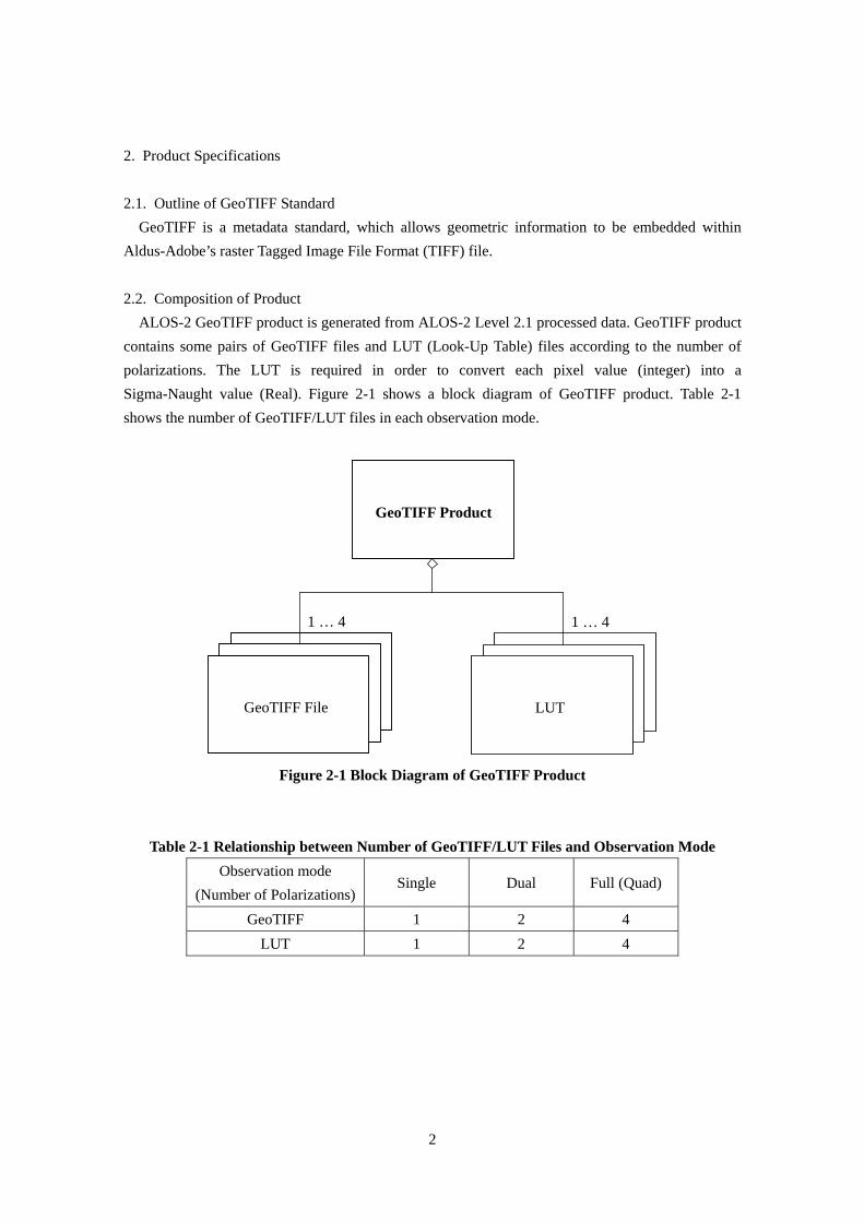
2.2. Composition of Product
ALOS-2 GeoTIFF product is generated from ALOS-2 Level 2.1 processed data. GeoTIFF product
contains some pairs of GeoTIFF files and LUT (Look-Up Table) files according to the number of
polarizations. The LUT is required in order to convert each pixel value (integer) into a
Sigma-Naught value (Real). Figure 2-1 shows a block diagram of GeoTIFF product. Table 2-1
shows the number of GeoTIFF/LUT files in each observation mode.
GeoTIFF Product
GeoTIFF File
1 … 4
LUT
1 … 4
Figure 2-1 Block Diagram of GeoTIFF Product
Table 2-1 Relationship between Number of GeoTIFF/LUT Files and Observation Mode
Observation mode
(Number of Polarizations) Single Dual Full (Quad)
GeoTIFF 1 2 4
LUT 1 2 4
2
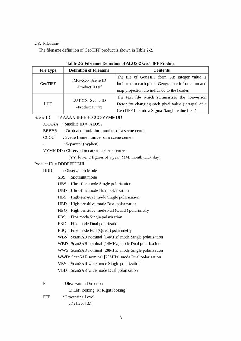
2.3. Filename
The filename definition of GeoTIFF product is shown in Table 2-2.
Table 2-2 Filename Definition of ALOS-2 GeoTIFF Product
File Type Definition of Filename Contents
GeoTIFF IMG-XX- Scene ID
-Product ID.tif
The file of GeoTIFF form. An integer value is
indicated to each pixel. Geographic information and
map projection are indicated to the header.
LUT LUT-XX- Scene ID
-Product ID.txt
The text file which summarizes the conversion
factor for changing each pixel value (integer) of a
GeoTIFF file into a Sigma Naught value (real).
Scene ID = AAAAABBBBBCCCC-YYMMDD
AAAAA : Satellite ID = 'ALOS2'
BBBBB : Orbit accumulation number of a scene center
CCCC : Scene frame number of a scene center
- : Separator (hyphen)
YYMMDD : Observation date of a scene center
(YY: lower 2 figures of a year, MM: month, DD: day)
Product ID = DDDEFFFGHI
DDD : Observation Mode
SBS : Spotlight mode
UBS : Ultra-fine mode Single polarization
UBD : Ultra-fine mode Dual polarization
HBS : High-sensitive mode Single polarization
HBD : High-sensitive mode Dual polarization
HBQ : High-sensitive mode Full (Quad.) polarimetry
FBS : Fine mode Single polarization
FBD : Fine mode Dual polarization
FBQ : Fine mode Full (Quad.) polarimetry
WBS : ScanSAR nominal [14MHz] mode Single polarization
WBD : ScanSAR nominal [14MHz] mode Dual polarization
WWS : ScanSAR nominal [28MHz] mode Single polarization
WWD: ScanSAR nominal [28MHz] mode Dual polarization
VBS : ScanSAR wide mode Single polarization
VBD : ScanSAR wide mode Dual polarization
E : Observation Direction
L: Left looking, R: Right looking
FFF : Processing Level
2.1: Level 2.1
3
4
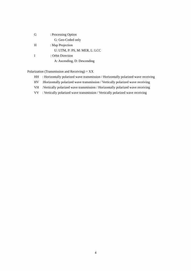
G : Processing Option
G: Geo-Coded only
H : Map Projection
U: UTM, P: PS, M: MER, L: LCC
I : Orbit Direction
A: Ascending, D: Descending
Polarization (Transmission and Receiving) = XX
HH : Horizontally polarized wave transmission / Horizontally polarized wave receiving
HV :Horizontally polarized wave transmission / Vertically polarized wave receiving
VH :Vertically polarized wave transmission / Horizontally polarized wave receiving
VV : Vertically polarized wave transmission / Vertically polarized wave receiving
3. Format
3.1. GeoTIFF File
GeoTIFF is a metadata standard which allows geometric information to be embedded within a
TIFF image file. In ALOS-2 GeoTIFF products, GeoTIFF files are generated in TIFF-Strip format,
and some GeoTIFF-tags (identifiers) are different in each processing level. All TIFF files and
GeoTIFF-tags are based on TIFF Revision 6.0 and GeoTIFF Revision 1.0 standard, and image data
is recorded in little endian.
Since TIFF format supports 4 GB image size in maximum, the image which exceeds 4 GB is
stored in BigTIFF format.
3.1.1. Common TIFF Tag
Some TIFF-tags common to all processing levels are shown in Table 3-1.
5
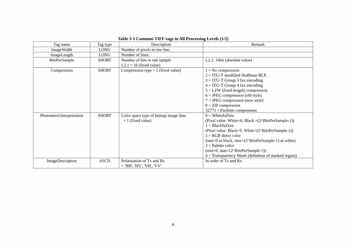
Table 3-1 Common TIFF-tags in All Processing Levels (1/2) Tag name Tag type Description Remark
ImageWidth LONG Number of pixels in one line. ImageLength LONG Number of lines.
BitsPerSample SHORT Number of bits in one sample L2.1 = 16 (fixed value)
L2.1: 16bit (absolute value)
Compression SHORT Compression type = 1 (fixed value) 1 = No compression 2 = ITU-T modified Huffman RLE 3 = ITU-T Group 3 fax encoding 4 = ITU-T Group 4 fax encoding 5 = LZW (fixed-length) compression 6 = JPEG compression (old style) 7 = JPEG compression (new style) 8 = ZIP compression 32773 = Packbits compression
PhotometricInterpretation SHORT Color space type of bitmap image data = 1 (fixed value)
0 = WhiteIsZero (Pixel value: White=0, Black =(2^BitsPerSample-1)) 1 = BlackIsZero (Pixel value: Black=0, White=(2^BitsPerSample-1)) 2 = RGB direct color (min=0 as black, max=(2^BitsPerSample-1) as white) 3 = Palette color (min=0, max=(2^BitsPerSample-1)) 4 = Transparency Mask (definition of masked region)
ImageDescription ASCII Polarization of Tx and Rx = 'HH', 'HV', 'VH', 'VV'
In order of Tx and Rx
6
7
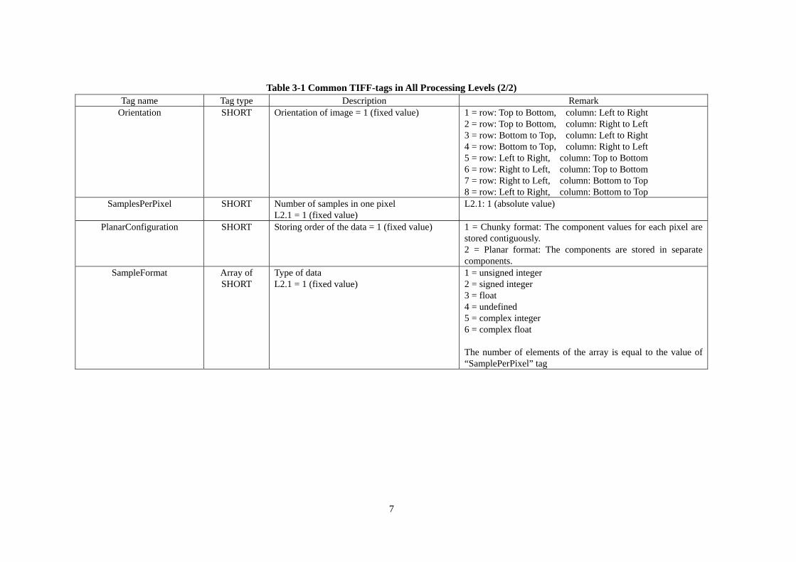
Table 3-1 Common TIFF-tags in All Processing Levels (2/2) Tag name Tag type Description Remark
Orientation SHORT Orientation of image = 1 (fixed value) 1 = row: Top to Bottom, column: Left to Right 2 = row: Top to Bottom, column: Right to Left 3 = row: Bottom to Top, column: Left to Right 4 = row: Bottom to Top, column: Right to Left 5 = row: Left to Right, column: Top to Bottom 6 = row: Right to Left, column: Top to Bottom 7 = row: Right to Left, column: Bottom to Top 8 = row: Left to Right, column: Bottom to Top
SamplesPerPixel SHORT Number of samples in one pixel L2.1 = 1 (fixed value)
L2.1: 1 (absolute value)
PlanarConfiguration SHORT Storing order of the data = 1 (fixed value) 1 = Chunky format: The component values for each pixel are stored contiguously. 2 = Planar format: The components are stored in separate components.
SampleFormat Array of SHORT
Type of data L2.1 = 1 (fixed value)
1 = unsigned integer 2 = signed integer 3 = float 4 = undefined 5 = complex integer 6 = complex float The number of elements of the array is equal to the value of “SamplePerPixel” tag
3.1.2. GeoTIFF tag of level 2.1 Product
GeoTIFF tags of ALOS-2 Level 2.1 GeoTIFF product are shown in Table 3-2.
8
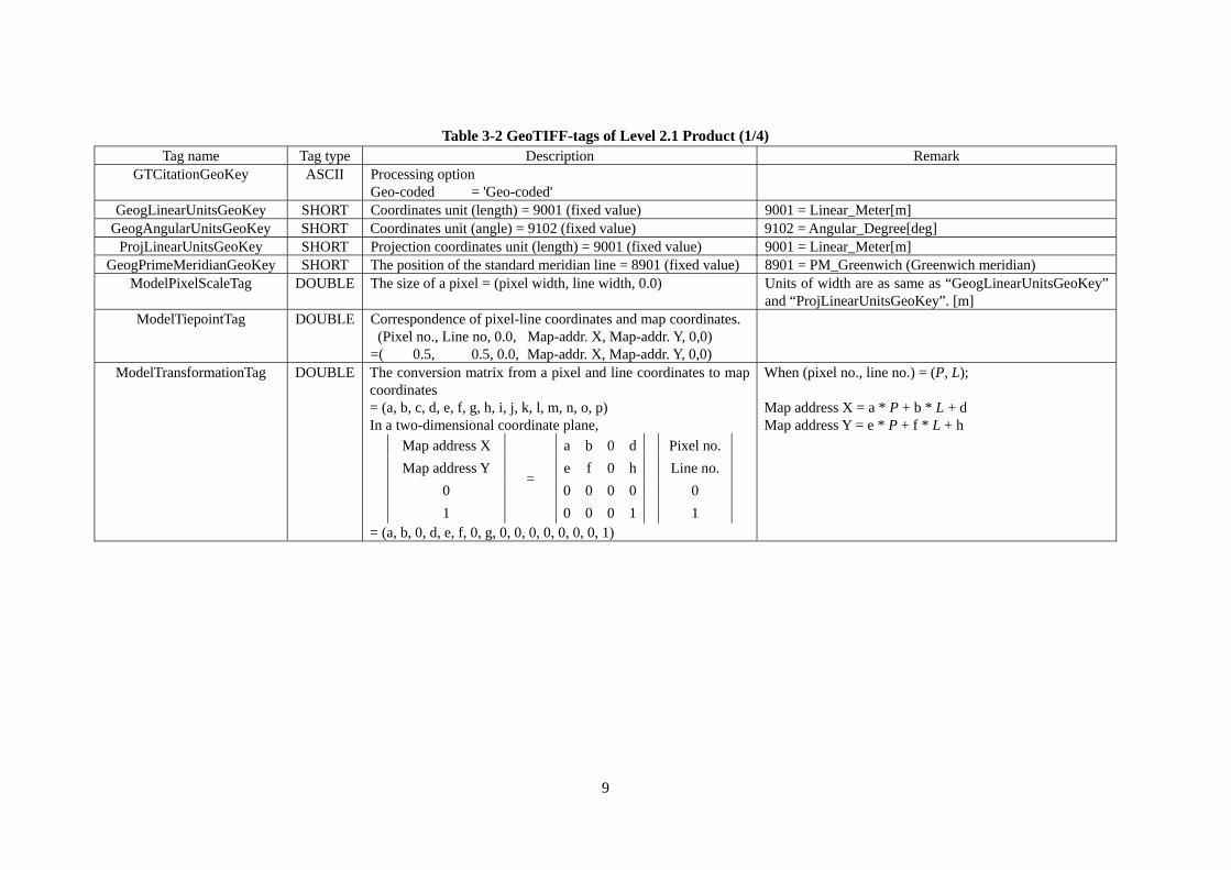
Table 3-2 GeoTIFF-tags of Level 2.1 Product (1/4) Tag name Tag type Description Remark
GTCitationGeoKey ASCII Processing option Geo-coded = 'Geo-coded'
GeogLinearUnitsGeoKey SHORT Coordinates unit (length) = 9001 (fixed value) 9001 = Linear_Meter[m] GeogAngularUnitsGeoKey SHORT Coordinates unit (angle) = 9102 (fixed value) 9102 = Angular_Degree[deg]
ProjLinearUnitsGeoKey SHORT Projection coordinates unit (length) = 9001 (fixed value) 9001 = Linear_Meter[m] GeogPrimeMeridianGeoKey SHORT The position of the standard meridian line = 8901 (fixed value) 8901 = PM_Greenwich (Greenwich meridian)
ModelPixelScaleTag DOUBLE The size of a pixel = (pixel width, line width, 0.0) Units of width are as same as “GeogLinearUnitsGeoKey” and “ProjLinearUnitsGeoKey”. [m]
ModelTiepointTag DOUBLE Correspondence of pixel-line coordinates and map coordinates. (Pixel no., Line no, 0.0, Map-addr. X, Map-addr. Y, 0,0)
=( 0.5, 0.5, 0.0, Map-addr. X, Map-addr. Y, 0,0)
ModelTransformationTag DOUBLE The conversion matrix from a pixel and line coordinates to map coordinates = (a, b, c, d, e, f, g, h, i, j, k, l, m, n, o, p) In a two-dimensional coordinate plane,
Map address X a b 0 d Pixel no.
Map address Y e f 0 h Line no.
0 =
0 0 0 0 0
1 0 0 0 1 1 = (a, b, 0, d, e, f, 0, g, 0, 0, 0, 0, 0, 0, 0, 1)
When (pixel no., line no.) = (P, L); Map address X = a * P + b * L + d Map address Y = e * P + f * L + h
9
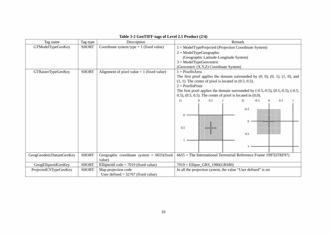
Table 3-2 GeoTIFF-tags of Level 2.1 Product (2/4) Tag name Tag type Description Remark
GTModelTypeGeoKey SHORT Coordinate system type = 1 (fixed value) 1 = ModelTypeProjected (Projection Coordinate System) 2 = ModelTypeGeographic
(Geographic Latitude-Longitude System) 3 = ModelTypeGeocentric (Geocentric (X,Y,Z) Coordinate System)
GTRasterTypeGeoKey SHORT Alignment of pixel value = 1 (fixed value) 1 = PixelIsArea The first pixel applies the domain surrounded by (0, 0), (0, 1), (1, 0), and (1, 1). The center of pixel is located in (0.5, 0.5). 2 = PixelIsPoint The first pixel applies the domain surrounded by (-0.5,-0.5), (0.5,-0.5), (-0.5, 0.5), (0.5, 0.5). The center of pixel is located in (0,0).
1) 0 0.5 1 2) -0.5 0 0.5 1
-0.5
0
0
0.5
0.5
1
1
GeogGeodeticDatumGeoKey SHORT Geographic coordinate system = 6655(fixed
value) 6655 = The International Terrestrial Reference Frame 1997(ITRF97)
GeogEllipsoidGeoKey SHORT Ellipsoid code = 7019 (fixed value) 7019 = Ellipse_GRS_1980(GRS80) ProjectedCSTypeGeoKey SHORT Map projection code
User defined = 32767 (fixed value) In all the projection system, the value “User defined” is set
10
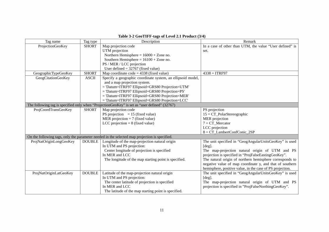
Table 3-2 GeoTIFF-tags of Level 2.1 Product (3/4) Tag name Tag type Description Remark
ProjectionGeoKey SHORT Map projection code UTM projection Northern Hemisphere = 16000 + Zone no. Southern Hemisphere = 16100 + Zone no.
PS / MER / LCC projection User defined = 32767 (fixed value)
In a case of other than UTM, the value “User defined” is set.
GeographicTypeGeoKey SHORT Map coordinate code = 4338 (fixed value) 4338 = ITRF97 GeogCitationGeoKey ASCII Specify a geographic coordinate system, an ellipsoid model,
and a map projection system. = 'Datum=ITRF97 Ellipsoid=GRS80 Projection=UTM' = 'Datum=ITRF97 Ellipsoid=GRS80 Projection=PS' = 'Datum=ITRF97 Ellipsoid=GRS80 Projection=MER' = 'Datum=ITRF97 Ellipsoid=GRS80 Projection=LCC'
The following tag is specified only when “ProjectionGeoKey” is set as “user defined” (32767) ProjCoordTransGeoKey SHORT Map projection code
PS projection = 15 (fixed value) MER projection = 7 (fixed value) LCC projection = 8 (fixed value)
PS projection 15 = CT_PolarStereographic MER projection 7 = CT_Mercator LCC projection 8 = CT_LambertConfConic_2SP
On the following tags, only the parameter needed in the selected map projection is specified. ProjNatOriginLongGeoKey DOUBLE Longitude of the map-projection natural origin
In UTM and PS projection: Center longitude of projection is specified In MER and LCC The longitude of the map starting point is specified.
The unit specified in “GeogAngularUnitsGeoKey” is used [deg]. The map-projection natural origin of UTM and PS projection is specified in “ProjFalseEastingGeoKey”. The natural origin of northern hemisphere corresponds to negative value of map coordinate y, and that of southern hemisphere, positive value, in the case of PS projection.
ProjNatOriginLatGeoKey DOUBLE Latitude of the map-projection natural origin In UTM and PS projection: The center latitude of projection is specified In MER and LCC The latitude of the map starting point is specified.
The unit specified in “GeogAngularUnitsGeoKey” is used [deg]. The map-projection natural origin of UTM and PS projection is specified in ”ProjFalseNorthingGeoKey”.
11
12
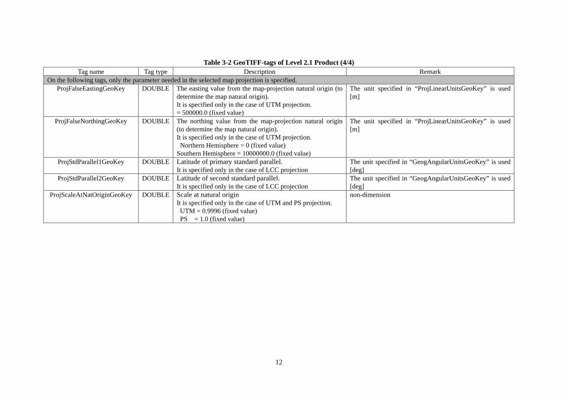
Table 3-2 GeoTIFF-tags of Level 2.1 Product (4/4) Tag name Tag type Description Remark
On the following tags, only the parameter needed in the selected map projection is specified. ProjFalseEastingGeoKey DOUBLE The easting value from the map-projection natural origin (to
determine the map natural origin). It is specified only in the case of UTM projection. = 500000.0 (fixed value)
The unit specified in “ProjLinearUnitsGeoKey” is used [m]
ProjFalseNorthingGeoKey DOUBLE The northing value from the map-projection natural origin (to determine the map natural origin). It is specified only in the case of UTM projection. Northern Hemisphere = 0 (fixed value)
Southern Hemisphere = 10000000.0 (fixed value)
The unit specified in “ProjLinearUnitsGeoKey” is used [m]
ProjStdParallel1GeoKey DOUBLE Latitude of primary standard parallel. It is specified only in the case of LCC projection
The unit specified in “GeogAngularUnitsGeoKey” is used [deg]
ProjStdParallel2GeoKey DOUBLE Latitude of second standard parallel. It is specified only in the case of LCC projection
The unit specified in “GeogAngularUnitsGeoKey” is used [deg]
ProjScaleAtNatOriginGeoKey DOUBLE Scale at natural origin It is specified only in the case of UTM and PS projection. UTM = 0.9996 (fixed value) PS = 1.0 (fixed value)
non-dimension
3.2. Look Up Table
The LUT is the text file which records the conversion factor for converting from the integer value
stored in each pixel of a GeoTIFF file into a real value ( : Sigma Naught). The conversion
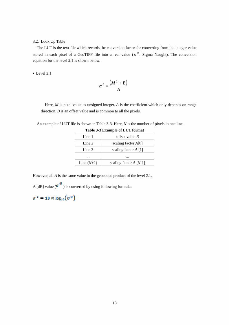
equation for the level 2.1 is shown below.
0
Level 2.1
A
BM
20
Here, M is pixel value as unsigned integer. A is the coefficient which only depends on range
direction. B is an offset value and is common to all the pixels.
An example of LUT file is shown in Table 3-3. Here, N is the number of pixels in one line.
Table 3-3 Example of LUT format
Line 1 offset value B
Line 2 scaling factor A[0]
Line 3 scaling factor A [1]
... ...
Line (N+1) scaling factor A [N-1]
However, all A is the same value in the geocoded product of the level 2.1.
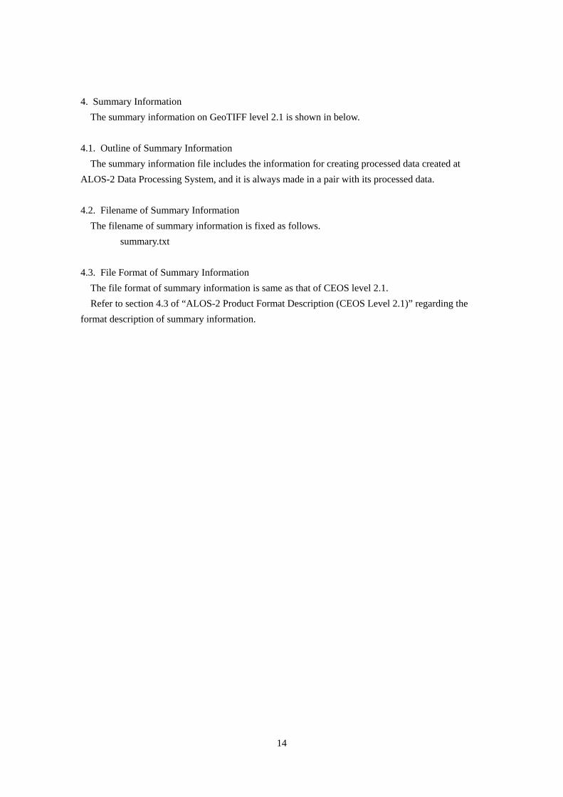
A [dB] value ( ) is converted by using following formula:
13
14
4. Summary Information
The summary information on GeoTIFF level 2.1 is shown in below.
4.1. Outline of Summary Information
The summary information file includes the information for creating processed data created at
ALOS-2 Data Processing System, and it is always made in a pair with its processed data.
4.2. Filename of Summary Information
The filename of summary information is fixed as follows.
summary.txt
4.3. File Format of Summary Information
The file format of summary information is same as that of CEOS level 2.1.
Refer to section 4.3 of “ALOS-2 Product Format Description (CEOS Level 2.1)” regarding the
format description of summary information.