(Almost) Everything you wanted to know about using S2PLOT to visualise astronomy datasets
Upload
hoangthuanCategory
view
225download
1
Almost everything you wanted to know about filters but were afraid to ask.
Presented By:Jeff Pender (K8KZB)
The Genesee County Radio Club
1

What are filters and why do I need to know about them?
Filters stop unwanted signals on both your transmitter and receiver.
Most of us who are old enough remember the CB’ers coming in on our TV set with their unfiltered foot warmer (illegal) amplifiers.
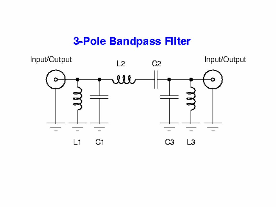
We will be going over three of the filters used in radio technology. They are the Low pass filter, the High pass filter and the Band pass filter.
February - We will discuss the very basics of filters and list places where you can get the needed parts for your filter designs.
March – We will discuss the mathematics involved with filter design and go over band pass filters by Lew Gordon K4VX from the September 1988 QST.
April – we will have a workshop on testing filter designs with a frequency generator and oscilloscope.

BPF
LPF
HPF


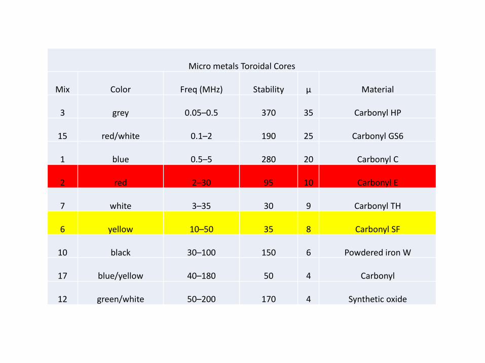
Micro metals Toroidal Cores
Mix Color Freq (MHz) Stability μ Material
3 grey 0.05–0.5 370 35 Carbonyl HP
15 red/white 0.1–2 190 25 Carbonyl GS6
1 blue 0.5–5 280 20 Carbonyl C
2 red 2–30 95 10 Carbonyl E
7 white 3–35 30 9 Carbonyl TH
6 yellow 10–50 35 8 Carbonyl SF
10 black 30–100 150 6 Powdered iron W
17 blue/yellow 40–180 50 4 Carbonyl
12 green/white 50–200 170 4 Synthetic oxide
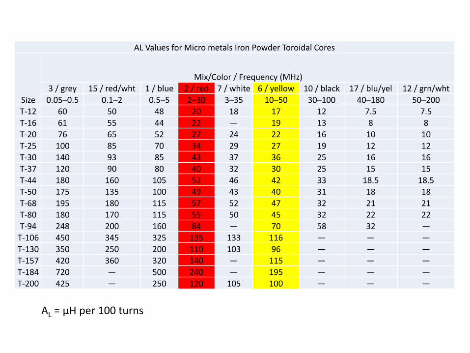
AL Values for Micro metals Iron Powder Toroidal Cores
Size
Mix/Color / Frequency (MHz) 3 / grey 15 / red/wht 1 / blue 2 / red 7 / white 6 / yellow 10 / black 17 / blu/yel 12 / grn/wht0.05–0.5 0.1–2 0.5–5 2–30 3–35 10–50 30–100 40–180 50–200
T-12 60 50 48 20 18 17 12 7.5 7.5
T-16 61 55 44 22 — 19 13 8 8T-20 76 65 52 27 24 22 16 10 10
T-25 100 85 70 34 29 27 19 12 12
T-30 140 93 85 43 37 36 25 16 16T-37 120 90 80 40 32 30 25 15 15
T-44 180 160 105 52 46 42 33 18.5 18.5T-50 175 135 100 49 43 40 31 18 18
T-68 195 180 115 57 52 47 32 21 21T-80 180 170 115 55 50 45 32 22 22
T-94 248 200 160 84 — 70 58 32 —
T-106 450 345 325 135 133 116 — — —T-130 350 250 200 110 103 96 — — —
T-157 420 360 320 140 — 115 — — —T-184 720 — 500 240 — 195 — — —
T-200 425 — 250 120 105 100 — — —
AL = μH per 100 turns
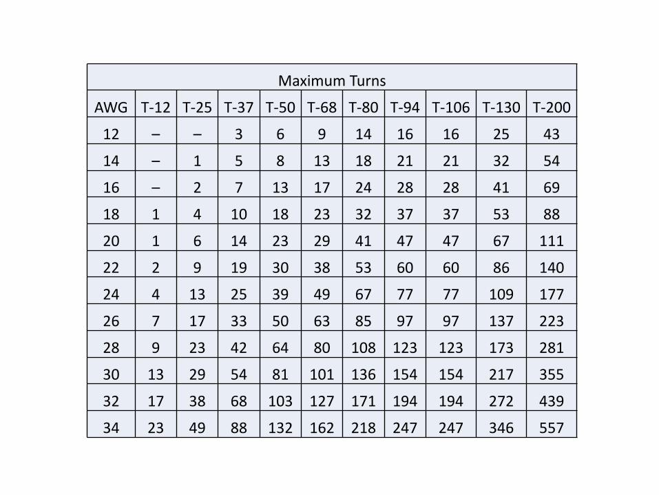
Maximum Turns
AWG T-12 T-25 T-37 T-50 T-68 T-80 T-94 T-106 T-130 T-200
12 – – 3 6 9 14 16 16 25 43
14 – 1 5 8 13 18 21 21 32 54
16 – 2 7 13 17 24 28 28 41 69
18 1 4 10 18 23 32 37 37 53 88
20 1 6 14 23 29 41 47 47 67 111
22 2 9 19 30 38 53 60 60 86 140
24 4 13 25 39 49 67 77 77 109 177
26 7 17 33 50 63 85 97 97 137 223
28 9 23 42 64 80 108 123 123 173 281
30 13 29 54 81 101 136 154 154 217 355
32 17 38 68 103 127 171 194 194 272 439
34 23 49 88 132 162 218 247 247 346 557

Pi Filter
The Pi Type which consists of two shunt capacitors with a series inductor.
This filter provides good performance with a minimum of component cost, since inductors are usually more expensive than capacitors. However, in some cases the above filterconfiguration does not provide sufficient attenuation of harmonics. This is because there isonly one series component and there may be too much coupling between the input and the output of the filter.
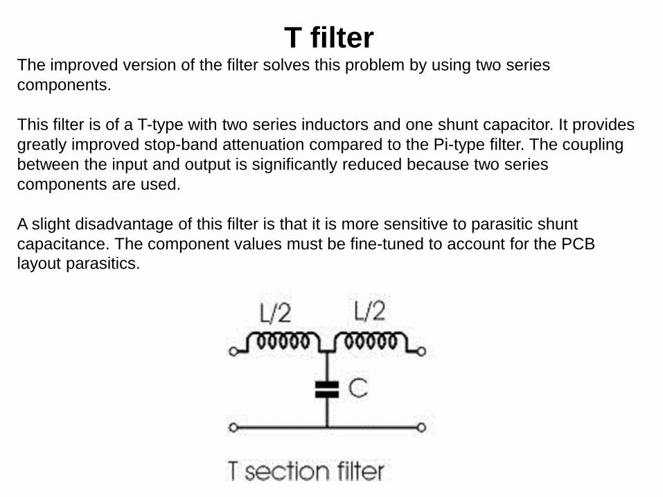
T filterThe improved version of the filter solves this problem by using two series
components.
This filter is of a T-type with two series inductors and one shunt capacitor. It provides
greatly improved stop-band attenuation compared to the Pi-type filter. The coupling
between the input and output is significantly reduced because two series
components are used.
A slight disadvantage of this filter is that it is more sensitive to parasitic shunt
capacitance. The component values must be fine-tuned to account for the PCB
layout parasitics.