Yuval Adar Yisrael Blustein Alex Krichevsky Behir Sabban Raviv Sobel Galia Turgeman.
Alma & Galia
Decommissioning Programmes

Alma & Galia Decommissioning Programmes Page 2 of 54
DOCUMENT CONTROL
Document ID: M3523-PDI-ALG-EG-000-REP-0005
Document Classification: PUBLIC
Document Ownership: Decommissioning
Date of Document: 11/10/19 Signature Date
Prepared by: M. McHardy
S. Axon 06/01/20
Reviewed by: C. Wheaton C. Wheaton 06/01/20
Approved by: N. Martin N. Martin 06/01/20
REVISION RECORD
Revision No. Date of Revision Reason for Issue
A1 14/08/19 Issued for Review and Comment
A2 09/09/19 Re-issued for Review and Comment
A3 17/09/19 Issued for EQ Internal Review and Comment
A4 07/10/19 Issued for Partner Review and Comment
A5 23/10/19 Issued to OPRED for Review and Comment
A6 25/11/19 Re-Issued to all for Review and Comment
A7 04/12/19 Re-Issued to OPRED for Review and Comment
A8 06/01/20 Issued for Statutory Consultation
DISTRIBUTION LIST
Company No. of copies
Offshore Petroleum Regulator for Environment and Decommissioning 1 electronic
GMG, NFFO, NIFPO, SFF 1 electronic
Partners, etc. 1 electronic
Newcastle City Library 1 hardcopy

Alma & Galia Decommissioning Programmes Page 3 of 54
TABLE OF CONTENTS INST P/L
1. Executive Summary 7 1.1 Combined Decommissioning Programmes 7 1.2 Introduction 7 1.3 Alma Field – Overview 8 1.4 Galia Field - Overview 9 1.5 Summary of Proposed Decommissioning Programmes 10 1.6 Field Locations including Field Layout and Adjacent Facilities 11 1.7 Industrial Implications 19 2. Description of Items to Be Decommissioned 20 2.1 Alma Installations: Surface Facilities 20 2.2 Alma Installations: Subsea including Stabilisation Features 20 2.3 Alma Pipelines including Stabilisation Features 23 2.4 Alma Wells 30 2.5 Alma Drill Cuttings 30 2.6 Alma Inventory Estimates 30 2.7 Galia Installations: Subsea including Stabilisation Features 31 2.8 Galia Pipelines including Stabilisation Features 32 2.9 Galia Wells 34 2.10 Galia Drill Cuttings 34 2.11 Galia Inventory Estimates 34 3. Removal and Disposal Methods 36 3.1 Installations - Surface Facilities, FPSO 36 3.2 Installations - Subsea Facilities & Stabilisation Features 37 3.3 Pipelines, Umbilicals and Cables 37 3.4 Pipeline Stabilisation Features 39 3.5 Well Decommissioning 44 3.6 Waste Stream Management Methods 44 4. Environmental Appraisal 46 4.1 Environmental Sensitivities 46 4.2 Potential Environmental Impacts and their Management 47 5. Interested Party Consultations 49 5.1 General 49 6. Programme Management 50 6.1 Project Management and Verification 50 6.2 Post-Decommissioning Debris Clearance and Verification 50 6.3 Schedule 50 6.4 Costs 52 6.5 Close Out 52 6.6 Post-Decommissioning Monitoring and Evaluation 52 7. Supporting Documents 53 Appendix A Public Notice & Consultee Correspondence 54 Appendix A.1 Public Notices 54 Appendix A.2 Correspondence with Individual Statutory Consultees 54
√ √ √ √ √ √ √ √ √ √ √ √ √ √ √ √ √ √ √ √ √ √ √ √ √ √ √ √ √ √ √ √ √ √ √ √ √ √ √ √ √ √ √
√ √ √ √ √ √ √ √ √ √ √ √ √ √ √ √ √ √ √ √ √ √ √ √ √ √ √ √ √ √ √ √ √ √ √ √ √ √ √ √ √ √ √
Alma & Galia Decommissioning Programmes Page 4 of 54
FIGURES AND TABLES
Figure 1.6.1: Alma & Galia Adjacent Facilities .............................................................................. 11 Figure 1.6.2: Alma & Galia Prior to Decommissioning .................................................................. 12 Figure 1.6.3: Overview of Alma & Galia ........................................................................................ 13 Figure 1.6.4: Overview of EnQuest Producer Approach ............................................................... 14 Figure 1.6.5: Overview of Alma Manifold & Well Approaches ....................................................... 15 Figure 1.6.6: Detail of Alma Manifold & Well Approaches ............................................................. 16 Figure 1.6.7: Overview of Galia Well Approaches......................................................................... 17 Figure 1.6.8: Overview of Umbilical and ESP Cable Buoyancy Arrangement ............................... 18 Figure 1.6.9: Overview of Production and Water Injection Flowline Buoyancy Arrangement ........ 18 Figure 2.6.1: Pie-Chart of Material Inventory for Alma Installations............................................... 30 Figure 2.6.2: Pie-Chart of Material Inventory for Alma Pipelines ................................................... 31 Figure 2.11.1: Pie-Chart of Material Inventory for Galia Installations ............................................ 34 Figure 2.11.2: Pie Chart of Material Inventory for Galia Pipelines ................................................. 35 Figure 3.4.1: Overview of Alma & Galia Decommissioning Proposals (Phase 1) ......................... 42 Figure 3.4.2: Overview of Alma & Galia Decommissioning Proposals (Phase 2) .......................... 43 Figure 6.3.1: Gantt Chart of Project Plan ...................................................................................... 51 Table 1.3.1: Installations Being Decommissioned........................................................................... 8 Table 1.3.2: Alma Installation Section 29 Notice Holders Details .................................................... 8 Table 1.3.3: Alma Pipelines Being Decommissioned ...................................................................... 8 Table 1.3.4: Alma Pipelines Section 29 Notice Holders Details ...................................................... 8 Table 1.4.1: Galia Installations Being Decommissioned ................................................................. 9 Table 1.4.2: Galia Installation Section 29 Notice Holders Details .................................................... 9 Table 1.4.3: Galia Pipelines Being Decommissioned1 .................................................................... 9 Table 1.4.4: Galia Pipelines Section 29 Notice Holders Details ...................................................... 9 Table 1.5.1: Summary of Decommissioning Programmes ............................................................ 10 Table 1.6.1: Adjacent Facilities ..................................................................................................... 19 Table 2.1.1: Surface Facilities Information .................................................................................... 20 Table 2.2.1: Alma Subsea Facilities Information ........................................................................... 20 Table 2.3.1: Alma Pipeline/Flowline/Umbilical Information ............................................................ 23 Table 2.3.2: Alma Subsea Pipeline Stabilisation Features ............................................................ 27 Table 2.4.1: Alma Well Information ............................................................................................... 30 Table 2.5.1: Alma Drill Cutting(s) Pile Information ........................................................................ 30 Table 2.7.1: Galia Subsea Facilities Information ........................................................................... 31 Table 2.8.1: Galia Pipeline/Flowline/Umbilical Information ............................................................ 32 Table 2.8.2: Galia Subsea Pipeline Stabilisation Features ............................................................ 33 Table 2.9.1: Galia Well Information .............................................................................................. 34 Table 2.10.1: Galia Drill Cutting(s) Pile Information ...................................................................... 34 Table 3.1.1: Cleaning of FPSO for removal .................................................................................. 36 Table 3.1.2: Topside Removal Methods ....................................................................................... 36 Table 3.2.1: Subsea Installations & Stabilisation Features ........................................................... 37 Table 3.3.1: Pipeline or Pipeline Groups Decommissioning Options............................................. 37 Table 3.3.2: Outcomes of Comparative Assessment .................................................................... 38 Table 3.4.1: Pipeline Stabilisation Features .................................................................................. 39 Table 3.5.1: Well Decommissioning.............................................................................................. 44 Table 3.6.1: Waste Stream Management Methods ....................................................................... 44 Table 3.6.2: Inventory Disposition ................................................................................................ 45 Table 3.6.3: Re-use, Recycle & Disposal Aspirations for Recovered Material .............................. 45 Table 4.1.1: Summary of Environmental Characteristics and Sensitivities .................................... 46 Table 4.2.1: Key Control and Mitigation Measures ....................................................................... 48 Table 5.1.1: Summary of Stakeholder Comments ........................................................................ 49

Alma & Galia Decommissioning Programmes Page 5 of 54
ABBREVIATION EXPLANATION
AHV Anchor Handling Vessel
AP1 through 9 Alma anchor pile AP1 through to AP9
AP1 through AP6 Alma Production Wells K1 through K7 respectively, noting that K6 is partially decommissioned with infrastructure rerouted to K7
AW1 & AW2 Alma Water Injection Wells (AW2 - future not installed)
CSV Construction Support Vessel
DBB Double Block and Bleed (valve arrangement with vent)
dia. Diameter
DSV Diving Support Vessel
EA Environmental Appraisal
EHC Electro-Hydraulic Control
E/H/C Electric, Hydraulic, Chemicals; products conveyed in umbilical pipeline
EnQuest EnQuest Heather Limited
ESP Electrical Submersible Pump
FPSO (EnQuest Producer) Floating, Production, Storage, Offloading (Vessel)
Gabion 1m3 ‘builder’s bag sometimes filled with 25kg grout bags
GMG Global Marine Group
HP High Pressure (Hydraulic)
HSE Health and Safety Executive
“, in Inch; 25.4 millimetres
Installation Offshore structure, typically comprising topsides and jacket, or a subsea wellhead protection structure, subsea manifold structure or an FPSO
km Kilometre
KUFPEC UK Ltd Kuwait Foreign Petroleum Exploration Co UK Limited
LAT Lowest Astronomical Tide
LP Low Pressure (Hydraulic)
m Metre(s)
MAT, SAT Master Application Template, Supplementary Application Template
MSV Multipurpose Support Vessel
N,S,E,W North, South, East, West
n/a Not Applicable
NFFO National Federation of Fishermen's Organisations
NIFPO Northern Ireland Fish Producers Organisation Ltd
NORM Naturally Occurring Radioactive Material
NORPIPE 34in nominal bore oil pipeline, 220 miles long connecting Ekofisk 2/4-J facility and the oil or Natural Gas Liquids terminal in Teeside, UK
OPRED Offshore Petroleum Regulator for Environment and Decommissioning

Alma & Galia Decommissioning Programmes Page 6 of 54
ABBREVIATION EXPLANATION
OSPAR Oslo-Paris Convention
P1, P2 Production Flowline Identifier
PL Pipeline Identification numbers (UK)
PLA Pipeline Operations as defined in MAT Operation Types
PON Petroleum Operations Notice
PVDF/PA12 Polyvinylidene fluoride (Kinar® PVDF/PA12 Polyamide 12) resins are used for chemical resistance
PVDF/HDPE Polyvinylidene fluoride/High Density polyethylene; flexible plastic pipe
PWA Pipeline Works Authorisation
ROV Remotely Operated Vehicle
ROVSV Remotely Operated Vehicle Support Vessel
SFF Scottish Fishermen’s Federation
SPCDU A, B Subsea Power & Communications Distribution Unit
Topsides Offshore structure typically furnished with reception and processing equipment for produced hydrocarbons, in this case an FPSO.
Turret A mooring turret is where all anchoring lines terminate and around which the ship is free to make rotations, enabling it to select a favourable heading for the environment
UK United Kingdom
UKCS United Kingdom Continental Shelf
WGS84 World Geodetic System 1984
WIF Water Injection Flowline
x Number of (e.g. 16x = 16 in Number)
Alma & Galia Decommissioning Programmes Page 7 of 54
1. EXECUTIVE SUMMARY
1.1 Combined Decommissioning Programmes
This document contains four Decommissioning Programmes, one for each set of notices under Section 29 of the Petroleum Act 1998. The Decommissioning Programmes are:
• The EnQuest Producer floating production storage and offloading vessel (FPSO) complete with all subsea equipment, including manifolds and wellhead protection structures;
• All pipelines associated with the Alma field including PL3006, PL3007, PL3008, PLU3009, PL3011, PL3012, and PL3013 and associated jumpers;
• The Galia installation, a wellhead protection structure; and,
• All associated pipelines including PL3014, PLU3015, and PL3016.
Installations: In accordance with the Petroleum Act 1998, EnQuest Heather Limited, as operator of the Alma and Galia fields, and on behalf of the Section 29 notice holders (Table 1.3.2 & Table 1.4.2), is applying to the Offshore Petroleum Regulator for Environment and Decommissioning (OPRED) to obtain approval for decommissioning the installations detailed in Section 2 of this document. Partner Letters of Support will be provided directly to OPRED.
Pipelines: In accordance with the Petroleum Act 1998, EnQuest Heather Limited, as operator of the Alma and Galia pipelines, and on behalf of the Section 29 notice holders (Tables 1.3.4 & Table 1.4.4), is applying to OPRED to obtain approval for decommissioning the pipelines detailed in Section 2 of this document. Partner Letters of Support will be provided directly to OPRED.
In conjunction with public, stakeholder and regulatory consultation, the Decommissioning Programmes are submitted in compliance with national and international regulations and OPRED guidance notes. The schedule outlined in this document is for a seven-year period with FPSO sailaway due to begin sometime Q3 2020.
1.2 Introduction
The Alma and Galia oil fields are situated in blocks 30/25c and 30/24b respectively of the United Kingdom Continental Shelf and operated by EnQuest Heather Limited. These fields are located approximately 282km north-east of Northumberland coast (Seahouses), in water depths of ~77m.
The Alma and Galia fields were developed as a single joint development and came onstream in late 2015. They produce via subsea wells tied-back to the FPSO vessel via one central hub for all fields. Alma has six production wells and one water injector, while Galia produces via one well. The Cessation of Production documentation for the Alma & Galia fields is currently under consideration by the Oil and Gas Authority.
The Decommissioning Programmes explain the principles of the removal activities and are supported by an environmental appraisal report. The Decommissioning Programmes for the pipelines are also supported by a comparative assessment.

Alma & Galia Decommissioning Programmes Page 8 of 54
1.3 Alma Field – Overview
1.3.1 Alma Field - Installations
Table 1.3.1: Installations Being Decommissioned
Field(s): Alma Production Type Oil
Water Depth (m) Approx. 77m UKCS Block 30/25c
Topside Installation(s) Weights
Number Type Weight Anchor Pile Weight (Te)
1 FPSO 95,300 629.64 (9)
Subsea Installation(s) Number of Wells
7 WHPS Topsides Subsea
1 Manifold, piled n/a 7
Drill Cuttings piles Distance to median Distance from nearest UK
coastline
n/a 17km 282km NE of Northumberland
Coast (Seahouses)
Table 1.3.2: Alma Installation Section 29 Notice Holders Details
Section 29 Notice Holder Registration Number License Equity
Interest (%)
EnQuest Dons Leasing Limited 07848478 0%
EnQuest Heather Limited 02748866 65%
KUFPEC UK Limited 07253693 35%
EnQuest plc 07140891 0%
Kuwait Foreign Petroleum Exploration Company K.S.C. n/a 0%
1.3.2 Alma Field - Pipelines
Table 1.3.3: Alma Pipelines Being Decommissioned1
Number of Pipelines, Cables, Umbilicals 7 (22) See Table 2.3.1
Table 1.3.4: Alma Pipelines Section 29 Notice Holders Details
Section 29 Notice Holder Registration Number License Equity
Interest (%)
EnQuest Heather Limited 02748866 65%
EnQuest plc 07140891 0%
KUFPEC UK Limited 07253693 35%
Kuwait Foreign Petroleum Exploration Company K.S.C. n/a 0%
1 The figure in brackets is total no. of pipelines including jumpers.

Alma & Galia Decommissioning Programmes Page 9 of 54
1.4 Galia Field - Overview
1.4.1 Galia Field – Installations
Table 1.4.1: Galia Installations Being Decommissioned
Field(s): Galia Production Type Oil
Water Depth (m) Approx. 77m UKCS Block 30/24b
Surface Installations
Number Type Topsides Weight (Te) Jacket Weight (Te)
None n/a n/a n/a
Subsea Installation(s) Number of Wells
Number Type Platform Subsea
1 WHPS n/a 1
Drill Cuttings piles Distance to median Distance from nearest UK
coastline
n/a n/a 22km 279km NE of
Northumberland Coast (Seahouses)
Table 1.4.2: Galia Installation Section 29 Notice Holders Details
Section 29 Notice Holder Registration Number License Equity
Interest (%)
EnQuest Heather Limited 02748866 65%
EnQuest plc 07140891 0%
KUFPEC UK Limited 07253693 35%
Kuwait Foreign Petroleum Exploration Company K.S.C. n/a 0%
1.4.2 Galia Field - Pipelines
Table 1.4.3: Galia Pipelines Being Decommissioned1
Number of Pipelines, Cables, Umbilicals 3 (7) See Table 2.8.1
Table 1.4.4: Galia Pipelines Section 29 Notice Holders Details
Section 29 Notice Holder Registration Number License Equity
Interest (%)
EnQuest Heather Limited 02748866 65%
EnQuest plc 07140891 0%
KUFPEC UK Limited 07253693 35%
Kuwait Foreign Petroleum Exploration Company K.S.C. n/a 0%
Alma & Galia Decommissioning Programmes Page 10 of 54
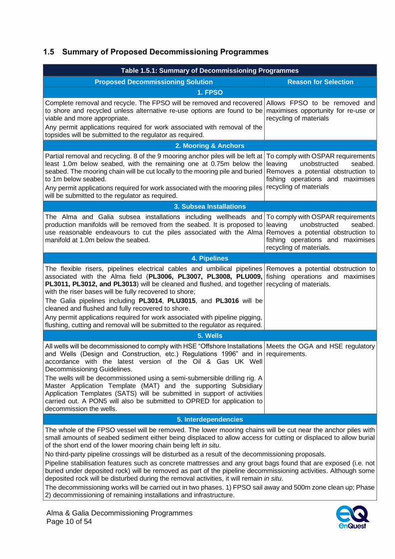
1.5 Summary of Proposed Decommissioning Programmes
Table 1.5.1: Summary of Decommissioning Programmes
Proposed Decommissioning Solution Reason for Selection
1. FPSO
Complete removal and recycle. The FPSO will be removed and recovered to shore and recycled unless alternative re-use options are found to be viable and more appropriate.
Any permit applications required for work associated with removal of the topsides will be submitted to the regulator as required.
Allows FPSO to be removed and maximises opportunity for re-use or recycling of materials
2. Mooring & Anchors
Partial removal and recycling. 8 of the 9 mooring anchor piles will be left at least 1.0m below seabed, with the remaining one at 0.75m below the seabed. The mooring chain will be cut locally to the mooring pile and buried to 1m below seabed.
Any permit applications required for work associated with the mooring piles will be submitted to the regulator as required.
To comply with OSPAR requirements leaving unobstructed seabed. Removes a potential obstruction to fishing operations and maximises recycling of materials
3. Subsea Installations
The Alma and Galia subsea installations including wellheads and production manifolds will be removed from the seabed. It is proposed to use reasonable endeavours to cut the piles associated with the Alma manifold at 1.0m below the seabed.
To comply with OSPAR requirements leaving unobstructed seabed. Removes a potential obstruction to fishing operations and maximises recycling of materials.
4. Pipelines
The flexible risers, pipelines electrical cables and umbilical pipelines associated with the Alma field (PL3006, PL3007, PL3008, PLU009, PL3011, PL3012, and PL3013) will be cleaned and flushed, and together with the riser bases will be fully recovered to shore;
The Galia pipelines including PL3014, PLU3015, and PL3016 will be cleaned and flushed and fully recovered to shore.
Any permit applications required for work associated with pipeline pigging, flushing, cutting and removal will be submitted to the regulator as required.
Removes a potential obstruction to fishing operations and maximises recycling of materials.
5. Wells
All wells will be decommissioned to comply with HSE “Offshore Installations and Wells (Design and Construction, etc.) Regulations 1996” and in accordance with the latest version of the Oil & Gas UK Well Decommissioning Guidelines.
The wells will be decommissioned using a semi-submersible drilling rig. A Master Application Template (MAT) and the supporting Subsidiary Application Templates (SATS) will be submitted in support of activities carried out. A PON5 will also be submitted to OPRED for application to decommission the wells.
Meets the OGA and HSE regulatory requirements.
5. Interdependencies
The whole of the FPSO vessel will be removed. The lower mooring chains will be cut near the anchor piles with small amounts of seabed sediment either being displaced to allow access for cutting or displaced to allow burial of the short end of the lower mooring chain being left in situ.
No third-party pipeline crossings will be disturbed as a result of the decommissioning proposals.
Pipeline stabilisation features such as concrete mattresses and any grout bags found that are exposed (i.e. not buried under deposited rock) will be removed as part of the pipeline decommissioning activities. Although some deposited rock will be disturbed during the removal activities, it will remain in situ.
The decommissioning works will be carried out in two phases. 1) FPSO sail away and 500m zone clean up; Phase 2) decommissioning of remaining installations and infrastructure.

Alma & Galia Decommissioning Programmes Page 11 of 54
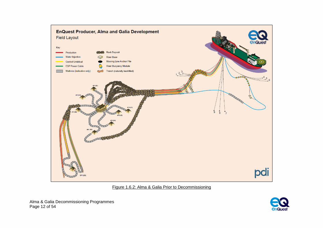
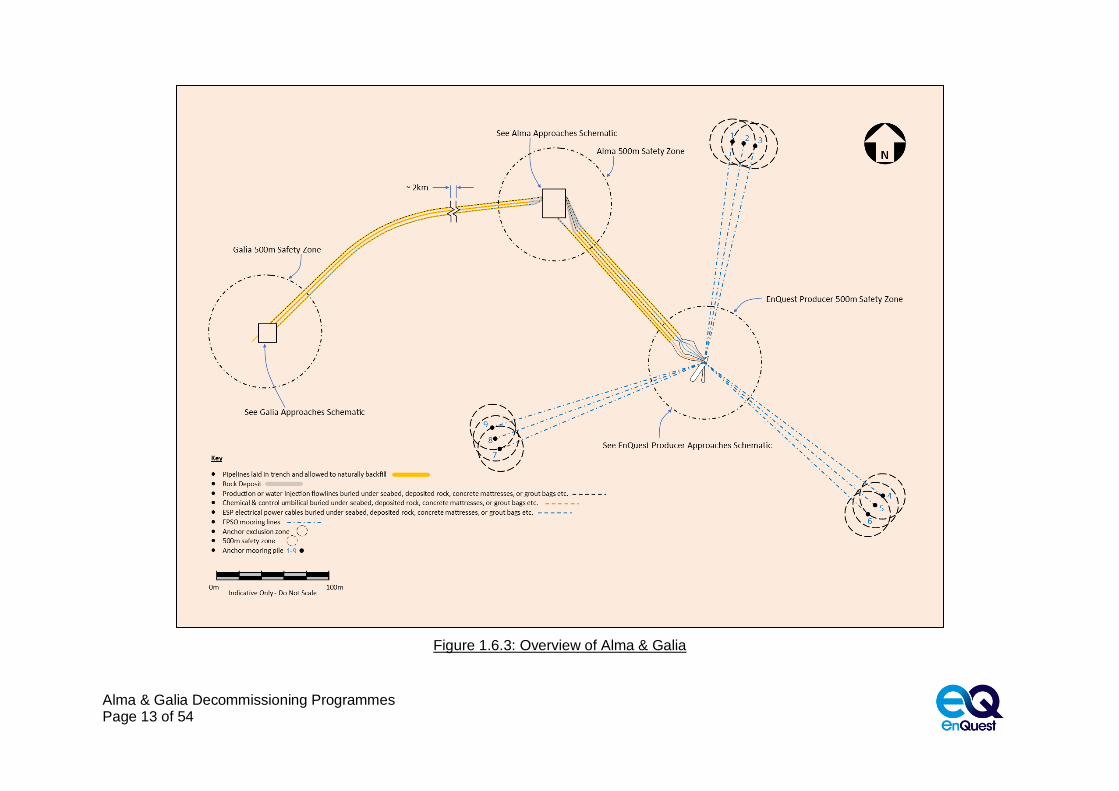
1.6 Field Locations including Field Layout and Adjacent Facilities
Figure 1.6.1: Alma & Galia Adjacent Facilities
Alma & Galia Decommissioning Programmes Page 12 of 54
Figure 1.6.2: Alma & Galia Prior to Decommissioning
Alma & Galia Decommissioning Programmes Page 13 of 54
Figure 1.6.3: Overview of Alma & Galia

Alma & Galia Decommissioning Programmes Page 14 of 54
Figure 1.6.4: Overview of EnQuest Producer Approach

Alma & Galia Decommissioning Programmes Page 15 of 54
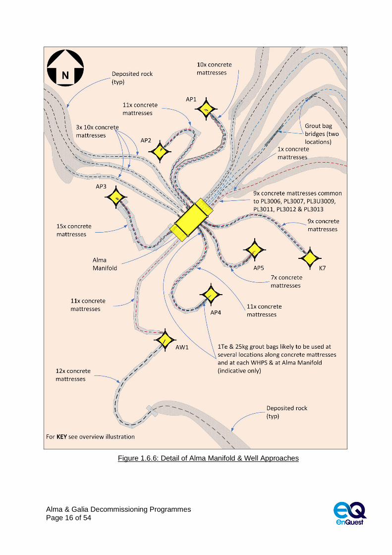
Figure 1.6.5: Overview of Alma Manifold & Well Approaches
Alma & Galia Decommissioning Programmes Page 16 of 54
Figure 1.6.6: Detail of Alma Manifold & Well Approaches

Alma & Galia Decommissioning Programmes Page 17 of 54
Figure 1.6.7: Overview of Galia Well Approaches
Alma & Galia Decommissioning Programmes Page 18 of 54
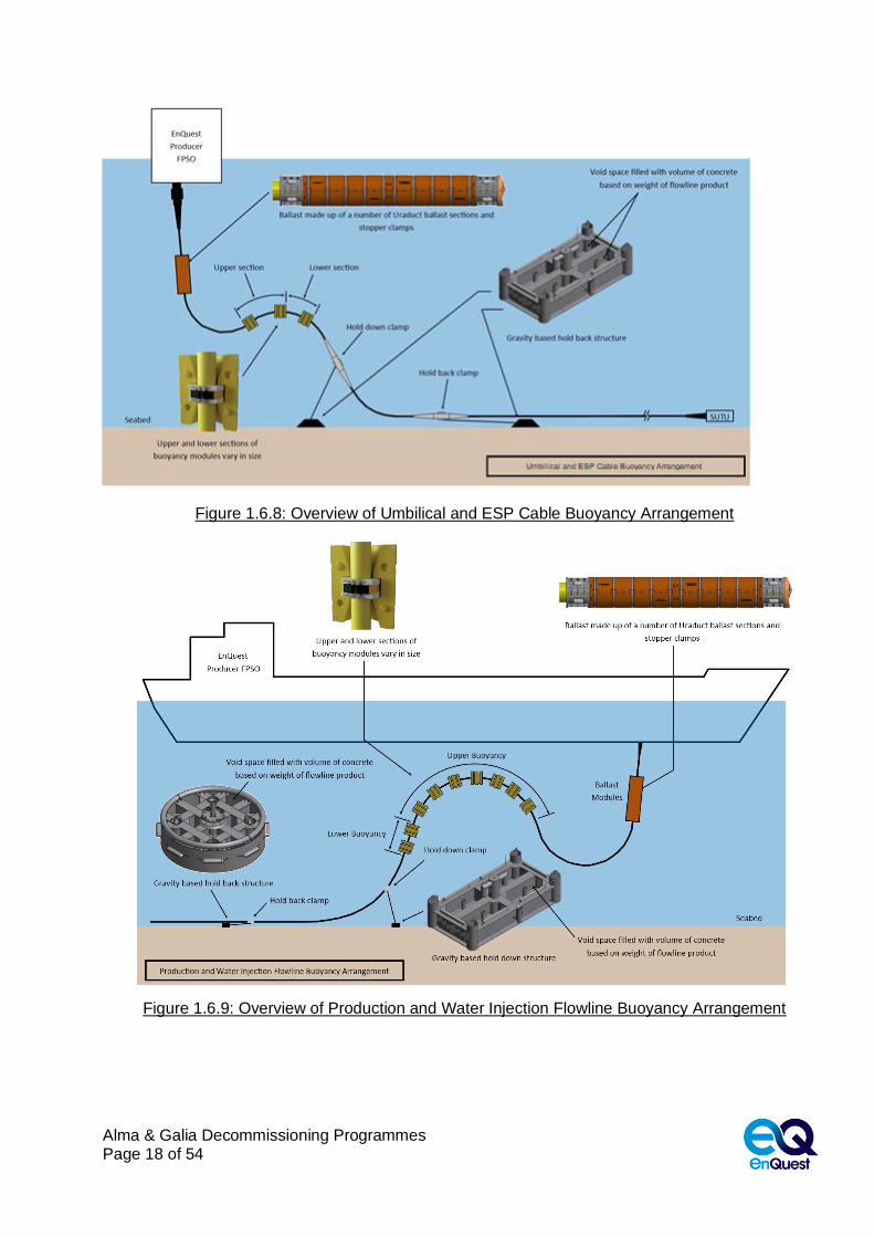
Figure 1.6.8: Overview of Umbilical and ESP Cable Buoyancy Arrangement
Figure 1.6.9: Overview of Production and Water Injection Flowline Buoyancy Arrangement
Alma & Galia Decommissioning Programmes Page 19 of 54
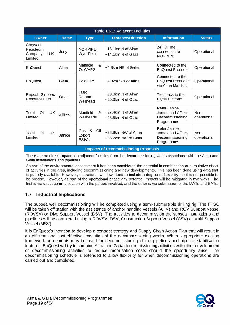
Table 1.6.1: Adjacent Facilities
Owner Name Type Distance/Direction Information Status
Chrysaor Petroleum Company U.K. Limited
Judy NORPIPE Wye Tie-In
~16.1km N of Alma
~14.1km N of Galia
24” Oil line connection to NORPIPE
Operational
EnQuest Alma Manifold & 7x WHPS
~4.8km NE of Galia Connected to the EnQuest Producer
Operational
EnQuest Galia 1x WHPS ~4.8km SW of Alma Connected to the EnQuest Producer via Alma Manifold
Operational
Repsol Sinopec Resources Ltd
Orion TOR Remote Wellhead
~29.8km N of Alma
~29.3km N of Galia
Tied back to the Clyde Platform
Operational
Total Oil UK Limited
Affleck Manifold & Wellheads
~27.4km N of Alma
~28.5km N of Galia
Refer Janice, James and Affleck Decommissioning Programmes
Non-operational
Total Oil UK Limited
Janice Gas & Oil Export SSIVs
~38.8km NW of Alma
~36.2km NW of Galia
Refer Janice, James and Affleck Decommissioning Programmes
Non-operational
Impacts of Decommissioning Proposals
There are no direct impacts on adjacent facilities from the decommissioning works associated with the Alma and Galia installations and pipelines.
As part of the environmental assessment it has been considered the potential in combination or cumulative effect of activities in the area, including decommissioning and new developments. This has been done using data that is publicly available. However, operational windows tend to include a degree of flexibility, so it is not possible to be precise. However, as part of the operational phase any potential impacts will be mitigated in two ways. The first is via direct communication with the parties involved, and the other is via submission of the MATs and SATs.
1.7 Industrial Implications
The subsea well decommissioning will be completed using a semi-submersible drilling rig. The FPSO will be taken off station with the assistance of anchor handing vessels (AHV) and ROV Support Vessel (ROVSV) or Dive Support Vessel (DSV). The activities to decommission the subsea installations and pipelines will be completed using a ROVSV, DSV, Construction Support Vessel (CSV) or Multi Support Vessel (MSV).
It is EnQuest’s intention to develop a contract strategy and Supply Chain Action Plan that will result in an efficient and cost-effective execution of the decommissioning works. Where appropriate existing framework agreements may be used for decommissioning of the pipelines and pipeline stabilisation features. EnQuest will try to combine Alma and Galia decommissioning activities with other development or decommissioning activities to reduce mobilisation costs should the opportunity arise. The decommissioning schedule is extended to allow flexibility for when decommissioning operations are carried out and completed.

Alma & Galia Decommissioning Programmes Page 20 of 54
2. DESCRIPTION OF ITEMS TO BE DECOMMISSIONED
2.1 Alma Installations: Surface Facilities
Table 2.1.1: Surface Facilities Information
Name Facility
Type Location
Topsides/ Facilities Mooring System
Weight (Te)
No of modules
Weight (Te)
Number of
mooring lines & piles
Weight of piles
(Te)
EnQuest Producer
FPSO
WGS84 Decimal
56.18587°N
2.78424°E
93,300 1 4,071.96 9 629.64 WGS84 Decimal Minute
56°11.1520''N
2°47.05464''E
2.2 Alma Installations: Subsea including Stabilisation Features
Table 2.2.1: Alma Subsea Facilities Information
Subsea Installations
Including Stabilisation
Features
Number Size / Weight (Te) Location Comments/
Status
FPSO mooring piles
9
AP1
63.36Te
WGS84 Decimal
56.20539°N
2.78949°E
Cluster 1, 84in diameter piled anchors, 32m long, AP2 & AP3 top of pile 1m below seabed. AP1 top of pile 0.75m below seabed
WGS84 Decimal Minute
56°12.32351N
2°47.36930E
AP2
63.36Te
WGS84 Decimal
56.20527°N
2.79116°E
WGS84 Decimal Minute
56°12.31593N
2°47.46939E
AP3
63.36Te
WGS84 Decimal
56.20508°N
2.792788°E
WGS84 Decimal Minute
56°12.30486N
2°47.56726E
AP4
79.2Te
WGS84 Decimal
56.17716°N
2.81113°E Cluster 2, 84in diameter piled anchors, 40m long, AP4 & AP5 top of pile 1m below seabed. AP6 top of pile 1.4m below seabed.
WGS84 Decimal Minute
56°10.62949N
2°48.66784E
AP5
79.2Te
WGS84 Decimal
56.17643°N
2.81011°E
WGS84 Decimal Minute
56°10.58557N
2°48.60664E

Alma & Galia Decommissioning Programmes Page 21 of 54
Table 2.2.1: Alma Subsea Facilities Information
Subsea Installations
Including Stabilisation
Features
Number Size / Weight (Te) Location Comments/
Status
AP6
79.2Te
WGS84 Decimal
56.17573°N
2.80901°E
WGS84 Decimal Minute
56°10.54376N
2°48.54086E
AP7
67.32Te
WGS84 Decimal
56.18080°N
2.75646°E
Cluster 3, 84in diameter piled anchors, 34m long, top of pile 1m below seabed
WGS84 Decimal Minute
56°10.84811N
2°45.38772E
AP8
67.32Te
WGS84 Decimal
56.18166°N
2.75587°E
WGS84 Decimal Minute
56°10.89936N
2°45.35212E
AP9
67.32Te
WGS84 Decimal
56.18254°N
2.75533°E
WGS84 Decimal Minute
56°10.95269N
2°45.31956E
Mooring lines 9
Length - 1980m (each)
Weight – 4,071.96Te
(452.44Te each)
Top chain 142mm dia. studlink 700m long
Sheathed Spiral Strand Rope 1150m long
Bottom chain 142mm dia. studlink 130m long
Connected to anchor piles
Xmas trees & protection structures
7
AP1 (K3)
9.2x8.8x6.7m
55.9Te
WGS84 Decimal
56.198792°N
2.762797°E Includes weight of protection structure WGS84
Decimal Minute
56°11.92752N
2°45.76782E
AP2 (K5)
9.2x8.8x6.7m
55.9Te
WGS84 Decimal
56.198608°N
2.76245°E Includes weight of protection structure WGS84
Decimal Minute
56°11.91648N
2°45.747E
AP3 (K4)
9.2x8.8x6.7m
55.9Te
WGS84 Decimal
56.198417°N
2.762114°E Includes weight of protection structure WGS84
Decimal Minute
56°11.90502N
2°45.72684E
AP4 (K1)
9.2x8.8x6.7m
55.9Te
WGS84 Decimal
56.198014°N
2.76285°E Includes weight of protection structure WGS84
Decimal Minute
56°11.88084°N
2°45.771°E

Alma & Galia Decommissioning Programmes Page 22 of 54
Table 2.2.1: Alma Subsea Facilities Information
Subsea Installations
Including Stabilisation
Features
Number Size / Weight (Te) Location Comments/
Status
AP5 (K2)
9.2x8.8x6.7m
55.9Te
WGS84 Decimal
56.198203°N
2.763181°E Includes weight of protection structure WGS84
Decimal Minute
56°11.89218°N
2°45.79086°E
AP6 (K7)
9.2x8.8x6.7m
55.9Te
WGS84 Decimal
56.198342°N
2.762703°E Includes weight of protection structure WGS84
Decimal Minute
56°11.9005N
2°45.7622E
AW1
9.2x8.8x6.7m
55.9Te
WGS84 Decimal
56.197922°N
2.762503°E Includes weight of protection structure WGS84
Decimal Minute
56°11.87532°N
2°45.75018°E
Manifold 1
17.2x9.4x5.0m
186.0Te
4x. 0.61m dia. Piles
22.0Te
WGS84 Decimal
56.198342°N
2.762703°E
Secured with four steel piles, 0.61m dia. x 14.65m long x 5.5 Te each
WGS84 Decimal Minute
56°11.90052N
2°45.76218E
Concrete mattresses
n/a n/a n/a n/a n/a
Grout bags n/a n/a n/a n/a n/a
Formwork n/a n/a n/a n/a n/a
Deposited rock n/a n/a n/a n/a n/a
Other n/a n/a n/a n/a n/a

Alma & Galia Decommissioning Programmes Page 23 of 54
2.3 Alma Pipelines including Stabilisation Features
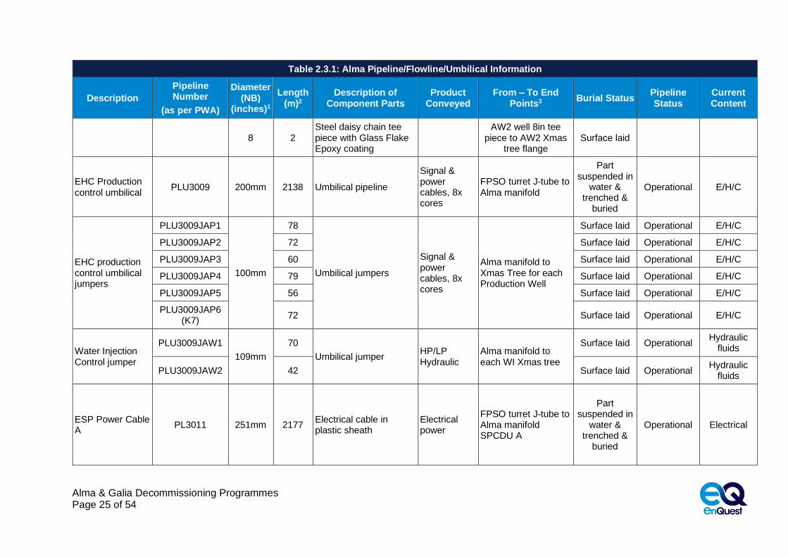
Table 2.3.1: Alma Pipeline/Flowline/Umbilical Information
Description
Pipeline Number
(as per PWA)
Diameter (NB)
(inches)1
Length (m)2
Description of Component Parts
Product Conveyed
From – To End Points3
Burial Status Pipeline Status
Current Content
P1 Production Flowline / Hot Tap Tee / Production Riser
PL3006
10 1848 Flexible flowline Kynar® PVDF/HDPE Yellow
Produced Crude Oil
Alma manifold flange to hot tap tee tie-in flange
Trenched & buried
Operational Produced Crude Oil
10 5 Steel pipe with Glass Flake Epoxy coating
Hot tap tee to topside tie-in flange
Surface laid
8 355 Flexible riser Kynar® PVDF/PA12 Black Mix
Hot tap tee 10in Production to topsides tie-in flange
Surface laid or suspended
in water
Pipe spool
PL3006JAP1 6
25 Steel pipe with Glass Flake Epoxy coating Produced
Crude Oil
Xmas tree flange to Alma manifold flange at each well
Surface laid
Operational Produced Crude Oil Flexible
production jumper 61.8
Flexible jumper Kynar® PVDF/HDPE Yellow
Surface laid
Pipe pool
PL3006JAP2 6
25 Steel pipe with Glass Flake Epoxy coating Produced
Crude Oil
Surface laid
Operational Produced Crude Oil Flexible
production jumper 57.6
Flexible jumper Kynar® PVDF/HDPE Yellow
Surface laid
Pipe spool
PL3006JAP3 6
25 Steel pipe with Glass Flake Epoxy coating Produced
Crude Oil
Surface laid
Operational Produced Crude Oil Flexible
production jumper 44.7
Flexible jumper Kynar® PVDF/HDPE Yellow
Surface laid
Pipe spool
PL3006JAP4 6
25 Steel pipe with Glass Flake Epoxy coating Produced
Crude Oil
Xmas tree flange to Alma manifold flange at each well
Surface laid
Operational Produced Crude Oil Flexible
production jumper 64
Flexible jumper Kynar® PVDF/HDPE Yellow
Surface laid

Alma & Galia Decommissioning Programmes Page 24 of 54
Table 2.3.1: Alma Pipeline/Flowline/Umbilical Information
Description
Pipeline Number
(as per PWA)
Diameter (NB)
(inches)1
Length (m)2
Description of Component Parts
Product Conveyed
From – To End Points3
Burial Status Pipeline Status
Current Content
Pipe spool
PL3006JAP5 6
25 Steel pipe with Glass Flake Epoxy coating Produced
Crude Oil
Surface laid
Operational Produced Crude Oil Flexible
production jumper 40
Flexible jumper Kynar® PVDF/HDPE Yellow
Surface laid
Pipe spool PL3006JAP6
(K7) 6
25 Steel pipe with Glass Flake Epoxy coating Produced
Crude Oil
Surface laid
Operational Produced Crude Oil Flexible
production jumper 57
Flexible jumper Kynar® PVDF/HDPE Yellow
Surface laid
P2 Production riser / flowline
PL3007
10 1799 Flexible flowline Kynar® PVDF/HDPE Yellow
Produced Crude Oil
Alma manifold flange to hot tap tee tie-in flange
Trenched & buried with exposures
Operational Produced Crude Oil
10 5 Steel pipe with Glass Flake Epoxy coating
Hot tap tee to topside tie-in flange
Surface laid
8 352 Flexible riser Kynar® PVDF/PA12 Black Mix
Hot tap tee 10in production to topsides tie-in flange
Surface laid or suspended
in water
Water injection riser & flowline
PL3008
8 343 Flexible riser PA12 Natural/PA12 Black Mix
Treated water
FPSO Turret J-tube to 8in WIF tie-in flange
Surface laid or suspended
in water
Operational Treated water
8 2111 Flexible flowline Nylon PA12 /HDPE Yellow
8in WIF tie-in flange to AW1 well 8in tee piece
Trenched & buried with exposures
8 2 Steel daisy chain tee piece with Glass Flake Epoxy coating
AW1 8in tee piece to AW1 Xmas tree flange
Surface laid
Water injection flowline jumper.
PL3008JAW2 8 52 Flexible flowline Kynar® PVDF/HDPE Yellow
Treated water
AW1 8in tee piece to AW2 8in tee piece
Surface laid Operational Treated water
Alma & Galia Decommissioning Programmes Page 25 of 54
Table 2.3.1: Alma Pipeline/Flowline/Umbilical Information
Description
Pipeline Number
(as per PWA)
Diameter (NB)
(inches)1
Length (m)2
Description of Component Parts
Product Conveyed
From – To End Points3
Burial Status Pipeline Status
Current Content
8 2 Steel daisy chain tee piece with Glass Flake Epoxy coating
AW2 well 8in tee piece to AW2 Xmas
tree flange Surface laid
EHC Production control umbilical
PLU3009 200mm 2138 Umbilical pipeline
Signal & power cables, 8x cores
FPSO turret J-tube to Alma manifold
Part suspended in
water & trenched &
buried
Operational E/H/C
EHC production control umbilical jumpers
PLU3009JAP1
100mm
78
Umbilical jumpers
Signal & power cables, 8x cores
Alma manifold to Xmas Tree for each Production Well
Surface laid Operational E/H/C
PLU3009JAP2 72 Surface laid Operational E/H/C
PLU3009JAP3 60 Surface laid Operational E/H/C
PLU3009JAP4 79 Surface laid Operational E/H/C
PLU3009JAP5 56 Surface laid Operational E/H/C
PLU3009JAP6 (K7)
72 Surface laid Operational E/H/C
Water Injection Control jumper
PLU3009JAW1
109mm
70
Umbilical jumper HP/LP Hydraulic
Alma manifold to each WI Xmas tree
Surface laid Operational Hydraulic
fluids
PLU3009JAW2 42 Surface laid Operational Hydraulic
fluids
ESP Power Cable A
PL3011 251mm 2177 Electrical cable in plastic sheath
Electrical power
FPSO turret J-tube to Alma manifold SPCDU A
Part suspended in
water & trenched &
buried
Operational Electrical

Alma & Galia Decommissioning Programmes Page 26 of 54
Table 2.3.1: Alma Pipeline/Flowline/Umbilical Information
Description
Pipeline Number
(as per PWA)
Diameter (NB)
(inches)1
Length (m)2
Description of Component Parts
Product Conveyed
From – To End Points3
Burial Status Pipeline Status
Current Content
ESP power cable jumpers
PLU3011JAP1
54mm
2x75
Electrical cable in plastic sheath
Electrical power
Alma manifold SPCDU to Xmas tree for each well
Surface laid Operational Electrical
PLU3011JAP2 2x74 Surface laid Operational Electrical
PLU3011JAP3 2x68 Surface laid Operational Electrical
PLU3011JAP4 2x83 Surface laid Operational Electrical
PLU3011JAP5 2x59 Surface laid Operational Electrical
PLU3011JAP6 (K7)
2x76 Surface laid Operational Electrical
ESP Power Cable B
PL3012 251mm 2150 Electrical cable in plastic sheath
Electrical power
FPSO turret J-tube to Alma manifold SPCDU B
Part suspended in
water & trenched &
buried
Operational Electrical
ESP Power Cable C
PL3013 251mm 2135 Electrical cable in plastic sheath
Electrical power
FPSO turret J-tube to Alma manifold SPCDU C
Part suspended in
water & trenched &
buried
Operational Electrical
NOTES
1. If diameter is expressed in mm it refers to outside diameter of electrical cable or umbilical pipeline;
2. Final pipeline lengths are as-built lengths and as such may vary slightly from lengths detailed within the PWAs;
3. The description of the End to End Points may differ slightly from those consented. Where appropriate, any affected PWAs will be updated.
Alma & Galia Decommissioning Programmes Page 27 of 54
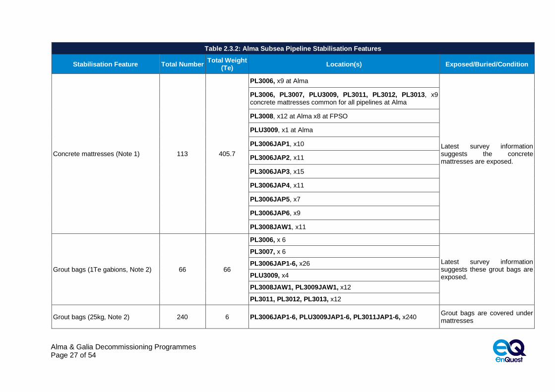
Table 2.3.2: Alma Subsea Pipeline Stabilisation Features
Stabilisation Feature Total Number Total Weight
(Te) Location(s) Exposed/Buried/Condition
Concrete mattresses (Note 1) 113 405.7
PL3006, x9 at Alma
Latest survey information suggests the concrete mattresses are exposed.
PL3006, PL3007, PLU3009, PL3011, PL3012, PL3013, x9 concrete mattresses common for all pipelines at Alma
PL3008, x12 at Alma x8 at FPSO
PLU3009, x1 at Alma
PL3006JAP1, x10
PL3006JAP2, x11
PL3006JAP3, x15
PL3006JAP4, x11
PL3006JAP5, x7
PL3006JAP6, x9
PL3008JAW1, x11
Grout bags (1Te gabions, Note 2) 66 66
PL3006, x 6
Latest survey information suggests these grout bags are exposed.
PL3007, x 6
PL3006JAP1-6, x26
PLU3009, x4
PL3008JAW1, PL3009JAW1, x12
PL3011, PL3012, PL3013, x12
Grout bags (25kg, Note 2) 240 6 PL3006JAP1-6, PLU3009JAP1-6, PL3011JAP1-6, x240 Grout bags are covered under mattresses

Alma & Galia Decommissioning Programmes Page 28 of 54
Table 2.3.2: Alma Subsea Pipeline Stabilisation Features
Stabilisation Feature Total Number Total Weight
(Te) Location(s) Exposed/Buried/Condition
Deposited Rock (Note 4) n/a 16,692
PL3006, 3,468Te
Latest survey information would suggest that the deposited rock is exposed (buried under a light covering of seabed sediment.
PL3007, 2,839Te
PL3008, 1,051Te
PLU3009, 2,481Te
PL3011, PL3012, PL3013, 6,853Te
Riser ballast modules 342 half shells
58 clamps 96.6
PL3006 13.7Te ballast (50 half shells & 10 clamps)
Connected to risers
PL3007 13.7Te ballast (50 half shells & 10 clamps)
PL3008 12.3Te ballast (50 half shells & 10 clamps)
PLU3009 10.1Te ballast (48 half shells & 7 clamps)
PL3011 15.6Te ballast (48 half shells & 7 clamps)
PL3012 15.6Te ballast (48 half shells & 7 clamps)
PL3013 15.6Te ballast (48 half shells & 7 clamps)
Riser buoyancy modules 99 Upper
67 Lower 103.3
PL3006 6.7Te upper (14) 7.0Te lower (9)
Connected to risers
PL3007 6.7Te upper (14) 7.0Te lower (9)
PL3008 6.6Te upper (14) 5.7Te lower (9)
PLU3009 6.2Te upper (15) 7.3Te lower (10)
PL3011 7.9Te upper (14) 8.7Te lower (10)
PL3012 7.9Te upper (14) 8.7Te lower (10)
PL3013 7.9Te upper (14) 8.7Te lower (10)

Alma & Galia Decommissioning Programmes Page 29 of 54
Table 2.3.2: Alma Subsea Pipeline Stabilisation Features
Stabilisation Feature Total Number Total Weight
(Te) Location(s) Exposed/Buried/Condition
Riser Bases
Flexible riser hold down (5.8 x 3.3 x 2.1m), 54.1Te
Umbilical & ESP power cable hold back (6.0 x 2.8 x 1.2m), 55.5Te
Flexible riser hold back (Ø4.9 x 1.4m), 55.7Te
ESP power cable hold back (5.5 x 2.8 x 1.8m), 88.7Te
Umbilical holdback (5.5 x 2.8 x 1.8m), 60.1Te
7 Hold Down Structures
877.6
PL3006 54.1Te
Gravity based structures
P3007 54.1Te
PL3008 54.1Te
PLU3009 55.5Te
PL3011 55.5Te
PL3012 55.5Te
PL3013 55.5Te
7 Hold Back Structures
PL3006 55.7Te
P3007 55.7Te
PL3008 55.7Te
PLU3009 60.1Te
PL3011 88.7Te
PL3012 88.7Te
PL3013 88.7Te
Fronded Mats n/a n/a n/a n/a
Other (describe briefly) n/a n/a n/a n/a
NOTES
1. Concrete mattresses are ‘Pipeshield’ Type 1: 6m x 3m x 0.15m c/w 16mm diameter polypropylene rope; Approx. weight each mattress 3.59Te;
2. The quantity of 1Te and 25kg grout bags is based on design information and deposit consents and so the quantities should be considered indicative only, as they are not ‘as-built’;
3. All JAP6 related jumpers connect to well K7;
4. The quantity of deposited rock may differ from that described on the original PWA application; the quantities quoted here are based on ‘as-built’ data.

Alma & Galia Decommissioning Programmes Page 30 of 54
2.4 Alma Wells
Table 2.4.1: Alma Well Information
WelI ID Designation Status Category of Well
30/24c-K1 Oil production In Service SS-3-1-1
30/24c-K2 Oil production In Service SS-3-1-1
30/24c-K3 Oil production In Service SS-3-1-1
30/24c-K4 Oil production In Service SS-3-1-1
30/24c-K5 Oil production In Service SS-3-1-1
30/24c-K6 Oil production Partially decommissioned SS-0-1-1
30/24c-K7 Oil production In Service SS-3-1-1
30/24c-W1 Water injection Shut In SS-2-1-1
For details of well categorisation please refer the latest version of the Oil & Gas UK Guidelines for the Decommissioning of Wells.
2.5 Alma Drill Cuttings
Table 2.5.1: Alma Drill Cutting(s) Pile Information
Location of Pile Centre Seabed Area (m2) Estimated Volume of drill
Cuttings (m3)
These wells were drilled after changes to legislation, so no drill cuttings piles exist at Alma
n/a n/a
2.6 Alma Inventory Estimates
Figure 2.6.1: Pie-Chart of Material Inventory for Alma Installations

Alma & Galia Decommissioning Programmes Page 31 of 54
Figure 2.6.2: Pie-Chart of Material Inventory for Alma Pipelines
Refer to section 2.4 of the Environmental Appraisal [2] for further details.
2.7 Galia Installations: Subsea including Stabilisation Features
Table 2.7.1: Galia Subsea Facilities Information
Subsea Installations
Including Stabilisation
Features
Number Size / Weight
(Te) Location Comments/ Status
Xmas trees & protection structures
1
GP1
9.2x8.8x6.7m
55.9Te
WGS84 Decimal
56.1558°N
2.688786°E Includes weight of protection structure WGS84
Decimal Minute
56°9.348N
2°41.32716E
Concrete mattresses
n/a n/a n/a n/a n/a
Grout bags n/a n/a n/a n/a n/a
Formwork n/a n/a n/a n/a n/a
Deposited rock n/a n/a n/a n/a n/a
Other n/a n/a n/a n/a n/a

Alma & Galia Decommissioning Programmes Page 32 of 54
2.8 Galia Pipelines including Stabilisation Features
Table 2.8.1: Galia Pipeline/Flowline/Umbilical Information
Description
Pipeline Number
(as per PWA)
Diameter (NB)
(inches)
Length (m)
Description of Component Parts
Product Conveyed
From – To End Points3 Burial Status
Pipeline Status
Current Content
GP1 Production Flowline
PL3014
8 1 Split gate valve with DBB
Produced Crude Oil
Future tie-in valve to GP1 flowline tee
Surface laid
Operational Produced Crude Oil
6 4 Steel pipe with Glass Flake Epoxy coating
GP1 Xmas tree flange to 8” flexible production flowline
Surface laid
8 5134 Flexible flowline Kynar® PVDF/HDPE Yellow
Hot tap tee 10in Production to topsides tie-in flange
Trenched & buried
Production control umbilical
PLU3015 200mm
8 Umbilical pipeline Signal & power cables, 8x cores, LP/HP hydraulic
GP1 Xmas tree to SUTU on GP1 Xmas tree
Surface laid
Operational E/H/C
5060 Kynar® PVDF/HDPE Yellow
SUTU on GP1 Xmas tree to SUTU on Alma manifold
Trenched & buried
ESP power cable & jumpers
PL3016 (1) 54mm 8
Electrical cable in plastic sheath
Electrical power
GP1 Xmas tree to SPCDU SP01, SP02
Surface laid
Operational Electrical
power
PL3016 (2) 54mm
PL3016 (3) 145mm 5050 GP1 SPCDU to Galia SPCDU
Trenched & buried
PL3016 (4) 54mm 20
Galia SPCDU to Alma manifold SPCDU (A, B or C)
Surface laid PL3016 (5) 54mm
NOTES
1. If diameter is expressed in mm it refers to outside diameter of electrical cable or umbilical pipeline;
2. Final pipeline lengths are as-built lengths and as such may vary slightly from lengths detailed within the PWAs;
3. The description of the End to End Points may differ slightly from those consented. Where appropriate, any affected PWAs will be updated.
Alma & Galia Decommissioning Programmes Page 33 of 54
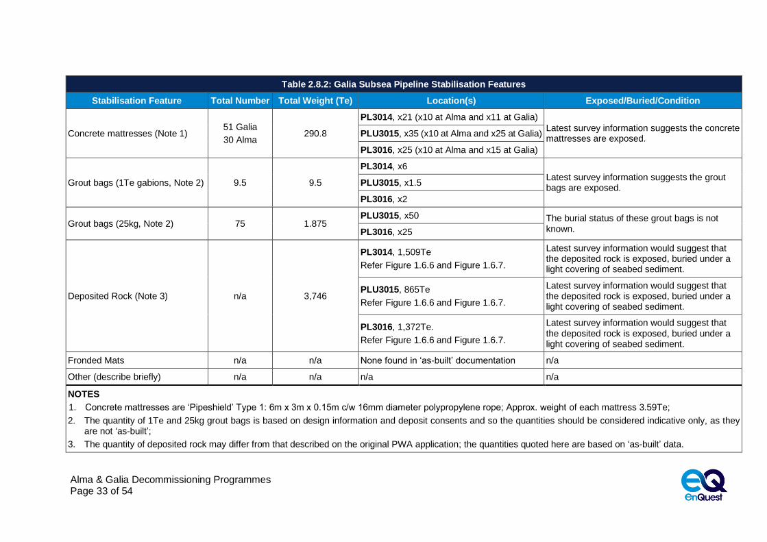
Table 2.8.2: Galia Subsea Pipeline Stabilisation Features
Stabilisation Feature Total Number Total Weight (Te) Location(s) Exposed/Buried/Condition
Concrete mattresses (Note 1) 51 Galia
30 Alma 290.8
PL3014, x21 (x10 at Alma and x11 at Galia)
Latest survey information suggests the concrete mattresses are exposed.
PLU3015, x35 (x10 at Alma and x25 at Galia)
PL3016, x25 (x10 at Alma and x15 at Galia)
Grout bags (1Te gabions, Note 2) 9.5 9.5
PL3014, x6
Latest survey information suggests the grout bags are exposed.
PLU3015, x1.5
PL3016, x2
Grout bags (25kg, Note 2) 75 1.875 PLU3015, x50 The burial status of these grout bags is not
known. PL3016, x25
Deposited Rock (Note 3) n/a 3,746
PL3014, 1,509Te
Refer Figure 1.6.6 and Figure 1.6.7.
Latest survey information would suggest that the deposited rock is exposed, buried under a light covering of seabed sediment.
PLU3015, 865Te
Refer Figure 1.6.6 and Figure 1.6.7.
Latest survey information would suggest that the deposited rock is exposed, buried under a light covering of seabed sediment.
PL3016, 1,372Te.
Refer Figure 1.6.6 and Figure 1.6.7.
Latest survey information would suggest that the deposited rock is exposed, buried under a light covering of seabed sediment.
Fronded Mats n/a n/a None found in ‘as-built’ documentation n/a
Other (describe briefly) n/a n/a n/a n/a
NOTES
1. Concrete mattresses are ‘Pipeshield’ Type 1: 6m x 3m x 0.15m c/w 16mm diameter polypropylene rope; Approx. weight of each mattress 3.59Te;
2. The quantity of 1Te and 25kg grout bags is based on design information and deposit consents and so the quantities should be considered indicative only, as they are not ‘as-built’;
3. The quantity of deposited rock may differ from that described on the original PWA application; the quantities quoted here are based on ‘as-built’ data.
Alma & Galia Decommissioning Programmes Page 34 of 54
2.9 Galia Wells
Table 2.9.1: Galia Well Information
WelI ID Designation Status Category of Well
30/24c-G1 Oil production In Service SS-3-1-1
For details of well categorisation please refer the latest version of the Oil & Gas UK Guidelines for the Decommissioning of Wells.
2.10 Galia Drill Cuttings
Table 2.10.1: Galia Drill Cutting(s) Pile Information
Location of Pile Centre Seabed Area (m2) Estimated Volume of drill
Cuttings (m3)
These wells were drilled after changes to legislation so no drill cuttings pile exists at Galia
n/a n/a
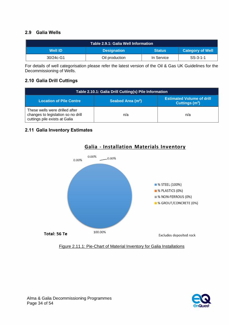
2.11 Galia Inventory Estimates
Figure 2.11.1: Pie-Chart of Material Inventory for Galia Installations

Alma & Galia Decommissioning Programmes Page 35 of 54
Figure 2.11.2: Pie Chart of Material Inventory for Galia Pipelines
Refer to section 2.4 of the Environmental Appraisal [2] for further details.

Alma & Galia Decommissioning Programmes Page 36 of 54
3. REMOVAL AND DISPOSAL METHODS
Waste will be dealt with in accordance with the Waste Framework Directive. The re-use of an installation, pipeline, umbilical pipeline or cable – or parts thereof, is first in the order of preferred decommissioning options. Options for re-use of an installation, pipeline, umbilical pipeline or cable – or parts thereof are currently under investigation. Waste generated during decommissioning will be segregated by type and periodically transported to shore in an auditable manner through licensed waste contractors. Steel and other recyclable metals are estimated to account for the greatest proportion of the materials inventory. Refer to Section 2.4 of the Environmental Appraisal [2] for further details concerning the disposal of waste.
3.1 Installations - Surface Facilities, FPSO
The FPSO will be towed from the field to a suitable quayside for preparation for re-use or decommissioning, the fate of which will be determined by the owner. The owner will be responsible for taking reasonable measures to assure itself that proposals to re-use the vessel will be credible, and that disposal of the FPSO will be in compliance with the IMO Hong Kong International Convention for the Safe and Environmentally Sound Recycling of Ships.
Preparation and cleaning: The methods that will be used to vent and purge the FPSO prior to removal to shore are summarised in Table 3.1.1.
Table 3.1.1: Cleaning of FPSO for removal
Waste type Composition of Waste Disposal Route
On-board hydrocarbons Full recovery Where possible, on-board hydrocarbons will be evacuated to tanker with residual materials being pumped into a donor well. Should this approach be unsuccessful, on-board hydrocarbons will be returned to shore for separation and use.
Other hazardous materials The presence of NORM will be identified.
NORM, if present, will be disposed of in accordance with the appropriate permit.
Table 3.1.2: Topside Removal Methods
1) Semi-Submersible Crane Vessel ; 2) Monohull Crane Vessel ; 3) Shear Leg Vessel ; 4) Jack up Work barge ; 5) Piece small or large ; 6) Complete with jacket ; 7) Other
Method Description
Proposed removal method and disposal route
The FPSO will be released from its moorings after all risers, flowlines and jumpers having been cleaned, flushed, cut and removed. The FPSO will then be towed to a suitable quayside where it will be refurbished for re-use or to an alternative location at a licensed facility to be decommissioned.
The opportunities for re-use are still to be confirmed.
A final decision on any decommissioning activities will be made following a commercial tendering process.

Alma & Galia Decommissioning Programmes Page 37 of 54
3.2 Installations - Subsea Facilities & Stabilisation Features
Table 3.2.1: Subsea Installations & Stabilisation Features
Subsea installations and stabilisation features
Number Option
Disposal Route (if applicable)
FPSO mooring piles 9 Leave in situ2 n/a
Mooring lines 9 Complete recovery with exception of a short section of buried chain (3x22.5m, 3x39.0m, 3x14.5m) that will be cut and left in situ.
Return to shore for re-use or recycling.
Xmas trees & protection structures
8 Complete recovery Return to shore for re-use or recycling
Manifold 1 Complete recovery. Piles will be severed at 1.0m below seabed.3
3.3 Pipelines, Umbilicals and Cables
*Key to options:
1. Complete removal – This involves the complete removal of the pipelines by whatever means would be most practicable and acceptable from a technical perspective;
2. Partial removal – This will involve removing exposed, poorly buried or potentially unstable sections of pipelines. Necessary remedial work will be carried out to make the remaining pipeline safe for leaving the remainder in situ; Please note, this option is only relevant for those pipelines that have known exposures, either because of upheaval buckling or because of poor depth of cover. There will likely be a need to verify their status via future surveys;
3. Leave in situ – This involves leaving the pipeline in situ with no remedial works but possibly needing to verify their status via future surveys.
Table 3.3.1: Pipeline or Pipeline Groups Decommissioning Options
Pipeline or Group Condition of line/group (Surface laid/Trenched/
Buried/ Spanning)
Whole or part of pipeline/group
Decommissioning options considered
Alma Pipelines
PL3006, PL3006JAP1-6
Flowline trenched and buried, riser suspended in water, pipe spools and jumpers are surface laid
8in Riser, 10in flowline, & associated 6in pipe spools & jumpers
1 (Riser)
1 & 3 (Flowline)
1 (Pipe spools & jumpers)
PL3007 Flowline trenched and buried with exposures, riser suspended in water
8in Riser, 10in flowline
1 (Riser)
1 & 3 (Flowline)
PL3008, PL3008JAW2
Water injection flowline trenched and buried with exposures, riser suspended in water, jumpers are surface laid
8in riser, 8in flowline, 8in jumper
1 (Riser)
1 & 3 (Flowline)
1 (Pipe spools & jumpers)
PLU3009, PLU3009JAP1-6, PLU3009JAW1-2
Umbilical pipeline trenched and buried, and part suspended in
Umbilical pipeline and associated electrical and hydraulic jumpers
1 & 2 (umbilical)
1 (umbilical jumpers)
2 This option was determined as a result of a comparative assessment. Given the stability of the seabed, the mooring piles will remain sufficiently buried with no intervention required; 3 Given the stability of the seabed the top of the piles will remain sufficiently buried.

Alma & Galia Decommissioning Programmes Page 38 of 54
Table 3.3.1: Pipeline or Pipeline Groups Decommissioning Options
Pipeline or Group Condition of line/group (Surface laid/Trenched/
Buried/ Spanning)
Whole or part of pipeline/group
Decommissioning options considered
water, umbilical jumpers are surface laid
PL3011, PL3011JAP1-6
Electrical power cable part suspended in water, part trenched and buried with short exposure, electrical jumpers are surface laid
Electrical power cable and associated jumpers
1, 2 & 3 (electrical power cable);
1 (electrical jumpers)
PL3012 Electrical power cable part suspended in water, part trenched and buried with short exposures
Electrical power cable 1, section suspended in water;
1, 2 & 3
PL3013 Electrical power cable part suspended in water, part trenched and buried with short exposures
Electrical power cable 1, section suspended in water;
1, 2 & 3
Galia Pipelines
PL3014 Flowline trenched and buried with exposures, pipe spools and valves at ends
Flowline and associated pipe spools and valves
1, 2 & 3 (flowline)
1 (pipe spools & valves)
PLU3015 Umbilical pipeline trenched and buried
Umbilical pipeline and umbilical jumper
1 & 3 (umbilical pipeline)
1 (umbilical jumpers)
PL3016 Electrical jumpers on GP1 tree and at Alma manifold, electrical cable trenched and buried,
Electrical cable and electrical jumpers
1 & 3 (Electrical cable)
1 (Electrical jumpers)
All surface laid equipment including flexible flowlines, risers that have not been trenched or buried will be completely recovered from the seabed and taken to shore for re-use or recycling or final disposal.
A comparative assessment of the decommissioning options was performed where each decommissioning option was qualitatively assessed against Safety, Environment, Technical and Societal Impact and Cost. Refer [1] for details.
3.3.1 Outcome of Comparative Assessment
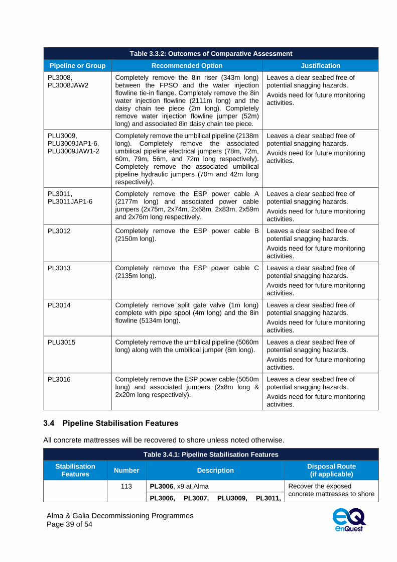
Table 3.3.2: Outcomes of Comparative Assessment
Pipeline or Group Recommended Option Justification
PL3006, PL3006JAP1-6
Completely remove the 8in riser (355m long) between the FPSO and the hot tap tee riser flange. Completely remove the 10in hot-tap tee (5m long), the 10in flowline (1848m long), pipe spools (6x25m long) and 6x6in jumpers (61.8m, 57.6m, 44.7m, 64m, 40m and 57m long respectively).
Leaves a clear seabed free of potential snagging hazards.
Avoids need for future monitoring activities.
PL3007 Completely remove the riser (352m long) between the FPSO and the hot tap tee riser flange. Completely remove the hot-tap tee (5m long) and 10in flowline (1799m long).
Leaves a clear seabed free of potential snagging hazards.
Avoids need for future monitoring activities.
Alma & Galia Decommissioning Programmes Page 39 of 54
Table 3.3.2: Outcomes of Comparative Assessment
Pipeline or Group Recommended Option Justification
PL3008, PL3008JAW2
Completely remove the 8in riser (343m long) between the FPSO and the water injection flowline tie-in flange. Completely remove the 8in water injection flowline (2111m long) and the daisy chain tee piece (2m long). Completely remove water injection flowline jumper (52m) long) and associated 8in daisy chain tee piece.
Leaves a clear seabed free of potential snagging hazards.
Avoids need for future monitoring activities.
PLU3009, PLU3009JAP1-6, PLU3009JAW1-2
Completely remove the umbilical pipeline (2138m long). Completely remove the associated umbilical pipeline electrical jumpers (78m, 72m, 60m, 79m, 56m, and 72m long respectively). Completely remove the associated umbilical pipeline hydraulic jumpers (70m and 42m long respectively).
Leaves a clear seabed free of potential snagging hazards.
Avoids need for future monitoring activities.
PL3011, PL3011JAP1-6
Completely remove the ESP power cable A (2177m long) and associated power cable jumpers (2x75m, 2x74m, 2x68m, 2x83m, 2x59m and 2x76m long respectively.
Leaves a clear seabed free of potential snagging hazards.
Avoids need for future monitoring activities.
PL3012 Completely remove the ESP power cable B (2150m long).
Leaves a clear seabed free of potential snagging hazards.
Avoids need for future monitoring activities.
PL3013 Completely remove the ESP power cable C (2135m long).
Leaves a clear seabed free of potential snagging hazards.
Avoids need for future monitoring activities.
PL3014 Completely remove split gate valve (1m long) complete with pipe spool (4m long) and the 8in flowline (5134m long).
Leaves a clear seabed free of potential snagging hazards.
Avoids need for future monitoring activities.
PLU3015 Completely remove the umbilical pipeline (5060m long) along with the umbilical jumper (8m long).
Leaves a clear seabed free of potential snagging hazards.
Avoids need for future monitoring activities.
PL3016 Completely remove the ESP power cable (5050m long) and associated jumpers (2x8m long & 2x20m long respectively).
Leaves a clear seabed free of potential snagging hazards.
Avoids need for future monitoring activities.
3.4 Pipeline Stabilisation Features
All concrete mattresses will be recovered to shore unless noted otherwise.
Table 3.4.1: Pipeline Stabilisation Features
Stabilisation Features
Number Description Disposal Route (if applicable)
113 PL3006, x9 at Alma Recover the exposed concrete mattresses to shore
PL3006, PL3007, PLU3009, PL3011,

Alma & Galia Decommissioning Programmes Page 40 of 54
Table 3.4.1: Pipeline Stabilisation Features
Stabilisation Features
Number Description Disposal Route (if applicable)
Alma field related concrete mattresses
PL3012, PL3013, x9 at Alma for re-use, recycling or disposal.
PL3008, x12 at Alma x8 at FPSO
PLU3009, x1 at Alma
PL3006JAP1, x10
PL3006JAP2, x11
PL3006JAP3, x15
PL3006JAP4, x11
PL3006JAP5, x7
PL3006JAP6, x9
PL3008JAW1, x11
Galia field related concrete mattresses
81 PL3014, x21 (x10 at Alma and x11 at Galia) Recover the exposed concrete mattresses to shore for re-use, recycling or disposal.
PLU3015, x35 (x10 at Alma and x25 at Galia)
PL3016, x25 (x10 at Alma and x15 at Galia)
Alma field grout bags (1Te Gabions)
66 PL3006, x6
Recover exposed 1Te grout bags to shore for re-use, recycling or disposal
PL3007, x6
PL3006JAP1-6, x26
PLU3009, x4
PL3008JAW1, PL3009JAW1, x12
PL3011, PL3012, PL3013, x12
Galia field grout bags (1Te Gabions)
9.5 PL3014, x6 Recover exposed 1Te grout bags to shore for re-use, recycling or disposal
PLU3015, x1.5
PL3016, x2
Alma grout bags (25kg)
240 PL3006JAP1-6, PLU3009JAP1-6, PL3011JAP1-6, x240
Recover exposed grout bags to shore for re-use, recycling or disposal
Galia grout bags (25kg)
75 PLU3015, x50 Recover exposed grout bags to shore for re-use, recycling or disposal PL3016, x25
Riser bases 14 PL3006, P3007, PL3008, PLU3009, PL3011, PL3012 and PL3013, x2 per riser
Recover structures to shore for re-use, recycling or disposal.
Alma deposited rock
16,692Te Interspersed along the Alma related pipeline routes
After dispersal following complete recovery of pipelines, umbilical pipelines and electrical power cables, leave in situ
Galia deposited rock
3,746Te Interspersed along the Galia related pipeline routes
After dispersal following complete recovery of pipelines, umbilical pipelines

Alma & Galia Decommissioning Programmes Page 41 of 54
Table 3.4.1: Pipeline Stabilisation Features
Stabilisation Features
Number Description Disposal Route (if applicable)
and electrical power cables, leave in situ

Alma & Galia Decommissioning Programmes Page 42 of 54
Figure 3.4.1: Overview of Alma & Galia Decommissioning Proposals (Phase 1)4 5
4 The decommissioning works will be carried out in two phases. 1) FPSO sail away and 500m zone clean up; Phase 2) decommissioning of remaining installations and infrastructure; 5 The cut pipeline ends will meantime be protected using the mattresses recovered from the water injection flowline inside the 500m zone.

Alma & Galia Decommissioning Programmes Page 43 of 54
Figure 3.4.2: Overview of Alma & Galia Decommissioning Proposals (Phase 2)

Alma & Galia Decommissioning Programmes Page 44 of 54
3.5 Well Decommissioning
Table 3.5.1: Well Decommissioning
The Alma and Galia fields host a total of eight production wells and one water injection well. (Alma: 30/24c-K1, K2, K3, K4, K5, K6, K7 and W1. Galia: 30/24c-G1). Well 30/24c-K6 has already been partially decommissioned. Except for K6, all the production wells contain ESPs, and so it is expected that a drilling rig will be required for Phase 1 of the well decommissioning activities. Theoretically, Phase 2 and Phase 3 of the well decommissioning could be done without using a drilling rig, but in view of the Phase 1 requirements, opportunities for cost savings will likely be limited. The wells will be decommissioned in accordance with latest version of the Oil & Gas UK Well Decommissioning Guidelines. A Master Application Template (MAT) and the supporting Supplementary Application Template (SAT) will be submitted in support of works carried out. A PON5 will also be submitted to OPRED for application to decommission the wells. Well decommissioning will be scheduled in accordance with the outline schedule presented in Section 6.3.
3.6 Waste Stream Management Methods
Table 3.6.1: Waste Stream Management Methods
Waste Stream Removal and Disposal Method
Bulk liquids Bulk hydrocarbons will be exported to tanker, with any residual hydrocarbons removed from the FPSO in accordance with contractual agreements with the vessel owner. Any associated bulk seawater from topsides will be cleaned and disposed overboard under permit. The production risers, pipelines and water injection flowlines will be flushed and left filled with seawater as appropriate prior to being disconnected at the ends. Any residual fluids from within these pipelines will be released to marine environment under permit prior to removal to shore. Further cleaning and decontamination will take place onshore prior to recycling / re-use or disposal.
Marine growth Where necessary and practicable to allow access, some marine growth will be removed offshore. The remainder will be brought to shore and disposed of according to guidelines and company policies.
NORM Based on production records to date, NORM is not expected. However, as a precaution tests for NORM will be undertaken offshore and any NORM encountered will be dealt with and disposed of in accordance with guidelines and company policies.
Asbestos No asbestos is associated with the Alma and Galia installations or pipelines. However, any such material found will be dealt with and disposed of in accordance with guidelines and company policies.
Other hazardous wastes
Will be recovered to shore and disposed of according to guidelines and company policies and will also take place under appropriate permits.
Onshore Dismantling sites
Appropriate licensed sites will be selected. Dismantling site must demonstrate proven disposal track record and waste stream management throughout the deconstruction process and demonstrate their ability to deliver re-use and recycling options.
Alma & Galia Decommissioning Programmes Page 45 of 54
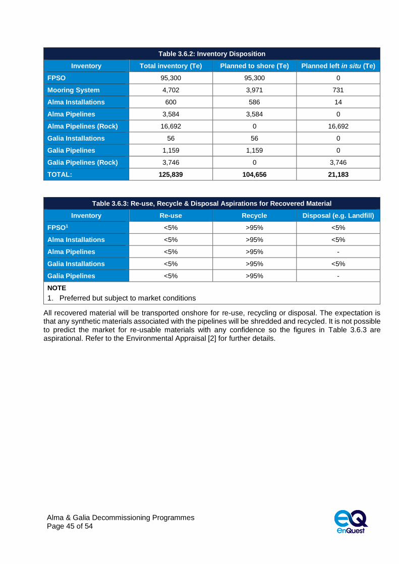
Table 3.6.2: Inventory Disposition
Inventory Total inventory (Te) Planned to shore (Te) Planned left in situ (Te)
FPSO 95,300 95,300 0
Mooring System 4,702 3,971 731
Alma Installations 600 586 14
Alma Pipelines 3,584 3,584 0
Alma Pipelines (Rock) 16,692 0 16,692
Galia Installations 56 56 0
Galia Pipelines 1,159 1,159 0
Galia Pipelines (Rock) 3,746 0 3,746
TOTAL: 125,839 104,656 21,183
Table 3.6.3: Re-use, Recycle & Disposal Aspirations for Recovered Material
Inventory Re-use Recycle Disposal (e.g. Landfill)
FPSO1 <5% >95% <5%
Alma Installations <5% >95% <5%
Alma Pipelines <5% >95% -
Galia Installations <5% >95% <5%
Galia Pipelines <5% >95% -
NOTE
1. Preferred but subject to market conditions
All recovered material will be transported onshore for re-use, recycling or disposal. The expectation is that any synthetic materials associated with the pipelines will be shredded and recycled. It is not possible to predict the market for re-usable materials with any confidence so the figures in Table 3.6.3 are aspirational. Refer to the Environmental Appraisal [2] for further details.

Alma & Galia Decommissioning Programmes Page 46 of 54
4. ENVIRONMENTAL APPRAISAL
4.1 Environmental Sensitivities
A summary of the environmental characteristics and sensitivities
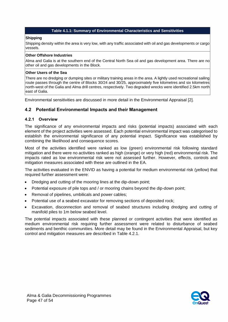
Table 4.1.1: Summary of Environmental Characteristics and Sensitivities
Physical Environment
Water depths are between 73 and 80 metres, with shallower depths towards the SE of the area. Tidal currents have maximum rates of 0.5 knots for spring tides, with residual currents flowing towards the south. South westerly winds predominate, and mean sea surface temperatures range from 5.7°C in March to 15.5°C in August.
Seabed Sediments and Contamination
Predominantly silty slightly shelly sands of between <1m and 4m thickness, underlain by firm to very still sandy gravelly clay. The east of the area is characterised by sand ripples whilst the west of the area is more homogenous, with a higher fines content. Seabed and linear depressions from historical oil and gas developments with legacy sediment contamination from historic oil-based mud discharges. Total hydrocarbon concentrations at Alma showed slightly elevated levels above background with no evidence of contamination at Galia. No discrete cuttings pile mounds present.
Fish
Alma and Galia is in spawning grounds for mackerel (May to Aug), cod and Norway pout (Jan to Apr), whiting (Feb to Jun), sprat (May to Aug), sandeel (Nov to Feb) and plaice (Dec to Mar); and in nursery grounds for mackerel, cod, whiting, Norway pout, sandeel, plaice, haddock, spurdog, herring, blue whiting, ling, hake and anglerfish (throughout the year)
Benthic Communities
A generally rich, evenly distributed faunal community dominated by polychaetes typical of North Sea sandy sediments. Some species considered tolerant to hydrocarbon contamination identified but abundance considered natural and representative of the wider area. 17 juvenile Arctica Islandica identified, primarily across the Alma site.
Plankton
Plankton species found in the project area are typically temperate shelf sea species.
Seabirds
The wider area is important for Auks, Kittiwake, Gannet, Fulmar, Herring Gull and Great Black-Backed Gull. However, the site is >279km offshore and has a low seabird vulnerability to surface pollution throughout the year except for the months of May and June where it increases to moderate in Block 30/25 and some adjacent Blocks.
Marine Mammals
Atlantic white-sided dolphin, common dolphin, harbour porpoise, white-beaked dolphin and minke whale sited within the area. They are however likely to be present in very low numbers, as are grey and harbour seals which are usually restricted to 40-50km from their haul out site.
Conservation Designations
The closest designated conservation sites to Alma and Galia are Fulmar MCZ (10.3km west of Galia), Dogger Bank SAC/SCI/MAP (77.9km to the south), Swallow Sands MCZ (86.1km west of Galia), and the East of Gannet and Montrose Fields MPA (104.4km to the north west).
Commercial Fisheries
Commercial fishing activity within the vicinity of the project area is very low with no data for most of the year and undisclosed data in June. The project area lies with ICES rectangle 41F2. Landings are predominantly demersal species although live weight and value of fish and shellfish landings for recent years (2015-2018) were undisclosed.
Alma & Galia Decommissioning Programmes Page 47 of 54
Table 4.1.1: Summary of Environmental Characteristics and Sensitivities
Shipping
Shipping density within the area is very low, with any traffic associated with oil and gas developments or cargo vessels.
Other Offshore Industries
Alma and Galia is at the southern end of the Central North Sea oil and gas development area. There are no other oil and gas developments in the Block.
Other Users of the Sea
There are no dredging or dumping sites or military training areas in the area. A lightly used recreational sailing route passes through the centre of Blocks 30/24 and 30/25, approximately five kilometres and six kilometres north-west of the Galia and Alma drill centres, respectively. Two degraded wrecks were identified 2.5km north east of Galia.
Environmental sensitivities are discussed in more detail in the Environmental Appraisal [2].
4.2 Potential Environmental Impacts and their Management
4.2.1 Overview
The significance of any environmental impacts and risks (potential impacts) associated with each element of the project activities were assessed. Each potential environmental impact was categorised to establish the environmental significance of any potential impact. Significance was established by combining the likelihood and consequence scores.
Most of the activities identified were ranked as low (green) environmental risk following standard mitigation and there were no activities ranked as high (orange) or very high (red) environmental risk. The impacts rated as low environmental risk were not assessed further. However, effects, controls and mitigation measures associated with these are outlined in the EA.
The activities evaluated in the ENVID as having a potential for medium environmental risk (yellow) that required further assessment were:
• Dredging and cutting of the mooring lines at the dip-down point;
• Potential exposure of pile tops and / or mooring chains beyond the dip-down point;
• Removal of pipelines, umbilicals and power cables;
• Potential use of a seabed excavator for removing sections of deposited rock;
• Excavation, disconnection and removal of seabed structures including dredging and cutting of manifold piles to 1m below seabed level.
The potential impacts associated with these planned or contingent activities that were identified as medium environmental risk requiring further assessment were related to disturbance of seabed sediments and benthic communities. More detail may be found in the Environmental Appraisal, but key control and mitigation measures are described in Table 4.2.1.

Alma & Galia Decommissioning Programmes Page 48 of 54
4.2.2 Key Control and Mitigation Measures
Table 4.2.1: Key Control and Mitigation Measures
Underwater Noise
• A SIMOPS plan for vessel activity in the field will be put in place
• Vessel, cutting and trenching operations will use standard methods and equipment. No explosives used.
Discharges to Sea
• All contracted vessels will operate in line with IMO and MARPOL regulations
• Pipelines and spool are to be flushed, filled with inhibited seawater and isolated prior to disconnection
• All discharges will be permitted under applicable UK legislation
Accidental Events
• All contracted vessels will have a ship-board oil pollution emergency plan (SOPEP) in place
• A Collision Risk Management Plan will be developed and implemented
• Agreed arrangements in place with oil spill response organisation for mobilising resources in event of a spill
• Existing field OPEP in place to reduce the likelihood of hydrocarbon release and define spill response in place
• Lifting operations will be planned to manage the risk
• Recovery of any dropped objects will take place
• Vessel contactors will have procedures for fuel bunkering that meet EnQuest’s standard
• Where practicable, re-fuelling will take place during daylight hours only
Physical Presence of Infrastructure & Vessels
• All vessels will comply with standard marking conditions and consent to locate conditions
• A SIMOPS plan for vessel activity in the field will be put in place
• All seabed infrastructure will be fully protected on the seabed in the interim period between Phase 1 & 2
• If full seabed clearance of the FPSO 500m zone is not completed in Phase 1 a guard vessel will remain on site
• A survey will be undertaken over the mooring chain and pile areas to confirm full burial
• Remedial levelling of the seabed planned post excavation of mooring piles cutting pits and mooring chain cutting points
• No additional rock or protection material is planned to be added to the area
• Seabed clearance certificate issued post completion of activities, seabed debris and overtrawl surveys
Atmospheric Emissions & Energy Use
• Time vessels spend in the field will be optimised, with a SIMOPS plan in place
• Reuse or recycling of materials will be the preferential option
Waste
• Onshore treatment will take place at waste management site with appropriate permits and licenses
• UK waste disposal sites will be used where practicable
Seabed Disturbance
• Activities which may lead to seabed disturbance planned, managed and implemented in such a way that disturbance is minimised
• Internal cutting of mooring piles will be used in preference where possible
• Natural backfill of the trenched areas, no planned mechanical backfill, or remedial seabed levelling of pipeline corridors
• Debris survey undertaken on completion of the activities and where possible resultant debris will be recovered
• Minimising disturbance to seabed from over-trawl through liaison with fishing organisations and regulator
Following the assessment undertaken during the EA process and implementation of additional control and mitigation measures where necessary, the level of environmental risk from the planned and unplanned decommissioning operations, is low. In addition, any cumulative impacts limited to seabed disturbance have been assessed and considered to be low. Therefore, the recommended options to decommission the Alma and Galia fields can be completed without causing significant impact to the environment.
In the unlikely event that the Decommissioning Programmes, there may be a requirement for a new Environmental Appraisal to be produced and submitted to OPRED. The approach will be discussed and agreed with OPRED at the time.
For further details please refer Environmental Appraisal [2].

Alma & Galia Decommissioning Programmes Page 49 of 54
5. INTERESTED PARTY CONSULTATIONS
5.1 General
Table 5.1.1: Summary of Stakeholder Comments
Who Comment Response
INFORMAL CONSULTATIONS
NFFO
The decommissioning proposals herein were sent via email to NFFO 11 September 2019
The NFFO had no adverse comment to make concerning the decommissioning proposals and were happy to use guidance from SFF
SFF The decommissioning proposals herein were presented to SFF on 18 July 2019
The SFF had no adverse comment to make concerning the decommissioning proposals
STATUTORY CONSULTATIONS
NFFO
NIFPO
SFF
GMG
Public

Alma & Galia Decommissioning Programmes Page 50 of 54
6. PROGRAMME MANAGEMENT
6.1 Project Management and Verification
An EnQuest project management team will manage the operations of competent contractors selected for all decommissioning activities. The team will ensure the decommissioning is executed safely, in accordance with legislation and EnQuest Health and Safety principles. If required, changes to the Decommissioning Programmes will be discussed with OPRED with any necessary approvals sought.
6.2 Post-Decommissioning Debris Clearance and Verification
The FPSO, the Alma and Galia installation sites and respective 500m safety zones will be subject to clear seabed assessment when decommissioning activities have concluded.
Should disconnection of the FPSO and sailaway result in mooring systems and risers temporarily being left in place, the riser buoyancy modules will either be removed or the risers will be anchored so that they remain stable. A guard vessel will be used to protect local users of the sea in the area until a clear seabed has been established.
It is proposed that EnQuest will work with OPRED and SFF to investigate use of an evidence-based approach to establish an acceptable clear seabed for the anchor piles, pipelines, umbilical pipelines and power cables outside of the existing 500m safety zones and along a 100m wide corridor for all decommissioned pipelines. As the seabed is not in an environmentally sensitive area an overtrawl may be carried out to verify the condition of the seabed after decommissioning activities have been completed. In the unlikely event that an extensive amount of debris is found an overtrawl may be appropriate.
Any seabed oil and gas debris will be recovered for onshore disposal or recycling in line with existing disposal methods. Independent verification of the seabed will be obtained by surveying the FPSO 500m zone and 100m wide pipeline corridor. If an overtrawl is carried out this will be supported by a Certificate of Clearance. Evidence of a clear seabed will be included in the Close Out Report and sent to the Seabed Data Centre (Offshore Installations) at the Hydrographic Office.
6.3 Schedule
A proposed schedule is provided in Figure 6.3.1. The activities are subject to the acceptance of the Decommissioning Programmes presented in this document and any unavoidable constraints (e.g. vessel availability) that may be encountered while executing the decommissioning activities. Therefore, activity schedule windows have been included to account for this uncertainty.
The commencement of offshore decommissioning activities will depend on commercial agreements and commitments.

Alma & Galia Decommissioning Programmes Page 51 of 54
Figure 6.3.1: Gantt Chart of Project Plan
Q1 Q2 Q3 Q4 Q1 Q2 Q3 Q4 Q1 Q2 Q3 Q4 Q1 Q2 Q3 Q4 Q1 Q2 Q3 Q4 Q1 Q2 Q3 Q4 Q1 Q2 Q3 Q4 Q1 Q2 Q3 Q4 Q1 Q2 Q3 Q4 Q1 Q2 Q3 Q4
Detailed engineering & proj. management
Cessation of Production window
Pipeline flushing
FPSO disconnection1,2
Remove risers, flowlines & mooring lines in 500m zone3
Wellheads, Risers, Pipelines & Installations RBI4
Well decommissioning, jumpers disconnected
Alma & Galia installation removal5
Pipeline decommissioning5
Onshore waste management activities
Post-decommissioning surveys & close out report6
Notes / Key
Most likely period of activity
Activity window to allow commercial flexibility associated with well and infrastructure decommissioning activities
1. Current indications are that FPSO sailaway will be carried out Q3 2020;
2. An interim progress report will be submitted to OPRED following FPSO sailaway;
3. Removal of risers, surface laid flowlines and mooring lines within 500m zone will follow FPSO sailaway but may be deferred;
4. The Alma Galia wellheads, risers, pipelines, and installations will be subjected to a risk-based inspection regime in the intervening period between FPSO sailaway and decommissioning activities;
5. Removal of Alma & Galia installations and pipelines will be done at the same time or sometime after well decommissioning activities have been completed;
6. Post decommissioning surveys and close out reports will be prepared on completion of decommissioning activities.
2024 2025 2026 2027 2028FPSO-ALMA-GALIA - Activity/Milestone
2019 2020 2021 2022 2023

Alma & Galia Decommissioning Programmes Page 52 of 54
6.4 Costs
Decommissioning costs will be provided separately to OPRED and OGA.
6.5 Close Out
In addition to seabed clearance verification surveys, environmental surveys may be required after decommissioning has been completed. The requirement and timing of these will be agreed with OPRED. The findings of any pipeline and stabilisation material status surveys and any environmental surveys will be completed with the findings being sent to OPRED in the Close Out report as required in the OPRED Guidance Notes. An interim progress report will be submitted after the 500m zone has been cleared. The reports will explain any variance from the Decommissioning Programmes.
6.6 Post-Decommissioning Monitoring and Evaluation
After decommissioning has been completed, pipeline status surveys will not be required, although the mooring anchor piles and chains will remain buried in situ. The frequency of future mooring pile status surveys after removal of the Alma and Galia installations will be agreed with OPRED and supported with risk assessments. Residual liability will remain with the Section 29 holders identified in Section 1.4, and Section 1.5. Unless agreed otherwise in advance with OPRED, EnQuest will remain the focal point for such matters, such as any change in ownership, for example.
The requirement for legacy and liability management will be described in more detail in the Close Out report.

Alma & Galia Decommissioning Programmes Page 53 of 54
7. SUPPORTING DOCUMENTS
[1] EnQuest (2019) Alma-Galia Decommissioning Pipeline Comparative Assessment, M3523-PDI-
ALG-EG-000-REP-0004;
[2] EnQuest (2019) Alma-Galia Decommissioning Environmental Appraisal, M3523-PDI-ALG-EG-
000-REP-0003;
Alma & Galia Decommissioning Programmes Page 54 of 54
APPENDIX A PUBLIC NOTICE & CONSULTEE CORRESPONDENCE
Appendix A.1 Public Notices
Appendix A.2 Correspondence with Individual Statutory Consultees