ALM 12V7 s-Series User’s Guide - NEC Energy Solutions · ALM ® 12V7 s-Series User’s Guide. End...
50
ALM ® 12V7 s-Series User’s Guide End User Documentation 406014-02EN, Rev. 05 © 2016 NEC Energy Solutions, Inc. All rights reserved. This document contains the proprietary information of NEC Energy Solutions, Inc. and may not be reproduced, retransmitted or redistributed, either in whole or in part, for any reason without NEC Energy Solutions’ prior written consent. April 21, 2016 www.neces.com
Transcript of ALM 12V7 s-Series User’s Guide - NEC Energy Solutions · ALM ® 12V7 s-Series User’s Guide. End...

ALM® 12V7 s-Series User’s GuideEnd User Documentation
406014-02EN, Rev. 05
© 2016 NEC Energy Solutions, Inc. All rights reserved.
This document contains the proprietary information ofNEC Energy Solutions, Inc. and may not be reproduced, retransmitted or redistributed, either in whole or in part, for any reason without NEC Energy Solutions’ prior written consent.
April 21, 2016 www.neces.com

ALM® 12V7 s-Series User’s Guide
Copyright Notice
© 2016 NEC Energy Solutions, Inc. All rights reserved.
DOCUMENT NOTICE
THE INFORMATION CONTAINED IN THIS MANUAL IS THE PROPERTY OF NEC ENERGY SOLUTIONS, INC. (“NEC ENERGY SOLUTIONS”) AND IS SUBJECT TO CHANGE WITHOUT NOTICE. NEC ENERGY SOLUTIONS RESERVES THE RIGHT TO MAKE CHANGES IN THE DESIGN OF ITS PRODUCTS OR COMPONENTS AS PROGRESS IN ENGINEERING AND MANUFACTURING MAY WARRANT. IT IS THE CUSTOMER’S RESPONSIBILITY TO SATISFY ITSELF AS TO WHETHER THE INFORMATION CONTAINED HEREIN IS ADEQUATE AND SUFFICIENT FOR A USER'S PARTICULAR USE. IT IS THE FURTHER RESPONSIBILITY OF EACH USER TO ENSURE THAT ALL APPLICATIONS OF NEC ENERGY SOLUTIONS' PRODUCTS ARE APPROPRIATE AND SAFE BASED ON CONDITIONS ANTICIPATED OR ENCOUNTERED DURING USE. CUSTOMER’S MISUSE OF THE PRODUCTS OR MODIFICATION OF THE PRODUCTS MAY LEAD TO MALFUNCTION OF THE PRODUCTS THAT MAY CAUSE INJURY AND CUSTOMER ASSUMES ALL RISKS ASSOCIATED WITH SUCH USE. THIS DOCUMENT DOES NOT CREATE ANY ADDITIONAL OBLIGATION FOR NEC ENERGY SOLUTIONS AND DOES NOT CONSTITUTE ADDITIONAL WARRANTIES AND REPRESENTATIONS.
Trademarks
NEC and the NEC logo are registered trademarks of NEC Corporation. ALM is a registered trademark and EverSafe is a trademark of NEC Energy Solutions, Inc. A123 Systems and Nanophosphate are registered trademarks of A123 Systems, LLC. All other trademarks used herein are the property of their respective owners.
Comments and Questions about this Documentation
Please call NEC Energy Solutions Technical Support at (508) 497-7100 or contact by e-mail at [email protected]
406014-02EN, Rev. 05 © 2016 NEC Energy Solutions, Inc. All rights reserved. Page 2 of 49
This document contains the proprietary information of NEC Energy Solutions, Inc. (“NECES”) and may not be modified, reproduced, retransmitted or redistributed, either in whole or in part, for any reason without NECES’ prior written consent.

ALM® 12V7 s-Series User’s Guide Contents
Preface .......................................................................................................7About this Guide ............................................................................................................................. 7Intended Users................................................................................................................................ 7Conventions Used in this Guide ..................................................................................................... 7
Notes, Caution, Warning, and Danger Notices ........................................................................ 7
Chapter 1 Introducing the ALM® 12V7 s-Series Batteries .................... 9Overview ......................................................................................................................................... 9ALM® 12V7 s-Series Product Line................................................................................................ 10
Chapter 2 Regulatory Compliance ........................................................ 11Overview ....................................................................................................................................... 11Environmental Regulations ........................................................................................................... 12Transporting Lithium-Ion Batteries................................................................................................ 12
Regulations Overview............................................................................................................. 13Regulations by Cell/Battery Size ............................................................................................ 13Following International and U.S. DOT Regulations ................................................................ 13
Chapter 3 Handling, Storage and Installation ...................................... 15Safety and Handling...................................................................................................................... 15Mounting ....................................................................................................................................... 16Battery Configuration Options ...................................................................................................... 16
Wiring Connections ................................................................................................................ 16Terminal Specifications........................................................................................................... 18Configuring Batteries in Series Strings................................................................................... 18Configuring Batteries in a Parallel Group (1S2P up to 4S10P)............................................... 19Series and Parallel Battery Configuration Warnings and Notices .......................................... 19
Transportation and Storage .......................................................................................................... 21Operating Environment ................................................................................................................. 21Disposal ........................................................................................................................................ 22
Chapter 4 ALM® 12V7 s-Series Specifications ..................................... 23Electrical and Environmental Specifications ................................................................................. 23Physical Specifications ................................................................................................................. 26
Chapter 5 Operation and System Design Considerations .................. 28Integrated EverSafe™ Battery Protection..................................................................................... 28
Transient Energy Limit ............................................................................................................ 28Over Current Protection ......................................................................................................... 28
406014-02EN, Rev. 05 © 2016 NEC Energy Solutions, Inc. All rights reserved. Page 3 of 49
This document contains the proprietary information of NEC Energy Solutions, Inc. (“NECES”) and may not be modified, reproduced, retransmitted or redistributed, either in whole or in part, for any reason without NECES’ prior written consent.

ALM® 12V7 s-Series User’s Guide Contents
Over Discharge Protection Under Voltage Protection (UVP) .................................................. 29Smart Charger Support .......................................................................................................... 30Over Charge Protection.......................................................................................................... 30Over Temperature Protection ................................................................................................. 30High Temperature Operation .................................................................................................. 31Low Temperature Operation................................................................................................... 33
Charging Single Batteries ............................................................................................................. 33Constant Current (CC), Float Voltage Chargers ..................................................................... 33Charge Limits and Temperatures............................................................................................ 34
Charging Multiple Batteries........................................................................................................... 36Charging Batteries in Series ................................................................................................... 36Charging Batteries in Parallel ................................................................................................. 36
Discharge Performance ................................................................................................................ 38Balancing ...................................................................................................................................... 41Cycle Life ...................................................................................................................................... 41Shelf Life ....................................................................................................................................... 42
Chapter 6 Troubleshooting ..................................................................... 44Overview ....................................................................................................................................... 44
Appendix A Operational Protection Hardware Circuitry ..................... 46
Appendix B Acronyms and Terminology ............................................... 47
Related Documents and Resources ............................................................................................. 49
406014-02EN, Rev. 05 © 2016 NEC Energy Solutions, Inc. All rights reserved. Page 4 of 49
This document contains the proprietary information of NEC Energy Solutions, Inc. (“NECES”) and may not be modified, reproduced, retransmitted or redistributed, either in whole or in part, for any reason without NECES’ prior written consent.

ALM® 12V7 s-Series User’s Guide
406014-02EN, Rev. 05 © 2016 NEC Energy Solutions, Inc. All rights reserved. Page 5 of 49
This document contains the proprietary information of NEC Energy Solutions, Inc. (“NECES”) and may not be modified, reproduced, retransmitted or redistributed, either in whole or in part, for any reason without NECES’ prior written consent.
Figures
Title Page
1 ALM 12V7 s-Series Battery................................................................................................ 92 ALM 12V7 s-Series Battery Block Diagram ..................................................................... 103 Three ALM 12V7 s-Series Batteries Connected in Series Creating a 3S1P
Configuration ................................................................................................................... 184 ALM 12V7 s-Series Mechanical Dimensions ................................................................... 275 Current Limit Profiles for the ALM 12V7s and ALM 12V7s HP Models ........................... 296 Battery Voltage and Current During Recharge ................................................................ 347 ALM 12V7 s-Series Typical Constant Current Discharge Behavior at 25 °C................... 388 ALM 12V7 s-Series Typical Constant Power Discharge Behavior at 25 °C..................... 399 ALM 12V7 s-Series Typical 50W Constant Power Discharge Behavior .......................... 4010 Cycle Life versus Delta SOC Behavior of Nanophosphate® Lithium-Ion Cell................. 4111 Cycle Life Test Results +1C/-1C, 23 °C, 100% DOD ...................................................... 42

ALM® 12V7 s-Series User’s Guide
406014-02EN, Rev. 05 © 2016 NEC Energy Solutions, Inc. All rights reserved. Page 6 of 49
This document contains the proprietary information of NEC Energy Solutions, Inc. (“NECES”) and may not be modified, reproduced, retransmitted or redistributed, either in whole or in part, for any reason without NECES’ prior written consent.
Tables
Title Page
1 ALM 12V s-Series Product Line Names UL Model Numbers .......................................... 12
2 Example of Steps to Obtain or Ensure Regulatory Compliance..................................... 14
3 Proper Shipping Names and UN Numbers...................................................................... 14
4 ALM 12V7 s-Series Electrical Specifications ................................................................... 23
5 ALM 12V7 s-Series Environmental Specifications........................................................... 24
6 Spécifications Electriques de l' 12V7 s-Séries ALM ..................................................... 25
7 Spécifications Environnementales de l'12V7 s-Séries ALM......................................... 26
8 ALM 12V7 s-Series Physical and Mechanical Specifications.......................................... 26
9 ALM 12V7 s-Séries Caractéristiques Physiques et Mécaniques.................................. 27
10 End of Discharge – Effective ALM 12V7 s-Series Terminal Cut-Off Voltages in Different Series Configurations ........................................................................................ 30
11 Thermal Capability and Delta SOC, BOL ........................................................................ 31
12 Capacité Thermique et Delta État de Charge, Début de la Vie .................................. 32
13 Charge Rate by Temperature .......................................................................................... 35
14 Taux des frais par Température ................................................................................ 35
15 Supported Float and Maximum Charge Voltages............................................................ 36
16 Tension de Maintien et les Tensions Charge Maximale ............................................. 37
17 ALM12V7s HP Troubleshooting and Solutions................................................................ 45
18 ALM 12V7 s-Series Operational Protection Parameters.................................................. 46

ALM® 12V7 s-Series User’s Guide Preface
About this Guide
This ALM® 12V7 s-Series User’s Guide provides detailed specifications for the ALM 12V7 s-Series batteries. It also provides guidance on safely and effectively configuring, and operating ALM 12V7 s-Series batteries as building blocks in various applications.
Intended Users
This ALM® 12V7 s-Series User’s Guide is intended for all personnel involved in designing, configuring and installing ALM 12V7 s-Series batteries.
Conventions Used in this Guide
Notes, Caution, Warning, and Danger Notices
NOTEA Notice presents information that is important, but not hazard-related.
REMARQUEUn avis présente des informations importantes mais pas en rapport avec des situations dangereuses.
CAUTIONA CAUTION notice identifies conditions or practices that could result in minor or moderate injury, or damage to the equipment.
ATTENTIONUne MISE EN GARDE contient des informations essentielles pour éviter des dommages au système ou à l'équipement. La mise en garde pourrait s'appliquer au matériel ou au logiciel.
406014-02EN, Rev. 05 © 2016 NEC Energy Solutions, Inc. All rights reserved. Page 7 of 49
This document contains the proprietary information of NEC Energy Solutions, Inc. (“NECES”) and may not be modified, reproduced, retransmitted or redistributed, either in whole or in part, for any reason without NECES’ prior written consent.

ALM® 12V7 s-Series User’s Guide Preface
WARNINGA WARNING notice contains information essential to avoid a hazard that can cause severe personal injury, death, or substantial property damage if you ignore the warning.
AVERTISSEMENTUn AVERTISSEMENT contient des informations essentielles pour éviter un danger qui peut causer des blessures corporelles graves, la mort ou des dommages matériels importants si vous ignorez l'avertissement.
DANGERA DANGER notice contains information essential to avoid a hazard that will cause severe personal injury, death, or substantial property damage if you ignore the message.
DANGERUn avis de DANGER contient des informations essentielles pour éviter un danger qui causera des blessures corporelles graves, la mort ou des dommages matériels importants si vous ignorez le message.
406014-02EN, Rev. 05 © 2016 NEC Energy Solutions, Inc. All rights reserved. Page 8 of 49
This document contains the proprietary information of NEC Energy Solutions, Inc. (“NECES”) and may not be modified, reproduced, retransmitted or redistributed, either in whole or in part, for any reason without NECES’ prior written consent.

ALM® 12V7 s-Series User’s Guide Chapter 1
Chapter 1: Introducing the ALM® 12V7 s-Series Batteries
Introducing the ALM® 12V7 s-Series Batteries
Overview
NEC Energy Solutions’ ALM 12V7 s-Series batteries are the next generation of the ALM 12V7 product line of lithium-ion batteries (Figure 1). ALM 12V7 s-Series batteries are designed as drop‐in replacements for 12-volt, lead-acid batteries. They provide improved performance with higher power, increased safety and exceptional calendar and cycle life compared to 12-volt, lead-acid batteries. They typically serve as a standby power source in many high‐availability and service‐critical applications.
The ALM 12V7 s-Series batteries are identical in size to common 7Ah, 12-volt, lead-acid batteries and designed to be compatible with most lead-acid chargers. This combination reduces product integration costs, minimizes OEM customer’s time to market and aftermarket customer replacement hurdles.
Figure 1 ALM 12V7 s-Series Battery
406014-02EN, Rev. 05 © 2016 NEC Energy Solutions, Inc. All rights reserved. Page 9 of 49
This document contains the proprietary information of NEC Energy Solutions, Inc. (“NECES”) and may not be modified, reproduced, retransmitted or redistributed, either in whole or in part, for any reason without NECES’ prior written consent.

ALM® 12V7 s-Series User’s Guide Chapter 1: Introducing the ALM® 12V7 s-Series Batteries
ALM® 12V7 s-Series Product Line
The ALM 12V7 s-Series consists of the following models:
• The ALM 12V7s is a standard series, base power model. It can:
• Deliver 66 watts for one 1 hour• Deliver 190 watts for 20 minutes• Deliver up to 350 watts in one-second pulses• Be fully charged (from 0 to 100%) in approximately 15 minutes
• The ALM 12V7s HP is a standard series, high power model. It can:
• Deliver 590 watts for six minutes• Deliver up to 700 watts in one-second pulses• Be fully charged (from 0 to 100%) in approximately 7 minutes
Each ALM 12V7 s-Series battery has integrated EverSafe™ protection and balancing circuitry (Figure 2) that safeguard the battery from over‐voltage, under‐voltage, short-circuit and over‐temperature conditions. At the core of the ALM 12V7 s-Series are eight A123 Systems® ANR26650M1B cells in a four‐series, two‐parallel (4S2P) configuration.
Figure 2 ALM 12V7 s-Series Battery Block Diagram
406014-02EN, Rev. 05 © 2016 NEC Energy Solutions, Inc. All rights reserved. Page 10 of 49
This document contains the proprietary information of NEC Energy Solutions, Inc. (“NECES”) and may not be modified, reproduced, retransmitted or redistributed, either in whole or in part, for any reason without NECES’ prior written consent.
ALM® 12V7 s-Series User’s Guide Chapter 2
Chapter 2: Regulatory Compliance
Regulatory Compliance
Overview
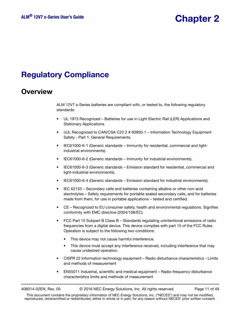
ALM 12V7 s-Series batteries are compliant with, or tested to, the following regulatory standards:
• UL 1973 Recognized – Batteries for use in Light Electric Rail (LER) Applications and Stationary Applications.
• cUL Recognized to CAN/CSA C22.2 # 60950-1 – Information Technology Equipment Safety - Part 1: General Requirements.
• IEC61000-6-1 (Generic standards – Immunity for residential, commercial and light-industrial environments).
• IEC61000-6-2 (Generic standards – Immunity for industrial environments).
• IEC61000-6-3 (Generic standards – Emission standard for residential, commercial and light-industrial environments).
• IEC61000-6-4 (Generic standards – Emission standard for industrial environments).
• IEC 62133 – Secondary cells and batteries containing alkaline or other non-acid electrolytes – Safety requirements for portable sealed secondary cells, and for batteries made from them, for use in portable applications – tested and certified.
• CE – Recognized to EU consumer safety, health and environmental regulations. Signifies conformity with EMC directive (2004/108/EC).
• FCC Part 15 Subpart B Class B – Standards regulating unintentional emissions of radio frequencies from a digital device. This device complies with part 15 of the FCC Rules. Operation is subject to the following two conditions:
• This device may not cause harmful interference.
• This device must accept any interference received, including interference that may cause undesired operation.
• CISPR 22 Information technology equipment – Radio disturbance characteristics - Limits and methods of measurement
• EN55011 Industrial, scientific and medical equipment – Radio- frequency disturbance characteristics limits and methods of measurement
406014-02EN, Rev. 05 © 2016 NEC Energy Solutions, Inc. All rights reserved. Page 11 of 49
This document contains the proprietary information of NEC Energy Solutions, Inc. (“NECES”) and may not be modified, reproduced, retransmitted or redistributed, either in whole or in part, for any reason without NECES’ prior written consent.

ALM® 12V7 s-Series User’s Guide Chapter 2: Regulatory Compliance
• EN 55022 Information Technology Equipment – Radio Disturbance characteristics Limits and methods of measurement
• VCCI Class B ITE emissions
• ICES-003 Information Technology Equipment (ITE) – Limits and Methods of Measurement
• UN 38.3 – Meets section 38.3 of the UN Recommendations on the Transport of Dangerous Goods – Manual of Test Criteria.
Table 1 describes the ALM 12V7 s-Series product line and UL regulatory model number conventions used for third-party certification.
Table 1 ALM 12V s-Series Product Line Names UL Model Numbers
Regulatory Model Numbers ALM 12V7 s-Series Battery Model Names
PSL000004 12V7s
PSL000005 12V7s HP
Environmental Regulations
ALM 12V7 s-Series batteries are compliant with the following applicable environmental regulations.
• EU Directive 2011/65/EC on the Restriction of the use of certain Hazardous Substances (RoHS) in electrical and electronic equipment (recast)
• EU Directive 2006/66/EC on batteries and accumulators and waste batteries and accumulators
• EU Directive 1907/2006 on the Registration Evaluation Authorization and Restriction of Chemicals (REACH)
• Management Methods for Controlling Pollution Caused by Electronic Information Products Regulation (China RoHS)
Transporting Lithium-Ion Batteries
The material presented in this guide is not all-inclusive of the regulations required to ship a product, but is meant to inform you of the complexity involved in doing so. The information contained herein is for informational purposes only and is not legal advice or a substitute for legal counsel.
Anyone involved in the integration of lithium-ion battery packs into a host product must review and meet the regulations cited in this guide. Additionally, the regulations discussed in this guide apply to lithium-ion cells and batteries. Once an ALM 12V7 s-Series battery is integrated into a host product, the host product may be subject to additional transportation regulations that require additional certification testing. Since NEC Energy Solutions can’t anticipate every possible configuration and application of an ALM 12V7 s-Series battery, the
406014-02EN, Rev. 05 © 2016 NEC Energy Solutions, Inc. All rights reserved. Page 12 of 49
This document contains the proprietary information of NEC Energy Solutions, Inc. (“NECES”) and may not be modified, reproduced, retransmitted or redistributed, either in whole or in part, for any reason without NECES’ prior written consent.
ALM® 12V7 s-Series User’s Guide Chapter 2: Regulatory Compliance
integrator must verify that the ALM 12V7 s-Series-powered host product is compliant with all applicable regulations. Refer to Table 3 on page 14 for a list of proper names and UN numbers required for shipping lithium-ion batteries.
Regulations Overview
Rechargeable lithium-ion (including lithium-ion polymer) cells and batteries are considered dangerous goods. The regulations that govern their transport are based on the UN Recommendations on the Transport of Dangerous Goods Model Regulations. Transport of dangerous goods is regulated internationally by:
• International Civil Aviation Organization (ICAO) Technical Instructions
• International Air Transport Association (IATA) Dangerous Goods Regulations
• International Maritime Dangerous Goods (IMDG) Code
In the United States, transportation of hazardous material is regulated by Title (part) 49 of the Code of Federal Regulations or CFR’s. Title 49 CFR Sections 100-185 of the U.S. Hazardous Materials Regulations (HMR) contains the requirements for transporting cells and batteries. Refer to the following sections within 49 CFR for specific information.
• Section 173.185 – Shipping requirements for lithium cells and batteries
• Section 172.102 – Special Provisions
• Sections 172.101, 178 – Further information and specifications on packaging
The Office of Pipeline and Hazardous Materials Safety Administration (PHMSA), which is within the U.S. Department of Transportation (DOT), is responsible for drafting and writing the U.S. regulations that govern the transportation of hazardous materials (also known as dangerous goods) by air, ground, and ocean.
Regulations by Cell/Battery Size
Lithium-ion batteries and cells are considered Class 9, which is one of nine classes of hazardous materials or dangerous goods defined in the regulations. As a class 9 material, cells and batteries must meet UN testing and packaging requirements as well as shipping regulations.
Following International and U.S. DOT Regulations
Failure to comply with International and U.S. DOT regulations while transporting Class 9 Hazardous Materials (Dangerous Goods) may result in substantial civil and criminal penalties.
406014-02EN, Rev. 05 © 2016 NEC Energy Solutions, Inc. All rights reserved. Page 13 of 49
This document contains the proprietary information of NEC Energy Solutions, Inc. (“NECES”) and may not be modified, reproduced, retransmitted or redistributed, either in whole or in part, for any reason without NECES’ prior written consent.

ALM® 12V7 s-Series User’s Guide Chapter 2: Regulatory Compliance
Table 2 outlines an example process to help ensure that batteries are shipped per the required regulations.
Table 2 Example of Steps to Obtain or Ensure Regulatory Compliance
Step Number Process step Comments
1 Design the battery pack. Design the battery pack to ensure it will pass UN Manual of Tests and Criteria.
2AShip the battery pack to a UN 38.3 test house if using an outside test laboratory.
Use the “Prototype” shipping special provisions provided in the regulations.
2B Test the battery pack. Perform UN testing T1-T5, & T7 for batteries.
3 Obtain UN compliant packaging.All Class 9 Dangerous Goods (DG) must be shipped in UN compliant packaging.a
a. U.S. and international regulations require that anyone involved in the packaging, documentation, and labeling of Dangerous Goods for transportation must be trained to do so.
4 Package the cell or battery. Pack per regulations and per packaging manufacturer's instructions.
5 Mark and label the package. Insure that packaging container has all the required labeling. Table 3 lists proper shipping names and descriptions for lithium-ion batteries.a
6 Fill out the shipping documentation. Complete shipper's declaration for dangerous goods, airway bill, etc. a
7 Ship the package.Ensure that shipping company can ship dangerous goods and that a Safety Data Sheet (or equivalent document) and any Competent Authority Approval accompanies the package. a
NOTETable 3 shows the proper shipping names and UN numbers required for shipping lithium-ion batteries.
Table 3 Proper Shipping Names and UN Numbers
Proper Shipping Name Description
Lithium ion batteries UN 3480
Lithium ion batteries packed with equipment UN 3481
Lithium ion batteries contained in equipment UN 3481
406014-02EN, Rev. 05 © 2016 NEC Energy Solutions, Inc. All rights reserved. Page 14 of 49
This document contains the proprietary information of NEC Energy Solutions, Inc. (“NECES”) and may not be modified, reproduced, retransmitted or redistributed, either in whole or in part, for any reason without NECES’ prior written consent.

ALM® 12V7 s-Series User’s Guide Chapter 3
Chapter 3: Handling, Storage and Installation
Handling, Storage and Installation
Safety and Handling
ALM 12V7 s-Series batteries are more abuse tolerant than other lithium-ion batteries; however, correct handling and system integration of ALM 12V7 s-Series batteries are still important to ensure safe operation.
WARNINGFailure to follow these warnings may result in personal injury or damage to the equipment.
• Do not expose the ALM 12V7 s-Series battery to heat in excess of 60°C during operation or in storage; do not incinerate or expose to open flames.
• Do not connect ALM 12V7 s-Series batteries to batteries of other chemistries or ALM batteries of different capacities. For example, do not connect an ALM 12V7 s-Series battery to any lead‐acid battery or to an ALM 12V35.
CAUTIONDo not charge or discharge an ALM 12V7 s-Series battery outside of its stated operating temperature range. Reduce charging limits for lower operating temperatures for longer life of the batteries.
AVERTISSEMENTNe pas suivre ces avertissements peut entraîner des blessures ou des dommages a l’équipement.
• Ne pas exposer les batteries ALM 12V7 s-Séries à une chaleur dépassant les 60°C pendant son fonctionnement ou son entreposage; ne pas l'incinérer ou l'exposer à des flammes nues.
• Ne pas connecter les batteries ALM 12V7 s-Séries avec des batteries d'autres compositions chimiques ou avec des batteries ALM de différentes capacités. Par exemple, ne pas connecter une batterie 12V7 s-Séries avec une batterie d'accumulateurs au plomb ou avec une batterie ALM 12V35.
406014-02EN, Rev. 05 © 2016 NEC Energy Solutions, Inc. All rights reserved. Page 15 of 49
This document contains the proprietary information of NEC Energy Solutions, Inc. (“NECES”) and may not be modified, reproduced, retransmitted or redistributed, either in whole or in part, for any reason without NECES’ prior written consent.

ALM® 12V7 s-Series User’s Guide Chapter 3: Handling, Storage and Installation
ATTENTIONNe pas charger ou décharger la batterie ALM 12V7 s-Séries en dehors de sa plage de température fonctionnelle indiquée. Réduire les limites de chargement pour les températures fonctionnelles plus basses pour la durée de vie des batteries.
The advanced design of the ALM 12V7 s-Series is intended to provide protection against operation under many unsafe conditions such as over voltage, under voltage, over temperature and short circuit. Proper use within the limits stated in Chapter 4,
ALM® 12V7 s-Series Specifications, starting on page 23, is required to ensure operator and equipment safety as well as battery life.
Mounting
The ALM 12V7 s-Series batteries may be installed in any orientation.
The ALM 12V7 s-Series battery case, including its top cover is capable of sustaining a mounting force of up to 200 Newtons spread over a one-inch-wide (2.5 cm-wide) bar or holding bracket across the center of the unit. Exertions beyond this level may result in deforming of the plastic.
MontageLes batteries de 12V7 s-Séries ALM peut être installé dans n'importe quelle direction.
Le boîtier de la batterie ALM 12V7 s-Séries, y compris le couvercle supérieur, peut soutenir une charge allant jusqu'à 200 Newtons répartie sur une barre d'un pouce (2,5 cm) de largeur ou sur une équerre de fixation traversant le centre de l'unité. Des efforts plus grands peuvent provoquer une déformation de la matière plastique.
Battery Configuration Options
ALM 12V7 s-Series batteries may be arranged in series and/or in parallel configurations to achieve higher operating voltages and capacities to meet the requirements of the intended application, up to a maximum of 48 volts (four in series) and 50 Ah (ten in parallel).
Wiring Connections
To connect ALM 12V7 s-Series batteries, use appropriate sized AWG wire and connectors that are rated for the maximum current and temperature expected. Table 11, on page 31, provides guidance on the conditions under which the battery may encounter internal thermal or external terminal touch temperature limits.
The battery can accommodate a maximum inductance of 5 μH. For reference, 5 μH is equivalent to 3 meters (10 feet) of individual standalone cable. In a battery system, cable
406014-02EN, Rev. 05 © 2016 NEC Energy Solutions, Inc. All rights reserved. Page 16 of 49
This document contains the proprietary information of NEC Energy Solutions, Inc. (“NECES”) and may not be modified, reproduced, retransmitted or redistributed, either in whole or in part, for any reason without NECES’ prior written consent.

ALM® 12V7 s-Series User’s Guide Chapter 3: Handling, Storage and Installation
length inductance includes all terminal-to-terminal connections as well as cabling to charge sources and load for both the positive and negative conductors added together. It is possible to reduce a battery system’s total cable inductance by orienting positive and negative conductors to cancel each other’s electromagnetic induction, thus allowing for longer total cable length. Contact NEC Energy Solutions Technical Support for assistance in determining appropriate wiring and bus bar configurations to address current sharing and stray inductance requirements.
CAUTION
• Exceeding the maximum inductance limit of 5 μH during operation could cause voltage spikes or current surges resulting in possible damage to the ALM 12V7 s-Series battery’s circuitry.
• Do not connect the ALM 12V7 s-Series to an inductive load such as a DC motor without the use of a motor controller. An “on-off” switch does not constitute a motor controller. Using the batteries directly with DC motors can permanently damage the battery. Contact NEC Energy Solutions Technical Support for further assistance.
Connexions de Câblage
Pour connecter les batteries ALM 12V7 s-Séries, utilisez un câble AWG de la bonne taille et les tenons classifiés pour le courant et la température maximum prévus. Tableau 12 à la page 32 fournit des directives sur les conditions dans lesquelles la batterie pourrait dépasser les limites de température de contact de borne externe ou thermique interne.
La batterie peut accepter une inductance maximum de 5 µH. Comme référence, 5 µH est équivalent à 3 mètres (10 pieds) de câble autonome individuel. Dans un système de batterie, la longueur du câble inducteur comprend toutes les connexions de borne à borne, ainsi que le câblage pour recharger les sources et les charges pour les conducteurs positif et négatif combinés. Il est possible de réduire l'inductance totale de câble d'un système de batterie en orientant les conducteurs positif et négatif pour annuler mutuellement l'induction électromagnétique, permettant ainsi une plus grande longueur de câble totale. Contactez le support technique de NEC Energy Solutions pour vous aider à déterminer les configurations de câblage et de barres omnibus appropriées pour traiter le partage de courant et les exigences d'inductance parasite.
ATTENTION• Le dépassement de la limite d’inductance maximale en fonctionnement de 5 µH
pourrait causer des pointes de tension ou de courant et causer des dommages aux circuits de la batterie ALM 12V7 s-Séries.
• Ne branchez pas la batterie ALM 12V7 s-Séries à une charge inductive, telle qu’un moteur à courant continu, sans l’utilisation d’un dispositif de commande de moteur. Un interrupteur « marche-arrêt » ne constitue pas un dispositif de commande de moteur. L’utilisation des batteries directement avec les moteurs à courant continu peut endommager définitivement celles-ci. Contactez l’assistance technique de NEC Energy Solutions pour obtenir de l’aide.
406014-02EN, Rev. 05 © 2016 NEC Energy Solutions, Inc. All rights reserved. Page 17 of 49
This document contains the proprietary information of NEC Energy Solutions, Inc. (“NECES”) and may not be modified, reproduced, retransmitted or redistributed, either in whole or in part, for any reason without NECES’ prior written consent.

ALM® 12V7 s-Series User’s Guide Chapter 3: Handling, Storage and Installation
Terminal Specifications
ALM 12V7 s-Series batteries use copper terminals with tin plating. The terminals have a maximum operating temperature rating of 90 °C. They are intended to mate with standard female 0.25 inch (6,35 cm) “quick connect” terminals (TE Connectivity FASTON or equivalent). Attach cable by inserting connector fully until the round locking detent has engaged the center hole.
Configuring Batteries in Series Strings
To achieve higher operating voltages, arrange the ALM 12V7 s-Series batteries in series strings by connecting the positive terminal of one battery to the negative terminal of the next battery, as shown in Figure 3.
NOTEThe following battery string wiring examples provide general configuration information. Actual wire configurations must be evaluated for their particular application.
The array voltage can be calculated as follows:
• Two batteries in series: 2 x 13.2 V = 26.4 V (nominal) for 24 V applications
• Three batteries in series: 3 x 13.2 V = 39.6 V (nominal) for 36 V applications
• Four batteries in series: 4 x 13.2 V = 52.8 V (nominal) for 48 V applications
The maximum number of ALM 12V7 s-Series batteries that may be connected in series is four.
Figure 3 illustrates three ALM 12V7 s-Series batteries connected in a three-series, one-parallel (3S1P) configuration.
Figure 3 Three ALM 12V7 s-Series Batteries Connected in Series Creating a 3S1P Configuration
406014-02EN, Rev. 05 © 2016 NEC Energy Solutions, Inc. All rights reserved. Page 18 of 49
This document contains the proprietary information of NEC Energy Solutions, Inc. (“NECES”) and may not be modified, reproduced, retransmitted or redistributed, either in whole or in part, for any reason without NECES’ prior written consent.
ALM® 12V7 s-Series User’s Guide Chapter 3: Handling, Storage and Installation
Configuring Batteries in a Parallel Group (1S2P up to 4S10P)
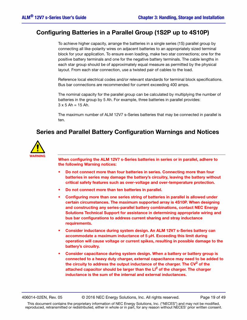
To achieve higher capacity, arrange the batteries in a single series (1S) parallel group by connecting all like‐polarity wires on adjacent batteries to an appropriately sized terminal block for your application. To ensure even loading, make two star connections; one for the positive battery terminals and one for the negative battery terminals. The cable lengths in each star group should be of approximately equal measure as permitted by the physical layout. From each star connection, use a twisted pair of cables to the load.
Reference local electrical codes and/or relevant standards for terminal block specifications. Bus bar connections are recommended for current exceeding 400 amps.
The nominal capacity for the parallel group can be calculated by multiplying the number of batteries in the group by 5 Ah. For example, three batteries in parallel provides: 3 x 5 Ah = 15 Ah.
The maximum number of ALM 12V7 s-Series batteries that may be connected in parallel is ten.
Series and Parallel Battery Configuration Warnings and Notices
WARNINGWhen configuring the ALM 12V7 s-Series batteries in series or in parallel, adhere to the following Warning notices:
• Do not connect more than four batteries in series. Connecting more than four batteries in series may damage the battery’s circuitry, leaving the battery without critical safety features such as over‐voltage and over‐temperature protection.
• Do not connect more than ten batteries in parallel.
• Configuring more than one series string of batteries in parallel is allowed under certain circumstances. The maximum supported array is 4S10P. When designing and constructing any series-parallel battery combinations, contact NEC Energy Solutions Technical Support for assistance in determining appropriate wiring and bus bar configurations to address current sharing and stray inductance requirements.
• Consider inductance during system design. An ALM 12V7 s-Series battery can accommodate a maximum inductance of 5 μH. Exceeding this limit during operation will cause voltage or current spikes, resulting in possible damage to the battery’s circuitry.
• Consider capacitance during system design. When a battery or battery group is connected to a heavy duty charger, external capacitance may need to be added to the circuity to address the output inductance of the charger. The CV2 of the attached capacitor should be larger than the LI2 of the charger. The charger inductance is the sum of the internal and external inductances.
406014-02EN, Rev. 05 © 2016 NEC Energy Solutions, Inc. All rights reserved. Page 19 of 49
This document contains the proprietary information of NEC Energy Solutions, Inc. (“NECES”) and may not be modified, reproduced, retransmitted or redistributed, either in whole or in part, for any reason without NECES’ prior written consent.

ALM® 12V7 s-Series User’s Guide Chapter 3: Handling, Storage and Installation
NOTEThe ALM 12V7 s-Series is UL Recognized as a standalone battery only and has not been evaluated by UL (or any other regulatory agency) for series and/or parallel configuration.
NEC Energy Solutions has successfully conducted noncertification testing witnessed by UL on multi-battery arrays in series/parallel configurations. It remains the end users responsibility to certify their own unique solution.
AVERTISSEMENTLors de la configuration des batteries en série ou parallèle, adhérer aux règles suivantes:
• Ne pas connecter plus de quatre batteries en série. La connexion de plus de quatre batteries en série dépasse la limite de tension électrique de la circuiterie de protection intégrée, laissant la batterie sans fonctionnalités de sécurité cruciales comme la protection contre la surtension et la surchauffe.
• Ne connectez pas plus de dix batteries ou chaînes de batteries en parallèle.
• La configuration de plusieurs chaînes de batteries en parallèle est autorisée dans certaines circonstances. Le réseau maximum supporté est 4S10P. Lors de la conception et la construction de toutes les combinaisons de batteries série-parallèle, contactez NEC Energy Solutions Support Technique pour vous aider à déterminer les configurations de câblage et de barres omnibus appropriés pour traiter le partage de courant et les exigences d inductance parasite.
• Envisager l'inductance lors de la conception du système. La batterie ALM 12V7 s-Séries peut supporter une inductance maximum de 5 uH. Le dépassement de cette limite en fonctionnement provoque des pointes de tension ou de courant, pouvant entraîner des dommages aux circuits de la batterie.
• Envisager la capacité (Farads) lors de la conception du système. Quand un groupe de batteries ou une batterie sont connectés à un chargeur de puissance élevée, il peut être nécessaire d' ajouter à la circuiterie une capacité externe pour compenser l'inductance
de sortie du chargeur. Le CV2 du condensateur CV doit être plus grande que la LI2 du chargeur. L'inductance de charge est la somme des inductances internes et externes.
REMARQUELa batterie ALM 12V7 s-Séries est homologuée UL comme batterie autonome seulement et n'a pas été évaluée par l'UL (ou tout autre organisme réglementaire) pour des configurations en série et/ou parallèles.NEC Energy Solutions a mené avec succès des tests non-accrédités vérifiés par UL sur plusieurs gammes de batteries en configuration en série et/ou parallèle. Il est de la responsabilité de l'utilisateur final de certifier leur propre solution.
406014-02EN, Rev. 05 © 2016 NEC Energy Solutions, Inc. All rights reserved. Page 20 of 49
This document contains the proprietary information of NEC Energy Solutions, Inc. (“NECES”) and may not be modified, reproduced, retransmitted or redistributed, either in whole or in part, for any reason without NECES’ prior written consent.

ALM® 12V7 s-Series User’s Guide Chapter 3: Handling, Storage and Installation
Transportation and Storage
When storing or transporting the ALM 12V7 s-Series batteries, NEC Energy Solutions recommends the following:
• The ALM 12V7 s-Series batteries can be stored in an environment with average temperatures between ‐40 °C and +35 °C, between 5% and 95% relative humidity, noncondensing at altitudes up to 25,000ft (7600m). Storing the ALM 12V7 s-Series in temperatures above +35°C can significantly reduce the battery’s state of charge as further described in Shelf Life on page 42.
• The ALM 12V7 s-Series batteries can be transported for up to two weeks in an environment with temperatures above 35 °C up to 80 °C and at altitudes up to 50,000 feet (15,240 meters).
• ALM 12V7 s-Series batteries have been tested to 11.6 kPa 20 °C ±5 °C at 20 °C ±5 °C.
Transport et Entreposage
Lors du stockage ou du transport des batteries ALM 12V7 s-Séries, NEC Energy Solutions recommande la suite:
• Les batteries ALM 12V7 s-Séries peuvent être stockées dans un environnement avec des températures moyennes comprises entre -40 °C et 35 °C, entre 5% et 95% d'humidité relative, sans condensation, et à des altitudes jusqu'à 25,000 pieds (7600m). Stockage de l' ALM 12V7 s-Séries à des températures supérieures à 35 °C peut réduire de façon significative l'état de charge et le temps de stockage tel que décrit dans la durée de conservation à la page 43 de ce document.
• L'ALM 12V7 s-Séries peuvent être transportées jusqu'à deux semaines dans un environnement avec des températures supérieures à 35 °C à 80 °C et jusqu'à une altitude de 50,000 pieds (15,240 m).
• Les batteries ALM 12V7 s-Séries ont été testées à 11,6 kPa (50,000 pieds) 20 °C ±5 °C.
Operating Environment
The ALM 12V7 s-Series batteries can be operated in an environment with temperatures between ‐40 °C and +60 °C, between 5% and 95% relative humidity, noncondensing, at altitudes up to 15,000 feet (4572 meters). Refer to Table 5, on page 24 for environmental specifications.
Environnement d'exploitationLa batterie ALM 12V7 s-Séries peut être utilisée dans un environnement avec des températures comprises entre -40 °C et +60 °C, entre 5% et 95%, d‘humidité relative, sans condensation jusqu‘a une altitude de 15000 pieds (4572 m). Reportez vous a la Tableau 7 à la page 26, des Spécifications Environnementales.
406014-02EN, Rev. 05 © 2016 NEC Energy Solutions, Inc. All rights reserved. Page 21 of 49
This document contains the proprietary information of NEC Energy Solutions, Inc. (“NECES”) and may not be modified, reproduced, retransmitted or redistributed, either in whole or in part, for any reason without NECES’ prior written consent.

ALM® 12V7 s-Series User’s Guide Chapter 3: Handling, Storage and Installation
Disposal
Do not incinerate or dispose of any ALM 12V7 s-Series batteries. Return end‐of‐life or defective batteries to your nearest recycling center per the appropriate local regulations.
Élimination
Ne pas incinérer ou jeter la batteries ALM 12V7 s-Séries. Retourner les batteries en fin de vie ou défectueuses à votre centre de recyclage le plus proche en respectant les réglementations locales appropriées.
406014-02EN, Rev. 05 © 2016 NEC Energy Solutions, Inc. All rights reserved. Page 22 of 49
This document contains the proprietary information of NEC Energy Solutions, Inc. (“NECES”) and may not be modified, reproduced, retransmitted or redistributed, either in whole or in part, for any reason without NECES’ prior written consent.

ALM® 12V7 s-Series User’s Guide Chapter 4
Chapter 4: ALM® 12V7 s-Series Specifications
ALM® 12V7 s-Series Specifications
Electrical and Environmental Specifications
Table 4 ALM 12V7 s-Series Electrical Specifications
Specification Description
Maximum Continuous Charge and Discharge Current to 100% at 25°C a
a. Continuous current (charge or discharge) is defined as occurring over a single full-charge or full-discharge cycle.
23 A (ALM 12V7s) b
b. Current that exceeds this value will be interrupted by the battery’s protection circuitry.
45 A (ALM 12V7s HP) b
Maximum Pulse Charge and Discharge Current
For time-based-pulse current limits, refer to Over Current Protection on page 28 and Figure 5 on page 29.
Nominal Operational Voltage 13.2 V
Minimum Operational Voltage 8.0 V
Minimum Charge Voltage (for 10% State of Charge) 12.0 V
Maximum Charge Voltage (CC or CV) 16 V
Recommended Float Charge Voltage 13.6 V to 14.4 V
Nominal Capacity 5 Ah
Minimum Capacity at BOL 4.8 Ah
Maximum Ripple Current at low frequencies (60Hz/120Hz)Peaks less than + 53 A and average less than 23 A c
c. Although high ripple current at low frequencies (60Hz/120Hz) is not recommended, the ALM 12V7 s-Series battery will support average ripple current with peaks up to 53 amps without any adverse effects. As a comparative example, the maximum ripple current for a typical AGM (absorbent glass mat) 12 volt 7 Ah VRLA battery (@ 20hr rate) would be 7 Ah/20 hr or 0.35 amps.
406014-02EN, Rev. 05 © 2016 NEC Energy Solutions, Inc. All rights reserved. Page 23 of 49
This document contains the proprietary information of NEC Energy Solutions, Inc. (“NECES”) and may not be modified, reproduced, retransmitted or redistributed, either in whole or in part, for any reason without NECES’ prior written consent.

ALM® 12V7 s-Series User’s Guide Chapter 4: ALM® 12V7 s-Series Specifications
Table 5 ALM 12V7 s-Series Environmental Specifications
Environmental Specification Description
Ambient Operating Temperature Range -40°C to +60 °C-40°F to +140 °F
Maximum Operational Altitude 15,000 ft a
a. The maximum operating temperature decreases by a factor of 1.1 °C per 1,000 ft of elevation above 7,500 ft.
Operating Relative Humidity (non-condensing) 5% to 95%
Environmental Rating for Battery Enclosure Meets IEC60529 – IP54 Environmental Rating for Battery Enclosure
Recommended Storage Environment ConditionsTemperature: ‐40 °C to +35 °C b
b. Storing ALM 12V7 s-Series batteries in temperatures above +35°C can significantly reduce the storage time. See Shelf Life on page 42.
Relative Humidity (noncondensing): 5% to 95%Altitude: Up to 25,000 ft (7600 m)
Transportation Environment Conditions for up to two weeks c
c. ALM 12V7 s-Series batteries have been tested to 11.6 kPa (50,000 ft) at 20 °C ±5 °C.
Temperature: ‐40 °C to +80 °C Relative Humidity (noncondensing): 5% to 95%Altitude: Up to 50,000 ft (15,240 m)
406014-02EN, Rev. 05 © 2016 NEC Energy Solutions, Inc. All rights reserved. Page 24 of 49
This document contains the proprietary information of NEC Energy Solutions, Inc. (“NECES”) and may not be modified, reproduced, retransmitted or redistributed, either in whole or in part, for any reason without NECES’ prior written consent.

ALM® 12V7 s-Series User’s Guide Chapter 4: ALM® 12V7 s-Series Specifications
Tableau 6 Spécifications Electriques de l' 12V7 s-Séries ALM
Spécifications Electriques et Environnementales
Spécification Description
Courant de charge et décharge continu maximum à une capacité de décharge de 100% à 25 °C a
23 Ampères (ALM 12V7s) b
45 Ampères (ALM 12V7s HP) b
Courant de charge et décharge de pointe de puissance maximum
Pour les limites actuelles basée sur le temps - impulsions, reportez-vous à Protection contre les surintensités à la page 28 et la Figure 5 à la page 29.
Tension fonctionnelle nominale 13,2 volts
Tension fonctionnelle minimum 8,0 volts
Tension de charge minimum (pour état de charge de 10%) 12,0 volts
Tension de charge maximum (CC ou TC) 16,0 volts
Tension de charge de maintien recommandée 13,6 volts à 14,4 volts
Capacité nominale 5,0 Ah
Capacité minimum en début de vie 4,8 Ah
Courant ondulatoire maximum à faibles fréquences (60Hz/120Hz)
Pics de charge et de décharge qui sont moins de 53 ampères et moyenne moins de 23 ampères c
a. Courant continu est défini comme se produisant sur un cycle complet de charge ou de decharge.b. Le courant qui dépasse cette valeur sera interrompu par la circuiterie de protection de la batterie.c. Bien haute courant d'ondulation aux basses fréquences (60 Hz/120 Hz) ne est pas recommandé, l’ batterie ALM 12V7
s-Séries soutiendra courant d'ondulation moyenne avec des pointes jusqu'à 53 ampères sans aucun effet indésirable. Comme exemple comparatif, le courant maximal d'ondulation pour une AGA typique (mat de verre absorbante) de 12 volts 7ampères de la batterie VRLA (@ 20hr de taux) serait cinq ampères / 20 h ou 0,35 ampères.
406014-02EN, Rev. 05 © 2016 NEC Energy Solutions, Inc. All rights reserved. Page 25 of 49
This document contains the proprietary information of NEC Energy Solutions, Inc. (“NECES”) and may not be modified, reproduced, retransmitted or redistributed, either in whole or in part, for any reason without NECES’ prior written consent.

ALM® 12V7 s-Series User’s Guide Chapter 4: ALM® 12V7 s-Series Specifications
Tableau 7 Spécifications Environnementales de l'12V7 s-Séries ALM
Physical Specifications
Table 8 and Figure 4 on page 27 provide details of the mechanical dimensions and weight of the ALM 12V7 s-Series batteries.
Table 8 ALM 12V7 s-Series Physical and Mechanical Specifications
Specification Description
Dimensions (excluding terminals) 151 x 64.5 x 99.7 mm (5.9 x 2.5 x 3.9 in)
Weight (approximate) ALM 12V7s: 914 g (2.01 lb)ALM 12V7s HP: 932 g (2.05 lb)
Case Material ABS Plastic, UL 94 5VA Flame Rating
Maximum Terminal Temperature (before damage) 90 °C
Spécification Description
Plage de température fonctionnelle ambiante-40 °C à +60 °C-40 °F à+140 °F
Altitude fonctionnelle maximum 15,000 pieds (4572 m)"a
Humidité relative fonctionnelle (sans condensation) 5% à 95%
Note de l'environnement pour boîtier de batterieConforme aux normes IEC60529 - IP54 environnementale pour les armoires de batteries
Recommandées environnement de stockage conditionsTempérature: -40 °C à+35 °C b
Humidité relative (sans condensation): 5% à 95%Altitude Max: 25,000 pieds (7620 m)
Conditions Environnementales de transport jusqu'à deux semaines. c
Température: -40 °C à +80 °C Humidité relative (sans condensation): 5% à 95%Altitude Max: 50 000 pieds (15240 m)
a. La température fonctionnelle maximum diminue par un facteur de 1,1 °C par 1000 pieds d'élévation au-dessus de 7500 pieds.
b. Stockage des batteries ALM 12V7 s-Séries à des températures supérieures à 35 °C peut réduire considérablement le temps de stockage. Voir Durée de Conservation on page 43.
c. Les batteries ALM 12V7 s-Séries ont été testées à 11,6 kPa (50,000 pieds) à 20 °C ±5 °C.
406014-02EN, Rev. 05 © 2016 NEC Energy Solutions, Inc. All rights reserved. Page 26 of 49
This document contains the proprietary information of NEC Energy Solutions, Inc. (“NECES”) and may not be modified, reproduced, retransmitted or redistributed, either in whole or in part, for any reason without NECES’ prior written consent.

ALM® 12V7 s-Series User’s Guide Chapter 4: ALM® 12V7 s-Series Specifications
Tableau 9 et Figure 4 fournissent des détails sur les dimensions mécaniques et le poids de les batteries ALM 12V7 s-Séries.
Tableau 9 ALM 12V7 s-Séries Caractéristiques Physiques et Mécaniques
ALM 12V7s: 914 g (2,01 lb)ALM 12V7s HP: 932 g (2,05 lb)
Figure 4 ALM 12V7 s-Series Mechanical Dimensions
Spécification Description
Dimensions (sans les bornes de connection) 151 x 64,5 x 99,7 mm (5,9 x 2,5 x 3,9 in)
Poids (approximatif)
Matériel du boîtierPlastique ABS, Cote d'inflammabilité conforme à UL 94 5VA
Terminal Température maximale (avant que des dommages) 90 °C
406014-02EN, Rev. 05 © 2016 NEC Energy Solutions, Inc. All rights reserved. Page 27 of 49
This document contains the proprietary information of NEC Energy Solutions, Inc. (“NECES”) and may not be modified, reproduced, retransmitted or redistributed, either in whole or in part, for any reason without NECES’ prior written consent.

ALM® 12V7 s-Series User’s Guide Chapter 5
Chapter 5: Operation and System Design Considerations
Operation and System Design Considerations
Integrated EverSafe™ Battery Protection
The ALM 12V7 s-Series EverSafe™ battery technology includes integrated protection circuitry to prevent the battery from certain damaging use conditions. The battery’s circuitry interrupts either charging or discharging current if the battery is in danger of exceeding upper or lower limits to voltage, current, and temperature.
Transient Energy Limit
The ALM 12V7 s-Series design protects the battery from transients containing excess energy of up to 46 Joules. Inductance inherent in the cabling used to connect to the battery can store this transient energy and release it to the battery’s protection devices as the battery’s protection mechanism engages, which introduces an open circuit. When this occurs, active sources like power supplies and battery chargers can create large transient spikes. While the product has been designed to handle a maximum inductance of 5 μH and tolerate connections to most power supplies, the user is responsible for ensuring that the battery does not experience over voltage surge energy in excess of 46 Joules when conduction is interrupted. External energy absorption devices like capacitors or clamps can reduce the overshoot or stress on the battery and may be required based on the application.
Over Current Protection
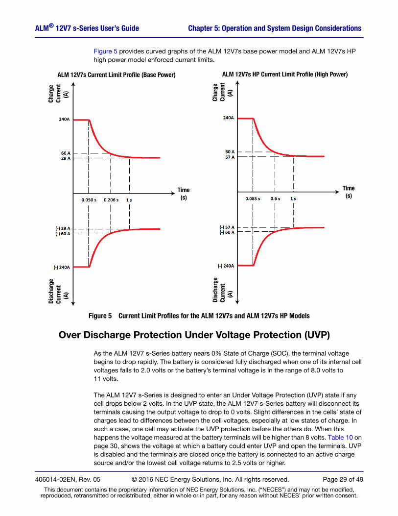
The ALM 12V7 s-Series batteries apply a time-based current limit profile that allows higher level current pulses for short durations. Figure 5 on page 29 shows the maximum amplitude limits enforced over increasing time intervals for the ALM 12V7s base power model and the ALM 12V7s HP high power model. These curves have a -2% / +15% tolerance. The maximum amplitude limit of 240 A decreases over time until it reaches a steady state limit of 23 A for the ALM 12V7s and 45 A for the ALM 12V7s HP. These current limit profiles apply to both charge and discharge operations.
NOTECharge sources exceeding the continuous current will charge the battery at a duty-cycle inversely proportional to the charger’s current. Exceeding the 240 A peak current will result in NO charge.
406014-02EN, Rev. 05 © 2016 NEC Energy Solutions, Inc. All rights reserved. Page 28 of 49
This document contains the proprietary information of NEC Energy Solutions, Inc. (“NECES”) and may not be modified, reproduced, retransmitted or redistributed, either in whole or in part, for any reason without NECES’ prior written consent.
ALM® 12V7 s-Series User’s Guide Chapter 5: Operation and System Design Considerations
Figure 5 provides curved graphs of the ALM 12V7s base power model and ALM 12V7s HP high power model enforced current limits.
ALM 12V7s Current Limit Profile (Base Power) ALM 12V7s HP Current Limit Profile (High Power)
Figure 5 Current Limit Profiles for the ALM 12V7s and ALM 12V7s HP Models
Over Discharge Protection Under Voltage Protection (UVP)
As the ALM 12V7 s-Series battery nears 0% State of Charge (SOC), the terminal voltage begins to drop rapidly. The battery is considered fully discharged when one of its internal cell voltages falls to 2.0 volts or the battery’s terminal voltage is in the range of 8.0 volts to 11 volts.
The ALM 12V7 s-Series is designed to enter an Under Voltage Protection (UVP) state if any cell drops below 2 volts. In the UVP state, the ALM 12V7 s-Series battery will disconnect its terminals causing the output voltage to drop to 0 volts. Slight differences in the cells’ state of charges lead to differences between the cell voltages, especially at low states of charge. In such a case, one cell may activate the UVP protection before the others do. When this happens the voltage measured at the battery terminals will be higher than 8 volts. Table 10 on page 30, shows the voltage at which a battery could enter UVP and open the terminals. UVP is disabled and the terminals are closed once the battery is connected to an active charge source and/or the lowest cell voltage returns to 2.5 volts or higher.
406014-02EN, Rev. 05 © 2016 NEC Energy Solutions, Inc. All rights reserved. Page 29 of 49
This document contains the proprietary information of NEC Energy Solutions, Inc. (“NECES”) and may not be modified, reproduced, retransmitted or redistributed, either in whole or in part, for any reason without NECES’ prior written consent.

ALM® 12V7 s-Series User’s Guide Chapter 5: Operation and System Design Considerations
Table 10 End of Discharge – Effective ALM 12V7 s-Series Terminal Cut-Off Voltages in Different Series Configurations
ALM ConfigurationTypical Observed ALM Terminal Cut-Off Voltage (V) Average Voltage per Cell (V)
Absolute Minimum ALM Terminal Cut-Off Voltage (V)
1S ‐ (12 V) 9.8 2.45 8.00
2S ‐ (24 V) 20.3 2.54 16.00
3S ‐ (36 V) 30.7 2.56 24.00
4S ‐ (48 V) 41.1 2.57 32.00
NOTEUnder voltage protection creates an open circuit, removing voltage from the terminals. With a lead-acid battery, finding no voltage at the terminals often indicates the battery is no longer usable. With the ALM 12V7 s-Series battery, no voltage at the terminals typically means the cell protection circuitry has interrupted current to protect the battery. Simply connect the battery to a charge source to restore voltage to the terminals.
Smart Charger Support
Smart charger technologies require the presence of a terminal voltage before supplying a charge current. To support smart chargers when in a protection state (i.e. Under Voltage Protection (UVP) the ALM 12V7 s-Series will present a current limited terminal voltage. When there is no charger or load connected, there is no current flowing so the circuit allows the terminals to show the actual battery voltage. This terminal voltage can be measured with a multi-meter or other high impedance voltage measurement device.
Over Charge Protection
Similar, but opposite to the case at low States of Charge, the ALM 12V7 s-Series battery’s terminal voltage begins to rise rapidly at high States of Charge. The ALM 12V7 s-Series is considered at 100% SOC when the cells are balanced and terminal voltage measures 13.8 volts or above. At this point, the average cell voltage is the terminal voltage divided by 4. The ALM12V7 s-Series batteries are designed to enter an Over Voltage Protection (OVP) state if any cell rises above 4.1 volts. In the OVP state, the ALM 12V7 s-Series will disconnect its terminals and not accept further charge current. To exit the OVP state, apply a load to discharge to the battery. The battery will then return to Normal State once the cell voltages fall below 4.1 volts. For further details, refer to Balancing, on page 41.
Over Temperature Protection
The ALM 12V7 s-Series circuitry continuously monitors the battery’s temperature. The battery will open its terminals when the temperature is too high for safe operation. Do not operate the battery outside of the operational temperature range specified in Table 4 on page 23.
406014-02EN, Rev. 05 © 2016 NEC Energy Solutions, Inc. All rights reserved. Page 30 of 49
This document contains the proprietary information of NEC Energy Solutions, Inc. (“NECES”) and may not be modified, reproduced, retransmitted or redistributed, either in whole or in part, for any reason without NECES’ prior written consent.

ALM® 12V7 s-Series User’s Guide Chapter 5: Operation and System Design Considerations
High Temperature Operation
Both charge and discharge functions increase battery temperatures. High rate battery usage causes the largest temperature increase. The ALM 12V7 s-Series battery’s over temperature protection (OTP) circuitry removes voltage from the terminals if the battery exceeds the temperature limits. During high rate battery usage, the user must ensure that ambient operating temperature combined with the charge or discharge rate does not exceed the operational temperature limits. Table 11 shows how the ALM 12V7 s-Series usage rate and ambient temperature relate to measured delta SOC before entering OTP state.
Under certain conditions, the ALM 12V7 s-Series terminals will exceed the 70°C touch temperature limit as described in UL 1973. For operation beyond those terminal touch temperature limits, not to exceed 90 °C, the ALM 12V7 s-Series batteries will require the placement of guards to prevent accidental contact. NEC Energy Solutions recommends that additional testing be conducted under specific use cases. The gauge of wire may be changed depending on final temperature requirements and application.
Table 11 Thermal Capability and Delta SOC, BOL a
Usage Rate: Charge or Discharge Current (A)
25 °C Ambient b
b. Testing was with 10 AWG cables at 25 °C and 60 °C
c
c. 100% = 5 Ah
60 °C Ambient b c
ALM 12V7s ALM 12V7s HP ALM 12V7s ALM 12V7s HP
% delta SOC % delta SOC% delta SOCInternal Limit
% delta SOCInternal Limit
5 100 100 100 100
10 100 100 84.4 90.4
23 100 100 17.9 (10.9 TT d) 25.6 (7.0 TT d)
d. TT = Touch Temperature. The % delta SOC TT when Touch Temperature (TT) of the terminal exceeds 70 °C. A cover or other protection is required to prevent incidental contact per UL1973.
30 N/A e
e. N/A = Not Applicable. The 12V7s battery is not capable of achieving this charge or discharge current.
100 N/A e 20 (5.0 TT d)
45 N/A e 100 N/A e 12 (2.5 TT d)
NOTECell life will be limited by exposure to high temperatures.
a. The values in this table show the battery’s performance prior to engaging its protection circuitry.
406014-02EN, Rev. 05 © 2016 NEC Energy Solutions, Inc. All rights reserved. Page 31 of 49
This document contains the proprietary information of NEC Energy Solutions, Inc. (“NECES”) and may not be modified, reproduced, retransmitted or redistributed, either in whole or in part, for any reason without NECES’ prior written consent.

ALM® 12V7 s-Series User’s Guide Chapter 5: Operation and System Design Considerations
Tableau 12 Capacité Thermique et Delta État de Charge, Début de la Vie a
Fonctionnement à haute température
Les deux fonctions de charge et de décharge augmentent températures de batterie. Utilisation élevée de la batterie de taux provoque la plus forte augmentation de température. La batterie ALM 12V7 s-Séries «plus de la protection de température (OTP) circuit supprime la tension des bornes si la batterie dépasse les limites de température. Lors de l'utilisation de la batterie de taux élevé, l'utilisateur doit se assurer que la température ambiante de fonctionnement combiné avec la charge ou de décharge taux ne dépasse pas les limites de températures de fonctionnement. Tableau 12 montre comment l' ALM 12V7s et ALM12V7s HP et la température ambiante concernent mesurée SOC delta avant d'entrer dans l'état OTP.
Sous certaines conditions, les bornes de connection de l' ALM 12V7 s-Séries dépasseront la limite de température de contact de 70 °C, ne pas dépasser 90 °C, comme décrit dans UL 1973. Pour un fonctionnement au-delà des limites de température de contact, l' ALM 12V7 s-Séries nécessitera la mise en place de protections pour empêcher tout contact accidentel. NEC Energy Solutions recommande que des tests supplémentaires soient effectues pour chaque cas d'utilisation spécifiques. La jauge de fil peut être modifiée en fonction des exigences du température finale et application.
REMARQUELa durée de vie les elements de la pile seront limites par l'exposition à des températures élevées.
Taux d'utilisation
Charge/ Décharge
Courants (A)
Température ambiante de 25 °C b c Température ambiante de 60 °C b c
ALM 12V7s ALM 12V7s HP ALM 12V7s ALM 12V7s HP
% delta SOC % delta SOC% delta SOC
Limite interne% delta SOC
Limite interne
5 100 100 100 100
10 100 100 84,4 90,4
23 100 100 17,9 (10.9 TT) 25,6 (7,0 TC d)
30 Pas Applicable e 100 Pas Applicable e 20,0 (5,0 TC d)
45 Pas Applicablee 100 Pas Applicable e 12 (2,5 TC d)
a. Les valeurs indiquées dans ce tableau montrent les performances de la batterie avant que les circuit de protection ne soient actifs.
b. Essai avec des câbles AWG 10 à 25 °C et 60 °Cc. 100% = 5 Ahd. TC = Température de contact dépasse. Le SOC TC % delta lorsque TC du terminal de la batterie dépasse 70 °C. Une
protection de couverture ou autre est nécessaire pour empêcher un contact accidentel à la borne, conformément à la
UL1973 réglementation.e. Pas Applicable = La batterie 12V7s ne est pas capable d'atteindre ce courant de charge ou de décharge
406014-02EN, Rev. 05 © 2016 NEC Energy Solutions, Inc. All rights reserved. Page 32 of 49
This document contains the proprietary information of NEC Energy Solutions, Inc. (“NECES”) and may not be modified, reproduced, retransmitted or redistributed, either in whole or in part, for any reason without NECES’ prior written consent.

ALM® 12V7 s-Series User’s Guide Chapter 5: Operation and System Design Considerations
Low Temperature Operation
At low temperatures, the maximum available discharge current decreases due to increased internal impedance at lower temperatures. Refer to Figure 9 on page 40 and Charge Limits and Temperatures, on page 34 for more details.
NOTEDo not operate the battery outside of the operational temperature range specified in Table 4 on page 23.
REMARQUENe pas faire fonctionner la batterie en dehors de la plage de température d'exploitation précisée dans Tableau 6 à la page 25.
Charging Single Batteries
The ALM 12V7 s-Series batteries are compatible with most common 12V lead‐acid battery chargers. A single ALM 12V7s HP battery can accept up to 45 A (23A with the ALM 12V7s) charge current maximum. Higher current for short durations is allowed. However, in some situations, internal component temperatures may be exceeded causing performance to be curtailed by the battery’s protection circuitry. For more information on hardware protection limits, refer to Appendix A, Operational Protection Hardware Circuitry on page 46. Additional charge limit information is also described in Charge Limits and Temperatures, on page 34.
NOTEUse of chargers with a temperature compensation feature, typically required for lead-acid batteries, may result in an incomplete or possibly no charge at elevated temperatures, but will not damage the battery. It is recommended that such temperature compensation features be disabled.
Constant Current (CC), Float Voltage Chargers
For ALM 12V7 s-Series batteries operating under normal conditions during a charge, a charger applies a constant current (CC) until the terminal voltage reaches its end of charge voltage (maximum), as shown in Figure 6 on page 34. This process is followed by a float voltage, where the charge current decays to near zero. As the battery approaches 100% State of Charge (SOC), the balancing circuitry performs cell balancing. This process charges the ALM 12V7 s-Series battery to 100% State of Charge (SOC).
406014-02EN, Rev. 05 © 2016 NEC Energy Solutions, Inc. All rights reserved. Page 33 of 49
This document contains the proprietary information of NEC Energy Solutions, Inc. (“NECES”) and may not be modified, reproduced, retransmitted or redistributed, either in whole or in part, for any reason without NECES’ prior written consent.

ALM® 12V7 s-Series User’s Guide Chapter 5: Operation and System Design Considerations
Figure 6 Battery Voltage and Current During Recharge
If the ALM 12V7 s-Series battery has entered an Under Voltage Protection (UVP) state, the battery disconnects from the load. Connecting a charger to the battery resumes normal operation based on replenished energy.
NOTENew batteries may be used as received. However, to ensure that all cells are balanced and fully charged before their first use, individual batteries should be charged for 4 to 24 hours with a float charge. Charging is particularly necessary prior to performing capacity tests. After initially balancing the batteries, normal use should maintain the cells in a proper state.
REMARQUELes nouvelles batteries peuvent être utilisees tels que reçuss. Cependant, our s'assurer que tous les elements de la pile sont équilibrés et pleinement chargés avant leur première utilisation, les batteries individuelles devraient être chargées pendant 4 à 24 heures avec une charge de maintien. La charge est particulièrement nécessaire avant de procéder à des tests de capacité. Après équilibrage d'abord des piles, l'utilisation normale devrait maintenir les elements de la pile en bon état.
Charge Limits and Temperatures
At room temperature and above, ALM 12V7 s-Series batteries can accept full rated charge. As with all battery technologies, charge acceptance is limited at low temperatures. A permanent loss of capacity over time may be observed if charge rates are not reduced at low cell temperatures. As the cells’ temperature rises during the charging process, they can gradually accept higher currents. Table 13 on page 35 shows charging guidelines to maximize battery life.
406014-02EN, Rev. 05 © 2016 NEC Energy Solutions, Inc. All rights reserved. Page 34 of 49
This document contains the proprietary information of NEC Energy Solutions, Inc. (“NECES”) and may not be modified, reproduced, retransmitted or redistributed, either in whole or in part, for any reason without NECES’ prior written consent.

ALM® 12V7 s-Series User’s Guide Chapter 5: Operation and System Design Considerations
Table 13 Charge Rate by Temperature a
Temperature (°C) Current (A) Temperature (°C) Current (A)
60 45 10 5.0
50 45 0 2.5
40 45 -10 1.5
30 45 -20 1.0
25 45 -30 0.25
20 23 -40 0.125
Tableau 14 Taux des frais par Température a
Température (°C) Courants (A) Température (°C) Courants (A)
60 45 10 5,0
50 45 0 2,5
40 45 -10 1,5
30 45 -20 1,0
25 45 -30 0,25
20 23 -40 0,125
a. Pour acceptation de charge, ne pas dépasser les limites spécifiées. Pour les températures plus élevées (et les taux de charge), le dépassement de ces taux peut entraîner engager le circuit de protection de l' ALM 12V7 s-Séries.
Pour des températures plus basses, le dépassement de ces taux entraînera dans une vie courte de la batterie.
Chargez Limites et températures
A température ambiante et au-dessus, les batteries ALM 12V7 s-Séries peuvent accepter la pleine charge nominale. Comme avec toutes les technologies batteries, de l'acceptation de charge est limitée à basse température. Une perte permanente de capacité au fil du temps peut être observée si les taux de charges ne sont pas réduits à des températures des elements de la pile. Comme la température basses elements de la pile augmente pendant le processus de charge, ils peuvent accepter progressivement des courants plus élevés. Tableau 14 spectacles de charge des lignes directrices afin de maximiser la vie de la batterie.
a. For charge acceptance, do not exceed the limits specified. For the higher temperatures (and charging rates), exceeding these rates may result in engaging the ALM 12V7 s-Series protection circuitry. For lower temperatures, exceeding these rates will result in a shorter battery life.
406014-02EN, Rev. 05 © 2016 NEC Energy Solutions, Inc. All rights reserved. Page 35 of 49
This document contains the proprietary information of NEC Energy Solutions, Inc. (“NECES”) and may not be modified, reproduced, retransmitted or redistributed, either in whole or in part, for any reason without NECES’ prior written consent.

ALM® 12V7 s-Series User’s Guide Chapter 5: Operation and System Design Considerations
Charging Multiple Batteries
When charging multiple batteries, maximum charge current should not exceed 45 A for arrays of ALM 12V7 s-Series batteries connected in parallel and/or series configurations. The end-of-charge voltage will depend on the system’s series and parallel configuration.
Charging Batteries in Series
To determine the maximum end-of-charge voltage to apply for battery systems configured in series, multiply the number of batteries connected in series by the maximum charge voltage of a single battery (14.4 V), as shown in Equation 1.
Eq. 1 (Number of Series Connected ALM 12V7 s-Series Batteries) x (14.4V) = Max Charge Voltage, Battery System.
Table 15 shows Recommended Float and Maximum Charge voltages. Charger voltages exceeding the Maximum up to 60.0 volts will not damage an ALM 12V7 s-Series battery, but the battery may not operate due to over voltage protection. When the battery is in the normal state, the charger voltage should be less than or equal to the Maximum Charge Voltage.
WARNINGApplying charger voltages in excess of 60.0 V could damage the charge and discharge control circuitry, creating a safety hazard, and will void the warranty.
Charging Batteries in Parallel
The maximum charge current for any parallel array of batteries is 45 A.
Table 15 Supported Float and Maximum Charge Voltages
Series Configuration Recommended Float Charge Voltage (V) Maximum Charge Voltage (V)
1s 13.6 to 14.4 16
2s 27.25 to 28.8 32
3s 40.8 to 43.2 48
4s 54.5 to 57.6 60
406014-02EN, Rev. 05 © 2016 NEC Energy Solutions, Inc. All rights reserved. Page 36 of 49
This document contains the proprietary information of NEC Energy Solutions, Inc. (“NECES”) and may not be modified, reproduced, retransmitted or redistributed, either in whole or in part, for any reason without NECES’ prior written consent.

ALM® 12V7 s-Series User’s Guide Chapter 5: Operation and System Design Considerations
Chargement des Piles Dans la Série
Pour déterminer la tension maximale en fin de charge à appliquer pour les systèmes de batterie configurés en série, multiplier le nombre de batteries connectées en série par la tension de charge maximale d'une seule batterie (14,4 V), comme indiqué dans l'Equation 2.
Eq. 2 (Nombre de batteries ALM 12V7 s-Séries connectées en série) x (14,4V) = Tension de charge maximale, système de batterie x (14,4V) = Tension Max Charge, Système de batterie.
Le Tableau 16 montre la tension de maintien recommandée et tensions charge maximale. La batterie ne sera pas endommagée par des tensions de charge ne dépassant pas 60 V, mais l' ALM 12V7 s-Séries peut ne pas fonctionner en raison de protection contre les surtensions. En condition normale, la tension de charge doit être inférieure ou égale à la tension de charge maximale.
AVERTISSEMENTAppliquer des tensions de charge excédant 60.0 V pourrait endommager la circuiterie de commande de charge et de décharge, créant un risque d'accident, et annulera la garantie.
Recharger les Batteries en Parallèle
Le courant de charge maximum pour un réseau parallèle de batteries est de 45 Ampères.
Tableau 16 Tension de Maintien et les Tensions Charge Maximale
Configuration de SérieTension de Maintien Recommandée Tension
de charge (V) Tension de Charge Maxima le (V)
1s 13,6 à 14,4 16
2s 27,2 à 28,8 32
3s 40,8 à 43,2 48
4s 54,4 à 57,6 60
406014-02EN, Rev. 05 © 2016 NEC Energy Solutions, Inc. All rights reserved. Page 37 of 49
This document contains the proprietary information of NEC Energy Solutions, Inc. (“NECES”) and may not be modified, reproduced, retransmitted or redistributed, either in whole or in part, for any reason without NECES’ prior written consent.

ALM® 12V7 s-Series User’s Guide Chapter 5: Operation and System Design Considerations
Discharge Performance
The typical 25 °C constant current discharge behavior of the ALM 12V7 s-Series at different discharge rates is shown in Figure 7. Compared to lead-acid batteries, the output voltage of the ALM 12V7 s-Series remains relatively constant across its capacity range at any given discharge rate.
Figure 7 ALM 12V7 s-Series Typical Constant Current Discharge Behavior at 25 °C
406014-02EN, Rev. 05 © 2016 NEC Energy Solutions, Inc. All rights reserved. Page 38 of 49
This document contains the proprietary information of NEC Energy Solutions, Inc. (“NECES”) and may not be modified, reproduced, retransmitted or redistributed, either in whole or in part, for any reason without NECES’ prior written consent.

ALM® 12V7 s-Series User’s Guide Chapter 5: Operation and System Design Considerations
As the ALM 12V7 s-Series discharges, this moderate voltage drop translates into superior (I x V) power delivery capability as shown in Figure 8. Additionally, the ALM 12V7 s-Series delivered capacity is nearly independent of discharge rate.
Figure 8 ALM 12V7 s-Series Typical Constant Power Discharge Behavior at 25 °C
406014-02EN, Rev. 05 © 2016 NEC Energy Solutions, Inc. All rights reserved. Page 39 of 49
This document contains the proprietary information of NEC Energy Solutions, Inc. (“NECES”) and may not be modified, reproduced, retransmitted or redistributed, either in whole or in part, for any reason without NECES’ prior written consent.

ALM® 12V7 s-Series User’s Guide Chapter 5: Operation and System Design Considerations
Voltage drop in the ALM 12V7 s-Series is an inverse function of the ALM 12V7 s-Series battery’s internal temperature. As the internal temperature of the ALM 12V7 s-Series drops, the impedance rises leading to an increased voltage drop. It is important to consider the resulting performance impacts when designing a product for cold conditions. Figure 9 shows impacts of temperature on 50W constant power discharge.
Figure 9 ALM 12V7 s-Series Typical 50W Constant Power Discharge Behavior
The ALM 12V7 s-Series battery’s End of Discharge (EOD) terminal voltage is a function of the core cells, any cell-to-cell variations and series impedance of the internal power pathway. These elements are impacted by discharge rate and temperature. The battery’s protection circuitry will stop discharge when any cell voltage drops below 2.0 volts.
Cell‐to‐cell variation has the largest impact on the expected EOD terminal voltage. Cells vary in performance in a variety of ways based on normal manufacturing.
Applications that use a low battery voltage threshold value (LVCO, LVLD, LVBD, etc.) to initiate actions such as disconnecting the load or initiating a charge cycle should adhere to the battery terminal voltages shown in the discharge performance curves in Figure 7, Figure 8, and Figure 9. Depending on the discharge rate, temperature, and other factors in the application, a different voltage trigger value based on the appropriate discharge curve may be needed, compared to lead-acid or other battery chemistries. Otherwise, undesired behavior of the battery application may occur such as the unexpected loss of voltage if the ALM 12V7 s-Series battery enters UVP state, or taking action too soon such as disconnecting the load while significant energy still remains in the battery.
406014-02EN, Rev. 05 © 2016 NEC Energy Solutions, Inc. All rights reserved. Page 40 of 49
This document contains the proprietary information of NEC Energy Solutions, Inc. (“NECES”) and may not be modified, reproduced, retransmitted or redistributed, either in whole or in part, for any reason without NECES’ prior written consent.

ALM® 12V7 s-Series User’s Guide Chapter 5: Operation and System Design Considerations
If the intent of the application is to maximize the amount of energy available from the ALM 12V7 s-Series battery before charging, it may be advantageous to disable external cutoff mechanisms based on the terminal voltage and instead use the battery’s internal protection circuitry to determine when to interrupt the discharge cycle. The battery protects itself from unsafe conditions and typically disconnects due to low voltage when only 5-10% of full charge capacity remains.
Balancing
Over time, the ALM 12V7 s-Series cells diverge in both capacity and SOC. All ALM 12V7 s-Series batteries perform cell voltage balancing at high SOC values based on cell voltage to maximize the available capacity of the battery. The balancing circuit’s purpose is to drive all cells to the same voltage. Cell balancing continues on a per-cell basis as long as the cell voltage exceeds 3.385 volts.
ALM 12V7 s-Series batteries are shipped at 100% SOC. However, fully charging the ALM and holding the ALM at float voltage for 4-24 hours prior to first use will ensure optimal balance and maximize the first discharge delivered capacity.
Cycle Life
Cycle life is dependent upon charge and discharge rates, operating temperature, calendar time and state of charge swing or delta SOC. Figure 10 projects cycle life expectations as a function of delta SOC where reducing delta SOC results in greatly enhanced cycle life.
Figure 10 Cycle Life versus Delta SOC Behavior of Nanophosphate® Lithium-Ion Cell
406014-02EN, Rev. 05 © 2016 NEC Energy Solutions, Inc. All rights reserved. Page 41 of 49
This document contains the proprietary information of NEC Energy Solutions, Inc. (“NECES”) and may not be modified, reproduced, retransmitted or redistributed, either in whole or in part, for any reason without NECES’ prior written consent.

ALM® 12V7 s-Series User’s Guide Chapter 5: Operation and System Design Considerations
After 6 years of continuous testing, original A123 Systems ANR26650M1A cells still retain 65% of their initial capacity after 20,000 full depth of discharge (100% DOD), +1C/-1C cycles at 23 °C. The ALM 12V7 s-Series batteries use the next generation ANR26650M1B cells. Through testing under the same conditions, cells of this model are demonstrating further improved cycle life behavior over their predecessors, as shown in Figure 11.
Figure 11 Cycle Life Test Results +1C/-1C, 23 °C, 100% DOD
NOTEThe number of cycles, as shown in Figure 10 and Figure 11, are dependent upon average SOC, charge/discharge rates, temperature and calendar time. Actual results will depend on specific use case. Contact NEC Energy Solutions for more detail.
NOTEOverall system life is a function of Shelf Life (Time at temperature) and Cycle Life (charge discharge rates and watt-hour throughput).
Shelf Life
ALM 12V7 s-Series batteries ship from the factory at approximately 100% State of Charge (SOC) and can remain functional for two years of shelf life where temperatures do not exceed 25 °C.
ALM 12V7 s-Series batteries being shipped by Air must comply with ICAO regulations, which requires that the batteries be at or below a 30% SOC. These batteries shipped by Air can remain functional for eight months of shelf life where temperatures do not exceed 25 °C.
Storage temperatures above 25 °C accelerate the rate of self-discharge and reduce the shelf life.
At 10% SOC, the ALM 12V7 s-Series battery has about 5% of usable energy, on average, before entering into an Under Voltage Protection (UVP) state as described in Over Discharge
406014-02EN, Rev. 05 © 2016 NEC Energy Solutions, Inc. All rights reserved. Page 42 of 49
This document contains the proprietary information of NEC Energy Solutions, Inc. (“NECES”) and may not be modified, reproduced, retransmitted or redistributed, either in whole or in part, for any reason without NECES’ prior written consent.

ALM® 12V7 s-Series User’s Guide Chapter 5: Operation and System Design Considerations
Protection Under Voltage Protection (UVP), on page 29. NEC Energy Solutions recommends applying a charge source whenever a battery is at 10% or lower SOC.
The ALM 12V7 s-Series battery will automatically discontinue a discharge when the battery reaches roughly 5% State of Charge (SOC), and will then disconnect its terminals. Due to the electrical drain within the battery management system; after the battery reaches the 5% SOC level at the Under Voltage Protection UVP state there is a limited time that the battery can remain without being charged. If the ALM 12V7 s-Series battery is discharged to the UVP 5% SOC level, it has approximately 30 days in this state, at 25 °C, before reaching its lowest power mode called the Under Voltage Lock-Out (UVLO) state. Once the battery reaches the UVLO state, it has approximately 36 hours before becoming permanently disabled.
While in UVLO, an ALM 12V7 s-Series battery can accept a small charge current through a precharge circuit to bring the battery to its proper operating range. Once the battery reaches the UVP state, it can accept a full rated charge current. NEC Energy Solutions recommends that the full rate charge remains until the battery is fully charged. Partial charges are acceptable, but they will limit the shelf life the battery can sustain in storage.
Durée de Conservation
Toutes les batteries ALM 12V7 s-Séries sont expédiées de l’usine à environ 100 % d’état de charge (SOC) et restent fonctionnelles pendant deux ans, à condition que les températures ne dépassent pas 25 °C.
Les batteries ALM 12V7 s-Séries expédiées par voie aérienne doivent être conformes aux règlements de l’OACI, qui exigent que ces batteries présentent un état de charge de 30 % maximum. Elles peuvent rester fonctionnelles pendant huit mois, à condition que les températures ne dépassent pas 25 °C.
Les températures de stockage supérieures à 25 °C accélèrent le taux d’autodécharge et réduisent la durée de vie.
À un état de charge de 10 %, la batterie ALM 12V7 s-Séries dispose d’environ 5 % d’énergie utilisable avant de passer en mode de protection contre les sous-tensions (UVP), tel que décrit dans la section Protection contre la décharge accélérée (protection contre les sous-tensions (UVP)), à la page 29. NEC Energy Solutions recommande d’utiliser une source de chargement dès qu’une batterie présente un état de charge de 10 % ou moins.
La batterie ALM 12V7 s-Séries interrompra automatiquement une opération de décharge lorsqu’elle atteint un état de charge d’environ 5 %, puis elle déconnectera ses bornes. En raison du drainage électrique dans le système de gestion de la batterie, une fois que la batterie atteint un état de charge de 5 % en mode de protection contre les sous-tensions (UVP), elle peut rester déchargée durant une période limitée. Si la batterie ALM 12V7 s-Séries est déchargée à 5 % en mode UVP, elle reste environ 30 jours dans cet état, à 25 °C, avant d’atteindre son mode d’alimentation le plus bas, appelé le Verrouillage de sous-tension (UVLO). Une fois que la batterie est en mode UVLO, elle dispose d’environ 36 heures avant de subir un endommagement permanent.
En mode UVLO, une batterie 36 heures peut accepter un faible courant de charge à travers un circuit de précharge pour atteindre sa bonne plage de fonctionnement. Une fois qu’elle passe en mode UVP, elle peut accepter un courant de charge nominale maximum. NEC Energy Solutions recommande de maintenir la charge maximale jusqu'à ce que la batterie soit complètement chargée. Les charges partielles sont acceptables, mais elles limiteront la durée de vie de la batterie lorsqu’elle est stockée.
406014-02EN, Rev. 05 © 2016 NEC Energy Solutions, Inc. All rights reserved. Page 43 of 49
This document contains the proprietary information of NEC Energy Solutions, Inc. (“NECES”) and may not be modified, reproduced, retransmitted or redistributed, either in whole or in part, for any reason without NECES’ prior written consent.

ALM® 12V7 s-Series User’s Guide Chapter 6
Chapter 6: Troubleshooting
Troubleshooting
Overview
The ALM 12V7 s-Series are extremely reliable batteries that provide greater useful life than comparable 12V7 lead‐acid batteries. Despite the high reliability of the ALM 12V7 s-Series batteries, you may encounter situations where the battery does not operate as expected. This chapter details potential issues with the ALM 12V7 s-Series batteries and the appropriate troubleshooting procedures.
406014-02EN, Rev. 05 © 2016 NEC Energy Solutions, Inc. All rights reserved. Page 44 of 49
This document contains the proprietary information of NEC Energy Solutions, Inc. (“NECES”) and may not be modified, reproduced, retransmitted or redistributed, either in whole or in part, for any reason without NECES’ prior written consent.

ALM® 12V7 s-Series User’s Guide Chapter 6: Troubleshooting
Table 17 ALM12V7s HP Troubleshooting and Solutions
Problem Possible Cause(s) Solution(s)
The battery does not deliver the expected Ah (capacity).
1. The battery is out‐of‐balance.
2. The battery has reached the end of its useful service life.
3. The battery overheated due to ambient temperature or C-Rate.
1. Apply a float charge for 48 hours to balance the battery cells.
2. Replace the battery.
3. Reduce the ambient temperature or C-Rate.
Charge current suddenly goes to zero while connected to a source.
1. The battery overheated, enabling over‐temperature protection.
2. The battery is out‐of‐balance.
3. Charge current is too high,
exceeding OCP protection. a
1. Allow the battery to cool.
2. Apply a float charge for 48 hours to balance the battery’s cells. For more details on charging battery, batteries, or strings, refer to Charging Single Batteries on page 33 and Charging Multiple Batteries on page 36.
3. Reduce charge current.
Voltage drops abruptly while in use after appearing constant.
1. The battery is fully discharged.
2. OCP has engaged
1. Perform a charge cycle.
2. Reduce the load.
Low or zero volts across the terminal1. The battery is in UVP or UVLO.
2. The battery is in OTP.
1. Perform a charge cycle.
2. Allow the battery to cool.
a. High-speed OCP occurs in10 μs so it will not be visible on a digital volt meter.
406014-02EN, Rev. 05 © 2016 NEC Energy Solutions, Inc. All rights reserved. Page 45 of 49
This document contains the proprietary information of NEC Energy Solutions, Inc. (“NECES”) and may not be modified, reproduced, retransmitted or redistributed, either in whole or in part, for any reason without NECES’ prior written consent.

ALM® 12V7 s-Series User’s Guide
406014-02EN, Rev. 05 © 2016 NEC Energy Solutions, Inc. All rights reserved. Page 46 of 49
This document contains the proprietary information of NEC Energy Solutions, Inc. (“NECES”) and may not be modified, reproduced, retransmitted or redistributed, either in whole or in part, for any reason without NECES’ prior written consent.
Appendix A
Appendix A: Operational Protection Hardware Circuitry
Operational Protection Hardware Circuitry
Table 18 lists the ALM 12V7 s-Series batteries Operational Protection matrix covering hardware circuitry for voltage and temperature. The following list defines abbreviations used in Table 18:
• FETs: Field-Effect Transistors
• OTP: Over-Temperature Protection
• OVP: Over-Voltage Protection
• UVP: Under-Voltage Protection
• UVLO: Under-Voltage Lock-Out
Table 18 ALM 12V7 s-Series Operational Protection Parameters
ParameterSet Value ALM 12V7s
Set Value ALM 12V7s HP
Clear Value ALM 12V7s
Clear ValueALM 12V7s HP Applies to
OVP >4.1 V >4.1 V <4.1 V <4.1 V Any cell
OVP-2 >4.25 V >4.25 V <4.25 V <4.25 V Any cell
UVP 2.00 V 2.00 V >2.50 V >2.50 V Any cell
Battery lockout <.7 V <.7 V Never a Never a Any cell
UVLO mode 7 V (No charger) 7 V (No charger) 7.3 V (With charger) 7.3 V (With charger) Battery
OTP cell 68 °C 68 °C 63 °C 63 °C Any cell
OTP-2 cell 80 °C 80 °C Never a Never a Any cell
OTP FET 110 °C 110 °C 90 °C 90 °C FETs
OTP-2 FET 130 °C 130 °C Never a Never a FETs
a. Internal circuitry does not allow this event to clear.

ALM® 12V7 s-Series User’s Guide Appendix B
Appendix B: Acronyms and Terminology
Acronyms and Terminology
The following table lists and describes acronyms and terms used in this guide.
Term/Acronym Description
Ah Amp-Hour is a unit of measure of charge that can be stored or delivered to/from a battery.
BatteryOne or more cells which are electrically connected together by permanent means, including case, terminals and markings. Also, the ALM 12V7 s-Series battery.
BMSBattery Management System – The Battery Management System refers to the collection of electronics responsible for monitoring and controlling an ESS. The ALM 12V7s HP does not require an external BMS (See Battery Configuration Options on page 16).
BOL Beginning of Life – at the time the product was first assembled at the factory.
CC Constant Current – A method to charge or discharge a battery in which the current is held constant independent of the battery’s terminal voltage.
CE Conformité Européenne, meaning “European Conformity”- Tests and Certifies safe and compliant product operation in Europe.
Cell The individual A123 Systems ANR26650M1B cell is the basis for the ALM 12V7 s-Series battery.
CFET Charge control FET
C-Rate An electrical current value corresponding to that which will fully charge or discharge a battery in one hour.
CV Constant Voltage – A method to charge a battery in which the terminal voltage is held constant, and the current is determined by the power path impedance or some active current limiting.
CV2/2 Formula for Energy stored in capacitance
DFET Discharge control FET
DOD Depth of Discharge
406014-02EN, Rev. 05 © 2016 NEC Energy Solutions, Inc. All rights reserved. Page 47 of 49
This document contains the proprietary information of NEC Energy Solutions, Inc. (“NECES”) and may not be modified, reproduced, retransmitted or redistributed, either in whole or in part, for any reason without NECES’ prior written consent.

ALM® 12V7 s-Series User’s Guide Appendix B: Acronyms and Terminology
EMC Electro Magnetic Compatibility
EOD End of Discharge
ESS Energy Storage System
FCC Federal Communications Commission. RF Emissions governing body in the United States.
FET Field-Effect Transistor, used for switching high current levels.
HW Hardware
kbit/s kilobit per second
LI2/2 Formula for Energy stored in inductance
LVBD Low Voltage Battery Disconnect
LVCO Low Voltage Cut-off
LVLD Low Voltage Load Disconnect
Mbit/s Megabit per second
OCP Over-Current Protection
OTP Over-Temperature Protection
OVP Over-Voltage Protection
OEM Original Equipment Manufacturer – in reference to this document, the maker of the equipment into which an ESS is installed and used.
Nominal Energy The energy value of a cell or battery determined under specified conditions and declared by the manufacturer. The nominal energy is calculated by multiplying nominal voltage by rated capacity expressed in ampere-hours. Also known as Watt-hour rating.
Nominal Voltage The approximate value of the voltage used to designate or identify a cell or battery
Non-Volatile MemoryGeneral term for all forms of solid state (no moving parts) memory that has the capability to hold saved data even when its power is turned off. Unlike volatile memory, it does not require periodic refreshing of its memory contents.
Room Temperature The range between 20 and 23 °C (68 and 73 °F), with an average of 21.5 °C (70.7 °F).
Term/Acronym Description
406014-02EN, Rev. 05 © 2016 NEC Energy Solutions, Inc. All rights reserved. Page 48 of 49
This document contains the proprietary information of NEC Energy Solutions, Inc. (“NECES”) and may not be modified, reproduced, retransmitted or redistributed, either in whole or in part, for any reason without NECES’ prior written consent.

ALM® 12V7 s-Series User’s Guide Appendix B: Acronyms and Terminology
Related Documents and Resources
• Link to International Civil Aviation Organization (ICAO) Technical Instructions:http://www.icao.int/safety/DangerousGoods/Pages/default.aspx
• Link to International Air Transport Association (IATA) Dangerous Goods Regulations: http://www.iata.org/whatwedo/cargo/dgr/Pages/lithium-batteries.aspx
• Link to International Maritime Dangerous Goods (IMDG) Code:http://www.imo.org/Publications/IMDGCode/Pages/Default.aspx
• Link to Lithium Battery Regulations on United Parcel Service web site:http://www.ups.com/media/news/en/intl_lithium_battery_regulations.pdf
• UN Recommendations on the Transport of Dangerous Goods - Manual of Test Criteria
• UN Recommendations on the Transport of Dangerous Goods Model Regulations
• U.S. Department of Transportation (DOT), Office of Pipeline and Hazardous Materials Safety Administration (PHMSA): Title 49 CFR Sections 100-185 of the U.S. Hazardous Materials Regulations (HMR)
This is a blank line.
SOC State of Charge
Touch Temperature The external surface temperature of various battery components
UL Underwriter Laboratories - Tests and Certifies safe and compliant product operation in North America & internationally
UVP Under-Voltage Protection
UTP Under-Temperature Protection
UVLO Under-Voltage Lock-Out
Wh Watt-Hour rating (see also Nominal Energy rating)
Term/Acronym Description
406014-02EN, Rev. 05 © 2016 NEC Energy Solutions, Inc. All rights reserved. Page 49 of 49
This document contains the proprietary information of NEC Energy Solutions, Inc. (“NECES”) and may not be modified, reproduced, retransmitted or redistributed, either in whole or in part, for any reason without NECES’ prior written consent.

NEC Energy Solutions, Inc.155 Flanders Road Westborough, MA 01581Technical Support Phone: [email protected]
Part Number: 406014-02EN
© 2016 NEC Energy Solutions, Inc. All Rights Reserved. www.neces.com