Allocating Dynamic Time-Spectrum Blocks in Cognitive...
69
$ Advances in On-Chip Networks Thomas Moscibroda Microsoft Research Footnote 1: Results presented are very biased towards my own research during the last couple. Footnote 2: Most results are joint work with Onur Mutlu (CMU). Other collaborators include Reetu Das (Intel), Chita Das (Penn State), Chris Fallin (CMU) and George Nychis (CMU). 1,2
Transcript of Allocating Dynamic Time-Spectrum Blocks in Cognitive...
$
Advances in
On-Chip Networks
Thomas MoscibrodaMicrosoft Research
Footnote 1: Results presented are very biased towards my own research
during the last couple.
Footnote 2: Most results are joint work with Onur Mutlu (CMU). Other
collaborators include Reetu Das (Intel), Chita Das (Penn State),
Chris Fallin (CMU) and George Nychis (CMU).
1,2

$
Thomas Moscibroda, Microsoft Research
Why Networks On-Chip…?
• More and more components on a single chip
• CPUs, caches, memory controllers, accelerators, etc…
• ever-larger chip multiprocessors (CMPs)
• Communication critical CMP’s performance
• Between cores, cache banks, DRAM controllers,…
• Servicing L1 misses quickly is crucial
• Delays in information can stall the pipeline
• Traditional architectures won’t scale:
• Common bus does not scale: electrical loading on the bus significantly reduces its speed
• Shared bus cannot support bandwidth demand

$
Thomas Moscibroda, Microsoft Research
Why Networks On-Chip…?
• (Energy-) cost of global wires increases
• Idea: connect components using local wires
• Traditional architectures won’t scale:
• Common bus does not scale: electrical loading on the
bus significantly reduces its speed
• Shared bus cannot support bandwidth demand
Idea: Use on-chip network to interconnect components!
Single-chip cloud computer … 48 cores
Tilera corperation TILE-G … 100 cores
etc

$
Thomas Moscibroda, Microsoft Research
• Why On-Chip Networks (NoC)…?
• Traditional NoC design
• Application-Aware NoC design
• Bufferless NoC design
• Theory of Bufferless NoC Routing
• Conclusions, Open Problems & Bibliography
Overview

$
Thomas Moscibroda, Microsoft Research
• Many different topologies have been proposed
• Different routing mechanisms
• Different router architectures
• Etc…
• Design goals in NoC design:
• High throughput, low latency
• Fairness between cores, QoS, …
• Low complexity, low cost
• Power, low energy consumption
Network On-Chip (NOC)

$
Thomas Moscibroda, Microsoft Research
Networks On-Chip (NoC)Multi-core Chip
CPU+L1 CPU+L1 CPU+L1 CPU+L1
CPU+L1 CPU+L1 CPU+L1 CPU+L1
Cache
-Bank
Cache
-Bank
Cache
-Bank
Cache
-Bank
Cache
-Bank
Cache
-Bank
Cache
-Bank
Cache
-Bank
Memory
Controller
Accelerator,
etc…

$
Thomas Moscibroda, Microsoft Research
A Typical Router
From East
From West
From North
From South
From PE
VC 0
VC Identifier
VC 1
VC 2
R
PE
R
PE
R
PE
R
PE
R
PE
R
PE
R
PE
R
PE
R
PE
R
PE
R
PE
R
PE
R
PE
R
PE
R
PE
R
PE
Crossbar (5x5)
To East
To PE
To West
To North
To South
Input Port with Buffers
Control Logic
Crossbar
R Routers
PE Processing Element(Cores, L2 Banks, Memory Controllers etc)
Routing Unit
(RC)
VC Allocator
(VA)
Switch Allocator (SA)

$
Thomas Moscibroda, Microsoft Research
Virtual Channels & Wormhole Routing
Conceptual
View
From East
From West
From North
From South
From PE
VC 0
VC 1
VC 2
App1 App2 App3 App4App5 App6 App7 App8
VC 0
VC 1
VC 2
From East
From West
From North
From South
From PE
Routing Unit
(RC)
VC Allocator
(VA)
Switch Allocator (SA)
Buffers partitioned into “virtual channels” (VC)
for efficiency and to avoid deadlocks
Sch
ed
ule
r

$
Thomas Moscibroda, Microsoft Research
• Packets consist of multiple flits
• Wormhole routing:
• Flits of a packet are routed through the network as a
“worm” all flits take the same route.
• Worm goes from a virtual channel in one router, to virtual
channel in the next router, etc.
• Virtual Channel Allocator (VA) allocates which virtual
channel a head-flit (and hence, the worm) goes to next.
• Switch Allocator (SA) decides – for each physical link – which flit
is being sent Arbitration.
• In traditional networks, simple arbitration policies are used
(round robin or age-based (oldest-first))
Virtual Channels & Wormhole Routing

$
Thomas Moscibroda, Microsoft Research
Virtual Channels & Wormhole Routing
From E
From W
From N
From S
From PE
From E
From W
From N
From S
From PE
From E
From W
From N
From S
From PE
From E
From W
From N
From S
From PE
head-flit
of the packet
Arbitration:
Switch allocator (SA)
decides which flit is
sent over physical link

$
Thomas Moscibroda, Microsoft Research
Virtual Channels & Wormhole Routing
• Advantages of wormhole routing:
• Only head-flit needs routing information
• Packet arrives at destination faster than if every flit is
routed independently
• Clever allocation of virtual channels can guarantee freedom
of deadlocks
$
Thomas Moscibroda, Microsoft Research
• Why On-Chip Networks (NoC)…?
• Traditional NoC design
• Application-Aware NoC design
• Bufferless NoC design
• Theory of Bufferless NoC Routing
• Conclusions, Open Problems & Bibliography
Overview
$
Thomas Moscibroda, Microsoft Research
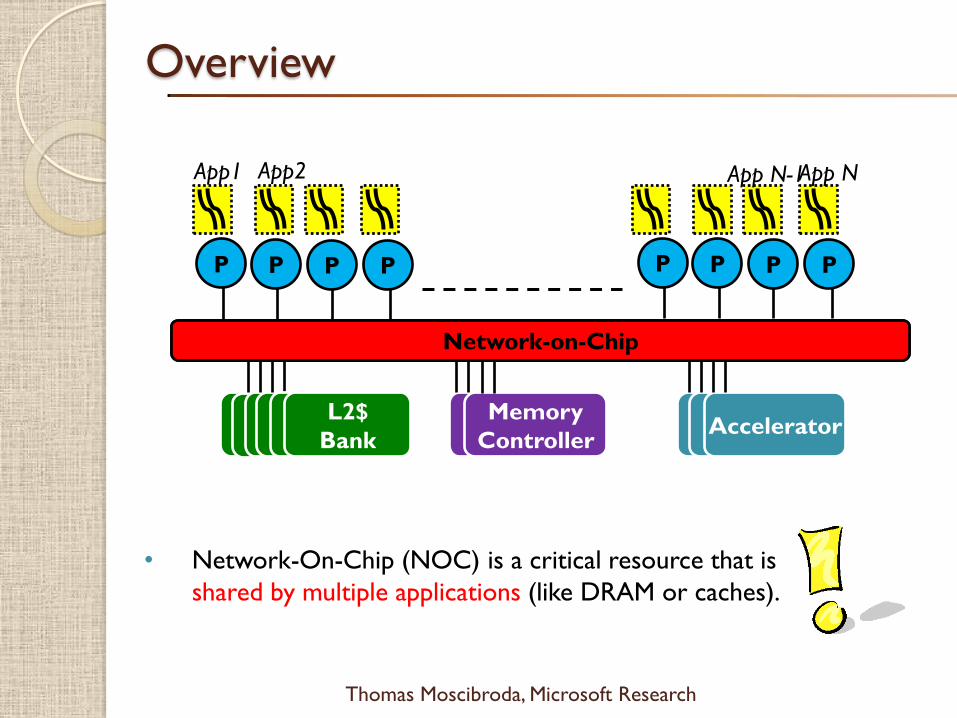
Overview
Network-on-Chip
L2$L2$L2$L2$
Bank
mem
cont
Memory
Controller
P
AcceleratorL2$
Bank
L2$
Bank
P P P P P P P
App1 App2 App NApp N-1
Network-on-Chip
• Network-On-Chip (NOC) is a critical resource that is
shared by multiple applications (like DRAM or caches).

$
Thomas Moscibroda, Microsoft Research
Virtual Channels & Wormhole Routing
Conceptual
View
From East
From West
From North
From South
From PE
VC 0
VC 1
VC 2
App1 App2 App3 App4App5 App6 App7 App8
VC 0
VC 1
VC 2
From East
From West
From North
From South
From PE
Routing Unit
(RC)
VC Allocator
(VA)
Switch Allocator (SA)
Sch
ed
ule
r

$
Thomas Moscibroda, Microsoft Research
Packet Scheduling in NoC
Existing switch allocation (scheduling) policies
◦ Round robin
◦ Age
Problem
◦ Treat all packets equally
◦ Application-oblivious
Packets have different criticality
◦ Packet is critical if latency of a packet affects application’s
performance
◦ Different criticality due to memory level parallelism (MLP)
All packets are not the
same…!!!

$
Thomas Moscibroda, Microsoft Research
MLP Principle
Latency ( )
StallCompute St.
Latency ( )
Latency ( )
Stall ( ) = large
Packet Latency != Network Stall Time
Different Packets have different criticality due to MLP
Criticality( ) > Criticality( ) > Criticality( )
Stall ( ) = 0
Stall ( ) = small
$
Thomas Moscibroda, Microsoft Research
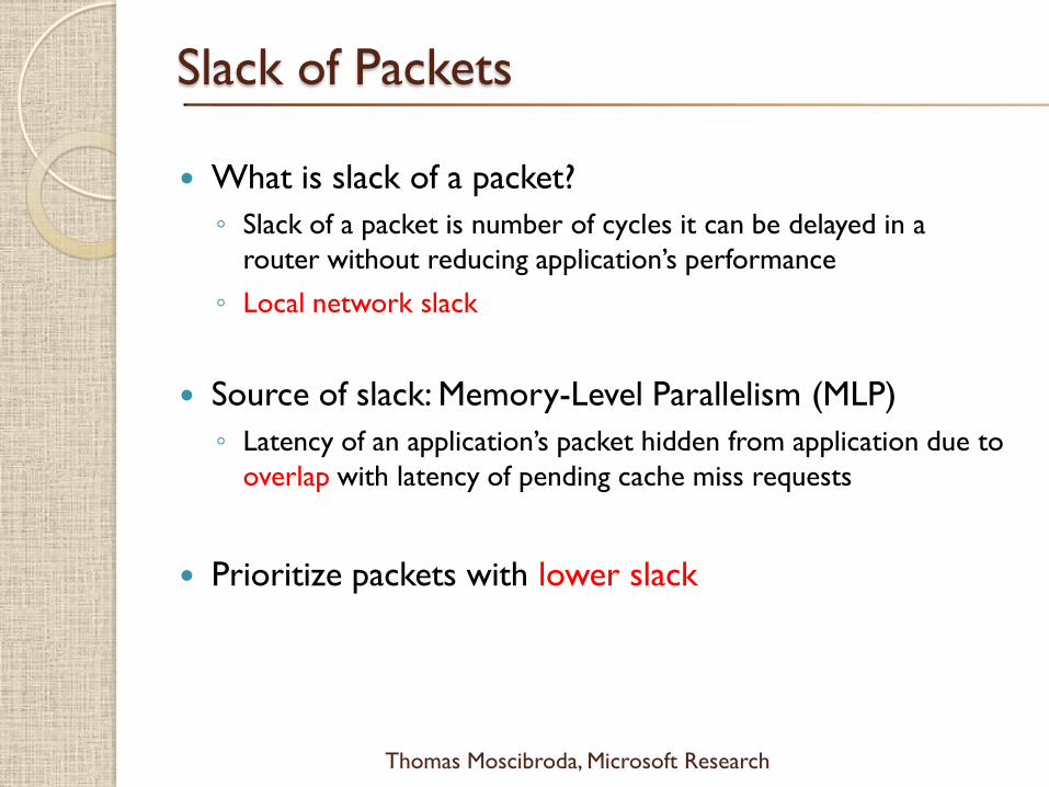
Slack of Packets
What is slack of a packet?
◦ Slack of a packet is number of cycles it can be delayed in a
router without reducing application’s performance
◦ Local network slack
Source of slack: Memory-Level Parallelism (MLP)
◦ Latency of an application’s packet hidden from application due to
overlap with latency of pending cache miss requests
Prioritize packets with lower slack

$
Thomas Moscibroda, Microsoft Research
Concept of Slack
Instruction
Window
Stall
Network-on-Chip
Load Miss causes 1
returns earlier than
necessary
2
1 2 2 1
Compute
Slack ( ) = Latency ( ) – Latency ( ) = 26 – 6 = 20 hops2 1 2
Execution Time
Packet( ) can be delayed for available slack cycles
without reducing performance!
2
causes Load Miss 2
Latency ( )1
Latency ( )2
SlackSlack
$
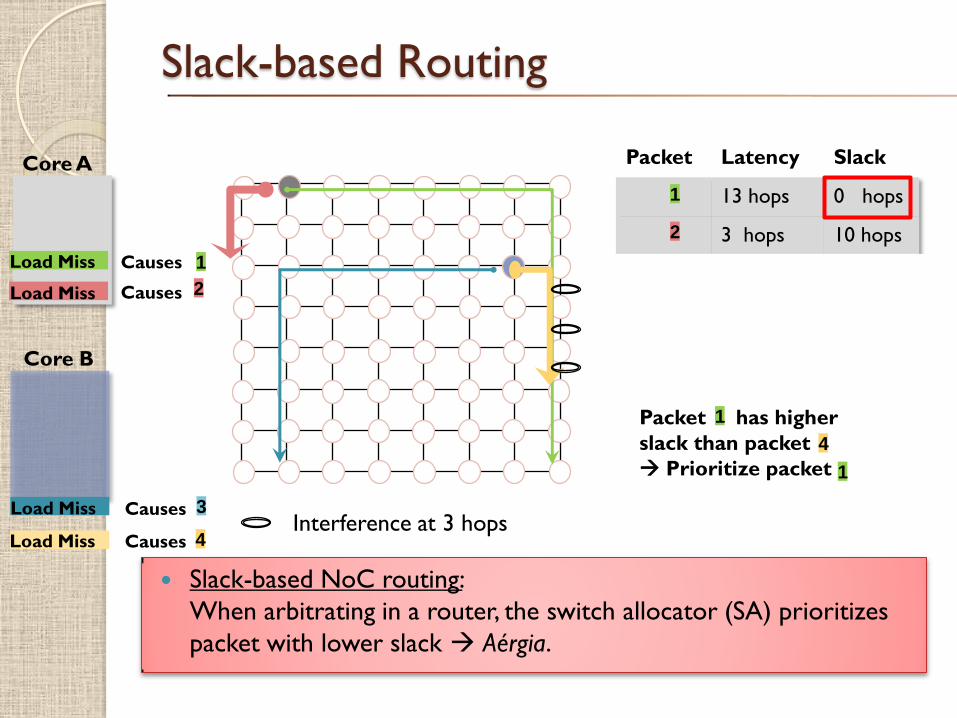
Core A
Core B
Packet Latency Slack
13 hops 0 hops
3 hops 10 hops
10 hops 0 hops
4 hops 6 hops
Causes
CausesLoad Miss
Load Miss 1
2
1
2
Load Miss
Load Miss Causes
Causes
3
4
4
3
Interference at 3 hops
Slack-based Routing
1Packet has higher
slack than packet
Prioritize packet
4
1
Slack-based NoC routing:
When arbitrating in a router, the switch allocator (SA) prioritizes
packet with lower slack Aérgia.

$
Thomas Moscibroda, Microsoft Research
What is Aergia?
Aergia is the spirit of laziness in Greek mythology
Some packets can afford to slack!

$
Thomas Moscibroda, Microsoft Research
Slack in Applications
0
10
20
30
40
50
60
70
80
90
100
0 50 100 150 200 250 300 350 400 450 500
Perc
enta
ge o
f all
Packets
(%
)
Slack in cycles
Gems
50% of packets have 350+ slack cycles
10% of packets have <50 slack
cycles
Non-
critical
critical

$
Thomas Moscibroda, Microsoft Research
Slack in Applications
0
10
20
30
40
50
60
70
80
90
100
0 50 100 150 200 250 300 350 400 450 500
Perc
enta
ge o
f all
Packets
(%
)
Slack in cycles
Gems
art
68% of packets have zero slack cycles

$
Thomas Moscibroda, Microsoft Research
Diversity in Slack
0
10
20
30
40
50
60
70
80
90
100
0 50 100 150 200 250 300 350 400 450 500
Perc
enta
ge o
f all
Packets
(%
)
Slack in cycles
Gems
omnet
tpcw
mcf
bzip2
sjbb
sap
sphinx
deal
barnes
astar
calculix
art
libquantum
sjeng
h264ref

$
Thomas Moscibroda, Microsoft Research
Diversity in Slack
0
10
20
30
40
50
60
70
80
90
100
0 50 100 150 200 250 300 350 400 450 500
Perc
enta
ge o
f all
Packets
(%
)
Slack in cycles
Gems
omnet
tpcw
mcf
bzip2
sjbb
sap
sphinx
deal
barnes
astar
calculix
art
libquantum
sjeng
h264ref
Slack varies between packets of different applications
Slack varies between packets of a single application

$
Thomas Moscibroda, Microsoft Research
Estimating Slack Priority
Slack (P) = Max (Latencies of P’s Predecessors) – Latency of P
Predecessors(P) are the packets of outstanding cache miss
requests when P is issued
Packet latencies not known when issued
Predicting latency of any packet Q
◦ Higher latency if Q corresponds to an L2 miss
◦ Higher latency if Q has to travel farther number of hops

$
Thomas Moscibroda, Microsoft Research
Slack of P = Maximum Predecessor Latency – Latency of P
Slack(P) =
PredL2: Number of predecessor packet that are servicing an
L2 miss.
MyL2: Set if P is NOT servicing an L2 miss
HopEstimate: Max (# of hops of Predecessors) – hops of P
Estimating Slack Priority
PredL2
(2 bits)
MyL2
(1 bit)
HopEstimate
(2 bits)

$
Thomas Moscibroda, Microsoft Research
Estimating Slack Priority
How to predict L2 hit or miss at core?
◦ Global Branch Predictor based L2 Miss Predictor
Use Pattern History Table and 2-bit saturating counters
◦ Threshold based L2 Miss Predictor
If #L2 misses in “M” misses >= “T” threshold then next load
is a L2 miss.
Number of miss predecessors?
◦ List of outstanding L2 Misses
Hops estimate?
◦ Hops => ∆X + ∆ Y distance
◦ Use predecessor list to calculate slack hop estimate

$
Thomas Moscibroda, Microsoft Research
Starvation Avoidance
Problem: Starvation
◦ Prioritizing packets can lead to starvation of lower priority packets
Solution: Time-Based Packet Batching
◦ New batches are formed at every T cycles
◦ Packets of older batches are prioritized over younger batches
Similar to batch-based
DRAM scheduling.
$
Thomas Moscibroda, Microsoft Research
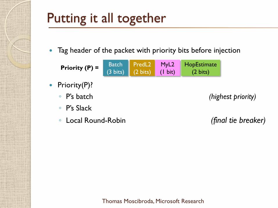
Putting it all together
Tag header of the packet with priority bits before injection
Priority(P)?
◦ P’s batch (highest priority)
◦ P’s Slack
◦ Local Round-Robin (final tie breaker)
PredL2
(2 bits)
MyL2
(1 bit)
HopEstimate
(2 bits)
Batch
(3 bits)Priority (P) =
$
Thomas Moscibroda, Microsoft Research
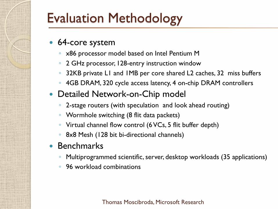
Evaluation Methodology
64-core system◦ x86 processor model based on Intel Pentium M
◦ 2 GHz processor, 128-entry instruction window
◦ 32KB private L1 and 1MB per core shared L2 caches, 32 miss buffers
◦ 4GB DRAM, 320 cycle access latency, 4 on-chip DRAM controllers
Detailed Network-on-Chip model ◦ 2-stage routers (with speculation and look ahead routing)
◦ Wormhole switching (8 flit data packets)
◦ Virtual channel flow control (6 VCs, 5 flit buffer depth)
◦ 8x8 Mesh (128 bit bi-directional channels)
Benchmarks◦ Multiprogrammed scientific, server, desktop workloads (35 applications)
◦ 96 workload combinations

$
Thomas Moscibroda, Microsoft Research
Qualitative Comparison
Round Robin & Age
◦ Local and application oblivious
◦ Age is biased towards heavy applications
Globally Synchronized Frames (GSF) [Lee et al., ISCA 2008]
◦ Provides bandwidth fairness at the expense of system performance
◦ Penalizes heavy and bursty applications
Application-Aware Prioritization Policies (SJF) [Das et al., MICRO 2009]
◦ Shortest-Job-First Principle
◦ Packet scheduling policies which prioritize network sensitive
applications which inject lower load

$
Thomas Moscibroda, Microsoft Research
System Performance
SJF provides 8.9% improvement
in weighted speedup
Aergia improves system
throughput by 10.3%
Aergia+SJF improves system
throughput by 16.1%
0.0
0.1
0.2
0.3
0.4
0.5
0.6
0.7
0.8
0.9
1.0
1.1
1.2
No
rmalized
Syst
em
Sp
eed
up
Age RR
GSF SJF
Aergia SJF+Aergia

$
Thomas Moscibroda, Microsoft Research
Network Unfairness
SJF does not imbalance
network fairness
Aergia improves network
unfairness by 1.5X
SJF+Aergia improves
network unfairness by 1.3X
0.0
3.0
6.0
9.0
12.0
Netw
ork
Un
fair
ness
Age RR
GSF SJF
Aergia SJF+Aergia
$
Thomas Moscibroda, Microsoft Research
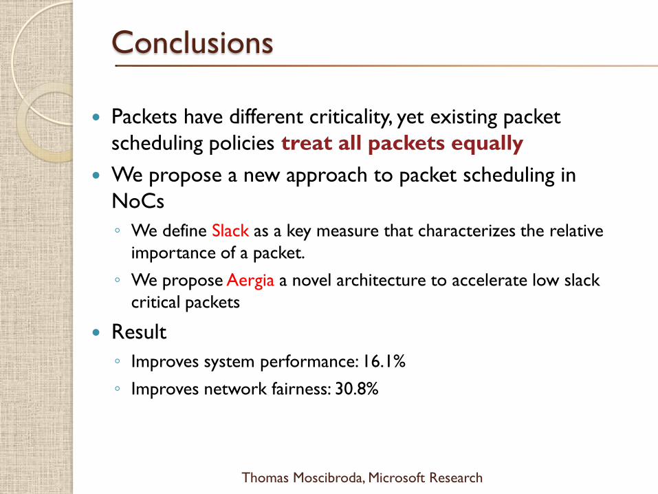
Conclusions
Packets have different criticality, yet existing packet
scheduling policies treat all packets equally
We propose a new approach to packet scheduling in
NoCs
◦ We define Slack as a key measure that characterizes the relative
importance of a packet.
◦ We propose Aergia a novel architecture to accelerate low slack
critical packets
Result
◦ Improves system performance: 16.1%
◦ Improves network fairness: 30.8%

$
Thomas Moscibroda, Microsoft Research
• Why On-Chip Networks (NoC)…?
• Traditional NoC design
• Application-Aware NoC design
• Bufferless NoC design
• Theory of Bufferless NoC Routing
• Conclusions, Open Problems & Bibliography
Overview

$
Thomas Moscibroda, Microsoft Research
• Many different topologies have been proposed
• Different routing mechanisms
• Different router architectures
• Etc…
• Design goals in NoC design:
• High throughput, low latency
• Fairness between cores, QoS, …
• Low complexity, low cost
• Power, low energy consumption
Network On-Chip (NOC)
Energy/Power in On-Chip Networks
• Power is a key constraint in the design
of high-performance processors
• NoCs consume substantial portion of system
power
• ~30% in Intel 80-core Terascale [IEEE Micro’07]
• ~40% in MIT RAW Chip [ISCA’04]
• NoCs estimated to consume 100s of Watts
[Borkar, DAC’07]
$
Thomas Moscibroda, Microsoft Research
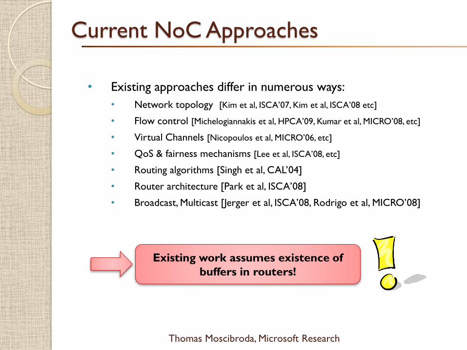
• Existing approaches differ in numerous ways:
• Network topology [Kim et al, ISCA’07, Kim et al, ISCA’08 etc]
• Flow control [Michelogiannakis et al, HPCA’09, Kumar et al, MICRO’08, etc]
• Virtual Channels [Nicopoulos et al, MICRO’06, etc]
• QoS & fairness mechanisms [Lee et al, ISCA’08, etc]
• Routing algorithms [Singh et al, CAL’04]
• Router architecture [Park et al, ISCA’08]
• Broadcast, Multicast [Jerger et al, ISCA’08, Rodrigo et al, MICRO’08]
Current NoC Approaches
Existing work assumes existence of
buffers in routers!
$
Thomas Moscibroda, Microsoft Research
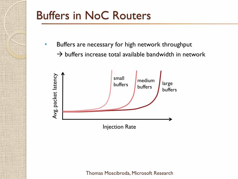
• Buffers are necessary for high network throughput
buffers increase total available bandwidth in network
Buffers in NoC Routers
Injection Rate
Avg
. pac
ket
late
ncy
large
buffers
medium
buffers
small
buffers

$
Thomas Moscibroda, Microsoft Research
• Buffers are necessary for high network throughput
buffers increase total available bandwidth in network
• Buffers consume significant energy/power
• Dynamic energy when read/write
• Static energy even when not occupied
• Buffers add complexity and latency
• Logic for buffer management
• Virtual channel allocation
• Credit-based flow control
• Buffers require significant chip area
• E.g., in TRIPS prototype chip, input buffers occupy 75% of
total on-chip network area [Gratz et al, ICCD’06]
Buffers in NoC Routers
$
Thomas Moscibroda, Microsoft Research
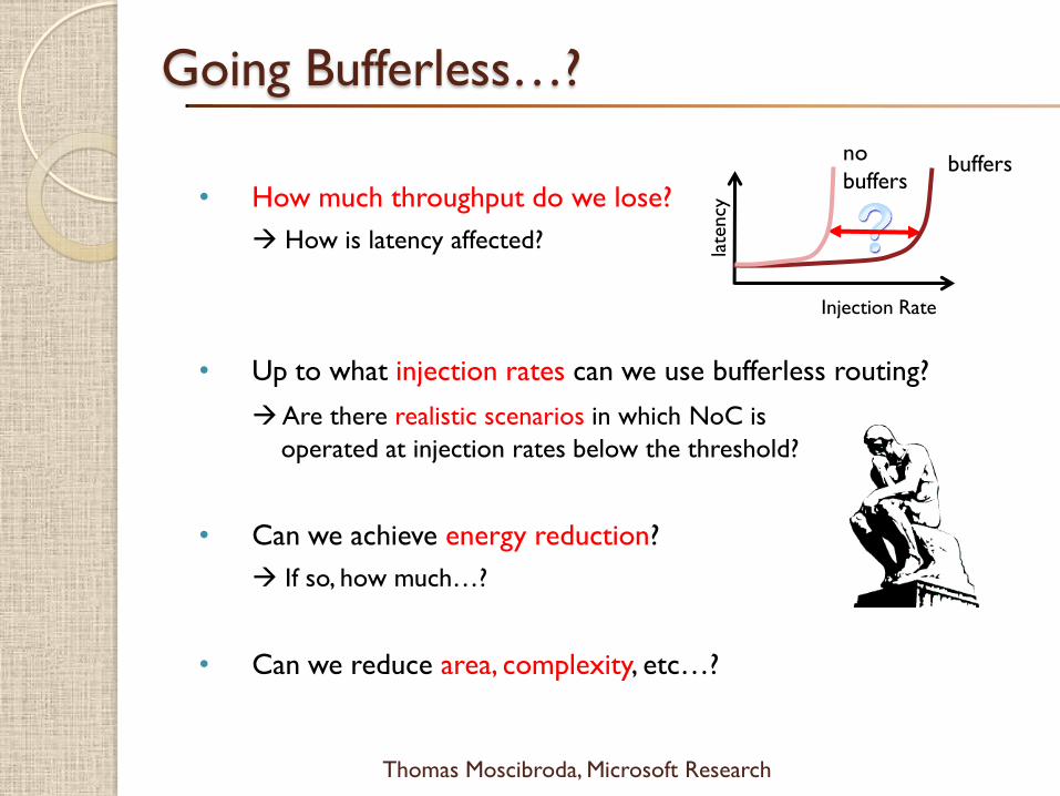
• How much throughput do we lose?
How is latency affected?
• Up to what injection rates can we use bufferless routing?
Are there realistic scenarios in which NoC is
operated at injection rates below the threshold?
• Can we achieve energy reduction?
If so, how much…?
• Can we reduce area, complexity, etc…?
Going Bufferless…?
Injection Rate
late
ncy
buffersno
buffers

$
Thomas Moscibroda, Microsoft Research
BLESS: Bufferless Routing
• Packet creation: L1 miss, L1 service, write-back, …
• Injection: A packet can be injected whenever at least one
output port is available (i.e., when <4 incoming flits in a grid)
• Always forward all incoming flits to some output port
• If no productive direction is available, send to another
direction
• packet is deflected
Hot-potato routing [Baran’64, etc]

$
Thomas Moscibroda, Microsoft Research
BLESS: Bufferless Routing
• Example: Two flits come in, both want to go North
• Traditional, buffered network: One flit is sent North, the
other is buffered
• In a bufferless network: One flit is sent North, the other is
sent to some other direction

$
Thomas Moscibroda, Microsoft Research
BLESS: Bufferless Routing
Routing
VC Arbiter
Switch Arbiter
Flit-Ranking
Port-
Prioritization
arbitration policy
Flit-Ranking 1. Create a ranking over all incoming flits
Port-
Prioritization 2. For a given flit in this ranking, find the best free output-port
Apply to each flit in order of ranking

$
Thomas Moscibroda, Microsoft Research
• Each flit is routed independently.
• Oldest-first arbitration (other policies evaluated in paper)
• Network Topology: Can be applied to most topologies (Mesh, Torus, Hypercube, Trees, …)
1) #output ports ¸ #input ports at every router2) every router is reachable from every other router
• Flow Control & Injection Policy:
Completely local, inject whenever input port is free
• Absence of Deadlocks: every flit is always moving
• Absence of Livelocks: with oldest-first ranking
FLIT-BLESS: Flit-Level Routing
Flit-Ranking 1. Oldest-first ranking
Port-
Prioritization2. Assign flit to productive port, if possible.
Otherwise, assign to non-productive port.
$
Thomas Moscibroda, Microsoft Research
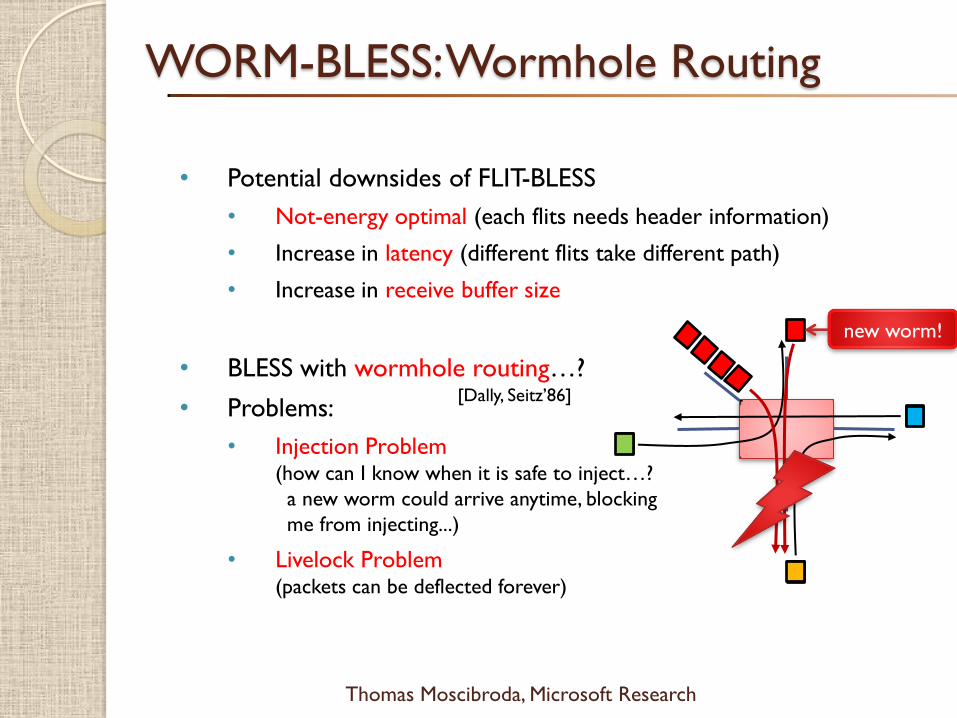
• Potential downsides of FLIT-BLESS
• Not-energy optimal (each flits needs header information)
• Increase in latency (different flits take different path)
• Increase in receive buffer size
• BLESS with wormhole routing…?
• Problems:
• Injection Problem(how can I know when it is safe to inject…?
a new worm could arrive anytime, blocking
me from injecting...)
• Livelock Problem(packets can be deflected forever)
WORM-BLESS: Wormhole Routing
new worm!
[Dally, Seitz’86]

$
Thomas Moscibroda, Microsoft Research
WORM-BLESS: Wormhole Routing
Flit-Ranking 1. Oldest-first ranking
Port-Prioritization2. If flit is head-flit
a) assign flit to unallocated, productive port
b) assign flit to allocated, productive port
c) assign flit to unallocated, non-productive port
d) assign flit to allocated, non-productive port
else,
a) assign flit to port that is allocated to worm
Deflect worms
if necessary!
Truncate worms
if necessary!
Head-flit: West
This worm
is truncated!
& deflected!
At low congestion, packets
travel routed as worms
allocated
to North
allocated
to West
Body-flit turns
into head-flit

$
Thomas Moscibroda, Microsoft Research
• BLESS without buffers is extreme end of a continuum
• BLESS can be integrated with buffers
• FLIT-BLESS with Buffers
• WORM-BLESS with Buffers
• Whenever a buffer is full, it’s first flit becomes
must-schedule
• must-schedule flits must be deflected if necessary
BLESS with Small Buffers

$
Thomas Moscibroda, Microsoft Research
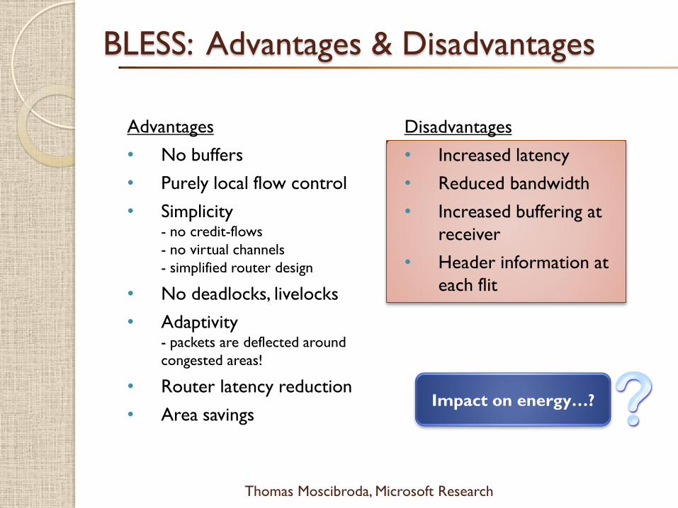
Advantages
• No buffers
• Purely local flow control
• Simplicity - no credit-flows
- no virtual channels
- simplified router design
• No deadlocks, livelocks
• Adaptivity- packets are deflected around
congested areas!
• Router latency reduction
• Area savings
BLESS: Advantages & Disadvantages
Disadvantages
• Increased latency
• Reduced bandwidth
• Increased buffering at
receiver
• Header information at
each flit
Impact on energy…?

$
Thomas Moscibroda, Microsoft Research
• BLESS gets rid of input buffers
and virtual channels
Reduction of Router Latency
BW
RC
VA
SAST
LT
BW SA STLT
RC STLT
RC STLT
LA LT
BW: Buffer Write
RC: Route Computation
VA: Virtual Channel Allocation
SA: Switch Allocation
ST: Switch Traversal
LT: Link Traversal
LA LT: Link Traversal of Lookahead
Baseline
Router
(speculative)
head
flit
body
flit
BLESS
Router
(standard)
RC STLT
RC STLT
Router 1
Router 2
Router 1
Router 2
BLESS
Router
(optimized)
Router Latency = 3
Router Latency = 2
Router Latency = 1
Can be improved to 2.
[Dally, Towles’04]
$
Thomas Moscibroda, Microsoft Research
Advantages
• No buffers
• Purely local flow control
• Simplicity - no credit-flows
- no virtual channels
- simplified router design
• No deadlocks, livelocks
• Adaptivity- packets are deflected around
congested areas!
• Router latency reduction
• Area savings
BLESS: Advantages & Disadvantages
Disadvantages
• Increased latency
• Reduced bandwidth
• Increased buffering at
receiver
• Header information at
each flit
Impact on energy…?

$
Thomas Moscibroda, Microsoft Research
• 2D mesh network, router latency is 2 cycles
o 4x4, 8 core, 8 L2 cache banks (each node is a core or an L2 bank)
o 4x4, 16 core, 16 L2 cache banks (each node is a core and an L2 bank)
o 8x8, 16 core, 64 L2 cache banks (each node is L2 bank and may be a core)
o 128-bit wide links, 4-flit data packets, 1-flit address packets
o For baseline configuration: 4 VCs per physical input port, 1 packet deep
• Benchmarks
o Multiprogrammed SPEC CPU2006 and Windows Desktop applications
o Heterogeneous and homogenous application mixes
o Synthetic traffic patterns: UR, Transpose, Tornado, Bit Complement
• x86 processor model based on Intel Pentium M
o 2 GHz processor, 128-entry instruction window
o 64Kbyte private L1 caches
o Total 16Mbyte shared L2 caches; 16 MSHRs per bank
o DRAM model based on Micron DDR2-800
Evaluation Methodology
Evaluations with perfect
L2 caches
Puts maximal stress
on NoC
Simulation is cycle-accurate
Models stalls in network
and processors
Self-throttling behavior
Aggressive processor model
$
Thomas Moscibroda, Microsoft Research
• Energy model provided by Orion simulator [MICRO’02]
o 70nm technology, 2 GHz routers at 1.0 Vdd
• For BLESS, the following is modeled
o Additional energy to transmit header information
o Additional buffers needed on the receiver side
o Additional logic to reorder flits of individual packets at receiver
• Network energy is partitioned into
buffer energy, router energy, and link energy,
each having static and dynamic components.
• Comparisons against non-adaptive and aggressive
adaptive buffered routing algorithms (DO, MIN-AD, ROMM)
Evaluation Methodology
$
Thomas Moscibroda, Microsoft Research
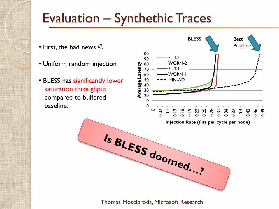
Evaluation – Synthethic Traces
• First, the bad news
• Uniform random injection
• BLESS has significantly lower
saturation throughput
compared to buffered
baseline. 0102030405060708090
100
0
0.0
7
0.1
0.1
3
0.1
6
0.1
9
0.2
2
0.2
5
0.2
8
0.3
1
0.3
4
0.3
7
0.4
0.4
3
0.4
6
0.4
9
Avera
ge L
ate
ncy
Injection Rate (flits per cycle per node)
FLIT-2
WORM-2
FLIT-1
WORM-1
MIN-AD
BLESS Best
Baseline

$
Thomas Moscibroda, Microsoft Research
Evaluation – Homogenous Case Study
• milc benchmarks
(moderately intensive)
• Perfect caches!
• Very little performance
degradation with BLESS
(less than 4% in dense
network)
•With router latency 1,
BLESS can even
outperform baseline
(by ~10%)
• Significant energy
improvements
(almost 40%)
02468
1012141618
W-S
peed
up
4x4, 8x milc 4x4, 16x milc 8x8, 16x milc
0
0.2
0.4
0.6
0.8
1
1.2E
nerg
y (
no
rmalized
)BufferEnergy LinkEnergy RouterEnergy
4x4, 16x milc 8x8, 16x milc4x4, 8x milc
Baseline BLESS RL=1
Observations:
1) Injection rates not extremely high
on average
self-throttling!
2) For bursts and temporary hotspots,
use network links as buffers!

$
Thomas Moscibroda, Microsoft Research
Evaluation – Homogenous Case Study
02468
1012141618
W-S
peed
up
4x4, 8xMatlab 4x4, 16xMatlab 8x8, 16xMatlab
0
0.2
0.4
0.6
0.8
1
1.2E
nerg
y (
no
rmalized
) BufferEnergy LinkEnergy RouterEnergy
4x4, 8xMatlab 4x4, 16xMatlab 8x8, 16xMatlab
• Matlab benchmarks
(most intensive)
• Perfect caches!
Worst-case for BLESS
• Performance loss is
within 15% for most
dense configuration
• Even here, more than
15% energy savings in
densest network!

$
Thomas Moscibroda, Microsoft Research
Evaluation – Further Results
• BLESS increases buffer requirement
at receiver by at most 2x overall, energy is still reduced
• Impact of memory latency
with real caches, very little slowdown! (at most 1.5%)
02468
1012141618
DO
MIN
-AD
RO
MM
FLIT
-2
WO
RM
-2
FLIT
-1
WO
RM
-1
DO
MIN
-AD
RO
MM
FLIT
-2
WO
RM
-2
FLIT
-1
WO
RM
-1
DO
MIN
-AD
RO
MM
FLIT
-2
WO
RM
-2
FLIT
-1
WO
RM
-1W-S
peed
up
4x4, 8x matlab 4x4, 16x matlab 8x8, 16x matlab
$
Thomas Moscibroda, Microsoft Research
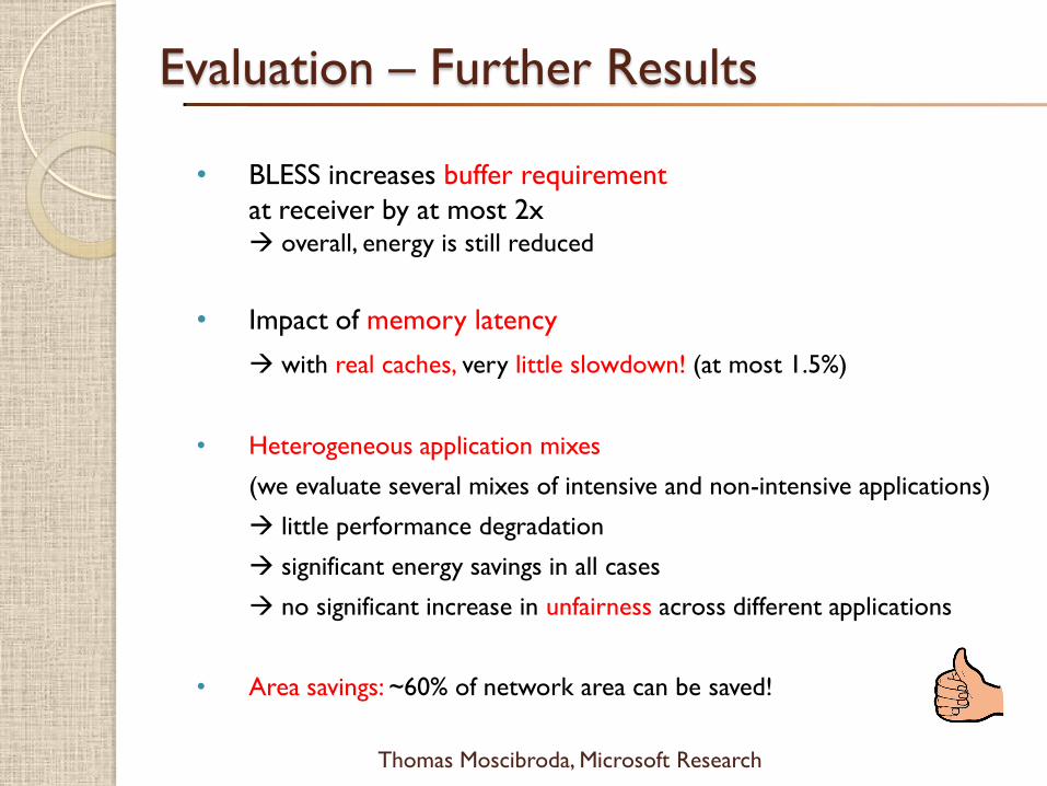
Evaluation – Further Results
• BLESS increases buffer requirement
at receiver by at most 2x overall, energy is still reduced
• Impact of memory latency
with real caches, very little slowdown! (at most 1.5%)
• Heterogeneous application mixes
(we evaluate several mixes of intensive and non-intensive applications)
little performance degradation
significant energy savings in all cases
no significant increase in unfairness across different applications
• Area savings: ~60% of network area can be saved!

$
Thomas Moscibroda, Microsoft Research
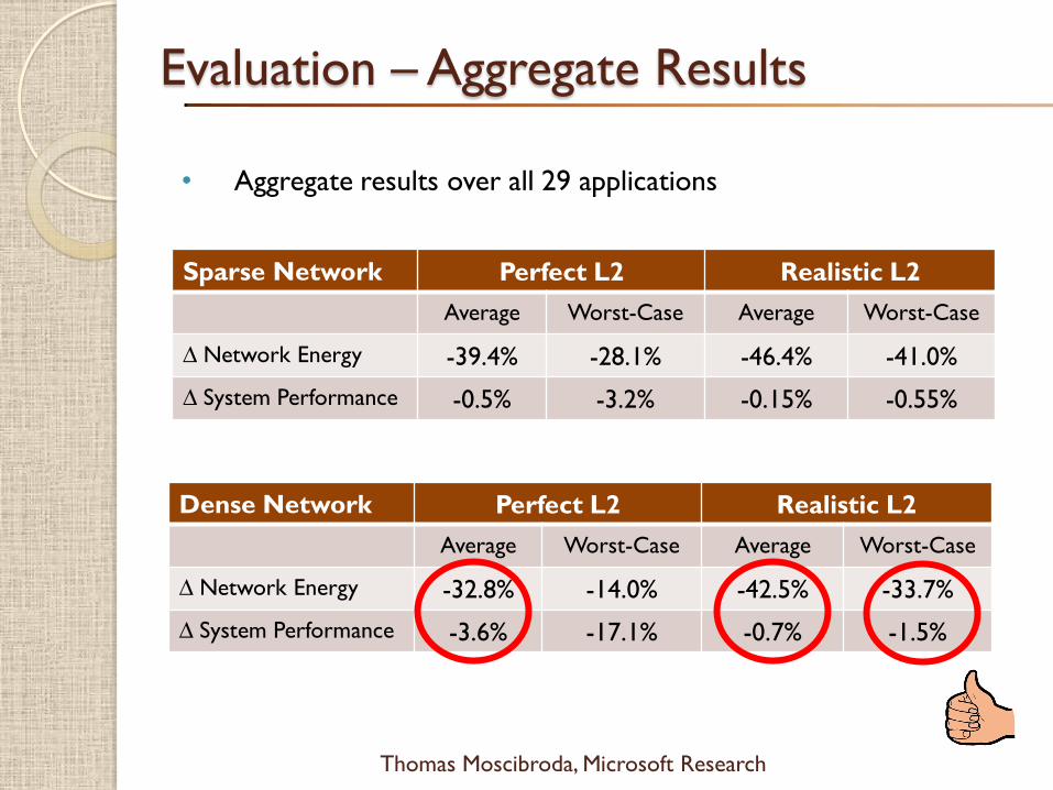
• Aggregate results over all 29 applications
Evaluation – Aggregate Results
Sparse Network Perfect L2 Realistic L2
Average Worst-Case Average Worst-Case
∆ Network Energy -39.4% -28.1% -46.4% -41.0%
∆ System Performance -0.5% -3.2% -0.15% -0.55%
0
0.2
0.4
0.6
0.8
1
En
erg
y
(no
rmalized
)
BufferEnergy LinkEnergy RouterEnergy
FLIT
WO
RM
BA
SE
FLIT
WO
RM
BA
SE
012345678
W-S
peed
up
FLIT
WO
RM
BA
SE
FLIT
WO
RM
BA
SE
Mean MeanWorst-Case Worst-Case
$
Thomas Moscibroda, Microsoft Research
• Aggregate results over all 29 applications
Evaluation – Aggregate Results
Sparse Network Perfect L2 Realistic L2
Average Worst-Case Average Worst-Case
∆ Network Energy -39.4% -28.1% -46.4% -41.0%
∆ System Performance -0.5% -3.2% -0.15% -0.55%
Dense Network Perfect L2 Realistic L2
Average Worst-Case Average Worst-Case
∆ Network Energy -32.8% -14.0% -42.5% -33.7%
∆ System Performance -3.6% -17.1% -0.7% -1.5%

$
Thomas Moscibroda, Microsoft Research
• For a very wide range of applications and network settings,
buffers are not needed in NoC
• Significant energy savings
(32% even in dense networks and perfect caches)
• Area-savings of 60%
• Simplified router and network design (flow control, etc…)
• Performance slowdown is minimal (can even increase!)
A strong case for a rethinking of NoC design!
Summary
$
Thomas Moscibroda, Microsoft Research
• Why On-Chip Networks (NoC)…?
• Traditional NoC design
• Application-Aware NoC design
• Bufferless NoC design
• Theory of Bufferless NoC Routing
• Conclusions, Open Problems & Bibliography
Overview

$
Thomas Moscibroda, Microsoft Research
Optimal Bufferless Routing…?
• BLESS uses age-based arbitration in combination with
XY-routing this may be sub-optimal
• Same packets (flits) could collide many times on the way to
their destination
• Is there a provably optimal arbitration & routing mechanism for
bufferless networks…?

$
Thomas Moscibroda, Microsoft Research
Optimal Bufferless Routing…?
• Optimal Bufferless “Greedy-Home-Run” Routing
• The following arbitration policy is provably optimal for an
m x m Mesh network (asymptotically at least)
1 - Packets move greedily towards their destination if possible
(if there are 2 good links, any of them is fine)
2 - If a packet is deflected, it gets “excited” with probability 1/p,
where p = £(1/m).
3 - When a packet is excited, it has higher priority than non-excited
packets
4 - When being excited, a packet tries to reach the destination
on the “home-run” path (row-column XY-path)
5 - When two excited packets contend, the one that goes straight
(i.e., keeps its direction) has priority
6 - If an excited packet is deflected it becomes normal again

$
Thomas Moscibroda, Microsoft Research
Optimal Bufferless Routing…?
1 2
Packet 1 wants to go to [7,7]
Packet 2 wants to go to [2,7]
say, Packet 1 gets deflected
with probability p, it gets excited
if excited, it is routed strictly on
the home-run path
if it is deflected on the home-run
path, it becomes non-excited again.
this can only happen at the first hop
or at the turn (only 2 possibilities!)
[0,0]
[7,7]home-run path

$
Thomas Moscibroda, Microsoft Research
Optimal Bufferless Routing…?
Proof-sketch:
• An excited packet can only be deflected at its start node, or when
trying to turn.
• In both cases, the probability to be deflected is a small constant
(because there needs to be another excited packet starting
at exactly the right instant at some other node)
• Thus, whenever a packet gets excited, it reaches its destination
with constant probability.
• Thus, on average, a packet needs to become excited only O(1)
times to reach its destination.
• Since a packet becomes excited every p’th time it gets deflected,
it only gets deflected O(1/p)=O(m) times in expectation.
• Finally, whenever a packet is NOT deflected, it gets close to its
destination.
Notice that even with buffers, O(m) is optimal.
Hence, asymptotically, having no buffers
does not harm the time-bounds of routing
(in expectation) !
$
Thomas Moscibroda, Microsoft Research
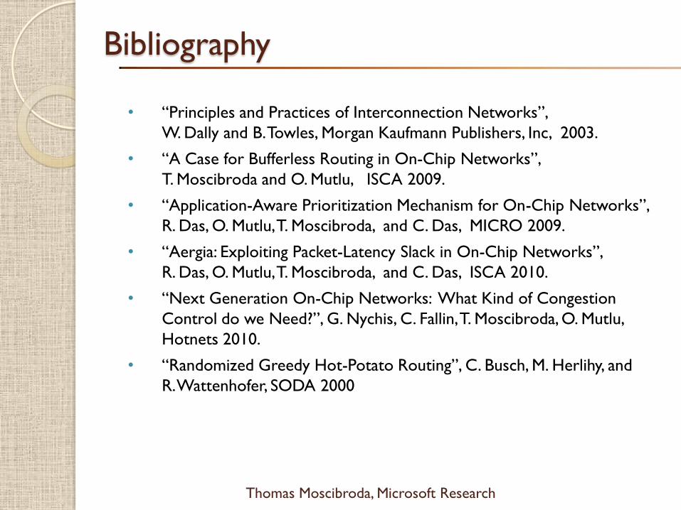
Bibliography
• “Principles and Practices of Interconnection Networks”,
W. Dally and B. Towles, Morgan Kaufmann Publishers, Inc, 2003.
• “A Case for Bufferless Routing in On-Chip Networks”,
T. Moscibroda and O. Mutlu, ISCA 2009.
• “Application-Aware Prioritization Mechanism for On-Chip Networks”,
R. Das, O. Mutlu, T. Moscibroda, and C. Das, MICRO 2009.
• “Aergia: Exploiting Packet-Latency Slack in On-Chip Networks”,
R. Das, O. Mutlu, T. Moscibroda, and C. Das, ISCA 2010.
• “Next Generation On-Chip Networks: What Kind of Congestion
Control do we Need?”, G. Nychis, C. Fallin, T. Moscibroda, O. Mutlu,
Hotnets 2010.
• “Randomized Greedy Hot-Potato Routing”, C. Busch, M. Herlihy, and
R. Wattenhofer, SODA 2000