Allen-Bradley ControlLogixEthernet DriverHelpftp.softwaretoolbox.com/demodnld/prod_docs/top... ·...
135
Allen-Bradley ControlLogix Ethernet Driver Help © 2011 Kepware Technologies
Transcript of Allen-Bradley ControlLogixEthernet DriverHelpftp.softwaretoolbox.com/demodnld/prod_docs/top... ·...
Allen-BradleyControlLogix Ethernet
Driver Help
© 2011 Kepware Technologies
Allen-Bradley ControlLogix Ethernet Driver Help
Table of ContentsTable of Contents 2Allen-Bradley ControlLogix Ethernet Driver Help 8Overview 8Quick Links 9ControlLogix 5500 Ethernet Quick Links 9CompactLogix 5300 Ethernet Quick Links 10FlexLogix 5400 Ethernet Quick Links 11SoftLogix 5800 Quick Links 11DH+ Gateway Quick Links 12ControlNet Gateway Quick Links 131761-NET-ENI (DF1) Quick Links 131761-NET-ENI (Logix) Quick Links 14MicroLogix 1100 Ethernet Quick Links 14
Device Setup 16Cable Diagrams 17Terminology 17Logix Setup 18ControlLogix 5500 Ethernet Device ID 18CompactLogix 5300 Ethernet Device ID 19FlexLogix 5400 Ethernet Device ID 19SoftLogix 5800 Device ID 20Logix Communications Parameters 20Logix Options 21Logix Database Settings 24LogixDatabaseOptions 25LogixDatabase Filtering 26
ENI DF1/DH+/ControlNet Gateway Communications Parameters 26DataHighwayPlus (TM) Gateway Setup 27DH+ Gateway Device ID 28ControlNet (TM) Gateway Setup 28ControlNet Gateway Device ID 291761-NET-ENI Setup 29ENI Device ID 30ENI Logix Communications Parameters 30MicroLogix 1100 Setup 30MicroLogix 1100 Device ID 31MicroLogix 1100 Communications Parameters 31Communications Routing 32
www. kepware.com
2
Allen-Bradley ControlLogix Ethernet Driver Help
Connection Path Specification 33Routing Examples 33Port Reference 36SLC 500 Slot Configuration 36SLC 500 Modular I/O Selection Guide 36
ControlLogix Performance Optimizations 39Optimizing Your Communications 39Optimizing Your Application 41Performance Statistics and Tuning 42Performance Tuning Example 43
Data Types Description 54Address Descriptions 55ControlLogix 5500 Addressing for Ethernet 55ControlLogix 5500 Addressing for ENI 55CompactLogix 5300 Addressing for Ethernet 55CompactLogix 5300 Addressing for ENI 55FlexLogix 5400 Addressing for Ethernet 56FlexLogix 5400 Addressing for ENI 56SoftLogix 5800 Addressing 56SLC 500 Modular I/O Addressing for DH+ 56SLC 500 Modular I/O Addressing for ENI 56SLC 500 Fixed I/O Addressing for ENI 57PLC-5 Series Addressing for DH+ 57PLC-5 Series Addressing for ControlNet 57PLC-5 Series Addressing for ENI 57MicroLogix Addressing for ENI 58MicroLogix 1100 Addressing 58MicroLogix 1400 Addressing 59Logix Tag-Based Addressing 59Addressing Introduction 60Terminology 60Logix Address Syntax 61Address Formats 61Tag Scope 62Logix Address Usage 63Addressing Atomic Data Types 63Addressing Structure Data Types 64Addressing String DATA Type 64Ordering of Logix Array Data 65Logix Advanced Addressing 66
www. kepware.com
3
Allen-Bradley ControlLogix Ethernet Driver Help
Advanced Addressing: BOOL 66Advanced Addressing: SINT 67Advanced Addressing: INT 68Advanced Addressing: DINT 68Advanced Addressing: LINT 69Advanced Addressing: REAL 70
Logix Addressing Examples 71Addressing Examples: BOOL 71Addressing Examples: SINT 72Addressing Examples: INT 72Addressing Examples: DINT 73Addressing Examples: LINT 74Addressing Examples: REAL 75
Logix Data Types 76File Listing 76Output Files 76Input Files 79Status Files 82Binary Files 82Timer Files 83Counter Files 84Control Files 84Integer Files 85Float Files 85ASCII Files 86String Files 86BCD Files 87Long Files 87MicroLogix PID Files 88PID Files 89MicroLogix Message Files 90Message Files 91Block Transfer Files 91Function File Listing 92High Speed Counter File (HSC) 92Real-TimeClockFile (RTC) 93Channel 0 Communication StatusFile (CS0) 94Channel 1 Communication StatusFile (CS1) 94I/OModule StatusFile (IOS) 95
Automatic Tag Database Generation 96
www. kepware.com
4
Allen-Bradley ControlLogix Ethernet Driver Help
Database Creation Settings 96Tag Hierarchy 98Controller-to-Server Name Conversions 100Preparing for Automatic Tag Database Generation 101
Error Codes 103Encapsulation Error Codes 103CIP Error Codes 1030x0001 Extended Error Codes 1040x001F Extended Error Codes 1040x00FF Extended Error Codes 104
Error Descriptions 106Address Validation Errors 106Missing address 106Device address '<address>' contains a syntax error 106Address '<address>' is out of range for the specified device or register 106Device address '<address>' is not supported by model '<model name>' 107Data Type '<type>' is not valid for device address '<address>' 107Device address '<address>' is Read Only 107Array size is out of range for address '<address>' 107Array support is not available for the specified address: '<address>' 107Memory could not be allocated for tag with address '<address>' on device '<device name>' 108Communication Errors 108
Winsock V1.1 or higher must be installed to use the Allen-Bradley ControlLogix Ethernet device driver108Winsock initialization failed (OS Error = n) 108Unable to bind to adapter: '<adapter>'. Connect failed 108Device Specific Error Messages 109Device '<device name>' is not responding 109Encapsulation error occurred during a request to device '<device name>'. [Encap. Error=<code>] 109Error occurred during a request to device '<device name>'. [CIP Error=<code>, Ext. Error=<code>] 109Frame received from device '<device name>' contains errors 110ControlLogix Specific Error Messages 110Read Errors (Non-Blocking) 110Read request for tag '<tag address>' on device '<device name>' failed due to a framing error. Tag deactivated 110Unable to read '<tag address>' on device '<device name>'. Tag deactivated 111Unable to read tag '<tag address>' on device '<device name>'. [CIPError=<code>, Ext. Error=<code>] 111Unable to read tag '<tag address>' on device '<device name>'. Controller tag data type '<type>' unknown. Tag deac-tivated 111
Unable to read tag '<tag address>' on device '<device name>'. Data type '<type>' not supported. Tag deactivated 111Unable to read tag '<tag address>' on device '<device name>'. Data type '<type>' is illegal for this tag. Tag deac-
www. kepware.com
5
Allen-Bradley ControlLogix Ethernet Driver Help
tivated 112Unable to read tag '<tag address>' on device '<device name>'. Tag doesnot support multi-element arrays. Tagdeactivated 112
Read Errors (Blocking) 112Read request for '<count>' element(s) starting at '<tag address>' on device '<device name>' failed due to a framingerror. BlockDeactivated 112Unable to read '<count>' element(s) starting at '<tag address>' on device '<device name>'. BlockDeactivated 113Unable to read '<count>' element(s) starting at '<tag address>' on device '<device name>'. [CIPError=<code>, Ext.Error=<code>] 113Unable to read '<count>' element(s) starting at '<address>' on device '<device>'. Controller tag data type '<type>'unknown. Blockdeactivated 113
Unable to read '<count>' element(s) starting at '<address>' on device '<device>'. Data type '<type>' not supported 114Unable to read '<count>' element(s) starting at '<address>' on device '<device>'. Data type '<type>' is illegal for thisblock 114Unable to read '<count>' element(s) starting at '<tag address>' on device '<device name>'. Blockdoesnot supportmulti-element arrays. BlockDeactivated 114
Write Errors 114Write request for tag '<tag address>' on device '<device name>' failed due to a framing error 115Unable to write to '<tag address>' on device '<device name>' 115Unable to write to tag '<tag address>' on device '<device name>'. [CIPError=<code>, Ext. Status=<code>] 115Unable to write to tag '<tag address>' on device '<device name>'. Controller tag data type '<type>' unknown 115Unable to write to tag '<tag address>' on device '<device name>'. Data type '<type>' not supported 116Unable to write to tag '<tag address>' on device '<device name>'. Data type '<type>' is illegal for this tag 116Unable to write to tag '<tag address>' on device '<device name>'. Tag doesnot support multi-element arrays 116
Project Upload Errors 116Lowmemory resources 117Invalid or corrupt controller project 117Encapsulation error occurred while uploading project information. [Encap. Error=<code>] 117Error occurred while uploading project information. [CIPError=<code>, Ext. Error=<code>] 117Framing error occurred while uploading project information 117
ENI/DH+/ControlNet Gateway Specific Error Messages 118Unable to read '<block size>' element(s) starting at '<address>' on device '<device name>'. Framereceived contains errors 118Unable to read '<block size>' element(s) starting at '<address>' on device '<device name>'. [DF1STS=<value>, EXT STS=<value>]. Tag(s) deactivated 118Unable to write to address <address> on device '<device name>'. Frame received contains errors 119Unable to write to address <address> on device '<device name>'. '[DF1 STS=<value>, EXTSTS=<value>]' 119Device '<device name>' is not responding. Local node responded with error '[DF1 STS=<value>]' 119Unable to write to address <address> on device '<device name>'. Local node responded with error'[DF1 STS=<value>]' 120Unable to write to function file <address> on device '<device name>'. Local node responded with error'[DF1 STS=<value>]' 120Automatic Tag Database Generation Errors 120
www. kepware.com
6
Allen-Bradley ControlLogix Ethernet Driver Help
Database Error: Array tags '<orig. tag name><dimensions>' exceed 31 characters. Tags renamed to'<new tag name><dimensions>' 121Database Error: Data type '<type>' for tag '<tag name>' not found in Tag Import file. Tag not added 121Database Error: Data type for Ref. Tag '<tag name>' unknown. Setting Alias Tag '<tag name>' datatype to Default ('<type>') 121Database Error: Error occurred processing Alias Tag '<tag name>'. Tag not added 121Database Error: Member data type '<type>' for UDT '<UDT name>' not found in Tag Import file. Settingto Default Type '<type>' 122Database Error: Program group '<orig. program name>' exceeds 31 characters. Program grouprenamed to '<new program name>' 122Database Error: Tag '<orig. tag name>' exceeds 31 characters. Tag renamed to '<new tag name>' 122Database Error: Unable to resolve CIP data type '<hex value>' for tag '<tag name>'. Setting to DefaultType '<logix data type>' 122Unable to generate a tag database for device <device name>. Reason: Import file not found 123Unable to generate a tag database for device <device name>. Reason: L5K File is invalid or corrupt 123Unable to generate a tag database for device <device name>. Reason: Low memory resources 123
Technical Notes 124RSLogix 5000 Project Edit Warning 124SoftLogix 5800 Connection Notes 124
Glossary 126Index 128
www. kepware.com
7
Allen-Bradley ControlLogix Ethernet Driver Help
Allen-Bradley ControlLogix Ethernet Driver Help
Help version 1.061
CONTENTS
OverviewWhat is the Allen-Bradley ControlLogix Ethernet Driver?
Device SetupHow do I configure a device for use with this driver?
DataHighwayPlus ™GatewayHow do I communicate with a SLC500 series or PLC-5 on a DH+ network via Allen-Bradley ControlLogix Ethernet?
ControlNet ™GatewayHow do I communicate with a PLC-5C on a ControlNet network via Allen-Bradley ControlLogix Ethernet?
Communications RoutingHow do I communicate with a remote ControlLogix 5000 processor or 1756-DHRIO/1756-CNB Interface Module?
Performance OptimizationsHow do I get the best performance from the Allen-Bradley ControlLogix Ethernet driver?
Data Types DescriptionWhat data types does this driver support?
Address DescriptionsHow do I address a tag on a Allen-Bradley ControlLogix Ethernet device?
Automatic Tag Database GenerationHow can I easily configure tags for the Allen-Bradley ControlLogix Ethernet driver?
Error DescriptionsWhat error messages does the Allen-Bradley ControlLogix Ethernet driver produce?
CIP Error CodesWhat are the Allen-Bradley ControlLogix Ethernet error codes?
Overview
The Allen-Bradley ControlLogix Ethernet Driver provides an easy and reliable way to connect Allen-Bradley Con-trolLogix Ethernet controllers to OPC client applications, including HMI, SCADA, Historian, MES, ERP and count-less custom applications.
Supported Allen-Bradley ControllersControlLogix 5500 SeriesCommunications with ControlLogix can be accomplished through an EtherNet/IP communication module for Eth-ernet communications or through a 1761-NET-ENI module for Ethernet-to-serial communications using the con-troller's serial port.
CompactLogix 5300 SeriesEthernet communications with CompactLogix requires a processor with a built-in EtherNet/IP port such as the1769-L35E. Communications with CompactLogix otherwise requires a 1761-NET-ENI module for Ethernet-to-serial communications using the controller's serial port.
FlexLogix 5400 SeriesCommunications with FlexLogix can be accomplished through a 1788-ENBT daughtercard for Ethernet com-munications or through a 1761-NET-ENI module for Ethernet-to-serial communications using the controller'sserial port.
SoftLogix5800The Allen-Bradley ControlLogix Ethernet Device Driver also supports the Allen-Bradley SoftLogix5800 Series Con-troller up to firmware version 12 and requires an Ethernet card in the SoftLogix PC.
DataHighwayPlus Gateway
www. kepware.com
8
Allen-Bradley ControlLogix Ethernet Driver Help
The driver supports the PLC-5 Series and SLC 500 Series with a Data Highway Plus interface. This is accom-plished through a DH+ gateway and requires one of the aforementioned PLCs, an EtherNet/IP communicationmodule and a 1756-DHRIO-interface module (both residing in the ControlLogix rack).
ControlNet GatewayThe driver also supports the PLC-5C Series. This is accomplished through a ControlNet gateway and requires theaforementioned PLC, an EtherNet/IP communication module and a 1756-CNB/CNBR interface module (both resid-ing in the ControlLogix rack).
1761-NET-ENIThe Allen-Bradley ControlLogix Ethernet Device Driver supports communications with the 1761-NET-ENI device.The ENI device adds extra flexibility in device networking and communications by providing an Ethernet-to-serialinterface for both Full Duplex DF1 controllers and Logix controllers. In conjunction with the ENI device, thisdriver supports the following:
l ControlLogix 5500 Series*
l CompactLogix 5300 Series*
l FlexLogix 5400 Series*
l Micrologix Series
l SLC 500 Fixed I/O Processor
l SLC 500 Modular I/O Series
l PLC-5 Series
*These models require 1761-NET-ENI Series B.
MicroLogix 1100The Allen-Bradley ControlLogix Ethernet Device Driver supports communications with the MicroLogix 1100 (CH1Ethernet) using EtherNet/IP.
See Also: Device Setup
Quick Links
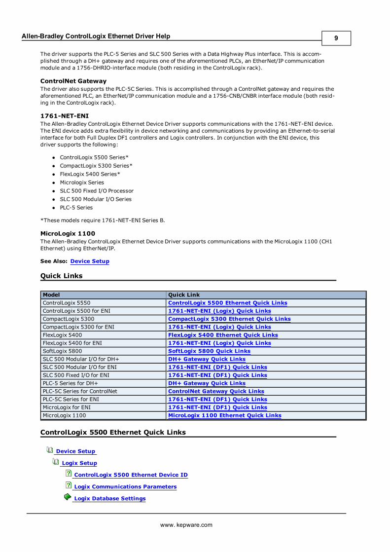
Model Quick Link
ControlLogix 5550 ControlLogix 5500 Ethernet Quick Links
ControlLogix 5500 for ENI 1761-NET-ENI (Logix) Quick Links
CompactLogix 5300 CompactLogix 5300 Ethernet Quick Links
CompactLogix 5300 for ENI 1761-NET-ENI (Logix) Quick Links
FlexLogix 5400 FlexLogix 5400 Ethernet Quick Links
FlexLogix 5400 for ENI 1761-NET-ENI (Logix) Quick Links
SoftLogix 5800 SoftLogix 5800 Quick Links
SLC 500 Modular I/O for DH+ DH+ Gateway Quick Links
SLC 500 Modular I/O for ENI 1761-NET-ENI (DF1) Quick Links
SLC 500 Fixed I/O for ENI 1761-NET-ENI (DF1) Quick Links
PLC-5 Series for DH+ DH+ Gateway Quick Links
PLC-5C Series for ControlNet ControlNet Gateway Quick Links
PLC-5C Series for ENI 1761-NET-ENI (DF1) Quick Links
MicroLogix for ENI 1761-NET-ENI (DF1) Quick Links
MicroLogix 1100 MicroLogix 1100 Ethernet Quick Links
ControlLogix 5500 Ethernet Quick Links
Device Setup
Logix Setup
ControlLogix 5500 Ethernet Device ID
Logix Communications Parameters
Logix Database Settings
www. kepware.com
9
Allen-Bradley ControlLogix Ethernet Driver Help
Logix Options
Communications Routing
Cable Diagrams
Terminology
Performance Optimization
Optimizing Your Communications
Optimizing Your Applications
Performance Statistics and Tuning
Performance Tuning Example
Data Types
Address Descriptions
ControlLogix 5500 Addressing for Ethernet
Logix Tag-Based Addressing
Automatic Tag Database Generation
Error Codes
Technical Notes
Controller Project Activity
Error Descriptions
Glossary
CompactLogix 5300 Ethernet Quick Links
Device Setup
Logix Setup
CompactLogix 5300 Ethernet Device ID
Logix Communications Parameters
Logix Database Settings
Logix Options
Communications Routing
Cable Diagrams
Terminology
Performance Optimization
Optimizing Your Communications
Optimizing Your Applications
Performance Statistics and Tuning
Performance Tuning Example
Data Types
Address Descriptions
CompactLogix 5300 Addressing for Ethernet
www. kepware.com
10
Allen-Bradley ControlLogix Ethernet Driver Help
Logix Tag-Based Addressing
Automatic Tag Database Generation
Error Codes
Technical Notes
Controller Project Activity
Error Descriptions
Glossary
FlexLogix 5400 Ethernet Quick Links
Device Setup
Logix Setup
FlexLogix 5400 Ethernet Device ID
Logix Communications Parameters
Logix Database Settings
Logix Options
Communications Routing
Cable Diagrams
Terminology
Performance Optimization
Optimizing Your Communications
Optimizing Your Applications
Performance Statistics and Tuning
Performance Tuning Example
Data Types
Address Descriptions
FlexLogix 5400 Addressing for Ethernet
Logix Tag-Based Addressing
Automatic Tag Database Generation
Error Codes
Technical Notes
Controller Project Activity
Error Descriptions
Glossary
SoftLogix 5800 Quick Links
Device Setup
Logix Setup
SoftLogix 5800 Device ID
www. kepware.com
11
Allen-Bradley ControlLogix Ethernet Driver Help
Logix Communications Parameters
Logix Database Settings
Logix Options
Communications Routing
Cable Diagrams
Terminology
Performance Optimization
Optimizing Your Communications
Optimizing Your Applications
Performance Statistics and Tuning
Performance Tuning Example
Data Types
Address Descriptions
SoftLogix 5800 Addressing
Logix Tag-Based Addressing
Automatic Tag Database Generation
Error Codes
Technical Notes
Controller Project Activity
Error Descriptions
Glossary
DH+ Gateway Quick Links
Device Setup
DH+ Gateway Setup
Communications Routing
Cable Diagrams
Terminology
Performance Optimization
Optimizing Your Communications
Optimizing Your Applications
Data Types
Address Descriptions
SLC 500 Modular I/O Addressing for DH+
PLC-5 Series Addressing for DH+
DF1 File Listing
Error Codes
Error Descriptions
www. kepware.com
12
Allen-Bradley ControlLogix Ethernet Driver Help
Glossary
ControlNet Gateway Quick Links
Device Setup
ControlNet Gateway Setup
Communications Routing
Cable Diagrams
Terminology
Performance Optimization
Optimizing Your Communications
Optimizing Your Applications
Data Types
Address Descriptions
PLC-5 Series Addressing for ControlNet
DF1 File Listing
Error Codes
Error Descriptions
Glossary
1761-NET-ENI (DF1) Quick Links
Device Setup
1761-NET-ENI Setup
Cable Diagrams
Terminology
Performance Optimization
Optimizing Your Communications
Optimizing Your Applications
Data Types
Address Descriptions
SLC 500 Modular I/O Addressing for ENI
SLC 500 Fixed I/O Addressing for ENI
PLC-5 Series Addressing for ENI
MicroLogix Addressing for ENI
DF1 File Listing
Error Codes
Error Descriptions
Glossary
www. kepware.com
13
Allen-Bradley ControlLogix Ethernet Driver Help
1761-NET-ENI (Logix) Quick Links
Device Setup
Logix Setup
Logix Communications Parameters
Logix Database Settings
Logix Options
1761-NET-ENI Setup
Cable Diagrams
Terminology
Performance Optimization
Optimizing Your Communications
Optimizing Your Applications
Performance Statistics and Tuning
Performance Tuning Example
Data Types
Address Descriptions
ControlLogix 5500 Addressing for ENI
CompactLogix 5300 Addressing for ENI
FlexLogix 5300 Addressing for ENI
Logix Tag-Based Addressing
Automatic Tag Database Generation
Error Codes
Technical Notes
Controller Project Activity
Error Descriptions
Glossary
MicroLogix 1100 Ethernet Quick Links
Device Setup
MicroLogix 1100 Setup
Cable Diagrams
Terminology
Performance Optimization
Optimizing Your Communications
Optimizing Your Applications
Data Types
Address Descriptions
MicroLogix 1100 Addressing
www. kepware.com
14
Allen-Bradley ControlLogix Ethernet Driver Help
DF1 File Listing
Error Codes
Error Descriptions
Glossary
www. kepware.com
15
Allen-Bradley ControlLogix Ethernet Driver Help
Device Setup
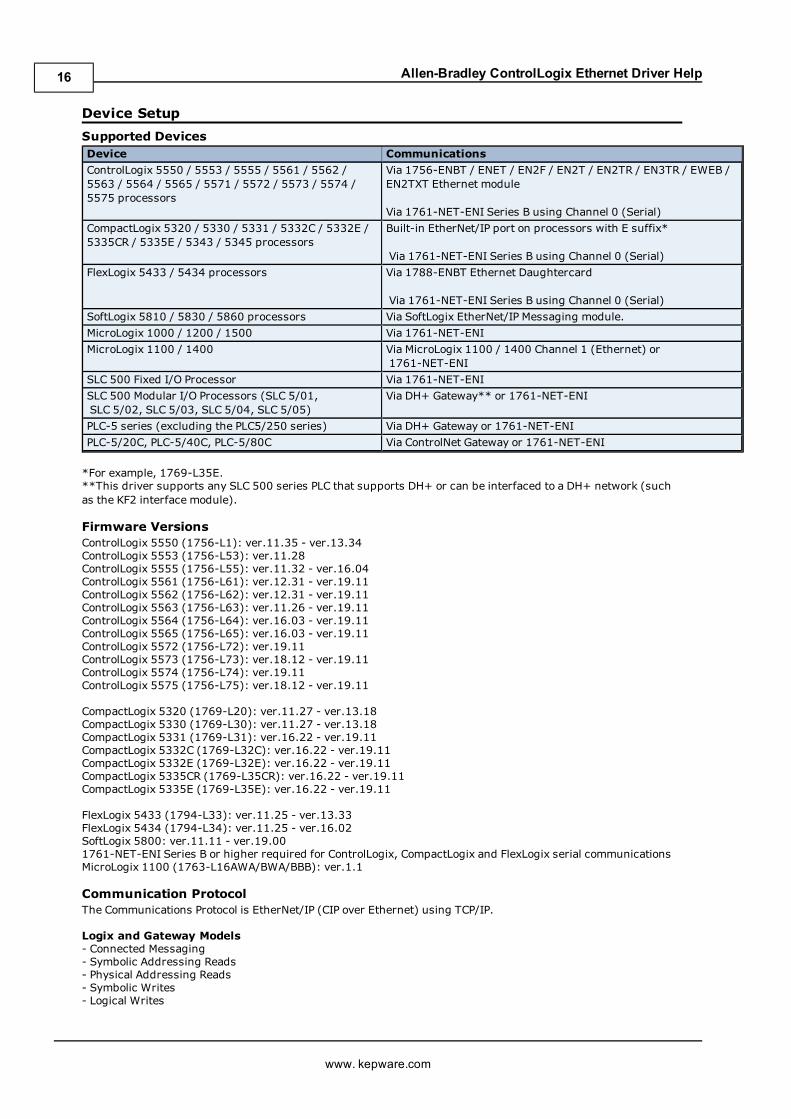
Supported DevicesDevice Communications
ControlLogix 5550 / 5553 / 5555 / 5561 / 5562 /5563 / 5564 / 5565 / 5571 / 5572 / 5573 / 5574 /5575 processors
Via 1756-ENBT / ENET / EN2F / EN2T / EN2TR / EN3TR / EWEB /EN2TXT Ethernet module
Via 1761-NET-ENI Series B using Channel 0 (Serial)
CompactLogix 5320 / 5330 / 5331 / 5332C / 5332E /5335CR / 5335E / 5343 / 5345 processors
Built-in EtherNet/IP port on processors with E suffix*
Via 1761-NET-ENI Series B using Channel 0 (Serial)
FlexLogix 5433 / 5434 processors Via 1788-ENBT Ethernet Daughtercard
Via 1761-NET-ENI Series B using Channel 0 (Serial)
SoftLogix 5810 / 5830 / 5860 processors Via SoftLogix EtherNet/IP Messaging module.
MicroLogix 1000 / 1200 / 1500 Via 1761-NET-ENI
MicroLogix 1100 / 1400 Via MicroLogix 1100 / 1400 Channel 1 (Ethernet) or1761-NET-ENI
SLC 500 Fixed I/O Processor Via 1761-NET-ENI
SLC 500 Modular I/O Processors (SLC 5/01,SLC 5/02, SLC 5/03, SLC 5/04, SLC 5/05)
Via DH+ Gateway** or 1761-NET-ENI
PLC-5 series (excluding the PLC5/250 series) Via DH+ Gateway or 1761-NET-ENI
PLC-5/20C, PLC-5/40C, PLC-5/80C Via ControlNet Gateway or 1761-NET-ENI
*For example, 1769-L35E.**This driver supports any SLC 500 series PLC that supports DH+ or can be interfaced to a DH+ network (suchas the KF2 interface module).
Firmware VersionsControlLogix 5550 (1756-L1): ver.11.35 - ver.13.34ControlLogix 5553 (1756-L53): ver.11.28ControlLogix 5555 (1756-L55): ver.11.32 - ver.16.04ControlLogix 5561 (1756-L61): ver.12.31 - ver.19.11ControlLogix 5562 (1756-L62): ver.12.31 - ver.19.11ControlLogix 5563 (1756-L63): ver.11.26 - ver.19.11ControlLogix 5564 (1756-L64): ver.16.03 - ver.19.11ControlLogix 5565 (1756-L65): ver.16.03 - ver.19.11ControlLogix 5572 (1756-L72): ver.19.11ControlLogix 5573 (1756-L73): ver.18.12 - ver.19.11ControlLogix 5574 (1756-L74): ver.19.11ControlLogix 5575 (1756-L75): ver.18.12 - ver.19.11
CompactLogix 5320 (1769-L20): ver.11.27 - ver.13.18CompactLogix 5330 (1769-L30): ver.11.27 - ver.13.18CompactLogix 5331 (1769-L31): ver.16.22 - ver.19.11CompactLogix 5332C (1769-L32C): ver.16.22 - ver.19.11CompactLogix 5332E (1769-L32E): ver.16.22 - ver.19.11CompactLogix 5335CR (1769-L35CR): ver.16.22 - ver.19.11CompactLogix 5335E (1769-L35E): ver.16.22 - ver.19.11
FlexLogix 5433 (1794-L33): ver.11.25 - ver.13.33FlexLogix 5434 (1794-L34): ver.11.25 - ver.16.02SoftLogix 5800: ver.11.11 - ver.19.001761-NET-ENI Series B or higher required for ControlLogix, CompactLogix and FlexLogix serial communicationsMicroLogix 1100 (1763-L16AWA/BWA/BBB): ver.1.1
Communication ProtocolThe Communications Protocol is EtherNet/IP (CIP over Ethernet) using TCP/IP.
Logix and Gateway Models- Connected Messaging- Symbolic Addressing Reads- Physical Addressing Reads- Symbolic Writes- Logical Writes
www. kepware.com
16
Allen-Bradley ControlLogix Ethernet Driver Help
ENI Models- Unconnected Messaging
Select from the list below for information on setting up a specific type of project.
Logix SetupDH+ Gateway SetupControlNet Gateway Setup1761-NET-ENI SetupMicroLogix 1100 SetupCommunications Routing SetupSLC 500 Slot Configuration
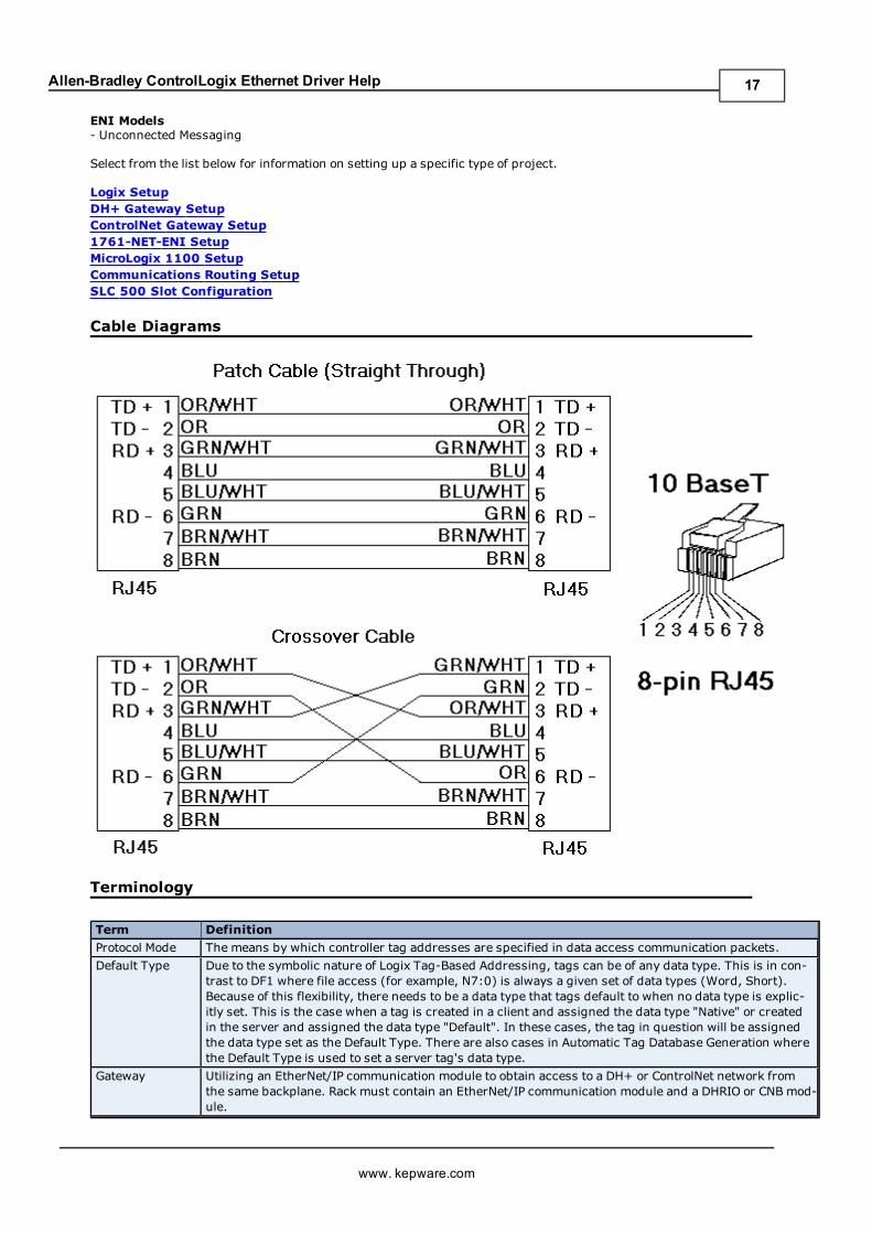
Cable Diagrams
Terminology
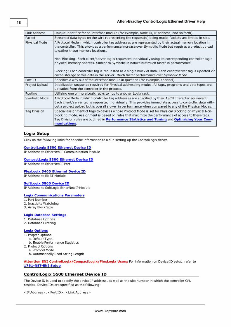
Term Definition
Protocol Mode The means by which controller tag addresses are specified in data access communication packets.
Default Type Due to the symbolic nature of Logix Tag-Based Addressing, tags can be of any data type. This is in con-trast to DF1 where file access (for example, N7:0) is always a given set of data types (Word, Short).Because of this flexibility, there needs to be a data type that tags default to when no data type is explic-itly set. This is the case when a tag is created in a client and assigned the data type "Native" or createdin the server and assigned the data type "Default". In these cases, the tag in question will be assignedthe data type set as the Default Type. There are also cases in Automatic Tag Database Generation wherethe Default Type is used to set a server tag's data type.
Gateway Utilizing an EtherNet/IP communication module to obtain access to a DH+ or ControlNet network fromthe same backplane. Rack must contain an EtherNet/IP communication module and a DHRIO or CNB mod-ule.
www. kepware.com
17
Allen-Bradley ControlLogix Ethernet Driver Help
Link Address Unique Identifier for an interface module (for example, Node ID, IP address, and so forth)
Packet Stream of data bytes on the wire representing the request(s) being made. Packets are limited in size.
Physical Mode A Protocol Mode in which controller tag addresses are represented by their actual memory location inthe controller. This provides a performance increase over Symbolic Mode but requires a project uploadto gather these memory locations.
Non-Blocking: Each client/server tag is requested individually using its corresponding controller tag'sphysical memory address. Similar to Symbolic in nature but much faster in performance.
Blocking: Each controller tag is requested as a single block of data. Each client/server tag is updated viacache storage of this data in the server. Much faster performance over Symbolic Mode.
Port ID Specifies a way out of the interface module in question (for example, channel).
Project Upload Initialization sequence required for Physical addressing modes. All tags, programs and data types areuploaded from the controller in the process.
Routing Utilizing one or more Logix racks to hop to another Logix rack.
Symbolic Mode A Protocol Mode in which controller tag addresses are specified by their ASCII character equivalent.Each client/server tag is requested individually. This provides immediate access to controller data with-out a project upload but is overall slower in performance when compared to any of the Physical Modes.
Tag Division Special assignment of tags to devices whose Protocol Mode is set for Physical Blocking or Physical Non-Blocking mode. Assignment is based on rules that maximize the performance of access to these tags.Tag Division rules are outlined in Performance Statistics and Tuning and Optimizing Your Com-munications.
Logix Setup
Click on the following links for specific information to aid in setting up the ControlLogix driver.
ControlLogix 5500 Ethernet Device IDIP Address to EtherNet/IP Communication Module
CompactLogix 5300 Ethernet Device IDIP Address to EtherNet/IP Port
FlexLogix 5400 Ethernet Device IDIP Address to ENBT Module
SoftLogix 5800 Device IDIP Address to SoftLogix EtherNet/IP Module
Logix Communications Parameters1. Port Number2. Inactivity Watchdog3. Array Block Size
Logix Database Settings1. Database Options2. Database Filtering
Logix Options1. Project Optionsa. Default Typeb. Enable Performance Statistics
2. Protocol Optionsa. Protocol Modeb. Automatically Read String Length
Attention ENI ControlLogix/CompactLogix/FlexLogix Users: For information on Device ID setup, refer to1761-NET-ENI Setup.
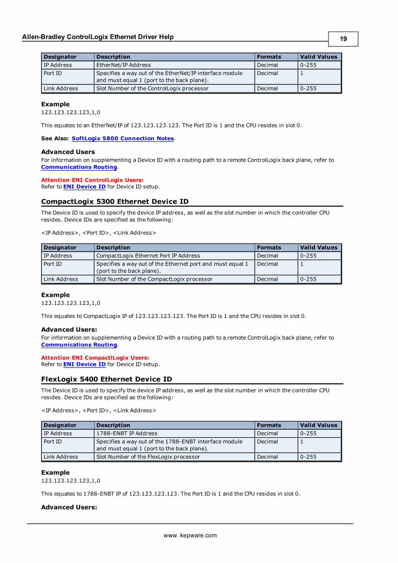
ControlLogix 5500 Ethernet Device ID
The Device ID is used to specify the device IP address, as well as the slot number in which the controller CPUresides. Device IDs are specified as the following:
<IP Address>, <Port ID>, <Link Address>
www. kepware.com
18
Allen-Bradley ControlLogix Ethernet Driver Help
Designator Description Formats Valid Values
IP Address EtherNet/IP Address Decimal 0-255
Port ID Specifies a way out of the EtherNet/IP interface moduleand must equal 1 (port to the back plane).
Decimal 1
Link Address Slot Number of the ControlLogix processor Decimal 0-255
Example123.123.123.123,1,0
This equates to an EtherNet/IP of 123.123.123.123. The Port ID is 1 and the CPU resides in slot 0.
See Also: SoftLogix 5800 Connection Notes.
Advanced UsersFor information on supplementing a Device ID with a routing path to a remote ControlLogix back plane, refer toCommunications Routing.
Attention ENI ControlLogix Users:Refer to ENI Device ID for Device ID setup.
CompactLogix 5300 Ethernet Device ID
The Device ID is used to specify the device IP address, as well as the slot number in which the controller CPUresides. Device IDs are specified as the following:
<IP Address>, <Port ID>, <Link Address>
Designator Description Formats Valid Values
IP Address CompactLogix Ethernet Port IP Address Decimal 0-255
Port ID Specifies a way out of the Ethernet port and must equal 1(port to the back plane).
Decimal 1
Link Address Slot Number of the CompactLogix processor Decimal 0-255
Example123.123.123.123,1,0
This equates to CompactLogix IP of 123.123.123.123. The Port ID is 1 and the CPU resides in slot 0.
Advanced Users:For information on supplementing a Device ID with a routing path to a remote ControlLogix back plane, refer toCommunications Routing.
Attention ENI CompactlLogix Users:Refer to ENI Device ID for Device ID setup.
FlexLogix 5400 Ethernet Device ID
The Device ID is used to specify the device IP address, as well as the slot number in which the controller CPUresides. Device IDs are specified as the following:
<IP Address>, <Port ID>, <Link Address>
Designator Description Formats Valid Values
IP Address 1788-ENBT IP Address Decimal 0-255
Port ID Specifies a way out of the 1788-ENBT interface moduleand must equal 1 (port to the back plane).
Decimal 1
Link Address Slot Number of the FlexLogix processor Decimal 0-255
Example123.123.123.123,1,0
This equates to 1788-ENBT IP of 123.123.123.123. The Port ID is 1 and the CPU resides in slot 0.
Advanced Users:
www. kepware.com
19
Allen-Bradley ControlLogix Ethernet Driver Help
For information on supplementing a Device ID with a routing path to a remote ControlLogix back plane, refer toCommunications Routing.
Attention ENI FlexLogix Users:Refer to ENI Device ID for Device ID setup.
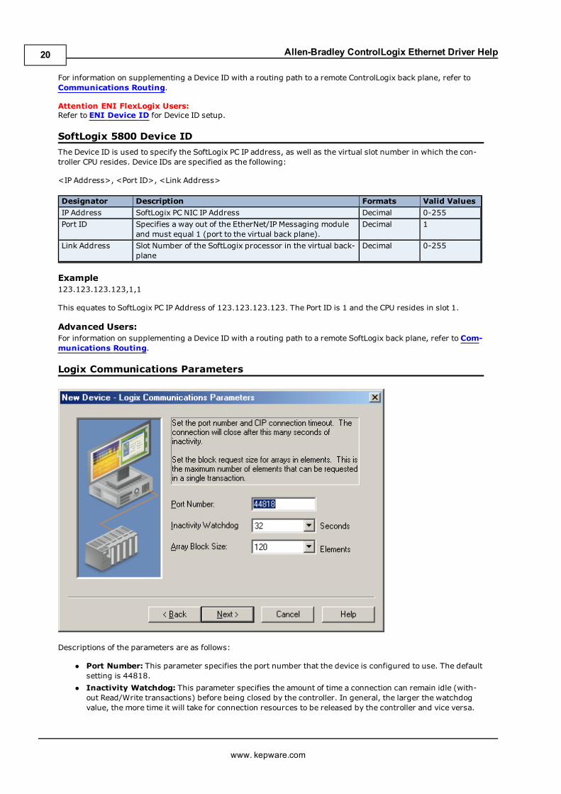
SoftLogix 5800 Device ID
The Device ID is used to specify the SoftLogix PC IP address, as well as the virtual slot number in which the con-troller CPU resides. Device IDs are specified as the following:
<IP Address>, <Port ID>, <Link Address>
Designator Description Formats Valid Values
IP Address SoftLogix PC NIC IP Address Decimal 0-255
Port ID Specifies a way out of the EtherNet/IP Messaging moduleand must equal 1 (port to the virtual back plane).
Decimal 1
Link Address Slot Number of the SoftLogix processor in the virtual back-plane
Decimal 0-255
Example123.123.123.123,1,1
This equates to SoftLogix PC IP Address of 123.123.123.123. The Port ID is 1 and the CPU resides in slot 1.
Advanced Users:For information on supplementing a Device ID with a routing path to a remote SoftLogix back plane, refer to Com-munications Routing.
Logix Communications Parameters
Descriptions of the parameters are as follows:
l Port Number: This parameter specifies the port number that the device is configured to use. The defaultsetting is 44818.
l Inactivity Watchdog: This parameter specifies the amount of time a connection can remain idle (with-out Read/Write transactions) before being closed by the controller. In general, the larger the watchdogvalue, the more time it will take for connection resources to be released by the controller and vice versa.
www. kepware.com
20
Allen-Bradley ControlLogix Ethernet Driver Help
The default setting is 32 seconds.
Note: If the Event Log error "CIP Connection timed-out while uploading project information" occursfrequently, increase the Inactivity Watchdog value. Otherwise, an Inactivity Watchdog value of 32 sec-onds is preferred.
l Array Block Size: This parameter specifies the maximum number of array elements to read in a singletransaction. The value is adjustable and ranges from 30 to 3840 elements. The default setting is 120 ele-ments.
Note: For Boolean arrays, a single "element" is considered a 32-element bit array. Thus, setting the blocksize to 30 elements translates to 960 bit elements, while 3840 elements translate to 122880 bit elements.
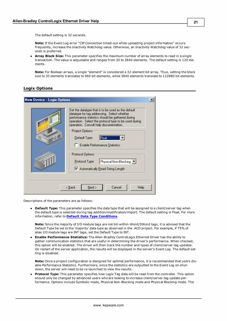
Logix Options
Descriptions of the parameters are as follows:
l Default Type: This parameter specifies the data type that will be assigned to a client/server tag whenthe default type is selected during tag addition/modification/import. The default setting is Float. For moreinformation, refer toDefault Data Type Conditions.
Note: Since the majority of I/O module tags are not bit-within-Word/DWord tags, it is advised that theDefault Type be set to the 'majority' data type as observed in the .ACD project. For example, if 75% ofalias I/O module tags are INT tags, set the Default Type to INT.
l Enable Performance Statistics: The Allen-Bradley ControlLogix Ethernet Driver has the ability togather communication statistics that are useful in determining the driver's performance. When checked,this option will be enabled. The driver will then track the number and types of client/server tag updates.On restart of the server application, the results will be displayed in the server's Event Log. The default set-ting is disabled.
Note: Once a project configuration is designed for optimal performance, it is recommended that users dis-able Performance Statistics. Furthermore, since the statistics are outputted to the Event Log on shut-down, the server will need to be re-launched to view the results.
l Protocol Type: This parameter specifies how Logix Tag data will be read from the controller. This optionshould only be changed by advanced users who are looking to increase client/server tag update per-formance. Options include Symbolic mode, Physical Non-Blocking mode and Physical Blocking mode. The
www. kepware.com
21
Allen-Bradley ControlLogix Ethernet Driver Help
server project is interchangeable between these three modes. The default setting is Physical Non-Block-ing. For more information, refer to Protocol Types Description.
l Automatically Read String Length:When checked, the driver will automatically read the LEN memberof the STRING structure whenever the DATA member is read. The DATA string will be terminated at thefirst null character encountered, the character whose position equals the value of LEN, or the maximumstring length of DATA (whichever occurs first). When unchecked, the driver will bypass the LEN memberread and terminate the DATA string at either the first null character encountered or the maximum stringlength of DATA (whichever occurs first). Therefore, if LEN is reduced by an external source without mod-ification to DATA, the driver will not terminate DATA according to this reduced length. The default settingis checked.
Default Data Type ConditionsClient/Server tags are assigned the default data type when any of the following conditions occur:
1. A Dynamic Tag is created in the client with Native as its assigned data type.2. A Static Tag is created in the server with Default as its assigned data type.3. In offline auto tag generation, when an unknown data type is encountered in the L5K/L5X file for the followingtypes of tags:
a. UDT members
b. Alias tags
4. In offline auto tag generation, when an alias of the following type is encountered in the L5K/L5X:
a. Alias of an alias.
b. Alias of non bit-within-Word/DWord I/O module tag. For example, if tag 'AliasTag' references I/O moduletag 'Local:5:C.ProgToFaultEn' @ BOOL, the data type for 'AliasTag' cannot be resolved and thus thisDefault Type is assigned to it. On the other hand, if 'Alias Tag' references I/O module tag 'Local:5:C.C-h0Config.RangeType.0' @ BOOL, the data type can be resolved because of the . (dot) BIT that defines it asa bit-within-Word/DWord. Aliases of bit-within-Word/DWord I/O module tags are automatically assignedthe Boolean data type.
Protocol Types DescriptionSymbolic ModeEach Client/Server Tag address is represented in the packet by its ASCII character name. Prior to Allen-BradleyControlLogix Ethernet Driver Version 4.6.0.xx, the driver was using Symbolic mode. Symbolic mode is convenientin that all the information needed to make a data request lies in the client/server tag's address. To take advantageof the Multi-Request Packet optimization, as many tags should be represented in a single packet as possible.Since tag addresses are represented by their ASCII character name in the packet, this implies tag addressesshould be made as short as possible. For example, MyTag is preferred over MyVe-ryLongTagNameThatContains36Chars.
Category Description
Pros 1. Low initialization overhead. All information needed lies in client/servertag's address.2. Only the data being accessed in client/server tags is requested fromthe PLC.3. Backward compatibility.
Cons 1. High device turnaround time to process symbolic address.2. Less requests per Multi Request Packet since each request is of variablesize.
Physical ModesIn the physical protocol modes, the physical address in the controller for each client/server Tag (member forstructures / element for arrays) is retrieved in a controller project upload sequence performed automatically bythe driver. For large projects, this upload sequence can be timely when performed but quickly pays off as trans-actions are processed much faster than its symbolic mode counterpart. The reason is that the physical modesavoid the timely address parsing and lookups required upon every symbolic request. There are two physical pro-tocol modes, non-blocking and blocking.
www. kepware.com
22
Allen-Bradley ControlLogix Ethernet Driver Help
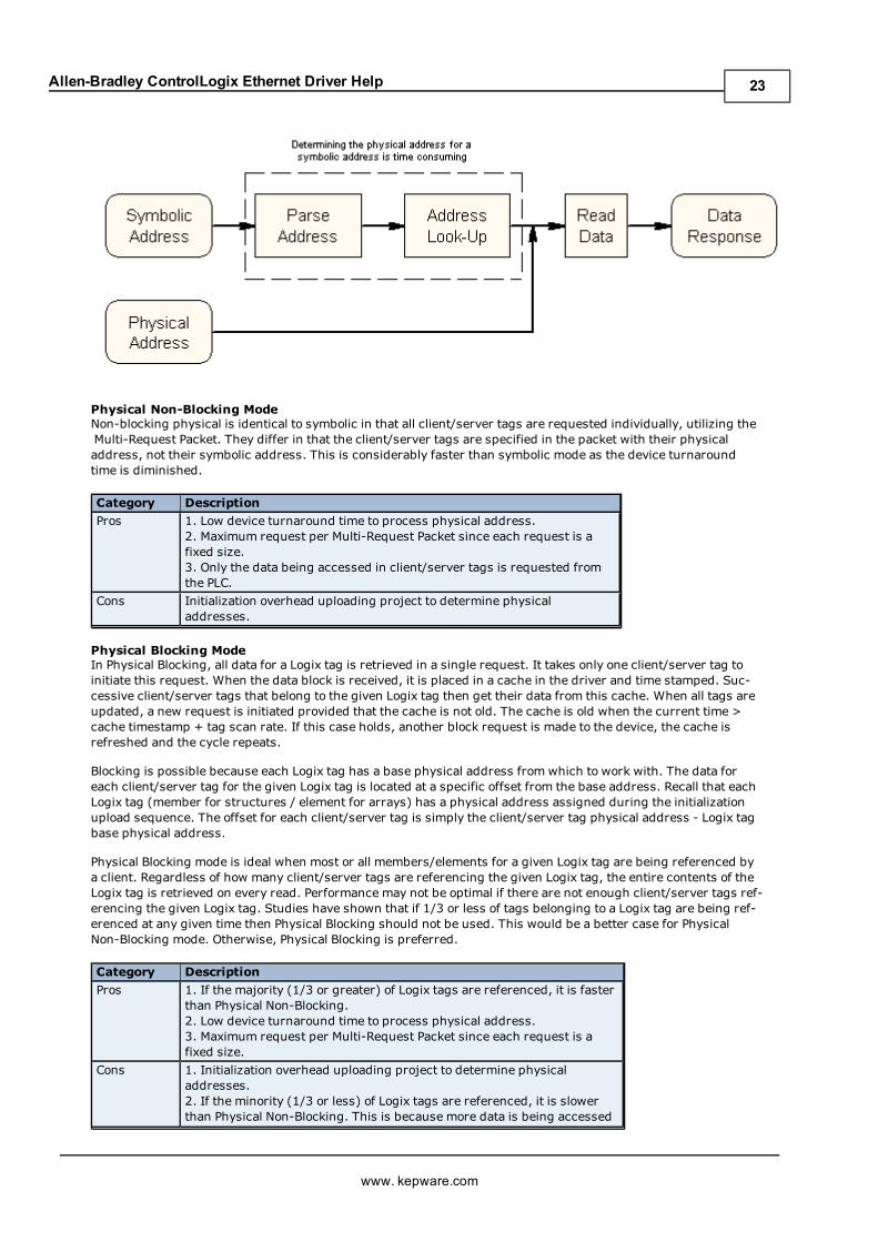
Physical Non-Blocking ModeNon-blocking physical is identical to symbolic in that all client/server tags are requested individually, utilizing theMulti-Request Packet. They differ in that the client/server tags are specified in the packet with their physicaladdress, not their symbolic address. This is considerably faster than symbolic mode as the device turnaroundtime is diminished.
Category Description
Pros 1. Low device turnaround time to process physical address.2. Maximum request per Multi-Request Packet since each request is afixed size.3. Only the data being accessed in client/server tags is requested fromthe PLC.
Cons Initialization overhead uploading project to determine physicaladdresses.
Physical Blocking ModeIn Physical Blocking, all data for a Logix tag is retrieved in a single request. It takes only one client/server tag toinitiate this request. When the data block is received, it is placed in a cache in the driver and time stamped. Suc-cessive client/server tags that belong to the given Logix tag then get their data from this cache. When all tags areupdated, a new request is initiated provided that the cache is not old. The cache is old when the current time >cache timestamp + tag scan rate. If this case holds, another block request is made to the device, the cache isrefreshed and the cycle repeats.
Blocking is possible because each Logix tag has a base physical address from which to work with. The data foreach client/server tag for the given Logix tag is located at a specific offset from the base address. Recall that eachLogix tag (member for structures / element for arrays) has a physical address assigned during the initializationupload sequence. The offset for each client/server tag is simply the client/server tag physical address - Logix tagbase physical address.
Physical Blocking mode is ideal when most or all members/elements for a given Logix tag are being referenced bya client. Regardless of how many client/server tags are referencing the given Logix tag, the entire contents of theLogix tag is retrieved on every read. Performance may not be optimal if there are not enough client/server tags ref-erencing the given Logix tag. Studies have shown that if 1/3 or less of tags belonging to a Logix tag are being ref-erenced at any given time then Physical Blocking should not be used. This would be a better case for PhysicalNon-Blocking mode. Otherwise, Physical Blocking is preferred.
Category Description
Pros 1. If the majority (1/3 or greater) of Logix tags are referenced, it is fasterthan Physical Non-Blocking.2. Low device turnaround time to process physical address.3. Maximum request per Multi-Request Packet since each request is afixed size.
Cons 1. Initialization overhead uploading project to determine physicaladdresses.2. If the minority (1/3 or less) of Logix tags are referenced, it is slowerthan Physical Non-Blocking. This is because more data is being accessed
www. kepware.com
23
Allen-Bradley ControlLogix Ethernet Driver Help
from the PLC than referenced in client/server tags.
Note: For proper and optimal use of the physical protocol modes, refer toOptimizing Your Communications.
See Also: Performance Statistics and Tuning
Logix Database Settings
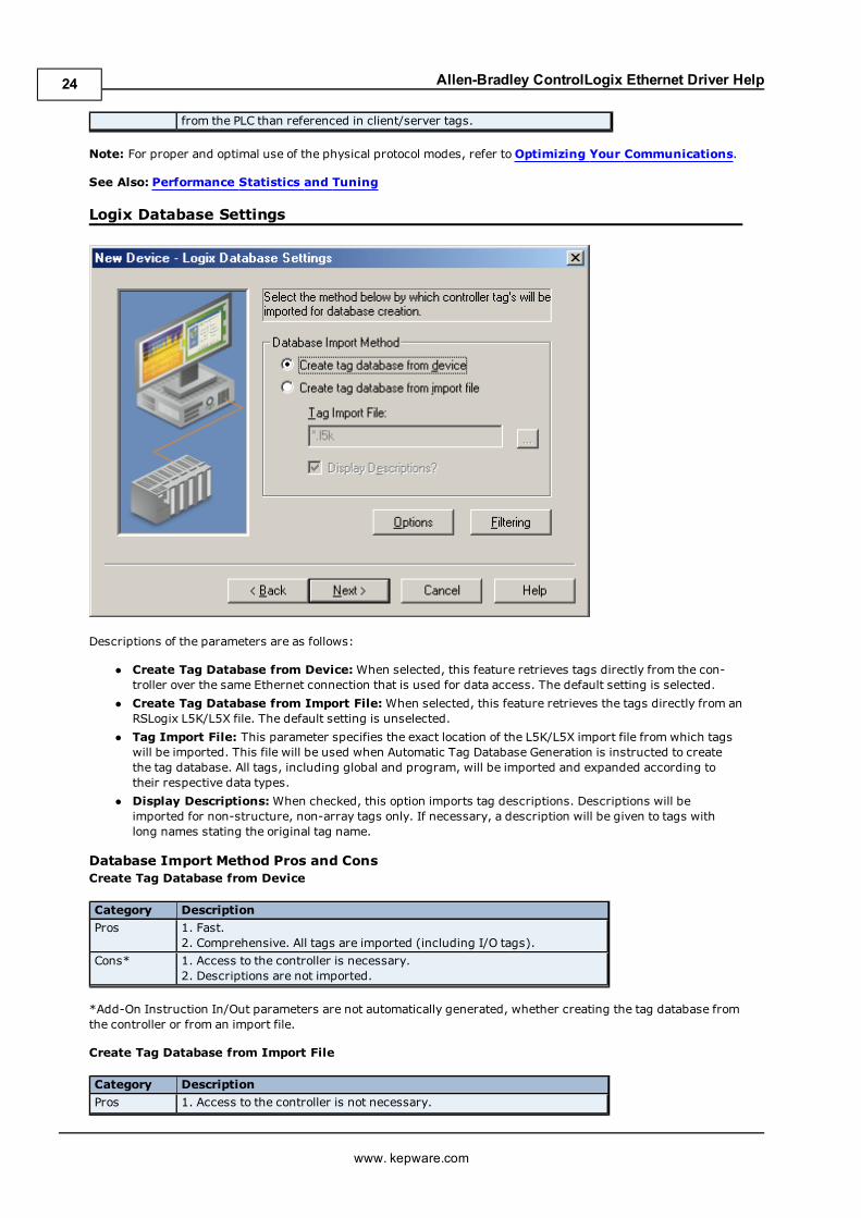
Descriptions of the parameters are as follows:
l Create Tag Database from Device:When selected, this feature retrieves tags directly from the con-troller over the same Ethernet connection that is used for data access. The default setting is selected.
l Create Tag Database from Import File: When selected, this feature retrieves the tags directly from anRSLogix L5K/L5X file. The default setting is unselected.
l Tag Import File: This parameter specifies the exact location of the L5K/L5X import file from which tagswill be imported. This file will be used when Automatic Tag Database Generation is instructed to createthe tag database. All tags, including global and program, will be imported and expanded according totheir respective data types.
l Display Descriptions:When checked, this option imports tag descriptions. Descriptions will beimported for non-structure, non-array tags only. If necessary, a description will be given to tags withlong names stating the original tag name.
Database Import Method Pros and ConsCreate Tag Database from Device
Category Description
Pros 1. Fast.2. Comprehensive. All tags are imported (including I/O tags).
Cons* 1. Access to the controller is necessary.2. Descriptions are not imported.
*Add-On Instruction In/Out parameters are not automatically generated, whether creating the tag database fromthe controller or from an import file.
Create Tag Database from Import File
Category Description
Pros 1. Access to the controller is not necessary.
www. kepware.com
24
Allen-Bradley ControlLogix Ethernet Driver Help
2. Contains the ability to work offline.3. Descriptions are imported.
Cons* 1. Slow.2. I/O tags are not imported.
*Add-On Instruction In/Out parameters are not automatically generated, whether creating the tag database fromthe controller or from an import file.
Logix Database Options
Descriptions of the parameters are as follows:
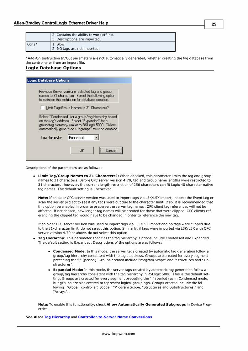
l Limit Tag/Group Names to 31 Characters?:When checked, this parameter limits the tag and groupnames to 31 characters. Before OPC server version 4.70, tag and group name lengths were restricted to31 characters; however, the current length restriction of 256 characters can fit Logix 40 character nativetag names. The default setting is unchecked.
Note: If an older OPC server version was used to import tags via L5K/L5X import, inspect the Event Log orscan the server project to see if any tags were cut due to the character limit. If so, it is recommended thatthis option be enabled in order to preserve the server tag names. OPC client tag references will not beaffected. If not chosen, new longer tag names will be created for those that were clipped. OPC clients ref-erencing the clipped tag would have to be changed in order to reference the new tag.
If an older OPC server version was used to import tags via L5K/L5X import and no tags were clipped dueto the 31-character limit, do not select this option. Similarly, if tags were imported via L5K/L5X with OPCserver version 4.70 or above, do not select this option.
l Tag Hierarchy: This parameter specifies the tag hierarchy. Options include Condensed and Expanded.The default setting is Expanded. Descriptions of the options are as follows:
l Condensed Mode: In this mode, the server tags created by automatic tag generation follow agroup/tag hierarchy consistent with the tag's address. Groups are created for every segmentpreceding the "." (period). Groups created include "Program Scope" and "Structures and Sub-structures".
l Expanded Mode: In this mode, the server tags created by automatic tag generation follow agroup/tag hierarchy consistent with the tag hierarchy in RSLogix 5000. This is the default set-ting. Groups are created for every segment preceding the "." (period) as in Condensed mode,but groups are also created to represent logical groupings. Groups created include the fol-lowing: "Global (controller) Scope," "Program Scope, "Structures and Substructures," and"Arrays".
Note: To enable this functionality, check Allow Automatically Generated Subgroups in Device Prop-erties.
See Also: Tag Hierarchy and Controller-to-Server Name Conversions
www. kepware.com
25
Allen-Bradley ControlLogix Ethernet Driver Help
Logix Database Filtering
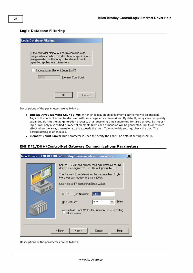
Descriptions of the parameters are as follows:
l Impose Array Element Count Limit:When checked, an array element count limit will be imposed.Tags in the controller can be declared with very large array dimensions. By default, arrays are completelyexpanded during the tag generation process, thus becoming time consuming for large arrays. By impos-ing a limit, only a specified number of elements from each dimension will be generated. Limits only takeseffect when the array dimension size is exceeds the limit. To enable this setting, check the box. Thedefault setting is unchecked.
l Element Count Limit: This parameter is used to specify the limit. The default setting is 2000.
ENI DF1/DH+/ControlNet Gateway Communications Parameters
Descriptions of the parameters are as follows:
www. kepware.com
26
Allen-Bradley ControlLogix Ethernet Driver Help
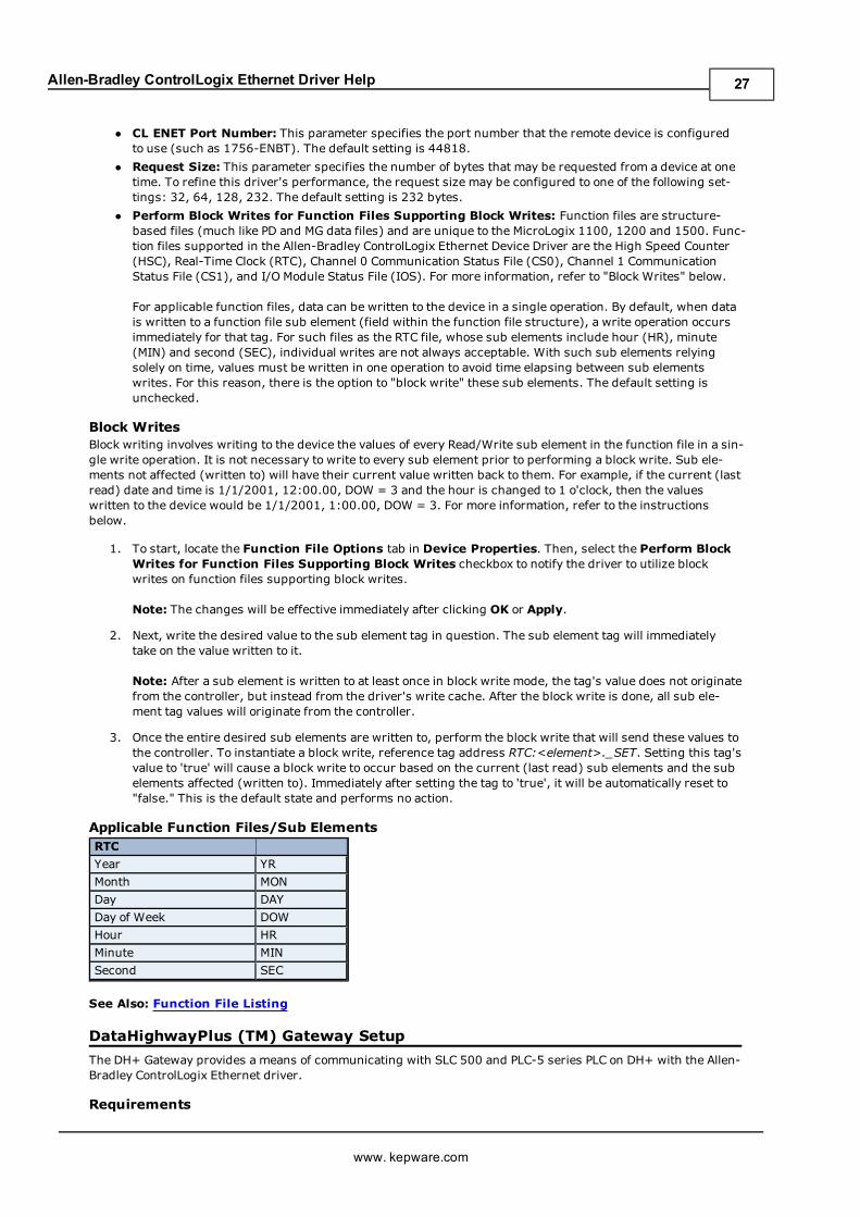
l CL ENET Port Number: This parameter specifies the port number that the remote device is configuredto use (such as 1756-ENBT). The default setting is 44818.
l Request Size: This parameter specifies the number of bytes that may be requested from a device at onetime. To refine this driver's performance, the request size may be configured to one of the following set-tings: 32, 64, 128, 232. The default setting is 232 bytes.
l Perform Block Writes for Function Files Supporting Block Writes: Function files are structure-based files (much like PD and MG data files) and are unique to the MicroLogix 1100, 1200 and 1500. Func-tion files supported in the Allen-Bradley ControlLogix Ethernet Device Driver are the High Speed Counter(HSC), Real-Time Clock (RTC), Channel 0 Communication Status File (CS0), Channel 1 CommunicationStatus File (CS1), and I/O Module Status File (IOS). For more information, refer to "Block Writes" below.
For applicable function files, data can be written to the device in a single operation. By default, when datais written to a function file sub element (field within the function file structure), a write operation occursimmediately for that tag. For such files as the RTC file, whose sub elements include hour (HR), minute(MIN) and second (SEC), individual writes are not always acceptable. With such sub elements relyingsolely on time, values must be written in one operation to avoid time elapsing between sub elementswrites. For this reason, there is the option to "block write" these sub elements. The default setting isunchecked.
Block WritesBlock writing involves writing to the device the values of every Read/Write sub element in the function file in a sin-gle write operation. It is not necessary to write to every sub element prior to performing a block write. Sub ele-ments not affected (written to) will have their current value written back to them. For example, if the current (lastread) date and time is 1/1/2001, 12:00.00, DOW = 3 and the hour is changed to 1 o'clock, then the valueswritten to the device would be 1/1/2001, 1:00.00, DOW = 3. For more information, refer to the instructionsbelow.
1. To start, locate the Function File Options tab in Device Properties. Then, select the Perform BlockWrites for Function Files Supporting Block Writes checkbox to notify the driver to utilize blockwrites on function files supporting block writes.
Note: The changes will be effective immediately after clicking OK or Apply.
2. Next, write the desired value to the sub element tag in question. The sub element tag will immediatelytake on the value written to it.
Note: After a sub element is written to at least once in block write mode, the tag's value does not originatefrom the controller, but instead from the driver's write cache. After the block write is done, all sub ele-ment tag values will originate from the controller.
3. Once the entire desired sub elements are written to, perform the block write that will send these values tothe controller. To instantiate a block write, reference tag address RTC:<element>._SET. Setting this tag'svalue to 'true' will cause a block write to occur based on the current (last read) sub elements and the subelements affected (written to). Immediately after setting the tag to 'true', it will be automatically reset to"false." This is the default state and performs no action.
Applicable Function Files/Sub ElementsRTC
Year YR
Month MON
Day DAY
Day of Week DOW
Hour HR
Minute MIN
Second SEC
See Also: Function File Listing
DataHighwayPlus (TM) Gateway Setup
The DH+ Gateway provides a means of communicating with SLC 500 and PLC-5 series PLC on DH+ with the Allen-Bradley ControlLogix Ethernet driver.
Requirements
www. kepware.com
27
Allen-Bradley ControlLogix Ethernet Driver Help
Ethernet/IP Interface module.1756-DHRIO Interface Module with appropriate channel configured for DH+.SLC500 or PLC-5 series PLC on DH+ Network.
Note: For more information about setting up a DH+ Gateway, refer toDH+ Gateway Device ID.
This also includes specification of the EtherNet/IP communication module address, the slot number of the 1756-DHRIOmodule, the DH+ Channel to use and the destination DH+ Node ID.
ENI DF1/DH+/ControlNet Gateway Communications Parameters1. Ethernet/IP Port Number.2. Block Request Size.
Note: DH+ Gateway models do not support automatic tag database generation.
DH+ Gateway Device ID
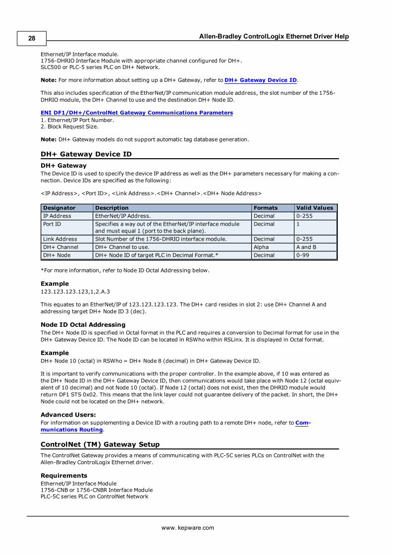
DH+ GatewayThe Device ID is used to specify the device IP address as well as the DH+ parameters necessary for making a con-nection. Device IDs are specified as the following:
<IP Address>, <Port ID>, <Link Address>.<DH+ Channel>.<DH+ Node Address>
Designator Description Formats Valid Values
IP Address EtherNet/IP Address. Decimal 0-255
Port ID Specifies a way out of the EtherNet/IP interface moduleand must equal 1 (port to the back plane).
Decimal 1
Link Address Slot Number of the 1756-DHRIO interface module. Decimal 0-255
DH+ Channel DH+ Channel to use. Alpha A and B
DH+ Node DH+ Node ID of target PLC in Decimal Format.* Decimal 0-99
*For more information, refer to Node ID Octal Addressing below.
Example123.123.123.123,1,2.A.3
This equates to an EtherNet/IP of 123.123.123.123. The DH+ card resides in slot 2: use DH+ Channel A andaddressing target DH+ Node ID 3 (dec).
Node ID Octal AddressingThe DH+ Node ID is specified in Octal format in the PLC and requires a conversion to Decimal format for use in theDH+ Gateway Device ID. The Node ID can be located in RSWho within RSLinx. It is displayed in Octal format.
ExampleDH+ Node 10 (octal) in RSWho = DH+ Node 8 (decimal) in DH+ Gateway Device ID.
It is important to verify communications with the proper controller. In the example above, if 10 was entered asthe DH+ Node ID in the DH+ Gateway Device ID, then communications would take place with Node 12 (octal equiv-alent of 10 decimal) and not Node 10 (octal). If Node 12 (octal) does not exist, then the DHRIOmodule wouldreturn DF1 STS 0x02. This means that the link layer could not guarantee delivery of the packet. In short, the DH+Node could not be located on the DH+ network.
Advanced Users:For information on supplementing a Device ID with a routing path to a remote DH+ node, refer to Com-munications Routing.
ControlNet (TM) Gateway Setup
The ControlNet Gateway provides a means of communicating with PLC-5C series PLCs on ControlNet with theAllen-Bradley ControlLogix Ethernet driver.
RequirementsEthernet/IP Interface Module1756-CNB or 1756-CNBR Interface ModulePLC-5C series PLC on ControlNet Network
www. kepware.com
28
Allen-Bradley ControlLogix Ethernet Driver Help
ControlNet Gateway Device IDThis includes specification of the EtherNet/IP communication module address, the slot number of the 1756-CNBmodule, the ControlNet Channel to use and the destination ControlNet Node ID.
ENI DF1/DH+/ControlNet Gateway Communications Parameters1. Ethernet/IP Port Number.2. Block Request Size.
Note: ControlNet Gateway models do not support automatic tag database generation.
ControlNet Gateway Device ID
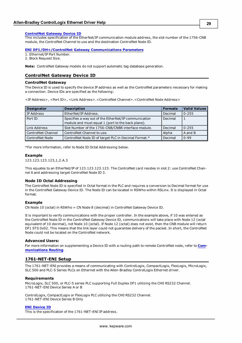
ControlNet GatewayThe Device ID is used to specify the device IP address as well as the ControlNet parameters necessary for makinga connection. Device IDs are specified as the following:
<IP Address>, <Port ID>, <Link Address>.<ControlNet Channel>.<ControlNet Node Address>
Designator Description Formats Valid Values
IP Address EtherNet/IP Address. Decimal 0-255
Port ID Specifies a way out of the EtherNet/IP communicationmodule and must equal 1 (port to the back plane).
Decimal 1
Link Address Slot Number of the 1756-CNB/CNBR interface module. Decimal 0-255
ControlNet Channel ControlNet Channel to use. Alpha A and B
ControlNet Node ControlNet Node ID of target PLC in Decimal Format.* Decimal 0-99
*For more information, refer to Node ID Octal Addressing below.
Example123.123.123.123,1,2.A.3
This equates to an EtherNet/IP of 123.123.123.123. The ControlNet card resides in slot 2: use ControlNet Chan-nel A and addressing target ControlNet Node ID 3.
Node ID Octal AddressingThe ControlNet Node ID is specified in Octal format in the PLC and requires a conversion to Decimal format for usein the ControlNet Gateway Device ID. The Node ID can be located in RSWho within RSLinx. It is displayed in Octalformat.
ExampleCN Node 10 (octal) in RSWho = CN Node 8 (decimal) in ControlNet Gateway Device ID.
It is important to verify communications with the proper controller. In the example above, if 10 was entered asthe ControlNet Node ID in the ControlNet Gateway Device ID, communications will take place with Node 12 (octalequivalent of 10 decimal), not Node 10 (octal). If Node 12 (octal) does not exist, then the CNB module will returnDF1 STS 0x02. This means that the link layer could not guarantee delivery of the packet. In short, the ControlNetNode could not be located on the ControlNet network.
Advanced Users:For more information on supplementing a Device ID with a routing path to remote ControlNet node, refer to Com-munications Routing.
1761-NET-ENI Setup
The 1761-NET-ENI provides a means of communicating with ControlLogix, CompactLogix, FlexLogix, MicroLogix,SLC 500 and PLC-5 Series PLCs on Ethernet with the Allen-Bradley ControlLogix Ethernet driver.
RequirementsMicroLogix, SLC 500, or PLC-5 series PLC supporting Full Duplex DF1 utilizing the CH0 RS232 Channel.1761-NET-ENI Device Series A or B
ControlLogix, CompactLogix or FlexLogix PLC utilizing the CH0 RS232 Channel.1761-NET-ENI Device Series B Only
ENI Device IDThis is the specification of the 1761-NET-ENI IP address.
www. kepware.com
29
Allen-Bradley ControlLogix Ethernet Driver Help
ENI DF1/DH+/ControlNet Gateway Communications Parameters1. Ethernet/IP Port Number.2. Block Request Size.3. Function File Block Writes.
ENI Logix Communications Parameters1. Port Number.2. Inactivity Watchdog.3. Array Block Size.
Attention ENI ControlLogix / CompactLogix / FlexLogix UsersRefer to Logix Setup for communications parameters, database settings and project/protocol options.
Note: These settings are for the driver. In addition to the driver settings, the following setting must be made toENI modules connecting to ControlLogix / CompactLogix / FlexLogix devices:
Important: Use the ENI / ENIW utility supplied by Allen-Bradley to turn on the CompactLogix Routing option(on the ENI IP Addr tab of the utility). This was tested on an ENI module with firmware revision 2.31.
Note: Only ENI ControlLogix, CompactLogix and FlexLogix models support automatic tag database generation.
ENI Device ID
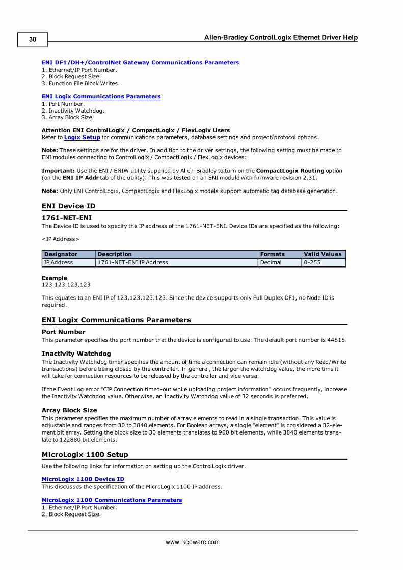
1761-NET-ENIThe Device ID is used to specify the IP address of the 1761-NET-ENI. Device IDs are specified as the following:
<IP Address>
Designator Description Formats Valid Values
IP Address 1761-NET-ENI IP Address Decimal 0-255
Example123.123.123.123
This equates to an ENI IP of 123.123.123.123. Since the device supports only Full Duplex DF1, no Node ID isrequired.
ENI Logix Communications Parameters
Port NumberThis parameter specifies the port number that the device is configured to use. The default port number is 44818.
Inactivity WatchdogThe Inactivity Watchdog timer specifies the amount of time a connection can remain idle (without any Read/Writetransactions) before being closed by the controller. In general, the larger the watchdog value, the more time itwill take for connection resources to be released by the controller and vice versa.
If the Event Log error "CIP Connection timed-out while uploading project information" occurs frequently, increasethe Inactivity Watchdog value. Otherwise, an Inactivity Watchdog value of 32 seconds is preferred.
Array Block SizeThis parameter specifies the maximum number of array elements to read in a single transaction. This value isadjustable and ranges from 30 to 3840 elements. For Boolean arrays, a single "element" is considered a 32-ele-ment bit array. Setting the block size to 30 elements translates to 960 bit elements, while 3840 elements trans-late to 122880 bit elements.
MicroLogix 1100 Setup
Use the following links for information on setting up the ControlLogix driver.
MicroLogix 1100 Device IDThis discusses the specification of the MicroLogix 1100 IP address.
MicroLogix 1100 Communications Parameters1. Ethernet/IP Port Number.2. Block Request Size.
www. kepware.com
30
Allen-Bradley ControlLogix Ethernet Driver Help
3. Function File Block Writes.
MicroLogix 1100 Device ID
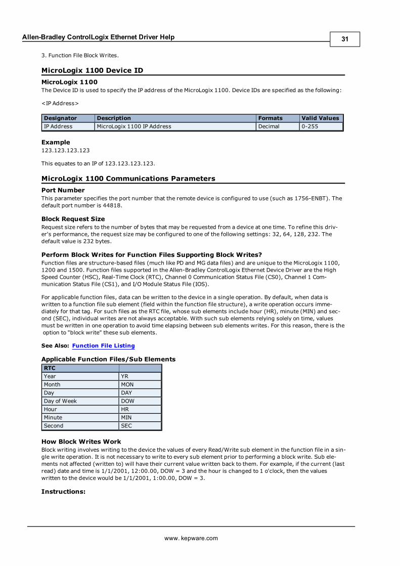
MicroLogix 1100The Device ID is used to specify the IP address of the MicroLogix 1100. Device IDs are specified as the following:
<IP Address>
Designator Description Formats Valid Values
IP Address MicroLogix 1100 IP Address Decimal 0-255
Example123.123.123.123
This equates to an IP of 123.123.123.123.
MicroLogix 1100 Communications Parameters
Port NumberThis parameter specifies the port number that the remote device is configured to use (such as 1756-ENBT). Thedefault port number is 44818.
Block Request SizeRequest size refers to the number of bytes that may be requested from a device at one time. To refine this driv-er's performance, the request size may be configured to one of the following settings: 32, 64, 128, 232. Thedefault value is 232 bytes.
Perform Block Writes for Function Files Supporting Block Writes?Function files are structure-based files (much like PD and MG data files) and are unique to the MicroLogix 1100,1200 and 1500. Function files supported in the Allen-Bradley ControlLogix Ethernet Device Driver are the HighSpeed Counter (HSC), Real-Time Clock (RTC), Channel 0 Communication Status File (CS0), Channel 1 Com-munication Status File (CS1), and I/O Module Status File (IOS).
For applicable function files, data can be written to the device in a single operation. By default, when data iswritten to a function file sub element (field within the function file structure), a write operation occurs imme-diately for that tag. For such files as the RTC file, whose sub elements include hour (HR), minute (MIN) and sec-ond (SEC), individual writes are not always acceptable. With such sub elements relying solely on time, valuesmust be written in one operation to avoid time elapsing between sub elements writes. For this reason, there is theoption to "block write" these sub elements.
See Also: Function File Listing
Applicable Function Files/Sub ElementsRTC
Year YR
Month MON
Day DAY
Day of Week DOW
Hour HR
Minute MIN
Second SEC
How Block Writes WorkBlock writing involves writing to the device the values of every Read/Write sub element in the function file in a sin-gle write operation. It is not necessary to write to every sub element prior to performing a block write. Sub ele-ments not affected (written to) will have their current value written back to them. For example, if the current (lastread) date and time is 1/1/2001, 12:00.00, DOW = 3 and the hour is changed to 1 o'clock, then the valueswritten to the device would be 1/1/2001, 1:00.00, DOW = 3.
Instructions:
www. kepware.com
31
Allen-Bradley ControlLogix Ethernet Driver Help
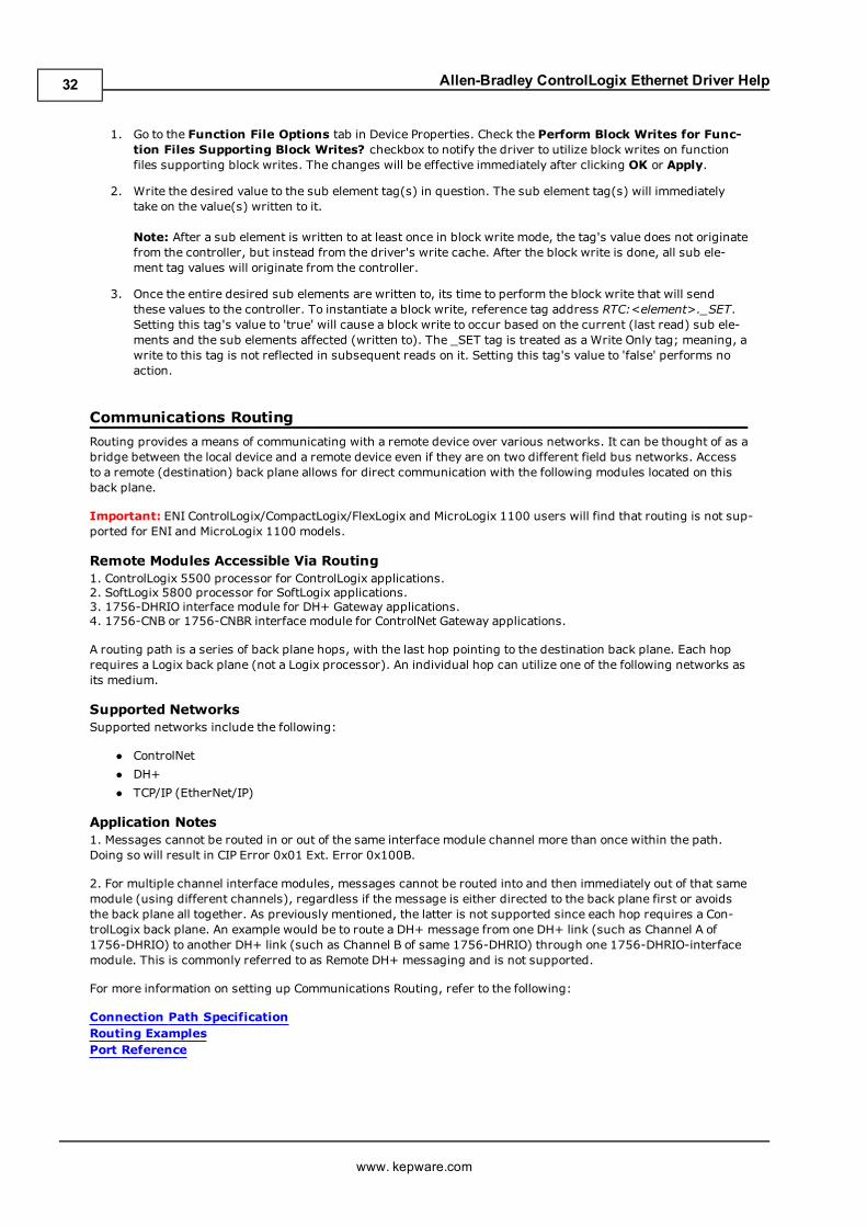
1. Go to the Function File Options tab in Device Properties. Check the Perform Block Writes for Func-tion Files Supporting Block Writes? checkbox to notify the driver to utilize block writes on functionfiles supporting block writes. The changes will be effective immediately after clicking OK or Apply.
2. Write the desired value to the sub element tag(s) in question. The sub element tag(s) will immediatelytake on the value(s) written to it.
Note: After a sub element is written to at least once in block write mode, the tag's value does not originatefrom the controller, but instead from the driver's write cache. After the block write is done, all sub ele-ment tag values will originate from the controller.
3. Once the entire desired sub elements are written to, its time to perform the block write that will sendthese values to the controller. To instantiate a block write, reference tag address RTC:<element>._SET.Setting this tag's value to 'true' will cause a block write to occur based on the current (last read) sub ele-ments and the sub elements affected (written to). The _SET tag is treated as a Write Only tag; meaning, awrite to this tag is not reflected in subsequent reads on it. Setting this tag's value to 'false' performs noaction.
Communications Routing
Routing provides a means of communicating with a remote device over various networks. It can be thought of as abridge between the local device and a remote device even if they are on two different field bus networks. Accessto a remote (destination) back plane allows for direct communication with the following modules located on thisback plane.
Important: ENI ControlLogix/CompactLogix/FlexLogix and MicroLogix 1100 users will find that routing is not sup-ported for ENI and MicroLogix 1100 models.
Remote Modules Accessible Via Routing1. ControlLogix 5500 processor for ControlLogix applications.2. SoftLogix 5800 processor for SoftLogix applications.3. 1756-DHRIO interface module for DH+ Gateway applications.4. 1756-CNB or 1756-CNBR interface module for ControlNet Gateway applications.
A routing path is a series of back plane hops, with the last hop pointing to the destination back plane. Each hoprequires a Logix back plane (not a Logix processor). An individual hop can utilize one of the following networks asits medium.
Supported NetworksSupported networks include the following:
l ControlNet
l DH+
l TCP/IP (EtherNet/IP)
Application Notes1. Messages cannot be routed in or out of the same interface module channel more than once within the path.Doing so will result in CIP Error 0x01 Ext. Error 0x100B.
2. For multiple channel interface modules, messages cannot be routed into and then immediately out of that samemodule (using different channels), regardless if the message is either directed to the back plane first or avoidsthe back plane all together. As previously mentioned, the latter is not supported since each hop requires a Con-trolLogix back plane. An example would be to route a DH+ message from one DH+ link (such as Channel A of1756-DHRIO) to another DH+ link (such as Channel B of same 1756-DHRIO) through one 1756-DHRIO-interfacemodule. This is commonly referred to as Remote DH+ messaging and is not supported.
For more information on setting up Communications Routing, refer to the following:
Connection Path SpecificationRouting ExamplesPort Reference
www. kepware.com
32
Allen-Bradley ControlLogix Ethernet Driver Help
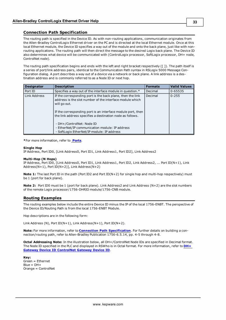
Connection Path Specification
The routing path is specified in the Device ID. As with non-routing applications, communication originates fromthe Allen-Bradley ControlLogix Ethernet driver on the PC and is directed at the local Ethernet module. Once at thislocal Ethernet module, the Device ID specifies a way out of the module and onto the back plane, just like with non-routing applications. The routing path will then direct the message to the desired Logix back plane. The Device IDalso determines what device will be communicated with (ControlLogix processor, SoftLogix processor, DH+ node,ControlNet node).
The routing path specification begins and ends with the left and right bracket respectively ([ ]). The path itself isa series of port/link address pairs, identical to the Communication Path syntax in RSLogix 5000 Message Con-figuration dialog. A port describes a way out of a device via a network or back plane. A link address is a des-tination address and is commonly referred to as a Node ID or next hop.
Designator Description Formats Valid Values
Port ID Specifies a way out of the interface module in question.* Decimal 0-65535
Link Address If the corresponding port is the back plane, then the linkaddress is the slot number of the interface module whichwill go out.
If the corresponding port is an interface module port, thenthe link address specifies a destination node as follows.
- DH+/ControlNet: Node ID- EtherNet/IP communication module: IP address- SoftLogix EtherNet/IP module: IP address
Decimal 0-255
*For more information, refer to Ports.
Single HopIP Address, Port ID0, [Link Address0, Port ID1, Link Address1, Port ID2], Link Address2
Multi-Hop (N Hops)IP Address, Port ID0, [Link Address0, Port ID1, Link Address1, Port ID2, Link Address2, ... Port ID(N+1), LinkAddress(N+1), Port ID(N+2)], Link Address(N+2)
Note 1: The last Port ID in the path (Port ID2 and Port ID(N+2) for single hop and multi-hop respectively) mustbe 1 (port for back plane).
Note 2: Port ID0 must be 1 (port for back plane). Link Address2 and Link Address (N+2) are the slot numbersof the remote Logix processor/1756-DHRIOmodule/1756-CNB module.
Routing Examples
The routing examples below include the entire Device ID minus the IP of the local 1756-ENBT. The perspective ofthe Device ID/Routing Path is from the local 1756-ENBT Module.
Hop descriptions are in the following form:
Link Address (N), Port ID(N+1), Link Address(N+1), Port ID(N+2).
Note: For more information, refer to Connection Path Specification. For further details on building a con-nection/routing path, refer to Allen-Bradley Publication 1756-6.5.14, pp. 4-5 through 4-8.
Octal Addressing Note: In the illustration below, all DH+/ControlNet Node IDs are specified in Decimal format.The Node ID specified in the PLC and displayed in RSWho is in Octal format. For more information, refer toDH+Gateway Device ID ControlNet Gateway Device ID.
Key:Green = EthernetBlue = DH+Orange = ControlNet
www. kepware.com
33
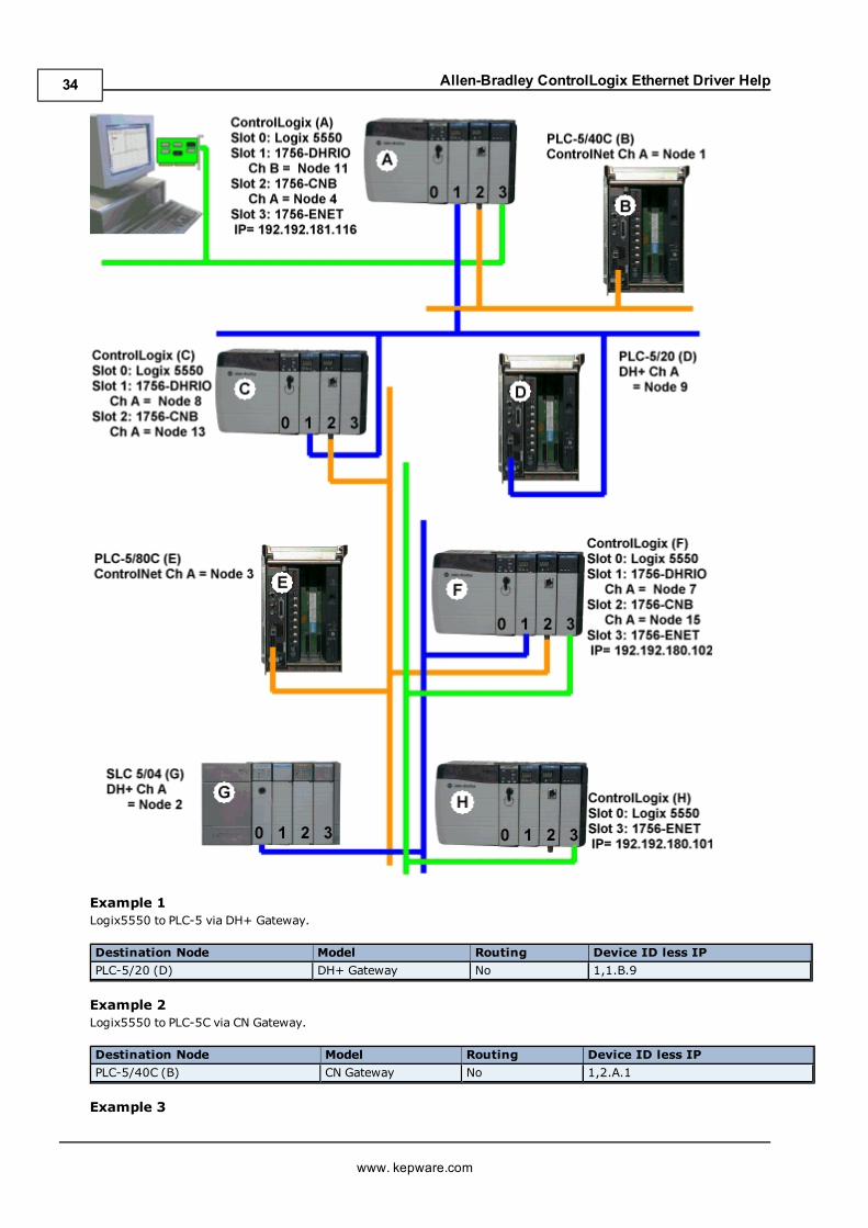
Allen-Bradley ControlLogix Ethernet Driver Help
Example 1Logix5550 to PLC-5 via DH+ Gateway.
Destination Node Model Routing Device ID less IP
PLC-5/20 (D) DH+ Gateway No 1,1.B.9
Example 2Logix5550 to PLC-5C via CN Gateway.
Destination Node Model Routing Device ID less IP
PLC-5/40C (B) CN Gateway No 1,2.A.1
Example 3
www. kepware.com
34
Allen-Bradley ControlLogix Ethernet Driver Help
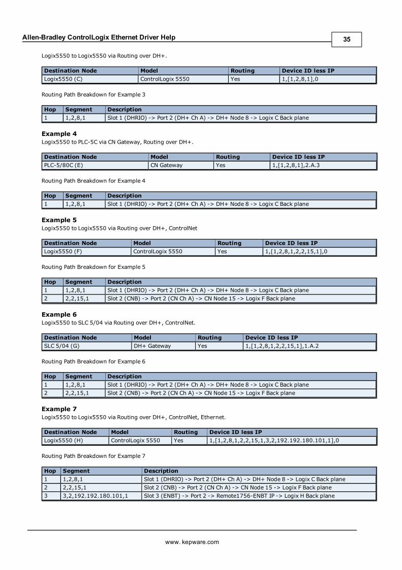
Logix5550 to Logix5550 via Routing over DH+.
Destination Node Model Routing Device ID less IP
Logix5550 (C) ControlLogix 5550 Yes 1,[1,2,8,1],0
Routing Path Breakdown for Example 3
Hop Segment Description
1 1,2,8,1 Slot 1 (DHRIO) -> Port 2 (DH+ Ch A) -> DH+ Node 8 -> Logix C Back plane
Example 4Logix5550 to PLC-5C via CN Gateway, Routing over DH+.
Destination Node Model Routing Device ID less IP
PLC-5/80C (E) CN Gateway Yes 1,[1,2,8,1],2.A.3
Routing Path Breakdown for Example 4
Hop Segment Description
1 1,2,8,1 Slot 1 (DHRIO) -> Port 2 (DH+ Ch A) -> DH+ Node 8 -> Logix C Back plane
Example 5Logix5550 to Logix5550 via Routing over DH+, ControlNet
Destination Node Model Routing Device ID less IP
Logix5550 (F) ControlLogix 5550 Yes 1,[1,2,8,1,2,2,15,1],0
Routing Path Breakdown for Example 5
Hop Segment Description
1 1,2,8,1 Slot 1 (DHRIO) -> Port 2 (DH+ Ch A) -> DH+ Node 8 -> Logix C Back plane
2 2,2,15,1 Slot 2 (CNB) -> Port 2 (CN Ch A) -> CN Node 15 -> Logix F Back plane
Example 6Logix5550 to SLC 5/04 via Routing over DH+, ControlNet.
Destination Node Model Routing Device ID less IP
SLC 5/04 (G) DH+ Gateway Yes 1,[1,2,8,1,2,2,15,1],1.A.2
Routing Path Breakdown for Example 6
Hop Segment Description
1 1,2,8,1 Slot 1 (DHRIO) -> Port 2 (DH+ Ch A) -> DH+ Node 8 -> Logix C Back plane
2 2,2,15,1 Slot 2 (CNB) -> Port 2 (CN Ch A) -> CN Node 15 -> Logix F Back plane
Example 7Logix5550 to Logix5550 via Routing over DH+, ControlNet, Ethernet.
Destination Node Model Routing Device ID less IP
Logix5550 (H) ControlLogix 5550 Yes 1,[1,2,8,1,2,2,15,1,3,2,192.192.180.101,1],0
Routing Path Breakdown for Example 7
Hop Segment Description
1 1,2,8,1 Slot 1 (DHRIO) -> Port 2 (DH+ Ch A) -> DH+ Node 8 -> Logix C Back plane
2 2,2,15,1 Slot 2 (CNB) -> Port 2 (CN Ch A) -> CN Node 15 -> Logix F Back plane
3 3,2,192.192.180.101,1 Slot 3 (ENBT) -> Port 2 -> Remote1756-ENBT IP -> Logix H Back plane
www. kepware.com
35
Allen-Bradley ControlLogix Ethernet Driver Help
Port Reference
PortsInterface Module Port 1 Port 2 Port 3
Ethernet/IP Communication Module Backplane Ethernet Network N/A
SoftLogix EtherNet/IP Messaging Module Virtual Backplane Ethernet Network N/A
1756-DHRIO Backplane DH+ Network on Ch. A DH+ Network on Ch. B
1756-CNB Backplane ControlNet Network N/A
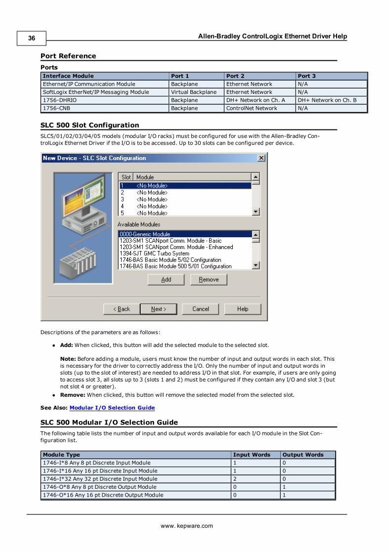
SLC 500 Slot Configuration
SLC5/01/02/03/04/05 models (modular I/O racks) must be configured for use with the Allen-Bradley Con-trolLogix Ethernet Driver if the I/O is to be accessed. Up to 30 slots can be configured per device.
Descriptions of the parameters are as follows:
l Add: When clicked, this button will add the selected module to the selected slot.
Note: Before adding a module, users must know the number of input and output words in each slot. Thisis necessary for the driver to correctly address the I/O. Only the number of input and output words inslots (up to the slot of interest) are needed to address I/O in that slot. For example, if users are only goingto access slot 3, all slots up to 3 (slots 1 and 2) must be configured if they contain any I/O and slot 3 (butnot slot 4 or greater).
l Remove:When clicked, this button will remove the selected model from the selected slot.
See Also: Modular I/O Selection Guide
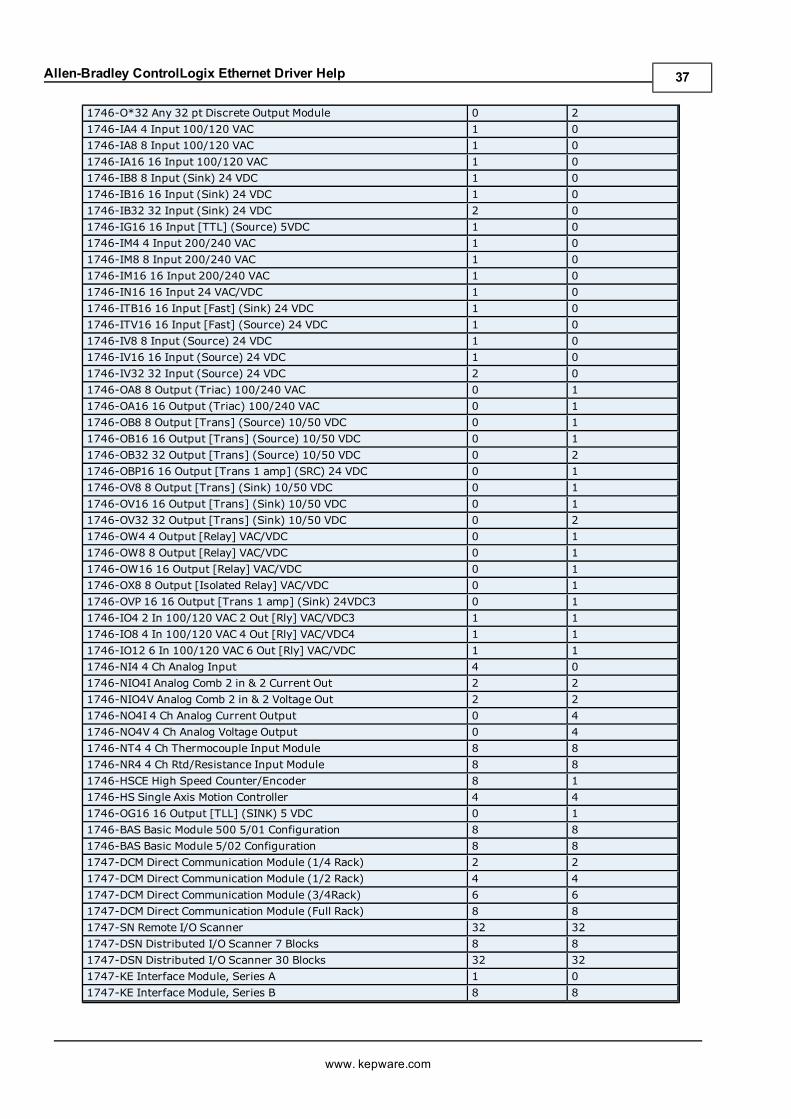
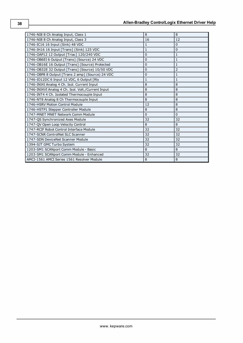
SLC 500 Modular I/O Selection Guide
The following table lists the number of input and output words available for each I/O module in the Slot Con-figuration list.
Module Type Input Words Output Words
1746-I*8 Any 8 pt Discrete Input Module 1 0
1746-I*16 Any 16 pt Discrete Input Module 1 0
1746-I*32 Any 32 pt Discrete Input Module 2 0
1746-O*8 Any 8 pt Discrete Output Module 0 1
1746-O*16 Any 16 pt Discrete Output Module 0 1
www. kepware.com
36
Allen-Bradley ControlLogix Ethernet Driver Help
1746-O*32 Any 32 pt Discrete Output Module 0 2
1746-IA4 4 Input 100/120 VAC 1 0
1746-IA8 8 Input 100/120 VAC 1 0
1746-IA16 16 Input 100/120 VAC 1 0
1746-IB8 8 Input (Sink) 24 VDC 1 0
1746-IB16 16 Input (Sink) 24 VDC 1 0
1746-IB32 32 Input (Sink) 24 VDC 2 0
1746-IG16 16 Input [TTL] (Source) 5VDC 1 0
1746-IM4 4 Input 200/240 VAC 1 0
1746-IM8 8 Input 200/240 VAC 1 0
1746-IM16 16 Input 200/240 VAC 1 0
1746-IN16 16 Input 24 VAC/VDC 1 0
1746-ITB16 16 Input [Fast] (Sink) 24 VDC 1 0
1746-ITV16 16 Input [Fast] (Source) 24 VDC 1 0
1746-IV8 8 Input (Source) 24 VDC 1 0
1746-IV16 16 Input (Source) 24 VDC 1 0
1746-IV32 32 Input (Source) 24 VDC 2 0
1746-OA8 8 Output (Triac) 100/240 VAC 0 1
1746-OA16 16 Output (Triac) 100/240 VAC 0 1
1746-OB8 8 Output [Trans] (Source) 10/50 VDC 0 1
1746-OB16 16 Output [Trans] (Source) 10/50 VDC 0 1
1746-OB32 32 Output [Trans] (Source) 10/50 VDC 0 2
1746-OBP16 16 Output [Trans 1 amp] (SRC) 24 VDC 0 1
1746-OV8 8 Output [Trans] (Sink) 10/50 VDC 0 1
1746-OV16 16 Output [Trans] (Sink) 10/50 VDC 0 1
1746-OV32 32 Output [Trans] (Sink) 10/50 VDC 0 2
1746-OW4 4 Output [Relay] VAC/VDC 0 1
1746-OW8 8 Output [Relay] VAC/VDC 0 1
1746-OW16 16 Output [Relay] VAC/VDC 0 1
1746-OX8 8 Output [Isolated Relay] VAC/VDC 0 1
1746-OVP 16 16 Output [Trans 1 amp] (Sink) 24VDC3 0 1
1746-IO4 2 In 100/120 VAC 2 Out [Rly] VAC/VDC3 1 1
1746-IO8 4 In 100/120 VAC 4 Out [Rly] VAC/VDC4 1 1
1746-IO12 6 In 100/120 VAC 6 Out [Rly] VAC/VDC 1 1
1746-NI4 4 Ch Analog Input 4 0
1746-NIO4I Analog Comb 2 in & 2 Current Out 2 2
1746-NIO4V Analog Comb 2 in & 2 Voltage Out 2 2
1746-NO4I 4 Ch Analog Current Output 0 4
1746-NO4V 4 Ch Analog Voltage Output 0 4
1746-NT4 4 Ch Thermocouple Input Module 8 8
1746-NR4 4 Ch Rtd/Resistance Input Module 8 8
1746-HSCE High Speed Counter/Encoder 8 1
1746-HS Single Axis Motion Controller 4 4
1746-OG16 16 Output [TLL] (SINK) 5 VDC 0 1
1746-BAS Basic Module 500 5/01 Configuration 8 8
1746-BAS Basic Module 5/02 Configuration 8 8
1747-DCM Direct Communication Module (1/4 Rack) 2 2
1747-DCM Direct Communication Module (1/2 Rack) 4 4
1747-DCM Direct Communication Module (3/4Rack) 6 6
1747-DCM Direct Communication Module (Full Rack) 8 8
1747-SN Remote I/O Scanner 32 32
1747-DSN Distributed I/O Scanner 7 Blocks 8 8
1747-DSN Distributed I/O Scanner 30 Blocks 32 32
1747-KE Interface Module, Series A 1 0
1747-KE Interface Module, Series B 8 8
www. kepware.com
37
Allen-Bradley ControlLogix Ethernet Driver Help
1746-NI8 8 Ch Analog Input, Class 1 8 8
1746-NI8 8 Ch Analog Input, Class 3 16 12
1746-IC16 16 Input (Sink) 48 VDC 1 0
1746-IH16 16 Input [Trans] (Sink) 125 VDC 1 0
1746-OAP12 12 Output [Triac] 120/240 VDC 0 1
1746-OB6EI 6 Output [Trans] (Source) 24 VDC 0 1
1746-OB16E 16 Output [Trans] (Source) Protected 0 1
1746-OB32E 32 Output [Trans] (Source) 10/50 VDC 0 2
1746-OBP8 8 Output [Trans 2 amp] (Source) 24 VDC 0 1
1746-IO12DC 6 Input 12 VDC, 6 Output [Rly 1 1
1746-INI4I Analog 4 Ch. Isol. Current Input 8 8
1746-INI4VI Analog 4 Ch. Isol. Volt./Current Input 8 8
1746-INT4 4 Ch. Isolated Thermocouple Input 8 8
1746-NT8 Analog 8 Ch Thermocouple Input 8 8
1746-HSRV Motion Control Module 12 8
1746-HSTP1 Stepper Controller Module 8 8
1747-MNET MNET Network CommModule 0 0
1747-QS Synchronized Axes Module 32 32
1747-QV Open Loop Velocity Control 8 8
1747-RCIF Robot Control Interface Module 32 32
1747-SCNR ControlNet SLC Scanner 32 32
1747-SDN DeviceNet Scanner Module 32 32
1394-SJT GMC Turbo System 32 32
1203-SM1 SCANport CommModule - Basic 8 8
1203-SM1 SCANport CommModule - Enhanced 32 32
AMCI-1561 AMCI Series 1561 Resolver Module 8 8
www. kepware.com
38
Allen-Bradley ControlLogix Ethernet Driver Help
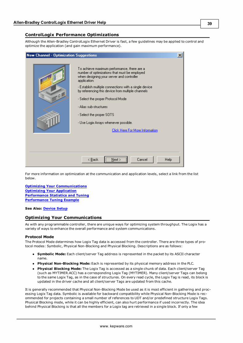
ControlLogix Performance Optimizations
Although the Allen-Bradley ControlLogix Ethernet Driver is fast, a few guidelines may be applied to control andoptimize the application (and gain maximum performance).
For more information on optimization at the communication and application levels, select a link from the listbelow.
Optimizing Your CommunicationsOptimizing Your ApplicationPerformance Statistics and TuningPerformance Tuning Example
See Also: Device Setup
Optimizing Your Communications
As with any programmable controller, there are unique ways for optimizing system throughput. The Logix has avariety of ways to enhance the overall performance and system communications.
Protocol ModeThe Protocol Mode determines how Logix Tag data is accessed from the controller. There are three types of pro-tocol modes: Symbolic, Physical Non-Blocking and Physical Blocking. Descriptions are as follows:
l Symbolic Mode: Each client/server Tag address is represented in the packet by its ASCII charactername.
l Physical Non-Blocking Mode: Each is represented by its physical memory address in the PLC.
l Physical Blocking Mode: The Logix Tag is accessed as a single chunk of data. Each client/server Tag(such as MYTIMER.ACC) has a corresponding Logix Tag (MYTIMER). Many client/server Tags can belongto the same Logix Tag, as in the case of structures. On every read cycle, the Logix Tag is read, its block isupdated in the driver cache and all client/server Tags are updated from this cache.
It is generally recommended that Physical Non-Blocking Mode be used as it is most efficient in gathering and proc-essing Logix Tag data. Symbolic is available for backward compatibility while Physical Non-Blocking Mode is rec-ommended for projects containing a small number of references to UDT and/or predefined structure Logix Tags.Physical Blocking mode, while it can be highly efficient, can also hurt performance if used incorrectly. The ideabehind Physical Blocking is that all the members for a Logix tag are retrieved in a single block. If only a few
www. kepware.com
39
Allen-Bradley ControlLogix Ethernet Driver Help
members are going to be referenced, it would be a waste to read the Logix tag as a block. This is a case wherePhysical Blocking is not recommended.
Tag Division TipsDesignate one or more devices for Physical Blocking purposes and one or more devices for Physical Non-Blockingpurposes. This provides some tags with better performance using Physical Blocking while others will get betterperformance using Physical Non-Blocking. When using such tag division, users should do the following:
1. Assign server tags referencing Atomic Logix tags (array or non-array) to the Physical Non-Blockingdevice.
2. Assign server tags referencing a Structure Logix tag composing of a 1/3* or less of the Structure tag tothe Physical Non-Blocking device(s). For example, if there are 55** or less member tags referencing aPID_ENHANCED Logix tag, all these tags should be assigned to the Physical Non-Blocking device.
3. Assign server tags referencing a Structure Logix tag composing of a 1/3* or more of the Structure tag tothe Physical Blocking device(s). For example, if there are more than 55** member tags referencing aPID_ENHANCED Logix tag, all of those tags should be assigned to the Physical Blocking device.
*1/3 is not an exact limit, but a round figure that has held true in a number of studies.**A PID_ENHANCED structure has 165 tags; thus, 1/3 = 55 tags.
UDT Substructure AliasingIf a UDT contains large substructures and 1/3* or more of the substructure are referenced (but the rest of theUDT is sparsely referenced), create an alias in RSLogix 5000. Then, assign server tags referencing this aliasedsubstructure to a Physical Blocking device. Assign the server tags referencing the rest of the UDT to a PhysicalNon-Blocking device. In this way, Structure Logix Tag access can be optimized based on how the substructuresare referenced.
*1/3 is not an exact limit, but a round figure that has held true in a number of studies.
System Overhead Time SliceThe System Overhead Time Slice (SOTS) is the percentage of time allocated to perform communication tasks(such as OPC driver communications) that is set in RSLogix5000. 100% - SOTS is the percentage of time for con-troller tasks (such as ladder logic). The default SOTS is 10%. This means that for every 10ms program scan thatoccurs, the controller spends 1ms processing Allen-Bradley ControlLogix Ethernet driver requests. The SOTS'svalue defines the task's priority. If controller tasks are a high priority, the SOTS should be set below 30%. If thecommunication tasks (such as OPC application) are high priority, the SOTS should be set at or above 30%. Forthe best balance of communications performance and CPU utilization, set the SOTS to 10% - 40% .
Multi-Request PacketsThe Allen-Bradley ControlLogix Ethernet driver has been designed to optimize reads and writes. For non-array,non-string tags (tags requesting only one element), requests are blocked into a single transaction. This providesdrastic improvement in performance over single tag transactions. The only limitation is on the number of databytes that can fit in a single transaction.
Important: Symbolic Mode Users should note that in Symbolic mode, each tag's ASCII string value is insertedinto the request packet until no more tag requests will fit. For this reason, tag names should be kept to a mini-mum in size for optimum performance. The smaller the tag name, the more tags that will fit in a single trans-action, the fewer transactions that are necessary to process all tags.
Array Elements Blocked (Symbolic and Physical Non-Blocking Modes Only)The reading of Logix atomic array elements is optimized by reading a block of the array in a single request insteadof individually. The more elements read in a block, the greater the performance. Since transaction overhead andprocessing consumes the most time, it is optimal to do as few transactions as possible while scanning as manydesired tags as possible. This is the essence of array element blocking.
Block sizes are specified as an element count. A block size of 120 elements means that a maximum of 120 arrayelements will be read in one request. The maximum block size is 3840 elements. Boolean arrays are treated a lit-tle different. In protocol, a Boolean array is a 32-bit array. Thus, requesting element 0 is requesting bits 0through 31. To maintain consistency in discussion, a Boolean array element will be considered a single bit. Insummary, the maximum number of array elements (based on block size of 3840) that can be requested is:122880 BOOL, 3840 SINT, 3840 INT, 3840 DINT and 3840 REAL.
As discussed in ControlLogix Communication Parameters, the block size is adjustable. The block size tochoose depends on the project at hand. For example, if array elements 0-26 and element 3839 are tags to beread, then using a block size of 3840 is not only overkill, but detrimental to the driver's performance. The reason
www. kepware.com
40
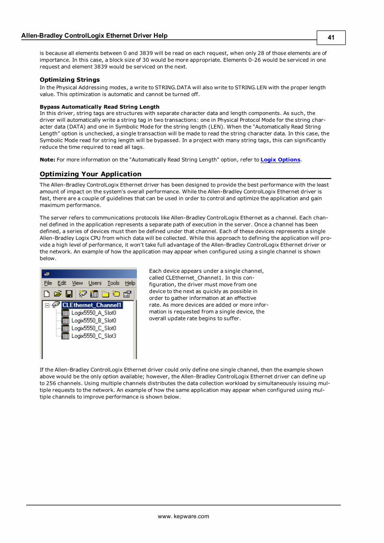
Allen-Bradley ControlLogix Ethernet Driver Help
is because all elements between 0 and 3839 will be read on each request, when only 28 of those elements are ofimportance. In this case, a block size of 30 would be more appropriate. Elements 0-26 would be serviced in onerequest and element 3839 would be serviced on the next.
Optimizing StringsIn the Physical Addressing modes, a write to STRING.DATA will also write to STRING.LEN with the proper lengthvalue. This optimization is automatic and cannot be turned off.
Bypass Automatically Read String LengthIn this driver, string tags are structures with separate character data and length components. As such, thedriver will automatically write a string tag in two transactions: one in Physical Protocol Mode for the string char-acter data (DATA) and one in Symbolic Mode for the string length (LEN). When the "Automatically Read StringLength" option is unchecked, a single transaction will be made to read the string character data. In this case, theSymbolic Mode read for string length will be bypassed. In a project with many string tags, this can significantlyreduce the time required to read all tags.
Note: For more information on the "Automatically Read String Length" option, refer to Logix Options.
Optimizing Your Application
The Allen-Bradley ControlLogix Ethernet driver has been designed to provide the best performance with the leastamount of impact on the system's overall performance. While the Allen-Bradley ControlLogix Ethernet driver isfast, there are a couple of guidelines that can be used in order to control and optimize the application and gainmaximum performance.
The server refers to communications protocols like Allen-Bradley ControlLogix Ethernet as a channel. Each chan-nel defined in the application represents a separate path of execution in the server. Once a channel has beendefined, a series of devices must then be defined under that channel. Each of these devices represents a singleAllen-Bradley Logix CPU from which data will be collected. While this approach to defining the application will pro-vide a high level of performance, it won't take full advantage of the Allen-Bradley ControlLogix Ethernet driver orthe network. An example of how the application may appear when configured using a single channel is shownbelow.
Each device appears under a single channel,called CLEthernet_Channel1. In this con-figuration, the driver must move from onedevice to the next as quickly as possible inorder to gather information at an effectiverate. As more devices are added or more infor-mation is requested from a single device, theoverall update rate begins to suffer.
If the Allen-Bradley ControlLogix Ethernet driver could only define one single channel, then the example shownabove would be the only option available; however, the Allen-Bradley ControlLogix Ethernet driver can define upto 256 channels. Using multiple channels distributes the data collection workload by simultaneously issuing mul-tiple requests to the network. An example of how the same application may appear when configured using mul-tiple channels to improve performance is shown below.
www. kepware.com
41
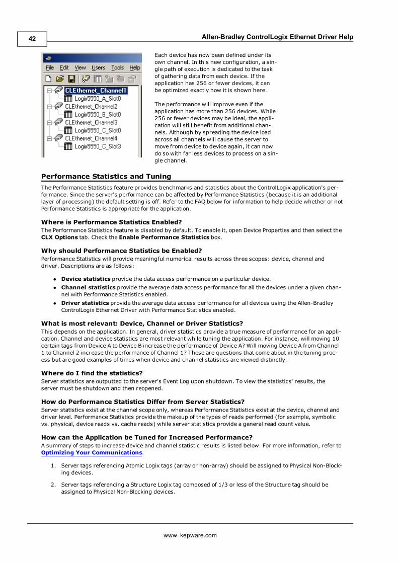
Allen-Bradley ControlLogix Ethernet Driver Help
Each device has now been defined under itsown channel. In this new configuration, a sin-gle path of execution is dedicated to the taskof gathering data from each device. If theapplication has 256 or fewer devices, it canbe optimized exactly how it is shown here.
The performance will improve even if theapplication has more than 256 devices. While256 or fewer devices may be ideal, the appli-cation will still benefit from additional chan-nels. Although by spreading the device loadacross all channels will cause the server tomove from device to device again, it can nowdo so with far less devices to process on a sin-gle channel.
Performance Statistics and Tuning
The Performance Statistics feature provides benchmarks and statistics about the ControlLogix application's per-formance. Since the server's performance can be affected by Performance Statistics (because it is an additionallayer of processing) the default setting is off. Refer to the FAQ below for information to help decide whether or notPerformance Statistics is appropriate for the application.
Where is Performance Statistics Enabled?The Performance Statistics feature is disabled by default. To enable it, open Device Properties and then select theCLX Options tab. Check the Enable Performance Statistics box.
Why should Performance Statistics be Enabled?Performance Statistics will provide meaningful numerical results across three scopes: device, channel anddriver. Descriptions are as follows:
l Device statistics provide the data access performance on a particular device.
l Channel statistics provide the average data access performance for all the devices under a given chan-nel with Performance Statistics enabled.
l Driver statistics provide the average data access performance for all devices using the Allen-BradleyControlLogix Ethernet Driver with Performance Statistics enabled.
What is most relevant: Device, Channel or Driver Statistics?This depends on the application. In general, driver statistics provide a true measure of performance for an appli-cation. Channel and device statistics are most relevant while tuning the application. For instance, will moving 10certain tags from Device A to Device B increase the performance of Device A? Will moving Device A from Channel1 to Channel 2 increase the performance of Channel 1? These are questions that come about in the tuning proc-ess but are good examples of times when device and channel statistics are viewed distinctly.
Where do I find the statistics?Server statistics are outputted to the server's Event Log upon shutdown. To view the statistics' results, theserver must be shutdown and then reopened.
How do Performance Statistics Differ from Server Statistics?Server statistics exist at the channel scope only, whereas Performance Statistics exist at the device, channel anddriver level. Performance Statistics provide the makeup of the types of reads performed (for example, symbolicvs. physical, device reads vs. cache reads) while server statistics provide a general read count value.
How can the Application be Tuned for Increased Performance?A summary of steps to increase device and channel statistic results is listed below. For more information, refer toOptimizing Your Communications.
1. Server tags referencing Atomic Logix tags (array or non-array) should be assigned to Physical Non-Block-ing devices.
2. Server tags referencing a Structure Logix tag composed of 1/3 or less of the Structure tag should beassigned to Physical Non-Blocking devices.
www. kepware.com
42
Allen-Bradley ControlLogix Ethernet Driver Help
3. Server tags referencing a Structure Logix tag composed of 1/3 or more of the Structure tag should beassigned to Physical Blocking devices.
4. If Symbolic mode is used, Logix names should be kept to a minimum length.
5. Logix Arrays should be used as often as possible.
6. Only the necessary amount of System Overhead Time Slice for Ladder Logic/FBD should allocated in orderto leave the rest for driver communications.
7. For projects that read a large number of string tags in Physical Mode, uncheck the "Automatically ReadString Length" option (located in the Logix Options tab of Device Properties).
A summary of steps to increase driver statistic results are listed below. For more information, refer toOpti-mizing Your Application.
1. Devices should be spread across channels. More than one device should not be put on a channel unlessabsolutely necessary.
2. Load should be spread evenly across devices. A single device should not be overloaded unless absolutelynecessary.
3. The same Logix tag should not be referenced across different devices.
Note: These general rules can help optimize performance, but it ultimately depends on the application at hand.Note that the scan rate can obscure results: if tag requests are light, Read and Write transactions can completebefore the next request comes in. In this case, Physical Blocking and Physical Non-Blocking will have the samePerformance Statistics results. If tag requests are high (many tags or high scan rates), transaction completiontime may take longer. This is when the strengths and weaknesses of Physical Blocking and Physical Non-Blockingbecome apparent. Performance Statistics can help tune the application for maximum performance. For an exam-ple of tuning applications, refer to Application Performance Tuning Example.
Performance Tuning Example
This example is designed to illustrate the concepts discussed in the following sections:
Optimizing Your CommunicationsOptimizing Your ApplicationPerformance Statistics and Tuning
Statistics can be applied to any application. In this example, the Quick Client is used in the performance tuningprocess. The idea is that all the tags used in the project are read at the same time at a fast scan rate. Though thisis not realistic, it does provide an accurate benchmark to the project layout in the server (tags belonging to spe-cific devices, devices belonging to specific channels and and so forth.).
The statistics gathered are relative. Users should start with a server project layout, gather the statistics and thentune. Once the most efficient layout is determined, the client application can be built with reassurance that theserver is optimal.
Note: More than one trial is required to properly assess the results for a given layout.
Caution: Performance results obtained using the Quick Client will not equate to performance results obtainedusing other Client applications. The amount of tags being read/written at any given time, the tag scan rates andthe number of clients involved are just a few of the factors that will produce discrepancies between Quick Clientresults and other Client application results. The tuning process described here provides the optimal project lay-out assuming all tags are being read at a fast scan rate. Writes will hinder this performance.
Users can also perform performance tuning with the client application instead of the Quick Client. This will pro-vide the most accurate results. The only downside is that any tuning required will not only affect the serverproject, but most likely the Client application as well. It is recommended that the Quick Client be used to tune theapplication before the client application is developed.
1. In the controller project below, there are the following:
l 2 Atomics
l 1 Atomic array
l 1 UDT
www. kepware.com
43
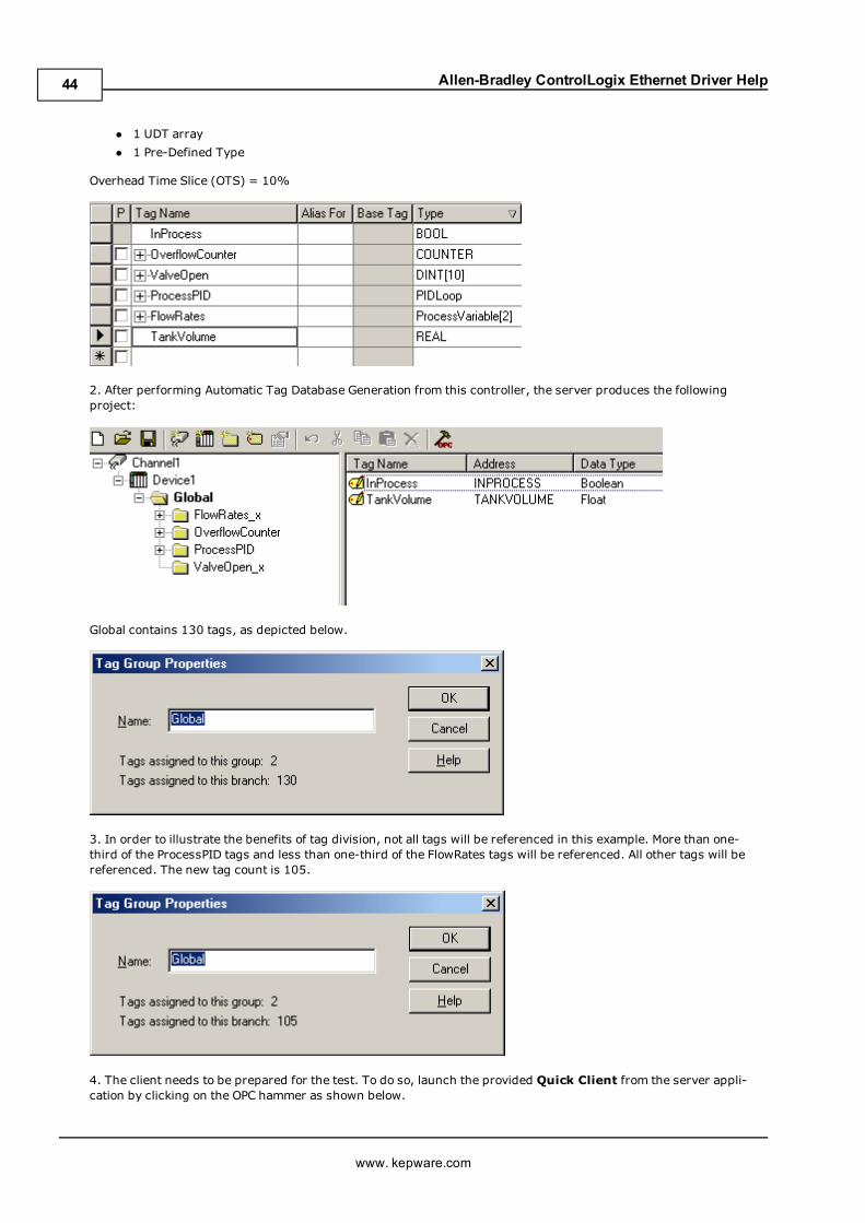
Allen-Bradley ControlLogix Ethernet Driver Help
l 1 UDT array
l 1 Pre-Defined Type
Overhead Time Slice (OTS) = 10%
2. After performing Automatic Tag Database Generation from this controller, the server produces the followingproject:
Global contains 130 tags, as depicted below.
3. In order to illustrate the benefits of tag division, not all tags will be referenced in this example. More than one-third of the ProcessPID tags and less than one-third of the FlowRates tags will be referenced. All other tags will bereferenced. The new tag count is 105.
4. The client needs to be prepared for the test. To do so, launch the provided Quick Client from the server appli-cation by clicking on the OPC hammer as shown below.
www. kepware.com
44
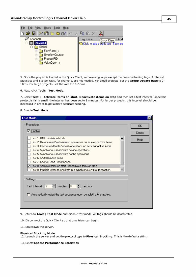
Allen-Bradley ControlLogix Ethernet Driver Help
5. Once the project is loaded in the Quick Client, remove all groups except the ones containing tags of interest.Statistics and System tags, for example, are not needed. For small projects, set the Group Update Rate to 0-10ms. For large projects, set the rate to 10-50ms.
6. Next, click Tools | Test Mode.
7. Select Test 8. Activate items on start. Deactivate items on stop and then set a test interval. Since thisproject is fairly small, the interval has been set to 2 minutes. For larger projects, this interval should beincreased in order to get a more accurate reading.
8. Enable Test Mode.
9. Return to Tools | Test Mode and disable test mode. All tags should be deactivated.
10. Disconnect the Quick Client so that time trials can begin.
11. Shutdown the server.
Physical Blocking Mode12. Launch the server and set the protocol type to Physical Blocking. This is the default setting.
13. Select Enable Performance Statistics.
www. kepware.com
45
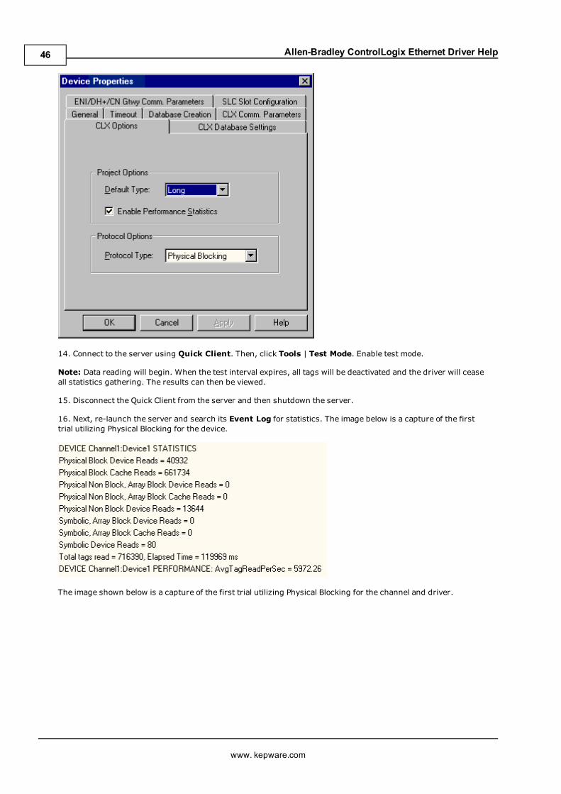
Allen-Bradley ControlLogix Ethernet Driver Help
14. Connect to the server using Quick Client. Then, click Tools | Test Mode. Enable test mode.
Note: Data reading will begin. When the test interval expires, all tags will be deactivated and the driver will ceaseall statistics gathering. The results can then be viewed.
15. Disconnect the Quick Client from the server and then shutdown the server.
16. Next, re-launch the server and search its Event Log for statistics. The image below is a capture of the firsttrial utilizing Physical Blocking for the device.
The image shown below is a capture of the first trial utilizing Physical Blocking for the channel and driver.
www. kepware.com
46
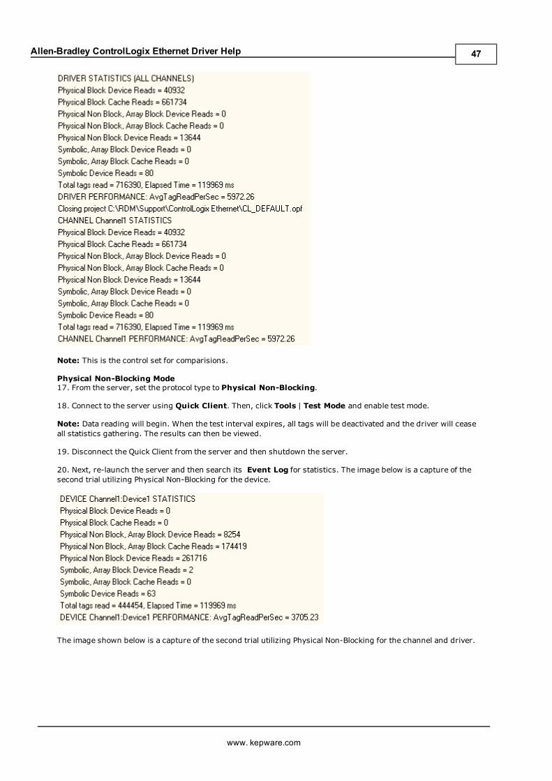
Allen-Bradley ControlLogix Ethernet Driver Help
Note: This is the control set for comparisions.
Physical Non-Blocking Mode17. From the server, set the protocol type to Physical Non-Blocking.
18. Connect to the server using Quick Client. Then, click Tools | Test Mode and enable test mode.
Note: Data reading will begin. When the test interval expires, all tags will be deactivated and the driver will ceaseall statistics gathering. The results can then be viewed.
19. Disconnect the Quick Client from the server and then shutdown the server.
20. Next, re-launch the server and then search its Event Log for statistics. The image below is a capture of thesecond trial utilizing Physical Non-Blocking for the device.
The image shown below is a capture of the second trial utilizing Physical Non-Blocking for the channel and driver.
www. kepware.com
47
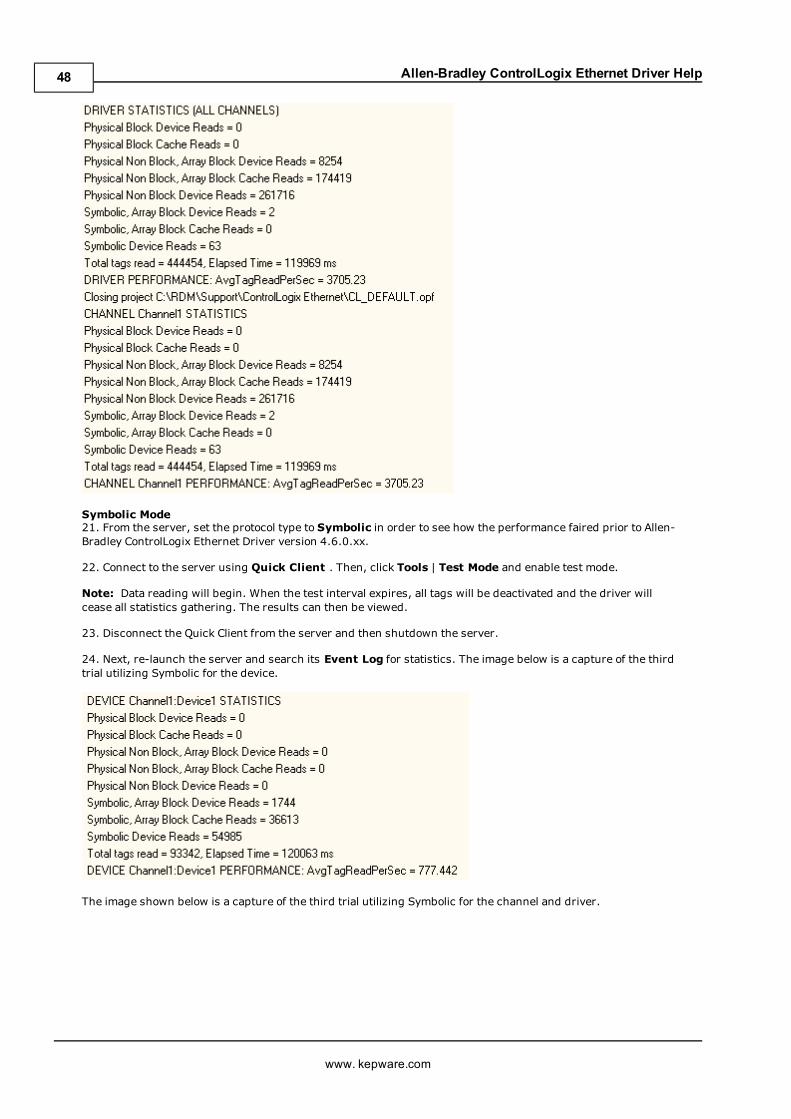
Allen-Bradley ControlLogix Ethernet Driver Help
Symbolic Mode21. From the server, set the protocol type to Symbolic in order to see how the performance faired prior to Allen-Bradley ControlLogix Ethernet Driver version 4.6.0.xx.
22. Connect to the server using Quick Client . Then, click Tools | Test Mode and enable test mode.
Note: Data reading will begin. When the test interval expires, all tags will be deactivated and the driver willcease all statistics gathering. The results can then be viewed.
23. Disconnect the Quick Client from the server and then shutdown the server.
24. Next, re-launch the server and search its Event Log for statistics. The image below is a capture of the thirdtrial utilizing Symbolic for the device.
The image shown below is a capture of the third trial utilizing Symbolic for the channel and driver.
www. kepware.com
48
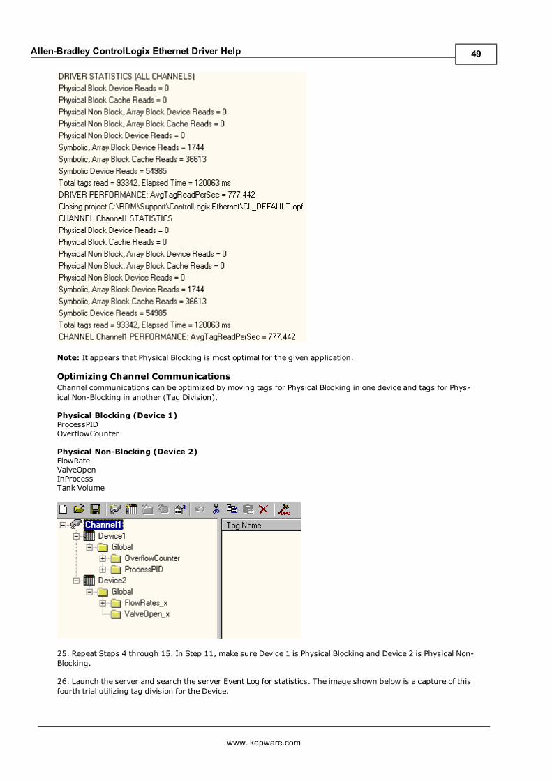
Allen-Bradley ControlLogix Ethernet Driver Help
Note: It appears that Physical Blocking is most optimal for the given application.
Optimizing Channel CommunicationsChannel communications can be optimized by moving tags for Physical Blocking in one device and tags for Phys-ical Non-Blocking in another (Tag Division).
Physical Blocking (Device 1)ProcessPIDOverflowCounter
Physical Non-Blocking (Device 2)FlowRateValveOpenInProcessTank Volume
25. Repeat Steps 4 through 15. In Step 11, make sure Device 1 is Physical Blocking and Device 2 is Physical Non-Blocking.
26. Launch the server and search the server Event Log for statistics. The image shown below is a capture of thisfourth trial utilizing tag division for the Device.
www. kepware.com
49
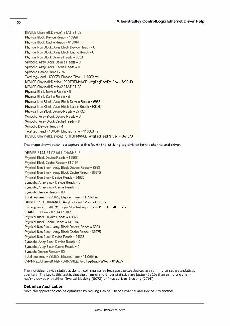
Allen-Bradley ControlLogix Ethernet Driver Help
The image shown below is a capture of this fourth trial utilizing tag division for the channel and driver.
The individual device statistics do not look impressive because the two devices are running on separate statisticcounters. The key to this test is that the channel and driver statistics are better (6126) than using one chan-nel/one device with either Physical Blocking (5972) or Physical Non-Blocking (3705).
Optimize ApplicationNext, the application can be optimized by moving Device 1 to one channel and Device 2 to another.
www. kepware.com
50
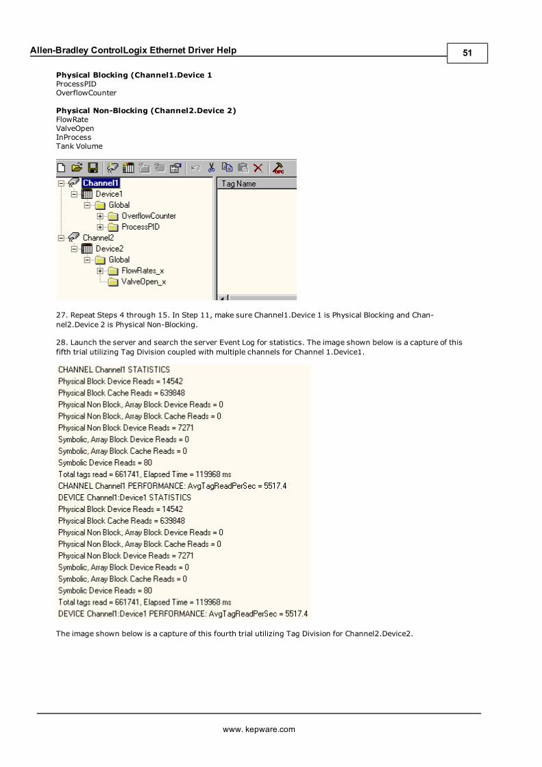
Allen-Bradley ControlLogix Ethernet Driver Help
Physical Blocking (Channel1.Device 1ProcessPIDOverflowCounter
Physical Non-Blocking (Channel2.Device 2)FlowRateValveOpenInProcessTank Volume
27. Repeat Steps 4 through 15. In Step 11, make sure Channel1.Device 1 is Physical Blocking and Chan-nel2.Device 2 is Physical Non-Blocking.
28. Launch the server and search the server Event Log for statistics. The image shown below is a capture of thisfifth trial utilizing Tag Division coupled with multiple channels for Channel 1.Device1.
The image shown below is a capture of this fourth trial utilizing Tag Division for Channel2.Device2.
www. kepware.com
51
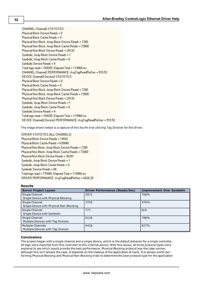
Allen-Bradley ControlLogix Ethernet Driver Help
The image shown below is a capture of this fourth trial utilizing Tag Division for the Driver.
ResultsServer Project Layout Driver Performance (Reads/Sec) Improvement Over Symbolic
Single ChannelSingle Device with Physical Blocking
5972 768%
Single ChannelSingle Device with Physical Non-Blocking
3705 476%
Single ChannelSingle Device with Symbolic
777 N/A
Single ChannelMultiple Devices with Tag Division
6126 788%
Multiple ChannelsMultiple Devices with Tag Division
6426 827%
ConclusionsThe project began with a single channel and a single device, which is the default behavior for a single controller.All tags were imported from this controller to this channel.device. With this layout, all three protocol types wereexplored to see which would provide the best performance. Physical Blocking protocol was the clear winner,although this isn't always the case. It depends on the makeup of the application at hand. It is always worth per-forming Physical Blocking and Physical Non-Blocking trials to determine the best protocol type for the application
www. kepware.com
52
Allen-Bradley ControlLogix Ethernet Driver Help
when performance is crucial. Symbolic protocol is not necessary since it will never meet the performance caliberof either one of these other protocol types. It is shown here for the sake of example.
Measures were taken to optimize communications using the tips outlined in Optimizing YourCommunications. Most notably, tag division was used to place the Physical Blocking type tags in a deviceassigned Physical Blocking and the Physical Non-Blocking type tags in a device assigned Physical Non-Blocking.Both devices resided on the same channel. The results show an improvement over just using Physical Blocking ona single device. This is because some tags lend themselves better to one protocol type over another. For example,reading an entire COUNTER will benefit from Physical Blocking over Physical Non-Blocking since its much fasterreading the COUNTER as a block then reading its individual members.
Measures were also taken to optimize the application by placing devices on their own channel. Using the devicescreated in the previous trial, a Physical Blocking device was placed on one channel and a Physical Non-Blockingdevice on another. The results show improvement over the single channel/multiple devices scenario from the pre-vious trial. This reinforces the idea that performance is improved by having as few devices per channel and asmany channels as necessary.
After using these three optimization methods, the project has an 827% performance increase over Allen-BradleyControlLogix Ethernet Driver version earlier than 4.6.0.xx. Tag division and multiple channels improved the per-formance by 107%. The performance increases will be more apparent with larger projects.
www. kepware.com
53
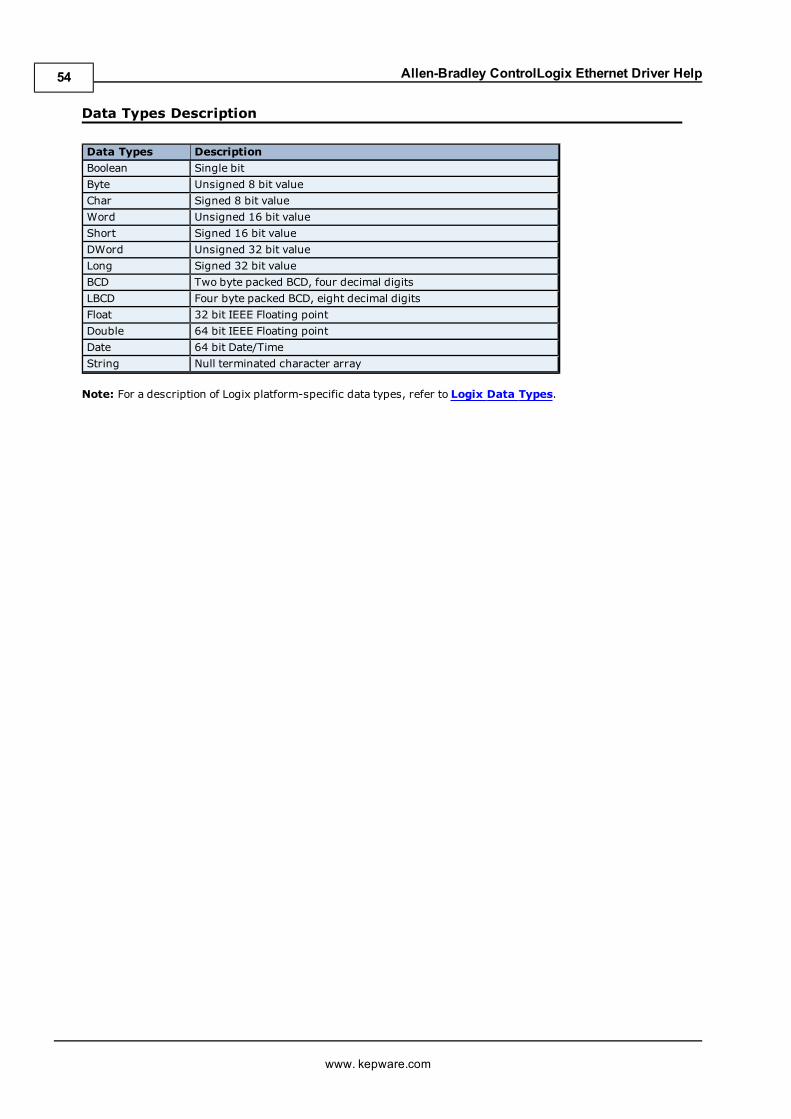
Allen-Bradley ControlLogix Ethernet Driver Help
Data Types Description
Data Types Description
Boolean Single bit
Byte Unsigned 8 bit value
Char Signed 8 bit value
Word Unsigned 16 bit value
Short Signed 16 bit value
DWord Unsigned 32 bit value
Long Signed 32 bit value
BCD Two byte packed BCD, four decimal digits
LBCD Four byte packed BCD, eight decimal digits
Float 32 bit IEEE Floating point
Double 64 bit IEEE Floating point
Date 64 bit Date/Time
String Null terminated character array
Note: For a description of Logix platform-specific data types, refer to Logix Data Types.
www. kepware.com
54
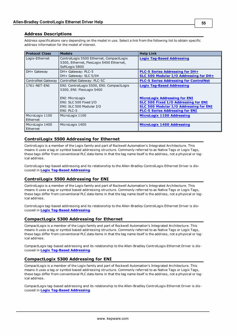
Allen-Bradley ControlLogix Ethernet Driver Help
Address Descriptions
Address specifications vary depending on the model in use. Select a link from the following list to obtain specificaddress information for the model of interest.
Protocol Class Models Help Link
Logix-Ethernet ControlLogix 5500 Ethernet, CompactLogix5300, Ethernet, FlexLogix 5400 Ethernet,SoftLogix 5800
Logix Tag-Based Addressing
DH+ Gateway DH+ Gateway: PLC-5DH+ Gateway: SLC 5/04
PLC-5 Series Addressing for DH+SLC 500 Modular I/O Addressing for DH+
ControlNet Gateway ControlNet Gateway: PLC-5C PLC-5 Series Addressing for ControlNet
1761-NET-ENI ENI: ControlLogix 5500, ENI: CompactLogix5300, ENI: FlexLogix 5400
ENI: MicroLogixENI: SLC 500 Fixed I/OENI: SLC 500 Modular I/OENI: PLC-5
Logix Tag-Based Addressing
MicroLogix Addressing for ENISLC 500 Fixed I/O Addressing for ENISLC 500 Modular I/O Addressing for ENIPLC-5 Series Addressing for ENI
MicroLogix 1100Ethernet
MicroLogix 1100 MicroLogix 1100 Addressing
MicroLogix 1400Ethernet
MicroLogix 1400 MicroLogix 1400 Addressing
ControlLogix 5500 Addressing for Ethernet
ControlLogix is a member of the Logix family and part of Rockwell Automation's Integrated Architecture. Thismeans it uses a tag or symbol based addressing structure. Commonly referred to as Native Tags or Logix Tags,these tags differ from conventional PLC data items in that the tag name itself is the address, not a physical or log-ical address.
ControlLogix tag-based addressing and its relationship to the Allen-Bradley ControlLogix Ethernet Driver is dis-cussed in Logix Tag-Based Addressing.
ControlLogix 5500 Addressing for ENI
ControlLogix is a member of the Logix family and part of Rockwell Automation's Integrated Architecture. Thismeans it uses a tag or symbol based addressing structure. Commonly referred to as Native Tags or Logix Tags,these tags differ from conventional PLC data items in that the tag name itself is the address, not a physical or log-ical address.
ControlLogix tag-based addressing and its relationship to the Allen-Bradley ControlLogix Ethernet Driver is dis-cussed in Logix Tag-Based Addressing.
CompactLogix 5300 Addressing for Ethernet
CompactLogix is a member of the Logix family and part of Rockwell Automation's Integrated Architecture. Thismeans it uses a tag or symbol based addressing structure. Commonly referred to as Native Tags or Logix Tags,these tags differ from conventional PLC data items in that the tag name itself is the address, not a physical or log-ical address.
CompactLogix tag-based addressing and its relationship to the Allen-Bradley ControlLogix Ethernet Driver is dis-cussed in Logix Tag-Based Addressing.
CompactLogix 5300 Addressing for ENI
CompactLogix is a member of the Logix family and part of Rockwell Automation's Integrated Architecture. Thismeans it uses a tag or symbol based addressing structure. Commonly referred to as Native Tags or Logix Tags,these tags differ from conventional PLC data items in that the tag name itself is the address, not a physical or log-ical address.
CompactLogix tag-based addressing and its relationship to the Allen-Bradley ControlLogix Ethernet Driver is dis-cussed in Logix Tag-Based Addressing.
www. kepware.com
55
Allen-Bradley ControlLogix Ethernet Driver Help
FlexLogix 5400 Addressing for Ethernet
FlexLogix is a member of the Logix family and part of Rockwell Automation's Integrated Architecture. This meansit uses a tag or symbol based addressing structure. Commonly referred to as Native Tags or Logix Tags, thesetags differ from conventional PLC data items in that the tag name itself is the address, not a physical or logicaladdress.
FlexLogix tag-based addressing and its relationship to the Allen-Bradley ControlLogix Ethernet Driver is dis-cussed in Logix Tag-Based Addressing.
FlexLogix 5400 Addressing for ENI
FlexLogix is a member of the Logix family and part of Rockwell Automation's Integrated Architecture. This meansit uses a tag or symbol based addressing structure. Commonly referred to as Native Tags or Logix Tags, thesetags differ from conventional PLC data items in that the tag name itself is the address, not a physical or logicaladdress.
FlexLogix tag-based addressing and its relationship to the Allen-Bradley ControlLogix Ethernet Driver is dis-cussed in Logix Tag-Based Addressing.
SoftLogix 5800 Addressing
SoftlLogix is a member of the Logix family and part of Rockwell Automation's Integrated Architecture. This meansit uses a tag or symbol based addressing structure. Commonly referred to as Native Tags or Logix Tags, thesetags differ from conventional PLC data items in that the tag name itself is the address, not a physical or logicaladdress.
SoftLogix tag-based addressing and its relationship to the Allen-Bradley ControlLogix Ethernet Driver is dis-cussed in Logix Tag-Based Addressing.
SLC 500 Modular I/O Addressing for DH+
Open Addressing In UseThe actual number of addresses available depends on the model of the PLC. The ranges have been opened up assuch to allow for maximum flexibility with future models. If at runtime the driver finds that an address is notpresent in the device, the driver will post an error message and remove the tag from its scan list.
File Specific AddressingOutput FilesInput FilesStatus FilesBinary FilesTimer FilesCounter FilesControl FilesInteger FilesFloat FilesASCII FilesString Files
SLC 500 Modular I/O Addressing for ENI
Open Addressing In UseThe actual number of addresses available depends on the model of the PLC. The ranges have been opened up assuch to allow for maximum flexibility with future models. If at runtime the driver finds that an address is notpresent in the device, the driver will post an error message and remove the tag from its scan list.
File Specific AddressingOutput FilesInput FilesStatus FilesBinary FilesTimer FilesCounter FilesControl FilesInteger Files
www. kepware.com
56
Allen-Bradley ControlLogix Ethernet Driver Help
Float FilesASCII FilesString Files
SLC 500 Fixed I/O Addressing for ENI
File Specific AddressingOutput FilesInput FilesStatus FilesBinary FilesTimer FilesCounter FilesControl FilesInteger Files
PLC-5 Series Addressing for DH+
File Specific AddressingOutput FilesInput FilesStatus FilesBinary FilesTimer FilesCounter FilesControl FilesInteger FilesFloat FilesASCII FilesString FilesBCD FilesPID FilesMessage FilesBlock Transfer Files
PLC-5 Series Addressing for ControlNet
File Specific AddressingOutput FilesInput FilesStatus FilesBinary FilesTimer FilesCounter FilesControl FilesInteger FilesFloat FilesASCII FilesString FilesBCD FilesPID FilesMessage FilesBlock Transfer Files
PLC-5 Series Addressing for ENI
File Specific AddressingOutput FilesInput FilesStatus FilesBinary FilesTimer Files
www. kepware.com
57
Allen-Bradley ControlLogix Ethernet Driver Help
Counter FilesControl FilesInteger FilesFloat FilesASCII FilesString FilesBCD FilesPID FilesMessage FilesBlock Transfer Files
MicroLogix Addressing for ENI
Open AddressingThe actual number of addresses available depends on the model of the PLC. The ranges have been opened up assuch to allow for maximum flexibility with future models. If at runtime the driver finds that an address is notpresent in the device, the driver will post an error message and remove the tag from its scan list.
File Specific AddressingOutput FilesInput FilesStatus FilesBinary FilesTimer FilesCounter FilesControl FilesInteger FilesFloat FilesASCII FilesString FilesLong FilesMicroLogix PID FilesMicroLogix Message Files
Function FilesHigh Speed Counter File (HSC)Real-Time Clock File (RTC)Channel 0 Communication Status File (CS0)Channel 1 Communication Status File (CS1)I/O Module Status File (IOS)
MicroLogix 1100 Addressing
Open AddressingThe actual number of addresses available depends on the model of the PLC. The ranges have been opened up assuch to allow for maximum flexibility with future models. If at runtime the driver finds that an address is notpresent in the device, the driver will post an error message and remove the tag from its scan list.
File Specific AddressingOutput FilesInput FilesStatus FilesBinary FilesTimer FilesCounter FilesControl FilesInteger FilesFloat FilesString FilesLong FilesMicroLogix PID FilesMicroLogix Message Files
www. kepware.com
58
Allen-Bradley ControlLogix Ethernet Driver Help
Function FilesHigh Speed Counter File (HSC)Real-Time Clock File (RTC)Channel 0 Communication Status File (CS0)Channel 1 Communication Status File (CS1)I/O Module Status File (IOS)
MicroLogix 1400 Addressing
Open AddressingThe actual number of addresses available depends on the model of the PLC. The ranges have been opened up assuch to allow for maximum flexibility with future models. If at runtime the driver finds that an address is notpresent in the device, the driver will post an error message and remove the tag from its scan list.
File Specific AddressingOutput FilesInput FilesStatus FilesBinary FilesTimer FilesCounter FilesControl FilesInteger FilesFloat FilesASCII FilesString FilesLong FilesMicroLogix PID FilesMicroLogix Message Files
Function FilesHigh Speed Counter File (HSC)Real-Time Clock File (RTC)Channel 0 Communication Status File (CS0)Channel 1 Communication Status File (CS1)I/O Module Status File (IOS)
Logix Tag-Based Addressing
Introduction1. Logix vs. client/server data types and tags.2. Atomic vs. Structure Logix data types.3. Client/Server tag name and address naming conventions.
Syntax1. Address format syntax allowed for each Logix atomic data type.2. Global vs. program controller tags.
Usage1. Basic use of address formats in addressing Logix atomic data types.2. Ordering of Logix Array data as returned to the server.3. Advanced use of address formats in addressing Logix atomic data types.4. Addressing examples.
Logix Data Type Reference1. List of pre-defined atomic data types.2. List of pre-defined structure data types.
TerminologyTerms commonly used throughout this section.
Note: Throughout this help file, Logix Tags are assumed to be global in nature unless specified otherwise.
www. kepware.com
59
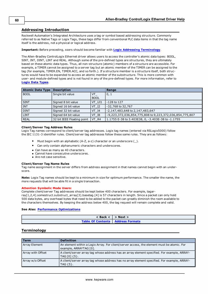
Allen-Bradley ControlLogix Ethernet Driver Help
Addressing Introduction
Rockwell Automation's Integrated Architecture uses a tag or symbol based addressing structure. Commonlyreferred to as Native Tags or Logix Tags, these tags differ from conventional PLC data items in that the tag nameitself is the address, not a physical or logical address.
Important: Before preceding, ssers should become familiar with Logix Addressing Terminology.
The Allen-Bradley ControlLogix Ethernet driver allows users to access the controller's atomic data types: BOOL,SINT, INT, DINT, LINT and REAL. Although some of the pre-defined types are structures, they are ultimatelybased on these atomic data types. Thus, all non-structure (atomic) members of a structure are accessible. Forexample, a TIMER cannot be assigned to a server tag but an atomic member of the TIMER can be assigned to thetag (for example, TIMER.EN, TIMER.ACC, and so forth.). If a structure member is a structure itself, both struc-tures would have to be expanded to access an atomic member of the substructure. This is more common withuser- and module-defined types and is not found in any of the pre-defined types. For more information, refer toLogix Data Types.
Atomic Data Type Description Range
BOOL Single bit value VT_BOOL
0, 1
SINT Signed 8 bit value VT_UI1 -128 to 127
INT Signed 16 bit value VT_I2 -32,768 to 32,767
DINT Signed 32 bit value VT_I4 -2,147,483,648 to 2,147,483,647
LINT Signed 64 bit value VT_I8 –9,223,372,036,854,775,808 to 9,223,372,036,854,775,807
REAL 32 bit IEEE Floating point VT_R4 1.1755 E-38 to 3.403E38, 0, -3.403E-38 to -1.1755
Client/Server Tag Address RulesLogix Tag names correspond to client/server tag addresses. Logix tag names (entered via RSLogix5000) followthe IEC 1131-3 identifier rules. Client/server tag addresses follow these same rules. They are as follows:
l Must begin with an alphabetic (A-Z, a-z) character or an underscore (_).l Can only contain alphanumeric characters and underscores.
l Can have as many as 40 characters.l Cannot have consecutive underscores.l Are not case sensitive.
Client/Server Tag Name RulesTag name assignment in the server differs from address assignment in that names cannot begin with an under-score.
Note: Logix Tag names should be kept to a minimum in size for optimum performance. The smaller the name, themore requests that will be able fit in a single transaction.
Attention Symbolic Mode Users:Complete client/server Tag addresses should be kept below 400 characters. For example, tagar-ray[1,2,4].somestruct.substruct_array[3].basetag.[4] is 57 characters in length. Since a packet can only hold500 data bytes, any overhead bytes that need to be added to the packet can greatly diminish the room available tothe characters themselves. By keeping the address below 400, the tag request will remain complete and valid.
See Also: Performance Optimizations
< Back < > Next >
Table Of Contents Address Formats
Terminology
Term Definition
Array Element An element within a Logix Array. For client/server access, the element must be atomic. Forexample, ARRAYTAG [0].
Array with Offset A client/server array tag whose address has an array element specified. For example, ARRAY-TAG [0] {5}.
Array w/o Offset A client/server array tag whose address has no array element specified. For example, ARRAY-TAG {5}.
www. kepware.com
60
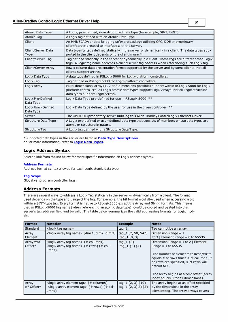
Allen-Bradley ControlLogix Ethernet Driver Help
Atomic Data Type A Logix, pre-defined, non-structured data type (for example, SINT, DINT).
Atomic Tag A Logix tag defined with an Atomic Data Type.
Client An HMI/SCADA or data bridging software package utilizing OPC, DDE or proprietaryclient/server protocol to interface with the server.
Client/Server DataType
Data type for tags defined statically in the server or dynamically in a client. The data types sup-ported in the client depends on the client in use.*
Client/Server Tag Tag defined statically in the server or dynamically in a client. These tags are different than Logixtags. A Logix tag name becomes a client/server tag address when referencing such Logix tag.
Client/Server Array Row x column data presentation format supported by the server and by some clients. Not allclients support arrays.
Logix Data Type A data type defined in RSLogix 5000 for Logix-platform controllers.
Logix Tag Tag defined in RSLogix 5000 for Logix-platform controllers.
Logix Array Multi-dimensional array (1, 2 or 3 dimensions possible) support within RSLogix 5000 for Logix-platform controllers. All Logix atomic data types support Logix Arrays. Not all Logix structuredata types support Logix Arrays.
Logix Pre-DefinedData Type
Logix Data Type pre-defined for use in RSLogix 5000. **
Logix User-DefinedData Type
Logix Data Type defined by the user for use in the given controller. **
Server The OPC/DDE/proprietary server utilizing this Allen-Bradley ControlLogix Ethernet Driver.
Structure Data Type A Logix pre-defined or user-defined data type that consists of members whose data types areatomic or structure in nature.
Structure Tag A Logix tag defined with a Structure Data Type.
*Supported data types in the server are listed in Data Type Descriptions.**For more information, refer to Logix Data Types.
Logix Address Syntax
Select a link from the list below for more specific information on Logix address syntax.
Address FormatsAddress format syntax allowed for each Logix atomic data type.
Tag ScopeGlobal vs. program controller tags.
Address Formats
There are several ways to address a Logix Tag statically in the server or dynamically from a client. The formatused depends on the type and usage of the tag. For example, the bit format woul dbe used when accessing a bitwithin a SINT-type tag. Every format is native to RSLogix5000 except the Array and String formats. This meansthat an RSLogix5000 tag name (when referencing an atomic data type), could be copied and pasted into theserver's tag address field and be valid. The table below summarizes the valid addressing formats for Logix mod-els.
Format Notation Example Notes
Standard <logix tag name> tag_1 Tag cannot be an array.
ArrayElement
<logix array tag name> [dim 1, dim2, dim 3] tag_1 [2, 58, 547]tag_1 [0, 3]
Dimension Range = 1to 3 | Element Range = 0 to 65535
Array w/oOffset*
<logix array tag name> {# columns}<logix array tag name> {# rows}{# col-umns}
tag_1 {8}tag_1 {2}{4}
Dimension Range = 1 to 2 | ElementRange = 1 to 65535
The number of elements to Read/Writeequals # of rows times # of columns. Ifno rows are specified, # of rows willdefault to 1.
The array begins at a zero offset (arrayindex equals 0 for all dimensions).
Arrayw/ Offset*
<logix array element tag> {# columns}<logix array element tag> {# rows}{# col-umns}
tag_1 [2, 3] {10}tag_1 [2, 3] 2}{5}
The array begins at an offset specifiedby the dimensions in the arrayelement tag. The array always covers
www. kepware.com
61
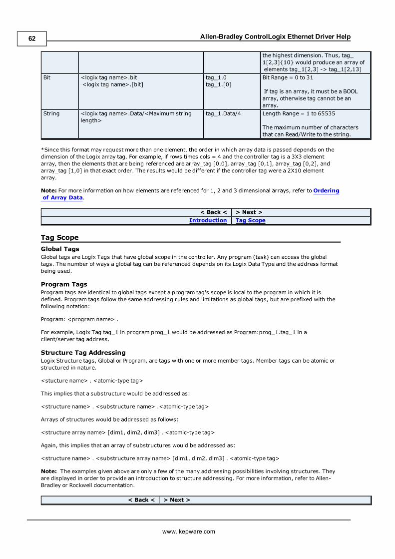
Allen-Bradley ControlLogix Ethernet Driver Help
the highest dimension. Thus, tag_1[2,3]{10} would produce an array ofelements tag_1[2,3] -> tag_1[2,13]
Bit <logix tag name>.bit<logix tag name>.[bit]
tag_1.0tag_1.[0]
Bit Range = 0 to 31
If tag is an array, it must be a BOOLarray, otherwise tag cannot be anarray.
String <logix tag name>.Data/<Maximum stringlength>
tag_1.Data/4 Length Range = 1 to 65535
The maximum number of charactersthat can Read/Write to the string.
*Since this format may request more than one element, the order in which array data is passed depends on thedimension of the Logix array tag. For example, if rows times cols = 4 and the controller tag is a 3X3 elementarray, then the elements that are being referenced are array_tag [0,0], array_tag [0,1], array_tag [0,2], andarray_tag [1,0] in that exact order. The results would be different if the controller tag were a 2X10 elementarray.
Note: For more information on how elements are referenced for 1, 2 and 3 dimensional arrays, refer toOrderingof Array Data.
< Back < > Next >
Introduction Tag Scope
Tag Scope
Global TagsGlobal tags are Logix Tags that have global scope in the controller. Any program (task) can access the globaltags. The number of ways a global tag can be referenced depends on its Logix Data Type and the address formatbeing used.
Program TagsProgram tags are identical to global tags except a program tag's scope is local to the program in which it isdefined. Program tags follow the same addressing rules and limitations as global tags, but are prefixed with thefollowing notation:
Program: <program name> .
For example, Logix Tag tag_1 in program prog_1 would be addressed as Program:prog_1.tag_1 in aclient/server tag address.
Structure Tag AddressingLogix Structure tags, Global or Program, are tags with one or more member tags. Member tags can be atomic orstructured in nature.
<stucture name> . <atomic-type tag>
This implies that a substructure would be addressed as:
<structure name> . <substructure name> .<atomic-type tag>
Arrays of structures would be addressed as follows:
<structure array name> [dim1, dim2, dim3] . <atomic-type tag>
Again, this implies that an array of substructures would be addressed as:
<structure name> . <substructure array name> [dim1, dim2, dim3] . <atomic-type tag>
Note: The examples given above are only a few of the many addressing possibilities involving structures. Theyare displayed in order to provide an introduction to structure addressing. For more information, refer to Allen-Bradley or Rockwell documentation.
< Back < > Next >
www. kepware.com
62
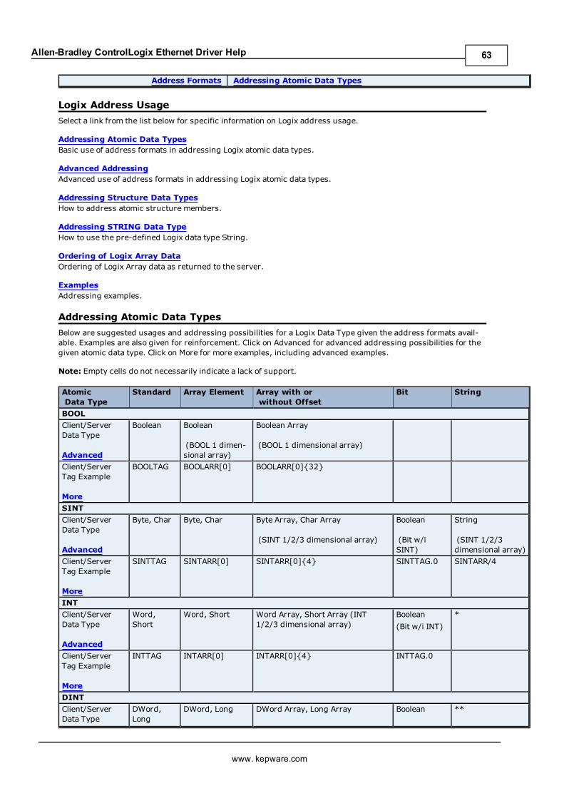
Allen-Bradley ControlLogix Ethernet Driver Help
Address Formats Addressing Atomic Data Types
Logix Address Usage
Select a link from the list below for specific information on Logix address usage.
Addressing Atomic Data TypesBasic use of address formats in addressing Logix atomic data types.
Advanced AddressingAdvanced use of address formats in addressing Logix atomic data types.
Addressing Structure Data TypesHow to address atomic structure members.
Addressing STRING Data TypeHow to use the pre-defined Logix data type String.
Ordering of Logix Array DataOrdering of Logix Array data as returned to the server.
ExamplesAddressing examples.
Addressing Atomic Data Types
Below are suggested usages and addressing possibilities for a Logix Data Type given the address formats avail-able. Examples are also given for reinforcement. Click on Advanced for advanced addressing possibilities for thegiven atomic data type. Click on More for more examples, including advanced examples.
Note: Empty cells do not necessarily indicate a lack of support.
AtomicData Type
Standard Array Element Array with orwithout Offset
Bit String
BOOL
Client/ServerData Type
Advanced
Boolean Boolean
(BOOL 1 dimen-sional array)
Boolean Array
(BOOL 1 dimensional array)
Client/ServerTag Example
More
BOOLTAG BOOLARR[0] BOOLARR[0]{32}
SINT
Client/ServerData Type
Advanced
Byte, Char Byte, Char Byte Array, Char Array
(SINT 1/2/3 dimensional array)
Boolean
(Bit w/iSINT)
String
(SINT 1/2/3dimensional array)
Client/ServerTag Example
More
SINTTAG SINTARR[0] SINTARR[0]{4} SINTTAG.0 SINTARR/4
INT
Client/ServerData Type
Advanced
Word,Short
Word, Short Word Array, Short Array (INT1/2/3 dimensional array)
Boolean
(Bit w/i INT)
*
Client/ServerTag Example
More
INTTAG INTARR[0] INTARR[0]{4} INTTAG.0
DINT
Client/ServerData Type
DWord,Long
DWord, Long DWord Array, Long Array Boolean **
www. kepware.com
63
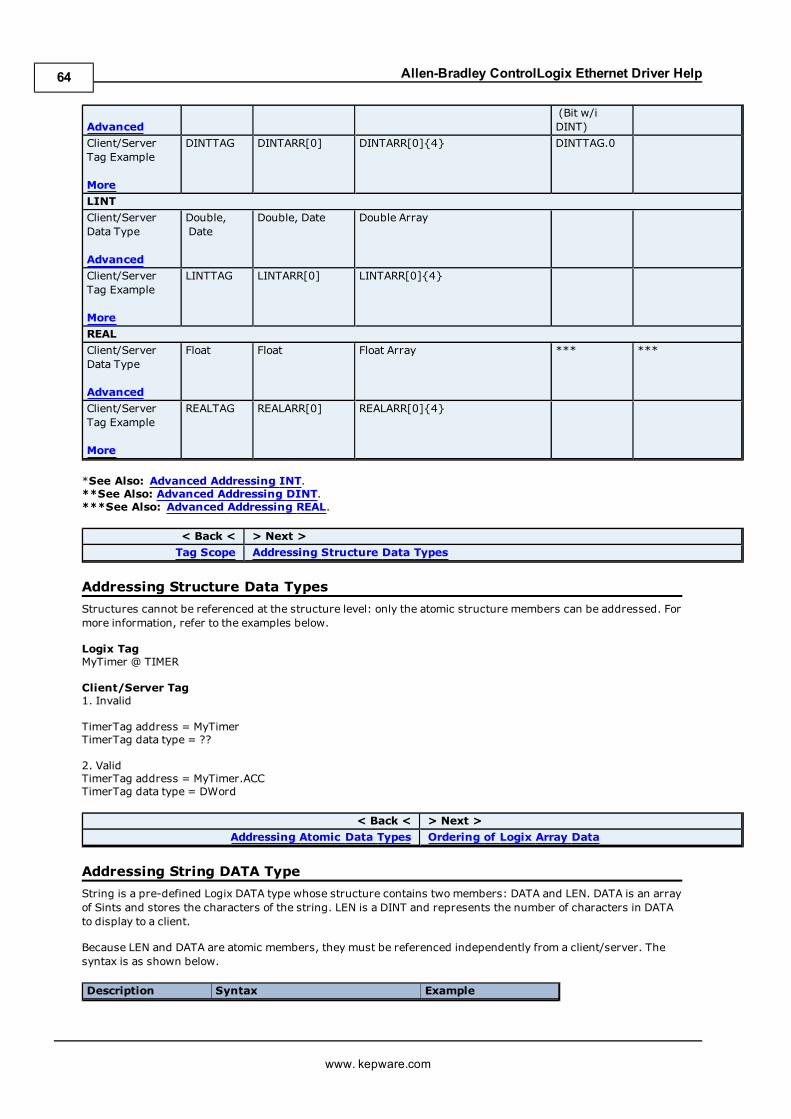
Allen-Bradley ControlLogix Ethernet Driver Help
Advanced(Bit w/iDINT)
Client/ServerTag Example
More
DINTTAG DINTARR[0] DINTARR[0]{4} DINTTAG.0
LINT
Client/ServerData Type
Advanced
Double,Date
Double, Date Double Array
Client/ServerTag Example
More
LINTTAG LINTARR[0] LINTARR[0]{4}
REAL
Client/ServerData Type
Advanced
Float Float Float Array *** ***
Client/ServerTag Example
More
REALTAG REALARR[0] REALARR[0]{4}
*See Also: Advanced Addressing INT.**See Also: Advanced Addressing DINT.***See Also: Advanced Addressing REAL.
< Back < > Next >
Tag Scope Addressing Structure Data Types
Addressing Structure Data Types
Structures cannot be referenced at the structure level: only the atomic structure members can be addressed. Formore information, refer to the examples below.
Logix TagMyTimer @ TIMER
Client/Server Tag1. Invalid
TimerTag address = MyTimerTimerTag data type = ??
2. ValidTimerTag address = MyTimer.ACCTimerTag data type = DWord
< Back < > Next >
Addressing Atomic Data Types Ordering of Logix Array Data
Addressing String DATA Type
String is a pre-defined Logix DATA type whose structure contains twomembers: DATA and LEN. DATA is an arrayof Sints and stores the characters of the string. LEN is a DINT and represents the number of characters in DATAto display to a client.
Because LEN and DATA are atomic members, they must be referenced independently from a client/server. Thesyntax is as shown below.
Description Syntax Example
www. kepware.com
64
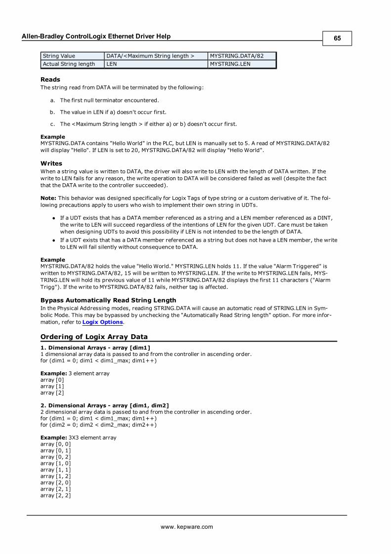
Allen-Bradley ControlLogix Ethernet Driver Help
String Value DATA/<Maximum String length > MYSTRING.DATA/82
Actual String length LEN MYSTRING.LEN
ReadsThe string read from DATA will be terminated by the following:
a. The first null terminator encountered.
b. The value in LEN if a) doesn't occur first.
c. The <Maximum String length > if either a) or b) doesn't occur first.
ExampleMYSTRING.DATA contains "Hello World" in the PLC, but LEN is manually set to 5. A read of MYSTRING.DATA/82will display "Hello". If LEN is set to 20, MYSTRING.DATA/82 will display "Hello World".
WritesWhen a string value is written to DATA, the driver will also write to LEN with the length of DATA written. If thewrite to LEN fails for any reason, the write operation to DATA will be considered failed as well (despite the factthat the DATA write to the controller succeeded).
Note: This behavior was designed specifically for Logix Tags of type string or a custom derivative of it. The fol-lowing precautions apply to users who wish to implement their own string in UDTs.
l If a UDT exists that has a DATA member referenced as a string and a LEN member referenced as a DINT,the write to LEN will succeed regardless of the intentions of LEN for the given UDT. Care must be takenwhen designing UDTs to avoid this possibility if LEN is not intended to be the length of DATA.
l If a UDT exists that has a DATA member referenced as a string but does not have a LEN member, the writeto LEN will fail silently without consequence to DATA.
ExampleMYSTRING.DATA/82 holds the value "Hello World." MYSTRING.LEN holds 11. If the value "Alarm Triggered" iswritten to MYSTRING.DATA/82, 15 will be written to MYSTRING.LEN. If the write to MYSTRING.LEN fails, MYS-TRING.LEN will hold its previous value of 11 while MYSTRING.DATA/82 displays the first 11 characters ("AlarmTrigg"). If the write to MYSTRING.DATA/82 fails, neither tag is affected.
Bypass Automatically Read String LengthIn the Physical Addressing modes, reading STRING.DATA will cause an automatic read of STRING.LEN in Sym-bolic Mode. This may be bypassed by unchecking the "Automatically Read String length" option. For more infor-mation, refer to Logix Options.
Ordering of Logix Array Data
1. Dimensional Arrays - array [dim1]1 dimensional array data is passed to and from the controller in ascending order.for (dim1 = 0; dim1 < dim1_max; dim1++)
Example: 3 element arrayarray [0]array [1]array [2]
2. Dimensional Arrays - array [dim1, dim2]2 dimensional array data is passed to and from the controller in ascending order.for (dim1 = 0; dim1 < dim1_max; dim1++)for (dim2 = 0; dim2 < dim2_max; dim2++)
Example: 3X3 element arrayarray [0, 0]array [0, 1]array [0, 2]array [1, 0]array [1, 1]array [1, 2]array [2, 0]array [2, 1]array [2, 2]
www. kepware.com
65
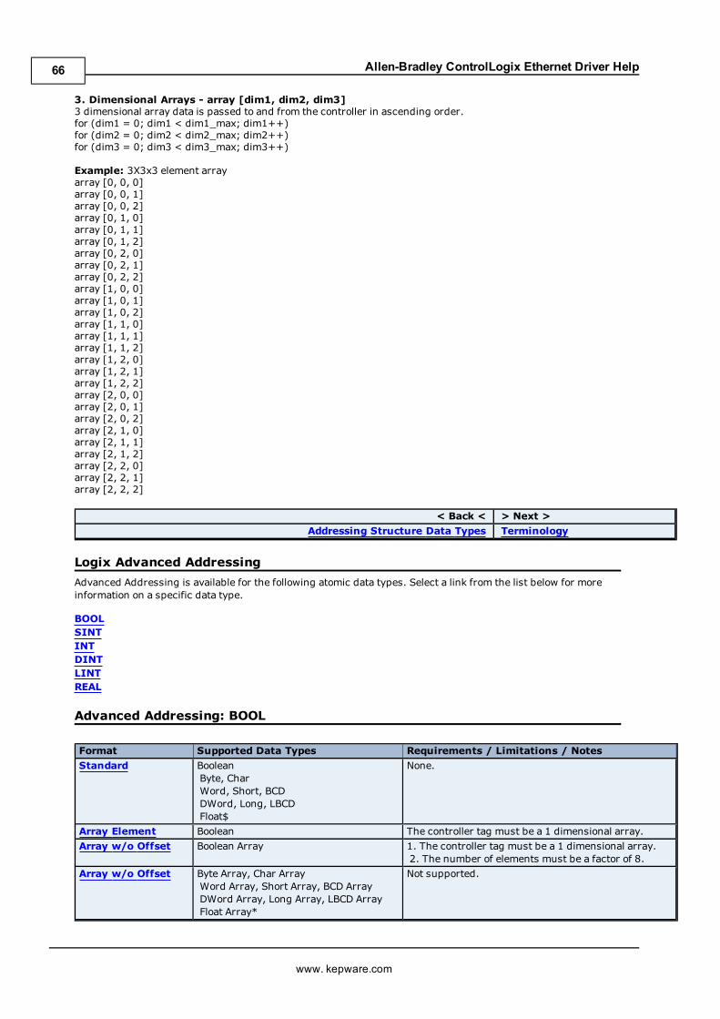
Allen-Bradley ControlLogix Ethernet Driver Help
3. Dimensional Arrays - array [dim1, dim2, dim3]3 dimensional array data is passed to and from the controller in ascending order.for (dim1 = 0; dim1 < dim1_max; dim1++)for (dim2 = 0; dim2 < dim2_max; dim2++)for (dim3 = 0; dim3 < dim3_max; dim3++)
Example: 3X3x3 element arrayarray [0, 0, 0]array [0, 0, 1]array [0, 0, 2]array [0, 1, 0]array [0, 1, 1]array [0, 1, 2]array [0, 2, 0]array [0, 2, 1]array [0, 2, 2]array [1, 0, 0]array [1, 0, 1]array [1, 0, 2]array [1, 1, 0]array [1, 1, 1]array [1, 1, 2]array [1, 2, 0]array [1, 2, 1]array [1, 2, 2]array [2, 0, 0]array [2, 0, 1]array [2, 0, 2]array [2, 1, 0]array [2, 1, 1]array [2, 1, 2]array [2, 2, 0]array [2, 2, 1]array [2, 2, 2]
< Back < > Next >
Addressing Structure Data Types Terminology
Logix Advanced Addressing
Advanced Addressing is available for the following atomic data types. Select a link from the list below for moreinformation on a specific data type.
BOOLSINTINTDINTLINTREAL
Advanced Addressing: BOOL
Format Supported Data Types Requirements / Limitations / Notes
Standard BooleanByte, CharWord, Short, BCDDWord, Long, LBCDFloat$
None.
Array Element Boolean The controller tag must be a 1 dimensional array.
Array w/o Offset Boolean Array 1. The controller tag must be a 1 dimensional array.2. The number of elements must be a factor of 8.
Array w/o Offset Byte Array, Char ArrayWord Array, Short Array, BCD ArrayDWord Array, Long Array, LBCD ArrayFloat Array*
Not supported.
www. kepware.com
66
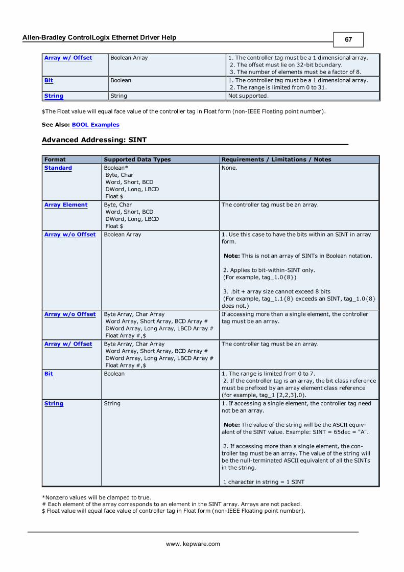
Allen-Bradley ControlLogix Ethernet Driver Help
Array w/ Offset Boolean Array 1. The controller tag must be a 1 dimensional array.2. The offset must lie on 32-bit boundary.3. The number of elements must be a factor of 8.
Bit Boolean 1. The controller tag must be a 1 dimensional array.2. The range is limited from 0 to 31.
String String Not supported.
$The Float value will equal face value of the controller tag in Float form (non-IEEE Floating point number).
See Also: BOOL Examples
Advanced Addressing: SINT
Format Supported Data Types Requirements / Limitations / Notes
Standard Boolean*Byte, CharWord, Short, BCDDWord, Long, LBCDFloat $
None.
Array Element Byte, CharWord, Short, BCDDWord, Long, LBCDFloat $
The controller tag must be an array.
Array w/o Offset Boolean Array 1. Use this case to have the bits within an SINT in arrayform.
Note: This is not an array of SINTs in Boolean notation.
2. Applies to bit-within-SINT only.(For example, tag_1.0{8})
3. .bit + array size cannot exceed 8 bits(For example, tag_1.1{8} exceeds an SINT, tag_1.0{8}does not.)
Array w/o Offset Byte Array, Char ArrayWord Array, Short Array, BCD Array #DWord Array, Long Array, LBCD Array #Float Array #,$
If accessing more than a single element, the controllertag must be an array.
Array w/ Offset Byte Array, Char ArrayWord Array, Short Array, BCD Array #DWord Array, Long Array, LBCD Array #Float Array #,$
The controller tag must be an array.
Bit Boolean 1. The range is limited from 0 to 7.2. If the controller tag is an array, the bit class referencemust be prefixed by an array element class reference(for example, tag_1 [2,2,3].0).
String String 1. If accessing a single element, the controller tag neednot be an array.
Note: The value of the string will be the ASCII equiv-alent of the SINT value. Example: SINT = 65dec = "A".
2. If accessing more than a single element, the con-troller tag must be an array. The value of the string willbe the null-terminated ASCII equivalent of all the SINTsin the string.
1 character in string = 1 SINT
*Nonzero values will be clamped to true.# Each element of the array corresponds to an element in the SINT array. Arrays are not packed.$ Float value will equal face value of controller tag in Float form (non-IEEE Floating point number).
www. kepware.com
67
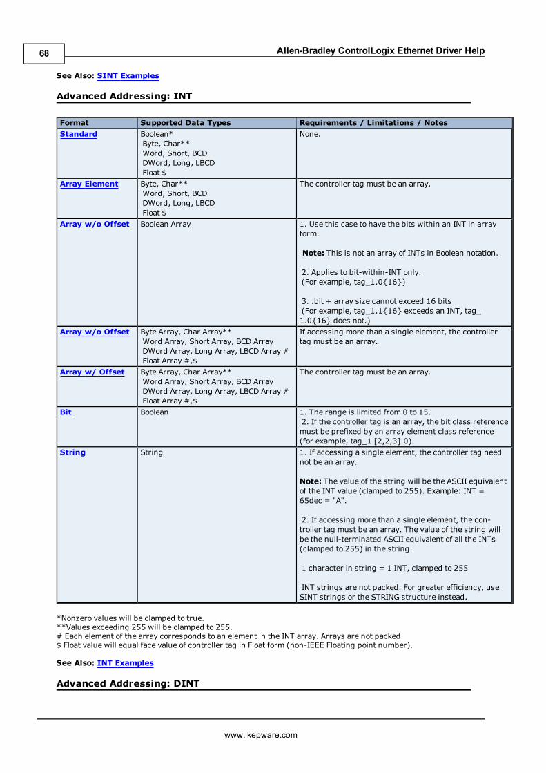
Allen-Bradley ControlLogix Ethernet Driver Help
See Also: SINT Examples
Advanced Addressing: INT
Format Supported Data Types Requirements / Limitations / Notes
Standard Boolean*Byte, Char**Word, Short, BCDDWord, Long, LBCDFloat $
None.
Array Element Byte, Char**Word, Short, BCDDWord, Long, LBCDFloat $
The controller tag must be an array.
Array w/o Offset Boolean Array 1. Use this case to have the bits within an INT in arrayform.
Note: This is not an array of INTs in Boolean notation.
2. Applies to bit-within-INT only.(For example, tag_1.0{16})
3. .bit + array size cannot exceed 16 bits(For example, tag_1.1{16} exceeds an INT, tag_1.0{16} does not.)
Array w/o Offset Byte Array, Char Array**Word Array, Short Array, BCD ArrayDWord Array, Long Array, LBCD Array #Float Array #,$
If accessing more than a single element, the controllertag must be an array.
Array w/ Offset Byte Array, Char Array**Word Array, Short Array, BCD ArrayDWord Array, Long Array, LBCD Array #Float Array #,$
The controller tag must be an array.
Bit Boolean 1. The range is limited from 0 to 15.2. If the controller tag is an array, the bit class referencemust be prefixed by an array element class reference(for example, tag_1 [2,2,3].0).
String String 1. If accessing a single element, the controller tag neednot be an array.
Note: The value of the string will be the ASCII equivalentof the INT value (clamped to 255). Example: INT =65dec = "A".
2. If accessing more than a single element, the con-troller tag must be an array. The value of the string willbe the null-terminated ASCII equivalent of all the INTs(clamped to 255) in the string.
1 character in string = 1 INT, clamped to 255
INT strings are not packed. For greater efficiency, useSINT strings or the STRING structure instead.
*Nonzero values will be clamped to true.**Values exceeding 255 will be clamped to 255.# Each element of the array corresponds to an element in the INT array. Arrays are not packed.$ Float value will equal face value of controller tag in Float form (non-IEEE Floating point number).
See Also: INT Examples
Advanced Addressing: DINT
www. kepware.com
68
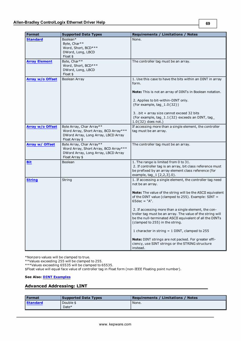
Allen-Bradley ControlLogix Ethernet Driver Help
Format Supported Data Types Requirements / Limitations / Notes
Standard Boolean*Byte, Char**Word, Short, BCD***DWord, Long, LBCDFloat $
None.
Array Element Byte, Char**Word, Short, BCD***DWord, Long, LBCDFloat $
The controller tag must be an array.
Array w/o Offset Boolean Array 1. Use this case to have the bits within an DINT in arrayform.
Note: This is not an array of DINTs in Boolean notation.
2. Applies to bit-within-DINT only.(For example, tag_1.0{32})
3. .bit + array size cannot exceed 32 bits(For example, tag_1.1{32} exceeds an DINT, tag_1.0{32} does not.)
Array w/o Offset Byte Array, Char Array**Word Array, Short Array, BCD Array***DWord Array, Long Array, LBCD ArrayFloat Array $
If accessing more than a single element, the controllertag must be an array.
Array w/ Offset Byte Array, Char Array**Word Array, Short Array, BCD Array***DWord Array, Long Array, LBCD ArrayFloat Array $
The controller tag must be an array.
Bit Boolean 1. The range is limited from 0 to 31.2. If controller tag is an array, bit class reference mustbe prefixed by an array element class reference (forexample, tag_1 [2,2,3].0).
String String 1. If accessing a single element, the controller tag neednot be an array.
Note: The value of the string will be the ASCII equivalentof the DINT value (clamped to 255). Example: SINT =65dec = "A".
2. If accessing more than a single element, the con-troller tag must be an array. The value of the string willbe the null-terminated ASCII equivalent of all the DINTs(clamped to 255) in the string.
1 character in string = 1 DINT, clamped to 255
Note: DINT strings are not packed. For greater effi-ciency, use SINT strings or the STRING structureinstead.
*Nonzero values will be clamped to true.**Values exceeding 255 will be clamped to 255.***Values exceeding 65535 will be clamped to 65535.$Float value will equal face value of controller tag in Float form (non-IEEE Floating point number).
See Also: DINT Examples
Advanced Addressing: LINT
Format Supported Data Types Requirements / Limitations / Notes
Standard Double $Date*
None.
www. kepware.com
69
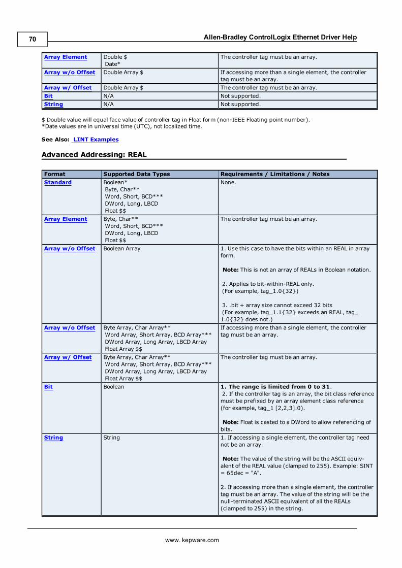
Allen-Bradley ControlLogix Ethernet Driver Help
Array Element Double $Date*
The controller tag must be an array.
Array w/o Offset Double Array $ If accessing more than a single element, the controllertag must be an array.
Array w/ Offset Double Array $ The controller tag must be an array.
Bit N/A Not supported.
String N/A Not supported.
$ Double value will equal face value of controller tag in Float form (non-IEEE Floating point number).*Date values are in universal time (UTC), not localized time.
See Also: LINT Examples
Advanced Addressing: REAL
Format Supported Data Types Requirements / Limitations / Notes
Standard Boolean*Byte, Char**Word, Short, BCD***DWord, Long, LBCDFloat $$
None.
Array Element Byte, Char**Word, Short, BCD***DWord, Long, LBCDFloat $$
The controller tag must be an array.
Array w/o Offset Boolean Array 1. Use this case to have the bits within an REAL in arrayform.
Note: This is not an array of REALs in Boolean notation.
2. Applies to bit-within-REAL only.(For example, tag_1.0{32})
3. .bit + array size cannot exceed 32 bits(For example, tag_1.1{32} exceeds an REAL, tag_1.0{32} does not.)
Array w/o Offset Byte Array, Char Array**Word Array, Short Array, BCD Array***DWord Array, Long Array, LBCD ArrayFloat Array $$
If accessing more than a single element, the controllertag must be an array.
Array w/ Offset Byte Array, Char Array**Word Array, Short Array, BCD Array***DWord Array, Long Array, LBCD ArrayFloat Array $$
The controller tag must be an array.
Bit Boolean 1. The range is limited from 0 to 31.2. If the controller tag is an array, the bit class referencemust be prefixed by an array element class reference(for example, tag_1 [2,2,3].0).
Note: Float is casted to a DWord to allow referencing ofbits.
String String 1. If accessing a single element, the controller tag neednot be an array.
Note: The value of the string will be the ASCII equiv-alent of the REAL value (clamped to 255). Example: SINT= 65dec = "A".
2. If accessing more than a single element, the controllertag must be an array. The value of the string will be thenull-terminated ASCII equivalent of all the REALs(clamped to 255) in the string.
www. kepware.com
70
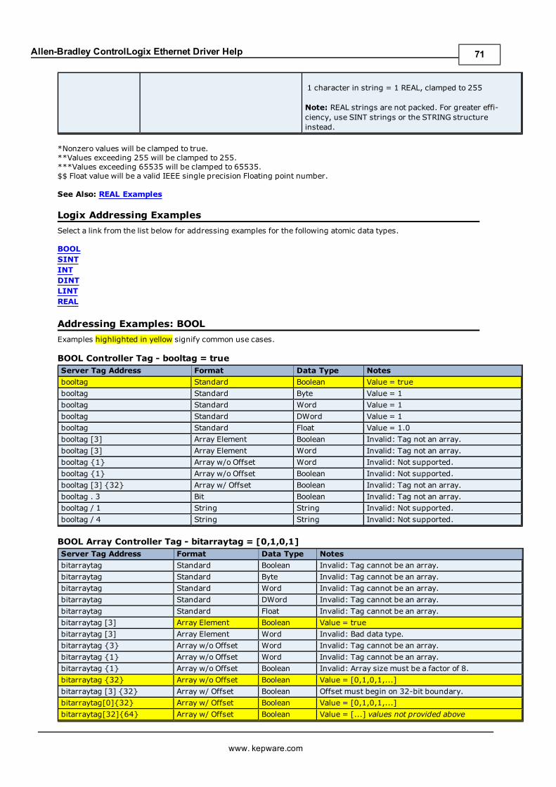
Allen-Bradley ControlLogix Ethernet Driver Help
1 character in string = 1 REAL, clamped to 255
Note: REAL strings are not packed. For greater effi-ciency, use SINT strings or the STRING structureinstead.
*Nonzero values will be clamped to true.**Values exceeding 255 will be clamped to 255.***Values exceeding 65535 will be clamped to 65535.$$ Float value will be a valid IEEE single precision Floating point number.
See Also: REAL Examples
Logix Addressing Examples
Select a link from the list below for addressing examples for the following atomic data types.
BOOLSINTINTDINTLINTREAL
Addressing Examples: BOOL
Examples highlighted in yellow signify common use cases.
BOOL Controller Tag - booltag = trueServer Tag Address Format Data Type Notes
booltag Standard Boolean Value = true
booltag Standard Byte Value = 1
booltag Standard Word Value = 1
booltag Standard DWord Value = 1
booltag Standard Float Value = 1.0
booltag [3] Array Element Boolean Invalid: Tag not an array.
booltag [3] Array Element Word Invalid: Tag not an array.
booltag {1} Array w/o Offset Word Invalid: Not supported.
booltag {1} Array w/o Offset Boolean Invalid: Not supported.
booltag [3] {32} Array w/ Offset Boolean Invalid: Tag not an array.
booltag . 3 Bit Boolean Invalid: Tag not an array.
booltag / 1 String String Invalid: Not supported.
booltag / 4 String String Invalid: Not supported.
BOOL Array Controller Tag - bitarraytag = [0,1,0,1]Server Tag Address Format Data Type Notes
bitarraytag Standard Boolean Invalid: Tag cannot be an array.
bitarraytag Standard Byte Invalid: Tag cannot be an array.
bitarraytag Standard Word Invalid: Tag cannot be an array.
bitarraytag Standard DWord Invalid: Tag cannot be an array.
bitarraytag Standard Float Invalid: Tag cannot be an array.
bitarraytag [3] Array Element Boolean Value = true
bitarraytag [3] Array Element Word Invalid: Bad data type.
bitarraytag {3} Array w/o Offset Word Invalid: Tag cannot be an array.
bitarraytag {1} Array w/o Offset Word Invalid: Tag cannot be an array.
bitarraytag {1} Array w/o Offset Boolean Invalid: Array size must be a factor of 8.
bitarraytag {32} Array w/o Offset Boolean Value = [0,1,0,1,...]
bitarraytag [3] {32} Array w/ Offset Boolean Offset must begin on 32-bit boundary.
bitarraytag[0]{32} Array w/ Offset Boolean Value = [0,1,0,1,...]
bitarraytag[32]{64} Array w/ Offset Boolean Value = [...] values not provided above
www. kepware.com
71
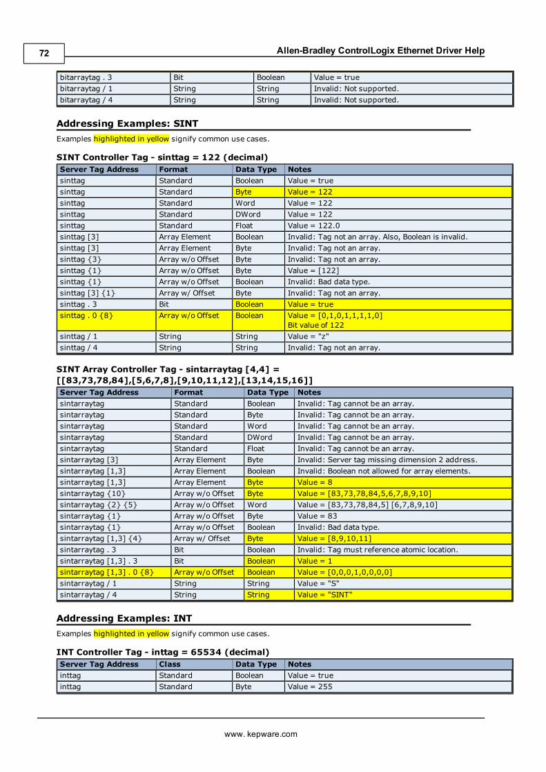
Allen-Bradley ControlLogix Ethernet Driver Help
bitarraytag . 3 Bit Boolean Value = true
bitarraytag / 1 String String Invalid: Not supported.
bitarraytag / 4 String String Invalid: Not supported.
Addressing Examples: SINT
Examples highlighted in yellow signify common use cases.
SINT Controller Tag - sinttag = 122 (decimal)Server Tag Address Format Data Type Notes
sinttag Standard Boolean Value = true
sinttag Standard Byte Value = 122
sinttag Standard Word Value = 122
sinttag Standard DWord Value = 122
sinttag Standard Float Value = 122.0
sinttag [3] Array Element Boolean Invalid: Tag not an array. Also, Boolean is invalid.
sinttag [3] Array Element Byte Invalid: Tag not an array.
sinttag {3} Array w/o Offset Byte Invalid: Tag not an array.
sinttag {1} Array w/o Offset Byte Value = [122]
sinttag {1} Array w/o Offset Boolean Invalid: Bad data type.
sinttag [3] {1} Array w/ Offset Byte Invalid: Tag not an array.
sinttag . 3 Bit Boolean Value = true
sinttag . 0 {8} Array w/o Offset Boolean Value = [0,1,0,1,1,1,1,0]Bit value of 122
sinttag / 1 String String Value = "z"
sinttag / 4 String String Invalid: Tag not an array.
SINT Array Controller Tag - sintarraytag [4,4] =[[83,73,78,84],[5,6,7,8],[9,10,11,12],[13,14,15,16]]Server Tag Address Format Data Type Notes
sintarraytag Standard Boolean Invalid: Tag cannot be an array.
sintarraytag Standard Byte Invalid: Tag cannot be an array.
sintarraytag Standard Word Invalid: Tag cannot be an array.
sintarraytag Standard DWord Invalid: Tag cannot be an array.
sintarraytag Standard Float Invalid: Tag cannot be an array.
sintarraytag [3] Array Element Byte Invalid: Server tag missing dimension 2 address.
sintarraytag [1,3] Array Element Boolean Invalid: Boolean not allowed for array elements.
sintarraytag [1,3] Array Element Byte Value = 8
sintarraytag {10} Array w/o Offset Byte Value = [83,73,78,84,5,6,7,8,9,10]
sintarraytag {2} {5} Array w/o Offset Word Value = [83,73,78,84,5] [6,7,8,9,10]
sintarraytag {1} Array w/o Offset Byte Value = 83
sintarraytag {1} Array w/o Offset Boolean Invalid: Bad data type.
sintarraytag [1,3] {4} Array w/ Offset Byte Value = [8,9,10,11]
sintarraytag . 3 Bit Boolean Invalid: Tag must reference atomic location.
sintarraytag [1,3] . 3 Bit Boolean Value = 1
sintarraytag [1,3] . 0 {8} Array w/o Offset Boolean Value = [0,0,0,1,0,0,0,0]
sintarraytag / 1 String String Value = "S"
sintarraytag / 4 String String Value = "SINT"
Addressing Examples: INT
Examples highlighted in yellow signify common use cases.
INT Controller Tag - inttag = 65534 (decimal)Server Tag Address Class Data Type Notes
inttag Standard Boolean Value = true
inttag Standard Byte Value = 255
www. kepware.com
72
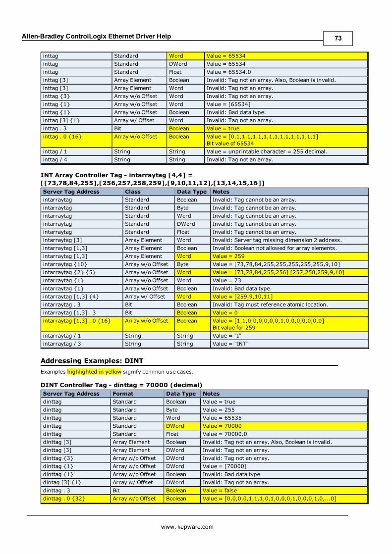
Allen-Bradley ControlLogix Ethernet Driver Help
inttag Standard Word Value = 65534
inttag Standard DWord Value = 65534
inttag Standard Float Value = 65534.0
inttag [3] Array Element Boolean Invalid: Tag not an array. Also, Boolean is invalid.
inttag [3] Array Element Word Invalid: Tag not an array.
inttag {3} Array w/o Offset Word Invalid: Tag not an array.
inttag {1} Array w/o Offset Word Value = [65534]
inttag {1} Array w/o Offset Boolean Invalid: Bad data type.
inttag [3] {1} Array w/ Offset Word Invalid: Tag not an array.
inttag . 3 Bit Boolean Value = true
inttag . 0 {16} Array w/o Offset Boolean Value = [0,1,1,1,1,1,1,1,1,1,1,1,1,1,1,1]Bit value of 65534
inttag / 1 String String Value = unprintable character = 255 decimal.
inttag / 4 String String Invalid: Tag not an array.
INT Array Controller Tag - intarraytag [4,4] =[[73,78,84,255],[256,257,258,259],[9,10,11,12],[13,14,15,16]]Server Tag Address Class Data Type Notes
intarraytag Standard Boolean Invalid: Tag cannot be an array.
intarraytag Standard Byte Invalid: Tag cannot be an array.
intarraytag Standard Word Invalid: Tag cannot be an array.
intarraytag Standard DWord Invalid: Tag cannot be an array.
intarraytag Standard Float Invalid: Tag cannot be an array.
intarraytag [3] Array Element Word Invalid: Server tag missing dimension 2 address.
intarraytag [1,3] Array Element Boolean Invalid: Boolean not allowed for array elements.
intarraytag [1,3] Array Element Word Value = 259
intarraytag {10} Array w/o Offset Byte Value = [73,78,84,255,255,255,255,255,9,10]
intarraytag {2} {5} Array w/o Offset Word Value = [73,78,84,255,256] [257,258,259,9,10]
intarraytag {1} Array w/o Offset Word Value = 73
intarraytag {1} Array w/o Offset Boolean Invalid: Bad data type.
intarraytag [1,3] {4} Array w/ Offset Word Value = [259,9,10,11]
intarraytag . 3 Bit Boolean Invalid: Tag must reference atomic location.
intarraytag [1,3] . 3 Bit Boolean Value = 0
intarraytag [1,3] . 0 {16} Array w/o Offset Boolean Value = [1,1,0,0,0,0,0,0,1,0,0,0,0,0,0,0]Bit value for 259
intarraytag / 1 String String Value = "I"
intarraytag / 3 String String Value = "INT"
Addressing Examples: DINT
Examples highlighted in yellow signify common use cases.
DINT Controller Tag - dinttag = 70000 (decimal)Server Tag Address Format Data Type Notes
dinttag Standard Boolean Value = true
dinttag Standard Byte Value = 255
dinttag Standard Word Value = 65535
dinttag Standard DWord Value = 70000
dinttag Standard Float Value = 70000.0
dinttag [3] Array Element Boolean Invalid: Tag not an array. Also, Boolean is invalid.
dinttag [3] Array Element DWord Invalid: Tag not an array.
dinttag {3} Array w/o Offset DWord Invalid: Tag not an array.
dinttag {1} Array w/o Offset DWord Value = [70000]
dinttag {1} Array w/o Offset Boolean Invalid: Bad data type
dintag [3] {1} Array w/ Offset DWord Invalid: Tag not an array.
dinttag . 3 Bit Boolean Value = false
dinttag . 0 {32} Array w/o Offset Boolean Value = [0,0,0,0,1,1,1,0,1,0,0,0,1,0,0,0,1,0,...0]
www. kepware.com
73

Allen-Bradley ControlLogix Ethernet Driver Help
Bit value for 70000
dinttag / 1 String String Value = unprintable character = 255 decimal
dinttag / 4 String String Invalid: Tag not an array.
DINT Array Controller Tag - dintarraytag [4,4] =[[68,73,78,84],[256,257,258,259],[9,10,11,12],[13,14,15,16]]Server Tag Address Format Data Type Notes
dintarraytag Standard Boolean Invalid: Tag cannot be an array.
dintarraytag Standard Byte Invalid: Tag cannot be an array.
dintarraytag Standard Word Invalid: Tag cannot be an array.
dintarraytag Standard DWord Invalid: Tag cannot be an array.
dintarraytag Standard Float Invalid: Tag cannot be an array.
dintarraytag [3] Array Element DWord Invalid: Server tag missing dimension 2 address.
dintarraytag [1,3] Array Element Boolean Invalid: Boolean not allowed for array elements.
dintarraytag [1,3] Array Element DWord Value = 259
dintarraytag {10} Array w/o Offset Byte Value = [68,73,78,84,255,255,255,255,9,10]
dintarraytag {2}{5} Array w/o Offset DWord Value = [68,73,78,84,256] [257,258,259,9,10]
dintarraytag {1} Array w/o Offset DWord Value = 68
dintarraytag {1} Array w/o Offset Boolean Invalid: Bad data type.
dintarraytag [1,3]{4} Array w/ Offset DWord Value = [259,9,10,11]
dintarraytag . 3 Bit Boolean Invalid: Tag must reference atomic location.
dintarraytag [1,3] . 3 Bit Boolean Value = 0
dintarraytag [1,3] .0 {32} Array w/o Offset Boolean Value = [1,1,0,0,0,0,0,0,1,0,0,0,0,0,0,0]Bit value for 259
dintarraytag / 1 String String Value = "D"
dintarraytag / 3 String String Value = "DINT"
Addressing Examples: LINT
Examples highlighted in yellow signify common use cases.
LINT Controller Tag - linttag = 2007-01-01T16:46:40.000 (date) == 1.16767E+15 (dec-imal)Server Tag Address Format Data Type Notes
linttag Standard Boolean Invalid: Boolean not supported.
linttag Standard Byte Invalid: Byte not supported.
linttag Standard Word Invalid: Word not supported.
linttag Standard Double Value = 1.16767E+15
linttag Standard Date Value = 2007-01-01T16:46:40.000*
linttag [3] Array Element Boolean Invalid: Tag not an array. Also, Boolean is invalid.
linttag [3] Array Element Double Invalid: Tag not an array.
linttag {3} Array w/o Offset Double Invalid: Tag not an array.
linttag {1} Array w/o Offset Double Value = [1.16767E+15]
linttag {1} Array w/o Offset Boolean Invalid: Bad data type.
lintag [3] {1} Array w/ Offset Double Invalid: Tag not an array.
linttag . 3 Bit Boolean Invalid: Syntax/data type not supported.
linttag / 1 String String Invalid: Syntax/data type not supported.
*Date values are in universal time (UTC), not localized time.
LINT Array Controller Tag -dintarraytag [2,2] = [0, 1.16767E+15],[9.4666E+14, 9.46746E+14] where:1.16767E+15 == 2007-01-01T16:46:40.000 (date)9.4666E+14 == 1999-12-31T17:06:40.0009.46746E+14 == 2000-01-1T17:00:00.0000 == 1970-01-01T00:00:00.000
Server Tag Address Format Data Type Notes
www. kepware.com
74
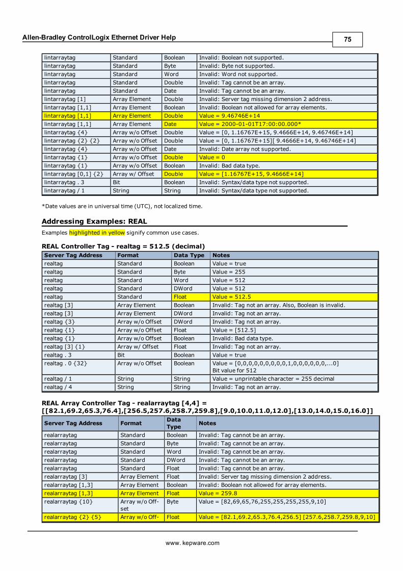
Allen-Bradley ControlLogix Ethernet Driver Help
lintarraytag Standard Boolean Invalid: Boolean not supported.
lintarraytag Standard Byte Invalid: Byte not supported.
lintarraytag Standard Word Invalid: Word not supported.
lintarraytag Standard Double Invalid: Tag cannot be an array.
lintarraytag Standard Date Invalid: Tag cannot be an array.
lintarraytag [1] Array Element Double Invalid: Server tag missing dimension 2 address.
lintarraytag [1,1] Array Element Boolean Invalid: Boolean not allowed for array elements.
lintarraytag [1,1] Array Element Double Value = 9.46746E+14
lintarraytag [1,1] Array Element Date Value = 2000-01-01T17:00:00.000*
lintarraytag {4} Array w/o Offset Double Value = [0, 1.16767E+15, 9.4666E+14, 9.46746E+14]
lintarraytag {2} {2} Array w/o Offset Double Value = [0, 1.16767E+15][ 9.4666E+14, 9.46746E+14]
lintarraytag {4} Array w/o Offset Date Invalid: Date array not supported.
lintarraytag {1} Array w/o Offset Double Value = 0
lintarraytag {1} Array w/o Offset Boolean Invalid: Bad data type.
lintarraytag [0,1] {2} Array w/ Offset Double Value = [1.16767E+15, 9.4666E+14]
lintarraytag . 3 Bit Boolean Invalid: Syntax/data type not supported.
lintarraytag / 1 String String Invalid: Syntax/data type not supported.
*Date values are in universal time (UTC), not localized time.
Addressing Examples: REAL
Examples highlighted in yellow signify common use cases.
REAL Controller Tag - realtag = 512.5 (decimal)Server Tag Address Format Data Type Notes
realtag Standard Boolean Value = true
realtag Standard Byte Value = 255
realtag Standard Word Value = 512
realtag Standard DWord Value = 512
realtag Standard Float Value = 512.5
realtag [3] Array Element Boolean Invalid: Tag not an array. Also, Boolean is invalid.
realtag [3] Array Element DWord Invalid: Tag not an array.
realtag {3} Array w/o Offset DWord Invalid: Tag not an array.
realtag {1} Array w/o Offset Float Value = [512.5]
realtag {1} Array w/o Offset Boolean Invalid: Bad data type.
realtag [3] {1} Array w/ Offset Float Invalid: Tag not an array.
realtag . 3 Bit Boolean Value = true
realtag . 0 {32} Array w/o Offset Boolean Value = [0,0,0,0,0,0,0,0,0,1,0,0,0,0,0,0,...0]Bit value for 512
realtag / 1 String String Value = unprintable character = 255 decimal
realtag / 4 String String Invalid: Tag not an array.
REAL Array Controller Tag - realarraytag [4,4] =[[82.1,69.2,65.3,76.4],[256.5,257.6,258.7,259.8],[9.0,10.0,11.0,12.0],[13.0,14.0,15.0,16.0]]
Server Tag Address FormatDataType
Notes
realarraytag Standard Boolean Invalid: Tag cannot be an array.
realarraytag Standard Byte Invalid: Tag cannot be an array.
realarraytag Standard Word Invalid: Tag cannot be an array.
realarraytag Standard DWord Invalid: Tag cannot be an array.
realarraytag Standard Float Invalid: Tag cannot be an array.
realarraytag [3] Array Element Float Invalid: Server tag missing dimension 2 address.
realarraytag [1,3] Array Element Boolean Invalid: Boolean not allowed for array elements.
realarraytag [1,3] Array Element Float Value = 259.8
realarraytag {10} Array w/o Off-set
Byte Value = [82,69,65,76,255,255,255,255,9,10]
realarraytag {2} {5} Array w/o Off- Float Value = [82.1,69.2,65.3,76.4,256.5] [257.6,258.7,259.8,9,10]
www. kepware.com
75
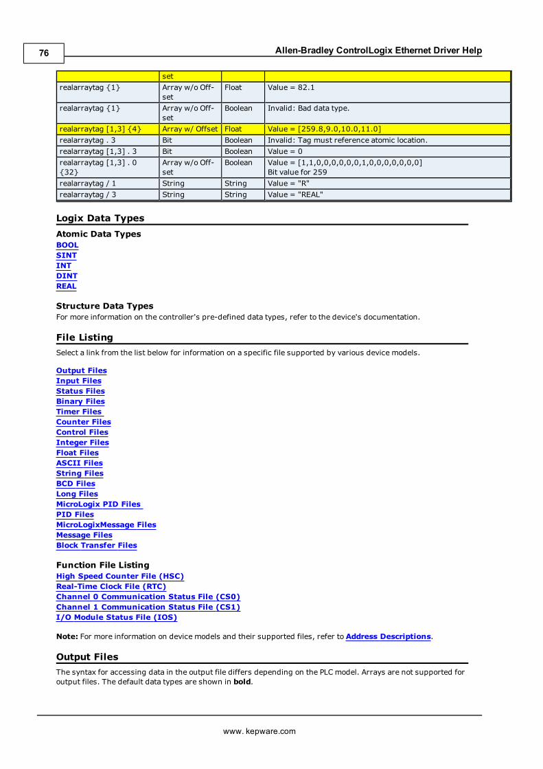
Allen-Bradley ControlLogix Ethernet Driver Help
set
realarraytag {1} Array w/o Off-set
Float Value = 82.1
realarraytag {1} Array w/o Off-set
Boolean Invalid: Bad data type.
realarraytag [1,3] {4} Array w/ Offset Float Value = [259.8,9.0,10.0,11.0]
realarraytag . 3 Bit Boolean Invalid: Tag must reference atomic location.
realarraytag [1,3] . 3 Bit Boolean Value = 0
realarraytag [1,3] . 0{32}
Array w/o Off-set
Boolean Value = [1,1,0,0,0,0,0,0,1,0,0,0,0,0,0,0]Bit value for 259
realarraytag / 1 String String Value = "R"
realarraytag / 3 String String Value = "REAL"
Logix Data Types
Atomic Data TypesBOOLSINTINTDINTREAL
Structure Data TypesFor more information on the controller's pre-defined data types, refer to the device's documentation.
File Listing
Select a link from the list below for information on a specific file supported by various device models.
Output FilesInput FilesStatus FilesBinary FilesTimer FilesCounter FilesControl FilesInteger FilesFloat FilesASCII FilesString FilesBCD FilesLong FilesMicroLogix PID FilesPID FilesMicroLogixMessage FilesMessage FilesBlock Transfer Files
Function File ListingHigh Speed Counter File (HSC)Real-Time Clock File (RTC)Channel 0 Communication Status File (CS0)Channel 1 Communication Status File (CS1)I/O Module Status File (IOS)
Note: For more information on device models and their supported files, refer to Address Descriptions.
Output Files
The syntax for accessing data in the output file differs depending on the PLCmodel. Arrays are not supported foroutput files. The default data types are shown in bold.
www. kepware.com
76
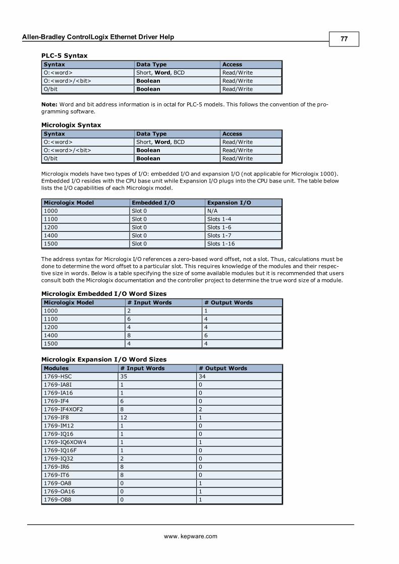
Allen-Bradley ControlLogix Ethernet Driver Help
PLC-5 SyntaxSyntax Data Type Access
O:<word> Short,Word, BCD Read/Write
O:<word>/<bit> Boolean Read/Write
O/bit Boolean Read/Write
Note: Word and bit address information is in octal for PLC-5 models. This follows the convention of the pro-gramming software.
Micrologix SyntaxSyntax Data Type Access
O:<word> Short,Word, BCD Read/Write
O:<word>/<bit> Boolean Read/Write
O/bit Boolean Read/Write
Micrologix models have two types of I/O: embedded I/O and expansion I/O (not applicable for Micrologix 1000).Embedded I/O resides with the CPU base unit while Expansion I/O plugs into the CPU base unit. The table belowlists the I/O capabilities of each Micrologix model.
Micrologix Model Embedded I/O Expansion I/O
1000 Slot 0 N/A
1100 Slot 0 Slots 1-4
1200 Slot 0 Slots 1-6
1400 Slot 0 Slots 1-7
1500 Slot 0 Slots 1-16
The address syntax for Micrologix I/O references a zero-based word offset, not a slot. Thus, calculations must bedone to determine the word offset to a particular slot. This requires knowledge of the modules and their respec-tive size in words. Below is a table specifying the size of some available modules but it is recommended that usersconsult both the Micrologix documentation and the controller project to determine the true word size of a module.
Micrologix Embedded I/O Word SizesMicrologix Model # Input Words # Output Words
1000 2 1
1100 6 4
1200 4 4
1400 8 6
1500 4 4
Micrologix Expansion I/O Word SizesModules # Input Words # Output Words
1769-HSC 35 34
1769-IA8I 1 0
1769-IA16 1 0
1769-IF4 6 0
1769-IF4XOF2 8 2
1769-IF8 12 1
1769-IM12 1 0
1769-IQ16 1 0
1769-IQ6XOW4 1 1
1769-IQ16F 1 0
1769-IQ32 2 0
1769-IR6 8 0
1769-IT6 8 0
1769-OA8 0 1
1769-OA16 0 1
1769-OB8 0 1
www. kepware.com
77
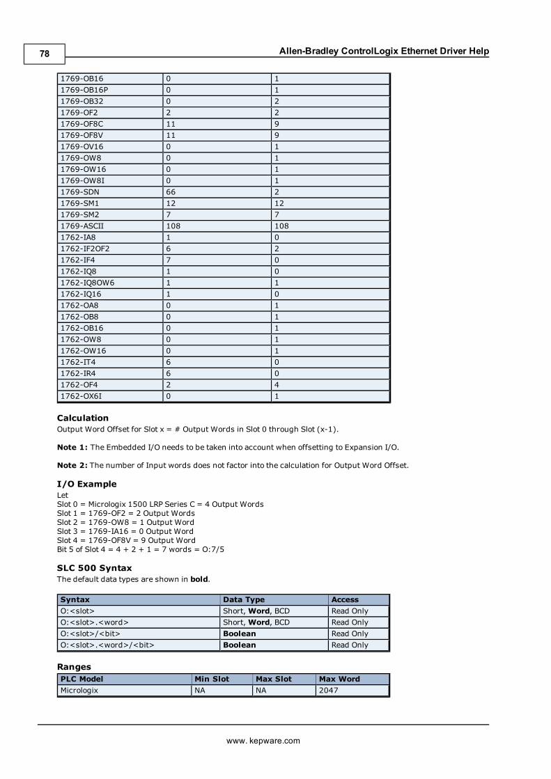
Allen-Bradley ControlLogix Ethernet Driver Help
1769-OB16 0 1
1769-OB16P 0 1
1769-OB32 0 2
1769-OF2 2 2
1769-OF8C 11 9
1769-OF8V 11 9
1769-OV16 0 1
1769-OW8 0 1
1769-OW16 0 1
1769-OW8I 0 1
1769-SDN 66 2
1769-SM1 12 12
1769-SM2 7 7
1769-ASCII 108 108
1762-IA8 1 0
1762-IF2OF2 6 2
1762-IF4 7 0
1762-IQ8 1 0
1762-IQ8OW6 1 1
1762-IQ16 1 0
1762-OA8 0 1
1762-OB8 0 1
1762-OB16 0 1
1762-OW8 0 1
1762-OW16 0 1
1762-IT4 6 0
1762-IR4 6 0
1762-OF4 2 4
1762-OX6I 0 1
CalculationOutput Word Offset for Slot x = # Output Words in Slot 0 through Slot (x-1).
Note 1: The Embedded I/O needs to be taken into account when offsetting to Expansion I/O.
Note 2: The number of Input words does not factor into the calculation for Output Word Offset.
I/O ExampleLetSlot 0 = Micrologix 1500 LRP Series C = 4 Output WordsSlot 1 = 1769-OF2 = 2 Output WordsSlot 2 = 1769-OW8 = 1 Output WordSlot 3 = 1769-IA16 = 0 Output WordSlot 4 = 1769-OF8V = 9 Output WordBit 5 of Slot 4 = 4 + 2 + 1 = 7 words = O:7/5
SLC 500 SyntaxThe default data types are shown in bold.
Syntax Data Type Access
O:<slot> Short,Word, BCD Read Only
O:<slot>.<word> Short,Word, BCD Read Only
O:<slot>/<bit> Boolean Read Only
O:<slot>.<word>/<bit> Boolean Read Only
RangesPLC Model Min Slot Max Slot Max Word
Micrologix NA NA 2047
www. kepware.com
78
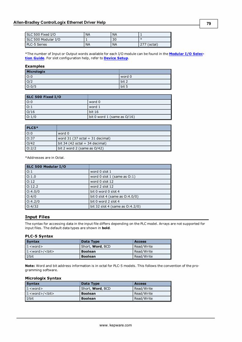
Allen-Bradley ControlLogix Ethernet Driver Help
SLC 500 Fixed I/O NA NA 1
SLC 500 Modular I/O 1 30 *
PLC-5 Series NA NA 277 (octal)
*The number of Input or Output words available for each I/O module can be found in theModular I/O Selec-tion Guide. For slot configuration help, refer toDevice Setup.
ExamplesMicrologix
O:0 word 0
O/2 bit 2
O:0/5 bit 5
SLC 500 Fixed I/O
O:0 word 0
O:1 word 1
O/16 bit 16
O:1/0 bit 0 word 1 (same as O/16)
PLC5*
O:0 word 0
O:37 word 31 (37 octal = 31 decimal)
O/42 bit 34 (42 octal = 34 decimal)
O:2/2 bit 2 word 2 (same as O/42)
*Addresses are in Octal.
SLC 500 Modular I/O
O:1 word 0 slot 1
O:1.0 word 0 slot 1 (same as O:1)
O:12 word 0 slot 12
O:12.2 word 2 slot 12
O:4.0/0 bit 0 word 0 slot 4
O:4/0 bit 0 slot 4 (same as O:4.0/0)
O:4.2/0 bit 0 word 2 slot 4
O:4/32 bit 32 slot 4 (same as O:4.2/0)
Input Files
The syntax for accessing data in the input file differs depending on the PLCmodel. Arrays are not supported forinput files. The default data types are shown in bold.
PLC-5 SyntaxSyntax Data Type Access
I:<word> Short,Word, BCD Read/Write
I:<word>/<bit> Boolean Read/Write
I/bit Boolean Read/Write
Note: Word and bit address information is in octal for PLC-5 models. This follows the convention of the pro-gramming software.
Micrologix SyntaxSyntax Data Type Access
I:<word> Short,Word, BCD Read/Write
I:<word>/<bit> Boolean Read/Write
I/bit Boolean Read/Write
www. kepware.com
79
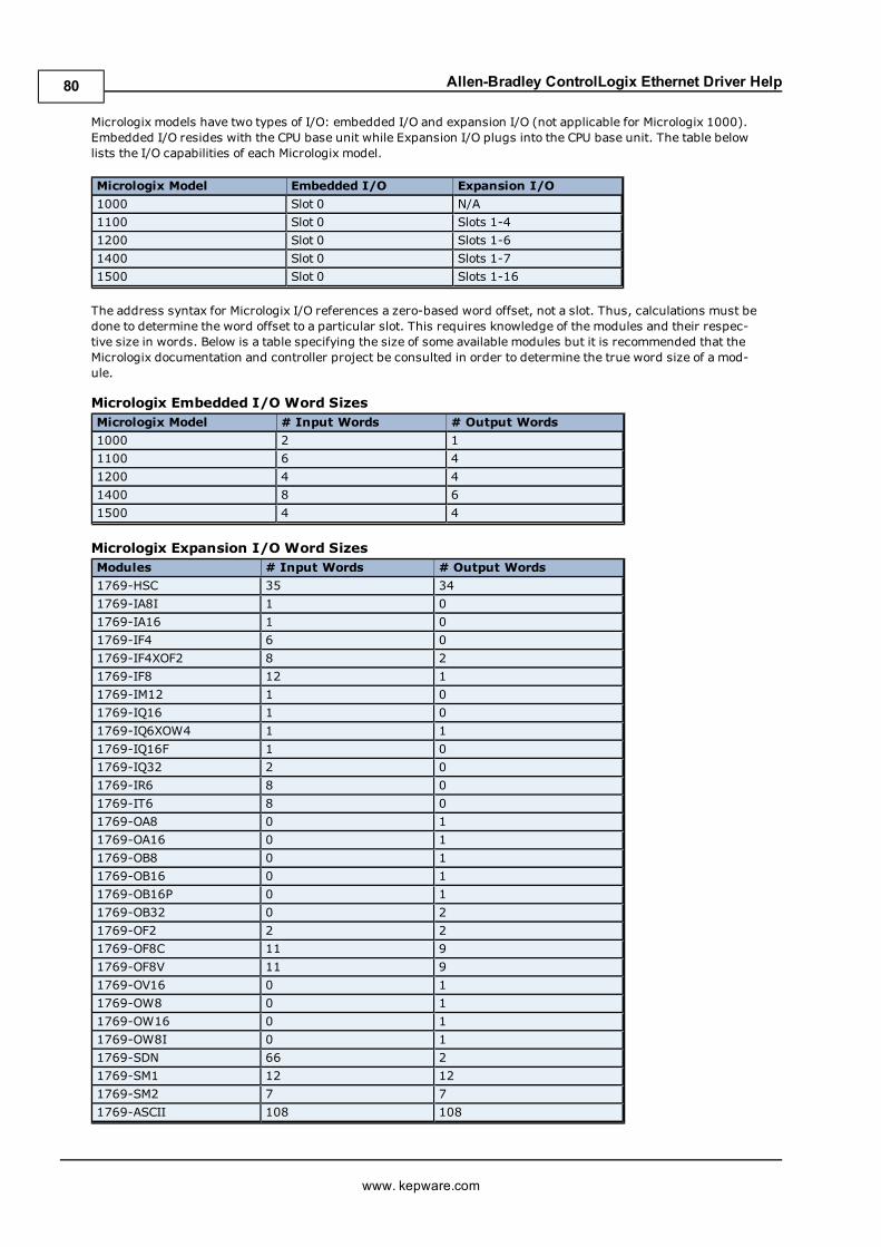
Allen-Bradley ControlLogix Ethernet Driver Help
Micrologix models have two types of I/O: embedded I/O and expansion I/O (not applicable for Micrologix 1000).Embedded I/O resides with the CPU base unit while Expansion I/O plugs into the CPU base unit. The table belowlists the I/O capabilities of each Micrologix model.
Micrologix Model Embedded I/O Expansion I/O
1000 Slot 0 N/A
1100 Slot 0 Slots 1-4
1200 Slot 0 Slots 1-6
1400 Slot 0 Slots 1-7
1500 Slot 0 Slots 1-16
The address syntax for Micrologix I/O references a zero-based word offset, not a slot. Thus, calculations must bedone to determine the word offset to a particular slot. This requires knowledge of the modules and their respec-tive size in words. Below is a table specifying the size of some available modules but it is recommended that theMicrologix documentation and controller project be consulted in order to determine the true word size of a mod-ule.
Micrologix Embedded I/O Word SizesMicrologix Model # Input Words # Output Words
1000 2 1
1100 6 4
1200 4 4
1400 8 6
1500 4 4
Micrologix Expansion I/O Word SizesModules # Input Words # Output Words
1769-HSC 35 34
1769-IA8I 1 0
1769-IA16 1 0
1769-IF4 6 0
1769-IF4XOF2 8 2
1769-IF8 12 1
1769-IM12 1 0
1769-IQ16 1 0
1769-IQ6XOW4 1 1
1769-IQ16F 1 0
1769-IQ32 2 0
1769-IR6 8 0
1769-IT6 8 0
1769-OA8 0 1
1769-OA16 0 1
1769-OB8 0 1
1769-OB16 0 1
1769-OB16P 0 1
1769-OB32 0 2
1769-OF2 2 2
1769-OF8C 11 9
1769-OF8V 11 9
1769-OV16 0 1
1769-OW8 0 1
1769-OW16 0 1
1769-OW8I 0 1
1769-SDN 66 2
1769-SM1 12 12
1769-SM2 7 7
1769-ASCII 108 108
www. kepware.com
80
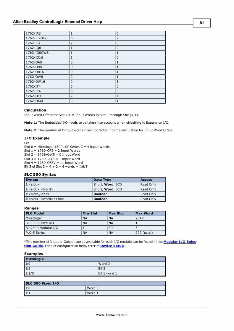
Allen-Bradley ControlLogix Ethernet Driver Help
1762-IA8 1 0
1762-IF2OF2 6 2
1762-IF4 7 0
1762-IQ8 1 0
1762-IQ8OW6 1 1
1762-IQ16 1 0
1762-OA8 0 1
1762-OB8 0 1
1762-OB16 0 1
1762-OW8 0 1
1762-OW16 0 1
1762-IT4 6 0
1762-IR4 6 0
1762-OF4 2 4
1762-OX6I 0 1
CalculationInput Word Offset for Slot x = # Input Words in Slot 0 through Slot (x-1).
Note 1: The Embedded I/O needs to be taken into account when offsetting to Expansion I/O.
Note 2: The number of Output words does not factor into the calculation for Input Word Offset.
I/O ExampleLetSlot 0 = Micrologix 1500 LRP Series C = 4 Input WordsSlot 1 = 1769-OF2 = 2 Input WordsSlot 2 = 1769-OW8 = 0 Input WordSlot 3 = 1769-IA16 = 1 Input WordSlot 4 = 1769-OF8V = 11 Input WordBit 5 of Slot 3 = 4 + 2 = 6 words = I:6/5
SLC 500 SyntaxSyntax Data Type Access
I:<slot> Short,Word, BCD Read Only
I:<slot>.<word> Short,Word, BCD Read Only
I:<slot>/<bit> Boolean Read Only
I:<slot>.<word>/<bit> Boolean Read Only
RangesPLC Model Min Slot Max Slot Max Word
Micrologix NA NA 2047
SLC 500 Fixed I/O NA NA 1
SLC 500 Modular I/O 1 30 *
PLC-5 Series NA NA 277 (octal)
*The number of Input or Output words available for each I/O module can be found in theModular I/O Selec-tion Guide. For slot configuration help, refer toDevice Setup.
ExamplesMicrologix
I:0 Word 0
I/2 Bit 2
I:1/5 Bit 5 word 1
SLC 500 Fixed I/O
I:0 Word 0
I:1 Word 1
www. kepware.com
81
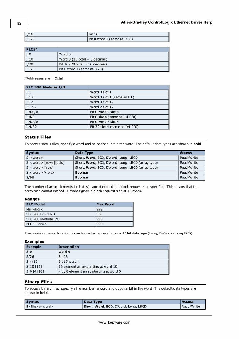
Allen-Bradley ControlLogix Ethernet Driver Help
I/16 bit 16
I:1/0 Bit 0 word 1 (same as I/16)
PLC5*
I:0 Word 0
I:10 Word 8 (10 octal = 8 decimal)
I/20 Bit 16 (20 octal = 16 decimal)
I:1/0 Bit 0 word 1 (same as I/20)
*Addresses are in Octal.
SLC 500 Modular I/O
I:1 Word 0 slot 1
I:1.0 Word 0 slot 1 (same as I:1)
I:12 Word 0 slot 12
I:12.2 Word 2 slot 12
I:4.0/0 Bit 0 word 0 slot 4
I:4/0 Bit 0 slot 4 (same as I:4.0/0)
I:4.2/0 Bit 0 word 2 slot 4
I:4/32 Bit 32 slot 4 (same as I:4.2/0)
Status Files
To access status files, specify a word and an optional bit in the word. The default data types are shown in bold.
Syntax Data Type Access
S:<word> Short,Word, BCD, DWord, Long, LBCD Read/Write
S:<word> [rows][cols] Short,Word, BCD, DWord, Long, LBCD (array type) Read/Write
S:<word> [cols] Short,Word, BCD, DWord, Long, LBCD (array type) Read/Write
S:<word>/<bit> Boolean Read/Write
S/bit Boolean Read/Write
The number of array elements (in bytes) cannot exceed the block request size specified. This means that thearray size cannot exceed 16 words given a block request size of 32 bytes.
RangesPLC Model Max Word
Micrologix 999
SLC 500 Fixed I/O 96
SLC 500 Modular I/O 999
PLC-5 Series 999
The maximumword location is one less when accessing as a 32 bit data type (Long, DWord or Long BCD).
ExamplesExample Description
S:0 Word 0
S/26 Bit 26
S:4/15 Bit 15 word 4
S:10 [16] 16 element array starting at word 10
S:0 [4] [8] 4 by 8 element array starting at word 0
Binary Files
To access binary files, specify a file number, a word and optional bit in the word. The default data types areshown in bold.
Syntax Data Type Access
B<file>:<word> Short,Word, BCD, DWord, Long, LBCD Read/Write
www. kepware.com
82
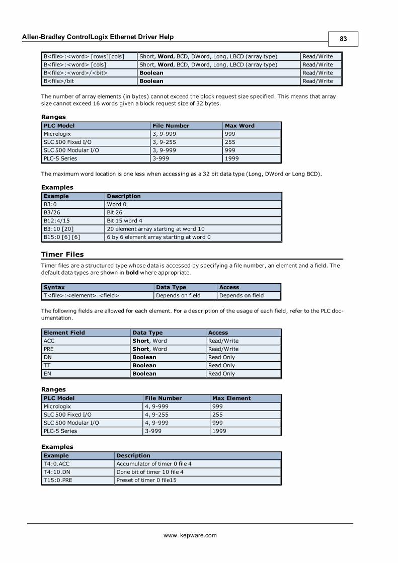
Allen-Bradley ControlLogix Ethernet Driver Help
B<file>:<word> [rows][cols] Short,Word, BCD, DWord, Long, LBCD (array type) Read/Write
B<file>:<word> [cols] Short,Word, BCD, DWord, Long, LBCD (array type) Read/Write
B<file>:<word>/<bit> Boolean Read/Write
B<file>/bit Boolean Read/Write
The number of array elements (in bytes) cannot exceed the block request size specified. This means that arraysize cannot exceed 16 words given a block request size of 32 bytes.
RangesPLC Model File Number Max Word
Micrologix 3, 9-999 999
SLC 500 Fixed I/O 3, 9-255 255
SLC 500 Modular I/O 3, 9-999 999
PLC-5 Series 3-999 1999
The maximumword location is one less when accessing as a 32 bit data type (Long, DWord or Long BCD).
ExamplesExample Description
B3:0 Word 0
B3/26 Bit 26
B12:4/15 Bit 15 word 4
B3:10 [20] 20 element array starting at word 10
B15:0 [6] [6] 6 by 6 element array starting at word 0
Timer Files
Timer files are a structured type whose data is accessed by specifying a file number, an element and a field. Thedefault data types are shown in boldwhere appropriate.
Syntax Data Type Access
T<file>:<element>.<field> Depends on field Depends on field
The following fields are allowed for each element. For a description of the usage of each field, refer to the PLC doc-umentation.
Element Field Data Type Access
ACC Short, Word Read/Write
PRE Short, Word Read/Write
DN Boolean Read Only
TT Boolean Read Only
EN Boolean Read Only
RangesPLC Model File Number Max Element
Micrologix 4, 9-999 999
SLC 500 Fixed I/O 4, 9-255 255
SLC 500 Modular I/O 4, 9-999 999
PLC-5 Series 3-999 1999
ExamplesExample Description
T4:0.ACC Accumulator of timer 0 file 4
T4:10.DN Done bit of timer 10 file 4
T15:0.PRE Preset of timer 0 file15
www. kepware.com
83
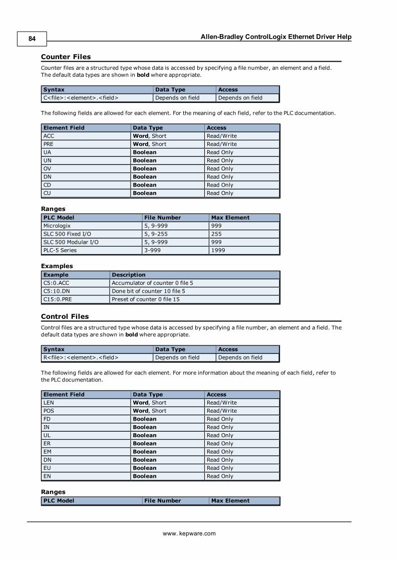
Allen-Bradley ControlLogix Ethernet Driver Help
Counter Files
Counter files are a structured type whose data is accessed by specifying a file number, an element and a field.The default data types are shown in boldwhere appropriate.
Syntax Data Type Access
C<file>:<element>.<field> Depends on field Depends on field
The following fields are allowed for each element. For the meaning of each field, refer to the PLC documentation.
Element Field Data Type Access
ACC Word, Short Read/Write
PRE Word, Short Read/Write
UA Boolean Read Only
UN Boolean Read Only
OV Boolean Read Only
DN Boolean Read Only
CD Boolean Read Only
CU Boolean Read Only
RangesPLC Model File Number Max Element
Micrologix 5, 9-999 999
SLC 500 Fixed I/O 5, 9-255 255
SLC 500 Modular I/O 5, 9-999 999
PLC-5 Series 3-999 1999
ExamplesExample Description
C5:0.ACC Accumulator of counter 0 file 5
C5:10.DN Done bit of counter 10 file 5
C15:0.PRE Preset of counter 0 file 15
Control Files
Control files are a structured type whose data is accessed by specifying a file number, an element and a field. Thedefault data types are shown in boldwhere appropriate.
Syntax Data Type Access
R<file>:<element>.<field> Depends on field Depends on field
The following fields are allowed for each element. For more information about the meaning of each field, refer tothe PLC documentation.
Element Field Data Type Access
LEN Word, Short Read/Write
POS Word, Short Read/Write
FD Boolean Read Only
IN Boolean Read Only
UL Boolean Read Only
ER Boolean Read Only
EM Boolean Read Only
DN Boolean Read Only
EU Boolean Read Only
EN Boolean Read Only
RangesPLC Model File Number Max Element
www. kepware.com
84
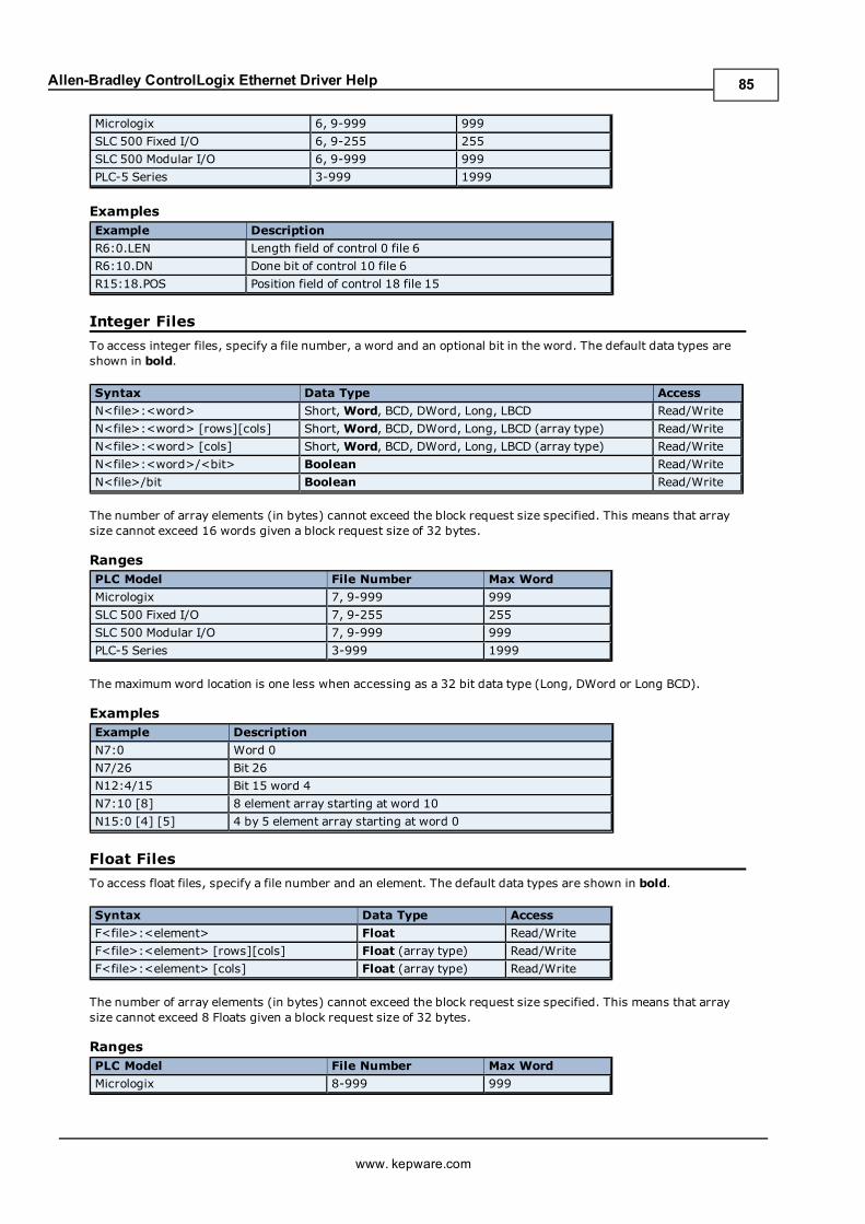
Allen-Bradley ControlLogix Ethernet Driver Help
Micrologix 6, 9-999 999
SLC 500 Fixed I/O 6, 9-255 255
SLC 500 Modular I/O 6, 9-999 999
PLC-5 Series 3-999 1999
ExamplesExample Description
R6:0.LEN Length field of control 0 file 6
R6:10.DN Done bit of control 10 file 6
R15:18.POS Position field of control 18 file 15
Integer Files
To access integer files, specify a file number, a word and an optional bit in the word. The default data types areshown in bold.
Syntax Data Type Access
N<file>:<word> Short,Word, BCD, DWord, Long, LBCD Read/Write
N<file>:<word> [rows][cols] Short,Word, BCD, DWord, Long, LBCD (array type) Read/Write
N<file>:<word> [cols] Short,Word, BCD, DWord, Long, LBCD (array type) Read/Write
N<file>:<word>/<bit> Boolean Read/Write
N<file>/bit Boolean Read/Write
The number of array elements (in bytes) cannot exceed the block request size specified. This means that arraysize cannot exceed 16 words given a block request size of 32 bytes.
RangesPLC Model File Number Max Word
Micrologix 7, 9-999 999
SLC 500 Fixed I/O 7, 9-255 255
SLC 500 Modular I/O 7, 9-999 999
PLC-5 Series 3-999 1999
The maximumword location is one less when accessing as a 32 bit data type (Long, DWord or Long BCD).
ExamplesExample Description
N7:0 Word 0
N7/26 Bit 26
N12:4/15 Bit 15 word 4
N7:10 [8] 8 element array starting at word 10
N15:0 [4] [5] 4 by 5 element array starting at word 0
Float Files
To access float files, specify a file number and an element. The default data types are shown in bold.
Syntax Data Type Access
F<file>:<element> Float Read/Write
F<file>:<element> [rows][cols] Float (array type) Read/Write
F<file>:<element> [cols] Float (array type) Read/Write
The number of array elements (in bytes) cannot exceed the block request size specified. This means that arraysize cannot exceed 8 Floats given a block request size of 32 bytes.
RangesPLC Model File Number Max Word
Micrologix 8-999 999
www. kepware.com
85
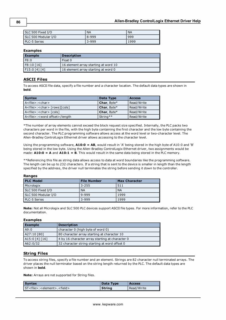
Allen-Bradley ControlLogix Ethernet Driver Help
SLC 500 Fixed I/O NA NA
SLC 500 Modular I/O 8-999 999
PLC-5 Series 3-999 1999
ExamplesExample Description
F8:0 Float 0
F8:10 [16] 16 element array starting at word 10
F15:0 [4] [4] 16 element array starting at word 0
ASCII Files
To access ASCII file data, specify a file number and a character location. The default data types are shown inbold.
Syntax Data Type Access
A<file>:<char> Char, Byte* Read/Write
A<file>:<char> [rows][cols] Char, Byte* Read/Write
A<file>:<char> [cols] Char, Byte* Read/Write
A<file>:<word offset>/length String** Read/Write
*The number of array elements cannot exceed the block request size specified. Internally, the PLC packs twocharacters per word in the file, with the high byte containing the first character and the low byte containing thesecond character. The PLC programming software allows access at the word level or two-character level. TheAllen-Bradley ControlLogix Ethernet driver allows accessing to the character level.
Using the programming software, A10:0 = AB, would result in 'A' being stored in the high byte of A10:0 and 'B'being stored in the low byte. Using the Allen-Bradley ControlLogix Ethernet driver, two assignments would bemade: A10:0 = A and A10:1 = B. This would result in the same data being stored in the PLCmemory.
**Referencing this file as string data allows access to data at word boundaries like the programming software.The length can be up to 232 characters. If a string that is sent to the device is smaller in length than the lengthspecified by the address, the driver null terminates the string before sending it down to the controller.
RangesPLC Model File Number Max Character
Micrologix 3-255 511
SLC 500 Fixed I/O NA NA
SLC 500 Modular I/O 9-999 1999
PLC-5 Series 3-999 1999
Note: Not all Micrologix and SLC 500 PLC devices support ASCII file types. For more information, refer to the PLCdocumentation.
ExamplesExample Description
A9:0 character 0 (high byte of word 0)
A27:10 [80] 80 character array starting at character 10
A15:0 [4] [16] 4 by 16 character array starting at character 0
A62:0/32 32 character string starting at word offset 0
String Files
To access string files, specify a file number and an element. Strings are 82 character null terminated arrays. Thedriver places the null terminator based on the string length returned by the PLC. The default data types areshown in bold.
Note: Arrays are not supported for String files.
Syntax Data Type Access
ST<file>:<element>.<field> String Read/Write
www. kepware.com
86
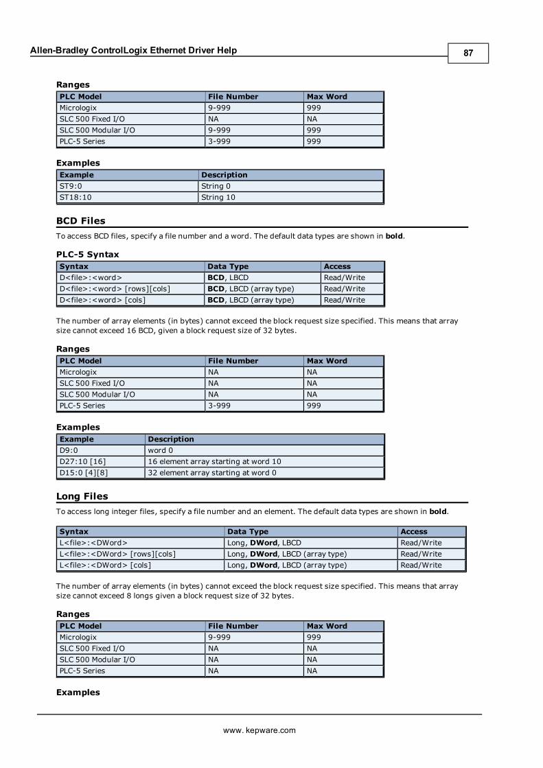
Allen-Bradley ControlLogix Ethernet Driver Help
RangesPLC Model File Number Max Word
Micrologix 9-999 999
SLC 500 Fixed I/O NA NA
SLC 500 Modular I/O 9-999 999
PLC-5 Series 3-999 999
ExamplesExample Description
ST9:0 String 0
ST18:10 String 10
BCD Files
To access BCD files, specify a file number and a word. The default data types are shown in bold.
PLC-5 SyntaxSyntax Data Type Access
D<file>:<word> BCD, LBCD Read/Write
D<file>:<word> [rows][cols] BCD, LBCD (array type) Read/Write
D<file>:<word> [cols] BCD, LBCD (array type) Read/Write
The number of array elements (in bytes) cannot exceed the block request size specified. This means that arraysize cannot exceed 16 BCD, given a block request size of 32 bytes.
RangesPLC Model File Number Max Word
Micrologix NA NA
SLC 500 Fixed I/O NA NA
SLC 500 Modular I/O NA NA
PLC-5 Series 3-999 999
ExamplesExample Description
D9:0 word 0
D27:10 [16] 16 element array starting at word 10
D15:0 [4][8] 32 element array starting at word 0
Long Files
To access long integer files, specify a file number and an element. The default data types are shown in bold.
Syntax Data Type Access
L<file>:<DWord> Long, DWord, LBCD Read/Write
L<file>:<DWord> [rows][cols] Long, DWord, LBCD (array type) Read/Write
L<file>:<DWord> [cols] Long, DWord, LBCD (array type) Read/Write
The number of array elements (in bytes) cannot exceed the block request size specified. This means that arraysize cannot exceed 8 longs given a block request size of 32 bytes.
RangesPLC Model File Number Max Word
Micrologix 9-999 999
SLC 500 Fixed I/O NA NA
SLC 500 Modular I/O NA NA
PLC-5 Series NA NA
Examples
www. kepware.com
87
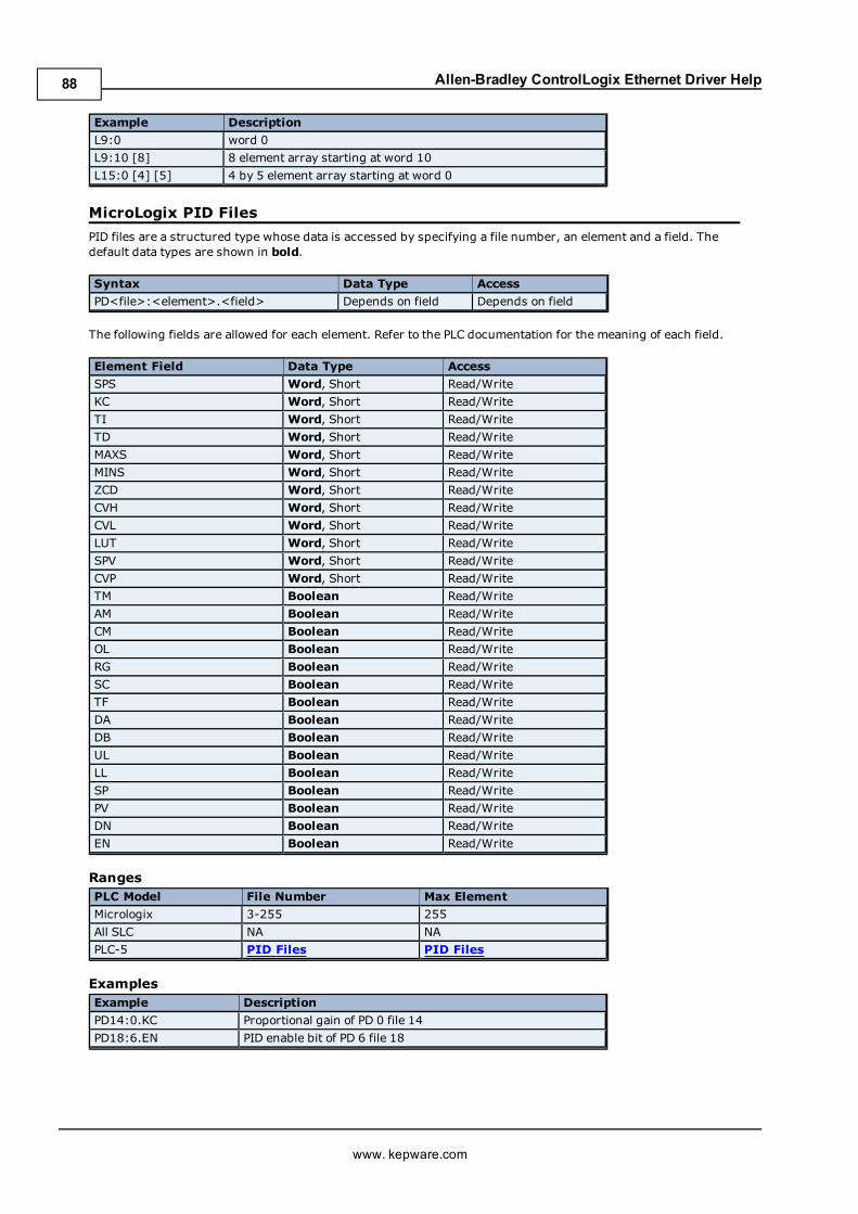
Allen-Bradley ControlLogix Ethernet Driver Help
Example Description
L9:0 word 0
L9:10 [8] 8 element array starting at word 10
L15:0 [4] [5] 4 by 5 element array starting at word 0
MicroLogix PID Files
PID files are a structured type whose data is accessed by specifying a file number, an element and a field. Thedefault data types are shown in bold.
Syntax Data Type Access
PD<file>:<element>.<field> Depends on field Depends on field
The following fields are allowed for each element. Refer to the PLC documentation for the meaning of each field.
Element Field Data Type Access
SPS Word, Short Read/Write
KC Word, Short Read/Write
TI Word, Short Read/Write
TD Word, Short Read/Write
MAXS Word, Short Read/Write
MINS Word, Short Read/Write
ZCD Word, Short Read/Write
CVH Word, Short Read/Write
CVL Word, Short Read/Write
LUT Word, Short Read/Write
SPV Word, Short Read/Write
CVP Word, Short Read/Write
TM Boolean Read/Write
AM Boolean Read/Write
CM Boolean Read/Write
OL Boolean Read/Write
RG Boolean Read/Write
SC Boolean Read/Write
TF Boolean Read/Write
DA Boolean Read/Write
DB Boolean Read/Write
UL Boolean Read/Write
LL Boolean Read/Write
SP Boolean Read/Write
PV Boolean Read/Write
DN Boolean Read/Write
EN Boolean Read/Write
RangesPLC Model File Number Max Element
Micrologix 3-255 255
All SLC NA NA
PLC-5 PID Files PID Files
ExamplesExample Description
PD14:0.KC Proportional gain of PD 0 file 14
PD18:6.EN PID enable bit of PD 6 file 18
www. kepware.com
88
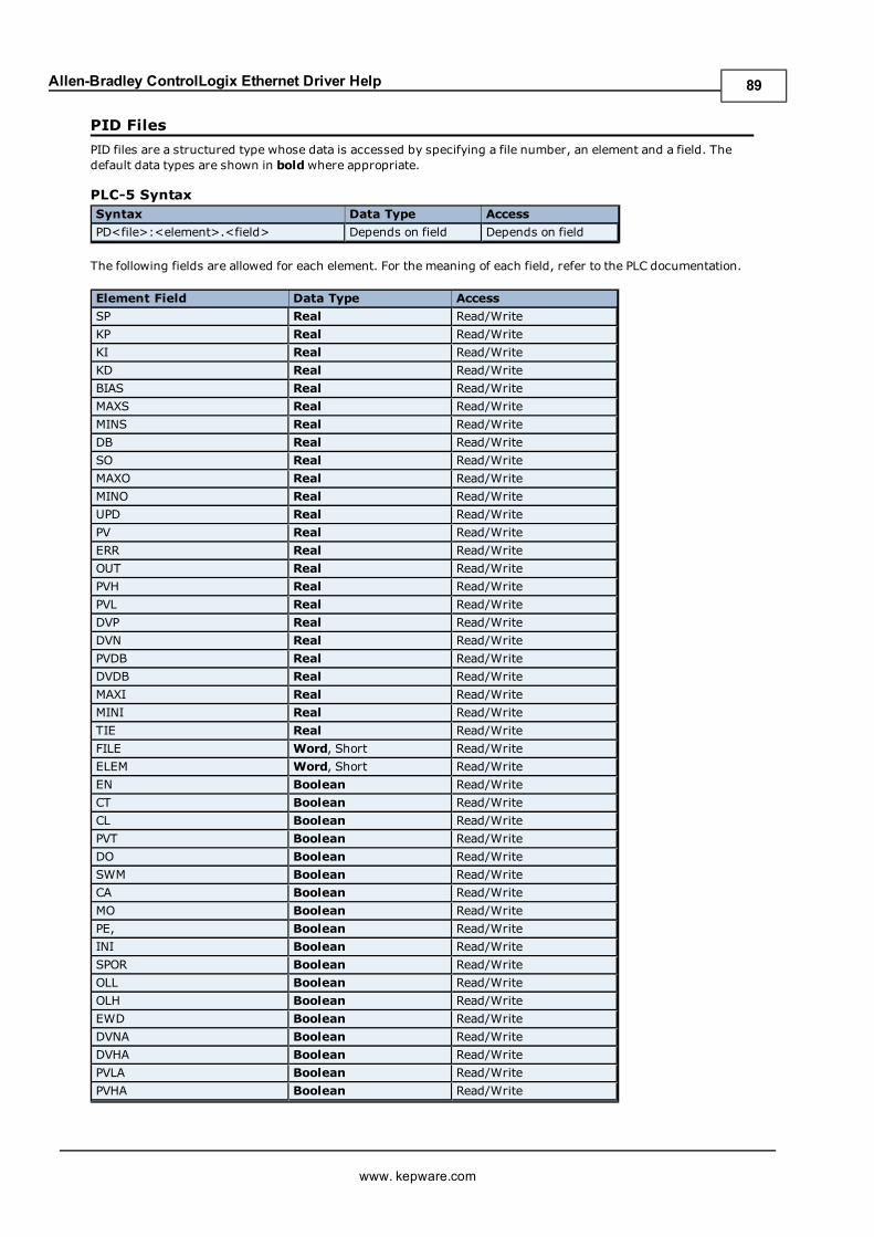
Allen-Bradley ControlLogix Ethernet Driver Help
PID Files
PID files are a structured type whose data is accessed by specifying a file number, an element and a field. Thedefault data types are shown in boldwhere appropriate.
PLC-5 SyntaxSyntax Data Type Access
PD<file>:<element>.<field> Depends on field Depends on field
The following fields are allowed for each element. For the meaning of each field, refer to the PLC documentation.
Element Field Data Type Access
SP Real Read/Write
KP Real Read/Write
KI Real Read/Write
KD Real Read/Write
BIAS Real Read/Write
MAXS Real Read/Write
MINS Real Read/Write
DB Real Read/Write
SO Real Read/Write
MAXO Real Read/Write
MINO Real Read/Write
UPD Real Read/Write
PV Real Read/Write
ERR Real Read/Write
OUT Real Read/Write
PVH Real Read/Write
PVL Real Read/Write
DVP Real Read/Write
DVN Real Read/Write
PVDB Real Read/Write
DVDB Real Read/Write
MAXI Real Read/Write
MINI Real Read/Write
TIE Real Read/Write
FILE Word, Short Read/Write
ELEM Word, Short Read/Write
EN Boolean Read/Write
CT Boolean Read/Write
CL Boolean Read/Write
PVT Boolean Read/Write
DO Boolean Read/Write
SWM Boolean Read/Write
CA Boolean Read/Write
MO Boolean Read/Write
PE, Boolean Read/Write
INI Boolean Read/Write
SPOR Boolean Read/Write
OLL Boolean Read/Write
OLH Boolean Read/Write
EWD Boolean Read/Write
DVNA Boolean Read/Write
DVHA Boolean Read/Write
PVLA Boolean Read/Write
PVHA Boolean Read/Write
www. kepware.com
89
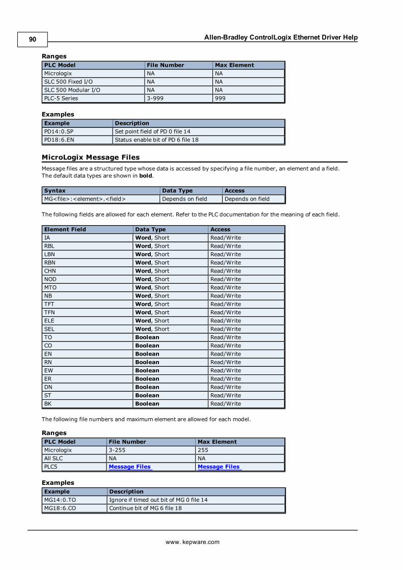
Allen-Bradley ControlLogix Ethernet Driver Help
RangesPLC Model File Number Max Element
Micrologix NA NA
SLC 500 Fixed I/O NA NA
SLC 500 Modular I/O NA NA
PLC-5 Series 3-999 999
ExamplesExample Description
PD14:0.SP Set point field of PD 0 file 14
PD18:6.EN Status enable bit of PD 6 file 18
MicroLogix Message Files
Message files are a structured type whose data is accessed by specifying a file number, an element and a field.The default data types are shown in bold.
Syntax Data Type Access
MG<file>:<element>.<field> Depends on field Depends on field
The following fields are allowed for each element. Refer to the PLC documentation for the meaning of each field.
Element Field Data Type Access
IA Word, Short Read/Write
RBL Word, Short Read/Write
LBN Word, Short Read/Write
RBN Word, Short Read/Write
CHN Word, Short Read/Write
NOD Word, Short Read/Write
MTO Word, Short Read/Write
NB Word, Short Read/Write
TFT Word, Short Read/Write
TFN Word, Short Read/Write
ELE Word, Short Read/Write
SEL Word, Short Read/Write
TO Boolean Read/Write
CO Boolean Read/Write
EN Boolean Read/Write
RN Boolean Read/Write
EW Boolean Read/Write
ER Boolean Read/Write
DN Boolean Read/Write
ST Boolean Read/Write
BK Boolean Read/Write
The following file numbers and maximum element are allowed for each model.
RangesPLC Model File Number Max Element
Micrologix 3-255 255
All SLC NA NA
PLC5 Message Files Message Files
ExamplesExample Description
MG14:0.TO Ignore if timed out bit of MG 0 file 14
MG18:6.CO Continue bit of MG 6 file 18
www. kepware.com
90
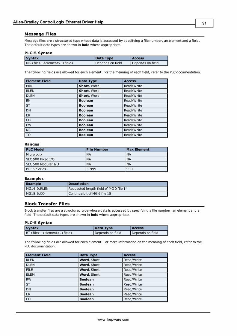
Allen-Bradley ControlLogix Ethernet Driver Help
Message Files
Message files are a structured type whose data is accessed by specifying a file number, an element and a field.The default data types are shown in boldwhere appropriate.
PLC-5 SyntaxSyntax Data Type Access
MG<file>:<element>.<field> Depends on field Depends on field
The following fields are allowed for each element. For the meaning of each field, refer to the PLC documentation.
Element Field Data Type Access
ERR Short, Word Read/Write
RLEN Short, Word Read/Write
DLEN Short, Word Read/Write
EN Boolean Read/Write
ST Boolean Read/Write
DN Boolean Read/Write
ER Boolean Read/Write
CO Boolean Read/Write
EW Boolean Read/Write
NR Boolean Read/Write
TO Boolean Read/Write
RangesPLC Model File Number Max Element
Micrologix NA NA
SLC 500 Fixed I/O NA NA
SLC 500 Modular I/O NA NA
PLC-5 Series 3-999 999
ExamplesExample Description
MG14:0.RLEN Requested length field of MG 0 file 14
MG18:6.CO Continue bit of MG 6 file 18
Block Transfer Files
Block transfer files are a structured type whose data is accessed by specifying a file number, an element and afield. The default data types are shown in boldwhere appropriate.
PLC-5 SyntaxSyntax Data Type Access
BT<file>:<element>.<field> Depends on field Depends on field
The following fields are allowed for each element. For more information on the meaning of each field, refer to thePLC documentation.
Element Field Data Type Access
RLEN Word, Short Read/Write
DLEN Word, Short Read/Write
FILE Word, Short Read/Write
ELEM Word, Short Read/Write
RW Boolean Read/Write
ST Boolean Read/Write
DN Boolean Read/Write
ER Boolean Read/Write
CO Boolean Read/Write
www. kepware.com
91
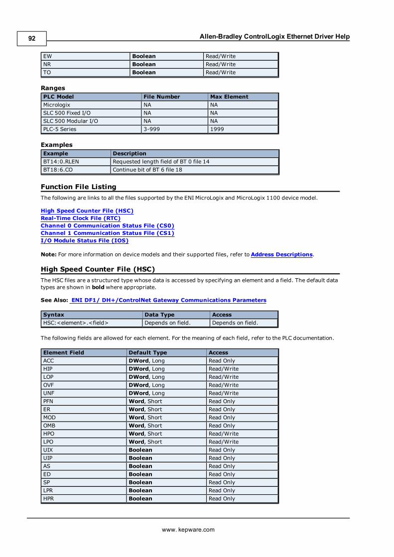
Allen-Bradley ControlLogix Ethernet Driver Help
EW Boolean Read/Write
NR Boolean Read/Write
TO Boolean Read/Write
RangesPLC Model File Number Max Element
Micrologix NA NA
SLC 500 Fixed I/O NA NA
SLC 500 Modular I/O NA NA
PLC-5 Series 3-999 1999
ExamplesExample Description
BT14:0.RLEN Requested length field of BT 0 file 14
BT18:6.CO Continue bit of BT 6 file 18
Function File Listing
The following are links to all the files supported by the ENI MicroLogix and MicroLogix 1100 device model.
High Speed Counter File (HSC)Real-Time Clock File (RTC)Channel 0 Communication Status File (CS0)Channel 1 Communication Status File (CS1)I/O Module Status File (IOS)
Note: For more information on device models and their supported files, refer to Address Descriptions.
High Speed Counter File (HSC)
The HSC files are a structured type whose data is accessed by specifying an element and a field. The default datatypes are shown in boldwhere appropriate.
See Also: ENI DF1/ DH+/ControlNet Gateway Communications Parameters
Syntax Data Type Access
HSC:<element>.<field> Depends on field. Depends on field.
The following fields are allowed for each element. For the meaning of each field, refer to the PLC documentation.
Element Field Default Type Access
ACC DWord, Long Read Only
HIP DWord, Long Read/Write
LOP DWord, Long Read/Write
OVF DWord, Long Read/Write
UNF DWord, Long Read/Write
PFN Word, Short Read Only
ER Word, Short Read Only
MOD Word, Short Read Only
OMB Word, Short Read Only
HPO Word, Short Read/Write
LPO Word, Short Read/Write
UIX Boolean Read Only
UIP Boolean Read Only
AS Boolean Read Only
ED Boolean Read Only
SP Boolean Read Only
LPR Boolean Read Only
HPR Boolean Read Only
www. kepware.com
92
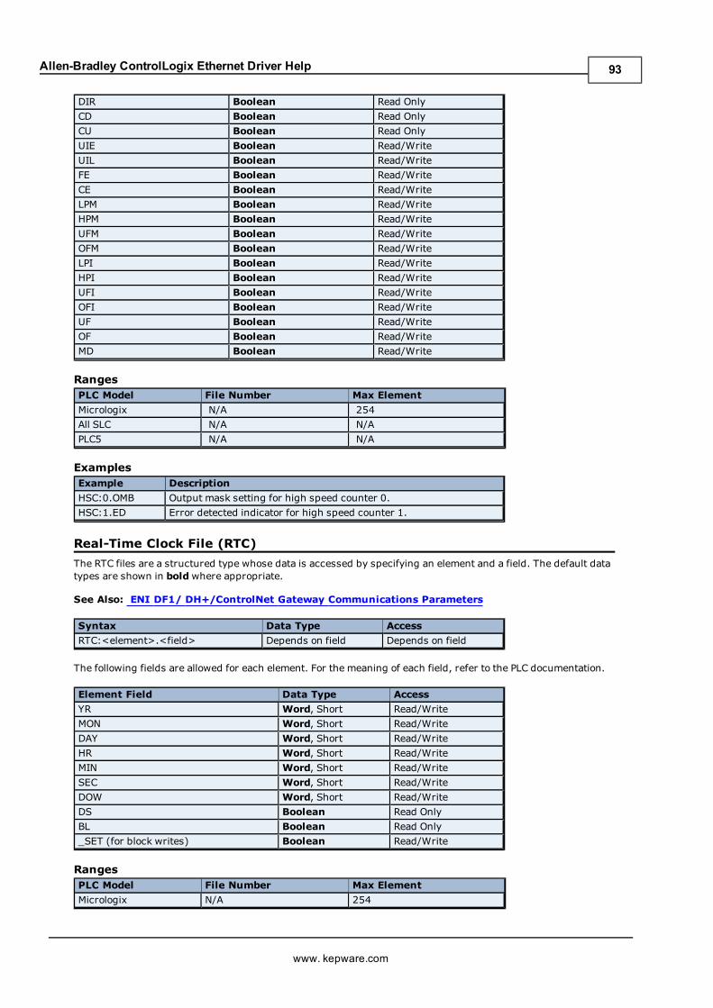
Allen-Bradley ControlLogix Ethernet Driver Help
DIR Boolean Read Only
CD Boolean Read Only
CU Boolean Read Only
UIE Boolean Read/Write
UIL Boolean Read/Write
FE Boolean Read/Write
CE Boolean Read/Write
LPM Boolean Read/Write
HPM Boolean Read/Write
UFM Boolean Read/Write
OFM Boolean Read/Write
LPI Boolean Read/Write
HPI Boolean Read/Write
UFI Boolean Read/Write
OFI Boolean Read/Write
UF Boolean Read/Write
OF Boolean Read/Write
MD Boolean Read/Write
RangesPLC Model File Number Max Element
Micrologix N/A 254
All SLC N/A N/A
PLC5 N/A N/A
ExamplesExample Description
HSC:0.OMB Output mask setting for high speed counter 0.
HSC:1.ED Error detected indicator for high speed counter 1.
Real-Time Clock File (RTC)
The RTC files are a structured type whose data is accessed by specifying an element and a field. The default datatypes are shown in boldwhere appropriate.
See Also: ENI DF1/ DH+/ControlNet Gateway Communications Parameters
Syntax Data Type Access
RTC:<element>.<field> Depends on field Depends on field
The following fields are allowed for each element. For the meaning of each field, refer to the PLC documentation.
Element Field Data Type Access
YR Word, Short Read/Write
MON Word, Short Read/Write
DAY Word, Short Read/Write
HR Word, Short Read/Write
MIN Word, Short Read/Write
SEC Word, Short Read/Write
DOW Word, Short Read/Write
DS Boolean Read Only
BL Boolean Read Only
_SET (for block writes) Boolean Read/Write
RangesPLC Model File Number Max Element
Micrologix N/A 254
www. kepware.com
93
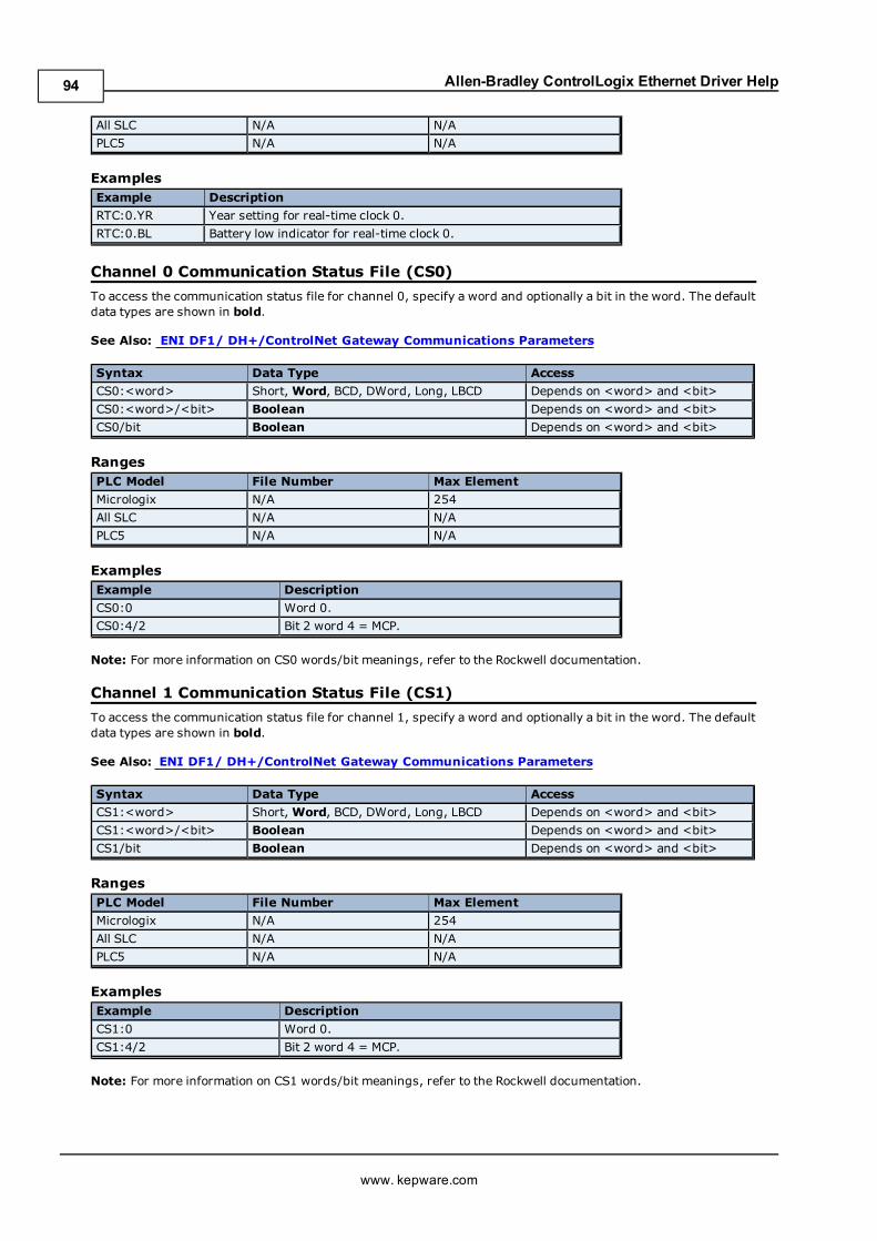
Allen-Bradley ControlLogix Ethernet Driver Help
All SLC N/A N/A
PLC5 N/A N/A
ExamplesExample Description
RTC:0.YR Year setting for real-time clock 0.
RTC:0.BL Battery low indicator for real-time clock 0.
Channel 0 Communication Status File (CS0)
To access the communication status file for channel 0, specify a word and optionally a bit in the word. The defaultdata types are shown in bold.
See Also: ENI DF1/ DH+/ControlNet Gateway Communications Parameters
Syntax Data Type Access
CS0:<word> Short,Word, BCD, DWord, Long, LBCD Depends on <word> and <bit>
CS0:<word>/<bit> Boolean Depends on <word> and <bit>
CS0/bit Boolean Depends on <word> and <bit>
RangesPLC Model File Number Max Element
Micrologix N/A 254
All SLC N/A N/A
PLC5 N/A N/A
ExamplesExample Description
CS0:0 Word 0.
CS0:4/2 Bit 2 word 4 = MCP.
Note: For more information on CS0 words/bit meanings, refer to the Rockwell documentation.
Channel 1 Communication Status File (CS1)
To access the communication status file for channel 1, specify a word and optionally a bit in the word. The defaultdata types are shown in bold.
See Also: ENI DF1/ DH+/ControlNet Gateway Communications Parameters
Syntax Data Type Access
CS1:<word> Short,Word, BCD, DWord, Long, LBCD Depends on <word> and <bit>
CS1:<word>/<bit> Boolean Depends on <word> and <bit>
CS1/bit Boolean Depends on <word> and <bit>
RangesPLC Model File Number Max Element
Micrologix N/A 254
All SLC N/A N/A
PLC5 N/A N/A
ExamplesExample Description
CS1:0 Word 0.
CS1:4/2 Bit 2 word 4 = MCP.
Note: For more information on CS1 words/bit meanings, refer to the Rockwell documentation.
www. kepware.com
94
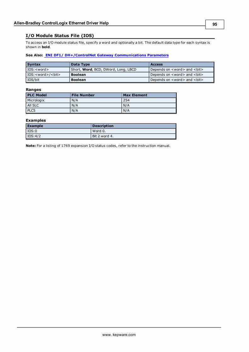
Allen-Bradley ControlLogix Ethernet Driver Help
I/O Module Status File (IOS)
To access an I/O module status file, specify a word and optionally a bit. The default data type for each syntax isshown in bold.
See Also: ENI DF1/ DH+/ControlNet Gateway Communications Parameters
Syntax Data Type Access
IOS:<word> Short,Word, BCD, DWord, Long, LBCD Depends on <word> and <bit>
IOS:<word>/<bit> Boolean Depends on <word> and <bit>
IOS/bit Boolean Depends on <word> and <bit>
RangesPLC Model File Number Max Element
Micrologix N/A 254
All SLC N/A N/A
PLC5 N/A N/A
ExamplesExample Description
IOS:0 Word 0.
IOS:4/2 Bit 2 word 4.
Note: For a listing of 1769 expansion I/O status codes, refer to the instruction manual.
www. kepware.com
95
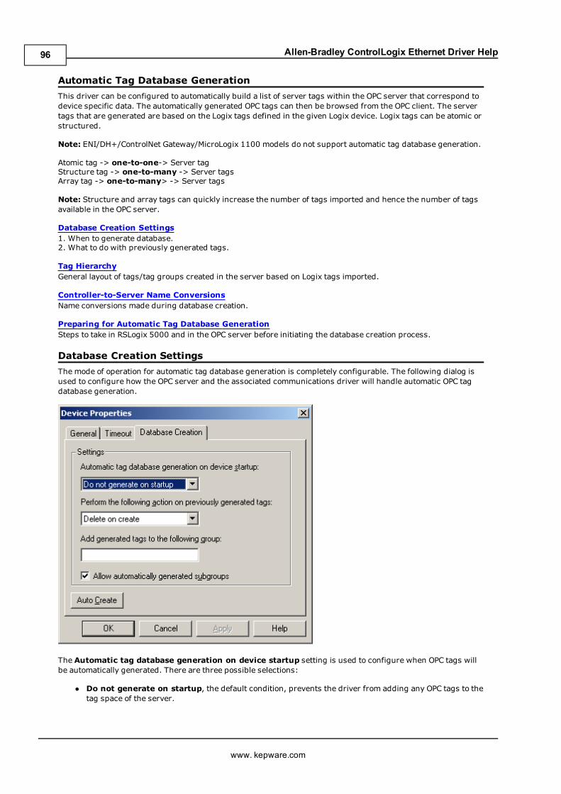
Allen-Bradley ControlLogix Ethernet Driver Help
Automatic Tag Database Generation
This driver can be configured to automatically build a list of server tags within the OPC server that correspond todevice specific data. The automatically generated OPC tags can then be browsed from the OPC client. The servertags that are generated are based on the Logix tags defined in the given Logix device. Logix tags can be atomic orstructured.
Note: ENI/DH+/ControlNet Gateway/MicroLogix 1100 models do not support automatic tag database generation.
Atomic tag -> one-to-one-> Server tagStructure tag -> one-to-many -> Server tagsArray tag -> one-to-many> -> Server tags
Note: Structure and array tags can quickly increase the number of tags imported and hence the number of tagsavailable in the OPC server.
Database Creation Settings1. When to generate database.2. What to do with previously generated tags.
Tag HierarchyGeneral layout of tags/tag groups created in the server based on Logix tags imported.
Controller-to-Server Name ConversionsName conversions made during database creation.
Preparing for Automatic Tag Database GenerationSteps to take in RSLogix 5000 and in the OPC server before initiating the database creation process.
Database Creation Settings
The mode of operation for automatic tag database generation is completely configurable. The following dialog isused to configure how the OPC server and the associated communications driver will handle automatic OPC tagdatabase generation.
The Automatic tag database generation on device startup setting is used to configure when OPC tags willbe automatically generated. There are three possible selections:
l Do not generate on startup, the default condition, prevents the driver from adding any OPC tags to thetag space of the server.
www. kepware.com
96
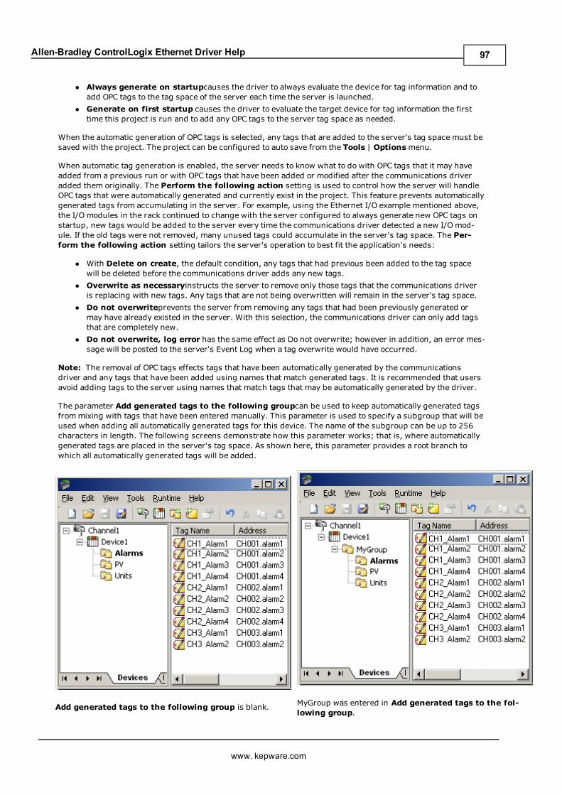
Allen-Bradley ControlLogix Ethernet Driver Help
l Always generate on startupcauses the driver to always evaluate the device for tag information and toadd OPC tags to the tag space of the server each time the server is launched.
l Generate on first startup causes the driver to evaluate the target device for tag information the firsttime this project is run and to add any OPC tags to the server tag space as needed.
When the automatic generation of OPC tags is selected, any tags that are added to the server's tag space must besaved with the project. The project can be configured to auto save from the Tools | Optionsmenu.
When automatic tag generation is enabled, the server needs to know what to do with OPC tags that it may haveadded from a previous run or with OPC tags that have been added or modified after the communications driveradded them originally. The Perform the following action setting is used to control how the server will handleOPC tags that were automatically generated and currently exist in the project. This feature prevents automaticallygenerated tags from accumulating in the server. For example, using the Ethernet I/O example mentioned above,the I/O modules in the rack continued to change with the server configured to always generate new OPC tags onstartup, new tags would be added to the server every time the communications driver detected a new I/O mod-ule. If the old tags were not removed, many unused tags could accumulate in the server's tag space. The Per-form the following action setting tailors the server's operation to best fit the application's needs:
l With Delete on create, the default condition, any tags that had previous been added to the tag spacewill be deleted before the communications driver adds any new tags.
l Overwrite as necessaryinstructs the server to remove only those tags that the communications driveris replacing with new tags. Any tags that are not being overwritten will remain in the server's tag space.
l Do not overwriteprevents the server from removing any tags that had been previously generated ormay have already existed in the server. With this selection, the communications driver can only add tagsthat are completely new.
l Do not overwrite, log error has the same effect as Do not overwrite; however in addition, an error mes-sage will be posted to the server's Event Log when a tag overwrite would have occurred.
Note: The removal of OPC tags effects tags that have been automatically generated by the communicationsdriver and any tags that have been added using names that match generated tags. It is recommended that usersavoid adding tags to the server using names that match tags that may be automatically generated by the driver.
The parameter Add generated tags to the following groupcan be used to keep automatically generated tagsfrommixing with tags that have been entered manually. This parameter is used to specify a subgroup that will beused when adding all automatically generated tags for this device. The name of the subgroup can be up to 256characters in length. The following screens demonstrate how this parameter works; that is, where automaticallygenerated tags are placed in the server's tag space. As shown here, this parameter provides a root branch towhich all automatically generated tags will be added.
Add generated tags to the following group is blank. MyGroup was entered in Add generated tags to the fol-lowing group.
www. kepware.com
97
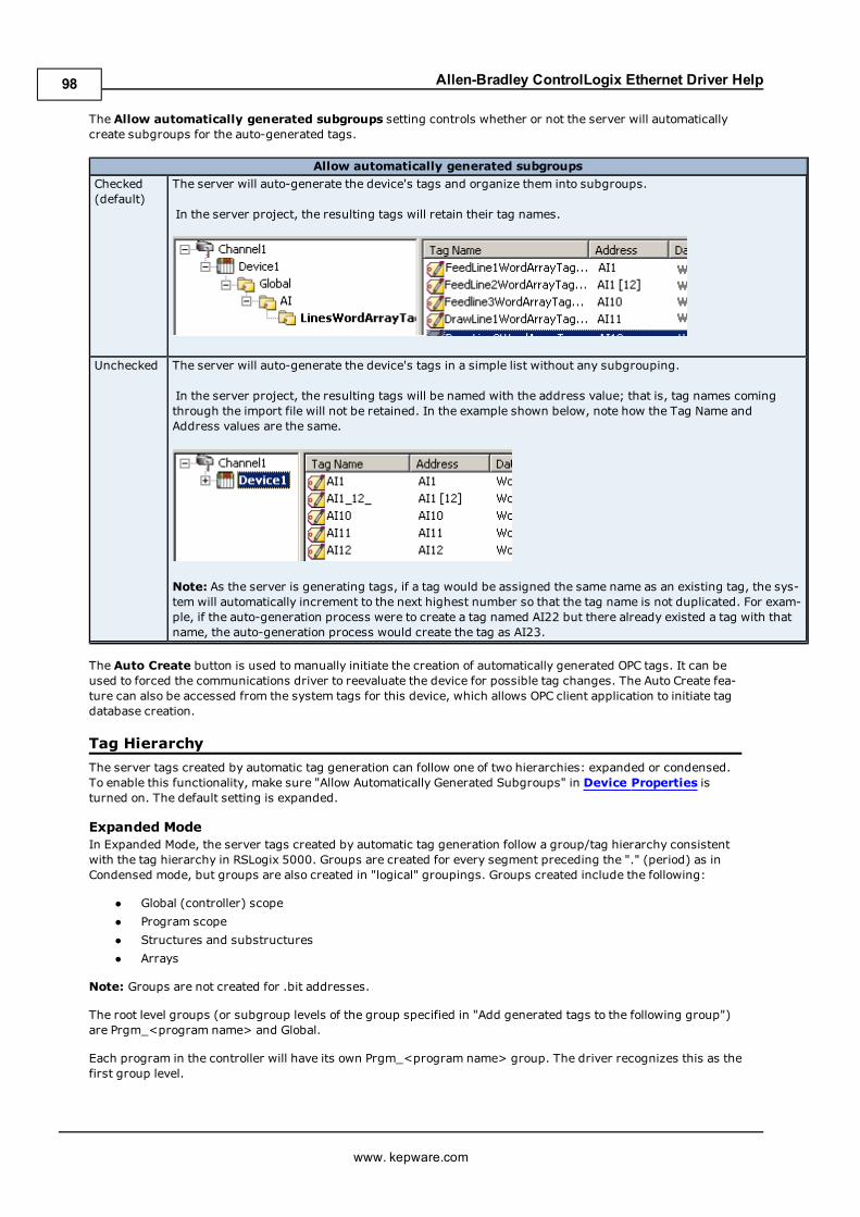
Allen-Bradley ControlLogix Ethernet Driver Help
The Allow automatically generated subgroups setting controls whether or not the server will automaticallycreate subgroups for the auto-generated tags.
Allow automatically generated subgroups
Checked(default)
The server will auto-generate the device's tags and organize them into subgroups.
In the server project, the resulting tags will retain their tag names.
Unchecked The server will auto-generate the device's tags in a simple list without any subgrouping.
In the server project, the resulting tags will be named with the address value; that is, tag names comingthrough the import file will not be retained. In the example shown below, note how the Tag Name andAddress values are the same.
Note: As the server is generating tags, if a tag would be assigned the same name as an existing tag, the sys-tem will automatically increment to the next highest number so that the tag name is not duplicated. For exam-ple, if the auto-generation process were to create a tag named AI22 but there already existed a tag with thatname, the auto-generation process would create the tag as AI23.
The Auto Create button is used to manually initiate the creation of automatically generated OPC tags. It can beused to forced the communications driver to reevaluate the device for possible tag changes. The Auto Create fea-ture can also be accessed from the system tags for this device, which allows OPC client application to initiate tagdatabase creation.
Tag Hierarchy
The server tags created by automatic tag generation can follow one of two hierarchies: expanded or condensed.To enable this functionality, make sure "Allow Automatically Generated Subgroups" in Device Properties isturned on. The default setting is expanded.
Expanded ModeIn Expanded Mode, the server tags created by automatic tag generation follow a group/tag hierarchy consistentwith the tag hierarchy in RSLogix 5000. Groups are created for every segment preceding the "." (period) as inCondensed mode, but groups are also created in "logical" groupings. Groups created include the following:
l Global (controller) scope
l Program scope
l Structures and substructures
l Arrays
Note: Groups are not created for .bit addresses.
The root level groups (or subgroup levels of the group specified in "Add generated tags to the following group")are Prgm_<program name> and Global.
Each program in the controller will have its own Prgm_<program name> group. The driver recognizes this as thefirst group level.
www. kepware.com
98
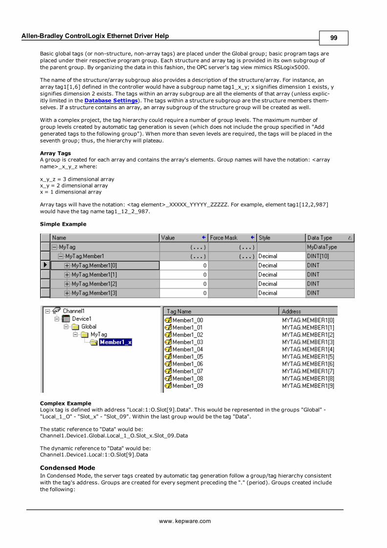
Allen-Bradley ControlLogix Ethernet Driver Help
Basic global tags (or non-structure, non-array tags) are placed under the Global group; basic program tags areplaced under their respective program group. Each structure and array tag is provided in its own subgroup ofthe parent group. By organizing the data in this fashion, the OPC server's tag view mimics RSLogix5000.
The name of the structure/array subgroup also provides a description of the structure/array. For instance, anarray tag1[1,6] defined in the controller would have a subgroup name tag1_x_y; x signifies dimension 1 exists, ysignifies dimension 2 exists. The tags within an array subgroup are all the elements of that array (unless explic-itly limited in the Database Settings). The tags within a structure subgroup are the structure members them-selves. If a structure contains an array, an array subgroup of the structure group will be created as well.
With a complex project, the tag hierarchy could require a number of group levels. The maximum number ofgroup levels created by automatic tag generation is seven (which does not include the group specified in "Addgenerated tags to the following group"). When more than seven levels are required, the tags will be placed in theseventh group; thus, the hierarchy will plateau.
Array TagsA group is created for each array and contains the array's elements. Group names will have the notation: <arrayname>_x_y_z where:
x_y_z = 3 dimensional arrayx_y = 2 dimensional arrayx = 1 dimensional array
Array tags will have the notation: <tag element>_XXXXX_YYYYY_ZZZZZ. For example, element tag1[12,2,987]would have the tag name tag1_12_2_987.
Simple Example
Complex ExampleLogix tag is defined with address "Local:1:O.Slot[9].Data". This would be represented in the groups "Global" -"Local_1_O" - "Slot_x" - "Slot_09". Within the last group would be the tag "Data".
The static reference to "Data" would be:Channel1.Device1.Global.Local_1_O.Slot_x.Slot_09.Data
The dynamic reference to "Data" would be:Channel1.Device1.Local:1:O.Slot[9].Data
Condensed ModeIn Condensed Mode, the server tags created by automatic tag generation follow a group/tag hierarchy consistentwith the tag's address. Groups are created for every segment preceding the "." (period). Groups created includethe following:
www. kepware.com
99
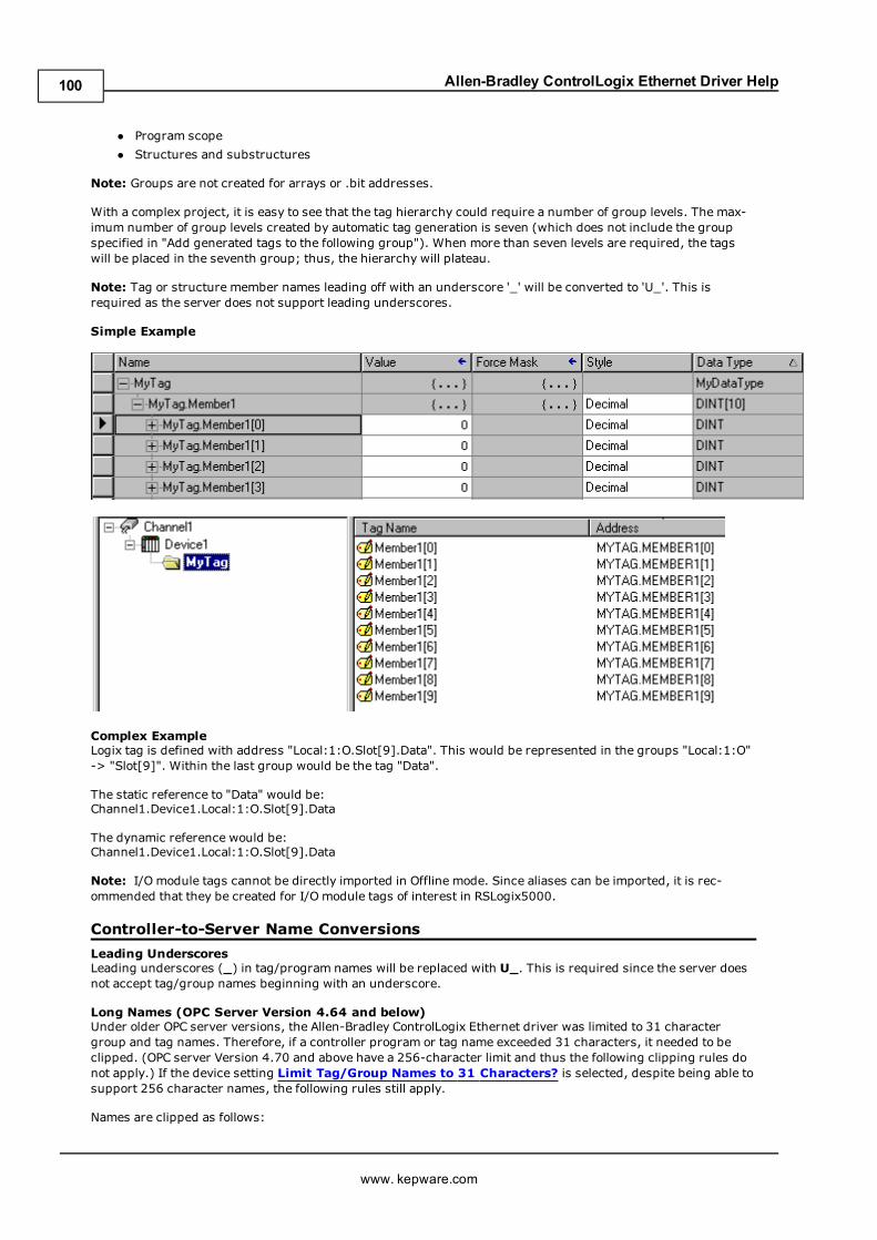
Allen-Bradley ControlLogix Ethernet Driver Help
l Program scope
l Structures and substructures
Note: Groups are not created for arrays or .bit addresses.
With a complex project, it is easy to see that the tag hierarchy could require a number of group levels. The max-imum number of group levels created by automatic tag generation is seven (which does not include the groupspecified in "Add generated tags to the following group"). When more than seven levels are required, the tagswill be placed in the seventh group; thus, the hierarchy will plateau.
Note: Tag or structure member names leading off with an underscore '_' will be converted to 'U_'. This isrequired as the server does not support leading underscores.
Simple Example
Complex ExampleLogix tag is defined with address "Local:1:O.Slot[9].Data". This would be represented in the groups "Local:1:O"-> "Slot[9]". Within the last group would be the tag "Data".
The static reference to "Data" would be:Channel1.Device1.Local:1:O.Slot[9].Data
The dynamic reference would be:Channel1.Device1.Local:1:O.Slot[9].Data
Note: I/O module tags cannot be directly imported in Offline mode. Since aliases can be imported, it is rec-ommended that they be created for I/O module tags of interest in RSLogix5000.
Controller-to-Server Name Conversions
Leading UnderscoresLeading underscores (_) in tag/program names will be replaced with U_. This is required since the server doesnot accept tag/group names beginning with an underscore.
Long Names (OPC Server Version 4.64 and below)Under older OPC server versions, the Allen-Bradley ControlLogix Ethernet driver was limited to 31 charactergroup and tag names. Therefore, if a controller program or tag name exceeded 31 characters, it needed to beclipped. (OPC server Version 4.70 and above have a 256-character limit and thus the following clipping rules donot apply.) If the device setting Limit Tag/Group Names to 31 Characters? is selected, despite being able tosupport 256 character names, the following rules still apply.
Names are clipped as follows:
www. kepware.com
100
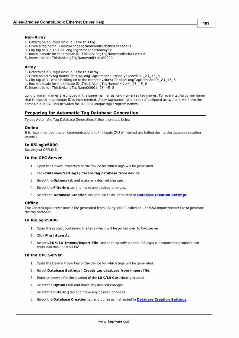
Allen-Bradley ControlLogix Ethernet Driver Help
Non-Array1. Determine a 5-digit Unique ID for this tag.2. Given a tag name: ThisIsALongTagNameAndProbablyExceeds313. Clip tag at 31: ThisIsALongTagNameAndProbablyEx4. Room is made for the Unique ID: ThisIsALongTagNameAndProba#####5. Insert this id: ThisIsALongTagNameAndProba00000
Array1. Determine a 5-digit Unique ID for this array.2. Given an array tag name: ThisIsALongTagNameAndProbablyExceeds31_23_45_83. Clip tag at 31 while holding on to the element values: ThisIsALongTagNameAndPr_23_45_84. Room is made for the Unique ID: ThisIsALongTagName#####_23_45_85. Insert this id: ThisIsALongTagName00001_23_45_8
Long program names are clipped in the samemanner as long non-array tag names. For every tag/program namethat is clipped, the Unique ID is incremented. Array tag names (elements) of a clipped array name will have thesame Unique ID. This provides for 100000 unique tag/program names.
Preparing for Automatic Tag Database Generation
To use Automatic Tag Database Generation, follow the steps below.
OnlineIt is recommended that all communications to the Logix CPU of interest are halted during the database creationprocess.
In RSLogix5000Set project OFFLINE.
In the OPC Server
1. Open the Device Properties of the device for which tags will be generated.
2. Click Database Settings | Create tag database from device.
3. Select theOptions tab and make any desired changes.
4. Select the Filtering tab and make any desired changes.
5. Select the Database Creation tab and utilize as instructed in Database Creation Settings.
OfflineThe ControlLogix driver uses a file generated from RSLogix5000 called an L5K/L5X import/export file to generatethe tag database.
In RSLogix5000
1. Open the project containing the tags which will be ported over to OPC server.
2. Click File | Save As.
3. Select L5K/L5X Import/Export File and then specify a name. RSLogix will export the project's con-tents into this L5K/L5X file.
In the OPC Server
1. Open the Device Properties of the device for which tags will be generated.
2. Select Database Settings | Create tag database from import file.
3. Enter or browse for the location of the L5K/L5X previously created.
4. Select theOptions tab and make any desired changes.
5. Select the Filtering tab and make any desired changes.
6. Select the Database Creation tab and utilize as instructed in Database Creation Settings.
www. kepware.com
101
Allen-Bradley ControlLogix Ethernet Driver Help
Note: Imported pre-defined tag types are based on the latest version supported by this driver. For more infor-mation, refer to Firmware Versions.
www. kepware.com
102
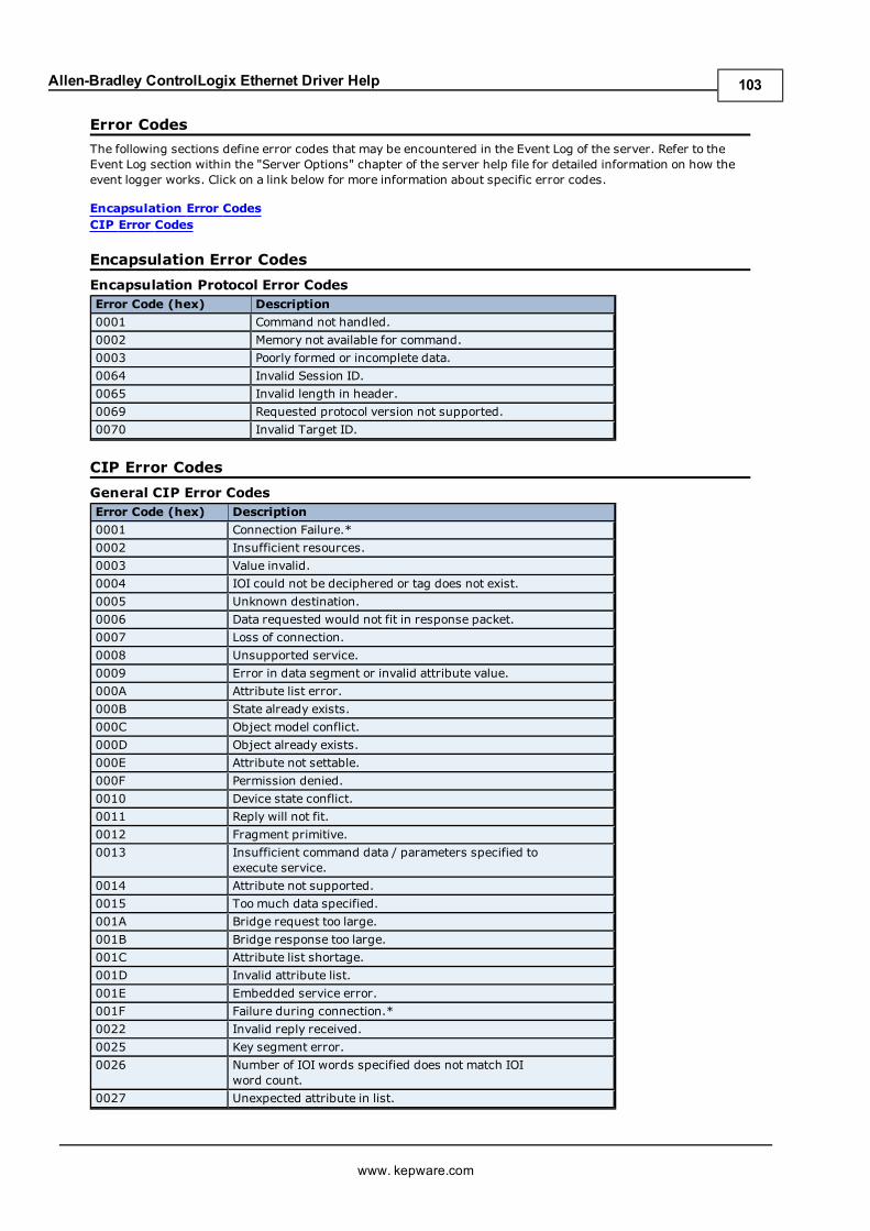
Allen-Bradley ControlLogix Ethernet Driver Help
Error Codes
The following sections define error codes that may be encountered in the Event Log of the server. Refer to theEvent Log section within the "Server Options" chapter of the server help file for detailed information on how theevent logger works. Click on a link below for more information about specific error codes.
Encapsulation Error CodesCIP Error Codes
Encapsulation Error Codes
Encapsulation Protocol Error CodesError Code (hex) Description
0001 Command not handled.
0002 Memory not available for command.
0003 Poorly formed or incomplete data.
0064 Invalid Session ID.
0065 Invalid length in header.
0069 Requested protocol version not supported.
0070 Invalid Target ID.
CIP Error Codes
General CIP Error CodesError Code (hex) Description
0001 Connection Failure.*
0002 Insufficient resources.
0003 Value invalid.
0004 IOI could not be deciphered or tag does not exist.
0005 Unknown destination.
0006 Data requested would not fit in response packet.
0007 Loss of connection.
0008 Unsupported service.
0009 Error in data segment or invalid attribute value.
000A Attribute list error.
000B State already exists.
000C Object model conflict.
000D Object already exists.
000E Attribute not settable.
000F Permission denied.
0010 Device state conflict.
0011 Reply will not fit.
0012 Fragment primitive.
0013 Insufficient command data / parameters specified toexecute service.
0014 Attribute not supported.
0015 Toomuch data specified.
001A Bridge request too large.
001B Bridge response too large.
001C Attribute list shortage.
001D Invalid attribute list.
001E Embedded service error.
001F Failure during connection.*
0022 Invalid reply received.
0025 Key segment error.
0026 Number of IOI words specified does not match IOIword count.
0027 Unexpected attribute in list.
www. kepware.com
103
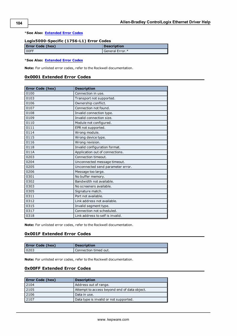
Allen-Bradley ControlLogix Ethernet Driver Help
*See Also: Extended Error Codes
Logix5000-Specific (1756-L1) Error CodesError Code (hex) Description
00FF General Error.*
*See Also: Extended Error Codes
Note: For unlisted error codes, refer to the Rockwell documentation.
0x0001 Extended Error Codes
Error Code (hex) Description
0100 Connection in use.
0103 Transport not supported.
0106 Ownership conflict.
0107 Connection not found.
0108 Invalid connection type.
0109 Invalid connection size.
0110 Module not configured.
0111 EPR not supported.
0114 Wrong module.
0115 Wrong device type.
0116 Wrong revision.
0118 Invalid configuration format.
011A Application out of connections.
0203 Connection timeout.
0204 Unconnected message timeout.
0205 Unconnected send parameter error.
0206 Message too large.
0301 No buffer memory.
0302 Bandwidth not available.
0303 No screeners available.
0305 Signature match.
0311 Port not available.
0312 Link address not available.
0315 Invalid segment type.
0317 Connection not scheduled.
0318 Link address to self is invalid.
Note: For unlisted error codes, refer to the Rockwell documentation.
0x001F Extended Error Codes
Error Code (hex) Description
0203 Connection timed out.
Note: For unlisted error codes, refer to the Rockwell documentation.
0x00FF Extended Error Codes
Error Code (hex) Description
2104 Address out of range.
2105 Attempt to access beyond end of data object.
2106 Data in use.
2107 Data type is invalid or not supported.
www. kepware.com
104
Allen-Bradley ControlLogix Ethernet Driver Help
Note: For unlisted error codes, refer to the Rockwell documentation.
www. kepware.com
105
Allen-Bradley ControlLogix Ethernet Driver Help
Error Descriptions
The following is a list of sub type error topics. Click on a link for more information about that specific error mes-sage.
Address Validation ErrorsCommunication ErrorsDevice Specific Error MessagesControlLogix Specific Error MessagesENI/DH+/ControlNet Gateway Specific Error MessagesAutomatic Tag Database Generation Errors
Address Validation Errors
The following is a list of sub type error topics. Click on a link for more information about that specific error mes-sage.
Address ValidationMissing addressDevice address '<address>' contains a syntax errorAddress '<address>' is out of range for the specified device or registerDevice address '<address>' is not supported by model '<model name>'Data Type '<type>' is not valid for device address '<address>'Device address '<address>' is Read OnlyArray size is out of range for address '<address>'Array support is not available for the specified address: '<address>'Memory could not be allocated for tag with address '<address>' on device '<device name>'
Missing address
Error Type:Warning
Possible Cause:A tag address that has been specified statically has no length.
Solution:Re-enter the address in the client application.
Device address '<address>' contains a syntax error
Error Type:Warning
Possible Cause:A tag address that has been specified statically contains one or more of the following errors.
1. Address doesn't conform to the tag address naming conventions.2. Address is invalid according to the address format and underlying controller tag data type.3. A program tag was specified incorrectly.4. An invalid address format was used.
Solution:Re-enter the address in the client application.
See Also:Entering Tag Names & AddressesAddressing Atomic Data TypesTag AddressingAddress Formats
Address '<address>' is out of range for the specified device or register
Error Type:Warning
www. kepware.com
106
Allen-Bradley ControlLogix Ethernet Driver Help
Possible Cause:A tag address that has been specified statically references a location that is beyond the range of the device's sup-ported locations.
Solution:Verify that the address is correct; if it is not, re-enter it in the client application.
Note:For valid bit and array element ranges, refer to Address Formats.
Device address '<address>' is not supported by model '<model name>'
Error Type:Warning
Possible Cause:A tag address that has been specified statically references a location that is valid for the communications protocolbut not supported by the target device.
Solution:Verify the address is correct; if it is not, re-enter it in the client application. Also verify that the selected modelname for the device is correct.
Data Type '<type>' is not valid for device address '<address>'
Error Type:Warning
Possible Cause:A tag address that has been specified statically has been assigned an invalid data type.
Solution:Modify the requested data type in the client application.
Device address '<address>' is Read Only
Error Type:Warning
Possible Cause:A tag address that has been specified statically has a requested access mode that is not compatible with what thedevice supports for that address.
Solution:Change the access mode in the client application.
Array size is out of range for address '<address>'
Error Type:Warning
Possible Cause:A tag address that has been specified statically is requesting an array size that is too large.
Solution:Specify a smaller value for the array or a different starting point by re-entering the address in the client appli-cation.
Note:For valid array size ranges, refer to Address Formats.
Array support is not available for the specified address: '<address>'
Error Type:
www. kepware.com
107
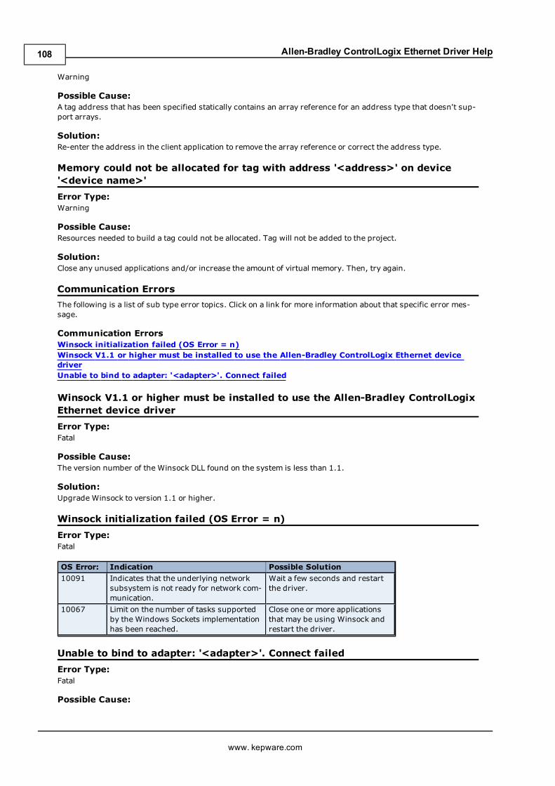
Allen-Bradley ControlLogix Ethernet Driver Help
Warning
Possible Cause:A tag address that has been specified statically contains an array reference for an address type that doesn't sup-port arrays.
Solution:Re-enter the address in the client application to remove the array reference or correct the address type.
Memory could not be allocated for tag with address '<address>' on device'<device name>'
Error Type:Warning
Possible Cause:Resources needed to build a tag could not be allocated. Tag will not be added to the project.
Solution:Close any unused applications and/or increase the amount of virtual memory. Then, try again.
Communication Errors
The following is a list of sub type error topics. Click on a link for more information about that specific error mes-sage.
Communication ErrorsWinsock initialization failed (OS Error = n)Winsock V1.1 or higher must be installed to use the Allen-Bradley ControlLogix Ethernet devicedriverUnable to bind to adapter: '<adapter>'. Connect failed
Winsock V1.1 or higher must be installed to use the Allen-Bradley ControlLogixEthernet device driver
Error Type:Fatal
Possible Cause:The version number of the Winsock DLL found on the system is less than 1.1.
Solution:Upgrade Winsock to version 1.1 or higher.
Winsock initialization failed (OS Error = n)
Error Type:Fatal
OS Error: Indication Possible Solution
10091 Indicates that the underlying networksubsystem is not ready for network com-munication.
Wait a few seconds and restartthe driver.
10067 Limit on the number of tasks supportedby the Windows Sockets implementationhas been reached.
Close one or more applicationsthat may be using Winsock andrestart the driver.
Unable to bind to adapter: '<adapter>'. Connect failed
Error Type:Fatal
Possible Cause:
www. kepware.com
108
Allen-Bradley ControlLogix Ethernet Driver Help
The driver was unable to bind to the specified network adapter, which is necessary for communications with thedevice.
Reasons:1. Adapter is disabled or no longer exists.2. Network system failure, such as Winsock or network adapter failure.3. No more available ports.
Solution:1. For network adapters available on the system, check the Channel Properties | Network Interface | NetworkAdapter list in the communications server application. If '<adapter>' is not in this list, steps should be taken tomake it available to the system. This includes verifying that the network connection is enabled and connected inthe PC's Network Connections.
2. Determine how many channels are using the same '<adapter>' in the communications server application.Reduce this number so that only one channel is referencing '<adapter>'. If the error still occurs, check to see ifother applications are using that adapter and shut down those applications.
Device Specific Error Messages
The following is a list of device specific error topics. Click on a link for more information about that specific errormessage.
Device Specific Error MessagesDevice '<device name>' is not respondingEncapsulation error occurred during a request to device '<device name>'. [Encap. Error=<code>]Error occurred during a request to device '<device name>'. [CIP Error=<code>, Ext. Error=<code>]Frame received from device '<device name>' contains errors
Device '<device name>' is not responding
Error Type:Warning
Possible Cause:1. The Ethernet connection between the device and the Host PC is broken.2. The communications parameters for the Ethernet connection are incorrect.3. The named device may have been assigned an incorrect IP address.
Solution:1. Verify the cabling between the PC and the device.2. Verify that the correct port is specified for the named device.3. Verify that the IP address given to the named device matches that of the actual device.
Encapsulation error occurred during a request to device '<device name>'.[Encap. Error=<code>]
Error Type:Warning
Possible Cause:Device '<device name>' returned an error within the Encapsulation portion of the Ethernet/IP packet during arequest. All reads and writes within the request are failed.
Solution:The driver will attempt to recover from such an error but if the problem persists contact Technical Support withthe encapsulation error (except for error 0x02 which is device related, not driver related.)
See Also:Encapsulation Error Codes
Error occurred during a request to device '<device name>'. [CIPError=<code>, Ext. Error=<code>]
Error Type:
www. kepware.com
109
Allen-Bradley ControlLogix Ethernet Driver Help
Warning
Possible Cause:Device '<device name>' returned an error within the CIP portion of the Ethernet/IP packet during a request. Allreads and writes within the request are failed.
Solution:The solution depends on the error code(s) returned.
See Also:CIP Error Codes
Frame received from device '<device name>' contains errors
Error Type:Warning
Possible Cause:1. Misalignment of packets due to connection/disconnection between PC and device.2. Bad cabling connecting the device, causing noise.
Solution:1. Place device on less noisy network if that is the case.2. Increase the request timeout and/or attempts
ControlLogix Specific Error Messages
The following sections pertain to messaging from the ControlLogix driver level source.
ControlLogix Specific Error MessagesRead Errors (Non-Blocking)Read Errors (Blocking)Write ErrorsProject Upload Errors
Read Errors (Non-Blocking)
The following error/warning messages may be generated. Click on the link for a description of the message.
Read Errors (Non-Blocking) Error MessagesRead request for tag '<tag address>' on device '<device name>' failed due to a framing error. TagdeactivatedUnable to read '<tag address>' on device '<device name>'. Tag deactivatedUnable to read tag '<tag address>' on device '<device name>'. [CIP Error=<code>, Ext.Error=<code>]Unable to read tag '<tag address>' on device '<device name>'. Controller tag data type '<type>'unknown. Tag deactivatedUnable to read tag '<tag address>' on device '<device name>'. Data type '<type>' not supported.Tag deactivatedUnable to read tag '<tag address>' on device '<device name>'. Data type '<type>' is illegal for thistag. Tag deactivatedUnable to read tag '<tag address>' on device '<device name>'. Tag does not support multi-elementarrays. Tag deactivated
Read request for tag '<tag address>' on device '<device name>' failed due toa framing error. Tag deactivated
Error Type:Warning
Possible Cause:A read request for the specified tag failed due to one of the following reasons:
1. Incorrect request service code.2. Received more or less bytes than expected.
www. kepware.com
110
Allen-Bradley ControlLogix Ethernet Driver Help
Solution:If this error occurs frequently, there may be an issue with the cabling or the device itself. If the error occursfrequently for a specific tag, contact Technical Support. Increasing the request attempts will also give the drivermore opportunities to recover from this error. In response to this error, the tag will be deactivated; thus, it willnot be processed again.
Unable to read '<tag address>' on device '<device name>'. Tag deactivated
Error Type:Warning
Possible Cause:1. The Ethernet connection between the device and the Host PC is broken.2. The communication parameters for the Ethernet connection are incorrect.3. The named device may have been assigned an incorrect IP address.
Solution:1. Verify the cabling between the PC and the device.2. Verify that the correct port has been specified for the named device.3. Verify that the IP address given to the named device matches that of the actual device.
Note:In response to this error, the tag will be deactivated and will not be processed again.
Unable to read tag '<tag address>' on device '<device name>'. [CIPError=<code>, Ext. Error=<code>]
Error Type:Warning
Possible Cause:Device '<device name>' returned an error within the CIP portion of the Ethernet/IP packet during a read requestfor tag '<tag address>'.
Solution:The solution depends on the error code(s) returned.
See Also:CIP Error Codes
Unable to read tag '<tag address>' on device '<device name>'. Controller tagdata type '<type>' unknown. Tag deactivated
Error Type:Warning
Possible Cause:A read request for the specified tag failed because the controller's tag data type is not currently supported.
Solution:Contact Technical Support so that support may be added for this type. In response to this error, the tag will bedeactivated; thus, it will not be processed again.
Unable to read tag '<tag address>' on device '<device name>'. Data type'<type>' not supported. Tag deactivated
Error Type:Warning
Possible Cause:A read request for the specified tag failed because the client's tag data type is not supported.
Solution:
www. kepware.com
111
Allen-Bradley ControlLogix Ethernet Driver Help
Change the tag's data type to one that is supported. In response to this error, the tag will be deactivated; thus, itwill not be processed again.
See Also:Addressing Atomic Data Types
Unable to read tag '<tag address>' on device '<device name>'. Data type'<type>' is illegal for this tag. Tag deactivated
Error Type:Warning
Possible Cause:A read request for the specified tag failed because the client's tag data type is illegal for the given controller tag.
Solution:Change the tag's data type to one that is supported. For example, data type Short is illegal for a BOOL array con-troller tag. Changing the data type to Boolean would remedy this problem. In response to this error, the tag willbe deactivated; thus, it will not be processed again.
See Also:Addressing Atomic Data Types
Unable to read tag '<tag address>' on device '<device name>'. Tag does notsupport multi-element arrays. Tag deactivated
Error Type:Warning
Possible Cause:A read request for the specified tag failed because the driver does not support multi-element array access to thegiven controller tag.
Solution:Change the tag's data type or address to one that is supported. In response to this error, the tag will be deac-tivated; thus, it will not be processed again.
See Also:Addressing Atomic Data Types
Read Errors (Blocking)
The following error/warning messagesmay be generated. Click on the link for a description of the message.
Read Errors (Blocking) Error MessagesRead request for '<count>' element(s) starting at '<tag address>' on device '<device name>'failed due to a framing error. Block DeactivatedUnable to read '<count>' element(s) starting at '<tag address>' on device '<device name>'. BlockDeactivatedUnable to read '<count>' element(s) starting at '<tag address>' on device '<device name>'. [CIPError=<code>, Ext. Error=<code>]Unable to read '<count>' element(s) starting at '<tag address>' on device '<device name>'. Con-troller tag data type '<type>' unknown. Block DeactivatedUnable to read '<count>' element(s) starting at '<tag address>' on device '<device name>'. Datatype '<type>' not supported. Block DeactivatedUnable to read '<count>' element(s) starting at '<tag address>' on device '<device name>'. Datatype '<type>' is illegal for this block. Block DeactivatedUnable to read '<count>' element(s) starting at '<tag address>' on device '<device name>'. Blockdoes not support multi-element arrays. Block Deactivated
Read request for '<count>' element(s) starting at '<tag address>' on device'<device name>' failed due to a framing error. Block Deactivated
Error Type:
www. kepware.com
112
Allen-Bradley ControlLogix Ethernet Driver Help
Warning
Possible Cause:A read request for tags <tag address> to <tag address>+<count> failed due to one of the following reasons:
1. Incorrect request service code.2. Received more or less bytes than expected.
Solution:If this error occurs frequently, there may be an issue with the cabling or the device itself. If the error occursfrequently for a specific tag, contact Technical Support. Increasing the request attempts will also give the drivermore opportunities to recover from this error. In response to this error, <count> elements of the block will bedeactivated; thus, it will not be processed again.
Unable to read '<count>' element(s) starting at '<tag address>' on device'<device name>'. Block Deactivated
Error Type:Warning
Possible Cause:1. The Ethernet connection between the device and the Host PC is broken.2. The communication parameters for the Ethernet connection are incorrect.3. The named device may have been assigned an incorrect IP address.
Solution:1. Verify the cabling between the PC and the device.2. Verify that the correct port has been specified for the named device.3. Verify that the IP address given to the named device matches that of the actual device.
Note:In response to this error, <count> elements of the block will be deactivated; thus, it will not be processed again.
Unable to read '<count>' element(s) starting at '<tag address>' on device'<device name>'. [CIP Error=<code>, Ext. Error=<code>]
Error Type:Warning
Possible Cause:Device '<device name>' returned an error within the CIP portion of the Ethernet/IP packet during a read requestfor tag '<tag address>'.
Solution:The solution depends on the error code(s) returned.
See Also:CIP Error Codes
Unable to read '<count>' element(s) starting at '<address>' on device'<device>'. Controller tag data type '<type>' unknown. Block deactivated
Error Type:Warning
Possible Cause:A read request for tags <tag address> to <tag address>+<count>, failed because the controller's tag data typeis not currently supported.
Solution:Contact Technical Support so that support may be added for this type. In response to this error, <count> ele-ments of the block will be deactivated; thus, it will not be processed again.
www. kepware.com
113
Allen-Bradley ControlLogix Ethernet Driver Help
Unable to read '<count>' element(s) starting at '<address>' on device'<device>'. Data type '<type>' not supported
Error Type:Warning
Possible Cause:A read request for tags <tag address> to <tag address>+<count> failed because the client's tag data type isnot supported.
Solution:Change the data type for tags within this block to one that is supported. In response to this error, <count> ele-ments of the block will be deactivated; thus, it will not be processed again.
See Also:Addressing Atomic Data Types
Unable to read '<count>' element(s) starting at '<address>' on device'<device>'. Data type '<type>' is illegal for this block
Error Type:Warning
Possible Cause:A read request for tags <tag address> to <tag address>+<count>, failed because the client's tag data type isillegal for the given controller tag.
Solution:Change the data type for tags within this block to one that is supported. For example, data type Short is illegal fora BOOL array controller tag. Changing the data type to Boolean would remedy this problem. In response to thiserror, <count> elements of the block will be deactivated; thus, it will not be processed again.
See Also:Addressing Atomic Data Types
Unable to read '<count>' element(s) starting at '<tag address>' on device'<device name>'. Block does not support multi-element arrays. Block Deac-tivated
Error Type:Warning
Possible Cause:A read request for tags <tag address> to <tag address>+<count>, failed because the driver does not supportmulti-element array access to the given controller tag.
Solution:Change the data type or address for tags within this block to one that is supported. In response to this error,<count> elements of the block will be deactivated; thus, it will not be processed again.
See Also:Addressing Atomic Data Types
Write Errors
The following error/warning messages may be generated. Click on the link for a description of the message.
Write ErrorsWrite request for tag '<tag address>' on device '<device name>' failed due to a framing errorUnable to write to '<tag address>' on device '<device name>'Unable to write to tag '<tag address>' on device '<device name>'. [CIP Error=<code>, Ext. Stat-us=<code>]
www. kepware.com
114
Allen-Bradley ControlLogix Ethernet Driver Help
Unable to write to tag '<tag address>' on device '<device name>'. Controller tag data type'<type>' unknownUnable to write to tag '<tag address>' on device '<device name>'. Data type '<type>' not sup-portedUnable to write to tag '<tag address>' on device '<device name>'. Data type '<type>' is illegal forthis tagUnable to write to tag '<tag address>' on device '<device name>'. Tag does not support multi-ele-ment arrays
Write request for tag '<tag address>' on device '<device name>' failed due toa framing error
Error Type:Warning
Possible Cause:A write request for the specified tag failed after so many retries due to one of the following reasons:
1. Incorrect request service code.2. Received more or less bytes than expected.
Solution:If this error occurs frequently, there may be an issue with the cabling or the device itself. Increasing the RetryAttempts will also give the driver more opportunities to recover from this error.
Unable to write to '<tag address>' on device '<device name>'
Error Type:Warning
Possible Cause:1. The Ethernet connection between the device and the Host PC is broken.2. The communication parameters for the Ethernet connection are incorrect.3. The named device may have been assigned an incorrect IP address.
Solution:1. Verify the cabling between the PC and the device.2. Verify that the correct port has been specified for the named device.3. Verify that the IP address given to the named device matches that of the actual device.
Unable to write to tag '<tag address>' on device '<device name>'. [CIPError=<code>, Ext. Status=<code>]
Error Type:Warning
Possible Cause:Device '<device name>' returned an error within the CIP portion of the Ethernet/IP packet during a write requestfor tag '<tag address>'.
Solution:The solution depends on the error code(s) returned.
See Also:CIP Error Codes
Unable to write to tag '<tag address>' on device '<device name>'. Controllertag data type '<type>' unknown
Error Type:Warning
Possible Cause:A write request for the specified tag failed because the controller's tag data type is not currently supported.
www. kepware.com
115
Allen-Bradley ControlLogix Ethernet Driver Help
Solution:Contact Technical Support so that support may be added for this type.
Unable to write to tag '<tag address>' on device '<device name>'. Data type'<type>' not supported
Error Type:Warning
Possible Cause:A write request for the specified tag failed because the client's tag data type is not supported.
Solution:Change the tag's data type to one that is supported.
See Also:Addressing Atomic Data Types
Unable to write to tag '<tag address>' on device '<device name>'. Data type'<type>' is illegal for this tag
Error Type:Warning
Possible Cause:A write request for the specified tag failed because the client's tag data type is illegal for the given controller tag.
Solution:Change the tag's data type to one that is supported. For example, data type Short is illegal for a BOOL array con-troller tag. Changing the data type to Boolean would remedy this problem.
See Also:Addressing Atomic Data Types
Unable to write to tag '<tag address>' on device '<device name>'. Tag doesnot support multi-element arrays
Error Type:Warning
Possible Cause:A write request for the specified tag failed because the driver does not support multi-element array access to thegiven controller tag.
Solution:Change the tag's data type or address to one that is supported.
See Also:Addressing Atomic Data Types
Project Upload Errors
A project upload is required for the Physical Addressing modes. Without it, the driver does not have the infor-mation necessary to perform Physical Addressing reads/writes. Each error below is preceded with the following:
"The following error(s) occurred uploading controller project from device '<device name>'. Resorting to sym-bolic addressing."
Project Upload ErrorsLow memory resourcesInvalid or corrupt controller projectEncapsulation error occurred while uploading project information. [Encap. Error=<code>]Error occurred while uploading project information. [CIP Error=<code>, Ext. Error=<code>]Framing error occurred while uploading project information
www. kepware.com
116
Allen-Bradley ControlLogix Ethernet Driver Help
Low memory resources
Error Type:Warning
Possible Cause:Memory required for controller project upload could not be allocated.
Solution:Close any unused applications and/or increase the amount of virtual memory. Then, restart the server and tryagain. A project upload is required for the Physical Addressing modes.
Invalid or corrupt controller project
Error Type:Warning
Possible Cause:The controller project was considered to be invalid or corrupt at the time of the upload.
Solution:Re-download the project to the controller, restart the server and try again. A project upload is required for thePhysical Addressing modes.
Encapsulation error occurred while uploading project information. [Encap.Error=<code>]
Error Type:Warning
Possible Cause:Device '<device name>' returned an error within the Encapsulation portion of the Ethernet/IP packet whileuploading the controller project.
Solution:Solution depends on the error code returned. If the problem persists contact Technical Support with the error. Aproject upload is required for the Physical Addressing modes.
See Also:Encapsulation Error Codes
Error occurred while uploading project information. [CIP Error=<code>, Ext.Error=<code>]
Error Type:Warning
Possible Cause:Device '<device name>' returned an error within the CIP portion of the Ethernet/IP packet while uploading thecontroller project.
Solution:The solution depends on the error code(s) returned. If the problem persists contact Technical Support with theerror. A project upload is required for the Physical Addressing modes.
See Also:CIP Error Codes
Framing error occurred while uploading project information
Error Type:Warning
www. kepware.com
117

Allen-Bradley ControlLogix Ethernet Driver Help
Possible Cause:1. Misalignment of packets due to connection/disconnection between PC and device.2. Bad cabling connecting the device, causing noise.
Solution:1. Place device on less noisy network if that is the case.2. Increase the request timeout and/or attempts3. Restart the server and try again.
Note:A project upload is required for the Physical Addressing modes.
ENI/DH+/ControlNet Gateway Specific Error Messages
The following is a list of sub type error topics. Click on a link for more information about that specific error mes-sage.
ENI/DH+/ControlNet Gateway Specific Error MessagesUnable to read '<block size>' element(s) starting at '<address>' on device '<device name>'. Framereceived contains errorsUnable to read '<block size>' element(s) starting at '<address>' on device '<device name>'. [DF1STS=<value>, EXT STS=<value>]. Tag(s) deactivatedUnable to write to address <address> on device '<device name>'. Frame received contains errorsUnable to write to address <address> on device '<device name>'. [DF1 STS=<value>, EXTSTS=<value>]Device '<device name>' is not responding. Local node responded with error '[DF1 STS=<value>]'Unable to write to address <address> on device '<device name>'. Local node responed with error'[DF1 STS=<value>]'Unable to write to function file <address> on device '<device name>'. Local node responed witherror '[DF1 STS=<value>]'
Unable to read '<block size>' element(s) starting at '<address>' on device'<device name>'. Frame received contains errors
Error Type:Warning
The Error Could Be:1. Incorrect frame size received.2. TNS mismatch.3. Invalid response command returned from device.
Possible Cause:1. Misalignment of packets due to connection/disconnection between PC and device.2. There is bad cabling connecting the devices causing noise.
Solution:The driver will recover from this error without intervention. If this error occurs frequently, there may be an issuewith the cabling or the device itself.
Unable to read '<block size>' element(s) starting at '<address>' on device'<device name>'. [DF1 STS=<value>, EXT STS=<value>]. Tag(s) deactivated
Error Type:Warning
Possible Cause:The address requested in the block does not exist in the PLC.
Solution:Check the status and extended status codes that are being returned by the PLC. Note that an extended statuscode may not always be returned and thus the error information is contained within the status code. The codesare displayed in hexadecimal.
www. kepware.com
118
Allen-Bradley ControlLogix Ethernet Driver Help
Status code errors in the low nibble of the status code indicate errors found by the local node. The driver will con-tinue to retry reading these blocks of data periodically. Errors found by the local node occur when the KF modulecannot see the destination plc on the network for some reason.
Status code errors in the high nibble of the status code indicate errors found by the PLC. These errors are gen-erated when the block of data the driver is asking for is not available in the PLC. The driver will not ask for theseblocks again after receiving this kind of error. This kind of error can be generated if the address does not exist inthe PLC.
Note:The block starting at address <address> may be deactivated in the process depending on the severity of theerror. The error message will state this as it does above.
See Also:A-B documentation for STS and Ext. STS error code definitions.
Unable to write to address <address> on device '<device name>'. Framereceived contains errors
The type of error could be1. Incorrect frame size received.2. TNS mismatch.3. Invalid response command returned from device.
Error Type:Warning
Possible Cause:1. Misalignment of packets due to connection/disconnection between PC and device.2. There is bad cabling connecting the devices causing noise.
Solution:The driver will recover from this error without intervention. If this error occurs frequently, there may be an issuewith the cabling or the device itself.
Unable to write to address <address> on device '<device name>'. '[DF1STS=<value>, EXT STS=<value>]'
Error Type:Warning
Possible Cause:The address written to does not exist in the PLC.
Solution:Check the status and extended status codes that are being returned by the PLC. Note that an extended statuscode may not always be returned and thus the error information is contained within the status code. The codesare displayed in hexadecimal.
Status code errors in the low nibble of the status code indicate errors found by the local node. Errors found bythe local node occur when the KF module cannot see the destination PLC on the network for some reason.
Status code errors in the high nibble of the status code indicate errors found by the PLC. These errors are gen-erated when the data location is not available in the PLC or not write able.
See Also:A-B documentation for STS and Ext. STS error code definitions.
Device '<device name>' is not responding. Local node responded with error'[DF1 STS=<value>]'
Error Type:Warning
Possible Cause:
www. kepware.com
119
Allen-Bradley ControlLogix Ethernet Driver Help
This error means that the PLC did not respond to the read request from the local node. A local node could be anintermediate node like 1756-DHRIO, 1756-CNB, 1761-NET-ENI and and so forth. Refer to A-B documentation forSTS error code definitions.
Solution:Depends on the STS error code. For example, if STS code '0x02'(hex) is returned, verify the cabling between theremote node (PLC) and the local node.
Unable to write to address <address> on device '<device name>'. Local noderesponded with error '[DF1 STS=<value>]'
Error Type:Warning
Possible Cause:This error means that the PLC did not respond to the write request from the local node. A local node could be anintermediate node like 1756-DHRIO, 1756-CNB, 1761-NET-ENI and and so forth. Refer to A-B documentation forSTS error code definitions.
Solution:Depends on the STS error code. For example, if the STS code '0x02'(hex) is returned, verify the cabling betweenthe remote node (PLC) and the local node.
Unable to write to function file <address> on device '<device name>'. Localnode responded with error '[DF1 STS=<value>]'
Error Type:Warning
Possible Cause:This error means that the PLC did not respond to the write request from the local node. A local node could be anintermediate node like 1756-DHRIO, 1756-CNB, 1761-NET-ENI and and so forth. Refer to A-B documentation forSTS error code definitions.
Solution:Depends on the STS error code. For example, if the STS code '0x02'(hex) is returned, verify the cabling betweenthe remote node (PLC) and the local node.
Automatic Tag Database Generation Errors
The following is a list of sub type error topics. Click on a link for more information about that specific error mes-sage.
Automatic Tag Database Generation ErrorsDatabase Error: Array tags '<orig. tag name><dimensions>' exceed 31 characters. Tags renamed to'<new tag name><dimensions>'Database Error: Data type '<type>' for tag '<tag name>' not found in Tag Import file. Tag notaddedDatabase Error: Data type for Ref. Tag '<tag name>' unknown. Setting Alias Tag '<tag name>' datatype to Default ('<type>')Database Error: Error occurred processing Alias Tag '<tag name>'. Tag not addedDatabase Error: Member data type '<type>' for UDT '<UDT name>' not found in Tag Import file. Set-ting to Default Type '<type>'Database Error: Program group '<orig. program name>' exceeds 31 characters. Program grouprenamed to '<new program name>'Database Error: Tag '<orig. tag name>' exceeds 31 characters. Tag renamed to '<new tag name>'Database Error: Unable to resolve CIP data type '<hex value>' for tag '<tag name>'. Setting toDefault Type '<logix data type>'Unable to generate a tag database for device <device name>. Reason: Import file not foundUnable to generate a tag database for device <device name>. Reason: L5K File is invalid or corruptUnable to generate a tag database for device <device name>. Reason: Low memory resources
www. kepware.com
120
Allen-Bradley ControlLogix Ethernet Driver Help
Database Error: Array tags '<orig. tag name><dimensions>' exceed 31 char-acters. Tags renamed to '<new tag name><dimensions>'
Error Type:Warning
Possible Cause:The name assigned to an array tag originates from the tag name in the controller. This name exceeds the 31-char-acter limitation and will be renamed to one that is valid. <Dimensions> define the number of dimensions for thegiven array tag. XXX for 1 dimension, XXX_YYY for 2, XXX_YYY_ZZZ for 3. The number of X's, Y's and Z's approx-imates the number of elements for the respective dimensions. Since such an error will occur for each element,generalizing with XXX, YYY and ZZZ implies all array elements will be affected.
Solution:None.
See Also:Controller-to-Server Name Conversions
Database Error: Data type '<type>' for tag '<tag name>' not found in TagImport file. Tag not added
Error Type:Warning
Possible Cause:The definition of data type '<type>', for tag <tag name>, could not be found in the Tag Import file. Tag will notbe added to the database.
Solution:Contact Technical Support.
Database Error: Data type for Ref. Tag '<tag name>' unknown. Setting AliasTag '<tag name>' data type to Default ('<type>')
Error Type:Warning
Possible Cause:The data type of the "Alias For" *tag referenced in the Alias Tag's declaration could not found in the Tag Importfile. This data type is necessary to generate the alias tag correctly.
Solution:The Alias Tag will take on the default type specified in the Default Type in Device Properties.
Note:In RSLogix5000, "Alias For" is a column in the tag view under the Edit Tags tab. This is where the reference to thetag, structure tag member, or bit that the alias tag will represent is entered.
Database Error: Error occurred processing Alias Tag '<tag name>'. Tag notadded
Error Type:Warning
Possible Cause:An internal error occurred processing alias tag <tag name>. Alias tag could not be generated.
Solution:None.
www. kepware.com
121
Allen-Bradley ControlLogix Ethernet Driver Help
Database Error: Member data type '<type>' for UDT '<UDT name>' not foundin Tag Import file. Setting to Default Type '<type>'
Error Type:Warning
Possible Cause:The definition of data type '<type>', for a member in the user-defined type <UDT name>, could not be found inthe Tag Import file.
Solution:This member will take on the default type specified in the Default Type in Device Properties.
Database Error: Program group '<orig. program name>' exceeds 31 char-acters. Program group renamed to '<new program name>'
Error Type:Warning
Possible Cause:Each Program is assigned its own group. The name assigned to this group is the Program name. This nameexceeds the 31-character limitation and will be renamed to one that is valid.
Solution:None.
See Also:Controller-to-Server Name Conversions
Database Error: Tag '<orig. tag name>' exceeds 31 characters. Tag renamed to'<new tag name>'
Error Type:Warning
Possible Cause:The name assigned to a tag originates from the tag name in the controller. This name exceeds the 31-characterlimitation and will be renamed to one that is valid.
Solution:None.
See Also:Controller-to-Server Name Conversions
Database Error: Unable to resolve CIP data type '<hex value>' for tag '<tagname>'. Setting to Default Type '<logix data type>'
Error Type:Warning
Possible Cause:1. The CIP data type in the import file is unknown.2. The import file may contain an error.
Solution:Resolve any errors in RSLogix. Then, retry the tag export process in order to produce a new tag import file.
See Also:Preparing for Automatic Tag Database Generation
www. kepware.com
122
Allen-Bradley ControlLogix Ethernet Driver Help
Unable to generate a tag database for device <device name>. Reason: Importfile not found
Error Type:Warning
Possible Cause:The file specified as the Tag Import File in the Database Settings Device Properties page cannot be found.
Solution:Select a valid Tag Import file or retry the tag export process in RSLogix to produce a new Tag Import file.
See Also:Automatic Tag Database Generation Preparation
Unable to generate a tag database for device <device name>. Reason: L5K Fileis invalid or corrupt
Error Type:Warning
Possible Cause:The file specified as the Tag Import File in the Database Settings Device Properties page is not an L5K file or is acorrupt L5K file.
Solution:Select a valid L5K file or retry the tag export process in RSLogix to produce a new L5K file.
See Also:Automatic Tag Database Generation Preparation
Unable to generate a tag database for device <device name>. Reason: Lowmemory resources
Error Type:Warning
Possible Cause:Memory required for database generation could not be allocated. The process is aborted.
Solution:Close any unused applications and/or increase the amount of virtual memory. Then, try again.
www. kepware.com
123
Allen-Bradley ControlLogix Ethernet Driver Help
Technical Notes
RSLogix 5000 Project Edit Warning1. Information on downloading a project while clients are connected.2. Information on making online edits while clients are connected.
SoftLogix 5800 Connection Notes1. Information on preventing communication errors.2. Instructions for connecting to a SoftLogix Soft PLC on the same PC as the OPC server.
RSLogix 5000 Project Edit Warning
There are three primary concerns with the Controller project: making online edits, downloading a project whileclients are connected and accessing active tags.
Online EditsThere is no mechanism for detecting and handling project correlation errors resulting from online edits made to aproject.
Caution: If online edits are made while clients are accessing active tags, the Allen-Bradley ControlLogix Ethernetdriver will access incorrect data for tags modified and will not be flagged as invalid. This applies to PhysicalAddressing modes only.
Project DownloadThe Allen-Bradley ControlLogix Ethernet Driver has been designed to monitor for project correlation errors result-ing from downloads. The only caveat is that there must be data access occurring while the download occurs.When a download is detected, the following actions take place:
Symbolic Addressing Mode1. Download occurs and is detected.2. Tags in progress are invalidated.3. During download process, device is polled on a 2 second interval to detect if download is complete.4. Upon download completion, normal tag transactions resume.
Physical Addressing Mode1. Download occurs and is detected.2. Tags in progress are invalidated.3. During download process, device is polled on a 2 second interval to detect if download is complete.4. Upon download completion, tags processed are demoted to Symbolic Addressing Mode.5. 60 seconds after project download, tags are promoted back to Physical Addressing Mode as normal tag trans-actions resume.
Caution: If data access is not occurring on a device while a download occurs, the download operation will not bedetected. This will result in invalid access to the controllers memory. To prevent this, have at least 1 tag access-ing the controller every 500-1000ms so that downloads can be detected and handled properly.
ExampleOnly 1 tag is being accessed on a given device whose scan rate is 10 seconds.Scan x @ time tDownload starts @ time t + 3 secondsDownload finishes @ time t + 8 secondsScan x+1 @ time t + 10
In this example, the download operation is not caught.
SoftLogix 5800 Connection Notes
For proper operation, no Ethernet-based drivers (such as ethernet devices, remote devices via Gateway and andso forth.) should be installed in RSLinx on the SoftLogix PC. It has been shown that with one or more Ethernet-based drivers installed, requests return with CIP Error 0x5 Ext. Error 0x1 and CIP Error 0x8.
Connecting to a SoftLogix Soft PLC on the Same PC as the OPC ServerTo connect the Allen-Bradley ControlLogix Ethernet driver to a SoftLogix Soft PLC running on the same PC as theOPC server, follow the instructions below.
1. Ensure that there are no Ethernet-based drivers currently running in RSLinx on the PC.
2. Verify that the Ethernet/IP Message Module is installed in the SoftLogix virtual chassis.
www. kepware.com
124
Allen-Bradley ControlLogix Ethernet Driver Help
3. Open the OPC server's Device Propeties. In the General tab, locate the Device ID value. It should not be"127.0.0.1, 1, <PLC_CPU_slot>". The Device ID should be set to "<specific_IP_address_of_PC>, 1,<PLC_CPU_slot>".
For example, if the PC's IP address is 192.168.3.4 and the SoftLogix CPU is in slot 2 of the virtual chassis,then the correct Device ID would be: "192.168.3.4, 1, 2".
www. kepware.com
125
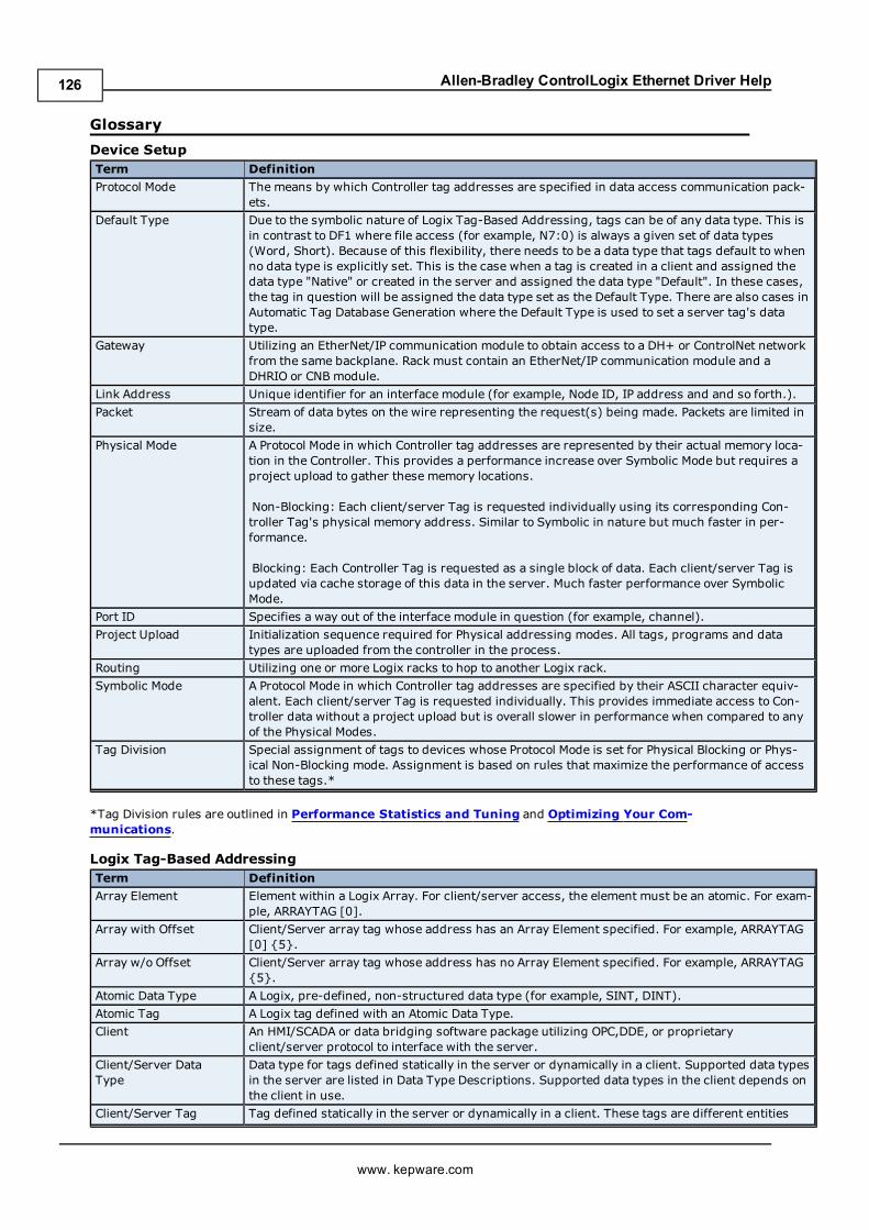
Allen-Bradley ControlLogix Ethernet Driver Help
Glossary
Device SetupTerm Definition
Protocol Mode The means by which Controller tag addresses are specified in data access communication pack-ets.
Default Type Due to the symbolic nature of Logix Tag-Based Addressing, tags can be of any data type. This isin contrast to DF1 where file access (for example, N7:0) is always a given set of data types(Word, Short). Because of this flexibility, there needs to be a data type that tags default to whenno data type is explicitly set. This is the case when a tag is created in a client and assigned thedata type "Native" or created in the server and assigned the data type "Default". In these cases,the tag in question will be assigned the data type set as the Default Type. There are also cases inAutomatic Tag Database Generation where the Default Type is used to set a server tag's datatype.
Gateway Utilizing an EtherNet/IP communication module to obtain access to a DH+ or ControlNet networkfrom the same backplane. Rack must contain an EtherNet/IP communication module and aDHRIO or CNB module.
Link Address Unique identifier for an interface module (for example, Node ID, IP address and and so forth.).
Packet Stream of data bytes on the wire representing the request(s) being made. Packets are limited insize.
Physical Mode A Protocol Mode in which Controller tag addresses are represented by their actual memory loca-tion in the Controller. This provides a performance increase over Symbolic Mode but requires aproject upload to gather these memory locations.
Non-Blocking: Each client/server Tag is requested individually using its corresponding Con-troller Tag's physical memory address. Similar to Symbolic in nature but much faster in per-formance.
Blocking: Each Controller Tag is requested as a single block of data. Each client/server Tag isupdated via cache storage of this data in the server. Much faster performance over SymbolicMode.
Port ID Specifies a way out of the interface module in question (for example, channel).
Project Upload Initialization sequence required for Physical addressing modes. All tags, programs and datatypes are uploaded from the controller in the process.
Routing Utilizing one or more Logix racks to hop to another Logix rack.
Symbolic Mode A Protocol Mode in which Controller tag addresses are specified by their ASCII character equiv-alent. Each client/server Tag is requested individually. This provides immediate access to Con-troller data without a project upload but is overall slower in performance when compared to anyof the Physical Modes.
Tag Division Special assignment of tags to devices whose Protocol Mode is set for Physical Blocking or Phys-ical Non-Blocking mode. Assignment is based on rules that maximize the performance of accessto these tags.*
*Tag Division rules are outlined in Performance Statistics and Tuning and Optimizing Your Com-munications.
Logix Tag-Based AddressingTerm Definition
Array Element Element within a Logix Array. For client/server access, the element must be an atomic. For exam-ple, ARRAYTAG [0].
Array with Offset Client/Server array tag whose address has an Array Element specified. For example, ARRAYTAG[0] {5}.
Array w/o Offset Client/Server array tag whose address has no Array Element specified. For example, ARRAYTAG{5}.
Atomic Data Type A Logix, pre-defined, non-structured data type (for example, SINT, DINT).
Atomic Tag A Logix tag defined with an Atomic Data Type.
Client An HMI/SCADA or data bridging software package utilizing OPC,DDE, or proprietaryclient/server protocol to interface with the server.
Client/Server DataType
Data type for tags defined statically in the server or dynamically in a client. Supported data typesin the server are listed in Data Type Descriptions. Supported data types in the client depends onthe client in use.
Client/Server Tag Tag defined statically in the server or dynamically in a client. These tags are different entities
www. kepware.com
126
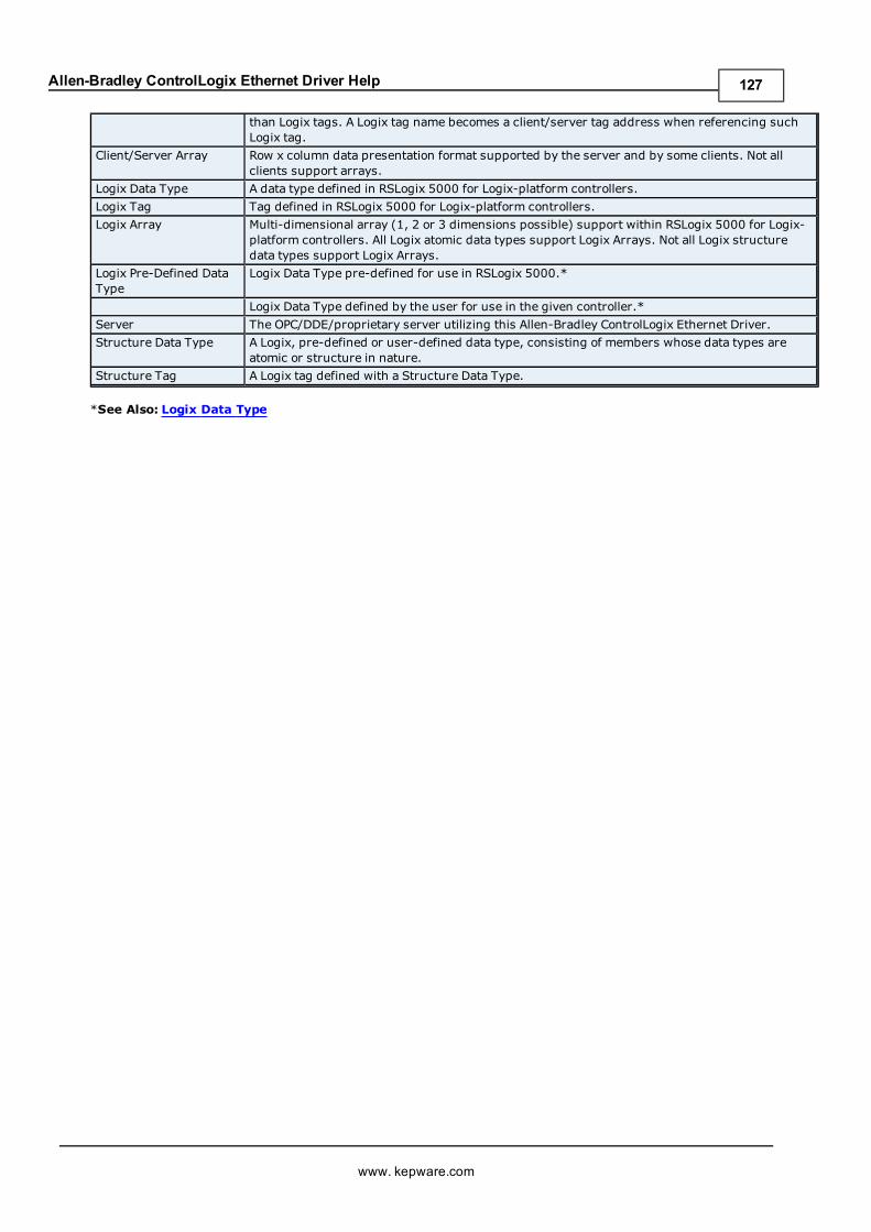
Allen-Bradley ControlLogix Ethernet Driver Help
than Logix tags. A Logix tag name becomes a client/server tag address when referencing suchLogix tag.
Client/Server Array Row x column data presentation format supported by the server and by some clients. Not allclients support arrays.
Logix Data Type A data type defined in RSLogix 5000 for Logix-platform controllers.
Logix Tag Tag defined in RSLogix 5000 for Logix-platform controllers.
Logix Array Multi-dimensional array (1, 2 or 3 dimensions possible) support within RSLogix 5000 for Logix-platform controllers. All Logix atomic data types support Logix Arrays. Not all Logix structuredata types support Logix Arrays.
Logix Pre-Defined DataType
Logix Data Type pre-defined for use in RSLogix 5000.*
Logix Data Type defined by the user for use in the given controller.*
Server The OPC/DDE/proprietary server utilizing this Allen-Bradley ControlLogix Ethernet Driver.
Structure Data Type A Logix, pre-defined or user-defined data type, consisting of members whose data types areatomic or structure in nature.
Structure Tag A Logix tag defined with a Structure Data Type.
*See Also: Logix Data Type
www. kepware.com
127
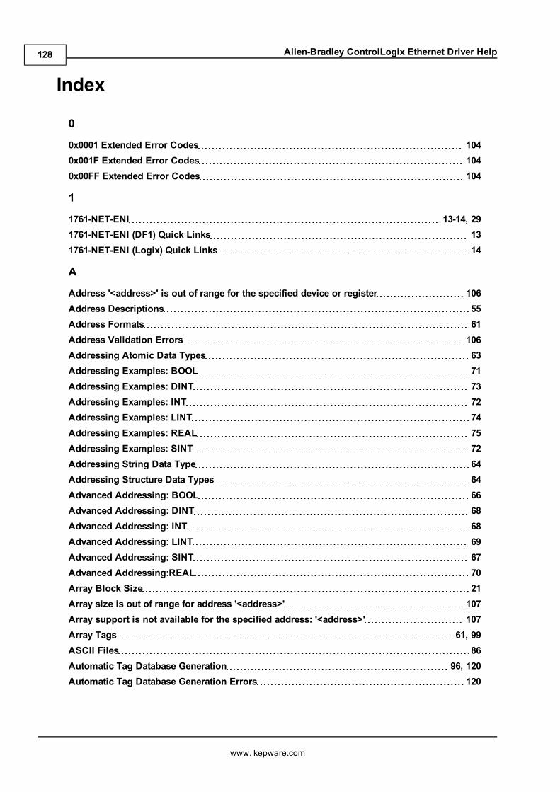
Allen-Bradley ControlLogix Ethernet Driver Help
Index
0
0x0001 Extended Error Codes 1040x001F Extended Error Codes 1040x00FF Extended Error Codes 104
1
1761-NET-ENI 13-14, 291761-NET-ENI (DF1) Quick Links 131761-NET-ENI (Logix) Quick Links 14
A
Address '<address>' is out of range for the specified device or register 106Address Descriptions 55Address Formats 61Address Validation Errors 106Addressing Atomic Data Types 63Addressing Examples: BOOL 71Addressing Examples: DINT 73Addressing Examples: INT 72Addressing Examples: LINT 74Addressing Examples: REAL 75Addressing Examples: SINT 72Addressing String Data Type 64Addressing Structure Data Types 64Advanced Addressing: BOOL 66Advanced Addressing: DINT 68Advanced Addressing: INT 68Advanced Addressing: LINT 69Advanced Addressing: SINT 67Advanced Addressing:REAL 70Array Block Size 21Array size is out of range for address '<address>' 107Array support is not available for the specified address: '<address>' 107Array Tags 61, 99ASCII Files 86Automatic Tag Database Generation 96, 120Automatic Tag Database Generation Errors 120
www. kepware.com
128
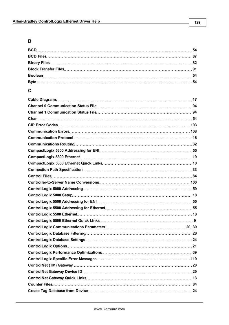
Allen-Bradley ControlLogix Ethernet Driver Help
B
BCD 54BCD Files 87Binary Files 82Block Transfer Files 91Boolean 54Byte 54
C
Cable Diagrams 17Channel 0 Communication Status File 94Channel 1 Communication Status File 94Char 54CIP Error Codes 103Communication Errors 108Communication Protocol 16Communications Routing 32CompactLogix 5300 Addressing for ENI 55CompactLogix 5300 Ethernet 19CompactLogix 5300 Ethernet Quick Links 10Connection Path Specification 33Control Files 84Controller-to-Server Name Conversions 100ControlLogix 5000 Addressing 59ControlLogix 5000 Setup 18ControlLogix 5500 Addressing for ENI 55ControlLogix 5500 Addressing for Ethernet 55ControlLogix 5500 Ethernet 18ControlLogix 5500 Ethernet Quick Links 9ControlLogix Communications Parameters 20, 30ControlLogix Database Filtering 26ControlLogix Database Settings 24ControlLogix Options 21ControlLogix Performance Optimizations 39ControlLogix Specific Error Messages 110ControlNet (TM) Gateway 28ControlNet Gateway Device ID 29ControlNet Gateway Quick Links 13Counter Files 84Create Tag Database from Device 24
www. kepware.com
129
Allen-Bradley ControlLogix Ethernet Driver Help
Create Tag Database from Import File 24
D
Data Type '<type>' is not valid for device address '<address>' 107Data Types Description 54Database Creation Settings 96Database Error: Array tags '<orig. tag name><dimensions>' exceed 31 characters. Tagsrenamed to '<new tag name><dimensions>'
121
Database Error: Data type '<type>' for tag '<tag name>' not found in Tag Import file. Tagnot added
121
Database Error: Data type for Ref. Tag '<tag name>' unknown. Setting Alias Tag '<tagname>' data type to Default ('<type>')
121
Database Error: Error occurred processing Alias Tag '<tag name>'. Tag not added 121Database Error: Member data type '<type>' for UDT '<UDT name>' not found in TagImport file. Setting to Default Type '<type>'
122
Database Error: Program group '<orig. program name>' exceeds 31 characters. Programgroup renamed to '<new program name>'
122
Database Error: Tag '<orig. tag name>' exceeds 31 characters. Tag renamed to '<new tagname>'
122
Database Error: Unable to resolve CIP data type '<hex value>' for tag '<tag name>'. Settingto Default Type '<logix data type>'
122
DataHighwayPlus (TM) Gateway Setup 27Device '<device name>' is not responding 109Device '<device name>' is not responding. Local node responded with error '[DF1STS=<value>]'
119
Device address '<address>' contains a syntax error 106Device address '<address>' is not supported by model '<model name>' 107Device address '<address>' is Read Only 107Device ID 18-20Device Setup 16-17Device Setup Terminology 17Device Specific Error Messages 109DH+ Gateway Device ID 28Display Descriptions 24DWord 54
E
Encapsulation Error Codes 103Encapsulation error occurred during a request to device '<device name>'. [Encap.Error=<code>]
109
Encapsulation error occurred while uploading project information. [Encap. Error <code>] 117ENI Device ID 30ENI DF1/DH+/ControlNet Gateway Communications Parameters 26
www. kepware.com
130
Allen-Bradley ControlLogix Ethernet Driver Help
ENI/DH+/ControlNet Gateway Specific Error Messages 118Error Codes 103Error Descriptions 106Error occurred during a request to device '<device name>'. [CIP Error=<code>, Ext.Error=<code>]
109
Error occurred while uploading project information. [CIP Error=<code>, Ext.Error=<code>]
117
F
File Listing 76FlexLogix 5400 Addressing for ENI 56FlexLogix 5400 Addressing for Ethernet 56FlexLogix 5400 Ethernet 19FlexLogix 5400 Ethernet Quick Links 11Float 54, 85Float Files 85Frame received from device '<device name>' contains errors 110Framing error occurred while uploading project information 117Function File Listing 92
G
Gateway Quick Links 12Global Tags 62Glossary 126
H
Help Contents 8High Speed Counter File (HSC) 92
I
I/O Module Statis File (IOS) 95Inactivity Watchdog 20Input Files 79Integer Files 85Introduction 60Invalid or corrupt controller project 117
L
LBCD 54Leading Underscores 100Link Address 33Logix Address Syntax 61
www. kepware.com
131
Allen-Bradley ControlLogix Ethernet Driver Help
Logix Address Usage 63Logix Addressing 59Logix Addressing Examples 71Logix Addresssing Terminology 60Logix Advanced Addressing 66Logix Communications Parameters 20Logix Data Types 76Logix Database Filtering 26Logix Database Options 25Logix Database Settings 24Logix Options 21Logix Setup 18Logix Tag-Based Addressing 59Long 54Long Controller Program & Tag Names 96Long Files 87Low memory resources 117
M
Memory could not be allocated for tag with address '<address>' on device '<devicename>'
108
Message Files 91Micrologix 1100 14, 31Micrologix 1100 Addressing 58MicroLogix 1100 Communications Parameters 31Micrologix 1100 Device ID 31MicroLogix 1100 Ethernet Quick Links 14MicroLogix 1100 Setup 30MicroLogix 1400 Addressing 59MicroLogix Addressing for ENI 58MicroLogix Message Files 90MicroLogix PID Files 88Missing address 106
N
Non-Blocking 110
O
Online Edits 124Optimizing Your Application 41Optimizing Your Communications 39Ordering of Logix Array Data 65
www. kepware.com
132
Allen-Bradley ControlLogix Ethernet Driver Help
Output Files 76Overview 8
P
Performance Statistics and Tuning 42Performance Tuning Example 43PID Files 89PLC-5 Series Addressing for ControlNet 57PLC-5 Series Addressing for DH+ 57PLC-5 Series Addressing for ENI 57Port ID 33Port Number 20Port Reference 36Pre-Defined Data Types 76Preparing for Automatic Tag Database Generation 101Program Tags 62Project Correlation Error 124Project Download 124Project Upload Errors 116
Q
Quick Links 9
R
Read Errors 110, 112Read request for '<count>' element(s) starting at '<address>' on device '<device>' faileddue to a framing error. Block deactivated
112
Read request for tag '<tag address>' on device '<device name>' failed due to a framingerror. Tag deactivated
110
Real-Time Clock File (RTC) 93Routing Examples 33RSLogix 5000 Project Edit Warning 124
S
Short 54SLC 500 Fixed I/O Addressing for ENI 57SLC 500 Modular I/O Addressing for DH+ 56SLC 500 Modular I/O Addressing for ENI 56SLC 500 Modular I/O Selection Guide 36SLC 500 Slot Configuration 36SoftLogix 5800 20SoftLogix 5800 Addressing 56
www. kepware.com
133
Allen-Bradley ControlLogix Ethernet Driver Help
SoftLogix 5800 Quick Links 11SoftLogix 5800 Setup 18SoftLogix Communications Parameters 20SoftLogix Database Filtering 26SoftLogix Database Settings 24SoftLogix Options 21SoftLogix Soft PLC Connection Notes 124Status Files 82String Files 86Structure Tag Addressing 62Subgroups 98Supported Devices 16
T
Tag Hierarchy 96, 98Tag Import File 24Tag Scope 62Technical Notes 124Timer Files 83
U
Unable to bind to adapter: '<adapter>'. Connect failed 108Unable to generate a tag database for device <device name>. Reason: Import file notfound
123
Unable to generate a tag database for device <device name>. Reason: L5K File is invalidor corrupt
123
Unable to generate a tag database for device <device name>. Reason: Low memoryresources
123
Unable to read '<block size>' element(s) starting at '<address>' on device '<device name>'.[DF1 STS_EXT STS]. Tag(s) deactivated
118
Unable to read '<block size>' element(s) starting at '<address>' on device '<device name>'.Frame received contains errors
118
Unable to read '<count>' element(s) starting at '<address>' on device '<device>'. Con-troller tag data type '<type>' unknown. Block deactivated
113
Unable to read '<count>' element(s) starting at '<address>' on device '<device>'. Data type'<type>' is illegal for this block
114
Unable to read '<count>' element(s) starting at '<address>' on device '<device>'. Data type'<type>' not supported
114
Unable to read '<count>' element(s) starting at '<tag address>' on device '<device name>'.[CIP Error=<code>, Ext. Error=<code>]
113
Unable to read '<count>' element(s) starting at '<tag address>' on device '<device name>'.Block Deactivated
113
Unable to read '<count>' element(s) starting at '<tag address>' on device '<device name>'.Block does not support multi-element arrays. Block Deactivated
114
www. kepware.com
134
Allen-Bradley ControlLogix Ethernet Driver Help
Unable to read '<tag address>' on device '<device name>'. Tag deactivated 111Unable to read tag '<tag address>' on device '<device name>'. [CIP Error=<code>, Ext.Error=<code>]
111
Unable to read tag '<tag address>' on device '<device name>'. Controller tag data type'<type>' unknown. Tag deactivated
111
Unable to read tag '<tag address>' on device '<device name>'. Data type '<type>' is illegalfor this tag. Tag deactivated
112
Unable to read tag '<tag address>' on device '<device name>'. Data type '<type>' not sup-ported. Tag deactivated
111
Unable to read tag '<tag address>' on device '<device name>'. Tag does not support multi-element arrays. Tag deactivated
112
Unable to write to '<tag address>' on device '<device name>' 115Unable to write to address <address> on device '<device name>'. '[DF1 STS=<value>, EXTSTS=<value>]'
119
Unable to write to address <address> on device '<device name>'. Local node respondedwith error '[DF1 STS=<value>]'
120
Unable to write to address <address> on device <device name>. Frame received containserrors
119
Unable to write to function file <address> on device '<device name>'. Local noderesponded with error '[DF1 STS=<value>]'
120
Unable to write to tag '<tag address>' on device '<device name>'. [CIP Error=<code>, Ext.Status=<code>]
115
Unable to write to tag '<tag address>' on device '<device name>'. Controller tag data type'<type>' unknown
115
Unable to write to tag '<tag address>' on device '<device name>'. Data type '<type>' is ille-gal for this tag
116
Unable to write to tag '<tag address>' on device '<device name>'. Tag does not supportmulti-element arrays
116
Unable to write to tag <tag address> on device <device name> . Data type <type> not sup-ported
116
W
Winsock initialization failed (OS Error = n) 108Winsock V1.1 or higher must be installed to use the Allen-Bradley ControlLogix Ethernetdevice driver
108
Word 54Write Errors 114Write request for tag '<tag address>' on device '<device name>' failed due to a framingerror
115
www. kepware.com
135