All In One · Web viewJig Boring Machine: Used for locating and boring in Jig, fixture, dies gages...
79
Lathe: Lathe is the oldest and most common type of machine tool which removes materials by rotating the work piece against a single point cutter. BASIC WORKING PRINCIPLE OF LATHE MACHINE Lathe removes undesired material from a rotating work piece in the form of chips with the help of a tool which is traversed across the work and can be fed deep in work. The tool material should be harder than the work piece and the latter held securely and rigidly on the machine. The tool may be given linear motion in any direction. A lathe is used principally to produce cylindrical surfaces and plane surface, at right angles to the axis of rotation. It can also produce tapers and bellows etc. Operation of turning is done on parts as small as those used by watches to huge parts weighing several tons. A lathe basically consists of a bed to provide support, a headstock, a cross slide to traverse the tool, a tool post mounted on the cross slide. The spindle is driven by a motor through a gear box to obtain a range of speeds. The carriage moves over the bed guide ways parallel to the work piece and the cross slide provides the transverse motion. A feed shaft and lead screw are also provided to power the carriage and for cutting the threads respectively.
Transcript of All In One · Web viewJig Boring Machine: Used for locating and boring in Jig, fixture, dies gages...

Lathe: Lathe is the oldest and most common type of machine tool which removes materials by rotating the work piece against a single point cutter.
BASIC WORKING PRINCIPLE OF LATHE MACHINE
Lathe removes undesired material from a rotating work piece in the form of chips with the help of a tool which is traversed across the work and can be fed deep in work. The tool material should be harder than the work piece and the latter held securely and rigidly on the machine. The tool may be given linear motion in any direction. A lathe is used principally to produce cylindrical surfaces and plane surface, at right angles to the axis of rotation. It can also produce tapers and bellows etc. Operation of turning is done on parts as small as those used by watches to huge parts weighing several tons.A lathe basically consists of a bed to provide support, a headstock, a cross slide to traverse the tool, a tool post mounted on the cross slide. The spindle is driven by a motor through a gear box to obtain a range of speeds. The carriage moves over the bed guide ways parallel to the work piece and the cross slide provides the transverse motion. A feed shaft and lead screw are also provided to power the carriage and for cutting the threads respectively.
OPERATIONS PERFORMED ON LATHE MACHINE
The most common operations which can be performed on the lathe are1. Facing, 2. Turning,

3.Taper turning, 4. Eccentric turning,5. Boring, drilling, 6. Reaming,7. Threading, 8. Knurling, and9. Scroll cutting etc.In addition to it, with the help of special attachments, operations like1. Keyway cutting, 2. Cam and gear cutting,3. Shaping, 4. Milling,5.Fluting, and 6. Grinding can also be performed on this machine
Diagram of a lathe machine:
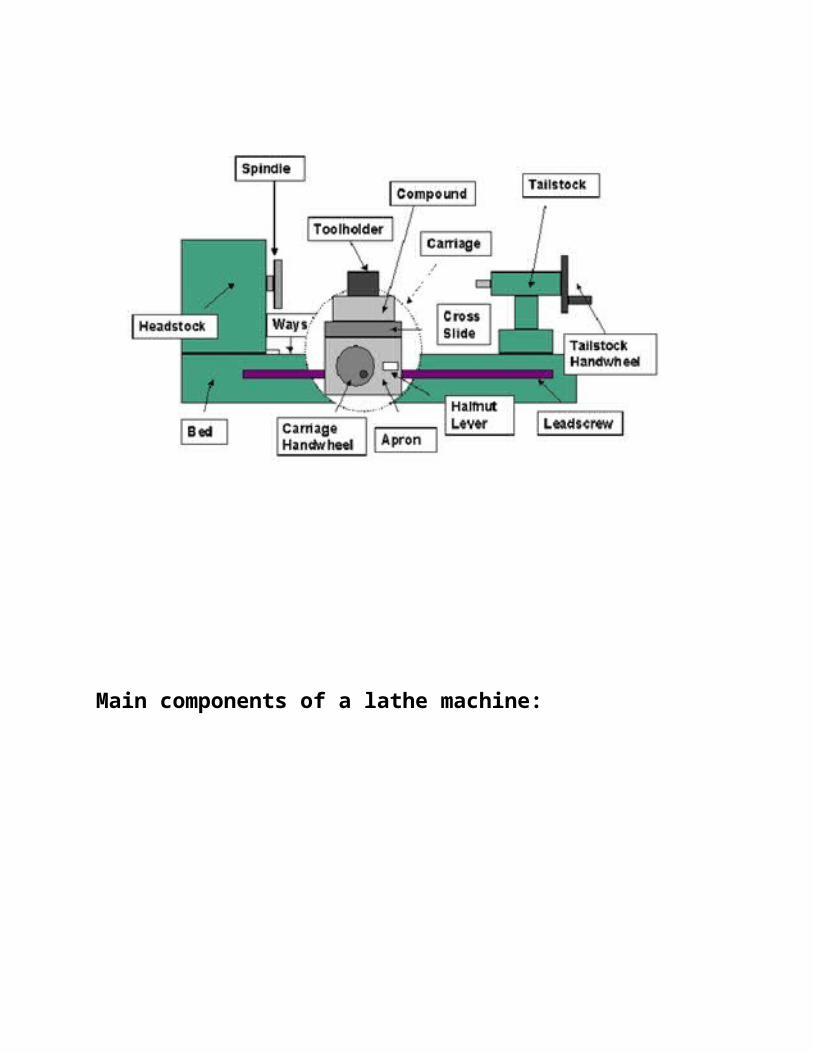
Main components of a lathe machine:
Bed:
A lathe is built around a bed, made massive and rigid to resist deflection and vibration. Three major units mounted on bed are the head stock, the tail stock, and the carriage.

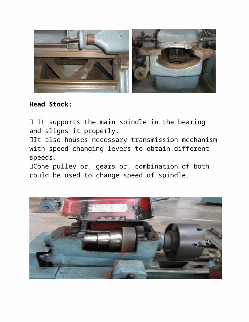
Head Stock:
It supports the main spindle in the bearing and aligns it properly. It also houses necessary transmission mechanism with speed changing levers to obtain different speeds. Cone pulley or, gears or, combination of both could be used to change speed of spindle.
Speed gear box:
A separate speed change gear box is placed below head stock to reduce the speed in order to have different feed rates for threading and automatic lateral movement of carriage.
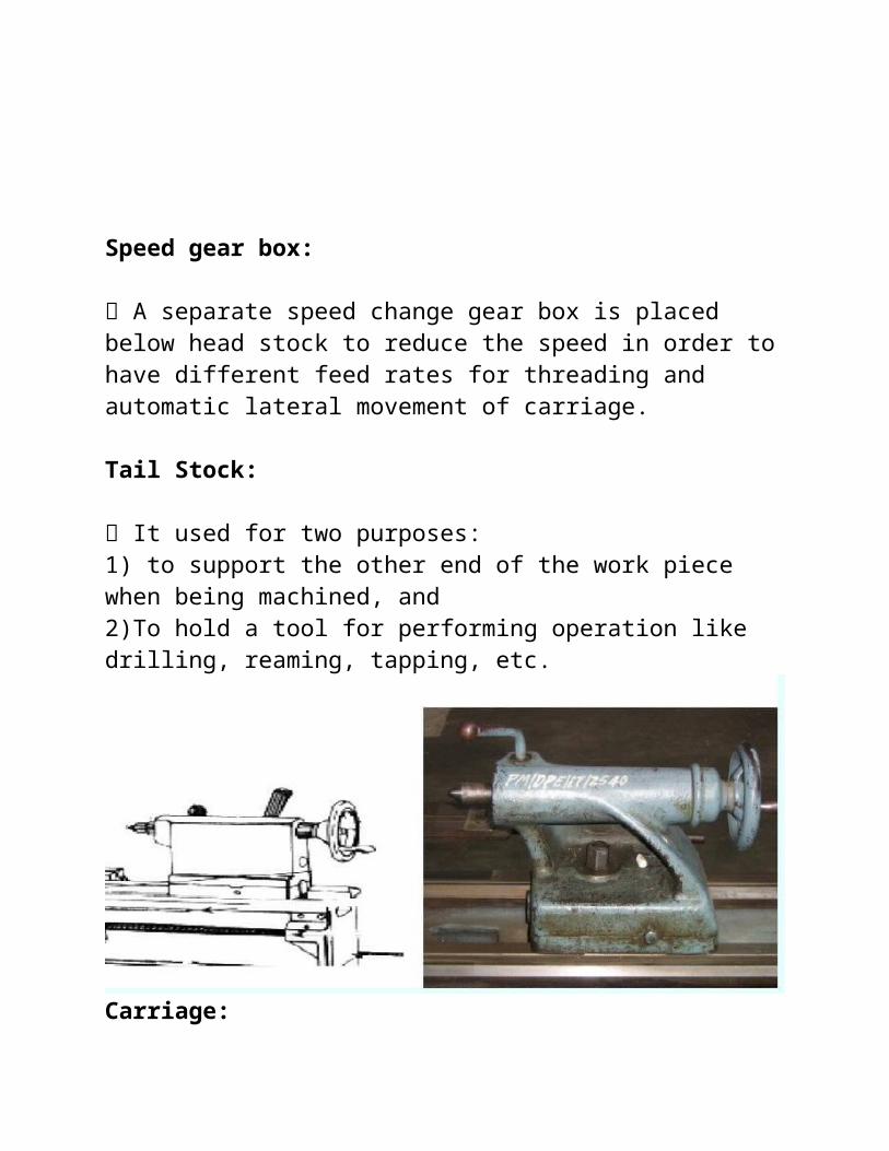
Tail Stock:
It used for two purposes: 1) to support the other end of the work piece when being machined, and 2)To hold a tool for performing operation like drilling, reaming, tapping, etc.
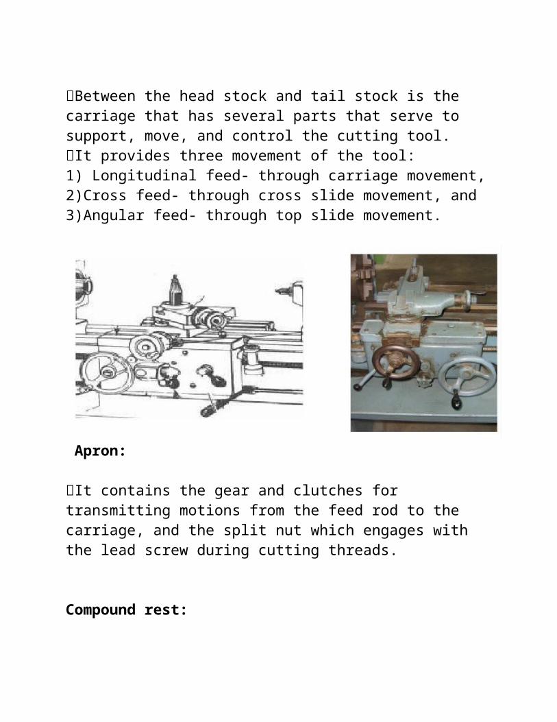
Carriage:
Between the head stock and tail stock is the carriage that has several parts that serve to support, move, and control the cutting tool. It provides three movement of the tool: 1) Longitudinal feed- through carriage movement, 2)Cross feed- through cross slide movement, and 3)Angular feed- through top slide movement.
Apron:
It contains the gear and clutches for transmitting motions from the feed rod to the carriage, and the split nut which engages with the lead screw during cutting threads.
Compound rest:
It supports cutting tool post and cutting tool in its various position. It be swiveled on the cross-slide to any angle in the horizontal plane.
Feed rod:
The feed rod is used to save the lead screw when other than threading operations are done.
Lead screw:
It is used to move the carriage along at a precise rate for cutting a thread. The lead screw passes through a split or, half nut attached to the apron
Feed gear box:
The feed change gears are in a sliding transmission gear box on the left of the bed below the head stock. A chart on the box tells the operator how to shift the levers to select the available feed.
Cross-slide:
On the top of the saddle is across-slide that is adjusted and feed at right angle to the length of the bed by a crank and graduated dial on the front of the saddle.

Types of Lathe Machine:
A suitable classification of lathe machine is very difficult. According to some outstanding design characteristics:
1. Speed Lathe 2. Engine Lathe 3. Bench Lathe 4. Special purpose Lathe 5. Turret Lathe 6. Tool Room Lathe 7. Automatic screw Lathe 8. Capstan Lathe
Speed Lathe:
It is so named because of the very high speed of the head stock spindle. It consists of a simple head stock, a tail stock, and tool post. It is used principally in the turning of wood. RPM of the chuck or work piece is constant.
Engine Lathe:
At early stage, it was driven by engine, so the name engine lathe. It is most common and most widely used lathe machine. RPM of chuck or work piece can be changed a) by gear or b) by pulley. It consists of head stock, tail stock, carriage, tool post, lead screw, feed rod, etc.
Bench Lathe:
Small lathe with bed up to six feet long. Able to swing diameter up to twelve inch. It is commonly set on a bench. Used for small and light work.
Tool room Lathe:
Modern engine lathe. Used for accurate tool room work. Best for production of cutting tools, dies, gauges etc.
Special purpose Lathe:
It is used for special type of works. It is commonly used for making crank-shaft, cam shaft, duplicating, etc.

Turret Lathe:
It is a production machine used to perform a large number of operation simultaneously. The hexagonal-turret usually carry six tool for different operations. Front and rear tool posts also carry some tools. More than one operation can be done at a time.
Automatic screw Lathe:
It is used mainly for manufacturing bolts and screws. It can produce parts one after the other with little attention from the operator. Provide a controlling movement for the turret.
Capstan Lathe:
It is similar to the turret lathe. Capstan slide can be clamped in any position. It is best suited for fast production of small parts.
Accessories:
Lathe accessories are commonly work holders and tool holders. It supports the face plate, chucks, collets, drivers, rests fixtures and mandrels.
Lathe size:
The lathe can be denoted in three ways:
1) The maximum diameter of the work piece that can be mounted.
2) The maximum length of the work piece that can be machined.
3) The maximum bed length.

Turret lathes:
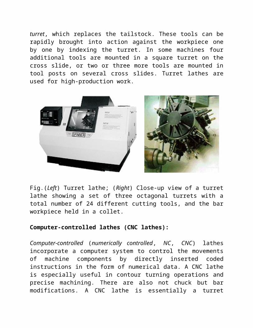
These machines are capable of carrying out multiple cutting operations on the same workpiece. Several cutting tools are mounted on a tetra-, penta-, or hexagonal turret, which replaces the tailstock. These tools can be rapidly brought into action against the workpiece one by one by indexing the turret. In some machines four additional tools are mounted in a square turret on the cross slide, or two or three more tools are mounted in tool posts on several cross slides. Turret lathes are used for high-production work.
Fig.(Left) Turret lathe; (Right) Close-up view of a turret lathe showing a set of three octagonal turrets with a total number of 24 different cutting tools, and the bar workpiece held in a collet.
Computer-controlled lathes (CNC lathes):
Computer-controlled (numerically controlled, NC, CNC) lathes incorporate a computer system to control the movements of machine components by directly inserted coded instructions in the form of numerical data. A CNC lathe is especially useful in contour turning operations and precise machining. There are also not chuck but bar modifications. A CNC lathe is essentially a turret lathe. The major advantage of these machines is in their versatility - to adjust the CNC lathe for a different part to be machined requires a simple change in the computer program and, in some cases, a new set of cutting tools.
SHAPER:
The shaper (also called shaping machine) is a reciprocating type of machine tool used for producing small flat surfaces with the help of a single point tool reciprocating over the stationary work piece. The flat surface may be horizontal, inclined or vertical. The reciprocating motion of the tool is obtained either by the crank and slotted lever quick return motion mechanism or Whitworth quick return motion mechanism.
Principal Parts of a Shaper
The principal parts of a shaper, as shown in Fig. are as follows:1. Base: It is a heavy structure of cast iron which supports other parts of a shaper.
2. Column: It is a box-like structure made up of cast iron and mounted upon the base. It contains the driving mechanism and is provided with two machined guide ways on the top of it on which the ram reciprocates.3. Ram: It is a reciprocating member which reciprocates on the guide ways provided above the column. It carries a tool-slide on its head and a mechanism for adjusting the stroke length.

4. Tool head: It is attached to the front portion of the ram with the help of a nut and a bolt. It is used to hold the tool rigidly, it also provides the vertical and angular movements to the tool for cutting.
5. Cross-rail: It is attached to the front vertical portion of the column. It is used for the following two purposes:(a) It helps in elevating the table over the column in the upward direction, and(b) The table can be moved in a direction perpendicular to the axis of the ram over this cross rail.
6. Table: It is used for holding the work piece. It can be adjusted horizontally and vertically with the help of spindles.
Fig. Principal Parts of a Shaper
Working Principle and Operation of a Shaper:
We have already discussed that in a shaper, a single point cutting tool reciprocates over the stationary work piece. The tool is held in the tool post of the reciprocating ram and performs the cutting operation during its forward stroke. It may be noted
that during the backward stroke of the ram, the tool does not remove material from the work piece. Both these strokes (i.e., forward and backward strokes) form one working cycle of the shaper.
Fig. Working Principle and Operation of a Shaper
For shaping in horizontal direction, as shown in Fig.(a), the clamped work piece is fed against the reciprocating tool after every cutting cycle. The depth of cut is adjusted by moving the tool downward towards the work piece. For shaping in vertical direction, as shown in Fig.(b),The tool is fed vertically towards the work piece after every cutting cycle. The depth of cut is adjusted by moving the work piece sideways.
Classifications of Shapers:The shapers are classified as follows:1. According to the ram driving mechanismAccording to the ram driving mechanism, the shapers are classified as follows:(a) Crank shaper.(b) Geared shaper(c) Hydraulic shaper. 2. According to position and travel of ramAccording to the position and travel of ram, the shapers are classified as follows:(a) Horizontal shaper.(b) Vertical shaper.3. According to the direction of cutting strokeAccording to the direction of cutting stroke, the shapers are classified as follows:

(a) Push-Cut shaper. (b) Draw-cut shaper.4. According to the design of the tableAccording to the design of the table, the shapers are classified as:(a) Standard or plain shaper.(b) Universal shaper.
Quick Return Mechanism (Mechanical device):
There are different types of quick return mechanism used in shaper machine. The most common is oscillating arm type.
The bull gear in the middle of the column rotates clockwise at a uniform rates. A block on a crankpin that travels in a circle on the bull gear slides in a slot in the crank and causes it to reciprocate. The crank is pivoted at the bottom and is connected at the top to the ram through a link. The direction of movement of the

crank changes when the center line of the crank is tangent to the circular path of the crankpin on the bull gear. For a constant bull gear speed, the ram speed changes with the radial setting of crank pin. When the ram moves forward on the cutting stroke, the driving pin moves through an arc of 220 degree. On the return stroke, the pin travels through only 140 degree of the arc. Thus the ram travels much faster and takes less time on the return stroke than on the forward or cutting stroke. This quick return motion saves time when the tool is not cutting.
Why Quick return mechanism is used in Shaper machine?
In shaping machine the cutting take place only during the forward stroke and the return stroke is the idle stroke during which no cutting takes place. It is therefore desired that the return stroke should operate at higher speed than the forward stroke. To achieve this requirement quick return motion mechanisms are used in the shaper machine.
Size of a shaper machine:
The size of a shaper designates its longest nominal cutting stroke. Therefore, a 24 inch shaper has ram travel enough to drive a tool across a 24 inch long surface. Sometimes a ram travel little more. Shapers with longer ram are not practical.

PLANER:
The planer (also called planing machine) is a machine tool used to produce plane and flat surface by a single point cutting tool. It is similar to a shaper but its size is very large and is adopted for producing flat surfaces of much larger work than a shaper. The fundamental difference between a planer and shaper is that in a planer, the tool remains stationary and the work reciprocates whereas in the shaper, the work remains stationary and the tool reciprocates.
The various types of planers commonly used are1. Standard or double housing planer,2. Open side planer,3. Pit planer,4. Edge or plate planer, and5. Divided table planer.Of all the above types of planers, the standard or double housing planer is most widely used in workshops.
Fig. Standards or double housing planer

Double-housing Planer:
The double-housing is of extremely robust construction and most commonly used. The support is furnished to the tool by two columns and heavy cross rail, thus allowing heavy cuts to be taken even far above the table.
Open- side Planer:
An open-side planer has a housing only on one side of the bed. The other side is open so that extra wide work can hang over the side of the bed.
Pit-type Planer:
It is more massive in construction than the double housing planer. In it the table is stationary and the tools are moved over the work-piece.
Edge or Plate Planer:
Used for heavy steel plates. The plate (work-piece) is stationary and is clamped on a large bed. The cutting tool is attached to a carriage which moves.
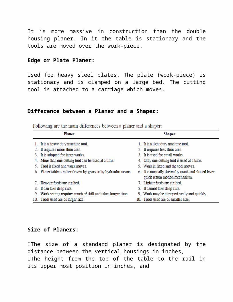
Difference between a Planer and a Shaper:
Size of Planers:
The size of a standard planer is designated by the distance between the vertical housings in inches, The height from the top of the table to the rail in its upper most position in inches, and The maximum length of the table travel in feet. The length of travel is often the length of the working area of the table. Sometimes, when the first two figures are the same, they are expressed by one quantity, such as 42" x 10" for 42" x 42" x 10".

Drilling:
Drilling is a process of making hole or enlarging a hole in an object by forcing a rotating tool call drill.
Drilling is the operation of producing circular hole in the work-piece by using a rotating cutter called drill.
The machine used for drilling is called drilling machine.
The drilling operation can also be accomplished in lathe, in which the drill is held in tailstock and the work is held by the chuck.
The most common drill used is the twist drill.
Drilling Operations:
The most common operations which can be carried on a drilling machine are Drilling Boring Reaming Tapping counter boring spot facing and counter sinking.
These operations are discussed as follows:
1. Drilling: It is an operation of producing a circular hole in a work piece by forcing a drill against it.
2. Boring: It is an operation of enlarging a hole that has already been drilled by a single point tool, so as to make it we to the required size.

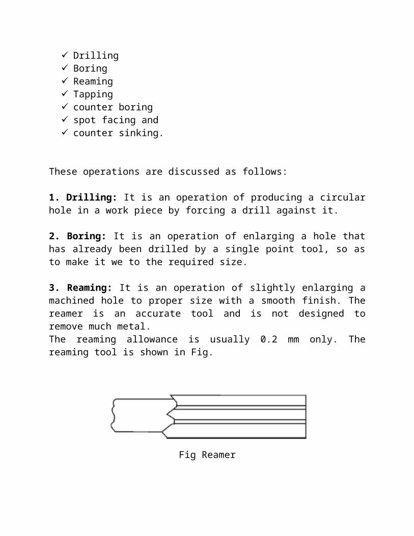
3. Reaming: It is an operation of slightly enlarging a machined hole to proper size with a smooth finish. The reamer is an accurate tool and is not designed to remove much metal.The reaming allowance is usually 0.2 mm only. The reaming tool is shown in Fig.
Fig Reamer
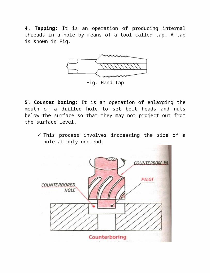
4. Tapping: It is an operation of producing internal threads in a hole by means of a tool called tap. A tap is shown in Fig.
Fig. Hand tap
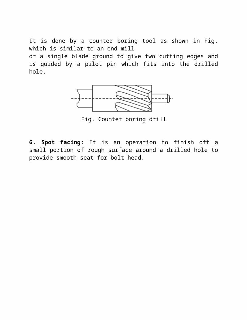
5. Counter boring: It is an operation of enlarging the mouth of a drilled hole to set bolt heads and nuts below the surface so that they may not project out from the surface level.
This process involves increasing the size of a hole at only one end.

It is done by a counter boring tool as shown in Fig, which is similar to an end millor a single blade ground to give two cutting edges and is guided by a pilot pin which fits into the drilled hole.
Fig. Counter boring drill
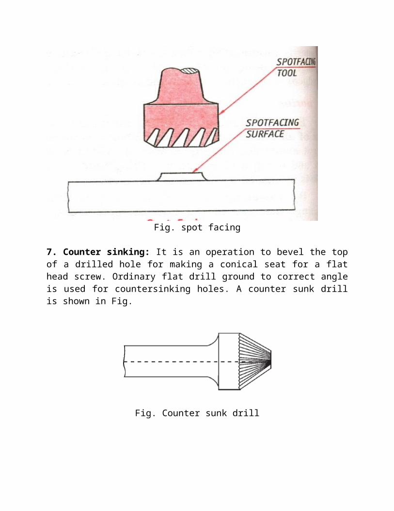
6. Spot facing: It is an operation to finish off a small portion of rough surface around a drilled hole to provide smooth seat for bolt head.

Fig. spot facing
7. Counter sinking: It is an operation to bevel the top of a drilled hole for making a conical seat for a flat head screw. Ordinary flat drill ground to correct angle is used for countersinking holes. A counter sunk drill is shown in Fig.
Fig. Counter sunk drill
This is an operation of making the end of a hole into a conical shape.
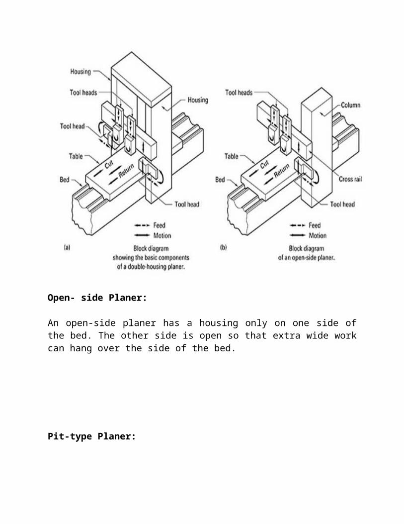
Fig. Counter sinking
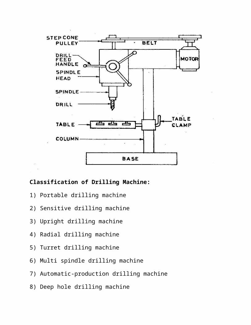
Diagram of a Drilling Machine:
Classification of Drilling Machine:
1) Portable drilling machine
2) Sensitive drilling machine
3) Upright drilling machine
4) Radial drilling machine
5) Turret drilling machine
6) Multi spindle drilling machine
7) Automatic-production drilling machine
8) Deep hole drilling machine
9) Gang drilling machine
Portable Drilling Machine:
It is a small compact drilling machine used principally for drilling operation which can be performed on a regular drill process. It is equipped with a small electric motor which gives power while working.
Sensitive Drilling Machine:
It is a light, simple bench type machine for light duty working. The major component of this machine are spindle, column, table and the base. It is usually hand feed and operate on the principle of rack and pinion drive.
Upright or Column Drilling Machine:
This type of machine have power feeding mechanism for rotating the drill and are designed for heavier work. These machine have box type column which is more rigid.
Radial Drilling Machine:
It is the largest and most versatile of the drilling machines and is very well suited for drilling large number of holes. It is a single spindle machine intended for handling large and heavy work and work which beyond the capacity of the small drilling machines.
Gang Drilling Machine:
Gang drilling machines have two or more drill heads mounted on same table. These can be run either simultaneously or in sequence.
Turret Drilling Machines:
These are used when a series of holes of different size or a series of operation (Center drilling, drilling, reaming and spot facing) must be done repeatedly in succession. The tools selector are mounted in the turret. Each tool can quickly be brought into position merely by rotating the turret .
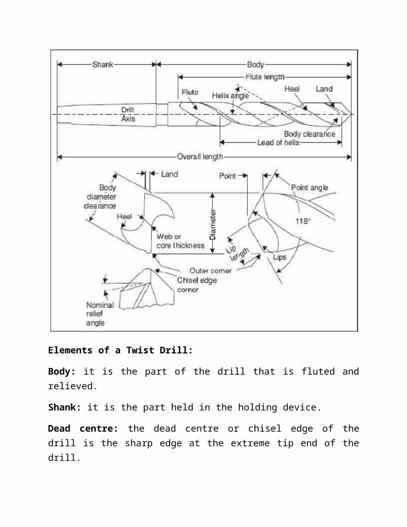
Diagram/Elements of a Twist Drill:
Elements of a Twist Drill:
Body: it is the part of the drill that is fluted and relieved.
Shank: it is the part held in the holding device.
Dead centre: the dead centre or chisel edge of the drill is the sharp edge at the extreme tip end of the drill.
Lip: lip or cutting edge formed by the intersection of the flank and face. Both the lips of the drill should be equal length and should be at the same angle of inclination with the drill.
Flank: flank is the surface on a drill point which extends behind the lip to the flowing flute.
Chisel edge corner: the corner formed by the intersection of a lip and the chisel edge is called chisel edge corner.
Flutes: the grooves in the body of the drill which provides lips.
Boring:
Boring is a process of enlarging the hole that has already been drilled.
Basically it is an operation of turning a hole with a single point cutting tool.
The machine used for boring is called boring machine

Types of Boring Machine:
1)Horizontal boring machine
2)Vertical boring machine
3)Jig boring machine
Jig Boring Machine:
Used for locating and boring in Jig, fixture, dies gages etc. and other precision parts.
It is similar to vertical milling machine.
Direct reading dials for longitudinal and transverse movement.
Work-piece is automatically and accurately positioned.
Numerical control is available in this machine.
MILLING:
Milling is the machine operation in which the removal of metal from the work piece takes place due to a rotating cutting tool(cutter) when the work is fed past it. The cutter has multiple cutting edges and rotates at a very fast rate. The rotating cutting tool known as the “Milling Cutter” is a multiple point tool having the shape of a solid revolution with cutting teeth arranged either on the periphery or on end or on both. The revolving cutter is held on a spindle or arbor and the work piece is clamped or bolted on the machine table or may be in a vise or a three jaw chuck or an index head held or a rotary table etc. The milling process is employed for producing flat contoured or helical surfaces, for making helical grooves, to cut teeth and toothed gears.
Working Principle of Milling:
Fig . illustrates the working principle employed in metal removing operation on a milling machine. The job or work piece is rigidly clamped on the table of the machine or in a chuck or an index head and a revolving multiteeth cutter is mounted either on a spindle or an arbor. The job is fed slowly past the cutter. The work can be fed in a vertical, longitudinal or cross direction. With the movement of the work piece, the cutter teeth remove metal from the job in the form of chips to produce the desired shape. Generally, the size of a milling machine is denoted
by the dimension i.e. length and breadth of the table. Other main specifications of the machine or placing an order are the H.P. of the driving motor, number of spindle speeds and feeds, the taper of spindle nose (Whether Morse Taper or Some other Taper) required floor area, gross weight of the m/c etc. Some manufacturers, however, denote these machine sizes by different numbers such as 0, 1, 2, 3, 4, 5 etc.
Fig. Working Principle of Milling Machine
Types of Milling Machines:
The milling machines are available in different shapes and sizes. These machines may be classified as follows:
(1) Column and knee type milling machines
(a) Horizontal milling machines

(b) Vertical milling machines
(c) Ram type milling machines
(2) Bed type milling machines
(a) Manufacturing or fixed bed type milling machines
(b) Horizontal bed type milling machines
(c) Vertical bed type milling machines
(3) Planer type milling machines
(4) Special purpose milling machines
(a) Rotary table milling machines
(b) Drum type milling machines
(c) Tracer controlled milling machines
(d) Thread milling machine
(e) Key-way milling machine
(f) Skin and spar milling machine
(g) Planetary milling machine
Milling Machine Operations
The operations that can be performed on a milling machine are broadly classified as follows:
(1) Plain Milling (2) Face Milling (3) Angular Milling
(4) Staggered Milling (5) Form Milling (6) End Milling

Principal Parts:
Base: It provides rest for all parts of milling machine including column. It is made of grey iron by casting.
Column: It is a type of rigid vertical long box. It houses driving mechanism of spindle, table, knee is also fixed to the guide ways of column.
Knee: Knee can be adjusted at a height on the column. It houses the feed mechanism of the table and other controls.
Saddle: Saddle is placed at the top of the knee. Saddle provides guide ways for the movement of the table.
Table: Table rests on the saddle. It consists of „T‟ shaped slots for clamping the workpiece. Movements of the table (feed motions) are given in very controlled manner be lead screw.
Overhanging Arm: Overhanging arm is mounted on the column and serves a bearing support for the arbor. This arm is adjustable so that the bearing support may be provided near to the milling cutter. There can be more than one bearing supports to the arbor.
Arbor: It holds rotating milling cutters rigidly and mounted on the spindle. Sometimes arbor is supported at maximum distance from support of overhanging arm like a cantilever, it is called stub arbor. Locking provisions are provided in the arbor assembly to ensure its reliability.
Spindle: Spindle is projected from the column face and provided with a tapered hole to accommodate the arbor. Performance of a milling machine depends on the accuracy, strength and rigidity of the spindle. Spindle also transfer the motive power to arbor through belt or gear from column.

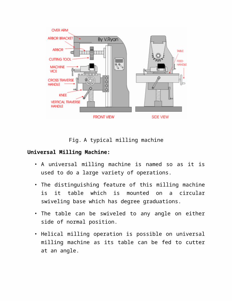
Fig. A typical milling machine
Fig. A typical milling machine
Universal Milling Machine:
• A universal milling machine is named so as it is used to do a large variety of operations.
• The distinguishing feature of this milling machine is it table which is mounted on a circular swiveling base which has degree graduations.
• The table can be swiveled to any angle on either side of normal position.
• Helical milling operation is possible on universal milling machine as its table can be fed to cutter at an angle.
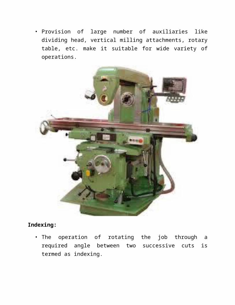
• Provision of large number of auxiliaries like dividing head, vertical milling attachments, rotary table, etc. make it suitable for wide variety of operations.
Indexing:
• The operation of rotating the job through a required angle between two successive cuts is termed as indexing.
• This is accomplished with the help of a milling attachment known as dividing head, which is an accessory to the milling machine.
• It helps to divide the job periphery into a number of equal division.
Methods of indexing:
There are five methods of indexing:
1. Direct indexing
2. Simple or plain indexing
3. Compound indexing
4. Differential indexing
5. Angular indexing
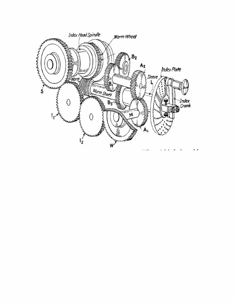
Indexing or dividing head:


DIRECT INDEXING:
• The dividing head has an index plate , fitted directly on the spindle.
• The intermediate use of worm and worm-wheel is avoided.
• The index plate has 24 holes.
• Numbers that can be divided into 24 can be indexed in this manner.
• To find the number of holes to move the index plate, divide 24 by the number of divisions required.
• Number of holes to move = 24/ N
Where,N = required number of divisions
Example: Indexing for a hexagon head bolt:
because a hexagon head has six flats,
Simple or plain indexing:
• Indexing plate with varying number of holes are used to increase the range of indexing.
• The index plate is fixed in position by a pin called lock pin.
• The spindle is then rotated by rotating the handle (index crank) which is keyed to the worm-shaft.
• The following relation is used for simple indexing : T= 40/N ; where T is the number of turns or parts of a turn and N is the required number of division on the job periphery.

For example, to index for the machining of a hexagon (N = 6):
Thus it required 6 full turns with 10 holes in a 15-hole circle or,12 holes in a 18-hole circle.
Compound indexing:
• The principle of operation of compound indexing is the same as that of the simple indexing.
• The only difference is that compound indexing uses two different circles of one plate.
• The principle of compound indexing is to obtain the required division in two stages:
i. By rotating the crank or handle in usual way keeping the index plate fixed with lock pin.
ii. By releasing the back pin (lock pin) and then rotating the index plate with the handle.
• For example, if a 27 teeth gear is to cut, then T= 40/27; the rotation required for one tooth spacing is 40/27 which may be written as 2/3+22/27 or 12/18+22/27.
• So for each tooth, the worm will be rotated by 12 holes of 18 hole circle with the help of the crank and then the index plate is rotated by 22 holes of the 27 hole circle.

Angular indexing:
• Instead of rotating the job through certain division on its periphery, sometimes it may be needed to rotate the job through certain angle.
• Angular indexing is used for this purpose.
• Since the crank and spindle ratio is 40:1 so when the crank moves 1 revolution, the spindle or job moves through 1/40 of revolution.
• This means the job will revolve through an angular movement of 9 degree.
• If it is desired to index a job by 35 degree, then the indexing head movement required to perform the operation will be = 35/9=3+8/9=3+24/27
• That is the crank must turned three complete revolutions plus 24 holes in the 27 holes circle.
Differential Indexing:
• The term differential is used because the needed division is obtained by a combination of two movements:
1. The simple indexing movement of the index crank, and
2. The movement of the index plate itself,
• These two movements happen at the same time with a differential in their movement relationship.
• The index-head spindle and the index plate are connected by a train of gears so that the index plate will turn either in the same direction as the movement of the crank or in the opposite direction.
• For making the necessary calculations and to find the change of gears to be placed between the spindle and the worm shaft, use the following relation:
Driver/Driven = (n-N) *40/ᴫ
Crank movement = T = 40 / n

Where, n is a number slightly greater or less than N
• The difference of N and n causes the index plate to rotate itself in a proper direction relative to crank.
• If (n – N) is positive, the index plate will rotate in the direction in which crank is rotated.
• If (n – N) is negative, the index plate will rotate in opposite direction to that of crank.

Types of milling:
There are two basic types of milling, as shown in the figure:
Down (climb) milling, when the cutter rotation is in the same direction as the motion of the workpiece being fed.
and
Up (conventional) milling, in which the workpiece is moving towards the cutter, opposing the cutter direction of rotation.

In down milling, the cutting force is directed into the work table, which allows thinner workparts to be machined. Better surface finish is obtained but the stress load on the teeth is abrupt, which may damage the cutter.
In up milling, the cutting force tends to lift the workpiece. The work conditions for the cutter are more favourable. Because the cutter does not start to cut when it makes contact (cutting at zero cut is impossible), the surface has a natural waviness.
Comparison between up milling and down Milling:

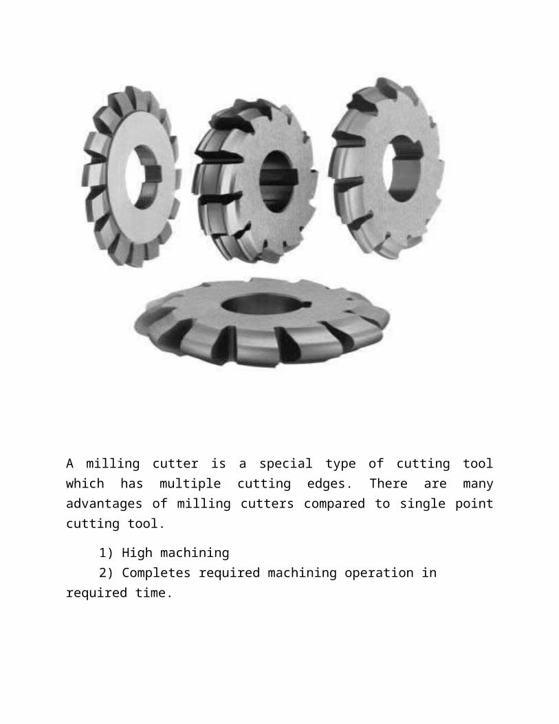
Milling Cutters:
A milling cutter is a special type of cutting tool which has multiple cutting edges. There are many advantages of milling cutters compared to single point cutting tool.
1) High machining2) Completes required machining operation in required time.
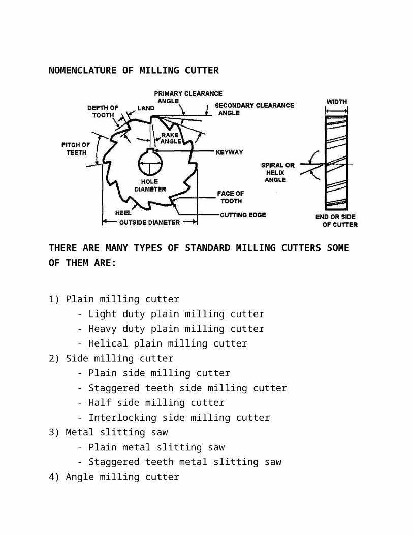
NOMENCLATURE OF MILLING CUTTER
THERE ARE MANY TYPES OF STANDARD MILLING CUTTERS SOME OF THEM ARE:
1) Plain milling cutter - Light duty plain milling cutter - Heavy duty plain milling cutter - Helical plain milling cutter2) Side milling cutter - Plain side milling cutter - Staggered teeth side milling cutter - Half side milling cutter - Interlocking side milling cutter3) Metal slitting saw
- Plain metal slitting saw - Staggered teeth metal slitting saw4) Angle milling cutter - Single angle milling cutter - Double angle milling cutter5) End mill - Taper shank end mill - Straight shank end mill - Shell end mill
6) T-slot milling cutter 9) Formed cutter 7) Woodruff key slot milling cutter - Convex milling cutter 8) Fly cutter - Concave milling cutter

PLAIN MILLING CUTTER- Once widely used - Cylinder of high-speed steel with teeth cut on periphery- Used to produce flat surface Several types
- Light-duty- Light-duty helical- Heavy-duty- High-helix
SIDE MILLING CUTTER- Comparatively narrow cylindrical milling cutters with teeth on each side and on periphery- Used for cutting slots and for face and straddle milling operations- Free cutting action at high speeds and feeds- Suited for milling deep, narrow slots

FACE MILLING CUTTER Generally over 6 in. in diameter
- Have inserted teeth made of high-speed steel head in place by wedging device
Most cutting action occurs at beveled corners and periphery of cutter Makes roughing and finishing cuts in one pass
END MILLING CUTTER Face milling cutters under 6 inch Solid, multiple-tooth cutters with teeth on face and periphery Held on stub arbor
- May be threaded or use key in shank to drive cutter

ANGULAR CUTTERS
-Teeth neither parallel nor perpendicular to cutting axis - Used for milling angular surfaces
- Grooves, serrations, chamfers and reamer teeth- Divided into two groups
- Single-angle milling cutters- Double-angle milling cutters
- Single-angle- Teeth on angular surface- May or may not have teeth on flat- 45º or 60º
- Double-angle- Two intersecting angular surfaces with cutting teeth on both- Equal angles on both side of line at right angle to axis
Troubleshooting Guide for Milling Operations:
FORMED CUTTERS- Incorporate exact shape of part to be produced- Useful for production of small parts- Each tooth identical in shape- Sharpened by grinding tooth face (may have positive, zero or negative rake)
- Important to maintain original rake- Difficult to sharpen
TYPES OF FORMED CUTTERS
Concave Convex Gear Tooth

Why milling machine is called most versatile of all machine tools:
Milling machine is one of the most important machine tool in a tool room, because of varieties of operation with great accuracy and excellent surface finish can be done. It can be used for machining flat surfaces, contoured surfaces, complex and irregular areas, surface of revolution, slotting, external and internal threads, gear cutting, helical surface of various cross section etc. to close tolerances for both limited quantity and mass production. Besides these, all jobs of shaper, drilling and gear cutting machine can be done on milling machine. For these, milling machine is called the most versatile of all machine tools.
Grinding:
Grinding is a process carried out with a grinding wheel made up of abrasive grains for removing very fine quantities of material from the work piece surface.
The required size of abrasive grains are thoroughly mixed with the bonding material and then pressed into a disc shape of given diameter and thickness.
This can be compared to a milling process with an infinite number of cutting edges.
Abrasives:
• Grinding wheels are made of abrasive particles bonded together by means of some suitable bond.
• An abrasive is a hard material which can be used to cut or wear away other materials.
• It is extremely hard and tough, and when fractured, it forms sharp cutting edges and corners.
• Abrasive particles used for grinding wheels are of two types:
a. Natural abrasives and
b. Artificial abrasives.
Natural abrasives: These are produced by uncontrolled forces of nature. The following are the generally found and used natural abrasive:
a. Sand stone or solid quartz
b. Emery (50-60% crystalline Al2 03 + iron oxide)

c. Corundum (75-90% crystalline Al2 03 + iron oxide)
d. Diamonds
e. Garnet.
Artificial or manufactured abrasives: the quality and composition of these particles can be easily controlled and their efficiency is far better than that of natural abrasives. Most commonly used manufactured abrasives are:
i. Silicon carbide
ii. Aluminium Oxide
iii. Boron carbide
iv. Boron nitrite.
Efficiency of abrasive particles depends upon:
a. Purity
b. Uniformity in composition
c. Hardness: Common rule about it is that hardness of abrasive should be more that of work material.
d. Toughness: If wheel is not tough, the abrasive particles will facture readily and wheel wear will be excessive.
e. Sharpness of fracture: the better cutting action is obtained by sharp edge abrasives. The natural abrasives give rounded edges and are, therefore, not efficient in cutting.
Specification of grinding wheel:
Classification of Grinders:
a. External Cylindrical Grinder:
1)Centre type grinder
2)Centre less grinder: i) Through-feed ii) In-feed iii) End-feed
b. Internal Cylindrical Grinder:
1)Centre type grinder
2)Centre less grinder: i) Roll type centre less internal grinder. ii) Shoe type centre less internal grinder.
Comparison between centre type and centre less Grinding:
1) More time is needed to set up a centre type grinder

2) Centre less is faster than centre type grinder.
3) Loading and unloading time is minimum for centre less.
4) No axial trust in centre less.
5) Lower order of skill of worker is needed for centre less.
6) No chucking or mounting of work piece in centre less.
7) Centre less is suitable for large lot.
8) Work-piece is rigidly supported in centre less type and there is no tendency of deflection.
9) Work-piece size can be easily controlled in centre less.
10) Work-piece with flat and key ways can not be ground in centre less.
11) Work-piece with several diameter is not easy to grind in centre less.
Surface Grinding:
The grinding of flat or plain surface is known as surface grinding.
Surface grinding involves grinding flat surfaces and is one of the most common grinding operations.
Typically, the work-piece is secured on a magnetic chuck attached to the work of the grinder.
Non-magnetic materials are generally held by vises, special fixtures, vacuum chucks or double-sided adhesive types.
Surface Grinder:
In surface grinding, the spindle position is either horizontal or vertical, and the relative motion of the workpiece is achieved either by reciprocating the workpiece past the wheel or by rotating it. The possible combinations of spindle orientations and workpiece motions yield four types of surface grinding processes illustrated in the figure:

1) Rotary type: It is one in which the table is circular in shape and rotates under the wheel.
2) Planer type: It is one in which the table is rectangular and traverses under the wheel.
(a) Rotary table with rotary motion:
(i) Horizontal spindle (ii) Vertical spindle
(b) Rectangular table with reciprocating motion:
(i) Horizontal spindle (ii) Vertical spindle
Centreless Grinding:

This type of machine is used for grinding both external and internal cylindrical surfaces without mounting the work piece between centers in a chuck. This machine makes use of two grinding wheels. The larger grinding wheel does the actual grinding and the small grinding wheel is mounted at an angle to the plane of the grinding wheel. The small wheel is responsible for the feed of the work piece. The work piece with its both ends freely supported on a ‘V’ rotates between large and small wheels. The small wheel also called the regulating wheel does not perform grinding operations but only controls the speed of rotation and longitudinal motion of the work piece.
Fig. Centerless grinding
Advantages of Centreless Grinding:
The advantages of centreless grinding are as follows:
1. Chuck and centers are not required.
2. The work piece is rigidly supported during grinding, so there is no change of direction of work piece.
3. This process is fast.
4. Less skilled operator can carry out operation.
5. Wide range of components can be ground.
6. Large grinding wheels can be used so as to minimize wheel wear.
Lapping:
It is a process of removing surface roughness, tool marks, surface cracks from grinding, slight distortions and other minor defects from previous operations.
This process is used for producing extremely accurate highly finished surfaces. Lapping is carried out by means of shoes called Laps. The Laps are made up of soft cast iron, copper, lead and brass. Fine abrasive particles are charged into the lap. Silicon carbide, aluminum oxide and diamond dust are the commonly used lapping powders. Oil and greases are used to spread the abrasive powders. The charged lap is rubbed against the work piece surface and the abrasive particles in the surface of the lap remove small amounts of material from the work piece surface. The material removed by lapping is usually less than 0.025 mm.
Lapping can be done either by hand or special machines. The lap has a series of grooves in it. These are provided for collecting the excess abrasive and chips. The surface of the lap is charged with a fine abrasive. The work piece is moved across the surface of the lap using reciprocating or rotary motion. In machine lapping, two flat laps are used that are called upper and lower laps. The work pieces to be lapped are inserted between these two laps rotating in opposite direction. The work piece holder can accommodate a number of work pieces which are not clamped.
Honing:
Honing is an abrading process for removing stock from metallic and non-metallic surfaces.
Honing is the applications of bonded abrasive stones to a surface for the purpose of limited stock removal and attainment of a surface finish.
Honing is an abrasing process used for finishing internal cylindrical surfaces like drilled or bored holes. Honing stones are manufactured by bonding abrasives like aluminum oxide or silicon carbide. Materials like sulphur, resin or wax are added to improve the cutting action. Honing can be done manually or by machines. The preferred method is by using machines. The stones are held in a honing head. This head is directed to move in and out of the hole for carrying out operation. Honing is both a sizing and finishing operation and is generally used for removing the scratch marks produced by grinding. The material removal is less than 0.125 mm.

Super finishing:
It is an abrasive process for removing scratches produced by machining and other surface irregularities. It is used for producing extremely high quality surface finish.
The amount of material removal is 0.005 to 0.0025 mm. In super finishing, an abrasive stick is retained in a suitable holder and applied to the surface of the work piece with a light pressure. This process is normally carried out for finishing outer surfaces. The abrasive block reciprocates across the rotating work piece. These two motions produce a high degree of accuracy. The abrasive used are aluminum oxide for materials like alloy and high speed steels. Silicon carbide abrasives are used for materials like cast iron, aluminium, brass. Bonded diamond dust is used for finishing carbide tools.


Modern Machining Process:
Modern machining processes are also called non-conventional machining process or non-traditional process.
Normal machining process used mechanical energy.
Modern machining processes are use mechanical, chemical, electrochemical, thermoelectric etc energy.
Reason or need of development:
1) Increased strength and hardness of work-piece material.
2) Complex design
3) Higher accuracy requirement.