Ali Hanzala Khan Consistency of UML Based Designs Using ...
169
Turku Centre for Computer Science TUCS Dissertations No 168, December 2013 Ali Hanzala Khan Consistency of UML Based Designs Using Ontology Reasoners
Transcript of Ali Hanzala Khan Consistency of UML Based Designs Using ...
Turku Centre for Computer Science
TUCS DissertationsNo 168, December 2013
Ali Hanzala Khan
Consistency ofUML Based DesignsUsing Ontology Reasoners


Consistency of UML Based DesignsUsing Ontology Reasoners
Ali Hanzala Khan
To be presented, with the due permission of the Department of InformationTechnologies at Abo Akademi University, for public criticism in AuditoriumGamma, at ICT building, Turku, Finland, on December 19, 2013, at 12 noon.
Abo Akademi UniversityDepartment of Information Technologies
Joukahaisenkatu 3–5 A, 20520 Turku, Finland
2013

Supervisor
Professor Ivan PorresDepartment of Information TechnologiesAbo Akademi UniversityJoukahasenkatu 3–5 A, 20520 TurkuFinland
Reviewers
Professor Oscar PastorCentro de Investigacion en Metodos de Produccion de SoftwareUniversidad Politecnica Valencia (Technical University of Valencia)Valencia 46022Spain
Professor Fernando Silva ParreirasLaboratory of Advanced Information Systems - LAISFaculty of Business SciencesFUMEC UniversityAv. Afonso Pena 388030130-009 Belo Horizonte - MGBrazil
Opponent
Professor Oscar PastorCentro de Investigacion en Metodos de Produccion de SoftwareUniversidad Politecnica Valencia (Technical University of Valencia)Valencia 46022Spain
ISBN 978-952-12-2985-5ISSN 1239-1883

Dedicated to my beloved father and mother Mr. and Mrs. Muhammad Ali Khanwho gave me guidance, support and love endlessly throughout my life

“Seek knowledge from the cradle to the grave.”Prophet Muhammad (Peace be upon him)

Abstract
Software plays an important role in our society and economy. Software de-velopment is an intricate process, and it comprises many different tasks:gathering requirements, designing new solutions that fulfill these require-ments, as well as implementing these designs using a programming languageinto a working system. As a consequence, the development of high qualitysoftware is a core problem in software engineering. This thesis focuses onthe validation of software designs.
The issue of the analysis of designs is of great importance, since errorsoriginating from designs may appear in the final system. It is consideredeconomical to rectify the problems as early in the software developmentprocess as possible. Practitioners often create and visualize designs usingmodeling languages, one of the more popular being the Unified ModelingLanguage (UML). The analysis of the designs can be done manually, but incase of large systems, the need of mechanisms that automatically analyzethese designs arises.
In this thesis, we propose an automatic approach to analyze UML baseddesigns using logic reasoners. This approach firstly proposes the translationsof the UML based designs into a language understandable by reasoners inthe form of logic facts, and secondly shows how to use the logic reasonersto infer the logical consequences of these logic facts. We have implementedthe proposed translations in the form of a tool that can be used with anystandard compliant UML modeling tool. Moreover, we authenticate theproposed approach by automatically validating hundreds of UML baseddesigns that consist of thousands of model elements available in an onlinemodel repository. The proposed approach is limited in scope, but is fullyautomatic and does not require any expertise of logic languages from theuser. We exemplify the proposed approach with two applications, whichinclude the validation of domain specific languages and the validation ofweb service interfaces.
i

ii

SammanfattningProgramvara har en viktig roll i vart samhalle och var ekonomi. Program-varuproduktion ar en invecklad process som bestar av flera olika delsteg:samling av krav, design av nya losningar vilka uppfyller dessa krav, samtimplementering av dessa designer med hjalp av programmeringssprak tillett fungerande system. Som en foljd av detta ar utvecklingen av programav hog kvalitet ett centralt problem i programvaruproduktion. Denna av-handling fokuserar pa validering av designer for programvara.
Analys av design ar av stor betydelse, eftersom fel som harstammarfran designer kan framtrada i det slutliga systemet. Det anses vara eko-nomiskt att atgarda problem sa tidigt som mojligt i utvecklingsprocessen.Vanligtvis skapar och visualiserar utvecklarna sina designer med hjalp avmodelleringssprak, t.ex. med ett av de mer populara spraken Unified Mo-deling Language (UML). Analysen av designer kan goras manuellt, men forstorre system finns ett behov for automatiserade mekanismer for analysen.
I denna avhandling lagger vi fram en automatisk metod for analys avUML baserade designer med hjalp av logiska resonerare. For det forstalagger detta tillvagagangssatt fram oversattningar av UML baserade de-signer till ett sprak som forstas av resonerare i form av logiska fakta. Fordet andra visar detta tillvagagangssatt hur logiska resonerare anvands foratt harleda de logiska konsekvenserna vilka dessa logiska fakta medfor. Vihar implementerat de framlagda oversattningarna i form av ett verktyg somkan anvandas tillsammans med alla vanliga UML kompatibla modellerings-verktyg. Vidare har vi verifierat det framlagda tillvagagangssattet genomatt automatiskt validera hundratals UML baserade designer, bestaende avtusentals modellelement, vilka ar tillgangliga i en on-line modelldatabas.Det framlagda tillvagagangssattet ar begransat i omfattning, men ar fulltautomatiserat och kraver inte expertkunskap om logiska sprak av dess an-vandare. Vi belyser tillvagagangssattet med tva exempelapplikationer, vilkainkluderar validering av domanspecifika sprak samt validering av granssnittfor natverkstjanster.
iii

iv

Acknowledgements
It is a pleasure for me to take this opportunity to express my deepestgratitude to those who made this thesis possible.
First of all, I would like to thank my supervisor Professor Ivan Porresfor having confidence in me and for supporting and guiding me in this work.It has been a privilege for me to have had the opportunity to work closelywith Ivan in many interesting projects.
I would also wish to thank Professor Oscar Pastor and Professor Fer-nando Silva Parreiras for reviewing this thesis and for providing me withuseful comments. I would like to thank Prof. Oscar for kindly acceptingthe task of being my opponent at the public defence.
I would like to thank my teachers of all the courses that I have studiedfor my PhD degree. Especially Dragos Truscan, Barbro Back, Luigia Petre,Elena Troubitsyna and Patrick Sibelius.
I also thank my co-authors Soren Hoglund, Ye Liu, Espen Suenson andIrum Rauf. I have had many interesting discussions with Espen and Irumthat helped me evolving this work. I would like to thank Soren and Ye forhelping me in the development of the translation tool.
I would like to thank Dragos, Espen and Irum for the proofreading ofmy articles. I would also like to thank Marta, Kristian, Irum, Adnan, Max,Benjamin and Jokhio for reviewing and proposing corrections in this work.
Furthermore, I would also like to extend my thanks to the administrativeand technical staff of our department. Especially, Christel, Nina and Tovefor keeping this department running and providing full support in all theadministrative matters. Also, Joakim and Magnus for providing excellenttechnical support.
Thanks also goes to the colleagues at the Software Engineering Lab forproviding an enjoyable and fun place to work. In particular I would liketo thank Dragos, Adnan, Kristian, Max, Marta, Jeanette, Irum, Espen,Fredrik, Tanvir, Nouman, Benjamin, Mehdi and Torbjorn. Moreover, Iwould like to thank all my Pakistani friends, especially Moazzam, Qaisar,Mohsin, Adnan, Jokhio and Kashif for always being there for me.
v
I am honored and grateful for the generous funding I received for fouryears from VAMOLA project sponsored by Academy of Finland. I am alsothankful for the generous scholarships I received from Abo Akademi andUlla Tuominen Foundation during the last year of my studies.
I would also like to thank all my family members Hyder, Asif, Umair,Adnan and Aoug for their endless support, for missing me and praying forme. I would like to thank my father (Baa) and mother (Ami), Mr. andMrs. Muhammad Ali Khan for guiding me throughout my life and lovingme endlessly. What I am today is only because of your prayers. I wouldalso like to thank my wife, Faiza Urooj Khan, and my daughter, ShahzeenKhan for their understanding, unyielding devotion, support, patience andunwavering love to lighten up my spirit to complete this thesis.
Ali Hanzala KhanTurku, Finland.
vi

Contents
1 Introduction 1
1.1 Introduction . . . . . . . . . . . . . . . . . . . . . . . . . . . 1
1.2 Research Objectives . . . . . . . . . . . . . . . . . . . . . . 6
1.3 List of Original Publications . . . . . . . . . . . . . . . . . . 6
1.4 Research Contribution Overview . . . . . . . . . . . . . . . 8
1.5 Thesis Organization Overview . . . . . . . . . . . . . . . . . 8
2 Background 9
2.1 MDE Foundations . . . . . . . . . . . . . . . . . . . . . . . 9
2.1.1 Four Layer OMG Modeling Hierarchy . . . . . . . . 9
2.1.2 UML . . . . . . . . . . . . . . . . . . . . . . . . . . . 11
2.1.3 Meta Object Facility . . . . . . . . . . . . . . . . . . 11
2.1.4 Constraints . . . . . . . . . . . . . . . . . . . . . . . 13
2.1.5 XML Metadata Interchange . . . . . . . . . . . . . . 13
2.2 Ontology Foundations . . . . . . . . . . . . . . . . . . . . . 14
2.2.1 Reasoners . . . . . . . . . . . . . . . . . . . . . . . . 15
2.2.2 Description Logic . . . . . . . . . . . . . . . . . . . . 15
2.2.3 Web Ontology Language OWL 2 . . . . . . . . . . . 16
2.2.4 Ontology Definition Metamodel . . . . . . . . . . . . 17
2.2.5 ODM vs UML . . . . . . . . . . . . . . . . . . . . . 18
2.2.6 Open and Closed world assumptions . . . . . . . . . 19
2.3 Analyzing UML Models . . . . . . . . . . . . . . . . . . . . 19
2.3.1 OWL 2 Reasoners . . . . . . . . . . . . . . . . . . . 21
2.3.2 Reasoning Tool Chain for UML Models . . . . . . . 22
3 Related Work 23
3.1 Consistency of UML Class Diagrams . . . . . . . . . . . . . 23
3.2 Consistency of Class and Statechart Diagrams . . . . . . . . 25
3.3 Consistency of REST Web Service Interfaces . . . . . . . . 27
3.4 Consistency of Class and Object Diagrams . . . . . . . . . . 29
3.5 Consistency of Multiple UML Diagrams . . . . . . . . . . . 30
vii

4 Representation of UML Class Diagrams in OWL 2 31
4.1 Introduction . . . . . . . . . . . . . . . . . . . . . . . . . . . 31
4.2 Basic Class Diagrams . . . . . . . . . . . . . . . . . . . . . 32
4.2.1 Class . . . . . . . . . . . . . . . . . . . . . . . . . . . 32
4.2.2 Class Specialization . . . . . . . . . . . . . . . . . . 32
4.2.3 Disjoint Classes . . . . . . . . . . . . . . . . . . . . . 32
4.2.4 Associations . . . . . . . . . . . . . . . . . . . . . . . 33
4.2.5 Multiplicity . . . . . . . . . . . . . . . . . . . . . . . 34
4.2.6 Bidirectionality . . . . . . . . . . . . . . . . . . . . . 34
4.2.7 Association Generalization . . . . . . . . . . . . . . 35
4.2.8 Class Attributes . . . . . . . . . . . . . . . . . . . . 35
4.2.9 Data Enumeration . . . . . . . . . . . . . . . . . . . 36
4.2.10 Composition . . . . . . . . . . . . . . . . . . . . . . 37
4.3 Class Diagrams with DPF Constraints . . . . . . . . . . . . 38
4.3.1 Irreflexive . . . . . . . . . . . . . . . . . . . . . . . . 39
4.3.2 Injective . . . . . . . . . . . . . . . . . . . . . . . . . 40
4.3.3 Jointly Injective . . . . . . . . . . . . . . . . . . . . 40
4.3.4 Surjective . . . . . . . . . . . . . . . . . . . . . . . . 41
4.3.5 Jointly Surjective . . . . . . . . . . . . . . . . . . . . 42
4.3.6 Bijective . . . . . . . . . . . . . . . . . . . . . . . . . 43
4.3.7 Composition Morphism . . . . . . . . . . . . . . . . 43
4.3.8 Example . . . . . . . . . . . . . . . . . . . . . . . . . 44
4.4 Class Diagrams Including OCL Constraints . . . . . . . . . 45
4.4.1 Linking OCL Constraints with Classes in OWL 2 . . 45
4.4.2 Attribute Constraints . . . . . . . . . . . . . . . . . 46
4.4.3 Multiplicity Constraints . . . . . . . . . . . . . . . . 46
4.4.4 Boolean Operators . . . . . . . . . . . . . . . . . . . 48
4.4.5 Example . . . . . . . . . . . . . . . . . . . . . . . . . 48
4.5 Conclusion . . . . . . . . . . . . . . . . . . . . . . . . . . . 49
5 Application: Metamodel Validation 51
5.1 Introduction . . . . . . . . . . . . . . . . . . . . . . . . . . . 51
5.1.1 Validation Approach . . . . . . . . . . . . . . . . . . 53
5.1.2 Consistency Analysis of Metamodels . . . . . . . . . 53
5.2 Implementation . . . . . . . . . . . . . . . . . . . . . . . . . 53
5.3 Validation of Metamodels at Atlantic Zoo . . . . . . . . . . 54
5.3.1 Selection of Evaluation Data . . . . . . . . . . . . . 54
5.3.2 Method . . . . . . . . . . . . . . . . . . . . . . . . . 55
5.3.3 Validation Results . . . . . . . . . . . . . . . . . . . 56
5.4 Performance Test for Reasoners . . . . . . . . . . . . . . . . 58
5.4.1 Expressiveness . . . . . . . . . . . . . . . . . . . . . 58
5.4.2 Maturity of Reasoners . . . . . . . . . . . . . . . . . 59
5.4.3 Performance . . . . . . . . . . . . . . . . . . . . . . 59
viii

5.4.4 Complexity . . . . . . . . . . . . . . . . . . . . . . . 60
5.4.5 Problem Reporting . . . . . . . . . . . . . . . . . . . 61
5.5 Conclusion . . . . . . . . . . . . . . . . . . . . . . . . . . . 62
6 Consistency of Class Diagrams and Statechart Diagrams 63
6.1 Introduction . . . . . . . . . . . . . . . . . . . . . . . . . . . 63
6.2 Consistency of Class Diagrams and Statechart Diagrams . . 64
6.2.1 Class Diagram Representing Structure of CMS . . . 65
6.2.2 Statechart Diagram Representing Behavior of CMS . 65
6.2.3 State Invariants . . . . . . . . . . . . . . . . . . . . . 66
6.2.4 Invalid State Invariant . . . . . . . . . . . . . . . . . 67
6.3 Consistency Analysis . . . . . . . . . . . . . . . . . . . . . . 67
6.3.1 Reasoning . . . . . . . . . . . . . . . . . . . . . . . . 68
6.4 From Statechart Diagrams to OWL 2 DL . . . . . . . . . . 69
6.4.1 State and State Hierarchy . . . . . . . . . . . . . . . 69
6.4.2 Non-Orthogonal States are Exclusive . . . . . . . . . 70
6.4.3 Orthogonal States are Non-Exclusive . . . . . . . . . 70
6.5 State invariant into OWL 2 DL . . . . . . . . . . . . . . . . 71
6.5.1 State Constraints . . . . . . . . . . . . . . . . . . . . 72
6.5.2 A State Invariant Characterizes a State . . . . . . . 72
6.6 OCL to OWL 2 DL . . . . . . . . . . . . . . . . . . . . . . 72
6.7 Consistency Analysis using an OWL 2 Reasoning Tool . . . 74
6.7.1 Reasoning . . . . . . . . . . . . . . . . . . . . . . . . 75
6.7.2 Performance Analysis . . . . . . . . . . . . . . . . . 76
6.8 Conclusion . . . . . . . . . . . . . . . . . . . . . . . . . . . 77
7 Application: Design of Behavioral REST Web Service In-terfaces 79
7.1 Introduction . . . . . . . . . . . . . . . . . . . . . . . . . . . 79
7.2 REST Designs and their Inconsistencies . . . . . . . . . . . 80
7.2.1 Modeling REST Behavioral Interfaces . . . . . . . . 81
7.2.2 Inconsistency Problems . . . . . . . . . . . . . . . . 82
7.3 Consistency Analysis . . . . . . . . . . . . . . . . . . . . . . 82
7.3.1 Reasoning Tool Chain . . . . . . . . . . . . . . . . . 83
7.4 Structure of Behavioral RESTful Interfaces . . . . . . . . . 83
7.4.1 Structure of Resource Model . . . . . . . . . . . . . 84
7.4.2 Structure of Behavioral Model . . . . . . . . . . . . 86
7.5 From Resource and Behavioral Diagrams to OWL 2 DL . . 88
7.5.1 Resource Model in OWL 2 . . . . . . . . . . . . . . 88
7.5.2 Behavioral Model in OWL 2 . . . . . . . . . . . . . 90
7.6 Validation of RESTful Interfaces . . . . . . . . . . . . . . . 90
7.7 Conclusion . . . . . . . . . . . . . . . . . . . . . . . . . . . 91
ix

8 Consistency of Class and Object Diagrams 938.1 Introduction . . . . . . . . . . . . . . . . . . . . . . . . . . . 93
8.1.1 Overview of the Approach . . . . . . . . . . . . . . . 938.2 UML Object Diagrams . . . . . . . . . . . . . . . . . . . . . 95
8.2.1 UML Classes and Objects . . . . . . . . . . . . . . . 958.2.2 Class Memberships . . . . . . . . . . . . . . . . . . . 968.2.3 Class Memberships Within Inheritance Hierarchies . 968.2.4 UML Association and Links . . . . . . . . . . . . . . 978.2.5 Unique and Non-Unique Associations . . . . . . . . 978.2.6 Ordered Properties . . . . . . . . . . . . . . . . . . . 99
8.3 Implementation of a Model Conformance Tool . . . . . . . . 1018.3.1 Translator . . . . . . . . . . . . . . . . . . . . . . . . 1018.3.2 Reasoning Engine . . . . . . . . . . . . . . . . . . . 1038.3.3 Conformance Report . . . . . . . . . . . . . . . . . . 1038.3.4 Tool Validation . . . . . . . . . . . . . . . . . . . . . 103
8.4 Evaluation . . . . . . . . . . . . . . . . . . . . . . . . . . . . 1058.4.1 Conformance of Objects against DPF Constraints . 1058.4.2 Conformance of Objects against OCL Constraints . 108
8.5 Conclusion . . . . . . . . . . . . . . . . . . . . . . . . . . . 110
9 Consistency of Multiple UML Diagrams using OWL 2 1119.1 Introduction . . . . . . . . . . . . . . . . . . . . . . . . . . . 1119.2 Model Merging using OWL 2 . . . . . . . . . . . . . . . . . 1129.3 Consistency Analysis of Merged Models . . . . . . . . . . . 114
9.3.1 Validation of Merged Models . . . . . . . . . . . . . 1149.3.2 Reasoner . . . . . . . . . . . . . . . . . . . . . . . . 1159.3.3 Validation Report . . . . . . . . . . . . . . . . . . . 115
9.4 Conclusion . . . . . . . . . . . . . . . . . . . . . . . . . . . 117
10 Conclusions 119
Appendices 123
A Validation Results of the Metamodel at the Atlantic Zoo 125A.1 Composition cycle errors between several classes . . . . . . 125A.2 Unsatisfiable class due to multiplicity constraints . . . . . . 126A.3 Composition cycle errors involving a single class . . . . . . 126A.4 Classes forced to have multiple owners . . . . . . . . . . . . 127A.5 Multiple occurrences of a class name in a package . . . . . . 130
Bibliography 131
x

List of Figures
1.1 Example of modeling artifacts that we treat in this thesis. . 3
2.1 The four layer OMG Modeling Hierarchy. . . . . . . . . . . 10
2.2 A fragment of MOF Metametamodel. . . . . . . . . . . . . 12
2.3 A UML model depicting a class C1 being a subclass of a classC2. . . . . . . . . . . . . . . . . . . . . . . . . . . . . . . . . 14
2.4 The UML Model representing two classes C1 and C2 con-nected with each other using the association A. . . . . . . . 16
2.5 A graphical overview of the ODM in a four layer OMG Mod-eling Hierarchy. . . . . . . . . . . . . . . . . . . . . . . . . . 18
2.6 An overview of a Metamodel/Model conformance hierarchy. 21
2.7 Workflow of the proposed consistency checking approach . . 22
4.1 Class Specialization . . . . . . . . . . . . . . . . . . . . . . 32
4.2 Disjoint Classes . . . . . . . . . . . . . . . . . . . . . . . . . 33
4.3 Association . . . . . . . . . . . . . . . . . . . . . . . . . . . 34
4.4 Association Bidirectionality . . . . . . . . . . . . . . . . . . 34
4.5 Association Generalization A1 ⊆ A2 . . . . . . . . . . . . . 35
4.6 Class Attributes . . . . . . . . . . . . . . . . . . . . . . . . 36
4.7 Enumeration Datatype . . . . . . . . . . . . . . . . . . . . . 36
4.8 Composition C1 owns C2 . . . . . . . . . . . . . . . . . . . 37
4.9 The UML class diagram using DPF constraints depicting ascenario that a PhD student cannot enroll in a course thathe is teaching by himself. . . . . . . . . . . . . . . . . . . . 39
4.10 Irreflexive Constraint . . . . . . . . . . . . . . . . . . . . . . 39
4.11 Injective Constraint . . . . . . . . . . . . . . . . . . . . . . 40
4.12 Jointly Injective Constraint . . . . . . . . . . . . . . . . . . 41
4.13 Surjective Constraint . . . . . . . . . . . . . . . . . . . . . . 41
4.14 Jointly Surjective Constraint . . . . . . . . . . . . . . . . . 42
4.15 Bijective Constraint . . . . . . . . . . . . . . . . . . . . . . 43
4.16 Composition Morphism . . . . . . . . . . . . . . . . . . . . 44
4.17 A UML class diagram with OCL constraints. . . . . . . . . 45
4.18 The grammar of the supported OCL fragment. . . . . . . . 46
xi

5.1 Examples of invalid metamodels. Top: Invalid due to themultiplicity error. Bottom: Invalid due to the compositionerror. . . . . . . . . . . . . . . . . . . . . . . . . . . . . . . . 52
5.2 An erroneous model conforming to the bad metamodel inthe bottom of Figure 5.1. . . . . . . . . . . . . . . . . . . . 52
5.3 (As in [53, 1]) The metamodel fragment describes an Archi-tectural Description, containing an unsatisfiable class Mod-elElement. This metamodel is unsatisfiable due to the vio-lation of the single owner restriction of composition. . . . . 56
5.4 (As in [17, 1]) The metamodel fragment describes a Busi-ness Process Model with unsatisfiable classes Task and Com-poundTask due to the composition cycle error. . . . . . . . 57
5.5 MOFScript transformation performance. . . . . . . . . . . . 60
5.6 Reasoner satisfiability checking performance. . . . . . . . . 61
6.1 The static view of Content Management System. . . . . . . 65
6.2 The behavioral view of the class Article of the class diagramshown in Figure 6.1. . . . . . . . . . . . . . . . . . . . . . . 66
6.3 State and State Hierarchy . . . . . . . . . . . . . . . . . . . 69
6.4 Non-Orthogonal States are Exclusive . . . . . . . . . . . . . 70
6.5 Orthogonal States are Non-Exclusive . . . . . . . . . . . . . 70
6.6 OCL State invariant . . . . . . . . . . . . . . . . . . . . . . 71
6.7 OCL State invariant - Attribute Constraint . . . . . . . . . 73
6.8 OCL State invariant - Multiplicity Constraints . . . . . . . 73
6.9 OCL State invariant - Boolean Operators . . . . . . . . . . 73
6.10 Excerpt of the output ontology generated by the translationtool. . . . . . . . . . . . . . . . . . . . . . . . . . . . . . . . 74
6.11 The satisfiability report of the ontology shown in Figure 8.8generated by the OWL 2 reasoner Pellet. . . . . . . . . . . . 75
6.12 The graph of the total time (Translation time + Reasoningtime) to process valid and mutated models. . . . . . . . . . 76
7.1 Resource Model for RESTful Web Service with Invariants . 84
7.2 Behavioral Model of REST Web Service Interface . . . . . . 86
8.1 (a): A UML class diagram depicting a class hierarchy, acomposition and a non-unique association. (b): A consistentUML object diagram conforms to the UML class diagram,and (c): An inconsistent object diagram due to the sharedowner. . . . . . . . . . . . . . . . . . . . . . . . . . . . . . . 94
8.2 Automatic object and class diagram conformance process. . 94
xii

8.3 (a): A class diagram depicting an association P connectingtwo classes, (b): A consistent object diagram for both uniqueand non-unique P, (c): An inconsistent object diagram if Pis unique, and (d): A consistent object diagram if P is non-unique. . . . . . . . . . . . . . . . . . . . . . . . . . . . . . . 98
8.4 Top: A UML class diagram depicting ordered property. Bot-tom: A UML object diagram depicting ordered links . . . . 100
8.5 Top: UML class diagram depicting Automated Teller Ma-chine (ATM) login operation by using ordered property, Mid-dle: Consistent UML object diagram, Bottom: InconsistentUML object diagram due to the non-unique index link. . . . 102
8.6 List of test cases and the conformance report summary ofinvalid object diagrams. . . . . . . . . . . . . . . . . . . . . 104
8.7 (a) The UML metamodel depicting a condition that a PhDstudent cannot enroll in a course that he is teaching by him-self. (b) Invalid object diagram, (c) Valid object diagram. . 105
8.8 The OWL 2 translation of models shown in Figure 8.7(a)and Figure 8.7(b). . . . . . . . . . . . . . . . . . . . . . . . 106
8.9 The SWRL rule for the [comp] constraint of the associationstudyandteach shown in Figure 8.7(a). . . . . . . . . . . . . 107
8.10 The validation report of the OWL 2 ontology of the classand object diagram shown in Figure 8.8 and Figure 8.9. . . 108
8.11 Top: A UML class diagram with OCL constraints. Bottom:The object diagram of a class diagram depicted on top. . . 108
8.12 The OWL 2 translation of models shown in Figure 8.11. . . 109
9.1 The merge or union of two versions of a Model. . . . . . . . 1129.2 The OWL 2 ontology of models M1 and M2 shown in Fig-
ure 9.1. . . . . . . . . . . . . . . . . . . . . . . . . . . . . . 1139.3 The classification report of the OWL 2 ontology shown in
Figure 9.2 generated by Pellet. . . . . . . . . . . . . . . . . 1149.4 The invalid merge of two valid UML models. . . . . . . . . 1159.5 The OWL 2 ontology of the models M , M1 and M2 (Fig-
ure 9.4). . . . . . . . . . . . . . . . . . . . . . . . . . . . . . 116
xiii

xiv
List of Tables
1.1 Research contribution overview. . . . . . . . . . . . . . . . . 8
2.1 DL interpretation of the main OWL 2 expressions used inthis thesis . . . . . . . . . . . . . . . . . . . . . . . . . . . . 17
2.2 UML elements which have the DL equivalent OWL 2 DLelements . . . . . . . . . . . . . . . . . . . . . . . . . . . . . 19
2.3 UML elements which do not have the DL equivalent OWL 2 DLelements . . . . . . . . . . . . . . . . . . . . . . . . . . . . . 20
6.1 Time taken by the translation tool and reasoning engines toprocess UML models. . . . . . . . . . . . . . . . . . . . . . 76
xv

xvi

Chapter 1
Introduction
1.1 Introduction
Software is a key element of our contemporary world. The presence of avariety of software is increasing in all domains of life, therefore, the failureof a software system may not only cause the loss of money and time, butalso may become life-threatening.
Software development is a complex process. It starts from gatheringrequirements, to designing and analysis of specifications using models orby other means, and then implementing the designs using a programminglanguage.
The quality of software is of great concern. There are a number oftechniques available in order to improve the quality of a software system,being the most popular software testing.
In software testing, the quality of software is assured by first givinginputs to the software system and then by checking whether the outputscomply to the specification. A specification of software is a description of asystem to be developed. It plays an important role in the development ofsoftware throughout the development process. Software testing is in manycases a manual job and it involves an iterative loop between developers andtesters. Once a software module is developed, it is sent for testing, thetester then checks the module by giving a set of inputs and then analyzesthe output. If the module is found erroneous, then the module is sent backto the developer to fix the errors. This iterative loop continues until allerrors that are found using this technique are corrected.
Software testing as a quality assurance technique depends on the qualityof the system specification. Therefore, we need mechanisms to analyze thespecifications of a software system as early in the software developmentprocess as possible. The sooner we discover an error, the cheaper it is tofix it.
1
The specifications are usually written in the form of a natural languageor using mathematical notations. In order to analyze the specificationsduring a software development process, practitioners often create models ofthese specifications using a modeling language.
A software model usually comprises a number of diagrams. Each dia-gram in a software model represents different viewpoint of a system. Thesediagrams allow us to decompose the design of a large system into smallerand more manageable views, and allow us to examine the software designsin the early stages of a software development process. This helps in thedetection of errors or shortcomings beforehand, which allows us to makecorrections in software designs in a pre development phase. We assumethat if a model is a true depiction of a specification, then any error in themodel is considered a reflection of an error in the specification.
The diagrams in a software model are described using a particular mod-eling language. The modeling language can be a general modeling language,or can be limited to some specific domain. A well-known general modelinglanguage used by practitioners during software development process is theUnified Modeling Language (UML) [77, 32]. A language that is limitedto some specific domain is called a Domain Specific Language (DSL) [37].The definition of a modeling language is given in terms of a metamodel byusing a metamodeling language, such as Meta Object Facility (MOF) [71]or Kernel Meta Meta Model (KM3) [52]. This thesis focuses on the analysisof modeling artifacts, such as models and metamodels specified using UMLsuperstructure specification [77] and MOF. An example of the modelingartifacts that we tackle in this thesis is shown in Figure 1.1.
In formal methods, the specification of a system is written in the formof mathematical notations. These notations represent an abstraction of asystem. Once the specification is produced, the specification is used as aguide for the development of a system. One way to write the specificationis in the form of preconditions and postconditions. A precondition is acondition that must be true before a function in software is invoked, and apostcondition is a condition that must be true after the invoked function iscompleted.
UML models can also be represented in the form of mathematical log-ics [69], such as, description logics [13] or predicate logics [35]. A consistentlogical theory is the one which does not contain a contradiction [91, 12].Similarly, a model which does not contain a contradiction is considered asconsistent.
A model in many cases comprises of classes and their associations,whereas in mathematical/description logic the classes are considered asconcepts and associations as roles. A mathematical theory in many casescomprises a number of formulas. In mathematical theory these formulasare also known as well−formed formulas [69]. A mathematical theory is
2

Class
Association
State Transition*
outgoing1 source
*incoming1 target
«instance Of»
«instance Of»
«instance Of»
«instance Of»
Logged in
Logged out
Login()
Logot()
«instance Of»
«instance Of»
«instance Of»
Login()
«instance Of»
«instance Of»
«instance Of»
M3 (MetaMetaModel)
M2 (MetaModel)
M1 (Model)
System.UserLogin()Logout()
«instance Of»
me:System.UserM0 (Instances)
Class
«instance Of»
«instance Of»
Figure 1.1: Example of modeling artifacts that we treat in this thesis.
considered as consistent if and only if all formulas in the theory are true. Inmathematical logic the true formulas of a mathematical theory are calledsatisfiable formulas [33]. Consequently, the formulas which are not trueare called unsatisfiable formulas.
Similar to the formulas of mathematical logic, the modeling artifactsmay also have unsatisfiable concepts, and the presence of any unsatisfiableconcept in a modeling artifact makes the whole artifact inconsistent. Con-sequently, such artifacts cannot be instantiated, meaning that if an artifactis inconsistent, then a system based on that artifact cannot exist. Morecorrectly, if a class diagram has unsatisfiable classes, then the objects ofthese classes cannot exist. Furthermore, in case of an inconsistent behaviordiagram (such as inconsistent statechart diagrams), an object cannot enterinto an unsatisfiable state.
3

The unsatisfiable concepts in modeling artifacts should be identifiedas early in the modeling process as possible. In this thesis we propose anapproach that automatically checks the consistency of modeling artifacts. Ifan artifact is found to be inconsistent, then the proposed approach indicatesthe unsatisfiable concepts that make the whole artifact inconsistent.
We call the task of finding out the inconsistencies in modeling artifactsthe model validation. The problem of the validation of modeling artifactshas been discussed in many research papers [104, 85, 96, 15, 41, 3], how-ever, it still remains open. A software model usually comprises a number ofstructural and behavioral diagrams that represent static and dynamic ab-stractions of a system, respectively. In each type of a diagram in a model,there are a number of validation problems that have been discussed byother researchers in the past.
Among the validation problems in behavioral diagrams that has alreadybeen discussed by other researchers are for instance, analysis of the controllooping to find deadlocks [104], analysis of method invocations against theclass description for finding deadlocks [85]. Also, checking the consistencyof statechart diagrams and class diagrams by using the π-calculus [96].
The validation problems of structural diagrams are very vast. A num-ber of problems that have been discussed by other researchers include, theconsistency of UML class diagrams with hierarchy constraints [15], the rea-soning of UML class diagrams [19], the Full satisfiability of UML classdiagrams [11], and the inconsistency management in model driven engi-neering [94]. Moreover, there is a number of theorem proving tools avail-able that are based on a high order logic, such as HOL [41]. These toolsare very powerful but they require interaction with an expert human user.Also, there are model finders, such as Alloy [10] or Microsoft formula [3],which are automatic, but require that we artificially limit the search space.Furthermore, there are reasoners for logics with the efficient decision pro-cedures that are automatic [90, 83]. In order to use these reasoners weneed a mechanism, which translates the designs from the languages usedby designers to the input language used by reasoning tools.
In this thesis we propose an approach that first automatically translatesthe modeling artifacts into logical facts, and then uses automatic logicalreasoners to infer the logical consequences in the translated logical facts.Also, the approach we present in this thesis is implemented in the form ofa tool that can be used with any standard compliant UML modeling tool.The implemented tool takes a UML model as an input then processes it.This allow us to integrate our approach with different modeling tools.
Although, a lot of research work has already been done in the area ofthe validation of structural and behavioral diagrams, we still believe thereis a room for improvements in the existing work. In this thesis we addressthe issues that have been inadequately or not addressed in the previous
4
research. The novelty of our work is that we offer the validation of manymodeling concepts under one approach. The modeling concepts that canbe validated using our approach include the following: classes, objects, as-sociations, links, labeled links, domain and range, multiplicity, composition(herein unshearedness and acyclicity), unique and non-unique associations,ordering, class generalization, and association generalization. Furthermore,the proposed approach also allows us to analyze the conformance of ob-ject diagrams against class diagrams, consistency of class diagrams andstatchart diagrams, consistency of state invariants written using a subsetof object constraint language, and the consistency of multiple models of thesame metamodels when merged together.
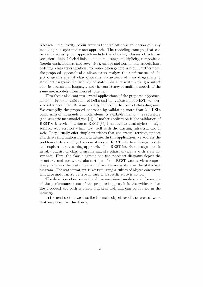
This thesis also contains several applications of the proposed approach.These include the validation of DSLs and the validation of REST web ser-vice interfaces. The DSLs are usually defined in the form of class diagrams.We exemplify the proposed approach by validating more than 300 DSLscomprising of thousands of model elements available in an online repository(the Atlantic metamodel zoo [1]). Another application is the validation ofREST web service interfaces. REST [36] is an architectural style to designscalable web services which play well with the existing infrastructure ofweb. They usually offer simple interfaces that can create, retrieve, updateand delete information from a database. In this application, we address theproblem of determining the consistency of REST interface design modelsand explain our reasoning approach. The REST interface design modelsusually consist of class diagrams and statechart diagrams with state in-variants. Here, the class diagrams and the statchart diagrams depict thestructural and behavioral abstractions of the REST web services respec-tively, whereas the state invariant characterizes a state in the statechartdiagram. The state invariant is written using a subset of object constraintlanguage and it must be true in case of a specific state is active.
The detection of errors in the above mentioned models, and the resultsof the performance tests of the proposed approach is the evidence thatthe proposed approach is viable and practical, and can be applied in theindustry.
In the next section we describe the main objectives of the research workthat we present in this thesis.
5

1.2 Research Objectives
The main objective of this thesis is to study and develop an automaticapproach addressing the following research questions:
I How can one ensure that a class model is consistent?
II How can one detect inconsistencies between different models, expressedin different languages such as class diagrams and statechart diagrams?Assuming the each model is valid with respect to its language, we stillneed to ensure that the model elements of one model do not contradictwith the model elements of the other model.
III How can one validate the constraints applied to models such as: Stateinvariants in the form of Object Constraint Language (OCL)?
IV How can one validate a given model against its metamodel?
V How can one detect the possible inconsistencies that arise due to themerging of multiple models representing different views of the samesystem using the same metamodel?
VI How can we integrate our approach in existing UML modeling tools?
1.3 List of Original Publications
This thesis is based on the articles listed below. The details about thecontribution of the author is stated in the description of each article. Inaddition, the research work presented in this thesis extends and in somecases improves the content of some of the listed publications.
I Hoglund, Soren and Khan, Ali Hanzala and Liu, Ye and Porres, Ivan.Representing and Validating Metamodels using OWL 2 and SWRL. InProceedings of the 9th Joint Conference on Knowledge-Based SoftwareEngineering JCKBSE, Aug 2010 [46].Author’s contribution: The author jointly developed the mainidea of this paper with other authors. The author contributed to thetranslations of UML class diagrams to OWL 2.
II Liu, Ye and Hoglund, Soren and Khan, Ali Hanzala and Porres, Ivan.A Feasibility Study on the Validation of Domain Specific LanguagesUsing OWL 2 Reasoners. In Third Workshop on Transforming andWeaving OWL Ontologies and MDE at TOOLS, Jun 2010 [63].Author’s contribution: This article is the implementation and thevalidation of the work presented in Article I. The author jointly de-veloped the main idea of this paper with other authors. The author
6

contributed to the implementation of UML class diagram to OWL 2translations in the form of a MOFScript-based translation tool. Thetranslation tool is used to translate UML metamodels of the AtlanticZoo into OWL 2 in order to conduct the study shown in this article.
III Khan, Ali Hanzala and Suenson, Espen and Porres, Ivan. Representa-tion and Conformance of UML Models Containing Ordered PropertiesUsing OWL 2. In OrdRing First International Workshop on Orderingand Reasoning, at The 10th International Semantic Web Conference(ISWC) Oct 2011 [57].Author’s contribution: The main idea of this article was jointlydeveloped by all authors. The author and Suenson proposed the trans-lations of UML object diagrams to OWL 2 and developed the transla-tion tool using MOFScript.
IV Khan, Ali Hanzala and Suenson, Espen and Porres, Ivan. Class andobject diagram Conformance using OWL 2 Reasoners. In 12th Sym-posium on Programming Languages and Software Tools SPLST, Oct2011 [58].Author’s contribution: This article is the extension of the workpresented in Article III. The main idea of this article was jointly de-veloped by all authors. The author and Suenson proposed the transla-tions of UML object diagrams with ordered properties to OWL 2 anddeveloped the translation tool using MOFScript.
V Khan, Ali Hanzala and Rauf, Irum and Porres, Ivan. Consistency ofUML Class and Statechart Diagrams. In First International Confer-ence on Model-Driven Engineering and Software Development, MOD-ELSWARD Feb 2013 [56].Author’s contribution: The main idea of this article was jointlydeveloped by all authors. The author and Rauf proposed the trans-lations of UML statechart diagrams and OCL constraints to OWL 2and developed the prototype of the translation tool using Python.
VI Rauf, Irum and Khan, Ali Hanzala and Porres, Ivan. Analyzing Con-sistency of Behavioral REST Web Service Interfaces . The 8th Interna-tional Workshop on Automated Specification and Verification of WebSystems, WWV, Jun 2012 [86].Author’s contribution: This article is the implementation andevaluation of the work presented in Article V. The main idea of thisarticle was also jointly developed by all authors. The author and Raufproposed the translations of UML diagrams and OCL constraints de-picting an interface of a REST Web service to OWL 2 and developedthe prototype of the translation tool using Python.
7

1.4 Research Contribution Overview
The summary of the research objectives that we address in different articlesis given in Table 1.1. In this table, the rows refer to the research objectivesthat we address in this thesis, and the columns point to the articles onwhich these research objectives are based.
Table 1.1: Research contribution overview.
Research PublicationsObjectives I II III IV V VI
I X XII X XIII X XIV X XV X X X XVI X X X X X X
1.5 Thesis Organization Overview
This thesis is organized as follows: Chapter 2 discusses the terminologiesused in this thesis, such as: MDE, UML, ontology foundations, descriptionlogic and OWL 2. Chapter 3 describes the related work. The related work iscategorized according to the problems discussed in the rest of the chapters.Chapter 4 discusses the translations of UML class diagram concepts, DPFand OCL constraints into OWL 2. This chapter is based on the workpresented in Articles I, III and V. Chapter 5 presents the application of theUML class diagrams translations proposed in Chapter 1, and discusses howto validate the UML class diagrams available in the Atlantic metamodelzoo (an online repository containing more than 300 metamodels) by usingOWL 2 reasoners. This chapter is based on the work presented in ArticleII. Chapter 6 addresses the issue of the consistency of class diagrams andstatechart diagrams with state invariants. This chapter is based on thework presented in Articles I and V. Chapter 7 presents the applicationof the work discussed in Chapter 6 by using a scenario of a REST webservice interface. It is based on the work described in Articles V and VI.Chapter 8 discusses the translation of UML object diagraming concepts intoOWL 2, and also describes how to validate these concepts using OWL 2reasoners. This chapter is based on the work presented in Articles I, IIIand IV. Chapter 9 proposes the method of the validation of multiple UMLdiagrams of the same metamodel using OWL 2 reasoners. This chapter isbased on the lessons learned from the Articles I, III, IV and V. Finally,Chapter 10 concludes the thesis.
8

Chapter 2
Background
In this chapter, we give an overview of the MDE foundations, ontologyfoundations and the validation problems that we address in this thesis. Wealso discuss the proposed approach that addresses these problems.
2.1 MDE Foundations
Model Driven Engineering (MDE) [55] advocates the use of models to rep-resent the most relevant design decisions of a software development project.Each software development project involves the creation of many models.A model is a description or an analogy used for describing, visualizing andobserving different viewpoints of a system at different levels of abstrac-tions [77]. Each model in a software development project is described byusing a particular modeling language, such as UML or DSL. A modeling lan-guage is an abstract syntax for models that specifies the allowed elementsand their relationships in the form of a metamodel [77]. Similarly, eachmodeling language is designed by using a meta-language, such as Meta Ob-ject Facility (MOF) [71] or Kernel Meta Meta Model [52]. A meta-languageis defined in term of metametamodel that describes the meta-language ar-chitecture for the designing of metamodels or DSLs [77].
2.1.1 Four Layer OMG Modeling Hierarchy
The Object Management Group (OMG) [71] specifies the object orientedmodeling concepts in the form of a four layer modeling hierarchy. Eachlayer represents different types of instances involved in the object orientedmodeling such as, objects are the instances of classes, and the classes arethe instances of meta-classes, where classes are the part of a model, andmeta-classes are the part of a metamodel ([43], p.5). These layers are namedas M3, M2, M1 and M0. A graphical overview of these layers is given inFigure 2.1. The details about these layers are as follows:
9
M3 (MetaMetaModel) MOF M2 (MetaModel) UML / DSL M1 (Model) Class Diagrams / StateChart Diagrams / Object Diagrams /..... M0 (Instances) Object Diagrams
«snapshot»
«instance»
«instance»
«instance»
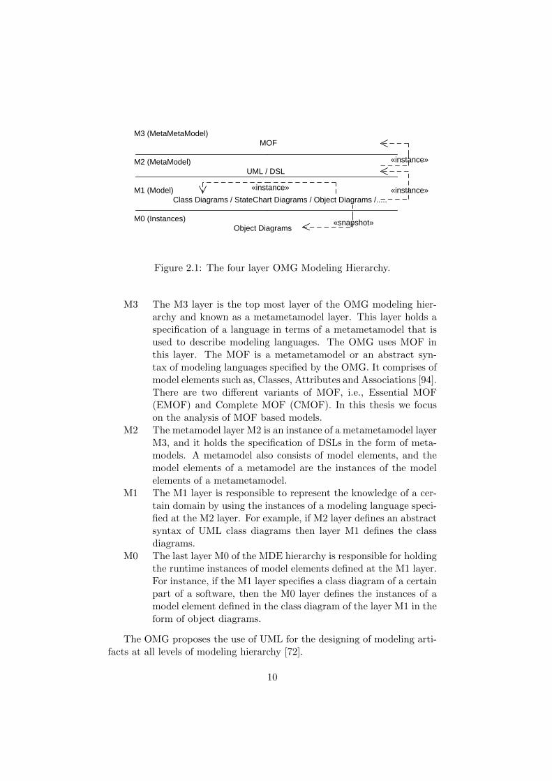
Figure 2.1: The four layer OMG Modeling Hierarchy.
M3 The M3 layer is the top most layer of the OMG modeling hier-archy and known as a metametamodel layer. This layer holds aspecification of a language in terms of a metametamodel that isused to describe modeling languages. The OMG uses MOF inthis layer. The MOF is a metametamodel or an abstract syn-tax of modeling languages specified by the OMG. It comprises ofmodel elements such as, Classes, Attributes and Associations [94].There are two different variants of MOF, i.e., Essential MOF(EMOF) and Complete MOF (CMOF). In this thesis we focuson the analysis of MOF based models.
M2 The metamodel layer M2 is an instance of a metametamodel layerM3, and it holds the specification of DSLs in the form of meta-models. A metamodel also consists of model elements, and themodel elements of a metamodel are the instances of the modelelements of a metametamodel.
M1 The M1 layer is responsible to represent the knowledge of a cer-tain domain by using the instances of a modeling language speci-fied at the M2 layer. For example, if M2 layer defines an abstractsyntax of UML class diagrams then layer M1 defines the classdiagrams.
M0 The last layer M0 of the MDE hierarchy is responsible for holdingthe runtime instances of model elements defined at the M1 layer.For instance, if the M1 layer specifies a class diagram of a certainpart of a software, then the M0 layer defines the instances of amodel element defined in the class diagram of the layer M1 in theform of object diagrams.
The OMG proposes the use of UML for the designing of modeling arti-facts at all levels of modeling hierarchy [72].
10

2.1.2 UML
The Unified Modeling Language (UML) is a widely used graphical notationfor the designing of modeling artifacts at all layers of the OMG modelinghierarchy, i.e., Metametamodel, Metamodel and Model layer [77, 43]. TheUML was formally proposed by OMG in 1997 ([60], p.176) and it is basedon MOF. The main purpose of UML is to help IT professionals in the de-signing of computer applications. With time UML evolved considerablyand still the scope of UML is expanding rapidly. Nowadays, UML is notonly used in the designing of computer applications, but also in the auto-matic model based software development, which includes automatic codegeneration from models.
A software project involves the creation of many designs that depictboth static and behavior abstractions of a software project. The UML hasa capacity to portray both kinds of abstractions. The static structure of asoftware project is captured by using a class diagram, whereas, a behaviorof the software is designed using statechart diagrams or sequence diagrams.A class diagram is a collection of classes and their associations. A class ina class diagram can depict the attributes and operations, but the actualbehavior of these operations is captured by using behavioral diagrams.
The UML behavioral diagrams, such as statechart diagrams and se-quence diagrams, are used to describe behaviour of an object of a classduring its lifetime. These diagrams are composed of states and transitions,where each transition is annotated with an operation. The operation on thetransition describes what happens to the object during its whole lifetime.Each state in a statechart diagram is made using state invariant. A stateinvariant is a condition that characterises the state and must be true incase of a specific state is active. These invariants are written using objectconstraint language or some other constraint language.
In this thesis, we are focused on the analysis of modeling artifacts basedon UML/MOF.
2.1.3 Meta Object Facility
The Meta Object Facility (MOF) is a standard for MDE [55], and it is basedon the UML superstructure specifications [77] specified by OMG. The MOFis used for defining UML based metamodels. It consists of model elementssuch as, Classes, Attributes and Associations [94]. The relevant part ofMOF architecture used in this thesis is shown in Figure 2.2. In this thesiswe mainly focus on the validation of metamodels and models. The modelvalidation includes the validation of class diagrams, object diagrams andstatechart diagrams including constraints written using a subset of OCL.Therefore, the MOF architecture that we present here is restricted to the
11

fragment, which describes the metamodels that are capable to define bothstatic and behavioral structure of a software project.
ModelElementname: String
Namespace Constraint TypedElement
GeneralizableElement
Package Classifier
Class Association DatatypeOperation
EnumerationType
Feature
Behavioral Feature
StructuralFeaturemultiplicity: MultiplicityType
Exception
Reference
Attributes
AssociationEndisNavigable: Booleanmultiplicity: MultiplicityType
exposedEnd
*
referencedEnd *
type
*
MultiplicityTypeupper: Integerlower: IntegerisUnique: BooleanisOrdered: Boolean
*
subtype
Figure 2.2: A fragment of MOF Metametamodel.
The model of MOF is based on the foundation of object relationshipmodeling. Here, the model elements Class, Association and Datatypeare used to define the objects, links and data values, respectively. Allthese model elements are derived by Classifier, and every Classifieris derived by a GeneralizableElement and has a Namespece. Each el-ement of the Namespace is derived by a ModelElement. Every objectcan have attributes and operations which are described by the model el-ement Attributes and Operations respectively, where the model elementAttributes is derived by StructuralFeature and the model elementOperat−ion is derived by BehavioralFeature. Similarly the attributes of associ-ations, such as multiplicity, ordering, uniqueness and navigability are de-scribed by the attributes of the model element AssociationEnd. The modelelement AssociationEnd is derived by the model element TypeElement.The referenced and exposed end of the association is defined by the modelelementReference, which is derived from the model element StructuralFe−ature. The additional constraints on metamodels in the form of OCL or in
12

the other textual format are described by the model element Constraint.The model element Constraint in the MOF metametamodel is derived byModelElement.
2.1.4 Constraints
The UML models can be annotated with constraints. The constraints areused to add additional restrictions on the models. These constraints mayalso have errors and can make whole model inconsistent. In this thesis,we also discuss the semantic meaning of a subset of constraint languagesand show how to validate the UML diagrams with constraints using logicreasoners. The constraint languages that are supported by the proposedapproach are as follows:
Object Constraint Language (OCL): OMG specifies the UML well-formedness rules and a part of UML semantics by using the Object Con-straint Language (OCL) [74]. The OCL is a textual constraint language andis always specified by using certain OCL constructs, for example, context,inv, value and size. The OCL constraints are also used to apply additionalrestrictions over UML diagrams that cannot be applied using existing UMLnotations. The constraints are also known as invariants.
Diagram Predicate Framework (DPF): In order to apply restric-tions on UML diagrams, there are also other textual constraint languagesavailable, one of them is proposed by the Diagram Predicate FrameworkDPF [61]. DPF proposes to apply constraints by adding a textual symbolover the existing UML notations, such as [irr], [inj] and [bij].
The detail about the semantics of different types of constructs supportedin our approach, and how to analyze UML diagrams with these constraintswill be discussed later in different chapters of this thesis.
2.1.5 XML Metadata Interchange
The XML Metadata Interchange (XMI) [73] is a Extendable Markup Lan-guage (XML) [99] based standard for a model interchange specified byOMG. The models are composed of model elements and each model el-ement has some attributes. In XMI each model element of a model isrepresented as a XML element with unique ID, and an attribute of a modelelement is represented as a XML element attribute. In models, the modelelements are usually interconnected with each other. In XMI the intercon-nection between XML elements is achieved by using the ID of one XMLelement as a reference in another. The modeling tools usually generate
13

the XMI of UML models in some specific format. The XMI format that isunderstandable by our approach is the XMI 2.1 schema for UML 2.3.
2.2 Ontology Foundations
An ontology is a specification of a conceptualization [62]. In this thesisour understanding of the term ”specification of a conceptualization” is thespecification of concepts and relationships that can represent an abstractionof a program. The abstraction of a program is typically expressed in theform of models by using modeling languages such as UML or DSLs. Forexample the fact that a class C1 is a subclass of a class C2 is drawn byusing UML, as given in Figure 2.3.
C2
C1
Figure 2.3: A UML model depicting a class C1 being a subclass of a classC2.
In logics the abstraction of a program is expressed in the form of logi-cal facts using logical languages such as description logic [48] or predicatelogic [35]. For example the fact depicted in Figure 2.3 that the class C1 isa subclass of the class C2 is written in description logics as:
C1 ⊆ C2
In ontologies the concepts are represented in the form of axioms thatdepict the specification of a conceptualization [62]. These axioms representconcepts as classes, and the relationship among concepts as properties.Since the ontology deals with concepts and their relationships, the languageused for writing an ontology is semantically very close to the language usedto express the logic [62]. This allows us to write the logical facts as axiomsin the ontology. For example, the specialization relation C1 ⊆ C2 (shownin Figure 2.3) is written in ontology as:
SubClassOf( C1 C2 )
The ontologies are typically used at the semantic level, due to this, theyplay an essential role in the interoperability of heterogeneous systems. Also,ontologies are part of the W3C standards [23]. The main role of ontologiesin the semantic web is to act as a knowledge base that represents data mod-els at all levels of abstractions. The prominent use of ontologies includes
14

interoperability of systems containing multiple database searches using dif-ferent web services [62]. However, in this thesis we are using ontologies torepresent the semantics of UML models as logical facts, so that we mayable to infer the logical consequences from these logical facts automaticallyusing a reasoner.
2.2.1 Reasoners
A reasoner is a utility that automatically infers the logical consequencesfrom a set of logical facts. The reasoning performed by a reasoner is basedon the inference rules [14]. These rules are written in a form of a logic, oftenby using description logic or first-order predicate logic [14]. The reasoningis typically carried out by forward chaining and backward chaining [28]. Areasoner takes a set of logical facts as an input and then checks if each ruleis valid or not. A fact is valid if it follows the inference rules implementedin a reasoner. If the fact is true under an interpretation, then so is theconclusion.
2.2.2 Description Logic
The Description Logic (DL) used in our approach is classified as SROIQ [48].Description Logic is made up of concepts, denoted here by C,D, and roles,denoted here by R,Q. A concept or role can be named, also called atomic,or it can be composed from other concepts and roles.
An interpretation I consists of a non-empty set ∆I and an interpreta-tion function which assigns a set CI ⊆ ∆I to every named concept C anda binary relation RI ⊆ ∆I ×∆I to every named role R.
The constructors of Description Logic are as follows:
Everything >I = ∆I
Nothing ⊥I = ∅Complement (¬C)I = ∆I\CI
Inverse (R−)I = {(y, x) | (x, y) ∈ RI}Intersection (C uD)I = CI ∩DI
Union (C tD)I = CI ∪DI
Restriction
Universal (∀R.C)I = {x | ∀y.(x, y) ∈ RI → y ∈ CI}Existential (∃R.C)I = {x | ∃y.(x, y) ∈ RI ∧ y ∈ CI}Cardinality (≥ nR)I = {x | #{y | (x, y) ∈ RI} ≥ n}
(≤ nR)I = {x | #{y | (x, y) ∈ RI} ≤ n}
15

where #X is the cardinality of X. The axioms in DL can be either inclu-sions C v D, C v D or equalities C ≡ D, R ≡ Q.
An interpretation satisfies an inclusion C v D if CI ⊆ DI and aninclusion R v Q if RI ⊆ QI . An interpretation satisfies an equality C ≡ Dif CI = DI and an equality R ≡ Q if RI = QI . I satisfies a set of axiomsif it satisfies each axiom individually – I is then said to be a model of theset of axioms. Given a set of axioms K, a named concept C is said to besatisfiable if there exists at least one model I of K in which CI 6= ∅. A setof axioms is said to be satisfiable if all of the named concepts that appearin the set are satisfiable. If a set of axioms K is satisfiable, we say that anaxiom φ is satisfiable with respect to K if K ∪ {φ} is satisfiable. Similarly,we say that φ is unsatisfiable (w.r.t. K) if K ∪ {φ} is unsatisfiable.
The decidability of SROIQ is demonstrated by Horrocks et al. [48], andthere exist several reasoners that can process answer satisfiability problemsautomatically [90, 83].
2.2.3 Web Ontology Language OWL 2
The Web Ontology language OWL 2 [23] is a language for defining ontolo-gies. The OWL 2 provides axioms to express model-theoretic semanticswhich are compatible with the DL SROIQ such as classes, properties,individuals and data values [23]. The OWL 2 is also supported by logicreasoners such as Pellet [90] and HermiT [83]. In this thesis, we use theOWL 2 functional syntax (OWL2fs) [20] to explain the translations of UMLconcepts to OWL 2 axioms. The UML to OWL 2 translation that we pro-pose in this thesis is also implemented in the form of a translation tool. Thetranslation tool generates OWL 2 files that contain the translations of UMLmodels in two different syntaxes such as: OWL2fs and OWL 2 Manchestersyntax. The reason of generating outputs in two different OWL 2 syn-taxes is because we want to analyze the performance of different reasoners.The detail about the performance of different reasoners will be discussedin Chapter 5. The interpretation of the main OWL 2 expressions used inthis thesis is shown in Table 2.1. A complete description of the OWL 2semantics, including support for data types can be found in [23].
C2
C1
min..maxA
Figure 2.4: The UML Model representing two classes C1 and C2 connectedwith each other using the association A.
16

Table 2.1: DL interpretation of the main OWL 2 expressions used in thisthesis
OWL 2 DL
SubClassOf(C D) C v DEquivalentClasses(C D) C ≡ DDisjointClasses(C D) C uD = ∅ObjectIntersectionOf(C D) C uDObjectUnionOf(C D) C tDSubObjectPropertyOf(R1 R2) R1 v R2InverseObjectProperties(R1 R2) R1 ≡ R2−1
InverseFunctionalObjectProperty(R) > v (≤ 1R−)ObjectPropertyDomain(R C) ∃R.> v CObjectPropertyRange(R C) > v ∀R.CObjectMinCardinality(n R) ≥ nRObjectMaxCardinality(n R) ≤ nRObjectExactCardinality(n R) (≥ nR) u (≤ nR)ClassAssertion(C x) C(x)ObjectPropertyAssertion(R x y) R(x, y)NegativeObjectPropertyAssertion(R x y) −R(x, y)
Example: The OWL 2 translation of the UML model shown in Fig-ure 2.4 is as follows:
Declaration(Class(C1))
Declaration(Class(C2))
Declaration(ObjectProperty(A))
ObjectPropertyDomain( A C1 )
ObjectPropertyRange( A C2 )
SubClassOf( C1 ObjectMinCardinality( min A ) )
SubClassOf( C1 ObjectMaxCardinality( max A ) )
2.2.4 Ontology Definition Metamodel
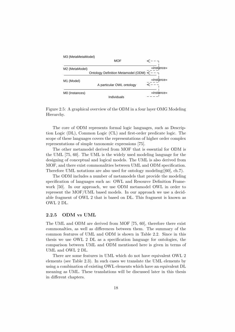
The OMG specifies the Ontology Definition Metamodel (ODM) [75] thatmakes the concepts of OMG modeling hierarchy applicable to the ontol-ogy engineering [75]. The ODM follows the similar hierarchy as the onementioned in a four layer OMG modeling hierarchy (see Figure 2.1). Theoverview of the ODM hierarchy is shown in Figure 2.5.
The ODM is a specification of ontology structure, and it is derived fromMOF [75, 60]. It comprises of classes, associations and constraints ([60],ch.7).
17
M3 (MetaMetaModel) MOF M2 (MetaModel) Ontology Definition Metamodel (ODM) M1 (Model) A particular OWL ontology M0 (Instances) Individuals
«instance»
«instance»
«instance»
Figure 2.5: A graphical overview of the ODM in a four layer OMG ModelingHierarchy.
The core of ODM represents formal logic languages, such as Descrip-tion Logic (DL), Common Logic (CL) and first-order predicate logic. Thescope of these languages covers the representations of higher order complexrepresentations of simple taxonomic expressions [75].
The other metamodel derived from MOF that is essential for ODM isthe UML [75, 60]. The UML is the widely used modeling language for thedesigning of conceptual and logical models. The UML is also derived fromMOF, and there exist commonalities between UML and ODM specification.Therefore UML notations are also used for ontology modeling([60], ch.7).
The ODM includes a number of metamodels that provide the modelingspecification of languages such as: OWL and Resource Definition Frame-work [50]. In our approach, we use ODM metamodel OWL in order torepresent the MOF/UML based models. In our approach we use a decid-able fragment of OWL 2 that is based on DL. This fragment is known asOWL 2 DL.
2.2.5 ODM vs UML
The UML and ODM are derived from MOF [75, 60], therefore there existcommonalties, as well as differences between them. The summary of thecommon features of UML and ODM is shown in Table 2.2. Since in thisthesis we use OWL 2 DL as a specification language for ontologies, thecomparison between UML and ODM mentioned here is given in terms ofUML and OWL 2 DL.
There are some features in UML which do not have equivalent OWL 2elements (see Table 2.3). In such cases we translate the UML elements byusing a combination of existing OWL elements which have an equivalent DLmeaning as UML. These translations will be discussed later in this thesisin different chapters.
18

Table 2.2: UML elements which have the DL equivalent OWL 2 DL ele-ments
UML Elements OWL Elements
class class
instance individual
binary association property
binary association link property assertion
class generalization subclass
property generalization subproperty
enumeration oneOf
multiplicity min/max/exact Cardinality
navigation domain/range
datatype datatype
2.2.6 Open and Closed world assumptions
Although there are commonalities between UML and OWL, still there ex-ists a foundational difference between UML and OWL, i.e. the open worldand closed world assumptions. The UML follows closed world assumptionswhere complete knowledge is assumed to be provided, whereas in OWL 2the knowledge, which is not provided, remains unknown. This knowledgeincludes the well-formedness rules which are defined in the UML super-structure specifications [77].
While reasoning about the UML models using an OWL reasoner werealize that the representation of UML elements using only the obviousOWL 2 axioms is not enough, because it lacks UML well-formedness. Forexample in UML an object cannot belong to two classes, except when thesetwo classes are in a specialization relationship, whereas in OWL 2 an in-dividual (class assertion or object) can belong to many classes except tothose classes, which are marked as disjoint with each other. In this thesis,we make sure that the translations that we present in this thesis follow theUML well-formedness rules and also bridge the gap of open-close assump-tions between UML and ontologies.
2.3 Analyzing UML Models
Analysis of UML models and metamodels is very important at all layersof OMG modeling hierarchy [104, 85, 96, 15, 41, 3]. The analysis approachof UML models presented in this thesis addresses a number of validation
19

Table 2.3: UML elements which do not have the DL equivalent OWL 2 DLelements
UML Elements OWL Elements
ordering X
composition X
composition unshearedness X
composition acyclicity X
non-unique properties X
label on a link X
state X
transition X
state invariant X
OCL constructs X
DPF textual symbols/constructs X
problems throughout the MOF modeling hierarchy. The validation prob-lems that we address in this thesis are as follows:
Validation of Metamodels against MOF: Two problems are ad-dressed: (1) Are all model elements of metamodels at layer M2 instancesof model elements of a metametamodel that exists at layer M3?, (2) Doall model elements of a metamodel at layer M2 follow the well-formednessrules specified at the layer M3?
Validation of Models against Metamodels: Two problems are ad-dressed: (1) Are all model elements of the models at layer M1 instances ofmodel elements of a metamodel that exists at layer M2? (2) Do all modelelements at layer M1 follow the constraint expressing the well-formednessand other constraints in the form of OCL or textual symbols specified atlayer M2?
Validation of Models against Models with Constraints: Twoproblems are addressed: (1) Do the valid models of different metamodelsat layer M1 contradict with one another when viewed together? We addressthis problem by checking consistency of a class diagram and a statechartdiagram with state invariants altogether. (2) Do the valid models of thesame metamodel at layer M1 contradict with one another when viewedtogether. We address this problem by validating multiple valid models ofthe same metamodel together, so that the possible contradictions that arisewhen we view multiple models together can be detected.
20

M3 (MetaMetaModel) MOF M2 (MetaModel) UML / DSL M1 (Model) Class Diagrams / StateChart Diagrams / Object Diagrams /..... M0 (Instances) Object Diagrams «snapshot»
conforms-to
conforms-to
conforms-to
conforms-to
Figure 2.6: An overview of a Metamodel/Model conformance hierarchy.
Validation of Object Diagrams against Class Diagrams: Twoproblems are addressed: (1) Are model elements of object diagrams at layerM0 instances of the model elements of class diagrams that exist at layerM1, (2) Do model elements on layer M0 follow the well-formedness rulesand other constraints expressed by using OCL or textual symbols specifiedat layer M1.
In order to address all above mentioned validation problems, we proposeto automatically translate UML metamodels and/or models into OWL 2 [48],and analyze these translations using automated OWL 2 reasoners [90, 83].
2.3.1 OWL 2 Reasoners
We have several selection criteria for the reasoners, which include, first, acomplete support for OWL 2 and Semantic Web Rule Language (SWRL,discussed later Chapter 4), and second, the reasoner is freely available asopen source. The first requirement is motivated by the ontologies used inour research. The second requirement ensures that the research is easilyrepeatable by others.
Based on these criteria, we have chosen the following two reasoners:
1. Pellet [90]: An open source Java-based ontology reasoner developedby Clark& Parsia LLC, which is an R&D firm, specializing in Seman-tic Web and advanced systems.
2. HermiT [83]: An open source reasoner that is implemented in Java,and developed by the Information Systems Group of Oxford Univer-sity.
21

Metamodel and/or Models with/without Invariants
Translation Tool
OWL2 OntologyOWL2 ReasonerReport
Figure 2.7: Workflow of the proposed consistency checking approach
Both reasoners are implemented in Java, offer complete support for OWL 2and SWRL and are freely available as open source, which satisfy our re-quirements.
2.3.2 Reasoning Tool Chain for UML Models
The workflow of our approach is shown in Figure 2.7. A number of UMLmetamodels/class diagrams and object diagrams or statechart diagrams aretaken as an input. All the inputs are translated to a decidable fragmentof OWL 2, i.e., OWL 2 DL [20]. We have chosen OWL 2 DL to representour UML models, because there exist several OWL 2 reasoners [90, 83] forchecking concept satisfiability. In the next step, the OWL 2 translationsof UML diagrams are passed to a reasoner in the form of an ontology.The reasoner processes the ontology and produces a validation report. Thevalidation report reveals the inconsistencies in the ontology representing theUML models. The detailed discussion about the contents of the validationreport are discussed later in different chapters of this thesis.
22

Chapter 3
Related Work
In this chapter, we discuss the most important related works done by otherresearchers in the area of model validation. The discussion included in thischapter is categorized according to the problems that we address in the restof the thesis.
3.1 Consistency of UML Class Diagrams
Description Logics: The pioneering work in the area of DL formaliza-tion of UML class diagrams was presented by Berardi et al. [19]. Their ap-proach is purely theoretical, and gives very detailed formalization of UMLclass diagrams using DL. We consider their work as a starting point ofour research, specially in the area of metamodel validation. In our work ofmetamodel validation, we expand the scope of their work, by addressing theformalization of some of the important class diagram concepts, which werenot addressed in their work, such as composition, property specializationand the most specific class assumption. Also, we propose and implementthe DL equivalent OWL 2 translations of UML class diagram concepts inthe form of a translation tool. We have tested the translation tool on pub-lished metamodels. The results indicate that most of the errors discoveredinvolve composition. This clearly shows the importance of the validationof composition and the feasibility of our approach in practice.
Artale et al. [11] proposed an approach that is similar to our approach.However, the problem that they solved, i.e., full satisfiability, is a specialcase of satisfiability. It is not clear why they limit themselves in this way,since the general case of satisfiability is much more useful for validation.
Several authors have proposed formalizations of UML, MOF and Ecoremetamodeling languages, including Akehurst et al. [31], Alanen and Por-res [9], Clark et al. [29], Varro [95] and Van Der Straeten [94]. Balabanet al. [15] discussed the consistency of UML class diagrams with hierarchy
23

constraints. These formalizations can be seen as alternatives to the onepresented here.
Although a lot of work has already been done in the area of class di-agram satisfiability, there is a still room for improvements in the existingworks. The existing works are mostly theoretical or leave out the valida-tion of modeling concepts that we discuss in this thesis. Therefore, whetherthey are actually suited to that purpose, only an actual implementation canshow. The importance of a usable, automatic implementation of a valida-tion approach that has been tested on published examples, as the present,cannot be underestimated. The detail, about the testing of our approachon published examples are discussed in Chapter 5.
Ontology: Parreiras et al. proposed the OntoDSL an ontology basedframework for defining DSLs [101]. Their framework uses KM3, Ontologyand OCL combination at the metametamodel layer M3, whereas our ap-proach uses MOF at layer M3. Their approach also gives the facility ofreasoning of DSLs drawn by using their framework, whereas our approachgives the facility of reasoning of any MOF based DSL which is drawn byusing any tool that follows UML 2 3.0.0. The main evidence of this claim isthe validation of 303 DSLs that exist in the Atlantic Metamodel Zoo. Thedetail about the validation of these DSLs and the results are discussed inChapter 5.
Gasevic et al. discussed the use of UML diagrams to construct ontolo-gies [39]. This is a totally different domain than ours, since their work isbasically in the domain of Ontology Development Modeling.
Rahmani et al. proposed a mapping from OWL to Ecore [84]. Themain idea of their work is to preserve the web knowledge available in theform of ontologies into Ecore. Their work is basically opposite to our work.We translate UML to OWL and their work translates OWL to Ecore.
Alloy: Alloy Analyzer [10] is a tool for the formalization, simulationand verification of UML models. In order to use Alloy, we can either makea metamodel using Alloy script or draw the diagram of a metamodel in aUML modeling tool such as: Magic draw or Topcased and then translatethe metamodel into an Alloy script by using UMLtoAlloy translator [89].However, the UMLtoAlloy translator does not provide the translations ofall UML concepts that we discuss in this thesis. These include composition,ordered properties, non-unique associations and the translation of OCL andtextual constraints. However, any missing translation of UML concepts orconstraints during the translation of UML to Alloy script may lead thewhole validation result to become false positive.
24

OCL: USE [40] is a tool for the validation of UML models using OCLexpressions. In this tool, a UML model is taken as an input along with allits possible well-formedness rules in the form of OCL expressions. Then,the parser parses the UML model and OCL expressions, and checks whetherthe UML model is according to the specifications mentioned in the OCLexpression or not. It means that the overall validation process is based onthe OCL expressions, and if any well-formedness rule of UML is missing,the overall validation process may produce false positive results.
DPF: The Diagram Predicate Framework (DPF) [87] provides a cate-gory theory and graph transformation based formal approach for designingmetamodels and models. The DPF workbench [61] allows us to draw meta-models and models based on UML notations. Also, it gives the facility todraw textual symbols on UML models to express constraints such as: [irr]for irreflexive, [comp] for association composition morphism, [surj] for sur-jective and [inj] for injunctive associations. However, the DPF workbenchdoes not provide any facility to validate metamodels. Therefore, we alsoaddress this issue in Chapter 4 by translating the textual constraint intoan OWL 2 ontology and then validate the ontology by using an OWL 2reasoner.
TWOUSE Approach: The TWOUSE approach [6] is focused on twoareas: The first is the ontology development modeling [78], and the secondis the validation of DSLs by using OWL 2 reasoners [100]. The TWOUSEapproach proposes the same methodology for the validation of DSLs as pre-sented in this thesis for the validation of metamodels. However, it leavesout some of the important UML concepts such as: composition includingunshared and acyclicity constraints, open-world assumptions in the transla-tion of class specializations and class memberships, non-unique associations,ordered properties, and the validation of basic textual constraints like OCLand the constraints proposed by the DPF. Their work is mainly conductedin parallel with our work on the metamodel validation i.e., during the year2010. Moreover, their work on the validation is limited to the validationof DSLs and does not offer the validation of object diagrams against theclass diagrams, nor analyzes the consistency of statechart diagrams with orwithout invariants.
3.2 Consistency of Class and Statechart Diagrams
Description Logics: The use of ontology languages and descriptionlogic in the context of model validation has been proposed in the past bydifferent authors [94, 102, 19, 16]. However, to the best of our knowledge,
25

none of them has addressed the reasoning of the satisfiability of state invari-ants using OWL 2 DL. These works focus on the problem of class diagramssatisfiability, i.e. whether a class diagram can generate consistent objectdiagrams or not. Furthermore, the TWOUSE approach [100] is focused ontwo areas: The first is the ontology development modeling, and the secondis the translation and validation of Domain Specific Languages (DSL) byusing OWL 2. The TWOUSE approach proposed the same methodologyfor the validation of DSLs as presented in this thesis. However, their workon validation is limited to the validation of DSLs, and has not yet offeredthe validation of statechart diagrams with state invariants.
B-Method and CSP: Yeung et al. [104] analyzed control looping to finddeadlocks, by translating class diagrams into the B-Method and statechartdiagrams into CSP. Their approach does not focus on the consistency ofstate invariants, the translation is done manually and there is no discussionabout the verification method, whether it is manual or automatic.
Object-Z, CSP and FDR: Rasch et al. [85], used Object-Z for theformalization of class diagrams and CSP for statechart diagrams. Theirapproach analyzes method invocations against the class description andfinds deadlocks by running the class and statechart diagram formalizationin FDR. Their approach is not focused on analyzing the consistency of stateinvariants.
π-Calculus: Lam et al. [96] analyzed the consistency of statechart dia-grams and class diagrams by using the π-calculus. The translation of UMLdiagrams to π-calculus is done manually and the consistency is analyzedby running the π-calculus script on the Workbench. Their work is notanalyzing the consistency of state invariants.
Program Statements in Transitions: Emil Sekerinski [88] verifiedthe UML statecharts, in which the events are manually translated intogeneralized program statements, and these statements appear as the bodyof a transition. The execution of the program statements is based on theassumption that the body of the transition can read or write the values ofthe class variables.
Alloy: Moaz et al. [68], analyzed the consistency of class and objectdiagrams by using Alloy. It is a fully automatic approach, in which the classand object diagrams are first translated into a parameterized Alloy module,and then the consistency analysis is done by analyzing the translated Alloy
26

module by using the Alloy Analyzer. Their approach does not yet supportstatecharts and OCL constraints.
OCL: The state invariants are usually written by using the Object Con-straint Language (OCL). It is the widely accepted language for writing con-straints over UML diagrams. The reason why the existing research is notfocused on analyzing the satisfiability of state invariants is because, in gen-eral, OCL is undecidable. However, the undecidability can be avoided, if welimit our approach to known constructs of OCL. The use of a limited subsetof OCL to avoid undecidability is not new. For example OCL − Lite [82]uses a limited subset of OCL to express constraints on UML class diagrams.Similarly, in our approach, we use a limited subset of OCL to express stateinvariants in statechart diagrams.
Bogumila et al. [45] analyzed the consistency of the statechart diagramof a class by writing OCL rules manually, and then execute the OCL rules byusing an OCL compiler. This approach is limited to analyzing consistencyof statechart diagrams against the class description and not using stateinvariants. In OCL, the model validation rules must be defined explicitly,based on the syntax of the UML models. In our approach, model validationis defined on the semantic interpretation of the OCL and UML models. Thedifference is that while OCL must define a large number of well-formedrules for different variations and combinations of model elements, a logicapproach requires a smaller number of axioms that are often simpler.
To the best of our knowledge, none of the above mentioned works pro-posed an automatic translation and consistency checking approach for UMLmodels with state invariants.
In the next section, we discuss the most important related works forthe validation of a REST web service interface. The REST web serviceinterface comprises class diagrams and state machine diagrams with stateinvariants. These diagrams depict the structural and behavioral abstrac-tions of a REST web service. In this thesis, we also validate the REST webservice interface in order to show the application of our proposed approach.
3.3 Consistency of REST Web Service Interfaces
Consistency analysis and checking of design models has been studied bya number of researchers in the past, but in the area of web services ithas not been researched very extensively, especially in the area of RESTweb services, we were unable to find any consistency checking approaches.However, in the area of consistency checking for web services, the followingworks are noteworthy.
27

MTT: Yin et al. [105] used type theory to verify consistency of webservices behavior. Their work addresses web services choreography. It an-alyzes the structure of service behavior and uses extended MTT, which isa constructive type theory, to formally describe service behavior. The pro-cedures of deductions are given that verify the suitability between servicesalong with discussion on type rules for subtype, duality and consistency ofweb services behavior.
C & C: In [92] and [93], Tsai et al. presented a specification basedrobust testing framework for web services. The approach first uses anevent driven modeling and specification language to specify web servicesand then uses a completeness and consistency (C & C) approach to analyzethem. Based on these, positive and negative test cases are generated forrobustness testing. The approach assumes that web services are specifiedin OWL-S. The approach aims towards testing of web services. However,C&C analysis is performed on OWL-S specification, which was of interestfor us. The approach identifies missing conditions and events, whereas, ourapproach checks the structure of web services and validates implementationof the service requests.
Model Checking: Xiaoxia [27] verified the service oriented require-ments using model checking. The service-oriented computer independentmodel is used to structure the requirements and then automated modelchecking is done to do completeness and consistency checking of require-ments. It provides a formal definition of completeness checking as a checkthat all the required services are included in a model. Moreover, it does notgives any specific consistency checking constraint except the requirementrelation applied to an example.
Xlinkit Framework: Nentwich et al. [70] presented a static consis-tency checking approach for distributed specifications. It describes xlinkitframework that provides a distribution-transparent language for expressingconstraints between web service specifications. It provides semantics forconstraints that allow the generation of hyperlinks between inconsistent el-ements. The implementation of xlinkit is done on light-weight web serviceusing XML.
CSP: Heckel et al. [42] presented a model-based consistency managementapproach for web service architectures. They advocate the use of UMLclass and activity diagrams for modeling web services. The consistencyproblems are then identified in the UML based development process. Foreach consistency problem, a partial formalization into a suitable semantic
28

domain is done and a consistency check is defined. The consistency prob-lems identified include syntactic correctness and deadlock freedom. Basedon these, those activity diagrams are identified that are relevant to con-sistency checks. These are partially translated to CSP which are thenassembled in a single file and handed over directly to model checker. Thepaper outlined a good consistency management approach for web servicesarchitecture that needs a concrete development.
3.4 Consistency of Class and Object Diagrams
Description Logics and OWL 2: The use of ontology languages anddescription logic in the context of model validation has been proposed inthe past by different authors [94, 79, 65, 84, 102, 19, 11]. However, tothe best of our knowledge, none of them has addressed the reasoning ofcomposition, ordered properties and non-unique properties in detail, neitherthe enforcement of the closed-world restrictions in OWL 2 DL. These worksfocus on the problem of ontology modeling or on class diagram satisfiability,i.e. if a class diagram can be instantiated or not.
OCL: The validation of UML models using OCL has been discussed byseveral authors, including [54, 66]. In OCL, the model conformance rulesmust be defined explicitly based on the syntax of the UML models. In ourapproach, model conformance is defined on the semantic interpretation ofthe models. The difference is that while OCL must define a large numberof well-formed rules for different variations and combinations of model ele-ments whereas a logic approach requires a smaller number of axioms thatare often simpler.
MOVA: MOVA tool [30] provides the facility to draw and validate mod-els against a subset of the UML metamodels. There are a number of limi-tations in this tool, firstly, this tool produces MOVA specific XMI of UMLmodels, and due to this the models generated by using this tool are notreadable by any other modeling tools and vice versa. Secondly, this toolonly supports a limited subset of a UML metamodel and does not supportthe object and class diagram concepts such as: ordered properties and or-dered links, composition and non-unique associations and links. Lastly, thistool admittedly does not support the full OCL syntax.
Alloy: Alloy [10] is a tool for the validation of a model against themetamodel. In order to use this tool we need to give a model and itsmetamodel as an input in the form of an Alloy script. There are someplugins available for example UMLtoAlloy [89], which can transform a UML
29

model into the Alloy script, but the details about whether they can translateUML concepts such as: composition, ordered properties and non-uniqueassociations is missing.
UML Analyzer: UML Analyzer [34], used a text based rulebase for theanalysis of UML models. Any missing translation rule of UML constraintsduring translation may lead the whole validation result to become falsepositive.
3.5 Consistency of Multiple UML Diagrams
The problem of model merging has been discussed by several authors inthe past. For instance, Lutz et al. [64] discussed the merging of modelsby humans. In their approach, the common model elements in modelsare calculated manually, and then models are merged using these commonmodel elements. Moreover, the approaches presented at [18, 7, 67] discussthe difference and union of UML models. These approaches propose to takethe union of all models in order to perform model merge. We have also useda similar approach while merging UML models by translating the union ofall model elements of all models into a single ontology. To the best of ourknowledge, none of the above mentioned works does this using OWL 2.Moreover, they do not discuss the automatic discovery of inconsistencies,which occur due to the merging of different versions of a UML model.
30

Chapter 4
Representation of UMLClass Diagrams in OWL 2
In this chapter, we firstly explain our understanding of UML class diagramconcepts using logic and show how to translate these concepts into OWL 2.Secondly, we discuss different types of textual constraint languages that wetreat in our approach. We also show the equivalent OWL 2 translations ofa subset of these languages. This chapter is based on the works presentedin Articles I, III and V.
4.1 Introduction
The UML class diagrams are defined as a set of classes and their rela-tionships in the form of generalizations and associations ([77],p.144). Thediagrams are used to express the static content or a structure of the sys-tem under development. Unfortunately, the semantics of UML are mostlyspecified semi-formally by means of a textual description [77]. The prob-lem of the automatic validation of these diagrams necessitates the need ofa formalization that can be understood by a reasoner. Therefore, in thischapter, we show the formalization and the corresponding OWL 2 trans-lations of UML class diagram concepts that we address in our approach.The basis for the UML metamodel approach is at the same time the coreset of constructs of the UML class diagrams [76]. Hence, the formaliza-tions presented here can equally well be viewed as a core construction ofMOF/UML-based metamodels. In this chapter, we additionally show theformalization and translation of constraints that can be applied on the UMLclass diagrams, and also motivate our choice of features that are includedin the formalizations.
31

4.2 Basic Class Diagrams
4.2.1 Class
A class in a class diagram represents a collection of objects which share thesame features, constraints and definition. Each class in a class diagram istreated as a class in OWL 2. A UML class C is translated in OWL 2 as:
Declaration(Class(C))
4.2.2 Class Specialization
C2
C1
Figure 4.1: Class Specialization
Class specialization is reduced to the set inclusion. We represent thefact that a UML class C1 is a specialization of UML class C2 with thecondition:
C1 ⊆ C2.
In this case, we say that C2 is a superclass of C1. If two classes C1 andC2 have a common superclass, or C2 is the superclass of C1 we say thatthey are in a specialization relation. The specialization relation C1 ⊆ C2is translated in OWL 2 as:
SubClassOf( C1 C2 )
4.2.3 Disjoint Classes
We assume that an object cannot belong to two classes, except when thesetwo classes are in a specialization relation. In our semantic interpretationof a UML class diagram, it is equally important to denote the facts that twoclasses are not in a specialization relation. This is due to the fact that inobject-oriented models an object cannot belong to two classes, except whenthese two classes are in a specialization relation. We represent the fact thatUML class C1 and UML class C2 are not in a specialization relation withthe condition:
C1 ∩ C2 = ∅With this condition, an object cannot belong to these two classes simulta-neously. Due to the open-world assumption used in Description Logic, weneed to explicitly state this fact in OWL 2 as:
32

C
C1 C2
Figure 4.2: Disjoint Classes
DisjointClasses( C1 C2 )
It is necessary for all classes to either explicitly or implicitly declare thatthey are disjoint to classes that they do not share model elements with.However, given that these axioms need to take the entire class hierarchyinto account, how to efficiently generate this information is not immedi-ately apparent. We have declared every class equivalent to the union ofits subclasses and direct instances — or if it has no subclasses, equivalentto its direct instances. We have therefore provided enough information fora reasoner to be able to deduce which direct instances any given class ismade up of. Correctly declaring the direct instances disjoint is consequentlyenough information for a reasoner to infer if any given pair of classes aredisjoint.
A pair of classes are disjoint if neither is a superclass to or a subclass ofthe other, and they do not share any subclasses. The direct instance classnever has any subclasses, so deciding whether it is disjoint to another classmerely requires that we verify that the class in question is not a superclassof the direct instance. This make it necessary to only traverse part of theclass hierarchy. Furthermore, this approach limits the amount of generatedaxioms to one per class. As classes inherit the properties of superclasses, itis only necessary to include top level classes and its superclasses’ unshareddirect subclasses in the axiom.
4.2.4 Associations
The association is another fundamental concept of UML class diagramsand it represents a basic relationship between the instances of two or moreclasses. We represent a UML directed binary association A from class C1to C2 as a relation:
A : C1xC2
Each association in a class diagram contains two properties, namelyDomainand Range, that represent each end of the association. In our example, C1is the domain and C2 is the range of the association A.
33

C2
C1
min..maxA
Figure 4.3: Association
A UML association A from UML class C1 to C2 is represented in OWL 2as:
Declaration(ObjectProperty(A))
ObjectPropertyDomain( A C1 )
ObjectPropertyRange( A C2 )
4.2.5 Multiplicity
A UML association in a class diagram is annotated with a positive num-ber; this number indicates the multiplicity of an association. Associationmultiplicity describes the number of allowable objects of a range class tolink with the object of a domain class. The multiplicity of an associationdefines additional conditions over this relation:
#{y|(x, y) ∈ A} ≥ min#{y|(x, y) ∈ A} ≤ max
We map the multiplicity of a UML association into OWL 2, by definingthe domain class of an association as a subclass of a set of classes, whichrelates with the same property and the given cardinality.
The UML association A from class C1 and C2 having a multiplicityconstraint of (min,max) is represented in OWL 2 as:
SubClassOf( C1 ObjectMinCardinality( min A ) )
SubClassOf( C1 ObjectMaxCardinality( max A ) )
4.2.6 Bidirectionality
C1 C2A1 A2
Figure 4.4: Association Bidirectionality
34

In UML, the associations that share opposite domain and range forma bidirectional association. For example if A1 and A2 are UML associa-tions and both associations share opposite domain and range, then bothassociations are considered as bidirectional of each other, such that:
A1 = (x, y)|(y, x) ∈ A2
The UML bidirectionality between the associations A1 and A2 is expressedin OWL 2 as:
InverseObjectProperty( A1 A2 )
4.2.7 Association Generalization
C1 C2
A1
A2
Figure 4.5: Association Generalization A1 ⊆ A2
An association can be generalized by another association. The associ-ation generalization is also known as association subsetting. Associationsubsetting allows the specialization of an existing association, with newcharacteristics while retaining its existing features, such as: domain andrange. However, we can reassign a domain and a range of a subassocia-tion, provided that the new domain and the range of a subassociation arethe subclasses of the domain and the range of a parent association. Eachinstance of the specialized association is also an instance of the originalproperty. Therefore, elements that are a part of its slot should be a partof the original association slot. The association subsetting between associ-ation A1 and A2 is defined as:
A1 ⊆ A2
Where A1 is a subassociation of A2, and translated in OWL 2 as:
SubObjectPropertyOf( A1 A2 )
4.2.8 Class Attributes
The class attributes depicting variables of various datatypes such as string,integer or boolean are also considered as relations. In this case, the rangeof the relation A belongs to the set D representing the datatype as:
∀x, y : (x, y) ∈ A =⇒ y ∈ D
35

C+Att1: Integer+Att2: String+Att3: Date+Att4: Boolean+Att4: Enum
Figure 4.6: Class Attributes
Attributes usually have a multiplicity restriction to one value. The at-tributes of a UML class in a class diagram are translated in OWL 2 as aDataProperty. In OWL 2, the data property uses datatype in its range.The datatype can be xsd:boolean, xsd:string, xsd:int and other datatypes(shown in [20],Table 3). We map attributes that use basic types by declaringa data property with the attribute’s name. An attribute is a required com-ponent of its class. Consequently, the data properties describing attributeshave an exact cardinality of one. The attribute Att of the UML class Chaving any of the above mentioned DataType is translated in OWL 2 as:
Declaration(DataProperty( Att ))
SubClassOf(C DataExactCardinality(1 Att ))
DataPropertyDomain( Att C )
DataPropertyRange( Att DataType )
4.2.9 Data Enumeration
«enumeration»Enum
literal_1..literal_n
Figure 4.7: Enumeration Datatype
Enumeration is a kind of datatype, whose instances are user-definedenumeration literals ([77],p.67). The enumeration Enum is declared byusing a DatatypeDefinition axiom in OWL 2 DL. The class attribute Atthaving a datatype Enum, means:
∀x, y : (x, y) ∈ Att =⇒ y ∈ Enum
Where Enum being a set of enumeration literals {(literal1), ..., (literaln)}is represented in OWL 2 as:
DataPropertyRange(Att DataOneOf("literal1"^^datatype ..))
36

4.2.10 Composition
In composition, an object of a class is made up of parts that are the objectsof another class. To give a formal definition of composition, we use a singlepredicate owns to keep track of the composition relationships. If C1 ownsC2 via a composition association P , and P is the property from C1 to C2,then:
C1
C2
P
Figure 4.8: Composition C1 owns C2
∀x, y : (x, y) ∈ P =⇒ x ∈ C1
∀x, y : (x, y) ∈ P =⇒ y ∈ C2
P ⊆ owns
Composition relationships are defined in UML by two constraints, exclusiveownership and acyclicity. Exclusive ownership means that an object canhave only one owner:
∀x, y, z : (x, z) ∈ owns and (y, z) ∈ owns =⇒ x = y
Acyclicity means that an object cannot transitively become an ownerof itself. A situation where an object x owns y, y owns z and z owns x isdisallowed. A necessary and sufficient condition for acyclicity of owns isthat the transitive closure of the relation is irreflexive. We can define thetransitive closure of owns, in the following way:
∀x, y, z : (x, y) ∈ owns and (y, z) ∈ owns =⇒ (x, z) ∈ owns
Irreflexivity of the transitive closure is then simply expressed as:
∀x : x ∈ ∆i =⇒ (x, x) /∈ owns
In order to translate the composition association mentioned above intoOWL 2, we first define an object property named ”P” from class C1 to classC2.
37

Declaration( ObjectProperty( P ) )
ObjectPropertyDomain( P C1 )
ObjectPropertyRange( P C2 )
Next, we consider the exclusive ownership constraint of the compositionon the owning end of a composite relationship. To implement the singleowner requirement of a composition relationship in OWL 2, we have firstly,defined the global property owns as:
InverseFunctionalObjectProperty( owns )
The inverse functional property will restrict the individuals of containingclass to link with more than one individuals of owning class. Secondly, wemake the composite relationship ”P”, a subproperty of the global propertyowns:
SubObjectPropertyOf( P owns )
Moreover, in order to capture the acyclic requirement of the composition,we make owns transitive and irreflexive at the same time. Transitivity willcapture the self ownership and irreflexiveness will disallow the individualbecoming an owner of itself. This is equivalent to saying that the transitiveclosure of the ownership property is irreflexive. However, it is not possi-ble to combine a cardinality restriction with transitive properties [51]. InOWL 2 DL, if we could do so, the logic system would no longer be decid-able, and we would not be able to use a fully automatic reasoner to carryout validation. To solve this problem, we translate transitivity in SemanticWeb Rule Language (SWRL) and irreflexivity in OWL 2. The transitivityof the property owns is written in SWRL as:
owns(?x, ?y) ∧ owns(?y, ?z) =⇒ owns(?x, ?z)
and irreflexivity of owns is translated in OWL 2 as:
IrreflexiveObjectProperty( owns )
4.3 Class Diagrams with DPF Constraints
The Diagram Predicate Framework (DPF) [87] provides the category theoryand graph transformation based formal approach for designing metamodelsand models by using the DPF workbench [61]. The DPF workbench allowsus to draw metamodels and models based on UML notations. Also, it givesthe facility to draw textual symbols on UML models to express constraintssuch as: [irr] for irreflexive, [comp] for association composition morphism,[surj] for surjective and [inj] for injunctive associations. An example of a
38

Student TeacherCourse
PhD Student
[inv] 0..* study
0..*
teach
1..* teacher [surj]
[irr] studyandteach'
0..*
student [surj]
0..* studyandteach[comp]
[inv]
Figure 4.9: The UML class diagram using DPF constraints depicting ascenario that a PhD student cannot enroll in a course that he is teachingby himself.
UML class diagram with DPF constraints is shown in Figure 4.9. In thissection, we show the formalization and OWL 2 translations of a subset oftextual constraints proposed by DPF. All OWL 2 translations we proposein this section are based on the semantics of textual constraints providedin [87]. The OWL 2 translations shown in this section are later passed toan OWL 2 reasoner for the validation of UML models including textualconstraints.
4.3.1 Irreflexive
x:X
R
X
[irr] R
Figure 4.10: Irreflexive Constraint
An irreflexive [irr] constraint on an association disallows an object ofa class to link with itself, i.e., if there exists a concept X which has a selfassociation R and it is irreflexive, then:
∀x ∈ X : x /∈ R(x)
39

The association R having an irreflexive constraint [irr] is translated inOWL 2 as:
IrreflexiveObjectProperty( R )
4.3.2 Injective
x:X
x':X
y:Y
y':Y
y'':Y
f
fX f[inj]
Y
Figure 4.11: Injective Constraint
The injective [inj] constraint of an association restricts an object of adomain class to link to at most one object of a range class. The injectiveconstraint is also known as ”One-to-One”. If we have the association f withthe injective constraint from class X to class Y , then:
∀x, x′ ∈ X : f(x) = f(x′) =⇒ x = x′
The injective property is translated in OWL 2 by using axioms InverseFun−ctionalObjectProperty and FunctionalObjectProperty. The inverse func-tional object property disallows an object of a range class to link with morethan one object of a domain class, whereas, the functional object propertydisallows an object of a domain class to link with more than one object ofa range class. The injective association f is translated in OWL 2 as:
InverseFunctionalObjectProperty(f)
FunctionalObjectProperty(f)
4.3.3 Jointly Injective
The jointly injective [ji] constraint is a collection of injective associations,i.e., if we have three classes X,Y and Z and there exists two injectiveassociations f and g, where f is from X to Y , and g is from X to Z, andboth associations are jointly injective then:
∀x, x′ ∈ X : f(x) = f(x′) and g(x) = g(x′) =⇒ x = x′
40

x:X
x':X
y:Y
z:Z
z':Z
f
gX
f Y
Z
g
[ ji ]
Figure 4.12: Jointly Injective Constraint
In order to translate jointly injective associations in OWL 2, we first declarean object property JInjective in OWL 2, and then, make both injectiveassociations a SubObjectPropertyOf of JInjective. Since, both injectiveassociations share the same domain, the domain of JInjective will be thesame as the domain of injective associations. However, to join both injectiveassociations, the range of JInjective is the union of the range classes ofboth injective associations. The translation of jointly injective associationsmentioned above into OWL 2 is as follows:
Declaration(ObjectProperty(JInjective))
SubObjectPropertyOf(f JInjective)
SubObjectPropertyOf(g JInjective)
ObjectPropertyDomain(JInjective X)
ObjectPropertyRange(JInjective ObjectUnionOf(Y Z))
4.3.4 Surjective
x:X
x':X
y:Y
y':Y
y'':Y
f
f
f
X f[surj]
Y
Figure 4.13: Surjective Constraint
The surjective constraint [surj] of an association allows an object ofa domain class to link to many objects of a range class. The surjective
41

constraint is also known as ”One-to-Many”. If an association f from classX to class Y is surjective, then for every individual in Y , there is at leastone individual in X such that:
f(X) = Y
One-to-many is the by default feature of an object property in OWL 2. Thesurjective constraint on the association f mentioned above is translated intoOWL 2 as:
Declaration(ObjectProperty(f))
ObjectPropertyDomain(f X)
ObjectPropertyRange(f Y)
4.3.5 Jointly Surjective
x:X
z:Z
y:Y
y':Y
z':Z
f
g
g
Xf
g
[ js ]
Z
Y
Figure 4.14: Jointly Surjective Constraint
Jointly surjective [sj] is a collection of surjective associations, i.e., if wehave three classes X,Y and Z and there exists two surjective associations fand g, where f is from X to Y , and g is from Z to Y , and both associationsare jointly surjective then:
f(X) ∪ g(Z) = Y
To translate the jointly surjective associations in OWL 2, we first declarean object property JSurjective in OWL 2, and then, make both surjectiveassociations i.e., f and g, a SubObjectPropertyOf of JSurjective. Tojoin both surjective associations, the domain of JSurjective is the sameas the domain of the surjective associations, and the range is the union ofthe range of both surjective associations. The OWL 2 translation of jointlysurjective associations is as follows:
Declaration(ObjectProperty(JSurjective))
SubObjectPropertyOf(f JSurjective)
42
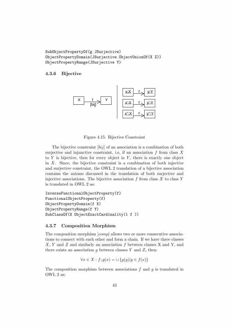
SubObjectPropertyOf(g JSurjective)
ObjectPropertyDomain(JSurjective ObjectUnionOf(X Z))
ObjectPropertyRange(JSurjective Y)
4.3.6 Bijective
x:X
x':X
y:Y
y':Y
y'':Y
f
f
fx'':X
X f[bij]
Y
Figure 4.15: Bijective Constraint
The bijective constraint [bij] of an association is a combination of bothsurjective and injunctive constraint, i.e, if an association f from class Xto Y is bijective, then for every object in Y , there is exactly one objectin X. Since, the bijective constraint is a combination of both injectiveand surjective constraint, the OWL 2 translation of a bijective associationcontains the axioms discussed in the translation of both surjective andinjective associations. The bijective association f from class X to class Yis translated in OWL 2 as:
InverseFunctionalObjectProperty(f)
FunctionalObjectProperty(f)
ObjectPropertyDomain(f X)
ObjectPropertyRange(f Y)
SubClassOf(X ObjectExactCardinality(1 f ))
4.3.7 Composition Morphism
The composition morphism [comp] allows two or more consecutive associa-tions to connect with each other and form a chain. If we have three classesX, Y and Z and similarly an association f between classes X and Y, andthere exists an association g between classes Y and Z, then:
∀x ∈ X : f ; g(x) = ∪{g(y)|y ∈ f(x)}
The composition morphism between associations f and g is translated inOWL 2 as:
43

X Y
Z
f
g fg[comp]
Figure 4.16: Composition Morphism
Declaration(ObjectProperty(f))
Declaration(ObjectProperty(g))
Declaration(ObjectProperty(fg))
However, according to the restrictions on the axiom closure in OWL 2DL ([22], Sec. 11.2), to prevent cyclic definitions involving object sub-property axioms with property chains, it is not possible in OWL 2 DLto use ObjectPropertyChain axiom with SubObjectPropertyOf . If wecould do so, the logic system would no longer be decidable, and we wouldnot be able to use a fully automatic reasoner to carry out validation. Tosolve this problem, we have expressed the OWL 2 object chaining i.e.SubObjectPropertyOf( ObjectPropertyChai-n( f g ) fg ) in SemanticWeb Rule Language (SWRL) [49]. The [comp] constraint mentioned aboveis translated into SWRL as:
f(?x, ?y) ∧ g(?y, ?z) =⇒ fg(?x, ?z)
4.3.8 Example
The class diagram shown in Figure 4.9 is translated to OWL 2 as follows:
Declaration(Class(Student))
Declaration(Class(Course))
Declaration(ObjectProperty( study ))
ObjectPropertyDomain(study Student)
ObjectPropertyRange(study Course)
Declaration(ObjectProperty( hasStudent ))
ObjectPropertyDomain(hasStudent Course)
ObjectPropertyRange(hasStudent Student)
InverseObjectProperties( study student )
SubClassOf(Student ObjectMinCardinality(2 study))
SubClassOf(Student ObjectMaxCardinality(1 study))
44

Since the constraints proposed by DPF apply restrictions on objects,the conformance of the objects against these constraints is discussed inChapter 8.
4.4 Class Diagrams Including OCL Constraints
Context Person inv SelfParent self.hasParent->excludes(self.hasParent)
Person hasParent
Figure 4.17: A UML class diagram with OCL constraints.
The UML specification proposes the use of Object Constraint Language(OCL) [74] to define constraints on UML models, such as the restrictions onthe values of object attributes and the restrictions on the existence of ob-jects by using a multiplicity constraint of an association. These constraintsare combined using boolean operators.
The OCL constraints may also have inconsistencies. According to Wilkeand Demuth [103], 48.5% of the OCL constraints used for expressing thewell-formedness of UML in OMG documents are erroneous. The erroneousOCL constraints may cause a context class in a class diagram to becomeunsatisfiable. In order to identify the inconsistencies in OCL constraints, weneed to do the reasoning of these constraints. But unfortunately, in general,OCL is not decidable. However, we can avoid undecidability by restrictingour approach to a reduced fragment of the full OCL. Therefore, in order touse the reasoners for checking the inconsistencies in OCL constraints, we usea reduced subset of OCL which is limited to the constructs of multiplicity,attributes value and boolean operators. In this section, we discuss andtranslate the different types of OCL constructs supported in our approach.The grammar of OCL supported in our approach is shown in Figure 4.18.
4.4.1 Linking OCL Constraints with Classes in OWL 2
Each OCL constraint of a class diagram comprises a number of elementssuch as context, name and the invariant. These elements hold the name ofa constrained class, the name of an invariant and the constraint in OCL,respectively. The OCL constraints are used to apply restrictions on objectmemberships, i.e. an object can only belong to a particular class if it fulfillsthe conditions applied by the OCL constraint of that class, such that:
45

〈OCL-expression〉 ::= 〈cond-expr〉 (〈logic-op〉〈cond-expr〉)∗〈logic-op〉 ::= and | or〈cond-expr〉 ::= 〈ref〉 →size()〈relational-operator〉〈integer-literal〉
| 〈ref〉〈relational-operator〉〈primitive-literal〉| 〈ref〉 →isEmpty() | 〈ref〉 → notEmpty()| 〈ref〉 →excludes(〈ref〉)
〈ref〉 ::= self.〈identifier〉〈identifier〉 ::= ′{〈characters〉} | 0..9 {0..9}′
〈relational-operator〉 ::= < | <= | > | >= | <> | =〈primitive-literal〉 ::= 〈boolean-literal〉 | 〈integer-literal〉
| 〈string-literal〉 | null〈boolean-literal〉 ::= true | false〈integer-literal〉 ::= 0..9 {0..9}〈string-literal〉 ::= ′{〈characters〉}′
Figure 4.18: The grammar of the supported OCL fragment.
Context ≡ Invariant
4.4.2 Attribute Constraints
The value of the attribute is accessed in OCL by using a keyword self orby using a class reference ([74],p.15), the value constraint of the attributeAtt is written in OCL as self.Att=Value, meaning:
{x|(x, V alue) ∈ Att}
where V alue represents the attribute value. The restriction on the valueof the attribute is translated in OWL 2 by using the axiom DataHasValue.The OCL attribute value constraint self.Att=Value is translated to OWL 2as:
DataHasValue(Att "Value"^^datatype )
In this translation, Att is the name of the attribute, V alue is the value ofthe attribute, and datatype is the datatype of the attribute V alue.
4.4.3 Multiplicity Constraints
The multiplicity of an association is accessed by using the size() operationin OCL ([74],p.144). The multiplicity constraint on the association A inOCL is written as self.A->size()=Value, where V alue is a positive in-teger and represents the number of allowable instances of the range class of
46

the association A. We can use a number of value restriction infix operatorswith the size() operation, such as =, >=, <=, < and >. The multiplicityconstraint on an association A is defined as:
{x|#{y|(x, y) ∈ A}OP V alue}
Where OP is the infix operator and V alue is a positive integer. The trans-lation of the size() operation in OWL 2 is based on the infix operator usedwith the size() operation, such as:
� ”size() >=”or ”size() >”translated using the ObjectMinCardinalityaxiom.
� ”size() <=”or ”size() <”translated using the ObjectMaxCardinalityaxiom.
� ”size() =” translated in OWL 2 using the ObjectExactCardinality
axiom.
For example, the OCL constraint self.A->size()=Value, in which A isthe name of an association and V alue is a positive integer, is translated toOWL 2 as:
ObjectExactCardinality(Value A)
Furthermore, the constructs isEmpty and notEmpty represent size() = 0and size() > 0 respectively. The invariant self.A->isEmpty() is trans-lated in OWL 2 as:
ObjectExactCardinality(0 A)
and similarly the invariant self.A->notEmpty() is translated in OWL 2as:
ObjectMinCardinality(1 A)
The OCL constraints over the multiplicity of an association is furtherextended by using construct excludes. This construct is used to applyrestriction on the objects of a domain class of an association to not to linkwith some specific objects of a range class. For example, if we consider anexample that an object of a class cannot link with itself by using a linkof an association A, such that self.A->excludes(self.A), the constructexcludes in this specific case in translated in OWL 2 as:
IrreflexiveObjectProperty( A )
In OWL 2, an association that is declared Irreflexive disallows an objectof its domain or range class to link with itself.
47

4.4.4 Boolean Operators
The constraints in a state invariant are written in the form of a booleanexpression, and joined by using the boolean operators, such as “and” and“or”([74],p.144).
The binary “and” operator evaluates to true when both boolean expres-sions Ex1 and Ex2 are true. In our translation, this is represented by theintersection of the sets that represent both expressions, i.e.:
Ex1 ∩ Ex2
This is represented in OWL 2 as:
ObjectIntersectionOf(Ex1 Ex2)
The binary “or” operator evaluates to true when at least one of the booleanexpression Ex1 or Ex2 is true. In our translation, this is represented bythe union of the sets that represent both expressions, such as:
Ex1 ∪ Ex2
This is represented in OWL 2 as:
ObjectUnionOf(Ex1 Ex2)
4.4.5 Example
The OCL invariant self.hasParent− > excludes(self.hasParent) has thecontext class Person shown in Figure 4.17 representing a condition that aperson cannot become a parent of itself. The class diagram with the OCLconstraint is translated in OWL 2 as:
Declaration(Class(Person))
Declaration(ObjectProperty( hasParent ))
ObjectPropertyDomain(hasParent Person)
ObjectPropertyRange(hasParent Person)
IrreflexiveObjectProperty(hasParent)
The details about how the inconsistent OCL constraint makes a UMLmodel inconsistent and how to detect the inconsistencies in OCL constraintsusing OWL 2 reasoners is discussed in Chapter 6. Furthermore, the con-formance of the objects against the OCL constraints specified with a classdiagram is discussed in Chapter 8.
48

4.5 Conclusion
In this chapter, we presented the translations of UML class diagrams withor without constraints into OWL 2. These translations allow us to vali-date UML class diagrams with or without constraints using reasoners. Inthe next chapter, we will show how to validate the metamodels or classdiagrams using the translations proposed in this chapter. Also, we discussthe implementation of translations in the form of a translation tool. Thetranslation tool will allow us to automatically translate UML diagrams toOWL 2. The output of the translation tool is later on passed to a reasonerfor the reasoning of translated diagrams.
49

50
Chapter 5
Application: MetamodelValidation
In this chapter, we present an application of the UML class diagram trans-lations proposed in Chapter 4 and discuss how to validate the UML classdiagrama or metamodels using OWL 2 reasoners. Also, we exemplify theproposed approach by validating more than 300 metamodels comprising ofup to thousands of model elements available in an online repository calledthe Atlantic Metamodel Zoo [1]. This chapter is based on the work pre-sented in Article II.
5.1 Introduction
Each software model created during a software development process is de-scribed using a particular modeling language such as the UML or a domain-specific language. The definition of a modeling language is given in the formof a metamodel by using a metamodeling language or a language to definemodeling language.
A metamodel represents constraints on how concepts in a model can berelated to each other, such as multiplicity, domain and range, compositionand subset constraints. A metamodel, like any other software artifact,may contain errors. As an example, let us assume that we are creating ametamodel for a statechart language that includes concepts such as simplestates and composite states that can contain other states and transitionsbetween states. A fragment of such a metamodel is shown in the first half ofFigure 5.1. This metamodel contains a rather obvious contradiction: thereis a property called outgoing with its minimum multiplicity larger than itsmaximum multiplicity. Such contradictions mean that there are no validmodels that can make use of this property.
Another example of a metamodel containing a contradiction is shown
51

1 source 2..1outgoing
Transition
CompositeState
0..*substates
1container
State 1 source 0..*outgoing
1 target 0..*incoming
Transition
1 target 0..*incoming
State
Figure 5.1: Examples of invalid metamodels. Top: Invalid due to themultiplicity error. Bottom: Invalid due to the composition error.
in the second half of Figure 5.1. Here, the multiplicity restriction on thecontainer property leads to each instance of CompositeState having to bein a composite relationship with another instance of CompositeState. Thisviolates one of the composition constraints — elements having only oneowner and there being no cycles in the composition, given a finite set ofinstances of CompositeState. Since models are finite, any conforming modelwill contain a violation of the composition constraints, as exemplified bythe model in Figure 5.2 where the element cs violates the constraint oncycles by owning itself.
t:Transitions:State
cs:CompositeState
source outgoing
container
substates target incoming
container
substates
Figure 5.2: An erroneous model conforming to the bad metamodel in thebottom of Figure 5.1.
As shown in the examples, metamodels can contain errors or contra-dictions. We consider it necessary to validate a metamodel to ensure thatthere are no such problems before they are used. This requires a formaldefinition of a metamodeling language and an approach to reason aboutthe formalized metamodels.
52

5.1.1 Validation Approach
To show the application of the translations proposed in the previous chap-ter, in this chapter we present an approach and a tool to validate meta-models by formalizing the semantics of metamodels in terms of DescriptionLogic (DL) [13] and represent the DL in terms of an ontology language, inour case the OWL 2 Web Ontology Language [21].
By creating a mapping between a metamodeling language (UML) anda DL, we obtain important benefits:
� We provide a formal and unambiguous definition of the metamodelingconcepts that is independent of a specific model repository. This mayhelp ensure interoperability between metamodeling tools.
� Use the same language to represent the constraints that apply tometamodels and the constraints that metamodels impose on models.
� We can use existing reasoning tools to analyze and validate meta-models and detect problems.
The translation from a UML metamodel to an OWL 2 ontology is doneautomatically using a model transformation. Once the ontology of a meta-model has been generated by using our transformation, we use a reasonerto check the ontology consistency and satisfiability.
5.1.2 Consistency Analysis of Metamodels
In our work, the consistency of metamodels is defined with the assumptionthat there is a nonempty set ∆I called the object domain containing allthe possible objects in our domain. We propose that a UML metamodeldepicting a class diagram is interpreted as a number of subsets of ∆I rep-resenting each class in the metamodel and as a number of conditions thatneed to be satisfied by these sets. A metamodel is consistent if each classin a metamodel can be instantiated i.e., if C is a class in the metamodeland C ⊆ ∆I , then C 6≡⊥I must hold.
5.2 Implementation
We have implemented an automatic transformation from UML metamod-els to OWL 2. The transformation is implemented using the model-to-texttransformation tool in the Eclipse Modeling Framework (EMF) by usingMOFScript [5, 8]. EMF is an open source software and provides an opendevelopment platform comprised of extensible frameworks, tools and run-times for building, deploying and managing software across the lifecycle.
MOFScript is an Eclipse plugin for the model to text transformation,for example, to generate code or documentation from models. It providesa framework that allows generating text or code from models based on any
53

kind of metamodel and its instances. Also, the MOFScript language iscurrently a candidate in the OMG RFP process on MOF Model to TestTransformation. MOFScript transformations define a set of rules as to howmetamodel elements should be translated through print statements. Themetamodel input format in our implementation is UML XMI 2.1 parsedaccording to UML 2 3.0.0.
We used the MOFScript subproject for code generation of the UMLclass and object diagrams. This subproject is built for the generation ofMOF-based models, and has the ability to generate text from any MOF-based model, for example, UML models or any kind of domain model, suchas, metamodels expressing the specification of domain specific languages.This subproject also has the ability to specify basic control mechanism,such as, loops and conditional statements. It also provides the facility forstring manipulation and generates the output of expressions referencinga model to a specified output file. In our case, the output files are inboth OWL 2 functional syntax and in Manchester Syntax that carries theOWL 2 translation of UML models, whereas, the SWRL rules are written ina sperate .OWL file wherever it is required, for example, SWRL is requiredfor the translation of composition transitivity.
5.3 Validation of Metamodels at Atlantic Zoo
To evaluate our approach, we conducted a number of experiments wherewe translated the metamodels from the Atlantic Metamodel Zoo to OWL 2ontologies and then validated them by using OWL 2 reasoners.
5.3.1 Selection of Evaluation Data
The Atlantic Metamodel Zoo is a library consisting of 303 metamodelsat the time of writing, maintained by the AtlanMod team. The AtlanModteam does not state the criteria for the inclusion of a metamodel in the zoo,but most of the metamodels seem to have been entered by modeling andcomputer science researchers. The metamodels are available in differentlanguages, including UML 2, OWL, KM3, among others.
The choice of the Atlantic Metamodel Zoo as evaluation suite has bothadvantages and disadvantages. One disadvantage is that the repositoryis not completely recent; many of the published metamodels date backto 2005 or 2006. Another disadvantage is that many of the metamodelspresumably have not been used in practice. The high rate of metamodelscontaining errors, nearly half of the repository, is an indication of this, sincethe erroneous metamodels would most likely have been weeded out if themetamodels had been used in practical work.
54

A related disadvantage is that a part of the errors found seem not tobe conceptual errors introduced by humans, but rather artifacts of conver-sion processes from other formats. This is for example the case with thematemodels listed in table A.5, which are presumably originally written inOWL and subsequently converted to UML.
However, the use of the Atlantic Metamodel Zoo also has advantagesthat we consider outweigh the disadvantages. The main advantage of At-lantic Zoo is that it is publicly available on the Internet. While it would beoptimal to test our approach on live, production use metamodels, it wouldbe quite difficult to obtain a sufficient amount of such metamodels. This isdue to the fact that businesses understandably often consider their meta-models part of business sensitive intellectual property, and as such they arereluctant to release them to researchers.
While it would have been better to use production metamodels for eval-uation, the high rate of errors in the Atlantic Metamodel Zoo can from atesting perspective be seen as an advantage rather than a disadvantage.If we instead had reported 300 flawless production metamodels, we wouldnot have been as convinced of the ability of our approach to actually catcherrors. The high error rate of the Atlantic Metamodel Zoo is unfortunatefrom a metamodeling perspective, but from the perspective of developinga diagnostic tool it is helpful. The same can be said for the errors causedby conversion artifacts in the Atlantic Metamodel Zoo. Instead of being anuisance, they rather show that our approach can catch both automaticallyintroduced errors and those introduced by humans.
5.3.2 Method
We ran our OWL 2 translator through all the examples in the AtlanticMetamodel Zoo and used the reasoners Pellet and HermiT to validate thegenerated ontologies. Given a source metamodel, the process consists ofthree steps:
1. Run the source metamodel through the translator.
2. Check the satisfiability of the generated ontology. If the ontology isinconsistent, it will also be reported in this step.
3. If the reasoner reports a problem, an explanation is generated bythe reasoner in the form of a list of violated axioms. It is necessaryto manually inspect the generated explanation and usually also adiagram of the metamodel in question since the cause of the problemin many cases is not obvious from the explanation.
In our experiment, we ran HermiT 1.2.1 from the command line andused the options -k and -U to check the consistency and concept satisfia-
55

bility, respectively. In the case of Pellet, we used version 2.0.1 and laterversions from the command line and used the options consistency andunsat to check the consistency and concept satisfiability, respectively.
5.3.3 Validation Results
Out of the 303 metamodels, 149 were found to be invalid. The errors arereported in Appendices A.2–A.4. For each metamodel, one or more classesthat are involved in the constraint violation is listed. The class list is notexhaustive. The metamodels may be listed in more than one category.
As can be seen from the Appendixes, the most common error by far isa violation of the one ownership constraint of composition (Appendix A.4).An example of such violation is shown in Figure 5.3.
Figure 5.3: (As in [53, 1]) The metamodel fragment describes an Archi-tectural Description, containing an unsatisfiable class ModelElement. Thismetamodel is unsatisfiable due to the violation of the single owner restric-tion of composition.
There is also a fair number of metamodels violating the acyclic compo-sition constraints. An example of such a violation is shown in Figure 5.4and the list of all violations of acyclic composition constraints found byusing our approach is shown in Appendices A.1 and A.3.
56
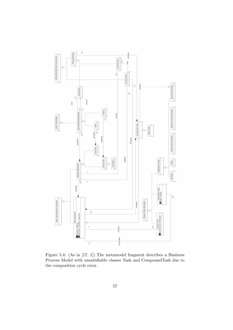
Clo
ck
Se
nd
Co
nm
un
ica
tio
nR
ece
ive
Co
mm
un
ica
tio
n
UM
L::
Na
me
Sp
ace
(a
bstr
act)
UM
L::
Mo
de
lEle
me
nt
(ab
str
act)
Mu
lti T
ask
Ou
tpu
t S
et
Ou
tpu
t
0..
*0
..*
co
nta
ins
Sim
ple
Ta
sk (
ab
str
act)
De
cis
ion
Bu
sin
ess P
roce
ss
Inp
ut
Se
tIn
pu
t0
..*
0..
*
co
nta
ins
Ap
plica
tio
n T
ask
Da
ta F
low
Flo
w (
ab
str
act)
Da
ta E
lem
en
t (a
bstr
act)
1
0..
*
1
0..
*
sin
k
1
0..
*
1
0..
*
so
urc
e
Co
mp
ou
nd
Ta
sk
0..*
0..*
co
nta
ins
rea
lise
s
Invo
ke
r T
ask
syn
ch
ron
ou
s :
Bo
ole
an
Te
rmin
ato
r T
ask
sty
le :
Str
ing
Co
ntr
ol F
low
Da
taS
et
(ab
str
act)
0..
*0
..*
co
nta
ins
1
0..
*
1
0..
*so
urc
e
Ta
sk (
ab
str
act)
fun
ctio
n :
Str
ing
exce
ptio
n_
ha
nd
ler
: B
oo
lea
n3
..*
3..
*
co
nta
ins
0..
*0
..*
co
nta
ins
0..
*
1
0..
*
1
invo
ke
s
1..
*
0..
*
1..
*
0..
*
term
ina
tes
Co
ntr
ol P
oin
t
1
0..
*
1
0..
*
sin
k
1
0..
*
1
0..
*
trig
ge
rs
0..
*0
..*
co
nta
ins
UM
L::
Pa
ram
ete
r
Exce
ptio
n
Figure 5.4: (As in [17, 1]) The metamodel fragment describes a BusinessProcess Model with unsatisfiable classes Task and CompoundTask due tothe composition cycle error.
57
A number of metamodels erroneously declare the same class name sev-eral times, which will generate conflicting restrictions on the class (Ap-pendix A.5). These metamodels all seem to originally have been written asOWL ontologies, where this would not have been an error.
The metamodels that were not found to have problems are not guar-anteed to be free of errors, they are just free from inconsistencies that ourapproach can detect.
A very useful future improvement would be to enhance the way problemsin ontologies are reported. As it is now, the reasoner can give a list ofviolated OWL 2 axioms. However, the relationship between UML conceptsand OWL 2 axioms is not so obvious that it is possible to immediately pointout the cause of the problem based on these violations without manualinspection of the problematic metamodel. It would greatly add to theusefulness of the method to have some sort of automated discovery of thecause of violations.
5.4 Performance Test for Reasoners
We ran our OWL 2 translator through all the examples in the AtlanticMetamodel Zoo [1] and used the reasoners Pellet and HermiT to validate thegenerated ontologies. In our experiments, we ran HermiT version 1.2.5.929and Pellet version 2.2.0. We evaluated the reasoners in terms of maturity,performance, expressiveness, and their problem reporting mechanism.
5.4.1 Expressiveness
The expressiveness is evaluated in two aspects: the concepts contained inthe metamodels and the Description Logic which the reasoners are basedon.
On one hand, the metamodels in the Atlantic Zoo are simple in thesense that they do not cover all the concepts that are within the ability ofthe UML metamodeling language. For example, there are no metamodelsthat contain any ordered properties, ordered composition or ordered subsetproperties. The constraints of these concepts are expressed in SWRL rules.
On the other hand, we noticed problems with UML composition: trans-lating composition to OWL 2 requires the transitivity axiom and irreflexiveaxiom, whereas the OWL 2 specification forbids the two axioms used onthe same object property. This can be solved by expressing them in SWRL,although SWRL rules are only applied on individuals rather than classes.
58

5.4.2 Maturity of Reasoners
Both HermiT and Pellet can process all the ontologies generated from theAtlantic Zoo without generating any runtime error or getting into an infiniteloop. Furthermore, both reasoners always produce the same report for allthe metamodels. This is a significant observation because they have beenimplemented independently by two different development groups. Based onthis, we claim that the current implementation of both HermiT and Pelletare mature enough for the task of validating metamodels.
During our experiment, we found that Pellet 2.0.1 supports OWL 1.1functional syntax [24] which is different from OWL 2 in terms of prefixdeclaration and datatype maps. HermiT supports strict OWL 2 functionalsyntax. The ontologies to be processed by HermiT and Pellet are slightlydifferent syntactically, accordingly, the MOFScript transformation for eachsyntax should be different too.
5.4.3 Performance
We ran our performance experiments using a desktop computer with an In-tel Core 2 6400 processor running at 2.13GHz, 2GB of RAM, Linux FedoraCore 10 and Java 1.6.0 10 rc2. We processed each metamodel three timesand reported the average execution time.
The time taken to translate the metamodels grows exponentially with itssize. 83% of the metamodels took under 10 seconds, but large metamodelscan take a few minutes, with the largest taking 4.5 minutes to translate.Generally, the increase in time follows an exponential curve, however, thegraph shown in Figure 5.5 is a linear graph, because we validate classdiagrams/metamodels without instances. The time taken for the reasonersis generally below 10 seconds; 286 of the 303 ontologies were processedby HermiT in under 10 seconds compared to 282 for Pellet. The resultsare shown in Figure 5.6. However, it should be noted that there are severaloutliers. HermiT, while generally slightly faster than Pellet has five outliersthat take more than 300 seconds to process, while Pellet only has one. Thelongest processing time for HermiT was 131 minutes, while the longest forpellet was 56 minutes.
Figure 5.6 also shows the comparison of the times taken to processeach metamodel by both reasoners. The x-axis represents the number ofaxioms in a generated ontology. The y-axis represents the total time in sec-onds necessary to load an ontology representing a metamodel, and checkit for consistency and satisfiability. As for the counting of number of ax-ioms, though, certain expressions are a combination of OWL 2 axioms. Forinstance, the minimum cardinality in Figure 5.1 is expressed as follows,
59

++
+++
+ ++ +++++
++++++ +++
+
+
+++++ ++++++++++
++++
++
+
+++++++
+
++++++ +++ +++++++++++++ +++
+
+
+
+
++
++++++++++++++++++++ ++++ ++
+
++
+
++ ++
++
+
+++
+
+
++
+
++++
+
+++++++
+
+++++++++ ++ +++++ +
+++ +
+ +++++
++++++ +++++
+
+ +
+
++++
+
+++++++++++ ++ +
+
++++++++ ++
+ +
++++++ +++
+
+
++
+
+
++++
+
+++++++
+++ + ++ ++++++++ +++++++
+
+ ++ +
+
+++++++++++
+
+++++++++++
+
+ + ++++++
0 2000 4000 6000 8000 10000 12000
050
100
150
200
250
Size (number of axioms)
Tim
e (S
econ
ds)
Transformation performance
Figure 5.5: MOFScript transformation performance.
which is a combination of axiom SubClassOf and ObjectMinCardinality,we count this as one axiom.
SubClassOf(State ObjectMinCardinality(2 State_outgoing ))
As we can observe from Figure 5.6, HermiT is consistently faster thanPellet, but both tools can process each metamodel in less than 10 seconds.
Based on this, we consider that the efficiency of the two reasoners issatisfactory for the given problem and an average desktop computer.
5.4.4 Complexity
We used OWL 2 DL for the representation of UML concepts wherever itis possible, and used a decidable fragment of SWRL only for the represen-tation of a model composition constraint. OWL 2 DL is the standardizedformalism of DL which is equivalent to SHOIN (D+). The complexity ofOWL 2 DL with regard to the reasoning problems of ontology consistencyand instance checking is NEXPTIME complete [50], whereas the complex-ity of SWRL is undecidable [49, 106]. The combination of OWL 2 DL andSWRL becomes undecidable [49]. However, if all atoms that exist in theSWRL rule use OWL 2 class and property names are restricted to known
60

0 2000 4000 6000 8000 10000 12000
050
100
150
200
250
300
Size (number of axioms)
Tim
e (S
econ
ds)
+ +++ ++ ++ ++ ++ +++++++ +++ + ++++++ +++++++ +++ ++++ + + +
+++++++++
+++++ +++ +++++++++++++ +++
+
+
+
+ ++++++++++++++++++++++ ++++ ++
+
++
+
++ + +++ +++ + ++++ +++++
+
+++++++
+
+++++++++ ++ +++++ ++++ ++ +++++ ++++++ +++++
+
+ +
+
++++
+
+++++++++++ ++ + +++++++++ +++ +++++++ +++
+
+ +++
++++
+
++++++ ++++ ++
+ ++++++++ ++++++ ++
++
+ +++++++++++++ +++++++++++++
+ + ++++++x xxx xx xx xx xx xxxxxxx xxx x xxxxxx xxxxxxx xxx xxx x x xxxxxxxxx xxxxxx xxx xxxxxxxxxxxxx xxx xxx
xxx
xxxxxxxxxxxxxxxxxxxx xxxx xxx
xxxx x xxx xxx x xxxx xxxxx
x
xxxxxxx xx
x
x xx
xxxx xx xxxxx xxxx xx xxxxx xxxxxx xxxxxx
x xx
xxxx
x
x xxxxxxxxxx xx x xxxxxxxxx xxx xxxxxxx xxx x xx
x
xxxx
x
xx xxxx xxxx xx xxxxxxxx xxxxxx xx
x
x
x xxxxxxxxxxxxx xx xxxxxxxxxxx
x x xxxx xx
+x
PelletHermiT
Satisfiability Checking
Figure 5.6: Reasoner satisfiability checking performance.
individuals, then the SWRL rule is considered DL-Safe rule and becomesdecidable [106, 44]. The data complexity of query answering in the decid-able fragment of SWRL is deterministic exponential time [106].
The ontology generated by the translation tool is written by using bothOWL 2 DL and the decidable fragment of SWRL. In the light of abovediscussion, we conclude that the ontology generated by the translation toolis decidable, and the complexity with regard to the reasoning problems suchas ontology consistency and instance checking is deterministic NEXPTIMEcomplete.
5.4.5 Problem Reporting
Pellet produces an error message if a given input contains a syntax error orthe wrong file header. Such input cannot be further checked for consistencyand unsatisfiability. When checking consistency, Pellet simply shows ifthe input ontology is consistent or not. When checking unsatisfiability,given a consistent ontology, Pellet reports the number of elements checked,time used and number of unsatisfiable elements. If there are unsatisfiableelements, the specific class names are shown.
61

Pellet provides an option to print verbose information while reasoning.The printed information indicates input size, specific number of classes,properties and individuals, expressivity, used time summary, among others.Once an element that leads to an inconsistency is found, Pellet stops furtherprocessing and points out a possible reason, but the actual reason still needsbe verified by users.
HermiT also provides verbose information printing, such as the file un-der processing, and timing for parsing, among others. In contrast to Pellet,when an input is inconsistent, HermiT shows no possible reasons. As faras processing procedure is concerned, HermiT differs from Pellet in that itallows checking unsatisfiability of an inconsistent metamodel.
Regardless of how the two reasoners report the results, the informationthey give can be difficult to interpret when a metamodel is inconsistent orhas unsatisfiable concepts. In the best case, they show the name of theunsatisfiable concepts but no further explanations. More information onwhat makes a concept unsatisfiable would be extremely helpful.
5.5 Conclusion
In this chapter, we proposed an approach to validate UML and MOF-likemetamodels by providing a mapping from UML-like metamodel concepts toOWL 2, to allow automatic validation of metamodels using reasoners. Wehave used our approach to validate 303 published metamodels. Out of themetamodels in this public repository, 49% are not well-formed. This showsthat the problem of metamodel validation is indeed an issue of practicalconcern. It also demonstrates the value of our approach.
62

Chapter 6
Consistency of ClassDiagrams and StatechartDiagrams
In this chapter we discuss how to check the consistency of class diagramsand statechart diagrams with state invariants. This chapter is based on thework presented in Articles I and V.
6.1 Introduction
UML is a widely used modeling notation for documenting the design ofsoftware intensive systems [77]. A UML model usually comprises a numberof diagrams providing different views of a system. These diagrams allow usto decompose the design of a large system into smaller and more manageableviews. However, representing a system as a collection of diagrams raisesthe issue of possible design inconsistencies. In this chapter we address theproblem of the consistency of UML class and statechart diagrams with stateinvariants.
A class diagram describes the structure of a system in the form of classes,their associations with each other, the attributes of each class and opera-tions that can be invoked on them. On the other hand, a statechart diagramprovides the behavioral interface of a class. It defines all possible sequencesof method invocations, the conditions under which methods can be invokedand their expected results.
Each state in a statechart diagram represents a certain condition that istrue when the state is active. The condition can be implicit in the design,or defined explicitly in the form of a state invariant. A state invariantis a boolean expression that is true when a given state is active and falseotherwise. State invariants are defined using the attributes and associations
63

described in the class diagram and expressed using the Object ConstraintLanguage (OCL) [74].
Given a number of UML class and statechart diagrams, it is possible tospecify unsatisfiable state invariants which describe states that can neverbe active or operations that cannot be implemented according to the well-formedness rules specified in the UML superstructure specification [77]. Anunsatisfiable state invariant is considered inconsistent with respect to a classdiagram since there are no object instances that can make an unsatisfiableinvariant evaluate to true.
The inconsistent state invariants are design errors and, in order to re-duce development cost and time, they must be detected and corrected asearly in the software development process as possible. The approach wepropose to detect such inconsistencies is based on the use of the automaticreasoning tools developed initially in the context of the semantic web. Wefirst translate the class and statechart diagrams with state invariants in aUML model to the Web Ontology Language version 2 for Description Logic(OWL 2 DL) [20], and then use an OWL 2 DL reasoning tool [90, 83] todetermine the consistency of the UML design.
The approach presented here is limited to a fragment of the OCL lan-guage, but on the other hand is decidable and fully automatic. The designerdoes not need to know the details of the translation or the reasoning per-formed by the underlying tools. In addition, the current reasoning toolsand desktop computers can process relatively large UML models in fewseconds. Therefore we consider that this approach has the potential to beintegrated with existing and future UML tools and provides consistencyanalysis service that goes beyond what is being offered in the current toolswhich only use basic syntactic analysis and well-formed rules.
6.2 Consistency of Class Diagrams and StatechartDiagrams
In this section we present an overview of our approach that we demonstratewith a running example. Our example system is a Content ManagementSystem (CMS). In this system, authors post new articles to be publishedafter being reviewed by a reviewer. A reviewer can accept, reject or advisea revision of the article. Only an accepted article can be published. Anarticle can be withdrawn if it is under review. However, a published articlecannot be withdrawn. The structure of this system is described as a UMLclass diagram (Figure 6.1), while its behavior is described using a UMLstatechart diagram (Figure 6.2).
64

Figure 6.1: The static view of Content Management System.
6.2.1 Class Diagram Representing Structure of CMS
The class diagram provides the main classes involved in the system un-der development and their associations with each other. It exposes theattributes of each class and operations that can be invoked on them.
The class diagram shown in Figure 6.1 shows the syntactic view of CMS.It consists of 5 classes, namely, Article, Review, Withdraw, Publication-Record and an enumeration class DecisionType. An article is associated toReview, Withdraw and PublicationRecord classes via associations review,withdraw and publicationRecord, respectively. Review class is further as-sociated to an enumeration class DecisionType with literals accept, rejectand revise. An instance of the article class can be submitted, withdrawn,published or revisioned via Submit, Withdraw, Publish and Revisioned op-erations, respectively. An accept, reject and revise operation can be calledon an instance of Review class.
6.2.2 Statechart Diagram Representing Behavior of CMS
A statechart diagram defines behavior of a class in terms of states that aninstance of a class takes during its lifecycle and the transitions betweenthem. Each transition from a source to a target state is triggered by afunction call.
The statechart diagram shown in Figure 6.2 defines the behavioral viewof the class Article of the class diagram shown in Figure 6.1 in terms ofstates. It consists of one composite state ArticleReview and two simplestates Publish and ArticleWithdraw. The ArticleReview composite stateconsists of four simple states namely, WaitingforReview, Revisioning, Arti-cleRejected and Accept. When the submit() method is called on an object
65

Figure 6.2: The behavioral view of the class Article of the class diagramshown in Figure 6.1.
of the class Article, the statechart diagram is initiated and the object en-ters into the state WaitingforReview, a substate of ArticleReview. Themethod calls accept(), reject() and revise() take the object to the Accept,ArticleRejected and Revisioning states respectively. When the author ofthe article is revisioning the article, the object of the class Article is inthe Revisioning state. When the author revises the article, he invokes theRevisioned() method of the Article class and the object again comes intothe WaitingforReview state. The publish() method can be invoked fromthe Accept state and the object switches to the Publish state. An articlecan be withdrawn by invoking the method withdraw() whenever the stateArticleReview is active, but the withdraw() method cannot be invoked ifthe object of the class Article is in the Publish state.
6.2.3 State Invariants
Each state in a statechart is annotated with a state invariant. The stateinvariant is a boolean expression that links classes of a class diagram tothe states of a statechart diagram. We say that an object of a class is in acertain state if the state invariant of that state is true. We express the stateinvariant of each state by using OCL and annotate the behavioral diagramof our example with state invariants in Figure 6.2. The details about theOCL constructs used in our approach will be discussed in Section 6.6.
66

6.2.4 Invalid State Invariant
We consider the state invariants which let the statechart diagram behaveagainst the UML superstructure specifications for statechart diagrams [77]as inconsistent state invariants, and they may cause the whole system tobecome unsatisfiable or inconsistent. The examples of inconsistent stateinvariants are as follows:
Inconsistent State Invariant Example 1: According to the UMLsuperstructure specification, invariants of non-orthogonal states must bemutually exclusive ([77], p.564), for example in the statechart diagramshown in Figure 6.2, the article cannot be in the state ArticleRejectedif at the same time this article is in the state Accept. If we introducean error by changing the invariant value of the state ArticleRejected toself.review->size()=1 and self.review.Decision=accept, this meansthat an article can be rejected and accepted at the same time. The intro-duced error allows an object of the class Article to belong to two non-orthogonal states i.e. Accept and ArticleRejected, which is the violationof the UML superstructure specification of the statechart diagram, and asa consequence the invariants of states ActicleRejected and Accept becomeinconsistent.
Inconsistent State Invariant Example 2: According to the UML su-perstructure specification, whenever a state is active, all its superstatesare active ([77], p.565). This means that all the invariants of an activestate and its superstates directly or transitively are true. For example,in a statechart diagram, see Figure 6.2, if the state Accept is active thenits superstate ArticleReview should be also active. If we introduce an er-ror by adding the condition self.withdraw->size()=1 in the invariant ofthe state Accept, this means that a withdrawn article can also be accepted.The introduced error causes the contradiction between the invariants of thestate Accept and its superstate ArticleReview, and violates the UML su-perstructure specification of the statechart diagram. Consequently it makesthe invariant of the states Accept, ArticleReview and ArticleWithdrawninconsistent.
In the next section we discuss how we can carry out the analysis of thesekind of models using OWL 2 reasoning tools.
6.3 Consistency Analysis
In this section we define the problem of determining the consistency of UMLmodels containing class and statechart diagrams as follows. Our view ofmodel consistency is inspired by the work of Broy et al. [25]. This work
67

considers the semantics of a UML diagram as their denotation in terms ofa so-called system model and defines a set of diagrams as consistent whenthe intersection of their semantic interpretation is nonempty.
In our work, we assume that there is a nonempty set ∆ called the objectdomain containing all the possible objects in our domain. We proposethat a UML model depicting a number of class and statechart diagrams isinterpreted as a number of subsets of ∆ representing each class and eachstate in the model and as a number of conditions that need to be satisfiedby these sets.
A UML class is represented by a set C, such that C ⊆ ∆. An objecto belongs to a UML class C iff o ∈ C. We also represent each state S ina statechart as a subset of our domain S ⊆ ∆. In this interpretation, thestate set S represents all the objects in the domain that have such stateactive, i.e., object o is in UML state S iff o ∈ S.
Other elements that can appear in a UML model such as generalizationof classes, association of classes, state hierarchy and state invariants areinterpreted as additional conditions over the sets representing classes andstates. For example class specialization is interpreted as a condition statingthat the set representing a subclass is a subset of the set representing itssuperclass. These conditions are described in detail in the next section.
In this interpretation, the problem of a UML model consistency is thenreduced to the problem of satisfiability of the conjunction of all the condi-tions derived from the model. If such conditions cannot be satisfied, thena UML model will describe one or more UML classes that cannot be in-stantiated into objects or objects that cannot ever enter a UML state ina statechart. This can be considered a design error, except in the rareoccasion that a designer is purposely describing a system that cannot berealized. To analyze the UML models and discover possible inconsistencieswe will use the services of an OWL 2 reasoning tool, as described in therest of this section.
6.3.1 Reasoning
In order to determine the satisfiability of the concepts represented in a UMLmodel, we propose to represent the UML model using a Description Logic,and analyze the satisfiability of the concepts using automated reasoningtools. We have chosen OWL 2 DL to represent our UML models sincewe consider it well supported and adapted, and there exist several OWL 2reasoners [90, 83] for analyzing concept satisfiability. A number of UMLclass diagrams, statechart diagrams and state invariants are taken as aninput. All the inputs are translated to OWL 2 DL, and then analyzed bya reasoner. The reasoner provides a report of unsatisfiable and satisfiable
68

concepts. Unsatisfiable concepts will reveal UML classes that cannot beinstantiated or UML states that cannot be entered.
In the next section, we discuss and translate the structure of UMLmodels with state invariants, and the UML superstructure specificationconditions over the sets representing classes and states into OWL 2 DL.
6.4 From Statechart Diagrams to OWL 2 DL
A statechart diagram provides the behavioral interface of a class and definesthe sequence of method invocations, the conditions under which they can beinvoked and their expected results. In order to analyze the satisfiability ofstate invariants in a statechart diagram, we need to translate the states andtheir invariants into OWL 2 DL. The translation of the state and the stateinvariant includes the reference of the class and its attributes. Therefore,we translate a statechart diagram in the same ontology that contains theOWL 2 translation of a class diagram.
6.4.1 State and State Hierarchy
We represent a UML state as a concept representing the objects that havesuch state active. A concept representing a state will be included in theconcept representing all object instances of the class associated to the stat-echart diagram, since all objects that can have the state active belong tothe given class. That is, if the state S belongs to a statechart diagramdescribing the behavior of the class C, then:
S v C
We represent this in OWL 2 as follows:
Declaration(Class(S))
SubClassOf( S C )
S
sub
Figure 6.3: State and State Hierarchy
State hierarchy is also represented using the concept inclusion. Whenevera substate is active, its containing state is also active. This implies that the
69

concept representing a substate will be included in the concept representingits parent state, such as:
sub v S
This is represented in OWL 2 as:
SubClassOf( sub S )
6.4.2 Non-Orthogonal States are Exclusive
S
S1 S2
Figure 6.4: Non-Orthogonal States are Exclusive
The UML Superstructure specification requires that if a composite stateis active and not orthogonal, at most one of its substates is active ([77],p.564). This means that an object cannot be at the same time in thetwo concepts representing two exclusive states, i.e., if S1 and S2 representsubstates of an active and not orthogonal composite state then:
S1 u S2 =⊥
When representing a statechart diagram in OWL 2, the non-orthogonalexclusive states are declared as disjoint, so that they may not able to shareany object.
DisjointClasses( S1..Sn )
6.4.3 Orthogonal States are Non-Exclusive
S
R1 R2
S2S1
Figure 6.5: Orthogonal States are Non-Exclusive
The UML Superstructure specification requires that if a composite stateis active and orthogonal, all of its regions are active ([77], p.564). That is
70

if R1 and R2 are concepts representing the two regions of an orthogonalcomposite state represented by the concept S, then:
R1 tR2 = S
We should note that if S1 and S2 represent two substates where,
S1 v R1
S2 v R2
then they are not exclusive and
S1 u S2 6=⊥
Due to the open-world assumption of DL, concepts may represent commonindividuals unless they are explicitly declared as disjoint.
6.5 State invariant into OWL 2 DL
The UML specification defines a state in a UML diagram as the repre-sentation of a specific condition “A state models a situation during whichsome (usually implicit) invariant condition holds” ([77], p.559-560). We un-derstand from this definition that the invariant condition characterizes thestate: if the invariant condition holds the state is active, otherwise if theinvariant condition does not hold the state is not active. In our approach
S
Invariant
Figure 6.6: OCL State invariant
we represent an invariant as an OWL 2 concept representing objects thatmake that invariant evaluate to true. Since the invariant holds iff the asso-ciated state is active, the concept representing a state will be the same asthe concept representing an invariant. This is represented in OWL 2 as anequivalent class relation between the state and its invariant:
EquivalentClasses (S Invariant)
Due to the equivalent relationship between the state and its invariant, allobjects that fulfill the condition of its state invariant will also be in thatspecific state.
71
6.5.1 State Constraints
The UML also allows us to define additional constraints to a state, andnames these constraints also as state invariants. However, the semanticsof a state constraint are more relaxed since it “specifies conditions thatare always true when this state is the current state” ([77], p.562). In thissense, the state constraints define necessary conditions for a state to beactive, but not sufficient. This means that, the actual state invariant mayremain implicit. However, we consider a state invariant as a predicatecharacterizing a state. That is, a state will be active if and only if its stateinvariant holds.
6.5.2 A State Invariant Characterizes a State
The UML superstructure specification requires that whenever a state is ac-tive its state invariant evaluates to true ([77], p.562). A consequence of thisis that state invariants should be satisfiable. That is, every state invari-ant in a statechart diagram must hold in at least one object configuration.Otherwise there cannot be objects that have such state active. Since in-variants should be satisfiable, the concept S representing a state should besatisfiable, i.e.
S 6=⊥
6.6 OCL to OWL 2 DL
A state invariant is a runtime constraint on a state in a statechart ([77],p.514). The UML specification proposes the use of OCL to define con-straints in UML models, including state invariants. OCL is well supportedby many modeling tools [2, 38]. Unfortunately, in general OCL is not de-cidable. However, we can avoid undecidability by restricting our approachto a reduced fragment of the full OCL [81]. The use of a limited fragmentof OCL to avoid undecidability has been proposed in the past also by otherauthors [81, 82].
In this thesis, we consider OCL constructs using mainly multiplicity,attributes value and boolean operators. The detail translation of OCL toOWL 2 has been already discussed in Section 4.4. The only difference isthe context of OCL constraint. In case of class diagrams the context of anOCL constraint is a Class, whereas in case of statecharts the context ofOCL constraint is a State, for example:
In case of AttributeConstraints: The restriction on the value of theattribute is translated in OWL 2 by using the axiom DataHasValue. The
72

State
{self.Att=Value}
Figure 6.7: OCL State invariant - Attribute Constraint
OCL attribute value constraint self.Att=Value is translated in OWL 2as:
EquivalentClasses (State DataHasValue(Att "Value"^^datatype ))
In the above translation, State is the context of the OCL constraint, Attis the name of the attribute, V alue is the value of the attribute and it isalways written in OWL 2 in double quotes, and datatype is the datatypeof the attribute V alue.
State
{self.A-->size()=Value}
Figure 6.8: OCL State invariant - Multiplicity Constraints
In case of MultiplicityConstraints: The OCL constraint self.A->siz-e()=Value, in which A is the name of an association, ”>” is an infix oper-ator and V alue is a positive integer, is translated in OWL 2 as:
EquivalentClasses (State ObjectExactCardinality(Value A))
State
{self.Att=Value and self.A->size()=Value}
Figure 6.9: OCL State invariant - Boolean Operators
In case of BooleanOperators: The OCL constraint self.Att=Value
and self.A->size()=Value is translated in OWL 2 as:
73

EquivalentClasses (State
ObjectIntersectionOf(
DataHasValue(Att "Value"^^datatype )
ObjectExactCardinality(Value A) ))
6.7 Consistency Analysis using an OWL 2 Rea-soning Tool
We have defined earlier the satisfiability of UML models in Section 7.3. Theconsistency analysis of UML models is reduced to the satisfiability of theconjunction of all conditions derived from a model. In order to determinethe satisfiability of the conditions represented in UML models, we firsttranslate the UML models into an OWL 2 ontology, then use an OWL 2reasoner to analyze the satisfiability of translated concepts.
// Class Diagram into OWL 2 DL
Declaration(Class(Article))
Declaration(Class(Review))
Declaration(Class(Withdraw))
Declaration(Class(PublicationRecord))
...
DisjointClasses( Article Review ...)
Declaration(ObjectProperty(review))
ObjectPropertyDomain( review Article)
ObjectPropertyRange( review Review )
...
SubClassOf( Article
ObjectMaxCardinality( 1 review ))
....
Declaration(
DataProperty( WaitingforRevision))
SubClassOf(Article
DataExactCardinality(1
WaitingforRevision))
...
DataPropertyDomain(
WaitingforRevision Article )
..
DataPropertyRange(
WaitingforRevision xsd:boolean )
//Statechart diagram into OWL 2 DL
Declaration(Class(ArticleReview))
Declaration(Class(ArticleWithdraw))
Declaration(Class(Publish))
SubClassOf( ArticleReview Article )
SubClassOf( ArticleWithdraw Article )
SubClassOf( Publish Article ))
...
DisjointClasses( ArticleReview
ArticleWithdraw Publish )
Declaration(Class(WaitingforReview))
SubClassOf( WaitingforReview ArticleReview )
...
//Invariant of state Publish Start
EquivalentClasses (Publish
ObjectIntersectionOf(
ObjectIntersectionOf(
ObjectExactCardinality(1 review)
DataHasValue(Decision "accept"^^xsd:string ))
ObjectIntersectionOf ( ObjectExactCardinality
(0 withdraw) ObjectExactCardinality
(1 publicationRecord)) ) )
//Invariant of state Publish End
Figure 6.10: Excerpt of the output ontology generated by the translationtool.
To translate UML models into OWL 2 ontology, we have implementedthe translations of class diagrams, statechart diagrams and state invariantsdiscussed in previous sections, in an automatic model to text translationtool. The implemented translation tool allows us to automatically translateclass diagrams, statechart diagrams and state invariants into OWL 2 DL.
74

Found 4 unsatisfiable concept(s):
a:Accept
a:ArticleRejected
a:ArticleReview
a:ArticleWithdrawn
Figure 6.11: The satisfiability report of the ontology shown in Figure 8.8generated by the OWL 2 reasoner Pellet.
The translator reads class diagrams, statechart diagrams and OCL stateinvariants from an input model serialized using the XMI format. The XMIis generated by using a modeling tool. We used Magicdraw to create theexample designs used in this chapter. The output of the translation tool isan ontology file ready to be processed by an OWL 2 reasoner.
As an example, we have translated the class diagram, statechart dia-gram and OCL state invariants shown in Figure 6.1 and Figure 6.2, intoOWL 2 DL ontology using the implemented translation tool. An excerpt ofthe output ontology generated by the translation tool is shown in Figure 8.8.
6.7.1 Reasoning
After translating the class diagram, statechart diagram and state invariantsinto an OWL 2 ontology by using the implemented translation tool, weprocess the ontology by using an OWL 2 reasoner. The OWL 2 reasonercombines all the facts presented as axioms in the ontology and infers logicalconsequences from them. When we give the generated ontology to thereasoner, it generates a satisfiability report indicating which concepts aresatisfiable and which not. If the ontology has one or more unsatisfiableconcept, this means that the instance of any unsatisfiable concept will makethe whole ontology inconsistent. Consequently, an instance of the classdescribing an unsatisfiable concept in a class diagram will not exist, orobjects will not enter into a state describing an unsatisfiable condition,otherwise vice versa.
In order to analyze the satisfiability of the inconsistent invariants listedin Section 6.2.4, the ontology of an example model with inconsistent in-variants is validated by using an OWL 2 reasoner name Pellet [90]. Thesatisfiability report of the ontology of UML models with inconsistent stateinvariants is shown in Figure 6.11. As explained in Section 6.5, a stateinvariant characterizes the state ([77], p.559-560). Therefore, the presenceof unsatisfiable states in the satisfiability report indicates the existence ofinconsistent state invariants in identified states.
75

6.7.2 Performance Analysis
In order to determine the performance of the translation and reasoningtools, we conducted an experiment using UML class and statechart dia-grams consisting of 10 to 2000 model elements. We use a desktop computerwith an Intel Core 2 Duo E8500 processor running at 3.16GHz with 2GBof RAM. The performance tests are conducted for both consistent and mu-tated models containing inconsistencies introduced by us. For each test, wemeasure the time required to translate a model from UML to OWL 2 andthe time required by the OWL 2 reasoners Pellet [90] and HermiT [83] toanalyze the models. The results are shown in Table 6.1, and in Figure 6.12.
Table 6.1: Time taken by the translation tool and reasoning engines toprocess UML models.
Model El-ements
10 100 500 1000 1500 2000
TranslationTime
0.08s 0.11s 0.19s 0.30s 0.44s 0.53s
Pellet
Valid 2.2s 2.3s 2.6s 3.2s 3.6s 3.8s
Mutated 2.2s 2.4s 2.7s 3.2s 3.6s 3.9s
HermiT
Valid 0.6s 0.7s 1.2s 1.7s 2.2s 2.6s
Mutated 0.7s 0.7s 1.3s 1.8s 2.3s 2.6s
Figure 6.12: The graph of the total time (Translation time + Reasoningtime) to process valid and mutated models.
76

The time complexity of OWL 2 DL with respect to the reasoning prob-lems of the ontology consistency and instance analyzing is NEXPTIMEcomplete [50]. However, the graph (Figure 6.12) of the performance testshows that the time required to reason about models only grows linearly.This is due to the fact that in our approach we analyze the consistency ofclass and statechart diagrams without individuals.
6.8 Conclusion
In this chapter we have presented an approach to analyze the consistency ofUML class diagrams and UML statechart diagrams with state invariants.The approach is fully automated thanks to the translation tool and theexisting OWL 2 reasoners. Since the translation tool accepts standardUML models serialized using the XMI standard, the approach can be easilyintegrated with existing UML modeling tools.
Our approach is decidable because we restrict ourselves to an admittedlysmall fragment of OCL. This strategy has been already used for expressingconstraints over class diagrams [26, 82]. We believe that the use of limitedsubsets of OCL does not reduce the merits of this and similar approacheseven if they cannot be used to process all possible OCL constraints. Ananalysis tool could in fact integrate different analysis approaches and usethe right one depending on the fragment of OCL used in the models.
The performance experiments show that the proposed approach can pro-cess relatively large UML models in few seconds by using current reasoningtools on desktop computers. Therefore, we consider that this approach hasthe potential to be incorporated with existing and future UML modelingtools and offer consistency analysis services that go ahead of what is beingoffered in current modeling tools.
77

78

Chapter 7
Application: Design ofBehavioral REST WebService Interfaces
In this chapter we present an application of the work discussed in Chapter 6by using a scenario of a REST web service interface, and it is based on thework presented in Articles V and VI.
7.1 Introduction
The design phase of a software development lifecycle is crucial in the de-velopment of a reliable software, since the design models developed in thisphase are carried forward to all the other phases. It is therefore importantthat these design models are constructed correctly. The design models arecreated from different viewpoints to capture different features of the sys-tem under development, since all the features are difficult to capture in asingle model and can make a single model complex. Capturing the sys-tem under development in different models from different viewpoints givesa better and simpler understanding of the system, but raises the issue ofmodels inconsistency. Models can become inconsistent, if they define thesame system but have contradicting specifications in different models orhave specifications that cannot be satisfied and resulting in undesirable re-sults in its implementation. This raises the need for consistency analysis ofdesign models. The need for consistency analysis of models can rise evenif the models themselves have no errors. Designers may specify certain re-quirements in different models that contradict each other and thus, cannotexist together leading to inconsistent diagrams. These mistakes can leadto implementations that do not provide correct functionality as expectedfrom them.
79

As the software shifts from software as a product to software as a service,the need for consistency analysis of design models rises even further sincethe service users have no control over the software and completely rely onadvertised service specifications. Also, since web services are offered fromremote locations that consumers use via Internet using standard internetprotocols, they can be expensive in terms of bandwidth and other costs.Thus, it is important to deliver services that are reliable and do not containunintended design mistakes to avoid undesired results.
In this chapter, we discuss a consistency checking approach for the de-sign models of behavioral REST web service interfaces. REST [36] is anarchitectural style to design scalable web services which play well with theexisting infrastructure of web. They usually offer simple interfaces that cancreate, retrieve, update and delete information from a database. However,it is possible to create REST web service interfaces that do more than sim-ple CRUD operations. Such beyond CRUD REST interfaces offer differentservice states that need to be preserved as the consumer goes through trailsof resources.
In [80], we present a design approach that creates behavioral RESTweb service interfaces by construction. Designing and publishing a RESTweb service interface with stateful behavior may involve many resourcesand different service states that are dependent on these resources. This canresult in inconsistencies leading to service implementations with unintendedbehavior. In this chapter we present a consistency checking approach thatanalyzes the REST design models to detect inconsistent behavior and assuch advises the developer to correct the detected design mistakes andcreate consistent behavioral REST web service interfaces. A behavioralinterface is said to be consistent if it does not contain any contradictingspecifications and there exists a service that can satisfy it.
7.2 REST Designs and their Inconsistencies
REST is a resource-centric architecture and a REST interface exposes re-sources that can be manipulated using standard HTTP methods. It offersfeatures of connectivity, addressability, statelessness and uniform interface.Connectivity requires that there is no isolated resource and every resourceis reachable. Addressability feature requires that every resource can bereached independently with a URI (path). The statelessness feature re-quires that no hidden session or state information is passed in the methodcalls and the uniform interface feature requires that the same set of methods(standard HTTP methods) is used to manipulate all resources. A behav-ioral REST interface should exhibit all these features of a REST interfaceand also provide information on how to use a service, e.g. the sequence ofmethod invocations and the effects of service requests on that service.
80

7.2.1 Modeling REST Behavioral Interfaces
We represent a behavioral REST interface with resource and behavioralmodels using UML class and protocol state machine diagrams from UML [77],respectively, with some additional constraints to make them RESTful. Forexample, Figure 7.1 and Figure 7.2 shown in Section 4 depicts a resourcemodel and a behavioral model for a hotel booking REST web service inter-face that takes payment from the customer and books a room in the hotel.The web service reserves a room for the customer and uses a third partypayment service for confirmation. The service can be canceled when it isnot processing payment and can be deleted only if it is canceled.The ex-ample is simple to understand and helps in demonstrating complex servicestates.
A resource is a piece of information that is exposed via a URI and thatcan be manipulated with standard HTTP methods. A resource can be ei-ther a collection resource or a normal resource. Collection resource doesnot have any attributes of its own and contains a list of other resources,whereas, a normal resource has its own attributes and represents a pieceof information. In our resource model, we represent resource definitionsas classes, such that instance of these resource definitions are termed asresources, analogous to the relationship between class and its objects inobject oriented paradigm. A collection resource definition is represented bya class with no attributes and a normal resource definition has one or moreattributes. Each association has a name and minimum and maximum car-dinalities. These cardinalities define the minimum and maximum numberof resources that can be a part of the association. We also define a rootresource definition in the resource model that represents the service. Rootresource definition is connected to every other resource definition in thebehavioral model. In Figure 7.1, Booking is the root resource definition.
The behavioral specifications of a REST interface are represented asa behavioral model that represents different states of a service during itslifecycle, the methods that can be invoked on these resources and a sequenceof these methods invocations. A state in a behavioral model represents theresource configuration of the service at a particular instance of time. Atransition (from source state to target state) with a trigger method indicatesthe change of service state when an HTTP method with a side effect isinvoked. The only allowed methods in our behavioral model are HTTPGET, PUT, POST and DELETE methods leading to a uniform interface.Of these methods, GET is idempotent and does not change the state of aservice whereas PUT, POST and DELETE have side-effects and can changethe state of a service.
81

7.2.2 Inconsistency Problems
Each service state has a state invariant. We define invariants of states aspredicates over resources defined in the resource model having either a trueor a false value. For a state to be active, its state invariant should be true,otherwise it should be false. When the client makes a service request, it ismapped to a transition in the behavioral model that has that method asa trigger. The transition is fired from a source state to a target state. Ifthe state invariant of the source state is inconsistent, a service can neverexist in this state and it would be impossible for the implementation of theinterface to decide which transition to take as a result of a service request.For example in Figure 7.2, the state invariant of state processingPayment isself.payment− > size() = 1 and payment.waiting = True. If we changeits invariant to have payment.waiting = False, then it could conflict withthe state invariant of unpaidBooking, i.e. both the states can be true atthe same time. In this case, if PUT is invoked on payment resource, the im-plementation would not know which transition to take. Such inconsistencyproblems can lead to service implementations with undesirable behavior.
7.3 Consistency Analysis
In this section we define the problem of determining the consistency of ourREST web service design models. In our work, we assume that there is anonempty set ∆I called the domain containing all the possible resourcesand resource configurations in our domain. We propose that a design modeldepicting a number of resource and behavioral diagrams is interpreted asa number of subsets of ∆I representing each resource definition and eachstate in the model and as a number of conditions that need to be satisfiedby these sets.
A resource definition is represented by a set R, such that R ⊆ ∆I . Aresource r belongs to a resource definition R iff r ∈ R. We also representeach state S in a statechart as a subset of our domain S ⊆ ∆I . In thisinterpretation, the state set S represents all the resources in the domainthat have such state active, i.e., resource r is in state S iff r ∈ S.
Since resource and behavioral models are represented with class andstate machine diagrams respectively, other elements that can appear in aUML model such as generalization of classes, association of classes, statehierarchy and state invariants are interpreted as additional conditions overthe sets representing resources and states. For example specialization isinterpreted as a condition stating that the set representing a subresourceis a subset of the set representing its superresource. These conditions aredescribed in detail in the next section.
82

In this interpretation, the problem of design model consistency is thenreduced to the problem of satisfiability of the conjunction of all the condi-tions derived from the model. If such conditions cannot be satisfied, then adesign model will describe one or more resource definitions that cannot beinstantiated into resources or resources that cannot ever enter a behavioralstate in a statechart. This can be considered a design error, except in therare occasion that a designer is purposely describing a system that cannotbe realized.
7.3.1 Reasoning Tool Chain
In order to determine the satisfiability of the concepts represented in ourdesign model, we propose to represent the resource and behavioral modelsusing a Description Logic, and analyze the satisfiability of the conceptsusing an automated reasoning tool. We have chosen OWL 2 DL to representour UML models since we consider that it is well supported and adapted,and there exist several OWL 2 reasoners for checking concept satisfiability.
A number of resource models, behavioral models and state invariantsare taken as an input. All the inputs are translated to OWL 2 DL, a webontology language [20]. The OWL 2 translation of design models are passedto a reasoner. The reasoner provides report of unsatisfiable and satisfiableconcepts. Unsatisfiable concepts will reveal resource definitions that cannotbe instantiated or behavioral states that cannot be entered.
We have also implemented tool that generates a) skeleton of REST webservices from design models, b) OWL 2 DL from design models. The gener-ation of REST web service skeleton is implemented using python in Djangoweb framework [47]. We translate resource and behavioral models intomodels.py, urls.py and views.py that are basic files of Django. The skeletonfor each resource contains information on its representation and its relativeURI, the allowed methods, and the preconditions and postconditions formethods that have side-effects. The developer can inspect the generatedcode and fill in the desired logic for methods in the generated REST webservice skeletons. The tool that generates OWL 2 DL from design modelsis discussed later in Section 7.6.
In order to translate the design models into OWL 2 ontology, we needto first formally define the structure of our design models.
7.4 Structure of Behavioral RESTful Interfaces
In this section, we formally define the resource and behavioral models of be-havioral REST interfaces and define the constraints that make them REST-ful.
83

Figure 7.1: Resource Model for RESTful Web Service with Invariants
7.4.1 Structure of Resource Model
The structure of a REST interface is represented with a class diagram fromUML [77] with some additional constraints. Figure 7.1 shows the resourcemodel of Hotel Booking REST web service interface. It has six resourceswith two collection resources: bookings and rooms, and four normal re-sources: Booking, Room, Cancellation and Payment. There is no isolatedresource definition and every resource definition is connected via associa-tion. Each association has a name and multiplicity constraint.
Definition 1 A resource model RM is defined as a tuple:
RM = 〈R def, root, Att, A, l, issubresource,min,max〉
where R def is a set of resource definitions, root is the root resource defi-nition and Att is a set of attributes. Also:
� A is a set of associations where each association connects two resourcedefinitions. We define association as a relation between two resourcedefinitions, i.e. a : R def ×R def .
� l(a) gives name of the association. l is defined as an injective functionfrom set of associations A to L, the set of labels, i.e. l : A→ L. Theinjective function implies that every association has a unique name.
� min(a) and max(a) give the minimum and maximum cardinalitieson association a. They are both defined as a function from a set of
84

associations to natural numbers, i.e.,min : A → N and max : A →N , such that min(a) ≤ max(a).
� issubresource(r1, r) evaluates to true if r1 is a subresource of r. Re-source model can have resource hierarchy in which subresources of aresource inherit the properties and attributes of its parent resource.
R def represents resource definition that defines a resource in resourcemodel. The instances of these resource definitions are resources. The re-lation between resource definition and its resources is the same as the re-lationship between class and its objects in object oriented paradigm whereclass represents all the entities that share the same set of properties and itsobject represents its instance.
The set of resource definitions R def in RM is the union of a collectionresource Rc and a normal resource Rn definitions, i.e. R def = Rc def ∪Rn def and Rc def ∩Rn def = ∅
� Rc def is a set of collection resource definitions. A collection re-source does not contain any attribute of its own, i.e. Rc def = {rc ∈Rc def : ∀rc ∈ RC ∧ ∀att ∈ Att : att /∈ rc}, where rc is an instance ofcollection resource Rc.
� Rn def is a set of normal resource definitions. We call a resourcenormal (not collection) if a resource has at least one attribute, i.e.,Rn def = {rn ∈ Rn def : ∃att ∈ Att : att ∈ rn}
We take a root as a resource definition that represents the service. Allother resource definitions are linked to root and are navigated through it. InFigure 7.1, we take Booking resource definition as Root. This root resourcedefinition is accessed with its specific booking Id, i.e., the starting naviga-tion path for all the resource definitions in resource model is /{bookingId}/.
In order to exhibit features of connectivity and addressability, we con-strain our resource model with the following design decisions.
Connectivity
All resource definitions should be connected via associations and every re-source definition is reachable from the root resource definition such thatthere is no isolated resource definition or sub-graph. For example, the re-source model in Figure 7.1 is connected because there is a path from rootresource definition Booking to every other resource definition.
Addressability
The addressability feature of REST interface requires that every resourceshould have a URI address. We can retrieve the relative navigation pathto a resource definition from a resource model by concatenating the asso-ciation names of associations that make a path to the resource definition.
85

Figure 7.2: Behavioral Model of REST Web Service Interface
For example, the payment resource definition in Figure 7.1 can be reachedvia /{bookingId}/payment. We ensure the addressability feature by con-straining each association to have a unique association name and direction.This is implied by the injective l function defined above. These associationnames and directions give the addressable path to the resource definitionsand navigation directions.
7.4.2 Structure of Behavioral Model
The behavior of a REST interface is represented as a protocol state machinefrom UML [77] with some additional constraints. Figure 7.2 shows the be-havioral model of Hotel Booking REST web service interface. A Bookingresource is created when POST is called on bookings collection resource. ABooking is active and unpaid when it is created. When user of the serviceinvokes a PUT on payment resource, the web service goes to processingPay-ment state. If the payment is confirmed to be true, it goes to confirm state,otherwise it goes back to the unpaidBooking state. The booking cannot becancelled if it is processing the payment. When DELETE is invoked onBooking resource from the state cancel, it is deleted from the system.
Definition 2 A behavioral model of REST web service is given as a tuple:
BM = 〈S, ι, F, T, σ, g, pc, inv, issubstate, trigger, region〉where S is a set of states, ι is the initial state such that ι ∈ S, F is the
set of final states such that F ⊆ S, T is a set of transitions and σ givesthe resource configuration of the web service in a particular state such thatσ ∈
∑where
∑is the set of all possible resource configurations. Also,
86

� g(σ, t) evaluates the guard and pc(σ, t) evaluates the postcondition oftransition t in state σ . They evaluate to true in case they are notmentioned.
� inv(s, σ) evaluates the invariant of state s of a service in state σ.The invariant of state s for a RESTful web service is retrieved byinvoking a GET method on all resources that are a part of resourceconfiguration in σ in state s.
� issubstate(s, s1) evaluates to true if s is a substate of s1.� trigger(t) gives the trigger method for transition t and is defined as
a function, trigger : T → Trigger, where Trigger = {PUT, POST,DELETE}
� region(s1, s2) is a predicate that returns true if state s1 and s2 belongto the same region.
We make the following main design decisions in the construction of ourbehavioral interface for REST web service to address features of RESTinterface.
Uniform Interface
We only allow HTTP methods GET, PUT, POST and DELETE in ourbehavioral model. The GET method is idempotent and has no side-effects.GET method is used to retrieve the state of resources that constitute stateinvariants. The only allowed methods that can trigger a state change inour state machine are PUT, POST and DELETE.
Statelessness
When a method is invoked, it makes a transition from one service state toanother. The statelessness feature requires that no hidden state or sessioninformation should be passed as a part of the method call such that eachHTTP request is treated as an independent request. This features leads toscalability of web services. For this feature we require that all the informa-tion passed with the method call is either a part of URL or is in requestparameters.
Also, in order to define statelessness of REST interface, we define statesof a service as predicates over resources. A state is active when the resourceconfiguration defined in its state invariant is true otherwise false. We,thus, define service states of a REST web service without violating thestatelessness feature of REST interface.
In the next section, we discuss and translate the structure of a resourceand behavioral model with state invariants over the sets representing re-source definitions and states into OWL 2 DL.
87

7.5 From Resource and Behavioral Diagrams toOWL 2 DL
In order to check the satisfiability of resource definitions in a resource model,we need to first translate all resource definitions and their associationsinto OWL 2 ontology, and then validate the OWL 2 ontology using anOWL 2 reasoner. In this section we only present the translation of thoseconcepts of a resource model which are required for the validation of thebehavioral model such as: resource definitions, associations, multiplicityand attributes.
7.5.1 Resource Model in OWL 2
Each resource in a conceptual model is shown as a class in an ontology andan association as an object property. A class in OWL 2 is a set of indi-viduals and ObjectProperty connects a pair of individuals[20]. Accordingto the definition of a resource model given in Definition 1, we need to mapthese concepts in OWL 2 DL: resource definitions and their specializations,attributes, associations and association multiplicities.
Resource Specification and Hierarchy
A resource definition in a resource model represents a collection of resourceswhich share the same features, constraints and definition. For each resourcedefinition R def in RM, we define an OWL 2 axiom:
Declaration(Class(R_def))
issubresource(r1, r) is true if r1 is a subresource of resource r. We explic-itly define the hierarchy of resources in OWL 2 between resources. Thespecialization of resources represented as classes is reduced to the set inclu-sion. We represent the fact that a resource definition R1 is a specializationof resource definition R2 with the condition R1 ⊆ R2. In this case we saythat R2 is a super resource of R1, analogous to the superclass in a UMLclass diagram. If two resource definitions, R1 and R2, have a common su-per resource, or R2 is the super resource of R1 we say that they are in aspecialization relation. The specialization relation R1 ⊆ R2 is translated inOWL 2 as:
SubClassOf( R1 R2 )
Each resource definition at the same hierarchical level in a resourcemodel represent a different piece of information. We assume that a resourcecannot belong to two resource definitions, except when these two resourcedefinitions are in a specialization relation. In our semantic interpretation
88
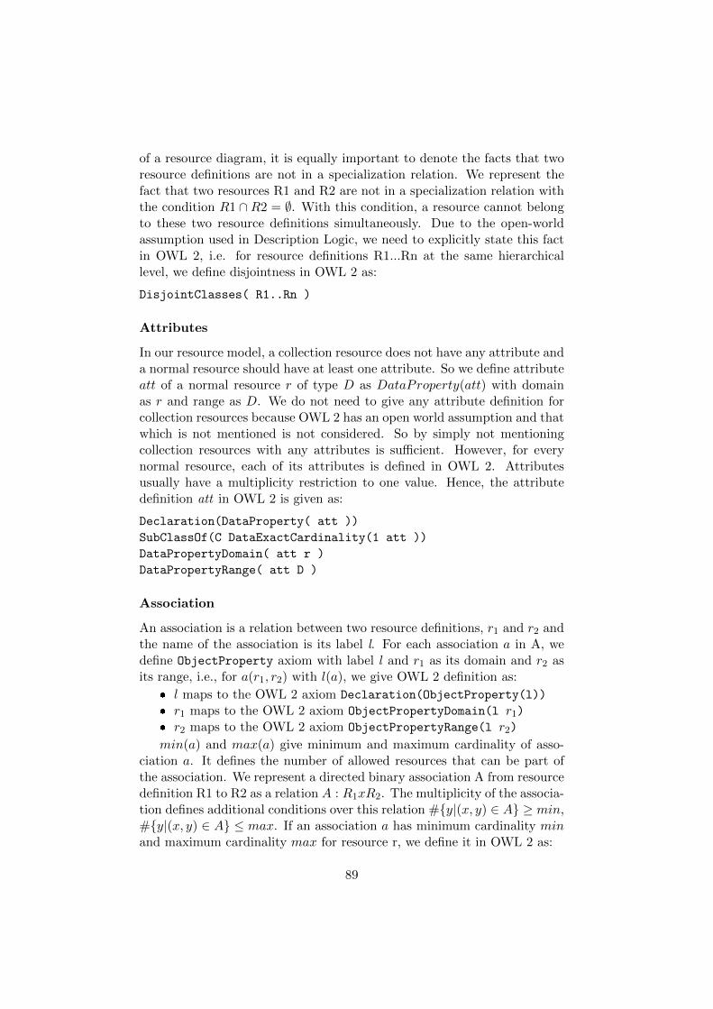
of a resource diagram, it is equally important to denote the facts that tworesource definitions are not in a specialization relation. We represent thefact that two resources R1 and R2 are not in a specialization relation withthe condition R1 ∩R2 = ∅. With this condition, a resource cannot belongto these two resource definitions simultaneously. Due to the open-worldassumption used in Description Logic, we need to explicitly state this factin OWL 2, i.e. for resource definitions R1...Rn at the same hierarchicallevel, we define disjointness in OWL 2 as:
DisjointClasses( R1..Rn )
Attributes
In our resource model, a collection resource does not have any attribute anda normal resource should have at least one attribute. So we define attributeatt of a normal resource r of type D as DataProperty(att) with domainas r and range as D. We do not need to give any attribute definition forcollection resources because OWL 2 has an open world assumption and thatwhich is not mentioned is not considered. So by simply not mentioningcollection resources with any attributes is sufficient. However, for everynormal resource, each of its attributes is defined in OWL 2. Attributesusually have a multiplicity restriction to one value. Hence, the attributedefinition att in OWL 2 is given as:
Declaration(DataProperty( att ))
SubClassOf(C DataExactCardinality(1 att ))
DataPropertyDomain( att r )
DataPropertyRange( att D )
Association
An association is a relation between two resource definitions, r1 and r2 andthe name of the association is its label l. For each association a in A, wedefine ObjectProperty axiom with label l and r1 as its domain and r2 asits range, i.e., for a(r1, r2) with l(a), we give OWL 2 definition as:
� l maps to the OWL 2 axiom Declaration(ObjectProperty(l))
� r1 maps to the OWL 2 axiom ObjectPropertyDomain(l r1)� r2 maps to the OWL 2 axiom ObjectPropertyRange(l r2)
min(a) and max(a) give minimum and maximum cardinality of asso-ciation a. It defines the number of allowed resources that can be part ofthe association. We represent a directed binary association A from resourcedefinition R1 to R2 as a relation A : R1xR2. The multiplicity of the associa-tion defines additional conditions over this relation #{y|(x, y) ∈ A} ≥ min,#{y|(x, y) ∈ A} ≤ max. If an association a has minimum cardinality minand maximum cardinality max for resource r, we define it in OWL 2 as:
89

SubClassOf( r ObjectMinCardinality( min a ) )
SubClassOf( r ObjectMaxCardinality( max a ) )
7.5.2 Behavioral Model in OWL 2
A behavioral model provides the behavioral interface of a web service anddefines the sequence of method invocations, the conditions under whichthey can be invoked and their expected results. To check the satisfiabilityof state invariants in a behavioral model, we need to translate the statesand their invariants into OWL 2. The translation of the state and thestate invariant includes the reference of resources and their attributes sowe translate a behavioral model in the same ontology that contains theOWL 2 translation of a resource model.
We need to cover following concepts of our behavioral model in OWL 2:state, state hierarchy, state disjointness and state invariant. The behaviourmodel is translated into OWL 2 by following the translation method dis-cussed in the previous chapter.
7.6 Validation of RESTful Interfaces
We have defined earlier the satisfiability of our design models in Section 7.3.The consistency analysis of resource and behavioral models is reduced to thesatisfiability of the conjunction of all the conditions derived from the model.In order to determine the satisfiability of the conditions represented in thedesign models, we first translate the resource and behavioral models into anOWL 2 ontology, then use an OWL 2 reasoner to analyze the satisfiabilityof translated concepts.
To translate the resource and behavioral models into OWL 2 ontology,we have implemented the translations of resource and behavioral diagramsin OWL 2, discussed in Section 7.5 in the form of a translation tool. Wehave used Python programming language for the implementation of theprototype of the translation tool. The implemented translation tool al-lows us to automatically transform a resource and behavioral model intoOWL 2 DL. The translator takes these models and OCL state invariant asan input in the form of XMI. The XMI is generated by using a modelingtool, Magicdraw. The XMI generated by the modeling tool contains thesource code of both resource and behavioral model in the form of XML.While modeling in a modeling tool we have used OCL to express the stateinvariants in a behavioral model. The state invariant written in OCL isalso a part of a XMI generated by the modeling tool. Moreover, the outputof an implemented translation tool is an ontology file, which contain thetransformed resource model, behavioral model and state invariants in thefrom of OWL 2 functional syntax.
90

After translating the design models and state invariants into OWL 2ontology by using the implemented translation tool, we will validate theoutput ontology by using an OWL 2 reasoner. The OWL 2 reasoner ana-lyzes different facts presented as axioms in the ontology and infers logicalconsequences from them. When we give our ontology to the reasoner, itgenerates satisfiability report indicating which concepts are satisfiable andwhich not. If the ontology has one or more unsatisfiable concepts, thismeans that the instance of any unsatisfiable concept will make the wholeontology inconsistent, consequently, an instance of the resource definitiondescribing an unsatisfiable concept in a resource diagram will not exist, orresources will not enter in a state describing an unsatisfiable condition, andvice versa. However, the ontology generated by the translation tool is inOWL 2 functional syntax, therefore, the satisfiability of the translated con-cepts can be checked by using any OWL 2 reasoner which supports OWL 2functional syntax.
7.7 Conclusion
A REST interface can do more than simply creating, retrieving, updatingand deleting data from a database. Designing behavioral interface for suchweb services that provide different states of the service and offer REST in-terface features is an interesting design challenge since it can involve manyresources and resource configurations that define different states of the ser-vice. In this chapter, we address how to analyze the consistency of designmodels that create behavioral REST interfaces. We check the consistency ofresource and behavioral diagrams with state invariants using OWL 2 reason-ers. The structure of both the diagrams is formally defined and translatedto OWL 2 ontology. The ontology is given to an ontology reasoner thatchecks the ontology for any unsatisfiable concepts. The unsatisfiable con-cepts indicate the design errors that can cause undesirable behavior in theimplementation of the service. The approach is automated as we provideprototype tools that generate web service skeletons and OWL 2 ontologyfrom the design models. Also, thanks to the existing OWL 2 reasoners thegeneration of satisfiability report for our OWL 2 ontology is also automatedthat is analyzed to check the consistency of design models.
In our future work, we plan to take into account guards on transitionsin the consistency analysis of our design models.
91

92
Chapter 8
Consistency of Class andObject Diagrams
In this chapter we discuss the translations of UML object diagram conceptsinto OWL 2, and also discuss how to validate these concepts using OWL 2reasoners. This chapter is based on the work presented in Articles I, IIIand IV.
8.1 Introduction
In MDE, each software model is described using a particular modeling lan-guage, such as the UML or DSLs, and this raises the question if each modelconforms to its metamodel or not. In our context, conformance means thatin a given UML class diagram containing classes and associations, and aUML object diagram containing objects and links, we want to know, first,if each object is a proper instance of a class and each link is an instanceof an association depicted in the class diagram. Second, objects and linksmust preserve the uniqueness, multiplicity, source, target and compositionconstraints of their classes and associations. An example of a valid and aninvalid object diagram and a class diagram is shown in Figure 8.1.
8.1.1 Overview of the Approach
In order to mechanically reason about model conformance we need to have aformal definition of UML. In this chapter we have chosen the Web OntologyLanguage version 2 for Description Logic (OWL 2 DL) [98] to formalizethe UML class and object diagraming concepts. There are a number ofreasons behind the selection of OWL 2 DL. Firstly, OWL 2 DL is thesubset of OWL 2 that is decidable. Secondly, by using OWL 2 DL we willbe able to use existing OWL 2 reasoners for model conformance. Finally,
93

C1
C3 C4
x:C2
z:C4P2
1 0..nP1
C2
n..mP2 {non-unique}
y:C3
P1
P2
(a) UML Class Model
(b) Valid UML Object Model
y1:C1
y2:C1
x:C2
P1
P1
(c) Invalid UML Object Model
Figure 8.1: (a): A UML class diagram depicting a class hierarchy, a compo-sition and a non-unique association. (b): A consistent UML object diagramconforms to the UML class diagram, and (c): An inconsistent object dia-gram due to the shared owner.
Translator
Validation using Reasoner
Validation Report
UML Class and Object Models
Ontology
Figure 8.2: Automatic object and class diagram conformance process.
OWL 2 DL already provides constructs to represent many UML conceptssuch as classes, associations, objects, and links in a straightforward way.
Still, a translation of UML models to OWL 2 presents several challenges.Unfortunately, OWL 2 DL does not provide any constructs to representUML concepts such as composition, ordering and non-unique associations.Also, OWL 2 uses open-world assumption, whereas UML operates underthe closed-world assumption [59], where complete knowledge of the domainis assumed to be provided in a model. We assume that all existing classesand objects are known and depicted explicitly in the models.
The details about representing composition, ordering and non-uniqueassociations and the closed-world environment in OWL 2 DL are the maincontributions of this chapter and will be discussed later. To tackle theproblem of model conformance, we propose a tool to translate UML modelsinto OWL 2 DL, and then mechanically check the translated models for
94
consistency using an OWL 2 reasoner. An overview of the process is givenin Figure 8.2. The translator takes a UML class diagram and an objectdiagram as an input in the form of XMI [73] and produces ontology inOWL 2 format as an output. The translator contains the translations ofUML concepts into OWL 2 axioms in the form of MOFScript [5]. The detailabout the translation of a UML class and object diagraming concepts intoOWL 2 will be discussed in Section 8.2, and the detail about the translationprocess will be discussed in Section 8.3.
Furthermore, the ontology generated by the translator contains thetranslation of the object diagram and the class diagram in the form ofOWL 2 DL. The generated ontology will further be validated by using anOWL 2 reasoner.
� If a generated ontology is consistent, it means that the object diagramconforms to all constraints of the class diagram interpreted accordingto the semantics that we have given in our translation.
� If a generated ontology is inconsistent, it means that the object dia-gram does not conform to the constraints given in the class diagram.
8.2 UML Object Diagrams
In this section we give a formal definition of the UML class and objectdiagraming concepts that we treat in our approach. The definition is givenin terms of predicate logic. In this section we also give the translation ofUML Object diagraming concepts to OWL 2 and motivate our choice offeatures that are included in the definition.
8.2.1 UML Classes and Objects
A UML class represents a set of objects that have the same characteris-tics [77]. A UML class C is defined as a unary predicate C in predicatelogic.
An instance of a class is called an object. In UML, every object in anobject diagram must belong to a specific class in a class diagram. An objectx in an object diagram belongs to a class C in a class diagram is defined inpredicate logic as:
C(x)
A UML Class C in the class diagram is translated to OWL 2 as:
Declaration( Class( C ) )
Furthermore, every object that exists in an object diagram must belong toa specific class in a class diagram. In OWL 2 the UML object is representedas a class assertion and is called an individual. A UML object x of the classC is translated in OWL 2 as:
95

ClassAssertion( C x )
Furthermore, every object in a UML object diagram is by default differentfrom another. Whereas, in OWL 2 due to the open-world assumption, weneed to explicitly mention that all individuals are different from each other.For example: for objects x1, .., xn in an object diagram, we use the OWL 2axiom:
DifferentIndividuals(x1..xn)
8.2.2 Class Memberships
The UML and MOF semantics for instantiation follow closely the object-oriented paradigm i.e. the closed world assumptions [59]. In this context,when declaring that a model element m is of type C, it is required that thefollowing holds:
1. m is a direct instance of the class C.
2. m is an indirect instance of all the superclasses of C.
3. m is not an instance of any other class.
However, OWL 2 follows the open world assumption. Therefore, declaringthat an element m is of type C in OWL 2 asserts that:
1. m is a direct or indirect instance of the class C.
2. m is an indirect instance of all the superclasses of C.
3. m is not an instance of any classes explicitly declared disjoint to C.
Furthermore, these semantic differences require that we introduce addi-tional axioms in our ontology to restrict object membership to the intendedclass hierarchies.
8.2.3 Class Memberships Within Inheritance Hierarchies
According to UML semantics of class membership, whenever we assert thata model element is an instance of a class, we also assert that it is not aninstance of its subclasses. But in OWL 2 this is not the case. In order toovercome this semantic gap between OWL 2 and UML, we translate UMLclass into OWL 2 as a union of two disjoint concepts.
EquivalentClasses( C ObjectUnionOf( C_Direct C1..Cn ) )
DisjointClasses( C_Direct ObjectUnionOf( C1..Cn ) )
First concept C Direct, represents the collection of all the objects which aredirect instances of a class. And, the second concept represents all objectsthat belong to its subclasses C1, .., Cn.
96

8.2.4 UML Association and Links
A UML binary association defines a relationship between two classes [77].A UML link is an instance of an association. A link l of an association Pconnecting objects x and y is represented in predicate logic as:
P (x, y, l)
We often do not need to differentiate what link is used to connect twoobjects. Therefore it is convenient for us to define the following:
∀x, y, l.P (x, y, l)→ P (x, y)
A UML association is represented in OWL 2 as an object property. Anassociation P from a class C1 to a class C2 is represented in OWL 2 as:
Declaration( ObjectProperty( P ) )
ObjectPropertyDomain( P C1 )
ObjectPropertyRange( P C2 )
A link in OWL 2 is represented as a property assertion. The link ofan association P between the objects x1 and x2 in an object diagram isrepresented in OWL 2 as:
ObjectPropertyAssertion( P x1 x2 )
Moreover, due to the open-world assumptions of OWL 2, for a reasonerto be able to detect a violation of a minimum multiplicity constraint, weneed to provide a definitive knowledge about the links, connecting or notconnecting the individuals of a domain class and a range class of an associ-ation. Therefore, if there is no link between the objects of a domain classand a range class of a UML association, we need to explicitly declare thatthere is no connection between the individuals. The knowledge about thenon-existence of a link between individuals is called a negative assertion.The negative assertion of an association P between the objects x1 and x2in OWL 2 is written as:
NegativeObjectPropertyAssertion( P x1 x2 )
A negative assertion is required when there exists an association betweenthe classes but their specific individuals are not connected with a link.
8.2.5 Unique and Non-Unique Associations
A UML association multiplicity can be unique or non-unique. A uniqueassociation does not allow two objects to be linked with each other morethan one time, as shown in Figure 8.3c.
97

C2C1
a:C1b:C2
n..mP (a) Class Model
c:C2
a:C1 b:C2(b) Object Modelvalid for bothP {unique} andP {non-unique}
(c) Invalid if P {unique} and(d) Valid ifP {non-unique}
PP
P
P
Figure 8.3: (a): A class diagram depicting an association P connecting twoclasses, (b): A consistent object diagram for both unique and non-uniqueP, (c): An inconsistent object diagram if P is unique, and (d): A consistentobject diagram if P is non-unique.
The restriction of unique association P is written in predicate logic as:
∀x, y, l1, l2.P (x, y, l1) ∧ P (x, y, l2)→ l1 = l2
In the case of non-unique associations this restriction does not apply.In OWL 2 the UML unique association is treated as a normal object
property, and the translation of a multiplicity constraint of a unique asso-ciation is done by using OWL 2 axioms: ObjectMinCardinality and Object-MaxCardinality. However, in case of a non-unique association, there can bemultiple links between the objects of a domain class and a range class, asshown in Figure 8.3d. The OWL 2 reasoner considers all links which havea common source and target as one link, and to make the reasoner ableto consider all those links as different links, we have introduced an inter-mediate class in between a domain class and a range class of a non-uniqueassociation. As a consequence, every non-unique association P is translatedin OWL 2 as a combination of two object properties P I and I P . WhereP I connects a domain class to an intermediate class, and I P connects anintermediate class to a range class of a non-unique association. The objectproperty P I is written in OWL 2 as:
InverseFunctionalObjectProperty( P_I )
An inverse functional object property restricts an individual of a domainclass connecting with more than one individuals of an intermediate class.Furthermore, we put a cardinality restriction of n..m on P I by usingOWL 2 axioms: ObjectMinCardinality and ObjectMaxCardinality. Moreover,the object property I P is written in OWL 2 as a normal object property.In order to ensure that the individuals of an intermediate class C I connectone to one with the individuals of a range class, we have to put the exactcardinality of one on the property I P as:
98

SubClassOf( C_I ObjectExactCardinality( 1 I_P ) )
Furthermore, a link of a non-unique association P from object a to b in anobject diagram is translated as the assertions of the object properties P Iand I P as:
ObjectPropertyAssertion( P_I a C_I_# )
ObjectPropertyAssertion( I_P C_I_# b )
Where C I # is an individual of an intermediate class C I, and # is anauto generated unique number which is responsible to create a distinctionbetween the identical links of a non-unique association. For example, thetranslation of identical links of the object diagram shown in Figure 8.3d is:
\\Link 1
ObjectPropertyAssertion( P_I a C_I_1 )
ObjectPropertyAssertion( I_P C_I_1 b )
\\Link 2
ObjectPropertyAssertion( P_I a C_I_2 )
ObjectPropertyAssertion( I_P C_I_2 b )
8.2.6 Ordered Properties
In UML ordering, the links of an ordered property are labeled with a uniquenumbered index, and it is required that the indexes are in order. An order-ing would be used for example to preserve a sequence of a parameter in afunction. A link of an ordered property P connecting object x of the sourceclass and object y of the target class of the ordered property P having alabel i is represented in predicate logic as:
P (x, y, i)
Furthermore, all links of an ordered property having identical index i arerequired to have an identical source and target, in predicate logic it isrepresented as:
∀i ∈ N ∀x, y, a, b.P (x, a, i) ∧ P (y, b, i)→ (x = y) ∧ (a = b)
Where, x, y are the objects of a domain class and a, b are the objects of arange class of an ordered property P .
The UML ordered property is translated in OWL 2 as a normal ob-jectproperty. The translation of basic constraints like domain, range andmultiplicity is also the same as mentioned in Section 8.2.4. For examplethe translation of an ordered property P depicted on top of Figure 8.4 isas follows.
99

C1 C2n..m
{ ordered }P
y1:C21
y2:C2
2x1:C1
Class ModelObject Model
Figure 8.4: Top: A UML class diagram depicting ordered property. Bot-tom: A UML object diagram depicting ordered links
Declaration( ObjectProperty( P ) )
ObjectPropertyDomain( P C1 )
ObjectPropertyRange( P C2 )
SubClassOf( C1 ObjectMinCardinality( n P ) )
SubClassOf( C1 ObjectMaxCardinality( m P ) )
Moreover, in a UML object diagram, a link of an ordered property is labeledwith an index, and requires that the index is unique and in order. In OWL 2there is no specific axiom for the representation of a UML ordered propertylink or any link with a label. Due to this fact, we translate a UML orderedproperty link into OWL 2 in four steps. First, declare an index propertyfor each ordered property link that exist in an object diagram. The indexproperty is declared in OWL 2 as:
Declaration( ObjectProperty( index_P_# ) )
To make every ordered property link reachable while parsing a translatedobject diagram in OWL 2, the name of an index property comprises threeparts. First, index refers that the link of this object property will representan ordered property link. Second, P refers the name of an ordered propertyin a class diagram. Third, # is representing an index or a label on a link ofan ordered property. The data type of an index can be ”xsd:integer” [97] or”xsd:string” [97]. For example, for each labeled link 1 and 2 of the orderedproperty P shown at the bottom of Figure 8.4, we will declare an indexproperty in OWL 2 as:
Declaration(ObjectProperty( index_P_1 ))
Declaration(ObjectProperty( index_P_2 ))
Second, a domain and a range of each index property in OWL 2 is the sameas the domain and the range of an ordered property. Therefore, each indexproperty in OWL 2 will be a subproperty of an ordered property P :
SubObjectPropertyOf( index_P_# P )
100

Third, all links of an index property must have an identical source and tar-get. In OWL 2 all links having an identical source and target are consideredas one link. Therefore, we have also made the index property:
1. FunctionalObjectProperty so that one link of an index property maynot lead to two individuals.
FunctionalObjectProperty( index_P_# )
2. InverseFunctionalObjectProperty so that two links of an index prop-erty may not lead to one individual.
InverseFunctionalObjectProperty( index_P_# )
Last, each index property in OWL 2 is instantiated among the respectiveindividuals of a domain and a range class of an ordered property. Forexample the UML ordered property links P (x1, y1, 1) and P (x1, y2, 2) asshown at the bottom of Figure 8.4, is represented in OWL 2 as:
ObjectPropertyAssertion( index_P_1 x1 y1)
ObjectPropertyAssertion( index_P_2 x1 y2)
8.3 Implementation of a Model Conformance Tool
8.3.1 Translator
We have implemented the translations of UML class and object modelingconcepts as discussed in Section 8.2 into a translator by using the model-to-text translation tool MOFScript [5]. The implemented translator inMOFScript allows us to automatically transform the UML class and objectdiagrams into OWL 2. The translator takes a UML class diagram and anobject diagram as an input in the form of UML XMI 2.1 [73], which isparsed according to UML 2. The output of the translator is an ontology,which contains a transformed object diagram and its class diagram in thefrom of OWL 2 functional syntax. The translator script can be downloadedfrom [4].
We have translated the class diagram and its inconsistent object dia-gram as shown in Figure 8.5, into an OWL 2 DL ontology, by using theimplemented translator, the output ontology generated by the translator isas follows:
Declaration(Class(Operation))
SubClassOf( Operation_Direct Operation )
EquivalentClasses( Operation Operation_Direct )
101
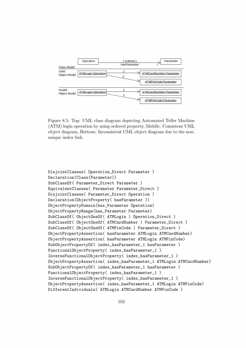
ValidObject Model
ATMCardNumber:Parameter
ATMPinCode:Parameter
1
1ATMLogin:Operation
Class Model
ATMLogin:Operation2
ATMPinCode:Parameter
1ATMCardNumber:Parameter
InvalidObject Model
*
{ ordered }hasParameter
ParameterOperation
Figure 8.5: Top: UML class diagram depicting Automated Teller Machine(ATM) login operation by using ordered property, Middle: Consistent UMLobject diagram, Bottom: Inconsistent UML object diagram due to the non-unique index link.
DisjointClasses( Operation_Direct Parameter )
Declaration(Class(Parameter))
SubClassOf( Parameter_Direct Parameter )
EquivalentClasses( Parameter Parameter_Direct )
DisjointClasses( Parameter_Direct Operation )
Declaration(ObjectProperty( hasParameter ))
ObjectPropertyDomain(has_Parameter Operation)
ObjectPropertyRange(has_Parameter Parameter)
SubClassOf( ObjectOneOf( ATMLogin ) Operation_Direct )
SubClassOf( ObjectOneOf( ATMCardNumber ) Parameter_Direct )
SubClassOf( ObjectOneOf( ATMPinCode ) Parameter_Direct )
ObjectPropertyAssertion( hasParameter ATMLogin ATMCardNumber)
ObjectPropertyAssertion( hasParameter ATMLogin ATMPinCode)
SubObjectPropertyOf( index_hasParameter_1 hasParameter )
FunctionalObjectProperty( index_hasParameter_1 )
InverseFunctionalObjectProperty( index_hasParameter_1 )
ObjectPropertyAssertion( index_hasParameter_1 ATMLogin ATMCardNumber)
SubObjectPropertyOf( index_hasParameter_1 hasParameter )
FunctionalObjectProperty( index_hasParameter_1 )
InverseFunctionalObjectProperty( index_hasParameter_1 )
ObjectPropertyAssertion( index_hasParameter_1 ATMLogin ATMPinCode)
DifferentIndividuals( ATMLogin ATMCardNumber ATMPinCode )
102

8.3.2 Reasoning Engine
The conformance of an object diagram against a class diagram is doneby validating an output ontology using an OWL 2 reasoner. The outputontology contains the transformed object diagram and its class diagram inthe form of OWL 2. Since the translation tool produces an output ontologyin OWL 2 functional syntax, validation of the output ontology can be doneby using any ontology reasoner which supports OWL 2 functional syntax.
8.3.3 Conformance Report
A conformance report is an output of an OWL 2 reasoner. After the valida-tion of a transformed object diagram against its class diagram, a reasonerwill produce a conformance report. This report contains the details aboutthe inconsistencies present in a transformed object diagram against its classdiagram. The output of a translation tool which contains the transformedobject diagram and its class diagram is then validated by a reasoner. Theconformance report of the output ontology produced by a reasoner is asfollows:
Consistent: No
Reason: Individual ATMLogin has more than one value
for the functional property index_hasParameter_1
The above conformance report is generated by using the Pellet OWL 2reasoner version 2.3.0 [90]. The conformance report clearly indicates theinconsistency that exists in the object diagram that there exists more thanone link of an ordered property hasParameter with an index label 1.
8.3.4 Tool Validation
In order to evaluate the proposed validation approach, the proposed modeltranslation tool has been validated by a suite of test cases that covers allclass and object modeling concepts discussed in Section 8.2. Each test caseincludes a class diagram, a valid object diagram, and an invalid objectdiagram. Each test case is transformed into OWL 2 using the proposedtranslation tool and validated by using an OWL 2 reasoner. The detailsof test cases and the summary of the conformance report is expressed inFigure 8.6.
103

Cla
ss1
2R
C1:
Cla
ss1
C3:
Cla
ss2
C2:
Cla
ss2
R
Cla
ss2
RC
1: C
lass
1C
2: C
lass
2
C1:
Cla
ss1
R
R
C3:
Cla
ss2
C2:
Cla
ss2
C4:
Cla
ss2
R
Cla
ss1
RC
lass
2
Cla
ss3
C1:
Cla
ss1
RC
2: C
lass
2C
2: C
lass
3R
C1:
Cla
ss1
0..2
R {
uniq
ue}
Cla
ss1
Cla
ss2
C1:
Cla
ss1
RC
2: C
lass
2C
1: C
lass
1C
2: C
lass
2R R
C1:
Cla
ss1
C3:
Cla
ss1
C2:
Cla
ss1
RC
1: C
lass
1
R RC
3: C
lass
1
C2:
Cla
ss1
C2:
Cla
ss2
C3:
Cla
ss2
R
a b
cd
C1:
Cla
ss3
C3:
Cla
ss2
C2:
Cla
ss2
a b
C1:
Cla
ss3
C2:
Cla
ss2
C3:
Cla
ss2
Cla
ss M
od
elV
alid
Ob
ject
Mo
del
Inva
lid O
bje
ct M
od
el
Mu
ltip
licit
y
Do
mai
n a
nd
Ran
ge
Un
iqu
e an
d
no
n-U
niq
ue
Co
mp
osi
tio
nE
xclu
sive
and
Acy
clic
Su
bP
rop
erty
UM
LC
on
cep
ts
Vio
latio
n of
excl
usiv
e ow
ner
Vio
latio
n of
max
imum
mul
tiplic
ity
Vio
latio
n of
min
imum
m
ultip
licity
Vio
latio
nof
acy
clic
Inva
lid r
ange
of
R
Inva
lid
exis
tenc
e of
no
n-un
ique
link
Mis
sing
link
of
supe
rpro
pert
y b/
w C
1 an
d C
3
Co
nfo
rman
ce
Rep
ort
R
cd
a b
R
C1:
Cla
ss1
1
0..4
R
Cla
ss1
Cla
ss2
1a
0..6
bC
lass
1
1c
1
d {s
ubse
ts b
}C
lass
3
R
R
Figure 8.6: List of test cases and the conformance report summary of invalidobject diagrams. 104
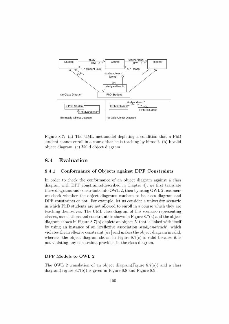
Student TeacherCourse
PhD Student
[inv] 0..* study
0..*
teach
1..* teacher [surj]
[irr] studyandteach'
0..*
student [surj]
0..* studyandteach[comp]
[inv]
X:PhD Student
studyandteach'
X:PhD Student studyandteach'
Y:PhD Student
(b) Invalid Object Diagram (c) Valid Object Diagram
(a) Class Diagram
Figure 8.7: (a) The UML metamodel depicting a condition that a PhDstudent cannot enroll in a course that he is teaching by himself. (b) Invalidobject diagram, (c) Valid object diagram.
8.4 Evaluation
8.4.1 Conformance of Objects against DPF Constraints
In order to check the conformance of an object diagram against a classdiagram with DPF constraints(described in chapter 4), we first translatethese diagrams and constraints into OWL 2, then by using OWL 2 reasonerswe check whether the object diagrams conform to its class diagram andDPF constraints or not. For example, let us consider a university scenarioin which PhD students are not allowed to enroll in a course which they areteaching themselves. The UML class diagram of this scenario representingclasses, associations and constraints is shown in Figure 8.7(a) and the objectdiagram shown in Figure 8.7(b) depicts an object X that is linked with itselfby using an instance of an irreflexive association studyandteach′, whichviolates the irreflexive constraint [irr] and makes the object diagram invalid,whereas, the object diagram shown in Figure 8.7(c) is valid because it isnot violating any constraints provided in the class diagram.
DPF Models to OWL 2
The OWL 2 translation of an object diagram(Figure 8.7(a)) and a classdiagram(Figure 8.7(b)) is given in Figure 8.8 and Figure 8.9.
105

//Class Diagram
Declaration(Class(Student))
Declaration(Class(Course))
Declaration(Class(Teacher))
Declaration(Class(PhDStudent))
Declaration(ObjectProperty( study ))
ObjectPropertyDomain(study Student)
ObjectPropertyRange(study Course)
Declaration(ObjectProperty( student ))
ObjectPropertyDomain(student Course)
ObjectPropertyRange(student Student)
InverseObjectProperties( study student )
Declaration(ObjectProperty( teach ))
ObjectPropertyDomain(teach Teacher)
ObjectPropertyRange(teach Course)
Declaration(ObjectProperty( teacher ))
ObjectPropertyDomain(teacher Course)
ObjectPropertyRange(teacher Teacher)
InverseObjectProperties( teach teacher )
Declaration(ObjectProperty( studyandteach ))
ObjectPropertyDomain(studyandteach Teacher)
ObjectPropertyRange(studyandteach Student)
SubClassOf( PhDStudent
ObjectUnionOf( Student Teacher ) )
Declaration(ObjectProperty( studyandteach’ ))
ObjectPropertyDomain(studyandteach’ PhdStudent)
ObjectPropertyRange(studyandteach’ PhdStudent)
SubObjectPropertyOf(studyandteach’ studyandteach )
IrreflexiveObjectProperty(studyandteach’)
//Object Diagram
SubClassOf( ObjectOneOf( X ) PhDStudent )
ObjectPropertyAssertion( studyandteach’ X X)
Figure 8.8: The OWL 2 translation of models shown in Figure 8.7(a) andFigure 8.7(b).
106

<swrl:Variable rdf:ID="x"/>
<swrl:Variable rdf:ID="y"/>
<swrl:Variable rdf:ID="z"/>
<owl:ObjectProperty rdf:ID="teach"/>
<owl:ObjectProperty rdf:ID="student"/>
<owl:ObjectProperty rdf:ID="studyandteach"/>
<swrl:Imp>
<swrl:body rdf:parseType="Collection">
<swrl:IndividualPropertyAtom>
<swrl:propertyPredicate rdf:resource="#teach"/>
<swrl:argument1 rdf:resource="#x"/>
<swrl:argument2 rdf:resource="#y"/>
</swrl:IndividualPropertyAtom>
<swrl:IndividualPropertyAtom>
<swrl:propertyPredicate rdf:resource="#student"/>
<swrl:argument1 rdf:resource="#y"/>
<swrl:argument2 rdf:resource="#z"/>
</swrl:IndividualPropertyAtom>
</swrl:body>
<swrl:head rdf:parseType="Collection">
<swrl:IndividualPropertyAtom>
<swrl:propertyPredicate rdf:resource="#studyandteach"/>
<swrl:argument1 rdf:resource="#x"/>
<swrl:argument2 rdf:resource="#z"/>
</swrl:IndividualPropertyAtom>
</swrl:head>
</swrl:Imp>
Figure 8.9: The SWRL rule for the [comp] constraint of the associationstudyandteach shown in Figure 8.7(a).
107

D:\pellet-2.3.0>pellet consistency -l OWLAPI D:\example.OWL2FS
Consistent: No
Reason: Irreflexive property nullstudyandteachPrime
Figure 8.10: The validation report of the OWL 2 ontology of the class andobject diagram shown in Figure 8.8 and Figure 8.9.
Person Context Person inv SelfParent self.hasParent->excludes(self.hasParent)
X:Person hasParent
hasParent
Figure 8.11: Top: A UML class diagram with OCL constraints. Bottom:The object diagram of a class diagram depicted on top.
Reasoning
We validate the OWL 2 translations of DPF UML diagrams by using anOWL 2 reasoner. Since, the translations are in OWL 2 functional syntax(OWL2fs), we can use any OWL 2 reasoner for the purpose of validationwhich supports OWL2fs.
After the validation of the translated UML diagrams, the reasoner pro-duces a validation report. The validation report contains detailed analysisof the inconsistencies in the translated diagrams. The validation report ofthe OWL 2 ontology of the class and object diagram shown in Figure 8.8and Figure 8.9 is given in Figure 8.10.
The validation report shown in Figure 8.10 clearly indicates the viola-tion of an irreflexive constraint of association studyandteach′, and resultsthe whole ontology as inconsistent.
8.4.2 Conformance of Objects against OCL Constraints
In order to check the conformance of an object diagram against a classdiagram with OCL constraints, we need to first translate these diagramsand OCL constraints into OWL 2 by following the translations discussedin previous chapters. The next step is to validate the OWL 2 translationsby using an OWL 2 reasoner. As an example we have a class diagramshown in Figure 8.11 consisting of a class name Person, and the associationname hasParent. Along with the class diagram there is an OCL constraint
108

//Class Diagram
Declaration(Class(Person))
Declaration(ObjectProperty( hasParent ))
ObjectPropertyDomain(hasParent Person)
ObjectPropertyRange(hasParent Person)
//OCL Constraint
IrreflexiveObjectProperty(hasParent)
//Object Diagram
SubClassOf( ObjectOneOf( X ) Person )
ObjectPropertyAssertion( hasParent X X)
Figure 8.12: The OWL 2 translation of models shown in Figure 8.11.
name SelfParent which has a context class Person. This OCL constraint isapplying a restriction on the objects of a class person that they cannot linkto them selves by using an instance/link of an association hasParent. Atthe bottom of Figure 8.11 we have an object diagram depicting an objectX of the class Person. This object is linked with itself by using a link ofthe association hasParent. In order to determine that the object diagramconfirms to the class diagram, we first translate these diagrams and OCLconstraint into OWL 2.
OCL to OWL 2
The translation of a class diagram and an object diagram along with OCLconstraints (Figure 8.11) into OWL 2 is shown in Figure 8.12.
Reasoning
After translating the class and object diagram with OCL constraint wepass the OWL 2 ontology to the OWL 2 reasoner. The reasoner parses theontology and creates the validation report. The validation report of theontology of the diagrams and constraint shown in Figure 8.11 is as follows:
D:\pellet-2.3.0>pellet consistency -l OWLAPI D:\OCL.OWL2FS
Consistent: No
Reason: Irreflexive property nullhasParent
The above validation report clearly shows the violation of the OCL con-straint that an object cannot link with its own self by using a link of the
109

association hasParent i.e. Irreflexive(hasParent). Due to the violationof the OCL constraint the reasoner finds the ontology inconsistent.
8.5 Conclusion
In this chapter, we have presented an approach to reasoning about the con-formance of a UML object model against its class model using an OWL 2reasoner. Furthermore, we have discussed the implementation of the trans-lations as an automatic model translation tool.
The approach is fully automated thanks to the translation tool andthe existing OWL 2 reasoners. Since the translation tools accept standardUML models serialized using the XMI standard, the approach can be easilyintegrated with existing UML modeling tools. Unfortunately, the valida-tion report generated by OWL 2 reasoners is not always self-explanatory,because the relationship between UML concepts and OWL 2 axioms is notalways obvious. As a consequence, it is not always possible to immediatelypoint out the cause of the problem based on these violations without man-ual inspection of the validation report and the problematic object models.It would greatly add to the usefulness of the method to have some sort ofautomated discovery of the cause of violations.
110

Chapter 9
Consistency of MultipleUML Diagrams usingOWL 2
In this chapter we discuss a method for the validation of multiple UMLdiagrams of the same metamodel using OWL 2 reasoners. This chapter isbased on the Articles I, III, IV and V.
9.1 Introduction
UML is a language for modeling that is widely used during software devel-opment [77]. Each software development project involves the creation ofmany models. These models may represent different versions of the samesoftware component, often designed in parallel by a number of designers.These different versions of a model may create contradictions when com-bined. This raises a need of a mechanism to semantically merge differentversions of a UML model together and find out the possible contradictionsand inconsistencies arise between model elements when they are viewedtogether.
The issue of merging UML models has been studied in the researchliterature previously [18, 7, 67, 64]. However, these approaches do not pro-vide the mechanism to check the consistency of merged models. In thischapter, we propose an approach to study how different models of the samemetamodel are merged, and how to validate the merged models. In thevalidation of merged models, we want to identify the possible inconsisten-cies that arise when the different models of the same metamodel are viewedtogether/merged. In this approach we use a decidable fragment of Web On-tology Language (OWL 2 DL) [20] to represent and merge UML models,and then use OWL 2 reasoning tools [90, 83] to determine the inconsisten-
111

A
B
C
D
AP
CP
A C
D
P
B
U =
M1 M2 M = M1 U M2
Figure 9.1: The merge or union of two versions of a Model.
cies in the merged model. We select OWL 2 DL to represent the UMLmodels because we consider it well supported and adapted, and there existseveral OWL 2 reasoners [90, 83] for checking concept satisfiability. Thedetails about the translation of UML models into OWL 2 and the valida-tion of UML models using OWL 2 reasoners has been discussed in chapters4, 6 and 8.
9.2 Model Merging using OWL 2
In this section we show how to perform model merging. The merging ofgiven models is performed by putting the union of all model elements ofall models in to a single model, i.e. the merged model, such as, if M1 andM2 are given models then the merged model M represents the union ofall model elements of all given models, i.e., M = M1 ∪M2. For example,in Figure 9.1 the merged model M is a union (M1 ∪M2) of given modelsM1 = {A,C,B} and M2 = {A,C,D}.
In order to merge the UML models representing different versions ofa UML model, we propose to use Description Logic [48]. Furthermore todetect the inconsistencies originating from the merging of different versionsof a model, we propose to use the automated reasoning tools [90, 83]. Anumber of UML models representing different versions of a UML model aretaken as an input. All the inputs are translated to OWL 2 DL and thenmerged into a single ontology. Next, the OWL 2 ontology of UML models ispassed to a reasoner. Finally, the reasoner processes the ontology and pro-duces a validation report. The validation report reveals the inconsistenciesin the ontology representing a merged UML model.
In order to demonstrate the merging of different versions of a UMLmodel, we first translate all UML models into OWL 2 DL by using themethod discussed in previous chapters and merge the OWL 2 translationsof all UML models into a single ontology. Since we translate all model ele-ments of all UML models into a single ontology, the common elements of allmodels (i.e. M1∩M2 in our example Figure 9.1) will overlap. Additionally,
112

//M1
Declaration(Class(A))
Declaration(Class(C))
Declaration(Class(B))
SubClassOf( B A )
Declaration(ObjectProperty( P ))
ObjectPropertyDomain(P A)
ObjectPropertyRange(P C)
//M2
Declaration(Class(A))
Declaration(Class(C))
Declaration(Class(D))
SubClassOf( D C )
Declaration(ObjectProperty( P ))
ObjectPropertyDomain(P A)
ObjectPropertyRange(P C)
Figure 9.2: The OWL 2 ontology of models M1 and M2 shown in Fig-ure 9.1.
due to the open-world assumptions [59] of OWL 2, where model elementsare recognized by their names, all model elements having the same nameare considered as a one model element or concept. Consequently, due tothis assumption all models will merge or connect with each other by us-ing common model elements. In Figure 9.2 we provide an example of theOWL 2 translation of models M1 and M2 given earlier in Figure 9.1.
The given models M1 and M2 represent six classes in total i.e., M1 ={A,C,B} and M2 = {A,C,D}. We translate all six classes of M1 andM2 into a single ontology. Due to the unique name assumption of OWL 2,the reasoner recognises distinct classes, and counts all six classes, i.e, M1 ={A,C,B} andM2 = {A,C,D} as four classes, i.e., M1∪M2 = {A,C,B,D}.
The unique name assumption of OWL 2 is also applied on the relation-ships such as associations, generalization and on association constraintssuch as multiplicity, composition, domain and range constraints. For ex-ample, both models M1 and M2 represent four relationships in total, inwhich there are two associations and two generalization relationships. Bothmodels depict association P from the class A to the class C, therefore, dueto the unique name assumption of OWL 2, the reasoner recognises the dis-tinct associations and count three relations instead of four. Within theserelations there are two generalization relationships and one association.
In order to determine the number of elements in an ontology, the rea-
113

D:\pellet-2.3.0>pellet classify -l OWLAPI D:\Merging.owl2fs
Classifiying 7 elements
Classifiying: 100% complete in 00:00
Classifiying finished in 00:00
owl:Thing
merging.owl2fs:A
merging.owl2fs:B
merging.owl2fs:C
merging.owl2fs:D
Figure 9.3: The classification report of the OWL 2 ontology shown in Fig-ure 9.2 generated by Pellet.
soner produces a classification report of an ontology. The classificationreport of the ontology shown in Figure 9.2 is given in Figure 9.3. Theclassification report clearly shows that the reasoner recognises the distinctmodel elements of all models, i.e., M1 ∪M2 = {A,C,B,D}. It also showsthe total number of seven model elements found in the ontology, whichincludes four classes {A,C,B,D}, two subclass relationships, and one as-sociation.
9.3 Consistency Analysis of Merged Models
To explain the consistency of a merged model, we assume that there isa nonempty set ∆I called the object domain containing all the possibleobjects in our domain. We propose that a merged model depicting a classdiagram is interpreted as a number of subsets of ∆I representing each classin the merged model and as a number of conditions that need to be satisfiedby these sets. The merged model is consistent, if each class in a mergedmodel can be instantiated i.e, if C is a class in a merged model and C ⊆ ∆I
then C 6≡⊥I must hold.
Moreover, in order to check the model conformance (that an objectdiagram conforms to the class diagram), we want to know, if each object oin an object diagram is a proper instance of a class C in a class diagrami.e, o ∈ C. Moreover, we want to investigate that each link in an objectdiagram is an instance of an association depicted in a class diagram. Also,objects and links must preserve the constraints applied in a class diagramsuch as: uniqueness, multiplicity, source, target, ordering and compositionconstraints of their classes and associations.
9.3.1 Validation of Merged Models
The consistent UML models representing different versions of a UML modelmay have inconsistencies when merged. For example UML models M1 and
114

A
B
Class Diagram
M2
a2:Aa1:A
b:B
M1 U M2
=
M1
b:B
a1:A
U
Object Diagrams
b:B
a2:A
M
Figure 9.4: The invalid merge of two valid UML models.
M2 shown in Figure 9.4 are valid and consistent models, but when they aremerged, the merged model M1∪M2 is inconsistent, because it is violatingthe exclusive ownership constraint of composition. Exclusive ownershipmeans that an object can have only one owner.
In order to detect the inconsistencies occurred by the merging of models,we first translate the models into the OWL 2 ontology, and then use anOWL 2 reasoner to detect the inconsistencies in the translated ontology.To demonstrate our validation approach we have translated the models M ,M1 and M2 shown in Figure 9.4 into an ontology. The generated ontologyis shown in Figure 9.5.
9.3.2 Reasoner
In order to detect the inconsistencies in an ontology(Fiure 9.5) of a mergedmodel(Figure 9.4), the OWL 2 ontology of the merged model is passed tothe OWL 2 reasoner. Since the ontology is in OWL2fs format, we can useany reasoner which supports this format. In our example we have usedPellet [90] version 2.3.0. The reasoner processes the ontology and revealsthe inconsistencies in the ontology in the form of a validation report.
9.3.3 Validation Report
The validation report indicates the contradictions and inconsistencies in theontology caused by the model merge. The validation report of the ontology(shown in Figure 9.5) of models (Figure 9.4) is as follows:
D:\pellet-2.3.0>pellet consistency -l OWLAPI D:\METest.owl2fs
Consistent: No
Reason: Individual file:D:/METest.owl2fs#b has more than one
value for the functional property inv(file:D:/METest.owl2fs#owns)
115

//These are the global properties enforcing composition restrictions
IrreflexiveObjectProperty(rules:contains )
SubObjectPropertyOf( owns rules:contains )
InverseFunctionalObjectProperty( owns )
//Class Diagram M
Declaration(Class(A))
Declaration(Class(B))
Declaration(ObjectProperty( association_A_B ))
ObjectPropertyDomain(association_A_B A)
ObjectPropertyRange(association_A_B B)
SubObjectPropertyOf(association_A_B owns )
//Object diagram M1
SubClassOf( ObjectOneOf( A ) a1 )
SubClassOf( ObjectOneOf( B ) b )
ObjectPropertyAssertion( association_A_B a1 b)
//Object diagram M2
SubClassOf( ObjectOneOf( A ) a2 )
SubClassOf( ObjectOneOf( B ) b )
ObjectPropertyAssertion( association_A_B a2 b)
DifferentIndividuals( a1 a2 b )
// The SWRL rule for capturing transitivity for acyclic constraint of composition.
<rdf:RDF>
<owl:Ontology rdf:about="compoRule"/>
<swrl:Variable rdf:ID="x"/>
<swrl:Variable rdf:ID="y"/>
<swrl:Variable rdf:ID="z"/>
<swrl:Variable rdf:ID="a"/>
<swrl:Variable rdf:ID="b"/>
<owl:ObjectProperty rdf:ID="contains"/>
<owl:ObjectProperty rdf:ID="owns"/>
<swrl:Imp>
<swrl:body rdf:parseType="Collection">
<swrl:IndividualPropertyAtom>
<swrl:propertyPredicate rdf:resource="contains"/>
<swrl:argument1 rdf:resource="#x"/>
<swrl:argument2 rdf:resource="#y"/>
</swrl:IndividualPropertyAtom>
<swrl:IndividualPropertyAtom>
<swrl:propertyPredicate rdf:resource="contains"/>
<swrl:argument1 rdf:resource="#y"/>
<swrl:argument2 rdf:resource="#z"/>
</swrl:IndividualPropertyAtom>
</swrl:body>
<swrl:head rdf:parseType="Collection">
<swrl:IndividualPropertyAtom>
<swrl:propertyPredicate rdf:resource="contains"/>
<swrl:argument1 rdf:resource="#x"/>
<swrl:argument2 rdf:resource="#z"/>
</swrl:IndividualPropertyAtom>
</swrl:head>
</swrl:Imp>
</rdf:RDF>
Figure 9.5: The OWL 2 ontology of the models M , M1 and M2 (Fig-ure 9.4).
116

The validation report clearly indicates the violation of the mutually ex-clusive ownership constraint of composition is that the object b has morethan one value for the inverse functional property owns. In our OWL 2translations of a composition the inverse-functional object-property ownsrepresents the exclusive ownership constraint of the composition. The de-tails about the translation of composition constraints have already beendiscussed in Chapter 4.
9.4 Conclusion
In this chapter we have presented an approach to semantically merge UMLmodels depicting different versions of a UML model. We have also dis-cussed a mechanism to validate the merged models. Moreover, we havedemonstrated our work using example models. The automatic discovery ofinconsistencies in a merged model by the reasoner clearly shows the useful-ness of the proposed merging and the validation approach.
This approach is purely based on the lessons learned from the workpresented in the previous chapters. Therefore, on the basis of the resultsof the viability tests that we have shown in the previous chapters, we canclaim that this approach is also viable, because it is using the same set ofOWL 2 translations used in the previous approaches.
117

118

Chapter 10
ConclusionsThis chapter discusses the conclusions of this thesis. The conclusions thatwe discuss here are categorized according to the research problems that areaddressed in different chapters of this thesis.
Consistency of class diagrams: We addressed the problem of check-ing the consistency of class diagrams by translating class diagrams intoOWL 2 ontology, and then use an OWL 2 reasoner for the reasoning oftranslated OWL 2 ontology. Also, we successfully demonstrated the viabil-ity of the proposed approach by validating more than 300 metamodels/classdiagrams available at the Atlantic Metamodel Zoo, which comprises thou-sands of model elements. Out of these metamodels 49% has errors. Thisshows the significance of the problem of the validation of metamodels. Fur-thermore, these results affirm the valuable contribution of our approach inthis validation area.
Consistency of diagrams expressed in different languages: Theproblem of checking the consistency of diagrams expressed using differentlanguage is addressed by using a specific type of interaction, i.e., the in-teraction of static and dynamic diagrams of a system. In this interactiona class diagram explaining the static content of a system interacts with astatechart diagram depicting a behavior of one of the class existing in theclass diagram. In this case the interaction is done by using state invariantsexpressed using OCL. This whole system represented by a class diagramand a statechart diagram with state invariants is automatically translatedinto OWL 2 and then validated by using an OWL 2 reasoner. We havevalidated this approach using two different scenarios: the content manage-ment system and the REST web service interface. These scenarios havebeen validated by using both valid and mutated models, and the detectionof mutants during the validation process clearly indicated the usefulness ofthe proposed approach.
119

Validation of OCL constraints: In general OCL is undecidable, anddue to this it is not possible to do the reasoning of OCL constraints. How-ever, previous research shows that if we restrict our approach to a lim-ited known set of OCL constructs, then the undecidability can be avoided.Therefore, in our approach we restrict ourselves to the limited set of OCLconstructs that comprise value, multiplicity and boolean constructs. Theseconstructs are the basic OCL constructs, and are used to express the con-ditions in the states of a statechart diagram. We have validated the OCLconstraints by translating them into OWL 2 and then used OWL 2 rea-soners for the reasoning about the translated constraints. We have alsoshown the validation of the proposed approach using both valid and mu-tated OCL constraints. The detection of the mutated OCL constraints bythe proposed approach is an evidence of the correctness of this approach.The performance of this approach was also tested by using both valid andmutated models consisting of 10 to 2000 model elements. The translationand the reasoning time on all models was less than 4.5 seconds in all cases.This shows once again that the proposed approach can process relativelylarge UML models in a few seconds.
Conformance of a model against its metamodel: We address theissue of the model conformance by expanding the approach that is usedfor the metamodel validation. The expansion consists of the translationsof those model elements that are inadequately or not at all addressed in arelated research. These include the OWL 2 translations of modeling con-cepts such as non-unique association, ordered property, open-closed worldissues and composition (including unshearedness and acyclicity). Since themain approach has already been tested on a large scale by validating themetamodels of the Atlantic Metamodel Zoo, this time we have only testedthis approach by using a set of test cases containing both valid and mutatedmodels. The detection of the inconsistencies during the validation of testcases is the evidence of the viability of this approach.
Validation of multiple models: The validation of multiple models ofthe same metamodel is based on the approach of translating all models intoa single ontology, and then use the OWL 2 reasoner for the reasoning. Thisapproach is utilizing one of the open-world assumptions of OWL 2 thattwo concepts having the same name are considered as a single concept.The base of this approach is the same as the approach mentioned in themetamodel or model validation chapters. Therefore on the basis of thelessons learned from the viability test of the work of metamodel or modelvalidation. We claim that this approach is also viable because it is usingthe same set of OWL 2 translations that are used in the work of metamodelor model validation.
120

Integration of our approach in existing tools: There are numeroustools available for the modeling of UML models. In these tools, each UMLmodel is generally specified in two forms, one is a graphical form, andother is a syntactical form. The standard for the graphical form of UMLmodels followed by the well known modeling tools is more or less the same.Unfortunately, the syntax of the XML version of UML models generated bydifferent modeling tools are usually not the same. In our implementationwe have followed the syntactic standard of UML 2 version 3.0.0. This allowsus to integrate our approach with any standard compliant UML modelingtool that follows this UML standard. In order to show the integration ofour approach with the existing standard UML modeling tools, we have usedEMF plugin Topcased and Magicdraw for the modeling of the UML modelsthat are presented in this thesis.
The approach we proposed in this thesis is fully automated thanks tothe implemented translation tool and the existing OWL 2 reasoners. Avery constructive potential improvement in the current work would be toenhance the way problems in ontologies are reported. In few cases, therelationship between UML concepts and OWL 2 axioms is not so obviousthat it is possible to immediately point out the cause of the problem basedon these violations without a manual inspection of the validation reportand the problematic models. It would greatly add to the usefulness of themethod to have some sort of automated discovery of the cause of violations.However, the metamodels or models that were not found to have problemsare not guaranteed to be free of errors, they are just free from inconsistenciesthat our approach can detect.
Nonetheless, we consider that the use of languages and tools envisionedfor the semantic web as a foundation for software modeling languages andtools is a promising proposition. The existing consistency issues of meta-models and models faced by current modeling tools could be addressed byreusing results from the semantic web community. However, the successfuldetection of the errors in the models present in the online model repository,and the results of the performance test of the proposed approach, is theevidence that the proposed approach is viable, and can be practised in theindustry.
121

122

Appendices
123


Appendix A
Validation Results of theMetamodel at the AtlanticZoo
A.1 Composition cycle errors between several classes
Metamodel Classes involved
Agate Site, GenericSite, ReusableObjectBusinessProcessModel Task, CompoundTaskChocoModel Expression, ConstraintclassDiagram Class, Classifier, InterfaceDotNET SystemReflection Type, MemberInfoEclipseLaunchConfiguration MapEntry, Attribute, LaunchConfigura-
tionHierarchicalSignalFlow Base, CompoundQoS Statement QoSStatement, CompoundQoSStatementRDFS Graph, ResourceSignalFlow CompoundComponent, BaseComponentUML withReuseContracts ReuserClause, CompositeReuserUnixFS Directory, FileXUL-Interactorl Container, Interactor
125

A.2 Unsatisfiable class due to multiplicity con-straints
Metamodel Classes involved
OCL Expressions VariableInitialization
A.3 Composition cycle errors involving a singleclass
Metamodel Classes involved
Agate PackageAntScripts TaskElementBusinessProcessModel CompoundTaskCADM MaterielItemCPR Plan, Action, Actordeployment NodeDoDAF PerformerFiniteStateMachine RootFolderGeoTrans GeoTransfoKlaperPropCheck Behavior, StepMavenProject ProjectPDG ExpressionNodeProMarte StepSecureUML RoleSimulinkStateFlow SystemUMLDI-Collaborations InstanceUMLDI-UseCasesPropCheck Instance
126
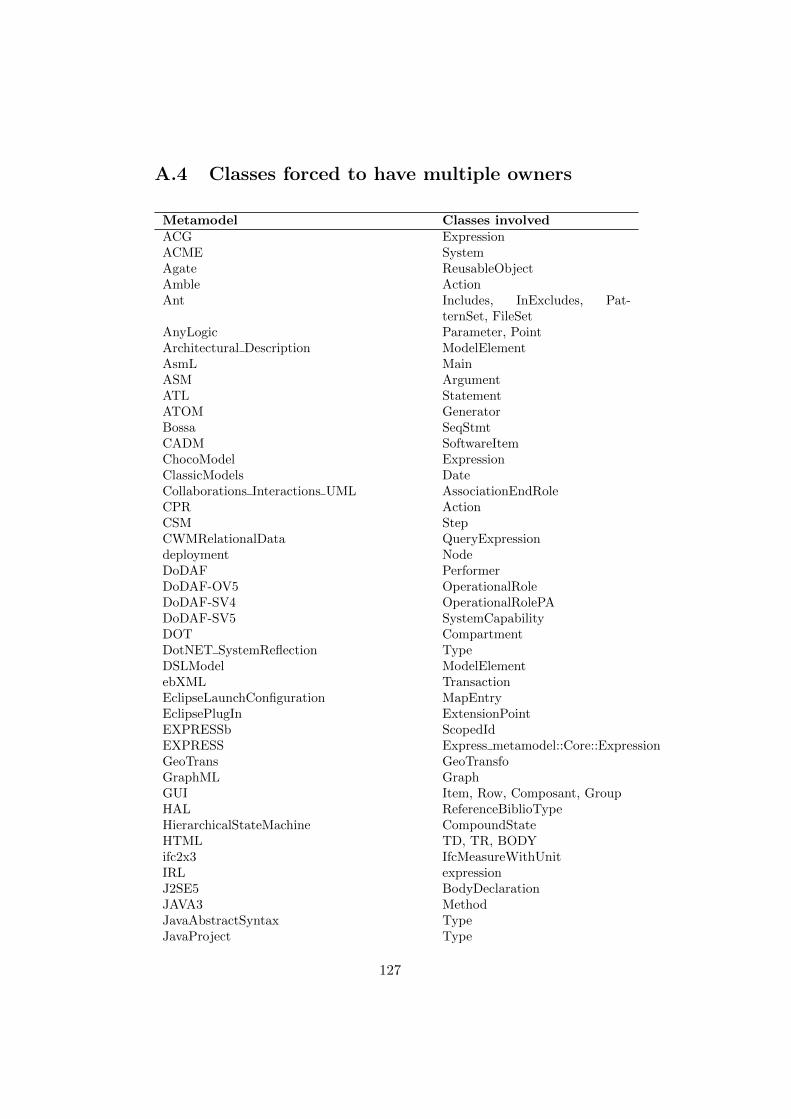
A.4 Classes forced to have multiple owners
Metamodel Classes involvedACG ExpressionACME SystemAgate ReusableObjectAmble ActionAnt Includes, InExcludes, Pat-
ternSet, FileSetAnyLogic Parameter, PointArchitectural Description ModelElementAsmL MainASM ArgumentATL StatementATOM GeneratorBossa SeqStmtCADM SoftwareItemChocoModel ExpressionClassicModels DateCollaborations Interactions UML AssociationEndRoleCPR ActionCSM StepCWMRelationalData QueryExpressiondeployment NodeDoDAF PerformerDoDAF-OV5 OperationalRoleDoDAF-SV4 OperationalRolePADoDAF-SV5 SystemCapabilityDOT CompartmentDotNET SystemReflection TypeDSLModel ModelElementebXML TransactionEclipseLaunchConfiguration MapEntryEclipsePlugIn ExtensionPointEXPRESSb ScopedIdEXPRESS Express metamodel::Core::ExpressionGeoTrans GeoTransfoGraphML GraphGUI Item, Row, Composant, GroupHAL ReferenceBiblioTypeHierarchicalStateMachine CompoundStateHTML TD, TR, BODYifc2x3 IfcMeasureWithUnitIRL expressionJ2SE5 BodyDeclarationJAVA3 MethodJavaAbstractSyntax TypeJavaProject Type
127
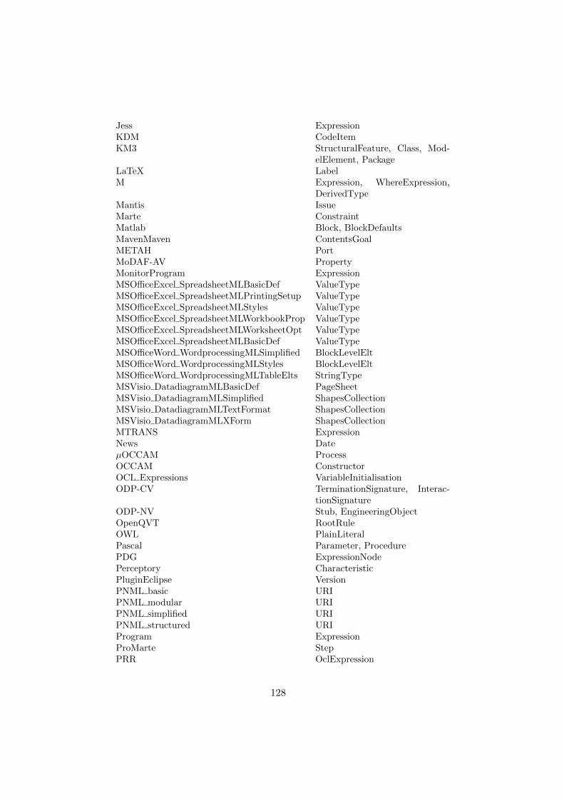
Jess ExpressionKDM CodeItemKM3 StructuralFeature, Class, Mod-
elElement, PackageLaTeX LabelM Expression, WhereExpression,
DerivedTypeMantis IssueMarte ConstraintMatlab Block, BlockDefaultsMavenMaven ContentsGoalMETAH PortMoDAF-AV PropertyMonitorProgram ExpressionMSOfficeExcel SpreadsheetMLBasicDef ValueTypeMSOfficeExcel SpreadsheetMLPrintingSetup ValueTypeMSOfficeExcel SpreadsheetMLStyles ValueTypeMSOfficeExcel SpreadsheetMLWorkbookProp ValueTypeMSOfficeExcel SpreadsheetMLWorksheetOpt ValueTypeMSOfficeExcel SpreadsheetMLBasicDef ValueTypeMSOfficeWord WordprocessingMLSimplified BlockLevelEltMSOfficeWord WordprocessingMLStyles BlockLevelEltMSOfficeWord WordprocessingMLTableElts StringTypeMSVisio DatadiagramMLBasicDef PageSheetMSVisio DatadiagramMLSimplified ShapesCollectionMSVisio DatadiagramMLTextFormat ShapesCollectionMSVisio DatadiagramMLXForm ShapesCollectionMTRANS ExpressionNews DateµOCCAM ProcessOCCAM ConstructorOCL Expressions VariableInitialisationODP-CV TerminationSignature, Interac-
tionSignatureODP-NV Stub, EngineeringObjectOpenQVT RootRuleOWL PlainLiteralPascal Parameter, ProcedurePDG ExpressionNodePerceptory CharacteristicPluginEclipse VersionPNML basic URIPNML modular URIPNML simplified URIPNML structured URIProgram ExpressionProMarte StepPRR OclExpression
128

PtolemyII ComponentEntity, AttributeQoS ParameterQVT Ocl ExpressionR2ML VocabularyRSS-2.0 CategorySBVRvoc PrimaryRepresentationSCADE NamedTypeScilab LinkSEE Design ExpressionSharengo BusinessRuleSignalFlow CompoundComponentSimulinkStateFlow SystemSPL PlaceSQLDDL ValueSQLDML ExpressionSysML FlowPropertyTextualPathExp PathUIML-3.0 EventUML2 OutputPinUMLDI TaggedValueUMLDI-ActivityGraphs ActionUMLDI-StateMachines ActionUSECASE1 Parametervb expressionWebApplications ConceptualModel LogicElementWorkDefinitions Phase, WorkDefinitionWSDL BindingOperationXHTML LinkTypesXPDL-1.14 ActivityXQuery XPath, BooleanExpXSchema AbstractContentXUL-Interactorl InteractoryUML Note, Model, ClassReference
129

A.5 Multiple occurrences of a class name in apackage
Metamodel Classes involved
Conference.owl Abstractconfious.owl AbstractconfOf.owl Abstractcrs dr.owl Abstractedas.owl Abstractekaw.owl Research Topiciasted.owl Research TopicMICRO.owl Research TopicOpenConf.owl Research Topicpaperdyne.owl Research TopicPCS.owl Research Topicsigkdd.owl Research Topic
130
Bibliography
[1] AtlanMod metamodel zoo, available at http://www.emn.fr/
z-info/atlanmod/index.php/Zoos.
[2] Dresden OCL Toolkit, available at http://www.dresden-ocl.org.
[3] Formal Modeling Using Logic Programming and Analysis, availableat http://research.microsoft.com/en-us/projects/formula/
[4] Model Validation MOFScript, available at http://users.abo.fi/
akhan/model_validation.m2t.
[5] MOFScript Homepage, available at http://www.eclipse.org/gmt/
mofscript/.
[6] Semantic Web and Model Driven Development, available at http:
//code.google.com/p/twouse/
[7] UML 2003 - The Unified Modeling Language, Modeling Languagesand Applications, 6th International Conference, San Francisco, CA,USA, October 20-24, 2003, Proceedings. In: Stevens, P., Whittle, J.,Booch, G. (eds.) UML. Lecture Notes in Computer Science, vol. 2863.Springer (2003)
[8] MOFScript User Guide (2009), document Available at http://www.eclipse.org/gmt/mofscript/doc/MOFScript-User-Guide-0.8.
pdf.
[9] Alanen, M., Porres, I.: A Metamodeling Language Supporting Subsetand Union Properties. Springer International Journal on Software andSystems Modeling 7(1), 103–124 (2007), available at http://www.
springerlink.com/content/8k67436222447147/.
[10] Anastasakis, K., Bordbar, B., Kuster, J.M.: Analysis of Model Trans-formations via Alloy. In: Proceedings of MoDeVVa 2007. pp. 47–56(2007)
131

[11] Artale, A., Calvanese, D., Ibanez Garcıa, A.: Full satisfiability ofUML class diagrams. In: Proceedings of the 29th international confer-ence on Conceptual modeling. pp. 317–331. ER’10, Springer-Verlag,Berlin, Heidelberg (2010), http://portal.acm.org/citation.cfm?id=1929757.1929788
[12] Audi, R.: The Cambridge Dictionary of Philosophy. Paw Prints(2008)
[13] Baader, F., Calvanese, D., McGuinness, D.L., Nardi, D., Patel-Schneider, P.F. (eds.): The description logic handbook: theory, im-plementation, and applications. Cambridge University Press, NewYork, NY, USA (2003)
[14] Babenyshev, S., Rybakov, V.: Reasoning and Inference Rules inBasic Linear Temporal Logic BLTL. In: Setchi, R., Jordanov, I.,Howlett, R., Jain, L. (eds.) Knowledge-Based and Intelligent Infor-mation and Engineering Systems, Lecture Notes in Computer Sci-ence, vol. 6277, pp. 224–233. Springer Berlin Heidelberg (2010),http://dx.doi.org/10.1007/978-3-642-15390-7_23
[15] Balaban, M., Maraee, A.: Consistency of UML Class Diagramswith Hierarchy Constraints. In: Etzion, O., Kuflik, T., Motro, A.(eds.) Next Generation Information Technologies and Systems, Lec-ture Notes in Computer Science, vol. 4032, pp. 71–82. Springer BerlinHeidelberg (2006), http://dx.doi.org/10.1007/11780991_7
[16] Balaban, M., Maraee, A.: A UML-based method for deciding finitesatisfiability in description logics. In: Description Logics (2008)
[17] Barros, A., Duddy, K., Lawley, M., Milosevic, Z., Raymond, K.,Wood, A.: Processes, Roles, and Events: UML Concepts for En-terprise Architecture. In: Evans, A., Kent, S., Selic, B. (eds.) UML2000 - The Unified Modeling Language, Lecture Notes in ComputerScience, vol. 1939, pp. 62–77. Springer Berlin Heidelberg (2000),http://dx.doi.org/10.1007/3-540-40011-7_5
[18] Bendix, L., Emanuelsson, P.: Diff and merge support for model baseddevelopment. In: Proceedings of the 2008 international workshop onComparison and versioning of software models. pp. 31–34. CVSM,ACM (2008)
[19] Berardi, D., Calvanese, D., Giacomo, G.D.: Reasoning on UML classdiagrams. Artif. Intell. 168(1-2), 70–118 (2005)
132

[20] Bock, C., Fokoue, A., Haase, P., Hoekstra, R., Horrocks, I.,Ruttenberg, A., Sattler, U., Smith, M.: OWL 2 Web Ontol-ogy Language Structural Specification and Functional-Style Syn-tax. W3 Recommendation (2009), http://www.w3.org/TR/2009/
REC-owl2-syntax-20091027/
[21] Bock, C., Fokoue, A., Haase, P., Hoekstra, R., Horrocks, I.,Ruttenberg, A., Sattler, U., Smith, M.: OWL 2 Web Ontol-ogy Language Structural Specification and Functional-Style Syntax,w3 Recommendation Available at http://www.w3.org/TR/2009/
REC-owl2-syntax-20091027/
[22] Boris, M., et al.: OWL 2 web ontology language structural spec-ification and functional-style syntax. W3 Recommendation http:
//www.w3.org/TR/owl2-syntax/
[23] Boris, M., Peter F, P.S., Bernardo, C.G.: OWL 2 WebOntology Language Direct Semantics, http://www.w3.org/TR/
owl2-direct-semantics/
[24] Boris Motic, Peter F. Patel-Scheneider, Ian Horrocks: OWL 1.1Web Ontology Language Structural Specification and Functional-Sytle Syntax (May 2007), available at http://www.webont.org/owl/1.1/owl\_specification.html.
[25] Broy, M., Cengarle, M.V., Granniger, H., Rumpe, B.: Considerationsand Rationale for a UML System Model, pp. 43–60. John Wiley andSons, Inc. (2009)
[26] Cabot, J., Clariso, R., Riera, D.: Verification of UML OCL classdiagrams using constraint programming. IEEE International Con-ference on Software Testing Verification and Validation Workshop(ICSTW’08) pp. 73–80 (2008)
[27] Cao, X., Miao, H., Xu, Q.: Verifying service-oriented requirementsusing model checking. In: Proceedings of the 2008 IEEE InternationalConference on e-Business Engineering. pp. 643–648. ICEBE ’08, IEEEComputer Society, Washington, DC, USA (2008)
[28] Chen, W.: Tactic-based theorem proving and knowledge-based for-ward chaining: An experiment with Nuprl and Ontic. In: Kapur,D. (ed.) Automated Deduction CADE, Lecture Notes in ComputerScience, vol. 607, pp. 552–566. Springer Berlin Heidelberg (1992),http://dx.doi.org/10.1007/3-540-55602-8_191
133

[29] Clark, T., Evans, A., Kent, S.: The Metamodelling Language Calcu-lus: Foundation Semantics for UML. In: Proceedings of the Funda-mental Aspects of Software Engineering (FASE). pp. 17–31 (2001)
[30] Clavel, M., Egea, M., da Silva, V.T.: The MOVA Tool: A Rewriting-Based UML Modeling, Measuring and Validation Tool. In: JISBD.pp. 393–394 (2007)
[31] David H. Akehurst and Stuart Kent and Octavian Patrascoiu: Arelational approach to defining and implementing transformationsbetween metamodels. Software and System Modeling 2(4), 215–239(2003)
[32] Dobing, B., Parsons, J.: Current Practices in the Use of UML. In:Akoka, J., Liddle, S., Song, I.Y., Bertolotto, M., Comyn-Wattiau,I., Heuvel, W.J., Kolp, M., Trujillo, J., Kop, C., Mayr, H. (eds.)Perspectives in Conceptual Modeling, Lecture Notes in ComputerScience, vol. 3770, pp. 2–11. Springer Berlin Heidelberg (2005), http://dx.doi.org/10.1007/11568346_2
[33] Ebbinghaus, H., Flum, J., Thomas, W.: Mathematical Logic. Under-graduate Texts in Mathematics, Springer (1994)
[34] Egyed, A.: UML Analyzer: A Tool for the Instant Consistency Check-ing of UML Models. In: Proceedings of ICSE 2007. pp. 793 –796 (may2007)
[35] Epstein, R.: Predicate logic: the semantic foundations of logic.Wadsworth Thomson Learning (2001)
[36] Fielding, R.T.: Architectural Styles and the Design of Network-basedSoftware Architectures. Ph.D. thesis, Citeseer (2000), http://www.ics.uci.edu/~fielding/pubs/dissertation/top.htm
[37] Fowler, M.: Domain-Specific Languages. Addison-Wesley SignatureSeries, Pearson Education (2010)
[38] Garcia, M., Shidqie, A.J.: OCL Compiler for EMF. In: Eclipse Mod-eling Symposium at Eclipse Summit Europe 2007, Stuttgart, Ger-many (2007)
[39] Gasevic, D., Djuric, D., Devedzic, V.: MDA-based Automatic OWLOntology Development. Int. J. Softw. Tools Technol. Transf. 9(2),103–117 (2007)
[40] Gogolla, M., BAijttner, F., Richters, M.: USE: A UML-basedspecification environment for validating UML and OCL. Science
134

of Computer Programming 69(1-3), 27 – 34 (2007), http://www.
sciencedirect.com/science/article/pii/S0167642307001608,special issue on Experimental Software and Toolkits
[41] Gordon, M.J.C., Melham, T.F. (eds.): Introduction to HOL: A the-orem proving environment for higher order logic. Cambridge Uni-versity Press (1993), http://www.cs.ox.ac.uk/tom.melham/pub/
Gordon-1993-ITH.html
[42] Heckel, R., Voigt, H., Kuster, J., Thone, S.: Towards Consistencyof Web Service Architectures. In the Proceedings of the 7th WorldMulticonference on Systemics, Cybernetics, and Informatics (2003)
[43] Henderson-Sellers, B.: On the Mathematics of Modelling, Metamod-elling, Ontologies and Modelling Languages. Springer Briefs in Com-puter Science, Springer (2012)
[44] Hitzler, P., Krotzsch, M., Rudolph, S.: Foundations of Semantic WebTechnologies. Chapman & Hall/CRC (2009)
[45] Hnatkowska B., Huzar Z., M.J.: Consistency Checking in UML Mod-els. In: ISM’01 (2001)
[46] Hoglund, S., Khan, A.H., Liu, Y., Porres, I.: Representing and Val-idating Metamodels using OWL 2 and SWRL. In: JCKBSE’10. pp.133–144. Kaunas University of Technology (2010)
[47] Holovaty, A., Kaplan-Moss, J.: The Definitive Guide to Django: WebDevelopment Done Right. Apress (2007)
[48] Horrocks, I., Kutz, O., Sattler, U.: The even more irresistibleSROIQ. In: Proc. of the 10th Int. Conf. on Principles of KnowledgeRepresentation and Reasoning (KR 2006). pp. 57–67. AAAI Press(2006), download/2006/HoKS06a.pdf
[49] Horrocks, I., Patel-Schneider, P.F., Boley, H., Tabet, S., Grosof, B.,Dean, M.: SWRL: A semantic web rule language combining OWL andRuleML (2004), availible at http://www.w3.org/Submission/SWRL/
[50] Horrocks, I., Patel-Schneider, P.F., Harmelen, F.V.: From SHIQ andRDF to OWL: The Making of a Web Ontology Language. Journal ofWeb Semantics 1, 2003 (2003)
[51] Horrocks, I., Sattler, U., Tobies, S.: Practical reasoning for expres-sive description logics. In: Proceedings of LPAR 1999. pp. 161–180.Springer-Verlag, London, UK (1999)
135
[52] Jouault, F., Bezivin, J.: KM3: a DSL for Metamodel Specifica-tion. In: Proceedings of 8th IFIP International Conference on FormalMethods for Open Object-Based Distributed Systems. Bologna, Italy(2006)
[53] Kande, M.M., Strohmeier, A.: Towards a UML profile for software ar-chitecture descriptions. In: Proceedings of the 3rd international con-ference on The unified modeling language: advancing the standard.pp. 513–527. UML’00, Springer-Verlag, Berlin, Heidelberg (2000),http://dl.acm.org/citation.cfm?id=1765175.1765230
[54] Kaneiwa, K., Satoh, K.: Consistency Checking Algorithms forRestricted UML Class Diagrams. In: Proceedings of FoIKS2006,Springer. Springer (2006)
[55] Kent, S.: Model Driven Engineering. In: Proc. of IFM InternationalFormal Methods 2002. LNCS, vol. 2335. Springer-Verlag (2002)
[56] Khan, A.H., Rauf, I., Porres, I.: Consistency of UMLClass and Statechart Diagrams with State Invariants. In: Fil-ipe, J., Neves, R.C.d. (eds.) First International Conference onModel-Driven Engineering and Software Development, MODEL-SWARD 2013. vol. 1, pp. 1–11. SciTePress Digital Library(http://www.scitepress.org/DigitalLibrary/). SciTePress is memberof CrossRef (http://www.crossref.org/). (2013)
[57] Khan, A.H., Suenson, E., Porres, I.: Class and Object Model Confor-mance using OWL2 Reasoners. In: Penjam, J. (ed.) SPLST’11. pp.126–137. TUT Press (2011)
[58] Khan, A.H., Suenson, E., Porres, I.: Representation and Confor-mance of UML Models Containing Ordered Properties Using OWL2.In: OrdRing’11. CEUR-WS Proceedings., vol. 2011. ISWC 2011(2011)
[59] Knorr, M., Alferes, J.J., Hitzler, P.: Local closed world reasoningwith description logics under the well-founded semantics. ArtificialIntelligence 175(9-10), 1528 – 1554 (2011)
[60] Krogstie, J.: Model-Based Development and Evolution of InformationSystems - A Quality Approach. Springer (2012)
[61] Lamo, Y., Wang, X., Mantz, F., MacCaull, W., Rutle, A.: DPFWorkbench: A Diagrammatic Multi-Layer Domain Specific (Meta-)Modelling Environment. In: Computer and Information Science2012, vol. 429, pp. 37–52. Springer (2012)
136

[62] Liu, L., Ozsu, M.T. (eds.): Encyclopedia of Database Systems.Springer US (2009)
[63] Liu, Y., Hoglund, S., Khan, A.H., Porres, I.: A Feasibility Study onthe Validation of Domain Specific Languages Using OWL 2 Reason-ers. In: Proceedings of TWOMDE 2010. CEUR Workshop Preceed-ings, CEUR (2010)
[64] Lutz, R., Wurfel, D., Diehl, S.: How Humans Merge UML-Models.pp. 177–186. ESEM ’11, IEEE (2011)
[65] Machines, I.B., Group, O.M., Software, S.: Ontology definitionmetamodel (ODM), OMG Document ad/2003-02-23. Available athttp://www.omg.org/.
[66] Malgouyres, H., Motet, G.: A UML model consistency verificationapproach based on meta-modeling formalization. In: Proceedings ofSAC2006. pp. 1804–1809. SAC ’06, ACM, New York, NY, USA (2006)
[67] Maoz, S., Jan Oliver, R., Bernhard, R.: Summarizing semantic modeldifferences. In: Proceedings of The International Workshop on Modelsand Evolution. ME (2011)
[68] Maoz, S., Ringert, J.O., Rumpe, B.: Semantically configurable con-sistency analysis for class and object diagrams. In: MoDELS. pp.153–167 (2011)
[69] Mendelson, E.: Introduction to mathematical logic; (3rd ed.).Wadsworth and Brooks/Cole Advanced Books & Software, Monterey,CA, USA (1987)
[70] Nentwich, C., Emmerich, W., Finkelstein, A.: Static ConsistencyChecking for Distributed Specifications. In the Proceedings of the16th IEEE international conference on Automated software engineer-ing (2001)
[71] OMG: Meta Object Facility, version 1.4 (April 2002), documentformal/2002-04-03. Available at http://www.omg.org/.
[72] OMG: Unified Language Specification (March 2003), version 1.5, Doc-ument formal/03-03-01, available at http://www.omg.org/.
[73] OMG: XML Metadata Interchange (XMI) Specification, version 2.1(September 2005), document formal/05-09-01, available at http://
www.omg.org/.
[74] OMG: OCL Specification, Version 2.0 (2006), http://www.omg.org/spec/OCL/2.0/
137

[75] OMG: ODM Ontology Definition Metamodel (2009), http://www.
omg.org/spec/ODM/1.0
[76] OMG: UML 2.2 Infrastructure Specification (February 2009), avail-able at http://www.omg.org/.
[77] OMG: UML, Superstructure Specification, Version 2.4.1. Tech. rep.(2011), http://www.omg.org/spec/UML/2.4.1/Superstructure/
PDF/
[78] Parreiras, F.S.: Marrying model-driven engineering and ontologytechnologies: The TwoUse approach. Ph.D. thesis (2011)
[79] Parreiras, F.S., Staab, S., Winter, A.: On marrying ontological andmetamodeling technical spaces. In: ESEC-FSE ’07: Proceedings. pp.439–448. ACM, New York, NY, USA (2007)
[80] Porres, I., Rauf, I.: Modeling Behavioral RESTful Web Service Inter-faces in UML. Accepted in 26th Annual ACM Symposium on AppliedComputing Track on Service Oriented Architectures and Program-ming(SAC 2011) (2011)
[81] Queralt, A., Artale, A., Calvanese, D., Teniente, E.: OCL-Lite: Adecidable (yet expressive) fragment of OCL. In: Proc. of the 25thInt. Workshop on Description Logics (DL 2012). CEUR ElectronicWorkshop Proceedings, http://ceur-ws.org/, vol. 846, pp. 312–322(2012)
[82] Queralt, A., Artale, A., Calvanese, D., Teniente, E.: OCL-Lite: FiniteReasoning on UML/OCL Conceptual Schemas. Data and KnowledgeEngineering 73, 1–22 (2012)
[83] R, S., B, M., I, H.: HermiT: A highly-efficient OWL reasoner. Pro-ceedings of the 5th International Workshop on OWL: Experiencesand Directions (OWLED 2008) (2008)
[84] Rahmani, Oberle, Dahms: An Adjustable Transformation from OWLto Ecore. In: MODELS 2010, Oslo, Norway, October 3-8, 2010. Pro-ceedings. LNCS, Springer (2010)
[85] Rasch, H., Wehrheim, H.: Checking Consistency in UML Diagrams:Classes and State Machines. In: Formal Methods for Open Object-Based Distributed Systems, LNCS, vol. 2884, pp. 229–243 (2003)
[86] Rauf, I., Khan, A.H., Porres, I.: Analyzing Consistency of Behav-ioral REST Web Service Interfaces. In: Silva, J., Tiezzi, F. (eds.) The
138

8th International Workshop on Automated Specification and Verifica-tion of Web Systems. pp. 1–15. Electronic Proceedings in TheoreticalComputer Science (EPTCS). (2012)
[87] Rutle, A., Rossini, A., Lamo, Y., Wolter, U.: A formal approachto the specification and transformation of constraints in MDE. In:Journal of Logic and Algebraic Programming. vol. 81, pp. 422 – 457.ELSEVIER (2012)
[88] Sekerinski, E.: Verifying statecharts with state invariants. In:ICECCS. pp. 7–14 (2008)
[89] Shah, S.M.A., Anastasakis, K., Bordbar, B.: From UML to Alloyand back again. In: Proceedings of MoDeVVa 2009. pp. 4:1–4:10.MoDeVVa ’09, ACM, New York, NY, USA (2009)
[90] Sirin, E., Parsia, B., Grau, B.C., Kalyanpur, A., Katz, Y.: Pellet: Apractical OWL-DL reasoner. Web Semantics: Science, Services andAgents on the World Wide Web 5, 51–53 (2007)
[91] Tarski, A., Helmer-Hirschberg, O.: Introduction to Logic and theMethodology of Deductive Sciences. Oxford (1946)
[92] Tsai, W.T., Wei, X., Chen, Y., Paul, R.: A robust testing frameworkfor verifying web services by completeness and consistency analysis.In: Proceedings of the IEEE International Workshop. pp. 159–166.SOSE ’05, IEEE Computer Society, Washington, DC, USA (2005)
[93] Tsai, W., Wei, X., Chen, Y., Xiao, B., Paul, R., Huang, H.: Devel-oping and assuring trustworthy Web services. In the Proceedings ofAutonomous Decentralized Systems (2005)
[94] Van Der Straeten, R.: Inconsistency Management in Model-drivenEngineering. An Approach using Description Logics. Ph.D. thesis,Vrije Universiteit Brussel, Brussels, Belgium (September 2005)
[95] Varro, D., Pataricza, A.: VPM: A visual, precise and multilevel meta-modeling framework for describing mathematical domains and UML.Journal of Software and Systems Modeling 2(3), 187–210 (October2003), http://www.inf.mit.bme.hu/FTSRG/Publications/varro/
2003/sosym2003_vp.pdf
[96] Vitus S. W. Lam, J.A.P.: Consistency checking of statechart diagramsof a class hierarchy. In: ECOOP. pp. 412–427 (2005)
[97] Vlist, E.V.D. (ed.): RELAX NG: A Simpler Schema Language forXML. O’Reilly, California, CA, USA (2003)
139

[98] W3: OWL 2 Document Overview (October 2009), available at http://www.w3.org/TR/owl2-overview.
[99] W3C: Extendable Markup Language XML Version 1.0 (September2005), available at http://www.w3.org/TR/xml-id/.
[100] Walter, T., Parreiras, F., Staab, S.: An ontology-based frame-work for domain-specific modeling. Software and Systems Mod-eling pp. 1–26, http://dx.doi.org/10.1007/s10270-012-0249-9,10.1007/s10270-012-0249-9
[101] Walter, T., Parreiras, F.S., Staab, S.: OntoDSL: An ontology-basedframework for domain-specific languages. In: Schurr, A., Selic, B.(eds.) MoDELS. Lecture Notes in Computer Science, vol. 5795, pp.408–422. Springer (2009)
[102] Wang, S., Jin, L., Jin, C.: Ontology Definition Metamodel basedConsistency Checking of UML Models. pp. 1 –5 (may 2006)
[103] Wilke, C., Demuth, B.: UML is still inconsistent! How to im-prove OCL Constraints in the UML 2.3 Superstructure. ECEASST44 (2011)
[104] Yeung, W.L.: Checking Consistency between UML Class and StateModels Based on CSP and B. J. UCS 10(11), 1540–1559 (2004)
[105] Yin, Y., Yin, J., Li, Y., Deng, S.: Verifying consistency of web ser-vices behavior using type theory. In: Asia-Pacific Services ComputingConference, 2008. APSCC ’08. IEEE. pp. 1560–1567 (dec 2008)
[106] Zhao, Y., Pan, J.Z., Jekjantuk, N., Henriksson, J., Groner, G., Ren,Y.: Most project - definition of language hierarchy (2008), availi-ble at https://www.most-project.eu/admin/xinha/plugins/
ExtendedFileManager/images/Deliverables/MOST_Deliverable_
D3.1.pdf
140

Turku Centre for Computer Science
TUCS Dissertations 1. Marjo Lipponen, On Primitive Solutions of the Post Correspondence Problem 2. Timo Käkölä, Dual Information Systems in Hyperknowledge Organizations 3. Ville Leppänen, Studies on the Realization of PRAM 4. Cunsheng Ding, Cryptographic Counter Generators 5. Sami Viitanen, Some New Global Optimization Algorithms 6. Tapio Salakoski, Representative Classification of Protein Structures 7. Thomas Långbacka, An Interactive Environment Supporting the Development of
Formally Correct Programs 8. Thomas Finne, A Decision Support System for Improving Information Security 9. Valeria Mihalache, Cooperation, Communication, Control. Investigations on
Grammar Systems. 10. Marina Waldén, Formal Reasoning About Distributed Algorithms 11. Tero Laihonen, Estimates on the Covering Radius When the Dual Distance is
Known 12. Lucian Ilie, Decision Problems on Orders of Words 13. Jukkapekka Hekanaho, An Evolutionary Approach to Concept Learning 14. Jouni Järvinen, Knowledge Representation and Rough Sets 15. Tomi Pasanen, In-Place Algorithms for Sorting Problems 16. Mika Johnsson, Operational and Tactical Level Optimization in Printed Circuit
Board Assembly 17. Mats Aspnäs, Multiprocessor Architecture and Programming: The Hathi-2 System 18. Anna Mikhajlova, Ensuring Correctness of Object and Component Systems 19. Vesa Torvinen, Construction and Evaluation of the Labour Game Method 20. Jorma Boberg, Cluster Analysis. A Mathematical Approach with Applications to
Protein Structures 21. Leonid Mikhajlov, Software Reuse Mechanisms and Techniques: Safety Versus
Flexibility 22. Timo Kaukoranta, Iterative and Hierarchical Methods for Codebook Generation in
Vector Quantization 23. Gábor Magyar, On Solution Approaches for Some Industrially Motivated
Combinatorial Optimization Problems 24. Linas Laibinis, Mechanised Formal Reasoning About Modular Programs 25. Shuhua Liu, Improving Executive Support in Strategic Scanning with Software
Agent Systems 26. Jaakko Järvi, New Techniques in Generic Programming – C++ is more Intentional
than Intended 27. Jan-Christian Lehtinen, Reproducing Kernel Splines in the Analysis of Medical
Data 28. Martin Büchi, Safe Language Mechanisms for Modularization and Concurrency 29. Elena Troubitsyna, Stepwise Development of Dependable Systems 30. Janne Näppi, Computer-Assisted Diagnosis of Breast Calcifications 31. Jianming Liang, Dynamic Chest Images Analysis 32. Tiberiu Seceleanu, Systematic Design of Synchronous Digital Circuits 33. Tero Aittokallio, Characterization and Modelling of the Cardiorespiratory System
in Sleep-Disordered Breathing 34. Ivan Porres, Modeling and Analyzing Software Behavior in UML 35. Mauno Rönkkö, Stepwise Development of Hybrid Systems 36. Jouni Smed, Production Planning in Printed Circuit Board Assembly 37. Vesa Halava, The Post Correspondence Problem for Market Morphisms 38. Ion Petre, Commutation Problems on Sets of Words and Formal Power Series 39. Vladimir Kvassov, Information Technology and the Productivity of Managerial
Work 40. Frank Tétard, Managers, Fragmentation of Working Time, and Information
Systems

41. Jan Manuch, Defect Theorems and Infinite Words 42. Kalle Ranto, Z4-Goethals Codes, Decoding and Designs 43. Arto Lepistö, On Relations Between Local and Global Periodicity 44. Mika Hirvensalo, Studies on Boolean Functions Related to Quantum Computing 45. Pentti Virtanen, Measuring and Improving Component-Based Software
Development 46. Adekunle Okunoye, Knowledge Management and Global Diversity – A Framework
to Support Organisations in Developing Countries 47. Antonina Kloptchenko, Text Mining Based on the Prototype Matching Method 48. Juha Kivijärvi, Optimization Methods for Clustering 49. Rimvydas Rukšėnas, Formal Development of Concurrent Components 50. Dirk Nowotka, Periodicity and Unbordered Factors of Words 51. Attila Gyenesei, Discovering Frequent Fuzzy Patterns in Relations of Quantitative
Attributes 52. Petteri Kaitovaara, Packaging of IT Services – Conceptual and Empirical Studies 53. Petri Rosendahl, Niho Type Cross-Correlation Functions and Related Equations 54. Péter Majlender, A Normative Approach to Possibility Theory and Soft Decision
Support 55. Seppo Virtanen, A Framework for Rapid Design and Evaluation of Protocol
Processors 56. Tomas Eklund, The Self-Organizing Map in Financial Benchmarking 57. Mikael Collan, Giga-Investments: Modelling the Valuation of Very Large Industrial
Real Investments 58. Dag Björklund, A Kernel Language for Unified Code Synthesis 59. Shengnan Han, Understanding User Adoption of Mobile Technology: Focusing on
Physicians in Finland 60. Irina Georgescu, Rational Choice and Revealed Preference: A Fuzzy Approach 61. Ping Yan, Limit Cycles for Generalized Liénard-Type and Lotka-Volterra Systems 62. Joonas Lehtinen, Coding of Wavelet-Transformed Images 63. Tommi Meskanen, On the NTRU Cryptosystem 64. Saeed Salehi, Varieties of Tree Languages 65. Jukka Arvo, Efficient Algorithms for Hardware-Accelerated Shadow Computation 66. Mika Hirvikorpi, On the Tactical Level Production Planning in Flexible
Manufacturing Systems 67. Adrian Costea, Computational Intelligence Methods for Quantitative Data Mining 68. Cristina Seceleanu, A Methodology for Constructing Correct Reactive Systems 69. Luigia Petre, Modeling with Action Systems 70. Lu Yan, Systematic Design of Ubiquitous Systems 71. Mehran Gomari, On the Generalization Ability of Bayesian Neural Networks 72. Ville Harkke, Knowledge Freedom for Medical Professionals – An Evaluation Study
of a Mobile Information System for Physicians in Finland 73. Marius Cosmin Codrea, Pattern Analysis of Chlorophyll Fluorescence Signals 74. Aiying Rong, Cogeneration Planning Under the Deregulated Power Market and
Emissions Trading Scheme 75. Chihab BenMoussa, Supporting the Sales Force through Mobile Information and
Communication Technologies: Focusing on the Pharmaceutical Sales Force 76. Jussi Salmi, Improving Data Analysis in Proteomics 77. Orieta Celiku, Mechanized Reasoning for Dually-Nondeterministic and
Probabilistic Programs 78. Kaj-Mikael Björk, Supply Chain Efficiency with Some Forest Industry
Improvements 79. Viorel Preoteasa, Program Variables – The Core of Mechanical Reasoning about
Imperative Programs 80. Jonne Poikonen, Absolute Value Extraction and Order Statistic Filtering for a
Mixed-Mode Array Image Processor 81. Luka Milovanov, Agile Software Development in an Academic Environment 82. Francisco Augusto Alcaraz Garcia, Real Options, Default Risk and Soft
Applications 83. Kai K. Kimppa, Problems with the Justification of Intellectual Property Rights in
Relation to Software and Other Digitally Distributable Media 84. Dragoş Truşcan, Model Driven Development of Programmable Architectures 85. Eugen Czeizler, The Inverse Neighborhood Problem and Applications of Welch
Sets in Automata Theory

86. Sanna Ranto, Identifying and Locating-Dominating Codes in Binary Hamming Spaces
87. Tuomas Hakkarainen, On the Computation of the Class Numbers of Real Abelian Fields
88. Elena Czeizler, Intricacies of Word Equations 89. Marcus Alanen, A Metamodeling Framework for Software Engineering 90. Filip Ginter, Towards Information Extraction in the Biomedical Domain: Methods
and Resources 91. Jarkko Paavola, Signature Ensembles and Receiver Structures for Oversaturated
Synchronous DS-CDMA Systems 92. Arho Virkki, The Human Respiratory System: Modelling, Analysis and Control 93. Olli Luoma, Efficient Methods for Storing and Querying XML Data with Relational
Databases 94. Dubravka Ilić, Formal Reasoning about Dependability in Model-Driven
Development 95. Kim Solin, Abstract Algebra of Program Refinement 96. Tomi Westerlund, Time Aware Modelling and Analysis of Systems-on-Chip 97. Kalle Saari, On the Frequency and Periodicity of Infinite Words 98. Tomi Kärki, Similarity Relations on Words: Relational Codes and Periods 99. Markus M. Mäkelä, Essays on Software Product Development: A Strategic
Management Viewpoint 100. Roope Vehkalahti, Class Field Theoretic Methods in the Design of Lattice Signal
Constellations 101. Anne-Maria Ernvall-Hytönen, On Short Exponential Sums Involving Fourier
Coefficients of Holomorphic Cusp Forms 102. Chang Li, Parallelism and Complexity in Gene Assembly 103. Tapio Pahikkala, New Kernel Functions and Learning Methods for Text and Data
Mining 104. Denis Shestakov, Search Interfaces on the Web: Querying and Characterizing 105. Sampo Pyysalo, A Dependency Parsing Approach to Biomedical Text Mining 106. Anna Sell, Mobile Digital Calendars in Knowledge Work 107. Dorina Marghescu, Evaluating Multidimensional Visualization Techniques in Data
Mining Tasks 108. Tero Säntti, A Co-Processor Approach for Efficient Java Execution in Embedded
Systems 109. Kari Salonen, Setup Optimization in High-Mix Surface Mount PCB Assembly 110. Pontus Boström, Formal Design and Verification of Systems Using Domain-
Specific Languages 111. Camilla J. Hollanti, Order-Theoretic Mehtods for Space-Time Coding: Symmetric
and Asymmetric Designs 112. Heidi Himmanen, On Transmission System Design for Wireless Broadcasting 113. Sébastien Lafond, Simulation of Embedded Systems for Energy Consumption
Estimation 114. Evgeni Tsivtsivadze, Learning Preferences with Kernel-Based Methods 115. Petri Salmela, On Commutation and Conjugacy of Rational Languages and the
Fixed Point Method 116. Siamak Taati, Conservation Laws in Cellular Automata 117. Vladimir Rogojin, Gene Assembly in Stichotrichous Ciliates: Elementary
Operations, Parallelism and Computation 118. Alexey Dudkov, Chip and Signature Interleaving in DS CDMA Systems 119. Janne Savela, Role of Selected Spectral Attributes in the Perception of Synthetic
Vowels 120. Kristian Nybom, Low-Density Parity-Check Codes for Wireless Datacast Networks 121. Johanna Tuominen, Formal Power Analysis of Systems-on-Chip 122. Teijo Lehtonen, On Fault Tolerance Methods for Networks-on-Chip 123. Eeva Suvitie, On Inner Products Involving Holomorphic Cusp Forms and Maass
Forms 124. Linda Mannila, Teaching Mathematics and Programming – New Approaches with
Empirical Evaluation 125. Hanna Suominen, Machine Learning and Clinical Text: Supporting Health
Information Flow 126. Tuomo Saarni, Segmental Durations of Speech 127. Johannes Eriksson, Tool-Supported Invariant-Based Programming

128. Tero Jokela, Design and Analysis of Forward Error Control Coding and Signaling for Guaranteeing QoS in Wireless Broadcast Systems
129. Ville Lukkarila, On Undecidable Dynamical Properties of Reversible One-Dimensional Cellular Automata
130. Qaisar Ahmad Malik, Combining Model-Based Testing and Stepwise Formal Development
131. Mikko-Jussi Laakso, Promoting Programming Learning: Engagement, Automatic Assessment with Immediate Feedback in Visualizations
132. Riikka Vuokko, A Practice Perspective on Organizational Implementation of Information Technology
133. Jeanette Heidenberg, Towards Increased Productivity and Quality in Software Development Using Agile, Lean and Collaborative Approaches
134. Yong Liu, Solving the Puzzle of Mobile Learning Adoption 135. Stina Ojala, Towards an Integrative Information Society: Studies on Individuality
in Speech and Sign 136. Matteo Brunelli, Some Advances in Mathematical Models for Preference Relations 137. Ville Junnila, On Identifying and Locating-Dominating Codes 138. Andrzej Mizera, Methods for Construction and Analysis of Computational Models
in Systems Biology. Applications to the Modelling of the Heat Shock Response and the Self-Assembly of Intermediate Filaments.
139. Csaba Ráduly-Baka, Algorithmic Solutions for Combinatorial Problems in Resource Management of Manufacturing Environments
140. Jari Kyngäs, Solving Challenging Real-World Scheduling Problems 141. Arho Suominen, Notes on Emerging Technologies 142. József Mezei, A Quantitative View on Fuzzy Numbers 143. Marta Olszewska, On the Impact of Rigorous Approaches on the Quality of
Development 144. Antti Airola, Kernel-Based Ranking: Methods for Learning and Performace
Estimation 145. Aleksi Saarela, Word Equations and Related Topics: Independence, Decidability
and Characterizations 146. Lasse Bergroth, Kahden merkkijonon pisimmän yhteisen alijonon ongelma ja sen
ratkaiseminen 147. Thomas Canhao Xu, Hardware/Software Co-Design for Multicore Architectures 148. Tuomas Mäkilä, Software Development Process Modeling – Developers
Perspective to Contemporary Modeling Techniques 149. Shahrokh Nikou, Opening the Black-Box of IT Artifacts: Looking into Mobile
Service Characteristics and Individual Perception 150. Alessandro Buoni, Fraud Detection in the Banking Sector: A Multi-Agent
Approach 151. Mats Neovius, Trustworthy Context Dependency in Ubiquitous Systems 152. Fredrik Degerlund, Scheduling of Guarded Command Based Models 153. Amir-Mohammad Rahmani-Sane, Exploration and Design of Power-Efficient
Networked Many-Core Systems 154. Ville Rantala, On Dynamic Monitoring Methods for Networks-on-Chip 155. Mikko Pelto, On Identifying and Locating-Dominating Codes in the Infinite King
Grid 156. Anton Tarasyuk, Formal Development and Quantitative Verification of
Dependable Systems 157. Muhammad Mohsin Saleemi, Towards Combining Interactive Mobile TV and
Smart Spaces: Architectures, Tools and Application Development 158. Tommi J. M. Lehtinen, Numbers and Languages 159. Peter Sarlin, Mapping Financial Stability 160. Alexander Wei Yin, On Energy Efficient Computing Platforms 161. Mikołaj Olszewski, Scaling Up Stepwise Feature Introduction to Construction of
Large Software Systems 162. Maryam Kamali, Reusable Formal Architectures for Networked Systems 163. Zhiyuan Yao, Visual Customer Segmentation and Behavior Analysis – A SOM-
Based Approach 164. Timo Jolivet, Combinatorics of Pisot Substitutions 165. Rajeev Kumar Kanth, Analysis and Life Cycle Assessment of Printed Antennas for
Sustainable Wireless Systems 166. Khalid Latif, Design Space Exploration for MPSoC Architectures

167. Bo Yang, Towards Optimal Application Mapping for Energy-Efficient Many-Core Platforms
168. Ali Hanzala Khan, Consistency of UML Based Designs Using Ontology Reasoners

Joukahaisenkatu 3-5 B, 20520 Turku, Finland | www. tucs.fi
TurkuCentre forComputerScience
University of TurkuFaculty of Mathematics and Natural Sciences • Department of Information Technology • Department of Mathematics and StatisticsTurku School of Economics • Institute of Information Systems Science
Åbo Akademi UniversityDivision for Natural Sciences and Technology • Department of Information Technologies
ISBN 978-952-12-2985-5ISSN 1239-1883

Ali H
anzala Khan
Consistency of U
ML B
ased Designs U
sing Ontology Reasoners