Alhambra Underpass Alternative Study Memo
13
ALHAMBRA UNDERPASS AT UPRR FEASIBILITY STUDIES FOR BICYCLE/PEDESTRIAN AND VEHICULAR UNDERPASS ALTERNATIVES Submitted to: City of Sacramento Department of Public Works Prepared by: 2495 NATOMAS PARK DRIVE, SUITE 600 SACRAMENTO, CA 95833 CONTACT : JOHN S. BISHOP, SE 916-576-2769 MARCH 6, 2014
-
Upload
vuongtuyen -
Category
Documents
-
view
227 -
download
0
Transcript of Alhambra Underpass Alternative Study Memo

ALHAMBRA UNDERPASS AT UPRR
FEASIBILITY STUDIES FOR BICYCLE/PEDESTRIAN AND
VEHICULAR UNDERPASS ALTERNATIVES
Submitted to:
City of Sacramento Department of Public Works
Prepared by:
2495 NATOMAS PARK DRIVE, SUITE 600
SACRAMENTO, CA 95833
CONTACT : JOHN S. BISHOP, SE
916-576-2769
MARCH 6, 2014

MCKINLEY VILLAGE ALHAMBRA UNDERPASS – FEASIBILITY STUDIES MARCH 6, 2014
1
EXECUTIVE SUMMARY
In January 2014, the City of Sacramento Department of Public Works (Public Works) requested that Parsons provide information and analysis regarding bicycle/pedestrian and vehicular underpass alternatives at the northern termination of Alhambra Boulevard. Encore McKinley Village, LLC, with whom Parsons is under contract to design a vehicular underpass at 40th Street and a bicycle/pedestrian underpass at Alhambra Boulevard, directed Parsons to provide such information and analysis to assist Public Works in Public Works’ evaluation of this matter.
In June 2013, pursuant to a contract with Encore McKinley Village, LLC, Parsons began developing alternatives to construct an underpass at the Union Pacific Railroad tracks at the northern termination of Alhambra Boulevard to accommodate pedestrians and bicyclists. Many design issues and constraints have been identified for this project, but the two key issues are continued safety for freight and passenger trains and Union Pacific’s requirement that all three tracks remain in continuous service on this important rail corridor. Through the collection of site information, including field surveys and geotechnical borings, and extensive coordination with Union Pacific we have developed three alternatives to construct the underpass for pedestrian and bicyclists including conventional cut and cover methods and unconventional methods where construction remains below grade and under the tracks. This memorandum describes the information gathered to date and a description of the alternatives studied. Also included is a discussion addressing the feasibility of constructing a larger vehicular underpass in lieu of the smaller underpass for pedestrians and bicyclists or enlarging the smaller pedestrian and bicycle underpass to accommodate vehicles.
INFORMATION GATHERED
In support of the alternatives development, Parsons has obtained site survey data gathered in January 2014 by Wood Rogers and contracted with Group Delta Consultants to perform geotechnical borings and soil testing. We’ve also communicated directly with Union Pacific engineering personnel on multiple occasions to obtain design requirements and project constraints not already presented in Union Pacific’s “Guidelines for Railroad Grade Separation Projects”.
Survey data indicates that the roadway surface elevation at the termination of Alhambra Blvd is roughly 25.1 feet and increases to elevation 27.0 feet at the toe of railroad embankment. The south slope of embankment is close to 2H:1V with the top of the railroad embankment at roughly 44.5 feet. The top of rails is at elevation 45.3 feet. On the north side of the embankment, the slope is again 2H:1V with toe of slope at roughly 19.2 feet with a shallow slope to a low point of 17.6 feet roughly 30 feet from the toe.
Geotechnical borings completed in January 2014 indicate the railroad ballast is roughly 2 feet deep with an additional 3 feet of silty sand and clayey sand with cobbles and migrated ballast. The remaining depth of embankment consists of silty sand and clayey sand with cobbles. From the base of the embankment (elevation of Alhambra Blvd at 25.1 feet), the soil profile is basically silty sand with layers of clay to elevation -15.0 feet where a dense layer of gravel and cobbles was encountered. Groundwater was encountered at elevation 1.0 foot. Based on other borings performed at the site, the dense gravel and cobble layer appears to uniformly underlie the site from Alhambra Blvd northeast to Lanatt Street and has a depth of at least 15 feet where the boring rig encountered refusal at elevation -30.0.
Through conversations and written communication with Union Pacific over the past year, design, operational, and safety requirements were provided. First, Union Pacific has required a ¼” maximum track settlement limit produced by any temporary or permanent construction.

MCKINLEY VILLAGE ALHAMBRA UNDERPASS – FEASIBILITY STUDIES MARCH 6, 2014
2
Calculations would need to demonstrate this limit is not exceeded and continual measurement of track profile in the vicinity of work would be required during construction. Second, Union Pacific will not approve any structure alternative that requires temporary closure of any of the three existing tracks at the proposed crossing site (See attached letter from UP which formally confirms the position that they have conveyed to Parsons consistently since we began our work on this project).
PEDESTRIAN AND BICYCLE UNDERPASS ALTERNATIVES
All alternatives considered and developed to date are described below. The jacked box culvert alternative has been presented to Union Pacific and reviewed by their engineering department. We are currently studying the method to construct the underpass with a pipe screen and are also investigating other possible ways to construct the underpass. While all the alternatives presented here have been used in the United States on tracks owned by various railroad operators, to our knowledge, only the cut and cover method has been used at Union Pacific tracks.
UNDERPASS BRIDGE IN OPEN CUT
This alternative using standard cut and cover techniques to construct the underpass was the first one the team evaluated. The method generally requires shooflies or temporary track closures to complete the structure in two or more stages where constructed at live tracks. At this site, the number of tracks and adjacent freeway and elevation geometry makes the method extremely expensive. Our preliminary estimate to construct a bicycle and pedestrian underpass providing 16 feet clear horizontal width and 12 feet of vertical clear width is $22.3 million, with the most significant issues and cost components being the following:
1. All three tracks must be on shooflies given the close spacing of the existing tracks. And the shooflies must be placed to the north given limited space within the Union Pacific right-of-way to the south of the existing tracks.
2. A new underpass or widening of the existing underpass must be constructed over Business-80 and the at-grade crossing at 28th Street will likely need to be temporarily modified.
3. The Verizon fiber optic line in the upper portion of the railroad embankment will need to be relocated.
A possible alternative to construct this underpass by the conventional cut and cover method worth exploring would be to combine this project with the potential future Capital Corridor Project, if and when that project proceeds forward. If it is possible to combine the projects, there could potentially be significant savings if the bulk of the shoofly costs are no longer borne by the underpass project, but rather by the Capital Corridor project to accommodate their new track. Additionally, the Business-80 underpass and the 28th Street at-grade crossing would be replaced or widened as part of the Capital Corridor Project. The City and the Joint Powers Authority would need to closely coordinate the projects but our preliminary examination shows that roughly $16 million in project costs for the underpass could potentially be transferred to the Capital Corridor project. Assuming that the Capitol Corridor project absorbs such costs, our preliminary estimate for the project is $5.6 million which would cover the underpass and the two additional shoofly track shifts needed to stage the underpass construction. The staging might proceed in the following sequence:
1. Construct the outside underpass segments on both sides of existing tracks (roughly 75 feet total width).
MCKINLEY VILLAGE ALHAMBRA UNDERPASS – FEASIBILITY STUDIES MARCH 6, 2014
3
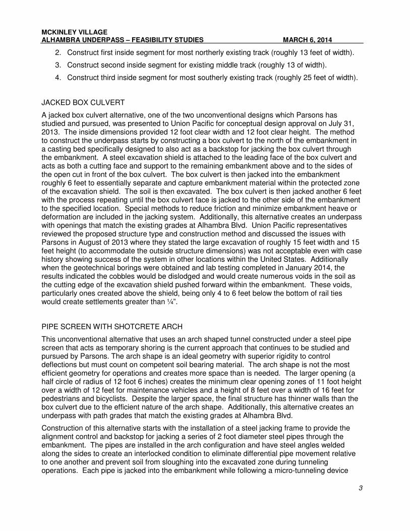
2. Construct first inside segment for most northerly existing track (roughly 13 feet of width).
3. Construct second inside segment for existing middle track (roughly 13 of width).
4. Construct third inside segment for most southerly existing track (roughly 25 feet of width).
JACKED BOX CULVERT
A jacked box culvert alternative, one of the two unconventional designs which Parsons has studied and pursued, was presented to Union Pacific for conceptual design approval on July 31, 2013. The inside dimensions provided 12 foot clear width and 12 foot clear height. The method to construct the underpass starts by constructing a box culvert to the north of the embankment in a casting bed specifically designed to also act as a backstop for jacking the box culvert through the embankment. A steel excavation shield is attached to the leading face of the box culvert and acts as both a cutting face and support to the remaining embankment above and to the sides of the open cut in front of the box culvert. The box culvert is then jacked into the embankment roughly 6 feet to essentially separate and capture embankment material within the protected zone of the excavation shield. The soil is then excavated. The box culvert is then jacked another 6 feet with the process repeating until the box culvert face is jacked to the other side of the embankment to the specified location. Special methods to reduce friction and minimize embankment heave or deformation are included in the jacking system. Additionally, this alternative creates an underpass with openings that match the existing grades at Alhambra Blvd. Union Pacific representatives reviewed the proposed structure type and construction method and discussed the issues with Parsons in August of 2013 where they stated the large excavation of roughly 15 feet width and 15 feet height (to accommodate the outside structure dimensions) was not acceptable even with case history showing success of the system in other locations within the United States. Additionally when the geotechnical borings were obtained and lab testing completed in January 2014, the results indicated the cobbles would be dislodged and would create numerous voids in the soil as the cutting edge of the excavation shield pushed forward within the embankment. These voids, particularly ones created above the shield, being only 4 to 6 feet below the bottom of rail ties would create settlements greater than ¼”.
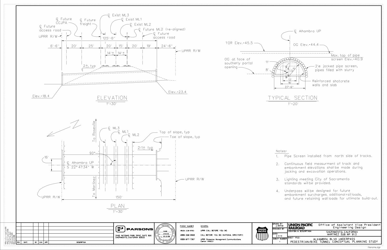
PIPE SCREEN WITH SHOTCRETE ARCH
This unconventional alternative that uses an arch shaped tunnel constructed under a steel pipe screen that acts as temporary shoring is the current approach that continues to be studied and pursued by Parsons. The arch shape is an ideal geometry with superior rigidity to control deflections but must count on competent soil bearing material. The arch shape is not the most efficient geometry for operations and creates more space than is needed. The larger opening (a half circle of radius of 12 foot 6 inches) creates the minimum clear opening zones of 11 foot height over a width of 12 feet for maintenance vehicles and a height of 8 feet over a width of 16 feet for pedestrians and bicyclists. Despite the larger space, the final structure has thinner walls than the box culvert due to the efficient nature of the arch shape. Additionally, this alternative creates an underpass with path grades that match the existing grades at Alhambra Blvd.
Construction of this alternative starts with the installation of a steel jacking frame to provide the alignment control and backstop for jacking a series of 2 foot diameter steel pipes through the embankment. The pipes are installed in the arch configuration and have steel angles welded along the sides to create an interlocked condition to eliminate differential pipe movement relative to one another and prevent soil from sloughing into the excavated zone during tunneling operations. Each pipe is jacked into the embankment while following a micro-tunneling device

MCKINLEY VILLAGE ALHAMBRA UNDERPASS – FEASIBILITY STUDIES MARCH 6, 2014
4
that sits within the pipe and projecting a few inches in front of the leading end of the pipe. After completion of the pipe screen, the protected space below the screen is then excavated in 10 to 15 foot long segments and the permanent reinforced shotcrete structure is installed. The process is performed from both ends in sequential staging to save time. When completed, the pipe screen will remain in place and covered with soil wherever exposed. The inside visible surface of the tunnel will be the shotcrete finish.
Despite the embankment being in place for roughly 150 years, the underlying native and embankment soils have not compacted and remain soft and compressible. The structure creates an extra 1000 pounds per square feet of pressure localized under the arch corners due to force redistribution. The net increase in pressure results in an anticipated settlement of several inches in the native soils. To mitigate this settlement, the underlying soil needs to be strengthened by injecting or mixing grout into the soil zone below the pipe screen to the competent gravel and cobble layer. The soil improvement would need to be completed before the pipe screen installation was started.
This method of construction has several issues that make the prosecution of the work challenging. First, the lack of access within the track zone of any substantial duration makes soil mixing difficult since it requires equipment to placed directly over the soil zone to be mixed and the process takes anywhere from half an hour to an hour for each mixing cycle (plus mobilization and demobilization time). There are roughly 60 individual mixing cycles within the operation envelope of the Union Pacific tracks. Union Pacific would need to approve allowing equipment to operate within this zone for the time required to complete the work consistent with their train operations. Grout injection, the second option, creates a potential soil heaving issue particularly on the sides of the embankment and could potentially cause embankment “blow-out” where the sides slough off due to the loss of shear strength when the wet grout mixture mixes with the soil under high pressure. Ungrouted soil above a freshly grouted layer could also slip out as the wetted soil below has a temporary loss of shear strength. As we continue to study and develop mitigation measures to protect the embankment and minimize potential operation impacts from the two possible ground improvement methods, we have discussed this alternative with Union Pacific, but have not yet formally submitted it for required 30% design level review pending resolution of outstanding issues. Potential solutions include the addition of piles to reduce the limits of the grout injected zone and using directional grouting where the work can be performed from the side of the embankment.
The cost to construct this alternative based on our preliminary estimate is $1.7 million including hard and soft costs. See attached planning study and staging sheets for more detail.
If appropriate solutions or mitigations to the above described issues cannot be developed, then Parsons will examine other alternative approaches.
VEHICULAR UNDERPASS OPTION
We’ve reviewed whether a vehicular underpass can be constructed at the site as either a standalone project or through future enlarging or widening of a pedestrian and bicycle underpass. The following are our findings:
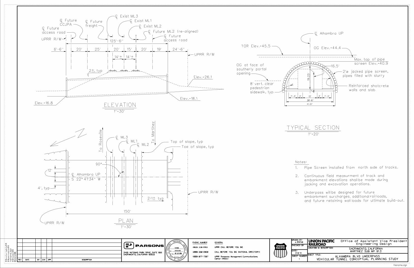
• If an acceptable solution is found to avoid slope instability during grouting or to resolve operational impacts on Union Pacific created by soil mixing, a single lane vehicular underpass built by the pipe screen method in lieu of a pedestrian and bike underpass could be theoretically possible. However, certain constructability issues have been identified and are described below. To accommodate a single travel lane with shoulders that provides at least 8 feet for a vehicle to pull over and 12 feet for an emergency vehicle

MCKINLEY VILLAGE ALHAMBRA UNDERPASS – FEASIBILITY STUDIES MARCH 6, 2014
5
to pass, the tunnel would need a 19.25 foot radius (19.25 foot clear height and 38.5 foot width) to create a 16.5 foot high by 20 foot clear zone for vehicles (see attached conceptual planning study). 16.5 feet is the minimum vertical clearance required by Union Pacific for an underpass accommodating vehicles to minimize the probability of a vehicle strike against the underpass structure which could damage the structure, thus creating an unsafe condition. Total cost to build the vehicular underpass by this method based on our preliminary estimate is $7.8 million not including right of way costs and assuming the technical issues below can be resolved. The following issues and major cost components with the construction of this design are identified:
o After consultation with tunneling contractors, it was determined the larger tunnel built by the pipe screen method requires at least three excavation zones to create the open space inside the pipe screen. Needing more than two stages for each segment (two vertical and symmetric stages are needed about the centerline of the smaller tunnel) creates an asymmetric load transfer condition in the pipe screen as these additional stages are now horizontally oriented. Partial length rigid shoring is immediately installed in the excavated zones against the pipe screen while the remaining unexcavated soil supports the other portion of the pipe screen. All applied loads will transfer to the more rigid supports rather than the softer soils according the relative stiffness. Given the poor site soils, the magnitude of potential transfer adds risk and unknowns to the design and construction process that does not exist with the smaller tunnel.
o Alhambra Blvd would need to be depressed roughly 8 feet to accommodate the extra height of the opening (7 feet) and increased shotcrete wall thickness (1 foot).
o Driveway access for up to 6 properties is adversely affected and would need to be modified. Appropriate construction easements and rights of way would have to be obtained. As noted above, right-of-way costs are not included in the cost estimate.
o The parcel northwest of the intersection of Alhambra Blvd and B Street adjacent to the Union Pacific tracks would likely lose access to Alhambra Blvd and therefore would likely have to be acquired. As noted above, this cost is not included in the cost estimate.
o B Street will either need to be modified to a cul-de-sac due to the lowered Alhambra Street grade (approximately 3-4 feet at B Street intersection) or at a minimum be lowered, if possible, to connect to the lowered Alhambra Blvd.
o Water, gas, sanitary sewer and storm sewer utilities would need to be relocated.
o A potential need for a pump station would be created given the relative elevation of the lowered underpass road surface to drainage basins in the McKinley Village development. This item is not included in the cost estimate.
o A direct connection to A Street is not possible given the difference in proposed grades of Alhambra (depressed 8 feet) and A Street which is elevated to cross Business-80. The road alignment to connect the Alhambra Blvd extension to Street 1 includes a 130 foot radius curve followed by a 100 foot radius curve (see attached conceptual alignment). Since Alhambra would be a public street, it requires a minimum centerline radius of 200 feet per City standards. The conceptual road alignment shown in the attachment would have to be striped for one way traffic and prohibit truck traffic given the substandard radii and pavement width. Even with that, this alignment would create an unsafe condition. Therefore

MCKINLEY VILLAGE ALHAMBRA UNDERPASS – FEASIBILITY STUDIES MARCH 6, 2014
6
a grade separation at A Street must be constructed so the Alhambra extension can connect to Street 8.
o Flood control gates large enough to seal an opening roughly 39 feet wide and 20 feet high must be constructed at the north portal of the underpass.
o The City's Department of Utilities has identified the City property adjacent to the A Street overcrossing as a potential location for a surge tank for the City's combined sewer system. An extension of Alhambra Boulevard would utilize the same area.
• Enlarging an existing pedestrian and bicycle tunnel is not possible with the existing improvements in place. The pipes of the temporary pipe screen and shotcrete walls cannot be removed in part or whole as both are solidly connected and they are grouted into the soil making the whole tunnel one solid unit with the soil. Additionally, any temporary shoring would be in the way of the removal operations.
• Adding another arch opening for vehicles adjacent to an existing arch tunnel in the future to accommodate an additional travel lane would not be feasible as the excavation for the second tunnel would eliminate the passive soil pressure on one side of the existing tunnel and potentially cause failure of the existing arch when asymmetric train loading is applied. The asymmetric load condition occurs whenever locomotives approach the site from the opposite side of the existing tunnel that the proposed second tunnel would be constructed.
In addition to the findings above, we’ve also examined three more options to construct a vehicular underpass:
• As presented in the “Alhambra Underpass at UPRR – Estimate for Full Width Roadway” dated November 25, 2013, the preliminary estimated cost is $28.4 million to construct a full two lane vehicular underpass similar to the 40th Street Underpass providing 56 feet of opening width. This assumes the cut and cover method is used to construct the underpass.
• Constructing a full width vehicular underpass using conventional cut and cover techniques in combination with the potential future Capital Corridor project is estimated to be roughly $11.0 million assuming the bulk of the shoofly costs are borne by the Capital Corridor project.
• We also investigated implementing the staged construction method used at the G Street Underpass at BNSF tracks in Merced, California for this site. After Union Pacific’s review of the contract staging plans for that project and multiple conversations with Parsons, Union Pacific rejected the proposed method because of the track closures necessary to implement the staging. As indicated above, Union Pacific has provided a formal written response addressing the use of track closures at the site.

MCKINLEY VILLAGE ALHAMBRA UNDERPASS – FEASIBILITY STUDIES MARCH 6, 2014
7
ATTACHMENTS

J. Bishop
1
1"=30'
1"=30'
C Alhambra UPL
1"=20'
TYPICAL SECTION
opening
southerly portal
OG at face of
2:1± typ
C ML2C ML1
C ML3
To
Roseville
14'± 14'±
1
2±, typ
C Exist ML3
C Exist ML1
To
Martin
ez
Notes:
N
L
LL
C Alhambra UPL
20' 25' 20' 15' 20' 19'6'-6"
L
L
L
LL
L
LCCJPA
C Future
freight
C Future
C Exist ML2
125'-6"
L
Top of slope, typ
Toe of slope, typ
C Future ML2 (re-aligned)
UPRR R/W
UPRR R/W
access road
C Future
access road
C Future
90°
S 22°41'34" W
UPRR R/W
UPRR R/W
ELEVATION
PLAN
150'
24'-6"
4.
3.
2.
1.
and future retaining wall loads for ultimate build-out.
embankment surcharges, additional rail loads,
Underpass will be designed for future
standards will be provided.
Lighting meeting City of Sacramento
jacking and excavation operations.
embankment elevations shall be made during
Continuous field measurment of track and
Pipe Screen installed from north side of tracks.16'
Elev.=23.4
Elev.=18.4
TOR Elev.=45.5OG Elev.=44.4
2-11-14
PEDESTRIAN/BIKE TUNNEL CONCEPTUAL PLANNING STUDYALHAMBRA BLVD UNDERPASS
8'
11'
pipes filled with slurry
2'Ø jacked pipe screen,
walls and slab
Reinforced shotcrete
12.5'
12'
16'
27'-6"
screen Elev.=40.9
Max. top of pipe
filename.dgn
$$date$$
filena
me.d
gn
$$pentable$$
$$
model$$
REV DATE BY CHK APP DESCRIPTION
NAME
C12345
01-01-09
Engineering Design
Office of Assistant Vice President
CHECKED BY:
DRAWN BY:
DATE:
LOCATION & DESCRIPTION:
SHEET TITLE:SHEET NUMBER
$$colortable$$
MARTINEZ SUB MP 91.2
SACRAMENTO, CALIFORNIA
2495 NATOMAS PARK DRIVE, SUITE 600
SACRAMENTO, CALIFORNIA 95833
UPRR Response Management Communications
Center (RMCC)
PHONE NUMBER GENERAL
UPRR CALL BEFORE YOU DIG
CALL BEFORE YOU DIG (NATIONAL DIRECTORY)
(888) 877-7267
(800) 336-9193
(888) 258-0808
p001318A
Typewritten Text
Pipe Screen - Arch Tunnel

1"=40'
1"=40'
1"=40'
1"=40'
1"=40'
J. Bishop
2
C Exist ML2
C Exist ML1
C Exist ML3
C Exist ML2
C Exist ML1
C Exist ML3
C Exist ML2
C Exist ML1
C Exist ML3
C Exist ML2
C Exist ML1
C Exist ML3
C Exist ML2
C Exist ML1
C Exist ML3
L
L
L
UPRR R/W
14'± 14'±
ELEVATION STAGE 4
57'± 65'±
ELEVATION - STAGE 1
ELEVATION - STAGE 2
ELEVATION - STAGE 3
ELEVATION - STAGE 5
Zone B limits
Excavate to
jacking bed and regrade
Remove casting and
UPRR R/W
14'± 14'±57'± 65'±
UPRR R/W
14'± 14'±57'± 65'±
UPRR R/W
14'± 14'±57'± 65'±
UPRR R/W
14'± 14'±57'± 65'±
UPRR R/W
UPRR R/W
UPRR R/W
UPRR R/W
UPRR R/W
1 •
1
L
L
L
L
L
L
L
L
L
L
L
L
CONCEPTUAL CONSTRUCTION SEQUENCEALHAMBRA BLVD PED/BIKE UNDERPASS
Construct jacking bed
pipe screen into place
Jack and microtunnel
embankment (earthen ramp)
Place surcharge
emabankment (earthen ramp)
Construct surcharge
Jet grout soil
to 30' below OG
Jet grout soil
embankments, typ
Remove surcharge
(staged from both ends)
in 13' maximum length sections
Construct shotcrete tunnel
and regrade
Construct headwalls
2-11-14
filename.dgn
$$date$$
filena
me.d
gn
$$pentable$$
$$
model$$
REV DATE BY CHK APP DESCRIPTION
NAME
C12345
01-01-09
Engineering Design
Office of Assistant Vice President
CHECKED BY:
DRAWN BY:
DATE:
LOCATION & DESCRIPTION:
SHEET TITLE:SHEET NUMBER
$$colortable$$
MARTINEZ SUB MP 91.2
SACRAMENTO, CALIFORNIA
2495 NATOMAS PARK DRIVE, SUITE 600
SACRAMENTO, CALIFORNIA 95833
UPRR Response Management Communications
Center (RMCC)
PHONE NUMBER GENERAL
UPRR CALL BEFORE YOU DIG
CALL BEFORE YOU DIG (NATIONAL DIRECTORY)
(888) 877-7267
(800) 336-9193
(888) 258-0808
p001318A
Typewritten Text
Pipe Screen - Arch Tunnel
J. Bishop
1
1"=30'
1"=30'
C Alhambra UPL
1"=20'
TYPICAL SECTION
opening
southerly portal
OG at face of
2:1± typ
C ML2C ML1
C ML3
To
Roseville
14'± 14'±
1
2±, typ
C Exist ML3
C Exist ML1
To
Martin
ez
Notes:
N
L
LL
C Alhambra UPL
20' 25' 20' 15' 20' 19'6'-6"
L
L
L
LL
L
LCCJPA
C Future
freight
C Future
C Exist ML2
125'-6"
L
Top of slope, typ
Toe of slope, typ
C Future ML2 (re-aligned)
UPRR R/W
UPRR R/W
access road
C Future
access road
C Future
90°
S 22°41'34" W
UPRR R/W
UPRR R/W
ELEVATION
PLAN
150'
24'-6"
12'
Elev.=18.1
Elev.=16.8
TOR Elev.=45.5OG Elev.=44.4
pipes filled with slurry
2'Ø jacked pipe screen,
walls and slab
Reinforced shotcrete
screen Elev.=40.9
Max. top of pipe
16.5'
sidewalk, typ
pedestrian
8' vert. clear
4', typ
VEHICULAR TUNNEL CONCEPTUAL PLANNING STUDYALHAMBRA BLVD UNDERPASS
Elev.=26.1
19.2
5'
38'-6"
41-6"
4' 12' 4'7'-3" 7'-3"
and future retaining wall loads for ultimate build-out.
embankment surcharges, additional rail loads,
Underpass will be designed for future
jacking and excavation operations.
embankment elevations shall be made during
Continuous field measurment of track and
Pipe Screen installed from north side of tracks.
3.
2.
1.
3-6-14
filename.dgn
$$date$$
filena
me.d
gn
$$pentable$$
$$
model$$
REV DATE BY CHK APP DESCRIPTION
NAME
C12345
01-01-09
Engineering Design
Office of Assistant Vice President
CHECKED BY:
DRAWN BY:
DATE:
LOCATION & DESCRIPTION:
SHEET TITLE:SHEET NUMBER
$$colortable$$
MARTINEZ SUB MP 91.2
SACRAMENTO, CALIFORNIA
2495 NATOMAS PARK DRIVE, SUITE 600
SACRAMENTO, CALIFORNIA 95833
UPRR Response Management Communications
Center (RMCC)
PHONE NUMBER GENERAL
UPRR CALL BEFORE YOU DIG
CALL BEFORE YOU DIG (NATIONAL DIRECTORY)
(888) 877-7267
(800) 336-9193
(888) 258-0808