Alfa Laval Alfie - images-na.ssl-images-amazon.com · Book No.: 9017117-02 Rev. 8 Alfa Laval Alfie...
80
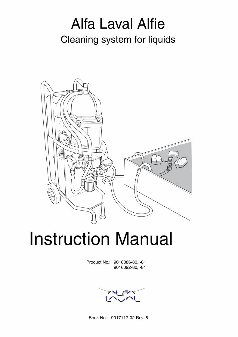
Book No.: 9017117-02 Rev. 8 Alfa Laval Alfie Cleaning system for liquids Product No.: 9016086-80, -81 9016092-80, -81 Instruction Manual
Transcript of Alfa Laval Alfie - images-na.ssl-images-amazon.com · Book No.: 9017117-02 Rev. 8 Alfa Laval Alfie...
Book No.: 9017117-02 Rev. 8
Alfa Laval AlfieCleaning system for liquids
Product No.: 9016086-80, -81 9016092-80, -81
Instruction Manual
Published By:Alfa Laval Tumba ABSE-147 80 Tumba, Sweden
Telephone: +46 8 530 650 00
Telefax: +46 8 530 310 40
© Alfa Laval Tumba AB 05-2016
Original instruction
This publication or any part there of may notbe reproduced or transmitted by any processor means without prior written permission ofAlfa Laval Tumba AB.
Contents
1 Safety instructions 7
2 Application 9
3 Machine plates 11
4 Description of main parts 13
4.1 System overview 13
4.2 Separator 16
4.3 Pump 16
4.4 Control unit 16
4.5 Collecting tank 17
5 Working principle of the separator 19
6 Control Cabinet 21
6.1 Operator panel 21
6.2 Connection for correct voltage 27
6.3 Alarm light pattern 28
6.4 Alarm table 29
7 Operating instructions 31
7.1 Before first start 31
7.2 Before normal start 31
7.3 Start 31
7.4 Operation 35
7.5 Standby 35
7.6 Stop 35
8 Trouble shooting 37
8.1 Cleaning system/separator does notstart or stops shortly after start 37
3
8.2 Pump does not start 37
8.3 Pump stops 37
8.4 Separator stops 38
8.5 Noise 38
8.6 Separator vibrates 39
8.7 No flow from pump 39
8.8 Flow too low 40
8.9 No flow either through clean oil outletor through drain to collecting tank 40
8.10 Some liquid escaping through drainoutlet to collecting tank 41
8.11 Oil flow through drain outlet tocollecting tank only 41
8.12 Oil leakage through drain outlet tocollecting tank when separator is notrunning 41
8.13 Collecting tank overflowing but pumpdoes not stop 41
8.14 Insuficient separation result 42
9 Maintenance 43
9.1 Cleaning 439.1.1 Strainer 439.1.2 Separator 43
9.2 Once per month 449.2.1 Pump 44
9.3 Once per year 449.3.1 Separator 44
9.4 Every second year 459.4.1 Separator 45
9.5 Dismantling - assembly instructions forseparator 45
9.5.1 Introduction 459.5.2 Cleaning of bowl 469.5.3 Replacement of O-rings 509.5.4 Replacement of motor bearings 52
9.6 Replacing the impeller and mechanicalseal for pump 55
10 Technical data 57
10.1 Technical data, system 57
4
10.2 Declaration 58
11 Lifting instruction 59
11.1 Cleaning unit 59
12 Diagrams 61
12.1 Electrical system 61
5

1 Safety instructions
Study this instruction manualand observe the warningsbefore installation, operation,service and maintenance.Not following the instructionscan result in serious accidents.
The centrifugal separator, which is the majorpart of the cleaning unit, includes parts thatrotate at high speed.Incorrect operation and maintenance of thecleaning unit can result in serious damageand/or injury.The following basic safety instructions thereforeapply:
• Use the cleaning unit only for thepurpose and parameter range specifiedby Alfa Laval.
• Only use the cleaning unit innon-explosion environment.
• Strictly follow the instructions forinstallation, operation and maintenance.
• Ensure that personnel are competentand have sufficient knowledge ofmaintenance and operation.
• Use only Alfa Laval genuine spare partsand the special tools supplied.
D! ANGER
Electrocution riskSwitch off the power supply and remove theelectric cable from the socket before opening thestarter/control unit.
7
1 Safety instructions
! WARNING
Disintegration hazardThe separator is supplied with a safety yoke and amagnetic safety switch. Modifications to the machinewhich put the safety devices out of operation can leadto serious injury or damage.
If excessive vibrations occur, stop the separator.
! WARNING
Entrapment hazardMake sure that rotating parts inside the separator havecome to a complete standstill before moving thecleaning unit or starting any dismantling work.
To avoid accidental start, switch off the power supplyand remove the electric cable from the socket beforestarting any dismantling work.
Warning label located onseparator hood
Warning labelsA warning label is placed on theseparator hood.The interpretation of the label is:STOP! Read the instructionmanual before installation,operation and maintenance.Consider inspection intervals.Another warning label is placed onthe door for the heater control unit.The interpretation of the label is:Switch off the power beforeopening the cover.
8
2 Application
The Alfa Laval Alfie 500 cleaning system isrestricted to the removal of solids and oil fromliquids with a temperature range between +15and +70 °C.
! WARNING
Disintegration hazardThe cleaning system must not be operated in anexplosion environment.
9

2 Application
3 Machine plates
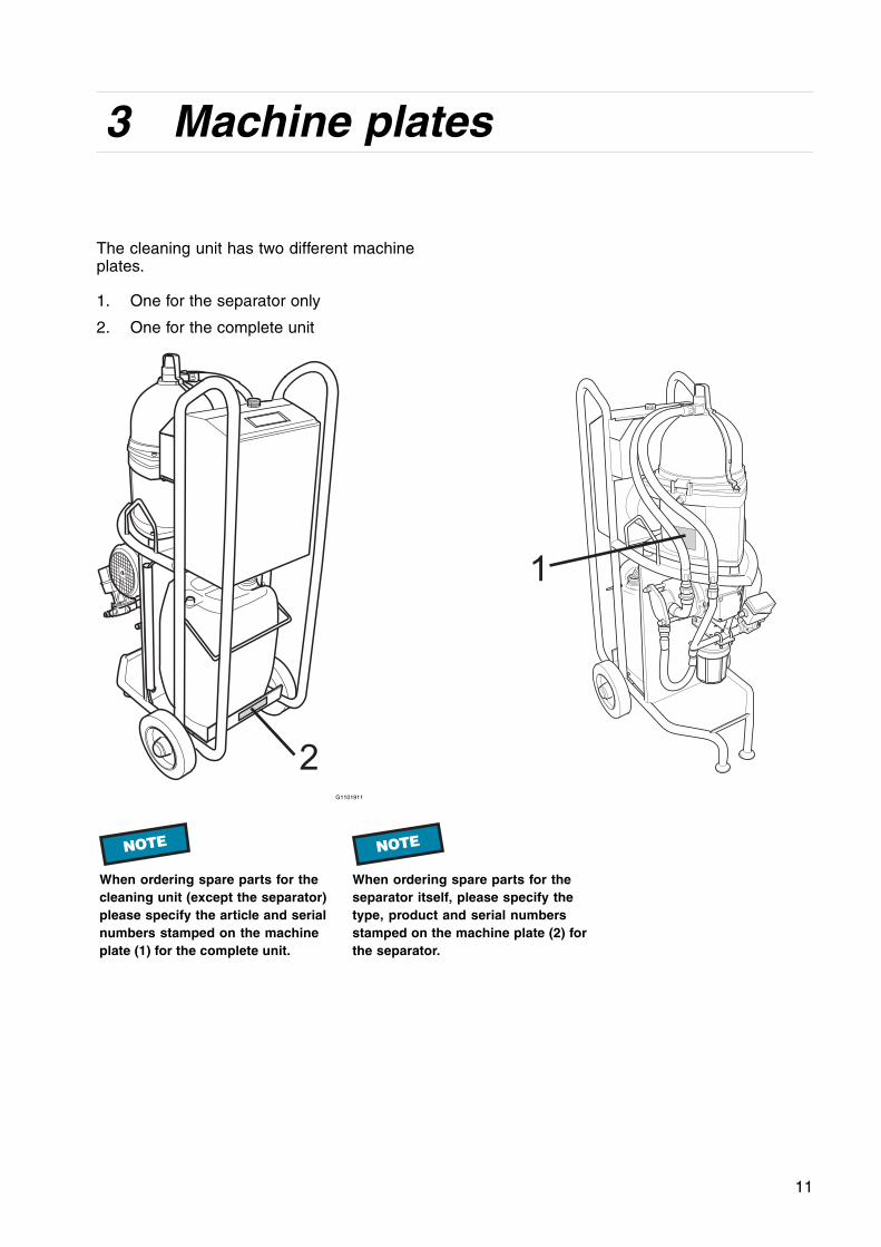
The cleaning unit has two different machineplates.
1. One for the separator only
2. One for the complete unit
1
2G1101911
NOTE
When ordering spare parts for thecleaning unit (except the separator)please specify the article and serialnumbers stamped on the machineplate (1) for the complete unit.
NOTE
When ordering spare parts for theseparator itself, please specify thetype, product and serial numbersstamped on the machine plate (2) forthe separator.
11
3 Machine plates
A
C
E
G
H
B
D
F
IG1114211
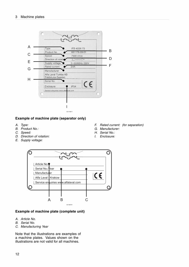
Example of machine plate (separator only)
A. Type:B. Product No.:C. Speed:D. Direction of rotation:E. Supply voltage:
F. Rated current: (for separation)G. Manufacturer:H. Serial No.:I. Enclosure:
Article No.
Serial No./Year
Manufacturer
Alfa Laval - Krakow
Service enquiries www.alfalaval.com
A B CG1102721
Example of machine plate (complete unit)
A. Article No.B. Serial No.C. Manufacturing Year
Note that the illustrations are examples ofa machine plates. Values shown on theillustrations are not valid for all machines.
12
4 Description of main parts
4.1 System overview
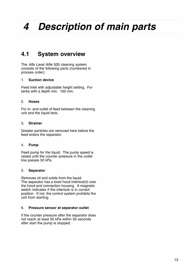
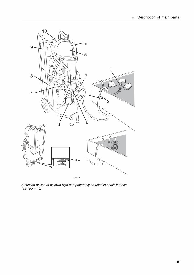
The Alfa Laval Alfie 500 cleaning systemconsists of the following parts (numbered inprocess order):
1. Suction device
Feed inlet with adjustable height setting. Fortanks with a depth min. 100 mm.
2. Hoses
For in- and outlet of feed between the cleaningunit and the liquid tank.
3. Strainer
Greater particles are removed here before thefeed enters the separator.
4. Pump
Feed pump for the liquid. The pump speed israised until the counter pressure in the outletline passes 50 kPa.
5. Separator
Removes oil and solids from the liquid.The separator has a bowl hood interlock(•) overthe hood and connection housing. A magneticswitch indicates if the interlock is in correctposition. If not, the control system prohibits theunit from starting.
6. Pressure sensor at separator outlet
If the counter pressure after the separator doesnot reach at least 50 kPa within 35 secondsafter start the pump is stopped.
13
4 Description of main parts
7. Motorised regulating valveFor maintaining the correct counterpressure in the outlet line (ca. 100 - 180kPa). The valve is regulated by the controlunit (9).
8. Collecting tank (20 litres)
Collects the oil separated out from the liquid.The tank stands on a support under theseparator which is held in its upper position by aspring with adjustable tension (••). This springis adjusted by the handle on the underside ofthe support. When the collecting tank is nearlyfull the weight will overcome the spring tensionand a limit switch is actuated. The signal goesto the control unit (9) which stops the pump (4).An alarm alerts the operator.
9. Control cabinet(further described inchapter 6 Control Cabinet on page 21).The control system supervises the startingand stopping of the cleaning unit. It alsosupervises system functions such as:
- frequency converters, one for theseparator and one for the pump.
- motor load
- bowl hood interlock
- amount of liquid in the collecting tank
- counter pressure at outlet
The red alarm light on top of the Control cabinet(10) indicates if there is any problem with thesupervised functions. Detailed information ofthe problem is presented on the operator panel.See 6.3 Alarm light pattern on page 28
14
4 Description of main parts
1
2
8 7
6
5
4
3
9∗
∗∗
10
G1102011
A suction device of bellows type can preferably be used in shallow tanks(55-100 mm).
15

4 Description of main parts
4.2 SeparatorThe separator has a bowl hood interlock (3)over the hood (2) and connection housing (1).A magnet (4) in contact with a safety switchindicates if the yoke is in correct position. Ifnot, no power is supplied to the motor. For adescription of the separator function, see 5Working principle of the separator on page 19.
G0907931
4.3 PumpThe flow is controlled by the VFD in the controlcabinet, see chapter 6 Control Cabinet.
4.4 Control unit
The Control unit consist of following main parts:
1. Power supply, 24 V DC
2. PLC kit
3. Frequency converter, separator
4. Frequency converter, feed pump
5. Mini terminal
6. Contactor
See chapter 6 Control Cabinet.
1
5
6
G1115311
16
4 Description of main parts
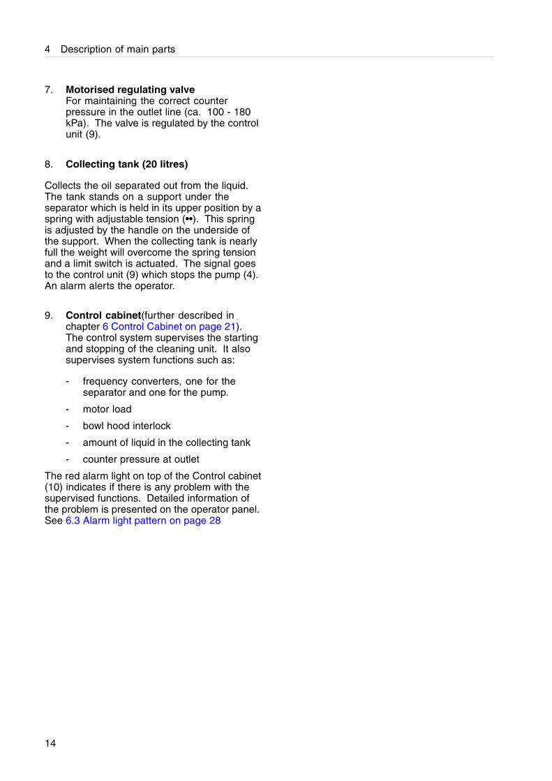
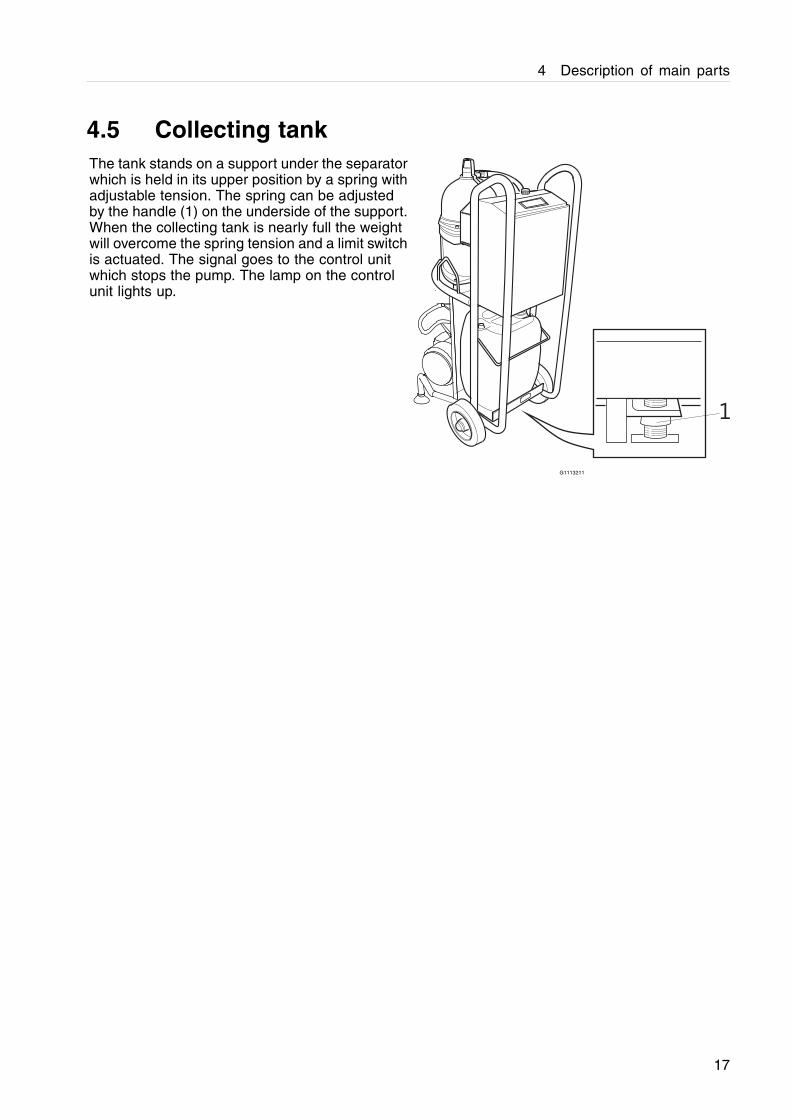
4.5 Collecting tankThe tank stands on a support under the separatorwhich is held in its upper position by a spring withadjustable tension. The spring can be adjustedby the handle (1) on the underside of the support.When the collecting tank is nearly full the weightwill overcome the spring tension and a limit switchis actuated. The signal goes to the control unitwhich stops the pump. The lamp on the controlunit lights up.
1
G1113211
17

4 Description of main parts
5 Working principle of theseparator
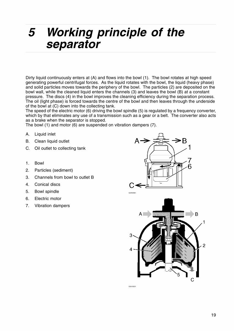
Dirty liquid continuously enters at (A) and flows into the bowl (1). The bowl rotates at high speedgenerating powerful centrifugal forces. As the liquid rotates with the bowl, the liquid (heavy phase)and solid particles moves towards the periphery of the bowl. The particles (2) are deposited on thebowl wall, while the cleaned liquid enters the channels (3) and leaves the bowl (B) at a constantpressure. The discs (4) in the bowl improves the cleaning efficiency during the separation process.The oil (light phase) is forced towards the centre of the bowl and then leaves through the undersideof the bowl at (C) down into the collecting tank.The speed of the electric motor (6) driving the bowl spindle (5) is regulated by a frequency converter,which by that eliminates any use of a transmission such as a gear or a belt. The converter also actsas a brake when the separator is stopped.The bowl (1) and motor (6) are suspended on vibration dampers (7).
A. Liquid inlet
B. Clean liquid outlet
C. Oil outlet to collecting tank
1. Bowl
2. Particles (sediment)
3. Channels from bowl to outlet B
4. Conical discs
5. Bowl spindle
6. Electric motor
7. Vibration dampers
G0450581
G0519231
19

5 Working principle of the separator
6 Control Cabinet
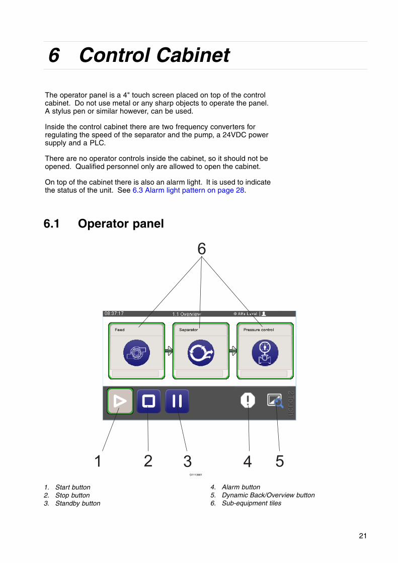
The operator panel is a 4" touch screen placed on top of the controlcabinet. Do not use metal or any sharp objects to operate the panel.A stylus pen or similar however, can be used.
Inside the control cabinet there are two frequency converters forregulating the speed of the separator and the pump, a 24VDC powersupply and a PLC.
There are no operator controls inside the cabinet, so it should not beopened. Qualified personnel only are allowed to open the cabinet.
On top of the cabinet there is also an alarm light. It is used to indicatethe status of the unit. See 6.3 Alarm light pattern on page 28.
6.1 Operator panel
1 2 3 4 5
6
G1113881
1. Start button2. Stop button3. Standby button
4. Alarm button5. Dynamic Back/Overview button6. Sub-equipment tiles
21
6 Control Cabinet
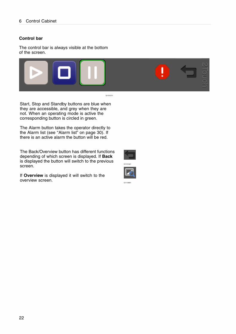
Control bar
The control bar is always visible at the bottomof the screen.
G1101211
Start, Stop and Standby buttons are blue whenthey are accessible, and grey when they arenot. When an operating mode is active thecorresponding button is circled in green.
The Alarm button takes the operator directly tothe Alarm list (see ‘‘Alarm list” on page 30). Ifthere is an active alarm the button will be red.
The Back/Overview button has different functionsdepending of which screen is displayed. If Backis displayed the button will switch to the previousscreen.
If Overview is displayed it will switch to theoverview screen.
G1101221
G1116691
22
6 Control Cabinet
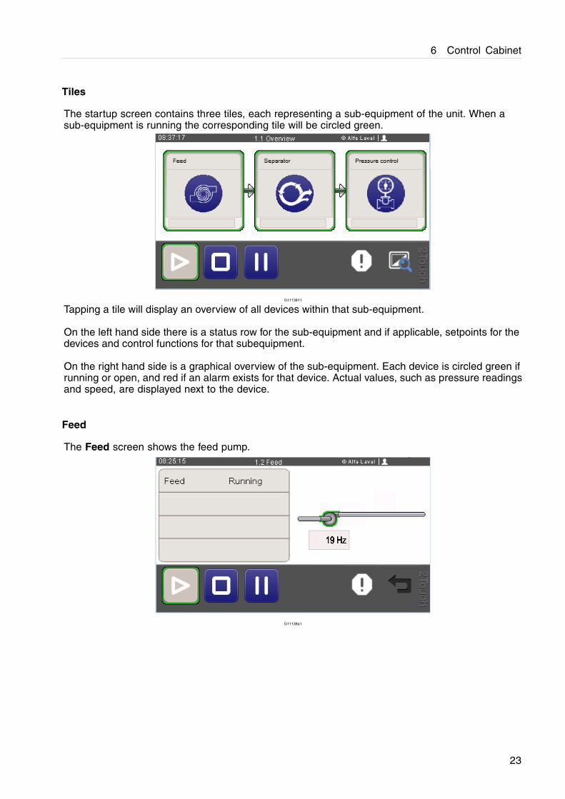
Tiles
The startup screen contains three tiles, each representing a sub-equipment of the unit. When asub-equipment is running the corresponding tile will be circled green.
G1113811
Tapping a tile will display an overview of all devices within that sub-equipment.
On the left hand side there is a status row for the sub-equipment and if applicable, setpoints for thedevices and control functions for that subequipment.
On the right hand side is a graphical overview of the sub-equipment. Each device is circled green ifrunning or open, and red if an alarm exists for that device. Actual values, such as pressure readingsand speed, are displayed next to the device.
Feed
The Feed screen shows the feed pump.
G11138a1
23
6 Control Cabinet
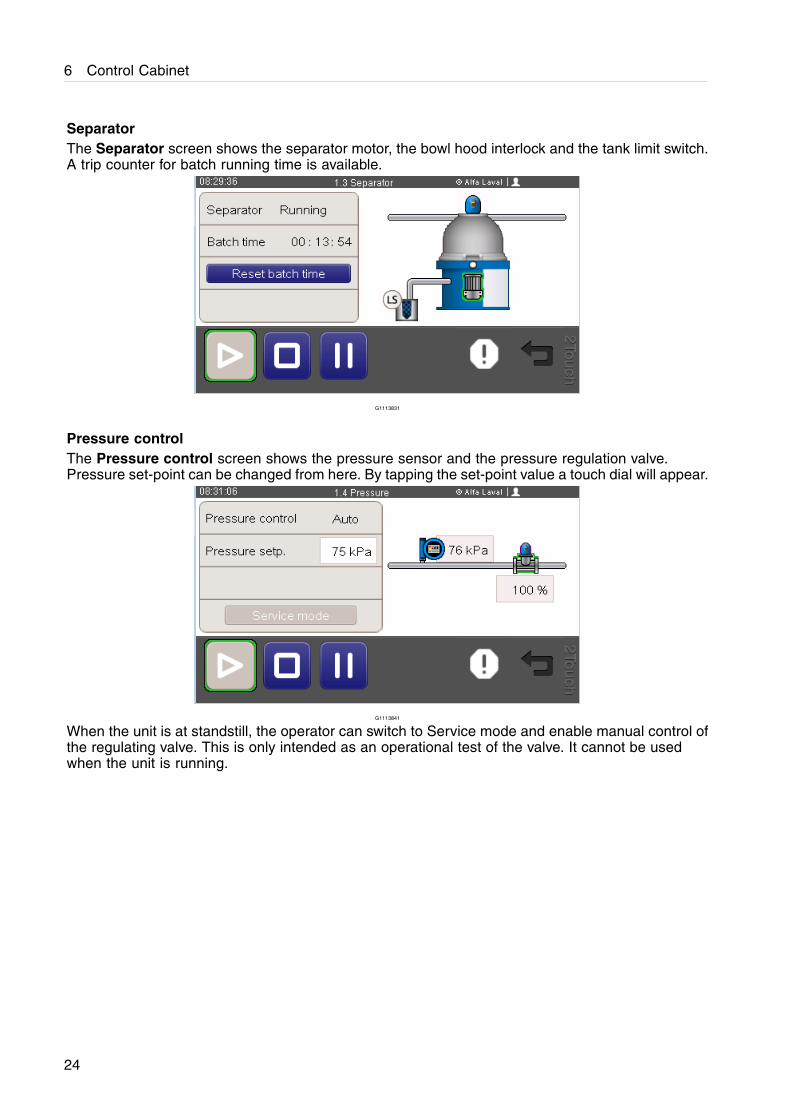
SeparatorThe Separator screen shows the separator motor, the bowl hood interlock and the tank limit switch.A trip counter for batch running time is available.
G1113831
Pressure controlThe Pressure control screen shows the pressure sensor and the pressure regulation valve.Pressure set-point can be changed from here. By tapping the set-point value a touch dial will appear.
G1113841
When the unit is at standstill, the operator can switch to Service mode and enable manual control ofthe regulating valve. This is only intended as an operational test of the valve. It cannot be usedwhen the unit is running.
24
6 Control Cabinet
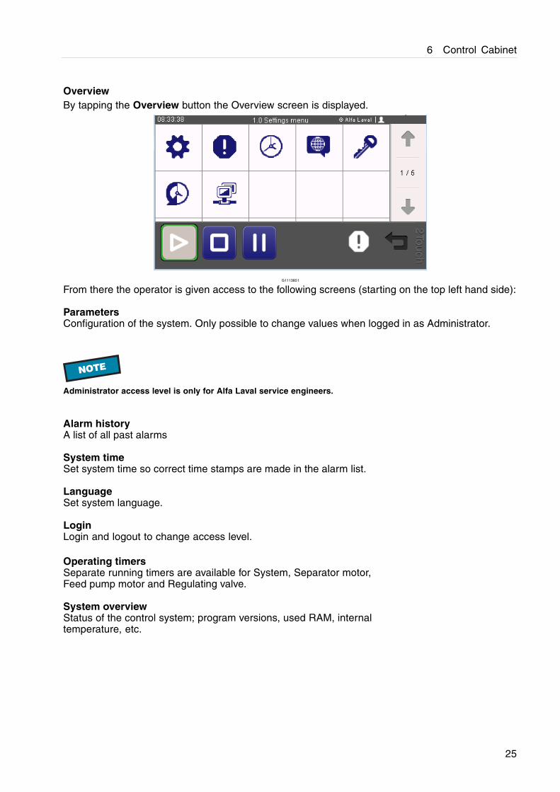
OverviewBy tapping the Overview button the Overview screen is displayed.
G1113851
From there the operator is given access to the following screens (starting on the top left hand side):
ParametersConfiguration of the system. Only possible to change values when logged in as Administrator.
NOTE
Administrator access level is only for Alfa Laval service engineers.
Alarm historyA list of all past alarms
System timeSet system time so correct time stamps are made in the alarm list.
LanguageSet system language.
LoginLogin and logout to change access level.
Operating timersSeparate running timers are available for System, Separator motor,Feed pump motor and Regulating valve.
System overviewStatus of the control system; program versions, used RAM, internaltemperature, etc.
25
6 Control Cabinet
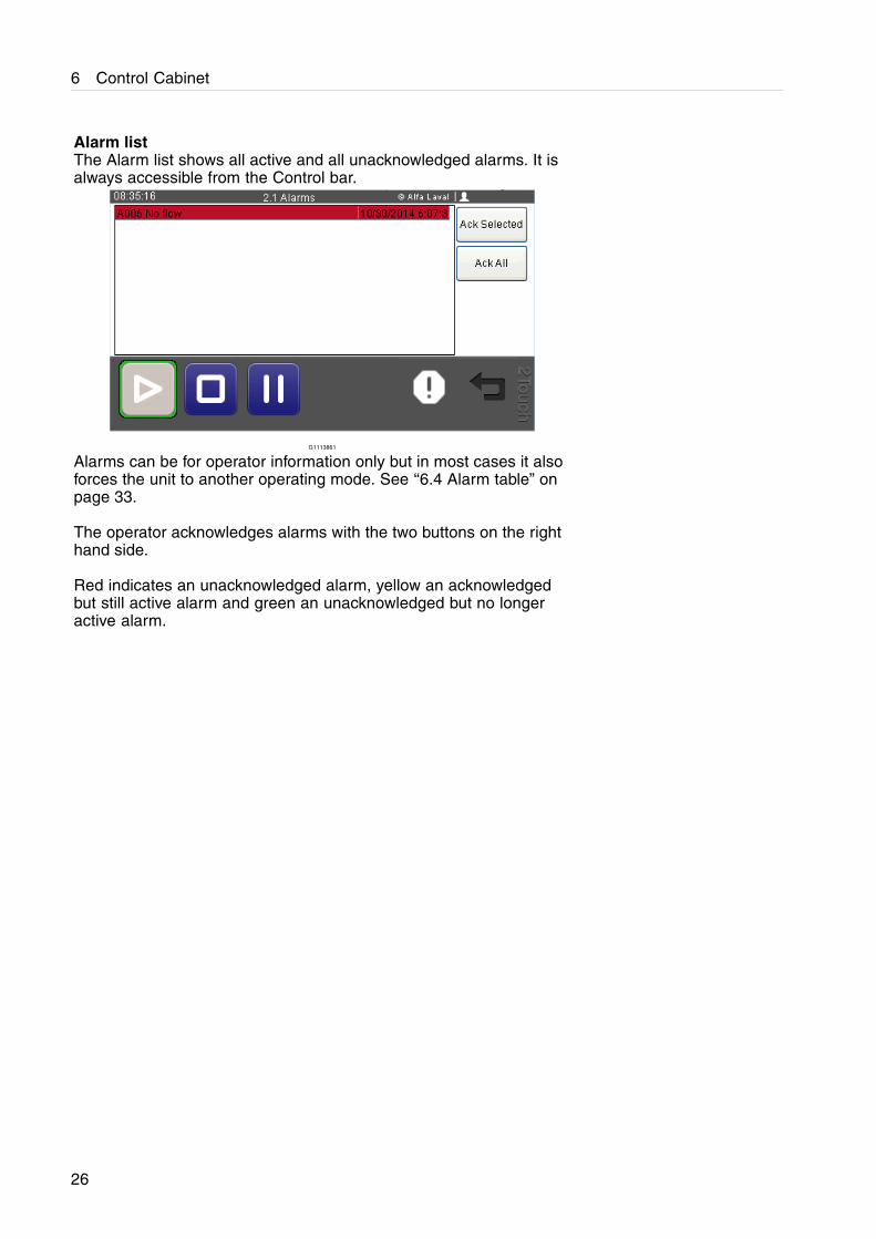
Alarm listThe Alarm list shows all active and all unacknowledged alarms. It isalways accessible from the Control bar.
G1113861
Alarms can be for operator information only but in most cases it alsoforces the unit to another operating mode. See ‘‘6.4 Alarm table” onpage 33.
The operator acknowledges alarms with the two buttons on the righthand side.
Red indicates an unacknowledged alarm, yellow an acknowledgedbut still active alarm and green an unacknowledged but no longeractive alarm.
26
6 Control Cabinet
6.2 Connection for correct voltage
NOTE
If the power supply is equipped with an ELCB (EarthLeakage Circuit Breaker) make sure that it is ofindustrial type that allows higher (30mA at 230 V)leakage current.
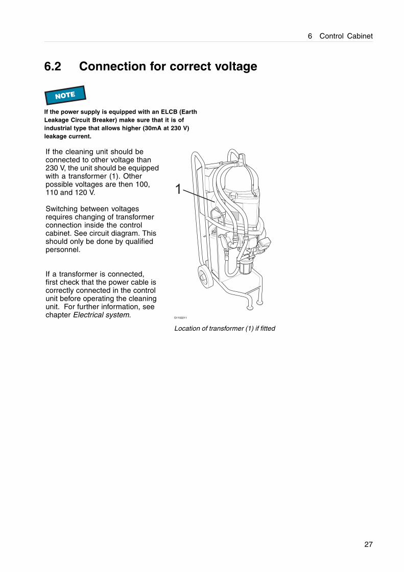
If the cleaning unit should beconnected to other voltage than230 V, the unit should be equippedwith a transformer (1). Otherpossible voltages are then 100,110 and 120 V.
Switching between voltagesrequires changing of transformerconnection inside the controlcabinet. See circuit diagram. Thisshould only be done by qualifiedpersonnel.
If a transformer is connected,first check that the power cable iscorrectly connected in the controlunit before operating the cleaningunit. For further information, seechapter Electrical system.
1
G1102211
Location of transformer (1) if fitted
27
6 Control Cabinet
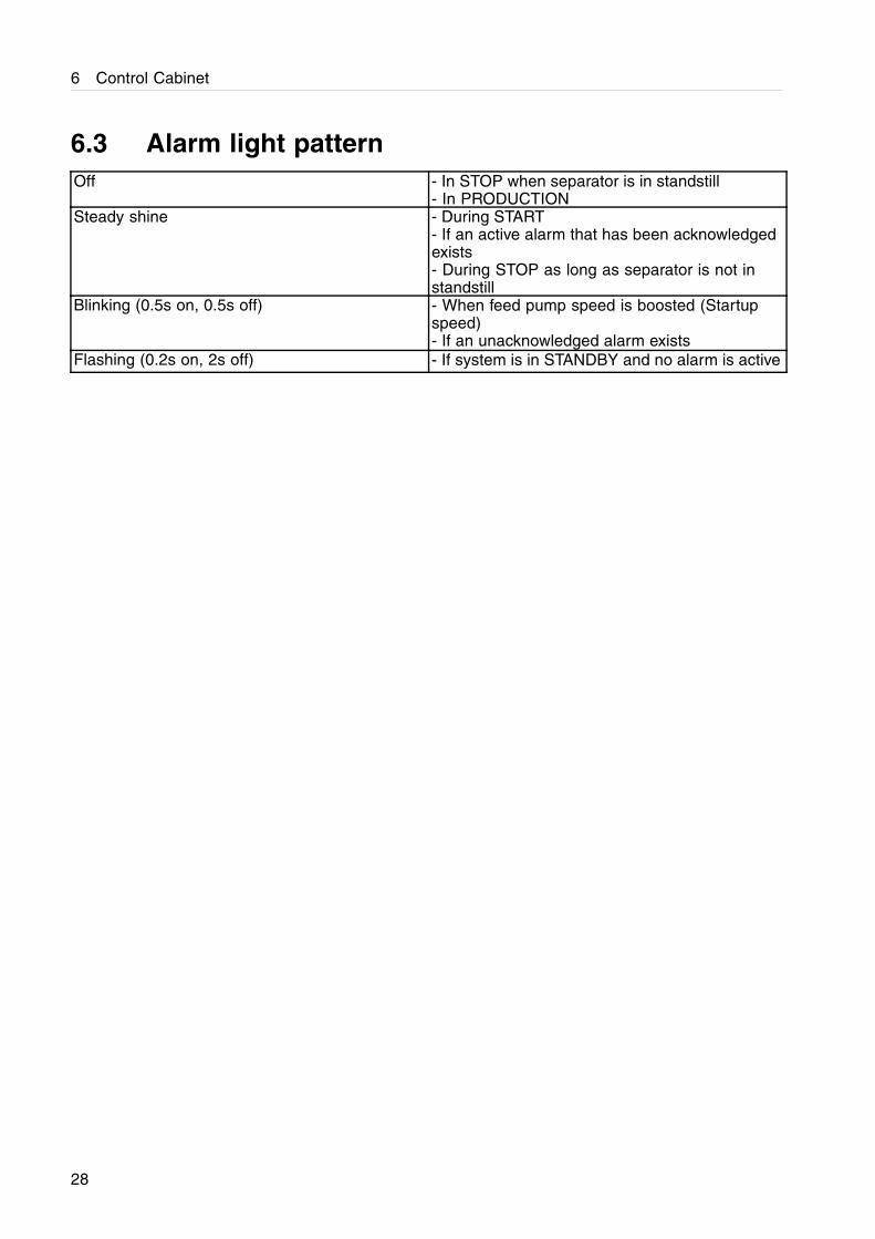
6.3 Alarm light patternOff - In STOP when separator is in standstill
- In PRODUCTIONSteady shine - During START
- If an active alarm that has been acknowledgedexists- During STOP as long as separator is not instandstill
Blinking (0.5s on, 0.5s off) - When feed pump speed is boosted (Startupspeed)- If an unacknowledged alarm exists
Flashing (0.2s on, 2s off) - If system is in STANDBY and no alarm is active
28
6 Control Cabinet
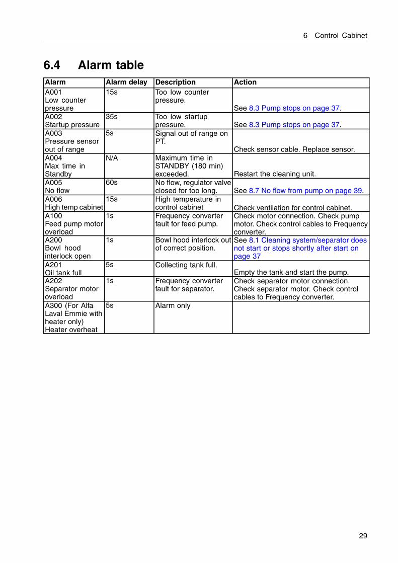
6.4 Alarm tableAlarm Alarm delay Description ActionA001Low counterpressure
15s Too low counterpressure.
See 8.3 Pump stops on page 37.A002Startup pressure
35s Too low startuppressure. See 8.3 Pump stops on page 37.
A003Pressure sensorout of range
5s Signal out of range onPT.
Check sensor cable. Replace sensor.A004Max time inStandby
N/A Maximum time inSTANDBY (180 min)exceeded. Restart the cleaning unit.
A005No flow
60s No flow, regulator valveclosed for too long. See 8.7 No flow from pump on page 39.
A006High temp cabinet
15s High temperature incontrol cabinet Check ventilation for control cabinet.
A100Feed pump motoroverload
1s Frequency converterfault for feed pump.
Check motor connection. Check pumpmotor. Check control cables to Frequencyconverter.
A200Bowl hoodinterlock open
1s Bowl hood interlock outof correct position.
See 8.1 Cleaning system/separator doesnot start or stops shortly after start onpage 37
A201Oil tank full
5s Collecting tank full.Empty the tank and start the pump.
A202Separator motoroverload
1s Frequency converterfault for separator.
Check separator motor connection.Check separator motor. Check controlcables to Frequency converter.
A300 (For AlfaLaval Emmie withheater only)Heater overheat
5s Alarm only
29

6 Control Cabinet
7 Operating instructions
7.1 Before first start
Check that the unit is wired for correct voltage,see 6.2 Connection for correct voltage on page27.
7.2 Before normal start
1. If the strainer (pos. 7) has been cleaned/emptied, check that filter housing is filled with liquid.
2. If the cleaning unit has been out of operation for a longer period, the pump impeller should begreased before use to receive optimal suction ability.
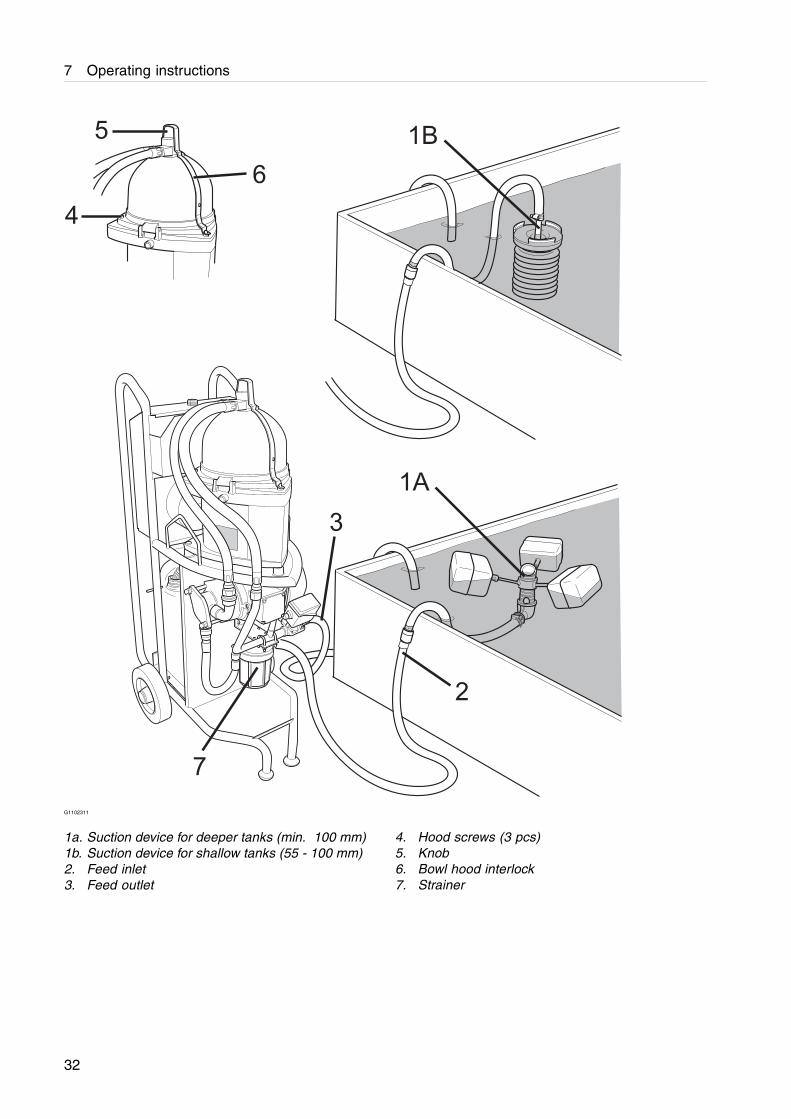
3. Place the suction device (1A) with floaters in the tank as illustrated. If using the optionalsuction device with bellows (1B), place it in the tank as illustrated. Fill the inside of the bellowswith liquid by pressing it below the surface. The device 1A is floating while 1B stands onthe tank bottom.
4. Check that the hose for the feed inlet (2) is connected to the strainer. Admitted suction heightfor the separator is max. 1.7 metres.
5. Check that the return hose for the feed outlet (3) is placed securely in the tank and far awayfrom the feed inlet, if possible.
6. Make sure that the three hood screws (4) and the knob (5) are firmly tightened and that thebowl hood interlock(6) is in closed (vertical) position.
7.3 Start
1. Connect the unit to the power supply.
NOTE
Fill the filter housing with liquid before start. Runningthe pump dry will damage the impeller and may resultin damage to the pump housing and/or motor.
31
7 Operating instructions
6
5
4
1A
3
2
1B
7
G1102311
1a. Suction device for deeper tanks (min. 100 mm)1b. Suction device for shallow tanks (55 - 100 mm)2. Feed inlet3. Feed outlet
4. Hood screws (3 pcs)5. Knob6. Bowl hood interlock7. Strainer
32
7 Operating instructions
2. When there is no alarm active andunacknowledged the operator can tap the Startbutton and the cleaning unit will start. Theseparator starts. When it has reached full speedthe feed pump starts. The control system waitsfor the pressure to rise. When the pressurehas reached the set-point (see tile menu forpressure under 6.1 Operator panel on page 21),the feed pump speed decreases to separationspeed and the automatic pressure regulationstarts. The cleaning unit is now running inProduction mode.
G1106011
Disintegration hazardSome vibration can occur for short periods duringthe start phase when the separator passes throughthe critical speed. This is normal and passes overwithout danger. If the vibration becomes verysevere or continues at full speed, stop the separatorimmediately. See chapter 8.6 Separator vibrateson page 39 for possible causes.
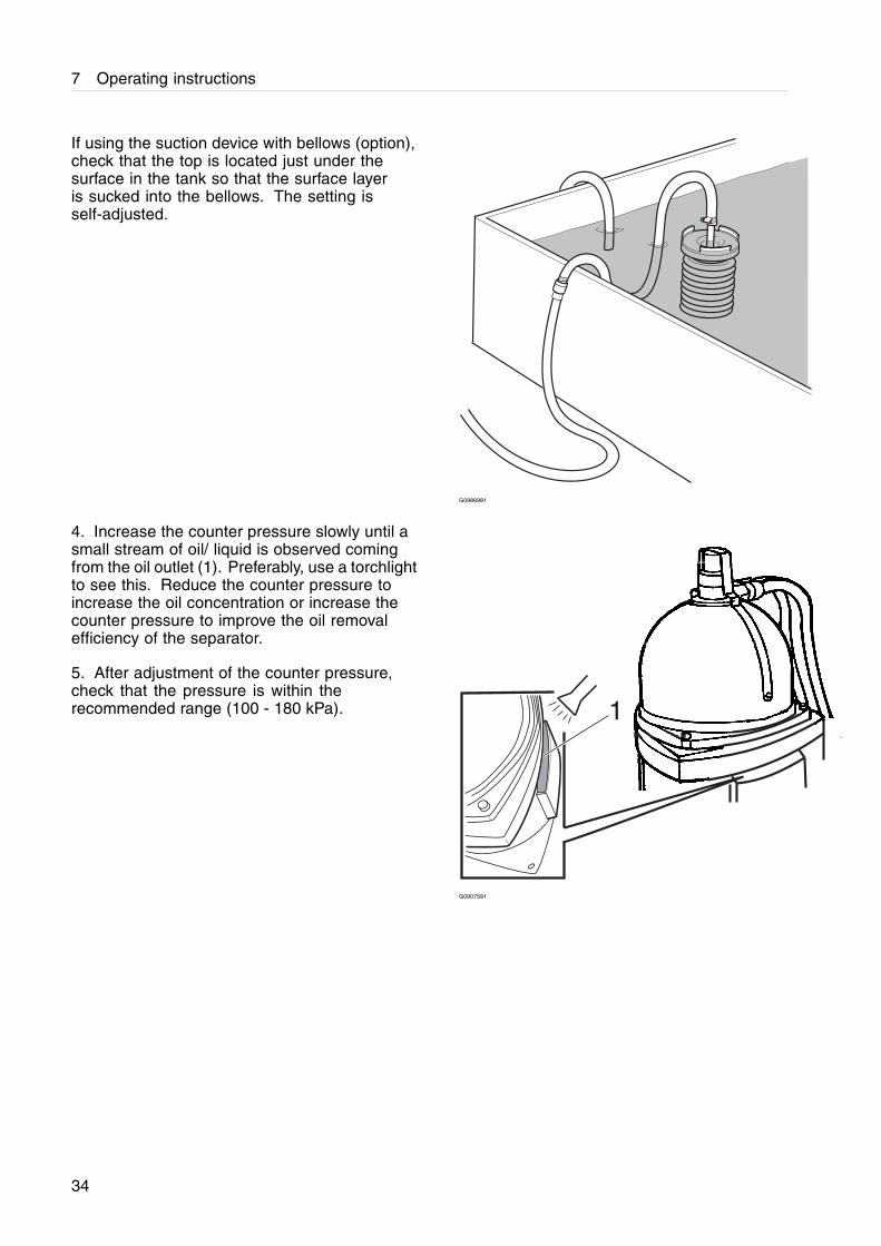
3. Check that the flow into the suction device isas illustrated. It is the surface layer A (normallyoil) that should be sucked into the inlet.If the suction device is lying too high, air issucked in. If the device is lying too low, liquidunder the oil layer will be sucked instead of theoil itself.
�
G0986971
33
7 Operating instructions
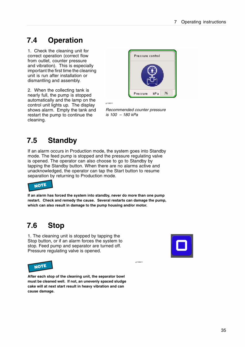
If using the suction device with bellows (option),check that the top is located just under thesurface in the tank so that the surface layeris sucked into the bellows. The setting isself-adjusted.
G0986981
4. Increase the counter pressure slowly until asmall stream of oil/ liquid is observed comingfrom the oil outlet (1). Preferably, use a torchlightto see this. Reduce the counter pressure toincrease the oil concentration or increase thecounter pressure to improve the oil removalefficiency of the separator.
5. After adjustment of the counter pressure,check that the pressure is within therecommended range (100 - 180 kPa).
G0907591
34
7 Operating instructions
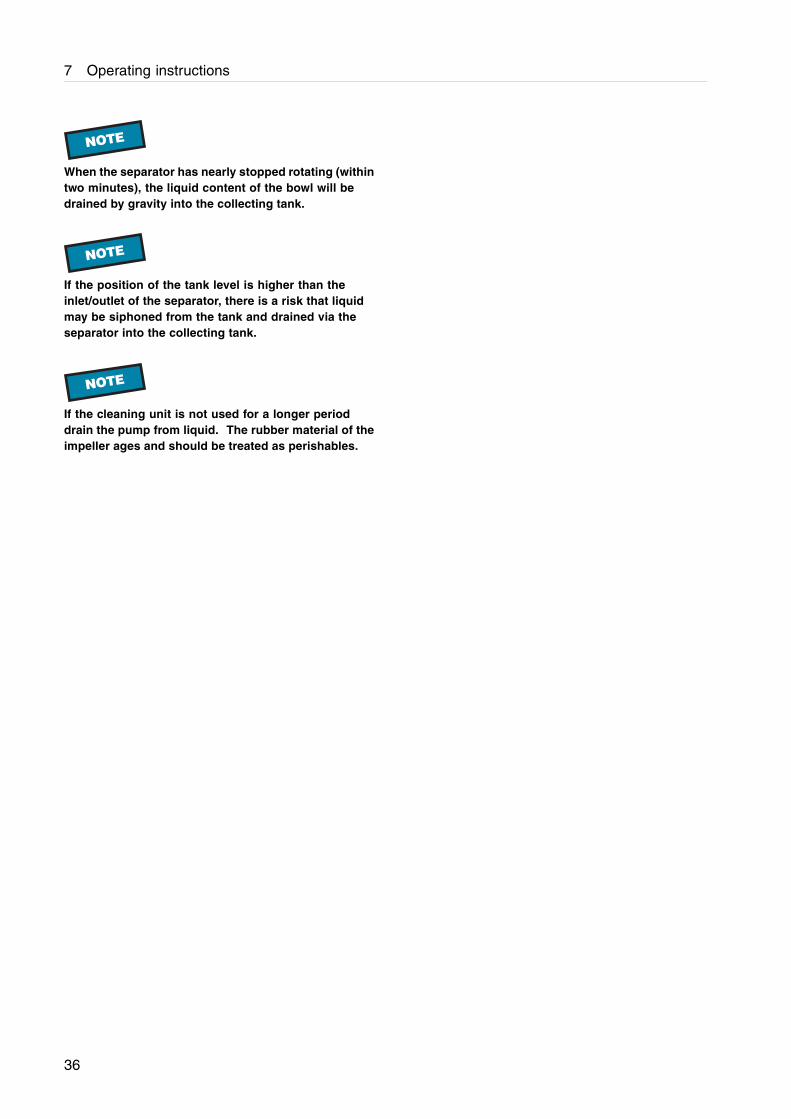
7.4 Operation1. Check the cleaning unit forcorrect operation (correct flowfrom outlet, counter pressureand vibration). This is especiallyimportant the first time the cleaningunit is run after installation ordismantling and assembly.
2. When the collecting tank isnearly full, the pump is stoppedautomatically and the lamp on thecontrol unit lights up. The displayshows alarm. Empty the tank andrestart the pump to continue thecleaning.
g1106311
Recommended counter pressureis 100 – 180 kPa
7.5 StandbyIf an alarm occurs in Production mode, the system goes into Standbymode. The feed pump is stopped and the pressure regulating valveis opened. The operator can also choose to go to Standby bytapping the Standby button. When there are no alarms active andunacknowledged, the operator can tap the Start button to resumeseparation by returning to Production mode.
NOTE
If an alarm has forced the system into standby, never do more than one pumprestart. Check and remedy the cause. Several restarts can damage the pump,which can also result in damage to the pump housing and/or motor.
7.6 Stop1. The cleaning unit is stopped by tapping theStop button, or if an alarm forces the system tostop. Feed pump and separator are turned off.Pressure regulating valve is opened.
NOTE
After each stop of the cleaning unit, the separator bowlmust be cleaned well. If not, an unevenly spaced sludgecake will at next start result in heavy vibration and cancause damage.
g1106211
35
7 Operating instructions
NOTE
When the separator has nearly stopped rotating (withintwo minutes), the liquid content of the bowl will bedrained by gravity into the collecting tank.
NOTE
If the position of the tank level is higher than theinlet/outlet of the separator, there is a risk that liquidmay be siphoned from the tank and drained via theseparator into the collecting tank.
NOTE
If the cleaning unit is not used for a longer perioddrain the pump from liquid. The rubber material of theimpeller ages and should be treated as perishables.
36
8 Trouble shooting
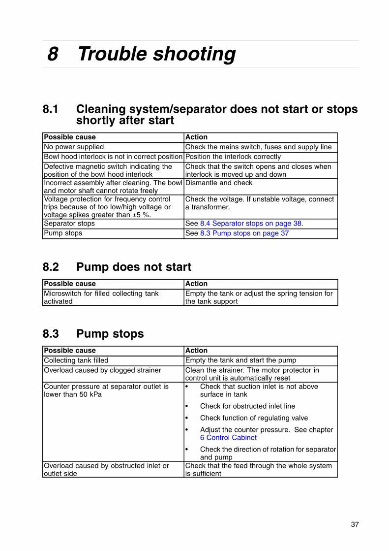
8.1 Cleaning system/separator does not start or stopsshortly after start
Possible cause ActionNo power supplied Check the mains switch, fuses and supply lineBowl hood interlock is not in correct position Position the interlock correctlyDefective magnetic switch indicating theposition of the bowl hood interlock
Check that the switch opens and closes wheninterlock is moved up and down
Incorrect assembly after cleaning. The bowland motor shaft cannot rotate freely
Dismantle and check
Voltage protection for frequency controltrips because of too low/high voltage orvoltage spikes greater than ±5 %.
Check the voltage. If unstable voltage, connecta transformer.
Separator stops See 8.4 Separator stops on page 38.Pump stops See 8.3 Pump stops on page 37
8.2 Pump does not startPossible cause ActionMicroswitch for filled collecting tankactivated
Empty the tank or adjust the spring tension forthe tank support
8.3 Pump stopsPossible cause ActionCollecting tank filled Empty the tank and start the pumpOverload caused by clogged strainer Clean the strainer. The motor protector in
control unit is automatically resetCounter pressure at separator outlet islower than 50 kPa
• Check that suction inlet is not abovesurface in tank
• Check for obstructed inlet line
• Check function of regulating valve
• Adjust the counter pressure. See chapter6 Control Cabinet
• Check the direction of rotation for separatorand pump
Overload caused by obstructed inlet oroutlet side
Check that the feed through the whole systemis sufficient
37
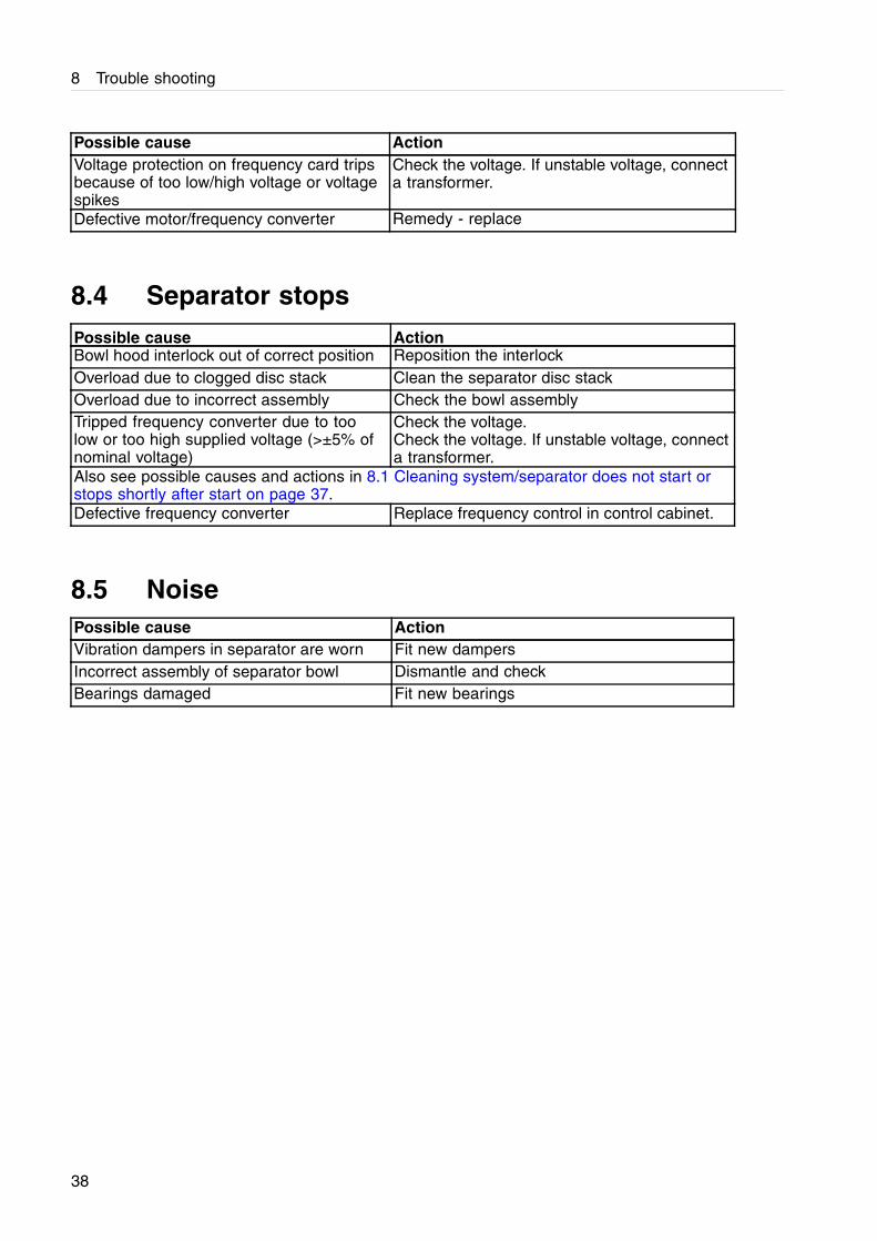
8 Trouble shooting
Possible cause ActionVoltage protection on frequency card tripsbecause of too low/high voltage or voltagespikes
Check the voltage. If unstable voltage, connecta transformer.
Defective motor/frequency converter Remedy - replace
8.4 Separator stopsPossible cause ActionBowl hood interlock out of correct position Reposition the interlockOverload due to clogged disc stack Clean the separator disc stackOverload due to incorrect assembly Check the bowl assemblyTripped frequency converter due to toolow or too high supplied voltage (>±5% ofnominal voltage)
Check the voltage.Check the voltage. If unstable voltage, connecta transformer.
Also see possible causes and actions in 8.1 Cleaning system/separator does not start orstops shortly after start on page 37.Defective frequency converter Replace frequency control in control cabinet.
8.5 NoisePossible cause ActionVibration dampers in separator are worn Fit new dampersIncorrect assembly of separator bowl Dismantle and checkBearings damaged Fit new bearings
38
8 Trouble shooting
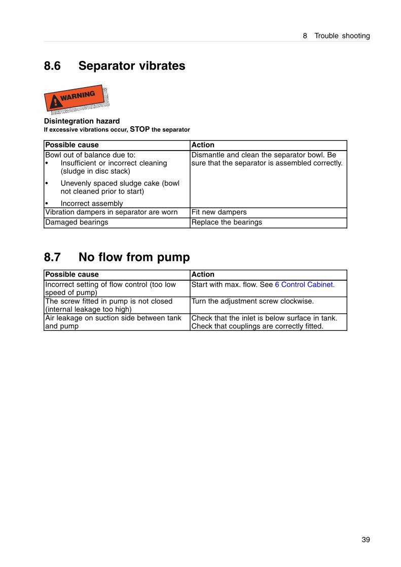
8.6 Separator vibrates
! WARNING
Disintegration hazardIf excessive vibrations occur, STOP the separator
Possible cause ActionBowl out of balance due to:• Insufficient or incorrect cleaning
(sludge in disc stack)
• Unevenly spaced sludge cake (bowlnot cleaned prior to start)
• Incorrect assembly
Dismantle and clean the separator bowl. Besure that the separator is assembled correctly.
Vibration dampers in separator are worn Fit new dampersDamaged bearings Replace the bearings
8.7 No flow from pumpPossible cause ActionIncorrect setting of flow control (too lowspeed of pump)
Start with max. flow. See 6 Control Cabinet.
The screw fitted in pump is not closed(internal leakage too high)
Turn the adjustment screw clockwise.
Air leakage on suction side between tankand pump
Check that the inlet is below surface in tank.Check that couplings are correctly fitted.
39
8 Trouble shooting
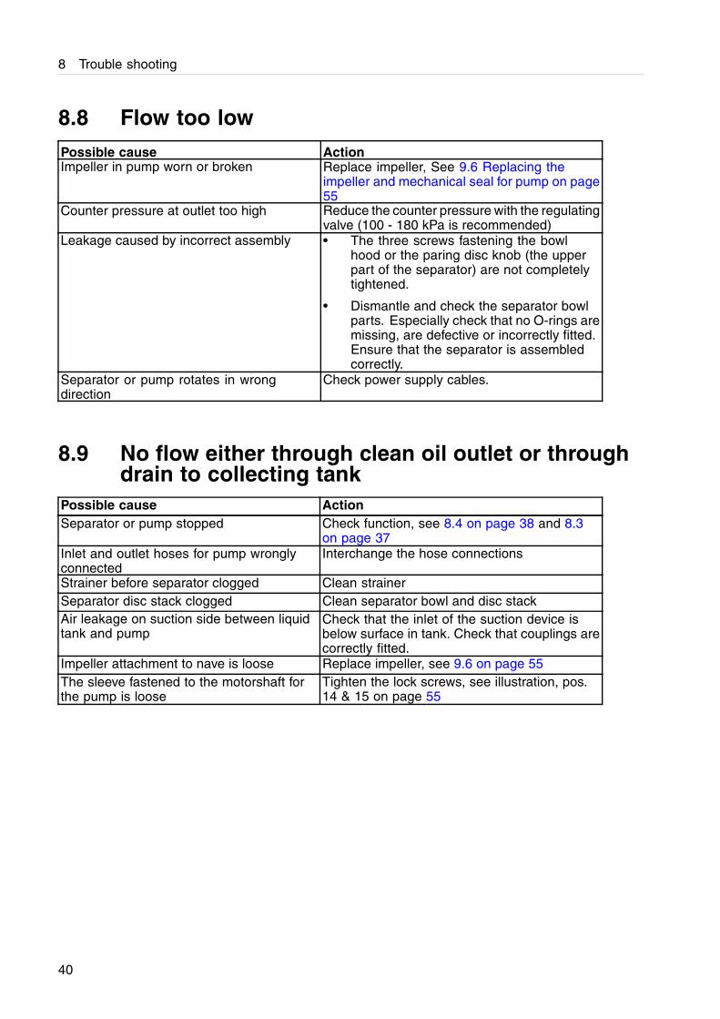
8.8 Flow too lowPossible cause ActionImpeller in pump worn or broken Replace impeller, See 9.6 Replacing the
impeller and mechanical seal for pump on page55
Counter pressure at outlet too high Reduce the counter pressure with the regulatingvalve (100 - 180 kPa is recommended)
Leakage caused by incorrect assembly • The three screws fastening the bowlhood or the paring disc knob (the upperpart of the separator) are not completelytightened.
• Dismantle and check the separator bowlparts. Especially check that no O-rings aremissing, are defective or incorrectly fitted.Ensure that the separator is assembledcorrectly.
Separator or pump rotates in wrongdirection
Check power supply cables.
8.9 No flow either through clean oil outlet or throughdrain to collecting tank
Possible cause ActionSeparator or pump stopped Check function, see 8.4 on page 38 and 8.3
on page 37Inlet and outlet hoses for pump wronglyconnected
Interchange the hose connections
Strainer before separator clogged Clean strainerSeparator disc stack clogged Clean separator bowl and disc stackAir leakage on suction side between liquidtank and pump
Check that the inlet of the suction device isbelow surface in tank. Check that couplings arecorrectly fitted.
Impeller attachment to nave is loose Replace impeller, see 9.6 on page 55The sleeve fastened to the motorshaft forthe pump is loose
Tighten the lock screws, see illustration, pos.14 & 15 on page 55
40
8 Trouble shooting
8.10 Some liquid escaping through drain outlet tocollecting tank
Possible cause ActionCounter pressure at outlet too high • Reduce the counter pressure with the
regulating valve (100 - 180 kPa isrecommended)
• Reduce the flow by adjusting the screwfitted in pump
Leaking O-rings in separator Replace O-ringsClogged disc stack Clean the bowl and disc stackThe three screws fastening the bowl hoodor the paring disc knob (the upper part ofthe separator) are not completely tightened,causing leakage
Tighten the screws and/or the knob
8.11 Oil flow through drain outlet to collecting tank onlyPossible cause ActionIf operating in purifier mode:broken liquid seal in separator bowl
• Stop the pump and add water through theinlet at top of the separator.
Obstruction in cleaned oil feed line • Check that regulating valve is open
• Check that outlet end to tank is open (noclosed check valve in hose connection)
8.12 Oil leakage through drain outlet to collecting tankwhen separator is not running
Possible cause ActionOil is siphoned from fluid tank due to siphoneffect
Disconnect both hoses connected to the oiltank
8.13 Collecting tank overflowing but pump does notstop
Possible cause ActionAdjustment of the spring tension for thetank support is incorrect
Adjust the setting. See description in 4.5Collecting tank on page 17.
Faulty limit switch Remedy
41
8 Trouble shooting
8.14 Insuficient separation resultPossible cause ActionThe suction device in liquid tank lays toohigh
Adjust the height. See description in chapter7.3 Start on page 31
Separator disc stack clogged Clean separator bowl and disc stack
The counter pressure is too low
Increase the counter pressure until oil isobserved to be discharged from the oil outlet,see chapter 7.3 Start on page 31
42
9 Maintenance
! WARNING
Entrapment hazardSwitch off the power supply, remove the electric cablesfrom the sockets and make sure that rotating partshave come to a complete standstill before startingany dismantling work.
NOTE
Never use cleaning agents with a pH below 6 or above9 as they can damage the metal surfaces.
9.1 Cleaning
9.1.1 Strainer
The strainer has to be cleaned regularly. During the initial period, open and inspect once everyweek to determine the necessary cleaning interval.
NOTE
When fitting the filter housing it must first be filled with liquid to prevent the pump operating in dry condition.Otherwise the life of pump will be shortened.
9.1.2 Separator
The separated solids collected inside theseparator bowl must be removed manually. Thelength of the cleaning interval depends on theliquid flow rate and on the amount of solids.During the initial period, open and inspect thebowl once a day to determine the necessarycleaning interval. The bowl must be cleanedbefore the solids layer has become thicker than10 mm. Otherwise there will be risk that theclean liquid outlet in the bowl will be coveredby solids.
43
9 Maintenance
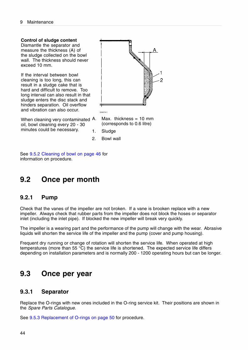
Control of sludge contentDismantle the separator andmeasure the thickness (A) ofthe sludge collected on the bowlwall. The thickness should neverexceed 10 mm.
If the interval between bowlcleaning is too long, this canresult in a sludge cake that ishard and difficult to remove. Toolong interval can also result in thatsludge enters the disc stack andhinders separation. Oil overflowand vibration can also occur.
When cleaning very contaminatedoil, bowl cleaning every 20 - 30minutes could be necessary.
G0907411
A. Max. thickness = 10 mm(corresponds to 0.6 litre)
1. Sludge
2. Bowl wall
See 9.5.2 Cleaning of bowl on page 46 forinformation on procedure.
9.2 Once per month
9.2.1 Pump
Check that the vanes of the impeller are not broken. If a vane is brooken replace with a newimpeller. Always check that rubber parts from the impeller does not block the hoses or separatorinlet (including the inlet pipe). If blocked the new impeller will break very quickly.
The impeller is a wearing part and the performance of the pump will change with the wear. Abrasiveliquids will shorten the service life of the impeller and the pump (cover and pump housing).
Frequent dry running or change of rotation will shorten the service life. When operated at hightemperatures (more than 55 °C) the service life is shortened. The expected service life differsdepending on installation parameters and is normally 200 - 1200 operating hours but can be longer.
9.3 Once per year
9.3.1 Separator
Replace the O-rings with new ones included in the O-ring service kit. Their positions are shown inthe Spare Parts Catalogue.
See 9.5.3 Replacement of O-rings on page 50 for procedure.
44
9 Maintenance
Check the condition of discs in the bowl, replace if necessary.
Fit new vibration dampers.To get access to the dampers, only remove thethree screws and washers shown in illustration10 on page 52. Inspect the stop flanges of thedampers for possible damage and replace thestop flanges with new ones if necessary. UseLoctite 243 at assembly, see illustration 33 inchapter 9.4.5 Replacement of motor bearings.
9.4 Every second year
9.4.1 Separator
Check/replace the disc stack to maintain the separation efficiency.
See 9.5.3 Replacement of O-rings on page 50 for procedure.
9.5 Dismantling - assembly instructions for separator
9.5.1 Introduction
The illustrations on the following pages describe step by step how to dismantle, clean, replace andassemble the various parts of the separator.
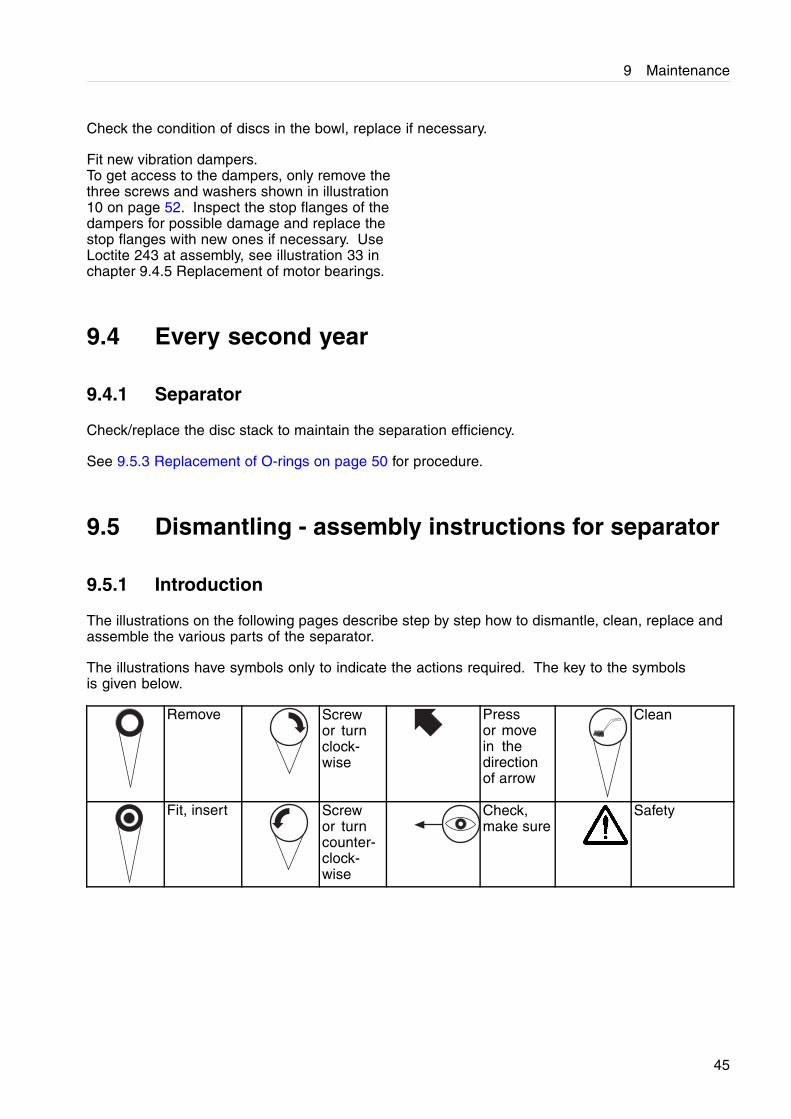
The illustrations have symbols only to indicate the actions required. The key to the symbolsis given below.
Remove Screwor turnclock-wise
Pressor movein thedirectionof arrow
Clean
Fit, insert Screwor turncounter-clock-wise
Check,make sure
Safety
45
9 Maintenance
9.5.2 Cleaning of bowl
Comments to illustrations following.
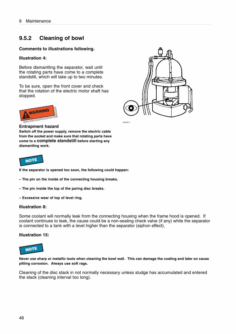
Illustration 4:
Before dismantling the separator, wait untilthe rotating parts have come to a completestandstill, which will take up to two minutes.
To be sure, open the front cover and checkthat the rotation of the electric motor shaft hasstopped.
! WARNING
Entrapment hazardSwitch off the power supply, remove the electric cablefrom the socket and make sure that rotating parts havecome to a complete standstill before starting anydismantling work.
G0908711
NOTE
If the separator is opened too soon, the following could happen:
– The pin on the inside of the connecting housing breaks.
– The pin inside the top of the paring disc breaks.
– Excessive wear of top of level ring.
Illustration 8:
Some coolant will normally leak from the connecting housing when the frame hood is opened. Ifcoolant continues to leak, the cause could be a non-sealing check valve (if any) while the separatoris connected to a tank with a level higher than the separator (siphon effect).
Illustration 15:
NOTE
Never use sharp or metallic tools when cleaning the bowl wall. This can damage the coating and later on causepitting corrosion. Always use soft rags.
Cleaning of the disc stack in not normally necessary unless sludge has accumulated and enteredthe stack (cleaning interval too long).
46
9 Maintenance
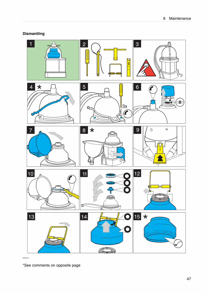
Dismantling
G04491c1
*See comments on opposite page
47
9 Maintenance
Comments to illustrations on opposite page.
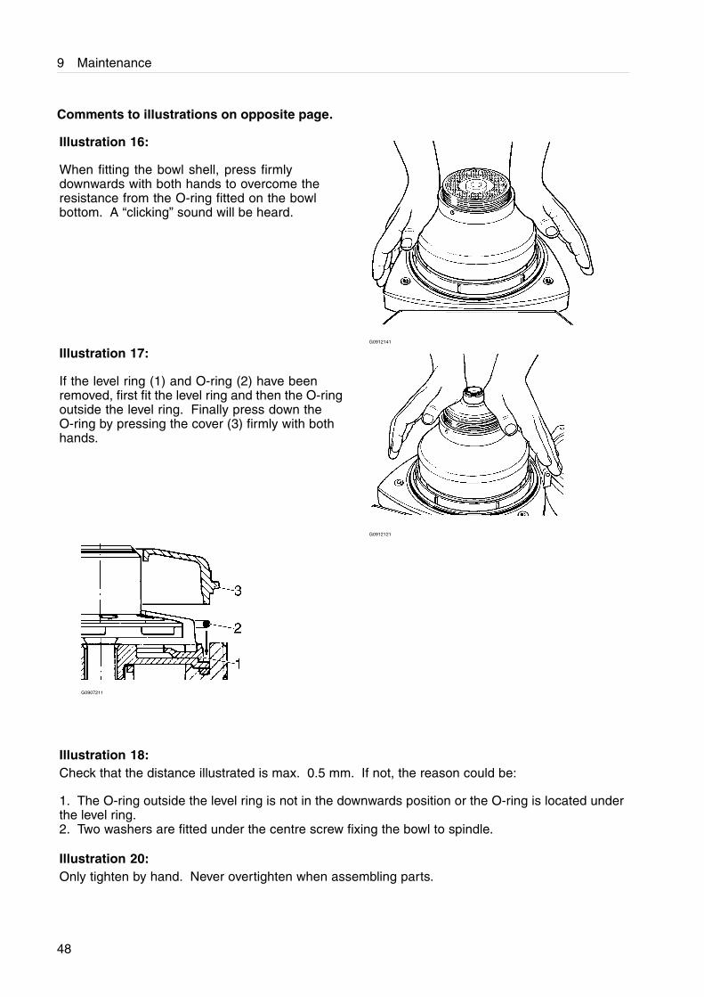
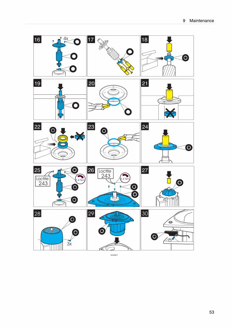
Illustration 16:
When fitting the bowl shell, press firmlydownwards with both hands to overcome theresistance from the O-ring fitted on the bowlbottom. A “clicking” sound will be heard.
G0912141
Illustration 17:
If the level ring (1) and O-ring (2) have beenremoved, first fit the level ring and then the O-ringoutside the level ring. Finally press down theO-ring by pressing the cover (3) firmly with bothhands.
G0912121
G0907211
Illustration 18:Check that the distance illustrated is max. 0.5 mm. If not, the reason could be:
1. The O-ring outside the level ring is not in the downwards position or the O-ring is located underthe level ring.2. Two washers are fitted under the centre screw fixing the bowl to spindle.
Illustration 20:Only tighten by hand. Never overtighten when assembling parts.
48
9 Maintenance
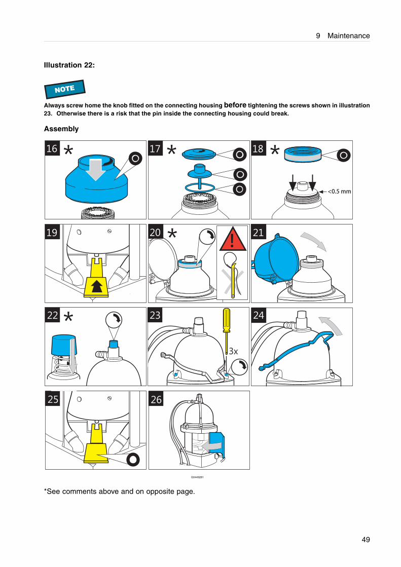
Illustration 22:
NOTE
Always screw home the knob fitted on the connecting housing before tightening the screws shown in illustration23. Otherwise there is a risk that the pin inside the connecting housing could break.
Assembly
16
<0.5 mm
21
24
25
!20
17 18
19
26
23
3x
22
* * *
*
*
G0449281
*See comments above and on opposite page.
49
9 Maintenance
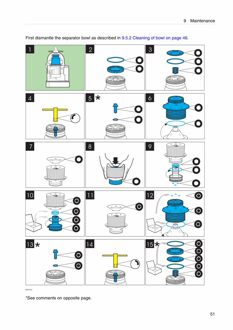
9.5.3 Replacement of O-rings
Comments to illustrations on opposite page.
Illustration 5:
Take care of the washer.
Illustration 13:
Check that the washer is fitted. Otherwise there is a risk that the bowl will not make firm contactwith the spindle.
If two or more washers are fitted accidentally this will prevent the top parts of the bowl from beingpositioned correctly.
Illustration 15:
NOTE
Fit the upper O-ring outside the level ring, see comments to illustration 17.
50
9 Maintenance
First dismantle the separator bowl as described in 9.5.2 Cleaning of bowl on page 46.
3
4 5
7
15
11 12
14
10
1 2
13
6
8 9
**
* *
G05191j1
*See comments on opposite page.
51
9 Maintenance
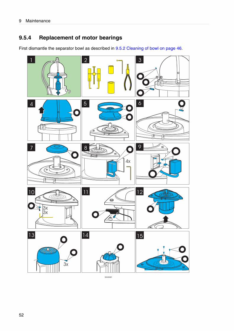
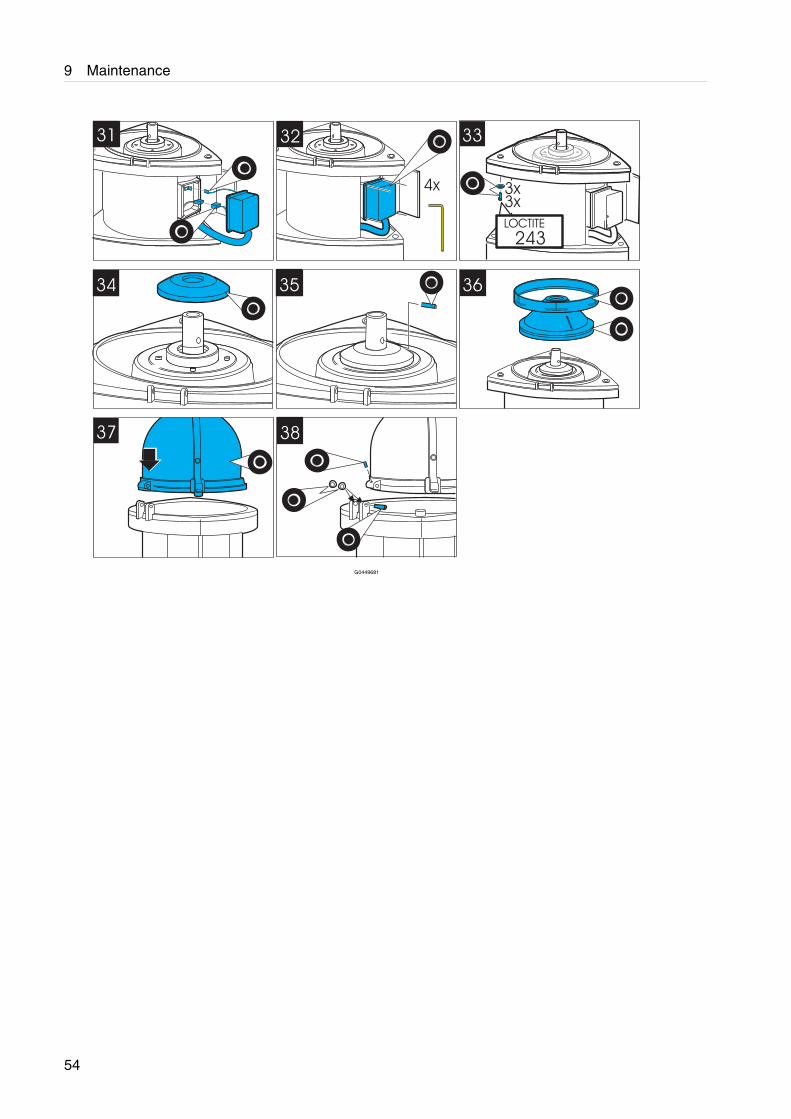
9.5.4 Replacement of motor bearings
First dismantle the separator bowl as described in 9.5.2 Cleaning of bowl on page 46.
G0449461
52
9 Maintenance
G0449671
53
9 Maintenance
G0449681
54
9 Maintenance
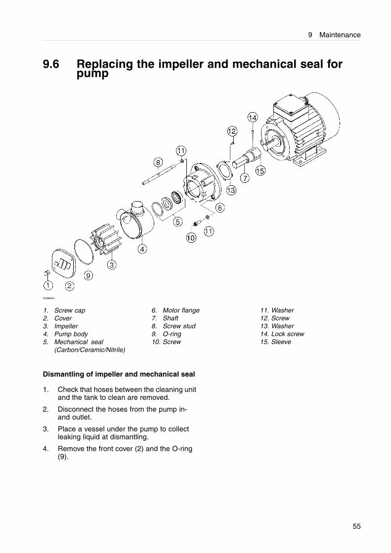
9.6 Replacing the impeller and mechanical seal forpump
G09869a1
1. Screw cap2. Cover3. Impeller4. Pump body5. Mechanical seal
(Carbon/Ceramic/Nitrile)
6. Motor flange7. Shaft8. Screw stud9. O-ring10. Screw
11. Washer12. Screw13. Washer14. Lock screw15. Sleeve
Dismantling of impeller and mechanical seal
1. Check that hoses between the cleaning unitand the tank to clean are removed.
2. Disconnect the hoses from the pump in-and outlet.
3. Place a vessel under the pump to collectleaking liquid at dismantling.
4. Remove the front cover (2) and the O-ring(9).
55
9 Maintenance
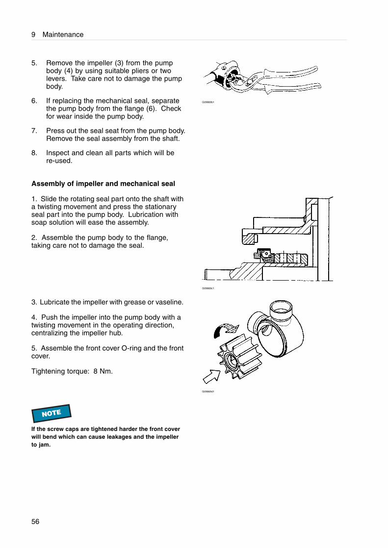
5. Remove the impeller (3) from the pumpbody (4) by using suitable pliers or twolevers. Take care not to damage the pumpbody.
6. If replacing the mechanical seal, separatethe pump body from the flange (6). Checkfor wear inside the pump body.
7. Press out the seal seat from the pump body.Remove the seal assembly from the shaft.
8. Inspect and clean all parts which will bere-used.
G09869b1
Assembly of impeller and mechanical seal
1. Slide the rotating seal part onto the shaft witha twisting movement and press the stationaryseal part into the pump body. Lubrication withsoap solution will ease the assembly.
2. Assemble the pump body to the flange,taking care not to damage the seal.
G09869c1
3. Lubricate the impeller with grease or vaseline.
4. Push the impeller into the pump body with atwisting movement in the operating direction,centralizing the impeller hub.
5. Assemble the front cover O-ring and the frontcover.
Tightening torque: 8 Nm.
G09869d1
NOTE
If the screw caps are tightened harder the front coverwill bend which can cause leakages and the impellerto jam.
56
10 Technical data
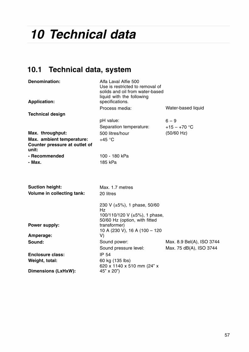
10.1 Technical data, systemDenomination: Alfa Laval Alfie 500
Application:
Use is restricted to removal ofsolids and oil from water-basedliquid with the followingspecifications.
Process media: Water-based liquidTechnical design
pH value: 6 – 9Separation temperature: +15 – +70 °C
Max. throughput: 500 litres/hour (50/60 Hz)Max. ambient temperature: +45 °CCounter pressure at outlet ofunit:- Recommended 100 - 180 kPa- Max. 185 kPa
Suction height: Max. 1.7 metresVolume in collecting tank: 20 litres
Power supply:
230 V (±5%), 1 phase, 50/60Hz100/110/120 V (±5%), 1 phase,50/60 Hz (option, with fittedtransformer)
Amperage:10 A (230 V), 16 A (100 – 120V)
Sound: Sound power: Max. 8.9 Bel(A), ISO 3744Sound pressure level: Max. 75 dB(A), ISO 3744
Enclosure class: IP 54Weight, total: 60 kg (135 lbs)
Dimensions (LxHxW):620 x 1140 x 510 mm (24” x45” x 20”)
57
10 Technical data
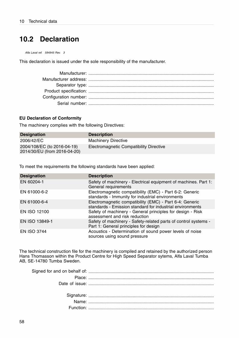
10.2 Declaration
Alfa Laval ref. 594945 Rev. 3
This declaration is issued under the sole responsibility of the manufacturer.
Manufacturer: ......................................................................................................Manufacturer address: ......................................................................................................
Separator type: ......................................................................................................Product specification: ......................................................................................................
Configuration number: ......................................................................................................Serial number: ......................................................................................................
EU Declaration of Conformity
The machinery complies with the following Directives:
Designation Description2006/42/EC Machinery Directive2004/108/EC (to 2016-04-19)2014/30/EU (from 2016-04-20)
Electromagnetic Compatibility Directive
To meet the requirements the following standards have been applied:
Designation DescriptionEN 60204-1 Safety of machinery - Electrical equipment of machines. Part 1:
General requirementsEN 61000-6-2 Electromagnetic compatibility (EMC) - Part 6-2: Generic
standards - Immunity for industrial environmentsEN 61000-6-4 Electromagnetic compatibility (EMC) - Part 6-4: Generic
standards - Emission standard for industrial environmentsEN ISO 12100 Safety of machinery - General principles for design - Risk
assessment and risk reductionEN ISO 13849-1 Safety of machinery - Safety-related parts of control systems -
Part 1: General principles for designEN ISO 3744 Acoustics - Determination of sound power levels of noise
sources using sound pressure
The technical construction file for the machinery is compiled and retained by the authorized personHans Thomasson within the Product Centre for High Speed Separator sytems, Alfa Laval TumbaAB, SE-14780 Tumba Sweden.
Signed for and on behalf of: ......................................................................................................Place: ......................................................................................................
Date of issue: ......................................................................................................
Signature: ......................................................................................................Name: ......................................................................................................
Function: ......................................................................................................
58
11 Lifting instruction
11.1 Cleaning unit
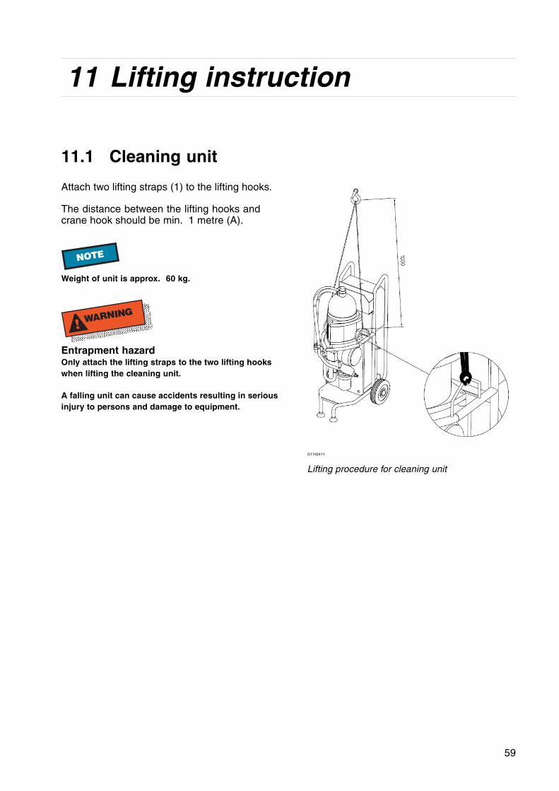
Attach two lifting straps (1) to the lifting hooks.
The distance between the lifting hooks andcrane hook should be min. 1 metre (A).
NOTE
Weight of unit is approx. 60 kg.
! WARNING
Entrapment hazardOnly attach the lifting straps to the two lifting hookswhen lifting the cleaning unit.
A falling unit can cause accidents resulting in seriousinjury to persons and damage to equipment.
G1102411
Lifting procedure for cleaning unit
59

11 Lifting instruction
12 Diagrams
12.1 Electrical system
Alfa Laval ref. 9014733 Rev. 7
61
0 1 2 3 4 5 6 7 8 9Th
is d
ocum
ent
and
it's
cont
ents
are
the
exc
lusi
ve p
rope
rty
of A
lfa L
aval
AB,
and
may
not
be
copi
ed, r
epro
duce
d, t
rans
mitt
ed o
r co
mm
unic
ated
to
a th
ird p
arty
,no
r us
ed fo
r an
y pu
pose
with
out
writ
ten
perm
issi
on.
This
doc
umen
t co
nstit
utes
a c
ontr
actu
al o
blig
atio
n on
our
pa
rt o
nly
to t
he e
xten
t ex
pres
sly
agre
ed u
pon.
SETUTBLCreated by
SETUTBLRevised by
Approved date
2015-10-23Approved by
SETUNLNCATDepartment
2014-04-01Created date
Document No.
9014733
Page Revision
Latest Revision
07
Project
Title page / cover sheetLocation
Mounting
Title
Alfie/EmmieRevised date
1
2Next page
Page
2014-09-05
Alfa Laval Tumba AB
Project description Alfie/Emmie
Control voltage
2014-04-01
Edit date
230V AC (100/110/120VAC with optional transformer)
Created on
Main supply
9014733
SETUAKL
Drawing number
Manufacturer (company)
Company / customer
2015-10-07
24V DC
Alfa Laval Tumba ABC:\Documents and Settings\SETUGNH\My Documents\My Pictures\alfalaval.bmp
SETUTBL
0 1 2 3 4 5 6 7 8 9Th
is d
ocum
ent
and
it's
cont
ents
are
the
exc
lusi
ve p
rope
rty
of A
lfa L
aval
AB,
and
may
not
be
copi
ed, r
epro
duce
d, t
rans
mitt
ed o
r co
mm
unic
ated
to
a th
ird p
arty
,no
r us
ed fo
r an
y pu
pose
with
out
writ
ten
perm
issi
on.
This
doc
umen
t co
nstit
utes
a c
ontr
actu
al o
blig
atio
n on
our
pa
rt o
nly
to t
he e
xten
t ex
pres
sly
agre
ed u
pon.
SETUTBLCreated by
SETUTBLRevised by
Approved date
2015-10-23Approved by
SETUNLNCATDepartment
2014-04-01Created date
Document No.
9014733
Page Revision
Latest Revision
07
Project
Cable-connection diagram 1 W001W002 W003 W201
Location
Mounting
Title
Alfie/EmmieRevised date
06 2
3Next page
Page
2015-03-26
Inte
rnal
tar
gets
Exte
rnal
tar
gets
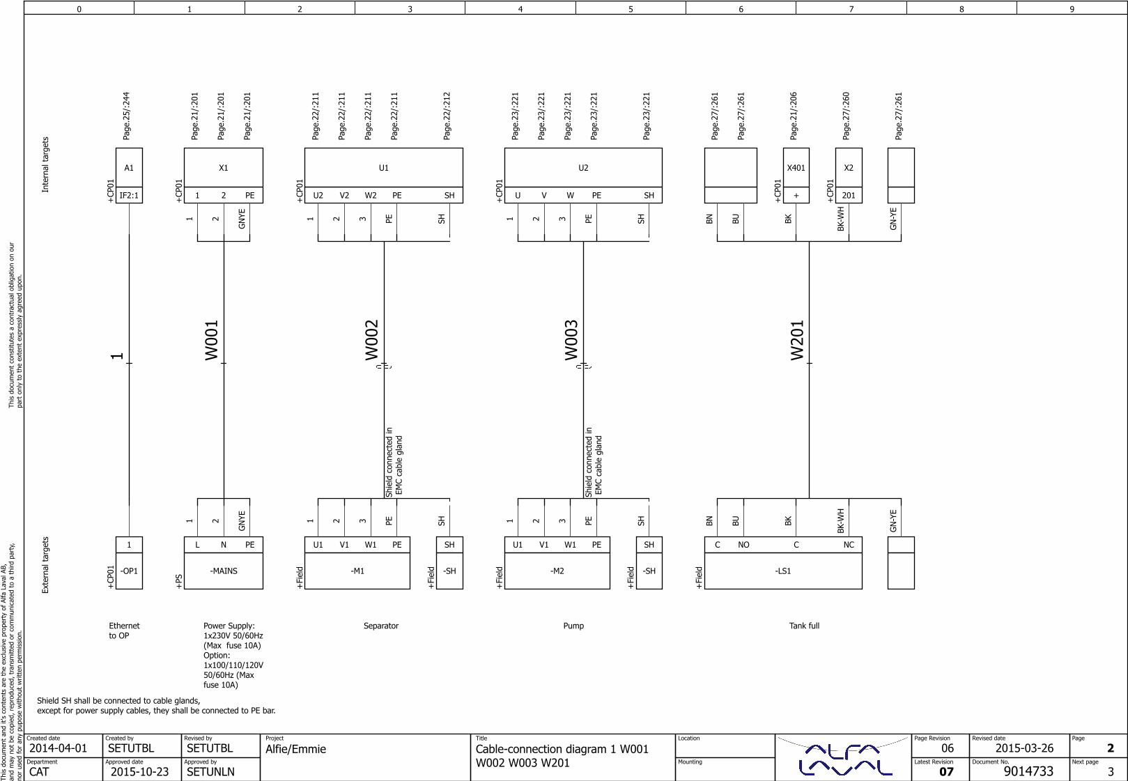
Shield SH shall be connected to cable glands,except for power supply cables, they shall be connected to PE bar.
Page
.25/
:244
IF2:1+CP
01
A1
1
+CP
01 -OP1
Ethernetto OP
1
GN
-YE
GN
-YE
Page
.27/
:261
Tank full
W20
1
PEWV
SHSH
Page
.23/
:221
SHU+CP
01
U2
SH
+Fi
eld -SH
Shie
ld c
onne
cted
in E
MC
cabl
e gl
and
Pump
W00
3
11
Page
.21/
:201
22
Page
.21/
:201
GN
YEG
NYE
Page
.21/
:201
PE21+CP
01X1
PENL
+PS
-MAINS
Power Supply:1x230V 50/60Hz(Max fuse 10A)Option:1x100/110/120V50/60Hz (Max fuse 10A)
W00
1
11
Page
.23/
:221
BNBN
Page
.27/
:261
22
Page
.22/
:211
33
Page
.22/
:211
PEPE
Page
.22/
:211
PEW1V1U1
+Fi
eld -M1
22
Page
.23/
:221
33
Page
.23/
:221
PEPE
Page
.23/
:221
PEW1V1U1
+Fi
eld -M2
BUBU
Page
.27/
:261
11
Page
.22/
:211
BKBK
Page
.21/
:206
++CP
01
X401
PEW2V2
SHSH
Page
.22/
:212
SHU2+CP
01
U1
SH
+Fi
eld -SH
Shie
ld c
onne
cted
in E
MC
cabl
e gl
and
Separator
W00
2
NO
BK-W
HBK
-WH
Page
.27/
:260
201+CP
01
X2
NCCC
+Fi
eld -LS1
0 1 2 3 4 5 6 7 8 9Th
is d
ocum
ent
and
it's
cont
ents
are
the
exc
lusi
ve p
rope
rty
of A
lfa L
aval
AB,
and
may
not
be
copi
ed, r
epro
duce
d, t
rans
mitt
ed o
r co
mm
unic
ated
to
a th
ird p
arty
,no
r us
ed fo
r an
y pu
pose
with
out
writ
ten
perm
issi
on.
This
doc
umen
t co
nstit
utes
a c
ontr
actu
al o
blig
atio
n on
our
pa
rt o
nly
to t
he e
xten
t ex
pres
sly
agre
ed u
pon.
SETUAKLCreated by
SETUAKLRevised by
Approved date
2015-10-23Approved by
SETUNLNCATDepartment
2014-04-01Created date
Document No.
9014733
Page Revision
Latest Revision
07
Project
Cable-connection diagram W202W401 W402
Location
Mounting
Title
Alfie/EmmieRevised date
07 3
4Next page
Page
2015-10-07
Inte
rnal
tar
gets
Exte
rnal
tar
gets
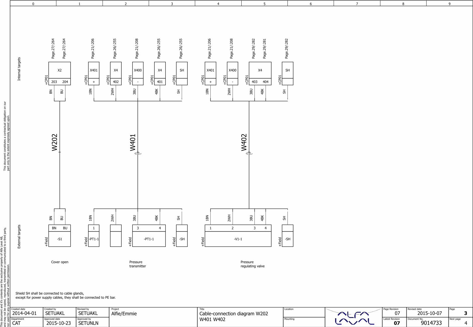
Shield SH shall be connected to cable glands,except for power supply cables, they shall be connected to PE bar.
BNBN
Page
.27/
:264
SHSH
Page
.29/
:282
+CP
01
SH
+Fi
eld -SH
Pressureregulating valve
W40
2
2WH
2WH
Page
.21/
:208
-+CP
01
X400
SHSH
Page
.26/
:255
+CP
01
SH
+Fi
eld -SH
Pressuretransmitter
W40
13B
U3B
UPa
ge.2
1/:2
08
-+CP
01
X400
203+CP
01
BN
+Fi
eld
BUBU
Page
.27/
:264
204
X2
BU
-S1
Cover open
W20
2
2WH
2WH
Page
.26/
:255
402+CP
01
X4
4BK
4BK
Page
.26/
:255
401+CP
01
X4
43
+Fi
eld -PT1-1
3BU
3BU
Page
.29/
:282
1BN
1BN
Page
.21/
:206
++CP
01
X401
1
+Fi
eld -PT1-1
1BN
1BN
Page
.21/
:206
++CP
01
X401
403+CP
01
32
4BK
4BK
Page
.29/
:281
404
X4
41
+Fi
eld -V1-1
0 1 2 3 4 5 6 7 8 9Th
is d
ocum
ent
and
it's
cont
ents
are
the
exc
lusi
ve p
rope
rty
of A
lfa L
aval
AB,
and
may
not
be
copi
ed, r
epro
duce
d, t
rans
mitt
ed o
r co
mm
unic
ated
to
a th
ird p
arty
,no
r us
ed fo
r an
y pu
pose
with
out
writ
ten
perm
issi
on.
This
doc
umen
t co
nstit
utes
a c
ontr
actu
al o
blig
atio
n on
our
pa
rt o
nly
to t
he e
xten
t ex
pres
sly
agre
ed u
pon.
SETUTBLCreated by
SETUTBLRevised by
Approved date
2015-10-23Approved by
SETUNLNCATDepartment
2014-04-01Created date
Document No.
9014733
Page Revision
Latest Revision
07
Project
Cable overview : 1 - W402Location
Mounting
Title
Alfie/EmmieRevised date
06 4
=9014733+CP01&Circuit/10Next page
Page
2015-03-26
Cable no Source (from)
Cable overviewConductors
usedTarget (to) Conductors /Area Function textCable type
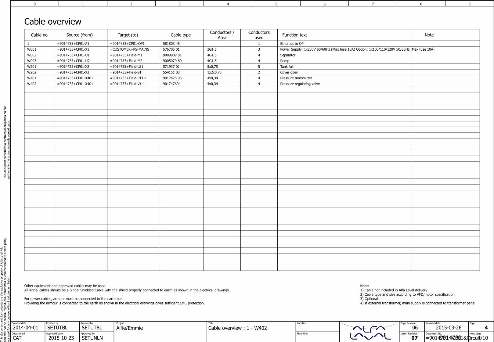
Other equivalent and approved cables may be used.All signal cables should be a Signal Shielded Cable with the shield properly connected to earth as shown in the electrical drawings.
For power cables, armour must be connected to the earth bar.Providing the armour is connected to the earth as shown in the electrical drawings gives sufficient EMC protection.
Note:1) Cable not included in Alfa Laval delivery2) Cable type and size according to VFD/motor specification3) Optional4) If external transformer, main supply is connected to transformer panel
Note
Ethernet to OP11 581803 45=9014733+CP01-OP1=9014733+CP01-A1
Power Supply: 1x230V 50/60Hz (Max fuse 10A) Option: 1x100/110/120V 50/60Hz (Max fuse 10A)3W001 576705 01=CUSTOMER+PS-MAINS=9014733+CP01-X1 3G1,5
Separator4W002 9009089 81=9014733+Field-M1=9014733+CP01-U1 4G1,5
Pump4W003 9005079 80=9014733+Field-M2=9014733+CP01-U2 4G1,5
Tank full5W201 571937 01=9014733+Field-LS1=9014733+CP01-X2
Cover open2W202 554151 03=9014733+Field-S1=9014733+CP01-X2 1x2x0,75
Pressure transmitter4W401 9017476 03=9014733+CP01-X401 4x0,34
Pressure regulating valve4W402 901747604=9014733+Field-V1-1=9014733+CP01-X401 4x0,34
=9014733+Field-PT1-1
5x0,75
0 1 2 3 4 5 6 7 8 9Th
is d
ocum
ent
and
it's
cont
ents
are
the
exc
lusi
ve p
rope
rty
of A
lfa L
aval
AB,
and
may
not
be
copi
ed, r
epro
duce
d, t
rans
mitt
ed o
r co
mm
unic
ated
to
a th
ird p
arty
,no
r us
ed fo
r an
y pu
pose
with
out
writ
ten
perm
issi
on.
This
doc
umen
t co
nstit
utes
a c
ontr
actu
al o
blig
atio
n on
our
pa
rt o
nly
to t
he e
xten
t ex
pres
sly
agre
ed u
pon.
SETUTBLCreated by
SETUTBLRevised by
Approved date
2015-10-23Approved by
SETUNLNCATDepartment
2014-04-01Created date
Document No.
9014733
Page Revision
Latest Revision
07
Project
Wiring tableLocation
Mounting
=9014733
+CP01
Title
Alfie/EmmieRevised date
02 10
11Next page
Page
2014-09-05
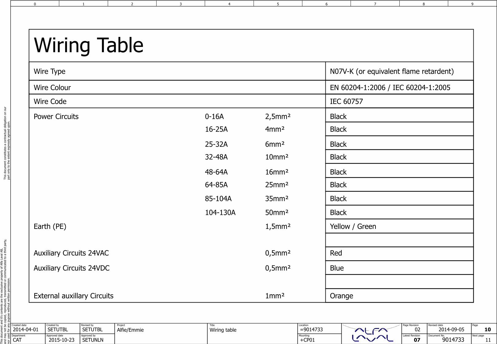
Wiring TableWire Type N07V-K (or equivalent flame retardent)
Black
Black
Black
Black
Black
Black
Red
Blue
Yellow / Green
Orange
Wire Colour
Power Circuits
Auxiliary Circuits 24VAC
Auxiliary Circuits 24VDC
Earth (PE)
External auxillary Circuits
2,5mm²
4mm²
6mm²
10mm²
16mm²
25mm²
0,5mm²
0,5mm²
1,5mm²
1mm²
0-16A
16-25A
25-32A
32-48A
48-64A
64-85A
85-104A 35mm² Black
104-130A 50mm² Black
EN 60204-1:2006 / IEC 60204-1:2005
Wire Code IEC 60757
0 1 2 3 4 5 6 7 8 9Th
is d
ocum
ent
and
it's
cont
ents
are
the
exc
lusi
ve p
rope
rty
of A
lfa L
aval
AB,
and
may
not
be
copi
ed, r
epro
duce
d, t
rans
mitt
ed o
r co
mm
unic
ated
to
a th
ird p
arty
,no
r us
ed fo
r an
y pu
pose
with
out
writ
ten
perm
issi
on.
This
doc
umen
t co
nstit
utes
a c
ontr
actu
al o
blig
atio
n on
our
pa
rt o
nly
to t
he e
xten
t ex
pres
sly
agre
ed u
pon.
SETUTBLCreated by
SETUAKLRevised by
Approved date
2015-10-23Approved by
SETUNLNCATDepartment
2014-04-01Created date
Document No.
9014733
Page Revision
Latest Revision
07
Project
Control cabinetassembly
Location
Mounting
=9014733
+CP01
Title
Alfie/EmmieRevised date
07 11
12Next page
Page
2015-10-23
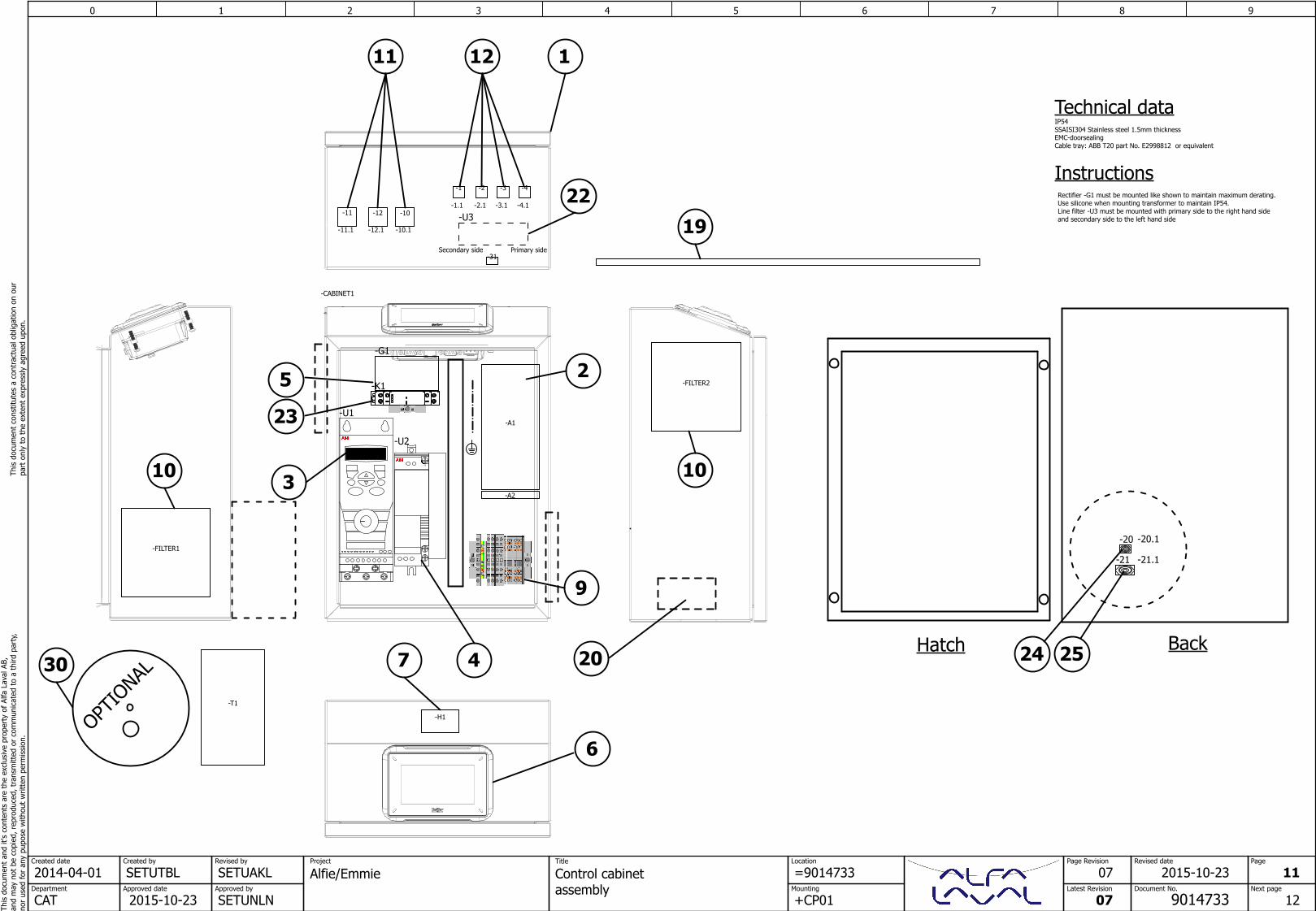
Technical data
Hatch Back
-G1
OPTIO
NAL
1
PE
-U2
11 12
10 10
2
9
5
3
7
6
4
IP54SSAISI304 Stainless steel 1.5mm thicknessEMC-doorsealingCable tray: ABB T20 part No. E2998812 or equivalent
30
InstructionsRectifier -G1 must be mounted like shown to maintain maximum derating.Use silicone when mounting transformer to maintain IP54.Line filter -U3 must be mounted with primary side to the right hand side and secondary side to the left hand side19
-K1
22
-U123
20 24 25
-21
-20
Primary sideSecondary side
-H1
-12-11 -10
-CABINET1
-M1
-10.1-11.1 -12.1
-FILTER1
-FILTER2
-31
-2
-2.1
-3
-3.1
-4
-4.1
-1
-1.1
-T1
-U3
-A1
-A2
-20.1
-21.1
0 1 2 3 4 5 6 7 8 9Th
is d
ocum
ent
and
it's
cont
ents
are
the
exc
lusi
ve p
rope
rty
of A
lfa L
aval
AB,
and
may
not
be
copi
ed, r
epro
duce
d, t
rans
mitt
ed o
r co
mm
unic
ated
to
a th
ird p
arty
,no
r us
ed fo
r an
y pu
pose
with
out
writ
ten
perm
issi
on.
This
doc
umen
t co
nstit
utes
a c
ontr
actu
al o
blig
atio
n on
our
pa
rt o
nly
to t
he e
xten
t ex
pres
sly
agre
ed u
pon.
SETUTBLCreated by
SETUAKLRevised by
Approved date
2015-10-23Approved by
SETUNLNCATDepartment
2014-04-01Created date
Document No.
9014733
Page Revision
Latest Revision
07
Project
Control cabinetassembly
Location
Mounting
=9014733
+CP01
Title
Alfie/EmmieRevised date
07 12
13Next page
Page
2015-10-23
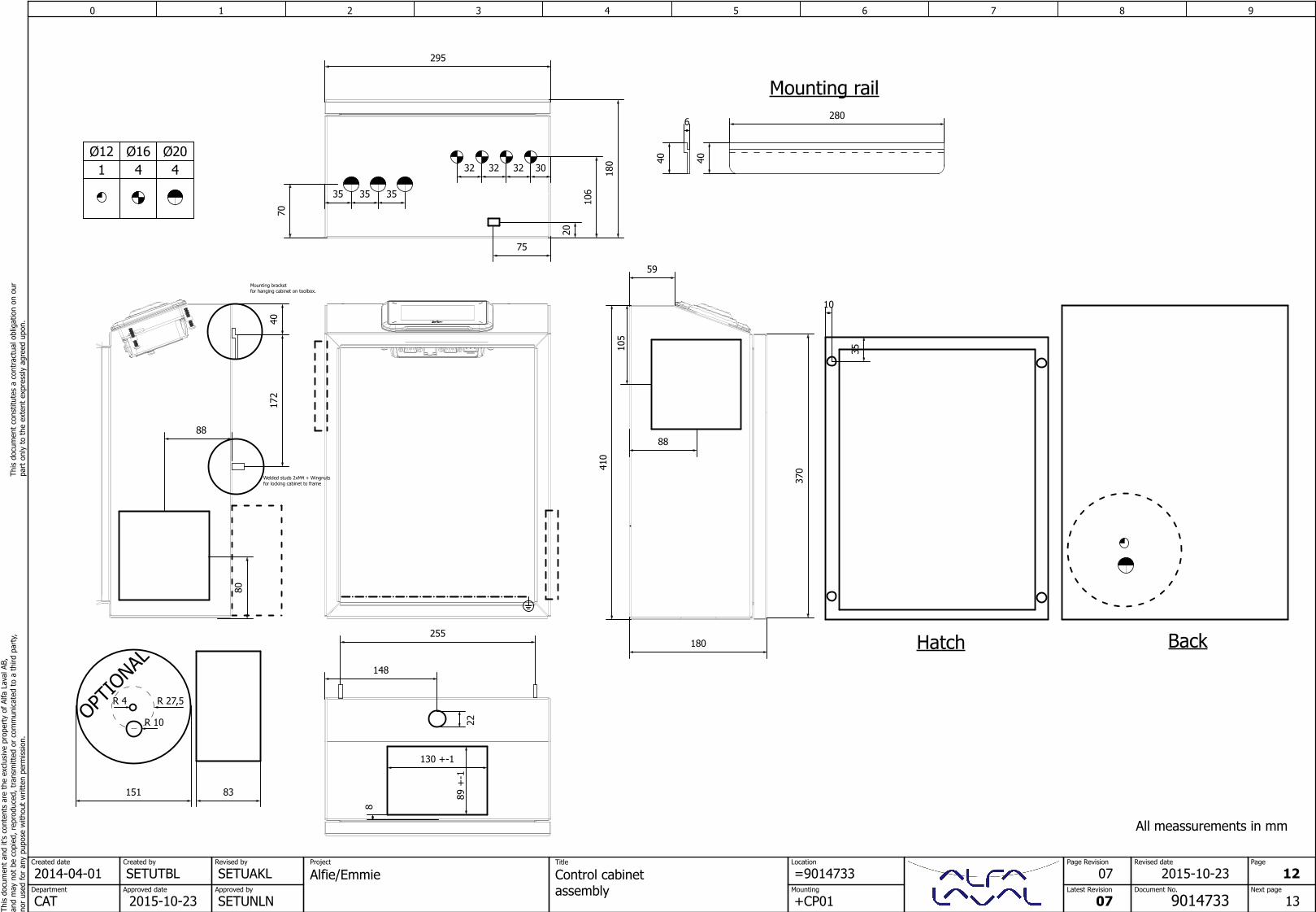
295
37041
0
180
59Mounting bracketfor hanging cabinet on toolbox.
280
4040
6
All meassurements in mm
151 83
Hatch Back
OPTIO
NAL
88
105
88
Mounting rail
70
Ø16 Ø204 4
148
32 32 32 30
35 35 35
75
180
20
106
22
80
Welded studs 2xM4 + Wingnutsfor locking cabinet to frame
130 +-1
8
89 +
-1
172
40
255
R 27,5
R 10
R 4
Ø121
10
35
0 1 2 3 4 5 6 7 8 9Th
is d
ocum
ent
and
it's
cont
ents
are
the
exc
lusi
ve p
rope
rty
of A
lfa L
aval
AB,
and
may
not
be
copi
ed, r
epro
duce
d, t
rans
mitt
ed o
r co
mm
unic
ated
to
a th
ird p
arty
,no
r us
ed fo
r an
y pu
pose
with
out
writ
ten
perm
issi
on.
This
doc
umen
t co
nstit
utes
a c
ontr
actu
al o
blig
atio
n on
our
pa
rt o
nly
to t
he e
xten
t ex
pres
sly
agre
ed u
pon.
SETUTBLCreated by
SETUTBLRevised by
Approved date
2015-10-23Approved by
SETUNLNCATDepartment
2014-04-01Created date
Document No.
9014733
Page Revision
Latest Revision
07
Project
Control cabinetassembly
Location
Mounting
=9014733
+CP01
Title
Alfie/EmmieRevised date
02 13
14Next page
Page
2014-09-05
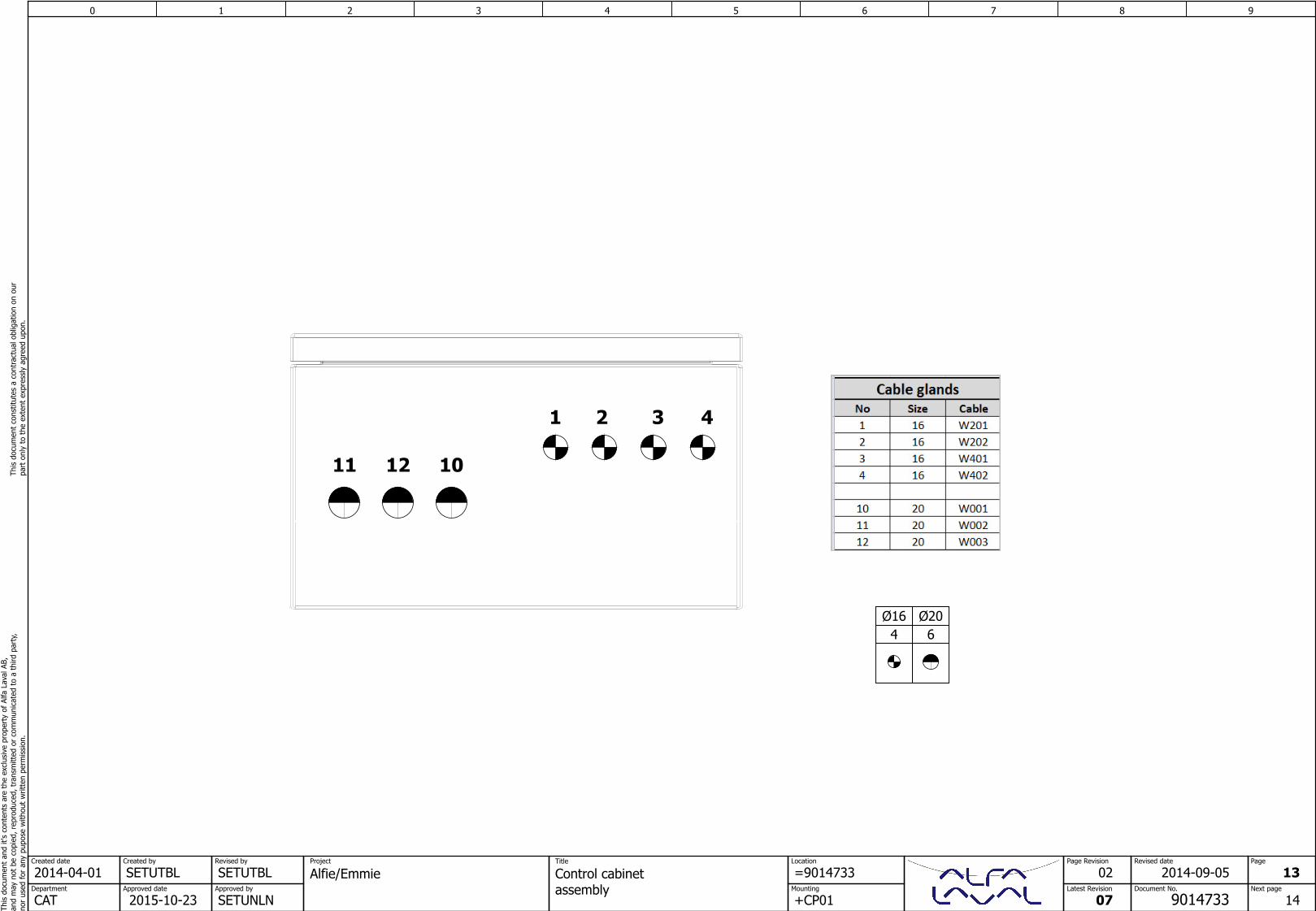
11 12 10
1 2 3 4
Ø16 Ø204 6
0 1 2 3 4 5 6 7 8 9Th
is d
ocum
ent
and
it's
cont
ents
are
the
exc
lusi
ve p
rope
rty
of A
lfa L
aval
AB,
and
may
not
be
copi
ed, r
epro
duce
d, t
rans
mitt
ed o
r co
mm
unic
ated
to
a th
ird p
arty
,no
r us
ed fo
r an
y pu
pose
with
out
writ
ten
perm
issi
on.
This
doc
umen
t co
nstit
utes
a c
ontr
actu
al o
blig
atio
n on
our
pa
rt o
nly
to t
he e
xten
t ex
pres
sly
agre
ed u
pon.
SETUTBLCreated by
SETUTBLRevised by
Approved date
2015-10-23Approved by
SETUNLNCATDepartment
2014-04-01Created date
Document No.
9014733
Page Revision
Latest Revision
07
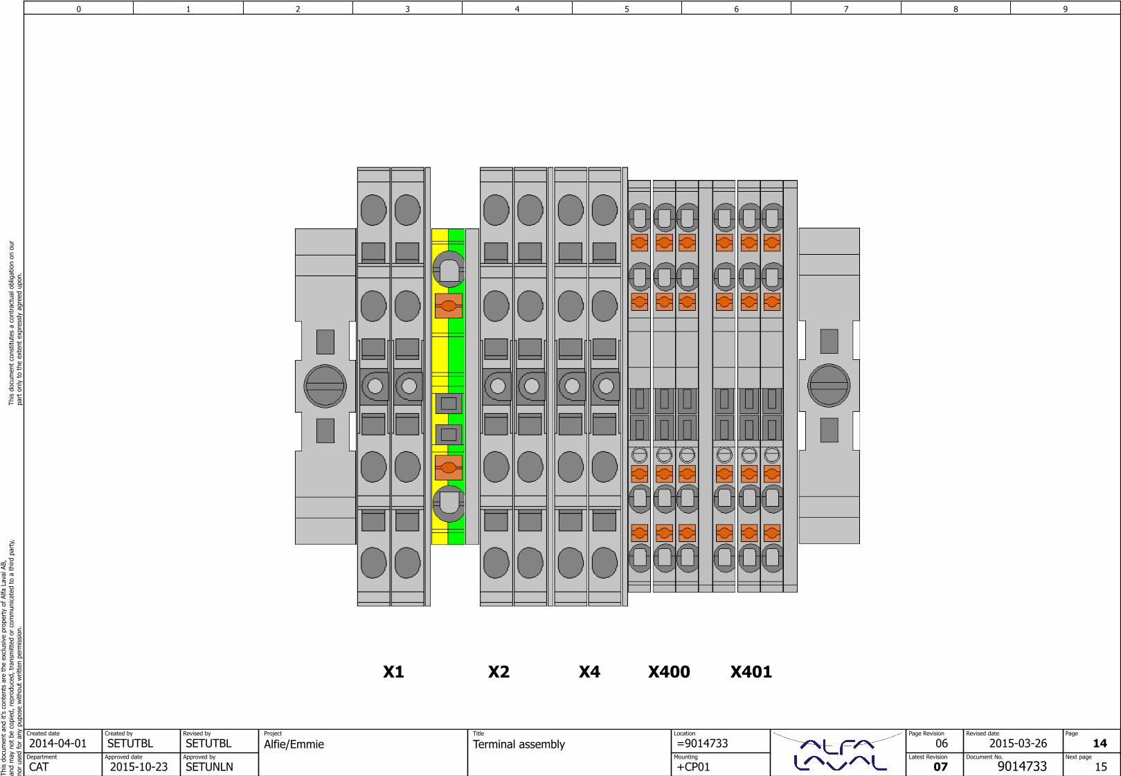
Project
Terminal assemblyLocation
Mounting
=9014733
+CP01
Title
Alfie/EmmieRevised date
06 14
15Next page
Page
2015-03-26
X1 X2 X400 X401X4
0 1 2 3 4 5 6 7 8 9Th
is d
ocum
ent
and
it's
cont
ents
are
the
exc
lusi
ve p
rope
rty
of A
lfa L
aval
AB,
and
may
not
be
copi
ed, r
epro
duce
d, t
rans
mitt
ed o
r co
mm
unic
ated
to
a th
ird p
arty
,no
r us
ed fo
r an
y pu
pose
with
out
writ
ten
perm
issi
on.
This
doc
umen
t co
nstit
utes
a c
ontr
actu
al o
blig
atio
n on
our
pa
rt o
nly
to t
he e
xten
t ex
pres
sly
agre
ed u
pon.
SETUTBLCreated by
SETUTBLRevised by
Approved date
2015-10-23Approved by
SETUNLNCATDepartment
2014-04-01Created date
Document No.
9014733
Page Revision
Latest Revision
07
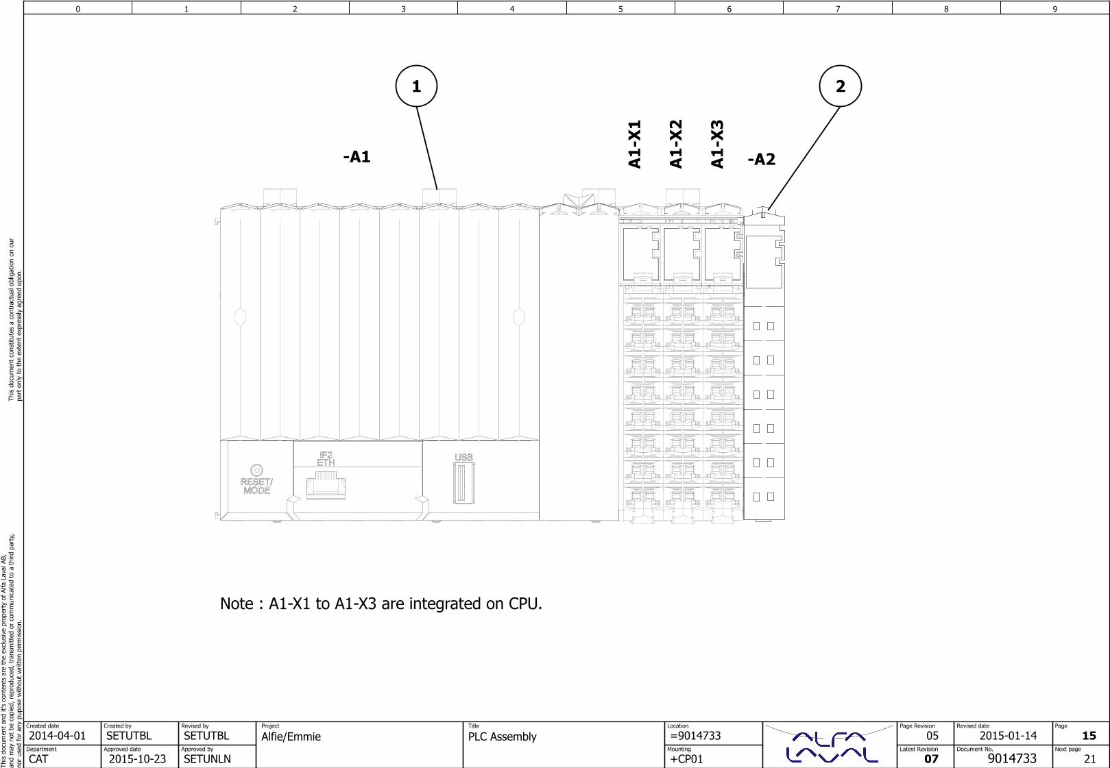
Project
PLC AssemblyLocation
Mounting
=9014733
+CP01
Title
Alfie/EmmieRevised date
05 15
21Next page
Page
2015-01-14
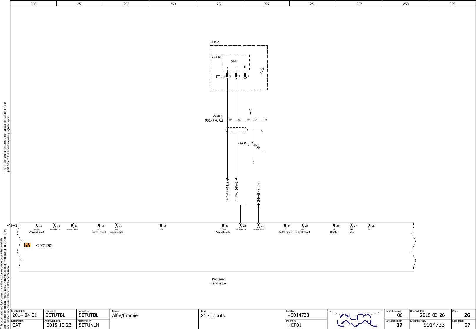
-A1 A1-X1
-A2A1-X2
A1-X3
Note : A1-X1 to A1-X3 are integrated on CPU.
1 2
200 201 202 203 204 205 206 207 208 209Th
is d
ocum
ent
and
it's
cont
ents
are
the
exc
lusi
ve p
rope
rty
of A
lfa L
aval
AB,
and
may
not
be
copi
ed, r
epro
duce
d, t
rans
mitt
ed o
r co
mm
unic
ated
to
a th
ird p
arty
,no
r us
ed fo
r an
y pu
pose
with
out
writ
ten
perm
issi
on.
This
doc
umen
t co
nstit
utes
a c
ontr
actu
al o
blig
atio
n on
our
pa
rt o
nly
to t
he e
xten
t ex
pres
sly
agre
ed u
pon.
SETUTBLCreated by
SETUAKLRevised by
Approved date
2015-10-23Approved by
SETUNLNCATDepartment
2014-04-01Created date
Document No.
9014733
Page Revision
Latest Revision
07
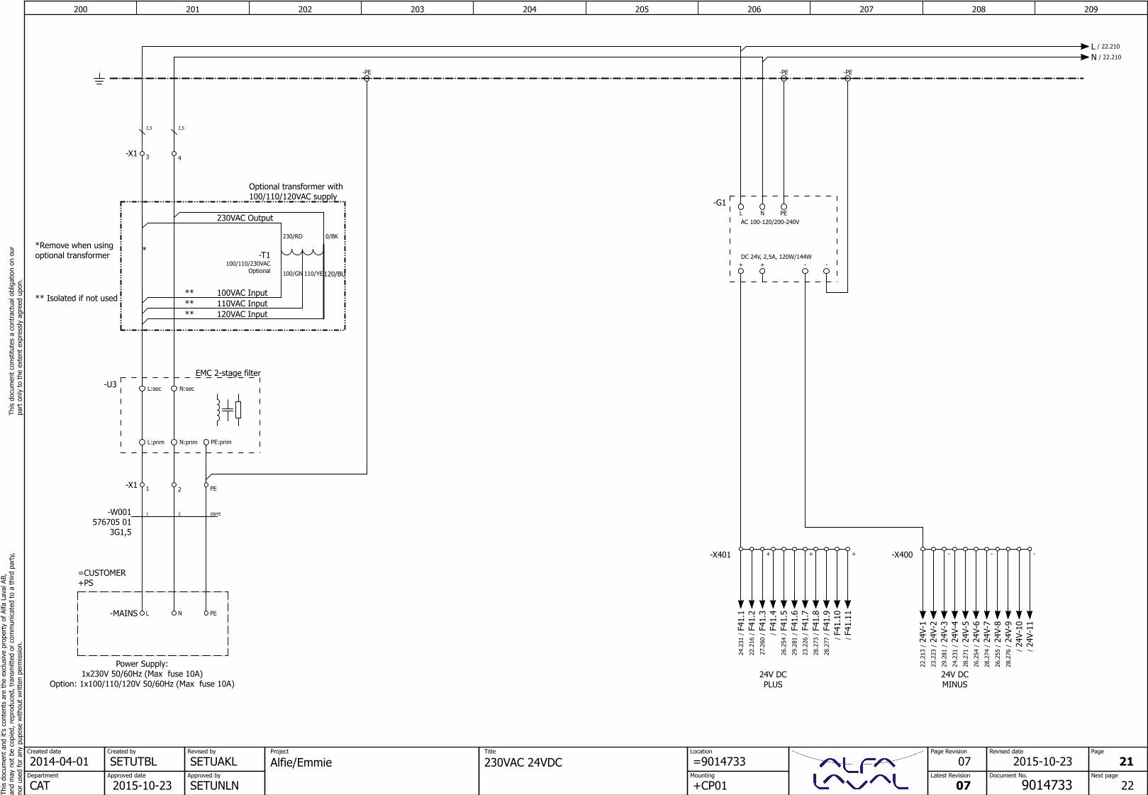
Project
230VAC 24VDCLocation
Mounting
=9014733
+CP01
Title
Alfie/EmmieRevised date
07 21
22Next page
Page
2015-10-23
Power Supply:1x230V 50/60Hz (Max fuse 10A)
Option: 1x100/110/120V 50/60Hz (Max fuse 10A)24V DCPLUS
-G1
AC 100-120/200-240V
DC 24V, 2,5A, 120W/144W
L N PE
+ - -+
24V DCMINUS
EMC 2-stage filter
*Remove when usingoptional transformer
** Isolated if not used
Optional transformer with100/110/120VAC supply
100VAC Input
230VAC Output
110VAC Input
*
****
120VAC Input**
120/BU
-MAINS L N
=CUSTOMER+PS
PE
2,5 2,5
-PE
-W001576705 01
3G1,5
1 2 GNYE
-PE -PE
-X401 +
-X1 1 2 PE
-X400 -+ + - -
-X1 3 4
-U3 L:sec N:sec
L:prim N:prim PE:prim
230/RD
100/GN
0/BK
110/YE
-T1100/110/230VAC
Optional
L / 22.210
N / 22.210
F41.
1/
24.2
31 24V-
1/
22.2
13
24V-
2/
23.2
23
24V-
3/
29.2
81
F41.
3/
27.2
60 24V-
4/
24.2
31
F41.
5/
26.2
54 24V-
5/
28.2
71
24V-
6/
26.2
54
F41.
4/
F41.
2/
22.2
16
F41.
7/
23.2
26
F41.
8/
28.2
73
F41.
11/ 24
V-7
/28
.274
24V-
9/
28.2
76
24V-
10/
24V-
11/
F41.
6/
29.2
81
F41.
10/ 24
V-8
/26
.255
F41.
9/
28.2
77
210 211 212 213 214 215 216 217 218 219Th
is d
ocum
ent
and
it's
cont
ents
are
the
exc
lusi
ve p
rope
rty
of A
lfa L
aval
AB,
and
may
not
be
copi
ed, r
epro
duce
d, t
rans
mitt
ed o
r co
mm
unic
ated
to
a th
ird p
arty
,no
r us
ed fo
r an
y pu
pose
with
out
writ
ten
perm
issi
on.
This
doc
umen
t co
nstit
utes
a c
ontr
actu
al o
blig
atio
n on
our
pa
rt o
nly
to t
he e
xten
t ex
pres
sly
agre
ed u
pon.
SETUTBLCreated by
SETUTBLRevised by
Approved date
2015-10-23Approved by
SETUNLNCATDepartment
2014-04-01Created date
Document No.
9014733
Page Revision
Latest Revision
07
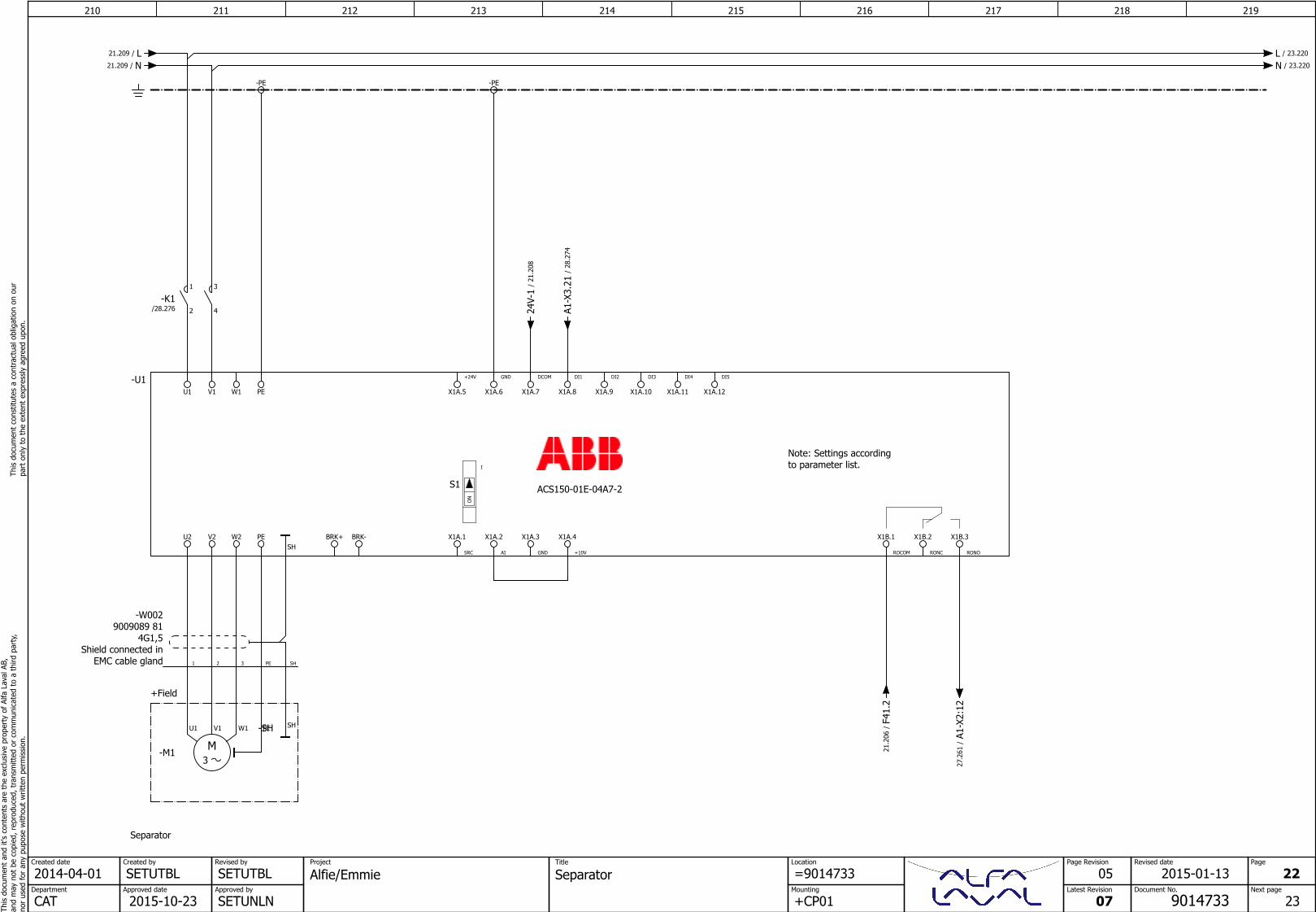
Project
SeparatorLocation
Mounting
=9014733
+CP01
Title
Alfie/EmmieRevised date
05 22
23Next page
Page
2015-01-13
S1
IO
N
Separator
Note: Settings accordingto parameter list.
GND
X1A.3
AI
X1A.2
SRC
X1A.1
RONO
X1B.3
RONC
X1B.2
ROCOM
X1B.1BRK-BRK+
W1
PE
PE
W2V2U2
U1 V1
DI3
X1A.10
DI2
X1A.9
DI1
X1A.8
DCOM
X1A.7
GND
X1A.6
+24V
X1A.5
-U1
ACS150-01E-04A7-2
DI5
X1A.12
DI4
X1A.11
+10V
X1A.4
-PE
U1 V1 W1 PE
-M13M
-PE
Shield connected in EMC cable gland
4G1,59009089 81
-W002
1 32 PE
+Field
SH
SH-SH
SH
1
2
-K1/28.276
3
4
L / 23.220
N / 23.220
L/21.209
N/21.209
24V-
1/
21.2
08
A1-X
3.21
/28
.274
F41.
2/
21.2
06 A1-X
2:12
/27
.261
220 221 222 223 224 225 226 227 228 229Th
is d
ocum
ent
and
it's
cont
ents
are
the
exc
lusi
ve p
rope
rty
of A
lfa L
aval
AB,
and
may
not
be
copi
ed, r
epro
duce
d, t
rans
mitt
ed o
r co
mm
unic
ated
to
a th
ird p
arty
,no
r us
ed fo
r an
y pu
pose
with
out
writ
ten
perm
issi
on.
This
doc
umen
t co
nstit
utes
a c
ontr
actu
al o
blig
atio
n on
our
pa
rt o
nly
to t
he e
xten
t ex
pres
sly
agre
ed u
pon.
SETUTBLCreated by
SETUTBLRevised by
Approved date
2015-10-23Approved by
SETUNLNCATDepartment
2014-04-01Created date
Document No.
9014733
Page Revision
Latest Revision
07
Project
PumpLocation
Mounting
=9014733
+CP01
Title
Alfie/EmmieRevised date
04 23
24Next page
Page
2014-12-01
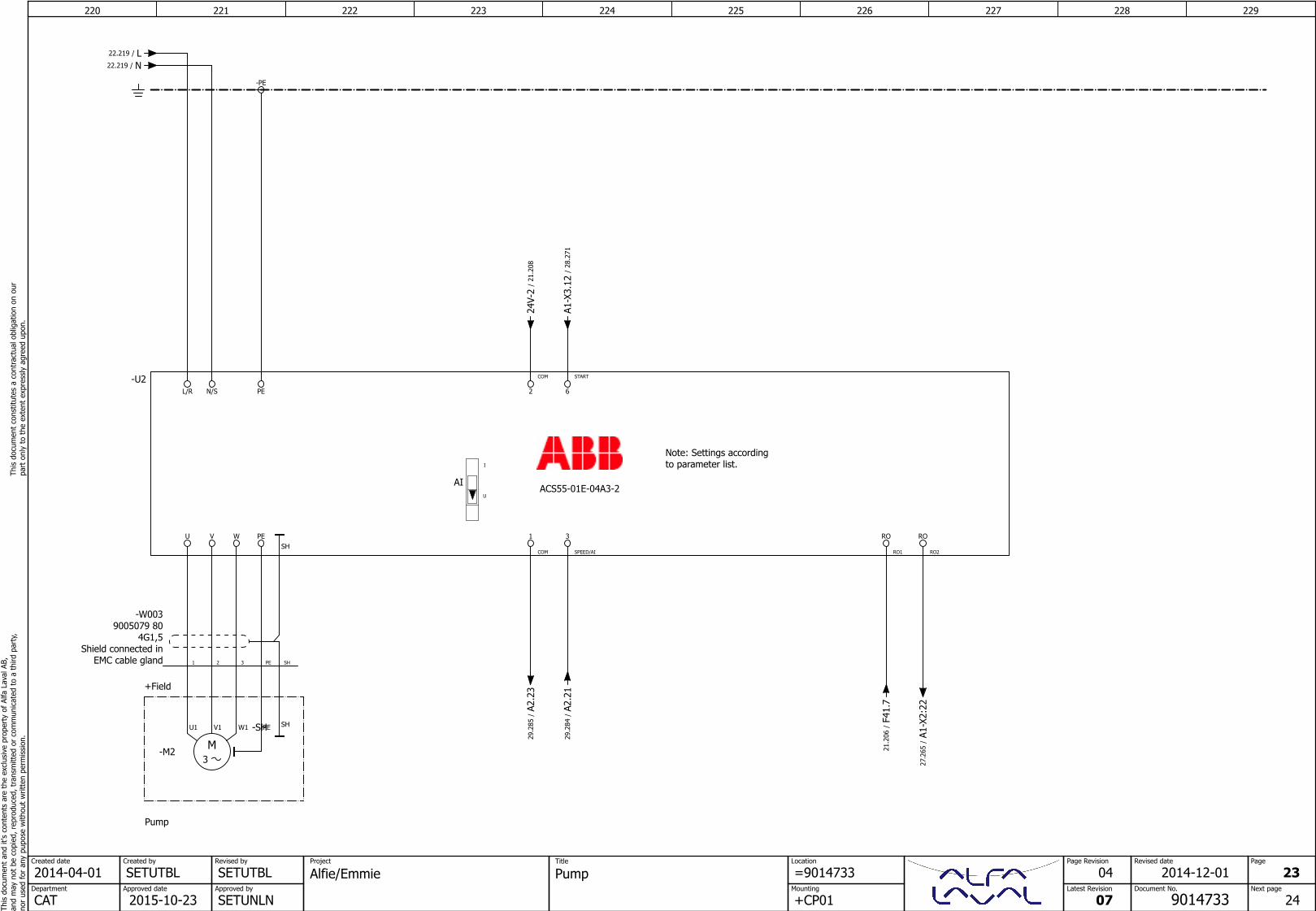
Pump
Note: Settings accordingto parameter list.
AI
I
U
SPEED/AI
3
COM
1
RO2
RO
RO1
ROPE
PE
WVU
L/R N/S
START
6
COM
2
-U2
ACS55-01E-04A3-2
-PE
U1 V1 W1 PE
-M23M
Shield connected in EMC cable gland
4G1,59005079 80
-W003
1 2 3 PE
+Field
SH
SH
SH-SH
L/22.219
N/22.219
F41.
7/
21.2
06
24V-
2/
21.2
08
A1-X
3.12
/28
.271
A2.2
3/
29.2
85
A2.2
1/
29.2
84
A1-X
2:22
/27
.265
230 231 232 233 234 235 236 237 238 239Th
is d
ocum
ent
and
it's
cont
ents
are
the
exc
lusi
ve p
rope
rty
of A
lfa L
aval
AB,
and
may
not
be
copi
ed, r
epro
duce
d, t
rans
mitt
ed o
r co
mm
unic
ated
to
a th
ird p
arty
,no
r us
ed fo
r an
y pu
pose
with
out
writ
ten
perm
issi
on.
This
doc
umen
t co
nstit
utes
a c
ontr
actu
al o
blig
atio
n on
our
pa
rt o
nly
to t
he e
xten
t ex
pres
sly
agre
ed u
pon.
SETUTBLCreated by
SETUTBLRevised by
Approved date
2015-10-23Approved by
SETUNLNCATDepartment
2014-04-01Created date
Document No.
9014733
Page Revision
Latest Revision
07
Project
HMI PanelsLocation
Mounting
=9014733
+CP01
Title
Alfie/EmmieRevised date
06 24
25Next page
Page
2015-03-24
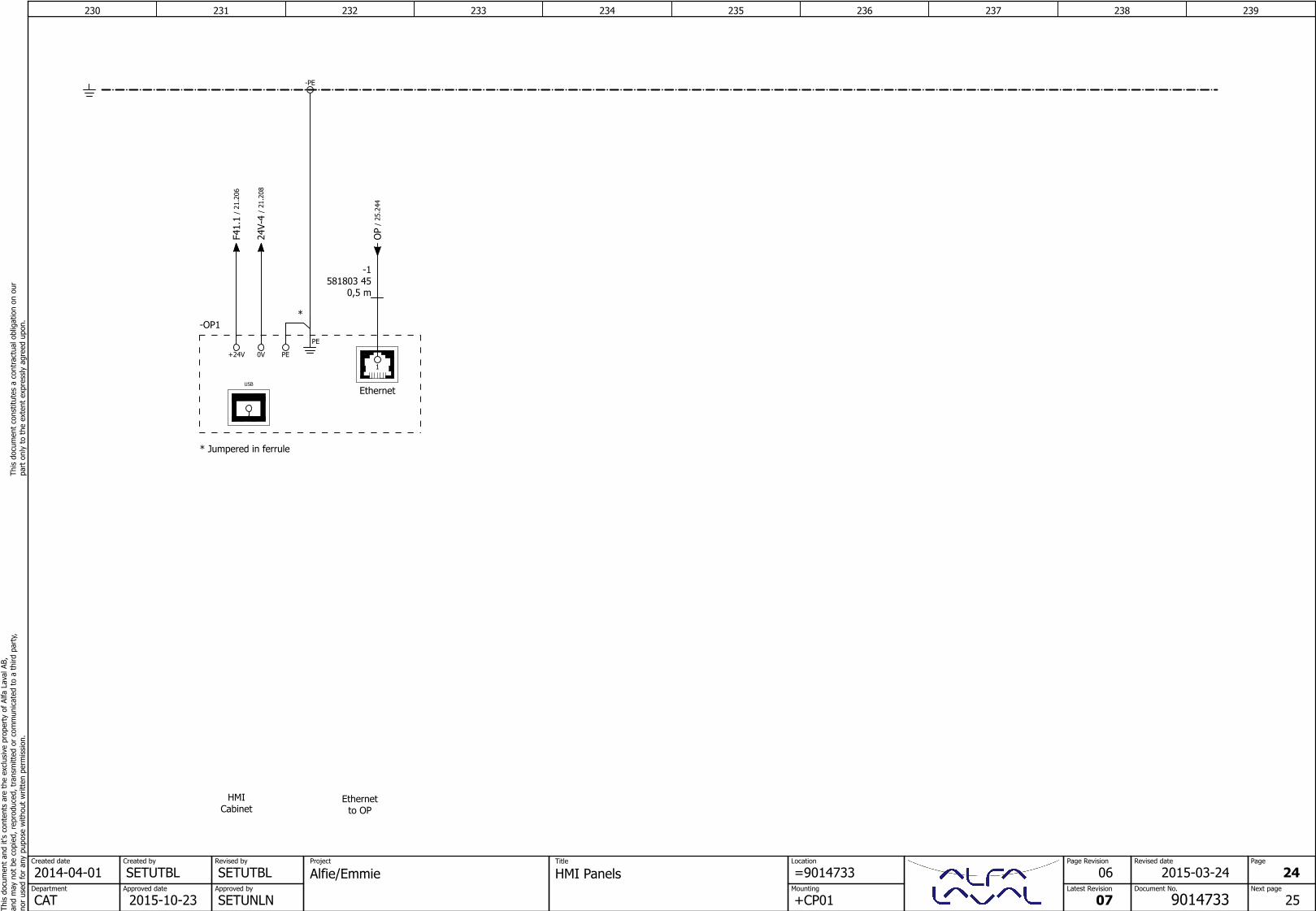
HMICabinet
1
Ethernet
-OP1
+24V 0V PE
Ethernetto OP
* Jumpered in ferrule
*
USB
PE
-PE
0,5 m581803 45
-1
OP
/25
.244
F41.
1/
21.2
06
24V-
4/
21.2
08
240 241 242 243 244 245 246 247 248 249Th
is d
ocum
ent
and
it's
cont
ents
are
the
exc
lusi
ve p
rope
rty
of A
lfa L
aval
AB,
and
may
not
be
copi
ed, r
epro
duce
d, t
rans
mitt
ed o
r co
mm
unic
ated
to
a th
ird p
arty
,no
r us
ed fo
r an
y pu
pose
with
out
writ
ten
perm
issi
on.
This
doc
umen
t co
nstit
utes
a c
ontr
actu
al o
blig
atio
n on
our
pa
rt o
nly
to t
he e
xten
t ex
pres
sly
agre
ed u
pon.
SETUTBLCreated by
SETUTBLRevised by
Approved date
2015-10-23Approved by
SETUNLNCATDepartment
2014-04-01Created date
Document No.
9014733
Page Revision
Latest Revision
07
Project
A1 - CPULocation
Mounting
=9014733
+CP01
Title
Alfie/EmmieRevised date
02 25
26Next page
Page
2014-09-05
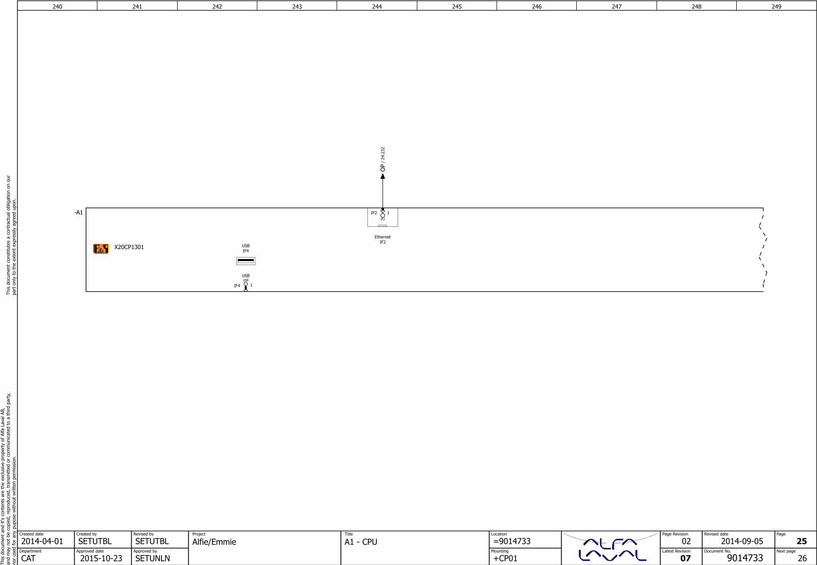
USBIF4
EthernetIF2
IF2 1IF2
IF4 1USBUSB
-A1
X20CP1301
OP
/24
.232
250 251 252 253 254 255 256 257 258 259Th
is d
ocum
ent
and
it's
cont
ents
are
the
exc
lusi
ve p
rope
rty
of A
lfa L
aval
AB,
and
may
not
be
copi
ed, r
epro
duce
d, t
rans
mitt
ed o
r co
mm
unic
ated
to
a th
ird p
arty
,no
r us
ed fo
r an
y pu
pose
with
out
writ
ten
perm
issi
on.
This
doc
umen
t co
nstit
utes
a c
ontr
actu
al o
blig
atio
n on
our
pa
rt o
nly
to t
he e
xten
t ex
pres
sly
agre
ed u
pon.
SETUTBLCreated by
SETUTBLRevised by
Approved date
2015-10-23Approved by
SETUNLNCATDepartment
2014-04-01Created date
Document No.
9014733
Page Revision
Latest Revision
07
Project
X1 - InputsLocation
Mounting
=9014733
+CP01
Title
Alfie/EmmieRevised date
06 26
27Next page
Page
2015-03-26
Pressuretransmitter
11AI +1I
AnalogInput1
12AI+1U/Sens+
13AI-1U/I/Sens-
14DI1
DigitalInput1
15DI3
DigitalInput3
21AI +2I
AnalogInput2
22AI+2U/Sens+
23AI-2U/I/Sens-
24DI2
DigitalInput2
25DI4
DigitalInput4
26TXD
RS232
27RXD
R232
18GND
28GND
-A1-X1
X20CP1301
-X4 401 402
0-10 Bar
-PT1-1 1
0-10V
+
3
-
+Field
4
U
9017476 03-W401
1BN 2WH3BU 4BK
SH
SH
SH
F41.
5/
21.2
06
24V-
6/
21.2
08
24V-
8/
21.2
08
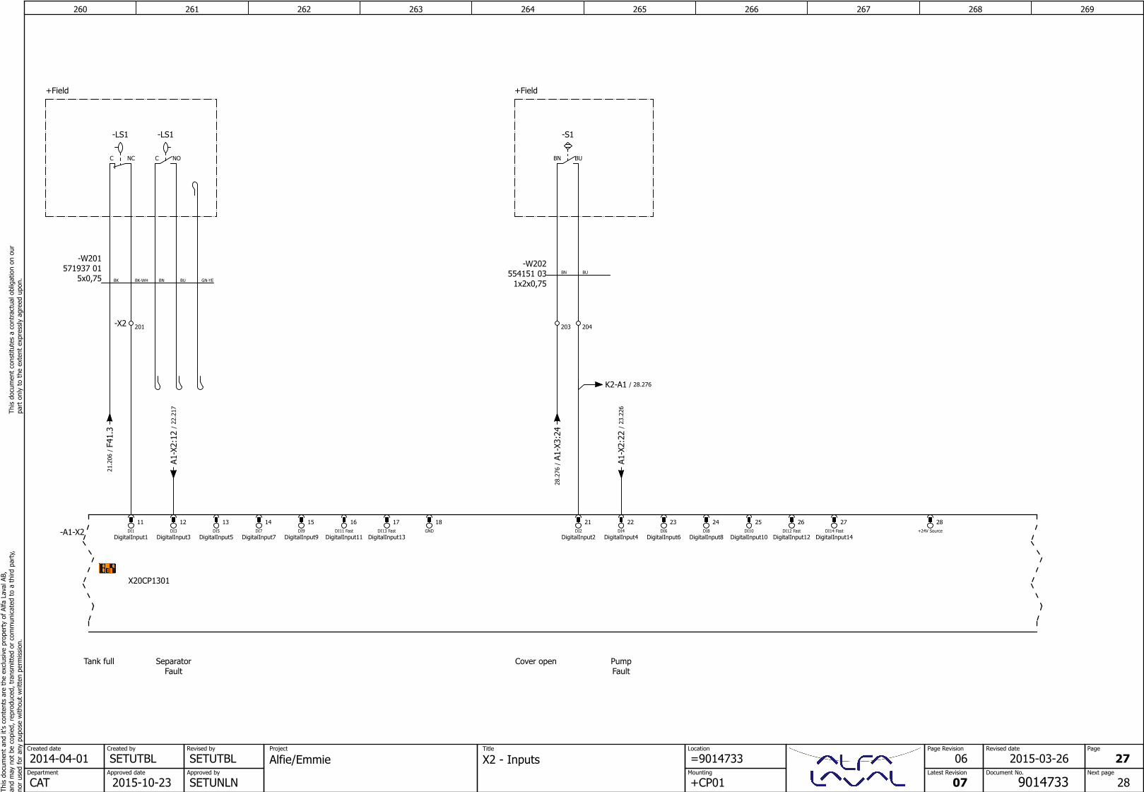
260 261 262 263 264 265 266 267 268 269Th
is d
ocum
ent
and
it's
cont
ents
are
the
exc
lusi
ve p
rope
rty
of A
lfa L
aval
AB,
and
may
not
be
copi
ed, r
epro
duce
d, t
rans
mitt
ed o
r co
mm
unic
ated
to
a th
ird p
arty
,no
r us
ed fo
r an
y pu
pose
with
out
writ
ten
perm
issi
on.
This
doc
umen
t co
nstit
utes
a c
ontr
actu
al o
blig
atio
n on
our
pa
rt o
nly
to t
he e
xten
t ex
pres
sly
agre
ed u
pon.
SETUTBLCreated by
SETUTBLRevised by
Approved date
2015-10-23Approved by
SETUNLNCATDepartment
2014-04-01Created date
Document No.
9014733
Page Revision
Latest Revision
07
Project
X2 - InputsLocation
Mounting
=9014733
+CP01
Title
Alfie/EmmieRevised date
06 27
28Next page
Page
2015-03-26
Tank full Cover openSeparatorFault
PumpFault
11DI1
DigitalInput1
12DI3
DigitalInput3
13DI5
DigitalInput5
14DI7
DigitalInput7
15DI9
DigitalInput9
16DI11 Fast
DigitalInput11
17DI13 Fast
DigitalInput13
18GND
21DI2
DigitalInput2
22DI4
DigitalInput4
23DI6
DigitalInput6
24DI8
DigitalInput8
25DI10
DigitalInput10
26DI12 Fast
DigitalInput12
27DI14 Fast
DigitalInput14
28+24V Source-A1-X2
X20CP1301
+Field +Field
1x2x0,75554151 03
-W202
C NC
-LS1
-X2 201
NOC
-LS1
BUBN
-S1
BN BU
5x0,75571937 01
-W201
BN BUBK BK-WH GN-YE
204203
F41.
3/
21.2
06 A1-X
3:24
/28
.276
A1-X
2:12
/22
.217
A1-X
2:22
/23
.226
K2-A1 / 28.276
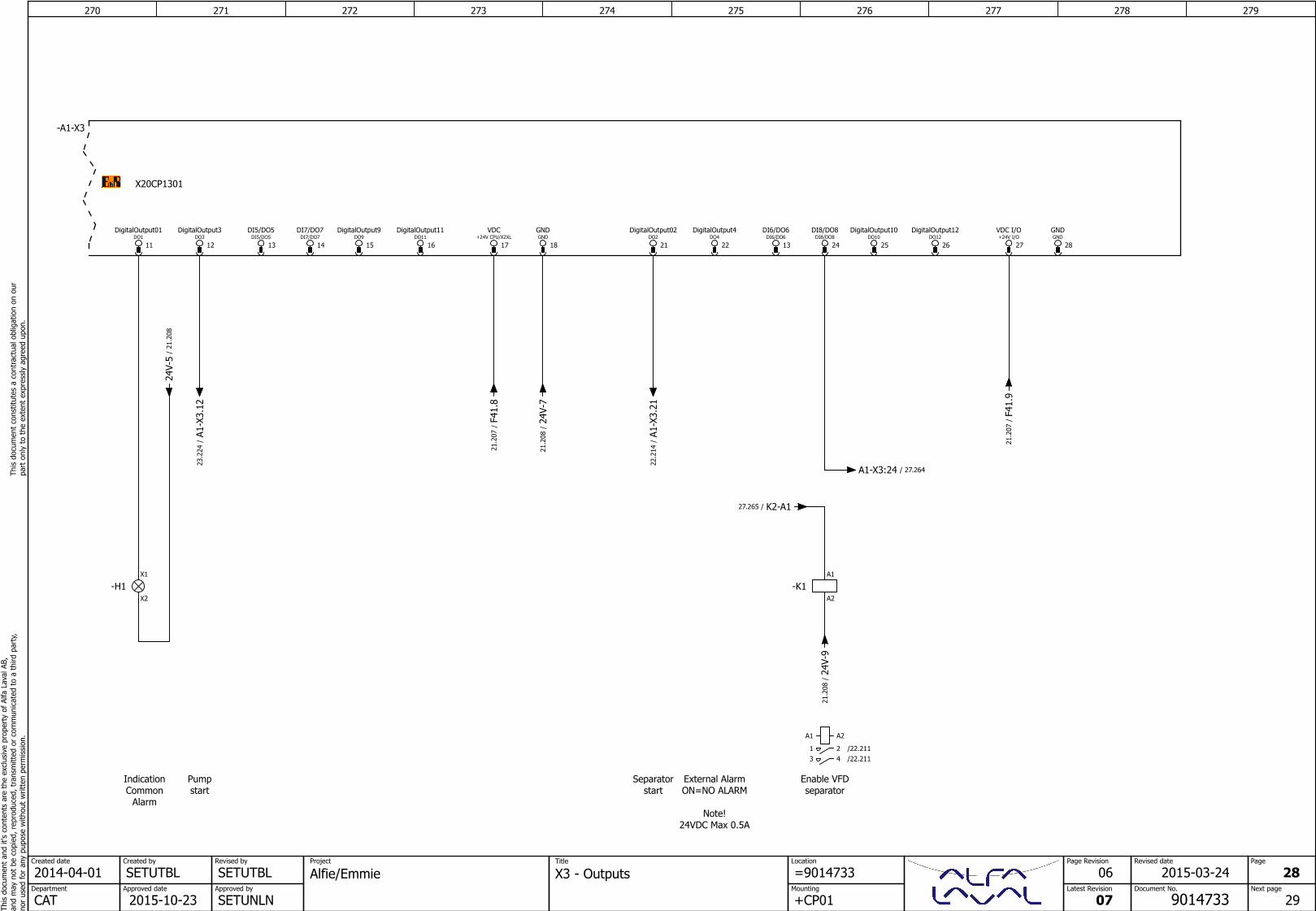
270 271 272 273 274 275 276 277 278 279Th
is d
ocum
ent
and
it's
cont
ents
are
the
exc
lusi
ve p
rope
rty
of A
lfa L
aval
AB,
and
may
not
be
copi
ed, r
epro
duce
d, t
rans
mitt
ed o
r co
mm
unic
ated
to
a th
ird p
arty
,no
r us
ed fo
r an
y pu
pose
with
out
writ
ten
perm
issi
on.
This
doc
umen
t co
nstit
utes
a c
ontr
actu
al o
blig
atio
n on
our
pa
rt o
nly
to t
he e
xten
t ex
pres
sly
agre
ed u
pon.
SETUTBLCreated by
SETUTBLRevised by
Approved date
2015-10-23Approved by
SETUNLNCATDepartment
2014-04-01Created date
Document No.
9014733
Page Revision
Latest Revision
07
Project
X3 - OutputsLocation
Mounting
=9014733
+CP01
Title
Alfie/EmmieRevised date
06 28
29Next page
Page
2015-03-24
Separatorstart
IndicationCommon
Alarm
Pumpstart
External AlarmON=NO ALARM
Note!24VDC Max 0.5A
Enable VFDseparator
12DO3
DigitalOutput3
11DO1
DigitalOutput01
13DI5/DO5
DI5/DO5
-A1-X3
X20CP1301
14DI7/DO7
DI7/DO7
15DO9
DigitalOutput9
16DO11
DigitalOutput11
17+24V CPU/X2XL
VDC
18GNDGND
22DO4
DigitalOutput4
21DO2
DigitalOutput02
13DI6/DO6
DI6/DO6
24DI8/DO8
DI8/DO8
25DO10
DigitalOutput10
26DO12
DigitalOutput12
27+24V I/OVDC I/O
28GNDGND
X1
X2
-H1A1
A2
-K1
A1 A2
1 2 /22.2113 4 /22.211
A1-X
3.12
/23
.224
A1-X
3.21
/22
.214
24V-
5/
21.2
08
F41.
9/
21.2
07
24V-
7/
21.2
08
F41.
8/
21.2
07
24V-
9/
21.2
08
A1-X3:24 / 27.264
K2-A1/27.265
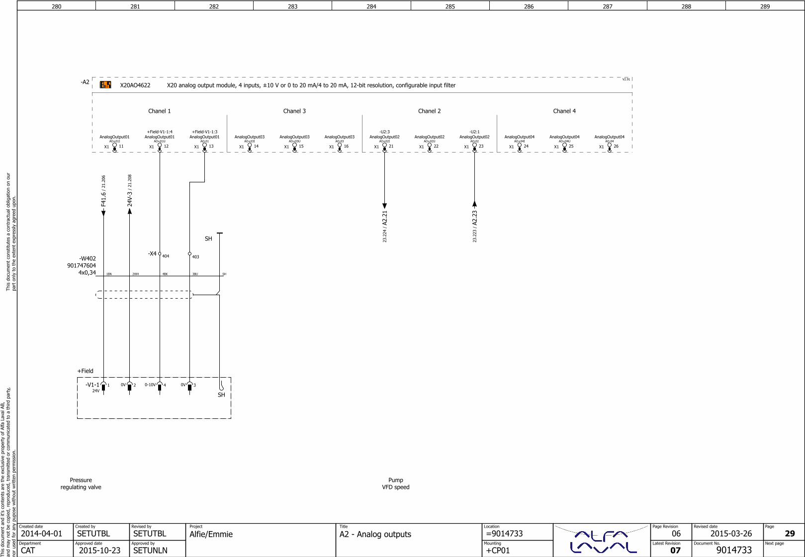
280 281 282 283 284 285 286 287 288 289Th
is d
ocum
ent
and
it's
cont
ents
are
the
exc
lusi
ve p
rope
rty
of A
lfa L
aval
AB,
and
may
not
be
copi
ed, r
epro
duce
d, t
rans
mitt
ed o
r co
mm
unic
ated
to
a th
ird p
arty
,no
r us
ed fo
r an
y pu
pose
with
out
writ
ten
perm
issi
on.
This
doc
umen
t co
nstit
utes
a c
ontr
actu
al o
blig
atio
n on
our
pa
rt o
nly
to t
he e
xten
t ex
pres
sly
agre
ed u
pon.
SETUTBLCreated by
SETUTBLRevised by
Approved date
2015-10-23Approved by
SETUNLNCATDepartment
2014-04-01Created date Project
A2 - Analog outputsLocation
Mounting
=9014733
+CP01
Title
Alfie/EmmiePage Revision
Latest Revision
07
06Next page
Page
29Revised date
9014733Document No.
2015-03-26
PumpVFD speed
Chanel 1 Chanel 2Chanel 3 Chanel 4
X1 11AO+01I
AnalogOutput01
X1 14AO+03I
AnalogOutput03
X1 12AO+01U
AnalogOutput01+Field-V1-1:4
X1 13AO-01
AnalogOutput01+Field-V1-1:3
X1 16AO-03
AnalogOutput03
X1 15AO+03U
AnalogOutput03
-A2 X20AO4622 X20 analog output module, 4 inputs, ±10 V or 0 to 20 mA/4 to 20 mA, 12-bit resolution, configurable input filterV2.91
X1 21AO+02I
AnalogOutput02-U2:3
X1 23AO-02
AnalogOutput02-U2:1
X1 22AO+02U
AnalogOutput02
X1 24AO+04I
AnalogOutput04
X1 26AO-04
AnalogOutput04
X1 25AO+04U
AnalogOutput04
Pressureregulating valve
+Field
0V 2 0-10V 4-V1-124V
1 0V 3
403-X4 404
SH
SH
4x0,34901747604
-W402
1BN 2WH 3BU4BK SH
A2.2
3/
23.2
23
A2.2
1/
23.2
24
24V-
3/
21.2
08
F41.
6/
21.2
06


![Alfa Laval Culturefuge 400 B · Alfa Laval is a trademark registered and owned by Alfa Laval Corporate AB. [Product name] is a trademark owned by Alfa Laval Corporate AB. PCHS00142EN](https://static.fdocuments.in/doc/165x107/5e71a377bc5a292f26773958/alfa-laval-culturefuge-400-b-alfa-laval-is-a-trademark-registered-and-owned-by-alfa.jpg)