ALF-RSCONTROLLER Analog PTZ Camera Controller
19
www.alfatronelectronics.com ALFATRON ELECTRONICS GmbH GERMANY ALF-RSCONTROLLER Analog PTZ Camera Controller
Transcript of ALF-RSCONTROLLER Analog PTZ Camera Controller
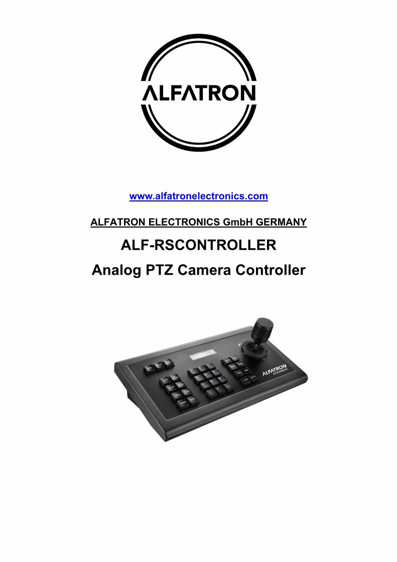
www.alfatronelectronics.com
ALFATRON ELECTRONICS GmbH GERMANY
ALF-RSCONTROLLER Analog PTZ Camera Controller
Alfatron ALF-RSCONTROLLER
- 2 -
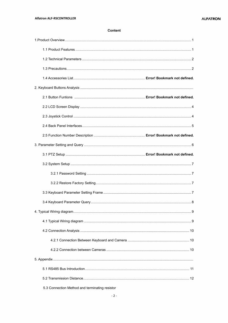
Content
1.Product Overview ................................................................................................................................... 1
1.1 Product Features ........................................................................................................................ 1
1.2 Technical Parameters ................................................................................................................. 2
1.3 Precautions ................................................................................................................................. 2
1.4 Accessories List .......................................................................... Error! Bookmark not defined.
2. Keyboard Buttons Analysis .....................................................................................................................
2.1 Button Funtions ......................................................................... Error! Bookmark not defined.
2.2 LCD Screen Display ................................................................................................................... 4
2.3 Joystick Control .......................................................................................................................... 4
2.4 Back Panel Interfaces ................................................................................................................. 5
2.5 Function Number Description ..................................................... Error! Bookmark not defined.
3. Parameter Setting and Query ............................................................................................................... 6
3.1 PTZ Setup .................................................................................. Error! Bookmark not defined.
3.2 System Setup ............................................................................................................................. 7
3.2.1 Password Setting ............................................................................................................ 7
3.2.2 Restore Factory Setting ................................................................................................... 7
3.3 Keyboard Parameter Setting Frame ........................................................................................... 7
3.4 Keyboard Parameter Query ........................................................................................................ 8
4. Typical Wiring diagram .......................................................................................................................... 9
4.1 Typical Wiring diagram ............................................................................................................... 9
4.2 Connection Analysis ................................................................................................................. 10
4.2.1 Connection Between Keyboard and Camera ................................................................ 10
4.2.2 Connection between Cameras ...................................................................................... 10
5. Appendix .................................................................................................................................................
5.1 RS485 Bus Introduction ............................................................................................................ 11
5.2 Transmission Distance .............................................................................................................. 12
5.3 Connection Method and terminating resistor

Alfatron ALF-RSCONTROLLER
- 3 -
5.4 Problems in Actual Application ..................................................................................................... 12
6. Trouble Shootings ............................................................................................................................... 13
7. Warranty ............................................................................................................................................. 12
Alfatron ALF-RSCONTROLLER
1
Statement:
The descriptions in this manual may differ from the version you are using. If you are having trouble
during using this manual, please contact our technical support for assistance. The contents of this
manual will be updated, and our company reserves the right to leave it without notice.
Precautions
The controller is an indispensable device in the integrated video conferencing system, providing full
control of all front-end cameras, pan/tilt and motorized lenses. There are usually many numeric keys and
function keys on the controller. The numeric keys are used to select the camera or decoder address, and
the function keys are used to perform various control operations on the selected front-end device. An
LCD liquid crystal display is provided on the control keyboard for displaying control commands or working
states of various monitoring programs in the system. One system uses one controller for remote control
of the entire video conferencing system.
1.Product Overview
1.1 Product Features
Adopt RS485, RS422, RS232 multiple interface control signals, max up to 255 cameras
Support PELCO-D, PELCO-P and VISCA Control protocol
Metal housing, computer keyboard button design
Adopt 3D joystick to control the camera speed.
Control camera rotation, zoom, aperture, focus and other camera parameter settings
English & Chinese LCD display, displaying the real-time working status of the decoder and matrix
With button sound prompt function
Unique control code learning function allows customers to modify control code commands by
themselves
Alfatron ALF-RSCONTROLLER
2
Any device connected with RS485 cable can be set with different protocols and baud rates
separately.
RS422 communication interface has the over-current protection ability to recover from short circuit.
The max communication distance is up to 1200M (0.5MM Twisted Pair Cable).
1.2Technical Parameters
Parameters /Model No ALF-RSCONTROLLER
Communication Mode RS485 Half duplex, RS422 Full duplex, RS232 Serial Port
Baud Rate 2400bps,4800bps,9600bps,19200bps
Interfaces 5PIN Crimping terminal, RS232 Port
Joystick Rocker 3D Control:Up, Down, Left, Right, Rotate)
Display Blue screen LCD
Input voltage DC12V±10%
Power Consumption 6W MAX
Temperature -10℃~50℃
Humidity ≦90%RH (No frosting)
Dimension 320mm(L)X179.3mm(W)X106.4mm(H)
1.3 Precautions
LCD Screen is fragile, do not squeeze or leave under harsh light for too long.
The joystick rocker is fragile. Do use the original package or properly packaged before shipment
back.
Make it work in the place with favorite temperature and humidity.
Strictly follow the manual for correct connection.
Alfatron ALF-RSCONTROLLER
3
1.4 Accessories List
Name Quantity Unit Remarks
5PIN Plug 1 Pc
DC-12V Power Adapter 1 Pc INPUT:100-240VAC~50/60HZ
Certificate 1 Pc
Warranty Card 1 Pc
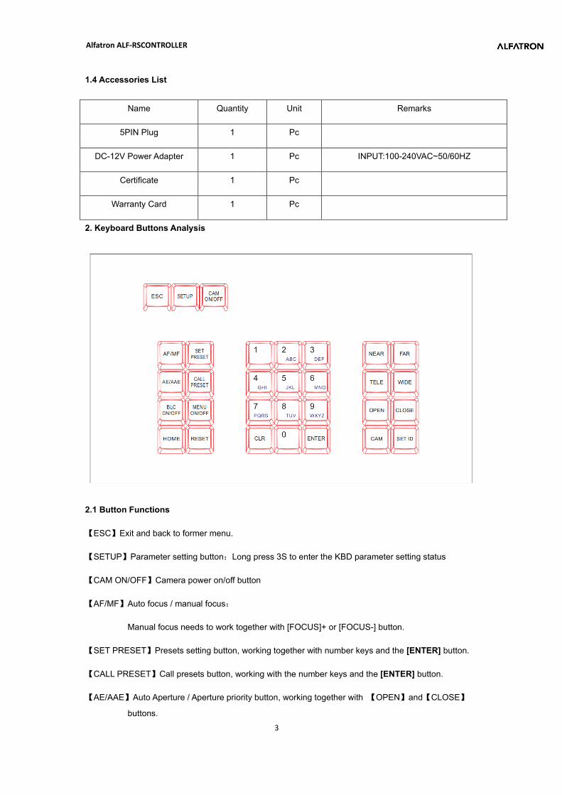
2. Keyboard Buttons Analysis
2.1 Button Functions
【ESC】Exit and back to former menu.
【SETUP】Parameter setting button:Long press 3S to enter the KBD parameter setting status
【CAM ON/OFF】Camera power on/off button
【AF/MF】Auto focus / manual focus:
Manual focus needs to work together with [FOCUS]+ or [FOCUS-] button.
【SET PRESET】Presets setting button, working together with number keys and the [ENTER] button.
【CALL PRESET】Call presets button, working with the number keys and the [ENTER] button.
【AE/AAE】Auto Aperture / Aperture priority button, working together with 【OPEN】and【CLOSE】
buttons.
Alfatron ALF-RSCONTROLLER
4
【BLC ON/OFF】: Back light compensation ON/OFF button
【MENU ON/OFF】: MENU ON/OFF button
【HOME】:HOME button
【RESET】: Pan/tilt reset button
【CLR】Clear button: clear the current inputs.
【0】~【9】Number keys:0,1,2,3,4,5,6,7,8,9.
【ENTER】Confirmation key: Confirm the current inputs.
【NEAR】Focus in: manually focus in to make far distance objects clearer
【FAR】Focus out: manually focus out to make near distance objects clearer
【TELE】Narrow-angle button/ Zoom-in button: increase lens magnification, reduce the lens field of view,
enlarge the monitor target.
【WIDE】Wide-angle button/Zoom out button: reduce lens magnification, expand lens field of view and
monitoring range
【OPEN】Aperture plus button: Increase manual aperture. When the aperture is at its maximum, the LCD
screen is displayed in full white. When the camera menu mode is turned on, the next level menu is
entered.
【CLOSE】Aperture minus button: Reduce manual aperture . When the aperture is at its minimum, the
LCD screen is displayed as black. When the camera menu mode is turned on, the menu is returned to
the previous menu.
【CAM】Address selection button: Select the address of the control device (decoder or camera) , it needs
to use together with the number keys and [ENTER] button
【SET ID】Set ID button: long press 3s to set the cascade camera protocol address.
2.2 LCD screen display
All button operations will be displayed on LCD screen. It would enter power saving mode (with darkest
light), with initializing status displayed if no operation for 30 seconds.
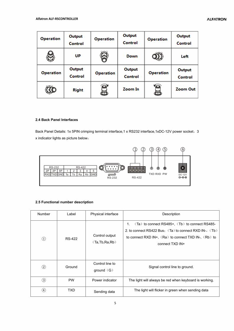
2.3 Joystick Control
(Clockwise/ Counterclockwise rotation only available for 3D design)
Alfatron ALF-RSCONTROLLER
5
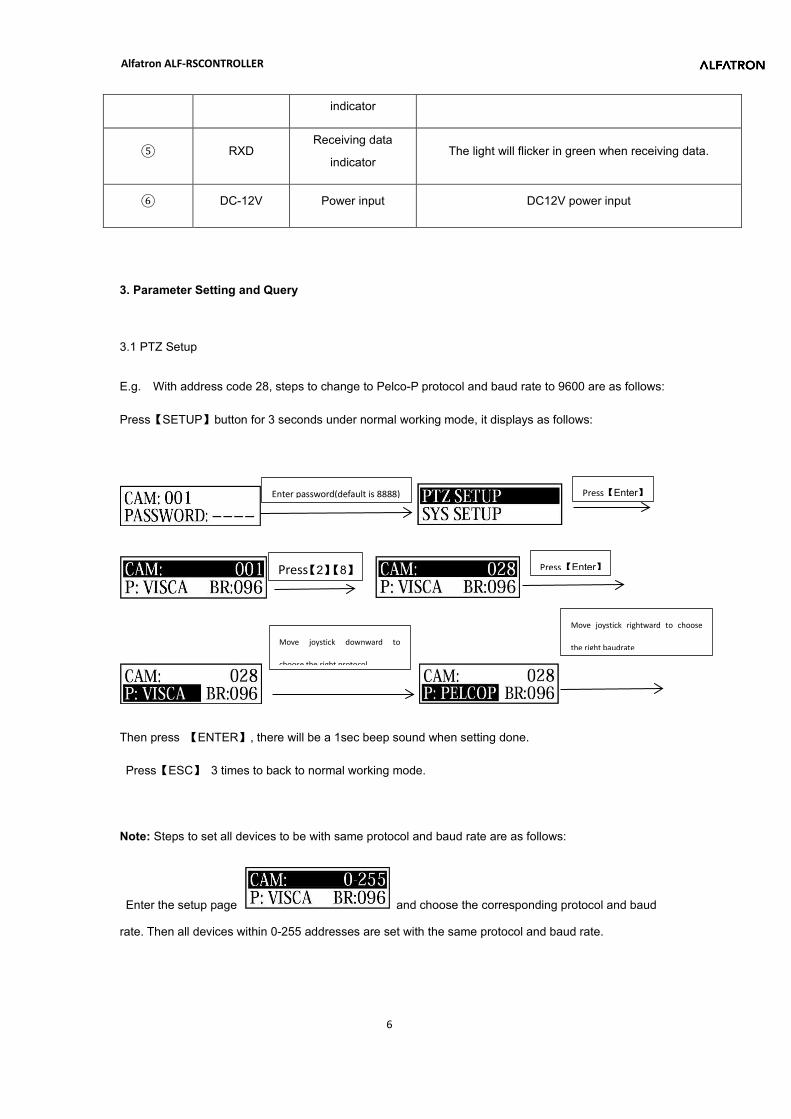
2.4 Back Panel Interfaces
Back Panel Details: 1x 5PIN crimping terminal interface,1 x RS232 interface,1xDC-12V power socket,3
x indicator lights as picture below:
2.5 Functional number description
Number Label Physical interface Description
① RS-422 Control output
(Ta,Tb,Ra,Rb)
1. (Ta)to connect RS485+,(Tb)to connect RS485-
2. to connect RS422 Bus;(Ta)to connect RXD IN-,(Tb)
to connect RXD IN+,(Ra)to connect TXD IN-,(Rb)to
connect TXD IN+
② Ground Control line to
ground(G) Signal control line to ground.
③ PW Power indicator The light will always be red when keyboard is working.
④ TXD Sending data The light will flicker in green when sending data
Alfatron ALF-RSCONTROLLER
6
indicator
⑤ RXD Receiving data
indicator The light will flicker in green when receiving data.
⑥ DC-12V Power input DC12V power input
3. Parameter Setting and Query
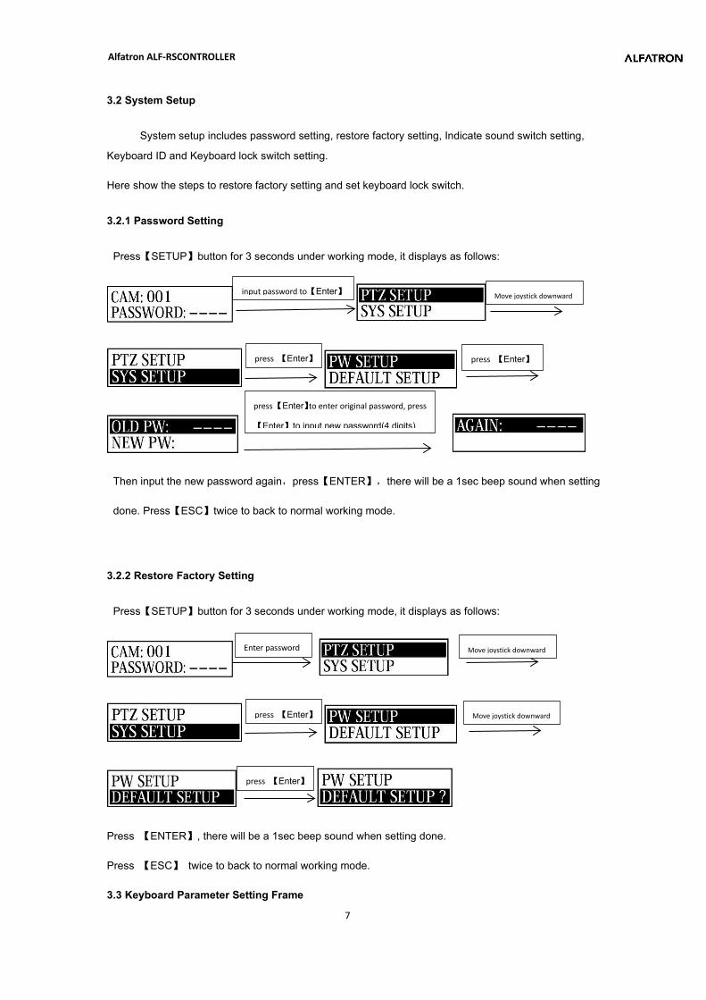
3.1 PTZ Setup
E.g. With address code 28, steps to change to Pelco-P protocol and baud rate to 9600 are as follows:
Press【SETUP】button for 3 seconds under normal working mode, it displays as follows:
Then press 【ENTER】, there will be a 1sec beep sound when setting done.
Press【ESC】 3 times to back to normal working mode.
Note: Steps to set all devices to be with same protocol and baud rate are as follows:
Enter the setup page and choose the corresponding protocol and baud
rate. Then all devices within 0-255 addresses are set with the same protocol and baud rate.
Enter password(default is 8888) Press【Enter】
Press【2】【8】 Press 【Enter】
Move joystick downward to
choose the right protocol
Move joystick rightward to choose
the right baudrate
Alfatron ALF-RSCONTROLLER
7
3.2 System Setup
System setup includes password setting, restore factory setting, Indicate sound switch setting,
Keyboard ID and Keyboard lock switch setting.
Here show the steps to restore factory setting and set keyboard lock switch.
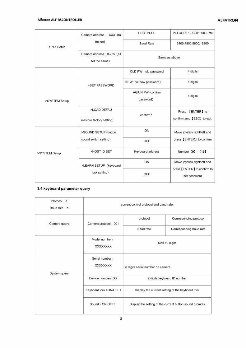
3.2.1 Password Setting
Press【SETUP】button for 3 seconds under working mode, it displays as follows:
Then input the new password again,press【ENTER】,there will be a 1sec beep sound when setting
done. Press【ESC】twice to back to normal working mode.
3.2.2 Restore Factory Setting
Press【SETUP】button for 3 seconds under working mode, it displays as follows:
Press 【ENTER】, there will be a 1sec beep sound when setting done.
Press 【ESC】 twice to back to normal working mode.
3.3 Keyboard Parameter Setting Frame
Enter password Move joystick downward
press 【Enter】
Move joystick downward
press 【Enter】
Move joystick downward
press 【Enter】 press 【Enter】
press 【Enter】to enter original password, press
【Enter】to input new password(4 digits)
input password to【Enter】
Alfatron ALF-RSCONTROLLER
8
>PTZ Setup
Camera address: XXX(to
be set)
PROTPCOL PELCOD,PELCOP,RULE,ctc
Baud Rate 2400,4800,9600,19200
Camera address:0-255(all
set the same) Same as above
>SYSTEM Setup
>SET PASSWORD
OLD PW:old password 4 digits
NEW PW(new password) 4 digits
AGAIN PW:(confirm
password) 4 digits
>LOAD DEFAU
(restore factory setting) confirm?
Press 【ENTER】to
confirm ,and【ESC】to exit.
>SYSTEM Setup
>SOUND SETUP (button
sound switch setting)
ON Move joystick right/left and
press【ENTER】to confirm OFF
>HOST ID SET Keyboard address Number【0】-【15】
>LEARN SETUP(keyboard
lock setting)
ON Move joystick right/left and
press【ENTER】to confirm to
set password OFF
3.4 keyboard parameter query
Protocol:X
Baud rate:X current control protocol and baud rate.
Camera query Camera protocol:001 protocol Corresponding protocol
Baud rate Corresponding baud rate
System query
Model number:
XXXXXXXX Max 10 digits
Serial number:
XXXXXXXX
8 digits serial number on camera
Device number:XX 2 digits keyboard ID number
Keyboard lock(ON/OFF) Display the current setting of the keyboard lock
Sound(ON/OFF) Display the setting of the current button sound prompts
Alfatron ALF-RSCONTROLLER
9
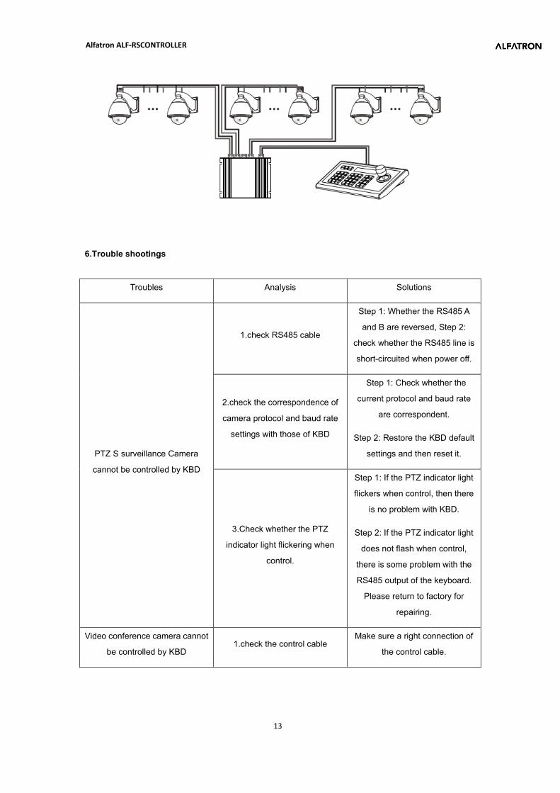
4.Typical wiring diagram
4.1Typical wiring diagram
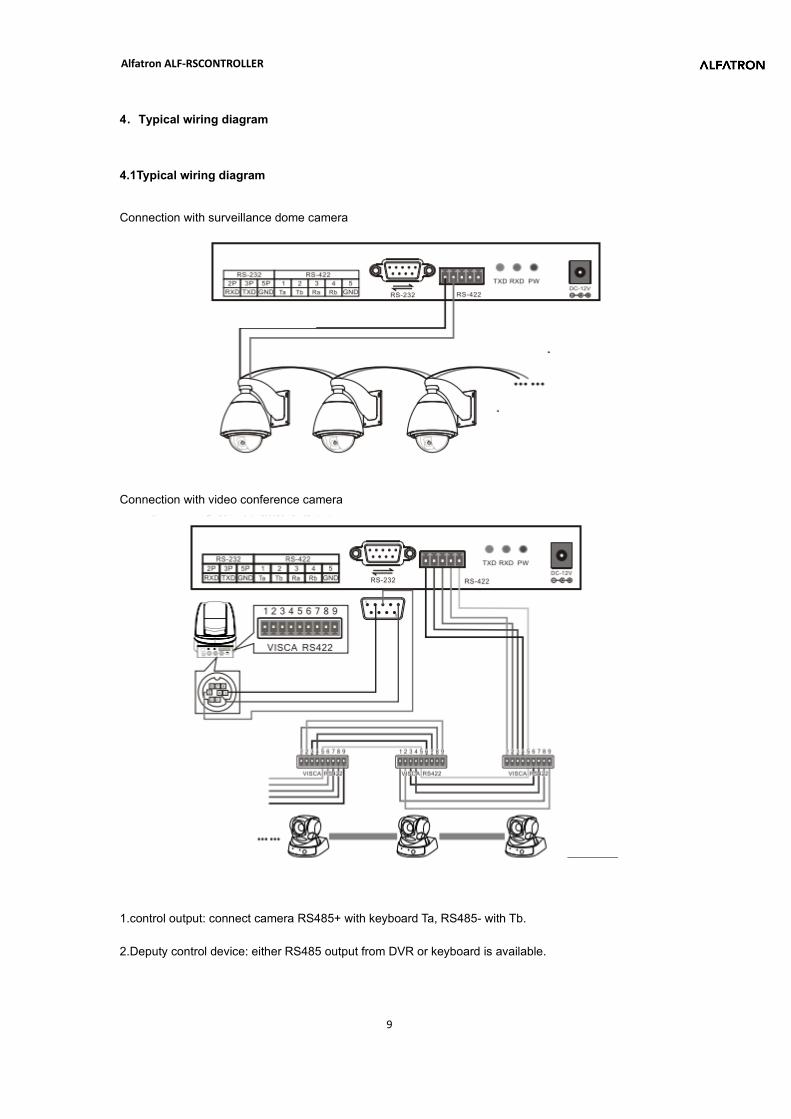
Connection with surveillance dome camera
Connection with video conference camera
1.control output: connect camera RS485+ with keyboard Ta, RS485- with Tb.
2.Deputy control device: either RS485 output from DVR or keyboard is available.
Alfatron ALF-RSCONTROLLER
10
4.2 Connection Analysis
4.2.1 connection between keyboard and camera
With RS422 bus connection way, the keyboard third pin (Ra) is connected with the camera third pin TXD
IN- , the keyboard fourth pin (Rb) with the camera fourth pin TXD IN+ , the keyboard first pin(Ta ) with the
camera first pin RXD IN-, the keyboard second pin (Tb)with the camera second pin RXD IN +.
KBD CAMERA
Ra<········>TXD IN-
Rb<········>TXD IN+
Ta<········>RXD IN-
Tb<········>RXD IN+
With RS232 connection way, the KBD(10pin connecting terminal) first pin RXD is connected with the
third pin TXD of camera RS232 port, the KBD second pin TXD with the camera fifth RXD, the KBD third
GND with the camera forth pin GND.(It is also available to connect camera with the standard RS232 port
on the KBD.)
KBD CAMERA
RXD<········>TXD
TXD<········>RXD
GND<········>RXD
The camera can be controlled by any connection way mentioned above.
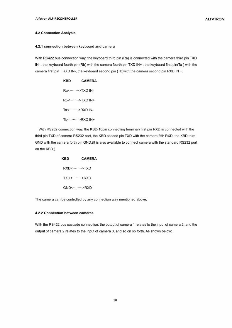
4.2.2 Connection between cameras
With the RS422 bus cascade connection, the output of camera 1 relates to the input of camera 2, and the
output of camera 2 relates to the input of camera 3, and so on so forth. As shown below:
Alfatron ALF-RSCONTROLLER
11
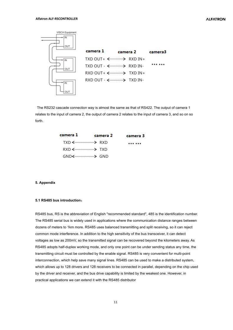
The RS232 cascade connection way is almost the same as that of RS422. The output of camera 1
relates to the input of camera 2, the output of camera 2 relates to the input of camera 3, and so on so
forth.
5. Appendix
5.1 RS485 bus introduction:
RS485 bus, RS is the abbreviation of English "recommended standard", 485 is the identification number.
The RS485 serial bus is widely used in applications where the communication distance ranges between
dozens of meters to 1km more. RS485 uses balanced transmitting and split receiving, so it can reject
common mode interference. In addition to the high sensitivity of the bus transceiver, it can detect
voltages as low as 200mV, so the transmitted signal can be recovered beyond the kilometers away. As
RS485 adopts half-duplex working mode, and only one point can be under sending status any time, the
transmitting circuit must be controlled by the enable signal. RS485 is very convenient for multi-point
interconnection, which help save many signal lines. RS485 can be used to make a distributed system,
which allows up to 128 drivers and 128 receivers to be connected in parallel, depending on the chip used
by the driver and receiver, and the bus drive capability is limited by the weakest one. However, in
practical applications we can extend it with the RS485 distributor
Alfatron ALF-RSCONTROLLER
12
5.2 Transmission distance:
When a 0.56mm (24AWG) twisted pair cable is used as the communication cable, the theoretical value pf
the maximum transmission distance varies with different baud rate: 1800 meters can be transmitted
when the baud rate is 2400 bps, and 600 meters under 19200 bps. When using a thinner communication
cable or using the product in an environment with strong electromagnetic interference, or when too many
devices are connected with the bus, the maximum transmission distance will be shortened accordingly,
or the maximum distance is longer.
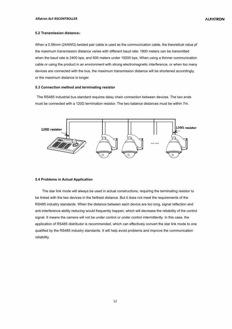
5.3 Connection method and terminating resistor
The RS485 industrial bus standard requires daisy chain connection between devices. The two ends
must be connected with a 120Ω termination resistor. The two balance distances must be within 7m.
5.4 Problems in Actual Application
The star link mode will always be used in actual constructions, requiring the terminating resistor to
be linked with the two devices in the farthest distance. But it does not meet the requirements of the
RS485 industry standards. When the distance between each device are too long, signal reflection and
anti-interference ability reducing would frequently happen, which will decrease the reliability of the control
signal. It means the camera will not be under control or under control intermittently. In this case, the
application of RS485 distributor is recommended, which can effectively convert the star link mode to one
qualified by the RS485 industry standards. It will help avoid problems and improve the communication
reliability.
Alfatron ALF-RSCONTROLLER
13
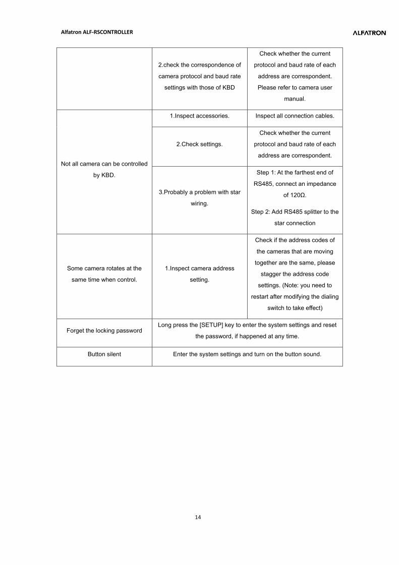
6.Trouble shootings
Troubles Analysis Solutions
PTZ S surveillance Camera
cannot be controlled by KBD
1.check RS485 cable
Step 1: Whether the RS485 A
and B are reversed, Step 2:
check whether the RS485 line is
short-circuited when power off.
2.check the correspondence of
camera protocol and baud rate
settings with those of KBD
Step 1: Check whether the
current protocol and baud rate
are correspondent.
Step 2: Restore the KBD default
settings and then reset it.
3.Check whether the PTZ
indicator light flickering when
control.
Step 1: If the PTZ indicator light
flickers when control, then there
is no problem with KBD.
Step 2: If the PTZ indicator light
does not flash when control,
there is some problem with the
RS485 output of the keyboard.
Please return to factory for
repairing.
Video conference camera cannot
be controlled by KBD 1.check the control cable
Make sure a right connection of
the control cable.
Alfatron ALF-RSCONTROLLER
14
2.check the correspondence of
camera protocol and baud rate
settings with those of KBD
Check whether the current
protocol and baud rate of each
address are correspondent.
Please refer to camera user
manual.
Not all camera can be controlled
by KBD.
1.Inspect accessories. Inspect all connection cables.
2.Check settings.
Check whether the current
protocol and baud rate of each
address are correspondent.
3.Probably a problem with star
wiring.
Step 1: At the farthest end of
RS485, connect an impedance
of 120Ω.
Step 2: Add RS485 splitter to the
star connection
Some camera rotates at the
same time when control.
1.Inspect camera address
setting.
Check if the address codes of
the cameras that are moving
together are the same, please
stagger the address code
settings. (Note: you need to
restart after modifying the dialing
switch to take effect)
Forget the locking password Long press the [SETUP] key to enter the system settings and reset
the password, if happened at any time.
Button silent Enter the system settings and turn on the button sound.
Alfatron ALF-RSCONTROLLER
15
Warranty
1.1 This limited warranty covers defects in materials and workmanship in this product. 1.2 Should warranty service be required, proof of purchase must be presented to the Company. The serial number on the product must be clearly visible and not have been tampered with in any way whatsoever. 1.3 This limited warranty does not cover any damage, deterioration or malfunction resulting from any alteration, modification, improper or unreasonable use or maintenance, misuse, abuse, accident, neglect, exposure to excess moisture, fire, improper packing and shipping (such claims must be presented to the carrier), lightning, power surges, or other acts of nature. This limited warranty does not cover any damage, deterioration or malfunction resulting from the installation or removal of this product from any installation, any unauthorized tampering with this product, any repairs attempted by anyone unauthorized by the Company to make such repairs, or any other cause which does not relate directly to a defect in materials and/or workmanship of this product. This limited warranty does not cover equipment enclosures, cables or accessories used in conjunction with this product. This limited warranty does not cover the cost of normal maintenance. Failure of the product due to insufficient or improper maintenance is not covered. 1.4 The Company does not warrant that the product covered hereby, including, without limitation, the technology and/or integrated circuit(s) included in the product, will not become obsolete or that such items are or will remain compatible with any other product or technology with which the product may be used. 1.5 Only the original purchaser of this product is covered under this limited warranty. This limited warranty is not transferable to subsequent purchasers or owners of this product. 1.6 Unless otherwise specified, the goods are warranted in accordance with the manufacturer’s product specific warranties against any defect attributable to faulty workmanship or materials, fair wear and tear being excluded. 1.7 This limited warranty only covers the cost of faulty goods and does not include the cost of labor and travel to return the goods to the Company’s premises. 1.8 In the event of any improper maintenance, repair or service being carried out by any third persons during the warranty period without the Company’s written authorization, the limited warranty shall be void. 1.9 A 7 (seven) year limited warranty is given on the aforesaid product where used correctly according to the Company’s instructions, and only with the use of the Company’s components. 1.10 The Company will, at its sole option, provide one of the following three remedies to whatever extent it shall deem necessary to satisfy a proper claim under this limited warranty: 1.10.1 Elect to repair or facilitate the repair of any defective parts within a reasonable period of time, free of any charge for the necessary parts and labor to complete the repair and restore this product to its proper operating condition.; or 1.10.2 Replace this product with a direct replacement or with a similar product deemed by the Company to perform substantially the same function as the original product; or 1.10.3 Issue a refund of the original purchase price less depreciation to be determined based on the age of the product at the time remedy is sought under this limited warranty.
Alfatron ALF-RSCONTROLLER
16
1.11 The Company is not obligated to provide the Customer with a substitute unit during the limited warranty period or at any time thereafter. 1.12 If this product is returned to the Company this product must be insured during shipment, with the insurance and shipping charges prepaid by the Customer. If this product is returned uninsured, the Customer assumes all risks of loss or damage during shipment. The Company will not be responsible for any costs related to the removal or re-installation of this product from or into any installation. The Company will not be responsible for any costs related to any setting up this product, any adjustment of user controls or any programming required for a specific installation of this product. 1.13 Please be aware that the Company’s products and components have not been tested with competitor’s products and therefore the Company cannot warrant products and/or components used in conjunction with competitor’s products. 1.14 The appropriateness of the goods for the purpose intended is only warranted to the extent that the goods are used in accordance with the Company’s installation, classification, and usage instructions. 1.15 Any claim by the Customer which is based on any defect in the quality or condition of the goods or their failure to correspond with specification shall be notified in writing to the Company within 7 days of delivery or (where the defect or failure was not apparent on reasonable inspection by the Customer) within a reasonable time after discovery of the defect or failure, but, in any event, within 6 months of delivery. 1.16 If delivery is not refused, and the Customer does not notify the Company accordingly, the Customer may not reject the goods and the Company shall have no liability and the Customer shall pay the price as if the goods had been delivered in accordance with the Agreement. 1.17 THE MAXIMUM LIABILITY OF THE COMPANY UNDER THIS LIMITED WARRANTY SHALL NOT EXCEED THE ACTUAL PURCHASE PRICE PAID FOR THE PRODUCT