ALEXANDRIA RENEW ENTERPRISES Request for Proposal No. 19 ... · "guaranteed" per ASME PTC-10/09...
62
10203-10134719 AlexRenew December 3, 2018 PAC System Upgrade – Purchase of PAC Turbo Blowers Addendum No. 1 1 ALEXANDRIA RENEW ENTERPRISES Request for Proposal No. 19-006 ADDENDUM NO. 1 To Process Air Compressor (PAC) System Upgrade; Purchase of PAC Turbo Blowers December 3, 2018 Manufacturer shall acknowledge receipt of this Addendum as provided in Section 00 41 63, Bid Form. Addendum No. 1 consists of the following: • Two pages of text. • Attachment – 1: Replacement of INSERT SPECIFICATION SECTION 00 41 63 (14 Pages). • Attachment – 2: Replacement of INSERT SPECIFICATION SECTION 40 62 16 (4 Pages). • Attachment – 3: Replacement of INSERT SPECIFICATION SECTION 40 63 43 (10 Pages). • Attachment – 4: Replacement of INSERT SPECIFICATION SECTION 40 90 05 (6 Pages). • Attachment – 5: Replacement of INSERT SPECIFICATION SECTION 43 11 14 (16 Pages). • Manufacturer shall make the following changes to all pertinent sheets, pages, and paragraphs of the Contract Documents and take same into full consideration in arriving at the Proposal. Changes made in this Addendum have been marked as follows with the exception of the Table of Contents (TOC) and the page numbers: 1. Additions and modifications have been marked with an underline. 2. Deletions of text have been marked with a strikethrough. 3. The note “[Addendum No. 1]” has been added after any change. SPECIFICATIONS / REFERENCE DRAWINGS A. Remove SPECIFICATION SECTION 00 41 63 and replace with SPECIFICATION SECTION 00 41 63 in Attachment – 1 Summary of changes are:
Transcript of ALEXANDRIA RENEW ENTERPRISES Request for Proposal No. 19 ... · "guaranteed" per ASME PTC-10/09...

10203-10134719 AlexRenew December 3, 2018 PAC System Upgrade – Purchase of PAC Turbo Blowers Addendum No. 1 1
ALEXANDRIA RENEW ENTERPRISES
Request for Proposal No. 19-006
ADDENDUM NO. 1
To
Process Air Compressor (PAC) System Upgrade; Purchase of PAC Turbo Blowers
December 3, 2018
Manufacturer shall acknowledge receipt of this Addendum as provided in Section 00 41 63, Bid Form.
Addendum No. 1 consists of the following:
• Two pages of text.
• Attachment – 1: Replacement of INSERT SPECIFICATION SECTION 00 41 63 (14 Pages).
• Attachment – 2: Replacement of INSERT SPECIFICATION SECTION 40 62 16 (4 Pages).
• Attachment – 3: Replacement of INSERT SPECIFICATION SECTION 40 63 43 (10 Pages).
• Attachment – 4: Replacement of INSERT SPECIFICATION SECTION 40 90 05 (6 Pages).
• Attachment – 5: Replacement of INSERT SPECIFICATION SECTION 43 11 14 (16 Pages).
• Manufacturer shall make the following changes to all pertinent sheets, pages, and paragraphs of the Contract Documents and take same into full consideration in arriving at the Proposal.
Changes made in this Addendum have been marked as follows with the exception of the Table of Contents (TOC) and the page numbers:
1. Additions and modifications have been marked with an underline.
2. Deletions of text have been marked with a strikethrough.
3. The note “[Addendum No. 1]” has been added after any change.
SPECIFICATIONS / REFERENCE DRAWINGS
A. Remove SPECIFICATION SECTION 00 41 63 and replace with SPECIFICATION SECTION 00 41 63 in Attachment – 1 Summary of changes are:

10203-10134719 AlexRenew December 3, 2018 PAC System Upgrade – Purchase of PAC Turbo Blowers Addendum No. 1 2
a. Added language in ARTICLE 5.04.F.3.
B. Remove SPECIFICATION SECTION 40 62 16 and replace with SPECIFICATION SECTION 40 62 16 in Attachment – 2 Summary of changes are:
a. Removed language in ARTICLE 2.3.A.1 – 2.3.A.4.
b. Removed language in ARTICLE 2.3.B.
C. Remove SPECIFICATION SECTION 40 63 43 and replace with SPECIFICATION SECTION 40 63 43 in Attachment – 3 Summary of changes are:
a. Replaced language in ARTICLE 2.1.A.1.
b. Added language in ARTICLE 2.1.A.2.
c. Removed language in ARTICLE 2.1.B.
D. Remove SPECIFICATION SECTION 40 90 05 and replace with SPECIFICATION SECTION 40 90 05 in Attachment – 4 Summary of changes are:
a. Replaced language in ARTICLE 3.2.A.4.a – 3.2.A.4.c.
b. Removed language in ARTICLE 3.2.A.4.d.
c. Replaced language in ARTICLE 3.2.A.5.a.
d. Replaced language in ARTICLE 3.2.A.5.b.
e. Replaced language in ARTICLE 3.2.A.5.c.
f. Removed language in ARTICLE 3.2.A.5.d.
g. Removed language in ARTICLE 3.2.A.5.e.
h. Removed language in ARTICLE 3.2.A.5.g.37.
i. Removed language in ARTICLE 3.2.A.5.g.38.
j. Added language in ARTICLE 3.2.A.5.h.23 – 3.2.A.5.h.27.
E. Remove SPECIFICATION SECTION 43 11 14 and replace with SPECIFICATION SECTION 43 11 14 in Attachment – 5 Summary of changes are:
a. Added language in ARTICLE 2.3.A.7.
b. Added language in ARTICLE 2.5.D.1.
c. Replaced language in ARTICLE 2.5.E.6.
d. Added language in ARTICLE 2.5.F.2.
END OF ADDENDUM NO. 1

ATTACHMENT NO. 1
SPECIFICATION SECTION 00 41 63

THIS PAGE INTENTIONALLY LEFT BLANK

10203-10134719 AlexRenew December 3, 2018 PAC System Upgrade – Purchase of PAC Turbo Blowers BID FORM [Addendum No. 1] 00 41 63 - 1
SECTION 00 41 63
BID FORM
ARTICLE 1 - BID RECIPIENT
1.01 This Bid is submitted to:
Alexandria Renew Enterprises 1800 Limerick Street, Alexandria, VA 22314 Attention: Maryam N. Zahory, Purchasing Agent Project: Process Air Compressor (PAC) System Upgrade – Purchase of PAC Turbo Blowers 1.02 The undersigned Bidder proposes and agrees, if this Bid is accepted, to enter into a Contract with
Buyer in the form included in the Bidding Documents to furnish the Goods and Special Services as specified or indicated in the Bidding Documents, for the prices and within the times indicated in this Bid, and in accordance with the other terms and conditions of the Bidding Documents.
ARTICLE 2 - BIDDER’S ACKNOWLEDGMENTS
2.01 Bidder accepts all of the terms and conditions of the Instructions to Bidders. This Bid will remain subject to acceptance for 60 days after the Bid opening, or for such longer period of time that Bidder may agree to in writing upon request of Buyer.
ARTICLE 3 - BIDDER’S REPRESENTATIONS
3.01 In submitting this Bid, Bidder represents that:
A. Bidder has examined and carefully studied the Bidding Documents, the related data identified in the Bidding Documents, and the following Addenda, receipt of which is hereby acknowledged:
Addendum No. Addendum Date
B. Bidder has visited the Point of Destination and site where the Goods are to be installed or Special Services will be provided and become familiar with and is satisfied as to the observable local conditions that may affect cost, progress, or the furnishing of Goods and Special Services, if required to do so by the Bidding Documents, or if, in Bidder’s judgment, any local condition may affect cost, progress, or the furnishing of Goods and Special Services.
C. Bidder is familiar with and is satisfied as to all Laws and Regulations in effect as of the date of the Bid that may affect cost, progress, and the furnishing of Goods and Special Services.
D. Bidder has carefully studied, considered, and correlated the information known to Bidder; information commonly known to sellers of similar goods doing business in the locality of the Point of Destination and the site where the Goods will be installed or where Special Services will be provided; information and observations obtained from Bidder’s visits, if any, to the

10203-10134719 AlexRenew December 3, 2018 PAC System Upgrade – Purchase of PAC Turbo Blowers BID FORM [Addendum No. 1] 00 41 63 - 2
Point of Destination and the site where the Goods will be installed or Special Services will be provided; and any reports and drawings identified in the Bidding Documents regarding the Point of Destination and the site where the Goods will be installed or where Special Services will be provided, with respect to the effect of such information, observations, and documents on the cost, progress, and performance of Seller's obligations under the Bidding Documents.
E. Bidder has given Buyer written notice of all conflicts, errors, ambiguities, and discrepancies that Bidder has discovered in the Bidding Documents, and the written resolution (if any) thereof by Buyer is acceptable to Bidder.
F. The Bidding Documents are generally sufficient to indicate and convey understanding of all terms and conditions for furnishing the Goods and Special Services for which this Bid is submitted.
ARTICLE 4 - BIDDER’S CERTIFICATIONS
4.01 Bidder certifies that:
A. This Bid is genuine and not made in the interest of or on behalf of any undisclosed individual or entity and is not submitted in conformity with any collusive agreement or rules of any group, association, organization, or corporation; Bidder has not directly or indirectly induced or solicited any other Bidder to submit a false or sham Bid;
B. Bidder has not solicited or induced any individual or entity to refrain from bidding; and
C. Bidder has not engaged in corrupt, fraudulent, collusive, or coercive practices in competing for the Contract. For the purposes of this Paragraph 4.01.D:
1. “Corrupt practice” means the offering, giving, receiving, or soliciting of any thing of value likely to influence the action of a public official in the bidding process.
2. “Fraudulent practice” means an intentional misrepresentation of facts made (a) to influence the bidding process to the detriment of Buyer, (b) to establish bid prices at artificial non-competitive levels, or (c) to deprive Buyer of the benefits of free and open competition.
3. “Collusive practice” means a scheme or arrangement between two or more Bidders, with or without the knowledge of Buyer, a purpose of which is to establish bid prices at artificial, non-competitive levels.
4. “Coercive practice” means harming or threatening to harm, directly or indirectly, persons or their property to influence their participation in the bidding process.
D. None of its principals, agents, or any persons associated with the firm is/are currently debarred from submitting bids to AlexRenew, or any other state, federal or political subdivisions.
ARTICLE 5 - BASIS OF BID
5.01 Before submitting a Bid, read the entire solicitation including the terms and conditions. Failure to read a portion of the solicitation will not relieve a Bidder of its obligation to submit a complete Bid.
5.02 All bids shall meet or exceed the requirements of this solicitation.

10203-10134719 AlexRenew December 3, 2018 PAC System Upgrade – Purchase of PAC Turbo Blowers BID FORM [Addendum No. 1] 00 41 63 - 3
5.03 Cost Proposal
A. Bidder shall provide a non-binding cost proposal for the Goods and Special Services in accordance with the Contract Documents:
NO. ITEM TOTAL PRICE
1 Single-Stage Centrifugal Blowers
2 Shop Drawings
3 O&M Manual
4 Maintenance and Spare Parts
5 Field Services and Field Performance Demonstration
6 Personnel Training
Lump Sum / Total Cost of Ownership

10203-10134719 AlexRenew December 3, 2018 PAC System Upgrade – Purchase of PAC Turbo Blowers BID FORM [Addendum No. 1] 00 41 63 - 4
5.04 Technical Proposal
A. It is the Bidders responsibility to clearly identify and describe the Goods and Special Services being offered in response to this solicitation. Bidders are cautioned that organization of their response, as well as thoroughness, is critical to AlexRenew’s evaluation process. The Bid Form shall be completed in its entirety; and all required supplemental information must be furnished and presented in an organized, comprehensive, and easy to follow manner. Bidders shall address each of the specific requirements listed below. Failure to include any of the requested information may be cause for the Bid to be considered non-responsive and rejected.
B. Guaranteed Electric Power Consumption
The Bidder shall enter the guaranteed wire-to-air (“wire”) power for the blowers offered under each operating point in units of kilowatts (kW) by completing the blank spaces in the table below. The wire kW shall include all losses associated with the blower units.
Operating
Point
Blower
Discharge
Flow,
SCFM
Pressure, psia Inlet
Temp,
DegF
Rel Hum,
%
Guaranteed
Wire Power of
Blower, kW
Baro Outlet
3 5,000 14.7 27.0 68 38
4 11,300 14.7 27.0 68 38
5 18,500 14.7 27.0 68 38
6 19,000 14.7 27.0 68 38
Notes: 1. Wire kW consists of Blower, Motor, VFD or inverter, harmonic filter, PLC/RTU/CPU
and any cooling or other auxiliary systems if used.
2. CFM measured at conditions listed in table.
3. The guaranteed wire power kW numbers at the above specified operating points shall be
"guaranteed" per ASME PTC-10/09 testing and/or other applicable test codes such as
ISO5389/1217 numbers with zero tolerance as modified by the contract documents.
4. Temperature of the inlet air measured at the inlet to the inlet filter or external inlet flange
to the blower cabinet.
5. Inlet pressure measured at the same location as the inlet temperature.
C. Operational History
Bidder shall check one box under each of the following questions. Provide references of Project Name, Location, Contact, e-mail address and telephone number for each site used to respond to Questions 1 through 4 under Operational History.
1. Number of blowers of model, horsepower, bearing type, and discharge pressure being
proposed for this project operating in the United States. Horsepower and discharge
pressure can be equal to or greater than the value being proposed.
� 0
� 1-5
� 6-10
� >10

10203-10134719 AlexRenew December 3, 2018 PAC System Upgrade – Purchase of PAC Turbo Blowers BID FORM [Addendum No. 1] 00 41 63 - 5
2. Number of operating installations in the United States with a blower master control panel
controlling three or more blowers.
� 0
� 1-5
� 6-10
� >10
3. Number of blower installations in the United States with the same bearing type being
proposed for this project where blowers are subject to air ON and air OFF
aeration/mixing such as simultaneous nitrification/denitrification (NDN), Anammox,
Membrane Bioreactor (MBR) or membrane filtration processes.
� 0
� 1-5
� 6-10
� >10
4. Any blower core failures using the same bearing type being proposed for this project
within __ years of startup? A failure is a fault in the part that requires that the part be
replaced or returned to the factory for rebuild. References provided for this question
shall include all installations with core failures on blowers with the same bearing type
being proposed for this project.
� < 6 months
� 6 months - < 1 year
� 1-5 years
� 6-10 years
� >10 years or no failures
If there have been any core failures within 10 years of startup (any of the first four boxes
checked) the cost for core replacement/rebuild SHALL be included in the Lump Sum Bid
Price, under Maintenance and Spare Parts, entered in the Bid Form.
D. Operations and Maintenance Considerations:
Bidder shall check one box under each of the following questions. An auxiliary cooling system is defined as a system that cools the equipment using a fluid other than room or process air.
1. If an auxiliary cooling system is required for cooling, what is the frequency of cooling
pump servicing?
Auxiliary Cooling System provided? Yes No

10203-10134719 AlexRenew December 3, 2018 PAC System Upgrade – Purchase of PAC Turbo Blowers BID FORM [Addendum No. 1] 00 41 63 - 6
If “yes,”
� More frequently than once per year
� Once every 1-2 years
� Once every 3-4 years
� Less frequently than one every 4 years
2. If auxiliary cooling system is required for cooling, what is the frequency of
flushing/changing coolant?
Auxiliary Cooling System provided? Yes No If “yes,”
� More frequently than once per year
� Once every 1-2 years
� Once every 3-4 years
� Less frequently than one every 4 years
3. What is the frequency of changing battery backup, if provided?
Battery Backup/UPS System provided? Yes No
If “yes,”
� More frequently than once per year
� Once every 1-2 years
� Once every 3-4 years
� Less frequently than one every 4 years
4. What is the frequency of lubricating/maintaining/checking auxiliary inlet or discharge
guide vanes, if provided?
Inlet or discharge guide vanes provided? Yes No If “yes,”
� More frequently than once per year
� Once every 1-2 years
� Once every 3-4 years
� Less frequently than one every 4 years

10203-10134719 AlexRenew December 3, 2018 PAC System Upgrade – Purchase of PAC Turbo Blowers BID FORM [Addendum No. 1] 00 41 63 - 7
5. What is the frequency of changing electronic capacitors/filters on the VFDs?
� More frequently than once per year
� Once every 1-2 years
� Once every 3-4 years
� Less frequently than once every 4 years
6. What is the frequency that air or magnetic bearings require rework/overhaul/replacement
at factory?
� More frequently than once every 5 years
� Once every 5-10 years
� Once every 11-15 years
� Less frequently than once every 15 years
7. What is the frequency of touchdown bearing replacement, if provided?
Touchdown bearing provided? Yes No If “yes,”
� More frequently than once every 5 years
� Once every 5-10 years
� Once every 11-15 years
� Less frequently than once every 15 years
8. What is the frequency and cost of changing inlet filters, if provided?
Are inlet filters required in addition to the MERV-8 filters being installed under the construction contract? Yes No
If “yes,”
� More frequently than once every 3 months
� Once every 4-6 months
� Once every 7-9 months
� Once every 10-12 months
� Less frequently than once every 12 months
Enter the price of replacement filter for one blower here: $______________

10203-10134719 AlexRenew December 3, 2018 PAC System Upgrade – Purchase of PAC Turbo Blowers BID FORM [Addendum No. 1] 00 41 63 - 8
9. Nearest Factory Authorized Service Center from Alexandria, VA:
� 0-75 miles
� 76-200 miles
� 201-500 miles
� More than 500 miles or none in the United States
Provide address of nearest factory authorized service center:______________________
_______________________________________________________________________.
10. Number of Factory Qualified Service Technicians in Nearest Factory Authorized Service
Center:
� 2 or less
� 3-5
� >5
11. Spare Parts Delivery Lead Time:
� 24 hours or less
� 24-48 hours
� 3-5 days
� >5 days
12. Number of years Seller will service blower and provide spare parts:
� 0-5
� 6-10
� 11-15
� >15
E. Environmental Impacts:
Bidder shall check one box under each of the following questions.
1. Cooling for the blower/motor/VFD/controls being proposed for this project uses:
� Air from the room
� Potable and/or Non-potable water from the plant. If this box is checked, describe
chemical treatment requirements:______________________________________
____________________________________________________________________
� Internal closed loop cooling system. If this box is checked, describe type of coolant
and maintenance requirements and, if glycol, state the glycol to water ratio:________
____________________________________________________________________
____________________________________________________________________

10203-10134719 AlexRenew December 3, 2018 PAC System Upgrade – Purchase of PAC Turbo Blowers BID FORM [Addendum No. 1] 00 41 63 - 9
2. The blowers being proposed for this project:
a. Cooling air for blower and motor is rejected to?
� Process Air Flow
� Room
� Outside via ducting
b. Cooling air for VFD/PLC/Electronics is rejected to?
� Process Air Flow
� Room
� Outside via ducting
F. Noise Impacts:
Bidder shall check one box under each of the following questions.
1. Sound level from blower enclosure in dBa at 3 feet free field as guaranteed and measured
in a sound room.
� > 80 dBa
� < 80 but >75 dBa
� < 75 but >70 dBa
� <70 but > 65 dBa
� < 65 dBa
2. Sound level from blower blow-off valve with silencer being provided for this project in
dBa at 3 feet free field as guaranteed and measured in a sound room.
� > 80 dBa
� < 80 but >75 dBa
� < 75 but >70 dBa
� <70 but > 65 dBa
� < 65 dBa
3. Sound level from blower if idle mode is used to control the number of blower stops and
starts per hour in dBa at 3 feet free field as guaranteed and measured in a sound room.
Idle Mode used? Yes No

10203-10134719 AlexRenew December 3, 2018 PAC System Upgrade – Purchase of PAC Turbo Blowers BID FORM [Addendum No. 1] 00 41 63 - 10
If “yes,” [Addendum No. 1]
� > 80 dBa
� < 80 but >75 dBa
� < 75 but >70 dBa
� <70 but > 65 dBa
� < 65 dBa
G. Servicing Schedule:
Bidder shall check one box under each of the following questions.
1. Time required for Service Technicians to assist with emergency warranty issues.
� < 2 hours
� 2 - < 4 hours
� 4 - < 6 hours
� 6 hours or longer
2. Time required for Service Technicians to assist with normal warranty issues.
� < 2 days
� 2 - < 4 days
� 4 - < 6 days
� 6 days or longer

10203-10134719 AlexRenew December 3, 2018 PAC System Upgrade – Purchase of PAC Turbo Blowers BID FORM [Addendum No. 1] 00 41 63 - 11
ARTICLE 6 - TIME OF COMPLETION
6.01 Bidder agrees that the furnishing of Goods and Special Services will conform to the schedule set forth in Article 5 of the Agreement.
6.02 Bidder accepts the provisions of the Agreement as to liquidated damages.
ARTICLE 7 - ATTACHMENTS TO THIS BID
7.01 The following documents are attached to and made a condition of this Bid:
A. The Bid Form is to be completed and submitted with the following documents:
1. Blower performance curve.
2. Motor size.
3. Plan and elevation drawings of blower.
4. Blower dimensions and weight.
5. Listing of Maintenance and Spare Parts included in Lump Sum Bid Price.
6. References for each site used to respond to Operational History, Questions 1 through 4, of the Bid Form.
7. Written evidence to demonstrate it meets the qualifications requirements stated in Specification Section 43 11 14, paragraph 1.2.B.
8. Copy of certificate issued by Virginia State Corporation Commission authorizing Bidder to transact business in the Commonwealth of Virginia or a statement as to why the Bidder is not required to be so authorized (see Article 12.13 of the Instructions to Bidders).
9. Notarized statement that the electronic version is a true copy of the printed version (see Article 14.03 of the Instructions to Bidders).
ARTICLE 8 - DEFINED TERMS
8.01 The terms used in this Bid with initial capital letters have the meanings stated in the Instructions to Bidders, the General Conditions, and the Supplementary Conditions.

10203-10134719 AlexRenew December 3, 2018 PAC System Upgrade – Purchase of PAC Turbo Blowers BID FORM [Addendum No. 1] 00 41 63 - 12
ARTICLE 9 - BID SUBMITTAL
9.01 This Bid submitted by:
If Bidder is:
An Individual
Name (typed or printed):
By: (Individual’s signature)
Doing business as:
Business address:
Phone: Facsimile:
E-mail address: _______________________________
A Partnership
Partnership Name: (SEAL)
By: (Signature of general partner - attach evidence of authority to sign)
Name (typed or printed):
Business address:
Phone: Facsimile:
E-mail address: _______________________________

10203-10134719 AlexRenew December 3, 2018 PAC System Upgrade – Purchase of PAC Turbo Blowers BID FORM [Addendum No. 1] 00 41 63 - 13
A Corporation
Corporation Name:
State of Incorporation:
Type (General Business, Professional, Service, other):
By: (Signature - attach evidence of authority to sign)
Name (typed or printed):
Title:
(CORPORATE SEAL) Attest (Signature of Corporate Secretary)
Business address:
Phone: Facsimile:
E-mail address: _______________________________
A Limited Liability Company (LLC)
LLC Name:
State in which organized:
By: (Signature - attach evidence of authority to sign)
Name (typed or printed):
Title:
Business address:
Phone: Facsimile:
E-mail address: _______________________________

10203-10134719 AlexRenew December 3, 2018 PAC System Upgrade – Purchase of PAC Turbo Blowers BID FORM [Addendum No. 1] 00 41 63 - 14
A Joint Venture
First Joint Venturer Name: (SEAL)
By: (Signature - attach evidence of authority to sign)
Name (typed or printed):
Title:
Business address:
Phone: Facsimile:
E-mail address: _______________________________
Second Joint Venturer Name: (SEAL)
By: (Signature - attach evidence of authority to sign)
Name (typed or printed):
Title:
Business address:
Phone: Facsimile:
E-mail address: _______________________________
Phone and Facsimile Number, and Address for receipt of official communications to Joint
Venture:
(Each joint venturer must sign. The manner of signing for each individual, partnership,
corporation, and limited liability company that is a party to the joint venture should be in the
manner indicated above.)

ATTACHMENT NO. 2
SPECIFICATION SECTION 40 62 16

THIS PAGE INTENTIONALLY LEFT BLANK

10203-10134719 AlexRenew December 3, 2018 PAC System Upgrade – Purchase of PAC Turbo Blowers COMPUTER NETWORK AND HUMAN MACHINE INTERFACE (HMI) HARDWARE [Addendum No. 1] 40 62 16 - 1
SECTION 40 62 16
COMPUTER NETWORK AND HUMAN MACHINE INTERFACE (HMI) HARDWARE
PART 1 - GENERAL
1.1 SUMMARY
A. Section Includes: 1. Computer network and HMI hardware requirements, which include, but are not necessarily
limited to: a. Panel Mounted OIT (Operator Interface Terminals). b. Ethernet Switches. c. Software. d. Accessories and Maintenance Materials.
B. Related Specification Sections include, but are not necessarily limited to: 1. Division 00 - Procurement and Contracting Requirements. 2. Division 01 - General Requirements.
1.2 QUALITY ASSURANCE
A. Referenced Standards: 1. Institute of Electrical and Electronics Engineers, Inc. (IEEE):
a. 802.3, Information Technology - Local and Metropolitan Area Networks - Part 3: Carrier Sense Multiple Access with Collision Detection (CSMA/CD) Access Method and Physical Layer Specifications. 1) 802.3u: IEEE Standards for Local and Metropolitan Area Networks: Supplement
to Carrier Sense Multiple Access with Collision Detection (CSMA/CD) Access Method and Physical Layer Specifications Media Access Control (MAC) Parameters, Physical Layer, Medium Attachment Units, and Repeater for 100 Mb/s Operation, Type 100BASE-T.
2) 802.3x: IEEE Standards for Local and Metropolitan Area Networks: Specification for 802.3 Full Duplex Operation.
1.3 DEFINITIONS
A. HMI: Human Machine Interface.
B. LCD: Liquid Crystal Display.
C. OIT: Operator Interface Terminal.
D. OPC: “OLE for Process Control”, a software standard utilizing a client/server model that makes interoperability possible between automation/control applications and field systems/devices.
E. PC: Personal Computer.
F. RAID: Redundant Array of Independent Disks, a method of storing the same data in different places on multiple hard disks.
G. RAM: Random Access Memory.
H. SCSI: Short for Small Computer System Interface, a parallel interface standard used for attaching peripheral devices to computers.
I. SDRAM: Synchronous Dynamic RAM.
J. SNMP: Simple Network Management Protocol, a set of protocols for managing complex networks.

10203-10134719 AlexRenew December 3, 2018 PAC System Upgrade – Purchase of PAC Turbo Blowers COMPUTER NETWORK AND HUMAN MACHINE INTERFACE (HMI) HARDWARE [Addendum No. 1] 40 62 16 - 2
K. TFT: Thin-Film Transistor, a technology for building LCD screens.
1.4 SUBMITTALS
A. Shop Drawings: 1. See Specification Section 01 33 00 for requirements for the mechanics and administration of
the submittal process. 2. Product technical data including:
a. Acknowledgement that products submitted meet requirements of standards referenced.
B. Contract Closeout Information: 1. Operation and Maintenance Data:
a. See Specification Section 01 33 04 for requirements for the mechanics, administration, and the content of Operation and Maintenance Manual submittals.
PART 2 - PRODUCTS
2.1 MANUFACTURERS
A. Subject to compliance with the Contract Documents, the manufacturers listed within the following Articles are acceptable.
B. Submit request for substitution in accordance with Specification Section 01 25 13.
2.2 PANEL MOUNTED OPERATOR INTERFACE PANELS (OIT)
A. Manufacturers: 1. Allen-Bradley PanelView
B. Provide Panel Mounted Operator Interface Panels (OITs) as shown on the Drawings and the Schedule herein.
C. Design and Fabrication: 1. Programming Software: FactoryTalk View ME 2. Display: Color graphics. 3. Touch screen. 4. 24 VDC power supply. 5. Real time battery-backed clock, time stamp data. 6. Communicate via Ethernetto associated PLC and Plant network. 7. USB port for external data logging. 8. Provide password protection to prevent unauthorized entries for a minimum of two levels:
a. Authorization to operate. b. Authorization to adjust setpoints.
9. Operating temperature: 32 DEGF to 131 DEGF. 10. Humidity: 10 to 90 PCT RH non-condensing. 11. Configuration software:
a. Provide latest version of configuration software licensed to Owner.
2.3 ETHERNET SWITCHES
A. Manufacturers: 1. Hirschmann. [Addendum No.1] 2. Siemens. [Addendum No.1] 3. N-TRON. [Addendum No.1] 4. Phoenix Contact. [Addendum No.1] 5. Allen-Bradley/Cisco.
B. Provided Managed Ethernet Switches and Unmanaged Ethernet Switches as shown on the Drawings and the Schedule herein. [Addendum No.1]

10203-10134719 AlexRenew December 3, 2018 PAC System Upgrade – Purchase of PAC Turbo Blowers COMPUTER NETWORK AND HUMAN MACHINE INTERFACE (HMI) HARDWARE [Addendum No. 1] 40 62 16 - 3
C. Managed Ethernet Switches: 1. Design and fabrication:
a. Support Ethernet 100 MBit/s. b. Support SNMP and Web based management. c. Rapid Spanning Tree Protocol. d. IGMP (Internet Group Management Protocol) support for IP multicast filtering to
enable switches to automatically route messages only to appropriate ports. e. Backbone ports for connection to multimode fiber via type ST connectors.
1) Quantity as required for communication with devices as depicted in the Contract Documents.
f. 10/100/1000 MBit/s twisted pair ports (RJ45) as required for communication with devices as depicted in the Contract Documents. 1) Unless otherwise noted, provide at least two spare 10/100/1000 MBit/s port
(twisted pair) at each Ethernet switch. g. Check all received data for validity.
1) Discard invalid and defective frames or fragments. h. Monitor connected TP/TX line segments for short-circuit or interrupt using regular link
test pulses in accordance with IEEE 802.3. i. Monitor attached fiber optic lines for open circuit conditions in accordance with
IEEE 802.3. j. As applicable, meet requirements of IEEE 802.3. k. Power switch with two independent 24 VDC power inputs.
1) Automatically switch without loss of operation from primary to secondary power input in the event of loss of supply to the primary power input.
l. Provide LED status lights to indicate: 1) Power: Supply voltage present. 2) Fault. 3) Port status.
m. Environmental rating: 1) Operating temperature: 32 DEGF to 122 DEGF. 2) Humidity: 95 PCT relative humidity, non-condensing.
2. Function in self-healing ring structure. a. If one section in the ring fails, the ring structure changes to a line structure within 0.5
seconds.
2.4 SOFTWARE
A. Provide all software and associated programming/configuration required to meet performance requirements of the Contract Documents. 1. At substantial completion of the Project:
a. Turn current licenses for all software over to the Owner in the Owner's name and install the latest version, upgrade or service pack for all software.
b. Provide the respective software supplier's Comprehensive Support Contract for all software covering a full one year warranty period following substantial completion which shall provide no cost software upgrades, service packs and tech support from the software supplier.
B. All software must be latest edition and licensed to the Owner.
2.5 ACCESSORIES AND MAINTENANCE MATERIALS
A. Provide all accessories required to furnish a complete computer-based network for the control system to accomplish the requirements of the Drawings and Specifications.
B. Furnish Owner with the following extra materials: 1. One spare Ethernet switch of each type utilized.

10203-10134719 AlexRenew December 3, 2018 PAC System Upgrade – Purchase of PAC Turbo Blowers COMPUTER NETWORK AND HUMAN MACHINE INTERFACE (HMI) HARDWARE [Addendum No. 1] 40 62 16 - 4
PART 3 - EXECUTION
3.1 DEMONSTRATION
A. Demonstrate system in accordance with Specification Section 01 75 03.
END OF SECTION

ATTACHMENT NO. 3
SPECIFICATION SECTION 40 63 43

THIS PAGE INTENTIONALLY LEFT BLANK

10203-10134719 AlexRenew December 3, 2018 PAC System Upgrade – Purchase of PAC Turbo Blowers PROGRAMMABLE LOGIC CONTROLLER (PLC) CONTROL SYSTEM [Addendum No. 1] 40 63 43 - 1
SECTION 40 63 43
PROGRAMMABLE LOGIC CONTROLLER (PLC) CONTROL SYSTEM
PART 1 - GENERAL
1.1 SUMMARY
A. Section Includes: 1. Programmable logic controller (PLC) control system(s), including Hardware, software,
programming, documentation, and training.
B. Related Sections include but are not necessarily limited to: 1. Division 00 - Procurement and Contracting Requirements. 2. Division 01 - General Requirements. 3. Section 40 67 00 - Control System Equipment Panels and Racks.
1.2 QUALITY ASSURANCE
A. Referenced Standards: 1. The Institute of Electrical and Electronics Engineers, Inc. (IEEE):
a. C37.90.2, Withstand Capability of Relay Systems to Radiated Electromagnetic Interference from Transceivers.
b. C62.41.2, Recommended Practice on Characterization of Surges in Low-Voltage (1000 V and Less) AC Power Circuits.
2. National Electrical Manufacturers Association (NEMA): a. ICS 1, Industrial Control and Systems General Requirements.
B. Qualifications: 1. Installation supervisor shall have had experience in overseeing installation and startup of at
least three similar installations within the last five years. 2. Programmer(s) shall have had experience in programming PLCs for at least two projects of
similar size and complexity.
1.3 SUBMITTALS
A. Shop Drawings: 1. See Specification Section 01 33 00 for requirements for the mechanics and administration of
the submittal process. 2. Product technical data including:
a. Annotated copies of complete PLC software programs. 1) Provide one PDF-format file with fully annotated PLC code that can be read
without the native configuration and programming environment on electronic media (DVD or USB drive).
2) Provide written descriptions completely defining all function blocks used in program.
3) Provide list of all addresses referenced in logic diagram with description of data associated with each address (Tag database).
b. Results of factory testing or simulation procedures. c. Drawings containing the following information to be submitted as part of Specification
Section 40 67 00 (control panels) submittals: 1) Arrangement drawings for PLC system components. 2) Panel and enclosure plans, sections and details. 3) Access opening locations and required clearances for each panel and enclosure. 4) Enclosure internal wiring and terminal blocks.
d. DIP Switch and Jumper Settings, if applicable. e. I/O Rack and I/O Module Layout.

10203-10134719 AlexRenew December 3, 2018 PAC System Upgrade – Purchase of PAC Turbo Blowers PROGRAMMABLE LOGIC CONTROLLER (PLC) CONTROL SYSTEM [Addendum No. 1] 40 63 43 - 2
f. Wiring and Interconnection diagrams. 1) Power Supplies. 2) I/O Points. 3) Communications.
g. Catalog cut sheets containing information on PLC components to be submitted as part of these Specification Section submittals.
3. Certifications: a. Qualifications of installation supervisor. b. Qualifications of programmer(s).
4. Software Licenses: a. Documentation proving all software package licenses are assigned to owner.
B. Operation and Maintenance Data: 1. See Specification Section 01 33 04 for requirements for:
a. The mechanics and administration of the submittal process. b. The content of Operation and Maintenance Manuals.
2. Program Documentation. a. Program Overview. b. Program Listing. c. I/O Listing. d. Memory Map. e. I/O Cross Reference.
3. Submit maintenance procedures available to Owner. a. Include the location and phone numbers of service centers (including 24 HR "hot
lines"). b. Provide specific information including operation and maintenance requirements,
programming assistance, troubleshooting guide, parts ordering, field service personnel requests, and service contracts.
PART 2 - PRODUCTS
2.1 MANUFACTURERS
A. Subject to compliance with the Contract Documents, the following manufacturers are acceptable: 1. Rockwell Automation: Allen-Bradley-Controllogix. Master Control Panel PLC:
[Addendum No. 1] a. Allen-Bradley Controllogix [Addendum No. 1] b. No like, equivalent or “or-equal item or substitution is permitted. [Addendum No. 1]
2. Local Control Panel PLC: [Addendum No. 1] a. Allen-Bradley Controllogix or Micrologix [Addendum No. 1] b. Or equal [Addendum No. 1]
B. No like, equivalent or "or-equal" item or substitution is permitted. [Addendum No. 1]
C. Products nearing their "End of Life" shall not be used. "Used" hardware shall also not be used.
2.2 PERFORMANCE AND DESIGN REQUIREMENTS
A. The PLC system shall accomplish the control requirements of the Loop Descriptions, Drawings, and Specifications.
B. PLC programming shall be documented and factory tested.
C. The PLC system shall operate in ambient conditions of 32 to 140 DEGF temperatures and 5 to 95 PCT relative humidity without the need for purging or air conditioning.
D. Environmental Controls: 1. Furnish circulation fans in solid state control system enclosures.

10203-10134719 AlexRenew December 3, 2018 PAC System Upgrade – Purchase of PAC Turbo Blowers PROGRAMMABLE LOGIC CONTROLLER (PLC) CONTROL SYSTEM [Addendum No. 1] 40 63 43 - 3
2. Over-temperature switches shall be utilized to provide special cooling if required to maintain operating temperatures within the manufacturer's specified range.
3. Air conditioning applications shall include means of preventing moisture condensation.
E. Where the PLC is utilized to control multiple trains of equipment and where the equipment in each train operates as a unit relatively independent of other equipment trains (e.g., facility with multiple boiler units or filter trains), the PLC components (I/O modules, power supplies, etc.) shall be assigned so that the failure of any one component does not affect equipment on all trains. 1. I/O modules shall be segregated on a train basis unless required otherwise for safety
reasons. 2. Where several equipment units operate in parallel, but are not considered assigned to a
particular equipment train (e.g., multiple raw water pumps or chemical feed pumps all discharging into a common system), the PLC I/O modules associated with each equipment unit shall be assigned so that the failure of any one I/O module does not affect all of the parallel operating equipment units.
2.3 HARDWARE
A. Processor shall include diagnostic indicators for power, mode, low battery, communications ports, and memory and I/O errors.
B. I/O modules shall be capable of being replaced while under power.
C. All I/O modules shall report to the CPU should a terminal block fail or be removed.
D. Analog output modules shall have a resolution of at least 12 bits.
E. Provide electric isolation between logic and field device.
F. Field wiring shall not be disturbed when removing or replacing an I/O module.
G. Power Supply Units: 1. Electrical service to PLC system is 105 to 125 V, 60 Hz, ±10 PCT, 1 PH power.
H. All PLC control system components shall be capable of meeting or exceeding electromagnetic interference tests per IEEE C37.90.2.
I. Incorporate the following minimum safety measures: 1. Watchdog function to monitor:
a. Internal processor clock failure. b. Processor memory failure. c. Loss of communication between processor and I/O modules. d. Processor ceases to execute logic program.
2. Safety function wiring: Emergency shutdown switches shall not be wired into the controller.
3. Safe wiring: a. Unless otherwise specified, activation of alarms and stopping of equipment shall result
from the de-energization of control circuits, rather than the energization of control circuits.
b. Low voltage control signal wires: 1) Place in conduit segregated for that purpose only. 2) Twisted shielded wire pair. 3) Not located in the same conduit or bundle with power wiring.
4. Initial safety conditions: a. Utilize program module to dictate output states in a known and safe manner prior to
running of control program. b. Utilize program each time PLC is re-initiated and the control program activated.
5. Monitoring of internal faults and display: a. Internal PLC system status and faults shall be monitored and displayed.

10203-10134719 AlexRenew December 3, 2018 PAC System Upgrade – Purchase of PAC Turbo Blowers PROGRAMMABLE LOGIC CONTROLLER (PLC) CONTROL SYSTEM [Addendum No. 1] 40 63 43 - 4
1) Monitored items shall include: a) Memory ok/loss of memory. b) Processor ok/processor fault. c) Scan time overrun.
6. Control of programs: Protect access to PLC program loading with password protection or with locked, key operated selector switches. a. Provide passwords and/or keys to owner at Substantial Completion.
7. Design PLC system with high noise immunity to prevent occurrence of false logic signals resulting from switching transients, relay and circuit breaker noise or conducted and radiated radio frequency interference.
8. Operator intervention: a. Logic system failure shall not preclude proper operator intervention. b. Safety shutdown of equipment or a system shall require manual operator intervention
before the equipment or system operation may be reestablished.
2.4 SOFTWARE
A. All software will be furnished and licensed to owner. 1. Once project is accepted as complete, transfer all licenses and media to owner. 2. All software must be latest edition and licensed to the Owner.
B. Programming. 1. Languages supported: All application programming in IEC 61131-3 compliant language. 2. Program PLC utilizing ladder diagram, function block, or structured text format. 3. Protect program via removable key switch or password to prevent unauthorized changes.
Provide password and/or programming keys to owner. 4. Capable of on-line and off-line programming.
C. PLC program Structure. 1. Clear, concise, well-annotated logic. 2. Implement a modular design to allow specific functions to be replicated to ensure
consistency. 3. Program shall align with the control strategies. Include comments reflecting alignment with
control strategies. 4. Include named variables that reflect the actual use of the variable. 5. Annotate program listing to include the following (using the features of the appropriate PLC
programming software): a. Clearly identified variables, I/O points, contacts, and analog values. b. Written description of each functional area. c. Written description of each rung's function. d. Reference to control loop number for each rung where applicable. e. Reference to instrumentation tag number of I/O devices for each rung where applicable.
2.5 COMPONENTS
A. PLC System Central Processor Unit (CPU): 1. CPU shall provide communications with other control systems and man-machine interfaces
as specified. 2. CPU shall include capability to modify logic via an Ethernet port without taking processor
off line. 3. Memory:
a. Battery-backed RAM. b. Non-volatile program storage via flash EEPROM:
1) Automatically download to RAM in the event RAM is corrupted. 4. Memory battery backup shall be capable of 180 days memory retention with fresh battery.
a. Provide visual indication of battery status and alarm low battery voltage.

10203-10134719 AlexRenew December 3, 2018 PAC System Upgrade – Purchase of PAC Turbo Blowers PROGRAMMABLE LOGIC CONTROLLER (PLC) CONTROL SYSTEM [Addendum No. 1] 40 63 43 - 5
b. Memory battery backup shall be capable of 28 days memory retention after the "Battery Low" indicating LED is on.
5. Plug-in card designed to allow quick field replacement of faulty devices. a. Provide unit designed for field replacement and expansion of memory without requiring
rewiring or use of special tools. 6. 20 PCT minimum spare useable memory capacity after all required programming is in place
and operating. 7. Capable of executing all control functions required by the Specifications and Drawings. 8. Built-in three-mode (proportional-integral-derivative) control capabilities.
a. As directly selectable algorithms requiring no user knowledge of programming languages.
9. Lighted status indicators for "RUN" and "FAILURE". 10. Capable of manual or automatic control mode transfer from the operating console stations or
from within the control strategy. a. Transfer shall be bumpless and balanceless.
B. Input/output (I/O) Modules: 1. Provide plug-in modular-type I/O racks with cables to connect to all other required PLC
system components. 2. Provide I/O system with:
a. I/O solid state boards with status lights indicating I/O status. b. Electric isolation between logic and field device. c. Capability of withstanding low energy common mode transient to 1000 V without
failure. d. Incorporate noise suppression design. e. Capable of meeting or exceeding electrical noise tests, NEMA ICS 1-109.60-109.66. f. Capable of being removed and inserted into the I/O rack under power, without affecting
any other I/O modules in the rack. g. Install 20 PCT spare I/O points for each type.
3. Input/output connection requirements: a. Make connections to I/O subsystem by terminating all field wiring on terminal blocks
within the I/O enclosure. b. Prewire I/O modules to terminal blocks. c. Provide terminal blocks with continuous marking strip. d. Size terminals to accommodate all active data base points and spares. e. Provide terminals for individual termination of each signal shield. f. Field wiring shall not be disturbed when removing or replacing an I/O module.
4. Discrete I/O modules: a. Interface to ON/OFF devices. b. I/O status indicator on module front. c. Voltage rating to match circuit voltage. d. Output module current rating:
1) Match maximum circuit current draw. 2) Minimum 1.0 continuous A/point for 120 VAC applications.
e. Isolated modules for applications where one module interfaces with devices utilizing different sources of power.
5. Discrete outputs shall be fused: a. Provide one fuse per common or per isolated output. b. Provide blown fuse indication. c. External fusing shall be provided if output module does not possess internal fusing. d. Fuses provided external to output model shall:
1) Be in accordance with module manufacturer's specifications. 2) Be installed at terminal block.
6. Analog I/O modules: a. Input modules to accept signals indicated on Drawings or Specifications.

10203-10134719 AlexRenew December 3, 2018 PAC System Upgrade – Purchase of PAC Turbo Blowers PROGRAMMABLE LOGIC CONTROLLER (PLC) CONTROL SYSTEM [Addendum No. 1] 40 63 43 - 6
b. Minimum 12 bit resolution. c. I/O chassis supplied power for powering connected field devices. d. Differential inputs and outputs. e. User configurable for desired fault-response state. f. Provide output signals as indicated on Drawings and Specifications. g. Individual D/A converter for each output module. h. Individual A/D converter for each input module.
C. Power Supply Units: 1. Provide regulated power units:
a. Designed to operate with PLC system and shall provide power to: 1) All components of PLC system. 2) All two-wire field instruments. 3) Other devices as indicated on Drawings or Specifications.
b. Capable of supplying PLC system when all of the specified spare capacity is utilized. c. Each power supply shall be sized such that it will carry no more than 75 PCT of
capacity under normal loads. 2. Electrical service to PLC system is 105 to 125 V, 60 Hz, +1 PCT, 1 PH power. 3. Separate AC circuit breakers shall be provided for each power supply. 4. If the PLC system is field expandable beyond the specified spare capacity, and if such
expansion requires power supply modification, note such requirements in the submittals and allow room for power supply modification in the PLC system enclosure.
5. Capable of meeting or exceeding electrical noise tests, NEMA ICS 1-109.60-109.66. 6. Power distribution:
a. Immune to transients and surges resultant from noisy environment. b. Shall provide constant voltage level DC distribution to all devices.
7. Provide uninterruptible power supply (UPS) to sustain full power to UPS powered loads listed below for a minimum of 30 minutes following loss of primary power and to ensure that the transient power surges and dips do not affect the operation of the PLC system. a. UPS powered loads:
1) All rack mounted PLC components. 2) Local operator consoles. 3) All power supplies furnished with the PLC and associated loads.
b. Refer to Control Auxiliaries specification section 40 97 00 for UPS additional UPS requirements.
D. PLC System Enclosure: 1. In accordance with Specification Section 40 67 00 - Control Panels. 2. Component placement:
a. Mount all controller components vertically within the enclosure to allow maximum convection cooling.
b. Either install power supplies above all other equipment with at least 10 IN of clearance between the power supply and the enclosure top, or adjacent to other components, but with sufficient spacing for circulation of cooling air.
c. Do not place I/O racks directly above the CPU or power supply. d. Locate incoming line devices (isolation or constant voltage transformers, local power
disconnects, surge suppressors, etc.) so as to keep power wire runs within an enclosure as short as possible.
e. If items such as magnetic starters, contactors, relays, and other electromagnetic devices must be located within the same enclosure as the PLC system components, place a barrier with at least 6 IN of separation between the magnetic area and the control area.
f. Place circulating fans close to major heat generating devices. g. Segregate input/output modules into groups of identical type.
3. Wiring and grounding to be in accordance with Specification Section 40 67 00.

10203-10134719 AlexRenew December 3, 2018 PAC System Upgrade – Purchase of PAC Turbo Blowers PROGRAMMABLE LOGIC CONTROLLER (PLC) CONTROL SYSTEM [Addendum No. 1] 40 63 43 - 7
4. Termination requirements: a. In accordance with Specification Section 40 67 00. b. Make connections to I/O subsystem by terminating all field wiring on terminal blocks
within the enclosure. c. Prewire I/O modules to terminal blocks. d. Size terminals to accommodate all active database points and spares. e. Provide terminals for individual termination of each signal shield. f. Field wiring shall not be disturbed when removing or replacing an I/O module.
E. PLC System Software and Programming: 1. Provide all hardware and programming required to provide communication between the
PLC and the human-machine interface. 2. Coordinate with HMI programmer to allow modification of all setpoint through the HMI
utilizing appropriate security considerations. 3. Provide programming to accomplish all control and monitoring requirements of the
Drawings and Specifications. 4. Full documentation capability. 5. Online and offline programming. 6. Offline simulation prior to download. 7. Program over network capability. 8. Two-step commands requiring PLC programmer verification prior to modification of any
programming.
2.6 ACCESSORIES
A. Provide all accessories required to install and test a complete PLC control system to accomplish the requirements of the Drawings and Specifications.
B. Provide all programming cables required to configure the PLC logic.
2.7 SOURCE QUALITY CONTROL
A. Provide a performance test after factory completion and prior to shipment. 1. Conduct a test where the system is operated continuously and checked for correct operation
including loop controls, displays, printing, keyboard functions, alarm responses, and on/off sequencing control.
2. Conduct testing with simulated I/O to verify each control loop operation. 3. Allow for Owner and Engineer representatives to witness program testing.
a. Provide minimum of 15 days notice prior to testing. 4. Do not ship prior to successful completion of this testing program.
2.8 MAINTENANCE MATERIALS
A. Furnish Owner with the following extra materials: 1. One spare CPU for every four field CPUs or fraction thereof installed. 2. One spare I/O card of each card type for every 10 cards or fraction thereof installed. 3. One spare power supply for every 10 power supplies or fraction thereof installed.
B. Include a complete bill of materials indicating detailed part model number.
C. Include a complete set of all special tools required to install, maintain and test the PLCs.
PART 3 - EXECUTION
3.1 FUNCTIONALITY
A. Complete System. 1. Provide all programming, configuration, coordination, integration, and testing required for
furnishing a fully functioning system.

10203-10134719 AlexRenew December 3, 2018 PAC System Upgrade – Purchase of PAC Turbo Blowers PROGRAMMABLE LOGIC CONTROLLER (PLC) CONTROL SYSTEM [Addendum No. 1] 40 63 43 - 8
3.2 FACTORY TESTING
A. Witnessed Factory Acceptance Test (FAT)- After assembly, wiring configuration, and programming, and prior to shipment of the control system to the project site, verify system functionality by applying test signals to all input points and observing system response at output points.
B. Submit a factory test report indicating how the system was tested and which items were tested.
C. After Owner has had sufficient time to review the factory test report, provide an opportunity for Owner and Owner’s technical representative to witness a factory acceptance test.
D. Retain the system in test configuration until approval of the factory acceptance test.
E. Witnessed Site Acceptance Test (SAT).
3.3 INSTALLATION
A. Install PLC control system in accordance with manufacturer's written instructions.
3.4 FIELD QUALITY CONTROL
A. Employ and pay for services of equipment manufacturer's field service representative(s) to: 1. Inspect equipment covered by these Specifications. 2. Supervise adjustments and installation checks. 3. Maintain and submit an accurate daily or weekly log of all commissioning functions.
a. All commissioning functions may be witnessed by the Engineer. b. All reports shall be cosigned by the Contractor and the Engineer if witnessed.
4. Conduct startup of equipment and perform operational checks. 5. Provide Owner with a written statement that manufacturer's equipment has been installed
properly, started up, and is ready for operation by Owner's personnel.
3.5 COMMISSIONING AND ACCEPTANCE
A. Commission system in accordance with Specification Section 01 75 03, System Startup and Acceptance for High Speed Turbo Aeration Blower.
B. Demonstrate system in accordance with Specification Section 26 08 13, Acceptance Testing. 1. Factory Acceptance Test 2. Site Acceptance Test
3.6 TRAINING
A. Employee of the manufacturer or certified representative to provide one week of operation and maintenance training at the Project site after the system has successfully undergone all field testing and acceptance procedures.
B. As a minimum, training shall cover: 1. Hardware overview. 2. Software overview. 3. Documentation. 4. Maintenance. 5. Trouble shooting. 6. Operation, e.g., changing set points, passwords, etc.
3.7 DOCUMENTATION
A. Update O&M manuals to reflect as-built conditions.
3.8 SUPPORT
A. Provide on-call technical support for a period of one year after substantial completion. Include a minimum of two site visits to work with owner on any final modifications to the logic.

10203-10134719 AlexRenew December 3, 2018 PAC System Upgrade – Purchase of PAC Turbo Blowers PROGRAMMABLE LOGIC CONTROLLER (PLC) CONTROL SYSTEM [Addendum No. 1] 40 63 43 - 9
END OF SECTION

10203-10134719 AlexRenew December 3, 2018 PAC System Upgrade – Purchase of PAC Turbo Blowers PROGRAMMABLE LOGIC CONTROLLER (PLC) CONTROL SYSTEM [Addendum No. 1] 40 63 43 - 10
THIS PAGE INTENTIONALLY LEFT BLANK

ATTACHMENT NO. 4
SPECIFICATION SECTION 40 90 05

THIS PAGE INTENTIONALLY LEFT BLANK

10203-10134719 AlexRenew December 3, 2018 PAC System Upgrade – Purchase of PAC Turbo Blowers CONTROL LOOP DESCRIPTIONS [Addendum No. 1] 40 90 05 - 1
SECTION 40 90 05
CONTROL LOOP DESCRIPTIONS
PART 1 - GENERAL
1.1 SUMMARY
A. Section Includes: 1. Instrumentation control loops.
B. Related Specification Sections include but are not necessarily limited to: 1. Division 00 - Procurement and Contracting Requirements. 2. Division 01 - General Requirements.
1.2 QUALITY ASSURANCE
1.3 SYSTEM DESCRIPTION
A. The control loop descriptions provide the functional requirements of the control loops represented in the Contract Documents. 1. Descriptions are provided as follows:
a. Control system overview and general description. b. Major equipment to be controlled. c. Major field mounted instruments (does not include local gages). d. Manual control functions. e. Automatic control functions/interlocks. f. Major indications provided at local control panels and motor starters/VFD's. g. Remote indications and alarms.
B. The control loop descriptions are not intended to be an inclusive listing of all elements and appurtenances required to execute loop functions, but are rather intended to supplement and complement the Drawings and other Specification Sections. 1. The control loop descriptions shall not be considered equal to a bill of materials.
C. Provide instrumentation hardware and software as necessary to perform control functions specified herein and shown on Drawings.
1.4 SUBMITTALS
A. See Specification Section 01 33 00 for requirements for the mechanics and administration of the submittal process.
B. Contract Closeout Information: 1. Operation and Maintenance Data:
a. See Specification Section 01 33 04 for requirements for the mechanics, administration, and the content of Operation and Maintenance Manual submittals.
C. Control Strategy for Record Documents: 1. Obtain this Specification Section 40 90 05 in electronic format (Microsoft Word) from
Engineer at beginning of Project. 2. Revise and update the file monthly during construction and start-up to reflect all changes
that occur due to specific equipment and systems supplied on the Project. a. Show all revisions in 'track change' mode. b. Change Specification Section Title to read "Control Loop Descriptions - Contractor
Record Document." c. Reference all changes by Request for Information (RFI) number or Change Proposal
Request (CPR) number. d. Submit revised file monthly to Engineer for review.

10203-10134719 AlexRenew December 3, 2018 PAC System Upgrade – Purchase of PAC Turbo Blowers CONTROL LOOP DESCRIPTIONS [Addendum No. 1] 40 90 05 - 2
3. Deliver the revised and updated file as a final control loop description Record Document in the Operation and Maintenance Manual described in Specification Section 01 33 04.
4. Provide both paper copy and electronic copy (on CD-ROM) of the Record Document control loop descriptions in the Operation and Maintenance Manual described in Specification Section 01 33 04.
PART 2 - PRODUCTS - (NOT APPLICABLE TO THIS SPECIFICATION SECTION)
PART 3 - EXECUTION
3.1 CONTROL LOOPS
3.2 CONTROL LOOPS: BLOWERS
A. Blower Control 1. General Description:
a. Seven blowers (one future) controlled by one of two blower MCPs provide air to the Biological Reactor Basins (BRBs) and Secondary Settling Tank (SST). The blowers shall maintain a flow setpoint or a constant pressure in the header piping.
2. Major Equipment: a. Blowers No. 1 – No. 6, No. 7 (future)
3. Major Instruments: a. Differential Pressure Transmitter; PIT-XXXX, PIT-XXXX b. Pressure Transmitter (Header) – PIT-XXXX c. Flow Meter (Header) – FIT-XXXX d. Flow Meter (Secondary Settling Tank)- FIT-XXXX
4. Control Modes: a. SCADA Manual. LCP Local (Maintenance Mode Only) [Addendum No. 1]. b. SCADA Auto. MCP Local [Addendum No. 1]. c. Local Manual. MCP Auto [Addendum No. 1]. d. Local Auto. [Addendum No. 1].
5. Control Strategy: a. General: LCP Local: [Addendum No. 1].
1) Control is from the Local/Off/Auto selector switch on MCP and virtual Manual/Auto selector switch. LCP Local mode is for testing/maintenance purposes only.
2) In Local, control functions are provided on each blower LCP OIT MCP HMI and/or VFD keypad. [Addendum No. 1]. Control is from the virtual Local/Off/Remote selector switch located on the LCP OIT [Addendum No. 1].
3) In Off, the blower cannot be started from any location. In Local, The Operator starts and stops the blower from the virtual start and stop pushbuttons on the LCP OIT [Addendum No. 1].
4) In Auto, control is transferred to SCADA and the blower is controlled through an interface with either of the blower master PLCs. In Off, the blower cannot be started from any location [Addendum No. 1].
5) In Remote, control is transferred to SCADA and the blowers are controlled through an interface with either of the blower master PLCs [Addendum No. 1].
b. SCADA Manual MCP Local [Addendum No. 1]. 1) The Operator starts the blower and sets the blower speed from the HMI computer
workstation. Control is from the Local/Off/Auto selector switch on MCP [Addendum No. 1].
2) In Local, The Operator starts and stops the blower from the virtual start and stop pushbuttons on the MCP OIT [Addendum No. 1].
3) In Off, the blower cannot be started from any location [Addendum No. 1].

10203-10134719 AlexRenew December 3, 2018 PAC System Upgrade – Purchase of PAC Turbo Blowers CONTROL LOOP DESCRIPTIONS [Addendum No. 1] 40 90 05 - 3
4) In Auto control is transferred to SCADA and the blowers are controlled through an interface with either of the blower master PLCs [Addendum No. 1].
c. SCADA Auto MCP Auto [Addendum No. 1]. 1) Operator Entry:
a) Header Pressure Setpoint (11-13.5 psi). b) Header Flow Setpoint (2,000 – 22,200 SCFM). c) Blower Run Timer Setpoint (5 – 180 MIN). d) Blower Max Flow Setpoint (1,600 SCFM – 2,500 SCFM). e) Blower Min Flow Setpoint (2,800 SCFM – 4,000 SCFM). f) In Auto the Operator can select to run the blower system in either Flow mode
or Pressure Mode by using the graphical FLOW/PRESSURE selector switch on either Master Control Panel or through the HMI workstation. The Operator can also select continuous or intermittent operation by using the graphical CONTINUOUS/CYCLE selector switch on either Master Control Panel or HMI workstation.
2) Pressure a) In Auto mode the blower MCP receives an adjustable pressure setpoint (11-
13.5 psi), initially set at 12.5 psi, from the HMI computer workstation. The pressure setpoint is used in a P&I control loop to maintain pressure in the reactor basin header. If the setpoint cannot be maintained by the number of blowers running the MCP shall automatically start or stop blowers as required to maintain the setpoint. (1) Blowers shall not automatically rotate and shall rely on plant staff to
manually change blower designations at an appropriate cycle to integrate these blowers into the primary mode of operation.
(2) The number of blowers operating will be adjusted automatically so that each blower operates at a discharge rate between the Blower Min Flow and Blower Max Flow Setpoints.
(3) If Continuous is selected at the CONTINUOUS CYCLE graphical selector switch, the blowers will operate continuously. If Cycle is selected, the blowers will operate for the Blower Run Timer Setpoint and then stop operating for the same duration before starting again and continuing the cycle.
3) Flow a) In Auto mode the blower MCP receives an adjustable flow setpoint (2,000 –
22,200 SCFM), initially set at 11,300 SCFM, from the HMI computer workstation. The flow setpoint is used in a P&I control loop to maintain flow in the reactor basin header. If the setpoint cannot be maintained by the number of blowers running the MCP shall automatically start or stop blowers as required to maintain the setpoint. (1) Blowers shall not automatically rotate and shall rely on plant staff to
manually change blower designations at an appropriate cycle to integrate these blowers into the primary mode of operation.
(2) The number of blowers operating will be adjusted automatically so that each blower operates at a discharge rate between the Blower Min Flow and Blower Max Flow Setpoints.
(3) If Continuous is selected at the CONTINUOUS CYCLE graphical selector switch, the blowers will operate continuously. If Cycle is selected, the blowers will operate for the Blower Run Timer Setpoint and then stop operating for the same duration before starting again and continuing the cycle.
d. Local Manual: 1) Start and stop buttons and speed control functions are provided on the local VFD
keypad. [Addendum No. 1]

10203-10134719 AlexRenew December 3, 2018 PAC System Upgrade – Purchase of PAC Turbo Blowers CONTROL LOOP DESCRIPTIONS [Addendum No. 1] 40 90 05 - 4
e. Local Auto: 1) The MCP will control the blowers as described under SCADA Auto. 2) Should control from SCADA be lost, MCP shall provide control under Local Auto
automatically until SCADA control can be restored. [Addendum No. 1] f. Interlocks
1) Hardwired Interlocks a) By manufacturer.
2) Software Interlocks a) By manufacturer.
g. Alarms 1) High Pressure Drop Alarm No. 1 2) High Pressure Drop Alarm No. 2 3) Sequence Failure (Software-Typical of Six (6)) 4) VFD Fault Signal (Software-Typical of Six (6)) 5) Internal Fault Signal (Software-Typical of Six (6)) 6) Motor Coil Temperature Low (Software-Typical of Six (6)) 7) Motor Coil Temperature High (Software-Typical of Six (6)) 8) Motor Coil Temperature Invalid (Software-Typical of Six (6)) 9) Speed Request Violation (Software-Typical of Six (6)) 10) Maximum Torque Violation (Software-Typical of Six (6)) 11) Maximum Input Power Violation (Software-Typical of Six (6)) 12) Maximum Pressure Rise Violation (Software-Typical of Six (6)) 13) Maximum Start Time Exceeded (Software-Typical of Six (6)) 14) Flow Mode Minimum Seed Higher than Maximum Speed (Software-Typical of Six
(6)) 15) Flow Mode Data Error (Software-Typical of Six (6)) 16) Thermal Surge Protection (Software-Typical of Six (6)) 17) Compressor Cabin Pressure Too Low (Software-Typical of Six (6)) 18) Parameters Not Found (Software-Typical of Six (6)) 19) Parameters Save Failed (Software-Typical of Six (6)) 20) Measured Inlet Conditions Error (Software-Typical of Six (6)) 21) Machine Data Evaluation Error (Software-Typical of Six (6)) 22) Impossible Inlet Conditions (Software-Typical of Six (6)) 23) Compressor Inlet Temperature Low (Software-Typical of Six (6)) 24) Compressor Outlet Temperature Low (Software-Typical of Six (6)) 25) Motor Cooling Air Temperature Low (Software-Typical of Six (6)) 26) Electric Cabinet Temperature Low (Software-Typical of Six (6)) 27) Compressor Inlet Temperature High (Software-Typical of Six (6)) 28) Compressor Outlet Temperature High (Software-Typical of Six (6)) 29) Motor Cooling Air Temperature High (Software-Typical of Six (6)) 30) Electric Cabinet Temperature High (Software-Typical of Six (6)) 31) Temperature Signal Invalid (Software-Typical of Six (6)) 32) Temperature Signal Missing (Software-Typical of Six (6)) 33) Inlet Pressure Low (Software-Typical of Six (6)) 34) Blow-Off Valve State Mismatch (Software-Typical of Six (6)) 35) Electric Cabinet Cooling Air Filter Pressure High (Software-Typical of Six (6)) 36) Electric Cabinet Cooling Air Filter Pressure Low (Software-Typical of Six (6)) 37) Electric Cabinet Pressure Rise High Electric Cabinet Cooling Air Filter Pressure
High (Software-Typical of Six (6)) [Addendum No. 1]. 38) Electric Cabinet Pressure Rise High Electric Cabinet Cooling Air Filter Pressure
Low (Software-Typical of Six (6)) [Addendum No. 1]. h. HMI
1) Filter Pressure Drop 1 2) Filter Pressure Drop 2

10203-10134719 AlexRenew December 3, 2018 PAC System Upgrade – Purchase of PAC Turbo Blowers CONTROL LOOP DESCRIPTIONS [Addendum No. 1] 40 90 05 - 5
3) Blower Flow Volume (Software-Typical of Six (6)) 4) Blower Mass Flow (Software-Typical of Six (6)) 5) Blower Intake Pressure (Software-Typical of Six (6)) 6) Blower Discharge Pressure (Software-Typical of Six (6)) 7) Blower Output Frequency (Software-Typical of Six (6)) 8) Blower Speed Feedback (Software-Typical of Six (6)) 9) Blower Motor Temperature (Software-Typical of Six (6)) 10) Blower Motor Current (Software-Typical of Six (6)) 11) Blower Motor Voltage (Software-Typical of Six (6)) 12) Blower Motor Torque (Software) 13) Blower VFD Temperature (Software) 14) Blower DC Link Voltage (Software) 15) Blower Inlet Temperature (Software) 16) Blower Outlet Temperature (Software) 17) Blower Runtime (Software) 18) Blower Starts Counter (Software) 19) Blower In Remote (Software) 20) Blower Running 21) Input Power (Software) 22) Application Program Started (Software) 23) Header Pressure (Software) [Addendum No. 1] 24) Header Flow (Software) [Addendum No. 1] 25) Settling Tank Flow (Software) [Addendum No. 1] 26) Settling Tank Valve Position (Software) [Addendum No. 1] 27) Settling Tank Valve In Remote (Software) [Addendum No. 1] 28) Alarms
END OF SECTION

10203-10134719 AlexRenew December 3, 2018 PAC System Upgrade – Purchase of PAC Turbo Blowers CONTROL LOOP DESCRIPTIONS [Addendum No. 1] 40 90 05 - 6
THIS PAGE INTENTIONALLY LEFT BLANK

ATTACHMENT NO. 5
SPECIFICATION SECTION 43 11 14

THIS PAGE INTENTIONALLY LEFT BLANK

10203-10134719 AlexRenew December 3, 2018 PAC System Upgrade – Purchase of PAC Turbo Blowers HIGH SPEED TURBO AERATION BLOWER [Addendum No. 1] 43 11 14 - 1
SECTION 43 11 14
HIGH SPEED TURBO AERATION BLOWER
PART 1 - GENERAL
1.1 SUMMARY
A. Section Includes: 1. The requirements for the design, fabrication, and installation of high speed turbo blowers
including: a. Integral variable frequency drive units with harmonic filters that are internal and/or
external to blower package. 1) Seller’s external harmonic filters shall be installed in Electrical Room.
b. Valves for blow-off, backflow prevention, and isolation. c. Inlet filter if required by Seller. d. Blow-off silencers. e. Flexible connectors. f. Inlet pressure, outlet pressure, inlet air filter differential pressure, vibration, speed, and
temperature monitoring devices. g. Local control panels (LCPs) that interface with a Master Control Panels (MCPs).
2. Equipment control systems and interface with Plant Control System (PCS), including one local control panel (LCP) for each blower. Two “hot standby” master control panels (MCPs) for control of the entire blower system shall be provided.
B. Related Sections include but are not necessarily limited to: 1. Division 00 - Bidding Requirements, Contract Forms, and Conditions of the Contract. 2. Division 01 - General Requirements. 3. Section 40 61 43 – Surge Protection Devices (SPD) for Instrumentation and Control
Equipment. 4. Section 40 62 16 – Computer Network and Human Machine Interface (HMI) Hardware. 5. Section 40 63 43 – Programmable Logic Controller (PLC) Control Systems. 6. Section 40 67 00 – Control System Equipment Panels and Racks. 7. Section 40 97 00 – Control Auxiliaries.
1.2 QUALITY ASSURANCE
A. Comply with all applicable provisions and recommendations of the following or equivalent IEC standards, except as otherwise shown or specified. 1. Anti-Friction Bearing Sellers Association (AFBMA). 2. American Gear Sellers Association (AGMA). 3. American Institute of Steel Construction (AISC). 4. American National Standard Institute (ANSI):
a. B16.1, Cast-Iron Pipe Flanges and Flanged Fittings, Class 25, 125, 250 and 800. 5. American Society of Mechanical Engineers (ASME):
a. PTC 10, Performance Test Code on Compressors and Exhausters. 6. American Society of Testing and Materials (ASTM) 7. American Welding Society (AWS) 8. Institute of Electrical and Electronics Engineering (IEEE):
a. 519, Recommended Practice and Requirements for Harmonic Control in electric Power Systems.
9. National Electrical Code (NEC). 10. National Electrical Sellers Association (NEMA). 11. Occupational Safety and Health Act (OSHA). 12. Underwriters Laboratories (UL).

10203-10134719 AlexRenew December 3, 2018 PAC System Upgrade – Purchase of PAC Turbo Blowers HIGH SPEED TURBO AERATION BLOWER [Addendum No. 1] 43 11 14 - 2
B. Seller’s Qualifications: Seller shall have experience in manufacturing high speed turbo blower systems of similar size and configuration to the equipment specified herein. For a Seller to be determined acceptable for providing the blower systems on this project, it must show evidence of a minimum of five municipal U.S. installations in operation and five years experience in the design and manufacture of high speed turbo blower systems of similar size, air flow, pressures above 12 psig and bearing type as specified herein.
1.3 DEFINITIONS
A. BRBs: Biological Reactor Basins.
B. High speed turbo aeration blower: An oil-free, non-contact magnetic bearing or air foil bearing blower powered by a high speed motor. Provides low pressure air to the BRB aeration system.
C. LCP: Local Control Panel integral to each blower.
D. MCP: Master Control Panel.
E. HMI: Human Machine Interface.
F. SCADA: Supervisory Control and Data Acquisition.
G. SCFM (Standard Cubic Feet Per Minute): Flow of air or gas at standard conditions defined by American Society of Mechanical Engineers (ASME) with quantity expressed as volume in cubic feet per minute at 68 DegF, 14.70 pounds per square inch absolute pressure, and 36 percent relative humidity.
H. VFD: Variable Frequency Drive.
1.4 SYSTEM DESCRIPTION
A. Install six new high speed turbo aeration blowers to provide process air for Biological Reactor Basins. Provide blower and accessories through a single Seller. Buyer’s Construction Contractor to provide and install all external piping, pipe supports, wiring, instrumentation, conduit and appurtenances not provided by the Seller for a complete, functional blower system that meets all performance requirements specified herein.
1.5 SUBMITTALS
A. General: 1. See Specification Section 01 33 00 for requirements for the mechanics and administration of
the submittal process. 2. All products required for submittal under this section shall be furnished in one complete
package. 3. All submittal dimensions, calculations and other information shall be in US English units of
measure.
B. Product Data: 1. Acknowledgement that products submitted meet requirements of standards referenced. 2. Seller's installation instructions. 3. Blower characteristics, specifications, and performance.
a. Descriptive brochures and blower data, including general description of blower with all performance data, blower curves, and model. 1) Minimum air flow at design pressure. 2) Maximum air flow at design pressure. 3) Blower’s minimum pressure and air flow at said pressure. 4) Blower’s maximum pressure and air flow at said pressure.
b. Factory certified performance curves indicating speed, capacity, horsepower, and efficiency over the range of operation.
c. SCFM at discharge pressure. d. Surge pressure and rise to surge.

10203-10134719 AlexRenew December 3, 2018 PAC System Upgrade – Purchase of PAC Turbo Blowers HIGH SPEED TURBO AERATION BLOWER [Addendum No. 1] 43 11 14 - 3
e. Input KW. f. Wire-to-air power at identified points. g. Material list and catalog information showing the details of blower construction. h. Blower weight and weights of each separate item of equipment. i. Complete bill of materials of all components and equipment supplied.
4. Motor characteristics, specifications, and performance (items marked with an asterisk (*) shall be included on the nameplate): a. Nameplate data. b. *Horsepower rating and service factor. c. *Ambient temperature rating. d. *Insulation system designation. e. *RPM at full load. f. *Electrical supply (number of phases, frequency, voltage). g. *Temperature rise at full load and service factor load.
5. Furnish a detailed identification of couplings, supports, and accessories, including but not limited to the following: a. Valves and flexible connections. b. Mechanical and structural components. c. Instruments. d. Programmable Logic Controller. e. HMI. f. Electrical components.
6. Variable frequency drive (VFD): a. Harmonic calculations by the VFD Seller with detailed drawings and/or information
showing how protection is applied to comply with harmonic limits as required by IEEE 519.
b. Harmonic filter data including dimensional data if the filter is separately mounted. 7. Certifications:
a. Submit data to verify and certify service life in accordance with specified parameters. 8. Seller’s Test reports:
a. Certified acoustical test results for each blower package. b. Certified report of dynamic balancing and maximum vibration amplitude. c. Certified blower performance test in accordance with ASME PTC 10 or equivalent
standard as modified herein. 9. Factory Blower Testing:
a. Submit a detailed test plan with complete piping and instrumentation configuration diagram per ASME PTC-10 showing inlet and discharge air test pipe size. The location, type, and quantity of all major instruments necessary for performance data, including those on air with corresponding distances from reference points, shall be identified per ASME PTC-10 requirements. As a minimum, the detailed test plan shall include: 1) Quality control procedures. 2) ASME PTC-10 test procedure and method of calculating results. 3) Functional testing of entire package, including instrumentation, ancillary
components, LCP and MCP. b. Submit the actual ASME PTC-10 test report with the blower system O&M manuals.
10. Copies of software for MCP. 11. Provide interconnect drawings between blower MCPs and blower LCPs.
a. Interconnect drawings between plant SCADA system and blower MCPs shall be the responsibility of the Construction Contractor.
12. A priced list of Seller’s recommended spare parts. 13. Surface preparation and shop paint specifications. 14. Configuration parameters for the VFDs.

10203-10134719 AlexRenew December 3, 2018 PAC System Upgrade – Purchase of PAC Turbo Blowers HIGH SPEED TURBO AERATION BLOWER [Addendum No. 1] 43 11 14 - 4
C. Shop Drawings: 1. Unloading, handling, storage, and maintenance requirements. 2. Certified dimensional drawings of the blower unit, including cutaway views. 3. Mechanical drawings with general arrangement showing blower base dimensions, floor
mounting, piping, and connection locations. 4. Instrumentation and control system schematics, tubing and conduit details, and wiring
diagrams for electrical and control components furnished. 5. Description of process control logic and process and instrumentation diagrams. 6. Certified drawings of the MCP and LCP including:
a. Bill of materials. b. Fully annotated electrical ladder diagram. c. Interconnect to all components outside the panel. d. Preliminary instrument configuration setting summary sheets. e. Preliminary VFD configuration setting summary sheets. f. Door layout. g. Interior layout. h. Sample HMI screens for the MCP and LCP. i. Preliminary input/output (I/O) listing for all control panel programmable logic controllers
(PLC). j. EtherNet/IP communications memory map. k. Operating description for LCP and MCP. Provide for back-up purposes a copy of the
MCP software ladder logic covering all logic and sequences of operation. Provide a soft copy of all documented MCP PLC codes on CD. Provide to Buyer for back-up purposes four software licenses of any PLC or Touchscreen HMI software that is used. Provide a list of instrument settings.
l. See Section 40 67 00 for additional submittal requirements.
D. Information to indicate compliance with paragraph 1.2.B.
E. Warranty. 1. Five year manufacturer’s standard warranty. If shipment to factory is required, Seller is
responsible for all costs for loading, shipping, return shipping and re-installation. 2. Warranty period starts upon date of successful acceptance test completion per Section 01 75
03.
F. Operation and Maintenance Manuals: 1. See Section 01 33 00. 2. Operation and Maintenance Manuals will include the following.
a. All dimensions, calculations and other information to be in USA English units of measure.
b. Provide a list of components and catalog cuts fully describing all items: 1) Mechanical and structural components. 2) Instruments. 3) Programmable logic controller (PLC). 4) HMI. 5) Electrical components. 6) VFD.
c. General description of blower with all performance data, blower curves and model. d. ASME PTC 10 test report. e. Mechanical drawings with general arrangement showing enclosure dimensions, overall
weights, weights of largest components requiring removal for maintenance, and clearances required around unit for maintenance access. Indicate surface preparation and paint specifications.
f. Description of process control logic and process and instrumentation diagrams.

10203-10134719 AlexRenew December 3, 2018 PAC System Upgrade – Purchase of PAC Turbo Blowers HIGH SPEED TURBO AERATION BLOWER [Addendum No. 1] 43 11 14 - 5
g. Drawings of all control panels to include: 1) Fully annotated electrical ladder diagram. 2) Interconnect to all components outside the panel. 3) Interior layout. 4) Sample HMI screens for the MCP. 5) Configuration points for VFD.
h. Operating description for LCP and MCP. i. HMI screens with detailed descriptions, the various monitors, preventative maintenance
items and data logging features. j. Input/output (I/O) listing. k. Maintenance summary forms listing all required maintenance activities by schedule and
type. l. Spare parts recommendation list and those supplied per specifications. m. Instrument settings. n. Troubleshooting guide. o. Provide the local sales representative contact information with the company name,
contact person, phone number and address.
G. Software: 1. Provide two copies of unrestricted software for each equipment type:
a. PLCs. b. VFDs. c. Miscellaneous.
2. Provide two cables of each type for connection from each equipment type to a laptop computer.
H. Programmed Settings: 1. For each protective relay, PLC, etc. with programmable requirements, provide the final “as-
built” settings for all devices. 2. Submit on 8.5”x11” sheets in 3-ring binders. 3. Provide in accordance with the submittals section.
I. Seller certification of proper installation and satisfactory performance.
1.6 DELIVERY, STORAGE, AND HANDLING
A. All equipment shall be skid mounted or crated to protect against damage during shipment. All parts shall be properly protected so that no damage or deterioration will occur during a prolonged delay from the time of shipment until installation is completed, and the units and equipment and equipment are ready for operation.
B. Finished surfaces of all exposed flanges shall be protected by fiberboard blank flanges strongly built and securely bolted thereto.
C. Shipment is not to be made until the Seller coordinates shipment to the jobsite with the Contractor, assuring that the equipment will be properly received and stored.
D. Upon receipt, store equipment in strict accordance with the Seller’s instructions.
PART 2 - PRODUCTS
2.1 ACCEPTABLE SELLERS
A. Subject to compliance with Contract Documents, the Sellers will be evaluated pursuant to the Bidding Requirements.
B. No like, equivalent or “or equal” item or substitution is permitted.
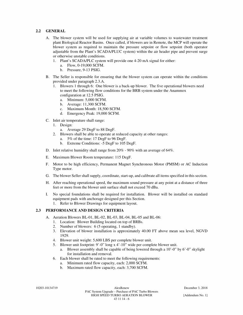
10203-10134719 AlexRenew December 3, 2018 PAC System Upgrade – Purchase of PAC Turbo Blowers HIGH SPEED TURBO AERATION BLOWER [Addendum No. 1] 43 11 14 - 6
2.2 GENERAL
A. The blower system will be used for supplying air at variable volumes to wastewater treatment plant Biological Reactor Basins. Once called, if blowers are in Remote, the MCP will operate the blower system as required to maintain the pressure setpoint or flow setpoint (both operator adjustable from the Plant’s SCADA/PLUC system) within the air header pipe and prevent surge or otherwise unstable conditions. 1. Plant’s SCADA/PLC system will provide one 4-20 mA signal for either:
a. Flow, 0-19,000 SCFM. b. Pressure, 9-13 PSIG.
B. The Seller is responsible for ensuring that the blower system can operate within the conditions provided under paragraph 2.3.A. 1. Blowers 1 through 6: One blower is a back-up blower. The five operational blowers need
to meet the following flow conditions for the BRB system under the Anammox configuration at 12.5 PSIG. a. Minimum: 5,000 SCFM. b. Average: 11,300 SCFM. c. Maximum Month: 18,500 SCFM. d. Emergency Peak: 19,000 SCFM.
C. Inlet air temperature shall range: 1. Design:
a. Average 29 DegF to 88 DegF. 2. Blowers shall be able to operate at reduced capacity at other ranges:
a. 5% of the time: 17 DegF to 96 DegF. b. Extreme Conditions: -5 DegF to 105 DegF.
D. Inlet relative humidity shall range from 20% - 90% with an average of 64%.
E. Maximum Blower Room temperature: 115 DegF.
F. Motor to be high efficiency, Permanent Magnet Synchronous Motor (PMSM) or AC Induction Type motor.
G. The blower Seller shall supply, coordinate, start-up, and calibrate all items specified in this section.
H. After reaching operational speed, the maximum sound pressure at any point at a distance of three feet or more from the blower unit surface shall not exceed 70 dBa.
I. No special foundations shall be required for installation. Blower will be installed on standard equipment pads with anchorage designed per this Section. 1. Refer to Blower Drawings for equipment layout.
2.3 PERFORMANCE AND DESIGN CRITERIA
A. Aeration Blowers BL-01, BL-02, BL-03, BL-04, BL-05 and BL-06: 1. Location: Blower Building located on top of BRBs. 2. Number of blowers: 6 (5 operating, 1 standby). 3. Elevation of blower installation is approximately 40.00 FT above mean sea level, NGVD
1929. 4. Blower unit weight: 5,600 LBS per complete blower unit. 5. Blower unit footprint: 9’-0” long x 4’-10” wide per complete blower unit.
a. Blower assembly shall be capable of being lowered through a 10’-0” by 6’-0” skylight for installation and removal.
6. Each blower shall be rated to meet the following requirements: a. Minimum rated flow capacity, each: 2,000 SCFM. b. Maximum rated flow capacity, each: 3,700 SCFM.

10203-10134719 AlexRenew December 3, 2018 PAC System Upgrade – Purchase of PAC Turbo Blowers HIGH SPEED TURBO AERATION BLOWER [Addendum No. 1] 43 11 14 - 7
c. Discharge air pressure at maximum air flow rate: 12.5 PSIG. 1) Discharge air pressure is measured at the air header pipe. Additional losses
induced by the Seller provided discharge valve, check valve and other appurtenances shall be accounted for by the Seller in sizing the blower system.
d. Discharge air pressure at minimum air flow rate: 12.5 PSIG. e. Barometric pressure: 14.67 PSIA. f. Differential pressure across dirty inlet filter assemblies: 0.30 PSIA.
1) If Seller requires a filter having a higher headloss than MERV 8 and or if a separate filter in the blower is required, Seller shall account for this additional loss in his performance calculations.
g. Maximum motor horsepower: 250. 7. Seller shall certify the entire blower system, with five of six blowers online will be capable
of a total flow of 18,500 SCFM at a pressure setting in the discharge header pipe of 12.5 PSIG (maximum) assuming a relative humidity of 90 percent, inlet temperature of 88 DegF and atmospheric pressure of 14.67 PSIA with a 0.30 PSIA pressure drop across the inlet filter. [Addendum No. 1]. a. Seller to provide performance of blowers at 13.0 psig.
8. Seller shall certify that under future conditions with a seventh blower installed and six of seven blowers online, system will be capable of a total flow of 22,200 SCFM at a pressure setting in the discharge header pipe of 13.0 PSIG (maximum).
9. The blower shall maintain a minimum of 2.0 psig away from surge at any operating point in the capacity range above. The blowers shall be capable of operating continuously and satisfactorily at any point between the minimum and the maximum flows without surge, vibration, hunting, overload of motor or VFD or excessive heating of the blower and motor.
10. Blowers with curves that reflect two possible capacities for a given pressure (head) at a single speed will not be acceptable.
11. The vibration of the blower shall not exceed 50% of Seller’s maximum allowable or not more than 1.25 mils as measured at the volute flanges.
12. The blower shall not exceed the nameplate motor rating over the entire range of operation. 13. Blowers shall be capable of a minimum turndown of 50 percent of maximum rated design
flow. 14. Blowers shall operate as specified without air conditioning of the blower room.
2.4 COMPONENTS
A. Enclosures: 1. The standard enclosure shall also act as a sound enclosure and air intake for the blowers. The
enclosures must be designed for easy inspection and maintenance of all blower package components. Doors shall provide easy and quick access for routine maintenance of the blower and the package components. Doors shall use a frame, reinforcements and supporting elements as required.
2. Blower electrical components, instrumentation and instrument connections shall all be mounted inside the blower enclosure (with the exception of the MCP). a. Harmonic filter may be mounted within the blower enclosure or exterior to it.
3. Motors are located inside the blower enclosures. Requirements for motor cooling air for each Seller shall meet the following requirements: a. Motor cooling air is exhausted to the blower room or building exterior depending on the
room interior temperature setpoint (operator adjustable). Air exhaust from the cooling of the motor and VFD shall have a fitting to duct air outside of the blower enclosure.
4. Enclosure shall be suitable for indoor use within a damp area.
B. Blowers: 1. Blowers shall have the capability to start and stop 30 times per hour. 2. Blowers may include an “off-loading” capability as part of the normal programming. Off-
loading shall be defined as the ability to operate the blower in an idle mode at minimum RPM while discharging air through the blow-off control valve.

10203-10134719 AlexRenew December 3, 2018 PAC System Upgrade – Purchase of PAC Turbo Blowers HIGH SPEED TURBO AERATION BLOWER [Addendum No. 1] 43 11 14 - 8
a. If Seller utilizes contact bearings while the blower is still rotating during the START and STOP cycle, the off-loading shall be used to minimize the starting and stopping of each blower to no more than once per 24 hour period.
3. Blowers shall already be UL Listed or CSA/US certified by CSA International, with certification label shown on nameplate. Field evaluation for certification approval shall not be permitted.
4. Blower casing shall have a maximum continuous duty design temperature of 400 DegF, and a design pressure of 50 PSIG.
5. Blower impellers shall be of the backswept three dimensional high efficiency configuration, designed using Computational Fluid Dynamics (CFD) with two stages in one (axial and centrifugal), and milled from forged aluminum alloy or cast stainless steel and with first lateral critical speed at least 120 percent of the maximum allowable operating speed. The impeller shall be mounted directly to the motor shaft and shall be statically and dynamically balanced. The axial gap between the impeller and blower casing shall be adjusted by shims as needed.
6. Each blower shall have built-in vibration isolation mounts. Seller shall be responsible for attenuating noise and vibration in the blower package so that no vibration from the blower shall be transmitted to the floor, intake, or discharge piping.
C. Motors: 1. Each blower shall be supplied with a high-efficiency permanent magnet or AC Induction
motor that shall operate on a 480 Volts, 3 Phase, 60 Hertz power supply, and be totally enclosed. a. The motor to have a 1.15 service factor, if applicable. b. Motor insulation rating: Class H. c. The motor to be able to start within 10 percent of rated voltage. d. The Seller shall be responsible for coordinating the starting torque requirement of the
blower and the motor. e. The motor to be capable of continuous operation at full load and rated frequency with a
voltage variance of +/- 10 percent of the nameplate voltage. f. The motor to be capable of operation at the rated voltage with a variance of +/- 5 percent
of the nameplate frequency. Motor to be rated for VFD. g. Motor accessories:
1) The motor and controls shall not require any space heaters. 2) The windings shall be provided with embedded thermocouples or RTDs for
temperature sensing and alarm.
D. Bearings: 1. Blowers shall be provided with a magnetic bearing system or air foil bearing system as
follows: a. Magnetic Bearing System:
1) The motor rotor shaft shall be continuously levitated in a magnetic field by the magnetic bearing system. This system shall consist of: a) Two radial and two axial active magnetic bearings. b) Two rotor position sensors. c) Magnetic bearing controller (MBC).
2) The position sensors shall continuously measure the shaft position and send a signal to the MBC controlling the energy in the active magnetic bearings to keep the motor rotor shaft levitated and centered.
3) There shall be no mechanical contact between any moving surfaces at any time during the blower operation.
4) The magnetic bearing system shall not require any oil lubrication. 5) The magnetic bearing controller shall be an MBC-12 powered by a 3 phase, 60 Hz,
480V power supply.

10203-10134719 AlexRenew December 3, 2018 PAC System Upgrade – Purchase of PAC Turbo Blowers HIGH SPEED TURBO AERATION BLOWER [Addendum No. 1] 43 11 14 - 9
b. Air Foil Bearing System: 1) Composed of corrugated bump foil and inner high temperature alloy core. 2) Bearing manufactured from synthetic media. 3) Bearing clearance of 1/30,000 IN. 4) The air bearing system shall not require any oil lubrication.
E. Inlet Filter: 1. Blower inlets shall draw air from a filter room with MERV 8 filters. If the Seller requires
additional filtration, the filters provided with the blowers shall meet the following: a. The filter media shall have an efficiency of 90 percent by weight per ASHRE 52-76
with synthetic dust equivalent to separation > 95 percent @ 10 microns or the filters shall be pocket Camfil Hi-Cap having a high density microfine glass fiber filter medium suitable for high efficiency filtration.
b. Maximum clean pressure loss across the filter shall be less than 0.12 PSIG. c. Filter performance losses across dirty filters to be included in the blower performance
calculation.
F. Flexible Connector: 1. Provide each blower with a discharge expansion joint capable of withstanding the anticipated
vacuum, pressure, and temperature under all operating conditions. The expansion joint shall be included with steel flanges sized as required to fit the blower outlet and drilled for ASME/ANSI B16.1, Class 150 bolt.
G. Blow-off (Bypass) Valves: 1. Provide Seller’s standard pneumatic actuated, electro-pneumatic, or solenoid blow-off valve.
Controls for the valve shall be incorporated in each blower LCP.
H. Inlet and Discharge Valves: 1. Provide blower with a flange type AWWA butterfly valve for shutoff service on blower inlet
and discharge. 2. Size shall be as required by blower system and determined by the Seller. 3. Valve operation shall be manual. 4. Valve elastomer seals shall be rated for 400 DegF.
I. Check Valves: 1. Provide each blower with a high performance wafer type non-slam discharge check valve of
the dual, flat-plate type with 316 stainless steel center hinge, spring closure, 316 stainless steel body, EPDM seal and aluminum plates, Inconel or approved equal springs, and rated for temperatures up to 400 DegF.
J. Blow-off Silencer: 1. A carbon steel blow-off silencer shall be provided for the blow-off (bypass) valve.
a. Internal baffles, packed with sound absorbent material, shall direct airflow around three 90-degree turns in an annular flow configuration.
b. The blow off silencer shall be an integral unit, fitted with one flange for direct bolting to the blow off valve or connected to the blow off valve discharge pipe via a slip flit connection and set screws.
c. Silencer shall be capable of mitigating sound to less than 60 dBA (free field) three feet from the blow-off exhaust.
2.5 INSTRUMENTATION
A. The Seller shall provide the blower instrumentation described in this section. Instruments shall be as specified in this section and the corresponding instrument section in Division 40. These components shall be mounted within the blower enclosure except as noted.
B. The controls shall be designed such that the blower cannot operate unless the controls are energized and functional. All controls and instruments shall fail into a safe condition.

10203-10134719 AlexRenew December 3, 2018 PAC System Upgrade – Purchase of PAC Turbo Blowers HIGH SPEED TURBO AERATION BLOWER [Addendum No. 1] 43 11 14 - 10
C. Instrumentation for each blower shall include, as a minimum: 1. Inlet air temperature sensor. 2. Inlet air pressure sensor. 3. Inlet air filter differential pressure switches:
a. Measure differential pressure across the inlet filter. b. Set switch alarm setpoint as recommended by Seller. c. Provide one differential pressure switch per filter where blowers share filter assemblies.
4. Discharge air pressure transmitter, 4-20 mA and pressure switch. 5. Discharge temperature sensor. 6. Blow-off valve limit switches position indicator (open/closed). 7. Motor Winding monitoring systems.
a. Monitor and display actual winding temperatures at the LCP. b. A high temperature (as determined by the Seller) shuts down the blower and gives an
alarm. The alarm/shutdown shall be displayed until reset. c. Provides necessary hardware for direct communication between motor temperature
sensors, PLC and HMI. 8. Amperage monitoring system:
a. Monitor amperage at the VFD. b. High amperage signal shall shutdown the blower and give an alarm.
9. Vibration monitoring system: a. Monitor and display vibration. b. High vibration (as determined by the Seller) shuts down the blower and gives an alarm.
D. Local Control Panel (LCP): 1. Each blower shall be equipped with a LCP including a dedicated PLC or microprocessor
[Addendum No. 1] that connects to the Master Control Panel. 2. The LCP shall contain controls for blower start-up and shutdown including valve sequencing,
surge and overload control, and equipment monitoring. 3. All LCP controls, alarms and monitoring shall be accessible through a touch screen control
panel or a keypad/display screen combination. 4. If communication is lost with the MCP, the LCP shall maintain blower operation at the last
local flow setpoint. 5. Ethernet communication shall be provided for all status information. 6. Timers, external or internal to the LCP, shall provide interlocks, time delays, and pulse signals
for blower control. 7. HMI:
a. All controls, alarms and monitoring shall be accessible through a touch screen control panel.
b. Operating data display. c. Graph of machine’s operating point. d. Operating history. e. Fault summary. f. Operating mode setup. g. On/Off control. h. Communication mode setup.
8. LCP shall be UL listed. Refer to the 40 67 00 specification for additional requirements.
E. Master Control Panel (MCP): 1. Two PLC-based MCPs shall be provided. The MCPs shall be redundant and contain all
controls for blower sequencing. 2. Enclosure: Freestanding, NEMA 12 enclosure with a PLC-based sequencing program and
color touchscreen HMI shall be provided and tested by the Seller for controlling multiple blowers automatically and to facilitate pressure set point and flow set point control. Power for the MCP shall be 120/60/1, 20 amp. a. MCPs will be located in conditioned Electrical Room.

10203-10134719 AlexRenew December 3, 2018 PAC System Upgrade – Purchase of PAC Turbo Blowers HIGH SPEED TURBO AERATION BLOWER [Addendum No. 1] 43 11 14 - 11
3. HMI Graphics shall match existing Buyer standards. 4. The MCPs shall start and shutdown the blowers in a permissive sequence, receive input, and
monitor and control operating variables. 5. The MCPs shall provide air header pressure control and/or air header flow control with any
single blower, any combination of blowers or with all of the blowers in service except for the spare blower. The PLC shall receive the main air header pressure and flow 4-20 mA signals, which calls for more or less air and increase/decrease on-line blower capacity to maintain the air header pressure or flow at the chosen set point. The air header pressure and flow set points shall be adjustable from the MCP or from a remote input provided by plant’s SCADA.
6. Refer to P&ID(s)Section 40 90 05 [Addendum No. 1] for minimum blower information to be communicated with Buyer’s SCADA.
7. In order to assure that aeration blower system can be adequately interfaced to the Buyer’s SCADA system, the Seller will be required to provide a fully programmed PLC to the Systems Integrator for use in a factory test prior to equipment shipment.
8. Each blower is required to be capable of running manually with the MCPs out of service 9. In addition to automatic operation, the system will allow SCADA Remote-Manual control.
In this mode, SCADA will also be able to manually start and stop the blowers. 10. Unless otherwise indicated in this Section, the MCP shall meet the requirements of the
following Sections: a. Section 40 62 16 – Computer Network and Human Machine Interface (HMI) Hardware. b. Section 40 67 00 – Control System Equipment Panels and Racks. c. Section 40 97 00 – Control Auxiliaries.
11. MCP shall be UL listed.
F. Communication: 1. Modbus TCP communication shall be provided between the MCPs and SCADA to provide
comprehensive monitoring of process parameters and alarms. All hardware, software, and programming shall be furnished to implement these data links.
2. Modbus TCP communication, Ethernet/IP or equal [Addendum No. 1] shall be provided between the LCPs and MCPs.
2.6 HARMONIC PROTECTION REQUIREMENTS
A. Each VFD shall be designed and provided with all necessary equipment to protect the VFD and the power system ahead of the VFD from voltage and current distortion. The equipment Seller shall provide harmonic filters as required. In accordance with and as defined by IEEE 519: 1. Each VFD shall be designed to operate from a power bus that may contain up to 5 percent
voltage distortion. 2. Each single VFD powered from the same bus shall be designed to limit percent distortion
factor to a maximum of 5 percent voltage distortion. 3. Current distortion limits shall not exceed the values listed in Table 10.3 of IEEE 519. 4. Line-to-line notching at the input to the drive shall have a maximum notch depth of 20 percent
and a maximum notch area of 22,800 volt-microseconds reflected back to the power source.
B. Harmonic filters may be separately mounted or integral with the VFD. Where filters are separately mounted, provide NEMA Type 1 enclosures with automatic isolating contact. The filter capacitors shall not be connected to the distribution system when the associated blower is not in operation. The filter dimensions are restricted to be not greater than the space allocated on the Drawings. Provide custom enclosures to meet the space restrictions. Contractor shall verify final cable and conduit sizing for the equipment supplied and provide the cable and conduit.
C. Power conductors for separately mounted harmonic filters shall be connected at the load side of the switchgear feeder circuit breaker as indicated on the Drawings. Coordinate Seller’s requirements and connect at recommended location if different than shown at no additional cost to the Buyer.

10203-10134719 AlexRenew December 3, 2018 PAC System Upgrade – Purchase of PAC Turbo Blowers HIGH SPEED TURBO AERATION BLOWER [Addendum No. 1] 43 11 14 - 12
D. The Point of Common Coupling (PCC) for all harmonic calculations and field measurements for both the voltage and current distortion shall be defined as the primary (line side) connection of each VFD or the harmonic filter if the filter is mounted outside the blower enclosure.
2.7 BLOWER VENTILATION REQUIREMENTS
A. Each blower enclosure shall be ventilated in accordance with the Seller’s recommended standards and this Section to ensure proper operation of the mechanical equipment, controllers, VFD and motors.
B. Blower system shall not require any external cooling requirements.
2.8 SURFACE PREPARATION AND SHOP PAINTING
A. All carbon steel or iron surfaces shall be prepared, shop primed, and finish painted in accordance with Seller’s standard coating system.
B. Machine surfaces that are not painted shall be protected by coating with Seller’s standard corrosive-protective compound.
2.9 SOURCE QUALITY CONTROL
A. Upon completion of assembly, the blower package shall be functionally tested at the place of assembly. Representatives of the Buyer and Engineer reserve the right to witness the testing at their own expense.
B. At a minimum, the blower system shall be factory tested for a duration of not less than eight hours at maximum load and maximum temperature.
C. The entire blower system, blow-off valve, and LCP, shall be tested as an operational system before shipment. The LCP shall be connected to all enclosure instruments, electric valves, and appurtenances. All start/stop and running sequences and all safety and alarm systems shall be tested. The Seller shall sign the test procedure and results, certifying that the assembled blowers, auxiliaries, blow-off valves, and LCP were tested together, as a system, in the Seller’s shop.
D. Each blower shall be performance tested in accordance with the ASME PTC 10 - 1997 Performance Test Code on Compressors and Exhausters (re-affirmed in 2003). The test shall verify compliance with the performance and design criteria listed in this specification.
E. A calibrated wattmeter (or other power measuring device approved by the Engineer) shall measure the total power input to the blower unit. Measured power shall include wire-to-air and include all losses associated with electrical shaft power, including, but not limited to the motor, inverter, bearings, and cooling system, if used.
F. Net delivered flow rate and discharge pressure shall be guaranteed with no negative tolerance. There shall be no tolerances or measuring uncertainties used in reporting test results (i.e., the tests shall be reported with ± zero percent tolerance using the measured values).
G. The sound pressure level shall be measured to verify compliance with these specifications.
H. The Seller shall sign each copy of the test data log sheet certifying that the required tests were performed in strict accordance with these specifications and the ISO 5389 Codes, modified to permit zero tolerance for flow and power. 1. The capacity of the blower shall be defined as per Paragraph 4.26 of the ISO 5389 Code,
including air flow measurement with zero tolerances. 2. All test equipment shall be calibrated and certified by an independent test agency no more
than 12 months prior to the test date. 3. Velocity vibration versus frequency levels shall be recorded within 10-1,000 and 10-10,000
Hz frequency range. Report vibration in velocity versus frequency.

10203-10134719 AlexRenew December 3, 2018 PAC System Upgrade – Purchase of PAC Turbo Blowers HIGH SPEED TURBO AERATION BLOWER [Addendum No. 1] 43 11 14 - 13
I. The blower test report shall present computations in exact accordance with Section 5, 6, and 7 of ASME PTC 10 Code with performance curves showing capacity, pressure, and kilowatt/horsepower inputs.
J. Test results of the motors and blowers shall be included in the Operations & Maintenance Manual.
K. Motor Tests: 1. The motor shall be tested as a part of blower system and where it is applicable:
a. Stator temperature attainment may be accomplished by restricting cooling air flow or by other industry standard methods but all effects of the method of testing shall be evaluated. Vibration readings shall be taken while air flow is not restricted.
b. Motor during test shall be complete including accessories and have nothing removed for convenience except the power lead conduit box. No extra devices shall be used except those required to measure or monitor variables.
c. All test variables shall conform to actual field values and shall be maintained throughout tests.
d. Prior to shipment to the blower Seller, the motor shall meet the following criteria: 1) Excessive noise and overheating shall be eliminated. 2) Changes made to enable motor(s) to meet above requirements shall make initial test
unacceptable and final shop tests shall be run after such changes have been made.
2.10 MAINTENANCE AND SPARE PARTS
A. Furnish all special tools and appliances necessary to disassemble, service, repair, and adjust the blower equipment and appurtenances. The following spare parts shall be furnished: 1. One complete set of air filters as required for each blower furnished. 2. One spare blow-off solenoid valve for each blower furnished. 3. Any parts that will require replacement in the first 10 years of operation, other than air filters.
This may include the following for each unit: a. Capacitors. b. Variable frequency drive units. c. Blower core (must be furnished if Seller has experienced core failure at any installation
within 10 years of startup).
PART 3 - EXECUTION
3.1 INSTALLATION
A. The blowers and appurtenances shall be installed in accordance with the instructions of the Seller, as shown on the Drawings. All piping shall be supported so as to preclude the possibility of exerting undue forces and movements on the blower flanges. Each blower unit shall be floor mounted in accordance with the recommendations of the Seller.
B. The Buyer’s Construction Contractor shall furnish the required piping, pipe supports, flange gaskets, bolts, nuts, oil, and grease for initial operation in accordance with the Seller’s recommendations.
3.2 SELLER’S FIELD SERVICES
A. The Seller shall provide a factory-trained service representative to inspect the final installation and supervise the field start-up tests of the equipment and software. 1. Provide, as a minimum, the following initial installation field services:
a. Verify proper connection of piping and installation of accessories. b. Check leveling of blower enclosure. c. Confirm proper wiring of all instruments and field wired items.
2. Provide written documentation of the field services performed, including but not limited to the following: a. Name(s) of representative(s) who performed the work.

10203-10134719 AlexRenew December 3, 2018 PAC System Upgrade – Purchase of PAC Turbo Blowers HIGH SPEED TURBO AERATION BLOWER [Addendum No. 1] 43 11 14 - 14
b. Dates and times when the work was performed. c. Documentation of final setting or tolerance. d. Name(s) of representative(s) who witnessed the final settings.
3. Equipment start-up testing: a. Minimum four hour duration per blower. b. Field acceptance test shall demonstrate that, under all conditions of operation, each unit:
1) Has not been damaged by transportation or installation. 2) Has been properly installed. 3) Has no mechanical defects. 4) Has fully functional instrumentation, which is properly calibrated and set. 5) Will start, run, and stop in the prescribed manner. 6) Will run through the entire range of specified pressure and flow. 7) Has the proper shutdown sequence of standard stop, soft stop, and emergency stop. 8) Is free of overheating of any parts. 9) Is free of objectionable vibration and noise. 10) Is free of overloading of any parts.
c. Field acceptance testing shall be conducted after the installation of all equipment has been completed and all instrumentation is calibrated and working as intended and the equipment has operated for a sufficient period to make all desirable corrections and adjustments. Contractor shall schedule testing with the full knowledge and consent of Buyer.
4. System functional demonstration test: a. A system functionality test shall be conducted after the blower installation and successful
completion of the equipment start-up testing. b. The functionality test shall demonstrate the blower automatic operating strategy. c. Demonstrate the functionality of the discharge header pressure control loop to
automatically stage blowers on and off and to adjust blower speed in a stable manner for the full range of operating conditions stated in paragraph 2.3.A of this specification. 1) Test discharge header pressure control loop operation at three different pressure set
points and three different flow set points to demonstrate stability of blowers operating in all conditions.
B. The Seller’s factory representative, who has complete knowledge of proper operation and maintenance shall instruct representatives of the Buyer on proper operation and maintenance, including start-up and shut-down procedures, proper lubrication practices, and troubleshooting of all equipment in accordance with Section 01 75 03.
3.3 FIELD PERFORAMNCE DEMONSTRATION
A. Performance Demonstration: 1. Air flow demands are defined as follows:
a. Low Air Flow: 5,000 SCFM. b. Total High Air Flow: 18,500 SCFM with 5 of 6 blowers in operation.
2. Test performed by representative of Seller in presence of Engineer and Buyer. 3. Run test over continuous 120 hour minimum for the blower system. System shall
demonstrate smooth transition when additional blowers are called to turn on or off by the MCPs.
4. Results from test will be used to verify compliance with requirements in PART 2 of this Section and shall be submitted to Buyer.
5. Air flow rate, CFM, to be measured and recorded every 15 minutes. 6. Air temperature of air going into blower and barometric pressure to be measured at one hour
intervals during test. 7. Power feed to blower will be measured and recorded with a recording watt meter (or other
approved device) at the motor control center feeding the blower. 8. Testing shall demonstrate stable operation at each of the blowers.

10203-10134719 AlexRenew December 3, 2018 PAC System Upgrade – Purchase of PAC Turbo Blowers HIGH SPEED TURBO AERATION BLOWER [Addendum No. 1] 43 11 14 - 15
9. Acceptance testing is specified in Section 01 75 03 – System Start-Up and Acceptance Testing for High Speed Turbo Blowers.
END OF SECTION

10203-10134719 AlexRenew December 3, 2018 PAC System Upgrade – Purchase of PAC Turbo Blowers HIGH SPEED TURBO AERATION BLOWER [Addendum No. 1] 43 11 14 - 16
THIS PAGE INTENTIONALLY LEFT BLANK