
Alex inspection proposal of cherries and CV
81
Automatic Optical Inspection proposal of cherries Hua Zhang (Alex) 264 Yaldhurst Road, Christchurch City 8042 Email: [email protected] Mobile: 021 0235 3269
Transcript of Alex inspection proposal of cherries and CV
Automatic Optical Inspection proposal
of cherries
Hua Zhang (Alex)264 Yaldhurst Road,Christchurch City 8042Email: [email protected]: 021 0235 3269
Outlines
Objective
Customer requirement
Feasibility study
Preliminary design
Detail design
Pending issue discussion
Appendix
Objective
Propose an Automatic Optical Inspection proposal for cherries in order to save labor cost
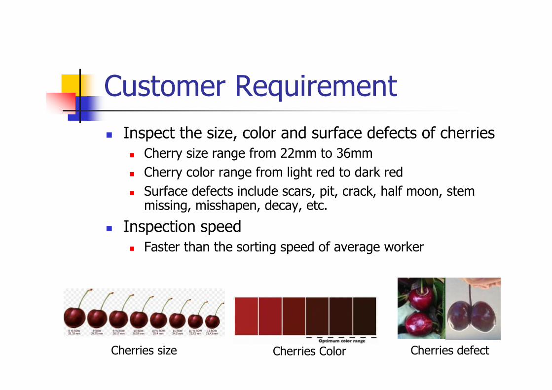
Customer Requirement
Inspect the size, color and surface defects of cherries Cherry size range from 22mm to 36mm
Cherry color range from light red to dark red
Surface defects include scars, pit, crack, half moon, stem missing, misshapen, decay, etc.
Inspection speed Faster than the sorting speed of average worker
Cherries ColorCherries size Cherries defect
Feasibility study
Need to find a way to take pictures of the entire surface
In order to achieve color detection, white illumination and color camera should be used
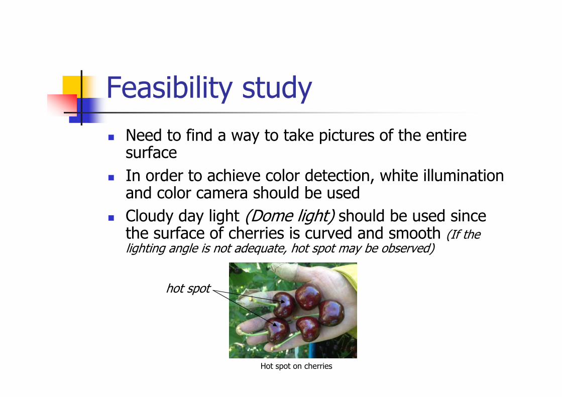
Cloudy day light (Dome light) should be used since the surface of cherries is curved and smooth (If the lighting angle is not adequate, hot spot may be observed)
hot spot
Hot spot on cherries
Feasibility study
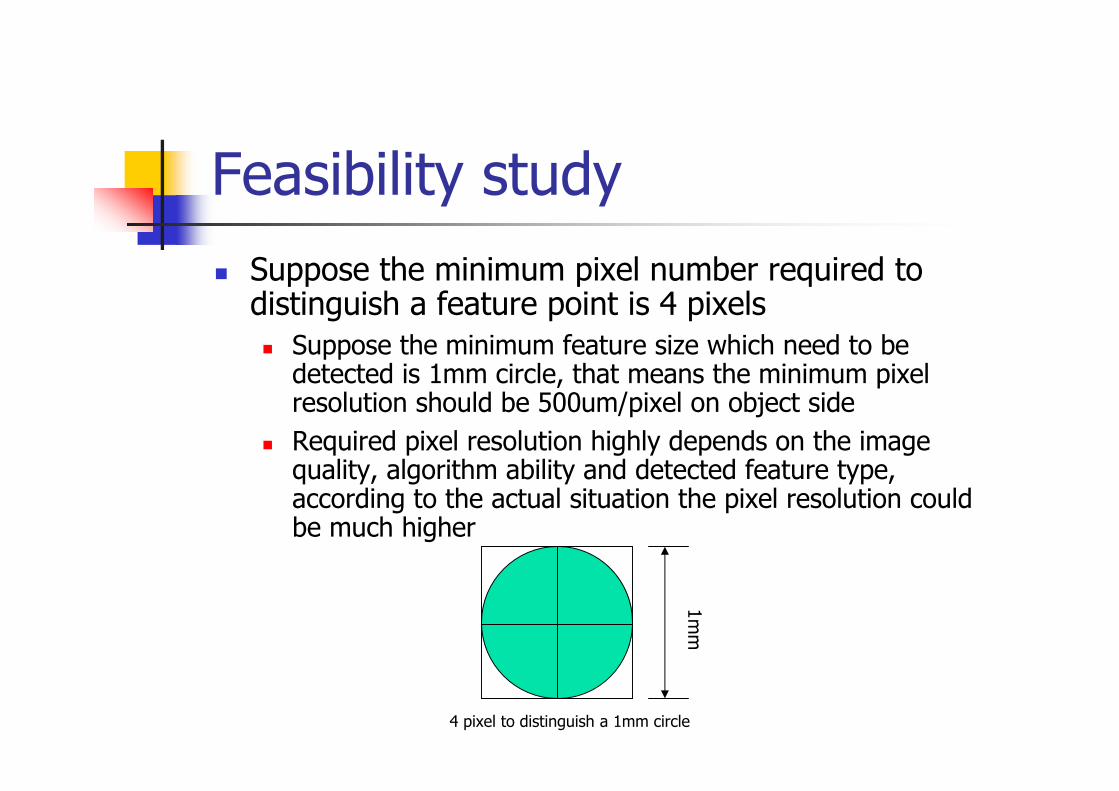
Suppose the minimum pixel number required to distinguish a feature point is 4 pixels Suppose the minimum feature size which need to be
detected is 1mm circle, that means the minimum pixel resolution should be 500um/pixel on object side
Required pixel resolution highly depends on the image quality, algorithm ability and detected feature type, according to the actual situation the pixel resolution could be much higher
1m
m
4 pixel to distinguish a 1mm circle
Feasibility study
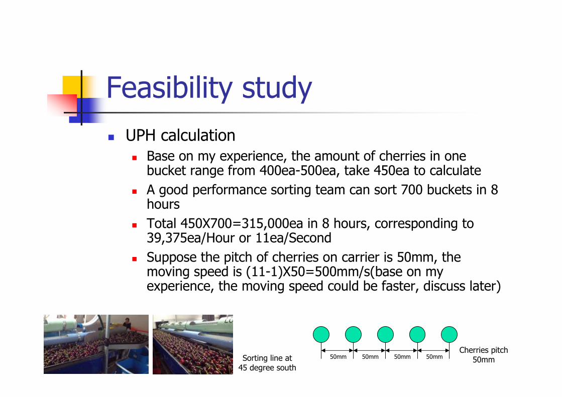
UPH calculation Base on my experience, the amount of cherries in one
bucket range from 400ea-500ea, take 450ea to calculate
A good performance sorting team can sort 700 buckets in 8 hours
Total 450X700=315,000ea in 8 hours, corresponding to 39,375ea/Hour or 11ea/Second
Suppose the pitch of cherries on carrier is 50mm, the moving speed is (11-1)X50=500mm/s(base on my experience, the moving speed could be faster, discuss later)
Sorting line at45 degree south
50mm 50mm 50mm 50mmCherries pitch
50mm
Feasibility study
Rough Vision System specification FOV>50mm
Pixel resolution>500um/pixel on object side
Frame rate>11frame/second
Moving speed>500mm/s
Exposure time to be determined
Lighting type should be cloudy day light
Preliminary design
How to place camera
What kind of camera
What kind of image lens
What kind of lighting
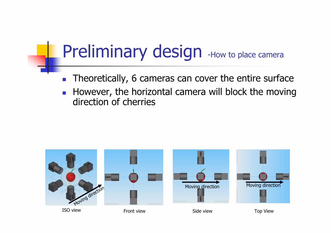
Preliminary design -How to place camera
Theoretically, 6 cameras can cover the entire surface
However, the horizontal camera will block the moving direction of cherries
Moving dire
ction
Top ViewSide viewFront view
Moving direction Moving direction
ISO view
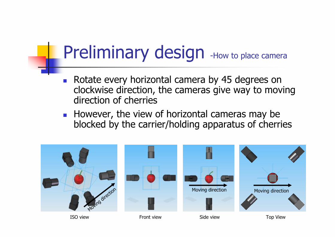
Preliminary design -How to place camera
Rotate every horizontal camera by 45 degrees on clockwise direction, the cameras give way to moving direction of cherries
However, the view of horizontal cameras may be blocked by the carrier/holding apparatus of cherries
Moving
dire
ction Moving directionMoving direction
Top ViewSide viewFront viewISO view
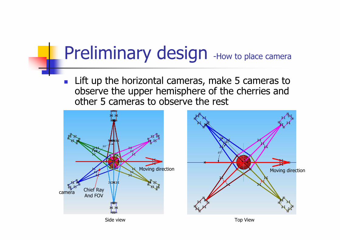
Lift up the horizontal cameras, make 5 cameras to observe the upper hemisphere of the cherries and other 5 cameras to observe the rest
Top ViewSide view
camera Chief RayAnd FOV
Moving direction Moving direction
Preliminary design -How to place camera
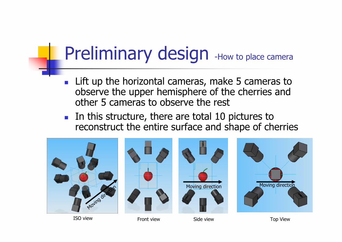
Lift up the horizontal cameras, make 5 cameras to observe the upper hemisphere of the cherries and other 5 cameras to observe the rest
In this structure, there are total 10 pictures to reconstruct the entire surface and shape of cherries
Moving
dire
ction
Moving directionMoving direction
Top ViewSide viewFront viewISO view
Preliminary design -How to place camera
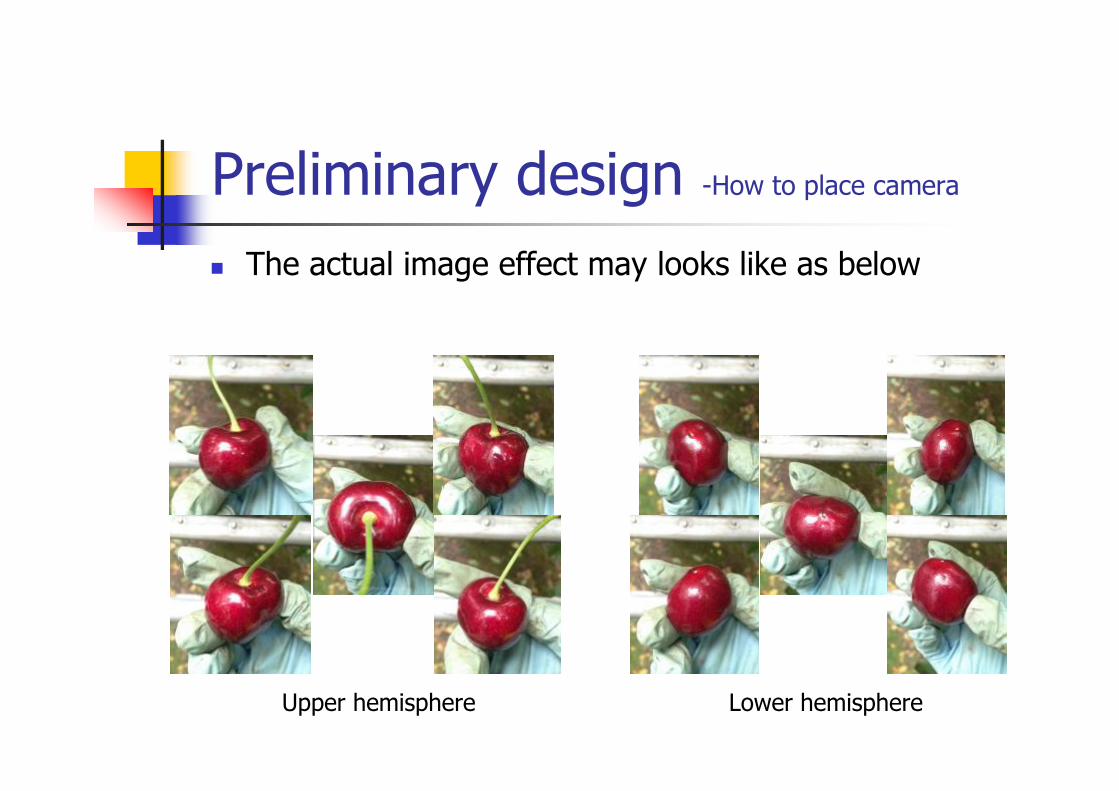
The actual image effect may looks like as below
Upper hemisphere Lower hemisphere
Preliminary design -How to place camera
Preliminary design –What kind of camera
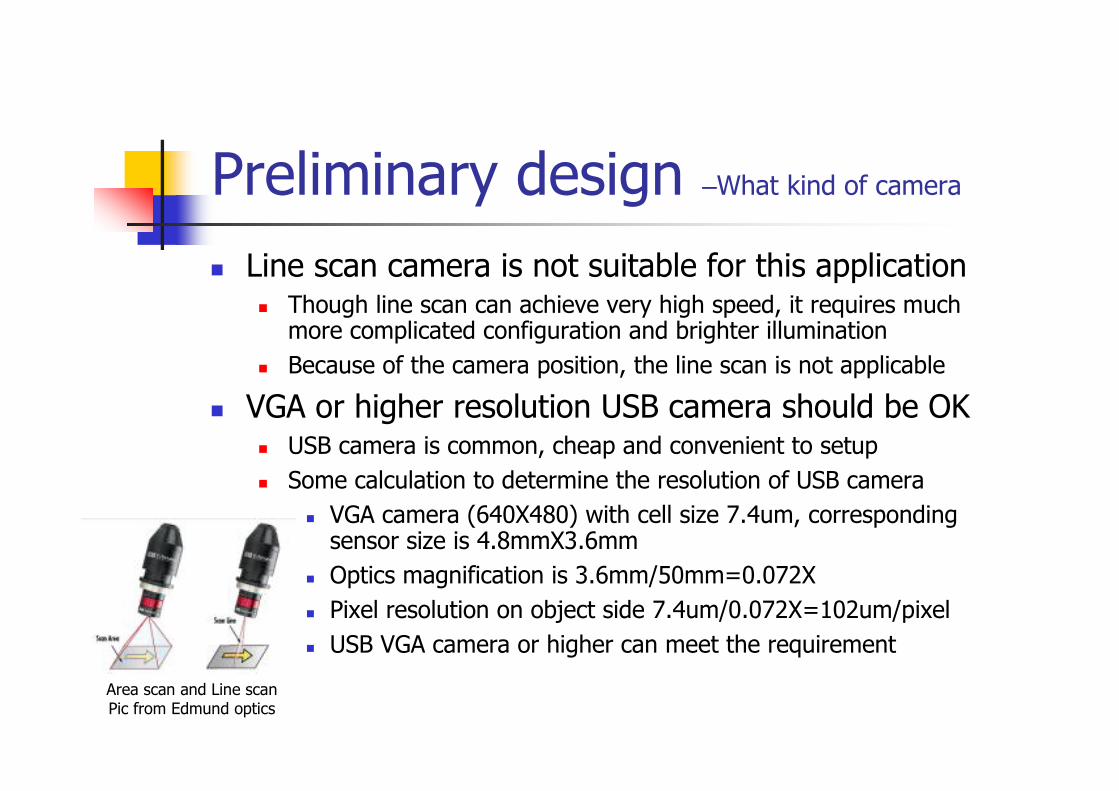
Line scan camera is not suitable for this application Though line scan can achieve very high speed, it requires much
more complicated configuration and brighter illumination
Because of the camera position, the line scan is not applicable
VGA or higher resolution USB camera should be OK USB camera is common, cheap and convenient to setup
Some calculation to determine the resolution of USB camera
VGA camera (640X480) with cell size 7.4um, corresponding sensor size is 4.8mmX3.6mm
Optics magnification is 3.6mm/50mm=0.072X
Pixel resolution on object side 7.4um/0.072X=102um/pixel
USB VGA camera or higher can meet the requirement
Area scan and Line scanPic from Edmund optics
Preliminary design –What kind of image lens
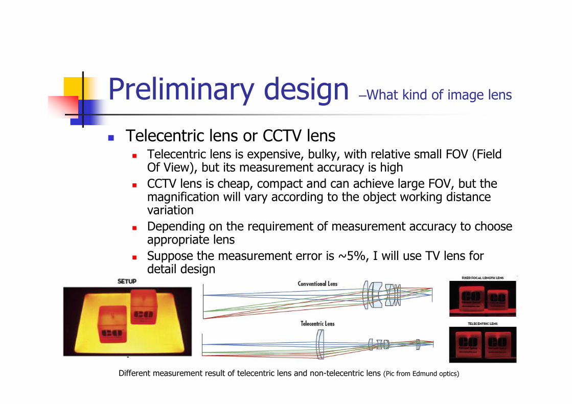
Telecentric lens or CCTV lens Telecentric lens is expensive, bulky, with relative small FOV (Field
Of View), but its measurement accuracy is high
CCTV lens is cheap, compact and can achieve large FOV, but the magnification will vary according to the object working distancevariation
Depending on the requirement of measurement accuracy to choose appropriate lens
Suppose the measurement error is ~5%, I will use TV lens for detail design
Different measurement result of telecentric lens and non-telecentric lens (Pic from Edmund optics)
Preliminary design–What kind of illumination
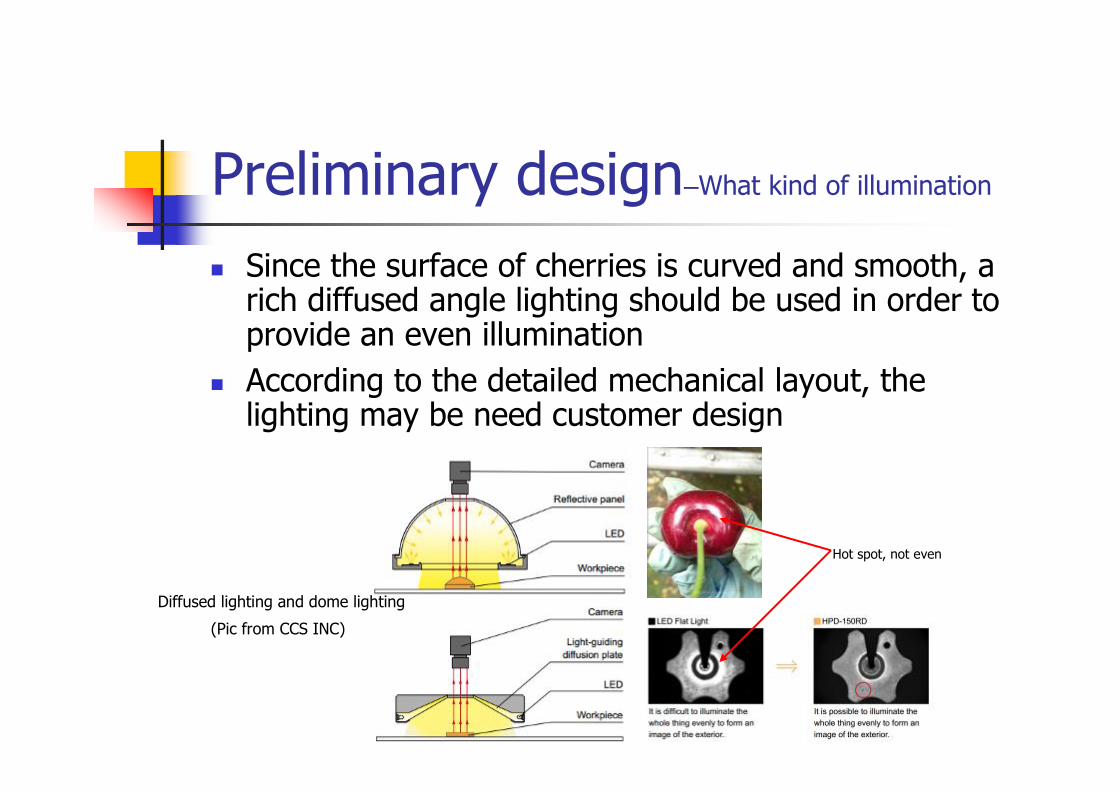
Since the surface of cherries is curved and smooth, a rich diffused angle lighting should be used in order to provide an even illumination
According to the detailed mechanical layout, the lighting may be need customer design
Hot spot, not even
Diffused lighting and dome lighting
(Pic from CCS INC)
Detail design
Detailed Layout, camera and lens model
Moving speed
Lighting structure and intensity
Detailed vision system specification
Detail design -Layout
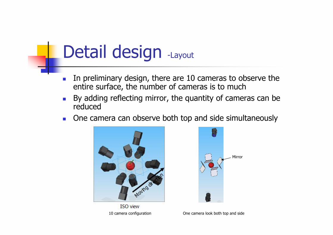
In preliminary design, there are 10 cameras to observe the entire surface, the number of cameras is to much
By adding reflecting mirror, the quantity of cameras can be reduced
One camera can observe both top and side simultaneously
10 camera configuration One camera look both top and side
Mirror
Detail design -Layout
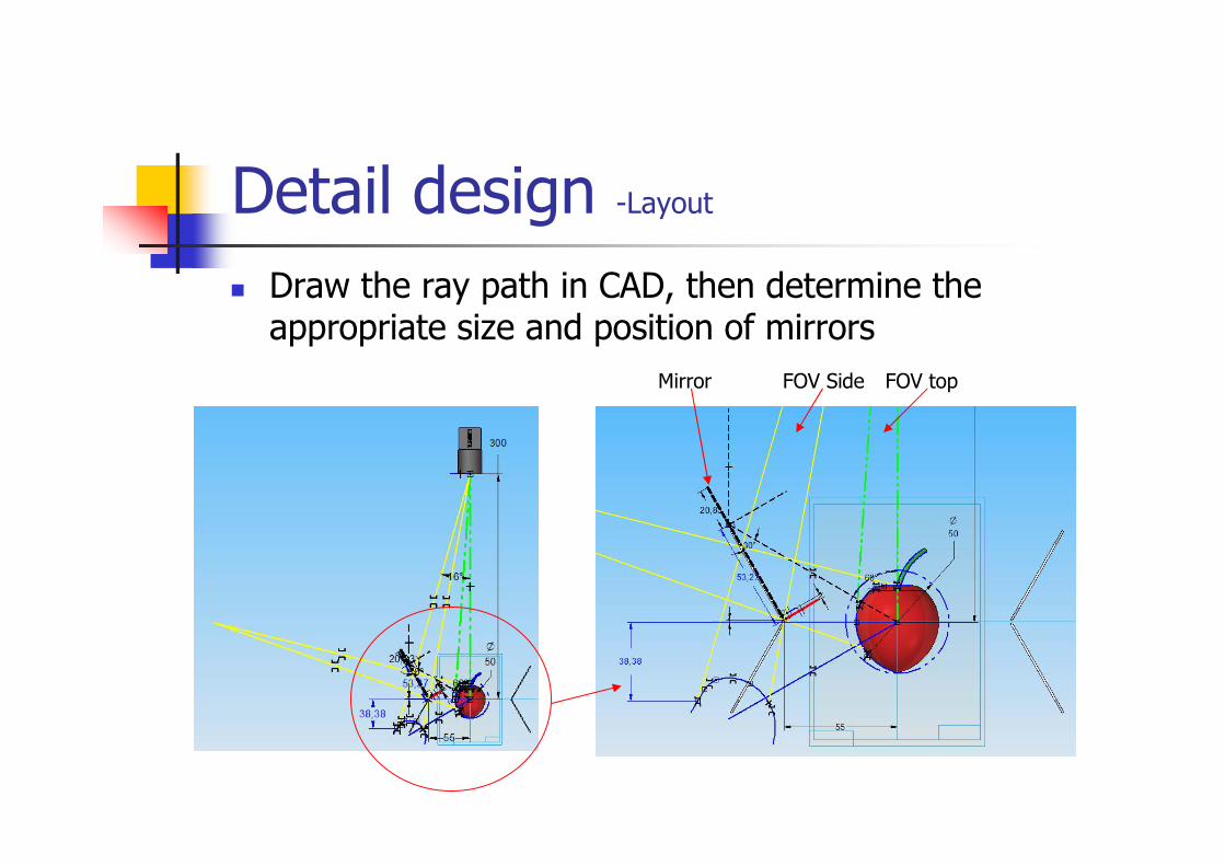
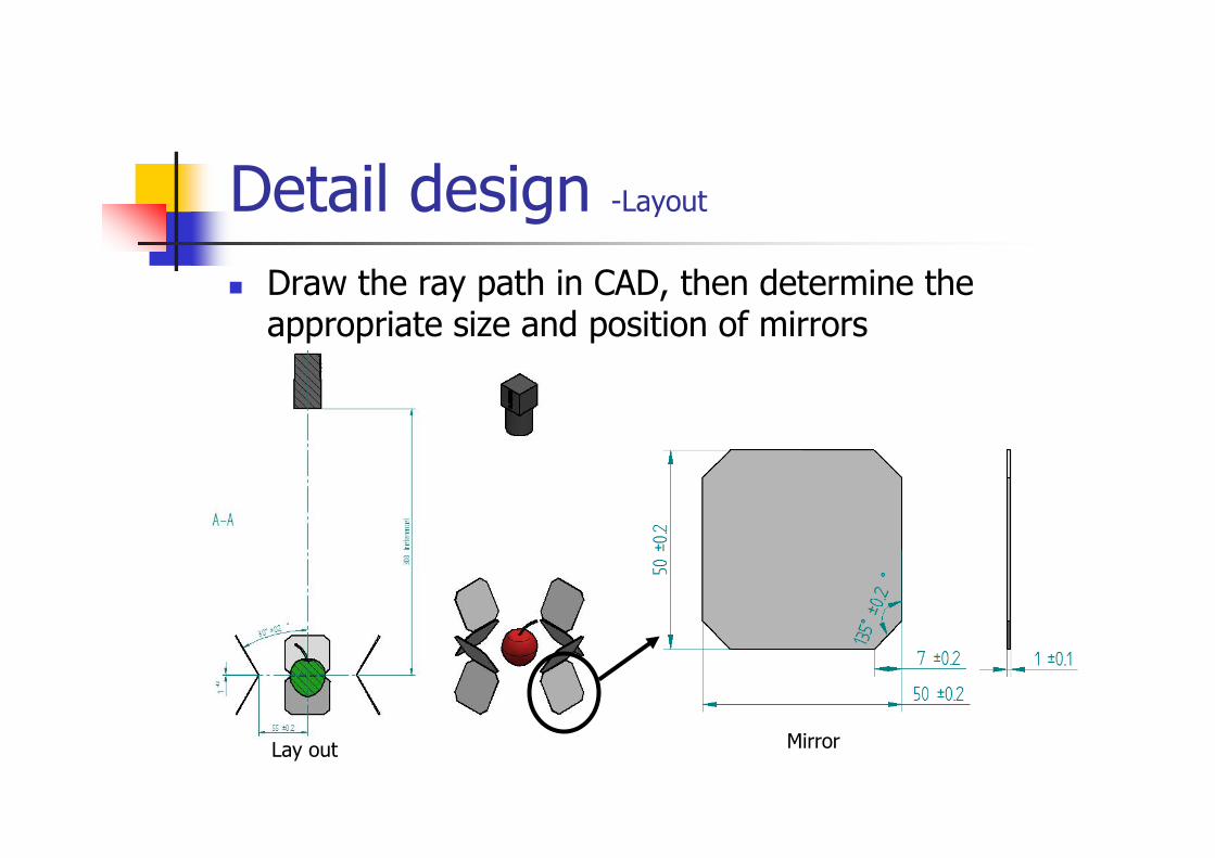
Draw the ray path in CAD, then determine the appropriate size and position of mirrors
FOV topFOV SideMirror
Detail design -Layout
Draw the ray path in CAD, then determine the appropriate size and position of mirrors
Lay out Mirror
Detail design -Layout
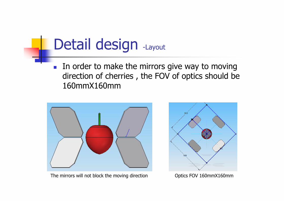
In order to make the mirrors give way to moving direction of cherries , the FOV of optics should be 160mmX160mm
The mirrors will not block the moving direction Optics FOV 160mmX160mm
Detail design –camera and lens
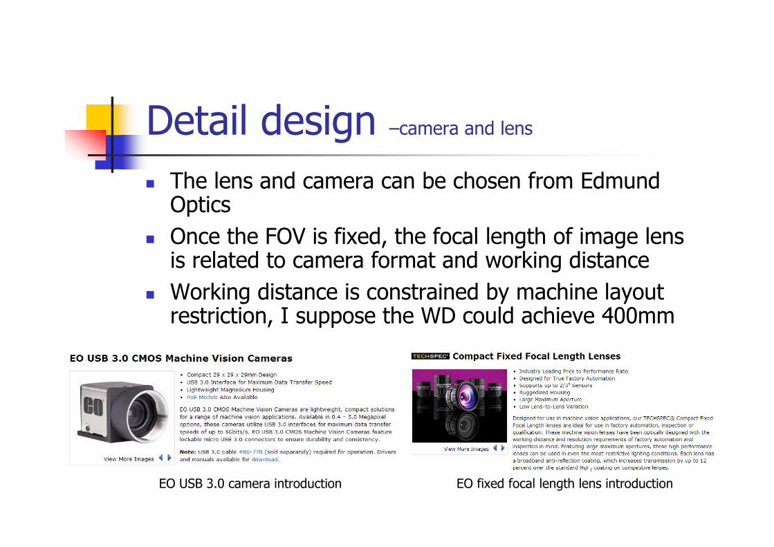
The lens and camera can be chosen from Edmund Optics
Once the FOV is fixed, the focal length of image lens is related to camera format and working distance
Working distance is constrained by machine layout restriction, I suppose the WD could achieve 400mm
EO USB 3.0 camera introduction EO fixed focal length lens introduction
Detail design –camera and lens
WD FOVCameramodel Pixel
Pixelsize
Sensor size(Vertical)
Framerate Price Mag
Pixelresolution
Focal lengthrequired
Ray angleof side FOV
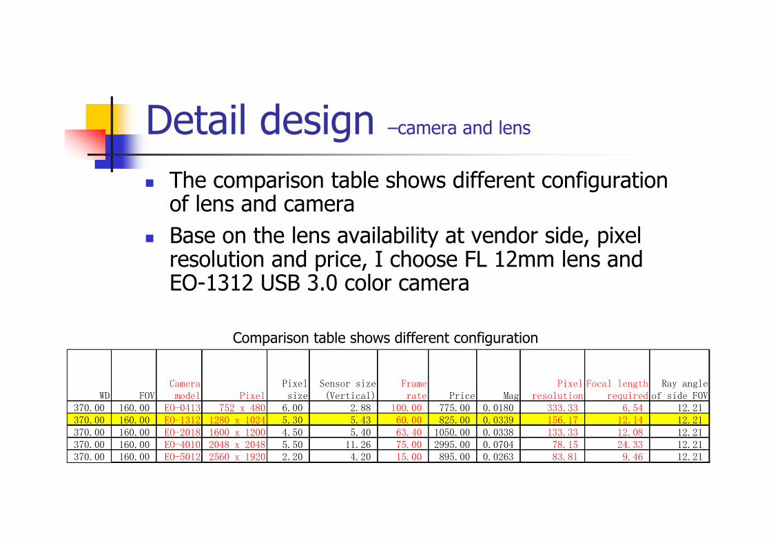
370.00 160.00 EO-0413 752 x 480 6.00 2.88 100.00 775.00 0.0180 333.33 6.54 12.21370.00 160.00 EO-1312 1280 x 1024 5.30 5.43 60.00 825.00 0.0339 156.17 12.14 12.21370.00 160.00 EO-2018 1600 x 1200 4.50 5.40 63.40 1050.00 0.0338 133.33 12.08 12.21370.00 160.00 EO-4010 2048 x 2048 5.50 11.26 75.00 2995.00 0.0704 78.15 24.33 12.21370.00 160.00 EO-5012 2560 x 1920 2.20 4.20 15.00 895.00 0.0263 83.81 9.46 12.21
The comparison table shows different configuration of lens and camera
Base on the lens availability at vendor side, pixel resolution and price, I choose FL 12mm lens and EO-1312 USB 3.0 color camera
Comparison table shows different configuration
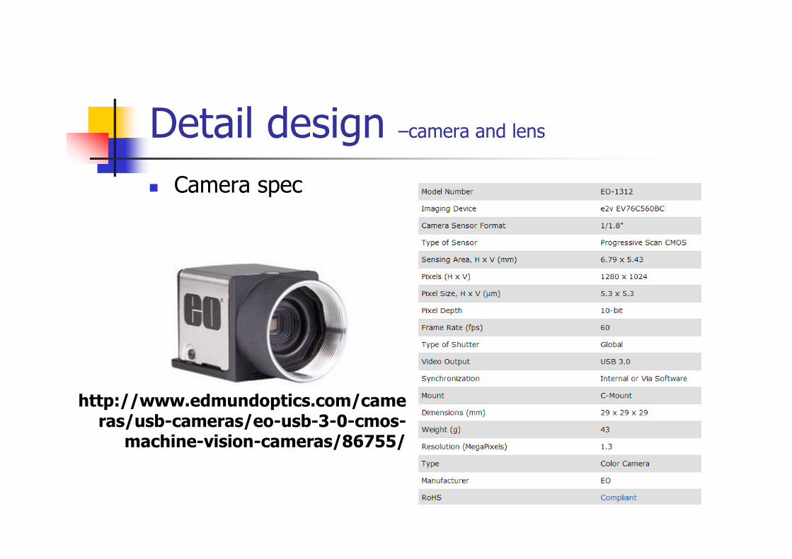
Camera spec
Detail design –camera and lens
http://www.edmundoptics.com/cameras/usb-cameras/eo-usb-3-0-cmos-
machine-vision-cameras/86755/
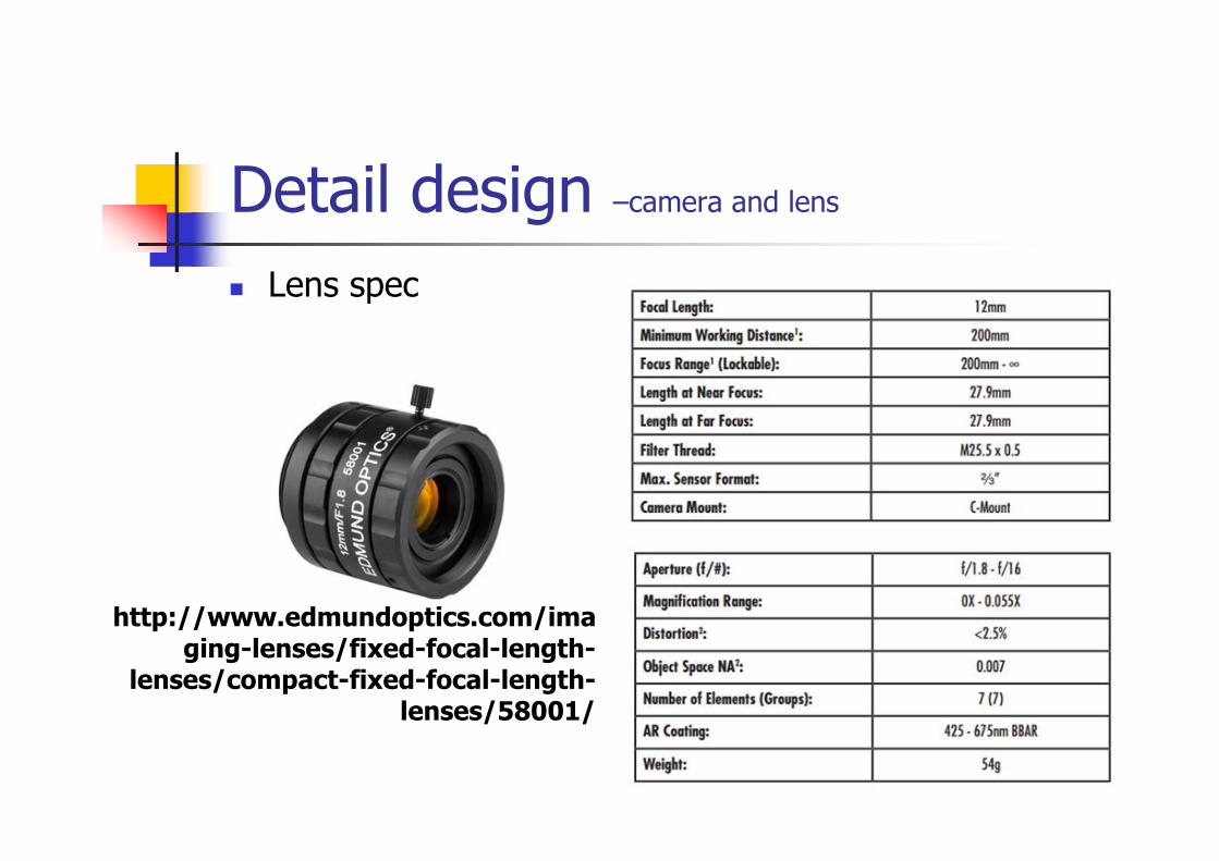
Detail design –camera and lens
Lens spec
http://www.edmundoptics.com/imaging-lenses/fixed-focal-length-
lenses/compact-fixed-focal-length-lenses/58001/
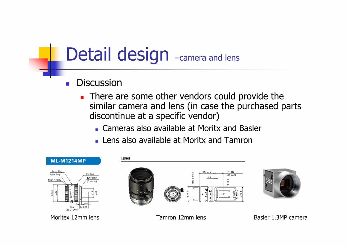
Discussion
There are some other vendors could provide the similar camera and lens (in case the purchased parts discontinue at a specific vendor)
Cameras also available at Moritx and Basler
Lens also available at Moritx and Tamron
Detail design –camera and lens
Moritex 12mm lens Tamron 12mm lens Basler 1.3MP camera
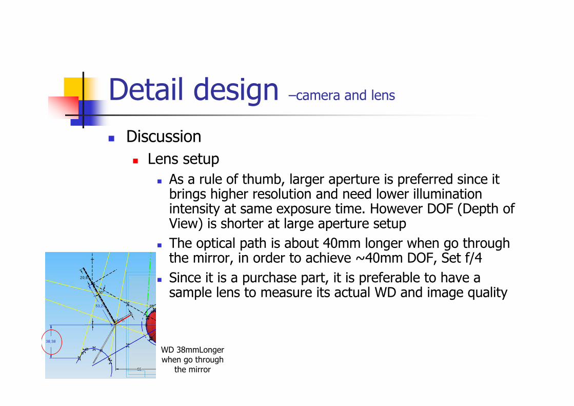
Discussion
Lens setup
As a rule of thumb, larger aperture is preferred since it brings higher resolution and need lower illumination intensity at same exposure time. However DOF (Depth of View) is shorter at large aperture setup
The optical path is about 40mm longer when go through the mirror, in order to achieve ~40mm DOF, Set f/4
Since it is a purchase part, it is preferable to have a sample lens to measure its actual WD and image quality
Detail design –camera and lens
WD 38mmLongerwhen go through
the mirror
Detail design –camera and lens
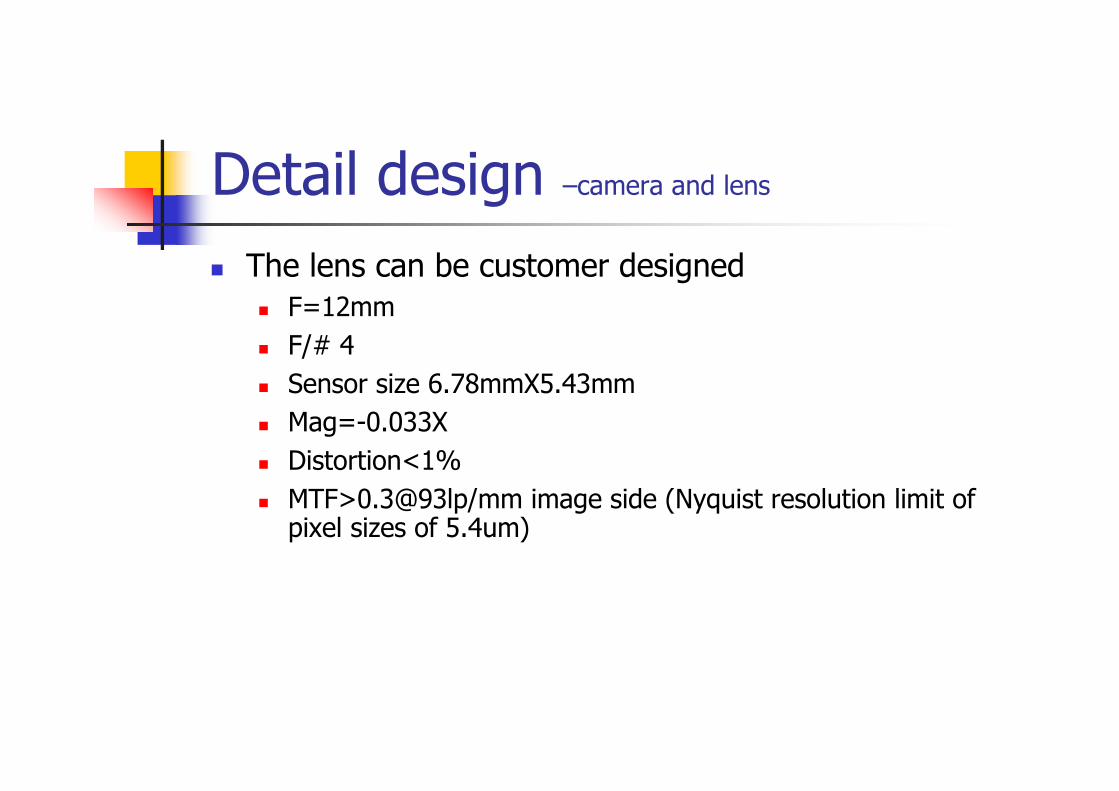
The lens can be customer designed F=12mm
F/# 4
Sensor size 6.78mmX5.43mm
Mag=-0.033X
Distortion<1%
MTF>0.3@93lp/mm image side (Nyquist resolution limit of pixel sizes of 5.4um)
Detail design –camera and lens
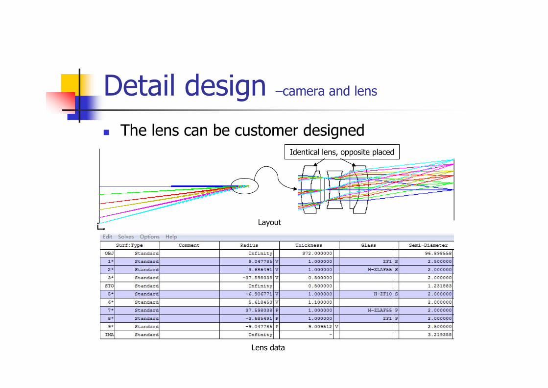
The lens can be customer designed
Layout
Lens data
Identical lens, opposite placed
Detail design –camera and lens
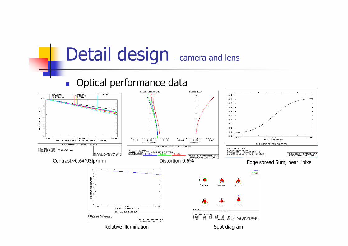
Optical performance data
Contrast~0.6@93lp/mm Distortion 0.6% Edge spread 5um, near 1pixel
Relative illumination Spot diagram
Detail design –camera and lens
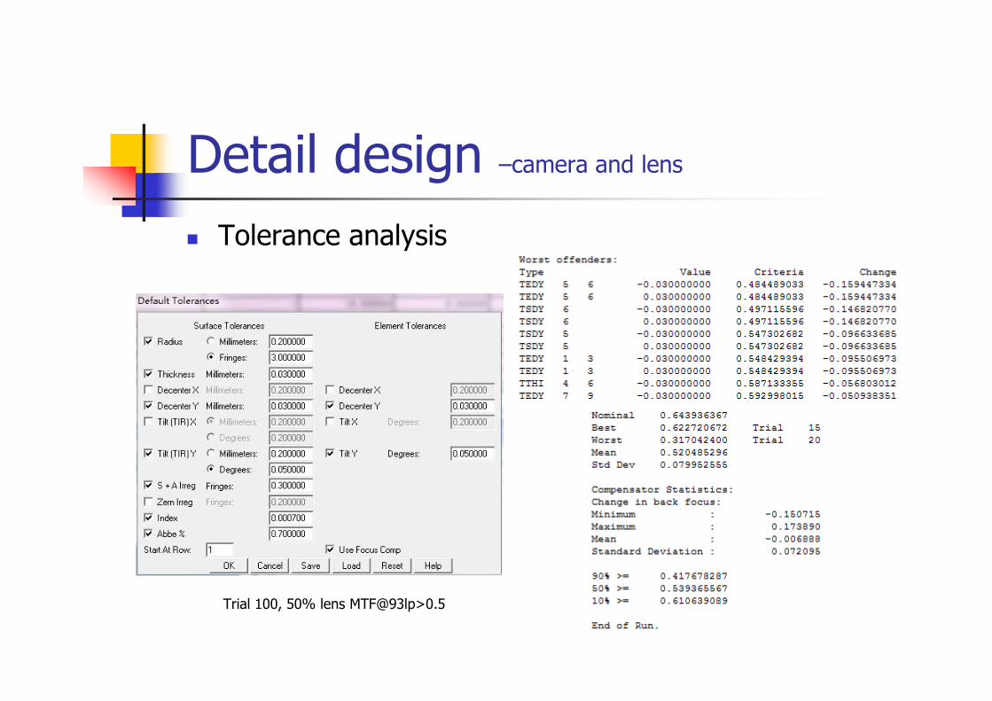
Tolerance analysis
Trial 100, 50% lens MTF@93lp>0.5

Detail design –Moving speed
In order to achieve high UPH, the capture method should be on-the-fly rather than stop-and-grab, which means the object is moving when take pic
The moving speed, exposure time, illumination intensity and image quality are correlated with each other, the goal is to get a bright and sharp image
Different object has different optical scatter property (described by BSDF). Experiment should be conducted to determine the illumination intensity needed under certain exposure time
Detail design –Moving speed
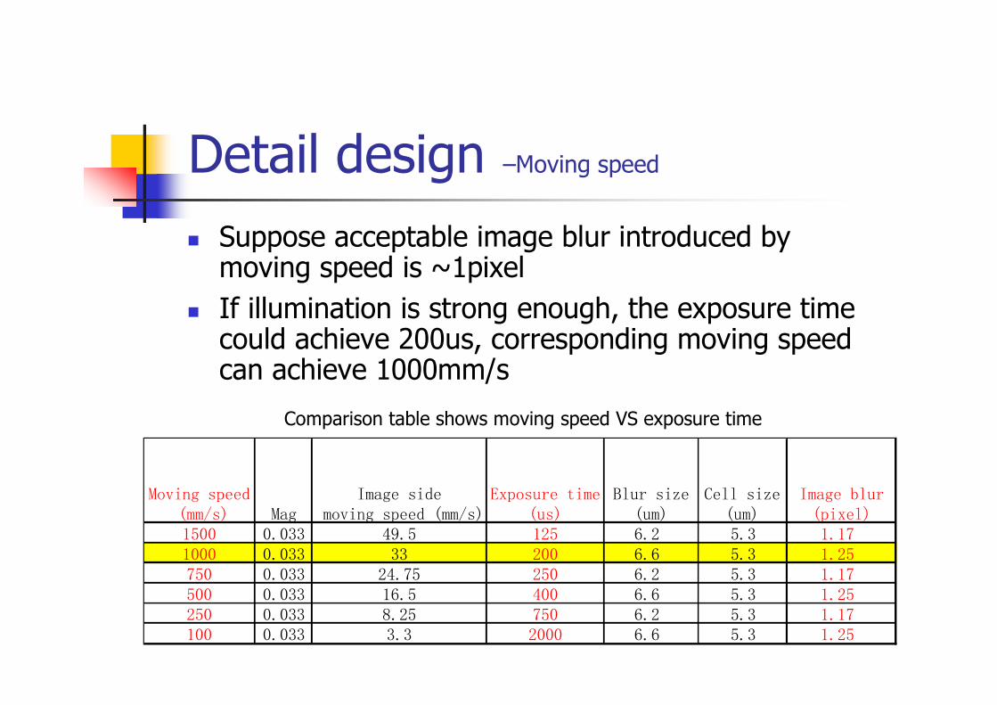
Moving speed (mm/s) Mag
Image side moving speed (mm/s)
Exposure time(us)
Blur size(um)
Cell size(um)
Image blur(pixel)
1500 0.033 49.5 125 6.2 5.3 1.171000 0.033 33 200 6.6 5.3 1.25750 0.033 24.75 250 6.2 5.3 1.17500 0.033 16.5 400 6.6 5.3 1.25250 0.033 8.25 750 6.2 5.3 1.17100 0.033 3.3 2000 6.6 5.3 1.25
Suppose acceptable image blur introduced by moving speed is ~1pixel
If illumination is strong enough, the exposure time could achieve 200us, corresponding moving speed can achieve 1000mm/s
Comparison table shows moving speed VS exposure time
Detail design –Lighting
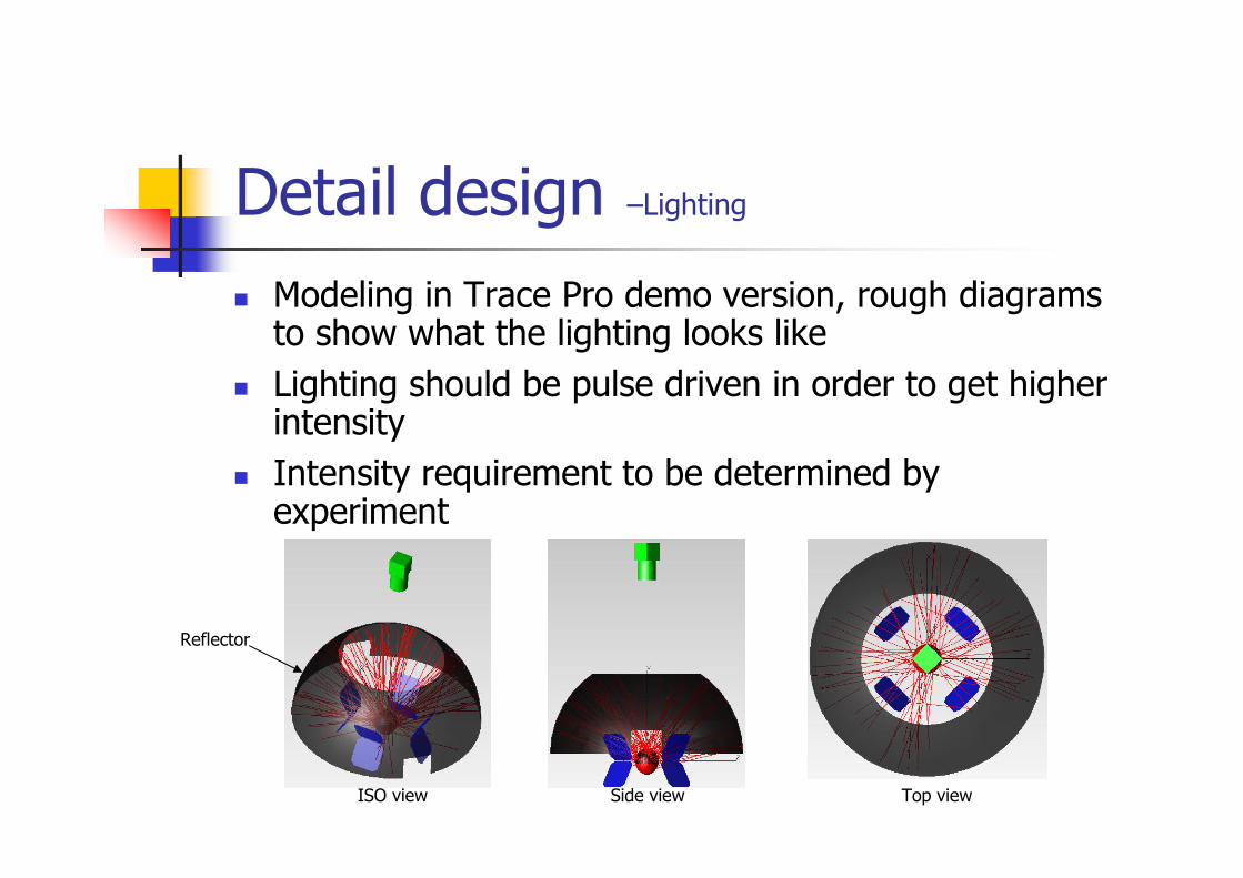
Modeling in Trace Pro demo version, rough diagrams to show what the lighting looks like
Lighting should be pulse driven in order to get higher intensity
Intensity requirement to be determined by experiment
ISO view Side view Top view
Reflector
Detail design –Lighting
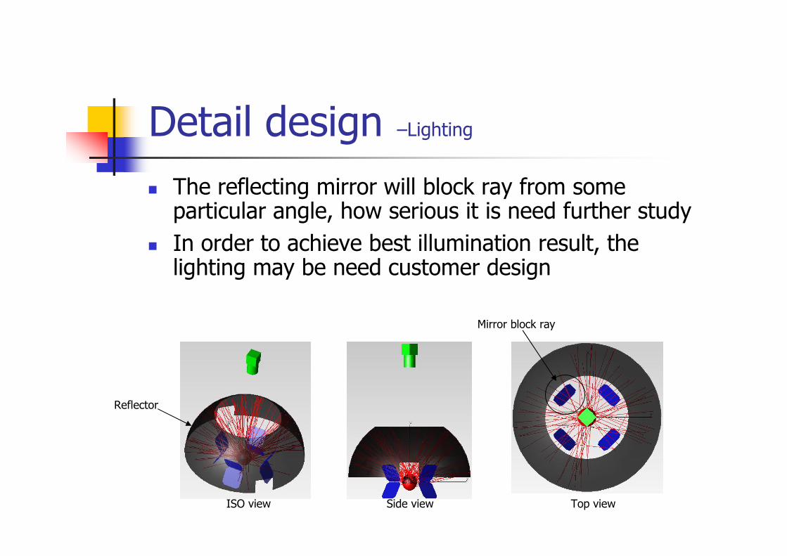
The reflecting mirror will block ray from some particular angle, how serious it is need further study
In order to achieve best illumination result, the lighting may be need customer design
ISO view Side view Top view
Reflector
Mirror block ray
Detail design –Vision system specification
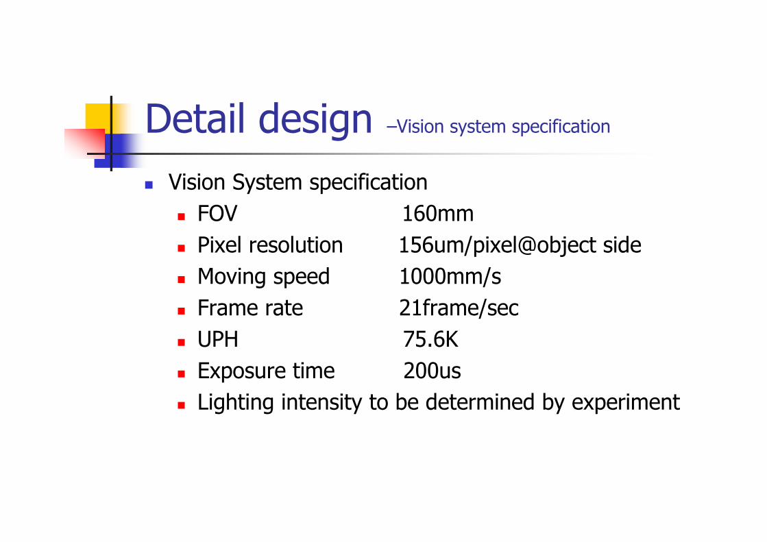
Vision System specification
FOV 160mm
Pixel resolution 156um/pixel@object side
Moving speed 1000mm/s
Frame rate 21frame/sec
UPH 75.6K
Exposure time 200us
Lighting intensity to be determined by experiment
Pending issue
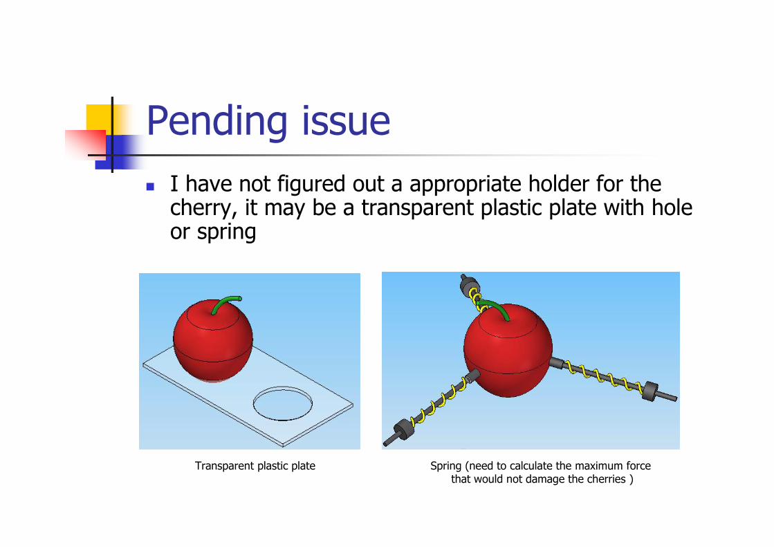
I have not figured out a appropriate holder for the cherry, it may be a transparent plastic plate with hole or spring
Transparent plastic plate Spring (need to calculate the maximum forcethat would not damage the cherries )
Pending issue
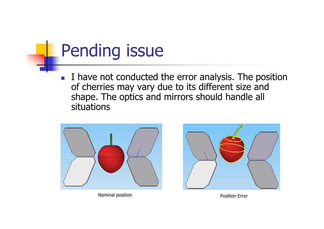
I have not conducted the error analysis. The position of cherries may vary due to its different size and shape. The optics and mirrors should handle all situations
Nominal position Position Error
Pending issue
I have not made a detailed procedure to assemble the vision module and test it
Lighting intensity should be determined by the experiment
In above design, there are a lot of assumptions such as allowed working distance, pixel resolution, the minimum feature size, etc. The actual value need teamwork to figure out. Keep systematic thinking in mind then balance system parameter to optimize the performance
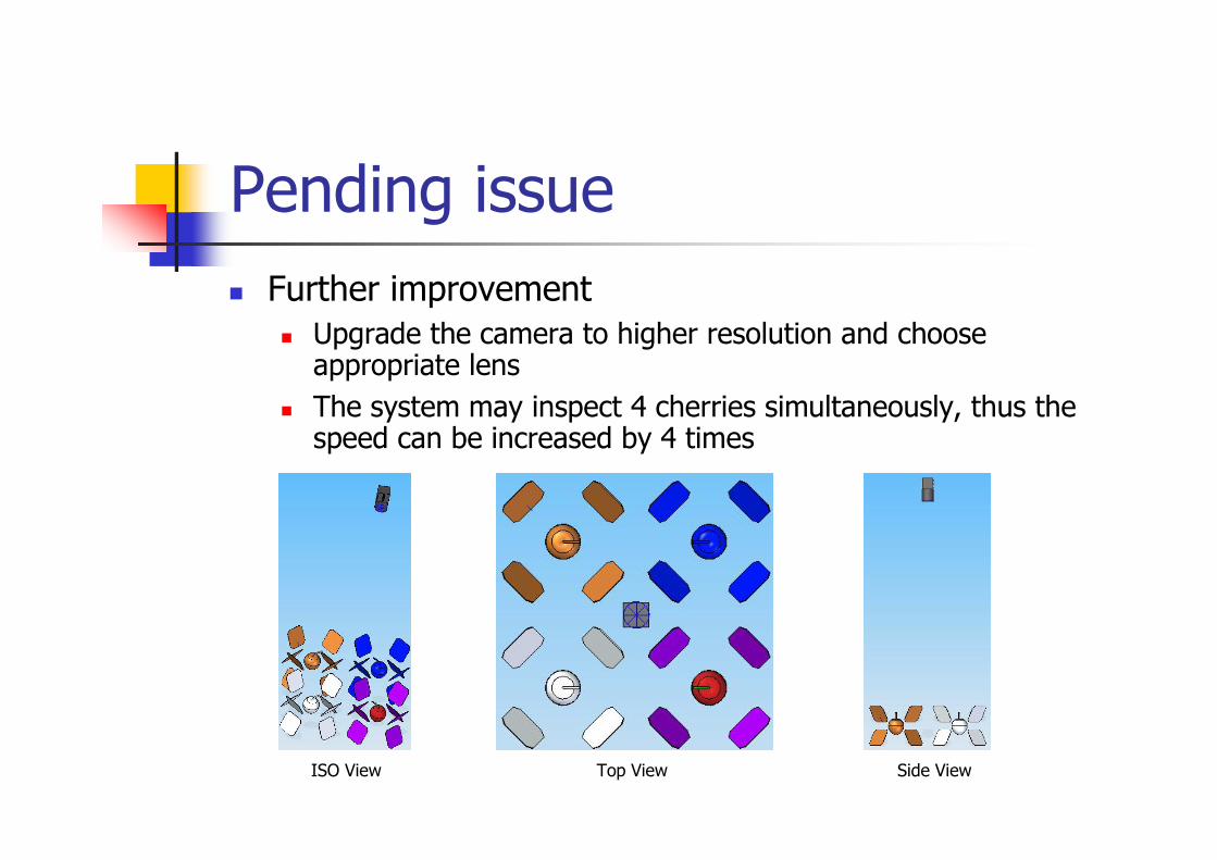
Further improvement Upgrade the camera to higher resolution and choose
appropriate lens
The system may inspect 4 cherries simultaneously, thus the speed can be increased by 4 times
Pending issue
ISO View Top View Side View
Appendix -Understanding about compac system
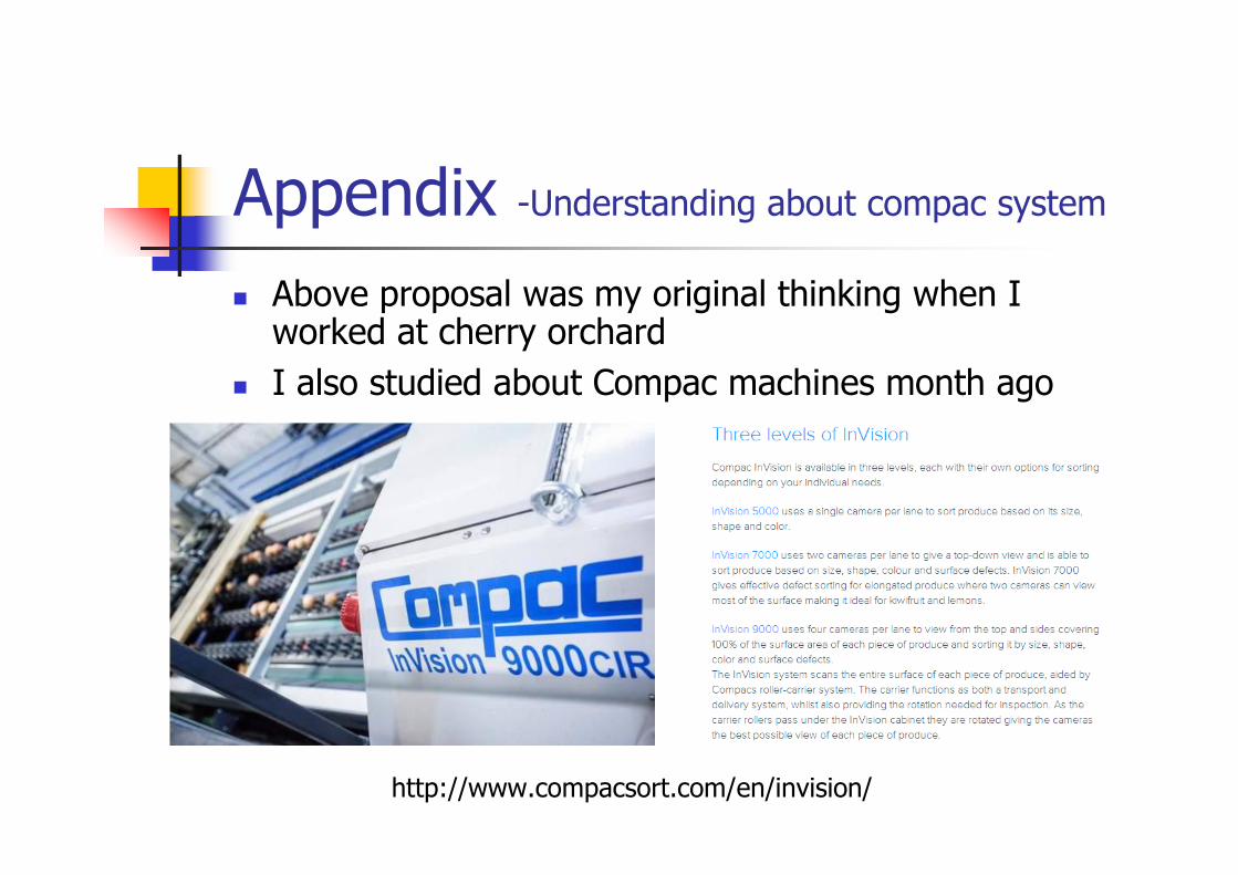
Above proposal was my original thinking when I worked at cherry orchard
I also studied about Compac machines month ago
http://www.compacsort.com/en/invision/
Appendix -Understanding about compac system
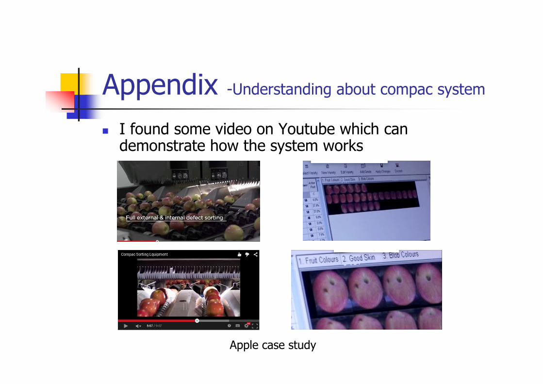
I found some video on Youtube which can demonstrate how the system works
Apple case study
Appendix -Understanding about compac system
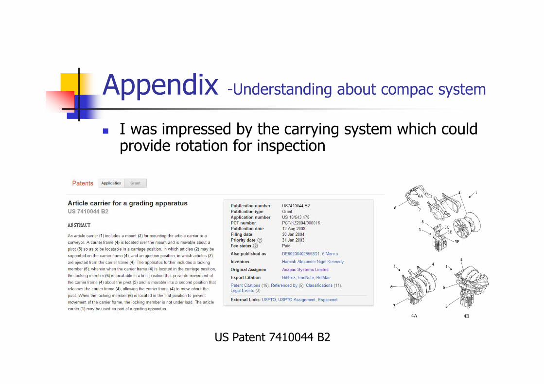
I was impressed by the carrying system which could provide rotation for inspection
US Patent 7410044 B2
Appendix -Understanding about compac system
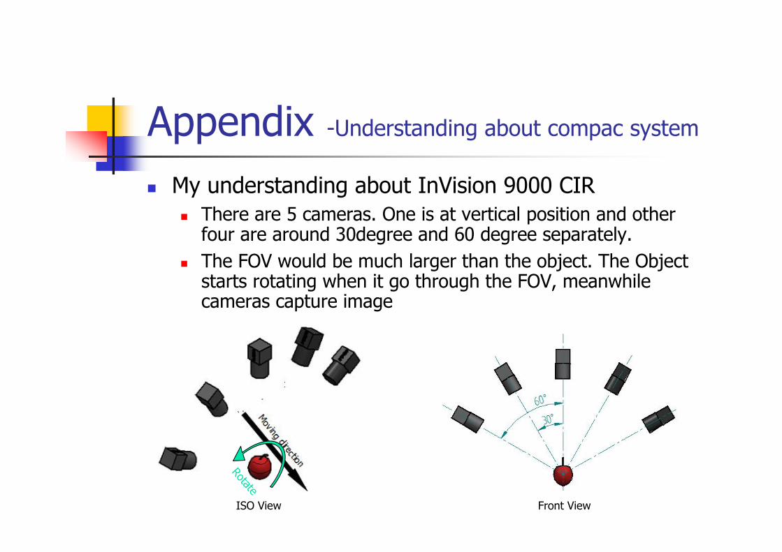
My understanding about InVision 9000 CIR There are 5 cameras. One is at vertical position and other
four are around 30degree and 60 degree separately.
The FOV would be much larger than the object. The Object starts rotating when it go through the FOV, meanwhile cameras capture image
Rotate
ISO View Front View
Appendix -Understanding about compac system
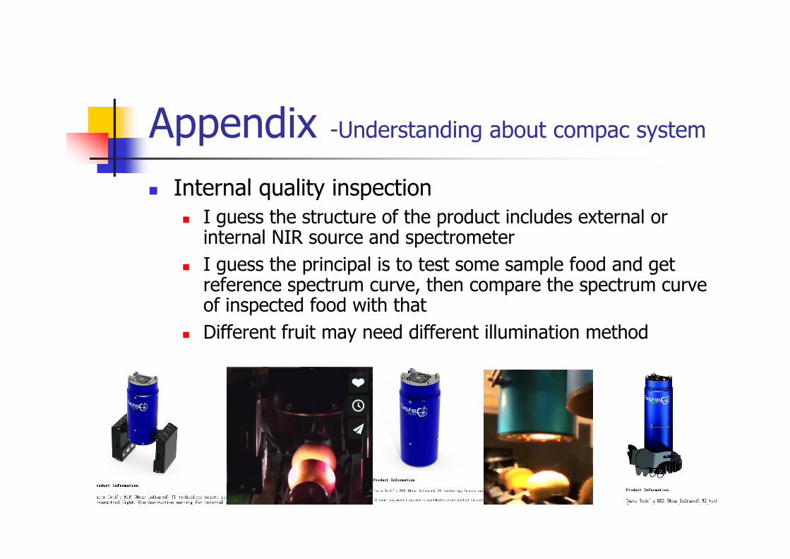
Internal quality inspection I guess the structure of the product includes external or
internal NIR source and spectrometer
I guess the principal is to test some sample food and get reference spectrum curve, then compare the spectrum curve of inspected food with that
Different fruit may need different illumination method
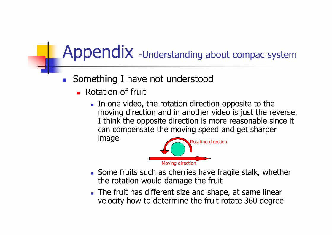
Something I have not understood
Rotation of fruit
In one video, the rotation direction opposite to the moving direction and in another video is just the reverse. I think the opposite direction is more reasonable since it can compensate the moving speed and get sharper image
Some fruits such as cherries have fragile stalk, whether the rotation would damage the fruit
The fruit has different size and shape, at same linear velocity how to determine the fruit rotate 360 degree
Appendix -Understanding about compac system
Moving direction
Rotating direction
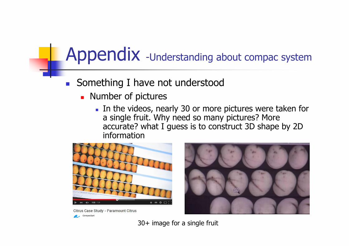
Something I have not understood
Number of pictures
In the videos, nearly 30 or more pictures were taken for a single fruit. Why need so many pictures? More accurate? what I guess is to construct 3D shape by 2D information
Appendix -Understanding about compac system
30+ image for a single fruit

The END
Thanks
Hua Zhang (Alex)
264 Yaldhurst Road,
Christchurch City 8042
Email: [email protected]
Mobile: 021 0235 3269
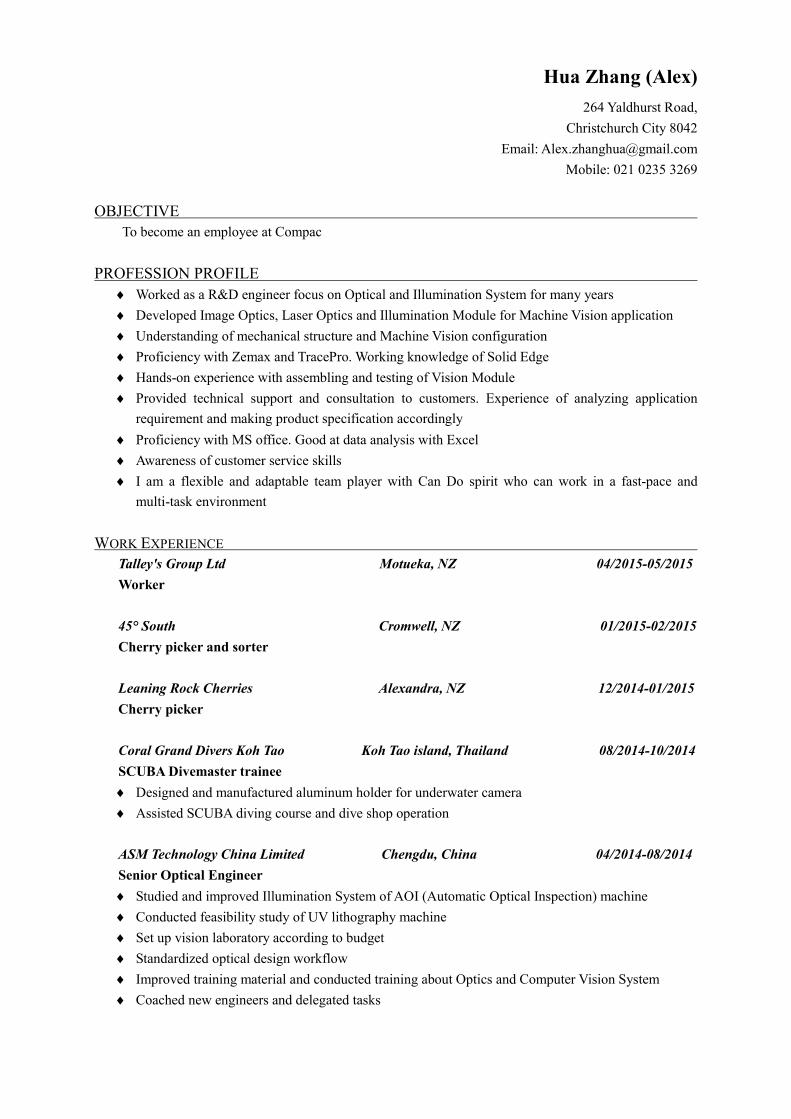
OBJECTIVE
To become an employee at Compac
PROFESSION PROFILE
Worked as a R&D engineer focus on Optical and Illumination System for many years
Developed Image Optics, Laser Optics and Illumination Module for Machine Vision application
Understanding of mechanical structure and Machine Vision configuration
Proficiency with Zemax and TracePro. Working knowledge of Solid Edge
Hands-on experience with assembling and testing of Vision Module
Provided technical support and consultation to customers. Experience of analyzing application
requirement and making product specification accordingly
Proficiency with MS office. Good at data analysis with Excel
Awareness of customer service skills
I am a flexible and adaptable team player with Can Do spirit who can work in a fast-pace and
multi-task environment
WORK EXPERIENCE
Talley's Group Ltd Motueka, NZ 04/2015-05/2015
Worker
45° South Cromwell, NZ 01/2015-02/2015
Cherry picker and sorter
Leaning Rock Cherries Alexandra, NZ 12/2014-01/2015
Cherry picker
Coral Grand Divers Koh Tao Koh Tao island, Thailand 08/2014-10/2014
SCUBA Divemaster trainee
Designed and manufactured aluminum holder for underwater camera
Assisted SCUBA diving course and dive shop operation
ASM Technology China Limited Chengdu, China 04/2014-08/2014
Senior Optical Engineer
Studied and improved Illumination System of AOI (Automatic Optical Inspection) machine
Conducted feasibility study of UV lithography machine
Set up vision laboratory according to budget
Standardized optical design workflow
Improved training material and conducted training about Optics and Computer Vision System
Coached new engineers and delegated tasks
ASM Technology Hong Kong Limited Hong Kong, China 03/2012-03/2014
R&D Engineer
Worked with product team and sales team to develop vision module
Worked with manufacturing team to ensure manufacturability and product delivery on schedule
Gave quick response to the field issues and new requirements which are fed back from customers
Summarized application requirements and made product specification accordingly
Developed standard Machine Vision image lens series and lighting series
Provided technical support for customer to choose appropriate vision module
Participated in development of LED inspection machine
Participated in development of Image Sensor Inspection and Camera Module Bonding machine
Improved lighting module of Lead frame inspection system
Developed Illumination System of UV and IR application
Studied the principal and the key designing factor of Mask Aligner Lithography machine
Improved in-house test station used to test the property of optical reflectance
ASM Technology China Limited Chengdu, China 02/2009-02/2012
Optical Engineer
Developed optical module of laser marking system (Patent Pending)
Developed Laser scribing system (US 8610902 B2, US 8354612 B2 )
Supported Optical Sensor research and development
Studied about fiber illumination system
Studied about the property of material reflectance
EDUCATION
University of Electronic Science and Technology of China Chengdu, Sichuan, China
Master of Science focus on Optics 09/2005-06/2008
Changchun Institute of Optics and Fine Mechanics Changchun, Jilin, China
Bachelor of Science focus on Optoelectronics 09/2001-06/2005
OTHER TRAINING AND SKILLS
5S workshop management
PADI Emergency First Response course
PADI Rescue diver and PADI Divemaster
HOBBIES AND INTEREST
Hiking, SCUBA Diving
REFEREES
Kieran Simpson, Cherry picker, Leaning Rock Cherry, Alexandra
Mobile: (0064) 027 810 8203
Xuqiong Chen, Technical Manager, ASM Technology Hong Kong Limited, Hong Kong
Phone: (00852) 2619 2450 Mobile: (00852) 6153 0188 Email: [email protected]
NY Hou, Section Manager, ASM Technology China Limited, Chengdu
Phone: (0086) 28 62870 0210 Mobile: (0086) 139 8097 5159 Email: [email protected]

Previous designs
Hua Zhang (Alex)264 Yaldhurst Road,Christchurch City 8042Email: [email protected]: 021 0235 3269
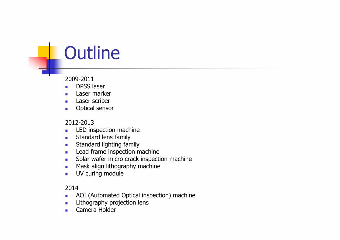
Outline2009-2011 DPSS laser Laser marker Laser scriber Optical sensor
2012-2013 LED inspection machine Standard lens family Standard lighting family Lead frame inspection machine Solar wafer micro crack inspection machine Mask align lithography machine UV curing module
2014 AOI (Automated Optical inspection) machine Lithography projection lens Camera Holder
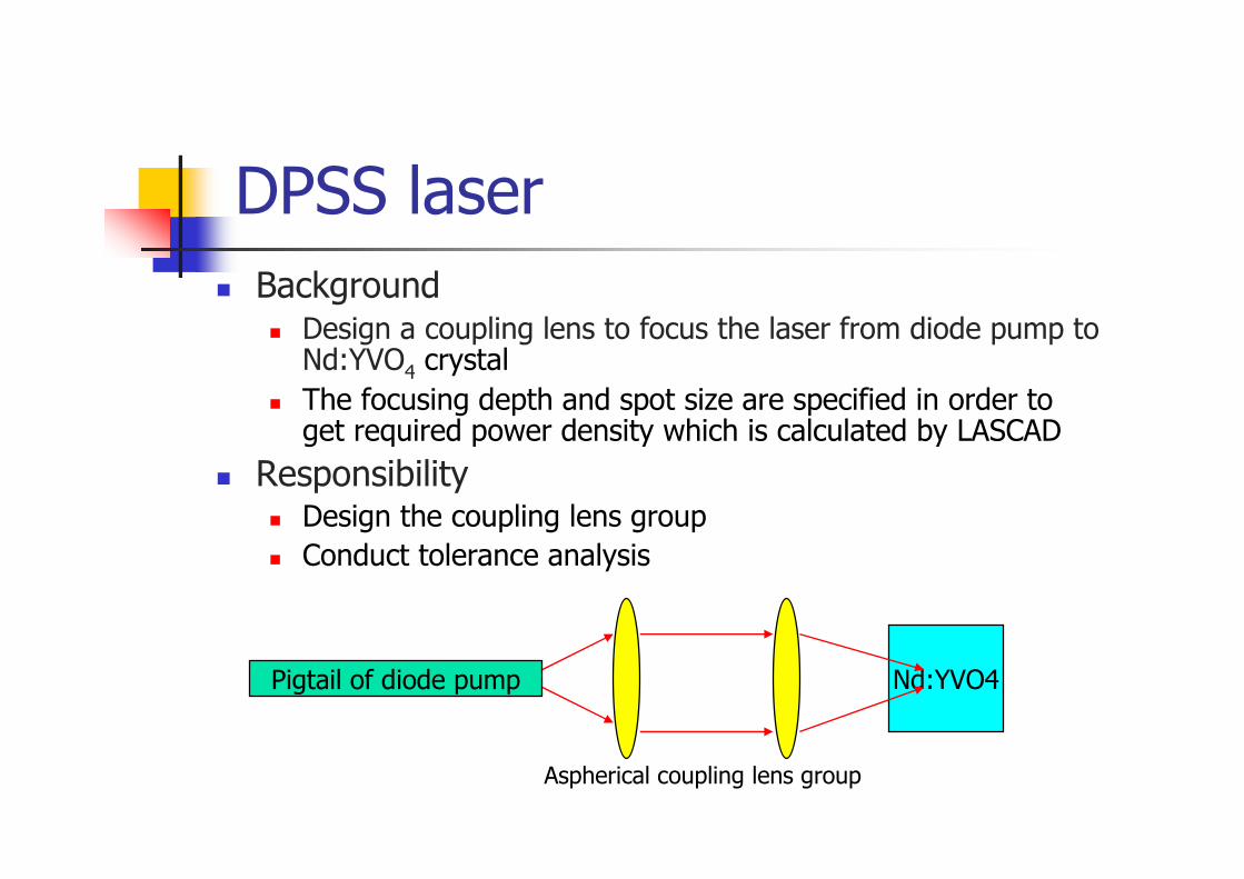
DPSS laser
Background Design a coupling lens to focus the laser from diode pump to
Nd:YVO4 crystal
The focusing depth and spot size are specified in order to get required power density which is calculated by LASCAD
Responsibility Design the coupling lens group
Conduct tolerance analysis
Pigtail of diode pump Nd:YVO4
Aspherical coupling lens group
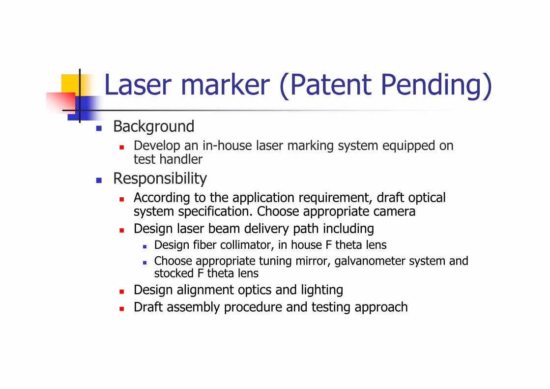
Laser marker (Patent Pending)
Background Develop an in-house laser marking system equipped on
test handler
Responsibility According to the application requirement, draft optical
system specification. Choose appropriate camera
Design laser beam delivery path including Design fiber collimator, in house F theta lens
Choose appropriate tuning mirror, galvanometer system and stocked F theta lens
Design alignment optics and lighting
Draft assembly procedure and testing approach
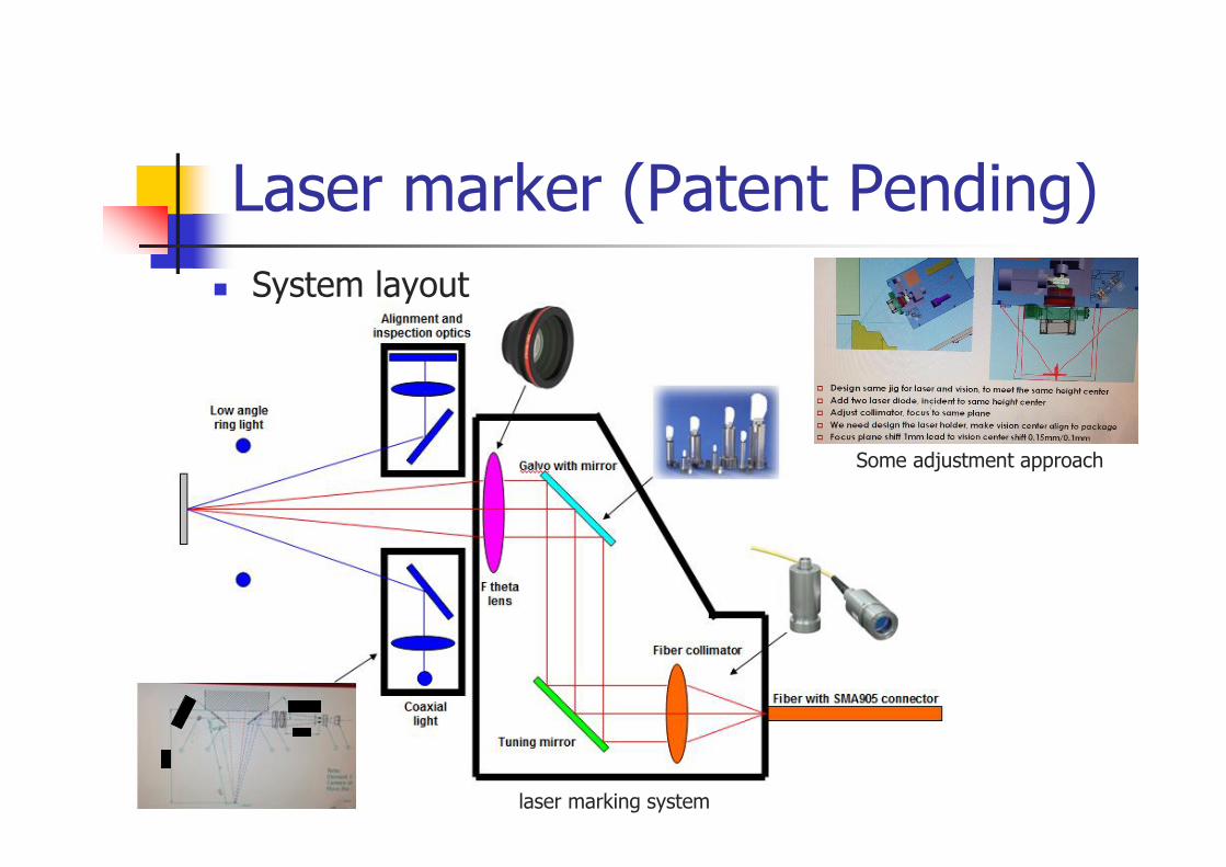
System layout
laser marking system
Some adjustment approach
Laser marker (Patent Pending)
Alignment optics
Height detection opticsPost-scribe inspection optics
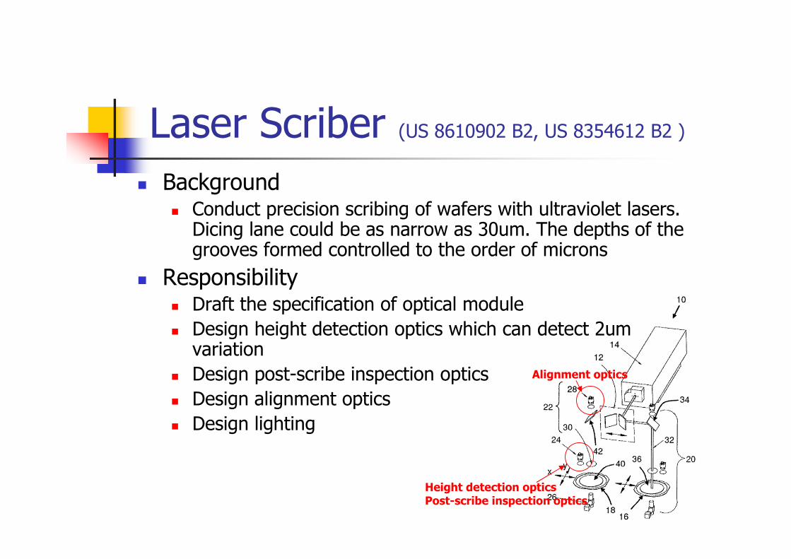
Laser Scriber (US 8610902 B2, US 8354612 B2 )
Background Conduct precision scribing of wafers with ultraviolet lasers.
Dicing lane could be as narrow as 30um. The depths of the grooves formed controlled to the order of microns
Responsibility Draft the specification of optical module
Design height detection optics which can detect 2um variation
Design post-scribe inspection optics
Design alignment optics
Design lighting
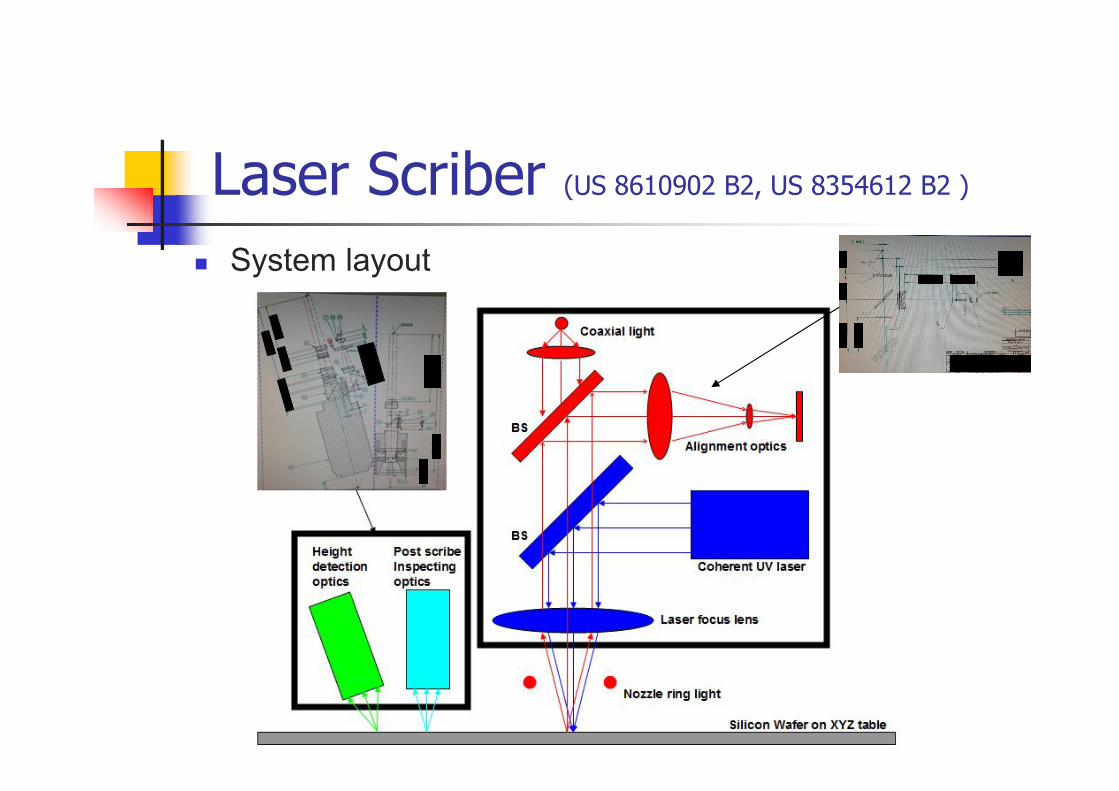
Laser Scriber (US 8610902 B2, US 8354612 B2 )
System layout
High PrecisionRonchi Rulings
Large NAObjectivelens
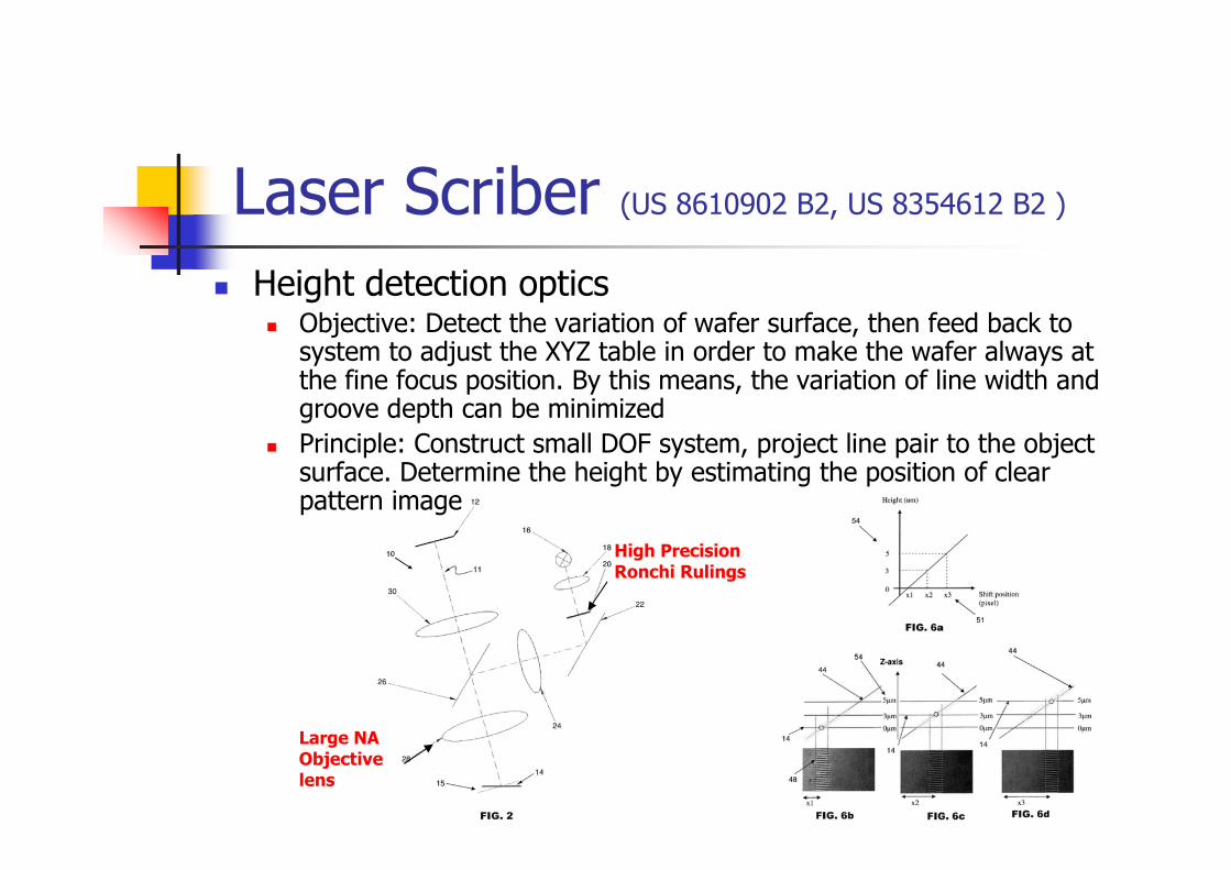
Laser Scriber (US 8610902 B2, US 8354612 B2 )
Height detection optics Objective: Detect the variation of wafer surface, then feed back to
system to adjust the XYZ table in order to make the wafer always at the fine focus position. By this means, the variation of line width and groove depth can be minimized
Principle: Construct small DOF system, project line pair to the object surface. Determine the height by estimating the position of clear pattern image
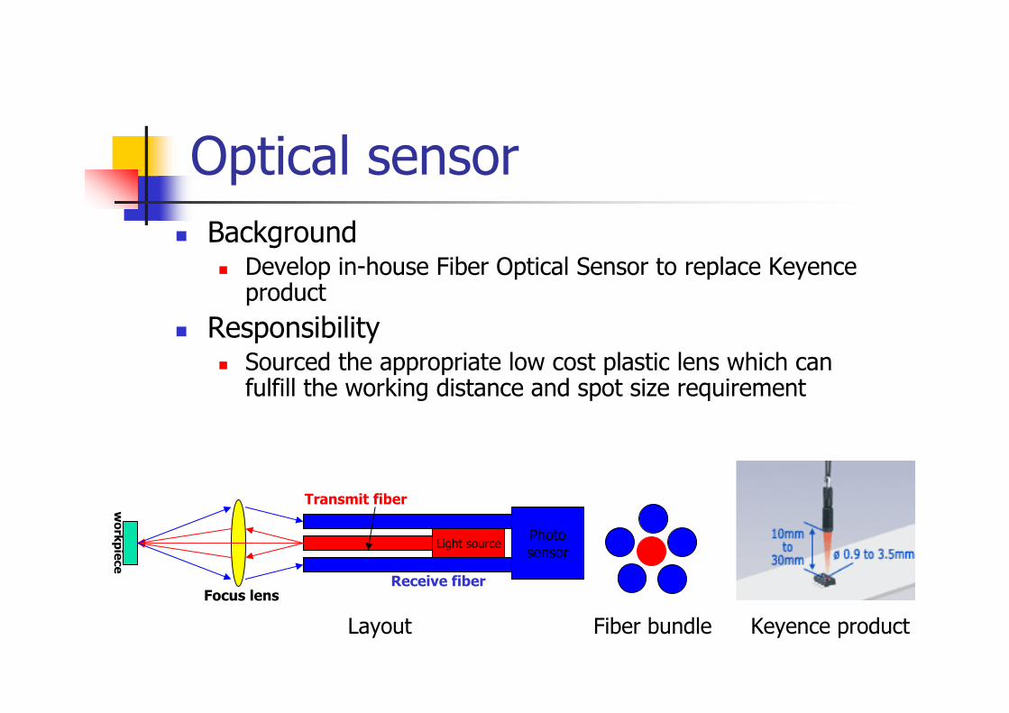
Optical sensor
Background Develop in-house Fiber Optical Sensor to replace Keyence
product
Responsibility Sourced the appropriate low cost plastic lens which can
fulfill the working distance and spot size requirement
Light sourcePhotosensor
Transmit fiber
Receive fiberFocus lens
wo
rkp
iece
Layout Fiber bundle Keyence product
LED inspection machine Background
Develop a machine to inspect the LED die on wafer
Responsibility Draft optical module specification
Design high mag inspection optics
Design ultra bright ring light
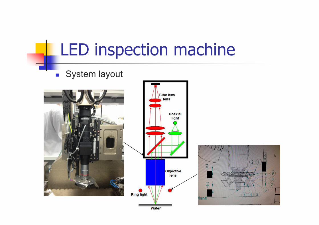
System layout
LED inspection machine
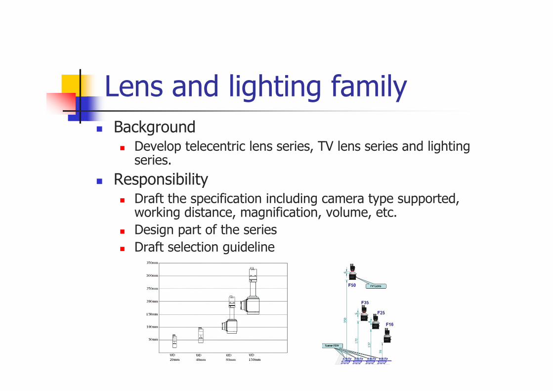
Lens and lighting family Background
Develop telecentric lens series, TV lens series and lighting series.
Responsibility Draft the specification including camera type supported,
working distance, magnification, volume, etc.
Design part of the series
Draft selection guideline
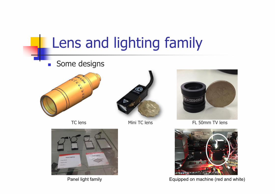
Lens and lighting family
Some designs
TC lens Mini TC lens FL 50mm TV lens
Panel light family Equipped on machine (red and white)
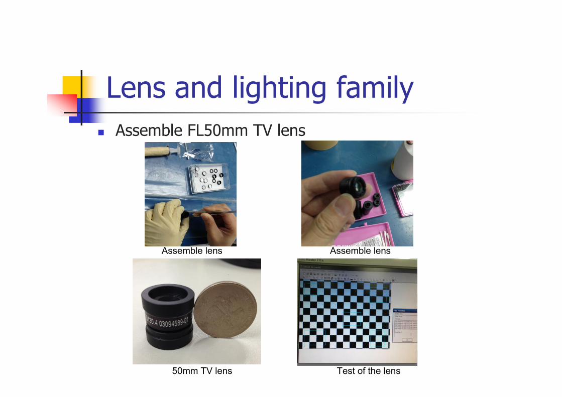
Assemble lens Assemble lens
Test of the lens50mm TV lens
Lens and lighting family
Assemble FL50mm TV lens
Lead frame inspection machine
Background Inspect the defect on lead frame by line scan camera and
rich angle lighting. The lighting module on first generation machine need to be improved
Responsibility Improve the lighting intensity
Improve the evenness
Conduct the analysis of mechanical part tolerance and assembly procedure.
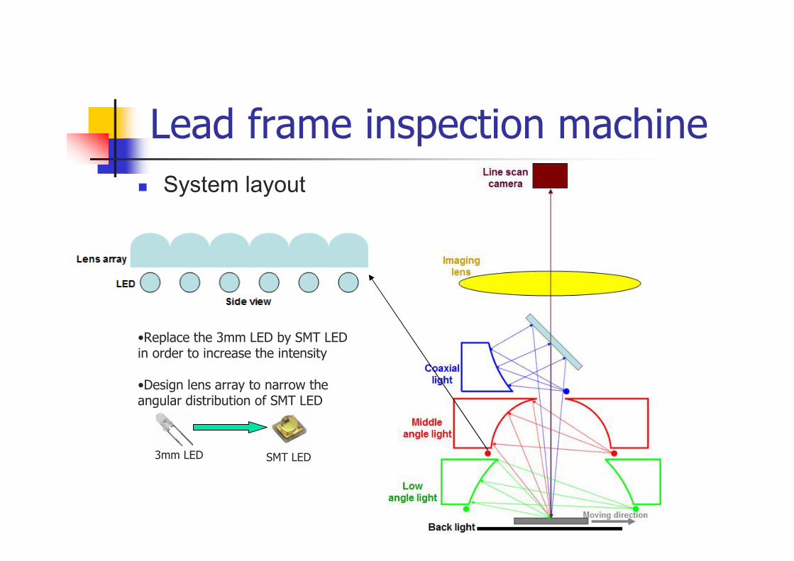
Lead frame inspection machine
System layout
•Replace the 3mm LED by SMT LED in order to increase the intensity
•Design lens array to narrow the angular distribution of SMT LED
3mm LED SMT LED
Solar wafer inspection machine
Background Inspect the micro crack on solar wafer by line scan camera
and IR lighting.
Responsibility Conduct the experiment to study the property of VCSEL
(Vertical-Cavity Surface-Emitting Laser) array
Conduct the experiment to determine the required lighting angle and lighting intensity
Design the lighting module
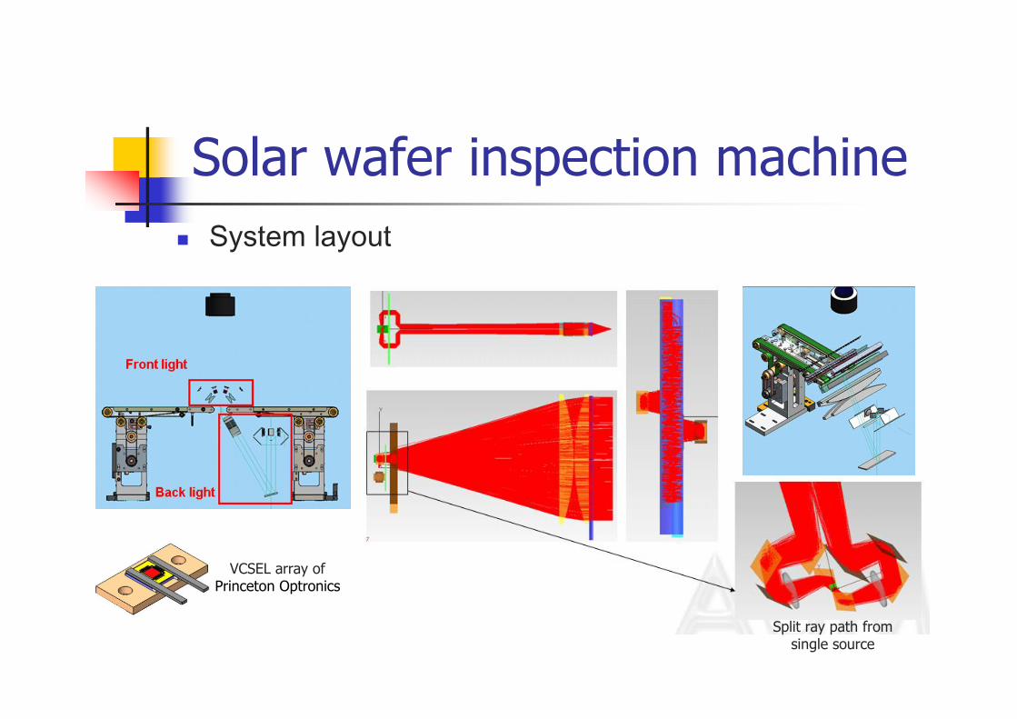
System layout
Solar wafer inspection machine
VCSEL array ofPrinceton Optronics
Split ray path from single source
Mask align lithography machine
Background Expose the structure of LED chip by UV light
Responsibility Study the key parameter and its impact on the system
Conduct simulation and find way to decrease the impact introduced by the variation of UV light source
Study the impact of diffraction at different gap between mask and wafer
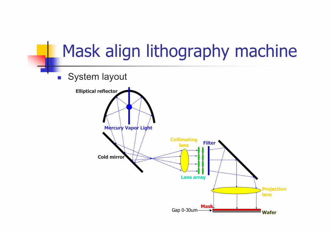
Mask align lithography machine
System layout
Projection lens
Elliptical reflector
Mercury Vapor Light
Cold mirror
Collimating lens
Lens array
Filter
Mask
WaferGap 0-30um
UV curing module
Background UV curing module is used to cure the UV glue. The machines
used to bond lens module and make LED panel equip such module
Responsibility Source suitable high power UV led
Design UV curing module, including spot curing type and line curing type
Propose cascade approach in order to achieve area curing
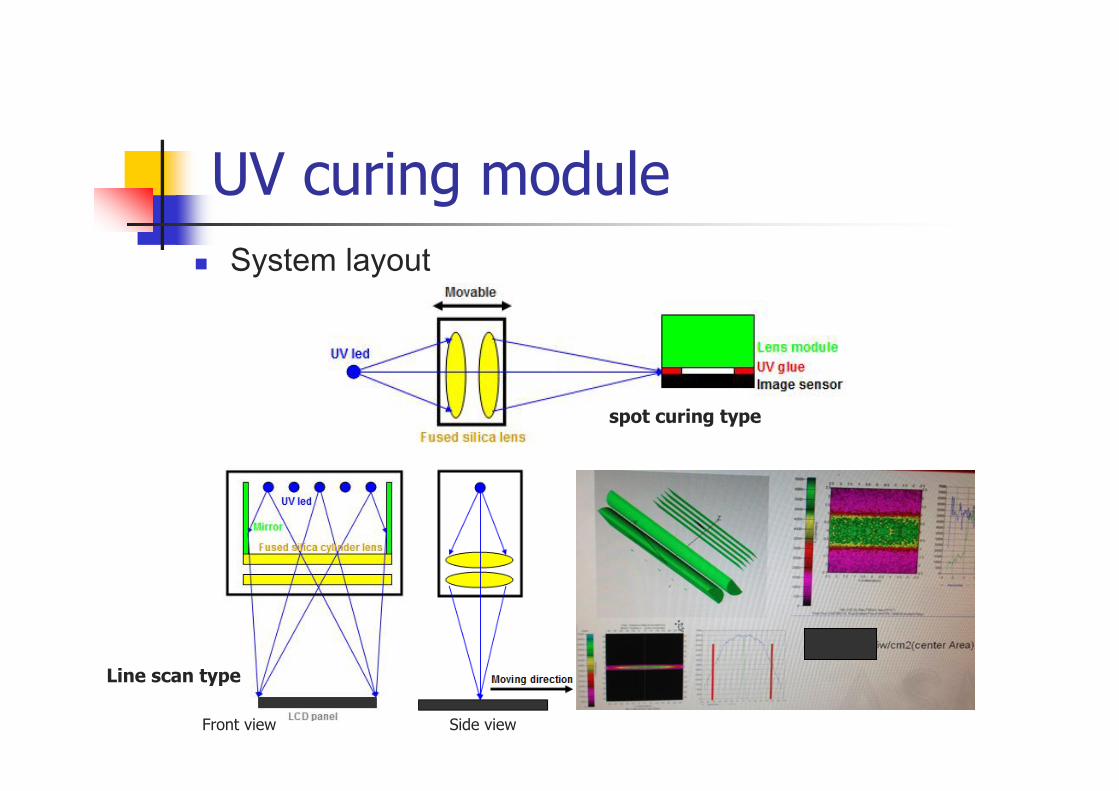
UV curing module
System layout
spot curing type
Line scan type
Front view Side view
AOI machine
Background AOI machine is used to inspect the defect of Semiconductor
chips, including Contamination, wire missing on IC chip
Foreign material on image sensor. The minimum size of foreign material could be as small as 2um
Responsibility Carry out experiment to determine the most optimized
lighting angle could highlight the feature on IC chip
Study the property of 2D reflective grating (Image sensor could be treated as grating)
Calculate the best combination of azimuth angle and zenith angle which could minimize the background noise
Design the lighting
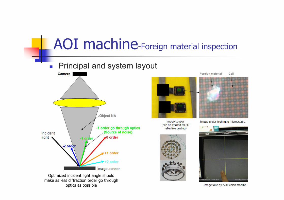
Optimized incident light angle should make as less diffraction order go through
optics as possible
Principal and system layout
AOI machine-Foreign material inspection
Lithography projection lens
Background The structure of high power SMT led requires deeper
groove depth while keep small critical dimension. it is hard to achieve by mask align approach. By projection approach, the process window could be wider
Responsibility Study the principal of stepper lithography and key design
factor at optical view
Source the commercial product and compare the specification
Source the third party lens maker who can design and make the large projection lens
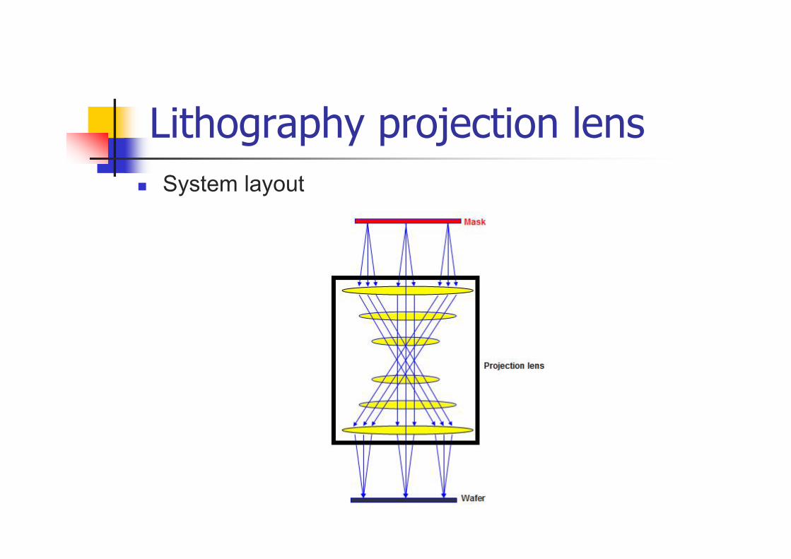
Lithography projection lens
System layout
Camera holder Background
Before I conducted my PADI Dive master training, I would like to buy a camera holder to hold my GoPro and Iphonewith waterproof case. With the holder, the video would be much more stable. The holder I found was too expensive (~200NZD). I designed one by myself and found a local workshop to make it. I made two set at unite price ~45NZD
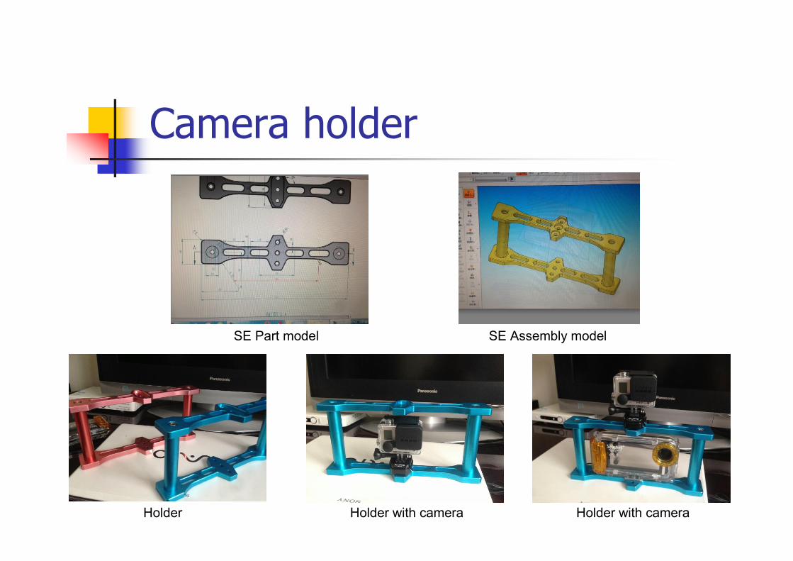
SE Part model SE Assembly model
Holder Holder with camera
Camera holder
Holder with camera
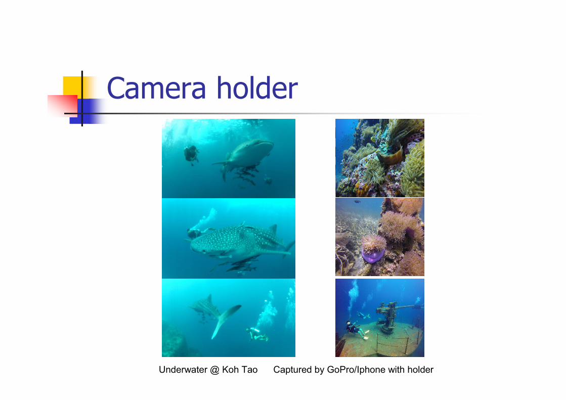
Underwater @ Koh Tao Captured by GoPro/Iphone with holder
Camera holder

THE END
THANK YOU