Alcohol Fermentation
82
PROJECT REPORT ON ETHANOL PRODUCTION SHIV BHATIA
Transcript of Alcohol Fermentation
PROJECT REPORT
ON
ETHANOL
PRODUCTION
SHIV BHATIA CONTENTS
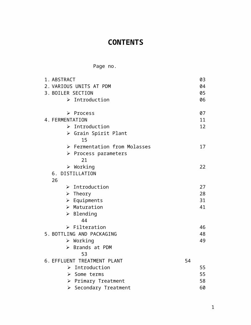
Page no.
1. ABSTRACT 032. VARIOUS UNITS AT PDM 043. BOILER SECTION 05
Introduction 06
Process 074. FERMENTATION 11
Introduction 12 Grain Spirit Plant 15 Fermentation from Molasses 17 Process parameters 21 Working 22
6. DISTILLATION 26 Introduction 27 Theory 28 Equipments 31 Maturation 41 Blending 44
Filteration 465. BOTTLING AND PACKAGING 48
Working 49 Brands at PDM 53
6. EFFLUENT TREATMENT PLANT 54 Introduction 55 Some terms 55 Primary Treatment 58 Secondary Treatment 60
7. LAB WORK 638. CONCLUSION 65
10. REFERENCES 66
1

ABSTRACT
The main target at the distillery is to produce ethanol efficiently using molasses and grain(wheat and rice). Ethanol is produced using fermentation (anaerobic). The microbe used for this purpose is Saccharomyces cerevisiae(yeast). Before fermentation inoculum is grown in a sterilized pre-fermenter(upstream). After the fermentation different constituents are separated using distillation (downstream). Then these constituents are subjected to blending by adding flavors. After it these different products are kept for maturation to have different tastes and color according to the quality needed. The different products obtained are packed in bottles in bottling and packaging section. The spent media (after fermentation )is subjected to ETP(primary and secondary) section before it is being discharged in nearby fields where it is used as fertilizers by the farmers.
2
Various Units at Patiala Distillery
1. Boiling Section
2. Fermentation Section
3. Distillation Section
4. Bottling Plant
5. Laboratories ( R & D and Distillery Lab)
6. Effluent Treatment Plant
3
BOILER SECTION
4
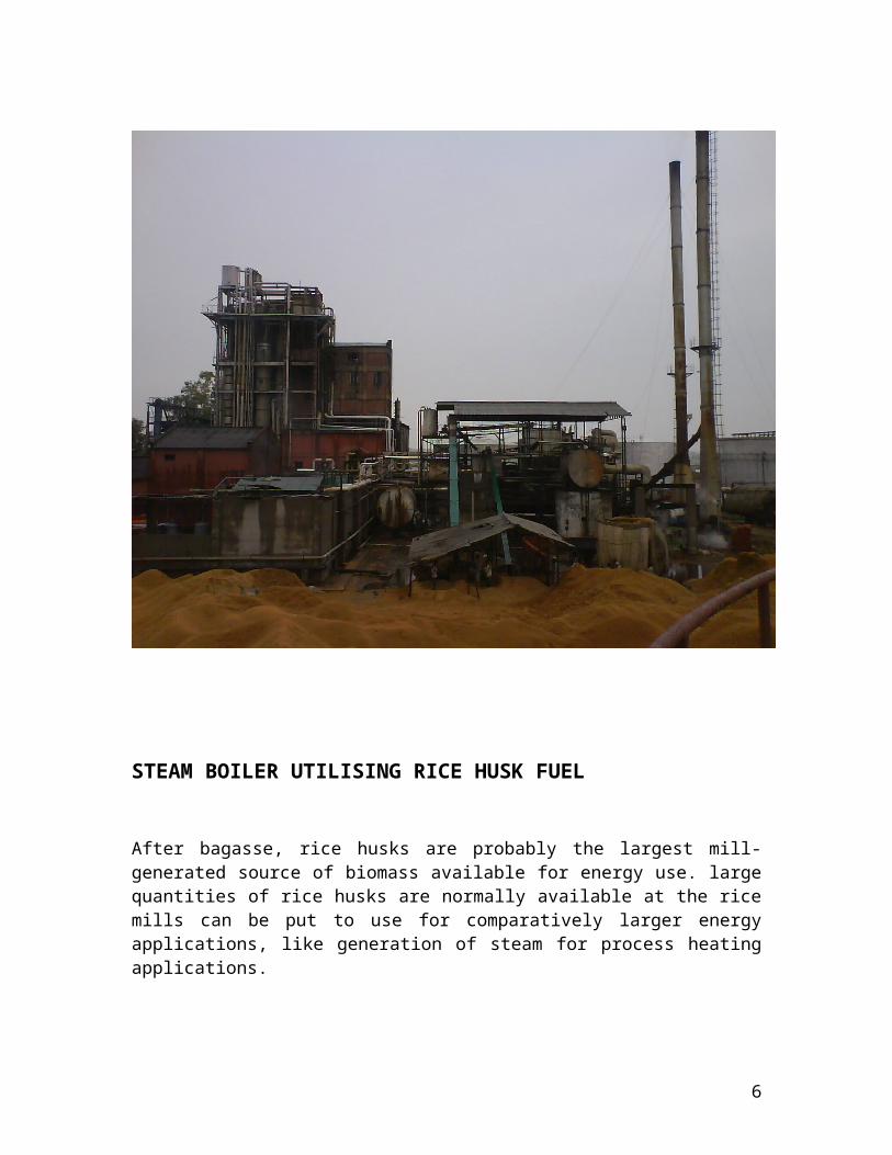
STEAM BOILER UTILISING RICE HUSK FUEL
After bagasse, rice husks are probably the largest mill-generated source of biomass available for energy use. large quantities of rice husks are normally available at the rice mills can be put to use for comparatively larger energy applications, like generation of steam for process heating applications.
Small process industries in northern India, like Distillers, paper mills, fertilizer industries etc have started using rice husk, as a substitute for firewood and coal, as a fuel in their boilers to generate steam.
In recent times, The development of compact, fluidized bed process steam boilers by the boiler manufacturers led to more efficient and environment-friendly utilization of this widely available bio-fuel resource. This, on the one hand, led to the sustainable use of rice husks, which was once a disposal problem, and on the other hand, enabled the process industries to meet their energy needs in a more cost-effective manner.
Some of the characteristics of such fluidized bed boilers include:
the ability to burn low-grade biomass fuels, due to the high thermal inertia and high turbulence of the fluidized bed.
the high combustion efficiency, due to the turbulent mixing of the fluidized bed and the long residence time of the fuel in the furnace.
The fluidised bed combustion technology gives a high efficiency of the order of 75-80%, the other advantages are quick start-up, low pollution, simple operation and maintenance.
5
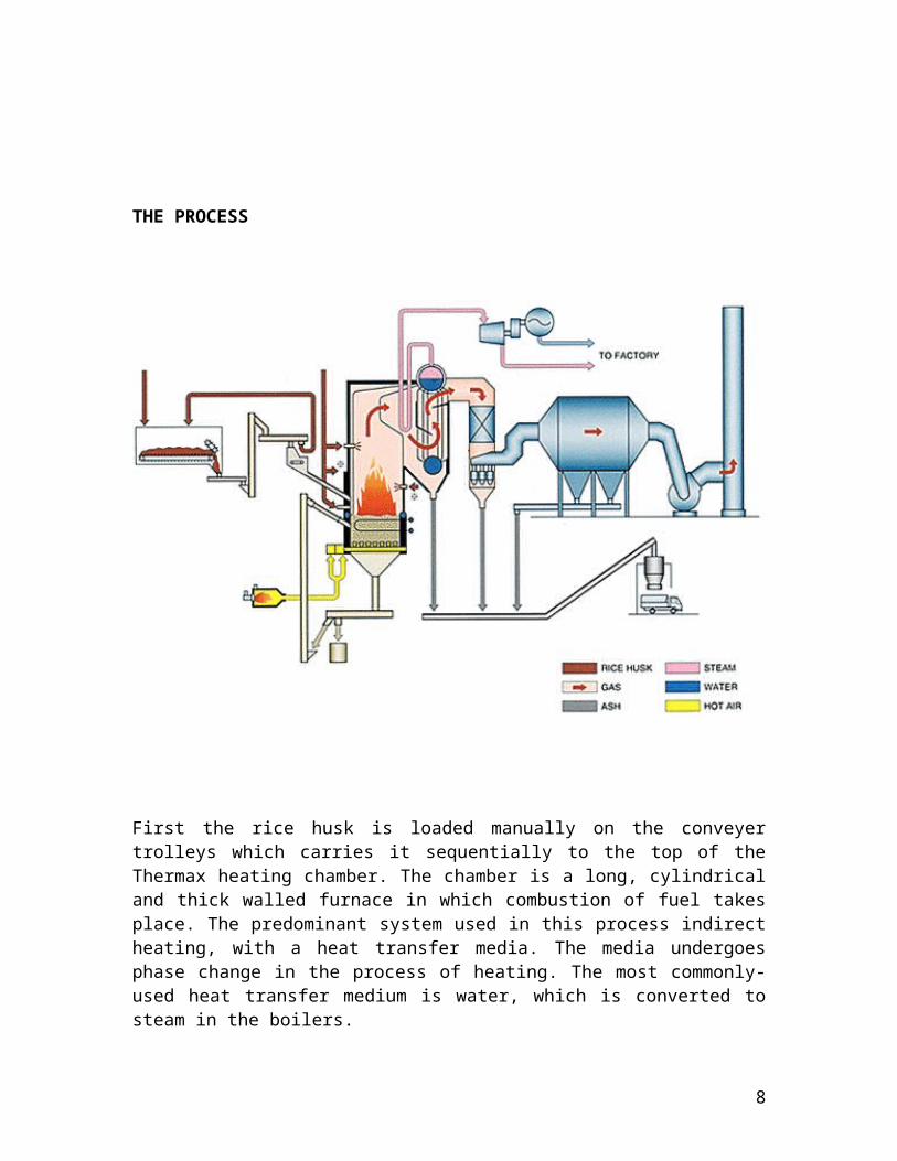
THE PROCESS
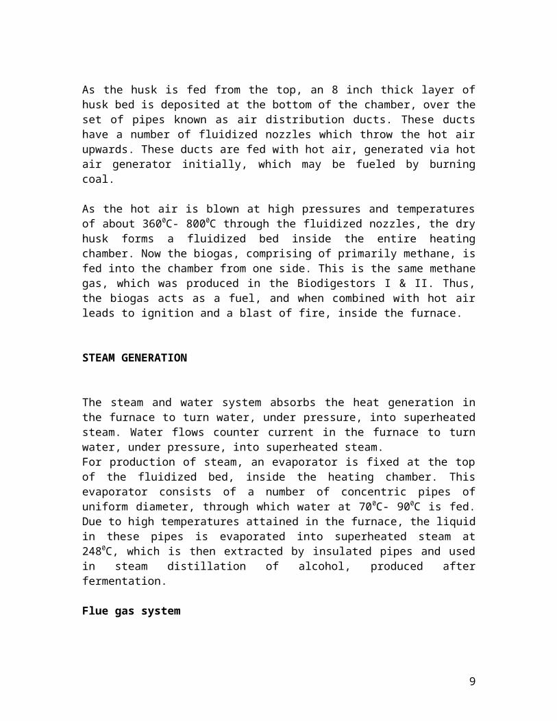
First the rice husk is loaded manually on the conveyer trolleys which carries it sequentially to the top of the Thermax heating chamber. The chamber is a long, cylindrical and thick walled furnace in which combustion of fuel takes place. The predominant system used in this process indirect heating, with a heat transfer media. The media undergoes phase change in the process of heating. The most commonly-used heat transfer medium is water, which is converted to steam in the boilers.
As the husk is fed from the top, an 8 inch thick layer of husk bed is deposited at the bottom of the chamber, over the set of pipes known
6
as air distribution ducts. These ducts have a number of fluidized nozzles which throw the hot air upwards. These ducts are fed with hot air, generated via hot air generator initially, which may be fueled by burning coal.
As the hot air is blown at high pressures and temperatures of about 3600C- 8000C through the fluidized nozzles, the dry husk forms a fluidized bed inside the entire heating chamber. Now the biogas, comprising of primarily methane, is fed into the chamber from one side. This is the same methane gas, which was produced in the Biodigestors I & II. Thus, the biogas acts as a fuel, and when combined with hot air leads to ignition and a blast of fire, inside the furnace.
STEAM GENERATION
The steam and water system absorbs the heat generation in the furnace to turn water, under pressure, into superheated steam. Water flows counter current in the furnace to turn water, under pressure, into superheated steam.For production of steam, an evaporator is fixed at the top of the fluidized bed, inside the heating chamber. This evaporator consists of a number of concentric pipes of uniform diameter, through which water at 700C- 900C is fed. Due to high temperatures attained in the furnace, the liquid in these pipes is evaporated into superheated steam at 2480C, which is then extracted by insulated pipes and used in steam distillation of alcohol, produced after fermentation.
Flue gas system
The flue gases, rising from the furnace, reach the secondary super heater section then pass across the primary super heater section. The boiler heating surface is specially designed to cool the gases containing dust or husk. The flue gases leave the furnace at a temperature of about 9440C from the spacious furnace zone. At this stage, the flue gas contains dried or burnt husk and dust particles. On coming in contact with relatively cold zones, they adhere to the surfaces.
Then, as the flue gas passes out of the furnace area the gases are cooled to around 5200C before entering the exit screen. At a lower temperature than the above mentioned the particles are entrained in the gas flow. The flue gas is passed through boiler bank which partially removes ash. Then the gases flow through the Electrostatic
7
Precipitator wherein, the burnt ash is collected into the large frustum shaped precipitator chamber. The precipitator collects the fly ash from the flue gases and conveys to the ash mixing tank.
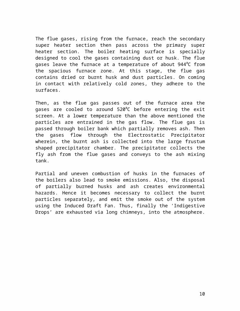
Partial and uneven combustion of husks in the furnaces of the boilers also lead to smoke emissions. Also, the disposal of partially burned husks and ash creates environmental hazards. Hence it becomes necessary to collect the burnt particles separately, and emit the smoke out of the system using the Induced Draft Fan. Thus, finally the ‘Indigestive Drops’ are exhausted via long chimneys, into the atmosphere.
Conveyor for loading husk
8
Induced draft fan for exhaust
9
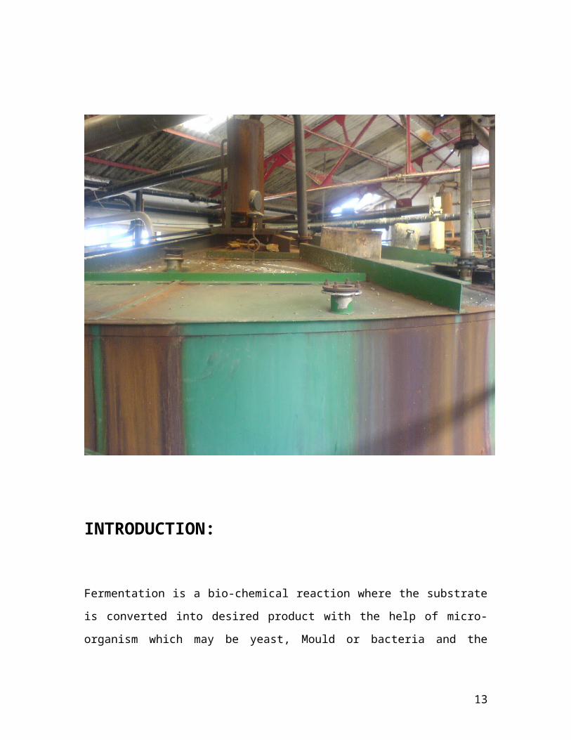
FERMENTATION SECTION
10
INTRODUCTION:
Fermentation is a bio-chemical reaction where the substrate is
converted into desired product with the help of micro-organism which
may be yeast, Mould or bacteria and the enzyme present in the Micro-
organism actually acts in the reaction.
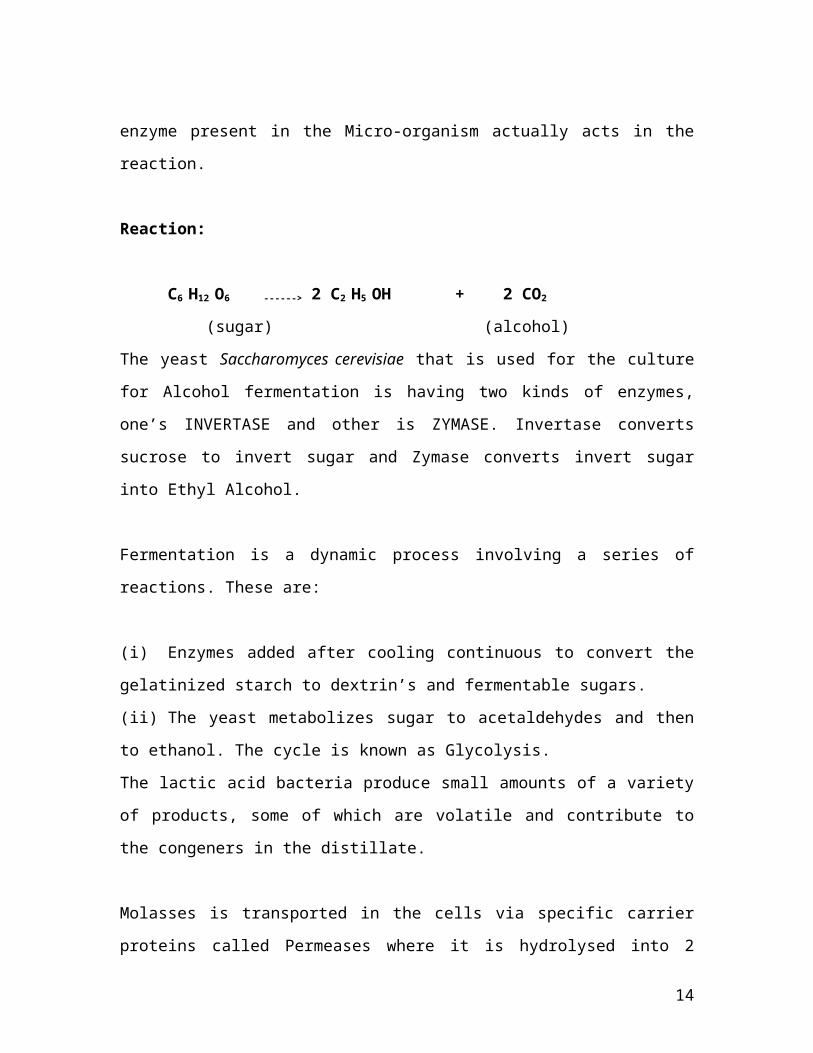
Reaction:
C6 H12 O6 ------> 2 C2 H5 OH + 2 CO2
(sugar) (alcohol)
The yeast Saccharomyces cerevisiae that is used for the culture for
Alcohol fermentation is having two kinds of enzymes, one’s INVERTASE
and other is ZYMASE. Invertase converts sucrose to invert sugar and
Zymase converts invert sugar into Ethyl Alcohol.
Fermentation is a dynamic process involving a series of reactions.
These are:
(i) Enzymes added after cooling continuous to convert the
gelatinized starch to dextrin’s and fermentable sugars.
(ii) The yeast metabolizes sugar to acetaldehydes and then to
ethanol. The cycle is known as Glycolysis.
The lactic acid bacteria produce small amounts of a variety of
products, some of which are volatile and contribute to the congeners in
the distillate.
11
Molasses is transported in the cells via specific carrier proteins called
Permeases where it is hydrolysed into 2 molecules of glucose. The
Permeases are substrate and require metabolic energy for operation.
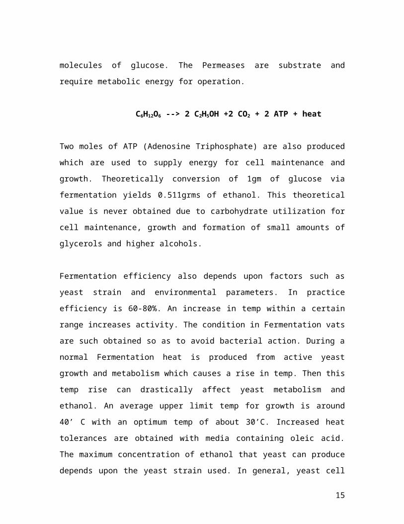
C6H12O6 --> 2 C2H5OH +2 CO2 + 2 ATP + heat
Two moles of ATP (Adenosine Triphosphate) are also produced which
are used to supply energy for cell maintenance and growth.
Theoretically conversion of 1gm of glucose via fermentation yields
0.511grms of ethanol. This theoretical value is never obtained due to
carbohydrate utilization for cell maintenance, growth and formation of
small amounts of glycerols and higher alcohols.
Fermentation efficiency also depends upon factors such as yeast strain
and environmental parameters. In practice efficiency is 60-80%. An
increase in temp within a certain range increases activity. The
condition in Fermentation vats are such obtained so as to avoid
bacterial action. During a normal Fermentation heat is produced from
active yeast growth and metabolism which causes a rise in temp. Then
this temp rise can drastically affect yeast metabolism and ethanol. An
average upper limit temp for growth is around 40’ C with an optimum
temp of about 30’C. Increased heat tolerances are obtained with media
containing oleic acid. The maximum concentration of ethanol that
yeast can produce depends upon the yeast strain used. In general,
yeast cell growth is inhibited around 10 to 12% wt/vol. ethanol while
20% ethanol will terminate cellular metabolism.
Ethanol Fermentation With Yeast:
12
The organisms of primary interest to industrial operations in
fermentation of ethanol include Saccharomyces cerevisiae, S. uvarum,
Schizosaccharomyces pombe, and Kluyueromyces sp. Yeast, under
anaerobic conditions, metabolize glucose to ethanol primarily by way
of the Embden-Meyerhof pathway. The overall net reaction involves
the production of 2 moles each of ethanol, but the yield attained in
practical fermentations however does not usually exceed 90 – 95% of
theorectical. This is partly due to the requirement for some nutrient to
be utilized in the synthesis of new biomass and other cell maintenance
related reactions.
A small concentration of oxygen must be provided to the
fermenting yeast as it is a necessary component in the biosynthesis of
polyunsaturated fats and lipids. Typical amounts of O2 maintained in
the broth are 0.05 – 0.10 mm Hg oxygen tension.
The relative requirements for nutrients not utilized in ethanol
synthesis are in proportion to the major components of the yeast cell.
These include carbon oxygen, nitrogen and hydrogen. To leaser extent
quantities of phosphorus, sulfur, potassium, and magnesium must also
be provided for the synthesis of minor components. Minerals (i.e. Mn,
Co, Cu, Zn) and organic factors (amino acids, nucleic acids, and
vitamins) are required in trace amounts.
Yeast are highly susceptible to ethanol inhibition. Concentration
of 1-2% (w/v) are sufficient to retard microbial growth and at 10% (w/v)
alcohol, the growth rate of the organism is nearly halted.
Fermentation at PDM is done through two ways:
1) Grain spirit plant (From wheat or rice flour)
13
2) Fermentation from Molasses
Grain Spirit Fermentation Plant
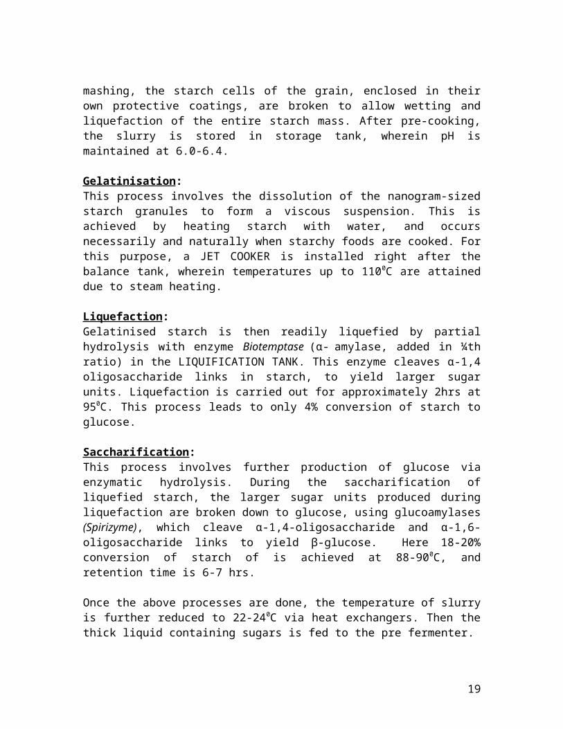
Nowadays, along with the use of molasses as a sugar source for fermentation, Distilleries are using grains, which are a potential source of fermentable sugars. For this, first the starch present in the grains has to be extracted and then converted into glucose either by acid hydrolysis, or by enzymatic hydrolysis. The process/methodology applied, is described below sequentially.
Screening:The first step is screening of grain. There are two meshes, one for the dust particles and other for foreign particles. Size of the dust mesh screen is 0.5mm and of the other 2.4mm. Once the screening is over, grain is stored in the tank called ‘SILO’.
Loading of grain: The grain (atta) is loaded into a vertical conveyer which carried it to a large Hopper (or Chute). The Hopper is a vertical or inclined path, channel, or passage through which objects are moved by means of gravity. It has some additional width and depth to provide a volume for temporary storage of material(s). The bottom of the hopper/ chute typically has a mechanism to control the flow of materials (usually a stop valve), thus allowing them to be metered out at the desired rate. From the hopper, the grain is carried to the Grinding section.
Mashing: Once grinding is done, the milled grain is mixed with hot water, in a ratio of 90-10 upto 50-50, (notably at 45°C, 62°C and 73°C), to allow enzymes to break down the starch in the grain into sugars. This section is also referred as PRE COOKER.
The purpose of the mashing operation is to (1) mix the proper proportions of grains, (2) increase the availability of the starch for enzyme action, and (3) convert the starches into fermentable sugars.
14
Mashing is done in a vessel called a mash tun, which is equipped with a means of agitation for mixing and is either jacketed or contains coils for heating and cooling. In mashing, the starch cells of the grain, enclosed in their own protective coatings, are broken to allow wetting and liquefaction of the entire starch mass. After pre-cooking, the slurry is stored in storage tank, wherein pH is maintained at 6.0-6.4.
Gelatinisation: This process involves the dissolution of the nanogram-sized starch granules to form a viscous suspension. This is achieved by heating starch with water, and occurs necessarily and naturally when starchy foods are cooked. For this purpose, a JET COOKER is installed right after the balance tank, wherein temperatures up to 1100C are attained due to steam heating.
Liquefaction: Gelatinised starch is then readily liquefied by partial hydrolysis with enzyme Biotemptase (α- amylase, added in ¼th ratio) in the LIQUIFICATION TANK. This enzyme cleaves α-1,4 oligosaccharide links in starch, to yield larger sugar units. Liquefaction is carried out for approximately 2hrs at 950C. This process leads to only 4% conversion of starch to glucose.
Saccharification: This process involves further production of glucose via enzymatic hydrolysis. During the saccharification of liquefied starch, the larger sugar units produced during liquefaction are broken down to glucose, using glucoamylases (Spirizyme), which cleave α-1,4-oligosaccharide and α-1,6-oligosaccharide links to yield β-glucose. Here 18-20% conversion of starch of is achieved at 88-900C, and retention time is 6-7 hrs.
Once the above processes are done, the temperature of slurry is further reduced to 22-240C via heat exchangers. Then the thick liquid containing sugars is fed to the pre fermenter.
15
The process
Fermentation from Molasses
Molasses is used as nutrient and acts as reducing sugar. Here the
yeast is grown in laboratory applying the strain improvement
technique used at PDM. The various stages in process of going from lab
to production fermenter are:
1) Seed fermenter
2) Prefermenter
3) Production/Industrial fermenter
1) Seed Fermenter:
16
Inoculum produced in lab is transferred to grow in sterilised seed
fermenter where a specific nutrient level is maintained. Basically we
are preparing our inoculum to adapt to harsh conditions and nutrient
level in fermenter. In seed fermenter the pH is approximately 4.7 and
temp of 360C.
At PDM we have four vessels basically working as seed fermenters,
But only two are working at a time. The capacities of these vessels are
500,1500,2000,2500 Bulk litres. Cell concentration in seed fermenter
reaches to 300 cell/ml.
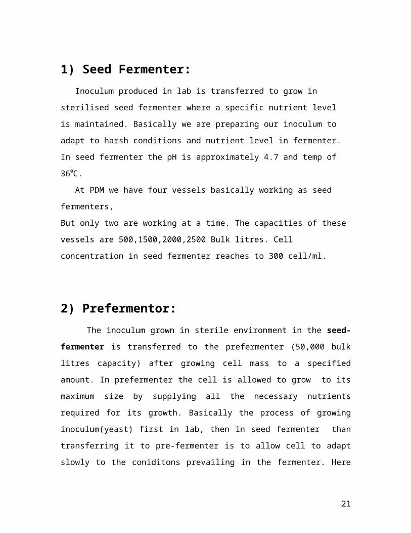
2) Prefermentor: The inoculum grown in sterile environment in the seed-fermenter
is transferred to the prefermenter (50,000 bulk litres capacity) after
growing cell mass to a specified amount. In prefermenter the cell is
allowed to grow to its maximum size by supplying all the necessary
nutrients required for its growth. Basically the process of growing
inoculum(yeast) first in lab, then in seed fermenter than transferring it
to pre-fermenter is to allow cell to adapt slowly to the coniditons
prevailing in the fermenter. Here also we get less than 2% yield of
alcohol. Here pH of 4.5(approx) and temp of 360C is maintained.
PROCESS
17
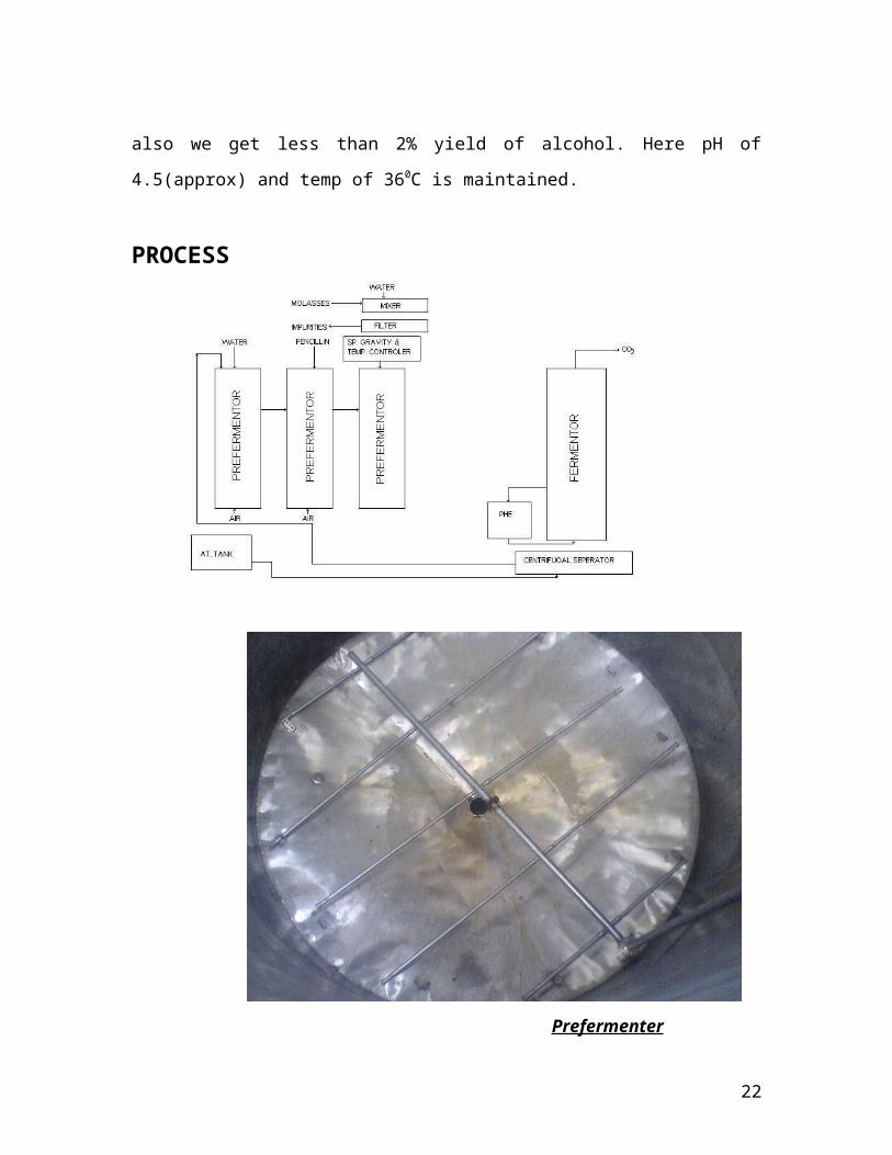
Prefermenter
The figure is showing an internal look of a pre-fermenter. It is
containing SPARGERS for supply of sterilized air to carry out aerobic
fermentation. Here we grow the inoculum to its maximum size, to be
able to feed the inoculum to the production fermenter.
3) Industrial fermenter The final alcohol production is done in industrial or production
fementer. The production fermenter of capacity 3,50,000 bulk Litres
capacity. All pipelines and production fermenter is steam sterilized
before running for next batch. ph here is more than 4.7 and normal
temp of 36-380C. The sum of glucose, fructose, and sucrose, i.e. the
total sugar content or Total Dissolved Sugar (TDS) in the molasses, sets
the potential alcohol yield. Theoretically, 100 kg sugar (glucose,
fructose) will yield approximately 51 kg or 64.5 l alcohol. Less than
18
theoretical yield is caused by sugar consumption by the yeast,
incomplete fermentation, the formation of fermentation side products
(e.g. fusel alcohols), and alcohol loss in the distillation process. For
these reasons a yield of only 56 liters of pure alcohol per 100 kg glucose
or fructose is generally realized in practice. Starch is a polymer
composed of repeating units of glucose; therefore, it is necessary to
break the starch down to the basic glucose unit for the yeast to convert
the sugar into alcohol. This process is called hydrolysis and can be
accomplished by use of enzymes or acids.
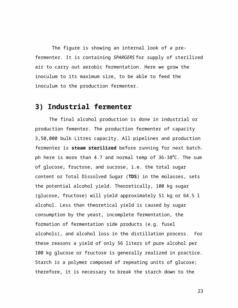
PROCESS FLOW
PRESERVED SLANT CULTURE
↓
SHAKER FLASK [ 4-5 % OF FREEZE CULTURE]
↓
SEED FERMENTER – 1 [10% OF WORKING VOLUME = INOCULUM
ADDED]
↓
SEED FERMENTER – 2
↓
PRE-FERMENTER
↓
19
PRODUCTION FERMENTER
PROCESS PARAMETERS
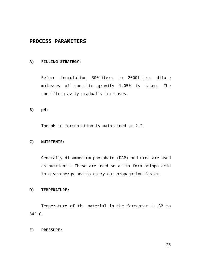
A) FILLING STRATEGY:
Before inoculation 300liters to 2000liters dilute molasses of
specific gravity 1.050 is taken. The specific gravity gradually
increases.
B) pH:
The pH in fermentation is maintained at 2.2
C) NUTRIENTS:
Generally di ammonium phosphate (DAP) and urea are used as
nutrients. These are used so as to form aminpo acid to give
energy and to carry out propagation faster.
D) TEMPERATURE:
Temperature of the material in the fermenter is 32 to 34’ C.
E) PRESSURE:
The process is carried out at Normal Pressure
20
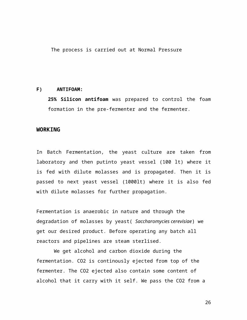
F) ANTIFOAM:
25% Silicon antifoam was prepared to control the foam
formation in the pre-fermenter and the fermenter.
WORKING
In Batch Fermentation, the yeast culture are taken from laboratory and
then putinto yeast vessel (100 lt) where it is fed with dilute molasses
and is propagated. Then it is passed to next yeast vessel (1000lt)
where it is also fed with dilute molasses for further propagation.
Fermentation is anaerobic in nature and through the degradation of
molasses by yeast( Saccharomycies cerevisiae) we get our desired
product. Before operating any batch all reactors and pipelines are
steam sterlised.
We get alcohol and carbon dioxide during the fermentation. CO2 is
continously ejected from top of the fermenter. The CO2 ejected also
contain some content of alcohol that it carry with it self. We pass the
CO2 from a tank and it is washed with water. And thus we extract the
ethanol content from the CO2 and we send this CO2 to nearby plants
which uses it for dry ice. Our fermentation product-Ethanol is extracted
from the bottom of the fermenter.
REACTION
C6 H12 O6 ------> 2 C2 H5 OH + 2 CO2 +Heat
21
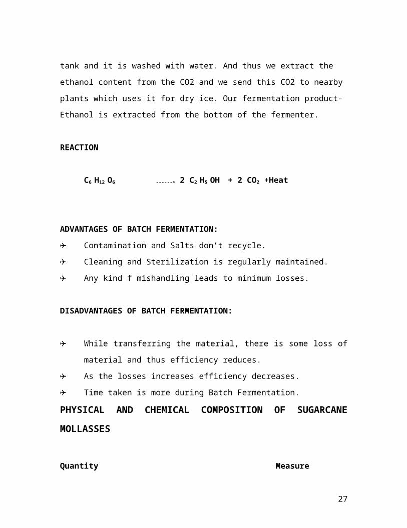
ADVANTAGES OF BATCH FERMENTATION:
Contamination and Salts don’t recycle.
Cleaning and Sterilization is regularly maintained.
Any kind f mishandling leads to minimum losses.
DISADVANTAGES OF BATCH FERMENTATION:
While transferring the material, there is some loss of material
and thus efficiency reduces.
As the losses increases efficiency decreases.
Time taken is more during Batch Fermentation.
PHYSICAL AND CHEMICAL COMPOSITION OF
SUGARCANE MOLLASSES
Quantity Measure
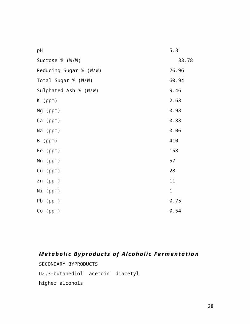
pH 5.3
Sucrose % (W/W) 33.78
Reducing Sugar % (W/W) 26.96
Total Sugar % (W/W) 60.94
Sulphated Ash % (W/W) 9.46
K (ppm) 2.68
Mg (ppm) 0.98
Ca (ppm) 0.88
Na (ppm) 0.06
B (ppm) 410
Fe (ppm) 158
Mn (ppm) 57
22
Cu (ppm) 28
Zn (ppm) 11
Ni (ppm) 1
Pb (ppm) 0.75
Co (ppm) 0.54
Metabolic Byproducts of Alcoholic
Fermentation
SECONDARY BYPRODUCTS
2,3-butanediol acetoin diacetyl
higher alcohols
these fermentation byproducts are part the cell building metabolism
(byproducts of AA synthesis valine, leucine, isoleucine)
Sulfur compounds (SO2, H2S, mercaptans,…)
Nutrient Limitation
Nitrogen (amino acids, short peptides, ammonia)
Pi (H3PO4)
nicotinic acid (B-vitamin) important for NAD (nicotinamid adenine
dinucleotide)
thiamin (B1) (pyruvate ---> acetaldehyde), lack: accumulation of pyruvate
and ketoglutarate
23
DISTILLATION
24
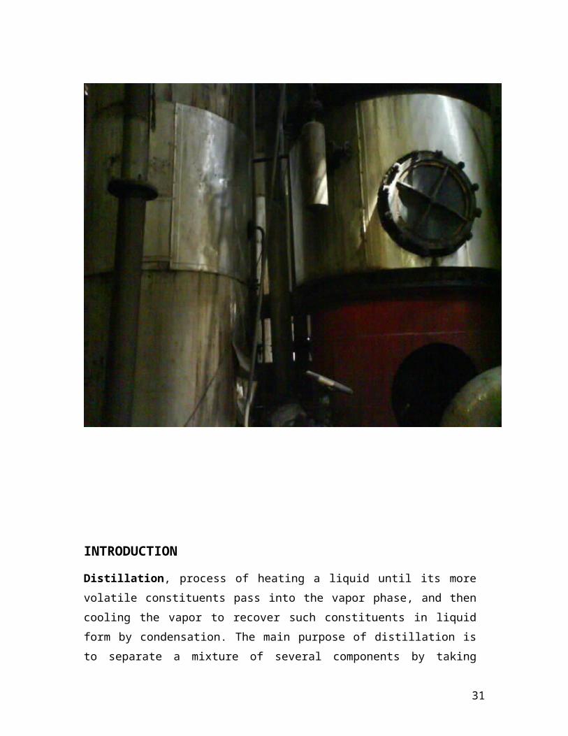
INTRODUCTION
Distillation, process of heating a liquid until its more volatile
constituents pass into the vapor phase, and then cooling the vapor to
recover such constituents in liquid form by condensation. The main
purpose of distillation is to separate a mixture of several components
by taking advantage of their different volatilities, or the separation of
25
volatile materials from nonvolatile materials. In evaporation and in
drying, the purpose usually is to obtain the less volatile constituent;
the more volatile constituent, in most cases water, is discarded. In
distillation, on the other hand, the principal object of the operation is
to obtain the more volatile constituent in pure form. The removal of
water from glycerin by vaporizing the water, for example, is called
evaporation, but the removal of water from alcohol by vaporizing the
alcohol is called distillation, although similar apparatus is used in
both cases.
DISTILLATION IN ‘PDM’
If the difference in volatility (and hence in boiling point) between the
two constituents is great, complete separation may be easily
26
accomplished by a single distillation. Seawater, for example, which
contains about 4 percent dissolved solids (principally common salt),
may be readily purified by vaporizing the water, condensing the
steam thus formed, and collecting the product, distilled water. This
product is, for most purposes, equivalent to pure water, although
actually it contains some impurities in the form of dissolved gases,
the most important of which is carbon dioxide.
THEORY OF DISTILLATION:
In the simplest mixture of two mutually soluble liquids, the volatility
of each is undisturbed by the presence of the other. In such a case,
the boiling point of a 50-50 mixture, for example, would be halfway
between the boiling points of the pure substances, and the degree of
separation produced by a single distillation would depend only on the
vapor pressure, or the volatility, of the separate components at this
temperature. This simple relationship is called as the Raoult's Law.
Raoult's law applies only to mixtures of liquids that are very similar in
chemical structure, such as benzene and toluene. In most cases wide
deviations occur from this law. Thus, one component is only slightly
soluble in the other, its volatility is abnormally increased. In the
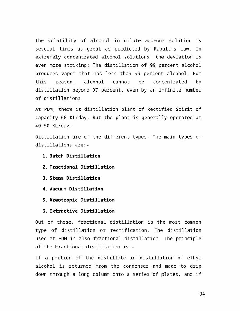
example above, the volatility of alcohol in dilute aqueous solution is
several times as great as predicted by Raoult's law. In extremely
concentrated alcohol solutions, the deviation is even more striking:
The distillation of 99 percent alcohol produces vapor that has less
than 99 percent alcohol. For this reason, alcohol cannot be
concentrated by distillation beyond 97 percent, even by an infinite
number of distillations.
27
At PDM, there is distillation plant of Rectified Spirit of capacity 60
KL/day. But the plant is generally operated at 40-50 KL/day.
Distillation are of the different types. The main types of distillations
are:-
1. Batch Distillation
2. Fractional Distillation
3. Steam Distillation
4. Vacuum Distillation
5. Azeotropic Distillation
6. Extractive Distillation
Out of these, fractional distillation is the most common type of
distillation or rectification. The distillation used at PDM is also
fractional distillation. The principle of the Fractional distillation is:-
If a portion of the distillate in distillation of ethyl alcohol is returned
from the condenser and made to drip down through a long column
onto a series of plates, and if the vapor as it rises on its way to the
condenser is made to bubble through this liquid at each plate, the
vapor and liquid will interact so that some of the water in the vapor
condenses and some of the alcohol in the liquid vaporizes. The
interaction at each plate is thus equivalent to a redistillation, and by
building a column with a sufficient number of plates, 95 percent
alcohol can be obtained in a single operation. Moreover, by feeding
the original 10 percent alcohol solution gradually at a point in the
middle of the column, virtually all the alcohol may be stripped from
the water as it descends to the lowest plate, so that no alcohol need
be wasted.
28
This process, known as rectification, fractionation, or fractional
distillation, is common in industrial usage, not only for simple
mixtures of two components (such as alcohol and water in
fermentation products, or oxygen and nitrogen in liquid air) but also
for highly complex mixtures such as those found in coal tar and
petroleum.
The only disadvantage of fractional distillation is that a large fraction
(as much as one-half) of the condensed distillate must be refluxed,
or. returned to the top of the tower and eventually boiled again, and
more heat must therefore be supplied. On the other hand, the
continuous operation made possible by fractionation allows great
heating economies, because the outgoing distillate may be used to
preheat the incoming feed.
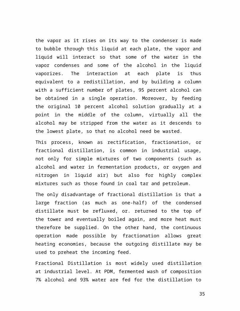
Fractional Distillation is most widely used distillation at industrial
level. At PDM, fermented wash of composition 7% alcohol and 93%
water are fed for the distillation to purify the ethanol upto 96.8%.
Ethanol can be purified upto 96.8% by simple distillation but cannot
be further purified by simple distillation. After that the azeotrope
forms and azeotropic distillation is required for the further
purification. Benzene is the solvent that is needed for the break up of
the azeotrope.
At PDM, feed introduced in the distillation column is at the bubble
point i.e. saturated liquid. Fermented wash is entered at 74-750C,
after coming from fermentation, the feed is heated in spiral heat
exchangers to temp. of 740C.
EQUIPMENTS
29
At PDM, tray towers are used for the effective separation. Tray
towers are particularly useful as compared to the packed towers
when fluctuations in the vapor or liquid rate may occur or where the
major changes in the overall capacity of the column are anticipated.
The problems of the poor liquid or gas distribution encountered at
various loading capacities with packed towers can be avoided with
plate or tray towers.
The main parts of the tray columns are:-
1. Shell and Trays
2. Weirs
3. Downcomers
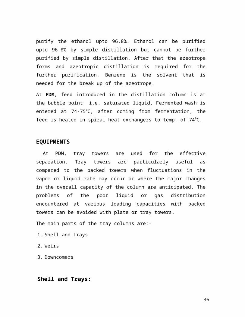
Shell and Trays:
Cylindrical shells are commonly used for the tray columns. The shell
may be constructed of short sections that are bolted together or in
the form of one long cylinder. Manholes should be provided to give
access to the individual trays for cleaning, maintenance and
installation. Adequate foundations and tower supports must be
provided. Both the corrosion characteristics of the fluids involved and
costs dictate the acceptable materials of construction for the shell
and trays. Trays are usually made of suitable metal to facilitate
fabrication and the shell material can be steel , resin lined steel or
any alloy. Supporting beams are used to stiffen the trays, and the
trays must be fastened securely to prevent movement caused by gas
surges.
Weirs and Down comers:
30
Downcomers for conducting the liquid from one tray to the next tray
below may be in the form of circular pipes or segments of the tower
isolated from the rising gas by means of vertical or angled plates.
Some vapor is entrained in the liquid gas the liquid enters the
downcomer, and sufficient residence time should be provided in the
downcomer to permit escape of the entrained vapor. A residence
time of 5s, is enough to permit release of most of the entrained
vapor. The liquid head in the downcomer should not be greater than
one half the plate spacing.
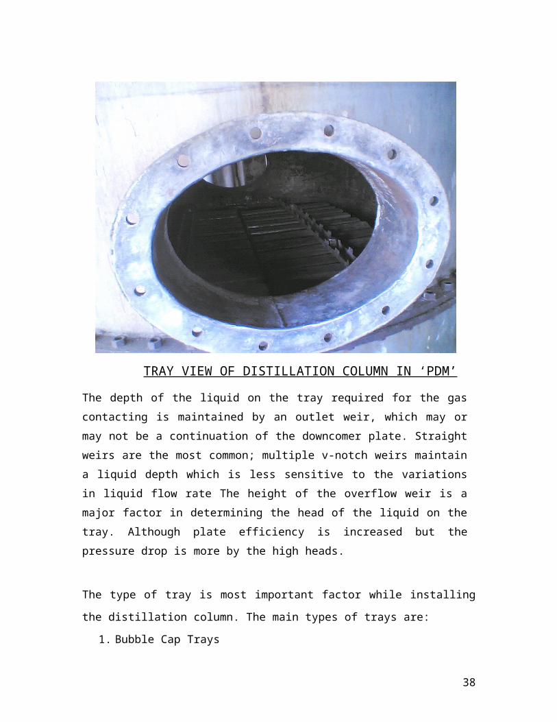
TRAY VIEW OF DISTILLATION COLUMN IN ‘PDM’
The depth of the liquid on the tray required for the gas contacting is
maintained by an outlet weir, which may or may not be a
continuation of the downcomer plate. Straight weirs are the most
common; multiple v-notch weirs maintain a liquid depth which is less
31

sensitive to the variations in liquid flow rate The height of the
overflow weir is a major factor in determining the head of the liquid
on the tray. Although plate efficiency is increased but the pressure
drop is more by the high heads.
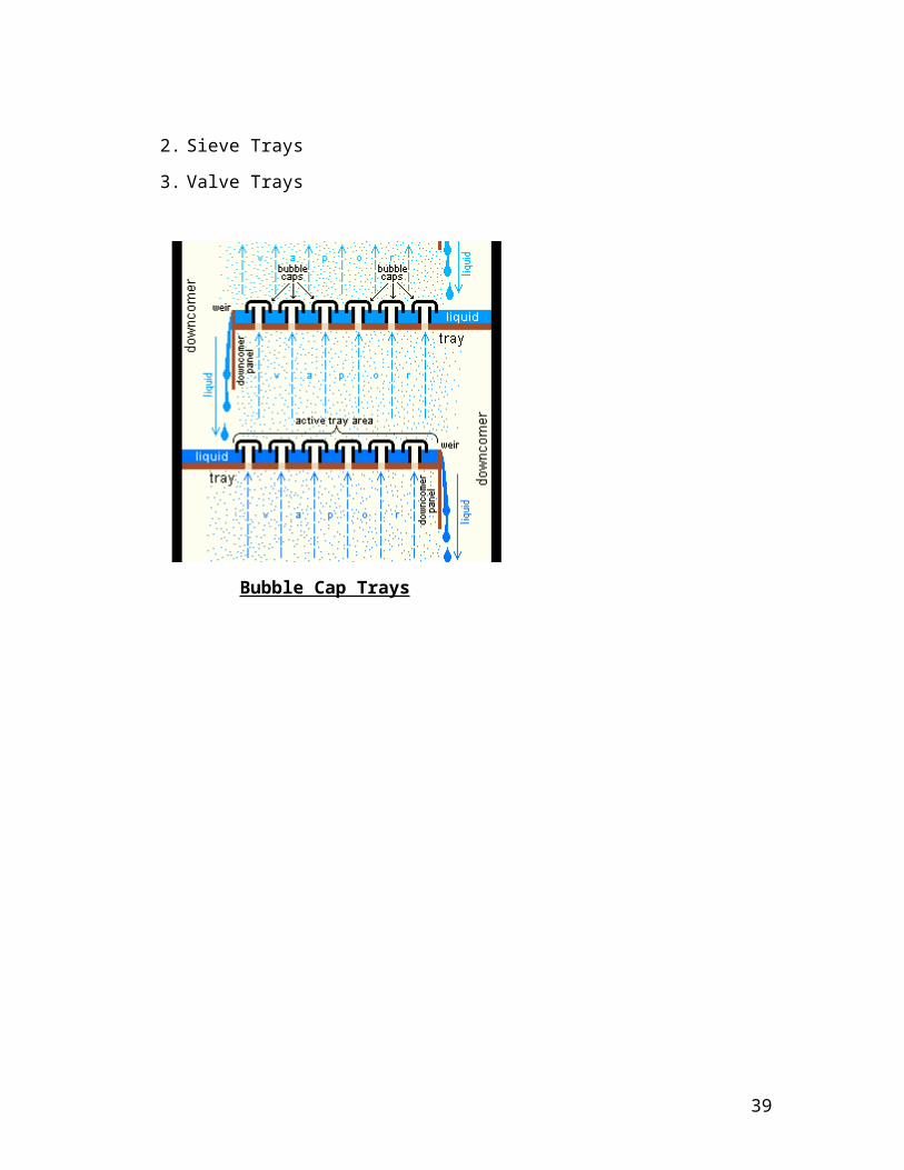
The type of tray is most important factor while installing the distillation
column. The main types of trays are:
1. Bubble Cap Trays
2. Sieve Trays
3. Valve Trays
Bubble Cap Trays
32
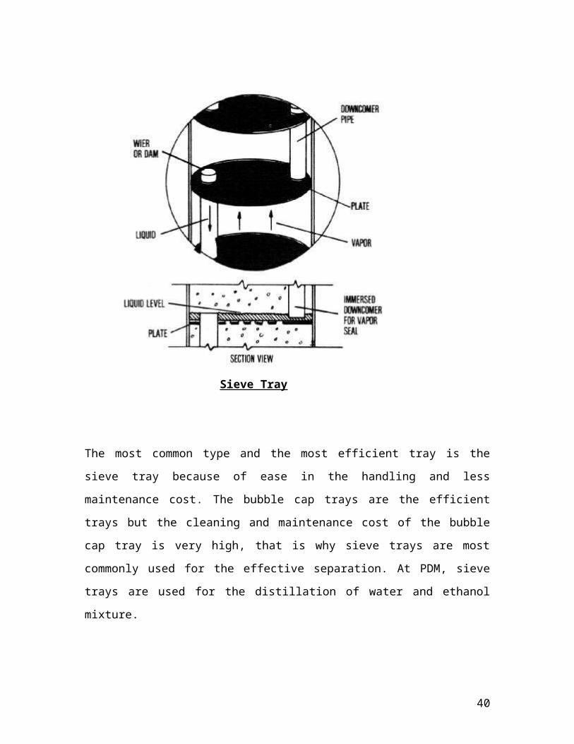
Sieve Tray
The most common type and the most efficient tray is the sieve tray
because of ease in the handling and less maintenance cost. The bubble
cap trays are the efficient trays but the cleaning and maintenance cost
of the bubble cap tray is very high, that is why sieve trays are most
commonly used for the effective separation. At PDM, sieve trays are
used for the distillation of water and ethanol mixture.
33
PROCESS DESCRIPTION:
At PDM, there is a distillation plant of Rectified Spirit of 60 KL/day
capacity. The Rectified spirit is used to manufacture the IMFL (Indian
Made Foreign Liquor). Fermented Wash that is the feed for the
distillation mainly consists of ethanol and water but it also contains
small fractions of the aldehydes, fusel oil, carbon dioxide, esters etc.
These are the main impurities formed during the process of the
fermentation. So, these impurities are also removed during the
distillation. These fusel oil, Carbon dioxide after treatment are selled to
another industries like Pharmeuticals industries. The relative volatility
of the mixture is around 2.2 i.e. = 2.2 . is the major factor that is
required for the distillation. The far is the value of the from 1.0, the
easy is the separation possible.
If the value is near the 1.0 or equal to 1.0 then the mixture is
azeotropic mixture and then third entrainer is used to break up the
azeotrope. Reflux Ratio is also important factor that is used to maintain
the overhead product concentration. At PDM, reflux ratio of 5:1 is
generally used.
At PDM, in distillation plant there are five main columns:-
1. MASH COLUMN OR BOILING COLUMN
2. PURIFICATION COLUMN
3. RECTIFIYING COLUMN
4. FAINTS COLUMN
5. METHANOL COLUMN
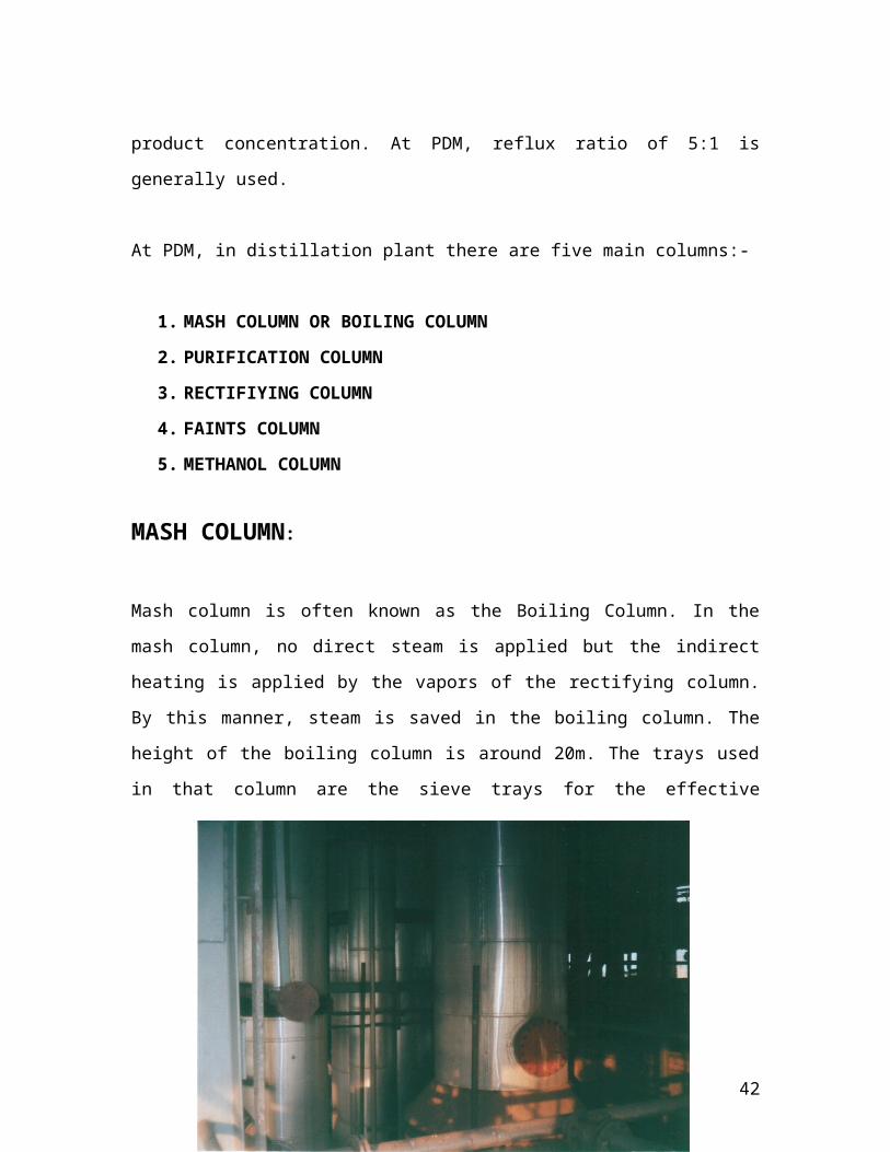
MASH COLUMN:
34
Mash column is often known as the Boiling Column. In the mash
column, no direct steam is applied but the indirect heating is applied
by the vapors of the rectifying column. By this manner, steam is saved
in the boiling column. The height of the boiling column is around 20m.
The trays used in that column are the sieve trays for the effective
separation. The boiling column is operated at total vacuum. Vacuum
pumps are used to create the vacuum in the mash column. The
vacuum is created because pressure is directly proportional to the
temperature and less is the pressure less heating is required to boil the
feed. That is why vacuum is created in the boiling column. The boiling
point of the fermented wash is around 1050C. But due to the vacuum it
boils at around 750C.Therefore it is commonly known as the boiling
column. Feed enters at boiling column at around 7% purity of ethanol
and after the distillation the purity of the ethanol is around 71% or 25-
30 Over Proof. In the mash column, 24 trays are used. The
temperature at the bottom of the column is around 750C and at the top
of the column, the temperature is around 600C. From the mash
column, the fed is sent to the purification column.
35
DISTILLATION COLUMNS IN ‘PDM’
PURIFICATION COLUMN:
From the mash or boiling column, ethanol of purity 71% is fed to the
purification column. In the purification column, soft water is added to
the mixture to increase the relative volatility of the mixture and
making the further separation easy. Direct steam is applied to the
purification column. By addition of the soft water, relative volatility of
the mixture increases and the impurities settle down and sent to the
faints column. The height of the purification column is around 15 m.
The pressure at the bottom of the column is around 0.47 mm Hg and
pressure at the top is around 0.3 mm Hg. After increasing the relative
volatility the mixture is fed to the rectifying column. Purification
column have around 32 trays.
RECTIFYING COLUMN:
The spirit obtained from the purification column is fed to the rectifier
column to increase the purity of the ethanol. Direct steam is supplied
to the rectifying column. Sieve trays are used in the rectifying column.
Rectification column has 56 trays for the effective separation. In the
rectifying column, purity of the ethanol is taken upto the 96.8% (v/v) or
69-70 over proof. The temperature at the bottom of the column is
around 1050 C and the temperature at top is around 950 C. Pressure at
the top of the rectification column is 0.49 mm Hg and the pressure at
the bottom is around 0.73 mm Hg.
36
In this column, there is no cross flow of the liquid, the liquid flows
across the tray and vapors passes counter currently through the
perforations of the tray. The spirit obtained from the rectification
column is 96.8% (v/v) purity. From the vapors of the rectification
column, indirect steam is applied to the mash column. This ethanol is
sent to the condensers , generally shell and tube type condensers are
used for the condensation of the ethanol. A part of the overhead
product is sent back to the column as the reflux for the increase the
concentration of overhead product. Impurities like aldehydes, esters
and fusel oil are sent to the faints column. Spent leese that majority
consists of water is sent to the E.T.P. plant.
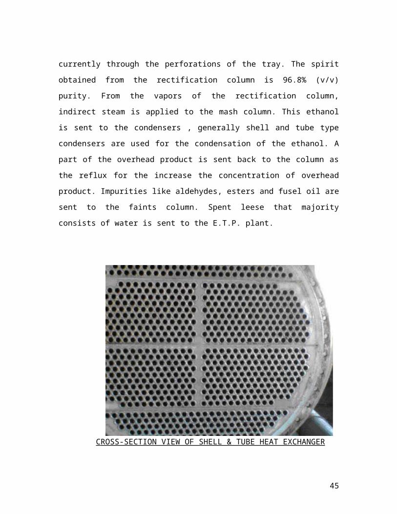
C ROSS-SECTION VIEW OF SHELL & TUBE HEAT EXCHANGER
FAINTS COLUMN:
37
All the impurities from the rectification column and the purification
column collects in the faints column. Impurities like methanol,
aldehydes, esters fusel oil collects in the faints column. From the faints
column, methanol is sent to the methanol column and aldehydes are
collected in the separate column. Fuse oil is used in pharmaceutical
industry therefore it is purified in the decanter and then collects as the
pure fusel oil.
MAIN PROBLEMS IN THE DISTILLATION COLUMNS:
The main problems during the distillation arise due to improper flow
rate of liquid or vapors. The main problems are faced during the
operation of the distillation column are:-
1. Flooding
2. Priming
3. Weeping
4. Coning
5. Dumping
High pressure drop directly lead to the condition of the flooding. With
a large pressure difference in the space between the trays, the level of
liquid leaving a tray at relatively low pressure and entering one of high
pressure must necessarily assume an elevated position in the
downcomer. As the pressure diff. is increased due to increased rate of
flow of either gas or liquid, the level of downcomer will rise further to
38
permit the liquid to enter the lower tray. Ultimately the liquid level may
reach the tray above. Further increase in flow rate then aggravates the
condition rapidly and liquid will fill the entire space between the trays.
Then tower is said to be flooded.
If liquid rates are too low, the gas rising through the openings of the
tray may push the liquid away and contact of vapor and liquid is poor.
This condition is called the coning.
If vapor rate is too low, much of the liquid may rain through the
perforations of the tray. This condition is called the weeping.
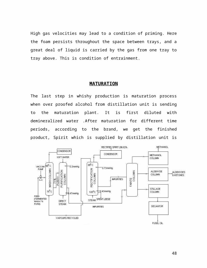
High gas velocities may lead to a condition of priming. Here the foam
persists throughout the space between trays, and a great deal of liquid
is carried by the gas from one tray to tray above. This is condition of
entrainment.
MATURATION
39
The last step in whishy production is maturation process when over
proofed alcohol from distillation unit is sending to the maturation plant.
It is first diluted with demineralized water .After maturation for
different time periods, according to the brand, we get the finished
product, Spirit which is supplied by distillation unit is 96% pure as it
contain some traces of aldebydes, esters, fusel oil etc. which can’t be
removed completely after distillation process. As this amount of
impurities does not make any harmful effect, hence it is considered to
be as 100% pure. The spirit is firstly diluted with ‘DM’ water in such a
way that the spirit contain 60% (v/v) alcohol.
For this need to check the following things
QUALITY CHECK OF SPIRIT
QUALITY CHECK OF DEMINERALIZED
After this above two combinations is taken in different ratio’s to get
different types of alcohol. The product of distillation at 105-125 deg.
proof is put into new charred white oak barrels. The filling hold is
closed with a populate wood and the barrels are entered in a
warehouse.
Barrels liquid volume during storage for several reasons. The main loss
of 4% per year is due to evaporation. The optimum temperature for
maturation ranges from 21-300C that results in a whisky production
with the desired flavor. If the temperature increases much over 300C,
the flavor of the product becomes too woody and resinous. At high
temperature and low humidity water migrates through the barrels
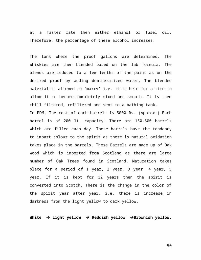
stores at a faster rate then either ethanol or fusel oil. Therefore, the
percentage of these alcohol increases.
40
The tank where the proof gallons are determined. The whiskies are
then blended based on the lab formula. The blends are reduced to a
few tenths of the point as on the desired proof by adding
demineralized water, The blended material is allowed to ‘marry’ i.e. it
is held for a time to allow it to become completely mixed and smooth.
It is then chill filtered, refiltered and sent to a bathing tank.
In PDM, The cost of each barrels is 5000 Rs. (Approx.).Each barrel is of
200 lt. capacity. There are 150-500 barrels which are filled each day.
These barrels have the tendency to impart colour to the spirit as there
is natural oxidation takes place in the barrels. These Barrels are made
up of Oak wood which is imported from Scotland as there are large
number of Oak Trees found in Scotland. Maturation takes place for a
period of 1 year, 2 year, 3 year, 4 year, 5 year. If it is kept for 12 years
then the spirit is converted into Scotch. There is the change in the
color of the spirit year after year. i.e. there is increase in darkness from
the light yellow to dark yellow.
White Light yellow Reddish yellow Brownish yellow.
In maturation unit the temperature is maintained below 170C. There
was automatic blower system which work automatically if the
temperature of the unit increases beyond 170C. The blowers are
connected with sensors which measure & indicate the temerature of
the unit and command the blowers according to that. We maintain the
temperature below 170C as the increase in temperature further cause
evaporation. After maturation there comes the important section of the
maturation unit i.e. Blending unit.
41
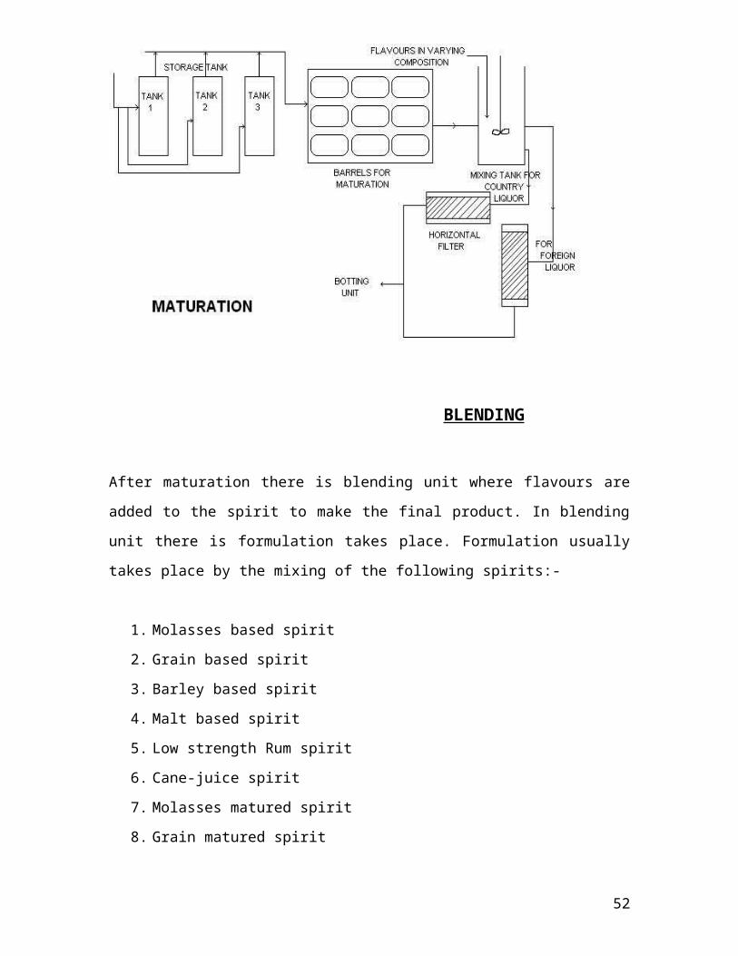
BLENDING
After maturation there is blending unit where flavours are added to the
spirit to make the final product. In blending unit there is formulation
takes place. Formulation usually takes place by the mixing of the
following spirits:-
1. Molasses based spirit
2. Grain based spirit
3. Barley based spirit
4. Malt based spirit
42
5. Low strength Rum spirit
6. Cane-juice spirit
7. Molasses matured spirit
8. Grain matured spirit
9. Wetted malt spirit
Blending relates to the secret part of company working. Each lot of
whisky is periodically checked for its maturation characteristics such as
smooth taste & pleasant aroma. The rate of maturation depends upon
the grain bill, geographical location of the warehouse and the location
of the barrel with in the warehouse. If the blended product is required,
a trail blend is made in the lab. Once the blend is identical to its flavor
standard, the proper numbers of barrels of each lot are withdrawn and
the barrels are emptied i.e. whisky is cleaned to remove barrel char,
The whisky is then pumped to a gauged. In blending some flavors are
added and mixed in varying compositions in different types of
whiskies.
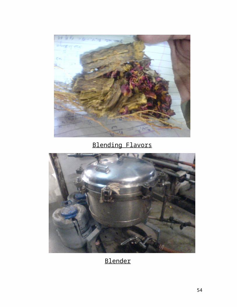
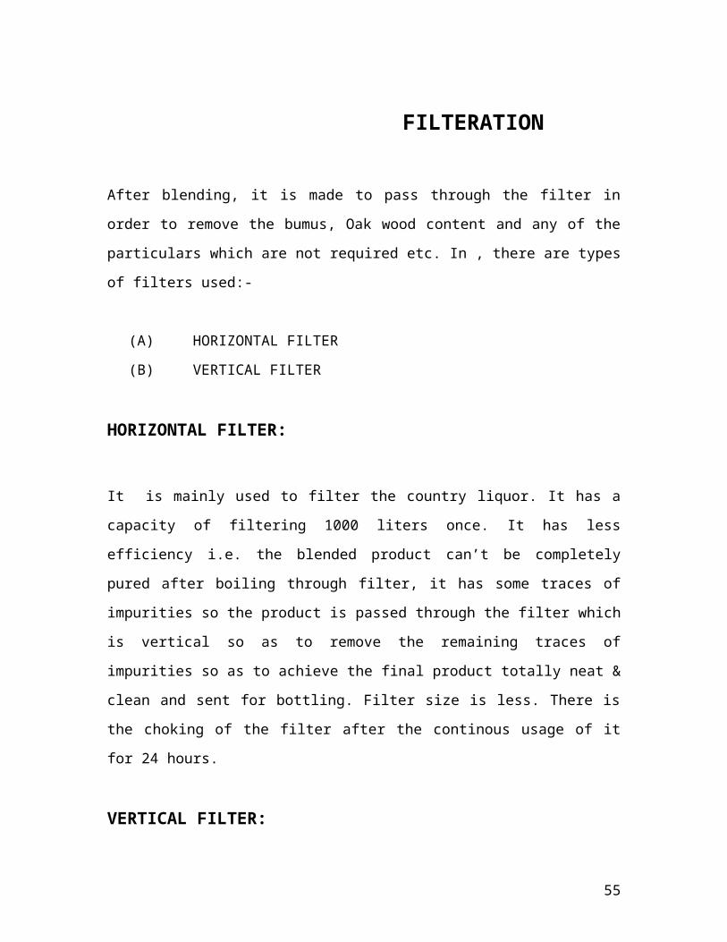
43
Blending Flavors
Blender
44
FILTERATION
After blending, it is made to pass through the filter in order to remove
the bumus, Oak wood content and any of the particulars which are not
required etc. In , there are types of filters used:-
(A) HORIZONTAL FILTER
(B) VERTICAL FILTER
HORIZONTAL FILTER:
It is mainly used to filter the country liquor. It has a capacity of
filtering 1000 liters once. It has less efficiency i.e. the blended product
can’t be completely pured after boiling through filter, it has some
traces of impurities so the product is passed through the filter which is
vertical so as to remove the remaining traces of impurities so as to
achieve the final product totally neat & clean and sent for bottling.
Filter size is less. There is the choking of the filter after the continous
usage of it for 24 hours.
VERTICAL FILTER:
It is used mainly to filter Indian made foreign liquor. This is used to
remove the impurities even presentaion traces. It has a capacity of
filtering 30,000-40000 lt. In single time (once). It has more filteration
power and efficiency. It has a filter size in the range of 8 mm-20 mm. It
can worth for 10 days continuously without choking.
45
After the filteration the sample of the spirit ore sent to the lab for the
testing of alcohol such that it contain 42.8% v/v or 75 proof. If there is
77 proof then water is added to it so as to make the product 75proof.
46
BOTTLING &
PACKAGING
47
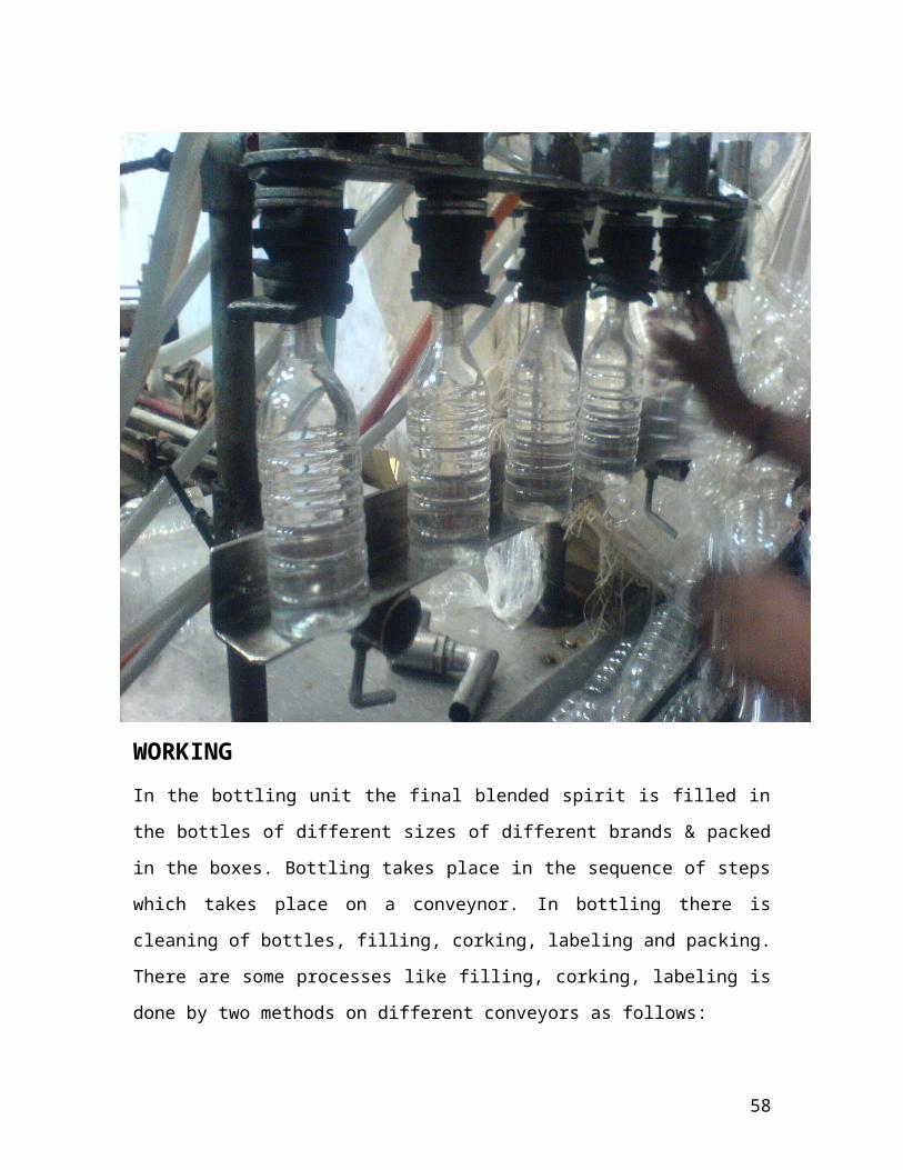
WORKING
In the bottling unit the final blended spirit is filled in the bottles of
different sizes of different brands & packed in the boxes. Bottling takes
place in the sequence of steps which takes place on a conveynor. In
bottling there is cleaning of bottles, filling, corking, labeling and
packing. There are some processes like filling, corking, labeling is done
by two methods on different conveyors as follows:
A.)MANUALLY WORKING
B.)AUTOMATICALLY WORKING
Presently, bottling is done automatically with the help of machines like
filling machine, sealing & labeling machine etc. This increases the
efficiency of the bottling unit and decrease the labor, thus it is directly
related to the economy.
There are ONE bottling units in the PDM. In the new Bottling unit where
English Whisky run on conveyer. There are 4 conveyors lying parallel
to each other which can work at a time depending on the load they
(conveyers) are used i.e. they have marked the conveyor for their
particular type of whisky usually conveyor work at a speed of 1 rpm.
Speed can be increased or decreased depending upon the load.
First step is washing yard. In washing yard, washing of bottles takes
place. Mainly ‘surf’ (detergent) is used for this purpose. Further, steam
is also used for washing purpose and this steam is supplied by Boiler
section. After washing yard, bottles are placed on the conveyor and
they are passed through a small opening of the wall. This wall is act as
a fence between the washing yard and rest of the bottling unit. Bottles
48
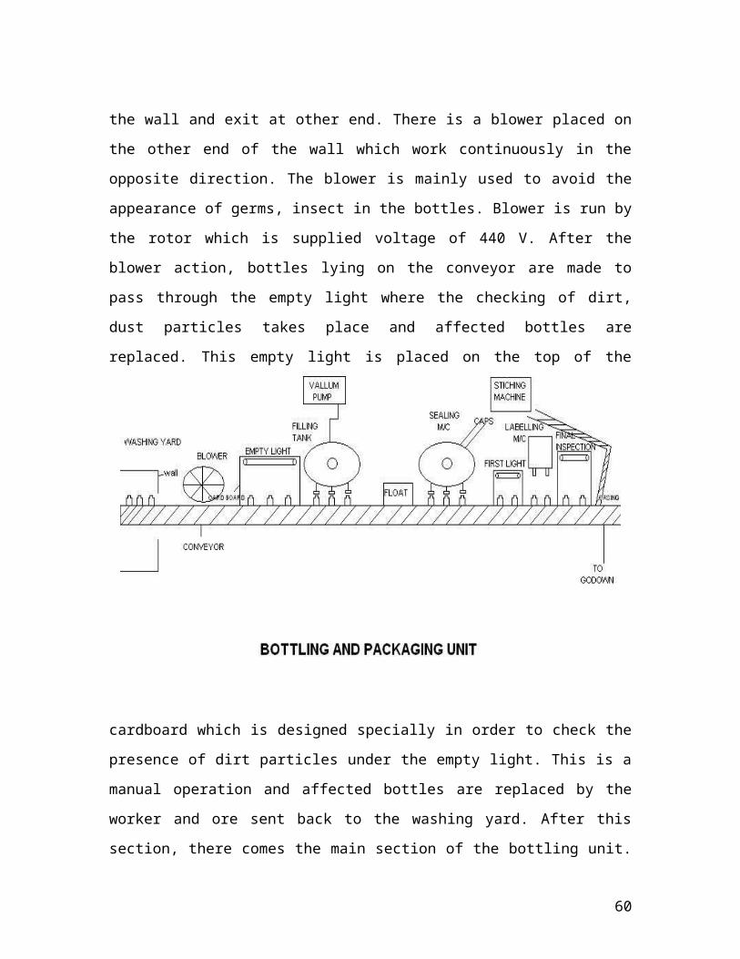
on the conveyor enter at one end of the wall and exit at other end.
There is a blower placed on the other end of the wall which work
continuously in the opposite direction. The blower is mainly used to
avoid the appearance of germs, insect in the bottles. Blower is run by
the rotor which is supplied voltage of 440 V. After the blower action,
bottles lying on the conveyor are made to pass through the empty light
where the checking of dirt, dust particles takes place and affected
bottles are replaced. This empty light is placed on the top of the
cardboard which is designed specially in order to check the presence of
dirt particles under the empty light. This is a manual operation and
affected bottles are replaced by the worker and ore sent back to the
washing yard. After this section, there comes the main section of the
bottling unit. i.e. ‘FILLING’. Filling of the blended spirit into the bottles
is mainly done by filling machine and this filling machine is attached to
the storage tank i.e. where spirit is stored with the help of pipelines.
This filling machine work at a rpm of 100. Atleast 10 bottles are
49
filled in one revolution. There is a vaccum pump placed behind the
filling machine which work at a pressure of max. 200kg/cm2 .
Then the bottles on the conveyor are made to pass through the float
which is used to avoid the overflow from the bottles. After the float
section there comes sealing section. In this section, sealing of the
bottles is done with the help of sealing cap made up of plastic. Sealing
machine is used for this purpose which work at 100 rpm.
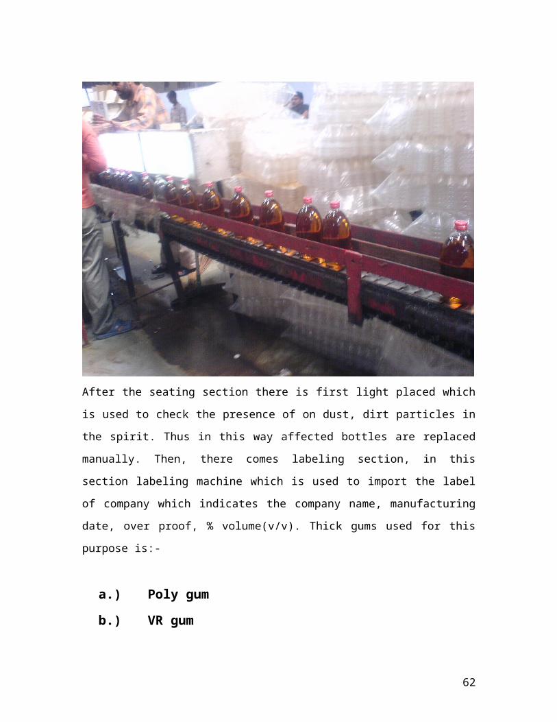
After the seating section there is first light placed which is used to
check the presence of on dust, dirt particles in the spirit. Thus in this
way affected bottles are replaced manually. Then, there comes
labeling section, in this section labeling machine which is used to
import the label of company which indicates the company name,
50
manufacturing date, over proof, % volume(v/v). Thick gums used for
this purpose is:-
a.) Poly gum
b.) VR gum
Then there is final inspection i.e. second light which is used to check
the presence of the dust particles. There is a Box and packing material
department which is placed along with the bottling unit. In this section
bottles, box commonly called as a ‘CASE’ is manufactured. There is a
stitching machine envolved during the manufacturing of the case. The
supply line of box department is attached a head to the conveyor of
the bottling unit.The bottles are placed in the case and sealed with the
help of ‘labelling tapes’. There are 12 bottles in each case and 48
bottles in each case. PDM has a capacity to manufacture 400-500
case/day. These cases are supplied and stored in the Godown there
after loaded on the truck and sent to various part of the country.
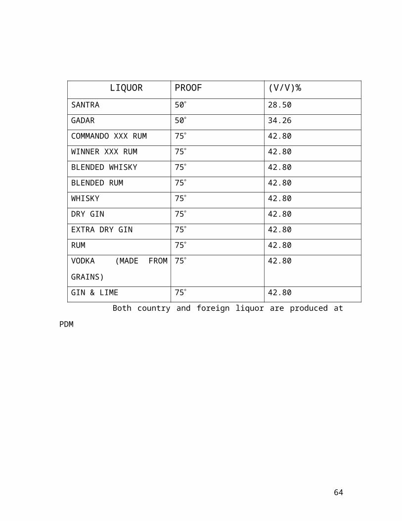
POPULAR BRANDS PRODUCED AT PDM
51
LIQUOR PROOF (V/V)%
SANTRA 50 28.50
GADAR 50 34.26
COMMANDO XXX RUM 75 42.80
WINNER XXX RUM 75 42.80
BLENDED WHISKY 75 42.80
BLENDED RUM 75 42.80
WHISKY 75 42.80
DRY GIN 75 42.80
EXTRA DRY GIN 75 42.80
RUM 75 42.80
VODKA (MADE FROM
GRAINS)
75 42.80
GIN & LIME 75 42.80
Both country and foreign liquor are produced at PDM
52
EFFLUENT TREATMENT
PLANT
Introduction
53
The effluent treatment plant in a distillery plays a crucial role in protecting the ecosystem, by controlling and treating the spent effluent, and disposing it in an appropriate manner, as per environmental norms.The untreated waste, coming out of the distillation house not only contains hazardous chemicals, but also has a high microbial content (cell mass), which is too unsafe to be readily disposed into the soil or any water body. Lowering of pH value, increase in organic load, depletion of oxygen content, destruction of aquatic life are some of the major pollution concerns.
The role of the effluent treatment plant in the Distillery is not just to make industrial wastes compatible to be disposed into the environment, but also to generate biogas, which can subsequently be used as a fuel. That is, bio-conversion of organic wastes in the liquor into CO2 and methane gas.
The effluent coming out of the distillation house is called Spent Wash. Spent wash, also known as spent broth, is the left over liquor after all the spirit has been recovered or extracted via distillation process. This liquor has very high BOD and COD of approximately 1,00,000mg/l along with very high amounts of potassium, calcium, chloride, Sulphate etc.
Effluent Quality standards for Distilleries:Under environmental protection act of 1986, the Govt. of India has specified Minimum National Standards(MINAS) for industries taking into account the characteristics of efflrent based on which the effluent from distilleries should have pH between 5.5-9.0, suspended solids 100mg/l, and a max BOD level of 100mg/l.
Significance of B.O.D :Biological Oxygen Demand (BOD) is one of the most common measures of pollutant organic material in effluent. BOD indicates the amount of putrescible organic matter present. Therefore, a low BOD is an indicator of good quality water, while a high BOD indicates polluted water. Dissolved oxygen (DO) is consumed by bacteria, when large amounts of organic matter from sewage or other discharges are present in the water, which makes the water unfit to be discharged into water bodies.
BOD test is a bioassay procedure that measures the amount of oxygen consumed by living organisms while they are utilizing the organic matter present in waste, under conditions similar in nature.
54
*BOD analysis was not applied in Patiala Distillers.
Volatile Fatty Acids (VFA):These are short-chain fatty acids like acetic, propionic, and butyric acids which, apart from their presence in some foods, are produced by bacteria from undigested starch and dietary fibre. To some extent they can be absorbed and used as a source of energy. It is these acids that are actually converted into methane in the bio-digestor. Therefore higher the availability of VFA in the spent wash, more is the biogas produced.
To check the VFA content in the spent wash-1. take 250ml of distilled water in a conical flask and add 1ml of
sample (spent wash).2. Transfer 20ml of this sol. into a round bottom COD flask.3. Add 10ml of 0.25N K2Cr2O7 and a pinch of Mercuric Sulphate
(catalyst).4. Now add 30ml of H2SO4 and put the COD flask over heater for 2
hours.
Significance of C.O.D :The chemical oxygen demand (COD) test is commonly used to indirectly measure the amount of organic compounds in effluent. It is expressed in milligrams per liter (mg/L), which indicates the mass of oxygen consumed per liter of solution. It may also be expressed in part per million (ppm).
In an effluent treatment plant, the spent wash is treated by the following treatments:
PRIMARY TREATMENT SECONDARY TREATMENT
From the distillation house, the spent wash having a high BOD & COD, from which all the spirit has been recovered, is collected in a large cooling pits. These are large cuboidal open storage tanks having a depth of about 12ft. The spent wash comes at a temperature of 60-700C in the first pit and stored so that the higher density particles settle down It is then cooled via heat exchangers before pumping into the second pit.
Plate Type Heat exchanger:
The plate heat exchanger normally consists of corrugated plates assembled into a frame. The hot fluid flows in one direction in alternating chambers while the cold fluid flows in true counter-current
55
flow in the other alternating chambers. A schematic diagram of the flow is shown in Figure. The fluids are directed into their proper chambers either by a suitable gasket or a weld depending on the type of exchanger chosen. Traditionally, plate and frame exchangers have been used almost exclusively for liquid to liquid heat transfer. The best example is in the dairy industry and distillery. Today, many variations of the plate technology have proven useful in applications where a phase change occurs as well. This includes condensing duties as well as vaporization duties.
Plate heat exchangers are best known for having overall heat transfer coefficients (U-values) in excess of 3–5 times the U-value in a shell and tube designed for the same service. Plate heat exchanger is an attractive option when more expensive materials of construction can be employed. The significantly higher U-value results in far less area for a given application. The higher U-values are obtained, by inducing turbulence between the plate surfaces. Owing to this, they are also known to minimize the fouling.
The cooled fluid, from the pit is pumped into storage tank. From here, the spent wash is subjected to primary treatment, after passing through clarifier. The clarifier is a settling tank used to remove dregs by sedimentation before the liquor is pumped into digester.
Primary Treatment
56

Anaerobic digesters serve as an energy conversion process by converting volatile solids into digester gas. The digester gas resulting from the bioenergy conversion, sometimes referred to as biogas, is a renewable fuel. The energy content in digester gas comes from methane: its dominant constituent.
Phase IAcid phase and methane phase digester:Initial phase, or the acid phase, continually receives an organic feed for short detention times of less than two days under conditions which efficiently liquefy and breakdown the feed, containing organic carbonaceous matter, to volatile fatty acids (VFA) of low molecular weight and other intermediates for conversion to methane. The most abundant VFA is acetic acid, followed by butyric and propionic acid. The volatile fatty acids remain solubilized in the liquid portion of the digester contents.
A succeeding phase (methane second phase) is operated, in a separate digester, to treat the lower molecular weight acids and intermediates for detention times of about two to about seven days, in which methanogenic microorganisms (methanobacterium, methanococcus etc) convert the volatile fatty acids to product gas composed primarily of methane and carbon dioxide. Product gas is removed from the methane second phase and processed or scrubbed to separate the methane component that is drawn off as pipeline gas.
A typical anaerobic digester product gas may contain, on a dry basis, 55% to 65% methane, 35% to 45% carbon dioxide, and less than 1% of other gases.
Phase IIThe spent liquor from the phase I digesters is fed to a large buffer tank. Also there is a direct supply of spent wash from the cooling pit simultaneously.
AUTO BUFFERING:The pH of the spent wash (from the distillation house) is about 4.6-4.5, and the pH of the slurry from the phase I digesters, is about 7.5. This increase in pH results from bioconversion of acids in the digesters. The purpose of the buffer tank is to mix these two separate streams of slurries and maintain the pH in the range 5.5-6.0, suitable for feeding
57
the subsequent Bio-Digesters. For example, if the pH reduces, more slurry is drawn from phase I digesters, and if pH increases, more spent wash is circulated from the storage tank. Auto buffering implies, that no external chemicals are added for maintainance of pH in Bio-Digester feed, or subsequent effluent treatment.The phase II consists of two Biodigestors, installed through Western Paque India Ltd, which are simultaneously feeded by the buffer tank. These digesters use acidogenic and methanogenic bacteria to produce CO2 and CH4 gas. This bioconversion of organic matter results in reduction of C.O.D to about 16000-17000mg/l. the following reactions occur in the anaerobic digester-
4H2 + CO2 CH4 + 2H2O4HCOOH CH4 + 3CO2 + 2H2OCH3COOH CH4 + CO2
2CH3OH 3CH4 + CO2 + 2H2O4(CH3)3N + H2O 9CH4 + 3CO2 + 6H2O + 4NH3
The effluent from the primary reactor is sent to effluent storage lagoon. This effluent is further treated by secondary treatment so as to make it capable for using in irrigation purposes.
Secondary Effluent treatment plant
The secondary effluent treatment plant treats the primary treatment plant discharge by anaerobic treatment on the basis of extended aerators form of activated sludge process. The discharge of the biomethanation plant comprises of not easily biodegradable organic matter.
58
Secondary treatment involves the following steps-
MIXING TANKThe effluent from the primary treatment plant is sent to the mixing tank where the effluent is mixed with water, so that the sludge settles down in the tank. After mixing the effluent is sent to Aeration Tank-I.
AERATION TANKIn an aeration tank the effluent is agitated in the presence of oxygen, since certain reactions take place in aerobic conditions. The effluent releases some of the gases and solid sludge. The released gases are NH3, NO2 etc, due to action of nitrifying bacteria. And also, due to agitation of the effluent, the Total Dissolved Solids(TDS) level falls and so does the level of BOD & COD.The discharge from the primary aerator is sent to primary Clarifier and to the aeration tank-II.
PRIMARY CLARIFIERThe Clarifier is a continuously operating, mechanically cleaned sedimentation device, which is designed to promote the separation of solid sludge from liquids. In Patiala Distilleries, the type of clarifier in operation was central feed fixed bridge circular clarifier. Feed enters from bottom of tank through the center column and goes into the clarifier. Feed flows down and then outward (radially) to the periphery of the tank where effluent is collected in a continuous peripheral launder. In circular sedimentation tanks the clarifier mechanism has
59
sludge scrapers attached to a rotating arm scraping the sludge towards a central hopper, into a discharge sump.
Final DisposalEffluent collected in the lauder, having BOD and COD approx 100mg/l and 735mg/l (as per environment act norm), is sent to nearby farms for irrigation purposes. The thick and viscous sludge is then pumped into a series of sludge drying beds. Here the solids are dried in open air and then provided to farmers as fertilizers in the nearby areas.
60
LAB WORK
TEST FOR ESTIMATING TOTAL REDUCING SUGAR
1. First, 50gm of concentrated molasses is taken in a beaker and the volume is made up to 500ml by adding tap water. (dilution factor=50/500)
2. Now, 100ml of this solution is taken and 5ml Hcl is added.3. Subsequently, 5-10ml of tap water is further added to prevent
burning of sugar, and then the beaker containing the solution is kept in a water bath of 65-700C.
4. After 15-20min, the beaker is cooled to room temperature.
61
5. Now, titration is performed against NaOH, with phenolphthalein as an indicator. Colour changes from yellow to pink.
6. Then take the same solution and add tap water to make up the volume to 100ml. name this sol X.
7. Mix 5 ml of solution-"A" with 5 ml of solution-"B". Put this mixture in a burette.
8. Titrate sol X against fehling mixture with methylene blue as an indicator. Note the burette reading.
9. A positive test is indicated by a green suspension and a red precipitate i:e appearance of brick red colour.
To calculate the total the Total Reducing Sugar (TRS):
TRS= Fehling factor *100D.F *burette reading
D.F (dilution factor)= (50/500)*(10/100)= 0.01
THE C.O.D TEST:
1. Take 1ml of sample (10,00,000 C.O.D) and mix with 250ml distilled water in a conical flask.
2. From the above solution, take 20ml and add 10ml of K2Cr2O7 . also add a pinch of Mercuric Sulphate (catalyst), in a round bottom C.O.D flask.
3. To this flask add 30ml of 1% Silver Sulphate, prepared in conc. H2SO4 ,and mix well.
4. Simultaneously, a blank (control) sol is prepared in the same way, except that sample is not added.
5. Perform fractional distillation for 2 hrs, for both sample and control.
6. Then cool at room temperature for about an hour. Then add 80ml of Distilled water.
7. Now titrate with 0.25N FAS sol, with feroine indicator.8. The colour change from green to wine red end point indicates
high C.O.D content. Note down the titrate value in both cases.
To estimate the C.O.D content using the following formula:
C.O.D= 1000 * {B-S} * 8000 * NFAS * Dil. factorVol. of diluted sample
B= titrate value of blank
62
S= titrate value of sample
TO CHECK THE ALCOHOL CONTENT OF THE FINAL SAMPLE:
1. A sample is taken from the fermentation unit. Its Specific gravity is checked by hydrometer. It comes out to be usually 94.8kg/m3.
2. 250 ml of sample is taken and 2 or 3 drops of antifoaming agent {usually tricker red oil (TRO)} is added.
3. Then the sample is heated to a temperature of 780C. The vapors start forming and they are condensed and collected in the another beaker. For 250 ml of the sample, approximately 150 ml of the alcohol is formed.
4. Specific gravity of the alcoholic sample is taken along with temperature. Corresponding to that temperature and specific gravity, degree proof of alcohol is found out.
CONCLUSION
The summer training at Patiala Distillers and Manufactures Ltd. was completed successfully during the period June-July 2008. I am fortunate to have got such such an opportunity to gain knowledge on the various industrial processes and operations. This exposure helped me familiarize with the actual industrial working culture and the practical aspects of the theoretical knowledge learnt in classroom and in the books.
During my training period I gained knowledge on the industry scale fermentation process, the equipments and the methodologies employed in the extraction of spirit. I learned the distillation, purification process of alcohol and also the safety and the quality concerns. I got the opportunity to understand the on-site working of the steam boiler, and also the techniques and processes employed in treatment of distillery effluent in the ETP, as per the environmental norms and regulations.
63
Though Patiala Dist. didn’t allow us to work and perform experiments in their laboratories regarding sugar content in raw material, alcohol estimation of final product, BOD and COD tests etc., but we were explained the methodologies of each experiment.
Thus, my summer training in Patiala Dist. was a very fruitful experience , and would certainly help me during my study and in future.
REFERENCES
1. Patiala Distillery, Hand outs2. Jagjit Industrries Ltd, Manuals on Fermentation,
Distillation3. http://www.energymanagertraining.com/distillery/
Manufacture_of_alcohol%20.htm accessed on 7,Oct4. http://dwb4.unl.edu/Chem/CHEM869P/
CHEM869PLinks/www-dept.usm.edu/~bsclabs/380/yeasts.htm accessed on 27,July
5. http://www.distillery-yeast.com/ ARTISANDISTILLING1.0.0.pdf accessed on 6,Oct
6. http://www.distillery-yeast.com/instruments.htm accessed on 6,Oct
64
7. http://www.andrew.cmu.edu/user/jitkangl/Fermentation %20of%20Ethanol/Fermentation%20of%20Ethanol.htm accessed on 7,Oct
8. http://www.h2flow.com/Website2003/Products/eimco/ Effluent_Clarifier.pdf accessed on 29,Aug
9. Principles of Fermentation Technology, Whittaker, Page no. 109-110;299-300;186-187.
65


![Direct Catalytic Upgrading of Current Dilute Alcohol ... · Direct Catalytic Upgrading of Current Dilute Alcohol Fermentation Streams to Hydrocarbons for Fungible Fuels [2.3.1.100]](https://static.fdocuments.in/doc/165x107/600bd2071c10ee288c4907b3/direct-catalytic-upgrading-of-current-dilute-alcohol-direct-catalytic-upgrading.jpg)