Albany Pump AF Series Fuel Oil Filtration and Polishing ... · Series Fuel Oil Filtration and...
22
Albany Pump AF Series Fuel Oil Filtration and Polishing Systems
Transcript of Albany Pump AF Series Fuel Oil Filtration and Polishing ... · Series Fuel Oil Filtration and...

Albany Pump AF Series Fuel Oil Filtration and Polishing Systems

CATALOG INDEX
Page CONTENTS
3-5 OVERVIEW PAGE
6 ASSEMBLY DRAWING
7-11 CONTROLLER DRAWING & USER INTERFACE DETAILS 12 PUMP CATALOG PAGE
13 10 MICRON FILTER CATALOG PAGE
14-20 FUEL OIL FILTER/ WATER SEPARARTOR CATALOG PAGES
20-22 TROUBLESHOOTING
PLEASE VIEW OUR WEBSITE FOR FURTHER DETAILS, DRAWINGS, CURVES, ETC.
WWW.ALBANYPUMP.COM
Albany Pump AF Series Fuel Oil Filtration and Polishing Systems are self-contained, pre-packaged and pre-wired units specifically designed to purify and filter stored diesel fuel. Preserving the integrity of the diesel fuel helps ensure trouble-free generator starts and reduces annual maintenance, contaminated fuel disposal and annual reservoir cleaning costs.
Maintaining clean and dry diesel fuel also discourages the growth of algae and bacteria while helping to reduce the need for expensive chemicals and biocide additives. Albany Pump AF Series Fuel Oil Filtration and Polishing Systems are fully automated with tank monitoring capabilities and are capable of servicing multiple tanks.
At the heart of each system is a diesel fuel purifier that is a simple one step unit. It removes nearly 100% of the free water and up to 98% of Particulate (to 2 microns). Even today's "clean" diesel fuel becomes contaminated all too easily. Water enters fuels systems through vents, leaks, and sometimes with the delivered fuel. Micro organisms can grow in fuel, especially in the presence of moisture.
The Albany Fuel Oil Filtration Assembly is designed to circulate and clean stored diesel fuel at critical facilities. Fuel Oil Filtration and Polishing has become an important aspect of emergency power reliability: Many critical facilities store increasing amounts of fuel onsite to assure continuity of operation and this fuel has low turnover in operation.
Diesel fuel can easily become contaminated with microorganisms such as bacteria, fungi, yeast, mold, and to a lesser extent algae. Diesel fuel in the presence of water and nutrients makes conditions ripe for high bacterial growth. In classical microbiology, microbes will generally need water, Carbon source, nitrogen, phosphorus, sulfur, trace minerals, and some form of oxygen (free or bound to other atoms) to grow. Most of these conditions are met in fuel tanks and fuel lines. Water and microbes can be introduced from the outside air or other environments. Water can also form from changes in storage temperatures, which causes condensation to occur.
Water allowed to remain in fuel will culture a microorganism or bacteria that feeds on the hydrocarbons in the fuel, therefore degrading the fuel quality. Water is the worst and most common form of fuel contamination.
The Need for Fuel Polishing in Storage Tanks
The most common reason for diesel engines in general to fail to run is associated with "bad diesel fuel." The things that make the diesel fuel bad generally have nothing to do with the original quality of the fuel. The problems come about because of the condition of the fuel we buy and what happens to the fuel when it gets stored. Most of this contamination adheres to the wall of the tanks and you might not immediately notice a problem. Once operation is underway and the fuel begins moving around the contamination tends to start breaking away from the wall of the tank and entering the fuel. This contamination can clog your filters and shut down your engines.
Day Tanks
The object of a day tank is essentially to provide a "day's" quantity of fuel that is guaranteed to be clean and dry for the engine. It is important to remember that the clean and dry fuel in the day tank will be exposed to the same conditions that cause the fuel in the main storage tank to become bad. Given enough time, the fuel in the day tank will get to the same condition as the fuel in the main tank. A filter and a water separator are still required on the outlet of the day tank.
To provide the desired results, this tank must, in fact, be a "Day Tank." That is, the fuel in this tank must remain there for only a short time. All the problems of long-time fuel storage in the main tank will be present in the day tank if fuel remains in it for long periods of time. Once it ceases to be a "Day Tank" it must be treated just like any other tank.
The Albany Fuel Oil Filtration Assembly has an innovative compact design has a minimal footprint for Filtration / Polishing of tanks from 500 to 50,000 gallon capacity
Each System Includes:
Albany ‘L’ or ‘G’ Series Positive Displacement Gear Pump with adjustable internal relief valve and totally enclosed fan cooled industrial motor. Shut-off valves and flanges are positioned so the pump may be removed for servicing without disturbing piping.
Weather proof NEMA 4X rated enclosure, with lockable door, rupture containment basin with leak detection sensor and 1/2" NPT plug drain port. Enclosure can be ordered for either wall mounting or with optional base for pad or tank top mounting.
Common system suction port and common system discharge port with "lost" flow detection sensor.
System inlet strainer with liquid filled compound vacuum pressure gauge and differential pressure gauge for "clean" strainer alarm indication.
Check valve and liquid filled pressure gauges on each pump discharge. UL/ULC listed control panel, containing programmable logic controller, adjustable
system timer, manual-off-auto illuminated pump mode selector switch, indicating lights, alarms and motor starter with overload protection.
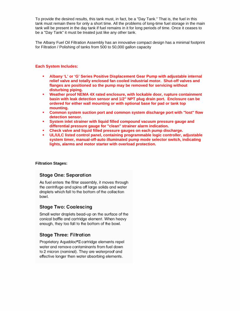
Filtration Stages:
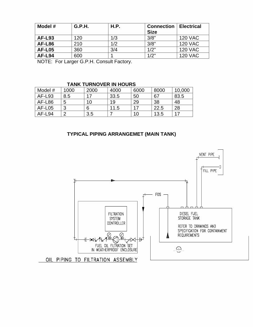
Model # G.P.H. H.P. Connection
Size Electrical
AF-L93 120 1/3 3/8” 120 VAC AF-L86 210 1/2 3/8” 120 VAC AF-L05 360 3/4 1/2” 120 VAC AF-L94 600 1 1/2" 120 VAC NOTE: For Larger G.P.H. Consult Factory. TANK TURNOVER IN HOURS Model # 1000 2000 4000 6000 8000 10,000 AF-L93 8.5 17 33.5 50 67 83.5 AF-L86 5 10 19 29 38 48 AF-L05 3 6 11.5 17 22.5 28 AF-L94 2 3.5 7 10 13.5 17
TYPICAL PIPING ARRANGEMET (MAIN TANK)


2010-06-06 Page 2 SF1-MAN001-E rev.0
The interface present on the HMI system is part of a five page display system. Each page has its specific role in the operation and management of the oil filtration controller and displays the current date and time on the bottom right corner. They go as follows:
• Home page that display all relevant information, as well as necessary buttons to operate the system.
• Filter schedule page, where the user is to configure the scheduling and duration of the filtering.
• Configuration page, where the user shall set the desired date, time and automatic mode timer.
• Logs page that shows the last 1000 events to have occurred on the system • Alarms page that shows the current alarm state of the controller.
Each of these sections will be described in details. The Home page is the default screen of the controller and, displays all relevant indications to the operator. The upper left side of the display, next to the navigation pane, shows the scheduling information. Start time and date of the next filtering is displayed, as well as the following start date according to the frequency set by the operator. The time is displayed in hh:mm format and the date is displayed in dd/mm/yyyy format. Beside the scheduling information resides the filtering information. Upon filtering, the message “Tank X Filtering” appears in a green box along with the stop time, according to the duration set by the operator.
Three selectors are present on the Main page, allowing the user to fully control the operations of the system. The Tank(s) selector is where the operator chooses to filter tank 1 only, tank 2 only, or tank 1 and then tank 2, according to duration information and automatic mode timer value. The Scheduling selector enables or disables the automatic filtering according to the date and time set by the operator. The Controller selector box is the main On-Off selector for the entire
system. When turned off, no operations are permitted to happen. Note that turning the Controller selector to off also turns off the Scheduling and prevents it from be turned on again as long as the Controller is in off position. Note that if a selector is not in the preferred position, its arrow indicator will flash red. Filtering happens only when the Controller is in on position and either Instant Filtering is pressed, remote start command has been received or the Scheduling is on and the date and time is equal to the scheduled values. Upon pump running, the Instant Filtering button becomes Stop Filtering and allows the sequence to be aborted with similar effect of having a remote stop command or putting the controller in off position.

2010-06-06 Page 3 SF1-MAN001-E rev.0
In the events of an alarm, the background of the home page flashes red to attract the operator’s attention. An alarm banner, displaying scrolling alarms messages, also appears on the bottom to give a quick overview of the situation. The Alarms tab, from the navigation pane, then flashes red to inform the operator that his attention is needed in the Alarm summary page. A user inactivity timeout is also in place, turning the backlight of the display off and returning the user to the Home page. This saves the backlight of the display and ensures all the information from the home page remains visible in the events of an alarm. For this reason, the backlight is turned on again in the event of an alarm. This timeout is factory set at two minutes. The Filtering schedule page provides the user with the means of setting the the automatic filtering of the system. On top of the page resides the time and date desired for the filtering to occur. Pressing on the time or date field brings a keypad enabling the entry of data. The calendar icon can also be pressed to select the appropriate date. Note that if the scheduling is on, a warning message appears to inform the user that he is about to change values that might start the filtering automatically. It is therefore recommended to momentarely turn the scheduling off prior to modifying these values. The duration box is
where the operator is to set for how log the filtering will take place for a given tank. Note that if this field is set to 0, the pumping will never occur. For this reason, a warning message appears and the Filter Sch tab flashes red if the duration time is null. The last selector gives the user the choice of the repetition of the selected scheduling. The operator can chose from a number of days, months or years by pressing the apropriate tab and entering the desired number. Note that the user cannot enter a number of more than
366 days or 12 months. Also note that the calendar is valid until year 2037. The purpose of the Set button is to update the repetition of the scheduling and should always be pressed when the frequency information is changed, or when the scheduling information is changed and the frequency is not null. The button flashes green to remind the user the need of updating the parameters. If a scheduled date is not entered, the button cannot be pressed and a warning message appears, reminding the user to first select a scheduled date.

2010-06-06 Page 4 SF1-MAN001-E rev.0
The Alarms log page shows the last 1000 events to have occurred in the system. Displayed information includes date and time the alarm became active, time the alarm returned to normal and the alarm message. The log entry color is set to red if the alarm is still active, and is green if the alarm state has returned to normal. Scroll bars can be used see the entire message or to scroll down and up the events log boxes. The Alarms page shows the active alarm. Buttons on top are, from left to right, acknowledge all alarms, acknowledge selected alarm, up, down, page up and page down. When an alarm condition is active, the alarms button in the navigation pane flashes red.
The Configuration page lets the user set the proper date and time. Like the filter scheduling page, the parameters are entered by pressing on the corresponding fields. Date and time parameters are saved when the set button is pressed. Note that the factory set date and time settings do not include daylight saving correction. This is achieved through the system menu explained in the following. The timer between the filtration of the first and second tanks, when tanks are in automatic mode, is configurable

2010-06-06 Page 5 SF1-MAN001-E rev.0
through this page. The user selects a value between 0 and 60 and sets the units to be minutes or seconds. The System menu is accessed by touching the top left and bottom right corners simultaneously. On the system tab, it is possible to configure the date and time, time zone and daylight saving feature. In offline mode, the backlight timeout can be changed. However, turning off the timeout will result in a premature end of life of the display and is highly not recommended. Also, be aware that going in offline mode puts the controller in off mode. It is mandatory to return to run mode as soon as possible. Changing the parameters in the system menu can result in a controller responding erratically and is not recommended unless done by an expert.
AlbAny PumP ComPAny ltd. l05 SerieS 5.75 gpm/0-150 pSi 1/2” npt
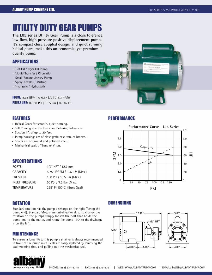
utility duty geAr PumPsthe l05 series Utility gear pump is a close tolerance, low flow, high pressure positive displacement pump. it’s compact close coupled design, and quiet runninghelical gears, make this an economic, yet premium quality pump.
APPliCAtions• Hot Oil / Fryer Oil Pump• Liquid Transfer / Circulation• Small Booster Jockey Pump• Spray Nozzles / Misting• Hydraulic / Hydrostatic
phone: (888) 334-3348 | FAx: (888) 335-3391 | Web: WWW.AlbAnypUmp.com | emAil: [email protected]
Flow: 5.75 GPM | 0-0.37 L/s | 0-1.3 m3/hr
Pressure: 0-150 PSI | 10.5 Bar | 0-346 Ft.
FeAtures• Helical Gears for smooth, quiet running.• Self Priming due to close manufacturing tolerances.• Suction lift of up to 20 feet• Pump housings are of close grain cast iron, or bronze.• Shafts are of ground and polished steel.• Mechanical seals of Buna or Viton.
rotAtionStandard rotation has the pump discharge on the right (facing the pump end). Standard Motors are uni-directional, so to change the rotation on the pumps simply loosen the bolt that holds the pump-end to the motor, and rotate the pump 180º so the discharge is on the left.
mAintenAnCeTo ensure a long life to this pump a strainer is always recommended in front of the pump inlet. Seals are easily replaced by removing the seal retaining ring, and pulling out the mechanical seal.
PerFormAnCe
0 25 50 75 100 125 150
PSI
GPM
8.5
6.0
4.5
3.0
1.5
0
1.2
1.0
.80
.60
.40
.20
0
HP
C a p a c ity
H p
Performance Curve - L05 Series
dimensions
1/2" NPT
3.00" 5.00" 4.88"
12.10"
7.86"
5.63"
sPeCiFiCAtionsPORTS 1/2“ NPT / 12.7 mm
CAPACITY 5.75 USGPM / 0.37 L/s (Max.)
PRESSURE 150 PSI / 10.5 Bar (Max.)
INLET PRESSURE 50 PSI / 3.5 Bar (Max.)
TEMPERATURE 225° F (100°C) (Buna Seal)


751000FHX

The quality solution
For more than 30 years Parker has been an innovator in diesel fuel filtration and water separation. Providing OEMs and end users with quality filtration solutions. The information contained here is designed to support our distributors in identifying key products: – filter assemblies, replacement elements and more, aimed specifically at the MRO Market.
Product technology and design innovationsAs one of the world’s leading manufacturers of fuel filtration products, we pride ourselves on our commitment to innovative products and our distributors play a vital role in achieving this consistently, providing local service, support and stock.
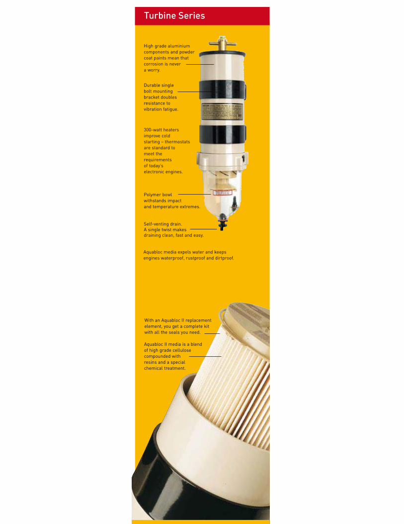
Turbine Series
With an Aquabloc II replacement element, you get a complete kit with all the seals you need.
Aquabloc II media is a blend of high grade cellulose compounded with resins and a special chemical treatment.
Durable single bolt mounting bracket doubles resistance to vibration fatigue.
High grade aluminium components and powder coat paints mean that corrosion is never a worry.
Aquabloc media expels water and keeps engines waterproof, rustproof and dirtproof.
300-watt heaters improve cold starting – thermostats are standard to meet the requirements of today’s electronic engines.
Polymer bowl withstands impact and temperature extremes.
Self-venting drain. A single twist makes draining clean, fast and easy.

Turbine Series
Turbine Series filter assemblies are designed
to be installed on the vacuum side of the fuel
transfer pump for best efficiency and protect
precision engine components from dirt, rust,
algae, asphaltines, varnishes, and especially
water, which is prevalent in engine fuels. They
remove contaminates from fuel using the following
legendary three stage process:
Stage One: Separation
As fuel enters the filter assembly, it moves through
the centrifuge and spins off large solids and water
droplets which fall to the bottom of the collection
bowl.
Stage Two: Coalescing
Small water droplets bead-up on the surface of the
conical baffle and cartridge element. When heavy
enough, they too fall to the bottom of the bowl.
Stage Three: Filtration
Proprietary Aquabloc®II cartridge elements repel
water and remove contaminants from fuel down
to two micron (nominal). They are waterproof and
effective longer then water absorbing elements.
Features and Benefits
• Available in several sizes to fit any application.
• Heavy duty construction.
• Installs quickly.
• Available in 2, 10, and 30 micron.
• Easy to service.
• Clear collection bowl.
• Self-venting water drain.
Optional accessories may include: water detection
kits, 12 or 24 volt dc heaters, heavy-duty fuel hose
and fittings. see Accessories section.

Mobile Fuel Filtration
Turbine Series
1
Specifications 75500FGX 75900FHX 751000FHX
Maximum Flow Rate:
(one unit online)
(two units online)
(three units online)
60 GPH (227 LPH)
120 GPH (454 LPH)
N/A
90 GPH (341 LPH)
180 GPH (681 LPH)
N/A
180 GPH (681 LPH)
360 GPH (1363 LPH)
N/A
Port Size (female threads)3/4”-16 UNF
(SAE J1926 female threads)
7/8”-14 UNF
(SAE J514 male threads)
7/8”-14 UNF
(SAE J514 male threads)
Min. Service Clearance:
(above assembly)
(below assembly)
5.0 in. (12.7 cm)
2.0 in. (5.1 cm)
7.5 in. (19.1 cm)
2.0 in (5.1 cm)
10.0 in. (25.4 cm)
2.0 in. (5.1 cm)
Replacement Element:
(2 micron)
(10 micron)
(30 micron)
(2 Per Assembly)
2010SM-OR
2010TM-OR
2010PM-OR
(2 Per Assembly)
2040SM-OR
2040TM-OR
2040PM-OR
(2 Per Assembly)
2020SM-OR
2020TM-OR
2020PM-OR
Height 11.5 in. (29.2 cm) 17.0 in. (43.2 cm) 22.0 in. (55.9 cm)
Depth 9.5 in. (24.1 cm) 11.0 in. (27.9 cm) 11.0 in. (27.9 cm)
Width 14.5 in. (36.8 cm) 18.8 in. (47.8 cm) 18.8 in. (47.8 cm)
Weight (dry) 17.0 lb (7.7 kg) 23.0 lb (10.4 kg) 30.0 lb (13.6 kg)
Clean Pressure Drop 0.7 PSI (4.8 kPa) 1.7 PSI (11.7 kPa) 3.7 PSI (25.5 kPa)
Maximum Pressure1 15 PSI (1 bar) 15 PSI (1 bar) 15 PSI (1 bar)
Water In Bowl Capacity:
(per bowl)3.7 oz (109 ml) 10.3 oz (305 ml) 10.3 oz (305 ml)
Available Options:2
(water detection kit)
(12 or 24 volt dc heater)
(vacuum gauge)
Yes
Yes
Yes
Yes
Yes
Yes
Yes
Yes
Yes
H2O Removal Efficiency 99%
Operating Temperature -40o to +255oF / -40o to +124oC
1 Pressure installations are applicable up to the maximum PSI shown. Vacuum installations are recommended.2 Not for use on gasoline applications.
Note: Units with 1/2” NPT ports are available, contact the factory.
steveb
Highlight
steveb
Highlight
steveb
Highlight
steveb
Highlight
steveb
Highlight
steveb
Highlight
steveb
Highlight
steveb
Highlight

224
Technical Support:800.344.3286 ext. [email protected]
225
Technical Support:800.344.3286 ext. [email protected]
Mobile Fuel Filtration
Turbine Series
1
224
Technical Support:800.344.3286 ext. [email protected]
225
Technical Support:800.344.3286 ext. [email protected]
751000FHX Part Number Description
1. 1000FH See 1000FH Replacement Part List
2. RK19476 Gauge Assembly Kit
3. RK11-1777 Main Bracket Kit
4. RK11815-103 Housing Bracket (includes hardware)
5. RK19475 Rigid Tubing and Fittings Kit
6. RK19473 Valve Assembly Kit
RK19506 Valve Service Kit (not shown)
Replacement Parts
1
4
5
6
3
2
4
5

Mobile Fuel Filtration
Turbine Series
(PSI X 2.036 = inHg) (PSI X 6.895 = kPa)
(Controlled laboratory test. Field results may vary.)
Test Data
751000FHX
75900FHX
75500FGX
Grams
SAE J905 Solids Capacity
(using SOFT-2A; 2010TM Element)
Flow (GPH)
SAE J905 Fuel Flow Restriction
Grams
SAE J905 Solids Capacity
(using SOFT-2A; 2040TM Element)
Flow (GPH)
SAE J905 Fuel Flow Restriction
Grams
SAE J905 Solids Capacity
(using SOFT-2A; 2020TM Element)
Flow (GPH)
SAE J905 Fuel Flow Restriction
steveb
Highlight
steveb
Highlight
Mobile Fuel Filtration
Turbine Series
1
New filter installations must be filled with fuel and the
fuel system must be adequately primed following the
engine manufacturer’s recommendations. Existing
installation difficulties are usually associated with
improper priming procedures or damage to the unit or
fuel system. The result is either internal air suction or
external fuel leakage. Diagnose with the following steps:
1. Check fuel tank level and verify fuel delivery
valves are open.
2. Verify T-handle, bowl fasteners and fuel fittings are
tight and bowl drain is closed.
3. If element is new, check potential restriction at
fuel tank draw tube. An in-tank strainer may
be plugged.
4. Review other troubleshooting instructions to
uncover other solutions.
Correct external fuel leaks immediately! These conditions
result in reduced engine performance such as: hard
starting, stalling, reduced power and fire hazards.
Correct Application
It is very important that Turbine Series filter assemblies
are not ‘under specified’ for the application. The
maximum fuel flow rating of the filter assembly must not
be exceeded; doing so will reduce efficiency and de-gas
(pull air from) the fuel.
Filter Elements
Replacement elements are available in 2, 10 and 30
micron ratings (nominal). Filtration needs are based on
application, fuel quality, maintenance schedules and
operating climates. A simple rule to remember is... the finer
the filtration, the more frequent the filter change interval.
Always carry extra replacement elements with your
equipment as one tankful of excessively contaminated
fuel can plug an element quickly.
When clogged to maximum capacity, elements will have
a brown to black color or tar like contaminants may be
present - this is normal. An appearance of a multi-colored
slime (which may have a foul odor) is an indication
of microbiological contamination. This condition must
be treated immediately. Racor offers a wide variety of
gasoline and diesel additives to prevent and treat these
problems; see ‘Additives’ section of this catalog. Severe
conditions must be corrected by a repair facility.
Never operate a filter assembly without the element in
place. The element safety valve on the fuel return tube
will not expose the outlet hole if the element is removed.
Instead, punch the emergency tab on the top of the
element and leave in place.
Warning! Puncturing the emergency tab will bypass all
filtration and send unfiltered fuel to your engine. Service
the element as soon as possible to avoid harmful
contaminants flowing downstream to the engine.
Water Sensors
This feature alerts the operator of a high-water
condition. The bowl must be drained of water at the
earliest convenience. A Racor water detection module
is needed to work with the in-bowl sensor. The unit
should activate when the water reaches the sensor tips
(and when they measure below 47,000 or 100,000 ohms
of resistance, depending on the detection module used).
If not, the tips may be fouled with a coating. Remove
the sensor and clean the tips with a cloth. Run a jumper
wire between the tips with the ignition ON to test the
system. Difficulties usually lie in the wire connections,
power source, or an independent ground.
Heaters
In-filter heaters are starting aids only, but may be left
on during cold operations to supply additional heat.
The 150 and 300 watt heaters are an extremely reliable
option, but MUST be powered via a relay switch due
to the initial amperage surge at start-up: 25 amps at
12 vdc and 12.5 amps at 24 vdc. They do not activate
unless the fuel is below 50oF (10oC) and automatically
deactivate at 80oF (28oC).
Heater Testing
The heater can only be tested when the thermostat is
closed (fuel temperature is below 50oF or 10oC). With
a voltmeter attached to external wiring, and engine off,
power should drop when heater is switched on. (Option
- remove the heater and place in a freezer until the
temperature is under 50oF (10oC). Remove the heater
and repeat the above test).
Troubleshooting

Mobile Fuel Filtration
Turbine Series
TroubleshootingAll Racor Turbine Series filters are 100% tested to ensure a leak-proof, quality product.
Apply Parker Super O-lube (part number RK31605) or equivalent to all seals at major attachment points to maintain
integrity, seal elasticity, to fill small voids and provide protection from degradation. Perform the following checks with
the engine OFF (and applicable valves closed). For replacement parts, refer to the appropriate ‘Replacement Parts’
section of this catalog.
Damaged, worn, or dirty seals will allow air ingestion. Inspect and replace all seals as needed. Lube all seals with
Parker Super O-Lube. Clean sealing surfaces thoroughly of dirt and debris every time an element is replaced.
Hand tighten T-handle; do not use tools!
If element is changed or assembly drained
for any reason, repriming assembly (filling
with fuel) may be necessary. Fill to just
above top of element before replacing lid.
Do not overtighten carriage bolt as this
may distort cylinder roundness.
Do not overtighten self-taping screws; this
may strip the threads. After disassembly,
start screws by hand prior to using tools.
Specifications: 55-65in. lbs.
The hollow aluminum check-ball floats up
against the seal when the fuel is stopped
thus preventing fuel bleed-back. If your
unit looses prime, inspect upsteam hose
connections first, otherwise, disassemble
the unit and inspect the seal and ball.
Drain water before it reaches this level.
Air bubbles or fuel leakage appearing
from drai may indicate that the drain is not
closed completely or that a seal has been
clogged with contaminants. Tighten drain
and inspect. If self-venting drain will not
work when opened, it may be clogged.
Cycle drain (open close) or attach a hose
and briefly apply air (<2-3 PSI, with T-
handle and lid removed) to dislodge any
contaminates that may be stuck.
Element should be replaced every 10,000
miles or every 500 hours, or every other
oil change, annually, or at first indication
of power loss, which ever comes first.
Construction and agricultural equipment
should change element every 300 hours.
See ‘Heaters’ on previous page.
SAE O-ring ports should have a smooth
angled seat for sealing. Do not scratch
surface. Check O-ring for damage.
Replace if necessary.
Heater feed-thru O-ring must
not be damaged or swollen.
Tighten snugly.
Specifications; 15-20 in. lbs.
Air bubbles appearing from turbine are an
indication of an upstream leak between
Racor inlet and fuel tank pick-up tube.
A water sensor plug is standard
equipment on new assemblies. Water
sensor kits are available as accessories;
see ‘Accessories’ section of this catalog.
Tighten plug or water sensor snugly.
Specification; 15-20 in. lbs.
Water sensors activate when water
contacts the sensor tips. Air bubbles or
fuel leakage appearing from sensor area
may indicate that it is loose or O-ring is
damaged. Tighten or disassemble and
inspect. Specification; 15-20 in. lbs.