ALARM VALVES - 4,6, and 8 INCH (100,150, and 200 mm)
12
ALARM VALVES - 4,6, and 8 INCH (100,150, and 200 mm) 4 and 6 Inch - Model F20 (Groove x Groove) 4,6, and 8 Inch - Model F200 (Flange x Flange) & F2001 (Flange x Groove) The 4 and 6 inch Model F20 Alarm Valves, as well as the 4, 6, and 8 inch Model F200 and F2001 Alarm Valves, are divided seat ring, rubber faced clapper, check type water-flow alarm valves which are intended for use in wet pipe (automatic sprinkler) fire pro- tection systems. They are designed to automatically actuate electrically and/or hydraulically operated alarms when there is a steady flow of water into the system which is equivalent to the discharge rate of one or more sprinklers. The Model F20, F200, and F2001 Alarm Valves may be installed either vertically or horizontally. Flanged con- nections are per ANSI Standard B16.1. Groove connections are cut in accor- dance with Gruvlok standard groove specifications for steel pipe, and they are suitable for use with grooved end couplings that are listed or approved for fire protection service. / PRESSURE ALARM SWITCH (OPTIONAL) Valve Size End-To-End inch::Amm) Dimension Model No. inches (mm) 4 (100) F20 IO-l/4 (260.4) 6 (150) F20 12-l/4 (311.2) 4 (100) F200 10 (254.0) 6 (150) F200 12 (304.8) 8 (200) F200 14 (355.6) Jt-s _ GAyE 1 6 (150) F20011 12~ 1 f304.8) 1 . , I I 4 (100) F2OOlj 10 1 (254,;; I , I , \ I 8 (200) F20011 14 1 (355.6) Model F20 Groove x Groove Model F200 Flange x Flange FIGURE A Model F2001 Flange x Groove TYPICAL VERTICAL INSTALLATION WITH CLOSED DRAIN TRIM (Shown With Model F211 Retard Chamber Which is Used With Systems Having A Variable Water Supply Pressure) Printed in U.S.A. 7-95 TD102 OBSOLETE
Transcript of ALARM VALVES - 4,6, and 8 INCH (100,150, and 200 mm)

ALARM VALVES - 4,6, and 8 INCH (100,150, and 200 mm) 4 and 6 Inch - Model F20 (Groove x Groove)
4,6, and 8 Inch - Model F200 (Flange x Flange) & F2001 (Flange x Groove)
The 4 and 6 inch Model F20 Alarm Valves, as well as the 4, 6, and 8 inch Model F200 and F2001 Alarm Valves, are divided seat ring, rubber faced clapper, check type water-flow alarm valves which are intended for use in wet pipe (automatic sprinkler) fire pro- tection systems. They are designed to automatically actuate electrically and/or hydraulically operated alarms when there is a steady flow of water into the system which is equivalent to the discharge rate of one or more sprinklers.
The Model F20, F200, and F2001 Alarm Valves may be installed either vertically or horizontally. Flanged con- nections are per ANSI Standard B16.1. Groove connections are cut in accor- dance with Gruvlok standard groove specifications for steel pipe, and they are suitable for use with grooved end couplings that are listed or approved for fire protection service.
/ PRESSURE ALARM SWITCH (OPTIONAL)
Valve Size End-To-End
inch::Amm) Dimension
Model No. inches (mm)
4 (100) F20 IO-l/4 (260.4)
6 (150) F20 12-l/4 (311.2)
4 (100) F200 10 (254.0)
6 (150) F200 12 (304.8)
8 (200) F200 14 (355.6)
Jt-s _ GAyE 1 6 (150) F20011 12~ 1 f304.8) 1
. , I I
4 (100) F2OOlj 10 1 (254,;;
I , I , \ I
8 (200) F20011 14 1 (355.6)
Model F20 Groove x Groove
Model F200 Flange x Flange FIGURE A
Model F2001 Flange x Groove
TYPICAL VERTICAL INSTALLATION WITH CLOSED DRAIN TRIM (Shown With Model F211 Retard Chamber Which is Used With Systems Having A Variable Water Supply Pressure)
Printed in U.S.A. 7-95 TD102
OBSOLETE

NOTE: Model F200 Valve illustrated. Components and NPT tap locations are identical for the Model F20 and F2001
3
Valves. 1 -Valve Body P-Handhole Cover 3-Handhole Cover
Gasket 4-Seat Ring 5-Clapper B-Clapper Facing 7-Clapper Washer 8-Self-Locking Hex
Hd. Cap Screw O-Hinge Pin
IO-Bushing (4 req’d)
11 -Spring 12-Hex t-id. Cap
Screw i/2”-13 UNC x l-3/4” fdr 4” and 6” Valves, 3/4”-10 UNC x 2” for 8” Valve
13Sq. Hd. Steel Plug, 3/S” NPT
A-Supply Pressure D-Upper By-pass Con- Gauge and Alarm nectton, t/2” NPT Test Connection, for 4” and 6” i/2” NPT valves, 314” NPT
B-System Pressure for 8” valves Gauge Connection, E-Alarm Connection, l/4” NPT 112” NPT
C-Lower By-pass Con- F-System Main Drain nection, l/2” NPT Connection, for 4” and 6” valves
’ 2” NPT
3/4” NPT for 8” valves
FIGURE 6 COMPONENTS AND CONNECTIONS FOR
MODEL F20, F200, AND F2001 ALARM VALVES
3/4” NPT CONNECTION TO zir;; MOTOR
l/2” NPT CONNECTION FOR PRESSURE ALARM SWITCH
3/4” x l/2” x 3/4” TEE
314” x l-l/2” NIPPLE
RETARD CHAMBER
l/2” NPT INLET FROM RESTRICTION ASSEMBLY
FIGURE C MODEL F211 RETARD
CHAMBER (Ordered separately for use with
variable pressure systems)
INLET RESTRICTION WITH 219” (5.6mm)ORIFICE
*SCREEN
DR-AIN RESTRICTION WITH .l25” 13.2mm) ORIFICE
FIGURE D RESTRICTION ASSEMBLY
The Model F211 Retard Chamber is required in installations which will be subject to variable pressures, such as are generally associated with public water supplies in order to help prevent false alarms. The Retard Chamber need not be used in relatively constant pressure installations typified by grav- ity and pressure tank water supplies.
Trim arrangements for the F20, F200, and F2001 Valves include an exter- nally mounted By-pass Check Valve. The By-pass Check Valve serves to further reduce the possibility of a false
alarm by permitting slow as well as small transient increases in water sup- ply pressure to be passed through to the system, and held at their highest value, without opening of the waterway Clapper.
closed alarm line drain is available on a “special order” basis.
Figure A represents a typical variable The 4 and 6 inch Model F20 Alarm pressure, vertical installation with a Valves, as well as the 4, 6, and 8 inch closed alarm line drain. An alternate Model F200 and F2001 Alarm Valves, vertical trim arrangement, which pro- vides an open alarm line drain, is avail-
are listed by Underwriters Labora- tories Inc. and Underwriters’ Labora-
able on a “special order” basis. Also, for horizontal installation, a horizontal
tories of Canada. They are approved
trim arrangement which provides a by Factory Mutual Research Corpora- tion, and by the New York City Board
-2-
OBSOLETE
SUPPLY PRESSURE. PSI
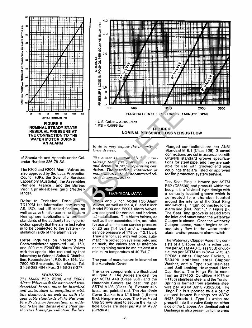
FIGURE E NOMINAL STEADY STATE RESIDUAL PRESSURE AT
THE CONNECTION TO THE WATER MOTOR DURING
AN ALARM
of Standards and Appeals under Cal- endar Number 236-79-SA.
The F200 and F2001 Alarm Valves are also approved by the Loss Prevention Council (UK), the Scientific Services Laboratory (Australia), the Assemblee Pleniere (France), and the Bureau Voor Sprinklerbeveilging (Nether- lands).
Refer to Technical Data Sheet TD102M for information concerning AS, ISO, and JIS drilled flanges, as well as valve trim for use in the Eastern Hemisphere applications where the standards of the authority having juris- diction specify that the alarm test valve is to be connected to the system (in- stallation) side of the alarm valve.
Refer inquiries on Verband der Sachversicherer approved 100, 150, and 200 mm F200DIN Alarm Valves with the special trim required by that laboratory to Grinnell Sales & Distribu- tion, Kopersteden 1, P.O. Box 198, NL- 7500 AD Enschede, Netherlands, Tel. 31-53-283-434 / Fax. 31-53-283-377.
WARNING The Model F.20, FZOO, and F2001 Alarm Valves with the associated trim described herein must be installed and maintained in compliance with this document, as well as with the applicable standards of the National Fire Protection Association, in addi- tion to the standards of any other au- thorities having jurisdiction. Failure
4.0
3.0
1.0
.9
.a
.7 500 1000 2000
FLOW RATE IN U. S. GALLONS PER MINUTE (GPM)
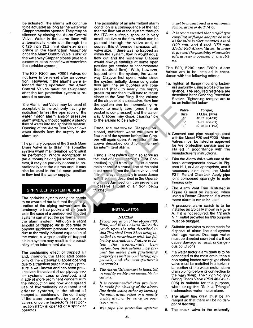
1 U.S. Gallon = 3.765 Litres 1 PSI = 0.0689 Bar
FIGURE F NOMINAL PRESSURE LOSS VERSUS FLOW
to do so may impair the integrity of these devices.
The owner is responsible for main- taining their fire protection system and devices in proper operating con- dition. The installing contractor or manufacturer should be contacted rel- ative to any questions.
The 4 and 6 inch Model F20 Alarm Valves, as well as the 4, 6, and 8 inch Model F200 and F2001 Alarm Valves, are designed for vertical and horizon- tal installations. The Alarm Valves, as well as their associated trim, are rated for use at a minimum service pressure of 20 psi (1,4 bar) and a maximum service pressure of 175 psi (12,l bar). They are for use with wet pipe, auto- matic fire protection systems only; and as such, the valves and all intercon- necting piping must be maintained at a minimum temperature of 4O’F/4”C.
The year of manufacture is located on the Handhole Cover.
The valve components are illustrated in Figure B. The Bodies are cast iron per ASTM A48 (Class 35B) and the Handhole Covers are cast iron per ASTM Al26 (Class B). Exterior sur- faces are painted red. The Handhole Cover Gasket is a l/16 inch (1,6 mm) thick Neoprene rubber. The Hex Head Cap Screws used to secure the Hand- hole Cover are steel per ASTM A307 (Grade A).
-3-
Flanged connections are per ANSI Standard 816.1 (Class 125). Grooved connections are cut in accordance with Gruvlok standard groove specifica- tions for steel pipe, and they are suit- able for use with grooved end pipe couplings that are listed or approved for fire protection system service.
The Seat Ring is bronze per ASTM B62 (CSSSOO) and press-fit within the body. It is a “divided” type design with a centrally located groove which is connected to a chamber located around the interior of the Seat Ring and which is, in turn, connected to the Alarm line (Ref. Port “E” in Figure B). The Seat Ring groove is sealed from the inlet and outlet when the waterway Clapper is closed. Once the waterway Clapper opens, water begins to im- mediately flow to the water motor alarm and/or pressure alarm switch.
The Waterway Clapper Assembly con- sists of a Clapper which is either cast iron per ASTM A48 (Class 35B) or duc- tile iron per ASTM A536 (65-4512), an EPDM rubber Clapper Facing, a S30400 stainless steel Clapper Washer, and a Type 18-8 stainless steel Self-Locking Hexagonal Head Cap Screw. The Hinge Pin is made from an S17400 (Condition H1075 or H 1150) stainless steel and the Torsion Spring is formed from stainless steel wire per ASTM A313 (S30200). The Hinge Pin is supported by a a pair of sintered bronze Bushings per ASTM 8438 (Grade 1, Type II) which are press-fit into the valve Body on either side of the Clapper. An identical pair of Bushings is also press-fit into the arms
OBSOLETE

of the Clapper, in order to ensure low rotational friction.
The Model F211 Retard Chamber (Ref. Figure C) is cast iron per ASTM Al26 (Class A) and painted red on the outside. A 314” x l/2” x 314” NPT Tee is provided at the top (outlet) for connect- ing electrical and/or hydraulic alarms.
The Restriction Assembly (Ref. Figure D), which is located beneath the Re- tard Chamber (in the case of variable pressure systems), is factory assem- bled. It consists of an inlet and drain restriction which are mounted in a tee. The diameters of the restriction ori- fices and the volume of the Retard Chamber have been established, in combination, to meet the listing and approval requirements with regard to time-to-alarm, once the waterway Clapper opens. These requirements represent a balancing of the need to minimize the possibility of a false alarm due to a transient surge in sup- ply pressure and the desire to mini- mize the time-to-alarm following a sprinkler operation.
In addition to controlling the fill time for the Retard Chamber, the inlet restric- tion lowers the residual pressure at the inlet of the water motor alarm (when it is used) and by doing so, it reduces wear of the water motor alarm gong. It is for this reason that the inlet restric- tion is retained in the constant pres- sure trim arrangements. The nominal steady state residual pressure at the connection to the water motor, during an alarm, is given in Figure E.
As mentioned in the General Descrip- tion section, the externally mounted by-pass around the waterway Clapper (Ref. Figures A and B) permits slow as well as small transient increases in water supply pressure to be passed through to the system, and held at their highest value, without opening of the Clapper. The resistance to flow pro- vided by the by-pass piping/fit- tings/check valve and the opening pressure differential for the waterway Clapper determine the minimum flow- for-alarm (i.e., flow around the by-pass to open the waterway Clapper). The combination of these parameters has been established so that when there is a flow into the sprinkler system which is equivalent to the discharge rate of one or more sprinklers, the waterway Clapper will open.
Once the waterway Clapper opens, the dynamic effects of the water mov- ing past the Seat Ring keeps the Clap- per open at a lower flow than that which is required to open it. This added sensitivity helps to maintain a steady flow of water into the sprinkler system and a steady alarm when the valve in the Inspector’s Test Connection is opened or a sprinkler operates.
The nominal pressure losses versus flow rates for the 4, 6, and 8 inch (100, 150, and 200 mm) Alarm Valves are shown in Figure F.
The approximate friction loss, based on the Hazen and Williams formula and expressed in equivaient length of Schedule 40 pipe with C=120, is 22 feet. This approximate friction loss has been caloulated on the basis of flow rates typically used with each size valve.
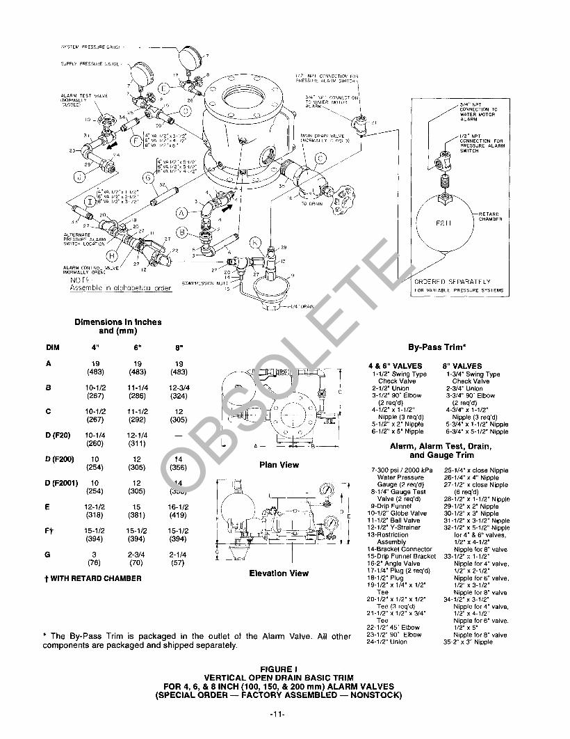
Basic trim arrangements which are suitable for use with the F20, F200 and F2001 Alarm Valves are illustrated in Figures H, I, and J. To ease field as- sembly, the Vertical Closed Drain Basic Trim and the Vertical Open Drain Basic Trim are factory assembled as shown in figures H and I.
The Vertical Closed Drain Basic Trim shown in Figure H is available as “standard order”. The Vertical Open Drain Basic Trim shown in Figure I and the Horizontal Closed Drain Basic Trim shown in Figure J are available on a “special order” basis.
The nipples utilized in the trim arrange- ments are Schedule 40 steel per ASTM A53 or Al35 and they are threaded per ANSI Standard B1.20.1. Fittings are either malleable iron per ANSI B16.3 or cast iron per ANSI 816.4. The Alarm Control Valve is a one-quarter turn ball type. It is con- structed of corrosion-resistant copper alloys with glass filled PTFE seals. The Alarm Test and Main Drain Valves are nitrile rubber disc sealed, bronze bod- ied, rising stem valves with aramid/ graphite packing. The By-pass and Alarm Line Drain Check Valves are bronze bodied, nitrile rubber disc sealed, swing type checks.
The inlet and drain restrictions of the Restriction Assembly are both fabri- cated from brass per ASTM B16 (C36000). The drain orifice is pro- tected, from rust or scale that might flake-off from the inside of the Retard Chamber, by a 24 mesh S30400 stain- less steel wire screen; while, both the inlet and drain orifices are protected from contaminants in the water supply by the l/2 inch Y-type Strainer located in the line from the Alarm Connection (Ref. Figure A). The l/2 inch Y-type Strainer is cast bronze and it has a removable 50 mesh S30400 stainless steel screen.
The Supply and System Pressure Gauges are constructed of corrosion resistant materials. They have mark-
-4-
ings of O-300 psi and O-2000 kPa. The Gauges are individually listed and ap- proved for fire protection system ser- vice. The three port Gauge Test Valves are bronze bodied, rising stem units with aramidlgraphite packing and a metal-to-metal seat. All trim compo- nents form a part of the listings and approvals for the F20, F200, and F2001 Alarm Valves.
In addition to the basic trim arrange- ments, there is the Alarm Vent Trim shown in Figure G which is required, when using a Retard Chamber, if a water motor alarm is not used.
In planning the installation, consider- ation must be given to the disposal of the large quantities of water which may be associated with draining the system or performing a flow test.
A pressure relief connection for use in relieving high system pressures, which might otherwise result from the ther- mal expansion of the water in wet pipe automatic sprinkler systems subject to abnormally high ambient tempera- tures, is described in Technical Data Sheet TD103.
When the fire protection system is ini- tially being pressurized, water will flow into the system until the water supply and system pressure become equal- ized and the torsion Spring closes the waterway Clapper. Once the pres- sures have stabilized, the Alarm Valve is ready to be placed in service and the Alarm Control Valve must be opened.
In the case of variable pressure sys- tems, slow as well as small transient increases in water supply pressure may continue to be built up in the sys- tem (via the by-pass check valve), without opening of the waterway Clap- per. A transient surge in supply pres- sure which is sufficient to only momen- tarily open the waterway Clapper will not cause a false alarm and a portion of the increase in pressure will be trapped within the system, thus reduc- ing the possibility of another opening. Any water in the alarm line is automat- ically drained, which helps to further reduce the possibility of a false alarm due to a successive transient surge in supply pressure.
When there is a steady flow of water into the sprinkler system either due to opening of the Inspector’s Test Con- nection, a sprinkler operation, or a sus- tained surge in supply pressure which is sufficient to maintain the waterway Clapper open, the water motor alarm and/or the pressure alarm switch will
OBSOLETE
be actuated. The alarms will continue to be actuated as long as the waterway Clapper remains opened. They may be silenced by closing the Alarm Control Valve. Water in the alarm lines will automatically drain out through the 0.125 inch (3,2 mm) diameter drain orifice in the Restriction Assembly once the Alarm Control Valve is shut or the waterway Clapper closes (due to a discontinuation in the flow of water into the sprinkler system).
The F20, F200, and F2001 Valves do not have to be re-set after an opera- tion. However, if the alarms were si- lenced during operation, the Alarm Control Valves must be re-opened after the fire protection system is re- stored to service.
The Alarm Test Valve may be used (if acceptable to the authority having ju- risdiction) to test the operation of the water motor alarm and/or pressure alarm switch, without creating a steady flow of water into the sprinkler system. Opening of the Alarm Test Valve flows water directly from the supply to the alarm line.
The primary purpose of the 2 inch Main Drain Valve is to drain the sprinkler system when maintenance work must be performed. Where acceptable to the authority having jurisdiction, how- ever, it may be partially opened to op- erationally test the alarms and, it may also be used in the full open position to flow test the water supply.
The sprinkler system designer needs to be aware of the fact that the config- uration of the piping network and its tendency to trap pockets of air (such as in the case of a peaked-roof gridded system) can affect the performance of the alarm system. Although a slight amount of trapped air is desirable to prevent significant pressure increases due to thermally induced expansion of the water, a large quantity of trapped air in a system may result in the possi- bility of an intermittent alarm.
The cushioning effect of trapped air and, therefore, the associated possi- bility of the waterway Clapper opening due to a transient surge in supply pres- sure is well known and has been pres- ent since the advent of wet pipe sprink- ler systems. Less understood, and made of more prominent concern with the introduction and now wide spread use of hydraulically calculated and gridded systems, is the effect of trapped air cushions on the continuity of the alarm transmitted by the alarm valves, once the Inspector’s Test Con- nection (ITC) is opened or a sprinkler operates.
The possibility of an intermittent alarm condition is a consequence of the fact that the flow out of the system through the ITC or a single sprinkler is very small relative to the flow which can be passed through the valve and, of course, this difference increases with valve size. If there was no trapped air within the system, flow in would equal flow out and the waterway Clapper would always stabilize at some open position (as needed to accommodate the required flow). With, however, trapped air in the system, the water- way Clapper first opens wider since the system initially demands greater flow until the air bubbles are com- pressed (back to nearly the supply pressure) and then it will tend to return closer to the Seat Ring. If the volume of the air pocket is excessive, flow into the system can be momentarily re- duced to nearly zero (once the air pocket is compressed) and the water- way Clapper may close, causing flow to the alarms to be shut-off.
Once the waterway Clapper has closed, sufficient water will have to flow out of the system before the Clap- per will again open. A repetition of the above described condition is termed an intermittent alarm.
Using a vent (which can also serve as the end-of-line Inspector’s Test Con- nection) piped from the top of a cross main or end of a branch line at the point most remote from the alarm valve, and filling the system slowly in accordance with the steps described in the Operat- ing Procedure section, can prevent an excessive amount of air from being trapped.
NOTES Proper operation of the MO&~ F20, FZOO, and F2001 Alarm Valves de- pends upon the trim described in this Technical Data Sheet being in- stalled in accordance with the fol- lowing instructions. Failure to fol- low the appropriate trim installation instructions may pre- vent the device from functioning properly as well as uoid listing, ap- provals, and the manufacturer’s warranties.
The Alarm Valves must be installed in readily visible and accessible lo- cations.
It is recommended that provision be made for viewing of the alarm line drain water; either by locating the main drain outlet in a readily visible area or by using an open type drain.
Wet pipe fire protection systems
-5-
5.
must be maintained at a minimum temperature of 4O”F/4”C.
It is recommended that a rigid type coupling or flange adapter be used at the inlet to riser mounted 4 inch (100 mm) and 6 inch (150 mm) Model F20 Alarm Valves, in order toprevent thepossibilty ofexcessive lateral riser movement or instabil- ity.
The F20, F200, and F2001 Alarm Valves are to be installed in accor- dance with the following criteria:
la. Tighten all flange mounting fasten- ers uniformly, using a cross-draw se- quence. The required fasteners are described in the Ordering Procedure Section, Tightening torques are to be as indicated below.
Valve Torque, Size Ft.Lbs. (Nm)
4” 40-50 (54-68) 6" 50-60 (68-81) 8" 60-75(81-102)
lb. Grooved end oioe couolinas used
2.
3.
4.
5.
6.
7.
8.
with the Model P20 and i2OGl Alarm Valves must be listed or approved for fire protection service and in- stalled in accordance with the manufacturer’s instructions.
Trim the Alarm Valve with one of the basic arrangements shown in Fig- ures H, I, or J as appropriate, and if necessary also install the Model F211 Retard Chamber. Apply pipe joint compound sparingly to male threads only.
The Alarm Vent Trim illustrated in Figure G must be installed, when using a Retard Chamber, if a water motor alarm is not to be used.
A pressure alarm switch is to be installed as typically shown in Figure A. If it is not required, the l/2 inch NPT outlet provided for this purpose must be plugged.
Suitable provision must be made for disposal of alarm line and system drainage water. Drainage water must be directed such that it will not cause damage or result in danger- ous conditions.
If a water motor alarm drain is to be connected to the main drain, then a non-spring loaded swing type check valve must be installed in a horizon- tal portion of the water motor alarm drain piping (before its connection to the main drain). The 1 inch No. 99s Swing Check Valve (PSN 46-049-l - 006) is suitable for this purpose, when using the “G in a Triangle” trademarked water motor alarm.
The alarm line drain must be ar- ranged so that there will be no dan- ger of freezing.
The check valve in the externally
OBSOLETE

9.
mounted By-pass around the water- way Clapper must be installed with its arrow pointed towards the Valve Body and the drain check valve must be installed with its arrow pointing towards the drain.
It is recommended that a vent con- nection (which may also be used as an end-of-line Inspector’s Test Con- nection), be piped from a cross main or branch line at the point most re- mote from the alarm valve. The vent line should be connected to the top of a cross main or to the end of a branch line and be located at the highest level of a multi-level installa- tion.
The vent connection can be used to bleed-off excessive air from the sys- tem and, therefore, minimize the possibility of a false alarm due to a transient surge in supply pressure. The contraction/expansion associ- ated with an excessive amount of trapped air could also cause the wa- terway Clapper to cycle open and shut during an inspector’s test or during a discharge by a single sprinkler.
Place the fire protection system in op- eration in accordance with the follow- ing procedure:
1.
2.
3.
4.
5.
6.
7.
8.
9.
Open the l/4 inch Gauge Test Valves for the Supply and System Pressure Gauges.
Check to see that the Handhole Cover bolts are tight. If not, cross- tighten them.
Close the Alarm Control Valve and the Alarm Test Valve.
Open the remote cross main or branch line vent connection (Ref. Note No. 9 in the Installation sec- tion).
Slowly open the main control valve until the sound of flowing water just begins and then open the valve one more turn.
Close the remote branch line vent connection after the discharge of aerated water ceases and the outlet has flowed full for at least 15 sec- onds.
Fully open the main control valve.
After the Supply and System Pres- sure Gauge readings have stabi- lized (i.e., the waterway Clapper has closed), open the Alarm Control Valve.
Open the Inspector’s Test Connec- tion (or the Alarm Test Valve, if ac- ceptable to the authority having ju- risdiction) and verify that the alarms operate in accordance with the re-
quirements of the authority having jurisdiction.
10. Close the Inspector’s Test Connec- tion (or the Alarm Test Valve).
11. Verify that water ceases to flow from the alarm line drain. If water contin- ues to flow, follow the corrective pro- cedure described in the Care and Maintenance section.
NOTE The Drain Restriction has a 0.125 inch (3,2 mm) diameter orifice. Sufficient time must be allowed for drainage of the Retard Cham- ber and the piping to the water motor alarm.
12. Once it has been verified that the flow of water out of the alarm line drain has stopped, the alarm valve is set and is ready for service.
It is recommended that the Alarm Control Valve be wire sealed in the open position with a No. 16 twisted wire, the ends of which are secured by a lead seal. The wire seal should be looped through the hole in the handle and tightly twisted around the pipe nipple at the outlet of the Alarm Control Valve.
NOTE After placing a fire protection sys- tem in service, notify the proper authorities and advise those re- sponsible for monitoring propri- etary and/or central station alarms.
When an alarm is actuated indicating that there has been or is a steady flow of water into the sprinkler system:
Immediately verify whether or not a fire situation is present. If a fire con- dition exists, notify the local fire ser- vice and follow the plan prescribed by the authority having jurisdiction.
If a fire condition does not exist and there is no flow of water out of the sprinkler system, then there has been a false alarm. Immediately no- tify the alarm monitoring stations (if applicable) and follow the procedure described in the Care and Mainte- nance section.
If a fire condition does not exist and there is a flow of water out of the sprinkler system, immediately close the main or sectional control valve (as appropriate) and then notify the alarm monitoring stations (if applica- ble) as well as the authority having jurisdiction that there is an impair- ment to the fire protection system.
Drain down the sprinkler system in accordance with the procedure de-
-6-
scribed in the Care and Mainte- nance section. Promptly correct the impairment and return the fire pro- tection system to service, as soon as possible, in accordance with the Op- erating Procedure section.
The Model F20, F200, and F2001 Alarm Valves do not require any regu- larly scheduled maintenance. It is rec- ommended, however, that proper op- eration of the alarms be periodically verified in accordance with a proce- dure which is acceptable to the author- ity having jurisdiction. Any impairment must be immediately corrected.
NOTES Before closing a fireprotection system main control valve for maintenance work on the fire protection systems which it controls, permission to shut down the affected fire protection sys- tems must first be obtained from the proper authorities and all personnel who may be affected by this decision must be notified.
If the alarms were silenced during operation, the Alarm Control Valve must be re-opened immediately after the fire protection system is restored to service. It is recommended that the Alarm Control Valve be wire sealed in the open position as described in Step 12 of the Operating Procedure section.
Inspection Procedure It is recommended that the following inspection procedure be performed at least quarterly by a qualified Inspec- tion Service:
1.
2.
3.
4.
5.
6.
Notify the proper authorities and all personnel who may be affected, that an alarm test is to be performed.
Open the valve in the Inspector’s Test Connection. Verify that the water motor alarm and/or the pres- sure alarm switch properly actuate and within the elapsed time required by the authority having jurisdiction.
Verify that water is flowing out of the alarm line drain at a rate consistent with the 0.125 inch (3,2 mm) diame- ter orifice in the Drain Restriction.
Close the valve in the Inspector’s Test Connection.
Verify that water ceases to flow from the alarm line drain.
Clean out the l/2 inch Strainer (lo- cated at the outlet of the Alarm Con- trol Valve) as well as the 3/4 inch Strainer (located at the connection to the water motor alarm). Be sure to replace the strainer baskets and tighten the caps securely.
OBSOLETE

NOTE Cleaning out of the Strainers after each operation of the alarms is especially important in the case of water supplies (such as lakes and rivers) having a large quantity of suspended matter. A clogged alarm line can prevent operation of the alarms.
7. Notify all authorities responsible for monitoring the installation that the fire protection system has been re- turned to service.
Sprinkler System Drain-Down Draining down of the sprinkler system must be done in accordance with the following procedure:
1.
2.
3.
4.
Close the main control valve, if this has not already been done.
Open the remote cross main or branch line vent connection (Ref. Note No. 9 in the Installation sec- tion).
Open the Main Drain Valve. Check to see that the drainage water will not cause damage or result in dan- gerous conditions.
Wait until the Supply Pressure Gauge reads zero pressure and the sound of draining water has stopped, before performing any maintenance work on the fire protec- tion system.
Leakage from Alarm Line Drain Follow the steps indicated below until water ceases to flow from the alarm line drain. Check for the discontinua- tion of the leakage after each step is complete.
1.
2.
3.
4.
5.
Close the Alarm Control Valve and then fully open the Main Drain Valve. Let the water flow for about 5 sec- onds before tightly re-closing the valve. This should flush out any loose debris that may have become trapped between the waterway Clapper and the Seat Ring or in the seating area of the Main Drain Valve. Re-open the Alarm Control Valve.
Repeat Step No. 1 if the rate of con- tinued flow out of the drain was no- ticeably reduced.
Open the Alarm Test Valve and allow the water to flow for about 5 seconds before re-closing the valve. This should flush out any loose debris that may have become trapped in the seating area of the Alarm Test Valve.
Repeat Step No. 3 if the rate of con- tinued flow out of the drain was no- ticeably reduced.
Slowly open the union in the Alarm Test Valve by-pass and determine whether the water is flowing from the Alarm connection (i.e., Port “E” in
6.
7.
8.
9.
Figure B) or past the Alarm Test Valve. If the leakage is past the Alarm Test Valve, close the main control valve, and then repair or re- place the Alarm Test Valve as nec- essary. Re-assemble the union- elbow and then re-open the main control valve.
If it appears the leakage noted in Step No. 5 is from the Alarm Con- nection, drain the system in accor- dance with the prescribed proce- dure. After the system has been dro%ryd, remove the Handhole
While holding the Spring down by the coils, remove the Hinge Pin. Re- move the Spring and Clapper As- sembly (Items 5, 6, 7, 8, & 10 in Figure B).
Using a light, check for and remove any debris that may have become lodged within the Seat Ring groove. Inspect the Seat Ring seat for any damage. If the Seat Ring has be- come dented across the seat then the valve will have to be replaced. It is impractical to re-face a Seat Ring in the field.
Check for and remove any debris which may have become lodged in the Clapper Facing. If a minor im- perfection remains in the Clapper Facing, then turn it over after thor- oughly cleaning both surfaces with a clean cloth. Replace the Clapper Facing if necessary. Be sure to se- curely re-tighten the retaining screw for the Clapper Washer.
Replace the Spring and Clapper As- sembly as shown in Figure B and then while holding the coils of the Spring down, re-insert the Hinge Pin. Be sure that the Hinge Pin is pushed all the way to the rear of the valve.
10. Replace the Handhole Cover. Re- turn the Alarm Valve to operation in accordance with the steps described in the Operating Procedure section.
Clogged Alarm Line Drain If water either does not flow or only dribbles out of the alarm line drain dur- ing an alarm test, then it is likely that the screen protecting the drain restric- tion orifice (Ref. Figure D) has become clogged.
NOTE A clogged alarm line drain will in- crease the likelihood of a false alarm in the case of a variable pressure sys- tem.
If the installation has a closed alarm line drain, first open the union below the Drain Restriction and then remove the Drain Restriction for cleaning by back-flushina the screen. Re-install the Drain Restriction and re-assemble the drain line.
-7- fDuPont Registered Trademark
If the installation has an open alarm line drain, unscrew the Drain Restric- tion from the Restriction Assembly and clean the screen by back-flushing.
NOTE In order to ease subsequent removals of the Drain Restriction, it is recom- mended that a Teflonf based pipe joint sealant be used for its reassem- bly.
Loss of Excess System Pressure In the case of a variable pressure sys- tem, the System Pressure Gauge should normally indicate a pressure greater than that shown by the Supply Pressure Gauge. Also, the value should be close to that of the peak supply pressure which has occurred after the system was placed in service.
NOTE Loss of excess system pressure will increase the likelihood of a false alarm in the case of a variable pres- sure system.
Follow the procedure indicated below to correct a loss of excess system pressure condition.
1. Check for signs of continued leak- age from the alarm line drain. If rust stains and/or water deposits indicate that continued leakage has been taking place, take corrective action according to the procedure de- scribed in the sub-section entitled “Leakage from Alarm Line Drain”.
2. If there are no signs of continued leakage from the alarm line drain, close the main control valve, open the Alarm Test Valve to relieve the supply pressure, and then slowly open the union in the externally mounted by-pass.
Swing the lower portion of the by- pass away and check for leakage past the By-pass Check Valve. If there is leakage, debris may have become lodged between its clapper and seat. Drain the system in accor- dance with the prescribed procedure and then clean or replace the By- pass Check Valve as required.
Re-assemble the externally mounted by-pass and return the fire protection system to operation in ac- cordance with the steps described in the Operating Procedure section.
3. If there are no signs of leakage past the By-pass Check Valve, inspect the sprinkler system for leakage.
System Pressure More Than 175 psi (12,l bar) The maximum rated service pressure of the F20, F200, and F2001 Alarm Valves as well as “G in a Triangle” trademarked automatic sprinklers is 175 psi (12,i bar). Wet pipe sprinkler systems subject to ambient tempera-
OBSOLETE

tures in excess of 1 OOF/38C can expe- rience significant increases in system pressure due to the thermal expansion of the water. In particular, a gridded wet-pipe system with a relatively small air pocket and no relief valve can be subjected to an increase of more than 100 psi (6,9 bar), due to an increase in ambient‘temperature of approximately 50-F/1 0-C.
Refer to Technical Data Sheet TD103 for information concerning the use of pressure relief trim to automatically re- lieve the over pressure which could otherwise be created in wet-pipe sys- tems which are exposed to significant increases in ambient temperature.
False Alarms If repeated false alarms occur in a vari- able pressure system:
1.
2.
3.
4.
Check for and correct the cause of continued leakage out the alarm line drain.
Check for and clean-out a clogged alarm line drain.
Check for and correct the cause of a loss in excess system pressure.
Drain down the sprinkler system and re-fill it in accordance with the steps described in the Operating Pro- cedure section.
Intermittent Alarms If the pressure alarm switch gives a steady signal but the water motor gen- erates an intermittent alarm, check for binding in the water motor alarm drive shaft.
If the water motor alarm and/or the pressure alarm switch provide an inter- mittent alarm, it is likely the conse- quence of an excessive amount of air being trapped within the sprinkler sys- tem. Drain down the sprinkler system and re-fill it in accordance with the steps described in the Operating Pro- cedure section.
A discontinuance of an alarm may also be caused by the waterway Clapper closing due to a sudden drop in supply pressure or the shut-off of a pump in the supply line. These types of prob- lems can only be corrected by main- taining a steady supply pressure.
Seller warrants for a period of one year from the date of shipment (warranty period) that the products furnished hereunder will be free from defects in material and workmanship.
For further details on Warranty, see Price List.
Orders for valves, retard chambers, trim, and replacement parts must in- clude the description and Product Symbol Number (PSN).
The pressure alarm switch and water motor alarm must be ordered sepa- rately. Refer to the appropriate Techni- cal Data Sheet for ordering informa- tion.
Special Instructions: The steel bolts and nuts required for the attachment of the F200 and F2001 Alarm Valve flanges to the mating flanges are not provided with the Valves and must be obtained sepa- rately. The material and dimensions for the fasteners must be in accordance with ANSI Standard B16.1 (Class 125). The bolt material must meet the mini- mum strength requirements of ASTM A307 (Grade B), and the nut material must meet the minimum strength re- quirements of ASTM A563 (Grade A). A description of the required fastener sizes is given in Table B, and Table C summarizes flange thickness refer- ence information.
NOTE When the lower flange of an F200 or F2001 Alarm Valve is to be attached directly to a PN or O.S. & Y gate valve between 1 and 3 of the mounting bolts (depending on the orientation of the Alarm Valve with respect to the gate valve) will have to be of the stud type. The length of the stud bolts for the 4, 6, and 8 inch valves must be 3-114, 3-314, and 4 inches, respec- tively.
Valves (Fig. B): Specify: (specify size) inch Model (specify number) Alarm Valve, PSN (specify).
Model F20 Alarm Valve 4” (100 mm) PSN 52-200-l-113 6” (150 mm) PSN 52-200-l-115
Model F200 Alarm Valve 4” (100 mm) PSN 52-200-l-013 6” (150 mm) PSN 52-200-l-015 6” (200 mm) PSN 52-200-l-016
Model F2001 Alarm Valve 4” (100 mm) PSN 52-200-l-413 6” (150 mm) _. _. PSN 52-200-l-615 6” (ZOO mm) PSN 52-200-I -616
Retard Chamber (Fig. C): Specify: Model F211 Retard Chamber, PSN 52-211-l-002.
Trim: Unless otherwise specified, trim ar- rangements for vertical installations are provided factory assembled as shown in Figures H and I. Unas- sembled trim packages can be pro- vided on “special order”. Product Sym-
-8-
bol numbers (PSN) need not be spec- ified when ordering unassembled trim.
“Standard Order” Black Trim:
Vertical Closed Drain Basic Trim, Factory Assembled, Black (Fig. H): - Specify: Factory assembled black 4, 6, and 8” Vertical Closed Drain Basic Trim for 4,6, and 8” F2O/F2OO/F2001 Alarm Valves, PSN 52-201-l-055.
Alarm Vent Trim (Fig. G): Specify: Alarm Vent Trim for 4,6, and 8 inch F2O/F2OO/F2001 Alarm Valves, PSN 52-201-l-012.
“Special Order” Black Trim:
Vertical Open Drain Basic Trim, Factory Assembled, Black (Fig. I): Specify: Factory assembled black 4, 6, and 8” Vertical Open Drain Basic Trim for 4, 6, and 8” F2O/F2OO/F2001 Alarm Valves, PSN 52-201-l -056.
Horizontal Closed Drain Basic Trim, Black (Fig. J): Specify: Black 4, 6, and 8” Horizontal Closed Drain Basic Trim for 4,6, and 8” F2O/F2OO/F2001 Alarm Valves, PSN 52-202-l-045.
“Special Order” Galvanized Trim:
Vertical Closed Drain Basic Trim, Factory Assembled, Galvanized (Fig. Hj: Specify: Factory assembled galva- nized 4, 6, and 8” Vertical Closed Drain Basic Trim for 4, 6, and 8” F2O/F2OO/F2001 Alarm Valves, PSN 52-201-2-055.
Vertical Open Drain Basic Trim, Factory Assembled, Galvanized (Fig. I): Specify: Factory assembled galva- nized 4, 6, and 8” Vertical Open Drain Basic Trim for 4, 6, and 8” F2O/F2OO/F2001 Alarm Valves, PSN 52-201-2-056.
Horizontal Closed Drain Basic Trim, Galvanized.(Fig. J): Specify: Galvanized 4, 6, and 8” Horizontal Closed Drain Basic Trim for 4, 6, and 8” F2O/F2OO/F2001 Alarm Valves, PSN 52-202-2-045.
OBSOLETE

;--. .-/
PRESSURE SWITCH rl
‘RETARD CHAMBER
I-3/4”xl/4” Hex Bushing
2-3132” (2,4mm) Vent Fitting
3-l/4” Tube, 5’ long
FIGURE G ALARM VENT TRIM
(Ordered separately for use with a Retard Chamber when a Water
Motor Alarm is not used)
Size Description Quantity of of Model Model
F200 F2001 Valve
4”
Fasteners
518” x Z-314” Heavy Hex Head Bolts
SIB” Heavy Hex Nuts
6” 314” x 3” Hex Head Bolts
314” Heavy Hex Nuts
16 8
16 8
16 8
16 8
8” 314” x 3-l/4” Hex Head Bolts 16 8
314” Heavy Hex Nuts 16 8
TABLE B FASTENER SIZE AND TYPE
REQUIREMENTS FOR MOUNTING TO CLASS 125 CAST IRON
FLANGE DRILLED PER ANSI 816.1
Size Flange of Valve Thickness
4” 0.94” (23,9 mm) 6” 1 .OO” (25,4 mm) 8’ 1.12” (28,4 mm)
TABLE C FLANGE THICKNESS
Valve Replacement Parts Kit: The Valve Replacement Parts Kit con- tains a Clapper Facing and a Handhole Cover Gasket. It is recommended to have these parts readily available when servicing the F2O/F2OO/F2001 Alarm Valve.
Specify: Valve Replacement Parts Kit for use with (specify size) inch Model F2O/F2OO/F2001 Alarm Valve.
4” (100 mm) _. _. PSN 92-200-l-416 6” (150 mm) PSN 92-200-l -620 8” (200 mm) PSN 92-200-l -816
Replacement Valve Parts: Specify: (specify description) for use with (specify size) inch Model F2O/F2OO/F2001 Alarm Valves, PSN (specify).
4” (100 mm) Model F20/F200/F2001 Alarm Valves
2-Handhole Cover w/Label . PSN 52-200-l-001
3-Handhole Cover Gasket PSN 92-200-I -413
5Clapper, w/Hinge Pin Bushings . . PSN 92-200-l -418
B-Clapper Facing PSN 92-200-I-403 7Clapper Washer PSN 92-200-I -405 E-Self-Locking
Hex Head Cap Screw PSN 62-636-l-105
S-Hinge Pin PSN 92-200-l-414 11 -Spring PSN 92-200-I -415
8”’ (150 mm) Model F20/F200/F2001 Alarm Valves
2-Handhole Cover w/Label PSN 52-200-I -002
3-Handhole Cover Gasket PSN 92-200-I -613
5Clapper, w/Hinge Pin Bushings PSN 92-200-I -618
B-Clapper Facing PSN 92-200-l -603 7Clapper Washer PSN 92-200-l -605 &Self-Locking
Hex Head Cap Screw PSN 62-636-I-105
g-Hinge Pin PSN 92-200-l -614 II-Spring _. _. _. PSN 92-200-I-615
8” (200 mm) Model F2O/F2OO/F2001 Alarm Valves
2-Handhole Cover w/Label PSN 52-200-I -003
3-Handhole Cover Gasket PSN 92-200-I -813
5Clapper, w/Hinge Pin Bushings.. PSN 92-200-I-818
6Clapper Facing PSN 92-200-l -803 7Clapper Washer PSN 92-200-l-805 &Self-Locking
Hex Head Cap Screw PSN 62-636-l-105
g-Hinge Pin PSN 92-200-l-814 1 l-Spring PSN 92-200-l -615
Replacement Trim Parts: Specify: (specify description) for use with 4, 6, and 8 inch Model F2O/F2OO/F2001 Alarm Valve Trim, PSN (specify).
FIGURES G THROUGH J -l/4” Gauge Test
Valve .PSN 46-005-I -002 -300 psi / 2000 kPa
Water Pressure Gauge . .PSN 92-343-l-005
-l/2” Swing Type Check Valve .PSN 46-049-l-004
-3/4” Swing Type Check Valve .PSN 46-049-I -005
-2” Angle Valve .PSN 46-048-l-009 -2’ Globe Valve .PSN 46-047-l-009 -l/2” Globe Valve .PSN 46-047-I -004 -l/2” Ball Valve .PSN 46-050-l -004 -l/2” Strainer .PSN 52-353-I-005 -Restriction Assem-
bly .PSN 92-210-l-005 -Inlet Restriction w/0.219” (5,6 mm) orifice .PSN 92-210-l-010
-Drain Restriction w/0.125” (3,2 mm) orifice and screen .PSN 92-210-i-004
-Drip Funnel .PSN 92-343-l-007 -Drip Funnel Bracket.. .PSN 92-21 l-l-003 -Bracket Connector .PSN 92-21 I-l -005 -3/32” (2,4 mm)
Vent Fitting .PSN 92-032-I -002
Items listed in Figures G through J but not included in the replacement parts list are common hardware items and they are to be obtained locally.
The following are the nominal weights for the valves and trim: 4” F20 Valve 45 Ibs. (20,4 kg) 4” F200 Valve 62 Ibs. (28,l kg) 4” F2001 Valve 6” F20 Valve
51 Ibs. (23,l kg) 68 Ibs. (30.9 kg)
6” F200 Valve 6” F2001 Valve
93 Ibs. (42,2 kg)
8” F200 Valve 78 Ibs. (35,4 kg)
. 167 Ibs. (75.8 kg) 8” F2001 Valve 148 Ibs. (67,l kg) F211 Retard Chamber 14 Ibs. 4 6 L 8” Vertical Closed
(6,4 kg)
Drain Basic Trim 4, 6. & 8” Vertical Open
24 Ibs. (lo,9 kg)
Drain Basic Trim 4,6, & 8” Horizontal Closed
23 Ibs. (IO,4 kg)
Drain Basic Trim Alarm Vent Trfm
25 Ibs. (11,3 kg) 1 lb. (0.5 kg)
-9-
OBSOLETE

‘%LIIRM CONTROL (NORMBLLY OPEN,
NOTE Assemble in alphabetical order.
Dimensions in Inches and (mm)
DIM 4”
A $3)
B 10-l/2 (267)
C 10-112 (267)
D (F20) 10-114 (260)
D (F200) $4,
D (F2001) 10 (254)
E 12-112 (318)
Ft 15-l/2 (394
G $3,
6”
(4-A,
1 l-114
(28’3
11-112 (292)
12-114
(311)
(&
(325,
(2l)
15-l/2
(394)
2-314 (70)
8”
(45
12-314 (324
(& -
(3::)
16-l/2 (419)
15-l/2 (394
2-l/4 (57)
/ -A
Plan View
Elevation View
t WITH RETARD CHAMBER
l The By-Pass Trim is packaged in the outlet of the Alarm Valve. All other components are packaged and shipped separately.
:T-
RETARD CHAMBER F2 I I
3RDERED SEPARATELY FOR VARIABLE PRESSURE SYSTEMS
By-Pass Trim*
4 & 6” VALVES 1 -i/2” Swing Type
Check Valve 2-i/2” Union 3-112” 90’ Elbow
(2 req’d) 4-l/2” x l-1/2”
Nipple (3 req’d) 5-l/2” x 2” Nipple 6-112” x 5” Nipple
i-3/4” Swing Type 8” VALVES
Check Valve 2-3/4” Union 3-3/4’ 90’ Elbow
(2 req’d) 4-3/4” x 1 -l/2”
Nipple (3 req’d) 5-314” x 1 -I/2” Nipple 6-314” x 5-112” Nipple
Alarm, Alarm Test, Drain, and Gauge Trim
7-300 psi / 2000 kPa Water Pressure Gauge (2 req’d)
&l/4” Gauge Test Valve (2 req’d)
9-l/2” Swing Type Check Valve
10-l/2” Globe Valve 1 l-1/2” Ball Valve 12-l/2” Y-Strainer 13-Restriction
Assembly 14-2’ Angle Valve 15-l/4” Plug (2 req’d) 16-l/2” Plug 17-l/2” 90’ Elbow
(2 req’d) 18-112” x l/4” x l/2”
Tee 19-l/2” Tee (2 req’d) 20-l/2” x l/2” x 3/4”
Tee 21-l/2” 45’ Elbow 22-l/2” Union
(2 req’d) 23-2” x 2’ x l/2” Tee 24-114” x close Nipple 25-l/4” x 4” Nipple
26-l/2” x close Nipple (7 req’d)
27-112” x l-112” Nipple (2 req’d)
28-l/2” x 2” Nipple 29-l/2” x 3” Nipple
(2 req’d) 30-l/2” x 3-112
Nipple 31-l/2” x5-112”
Nipple for 4” & 6 valves, 112” x 4-112 Nipple for 8’ valve
32-112” x l-112” Nipple for 4’valve, 112” x 2-112’ Nipple for 6” valve, 112” x 3-112 Nipple for 8” valve
33-112” x 3-112” Nipple for 4” valve, 112” x 4-112 y;pF;:“r 6” valve,
*
Nipple for 8’ valve 34-2” x 3” Nipple
(2 req’d)
FIGURE H VERTICAL CLOSED DRAIN BASIC TRIM
FOR 4,6, & 8 INCH (100,150, & 200 mm) ALARM VALVES (STANDARD ORDER - FACTORY ASSEMBLED - IN STOCK)
-lO-
OBSOLETE
Assemble In alphabetical order
Dimensions in Inches and (mm)
DIM 4”
A (d893)
B 10-l/2 (267)
C 10-l/2 (267)
D (F20) 10-114
(260)
D (F200) (2&
D (F2001) 10 (254)
E 12-l/2 (318)
Ft 15-112 (394
G (736,
8”
(z3,
1 l-114
(286)
11-112 (292,
12-l/4 (311)
(&,
(&)
(3Yl)
15-l/2
(394)
2-314 (70)
t WITH RETARD CHAMBER
8”
$3)
12-314 (324
(3E)
-
(26)
16-112 (419)
15-112 (394
2-l/4 (57)
Plan View
I Elevation View
* The By-Pass Trim is packaged in the outlet of the Alarm Valve. All other components are packaged and shipped separately.
:1 RETAFfD
F2 I I CHm.iSER
3RDERED SEPARATELY FOR “ARIABLE PRESSURE SYSTEMS
By-Pass Trim*
4 & 6” VALVES 8” VALVES 1 -l/2” Swing Type l-3/4” Swing Type
Check Valve Check Valve 2-112” Union 2-3/4” Union 3-l/2” 90’ Elbow 3-314” 90’ Elbow
(2 req’d) (2 req’d) 4-112” x l-112” 4-314” x 1 -l/2
Nipple (3 req’d) Nipple (3 req’d) 5-112” x 2” Nipple 5-314’ x l-112” Nipple 6-112” x 5” Nipple 6-3/4” x 5-112’ Nipple
Alarm, Alarm Test, Drain, and Gauge Trim
7-300 psi I2000 kPa Water Pressure Gauge (2 req’d)
8-114” Gauge Test Valve (2 req’d)
g-Drip Funnel 10-l/2” Globe Valve 1 l-1 12” Ball Valve 12-112” Y-Strainer 13Ftestriction
Assembly 14-Bracket Connector 15-Drip Funnel Bracket 16-2” Angle Valve 17-114” Plug (2 req’d) 10-112” Plug 19-112” x 114” x l/2”
Tee 20-112” x l/2” x l/2”
Tee (3 req’d) 21-112” x 112” x 3/4”
Tee 22-112” 45’ Elbow 23-112” 90’ Elbow 24-l/2” Union
FIGURE I VERTICAL OPEN DRAIN BASIC TRIM
FOR 4,6, & 8 INCH (100,150, & 200 mm) ALARM VALVES (SPECIAL ORDER - FACTORY ASSEMBLED - NONSTOCK)
-ll-
25-114” x close Nipple 26-l/4” x 4” Nipple 27-112” x close Nipple
(6 req’d) 26-112” x l-112” Nipple 29-112” x 2” Nipple 30-l/2” x 3” Nipple 31 -l/2” x 3-l/2” Nipple 32-112” x 5-112” Nipple
for 4” & 6” valves ’ 112’ x 4-112’
Nipple for 6” valve 33-112” :: I-112”
Nipple for 4” valve, l/2” x 2-l/2” Nipple for 6” valve, 112” x 3-112” Nipple for 8” valve
34-112” x 3-112” Nipple for 4” valve, l/2” x 4-l/2” Nipple for 6” valve, l/2” x 5” Nipple for 8” valve
35-2” x 3” Nipple
OBSOLETE
By-Pass Trim*
4 & 6” VALVES 6” VALVES l-1/2” Swing Type
Check Valve l-314” Swing Type
Check Valve Z-112’ Union 2-3/4” Union 3-112‘ 90’ Elbow 3-3/4” 90’ Elbow
(2 req’d) (2 req’d) 4-112” x 1-112” 4-3/4” x 1 -i/2”
Nipple (3 req’d) Nipple (3 req’d) 5-l/2” x 2” Nipple 53/4” x 1 -l/2” Nipple 6-i/2” x 5’ Nipple 6-3/4” x 5-l/2” Nipple
Alarm, Alarm Test, Drain, and Gauge Test
7-300 psi / 2000 kPa 26-i/2” x 3” Nipple Water Pressure (2 req’d) Gauge (2 req’d) 27-112” x 3-112”
8-M” Gauge Test Nipple Valve (2 req’d) 28-l/2” x 4” Nipple
9-l/2” Swing Type 29-l/2” x close Check Valve Nipple for 4” valve,
10-112” Globe Valve l/2” x 2” 1 l-1/2” Ball Valve Nipple for 6” valve, 12-l/2” Y-Strainer l/2” x 3” 13Bestriction Nipple for 8” valve
Assembly 30-l/2” x 5-l/2” 14-2” Globe Valve Nipple for 4” & 6” 15-l/4’ Plug (2 req’d) valves, 16-l/2’ x114” x 112 i/2” x4-1/2”
Tee Nipple for 8” valve 17-112’~ t/2” x l/2” 31-l/2” x l-1/2”
Tee (2 req’d) Nipple for 4” valve, 18-l/2” x l/2” x 314 l/2” x 2-l/2*
Tee Nipple for 6” valve, 19-1/2’90’ Elbow l/2” x3-1/2”
(2 req’d) Nipple for 8” valve 20-l/2” Union (2 req’d) 32-l/2” x3-1/2” 21-2” x 2’ x l/2” Tee Nipple for 4” valve, 22-l/4” x close Nipple t/2” x 4-112” 23-l/4” x 4” Nipple Nipple for 6” valve, 24-l/2” x l-112’ Nipple l/2” x 5
(5 req’d) Nipple for 8” valve 25-l/2’ x 2” Nipple 33-2” x close Nipple
(2 req’d) 34-2” x 2-l/2’ Nipple 35-l/2” Plug
SUPPLY PRESSURE GAUGE
.SYSTEM PRESSURE GAUGE
ALARM TEST
HANOHOLE COVER MUST GE AT LEAST 30 INCHES AWAY FROM A WALL
CONTROL (NORMALLY %GM
OPEN1
I l/Z” NPT CONNECTION FOR PRESSURE ALARM SWITCH
MAIN DRAIN VALVE ’
iES%
314” NPT CONNECTION TO WATER MOTOR
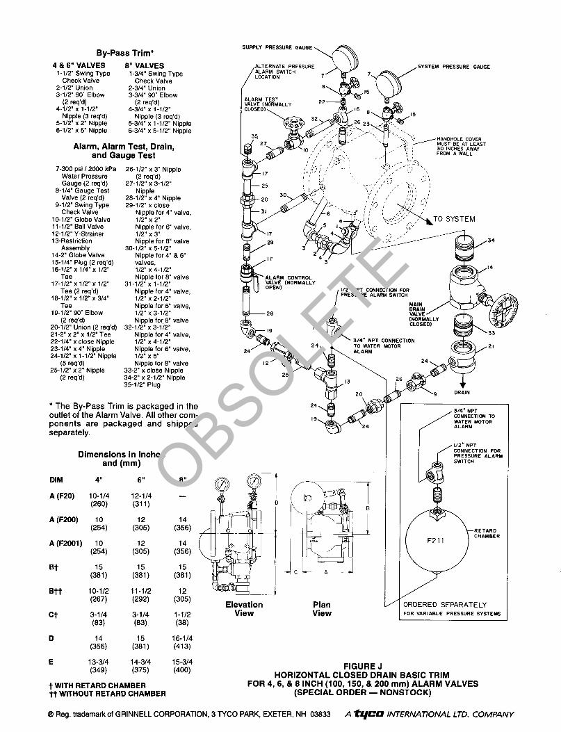
* The By-Pass Trim is packaged in the outlet of the Alarm Valve. All other com- ponents are packaged and shipped separately.
Dimensions in Inches and (mm)
24
CONNECTION FOR PRESSURE ALARM
3RDERED SEPARATELY ‘OR VARIABLE PRESSURE SYSTEMS
6”
12-114 (311)
(&)
$5)
(zl)
11-l/2
Gw
3-114 (83)
(2l,
14-314 (375)
8”
-
DIM 4”
A (F20) 10-114 (260)
A (F200) (:591,
A (F2001) 10
(254)
w $l)
Btt 10-l/2 (267)
ct 3-114 (83)
D (&
E 13-314
(34%
(3154s)
(zl) &) l-112
(38)
16-114 (413)
15-314
Elevation Plan View View
FIGURE J HORIZONTAL CLOSED DRAIN BASIC TRIM
FOR 4,6,& 8 INCH (100,150,& 200 mm) ALARM VALVES (SPECIAL ORDER - NONSTOCK)
(400)
t WITH RETARD CHAMBER j-t WITHOUT RETARD CHAMBER
@ Reg. trademark of GRINNELL CORPORATION, 3 TYCO PARK, EXETER, NH 03833 A ti,fCO INTERNATIONAL LTD. COMPANY
OBSOLETE


![Supporting Information Synthesis of 5-alkyl[3,4-c]thienopyrrole-4,6-dione … · Supporting Information Synthesis of 5-alkyl[3,4-c]thienopyrrole-4,6-dione-based polymers by a ...](https://static.fdocuments.in/doc/165x107/5ad096377f8b9ae2138dec1b/supporting-information-synthesis-of-5-alkyl34-cthienopyrrole-46-dione-information.jpg)