Alarm Troubleshooting - · PDF file2-2 Cisco ONS 15454 DWDM Troubleshooting Guide, R7.0...
180
CHAPTER 2-1 Cisco ONS 15454 DWDM Troubleshooting Guide, R7.0 78-17706-02 2 Alarm Troubleshooting Note The terms "Unidirectional Path Switched Ring" and "UPSR" may appear in Cisco literature. These terms do not refer to using Cisco ONS 15xxx products in a unidirectional path switched ring configuration. Rather, these terms, as well as "Path Protected Mesh Network" and "PPMN," refer generally to Cisco's path protection feature, which may be used in any topological network configuration. Cisco does not recommend using its path protection feature in any particular topological network configuration. This chapter gives a description, severity, and troubleshooting procedure for each commonly encountered Cisco DWDM alarm and condition. Tables 2-1 through 2-5 provide lists of DWDM alarms organized by severity. Table 2-6 on page 2-7 provides a list of alarms organized alphabetically. Table 2-7 gives definitions of all DWDM alarm logical objects, which are the basis of the alarm profile list in Table 2-8 on page 2-13. For a comprehensive list of all conditions and instructions for using TL1 commands, refer to the Cisco SONET TL1 Command Guide . An alarm’s troubleshooting procedure applies to both the Cisco Transport Controller (CTC) and TL1 version of that alarm. If the troubleshooting procedure does not clear the alarm, log into the Technical Support Website at http://www.cisco.com/techsupport for more information or call the Cisco Technical Assistance Center (1-800-553-2447). Alarms can occur even in those cards that are not explicitly mentioned in the Alarm sections. When an alarm is raised, refer to its clearing procedure. For more information about alarm profiles, refer to the “Manage Alarms” chapter in the Cisco ONS 15454 DWDM Procedure Guide. Note Unless otherwise noted, ONS 15454 refers to the ANSI and ETSI versions of the platform. 2.1 Alarm Indexes The following tables group alarms and conditions by their default severities in the ONS DWDM system. These severities are the same whether they are reported in the CTC Alarms window severity (SEV) column or in TL1. Note The CTC default alarm profile contains some alarms or conditions that are not currently implemented but are reserved for future use.
Transcript of Alarm Troubleshooting - · PDF file2-2 Cisco ONS 15454 DWDM Troubleshooting Guide, R7.0...

Cisco ONS 15 78-17706-02
C H A P T E R2
Alarm TroubleshootingNote The terms "Unidirectional Path Switched Ring" and "UPSR" may appear in Cisco literature. These terms do not refer to using Cisco ONS 15xxx products in a unidirectional path switched ring configuration. Rather, these terms, as well as "Path Protected Mesh Network" and "PPMN," refer generally to Cisco's path protection feature, which may be used in any topological network configuration. Cisco does not recommend using its path protection feature in any particular topological network configuration.
This chapter gives a description, severity, and troubleshooting procedure for each commonly encountered Cisco DWDM alarm and condition. Tables 2-1 through 2-5 provide lists of DWDM alarms organized by severity. Table 2-6 on page 2-7 provides a list of alarms organized alphabetically. Table 2-7 gives definitions of all DWDM alarm logical objects, which are the basis of the alarm profile list in Table 2-8 on page 2-13. For a comprehensive list of all conditions and instructions for using TL1 commands, refer to the Cisco SONET TL1 Command Guide .
An alarm’s troubleshooting procedure applies to both the Cisco Transport Controller (CTC) and TL1 version of that alarm. If the troubleshooting procedure does not clear the alarm, log into the Technical Support Website at http://www.cisco.com/techsupport for more information or call the Cisco Technical Assistance Center (1-800-553-2447).
Alarms can occur even in those cards that are not explicitly mentioned in the Alarm sections. When an alarm is raised, refer to its clearing procedure.
For more information about alarm profiles, refer to the “Manage Alarms” chapter in the Cisco ONS 15454 DWDM Procedure Guide.
Note Unless otherwise noted, ONS 15454 refers to the ANSI and ETSI versions of the platform.
2.1 Alarm Indexes The following tables group alarms and conditions by their default severities in the ONS DWDM system. These severities are the same whether they are reported in the CTC Alarms window severity (SEV) column or in TL1.
Note The CTC default alarm profile contains some alarms or conditions that are not currently implemented but are reserved for future use.
2-1454 DWDM Troubleshooting Guide, R7.0

Chapter 2 Alarm Troubleshooting2.1.1 Critical Alarms (CR)
Note The CTC default alarm profile in some cases contains two severities for one alarm (for example, MJ/MN). The platform default severity comes first (in this example, MJ), but the alarm can be demoted to the second severity in the presence of a higher-ranking alarm. This is in accordance with Telcordia GR-474.
2.1.1 Critical Alarms (CR) Table 2-1 alphabetically lists Critical (CR) DWDM alarms.
2.1.2 Major Alarms (MJ)Table 2-2 alphabetically lists Major (MJ) DWDM alarms.
Table 2-1 Critical DWDM Alarm List
2R: LOS FAN: MEA OTS: AWG-FAIL
AICI-AEP: EQPT FAN: MFGMEM OTS: AWG-OVERTEMP
AICI-AEP: MFGMEM FC: GE-OOSYNC OTS: LOS
AICI-AIE: EQPT GE: GE-OOSYNC OTS: LOS-P
AICI-AIE: MFGMEM ISC: GE-OOSYNC OTS: OPWR-HFAIL
AIP: MEA ISC: LOS OTS: OPWR-LFAIL
AIP: MFGMEM NE: HITEMP OTS: VOA-HFAIL
AOTS: GAIN-HFAIL NE: I-HITEMP OTS: VOA-LFAIL
AOTS: GAIN-LFAIL OCH: LOS-P PPM: EQPT
AOTS: OPWR-HFAIL OCH: OPWR-HFAIL PPM: IMPROPRMVL
AOTS: OPWR-LFAIL OCH: OPWR-LFAIL PPM: MEA
AOTS: VOA-HFAIL OCH: PORT-ADD-PWR-FAIL-HIGH PPM: MFGMEM
AOTS: VOA-LFAIL OCH: PORT-ADD-PWR-FAIL-LOW TRUNK: GE-OOSYNC
BPLANE: MFGMEM OCH: PORT-FAIL TRUNK: LOF
EQPT: BKUPMEMP OCH: VOA-HFAIL TRUNK: LOM
EQPT: EQPT OCH: VOA-LFAIL TRUNK: LOS
EQPT: IMPROPRMVL OMS: LOS-P TRUNK: LOS-P
EQPT: MEA OMS: OPWR-HFAIL TRUNK: OTUK-LOF
ESCON: LOS OMS: OPWR-LFAIL TRUNK: OTUK-TIM
FAN: EQPT-MISS OMS: VOA-HFAIL TRUNK: TIM
FAN: FAN OMS: VOA-LFAIL —
Table 2-2 Major DWDM Alarm List
AIP: INVMACADR ISC: CARLOSS SHELF: MEA
AOTS: LASERBIAS-FAIL ISC: SIGLOSS SHELF: SHELF-COMM-FAIL
2-2Cisco ONS 15454 DWDM Troubleshooting Guide, R7.0
78-17706-02

Chapter 2 Alarm Troubleshooting2.1.3 Minor Alarms (MN)
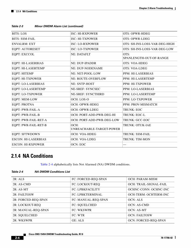
2.1.3 Minor Alarms (MN) Table 2-3 alphabetically lists Minor (MN) DWDM alarms.
EQPT: CARLOSS ISC: SYNCLOSS TRUNK: CARLOSS
EQPT: MEM-GONE NE: DBOSYNC TRUNK: DSP-COMM-FAIL
EQPT: PEER-NORESPONSE NE: OPTNTWMIS TRUNK: DSP-FAIL
ESCON: SIGLOSS NE: SYSBOOT TRUNK: FC-NO-CREDITS
FC: CARLOSS NE-SREF: SYNCPRI TRUNK: ODUK-TIM-PM
FC: FC-NO-CREDITS OSC-RING: RING-ID-MIS TRUNK: OUT-OF-SYNC
FC: OUT-OF-SYNC PWR: BAT-FAIL TRUNK: PROV-MISMATCH
FC: SIGLOSS PWR: EHIBATVG TRUNK: PTIM
FC: SYNCLOSS PWR: ELWBATVG TRUNK: SIGLOSS
GE: CARLOSS PWR: HIBATVG TRUNK: SYNCLOSS
GE: OUT-OF-SYNC PWR: LWBATVG TRUNK: UT-COMM-FAIL
GE: SIGLOSS SHELF: DUP-SHELF-ID TRUNK: WVL-MISMATCH
GE: SYNCLOSS — —
GFP: GFP-LFD — —
Table 2-2 Major DWDM Alarm List (continued)
Table 2-3 Minor DWDM Alarm List
2R: HI-LASERBIAS ESCON: HI-TXPOWER OCN: EOC-L
2R: HI-RXPOWER ESCON: LO-RXPOWER OCN: HI-LASERBIAS
2R: HI-TXPOWER ESCON: LO-TXPOWER OCN: HI-LASERTEMP
2R: LO-RXPOWER EXT-SREF: SYNCPRI OCN: HI-RXPOWER
2R: LO-TXPOWER EXT-SREF: SYNCSEC OCN: HI-TXPOWER
AOTS: CASETEMP-DEG EXT-SREF: SYNCTHIRD OCN: LO-LASERBIAS
AOTS: FIBERTEMP-DEG FC: HI-LASERBIAS OCN: LO-LASERTEMP
AOTS: GAIN-HDEG FC: HI-RXPOWER OCN: LO-RXPOWER
AOTS: GAIN-LDEG FC: HI-TXPOWER OCN: LO-TXPOWER
AOTS: LASERBIAS-DEG FC: LO-RXPOWER OMS: LOS-O
AOTS: LASERTEMP-DEG FC: LO-TXPOWER OMS: OPWR-HDEG
AOTS: OPWR-HDEG GE: HI-LASERBIAS OMS: OPWR-LDEG
AOTS: OPWR-LDEG GE: HI-RXPOWER OMS: VOA-HDEG
AOTS: VOA-HDEG GE: HI-TXPOWER OMS: VOA-LDEG
AOTS: VOA-LDEG GE: LO-RXPOWER OTS: AWG-DEG
BITS: BPV GE: LO-TXPOWER OTS: LASERBIAS-DEG
BITS: LOF ISC: HI-LASERBIAS OTS: LOS-O
2-3Cisco ONS 15454 DWDM Troubleshooting Guide, R7.0
78-17706-02
Chapter 2 Alarm Troubleshooting2.1.4 NA Conditions
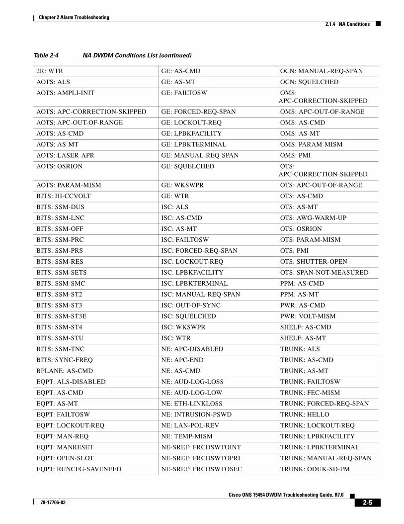
2.1.4 NA ConditionsTable 2-4 alphabetically lists Not Alarmed (NA) DWDM conditions.
BITS: LOS ISC: HI-RXPOWER OTS: OPWR-HDEG
BITS: SSM-FAIL ISC: HI-TXPOWER OTS: OPWR-LDEG
ENVALRM: EXT ISC: LO-RXPOWER OTS: SH-INS-LOSS-VAR-DEG-HIGH
EQPT: AUTORESET ISC: LO-TXPOWER OTS: SH-INS-LOSS-VAR-DEG-LOW
EQPT: EXCCOL NE: DATAFLT OTS: SPANLENGTH-OUT-OF-RANGE
EQPT: HI-LASERBIAS NE: DUP-IPADDR OTS: VOA-HDEG
EQPT: HI-LASERTEMP NE: DUP-NODENAME OTS: VOA-LDEG
EQPT: HITEMP NE: NET-POOL-LOW PPM: HI-LASERBIAS
EQPT: HI-TXPOWER NE: ROUTE-OVERFLOW PPM: HI-LASERTEMP
EQPT: LO-LASERBIAS NE: SNTP-HOST PPM: HI-TXPOWER
EQPT: LO-LASERTEMP NE-SREF: SYNCSEC PPM: LO-LASERBIAS
EQPT: LO-TXPOWER NE-SREF: SYNCTHIRD PPM: LO-LASERTEMP
EQPT: MEM-LOW OCH: LOS-O PPM: LO-TXPOWER
EQPT: PROTNA OCH: OPWR-HDEG PPM: PROV-MISMATCH
EQPT: PWR-FAIL-A OCH: OPWR-LDEG TRUNK: EOC
EQPT: PWR-FAIL-B OCH: PORT-ADD-PWR-DEG-HI TRUNK: EOC-L
EQPT: PWR-FAIL-RET-A OCH: PORT-ADD-PWR-DEG-LOW TRUNK: GCC-EOC
EQPT: PWR-FAIL-RET-B OCH: UNREACHABLE-TARGET-POWER
TRUNK: OTUK-IAE
EQPT: SFTWDOWN OCH: VOA-HDEG TRUNK: SSM-FAIL
ESCON: HI-LASERBIAS OCH: VOA-LDEG TRUNK: TIM-MON
ESCON: HI-RXPOWER OCN: EOC —
Table 2-3 Minor DWDM Alarm List (continued)
Table 2-4 NA DWDM Conditions List
2R: ALS FC: FORCED-REQ-SPAN OCH: PARAM-MISM
2R: AS-CMD FC: LOCKOUT-REQ OCH: TRAIL-SIGNAL-FAIL
2R: AS-MT FC: LPBKFACILITY OCHNC-CONN: OCHNC-INC
2R: FAILTOSW FC: LPBKTERMINAL OCH-TERM: OCHTERM-INC
2R: FORCED-REQ-SPAN FC: MANUAL-REQ-SPAN OCN: ALS
2R: LOCKOUT-REQ FC: SQUELCHED OCN: AS-CMD
2R: MANUAL-REQ-SPAN FC: WKSWPR OCN: AS-MT
2R: SQUELCHED FC: WTR OCN: FAILTOSW
2R: WKSWPR GE: ALS OCN: FORCED-REQ-SPAN
2-4Cisco ONS 15454 DWDM Troubleshooting Guide, R7.0
78-17706-02
Chapter 2 Alarm Troubleshooting2.1.4 NA Conditions
2R: WTR GE: AS-CMD OCN: MANUAL-REQ-SPAN
AOTS: ALS GE: AS-MT OCN: SQUELCHED
AOTS: AMPLI-INIT GE: FAILTOSW OMS: APC-CORRECTION-SKIPPED
AOTS: APC-CORRECTION-SKIPPED GE: FORCED-REQ-SPAN OMS: APC-OUT-OF-RANGE
AOTS: APC-OUT-OF-RANGE GE: LOCKOUT-REQ OMS: AS-CMD
AOTS: AS-CMD GE: LPBKFACILITY OMS: AS-MT
AOTS: AS-MT GE: LPBKTERMINAL OMS: PARAM-MISM
AOTS: LASER-APR GE: MANUAL-REQ-SPAN OMS: PMI
AOTS: OSRION GE: SQUELCHED OTS: APC-CORRECTION-SKIPPED
AOTS: PARAM-MISM GE: WKSWPR OTS: APC-OUT-OF-RANGE
BITS: HI-CCVOLT GE: WTR OTS: AS-CMD
BITS: SSM-DUS ISC: ALS OTS: AS-MT
BITS: SSM-LNC ISC: AS-CMD OTS: AWG-WARM-UP
BITS: SSM-OFF ISC: AS-MT OTS: OSRION
BITS: SSM-PRC ISC: FAILTOSW OTS: PARAM-MISM
BITS: SSM-PRS ISC: FORCED-REQ-SPAN OTS: PMI
BITS: SSM-RES ISC: LOCKOUT-REQ OTS: SHUTTER-OPEN
BITS: SSM-SETS ISC: LPBKFACILITY OTS: SPAN-NOT-MEASURED
BITS: SSM-SMC ISC: LPBKTERMINAL PPM: AS-CMD
BITS: SSM-ST2 ISC: MANUAL-REQ-SPAN PPM: AS-MT
BITS: SSM-ST3 ISC: OUT-OF-SYNC PWR: AS-CMD
BITS: SSM-ST3E ISC: SQUELCHED PWR: VOLT-MISM
BITS: SSM-ST4 ISC: WKSWPR SHELF: AS-CMD
BITS: SSM-STU ISC: WTR SHELF: AS-MT
BITS: SSM-TNC NE: APC-DISABLED TRUNK: ALS
BITS: SYNC-FREQ NE: APC-END TRUNK: AS-CMD
BPLANE: AS-CMD NE: AS-CMD TRUNK: AS-MT
EQPT: ALS-DISABLED NE: AUD-LOG-LOSS TRUNK: FAILTOSW
EQPT: AS-CMD NE: AUD-LOG-LOW TRUNK: FEC-MISM
EQPT: AS-MT NE: ETH-LINKLOSS TRUNK: FORCED-REQ-SPAN
EQPT: FAILTOSW NE: INTRUSION-PSWD TRUNK: HELLO
EQPT: LOCKOUT-REQ NE: LAN-POL-REV TRUNK: LOCKOUT-REQ
EQPT: MAN-REQ NE: TEMP-MISM TRUNK: LPBKFACILITY
EQPT: MANRESET NE-SREF: FRCDSWTOINT TRUNK: LPBKTERMINAL
EQPT: OPEN-SLOT NE-SREF: FRCDSWTOPRI TRUNK: MANUAL-REQ-SPAN
EQPT: RUNCFG-SAVENEED NE-SREF: FRCDSWTOSEC TRUNK: ODUK-SD-PM
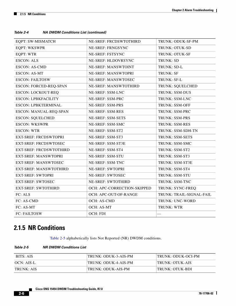
Table 2-4 NA DWDM Conditions List (continued)
2-5Cisco ONS 15454 DWDM Troubleshooting Guide, R7.0
78-17706-02
Chapter 2 Alarm Troubleshooting2.1.5 NR Conditions
2.1.5 NR ConditionsTable 2-5 alphabetically lists Not Reported (NR) DWDM conditions.
EQPT: SW-MISMATCH NE-SREF: FRCDSWTOTHIRD TRUNK: ODUK-SF-PM
EQPT: WKSWPR NE-SREF: FRNGSYNC TRUNK: OTUK-SD
EQPT: WTR NE-SREF: FSTSYNC TRUNK: OTUK-SF
ESCON: ALS NE-SREF: HLDOVRSYNC TRUNK: SD
ESCON: AS-CMD NE-SREF: MANSWTOINT TRUNK: SD-L
ESCON: AS-MT NE-SREF: MANSWTOPRI TRUNK: SF
ESCON: FAILTOSW NE-SREF: MANSWTOSEC TRUNK: SF-L
ESCON: FORCED-REQ-SPAN NE-SREF: MANSWTOTHIRD TRUNK: SQUELCHED
ESCON: LOCKOUT-REQ NE-SREF: SSM-LNC TRUNK: SSM-DUS
ESCON: LPBKFACILITY NE-SREF: SSM-PRC TRUNK: SSM-LNC
ESCON: LPBKTERMINAL NE-SREF: SSM-PRS TRUNK: SSM-OFF
ESCON: MANUAL-REQ-SPAN NE-SREF: SSM-RES TRUNK: SSM-PRC
ESCON: SQUELCHED NE-SREF: SSM-SETS TRUNK: SSM-PRS
ESCON: WKSWPR NE-SREF: SSM-SMC TRUNK: SSM-RES
ESCON: WTR NE-SREF: SSM-ST2 TRUNK: SSM-SDH-TN
EXT-SREF: FRCDSWTOPRI NE-SREF: SSM-ST3 TRUNK: SSM-SETS
EXT-SREF: FRCDSWTOSEC NE-SREF: SSM-ST3E TRUNK: SSM-SMC
EXT-SREF: FRCDSWTOTHIRD NE-SREF: SSM-ST4 TRUNK: SSM-ST2
EXT-SREF: MANSWTOPRI NE-SREF: SSM-STU TRUNK: SSM-ST3
EXT-SREF: MANSWTOSEC NE-SREF: SSM-TNC TRUNK: SSM-ST3E
EXT-SREF: MANSWTOTHIRD NE-SREF: SWTOPRI TRUNK: SSM-ST4
EXT-SREF: SWTOPRI NE-SREF: SWTOSEC TRUNK: SSM-STU
EXT-SREF: SWTOSEC NE-SREF: SWTOTHIRD TRUNK: SSM-TNC
EXT-SREF: SWTOTHIRD OCH: APC-CORRECTION-SKIPPED TRUNK: SYNC-FREQ
FC: ALS OCH: APC-OUT-OF-RANGE TRUNK: TRAIL-SIGNAL-FAIL
FC: AS-CMD OCH: AS-CMD TRUNK: UNC-WORD
FC: AS-MT OCH: AS-MT TRUNK: WTR
FC: FAILTOSW OCH: FDI —
Table 2-4 NA DWDM Conditions List (continued)
Table 2-5 NR DWDM Conditions List
BITS: AIS TRUNK: ODUK-3-AIS-PM TRUNK: ODUK-OCI-PM
OCN: AIS-L TRUNK: ODUK-4-AIS-PM TRUNK: OTUK-AIS
TRUNK: AIS TRUNK: ODUK-AIS-PM TRUNK: OTUK-BDI
2-6Cisco ONS 15454 DWDM Troubleshooting Guide, R7.0
78-17706-02

Chapter 2 Alarm Troubleshooting2.1.6 Alarms and Conditions Listed By Alphabetical Entry
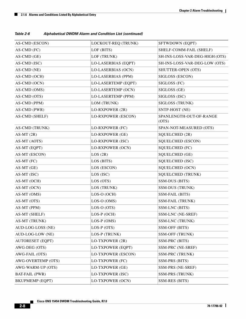
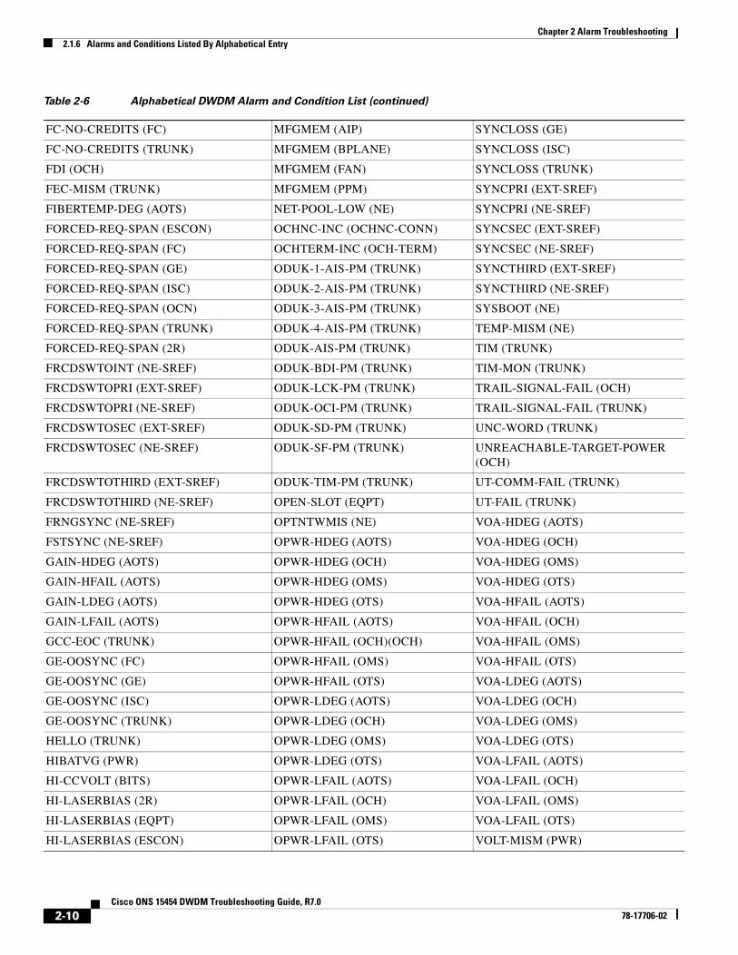
2.1.6 Alarms and Conditions Listed By Alphabetical EntryTable 2-6 alphabetically lists all DWDM alarms and conditions.
TRUNK: AIS-L TRUNK: ODUK-BDI-PM TRUNK: RFI
TRUNK: ODUK-1-AIS-PM TRUNK: ODUK-LCK-PM TRUNK: RFI-L
TRUNK: ODUK-2-AIS-PM — —
Table 2-5 NR DWDM Conditions List (continued)
Table 2-6 Alphabetical DWDM Alarm and Condition List
AIS (BITS) HITEMP (NE) PARAM-MISM (OCH)
ALS (2R) HITEMP (EQPT) PARAM-MISM (OMS)
AIS (TRUNK) HI-TXPOWER (2R) PARAM-MISM (OTS)
AIS-L (OCN) HI-TXPOWER (EQPT) PEER-NORESPONSE (EQPT)
AIS-L (TRUNK) HI-TXPOWER (ESCON) PMI (OMS)
ALS (AOTS) HI-TXPOWER (FC) PMI (OTS)
ALS (ESCON) HI-TXPOWER (GE) PORT-ADD-PWR-DEG-HI (OCH)
ALS (FC) HI-TXPOWER (ISC) PORT-ADD-PWR-DEG-LOW (OCH)
ALS (GE) HI-TXPOWER (OCN) PORT-ADD-PWR-FAIL-HIGH (OCH)
ALS (ISC) HI-TXPOWER (PPM) PORT-ADD-PWR-FAIL-LOW (OCH)
ALS (OCN) HLDOVRSYNC (NE-SREF) PORT-FAIL (OCH)
ALS (TRUNK) I-HITEMP (NE) PROTNA (EQPT)
ALS-DISABLED (EQPT) IMPROPRMVL (EQPT) PROV-MISMATCH (PPM)
AMPLI-INIT (AOTS) IMPROPRMVL (PPM) PROV-MISMATCH (TRUNK)
APC-CORRECTION-SKIPPED (AOTS) INTRUSION-PSWD (NE) PTIM (TRUNK)
APC-CORRECTION-SKIPPED (OCH) INVMACADR (AIP) PWR-FAIL-A (EQPT)
APC-CORRECTION-SKIPPED (OMS) LAN-POL-REV (NE) PWR-FAIL-B (EQPT)
APC-CORRECTION-SKIPPED (OTS) LASER-APR (AOTS) PWR-FAIL-RET-A (EQPT)
APC-DISABLED (NE) LASERBIAS-DEG (AOTS) PWR-FAIL-RET-B (EQPT)
APC-END (NE) LASERBIAS-DEG (OTS) RFI (TRUNK)
APC-OUT-OF-RANGE (AOTS) LASERBIAS-FAIL (AOTS) RFI-L (TRUNK)
APC-OUT-OF-RANGE (OCH) LASERTEMP-DEG (AOTS) RING-ID-MIS (OSC-RING)
APC-OUT-OF-RANGE (OMS) LOCKOUT-REQ (2R) ROUTE-OVERFLOW (NE)
APC-OUT-OF-RANGE (OTS) LOCKOUT-REQ (EQPT) RUNCFG-SAVENEED (EQPT)
AS-CMD (2R) LOCKOUT-REQ (ESCON) SD (TRUNK)
AS-CMD (AOTS) LOCKOUT-REQ (FC) SD-L (TRUNK)
AS-CMD (BPLANE) LOCKOUT-REQ (GE) SF (TRUNK)
AS-CMD (EQPT) LOCKOUT-REQ (ISC) SF-L (TRUNK)
2-7Cisco ONS 15454 DWDM Troubleshooting Guide, R7.0
78-17706-02
Chapter 2 Alarm Troubleshooting2.1.6 Alarms and Conditions Listed By Alphabetical Entry
AS-CMD (ESCON) LOCKOUT-REQ (TRUNK) SFTWDOWN (EQPT)
AS-CMD (FC) LOF (BITS) SHELF-COMM-FAIL (SHELF)
AS-CMD (GE) LOF (TRUNK) SH-INS-LOSS-VAR-DEG-HIGH (OTS)
AS-CMD (ISC) LO-LASERBIAS (EQPT) SH-INS-LOSS-VAR-DEG-LOW (OTS)
AS-CMD (NE) LO-LASERBIAS (OCN) SHUTTER-OPEN (OTS)
AS-CMD (OCH) LO-LASERBIAS (PPM) SIGLOSS (ESCON)
AS-CMD (OCN) LO-LASERTEMP (EQPT) SIGLOSS (FC)
AS-CMD (OMS) LO-LASERTEMP (OCN) SIGLOSS (GE)
AS-CMD (OTS) LO-LASERTEMP (PPM) SIGLOSS (ISC)
AS-CMD (PPM) LOM (TRUNK) SIGLOSS (TRUNK)
AS-CMD (PWR) LO-RXPOWER (2R) SNTP-HOST (NE)
AS-CMD (SHELF) LO-RXPOWER (ESCON) SPANLENGTH-OUT-OF-RANGE (OTS)
AS-CMD (TRUNK) LO-RXPOWER (FC) SPAN-NOT-MEASURED (OTS)
AS-MT (2R) LO-RXPOWER (GE) SQUELCHED (2R)
AS-MT (AOTS) LO-RXPOWER (ISC) SQUELCHED (ESCON)
AS-MT (EQPT) LO-RXPOWER (OCN) SQUELCHED (FC)
AS-MT (ESCON) LOS (2R) SQUELCHED (GE)
AS-MT (FC) LOS (BITS) SQUELCHED (ISC)
AS-MT (GE) LOS (ESCON) SQUELCHED (OCN)
AS-MT (ISC) LOS (ISC) SQUELCHED (TRUNK)
AS-MT (OCH) LOS (OTS) SSM-DUS (BITS)
AS-MT (OCN) LOS (TRUNK) SSM-DUS (TRUNK)
AS-MT (OMS) LOS-O (OCH) SSM-FAIL (BITS)
AS-MT (OTS) LOS-O (OMS) SSM-FAIL (TRUNK)
AS-MT (PPM) LOS-O (OTS) SSM-LNC (BITS)
AS-MT (SHELF) LOS-P (OCH) SSM-LNC (NE-SREF)
AS-MT (TRUNK) LOS-P (OMS) SSM-LNC (TRUNK)
AUD-LOG-LOSS (NE) LOS-P (OTS) SSM-OFF (BITS)
AUD-LOG-LOW (NE) LOS-P (TRUNK) SSM-OFF (TRUNK)
AUTORESET (EQPT) LO-TXPOWER (2R) SSM-PRC (BITS)
AWG-DEG (OTS) LO-TXPOWER (EQPT) SSM-PRC (NE-SREF)
AWG-FAIL (OTS) LO-TXPOWER (ESCON) SSM-PRC (TRUNK)
AWG-OVERTEMP (OTS) LO-TXPOWER (FC) SSM-PRS (BITS)
AWG-WARM-UP (OTS) LO-TXPOWER (GE) SSM-PRS (NE-SREF)
BAT-FAIL (PWR) LO-TXPOWER (ISC) SSM-PRS (TRUNK)
BKUPMEMP (EQPT) LO-TXPOWER (OCN) SSM-RES (BITS)
Table 2-6 Alphabetical DWDM Alarm and Condition List (continued)
2-8Cisco ONS 15454 DWDM Troubleshooting Guide, R7.0
78-17706-02

Chapter 2 Alarm Troubleshooting2.1.6 Alarms and Conditions Listed By Alphabetical Entry
BPV (BITS) LO-TXPOWER (PPM) SSM-RES (NE-SREF)
CARLOSS (EQPT) LPBKFACILITY (ESCON) SSM-RES (TRUNK)
CARLOSS (FC) LPBKFACILITY (FC) SSM-SDH-TN (TRUNK)
CARLOSS (GE) LPBKFACILITY (GE) SSM-SETS (BITS)
CARLOSS (ISC) LPBKFACILITY (ISC) SSM-SETS (NE-SREF)
CARLOSS (TRUNK) LPBKFACILITY (TRUNK) SSM-SETS (TRUNK)
CASETEMP-DEG (AOTS) LPBKTERMINAL (ESCON) SSM-SMC (BITS)
DATAFLT (NE) LPBKTERMINAL (FC) SSM-SMC (NE-SREF)
DBOSYNC (NE) LPBKTERMINAL (GE) SSM-SMC (TRUNK)
DSP-COMM-FAIL (TRUNK) LPBKTERMINAL (ISC) SSM-ST2 (BITS)
DSP-FAIL (TRUNK) LPBKTERMINAL (TRUNK) SSM-ST2 (NE-SREF)
DUP-IPADDR (NE) LWBATVG (PWR) SSM-ST2 (TRUNK)
DUP-NODENAME (NE) MAN-REQ (EQPT) SSM-ST3 (BITS)
DUP-SHELF-ID (SHELF) MANRESET (EQPT) SSM-ST3 (NE-SREF)
EHIBATVG (PWR) MANSWTOINT (NE-SREF) SSM-ST3 (TRUNK)
ELWBATVG (PWR) MANSWTOPRI (EXT-SREF) SSM-ST3E (BITS)
EOC (OCN) MANSWTOPRI (NE-SREF) SSM-ST3E (NE-SREF)
EOC (TRUNK) MANSWTOSEC (EXT-SREF) SSM-ST3E (TRUNK)
EOC-L (OCN) MANSWTOSEC (NE-SREF) SSM-ST4 (BITS)
EOC-L (TRUNK) MANSWTOTHIRD (EXT-SREF) SSM-ST4 (NE-SREF)
EQPT (EQPT) MANSWTOTHIRD (NE-SREF) SSM-ST4 (TRUNK)
EQPT (AICI-AEP) MANUAL-REQ-SPAN (2R) SSM-STU (BITS)
EQPT (AICI-AIE) MANUAL-REQ-SPAN (ESCON) SSM-STU (NE-SREF)
EQPT (PPM) MANUAL-REQ-SPAN (FC) SSM-STU (TRUNK)
EQPT-MISS (FAN) MANUAL-REQ-SPAN (GE) SSM-TNC (BITS)
ETH-LINKLOSS (NE) MANUAL-REQ-SPAN (ISC) SSM-TNC (NE-SREF)
EXCCOL (EQPT) MANUAL-REQ-SPAN (OCN) SSM-TNC (TRUNK)
EXT (ENVALRM) MANUAL-REQ-SPAN (TRUNK) SW-MISMATCH (EQPT)
FAILTOSW (2R) MEA (EQPT) SWTOPRI (EXT-SREF)
FAILTOSW (EQPT) MEA (AIP) SWTOPRI (NE-SREF)
FAILTOSW (ESCON) MEA (FAN) SWTOSEC (EXT-SREF)
FAILTOSW (FC) MEA (PPM) SWTOSEC (NE-SREF)
FAILTOSW (GE) MEA (SHELF) SWTOTHIRD (EXT-SREF)
FAILTOSW (ISC) MEM-GONE (EQPT) SWTOTHIRD (NE-SREF)
FAILTOSW (OCN) MEM-LOW (EQPT) SYNC-FREQ (BITS)
FAILTOSW (TRUNK) MFGMEM (AICI-AEP) SYNC-FREQ (TRUNK)
FAN (FAN) MFGMEM (AICI-AIE) SYNCLOSS (FC)
Table 2-6 Alphabetical DWDM Alarm and Condition List (continued)
2-9Cisco ONS 15454 DWDM Troubleshooting Guide, R7.0
78-17706-02
Chapter 2 Alarm Troubleshooting2.1.6 Alarms and Conditions Listed By Alphabetical Entry
FC-NO-CREDITS (FC) MFGMEM (AIP) SYNCLOSS (GE)
FC-NO-CREDITS (TRUNK) MFGMEM (BPLANE) SYNCLOSS (ISC)
FDI (OCH) MFGMEM (FAN) SYNCLOSS (TRUNK)
FEC-MISM (TRUNK) MFGMEM (PPM) SYNCPRI (EXT-SREF)
FIBERTEMP-DEG (AOTS) NET-POOL-LOW (NE) SYNCPRI (NE-SREF)
FORCED-REQ-SPAN (ESCON) OCHNC-INC (OCHNC-CONN) SYNCSEC (EXT-SREF)
FORCED-REQ-SPAN (FC) OCHTERM-INC (OCH-TERM) SYNCSEC (NE-SREF)
FORCED-REQ-SPAN (GE) ODUK-1-AIS-PM (TRUNK) SYNCTHIRD (EXT-SREF)
FORCED-REQ-SPAN (ISC) ODUK-2-AIS-PM (TRUNK) SYNCTHIRD (NE-SREF)
FORCED-REQ-SPAN (OCN) ODUK-3-AIS-PM (TRUNK) SYSBOOT (NE)
FORCED-REQ-SPAN (TRUNK) ODUK-4-AIS-PM (TRUNK) TEMP-MISM (NE)
FORCED-REQ-SPAN (2R) ODUK-AIS-PM (TRUNK) TIM (TRUNK)
FRCDSWTOINT (NE-SREF) ODUK-BDI-PM (TRUNK) TIM-MON (TRUNK)
FRCDSWTOPRI (EXT-SREF) ODUK-LCK-PM (TRUNK) TRAIL-SIGNAL-FAIL (OCH)
FRCDSWTOPRI (NE-SREF) ODUK-OCI-PM (TRUNK) TRAIL-SIGNAL-FAIL (TRUNK)
FRCDSWTOSEC (EXT-SREF) ODUK-SD-PM (TRUNK) UNC-WORD (TRUNK)
FRCDSWTOSEC (NE-SREF) ODUK-SF-PM (TRUNK) UNREACHABLE-TARGET-POWER (OCH)
FRCDSWTOTHIRD (EXT-SREF) ODUK-TIM-PM (TRUNK) UT-COMM-FAIL (TRUNK)
FRCDSWTOTHIRD (NE-SREF) OPEN-SLOT (EQPT) UT-FAIL (TRUNK)
FRNGSYNC (NE-SREF) OPTNTWMIS (NE) VOA-HDEG (AOTS)
FSTSYNC (NE-SREF) OPWR-HDEG (AOTS) VOA-HDEG (OCH)
GAIN-HDEG (AOTS) OPWR-HDEG (OCH) VOA-HDEG (OMS)
GAIN-HFAIL (AOTS) OPWR-HDEG (OMS) VOA-HDEG (OTS)
GAIN-LDEG (AOTS) OPWR-HDEG (OTS) VOA-HFAIL (AOTS)
GAIN-LFAIL (AOTS) OPWR-HFAIL (AOTS) VOA-HFAIL (OCH)
GCC-EOC (TRUNK) OPWR-HFAIL (OCH)(OCH) VOA-HFAIL (OMS)
GE-OOSYNC (FC) OPWR-HFAIL (OMS) VOA-HFAIL (OTS)
GE-OOSYNC (GE) OPWR-HFAIL (OTS) VOA-LDEG (AOTS)
GE-OOSYNC (ISC) OPWR-LDEG (AOTS) VOA-LDEG (OCH)
GE-OOSYNC (TRUNK) OPWR-LDEG (OCH) VOA-LDEG (OMS)
HELLO (TRUNK) OPWR-LDEG (OMS) VOA-LDEG (OTS)
HIBATVG (PWR) OPWR-LDEG (OTS) VOA-LFAIL (AOTS)
HI-CCVOLT (BITS) OPWR-LFAIL (AOTS) VOA-LFAIL (OCH)
HI-LASERBIAS (2R) OPWR-LFAIL (OCH) VOA-LFAIL (OMS)
HI-LASERBIAS (EQPT) OPWR-LFAIL (OMS) VOA-LFAIL (OTS)
HI-LASERBIAS (ESCON) OPWR-LFAIL (OTS) VOLT-MISM (PWR)
Table 2-6 Alphabetical DWDM Alarm and Condition List (continued)
2-10Cisco ONS 15454 DWDM Troubleshooting Guide, R7.0
78-17706-02

Chapter 2 Alarm Troubleshooting2.2 Logical Objects
2.2 Logical ObjectsThe CTC alarm profile list organizes all alarms and conditions according to the logical objects they are raised against. These logical objects represent physical objects such as cards, logical objects such as circuits, or transport and signal monitoring entities such as the SONET or ITU-T G.709 optical overhead bits. One alarm can appear in multiple entries. It can be raised against multiple objects. For example, the loss of signal (LOS) alarm can be raised against the optical signal (OC-N) or the optical transport layer overhead (OTN) as well as other objects. Therefore, both OCN: LOS and OTN: LOS appear in the list (as well as the other objects).
Alarm profile list objects are defined in Table 2-7.
Note Alarm logical object names can appear as abbreviated versions of standard terms used in the system and the documentation. For example, the “OCN” logical object refers to the OC-N signal. Logical object names or industry-standard terms are used within the entries as appropriate.
2.2.1 Alarm Logical ObjectsTable 2-7 lists all logical alarm objects used in this chapter.
HI-LASERBIAS (FC) OSRION (AOTS) WKSWPR (2R)
HI-LASERBIAS (GE) OSRION (OTS) WKSWPR (EQPT)
HI-LASERBIAS (ISC) OTUK-AIS (TRUNK) WKSWPR (ESCON)
HI-LASERBIAS (OCN) OTUK-BDI (TRUNK) WKSWPR (FC)
HI-LASERBIAS (PPM) OTUK-IAE (TRUNK) WKSWPR (GE)
HI-LASERTEMP (OCN) OTUK-LOF (TRUNK) WKSWPR (ISC)
HI-LASERTEMP (PPM) OTUK-SD (TRUNK) WTR (2R)
HI-LASERTEMP (EQPT) OTUK-SF (TRUNK) WTR (EQPT)
HI-RXPOWER (2R) OTUK-TIM (TRUNK) WTR (ESCON)
HI-RXPOWER (ESCON) OUT-OF-SYNC (FC) WTR (FC)
HI-RXPOWER (FC) OUT-OF-SYNC (GE) WTR (GE)
HI-RXPOWER (GE) OUT-OF-SYNC (ISC) WTR (ISC)
HI-RXPOWER (ISC) OUT-OF-SYNC (TRUNK) WTR (TRUNK)
HI-RXPOWER (OCN) PARAM-MISM (AOTS) WVL-MISMATCH (TRUNK)
Table 2-6 Alphabetical DWDM Alarm and Condition List (continued)
Table 2-7 Alarm Logical Object Type Definitions
Logical Object Definition
2R Reshape and retransmit (used for transponder [TXP] cards).
AICI-AEP Alarm Interface Controller–International/alarm expansion panel. A combination term that refers to this platform’s AIC-I card.
2-11Cisco ONS 15454 DWDM Troubleshooting Guide, R7.0
78-17706-02

Chapter 2 Alarm Troubleshooting2.2.1 Alarm Logical Objects
AICI-AIE Alarm Interface Controller-International/Alarm Interface Extension. A combination term that refers to this platform's AIC-I card.
AOTS Amplified optical transport section.
BITS Building integrated timing supply incoming references (BITS-1, BITS-2).
BPLANE The backplane.
ENVALRM An environmental alarm port.
EQPT A card, its physical objects, and its logical objects as they are located in any of the eight noncommon card slots. The EQPT object is used for alarms that refer to the card itself and all other objects on the card including ports, lines, synchronous transport signals (STS), and virtual tributaries (VT).
ESCON Enterprise System Connection fiber optic technology, referring to the following TXP cards: TXP_MR_2.5G, TXPP_MR_2.5G, MXP_MR_2.5G, MXPP_MR_2.5G.
EXT-SREF BITS outgoing references (SYNC-BITS1, SYNC-BITS2).
FAN Fan-tray assembly.
FC Fibre channel data transfer architecture, referring to the following muxponder (MXP) or TXP cards: MXP_MR_2.5G, MXPP_MR_2.5G, MXP_MR_10DME_C, MXP_MR_10DME_L, TXP_MR_2.5G, TXPP_MR_2.5G, TXP_MR_10E, TXP_MR_10E_C, TXP_MR_10E_L
GE Gigabit Ethernet, referring to the following MXP or TXP cards: MXP_MR_2.5G, MXPP_MR_2.5G, TXP_MR_2.5G, TXPP_MR_2.5G, TXP_MR_10G, TXP_MR_10E,TXP_MR_10E_C, TXP_MR_10E_L, MXP_MR_10DME_C, MXP_MR_10DME_L.
ISC Inter-service channel, referring to TXPP_MR_2.5G or TXP_MR_2.5G cards.
NE The entire network element.
NE-SREF The timing status of the NE.
OCH The optical channel, referring to dense wavelength division multiplexing (DWDM) cards.
OCHNC-CONN The optical channel network connection, referring to DWDM cards.
OMS Optical multiplex section.
OSC-RING Optical service channel ring.
OTS Optical transport section.
PPM Pluggable port module (PPM, also called SFP), referring to MXP and TXP cards.
PWR Power equipment.
TRUNK The optical or DWDM card carrying the high-speed signal; referring to MXP or TXP cards.
Table 2-7 Alarm Logical Object Type Definitions (continued)
Logical Object Definition
2-12Cisco ONS 15454 DWDM Troubleshooting Guide, R7.0
78-17706-02

Chapter 2 Alarm Troubleshooting2.2.2 Alarm List by Logical Object Type
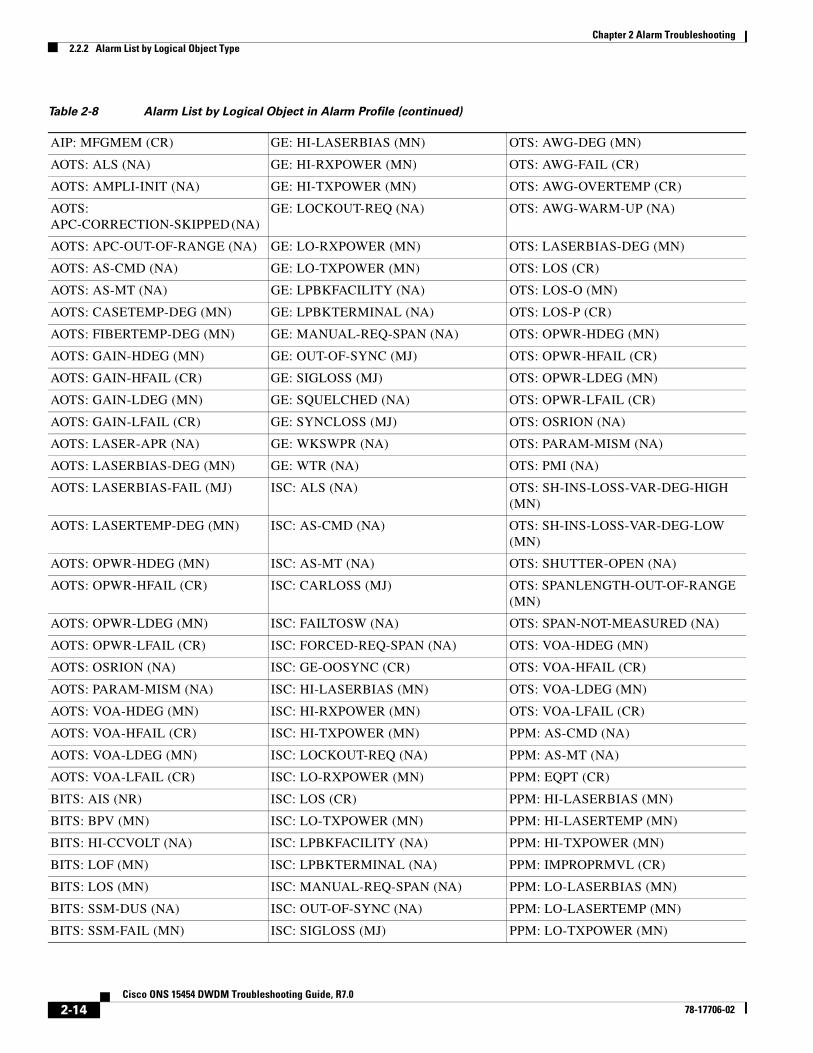
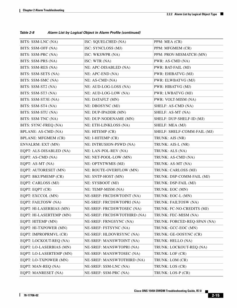
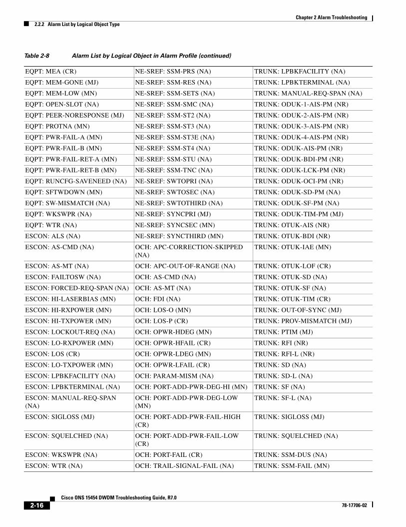
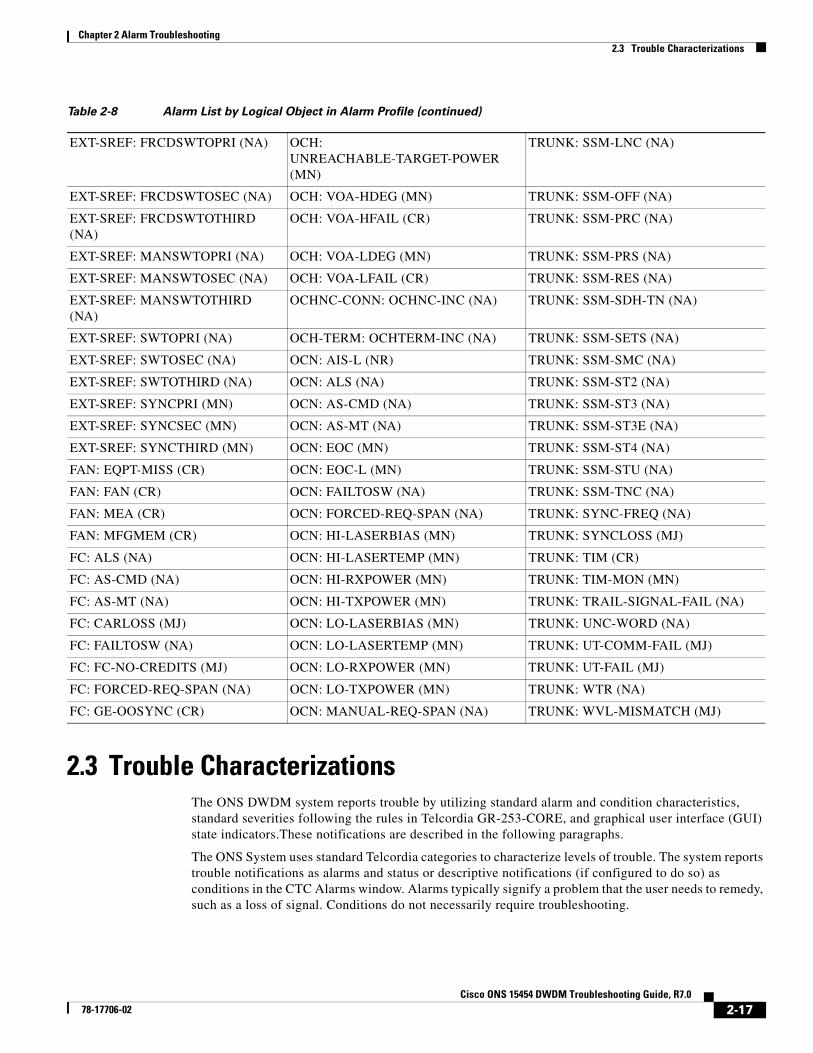
2.2.2 Alarm List by Logical Object TypeTable 2-8 lists all Release 7.0 DWDM alarms and logical objects as they are given in the system alarm profile. The list entries are organized by logical object name and then by alarm or condition name. Where appropriate, the alarm entries also contain troubleshooting procedures.
Note In a mixed network containing different types of nodes (for example, ONS 15310-CL, ONS 15454, and ONS 15600), the initially displayed alarm list in the node view (single-shelf mode) or shelf view (multishelf mode) Provisioning > Alarm Profiles tabs > Alarm Profile Editor tab lists all conditions that are applicable to all nodes in the network. However, when you load the default severity profile from a node, only applicable alarms will display severity levels. Nonapplicable alarms can display “use default” or “unset.”
Note In some cases this list does not follow alphabetical order, but it does reflect the order shown in CTC.
Table 2-8 Alarm List by Logical Object in Alarm Profile
2R: ALS (NA) FC: HI-LASERBIAS (MN) OCN: SQUELCHED (NA)
2R: AS-CMD (NA) FC: HI-RXPOWER (MN) OMS: APC-CORRECTION-SKIPPED (NA)
2R: AS-MT (NA) FC: HI-TXPOWER (MN) OMS: APC-OUT-OF-RANGE (NA)
2R: FAILTOSW (NA) FC: LOCKOUT-REQ (NA) OMS: AS-CMD (NA)
2R: FORCED-REQ-SPAN (NA) FC: LO-RXPOWER (MN) OMS: AS-MT (NA)
2R: HI-LASERBIAS (MN) FC: LO-TXPOWER (MN) OMS: LOS-O (MN)
2R: HI-RXPOWER (MN) FC: LPBKFACILITY (NA) OMS: LOS-P (CR)
2R: HI-TXPOWER (MN) FC: LPBKTERMINAL (NA) OMS: OPWR-HDEG (MN)
2R: LOCKOUT-REQ (NA) FC: MANUAL-REQ-SPAN (NA) OMS: OPWR-HFAIL (CR)
2R: LO-RXPOWER (MN) FC: OUT-OF-SYNC (MJ) OMS: OPWR-LDEG (MN)
2R: LOS (CR) FC: SIGLOSS (MJ) OMS: OPWR-LFAIL (CR)
2R: LO-TXPOWER (MN) FC: SQUELCHED (NA) OMS: PARAM-MISM (NA)
2R: MANUAL-REQ-SPAN (NA) FC: SYNCLOSS (MJ) OMS: PMI (NA)
2R: SQUELCHED (NA) FC: WKSWPR (NA) OMS: VOA-HDEG (MN)
2R: WKSWPR (NA) FC: WTR (NA) OMS: VOA-HFAIL (CR)
2R: WTR (NA) GE: ALS (NA) OMS: VOA-LDEG (MN)
AICI-AEP: EQPT (CR) GE: AS-CMD (NA) OMS: VOA-LFAIL (CR)
AICI-AEP: MFGMEM (CR) GE: AS-MT (NA) OSC-RING: RING-ID-MIS (MJ)
AICI-AIE: EQPT (CR) GE: CARLOSS (MJ) OTS: APC-CORRECTION-SKIPPED (NA)
AICI-AIE: MFGMEM (CR) GE: FAILTOSW (NA) OTS: APC-OUT-OF-RANGE (NA)
AIP: INVMACADR (MJ) GE: FORCED-REQ-SPAN (NA) OTS: AS-CMD (NA)
AIP: MEA (CR) GE: GE-OOSYNC (CR) OTS: AS-MT (NA)
2-13Cisco ONS 15454 DWDM Troubleshooting Guide, R7.0
78-17706-02
Chapter 2 Alarm Troubleshooting2.2.2 Alarm List by Logical Object Type
AIP: MFGMEM (CR) GE: HI-LASERBIAS (MN) OTS: AWG-DEG (MN)
AOTS: ALS (NA) GE: HI-RXPOWER (MN) OTS: AWG-FAIL (CR)
AOTS: AMPLI-INIT (NA) GE: HI-TXPOWER (MN) OTS: AWG-OVERTEMP (CR)
AOTS: APC-CORRECTION-SKIPPED (NA)
GE: LOCKOUT-REQ (NA) OTS: AWG-WARM-UP (NA)
AOTS: APC-OUT-OF-RANGE (NA) GE: LO-RXPOWER (MN) OTS: LASERBIAS-DEG (MN)
AOTS: AS-CMD (NA) GE: LO-TXPOWER (MN) OTS: LOS (CR)
AOTS: AS-MT (NA) GE: LPBKFACILITY (NA) OTS: LOS-O (MN)
AOTS: CASETEMP-DEG (MN) GE: LPBKTERMINAL (NA) OTS: LOS-P (CR)
AOTS: FIBERTEMP-DEG (MN) GE: MANUAL-REQ-SPAN (NA) OTS: OPWR-HDEG (MN)
AOTS: GAIN-HDEG (MN) GE: OUT-OF-SYNC (MJ) OTS: OPWR-HFAIL (CR)
AOTS: GAIN-HFAIL (CR) GE: SIGLOSS (MJ) OTS: OPWR-LDEG (MN)
AOTS: GAIN-LDEG (MN) GE: SQUELCHED (NA) OTS: OPWR-LFAIL (CR)
AOTS: GAIN-LFAIL (CR) GE: SYNCLOSS (MJ) OTS: OSRION (NA)
AOTS: LASER-APR (NA) GE: WKSWPR (NA) OTS: PARAM-MISM (NA)
AOTS: LASERBIAS-DEG (MN) GE: WTR (NA) OTS: PMI (NA)
AOTS: LASERBIAS-FAIL (MJ) ISC: ALS (NA) OTS: SH-INS-LOSS-VAR-DEG-HIGH (MN)
AOTS: LASERTEMP-DEG (MN) ISC: AS-CMD (NA) OTS: SH-INS-LOSS-VAR-DEG-LOW (MN)
AOTS: OPWR-HDEG (MN) ISC: AS-MT (NA) OTS: SHUTTER-OPEN (NA)
AOTS: OPWR-HFAIL (CR) ISC: CARLOSS (MJ) OTS: SPANLENGTH-OUT-OF-RANGE (MN)
AOTS: OPWR-LDEG (MN) ISC: FAILTOSW (NA) OTS: SPAN-NOT-MEASURED (NA)
AOTS: OPWR-LFAIL (CR) ISC: FORCED-REQ-SPAN (NA) OTS: VOA-HDEG (MN)
AOTS: OSRION (NA) ISC: GE-OOSYNC (CR) OTS: VOA-HFAIL (CR)
AOTS: PARAM-MISM (NA) ISC: HI-LASERBIAS (MN) OTS: VOA-LDEG (MN)
AOTS: VOA-HDEG (MN) ISC: HI-RXPOWER (MN) OTS: VOA-LFAIL (CR)
AOTS: VOA-HFAIL (CR) ISC: HI-TXPOWER (MN) PPM: AS-CMD (NA)
AOTS: VOA-LDEG (MN) ISC: LOCKOUT-REQ (NA) PPM: AS-MT (NA)
AOTS: VOA-LFAIL (CR) ISC: LO-RXPOWER (MN) PPM: EQPT (CR)
BITS: AIS (NR) ISC: LOS (CR) PPM: HI-LASERBIAS (MN)
BITS: BPV (MN) ISC: LO-TXPOWER (MN) PPM: HI-LASERTEMP (MN)
BITS: HI-CCVOLT (NA) ISC: LPBKFACILITY (NA) PPM: HI-TXPOWER (MN)
BITS: LOF (MN) ISC: LPBKTERMINAL (NA) PPM: IMPROPRMVL (CR)
BITS: LOS (MN) ISC: MANUAL-REQ-SPAN (NA) PPM: LO-LASERBIAS (MN)
BITS: SSM-DUS (NA) ISC: OUT-OF-SYNC (NA) PPM: LO-LASERTEMP (MN)
BITS: SSM-FAIL (MN) ISC: SIGLOSS (MJ) PPM: LO-TXPOWER (MN)
Table 2-8 Alarm List by Logical Object in Alarm Profile (continued)
2-14Cisco ONS 15454 DWDM Troubleshooting Guide, R7.0
78-17706-02
Chapter 2 Alarm Troubleshooting2.2.2 Alarm List by Logical Object Type
BITS: SSM-LNC (NA) ISC: SQUELCHED (NA) PPM: MEA (CR)
BITS: SSM-OFF (NA) ISC: SYNCLOSS (MJ) PPM: MFGMEM (CR)
BITS: SSM-PRC (NA) ISC: WKSWPR (NA) PPM: PROV-MISMATCH (MN)
BITS: SSM-PRS (NA) ISC: WTR (NA) PWR: AS-CMD (NA)
BITS: SSM-RES (NA) NE: APC-DISABLED (NA) PWR: BAT-FAIL (MJ)
BITS: SSM-SETS (NA) NE: APC-END (NA) PWR: EHIBATVG (MJ)
BITS: SSM-SMC (NA) NE: AS-CMD (NA) PWR: ELWBATVG (MJ)
BITS: SSM-ST2 (NA) NE: AUD-LOG-LOSS (NA) PWR: HIBATVG (MJ)
BITS: SSM-ST3 (NA) NE: AUD-LOG-LOW (NA) PWR: LWBATVG (MJ)
BITS: SSM-ST3E (NA) NE: DATAFLT (MN) PWR: VOLT-MISM (NA)
BITS: SSM-ST4 (NA) NE: DBOSYNC (MJ) SHELF: AS-CMD (NA)
BITS: SSM-STU (NA) NE: DUP-IPADDR (MN) SHELF: AS-MT (NA)
BITS: SSM-TNC (NA) NE: DUP-NODENAME (MN) SHELF: DUP-SHELF-ID (MJ)
BITS: SYNC-FREQ (NA) NE: ETH-LINKLOSS (NA) SHELF: MEA (MJ)
BPLANE: AS-CMD (NA) NE: HITEMP (CR) SHELF: SHELF-COMM-FAIL (MJ)
BPLANE: MFGMEM (CR) NE: I-HITEMP (CR) TRUNK: AIS (NR)
ENVALRM: EXT (MN) NE: INTRUSION-PSWD (NA) TRUNK: AIS-L (NR)
EQPT: ALS-DISABLED (NA) NE: LAN-POL-REV (NA) TRUNK: ALS (NA)
EQPT: AS-CMD (NA) NE: NET-POOL-LOW (MN) TRUNK: AS-CMD (NA)
EQPT: AS-MT (NA) NE: OPTNTWMIS (MJ) TRUNK: AS-MT (NA)
EQPT: AUTORESET (MN) NE: ROUTE-OVERFLOW (MN) TRUNK: CARLOSS (MJ)
EQPT: BKUPMEMP (CR) NE: SNTP-HOST (MN) TRUNK: DSP-COMM-FAIL (MJ)
EQPT: CARLOSS (MJ) NE: SYSBOOT (MJ) TRUNK: DSP-FAIL (MJ)
EQPT: EQPT (CR) NE: TEMP-MISM (NA) TRUNK: EOC (MN)
EQPT: EXCCOL (MN) NE-SREF: FRCDSWTOINT (NA) TRUNK: EOC-L (MN)
EQPT: FAILTOSW (NA) NE-SREF: FRCDSWTOPRI (NA) TRUNK: FAILTOSW (NA)
EQPT: HI-LASERBIAS (MN) NE-SREF: FRCDSWTOSEC (NA) TRUNK: FC-NO-CREDITS (MJ)
EQPT: HI-LASERTEMP (MN) NE-SREF: FRCDSWTOTHIRD (NA) TRUNK: FEC-MISM (NA)
EQPT: HITEMP (MN) NE-SREF: FRNGSYNC (NA) TRUNK: FORCED-REQ-SPAN (NA)
EQPT: HI-TXPOWER (MN) NE-SREF: FSTSYNC (NA) TRUNK: GCC-EOC (MN)
EQPT: IMPROPRMVL (CR) NE-SREF: HLDOVRSYNC (NA) TRUNK: GE-OOSYNC (CR)
EQPT: LOCKOUT-REQ (NA) NE-SREF: MANSWTOINT (NA) TRUNK: HELLO (NA)
EQPT: LO-LASERBIAS (MN) NE-SREF: MANSWTOPRI (NA) TRUNK: LOCKOUT-REQ (NA)
EQPT: LO-LASERTEMP (MN) NE-SREF: MANSWTOSEC (NA) TRUNK: LOF (CR)
EQPT: LO-TXPOWER (MN) NE-SREF: MANSWTOTHIRD (NA) TRUNK: LOM (CR)
EQPT: MAN-REQ (NA) NE-SREF: SSM-LNC (NA) TRUNK: LOS (CR)
EQPT: MANRESET (NA) NE-SREF: SSM-PRC (NA) TRUNK: LOS-P (CR)
Table 2-8 Alarm List by Logical Object in Alarm Profile (continued)
2-15Cisco ONS 15454 DWDM Troubleshooting Guide, R7.0
78-17706-02
Chapter 2 Alarm Troubleshooting2.2.2 Alarm List by Logical Object Type
EQPT: MEA (CR) NE-SREF: SSM-PRS (NA) TRUNK: LPBKFACILITY (NA)
EQPT: MEM-GONE (MJ) NE-SREF: SSM-RES (NA) TRUNK: LPBKTERMINAL (NA)
EQPT: MEM-LOW (MN) NE-SREF: SSM-SETS (NA) TRUNK: MANUAL-REQ-SPAN (NA)
EQPT: OPEN-SLOT (NA) NE-SREF: SSM-SMC (NA) TRUNK: ODUK-1-AIS-PM (NR)
EQPT: PEER-NORESPONSE (MJ) NE-SREF: SSM-ST2 (NA) TRUNK: ODUK-2-AIS-PM (NR)
EQPT: PROTNA (MN) NE-SREF: SSM-ST3 (NA) TRUNK: ODUK-3-AIS-PM (NR)
EQPT: PWR-FAIL-A (MN) NE-SREF: SSM-ST3E (NA) TRUNK: ODUK-4-AIS-PM (NR)
EQPT: PWR-FAIL-B (MN) NE-SREF: SSM-ST4 (NA) TRUNK: ODUK-AIS-PM (NR)
EQPT: PWR-FAIL-RET-A (MN) NE-SREF: SSM-STU (NA) TRUNK: ODUK-BDI-PM (NR)
EQPT: PWR-FAIL-RET-B (MN) NE-SREF: SSM-TNC (NA) TRUNK: ODUK-LCK-PM (NR)
EQPT: RUNCFG-SAVENEED (NA) NE-SREF: SWTOPRI (NA) TRUNK: ODUK-OCI-PM (NR)
EQPT: SFTWDOWN (MN) NE-SREF: SWTOSEC (NA) TRUNK: ODUK-SD-PM (NA)
EQPT: SW-MISMATCH (NA) NE-SREF: SWTOTHIRD (NA) TRUNK: ODUK-SF-PM (NA)
EQPT: WKSWPR (NA) NE-SREF: SYNCPRI (MJ) TRUNK: ODUK-TIM-PM (MJ)
EQPT: WTR (NA) NE-SREF: SYNCSEC (MN) TRUNK: OTUK-AIS (NR)
ESCON: ALS (NA) NE-SREF: SYNCTHIRD (MN) TRUNK: OTUK-BDI (NR)
ESCON: AS-CMD (NA) OCH: APC-CORRECTION-SKIPPED (NA)
TRUNK: OTUK-IAE (MN)
ESCON: AS-MT (NA) OCH: APC-OUT-OF-RANGE (NA) TRUNK: OTUK-LOF (CR)
ESCON: FAILTOSW (NA) OCH: AS-CMD (NA) TRUNK: OTUK-SD (NA)
ESCON: FORCED-REQ-SPAN (NA) OCH: AS-MT (NA) TRUNK: OTUK-SF (NA)
ESCON: HI-LASERBIAS (MN) OCH: FDI (NA) TRUNK: OTUK-TIM (CR)
ESCON: HI-RXPOWER (MN) OCH: LOS-O (MN) TRUNK: OUT-OF-SYNC (MJ)
ESCON: HI-TXPOWER (MN) OCH: LOS-P (CR) TRUNK: PROV-MISMATCH (MJ)
ESCON: LOCKOUT-REQ (NA) OCH: OPWR-HDEG (MN) TRUNK: PTIM (MJ)
ESCON: LO-RXPOWER (MN) OCH: OPWR-HFAIL (CR) TRUNK: RFI (NR)
ESCON: LOS (CR) OCH: OPWR-LDEG (MN) TRUNK: RFI-L (NR)
ESCON: LO-TXPOWER (MN) OCH: OPWR-LFAIL (CR) TRUNK: SD (NA)
ESCON: LPBKFACILITY (NA) OCH: PARAM-MISM (NA) TRUNK: SD-L (NA)
ESCON: LPBKTERMINAL (NA) OCH: PORT-ADD-PWR-DEG-HI (MN) TRUNK: SF (NA)
ESCON: MANUAL-REQ-SPAN (NA)
OCH: PORT-ADD-PWR-DEG-LOW (MN)
TRUNK: SF-L (NA)
ESCON: SIGLOSS (MJ) OCH: PORT-ADD-PWR-FAIL-HIGH (CR)
TRUNK: SIGLOSS (MJ)
ESCON: SQUELCHED (NA) OCH: PORT-ADD-PWR-FAIL-LOW (CR)
TRUNK: SQUELCHED (NA)
ESCON: WKSWPR (NA) OCH: PORT-FAIL (CR) TRUNK: SSM-DUS (NA)
ESCON: WTR (NA) OCH: TRAIL-SIGNAL-FAIL (NA) TRUNK: SSM-FAIL (MN)
Table 2-8 Alarm List by Logical Object in Alarm Profile (continued)
2-16Cisco ONS 15454 DWDM Troubleshooting Guide, R7.0
78-17706-02
Chapter 2 Alarm Troubleshooting2.3 Trouble Characterizations
2.3 Trouble CharacterizationsThe ONS DWDM system reports trouble by utilizing standard alarm and condition characteristics, standard severities following the rules in Telcordia GR-253-CORE, and graphical user interface (GUI) state indicators.These notifications are described in the following paragraphs.
The ONS System uses standard Telcordia categories to characterize levels of trouble. The system reports trouble notifications as alarms and status or descriptive notifications (if configured to do so) as conditions in the CTC Alarms window. Alarms typically signify a problem that the user needs to remedy, such as a loss of signal. Conditions do not necessarily require troubleshooting.
EXT-SREF: FRCDSWTOPRI (NA) OCH: UNREACHABLE-TARGET-POWER (MN)
TRUNK: SSM-LNC (NA)
EXT-SREF: FRCDSWTOSEC (NA) OCH: VOA-HDEG (MN) TRUNK: SSM-OFF (NA)
EXT-SREF: FRCDSWTOTHIRD (NA)
OCH: VOA-HFAIL (CR) TRUNK: SSM-PRC (NA)
EXT-SREF: MANSWTOPRI (NA) OCH: VOA-LDEG (MN) TRUNK: SSM-PRS (NA)
EXT-SREF: MANSWTOSEC (NA) OCH: VOA-LFAIL (CR) TRUNK: SSM-RES (NA)
EXT-SREF: MANSWTOTHIRD (NA)
OCHNC-CONN: OCHNC-INC (NA) TRUNK: SSM-SDH-TN (NA)
EXT-SREF: SWTOPRI (NA) OCH-TERM: OCHTERM-INC (NA) TRUNK: SSM-SETS (NA)
EXT-SREF: SWTOSEC (NA) OCN: AIS-L (NR) TRUNK: SSM-SMC (NA)
EXT-SREF: SWTOTHIRD (NA) OCN: ALS (NA) TRUNK: SSM-ST2 (NA)
EXT-SREF: SYNCPRI (MN) OCN: AS-CMD (NA) TRUNK: SSM-ST3 (NA)
EXT-SREF: SYNCSEC (MN) OCN: AS-MT (NA) TRUNK: SSM-ST3E (NA)
EXT-SREF: SYNCTHIRD (MN) OCN: EOC (MN) TRUNK: SSM-ST4 (NA)
FAN: EQPT-MISS (CR) OCN: EOC-L (MN) TRUNK: SSM-STU (NA)
FAN: FAN (CR) OCN: FAILTOSW (NA) TRUNK: SSM-TNC (NA)
FAN: MEA (CR) OCN: FORCED-REQ-SPAN (NA) TRUNK: SYNC-FREQ (NA)
FAN: MFGMEM (CR) OCN: HI-LASERBIAS (MN) TRUNK: SYNCLOSS (MJ)
FC: ALS (NA) OCN: HI-LASERTEMP (MN) TRUNK: TIM (CR)
FC: AS-CMD (NA) OCN: HI-RXPOWER (MN) TRUNK: TIM-MON (MN)
FC: AS-MT (NA) OCN: HI-TXPOWER (MN) TRUNK: TRAIL-SIGNAL-FAIL (NA)
FC: CARLOSS (MJ) OCN: LO-LASERBIAS (MN) TRUNK: UNC-WORD (NA)
FC: FAILTOSW (NA) OCN: LO-LASERTEMP (MN) TRUNK: UT-COMM-FAIL (MJ)
FC: FC-NO-CREDITS (MJ) OCN: LO-RXPOWER (MN) TRUNK: UT-FAIL (MJ)
FC: FORCED-REQ-SPAN (NA) OCN: LO-TXPOWER (MN) TRUNK: WTR (NA)
FC: GE-OOSYNC (CR) OCN: MANUAL-REQ-SPAN (NA) TRUNK: WVL-MISMATCH (MJ)
Table 2-8 Alarm List by Logical Object in Alarm Profile (continued)
2-17Cisco ONS 15454 DWDM Troubleshooting Guide, R7.0
78-17706-02
Chapter 2 Alarm Troubleshooting2.3.1 Alarm Characteristics
Note Unless otherwise specified in this chapter, “ONS 15454” refers to both ANSI and ETSI versions of the platform.
Note For a description of CTC-view terminology, refer to the “Cisco Transport Controller Operation” chapter in the Cisco ONS 15454 DWDM Reference Manual.
2.3.1 Alarm CharacteristicsThe ONS DWDM system uses standard alarm entities to identify what is causing trouble. All alarms stem from hardware, software, environment, or operator-originated problems whether or not they affect service. Current alarms for the network, CTC session, node, or card are listed in the Alarms tab. (In addition, cleared alarms are also found in the History tab.)
2.3.2 Condition CharacteristicsConditions include any problem detected on an ONS DWDM shelf. They can include standing or transient notifications. A snapshot of all current raised, standing conditions on the network, node, or card can be retrieved in the CTC Conditions window or using TL1's set of RTRV-COND commands. (In addition, some but not all cleared conditions are also found in the History tab.)
For a comprehensive list of all conditions, refer to the Cisco SONET TL1 Command Guide . For information about transients, see Chapter 3, “Transient Conditions.”
Note When an entity is put in the OOS,MT administrative state, the ONS 15454 suppresses all standing alarms on that entity. You can retrieve alarms and events on the Conditions tab. You can change this behavior for the LPBKFACILITY and LPBKTERMINAL alarms. To display these alarms on the Alarms tab, set the NODE.general.ReportLoopbackConditionsOnPortsInOOS-MT to TRUE on the NE Defaults tab.
2.3.3 SeverityThe ONS DWDM system uses Telcordia-devised standard severities for alarms and conditions: Critical (CR), Major (MJ), Minor (MN), Not Alarmed (NA) and Not Reported (NR). These are described below:
• A Critical (CR) alarm generally indicates severe, Service-Affecting (SA) trouble that needs immediate correction. Loss of traffic on an STS-1, which can hold 28 DS-1 circuits, would be a Critical (CR), Service-Affecting (SA) alarm.
• A Major (MJ) alarm is a serious alarm, but the trouble has less impact on the network. For example, loss of traffic on more than five DS-1 circuits is Critical (CR), but loss of traffic on one to four DS-1 circuits is Major (MJ).
• Minor (MN) alarms generally are those that do not affect service. For example, the automatic protection switching (APS) byte failure (APSB) alarm indicates that line terminating equipment (LTE) detects a byte failure on the signal that could prevent traffic from properly executing a traffic switch.
2-18Cisco ONS 15454 DWDM Troubleshooting Guide, R7.0
78-17706-02
Chapter 2 Alarm Troubleshooting2.3.4 Service Effect
• Not Alarmed (NA) conditions are information indicators, such as for free-run synchronization state (FRNGSYNC) or a forced-switch to primary (FRCSWTOPRI) timing event. They could or could not require troubleshooting, as indicated in the entries.
• Not Reported (NR) conditions occur as a secondary result of another event. For example, the alarm indication signal (AIS), with severity NR, is inserted by a downstream node when an LOS (CR or MJ) alarm occurs upstream. These conditions do not in themselves require troubleshooting, but are to be expected in the presence of primary alarms.
Severities can be customized for an entire network or for single nodes, from the network level down to the port level by changing or downloading customized alarm profiles. These custom severities are subject to the standard severity-demoting rules given in Telcordia GR-474-CORE. Procedures for customizing alarm severities are located in the “Manage Alarms” chapter in the Cisco ONS 15454 DWDM Procedure Guide.
2.3.4 Service EffectService-Affecting (SA) alarms—those that interrupt service—could be Critical (CR), Major (MJ), or Minor (MN) severity alarms. Service-Affecting (SA) alarms indicate service is affected. Non-Service-Affecting (NSA) alarms always have a Minor (MN) default severity.
2.3.5 StateThe Alarms or History tab State (ST) column indicate the disposition of the alarm or condition as follows:
• A raised (R) event is one that is active.
• A cleared (C) event is one that is no longer active.
• A transient (T) event is one that is automatically raised and cleared in CTC during system changes such as user login, logout, loss of connection to node/shelf view, etc. Transient events do not require user action. These are listed in Chapter 3, “Transient Conditions.”
2.4 Safety SummaryThis section covers safety considerations designed to ensure safe operation of the ONS DWDM system. Personnel should not perform any procedures in this chapter unless they understand all safety precautions, practices, and warnings for the system equipment. Some troubleshooting procedures require installation or removal of cards; in these instances users should pay close attention to the following caution.
Caution Hazardous voltage or energy could be present on the backplane when the system is operating. Use caution when removing or installing cards.
Some troubleshooting procedures require installation or removal of OC-192 cards; in these instances users should pay close attention to the following warnings.
2-19Cisco ONS 15454 DWDM Troubleshooting Guide, R7.0
78-17706-02

Chapter 2 Alarm Troubleshooting2.5 Trouble-Clearing Procedures
Warning On the OC-192 card, the laser is on when the card is booted and the safety key is in the on position (labeled 1). The port does not have to be in service for the laser to be on. The laser is off when the safety key is off (labeled 0). Statement 293
Warning Invisible laser radiation could be emitted from the end of the unterminated fiber cable or connector. Do not stare into the beam directly with optical instruments. Viewing the laser output with certain optical instruments (for example, eye loupes, magnifiers, and microscopes) within a distance of 100 mm could pose an eye hazard. Statement 1056
Warning Use of controls, adjustments, or performing procedures other than those specified could result in hazardous radiation exposure. Statement 1057
Warning Class 1 laser product. Statement 1008
Warning Do not reach into a vacant slot or chassis while you install or remove a module or a fan. Exposed circuitry could constitute an energy hazard. Statement 206
Warning The power supply circuitry for the equipment can constitute an energy hazard. Before you install or replace the equipment, remove all jewelry (including rings, necklaces, and watches). Metal objects can come into contact with exposed power supply wiring or circuitry inside the DSLAM equipment. This could cause the metal objects to heat up and cause serious burns or weld the metal object to the equipment. Statement 207
2.5 Trouble-Clearing ProceduresThis section list alarms alphabetically and includes some conditions commonly encountered when troubleshooting alarms. The severity, description, and troubleshooting procedure accompany each alarm and condition.
Note When you check the status of alarms for cards, ensure that the alarm filter icon in the lower right corner of the GUI is not indented. If it is, click it to turn it off. When you are done checking for alarms, you can click the alarm filter icon again to turn filtering back on. For more information about alarm filtering, refer to the “Manage Alarms” chapter in the Cisco ONS 15454 DWDM Procedure Guide.
Note When checking alarms, ensure that alarm suppression is not enabled on the card or port. For more information about alarm suppression, refer to the “Manage Alarms” chapter in the Cisco ONS 15454 DWDM Procedure Guide.
2-20Cisco ONS 15454 DWDM Troubleshooting Guide, R7.0
78-17706-02

Chapter 2 Alarm Troubleshooting2.5.1 AIS
Note When an entity is put in the OOS,MT administrative state, the ONS 15454 suppresses all standing alarms on that entity. All alarms and events appear on the Conditions tab. You can change this behavior for the LPBKFACILITY and LPBKTERMINAL alarms. To display these alarms on the Alarms tab, set the NODE.general.ReportLoopbackConditionsOnPortsInOOS-MT to TRUE on the NE Defaults tab.
2.5.1 AIS Default Severity: Not Reported (NR), Non-Service-Affecting (NSA)
Logical Objects: BITS, TRUNK
The Alarm Indication Signal (AIS) condition indicates that this node is detecting an alarm indication signal in the incoming signal SONET overhead.
Generally, any AIS is a special SONET signal that communicates to the receiving node when the transmit node does not send a valid signal. AIS is not considered an error. It is raised by the receiving node on each input when it detects the AIS instead of a real signal. In most cases when this condition is raised, an upstream node is raising an alarm to indicate a signal failure; all nodes downstream from it only raise some type of AIS. This condition clears when you resolved the problem on the upstream node.
Clear the AIS Condition
Step 1 Determine whether there are alarms such as LOS on the upstream nodes and equipment or if there are OOS,MT (or Locked,maintenance), or OOS,DSBLD (or Locked,disabled) ports.
Step 2 Clear the upstream alarms using the applicable procedures in this chapter.
Step 3 If the condition does not clear, log into the Technical Support Website at http://www.cisco.com/techsupport for more information or call Cisco TAC (1-800-553-2447).
2.5.2 AIS-L Default Severity: Not Reported (NR), Non-Service-Affecting (NSA)
logical Objects: OCN, TRUNK
The AIS Line condition indicates that this node is detecting line-level AIS in the incoming signal. This alarm is secondary to another alarm occurring simultaneously in an upstream node.
This condition can also be raised in conjunction with the “TIM-S” alarm if AIS-L is enabled. (For more information about the TIM-S alarm, refer to the “Alarm Troubleshooting” chapter in the Cisco ONS 15454 Troubleshooting Guide.
Note ONS 15454 DS-3 terminal (inward) loopbacks do not transmit an AIS in the direction away from the loopback. Instead of AIS, a continuance of the signal transmitted into the loopback is provided. A DS3/EC1-48 card can be provisioned to transmit AIS for a terminal loopback.
2-21Cisco ONS 15454 DWDM Troubleshooting Guide, R7.0
78-17706-02
Chapter 2 Alarm Troubleshooting2.5.3 ALS
Clear the AIS-L Condition
Step 1 Complete the “Clear the AIS Condition” procedure on page 2-21.
Step 2 If the condition does not clear, log into the Technical Support Website at http://www.cisco.com/techsupport for more information or call Cisco TAC (1-800-553-2447).
2.5.3 ALS Default Severity: Not Alarmed (NA), Non-Service-Affecting (NSA)
Logical Objects: 2R, AOTS, ESCON, FC, GE, ISC, OCN, TRUNK
The Automatic Laser Shutdown (ALS) condition occurs when an amplifier card (OPT-BST or OPT-PRE) is switched on. The turn-on process lasts approximately nine seconds, and the condition clears after approximately 10 seconds.
Note ALS is an informational condition and does not require troubleshooting.
2.5.4 ALS-DISABLEDDefault Severity: Not Alarmed (NA), Non-Service-Affecting (NSA)
Logical Object: EQPT
The Automatic Laser Shutdown (ALS) condition occurs when a DWDM Optical Preamplifier (OPT-PRE) or Optical Booster (OPT-BST) Amplifier card’s ALS is changed to Disabled from any other state (such as Enabled) by user command.
Clear the ALS-DISABLED Condition
Step 1 In node view (single-shelf mode) or shelf view (multishelf mode), double-click the OPT-BST or OPT-PRE card to display the card view.
Step 2 Click the Maintenance > ALS tabs.
Step 3 In the ALS Mode column, change the entry from Disabled to your required state.
Step 4 If the condition does not clear, log into the Technical Support Website at http://www.cisco.com/techsupport for more information or call Cisco TAC (1-800-553-2447).
2.5.5 AMPLI-INIT Default Severity: Not Alarmed (NA), Non-Service-Affecting (NSA)
Logical Object: AOTS
2-22Cisco ONS 15454 DWDM Troubleshooting Guide, R7.0
78-17706-02

Chapter 2 Alarm Troubleshooting2.5.6 APC-CORRECTION-SKIPPED
The Amplifier Initialized condition occurs when an amplifier card (OPT-BST or OPT-PRE) is not able to calculate gain. This condition typically accompanies the “APC-DISABLED” alarm on page 2-23.
Note For basic information about amplifier cards, refer to the “Card Reference” chapter of the Cisco ONS 15454 DWDM Reference Manual. For information abut gain, refer to the “Network Reference” chapter in the same manual. For information about changing their settings, refer to the “Change DWDM Card Settings” chapter in the Cisco ONS 15454 DWDM Procedure Guide.
Clear the AMPLI-INIT Condition
Step 1 Complete the “Delete a Circuit” procedure on page 2-174 on the most recently created circuit.
Step 2 Recreate this circuit using the procedures in the “Create Channels and Circuits” chapter of the Cisco ONS 15454 DWDM Procedure Guide.
Step 3 If the condition does not clear, log onto http://www.cisco.com/tac for more information or call TAC (1-800-553-2447).
2.5.6 APC-CORRECTION-SKIPPED Default Severity: Not Alarmed (NA), Non-Service-Affecting (NSA)
Logical Objects: AOTS, OCH, OMS, OTS
The Automatic Power Control (APC) Correction Skipped condition occurs when the actual power level of a DWDM channel exceeds the expected setting by 3 dBm or more. APC compares actual power levels with previous power levels every hour or after any channel allocation is performed. If the power difference to be compensated by APC exceeds the range of + 3 dBm or –3 dBm compared with the previous value set, APC is designed not to correct the level and the APC-CORRECTION-SKIPPED condition is raised.
There is no operator action to resolve this condition. It stays raised until the power level problem is resolved and APC obtains a normal reading. For more information about APC, refer to the “Network Reference” chapter in the Cisco ONS 15454 DWDM Reference Manual, and the “1.12.2 System Restart after a Fiber Cut” section on page 1-69.
2.5.7 APC-DISABLED Default Severity: Not Alarmed (NA), Non-Service-Affecting (NSA)
Logical Object: NE
The APC Disabled condition occurs when the information related to the number of DWDM channels is not reliable. The condition can occur when any of the following related alarms also occur: the “AMPLI-INIT” condition on page 2-22, the “EQPT” alarm on page 2-46, the “IMPROPRMVL” alarm on page 2-67, or the “MEA (EQPT)” alarm on page 2-103. If the condition occurs with the creation of the first circuit, delete and recreate the circuit. (Refer to the “Create Channels and Circuits” chapter of the Cisco ONS 15454 DWDM Procedure Guide for information about this.) For more information about APC, refer to the “Network Reference” chapter in the Cisco ONS 15454 DWDM Reference Manual.
2-23Cisco ONS 15454 DWDM Troubleshooting Guide, R7.0
78-17706-02

Chapter 2 Alarm Troubleshooting2.5.8 APC-END
Clear the APC-DISABLED Condition
Step 1 Complete the appropriate procedure to clear the main alarm:
• Clear the EQPT Alarm, page 2-46
• Clear the IMPROPRMVL Alarm, page 2-68
• Clear the MEA (EQPT) Alarm, page 2-103
Step 2 If the condition does not clear, complete the “Delete a Circuit” procedure on page 2-174 and then recreate it using procedures in the “Create Channels and Circuits” chapter in the Cisco ONS 15454 DWDM Procedure Guide.
Step 3 If the condition does not clear, log into the Technical Support Website at http://www.cisco.com/techsupport for more information or call Cisco TAC (1-800-553-2447).
2.5.8 APC-END Default Severity: Not Alarmed (NA), Non-Service-Affecting (NSA)
Logical Object: NE
The APC Terminated on Manual Request condition is raised when APC terminates after it is manually launched from CTC or TL1. APC-END is an informational condition that is raised and cleared spontaneously by the system and is not visible in the CTC Condition window. It is visible only by retrieving it in the Conditions or History tabs. For more information about APC, refer to the “Network Reference” chapter in the Cisco ONS 15454 DWDM Reference Manual.
Note APC-END is an informational condition and does not require troubleshooting.
2.5.9 APC-OUT-OF-RANGE Default Severity: Not Alarmed (NA), Non-Service-Affecting (NSA)
Logical Objects: AOTS, OCH, OMS, OTS
The APC Out of Range condition is raised on amplifier cards (OPT-PRE and OPT-BST); demultiplexer cards (32DMX) having a single variable optical attenuator (VOA); and optical add/drop multiplexer cards (AD-1C-xx.x, AD-2C-xx.x, AD-4C-xx.x, AD-1B-xx.x, and AD-4B-xx.x) when the requested gain or attenuation setpoint cannot be set because it exceeds the port parameter range. For example, this condition is raised when APC attempts to set the OPT-BST gain higher than 20 dBm (the card’s maximum setpoint) or to set the attenuation on the express VOA lower than 0 dBm (its minimum setpoint).
Note For general information about DWDM cards, refer to the “Card Reference” chapter of the Cisco ONS 15454 DWDM Reference Manual. For more information about APC, refer to the “Network Reference” chapter in the same manual. For information about changing their settings, refer to the “Change DWDM Card Settings” chapter in the Cisco ONS 15454 DWDM Procedure Guide.
2-24Cisco ONS 15454 DWDM Troubleshooting Guide, R7.0
78-17706-02

Chapter 2 Alarm Troubleshooting2.5.10 AS-CMD
Clear the APC-OUT-OF-RANGE Condition
Step 1 There are various root causes for the APC-OUT-OF-RANGE condition. To determine the correct root cause, complete the network-level troubleshooting procedures and node-level problems located in 1.13 Node Level (Intranode) Problems of Chapter 1, “General Troubleshooting.”
Step 2 If the condition does not clear, log into the Technical Support Website at http://www.cisco.com/techsupport for more information or call Cisco TAC (1-800-553-2447).
2.5.10 AS-CMD Default Severity: Not Alarmed (NA), Non-Service-Affecting (NSA)
Logical Objects: 2R, AOTS, BPLANE, EQPT, ESCON, FC, GE, ISC, NE, OCH, OCN/STMN, OMS, OTS, PPM, PWR, SHELF, TRUNK
The Alarms Suppressed by User Command condition applies to the network element (NE object), backplane (BPLANE object), a single MXP or TXP card, or a port on one of these cards. It occurs when alarms are suppressed for that object and its subordinate objects. For example, suppressing alarms on a card also suppresses alarms on its ports.
Note For more information about suppressing alarms, refer to the “Manage Alarms” chapter in the Cisco ONS 15454 DWDM Procedure Guide.
Note This condition is not raised for multiservice transport platform (MSTP) cards such as amplifiers, multiplexers, or demultiplexers.
Clear the AS-CMD Condition
Step 1 For all nodes, in node view (single-shelf mode) or shelf view (multishelf mode), click the Conditions tab.
Step 2 Click Retrieve. If you have already retrieved conditions, look under the Object column and Eqpt Type column and note what entity the condition is reported against, such as a port, slot, or shelf.
• If the condition is reported against a slot and card, alarms were either suppressed for the entire card or for one of the ports. Note the slot number and continue with Step 3.
• If the condition is reported against the backplane, go to Step 7.
• If the condition is reported against the NE object, go to Step 8.
Step 3 Determine whether alarms are suppressed for a port and if so, raise the suppressed alarms:
a. Double-click the card to open the card view.
b. Click the Provisioning > Alarm Profiles > Alarm Behavior tabs and complete one of the following substeps:
• If the Suppress Alarms column check box is checked for a port row, deselect it and click Apply.
• If the Suppress Alarms column check box is not checked for a port row, from the View menu choose Go to Previous View.
2-25Cisco ONS 15454 DWDM Troubleshooting Guide, R7.0
78-17706-02
Chapter 2 Alarm Troubleshooting2.5.11 AS-MT
Step 4 If the AS-CMD condition is reported for a card and not an individual port, in node view (single-shelf mode) or shelf view (multishelf mode), click the Provisioning > Alarm Profiles > Alarm Behavior tabs.
Step 5 Locate the row number for the reported card slot.
Step 6 Click the Suppress Alarms column check box to deselect the option for the card row.
Step 7 If the condition is reported for the backplane, the alarms are suppressed for cards such as the ONS 15454 AIP that are not in the optical or electrical slots. To clear the alarm, complete the following steps:
a. Click the Provisioning > Alarm Profiles > Alarm Behavior tabs.
b. In the backplane row, uncheck the Suppress Alarms column check box.
c. Click Apply.
Step 8 If the condition is reported for the shelf, cards and other equipment are affected. To clear the alarm, complete the following steps:
a. In node view (single-shelf mode) or shelf view (multishelf mode), click the Provisioning > Alarm Profiles > Alarm Behavior tabs if you have not already done so.
b. Click the Suppress Alarms check box located at the bottom of the window to deselect the option.
c. Click Apply.
Step 9 If the condition does not clear, log into the Technical Support Website at http://www.cisco.com/techsupport for more information or call Cisco TAC (1-800-553-2447).
2.5.11 AS-MT Default Severity: Not Alarmed (NA), Non-Service-Affecting (NSA)
Logical Objects: 2R, AOTS, EQPT, ESCON, FC, GE, ISC, OCH, OCN/STMN, OMS, OTS, PPM, SHELF, TRUNK
The Alarms Suppressed for Maintenance Command condition applies to MXP or TXP cards and occurs when a client or trunk port is placed in the Out-of-Service and Management, Maintenance (OOS-MA,MT) service state for loopback testing operations.
Clear the AS-MT Condition
Step 1 Complete the “Clear an MXP or TXP Card Loopback Circuit” procedure on page 2-175.
Step 2 If the condition does not clear, log into the Technical Support Website at http://www.cisco.com/techsupport for more information or call Cisco TAC (1-800-553-2447).
2.5.12 AUTORESET Default Severity: Minor (MN), Non-Service-Affecting (NSA)
Logical Object: EQPT
The Automatic System Reset alarm occurs when you change an IP address or perform any other operation that causes an automatic card-level reboot.
2-26Cisco ONS 15454 DWDM Troubleshooting Guide, R7.0
78-17706-02
Chapter 2 Alarm Troubleshooting2.5.13 AWG-DEG
AUTORESET typically clears after a card reboots (up to ten minutes). If the alarm does not clear, complete the following procedure.
Clear the AUTORESET Alarm
Step 1 Determine whether there are additional alarms that could have triggered an automatic reset. If there are, troubleshoot these alarms using the applicable section of this chapter.
Step 2 If the card automatically resets more than once a month with no apparent cause, complete the “Physically Replace a Card” procedure on page 2-173.
Warning Warning: High-performance devices on this card can get hot during operation. To remove the card, hold it by the faceplate and bottom edge. Allow the card to cool before touching any other part of it or before placing it in an antistatic bag. Statement 201
Step 3 If the alarm does not clear, log into the Technical Support Website at http://www.cisco.com/techsupport for more information or call Cisco TAC (1-800-553-2447).
2.5.13 AWG-DEG Default Severity: Minor (MN), Non-Service-Affecting (NSA)
Logical Object: OTS
The Arrayed Waveguide Gratings (AWG) Degrade alarm occurs when a 32MUX-O, 32WSS-O, 32DMX-O, or 32DMX card heater-control circuit degrades. The heat variance can cause slight wavelength drift. The card does not need to be replaced immediately, but it should be at the next opportunity.
Note For General information about 32MUX-O, 32WSS-O, 32DMX-O and 32DMX cards, refer to the “Card Reference” chapter of the Cisco ONS 15454 DWDM Reference Manual. For more information about changing their settings, refer to the “Change DWDM Card Settings” chapter in the Cisco ONS 15454 DWDM Procedure Guide.
Clear the AWG-DEG Alarm
Step 1 For the alarmed 32MUX-O, 32WSS-O, 32DMX-O, or 32DMX card, complete the “Physically Replace a Card” procedure on page 2-173 at the next opportunity.
Warning Warning: High-performance devices on this card can get hot during operation. To remove the card, hold it by the faceplate and bottom edge. Allow the card to cool before touching any other part of it or before placing it in an antistatic bag. Statement 201
2-27Cisco ONS 15454 DWDM Troubleshooting Guide, R7.0
78-17706-02
Chapter 2 Alarm Troubleshooting2.5.14 AWG-FAIL
Step 2 If the alarm does not clear, log into the Technical Support Website at http://www.cisco.com/techsupport for more information or call Cisco TAC (1-800-553-2447).
2.5.14 AWG-FAIL Default Severity: Critical (CR), Service-Affecting (SA)
Logical Object: OTS
The AWG Failure alarm occurs when a 32MUX-O, 32WSS-O, 32DMX-O, or 32DMX card heater-control circuit completely fails. The circuit failure disables wavelength transmission. The card must be replaced to restore traffic.
Note For general information about 32MUX-O, 32WSS-O, 32DMX-O and 32DMX cards, refer to the “Card Reference” chapter of the Cisco ONS 15454 DWDM Reference Manual. For information about changing their settings, refer to the “Change DWDM Card Settings” chapter in the Cisco ONS 15454 DWDM Procedure Guide.
Clear the AWG-FAIL Alarm
Step 1 For the alarmed 32MUX-O, 32WSS-O, 32DMX-O, or 32DMX card, complete the “Physically Replace a Card” procedure on page 2-173.
Warning Warning: High-performance devices on this card can get hot during operation. To remove the card, hold it by the faceplate and bottom edge. Allow the card to cool before touching any other part of it or before placing it in an antistatic bag. Statement 201
Step 2 If the alarm does not clear, log into the Technical Support Website at http://www.cisco.com/techsupport for more information or call Cisco TAC (1-800-553-2447) to report a Service-Affecting (SA) problem.
2.5.15 AWG-OVERTEMP Default Severity: Critical (CR), Service-Affecting (SA)
Logical Object: OTS
The AWG Over Temperature alarm is raised if a 32MUX-O, 32WSS-O, 32DMX-O, or 32DMX card having an AWG-FAIL alarm is not replaced and its heater-control circuit temperature exceeds 212 degrees F (100 degrees C). The card goes into protect mode and the heater is disabled.
Note For general information about these cards, refer to the “Card Reference” chapter in the Cisco ONS 15454 DWDM Reference Manual. For information about changing their settings, refer to the “Change DWDM Card Settings” chapter in the Cisco ONS 15454 DWDM Procedure Guide.
2-28Cisco ONS 15454 DWDM Troubleshooting Guide, R7.0
78-17706-02

Chapter 2 Alarm Troubleshooting2.5.16 AWG-WARM-UP
Clear the AWG-OVERTEMP Alarm
Step 1 Complete the “Clear the AWG-FAIL Alarm” procedure on page 2-28.
Step 2 If the alarm does not clear, log into the Technical Support Website at http://www.cisco.com/techsupport for more information or call Cisco TAC (1-800-553-2447) to report a Service-Affecting (SA) problem.
2.5.16 AWG-WARM-UP Default Severity: Not Alarmed (NA), Non-Service-Affecting (NSA)
Logical Object: OTS
The AWG Warm-Up condition occurs when a 32MUX-O, 32WSS-O, 32DMX-O, or 32DMX card heater-control circuit is attaining its operating temperature during startup. The condition lasts approximately 10 minutes but can vary somewhat from this period due to environmental temperature.
Note AWG-WARM-UP is an informational condition and does not require troubleshooting.
2.5.17 BAT-FAIL Default Severity: Major (MJ), Service-Affecting (SA)
Logical Object: PWR
The Battery Fail alarm occurs when one of the two power supplies (A or B) is not detected. This could be because the supply is removed or is not operational. The alarm does not distinguish between the individual power supplies, so onsite information about the conditions is necessary for troubleshooting.
Clear the BAT-FAIL Alarm
Step 1 At the site, determine which battery is not present or operational.
Step 2 Remove the power cable from the faulty supply. For procedures, refer to the “Install the Shelf and Common Control Cards” chapter in the Cisco ONS 15454 DWDM Procedure Guide. Reverse the power cable installation procedure.
Step 3 If the alarm does not clear, log into the Technical Support Website at http://www.cisco.com/techsupport for more information or call Cisco TAC (1-800-553-2447) in order to report a Service-Affecting (SA) problem.
2.5.18 BKUPMEMP Default Severity: Critical (CR), Service-Affecting (SA)
Logical Object: EQPT
2-29Cisco ONS 15454 DWDM Troubleshooting Guide, R7.0
78-17706-02

Chapter 2 Alarm Troubleshooting2.5.19 BPV
The Primary Nonvolatile Backup Memory Failure alarm refers to a problem with the TCC2/TCC2P flash memory. The alarm occurs when the TCC2/TCC2P is in use and has one of four problems:
• Flash manager fails to format a flash partition.
• Flash manager fails to write a file to a flash partition.
• Problem at the driver level.
• Code volume fails cyclic redundancy checking (CRC, which is a method to verify for errors in data transmitted to the TCC2/TCC2P).
The BKUPMEMP alarm can also cause the “EQPT” alarm, page 2-46. If the EQPT alarm is caused by BKUPMEMP, complete the following procedure to clear the BKUPMEMP and the EQPT alarm.
Caution A software update on a standby TCC2/TCC2P can take up to 30 minutes.
Clear the BKUPMEMP Alarm
Step 1 Verify that both TCC2/TCC2Ps are powered and enabled by confirming lighted ACT/SBY LEDs on the TCC2/TCC2Ps.
Step 2 Determine whether the active or standby TCC2/TCC2P has the alarm.
Step 3 If both TCC2/TCC2Ps are powered and enabled, reset the TCC2/TCC2P where the alarm is raised. If the card is the active TCC2/TCC2P, complete the “Reset an Active TCC2/TCC2P Card and Activate the Standby Card” procedure on page 2-171. If the card is the standby TCC2/TCC2P:
a. Right-click the standby TCC2/TCC2P in CTC.
b. Choose Reset Card from the shortcut menu.
c. Click Yes in the Are You Sure dialog box. The card resets, the FAIL LED blinks on the physical card.
d. Wait ten minutes to verify that the card you reset completely reboots.
Step 4 If the TCC2/TCC2P you reset does not reboot successfully, or the alarm has not cleared, call Cisco TAC (1-800-553-2447). If the Cisco TAC technician tells you to reseat the card, complete the “Remove and Reinsert (Reseat) the Standby TCC2/TCC2P Card” procedure on page 2-172. If the Cisco TAC technician tells you to remove the card and reinstall a new one, follow the “Physically Replace a Card” procedure on page 2-173.
Warning Warning: High-performance devices on this card can get hot during operation. To remove the card, hold it by the faceplate and bottom edge. Allow the card to cool before touching any other part of it or before placing it in an antistatic bag. Statement 201
2.5.19 BPVDefault Severity: Minor (MN), Non-Service-Affecting (NSA)
Logical Object: BITS
The 64K Clock Bipolar Density Violation alarm is raised on the TCC2P card if there is a frequency variation in the 8K BITS clock.
2-30Cisco ONS 15454 DWDM Troubleshooting Guide, R7.0
78-17706-02

Chapter 2 Alarm Troubleshooting2.5.20 CARLOSS (EQPT)
The TCC2P card contains an 8K clock and a 64K clock. Each has some bipolar variation, which is normal. This alarm is raised on the 8K clock if that variation discontinues. The BPV alarm is demoted by an LOF or LOS against the BITS clock.
Note This alarm is not raised on the TCC2 card.
Clear the BPV Alarm
Step 1 Reestablish a normal BITS input signal to clear the alarm. Clear any alarms on the incoming signal or against the BITS timing sources.
Step 2 If the alarm does not clear, log into the Technical Support Website at http://www.cisco.com/techsupport for more information or call Cisco TAC (1-800-553-2447) in order to report a Service-Affecting (SA) problem.
2.5.20 CARLOSS (EQPT) Default Severity: Major (MJ), Service-Affecting (SA)
Logical Object: EQPT
A Carrier Loss on the LAN Equipment alarm generally occurs on MXP or TXP cards when the ONS system and the workstation hosting CTC do not have a TCP/IP connection. The problem involves the LAN or data circuit used by the RJ-45 (LAN) connector on the TCC2/TCC2P or the LAN backplane pin connection. This CARLOSS alarm does not involve an Ethernet circuit connected to an Ethernet port. The problem is in the connection and not CTC or the node.
On TXP_MR_10G, TXP_MR_2.5G, TXPP_MR_2.5G, and MXP_2.5G_10G cards, CARLOSS is also raised against trunk ports when ITU-T G.709 encapsulation is turned off.
A TXP_MR_2.5G card can raise a CARLOSS alarm when the payload is incorrectly configured for the 10 Gigabit Ethernet or 1 Gigabit Ethernet payload data types.
Warning Invisible laser radiation could be emitted from the end of the unterminated fiber cable or connector. Do not stare into the beam directly with optical instruments. Viewing the laser output with certain optical instruments (for example, eye loupes, magnifiers, and microscopes) within a distance of 100 mm could pose an eye hazard. Statement 1056
Warning Use of controls, adjustments, or performing procedures other than those specified could result in hazardous radiation exposure. Statement 1057
Note For more information about provisioning MXP or TXP PPMs (also called SFPs), refer to the “Turn Up a Node” chapter of the Cisco ONS 15454 DWDM Procedure Guide. For PPM (SFP) specifications, refer to the “Hardware Specifications” appendix in the Cisco ONS 15454 DWDM Reference Manual. For more information about MRC-12 and OC192-XFP/STM64-XFP cards, refer to the “Optical Cards” chapter in the Cisco ONS 15454 Reference Manual.
2-31Cisco ONS 15454 DWDM Troubleshooting Guide, R7.0
78-17706-02

Chapter 2 Alarm Troubleshooting2.5.20 CARLOSS (EQPT)
Note For more information about Ethernet cards, refer to the Ethernet Card Software Feature and Configuration Guide for the Cisco ONS 15454, Cisco ONS 15454 SDH, and Cisco ONS 15327.
Clear the CARLOSS (EQPT) Alarm
Step 1 If the reporting card is an MXP or TXP card in an ONS 15454 node, verify the data rate configured on the PPM (also called SFP):
a. In node view (single-shelf mode) or shelf view (multishelf mode), double-click the reporting MXP or TXP card.
b. Click the Provisioning > Pluggable Port Modules tabs.
c. View the Pluggable Port Modules area port listing in the Actual Equipment Type column and compare this with the contents of the Selected PPM area Rate column for the MXP or TXP multirate port.
d. If the rate does not match the actual equipment, you must delete and recreate the selected PPM. Select the PPM (SFP), click Delete, then click Create and choose the correct rate for the port rate.
Note For more information about provisioning PPMs (SFPs), refer to the “Turn Up a Node” chapter of the Cisco ONS 15454 DWDM Procedure Guide. For PPM (SFP) specifications, refer to the “Hardware Specifications” appendix in the Cisco ONS 15454 DWDM Reference Manual.
Step 2 If the reporting card is an OC-N/STM-N card, verify connectivity by pinging the ONS system that is reporting the alarm by completing the “1.6.8 Verify PC Connection to the ONS 15454 (ping)” procedure on page 1-40.
Step 3 If the ping is successful, it demonstrates that an active TCP/IP connection exists. Restart CTC:
a. Exit from CTC.
b. Reopen the browser.
c. Log into CTC.
Step 4 Using optical test equipment, verify that proper receive levels are achieved. (For instructions about using optical test equipment, refer to the manufacturer documentation.)
Caution Always use the supplied electrostatic discharge wristband when working with a powered ONS system. Plug the wristband cable into the ESD jack located on the lower-right edge of the shelf assembly.
Step 5 Verify that the optical LAN cable is properly connected and attached to the correct port. For more information about fiber connections and terminations, refer to the “Turn Up a Node” chapter in the Cisco ONS 15454 DWDM Procedure Guide.
Step 6 If the fiber cable is properly connected and attached to the port, verify that the cable connects the card to another Ethernet device and is not misconnected to an OC-N/STM-N card.
Step 7 If you are unable to establish connectivity, replace the fiber cable with a new known-good cable. To do this, refer to the “Turn Up a Node” chapter in the Cisco ONS 15454 DWDM Procedure Guide.
2-32Cisco ONS 15454 DWDM Troubleshooting Guide, R7.0
78-17706-02
Chapter 2 Alarm Troubleshooting2.5.21 CARLOSS (FC)
Step 8 If you are unable to establish connectivity, perform standard network or LAN diagnostics. For example, trace the IP route, verify cable continuity, and troubleshoot any routers between the node and CTC. To verify cable continuity, follow site practices.
Step 9 If the alarm does not clear, log into the Technical Support Website at http://www.cisco.com/techsupport for more information or call Cisco TAC (1-800-553-2447) in order to report a Service-Affecting (SA) problem.
2.5.21 CARLOSS (FC) Default Severity: Major (MJ), Service-Affecting (SA)
Logical Object: FC
The Carrier Loss for Fibre Channel (FC) alarm occurs on the client port of a TXP_MR_10G, TXP_MR_10E, TXP_MR_10E_C, TXP_MR_10E_L, TXP_MR_2.5G, TXPP_MR_2.5G, MXP_MR_2.5G, MXPP_MR_2.5G, MXP_MR_10DME_C, MXP_MR_10DME_L, supporting 1-Gb Fibre Channel (FC1G), 2-Gb FC (FC2G), or 10Gb Fiber Channel (10G Fiber Channel) traffic. The loss can be due to a misconfiguration, fiber cut, or client equipment problem.
Note For general information about MXP and TXP cards, refer to the “Card Reference” chapter in the Cisco ONS 15454 DWDM Reference Manual. For information about provisioning them, refer to the “Provision Transponder and Muxponder Cards” chapter in the Cisco ONS 15454 DWDM Procedure Guide.
Clear the CARLOSS (FC) Alarm
Step 1 Complete the “Clear the CARLOSS (GE) Alarm” procedure on page 2-34.
Step 2 If the alarm does not clear, log into the Technical Support Website at http://www.cisco.com/techsupport for more information or call Cisco TAC (1-800-553-2447) in order to report a Service-Affecting (SA) problem.
2.5.22 CARLOSS (GE) Default Severity: Major (MJ), Service-Affecting (SA)
Logical Object: GE
The Carrier Loss for Gigabit Ethernet (GE) alarm occurs on the client port of a TXP_MR_10G, TXP_MR_10E, TXP_MR_10E_C, TXP_MR_10E_L, TXP_MR_2.5G, TXPP_MR_2.5G, MXP_MR_2.5G, MXPP_MR_2.5G, MXP_MR_10DME_C, MXP_MR_10DME_L supporting 1-Gbps or 10-Gbps traffic. The loss can be due to a misconfiguration, fiber cut, or client equipment problem.
2-33Cisco ONS 15454 DWDM Troubleshooting Guide, R7.0
78-17706-02

Chapter 2 Alarm Troubleshooting2.5.23 CARLOSS (ISC)
Note For general information about MXP and TXP cards, refer to the “Card Reference” chapter in the Cisco ONS 15454 DWDM Reference Manual. For information about provisioning them, refer to the “Provision Transponder and Muxponder Cards” chapter in the Cisco ONS 15454 DWDM Procedure Guide.
Clear the CARLOSS (GE) Alarm
Step 1 Ensure that the GE client is correctly configured:
a. In node view (single-shelf mode) or shelf view (multishelf mode), double-click the card to open the card view.
b. Click the Provisioning > Pluggable Port Modules tabs.
c. View the Pluggable Port Modules area port listing in the Actual Equipment Type column and compare this with the client equipment. If no PPM (SFP) is provisioned, refer to the “Turn Up a Node” chapter in the Cisco ONS 15454 DWDM Procedure Guide. PPM (SFP) specifications are listed in the “Hardware Specifications” appendix in the Cisco ONS 15454 DWDM Reference Manual.
d. If a PPM (SFP) has been created, view the contents of the Selected PPM area Rate column for the MXP or TXP MR card and compare this rate with the client equipment data rate. In this case, the rate should be ONE_GE or 10G Ethernet. If the PPM (SFP) rate is differently provisioned, select the PPM (SFP), click Delete, then click Create and choose the correct rate for the equipment type.
Note For information about installing provisioning PPMs (SFPs), refer to the “Turn Up a Node” chapter in the Cisco ONS 15454 DWDM Procedure Guide.
Step 2 If there is no PPM (SFP) misprovisioning, check for a fiber cut. An LOS alarm would also be present. If there is an alarm, complete the “Clear the LOS (OCN/STMN) Alarm” procedure located in Chapter 2, “Alarm Troubleshooting,” of the Cisco ONS 15454 Troubleshooting Guide or Cisco ONS 15454SDH Troubleshooting Guide.
Step 3 If there is no fiber cut or provisioning error, check the client-side equipment for any transmission errors on the line.
Step 4 If the alarm does not clear, log into the Technical Support Website at http://www.cisco.com/techsupport for more information or call Cisco TAC (1-800-553-2447) in order to report a Service-Affecting (SA) problem.
2.5.23 CARLOSS (ISC) Default Severity: Major (MJ), Service-Affecting (SA)
Logical Object: ISC
The Carrier Loss for Inter-Service Channel (ISC) alarm occurs on the client port of a TXP_MR_10G, TXP_MR_10E, TXP_MR_10E_C, TXP_MR_10E_L, TXP_MR_2.5G, TXPP_MR_2.5G, MXP_MR_2.5G, and MXPP_MR_2.5G supporting ISC traffic. The loss can be due to a misconfiguration, fiber cut, or client equipment problem.
2-34Cisco ONS 15454 DWDM Troubleshooting Guide, R7.0
78-17706-02

Chapter 2 Alarm Troubleshooting2.5.24 CARLOSS (TRUNK)
Note For general information about MXP and TXP cards, refer to the “Card Reference” chapter in the Cisco ONS 15454 DWDM Reference Manual. For information about provisioning them, refer to the “Provision Transponder and Muxponder Cards” chapter in the Cisco ONS 15454 DWDM Procedure Guide.
Clear the CARLOSS (ISC) Alarm
Step 1 Complete the “Clear the CARLOSS (GE) Alarm” procedure on page 2-34.
Step 2 If the alarm does not clear, log into the Technical Support Website at http://www.cisco.com/techsupport for more information or call Cisco TAC (1-800-553-2447) in order to report a Service-Affecting (SA) problem.
2.5.24 CARLOSS (TRUNK) Default Severity: Major (MJ), Service-Affecting (SA)
Logical Object: TRUNK
A Carrier Loss alarm is raised on the optical Trunk-RX port of a TXP_MR_10G, TXP_MR_10E, TXP_MR_10E_C, TXP_MR_10E_L, TXP_MR_2.5G, TXPP_MR_2.5G, MXP_MR_2.5G, and MXPP_MR_2.5G when the Ethernet payload is lost. This alarm only occurs when ITU-T G.709 encapsulation is disabled.
Note For general information about TXP cards and their monitoring capabilities, refer to the “Card Reference” chapter in the Cisco ONS 15454 DWDM Reference Manual. For information about provisioning them, refer to the “Provision Transponder and Muxponder Cards” chapter in the Cisco ONS 15454 DWDM Procedure Guide.
Clear the CARLOSS (TRUNK) Alarm
Step 1 Check for any upstream equipment failures:
• Verify that the far-end TXP or MXP is generating the signal to be received by the alarmed card.
• Verify that the Trunk-Tx port is not reporting any performance monitoring (PM) problems.
• Verify that the Client-Rx port is not reporting any PM problems that could cause the CARLOSS in this card.
Note For more information about performance monitoring, refer to the “Performance Monitoring” chapter of the Cisco ONS 15454 DWDM Reference Manual.
Step 2 If there is no cause upstream, verify cabling continuity from the transmitting port of the DWDM card (AD-xC-xx.x-xx.x, 32DMX-O, or 32DMX) connected to the TXP receiving port reporting this alarm.
2-35Cisco ONS 15454 DWDM Troubleshooting Guide, R7.0
78-17706-02
Chapter 2 Alarm Troubleshooting2.5.25 CASETEMP-DEG
Step 3 If a patch panel is used, ensure that the LC-LC adapter managing the connection is in good working order.
Step 4 If the continuity is good, clean the fiber according to site practice. If none exists, complete the fiber cleaning procedure in the “Maintain the Node” chapter in the Cisco ONS 15454 DWDM Procedure Guide.
Step 5 If the signal is valid, ensure that the transmit and receive outputs from the patch panel to your equipment are properly connected (that is, the correct wavelength is coming from the patch panel). For more information about fiber connections and terminations, refer to the “Turn Up a Node” chapter in the Cisco ONS 15454 DWDM Procedure Guide.
Step 6 If the correct port is in service but the alarm has not cleared, use an optical test set to confirm that a valid signal exists on the input port of the alarmed TXP. For specific procedures to use the test set equipment, consult the manufacturer. Test the line as close to the receiving card as possible.
Step 7 If the alarm does not clear, complete the “Physically Replace a Card” procedure on page 2-173 for the reporting card.
Warning Warning: High-performance devices on this card can get hot during operation. To remove the card, hold it by the faceplate and bottom edge. Allow the card to cool before touching any other part of it or before placing it in an antistatic bag. Statement 201
Step 8 If the alarm does not clear, log into the Technical Support Website at http://www.cisco.com/techsupport for more information or call Cisco TAC (1-800-553-2447) in order to report a Service-Affecting (SA) problem.
2.5.25 CASETEMP-DEG Default Severity: Minor (MN), Non-Service-Affecting (NSA)
Logical Object: AOTS
The Case Temperature Degrade alarm is raised when a DWDM card temperature sensor detects an out-of-range external temperature at the shelf level. The working range for DWDM cards is from 23 degrees F (–5 degrees C) to 149 degrees F (65 degrees C).
Note For specific temperature and environmental information about each DWDM card, refer to the “Hardware Specifications” appendix in the Cisco ONS 15454 DWDM Reference Manual.
Clear the CASETEMP-DEG Alarm
Step 1 Determine whether the air filter needs replacement. Complete the “Inspect, Clean, and Replace the Reusable Air Filter” procedure on page 2-176.
Step 2 If the filter is clean, complete the “Remove and Reinsert a Fan-Tray Assembly” procedure on page 2-177.
Step 3 If the fan does not run or the alarm persists, complete the “Replace the Fan-Tray Assembly” procedure on page 2-178. The fan should run immediately when correctly inserted.
2-36Cisco ONS 15454 DWDM Troubleshooting Guide, R7.0
78-17706-02
Chapter 2 Alarm Troubleshooting2.5.26 COMM-FAIL
Step 4 If the alarm does not clear, log into the Technical Support Website at http://www.cisco.com/techsupport for more information or call Cisco TAC (1-800-553-2447).
2.5.26 COMM-FAILDefault Severity: Minor (MN), Non-Service-Affecting (NSA)
Logical Object: EQPT
The Plug-In Module (card) Communication Failure indicates that there is a communication failure between the TCC2/TCC2P and the traffic card. The failure could indicate a broken card interface.
Clear the COMM-FAIL Alarm
Step 1 Complete the “Remove and Reinsert (Reseat) Any Card” procedure on page 2-173” for the reporting card.
Step 2 If the alarm does not clear, complete the “Physically Replace a Card” procedure on page 2-173” for the card.
Step 3 If the condition does not clear, log into the Technical Support Website at http://www.cisco.com/techsupport for more information or call Cisco TAC (1 800 553-2447).
2.5.27 DATAFLT Default Severity: Minor (MN), Non-Service-Affecting (NSA)
Logical Object: NE
The Software Data Integrity Fault alarm occurs when the TCC2/TCC2P exceeds its flash memory capacity.
Caution When the system reboots, the last configuration entered is not saved.
Clear the DATAFLT Alarm
Step 1 Complete the “Reset an Active TCC2/TCC2P Card and Activate the Standby Card” procedure on page 2-171.
Step 2 If the alarm does not clear, log into the Technical Support Website at http://www.cisco.com/techsupport for more information or call Cisco TAC (1-800-553-2447).
2-37Cisco ONS 15454 DWDM Troubleshooting Guide, R7.0
78-17706-02

Chapter 2 Alarm Troubleshooting2.5.28 DBOSYNC
2.5.28 DBOSYNC Default Severity: Major (MJ), Service-Affecting (SA)
Logical Object: NE
The Standby Database Out Of Synchronization alarm occurs when the standby TCC2/TCC2P database does not synchronize with the active database on the active TCC2/TCC2P.
Caution If you reset the active TCC2/TCC2P while this alarm is raised, you lose current provisioning.
Clear the DBOSYNC Alarm
Step 1 Save a backup copy of the active TCC2/TCC2P database. Refer to the “Maintain the Node” chapter in the Cisco ONS 15454 Procedure Guide or the Cisco ONS 15454 SDH Procedure Guide as appropriate for your purpose.
Step 2 Make a minor provisioning change to the active database to see if applying a provisioning change clears the alarm:
a. In node view (single-shelf mode) or multishelf view (multishelf mode), click the Provisioning > General > General tabs.
b. In the Description field, make a small change such as adding a period to the existing entry.
The change causes a database write but does not affect the node state. The write could take up to a minute.
Step 3 If the alarm does not clear, log into the Technical Support Website at http://www.cisco.com/techsupport for more information or call Cisco TAC (1-800-553-2447).
2.5.29 DISCONNECTEDDefault Severity: Minor (MN), Non-Service-Affecting (NSA)
Logical Object: SYSTEM
The Disconnected alarm is raised when CTC has been disconnected from the node. The alarm is cleared when CTC is reconnected to the node.
Clear the DISCONNECTED Alarm
Step 1 Restart the CTC application.
Step 2 If the alarm does not clear, log into the Technical Support Website at http://www.cisco.com/techsupport for more information or call TAC (1-800-553-2447).
2-38Cisco ONS 15454 DWDM Troubleshooting Guide, R7.0
78-17706-02

Chapter 2 Alarm Troubleshooting2.5.30 DSP-COMM-FAIL
2.5.30 DSP-COMM-FAIL Default Severity: Major (MJ), Service-Affecting (SA)
Logical Object: TRUNK
The Digital Signal Processor (DSP) Communication Failure alarm indicates that there is a communication failure between an MXP or TXP card microprocessor and the on-board DSP chip that controls the trunk (or DWDM) port. This alarm typically occurs after a DSP code upgrade.
The alarm is temporary and does not require user action. The MXP or TXP card microprocessor attempts to restore communication with the DSP chip until the alarm is cleared. (For general information about MXP and TXP cards, refer to the “Card Reference” chapter of the Cisco ONS 15454 DWDM Reference Manual.)
If the alarm is raised for an extended period, the MXP or TXP card raises the “DUP-IPADDR” alarm on page 2-39 and could affect traffic.
Note DSP-COMM-FAIL is an informational alarm and does not require troubleshooting.
2.5.31 DSP-FAILDefault Severity: Major (MJ), Service-Affecting (SA)
Logical Object: TRUNK
The DSP Failure alarm indicates that a “DSP-COMM-FAIL” alarm, page 2-39, has persisted for an extended period on an MXP or TXP card. It indicates that the card is faulty.
Clear the DSP-FAIL Alarm
Step 1 Complete the “Physically Replace a Card” procedure on page 2-173 for the reporting MXP or TXP card.
Warning Warning: High-performance devices on this card can get hot during operation. To remove the card, hold it by the faceplate and bottom edge. Allow the card to cool before touching any other part of it or before placing it in an antistatic bag. Statement 201
Step 2 If the alarm does not clear, log into the Technical Support Website at http://www.cisco.com/techsupport for more information or call Cisco TAC (1-800-553-2447) in order to report a service-affecting problem.
2.5.32 DUP-IPADDR Default Severity: Minor (MN), Non-Service Affecting (NSA)
Logical Object: NE
2-39Cisco ONS 15454 DWDM Troubleshooting Guide, R7.0
78-17706-02

Chapter 2 Alarm Troubleshooting2.5.33 DUP-NODENAME
The Duplicate IP Address alarm indicates that the alarmed node IP address is already in use within the same data communications channel (DCC) area. When this happens, CTC no longer reliably connects to either node. Depending on how the packets are routed, CTC could connect to either node (having the same IP address). If CTC has connected to both nodes before they shared the same address, it has two distinct NodeModel instances (keyed by the node ID portion of the MAC address).
Clear the DUP-IPADDR Alarm
Step 1 Isolate the alarmed node from the other node having the same address:
a. Connect to the alarmed node using the Craft port on the TCC2/TCC2P card.
b. Begin a CTC session.
c. In the login dialog box, uncheck the Network Discovery check box.
Step 2 In node view (single-shelf mode) or multishelf view (multishelf mode), click the Provisioning > Network > General tabs.
Step 3 In the IP Address field, change the IP address to a unique number.
Step 4 Click Apply.
Step 5 Restart any CTC sessions that are logged into either of the duplicate IP addresses. (For procedures to log in or log out, refer to the “Connect the PC and Log Into the GUI” chapter in the Cisco ONS 15454 DWDM Procedure Guide.
Step 6 If the alarm does not clear, log into the Technical Support Website at http://www.cisco.com/techsupport for more information or call Cisco TAC (1-800-553-2447).
2.5.33 DUP-NODENAME Default Severity: Minor (MN), Non-Service-Affecting (NSA)
Logical Object: NE
The Duplicate Node Name alarm indicates that the alarmed node alphanumeric name is already being used within the same DCC area.
Clear the DUP-NODENAME Alarm
Step 1 In node view (single-shelf mode) or multishelf view (multishelf mode), click the Provisioning > General > General tabs.
Step 2 In the Node Name field, enter a unique name for the node.
Step 3 Click Apply.
Step 4 If the alarm does not clear, log into the Technical Support Website at http://www.cisco.com/techsupport for more information or call Cisco TAC (1-800-553-2447).
2-40Cisco ONS 15454 DWDM Troubleshooting Guide, R7.0
78-17706-02

Chapter 2 Alarm Troubleshooting2.5.34 DUP-SHELF-ID
2.5.34 DUP-SHELF-ID Default Severity: Major (MJ), Service-Affecting (SA)
Logical Object: SHELF
The Duplicated Shelf Identifier alarm applies to a shelf that has multishelf management enabled when the TCC2/TCC2P detects that you have programmed an ID already in use by another shelf. For more information about provisioning an NC shelf or SS shelf for multishelf configurations, refer to the “Turn Up a Node” chapter in the Cisco ONS 15454 DWDM Procedure Guide and “Node Reference” chapter in the Cisco ONS 15454 DWDM Reference Manual.
Clear the DUP-SHELF-ID Alarm
Step 1 Unprovision the shelf ID of the duplicate shelf by completing the following steps:
a. In shelf view (multishelf mode) or multishelf view (multishelf mode), click the node controller Provisioning > General > Multishelf Config tabs.
b. Enter a new value in the Shelf ID field.
c. Click Apply.
Step 2 If the alarm does not clear, log into the Technical Support Website at http://www.cisco.com/techsupport for more information or call Cisco TAC (1-800-553-2447) in order to report a Service-Affecting (SA) problem.
2.5.35 EHIBATVG Default Severity: Major (MJ), Service-Affecting (SA)
Logical Object: PWR
The Extreme High Voltage Battery alarm occurs in a –48 VDC environment when a battery lead input voltage exceeds the extreme high power threshold. This threshold, with a default value of –56.5 VDC, is user-provisionable. The alarm remains raised until the voltage remains under the threshold for 120 seconds. (For information about changing this threshold, refer to the “Turn Up Node” chapter in the Cisco ONS 15454 DWDM Procedure Guide.)
Clear the EHIBATVG Alarm
Step 1 The problem is external to the ONS system. Troubleshoot the power source supplying the battery leads.
Step 2 If the alarm does not clear, log into the Technical Support Website at http://www.cisco.com/techsupport for more information or call Cisco TAC (1-800-553-2447) in order to report a Service-Affecting (SA) problem.
2-41Cisco ONS 15454 DWDM Troubleshooting Guide, R7.0
78-17706-02
Chapter 2 Alarm Troubleshooting2.5.36 ELWBATVG
2.5.36 ELWBATVG Default Severity: Major (MJ), Service-Affecting (SA)
Logical Object: PWR
The Extreme Low Voltage Battery alarm occurs in a –48 VDC environment when a battery lead input voltage falls below the extreme low power threshold. This threshold, with a default value of –40.5 VDC, is user-provisionable. The alarm remains raised until the voltage remains over the threshold for 120 seconds. (For information about changing this threshold, refer to the “Turn Up a Node” chapter in the Cisco ONS 15454 DWDM Procedure Guide.
Clear the ELWBATVG Alarm
Step 1 The problem is external to the ONS system. Troubleshoot the power source supplying the battery leads.
Step 2 If the alarm does not clear, log into the Technical Support Website at http://www.cisco.com/techsupport for more information or call Cisco TAC (1-800-553-2447) in order to report a Service-Affecting (SA) problem.
2.5.37 EOC Default Severity: Minor (MN), Non-Service-Affecting (NSA)
Logical Objects: OCN/STMN, TRUNK
The SONET DCC Termination Failure alarm occurs when the ONS system loses its DCC. Although this alarm is primarily SONET, it can apply to DWDM. For example, the OSCM card can raise this alarm on its OC-3 section overhead.
The SDCC consists of three bytes, D1 through D3, in the SONET overhead. The bytes convey information about operation, administration, maintenance, and provisioning (OAM&P). The ONS system uses the DCC on the SONET section layer to communicate network management information.
Warning Invisible laser radiation could be emitted from the end of the unterminated fiber cable or connector. Do not stare into the beam directly with optical instruments. Viewing the laser output with certain optical instruments (for example, eye loupes, magnifiers, and microscopes) within a distance of 100 mm could pose an eye hazard. Statement 1056
Warning Use of controls, adjustments, or performing procedures other than those specified could result in hazardous radiation exposure. Statement 1057
Note If a circuit shows a partial state when this alarm is raised, the logical circuit is in place. The circuit is able to carry traffic when the connection issue is resolved. You do not need to delete the circuit when troubleshooting this alarm.
2-42Cisco ONS 15454 DWDM Troubleshooting Guide, R7.0
78-17706-02
Chapter 2 Alarm Troubleshooting2.5.37 EOC
Note For general information about OSCM or other DWDM cards, refer to the “Card Reference” chapter in the Cisco ONS 15454 DWDM Reference Manual. For information about changing their settings, refer to the “Change DWDM Card Settings” chapter in the Cisco ONS 15454 DWDM Procedure Guide. For more information about the SONET (ANSI) or SDH (ETSI) overhead, refer to the “SONET Topologies and Upgrades” chapter of the Cisco ONS 15454 Procedure Guide or the “SDH Topologies and Upgrades” chapter of the Cisco ONS 15454 SDH Procedure Guide.
Note The EOC alarm is raised on the DWDM trunk in MSTP systems. Its SDH (ETSI) counterpart, MS-EOC, is not raised against the trunk port.
Clear the EOC Alarm
Step 1 If the LOS (DS1) alarm or SF-L alarm is reported, complete the appropriate troubleshooting procedure in the “Alarm Troubleshooting” chapter of the Cisco ONS 15454 Troubleshooting Guide.
Caution Always use the supplied electrostatic discharge wristband when working with a powered ONS system. Plug the wristband cable into the ESD jack located on the lower-right edge of the shelf assembly.
Step 2 If the alarm does not clear on the reporting node, verify the physical connections between the cards and that the fiber-optic cables are configured to carry SDCC traffic. For more information about fiber connections and terminations, refer to the “Turn Up a Node” chapter in the Cisco ONS 15454 DWDM Procedure Guide.
Step 3 If the physical connections are correct and configured to carry DCC traffic, ensure that both ends of the fiber span have in-service (IS) ports. Verify that the ACT/SBY LED on each card is green.
Step 4 When the LEDs on the cards are correctly illuminated, complete the “Verify or Create Node Section DCC Terminations” procedure on page 2-175 to verify that the DCC is provisioned for the ports at both ends of the fiber span.
Step 5 Repeat Step 4 at the adjacent nodes.
Step 6 If DCC is provisioned for the ends of the span, verify that the port is active and in service by completing the following steps:
a. Confirm that the card shows a green LED in CTC or on the physical card. A green ACT/SBY LED indicates an active card. An amber ACT/SBY LED indicates a standby card.
b. To determine whether the port is in service, in node view (single-shelf mode) or shelf view (multishelf mode), double-click the card in CTC to open the card view.
c. In card view, click the Provisioning > Line tabs.
d. Verify that the Admin State column lists the port as IS (or Unlocked).
e. If the Admin State column lists the port as OOS,MT (or Locked,maintenance) or OOS,DSBLD (or Locked,disabled), click the column and choose IS , or Unlocked. Click Apply.
Step 7 For all nodes, if the card is in service, use an optical test set to determine whether signal failures are present on fiber terminations. For specific procedures to use the test set equipment, consult the manufacturer.
2-43Cisco ONS 15454 DWDM Troubleshooting Guide, R7.0
78-17706-02
Chapter 2 Alarm Troubleshooting2.5.38 EOC-L
Caution Using an optical test set disrupts service on a card. It could be necessary to manually switch traffic carrying circuits over to a protection path. Refer to the “2.8.1 Protection Switching, Lock Initiation, and Clearing” section on page 2-168 for commonly used switching procedures.
Step 8 If no signal failures exist on terminations, measure power levels to verify that the budget loss is within the parameters of the receiver. Refer to the “Hardware Specifications” appendix in the Cisco ONS 15454 DWDM Reference Manual for card power levels.
Step 9 If budget loss is within parameters, ensure that fiber connectors are securely fastened and properly terminated. For more information about cabling, refer to the “Turn Up a Node” chapter in the Cisco ONS 15454 DWDM Procedure Guide.
Step 10 If fiber connectors are properly fastened and terminated, complete the “Reset an Active TCC2/TCC2P Card and Activate the Standby Card” procedure on page 2-171.
Wait ten minutes to verify that the card you reset completely reboots and becomes the standby card.
Resetting the active TCC2/TCC2P switches control to the standby TCC2/TCC2P. If the alarm clears when the ONS system node switches to the standby TCC2/TCC2P, the user can assume that the previously active card is the cause of the alarm.
Step 11 If the TCC2/TCC2P reset does not clear the alarm, delete the problematic SDCC termination:
a. From the View menu in card view, choose Go to Previous View if you have not already done so.
b. In node view (single-shelf mode) or multishelf view (multishelf mode), click the Provisioning > Comm Channels > SDCC tabs.
c. Highlight the problematic DCC termination.
d. Click Delete.
e. Click Yes in the Confirmation Dialog box.
Step 12 Recreate the SDCC termination. Refer to the “Turn Up a Node” chapter of the Cisco ONS 15454 DWDM Procedure Guide for procedures.
Step 13 Verify that both ends of the DCC have been recreated at the optical ports.
Step 14 If the alarm has not cleared, call Cisco TAC (1-800-553-2447). If the Cisco TAC technician tells you to reseat the card, complete the “Remove and Reinsert (Reseat) the Standby TCC2/TCC2P Card” procedure on page 2-172. If the Cisco TAC technician tells you to remove the card and reinstall a new one, follow the “Physically Replace a Card” procedure on page 2-173.
Warning Warning: High-performance devices on this card can get hot during operation. To remove the card, hold it by the faceplate and bottom edge. Allow the card to cool before touching any other part of it or before placing it in an antistatic bag. Statement 201
2.5.38 EOC-L Default Severity: Minor (MN), Non-Service-Affecting (NSA) for OCN/STMN
Logical Object: TRUNK
2-44Cisco ONS 15454 DWDM Troubleshooting Guide, R7.0
78-17706-02
Chapter 2 Alarm Troubleshooting2.5.38 EOC-L
The Line DCC (LDCC) Termination Failure alarm occurs when the ONS system loses its line data communications channel (LDCC) termination. For example, the OSCM card can raise this alarm on its OC-3 line overhead.
The LDCC consists of nine bytes, D4 through D12, in the SONET overhead. The bytes convey information about OAM&P. The ONS system uses the LDCCs on the SONET line layer to communicate network management information.
Warning On the OC-192 card, the laser is on when the card is booted and the safety key is in the on position (labeled 1). The port does not have to be in service for the laser to be on. The laser is off when the safety key is off (labeled 0). Statement 293
Warning Invisible laser radiation could be emitted from the end of the unterminated fiber cable or connector. Do not stare into the beam directly with optical instruments. Viewing the laser output with certain optical instruments (for example, eye loupes, magnifiers, and microscopes) within a distance of 100 mm could pose an eye hazard. Statement 1056
Warning Use of controls, adjustments, or performing procedures other than those specified could result in hazardous radiation exposure. Statement 1057
Note If a circuit shows a partial status when the EOC or EOC-L alarm is raised, it occurs when the logical circuit is in place. The circuit is able to carry traffic when the DCC termination issue is resolved. You do not need to delete the circuit when troubleshooting this alarm.
Note For general information about OSCM or other DWDM cards, refer to the “Card Reference” chapter in the Cisco ONS 15454 DWDM Reference Manual. For information about changing their settings, refer to the “Change DWDM Card Settings” chapter in the Cisco ONS 15454 DWDM Procedure Guide. For more information about the SONET (ANSI) or SDH (ETSI) overhead, refer to the “SONET Topologies and Upgrades” chapter of the Cisco ONS 15454 Procedure Guide or the “SDH Topologies and Upgrades” chapter of the Cisco ONS 15454 SDH Procedure Guide.
Clear the EOC-L Alarm
Step 1 Complete the “Clear the EOC Alarm” procedure on page 2-43.
Step 2 If the alarm has not cleared, call Cisco TAC (1-800-553-2447). If the Cisco TAC technician tells you to reseat the card, complete the “Remove and Reinsert (Reseat) the Standby TCC2/TCC2P Card” procedure on page 2-172. If the Cisco TAC technician tells you to remove the card and reinstall a new one, follow the “Physically Replace a Card” procedure on page 2-173.
2-45Cisco ONS 15454 DWDM Troubleshooting Guide, R7.0
78-17706-02
Chapter 2 Alarm Troubleshooting2.5.39 EQPT
Warning Warning: High-performance devices on this card can get hot during operation. To remove the card, hold it by the faceplate and bottom edge. Allow the card to cool before touching any other part of it or before placing it in an antistatic bag. Statement 201
2.5.39 EQPT Default Severity: Critical (CR), Service-Affecting (SA)
Logical Objects: AICI-AEP, AICI-AIE, EQPT, PPM
An Equipment Failure alarm indicates that a hardware failure has occurred on the reporting card. If the EQPT alarm occurs with a “BKUPMEMP” alarm, page 2-29, refer to the procedure to clear the alarm. (Clearing a BKUPMEMP alarm also clears an EQPT alarm.)
This alarm is also invoked if a diagnostic circuit detects a card application-specific integrated circuit (ASIC) failure. In this case, if the card is part of a protection group, an APS switch occurs. If the card is the protect card, switching is inhibited and a “PROTNA” alarm, page 2-134, is raised. The standby path generates a path-type alarm. For more information about provisioning PPMs (SFPs), refer to the “Turn Up a Node” chapter of the Cisco ONS 15454 DWDM Procedure Guide.
Clear the EQPT Alarm
Step 1 If traffic is active on the alarmed port, you could need to switch traffic away from it. See the “2.8.1 Protection Switching, Lock Initiation, and Clearing” section on page 2-168 for commonly used traffic-switching procedures.
Step 2 Complete the “Reset a Card in CTC” procedure on page 2-171 for the reporting card.
Step 3 Verify that the reset is complete and error-free and that no new related alarms appear in CTC. Verify the LED status. A green ACT/SBY LED indicates an active card. An amber ACT/SBY LED indicates a standby card.
Step 4 If the CTC reset does not clear the alarm, complete the “Remove and Reinsert (Reseat) Any Card” procedure on page 2-173 for the reporting card.
Warning Warning: High-performance devices on this card can get hot during operation. To remove the card, hold it by the faceplate and bottom edge. Allow the card to cool before touching any other part of it or before placing it in an antistatic bag. Statement 201
Step 5 If the physical reseat of the card fails to clear the alarm, complete the “Physically Replace a Card” procedure on page 2-173 for the reporting card.
Step 6 If the alarm does not clear, log into the Technical Support Website at http://www.cisco.com/techsupport for more information or call Cisco TAC (1-800-553-2447) in order to report a Service-Affecting (SA) problem.
2-46Cisco ONS 15454 DWDM Troubleshooting Guide, R7.0
78-17706-02

Chapter 2 Alarm Troubleshooting2.5.40 EQPT-MISS
2.5.40 EQPT-MISS Default Severity: Critical (CR), Service-Affecting (SA)
Logical Object: FAN
The Replaceable Equipment or Unit Missing alarm is reported against the fan-tray assembly unit. It indicates that the replaceable fan-tray assembly is missing or is not fully inserted. It could also indicate that the ribbon cable connecting the AIP to the system board is bad.
Caution Always use the supplied electrostatic discharge wristband when working with a powered ONS system. Plug the wristband cable into the ESD jack located on the lower-right edge of the shelf assembly.
Clear the EQPT-MISS Alarm
Step 1 If the alarm is reported against the fan, verify that the fan-tray assembly is present.
Step 2 If the fan-tray assembly is present, complete the “Replace the Fan-Tray Assembly” procedure on page 2-178.
Step 3 If no fan-tray assembly is present, obtain a fan-tray assembly and refer to the “Install the Fan-Tray Assembly,” procedure in the “Install the Shelf and Common Control Cards” chapter of the Cisco ONS 15454 DWDM Procedure Guide.
Step 4 If the alarm does not clear, replace the ribbon cable from the AIP to the system board with a known-good ribbon cable.
Step 5 If the alarm does not clear, log into the Technical Support Website at http://www.cisco.com/techsupport for more information or call Cisco TAC (1-800-553-2447) in order to report a Service-Affecting (SA) problem.
2.5.41 EXCCOL Default Severity: Minor (MN), Non-Service-Affecting (NSA)
Logical Object: EQPT
The Excess Collisions on the LAN alarm indicates that too many collisions are occurring between data packets on the network management LAN, and communications between the ONS system and CTC could be affected. The network management LAN is the data network connecting the workstation running the CTC software to the TCC2/TCC2P. The problem causing the alarm is external to the ONS system.
Troubleshoot the network management LAN connected to the TCC2/TCC2P for excess collisions. You might need to contact the system administrator of the network management LAN to accomplish the following steps.
Clear the EXCCOL Alarm
Step 1 Verify that the network device port connected to the TCC2/TCC2P has a flow rate set to 10 Mb, half-duplex.
2-47Cisco ONS 15454 DWDM Troubleshooting Guide, R7.0
78-17706-02

Chapter 2 Alarm Troubleshooting2.5.42 EXT
Step 2 If the port has the correct flow rate and duplex setting, troubleshoot the network device connected to the TCC2/TCC2P and the network management LAN.
Step 3 If the alarm does not clear, log into the Technical Support Website at http://www.cisco.com/techsupport for more information or call Cisco TAC (1-800-553-2447).
2.5.42 EXT Default Severity: Minor (MN), Non-Service-Affecting (NSA)
Logical Object: ENVALRM
A Failure Detected External to the NE alarm occurs because an environmental alarm is present. For example, a door could be open or flooding could have occurred.
Clear the EXT Alarm
Step 1 In node view (single-shelf mode) or shelf view (multishelf mode), double-click the AIC-I card to open the card view.
Step 2 Double-click the Maintenance > External Alarms tabs.
Step 3 Follow your standard operating procedure to remedy environmental conditions that cause alarms. The alarm clears when the situation is remedied.
Step 4 If the alarm does not clear, log into the Technical Support Website at http://www.cisco.com/techsupport for more information or call Cisco TAC (1-800-553-2447).
2.5.43 FAILTOSW (2R, EQPT, ESCON, FC, GE, ISC, OCN/STMN)Default Severity: Not Alarmed (NA), Non-Service-Affecting (NSA)
Logical Objects: 2R, EQPT, ESCON, FC, GE, ISC, OCN/STMN, TRUNK
The Failure to Switch to Protection Facility condition for MXP and TXP client ports occurs in a Y-cable protection group when a working or protect facility switches to its companion port by using a MANUAL command. For example, if you attempt to manually switch traffic from an unused protect port to an in-service working port, the switch will fail (because traffic is already present on the working port) and you will see the FAILTOSW condition.
Note For more information about protection schemes, refer to the “Manage the Node” chapter of the Cisco ONS 15454 DWDM Procedure Guide.
Clear the FAILTOSW (2R, EQPT, ESCON, FC, GE, ISC, OCN/STMN) Condition
Step 1 Look up and troubleshoot the higher-priority alarm. Clearing the higher-priority condition frees the card and clears the FAILTOSW.
2-48Cisco ONS 15454 DWDM Troubleshooting Guide, R7.0
78-17706-02
Chapter 2 Alarm Troubleshooting2.5.44 FAILTOSW (TRUNK)
Step 2 If the condition does not clear, replace the working card that is reporting the higher-priority alarm by following the “Physically Replace a Card” procedure on page 2-173. This card is the working facility using the protect facility and not reporting FAILTOSW.
Replacing the working card that is reporting the higher-priority alarm allows traffic to revert to the working slot and the card reporting the FAILTOSW to switch to the protect card.
Step 3 If the condition does not clear, log into the Technical Support Website at http://www.cisco.com/techsupport for more information or call Cisco TAC (1-800-553-2447).
2.5.44 FAILTOSW (TRUNK)Default Severity: Not Alarmed (NA), Non-Service-Affecting (NSA)
Logical Object: TRUNK
The Failure to Switch to Protection Facility condition applies to MXP and TXP trunk ports in splitter protection groups and occurs when a working or protect trunk port switches to its companion port by using a MANUAL command.
Note For more information about protection schemes, refer to the “Manage the Node” chapter of the Cisco ONS 15454 DWDM Procedure Guide.
Clear the FAILTOSW (TRUNK) Condition
Step 1 Look up and troubleshoot the higher-priority alarm. Clearing the higher-priority condition frees the card and clears the FAILTOSW.
Step 2 If the condition does not clear, replace the working card that is reporting the higher-priority alarm by following the “Physically Replace a Card” procedure on page 2-173. This card is the working facility using the protect facility and not reporting FAILTOSW.
Replacing the working card that is reporting the higher-priority alarm allows traffic to revert to the working slot and the card reporting the FAILTOSW to switch to the protect card.
Step 3 If the condition does not clear, log into the Technical Support Website at http://www.cisco.com/techsupport for more information or call Cisco TAC (1-800-553-2447).
2.5.45 FAN Default Severity: Critical (CR), Service-Affecting (SA)
Logical Object: FAN
The Fan Failure alarm indicates a problem with the fan-tray assembly. When the fan-tray assembly is not fully functional, the temperature of the ONS system can rise above its normal operating range.
The fan-tray assembly contains six fans and needs a minimum of five working fans to properly cool the shelf. However, even with five working fans, the fan-tray assembly could need replacement because a sixth working fan is required for extra protection against overheating.
2-49Cisco ONS 15454 DWDM Troubleshooting Guide, R7.0
78-17706-02
Chapter 2 Alarm Troubleshooting2.5.46 FC-NO-CREDITS
Caution Always use the supplied electrostatic discharge wristband when working with a powered ONS system. Plug the wristband cable into the ESD jack located on the lower-right edge of the shelf assembly.
Clear the FAN Alarm
Step 1 Determine whether the air filter needs replacement. Complete the “Inspect, Clean, and Replace the Reusable Air Filter” procedure on page 2-176.
Step 2 If the filter is clean, complete the “Remove and Reinsert a Fan-Tray Assembly” procedure on page 2-177.
Step 3 If the fan does not run or the alarm persists, complete the “Replace the Fan-Tray Assembly” procedure on page 2-178. The fan should run immediately when correctly inserted.
Step 4 If the replacement fan-tray assembly does not operate correctly, log into the Technical Support Website at http://www.cisco.com/techsupport for more information or call Cisco TAC to report a Service-Affecting (SA) problem (1-800-553-2447).
2.5.46 FC-NO-CREDITSDefault Severity: Major (MJ), Service-Affecting (SA)
Logical Objects: Client port
The Fibre Channel Distance Extension Credit Starvation alarm occurs on storage access networking (SAN) Fibre Channel/Fiber Connectivity (FICON) DWDM cards when the congestion prevents the GFP transmitter from sending frames to the DWDM card port. For example, the alarm can be raised when an operator configures a card to autodetect framing credits but the card is not connected to an interoperable FC-SW-standards-based Fibre Channel/FICON port.
FC-NO-CREDITS is raised only if transmission is completely prevented. (If traffic is slowed but still passing, this alarm is not raised.)
Clear the FC-NO-CREDITS Alarm
Step 1 If the port is connected to a Fibre Channel/FICON switch, make sure it is configured for interoperation mode using the manufacturer's instructions.
Step 2 If the port is not connected to a switch, turn off Autodetect Credits by completing the following steps:
a. Double-click the DWDM card.
b. Click the Provisioning > Port > General tabs.
c. Under Admin State, click the cell and choose OOS,MT (or Locked,maintenance).
d. Click Apply.
e. Click the Provisioning > Port > Distance Extension tabs.
f. Uncheck the Autodetect Credits column check box.
g. Click Apply.
2-50Cisco ONS 15454 DWDM Troubleshooting Guide, R7.0
78-17706-02

Chapter 2 Alarm Troubleshooting2.5.47 FDI
h. Click the Provisioning > Port > General tabs.
i. Under Admin State, click the cell and choose IS , or Unlocked.
j. Click Apply.
Step 3 Program the Credits Available value based on the buffers available on the connected equipment by completing the following steps:
Note The NumCredits entry must be provisioned to a value smaller than or equal to the receive buffers or credits available on the connected equipment.
a. Double-click the DWDM card.
b. Click the Provisioning > Port > Distance Extension tabs.
c. Enter a new value in the Credits Available column.
d. Click Apply.
Step 4 If the replacement fan-tray assembly does not operate correctly, log into the Technical Support Website at http://www.cisco.com/techsupport for more information or call Cisco TAC to report a Service-Affecting (SA) problem (1-800-553-2447).
2.5.47 FDIDefault Severity: Not Alarmed (NA), Non-Service-Affecting (NSA)
Logical Objects: OCH, OMS, OTS
The Forward Defect Indication (FDI) condition is part of MSTP network-level alarm correlation in R7.0. It is raised at the far end when the OCH optical payload is missing due to an optical channel signal (LOS), light (LOS-P), or optical power (OPWR-LFAIL) alarm root cause.
An LOS, LOS-P, or OPWR-LFAIL alarm on an MSTP circuit causes multiple alarms for each channel. Correlation simplifies troubleshooting by reporting a single alarm for multiple alarms having one root cause, then demoting the root alarms so that they are only visible in the Conditions window (showing their original severity.)
FDI clears when the optical channel is working on the aggregated or single-channel optical port.
Note Network-level alarm correlation is only supported for MSTP communication alarms. It is not supported for equipment alarms.
Clear the FDI Condition
Step 1 Clear the root-cause service-affecting alarm by using one of the following procedures, as appropriate:
• “Clear the LOS (OTS) Alarm” procedure on page 2-85
• “Clear the LOS (TRUNK) Alarm” procedure on page 2-86
• “Clear the LOS-P (OCH) Alarm” procedure on page 2-91
• “Clear the LOS-P (AOTS, OMS, OTS) Alarm” procedure on page 2-88
2-51Cisco ONS 15454 DWDM Troubleshooting Guide, R7.0
78-17706-02
Chapter 2 Alarm Troubleshooting2.5.48 FEC-MISM
• “Clear the LOS-P (TRUNK) Alarm” procedure on page 2-94
• “Clear the OPWR-LFAIL Alarm” procedure on page 2-121
Step 2 If the condition does not clear, log into the Technical Support Website at http://www.cisco.com/techsupport for more information or call Cisco TAC (1-800-553-2447).
2.5.48 FEC-MISM Default Severity: Major (MJ), Service-Affecting (SA)
Logical Object: TRUNK
The Forward Error Correction (FEC) Mismatch alarm applies to all cards featuring FEC/E-FEC capability: TXP_MR_10G, TXP_MR_10E, TXP_MR_10E_C, TXP_MR_10E_L, TXP_MR_2.5G, TXPP_MR_2.5G, MXP_10G, and MXP_MR_10E. FEC-MISMATCH is reported only on the card configured in Standard FEC mode or with FEC disabled. A card configured in enhanced FEC mode will report an “OTUK-LOF” alarm on page 2-124.
The alarm is related to ITU-T G.709 encapsulation and is only raised against a trunk port.
Note For general information about MXP and TXP cards and their monitoring capabilities, refer to the “Card Reference” chapter in the Cisco ONS 15454 DWDM Reference Manual. For information about provisioning them, refer to the “Provision Transponder and Muxponder Cards” chapter in the Cisco ONS 15454 DWDM Procedure Guide.
Clear the FEC-MISM Alarm
Step 1 In node view (single-shelf mode) or shelf view (multishelf mode), double-click the TXP_MR_10G, TXP_MR_10E, TXP_MR_10E_C, TXP_MR_10E_L, TXP_MR_2.5G, TXPP_MR_2.5G, MXP_MR_10G, and MXP_MR_10E card.
Step 2 Click the Provisioning > OTN > OTN Lines tabs.
Step 3 In the FEC column, click Enable to activate the FEC feature. This causes a different OTN frame to be transmitted. Alternately, in the E-FEC column (TXP_MR_10E and MXP_MR_10E), click Enable to activate the Enhanced FEC feature.
Step 4 Verify that the far-end card is configured the same way by repeating Step 1 through Step 3.
Step 5 If the alarm does not clear, log into the Technical Support Website at http://www.cisco.com/techsupport for more information or call Cisco TAC (1-800-553-2447) in order to report a Service-Affecting (SA) problem.
2.5.49 FIBERTEMP-DEG Default Severity: Minor (MN), Non-Service-Affecting (NSA)
Logical Object: AOTS
2-52Cisco ONS 15454 DWDM Troubleshooting Guide, R7.0
78-17706-02

Chapter 2 Alarm Troubleshooting2.5.50 FORCED-REQ-SPAN (2R, ESCON, FC, GE, ISC, OCN/STMN)
The Fiber Temperature Degrade alarm occurs when a DWDM card internal heater-control circuit fails. Degraded temperature can cause some signal drift. The card should be replaced at the next opportunity.
Note For general information about DWDM cards, refer to the “Card Reference” chapter in the Cisco ONS 15454 DWDM Reference Manual. For information about changing their settings, refer to the “Change DWDM Card Settings” chapter in the Cisco ONS 15454 DWDM Procedure Guide.
Clear the FIBERTEMP-DEG Alarm
Step 1 For the alarmed card, complete the “Physically Replace a Card” procedure on page 2-173 at the next opportunity.
Warning Warning: High-performance devices on this card can get hot during operation. To remove the card, hold it by the faceplate and bottom edge. Allow the card to cool before touching any other part of it or before placing it in an antistatic bag. Statement 201
Step 2 If the alarm does not clear, log into the Technical Support Website at http://www.cisco.com/techsupport for more information or call Cisco TAC (1-800-553-2447).
2.5.50 FORCED-REQ-SPAN (2R, ESCON, FC, GE, ISC, OCN/STMN)Default Severity: Not Alarmed (NA), Non-Service-Affecting (NSA)
Logical Objects: 2R, ESCON, FC, GE, ISC, OCN/STMN
The Force Switch Request Span condition applies to Y-cable-protected TXP configurable clients (OC-3, OC-12/STM-4,OC-48/STM-16, OC-192/STM-64, FC, ESCON, or FICON). If traffic is present on a working port and you use the FORCE command to prevent it from switching to the protect port (indicated by “FORCED TO WORKING”), FORCED-REQ-SPAN indicates this force switch. In this case, the force is affecting not only the facility, but the span.
Note For more information about protection schemes, refer to the “Manage the Node” chapter of the Cisco ONS 15454 DWDM Procedure Guide.
2.5.51 FORCED-REQ-SPAN (TRUNK)Default Severity: Not Alarmed (NA), Non-Service-Affecting (NSA)
Logical Object: TRUNK
The Force Switch Request Span condition applies to MXP and TXP trunk ports in splitter protection groups. If traffic is present on a working port and you use the FORCE command to prevent it from switching to the protect port (indicated by “FORCED TO WORKING”), FORCED-REQ-SPAN indicates this force switch. In this case, the force is affecting not only the facility, but the span.
2-53Cisco ONS 15454 DWDM Troubleshooting Guide, R7.0
78-17706-02

Chapter 2 Alarm Troubleshooting2.5.52 FRCDSWTOINT
Note For more information about protection schemes, refer to the “Manage the Node” chapter of the Cisco ONS 15454 DWDM Procedure Guide.
2.5.52 FRCDSWTOINT Default Severity: Not Alarmed (NA), Non-Service-Affecting (NSA)
Logical Object: NE-SREF
The Force Switch to Internal Timing condition occurs when the user issues a Force command to switch to an internal timing source.
Note FRCDSWTOINT is an informational condition and does not require troubleshooting.
2.5.53 FRCDSWTOPRI Default Severity: Not Alarmed (NA), Non-Service-Affecting (NSA)
Logical Objects: EXT-SREF, NE-SREF
The Force Switch to Primary Timing Source condition occurs when the user issues a Force command to switch to the primary timing source.
Note FRCDSWTOPRI is an informational condition and does not require troubleshooting.
2.5.54 FRCDSWTOSEC Default Severity: Not Alarmed (NA), Non-Service-Affecting (NSA)
Logical Objects: EXT-SREF, NE-SREF
The Force Switch to Second Timing Source condition occurs when the user issues a Force command to switch to the second timing source.
Note FRCDSWTOSEC is an informational condition and does not require troubleshooting.
2.5.55 FRCDSWTOTHIRD Default Severity: Not Alarmed (NA), Non-Service-Affecting (NSA)
Logical Objects: EXT-SREF, NE-SREF
The Force Switch to Third Timing Source condition occurs when the user issues a Force command to switch to a third timing source.
Note FRCDSWTOTHIRD is an informational condition and does not require troubleshooting.
2-54Cisco ONS 15454 DWDM Troubleshooting Guide, R7.0
78-17706-02
Chapter 2 Alarm Troubleshooting2.5.56 FRNGSYNC
2.5.56 FRNGSYNC Default Severity: Not Alarmed (NA), Non-Service-Affecting (NSA)
Logical Object: NE-SREF
The Free Running Synchronization Mode condition occurs when the reporting ONS system is in free-run synchronization mode. External timing sources have been disabled and the node is using its internal clock, or the node has lost its designated building integrated timing supply (BITS) timing source. After the 24-hour holdover period expires, timing slips could begin to occur on an ONS system node relying on an internal clock.
Note If the ONS system is configured to operate from its internal clock, disregard the FRNGSYNC condition.
Clear the FRNGSYNC Condition
Step 1 If the ONS system is configured to operate from an external timing source, verify that the BITS timing source is valid. Common problems with a BITS timing source include reversed wiring and bad timing cards. Refer to the “Timing” chapter in the Cisco ONS 15454 Reference Manual for more information.
Step 2 If the BITS source is valid, clear alarms related to the failures of the primary and secondary reference sources, such as the “SYNCPRI” alarm on page 2-155 and the “SYNCSEC” alarm on page 2-155.
Step 3 If the condition does not clear, log into the Technical Support Website at http://www.cisco.com/techsupport for more information or call Cisco TAC (1-800-553-2447).
2.5.57 FSTSYNC Default Severity: Not Alarmed (NA), Non-Service-Affecting (NSA)
Logical Object: NE-SREF
A Fast Start Synchronization Mode condition occurs when the node is choosing a new timing reference. The previous timing reference has failed.
The FSTSYNC alarm disappears after approximately 30 seconds. If the condition does not clear, log into the Technical Support Website at http://www.cisco.com/techsupport for more information or call Cisco TAC (1-800-553-2447).
Note FSTSYNC is an informational condition. It does not require troubleshooting.
2.5.58 GAIN-HDEG Default Severity: Minor (MN), Non-Service-Affecting (NSA)
Logical Object: AOTS
2-55Cisco ONS 15454 DWDM Troubleshooting Guide, R7.0
78-17706-02

Chapter 2 Alarm Troubleshooting2.5.58 GAIN-HDEG
The Gain High Degrade alarm is raised on an amplifier card (OPT-BST or OPT-PRE) when the amplifier reaches the Gain High Degrade Threshold. (This value is automatically provisioned with the gain setpoint, but the alarm threshold is 2 dBm higher than the setpoint. The card should be replaced at the first opportunity.
Note This alarm is applicable only when the amplifier working mode is set to Control Gain.
Note For general information about DWDM amplifier cards, refer to the “Card Reference” chapter in the Cisco ONS 15454 DWDM Reference Manual. For information about control gain, refer to the “Node Reference” chapter in the same manual. For information about changing their settings, refer to the “Change DWDM Card Settings” chapter in the Cisco ONS 15454 DWDM Procedure Guide.
Clear the GAIN-HDEG Alarm
Step 1 Verify that the LED is correctly illuminated on the physical card. A green ACT/SBY LED indicates an active card. A red ACT/SBY LED indicates a failed card.
Step 2 Complete “Reset a Card in CTC” procedure on page 2-171 on the failing amplifier.
Step 3 If the alarm does not clear, identify all the OCHNC circuits applying to the failing card. Force all the protected circuits on the optical path that the faulty amplifier does not belong to. Switch the OCHNC administrative state of all these circuits to OOS,DSBLD (or Locked,disabled).
Caution All remaining unprotected circuits will suffer for a traffic hit when you disable the circuits.
Step 4 Switch the administrative state of only one of the OCHNC circuits to IS,AINS (or Unlocked,automaticInService. This forces the amplifier to recalculate its gain setpoint and value.
Step 5 If the alarm does not clear and no other alarms exist that could be the source of the GAIN-HDEG alarm, or if clearing an alarm did not clear the GAIN-HDEG, place all of the card ports in OOS,DSBLD (or Locked,disabled) administrative state.
Step 6 Complete the “Physically Replace a Card” procedure on page 2-173 for the reporting card.
Warning Invisible laser radiation may be emitted from the end of the unterminated fiber cable or connector. Do not view directly with optical instruments. Viewing the laser output with certain optical instruments (for example, eye loupes, magnifiers, and microscopes) within a distance of 100 mm may pose an eye hazard. Statement 1056
Warning Warning: High-performance devices on this card can get hot during operation. To remove the card, hold it by the faceplate and bottom edge. Allow the card to cool before touching any other part of it or before placing it in an antistatic bag. Statement 201
Note Before disconnecting any optical amplifier card fiber for troubleshooting, ensure that the optical amplifier card is unplugged.
2-56Cisco ONS 15454 DWDM Troubleshooting Guide, R7.0
78-17706-02
Chapter 2 Alarm Troubleshooting2.5.59 GAIN-HFAIL
Step 7 If the alarm does not clear, log into the Technical Support Website at http://www.cisco.com/techsupport for more information or call Cisco TAC (1-800-553-2447).
2.5.59 GAIN-HFAIL Default Severity: Critical (CR), Service-Affecting (SA)
Logical Object: AOTS
The Gain High Degrade alarm is raised on an amplifier card (OPT-BST or OPT-PRE) when the amplifier reaches the Gain High Degrade Threshold. (This value is automatically provisioned with the gain setpoint, but the alarm threshold is 5 dBm higher than the setpoint.) If the alarm cannot be cleared, the card must be replaced.
Note This alarm is applicable only when the amplifier working mode is set to Control Gain.
Note For general information about DWDM cards, refer to the “Card Reference” chapter in the Cisco ONS 15454 DWDM Reference Manual. For information about control gain, refer to the “Node Reference” chapter in the same manual. For information about changing their settings, refer to the “Change DWDM Card Settings” chapter in the Cisco ONS 15454 DWDM Procedure Guide.
Clear the GAIN-HFAIL Alarm
Step 1 For the alarmed card, complete the “Clear the GAIN-HDEG Alarm” procedure on page 2-56.
Step 2 If the alarm does not clear, log into the Technical Support Website at http://www.cisco.com/techsupport for more information or call Cisco TAC (1-800-553-2447) to report a Service-Affecting (SA) problem.
2.5.60 GAIN-LDEG Default Severity: Minor (MN), Non-Service-Affecting (NSA)
Logical Object: AOTS
The Gain High Degrade alarm is raised on an amplifier card (OPT-BST or OPT-PRE) when the amplifier does not reach Gain High Degrade Threshold. (This value is automatically provisioned with the gain setpoint, but the alarm threshold is 2 dBm lower than the setpoint.) The card should be replaced at the first opportunity.
Note This alarm is applicable only when the amplifier working mode is set to Control Gain.
2-57Cisco ONS 15454 DWDM Troubleshooting Guide, R7.0
78-17706-02
Chapter 2 Alarm Troubleshooting2.5.61 GAIN-LFAIL
Note For general information about DWDM amplifier cards, refer to the “Card Reference” chapter in the Cisco ONS 15454 DWDM Reference Manual. For information about control gain, refer to the “Node Reference” chapter in the same manual. For information about changing their settings, refer to the “Change DWDM Card Settings” chapter in the Cisco ONS 15454 DWDM Procedure Guide.
Clear the GAIN-LDEG Alarm
Step 1 For the alarmed card, complete the “Clear the GAIN-HDEG Alarm” procedure on page 2-56.
Step 2 If the alarm does not clear, log into the Technical Support Website at http://www.cisco.com/techsupport for more information or call Cisco TAC (1-800-553-2447).
2.5.61 GAIN-LFAIL Default Severity: Critical (CR), Service-Affecting (SA)
Logical Object: AOTS
The Gain High Degrade alarm is raised on an amplifier card (OPT-BST or OPT-PRE) when the amplifier does not reach Gain High Degrade Threshold. (This value is automatically provisioned with the gain setpoint, but the alarm threshold is 5 dBm lower than the setpoint. If the alarm cannot be cleared, the card must be replaced.
Note This alarm is applicable only when the amplifier working mode is set to Control Gain.
Note For general information about DWDM amplifier cards, refer to the “Card Reference” chapter in the Cisco ONS 15454 DWDM Reference Manual. For information about control gain, refer to the “Node Reference” chapter in the same manual. For information about changing their settings, refer to the “Change DWDM Card Settings” chapter in the Cisco ONS 15454 DWDM Procedure Guide.
Clear the GAIN-LFAIL Alarm
Step 1 For the alarmed card, complete the “Clear the GAIN-HDEG Alarm” procedure on page 2-56.
Step 2 If the alarm does not clear, log into the Technical Support Website at http://www.cisco.com/techsupport for more information or call Cisco TAC (1-800-553-2447).
2.5.62 GCC-EOC Default Severity: Minor (MN), Non-Service-Affecting (NSA)
Logical Object: TRUNK
2-58Cisco ONS 15454 DWDM Troubleshooting Guide, R7.0
78-17706-02
Chapter 2 Alarm Troubleshooting2.5.63 GE-OOSYNC (FC, GE, ISC)
The GCC Embedded Operation Channel Failure alarm applies to the optical transport network (OTN) communication channel for TXP_MR_10G, TXP_MR_2.5G, TXPP_MR_2.5G, TXP_MR_10E, TXP_MR_10E_C, TXP_MR_10E_L, MXP_2.5G_10G, and MXP_2.5G_10E cards. The GCC-EOC alarm is raised when the channel cannot operate.
This alarm applies to trunk ports only when ITU-T G.709 encapsulation is enabled and a general communication channel (GCC) has been provisioned between the two TXP/MXP cards.
Note For more information about GCC circuits, please refer to the “Create Channels and Circuits” chapter in the Cisco ONS 15454 DWDM Procedure Guide.
Clear the GCC-EOC Alarm
Step 1 Complete the “Clear the EOC Alarm” procedure on page 2-43.
Step 2 If the alarm does not clear, log into the Technical Support Website at http://www.cisco.com/techsupport for more information or call Cisco TAC (1-800-553-2447).
2.5.63 GE-OOSYNC (FC, GE, ISC)Default Severity: Critical (CR), Service-Affecting (SA)
Logical Objects: FC, GE, ISC
The Gigabit Ethernet Out of Synchronization alarm applies to TXP_MR_10G,TXP_MR_10E, TXP_MR_10E_C, TXP_MR_10E_L, TXP_MR_2.5G,TXPP_MR_2.5G,MXP_MR_2.5G and MXPP_MR_2.5G cards when the Ethernet signal incoming on the Client-Rx port is out of synchronization.
Note For general information about MXP and TXP cards, refer to the “Card Reference” chapter in the Cisco ONS 15454 DWDM Reference Manual. For information about provisioning them, refer to the “Provision Transponder and Muxponder Cards” chapter in the Cisco ONS 15454 DWDM Procedure Guide.
Clear the GE-OOSYNC (FC, GE, ISC) Alarm
Step 1 Ensure that the incoming signal from the Client-Rx port is provisioned with the correct physical-layer protocol (Ethernet).
Step 2 Ensure that the line is provisioned with the correct line speed (10G or 1G Ethernet).
Step 3 Verify that the optical power and the optical signal-to-noise range (OSNR) of the incoming Client-Rx port optical signal are within the accepted ranges. You can find XFP/SFP ranges in the “Hardware Specifications” appendix of the Cisco ONS 15454 DWDM Reference Manual.
2-59Cisco ONS 15454 DWDM Troubleshooting Guide, R7.0
78-17706-02
Chapter 2 Alarm Troubleshooting2.5.64 GE-OOSYNC (TRUNK)
Step 4 If the alarm does not clear, log into the Technical Support Website at http://www.cisco.com/techsupport for more information or call Cisco TAC (1-800-553-2447) in order to report a Service-Affecting (SA) problem.
2.5.64 GE-OOSYNC (TRUNK)Default Severity: Critical (CR), Service-Affecting (SA)
Logical Objects: TRUNK
The Gigabit Ethernet Out of Synchronization alarm applies to TXP_MR_10G,TXP_MR_10E, TXP_MR_10E_C, TXP_MR_10E_L, TXP_MR_2.5G,TXPP_MR_2.5G,MXP_MR_2.5G and MXPP_MR_2.5G cards only when the ITU-T G.709 encapsulation framer is disabled.
Note For general information about MXP and TXP cards, refer to the “Card Reference” chapter in the Cisco ONS 15454 DWDM Reference Manual. For information about provisioning them, refer to the “Provision Transponder and Muxponder Cards” chapter in the Cisco ONS 15454 DWDM Procedure Guide.
Clear the GE-OOSYNC (TRUNK) Alarm
Step 1 Verify that ITU-T G.709 encapsulation is disabled:
a. In node view (single-shelf mode) or shelf view (multishelf mode), double-click the card to display the card view.
b. Click the Provisioning > OTN > OTN Lines tabs.
c. If the G.709 OTN column says Enable, choose Disable from the drop-down list.
d. Click Apply.
Step 2 For the TRUNK-RX port, double-click the card and click the Performance > OTN PM > FEC PM tabs. If post-FEC errors are present, troubleshoot this problem first. If not, move to next step.
Step 3 Verify the status of far-end TXP/MXP connected to the faulty near-end card. Look for any alarms reported by the Client-Rx port of far-end card. If these alarms exist, troubleshoot them.
Step 4 If the alarm does not clear, log into the Technical Support Website at http://www.cisco.com/techsupport for more information or call Cisco TAC (1-800-553-2447) in order to report a Service-Affecting (SA) problem.
2.5.65 GFP-LFDDefault Severity: Major (MJ), Service-Affecting (SA)
The alarm is raised when there is no more valid GFP stream coming from the far end card.
Possible root cause of this alarm is lack of valid Trunk/WDM signal or the far end client equipment have not been properly configured. In particular the client PPM has not been provisioned.
2-60Cisco ONS 15454 DWDM Troubleshooting Guide, R7.0
78-17706-02

Chapter 2 Alarm Troubleshooting2.5.66 HIBATVG
2.5.66 HIBATVG Default Severity: Major (MJ), Service-Affecting (SA)
Logical Object: PWR
The High Voltage Battery alarm occurs in a –48 VDC environment when a battery lead input voltage exceeds the high power threshold. This threshold, with a default value of –52 VDC, is user-provisionable. The alarm remains raised until the voltage remains under the threshold for 120 seconds. (For information about changing this threshold, refer to the “Turn Up a Node” chapter in the Cisco ONS 15454 Procedure Guide or the Cisco ONS 15454 SDH Procedure Guide as appropriate for your purpose.
Clear the HIBATVG Alarm
Step 1 The problem is external to the ONS system. Troubleshoot the power source supplying the battery leads.
Step 2 If the alarm does not clear, log into the Technical Support Website at http://www.cisco.com/techsupport for more information or call Cisco TAC (1-800-553-2447) in order to report a Service-Affecting (SA) problem.
2.5.67 HI-CCVOLTDefault Severity: Not Alarmed (NA), Non-Service-Affecting (NSA)
Logical Object: BITS
The 64K Composite Clock High NE Voltage alarm occurs when the 64K signal peak voltage exceeds 1.1 VDC.
Clear the HI-CCVOLT Condition
Step 1 Lower the source voltage to the clock.
Step 2 If the condition does not clear, add more cable length or add a 5 dBm attenuator to the cable.
Step 3 If the alarm does not clear, log into the Technical Support Website at http://www.cisco.com/techsupport for more information or call Cisco TAC (1-800-553-2447) in order to report a Service-Affecting (SA) problem.
2.5.68 HI-LASERBIAS Default Severity: Minor (MN), Non-Service-Affecting (NSA)
Logical Objects: 2R, EQPT, ESCON, FC, GE, ISC, OCN/STMN, PPM, TRUNK
2-61Cisco ONS 15454 DWDM Troubleshooting Guide, R7.0
78-17706-02

Chapter 2 Alarm Troubleshooting2.5.69 HI-LASERTEMP
The Equipment High Transmit Laser Bias Current alarm is raised against TXP_MR_10G, TXP_MR_2.5G, TXPP_MR_2.5G, TXP_MR_10E, TXP_MR_10E_C, TXP_MR_10E_L, MXP_2.5G_10G, and OC192-XFP card laser performance. The alarm indicates that the card laser has reached the maximum laser bias tolerance.
Laser bias typically starts at about 30 percent of the manufacturer maximum laser bias specification and increases as the laser ages. If the HI-LASERBIAS alarm threshold is set at 100 percent of the maximum, the laser usability has ended. If the threshold is set at 90 percent of the maximum, the card is still usable for several weeks or months before it needs to be replaced.
Note For general information about MXP and TXP cards, refer to the “Card Reference” chapter in the Cisco ONS 15454 DWDM Reference Manual. Specific hardware values are listed in the “Hardware Specifications” appendix of the same manual.
Clear the HI-LASERBIAS Alarm
Step 1 Complete the “Physically Replace a Card” procedure on page 2-173. Replacement is not urgent and can be scheduled during a maintenance window.
Warning Warning: High-performance devices on this card can get hot during operation. To remove the card, hold it by the faceplate and bottom edge. Allow the card to cool before touching any other part of it or before placing it in an antistatic bag. Statement 201
Caution Removing an active card can cause a traffic hit. To avoid this, perform an external switch if a switch has not already occurred. See the “2.8.1 Protection Switching, Lock Initiation, and Clearing” section on page 2-168 for commonly used traffic-switching procedures.
Step 2 If the alarm does not clear, log into the Technical Support Website at http://www.cisco.com/techsupport for more information or call Cisco TAC (1-800-553-2447).
2.5.69 HI-LASERTEMP Default Severity: Minor (MN), Non-Service-Affecting (NSA)
Logical Objects: EQPT, OCN/STMN, PPM
The Equipment High Laser Optical Transceiver Temperature alarm applies to the TXP and MXP cards. HI-LASERTEMP occurs when the internally measured transceiver temperature exceeds the card setting by 35.6 degrees F (2 degrees C). A laser temperature change affects the transmitted wavelength.
When the TXP or MXP card raises this alarm, the laser is automatically shut off. The LOS (OCN/STMN) alarm is raised at the far-end node and the “DUP-IPADDR” alarm, page 2-39, is raised at the near end. (For instructions to clear either of these alarms, you can also refer to the “Alarm Troubleshooting” chapter in the Cisco ONS 15454 Troubleshooting Guide or Cisco ONS 15454SDH Troubleshooting Guide.)
2-62Cisco ONS 15454 DWDM Troubleshooting Guide, R7.0
78-17706-02

Chapter 2 Alarm Troubleshooting2.5.70 HI-RXPOWER
Note For information about MXP and TXP cards and PPMs (SFPs), refer to the “Card Reference” chapter in the Cisco ONS 15454 DWDM Reference Manual. For information about provisioning them, refer to the “Turn Up a Node” chapter in the Cisco ONS 15454 DWDM Procedure Guide.
Clear the HI-LASERTEMP Alarm
Step 1 In node view (single-shelf mode) or shelf view (multishelf mode), double-click the TXP or MXP card to open the card view.
Step 2 Click the Performance > Optics PM > Current Values tabs.
Step 3 Verify the card laser temperature levels. Maximum, minimum, and average laser temperatures are shown in the Current column entries in the Laser Temp rows.
Step 4 Complete the “Reset a Card in CTC” procedure on page 2-171 for the MXP or TXP card.
Step 5 If the alarm does not clear, complete the “Physically Replace a Card” procedure on page 2-173 for the reporting MXP or TXP card.
Step 6 If the alarm does not clear, log into the Technical Support Website at http://www.cisco.com/techsupport for more information or call Cisco TAC (1-800-553-2447).
2.5.70 HI-RXPOWER Default Severity: Minor (MN), Non-Service-Affecting (NSA)
Logical Objects: 2R, ESCON, FC, GE, ISC, OCN/STMN, TRUNK
The Equipment High Receive Power alarm is an indicator of the optical signal power that is transmitted to the TXP_MR_10G, TXP_MR_2.5G, TXPP_MR_2.5G, TXP_MR_10E, TXP_MR_10E_C, TXP_MR_10E_L, MXP_2.5G_10G, or OC192-XFP card. HI-RXPOWER occurs when the measured optical power of the received signal exceeds the threshold. The threshold value is user-provisionable.
Note For general information about MXP and TXP cards and their power levels, refer to the “Card Reference” chapter in the Cisco ONS 15454 DWDM Reference Manual. For information about provisioning them, refer to the “Provision Transponder and Muxponder Cards” chapter in the Cisco ONS 15454 DWDM Procedure Guide.
Clear the HI-RXPOWER Alarm
Step 1 Check the PM of the TRUNK-RX port. Verify that received power is above the optics threshold:
a. In node view (single-shelf mode) or shelf view (multishelf mode), double-click the card to display the card view.
b. For the TRUNK-RX port, double-click the card and click the Performance > Optics PM > Historical PM tabs, choose the port in the Port drop-down list, and click Refresh.
c. Compare the refreshed PM values with the threshold (ensuring that it is above the threshold value) by clicking the Performance > Optics PM > Current Values tabs.
2-63Cisco ONS 15454 DWDM Troubleshooting Guide, R7.0
78-17706-02
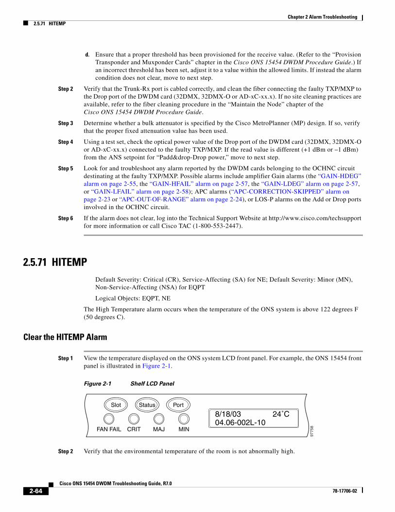
Chapter 2 Alarm Troubleshooting2.5.71 HITEMP
d. Ensure that a proper threshold has been provisioned for the receive value. (Refer to the “Provision Transponder and Muxponder Cards” chapter in the Cisco ONS 15454 DWDM Procedure Guide.) If an incorrect threshold has been set, adjust it to a value within the allowed limits. If instead the alarm condition does not clear, move to next step.
Step 2 Verify that the Trunk-Rx port is cabled correctly, and clean the fiber connecting the faulty TXP/MXP to the Drop port of the DWDM card (32DMX, 32DMX-O or AD-xC-xx.x). If no site cleaning practices are available, refer to the fiber cleaning procedure in the “Maintain the Node” chapter of the Cisco ONS 15454 DWDM Procedure Guide.
Step 3 Determine whether a bulk attenuator is specified by the Cisco MetroPlanner (MP) design. If so, verify that the proper fixed attenuation value has been used.
Step 4 Using a test set, check the optical power value of the Drop port of the DWDM card (32DMX, 32DMX-O or AD-xC-xx.x) connected to the faulty TXP/MXP. If the read value is different (+1 dBm or –1 dBm) from the ANS setpoint for “Padd&drop-Drop power,” move to next step.
Step 5 Look for and troubleshoot any alarm reported by the DWDM cards belonging to the OCHNC circuit destinating at the faulty TXP/MXP. Possible alarms include amplifier Gain alarms (the “GAIN-HDEG” alarm on page 2-55, the “GAIN-HFAIL” alarm on page 2-57, the “GAIN-LDEG” alarm on page 2-57, or “GAIN-LFAIL” alarm on page 2-58); APC alarms (“APC-CORRECTION-SKIPPED” alarm on page 2-23 or “APC-OUT-OF-RANGE” alarm on page 2-24), or LOS-P alarms on the Add or Drop ports involved in the OCHNC circuit.
Step 6 If the alarm does not clear, log into the Technical Support Website at http://www.cisco.com/techsupport for more information or call Cisco TAC (1-800-553-2447).
2.5.71 HITEMP Default Severity: Critical (CR), Service-Affecting (SA) for NE; Default Severity: Minor (MN), Non-Service-Affecting (NSA) for EQPT
Logical Objects: EQPT, NE
The High Temperature alarm occurs when the temperature of the ONS system is above 122 degrees F (50 degrees C).
Clear the HITEMP Alarm
Step 1 View the temperature displayed on the ONS system LCD front panel. For example, the ONS 15454 front panel is illustrated in Figure 2-1.
Figure 2-1 Shelf LCD Panel
Step 2 Verify that the environmental temperature of the room is not abnormally high.
FAN FAIL
Slot
8/18/0304.06-002L-10
24˚C
9775
8CRIT MAJ MIN
Status Port
2-64Cisco ONS 15454 DWDM Troubleshooting Guide, R7.0
78-17706-02
Chapter 2 Alarm Troubleshooting2.5.72 HI-TXPOWER
Step 3 If the room temperature is not abnormal, physically ensure that nothing prevents the fan-tray assembly from passing air through the ONS system shelf.
Step 4 If airflow is not blocked, physically ensure that blank faceplates fill the ONS system shelf empty slots. Blank faceplates help airflow.
Step 5 If faceplates fill the empty slots, determine whether the air filter needs replacement. Refer to the “Inspect, Clean, and Replace the Reusable Air Filter” procedure on page 2-176.
Step 6 If the fan does not run or the alarm persists, complete the “Replace the Fan-Tray Assembly” procedure on page 2-178.
Note The fan should run immediately when correctly inserted.
Step 7 If the replacement fan-tray assembly does not operate correctly, log into the Technical Support Website at http://www.cisco.com/techsupport for more information or call Cisco TAC to report a Service-Affecting (SA) problem (1-800-553-2447) if it applies to the NE, or a Non-Service-Affecting (NSA) problem if it applies to equipment.
2.5.72 HI-TXPOWER Default Severity: Minor (MN), Non-Service-Affecting (NSA)
Logical Objects: 2R, EQPT, ESCON, FC, GE, ISC, OCN/STMN, PPM, TRUNK
The Equipment High Transmit Power alarm is an indicator on the TXP_MR_E, TXP_MR_10G, TXP_MR_2.5G, TXPP_MR_2.5G, MXP_2.5G_10G, or OC192-XFP card transmitted optical signal power. HI-TXPOWER occurs when the measured optical power of the transmitted signal exceeds the threshold.
Note For general information about MXP and TXP cards and power levels, refer to the “Card Reference” chapter in the Cisco ONS 15454 DWDM Reference Manual. For information about provisioning them, refer to the “Provision Transponder and Muxponder Cards” chapter in the Cisco ONS 15454 DWDM Procedure Guide.
Clear the HI-TXPOWER Alarm
Step 1 Check the PM of the Trunk-Tx port. Verify that received power is above the optics threshold:
a. In node view (single-shelf mode) or shelf view (multishelf mode), double-click the card to display the card view.
b. For the Trunk-Tx port, double-click the card and click the Performance > Optics PM > Historical PM tabs, choose the port in the Port drop-down list, and click Refresh.
c. Compare the refreshed PM values with the threshold (ensuring that it is above the threshold value) by clicking the Performance > Optics PM > Current Values tabs.
d. Ensure that a proper threshold has been provisioned for the receive value. (Refer to the “Provision Transponder and Muxponder Cards” chapter in the Cisco ONS 15454 DWDM Procedure Guide.) If an incorrect threshold has been set, adjust it to a value within the allowed limits. If instead the alarm condition does not clear, move to next step.
2-65Cisco ONS 15454 DWDM Troubleshooting Guide, R7.0
78-17706-02
Chapter 2 Alarm Troubleshooting2.5.73 HLDOVRSYNC
Step 2 Physically verify, by using a standard power meter that the optical output power is overcoming the expected power threshold. If so, the card should be replaced at first opportunity
Note The higher power level is not a major issue for the DWDM card (32MUX-O, 32WSS-O, or AD-xC-xx.x) connected to the faulty TXP/MXP, because an internal VOA can automatically decrease the optical power to the expected level.
Step 3 Complete the “Physically Replace a Card” procedure on page 2-173.
Step 4 If the alarm does not clear after the replacement, log into the Technical Support Website at http://www.cisco.com/techsupport for more information or call Cisco TAC (1 800 553-2447) in order to report a Service-Affecting (SA) problem. If the alarm does not clear, log into the Technical Support Website at http://www.cisco.com/techsupport for more information or call Cisco TAC (1-800-553-2447).
2.5.73 HLDOVRSYNC Default Severity: Not Alarmed (NA), Non-Service-Affecting (NSA)
Logical Object: NE-SREF
The Holdover Synchronization Mode condition is caused by loss of the primary and second timing references in the node. Timing reference loss occurs when line coding on the timing input is different from the configuration on the node, and it often occurs during the selection of a new node reference clock. The condition clears when primary or second timing is reestablished. After the 24-hour holdover period expires, timing slips could begin to occur on an ONS system relying on an internal clock.
Clear the HLDOVRSYNC Condition
Step 1 Clear additional alarms that relate to timing, such as:
• 2.5.56 FRNGSYNC, page 2-55
• 2.5.57 FSTSYNC, page 2-55
• 2.5.86 LOF (BITS), page 2-76
• 2.5.95 LOS (BITS), page 2-83
• 2.5.118 MANSWTOINT, page 2-102
• 2.5.119 MANSWTOPRI, page 2-102
• 2.5.120 MANSWTOSEC, page 2-102
• 2.5.121 MANSWTOTHIRD, page 2-102
• 2.5.205 SWTOPRI, page 2-153
• 2.5.206 SWTOSEC, page 2-153
• 2.5.207 SWTOTHIRD, page 2-153
• 2.5.208 SYNC-FREQ, page 2-154
• 2.5.210 SYNCPRI, page 2-155
• 2.5.211 SYNCSEC, page 2-155
2-66Cisco ONS 15454 DWDM Troubleshooting Guide, R7.0
78-17706-02
Chapter 2 Alarm Troubleshooting2.5.74 I-HITEMP
• 2.5.212 SYNCTHIRD, page 2-156
Step 2 Reestablish a primary and secondary timing source according to local site practice. If none exists, refer to the “Turn Up the Network” chapter in the Cisco ONS 15454 DWDM Procedure Guide.
Step 3 If the condition does not clear, log into the Technical Support Website at http://www.cisco.com/techsupport for more information or call Cisco TAC (1-800-553-2447) in order to report a Service-Affecting (SA) problem.
2.5.74 I-HITEMP Default Severity: Critical (CR), Service-Affecting (SA)
Logical Object: NE
The Industrial High Temperature alarm occurs when the temperature of the ONS system is above 149 degrees F (65 degrees C) or below –40 degrees F (–40 degrees C). This alarm is similar to the HITEMP alarm but is used for the industrial environment. If this alarm is used, you can customize your alarm profile to ignore the lower-temperature HITEMP alarm.
Clear the I-HITEMP Alarm
Step 1 Complete the “Clear the HITEMP Alarm” procedure on page 2-64.
Step 2 If the alarm does not clear, log into the Technical Support Website at http://www.cisco.com/techsupport for more information or call TAC (1-800-553-2447) in order to report a Service-Affecting (SA) problem.
2.5.75 IMPROPRMVL Default Severity: Critical (CR), Service-Affecting (SA)
Logical Objects: EQPT, PPM
The Improper Removal (IMPROPRMVL) alarm occurs under the following conditions:
• A card is removed when the card was rebooting. It is recommended that after the card completely reboots, delete the card in CTC and only then remove the card physically. When you delete the card, CTC loses connection with the node view (single-shelf mode) or shelf view (multishelf mode), and goes to network view.
• When a card is deleted from CTC before physically removing the card from its slot. It is recommended that the card be physically removed from its slot before deleting it from CTC.
Note CTC provides the user approximately 15 seconds to physically remove the card before it begins rebooting the card.It can take up to 30 minutes for software to be updated on a standby TCC2/TCC2P card.
• A card is inserted into a slot but is not fully plugged into the backplane.
• A PPM (SFP) is provisioned but the physical module is not inserted into the port.
2-67Cisco ONS 15454 DWDM Troubleshooting Guide, R7.0
78-17706-02
Chapter 2 Alarm Troubleshooting2.5.75 IMPROPRMVL
• Removal of an SFP from the client ports of a Y-cable protection group card causes an IMPROPRMVL (PPM) alarm.
The working port raises the CR,IMPROPRMVL,SA alarm and the protected port raises the MN,IMPROPRMVL,NSA alarm. The severity on the client ports is changed according to the protection switch state.
For more information about protection schemes, refer to the “Manage the Node” chapter of the Cisco ONS 15454 DWDM Procedure Guide.
For more information about provisioning PPMs (SFPs), refer to the “Turn Up a Node” chapter of the Cisco ONS 15454 DWDM Procedure Guide. For specific PPM (SFP) values, refer to the “Hardware Specifications” appendix of the Cisco ONS 15454 DWDM Reference Manual.
• Electrical issues such as short circuit or failure of DC-DC conversion.
Clear the IMPROPRMVL Alarm
Step 1 In node view (single-shelf mode) or shelf view (multishelf mode), right-click the card reporting the IMPROPRMVL.
Step 2 Choose Delete from the shortcut menu.
Note CTC does not allow you to delete the reporting card if the card is in service, does have circuits mapped to it, is paired in a working protection scheme, has DCC enabled, or is used as a timing reference.
Step 3 If any ports on the card are in service, place them out of service (OOS,MT):
Caution Before placing a port out of service (OOS,MT) or OOS,DSBLD (or Locked,disabled), ensure that no live traffic is present.
a. In node view (single-shelf mode) or shelf view (multishelf mode), double-click the reporting card to open the card view.
b. Click the Provisioning > Line tabs.
c. Click the Admin State column of any in-service (IS) ports.
d. Choose OOS,MT (or Locked,maintenance) to take the ports out of service.
Step 4 If a circuit has been mapped to the card, complete the “Delete a Circuit” procedure on page 2-174.
Caution Before deleting the circuit, ensure that the circuit does not carry live traffic.
Step 5 If the card is paired in a protection scheme, delete the protection group by completing the following steps:
a. Click View > Go to Previous View to return to node view (single-shelf mode) or shelf view (multishelf mode).
b. If you are already in node view (single-shelf mode) or shelf view (multishelf mode), click the Provisioning > Protection tab.
c. Click the protection group of the reporting card.
2-68Cisco ONS 15454 DWDM Troubleshooting Guide, R7.0
78-17706-02

Chapter 2 Alarm Troubleshooting2.5.76 INCOMPATIBLE-SEND-PDIP
d. Click Delete.
Step 6 If the card is provisioned for DCC, delete the DCC provisioning by completing the following steps:
a. In node view (single-shelf mode) or multishelf view (multishelf mode), click the ONS system Provisioning > Comm Channels > SDCC (or Provisioning > Comm Channels > MS DCC) tabs.
b. Click the slots and ports listed in DCC terminations.
c. Click Delete and click Yes in the dialog box that appears.
Step 7 If the card is used as a timing reference, change the timing reference by completing the following steps:
a. In node view (single-shelf mode) or shelf view (multishelf mode), click the Provisioning > Timing > General tabs.
b. Under NE Reference, click the drop-down arrow for Ref-1.
c. Change Ref-1 from the listed OC-N/STM-N card to Internal Clock.
d. Click Apply.
Step 8 If the alarm does not clear, log into the Technical Support Website at http://www.cisco.com/techsupport for more information or call Cisco TAC (1-800-553-2447) in order to report a Service-Affecting (SA) problem.
2.5.76 INCOMPATIBLE-SEND-PDIPDefault Severity: Minor (MN), Non-Service-Affecting (NSA)
Logical Object: SYSTEM
The Incompatible Software alarm is raised when CTC’S send PDI-P provisioning differs from the host node's provisioning.
Clear the INCOMPATIBLE-SEND-PDIP Alarm
Step 1 Reconfigure CTC’s send PDI-P alarm capability to align with the host node settings.
Step 2 If the alarm does not clear, log into the Technical Support Website at http://www.cisco.com/techsupport for more information or call TAC (1-800-553-2447).
2.5.77 INCOMPATIBLE-SWDefault Severity: Minor (MN), Non-Service-Affecting (NSA)
Logical Object: SYSTEM
The Incompatible Software alarm is raised when CTC cannot connect to the NE due to differing, incompatible versions of software between CTC and the NE. The alarm is cleared by restarting CTC in order to redownload the CTC JAR files from the NE.
2-69Cisco ONS 15454 DWDM Troubleshooting Guide, R7.0
78-17706-02

Chapter 2 Alarm Troubleshooting2.5.78 INTRUSION-PSWD
Clear the INCOMPATIBLE-SW Alarm
Step 1 Restart the CTC application.
Step 2 If the alarm does not clear, log into the Technical Support Website at http://www.cisco.com/techsupport for more information or call TAC (1-800-553-2447).
2.5.78 INTRUSION-PSWD Default Severity: Not Alarmed (NA), Non-Service-Affecting (NSA)
Logical Object: NE
The Security Intrusion Incorrect Password condition occurs after a user attempts a provisionable (by Superuser) number of unsuccessful logins, a login with an expired password, or an invalid password. The alarmed user is locked out of the system, and INTRUSION-PSWD condition is raised. This condition is only shown in Superuser login sessions, not in login sessions for lower-level users. The INTRUSION-PSWD condition is automatically cleared when a provisionable lockout timeout expires, or it can be manually cleared in CTC by the Superuser if the lockout is permanent.
Clear the INTRUSION-PSWD Condition
Step 1 Log in as a user ID with superuser rights. (For more information about this, refer to the “Connect the PC and Log Into the GUI” chapter in the Cisco ONS 15454 DWDM Procedure Guide.)
Step 2 In node view (single-shelf mode) or multishelf view (multishelf mode), click the Provisioning > Security > Users tabs.
Step 3 Click Clear Security Intrusion Alarm.
Step 4 If the condition does not clear, log into the Technical Support Website at http://www.cisco.com/techsupport for more information or call Cisco TAC (1-800-553-2447).
2.5.79 INVMACADR Default Severity: Major (MJ), Non-Service Affecting (NSA)
Logical Object: AIP
The Equipment Failure Invalid MAC Address alarm occurs when the ONS system MAC address is invalid. Each ONS system has a unique, permanently assigned MAC address. The address resides on an AIP EEPROM. The TCC2/TCC2P reads the address value from the AIP chip during boot-up and keeps this value in its synchronous dynamic RAM (SDRAM).
Under normal circumstances, the read-only MAC address can be viewed in the node view (single-shelf mode) or multishelf view (multishelf mode) Provisioning > Network tab in CTC.
The ONS system uses both IP and MAC addresses for circuit routing. When an INVMACADR alarm exists on a node, you see a PARTIAL circuit in the CTC circuit status column. The circuit works and is able to carry traffic, but CTC cannot logically display the circuit end-to-end information.
2-70Cisco ONS 15454 DWDM Troubleshooting Guide, R7.0
78-17706-02

Chapter 2 Alarm Troubleshooting2.5.79 INVMACADR
An invalid MAC address can be caused when:
• There is a read error from the AIP during boot-up; in this case, the reading TCC2/TCC2P uses the default MAC address (00-10-cf-ff-ff-ff).
• There is a read error occurring on one of the redundant TCC2/TCC2Ps that read the address from the AIP; these cards read the address independently and could therefore each read different address values.
• An AIP component failure causes a read error.
• The ribbon cable connecting the AIP card to the backplane is bad.
Clear the INVMACADR Alarm
Step 1 Check for any outstanding alarms that were raised against the active and standby TCC2/TCC2P and resolve them.
Step 2 If the alarm does not clear, determine whether the LCD display on the fan tray (Figure 2-1 on page 2-64) is blank or if the text is garbled. If so, proceed to Step 8. If not, continue with Step 3.
Step 3 At the earliest maintenance window, reset the standby TCC2/TCC2P:
Note The reset requires approximately five minutes. Do not perform any other step until the reset is complete.
a. Log into a node on the network. If you are already logged in, continue with Step b.
b. Identify the active TCC2/TCC2P.
A green ACT/SBY LED indicates an active card. An amber ACT/SBY LED indicates a standby card.
c. In node view (single-shelf mode) or shelf view (multishelf mode), right-click the standby TCC2/TCC2P in CTC.
d. Choose Reset Card from the shortcut menu.
e. Click Yes in the Are You Sure dialog box.
The card resets, the FAIL LED blinks on the physical card, and connection to the node is lost. CTC switches to network view.
f. Verify that the reset is complete and error-free, and that no new related alarms appear in CTC. A green ACT/SBY LED indicates an active card. An amber ACT/SBY LED indicates a standby card.
g. Double-click the node and ensure that the reset TCC2/TCC2P is still in standby mode and that the other TCC2/TCC2P is active.
A green ACT/SBY LED indicates an active card. An amber ACT/SBY LED indicates a standby card.
h. Ensure that no new alarms associated with this reset appear in the CTC Alarms window.
If the standby TCC2/TCC2P fails to boot into standby mode and reloads continuously, the AIP is probably defective. In this case, the standby TCC2/TCC2P is unsuccessfully attempting to read the EEPROM located on the AIP. The TCC2/TCC2P reloads until it reads the EEPROM. Proceed to Step 8.
Step 4 If the standby TCC2/TCC2P rebooted successfully into standby mode, complete the “Remove and Reinsert (Reseat) the Standby TCC2/TCC2P Card” procedure on page 2-172.
Resetting the active TCC2/TCC2P causes the standby TCC2/TCC2P to become active. The standby TCC2/TCC2P keeps a copy of the chassis MAC address. If its stored MAC address is valid, the alarm should clear.
2-71Cisco ONS 15454 DWDM Troubleshooting Guide, R7.0
78-17706-02

Chapter 2 Alarm Troubleshooting2.5.80 LASER-APR
Step 5 After the reset, note whether or not the INVMACADR alarm has cleared or is still present.
Step 6 Complete the “Reset an Active TCC2/TCC2P Card and Activate the Standby Card” procedure on page 2-171 again to place the standby TCC2/TCC2P back into active mode.
After the reset, note whether or not the INVMACADR alarm has cleared or is still present. If the INVMACADR alarm remains standing through both TCC2/TCC2P resets, this indicates that the AIP is probably defective. Proceed to Step 8.
If the INVMACADR was raised during one TCC2/TCC2P reset and cleared during the other, the TCC2/TCC2P that was active while the alarm was raised needs to be replaced. Continue with Step 7.
Step 7 If the faulty TCC2/TCC2P is currently in standby mode, complete the “Physically Replace a Card” procedure on page 2-173 for this card. If the faulty TCC2/TCC2P is currently active, during the next available maintenance window complete the “Reset an Active TCC2/TCC2P Card and Activate the Standby Card” procedure on page 2-171 and then complete the “Physically Replace a Card” procedure on page 2-173.
Note If the replacement TCC2/TCC2P is loaded with a different software version from the current TCC2/TCC2P, the card boot-up could take up to 30 minutes. During this time, the card LEDs flicker between Fail and Act/Sby as the active TCC2/TCC2P version software is copied to the new standby card.
Step 8 Open a case with Cisco TAC (1 800 553-2447) for assistance with determining the node’s previous MAC address.
Step 9 Replace the ribbon cable between the system board and the AIP with a known-good cable.
Step 10 If the alarm persists, complete the “Replace an Alarm Interface Panel” procedure located in the “Alarm Troubleshooting” chapter of the Cisco ONS 15454 Troubleshooting Guide.
Step 11 If the alarm does not clear, log into the Technical Support Website at http://www.cisco.com/techsupport for more information or call Cisco TAC (1-800-553-2447).
2.5.80 LASER-APR Default Severity: Not Alarmed (NA), Non-Service-Affecting (NSA)
Logical Object: AOTS
The Laser Automatic Power Reduction (APR) alarm condition is raised by OSC-CSM, OSCM, OPT-BST, and OPT-PRE cards when the laser is working in power reduction mode. The condition clears as soon as safety conditions are released and the power value reaches the normal setpoint.
Warning Invisible laser radiation may be emitted from disconnected fibers or connectors. Do not stare into beams or view directly with optical instruments. Statement 1051.
Note Only inactivate the APR function temporarily for installation or maintenance reasons. Activate APR immediately after maintenance or installation.
2-72Cisco ONS 15454 DWDM Troubleshooting Guide, R7.0
78-17706-02

Chapter 2 Alarm Troubleshooting2.5.81 LASERBIAS-DEG
Note LASER-APR is an informational condition and does not require troubleshooting. For more information about optical amplifier APR, refer to the “Card Reference” chapter in the Cisco ONS 15454 DWDM Reference Manual.
2.5.81 LASERBIAS-DEG Default Severity: Minor (MN), Non-Service-Affecting (NSA)
Logical Objects: AOTS, OTS
The Laser Bias Current Degrade alarm occurs on an amplifier card (OPT-BST or OPT-PRE) when laser aging causes a degrade, but not failure, of laser transmission. The card should be replaced at the next opportunity.
Note For general information about optical amplifier cards, refer to the “Card Reference” chapter in the Cisco ONS 15454 DWDM Reference Manual. For information about changing their settings, refer to the “Change DWDM Card Settings” chapter in the Cisco ONS 15454 DWDM Procedure Guide.
Clear the LASERBIAS-DEG Alarm
Step 1 For the alarmed card, complete the “Physically Replace a Card” procedure on page 2-173 at the next opportunity.
Warning Invisible laser radiation may be emitted from the end of the unterminated fiber cable or connector. Do not view directly with optical instruments. Viewing the laser output with certain optical instruments (for example, eye loupes, magnifiers, and microscopes) within a distance of 100 mm may pose an eye hazard. Statement 1056
Note Before disconnecting any optical amplifier card fiber for troubleshooting, ensure that the optical amplifier card is unplugged.
Step 2 If the alarm does not clear, log into the Technical Support Website at http://www.cisco.com/techsupport for more information or call Cisco TAC (1-800-553-2447).
2.5.82 LASERBIAS-FAIL Default Severity: Major (MJ), Non-Service-Affecting (NSA)
Logical Object: AOTS
The Laser Bias Current Failure alarm occurs on an amplifier card (OPT-BST or OPT-PRE) when the laser control circuit fails or if the laser itself fails service. The card must be replaced to restore traffic.
2-73Cisco ONS 15454 DWDM Troubleshooting Guide, R7.0
78-17706-02
Chapter 2 Alarm Troubleshooting2.5.83 LASERTEMP-DEG
Note For general information about optical amplifier cards, refer to the “Card Reference” chapter in the Cisco ONS 15454 DWDM Reference Manual. For information about changing their settings, refer to the “Change DWDM Card Settings” chapter in the Cisco ONS 15454 DWDM Procedure Guide.
Clear the LASERBIAS-FAIL Alarm
Step 1 For the alarmed card, complete the “Physically Replace a Card” procedure on page 2-173.
Warning Invisible laser radiation may be emitted from the end of the unterminated fiber cable or connector. Do not view directly with optical instruments. Viewing the laser output with certain optical instruments (for example, eye loupes, magnifiers, and microscopes) within a distance of 100 mm may pose an eye hazard. Statement 1056
Note Before disconnecting any optical amplifier card fiber for troubleshooting, ensure that the optical amplifier card is unplugged.
Step 2 If the alarm does not clear, log into the Technical Support Website at http://www.cisco.com/techsupport for more information or call Cisco TAC (1-800-553-2447).
2.5.83 LASERTEMP-DEG Default Severity: Minor (MN), Non-Service-Affecting (NSA)
Logical Object: AOTS
The Laser Temperature Degrade alarm occurs when the Peltier control circuit fails on an amplifier card (OPT-BST or OPT-PRE). The Peltier control provides cooling for the amplifier. The card should be replaced at the next opportunity.
Note For general information about DWDM cards, refer to the “Card Reference” chapter in the Cisco ONS 15454 DWDM Reference Manual. For information about changing their settings, refer to the “Change DWDM Card Settings” chapter in the Cisco ONS 15454 DWDM Procedure Guide.
Clear the LASERTEMP-DEG Alarm
Step 1 For the alarmed DWDM card, complete the “Physically Replace a Card” procedure on page 2-173 at the next opportunity.
Warning Invisible laser radiation may be emitted from the end of the unterminated fiber cable or connector. Do not view directly with optical instruments. Viewing the laser output with certain optical instruments (for example, eye loupes, magnifiers, and microscopes) within a distance of 100 mm may pose an eye hazard. Statement 1056
2-74Cisco ONS 15454 DWDM Troubleshooting Guide, R7.0
78-17706-02
Chapter 2 Alarm Troubleshooting2.5.84 LOCKOUT-REQ (2R, EQPT, ESCON, FC, GE, ISC)
Note Before disconnecting any optical amplifier card fiber for troubleshooting, ensure that the optical amplifier card is unplugged.
Step 2 If the alarm does not clear, log into the Technical Support Website at http://www.cisco.com/techsupport for more information or call Cisco TAC (1-800-553-2447).
2.5.84 LOCKOUT-REQ (2R, EQPT, ESCON, FC, GE, ISC)Default Severity: Not Alarmed (NA), Non-Service-Affecting (NSA)
Logical Objects: 2R, EQPT, ESCON, FC, GE, ISC
The Lockout Switch Request on Facility or Equipment condition occurs in a Y-cable MXP or TXP client protection group for the above-listed clients when a user initiates a lockout switch request. The condition is raised when you lock traffic onto the working port with the Lock On command (thus locking it off the protect port), or you lock it off the protect port with the Lock Out command. In either case, the protect port will show “Lockout of Protection,” and the Conditions window will show the LOCKOUT-REQ condition.
A lockout prevents protection switching. Clearing the lockout again allows protection switching and clears the LOCKOUT-REQ condition.
Clear the LOCKOUT-REQ (2R, EQPT, ESCON, FC, GE, ISC) Condition
Step 1 Complete the “Clear a Lock-On or Lockout Command” procedure on page 2-170.
Step 2 If the condition does not clear, log into the Technical Support Website at http://www.cisco.com/techsupport for more information or call Cisco TAC (1-800-553-2447).
2.5.85 LOCKOUT-REQ (TRUNK)Default Severity: Not Alarmed (NA), Non-Service-Affecting (NSA)
Logical Object: TRUNK
The Lockout Switch Request on Facility or Equipment condition occurs in an MXP or TXP trunk port splitter protection group when you lock traffic onto the working port with the Lock On command (thus locking it off the protect port), or lock it off the protect port with the Lock Out command. In either case, the protect port will show “Lockout of Protection,” and the Conditions window will show the LOCKOUT-REQ condition.
A lockout prevents protection switching. Clearing the lockout again allows protection switching and clears the LOCKOUT-REQ condition.
Clear the LOCKOUT-REQ (TRUNK) Condition
Step 1 Complete the “Clear a Lock-On or Lockout Command” procedure on page 2-170.
2-75Cisco ONS 15454 DWDM Troubleshooting Guide, R7.0
78-17706-02

Chapter 2 Alarm Troubleshooting2.5.86 LOF (BITS)
Step 2 If the condition does not clear, log into the Technical Support Website at http://www.cisco.com/techsupport for more information or call Cisco TAC (1-800-553-2447).
2.5.86 LOF (BITS) Default Severity: Minor (MN), Non-Service-Affecting (NSA)
Logical Object: BITS
The Loss of Frame (LOF) BITS alarm occurs when a port on theTCC2/TCC2P BITS input detects an LOF on the incoming BITS timing reference signal. LOF indicates that the receiving ONS system has lost frame delineation in the incoming data.
Note The procedure assumes that the BITS timing reference signal is functioning properly. It also assumes the alarm is not appearing during node turn-up.
Clear the LOF (BITS) Alarm
Step 1 Verify that the line framing and line coding match between the BITS input and the TCC2/TCC2P:
a. In node or card view, note the slot and port reporting the alarm.
b. Find the coding and framing formats of the external BITS timing source. The formats should be in the user documentation for the external BITS timing source or on the timing source itself.
c. In node view (single-shelf mode) or shelf view (multishelf mode), click the Provisioning > Timing > BITS Facilities tabs.
d. Verify that the Coding setting matches the coding of the BITS timing source, either B8ZS or AMI.
e. If the coding does not match, click Coding and choose the appropriate coding from the drop-down list.
f. Verify that Framing matches the framing of the BITS timing source, either ESF or SF (D4).
g. If the framing does not match, click Framing and choose the appropriate framing from the drop-down list.
Note On the timing subtab, the B8ZS coding field is normally paired with ESF in the Framing field and the AMI coding field is normally paired with SF (D4) in the Framing field.
Step 2 If the alarm does not clear when the line framing and line coding match between the BITS input and the TCC2/TCC2P, complete the “Physically Replace a Card” procedure on page 2-173 for the TCC2/TCC2P.
Step 3 If the alarm does not clear, log into the Technical Support Website at http://www.cisco.com/techsupport for more information or call Cisco TAC (1-800-553-2447) in order to report a Service-Affecting (SA) problem.
2-76Cisco ONS 15454 DWDM Troubleshooting Guide, R7.0
78-17706-02
Chapter 2 Alarm Troubleshooting2.5.87 LOF (TRUNK)
2.5.87 LOF (TRUNK) Default Severity: Critical (CR), Service-Affecting (SA)
Logical Object: TRUNK
The Loss of Frame for the DWDM trunk applies to the trunk optical or electrical signal that is carried to TXP_MR_10G, TXP_MR_2.5G, TXPP_MR_2.5G, TXP_MR_10E, TXP_MR_10E_C, TXP_MR_10E_L, and MXP_2.5G_10G cards. It indicates that the receiving ONS system has lost frame delineation in the incoming data from trunk that serves the cards. LOF occurs when the SONET overhead loses a valid framing pattern for 3 milliseconds. Receiving two consecutive valid A1/A2 framing patterns clears the alarm.
Clear the LOF (TRUNK) Alarm
Step 1 Using site practices, verify fiber continuity to the port. Refer to the “Network Reference” chapter of the Cisco ONS 15454 DWDM Reference Manual for a procedure to detect a fiber cut.
Step 2 If the cabling is good, verify that the correct port is in service by completing the following steps:
a. Confirm that the LED is correctly illuminated on the physical card. A green ACT/SBY LED indicates an active card. An amber ACT/SBY LED indicates a standby card.
b. To determine whether the port is in service, in node view (single-shelf mode) or shelf view (multishelf mode), double-click the card in CTC to open the card view.
c. Click the Provisioning > Line tabs.
d. Verify that the Admin State column lists the port as IS (or Unlocked).
e. If the Admin State column lists the port as OOS,MT (or Locked,maintenance) or OOS,DSBLD (or Locked,disabled), click the column and choose IS , or Unlocked.
f. Click Apply.
Step 3 If the correct port is in service, clean the fiber according to site practice. If no site practice exists, complete the fiber cleaning procedure in the “Maintain the Node” chapter of the Cisco ONS 15454 DWDM Procedure Guide.
Step 4 If the alarm does not clear, verify that the power level of the optical signal is within the TXP or MXP card receiver specifications. (These specifications are listed in the “Hardware Specifications” appendix of the Cisco ONS 15454 DWDM Reference Manual.)
Step 5 If the optical power level is within specifications, use an optical test set to verify that a valid signal exists on the line. For specific procedures to use the test set equipment, consult the manufacturer. Test the line as close to the receiving card as possible.
Step 6 If a valid signal exists, replace the connector on the backplane.
Step 7 Repeat Steps 1 to 6 for any other port on the card reporting the LOF.
Step 8 If the alarm does not clear, look for and troubleshoot any other alarm that could identify the source of the problem.
Step 9 If no other alarms exist that could be the source of the LOF, or if clearing an alarm did not clear the LOF, complete the “Physically Replace a Card” procedure on page 2-173 for the reporting card.
Step 10 If the alarm does not clear, or if you need assistance conducting network troubleshooting tests, call Cisco TAC (1-800-553-2447) to report a Service-Affecting (SA) problem.
2-77Cisco ONS 15454 DWDM Troubleshooting Guide, R7.0
78-17706-02

Chapter 2 Alarm Troubleshooting2.5.88 LOGBUFR90
2.5.88 LOGBUFR90Default Severity: Minor (MN), Non-Service-Affecting (NSA)
Logical Object: SYSTEM
The Log Buffer Over 90 alarm indicates that the per-NE queue of incoming alarm, event, or update capacity of 5000 entries is over 90 percent full. LOGBUFR90 will clear if CTC recovers. If it does not clear, LOGBUFROVFL occurs.
Note LOGBUFR90 is an informational alarm and does not require troubleshooting.
2.5.89 LOGBUFROVFLDefault Severity: Minor (MN), Non-Service-Affecting (NSA)
Logical Object: SYSTEM
The Log Buffer Overflow alarm indicates that the CTC per-NE queue of incoming alarm, event, or updates, which has a capacity of 5,000 entries, has overflowed. This happens only very rarely. However if it does, you must restart the CTC session. It is likely that some updates will have been missed if this alarm occurs.
Clear the LOGBUFROVFL Alarm
Step 1 Restart the CTC session.
Step 2 If the alarm does not clear, log into the Technical Support Website at http://www.cisco.com/techsupport for more information or call TAC (1-800-553-2447).
2.5.90 LO-LASERBIAS Default Severity: Minor (MN), Non-Service-Affecting (NSA)
Logical Objects: EQPT, OCN/STMN, PPM
The Equipment Low Transmit Laser Bias Current alarm is raised against the TXP and MXP card laser performance. The alarm indicates that the card laser has reached the minimum laser bias tolerance.
If the LO-LASERBIAS alarm threshold is set at 0 percent (the default), the laser's usability has ended. If the threshold is set at 5 percent to 10 percent, the card is still usable for several weeks or months before you need to replace it.
Note For general information about MXP and TXP cards, refer to the “Card Reference” chapter in the Cisco ONS 15454 DWDM Reference Manual. For information about provisioning them, refer to the “Provision Transponder and Muxponder Cards” chapter in the Cisco ONS 15454 DWDM Procedure Guide.
2-78Cisco ONS 15454 DWDM Troubleshooting Guide, R7.0
78-17706-02

Chapter 2 Alarm Troubleshooting2.5.91 LO-LASERTEMP
Clear the LO-LASERBIAS Alarm
Step 1 Complete the “Physically Replace a Card” procedure on page 2-173.
Step 2 If the alarm does not clear, log into the Technical Support Website at http://www.cisco.com/techsupport for more information or call Cisco TAC (1-800-553-2447).
2.5.91 LO-LASERTEMP Default Severity: Minor (MN), Non-Service-Affecting (NSA)
Logical Objects: EQPT, OCN/STMN, PPM
The Equipment Low Laser Optical Transceiver Temperature alarm applies to the TXP and MXP cards. LO-LASERTEMP occurs when the internally measured transceiver temperature falls below the card setting by35.6 degrees F or 2 degrees C. A laser temperature change affects the transmitted wavelength. (This temperature is equivalent to about 200 picometers of wavelength.)
When the TXP or MXP card raises this alarm, the laser is automatically shut off. The An LOS for OCN/STMN is raised at the far-end node and the “DUP-IPADDR” alarm on page 2-39 is raised at the near end. (Both of these alarms are described in the “Alarm Troubleshooting” chapter of the Cisco ONS 15454 Troubleshooting Guide or the Cisco ONS 15454SDH Troubleshooting Guide). To verify the card laser temperature level, double-click the card in node view (single-shelf mode) or shelf view (multishelf mode) and click the Performance > Optics PM > Current Values tabs. Maximum, minimum, and average laser temperatures are shown in the Current column entries in the Laser Temp rows.
Note For general information about MXP and TXP cards, refer to the “Card Reference” chapter in the Cisco ONS 15454 DWDM Reference Manual. For information about provisioning them, refer to the “Provision Transponder and Muxponder Cards” chapter in the Cisco ONS 15454 DWDM Procedure Guide.
Clear the LO-LASERTEMP Alarm
Step 1 In node view (single-shelf mode) or shelf view (multishelf mode), complete the “Reset a Card in CTC” procedure on page 2-171 for the reporting MXP or TXP card.
Step 2 If the alarm does not clear, complete the “Physically Replace a Card” procedure on page 2-173 for the reporting MXP or TXP card.
Step 3 If the alarm does not clear, log into the Technical Support Website at http://www.cisco.com/techsupport for more information or call Cisco TAC (1-800-553-2447).
2.5.92 LOM Default Severity: Critical (CR), Service-Affecting (SA)
Logical Object: TRUNK
2-79Cisco ONS 15454 DWDM Troubleshooting Guide, R7.0
78-17706-02

Chapter 2 Alarm Troubleshooting2.5.93 LO-RXPOWER
The Optical Transport Unit (OTU) Loss of Multiframe alarm is an OTN alarm for the trunk port and occurs when the Multi Frame Alignment Signal (MFAS) is corrupted. The alarm applies to MXP_2.5G_10G, TXP_MR_10G, TXP_MR_2.5G, TXP_MR_10E, TXP_MR_10E_C, TXP_MR_10E_L, and TXPP_MR_2.5G cards when the MFAS) overhead field is errored for more than five frames and persists for more than 3 milliseconds.
Note For general information about MXP and TXP cards, refer to the “Card Reference” chapter in the Cisco ONS 15454 DWDM Reference Manual. For information about provisioning them, refer to the “Provision Transponder and Muxponder Cards” chapter in the Cisco ONS 15454 DWDM Procedure Guide.
Clear the LOM Alarm
Step 1 Ensure that the fiber connector for the card is completely plugged in. For more information about fiber connections and card insertion, refer to the “Turn Up a Node” chapter in the Cisco ONS 15454 DWDM Procedure Guide.
Step 2 If the bit error rate (BER) threshold is correct and at the expected level, use an optical test set to measure the power level of the line to ensure it is within guidelines. For specific procedures to use the test set equipment, consult the manufacturer.
Step 3 If the optical power level is good, verify that optical receive levels are within the acceptable range. Ranges for ONS 15454 DWDM cards are located in the “Hardware Specifications” appendix of the Cisco ONS 15454 DWDM Reference Manual.
Step 4 If receive levels are good, clean the fibers at both ends according to site practice. If no site practice exists, complete the fiber cleaning procedure in the “Maintain the Node” chapter in the Cisco ONS 15454 DWDM Procedure Guide.
Step 5 If the condition does not clear, verify that single-mode fiber is used.
Step 6 If the fiber is of the correct type, verify that a single-mode laser is used at the far-end node.
Step 7 Clean the fiber connectors at both ends for a signal degrade according to site practice.
Step 8 Verify that a single-mode laser is used at the far end.
Step 9 If the problem does not clear, the transmitter at the other end of the optical line could be failing and require replacement. Refer to the “2.8.3 Physical Card Reseating, Resetting, and Replacement” section on page 2-172.
Step 10 If the alarm does not clear, log into the Technical Support Website at http://www.cisco.com/techsupport for more information or call Cisco TAC (1-800-553-2447) in order to report a Service-Affecting (SA) problem.
2.5.93 LO-RXPOWER Default Severity: Minor (MN), Non-Service-Affecting (NSA)
Logical Objects: 2R, ESCON, FC, GE, ISC, OCN/STMN, TRUNK
2-80Cisco ONS 15454 DWDM Troubleshooting Guide, R7.0
78-17706-02
Chapter 2 Alarm Troubleshooting2.5.93 LO-RXPOWER
The Equipment Low Receive Power alarm is an indicator for TXP_MR_10G, TXP_MR_2.5G, TXPP_MR_2.5G, TXP_MR_10E, TXP_MR_10E_C, TXP_MR_10E_L, MXP_2.5G_10G and OC192-XFP card received optical signal power. LO-RXPOWER occurs when the measured optical power of the received signal falls below the threshold value, which is user-provisionable.
Note For general information about MXP and TXP cards and their necessary levels, refer to the “Card Reference” chapter and the “Hardware Specifications” appendix in the Cisco ONS 15454 DWDM Reference Manual.
Clear the LO-RXPOWER Alarm
Step 1 Check the PM of the TRUNK-RX port. Verify that received power is above the optics threshold:
a. In node view (single-shelf mode) or shelf view (multishelf mode), double-click the card to display the card view.
b. For the TRUNK-RX port, double-click the card and click the Performance > Optics PM > Historical PM tabs, choose the port in the Port drop-down list, and click Refresh.
c. Compare the refreshed PM values with the threshold (ensuring that they are above the threshold value) by clicking the Performance > Optics PM > Current Values tabs.
d. Ensure that a proper threshold has been provisioned for the receive value. (Refer to the “Provision Transponder and Muxponder Cards” chapter in the Cisco ONS 15454 DWDM Procedure Guide.) If an incorrect threshold has been set, adjust it to a value within the allowed limits. If instead the alarm condition does not clear, move to next step.
Step 2 Verify that the Trunk-Rx port is cabled correctly, and clean the fiber connecting the faulty TXP/MXP to the Drop port of the DWDM card (32DMX, 32DMX-O or AD-xC-xx.x). If no site cleaning practices are available, refer to the “Maintain the Node” chapter of the Cisco ONS 15454 DWDM Procedure Guide.
Step 3 Determine whether a bulk attenuator is specified by the Cisco MetroPlanner design. If so, verify that the proper fixed attenuation value has been used.
Step 4 Using a test set, check the optical power value of the Drop port of the DWDM card (32DMX, 32DMX-O or AD-xC-xx.x) connected to the faulty TXP/MXP. If the read value is different (+1 dBm or –1 dBm) from the ANS setpoint for “Padd&drop-Drop power,” move to next step. If not, complete the “Physically Replace a Card” section on page 2-173.
Step 5 Look for any alarm reported by the DWDM cards belonging to the OCHNC circuit whose destination is the faulty TXP/MXP and first troubleshoot that alarm. Possible alarm related include: amplifier Gain alarms (the “GAIN-HDEG” alarm on page 2-55, the “GAIN-HFAIL” alarm on page 2-57, the “GAIN-LDEG” alarm on page 2-57, or “GAIN-LFAIL” alarm on page 2-58); APC alarms (the “APC-CORRECTION-SKIPPED” alarm on page 2-23 or “APC-OUT-OF-RANGE” alarm on page 2-24), and LOS-P alarms on the Add or Drop ports belonging to the OCHNC circuit.
Step 6 If the alarm does not clear, log into the Technical Support Website at http://www.cisco.com/techsupport for more information or call Cisco TAC (1-800-553-2447).
2-81Cisco ONS 15454 DWDM Troubleshooting Guide, R7.0
78-17706-02
Chapter 2 Alarm Troubleshooting2.5.94 LOS (2R)
2.5.94 LOS (2R)Default Severity: Critical (CR), Service-Affecting (SA)
Logical Object: 2R
The Loss of Signal for a 2R client applies to TXP_MR_10G, TXP_MR_2.5G, TXPP_MR_2.5G, TXP_MR_10E, TXP_MR_10E_C, TXP_MR_10E_L, and MXP_2.5G_10G cards. The alarm is raised when the card port is not receiving input. An AIS is sent upstream.
Caution Always use the supplied electrostatic discharge wristband when working with a powered ONS system. Plug the wristband cable into the ESD jack located on the lower-right edge of the shelf assembly. To verify cable continuity, follow site practices.
Note For general information about MXP and TXP cards, refer to the “Card Reference” chapter in the Cisco ONS 15454 DWDM Reference Manual.
Clear the LOS (2R) Alarm
Step 1 Ensure that the signal entering the Client-Rx port is provisioned with the correct physical-layer protocol.
Step 2 Ensure that the signal feeding the Client-Rx port is provisioned with the correct line speed.
Step 3 Check the PM of the Client-Rx port.
Step 4 Verify that received power is above the optics threshold.
Step 5 Ensure that a proper threshold has been provisioned. (Refer to the “Provision Transponder and Muxponder Cards” chapter in the Cisco ONS 15454 DWDM Procedure Guide. Refer to the SFP/XFP plug-in specifications located in the “Hardware Specifications” appendix of the Cisco ONS 15454 DWDM Reference Manual.) If an incorrect threshold has been set, adjust it to a value within the allowed limits.
Step 6 Verify the proper cabling and clean the fibers according with the site practice. Cabling procedures are located in the “Turn Up a Node” chapter of the Cisco ONS 15454 DWDM Procedure Guide, and a fiber-cleaning procedure is located in the “Maintain the Node” chapter of the same guide.
Step 7 Verify using an optical test set that a valid signal exists on the line and feeds the Client-Rx port. (For specific procedures to use the test set equipment, consult the manufacturer.) Test the line as close to the receiving card as possible. If the alarm condition does not clear, move to next step.
Step 8 Complete the XFP/SFP installation procedure in the “Turn Up a Node” chapter of the Cisco ONS 15454 DWDM Procedure Guide or the “Physically Replace a Card” procedure on page 2-173 as appropriate for your purposes.
Step 9 If the alarm does not clear, log into the Technical Support Website at http://www.cisco.com/techsupport for more information or call Cisco TAC (1-800-553-2447) to report a Service-Affecting (SA) problem.
2.5.95 LOS (BITS) Default Severity: Minor (MN), Non-Service-Affecting (NSA)
2-82Cisco ONS 15454 DWDM Troubleshooting Guide, R7.0
78-17706-02

Chapter 2 Alarm Troubleshooting2.5.96 LOS (ESCON)
Logical Object: BITS
The LOS (BITS) alarm indicates that the TCC2/TCC2P has an LOS from the BITS timing source. LOS for BITS means the BITS clock or the connection to it failed.
Clear the LOS (BITS) Alarm
Caution Always use the supplied electrostatic discharge wristband when working with a powered ONS system. Plug the wristband cable into the ESD jack located on the lower-right edge of the shelf assembly.
Step 1 Verify the wiring connection from the BITS clock pin fields on the ONS system backplane to the timing source.
Step 2 If wiring is good, verify that the BITS clock is operating properly.
Step 3 If the alarm does not clear, log into the Technical Support Website at http://www.cisco.com/techsupport for more information or call Cisco TAC (1-800-553-2447) in order to report a Service-Affecting (SA) problem.
2.5.96 LOS (ESCON)Default Severity: Critical (CR), Service-Affecting (SA)
Logical Object: ESCON
The ESCON LOS alarm occurs on the TXP_MR_2.5G or TXPP_MR_2.5G card when there is a loss of signal for this payload, usually due to a physical error such as incorrect cabling connections, faulty cabling, or a break. It can also be caused by an incorrectly configured SFP.
Clear the LOS (ESCON) Alarm
Step 1 Check for any upstream equipment failures that could cause the ESCON LOS alarm in this node.
Step 2 If there is no cause upstream, verify cabling continuity from the transmitting port to the receiving port reporting this LOS. To verify cable continuity, follow site practices.
Caution Always use the supplied electrostatic discharge wristband when working with a powered ONS system. Plug the wristband cable into the ESD jack located on the lower-right edge of the shelf assembly.
Step 3 If the continuity is good, clean the fiber according to site practice. If none exists, complete the fiber-cleaning procedure in the “Maintain the Node” chapter in the Cisco ONS 15454 DWDM Procedure Guide.
Step 4 Ensure that the PPM (SFP) is correctly configured for this payload:
a. In node view (single-shelf mode) or shelf view (multishelf mode), double-click the card to open the card view.
b. Click the Provisioning > Pluggable Port Modules tabs.
c. Check the Pluggable Port Modules area for the PPM (SFP) associated with the port.
2-83Cisco ONS 15454 DWDM Troubleshooting Guide, R7.0
78-17706-02

Chapter 2 Alarm Troubleshooting2.5.97 LOS (ISC)
d. In the Pluggable Ports area, ensure that the rate for the errored PPM (SFP) is ESCON.
Note For information about provisioning PPMs (SFPs), refer to the “Turn Up a Node” chapter in the Cisco ONS 15454 DWDM Procedure Guide. PPM (SFP) specifications are listed in the “Hardware Specifications” appendix of the Cisco ONS 15454 DWDM Reference Manual.
Step 5 If the physical cabling and PPM (SFP) are good but the alarm does not clear, verify that the correct port is actually in service:
a. Confirm that the LED is correctly lit on the physical TXP card.
A green ACT/SBY LED indicates an active card. An amber ACT/SBY LED indicates a standby card.
b. To determine whether the port is in service, double-click the card in CTC to open the card view.
c. Click the Provisioning > Line tabs.
d. Verify that the Admin State column lists the port as IS (or Unlocked).
e. If the Admin State column lists the port as OOS,MT (or Locked,maintenance) or OOS,DSBLD (or Locked,disabled), click the column and choose IS , or Unlocked. Click Apply.
Step 6 If the correct port is in service but the alarm has not cleared, use an optical test set to confirm that a valid signal exists on the line. For specific procedures to use the test set equipment, consult the manufacturer. Test the line as close to the receiving card as possible.
Step 7 If the signal is valid, ensure that the transmit and receive outputs from the patch panel to your equipment are properly connected. For more information about fiber connections and terminations, refer to the “Turn Up a Node” chapter in the Cisco ONS 15454 DWDM Procedure Guide.
Step 8 If a valid signal exists but the alarm does not clear, replace the cable connector on the ONS system.
Step 9 Repeat Steps 2 through 6 for any other port on the card that reports the LOS (ESCON).
Step 10 If the alarm does not clear, the cabling could still be faulty despite correct attachments. Use the test set to locate the bad cable and replace it using the procedures in the “Manage the Node” chapter in the Cisco ONS 15454 DWDM Procedure Guide.
Step 11 If the alarm does not clear, look for any card-level alarm that could cause this port alarm.
Step 12 If the alarm does not clear, complete the “Physically Replace a Card” procedure on page 2-173 for the reporting card.
Step 13 If the alarm does not clear, log into the Technical Support Website at http://www.cisco.com/techsupport for more information or call Cisco TAC (1-800-553-2447) in order to report a Service-Affecting (SA) problem.
2.5.97 LOS (ISC)Default Severity: Critical (CR), Service-Affecting (SA)
Logical Object: ISC
The LOS alarm for the ISC port applies to TXPP_MR_2.5G or TXP_MR_2.5G client PPMs (SFPs) provisioned at the ISC port rate. Troubleshooting is similar to the LOS (2R) alarm.
2-84Cisco ONS 15454 DWDM Troubleshooting Guide, R7.0
78-17706-02
Chapter 2 Alarm Troubleshooting2.5.98 LOS (OTS)
Note For general information about MXP and TXP cards, refer to the “Card Reference” chapter in the Cisco ONS 15454 DWDM Reference Manual. For information about provisioning them, refer to the “Provision Transponder and Muxponder Cards” chapter in the Cisco ONS 15454 DWDM Procedure Guide.
Clear the LOS (ISC) Alarm
Caution Always use the supplied electrostatic discharge wristband when working with a powered ONS system. Plug the wristband cable into the ESD jack located on the lower-right edge of the shelf assembly.
Step 1 Complete the “Clear the LOS (2R) Alarm” procedure on page 2-82.
Step 2 If the alarm does not clear, log into the Technical Support Website at http://www.cisco.com/techsupport for more information or call Cisco TAC (1-800-553-2447) in order to report a Service-Affecting (SA) problem.
2.5.98 LOS (OTS) Default Severity: Critical (CR), Service-Affecting (SA)
Logical Object: OTS
The Loss of Signal for the OTS applies to the LINE-3-RX port of the OPT-BST amplifier and the LINE-2-RX port of the OSCM or OSC-CSM card. It indicates that a fiber cut has occurred and no power is being received from the span. The alarm is raised when both LOS-P and LOS-O alarms occur, and demotes them.
Clear the LOS (OTS) Alarm
Step 1 To troubleshoot this alarm, see the “1.12.1 Fiber Cut Detection” section on page 1-60.
Step 2 If the alarm does not clear, log into the Technical Support Website at http://www.cisco.com/techsupport for more information or call Cisco TAC (1-800-553-2447) in order to report a Service-Affecting (SA) problem.
2.5.99 LOS (TRUNK) Default Severity: Critical (CR), Service-Affecting (SA)
Logical Object: TRUNK
The Loss of Signal (LOS) for a TRUNK applies to TXP_MR_10G, TXP_MR_2.5G, TXPP_MR_2.5G, TXP_MR_10E, TXP_MR_10E_C, TXP_MR_10E_L, MXP_2.5G_10G, OPT-BST, OPT-BST-E, OPT-BST-L, and OSC-CSM cards.
2-85Cisco ONS 15454 DWDM Troubleshooting Guide, R7.0
78-17706-02

Chapter 2 Alarm Troubleshooting2.5.99 LOS (TRUNK)
Note The MXP_2.5G_10E card has no LOS (TRUNK) option, because G.709 cannot be disabled on the card.
The alarm is raised when the card port is not receiving input. An AIS is sent upstream.
The purpose of the LOS (TRUNK) alarm is to alert the user that no optical power is being received from the fiber. A typical fault condition signalled by the LOS (TRUNK) alarm is a fiber cut. In this case, neither the payload nor the overhead signals are being received.
Note With G.709 off, the alarm coming from the trunk is LOS (TRUNK) in accordance with SONET standards.
Note For general information about MXP and TXP cards, refer to the “Card Reference” chapter in the Cisco ONS 15454 DWDM Reference Manual. For information about provisioning them, refer to the “Provision Transponder and Muxponder Cards” chapter in the Cisco ONS 15454 DWDM Procedure Guide
Clear the LOS (TRUNK) Alarm
Step 1 Check the PMs of the TRUNK-RX port and verify that the received power is above the optics threshold.
Step 2 Check that a proper threshold has been provisioned. (For procedures, refer to the “Provision Transponder and Muxponder Cards” chapter in the Cisco ONS 15454 DWDM Procedure Guide.) If an incorrect threshold has been set, adjust it to a value within the allowed limits. If the alarm condition does not clear, move to next step.
Step 3 Verify the cabling of the Trunk-Rx port and clean the fiber connecting the faulty TXP/MXP to the Drop port of the DWDM card (32DMX, 32DMX-O or AD-xC-xx.x). For fiber cleaning procedures, refer to the “Maintain the Node” chapter of the Cisco ONS 15454 DWDM Procedure Guide.
Step 4 Using an optical test set, verify that a valid signal exists on the line and feeds the TRUNK-RX port.(For specific procedures to use the test set equipment, consult the manufacturer.) Test the line as close to the receiving card as possible. If the alarm condition does not clear, move to next step.
Step 5 Verify whether a bulk attenuator is specified in the Cisco MetroPlanner design. If so, verify that the proper fixed attenuation value has been used.
Step 6 Check the Drop port optical power value of the DWDM card (32DMX, 32DMX-O or AD-xC-xx.x) connected to the faulty TXP/MXP. If the read value is different (+1 dBm or –1 dBm) compared to the ANS setpoint “Padd&drop-Drop power,” move to next step. If not, complete the “Physically Replace a Card” procedure on page 2-173.
Step 7 If the alarm does not clear after the replacement, log into the Technical Support Website at http://www.cisco.com/techsupport for more information or call Cisco TAC (1 800 553-2447) in order to report a Service-Affecting (SA) problem.
Step 8 Look for and troubleshoot any alarms reported by the DWDM cards belonging to the OCHNC circuit whose destination is the faulty TXP/MXP. Possible alarms include: amplifier gain alarms (the “GAIN-HDEG” alarm on page 2-55, the “GAIN-HFAIL” alarm on page 2-57, the “GAIN-LDEG” alarm on page 2-57 or “GAIN-LFAIL” alarm on page 2-58); APC alarms (the “APC-CORRECTION-SKIPPED” alarm on page 2-23 and “APC-OUT-OF-RANGE” alarm on page 2-24), OR LOS-P alarms on the Add or Drop ports belonging to the OCHNC circuit.
2-86Cisco ONS 15454 DWDM Troubleshooting Guide, R7.0
78-17706-02

Chapter 2 Alarm Troubleshooting2.5.100 LOS-O
Step 9 If the alarm does not clear, log into the Technical Support Website at http://www.cisco.com/techsupport for more information or call Cisco TAC (1 800 553-2447) in order to report a Service-Affecting (SA) problem.
2.5.100 LOS-O Default Severity: Minor (MN), Non-Service-Affecting (NSA)
Logical Objects: OCH, OMS, OTS
The Incoming Overhead Loss of Signal alarm applies to the OSC-TX port of OPT-BST (LINE-1-RX), the OSC-RX internal optical port of OSC-CSM card (LINE-3-RX Port 3). It is raised when the monitored input power crosses the FAIL-LOW threshold associated to the OSC Power received. The is alarm is demoted if another LOS alarm is also present.
Clear the LOS-O Alarm
Step 1 Verify fiber continuity to the port by following site practices. Refer to the “Network Reference” chapter of the Cisco ONS 15454 DWDM Reference Manual for a procedure to detect a fiber cut.
Step 2 If the cabling is good, confirm that the LED is correctly illuminated on the physical card. A green ACT/SBY LED indicates an active card. A red ACT/SBY LED indicates a failed card.
Step 3 Display the optical thresholds by clicking one of the following tabs:
• For the OPT-BST card, click the Provisioning > Opt. Ampli. Line > Optics Thresholds tabs and click the Alarm checkbox in the Type panel.
• For the OSC-CSM cards, click the Provisioning > Optical Line > Optics Thresholds tabs.
Step 4 Verify that OSC Fail Low thresholds are correct according with Cisco MetroPlanner configuration file. To identify the MP value:
a. In node view (single-shelf mode) or shelf view (multishelf mode), click the Provisioning > WDM-ANS > Provisioning tabs.
b. Identify the following parameter: east or west side Rx channel OSC LOS threshold.
Step 5 If the port power is below the threshold, verify that OSC connections have been created on the other side of the span. If the connections are not present, refer to the “Provision Channels and Circuits” chapter of the Cisco ONS 15454 DWDM Procedure Guide for procedures.
Step 6 If OSC connections are present, check the OSC transmitted power using CTC on the far-end node. Refer to the “TurnUp Node” chapter of the Cisco ONS 15454 DWDM Procedure Guide for the proper procedure.
Step 7 If the transmitted OSC value is out of range, troubleshoot that problem first.
Step 8 If the OSC value is within range, come back to the port reporting the LOS-O alarm and clean the fiber according to site practice. If no site practice exists, complete the fiber-cleaning procedure in the “Maintain the Node” chapter of the Cisco ONS 15454 DWDM Procedure Guide.
Step 9 If the alarm does not clear, look for and troubleshoot any other alarm that could identify the source of the problem.
Step 10 If no other alarms exist that could be the source of the LOS-O, place all of the card ports in OOS,DSBLD (or Locked,disabled) administrative state.
2-87Cisco ONS 15454 DWDM Troubleshooting Guide, R7.0
78-17706-02
Chapter 2 Alarm Troubleshooting2.5.101 LOS-P (AOTS, OMS, OTS)
Step 11 Complete the “Physically Replace a Card” procedure on page 2-173 for the reporting card.
Step 12 If the alarm does not clear, log into the Technical Support Website at http://www.cisco.com/techsupport for more information or call Cisco TAC (1-800-553-2447).
2.5.101 LOS-P (AOTS, OMS, OTS) Default Severity: Critical (CR), Service-Affecting (SA)
Logical Objects: AOTS, OMS, OTS
The Loss of Signal for Optical Channel alarm (OMS and OTS layer) applies to all input ports of the following DWDM cards: AD-1B-xx.x, AD-4B-xx.x, 32DMX, 32DMX-O, OPT-PRE, OPT-BST, and OSC-CSM.
For AD-1C-xx.x, AD-2C-xx.x, AD-4C-xx.x, 32MUX-O and 32WSS cards, this alarm applies only to the input ports where an aggregate signal is managed, such as the COM-RX, EXP-RX, or xxBAND-RX ports). These ports are solely used for the AOTS, OMS, and OTS layers.
LOS-P (AOTS, OMS, or OTS) indicates a loss of receive signal, which means that the monitored input power value has crossed the Power Failure Low Threshold associated to the port.
Note When the LOS-P alarm is raised on the LINE-RX port of the OPT-BST or OSC-CSM card, it can indicate a fiber cut. Refer to the “Network Reference” chapter of the Cisco ONS 15454 DWDM Reference Manual for a fiber cut detection procedure.
Clear the LOS-P (AOTS, OMS, OTS) Alarm
Step 1 Verify that the card has the correct physical behavior by checking the LED on the physical card. A green ACT/SBY LED indicates an active card, and a red ACT/SBY LED indicates a failed card. If the LED is red, complete the “Physically Replace a Card” procedure on page 2-173 and continue to Step 7.
Note When you replace a card with an identical type of card, you do not need to make any changes to the database other than restoring the card’s port to the IS,AINS administrative state.
Step 2 Verify that there truly is a loss of input signal by completing the following steps:
a. In node view (single-shelf mode) or shelf view (multishelf mode), double-click the card to open the card view.
b. Verify the proper input power values by clicking one of the following tabs as appropriate:
• For the OPT-BST card, click the Provisioning > Optical Line > Parameters tabs.
• For the OPT-PRE card, click the Provisioning > Optical Line > Parameters tabs.
• For the AD-xC-xx.x card, click the Provisioning > Optical Line > Parameters tabs.
• For the AD-xB-xx.x card, click the Provisioning > Optical Band > Parameters tabs.
• For the 32MUX-O card, click the Provisioning > Optical Line > Parameters tabs.
• For the 32WSS card, click the Provisioning > Optical Line > Parameters tabs.
• For the 32DMX-O card, click the Provisioning > Optical Line > Parameters tabs.
2-88Cisco ONS 15454 DWDM Troubleshooting Guide, R7.0
78-17706-02

Chapter 2 Alarm Troubleshooting2.5.101 LOS-P (AOTS, OMS, OTS)
• For the 32DMX card, click the Provisioning > Optical Line > Parameters tabs.
• For the OSC-CSM card, click the Provisioning > Optical Line > Parameters tabs.
c. Display the proper Power Failure Low threshold by clicking one of the following tabs as appropriate:
• For the OPT-BST card, click the Provisioning > Optical Line > Optics Thresholds tabs.
• For the OPT-PRE card, click the Provisioning > Optical Line > Optics Thresholds tabs.
• For the AD-xC-xx.x card, click the Provisioning > Optical Line > Optics Thresholds tabs.
• For the AD-xB-xx.x card, click the Provisioning > Optical Band > Optics Thresholds tabs.
• For the AD-xB-xx.x card, click the Provisioning > Optical Line > Optics Thresholds tabs.
• For the 32MUX-O card, click the Provisioning > Optical Line > Optics Thresholds tabs.
• For the 32WSS card, click the Provisioning > Optical Line > Optics Thresholds tabs.
• For the 32DMX-O card, click the Provisioning > Optical Line > Optics Thresholds tabs.
• For the 32DMX card, click the Provisioning > Optical Line > Optics Thresholds tabs.
• For the OSC-CSM card, click the Provisioning > Optical Line > Optics Thresholds tabs.
Tip To view the alarm thresholds (as opposed to the warning thresholds), check the Alarm check box on the bottom-left of the Optics Thresholds tab and click Reset.
d. Compare the actual Power value with the Alarm Threshold value and complete one of the following actions:
• If the Power value is less than the Fail Low threshold, go to Step 3.
• If the Power value is greater than the Fail Low threshold plus the alarm hysteresis (allowance value) default of 1 dBm, complete the “Reset a Card in CTC” procedure on page 2-171 for the card.
If the alarm does not clear, complete the “Physically Replace a Card” procedure on page 2-173 and continue to Step 7.
Note When you replace a card with an identical type of card, you do not need to make any changes to the database other than restoring the card’s port to the IS,AINS administrative state.
Step 3 Verify the fiber continuity to the port by following site practices. Refer to the “Network Reference” chapter of the Cisco ONS 15454 DWDM Reference Manual for a procedure to detect a fiber cut.
Step 4 Check the “Internal Connections” file generated by Cisco MetroPlanner for the node where the errored card is located. If necessary, recable the node cabling in accordance with the MP file connections list. To cable a DWDM node, refer to the “Turn Up a Node” chapter in the Cisco ONS 15454 DWDM Procedure Guide.
Step 5 If the cabling is good, use an optical test set to measure the power value on the output port connected to the alarmed card. For specific procedures to use the test set equipment, consult the manufacturer. If the power difference reported is greater than 1 dBm (standard fiber jumper insertion loss is 0.3 dBm), clean the fiber according to site practice. If no site practice exists, complete the fiber-cleaning procedure in the “Maintain the Node” chapter of the Cisco ONS 15454 DWDM Procedure Guide.
2-89Cisco ONS 15454 DWDM Troubleshooting Guide, R7.0
78-17706-02

Chapter 2 Alarm Troubleshooting2.5.102 LOS-P (OCH)
Note Unplugging the fiber can cause a traffic hit. To avoid this, perform a traffic switch if possible. Refer to the “Manage the Node” chapter in the Cisco ONS 15454 DWDM Procedure Guide for detailed information.
Step 6 If the alarm does not clear, follow the general troubleshooting rules in the “Network Reference” chapter in the Cisco ONS 15454 DWDM Reference Manual for identifying any other upstream alarm in the logical signal flow that could be the root cause of the outstanding alarm.
Step 7 If the alarm does not clear, log into the Technical Support Website at http://www.cisco.com/techsupport for more information or call Cisco TAC (1-800-553-2447) in order to report a service-affecting problem.
2.5.102 LOS-P (OCH) Default Severity: Critical (CR), Service-Affecting (SA)
Logical Object: OCH
The Loss of Signal for Optical Channel alarm on the OCH layer applies to the channel Add or pass-through ports on the AD-1C-xx.x, AD-2C-xx.x, AD-4C-xx.x, 32MUX-O and 32WSS-O DWDM cards.
For the 32WSS-O, the LOS-P alarm can be associated with Add ports as well as pass-through internal ports. If the LOS-P (OCH) alarm is raised against this kind of port a different troubleshooting procedure is needed because the port does not have an optical power source directly connected to it. In this case, follow the general troubleshooting rules for network-level (inter-node) troubleshooting in Chapter 1, “General Troubleshooting,” to identify upstream alarms in the logical signal flow that could cause an LOS-P.
LOS-P (OCH) indicates a loss of received signal, which means the monitored input power value has crossed the Power Failure Low threshold associated with the port in accordance with the specific VOA power reference setpoint provisioned on VOA along the path.
Note For more information about provisioning VOA setpoints, refer to the “Network Reference” chapters of the Cisco ONS 15454 DWDM Reference Manual.
Clear the LOS-P (OCH) Alarm
Step 1 Verify that the card is exhibiting correct behavior by checking the LED behavior on the physical card. A green ACT/SBY LED indicates an active card, and a red ACT/SBY LED indicates a failed card. If the LED is red, complete the “Physically Replace a Card” procedure on page 2-173 and continue to Step 9.
Note When you replace a card with an identical type of card, you do not need to make any changes to the database other than restoring the card’s port to the IS,AINS administrative state.
Step 2 Verify that there truly is a loss of received signal by completing the following steps:
a. In node view (single-shelf mode) or shelf view (multishelf mode), double-click the card to open the card view.
2-90Cisco ONS 15454 DWDM Troubleshooting Guide, R7.0
78-17706-02
Chapter 2 Alarm Troubleshooting2.5.102 LOS-P (OCH)
b. View the proper input power values by clicking one of the following tabs as appropriate:
• For the AD-xC-xx.x card, click the Provisioning > Optical Chn > Parameters tabs.
• For the 32MUX-O card, click the Provisioning > Optical Chn > Parameters tabs.
• For the 32WSS-O card, click the Provisioning > Optical Chn: Optical Connector x > Parameters tabs.
c. Display the proper Power Failure Low threshold by clicking one of the following tabs as appropriate:
• For the AD-xC-xx.x card, click the Provisioning > Optical Chn > Optics Thresholds tabs.
• For the 32MUX-O card, click the Provisioning > Optical Chn > Optics Thresholds tabs.
• For the 32WSS-O card, click the Provisioning > Optical Chn: Optical Connector x > Optics Thresholds tabs.
Tip To view the alarm thresholds (as opposed to the warning thresholds), check the Alarm check box on the bottom-left of the Optics Thresholds tab and click Reset.
d. Compare the actual assigned Power value with the Alarm Threshold value and complete one of the following actions:
• If the Power value is less than the Fail Low threshold, go to Step 3.
• If the Power value is greater than the Fail Low threshold plus the alarm hysteresis (or allowance value) default of 1 dBm, complete the “Reset a Card in CTC” procedure on page 2-171 for the card.
If the alarm does not clear, complete the “Physically Replace a Card” procedure on page 2-173 and continue to Step 9.
Note When you replace a card with an identical type of card, you do not need to make any changes to the database other than restoring the card’s port to the IS,AINS administrative state.
Step 3 Verify the fiber continuity to the port using site practices. Refer to the “Network Reference” chapter of the Cisco ONS 15454 DWDM Reference Manual for a procedure to detect a fiber cut.
Step 4 Check the “Internal Connections” file generated by Cisco MetroPlanner for the node where the card is located. If necessary, recable the node in accordance with the MP file connections list. For procedures to cable a DWDM node, refer to the “Turn Up a Node” chapter of the Cisco ONS 15454 DWDM Procedure Guide.
Step 5 If the cabling is good, verify that each involved optical signal source, including TXP, MXP or ITU-T line card trunk transmit ports, is in the IS (or Unlocked) administrative state. To do this, click the following tabs as appropriate:
• For the TXP_MR_10G card, click the Provisioning > Line > SONET (or Provisioning > Line > SDH) tabs.
• For the TXP_MR_10E card, click the Provisioning > Line > SONET (or Provisioning > Line > SDH) tabs.
• For the TXP_MR_2.5G card, click the Provisioning > Line > SONET (or Provisioning > Line > SDH) tabs.
• For the TXPP_MR_2.5G card, click the Provisioning > Line > SONET (or Provisioning > Line > SDH) tabs.
2-91Cisco ONS 15454 DWDM Troubleshooting Guide, R7.0
78-17706-02

Chapter 2 Alarm Troubleshooting2.5.102 LOS-P (OCH)
• For the MXP_MR_2.5G card, click the Provisioning > Line > SONET (or Provisioning > Line > SDH) tabs.
• For the MXPP_MR_2.5G card, click the Provisioning > Line > SONET (or Provisioning > Line > SDH) tabs.
• For the MXP_2.5G_10E card, click the Provisioning > Line > Trunk tabs.
• For the MXP_2.5G_10G card, click the Provisioning > Line > SONET (or Provisioning > Line > SDH) tabs.
If the port administrative state is not IS (or Unlocked), choose IS , or Unlocked, from the Admin state drop-down list. If the alarm does not clear, continue with Step 9.
Note If the LOS-P (OCH) alarm applies to a 32WSS-O passthrough port, it means that a single optical source is not directly connected to the port. In this case, follow the general troubleshooting rules given in “Network Level (Internode) Troubleshooting” to identify any other alarm upstream to the logical signal flow that could be the root cause for the outstanding alarm.
Step 6 If the signal source is in IS (or Unlocked) administrative state, use an optical test set to verify that the transmit laser is active. For specific procedures to use the test set equipment, consult the manufacturer.
Step 7 If the laser is active, compare the card’s provisioned transmit optical power value with the expected range in the “Provision Transponder and Muxponder Cards” chapter of the Cisco ONS 15454 DWDM Procedure Guide. To display the provisioned transmit optical power values, click the following tabs as appropriate:
• For the TXP_MR_10G card, click the Performance > Optics PM > Current Values > Trunk Port tabs.
• For the TXP_MR_10E card, click the Performance > Optics PM > Current Values > Trunk Port tabs.
• For the MXP_2.5G_10E card, click the Performance > Optics PM > Current Values > Trunk Port tabs.
• For the MXP_2.5G_10G card, click the Performance > Optics PM > Current Values > Trunk Port tabs.
Step 8 Use a standard power meter to measure actual transmit optical power for the following cards as applicable:
• TXP_MR_2.5G
• TXPP_MR_2.5G
• MXP_MR_2.5G
• MXPP_MR_2.5G
• Every ITU-T line card
If the tested optical transmit optical power is within the expected range, go to Step 9. If the actual power value is outside the specification range, complete the “Physically Replace a Card” procedure on page 2-173. (These are listed in the “Hardware Specifications” appendix of the Cisco ONS 15454 DWDM Reference Manual.) When the newly installed card becomes active, verify that the LOS-P (OCH) alarm clears. If it does not, continue with Step 9.
2-92Cisco ONS 15454 DWDM Troubleshooting Guide, R7.0
78-17706-02
Chapter 2 Alarm Troubleshooting2.5.103 LOS-P (TRUNK)
Tip If a spare card is unavailable and the transmit power still functions, you can temporarily clear the LOS-P alarm by following the general procedure to add path VOAs during startup failure as noted in the “Perform Node Acceptance Tests” chapter of the Cisco ONS 15454 DWDM Procedure Guide. For more information about provisioning VOA setpoints, refer to the “Network Reference” chapter of the Cisco ONS 15454 DWDM Reference Manual.
Step 9 If the power is within the expected range, return to the port that reported LOS-P and clean the alarmed port’s fiber according to site practice. If no site practice exists, complete the procedure in the “Maintain the Node” chapter of the Cisco ONS 15454 DWDM Procedure Guide.
Note Unplugging the fiber can cause a traffic hit. To avoid this, perform a traffic switch if possible. Refer to the “2.8.1 Protection Switching, Lock Initiation, and Clearing” section on page 2-168 for basic instructions, or refer to the “Manage the Node” chapter in the Cisco ONS 15454 DWDM Procedure Guide for more detailed information.
Step 10 If the alarm does not clear, add path VOAs during startup failure as noted in the “Perform Node Acceptance Tests” chapter of the Cisco ONS 15454 DWDM Procedure Guide to remedy the problem.
Step 11 If the alarm does not clear, log into the Technical Support Website at http://www.cisco.com/techsupport for more information or call Cisco TAC (1-800-553-2447) in order to report a service-affecting problem.
2.5.103 LOS-P (TRUNK) Default Severity: Critical (CR), Service-Affecting (SA)
Logical Object: TRUNK
The Loss of Signal Payload (LOS-P) alarm for the trunk layer indicates that the incoming payload signal is absent at the input trunk port. There still may be optical power on the fiber, but the payload data is missing. This alarm applies to the following cards: TXP_MR_10G, TXP_MR_10E, MXP_2.5G_10G, TXP_MR_2.5G, TXPP_MR_2.5G, MXP_MR_2.5G, MXPP_MR_2.5G, OPT-BST, OPT-BST-E, OPT-BST-L, OPT-AMP-L, OPT-PRE, 32MUX-O, 32DMX-O, AD-xB, AD-xC, 4MD-xx.x, OSCM, OSC-CSM, and every ITU-T line card.
Note The MXP_2.5G_10E has no LOS-P (TRUNK) option, because ITU-T G.709 encapsulation on the card cannot be disabled.
Note With ITU-T G.709 encapsulation on, the alarm coming from the trunk is LOS-P (TRUNK) in accordance with the OTN standards.
Clear the LOS-P (TRUNK) Alarm
Step 1 Verify that the card behaves correctly by checking the LED behavior on the physical card. A green ACT/SBY LED indicates an active card, and a red ACT/SBY LED indicates a failed card. If the LED is red, complete the “Physically Replace a Card” procedure on page 2-173 and continue to Step 7.
2-93Cisco ONS 15454 DWDM Troubleshooting Guide, R7.0
78-17706-02
Chapter 2 Alarm Troubleshooting2.5.103 LOS-P (TRUNK)
Note When you replace a card with an identical type of card, you do not need to make any changes to the database other than restoring the card’s port to the IS,AINS administrative state.
Step 2 Verify that there truly is a loss of received optical power by completing the following steps:
a. In node view (single-shelf mode) or shelf view (multishelf mode), double-click the alarmed card to open the card view.
b. Click the Performance > Optics PM > Current Values > Trunk Port tabs and view the RX Optical Pwr value.
c. Compare the actual power levels with the expected power range given in the “Hardware Specifications” appendix of the Cisco ONS 15454 DWDM Reference Manual. Complete one of the following actions:
• If power is higher than –40 dBm (that is, –20 dBm, –1 dBm, 0 dBm or 10 dBm) and within the accepted range go to Step 4.
• or if the power is lower than –40 dBm (that is, –40 dBm, –45 dBm or –50 dBm) complete the “Reset a Card in CTC” procedure on page 2-171 for the card.
Step 3 If the alarm does not clear, complete the “Physically Replace a Card” procedure on page 2-173 for the reporting card and then go to Step 9.
Note When you replace a card with an identical type of card, you do not need to make any changes to the database other than restoring the card’s port to the IS,AINS administrative state.
Step 4 Verify the fiber continuity to the port by following site practices. Refer to the “Network Reference” chapter of the Cisco ONS 15454 DWDM Reference Manual for a procedure to detect a fiber cut.
Step 5 Check the “Internal Connections” file generated by Cisco MetroPlanner for the node containing the alarmed card. If necessary, recable the node in accordance with the MP file connections list. For procedures to cable a DWDM node, refer to the “Turn Up a Node” chapter of the Cisco ONS 15454 DWDM Procedure Guide.
Step 6 If the cabling is good, use a test set to verify the power value on the DWDM CH_DROP-TX port on the AD-xC-xx.x, 32DMX-O, or 32DMX. For specific procedures to use the test set equipment, consult the manufacturer.
Step 7 If the power difference reported is greater than 1 dBm (standard fiber jumper insertion loss is 0.3 dBm), clean the fiber according to site practice. If no site practice exists, complete the procedure in the “Maintain the Node” chapter of the Cisco ONS 15454 DWDM Procedure Guide.
Note Unplugging the fiber can cause a traffic hit. To avoid this, perform a traffic switch if possible. Refer to the “2.8.1 Protection Switching, Lock Initiation, and Clearing” section on page 2-168 for basic instructions, or to the “Manage the Node” chapter in the Cisco ONS 15454 DWDM Procedure Guide for more detailed information.
Step 8 If the alarm does not clear, follow the general troubleshooting rules stated in the “Network Reference” chapter of the Cisco ONS 15454 DWDM Reference Manual to identify upstream alarms in the logical signal flow that could cause an LOS-P.
2-94Cisco ONS 15454 DWDM Troubleshooting Guide, R7.0
78-17706-02
Chapter 2 Alarm Troubleshooting2.5.104 LO-TXPOWER
Step 9 If the alarm does not clear, log into the Technical Support Website at http://www.cisco.com/techsupport for more information or call Cisco TAC (1-800-553-2447) in order to report a service-affecting problem.
2.5.104 LO-TXPOWER Default Severity: Minor (MN), Non-Service-Affecting (NSA)
Logical Objects: 2R, EQPT, ESCON, FC, GE, ISC, OCN/STMN, PPM, TRUNK
The Equipment Low Transmit Power alarm is an indicator for the TXP_MR_10G, TXP_MR_2.5G, TXPP_MR_2.5G, TXP_MR_10E, TXP_MR_10E_C, TXP_MR_10E_L, MXP_2.5G_10G and OC192-XFP card transmitted optical signal power. LO-TXPOWER occurs when the measured optical power of the transmitted signal falls under the threshold. The threshold value is user-provisionable.
Note For more information about MXP and TXP cards and their power levels, refer to the “Card Reference” in the Cisco ONS 15454 DWDM Reference Manual. For information about provisioning them, refer to the “Provision Transponder and Muxponder Cards” chapter in the Cisco ONS 15454 DWDM Procedure Guide.
Clear the LO-TXPOWER Alarm
Step 1 In node view (single-shelf mode) or single-shelf view (multishelf mode), display the TXP_MR_10G, TXP_MR_2.5G, TXPP_MR_2.5G, TXP_MR_10E, TXP_MR_10E_C, TXP_MR_10E_L, MXP_2.5G_10G, or OC192-XFP card view.
Step 2 Click the Provisioning > Optics Thresholds > Current Values tabs.
Step 3 Increase the TX Power Low column value by 0.5 dBm.
Step 4 If the card transmit power setting cannot be increased without affecting the signal, complete the “Physically Replace a Card” procedure on page 2-173.
Step 5 If no ports are shown bad and the alarm does not clear, log into the Technical Support Website at http://www.cisco.com/techsupport for more information or call Cisco TAC (1-800-553-2447).
2.5.105 LPBKFACILITY (ESCON) Default Severity: Not Alarmed (NA), Non-Service-Affecting (NSA)
Logical Object: ESCON
The LPBKFACILITY (ESCON) condition occurs on a TXP_MR_2.5G or TXPP_MR_2.5G card PPM (SFP) provisioned for FICON1G or FICON 2G line speed when there is a facility loopback active on the card.
For information about troubleshooting these circuits with loopbacks, refer to the “1.2 Troubleshooting MXP or TXP Circuit Paths With Loopbacks” section on page 1-7.
2-95Cisco ONS 15454 DWDM Troubleshooting Guide, R7.0
78-17706-02
Chapter 2 Alarm Troubleshooting2.5.106 LPBKFACILITY (FC)
Clear the LPBKFACILITY (ESCON) Condition
Step 1 Complete the “Clear an MXP or TXP Card Loopback Circuit” procedure on page 2-175.
Step 2 If the alarm does not clear, or if you need assistance conducting network troubleshooting tests, call Cisco TAC to report a Service-Affecting (SA) problem (1-800-553-2447).
2.5.106 LPBKFACILITY (FC) Default Severity: Not Alarmed (NA), Non-Service-Affecting (NSA)
Logical Object: FC
A Loopback Facility condition for the FC payload occurs on a fibre channel (FC) line when a software facility (line) loopback is active for an MXPP_MR_2.5G, MXP_MR_2.5G, TXPP_MR_2.5G, and TXP_MR_2.5G card client PPM (SFP) provisioned at the FC1G, FC2G, FICON1G, or FICON 2G line speed.
For information about troubleshooting these circuits with loopbacks, refer to the “1.2 Troubleshooting MXP or TXP Circuit Paths With Loopbacks” section on page 1-7.
Note For more information about MXP and TXP cards, refer to the “Card Reference” chapter in the Cisco ONS 15454 DWDM Reference Manual. For information about provisioning them, refer to the “Provisioning Tranponder and Muxponder Cards” chapter in the Cisco ONS 15454 DWDM Procedure Guide.
Clear the LPBKFACILITY (FC) Condition
Step 1 Complete the “Clear an MXP or TXP Card Loopback Circuit” procedure on page 2-175.
Step 2 If the condition does not clear, log into the Technical Support Website at http://www.cisco.com/techsupport for more information or call Cisco TAC (1-800-553-2447).
2.5.107 LPBKFACILITY (GE) Default Severity: Not Alarmed (NA), Non-Service-Affecting (NSA)
Logical Object: GE
A Loopback Facility condition for a Gigabit Ethernet (GE) port occurs when a software facility (line) loopback is active for an MXP_MR_2.5G, MXPP_MR_2.5G, TXP_MR_2.5G, and TXPP_MR_2.5G card client PPM (SFP) provisioned at the ONE_GE port rate. For the TXP_MR_10E and TXP_MR_10G cards, this condition occurs when there is a facility loopback on a client PPM (SFP) provisioned at the TEN_GE port rate.
For information about troubleshooting these circuits with loopbacks, refer to the “1.2 Troubleshooting MXP or TXP Circuit Paths With Loopbacks” section on page 1-7.
2-96Cisco ONS 15454 DWDM Troubleshooting Guide, R7.0
78-17706-02

Chapter 2 Alarm Troubleshooting2.5.108 LPBKFACILITY (ISC)
Note For more information about MXP and TXP cards, refer to the “Card Reference” chapter in the Cisco ONS 15454 DWDM Reference Manual. For information about provisioning them, refer to the “Provision Transponder and Muponder Cards” chapter in the Cisco ONS 15454 DWDM Procedure Guide.
Clear the LPBKFACILITY (GE) Condition
Step 1 Complete the “Clear an MXP or TXP Card Loopback Circuit” procedure on page 2-175.
Step 2 If the condition does not clear, log into the Technical Support Website at http://www.cisco.com/techsupport for more information or call Cisco TAC (1-800-553-2447).
2.5.108 LPBKFACILITY (ISC) Default Severity: Not Alarmed (NA), Non-Service-Affecting (NSA)
Logical Object: ISC
A Loopback Facility condition for an ISC port occurs when a software facility (line) loopback is active for a TXPP_MR_2.5G or TXP_MR_2.5G client PPM (SFP) provisioned at the ISC port rate.
For information about troubleshooting these circuits with loopbacks, refer to the “1.2 Troubleshooting MXP or TXP Circuit Paths With Loopbacks” section on page 1-7.
Note For more information about MXP and TXP cards, refer to the “Card Reference” chapter in the Cisco ONS 15454 DWDM Reference Manual. For information about provisioning them, refer to the “Provision Transponder and Muxponder Cards” chapter in the Cisco ONS 15454 DWDM Procedure Guide.
Clear the LPBKFACILITY (ISC) Condition
Step 1 Complete the “Clear an MXP or TXP Card Loopback Circuit” procedure on page 2-175.
Step 2 If the condition does not clear, log into the Technical Support Website at http://www.cisco.com/techsupport for more information or call Cisco TAC (1-800-553-2447).
2.5.109 LPBKFACILITY (TRUNK) Default Severity: Not Alarmed (NA), Non-Service Affecting (NSA)
Logical Object: TRUNK
A Loopback Facility condition on MXP and TXP card trunk ports indicates that there is an active facility (line) loopback on the port. For this condition to be present, the administrative state is OOS,MT (or Locked,maintenance).
2-97Cisco ONS 15454 DWDM Troubleshooting Guide, R7.0
78-17706-02

Chapter 2 Alarm Troubleshooting2.5.110 LPBKTERMINAL (ESCON)
For information about troubleshooting these circuits with loopbacks, refer to the “1.2 Troubleshooting MXP or TXP Circuit Paths With Loopbacks” section on page 1-7.
Caution CTC permits loopbacks on an in-service (IS) circuit. Loopbacks are service-affecting.
Clear the LPBKFACILITY (TRUNK) Condition
Step 1 Complete the “Clear an MXP or TXP Card Loopback Circuit” procedure on page 2-175.
Step 2 If the condition does not clear, log into the Technical Support Website at http://www.cisco.com/techsupport for more information or call Cisco TAC (1-800-553-2447).
2.5.110 LPBKTERMINAL (ESCON) Default Severity: Not Alarmed (NA), Non-Service-Affecting (NSA)
Logical Object: ESCON
The LPBKTERMINAL (ESCON) condition occurs on a TXP_MR_2.5G or TXPP_MR_2.5G card PPM (SFP) provisioned for FICON1G or FICON 2G line speed when there is a terminal loopback active on the card.
For information about troubleshooting these circuits with loopbacks, refer to the “1.2 Troubleshooting MXP or TXP Circuit Paths With Loopbacks” section on page 1-7.
Clear the LPBKTERMINAL (ESCON) Condition
Step 1 Complete the “Clear an MXP or TXP Card Loopback Circuit” procedure on page 2-175.
Step 2 If the alarm does not clear, or if you need assistance conducting network troubleshooting tests, call Cisco TAC to report a Service-Affecting (SA) problem (1-800-553-2447).
2.5.111 LPBKTERMINAL (FC) Default Severity: Not Alarmed (NA), Non-Service-Affecting (NSA)
Logical Object: FC
A Loopback Terminal condition for the FC payload occurs on an FC when a software terminal (inward) loopback is active for an MXP_MR_2.5G, MXPP_MR_2.5G, TXP_MR_2.5G, and TXPP_MR_2.5G card client PPM (SFP) provisioned at the FC1G, FC2G, FICON1G, or FICON2G line speed.
For information about troubleshooting these circuits with loopbacks, refer to the “1.2 Troubleshooting MXP or TXP Circuit Paths With Loopbacks” section on page 1-7.
2-98Cisco ONS 15454 DWDM Troubleshooting Guide, R7.0
78-17706-02
Chapter 2 Alarm Troubleshooting2.5.112 LPBKTERMINAL (GE)
Note For more information about MXP and TXP cards, refer to the “Card Reference” chapter in the Cisco ONS 15454 DWDM Reference Manual. For information about provisioning them, refer to the “Provisioning Transponder and Muxponder Cards” chapter in the Cisco ONS 15454 DWDM Procedure Guide.
Clear the LPBKTERMINAL (FC) Condition
Step 1 Complete the “Clear an MXP or TXP Card Loopback Circuit” procedure on page 2-175.
Step 2 If the condition does not clear, log into the Technical Support Website at http://www.cisco.com/techsupport for more information or call Cisco TAC (1-800-553-2447).
2.5.112 LPBKTERMINAL (GE) Default Severity: Not Alarmed (NA), Non-Service-Affecting (NSA)
Logical Object: GE
A Loopback Terminal condition for a GE port occurs when a software terminal (inward) loopback is active for an MXP_MR_2.5G, MXPP_MR_2.5G, TXP_MR_2.5G, and TXPP_MR_2.5G card client PPM (SFP) provisioned at the ONE_GE port rate. For the TXP_MR_10E and TXP_MR_10G cards, this condition occurs when there is a facility loopback on a client PPM (SFP) provisioned at the TEN_GE port rate.
For information about troubleshooting these circuits with loopbacks, refer to the “1.2 Troubleshooting MXP or TXP Circuit Paths With Loopbacks” section on page 1-7.
Note For more information about MXP and TXP cards, refer to the “Card Reference” chapter in the Cisco ONS 15454 DWDM Reference Manual. For information about provisioning them, refer to the “Provision Transponder and Muxponder Cards” chapter in the Cisco ONS 15454 DWDM Procedure Guide.
Clear the LPBKTERMINAL (GE) Condition
Step 1 Complete the “Clear an MXP or TXP Card Loopback Circuit” procedure on page 2-175.
Step 2 If the condition does not clear, log into the Technical Support Website at http://www.cisco.com/techsupport for more information or call Cisco TAC (1-800-553-2447).
2.5.113 LPBKTERMINAL (ISC) Default Severity: Not Alarmed (NA), Non-Service-Affecting (NSA)
Logical Object: ISC
2-99Cisco ONS 15454 DWDM Troubleshooting Guide, R7.0
78-17706-02

Chapter 2 Alarm Troubleshooting2.5.114 LPBKTERMINAL (TRUNK)
A Loopback Terminal condition for an ISC port occurs when a software terminal (inward) loopback is active for a TXPP_MR_2.5G or TXP_MR_2.5G client PPM (SFP) provisioned at the ISC port rate.
For information about troubleshooting these circuits with loopbacks, refer to the “1.2 Troubleshooting MXP or TXP Circuit Paths With Loopbacks” section on page 1-7.
Note For more information about MXP and TXP cards, refer to the “Card Reference” chapter in the Cisco ONS 15454 DWDM Reference Manualand “Provisioning Transponder and Muxponder Cards” chapter in the Cisco ONS 15454 DWDM Procedure Guide.
Clear the LPBKTERMINAL (ISC) Condition
Step 1 Complete the “Clear an MXP or TXP Card Loopback Circuit” procedure on page 2-175.
Step 2 If the condition does not clear, log into the Technical Support Website at http://www.cisco.com/techsupport for more information or call Cisco TAC (1-800-553-2447).
2.5.114 LPBKTERMINAL (TRUNK) Default Severity: Not Alarmed (NA), Non-Service Affecting (NSA)
Logical Object: TRUNK
A Loopback Terminal condition on MXP or TXP trunk card indicates that there is an active terminal (inward) loopback on the port.
For information about troubleshooting, refer to the “1.2 Troubleshooting MXP or TXP Circuit Paths With Loopbacks” section on page 1-7.
Clear the LPBKTERMINAL (TRUNK) Condition
Step 1 Complete the “Clear an MXP or TXP Card Loopback Circuit” procedure on page 2-175.
Step 2 If the condition does not clear, log into the Technical Support Website at http://www.cisco.com/techsupport for more information or call Cisco TAC (1-800-553-2447).
2.5.115 LWBATVG Default Severity: Major (MJ), Service-Affecting (SA)
Logical Object: PWR
The Low Voltage Battery alarm occurs in a –48 VDC environment when a battery lead input voltage falls below the low power threshold. This threshold, with a default value of –44 VDC, is user-provisionable. The alarm remains raised until the voltage remains above the threshold for 120 seconds. (For information about changing this threshold, refer to the “Turn Up Node” chapter in the Cisco ONS 15454 DWDM Procedure Guide.
2-100Cisco ONS 15454 DWDM Troubleshooting Guide, R7.0
78-17706-02
Chapter 2 Alarm Troubleshooting2.5.116 MAN-REQ
Clear the LWBATVG Alarm
Step 1 The problem is external to the ONS system. Troubleshoot the power source supplying the battery leads.
Step 2 If the alarm does not clear, log into the Technical Support Website at http://www.cisco.com/techsupport for more information or call Cisco TAC (1-800-553-2447) in order to report a Service-Affecting (SA) problem.
2.5.116 MAN-REQ Default Severity: Not Alarmed (NA), Non-Service-Affecting (NSA)
Logical Object: EQPT
The Manual Switch Request condition occurs when a user initiates a Manual switch request on an OC-N/STM-N port. Clearing the Manual switch clears the MAN-REQ condition. You do not need to clear the switch if you want the Manual switch to remain.
Clear the MAN-REQ Condition
Step 1 Complete the “Initiate a 1+1 Manual Switch Command” procedure on page 2-168.
Step 2 If the condition does not clear, log into the Technical Support Website at http://www.cisco.com/techsupport for more information or call Cisco TAC (1-800-553-2447).
2.5.117 MANRESET Default Severity: Not Alarmed (NA), Non-Service-Affecting (NSA)
Logical Object: EQPT
A User-Initiated Manual Reset condition occurs when you right-click a card in CTC and choose Reset. Resets performed during a software upgrade also prompt the condition. The MANRESET condition clears automatically when the card finishes resetting.
Note MANRESET is an informational condition and does not require troubleshooting.
2.5.118 MANSWTOINTDefault Severity: Not Alarmed (NA), Non-Service-Affecting (NSA)
Logical Object: NE-SREF
The Manual Switch To Internal Clock condition occurs when the NE timing source is manually switched to an internal timing source.
2-101Cisco ONS 15454 DWDM Troubleshooting Guide, R7.0
78-17706-02
Chapter 2 Alarm Troubleshooting2.5.119 MANSWTOPRI
Note MANSWTOINT is an informational condition and does not require troubleshooting.
2.5.119 MANSWTOPRI Default Severity: Not Alarmed (NA), Non-Service-Affecting (NSA)
Logical Objects: EXT-SREF, NE-SREF
The Manual Switch To Primary Reference condition occurs when the NE timing source is manually switched to the primary timing source.
Note MANSWTOPRI is an informational condition and does not require troubleshooting.
2.5.120 MANSWTOSEC Default Severity: Not Alarmed (NA), Non-Service-Affecting (NSA)
Logical Objects: EXT-SREF, NE-SREF
The Manual Switch To Second Reference condition occurs when the NE timing source is manually switched to a second timing source.
Note MANSWTOSEC is an informational condition and does not require troubleshooting.
2.5.121 MANSWTOTHIRD Default Severity: Not Alarmed (NA), Non-Service-Affecting (NSA)
Logical Objects: EXT-SREF, NE-SREF
The Manual Switch To Third Reference condition occurs when the NE timing source is manually switched to a third timing source.
Note MANSWTOTHIRD is an informational condition and does not require troubleshooting.
2.5.122 MANUAL-REQ-SPAN (2R, ESCON, FC, GE, ISC, OCN/STMN)Default Severity: Not Alarmed (NA), Non-Service-Affecting (NSA)
Logical Objects: 2R, ESCON, FC, GE, ISC, OCN/STMN
The Manual Switch Request on Ring condition for clients occurs when a user initiates a Manual Span command on an MXP or TXP client for the above-listed client types to move traffic from a working span to a protect span. This condition appears on the network view Alarms, Conditions, and History tabs. The port where the MANUAL SPAN command was applied is marked with an “M” on the network view detailed circuit map.
2-102Cisco ONS 15454 DWDM Troubleshooting Guide, R7.0
78-17706-02

Chapter 2 Alarm Troubleshooting2.5.123 MANUAL-REQ-SPAN (TRUNK)
Note For more information about protection schemes, refer to the “Network Reference” chapter of the Cisco ONS 15454 DWDM Reference Manual.
2.5.123 MANUAL-REQ-SPAN (TRUNK)Default Severity: Not Alarmed (NA), Non-Service-Affecting (NSA)
Logical Object: TRUNK
The Manual Switch Request on Ring condition for the trunk occurs when a user initiates a Manual Span command on an MXP or TXP trunk port in a splitter protection group to move traffic from a working span to a protect span. This condition appears on the network view Alarms, Conditions, and History tabs. The port where the MANUAL SPAN command was applied is marked with an “M” on the network view detailed circuit map.
Note For more information about protection schemes, refer to the “Network Reference” chapter of the Cisco ONS 15454 DWDM Reference Manual.
2.5.124 MEA (EQPT) Default Severity: Critical (CR), Service-Affecting (SA)
Logical Object: EQPT
The MEA alarm for equipment is reported against a card slot when the physical card inserted into a slot does not match the card type that is provisioned for that slot in CTC. Removing the incompatible cards clears the alarm. For more information about card compatibility, refer to the “Card Reference” chapter of the Cisco ONS 15454 DWDM Reference Manual.
Note For more information about protection schemes, refer to the “Network Reference” chapter of the Cisco ONS 15454 DWDM Reference Manual.
Clear the MEA (EQPT) Alarm
Step 1 Physically verify the type of card that is installed in the slot reporting the MEA alarm. In node view (single-shelf mode) or shelf view (multishelf mode), click the Inventory tab and compare it to the actual installed card.
Step 2 Determine whether the ONS system shelf assembly is a newer 10-Gbps-compatible shelf assembly (15454-SA-ANSI or 15454-SA-HD) or an earlier shelf assembly. Under the HW Part # column, if the part number is 800-19857-XX or 800-19856-XX, then you have a 15454-SA-ANSI shelf. If the part number is 800-24848-XX, then you have a 15454-SA-HD shelf. If the number is not one of those listed here, then you are using an earlier shelf assembly.
Note On the 15454-SA-HD (P/N: 800-24848), 15454-SA-NEBS3E, 15454-SA-NEBS3, and 15454-SA-R1 (P/N: 800-07149) shelves, the AIP cover is clear plastic. On the 15454-SA-ANSI shelf (P/N: 800-19857), the AIP cover is metal.
2-103Cisco ONS 15454 DWDM Troubleshooting Guide, R7.0
78-17706-02
Chapter 2 Alarm Troubleshooting2.5.124 MEA (EQPT)
Step 3 If you prefer the card type depicted by CTC, complete the “Physically Replace a Card” procedure on page 2-173 for the reporting card.
Step 4 If you prefer the card that physically occupies the slot but the card is not in service, does not have circuits mapped to it, and is not part of a protection group, place the cursor over the provisioned card in CTC and right-click to choose Delete Card.
The card that physically occupies the slot reboots, and CTC automatically provisions the card type into that slot.
Note If the card is in service, does have circuits mapped to it, is paired in a working protection scheme, has DCC communications turned on, or is used as a timing reference, CTC does not allow you to delete the card.
Step 5 If any ports on the card are in service, place them out of service (OOS,MT):
Caution Before placing ports out of service, ensure that live traffic is not present.
a. In node view (single-shelf mode) or shelf view (multishelf mode), double-click the reporting card to open the card view.
b. Click the Provisioning tab.
c. Click the administrative state of any in-service ports.
d. Choose OOS,MT (or Locked,maintenance) to take the ports out of service.
Step 6 If a circuit has been mapped to the card, complete the “Delete a Circuit” procedure on page 2-174.
Caution Before deleting the circuit, ensure that live traffic is not present.
Step 7 If the card is paired in a protection scheme, delete the protection group:
a. node view (single-shelf mode) or shelf view (multishelf mode), click the Provisioning > Protection tabs.
b. Choose the protection group of the reporting card.
c. Click Delete.
Step 8 Right-click the card reporting the alarm.
Step 9 Choose Delete.
The card that physically occupies the slot reboots, and CTC automatically provisions the card type into that slot.
Step 10 If the alarm does not clear, log into the Technical Support Website at http://www.cisco.com/techsupport for more information or call Cisco TAC (1-800-553-2447) in order to report a Service-Affecting (SA) problem.
2-104Cisco ONS 15454 DWDM Troubleshooting Guide, R7.0
78-17706-02

Chapter 2 Alarm Troubleshooting2.5.125 MEA (FAN)
2.5.125 MEA (FAN) Default Severity: Critical (CR), Service-Affecting (SA)
Logical Object: FAN
The MEA alarm is reported against the fan-tray assembly when a newer fan-tray assembly (15454-FTA3) with a 5-A fuse is used with an older shelf assembly or when an older fan-tray assembly with a 2-A fuse is used with a newer 10-Gbps-compatible shelf assembly (15454-SA-ANSI or 15454-SA-HD) that contains cards introduced in Release 3.1 or later. If a 10-Gbps-compatible shelf assembly contains only cards introduced before Release 3.1, then an older fan-tray assembly (15454-FTA-2) can be used and does not report an MEA alarm.
Clear the MEA (FAN) Alarm
Step 1 Determine whether the shelf assembly is a newer 10-Gbps-compatible shelf assembly (15454-SA-ANSI or 15454-SA-HD) or an earlier shelf assembly. In node view (single-shelf mode) or shelf view (multishelf mode), click the Inventory tab.
Under the HW Part # column, if the part number is 800-19857-XX or 800-19856-XX, then you have a 15454-SA-ANSI shelf. If the part number is 800-24848-XX, you have a 15454-SA-HD shelf.
Under the HW Part # column, if the number is not one of those listed here, then you are using an earlier shelf assembly.
Step 2 If you have a 10-Gbps-compatible shelf assembly (15454-SA-ANSI or 15454-SA-HD), the alarm indicates that an older incompatible fan-tray assembly is installed in the shelf assembly. Obtain a newer fan-tray assembly (15454-FTA3) with a 5-A fuse and complete the “Replace the Fan-Tray Assembly” procedure on page 2-178.
Step 3 If you are using an earlier shelf assembly, the alarm indicates that you are using a newer fan-tray assembly (15454-FTA3), which is incompatible with the earlier version of the shelf assembly. Obtain an earlier version of the fan-tray assembly (15454-FTA2) and complete the “Replace the Fan-Tray Assembly” procedure on page 2-178.
Step 4 If the alarm does not clear, log into the Technical Support Website at http://www.cisco.com/techsupport for more information or call Cisco TAC (1-800-553-2447) in order to report a Service-Affecting (SA) problem.
2.5.126 MEA (PPM) Default Severity: Critical (CR), Service-Affecting (SA)
Logical Object: PPM
The Missing Equipment Attributes alarm for the PPM (SFP) is raised on TXP, MXP, MRC-12 and OC192-XFP/STM-64-XP cards when the PPM (SFP) is misprovisioned or unsupported. It can occur when you provision the PPM (SFP) for a wavelength that is explicitly not the first tunable wavelength.
2-105Cisco ONS 15454 DWDM Troubleshooting Guide, R7.0
78-17706-02
Chapter 2 Alarm Troubleshooting2.5.127 MEA (SHELF)
Note For general information about DWDM cards, refer to the “Card Reference” chapter in the Cisco ONS 15454 DWDM Reference Manual. For PPM (SFP) specifications, refer to the “Hardware Specifications” appendix in the same manual. For information about MRC-12 cards, refer to the “Optical Cards” chapter in the Cisco ONS 15454 Reference Manual.
Clear the MEA (PPM) Alarm
Step 1 To provision the PPM (SFP), you must first create it in CTC. To do this, complete the following steps:
a. In node view (single-shelf mode) or shelf view (multishelf mode), double-click the reporting card to open the card view.
b. Click the Provisioning > Pluggable Port Modules tabs. (If you already see the PPM [SFP] listed in the Pluggable Port Modules Area, go to Step 2.)
c. Under the Pluggable Port Modules area, click Create.
d. In the Create PPM dialog box, choose the card PPM (SFP) number from the drop-down list (for example, PPM 1).
e. Choose the PPM (SFP) type from the second drop-down list, for example PPM (1 Port).
f. Click OK.
Note For more information about provisioning MXP or TXP PPMs (SFPs), refer to the “Turn Up a Node” chapter in the Cisco ONS 15454 DWDM Procedure Guide. For information to provision PPMs (SFPs) for the MRC-12 and OC192/STM64-XFP, refer to the “Optical Cards” chapter in the Cisco ONS 15454 Reference Manual.
Step 2 After you have created the PPM (SFP), or if you see it listed in the Pluggable Port Modules area but not in the Selected PPM area, choose the port rate:
a. Under the Selected PPM area, click Create.
b. In the Create Port dialog box, choose the port (for example, 1-1) from the drop-down list.
c. Choose the correct port type from the drop-down list. (For more information about selecting PPM (SFP) port types, refer to the “Provision Transponder and Muxponder Cards” chapter of the Cisco ONS 15454 DWDM Procedure Guide.)
d. Click OK.
Step 3 If you see the port listed in the Pluggable Port Modules area and the Selected PPM area, the MEA indicates that the incorrect port rate was selected. Click the port in the Selected PPM area and click Delete.
Step 4 Complete Step 2 to correctly provision the port rate.
Step 5 If the alarm does not clear, log into the Technical Support Website at http://www.cisco.com/techsupport for more information or call Cisco TAC (1-800-553-2447) in order to report a Service-Affecting (SA) problem.
2.5.127 MEA (SHELF)Default Severity: Critical (CR), Service-Affecting (SA)
2-106Cisco ONS 15454 DWDM Troubleshooting Guide, R7.0
78-17706-02
Chapter 2 Alarm Troubleshooting2.5.128 MEM-GONE
Logical Object: SHELF
The MEA (Shelf) condition is raised when ANSI and ETSI shelves exist in the same node. For example, an ANSI subtended shelf is configured on an ETSI node controller or an ETSI subtended shelf is configured on an ANSI node controller.
Clear the MEA (SHELF) Condition
Step 1 Ensure that the shelves in the node are either ANSI only or ETSI only.
Step 2 If the condition does not clear, log onto http://www.cisco.com/tac for more information or call TAC (1-800-553-2447).
2.5.128 MEM-GONE Default Severity: Major (MJ), Non-Service-Affecting (NSA)
Logical Object: EQPT
The Memory Gone alarm occurs when data generated by software operations exceeds the memory capacity of the TCC2/TCC2P. The TCC2/TCC2P cards which exceed the memory capacity reboot to avoid failure of card operations.
Note The alarm does not require user intervention. The MEM-LOW alarm always preceeds the MEM-GONE alarm.
2.5.129 MEM-LOW Default Severity: Minor (MN), Non-Service-Affecting (NSA)
Logical Object: EQPT
The Free Memory of Card Almost Gone alarm occurs when data generated by software operations is close to exceeding the memory capacity of the TCC2/TCC2P. The alarm clears when additional memory becomes available. If additional memory is not made available and the memory capacity of the card is exceeded, CTC ceases to function.
The alarm does not require user intervention. If the alarm does not clear, log into the Technical Support Website at http://www.cisco.com/techsupport for more information or call Cisco TAC (1-800-553-2447).
2.5.130 MFGMEM Default Severity: Critical (CR), Service-Affecting (SA)
Logical Objects: AICI-AEP, AICI-AIE, AIP, BPLANE, FAN, PPM
The Manufacturing Data Memory Failure alarm occurs when the EEPROM fails on a card or component, or when the TCC2/TCC2P cannot read this memory. EEPROM stores manufacturing data that a system TCC2/TCC2P uses to determine system compatibility and shelf inventory status. Unavailability of this
2-107Cisco ONS 15454 DWDM Troubleshooting Guide, R7.0
78-17706-02

Chapter 2 Alarm Troubleshooting2.5.131 NOT-AUTHENTICATED
information can cause less-significant problems. The AIP EEPROM also stores the system MAC address. If the MFGMEM alarm indicates EEPROM failure on these panels, IP connectivity could be disrupted and the system icon is grayed out in CTC network view.
Tip When you lose LAN connectivity with an ONS system due to an MFGMEM alarm on the AIP, you can reestablish node management by disconnecting the Ethernet cable from the panel and connecting it to the active TCC2/TCC2P LAN port.
Clear the MFGMEM Alarm
Step 1 Complete the “Reset an Active TCC2/TCC2P Card and Activate the Standby Card” procedure on page 2-171.
Wait ten minutes to verify that the card you reset completely reboots and becomes the standby card.
Step 2 If the reset card has not rebooted successfully, or the alarm has not cleared, call Cisco TAC (1-800-553-2447). If the Cisco TAC technician tells you to reseat the card, complete the “Remove and Reinsert (Reseat) the Standby TCC2/TCC2P Card” procedure on page 2-172. If the Cisco TAC technician tells you to remove the card and reinstall a new one, complete the “Physically Replace a Card” procedure on page 2-173.
Step 3 If the MFGMEM alarm continues to report after replacing the TCC2/TCC2Ps, the problem lies with the EEPROM.
Step 4 If the MFGMEM is reported from the fan-tray assembly, obtain a fan-tray assembly and complete the “Replace the Fan-Tray Assembly” procedure on page 2-178.
Step 5 If the MFGMEM is reported from the AIP, the backplane, or the alarm persists after the fan-tray assembly is replaced, log into the Technical Support Website at http://www.cisco.com/techsupport for more information or call Cisco TAC (1-800-553-2447) to report a Service-Affecting (SA) problem.
2.5.131 NOT-AUTHENTICATEDDefault Severity: Minor (MN), Non-Service-Affecting (NSA)
Logical Object: SYSTEM
The NOT-AUTHENTICATED alarm is raised by CTC (not by the NE) when CTC fails to log into a node. This alarm only appears in CTC where the login failure occurred. This alarm differs from the “INTRUSION-PSWD” alarm, page 2-70, because INTRUSION-PSWD occurs when a user exceeds the login failures threshold.
Note NOT-AUTHENTICATED is an informational alarm and is resolved when CTC successfully logs into the node.
2.5.132 OCHNC-INC Default Severity: Not Alarmed (NA), Non-Service-Affecting (NSA)
Logical Object: OCHNC-CONN
2-108Cisco ONS 15454 DWDM Troubleshooting Guide, R7.0
78-17706-02
Chapter 2 Alarm Troubleshooting2.5.132 OCHNC-INC
The Optical Channel (OCH) Incomplete Cross-Connection condition is raised when an OCH cross connection on a two-way circuit is deleted. For example, if you create an OCH circuit on a linear DWDM structure with Nodes A, B and C—originating at Node A, traversing through Node B, and terminating at Node C—then mistakenly delete a cross-connect (such as by TL1 command DLT-WLEN) on Nodes B or C, this condition is raised on the source node (A). The condition is corrected by regenerating the cross-connect. The alarm also follows these guidelines:
• Two-way circuit with Nodes A, B, and C (as described in the preceding example): Deleting a cross-connection on Nodes B or C will raise OCHNC-INC on the Node A cross connection.
• Two-way circuit with Nodes A, B, and C: Deleting a cross connection on Node A will raise an OCHNC-INC alarm on the Node C cross connection.
• One-way circuit with Nodes A, B and C: Deleting a cross connection on Nodes B or C will raise an OCHNC-INC alarm on Node A cross connection.
• One-way circuit with Nodes A, B, and C: Deleting a cross connection on Node A will not raise an OCHNC-INC alarm.
Note If you delete one of the cross-connects, you might not be able to recreate this same circuit with CTC because the wavelength is already being used on the other component nodes for add, drop, or express.
The OCHNC-INC alarm can also be raised if you restore one node’s database that is inconsistent with other node databases, following the guidelines previously listed. (That is, an inconsistent database that does not contain up-to-date circuit cross-connection information will cause the same problem as if you had deleted the cross-connect.)
Caution It is important to create a backup version of the database for each node of a topology during a known-stable situation. You should give the saved files names that indicate their version and date or any other information needed to verify their consistency. For procedures to back up or restore database files, refer to the “Maintain the Node” chapter in the Cisco ONS 15454 DWDM Procedure Guide.
Clear the OCHNC-INC Alarm
Step 1 To recreate the missing cross-connect itself, establish a Telnet connection with the node where it was deleted and use the ENT-WLEN command with the Add port, Drop port, or Express port on the node.
For information about establishing a TL1 session connection, refer to the Cisco ONS SONET TL1 Reference Guide. For more information about ENT-WLEN and other TL1 commands, as well as their syntax, refer to the Cisco SONET TL1 Command Guide .
Step 2 If the alarm is not due to a deleted cross-connect but instead to an inconsistent database being restored on a node, correct the problem by restoring the correct backup version to that node. For the restore procedure, refer to the “Maintain the Node” chapter in the Cisco ONS 15454 DWDM Procedure Guide.
Note When you restore a database on a node, it replaces the database being used on both (ACT and SBY) TCC2/TCC2Ps as the cards synchronize this version into their active flash memory. If the active (ACT) TCC2/TCC2P is reset, the standby (SBY) TCC2/TCC2P will therefore use the same database version from its active flash memory. In the case of a power-up, both TCC2/TCC2Ps boot and choose which database to use from two criteria: (1) the most recent version compatible with the node software, and (2) the most recently loaded version of that compatible database (with the highest sequence number).
2-109Cisco ONS 15454 DWDM Troubleshooting Guide, R7.0
78-17706-02

Chapter 2 Alarm Troubleshooting2.5.133 OCHTERM-INC
Step 3 If the alarm does not clear, log into the Technical Support Website at http://www.cisco.com/techsupport for more information or call Cisco TAC (1-800-553-2447) in order to report a Service-Affecting (SA) problem.
2.5.133 OCHTERM-INCDefault Severity: Not Reported (NR), Non-Service-Affecting (NSA)
Logical Object: OCHTERM
The Optical Termination Incomplete condition is raised against an OCH termination of there is no peer OCH termination at the other end of a span.
Clear the OCHTERM-INC Condition
Step 1 Create an OCH termination at the other end of the span. For procedures to do this, refer to the “Create Channels and Circuits” chapter in the Cisco ONS 15454 DWDM Procedure Guide.
Step 2 If the condition does not clear, log into the Technical Support Website at http://www.cisco.com/techsupport for more information or call Cisco TAC (1-800-553-2447).
2.5.134 ODUK-1-AIS-PM Default Severity: Not Reported (NR), Non-Service-Affecting (NSA)
Logical Object: TRUNK
The ODUK-1-AIS-PM is a secondary condition raised on MXP card trunk signals when they experience an LOS (2R). Although the ODUK-1-AIS-PM is raised against the TRUNK object, it actually refers to the client signals contained within the trunk.
A single ODUK-x-AIS-PM can occur when one far-end client signal is lost; multiple ODK-x-AIS-PMs can occur (ODUK-1-AIS-PM, ODUK-2-AIS-PM, ODUK-3-AIS-PM, ODUK-4-AIS-PM) if more than one far-end client is lost. If the entire trunk signal is lost, LOS (TRUNK) occurs and demotes any LOS (2R) alarms.
Clear the ODUK-1-AIS-PM Condition
Step 1 Look for and clear the LOS (2R) alarm on the far-end client. This should clear the ODUK-1-AIS-PM condition on the trunk.
Step 2 If the condition does not clear, log into the Technical Support Website at http://www.cisco.com/techsupport for more information or call Cisco TAC (1-800-553-2447).
2-110Cisco ONS 15454 DWDM Troubleshooting Guide, R7.0
78-17706-02
Chapter 2 Alarm Troubleshooting2.5.135 ODUK-2-AIS-PM
2.5.135 ODUK-2-AIS-PM Default Severity: Not Reported (NR), Non-Service-Affecting (NSA)
Logical Object: TRUNK
The ODUK-2-AIS-PM is a secondary condition raised on MXP card trunk signals when they experience an LOS (2R). Although the ODUK-2-AIS-PM is raised against the TRUNK object, it actually refers to the client signals contained within the trunk.
Clear the ODUK-2-AIS-PM Condition
Step 1 Complete the “Clear the ODUK-1-AIS-PM Condition” procedure on page 2-111.
Step 2 If the condition does not clear, log into the Technical Support Website at http://www.cisco.com/techsupport for more information or call Cisco TAC (1-800-553-2447).
2.5.136 ODUK-3-AIS-PM Default Severity: Not Reported (NR), Non-Service-Affecting (NSA)
Logical Object: TRUNK
The ODUK-3-AIS-PM is a secondary condition raised on MXP card trunk signals when they experience an LOS (2R). Although the ODUK-3-AIS-PM is raised against the TRUNK object, it actually refers to the client signals contained within the trunk.
Clear the ODUK-3-AIS-PM Condition
Step 1 Complete the “Clear the “Clear the ODUK-1-AIS-PM Condition” procedure on page 2-111.
Step 2 If the condition does not clear, log into the Technical Support Website at http://www.cisco.com/techsupport for more information or call Cisco TAC (1-800-553-2447).
2.5.137 ODUK-4-AIS-PM Default Severity: Not Reported (NR), Non-Service-Affecting (NSA)
Logical Object: TRUNK
The ODUK-4-AIS-PM is a secondary condition raised on MXP card trunk signals when they experience an LOS (2R). Although the ODUK-4-AIS-PM is raised against the TRUNK object, it actually refers to the client signals contained within the trunk.
Clear the ODUK-4-AIS-PM Condition
Step 1 Complete the “Clear the ODUK-1-AIS-PM Condition” procedure on page 2-111.
2-111Cisco ONS 15454 DWDM Troubleshooting Guide, R7.0
78-17706-02
Chapter 2 Alarm Troubleshooting2.5.138 ODUK-AIS-PM
Step 2 If the condition does not clear, log into the Technical Support Website at http://www.cisco.com/techsupport for more information or call Cisco TAC (1-800-553-2447).
2.5.138 ODUK-AIS-PM Default Severity: Not Reported (NR), Non-Service-Affecting (NSA)
Logical Object: TRUNK
The Optical Data Unit (ODUK) AIS Path Monitoring (PM) condition applies to TXP_MR_10G, TXP_MR_2.5G, TXPP_MR_2.5G, TXP_MR_10E, TXP_MR_10E_C, TXP_MR_10E_L, and MXP_2.5G_10G cards when ITU-T G.709 encapsulation is enabled for the cards. ODUK-AIS-PM is a secondary condition that indicates a more serious condition such as the LOS (OCN/STMN) alarm occurring downstream. (This is described in the “Alarm Troubleshooting” chapter of the Cisco ONS 15454 Troubleshooting Guide or the Cisco ONS 15454SDH Troubleshooting Guide.) The ODUK-AIS-PM condition is reported in the path monitoring area of the optical data unit wrapper overhead. ODUK-AIS-PM is caused by the upstream 2.5.141 ODUK-OCI-PM, page 2-114.
ITU-T G.709 encapsulation refers to a digital data wrapper that is transparent across networking standards such as SONET and protocols (such as Ethernet or IP). For information about provisioning the TXP card or MXP card to enable ITU-T G.709 encapsulation, refer to the “Provision Transponder and Muxponder Cards” chapter in the Cisco ONS 15454 DWDM Procedure Guide.
Note For general information about MXP and TXP cards, refer to the “Card Reference” chapter in the Cisco ONS 15454 DWDM Reference Manual. For information about provisioning them, refer to the “Provision Transponder and Muxponder Cards” chapter in the Cisco ONS 15454 DWDM Procedure Guide.
Clear the ODUK-AIS-PM Condition
Step 1 Determine whether upstream nodes and equipment have alarms, especially the LOS (OCN/STMN) alarm, or OOS (or Locked) ports.
Step 2 Clear the upstream alarms using the “Clear the LOS (OCN/STMN) Procedure” located in the Cisco ONS 15454 Troubleshooting Guide or Cisco ONS 15454SDH Troubleshooting Guide.
Step 3 If the condition does not clear, log into the Technical Support Website at http://www.cisco.com/techsupport for more information or call Cisco TAC (1-800-553-2447).
2.5.139 ODUK-BDI-PM Default Severity: Not Reported (NR), Non-Service-Affecting (NSA)
Logical Object: TRUNK
2-112Cisco ONS 15454 DWDM Troubleshooting Guide, R7.0
78-17706-02
Chapter 2 Alarm Troubleshooting2.5.140 ODUK-LCK-PM
The ODUK Backward Defect Indicator (BDI) PM condition applies to TXP_MR_10G, TXP_MR_2.5G, TXPP_MR_2.5G, TXP_MR_10E, TXP_MR_10E_C, TXP_MR_10E_L, and MXP_2.5G_10G cards when ITU-T G.709 encapsulation is enabled for the cards. It indicates that there is a path termination error upstream in the data. The error is read as a BDI bit in the path monitoring area of the digital wrapper overhead.
Note For general information about MXP and TXP cards, refer to the “Card Reference” chapter in the Cisco ONS 15454 DWDM Reference Manual. For information about provisioning them, refer to the “Provision Transponder and Muxponder Cards” chapter in the Cisco ONS 15454 DWDM Procedure Guide.
Clear the ODUK-BDI-PM Condition
Step 1 Complete the “Clear the OTUK-BDI Condition” procedure on page 2-123.
Step 2 If the condition does not clear, log into the Technical Support Website at http://www.cisco.com/techsupport for more information or call Cisco TAC (1-800-553-2447).
2.5.140 ODUK-LCK-PM Default Severity: Not Reported (NR), Non-Service-Affecting (NSA)
Logical Object: TRUNK
The ODUK Locked Defect (LCK) PM condition applies to TXP_MR_10G, TXP_MR_2.5G, TXPP_MR_2.5G, TXP_MR_10E, TXP_MR_10E_C, TXP_MR_10E_L, and MXP_2.5G_10G cards when ITU-T G.709 encapsulation is enabled for the cards. ODUK-LCK-PM indicates that a signal is being sent downstream to indicate that the upstream connection is locked, preventing the signal from being passed. The lock is indicated by the STAT bit in the path overhead monitoring fields of the optical transport unit overhead of the digital wrapper.
Note For general information about MXP and TXP cards, refer to the “Card Reference” chapter in the Cisco ONS 15454 DWDM Reference Manual. For information about provisioning them, refer to the “Provision Transponder and Muxponder Cards” chapter in the Cisco ONS 15454 DWDM Procedure Guide.
Clear the ODUK-LCK-PM Condition
Step 1 Unlock the upstream node signal.
Step 2 If the condition does not clear, log into the Technical Support Website at http://www.cisco.com/techsupport for more information or call Cisco TAC (1-800-553-2447).
2-113Cisco ONS 15454 DWDM Troubleshooting Guide, R7.0
78-17706-02

Chapter 2 Alarm Troubleshooting2.5.141 ODUK-OCI-PM
2.5.141 ODUK-OCI-PM Default Severity: Not Reported (NR), Non-Service-Affecting (NSA)
Logical Object: TRUNK
The ODUK Open Connection Indication (OCI) PM condition applies to TXP_MR_10G, TXP_MR_2.5G, TXPP_MR_2.5G, TXP_MR_10E, TXP_MR_10E_C, TXP_MR_10E_L, and MXP_2.5G_10G cards when ITU-T G.709 encapsulation is enabled for the cards. It indicates that the upstream signal is not connected to a trail termination source. The error is read as a STAT bit in the path monitoring area of the digital wrapper overhead. ODUK-OCI-PM causes a downstream “ODUK-LCK-PM” alarm on page 2-113.
Note For general information about MXP and TXP cards, refer to the “Card Reference” chapter in the Cisco ONS 15454 DWDM Reference Manual. For information about provisioning them, refer to the “Provision Transponder and Muxponder Cards” chapter in the Cisco ONS 15454 DWDM Procedure Guide.
Clear the ODUK-OCI-PM Condition
Step 1 Verify the fiber connectivity at nodes upstream.
Step 2 If the condition does not clear, log into the Technical Support Website at http://www.cisco.com/techsupport for more information or call Cisco TAC (1-800-553-2447).
2.5.142 ODUK-SD-PM Default Severity: Not Alarmed (NA), Non-Service-Affecting (NSA)
Logical Object: TRUNK
The ODUK Signal Degrade (SD) PM condition applies to TXP_MR_10G, TXP_MR_2.5G, TXPP_MR_2.5G, TXP_MR_10E, TXP_MR_10E_C, TXP_MR_10E_L, and MXP_2.5G_10G cards when ITU-T G.709 encapsulation is enabled. ODUK-SD-PM indicates that incoming signal quality is poor, but the incoming line BER has not passed the fail threshold. The BER problem is indicated in the path monitoring area of the optical data unit frame overhead.
Note For general information about MXP and TXP cards, refer to the “Card Reference” chapter in the Cisco ONS 15454 DWDM Reference Manual. For information about provisioning them, refer to the “Provision Transponder and Muxponder Cards” chapter in the Cisco ONS 15454 DWDM Procedure Guide.
Clear the ODUK-SD-PM Condition
Step 1 Complete the “Clear the OTUK-SD Condition” procedure on page 2-125.
2-114Cisco ONS 15454 DWDM Troubleshooting Guide, R7.0
78-17706-02
Chapter 2 Alarm Troubleshooting2.5.143 ODUK-SF-PM
Step 2 If the condition does not clear, log into the Technical Support Website at http://www.cisco.com/techsupport for more information or call Cisco TAC (1-800-553-2447).
2.5.143 ODUK-SF-PM Default Severity: Not Alarmed (NA), Non-Service-Affecting (NSA)
Logical Object: TRUNK
The ODUK Signal Fail (SF) PM condition (ODUK-SD-PM) applies to TXP_MR_10G, TXP_MR_2.5G, TXPP_MR_2.5G, and MXP_2.5G_10G cards when ITU-T G.709 encapsulation is enabled. ODUK-SF-PM indicates that incoming signal quality is poor and the incoming line BER has passed the fail threshold. The BER problem is indicated in the path monitoring area of the optical data unit frame overhead.
Note For general information about MXP and TXP cards, refer to the “Card Reference” chapter in the Cisco ONS 15454 DWDM Reference Manual. For information about provisioning them, refer to the “Provision Transponder and Muxponder Cards” chapter in the Cisco ONS 15454 DWDM Procedure Guide.
Clear the ODUK-SF-PM Condition
Step 1 Complete the “Clear the SF (DS1, DS3) Condition” procedure located in the “Alarm Troubleshooting” chapter of the Cisco ONS 15454 Troubleshooting Guide.
Step 2 If the condition does not clear, log into the Technical Support Website at http://www.cisco.com/techsupport for more information or call Cisco TAC (1-800-553-2447).
2.5.144 ODUK-TIM-PM Default Severity: Major (MJ), Service-Affecting (SA)
Logical Object: TRUNK
The ODUK-TIM- PM condition applies to the path monitoring area of the OTN overhead for TXP_MR_10G, TXP_MR_2.5G, TXPP_MR_2.5G, TXP_MR_10E, TXP_MR_10E_C, TXP_MR_10E_L, and MXP_2.5G_10G cards. The condition occurs when there is a trace identifier mismatch in the data stream. ODUK-TIM-PM causes an 2.5.139 ODUK-BDI-PM, page 2-113, downstream.
The ODUK-TIM-PM condition applies to TXP cards and MXP cards when ITU-T G.709 encapsulation is enabled for the cards. It indicates that there is an error upstream in the optical transport unit overhead of the digital wrapper.
ITU-T G.709 encapsulation refers to a digital data wrapper that is transparent across networking standards such as SONET and protocols (such as Ethernet or IP). For information about provisioning the TXP card or MXP card to enable ITU-T G.709 encapsulation, refer to the “Provision Transponder and Muxponder Cards” chapter in the Cisco ONS 15454 DWDM Procedure Guide.
2-115Cisco ONS 15454 DWDM Troubleshooting Guide, R7.0
78-17706-02
Chapter 2 Alarm Troubleshooting2.5.145 OPEN-SLOT
Note For general information about MXP and TXP cards, refer to the “Card Reference” chapter in the Cisco ONS 15454 DWDM Reference Manual. For information about provisioning them, refer to the “Provision Transponder and Muxponder Cards” chapter in the Cisco ONS 15454 DWDM Procedure Guide.
Clear the ODUK-TIM-PM Condition
Step 1 Complete the “Clear the TIM-P Condition” procedure located in the “Alarm Troubleshooting” chapter of the Cisco ONS 15454 Troubleshooting Guide.
Step 2 If the condition does not clear, log into the Technical Support Website at http://www.cisco.com/techsupport for more information or call Cisco TAC (1-800-553-2447).
2.5.145 OPEN-SLOT Default Severity: Not Alarmed (NA)
Logical Object: EQPT
The Open Slot condition indicates that there is an open slot in the system shelf. Slot covers assist with airflow and cooling.
Clear the OPEN-SLOT Condition
Step 1 To install a slot cover and clear this condition, refer to the procedures located in the “Install Shelf and Common Control Cards” chapter of the Cisco ONS 15454 DWDM Procedure Guide.
Step 2 If the condition does not clear, log into the Technical Support Website at http://www.cisco.com/techsupport for more information or call Cisco TAC (1 800 553-2447).
2.5.146 OPTNTWMIS Default Severity: Major (MJ), Non-Service-Affecting (NSA)
Logical Object: NE
The Optical Network Type Mismatch alarm is raised when DWDM nodes are not configured for the same type of network, either MetroCore or MetroAccess. All DWDM nodes on the same network must be configured for the same network type because APC and ANS behave differently on each of these network types. For more information about APC and ANS, refer to the “Network Reference” chapter in the Cisco ONS 15454 DWDM Reference Manual.
When the OPTNTWMIS alarm occurs, the “APC-DISABLED” alarm on page 2-23 could also be raised.
2-116Cisco ONS 15454 DWDM Troubleshooting Guide, R7.0
78-17706-02

Chapter 2 Alarm Troubleshooting2.5.147 OPWR-HDEG
Note For general information about DWDM cards, refer to the “Card Reference” chapter in the Cisco ONS 15454 DWDM Reference Manual. For information about provisioning them, refer to the “Change DWDM Card Settings” chapter in the Cisco ONS 15454 DWDM Procedure Guide.
Clear the OPTNTWMIS Alarm
Step 1 In node view (single-shelf mode) or multishelf view (multishelf mode) of the alarmed node, click the Provisioning > WDM-ANS > Provisioning tabs.
Step 2 Choose the correct option from the Network Type list box, and click Apply.
Step 3 If the alarm does not clear, log into the Technical Support Website at http://www.cisco.com/techsupport for more information or call Cisco TAC (1-800-553-2447).
2.5.147 OPWR-HDEG Default Severity: Minor (MN), Non-Service-Affecting (NSA)
Logical Objects: AOTS, OCH, OMS, OTS
The Output Power High Degrade alarm occurs on all DWDM ports that use a power setpoint, including the OPT-BST and OPT-PRE card AOTS ports in control-power mode; the 32DMX, 32DMX-O, 32MUX-O, and 32WSS card OCH ports; and the OSC-CSM and OSCM OSC-TX ports.
The alarm generally indicates that an internal signal transmission problem prevents the signal output power from maintaining its setpoint and the signal has crossed the high-degrade threshold. For 32DMX, 32DMX-O, 32MUX-O, and 32WSS OCH ports and OSC-CSM and OSCM OSC-TX ports, OPWR-HDEG indicates that the card has a VOA control circuit failure affecting its attenuation capability. The alarmed card should be replaced at the next opportunity.
Note For more information about provisioning gain setpoints and VOA setpoints, refer to the “Node Reference” and “Network Reference” chapters, respectively, of the Cisco ONS 15454 DWDM Reference Manual. The “Hardware Specifications” appendix in the same manual contains power level tables for each card.
Clear the OPWR-HDEG Alarm
Step 1 Verify fiber continuity to the port by following site practices. Refer to the “Network Reference” chapter of the Cisco ONS 15454 DWDM Reference Manual for a procedure to detect a fiber cut.
Step 2 If the cabling is good, confirm that the LED is correctly illuminated on the physical card. A green ACT/SBY LED indicates an active card. A red ACT/SBY LED indicates a failed card.
Step 3 Verify that the power read by photodiode on the port is within the expected range as projected by Cisco MetroPlanner. The application generates a spreadsheet of values containing this information.
2-117Cisco ONS 15454 DWDM Troubleshooting Guide, R7.0
78-17706-02

Chapter 2 Alarm Troubleshooting2.5.147 OPWR-HDEG
Step 4 If the optical power level is within specifications, check the opwrMin threshold. (These are listed in the “Hardware Specifications” appendix of the Cisco ONS 15454 DWDM Reference Manual.) Refer to the Cisco MetroPlanner DWDM Operations Guide and decide what value to use for modifying the power level:
a. In node view (single-shelf mode) or shelf view (multishelf mode), double-click the card to open the card view.
b. Display the optical thresholds by clicking the following tabs:
• For the OPT-BST card, click the Provisioning > Opt. Ampli. Line > Optics Thresholds tabs.
• For the OPT-PRE card, click the Provisioning > Opt. Ampli. Line > Optics Thresholds tabs.
• For the WXC card, click the Provisioning > Optical Chn > Optics Thresholds tabs.
• For the AD-xC-xx.x card, click the Provisioning > Optical Chn > Optics Thresholds tabs.
• For the AD-xB-xx.x card, click the Provisioning > Optical Band > Optics Thresholds tabs.
• For the 32DMX or 32DMX-O card, click the Provisioning > Optical Chn > Optics Thresholds tabs.
• For the 32MUX-O card, click the Provisioning > Optical Chn > Optics Thresholds tabs.
• For the 32WSS card, click the Provisioning > Optical Chn: Optical Connector x > Optics Thresholds tabs.
• For the OSCM or OSC-CSM cards, click the Provisioning > Optical Line > Optics Thresholds tabs.
Step 5 If the received optical power level is within specifications, refer to the Cisco MetroPlanner DWDM Operations Guide to determine the correct levels and check the opwrMin threshold. (These are listed in the “Hardware Specifications” appendix of the Cisco ONS 15454 DWDM Reference Manual.) If necessary, modify the value as required.
Step 6 If the optical power is outside of the expected range, verify that all involved optical signal sources, namely the TXP or MXP trunk port or an ITU-T line card, are in IS administrative state by clicking the correct tab:
• For the MXPP_MR_2.5G card, click the Provisioning > Line > SONET (or Provisioning > Line > SDH) tabs.
• For the MXP_2.5G_10E card, click the Provisioning > Line > Trunk tabs.
• For the MXP_2.5G_10G card, click the Provisioning > Line > SONET (or Provisioning > Line > SDH) tabs.
• For the MXP_MR_2.5G card, click the Provisioning > Line > SONET (or Provisioning > Line > SDH) tabs.
• For the TXPP_MR_2.5G card, click the Provisioning > Line > SONET (or Provisioning > Line > SDH) tabs.
• For the TXP_MR_10E card, click the Provisioning > Line > SONET (or Provisioning > Line > SDH) tabs.
• For the TXP_MR_10G card, click the Provisioning > Line > SONET (or Provisioning > Line > SDH) tabs.
• For the TXP_MR_2.5G card, click the Provisioning > Line > SONET (or Provisioning > Line > SDH) tabs.
If it is not IS, choose IS (or Unlocked) from the administrative state drop-down list. This creates the IS-NR service state.
2-118Cisco ONS 15454 DWDM Troubleshooting Guide, R7.0
78-17706-02
Chapter 2 Alarm Troubleshooting2.5.148 OPWR-HFAIL
Step 7 If the port is in IS (or Unlocked) state but its output power is outside of the specifications, complete the “Clear the LOS-P (OCH) Alarm” procedure on page 2-91. (These specifications are listed in the “Hardware Specifications” appendix of the Cisco ONS 15454 DWDM Reference Manual.)
Step 8 If the signal source is IS and within expected range, come back to the unit reporting OPWR-HDEG and clean all connected fiber in the same line direction as the reported alarm according to site practice. If no site practice exists, complete the procedure in the “Maintain the Node” chapter of the Cisco ONS 15454 DWDM Procedure Guide.
Note Unplugging fiber can cause a traffic hit. To avoid this, perform a traffic switch if possible. Refer to the procedures in the “2.8.1 Protection Switching, Lock Initiation, and Clearing” section on page 2-168. For more detailed protection switching information, refer to the “Manage the Node” chapter in the Cisco ONS 15454 DWDM Procedure Guide.
Step 9 Repeat Steps 1 to 8 for any other port on the card reporting the OPWR-HDEG alarm.
Step 10 If the alarm does not clear, look for and troubleshoot any other alarm that could identify the source of the problem.
Step 11 If no other alarms exist that could be the source of the OPWR-HDEG, or if clearing an alarm did not clear the alarm, place all of the card ports in OOS,DSBLD (or Locked,disabled) administrative state.
Step 12 Complete the “Physically Replace a Card” procedure on page 2-173 for the reporting card.
Step 13 If the alarm does not clear, log into the Technical Support Website at http://www.cisco.com/techsupport for more information or call Cisco TAC (1-800-553-2447).
2.5.148 OPWR-HFAIL Default Severity: Critical (CR), Service-Affecting (SA)
Logical Objects: AOTS, OCH, OMS, OTS
The Output Power Failure alarm occurs on an amplifier card (OPT-BST or OPT-PRE) AOTS port if the transmitted power exceeds the high fail threshold. This alarm is raised only in control power working mode. The alarmed card should be replaced at the next opportunity.
Note For general information about DWDM cards, refer to the “Card Reference” chapter in the Cisco ONS 15454 DWDM Reference Manual. For information about changing their settings, refer to the “Change DWDM Card Settings” chapter in the Cisco ONS 15454 DWDM Procedure Guide.
Clear the OPWR-HFAIL Alarm
Step 1 Complete the “Clear the OPWR-HDEG Alarm” procedure on page 2-118.
Step 2 If the alarm does not clear, log into the Technical Support Website at http://www.cisco.com/techsupport for more information or call Cisco TAC (1-800-553-2447) in order to report a Service-Affecting (SA) problem.
2-119Cisco ONS 15454 DWDM Troubleshooting Guide, R7.0
78-17706-02
Chapter 2 Alarm Troubleshooting2.5.149 OPWR-LDEG
2.5.149 OPWR-LDEG Default Severity: Minor (MN), Non-Service-Affecting (NSA)
Logical Objects: AOTS, OCH, OMS, OTS
The Output Power Low Degrade alarm occurs on all DWDM ports that use a setpoint, including the an amplifier card (OPT-BST or OPT-PRE) AOTS ports in control-power mode; the 32DMX, 32DMX-O, 32MUX-O, and 32WSS card OCH ports; and the OSC-CSM and OSCM card OSC-TX ports.
The alarm generally indicates that an internal signal transmission problem prevents the signal output power from maintaining its setpoint and the signal has crossed the low degrade threshold. For the 32DMX, 32DMX-O, 32MUX-O, and 32WSS card OCH ports and the OSC-CSM and OSCM card OSC-TX ports, the OPWR-HDEG alarm indicates that the card has a VOA control circuit failure affecting its attenuation capability. The alarmed card should be replaced at the next opportunity.
Note For general information about DWDM cards, refer to the “Card Reference” chapter in the Cisco ONS 15454 DWDM Reference Manual. For more information about provisioning VOA setpoints, refer to the “Network Reference” chapter in the same manual.
Clear the OPWR-LDEG Alarm
Step 1 Complete the “Clear the OPWR-HDEG Alarm” procedure on page 2-118.
Step 2 If the alarm does not clear, log into the Technical Support Website at http://www.cisco.com/techsupport for more information or call Cisco TAC (1-800-553-2447).
2.5.150 OPWR-LFAIL Default Severity: Critical (CR), Service-Affecting (SA)
Logical Objects: AOTS, OCH, OMS, OTS
The Output Power Failure alarm applies to an amplifier card (OPT-BST or OPT-PRE) AOTS ports. It also applies to AD-1B-xx.x, AD-4B-xx.x, AD-1C-xx.x, AD-2C-xx.x, AD-4C-xx.x, OPT-PRE, OPT-BST, 32MUX-O, 32DMX, 32DMX-O, 32DMX, 32WSS, WXC and OSC-CSM transmit ports. The alarm is raised when monitored input power crosses the low fail threshold.
For the AD-1B-xx.x, AD-4B-xx.x, AD-1C-xx.x, AD-2C-xx.x, and AD-4C-xx.x card OCH ports and the 32MUX-O, 32DMX, 32DMX-O; 32WSS, OSCM, and OSC-CSM cards, OPWR-LFAIL indicates that the card has a VOA control circuit failure that affects its attenuation capability.
Note For general information about DWDM cards, refer to the “Card Reference” chapter in the Cisco ONS 15454 DWDM Reference Manual. For more information about provisioning VOA setpoints, refer to the “Network Reference” chapter in the same manual.
Clear the OPWR-LFAIL Alarm
Step 1 Complete the “Clear the OPWR-HDEG Alarm” procedure on page 2-118.
2-120Cisco ONS 15454 DWDM Troubleshooting Guide, R7.0
78-17706-02
Chapter 2 Alarm Troubleshooting2.5.151 OSRION
Step 2 If the alarm does not clear, log into the Technical Support Website at http://www.cisco.com/techsupport for more information or call Cisco TAC (1-800-553-2447) in order to report a Service-Affecting (SA) problem.
2.5.151 OSRION Default Severity: Not Alarmed (NA), Non-Service-Affecting (NSA)
Logical Objects: AOTS, OTS
The Optical Safety Remote Interlock On condition is raised an amplifier card (OPT-BST or OPT-PRE) when OSRI is set to ON. The condition does not correlate with the “OPWR-LFAIL” alarm on page 2-120, which is also reported on the same port.
Clear the OSRION Condition
Step 1 Turn the OSRI off:
a. In node view (single-shelf mode) or shelf view (multishelf mode), double-click the card to open the card view.
b. Click the Maintenance > ALS tabs.
c. In the OSRI column, choose OFF from the drop-down list.
Step 2 If the condition does not clear, log into the Technical Support Website at http://www.cisco.com/techsupport for more information or call Cisco TAC (1-800-553-2447).
2.5.152 OTUK-AIS Default Severity: Not Reported (NR), Non-Service-Affecting (NSA)
Logical Object: TRUNK
The Optical Transport Unit (OTUK) AIS condition applies to TXP_MR_10G, TXP_MR_2.5G, TXPP_MR_2.5G, TXP_MR_10E, TXP_MR_10E_C, TXP_MR_10E_L, MXP_2.5G_10G, and MXP_2.5G_10E cards when ITU-T G.709 encapsulation is enabled for the cards. OTUk-AIS is a generic AIS signal with a repeating AIS PN-11 sequence. This pattern is inserted by the card in the ITU-T G.709 frame (Trunk) when a faulty condition is present on the client side.
The detection of an OTUK-AIS on the RX-Trunk port of a near-end TXP or MXP is a secondary condition that indicates a more serious issue occurring on the far-end TXP/MXP card connected upstream, most likely on the client side. OTUK-AIS is reported in the optical transport unit overhead of the digital wrapper.
ITU-T G.709 encapsulation refers to a digital data wrapper that is transparent across networking standards such as SONET and protocols (such as Ethernet or IP).
2-121Cisco ONS 15454 DWDM Troubleshooting Guide, R7.0
78-17706-02

Chapter 2 Alarm Troubleshooting2.5.153 OTUK-BDI
Note For information about MXP and TXP cards and their monitoring capabilities, refer to the “Card Reference” and “Provision Transponder and Muxponder Cards” chapters in the Cisco ONS 15454 DWDM Procedure Guide.
Clear the OTUK-AIS Condition
Step 1 Complete the “Clear the AIS Condition” procedure on page 2-21.
Step 2 If the alarm does not clear, log into the Technical Support Website at http://www.cisco.com/techsupport for more information or call Cisco TAC (1-800-553-2447).
2.5.153 OTUK-BDI Default Severity: Not Reported (NR), Non-Service-Affecting (NSA)
Logical Object: TRUNK
The Section Monitoring Backward Defect Indication (OTUK BDI) condition applies to TXP_MR_10G, TXP_MR_2.5G, TXPP_MR_2.5G, TXP_MR_10E, TXP_MR_10E_C, TXP_MR_10E_L, MXP_2.5G_10G, and MXP_2.5G_10E cards when ITU-T G.709 encapsulation feature is enabled for the cards. The presence of OTUK-BDI is detected by ITU-T G.709 frame section-monitoring overhead field. The BDI bit is a single bit defined to convey the signal fail status detected in a section termination sink in the upstream direction.
Note If the near-end TXP detects an OTUK-BDI condition on its Trunk-RX port, this means that the far-end TXP has inserted the BDI bit in the transmitted (Trunk-Tx) frame, because a failure such as LOS or SD was detected on the Trunk-RX port. Troubleshoot the failure on the far-end side to clear this condition. For information about various DWDM LOS alarms, refer to the appropriate sections in this chapter. For an OC-N/STM-N LOS failure or an SD, refer to the “Alarm Troubleshooting” chapter of the Cisco ONS 15454 Troubleshooting Guide.
ITU-T G.709 encapsulation refers to a digital data wrapper that is transparent across networking standards such as SONET and protocols (such as Ethernet or IP).
Note For general information about MXP and TXP cards, refer to the “Card Reference” chapter in the Cisco ONS 15454 DWDM Reference Manual. For information about provisioning them, refer to the “Provision Transponder and Muxponder Cards” chapter in the Cisco ONS 15454 DWDM Procedure Guide.
Clear the OTUK-BDI Condition
Step 1 At the near-end node, use site practices to clean trunk transmitting fiber toward the far-end node and the client receiving fiber. If no site practice exists, complete the procedure in the “Maintain the Node” chapter of the Cisco ONS 15454 DWDM Procedure Guide.
2-122Cisco ONS 15454 DWDM Troubleshooting Guide, R7.0
78-17706-02

Chapter 2 Alarm Troubleshooting2.5.154 OTUK-IAE
Step 2 At the far-end node, determine whether an “OTUK-AIS” condition, page 2-121, is present on the Trunk-RX. If so, the root cause to be investigated is the Trunk-Tx side on the near-end card (the one alarmed for OTUK-BDI) because that is the section where the AIS bit is inserted.
Step 3 If there is no OTUK-AIS at the far-end node, continue to investigate performances of the Trunk-Rx: Look for other OTU-related alarms, such as the “OTUK-LOF” condition on page 2-124 or “OTUK-SD” condition on page 2-125 at the far-end Trunk-RX. If either is present, resolve the condition using the appropriate procedure in this chapter.
Step 4 If the OTUK-BDI alarm does not clear, use an OTN test set such as the Agilent OmniBerOTN tester to to check near-end transmitting signal quality. (For specific procedures to use the test set equipment, consult the manufacturer.)
Step 5 If the condition does not clear, log into the Technical Support Website at http://www.cisco.com/techsupport for more information or call Cisco TAC (1-800-553-2447).
2.5.154 OTUK-IAE Default Severity: Minor (MN), Non-Service-Affecting (NSA)
Logical Object: TRUNK
The OTUK Section-Monitoring Incoming Alignment Error (IAE) alarm occurs on TXP_MR_10G, TXP_MR_2.5G, TXPP_MR_2.5G, TXP_MR_10E, TXP_MR_10E_C, TXP_MR_10E_L, MXP_2.5G_10G, and MXP_2.5G_10E cards when ITU-T G.709 encapsulation is enabled for the cards and the trunk connection is present. This alarm is raised on the near-end node to indicate that the far-end node it has detected errors in the received OTUK frames, but they are not bad enough to cause an “OTUK-LOF” alarm, page 2-124.
The IAE bit in the section overhead allows the ingress point (in this case, the far-end node) to inform its corresponding egress (near-end) point that the alignment error is detected on the incoming signal OTUK frame alignment errors from NE. The error is an out-of-frame (OOF) alignment, in which the optical transport unit overhead frame alignment (FAS) area is errored for more than five frames.
Note For general information about MXP and TXP cards, refer to the “Card Reference” chapter in the Cisco ONS 15454 DWDM Reference Manual. For information about provisioning them, refer to the “Provision Transponder and Muxponder Cards” chapter in the Cisco ONS 15454 DWDM Procedure Guide.
Clear the OTUK-IAE Alarm
Step 1 At the near-end and far-end node, use site practices to clean transmitting fiber on near-end node's reporting port and receiving fiber on correspondent far-end port. If no site practice exists, complete the procedure in the “Maintain the Node” chapter of the Cisco ONS 15454 DWDM Procedure Guide.
Step 2 If the OTUK-IAE alarm does not clear, look for other OTU-related alarm, such as the “OTUK-LOF” alarm, page 2-124, at the far-end node and resolve it using the appropriate procedure in this guide.
Step 3 If the OTUK-IAE alarm does not clear, use an OTN test set such as the Agilent OmniBerOTN tester to to check near-end transmitting signal quality. For specific procedures to use the test set equipment, consult the manufacturer.
2-123Cisco ONS 15454 DWDM Troubleshooting Guide, R7.0
78-17706-02

Chapter 2 Alarm Troubleshooting2.5.155 OTUK-LOF
Step 4 If the alarm does not clear, log into the Technical Support Website at http://www.cisco.com/techsupport for more information or call Cisco TAC (1-800-553-2447).
2.5.155 OTUK-LOF Default Severity: Critical (CR), Service-Affecting (SA)
Logical Object: TRUNK
The OTUK-LOF alarm applies to TXP_MR_10G, TXP_MR_2.5G, TXPP_MR_2.5G, TXP_MR_10E, TXP_MR_10E_C, TXP_MR_10E_L, MXP_2.5G_10G, and MXP_2.5G_10E cards when ITU-T G.709 encapsulation is enabled for the cards. The alarm indicates that the card has lost frame delineation on the input data. Loss of frame occurs when the optical transport unit overhead frame alignment (FAS) area is errored for more than five frames and that the error persists more than three milliseconds.
ITU-T G.709 encapsulation refers to a digital data wrapper that is transparent across networking standards such as SONET and protocols (such as Ethernet or IP).
Note For general information about MXP and TXP cards, refer to the “Card Reference” chapter in the Cisco ONS 15454 DWDM Reference Manual. For information about provisioning them, refer to the “Provision Transponder and Muxponder Cards” chapter in the Cisco ONS 15454 DWDM Procedure Guide.
Clear the OTUK-LOF Alarm
Step 1 Verify cabling continuity to the port reporting the alarm.
Caution Always use the supplied electrostatic discharge wristband when working with a powered ONS system. Plug the wristband cable into the ESD jack located on the lower-right edge of the shelf assembly. To verify cable continuity, follow site practices.
Step 2 At the far-end node, verify the cabling of the Trunk-TX port of the TXP or MXP connected to alarmed card in the near-end. Clean the fibers according with site practice.(If no site practice exists, refer to the “Maintain the Node” chapter of the Cisco ONS 15454 DWDM Procedure Guide for procedures.)
Step 3 At the far-end node, verify the ITU-T G.709 encapsulation configuration of the Trunk-TX of the TXP/MXP connected to alarmed card in the near end.
Step 4 Look for other OTU-related alarms at the far-end Trunk-TX and resolve them if necessary using the appropriate procedure in this guide.
Step 5 If the OTUK-LOF alarm does not clear on the near end, use an OTN test set such as the Agilent OmniBer OTN tester to check far-end ITU-T G.709 transmitting signal quality. (For specific procedures to use the test set equipment, consult the manufacturer.)
Step 6 If the alarm does not clear, log into the Technical Support Website at http://www.cisco.com/techsupport for more information or call Cisco TAC (1-800-553-2447).
2-124Cisco ONS 15454 DWDM Troubleshooting Guide, R7.0
78-17706-02

Chapter 2 Alarm Troubleshooting2.5.156 OTUK-SD
2.5.156 OTUK-SD Default Severity: Not Alarmed (NA) Non-Service-Affecting (NSA)
Logical Object: TRUNK
The OTUK-SD condition applies to TXP_MR_10G, TXP_MR_2.5G, TXPP_MR_2.5G, TXP_MR_10E, TXP_MR_10E_C, TXP_MR_10E_L, MXP_2.5G_10G, and MXP_2.5G_10E cards when ITU-T G.709 encapsulation is enabled. The condition indicates that incoming signal quality is poor, but the incoming line BER has not passed the fail threshold. The BER value is calculated on the Trunk-Rx port’s incoming ITU-T G.709 encapsulation frame. If FEC or E-FEC feature is enabled, the BER is a pre-FEC measurement.
ITU-T G.709 encapsulation refers to a digital data wrapper that is transparent across networking standards such as SONET and protocols (such as Ethernet or IP).
Note For general information about MXP and TXP cards, refer to the “Card Reference” chapter in the Cisco ONS 15454 DWDM Reference Manual. For information about provisioning them, refer to the “Provision Transponder and Muxponder Cards” chapter in the Cisco ONS 15454 DWDM Procedure Guide.
Clear the OTUK-SD Condition
Step 1 Ensure that the fiber connector for the card is completely plugged in. For more information about fiber connections and card insertion, refer to the “Turn Up a Node” chapter in the Cisco ONS 15454 DWDM Procedure Guide.
Step 2 If the BER threshold is correct and at the expected level, use an optical test set to measure the power level of the line to ensure it is within guidelines. For specific procedures to use the test set equipment, consult the manufacturer.
Step 3 If the optical power level is good, verify that optical receive levels are within the acceptable range.
Step 4 If receive levels are good, clean the fibers at both ends according to site practice. If no site practice exists, complete the procedure in the “Maintain the Node” chapter in the Cisco ONS 15454 DWDM Procedure Guide.
Step 5 If the condition does not clear, verify that single-mode fiber is used.
Step 6 If the fiber is of the correct type, verify that a single-mode laser is used at the far-end node.
Step 7 Clean the fiber connectors at both ends for a signal degrade according to site practice.
Step 8 Verify that a single-mode laser is used at the far end.
Step 9 If the problem does not clear, the transmitter at the other end of the optical line could be failing and require replacement. Refer to the “2.8.3 Physical Card Reseating, Resetting, and Replacement” section on page 2-172.
Step 10 If the condition does not clear, log into the Technical Support Website at http://www.cisco.com/techsupport for more information or call Cisco TAC (1-800-553-2447).
2-125Cisco ONS 15454 DWDM Troubleshooting Guide, R7.0
78-17706-02

Chapter 2 Alarm Troubleshooting2.5.157 OTUK-SF
2.5.157 OTUK-SF Default Severity: Not Alarmed (NA), Non-Service-Affecting (NSA)
Logical Object: TRUNK
The OTUK-SF condition applies to TXP_MR_10G, TXP_MR_2.5G, TXPP_MR_2.5G, TXP_MR_10E, TXP_MR_10E_C, TXP_MR_10E_L, MXP_2.5G_10G, and MXP_2.5G_10E cards when ITU-T G.709 encapsulation is enabled. The condition indicates that incoming signal quality is poor and that the BER for the incoming line has passed the fail threshold. The BER value is calculated on the Trunk-Rx port’s incoming ITU-T G.709 encapsulation frame. If FEC or E-FEC feature is enabled, the BER is a pre-FEC measurement.
ITU-T G.709 encapsulation refers to a digital data wrapper that is transparent across networking standards such as SONET and protocols (such as Ethernet or IP).
Note For general information about MXP and TXP cards, refer to the “Card Reference” chapter in the Cisco ONS 15454 DWDM Reference Manual. For information about provisioning them, refer to the “Provision Transponder and Muxponder Cards” chapter in the Cisco ONS 15454 DWDM Procedure Guide.
Clear the OTUK-SF Condition
Step 1 Complete the “Clear the OTUK-SD Condition” procedure on page 2-125.
Step 2 If the condition does not clear, log into the Technical Support Website at http://www.cisco.com/techsupport for more information or call Cisco TAC (1-800-553-2447).
2.5.158 OTUK-TIM Default Severity: Critical (CR), Service-Affecting (SA)
Logical Object: TRUNK
The OTUK-TIM alarm applies to TXP_MR_10G, TXP_MR_2.5G, TXPP_MR_2.5G, TXP_MR_10E, TXP_MR_10E_C, TXP_MR_10E_L, MXP_2.5G_10G, and MXP_2.5G_10E cards when ITU-T G.709 encapsulation is enabled and section trace mode is set to manual. The alarm indicates that the expected section-monitoring trail trace identifier (TT1) string does not match the received TTI string and raises a Trace Identifier Mismatch (TIM) alarm. The TIM alarm in turn, triggers an “OTUK-BDI” alarm, page 2-122.
ITU-T G.709 encapsulation refers to a digital data wrapper that is transparent across networking standards such as SONET and protocols (such as Ethernet or IP).
Note For general information about MXP and TXP cards, refer to the “Card Reference” chapter in the Cisco ONS 15454 DWDM Reference Manual. For information about provisioning them, refer to the “Provision Transponder and Muxponder Cards” chapter in the Cisco ONS 15454 DWDM Procedure Guide.
2-126Cisco ONS 15454 DWDM Troubleshooting Guide, R7.0
78-17706-02
Chapter 2 Alarm Troubleshooting2.5.159 OUT-OF-SYNC
Clear the OTUK-TIM Condition
Step 1 Complete the “Clear the TIM Alarm” procedure on page 2-158.
Step 2 If the condition does not clear, log into the Technical Support Website at http://www.cisco.com/techsupport for more information or call Cisco TAC (1-800-553-2447).
2.5.159 OUT-OF-SYNC Default Severity: Major (MJ), Service-Affecting (SA); Not Alarmed (NA), Non-Service-Affecting (NSA) for ISC
Logical Objects: FC, GE, ISC, TRUNK
The Ethernet Out of Synchronization condition occurs on TXP_MR_2.5 and TXPP_MR_2.5 cards when the PPM (SFP) port is not correctly configured for the Gigabit Ethernet payload rate.
Note For general information about MXP and TXP cards, refer to the “Card Reference” chapter in the Cisco ONS 15454 DWDM Reference Manual. For information about provisioning them, refer to the “Provision Transponder and Muxponder Cards” chapter in the Cisco ONS 15454 DWDM Procedure Guide.
Clear the OUT-OF-SYNC Condition
Step 1 In node view (single-shelf mode) or shelf view (multishelf mode), double-click the alarmed card to open the card view.
Step 2 Click the Provisioning > Pluggable Port Modules tabs.
Step 3 Delete the provisioning for the PPM (SFP) by completing the following steps:
a. Click the PPM (SFP) in the Selected PPM area.
b. Click Delete.
Step 4 Recreate the PPM (SFP):
a. In the Pluggable Port Modules area, click Create.
b. In the Create PPM dialog box, choose the PPM (SFP) number you want to create.
c. Click OK.
Step 5 After the PPM (SFP) is created, provision the port’s data rate:
a. In the Pluggable Ports area, click Create.
b. In Create Port dialog box, choose ONE_GE from the Port Type drop-down list.
c. Click OK.
Step 6 If the condition does not clear, log into the Technical Support Website at http://www.cisco.com/techsupport for more information or call Cisco TAC (1-800-553-2447).
2-127Cisco ONS 15454 DWDM Troubleshooting Guide, R7.0
78-17706-02
Chapter 2 Alarm Troubleshooting2.5.160 PARAM-MISM
2.5.160 PARAM-MISM Default Severity: Not Alarmed (NA), Non-Service-Affecting (NSA)
Logical Objects: AOTS, OCH, OMS, OTS
The Plug-in Module Range Settings Mismatch condition is raised an amplifier card (OPT-BST and OPT-PRE), optical add-drop multiplexer (OADM) card (AD-1C-xx.x, AD-2C-xx.x, AD-4C-xx.x, AD-1B-xx.x, and AD-4B-xx.x), multiplexer card (32MUX-O and 32WSS), or demultiplexer cards (32DMX-O and 32DMX) when the parameter range values stored on the card are different from the parameters stored in TCC2/TCC2P database. The condition is not user-serviceable. Log into the Technical Support Website at http://www.cisco.com/techsupport for more information or call Cisco TAC (1-800-553-2447).
2.5.161 PEER-NORESPONSE Default Severity: Major (MJ), Non-Service-Affecting (NSA)
Logical Object: EQPT
The switch agent raises a Peer Card Not Responding alarm if either traffic card in a protection group does not receive a response to the peer status request message. PEER-NORESPONSE is a software failure and occurs at the task level, as opposed to a communication failure, which is a hardware failure between peer cards.
Clear the PEER-NORESPONSE Alarm
Step 1 Complete the “Reset a Card in CTC” procedure on page 2-171 for the reporting card.
Step 2 Verify that the reset is complete and error-free and that no new related alarms appear in CTC. Verify the LED appearance: A green ACT/SBY LED indicates an active card. An amber ACT/SBY LED indicates a standby card.
Step 3 If the alarm does not clear, log into the Technical Support Website at http://www.cisco.com/techsupport for more information or call Cisco TAC (1-800-553-2447).
2.5.162 PMIDefault Severity: Not Alarmed (NA), Non-Service-Affecting (NSA)
Logical objects: OCH, OMS, OTS
The Payload Missing Indication (PMI) condition is part of MSTP network-level alarm correlation. It is raised at the far end when OTS or OMS optical payload is missing due to an LOS, LOS-P, or OPWR-LFAIL alarm root cause. A single PMI condition is sent when every channel on the aggregated port is lost--that is, when there are no pass-through channels or active added channels in service.
An LOS, LOS-P, or OPWR-LFAIL alarm on an MSTP circuit causes multiple alarms for each channel. R7.0 correlation simplifies troubleshooting by reporting a single alarm for multiple alarms having one root cause, then demoting the root alarms so that they are only visible in the Conditions window (with Not Reported [NR] severity.)
PMI clears when the optical channel is working on the aggregated or single-channel optical port.
2-128Cisco ONS 15454 DWDM Troubleshooting Guide, R7.0
78-17706-02

Chapter 2 Alarm Troubleshooting2.5.163 PORT-ADD-PWR-DEG-HI
Note Network-level alarm correlation is only supported for MSTP communication alarms. It is not supported for equipment alarms.
Clear the PMI Condition
Step 1 Clear the root-cause service-affecting alarm by using one of the following procedures, as appropriate:
• “Clear the LOS (OTS) Alarm” procedure on page 2-85
• “Clear the LOS (TRUNK) Alarm” procedure on page 2-86
• “Clear the LOS-P (OCH) Alarm” procedure on page 2-91
• “Clear the LOS-P (AOTS, OMS, OTS) Alarm” procedure on page 2-88
• “Clear the LOS-P (TRUNK) Alarm” procedure on page 2-94
• “Clear the OPWR-LFAIL Alarm” procedure on page 2-121
Step 2 If the alarm does not clear, log into the Technical Support Website at http://www.cisco.com/techsupport for more information or call Cisco TAC (1-800-553-2447).
2.5.163 PORT-ADD-PWR-DEG-HI Default Severity: Minor (MN), Non-Service-Affecting (NSA)
Logical Object: OCH
The Add Port Power High Degrade alarm occurs on 32-WSS Add port if an internal signal transmission problem prevents the signal output power from reaching its Degrade-High VOA power setpoint. This alarm indicates that the card has a VOA control circuit failure, which affects the card’s automatic signal attenuation. The alarmed card should be replaced at the next opportunity.
Note For more information about provisioning VOA setpoints, refer to the “Network Reference” chapter of the Cisco ONS 15454 DWDM Reference Manual.
Clear the PORT-ADD-PWR-DEG-HI Alarm
Step 1 Complete the “Physically Replace a Card” procedure on page 2-173.
Step 2 If the alarm does not clear, log into the Technical Support Website at http://www.cisco.com/techsupport for more information or call Cisco TAC (1-800-553-2447).
2.5.164 PORT-ADD-PWR-DEG-LOW Default Severity: Minor (MN), Non-Service-Affecting (NSA)
Logical Object: OCH
2-129Cisco ONS 15454 DWDM Troubleshooting Guide, R7.0
78-17706-02
Chapter 2 Alarm Troubleshooting2.5.165 PORT-ADD-PWR-FAIL-HI
The Add Port Power Low Degrade alarm occurs on 32-WSS ADD port if an internal signal transmission problem prevents the signal output power from reaching its Degrade-Low VOA power setpoint. This alarm indicates that the card has a VOA control circuit failure, which affects the card’s automatic signal attenuation. The alarmed card should be replaced at the next opportunity.
Note For more information about provisioning VOA setpoints, refer to the “Network Reference” chapter of the Cisco ONS 15454 DWDM Reference Manual.
Clear the PORT-ADD-PWR-DEG-LOW Alarm
Step 1 Complete the “Physically Replace a Card” procedure on page 2-173.
Step 2 If the alarm does not clear, log into the Technical Support Website at http://www.cisco.com/techsupport for more information or call Cisco TAC (1-800-553-2447).
2.5.165 PORT-ADD-PWR-FAIL-HI Default Severity: Critical (CR), Service-Affecting (SA)
Logical Object: OCH
The Add Port Power High Fail alarm occurs on a 32WSS ADD port if an internal signal transmission crosses the High Fail threshold and the signal output power surpasses its VOA power setpoint.
Note For more information about provisioning VOA setpoints, refer to the “Network Reference” chapter of the Cisco ONS 15454 DWDM Reference Manual.
Clear the PORT-ADD-PWR-FAIL-HI Alarm
Step 1 Verify fiber continuity to the port by following site practices. Refer to the “Network Reference” chapter of the Cisco ONS 15454 DWDM Reference Manual for a procedure to detect a fiber cut.
Step 2 If the cabling is good, confirm that the LED is correctly illuminated on the physical card. A green ACT/SBY LED indicates an active card. A red ACT/SBY LED indicates a failed card.
Step 3 Verify that the received power (opwrMin) is within the expected range shown in Cisco MetroPlanner. To check the level in CTC, complete the following steps:
a. In node view (single-shelf mode) or shelf view (multishelf mode), double-click the 32 WSS card to open the card view.
b. Display the optical thresholds by clicking the Provisioning > Optical Chn: Optical Connector x > Optics Thresholds tabs.
Step 4 If the optical power level is within specifications, check the opwrMin threshold and refer to the Cisco MetroPlanner DWDM Operations Guide to determine the correct value. (These values are also listed in the “Hardware Specifications” appendix of the Cisco ONS 15454 DWDM Reference Manual.) Modify the value as necessary.
2-130Cisco ONS 15454 DWDM Troubleshooting Guide, R7.0
78-17706-02

Chapter 2 Alarm Troubleshooting2.5.166 PORT-ADD-PWR-FAIL-LOW
Step 5 If the power value is outside the expected range, verify that the trunk port of a TXP or MXP card connected to ADD-RX port is in IS-NR service state by clicking the correct tab:
• For the MXPP_MR_2.5G card, click the Provisioning > Line > SONET (or Provisioning > Line > SDH) tabs.
• For the MXP_2.5G_10E card, click the Provisioning > Line > Trunk tabs.
• For the MXP_2.5G_10G card, click the Provisioning > Line > SONET (or Provisioning > Line > SDH) tabs.
• For the MXP_MR_2.5G card, click the Provisioning > Line > SONET (or Provisioning > Line > SDH) tabs.
• For the TXPP_MR_2.5G card, click the Provisioning > Line > SONET (or Provisioning > Line > SDH) tabs.
• For the TXP_MR_10E card, click the Provisioning > Line > SONET (or Provisioning > Line > SDH) tabs.
• For the TXP_MR_10G card, click the Provisioning > Line > SONET (or Provisioning > Line > SDH) tabs.
• For the TXP_MR_2.5G card, click the Provisioning > Line > SONET (or Provisioning > Line > SDH) tabs.
If it is not IS-NR, choose IS , or Unlocked, from the administrative state drop-down list. This creates the IS-NR service state.
Step 6 If the port is in IS-NR service state but its output power is outside of the specifications, complete the “Clear the LOS-P (OCH) Alarm” procedure on page 2-91. (These specifications are listed in the “Hardware Specifications” appendix of the Cisco ONS 15454 DWDM Reference Manual.)
Step 7 If the signal source is IS-NR and within expected range, come back to the port reporting the PORT-ADD-PWR-FAIL-HIGH alarm and clean the fiber according to site practice. If no site practice exists, complete the procedure in the “Maintain the Node” chapter of the Cisco ONS 15454 DWDM Procedure Guide.
Step 8 Repeat Steps 1 through 7 for any other port on the card reporting the alarm.
Step 9 If the alarm does not clear, look for and troubleshoot any other alarm that could identify the source of the problem.
Step 10 If no other alarms exist that could be the source of the PORT-ADD-PWR-FAIL-HIGH, or if this procedure did not clear the alarm, place all of the card ports in OOS,DSBLD (or Locked,disabled) administrative state.
Step 11 Complete the “Physically Replace a Card” procedure on page 2-173 for the reporting card.
Step 12 If the alarm does not clear, log into the Technical Support Website at http://www.cisco.com/techsupport for more information or call Cisco TAC (1-800-553-2447).
2.5.166 PORT-ADD-PWR-FAIL-LOW Default Severity: Critical (CR), Service-Affecting (SA)
Logical Object: OCH
2-131Cisco ONS 15454 DWDM Troubleshooting Guide, R7.0
78-17706-02
Chapter 2 Alarm Troubleshooting2.5.166 PORT-ADD-PWR-FAIL-LOW
The Add Port Power Low Fail alarm occurs on a 32WSS ADD port if an internal signal transmission crosses the Low Fail threshold and prevents the signal output power from reaching its VOA power setpoint. This alarm indicates that the card has a VOA control circuit failure, which affects the card automatic signal attenuation.
Note For more information about provisioning VOA setpoints, refer to the “Network Reference” chapter of the Cisco ONS 15454 DWDM Reference Manual.
Clear the PORT-ADD-PWR-FAIL-LOW Alarm
Step 1 Verify fiber continuity to the port by following site practices. Refer to the “Network Reference” chapter of the Cisco ONS 15454 DWDM Reference Manual for a procedure to detect a fiber cut.
Step 2 If the cabling is good, confirm that the LED is correctly illuminated on the physical card. A green ACT/SBY LED indicates an active card. A red ACT/SBY LED indicates a failed card.
Step 3 Verify that the received power (opwrMin) is within the expected range shown in Cisco MetroPlanner. To check the level in CTC, complete the following steps:
a. In node view (single-shelf mode) or shelf view (multishelf mode), double-click the card to open the card view.
b. Display the optical thresholds by clicking the 32WSS Provisioning > Optical Chn: Optical Connector x > Optics Thresholds tabs.
Step 4 If the optical power level is within specifications, check the opwrMin threshold and refer to the Cisco MetroPlanner DWDM Operations Guide to determine the correct value. (These specifications are also listed in the “Hardware Specifications” appendix of the Cisco ONS 15454 DWDM Reference Manual.) Modify the value as necessary.
Step 5 If the power value is outside the expected range verify that the trunk port of a TXP or MXP card connected to ADD-RX port is in IS-NR service state by clicking the correct tab:
• For the MXPP_MR_2.5G card, click the Provisioning > Line > SONET (or Provisioning > Line > SDH) tabs.
• For the MXP_2.5G_10E card, click the Provisioning > Line > Trunk tabs.
• For the MXP_2.5G_10G card, click the Provisioning > Line > SONET (or Provisioning > Line > SDH) tabs.
• For the MXP_MR_2.5G card, click the Provisioning > Line > SONET (or Provisioning > Line > SDH) tabs.
• For the TXPP_MR_2.5G card, click the Provisioning > Line > SONET (or Provisioning > Line > SDH) tabs.
• For the TXP_MR_10E card click the Provisioning > Line > SONET (or Provisioning > Line > SDH) tabs.
• For the TXP_MR_10G card, click the Provisioning > Line > SONET (or Provisioning > Line > SDH) tabs.
• For the TXP_MR_2.5G card, click the Provisioning > Line > SONET (or Provisioning > Line > SDH) tabs.
If it is not IS-NR, choose IS , or Unlocked, from the administrative state drop-down list.
2-132Cisco ONS 15454 DWDM Troubleshooting Guide, R7.0
78-17706-02
Chapter 2 Alarm Troubleshooting2.5.167 PORT-FAIL
Step 6 If the port is in IS-NR service state but its output power is outside of the specifications, complete the “Clear the LOS-P (OCH) Alarm” procedure on page 2-91. (These specifications are also listed in the “Hardware Specifications” appendix of the Cisco ONS 15454 DWDM Reference Manual.)
Step 7 If the signal source is IS-NR and within expected range, come back to the port reporting the PORT-ADD-PWR-FAIL-LOW alarm and clean the fiber according to site practice. If no site practice exists, complete the procedure in the “Maintain the Node” chapter of the Cisco ONS 15454 DWDM Procedure Guide.
Step 8 Repeat Steps 1 through 7 for any other port on the card reporting the alarm.
Step 9 If the alarm does not clear, look for and troubleshoot any other alarm that could identify the source of the problem.
Step 10 If no other alarms exist that could be the source of the PORT-ADD-PWR-FAIL-LOW, or if this procedure did not clear the alarm, place all of the card ports in OOS,DSBLD (or Locked,disabled) administrative state.
Step 11 Complete the “Physically Replace a Card” procedure on page 2-173 for the reporting card.
Step 12 If the alarm does not clear, log into the Technical Support Website at http://www.cisco.com/techsupport for more information or call Cisco TAC (1-800-553-2447).
2.5.167 PORT-FAIL Default Severity: Critical (CR), Service-Affecting (SA)
Logical Object: OCH
The APC Port Failure alarm occurs when amplifier margins and VOA are saturated for a port, so APC cannot apply any control. For example, it is raised if APC attempts to set an OPT-BST port’s gain higher than 20 dBm (the maximum setpoint) or its attenuation on Express VOA lower than 0 dBm (the minimum setpoint).
Note For more information about provisioning VOA setpoints, refer to the “Network Reference” chapter of the Cisco ONS 15454 DWDM Reference Manual.
Clear the PORT-FAIL Alarm
Step 1 If a maintenance operation such as fiber repair, adding a card, or replacing a card has just been performed on the optical network (whether at the node raising the PORT-FAIL alarm or at any other node), determine whether this operation has added extra loss. This can happen if the repair is imperfect or if a patchcord is dirty. To test for signal loss, refer to procedures in the “Network Reference” chapter of the Cisco ONS 15454 DWDM Reference Manual.
Step 2 If there is loss added and fiber has been repaired or removed, first try cleaning the fiber by completing the procedures in the “Maintain the Node” chapter of the Cisco ONS 15454 DWDM Procedure Guide.
Step 3 If the alarm does not clear and fiber has been repaired, perform the repair again with new fiber if necessary. For fibering procedures, refer to the “Turn Up a Node” chapter in the Cisco ONS 15454 DWDM Procedure Guide. If the alarm does not clear, go to Step 4.
2-133Cisco ONS 15454 DWDM Troubleshooting Guide, R7.0
78-17706-02
Chapter 2 Alarm Troubleshooting2.5.168 PROTNA
Warning Invisible laser radiation may be emitted from the end of the unterminated fiber cable or connector. Do not view directly with optical instruments. Viewing the laser output with certain optical instruments (for example, eye loupes, magnifiers, and microscopes) within a distance of 100 mm may pose an eye hazard. Statement 1056
Note Before disconnecting any optical amplifier card fiber for troubleshooting, ensure that the optical amplifier card is unplugged.
Step 4 If a maintenance operation has not been recently executed on the network, the alarm indicates that the network has consumed all of its allocated aging margins. In this case, log into the Technical Support Website at http://www.cisco.com/techsupport for more information or call Cisco TAC (1-800-553-2447) in order to report a Service-Affecting (SA) problem.
2.5.168 PROTNA Default Severity: Minor (MN), Non-Service-Affecting (NSA)
Logical Object: EQPT
The Protection Unit Not Available alarm is caused by an OOS (or Locked) protection card when a TCC2/TCC2P or XC10G card that has been provisioned as part of a protection group is not available. The alarm clears if the device or facility is brought back in service.
Clear the PROTNA Alarm
Step 1 If the PROTNA alarm occurs and does not clear, and if it is raised against a controller card, ensure that there is a redundant TCC2/TCC2P installed and provisioned in the chassis.
Step 2 If the alarm is raised against a line card, verify that the ports have been taken out of service (OOS,MT):
a. In node view (single-shelf mode) or shelf view (multishelf mode), double-click the reporting card to open the card view.
b. Click the Provisioning tab.
c. Click the administrative state of any in-service (IS) ports.
d. Choose OOS,MT (or Locked,maintenance) to take the ports out of service.
Step 3 Complete the “Reset a Card in CTC” procedure on page 2-171 for the reporting card.
Step 4 Verify that the reset is complete and error-free and that no new related alarms appear in CTC. Verify the LED appearance: A green ACT/SBY LED indicates an active card. An amber ACT/SBY LED indicates a standby card.
Step 5 If the alarm does not clear, complete the “Remove and Reinsert (Reseat) Any Card” procedure on page 2-173 for the reporting card.
Step 6 If the alarm does not clear, log into the Technical Support Website at http://www.cisco.com/techsupport for more information or call Cisco TAC (1-800-553-2447).
2-134Cisco ONS 15454 DWDM Troubleshooting Guide, R7.0
78-17706-02
Chapter 2 Alarm Troubleshooting2.5.169 PROV-MISMATCH
2.5.169 PROV-MISMATCHDefault Severity: Minor (MN), Non-Service-Affecting (NSA)
Logical Object: PPM
The Provisioning Mismatch for an SFP alarm is raised against an SFP connector on MXP_2.5G_10E, MXP_2.5G_10E_C, MXP_2.5G_10E_L, MXP_2.5G_10G, MXP_MR_2.5G, MXPP_MR_2.5G, TXP_MR_2.5G, TXP_MR_10E, TXP_MR_10E_C, TXP_MR_10E_L, and TXPP_MR_2.5G under one of the following circumstances:
• The physical SFP’s range or wavelength does not match the provisioned value. SFPs have static wavelength values which must match the wavelengths provisioned for the card.
• The SFP’s reach (loss) value does not meet the reach value needed for the card.
• The reach of the inserted SFP does not match the physical SFP.
Clear the PROV-MISMATCH Alarm
Step 1 Determine what the SFP wavelength range should be by viewing the frequency provisioned for the card:
a. In node view (single-shelf mode) or shelf view (multishelf mode), double-click the card to open the card view.
b. Click the Maintenance > Info tabs.
c. Record the value shown in the Value column.
Step 2 Remove the incorrect SFP connector:
a. Unplug the SFP connector and fiber from the reporting card.
b. if the SFP connector has a latch securing the fiber cable, pull the latch upward to release the cable.
c. Pull the fiber cable straight out of the connector.
Step 3 Replace the unit with the correct SFP connector:
a. Plug the fiber into a Cisco-supported SFP connector. For more information about supported SFPs, refer to the “Hardware Specifications” appendix of the Cisco ONS 15454 DWDM Reference Manual.
b. If the new SFP connector has a latch, close the latch over the cable to secure it.
c. Plug the cabled SFP connector into the card port until it clicks.
Step 4 If the alarm does not clear, log into the Technical Support Website at http://www.cisco.com/techsupport for more information or call Cisco TAC (1-800-553-2447).
2.5.170 PTIM Default Severity: Major (MJ), Non-Service-Affecting (NSA)
Logical Object: TRUNK
2-135Cisco ONS 15454 DWDM Troubleshooting Guide, R7.0
78-17706-02

Chapter 2 Alarm Troubleshooting2.5.171 PWR-FAIL-A
The Payload Type Identifier Mismatch alarm occurs when there is a mismatch between the way the ITU-T G.709 encapsulation option is configured on MXP_2.5G_10G, TXP_MR_10G, TXP_MR_2.5G, TXP_MR_10E, TXP_MR_10E_C, TXP_MR_10E_L, or TXPP_MR_2.5G card at each end of the optical span.
Note For general information about MXP and TXP cards, refer to the “Card Reference” chapter in the Cisco ONS 15454 DWDM Reference Manual. For information about provisioning them, refer to the “Provision Transponder and Muxponder Cards” chapter in the Cisco ONS 15454 DWDM Procedure Guide.
Clear the PTIM Alarm
Step 1 In node view (single-shelf mode) or shelf view (multishelf mode), double-click the alarmed MXP_2.5G_10G, TXP_MR_10G, TXP_MR_2.5G, TXP_MR_10E, TXP_MR_10E_C, TXP_MR_10E_L, or TXPP_MR_2.5G card to open the card view.
Step 2 Click the Provisioning > OTN > OTN Lines tabs.
Step 3 Ensure that the G.709 OTN check box is checked. If not, check it and click Apply.
Step 4 If the alarm does not clear, log into the Technical Support Website at http://www.cisco.com/techsupport for more information or call Cisco TAC (1-800-553-2447).
2.5.171 PWR-FAIL-A Default Severity: Minor (MN), Non-Service-Affecting (NSA)
Logical Object: EQPT
The Equipment Power Failure at Connector A alarm occurs when there is no power supply from the main power connector to the equipment. This alarm occurs on the electrical interface assemblies (EIA), TCC2/TCC2P, or I/O cards.
Warning The power supply circuitry for the equipment can constitute an energy hazard. Before you install or replace the equipment, remove all jewelry (including rings, necklaces, and watches). Metal objects can come into contact with exposed power supply wiring or circuitry inside the DSLAM equipment. This could cause the metal objects to heat up and cause serious burns or weld the metal object to the equipment. Statement 207
Clear the PWR-FAIL-A Alarm
Step 1 If a single card has reported the alarm, take the following actions depending on the reporting card:
• If the reporting card is an active traffic line port in a 1+1 protection group or part of a path protection, ensure that an APS traffic switch has occurred to move traffic to the protect port.
2-136Cisco ONS 15454 DWDM Troubleshooting Guide, R7.0
78-17706-02

Chapter 2 Alarm Troubleshooting2.5.172 PWR-FAIL-B
Note Removing a card that currently carries traffic on one or more ports can cause a traffic hit. To avoid this, perform an external switch if a switch has not already occurred. See the “2.8.1 Protection Switching, Lock Initiation, and Clearing” section on page 2-168 for commonly used traffic-switching procedures.
• If the alarm is reported against a TCC2/TCC2P, complete the “Reset an Active TCC2/TCC2P Card and Activate the Standby Card” procedure on page 2-171.
• If the alarm is reported against an OC-N/STM-N card, complete the “Reset a Card in CTC” procedure on page 2-171.
Step 2 If the alarm does not clear, complete the “Remove and Reinsert (Reseat) Any Card” procedure on page 2-173.
Step 3 If the alarm does not clear, complete the “Physically Replace a Card” procedure on page 2-173 for the reporting card.
Step 4 If the single card replacement does not clear the alarm, or if multiple cards report the alarm, verify the office power. Refer to the “Install the Shelf and Common Control Cards” chapter in the Cisco ONS 15454 DWDM Procedure Guide for procedures. See the “1.10 Power Supply Problems” section on page 1-58 as necessary.
Step 5 If the alarm does not clear, reseat the power cable connection to the connector.
Step 6 If the alarm does not clear, physically replace the power cable connection to the connector.
Step 7 If the alarm does not clear, log into the Technical Support Website at http://www.cisco.com/techsupport for more information or call Cisco TAC (1-800-553-2447).
2.5.172 PWR-FAIL-B Default Severity: Minor (MN), Non-Service-Affecting (NSA)
Logical Object: EQPT
The Equipment Power Failure at Connector B alarm occurs when there is no power supply from the main power connector to the equipment. This alarm occurs on the electrical interface assemblies (EIA), TCC2/TCC2P, or I/O cards.
Warning The power supply circuitry for the equipment can constitute an energy hazard. Before you install or replace the equipment, remove all jewelry (including rings, necklaces, and watches). Metal objects can come into contact with exposed power supply wiring or circuitry inside the DSLAM equipment. This could cause the metal objects to heat up and cause serious burns or weld the metal object to the equipment. Statement 207
Clear the PWR-FAIL-B Alarm
Step 1 Complete the “Clear the PWR-FAIL-A Alarm” procedure on page 2-137.
2-137Cisco ONS 15454 DWDM Troubleshooting Guide, R7.0
78-17706-02

Chapter 2 Alarm Troubleshooting2.5.173 PWR-FAIL-RET-A
Step 2 If the alarm does not clear, log into the Technical Support Website at http://www.cisco.com/techsupport for more information or call Cisco TAC (1-800-553-2447).
2.5.173 PWR-FAIL-RET-A Default Severity: Minor (MN), Non-Service-Affecting (NSA)
Logical Object: EQPT
The Equipment Power Failure at Connector A alarm occurs when there is no power supplied to the backup power connector on the shelf. This alarm occurs on the electrical interface assemblies (EIA), or TCC2/TCC2P.
Clear the PWR-FAIL-RET-A Alarm
Step 1 Complete the “Clear the PWR-FAIL-A Alarm” procedure on page 2-137.
Step 2 If the alarm does not clear, log into the Technical Support Website at http://www.cisco.com/techsupport for more information or call Cisco TAC (1-800-553-2447).
2.5.174 PWR-FAIL-RET-B Default Severity: Minor (MN), Non-Service-Affecting (NSA)
Logical Object: EQPT
The Equipment Power Failure at Connector B alarm occurs when there is no power supplied to the backup power connector on the shelf. This alarm occurs on the electrical interface assemblies (EIA), or TCC2/TCC2P.
Clear the PWR-FAIL-RET-A Alarm
Step 1 Complete the “Clear the PWR-FAIL-A Alarm” procedure on page 2-137.
Step 2 If the alarm does not clear, log into the Technical Support Website at http://www.cisco.com/techsupport for more information or call Cisco TAC (1-800-553-2447).
2.5.175 RFI Default Severity: Not Reported (NR), Non-Service-Affecting (NSA)
Logical Object: TRUNK
2-138Cisco ONS 15454 DWDM Troubleshooting Guide, R7.0
78-17706-02
Chapter 2 Alarm Troubleshooting2.5.176 SD (TRUNK)
The Remote Failure Indication condition is raised against an MXP_2.5G_10G, TXP_MR_10G, TXP_MR_2.5G, TXP_MR_10E, TXP_MR_10E_C, TXP_MR_10E_L, or TXPP_MR_2.5G card when the card has the “AIS” condition, page 2-21. The MXP or TXP cards only raise AIS (or remote failure indication [RFI]) when they are in line or section termination mode, that is, when the MXP or TXP cards in line termination mode or section termination mode have improperly terminated overhead bytes.
Note For general information about MXP and TXP cards, refer to the “Card Reference” chapter in the Cisco ONS 15454 DWDM Reference Manual. For information about provisioning them, refer to the “Provision Transponder and Muxponder Cards” chapter in the Cisco ONS 15454 DWDM Procedure Guide.
Clear the RFI Condition
Step 1 Complete the “Delete a Circuit” procedure on page 2-174 and then recreate the circuit.
Step 2 If the condition does not clear, log into the Technical Support Website at http://www.cisco.com/techsupport for more information or call Cisco TAC (1-800-553-2447).
2.5.176 SD (TRUNK) Default Severity: Not Alarmed (NA), Non-Service-Affecting (NSA)
Logical Object: TRUNK
A Signal Degrade (SD) condition on the trunk occurs when the quality of an optical signal to the MXP_2.5G_10G, TXP_MR_10G, TXP_MR_2.5G, TXP_MR_10E, TXP_MR_10E_C, TXP_MR_10E_L, or TXPP_MR_2.5G card has BER on the incoming optical line that passes the signal degrade threshold. The alarm applies to the card ports and the trunk carrying optical or electrical signals to the card.
Signal degrade is defined by Telcordia as a soft failure condition. SD and SF both monitor the incoming BER and are similar, but SD is triggered at a lower BER than SF. The BER threshold on the ONS system is user-provisionable and has a range for SD from 1E–9 dBm to 1E–5 dBm.
Note For more information about MXP and TXP cards and their thresholds, refer to the “Card Reference” chapter and the “Hardware Specifications” appendix respectively in the Cisco ONS 15454 DWDM Reference Manual.
Clear the SD (TRUNK) Condition
Step 1 Ensure that the fiber connector for the card is completely plugged in. For more information about fiber connections and card insertion, refer to the “Turn Up a Node” chapter in the Cisco ONS 15454 DWDM Procedure Guide.
Step 2 If the BER threshold is correct and at the expected level, use an optical test set to measure the power level of the line to ensure it is within guidelines. For specific procedures to use the test set equipment, consult the manufacturer.
2-139Cisco ONS 15454 DWDM Troubleshooting Guide, R7.0
78-17706-02

Chapter 2 Alarm Troubleshooting2.5.177 SD-L (TRUNK)
Step 3 If the optical power level is good, verify that optical receive levels are within the acceptable range.
Step 4 If receive levels are good, clean the fibers at both ends according to site practice. If no site practice exists, complete the procedure in the “Maintain the Node” chapter in the Cisco ONS 15454 DWDM Procedure Guide.
Step 5 If the condition does not clear, verify that single-mode fiber is used.
Step 6 If the fiber is of the correct type, verify that a single-mode laser is used at the far-end node.
Step 7 Clean the fiber connectors at both ends for a signal degrade according to site practice.
Step 8 Verify that a single-mode laser is used at the far end.
Step 9 If the problem does not clear, the transmitter at the other end of the optical line could be failing and require replacement. Refer to the “2.8.3 Physical Card Reseating, Resetting, and Replacement” section on page 2-172.
Step 10 If the condition does not clear, log into the Technical Support Website at http://www.cisco.com/techsupport for more information or call Cisco TAC (1-800-553-2447).
2.5.177 SD-L (TRUNK)Default Severity: Not Alarmed (NA), Non-Service-Affecting (NSA)
Logical Object: TRUNK
A Signal Degrade (SD) condition on the trunk occurs when the quality of an optical signal to the MXP_2.5G_10G, TXP_MR_10G, TXP_MR_2.5G, TXP_MR_10E, TXP_MR_10E_C, TXP_MR_10E_L, TXPP_MR_2.5G, GE-XP, 10GE-XP, and ADM-10G card has bit error rate (BER) on the incoming optical line that passes the signal degrade threshold. The alarm applies to the card ports and the trunk carrying optical or electrical signals to the card.
Clear the SD-L (TRUNK) Condition
Step 1 Complete the “Clear the SD (TRUNK) Condition” procedure on page 2-140.
Step 2 If the condition does not clear, log into the Technical Support Website at http://www.cisco.com/techsupport for more information or call Cisco TAC (1-800-553-2447).
2.5.178 SF (TRUNK) Default Severity: Not Alarmed (NA), Non-Service-Affecting (NSA)
Logical Object: TRUNK
A Signal Fail (SF) condition for the trunk occurs when the quality of an optical signal to the MXP_2.5G_10G, TXP_MR_10G, TXP_MR_2.5G, TXP_MR_10E, TXP_MR_10E_C, TXP_MR_10E_L, or TXPP_MR_2.5G card has BER on the incoming optical line that passes the signal fail threshold. The alarm applies to the card ports and the trunk carrying optical or electrical signals to the card.
Signal fail is defined by Telcordia as a hard failure condition. SF monitors the incoming BER and is triggered when the BER surpasses the default range.
2-140Cisco ONS 15454 DWDM Troubleshooting Guide, R7.0
78-17706-02

Chapter 2 Alarm Troubleshooting2.5.179 SF-L (TRUNK)
Warning Invisible laser radiation could be emitted from the end of the unterminated fiber cable or connector. Do not stare into the beam directly with optical instruments. Viewing the laser output with certain optical instruments (for example, eye loupes, magnifiers, and microscopes) within a distance of 100 mm could pose an eye hazard. Statement 1056
Warning Use of controls, adjustments, or performing procedures other than those specified could result in hazardous radiation exposure. Statement 1057
Note For more information about MXP and TXP cards and their thresholds, refer to the “Card Reference” chapter and the “Hardware Specifications” appendix respectively in the Cisco ONS 15454 DWDM Reference Manual.
Clear the SF (TRUNK) Condition
Step 1 Complete the “Clear the SD (TRUNK) Condition” procedure on page 2-140.
Caution Always use the supplied electrostatic discharge wristband when working with a powered ONS system. Plug the wristband cable into the ESD jack located on the lower-right edge of the shelf assembly.
Step 2 If the condition does not clear, log into the Technical Support Website at http://www.cisco.com/techsupport for more information or call Cisco TAC (1-800-553-2447).
2.5.179 SF-L (TRUNK)Default Severity: Not Alarmed (NA), Non-Service-Affecting (NSA)
Logical Object: TRUNK
A Signal Fail (SF) condition is raised on the trunk when the quality of an incoming optical signal to the MXP_2.5G_10G, TXP_MR_10G, TXP_MR_2.5G, TXP_MR_10E, TXP_MR_10E_C, TXP_MR_10E_L, TXPP_MR_2.5G, or ADM-10G card has high BER due to bent or degraded fiber connected to the trunk, on the incoming optical line that passes the signal fail threshold. The alarm applies to the card ports and the trunk carrying optical or electrical signals to the card.
The SF-L condition monitors the incoming BER and is triggered when the BER surpasses the default range.
Clear the SF-L (TRUNK) Condition
Step 1 Complete the “Clear the SD (TRUNK) Condition” procedure on page 2-140.
2-141Cisco ONS 15454 DWDM Troubleshooting Guide, R7.0
78-17706-02
Chapter 2 Alarm Troubleshooting2.5.180 SFTWDOWN
Caution Always use the supplied electrostatic discharge wristband when working with a powered ONS system. Plug the wristband cable into the ESD jack located on the lower-right edge of the shelf assembly. For detailed instructions on how to wear the ESD wristband, refer to the Cisco ONS Electrostatic Discharge and Grounding Guide.
Step 2 If the condition does not clear, log into the Technical Support Website at http://www.cisco.com/techsupport for more information or call Cisco TAC (1-800-553-2447).
2.5.180 SFTWDOWN Default Severity: Minor (MN), Non-Service-Affecting (NSA)
Logical Object: EQPT
A Software Download in Progress alarm occurs when the TCC2/TCC2P is downloading or transferring software.
If the active and standby TCC2/TCC2Ps have the same versions of software, it takes approximately three minutes for software to be updated on a standby TCC2/TCC2P.
If the active and standby TCC2/TCC2Ps have different software versions, the transfer can take up to 30 minutes. Software transfers occur when different software versions exist on the two cards. After the transfer completes, the active TCC2/TCC2P reboots and goes into standby mode after approximately three minutes.
No action is necessary. Wait for the transfer or the software download to complete. If the alarm does not clear, log into the Technical Support Website at http://www.cisco.com/techsupport for more information or call Cisco TAC (1-800-553-2447).
Note SFTWDOWN is an informational alarm.
2.5.181 SHELF-COMM-FAILDefault Severity: Major (MJ), Service-Affecting (SA)
Logical Object: SHELF
The Shelf Communication Failure alarm applies to optical equipment when an NC shelf is unable to communicate with an SS shelf. Typically this occurs when there is a fiber disconnection. But the alarm can also occur if an SS shelf is resetting.
Clear the SHELF-COMM-FAIL Alarm
Step 1 Determine whether an SS shelf controller is being reset. If it is being reset, you must wait for the shelf to reset for this alarm to clear.
Step 2 If the alarm does not clear or if no shelf is being reset, check the cabling between the TCC2/TCC2P and the MS-ISC card. Correct it if necessary.
2-142Cisco ONS 15454 DWDM Troubleshooting Guide, R7.0
78-17706-02
Chapter 2 Alarm Troubleshooting2.5.182 SH-INS-LOSS-VAR-DEG-HIGH
Step 3 If the alarm does not clear, log into the Technical Support Website at http://www.cisco.com/techsupport for more information or call Cisco TAC (1-800-553-2447) to report a Service-Affecting (SA) problem.
2.5.182 SH-INS-LOSS-VAR-DEG-HIGH Default Severity: Minor (MN), Non-Service-Affecting (NSA)
Logical Object: OTS
The Switch Insertion Loss Variation Degrade High alarm occurs as the OSC-CSM card optical switch ages and slowly increases its insertion loss. This alarm indicates that the insertion loss has crossed the high degrade threshold. The card must eventually be replaced.
Note For more information about insertion loss, refer to the APC section of the “Network Reference” chapter of the Cisco ONS 15454 DWDM Reference Manual.
Clear the SH-INS-LOSS-VAR-DEG-HIGH Alarm
Step 1 For the alarmed card, complete the “Physically Replace a Card” procedure on page 2-173 as appropriate.
Step 2 If the alarm does not clear, log into the Technical Support Website at http://www.cisco.com/techsupport for more information or call Cisco TAC (1-800-553-2447).
2.5.183 SH-INS-LOSS-VAR-DEG-LOW Default Severity: Minor (MN), Non-Service-Affecting (NSA)
Logical Object: OTS
The Switch Insertion Loss Variation Degrade Low alarm occurs as the OSC-CSM card optical switch ages and slowly decreases its insertion loss. This alarm indicates that the insertion loss has crossed the low degrade threshold. The card must eventually be replaced.
Note For more information about insertion loss, refer to the APC section in the “Network Reference” chapter of the Cisco ONS 15454 DWDM Reference Manual.
Clear the SH-INS-LOSS-VAR-DEG-LOW Alarm
Step 1 For the alarmed card, complete the “Physically Replace a Card” procedure on page 2-173 as appropriate.
Step 2 If the alarm does not clear, log into the Technical Support Website at http://www.cisco.com/techsupport for more information or call Cisco TAC (1-800-553-2447).
2-143Cisco ONS 15454 DWDM Troubleshooting Guide, R7.0
78-17706-02

Chapter 2 Alarm Troubleshooting2.5.184 SHUTTER-OPEN
2.5.184 SHUTTER-OPEN Default Severity: Not Alarmed (NA), Non-Service-Affecting (NSA)
Logical Object: OTS
The SHUTTER-OPEN condition occurs if an OSC-CSM card laser shutter remains open after the “LOS (OTS)” alarm on page 2-85 is detected. A laser shutter remains open if an optical safety issue is present and closes when the OSC-CSM card LINE-RX port receives OSC power for three consecutive seconds.
Clear the SHUTTER-OPEN Condition
Step 1 Complete the “Clear the LOS (OTS) Alarm” procedure on page 2-85.
Step 2 If the SHUTTER-OPEN condition still does not clear, it indicates that the unit shutter is not working properly. Complete the “Physically Replace a Card” procedure on page 2-173.
Step 3 If the condition does not clear, log into the Technical Support Website at http://www.cisco.com/techsupport for more information or call Cisco TAC (1-800-553-2447).
2.5.185 SIGLOSS Default Severity: Major (MJ), Service-Affecting (SA)
Logical Objects: FC, GE, ISC, TRUNK
The Signal Loss on Data Interface alarm is raised on MXP card FC and ISC client data ports when there is a loss of signal. (Loss of Gigabit Ethernet client signal results in a CARLOSS [GE], not SIGLOSS.) SIGLOSS can also be raised on the MXP trunk port.
If the SYNCLOSS alarm was previously raised on the port, the SIGLOSS alarm will demote it.
Clear the SIGLOSS Alarm
Step 1 Ensure that the port connection at the near end of the SONET or SDH (ETSI) link is operational.
Step 2 Verify fiber continuity to the port. To verify fiber continuity, follow site practices.
Step 3 Check the physical port LED on the card. The port LED looks clear (that is, not lit green) if the link is not connected.
Step 4 If the alarm does not clear, log onto http://www.cisco.com/techsupport for more information or call Cisco TAC (1-800-553-2447) in order to report a Service-Affecting (SA) problem.
2.5.186 SNTP-HOST Default Severity: Minor (MN), Non-Service-Affecting (NSA)
Logical Object: NE
2-144Cisco ONS 15454 DWDM Troubleshooting Guide, R7.0
78-17706-02
Chapter 2 Alarm Troubleshooting2.5.187 SPANLENGTH-OUT-OF-RANGE
The Simple Network Timing Protocol (SNTP) Host Failure alarm indicates that an ONS system serving as an IP proxy for the other ONS system nodes in the ring is not forwarding SNTP information to the other nodes in the network. The forwarding failure can result from two causes: either the IP network attached to the ONS system proxy node is experiencing problems, or the ONS system proxy node itself is not functioning properly.
Clear the SNTP-HOST Alarm
Step 1 Ping the SNTP host from a workstation in the same subnet to ensure that communication is possible within the subnet by completing the “1.6.8 Verify PC Connection to the ONS 15454 (ping)” procedure on page 1-40.
Step 2 If the ping fails, contact the network administrator who manages the IP network that supplies the SNTP information to the proxy and determine whether the network is experiencing problems, which could affect the SNTP server/router connecting to the proxy ONS system.
Step 3 If no network problems exist, ensure that the ONS system proxy is provisioned correctly:
a. In node view (single-shelf mode) or shelf view (multishelf mode), for the ONS system serving as the proxy, click the Provisioning > General > General tabs.
b. Ensure that the Use NTP/SNTP Server check box is checked.
c. If the Use NTP/SNTP Server check box is not checked, click it.
d. Ensure that the Use NTP/SNTP Server field contains a valid IP address for the server.
Step 4 If proxy is correctly provisioned, refer to the “Timing” chapter in the Cisco ONS 15454 Reference Manual for more information on SNTP Host.
Step 5 If the alarm does not clear, log into the Technical Support Website at http://www.cisco.com/techsupport for more information or call Cisco TAC (1-800-553-2447).
2.5.187 SPANLENGTH-OUT-OF-RANGEDefault Severity: Minor (MN), Non-Service-Affecting (NSA)
Logical Object: OTS
The SPANLEN-OUT-OF-RANGE alarm is raised when span loss measured by CTC is higher than the maximum expected span loss (or lower than the minimum expected span loss).
The TCC2/TCC2P automatically measures span loss every hour, or it calculates it when you perform the “Calculate Span Loss” operation. (For procedures to perform this operation, refer to the “Manage the Node” chapter in the Cisco ONS 15454 DWDM Procedure Guide.)
To create its span calculation, CTC compares far-end POSC power with the near-end OSC power to create the span length measurement. The loss is recalculated in each MSTP node, since the OSC channel is regenerated in each MSTP node.
Clear the SPANLENGTH-OUT-OF-RANGE Alarm
Step 1 Determine the maximum and minimum expected span loss values provided by Cisco MetroPlanner and confirm that they are correctly entered in CTC.
2-145Cisco ONS 15454 DWDM Troubleshooting Guide, R7.0
78-17706-02

Chapter 2 Alarm Troubleshooting2.5.188 SPAN-NOT-MEASURED
Step 2 Determine whether the measured span length falls between these two values.
Note Cisco MetroPlanner determines the span length range according to span length and allocated margins. If this value is set to zero in CTC, the SPANLENGTH-OUT-OF-RANGE alarm is never raised.
Step 3 If the value falls outside this range, check the following factors in the fibering:
• Clearance
• Integrity
• Connection
Step 4 Determine whether any site variations are present which conflict with the Cisco MetroPlanner design and correct them.
Step 5 If the alarm does not clear, log into the Technical Support Website at http://www.cisco.com/techsupport for more information or call Cisco TAC (1-800-553-2447).
2.5.188 SPAN-NOT-MEASUREDSPAN-NOT-MEASURED is a transient condition. For more information about it, refer to Chapter 3, “Transient Conditions.”
2.5.189 SQUELCHED Default Severity: Not Alarmed (NA), Non-Service-Affecting (NSA)
Logical Objects: 2R, ESCON, FC, GE, ISC, OCN/STMN, TRUNK
The Client Signal Squelched condition is raised by a TXP_MR_10G, TXP_MR_10E, TXP_MR_10E_C, TXP_MR_10E_L, TXP_MR_2.5G, TXPP_MR_2.5G, MXP_2.5G_10G, MXP_2.5G_10E, MXP_2.5G_10E_C, MXP_2.5G_10E_L, MXP_MR_2.5G, and MXPP_MR_2.5G card.
The condition can be raised in the following situations:
• An MXP or TXP client facility detects that an upstream receive facility has experienced a loss of signal (such as an Ethernet CARLOSS, DWDM SIGLOSS, or optical LOS). In response, the facility’s transmit is turned off (SQUELCHED). The upstream receive facilities are the trunk receive on the same card as the client, as well as the client receive on the card at the other end of the trunk span.
• The client will squelch if the upstream trunk receive (on the same card) experiences a SIGLOSS, Ethernet CARLOSS, LOS, or LOS (TRUNK) alarm. In some transparent modes, the client is squelched if the trunk detects an AIS condition or a TIM alarm.
• The client will squelch if the upstream client receive (on the card at the other end of the DWDM span) experiences CARLOSS, SIGLOSS, or LOS.
In an example situation, an upstream MXP_2.5G_10G client port receive experiences a “loss of light,” and this port raises CARLOSS, SIGLOSS, or LOS (determined by the payload type) locally.
The local client raises SQUELCHED if it also raises one of the following alarms for the client, all of which are signalled by the upstream node:
2-146Cisco ONS 15454 DWDM Troubleshooting Guide, R7.0
78-17706-02
Chapter 2 Alarm Troubleshooting2.5.189 SQUELCHED
• 2.5.134 ODUK-1-AIS-PM, page 2-110
• 2.5.135 ODUK-2-AIS-PM, page 2-111
• 2.5.136 ODUK-3-AIS-PM, page 2-111
• 2.5.137 ODUK-4-AIS-PM, page 2-112
On the MXP_MR_10G, the local client raises a SQUELCHED condition if the upstream client detects one of the following alarms. Note that no corresponding local alarm is raised to indicate which of these conditions is present upstream.
• LOS for the clients including the “LOS (2R)” alarm on page 2-82, the “LOS (ESCON)” alarm on page 2-83, and the “LOS (ISC)” alarm on page 2-85
• CARLOSS for the clients including the “CARLOSS (FC)” alarm on page 2-33, the “CARLOSS (GE)” alarm on page 2-33, and the “CARLOSS (ISC)” alarm on page 2-34
The local client raises a SQUELCHED condition if the local trunk raises one of the following alarms:
• 2.5.155 OTUK-LOF, page 2-124
• 2.5.152 OTUK-AIS, page 2-121
• 2.5.99 LOS (TRUNK), page 2-86
• 2.5.158 OTUK-TIM, page 2-126 (squelching enabled)
• 2.5.138 ODUK-AIS-PM, page 2-112
• 2.5.140 ODUK-LCK-PM, page 2-113
• 2.5.144 ODUK-TIM-PM, page 2-115 (squelching enabled)
• 2.5.215 TIM, page 2-158 (for the OCN/STMN, squelching enabled)
• LOF (OCN/STMN) alarm in the “Alarm Troubleshooting” chapter of the Cisco ONS 15454 Troubleshooting Guide or Cisco ONS 15454SDH Troubleshooting Guide
• LOS (OCN/STMN) alarm the “Alarm Troubleshooting” chapter of the Cisco ONS 15454 Troubleshooting Guide or Cisco ONS 15454SDH Troubleshooting Guide
• 2.5.24 CARLOSS (TRUNK), page 2-35
• 2.5.231 WVL-MISMATCH, page 2-165 (client or trunk)
When troubleshooting the SQUELCHED condition locally, look for failures progressing upstream in the following order. (If you are troubleshooting this alarm remotely, reverse the order of progress.)
• Local client alarms, as previously listed
• Local trunk alarms, as previously listed
• Remote (upstream) client receive alarms, as previously listed
Note If you see a SQUELCHED condition on the trunk, this can only be caused by a transponder (TXP) card.
Clear the SQUELCHED Condition
Step 1 If the object is reported against any object besides ESCON, determine whether the remote node and local node reports and LOF or the LOS alarm (for the client trunk, as listed here). If it does, turn to the relevant section in this chapter and complete the troubleshooting procedure.
2-147Cisco ONS 15454 DWDM Troubleshooting Guide, R7.0
78-17706-02
Chapter 2 Alarm Troubleshooting2.5.190 SSM-DUS
Step 2 If no LOF or LOS is reported, determine whether any other listed remote node or local node conditions as listed here have occurred. If so, turn to the relevant section of this chapter and complete the troubleshooting procedure.
Step 3 If none of these alarms is reported, determine whether the local port reporting the SQUELCHED condition is in loopback. (You will see LPBKFACILITY OR LPBKTERMINAL in the condition window for this port.) If it is in loopback, complete the following steps:
a. In node view (single-shelf mode) or shelf view (multishelf mode), double-click the client card to open the card view.
b. Click the Maintenance > Loopback > Port tabs.
c. If the port Admin State column says OOS,MT (or Locked,maintenance) or OOS,DSBLD (or Locked,disabled), click the cell to highlight it and choose IS , or Unlocked, from the drop-down list. Changing the state to IS (or Unlocked) also clears any loopback provisioned on the port.
Step 4 If the condition does not clear, log into the Technical Support Website at http://www.cisco.com/techsupport for more information or call Cisco TAC (1-800-553-2447).
2.5.190 SSM-DUS Default Severity: Not Alarmed (NA), Non-Service-Affecting (NSA)
Logical Object: TRUNK
The Synchronization Status (SSM) Message Quality Changed to Do Not Use (DUS) condition occurs on MXP trunk ports when the synchronization status message (SSM) quality level degrades to DUS or is manually changed to DUS.
The signal is often manually changed to DUS to prevent timing loops from occurring. Sending a DUS prevents the timing from being reused in a loop. The DUS signal can also be sent for line maintenance testing.
Note SSM-DUS is an informational condition and does not require troubleshooting.
2.5.191 SSM-FAIL Single Failure Default Se verity: Minor (MN), Non-Service-Affecting (NSA); Double Failure Default Severity: Major (MJ), Service-Affecting (SA)
Logical Object: TRUNK
The SSM Failed alarm occurs on MXP trunk ports when the synchronization status messaging received by the system fails. The problem is external to the ONS system. This alarm indicates that although the ONS system is set up to receive SSM, the timing source is not delivering valid SSM messages.
Clear the SSM-FAIL Alarm
Step 1 Verify that SSM is enabled on the external timing source.
Step 2 If timing is enabled, use an optical test set to determine that the external timing source is delivering SSM. For specific procedures to use the test set equipment, consult the manufacturer.
2-148Cisco ONS 15454 DWDM Troubleshooting Guide, R7.0
78-17706-02
Chapter 2 Alarm Troubleshooting2.5.192 SSM-LNC
Step 3 If the alarm does not clear, log into the Technical Support Website at http://www.cisco.com/techsupport for more information or call Cisco TAC (1-800-553-2447).
2.5.192 SSM-LNC Default Severity: Not Alarmed (NA), Non-Service-Affecting (NSA)
Logical Object: TRUNK
The SSM Local Node Clock (LNC) Traceable condition occurs on MXP trunk ports when the SSM (S1) byte of the SONET overhead multiplexing section has been changed to signify that the line or BITS timing source is the LNC.
Note SSM-LNC is an informational condition and does not require troubleshooting.
2.5.193 SSM-OFF Default Severity: Not Alarmed (NA), Non-Service-Affecting (NSA)
Logical Object: TRUNK
The SSM Off condition applies to references used for timing related to the MXP trunk port. It occurs when the SSM for the reference has been turned off. The node is set up to receive SSM, but the timing source is not delivering SSM messages.
Clear the SSM-OFF Condition
Step 1 Complete the “Clear the SSM-FAIL Alarm” procedure on page 2-149.
Step 2 If the condition does not clear, log into the Technical Support Website at http://www.cisco.com/techsupport for more information or call Cisco TAC (1-800-553-2447).
2.5.194 SSM-PRC Default Severity: Not Alarmed (NA), Non-Service-Affecting (NSA)
Logical Object: TRUNK
The SSM Primary Reference Clock (PRC) Traceable condition occurs when the SONET transmission level for an MXP trunk port is PRC.
Note SSM-PRC is an informational condition and does not require troubleshooting.
2-149Cisco ONS 15454 DWDM Troubleshooting Guide, R7.0
78-17706-02
Chapter 2 Alarm Troubleshooting2.5.195 SSM-PRS
2.5.195 SSM-PRS Default Severity: Not Alarmed (NA), Non-Service-Affecting (NSA)
Logical Object: TRUNK
The SSM Primary Reference Source (PRS) Traceable condition occurs when the SSM transmission level for an MXP trunk port is Stratum 1 Traceable.
Note SSM-PRS is an informational condition and does not require troubleshooting.
2.5.196 SSM-RES Default Severity: Not Alarmed (NA), Non-Service-Affecting (NSA)
Logical Object: TRUNK
The SSM Reserved (RES) For Network Synchronization Use condition occurs when the synchronization message quality level for an MXP trunk port is RES.
Note SSM-RES is an informational condition and does not require troubleshooting.
2.5.197 SSM-SMC Default Severity: Not Alarmed (NA), Non-Service-Affecting (NSA)
Logical Object: TRUNK
The SSM SONET Minimum Clock (SMC) Traceable condition occurs when the synchronization message quality level for an MXP trunk port is SMC. The login node does not use the clock because the node cannot use any reference beneath its internal level, which is ST3.
Note SSM-SMC is an informational condition and does not require troubleshooting.
2.5.198 SSM-ST2 Default Severity: Not Alarmed (NA), Non-Service-Affecting (NSA)
Logical Object: TRUNK
The SSM Stratum 2 (ST2) Traceable condition occurs when the synchronization message quality level for an MXP trunk port is ST2.
Note SSM-ST2 is an informational condition and does not require troubleshooting.
2-150Cisco ONS 15454 DWDM Troubleshooting Guide, R7.0
78-17706-02
Chapter 2 Alarm Troubleshooting2.5.199 SSM-ST3
2.5.199 SSM-ST3 Default Severity: Not Alarmed (NA), Non-Service-Affecting (NSA)
Logical Object: TRUNK
The SSM Stratum 3 (ST3) Traceable condition occurs when the synchronization message quality level for an MXP trunk port is ST3.
Note SSM-ST3 is an informational condition and does not require troubleshooting.
2.5.200 SSM-ST3E Default Severity: Not Alarmed (NA), Non-Service-Affecting (NSA)
Logical Object: TRUNK
The SSM Stratum 3E (ST3E) Traceable condition indicates that the synchronization message quality level for an MXP trunk port is ST3E. SSM-ST3E is a Generation 2 SSM and is used for Generation 1.
Note SSM-ST3E is an informational condition and does not require troubleshooting.
2.5.201 SSM-ST4 Default Severity: Not Alarmed (NA), Non-Service-Affecting (NSA)
Logical Object: TRUNK
The SSM Stratum 4 (ST4) Traceable condition occurs when the synchronization message quality level is ST4 for an MXP trunk port. The message quality is not used because it is below ST3.
Note SSM-ST4 is an informational condition and does not require troubleshooting.
2.5.202 SSM-STU Default Severity: Not Alarmed (NA), Non-Service-Affecting (NSA)
Logical Object: TRUNK
The SSM Synchronization Traceability Unknown (STU) condition occurs when the reporting node is timed to a reference that does not support SSM, but the ONS system has SSM support enabled (for the MXP trunk port). SSM-STU can also occur if the timing source is sending out SSM messages but SSM is not enabled on the ONS system.
Clear the SSM-STU Condition
Step 1 In node view (single-shelf mode) or shelf view (multishelf mode), click the Provisioning > Timing > BITS Facilities tabs.
2-151Cisco ONS 15454 DWDM Troubleshooting Guide, R7.0
78-17706-02
Chapter 2 Alarm Troubleshooting2.5.203 SSM-TNC
Step 2 Complete one of the following depending upon the status of the Sync Messaging Enabled check box:
• If the Sync. Messaging Enabled check box for the BITS source is checked, uncheck the box.
• If the Sync. Messaging Enabled check box for the BITS source is not checked, check the box.
Step 3 Click Apply.
Step 4 If the condition does not clear, log into the Technical Support Website at http://www.cisco.com/techsupport for more information or call Cisco TAC (1-800-553-2447).
2.5.203 SSM-TNC Default Severity: Not Alarmed (NA), Non-Service-Affecting (NSA)
Logical Object: TRUNK
The SSM Transit Node Clock (TNC) Traceable condition occurs when the synchronization message quality level is TNC for an MXP trunk port.
Note SSM-TNC is an informational condition and does not require troubleshooting.
2.5.204 SW-MISMATCHDefault Severity: Not Alarmed (NA), Non-Service-Affecting (NSA)
Logical Object: EQPT
The Software Mismatch condition occurs during software upgrade when there is a mismatch between software versions. The card connecting to the TCC2/TCC2P is running an older version than the TCC2/TCC2P is.
Clear the SW-MISMATCH Condition
Step 1 Complete the “Reset a Card in CTC” procedure on page 2-171 for the errored card.
Step 2 If the condition does not clear, log into the Technical Support Website at http://www.cisco.com/techsupport for more information or call Cisco TAC (1-800-553-2447).
2.5.205 SWTOPRI Default Severity: Not Alarmed (NA), Non-Service-Affecting (NSA)
Logical Objects: EXT-SREF, NE-SREF
The Synchronization Switch to Primary Reference condition occurs when the ONS system switches to the primary timing source (reference 1). The ONS system uses three ranked timing references. The timing references are typically two BITS-level or line-level sources and an internal reference.
2-152Cisco ONS 15454 DWDM Troubleshooting Guide, R7.0
78-17706-02

Chapter 2 Alarm Troubleshooting2.5.206 SWTOSEC
Note SWTOPRI is an informational condition and does not require troubleshooting.
2.5.206 SWTOSEC Default Severity: Not Alarmed (NA), Non-Service-Affecting (NSA)
Logical Objects: EXT-SREF, NE-SREF
The Synchronization Switch to Secondary Reference condition occurs when the ONS system has switched to a secondary timing source (reference 2).
Clear the SWTOSEC Condition
Step 1 To clear the condition, clear alarms related to failures of the primary source, such as the “SYNCPRI” alarm on page 2-155.
Step 2 If the condition does not clear, log into the Technical Support Website at http://www.cisco.com/techsupport for more information or call Cisco TAC (1-800-553-2447).
2.5.207 SWTOTHIRD Default Severity: Not Alarmed (NA), Non-Service-Affecting (NSA)
Logical Objects: EXT-SREF, NE-SREF
The Synchronization Switch to Third Reference condition occurs when the ONS system has switched to a third timing source (reference 3).
Clear the SWTOTHIRD Condition
Step 1 To clear the condition, clear alarms related to failures of the primary source, such as the “SYNCPRI” alarm on page 2-155 or the “SYNCSEC” alarm on page 2-155.
Step 2 If the condition does not clear, log into the Technical Support Website at http://www.cisco.com/techsupport for more information or call Cisco TAC (1-800-553-2447).
2.5.208 SYNC-FREQ Default Severity: Not Alarmed (NA), Non-Service-Affecting (NSA)
Logical Object: TRUNK
The Synchronization Reference Frequency Out of Bounds condition is reported against any reference that is out of the bounds for valid references. The login node fails the reference and chooses another internal or external reference to use.
2-153Cisco ONS 15454 DWDM Troubleshooting Guide, R7.0
78-17706-02
Chapter 2 Alarm Troubleshooting2.5.209 SYNCLOSS
Clear the SYNC-FREQ Condition
Step 1 Use an optical test set to verify the timing frequency of the line or BITS timing source and ensure that it falls within the proper frequency. For specific procedures to use the test set equipment, consult the manufacturer.
For BITS, the proper timing frequency range is approximately –15 PPM to 15 PPM. For optical line timing, the proper frequency range is approximately –16 PPM to 16 PPM.
Step 2 If the reference source frequency is not outside of bounds, complete the “Physically Replace a Card” procedure on page 2-173 for the TCC2/TCC2P.
Note It takes up to 30 minutes for the TCC2/TCC2P to transfer the system software to the newly installed TCC2/TCC2P. Software transfer occurs in instances where different software versions exist on the two cards. When the transfer completes, the active TCC2/TCC2P reboots and goes into standby mode after approximately three minutes.
Step 3 If the SYNC-FREQ condition continues to report after replacing the TCC2/TCC2P, log into the Technical Support Website at http://www.cisco.com/techsupport for more information or call Cisco TAC (1-800-553-2447).
2.5.209 SYNCLOSS Default Severity: Major (MJ), Service-Affecting (SA)
Logical Objects: FC, GE, ISC, TRUNK
The Loss of Synchronization on Data Interface alarm is raised on MXP card client and trunk ports when there is a loss of signal synchronization on the port. This alarm is demoted by the SIGLOSS alarm.
Clear the SYNCLOSS Alarm
Step 1 Ensure that the data port connection at the near end of the SONET or SDH (ETSI) link is operational.
Step 2 Verify fiber continuity to the port. To do this, follow site practices.
Step 3 View the physical port LED to determine whether the alarm has cleared.
• If the LED is green, the alarm has cleared.
• If the port LED is clear (that is, not lit green), the link is not connected and the alarm has not cleared.
• If the LED is red, this indicates that the fiber is pulled.
Step 4 If the alarm does not clear, log into the Technical Support Website at http://www.cisco.com/techsupport for more information or call Cisco TAC (1-800-553-2447) to report a service-affecting problem.
2-154Cisco ONS 15454 DWDM Troubleshooting Guide, R7.0
78-17706-02

Chapter 2 Alarm Troubleshooting2.5.210 SYNCPRI
2.5.210 SYNCPRI Default Severity: Minor (MN), Non-Service-Affecting (NSA) for EXT-SREF
Logical Objects: EXT-SREF, NE-SREF
A Loss of Timing on Primary Reference alarm occurs when the ONS system loses the primary timing source (reference 1). The ONS system uses three ranked timing references. The timing references are typically two BITS-level or line-level sources and an internal reference. If SYNCPRI occurs, the ONS system should switch to its secondary timing source (reference 2). Switching to the secondary timing source also triggers the “SWTOSEC” alarm, page 2-153.
Clear the SYNCPRI Alarm
Step 1 In node view (single-shelf mode) or shelf view (multishelf mode), click the Provisioning > Timing > General tabs.
Step 2 Verify the current configuration for REF-1 of the NE Reference.
Step 3 If the primary timing reference is a BITS input, complete the “Clear the LOS (BITS) Alarm” procedure on page 2-83.
Step 4 If the primary reference clock is an incoming port on the ONS system, complete the “Clear the LOS (OCN/STMN) Alarm” procedure located in the “Alarm Troubleshooting” chapter of the Cisco ONS 15454 Troubleshooting Guide or Cisco ONS 15454SDH Troubleshooting Guide.
Step 5 If the condition does not clear, log into the Technical Support Website at http://www.cisco.com/techsupport for more information or call Cisco TAC (1-800-553-2447).
2.5.211 SYNCSEC Default Severity: Minor (MN), Non-Service-Affecting (NSA)
Logical Objects: EXT-SREF, NE-SREF
A Loss of Timing on Secondary Reference alarm occurs when the ONS system loses the secondary timing source (reference 2). If SYNCSEC occurs, the ONS system should switch to a third timing source (reference 3) to obtain valid timing for the ONS system. Switching to a third timing source also triggers the “SWTOTHIRD” alarm, page 2-153.
Clear the SYNCSEC Alarm
Step 1 In node view (single-shelf mode) or shelf view (multishelf mode), click the Provisioning > Timing > General tabs.
Step 2 Verify the current configuration of REF-2 for the NE Reference.
Step 3 If the secondary reference is a BITS input, complete the “Clear the LOS (BITS) Alarm” procedure on page 2-83.
Step 4 Verify that the BITS clock is operating properly.
2-155Cisco ONS 15454 DWDM Troubleshooting Guide, R7.0
78-17706-02
Chapter 2 Alarm Troubleshooting2.5.212 SYNCTHIRD
Step 5 If the secondary timing source is an incoming port on the ONS system, complete the “Clear the LOS (OCN/STMN) Alarm” procedure located in the “Alarm Troubleshooting” chapter of the Cisco ONS 15454 Troubleshooting Guide or the Cisco ONS 15454SDH Troubleshooting Guide.
Step 6 If the alarm does not clear, log into the Technical Support Website at http://www.cisco.com/techsupport for more information or call Cisco TAC (1-800-553-2447).
2.5.212 SYNCTHIRD Default Severity: Minor (MN), Non-Service-Affecting (NSA)
Logical Objects: EXT-SREF, NE-SREF
A Loss of Timing on Third Reference alarm occurs when the ONS system loses the third timing source (reference 3). If SYNCTHIRD occurs and the ONS system uses an internal reference for source three, the TCC2/TCC2P could have failed. The ONS system often reports either the “FRNGSYNC” condition on page 2-55 or the “HLDOVRSYNC” condition on page 2-66 after a SYNCTHIRD alarm.
Clear the SYNCTHIRD Alarm
Step 1 In node view (single-shelf mode) or shelf view (multishelf mode), click the Provisioning > Timing > General tabs.
Step 2 Verify that the current configuration of REF-3 for the NE Reference. For more information about references, refer to the “Timing” chapter in the Cisco ONS 15454 Reference Manual.
Step 3 If the third timing source is a BITS input, complete the “Clear the LOS (BITS) Alarm” procedure on page 2-83.
Step 4 If the third timing source is an incoming port on the ONS system, complete the “Clear the LOS (OCN/STMN) Alarm” procedure located in the “Alarm Troubleshooting” chapter of the Cisco ONS 15454 Troubleshooting Guide or the Cisco ONS 15454SDH Troubleshooting Guide.
Caution Always use the supplied electrostatic discharge wristband when working with a powered ONS system. Plug the wristband cable into the ESD jack located on the lower-right edge of the shelf assembly.
Step 5 If the third timing source uses the internal ONS system timing, complete the “Reset an Active TCC2/TCC2P Card and Activate the Standby Card” procedure on page 2-171.
Wait ten minutes to verify that the card you reset completely reboots and becomes the standby card.
Step 6 If the reset card has not rebooted successfully, or the alarm has not cleared, call Cisco TAC (1-800-553-2447). If the Cisco TAC technician tells you to reseat the card, complete the “Remove and Reinsert (Reseat) the Standby TCC2/TCC2P Card” procedure on page 2-172. If the Cisco TAC technician tells you to remove the card and reinstall a new one, follow the “Physically Replace a Card” procedure on page 2-173.
2-156Cisco ONS 15454 DWDM Troubleshooting Guide, R7.0
78-17706-02

Chapter 2 Alarm Troubleshooting2.5.213 SYSBOOT
2.5.213 SYSBOOT Default Severity: Major (MJ), Service-Affecting (SA)
Logical Object: NE
The System Reboot alarm indicates that new software is booting on the TCC2/TCC2P. No action is required. The alarm clears when all cards finish rebooting the new software. The reboot takes up to 30 minutes.
If the alarm does not clear, log into the Technical Support Website at http://www.cisco.com/techsupport for more information or call Cisco TAC (1-800-553-2447) in order to report a Service-Affecting (SA) problem.
Note SYSBOOT is an informational alarm. It only requires troubleshooting if it does not clear.
2.5.214 TEMP-MISMDefault Severity: Not Alarmed (NA), Non-Service-Affecting (NSA)
Logical Object: NE
Temperature Reading Mismatch Between Control Cards is raised when the temperature readings on the two TCC2/TCC2Ps are out of range of each other by more than some predefined difference (such as 5 degrees C). A message containing power monitoring and temperature information is exchanged between the two TCC2/TCC2Ps, allowing the values to be compared. The temperature of each TCC2/TCC2P is read from a system variable.
This condition can be caused by a clogged fan filter or by fan tray stoppage.
Clear the TEMP-MISM Condition
Step 1 Complete the “Inspect, Clean, and Replace the Reusable Air Filter” procedure on page 2-176.
Step 2 If the condition does not clear, complete the “Remove and Reinsert a Fan-Tray Assembly” procedure on page 2-177.
Step 3 If the alarm does not clear, log into the Technical Support Website at http://www.cisco.com/techsupport for more information or call Cisco TAC (1-800-553-2447).
2.5.215 TIM Default Severity: Critical (CR), Service-Affecting (SA)
Logical Object: TRUNK
The Section TIM alarm occurs when the expected J0 section trace string does not match the received section trace string. This occurs because the data being received is not correct, and the receiving port could not be connected to the correct transmitter port.
2-157Cisco ONS 15454 DWDM Troubleshooting Guide, R7.0
78-17706-02

Chapter 2 Alarm Troubleshooting2.5.216 TIM-MON
If the alarm occurs on a port that has been operating with no alarms, the circuit path has changed due to a fibering misconnection, a TL1 routing change, or to someone entering an incorrect value in the Current Transmit String field.
TIM occurs on a port that has previously been operating without alarms if someone switches optical fibers that connect the ports. TIM is usually accompanied by other alarms, such as the LOS (OCN/STMN) or UNEQ-P (or HP-UNEQ) alarms. (For instructions to clear these alarms, refer to the “Alarm Troubleshooting” chapter of the Cisco ONS 15454 Troubleshooting Guide and the Cisco ONS 15454SDH Troubleshooting Guide.) If these alarms accompany a TIM alarm, reattach or replace the original cables/fibers to clear the alarms. If a Transmit or Expected String was changed, restore the original string.
Clear the TIM Alarm
Step 1 Ensure that the physical fibers are correctly configured and attached. To do this, consult site documents. For more information about cabling an ONS system DWDM node, refer to the “Turn Up a Node” chapter in the Cisco ONS 15454 DWDM Procedure Guide.
Step 2 If the alarm does not clear, you can compare the J0 expected and transmitted strings and, if necessary, change them:
a. Log into the circuit source node and click the Circuits tab.
b. Select the circuit reporting the condition, then click Edit.
c. In the Edit Circuit window, check the Show Detailed Circuit Map check box and click Apply.
d. On the detailed circuit map, right-click the source circuit port and choose Edit J0 Path Trace (port) from the shortcut menu.
e. Compare the Current Transmit String and the Current Expected String entries in the Edit J0 Path Trace dialog box.
f. If the strings differ, correct the Transmit or Expected strings and click Apply.
g. Click Close.
Step 3 If the alarm does not clear, ensure that the signal has not been incorrectly routed. (Although the ONS system routes circuits automatically, the circuit route could have been changed using TL1.) If necessary, manually correct the routing using TL1. For instructions, refer to the Cisco ONS SONET TL1 Reference Guide and the Cisco SONET TL1 Command Guide .
Step 4 If the alarm does not clear, log into the Technical Support Website at http://www.cisco.com/techsupport for more information or call Cisco TAC (1-800-553-2447) in order to report a Service-Affecting (SA) problem if necessary.
2.5.216 TIM-MON Default Severity: Minor (MN), Non-Service-Affecting (NSA)
Logical Object: TRUNK
2-158Cisco ONS 15454 DWDM Troubleshooting Guide, R7.0
78-17706-02

Chapter 2 Alarm Troubleshooting2.5.217 TRAIL-SIGNAL-FAIL
The TIM Section Monitor TIM alarm is similar to the “TIM” alarm on page 2-158, but it applies to TXP_MR_10G, TXP_MR_2.5G, TXPP_MR_2.5G, TXP_MR_10E, TXP_MR_10E_C, TXP_MR_10E_L, and MXP_2.5G_10G cards when they are configured in transparent mode. (In transparent termination mode, all SONET overhead bytes are passed through from client ports to the trunk ports or from trunk ports to client ports.)
Note For general information about MXP and TXP cards, refer to the “Card Reference” chapter in the Cisco ONS 15454 DWDM Reference Manual. For information about provisioning them, refer to the “Provision Transponder and Muxponder Cards” chapter in the Cisco ONS 15454 DWDM Procedure Guide.
Clear the TIM-MON Alarm
Step 1 Complete the “Clear the TIM Alarm” procedure on page 2-158.
Step 2 If the alarm does not clear, log into the Technical Support Website at http://www.cisco.com/techsupport for more information or call Cisco TAC (1-800-553-2447).
2.5.217 TRAIL-SIGNAL-FAILDefault Severity: Not Alarmed (NA), Non-Service-Affecting (NSA)
Logical Objects: OCH, TRUNK
The Trail Signal Fail condition is raised on a DWDM trunk port or OCH port to correlate with the “LOS-P (TRUNK)” alarm on page 2-93 when the trunk port’s administrative state is set to OOS,DSBLD (or Locked,disabled).
Clear the TRAIL-SIGNAL-FAIL Condition
Step 1 Switch the OCHNC administrative state of the errored OCH or trunk port to IS , or Unlocked.:
Step 2 If the condition does not clear, log into the Technical Support Website at http://www.cisco.com/techsupport for more information or call Cisco TAC (1-800-553-2447).
2.5.218 UNC-WORD Default Severity: Not Alarmed (NA), Non-Service-Affecting (NSA)
Logical Object: TRUNK
The Uncorrected FEC Word condition indicates that the FEC capability could not sufficiently correct the frame.
2-159Cisco ONS 15454 DWDM Troubleshooting Guide, R7.0
78-17706-02

Chapter 2 Alarm Troubleshooting2.5.219 UNREACHABLE-TARGET-POWER
Note For general information about MXP and TXP cards, refer to the “Card Reference” chapter in the Cisco ONS 15454 DWDM Reference Manual. For information about provisioning them, refer to the “Provision Transponder and Muxponder Cards” chapter in the Cisco ONS 15454 DWDM Procedure Guide.
Clear the UNC-WORD Condition
Step 1 Ensure that the fiber connector for the card is completely plugged in. For more information about fiber connections and card insertion, refer to the “Turn Up a Node” chapter in the Cisco ONS 15454 DWDM Procedure Guide.
Step 2 Ensure that the ports on the far end and near end nodes have the same port rates and FEC settings. For more information about port rates and FEC settings, refer to the “Provision Transponder and Muxponder Cards” chapter in the Cisco ONS 15454 DWDM Procedure Guide.
Step 3 If the BER threshold is correct and at the expected level, use an optical test set to measure the power level of the line to ensure it is within guidelines. For specific procedures to use the test set equipment, consult the manufacturer.
Step 4 If the optical power level is good, verify that optical receive levels are within the acceptable range.
Step 5 If receive levels are good, clean the fibers at both ends according to site practice. If no site practice exists, complete the procedure in the “Maintain the Node” chapter in the Cisco ONS 15454 DWDM Procedure Guide.
Step 6 If the condition does not clear, verify that single-mode fiber is used.
Step 7 If the fiber is of the correct type, verify that a single-mode laser is used at the far-end node.
Step 8 Clean the fiber connectors at both ends for a signal degrade according to site practice.
Step 9 Verify that a single-mode laser is used at the far end.
Step 10 If the problem does not clear, the transmitter at the other end of the optical line could be failing and require replacement. Refer to the “2.8.3 Physical Card Reseating, Resetting, and Replacement” section on page 2-172.
Step 11 If the condition does not clear, log into the Technical Support Website at http://www.cisco.com/techsupport for more information or call Cisco TAC (1-800-553-2447).
2.5.219 UNREACHABLE-TARGET-POWER Default Severity: Minor (MN), Non-Service-Affecting (NSA)
Logical Object: OCH
The Unreachable Port Target Power alarm occurs on WSS32 cards during startup as the card laser attains its correct power level. The condition disappears when the card successfully boots.
Note Card power levels are listed in the “Hardware Specifications” appendix of the Cisco ONS 15454 DWDM Reference Manual.
2-160Cisco ONS 15454 DWDM Troubleshooting Guide, R7.0
78-17706-02

Chapter 2 Alarm Troubleshooting2.5.220 UT-COMM-FAIL
Note UNREACHABLE-TARGET-POWER is an informational condition. It only requires troubleshooting if it does not clear.
2.5.220 UT-COMM-FAIL Default Severity: Major (MJ), Service-Affecting (SA)
Logical Object: TRUNK
The Universal Transponder (UT) Module Communication Failure alarm is raised on MXP_2.5G_10E and TXP_MR_10E cards when there is a universal transponder communication failure because the universal transponder (UT) has stopped responding to the TCC2/TCC2P.
Clear the UT-COMM-FAIL Alarm
Step 1 In node view (single-shelf mode) or shelf view (multishelf mode), double-click the card to open the card view.
Step 2 Request a laser restart:
a. Click the Maintenance > ALS tabs.
b. Check the Request Laser Restart check box.
c. Click Apply.
Step 3 If the alarm does not clear, log into the Technical Support Website at http://www.cisco.com/techsupport for more information or call Cisco TAC (1-800-553-2447) in order to report a service-affecting problem.
2.5.221 UT-FAIL Default Severity: Major (MJ), Service-Affecting (SA)
Logical Object: TRUNK
The Universal Transponder Module Hardware Failure alarm is raised against MXP_2.5G_10E and TXP_MR_10E cards when a UT-COMM-FAIL alarm persists despite being reset.
Clear the UT-FAIL Alarm
Step 1 Complete the “Physically Replace a Card” procedure on page 2-173 for the alarmed card.
Step 2 If the alarm does not clear, log into the Technical Support Website at http://www.cisco.com/techsupport for more information or call Cisco TAC (1-800-553-2447) in order to report a service-affecting problem.
2-161Cisco ONS 15454 DWDM Troubleshooting Guide, R7.0
78-17706-02

Chapter 2 Alarm Troubleshooting2.5.222 VOA-HDEG
2.5.222 VOA-HDEG Default Severity: Minor (MN), Non-Service-Affecting (NSA)
Logical Objects: AOTS, OCH, OMS, OTS
The VOA High Degrade alarm is raised on DWDM cards when an equipped VOA exceeds the setpoint due to an internal problem. The alarm indicates that the attenuation has crossed the high degrade threshold. The alarmed card should be replaced at the next opportunity.
Note For more information about provisioning VOA setpoints, refer to the “Network Reference” chapter of the Cisco ONS 15454 DWDM Reference Manual. For general information about DWDM cards, refer to the “Card Reference” chapter in the same manual.
Clear the VOA-HDEG Alarm
Step 1 Complete the “Physically Replace a Card” procedure on page 2-173 for the alarmed card.
Step 2 If the alarm does not clear, log into the Technical Support Website at http://www.cisco.com/techsupport for more information or call Cisco TAC (1-800-553-2447).
2.5.223 VOA-HFAIL Default Severity: Critical (CR), Service-Affecting (SA)
Logical Objects: AOTS, OCH, OMS, OTS
The VOA High Fail alarm is raised on DWDM cards when an equipped VOA exceeds the setpoint due to an internal problem. The alarm indicates that the attenuation has crossed the high fail threshold. The card must be replaced.
Note For more information about provisioning VOA setpoints, refer to the “Network Reference” chapter of the Cisco ONS 15454 DWDM Reference Manual. For general information about DWDM cards, refer to the “Card Reference” chapter in the same manual.
Clear the VOA-HFAIL Alarm
Step 1 Complete the “Physically Replace a Card” procedure on page 2-173 for the alarmed card.
Step 2 If the alarm does not clear, log into the Technical Support Website at http://www.cisco.com/techsupport for more information or call Cisco TAC (1-800-553-2447) in order to report a Service-Affecting (SA) problem.
2-162Cisco ONS 15454 DWDM Troubleshooting Guide, R7.0
78-17706-02

Chapter 2 Alarm Troubleshooting2.5.224 VOA-LDEG
2.5.224 VOA-LDEG Default Severity: Minor (MN), Non-Service-Affecting (NSA)
Logical Objects: AOTS, OCH, OMS, OTS
The VOA Low Degrade alarm is raised on DWDM cards when an equipped VOA does not reach the setpoint due to an internal problem. The alarm indicates that the attenuation has crossed the low degrade threshold. The alarmed card should be replaced at the next opportunity.
Note For more information about provisioning VOA setpoints, refer to the “Network Reference” chapter of the Cisco ONS 15454 DWDM Reference Manual. For general information about DWDM cards, refer to the “Card Reference” chapter in the same manual.
Clear the VOA-LDEG Alarm
Step 1 Complete the “Physically Replace a Card” procedure on page 2-173 for the alarmed card.
Step 2 If the alarm does not clear, log into the Technical Support Website at http://www.cisco.com/techsupport for more information or call Cisco TAC (1-800-553-2447).
2.5.225 VOA-LFAIL Default Severity: Critical (CR), Service-Affecting (SA)
Logical Objects: AOTS, OCH, OMS, OTS
The VOA Low Fail alarm is raised on DWDM cards when an equipped VOA does not reach the setpoint due to an internal problem. The alarm indicates that the attenuation has crossed the low fail threshold. The card must be replaced.
Note For more information about provisioning VOA setpoints, refer to the “Network Reference” chapter of the Cisco ONS 15454 DWDM Reference Manual. For general information about DWDM cards, refer to the “Card Reference” chapter in the same manual.
Clear the VOA-LFAIL Alarm
Step 1 Complete the “Physically Replace a Card” procedure on page 2-173 for the alarmed card.
Step 2 If the alarm does not clear, log into the Technical Support Website at http://www.cisco.com/techsupport for more information or call Cisco TAC (1-800-553-2447) in order to report a Service-Affecting (SA) problem.
2-163Cisco ONS 15454 DWDM Troubleshooting Guide, R7.0
78-17706-02
Chapter 2 Alarm Troubleshooting2.5.226 VOLT-MISM
2.5.226 VOLT-MISMDefault Severity: Not Alarmed (NA), Non-Service-Affecting (NSA)
Logical Object: PWR
The Power Monitoring Mismatch Between Control Cards alarm is raised against the shelf when the power voltages of both TCC2/TCC2Ps are out of range of each other by more than 5 VDC.
Clear the VOLT-MISM Condition
Step 1 Check the incoming voltage level to the shelf using a voltmeter. Follow site practices or refer to the “Install the Shelf and Common Control Cards” chapter in the Cisco ONS 15454 DWDM Procedure Guide for power installation procedures.
Step 2 Correct any incoming voltage issues.
Step 3 If the alarm does not clear, log into the Technical Support Website at http://www.cisco.com/techsupport for more information or call Cisco TAC (1-800-553-2447).
2.5.227 WKSWPR (2R, EQPT, ESCON, FC, GE, ISC)Default Severity: Not Alarmed (NA), Non-Service-Affecting (NSA)
Logical Objects: 2R, EQPT, ESCON, FC, GE, ISC
This condition is raised when you use the FORCE SPAN, FORCE RING, or MANUAL SPAN command at for a Y-Cable-protected MXP or TXP client port (set for one the above-listed client configurations). WKSWPR is visible on the network view Alarms, Conditions, and History tabs.
Note For more information about protection schemes, refer to the “Manage the Node” chapter of the Cisco ONS 15454 DWDM Procedure Guide.
2.5.228 WKSWPR (TRUNK)Default Severity: Not Alarmed (NA), Non-Service-Affecting (NSA)
Logical Object: TRUNK
This condition is raised when you use the FORCE SPAN, FORCE RING, or MANUAL SPAN command at for a splitter-protection enabled MXP or TXP trunk port. WKSWPR is visible on the network view Alarms, Conditions, and History tabs.
Note For more information about protection schemes, refer to the “Manage the Node” chapter of the Cisco ONS 15454 DWDM Procedure Guide.
2-164Cisco ONS 15454 DWDM Troubleshooting Guide, R7.0
78-17706-02

Chapter 2 Alarm Troubleshooting2.5.229 WTR (2R, EQPT, ESCON, FC, GE, ISC)
2.5.229 WTR (2R, EQPT, ESCON, FC, GE, ISC)Default Severity: Not Alarmed (NA), Non-Service-Affecting (NSA)
Logical Objects: 2R, EQPT, ESCON, FC, GE, ISC
The Wait To Restore condition occurs for client ports in the above-listed types of configuration in a Y-cable protection group when the “WKSWPR (TRUNK)” condition, page 2-164, is raised. The condition occurs when the wait-to-restore time has not expired, meaning that the active protect path cannot revert to the working path. The condition clears when the timer expires and traffic switches back to the working path.
Note WTR is an informational condition and does not require troubleshooting.
2.5.230 WTR (TRUNK)Default Severity: Not Alarmed (NA), Non-Service-Affecting (NSA)
Logical Object: TRUNK
The Wait To Restore condition occurs when the “WKSWPR (TRUNK)” condition, page 2-164, is raised for MXP or TXP splitter protection scheme ports. The condition occurs when the wait-to-restore time has not expired, meaning that the active protect path cannot revert to the working path. The condition clears when the timer expires and traffic switches back to the working path.
Note WTR is an informational condition and does not require troubleshooting.
2.5.231 WVL-MISMATCH Default Severity: Major (MJ), Service-Affecting (SA)
Logical Object: TRUNK
The Equipment Wavelength Mismatch alarm applies to the following cards: TXP_MR_2.5G, TXPP_MR_2.5G, TXP_MR_10E, TXP_MR_10E_C, TXP_MR_10E_L, MXP_2.5G_10G, MXP_2.5G_10E, MXP_2.5G_10E_C, MXP_2.5G_10E_L, MXP__MR_2.5G, MXPP__MR_2.5G, MXP_MR_10DME_C, MXPP_MR_10DME_C. cards. It occurs when you provision the card in CTC with a wavelength that the card does not support.
Note For more information about supported card wavelengths, refer to the “Hardware Specifications” appendix in the Cisco ONS 15454 DWDM Reference Manual.
Clear the WVL-MISMATCH alarm
Step 1 In node view (single-shelf mode) or shelf view (multishelf mode), double-click the TXP or MXP card to open the card view.
Step 2 Click the Provisioning > Line > Wavelength Trunk Provisioning tabs.
Step 3 In the Wavelength field, view the provisioned card wavelength.
2-165Cisco ONS 15454 DWDM Troubleshooting Guide, R7.0
78-17706-02
Chapter 2 Alarm Troubleshooting2.6 DWDM Card LED Activity
Step 4 If you have access to the site, compare the wavelength listed on the card faceplate with the provisioned wavelength. If you are remote, compare this wavelength with the card identification in the inventory:
a. In node view (single-shelf mode) or shelf view (multishelf mode), click the Inventory tab.
b. Locate the slot where the TXP or MXP card is installed and view the card wavelength in the name.
Step 5 If the card was provisioned for the wrong wavelength, double-click the card in node view (single-shelf mode) or shelf view (multishelf mode) to open the card view.
Step 6 Click the Provisioning > Line > Wavelength Trunk Provisioning tabs.
Step 7 In the Wavelength field, click the drop-down list and choose the correct wavelength.
Step 8 Click Apply.
If the wavelength does not appear because the wavelength band of the card, either C or L, differs from the band that was provisioned in CTC, complete the following steps:
a. In the Wavelength field, click the drop-down list and choose First Tunable Wavelength.
b. Click Apply.
c. In the Wavelength field, click the drop-down list and choose the correct wavelength.
d. Click Apply.
Step 9 If the alarm does not clear, log into the Technical Support Website at http://www.cisco.com/techsupport for more information or call Cisco TAC (1-800-553-2447) in order to report a service-affecting problem.
2.6 DWDM Card LED ActivityThe following sections list the DWDM card LED sequences during card insertion and reset.
2.6.1 DWDM Card LED Activity After InsertionWhen an DWDM card is inserted in the shelf, the following LED activities occur:
1. The FAIL LED illuminates for approximately 35 seconds.
2. The FAIL LED blinks for approximately 40 seconds.
3. All LEDs illuminate and then turn off within 5 seconds.
4. If new software is being downloaded to the card, the ACT and SF LEDs blink for 20 seconds to 3.5 minutes, depending on the card type.
5. The ACT LED illuminates.
6. The SF LED stays illuminated until all card ports connect to their far-end counterparts and a signal is present.
2.6.2 DWDM Card LED Activity During ResetWhen an DWDM card resets (by software or hardware), the following LED activities occur:
1. The FAIL LED switches on for few seconds.
2. The FAIL LED on the physical card blinks and turns off.
2-166Cisco ONS 15454 DWDM Troubleshooting Guide, R7.0
78-17706-02
Chapter 2 Alarm Troubleshooting2.7 Traffic Card LED Activity
3. The white LED with the letters “LDG” appears on the reset card in CTC.
4. The green ACT LED appears in CTC.
2.7 Traffic Card LED ActivityONS system traffic card LED behavior patterns are listed in the following sections. These sections give behavior for card insertion, reset, and side-switch.
2.7.1 Typical Traffic Card LED Activity After InsertionWhen a non-DWDM card is inserted, the following LED activities occur:
1. The red FAIL LED turns on and remains illuminated for 20 to 30 seconds.
2. The red FAIL LED blinks for 35 to 45 seconds.
3. All LEDs blink once and turn off for 5 to 10 seconds.
4. The ACT or ACT/SBY LED turns on. The SF LED can persist until all card ports connect to their far-end counterparts and a signal is present.
2.7.2 Typical Traffic Card LED Activity During ResetWhile a non-DWDM card resets, the following LED activities occur:
1. The FAIL LED on the physical card blinks and turns off.
2. The white LED with the letters “LDG” appears on the reset card in CTC.
3. The green ACT LED appears in CTC.
2.7.3 Typical Card LED State After Successful ResetWhen a non-DWDM card successfully resets, the following LED states are present:
• If you are looking at the physical ONS system, the ACT/SBY LED is illuminated.
• If you are looking at node view (single-shelf mode) or shelf view (multishelf mode) of the ONS system, the current standby card has an amber LED depiction with the initials “SBY,” and this has replaced the white “LDG” depiction on the card in CTC.
• If you are looking at node view (single-shelf mode) or shelf view (multishelf mode) of the ONS system, the current active card has a green LED depiction with the initials “ACT,” and this has replaced the white “LDG” depiction on the card in CTC.
2-167Cisco ONS 15454 DWDM Troubleshooting Guide, R7.0
78-17706-02

Chapter 2 Alarm Troubleshooting2.8 Frequently Used Alarm Troubleshooting Procedures
2.8 Frequently Used Alarm Troubleshooting ProceduresThis section gives common procedures that are frequently used when troubleshooting alarms. Most of these procedures are summarized versions of fuller procedures existing elsewhere in the ONS system documentation. They are included in this chapter for the user’s convenience. For further information, please refer to the Cisco ONS 15454 DWDM Procedure Guide or the Cisco ONS 15454 DWDM Reference Manual as appropriate to your purpose
2.8.1 Protection Switching, Lock Initiation, and ClearingThe following sections give instructions for port, ring, and span switching and switch-clearing commands, as well as lock-ons and lockouts.
Initiate a 1+1 Protection Port Force Switch Command
The following sections give instructions for port switching and switch-clearing commands.
Step 1 In node view (single-shelf mode) or shelf view (multishelf mode), click the Maintenance > Protection tabs.
Step 2 In the Protection Groups area, select the protection group with the port you want to switch.
Step 3 In the Selected Groups area, select the port belonging to the card you are replacing. You can carry out this command for the working or protect port. For example, if you need to replace the card with the Protect/Standby port, click this port.
Step 4 In the Switch Commands area, click Force.
Step 5 Click Yes in the Confirm Force Operation dialog box.
Step 6 If the switch is successful, the group says “Force to working” in the Selected Groups area.
Initiate a 1+1 Manual Switch Command
This procedure switches 1+1 protection group traffic from one port in the group to the other using a Manual switch.
Note A Manual command switches traffic if the path has an error rate less than the signal degrade. A Manual switch is preempted by a Force switch.
Step 1 In node view (single-shelf mode) or shelf view (multishelf mode), click the Maintenance > Protection tabs.
Step 2 In the Protection Groups area, select the protection group with the port you want to switch.
Step 3 In the Selected Groups area, select the port belonging to the card you are replacing. You can carry out this command for the working or protect port. For example, if you need to replace the card with the protect/standby port, click this port.
Step 4 In the Switch Commands area, click Manual.
2-168Cisco ONS 15454 DWDM Troubleshooting Guide, R7.0
78-17706-02
Chapter 2 Alarm Troubleshooting2.8.1 Protection Switching, Lock Initiation, and Clearing
Step 5 Click Yes in the Confirm Force Operation dialog box.
Step 6 If the switch is successful, the group now says “Manual to working” in the Selected Groups area.
Clear a 1+1 Force or Manual Switch Command
Note If the 1+1 protection group is configured as revertive, clearing a Force switch to protect (or working) moves traffic back to the working port. In revertive operation, the traffic always switches back to working. There is no revert to the protect. If ports are not configured as revertive, clearing a Force switch to protect does not move traffic back.
Note If the Force Switch was user-initiated, the reversion occurs immediately when the clear command is issued. The five-minute WTR period is not needed in this case. If the Force was system-initiated, allow the five-minute waiting period (during WTR) before the reversion occurs.
Step 1 In node view (single-shelf mode) or shelf view (multishelf mode), click the Maintenance > Protection tabs.
Step 2 In the Protection Groups area, choose the protection group containing the port you want to clear.
Step 3 In the Selected Group area, choose the port you want to clear.
Step 4 In the Switching Commands area, click Clear.
Step 5 Click Yes in the Confirmation Dialog box.
The Force switch is cleared. Traffic immediately reverts to the working port if the group was configured for revertive switching.
Initiate a Lock-On Command
Note For 1:1 and 1:N electrical protection groups, working or protect cards can be placed in the Lock On state. For a 1+1 optical protection group, only the working port can be placed in the Lock On state.
Step 1 In node view (single-shelf mode) or shelf view (multishelf mode), click the Maintenance > Protection tabs.
Step 2 In the Protection Groups list, click the protection group where you want to apply a lock-on.
Step 3 If you determine that the protect card is in standby mode and you want to apply the lock-on to the protect card, make the protect card active if necessary:
a. In the Selected Group list, click the protect card.
b. In the Switch Commands area, click Force.
Step 4 In the Selected Group list, click the active card where you want to lock traffic.
Step 5 In the Inhibit Switching area, click Lock On.
2-169Cisco ONS 15454 DWDM Troubleshooting Guide, R7.0
78-17706-02

Chapter 2 Alarm Troubleshooting2.8.2 CTC Card Resetting and Switching
Step 6 Click Yes in the confirmation dialog box.
Initiate a Card or Port Lockout Command
Note For 1:1 or 1:N electrical protection groups, working or protect cards can be placed in the Lock Out state. For a 1+1 optical protection group, only the protect port can be placed in the Lock Out state.
Step 1 In node view (single-shelf mode) or shelf view (multishelf mode), click the Maintenance > Protection tabs.
Step 2 In the Protection Groups list, click the protection group that contains the card you want to lockout.
Step 3 In the Selected Group list, click the card where you want to lock out traffic.
Step 4 In the Inhibit Switching area, click Lock Out.
Step 5 Click Yes in the confirmation dialog box.
The lockout has been applied and traffic is switched to the opposite card.
Clear a Lock-On or Lockout Command
Step 1 In node view (single-shelf mode) or shelf view (multishelf mode), click the Maintenance > Protection tabs.
Step 2 In the Protection Groups list, click the protection group that contains the card you want to clear.
Step 3 In the Selected Group list, click the card you want to clear.
Step 4 In the Inhibit Switching area, click Unlock.
Step 5 Click Yes in the confirmation dialog box.
The lock-on or lockout is cleared.
2.8.2 CTC Card Resetting and SwitchingThis section gives instructions for resetting traffic cards and TCC2/TCC2Ps.
Caution For TXP and MXP cards placed in a Y-cable protection group, do not perform a software reset on both cards simultaneously. Doing so will cause a traffic hit of more than one minute. For more information about Y-cable protection groups, refer to the “Card Reference” chapter of the Cisco ONS 15454 DWDM Reference Manual.
2-170Cisco ONS 15454 DWDM Troubleshooting Guide, R7.0
78-17706-02
Chapter 2 Alarm Troubleshooting2.8.2 CTC Card Resetting and Switching
Caution Resetting the active card in a Y-cable group will cause a traffic outage if the standby card is down for any reason.
Note When an AIC-I card is rest in CTC, any subsequent user client operations (such as CTC or TL1 activity) is paused for approximately 5-10 seconds. The reset does not cause any conditions to be raised.
Note For more information about MXP and TXP cards, refer to the “Card Reference” chapter of the Cisco ONS 15454 DWDM Reference Manual.
Reset a Card in CTC
Step 1 Log into a node on the network. If you are already logged in, continue with Step 2.
Step 2 In node view (single-shelf mode) or shelf view (multishelf mode), position the cursor over the optical or electrical traffic card slot reporting the alarm.
Step 3 Right-click the card. Choose Reset Card from the shortcut menu.
Step 4 Click Yes in the Resetting Card dialog box.
Reset an Active TCC2/TCC2P Card and Activate the Standby Card
Caution Resetting an active TCC2/TCC2P can be service-affecting.
Note Before you reset the TCC2/TCC2P, you should wait at least 60 seconds after the last provisioning change you made to avoid losing any changes to the database.
Step 1 Log into a node on the network. If you are already logged in, continue with Step 2.
Step 2 Identify the active TCC2/TCC2P:
If you are looking at the physical ONS system shelf, the ACT/SBY LED of the active card is green. The ACT/STBLY LED of the standby card is amber.
Step 3 In node view (single-shelf mode) or shelf view (multishelf mode), right-click the active TCC2/TCC2P in CTC.
Step 4 Choose Reset Card from the shortcut menu.
Step 5 Click Yes in the Confirmation Dialog box.
The card resets, the FAIL LED blinks on the physical card, and connection to the node is lost. CTC switches to network view.
Step 6 Verify that the reset is complete and error-free and that no new related alarms appear in CTC. For LED appearance, see the “2.7.3 Typical Card LED State After Successful Reset” section on page 2-167.
2-171Cisco ONS 15454 DWDM Troubleshooting Guide, R7.0
78-17706-02

Chapter 2 Alarm Troubleshooting2.8.3 Physical Card Reseating, Resetting, and Replacement
Step 7 Double-click the node and ensure that the reset TCC2/TCC2P is in standby mode and that the other TCC2/TCC2P is active. Verify the following:
• If you are looking at the physical ONS system shelf, the ACT/SBY LED of the active card is green. The ACT/STBLY LED of the standby card is amber.
• No new alarms appear in the Alarms window in CTC.
2.8.3 Physical Card Reseating, Resetting, and ReplacementThis section gives instructions for physically reseating and replacing TCC2/TCC2Ps and traffic cards.
Caution Do not physically replace a card without first making provisions to switch or move traffic to a different card or circuit. General procedures for this are located in the “2.8.1 Protection Switching, Lock Initiation, and Clearing” section on page 2-168. In-depth traffic switching procedures and information can be found in the “Maintain the Node” chapter of the Cisco ONS 15454 Procedure Guide or the Cisco ONS 15454 SDH Procedure Guide as appropriate to your purpose.
Remove and Reinsert (Reseat) the Standby TCC2/TCC2P Card
Warning Warning: High-performance devices on this card can get hot during operation. To remove the card, hold it by the faceplate and bottom edge. Allow the card to cool before touching any other part of it or before placing it in an antistatic bag. Statement 201
Caution Always use the supplied electrostatic discharge wristband when working with a powered ONS system. Plug the wristband cable into the ESD jack located on the lower-right edge of the shelf assembly.
Caution Do not perform this action without the supervision and direction of Cisco TAC (1-800-553-2447).
Caution The TCC2/TCC2P reseat could be service-affecting. Refer to the “2.8.1 Protection Switching, Lock Initiation, and Clearing” section on page 2-168 for traffic-switching procedures.
Note Before you reset the TCC2/TCC2P, you should wait at least 60 seconds after the last provisioning change you made to avoid losing any changes to the database.
Note When a standby TCC2/TCC2P card is removed and reinserted (reseated), all three fan lights could momentarily turn on, indicating that the fans have also reset.
Step 1 Log into a node on the network.
2-172Cisco ONS 15454 DWDM Troubleshooting Guide, R7.0
78-17706-02

Chapter 2 Alarm Troubleshooting2.8.3 Physical Card Reseating, Resetting, and Replacement
Ensure that the TCC2/TCC2P you want to reseat is in standby mode. A standby card has an amber ACT/SBY (Active/Standby) LED illuminated.
Step 2 When the TCC2/TCC2P is in standby mode, unlatch both the top and bottom ejectors on the TCC2/TCC2P.
Step 3 Physically pull the card at least partly out of the slot until the lighted LEDs turn off.
Step 4 Wait 30 seconds. Reinsert the card and close the ejectors.
Note The TCC2/TCC2P requires several minutes to reboot and display the amber standby LED after rebooting. Refer to the xxx Cisco ONS 15454 DWDM Reference Manual for more information about LED behavior during a card reboot.
Remove and Reinsert (Reseat) Any Card
Warning Warning: High-performance devices on this card can get hot during operation. To remove the card, hold it by the faceplate and bottom edge. Allow the card to cool before touching any other part of it or before placing it in an antistatic bag. Statement 201
Caution Always use the supplied electrostatic discharge wristband when working with a powered ONS system. Plug the wristband cable into the ESD jack located on the lower-right edge of the shelf assembly.
Step 1 Open the card ejectors.
Step 2 Slide the card halfway out of the slot along the guide rails.
Step 3 Slide the card all the way back into the slot along the guide rails.
Step 4 Close the ejectors.
Physically Replace a Card
Warning Warning: High-performance devices on this card can get hot during operation. To remove the card, hold it by the faceplate and bottom edge. Allow the card to cool before touching any other part of it or before placing it in an antistatic bag. Statement 201
Caution Always use the supplied electrostatic discharge wristband when working with a powered ONS system. Plug the wristband cable into the ESD jack located on the lower-right edge of the shelf assembly.
2-173Cisco ONS 15454 DWDM Troubleshooting Guide, R7.0
78-17706-02
Chapter 2 Alarm Troubleshooting2.8.4 Generic Signal and Circuit Procedures
Caution Removing an active card can cause a traffic hit. To avoid this, perform an external switch if a switch has not already occurred. See the “2.8.1 Protection Switching, Lock Initiation, and Clearing” section on page 2-168 for commonly used traffic-switching procedures.
When you replace a card with the identical type of card, you do not need to make any changes to the database.
Step 1 Open the card ejectors.
Step 2 Slide the card out of the slot.
Step 3 Open the ejectors on the replacement card.
Step 4 Slide the replacement card into the slot along the guide rails.
Step 5 Close the ejectors.
2.8.4 Generic Signal and Circuit ProceduresThis section gives instructions for verify BER thresholds, deleting circuits, provisioning SDCC (or MS DCC) terminations, and clearing loopbacks.
Verify the Signal BER Threshold Level
This procedure is used for MXP or TXP cards.
Step 1 Log into a node on the network.
Step 2 In node view (single-shelf mode) or shelf view (multishelf mode), double-click the card reporting the alarm to open the card view.
Step 3 Click the Provisioning > Line > SONET (or SDH) tabs.
Step 4 Under the SD BER (or SF BER) column in the Provisioning window, verify that the cell entry is consistent with the originally provisioned threshold. The default setting is 1E-7.
Step 5 If the entry is consistent with the original provisioning, go back to your original procedure.
Step 6 If the entry is not consistent with what the system was originally provisioned for, click the cell to reveal the range of choices and click the original entry.
Step 7 Click Apply.
Delete a Circuit
Step 1 Log into a node on the network.
Step 2 In node view (single-shelf mode) or shelf view (multishelf mode), click the Circuits tab.
Step 3 Click the circuit row to highlight it and click Delete.
2-174Cisco ONS 15454 DWDM Troubleshooting Guide, R7.0
78-17706-02

Chapter 2 Alarm Troubleshooting2.8.4 Generic Signal and Circuit Procedures
Step 4 Click Yes in the Delete Circuits dialog box.
Verify or Create Node Section DCC Terminations
Step 1 Log into a node on the network.
Step 2 In node view (single-shelf mode) or multishelf view (multishelf mode), click the Provisioning > Comm Channels > SDCC (or Provisioning > Comm Channels > MS DCC) tab.
Step 3 View the Port column entries to see where terminations are present for a node. If terminations are missing, proceed to Step 4.
Step 4 If necessary, create a DCC termination:
a. Click Create.
b. In the Create SDCC Terminations (or Create MS DCC Terminations) dialog box, click the ports where you want to create the DCC termination. To select more than one port, press the Shift key.
c. In the port state area, click the Set to IS (or Set to Unlocked) radio button.
d. Verify that the Disable OSPF on Link check box is unchecked.
e. Click OK.
Clear an MXP or TXP Card Loopback Circuit
Step 1 Log into a node on the network.
Step 2 In node view (single-shelf mode) or shelf view (multishelf mode), double-click the reporting card in CTC to open the card view.
Step 3 Click the Maintenance > Loopback tabs.
Step 4 In the Loopback Type column, determine whether any port row shows a state other than None.
Step 5 If a row contains another state besides None, click in the column cell to display the drop-down list and select None.
Step 6 In the Admin State column, determine whether any port row shows an administrative state other than IS, for example, OOS,MT.
Step 7 If a row shows an administrative state other than IS, click in the column cell to display the drop-down list and select IS , or Unlocked.
Note If ports managed into IS (or Unlocked) administrative state are not receiving signals, the LOS alarm is either raised or remains, and the port service state transitions to OOS-AU,FLT (or Locked-disabled, automaticInService & failed).
Step 8 Click Apply.
2-175Cisco ONS 15454 DWDM Troubleshooting Guide, R7.0
78-17706-02
Chapter 2 Alarm Troubleshooting2.8.5 Air Filter and Fan Procedures
2.8.5 Air Filter and Fan ProceduresThis section gives instructions for cleaning or replacing the air filter and reseating or replacing the fan tray assembly.
Inspect, Clean, and Replace the Reusable Air Filter
To complete this task, you need a vacuum cleaner or detergent and water faucet, a spare filter, and a pinned hex key.
Warning Do not reach into a vacant slot or chassis while you install or remove a module or a fan. Exposed circuitry could constitute an energy hazard. Statement 206
Although the filter works if it is installed with either side facing up, Cisco recommends that you install it with the metal bracing facing up to preserve the surface of the filter.
Caution Always use the supplied electrostatic discharge wristband when working with a powered ONS system. Plug the wristband cable into the ESD jack located on the lower-right edge of the shelf assembly.
Step 1 Verify that you are replacing a reusable air filter. The reusable filter is made of a gray, open-cell, polyurethane foam that is specially coated to provide fire and fungi resistance. NEBS 3E and later versions of the ONS system use a reusable air filter.
Step 2 If the air filter is installed in the external filter brackets, slide the filter out of the brackets while being careful not to dislodge any dust that could have collected on the filter. If the filter is installed beneath the fan tray and not in the external filter brackets, open and remove the front door assembly by completing the following steps:
a. Open the front door of the shelf assembly by completing the following substeps.(If it is already open or if the shelf assembly does not have a front door, continue with Step 3.)
• Open the front door lock.
• Press the door button to release the latch.
• Swing the door open.
b. Remove the front door by completing the following substeps (optional):
• Detach the ground strap from either the door or the chassis by removing one of the Kepnuts.
• Place the Kepnut back on the stud after the ground strap is removed to avoid misplacement.
• Secure the dangling end of the ground strap to the door or chassis with tape.
Step 3 Push the outer side of the handles on the fan-tray assembly to expose the handles.
Step 4 Pull the handles and slide the fan-tray assembly one inch (25.4 mm) out of the shelf assembly and wait until the fans stop.
Step 5 When the fans have stopped, pull the fan-tray assembly completely out of the shelf assembly.
Step 6 Gently remove the air filter from the shelf assembly. Be careful not to dislodge any dust that could have collected on the filter.
Step 7 Visually inspect the air filter material for dirt and dust.
2-176Cisco ONS 15454 DWDM Troubleshooting Guide, R7.0
78-17706-02

Chapter 2 Alarm Troubleshooting2.8.5 Air Filter and Fan Procedures
Step 8 If the reusable air filter has a concentration of dirt and dust, either vacuum or wash the air filter. Prior to washing the air filter, replace the dirty air filter with a clean air filter and also reinsert the fan-tray assembly. Wash the dirty air filter under a faucet with a light detergent.
Spare ONS system filters should be kept in stock for this purpose.
Note Cleaning should take place outside the operating environment to avoid releasing dirt and dust near the equipment.
Step 9 If you washed the filter, allow it to completely air dry for at least eight hours.
Caution Do not put a damp filter back in the ONS system.
Step 10 If the air filter should be installed in the external filter brackets, slide the air filter all the way to the back of the brackets to complete the procedure.
Step 11 If the filter should be installed beneath the fan-tray assembly, remove the fan-tray assembly and slide the air filter into the recessed compartment at the bottom of the shelf assembly. Put the front edge of the air filter flush against the front edge of the recessed compartment. Push the fan tray back into the shelf assembly.
Caution If the fan tray does not slide all the way to the back of the shelf assembly, pull the fan tray out and readjust the position of the reusable filter until the fan tray fits correctly.
Note On a powered-up ONS system, the fans start immediately after the fan-tray assembly is correctly inserted.
Step 12 To verify that the tray is plugged into the backplane, ensure that the LCD on the front of the fan-tray assembly is activated and displays node information.
Step 13 Rotate the retractable handles back into their compartments.
Step 14 Replace the door and reattach the ground strap.
Remove and Reinsert a Fan-Tray Assembly
Step 1 Use the retractable handles embedded in the front of the fan-tray assembly to pull it forward several inches.
Step 2 Push the fan-tray assembly firmly back into the ONS system.
Step 3 Close the retractable handles.
2-177Cisco ONS 15454 DWDM Troubleshooting Guide, R7.0
78-17706-02

Chapter 2 Alarm Troubleshooting2.8.5 Air Filter and Fan Procedures
Replace the Fan-Tray Assembly
Caution The 15454-FTA3 fan-tray assembly can only be installed in ONS 15454 system R3.1 and later shelf assemblies (15454-SA-ANSI, P/N: 800-19857; 15454-SA-HD, P/N: 800-24848). It includes a pin that does not allow it to be installed in ONS 15454 shelf assemblies released before ONS 15454 R3.1 (15454-SA-NEBS3E, 15454-SA-NEBS3, and 15454-SA-R1, P/N: 800-07149). Equipment damage can result from attempting to install the 15454-FTA3 in a incompatible shelf assembly.
Caution Do not force a fan-tray assembly into place. Doing so can damage the connectors on the fan tray and/or the connectors on the backplane.
Caution Always use the supplied electrostatic discharge wristband when working with a powered ONS system. Plug the wristband cable into the ESD jack located on the lower-right edge of the shelf assembly.
To replace the fan-tray assembly, it is not necessary to move any of the cable management facilities.
Step 1 Open the front door of the shelf assembly by completing the following steps. If the shelf assembly does not have a front door, continue with Step 3.
a. Open the front door lock.
b. Press the door button to release the latch.
c. Swing the door open.
Step 2 Remove the front door (optional):
a. Detach the ground strap from either the door or the chassis by removing one of the Kepnuts.
b. Place the Kepnut back on the stud after the ground strap is removed to avoid misplacement.
c. Secure the dangling end of the ground strap to the door or chassis with tape.
Step 3 Push the outer side of the handles on the fan-tray assembly to expose the handles.
Step 4 Fold out the retractable handles at the outside edges of the fan tray.
Step 5 Pull the handles and slide the fan-tray assembly one inch (25.4 mm) out of the shelf assembly and wait until the fans stop.
Step 6 When the fans have stopped, pull the fan-tray assembly completely out of the shelf assembly.
Step 7 If you are replacing the fan-tray air filter and it is installed beneath the fan-tray assembly, slide the existing air filter out of the shelf assembly and replace it before replacing the fan-tray assembly.
If you are replacing the fan-tray air filter and it is installed in the external bottom bracket, you can slide the existing air filter out of the bracket and replace it at anytime. For more information on the fan-tray air filter, see the “Inspect, Clean, and Replace the Reusable Air Filter” section on page 2-176.
Step 8 Slide the new fan tray into the shelf assembly until the electrical plug at the rear of the tray plugs into the corresponding receptacle on the backplane.
Step 9 To verify that the tray has plugged into the backplane, check that the LCD on the front of the fan tray is activated.
2-178Cisco ONS 15454 DWDM Troubleshooting Guide, R7.0
78-17706-02

Chapter 2 Alarm Troubleshooting2.8.5 Air Filter and Fan Procedures
Step 10 If you replace the door, be sure to reattach the ground strap.
2-179Cisco ONS 15454 DWDM Troubleshooting Guide, R7.0
78-17706-02

Chapter 2 Alarm Troubleshooting2.8.5 Air Filter and Fan Procedures
2-180Cisco ONS 15454 DWDM Troubleshooting Guide, R7.0
78-17706-02


![3.2 Troubleshooting per servo alarm A15) Alarm No. 1251 Absolute position lost Alarm check period [Alleaning] When absolute position data is lost. This occurs when the power in the](https://static.fdocuments.in/doc/165x107/5aa2f7227f8b9ada698d9494/32-troubleshooting-per-servo-alarm-a-15-alarm-no-1251-absolute-position-lost.jpg)