Alarm Troubleshooting - Cisco...2-2 Cisco ONS 15454 SDH Troubleshooting Guide, Releases 9.1, 9.2,...
282
CHAPTER 2-1 Cisco ONS 15454 SDH Troubleshooting Guide, Releases 9.1, 9.2, and 9.2.1 78-19874-01 2 Alarm Troubleshooting This chapter gives a description, severity, and troubleshooting procedure for each commonly encountered Cisco ONS 15454 SDH alarm and condition. Tables 2-1 through 2-5 provide lists of ONS 15454 SDH alarms organized by severity. Table 2-6 on page 2-11 provides a list of alarms organized alphabetically. Table 2-7 gives definitions of all ONS 15454 SDH alarm logical objects, which are the basis of the alarm profile list in Table 2-8 on page 2-24. For a comprehensive list of all conditions, refer to the Cisco ONS 15454 SDH and Cisco ONS 15600 SDH TL1 Reference Guide. For instructions on using Transaction Language One (TL1) commands, refer to the Cisco ONS 15454 SDH and Cisco ONS 15600 SDH TL1 Command Guide. An alarm’s troubleshooting procedure applies to both the Cisco Transport Controller (CTC) and TL1 version of that alarm. If the troubleshooting procedure does not clear the alarm log into the Technical Support Website at http://www.cisco.com/techsupport for more information or log into http://www.cisco.com/warp/public/687/Directory/DirTAC.shtml to obtain a directory of toll-free Technical Support numbers for your country. Alarms can occur even in those cards that are not explicitly mentioned in the Alarm sections. When an alarm is raised, refer to its clearing procedure. More information about alarm profile information modification and downloads is located in the “Manage Alarms” chapter of the Cisco ONS 15454 SDH Procedure Guide. 2.1 Alarm Index by Default Severity The following tables group alarms and conditions by their default severities in the ONS 15454 SDH system. These severities are reported in the CTC Alarms window severity (SEV) column. Note The CTC default alarm profile contains some alarms or conditions that are not currently implemented but are reserved for future use. The following tables group alarms and conditions by the severity displayed in the CTC Alarms window in the severity (SEV) column. All severities listed in this manual are the default profile settings. Alarm severities can be altered from default settings for individual alarms or groups of alarms by creating a nondefault alarm profile and applying it on a port, card, or shelf basis. All settings (default or user-defined) that are Critical (CR) or Major (MJ) are demoted to Minor (MN) in situations that do not affect service.
Transcript of Alarm Troubleshooting - Cisco...2-2 Cisco ONS 15454 SDH Troubleshooting Guide, Releases 9.1, 9.2,...

Cisco ONS 15454 SDH78-19874-01
C H A P T E R 2
Alarm TroubleshootingThis chapter gives a description, severity, and troubleshooting procedure for each commonly encountered Cisco ONS 15454 SDH alarm and condition. Tables 2-1 through 2-5 provide lists of ONS 15454 SDH alarms organized by severity. Table 2-6 on page 2-11 provides a list of alarms organized alphabetically. Table 2-7 gives definitions of all ONS 15454 SDH alarm logical objects, which are the basis of the alarm profile list in Table 2-8 on page 2-24. For a comprehensive list of all conditions, refer to the Cisco ONS 15454 SDH and Cisco ONS 15600 SDH TL1 Reference Guide. For instructions on using Transaction Language One (TL1) commands, refer to the Cisco ONS 15454 SDH and Cisco ONS 15600 SDH TL1 Command Guide.
An alarm’s troubleshooting procedure applies to both the Cisco Transport Controller (CTC) and TL1 version of that alarm. If the troubleshooting procedure does not clear the alarm log into the Technical Support Website at http://www.cisco.com/techsupport for more information or log into http://www.cisco.com/warp/public/687/Directory/DirTAC.shtml to obtain a directory of toll-free Technical Support numbers for your country.
Alarms can occur even in those cards that are not explicitly mentioned in the Alarm sections. When an alarm is raised, refer to its clearing procedure.
More information about alarm profile information modification and downloads is located in the “Manage Alarms” chapter of the Cisco ONS 15454 SDH Procedure Guide.
2.1 Alarm Index by Default SeverityThe following tables group alarms and conditions by their default severities in the ONS 15454 SDH system. These severities are reported in the CTC Alarms window severity (SEV) column.
Note The CTC default alarm profile contains some alarms or conditions that are not currently implemented but are reserved for future use.
The following tables group alarms and conditions by the severity displayed in the CTC Alarms window in the severity (SEV) column. All severities listed in this manual are the default profile settings. Alarm severities can be altered from default settings for individual alarms or groups of alarms by creating a nondefault alarm profile and applying it on a port, card, or shelf basis. All settings (default or user-defined) that are Critical (CR) or Major (MJ) are demoted to Minor (MN) in situations that do not affect service.
2-1 Troubleshooting Guide, Releases 9.1, 9.2, and 9.2.1

Chapter 2 Alarm Troubleshooting2.1.1 Critical Alarms (CR)
Note The CTC default alarm profile in some cases contains two severities for one alarm (for example, MJ/MN). The ONS 15454 SDH platform default severity comes first (in this example, MJ), but the alarm can be demoted to the second severity in the presence of a higher-ranking alarm.
2.1.1 Critical Alarms (CR)Table 2-1 alphabetically lists ONS 15454 SDH Critical (CR) alarms.
Table 2-1 ONS 15454 SDH Critical Alarm List
ADD-OPWR-HFAIL (OCH) IMPROPRMVL (EQPT) MFGMEM (AICI-AIE)
ADD-OPWR-LFAIL (OCH) IMPROPRMVL (PPM) MFGMEM (BPLANE)
AU-LOF (VCTRM-HP) LINK-KEEPALIVE (ML1000) MFGMEM (FAN)
AU-LOP (VCMON-HP) LINK-KEEPALIVE (ML100T) MFGMEM (PPM)
AU-LOP (VCTRM-HP) LINK-KEEPALIVE (MLFX) OPWR-HFAIL (AOTS)
AUTOLSROFF (STMN) LINK-KEEPALIVE (MLMR) OPWR-HFAIL (OCH)
AWG-FAIL (OTS) LOA (VCG) OPWR-HFAIL (OMS)
AWG-OVERTEMP (OTS) LOF (DS3) OPWR-HFAIL (OTS)
BKUPMEMP (EQPT) LOF (E4) OPWR-LFAIL (AOTS)
COMIOXC (EQPT) LOF (STM1E) OPWR-LFAIL (OCH-TERM)
CONTBUS-DISABLED (EQPT) LOF (STMN) OPWR-LFAIL (OCH)
CTNEQPT-PBPROT (EQPT) LOF (TRUNK) OPWR-LFAIL (OMS)
CTNEQPT-PBWORK (EQPT) LOM (TRUNK) OPWR-LFAIL (OTS)
EQPT (AICI-AEP) LOM (VCMON-HP) OTUK-LOF (TRUNK)
EQPT (AICI-AIE) LOS (2R) OTUK-TIM (TRUNK)
EQPT (EQPT) LOS (DS3) PORT-FAIL (OCH)
EQPT (PPM) LOS (E3) —
EQPT-DIAG (EQPT) LOS (E4) —
EQPT-MISS (FAN) LOS (ESCON) RS-TIM (STMN)
FAN (FAN) LOS (ISC) SQM (VCTRM-HP)
GAIN-HFAIL (AOTS) LOS (OTS) SWMTXMOD-PROT (EQPT)
GAIN-LFAIL (AOTS) LOS (STM1E) SWMTXMOD-WORK (EQPT)
GE-OOSYNC (FC) LOS (STMN) TIM (STMN)
GE-OOSYNC (GE) LOS (TRUNK) TIM (TRUNK)
GE-OOSYNC (ISC) LOS-P (OCH) VOA-DISABLED (EQPT)
GE-OOSYNC (TRUNK) LOS-P (OMS) VOA-HFAIL (AOTS)
HITEMP (NE) LOS-P (OTS) VOA-HFAIL (OCH)
HP-ENCAP-MISMATCH (VCTRM-HP)
LOS-P (TRUNK) VOA-HFAIL (OMS)
2-2Cisco ONS 15454 SDH Troubleshooting Guide, Releases 9.1, 9.2, and 9.2.1
78-19874-01

Chapter 2 Alarm Troubleshooting2.1.2 Major Alarms (MJ)
2.1.2 Major Alarms (MJ) Table 2-2 alphabetically lists ONS 15454 SDH Major (MJ) alarms.
HP-PLM (VCMON-HP) LOS-RAMAN (OTS) VOA-HFAIL (OTS)
HP-PLM (VCTRM-HP) LP-ENCAP-MISMATCH (VCTRM-LP) VOA-LFAIL (AOTS)
HP-TIM (VCTRM-HP) MEA (BIC) VOA-LFAIL (OCH)
HP-UNEQ (VCMON-HP) MEA (EQPT) VOA-LFAIL (OMS)
HP-UNEQ (VCTRM-HP) MEA (FAN) VOA-LFAIL (OTS)
I-HITEMP (NE) MEA (PPM) —
ILK-FAIL (TRUNK) MFGMEM (AICI-AEP) —
Table 2-1 ONS 15454 SDH Critical Alarm List (continued)
Table 2-2 ONS 15454 SDH Major Alarm List
— GFP-DE-MISMATCH (GFP-FAC) PTIM (TRUNK)
— GFP-EX-MISMATCH (CE1000) PWR-PROT-ON (OTS)
APSCNMIS (STMN) GFP-EX-MISMATCH (FCMR) RCVR-MISS (DS1)
AUTONEG-RFI (ML1000) GFP-EX-MISMATCH (GFP-FAC) RCVR-MISS (E1)
BAT-FAIL (PWR) GFP-LFD (CE1000) RSV-RT-EXCD-RINGLET0 (RPRIF)
CARLOSS (CE1000) GFP-LFD (CE100T) RSV-RT-EXCD-RINGLET1 (RPRIF)
CARLOSS (CE100T) GFP-LFD (CEMR) RING-ID-MIS (OSC-RING)
CARLOSS (CEMR) GFP-LFD (FCMR) RING-ID-MIS (STMN)
CARLOSS (E1000F) GFP-LFD (GFP-FAC) RING-MISMATCH (STMN)
CARLOSS (E100T) GFP-LFD (ML1000) RPR-PEER-MISS (RPRIF)
CARLOSS (EQPT) GFP-LFD (ML100T) RPR-PROT-CONFIG-MISM (RPRIF)
CARLOSS (FC) GFP-LFD (MLFX) RPR-RI-FAIL (RPRIF)
CARLOSS (G1000) GFP-LFD (MLMR) RPR-SPAN-MISMATCH (ML1000)
CARLOSS (GE) GFP-NO-BUFFERS (FCMR) RPR-SPAN-MISMATCH (ML100T)
CARLOSS (ISC) GFP-NO-BUFFERS (GFP-FAC) RPR-SPAN-MISMATCH (MLFX)
CARLOSS (ML1000) GFP-UP-MISMATCH (CE1000) RPR-SPAN-MISMATCH (MLMR)
CARLOSS (ML100T) GFP-UP-MISMATCH (CE100T) SHELF-COMM-FAIL (SHELF)
CARLOSS (MLFX) GFP-UP-MISMATCH (CEMR) SIGLOSS (ESCON)
CARLOSS (MLMR) GFP-UP-MISMATCH (FCMR) SIGLOSS (FC)
CARLOSS (TRUNK) GFP-UP-MISMATCH (GFP-FAC) SIGLOSS (FCMR)
DATA-CRC (CE100T) GFP-UP-MISMATCH (ML1000) SIGLOSS (GE)
DATA-CRC (ML1000) GFP-UP-MISMATCH (ML100T) SIGLOSS (ISC)
DATA-CRC (ML100T) GFP-UP-MISMATCH (MLFX) SIGLOSS (TRUNK)
DATA-CRC (MLFX) GFP-UP-MISMATCH (MLMR) SQM (VCTRM-LP)
2-3Cisco ONS 15454 SDH Troubleshooting Guide, Releases 9.1, 9.2, and 9.2.1
78-19874-01

Chapter 2 Alarm Troubleshooting2.1.3 Minor Alarms (MN)
2.1.3 Minor Alarms (MN) Table 2-3 alphabetically lists ONS 15454 SDH Minor (MN) alarms.
DBOSYNC (NE) INVMACADR (BPLANE) SYNCLOSS (FC)
DSP-COMM-FAIL (TRUNK) LASER-OFF-WVL-DRIFT (STMN) SYNCLOSS (FCMR)
DSP-FAIL (TRUNK) LASER-OFF-WVL-DRIFT (TRUNCK) SYNCLOSS (GE)
DUP-SHELF-ID (SHELF) LASERBIAS-FAIL (AOTS) SYNCLOSS (ISC)
EFM-RFI-CE (MLMR) LOF (DS1) SYNCLOSS (TRUNK)
EFM-RFI-DG (MLMR) LOF (E1) SYNCPRI (NE-SREF)
EFM-RFI-LF (MLMR) LOM (VCTRM-HP) SYSBOOT (NE)
EHIBATVG (PWR) LOM (VCTRM-LP) TIM (STM1E)
ELWBATVG (PWR) LOS (DS1) TPTFAIL (CE1000)
E-W-MISMATCH (STMN) LOS (E1) TPTFAIL (CE100T)
EXTRA-TRAF-PREEMPT (STMN) LP-PLM (VCMON-LP) TPTFAIL (CEMR)
FC-DE-NES (FC) LP-PLM (VCTRM-LP) TPTFAIL (FCMR)
FC-DE-NES (FCMR) LP-TIM (VCMON-LP) TPTFAIL (G1000)
FC-DE-NES (TRUNK) LP-TIM (VCTRM-LP) TPTFAIL (ML1000)
FC-NO-CREDITS (FC) LP-UNEQ (VCMON-LP) TPTFAIL (ML100T)
FC-NO-CREDITS (FCMR) LP-UNEQ (VCTRM-LP) TPTFAIL (MLFX)
FC-NO-CREDITS (TRUNK) MAX-STATIONS (RPRIF) TPTFAIL (MLMR)
FEC-MISM (TRUNK) MEA (SHELF) TRMT (DS1)
GFP-CSF (CE1000) MEM-GONE (EQPT) TRMT (E1)
GFP-CSF (CE100T) MSSP-OOSYNC (STMN) TRMT-MISS (DS1)
GFP-CSF (CEMR) ODUK-TIM-PM (TRUNK) TRMT-MISS (E1)
GFP-CSF (FCMR) OUT-OF-SYNC (FC) TU-LOP (VCMON-LP)
GFP-CSF (GFP-FAC) OUT-OF-SYNC (GE) TU-LOP (VCTRM-LP)
GFP-CSF (ML1000) OUT-OF-SYNC (TRUNK) UT-COMM-FAIL (TRUNK)
GFP-CSF (ML100T) PORT-MISMATCH (CEMR) UT-FAIL (TRUNK)
GFP-CSF (MLFX) PORT-MISMATCH (MLMR) WAN-SYNCLOSS (VCMON-HP)
GFP-CSF (MLMR) PRC-DUPID (STMN) WAN-SYNCLOSS (VCTRM-HP)
GFP-DE-MISMATCH (FCMR) PROV-MISMATCH (TRUNK) WVL-MISMATCH (TRUNK)
Table 2-2 ONS 15454 SDH Major Alarm List (continued)
Table 2-3 ONS 15454 SDH Minor Alarm List
ADD-OPWR-HDEG (OCH) HI-LASERTEMP (PPM) LO-TXPOWER (EQPT)
ADD-OPWR-LDEG (OCH) HI-LASERTEMP (STMN) LO-TXPOWER (ESCON)
APC-CORR-SKIPPED (AOTS) HI-RXPOWER (2R) LO-TXPOWER (FC)
2-4Cisco ONS 15454 SDH Troubleshooting Guide, Releases 9.1, 9.2, and 9.2.1
78-19874-01

Chapter 2 Alarm Troubleshooting2.1.3 Minor Alarms (MN)
APC-CORR-SKIPPED (OCH) HI-RXPOWER (ESCON) LO-TXPOWER (GE)
APC-CORR-SKIPPED (OMS) HI-RXPOWER (FC) LO-TXPOWER (ISC)
APC-CORR-SKIPPED (OTS) HI-RXPOWER (GE) LO-TXPOWER (PPM)
APC-OUT-OF-RANGE (AOTS) HI-RXPOWER (ISC) LO-TXPOWER (STMN)
APC-OUT-OF-RANGE (OCH) HI-RXPOWER (STMN) LO-TXPOWER (TRUNK)
APC-OUT-OF-RANGE (OMS) HI-RXPOWER (TRUNK) MSSP-SW-VER-MISM (STMN)
APC-OUT-OF-RANGE (OTS) HITEMP (EQPT) OPWR-HDEG (AOTS)
APSB (STMN) HI-TXPOWER (2R) OPWR-HDEG (OCH-TERM)
APSCDFLTK (STMN) HI-TXPOWER (EQPT) OPWR-HDEG (OCH)
APSC-IMP (STMN) HI-TXPOWER (ESCON) OPWR-HDEG (OMS)
APSCINCON (STMN) HI-TXPOWER (FC) OPWR-HDEG (OTS)
APSCM (STMN) HI-TXPOWER (GE) OPWR-LDEG (AOTS)
APSIMP (STMN) HI-TXPOWER (ISC) OPWR-LDEG (OCH-TERM)
APS-INV-PRIM (STMN) HI-TXPOWER (PPM) OPWR-LDEG (OCH)
APS-PRIM-SEC-MISM (STMN) HI-TXPOWER (STMN) OPWR-LDEG (OMS)
AUTORESET (EQPT) HI-TXPOWER (TRUNK) OPWR-LDEG (OTS)
AWG-DEG (OTS) HP-TIM (VCMON-HP) OTUK-IAE (TRUNK)
CASETEMP-DEG (AOTS) ISIS-ADJ-FAIL (STMN) PEER-NORESPONSE (MLMR)
COMM-FAIL (EQPT) ISIS-ADJ-FAIL (TRUNK) PROTNA (EQPT)
CONTBUS-A-18 (EQPT) KBYTE-APS-CHAN-FAIL (STMN) PROV-MISMATCH (PPM)
CONTBUS-B-18 (EQPT) LASERBIAS-DEG (AOTS) PWR-FAIL-A (EQPT)
CONTBUS-IO-A (EQPT) LASERBIAS-DEG (OTS) PWR-FAIL-B (EQPT)
CONTBUS-IO-B (EQPT) LASERTEMP-DEG (AOTS) PWR-FAIL-RET-A (EQPT)
CPP-PEER-NO-RESP (MLMR) LMP-FAIL (CTRL) PWR-FAIL-RET-B (EQPT)
DATAFLT (NE) LMP-FAIL (GE) ROUTE-OVERFLOW (NSA)
DCU-LOSS-FAIL (OTS) LMP-FAIL (STMN) RS-EOC (STMN)
DUP-IPADDR (NE) LMP-FAIL (TLINK) SFTWDOWN (EQPT)
DUP-NODENAME (NE) LMP-SD (GE) SH-IL-VAR-DEG-HIGH (OTS)
RS-EOC (TRUNK) LMP-SD (STMN) SH-IL-VAR-DEG-LOW (OTS)
EOC-L (TRUNK) LMP-SF (GE) SNTP-HOST (NE)
EQPT-DEGRADE (EQPT) LMP-SF (STMN) SPANLEN-OUT-OF-RANGE (OTS)
ERROR-CONFIG (EQPT) LOF (BITS) SSM-FAIL (BITS)
EXC-BP (OTS) LO-LASERBIAS (EQPT) SSM-FAIL (E1)
EXCCOL (EQPT) LO-LASERBIAS (PPM) SSM-FAIL (STMN)
EXT (ENVALRM) LO-LASERBIAS (STMN) SSM-FAIL (TRUNK)
FAPS-CONFIG-MISMATCH (EQPT) LO-LASERTEMP (EQPT) SYNCPRI (EXT-SREF)
FEPRLF (STMN) LO-LASERTEMP (PPM) SYNCSEC (EXT-SREF)
Table 2-3 ONS 15454 SDH Minor Alarm List (continued)
2-5Cisco ONS 15454 SDH Troubleshooting Guide, Releases 9.1, 9.2, and 9.2.1
78-19874-01

Chapter 2 Alarm Troubleshooting2.1.4 Not Alarmed Conditions (NA)
2.1.4 Not Alarmed Conditions (NA)Table 2-4 alphabetically lists ONS 15454 SDH Not Alarmed (NA) conditions.
FIBERTEMP-DEG (AOTS) LO-LASERTEMP (STMN) SYNCSEC (NE-SREF)
FP-LINK-LOSS (EQPT) LO-RXPOWER (2R) SYNCTHIRD (EXT-SREF)
GAIN-HDEG (AOTS) LO-RXPOWER (ESCON) SYNCTHIRD (NE-SREF)
GAIN-LDEG (AOTS) LO-RXPOWER (FC) TIM-MON (STMN)
GCC-EOC (TRUNK) LO-RXPOWER (GE) TIM-MON (TRUNK)
HELLO (STMN) LO-RXPOWER (ISC) VOA-HDEG (AOTS)
HELLO (TRUNK) LO-RXPOWER (STMN) VOA-HDEG (OCH)
HI-LASERBIAS (2R) LO-RXPOWER (TRUNK) VOA-HDEG (OMS)
HI-LASERBIAS (EQPT) LOS (BITS) VOA-HDEG (OTS)
HI-LASERBIAS (ESCON) LOS (FUDC) VOA-LDEG (AOTS)
HI-LASERBIAS (FC) LOS (MSUDC) VOA-LDEG (OCH)
HI-LASERBIAS (GE) LOS-O (OCH) VOA-LDEG (OMS)
HI-LASERBIAS (ISC) LOS-O (OMS) VOA-LDEG (OTS)
HI-LASERBIAS (PPM) LOS-O (OTS) —
HI-LASERBIAS (STMN) LO-TXPOWER (2R) —
HI-LASERBIAS (TRUNK) MEM-LOW (EQPT) —
HI-LASERTEMP (EQPT) MS-EOC (STMN) —
Table 2-3 ONS 15454 SDH Minor Alarm List (continued)
Table 2-4 ONS 15454 SDH Not Alarmed Conditions List
— FORCED-REQ-SPAN (ISC) PARAM-MISM (OCH)
— FORCED-REQ-SPAN (OTS) PARAM-MISM (OMS)
ALS (2R) LPBKFACILITY (DS1) PARAM-MISM (OTS)
ALS (AOTS) FORCED-REQ-SPAN (STMN) PMI (OMS)
ALS (ESCON) FORCED-REQ-SPAN (TRUNK) PMI (OTS)
ALS (FC) FRCDSWTOINT (NE-SREF) PORT-MISMATCH (FCMR)
ALS (GE) FRCDSWTOPRI (EXT-SREF) RAI (DS1)
ALS (ISC) FRCDSWTOPRI (NE-SREF) RAI (DS3)
ALS (STMN) FRCDSWTOSEC (EXT-SREF) RAI (E1)
ALS (TRUNK) FRCDSWTOSEC (NE-SREF) RAMAN-SPAN-NOT-TUNED (OTS)
ALS-DISABLED (EQPT) FRCDSWTOTHIRD (EXT-SREF) RING-SW-EAST (STMN)
AMPLI-INIT (AOTS) FRCDSWTOTHIRD (NE-SREF) RING-SW-WEST (STMN)
APC-DISABLED (AOTS) FRNGSYNC (NE-SREF) RLS (OTS)
APC-DISABLED (EQPT) FSTSYNC (NE-SREF) ROLL (VCMON-HP)
2-6Cisco ONS 15454 SDH Troubleshooting Guide, Releases 9.1, 9.2, and 9.2.1
78-19874-01

Chapter 2 Alarm Troubleshooting2.1.4 Not Alarmed Conditions (NA)
APC-DISABLED (NE) FTA-MISMATCH (EQPT) ROLL (VCMON-LP)
APC-DISABLED (OCH) FULLPASSTHR-BI (STMN) ROLL (VCTRM-HP)
APC-DISABLED (OMS) HLDOVRSYNC (NE-SREF) ROLL (VCTRM-LP)
APC-DISABLED (OTS) HP-DEG (VCMON-HP) ROLL-PEND (VCMON-HP)
APC-DISABLED (SHELF) HP-DEG (VCTRM-HP) ROLL-PEND (VCMON-LP)
APC-END (NE) HP-EXC (VCMON-HP) ROLL-PEND (VCTRM-LP)
APC-WRONG-GAIN (AOTS) HP-EXC (VCTRM-HP) RPR-PASSTHR (RPRIF)
APS-PRIM-FAC (STMN) IDLE (DS1) RPR-PROT-ACTIVE (RPRIF)
AS-CMD (2R) INC-ISD (DS3) RPR-SD (ML1000)
AS-CMD (AOTS) INC-ISD (E3) RPR-SD (ML100T)
AS-CMD (BPLANE) INHSWPR (EQPT) RPR-SD (MLFX)
AS-CMD (CE1000) INHSWWKG (EQPT) RPR-SD (MLMR)
AS-CMD (CE100T) INTRUSION-PSWD (NE) RPR-SF (ML1000)
AS-CMD (CEMR) IOSCFGCOPY (EQPT) RPR-SF (ML100T)
AS-CMD (DS1) KB-PASSTHR (STMN) RPR-SF (MLFX)
AS-CMD (DS3) LAN-POL-REV (NE) RPR-SF (MLMR)
AS-CMD (E1000F) LASER-APR (AOTS, OTS) RPRW (ML1000)
AS-CMD (E100T) LCAS-CRC (VCTRM-HP) RPRW (ML100T)
AS-CMD (E1) LCAS-CRC (VCTRM-LP) RPRW (MLFX)
AS-CMD (E3) LCAS-RX-DNU (VCTRM-HP) RUNCFG-SAVENEED (EQPT)
AS-CMD (E4) LCAS-RX-DNU (VCTRM-LP) SBYTCC-NEINTCLK (EQPT)1
AS-CMD (EQPT) LCAS-RX-FAIL (VCTRM-HP) SD (DS1)
AS-CMD (ESCON) LCAS-RX-FAIL (VCTRM-LP) SD (DS3)
AS-CMD (FC) LCAS-RX-GRP-ERR (VCTRM-HP) SD (STM1E)
AS-CMD (FCMR) LCAS-RX-GRP-ERR (VCTRM-LP) SD (TRUNK)
AS-CMD (G1000) LCAS-TX-ADD (VCTRM-HP) SD-L (TRUNK)
AS-CMD (GE) LCAS-TX-ADD (VCTRM-LP) SF (DS1)
AS-CMD (GFP-FAC) LCAS-TX-DNU (VCTRM-HP) SF (DS3)
AS-CMD (ISC) LCAS-TX-DNU (VCTRM-LP) SF (TRUNK)
AS-CMD (ML1000) LKOUTPR-S (STMN) SF-L (TRUNK)
AS-CMD (ML100T) LMP-UNALLOC (GE) SHUTTER-OPEN (OTS)
AS-CMD (MLFX) LMP-UNALLOC (STMN) SPAN-NOT-MEASURED (OTS)
AS-CMD (MLMR) LOCKOUT-REQ (2R) SPAN-SW-EAST (STMN)
AS-CMD (NE) LOCKOUT-REQ (EQPT) SPAN-SW-WEST (STMN)
AS-CMD (OCH) LOCKOUT-REQ (ESCON) SQUELCH (STMN)
AS-CMD (OMS) LOCKOUT-REQ (FC) SQUELCHED (2R)
AS-CMD (OTS) LOCKOUT-REQ (GE) SQUELCHED (ESCON)
Table 2-4 ONS 15454 SDH Not Alarmed Conditions List (continued)
2-7Cisco ONS 15454 SDH Troubleshooting Guide, Releases 9.1, 9.2, and 9.2.1
78-19874-01

Chapter 2 Alarm Troubleshooting2.1.4 Not Alarmed Conditions (NA)
AS-CMD (PPM) LOCKOUT-REQ (ISC) SQUELCHED (FC)
AS-CMD (PWR) LOCKOUT-REQ (OTS) SQUELCHED (GE)
AS-CMD (SHELF) LOCKOUT-REQ (STMN) SQUELCHED (ISC)
AS-CMD (STM1E) LOCKOUT-REQ (TRUNK) SQUELCHED (STMN)
AS-CMD (STMN) LOCKOUT-REQ (VCMON-HP) SQUELCHED (TRUNK)
AS-CMD (TRUNK) LOCKOUT-REQ (VCMON-LP) SSM-DUS (BITS)
AS-MT (2R) LPBKCRS (VCMON-HP) SSM-DUS (DS1)
AS-MT (AOTS) LPBKCRS (VCTRM-HP) SSM-DUS (E1)
AS-MT (CE1000) LPBKDS1FE-CMD (DS1) SSM-DUS (STMN)
AS-MT (CE100T) LPBKDS3FEAC (DS3) SSM-DUS (TRUNK)
AS-MT (CEMR) LPBKDS3FEAC-CMD (DS3) SSM-LNC (BITS)
AS-MT (DS1) LPBKDS3FEAC-CMD (E3) SSM-LNC (NE-SREF)
AS-MT (DS3) LPBKE1FEAC (E3) SSM-LNC (STMN)
AS-MT (E1) LPBKE3FEAC (E3) SSM-LNC (TRUNK)
AS-MT (E3) LPBKFACILITY (CE1000) SSM-OFF (BITS)
AS-MT (E4) LPBKFACILITY (CE100T) SSM-OFF (DS1)
AS-MT (EQPT) LPBKFACILITY (CEMR) SSM-OFF (E1)
AS-MT (ESCON) LPBKFACILITY (DS3) SSM-OFF (STMN)
AS-MT (FC) LPBKFACILITY (E1) SSM-OFF (TRUNK)
AS-MT (FCMR) LPBKFACILITY (E3) SSM-PRC (BITS)
AS-MT (G1000) LPBKFACILITY (E4) SSM-PRC (NE-SREF)
AS-MT (GE) LPBKFACILITY (ESCON) SSM-PRC (STMN)
AS-MT (GFP-FAC) LPBKFACILITY (FC) SSM-PRC (TRUNK)
AS-MT (ISC) LPBKFACILITY (FCMR) SSM-PRS (E1)
AS-MT (ML1000) LPBKFACILITY (G1000) SSM-PRS (TRUNK)
AS-MT (ML100T) LPBKFACILITY (GE) SSM-RES (DS1)
AS-MT (MLFX) LPBKFACILITY (ISC) SSM-RES (E1)
AS-MT (MLMR) LPBKFACILITY (MLMR) SSM-RES (TRUNK)
AS-MT (OCH) LPBKFACILITY (STM1E) SSM-SDH-TN (BITS)
AS-MT (OMS) LPBKFACILITY (STMN) SSM-SDH-TN (NE-SREF)
AS-MT (OTS) LPBKFACILITY (TRUNK) SSM-SDH-TN (STMN)
AS-MT (PPM) LPBKTERMINAL (CE1000) SSM-SDH-TN (TRUNK)
AS-MT (SHELF) LPBKTERMINAL (CE100T) SSM-SETS (BITS)
AS-MT (STM1E) LPBKTERMINAL (CEMR) SSM-SETS (NE-SREF)
AS-MT (STMN) LPBKTERMINAL (DS1) SSM-SETS (STMN)
AS-MT (TRUNK) LPBKTERMINAL (DS3) SSM-SETS (TRUNK)
AS-MT-OOG (VCTRM-HP) LPBKTERMINAL (E1) SSM-SMC (E1)
Table 2-4 ONS 15454 SDH Not Alarmed Conditions List (continued)
2-8Cisco ONS 15454 SDH Troubleshooting Guide, Releases 9.1, 9.2, and 9.2.1
78-19874-01

Chapter 2 Alarm Troubleshooting2.1.4 Not Alarmed Conditions (NA)
AS-MT-OOG (VCTRM-LP) LPBKTERMINAL (E3) SSM-SMC (TRUNK)
AUD-LOG-LOSS (NE) LPBKTERMINAL (E4) SSM-ST2 (E1)
AUD-LOG-LOW (NE) LPBKTERMINAL (ESCON) SSM-ST2 (TRUNK)
AUTOSW-LOP-SNCP (VCMON-HP) LPBKTERMINAL (FC) SSM-ST3 (E1)
AUTOSW-LOP-SNCP (VCMON-LP) LPBKTERMINAL (FCMR) SSM-ST3 (TRUNK)
— LPBKTERMINAL (G1000) SSM-ST3E (E1)
— LPBKTERMINAL (GE) SSM-ST3E (TRUNK)
AUTOSW-SDBER-SNCP (VCMON-HP)
LPBKTERMINAL (ISC) SSM-ST4 (DS1)
AUTOSW-SDBER-SNCP (VCMON-LP)
LPBKTERMINAL (MLMR) SSM-ST4 (E1)
AUTOSW-SFBER-SNCP (VCMON-HP)
LPBKTERMINAL (STM1E) SSM-ST4 (STMN)
AUTOSW-SFBER-SNCP (VCMON-LP)
LPBKTERMINAL (STMN) SSM-ST4 (TRUNK)
AUTOSW-UNEQ-SNCP (VCMON-HP) LPBKTERMINAL (TRUNK) SSM-STU (BITS)
AUTOSW-UNEQ-SNCP (VCMON-LP) LP-DEG (VCMON-LP) SSM-STU (E1)
AWG-WARM-UP (OTS) LP-DEG (VCTRM-LP) SSM-STU (NE-SREF)
CLDRESTART (EQPT) LP-EXC (VCMON-LP) SSM-STU (STMN)
CPP-INCAPABLE (EQPT) LP-EXC (VCTRM-LP) SSM-STU (TRUNK)
CPP-INCAPABLE (MLMR) MAN-LASER-RESTART (OTS) SSM-TNC (NE-SREF)
CPP-INCAPABLE (RPR) MAN-LASER-RESTART (AOTS) SSM-TNC (STMN)
CTNEQPT-MISMATCH (EQPT) MAN-REQ (EQPT) SSM-TNC (TRUNK)
DS3-MISM (DS3) MAN-REQ (ML1000) SW-MISMATCH (EQPT)
ETH-LINKLOSS (NE) MAN-REQ (ML100T) SWTOPRI (EXT-SREF)
EXERCISE-RING-FAIL (STMN) MAN-REQ (MLFX) SWTOPRI (NE-SREF)
EXERCISE-SPAN-FAIL (STMN) MAN-REQ (MLMR) SWTOSEC (EXT-SREF)
FAILTOSW (2R) MAN-REQ (VCMON-HP) SWTOSEC (NE-SREF)
FAILTOSW (EQPT) MAN-REQ (VCMON-LP) SWTOTHIRD (EXT-SREF)
FAILTOSW (ESCON) MANRESET (EQPT) SWTOTHIRD (NE-SREF)
FAILTOSW (FC) MANSWTOINT (NE-SREF) SYNC-FREQ (DS1)
FAILTOSW (GE) MANSWTOPRI (EXT-SREF) SYNC-FREQ (E1)
FAILTOSW (ISC) MANSWTOPRI (NE-SREF) SYNC-FREQ (STMN)
FAILTOSW (OTS) MANSWTOSEC (EXT-SREF) SYNC-FREQ (TRUNK)
FAILTOSW (STMN) MANSWTOSEC (NE-SREF) TEMP-MISM (NE)
FAILTOSW (TRUNK) MANSWTOTHIRD (EXT-SREF) TRAIL-SIGNAL-FAIL (OCH)
FAILTOSW-PATH (VCMON-HP) MANSWTOTHIRD (NE-SREF) TRAIL-SIGNAL-FAIL (TRUNK)
FAILTOSW-PATH (VCMON-LP) MANUAL-REQ-RING (STMN) TX-IDLE (DS1)
Table 2-4 ONS 15454 SDH Not Alarmed Conditions List (continued)
2-9Cisco ONS 15454 SDH Troubleshooting Guide, Releases 9.1, 9.2, and 9.2.1
78-19874-01

Chapter 2 Alarm Troubleshooting2.1.4 Not Alarmed Conditions (NA)
FAILTOSWR (STMN) MANUAL-REQ-SPAN (2R) TX-RAI (DS1)
FAILTOSWS (STMN) MANUAL-REQ-SPAN (ESCON) TX-RAI (E1)
FAPS (FCMR) MANUAL-REQ-SPAN (FC) TX-RAI (E3)
FAPS (TRUNK) MANUAL-REQ-SPAN (GE) UNC-WORD (TRUNK)
FDI (OCH-TERM) MANUAL-REQ-SPAN (ISC) VCG-DEG (VCG)
FDI (OCH) MANUAL-REQ-SPAN (OTS) VCG-DOWN (VCG)
FE-AIS (E3) MANUAL-REQ-SPAN (STMN) VOLT-MISM (PWR)
FE-E1-MULTLOS (E3) MANUAL-REQ-SPAN (TRUNK) WIZARD-IS-RUNNING (OTS)
FE-E1-NSA (E3) MCAST-MAC-TABLE-FULL (EQPT) WKSWPR (2R)
FE-E1-SA (E3) MS-DEG (E1) WKSWPR (EQPT)
FE-E1-SNGLLOS (E3) MS-DEG (E3) WKSWPR (ESCON)
FE-E3-NSA (E3) MS-DEG (E4) WKSWPR (FC)
FE-E3-SA (E3) MS-DEG (STM1E) WKSWPR (GE)
FE-EQPT-NSA (E3) MS-DEG (STMN) WKSWPR (ISC)
FE-FRCDWKSWBK-SPAN (STMN) MS-EXC (E1) WKSWPR (OTS)
FE-FRCDWKSWPR-RING (STMN) MS-EXC (E3) WKSWPR (STMN)
FE-FRCDWKSWPR-SPAN (STMN) MS-EXC (E4) WKSWPR (VCMON-HP)
FE-IDLE (E3) MS-EXC (STM1E) WKSWPR (VCMON-LP)
FE-LOCKOUTOFPR-SPAN (STMN) MS-EXC (STMN) WTR (2R)
FE-LOF (E3) MS-SQUELCH-HP (STMN) WTR (EQPT)
FE-LOS (E3) MS-SQUELCH-LP (STMN) WTR (ESCON)
FE-MANWKSWBK-SPAN (STMN) MT-OCHNC (OTS) WTR (FC)
FE-MANWKSWPR-RING (STMN) NO-CONFIG (EQPT) WTR (GE)
FE-MANWKSWPR-SPAN (STMN) OCHNC-INC (OCHNC-CONN) WTR (ISC)
FORCED-REQ (EQPT) OCHTERM-INC (OCH-TERM) WTR (ML1000)
FORCED-REQ (ML1000) ODUK-SD-PM (TRUNK) WTR (ML100T)
FORCED-REQ (ML100T) ODUK-SF-PM (TRUNK) WTR (MLFX)
FORCED-REQ (MLFX) OOU-TPT (VCTRM-HP) WTR (MLMR)
FORCED-REQ (MLMR) OOU-TPT (VCTRM-LP) WTR (STMN)
FORCED-REQ (VCMON-HP) OSRION (AOTS) WTR (TRUNK)
FORCED-REQ (VCMON-LP) OSRION (OTS) WTR (VCMON-HP)
FORCED-REQ-RING (STMN) OTUK-SD (TRUNK) WTR (VCMON-LP)
FORCED-REQ-SPAN (2R) OTUK-SF (TRUNK) VCG-DOWN (VCG)
FORCED-REQ-SPAN (ESCON) OUT-OF-SYNC (ISC) VOLT-MISM (PWR)
FORCED-REQ-SPAN (FC) PARAM-MISM (AOTS) —
FORCED-REQ-SPAN (GE) PARAM-MISM (OCH-TERM) —
1. Supported only in Release 9.2.1
Table 2-4 ONS 15454 SDH Not Alarmed Conditions List (continued)
2-10Cisco ONS 15454 SDH Troubleshooting Guide, Releases 9.1, 9.2, and 9.2.1
78-19874-01

Chapter 2 Alarm Troubleshooting2.1.5 Not Reported Conditions (NR)
2.1.5 Not Reported Conditions (NR) Table 2-5 alphabetically lists ONS 15454 SDH Not Reported (NR) conditions.
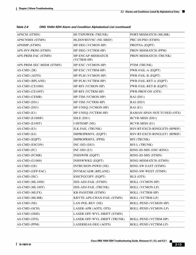
2.2 Alarms and Conditions Listed By Alphabetical EntryTable 2-6 alphabetically lists all ONS 15454 SDH alarms and conditions.
Table 2-5 ONS 15454 SDH Not Reported Conditions List
AIS (BITS) LP-RFI (VCMON-LP) OTUK-BDI (TRUNK)
AIS (DS1) LP-RFI (VCTRM-LP) RFI (TRUNK)
AIS (DS3) MS-AIS (STM1E) RFI-L (TRUNK)
AIS (E1) MS-AIS (STMN) ROLL-PEND (VCTRM-HP)
AIS (E3) MS-RFI (STM1E) TU-AIS (VCMON-LP)
AIS (E4) MS-RFI (STMN) TU-AIS (VCTRM-LP)
AIS (FUDC) NON-CISCO-PPM (PPM) TX-AIS (DS1)
AIS (MSUDC) ODUK-1-AIS-PM (TRUNK) TX-AIS (DS3)
AIS (TRUNK) ODUK-2-AIS-PM (TRUNK) TX-AIS (E1)
AIS-L (TRUNK) ODUK-3-AIS-PM (TRUNK) TX-AIS (E3)
AU-AIS (VCMON-HP) ODUK-4-AIS-PM (TRUNK) TX-LOF (DS1)
AU-AIS (VCTRM-HP) ODUK-AIS-PM (TRUNK) TX-LOF (E1)
AUTOSW-AIS-SNCP (VCMON-HP) ODUK-BDI-PM (TRUNK) UNQUAL-PPM (PPM)
AUTOSW-AIS-SNCP (VCMON-LP) ODUK-LCK-PM (TRUNK) VLAN-AIS (ETH)
HP-RFI (VCMON-HP) ODUK-OCI-PM (TRUNK) —
HP-RFI (VCTRM-HP) OTUK-AIS (TRUNK) —
Table 2-6 ONS 15454 SDH Alarm and Condition Alphabetical List
— GFP-LFD (CEMR) ODUK-SF-PM (TRUNK)
— GFP-LFD (FCMR) ODUK-TIM-PM (TRUNK)
— GFP-LFD (GFP-FAC) OOU-TPT (VCTRM-HP)
— GFP-LFD (ML1000) OOU-TPT (VCTRM-LP)
ADD-OPWR-HDEG (OCH) GFP-LFD (ML100T) OPWR-HDEG (AOTS)
ADD-OPWR-HFAIL (OCH) GFP-LFD (MLFX) OPWR-HDEG (OCH)
ADD-OPWR-LDEG (OCH) GFP-LFD (MLMR) OPWR-HDEG (OCH-TERM)
ADD-OPWR-LFAIL (OCH) GFP-NO-BUFFERS (FCMR) OPWR-HDEG (OMS)
AIS (BITS) GFP-NO-BUFFERS (GFP-FAC) OPWR-HDEG (OTS)
AIS (DS1) GFP-UP-MISMATCH (CE1000) OPWR-HFAIL (AOTS)
AIS (DS3) GFP-UP-MISMATCH (CE100T) OPWR-HFAIL (OCH)
AIS (E1) GFP-UP-MISMATCH (CEMR) OPWR-HFAIL (OMS)
2-11Cisco ONS 15454 SDH Troubleshooting Guide, Releases 9.1, 9.2, and 9.2.1
78-19874-01

Chapter 2 Alarm Troubleshooting2.2 Alarms and Conditions Listed By Alphabetical Entry
AIS (E3) GFP-UP-MISMATCH (FCMR) OPWR-HFAIL (OTS)
AIS (E4) GFP-UP-MISMATCH (GFP-FAC) OPWR-LDEG (AOTS)
AIS (FUDC) GFP-UP-MISMATCH (ML1000) OPWR-LDEG (OCH)
AIS (MSUDC) GFP-UP-MISMATCH (ML100T) OPWR-LDEG (OCH-TERM)
AIS (TRUNK) GFP-UP-MISMATCH (MLFX) OPWR-LDEG (OMS)
AIS-L (TRUNK) GFP-UP-MISMATCH (MLMR) OPWR-LDEG (OTS)
ALS (2R) HELLO (STMN) OPWR-LFAIL (AOTS)
ALS (AOTS) HELLO (TRUNK) OPWR-LFAIL (OCH)
ALS (ESCON) HI-LASERBIAS (2R) OPWR-LFAIL (OCH-TERM)
ALS (FC) HI-LASERBIAS (EQPT) OPWR-LFAIL (OMS)
ALS (GE) HI-LASERBIAS (ESCON) OPWR-LFAIL (OTS)
ALS (ISC) HI-LASERBIAS (FC) OSRION (AOTS)
ALS (STMN) HI-LASERBIAS (GE) OSRION (OTS)
ALS (TRUNK) HI-LASERBIAS (ISC) OTUK-AIS (TRUNK)
ALS-DISABLED (EQPT) HI-LASERBIAS (PPM) OTUK-BDI (TRUNK)
AMPLI-INIT (AOTS) HI-LASERBIAS (STMN) OTUK-IAE (TRUNK)
APC-CORR-SKIPPED (AOTS) HI-LASERBIAS (TRUNK) OTUK-LOF (TRUNK)
APC-CORR-SKIPPED (OCH) HI-LASERTEMP (EQPT) OTUK-SD (TRUNK)
APC-CORR-SKIPPED (OMS) HI-LASERTEMP (PPM) OTUK-SF (TRUNK)
APC-CORR-SKIPPED (OTS) HI-LASERTEMP (STMN) OTUK-TIM (TRUNK)
APC-DISABLED (AOTS) HI-RXPOWER (2R) OUT-OF-SYNC (FC)
APC-DISABLED (EQPT) HI-RXPOWER (ESCON) OUT-OF-SYNC (GE)
APC-DISABLED (NE) HI-RXPOWER (FC) OUT-OF-SYNC (ISC)
APC-DISABLED (OCH) HI-RXPOWER (GE) OUT-OF-SYNC (TRUNK)
APC-DISABLED (OMS) HI-RXPOWER (ISC) PARAM-MISM (AOTS)
APC-DISABLED (OTS) HI-RXPOWER (STMN) PARAM-MISM (OCH)
APC-DISABLED (SHELF) HI-RXPOWER (TRUNK) PARAM-MISM (OCH-TERM)
APC-END (NE) HITEMP (EQPT) PARAM-MISM (OMS)
APC-OUT-OF-RANGE (AOTS) HITEMP (NE) PARAM-MISM (OTS)
APC-OUT-OF-RANGE (OCH) HI-TXPOWER (2R) PEER-NORESPONSE (MLMR)
APC-OUT-OF-RANGE (OMS) HI-TXPOWER (EQPT) —
APC-OUT-OF-RANGE (OTS) HI-TXPOWER (ESCON) —
APC-WRONG-GAIN (AOTS) HI-TXPOWER (FC) PMI (OMS)
APSB (STMN) HI-TXPOWER (GE) PMI (OTS)
APSCDFLTK (STMN) HI-TXPOWER (ISC) PORT-FAIL (OCH)
APSC-IMP (STMN) HI-TXPOWER (PPM) PORT-MISMATCH (CEMR)
APSCINCON (STMN) HI-TXPOWER (STMN) PORT-MISMATCH (FCMR)
Table 2-6 ONS 15454 SDH Alarm and Condition Alphabetical List (continued)
2-12Cisco ONS 15454 SDH Troubleshooting Guide, Releases 9.1, 9.2, and 9.2.1
78-19874-01
Chapter 2 Alarm Troubleshooting2.2 Alarms and Conditions Listed By Alphabetical Entry
APSCM (STMN) HI-TXPOWER (TRUNK) PORT-MISMATCH (MLMR)
APSCNMIS (STMN) HLDOVRSYNC (NE-SREF) PRC-DUPID (STMN)
APSIMP (STMN) HP-DEG (VCMON-HP) PROTNA (EQPT)
APS-INV-PRIM (STMN) HP-DEG (VCTRM-HP) PROV-MISMATCH (PPM)
APS-PRIM-FAC (STMN) HP-ENCAP-MISMATCH (VCTRM-HP)
PROV-MISMATCH (TRUNK)
APS-PRIM-SEC-MISM (STMN) HP-EXC (VCMON-HP) PTIM (TRUNK)
AS-CMD (2R) HP-EXC (VCTRM-HP) PWR-FAIL-A (EQPT)
AS-CMD (AOTS) HP-PLM (VCMON-HP) PWR-FAIL-B (EQPT)
AS-CMD (BPLANE) HP-PLM (VCTRM-HP) PWR-FAIL-RET-A (EQPT)
AS-CMD (CE1000) HP-RFI (VCMON-HP) PWR-FAIL-RET-B (EQPT)
AS-CMD (CE100T) HP-RFI (VCTRM-HP) PWR-PROT-ON (OTS)
AS-CMD (CEMR) HP-TIM (VCMON-HP) RAI (DS1)
AS-CMD (DS1) HP-TIM (VCTRM-HP) RAI (DS3)
AS-CMD (DS3) HP-UNEQ (VCMON-HP) RAI (E1)
AS-CMD (E1) HP-UNEQ (VCTRM-HP) RAMAN-SPAN-NOT-TUNED (OTS)
AS-CMD (E1000F) IDLE (DS1) RCVR-MISS (DS1)
AS-CMD (E100T) I-HITEMP (NE) RCVR-MISS (E1)
AS-CMD (E3) ILK-FAIL (TRUNK) RSV-RT-EXCD-RINGLET0 (RPRIF)
AS-CMD (E4) IMPROPRMVL (EQPT) RSV-RT-EXCD-RINGLET1 (RPRIF)
AS-CMD (EQPT) IMPROPRMVL (PPM) RFI (TRUNK)
AS-CMD (ESCON) INC-ISD (DS3) RFI-L (TRUNK)
AS-CMD (FC) INC-ISD (E3) RING-ID-MIS (OSC-RING)
AS-CMD (FCMR) INHSWPR (EQPT) RING-ID-MIS (STMN)
AS-CMD (G1000) INHSWWKG (EQPT) RING-MISMATCH (STMN)
AS-CMD (GE) INTRUSION-PSWD (NE) RING-SW-EAST (STMN)
AS-CMD (GFP-FAC) INVMACADR (BPLANE) RING-SW-WEST (STMN)
AS-CMD (ISC) IOSCFGCOPY (EQPT) RLS (OTS)
AS-CMD (ML1000) ISIS-ADJ-FAIL (STMN) ROLL (VCMON-HP)
AS-CMD (ML100T) ISIS-ADJ-FAIL (TRUNK) ROLL (VCMON-LP)
AS-CMD (MLFX) KB-PASSTHR (STMN) ROLL (VCTRM-HP)
AS-CMD (MLMR) KBYTE-APS-CHAN-FAIL (STMN) ROLL (VCTRM-LP)
AS-CMD (NE) LAN-POL-REV (NE) ROLL-PEND (VCMON-HP)
AS-CMD (OCH) LASER-APR (AOTS, OTS) ROLL-PEND (VCMON-LP)
AS-CMD (OMS) LASER-OFF-WVL-DRIFT (STMN)
AS-CMD (OTS) LASER-OFF-WVL-DRIFT (TRUNK) ROLL-PEND (VCTRM-HP)
AS-CMD (PPM) LASERBIAS-DEG (AOTS) ROLL-PEND (VCTRM-LP)
Table 2-6 ONS 15454 SDH Alarm and Condition Alphabetical List (continued)
2-13Cisco ONS 15454 SDH Troubleshooting Guide, Releases 9.1, 9.2, and 9.2.1
78-19874-01

Chapter 2 Alarm Troubleshooting2.2 Alarms and Conditions Listed By Alphabetical Entry
AS-CMD (PWR) LASERBIAS-DEG (OTS) RPR-PASSTHR (RPRIF)
AS-CMD (SHELF) LASERBIAS-FAIL (AOTS) RPR-PEER-MISS (RPRIF)
AS-CMD (STM1E) LASERTEMP-DEG (AOTS) RPR-PROT-ACTIVE (RPRIF)
AS-CMD (STMN) LCAS-CRC (VCTRM-HP) RPR-PROT-CONFIG-MISM (RPRIF)
AS-CMD (TRUNK) LCAS-CRC (VCTRM-LP) RPR-RI-FAIL (RPRIF)
AS-MT (2R) LCAS-RX-DNU (VCTRM-HP) RPR-SD (ML1000)
AS-MT (AOTS) LCAS-RX-DNU (VCTRM-LP) RPR-SD (ML100T)
AS-MT (CE1000) LCAS-RX-FAIL (VCTRM-HP) RPR-SD (MLFX)
AS-MT (CE100T) LCAS-RX-FAIL (VCTRM-LP) RPR-SD (MLMR)
AS-MT (CEMR) LCAS-RX-GRP-ERR (VCTRM-HP) RPR-SF (ML1000)
AS-MT (DS1) LCAS-RX-GRP-ERR (VCTRM-LP) RPR-SF (ML100T)
AS-MT (DS3) LCAS-TX-ADD (VCTRM-HP) RPR-SF (MLFX)
AS-MT (E1) LCAS-TX-ADD (VCTRM-LP) RPR-SF (MLMR)
AS-MT (E3) LCAS-TX-DNU (VCTRM-HP) RPR-SPAN-MISMATCH (ML1000)
AS-MT (E4) LCAS-TX-DNU (VCTRM-LP) RPR-SPAN-MISMATCH (ML100T)
AS-MT (EQPT) LINK-KEEPALIVE (ML1000) RPR-SPAN-MISMATCH (MLFX)
AS-MT (ESCON) LINK-KEEPALIVE (ML100T) RPR-SPAN-MISMATCH (MLMR)
AS-MT (FC) LINK-KEEPALIVE (MLFX) RPRW (ML1000)
AS-MT (FCMR) LINK-KEEPALIVE (MLMR) RPRW (ML100T)
AS-MT (G1000) LKOUTPR-S (STMN) RPRW (MLFX)
AS-MT (GE) LMP-FAIL (CTRL) RS-EOC (STMN)
AS-MT (GFP-FAC) LMP-FAIL (GE) RS-TIM (STMN)
AS-MT (ISC) LMP-FAIL (STMN) RUNCFG-SAVENEED (EQPT)
AS-MT (ML1000) LMP-FAIL (TLINK) SBYTCC-NEINTCLK (EQPT)1
AS-MT (ML100T) LMP-SD (GE) SD (DS1)
AS-MT (MLFX) LMP-SD (STMN) SD (DS3)
AS-MT (MLMR) LMP-SF (GE) SD (STM1E)
AS-MT (OCH) LMP-SF (STMN) SD (TRUNK)
AS-MT (OMS) LMP-UNALLOC (GE) SD-L (TRUNK)
AS-MT (OTS) LMP-UNALLOC (STMN) SF (DS1)
AS-MT (PPM) LOA (VCG) SF (DS3)
AS-MT (SHELF) LOCKOUT-REQ (2R) SF (TRUNK)
AS-MT (STM1E) LOCKOUT-REQ (EQPT) SF-L (TRUNK)
AS-MT (STMN) LOCKOUT-REQ (ESCON) SFTWDOWN (EQPT)
AS-MT (TRUNK) LOCKOUT-REQ (FC) SHELF-COMM-FAIL (SHELF)
AS-MT-OOG (VCTRM-HP) LOCKOUT-REQ (GE) SH-IL-VAR-DEG-HIGH (OTS)
AS-MT-OOG (VCTRM-LP) LOCKOUT-REQ (ISC) SH-IL-VAR-DEG-LOW (OTS)
Table 2-6 ONS 15454 SDH Alarm and Condition Alphabetical List (continued)
2-14Cisco ONS 15454 SDH Troubleshooting Guide, Releases 9.1, 9.2, and 9.2.1
78-19874-01

Chapter 2 Alarm Troubleshooting2.2 Alarms and Conditions Listed By Alphabetical Entry
AU-AIS (VCMON-HP) LOCKOUT-REQ (OTS) SHUTTER-OPEN (OTS)
AU-AIS (VCTRM-HP) LOCKOUT-REQ (STMN) SIGLOSS (ESCON)
AUD-LOG-LOSS (NE) LOCKOUT-REQ (TRUNK) SIGLOSS (FC)
AUD-LOG-LOW (NE) LOCKOUT-REQ (VCMON-HP) SIGLOSS (FCMR)
AU-LOF (VCTRM-HP) LOCKOUT-REQ (VCMON-LP) SIGLOSS (GE)
AU-LOP (VCMON-HP) LOF (BITS) SIGLOSS (ISC)
AU-LOP (VCTRM-HP) LOF (DS1) SIGLOSS (TRUNK)
AUTOLSROFF (STMN) LOF (DS3) SNTP-HOST (NE)
AUTONEG-RFI (ML1000) LOF (E1) SPANLEN-OUT-OF-RANGE (OTS)
AUTORESET (EQPT) LOF (E4) SPAN-NOT-MEASURED (OTS)
AUTOSW-AIS-SNCP (VCMON-HP) LOF (STM1E) SPAN-SW-EAST (STMN)
AUTOSW-AIS-SNCP (VCMON-LP) LOF (STMN) SPAN-SW-WEST (STMN)
AUTOSW-LOP-SNCP (VCMON-HP) LOF (TRUNK) SQM (VCTRM-HP)
AUTOSW-LOP-SNCP (VCMON-LP) LO-LASERBIAS (EQPT) SQM (VCTRM-LP)
— LO-LASERBIAS (PPM) SQUELCH (STMN)
— LO-LASERBIAS (STMN) SQUELCHED (2R)
AUTOSW-SDBER-SNCP (VCMON-HP)
LO-LASERTEMP (EQPT) SQUELCHED (ESCON)
AUTOSW-SDBER-SNCP (VCMON-LP)
LO-LASERTEMP (PPM) SQUELCHED (FC)
AUTOSW-SFBER-SNCP (VCMON-HP)
LO-LASERTEMP (STMN) SQUELCHED (GE)
AUTOSW-SFBER-SNCP (VCMON-LP)
LOM (TRUNK) SQUELCHED (ISC)
AUTOSW-UNEQ-SNCP (VCMON-HP) LOM (VCMON-HP) SQUELCHED (STMN)
AUTOSW-UNEQ-SNCP (VCMON-LP) LOM (VCTRM-HP) SQUELCHED (TRUNK)
AWG-DEG (OTS) LOM (VCTRM-LP) SSM-DUS (BITS)
AWG-FAIL (OTS) LO-RXPOWER (2R) SSM-DUS (DS1)
AWG-OVERTEMP (OTS) LO-RXPOWER (ESCON) SSM-DUS (E1)
AWG-WARM-UP (OTS) LO-RXPOWER (FC) SSM-DUS (STMN)
BAT-FAIL (PWR) LO-RXPOWER (GE) SSM-DUS (TRUNK)
BKUPMEMP (EQPT) LO-RXPOWER (ISC) SSM-FAIL (BITS)
CARLOSS (CE1000) LO-RXPOWER (STMN) SSM-FAIL (E1)
CARLOSS (CE100T) LO-RXPOWER (TRUNK) SSM-FAIL (STMN)
CARLOSS (CEMR) LOS (2R) SSM-FAIL (TRUNK)
CARLOSS (E1000F) LOS (BITS) SSM-LNC (BITS)
CARLOSS (E100T) LOS (DS1) SSM-LNC (NE-SREF)
CARLOSS (EQPT) LOS (DS3) SSM-LNC (STMN)
Table 2-6 ONS 15454 SDH Alarm and Condition Alphabetical List (continued)
2-15Cisco ONS 15454 SDH Troubleshooting Guide, Releases 9.1, 9.2, and 9.2.1
78-19874-01

Chapter 2 Alarm Troubleshooting2.2 Alarms and Conditions Listed By Alphabetical Entry
CARLOSS (FC) LOS (E1) SSM-LNC (TRUNK)
CARLOSS (G1000) LOS (E3) SSM-OFF (BITS)
CARLOSS (GE) LOS (E4) SSM-OFF (DS1)
CARLOSS (ISC) LOS (ESCON) SSM-OFF (E1)
CARLOSS (ML1000) LOS (FUDC) SSM-OFF (STMN)
CARLOSS (ML100T) LOS (ISC) SSM-OFF (TRUNK)
CARLOSS (MLFX) LOS (MSUDC) SSM-PRC (BITS)
CARLOSS (MLMR) LOS (OTS) SSM-PRC (NE-SREF)
CARLOSS (TRUNK) LOS (STM1E) SSM-PRC (STMN)
CASETEMP-DEG (AOTS) LOS (STMN) SSM-PRC (TRUNK)
CLDRESTART (EQPT) LOS (TRUNK) SSM-PRS (E1)
COMIOXC (EQPT) LOS-O (OCH) SSM-PRS (TRUNK)
COMM-FAIL (EQPT) LOS-O (OMS) SSM-RES (DS1)
CONTBUS-A-18 (EQPT) LOS-O (OTS) SSM-RES (E1)
CONTBUS-B-18 (EQPT) LOS-P (OCH) SSM-RES (TRUNK)
CONTBUS-DISABLED (EQPT) LOS-P (OMS) SSM-SDH-TN (BITS)
CONTBUS-IO-A (EQPT) LOS-P (OTS) SSM-SDH-TN (NE-SREF)
CONTBUS-IO-B (EQPT) LOS-P (TRUNK) SSM-SDH-TN (STMN)
CPP-INCAPABLE (MLMR) LOS-RAMAN (OTS) SSM-SDH-TN (TRUNK)
CPP-PEER-NO-RESP (MLMR) LO-TXPOWER (2R) SSM-SETS (BITS)
CTNEQPT-MISMATCH (EQPT) LO-TXPOWER (EQPT) SSM-SETS (NE-SREF)
CTNEQPT-PBPROT (EQPT) LO-TXPOWER (ESCON) SSM-SETS (STMN)
CTNEQPT-PBWORK (EQPT) LO-TXPOWER (FC) SSM-SETS (TRUNK)
DATA-CRC (CE100T) LO-TXPOWER (GE) SSM-SMC (E1)
DATA-CRC (ML1000) LO-TXPOWER (ISC) SSM-SMC (TRUNK)
DATA-CRC (ML100T) LO-TXPOWER (PPM) SSM-ST2 (E1)
DATA-CRC (MLFX) LO-TXPOWER (STMN) SSM-ST2 (TRUNK)
DATAFLT (NE) LO-TXPOWER (TRUNK) SSM-ST3 (E1)
DBOSYNC (NE) LPBKCRS (VCMON-HP) SSM-ST3 (TRUNK)
DCU-LOSS-FAIL (OTS) LPBKCRS (VCTRM-HP) SSM-ST3E (E1)
DS3-MISM (DS3) LPBKDS1FE-CMD (DS1) SSM-ST3E (TRUNK)
DSP-COMM-FAIL (TRUNK) LPBKDS3FEAC (DS3) SSM-ST4 (DS1)
DSP-FAIL (TRUNK) LPBKDS3FEAC-CMD (DS3) SSM-ST4 (E1)
DUP-IPADDR (NE) LPBKDS3FEAC-CMD (E3) SSM-ST4 (STMN)
DUP-NODENAME (NE) LPBKE1FEAC (E3) SSM-ST4 (TRUNK)
DUP-SHELF-ID (SHELF) LPBKE3FEAC (E3) SSM-STU (BITS)
EFM-RFI-CE (MLMR) LPBKFACILITY (CE1000) SSM-STU (E1)
Table 2-6 ONS 15454 SDH Alarm and Condition Alphabetical List (continued)
2-16Cisco ONS 15454 SDH Troubleshooting Guide, Releases 9.1, 9.2, and 9.2.1
78-19874-01

Chapter 2 Alarm Troubleshooting2.2 Alarms and Conditions Listed By Alphabetical Entry
EFM-RFI-DG (MLMR) LPBKFACILITY (CE100T) SSM-STU (NE-SREF)
EFM-RFI-LF (MLMR) LPBKFACILITY (CEMR) SSM-STU (STMN)
EHIBATVG (PWR) LPBKFACILITY (DS1) SSM-STU (TRUNK)
ELWBATVG (PWR) LPBKFACILITY (DS3) SSM-TNC (NE-SREF)
RS-EOC (TRUNK) LPBKFACILITY (E1) SSM-TNC (STMN)
EOC-L (TRUNK) LPBKFACILITY (E3) SSM-TNC (TRUNK)
EQPT (AICI-AEP) LPBKFACILITY (E4) SW-MISMATCH (EQPT)
EQPT (AICI-AIE) LPBKFACILITY (ESCON) SWMTXMOD-PROT (EQPT)
EQPT (EQPT)
EQPT (PPM) LPBKFACILITY (FC) SWMTXMOD-WORK (EQPT)
EQPT-DEGRADE (EQPT) LPBKFACILITY (FCMR) SWTOPRI (EXT-SREF)
EQPT-DIAG (EQPT) LPBKFACILITY (G1000) SWTOPRI (NE-SREF)
EQPT-MISS (FAN) LPBKFACILITY (GE) SWTOSEC (EXT-SREF)
ERROR-CONFIG (EQPT) LPBKFACILITY (ISC) SWTOSEC (NE-SREF)
ETH-LINKLOSS (NE)
E-W-MISMATCH (STMN) LPBKFACILITY (MLMR) SWTOTHIRD (EXT-SREF)
EXC-BP (OTS) LPBKFACILITY (STM1E) SWTOTHIRD (NE-SREF)
EXCCOL (EQPT) LPBKFACILITY (STMN) SYNC-FREQ (DS1)
EXERCISE-RING-FAIL (STMN) LPBKFACILITY (TRUNK) SYNC-FREQ (E1)
EXERCISE-SPAN-FAIL (STMN) LPBKTERMINAL (CE1000) SYNC-FREQ (STMN)
EXT (ENVALRM) LPBKTERMINAL (CE100T) SYNC-FREQ (TRUNK)
EXTRA-TRAF-PREEMPT (STMN) LPBKTERMINAL (CEMR) SYNCLOSS (FC)
FAILTOSW (2R) LPBKTERMINAL (DS1) SYNCLOSS (FCMR)
FAILTOSW (EQPT) LPBKTERMINAL (DS3) SYNCLOSS (GE)
FAILTOSW (ESCON) LPBKTERMINAL (E1) SYNCLOSS (ISC)
FAILTOSW (FC) LPBKTERMINAL (E3) SYNCLOSS (TRUNK)
FAILTOSW (GE) LPBKTERMINAL (E4) SYNCPRI (EXT-SREF)
FAILTOSW (ISC) LPBKTERMINAL (ESCON) SYNCPRI (NE-SREF)
FAILTOSW (OTS) LPBKTERMINAL (FC) SYNCSEC (EXT-SREF)
FAILTOSW (STMN) LPBKTERMINAL (FCMR) SYNCSEC (NE-SREF)
FAILTOSW (TRUNK) LPBKTERMINAL (G1000) SYNCTHIRD (EXT-SREF)
FAILTOSW-PATH (VCMON-HP) LPBKTERMINAL (GE) SYNCTHIRD (NE-SREF)
FAILTOSW-PATH (VCMON-LP) LPBKTERMINAL (ISC) SYSBOOT (NE)
FAILTOSWR (STMN) LPBKTERMINAL (MLMR) TEMP-MISM (NE)
FAILTOSWS (STMN) LPBKTERMINAL (STM1E) TIM (STM1E)
FAN (FAN) LPBKTERMINAL (STMN) TIM (STMN)
FAPS (FCMR) LPBKTERMINAL (TRUNK) TIM (TRUNK)
Table 2-6 ONS 15454 SDH Alarm and Condition Alphabetical List (continued)
2-17Cisco ONS 15454 SDH Troubleshooting Guide, Releases 9.1, 9.2, and 9.2.1
78-19874-01

Chapter 2 Alarm Troubleshooting2.2 Alarms and Conditions Listed By Alphabetical Entry
FAPS (TRUNK) LP-DEG (VCMON-LP) TIM-MON (STMN)
FAPS-CONFIG-MISMATCH (EQPT) LP-DEG (VCTRM-LP) TIM-MON (TRUNK)
FC-DE-NES (FC) LP-ENCAP-MISMATCH (VCTRM-LP) TPTFAIL (CE1000)
FC-DE-NES (FCMR) LP-EXC (VCMON-LP) TPTFAIL (CE100T)
FC-DE-NES (TRUNK) LP-EXC (VCTRM-LP) TPTFAIL (CEMR)
FC-NO-CREDITS (FC) LP-PLM (VCMON-LP) TPTFAIL (FCMR)
FC-NO-CREDITS (FCMR) LP-PLM (VCTRM-LP) TPTFAIL (G1000)
FC-NO-CREDITS (TRUNK) LP-RFI (VCMON-LP) TPTFAIL (ML1000)
FDI (OCH) LP-RFI (VCTRM-LP) TPTFAIL (ML100T)
FDI (OCH-TERM) LP-TIM (VCMON-LP) TPTFAIL (MLFX)
FE-AIS (E3) LP-TIM (VCTRM-LP) TPTFAIL (MLMR)
FEC-MISM (TRUNK) LP-UNEQ (VCMON-LP) TRAIL-SIGNAL-FAIL (OCH)
FE-E1-MULTLOS (E3) LP-UNEQ (VCTRM-LP) TRAIL-SIGNAL-FAIL (TRUNK)
FE-E1-NSA (E3) MAN-LASER-RESTART (OTS) TRMT (DS1)
FE-E1-SA (E3) MAN-LASET-RESTART (AOTS) TRMT (E1)
FE-E1-SNGLLOS (E3) MAN-REQ (EQPT) TRMT-MISS (DS1)
FE-E3-NSA (E3) MAN-REQ (ML1000) TRMT-MISS (E1)
FE-E3-SA (E3) MAN-REQ (ML100T) TU-AIS (VCMON-LP)
FE-EQPT-NSA (E3) MAN-REQ (MLFX) TU-AIS (VCTRM-LP)
FE-FRCDWKSWBK-SPAN (STMN) MAN-REQ (MLMR) TU-LOP (VCMON-LP)
FE-FRCDWKSWPR-RING (STMN) MAN-REQ (VCMON-HP) TU-LOP (VCTRM-LP)
FE-FRCDWKSWPR-SPAN (STMN) MAN-REQ (VCMON-LP) TX-AIS (DS1)
FE-IDLE (E3) MANRESET (EQPT) TX-AIS (DS3)
FE-LOCKOUTOFPR-SPAN (STMN) MANSWTOINT (NE-SREF) TX-AIS (E1)
FE-LOF (E3) MANSWTOPRI (EXT-SREF) TX-AIS (E3)
FE-LOS (E3) MANSWTOPRI (NE-SREF) TX-IDLE (DS1)
FE-MANWKSWBK-SPAN (STMN) MANSWTOSEC (EXT-SREF) TX-LOF (DS1)
FE-MANWKSWPR-RING (STMN) MANSWTOSEC (NE-SREF) TX-LOF (E1)
FE-MANWKSWPR-SPAN (STMN) MANSWTOTHIRD (EXT-SREF) TX-RAI (DS1)
FEPRLF (STMN) MANSWTOTHIRD (NE-SREF) TX-RAI (E1)
FIBERTEMP-DEG (AOTS) MANUAL-REQ-RING (STMN) TX-RAI (E3)
FORCED-REQ (EQPT) MANUAL-REQ-SPAN (2R) UNC-WORD (TRUNK)
FORCED-REQ (ML1000) MANUAL-REQ-SPAN (ESCON) UNQUAL-PPM (PPM)
FORCED-REQ (ML100T) MANUAL-REQ-SPAN (FC) UT-COMM-FAIL (TRUNK)
FORCED-REQ (MLFX) MANUAL-REQ-SPAN (GE) UT-FAIL (TRUNK)
FORCED-REQ (MLMR) MANUAL-REQ-SPAN (ISC) VCG-DEG (VCG)
FORCED-REQ (VCMON-HP) MANUAL-REQ-SPAN (OTS) VCG-DOWN (VCG)
Table 2-6 ONS 15454 SDH Alarm and Condition Alphabetical List (continued)
2-18Cisco ONS 15454 SDH Troubleshooting Guide, Releases 9.1, 9.2, and 9.2.1
78-19874-01

Chapter 2 Alarm Troubleshooting2.2 Alarms and Conditions Listed By Alphabetical Entry
FORCED-REQ (VCMON-LP) MANUAL-REQ-SPAN (STMN) VLAN-AIS (ETH)
FORCED-REQ-RING (STMN) MANUAL-REQ-SPAN (TRUNK) VOA-DISABLED (EQPT)
FORCED-REQ-SPAN (2R) MAX-STATIONS (RPRIF) VOA-HDEG (AOTS)
FORCED-REQ-SPAN (ESCON) MCAST-MAC-TABLE-FULL (EQPT) VOA-HDEG (OCH)
FORCED-REQ-SPAN (FC) MEA (BIC) VOA-HDEG (OMS)
FORCED-REQ-SPAN (GE) MEA (EQPT) VOA-HDEG (OTS)
FORCED-REQ-SPAN (ISC) MEA (FAN) VOA-HFAIL (AOTS)
FORCED-REQ-SPAN (OTS) MEA (PPM) VOA-HFAIL (OCH)
FORCED-REQ-SPAN (STMN) MEA (SHELF) VOA-HFAIL (OMS)
FORCED-REQ-SPAN (TRUNK) MEM-GONE (EQPT) VOA-HFAIL (OTS)
FP-LINK-LOSS (EQPT) MEM-LOW (EQPT) VOA-LDEG (AOTS)
FRCDSWTOINT (NE-SREF) MFGMEM (AICI-AEP) VOA-LDEG (OCH)
FRCDSWTOPRI (EXT-SREF) MFGMEM (AICI-AIE) VOA-LDEG (OMS)
FRCDSWTOPRI (NE-SREF) MFGMEM (BPLANE) VOA-LDEG (OTS)
FRCDSWTOSEC (EXT-SREF) MFGMEM (FAN) VOA-LFAIL (AOTS)
FRCDSWTOSEC (NE-SREF) MFGMEM (PPM) VOA-LFAIL (OCH)
FRCDSWTOTHIRD (EXT-SREF) MS-AIS (STM1E) VOA-LFAIL (OMS)
FRCDSWTOTHIRD (NE-SREF) MS-AIS (STMN) VOA-LFAIL (OTS)
FRNGSYNC (NE-SREF) MS-DEG (E1) VOLT-MISM (PWR)
FSTSYNC (NE-SREF) MS-DEG (E3) WAN-SYNCLOSS (VCMON-HP)
FTA-MISMATCH (EQPT) MS-DEG (E4) WAN-SYNCLOSS (VCTRM-HP)
FULLPASSTHR-BI (STMN) MS-DEG (STM1E) WIZARD-IS-RUNNING (OTS)
GAIN-HDEG (AOTS) MS-DEG (STMN) WKSWPR (2R)
GAIN-HFAIL (AOTS) MS-EOC (STMN) WKSWPR (EQPT)
GAIN-LDEG (AOTS) MS-EXC (E1) WKSWPR (ESCON)
GAIN-LFAIL (AOTS) MS-EXC (E3) WKSWPR (FC)
GCC-EOC (TRUNK) MS-EXC (E4) WKSWPR (GE)
GE-OOSYNC (FC) MS-EXC (STM1E) WKSWPR (ISC)
GE-OOSYNC (GE) MS-EXC (STMN) WKSWPR (OTS)
GE-OOSYNC (ISC) MS-RFI (STM1E) WKSWPR (STMN)
GE-OOSYNC (TRUNK) MS-RFI (STMN) WKSWPR (VCMON-HP)
GFP-CSF (CE1000) MSSP-OOSYNC (STMN) WKSWPR (VCMON-LP)
GFP-CSF (CE100T) MSSP-SW-VER-MISM (STMN) WTR (2R)
GFP-CSF (CEMR) MS-SQUELCH-HP (STMN) WTR (EQPT)
GFP-CSF (FCMR) MS-SQUELCH-LP (STMN) WTR (ESCON)
GFP-CSF (GFP-FAC) MT-OCHNC (OTS) WTR (FC)
GFP-CSF (ML1000) NO-CONFIG (EQPT) WTR (GE)
Table 2-6 ONS 15454 SDH Alarm and Condition Alphabetical List (continued)
2-19Cisco ONS 15454 SDH Troubleshooting Guide, Releases 9.1, 9.2, and 9.2.1
78-19874-01

Chapter 2 Alarm Troubleshooting2.3 Alarm Logical Objects
2.3 Alarm Logical ObjectsThe CTC alarm profile list organizes all alarms and conditions according to the logical objects they are raised against. These logical objects represent physical objects such as cards, logical objects such as circuits, or transport and signal monitoring entities such as the SDH or ITU-T G.709 optical overhead bits. One alarm can appear in multiple entries. It can be raised against multiple objects. For example, the loss of signal (LOS) alarm can be raised against the optical signal (STM-N) or the optical transport layer overhead (OTN) as well as other objects. Therefore, both STM-N: LOS and OTN: LOS appear in the list (as well as the other objects).
Alarm profile list objects are defined in Table 2-7.
Note Alarm logical object names can appear as abbreviated versions of standard terms used in the system and the documentation. For example, the “STMN” logical object refers to the STM-N signal. Logical object names or industry-standard terms are used within the entries as appropriate.
GFP-CSF (ML100T) NON-CISCO-PPM (PPM) WTR (ISC)
GFP-CSF (MLFX) OCHNC-INC (OCHNC-CONN) WTR (ML1000)
GFP-CSF (MLMR) OCHTERM-INC (OCH-TERM) WTR (ML100T)
GFP-DE-MISMATCH (FCMR) ODUK-1-AIS-PM (TRUNK) WTR (MLFX)
GFP-DE-MISMATCH (GFP-FAC) ODUK-2-AIS-PM (TRUNK) WTR (MLMR)
GFP-EX-MISMATCH (CE1000) ODUK-3-AIS-PM (TRUNK) WTR (STMN)
GFP-EX-MISMATCH (FCMR) ODUK-4-AIS-PM (TRUNK) WTR (TRUNK)
GFP-EX-MISMATCH (GFP-FAC) ODUK-AIS-PM (TRUNK) WTR (VCMON-HP)
GFP-LFD (CE1000) ODUK-BDI-PM (TRUNK) WTR (VCMON-LP)
GFP-LFD (CE100T) ODUK-LCK-PM (TRUNK) WVL-MISMATCH (TRUNK)
1. Supported only in Release 9.2.1
Table 2-6 ONS 15454 SDH Alarm and Condition Alphabetical List (continued)
Table 2-7 Alarm Logical Object Type Definitions
Object Type Definition
2R Reshape and retransmit (used for transponder [TXP] cards). For more information about most of the alarms on this object, refer to the “Alarm Troubleshooting” chapter of the Cisco ONS 15454 DWDM Troubleshooting Guide.
AICI-AEP Alarm Interface Controller–International—Alarm expansion panel.
AICI-AIE Alarm Interface Controller-International/Alarm Interface Extension. A combination term that refers to this platform's AIC-I card.
AIP Alarm Interface Panel.
AOTS Amplified optical transport section. For more information about most of the alarms on this object, refer to the “Alarm Troubleshooting” chapter of the Cisco ONS 15454 DWDM Troubleshooting Guide.
BIC Backplane interface connector.
2-20Cisco ONS 15454 SDH Troubleshooting Guide, Releases 9.1, 9.2, and 9.2.1
78-19874-01

Chapter 2 Alarm Troubleshooting2.3 Alarm Logical Objects
BITS Building integrated timing supply incoming references (BITS-1, BITS-2).
BPLANE The backplane.
CE1000 CE-1000-4 card.
CE100T CE-100T-8 card.
CEMR CE-MR-10 card.
CTRL Control channel.
DS1 A DS-1 line on a DS-1 or DS-3 electrical card (DS1-14, DS3N-12E, DS3XM-6, DS3XM-12).
DS3 A DS-3 signal on a DS3i-N-12 card.
E1 E1-42 card.
E3 E3-12 card.
E4 Line type supported by the STM1E card.
E1000F An E1000-2-G card.
E100T An E100T-G card.
ENVALRM An environmental alarm port.
EQPT A card, its physical objects, and logical objects as they are located in any of the eight noncommon card slots. The EQPT object is used for alarms that refer to the card itself and all other objects on the card including ports, lines, STM, and VC.
ESCON Enterprise System Connection fiber optic technology, referring to the following TXP cards: TXP_MR_2.5G, TXPP_MR_2.5G. For more information about most of the alarms on this object, refer to the “Alarm Troubleshooting” chapter of the Cisco ONS 15454 DWDM Troubleshooting Guide.
EXT-SREF BITS outgoing references (SYNC-BITS1, SYNC-BITS2).
FAN Fan-tray assembly.
FC Fibre Channel data transfer architecture, referring to the following muxponder (MXP) or TXP cards: MXP_MR_2.5G, MXPP_MR_2.5G, TXP_MR_2.5G, TXPP_MR_2.5G, TXP_MR_10E. For more information about most of the alarms on this object, refer to the “Alarm Troubleshooting” chapter of the Cisco ONS 15454 DWDM Troubleshooting Guide.
FCMR An FC_MR-4 Fibre Channel card. For more information about most of the alarms on this object, refer to the “Alarm Troubleshooting” chapter of the Cisco ONS 15454 DWDM Troubleshooting Guide.
FUDC SDH F1 byte user data channel for ONS 15454 SDH ML-Series Ethernet cards.
G1000 The ONS 15454 SDH G-Series card.
GE Gigabit Ethernet, referring to the following MXP or TXP cards: MXP_MR_2.5G, MXPP_MR_2.5G, TXP_MR_2.5G, TXPP_MR_2.5G, TXP_MR_10E, TXP_MR_10G. For more information about most of the alarms on this object, refer to the “Alarm Troubleshooting” chapter of the Cisco ONS 15454 DWDM Troubleshooting Guide.
Table 2-7 Alarm Logical Object Type Definitions (continued)
Object Type Definition
2-21Cisco ONS 15454 SDH Troubleshooting Guide, Releases 9.1, 9.2, and 9.2.1
78-19874-01
Chapter 2 Alarm Troubleshooting2.3 Alarm Logical Objects
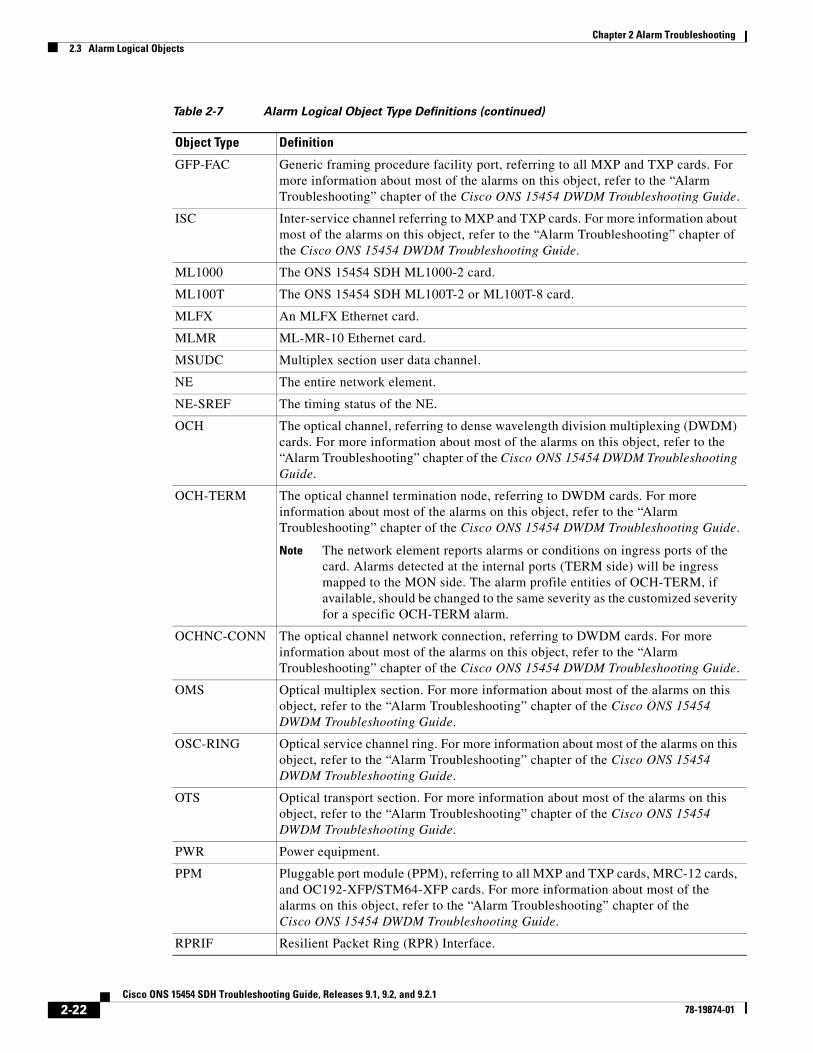
GFP-FAC Generic framing procedure facility port, referring to all MXP and TXP cards. For more information about most of the alarms on this object, refer to the “Alarm Troubleshooting” chapter of the Cisco ONS 15454 DWDM Troubleshooting Guide.
ISC Inter-service channel referring to MXP and TXP cards. For more information about most of the alarms on this object, refer to the “Alarm Troubleshooting” chapter of the Cisco ONS 15454 DWDM Troubleshooting Guide.
ML1000 The ONS 15454 SDH ML1000-2 card.
ML100T The ONS 15454 SDH ML100T-2 or ML100T-8 card.
MLFX An MLFX Ethernet card.
MLMR ML-MR-10 Ethernet card.
MSUDC Multiplex section user data channel.
NE The entire network element.
NE-SREF The timing status of the NE.
OCH The optical channel, referring to dense wavelength division multiplexing (DWDM) cards. For more information about most of the alarms on this object, refer to the “Alarm Troubleshooting” chapter of the Cisco ONS 15454 DWDM Troubleshooting Guide.
OCH-TERM The optical channel termination node, referring to DWDM cards. For more information about most of the alarms on this object, refer to the “Alarm Troubleshooting” chapter of the Cisco ONS 15454 DWDM Troubleshooting Guide.
Note The network element reports alarms or conditions on ingress ports of the card. Alarms detected at the internal ports (TERM side) will be ingress mapped to the MON side. The alarm profile entities of OCH-TERM, if available, should be changed to the same severity as the customized severity for a specific OCH-TERM alarm.
OCHNC-CONN The optical channel network connection, referring to DWDM cards. For more information about most of the alarms on this object, refer to the “Alarm Troubleshooting” chapter of the Cisco ONS 15454 DWDM Troubleshooting Guide.
OMS Optical multiplex section. For more information about most of the alarms on this object, refer to the “Alarm Troubleshooting” chapter of the Cisco ONS 15454 DWDM Troubleshooting Guide.
OSC-RING Optical service channel ring. For more information about most of the alarms on this object, refer to the “Alarm Troubleshooting” chapter of the Cisco ONS 15454 DWDM Troubleshooting Guide.
OTS Optical transport section. For more information about most of the alarms on this object, refer to the “Alarm Troubleshooting” chapter of the Cisco ONS 15454 DWDM Troubleshooting Guide.
PWR Power equipment.
PPM Pluggable port module (PPM), referring to all MXP and TXP cards, MRC-12 cards, and OC192-XFP/STM64-XFP cards. For more information about most of the alarms on this object, refer to the “Alarm Troubleshooting” chapter of the Cisco ONS 15454 DWDM Troubleshooting Guide.
RPRIF Resilient Packet Ring (RPR) Interface.
Table 2-7 Alarm Logical Object Type Definitions (continued)
Object Type Definition
2-22Cisco ONS 15454 SDH Troubleshooting Guide, Releases 9.1, 9.2, and 9.2.1
78-19874-01

Chapter 2 Alarm Troubleshooting2.3 Alarm Logical Objects
SHELF The shelf assembly. For more information about most of the alarms on this object, refer to the “Alarm Troubleshooting” chapter of the Cisco ONS 15454 DWDM Troubleshooting Guide.
STM1E Synchronous transfer mode 1 (speed) electrical interface
STMN An STM-N line on an STM-N card.
TLINK Traffic engineering (TE) link correlation.
VCTRM-HP VT alarm detection at termination (downstream from the cross-connect).
TRUNK The optical or DWDM card carrying the high-speed signal; referring to MXP, TXP, or ML-Series cards. For more information about most of the alarms on this object, refer to the “Alarm Troubleshooting” chapter of the Cisco ONS 15454 DWDM Troubleshooting Guide.
UCP-CKT Unified control plane circuit.
UCP-IPCC Unified control plane IP control channel.
UCP-NBR Unified control plane neighbor.
VCG ONS 15454 SDH virtual concatenation group of virtual tributaries (VT).
VCMON-HP High-order path virtual concatenation monitoring.
Note The network element reports alarms or conditions on ingress ports of the card. Alarms detected at the internal ports (TERM side) will be ingress mapped to the MON side. The alarm profile entities of VCMON-HP, if available, should be changed to the same severity as the customized severity for a specific VCMON-HP alarm.
VCMON-LP VC alarm detection at the monitor point (upstream from the cross-connect).
Note The network element reports alarms or conditions on ingress ports of the card. Alarms detected at the internal ports (TERM side) will be ingress mapped to the MON side. The alarm profile entities of VCMON-LP, if available, should be changed to the same severity as the customized severity for a specific VCMON-LP alarm.
VCTRM-HP High-order path concatenation termination monitoring.
Note The network element reports alarms or conditions on ingress ports of the card. Alarms detected at the internal ports (TERM side) will be ingress mapped to the MON side. The alarm profile entities of VCTRM-HP, if available, should be changed to the same severity as the customized severity for a specific VCTRM-HP alarm.
VCTRM-LP VC alarm detection at termination (downstream from the cross-connect).
Note The network element reports alarms or conditions on ingress ports of the card. Alarms detected at the internal ports (TERM side) will be ingress mapped to the MON side. The alarm profile entities of VCTRM-LP, if available, should be changed to the same severity as the customized severity for a specific VCTRM-LP alarm.
Table 2-7 Alarm Logical Object Type Definitions (continued)
Object Type Definition
2-23Cisco ONS 15454 SDH Troubleshooting Guide, Releases 9.1, 9.2, and 9.2.1
78-19874-01

Chapter 2 Alarm Troubleshooting2.4 Alarm List by Logical Object Type
2.4 Alarm List by Logical Object TypeTable 2-8 lists all ONS 15454 SDH alarms and logical objects as they are given in the system alarm profile. The list entries are organized by logical object name and then by alarm or condition name. Where appropriate, the alarm entries also contain troubleshooting procedures.
Note In a mixed network containing different types of nodes (such as ONS 15310-CL, ONS 15454 SDH, and ONS 15600), the initially displayed alarm list in the Provisioning > Alarm Profiles > Alarm Profile Editor tab lists all conditions that are applicable to all nodes in the network. However, when you load the default severity profile from a node, only applicable alarms will display severity levels. Nonapplicable alarms can display “use default” or “unset.”
Note In some cases this list does not follow alphabetical order, but it does reflect the order shown in CTC.
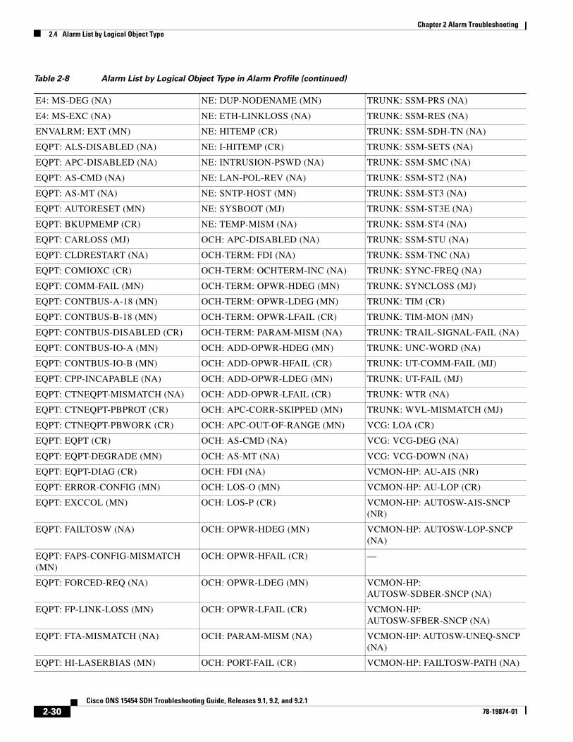
Table 2-8 Alarm List by Logical Object Type in Alarm Profile
2R: ALS (NA) FC: LOCKOUT-REQ (NA) PPM: UNQUAL-PPM (NR)
2R: AS-CMD (NA) FC: LPBKFACILITY (NA) PWR: AS-CMD (NA)
2R: AS-MT (NA) FC: LPBKTERMINAL (NA) PWR: BAT-FAIL (MJ)
2R: FAILTOSW (NA) FC: MANUAL-REQ-SPAN (NA) PWR: EHIBATVG (MJ)
2R: FORCED-REQ-SPAN (NA) FC: OUT-OF-SYNC (MJ) PWR: ELWBATVG (MJ)
2R: HI-LASERBIAS (MN) FC: SIGLOSS (MJ) PWR: VOLT-MISM (NA)
2R: HI-RXPOWER (MN) FC: SQUELCHED (NA) RPR: CPP-INCAPABLE (NA)
2R: HI-TXPOWER (MN) FC: SYNCLOSS (MJ) RPRIF: MAX-STATIONS (MJ)
2R: LO-RXPOWER (MN) FC: WKSWPR (NA) RPRIF: RSV-RT-EXCD-RINGLET0 (MJ)
2R: LO-TXPOWER (MN) FC: WTR (NA) RPRIF: RSV-RT-EXCD-RINGLET1 (MJ)
2R: LOCKOUT-REQ (NA) FCMR: AS-CMD (NA) RPRIF: RPR-PASSTHR (NA)
2R: LOS (CR) FCMR: AS-MT (NA) RPRIF: RPR-PEER-MISS (MJ)
2R: MANUAL-REQ-SPAN (NA) FCMR: FAPS (NA) RPRIF: RPR-PROT-ACTIVE (NA)
2R: SQUELCHED (NA) FCMR: FC-DE-NES (MJ) RPRIF: RPR-PROT-CONFIG-MISM (MJ)
2R: WKSWPR (NA) FCMR: FC-NO-CREDITS (MJ) RPRIF: RPR-RI-FAIL (MJ)
2R: WTR (NA) FCMR: GFP-CSF (MJ) SHELF: APC-DISABLED (NA)
AICI-AEP: EQPT (CR) FCMR: GFP-DE-MISMATCH (MJ) SHELF: AS-CMD (NA)
AICI-AEP: MFGMEM (CR) FCMR: GFP-EX-MISMATCH (MJ) SHELF: AS-MT (NA)
AICI-AIE: EQPT (CR) FCMR: GFP-LFD (MJ) SHELF: DUP-SHELF-ID (MJ)
AICI-AIE: MFGMEM (CR) FCMR: GFP-NO-BUFFERS (MJ) SHELF: MEA (MJ)
AOTS: ALS (NA) FCMR: GFP-UP-MISMATCH (MJ) SHELF: SHELF-COMM-FAIL (MJ)
AOTS: AMPLI-INIT (NA) FCMR: LPBKFACILITY (NA) STM1E: AS-CMD (NA)
2-24Cisco ONS 15454 SDH Troubleshooting Guide, Releases 9.1, 9.2, and 9.2.1
78-19874-01

Chapter 2 Alarm Troubleshooting2.4 Alarm List by Logical Object Type
AOTS: APC-CORR-SKIPPED (MN) FCMR: LPBKTERMINAL (NA) STM1E: AS-MT (NA)
AOTS: APC-DISABLED (NA) FCMR: PORT-MISMATCH (NA) STM1E: LOF (CR)
AOTS: APC-OUT-OF-RANGE (MN) FCMR: SIGLOSS (MJ) STM1E: LOS (CR)
AOTS: APC-WRONG-GAIN (NA) FCMR: SYNCLOSS (MJ) STM1E: LPBKFACILITY (NA)
AOTS: AS-CMD (NA) FCMR: TPTFAIL (MJ) STM1E: LPBKTERMINAL (NA)
AOTS: AS-MT (NA) FUDC: AIS (NR) STM1E: MS-AIS (NR)
AOTS: CASETEMP-DEG (MN) FUDC: LOS (MN) STM1E: MS-DEG (NA)
AOTS: FIBERTEMP-DEG (MN) G1000: AS-CMD (NA) STM1E: MS-EXC (NA)
AOTS: GAIN-HDEG (MN) G1000: AS-MT (NA) STM1E: MS-RFI (NR)
AOTS: GAIN-HFAIL (CR) G1000: CARLOSS (MJ) STM1E: SD (NA)
AOTS: GAIN-LDEG (MN) G1000: LPBKFACILITY (NA) STM1E: TIM (MJ)
AOTS: GAIN-LFAIL (CR) G1000: LPBKTERMINAL (NA) STMN: ALS (NA)
AOTS: LASER-APR (NA) G1000: TPTFAIL (MJ) STMN: APS-INV-PRIM (MN)
AOTS: LASERBIAS-DEG (MN) GE: ALS (NA) STMN: APS-PRIM-FAC (NA)
AOTS: LASERBIAS-FAIL (MJ) GE: AS-CMD (NA) STMN: APS-PRIM-SEC-MISM (MN)
AOTS: LASERTEMP-DEG (MN) GE: AS-MT (NA) STMN: APSB (MN)
AOTS: MAN-LASER-RESTART (NA)
AOTS: OPWR-HDEG (MN) GE: CARLOSS (MJ) STMN: APSC-IMP (MN)
AOTS: OPWR-HFAIL (CR) GE: FAILTOSW (NA) STMN: APSCDFLTK (MN)
AOTS: OPWR-LDEG (MN) GE: FORCED-REQ-SPAN (NA) STMN: APSCINCON (MN)
AOTS: OPWR-LFAIL (CR) GE: GE-OOSYNC (CR) STMN: APSCM (MN)
AOTS: OSRION (NA) GE: HI-LASERBIAS (MN) STMN: APSCNMIS (MJ)
AOTS: PARAM-MISM (NA) GE: HI-RXPOWER (MN) STMN: APSIMP (MN)
AOTS: VOA-HDEG (MN) GE: HI-TXPOWER (MN) STMN: AS-CMD (NA)
AOTS: VOA-HFAIL (CR) GE: LMP-FAIL (MN) STMN: AS-MT (NA)
AOTS: VOA-LDEG (MN) GE: LMP-SD (MN) STMN: AUTOLSROFF (CR)
AOTS: VOA-LFAIL (CR) GE: LMP-SF (MN) STMN: E-W-MISMATCH (MJ)
BIC: MEA (CR) GE: LMP-UNALLOC (NA) STMN: EXERCISE-RING-FAIL (NA)
BITS: AIS (NR) GE: LO-RXPOWER (MN) STMN: EXERCISE-SPAN-FAIL (NA)
BITS: LOF (MN) GE: LO-TXPOWER (MN) STMN: EXTRA-TRAF-PREEMPT (MJ)
BITS: LOS (MN) GE: LOCKOUT-REQ (NA) STMN: FAILTOSW (NA)
BITS: SSM-DUS (NA) GE: LPBKFACILITY (NA) STMN: FAILTOSWR (NA)
BITS: SSM-FAIL (MN) GE: LPBKTERMINAL (NA) STMN: FAILTOSWS (NA)
BITS: SSM-LNC (NA) GE: MANUAL-REQ-SPAN (NA) STMN: FE-FRCDWKSWBK-SPAN (NA)
BITS: SSM-OFF (NA) GE: OUT-OF-SYNC (MJ) STMN: FE-FRCDWKSWPR-RING (NA)
Table 2-8 Alarm List by Logical Object Type in Alarm Profile (continued)
2-25Cisco ONS 15454 SDH Troubleshooting Guide, Releases 9.1, 9.2, and 9.2.1
78-19874-01

Chapter 2 Alarm Troubleshooting2.4 Alarm List by Logical Object Type
BITS: SSM-PRC (NA) GE: SIGLOSS (MJ) STMN: FE-FRCDWKSWPR-SPAN (NA)
BITS: SSM-SDH-TN (NA) GE: SQUELCHED (NA) STMN: FE-LOCKOUTOFPR-SPAN (NA)
BITS: SSM-SETS (NA) GE: SYNCLOSS (MJ) STMN: FE-MANWKSWBK-SPAN (NA)
BITS: SSM-STU (NA) GE: WKSWPR (NA) STMN: FE-MANWKSWPR-RING (NA)
BPLANE: AS-CMD (NA) GE: WTR (NA) STMN: FE-MANWKSWPR-SPAN (NA)
BPLANE: INVMACADR (MJ) GFP-FAC: AS-CMD (NA) STMN: FEPRLF (MN)
BPLANE: MFGMEM (CR) GFP-FAC: AS-MT (NA) STMN: FORCED-REQ-RING (NA)
CE1000: AS-CMD (NA) GFP-FAC: GFP-CSF (MJ) STMN: FORCED-REQ-SPAN (NA)
CE1000: AS-MT (NA) GFP-FAC: GFP-DE-MISMATCH (MJ) STMN: FULLPASSTHR-BI (NA)
CE1000: CARLOSS (MJ) GFP-FAC: GFP-EX-MISMATCH (MJ) STMN: HELLO (MN)
CE1000: GFP-CSF (MJ) GFP-FAC: GFP-LFD (MJ) STMN: HI-LASERBIAS (MN)
CE1000: GFP-EX-MISMATCH (MJ) GFP-FAC: GFP-NO-BUFFERS (MJ) STMN: HI-LASERTEMP (MN)
CE1000: GFP-LFD (MJ) GFP-FAC: GFP-UP-MISMATCH (MJ) STMN: HI-RXPOWER (MN)
CE1000: GFP-UP-MISMATCH (MJ) ISC: ALS (NA) STMN: HI-TXPOWER (MN)
CE1000: LPBKFACILITY (NA) ISC: AS-CMD (NA) STMN: ISIS-ADJ-FAIL (MN)
CE1000: LPBKTERMINAL (NA) ISC: AS-MT (NA) STMN: KB-PASSTHR (NA)
CE1000: TPTFAIL (MJ) ISC: CARLOSS (MJ) STMN: KBYTE-APS-CHAN-FAIL (MN)
CE100T: AS-CMD (NA) ISC: FAILTOSW (NA) STMN: LASER-OFF-WVL-DRIFT (MJ)
CE100T: AS-MT (NA) ISC: FORCED-REQ-SPAN (NA) STMN: LKOUTPR-S (NA)
CE100T: CARLOSS (MJ) ISC: GE-OOSYNC (CR) STMN: LMP-FAIL (MN)
CE100T: DATA-CRC (MJ) ISC: HI-LASERBIAS (MN) STMN: LMP-SD (MN)
CE100T: GFP-CSF (MJ) ISC: HI-RXPOWER (MN) STMN: LMP-SF (MN)
CE100T: GFP-LFD (MJ) ISC: HI-TXPOWER (MN) STMN: LMP-UNALLOC (NA)
CE100T: GFP-UP-MISMATCH (MJ) ISC: LO-RXPOWER (MN) STMN: LO-LASERBIAS (MN)
CE100T: LPBKFACILITY (NA) ISC: LO-TXPOWER (MN) STMN: LO-LASERTEMP (MN)
CE100T: LPBKTERMINAL (NA) ISC: LOCKOUT-REQ (NA) STMN: LO-RXPOWER (MN)
CE100T: TPTFAIL (MJ) ISC: LOS (CR) STMN: LO-TXPOWER (MN)
CEMR: AS-CMD (NA) ISC: LPBKFACILITY (NA) STMN: LOCKOUT-REQ (NA)
CEMR: AS-MT (NA) ISC: LPBKTERMINAL (NA) STMN: LOF (CR)
CEMR: CARLOSS (MJ) ISC: MANUAL-REQ-SPAN (NA) STMN: LOS (CR)
CEMR: GFP-CSF (MJ) ISC: OUT-OF-SYNC (NA) STMN: LPBKFACILITY (NA)
CEMR: GFP-LFD (MJ) ISC: SIGLOSS (MJ) STMN: LPBKTERMINAL (NA)
Table 2-8 Alarm List by Logical Object Type in Alarm Profile (continued)
2-26Cisco ONS 15454 SDH Troubleshooting Guide, Releases 9.1, 9.2, and 9.2.1
78-19874-01

Chapter 2 Alarm Troubleshooting2.4 Alarm List by Logical Object Type
CEMR: GFP-UP-MISMATCH (MJ) ISC: SQUELCHED (NA) STMN: MANUAL-REQ-RING (NA)
CEMR: LPBKFACILITY (NA) ISC: SYNCLOSS (MJ) STMN: MANUAL-REQ-SPAN (NA)
CEMR: LPBKTERMINAL (NA) ISC: WKSWPR (NA) STMN: MS-AIS (NR)
CEMR: PORT-MISMATCH (MJ) ISC: WTR (NA) STMN: MS-DEG (NA)
CEMR: TPTFAIL (MJ) ML1000: AS-CMD (NA) STMN: MS-EOC (MN)
CTRL: LMP-FAIL (MN) ML1000: AS-MT (NA) STMN: MS-EXC (NA)
DS1: AIS (NR) ML1000: AUTONEG-RFI (MJ) STMN: MS-RFI (NR)
DS1: AS-CMD (NA) ML1000: CARLOSS (MJ) STMN: MS-SQUELCH-HP (NA)
DS1: AS-MT (NA) ML1000: DATA-CRC (MJ) STMN: MS-SQUELCH-LP (NA)
DS1: IDLE (NA) ML1000: FORCED-REQ (NA) STMN: MSSP-OOSYNC (MJ)
DS1: LOF (MJ) ML1000: GFP-CSF (MJ) STMN: MSSP-SW-VER-MISM (MN)
DS1: LOS (MJ) ML1000: GFP-LFD (MJ) STMN: PRC-DUPID (MJ)
DS1: LPBKDS1FE-CMD (NA) ML1000: GFP-UP-MISMATCH (MJ) STMN: RING-ID-MIS (MJ)
DS1: LPBKFACILITY (NA) ML1000: LINK-KEEPALIVE (CR) STMN: RING-MISMATCH (MJ)
DS1: LPBKTERMINAL (NA) ML1000: MAN-REQ (NA) STMN: RING-SW-EAST (NA)
DS1: RAI (NA) ML1000: RPR-SD (NA) STMN: RING-SW-WEST (NA)
DS1: RCVR-MISS (MJ) ML1000: RPR-SF (NA) STMN: RS-EOC (MN)
DS1: SD (NA) ML1000: RPR-SPAN-MISMATCH (MJ) STMN: RS-TIM (CR)
DS1: SF (NA) ML1000: RPRW (NA) STMN: SPAN-SW-EAST (NA)
DS1: SSM-DUS (NA) ML1000: TPTFAIL (MJ) STMN: SPAN-SW-WEST (NA)
DS1: SSM-OFF (NA) ML1000: WTR (NA) STMN: SQUELCH (NA)
DS1: SSM-RES (NA) ML100T: AS-CMD (NA) STMN: SQUELCHED (NA)
DS1: SSM-ST4 (NA) ML100T: AS-MT (NA) STMN: SSM-DUS (NA)
DS1: SYNC-FREQ (NA) ML100T: CARLOSS (MJ) STMN: SSM-FAIL (MN)
DS1: TRMT (MJ) ML100T: DATA-CRC (MJ) STMN: SSM-LNC (NA)
DS1: TRMT-MISS (MJ) ML100T: FORCED-REQ (NA) STMN: SSM-OFF (NA)
DS1: TX-AIS (NR) ML100T: GFP-CSF (MJ) STMN: SSM-PRC (NA)
DS1: TX-IDLE (NA) ML100T: GFP-LFD (MJ) STMN: SSM-SDH-TN (NA)
DS1: TX-LOF (NR) ML100T: GFP-UP-MISMATCH (MJ) STMN: SSM-SETS (NA)
DS1: TX-RAI (NA) ML100T: LINK-KEEPALIVE (CR) STMN: SSM-ST4 (NA)
DS3: AIS (NR) ML100T: MAN-REQ (NA) STMN: SSM-STU (NA)
DS3: AS-CMD (NA) ML100T: RPR-SD (NA) STMN: SSM-TNC (NA)
DS3: AS-MT (NA) ML100T: RPR-SF (NA) STMN: SYNC-FREQ (NA)
DS3: DS3-MISM (NA) ML100T: RPR-SPAN-MISMATCH (MJ)
STMN: TIM (CR)
DS3: INC-ISD (NA) ML100T: RPRW (NA) STMN: TIM-MON (MN)
DS3: LOF (CR) ML100T: TPTFAIL (MJ) STMN: WKSWPR (NA)
Table 2-8 Alarm List by Logical Object Type in Alarm Profile (continued)
2-27Cisco ONS 15454 SDH Troubleshooting Guide, Releases 9.1, 9.2, and 9.2.1
78-19874-01

Chapter 2 Alarm Troubleshooting2.4 Alarm List by Logical Object Type
DS3: LOS (CR) ML100T: WTR (NA) STMN: WTR (NA)
DS3: LPBKDS3FEAC (NA) MLFX: AS-CMD (NA) —
DS3: LPBKDS3FEAC-CMD (NA) MLFX: AS-MT (NA) —
DS3: LPBKFACILITY (NA) MLFX: CARLOSS (MJ) TLINK: LMP-FAIL (MN)
DS3: LPBKTERMINAL (NA) MLFX: DATA-CRC (MJ) TRUNK: AIS (NR)
DS3: RAI (NA) MLFX: FORCED-REQ (NA) TRUNK: AIS-L (NR)
DS3: SD (NA) MLFX: GFP-CSF (MJ) TRUNK: ALS (NA)
DS3: SF (NA) MLFX: GFP-LFD (MJ) TRUNK: AS-CMD (NA)
DS3: TX-AIS (NR) MLFX: GFP-UP-MISMATCH (MJ) TRUNK: AS-MT (NA)
E1000F: AS-CMD (NA) MLFX: LINK-KEEPALIVE (CR) TRUNK: CARLOSS (MJ)
E1000F: CARLOSS (MJ) MLFX: MAN-REQ (NA) TRUNK: DSP-COMM-FAIL (MJ)
E100T: AS-CMD (NA) MLFX: RPR-SD (NA) TRUNK: DSP-FAIL (MJ)
E100T: CARLOSS (MJ) MLFX: RPR-SF (NA) TRUNK: RS-EOC (MN)
E1: AIS (NR) MLFX: RPR-SPAN-MISMATCH (MJ) TRUNK: EOC-L (MN)
E1: AS-CMD (NA) MLFX: RPRW (NA) TRUNK: FAILTOSW (NA)
E1: AS-MT (NA) MLFX: TPTFAIL (MJ) TRUNK: FAPS (NA)
E1: LOF (MJ) MLFX: WTR (NA) TRUNK: FC-DE-NES (MJ)
E1: LOS (MJ) MLMR: AS-CMD (NA) TRUNK: FC-NO-CREDITS (MJ)
E1: LPBKFACILITY (NA) MLMR: AS-MT (NA) TRUNK: FEC-MISM (MJ)
E1: LPBKTERMINAL (NA) MLMR: CARLOSS (MJ) TRUNK: FORCED-REQ-SPAN (NA)
E1: MS-DEG (NA) MLMR: CPP-INCAPABLE (NA) TRUNK: GCC-EOC (MN)
E1: MS-EXC (NA) MLMR: CPP-PEER-NO-RESP (MN) TRUNK: GE-OOSYNC (CR)
E1: RAI (NA) MLMR: EFM-RFI-CE (MJ) TRUNK: HELLO (MN)
E1: RCVR-MISS (MJ) MLMR: EFM-RFI-DG (MJ) TRUNK: HI-LASERBIAS (MN)
E1: SSM-DUS (NA) MLMR: EFM-RFI-LF (MJ) TRUNK: HI-RXPOWER (MN)
E1: SSM-FAIL (MN) MLMR: FORCED-REQ (NA) TRUNK: HI-TXPOWER (MN)
E1: SSM-OFF (NA) MLMR: GFP-CSF (MJ) TRUNK: ILK-FAIL (CR)
E1: SSM-PRS (NA) MLMR: GFP-LFD (MJ) TRUNK: ISIS-ADJ-FAIL (MN)
E1: SSM-RES (NA) MLMR: GFP-UP-MISMATCH (MJ) TRUNK: LASER-OFF-WVL-DRIFT (MJ)
E1: SSM-SMC (NA) MLMR: LINK-KEEPALIVE (CR) TRUNK: LO-RXPOWER (MN)
E1: SSM-ST2 (NA) MLMR: LPBKFACILITY (NA) TRUNK: LO-TXPOWER (MN)
E1: SSM-ST3 (NA) MLMR: LPBKTERMINAL (NA) TRUNK: LOCKOUT-REQ (NA)
E1: SSM-ST3E (NA) MLMR: MAN-REQ (NA) TRUNK: LOF (CR)
E1: SSM-ST4 (NA) MLMR: PEER-NORESPONSE (MN) TRUNK: LOM (CR)
E1: SSM-STU (NA) MLMR: PORT-MISMATCH (MJ) TRUNK: LOS (CR)
E1: SYNC-FREQ (NA) MLMR: RPR-SD (NA) TRUNK: LOS-P (CR)
Table 2-8 Alarm List by Logical Object Type in Alarm Profile (continued)
2-28Cisco ONS 15454 SDH Troubleshooting Guide, Releases 9.1, 9.2, and 9.2.1
78-19874-01

Chapter 2 Alarm Troubleshooting2.4 Alarm List by Logical Object Type
E1: TRMT (MJ) MLMR: RPR-SF (NA) TRUNK: LPBKFACILITY (NA)
E1: TRMT-MISS (MJ) MLMR: RPR-SPAN-MISMATCH (MJ) TRUNK: LPBKTERMINAL (NA)
E1: TX-AIS (NR) MLMR: TPTFAIL (MJ) TRUNK: MANUAL-REQ-SPAN (NA)
E1: TX-LOF (NR) MLMR: WTR (NA) TRUNK: ODUK-1-AIS-PM (NR)
E1: TX-RAI (NA) MSUDC: AIS (NR) TRUNK: ODUK-2-AIS-PM (NR)
E3: AIS (NR) MSUDC: LOS (MN) TRUNK: ODUK-3-AIS-PM (NR)
E3: AS-CMD (NA) NE-SREF: FRCDSWTOINT (NA) TRUNK: ODUK-4-AIS-PM (NR)
E3: AS-MT (NA) NE-SREF: FRCDSWTOPRI (NA) TRUNK: ODUK-AIS-PM (NR)
E3: FE-AIS (NA) NE-SREF: FRCDSWTOSEC (NA) TRUNK: ODUK-BDI-PM (NR)
E3: FE-E1-MULTLOS (NA) NE-SREF: FRCDSWTOTHIRD (NA) TRUNK: ODUK-LCK-PM (NR)
E3: FE-E1-NSA (NA) NE-SREF: FRNGSYNC (NA) TRUNK: ODUK-OCI-PM (NR)
E3: FE-E1-SA (NA) NE-SREF: FSTSYNC (NA) TRUNK: ODUK-SD-PM (NA)
E3: FE-E1-SNGLLOS (NA) NE-SREF: HLDOVRSYNC (NA) TRUNK: ODUK-SF-PM (NA)
E3: FE-E3-NSA (NA) NE-SREF: MANSWTOINT (NA) TRUNK: ODUK-TIM-PM (MJ)
E3: FE-E3-SA (NA) NE-SREF: MANSWTOPRI (NA) TRUNK: OTUK-AIS (NR)
E3: FE-EQPT-NSA (NA) NE-SREF: MANSWTOSEC (NA) TRUNK: OTUK-BDI (NR)
E3: FE-IDLE (NA) NE-SREF: MANSWTOTHIRD (NA) TRUNK: OTUK-IAE (MN)
E3: FE-LOF (NA) NE-SREF: SSM-LNC (NA) TRUNK: OTUK-LOF (CR)
E3: FE-LOS (NA) NE-SREF: SSM-PRC (NA) TRUNK: OTUK-SD (NA)
E3: INC-ISD (NA) NE-SREF: SSM-SDH-TN (NA) TRUNK: OTUK-SF (NA)
E3: LOS (CR) NE-SREF: SSM-SETS (NA) TRUNK: OTUK-TIM (CR)
E3: LPBKDS3FEAC-CMD (NA) NE-SREF: SSM-STU (NA) TRUNK: OUT-OF-SYNC (MJ)
E3: LPBKE1FEAC (NA) NE-SREF: SSM-TNC (NA) TRUNK: PROV-MISMATCH (MJ)
E3: LPBKE3FEAC (NA) NE-SREF: SWTOPRI (NA) TRUNK: PTIM (MJ)
E3: LPBKFACILITY (NA) NE-SREF: SWTOSEC (NA) TRUNK: RFI (NR)
E3: LPBKTERMINAL (NA) NE-SREF: SWTOTHIRD (NA) TRUNK: RFI-L (NR)
E3: MS-DEG (NA) NE-SREF: SYNCPRI (MJ) TRUNK: SD (NA)
E3: MS-EXC (NA) NE-SREF: SYNCSEC (MN) TRUNK: SD-L (NA)
E3: TX-AIS (NR) NE-SREF: SYNCTHIRD (MN) TRUNK: SF (NA)
E3: TX-RAI (NA) NE: APC-DISABLED (NA) TRUNK: SF-L (NA)
E4: AIS (NR) NE: APC-END (NA) TRUNK: SIGLOSS (MJ)
E4: AS-CMD (NA) NE: AS-CMD (NA) TRUNK: SQUELCHED (NA)
E4: AS-MT (NA) NE: AUD-LOG-LOSS (NA) TRUNK: SSM-DUS (NA)
E4: LOF (CR) NE: AUD-LOG-LOW (NA) TRUNK: SSM-FAIL (MN)
E4: LOS (CR) NE: DATAFLT (MN) TRUNK: SSM-LNC (NA)
E4: LPBKFACILITY (NA) NE: DBOSYNC (MJ) TRUNK: SSM-OFF (NA)
E4: LPBKTERMINAL (NA) NE: DUP-IPADDR (MN) TRUNK: SSM-PRC (NA)
Table 2-8 Alarm List by Logical Object Type in Alarm Profile (continued)
2-29Cisco ONS 15454 SDH Troubleshooting Guide, Releases 9.1, 9.2, and 9.2.1
78-19874-01
Chapter 2 Alarm Troubleshooting2.4 Alarm List by Logical Object Type
E4: MS-DEG (NA) NE: DUP-NODENAME (MN) TRUNK: SSM-PRS (NA)
E4: MS-EXC (NA) NE: ETH-LINKLOSS (NA) TRUNK: SSM-RES (NA)
ENVALRM: EXT (MN) NE: HITEMP (CR) TRUNK: SSM-SDH-TN (NA)
EQPT: ALS-DISABLED (NA) NE: I-HITEMP (CR) TRUNK: SSM-SETS (NA)
EQPT: APC-DISABLED (NA) NE: INTRUSION-PSWD (NA) TRUNK: SSM-SMC (NA)
EQPT: AS-CMD (NA) NE: LAN-POL-REV (NA) TRUNK: SSM-ST2 (NA)
EQPT: AS-MT (NA) NE: SNTP-HOST (MN) TRUNK: SSM-ST3 (NA)
EQPT: AUTORESET (MN) NE: SYSBOOT (MJ) TRUNK: SSM-ST3E (NA)
EQPT: BKUPMEMP (CR) NE: TEMP-MISM (NA) TRUNK: SSM-ST4 (NA)
EQPT: CARLOSS (MJ) OCH: APC-DISABLED (NA) TRUNK: SSM-STU (NA)
EQPT: CLDRESTART (NA) OCH-TERM: FDI (NA) TRUNK: SSM-TNC (NA)
EQPT: COMIOXC (CR) OCH-TERM: OCHTERM-INC (NA) TRUNK: SYNC-FREQ (NA)
EQPT: COMM-FAIL (MN) OCH-TERM: OPWR-HDEG (MN) TRUNK: SYNCLOSS (MJ)
EQPT: CONTBUS-A-18 (MN) OCH-TERM: OPWR-LDEG (MN) TRUNK: TIM (CR)
EQPT: CONTBUS-B-18 (MN) OCH-TERM: OPWR-LFAIL (CR) TRUNK: TIM-MON (MN)
EQPT: CONTBUS-DISABLED (CR) OCH-TERM: PARAM-MISM (NA) TRUNK: TRAIL-SIGNAL-FAIL (NA)
EQPT: CONTBUS-IO-A (MN) OCH: ADD-OPWR-HDEG (MN) TRUNK: UNC-WORD (NA)
EQPT: CONTBUS-IO-B (MN) OCH: ADD-OPWR-HFAIL (CR) TRUNK: UT-COMM-FAIL (MJ)
EQPT: CPP-INCAPABLE (NA) OCH: ADD-OPWR-LDEG (MN) TRUNK: UT-FAIL (MJ)
EQPT: CTNEQPT-MISMATCH (NA) OCH: ADD-OPWR-LFAIL (CR) TRUNK: WTR (NA)
EQPT: CTNEQPT-PBPROT (CR) OCH: APC-CORR-SKIPPED (MN) TRUNK: WVL-MISMATCH (MJ)
EQPT: CTNEQPT-PBWORK (CR) OCH: APC-OUT-OF-RANGE (MN) VCG: LOA (CR)
EQPT: EQPT (CR) OCH: AS-CMD (NA) VCG: VCG-DEG (NA)
EQPT: EQPT-DEGRADE (MN) OCH: AS-MT (NA) VCG: VCG-DOWN (NA)
EQPT: EQPT-DIAG (CR) OCH: FDI (NA) VCMON-HP: AU-AIS (NR)
EQPT: ERROR-CONFIG (MN) OCH: LOS-O (MN) VCMON-HP: AU-LOP (CR)
EQPT: EXCCOL (MN) OCH: LOS-P (CR) VCMON-HP: AUTOSW-AIS-SNCP (NR)
EQPT: FAILTOSW (NA) OCH: OPWR-HDEG (MN) VCMON-HP: AUTOSW-LOP-SNCP (NA)
EQPT: FAPS-CONFIG-MISMATCH (MN)
OCH: OPWR-HFAIL (CR) —
EQPT: FORCED-REQ (NA) OCH: OPWR-LDEG (MN) VCMON-HP: AUTOSW-SDBER-SNCP (NA)
EQPT: FP-LINK-LOSS (MN) OCH: OPWR-LFAIL (CR) VCMON-HP: AUTOSW-SFBER-SNCP (NA)
EQPT: FTA-MISMATCH (NA) OCH: PARAM-MISM (NA) VCMON-HP: AUTOSW-UNEQ-SNCP (NA)
EQPT: HI-LASERBIAS (MN) OCH: PORT-FAIL (CR) VCMON-HP: FAILTOSW-PATH (NA)
Table 2-8 Alarm List by Logical Object Type in Alarm Profile (continued)
2-30Cisco ONS 15454 SDH Troubleshooting Guide, Releases 9.1, 9.2, and 9.2.1
78-19874-01

Chapter 2 Alarm Troubleshooting2.4 Alarm List by Logical Object Type
EQPT: HI-LASERTEMP (MN) OCH: TRAIL-SIGNAL-FAIL (NA) VCMON-HP: FORCED-REQ (NA)
EQPT: HI-TXPOWER (MN) OCH: VOA-HDEG (MN) VCMON-HP: HP-DEG (NA)
EQPT: HITEMP (MN) OCH: VOA-HFAIL (CR) VCMON-HP: HP-EXC (NA)
EQPT: IMPROPRMVL (CR) OCH: VOA-LDEG (MN) VCMON-HP: HP-PLM (CR)
EQPT: INHSWPR (NA) OCH: VOA-LFAIL (CR) VCMON-HP: HP-RFI (NR)
EQPT: INHSWWKG (NA) OCHNC-CONN: OCHNC-INC (NA) VCMON-HP: HP-TIM (MN)
EQPT: IOSCFGCOPY (NA) OMS: APC-CORR-SKIPPED (MN) VCMON-HP: HP-UNEQ (CR)
EQPT: LO-LASERBIAS (MN) OMS: APC-DISABLED (NA) VCMON-HP: LOCKOUT-REQ (NA)
EQPT: LO-LASERTEMP (MN) OMS: APC-OUT-OF-RANGE (MN) VCMON-HP: LOM (CR)
EQPT: LO-TXPOWER (MN) OMS: AS-CMD (NA) VCMON-HP: LPBKCRS (NA)
EQPT: LOCKOUT-REQ (NA) OMS: AS-MT (NA) VCMON-HP: MAN-REQ (NA)
EQPT: MAN-REQ (NA) OMS: LOS-O (MN) VCMON-HP: ROLL (NA)
EQPT: MANRESET (NA) OMS: LOS-P (CR) VCMON-HP: ROLL-PEND (NA)
EQPT: MEA (CR) OMS: OPWR-HDEG (MN) VCMON-HP: WKSWPR (NA)
EQPT: MEM-GONE (MJ) OMS: OPWR-HFAIL (CR) VCMON-HP: WTR (NA)
EQPT: MEM-LOW (MN) OMS: OPWR-LDEG (MN) VCMON-LP: AUTOSW-AIS-SNCP (NR)
EQPT: MCAST-MAC-TABLE-FULL (NA)
OMS: OPWR-LFAIL (CR) VCMON-LP: AUTOSW-LOP-SNCP (NA)
EQPT: NO-CONFIG (NA) OMS: PARAM-MISM (NA) —
EQPT: PROTNA (MN) OMS: PMI (NA) VCMON-LP: AUTOSW-SDBER-SNCP (NA)
EQPT: PWR-FAIL-A (MN) OMS: VOA-HDEG (MN) VCMON-LP: AUTOSW-SFBER-SNCP (NA)
EQPT: PWR-FAIL-B (MN) OMS: VOA-HFAIL (CR) VCMON-LP: AUTOSW-UNEQ-SNCP (NA)
EQPT: PWR-FAIL-RET-A (MN) OMS: VOA-LDEG (MN) VCMON-LP: FAILTOSW-PATH (NA)
EQPT: PWR-FAIL-RET-B (MN) OMS: VOA-LFAIL (CR) VCMON-LP: FORCED-REQ (NA)
EQPT: RUNCFG-SAVENEED (NA) OSC-RING: RING-ID-MIS (MJ) VCMON-LP: LOCKOUT-REQ (NA)
EQPT: SBYTCC-NEINTCLK (NA)1 OTS: APC-CORR-SKIPPED (MN) VCMON-LP: LP-DEG (NA)
EQPT: SFTWDOWN (MN) OTS: APC-DISABLED (NA) VCMON-LP: LP-EXC (NA)
EQPT: SW-MISMATCH (NA) OTS: APC-OUT-OF-RANGE (MN) VCMON-LP: LP-PLM (MJ)
EQPT: SWMTXMOD-PROT (CR) OTS: AS-CMD (NA) VCMON-LP: LP-RFI (NR)
EQPT: SWMTXMOD-WORK (CR) OTS: AS-MT (NA) VCMON-LP: LP-TIM (MJ)
EQPT: VOA-DISABLED (CR) OTS: AWG-DEG (MN) VCMON-LP: LP-UNEQ (MJ)
EQPT: WKSWPR (NA) OTS: AWG-FAIL (CR) VCMON-LP: MAN-REQ (NA)
EQPT: WTR (NA) OTS: AWG-OVERTEMP (CR) VCMON-LP: ROLL (NA)
ESCON: ALS (NA) OTS: AWG-WARM-UP (NA) VCMON-LP: ROLL-PEND (NA)
Table 2-8 Alarm List by Logical Object Type in Alarm Profile (continued)
2-31Cisco ONS 15454 SDH Troubleshooting Guide, Releases 9.1, 9.2, and 9.2.1
78-19874-01

Chapter 2 Alarm Troubleshooting2.4 Alarm List by Logical Object Type
ESCON: AS-CMD (NA) OTS: DCU-LOSS-FAIL (MN) VCMON-LP: TU-AIS (NR)
ESCON: AS-MT (NA) OTS: EXC-BP (MN) VCMON-LP: TU-LOP (MJ)
ESCON: FAILTOSW (NA) — VCMON-HP: WAN-SYNCLOSS (MJ)
ESCON: FORCED-REQ-SPAN (NA) OTS: FAILTOSW (NA) VCMON-LP: WKSWPR (NA)
ESCON: HI-LASERBIAS (MN) OTS: FORCED-REQ-SPAN (NA) VCMON-LP: WTR (NA)
ESCON: HI-RXPOWER (MN) OTS: LASER-APR (NA) VCTRM-HP: AS-MT-OOG (NA)
ESCON: HI-TXPOWER (MN) OTS: LASERBIAS-DEG (MN) VCTRM-HP: AU-AIS (NR)
ESCON: LO-RXPOWER (MN) OTS: LOCKOUT-REQ (NA) VCTRM-HP: AU-LOF (CR)
ESCON: LO-TXPOWER (MN) OTS: LOS (CR) VCTRM-HP: AU-LOP (CR)
ESCON: LOCKOUT-REQ (NA) OTS: LOS-O (MN) VCTRM-HP: HP-DEG (NA)
ESCON: LOS (CR) OTS: LOS-P (CR) VCTRM-HP: HP-ENCAP-MISMATCH (CR)
ESCON: LPBKFACILITY (NA) OTS: LOS-RAMAN (CR) VCTRM-HP: HP-EXC (NA)
— OTS: MAN-LASER-RESTART (NA) VCTRM-HP: HP-PLM (CR)
ESCON: LPBKTERMINAL (NA) OTS: MANUAL-REQ-SPAN (NA) VCTRM-HP: HP-RFI (NR)
ESCON: MANUAL-REQ-SPAN (NA) OTS: MT-OCHNC (NA) VCTRM-HP: HP-TIM (CR)
ESCON: SIGLOSS (MJ) OTS: OPWR-HDEG (MN) VCTRM-HP: HP-UNEQ (CR)
ESCON: SQUELCHED (NA) OTS: OPWR-HFAIL (CR) VCTRM-HP: LCAS-CRC (NA)
ESCON: WKSWPR (NA) OTS: OPWR-LDEG (MN) VCTRM-HP: LCAS-RX-DNU (NA)
ESCON: WTR (NA) OTS: OPWR-LFAIL (CR) VCTRM-HP: LCAS-RX-FAIL (NA)
ETH: VLAN-AIS (NR) OTS: OSRION (NA) VCTRM-HP: LCAS-RX-GRP-ERR (NA)
EXT-SREF: FRCDSWTOPRI (NA) OTS: PARAM-MISM (NA) VCTRM-HP: LCAS-TX-ADD (NA)
EXT-SREF: FRCDSWTOSEC (NA) OTS: PMI (NA) VCTRM-HP: LCAS-TX-DNU (NA)
EXT-SREF: FRCDSWTOTHIRD (NA) OTS: PWR-PROT-ON (MJ) VCTRM-HP: LOM (MJ)
EXT-SREF: MANSWTOPRI (NA) OTS: RAMAN-SPAN-NOT-TUNED (NA)
VCTRM-HP: LPBKCRS (NA)
EXT-SREF: MANSWTOSEC (NA) OTS: RLS (NA) VCTRM-HP: OOU-TPT (NA)
EXT-SREF: MANSWTOTHIRD (NA) OTS: SH-IL-VAR-DEG-HIGH (MN) VCTRM-HP: ROLL (NA)
EXT-SREF: SWTOPRI (NA) OTS: SH-IL-VAR-DEG-LOW (MN) VCTRM-HP: ROLL-PEND (NR)
EXT-SREF: SWTOSEC (NA) OTS: SHUTTER-OPEN (NA) VCTRM-HP: SQM (CR)
EXT-SREF: SWTOTHIRD (NA) OTS: SPAN-NOT-MEASURED (NA) VCTRM-LP: AS-MT-OOG (NA)
EXT-SREF: SYNCPRI (MN) OTS: SPANLEN-OUT-OF-RANGE (MN)
VCTRM-LP: LCAS-CRC (NA)
EXT-SREF: SYNCSEC (MN) OTS: VOA-HDEG (MN) VCTRM-LP: LCAS-RX-DNU (NA)
EXT-SREF: SYNCTHIRD (MN) OTS: VOA-HFAIL (CR) VCTRM-LP: LCAS-RX-FAIL (NA)
FAN: EQPT-MISS (CR) OTS: VOA-LDEG (MN) VCTRM-LP: LCAS-RX-GRP-ERR (NA)
Table 2-8 Alarm List by Logical Object Type in Alarm Profile (continued)
2-32Cisco ONS 15454 SDH Troubleshooting Guide, Releases 9.1, 9.2, and 9.2.1
78-19874-01

Chapter 2 Alarm Troubleshooting2.5 Trouble Notifications
2.5 Trouble NotificationsThe ONS 15454 SDH system reports trouble by utilizing standard alarm and condition characteristics, and standard severities following the rules in ITU-T x.733, and graphical user interface (GUI) state indicators. These notifications are described in the following paragraphs.
The ONS 15454 SDH uses standard categories to characterize levels of trouble. The system reports trouble notifications as alarms and status or descriptive notifications (if configured to do so) as conditions in the CTC Alarms window. Alarms typically signify a problem that the user needs to address, such as a loss of signal. Conditions do not necessarily require troubleshooting.
2.5.1 Alarm CharacteristicsThe ONS 15454 SDH uses standard alarm entities to identify what is causing trouble. All alarms stem from hardware, software, environment, or operator-originated problems whether or not they affect service. Current alarms for the network, CTC session, node, or card are listed in the Alarms tab. (In addition, cleared alarms are also found in the History tab.)
FAN: FAN (CR) OTS: VOA-LFAIL (CR) VCTRM-LP: LCAS-TX-ADD (NA)
FAN: MEA (CR) OTS: WIZARD-IS-RUNNING (NA) VCTRM-LP: LCAS-TX-DNU (NA)
FAN: MFGMEM (CR) OTS: WKSWPR (NA) VCTRM-LP: LOM (MJ)
FC: ALS (NA) PPM: AS-CMD (NA) VCTRM-LP: LP-DEG (NA)
FC: AS-CMD (NA) PPM: AS-MT (NA) VCTRM-LP: LP-ENCAP-MISMATCH (CR)
FC: AS-MT (NA) PPM: EQPT (CR) VCTRM-LP: LP-EXC (NA)
FC: CARLOSS (MJ) PPM: HI-LASERBIAS (MN) VCTRM-LP: LP-PLM (MJ)
FC: FAILTOSW (NA) PPM: HI-LASERTEMP (MN) VCTRM-LP: LP-RFI (NR)
FC: FC-DE-NES (MJ) PPM: HI-TXPOWER (MN) VCTRM-LP: LP-TIM (MJ)
FC: FC-NO-CREDITS (MJ) PPM: IMPROPRMVL (CR) VCTRM-LP: LP-UNEQ (MJ)
FC: FORCED-REQ-SPAN (NA) PPM: LO-LASERBIAS (MN) VCTRM-LP: OOU-TPT (NA)
FC: GE-OOSYNC (CR) PPM: LO-LASERTEMP (MN) VCTRM-LP: ROLL (NA)
FC: HI-LASERBIAS (MN) PPM: LO-TXPOWER (MN) VCTRM-LP: ROLL-PEND (NA)
FC: HI-RXPOWER (MN) PPM: MEA (CR) VCTRM-LP: SQM (MJ)
FC: HI-TXPOWER (MN) PPM: MFGMEM (CR) VCTRM-LP: TU-AIS (NR)
FC: LO-RXPOWER (MN) PPM: NON-CISCO-PPM (NR) VCTRM-LP: TU-LOP (MJ)
FC: LO-TXPOWER (MN) PPM: PROV-MISMATCH (MN) VCTRM-HP: WAN-SYNCLOSS (MJ)
1. Supported only in Release 9.2.1
Table 2-8 Alarm List by Logical Object Type in Alarm Profile (continued)
2-33Cisco ONS 15454 SDH Troubleshooting Guide, Releases 9.1, 9.2, and 9.2.1
78-19874-01

Chapter 2 Alarm Troubleshooting2.5.2 Condition Characteristics
2.5.2 Condition CharacteristicsConditions include any problem detected on an ONS 15454 SDH shelf. They could include standing or transient notifications. A snapshot of all current raised, standing conditions on the network, node, or card can be retrieved in the CTC Conditions window or using TL1’s set of RTRV-COND commands. (In addition, some but not all cleared conditions are also found in the History tab.)
For more information about transient conditions, see Chapter 3, “Transient Conditions.”
Note ONS 15454 SDH condition reporting is not ITU-compliant.
2.5.3 SeveritiesThe ONS 15454 SDH uses ITU-devised standard severities for alarms and conditions: Critical (CR), Major (MJ), Minor (MN), Not Alarmed (NA), and Not Reported (NR). These are described below:
• A Critical (CR) alarm generally indicates severe, Service-Affecting (SA) trouble that needs immediate correction, such as an LOS on a trunk port or STM signal.
• A Major (MJ) alarm is a serious alarm, but the trouble has less impact on the network. For example, an automatic protection switching (APS) channel mismatch (APSCNMIS) alarm occurs when working and protect channels have been inadvertently switched so that a working channel is expected at the receive end, but a protect channel is received instead.
• Minor (MN) alarms generally are those that do not affect service. For example, the APS byte failure (APSB) alarm indicates that line terminating equipment (LTE) detects a byte failure on the signal that could prevent traffic from properly executing a traffic switch.
• Not Alarmed (NA) conditions are information indicators, such as for a free-running synchronization (FRNGSYNC) state or a forced-switch to primary timing (FRCSWTOPRI) event. They could or could not require troubleshooting, as indicated in the entries.
• Not Reported (NR) conditions occur as a secondary result of another event. For example, the alarm indication signal (MS-AIS), with severity NR, is inserted by a downstream node when an LOS (CR or MJ) alarm occurs upstream. These conditions do not in themselves require troubleshooting, but are to be expected in the presence of primary alarms.
Severities can be customized for an entire network or for single nodes, from the network level down to the port level by changing or downloading customized alarm profiles. These custom severities are subject to the standard severity-demoting rules given in Telcordia GR-474-CORE and shown in the “2.5.4 Alarm Hierarchy” section on page 2-34. Procedures for customizing alarm severities are located in the “Manage Alarms” chapter of the Cisco ONS 15454 SDH Procedure Guide.
2.5.4 Alarm HierarchyAll alarm, condition, and unreported event severities listed in this manual are default profile settings. However in situations when traffic is not lost, such as when the alarm occurs on protected ports or circuits, alarms having Critical (CR) or Major (MJ) default severities can be demoted to lower severities such as Minor (MN) or Non-Service-Affecting (NSA) as defined in Telcordia GR-474-CORE.
2-34Cisco ONS 15454 SDH Troubleshooting Guide, Releases 9.1, 9.2, and 9.2.1
78-19874-01

Chapter 2 Alarm Troubleshooting2.5.4 Alarm Hierarchy
A path alarm can be demoted if a higher-ranking alarm is raised for the same object. For example, If an high-order path trace identifier mismatch (HP-TIM) is raised on a circuit path and then an administrative unit (AU) loss of pointer (LOP) is raised on it, the AU-LOP alarm stands and the HP-TIM closes. The path alarm hierarchy used in the ONS 15454 SDH system is shown in Table 2-9.
Facility (port) alarms also follow a hierarchy, which means that lower-ranking alarms are closed by higher-ranking alarms. The facility alarm hierarchy used in the ONS 15454 SDH system is shown in Table 2-10.
Near-end failures and far-end failures follow different hierarchies. Near-end failures stand according to whether they are for the entire signal (LOS, LOF), facility (MS-AIS), path (AU-AIS, etc.) or VT (TU-AIS, etc.). The full hierarchy for near-end failures is shown in Table 2-11. This table is taken from Telcordia GR-253-CORE.
Table 2-9 Path Alarm Hierarchy
Priority Condition Type
Highest AU-AIS
— AU-LOP
— HP-UNEQ
Lowest HP-TIM
Table 2-10 Facility Alarm Hierarchy
Priority Condition Type
Highest LOS
— LOF
— MS-AIS
— MS-EXC1
1. This alarm is not currently used in the platform.
— MS-DEG1
— MS-RDI1
— RS-TIM
— AU-AIS
— AU-LOP
— HP-EXC1
— HP-DEG1
— HP-UNEQ
— HP-TIM
— HP-PLM1
2-35Cisco ONS 15454 SDH Troubleshooting Guide, Releases 9.1, 9.2, and 9.2.1
78-19874-01

Chapter 2 Alarm Troubleshooting2.5.5 Service Effect
The far-end failure alarm hierarchy is shown in Table 2-12, as given in Telcordia GR-253-CORE.
2.5.5 Service EffectThe ITU also provides service effect standards. Service-Affecting (SA) alarms—those that interrupt service—could be Critical (CR), Major (MJ), or Minor (MN) severity alarms. Non-Service-Affecting (NSA) alarms always have a Minor (MN) default severity.
Table 2-11 Near-End Alarm Hierarchy
Priority Condition Type
Highest LOS
— LOF
— MS-AIS
— AU-AIS1
1. Although it is not defined as a defect or failure, all-ones VT pointer relay is also higher priority than AU-LOP. Similarly, all-ones VC pointer relay is higher priority than TU-LOP.
— AU-LOP2
2. AU-LOP is also higher priority than the far-end failure MS-RFI, which does not affect the detection of any near-end failures. Similarly, TU-LOP is higher priority than LP-RF.
— HP-UNEQ
— HP-TIM
— HP-PLM
— TU-AIS1
— TU-LOP2
— LP-UNEQ3
3. This alarm is not used in this platform in this release.
— LP-PLM3
Lowest DS-N AIS (if reported for outgoing DS-N signals)
Table 2-12 Far-End Alarm Hierarchy
Priority Condition Type
Highest MS-RDI1
1. This condition is not used in this platform in this release.
— HP-RFI
Lowest LP-RFI1
2-36Cisco ONS 15454 SDH Troubleshooting Guide, Releases 9.1, 9.2, and 9.2.1
78-19874-01

Chapter 2 Alarm Troubleshooting2.5.6 States
2.5.6 StatesThe Alarms and History tab State (ST) column indicate the disposition of the alarm or condition as follows:
• A raised (R) event is one that is active.
• A cleared (C) event is one that is no longer active.
• A transient (T) event is one that is automatically raised and cleared in CTC during system changes such as user login, logout, loss of connection to node view, etc. Transient events do not require user action. These are listed in Chapter 3, “Transient Conditions.”
2.6 Safety SummaryThis section covers safety considerations designed to ensure safe operation of the ONS 15454 SDH. Do not perform any procedures in this chapter unless you understand all safety precautions, practices, and warnings for the system equipment. Some troubleshooting procedures require installation or removal of cards; in these instances pay close attention to the following caution.
Caution Hazardous voltage or energy could be present on the backplane when the system is operating. Use caution when removing or installing cards.
Some troubleshooting procedures require installation or removal of STM-64 cards. In these instances, pay close attention to the following warnings.
Warning On the OC192 LR/STM64 LH 1550 card, the laser is on when the card is booted and the safety key is in the on position (labeled 1). The port does not have to be in service for the laser to be on. The laser is off when the safety key is off (labeled 0). Statement 293
Warning Invisible laser radiation could be emitted from the end of the unterminated fiber cable or connector. Do not stare into the beam directly with optical instruments. Viewing the laser output with certain optical instruments (for example, eye loupes, magnifiers, and microscopes) within a distance of 100 mm could pose an eye hazard. Statement 1056
Warning Use of controls, adjustments, or performing procedures other than those specified could result in hazardous radiation exposure. Statement 1057
Warning Class 1 laser product. Statement 1008
Warning Class 1M laser radiation when open. Do not view directly with optical instruments. Statement 1053
2-37Cisco ONS 15454 SDH Troubleshooting Guide, Releases 9.1, 9.2, and 9.2.1
78-19874-01

Chapter 2 Alarm Troubleshooting2.7 Alarm Procedures
Warning Do not reach into a vacant slot or chassis while you install or remove a module or a fan. Exposed circuitry could constitute an energy hazard. Statement 206
Warning The power supply circuitry for the equipment can constitute an energy hazard. Before you install or replace the equipment, remove all jewelry (including rings, necklaces, and watches). Metal objects can come into contact with exposed power supply wiring or circuitry inside the DSLAM equipment. This could cause the metal objects to heat up and cause serious burns or weld the metal object to the equipment. Statement 207
2.7 Alarm ProceduresThis section list alarms alphabetically and includes some conditions commonly encountered when troubleshooting alarms. The severity, description, and troubleshooting procedure accompany each alarm and condition.
Note When you check the status of alarms for cards, ensure that the alarm filter icon in the lower right corner of the GUI is not indented. If it is, click it to turn it off. When you're done checking for alarms, click the alarm filter icon again to turn filtering back on. For more information about alarm filtering, refer to the “Manage Alarms” chapter of the Cisco ONS 15454 SDH Procedure Guide.
Note When checking alarms, ensure that alarm suppression is not enabled on the card or port. For more information about alarm suppression, refer to the “Manage Alarms” chapter in the Cisco ONS 15454 SDH Procedure Guide.
Note When an entity is put in the Locked,maintenance administrative state, the ONS 15454 SDH suppresses all standing alarms on that entity and alarms and events appear on the Conditions tab. You can change this behavior for the LPBKFACILITY and LPBKTERMINAL alarms. To display these alarms on the Alarms tab, set the NODE.general.ReportLoopbackConditionsOnPortsInLocked,Maintenance to TRUE on the NE Defaults tab. For more information about changing NE defaults, refer to the “Maintain the Node” chapter in the Cisco ONS 15454 SDH Procedure Guide.
2.7.1 AISDefault Severity: Not Reported (NR), Non-Service-Affecting (NSA)
SDH Logical Objects: BITS, DS1, DS3, E1, E3, E4, FUDC, MSUDC
DWDM Logical Object: TRUNK
The Alarm Indication Signal (AIS) condition indicates that this node is detecting an alarm indication signal in the incoming signal SDH overhead.
2-38Cisco ONS 15454 SDH Troubleshooting Guide, Releases 9.1, 9.2, and 9.2.1
78-19874-01

Chapter 2 Alarm Troubleshooting2.7.2 AIS-L
Generally, any AIS is a special SDH signal that communicates to the receiving node when the transmit node does not send a valid signal. AIS is not considered an error. It is raised by the receiving node on each input when it detects the AIS instead of a real signal. In most cases when this condition is raised, an upstream node is raising an alarm to indicate a signal failure; all nodes downstream from it only raise some type of AIS. This condition clears when you resolved the problem on the upstream node.
Note DS3i-N-12 card DS3 facility and terminal loopbacks do not transmit DS3 AIS in the direction away from the loopback. Instead of DS3 AIS, a continuance of the signal transmitted to the loopback is provided.
Clear the AIS Condition
Step 1 Determine whether there are alarms on the upstream nodes and equipment, especially the “LOS (STM1E, STMN)” alarm on page 2-166, or if there are locked (Locked,maintenance or Locked,disabled) ports.
Step 2 Clear the upstream alarms using the applicable procedures in this chapter.
Step 3 If the condition does not clear, log into the Technical Support Website at http://www.cisco.com/techsupport for more information or log into http://www.cisco.com/warp/public/687/Directory/DirTAC.shtml to obtain a directory of toll-free Technical Support numbers for your country.
2.7.2 AIS-LThe AIS-L condition is not used in this platform in this release. It is reserved for development.
2.7.3 ALSFor information about this alarm or condition, refer to the “Alarm Troubleshooting” chapter in the Cisco ONS 15454 DWDM Troubleshooting Guide. This guide discusses all DWDM alarms.
2.7.4 ALS-DISABLEDFor information about this alarm or condition, refer to the “Alarm Troubleshooting” chapter in the Cisco ONS 15454 DWDM Troubleshooting Guide. This guide discusses all DWDM alarms.
2.7.5 AMPLI-INIT For information about this alarm or condition, refer to the “Alarm Troubleshooting” chapter in the Cisco ONS 15454 DWDM Troubleshooting Guide. This guide discusses all DWDM alarms.
2-39Cisco ONS 15454 SDH Troubleshooting Guide, Releases 9.1, 9.2, and 9.2.1
78-19874-01
Chapter 2 Alarm Troubleshooting2.7.6 APC-CORR-SKIPPED
2.7.6 APC-CORR-SKIPPED For information about this alarm or condition, refer to the “Alarm Troubleshooting” chapter in the Cisco ONS 15454 DWDM Troubleshooting Guide. This guide discusses all DWDM alarms.
2.7.7 APC-DISABLEDFor information about this alarm or condition, refer to the “Alarm Troubleshooting” chapter in the Cisco ONS 15454 DWDM Troubleshooting Guide. This guide discusses all DWDM alarms.
2.7.8 APC-END For information about this alarm or condition, refer to the “Alarm Troubleshooting” chapter in the Cisco ONS 15454 DWDM Troubleshooting Guide. This guide discusses all DWDM alarms.
2.7.9 APC-OUT-OF-RANGE For information about this alarm or condition, refer to the “Alarm Troubleshooting” chapter in the Cisco ONS 15454 DWDM Troubleshooting Guide. This guide discusses all DWDM alarms.
2.7.10 APC-WRONG-GAINFor information about this alarm or condition, refer to the “Alarm Troubleshooting” chapter in the Cisco ONS 15454 DWDM Troubleshooting Guide. This guide discusses all DWDM alarms.
2.7.11 APSB Default Severity: Minor (MN), Non-Service-Affecting (NSA)
SDH Logical Object: STMN
The APS Channel Byte Failure alarm occurs when LTE detects protection switching byte failure or an invalid switching code in the incoming APS signal. Some older SDH nodes not manufactured by Cisco send invalid APS codes if they are configured in a 1+1 protection group with newer SDH nodes, such as the ONS 15454 SDH. These invalid codes cause an APSB alarm on an ONS 15454 SDH node.
Clear the APSB Alarm
Step 1 Use an optical test set to examine the incoming SDH overhead to confirm inconsistent or invalid K bytes. For specific procedures to use the test set equipment, consult the manufacturer. If corrupted K bytes are confirmed and the upstream equipment is functioning properly, the upstream equipment might not interoperate effectively with the ONS 15454 SDH.
Step 2 If the alarm does not clear and the overhead shows inconsistent or invalid K bytes, you could need to replace the upstream cards for protection switching to operate properly. Complete the “Physically Replace a Traffic Card” procedure on page 2-276.
2-40Cisco ONS 15454 SDH Troubleshooting Guide, Releases 9.1, 9.2, and 9.2.1
78-19874-01

Chapter 2 Alarm Troubleshooting2.7.12 APSCDFLTK
Caution For the ONS 15454 SDH, removing a card that currently carries traffic on one or more ports can cause a traffic hit. To avoid this, perform an external switch if a switch has not already occurred. See the “2.9.2 Protection Switching, Lock Initiation, and Clearing” section on page 2-265 for commonly used alarm troubleshooting procedures.
Note When you replace a card with the identical type of card, you do not need to make any changes to the database.
Step 3 If the alarm does not clear, log into the Technical Support Website at http://www.cisco.com/techsupport for more information or log into http://www.cisco.com/warp/public/687/Directory/DirTAC.shtml to obtain a directory of toll-free Technical Support numbers for your country.
2.7.12 APSCDFLTK Default Severity: Minor (MN), Non-Service-Affecting (NSA)
SDH Logical Object: STMN
The APS Default K Byte Received alarm occurs when a multiplex section-shared protection ring (MS-SPRing) is not properly configured—for example, when a four-node MS-SPRing has one node configured as a subnetwork connection protection (SNCP) ring. When this misconfiguration occurs, a node in an SNCP ring or 1+1 configuration does not send the two valid K1/K2 APS bytes anticipated by a system configured for MS-SPRing. One of the bytes sent is considered invalid by the MS-SPRing configuration. The K1/K2 byte is monitored by receiving equipment for link-recovery information.
Troubleshooting for APSCDFLTK is often similar to troubleshooting for the “MSSP-OOSYNC” alarm on page 2-197.
Clear the APSCDFLTK Alarm
Step 1 Complete the “Identify an MS-SPRing Ring Name or Node ID Number” procedure on page 2-264 to verify that each node has a unique node ID number.
Step 2 Repeat Step 1 for all nodes in the ring.
Step 3 If two nodes have the same node ID number, complete the “Change an MS-SPRing Node ID Number” procedure on page 2-264 to change one node ID number so that each node ID is unique.
Step 4 If the alarm does not clear, verify correct configuration of east port and west port optical fibers. (See the “EXCCOL” alarm on page 2-96.) West port fibers must connect to east port fibers and east port fibers must connect to west port fibers. The “Install Cards and Fiber-Optic Cable” chapter in the Cisco ONS 15454 SDH Procedure Guide provides a procedure for fibering MS-SPRings.
Step 5 If the alarm does not clear and if the network is a four-fiber MS-SPRing, ensure that each protect fiber is connected to another protect fiber and each working fiber is connected to another working fiber. The software does not report any alarm if a working fiber is incorrectly attached to a protect fiber.
Step 6 If the alarm does not clear, complete the “Verify Node Visibility for Other Nodes” procedure on page 2-264.
2-41Cisco ONS 15454 SDH Troubleshooting Guide, Releases 9.1, 9.2, and 9.2.1
78-19874-01

Chapter 2 Alarm Troubleshooting2.7.13 APSC-IMP
Step 7 If nodes are not visible, complete the “Verify or Create Node RS-DCC Terminations” procedure on page 2-278 to ensure that regenerator section data communications channel (RS-DCC) terminations exist on each node.
Step 8 If the alarm does not clear, log into the Technical Support Website at http://www.cisco.com/techsupport for more information or log into http://www.cisco.com/warp/public/687/Directory/DirTAC.shtml to obtain a directory of toll-free Technical Support numbers for your country.
2.7.13 APSC-IMP Default Severity: Minor (MN), Non-Service-Affecting (NSA)
SDH Logical Object: STMN
An Improper SDH APS Code alarm indicates bad or invalid K bytes. The APSC-IMP alarm occurs on STM-N cards in a MS-SPRing configuration and can occur during MS-SPRing configuration.
The receiving equipment monitors K bytes or K1 and K2 APS bytes for an indication to switch from the working card to the protect card or from the protect card to the working one. K1/K2 bytes also contain bits that tell the receiving equipment whether the K byte is valid. The alarm clears when the node receives valid K bytes.
Note This alarm can occur on a VC_LO_PATH_TUNNEL tunnel when it does not have lower order circuits provisioned on it. It can also occur when the exercise command or a lockout is applied to a span. An externally switched span does not raise this alarm because the traffic is preempted.
Note The APSC-IMP alarm may be raised on a BLSR or MS-SPRing when a drop connection is part of a cross-connect loopback.
Note The APSC-IMP alarm may be momentarily raised on BLSR spans during PCA circuit creation or deletion across multiple nodes using CTC.
Warning Invisible laser radiation could be emitted from the end of the unterminated fiber cable or connector. Do not stare into the beam directly with optical instruments. Viewing the laser output with certain optical instruments (for example, eye loupes, magnifiers, and microscopes) within a distance of 100 mm could pose an eye hazard. Statement 1056
Warning Use of controls, adjustments, or performing procedures other than those specified could result in hazardous radiation exposure. Statement 1057
Clear the APSC-IMP Alarm
Step 1 Use an optical test set to determine the validity of the K byte signal by examining the received signal. For specific procedures to use the test set equipment, consult the manufacturer.
2-42Cisco ONS 15454 SDH Troubleshooting Guide, Releases 9.1, 9.2, and 9.2.1
78-19874-01

Chapter 2 Alarm Troubleshooting2.7.14 APSCINCON
Caution Always use the supplied electrostatic discharge wristband when working with a powered ONS 15454 SDH. Plug the wristband cable into the ESD jack located on the on the middle-right outside edge of the shelf assembly.
If the K byte is invalid, the problem lies with upstream equipment and not with the reporting ONS 15454 SDH. Troubleshoot the upstream equipment using the procedures in this chapter, as applicable. If the upstream nodes are not ONS 15454 SDHs, consult the appropriate user documentation.
Step 2 If the K byte is valid, verify that each node has a ring name that matches the other node ring names. Complete the “Identify an MS-SPRing Ring Name or Node ID Number” procedure on page 2-264.
Step 3 Repeat Step 2 for all nodes in the ring.
Step 4 If a node has a ring name that does not match the other nodes, make that node’s ring name identical to the other nodes. Complete the “Change an MS-SPRing Ring Name” procedure on page 2-264.
Step 5 If the condition does not clear, log into the Cisco Technical Support website at http://www.cisco.com/techsupport for more information or log into http://www.cisco.com/warp/public/687/Directory/DirTAC.shtml to obtain a directory of toll-free Technical Support numbers for your country.
2.7.14 APSCINCON Default Severity: Minor (MN), Non-Service-Affecting (NSA)
SDH Logical Object: STMN
An Inconsistent APS Code alarm indicates that the APS code contained in the SDH overhead is inconsistent. The SDH overhead contains K1/K2 APS bytes that notify receiving equipment, such as the ONS 15454 SDH, to switch the SDH signal from a working to a protect path when necessary. An inconsistent APS code occurs when three consecutive frames contain nonidentical APS bytes, which in turn give the receiving equipment conflicting commands about switching.
Clear the APSCINCON Alarm on an STM-N Card in an MS-SPRing
Step 1 Look for other alarms, especially the “LOS (STM1E, STMN)” alarm on page 2-166, the “LOF (DS1, DS3, E1, E4, STM1E, STMN)” alarm on page 2-157, or the “APSB” alarm on page 2-40. Clearing these alarms clears the APSCINCON alarm.
Step 2 If an APSINCON alarm occurs with no other alarms, log into the Cisco Technical Support Website at http://www.cisco.com/techsupport for more information or log into http://www.cisco.com/warp/public/687/Directory/DirTAC.shtml to obtain a directory of toll-free Technical Support numbers for your country.
2.7.15 APSCM Default Severity: Minor (MN), Non-Service-Affecting (NSA) for STMN
SDH Logical Object: STMN
2-43Cisco ONS 15454 SDH Troubleshooting Guide, Releases 9.1, 9.2, and 9.2.1
78-19874-01

Chapter 2 Alarm Troubleshooting2.7.16 APSCNMIS
An Improper SDH APS Code alarm indicates three consecutive, identical frames containing:
• Unused code in bits 6 through 8 of byte K2.
• Codes that are irrelevant to the specific protection switching operation being requested.
• Requests that are irrelevant to the ring state of the ring (such as a span protection switch request in a two-fiber ring NE).
• ET code in K2 bits 6 through 8 received on the incoming span, but not sourced from the outgoing span.
Warning On the OC192 LR/STM64 LH 1550 card, the laser is on when the card is booted and the safety key is in the on position (labeled 1). The port does not have to be in service for the laser to be on. The laser is off when the safety key is off (labeled 0). Statement 293
Warning Invisible laser radiation could be emitted from the end of the unterminated fiber cable or connector. Do not stare into the beam directly with optical instruments. Viewing the laser output with certain optical instruments (for example, eye loupes, magnifiers, and microscopes) within a distance of 100 mm could pose an eye hazard. Statement 1056
Warning Use of controls, adjustments, or performing procedures other than those specified could result in hazardous radiation exposure. Statement 1057
Clear the APSCM Alarm
Step 1 Verify that the working-card channel fibers are physically connected directly to the adjoining node’s working-card channel fibers.
Caution Always use the supplied electrostatic discharge wristband when working with a powered ONS 15454 SDH. Plug the wristband cable into the ESD jack located on the middle-right outside edge of the shelf assembly.
Step 2 If the alarm does not clear, verify that the protection-card channel fibers are physically connected directly to the adjoining node’s protection-card channel fibers.
Step 3 If the alarm does not clear, log into the Technical Support Website at http://www.cisco.com/techsupport for more information or log into http://www.cisco.com/warp/public/687/Directory/DirTAC.shtml to obtain a directory of toll-free Technical Support numbers for your country in order to report a Service-Affecting (SA) problem.
2.7.16 APSCNMIS Default Severity: Major (MJ), Service-Affecting (SA)
SDH Logical Object: STMN
2-44Cisco ONS 15454 SDH Troubleshooting Guide, Releases 9.1, 9.2, and 9.2.1
78-19874-01

Chapter 2 Alarm Troubleshooting2.7.17 APS-INV-PRIM
The APS Node ID Mismatch alarm occurs when the source node ID contained in the incoming APS channel K2 byte is not present in the ring map. APSCNMIS could occur and clear when an MS-SPRing is being provisioned. If so, the user can disregard the temporary occurrence. If the APSCNMIS occurs and stays, the alarm clears when a K byte with a valid source node ID is received.
Clear the APSCNMIS Alarm
Step 1 Complete the “Identify an MS-SPRing Ring Name or Node ID Number” procedure on page 2-264 for each node to verify that each node has a unique node ID number.
Step 2 If the Node ID column contains any two nodes with the same node ID listed, record the repeated node ID.
Step 3 Click Close in the Ring Map dialog box.
Step 4 If two nodes have the same node ID number, complete the “Change an MS-SPRing Node ID Number” procedure on page 2-264 to change one node ID number so that each node ID is unique.
Note If the node names shown in the network view do not correlate with the node IDs, log into each node and click the Provisioning > MS-SPRing tabs. The MS-SPRing window shows the node ID of the login node.
Note Applying and removing a lockout on a span causes the ONS node to generate a new K byte. The APSCNMIS alarm clears when the node receives a K byte containing the correct node ID.
Step 5 If the alarm does not clear, use the “Initiate a Lockout on an MS-SPRing Protect Span” procedure on page 2-271 to lock out the span.
Step 6 Complete the “Clear an MS-SPRing External Switching Command” procedure on page 2-272 to clear the lockout.
Step 7 If the alarm does not clear, log into the Technical Support Website at http://www.cisco.com/techsupport for more information or log into http://www.cisco.com/warp/public/687/Directory/DirTAC.shtml to obtain a directory of toll-free Technical Support numbers for your country in order to report a Service-Affecting (SA) problem.
2.7.17 APS-INV-PRIMThe APS-INV-PRIM alarm is not used in this platform in this release. It is reserved for development.
2.7.18 APS-PRIM-FACThe APS-PRIM-FAC condition is not used in this platform in this release. It is reserved for development.
2-45Cisco ONS 15454 SDH Troubleshooting Guide, Releases 9.1, 9.2, and 9.2.1
78-19874-01

Chapter 2 Alarm Troubleshooting2.7.19 APS-PRIM-SEC-MISM
2.7.19 APS-PRIM-SEC-MISMThe APS-PRIM-SEC-MISM condition is not used in this platform in this release. It is reserved for development.
2.7.20 AS-CMD Default Severity: Not Alarmed (NA), Non-Service-Affecting (NSA)
SDH Logical Objects: BPLANE, CEMR, CE100T, CE1000, DS1, DS3, E1, E100T, E1000F, E3, E4, EQPT, FCMR, G1000 GFP-FAC, ML100T, ML1000, MLFX, NE, PWR, STM1E, STMN
DWDM Logical Objects: 2R, AOTS, ESCON, FC, GE, ISC, OCH, OMS, OTS, PPM, SHELF, TRUNK
The Alarms Suppressed by User Command condition applies to the network element (NE object), backplane, a single card, or a port on a card. It occurs when alarms are suppressed for that object and its subordinate objects; For example, suppressing alarms on a card also suppresses alarms on its ports.
Note For more information about suppressing alarms, refer to the “Manage Alarms” chapter in the Cisco ONS 15454 SDH Procedure Guide.
Clear the AS-CMD Condition
Step 1 For all nodes, in node view, click the Conditions tab.
Step 2 Click Retrieve. If you have already retrieved conditions, look under the Object column and Eqpt Type column and note what entity the condition is reported against—such as a port, slot, or shelf.
If the condition is reported against an STM-N card and slot, alarms were either suppressed for the entire card or for one of the ports. Note the slot number and continue with Step 3.
If the condition is reported against the backplane, go to Step 8.
If the condition is reported against the NE object, go to Step 9.
Step 3 If the AS-CMD condition is reported for an STM-N card, determine whether alarms are suppressed for a port and if so, raise the suppressed alarms by completing the following steps:
a. Double-click the card to display the card view.
b. Click the Provisioning > Alarm Profiles > Alarm Behavior tabs an d complete one of the following substeps:
• If the Suppress Alarms column check box is checked for a port row, deselect it and click Apply.
• If the Suppress Alarms column check box is not checked for a port row, click View > Go to Previous View.
Step 4 If the AS-CMD condition is reported for an amplifier, combiner, or other DWDM card, determine whether alarms are suppressed for a port and if so, raise the suppressed alarms by completing the following steps:
a. Double-click the card to display the card view.
b. Click the Provisioning > Optical Line > Alarm Profiles tabs and complete one of the following substeps:
2-46Cisco ONS 15454 SDH Troubleshooting Guide, Releases 9.1, 9.2, and 9.2.1
78-19874-01

Chapter 2 Alarm Troubleshooting2.7.21 AS-MT
• If the Suppress Alarms column check box is checked for a port row, deselect it and click Apply.
• If the Suppress Alarms column check box is not checked for a port row, click View > Go to Previous View.
Step 5 In node view, if the AS-CMD condition is reported for a card and not an individual port, click the Provisioning > Alarm Profiles > Alarm Behavior tabs.
Step 6 Locate the row for the reported card slot.
Step 7 Click the Suppress Alarms column check box to deselect the option for the card row.
Step 8 If the condition is reported for the backplane, the alarms are suppressed for cards such as the AIP that are not in the optical or electrical slots. To clear the alarm, complete the following steps:
a. In node view, click the Provisioning > Alarm Profiles > Alarm Behavior tabs.
b. In the backplane row, uncheck the Suppress Alarms column check box.
c. Click Apply.
Step 9 If the condition is reported for the shelf, cards and other equipment are affected. To clear the alarm, complete the following steps:
a. In node view, click the Provisioning > Alarm Profiles > Alarm Behavior tabs.
b. Click the Suppress Alarms check box located at the bottom of the window to deselect the option.
c. Click Apply.
Step 10 If the condition does not clear, log into the Technical Support Website at http://www.cisco.com/techsupport for more information or log into http://www.cisco.com/warp/public/687/Directory/DirTAC.shtml to obtain a directory of toll-free Technical Support numbers for your country.
2.7.21 AS-MT Default Severity: Not Alarmed (NA), Non-Service-Affecting (NSA)
SDH Logical Objects: CEMR, CE100T, CE1000, DS1, DS3, E1, E3, E4, EQPT, FCMR, G1000, GFP-FAC, ML100T, ML1000, MLFX, STM1E, STMN
DWDM Logical Objects: 2R, AOTS, ESCON, FC, GE, ISC, OCH, OMS, OTS, PPM, SHELF, TRUNK
The Alarms Suppressed for Maintenance Command condition applies to STM-N, electrical cards, and Ethernet cards, and occurs when a port is placed in the Locked-Enabled, loopback & maintenance service state for loopback testing operations.
Clear the AS-MT Condition
Step 1 Complete the “Clear an STM-N Card Facility or Terminal Loopback Circuit” procedure on page 2-278.
Step 2 If the condition does not clear, log into the Technical Support Website at http://www.cisco.com/techsupport for more information or log into http://www.cisco.com/warp/public/687/Directory/DirTAC.shtml to obtain a directory of toll-free Technical Support numbers for your country.
2-47Cisco ONS 15454 SDH Troubleshooting Guide, Releases 9.1, 9.2, and 9.2.1
78-19874-01

Chapter 2 Alarm Troubleshooting2.7.22 AS-MT-OOG
2.7.22 AS-MT-OOG Default Severity: Not Alarmed (NA), Non-Service-Affecting (NSA)
SDH Logical Objects: VCTRM-HP, VCTRM-LP
The Alarms Suppressed on an Out-Of-Group VCAT Member condition is raised on a VC whenever the member is in the IDLE (AS-MT-OOG) admin state. This condition can be raised when a member is initially added to a group. In IDLE (AS-MT-OOG) state, all other alarms for the VC are suppressed.
Clear the AS-MT-OOG Condition
Step 1 The AS-MT-OOG condition clears when a VC member transitions to a different state from IDLE (AS-MT-OOG) or when it is removed completely from the group. It does not require troubleshooting unless it does not clear.
Step 2 If the condition does not clear, log into the Technical Support Website at http://www.cisco.com/techsupport for more information or log into http://www.cisco.com/warp/public/687/Directory/DirTAC.shtml to obtain a directory of toll-free Technical Support numbers for your country.
2.7.23 AU-AIS Default Severity: Not Reported (NR), Non-Service-Affecting (NSA)
SDH Logical Objects: VCMON-HP, VCTRM-HP
An AU AIS condition applies to the administration unit, which consists of the virtual container (VC) capacity and pointer bytes (H1, H2, and H3) in the SDH frame.
Generally, any AIS is a special SDH signal that communicates to the receiving node when the transmit node does not send a valid signal. AIS is not considered an error. It is raised by the receiving node on each input when it detects the AIS instead of a real signal. In most cases when this condition is raised, an upstream node is raising an alarm to indicate a signal failure; all nodes downstream from it only raise some type of AIS. This condition clears when you resolved the problem on the upstream node.
Clear the AU-AIS Condition
Step 1 Complete the “Clear the AIS Condition” procedure on page 2-39.
Step 2 If the condition does not clear, complete the “Clear the APSB Alarm” procedure on page 2-40.
Step 3 If the condition does not clear, log into the Technical Support Website at http://www.cisco.com/techsupport for more information or log into http://www.cisco.com/warp/public/687/Directory/DirTAC.shtml to obtain a directory of toll-free Technical Support numbers for your country.
2-48Cisco ONS 15454 SDH Troubleshooting Guide, Releases 9.1, 9.2, and 9.2.1
78-19874-01

Chapter 2 Alarm Troubleshooting2.7.24 AUD-LOG-LOSS
2.7.24 AUD-LOG-LOSS Default Severity: Not Alarmed (NA), Non-Service-Affecting (NSA)
SDH Logical Object: NE
The Audit Trail Log Loss condition occurs when the log is 100 percent full and that the oldest entries are being replaced as new entries are generated. The log capacity is 640 entries. You must off-load (save) the log to make room for more entries.
Clear the AUD-LOG-LOSS Condition
Step 1 In node view, click the Maintenance > Audit tabs.
Step 2 Click Retrieve.
Step 3 Click Archive.
Step 4 In the Archive Audit Trail dialog box, navigate to the directory (local or network) where you want to save the file.
Step 5 Enter a name in the File Name field.
You do not need to assign an extension to the file. The file is readable in any application that supports text files, such as WordPad, Microsoft Word (imported), etc.
Step 6 Click Save.
The 640 entries are saved in this file. New entries continue with the next number in the sequence, rather than starting over.
Step 7 If the condition does not clear, log into the Technical Support Website at http://www.cisco.com/techsupport for more information or log into http://www.cisco.com/warp/public/687/Directory/DirTAC.shtml to obtain a directory of toll-free Technical Support numbers for your country.
2.7.25 AUD-LOG-LOW Default Severity: Not Alarmed (NA), Non-Service-Affecting (NSA)
SDH Logical Object: NE
The Audit Trail Log Low condition occurs when the audit trail log is 80 percent full.
Note AUD-LOG-LOW is an informational condition. The condition does not require troubleshooting.
2.7.26 AU-LOFCritical (CR), Service-Affecting (SA)
SDH Logical Object: VCTRM-HP
The AU Loss of Frame (LOF) alarm indicates that the ONS 15454 SDH detects frame loss in the regenerator section of the SDH overhead.
2-49Cisco ONS 15454 SDH Troubleshooting Guide, Releases 9.1, 9.2, and 9.2.1
78-19874-01

Chapter 2 Alarm Troubleshooting2.7.27 AU-LOP
Clear the AU-LOF Alarm
Step 1 Complete the “Clear the LOF (TRUNK) Alarm” procedure, which is located in the “Alarm Troubleshooting” chapter of the Cisco ONS 15454 DWDM Troubleshooting Guide.
Step 2 If the alarm does not clear, log into the Technical Support Website at http://www.cisco.com/techsupport for more information or log into http://www.cisco.com/warp/public/687/Directory/DirTAC.shtml to obtain a directory of toll-free Technical Support numbers for your country to report a Service-Affecting (SA) problem.
2.7.27 AU-LOP Default Severity: Critical (CR), Service-Affecting (SA)
SDH Logical Objects: VCMON-HP, VCTRM-HP
An AU-LOP alarm indicates that the SDH high order path overhead section of the administration unit has detected a loss of path. AU-LOP occurs when there is a mismatch between the expected and provisioned circuit size. For the TXP card, an AU-LOP is raised if a port is configured for an SDH signal but receives a SDH signal instead. (This information is contained in the H1 byte bits 5 and 6.)
Warning Invisible laser radiation could be emitted from the end of the unterminated fiber cable or connector. Do not stare into the beam directly with optical instruments. Viewing the laser output with certain optical instruments (for example, eye loupes, magnifiers, and microscopes) within a distance of 100 mm could pose an eye hazard. Statement 1056
Warning Use of controls, adjustments, or performing procedures other than those specified could result in hazardous radiation exposure. Statement 1057
Note For more information about MXP and TXP cards, refer to the Cisco ONS 15454 SDH Reference Manual.
Clear the AU-LOP Alarm
Step 1 In node view, click the Circuits tab and view the alarmed circuit.
Step 2 Verify that the correct circuit size is listed in the Size column. If the size is different from what is expected, such as a VC4-4c instead of a VC4, this causes the alarm.
Step 3 If you have been monitoring the circuit with optical test equipment, a mismatch between the provisioned circuit size and the size expected by the test set can cause this alarm. Ensure that the test set monitoring is set up for the same size as the circuit provisioning. For specific procedures to use the test set equipment, consult the manufacturer.
Step 4 If you have not been using a test set, or if the test set is correctly set up, the error is in the provisioned CTC circuit size. Complete the “Delete a Circuit” procedure on page 2-278.
Step 5 Recreate the circuit for the correct size. For procedures, refer to the “Create Circuits and Tunnels” chapter in the Cisco ONS 15454 SDH Procedure Guide.
2-50Cisco ONS 15454 SDH Troubleshooting Guide, Releases 9.1, 9.2, and 9.2.1
78-19874-01

Chapter 2 Alarm Troubleshooting2.7.28 AUTOLSROFF
Step 6 If the alarm does not clear, log into the Technical Support Website at http://www.cisco.com/techsupport for more information or log into http://www.cisco.com/warp/public/687/Directory/DirTAC.shtml to obtain a directory of toll-free Technical Support numbers for your country in order to report a Service-Affecting (SA) problem.
2.7.28 AUTOLSROFF Default Severity: Critical (CR), Service-Affecting (SA)
SDH Logical Object: STMN
The Auto Laser Shutdown alarm occurs when the STM-64 card temperature exceeds 194 degrees F (90 degrees C). The internal equipment automatically shuts down the STM-64 laser when the card temperature rises to prevent the card from self-destructing.
Warning On the OC192 LR/STM64 LH 1550 card, the laser is on when the card is booted and the safety key is in the on position (labeled 1). The port does not have to be in service for the laser to be on. The laser is off when the safety key is off (labeled 0). Statement 293.
Warning Invisible laser radiation could be emitted from the end of the unterminated fiber cable or connector. Do not stare into the beam directly with optical instruments. Viewing the laser output with certain optical instruments (for example, eye loupes, magnifiers, and microscopes) within a distance of 100 mm could pose an eye hazard. Statement 1056
Warning Use of controls, adjustments, or performing procedures other than those specified could result in hazardous radiation exposure. Statement 1057
Clear the AUTOLSROFF Alarm
Step 1 View the temperature displayed on the ONS 15454 SDH LCD front panel (Figure 2-1).
Figure 2-1 shows the shelf LCD panel.
Figure 2-1 Shelf LCD Panel
Step 2 If the temperature of the shelf exceeds 194 degrees F (90 degrees C), the alarm should clear if you solve the ONS 15454 SDH temperature problem. Complete the “Clear the HITEMP Alarm” procedure on page 2-129.
FAN FAIL
Slot
8/18/0304.06-002L-10
24˚C
9775
8CRIT MAJ MIN
Status Port
2-51Cisco ONS 15454 SDH Troubleshooting Guide, Releases 9.1, 9.2, and 9.2.1
78-19874-01

Chapter 2 Alarm Troubleshooting2.7.29 AUTONEG-RFI
Step 3 If the temperature of the shelf is under 194 degrees F (90 degrees C), the HITEMP alarm is not the cause of the AUTOLSROFF alarm. Complete the “Physically Replace a Traffic Card” procedure on page 2-276 for the STM-64 card.
Note When you replace a card with the identical type of card, you do not need to make any changes to the database.
Step 4 If card replacement does not clear the alarm, log into the Technical Support Website at http://www.cisco.com/techsupport for more information or log into http://www.cisco.com/warp/public/687/Directory/DirTAC.shtml to obtain a directory of toll-free Technical Support numbers for your country in order to report a Service-Affecting (SA) problem.
2.7.29 AUTONEG-RFIDefault Severity: Major (MJ), Service-Affecting (SA)
SDH Logical Object: ML1000
The autonegotiation remote fault indication (RFI) indicates that an ML1000 Gigabit Ethernet port cannot detect its far-end link partner. This is typically caused by a far-end port shutdown or a unidirectional fiber cut. The partner node is likely raising a CARLOSS alarm.
AUTONEG-RFI may also be caused by misconfigured autonegotiation parameters. This causes more of a soft failure as opposed to CARLOSS, which is typically caused by a failure like a loss of light or optical fiber. The alarm clears the partner node is detected.
Note The far end of an Ethernet link is usually a switch or router that does not use an ONS management system.
Clear the AUTONEG-RFI Alarm
Step 1 Check for a “CARLOSS (EQPT)” alarm on page 2-62, or “CARLOSS (ML100T, ML1000, MLFX)” alarm on page 2-67, at the partner node. If the alarm exists there, follow the appropriate clearing procedure in this chapter.
Step 2 If the alarm does not clear or if there is no far-end CARLOSS, check the near-end Gigabit Ethernet port autonegotiation settings:
a. Double-click the ML1000 card to display the card view.
b. Click the IOS tab, then click Open IOS Connection.
c. In Privileged Executive mode, enter the following command:
router# show interface gigabitethernet 0
d. View the command output and record the autonegotiation setting, such as the following example:
Full-duplex, 1000Mb/s, Gbic not connected, Auto-negotiationoutput flow-control is off, input flow-control is on
2-52Cisco ONS 15454 SDH Troubleshooting Guide, Releases 9.1, 9.2, and 9.2.1
78-19874-01

Chapter 2 Alarm Troubleshooting2.7.30 AUTORESET
Step 3 View the autonegotiation configuration for the partner node. If it is ONS equipment, follow the previous step for this node. If the node is different vendor client equipment, follow that equipment documentation to obtain the information.
Step 4 If the alarm does not clear, check for any fiber breaks such as on the transmit cable from the partner node to the near-end node.
Step 5 If the alarm does not clear, log into the Technical Support Website at http://www.cisco.com/techsupport for more information or log into http://www.cisco.com/warp/public/687/Directory/DirTAC.shtml to obtain a directory of toll-free Technical Support numbers for your country.
2.7.30 AUTORESET Default Severity: Minor (MN), Non-Service-Affecting (NSA)
SDH Logical Object: EQPT
The Automatic System Reset alarm occurs when a card is performing an automatic warm reboot. An AUTORESET occurs when you change an IP address or perform any other operation that causes an automatic card-level reboot.
Resets performed during a software upgrade also prompt the condition. This condition clears automatically when the card finishes resetting.
Clear the AUTORESET Alarm
Step 1 Determine whether there are additional alarms that could have triggered an automatic reset. If there are, troubleshoot these alarms using the applicable section of this chapter.
Step 2 If the card automatically resets more than once a month with no apparent cause, complete the “Physically Replace a Traffic Card” procedure on page 2-276.
Caution Always use the supplied electrostatic discharge wristband when working with a powered ONS 15454 SDH. Plug the wristband cable into the ESD jack located on the middle-right outside edge of the shelf assembly.
Note When you replace a card with the identical type of card, you do not need to make any changes to the database.
Step 3 If the alarm does not clear, log into the Technical Support Website at http://www.cisco.com/techsupport for more information or log into http://www.cisco.com/warp/public/687/Directory/DirTAC.shtml to obtain a directory of toll-free Technical Support numbers for your country.
2.7.31 AUTOSW-AIS-SNCP Default Severity: Not Reported (NR), Non-Service-Affecting (NSA)
2-53Cisco ONS 15454 SDH Troubleshooting Guide, Releases 9.1, 9.2, and 9.2.1
78-19874-01

Chapter 2 Alarm Troubleshooting2.7.32 AUTOSW-LOP-SNCP
SDH Logical Objects: VCMON-HP, VCMON-LP
The Automatic SNCP Switch Caused by an AIS condition indicates that automatic SNCP protection switching occurred because of the “TU-AIS” condition on page 2-255. If the SNCP ring is configured for revertive switching, it switches back to the working path after the fault clears. The AUTOSW-AIS-SNCP clears when you clear the primary alarm on the upstream node.
Note This condition is only reported if the SNCP is set up for revertive switching.
Generally, any AIS is a special SDH signal that communicates to the receiving node when the transmit node does not send a valid signal. AIS is not considered an error. It is raised by the receiving node on each input when it detects the AIS instead of a real signal. In most cases when this condition is raised, an upstream node is raising an alarm to indicate a signal failure; all nodes downstream from it only raise some type of AIS. This condition clears when you resolved the problem on the upstream node.
Clear the AUTOSW-AIS-SNCP Condition
Step 1 Complete the “Clear the AIS Condition” procedure on page 2-39.
Step 2 If the condition does not clear, log into the Technical Support Website at http://www.cisco.com/techsupport for more information or log into http://www.cisco.com/warp/public/687/Directory/DirTAC.shtml to obtain a directory of toll-free Technical Support numbers for your country.
2.7.32 AUTOSW-LOP-SNCP Default Severity: Not Alarmed (NA), Non-Service-Affecting (NSA)
SDH Logical Objects: VCMON-HP, VCMON-LP
An Automatic SNCP Switch Caused by LOP alarm indicates that an automatic SNCP protection switching occurred because of the “AU-LOP” alarm on page 2-50. If the SNCP ring is configured for revertive switching, it switches back to the working path after the fault clears.
Note This condition is only reported if the SNCP is set up for revertive switching.
Clear the AUTOSW-LOP-SNCP Alarm
Step 1 Complete the “Clear the AU-LOP Alarm” procedure on page 2-50.
Step 2 If the alarm does not clear, log into the Technical Support Website at http://www.cisco.com/techsupport for more information or log into http://www.cisco.com/warp/public/687/Directory/DirTAC.shtml to obtain a directory of toll-free Technical Support numbers for your country.
2-54Cisco ONS 15454 SDH Troubleshooting Guide, Releases 9.1, 9.2, and 9.2.1
78-19874-01

Chapter 2 Alarm Troubleshooting2.7.33 AUTOSW-SDBER-SNCP
2.7.33 AUTOSW-SDBER-SNCP Default Severity: Not Alarmed (NA), Non-Service-Affecting (NSA)
SDH Logical Object: VCMON-HP, VCMON-LP
The Automatic SNCP Switch Caused by Signal Degrade Bit Error Rate (SDBER) condition indicates that a signal degrade [see the “SD (DS1, DS3, E1, E3, E4, STMN)” condition on page 2-227] caused automatic SNCP protection switching to occur. If the SNCP ring is configured for revertive switching, it reverts to the working path when the SD is resolved.
Note This condition is only reported if the SNCP is set up for revertive switching.
Clear the AUTOSW-SDBER-SNCP Condition
Step 1 Complete the “Clear the SD (DS3, E1, E3, E4, STMN) Condition” procedure on page 2-228.
Step 2 If the condition does not clear, log into the Technical Support Website at http://www.cisco.com/techsupport for more information or log into http://www.cisco.com/warp/public/687/Directory/DirTAC.shtml to obtain a directory of toll-free Technical Support numbers for your country.
2.7.34 AUTOSW-SFBER-SNCP Default Severity: Not Alarmed (NA), Non-Service-Affecting (NSA)
SDH Logical Object: VCMON-HP, VCMON-LP
The Automatic SNCP Switch Caused by Signal Fail Bit Error Rate (SFBER) condition indicates that a signal fail [see the “SF (DS1, DS3, E1, E3, E4, STMN)” condition on page 2-230] caused automatic SNCP protection switching to occur. If the SNCP ring is configured for revertive switching, it reverts to the working path when the SF is resolved.
Note This condition is only reported if the SNCP is set up for revertive switching.
Clear the AUTOSW-SFBER-SNCP Condition
Step 1 Complete the “Clear the SF (DS3, E1, E3, E4, STMN) Condition” procedure on page 2-231.
Step 2 If the condition does not clear, log into the Technical Support Website at http://www.cisco.com/techsupport for more information or log into http://www.cisco.com/warp/public/687/Directory/DirTAC.shtml to obtain a directory of toll-free Technical Support numbers for your country.
2-55Cisco ONS 15454 SDH Troubleshooting Guide, Releases 9.1, 9.2, and 9.2.1
78-19874-01

Chapter 2 Alarm Troubleshooting2.7.35 AUTOSW-UNEQ-SNCP (VCMON-HP)
2.7.35 AUTOSW-UNEQ-SNCP (VCMON-HP)Default Severity: Not Alarmed (NA), Non-Service-Affecting (NSA)
SDH Logical Object: VCMON-HP
The Automatic SNCP Switch Caused by an Unequipped condition indicates that an HP-UNEQ alarm caused automatic SNCP protection switching to occur (see the “HP-UNEQ” alarm on page 2-135). If the SNCP ring is configured for revertive switching, it reverts to the working path after the fault clears.
Warning Class 1 laser product. Statement 1008
Warning Class 1M laser radiation when open. Do not view directly with optical instruments. Statement 1053
Warning Invisible laser radiation could be emitted from the end of the unterminated fiber cable or connector. Do not stare into the beam directly with optical instruments. Viewing the laser output with certain optical instruments (for example, eye loupes, magnifiers, and microscopes) within a distance of 100 mm could pose an eye hazard. Statement 1056
Warning Use of controls, adjustments, or performing procedures other than those specified could result in hazardous radiation exposure. Statement 1057
Note This condition is only reported if the SNCP is set up for revertive switching.
Clear the AUTOSW-UNEQ-SNCP (VCMON-HP) Condition
Step 1 Complete the “Clear the HP-UNEQ Alarm” procedure on page 2-135.
Step 2 If the condition does not clear, log into the Technical Support Website at http://www.cisco.com/techsupport for more information or log into http://www.cisco.com/warp/public/687/Directory/DirTAC.shtml to obtain a directory of toll-free Technical Support numbers for your country.
2.7.36 AUTOSW-UNEQ-SNCP (VCMON-LP)Default Severity: Minor (MN), Non-Service-Affecting (NSA)
SDH Logical Object: VCMON-LP
AUTOSW-UNEQ-SNCP for VCMON-LP indicates that the “LP-UNEQ” alarm on page 2-184 caused automatic SNCP protection switching to occur. If the SNCP ring is configured for revertive switching, it reverts to the working path after the fault clears.
2-56Cisco ONS 15454 SDH Troubleshooting Guide, Releases 9.1, 9.2, and 9.2.1
78-19874-01

Chapter 2 Alarm Troubleshooting2.7.36 AUTOSW-UNEQ-SNCP (VCMON-LP)
Warning Class 1 laser product. Statement 1008
Warning Class 1M laser radiation when open. Do not view directly with optical instruments. Statement 1053
Warning Invisible laser radiation could be emitted from the end of the unterminated fiber cable or connector. Do not stare into the beam directly with optical instruments. Viewing the laser output with certain optical instruments (for example, eye loupes, magnifiers, and microscopes) within a distance of 100 mm could pose an eye hazard. Statement 1056
Note This condition is only reported if the SNCP is set up for revertive switching.
Clear the AUTOSW-UNEQ-SNCP (VCMON-LP) Condition
Step 1 Display the CTC network view and right-click the span reporting AUTOSW-UNEQ. Select Circuits from the shortcut menu.
Step 2 If the specified circuit is a low-order path tunnel, determine whether low-order paths are assigned to the tunnel.
Step 3 If the low-order path tunnel does not have assigned low-order paths, delete the low-order path tunnel from the list of circuits.
Step 4 If you have complete visibility to all nodes, determine whether there are incomplete circuits such as stranded bandwidth from circuits that were not completely deleted.
Step 5 If you find incomplete circuits, determine whether they are working circuits and if they are still passing traffic.
Step 6 If the incomplete circuits are not needed or are not passing traffic, delete them and log out of CTC. Log back in and search for incomplete circuits again. Recreate any needed circuits.
Step 7 If the condition does not clear, verify that all circuits terminating in the reporting card are active by completing the following steps:
a. In node view, click the Circuits tab.
b. Verify that the Status column lists the port as active.
c. If the Status column lists the port as incomplete, and the incomplete does not change after a full initialization, log into the Technical Support Website at http://www.cisco.com/techsupport for more information or log into http://www.cisco.com/warp/public/687/Directory/DirTAC.shtml to obtain a directory of toll-free Technical Support numbers for your country.
Step 8 After you determine that the port is active, verify the signal source received by the card reporting the alarm.
Step 9 If the condition does not clear, verify that the far-end STM-N card providing payload to the card is working properly.
Step 10 If the condition does not clear, verify the far-end cross-connect between the STM-N card and the E-N card.
2-57Cisco ONS 15454 SDH Troubleshooting Guide, Releases 9.1, 9.2, and 9.2.1
78-19874-01

Chapter 2 Alarm Troubleshooting2.7.37 AWG-DEG
Step 11 If the condition does not clear, clean the far-end optical fiber cable ends according to site practice. If no site practice exists, complete the procedure for cleaning optical connectors in the “Maintain the Node” chapter of the Cisco ONS 15454 SDH Procedure Guide.
Warning On the OC192 LR/STM64 LH 1550 card, the laser is on when the card is booted and the safety key is in the on position (labeled 1). The port does not have to be in service for the laser to be on. The laser is off when the safety key is off (labeled 0). Statement 293
Warning Invisible laser radiation could be emitted from the end of the unterminated fiber cable or connector. Do not stare into the beam directly with optical instruments. Viewing the laser output with certain optical instruments (for example, eye loupes, magnifiers, and microscopes) within a distance of 100 mm could pose an eye hazard. Statement 1056
Warning Use of controls, adjustments, or performing procedures other than those specified could result in hazardous radiation exposure. Statement 1057
Step 12 If the condition does not clear, log into the Technical Support Website at http://www.cisco.com/techsupport for more information or log into http://www.cisco.com/warp/public/687/Directory/DirTAC.shtml to obtain a directory of toll-free Technical Support numbers for your country.
2.7.37 AWG-DEG For information about this alarm or condition, refer to the “Alarm Troubleshooting” chapter in the Cisco ONS 15454 DWDM Troubleshooting Guide. This guide discusses all DWDM alarms.
2.7.38 AWG-FAIL For information about this alarm or condition, refer to the “Alarm Troubleshooting” chapter in the Cisco ONS 15454 DWDM Troubleshooting Guide. This guide discusses all DWDM alarms.
2.7.39 AWG-OVERTEMP For information about this alarm or condition, refer to the “Alarm Troubleshooting” chapter in the Cisco ONS 15454 DWDM Troubleshooting Guide. This guide discusses all DWDM alarms.
2.7.40 AWG-WARM-UP For information about this alarm or condition, refer to the “Alarm Troubleshooting” chapter in the Cisco ONS 15454 DWDM Troubleshooting Guide. This guide discusses all DWDM alarms.
2-58Cisco ONS 15454 SDH Troubleshooting Guide, Releases 9.1, 9.2, and 9.2.1
78-19874-01

Chapter 2 Alarm Troubleshooting2.7.41 BAT-FAIL
2.7.41 BAT-FAILDefault Severity: Major (MJ), Service-Affecting (SA)
SDH Logical Object: PWR
The Battery Fail alarm occurs when one of the two power supplies (A or B) is not detected. This could be because the supply is removed or is not operational. The alarm does not distinguish between the individual power supplies, so onsite information about the conditions is necessary for troubleshooting.
Clear the BATFAIL Alarm
Step 1 At the site, determine which battery is not present or operational.
Step 2 Remove the power cable from the faulty supply.
If the alarm does not clear, log into the Technical Support Website at http://www.cisco.com/techsupport for more information or log into http://www.cisco.com/warp/public/687/Directory/DirTAC.shtml to obtain a directory of toll-free Technical Support numbers for your country to report a Service-Affecting (SA) problem.
2.7.42 BKUPMEMP Default Severity: Critical (CR), Service-Affecting (SA)
Note The severity is Minor (MN), Non-Service-Affecting (NSA) for SBY TCC2/TCC2P card.
SDH Logical Object: EQPT
The Primary Nonvolatile Backup Memory Failure alarm refers to a problem with the TCC2/TCC2P card flash memory. This alarm is raised on ACT/SBY TCC2/TCC2P cards. The alarm occurs when the TCC2/TCC2P card is in active or standby state and has one of four problems:
• Failure to format a flash partition.
• Failure to write a file to a flash partition.
• Problem at the driver level.
• Code volume fails cyclic redundancy checking (CRC, a method to verify for errors in data transmitted to the TCC2/TCC2P card).
The BKUPMEMP alarm can also cause the “EQPT” alarm on page 2-89. If the EQPT alarm is caused by BKUPMEMP, complete the following procedure to clear the BKUPMEMP and the EQPT alarm.
Clear the BKUPMEMP Alarm
Step 1 Verify that both TCC2/TCC2P cards are powered and enabled by confirming lighted ACT/SBY LEDs on the TCC2/TCC2P cards.
Step 2 Determine whether the active or standby TCC2/TCC2P card has the alarm.
2-59Cisco ONS 15454 SDH Troubleshooting Guide, Releases 9.1, 9.2, and 9.2.1
78-19874-01

Chapter 2 Alarm Troubleshooting2.7.43 CARLOSS (CEMR, CE100T, CE1000)
Step 3 If both cards are powered and enabled, reset the TCC2/TCC2P card where the alarm is raised. If the card is the active TCC2/TCC2P card, complete the “Reset an ActiveTCC2/TCC2P Card and Activate the Standby Card” procedure on page 2-273. Wait ten minutes to verify that the card you reset completely reboots and becomes the standby card. The ACT/STBY LED of this card should be amber and the newly active TCC2/TCC2P card LED should be green. If the card is the standby TCC2/TCC2P card, complete the “Reset the Standby TCC2/TCC2P Card” procedure on page 2-274.
Step 4 If the reset TCC2/TCC2P card has not rebooted successfully, or the alarm has not cleared, log into the Cisco Technical Support Website at http://www.cisco.com/techsupport for more information or log into http://www.cisco.com/warp/public/687/Directory/DirTAC.shtml to obtain a directory of toll-free Technical Support numbers for your country. If the Technical Support technician tells you to reseat the card, complete the “Remove and Reinsert (Reseat) Any Card” procedure on page 2-276. If the Technical Support technician tells you to remove the card and reinstall a new one, follow the “Physically Replace a Traffic Card” procedure on page 2-276.
2.7.43 CARLOSS (CEMR, CE100T, CE1000)Default Severity: Major (MJ), Service-Affecting (SA)
SDH Logical Objects: CEMR, CE100T, CE1000
The Carrier Loss alarm is raised on CE-Series cards in Mapper mode when the port is In-Service (IS) state and if there is no carrier signal. Circuit need not be present to raise the alarm. In releases prior to 6.01 the Carrier Loss alarm is raised on CE-100T-8 cards in Mapper mode when there is a circuit failure due to link integrity. It does not get raised when a user simply puts the port in the In-Service and Normal (IS-NR) service state.
Note For more information about Ethernet cards, refer to the Cisco ONS 15454 and Cisco ONS 15454 SDH Ethernet Card Software Feature and Configuration Guide.
Clear the CARLOSS (CEMR, CE100T, CE1000) Alarm
Step 1 Complete the “Clear the CARLOSS (G1000) Alarm” procedure on page 2-65. However, rather than checking for a TPTFAIL (G1000) at the end of the procedure, check for a “TPTFAIL (CEMR, CE100T, CE1000)” alarm on page 2-251.
Step 2 If the alarm does not clear, log into the Technical Support Website at http://www.cisco.com/techsupport for more information or log into http://www.cisco.com/warp/public/687/Directory/DirTAC.shtml to obtain a directory of toll-free Technical Support numbers for your country in order to report a Service-Affecting (SA) problem.
2.7.44 CARLOSS (E100T, E1000F)Default Severity: Major (MJ), Service-Affecting (SA)
2-60Cisco ONS 15454 SDH Troubleshooting Guide, Releases 9.1, 9.2, and 9.2.1
78-19874-01

Chapter 2 Alarm Troubleshooting2.7.44 CARLOSS (E100T, E1000F)
SDH Logical Objects: E100T, E1000F
A Carrier Loss alarm on the LAN E-Series Ethernet card is the data equivalent of the “LOS (STM1E, STMN)” alarm on page 2-166. The Ethernet card has lost its link and is not receiving a valid signal. The most common causes of the CARLOSS alarm are a disconnected cable, an Ethernet Gigabit Interface Converter (GBIC) fiber connected to an optical card rather than an Ethernet device, or an improperly installed Ethernet card. Ethernet card ports must be enabled for CARLOSS to occur. CARLOSS is declared after no signal is received for approximately 2.5 seconds.
CARLOSS also occurs after the restoration of a node database. In this instance, the alarm clears approximately 30 seconds after the node reestablishes Spanning Tree Protocol (STP). Reestablishment applies to the E-Series Ethernet cards but not to the G-Series card. The G-Series card does not use STP and is not affected by STP reestablishment.
Note For more information about Ethernet cards, refer to the Cisco ONS 15454 and Cisco ONS 15454 SDH Ethernet Card Software Feature and Configuration Guide.
Clear the CARLOSS (E100T, E1000F) Alarm
Step 1 Verify that the fiber cable is properly connected and attached to the correct port. For more information about fiber connections and terminations, refer to the “Install Cards and Fiber-Optic Cable” chapter in the Cisco ONS 15454 SDH Procedure Guide.
Caution Always use the supplied electrostatic discharge wristband when working with a powered ONS 15454 SDH. Plug the wristband cable into the ESD jack located on the middle-right outside edge of the shelf assembly.
Step 2 If the fiber cable is properly connected and attached to the port, verify that the cable connects the card to another Ethernet device and is not misconnected to an STM-N card. For more information about fiber connections and terminations, refer to the “Install Cards and Fiber-Optic Cable” chapter in the Cisco ONS 15454 SDH Procedure Guide.
Step 3 If no misconnection to an STM-N card exists, verify that the transmitting device is operational. If not, troubleshoot the device.
Step 4 If the alarm does not clear, use an Ethernet test set to determine whether a valid signal is coming into the Ethernet port. For specific procedures to use the test set equipment, consult the manufacturer.
Step 5 If a valid Ethernet signal is not present and the transmitting device is operational, replace the fiber cable connecting the transmitting device to the Ethernet port. To do this, refer to the “Install Cards and Fiber-Optic Cable” chapter in the Cisco ONS 15454 SDH Procedure Guide.
Step 6 If a valid Ethernet signal is present, complete the “Remove and Reinsert (Reseat) Any Card” procedure on page 2-276 for the Ethernet card.
Step 7 If the alarm does not clear, complete the “Physically Replace a Traffic Card” procedure on page 2-276 for the Ethernet card.
Note When you replace a card with the identical type of card, you do not need to make any changes to the database.
2-61Cisco ONS 15454 SDH Troubleshooting Guide, Releases 9.1, 9.2, and 9.2.1
78-19874-01

Chapter 2 Alarm Troubleshooting2.7.45 CARLOSS (EQPT)
Step 8 If a CARLOSS alarm repeatedly appears and clears, use the following steps to examine the layout of your network to determine whether the Ethernet circuit is part of an Ethernet manual cross-connect.
An Ethernet manual cross-connect is used when another vendor’s equipment sits between ONS 15454 SDHs, and the open systems interconnect/target identifier address resolution protocol (OSI/TARP)-based equipment does not allow tunneling of the ONS 15454 SDH TCP/IP-based DCC. To circumvent a lack of continuous DCC, the Ethernet circuit is manually cross connected to a channel riding through the non-ONS network.
If the reporting Ethernet circuit is part of an Ethernet manual cross-connect, then the reappearing alarm could be a result of mismatched circuit sizes in the set up of the manual cross-connect. Determine this by completing the following steps. If the Ethernet circuit is not part of a manual cross-connect, the following steps do not apply.
a. Right-click anywhere in the row of the CARLOSS alarm.
b. Click Select Affected Circuits in the shortcut menu that appears.
c. Record the information in the type and size columns of the highlighted circuit.
d. From the examination of the layout of your network, determine which ONS 15454 SDH node and card are hosting the Ethernet circuit at the other end of the Ethernet manual cross-connect and complete the following substeps:
• Log into the ONS 15454 SDH at the other end of the Ethernet manual cross-connect.
• Double-click the Ethernet card that is part of the Ethernet manual cross-connect.
• Click the Circuits tab.
• Record the information in the type and size columns of the circuit that is part of the Ethernet manual cross-connect. The Ethernet manual cross-connect circuit connects the Ethernet card to an STM-N card at the same node.
e. Use the information you recorded to determine whether the two Ethernet circuits on each side of the Ethernet manual cross-connect have the same circuit size.
If one of the circuit sizes is incorrect, complete the “Delete a Circuit” procedure on page 2-278 and reconfigure the circuit with the correct circuit size. For procedures, refer to the “Create Circuits and Tunnels” chapter in the Cisco ONS 15454 SDH Procedure Guide.
Step 9 If the alarm does not clear, log into the Technical Support Website at http://www.cisco.com/techsupport for more information or log into http://www.cisco.com/warp/public/687/Directory/DirTAC.shtml to obtain a directory of toll-free Technical Support numbers for your country in order to report a Service-Affecting (SA) problem.
2.7.45 CARLOSS (EQPT) Default Severity: Major (MJ), Service-Affecting (SA)
SDH Logical Object: EQPT
The Carrier Loss Equipment alarm occurs when the ONS 15454 SDH and the workstation hosting CTC do not have a TCP/IP connection. CARLOSS is a problem involving the LAN or data circuit used by the RJ-45 connector on the TCC2/TCC2P card or the LAN backplane pin connection on the back of the ONS 15454 SDH. The alarm does not involve an Ethernet circuit connected to a port on an Ethernet (traffic) card. The problem is in the connection (usually a LAN problem) and not the CTC or the ONS 15454 SDH.
2-62Cisco ONS 15454 SDH Troubleshooting Guide, Releases 9.1, 9.2, and 9.2.1
78-19874-01

Chapter 2 Alarm Troubleshooting2.7.45 CARLOSS (EQPT)
On TXP_MR_10G, TXP_MR_2.5G, TXPP_MR_2.5G, and MXP_2.5G_10G cards, CARLOSS is also raised against trunk ports when ITU-T G.709 monitoring is turned off.
A TXP_MR_2.5G card can raise a CARLOSS alarm when the payload is incorrectly configured for the 10 Gigabit Ethernet or 1 Gigabit Ethernet payload data types.
Note For more information about MXP and TXP cards, refer to the “Provision Transponder and Muxponder Cards” chapter in the Cisco ONS 15454 DWDM Procedure Guide. For more information about MRC-12 cards and OC192-XFP/STM64-XFP cards, refer to the “Change Card Settings of the Cisco ONS 15454 SDH Procedure Guide.
Clear the CARLOSS (EQPT) Alarm
Step 1 If the reporting card is an MXP, TXP, MRC-12, or OC192-XVP/STM64-XFP card in an ONS 15454 SDH node, verify the data rate configured on the PPM by completing the following steps:
a. Double-click the reporting card.
b. Click the Provisioning > Pluggable Port Modules tabs.
c. View the Pluggable Port Modules area port listing in the Actual Equipment Type column for the card and compare this with the Selected PPM area Rate column contents.
d. If the rate does not match the actual equipment, you must delete and recreate the selected PPM. Select the PPM, click Delete, then click Create and choose the correct rate for the port rate.
Note For more information about provisioning PPMs, refer to the “Provision Transponder and Muxponder Cards” chapter in the Cisco ONS 15454 DWDM Procedure Guide.
Step 2 If the reporting card is an STM-N card, verify connectivity by pinging the ONS 15454 SDH that is reporting the alarm by completing the procedure in the “1.8.4 Verify PC Connection to the ONS 15454 SDH (ping)” section on page 1-109.
Step 3 If the ping is successful, it demonstrates that an active TCP/IP connection exists. Restart CTC by completing the following steps:
a. Exit from CTC.
b. Reopen the browser.
c. Log into CTC.
Step 4 Using optical test equipment, verify that proper receive levels are achieved. (For specific procedures to use the test set equipment, consult the manufacturer.)
Step 5 Verify that the optical LAN cable is properly connected and attached to the correct port. For more information about fiber connections and terminations, refer to the “Install Cards and Fiber-Optic Cable” chapter in the Cisco ONS 15454 SDH Procedure Guide
Step 6 If the fiber cable is properly connected and attached to the port, verify that the cable connects the card to another Ethernet device and is not misconnected to an STM-N card. For more information about fiber connections and terminations, refer to the “Install Cards and Fiber-Optic Cable” chapter in the Cisco ONS 15454 SDH Procedure Guide.
Step 7 If you are unable to establish connectivity, replace the fiber cable with a new known-good cable. To do this, refer to the “Install Cards and Fiber-Optic Cable” chapter of the Cisco ONS 15454 SDH Procedure Guide for procedures.
2-63Cisco ONS 15454 SDH Troubleshooting Guide, Releases 9.1, 9.2, and 9.2.1
78-19874-01

Chapter 2 Alarm Troubleshooting2.7.46 CARLOSS (FC)
Step 8 If you are unable to establish connectivity, perform standard network or LAN diagnostics. For example, trace the IP route, verify cable continuity, and troubleshoot any routers between the node and CTC. To verify cable continuity, follow site practices.
Step 9 If you are unable to establish connectivity, perform standard network/LAN diagnostics. For example, trace the IP route, verify cable continuity, and troubleshoot any routers between the node. If the alarm does not clear, log into the Technical Support Website at http://www.cisco.com/techsupport for more information or log into http://www.cisco.com/warp/public/687/Directory/DirTAC.shtml to obtain a directory of toll-free Technical Support numbers for your country to report a Service-Affecting (SA) problem.
2.7.46 CARLOSS (FC) For information about this alarm or condition, refer to the “Alarm Troubleshooting” chapter in the Cisco ONS 15454 DWDM Troubleshooting Guide. This guide discusses all DWDM alarms.
2.7.47 CARLOSS (G1000) Default Severity: Major (MJ), Service-Affecting (SA)
SDH Logical Object: G1000
A Carrier Loss alarm on the LAN G-Series Ethernet card is the data equivalent of the “LOS (STM1E, STMN)” alarm on page 2-166. The Ethernet card has lost its link and is not receiving a valid signal.
CARLOSS on the G-Series card is caused by one of two situations:
• The G-Series port reporting the alarm is not receiving a valid signal from the attached Ethernet device. The CARLOSS can be caused by an improperly connected Ethernet cable or a problem with the signal between the Ethernet device and the G-Series port.
• If a problem exists in the end-to-end path (including possibly the far-end G-Series card), it causes the reporting card to turn off the Gigabit Ethernet transmitter. Turning off the transmitter typically causes the attached device to turn off its link laser, which results in a CARLOSS on the reporting G-Series card. The root cause is the problem in the end-to-end path. When the root cause is cleared, the far-end G-Series port turns the transmitter laser back on and clears the CARLOSS on the reporting card. If a turned-off transmitter causes the CARLOSS alarm, other alarms such as the “TPTFAIL (G1000)” alarm on page 2-252 or STM-N alarms or conditions on the end-to-end path normally accompany the CARLOSS (G1000s) alarm.
Refer to the Cisco ONS 15454 SDH Reference Manual for a description of the G-Series card’s end-to-end Ethernet link integrity capability. Also see the “TRMT” alarm on page 2-253 for more information about alarms that occur when a point-to-point circuit exists between two cards.
Ethernet card ports must be enabled for CARLOSS to occur. CARLOSS is declared after no signal is received for approximately 2.5 seconds.
Note For more information about Ethernet cards, refer to the Cisco ONS 15454 and Cisco ONS 15454 SDH Ethernet Card Software Feature and Configuration Guide.
2-64Cisco ONS 15454 SDH Troubleshooting Guide, Releases 9.1, 9.2, and 9.2.1
78-19874-01

Chapter 2 Alarm Troubleshooting2.7.47 CARLOSS (G1000)
Clear the CARLOSS (G1000) Alarm
Step 1 Verify that the fiber cable is properly connected and attached to the correct port. For more information about fiber connections and terminations, refer to the “Install Cards and Fiber-Optic Cable” chapter in the Cisco ONS 15454 SDH Procedure Guide.
Caution Always use the supplied electrostatic discharge wristband when working with a powered ONS 15454 SDH. Plug the wristband cable into the ESD jack located on the on the middle-right outside edge of the shelf assembly.
Step 2 If the fiber cable is correctly connected and attached, verify that the cable connects the card to another Ethernet device and is not misconnected to an STM-N card.
Step 3 If no misconnection to the STM-N card exists, verify that the attached transmitting Ethernet device is operational. If not, troubleshoot the device.
Step 4 Verify that optical receive levels are within the normal range. The correct specifications are listed in the “1.11.3 Optical Card Transmit and Receive Levels” section on page 1-135.
Step 5 If the alarm does not clear, use an Ethernet test set to determine whether a valid signal is coming into the Ethernet port. For specific procedures to use the test set equipment, consult the manufacturer.
Step 6 If a valid Ethernet signal is not present and the transmitting device is operational, replace the fiber cable connecting the transmitting device to the Ethernet port. To do this, refer to the “Install Cards and Fiber-Optic Cable” chapter in the Cisco ONS 15454 SDH Procedure Guide.
Step 7 If the alarm does not clear, and link autonegotiation is enabled on the port but the autonegotiation process fails, the card turns off its transmitter laser and reports a CARLOSS alarm. If link autonegotiation has been enabled for the port, determine whether there are conditions that could cause autonegotiation to fail:
a. Confirm that the attached Ethernet device has autonegotiation enabled and is configured for compatibility with the asymmetric flow control on the card.
b. Confirm that the attached Ethernet device configuration allows reception of flow control frames.
Step 8 If the alarm does not clear, disable and reenable the Ethernet port to attempt to remove the CARLOSS condition. (The autonegotiation process restarts.)
Step 9 If the alarm does not clear and the “TPTFAIL (G1000)” alarm on page 2-252 is also reported, complete the “Clear the TPTFAIL (G1000) Alarm” procedure on page 2-252. If the TPTFAIL alarm is not raised, continue to the next step.
Note When the CARLOSS and the TPTFAIL alarms are reported, the reason for the condition could be the G-Series card's end-to-end link integrity feature taking action on a remote failure indicated by the TPTFAIL alarm.
Step 10 If the TPTFAIL alarm was not raised, determine whether a terminal (inward) loopback has been provisioned on the port:
a. In node view, click the card to go to card view.
b. Click the Maintenance > Loopback tabs.
c. If the service state is listed as Locked-disabled, loopback & maintenance, a loopback is provisioned. Go to Step 11.
2-65Cisco ONS 15454 SDH Troubleshooting Guide, Releases 9.1, 9.2, and 9.2.1
78-19874-01
Chapter 2 Alarm Troubleshooting2.7.47 CARLOSS (G1000)
Step 11 If a loopback was provisioned, complete the “Clear a Non-STM Card Facility or Terminal Loopback Circuit” procedure on page 2-279.
On the G-Series, provisioning a terminal (inward) loopback causes the transmit laser to turn off. If an attached Ethernet device detects the loopback as a loss of carrier, the attached Ethernet device shuts off the transmit laser to the G-Series card. Terminating the transmit laser could raise the CARLOSS alarm because the loopbacked G-Series port detects the termination.
If the does not have a loopback condition, continue to Step 12.
Step 12 If a CARLOSS alarm repeatedly appears and clears, the reappearing alarm could be a result of mismatched STS circuit sizes in the setup of the manual cross-connect. Perform the following steps if the Ethernet circuit is part of a manual cross-connect:
Note An ONS 15454 SDH Ethernet manual cross-connect is used when another vendor’s equipment sits between ONS nodes, and the OSI/TARP-based equipment does not allow tunneling of the ONS 15454 SDH TCP/IP-based DCC. To circumvent a lack of continuous DCC, the Ethernet circuit is manually cross connected to an STS channel riding through the non-ONS network.
a. Right-click anywhere in the row of the CARLOSS alarm.
b. Right-click or left-click Select Affected Circuits in the shortcut menu that appears.
c. Record the information in the type and size columns of the highlighted circuit.
d. Examine the layout of your network and determine which ONS 15454 SDH and card are hosting the Ethernet circuit at the other end of the Ethernet manual cross-connect and complete the following substeps:
• Log into the node at the other end of the Ethernet manual cross-connect.
• Double-click the Ethernet card that is part of the Ethernet manual cross-connect.
• Click the Circuits tab.
• Record the information in the type and size columns of the circuit that is part of the Ethernet manual cross-connect. The cross-connect circuit connects the Ethernet card to an STM-N card at the same node.
e. Determine whether the two Ethernet circuits on each side of the Ethernet manual cross-connect have the same circuit size from the circuit size information you recorded.
f. If one of the circuit sizes is incorrect, complete the “Delete a Circuit” procedure on page 2-278 and reconfigure the circuit with the correct circuit size. Refer to the “Create Circuits and VT Tunnels” chapter in the Cisco ONS 15454 SDH Procedure Guide for detailed procedures to create circuits.
Step 13 If a valid Ethernet signal is present, complete the “Remove and Reinsert (Reseat) Any Card” procedure on page 2-276.
Step 14 If the alarm does not clear, complete the “Physically Replace a Traffic Card” procedure on page 2-276 for the Ethernet card.
Step 15 If the alarm does not clear, log into http://www.cisco.com/warp/public/687/Directory/DirTAC.shtml to obtain a directory of toll-free Technical Support numbers for your country to report a Service-Affecting (SA) problem.
2-66Cisco ONS 15454 SDH Troubleshooting Guide, Releases 9.1, 9.2, and 9.2.1
78-19874-01

Chapter 2 Alarm Troubleshooting2.7.48 CARLOSS (GE)
2.7.48 CARLOSS (GE)For information about this alarm or condition, refer to the “Alarm Troubleshooting” chapter in the Cisco ONS 15454 DWDM Troubleshooting Guide. This guide discusses all DWDM alarms.
2.7.49 CARLOSS (ISC) For information about this alarm or condition, refer to the “Alarm Troubleshooting” chapter in the Cisco ONS 15454 DWDM Troubleshooting Guide. This guide discusses all DWDM alarms.
2.7.50 CARLOSS (ML100T, ML1000, MLFX)Default Severity: Major (MJ), Service-Affecting (SA)
SDH Logical Objects: ML100T, ML1000, MLFX
A Carrier Loss alarm on the ML-Series Ethernet card is the data equivalent of the “LOS (STM1E, STMN)” alarm on page 2-166. The Ethernet port has lost its link and is not receiving a valid signal.
A CARLOSS alarm occurs when the Ethernet port has been configured from the Cisco IOS command-line interface (CLI) as a no-shutdown port and one of the following problems also occurs:
• The cable is not properly connected to the near or far port.
• Autonegotiation is failing.
• The speed (10/100 ports only) is set incorrectly.
Note For information about provisioning ML-Series Ethernet cards from the Cisco IOS interface, refer to the Cisco ONS 15454 and Cisco ONS 15454 SDH Ethernet Card Software Feature and Configuration Guide.
Clear the CARLOSS (ML100T, ML1000, MLFX) Alarm
Step 1 Verify that the LAN cable is properly connected and attached to the correct port on the ML-Series card and on the peer Ethernet port. For more information about fiber connections and terminations, refer to the “Install Cards and Fiber-Optic Cable” chapter in the Cisco ONS 15454 SDH Procedure Guide.
Step 2 If the alarm does not clear, verify that autonegotiation is set properly on the ML-Series card port and the peer Ethernet port.
Step 3 If the alarm does not clear, verify that the speed is set properly on the ML-Series card port and the peer Ethernet port if you are using 10/100 ports.
Step 4 If the alarm does not clear, the Ethernet signal is not valid, but the transmitting device is operational, replace the LAN cable connecting the transmitting device to the Ethernet port.
Step 5 If the alarm does not clear, disable and reenable the Ethernet port by performing a “shutdown” and then a “no shutdown” on the Cisco IOS CLI. Autonegotiation restarts.
Step 6 If the problem persists with the loopback installed, complete the “Remove and Reinsert (Reseat) Any Card” procedure on page 2-276.
Step 7 If the alarm does not clear, complete the “Physically Replace a Traffic Card” procedure on page 2-276.
2-67Cisco ONS 15454 SDH Troubleshooting Guide, Releases 9.1, 9.2, and 9.2.1
78-19874-01
Chapter 2 Alarm Troubleshooting2.7.51 CARLOSS (TRUNK)
Note When you replace a card with the identical type of card, you do not need to make any changes to the database.
Step 8 If the alarm does not clear, log into the Technical Support Website at http://www.cisco.com/techsupport for more information or log into http://www.cisco.com/warp/public/687/Directory/DirTAC.shtml to obtain a directory of toll-free Technical Support numbers for your country in order to report a Service-Affecting (SA) problem.
2.7.51 CARLOSS (TRUNK)For information about this alarm or condition, refer to the “Alarm Troubleshooting” chapter in the Cisco ONS 15454 DWDM Troubleshooting Guide. This guide discusses all DWDM alarms.
2.7.52 CASETEMP-DEG For information about this alarm or condition, refer to the “Alarm Troubleshooting” chapter in the Cisco ONS 15454 DWDM Troubleshooting Guide. This guide discusses all DWDM alarms.
2.7.53 CLDRESTART Default Severity: Not Alarmed (NA), Non-Service-Affecting (NSA)
SDH Logical Object: EQPT
The Cold Restart condition occurs when a card is physically removed and inserted, replaced, or when the ONS 15454 SDH power is initialized.
Clear the CLDRESTART Condition
Step 1 Complete the “Remove and Reinsert (Reseat) the Standby TCC2/TCC2P Card” procedure on page 2-275.
Caution Always use the supplied electrostatic discharge wristband when working with a powered ONS 15454 SDH. Plug the wristband cable into the ESD jack located on the middle-right outside edge of the shelf assembly.
Step 2 If the condition fails to clear after the card reboots, complete the “Remove and Reinsert (Reseat) Any Card” procedure on page 2-276.
Step 3 If the condition does not clear, complete the “Physically Replace a Traffic Card” procedure on page 2-276 for the card.
Note When you replace a card with the identical type of card, you do not need to make any changes to the database.
2-68Cisco ONS 15454 SDH Troubleshooting Guide, Releases 9.1, 9.2, and 9.2.1
78-19874-01

Chapter 2 Alarm Troubleshooting2.7.54 COMIOXC
Step 4 If the condition does not clear, log into the Technical Support Website at http://www.cisco.com/techsupport for more information or log into http://www.cisco.com/warp/public/687/Directory/DirTAC.shtml to obtain a directory of toll-free Technical Support numbers for your country.
2.7.54 COMIOXC Default Severity: Critical (CR), Service-Affecting (SA)
SDH Logical Object: EQPT
The Input/Output Slot To Cross-Connect Communication Failure alarm can be caused by the cross-connect card when there is a communication failure for a traffic slot.
Clear the COMIOXC Alarm
Step 1 Complete the “Reset a Traffic Card in CTC” procedure on page 2-273 on the card in which the alarm is reported. For the LED behavior, see the “2.8.2 Typical Traffic Card LED Activity During Reset” section on page 2-263.
Step 2 Verify that the reset is complete and error-free and that no new related alarms appear in CTC. A green ACT/SBY LED indicates an active card. An amber ACT/SBY LED indicates a standby card.
Step 3 If the CTC reset does not clear the alarm, move traffic off the reporting cross-connect card. Complete the “Side Switch the Active and Standby Cross-Connect Cards” procedure on page 2-274.
Step 4 Complete the “Remove and Reinsert (Reseat) Any Card” procedure on page 2-276 on the card in which the alarm is reported.
Step 5 If the alarm does not clear, complete the “Physically Replace an In-Service Cross-Connect Card” procedure on page 2-277 for the reporting cross-connect card or complete the “Physically Replace a Traffic Card” procedure on page 2-276 on the card in which the alarm is reported.
Note When you replace a card with the identical type of card, you do not need to make any changes to the database.
Step 6 If the alarm does not clear, log into the Technical Support Website at http://www.cisco.com/techsupport for more information or log into http://www.cisco.com/warp/public/687/Directory/DirTAC.shtml to obtain a directory of toll-free Technical Support numbers for your country in order to report a Service-Affecting (SA) problem.
2.7.55 COMM-FAIL Default Severity: Minor (MN), Non-Service-Affecting (NSA)
SDH Logical Object: EQPT
The Plug-In Module (card) Communication Failure alarm indicates that there is a communication failure between the TCC2/TCC2P card and the card. The failure could indicate a broken card interface.
2-69Cisco ONS 15454 SDH Troubleshooting Guide, Releases 9.1, 9.2, and 9.2.1
78-19874-01

Chapter 2 Alarm Troubleshooting2.7.56 CONTBUS-A-18
Clear the COMM-FAIL Alarm
Step 1 Complete the “Reset a Traffic Card in CTC” procedure on page 2-273 for the reporting card.
Step 2 If the alarm does not clear, complete the “Physically Replace a Traffic Card” procedure on page 2-276 for the card.
Note When you replace a card with the identical type of card, you do not need to make any changes to the database.
Step 3 If the alarm does not clear, log into the Technical Support Website at http://www.cisco.com/techsupport for more information or log into http://www.cisco.com/warp/public/687/Directory/DirTAC.shtml to obtain a directory of toll-free Technical Support numbers for your country.
2.7.56 CONTBUS-A-18Default Severity: Minor (MN), Non-Service-Affecting (NSA)
SDH Logical Object: EQPT
A Communication Failure from Controller Slot to Controller Slot alarm for the TCC2/TCC2P card slot to TCC2/TCC2P card slot occurs when the main processor on the TCC2/TCC2P card in the first slot (TCC A) loses communication with the coprocessor on the same card. This applies to the Slot 7 TCC2/TCC2P card.
Clear the CONTBUS-A-18 Alarm
Step 1 Complete the “Remove and Reinsert (Reseat) the Standby TCC2/TCC2P Card” procedure on page 2-275 to make the Slot 11 TCC2/TCC2P card active.
Caution Always use the supplied electrostatic discharge wristband when working with a powered ONS 15454 SDH. Plug the wristband cable into the ESD jack located on the middle-right outside edge of the shelf assembly.
Step 2 Wait approximately 10 minutes for the Slot 7 TCC2/TCC2P card to reset as the standby TCC2/TCC2P card. Verify that the ACT/SBY LED is correctly illuminated before proceeding to the next step. A green ACT/SBY LED indicates an active card. An amber ACT/SBY LED indicates a standby card.
Step 3 Position the cursor over the Slot 11 TCC2/TCC2P card and complete the “Reset an ActiveTCC2/TCC2P Card and Activate the Standby Card” procedure on page 2-273 to return the card to the active state.
Step 4 If the reset card has not rebooted successfully, or the alarm has not cleared, log into the Technical Support Website at http://www.cisco.com/techsupport for more information or log into http://www.cisco.com/warp/public/687/Directory/DirTAC.shtml to obtain a directory of toll-free Technical Support numbers for your country. If the Technical Support technician tells you to reseat the
2-70Cisco ONS 15454 SDH Troubleshooting Guide, Releases 9.1, 9.2, and 9.2.1
78-19874-01

Chapter 2 Alarm Troubleshooting2.7.57 CONTBUS-B-18
card, complete the “Remove and Reinsert (Reseat) Any Card” procedure on page 2-276. If the Technical Support technician tells you to remove the card and reinstall a new one, follow the “Physically Replace a Traffic Card” procedure on page 2-276.
2.7.57 CONTBUS-B-18Default Severity: Minor (MN), Non-Service-Affecting (NSA)
SDH Logical Object: EQPT
A Communication Failure from Controller Slot to Controller Slot alarm for the TCC2/TCC2P card slot to TCC2/TCC2P card slot occurs when the main processor on the TCC2/TCC2P card in the second slot (TCC B) loses communication with the coprocessor on the same card. This applies to the Slot 11 TCC2/TCC2P card.
Clear the CONTBUS-B-18 Alarm
Step 1 Complete the “Reset an ActiveTCC2/TCC2P Card and Activate the Standby Card” procedure on page 2-273 to make the Slot 7 TCC2/TCC2P card active.
Step 2 Wait approximately 10 minutes for the Slot 11 TCC2/TCC2P card to reset as the standby TCC2/TCC2P card. Verify that the ACT/SBY LED is correctly illuminated before proceeding to the next step. A green ACT/SBY LED indicates an active card. An amber ACT/SBY LED indicates a standby card.
Step 3 Position the cursor over the Slot 7 TCC2/TCC2P card and complete the “Reset an ActiveTCC2/TCC2P Card and Activate the Standby Card” procedure on page 2-273 to return the Slot 11 TCC2/TCC2P card to the active state.
Step 4 If the reset card has not rebooted successfully, or the alarm has not cleared, log into the Technical Support Website at http://www.cisco.com/techsupport for more information or log into http://www.cisco.com/warp/public/687/Directory/DirTAC.shtml to obtain a directory of toll-free Technical Support numbers for your country. If the Technical Support technician tells you to reseat the card, complete the “Remove and Reinsert (Reseat) Any Card” procedure on page 2-276. If the Technical Support technician tells you to remove the card and reinstall a new one, follow the “Physically Replace a Traffic Card” procedure on page 2-276.
Caution Always use the supplied electrostatic discharge wristband when working with a powered ONS 15454 SDH. Plug the wristband cable into the ESD jack located on the middle-right outside edge of the shelf assembly.
2.7.58 CONTBUS-DISABLED Default Severity: Critical (CR), Service-Affecting (SA)
SDH Logical Object: EQPT
The CONTBUS-DISABLED alarm is a function of the enhanced cell bus verification feature. This alarm occurs when a card is defective upon insertion into the chassis or when a card already present in the chassis becomes defective. (That is, the card fails the enhanced cell bus verification test.) The alarm persists as long as the defective card remains in the chassis. When the card is removed,
2-71Cisco ONS 15454 SDH Troubleshooting Guide, Releases 9.1, 9.2, and 9.2.1
78-19874-01
Chapter 2 Alarm Troubleshooting2.7.59 CONTBUS-IO-A
CONTBUS-DISABLED will remain raised for a one-minute wait time. This wait time is designed as a guard period so that the system can distinguish this outage from a briefer card reset communication outage.
If no card is reinserted into the original slot during the wait time, the alarm clears. After this time, a different, nondefective card (not the original card) should be inserted.
When CONTBUS-DISABLED is raised, no message-oriented communication is allowed to or from this slot to the TCC2/TCC2P card (thus avoiding node communication failure).
Caution CONTBUS-DISABLED clears only when the faulty card is removed for one minute. If any card at all is reinserted before the one-minute guard period expires, the alarm does not clear.
CONTBUS-DISABLED overrides the IMPROPRMVL alarm during the one-minute wait period, but afterward IMPROPRMVL can be raised because it is no longer suppressed. IMPROPRMVL is raised after CONTBUS-DISABLED clears if the card is in the node database. If CONTBUS-DISABLED has cleared but IMPROPRMVL is still active, inserting a card will clear the IMPROPRMVL alarm.
Clear the CONTBUS-DISABLED Alarm
Step 1 If the IMPROPRMVL alarm is raised, complete the “Physically Replace a Traffic Card” procedure on page 2-276. (For general information about card installation, refer to the “Install Cards and Fiber-Optic Cable” chapter of the Cisco ONS 15454 SDH Procedure Guide.)
Step 2 If the condition does not clear, log into the Technical Support Website at http://www.cisco.com/techsupport for more information or log into http://www.cisco.com/warp/public/687/Directory/DirTAC.shtml to obtain a directory of toll-free Technical Support numbers for your country.
2.7.59 CONTBUS-IO-A Default Severity: Minor (MN), Non-Service-Affecting (NSA)
SDH Logical Object: EQPT
A TCCA to Shelf A Slot Communication Failure alarm occurs when the active Slot 7 TCC2/TCC2P card (TCC A) has lost communication with another card in the shelf. The other card is identified by the Object column in the CTC alarm window.
The CONTBUS-IO-A alarm can appear briefly when the ONS 15454 SDH switches to the protect TCC2/TCC2P card. In the case of a TCC2/TCC2P card protection switch, the alarm clears after the other cards establish communication with the newly active TCC2/TCC2P card. If the alarm persists, the problem lies with the physical path of communication from the TCC2/TCC2P card to the reporting card. The physical path of communication includes the TCC2/TCC2P card, the other card, and the backplane.
Clear the CONTBUS-IO-A Alarm
Step 1 Ensure that the reporting card is physically present in the shelf. Record the card type. Click the Inventory tab and view the Eqpt Type column to reveal the provisioned type.
2-72Cisco ONS 15454 SDH Troubleshooting Guide, Releases 9.1, 9.2, and 9.2.1
78-19874-01

Chapter 2 Alarm Troubleshooting2.7.60 CONTBUS-IO-B
If the actual card type and the provisioned card type do not match, see the “MEA (EQPT)” alarm on page 2-189 for the reporting card.
Step 2 If the alarm object is any single card slot other than the standby Slot 11 TCC2/TCC2P card, perform a CTC reset of the object card. Complete the “Reset a Traffic Card in CTC” procedure on page 2-273. For the LED behavior, see the “2.8.2 Typical Traffic Card LED Activity During Reset” section on page 2-263.
Step 3 If the alarm object is the standby Slot 11 TCC2/TCC2P card, complete the “Reset a Traffic Card in CTC” procedure on page 2-273 for it. The procedure is similar.
Wait ten minutes to verify that the card you reset completely reboots and becomes the standby card. (A reset standby card remains standby.)
Step 4 If CONTBUS-IO-A is raised on several cards at once, complete the “Reset an ActiveTCC2/TCC2P Card and Activate the Standby Card” procedure on page 2-273.
Wait ten minutes to verify that the card you reset completely reboots and becomes the standby card.
Step 5 Verify that the reset is complete and error-free and that no new related alarms appear in CTC. A green ACT/SBY LED indicates an active card. An amber ACT/SBY LED indicates a standby card.
Step 6 If the CTC reset does not clear the alarm, complete the “Remove and Reinsert (Reseat) Any Card” procedure on page 2-276 for the reporting card.
Caution Always use the supplied electrostatic discharge wristband when working with a powered ONS 15454 SDH. Plug the wristband cable into the ESD jack located on the middle-right outside edge of the shelf assembly.
Step 7 If the reset card has not rebooted successfully, or the alarm has not cleared, log into the Technical Support Website at http://www.cisco.com/techsupport for more information or log into http://www.cisco.com/warp/public/687/Directory/DirTAC.shtml to obtain a directory of toll-free TAC numbers for your country. If the Technical Support technician tells you to reseat the card, complete the “Remove and Reinsert (Reseat) the Standby TCC2/TCC2P Card” procedure on page 2-275. If the Technical Support technician tells you to remove the card and reinstall a new one, follow the “Physically Replace a Traffic Card” procedure on page 2-276.
2.7.60 CONTBUS-IO-B Default Severity: Minor (MN), Non-Service-Affecting (NSA)
SDH Logical Object: EQPT
A TCC B to Shelf Communication Failure alarm occurs when the active Slot 11 TCC2/TCC2P card (TCC B) has lost communication with another card in the shelf. The other card is identified by the Object column in the CTC alarm window.
The CONTBUS-IO-B alarm could appear briefly when the ONS 15454 SDH switches to the protect TCC2/TCC2P card. In the case of a TCC2/TCC2P card protection switch, the alarm clears after the other cards establish communication with the newly active TCC2/TCC2P card. If the alarm persists, the problem lies with the physical path of communication from the TCC2/TCC2P card to the reporting card. The physical path of communication includes the TCC2/TCC2P card, the other card, and the backplane.
2-73Cisco ONS 15454 SDH Troubleshooting Guide, Releases 9.1, 9.2, and 9.2.1
78-19874-01

Chapter 2 Alarm Troubleshooting2.7.61 CPP-INCAPABLE
Clear the CONTBUS-IO-B Alarm
Step 1 Ensure that the reporting card is physically present in the shelf. Record the card type. Click the Inventory tab and view the Eqpt Type column to reveal the provisioned type.
If the actual card type and the provisioned card type do not match, see the “MEA (EQPT)” alarm on page 2-189 for the reporting card.
Step 2 If the alarm object is any single card slot other than the standby Slot 7 TCC2/TCC2P card, perform a CTC reset of the object card. Complete the “Reset a Traffic Card in CTC” procedure on page 2-273. For the LED behavior, see the “2.8.2 Typical Traffic Card LED Activity During Reset” section on page 2-263.
Step 3 If the alarm object is the standby Slot 7 TCC2/TCC2P card, complete the “Reset a Traffic Card in CTC” procedure on page 2-273 for it. The procedure is similar.
Wait ten minutes to verify that the card you reset completely reboots and becomes the standby card. (A reset standby card remains standby.)
Step 4 If CONTBUS-IO-B is raised on several cards at once, complete the “Reset an ActiveTCC2/TCC2P Card and Activate the Standby Card” procedure on page 2-273.
Wait ten minutes to verify that the card you reset completely reboots and becomes the standby card.
Step 5 Verify that the reset is complete and error-free and that no new related alarms appear in CTC. A green ACT/SBY LED indicates an active card. An amber ACT/SBY LED indicates a standby card.
Step 6 If the CTC reset does not clear the alarm, complete the “Remove and Reinsert (Reseat) Any Card” procedure on page 2-276 for the reporting card.
Caution Always use the supplied electrostatic discharge wristband when working with a powered ONS 15454 SDH. Plug the wristband cable into the ESD jack located on the middle-right outside edge of the shelf assembly.
Step 7 If the reset card has not rebooted successfully, or the alarm has not cleared, log into the Technical Support Website at http://www.cisco.com/techsupport for more information or log into http://www.cisco.com/warp/public/687/Directory/DirTAC.shtml to obtain a directory of toll-free TAC numbers for your country. If the Technical Support technician tells you to reseat the card, complete the “Remove and Reinsert (Reseat) the Standby TCC2/TCC2P Card” procedure on page 2-275. If the Technical Support technician tells you to remove the card and reinstall a new one, follow the “Physically Replace a Traffic Card” procedure on page 2-276.
2.7.61 CPP-INCAPABLEDefault Severity: Not Alarmed (NA), Non-Service-Affecting (NSA)
SDH Logical Object: MLMR
The Card Port Protection Incapable alarm indicates that the ML-MR-10 card or port is unable to provide protection. This condition occurs when the Resilient Packet Ring (RPR) interface on the ML-MR-10 card is down, or when the CPP peer slot number is not configured from the Cisco IOS command line interface or the protection group is disabled.
2-74Cisco ONS 15454 SDH Troubleshooting Guide, Releases 9.1, 9.2, and 9.2.1
78-19874-01
Chapter 2 Alarm Troubleshooting2.7.62 CPP-PEER-NO-RESP
Note For information about provisioning ML-MR-10 Ethernet cards from the Cisco IOS interface, refer to the Cisco ONS 15454 and Cisco ONS 15454 SDH Ethernet Card Software Feature and Configuration Guide.
Clear the CPP-INCAPABLE Alarm
Step 1 Ensure that the RPR interface is not in the administratively shutdown state.
Step 2 Ensure that the RPR interface is in the line protocol UP state.
Step 3 Ensure that the CPP peer slot is configured in Cisco IOS under the protection group configuration.
Step 4 If the condition does not clear, log into the Technical Support Website at http://www.cisco.com/techsupport for more information or call Cisco TAC (800) 553-2447.
2.7.62 CPP-PEER-NO-RESPDefault Severity: Minor (MN), Non-Service-Affecting (NSA)
SDH Logical Object: MLMR
The CPP Peer No Response alarm is raised if a CPP ML-MR-10 card that is active does not receive any heartbeat response from its peer card. This happens under the following conditions:
• The peer card is not present in the ONS 15454 chassis.
• The peer card is not configured for protection.
• The protection is disabled on the peer card.
• The peer card is reset.
This alarm is reported against all the ports belonging to a particular group. The ports can be either Gigabit Ethernet, POS, or RPR ports.
Clear CPP-PEER-NO-RESP Condition
Step 1 Ensure that the CPP peer ML-MR-10 card has not failed, the correct protection configuration is present on both CPP ML-MR-10 cards, and protection is not disabled on the CPP peer ML-MR-10 card.
Step 2 If the alarm does not clear, log into the Cisco Technical Support Website at http://www.cisco.com/techsupport for more information or log into http://www.cisco.com/warp/public/687/Directory/DirTAC.shtml to obtain a directory of toll-free Technical Support numbers for your country.
2.7.63 CTNEQPT-MISMATCH Default Severity: Not Alarmed (NA), Non-Service-Affecting (NSA)
SDH Logical Object: EQPT
2-75Cisco ONS 15454 SDH Troubleshooting Guide, Releases 9.1, 9.2, and 9.2.1
78-19874-01

Chapter 2 Alarm Troubleshooting2.7.64 CTNEQPT-PBPROT
The Connection Equipment Mismatch condition is raised when there is a mismatch between the cross-connect card preprovisioned in the slot and the card actually present in the shelf. For example, an XC-VXL card could be preprovisioned in Slot 10, but another card could be physically installed.
Note Cisco does not support configurations of unmatched cross-connect cards in Slot 8 and Slot 10, although this situation could briefly occur during the upgrade process.
Note The cross-connect card you are replacing should not be the active card. (It can be in SBY state or otherwise not in use.)
Note During an upgrade, this condition occurs and is raised as its default severity, Not Alarmed (NA). However, after the upgrade has occurred, if you wish to change the condition’s severity so that it is Not Reported (NR), you can do this by modifying the alarm profile used at the node. For more information about modifying alarm severities, refer to the “Manage Alarms” chapter in the Cisco ONS 15454 SDH Procedure Guide.
Clear the CTNEQPT-MISMATCH Condition
Step 1 Determine what kind of card is preprovisioned in the slot by completing the following steps:
a. In node view, click the Inventory tab.
b. View the slot’s row contents in the Eqpt Type and Actual Eqpt Type columns.
The Eqpt Type column contains the equipment that is provisioned in the slot. The Actual Eqpt Type contains the equipment that is physically present in the slot. For example, Slot 8 could be provisioned for an XCVT card, which is shown in the Eqpt Type column, but a different cross-connect card could be physically present in the slot. (This card would be shown in the Actual Eqpt Type column.)
Step 2 Complete the “Physically Replace a Traffic Card” procedure on page 2-276 for the mismatched card.
Step 3 If the condition does not clear, log into the Technical Support Website at http://www.cisco.com/techsupport for more information or log into http://www.cisco.com/warp/public/687/Directory/DirTAC.shtml to obtain a directory of toll-free Technical Support numbers for your country.
2.7.64 CTNEQPT-PBPROT Default Severity: Critical (CR), Service-Affecting (SA)
SDH Logical Object: EQPT
The Interconnection Equipment Failure Protect Cross-Connect Card Payload Bus Alarm indicates a failure of the main payload between the protect ONS 15454 SDH Slot 10 cross-connect card and the reporting traffic card. The cross-connect card and the reporting card are no longer communicating through the backplane. The problem exists in the cross-connect card and the reporting traffic card, or the TCC2/TCC2P card and the backplane.
2-76Cisco ONS 15454 SDH Troubleshooting Guide, Releases 9.1, 9.2, and 9.2.1
78-19874-01

Chapter 2 Alarm Troubleshooting2.7.64 CTNEQPT-PBPROT
Note This alarm automatically raises and clears when the Slot 8 cross-connect card is reseated.
Caution Software update on a standby TCC2/TCC2P card can take up to 30 minutes.
Clear the CTNEQPT-PBPROT Alarm
Step 1 If all traffic cards show CTNEQPT-PBPROT alarm, complete the following steps:
a. Complete the “Remove and Reinsert (Reseat) the Standby TCC2/TCC2P Card” procedure on page 2-275 for the standby TCC2/TCC2P card.
Caution Always use the supplied electrostatic discharge wristband when working with a powered ONS 15454 SDH. Plug the wristband cable into the ESD jack located on the middle-right outside edge of the shelf assembly.
b. If the reseat fails to clear the alarm, complete the “Physically Replace a Traffic Card” procedure on page 2-276 for the standby TCC2/TCC2P card.
Caution Do not physically reseat an active TCC2/TCC2P card. Doing so disrupts traffic.
Step 2 If not all cards show the alarm, perform a CTC reset on the standby STM-64 card. Complete the “Reset a Traffic Card in CTC” procedure on page 2-273. For the LED behavior, see the “2.8.2 Typical Traffic Card LED Activity During Reset” section on page 2-263.
Step 3 Verify that the reset is complete and error-free and that no new related alarms appear in CTC. A green ACT/SBY LED indicates an active card. An amber ACT/SBY LED indicates a standby card.
If the cross-connect reset is not complete and error-free or if the TCC2/TCC2P card reboots automatically, log into the Technical Support Website at http://www.cisco.com/techsupport for more information or log into http://www.cisco.com/warp/public/687/Directory/DirTAC.shtml to obtain a directory of toll-free TAC numbers for your country.
Step 4 If the alarm does not clear, complete the “Remove and Reinsert (Reseat) Any Card” procedure on page 2-276 for the standby STM-64 card.
Step 5 Determine whether the card is an active card or standby card in a protection group. Click the node view Maintenance > Protection tabs, then click the protection group. The cards and their status are displayed in the list.
Step 6 If the reporting traffic card is the active card in the protection group, complete the “Initiate a 1:1 Card Switch Command” procedure on page 2-268. After you move traffic off the active card, or if the reporting card is standby, continue with the following steps.
Step 7 Complete the “Reset a Traffic Card in CTC” procedure on page 2-273 on the reporting card. For the LED behavior, see the “2.8.2 Typical Traffic Card LED Activity During Reset” section on page 2-263.
Step 8 Verify that the reset is complete and error-free and that no new related alarms appear in CTC. A green ACT/SBY LED indicates an active card. An amber ACT/SBY LED indicates a standby card.
Step 9 If the alarm does not clear, complete the “Remove and Reinsert (Reseat) Any Card” procedure on page 2-276 for the reporting card.
2-77Cisco ONS 15454 SDH Troubleshooting Guide, Releases 9.1, 9.2, and 9.2.1
78-19874-01

Chapter 2 Alarm Troubleshooting2.7.65 CTNEQPT-PBWORK
Step 10 Complete the “Initiate a 1:1 Card Switch Command” procedure on page 2-268 to switch traffic back.
Step 11 If the alarm does not clear, complete the “Physically Replace a Traffic Card” procedure on page 2-276 for the reporting traffic card.
Caution Removing a card that currently carries traffic on one or more ports can cause a traffic hit. To avoid this, perform an external switch if a switch has not already occurred. See the “2.9.2 Protection Switching, Lock Initiation, and Clearing” procedure on page 2-265 for commonly used traffic-switching procedures.
Note When you replace a card with the identical type of card, you do not need to make any changes to the database.
Step 12 If the alarm does not clear, log into the Technical Support Website at http://www.cisco.com/techsupport for more information or log into http://www.cisco.com/warp/public/687/Directory/DirTAC.shtml to obtain a directory of toll-free Technical Support numbers for your country in order to report a Service-Affecting (SA) problem.
2.7.65 CTNEQPT-PBWORK Default Severity: Critical (CR), Service-Affecting (SA)
SDH Logical Object: EQPT
The Interconnection Equipment Failure Working Cross-Connect Card Payload Bus alarm indicates a failure in the main payload bus between the ONS 15454 SDH Slot 8 cross-connect card and the reporting traffic card. The cross-connect card and the reporting card are no longer communicating through the backplane. The problem exists in the cross-connect card and the reporting traffic card, or the TCC2/TCC2P card and the backplane.
Note This alarm automatically raises and clears when the ONS 15454 SDH Slot 10 cross-connect card is reseated.
Clear the CTNEQPT-PBWORK Alarm
Step 1 If all traffic cards show CTNEEQPT-PBWORK alarm, complete the following steps:
a. Complete the “Reset an ActiveTCC2/TCC2P Card and Activate the Standby Card” procedure on page 2-273 for the active TCC2/TCC2P card and then complete the “Remove and Reinsert (Reseat) the Standby TCC2/TCC2P Card” procedure on page 2-275.
b. If the reseat fails to clear the alarm, complete the “Physically Replace a Traffic Card” procedure on page 2-276 for the TCC2/TCC2P card.
2-78Cisco ONS 15454 SDH Troubleshooting Guide, Releases 9.1, 9.2, and 9.2.1
78-19874-01

Chapter 2 Alarm Troubleshooting2.7.66 DATA-CRC
Caution Always use the supplied electrostatic discharge wristband when working with a powered ONS 15454 SDH. Plug the wristband cable into the ESD jack located on the middle-right outside edge of the shelf assembly.
Caution Do not physically reseat an active TCC2/TCC2P card; it disrupts traffic.
Step 2 If not all cards show the alarm, complete the “Side Switch the Active and Standby Cross-Connect Cards” procedure on page 2-274 for the active cross-connect card.
Step 3 Complete the “Reset a Traffic Card in CTC” procedure on page 2-273 for the reporting card. For the LED behavior, see the “2.8.2 Typical Traffic Card LED Activity During Reset” section on page 2-263.
Step 4 Verify that the reset is complete and error-free and that no new related alarms appear in CTC. A green ACT/SBY LED indicates an active card. An amber ACT/SBY LED indicates a standby card.
Step 5 If the alarm does not clear, complete the “Remove and Reinsert (Reseat) Any Card” procedure on page 2-276 for the standby cross-connect card.
Step 6 If the alarm does not clear and the reporting traffic card is the active card in the protection group, complete the “Initiate a 1:1 Card Switch Command” procedure on page 2-268. If the card is standby, or if you have moved traffic off the active card, proceed with the following steps.
Step 7 Complete the “Reset a Traffic Card in CTC” procedure on page 2-273 for the reporting card. For the LED behavior, see the “2.8.2 Typical Traffic Card LED Activity During Reset” section on page 2-263.
Step 8 Verify that the reset is complete and error-free and that no new related alarms appear in CTC. A green ACT/SBY LED indicates an active card. An amber ACT/SBY LED indicates a standby card.
Step 9 If the CTC reset does not clear the alarm, complete the “Remove and Reinsert (Reseat) Any Card” procedure on page 2-276 for the reporting card.
Step 10 If you switched traffic, complete the “Initiate a 1:1 Card Switch Command” procedure on page 2-268 to switch it back.
Step 11 If the alarm does not clear, complete the “Physically Replace a Traffic Card” procedure on page 2-276 for the cross-connect card.
Note When you replace a card with the identical type of card, you do not need to make any changes to the database.
Step 12 If the alarm does not clear, complete the “Physically Replace a Traffic Card” procedure on page 2-276 for the reporting traffic card.
Step 13 If the alarm does not clear, log into the Technical Support Website at http://www.cisco.com/techsupport for more information or log into http://www.cisco.com/warp/public/687/Directory/DirTAC.shtml to obtain a directory of toll-free Technical Support numbers for your country in order to report a Service-Affecting (SA) problem.
2.7.66 DATA-CRCDefault Severity: Major (MJ), Service-Affecting (SA)
2-79Cisco ONS 15454 SDH Troubleshooting Guide, Releases 9.1, 9.2, and 9.2.1
78-19874-01

Chapter 2 Alarm Troubleshooting2.7.67 DATAFLT
SDH Logical Objects: CE100T, ML100T, ML1000, MLFX
The data cyclic redundancy check (CRC) Bad Packet Count Exceeds Threshold alarm indicates that Cisco proprietary ring-wrapping (RPR) has been triggered for an ML-Series card in HDLC mode, but no SDH- or data-level alarm is raised along with the “RPRW” alarm on page 2-225 to indicate the failure.
In a typical scenario that triggers Cisco proprietary RPR, the errored node raises the “RPRW” alarm on page 2-225 and SDH or data errors (such as TPTFAIL). If, however, a POS port is placed in down administrative state, the card will raise an RPRW without raising any SDH B3 bit alarms or data alarms. The DATA-CRC alarm accompanies this instance of RPRW to indicate the signal interruption.
Clear the DATA-CRC Alarm
Step 1 Determine whether the “RPRW” alarm on page 2-225 is raised on the ring. If so, clear it using the appropriate trouble-clearing procedure in this chapter.
Step 2 If the DATA-CRC alarm does not clear, check whether the alarmed card POS port is in the Down administrative state:
a. Double-click the ML-Series card to display the card view.
b. Click the Provisioning > POS Ports tabs.
c. View the port’s setting in the Admin State column. If it is Down, verify that both POS ports are properly configured. Refer to the Cisco ONS 15454 and Cisco ONS 15454 SDH Ethernet Card Software Feature and Configuration Guide for configuration information.
Step 3 If the alarm does not clear, log into the Technical Support Website at http://www.cisco.com/techsupport for more information or log into http://www.cisco.com/warp/public/687/Directory/DirTAC.shtml to obtain a directory of toll-free Technical Support numbers for your country.
2.7.67 DATAFLT Default Severity: Minor (MN), Non-Service-Affecting (NSA)
SDH Logical Object: NE
The Software Data Integrity Fault alarm occurs when the TCC2/TCC2P card exceeds its flash memory capacity.
Caution When the system reboots, the last configuration entered is not saved.
Clear the DATAFLT Alarm
Step 1 Complete the “Remove and Reinsert (Reseat) the Standby TCC2/TCC2P Card” procedure on page 2-275.
2-80Cisco ONS 15454 SDH Troubleshooting Guide, Releases 9.1, 9.2, and 9.2.1
78-19874-01

Chapter 2 Alarm Troubleshooting2.7.68 DBOSYNC
Step 2 If the alarm does not clear, log into the Technical Support Website at http://www.cisco.com/techsupport for more information or log into http://www.cisco.com/warp/public/687/Directory/DirTAC.shtml to obtain a directory of toll-free Technical Support numbers for your country.
2.7.68 DBOSYNCDefault Severity: Major (MJ), Service-Affecting (SA)
SDH Logical Object: NE
The Standby Database Out Of Synchronization alarm occurs when the standbyTCC2/TCC2P card “To be Active” database does not synchronize with the active database on the active TCC2/TCC2P card.
Caution If you reset the active TCC2/TCC2P card while this alarm is raised, you lose current provisioning.
Clear the DBOSYNC Alarm
Step 1 Save a backup copy of the active TCC2/TCC2P card database. Refer to the “Maintain the Node” chapter in the Cisco ONS 15454 SDH Procedure Guide for procedures.
Step 2 Make a minor provisioning change to the active database to see if applying a provisioning change clears the alarm by completing the following steps:
a. In node view, click the Provisioning > General > General tabs.
b. In the Description field, make a small change such as adding a period to the existing entry.
The change causes a database write but does not affect the node state. The write could take up to a minute.
Step 3 If the alarm does not clear, log into the Technical Support Website at http://www.cisco.com/techsupport for more information or log into http://www.cisco.com/warp/public/687/Directory/DirTAC.shtml to obtain a directory of toll-free Technical Support numbers for your country.
2.7.69 DCU-LOSS-FAIL For information about this alarm or condition, refer to the “Alarm Troubleshooting” chapter in the Cisco ONS 15454 DWDM Troubleshooting Guide. This guide discusses all DWDM alarms.
2.7.70 DISCONNECTEDDefault Severity: Minor (MN), Non-Service-Affecting (NSA)
SDH Logical Object: SYSTEM
The Disconnected alarm is raised when CTC has been disconnected from the node. The alarm clears when CTC reconnects to the node.
2-81Cisco ONS 15454 SDH Troubleshooting Guide, Releases 9.1, 9.2, and 9.2.1
78-19874-01

Chapter 2 Alarm Troubleshooting2.7.71 DS3-MISM
Clear the DISCONNECTED Alarm
Step 1 Restart the CTC application.
Step 2 If the alarm does not clear, log into the Technical Support Website at http://www.cisco.com/techsupport for more information or call TAC (1-800-553-2447).
2.7.71 DS3-MISM Default Severity: Not Alarmed (NA), Non-Service-Affecting (NSA)
SDH Logical Object: DS3
The DS-3 Frame Format Mismatch condition indicates that a frame format mismatch on a signal transiting the ONS 15454 SDH DS3i-N-12 card. The condition occurs when the provisioned line type and incoming signal frame format type do no match. For example, if the line type for a DS3i-N-12 card is set to C Bit and the incoming signal frame format is detected as M13, then the ONS 15454 SDH reports a DS3-MISM condition.
Clear the DS3-MISM Condition
Step 1 Display the CTC card view for the reporting DS3i-N-12 card.
Step 2 Click the Provisioning > Line tabs.
Step 3 For the row on the appropriate port, verify that the Line Type column is set to match the expected incoming signal (C Bit or M13).
Step 4 If the Line Type drop-down list does not match the expected incoming signal, select the correct Line Type in the drop-down list.
Step 5 Click Apply.
Step 6 If the condition does not clear after the user verifies that the provisioned line type matches the expected incoming signal, use an optical test set to verify that the actual signal coming into the ONS 15454 SDH matches the expected incoming signal. For specific procedures to use the test set equipment, consult the manufacturer.
Step 7 If the condition does not clear, log into the Technical Support Website at http://www.cisco.com/techsupport for more information or log into http://www.cisco.com/warp/public/687/Directory/DirTAC.shtml to obtain a directory of toll-free Technical Support numbers for your country.
2.7.72 DSP-COMM-FAILFor information about this alarm or condition, refer to the “Alarm Troubleshooting” chapter in the Cisco ONS 15454 DWDM Troubleshooting Guide. This guide discusses all DWDM alarms.
2-82Cisco ONS 15454 SDH Troubleshooting Guide, Releases 9.1, 9.2, and 9.2.1
78-19874-01

Chapter 2 Alarm Troubleshooting2.7.73 DSP-FAIL
2.7.73 DSP-FAILFor information about this alarm or condition, refer to the “Alarm Troubleshooting” chapter in the Cisco ONS 15454 DWDM Troubleshooting Guide. This guide discusses all DWDM alarms.
2.7.74 DUP-IPADDR Default Severity: Minor (MN), Non-Service Affecting (NSA)
SDH Logical Object: NE
The Duplicate IP Address alarm indicates that the alarmed node IP address is already in use within the same DCC area. When this happens, CTC no longer reliably connects to either node. Depending on how the packets are routed, CTC could connect to either node (having the same IP address). If CTC has connected to both nodes before they shared the same address, it has two distinct NodeModel instances (keyed by the node ID portion of the MAC address).
Clear the DUP-IPADDR Alarm
Step 1 Isolate the alarmed node from the other node having the same address by completing the following steps:
a. Connect to the alarmed node using the Craft port on the ONS 15454 SDH chassis.
b. Begin a CTC session.
c. In the login dialog window, uncheck the Network Discovery check box.
Step 2 In node view, click the Provisioning > Network > General tabs.
Step 3 In the IP Address field, change the IP address to a unique number.
Step 4 Click Apply.
Step 5 Restart any CTC sessions that are logged into either of the formerly duplicated node IDs. (For procedures to log in or log out, refer to the “Set Up PC and Log Into the GUI” chapter in the Cisco ONS 15454 SDH Procedure Guide.)
Step 6 If the alarm does not clear, log into the Technical Support Website at http://www.cisco.com/techsupport for more information or log into http://www.cisco.com/warp/public/687/Directory/DirTAC.shtml to obtain a directory of toll-free Technical Support numbers for your country.
2.7.75 DUP-NODENAMEDefault Severity: Minor (MN), Non-Service-Affecting (NSA)
SDH Logical Object: NE
The Duplicate Node Name alarm indicates that the alarmed node’s alphanumeric name is already being used within the same DCC area.
Clear the DUP-NODENAME Alarm
Step 1 In node view, click the Provisioning > General > General tabs.
2-83Cisco ONS 15454 SDH Troubleshooting Guide, Releases 9.1, 9.2, and 9.2.1
78-19874-01

Chapter 2 Alarm Troubleshooting2.7.76 DUP-SHELF-ID
Step 2 In the Node Name field, enter a unique name for the node.
Step 3 Click Apply.
Step 4 If the alarm does not clear, log into the Technical Support Website at http://www.cisco.com/techsupport for more information or log into http://www.cisco.com/warp/public/687/Directory/DirTAC.shtml to obtain a directory of toll-free Technical Support numbers for your country.
2.7.76 DUP-SHELF-IDFor information about this alarm or condition, refer to the “Alarm Troubleshooting” chapter in the Cisco ONS 15454 DWDM Troubleshooting Guide. This guide discusses all DWDM alarms.
2.7.77 EFM-RFI-CEDefault Severity: Major (MJ), Service-Affecting (SA)
SDH Logical Object: MLMR
The ML-MR-10 card does not define the Critical Event, though ML-MR-10 is capable of raising the Remote Failure Indication Critical Event (RFI CE) alarm if the peer interface defines RFI CE.
Note If the peer device is not an ML-MR-10 card, consult the peer device manual to find the scenarios under which RFI LF is raised.
Clear the EFM-RFI-CE Alarm
Cisco devices do not generate RFI CE events. If a non-Cisco peer device generates an RFI CE event, a Cisco device can raise the EFM-RFI-CE alarm. Check the scenarios under which a non Cisco peer device generates the RFI CE and then clear the condition that lead to the RFI CE.
2.7.78 EFM-RFI-DGDefault Severity: Major (MJ), Service-Affecting (SA)
SDH Logical Object: MLMR
The EFM Remote Failure Indication Dying Gasp alarm indicates one of the following:
• The peer interface is administratively shut.
• The Ethernet OAM protocol (EFM) is unconfigured on the peer interface.
• The peer card is reloading.
Clear the EFM-RFI-DG Alarm
Step 1 Check if the peer Ethernet interface is administratively shut down. If it is administratively shut down, restart the Ethernet interface.
2-84Cisco ONS 15454 SDH Troubleshooting Guide, Releases 9.1, 9.2, and 9.2.1
78-19874-01

Chapter 2 Alarm Troubleshooting2.7.79 EFM-RFI-LF
Step 2 Check if the EFM protocol is disabled on the peer Ethernet interface. If it is disabled, enable the EFM protocol on the peer Ethernet interface.
Step 3 Check if the peer card is rebooting. The alarm clears when the card comes up.
Note If the peer device is not a ML-MR-10, consult the peer device manual to find the scenarios under which RFI DG is raised.
2.7.79 EFM-RFI-LFDefault Severity: Major (MJ), Service-Affecting (SA)
SDH Logical Object: MLMR
The Remote Failure Indication Link Fault alarm indicates that the peer interface has a carrier loss.
Clear the EFM-RFI-LF Alarm
Check if the CARLOSS alarm exists on the peer Ethernet interface. If it exists, clear the CARLOSS alarm on the peer Ethernet interface to clear the EFM-RFI-LF alarm.
Note If the peer device is not an ML-MR-10 card, consult the peer device manual to find the scenarios under which RFI LF is raised.
2.7.80 EHIBATVGDefault Severity: Major (MJ), Service-Affecting (SA)
SDH Logical Object: PWR
The Extreme High Voltage Battery alarm occurs in a –48 VDC or –60 VDC environment when the voltage on a battery lead input exceeds the extreme high power threshold. This threshold, with a value of –56.7 VDC in –48 VDC systems or –72 VDC in –60 VDC systems, is user-provisionable. The alarm remains raised until the voltage remains under the threshold for 120 seconds. (For information about changing this threshold, refer to the “Turn Up Node” chapter in the Cisco ONS 15454 SDH Procedure Guide.)
Clear the EHIBATVG Alarm
Step 1 The problem is external to the ONS 15454 SDH. Troubleshoot the power source supplying the battery leads.
Step 2 If the alarm does not clear, log into the Technical Support Website at http://www.cisco.com/techsupport for more information or log into http://www.cisco.com/warp/public/687/Directory/DirTAC.shtml to obtain a directory of toll-free Technical Support numbers for your country to report a Service-Affecting (SA) problem.
2-85Cisco ONS 15454 SDH Troubleshooting Guide, Releases 9.1, 9.2, and 9.2.1
78-19874-01

Chapter 2 Alarm Troubleshooting2.7.81 ELWBATVG
2.7.81 ELWBATVGDefault Severity: Major (MJ), Service-Affecting (SA)
SDH Logical Object: PWR
The Extreme Low Voltage Battery alarm occurs in a –48 VDC environment when the voltage on the battery feeds is extremely low or has been lost, and power redundancy is no longer guaranteed. The threshold for this alarm is –40.5 VDC in –48 VDC systems or –50 VDC in –60 VDC systems. The alarm clears when voltage remains above –40.5 VDC for 120 seconds.
Clear the ELWBATVG Alarm
Step 1 The problem is external to the ONS 15454 SDH. Troubleshoot the power source supplying the battery leads.
Step 2 If the alarm does not clear, log into the Technical Support Website at http://www.cisco.com/techsupport for more information or log into http://www.cisco.com/warp/public/687/Directory/DirTAC.shtml to obtain a directory of toll-free Technical Support numbers for your country to report a Service-Affecting (SA) problem.
2.7.82 RS-EOCDefault Severity: Minor (MN), Non-Service-Affecting (NSA)
SDH Logical Objects: STMN
DWDM Logical Object: TRUNK
The SDH Data Communications Channel (DCC) Termination Failure alarm occurs when the ONS 15454 SDH loses its data communications channel. Although this alarm is primarily SDH, it can apply to DWDM. For example, the OSCM card can raise this alarm on its STM-1 section overhead.
The RS-DCC consists of three bytes, D1 through D3, in the SDH overhead. The bytes convey information about operation, administration, maintenance, and provisioning (OAM&P). The ONS 15454 SDH uses the DCC on the SDH section overhead to communicate network management information.
Warning Class 1 laser product. Statement 1008
Warning Class 1M laser radiation when open. Do not view directly with optical instruments. Statement 1053
Warning On the OC192 LR/STM64 LH 1550 card, the laser is on when the card is booted and the safety key is in the on position (labeled 1). The port does not have to be in service for the laser to be on. The laser is off when the safety key is off (labeled 0). Statement 293
2-86Cisco ONS 15454 SDH Troubleshooting Guide, Releases 9.1, 9.2, and 9.2.1
78-19874-01

Chapter 2 Alarm Troubleshooting2.7.82 RS-EOC
Warning Invisible laser radiation could be emitted from the end of the unterminated fiber cable or connector. Do not stare into the beam directly with optical instruments. Viewing the laser output with certain optical instruments (for example, eye loupes, magnifiers, and microscopes) within a distance of 100 mm could pose an eye hazard. Statement 1056
Warning Use of controls, adjustments, or performing procedures other than those specified could result in hazardous radiation exposure. Statement 1057
Note If a circuit shows an incomplete state when this alarm is raised, the logical circuit is in place. The circuit is able to carry traffic when the connection issue is resolved. You do not need to delete the circuit when troubleshooting this alarm.
Note For information about DWDM cards, refer to the Cisco ONS 15454 DWDM Reference Manual.
Clear the RS-EOC Alarm
Step 1 If the “LOS (DS1, DS3)” alarm on page 2-162 is also reported, complete the “Clear the LOS (STM1E, STMN) Alarm” procedure on page 2-167.
Step 2 If the “SFTWDOWN” condition on page 2-232 is reported, complete the “Clear the SF (DS3, E1, E3, E4, STMN) Condition” procedure on page 2-231.
Step 3 If the alarm does not clear on the reporting node, verify the physical connections between the cards and that the fiber-optic cables are configured to carry RS-DCC traffic. If they are not, correct them. For more information about STM-N fiber connections and terminations, refer to the “Install Cards and Fiber-Optic Cable” chapter in the Cisco ONS 15454 SDH Procedure Guide. For more information about OSCM fiber connections and terminations, refer to the Cisco ONS 15454 DWDM Troubleshooting Guide.
Caution Always use the supplied electrostatic discharge wristband when working with a powered ONS 15454 SDH. Plug the wristband cable into the ESD jack located on the middle-right outside edge of the shelf assembly.
If the physical connections are correct and configured to carry DCC traffic, ensure that both ends of the fiber span have unlocked ports. Verify that the ACT/SBY LED on each card is green.
Step 4 When the LEDs on the cards are correctly illuminated, complete the “Verify or Create Node RS-DCC Terminations” procedure on page 2-278 to verify that the DCC is provisioned for the ports at both ends of the fiber span.
Step 5 Repeat Step 4 at the adjacent nodes.
Step 6 If DCC is provisioned for the ends of the span, verify that the port is active and in service by completing the following steps:
a. Confirm that the card shows a green LED in CTC or on the physical card.
A green ACT/SBY LED indicates an active card. An amber ACT/SBY LED indicates a standby card.
b. To determine whether the port is in service, double-click the card in CTC to display the card view.
2-87Cisco ONS 15454 SDH Troubleshooting Guide, Releases 9.1, 9.2, and 9.2.1
78-19874-01

Chapter 2 Alarm Troubleshooting2.7.82 RS-EOC
c. For an STM-N card, click the Provisioning > Line tabs. For the OSCM card, click the Provisioning > STM-1 Line tabs.
d. Verify that the Admin State column lists the port as Unlocked.
e. If the Admin State column lists the port as Locked,maintenance or Locked,disabled, click the column and click Unlocked from the drop-down list. Click Apply.
Note If a port in the unlocked admin state does not receive a signal, the LOS alarm is raised and the port service state transitions to Locked-disabled, automaticInService & failed.
Step 7 For all nodes, if the card is in service, use an optical test set to determine whether signal failures are present on fiber terminations. For specific procedures to use the test set equipment, consult the manufacturer.
Caution Using an optical test set disrupts service on an STM-N card. It could be necessary to manually switch traffic carrying circuits over to a protection path. Refer to the “2.9.2 Protection Switching, Lock Initiation, and Clearing” section on page 2-265 for commonly used switching procedures.
Step 8 If no signal failures exist on terminations, measure power levels to verify that the budget loss is within the parameters of the receiver. See the “1.11.3 Optical Card Transmit and Receive Levels” section on page 1-135 for non-DWDM card levels and refer to the Cisco ONS 15454 DWDM Reference Manual for DWDM card levels.
Step 9 If budget loss is within parameters, ensure that fiber connectors are securely fastened and properly terminated. For more information refer to “Install Cards and Fiber-Optic Cables” chapter in the Cisco ONS 15454 SDH Procedure Guide.
Step 10 If fiber connectors are properly fastened and terminated, complete the “Reset an ActiveTCC2/TCC2P Card and Activate the Standby Card” procedure on page 2-273.
Wait ten minutes to verify that the card you reset completely reboots and becomes the standby card.
Resetting the active TCC2/TCC2P card switches control to the standby TCC2/TCC2P card. If the alarm clears when the ONS 15454 SDH node switches to the standby TCC2/TCC2P card, the user can assume that the previously active card is the cause of the alarm.
Step 11 If the TCC2/TCC2P card reset does not clear the alarm, delete the problematic RS-DCC termination by completing the following steps:
a. From card view, click View > Go to Previous View if you have not already done so.
b. Click the Provisioning > Comm Channels > RS-DCC tabs.
c. Highlight the problematic DCC termination.
d. Click Delete.
e. Click Yes in the Confirmation Dialog box.
Step 12 Recreate the RS-DCC termination. Refer to the “Turn Up Network” chapter in the Cisco ONS 15454 SDH Procedure Guide for procedures.
Step 13 Verify that both ends of the DCC have been recreated at the optical ports.
Step 14 If the alarm has not cleared, log into the Technical Support Website at http://www.cisco.com/techsupport for more information or log into http://www.cisco.com/warp/public/687/Directory/DirTAC.shtml to obtain a directory of toll-free Technical Support numbers for your country. If the Technical Support
2-88Cisco ONS 15454 SDH Troubleshooting Guide, Releases 9.1, 9.2, and 9.2.1
78-19874-01

Chapter 2 Alarm Troubleshooting2.7.83 EQPT
technician tells you to reseat the card, complete the “Remove and Reinsert (Reseat) Any Card” procedure on page 2-276. If the Technical Support technician tells you to remove the card and reinstall a new one, follow the “Physically Replace a Traffic Card” procedure on page 2-276.
2.7.83 EQPT Default Severity: Critical (CR), Service-Affecting (SA)
SDH Logical Objects: AICI-AEP, AICI-AIE, EQPT
DWDM Logical Object: PPM
An Equipment Failure alarm indicates that a hardware failure has occurred on the reporting card.
If the EQPT alarm occurs with a BKUPMEMP alarm, see the “2.7.42 BKUPMEMP” section on page 2-59. The BKUPMEMP procedure also clears the EQPT alarm.
Clear the EQPT Alarm
Step 1 If traffic is active on the alarmed port, you could need to switch traffic away from it. See the “2.9.2 Protection Switching, Lock Initiation, and Clearing” section on page 2-265 for commonly used traffic-switching procedures.
Step 2 Complete the “Reset a Traffic Card in CTC” procedure on page 2-273 for the reporting card. For the LED behavior, see the “2.8.2 Typical Traffic Card LED Activity During Reset” section on page 2-263.
Step 3 Verify that the reset is complete and error-free and that no new related alarms appear in CTC. Verify the LED status. A green ACT/SBY LED indicates an active card. An amber ACT/SBY LED indicates a standby card.
Step 4 If the CTC reset does not clear the alarm, complete the “Remove and Reinsert (Reseat) Any Card” procedure on page 2-276 for the reporting card.
Caution Always use the supplied electrostatic discharge wristband when working with a powered ONS 15454 SDH. Plug the wristband cable into the ESD jack located on the middle-right outside edge of the shelf assembly.
Step 5 If the physical reseat of the card fails to clear the alarm, complete the “Physically Replace a Traffic Card” procedure on page 2-276 for the reporting card.
Caution Removing a card that currently carries traffic on one or more ports can cause a traffic hit. To avoid this, perform an external switch if a switch has not already occurred. See the “2.9.2 Protection Switching, Lock Initiation, and Clearing” section on page 2-265 for commonly used traffic-switching procedures.
Note When you replace a card with the identical type of card, you do not need to make any changes to the database.
2-89Cisco ONS 15454 SDH Troubleshooting Guide, Releases 9.1, 9.2, and 9.2.1
78-19874-01

Chapter 2 Alarm Troubleshooting2.7.84 EQPT-DEGRADE
Step 6 If the alarm does not clear, log into the Technical Support Website at http://www.cisco.com/techsupport for more information or log into http://www.cisco.com/warp/public/687/Directory/DirTAC.shtml to obtain a directory of toll-free Technical Support numbers for your country in order to report a Service-Affecting (SA) problem.
2.7.84 EQPT-DEGRADEDefault Severity: Minor (MN), Non-Service-Affecting (NSA)
Logical Objects: EQPT
The Equipment Degrade condition is raised when a permanent failure that limits or compromises the normal behavior of the card (without impact on traffic) is detected.
Clear the EQPT-DEGRADE Condition
Step 1 Replace the card on which the EQPR-DEGRADE condition is raised. Complete the “Physically Replace a Traffic Card” procedure on page 2-276 to replace the card.
Step 2 If the condition does not clear, log into the Technical Support Website at http://www.cisco.com/techsupport for more information or call Cisco TAC (800) 553-2447.
2.7.85 EQPT-DIAG Default Severity: Critical (CR), Service-Affecting (SA)
SDH Logical Object: EQPT
An Equipment-Diagnostic Failure alarm indicates that a software or hardware failure has occurred on the reporting card. This alarm can be raised against a traffic card or a cross-connect card.
Clear the EQPT-DIAG Alarm
Step 1 If traffic is active on the alarmed card, you could need to switch traffic away from it. Refer to the “2.9.5 Generic Signal and Circuit Procedures” section on page 2-277 for procedures.
Step 2 Complete the “Remove and Reinsert (Reseat) Any Card” procedure on page 2-276 for the alarmed card.
Caution If the card carries live traffic, reseating it can affect this traffic.
Step 3 If the alarm does not clear, complete the “Physically Replace a Traffic Card” procedure on page 2-276 if it is raised against a traffic card, or complete the “Physically Replace an In-Service Cross-Connect Card” procedure on page 2-277 if the alarm is raised against the cross-connect card.
2-90Cisco ONS 15454 SDH Troubleshooting Guide, Releases 9.1, 9.2, and 9.2.1
78-19874-01

Chapter 2 Alarm Troubleshooting2.7.86 EQPT-MISS
Step 4 If the alarm does not clear, log into the Technical Support Website at http://www.cisco.com/techsupport for more information or log into http://www.cisco.com/warp/public/687/Directory/DirTAC.shtml to obtain a directory of toll-free Technical Support numbers for your country.
2.7.86 EQPT-MISS Default Severity: Critical (CR), Service-Affecting (SA)
SDH Logical Object: FAN
The Replaceable Equipment or Unit Missing alarm is reported against the fan-tray assembly unit. It indicates that the replaceable fan-tray assembly is missing or not fully inserted. It could also indicate that the ribbon cable connecting the alarm interface extension (AIE) to the system board is bad.
Clear the EQPT-MISS Alarm
Step 1 If the alarm is reported against the fan, verify that the fan-tray assembly is present.
Step 2 If the fan-tray assembly is present, complete the “Replace the Fan-Tray Assembly” procedure on page 2-281.
Caution Always use the supplied electrostatic discharge wristband when working with a powered ONS 15454 SDH. Plug the wristband cable into the ESD jack located on the middle-right outside edge of the shelf assembly.
Step 3 If no fan-tray assembly is present, obtain a fan-tray assembly and install it using the “Install the Fan-Tray Assembly,” procedure in the “Maintain the Node” chapter in the Cisco ONS 15454 SDH Procedure Guide.
Step 4 If the alarm does not clear, replace the ribbon cable from the AIE to the system board with a known-good ribbon cable.
Step 5 If the alarm does not clear, log into the Technical Support Website at http://www.cisco.com/techsupport for more information or log into http://www.cisco.com/warp/public/687/Directory/DirTAC.shtml to obtain a directory of toll-free Technical Support numbers for your country in order to report a Service-Affecting (SA) problem.
2.7.87 ERROR-CONFIG Default Severity: Minor (MN), Non-Service-Affecting (NSA)
SDH Logical Object: EQPT
The Error in Startup Configuration alarm applies to the ML-Series Ethernet cards. These cards process startup configuration files line by line. If one or more lines cannot be executed, the error causes the ERROR-CONFIG alarm. ERROR-CONFIG is not caused by hardware failure.
The typical reasons for an errored startup file are:
2-91Cisco ONS 15454 SDH Troubleshooting Guide, Releases 9.1, 9.2, and 9.2.1
78-19874-01

Chapter 2 Alarm Troubleshooting2.7.87 ERROR-CONFIG
• The user stored the configuration for one type of ML-Series card in the database and then installed another type in its slot.
• The configuration file contained a syntax error on one of the lines.
• The user stored the configuration for the ML-Series card and then changed the card mode from RPR-IEEE mode to another mode, or vice versa.
Note For information about provisioning the ML-Series Ethernet cards from the Cisco IOS interface, refer to the Cisco ONS 15454 and Cisco ONS 15454 SDH Ethernet Card Software Feature and Configuration Guide.
Clear the ERROR-CONFIG Alarm
Step 1 If you have a different type of ML-Series card specified in the startup configuration file than what you have installed, create the correct startup configuration.
Follow the card provisioning instructions in the Cisco ONS 15454 and Cisco ONS 15454 SDH Ethernet Card Software Feature and Configuration Guide.
Step 2 Upload the configuration file to the TCC2/TCC2P card by completing the following steps:
a. In node view, right-click the ML-Series card graphic.
b. Choose IOS Startup Config from the shortcut menu.
c. Click Local > TCC and navigate to the file location in the Open dialog box.
Step 3 Complete the “Reset a Traffic Card in CTC” procedure on page 2-273.
Step 4 If the alarm does not clear or if your configuration file was correct according to the installed card, start an Cisco IOS CLI for the card by completing the following steps:
a. Right click the ML-Series card graphic in node view.
b. Choose Open IOS Connection from the shortcut menu.
Note Open IOS Connection is not available unless the ML-Series card is physically installed in the shelf.
Follow the card provisioning instructions in the Cisco ONS 15454 and Cisco ONS 15454 SDH Ethernet Card Software Feature and Configuration Guide to correct the errored configuration file line.
Step 5 Execute the following CLI command:
copy run start
The command copies the new card configuration into the database and clears the alarm.
Step 6 If the alarm does not clear, log into the Technical Support Website at http://www.cisco.com/techsupport for more information or log into http://www.cisco.com/warp/public/687/Directory/DirTAC.shtml to obtain a directory of toll-free Technical Support numbers for your country.
2-92Cisco ONS 15454 SDH Troubleshooting Guide, Releases 9.1, 9.2, and 9.2.1
78-19874-01

Chapter 2 Alarm Troubleshooting2.7.88 ETH-LINKLOSS
2.7.88 ETH-LINKLOSS Default Severity: Not Alarmed (NA), Non-Service-Affecting (NSA)
SDH Logical Object: NE
The Rear Panel Ethernet Link Removed condition, if enabled in the network defaults, is raised under the following conditions:
• The node.network.general.AlarmMissingBackplane LAN field in NE defaults is enabled.
• The node is configured as a gateway network element (GNE).
• The backplane LAN cable is removed.
Clear the ETH-LINKLOSS Condition
Step 1 To clear this alarm, reconnect the backplane cable. Refer to the “Install the Shelf and FMECS” chapter in the Cisco ONS 15454 SDH Procedure Guide for procedures to install this cable.
Step 2 If the condition does not clear, log into the Technical Support Website at http://www.cisco.com/techsupport for more information or log into http://www.cisco.com/warp/public/687/Directory/DirTAC.shtml to obtain a directory of toll-free Technical Support numbers for your country.
2.7.89 E-W-MISMATCHDefault Severity: Major (MJ), Service-Affecting (SA)
SDH Logical Object: STMN
A Procedural Error Misconnect East/West Direction alarm occurs when nodes in a ring have an east slot misconnected to another east slot or a west slot misconnected to another west slot. In most cases, the user did not connect the fibers correctly or the ring provisioning plan was flawed. You can physically reconnect the cable to the correct slots to clear the E-W-MISMATCH alarm. Alternately, you can delete and recreate the span in CTC to change the west line and east line designations. The CTC method clears the alarm, but could change the traditional east-west node connection pattern of the ring.
Note The E-W-MISMATCH alarm also appears during the initial setup of a ring with its east-west slots and ports configured correctly. In this instance, the alarm clears itself shortly after the ring setup is complete.
Note The lower-numbered slot on a node is traditionally labeled the west slot. The higher numbered slot is traditionally labeled the east slot. For example, Slot 1 is West and Slot 14 is East.
Note The physical switch procedure is the recommend method of clearing the E-W-MISMATCH alarm. The physical switch method reestablishes the logical pattern of connection in the ring. However, you can also use CTC to recreate the span and identify the misconnected slots as east and west. The CTC method is useful when the misconnected node is not geographically near the troubleshooter.
2-93Cisco ONS 15454 SDH Troubleshooting Guide, Releases 9.1, 9.2, and 9.2.1
78-19874-01
Chapter 2 Alarm Troubleshooting2.7.89 E-W-MISMATCH
Clear the E-W-MISMATCH Alarm with a Physical Switch
Step 1 Diagram the ring setup, including nodes and spans, on a piece of paper or white board.
Step 2 In node view, click View > Go to Network View.
Step 3 Label each of the nodes on the diagram with the same name that appears on the network map.
Step 4 Right-click each span to display the node name/slot/port for each end of the span.
Step 5 Label the span ends on the diagram with the same information. For example, with Node 1/Slot 12/Port 1—Node 2/Slot 6/Port 1 (2F MS-SPRing STM-16, Ring Name=0), label the end of the span that connects Node 1 and Node 2 at the Node 1 end as Slot 12/Port 1. Label the Node 2 end of that same span Slot 6/ Port 1.
Step 6 Repeat Steps 4 and 5 for each span on your diagram.
Step 7 Label the highest slot at each node east and the lowest slot at each node west.
Step 8 Examine the diagram. You should see a clockwise pattern of west slots connecting to east slots for each span. Refer to the “Install Cards and Fiber-Optic Cable” chapter in the Cisco ONS 15454 SDH Procedure Guide for more information about configuring the system.
Step 9 If any span has an east-to-east or west-to-west connection, physically switching the fiber connectors from the card that does not fit the pattern to the card that continues the pattern should clear the alarm.
Warning On the OC192 LR/STM64 LH 1550 card, the laser is on when the card is booted and the safety key is in the on position (labeled 1). The port does not have to be in service for the laser to be on. The laser is off when the safety key is off (labeled 0). Statement 293
Warning Invisible laser radiation could be emitted from the end of the unterminated fiber cable or connector. Do not stare into the beam directly with optical instruments. Viewing the laser output with certain optical instruments (for example, eye loupes, magnifiers, and microscopes) within a distance of 100 mm could pose an eye hazard. Statement 1056
Warning Use of controls, adjustments, or performing procedures other than those specified could result in hazardous radiation exposure. Statement 1057
Step 10 If the alarm does not clear, log into the Technical Support Website at http://www.cisco.com/techsupport for more information or log into http://www.cisco.com/warp/public/687/Directory/DirTAC.shtml to obtain a directory of toll-free Technical Support numbers for your country in order to report a Service-Affecting (SA) problem.
Clear the E-W-MISMATCH Alarm in CTC
Step 1 Log into the misconnected node. A misconnected node has both ring fibers connecting it to its neighbor nodes misconnected.
Step 2 Click the Maintenance > MS-SPRing tabs.
2-94Cisco ONS 15454 SDH Troubleshooting Guide, Releases 9.1, 9.2, and 9.2.1
78-19874-01

Chapter 2 Alarm Troubleshooting2.7.90 EXC-BP
Step 3 From the row of information for the fiber span, complete the “Identify an MS-SPRing Ring Name or Node ID Number” procedure on page 2-264 to identify the node ID, ring name, and the slot and port in the East Line column and West Line column. Record the above information.
Step 4 Click View > Go to Network View.
Step 5 Delete and recreate the MS-SPRing by completing the following steps:
a. Click the Provisioning > MS-SPRing tabs.
b. Click the row from Step 3 to select it and click Delete.
c. Click Create.
d. Fill in the ring name and node ID from the information collected in Step 3.
e. Click Finish.
Step 6 Display node view and click the Maintenance > MS-SPRing tabs.
Step 7 Change the West Line drop-down list to the slot you recorded for the East Line in Step 3.
Step 8 Change the East Line drop-down list to the slot you recorded for the West Line in Step 3.
Step 9 Click OK.
Step 10 If the alarm does not clear, log into the Technical Support Website at http://www.cisco.com/techsupport for more information or log into http://www.cisco.com/warp/public/687/Directory/DirTAC.shtml to obtain a directory of toll-free Technical Support numbers for your country in order to report a Service-Affecting (SA) problem.
2.7.90 EXC-BPDefault Severity: Minor (MN), Non-Service-Affecting (NSA)
Logical Objects: OTS
The Excessive Back Propagation condition occurs due to excessive backscattered Raman pump power at the LINE-RX connector. This condition is caused either due to a dirty connector, bad optical patch panel connection, or disconnected LINE-RX connector. When the EXC-BP alarm is raised, the level of backscattered power is at a hazardous level, with the risk of possible damage to the unit and/or the external equipment.
Clear the EXC-BP Condition
Step 1 Clean the connectors using site practices or, if none exists, complete the procedure in the “Maintain the Node” chapter of the Cisco ONS 15454 SDH Procedure Guide.
Step 2 If cleaning the connector does not clear the condition, verify that the power level of the optical signal is within the OC-N card receiver specifications. The “1.11.3 Optical Card Transmit and Receive Levels” section on page 1-135 lists these specifications.
Step 3 If the condition does not clear, log into the Technical Support Website at http://www.cisco.com/techsupport for more information or call Cisco TAC (800) 553-2447.
2-95Cisco ONS 15454 SDH Troubleshooting Guide, Releases 9.1, 9.2, and 9.2.1
78-19874-01

Chapter 2 Alarm Troubleshooting2.7.91 EXCCOL
2.7.91 EXCCOL Default Severity: Minor (MN), Non-Service-Affecting (NSA)
SDH Logical Object: EQPT
The Excess Collisions on the LAN alarm indicates that too many collisions are occurring between data packets on the network management LAN, and communications between the ONS 15454 SDH and CTC could be affected. The network management LAN is the data network connecting the workstation running the CTC software to the TCC2/TCC2P card. The problem causing the alarm is external to the ONS 15454 SDH.
Troubleshoot the network management LAN connected to the TCC2/TCC2P card for excess collisions. You might need to contact the system administrator of the network management LAN to accomplish the following steps.
Clear the EXCCOL Alarm
Step 1 Verify that the network device port connected to the TCC2/TCC2P card has a flow rate set to 10 Mb, half-duplex.
Step 2 If the alarm does not clear, troubleshoot the network device connected to the TCC2/TCC2P card and the network management LAN.
Step 3 If the alarm does not clear, log into the Technical Support Website at http://www.cisco.com/techsupport for more information or log into http://www.cisco.com/warp/public/687/Directory/DirTAC.shtml to obtain a directory of toll-free Technical Support numbers for your country.
2.7.92 EXERCISE-RING-FAIL Default Severity: Not Alarmed (NA), Non-Service-Affecting (NSA)
SDH Logical Object: STMN
The Exercise Ring command issues ring protection switching of the requested channel without completing the actual bridge and switch. The EXERCISE-RING-FAIL condition is raised if the command was issued and accepted but the exercise did not take place.
Note If the exercise command gets rejected due to the existence of a higher priority condition in the ring, EXERCISE-RING-FAIL is Not Reported (NR).
Clear the EXERCISE-RING-FAIL Condition
Step 1 Look for and clear, if present, the “LOF (DS1, DS3, E1, E4, STM1E, STMN)” alarm on page 2-157, the “LOS (STM1E, STMN)” alarm on page 2-166, or MS-SPRing alarms.
Step 2 Reissue the Exercise Ring command by completing the following steps:
a. Click the Maintenance > MS-SPRing tabs.
b. Click the row of the affected ring under the West Switch column.
2-96Cisco ONS 15454 SDH Troubleshooting Guide, Releases 9.1, 9.2, and 9.2.1
78-19874-01

Chapter 2 Alarm Troubleshooting2.7.93 EXERCISE-SPAN-FAIL
c. Select Exercise Ring in the drop-down list.
Step 3 If the condition does not clear, log into the Cisco Technical Support Website at http://www.cisco.com/techsupport for more information or log into http://www.cisco.com/warp/public/687/Directory/DirTAC.shtml to obtain a directory of toll-free Technical Support numbers for your country.
2.7.93 EXERCISE-SPAN-FAIL Default Severity: Not Alarmed (NA), Non-Service-Affecting (NSA)
SDH Logical Object: STMN
The Exercise Span command issues span switching of the requested channel without completing the actual bridge and switch. The EXERCISE-SPAN-FAIL alarm is raised if the command was issued and accepted but the exercise did not take place.
Note If the exercise command gets rejected due to the existence of a higher priority condition in the span or ring, EXERCISE-SPAN-FAIL is Not Reported (NR).
Clear the EXERCISE-SPAN-FAIL Condition
Step 1 Look for and clear, if present, the “LOF (DS1, DS3, E1, E4, STM1E, STMN)” alarm on page 2-157, the “LOS (STM1E, STMN)” alarm on page 2-166, or a MS-SPRing alarm.
Step 2 Complete the “Initiate an Exercise Ring Switch on an MS-SPRing” procedure on page 2-272.
Step 3 If the condition does not clear, log into the Cisco Technical Support Website at http://www.cisco.com/techsupport for more information or log into http://www.cisco.com/warp/public/687/Directory/DirTAC.shtml to obtain a directory of toll-free Technical Support numbers for your country.
2.7.94 EXT Default Severity: Minor (MN), Non-Service-Affecting (NSA)
SDH Logical Object: ENVALRM
An External Facility alarm is detected externally from the node because an environmental alarm is present. For example, an open door or flooding can cause the alarm.
Clear the EXT Alarm
Step 1 In node view, double-click the MIC-A/P card to display the card view.
Step 2 Click the Maintenance tab to gather further information about the EXT alarm.
Step 3 Perform your standard operating procedure for this environmental condition.
2-97Cisco ONS 15454 SDH Troubleshooting Guide, Releases 9.1, 9.2, and 9.2.1
78-19874-01

Chapter 2 Alarm Troubleshooting2.7.95 EXTRA-TRAF-PREEMPT
Step 4 If the alarm does not clear, log into the Cisco Technical Support Website at http://www.cisco.com/techsupport for more information or log into http://www.cisco.com/warp/public/687/Directory/DirTAC.shtml to obtain a directory of toll-free Technical Support numbers for your country.
2.7.95 EXTRA-TRAF-PREEMPTDefault Severity: Major (MJ), Service-Affecting (SA)
SDH Logical Object: STMN
An Extra Traffic Preempted alarm occurs on STM-N cards in two-fiber and four-fiber MS-SPRings because low-priority traffic directed to the protect system has been preempted by a working system protection switch.
Clear the EXTRA-TRAF-PREEMPT Alarm
Step 1 Verify that the protection switch has occurred by verifying that the Conditions window shows the switch.
Step 2 If a ring switch has occurred, clear the alarm on the working system by following the appropriate alarm procedure in this chapter. For more information about protection switches, refer to the “2.9.2 Protection Switching, Lock Initiation, and Clearing” section on page 2-265.
Step 3 If the alarm does not clear, log into the Cisco Technical Support Website at http://www.cisco.com/techsupport for more information or log into http://www.cisco.com/warp/public/687/Directory/DirTAC.shtml to obtain a directory of toll-free Technical Support numbers for your country to report a Service-Affecting (SA) problem.
2.7.96 FAILTOSW Default Severity: Not Alarmed (NA), Non-Service-Affecting (NSA)
SDH Logical Objects: EQPT, STMN, OTS
DWDM Logical Objects: 2R, ESCON, FC, GE, ISC, TRUNK
The Failure to Switch to Protection Facility condition occurs when a working or protect electrical or optical facility switches to its companion port by using a MANUAL command. For example, if you attempt to manually switch traffic from an unused protect port to an in-service working port, the switch will fail (because traffic is already present on the working port) and you will see the FAILTOSW condition.
Clear the FAILTOSW Condition
Step 1 Look up and troubleshoot the higher-priority alarm. Clearing the higher-priority condition frees the card and clears the FAILTOSW.
2-98Cisco ONS 15454 SDH Troubleshooting Guide, Releases 9.1, 9.2, and 9.2.1
78-19874-01

Chapter 2 Alarm Troubleshooting2.7.97 FAILTOSW-HO
Note A higher-priority alarm is an alarm raised on the working electrical or optical card using the 1:N card protection group. The working electrical or optical card is reporting an alarm but not reporting a FAILTOSW condition.
Step 2 If the condition does not clear, replace the working electrical or optical card that is reporting the higher priority alarm by following the “Physically Replace a Traffic Card” procedure on page 2-276. This card is the working electrical or optical card using the protect card and not reporting FAILTOSW.
Replacing the working electrical or optical card that is reporting the higher-priority alarm allows traffic to revert to the working slot and the card reporting the FAILTOSW to switch to the protect card.
Note Removing a card that currently carries traffic on one or more ports can cause a traffic hit. To avoid this, perform an external switch if a switch has not already occurred. See the “2.9.2 Protection Switching, Lock Initiation, and Clearing” section on page 2-265 for commonly used traffic-switching procedures.
Note When you replace a card with the identical type of card, you do not need to make any changes to the database.
Step 3 If the condition does not clear, log into the Cisco Technical Support Website at http://www.cisco.com/techsupport for more information or log into http://www.cisco.com/warp/public/687/Directory/DirTAC.shtml to obtain a directory of toll-free Technical Support numbers for your country.
2.7.97 FAILTOSW-HO Default Severity: Not Alarmed (NA), Non-Service-Affecting (NSA)
SDH Logical Objects: VCMON-HP
The High-Order Path Failure to Switch to Protection condition occurs when a high-order path circuit fails to switch to the working or protect electrical circuit using the MANUAL command.
Clear the FAILTOSW-HO Condition
Step 1 Complete the “Clear the FAILTOSW Condition” procedure on page 2-98.
Step 2 If the condition does not clear, log into the Cisco Technical Support Website at http://www.cisco.com/techsupport for more information or log into http://www.cisco.com/warp/public/687/Directory/DirTAC.shtml to obtain a directory of toll-free Technical Support numbers for your country.
2-99Cisco ONS 15454 SDH Troubleshooting Guide, Releases 9.1, 9.2, and 9.2.1
78-19874-01

Chapter 2 Alarm Troubleshooting2.7.98 FAILTOSW-LO
2.7.98 FAILTOSW-LO Default Severity: Not Alarmed (NA), Non-Service-Affecting (NSA)
SDH Logical Objects: VCMON-LP
The Low-Order Failure to Switch to Protection condition occurs when a low-order path circuit fails to switch to the working or protect electrical circuit using the MANUAL command.
Clear the FAILTOSW-LO Condition
Step 1 Complete the “Clear the FAILTOSW Condition” procedure on page 2-98.
Step 2 If the condition does not clear, log into the Cisco Technical Support Website at http://www.cisco.com/techsupport for more information or log into http://www.cisco.com/warp/public/687/Directory/DirTAC.shtml to obtain a directory of toll-free Technical Support numbers for your country.
2.7.99 FAILTOSWR Default Severity: Not Alarmed (NA), Non-Service-Affecting (NSA)
SDH Logical Object: STMN
The Fail to Switch to Protection Ring condition occurs when a ring switch did not complete because of internal APS problems.
FAILTOSWR clears in any of the following situations:
• A physical card pull of the active TCC2/TCC2P card (done under the supervision of Cisco Technical Support).
• A node power cycle.
• A higher priority event, such as an external switch command.
• The next ring switch succeeds.
• The cause of the APS switch such as the “SD (DS1, DS3, E1, E3, E4, STMN)” condition on page 2-227 or the “SF (DS1, DS3, E1, E3, E4, STMN)” condition on page 2-230 clears.
Warning On the OC192 LR/STM64 LH 1550 card, the laser is on when the card is booted and the safety key is in the on position (labeled 1). The port does not have to be in service for the laser to be on. The laser is off when the safety key is off (labeled 0). Statement 293
Warning Invisible laser radiation could be emitted from the end of the unterminated fiber cable or connector. Do not stare into the beam directly with optical instruments. Viewing the laser output with certain optical instruments (for example, eye loupes, magnifiers, and microscopes) within a distance of 100 mm could pose an eye hazard. Statement 1056
2-100Cisco ONS 15454 SDH Troubleshooting Guide, Releases 9.1, 9.2, and 9.2.1
78-19874-01

Chapter 2 Alarm Troubleshooting2.7.99 FAILTOSWR
Warning Use of controls, adjustments, or performing procedures other than those specified could result in hazardous radiation exposure. Statement 1057
Note If a circuit shows a partial state when this alarm is raised, the logical circuit is in place. The circuit is able to carry traffic when the connection issue is resolved. You do not need to delete the circuit when troubleshooting this alarm.
Clear the FAILTOSWR Condition on a Four-Fiber MS-SPRing Configuration
Step 1 Perform the EXERCISE RING command on the reporting card by completing the following steps:
a. Click the Maintenance > MS-SPRing tabs.
b. Click the row of the affected ring under the West Switch column.
c. Select Exercise Ring in the drop-down list.
Step 2 If the condition does not clear, from the view menu, choose Go to Network View.
Step 3 Look for alarms on STM-N cards that make up the ring or span and troubleshoot these alarms.
Step 4 If clearing other alarms does not clear the FAILTOSWR condition, log into the near-end node.
Step 5 Click the Maintenance > MS-SPRing tabs.
Step 6 Record the STM-N cards listed under West Line and East Line. Ensure that these STM-N cards and ports are active and in service by completing the following steps:
a. Verify the LED status: A green ACT/SBY LED indicates an active card. An amber ACT/SBY LED indicates a standby card.
b. Double-click the card in CTC to display the card view.
c. Click the Provisioning > Line tabs.
d. Verify that the Admin State column lists the port as Unlocked.
e. If the Admin State column lists the port as Locked,maintenance or Locked,disabled, click the column and choose Unlocked. Click Apply.
Note If a port in the unlocked admin state does not receive a signal, the LOS alarm is raised and the port service state transitions to Locked-disabled, automaticInService & failed.
Step 7 If the STM-N cards are active and in service, verify fiber continuity to the ports on the recorded cards. To verify fiber continuity, follow site practices.
Step 8 If fiber continuity to the ports is good, use an optical test set to verify that a valid signal exists on the line. For specific procedures to use the test set equipment, consult the manufacturer. Test the line as close to the receiving card as possible.
Caution Using an optical test set disrupts service on the STM-N card. It could be necessary to manually switch traffic carrying circuits over to a protection path. Refer to the “2.9.2 Protection Switching, Lock Initiation, and Clearing” section on page 2-265 for commonly used switching procedures.
2-101Cisco ONS 15454 SDH Troubleshooting Guide, Releases 9.1, 9.2, and 9.2.1
78-19874-01

Chapter 2 Alarm Troubleshooting2.7.100 FAILTOSWS
Step 9 If the signal is valid, clean the fiber according to site practice. If no site practice exists, complete the procedure for cleaning optical connectors in the “Maintain the Node” chapter of the Cisco ONS 15454 SDH Procedure Guide.
Step 10 If cleaning the fiber does not clear the condition, verify that the power level of the optical signal is within the STM-N card receiver specifications. The “1.11.3 Optical Card Transmit and Receive Levels” section on page 1-135 lists these specifications.
Step 11 Repeat Steps 7 through 10 for any other ports on the card.
Step 12 If the optical power level for all STM-N cards is within specifications, complete the “Physically Replace a Traffic Card” procedure on page 2-276 for the protect standby STM-N card.
Note When you replace a card with the identical type of card, you do not need to make any changes to the database.
Step 13 If the condition does not clear after you replace the MS-SPRing cards on the node one by one, repeat Steps 4 through 12 for each of the nodes in the ring.
Step 14 If the condition does not clear, log into the Cisco Technical Support Website at http://www.cisco.com/techsupport for more information or log into http://www.cisco.com/warp/public/687/Directory/DirTAC.shtml to obtain a directory of toll-free Technical Support numbers for your country.
2.7.100 FAILTOSWS Default Severity: Not Alarmed (NA), Non-Service-Affecting (NSA)
SDH Logical Object: STMN
The Failure to Switch to Protection Span condition signals an APS span switch failure. For a four-fiber MS-SPRing, a failed span switch initiates a ring switch. If the ring switch occurs, the FAILTOSWS condition does not appear. If the ring switch does not occur, the FAILTOSWS condition appears. FAILTOSWS clears when one of the following situations occurs:
• A physical card pull of the active TCC2/TCC2P card (done under the supervision of Cisco Technical Support).
• A node power cycle.
• A higher priority event such as an external switch command.
• The next span switch succeeds.
• The cause of the APS switch such as the “SD (DS1, DS3, E1, E3, E4, STMN)” condition on page 2-227 or the “SF (DS1, DS3, E1, E3, E4, STMN)” condition on page 2-230 clears.
Clear the FAILTOSWS Condition
Step 1 Perform the EXERCISE SPAN command on the reporting card by completing the following steps:
a. Click the Maintenance > MS-SPRing tabs.
b. Determine whether the card you would like to exercise is the east card or the west card.
c. Click the row of the affected span under the East Switch or West Switch column.
2-102Cisco ONS 15454 SDH Troubleshooting Guide, Releases 9.1, 9.2, and 9.2.1
78-19874-01

Chapter 2 Alarm Troubleshooting2.7.100 FAILTOSWS
d. Select Exercise Span in the drop-down list.
Step 2 If the condition does not clear, from the view menu, choose Go to Network View.
Step 3 Look for alarms on STM-N cards that make up the ring or span and troubleshoot these alarms.
Step 4 If clearing other alarms does not clear the FAILTOSWS condition, log into the near-end node.
Step 5 Click the Maintenance > MS-SPRing tabs.
Step 6 Record the STM-N cards listed under West Line and East Line. Ensure that these STM-N cards are active and in service by completing the following steps:
a. Verify the LED status: A green ACT/SBY LED indicates an active card. An amber ACT/SBY LED indicates a standby card.
b. To determine whether the STM-N port is in service, double-click the card in CTC to display the card view.
c. Click the Provisioning > Line tabs.
d. Verify that the Admin State column lists the port as Unlocked.
e. If the Admin State column lists the port as Locked,maintenance or Locked,disabled, click the column and choose Unlocked. Click Apply.
Note If a port in the unlocked admin state does not receive a signal, the LOS alarm is raised and the port service state transitions to Locked-disabled, automaticInService & failed.
Step 7 If the STM-N cards are active and in service, verify fiber continuity to the ports on the recorded cards. To verify fiber continuity, follow site practices.
Step 8 If fiber continuity to the ports is good, use an optical test set to verify that a valid signal exists on the line. For specific procedures to use the test set equipment, consult the manufacturer. Test the line as close to the receiving card as possible.
Caution Using an optical test set disrupts service on the STM-N card. It could be necessary to manually switch traffic carrying circuits over to a protection path. Refer to the “2.9.2 Protection Switching, Lock Initiation, and Clearing” section on page 2-265 for commonly used switching procedures.
Step 9 If the signal is valid, clean the fiber according to site practice. If no site practice exists, complete the procedure for cleaning optical connectors in the “Maintain the Node” chapter of the Cisco ONS 15454 SDH Procedure Guide.
Step 10 If cleaning the fiber does not clear the condition, verify that the power level of the optical signal is within the STM-N card receiver specifications. The “1.11.3 Optical Card Transmit and Receive Levels” section on page 1-135 lists these specifications.
Step 11 Repeat Steps 7 through 10 for any other ports on the card.
Step 12 If the optical power level for all STM-N cards is within specifications, complete the “Physically Replace a Traffic Card” procedure on page 2-276 for the protect standby STM-N card.
Caution Removing a card that currently carries traffic on one or more ports can cause a traffic hit. To avoid this, perform an external switch if a switch has not already occurred. See the “2.9.2 Protection Switching, Lock Initiation, and Clearing” section on page 2-265 for commonly used traffic-switching procedures.
2-103Cisco ONS 15454 SDH Troubleshooting Guide, Releases 9.1, 9.2, and 9.2.1
78-19874-01

Chapter 2 Alarm Troubleshooting2.7.101 FAN
Note When you replace a card with the identical type of card, you do not need to make any changes to the database.
Step 13 If the condition does not clear after you replace the MS-SPRing cards on the node one by one, follow Steps 4 through 12 for each of the nodes in the ring.
Step 14 If the condition does not clear, log into the Cisco Technical Support Website at http://www.cisco.com/techsupport for more information or log into http://www.cisco.com/warp/public/687/Directory/DirTAC.shtml to obtain a directory of toll-free Technical Support numbers for your country.
2.7.101 FAN Default Severity: Critical (CR), Service-Affecting (SA)
SDH Logical Object: FAN
The Fan Failure alarm indicates a problem with the fan-tray assembly. When the fan-tray assembly is not fully functional, the temperature of the ONS 15454 SDH can rise above its normal operating range. The fan-tray assembly contains six fans and needs a minimum of five working fans to properly cool the ONS 15454 SDH. However, even with five working fans, the fan-tray assembly could need replacement because a sixth working fan is required for extra protection against overheating.
Clear the FAN Alarm
Step 1 Determine whether the air filter needs replacement. Complete the “Inspect, Clean, and Replace the Reusable Air Filter” procedure on page 2-280.
Caution Always use the supplied electrostatic discharge wristband when working with a powered ONS 15454 SDH. Plug the wristband cable into the ESD jack located on the middle-right outside edge of the shelf assembly.
Step 2 If the filter is clean, complete the “Remove and Reinsert a Fan-Tray Assembly” procedure on page 2-281.
Note The fan-tray assembly should run immediately when correctly inserted.
Step 3 If the fan does not run or the alarm persists, complete the “Replace the Fan-Tray Assembly” procedure on page 2-281.
Step 4 If the replacement fan-tray assembly does not operate correctly, log into the Cisco Technical Support Website at http://www.cisco.com/techsupport for more information or log into http://www.cisco.com/warp/public/687/Directory/DirTAC.shtml to obtain a directory of toll-free Technical Support numbers for your country in order to report a Service-Affecting (SA) problem.
2-104Cisco ONS 15454 SDH Troubleshooting Guide, Releases 9.1, 9.2, and 9.2.1
78-19874-01

Chapter 2 Alarm Troubleshooting2.7.102 FAPS
2.7.102 FAPS Default Severity: Not Alarmed (NA), Non-Service-Affecting (NSA)
SDH Logical Object: FCMR
DWDM Logical Objects: TRUNK
The Fast Automatic Protection Switching condition is applicable to GEXP or 10GEXP cards. This condition occurs when the protection port, on the master card, switches from blocking to forwarding state.
Clear the FAPS Alarm
Step 1 When the cause of switching disappears, the protection port switches from the forwarding to the blocking state, and the FAPS alarm clears.
Step 2 If the alarm does not clear even after the protection port switches back to the blocking state, log into the Technical Support Website at http://www.cisco.com/techsupport for more information or call Cisco TAC (1 800 553-2447).
2.7.103 FAPS-CONFIG-MISMATCH For information about this alarm or condition, refer to the “Alarm Troubleshooting” chapter in the Cisco ONS 15454 DWDM Troubleshooting Guide. This guide discusses all DWDM alarms.
2.7.104 FC-DE-NESDefault Severity: Major (MJ), Service-Affecting (SA)
SDH Logical Object: FCMR
DWDM Logical Objects: FC, TRUNK
The Fiber Channel Distance Extension Function Not Established condition occurs when the Fiber Channel client setup or distance extension configuration is incorrect.
Clear the FC-DE-NES Alarm
Step 1 Ensure that the FC client setup and distance extension configuration is correct.
Step 2 If the condition does not clear, log into the Technical Support Website at http://www.cisco.com/techsupport for more information or call Cisco TAC (1 800 553-2447).
2.7.105 FC-NO-CREDITS Default Severity: Major (MJ), Service-Affecting (SA)
2-105Cisco ONS 15454 SDH Troubleshooting Guide, Releases 9.1, 9.2, and 9.2.1
78-19874-01

Chapter 2 Alarm Troubleshooting2.7.105 FC-NO-CREDITS
SDH Logical Object: FCMR
DWDM Logical Objects: FC, TRUNK
The Fibre Channel Distance Extension Credit Starvation alarm occurs on storage access networking (SAN) Fibre Channel/Fiber Connectivity (FICON) FC_MR-4 cards when the congestion prevents the GFP transmitter from sending frames to the FC_MR-4 card port. For example, the alarm can be raised when an operator configures a card to autodetect framing credits but the card is not connected to an interoperable FC-SW-standards-based Fibre Channel/FICON port.
FC-NO-CREDITS is raised only if transmission is completely prevented. (If traffic is slowed but still passing, this alarm is not raised.) The alarm is raised in conjunction with the GFP-NO-BUFFERS alarm. For example, if the FC-NO-CREDITS alarm is generated at an FC_MR-4 data port, a GFP-NO-BUFFERS alarm could be raised at the upstream remote FC_MR-4 data port.
Clear the FC-NO-CREDITS Alarm
Step 1 If the port is connected to a Fibre Channel/FICON switch, make sure it is configured for interoperation mode using the manufacturer’s instructions.
Step 2 If the port is not connected to a switch, turn off Autodetect Credits:
a. Double-click the FC_MR-4 card.
b. Click Provisioning > Port > General.
c. Under Admin State, click the cell and choose Locked,maintenance.
d. Click Apply.
e. Click the Provisioning > Port > Distance Extension tabs.
f. Uncheck the Autodetect Credits column check box.
g. Click Apply.
h. Click Provisioning > Port > General.
i. Under Admin State, click the cell and choose Unlocked.
j. Click Apply.
Note If a port in the unlocked admin state does not receive a signal, the LOS alarm is raised and the port service state transitions to Locked-disabled, automaticInService & failed.
Step 3 Program the Credits Available value based on the buffers available on the connected equipment:
Note The NumCredits must be provisioned to a value smaller than or equal to the receive buffers or credits available on the connected equipment.
a. Double-click the FC_MR-4 card.
b. Click the Provisioning > Port > Distance Extension tabs.
c. Enter a new value in the Credits Available column.
d. Click Apply.
2-106Cisco ONS 15454 SDH Troubleshooting Guide, Releases 9.1, 9.2, and 9.2.1
78-19874-01

Chapter 2 Alarm Troubleshooting2.7.106 FDI
Step 4 If the alarm does not clear, log into the Cisco Technical Support Website at http://www.cisco.com/techsupport for more information or log into http://www.cisco.com/warp/public/687/Directory/DirTAC.shtml to obtain a directory of toll-free Technical Support numbers for your country in order to report a Service-Affecting (SA) problem.
2.7.106 FDIFor information about this alarm or condition, refer to the “Alarm Troubleshooting” chapter in the Cisco ONS 15454 DWDM Troubleshooting Guide. This guide discusses all DWDM alarms.
2.7.107 FE-AIS Default Severity: Not Alarmed (NA), Non-Service-Affecting (NSA)
SDH Logical Object: E3
The Far-End AIS condition accompanies the “AIS” condition on page 2-38 at the far-end node. An AIS usually occurs in conjunction with a downstream “LOS (STM1E, STMN)” alarm on page 2-166.
Generally, any AIS is a special SDH signal that communicates to the receiving node when the transmit node does not send a valid signal. AIS is not considered an error. It is raised by the receiving node on each input when it detects the AIS instead of a real signal. In most cases when this condition is raised, an upstream node is raising an alarm to indicate a signal failure; all nodes downstream from it only raise some type of AIS. This condition clears when you resolved the problem on the upstream node.
Clear the FE-AIS Condition
Step 1 Complete the “Clear the AIS Condition” procedure on page 2-39.
Step 2 If the condition does not clear, log into the Cisco Technical Support Website at http://www.cisco.com/techsupport for more information or log into http://www.cisco.com/warp/public/687/Directory/DirTAC.shtml to obtain a directory of toll-free Technical Support numbers for your country.
2.7.108 FEC-MISMFor information about this alarm or condition, refer to the “Alarm Troubleshooting” chapter in the Cisco ONS 15454 DWDM Troubleshooting Guide. This guide discusses all DWDM alarms.
2.7.109 FE-E1-MULTLOS Default Severity: Not Alarmed (NA), Non-Service-Affecting (NSA)
SDH Logical Object: E3
The Far End Multiple E-1 LOS Detected on an E1-42 card condition occurs when multiple E1 inputs detect signal loss on a far-end E1-42 port at the far-end node.
2-107Cisco ONS 15454 SDH Troubleshooting Guide, Releases 9.1, 9.2, and 9.2.1
78-19874-01

Chapter 2 Alarm Troubleshooting2.7.110 FE-E1-NSA
The prefix FE means the main alarm is occurring at the far-end node and not at the node reporting the FE-E1-MULTLOS condition. Troubleshoot the FE alarm or condition by troubleshooting the main alarm at its source. The secondary alarms or conditions clear when the main alarm clears.
Clear the FE-E1-MULTLOS Condition
Step 1 To troubleshoot an FE condition, determine which node and card link directly to the card reporting the FE condition. For example, an FE condition on a card in Slot 12 of Node 1 could relate to a main alarm from a card in Slot 6 of Node 2.
Step 2 Log into the node that links directly to the card reporting the FE condition.
Step 3 Clear the main alarm. Refer to the appropriate alarm section in this chapter for troubleshooting instructions.
Step 4 If the condition does not clear, log into the Cisco Technical Support Website at http://www.cisco.com/techsupport for more information or log into http://www.cisco.com/warp/public/687/Directory/DirTAC.shtml to obtain a directory of toll-free Technical Support numbers for your country.
2.7.110 FE-E1-NSA Default Severity: Not Alarmed (NA), Non-Service-Affecting (NSA)
SDH Logical Object: E3
The Far End E1 Equipment Failure Non-Service-Affecting (NSA) condition occurs when a far-end E-1 equipment failure occurs, but does not affect service because the port is protected and traffic is able to switch to the protect port.
Clear the FE-E1-NSA Condition
Step 1 To troubleshoot an FE condition, determine which node and card link directly to the card reporting the FE alarm. For example, an FE-AIS condition from the card in Slot 12 of Node 1 could link to the main AIS condition from a card in Slot 6 of Node 2.
Step 2 Log into the node that links directly to the card reporting the FE condition.
Step 3 Clear the main alarm. Refer to the appropriate alarm section in this chapter for troubleshooting instructions.
Step 4 If the condition does not clear, log into the Cisco Technical Support Website at http://www.cisco.com/techsupport for more information or log into http://www.cisco.com/warp/public/687/Directory/DirTAC.shtml to obtain a directory of toll-free Technical Support numbers for your country.
2.7.111 FE-E1-SA Default Severity: Not Alarmed (NA), Non-Service-Affecting (NSA)
2-108Cisco ONS 15454 SDH Troubleshooting Guide, Releases 9.1, 9.2, and 9.2.1
78-19874-01

Chapter 2 Alarm Troubleshooting2.7.112 FE-E1-SNGLLOS
SDH Logical Object: E3
The Far End E-1 Equipment Failure Service-Affecting (SA) condition occurs when a far-end E-1 equipment failure occurs and affects service because traffic is unable to switch to the protect port.
Clear the FE-E1-SA Condition
Step 1 To troubleshoot an FE condition, determine which node and card link directly to the card reporting the FE alarm. For example, an FE-AIS condition from the card in Slot 12 of Node 1 could link to the main AIS condition from a card in Slot 6 of Node 2.
Step 2 Log into the node that links directly to the card reporting the FE condition.
Step 3 Clear the main alarm. Refer to the appropriate alarm section in this chapter for troubleshooting instructions.
Step 4 If the condition does not clear, log into the Cisco Technical Support Website at http://www.cisco.com/techsupport for more information or log into http://www.cisco.com/warp/public/687/Directory/DirTAC.shtml to obtain a directory of toll-free Technical Support numbers for your country.
2.7.112 FE-E1-SNGLLOS Default Severity: Not Alarmed (NA), Non-Service-Affecting (NSA)
SDH Logical Object: E3
The Far End Single E-1 LOS on the E-3 condition occurs when one of the E3-12 ports on the far end detects an LOS.
Clear the FE-E1-SNGLLOS Condition
Step 1 To troubleshoot an FE condition, determine which node and card link directly to the card reporting the FE condition. For example, an FE condition on a card in Slot 12 of Node 1 could relate to a main alarm from a card in Slot 6 of Node 2.
Step 2 Log into the node that links directly to the card reporting the FE condition.
Step 3 Clear the main alarm. Refer to the appropriate alarm section in this chapter for troubleshooting instructions.
Step 4 If the condition does not clear, log into the Cisco Technical Support Website at http://www.cisco.com/techsupport for more information or log into http://www.cisco.com/warp/public/687/Directory/DirTAC.shtml to obtain a directory of toll-free Technical Support numbers for your country.
2.7.113 FE-E3-NSA Default Severity: Not Alarmed (NA), Non-Service-Affecting (NSA)
2-109Cisco ONS 15454 SDH Troubleshooting Guide, Releases 9.1, 9.2, and 9.2.1
78-19874-01

Chapter 2 Alarm Troubleshooting2.7.114 FE-E3-SA
SDH Logical Object: E3
The Far End E3 Equipment Failure Non-Service-Affecting (NSA) condition occurs when a far-end E-3 equipment failure occurs, but does not affect service because the port is protected and traffic is able to switch to the protect port.
Clear the FE-E3-NSA Condition
Step 1 To troubleshoot an FE condition, determine which node and card link directly to the card reporting the FE alarm. For example, an FE-AIS condition from the card in Slot 12 of Node 1 could link to the main AIS condition from a card in Slot 6 of Node 2.
Step 2 Log into the node that links directly to the card reporting the FE condition.
Step 3 Clear the main alarm. Refer to the appropriate alarm section in this chapter for troubleshooting instructions.
Step 4 If the condition does not clear, log into the Cisco Technical Support Website at http://www.cisco.com/techsupport for more information or log into http://www.cisco.com/warp/public/687/Directory/DirTAC.shtml to obtain a directory of toll-free Technical Support numbers for your country.
2.7.114 FE-E3-SA Default Severity: Not Alarmed (NA), Non-Service-Affecting (NSA)
SDH Logical Object: E3
The Far End E3 Equipment Failure Service Affecting condition occurs when a far-end E-3 equipment failure occurs and affects service because traffic is unable to switch to the protect port.
Clear the FE-E3-SA Condition
Step 1 To troubleshoot an FE condition, determine which node and card link directly to the card reporting the FE alarm. For example, an FE-AIS condition from the card in Slot 12 of Node 1 could link to the main AIS condition from a card in Slot 6 of Node 2.
Step 2 Log into the node that links directly to the card reporting the FE condition.
Step 3 Clear the main alarm. Refer to the appropriate alarm section in this chapter for troubleshooting instructions.
Step 4 If the condition does not clear, log into the Cisco Technical Support Website at http://www.cisco.com/techsupport for more information or log into http://www.cisco.com/warp/public/687/Directory/DirTAC.shtml to obtain a directory of toll-free Technical Support numbers for your country.
2.7.115 FE-EQPT-NSA Default Severity: Not Alarmed (NA), Non-Service-Affecting (NSA)
2-110Cisco ONS 15454 SDH Troubleshooting Guide, Releases 9.1, 9.2, and 9.2.1
78-19874-01

Chapter 2 Alarm Troubleshooting2.7.116 FE-FRCDWKSWBK-SPAN
SDH Logical Object: E3
The Far End Common Equipment Failure condition occurs when a Non-Service-Affecting (NSA) equipment failure is detected on a far-end DS1i-N-14, DS3i-N-12, or E-N card.
Clear the FE-EQPT-NSA Condition
Step 1 To troubleshoot an FE condition, determine which node and card link directly to the card reporting the FE condition. For example, an FE condition on a card in Slot 12 of Node 1 could relate to a main alarm from a card in Slot 6 of Node 2.
Step 2 Log into the node that links directly to the card reporting the FE condition.
Step 3 Clear the main alarm. Refer to the appropriate alarm section in this chapter for troubleshooting instructions.
Step 4 If the condition does not clear, log into the Cisco Technical Support Website at http://www.cisco.com/techsupport for more information or log into http://www.cisco.com/warp/public/687/Directory/DirTAC.shtml to obtain a directory of toll-free Technical Support numbers for your country.
2.7.116 FE-FRCDWKSWBK-SPAN Default Severity: Not Alarmed (NA), Non-Service-Affecting (NSA)
SDH Logical Object: STMN
The Far End Forced Switch Back to Working–Span condition is raised on a far-end 1+1 protect port when it is Force switched to the working port.
Note WKSWBK-type conditions apply only to nonrevertive circuits.
Clear the FE-FRCDWKSWBK-SPAN Condition
Step 1 Complete the “Clear a 1+1 Protection Port Force or Manual Switch Command” procedure on page 2-266 for the far-end port.
Step 2 If the condition does not clear, log into the Technical Support Website at http://www.cisco.com/techsupport for more information or log into http://www.cisco.com/warp/public/687/Directory/DirTAC.shtml to obtain a directory of toll-free Technical Support numbers for your country.
2.7.117 FE-FRCDWKSWPR-RING Default Severity: Not Alarmed (NA), Non-Service-Affecting (NSA)
SDH Logical Object: STMN
2-111Cisco ONS 15454 SDH Troubleshooting Guide, Releases 9.1, 9.2, and 9.2.1
78-19874-01

Chapter 2 Alarm Troubleshooting2.7.118 FE-FRCDWKSWPR-SPAN
The Far End Ring Working Facility Forced to Switch to Protection condition occurs from a far-end node when a MS-SPRing is forced from working to protect using the Force Ring command. This condition is only visible on the network view Conditions tab.
Clear the FE-FRCDWKSWPR-RING Condition
Step 1 To troubleshoot an FE condition, determine which node and card link directly to the card reporting the FE alarm. For example, an FE-AIS condition from the STM-16 card in Slot 12 of Node 1 could link to the main AIS condition from an STM-16 card in Slot 6 of Node 2.
Step 2 Log into the node that links directly to the card reporting the FE condition.
Step 3 Clear the main alarm.
Step 4 If the FE-FRCDWKSWPR-RING condition does not clear, complete the “Clear an MS-SPRing External Switching Command” procedure on page 2-272.
Step 5 If the condition does not clear, log into the Cisco Technical Support Website at http://www.cisco.com/techsupport for more information or log into http://www.cisco.com/warp/public/687/Directory/DirTAC.shtml to obtain a directory of toll-free Technical Support numbers for your country.
2.7.118 FE-FRCDWKSWPR-SPAN Default Severity: Not Alarmed (NA), Non-Service-Affecting (NSA)
SDH Logical Object: STMN
The Far End Working Facility Forced to Switch to Protection Span condition occurs from a far-end node when a span on a four-fiber MS-SPRing is forced from working to protect using the Force Span command. This condition is only visible on the network view Conditions tab. The port where the Force Switch occurred is indicated by an “F” on the network view detailed circuit map. This condition is accompanied by WKSWPR.
Clear the FE-FRCDWKSWPR-SPAN Condition
Step 1 To troubleshoot an FE condition, determine which node and card link directly to the card reporting the FE alarm. For example, an FE-AIS condition from the STM-16 card in Slot 12 of Node 1 could link to the main AIS condition from an STM-16 card in Slot 6 of Node 2.
Step 2 Log into the node that links directly to the card reporting the FE condition.
Step 3 Clear the main alarm.
Step 4 If the FE-FRCDWKSWPR-SPAN condition does not clear, complete the “Clear an MS-SPRing External Switching Command” procedure on page 2-272.
Step 5 If the condition does not clear, log into the Cisco Technical Support Website at http://www.cisco.com/techsupport for more information or log into http://www.cisco.com/warp/public/687/Directory/DirTAC.shtml to obtain a directory of toll-free Technical Support numbers for your country.
2-112Cisco ONS 15454 SDH Troubleshooting Guide, Releases 9.1, 9.2, and 9.2.1
78-19874-01
Chapter 2 Alarm Troubleshooting2.7.119 FE-IDLE
2.7.119 FE-IDLE The FE-IDLE condition is not used in this platform in this release. It is reserved for development.
2.7.120 FE-LOCKOUTOFPR-SPAN Default Severity: Not Alarmed (NA), Non-Service-Affecting (NSA)
SDH Logical Object: STMN
The Far-End Lock Out of Protection Span condition occurs when an MS-SPRing span is locked out of the protection system from a far-end node using the Lockout Protect Span command. This condition is only seen on the network view Conditions tab and is accompanied by LKOUTPR-S. The port where the lockout originated is marked by an “L” on the network view detailed circuit map.
Clear the FE-LOCKOUTOFPR-SPAN Condition
Step 1 To troubleshoot an FE condition, determine which node and card link directly to the card reporting the FE alarm. For example, an FE-AIS condition from the STM-16 card in Slot 12 of Node 1 could link to the main AIS condition from an STM-16 card in Slot 6 of Node 2.
Step 2 Log into the node that links directly to the card reporting the FE condition.
Step 3 Ensure there is no lockout set. Complete the “Clear an MS-SPRing External Switching Command” procedure on page 2-272.
Step 4 If the condition does not clear, log into the Cisco Technical Support Website at http://www.cisco.com/techsupport for more information or log into http://www.cisco.com/warp/public/687/Directory/DirTAC.shtml to obtain a directory of toll-free Technical Support numbers for your country.
2.7.121 FE-LOF Default Severity: Not Alarmed (NA), Non-Service-Affecting (NSA)
SDH Logical Object: E3
The Far End LOF condition occurs when a far-end node reports a DS-1 LOF on a DS1i-N-14 card, a DS-3 LOF on a DS3i-N-12 card, or an LOF on an E-N card.
Clear the FE-LOF Condition
Step 1 To troubleshoot an FE condition, determine which node and card link directly to the card reporting the FE condition. For example, an FE condition on a card in Slot 12 of Node 1 could relate to a main alarm from a card in Slot 6 of Node 2.
Step 2 Log into the node that links directly to the card reporting the FE condition.
Step 3 Complete the “2.7.200 LOF (TRUNK)” procedure on page 2-158. The procedure also applies to FE-LOF.
2-113Cisco ONS 15454 SDH Troubleshooting Guide, Releases 9.1, 9.2, and 9.2.1
78-19874-01

Chapter 2 Alarm Troubleshooting2.7.122 FE-LOS
Step 4 If the condition does not clear, log into the Cisco Technical Support Website at http://www.cisco.com/techsupport for more information or log into http://www.cisco.com/warp/public/687/Directory/DirTAC.shtml to obtain a directory of toll-free Technical Support numbers for your country.
2.7.122 FE-LOS Default Severity: Not Alarmed (NA), Non-Service-Affecting (NSA)
SDH Logical Object: E3
The Far End LOS condition occurs when a far-end node reports a DS-1 LOF on a DS1i-N-14 card, a DS-3 LOS on a DS3i-N-12 card, or an E-N LOS.
Clear the FE-LOS Condition
Step 1 To troubleshoot the FE condition, determine which node and card is linked directly to the card reporting the FE condition. For example, an FE condition on a card in Slot 12 of Node 1 could relate to a main alarm from a card in Slot 6 of Node 2.
Step 2 Log into the node that is linked directly to the card reporting the FE condition.
Step 3 Complete the “Clear the LOS (STM1E, STMN) Alarm” procedure on page 2-167.
Step 4 If the condition does not clear, log into the Cisco Technical Support Website at http://www.cisco.com/techsupport for more information or log into http://www.cisco.com/warp/public/687/Directory/DirTAC.shtml to obtain a directory of toll-free Technical Support numbers for your country.
2.7.123 FE-MANWKSWBK-SPAN Default Severity: Not Alarmed (NA), Non-Service-Affecting (NSA)
SDH Logical Object: STMN
The Far End Manual Switch Back to Working—Span condition occurs when a far-end span is Manual switches back to working.
Note WKSWBK-type conditions apply only to nonrevertive circuits.
Clear the FE-MANWKSWBK-SPAN Condition
Step 1 To troubleshoot the FE condition, determine which node and card is linked directly to the card reporting the FE condition. For example, an FE condition on a card in Slot 12 of Node 1 could relate to a main alarm from a card in Slot 6 of Node 2.
Step 2 Log into the node that is linked directly to the card reporting the FE condition.
Step 3 Complete the “Clear an MS-SPRing External Switching Command” procedure on page 2-272.
2-114Cisco ONS 15454 SDH Troubleshooting Guide, Releases 9.1, 9.2, and 9.2.1
78-19874-01

Chapter 2 Alarm Troubleshooting2.7.124 FE-MANWKSWPR-RING
Step 4 If the condition does not clear, log into the Technical Support Website at http://www.cisco.com/techsupport for more information or log into http://www.cisco.com/warp/public/687/Directory/DirTAC.shtml to obtain a directory of toll-free Technical Support numbers for your country.
2.7.124 FE-MANWKSWPR-RING Default Severity: Not Alarmed (NA), Non-Service-Affecting (NSA)
SDH Logical Object: STMN
The Far End Ring Manual Switch of Working Facility to Protect condition occurs when an MS-SPRing working ring is switched from working to protect at a far-end node using the Manual Ring command.
Clear the FE-MANWKSWPR-RING Condition
Step 1 To troubleshoot an FE condition, determine which node and card link directly to the card reporting the FE alarm. For example, an FE condition on a card in Slot 12 of Node 1 could link to the main condition from a card in Slot 6 of Node 2.
Step 2 Log into the node that links directly to the card reporting the FE condition.
Step 3 Complete the “Clear an MS-SPRing External Switching Command” procedure on page 2-272.
Step 4 If the condition does not clear, log into the Cisco Technical Support Website at http://www.cisco.com/techsupport for more information or log into http://www.cisco.com/warp/public/687/Directory/DirTAC.shtml to obtain a directory of toll-free Technical Support numbers for your country.
2.7.125 FE-MANWKSWPR-SPAN Default Severity: Not Alarmed (NA), Non-Service-Affecting (NSA)
SDH Logical Object: STMN
The Far-End Span Manual Switch Working Facility to Protect condition occurs when a four-fiber MS-SPRing span is switched from working to protect at the far-end node using the Manual Span command. This condition is only visible on the network view Conditions tab and is accompanied by WKSWPR. The port where the Manual Switch occurred is indicated by an “M” on the network view detailed circuit map.
Clear the FE-MANWKSWPR-SPAN Condition
Step 1 To troubleshoot an FE condition, determine which node and card link directly to the card reporting the FE alarm. For example, an FE condition on a card in Slot 12 of Node 1 could link to the main condition from a card in Slot 6 of Node 2.
Step 2 Log into the node that links directly to the card reporting the FE condition.
Step 3 Complete the “Clear an MS-SPRing External Switching Command” alarm on page 2-272.
2-115Cisco ONS 15454 SDH Troubleshooting Guide, Releases 9.1, 9.2, and 9.2.1
78-19874-01

Chapter 2 Alarm Troubleshooting2.7.126 FEPRLF
Step 4 If the condition does not clear, log into the Cisco Technical Support Website at http://www.cisco.com/techsupport for more information or log into http://www.cisco.com/warp/public/687/Directory/DirTAC.shtml to obtain a directory of toll-free Technical Support numbers for your country.
2.7.126 FEPRLF Default Severity: Minor (MN), Non-Service-Affecting (NSA)
SDH Logical Object: STMN
The Far-End Protection Line Failure alarm occurs when there was an “SF (DS1, DS3, E1, E3, E4, STMN)” condition on page 2-230 condition on the protect card’s APS channel coming into the node.
Note The FEPRLF alarm occurs on the ONS 15454 SDH only when bidirectional protection is used on optical (traffic) cards in a 1+1 protection group configuration.
Clear the FEPRLF Alarm on an MS-SPRing
Step 1 To troubleshoot the FE alarm, determine which node and card is linked directly to the card reporting the FE alarm. For example, an FE alarm or condition on a card in Slot 16 of Node 1 could relate to a main alarm from a card in Slot 16 in Node 2.
Step 2 Log into the node that is linked directly to the card reporting the FE alarm.
Step 3 Clear the main alarm. Refer to the appropriate alarm section in this chapter for procedures.
Step 4 If the alarm does not clear, log into the Cisco Technical Support Website at http://www.cisco.com/techsupport for more information or log into http://www.cisco.com/warp/public/687/Directory/DirTAC.shtml to obtain a directory of toll-free Technical Support numbers for your country.
2.7.127 FIBERTEMP-DEG For information about this alarm or condition, refer to the “Alarm Troubleshooting” chapter in the Cisco ONS 15454 DWDM Troubleshooting Guide. This guide discusses all DWDM alarms.
2.7.128 FORCED-REQ Default Severity: Not Alarmed (NA), Non-Service-Affecting (NSA)
SDH Logical Objects: EQPT, ML1000, ML100T, MLFX, VCMON-HP, VCMON-LP
The Force Switch Request on Facility or Port condition occurs when you enter the Force command on a port to force traffic from a working port to a protect port or protection span (or from a protect port to a working port or span). You do not need to clear the condition if you want the Force switch to remain.
2-116Cisco ONS 15454 SDH Troubleshooting Guide, Releases 9.1, 9.2, and 9.2.1
78-19874-01

Chapter 2 Alarm Troubleshooting2.7.129 FORCED-REQ-RING
FORCED-REQ is raised for an IEEE 802.17b-based RPR span if the force was requested in the Cisco IOS CLI using the “rpr-ieee protection request force-switch {east | west}” command. It clears from the RPR-IEEE span when you remove the switch in the CLI. For the IEEE 802.17b-based RPR interface, FORCED-REQ is suppressed by the “RPR-PASSTHR” alarm on page 2-218. It also suppresses the following alarms:
• 2.7.257 MAN-REQ, page 2-186 (for an ML-Series object)
• 2.7.357 RPR-SF, page 2-223
• 2.7.356 RPR-SD, page 2-222
• 2.7.443 WTR, page 2-262 (for an ML-Series object)
Clear the FORCED-REQ Condition
Step 1 Complete the “Clear a 1+1 Protection Port Force or Manual Switch Command” procedure on page 2-266.
Step 2 If the condition is raised on an IEEE 802.17b-based RPR span, enter the following command in the CLI in RPR-IEEE interface configuration mode:
router(config-if)#no rpr-ieee protection request force-switch {east | west}
Step 3 If the condition does not clear, log into the Cisco Technical Support Website at http://www.cisco.com/techsupport for more information or log into http://www.cisco.com/warp/public/687/Directory/DirTAC.shtml to obtain a directory of toll-free Technical Support numbers for your country.
2.7.129 FORCED-REQ-RING Default Severity: Not Alarmed (NA), Non-Service-Affecting (NSA)
SDH Logical Object: STMN
The Force Switch Request Ring condition applies to optical trunk cards when the Force Ring command is applied to MS-SPRings to move traffic from working to protect. This condition is visible on the network view Alarms, Conditions, and History tabs and is accompanied by WKSWPR. The port where the FORCE RING command originated is marked with an “F” on the network view detailed circuit map.
Clear the FORCED-REQ-RING Condition
Step 1 Complete the “Clear an MS-SPRing External Switching Command” procedure on page 2-272.
Step 2 If the condition does not clear, log into the Cisco Technical Support Website at http://www.cisco.com/techsupport for more information or log into http://www.cisco.com/warp/public/687/Directory/DirTAC.shtml to obtain a directory of toll-free Technical Support numbers for your country.
2-117Cisco ONS 15454 SDH Troubleshooting Guide, Releases 9.1, 9.2, and 9.2.1
78-19874-01

Chapter 2 Alarm Troubleshooting2.7.130 FORCED-REQ-SPAN
2.7.130 FORCED-REQ-SPAN Default Severity: Not Alarmed (NA), Non-Service-Affecting (NSA)
SDH Logical Object: STMN
DWDM Logical Objects: 2R, ESCON, FC, GE, ISC, TRUNK
The Force Switch Request Span condition applies to optical trunk cards in two-fiber or four-fiber MS-SPRings when the Force Span command is applied to a MS-SPRing SPAN to force traffic from working to protect or from protect to working. This condition appears on the network view Alarms, Conditions, and History tabs. The port where the FORCE SPAN command was applied is marked with an “F” on the network view detailed circuit map.
This condition can also be raised in 1+1 facility protection groups. If traffic is present on a working port and you use the FORCE command to prevent it from switching to the protect port (indicated by “FORCED TO WORKING”), FORCED-REQ-SPAN indicates this force switch. In this case, the force is affecting both the facility and the span.
Clear the FORCED-REQ-SPAN Condition
Step 1 Complete the “Clear an MS-SPRing External Switching Command” procedure on page 2-272.
Step 2 If the condition does not clear, log into the Cisco Technical Support Website at http://www.cisco.com/techsupport for more information or log into http://www.cisco.com/warp/public/687/Directory/DirTAC.shtml to obtain a directory of toll-free Technical Support numbers for your country.
2.7.131 FP-LINK-LOSS Default Severity: Minor (MN), Non-Service-Affecting (NSA)
SDH Logical Object: EQPT
The Front Port Link Loss condition occurs when a LAN cable is not connected to the front port of the TCC2/TCC2P card.
Clear the FP-LINK-LOSS Condition
Step 1 Connect a LAN cable to the front port of the TCC2/TCC2P card.
Step 2 If the condition does not clear, log into the Technical Support Website at http://www.cisco.com/techsupport for more information or call Cisco TAC (800) 553-2447.
2.7.132 FRCDSWTOINT Default Severity: Not Alarmed (NA), Non-Service-Affecting (NSA)
SDH Logical Object: NE-SREF
2-118Cisco ONS 15454 SDH Troubleshooting Guide, Releases 9.1, 9.2, and 9.2.1
78-19874-01

Chapter 2 Alarm Troubleshooting2.7.133 FRCDSWTOPRI
The Force Switch to Internal Timing condition occurs when the user issues a FORCE command to switch to an internal timing source.
Note FRCDSWTOINT is an informational condition. The condition does not require troubleshooting.
2.7.133 FRCDSWTOPRI Default Severity: Not Alarmed (NA), Non-Service-Affecting (NSA)
SDH Logical Objects: EXT-SREF, NE-SREF
The Force Switch to Primary Timing Source condition occurs when the user issues a FORCE command to switch to the primary timing source.
Note FRCDSWTOPRI is an informational condition. The condition does not require troubleshooting.
2.7.134 FRCDSWTOSEC Default Severity: Not Alarmed (NA), Non-Service-Affecting (NSA)
SDH Logical Objects: EXT-SREF, NE-SREF
The Force Switch to Second Timing Source condition occurs when the user issues a FORCE command to switch to the second timing source.
Note FRCDSWTOSEC is an informational condition. The condition does not require troubleshooting.
2.7.135 FRCDSWTOTHIRD Default Severity: Not Alarmed (NA), Non-Service-Affecting (NSA)
SDH Logical Objects: EXT-SREF, NE-SREF
The Force Switch to Third Timing Source condition occurs when the user issues a FORCE command to switch to a third timing source.
Note FRCDSWTOTHIRD is an informational condition. The condition does not require troubleshooting.
2.7.136 FRNGSYNC Default Severity: Not Alarmed (NA), Non-Service-Affecting (NSA)
SDH Logical Object: NE-SREF
2-119Cisco ONS 15454 SDH Troubleshooting Guide, Releases 9.1, 9.2, and 9.2.1
78-19874-01

Chapter 2 Alarm Troubleshooting2.7.137 FSTSYNC
The Free Running Synchronization Mode condition occurs when the reporting ONS 15454 SDH is in free-run synchronization mode. External timing sources have been disabled and the node is using its internal clock, or the ONS 15454 SDH has lost its designated BITS timing source. After the 24-hour holdover period expires, timing slips could begin to occur on an ONS 15454 SDH relying on an internal clock.
Note If the ONS 15454 SDH is configured to operate from its internal clock, disregard the FRNGSYNC condition.
Clear the FRNGSYNC Condition
Step 1 If the ONS 15454 SDH is configured to operate from an external timing source, verify that the BITS timing source is valid. Common problems with a BITS timing source include reversed wiring and bad timing cards. Refer to the “Timing” chapter in the Cisco ONS 15454 SDH Reference Manual for more information about it.
Step 2 If the BITS source is valid, clear alarms related to the failures of the primary and secondary reference sources, such as the “SYNCPRI” alarm on page 2-246 and the “SYSBOOT” alarm on page 2-248.
Step 3 If the condition does not clear, log into the Cisco Technical Support Website at http://www.cisco.com/techsupport for more information or log into http://www.cisco.com/warp/public/687/Directory/DirTAC.shtml to obtain a directory of toll-free Technical Support numbers for your country.
2.7.137 FSTSYNC Default Severity: Not Alarmed (NA), Non-Service-Affecting (NSA)
SDH Logical Object: NE-SREF
A Fast Start Synchronization Mode condition occurs when the ONS 15454 SDH is choosing a new timing reference. The previous timing reference has failed.
The FSTSYNC condition disappears after approximately 30 seconds. If the condition does not clear, log into the Cisco Technical Support Website at http://www.cisco.com/techsupport for more information or log into http://www.cisco.com/warp/public/687/Directory/DirTAC.shtml to obtain a directory of toll-free Technical Support numbers for your country.
Note FSTSYNC is an informational condition. The condition does not require troubleshooting.
2.7.138 FTA-MISMATCHFor information about this alarm or condition, refer to the “Alarm Troubleshooting” chapter in the Cisco ONS 15454 DWDM Troubleshooting Guide. This guide discusses all DWDM alarms.
2-120Cisco ONS 15454 SDH Troubleshooting Guide, Releases 9.1, 9.2, and 9.2.1
78-19874-01

Chapter 2 Alarm Troubleshooting2.7.139 FULLPASSTHR-BI
2.7.139 FULLPASSTHR-BI Default Severity: Not Alarmed (NA), Non-Service-Affecting (NSA)
SDH Logical Object: STMN
The Bidirectional Full Pass-Through Active condition occurs on a nonswitching node for an MS-SPRing when the protect channels on the node are active and carrying traffic and there is a change in the receive K byte from No Request.
Clear the FULLPASSTHR-BI Condition
Step 1 Complete the “Clear an MS-SPRing External Switching Command” procedure on page 2-272.
Step 2 If the condition does not clear, log into the Cisco Technical Support Website at http://www.cisco.com/techsupport for more information or log into http://www.cisco.com/warp/public/687/Directory/DirTAC.shtml to obtain a directory of toll-free Technical Support numbers for your country.
2.7.140 GAIN-HDEG For information about this alarm or condition, refer to the “Alarm Troubleshooting” chapter in the Cisco ONS 15454 DWDM Troubleshooting Guide. This guide discusses all DWDM alarms.
2.7.141 GAIN-HFAIL For information about this alarm or condition, refer to the “Alarm Troubleshooting” chapter in the Cisco ONS 15454 DWDM Troubleshooting Guide. This guide discusses all DWDM alarms.
2.7.142 GAIN-LDEG For information about this alarm or condition, refer to the “Alarm Troubleshooting” chapter in the Cisco ONS 15454 DWDM Troubleshooting Guide. This guide discusses all DWDM alarms.
2.7.143 GAIN-LFAIL For information about this alarm or condition, refer to the “Alarm Troubleshooting” chapter in the Cisco ONS 15454 DWDM Troubleshooting Guide. This guide discusses all DWDM alarms.
2.7.144 GCC-EOC For information about this alarm or condition, refer to the “Alarm Troubleshooting” chapter in the Cisco ONS 15454 DWDM Troubleshooting Guide. This guide discusses all DWDM alarms.
2-121Cisco ONS 15454 SDH Troubleshooting Guide, Releases 9.1, 9.2, and 9.2.1
78-19874-01

Chapter 2 Alarm Troubleshooting2.7.145 GE-OOSYNC
2.7.145 GE-OOSYNC For information about this alarm or condition, refer to the “Alarm Troubleshooting” chapter in the Cisco ONS 15454 DWDM Troubleshooting Guide. This guide discusses all DWDM alarms.
2.7.146 GFP-CSFDefault Severity: Major (MJ), Service-Affecting (SA)
SDH Logical Objects: CEMR, CE100T, CE1000, FCMR, GFP-FAC, ML100T, ML1000, MLFX
The GFP Client Signal Fail Detected alarm is a secondary alarm raised on local GFP data ports when a remote Service-Affecting (SA) alarm causes invalid data transmission. The alarm is raised locally on CE-100T-8, CE-1000-4, CE-MR-10, FC_MR-4, ML100T, ML1000, ML100X-8, ML-MR-10, MXP_MR_25G, and MXPP_MR_25G GFP data ports and does not indicate that a Service-Affecting (SA) failure is occurring at the local site, but that a CARLOSS, LOS, or SYNCLOSS alarm caused by an event such as a pulled receive cable is affecting a remote data port's transmission capability. This alarm can be demoted when a facility loopback is placed on the FC_MR-4 port.
Note For more information about provisioning MXP or TXP cards, refer to the Cisco ONS 15454 DWDM Reference Manual. For more information about Ethernet cards, refer to the Cisco ONS 15454 and Cisco ONS 15454 SDH Ethernet Card Software Feature and Configuration Guide.
Clear the GFP-CSF Alarm
Step 1 Clear the Service-Affecting (SA) alarm at the remote data port.
Step 2 If the GFP-CSF alarm does not clear, log into the Technical Support Website at http://www.cisco.com/techsupport for more information or call Cisco TAC (800) 553-2447 to report a Service-Affecting (SA) problem.
2.7.147 GFP-DE-MISMATCH Default Severity: Major (MJ), Service-Affecting (SA)
SDH Logical Objects: FCMR, GFP-FAC
The GFP Fibre Channel Distance Extension Mismatch alarm indicates that a port configured for Distance Extension is connected to a port that is not operating in Cisco's proprietary Distance Extension mode. It is raised on Fibre Channel and FICON card GFP ports supporting distance extension. The alarm occurs when distance extension is enabled on one side of the transport but not on the other. To clear, distance extension must be enabled on both ports connected by a circuit.
Note For more information about Ethernet cards, refer to the Cisco ONS 15454 and Cisco ONS 15454 SDH Ethernet Card Software Feature and Configuration Guide.
2-122Cisco ONS 15454 SDH Troubleshooting Guide, Releases 9.1, 9.2, and 9.2.1
78-19874-01

Chapter 2 Alarm Troubleshooting2.7.148 GFP-EX-MISMATCH
Clear the GFP-DE-MISMATCH Alarm
Step 1 Ensure that the distance extension protocol is configured correctly on both sides:
a. Double-click the card to open the card view.
b. Click the Provisioning > Port > General tabs.
c. Under Admin State, click the cell and choose Locked,maintenance.
d. Click Apply.
e. Click the Provisioning > Port > Distance Extension tabs.
f. Check the check box in the Enable Distance Extension column.
g. Click Apply.
h. Click the Provisioning > Port > General tabs.
i. Under Admin State, click the cell and choose Unlocked.
j. Click Apply.
Note If a port in the unlocked admin state does not receive a signal, the LOS alarm is raised and the port service state transitions to Locked-disabled, automaticInService & failed.
Step 2 If the GFP-DE-MISMATCH alarm does not clear, log into the Technical Support Website at http://www.cisco.com/techsupport for more information or call Cisco TAC (800) 553-2447 to report a Service-Affecting (SA) problem.
2.7.148 GFP-EX-MISMATCH Default Severity: Major (MJ), Service-Affecting (SA)
SDH Logical Objects: CE1000, FCMR, GFP-FAC
The GFP Extension Header Mismatch alarm is raised on Fibre Channel/FICON cards when it receives frames with an extension header that is not null. The alarm occurs when a provisioning error causes all GFP frames to be dropped for 2.5 seconds.
Ensure that both end ports are sending a null extension header for a GFP frame. The FC_MR-4 card always sends a null extension header, so if the equipment is connected to other vendors’ equipment, those need to be provisioned appropriately.
Note For more information about Ethernet cards, refer to the Cisco ONS 15454 and Cisco ONS 15454 SDH Ethernet Card Software Feature and Configuration Guide.
Clear the GFP-EX-MISMATCH Alarm
Step 1 Ensure that the vendor equipment is provisioned to send a null extension header in order to interoperate with the FC_MR-4 card. (The FC_MR-4 card always sends a null extension header.)
2-123Cisco ONS 15454 SDH Troubleshooting Guide, Releases 9.1, 9.2, and 9.2.1
78-19874-01

Chapter 2 Alarm Troubleshooting2.7.149 GFP-LFD
Step 2 If the GFP-EX-MISMATCH alarm does not clear, log into the Technical Support Website at http://www.cisco.com/techsupport for more information or call Cisco TAC (800) 553-2447 to report a Service-Affecting (SA) problem.
2.7.149 GFP-LFD Default Severity: Major (MJ), Service-Affecting (SA)
SDH Logical Objects: CEMR, CE100T, CE1000, FCMR, GFP-FAC, ML100T, ML1000, MLFX
The GFP Loss of Frame Delineation alarm applies to Fibre Channel, FICON GFP, and Ethernet ports. This alarm occurs if there is a faulty SONET connection, if SONET path errors cause GFP header errors in the check sum calculated over payload length (PLI/cHEC) combination, or if the GFP source port sends an invalid PLI/cHEC combination. This loss causes traffic stoppage.
Note For more information about Ethernet cards, refer to the Cisco ONS 15454 and Cisco ONS 15454 SDH Ethernet Card Software Feature and Configuration Guide.
Clear the GFP-LFD Alarm
Step 1 Look for and clear any associated SDH path errors such as LOS or the “AU-AIS” alarm on page 2-48 that originate at the transmit node.
Step 2 If the GFP-LFD alarm does not clear, log into the Technical Support Website at http://www.cisco.com/techsupport for more information or call Cisco TAC (800) 553-2447 to report a Service-Affecting (SA) problem.
2.7.150 GFP-NO-BUFFERS Default Severity: Major (MJ), Service-Affecting (SA)
SDH Logical Objects: FCMR, GFP-FAC
The GFP Fibre Channel Distance Extension Buffer Starvation alarm is raised on Fibre Channel/FICON card ports supporting GFP and the distance extension protocol when the GFP transmitter cannot send GFP frames due to lack of remote GFP receiver buffers. This occurs when the remote GFP-T receiver experiences congestion and is unable to send frames over the Fibre Channel/FICON link.
This alarm could be raised in conjunction with the FC-NO-CREDITS alarm. For example, if the FC-NO-CREDITS alarm is generated at an FC_MR-4 data port, a GFP-NO-BUFFERS alarm could be raised at the upstream remote FC_MR-4 data port.
Note For more information about Ethernet cards, refer to the Cisco ONS 15454 and Cisco ONS 15454 SDH Ethernet Card Software Feature and Configuration Guide.
2-124Cisco ONS 15454 SDH Troubleshooting Guide, Releases 9.1, 9.2, and 9.2.1
78-19874-01

Chapter 2 Alarm Troubleshooting2.7.151 GFP-UP-MISMATCH
Clear the GFP-NO-BUFFERS Alarm
Step 1 Complete the “Clear the FC-NO-CREDITS Alarm” procedure on page 2-106.
Step 2 If the GFP-CSF alarm does not clear, log into the Cisco Technical Support Website at http://www.cisco.com/techsupport for more information or log into http://www.cisco.com/warp/public/687/Directory/DirTAC.shtml to obtain a directory of toll-free Technical Support numbers for your country.
2.7.151 GFP-UP-MISMATCH Default Severity: Major (MJ), Service-Affecting (SA)
SDH Logical Objects: CEMR, CE100T, CE1000, FCMR, GFP-FAC, ML100T, ML1000, MLFX
The GFP User Payload Mismatch is raised against Fibre Channel/FICON ports supporting GFP. It occurs when the received frame user payload identifier (UPI) does not match the transmitted UPI and all frames are dropped. The alarm is caused by a provisioning error, such as the port media type not matching the remote port media type. For example, the local port media type could be set to Fibre Channel—1 Gbps ISL or Fibre Channel—2 Gbps ISL and the remote port media type could be set to FICON—1 Gbps ISL or FICON—2 Gbps ISL.
Note For more information about Ethernet cards, refer to the Cisco ONS 15454 and Cisco ONS 15454 SDH Ethernet Card Software Feature and Configuration Guide.
Clear the GFP-UP-MISMATCH Alarm
Step 1 Ensure that the transmit port and receive port are identically provisioned for distance extension by completing the following steps:
a. Double-click the card to open the card view.
b. Click the Provisioning > Port > Distance Extension tabs.
c. Check the check box in the Enable Distance Extension column.
d. Click Apply.
Step 2 Ensure that both ports are set for the correct media type. For each port, complete the following steps:
a. Double-click the card to open the card view (if you are not already in card view).
b. Click the Provisioning > Port > General tabs.
c. Choose the correct media type (Fibre Channel - 1Gbps ISL, Fibre Channel - 2 Gbps ISL, FICON - 1 Gbps ISL, or FICON - 2 Gbps ISL) from the drop-down list.
d. Click Apply.
Step 3 If the GFP-UP-MISMATCH alarm does not clear, log into the Technical Support Website at http://www.cisco.com/techsupport for more information or call Cisco TAC (800) 553-2447 to report a Service-Affecting (SA) problem.
2-125Cisco ONS 15454 SDH Troubleshooting Guide, Releases 9.1, 9.2, and 9.2.1
78-19874-01

Chapter 2 Alarm Troubleshooting2.7.152 HELLO
2.7.152 HELLO Default Severity: Minor (MN), Non-Service-Affecting (NSA)
SDH Logical Object: STMN
DWDM Logical Object: TRUNK
The Open Shortest Path First (OSPF) Hello alarm is raised when the two end nodes cannot bring an OSPF neighbor up to the full state. Typically, this problem is caused by an area ID mismatch, and/or OSPF HELLO packet loss over the DCC.
Clear the HELLO Alarm
Step 1 Ensure that the area ID is correct on the missing neighbor by completing the following steps:
a. In node view, click the Provisioning > Network > OSPF tabs.
b. Ensure that the IP address in the Area ID column matches the other nodes.
c. If the address does not match, click the incorrect cell and correct it.
d. Click Apply.
Step 2 If the alarm does not clear, log into the Technical Support Website at http://www.cisco.com/techsupport for more information or log into http://www.cisco.com/warp/public/687/Directory/DirTAC.shtml to obtain a directory of toll-free Technical Support numbers for your country.
2.7.153 HI-LASERBIAS Default Severity: Minor (MN), Non-Service-Affecting (NSA)
SDH Logical Objects: EQPT, STMN
DWDM Logical Objects: 2R, ESCON, FC, GE, ISC, PPM, TRUNK
The Equipment High Transmit Laser Bias Current alarm is raised against TXP_MR_10G, TXP_MR_2.5G, TXPP_MR_2.5G, TXP_MR_10E, MXP_2.5G_10G, and OC192-XFP card laser performance. The alarm indicates that the card laser has reached the maximum laser bias tolerance.
Laser bias typically starts at about 30 percent of the manufacturer maximum laser bias specification and increases as the laser ages. If the HI-LASERBIAS alarm threshold is set at 100 percent of the maximum, the laser usability has ended. If the threshold is set at 90 percent of the maximum, the card is still usable for several weeks or months before it needs to be replaced.
Note For more information about provisioning MXP or TXP PPMs, refer to the “Provision Transponder and Muxponder Cards” chapter in the Cisco ONS 15454 DWDM Procedure Guide. For more information about the cards themselves, refer to the “Transponder and Muxponder Cards” chapter in the Cisco ONS 15454 DWDM Reference Manual.
2-126Cisco ONS 15454 SDH Troubleshooting Guide, Releases 9.1, 9.2, and 9.2.1
78-19874-01

Chapter 2 Alarm Troubleshooting2.7.154 HI-LASERTEMP
Clear the HI-LASERBIAS Alarm
Step 1 Complete the “Physically Replace a Traffic Card” procedure on page 2-276. Replacement is not urgent and can be scheduled during a maintenance window.
Step 2 If the alarm does not clear, log into the Technical Support Website at http://www.cisco.com/techsupport for more information or log into http://www.cisco.com/warp/public/687/Directory/DirTAC.shtml to obtain a directory of toll-free Technical Support numbers for your country.
2.7.154 HI-LASERTEMP Default Severity: Minor (MN), Non-Service-Affecting (NSA)
SDH Logical Objects: EQPT, STMN
DWDM Logical Object: PPM
The Equipment High Laser Optical Transceiver Temperature alarm applies to the TXP and MXP cards. HI-LASERTEMP occurs when the internally measured transceiver temperature exceeds the card setting by 35.6 degrees F (2 degrees C). A laser temperature change affects the transmitted wavelength.
When the TXP or MXP card raises this alarm, the laser is automatically shut off. The “LOS (STM1E, STMN)” alarm on page 2-166 is raised at the far-end node and the “DUP-IPADDR” alarm on page 2-83 is raised at the near end.
Note For more information about provisioning MXP or TXP PPMs, refer to the “Provision Transponder and Muxponder Cards” chapter of the Cisco ONS 15454 DWDM Procedure Guide. For more information about the cards themselves, refer to the “Transponder and Muxponder Cards” chapter in the Cisco ONS 15454 DWDM Reference Manual.
Clear the HI-LASERTEMP Alarm
Step 1 In node view, double-click the TXP or MXP card to open the card view.
Step 2 Click the Performance > Optics PM > Current Values tabs.
Step 3 Verify the card laser temperature levels. Maximum, minimum, and average laser temperatures are shown in the Current column entries in the Laser Temp rows.
Step 4 Complete the “Reset a Traffic Card in CTC” procedure on page 2-273 for the MXP or TXP card.
Step 5 If the alarm does not clear, complete the “Physically Replace a Traffic Card” procedure on page 2-276 for the reporting MXP or TXP card.
Step 6 If the alarm does not clear, log into the Technical Support Website at http://www.cisco.com/techsupport for more information or log into http://www.cisco.com/warp/public/687/Directory/DirTAC.shtml to obtain a directory of toll-free Technical Support numbers for your country.
2-127Cisco ONS 15454 SDH Troubleshooting Guide, Releases 9.1, 9.2, and 9.2.1
78-19874-01
Chapter 2 Alarm Troubleshooting2.7.155 HI-RXPOWER
2.7.155 HI-RXPOWER Default Severity: Minor (MN), Non-Service-Affecting (NSA)
SDH Logical Object: STMN
DWDM Logical Objects: 2R, ESCON, FC, GE, ISC, TRUNK
The Equipment High Receive Power alarm is an indicator of the optical signal power that is transmitted to the TXP_MR_10G, TXP_MR_2.5G, TXPP_MR_2.5G, TXP_MR_10E, MXP_2.5G_10G, or OC192-XFP card. HI-RXPOWER occurs when the measured optical power of the received signal exceeds the threshold. The threshold value is user-provisionable.
Note For more information about MXP or TXP cards, refer to the Cisco ONS 15454 DWDM Reference Manual.
Note When you upgrade a node to Software Release 6.0 or later, this enables received optical power PMs for the STM1-8, STM64-SR, STM64-IR, STM64-ITU, STM64-XFP, MRC-12, and MRC25G-4 cards. The newly enabled HI-RXPOWER and LO-RXPOWER alarms require that you initialize a site-accepted optical power (OPR0) nominal value after the upgrade. (To do this, refer to the procedure in the “Turn Up a Node” chapter in the Cisco ONS 15454 SDH Procedure Guide.) When you apply the value change, CTC uses the new OPR0 value to calculate PM percentage values. If you do not change the nominal value, the HI-RXPOWER or LO-RXPOWER may be raised in response to the unmodified setting.
Clear the HI-RXPOWER Alarm
Step 1 Find out whether gain (the amplification power) of any amplifiers has been changed. This change also causes channel power to need adjustment.
Step 2 Find out whether channels have been dropped from the fiber. Increasing or decreasing channels can affect power. If channels have been dropped, the power levels of all channels have to be adjusted.
Note If the card is part of an amplified DWDM system, dropping channels on the fiber affects the transmission power of each channel more than it would in an unamplified system.
Step 3 At the transmit end of the errored circuit, decrease the transmit power level within safe limits.
Step 4 If neither of these problems cause the HI-RXPOWER alarm, there is a slight possibility that another wavelength is drifting on top of the alarmed signal. In this case, the receiver gets signals from two transmitters at the same time and data alarms would be present. If wavelengths are drifting, the data is garbled and receive power increases by about +3 dBm.
Step 5 If the alarm does not clear, add fiber attenuators to the receive ports. Start with low-resistance attenuators and use stronger ones as needed, depending on factors such as the transmission distance, according to standard practice.
Step 6 If the alarm does not clear and no faults are present on the other port(s) of the transmit or receive card, use a known-good loopback cable to complete the “1.3.1 Perform a Facility Loopback on a Source-Node Optical Port” procedure on page 1-39 and test the loopback.
2-128Cisco ONS 15454 SDH Troubleshooting Guide, Releases 9.1, 9.2, and 9.2.1
78-19874-01

Chapter 2 Alarm Troubleshooting2.7.156 HITEMP
Step 7 If a port is bad and you need to use all the port bandwidth, complete the “Physically Replace a Traffic Card” procedure on page 2-276. If the port is bad but you can move the traffic to another port, replace the card at the next available maintenance window.
Step 8 If the alarm does not clear, log into the Technical Support Website at http://www.cisco.com/techsupport for more information or log into http://www.cisco.com/warp/public/687/Directory/DirTAC.shtml to obtain a directory of toll-free Technical Support numbers for your country.
2.7.156 HITEMP Default Severity: Critical (CR), Service-Affecting (SA) for NE; Minor (MN), Non-Service-Affecting (NSA) for EQPT
SDH Logical Objects: EQPT, NE
The High Temperature alarm occurs when the temperature of the ONS 15454 SDH is above 50 degrees C (122 degrees F).
Clear the HITEMP Alarm
Step 1 View the temperature displayed on the ONS 15454 SDH LCD front panel. For an illustration of the LCD panel, see Figure 2-1.
Step 2 Verify that the environmental temperature of the room is not abnormally high.
Step 3 If the room temperature is not abnormal, physically ensure that nothing prevents the fan-tray assembly from passing air through the ONS 15454 SDH.
Step 4 If airflow is not blocked, physically ensure that blank faceplates fill the ONS 15454 SDH empty slots. Blank faceplates help airflow.
Caution Always use the supplied electrostatic discharge wristband when working with a powered ONS 15454 SDH. Plug the wristband cable into the ESD jack located on the middle-right outside edge of the shelf assembly.
Step 5 If faceplates fill the empty slots, determine whether the air filter needs replacement. Complete the “Inspect, Clean, and Replace the Reusable Air Filter” procedure on page 2-280.
Step 6 If the filter is clean, complete the “Remove and Reinsert a Fan-Tray Assembly” procedure on page 2-281.
Note The fan-tray assembly should run immediately when correctly inserted.
Step 7 If the fan does not run or the alarm persists, complete the “Replace the Fan-Tray Assembly” procedure on page 2-281.
2-129Cisco ONS 15454 SDH Troubleshooting Guide, Releases 9.1, 9.2, and 9.2.1
78-19874-01

Chapter 2 Alarm Troubleshooting2.7.157 HI-TXPOWER
Step 8 If the replacement fan-tray assembly does not operate correctly, log into the Cisco Technical Support Website at http://www.cisco.com/techsupport for more information. If the alarm does not clear, log into http://www.cisco.com/warp/public/687/Directory/DirTAC.shtml to obtain a directory of toll-free Technical Support numbers for your country in order to report a Service-Affecting (SA) problem.
2.7.157 HI-TXPOWER Default Severity: Minor (MN), Non-Service-Affecting (NSA)
SDH Logical Objects: EQPT, STMN
DWDM Logical Objects: 2R, ESCON, FC, GE, ISC, PPM, TRUNK
The Equipment High Transmit Power alarm is an indicator on the TXP_MR_E, TXP_MR_10G, TXP_MR_2.5G, TXPP_MR_2.5G, MXP_2.5G_10G, or OC192-XFP card transmitted optical signal power. HI-TXPOWER occurs when the measured optical power of the transmitted signal exceeds the threshold.
Note For more information about provisioning MXP or TXP PPMs, refer to the “Provision Transponder and Muxponder Cards” chapter of the Cisco ONS 15454 DWDM Procedure Guide. For more information about the cards themselves, refer to the “Transponder and Muxponder Cards” chapter in the Cisco ONS 15454 DWDM Reference Manual.
Clear the HI-TXPOWER Alarm
Step 1 In node view, double-click the card view for the TXP_MR_10E, TXP_MR_10G, TXP_MR_2.5G, TXPP_MR_2.5G, MXP_2.5G_10G, or OC192-XFP card.
Step 2 Click the Provisioning > Optics Thresholds > Current Values tabs.
Step 3 Decrease (change toward the negative direction) the OPT-HIGH column value by 0.5 dBm.
Step 4 If the card transmit power setting cannot be lowered without disrupting the signal, complete the “Physically Replace a Traffic Card” section on page 2-276.
Step 5 If the alarm does not clear, log into the Technical Support Website at http://www.cisco.com/techsupport for more information or log into http://www.cisco.com/warp/public/687/Directory/DirTAC.shtml to obtain a directory of toll-free Technical Support numbers for your country.
2.7.158 HLDOVRSYNC Default Severity: Not Alarmed (NA), Non-Service-Affecting (NSA)
SDH Logical Object: NE-SREF
The Holdover Synchronization Mode condition is caused by loss of the primary and second timing references in the node. Timing reference loss occurs when line coding on the timing input is different from the configuration on the node, and it often occurs during the selection of a new node reference clock. The condition clears when primary or second timing is reestablished. After the 24-hour holdover period expires, timing slips could begin to occur on an ONS 15454 SDH relying on an internal clock.
2-130Cisco ONS 15454 SDH Troubleshooting Guide, Releases 9.1, 9.2, and 9.2.1
78-19874-01

Chapter 2 Alarm Troubleshooting2.7.159 HP-DEG
Clear the HLDOVRSYNC Alarm
Step 1 Clear additional events that relate to timing, such as:
• 2.7.136 FRNGSYNC, page 2-119
• 2.7.137 FSTSYNC, page 2-120
• 2.7.158 HLDOVRSYNC, page 2-130
• 2.7.199 LOF (DS1, DS3, E1, E4, STM1E, STMN), page 2-157
• 2.7.214 LOS (STM1E, STMN), page 2-166
• 2.7.259 MANSWTOINT, page 2-187
• 2.7.260 MANSWTOPRI, page 2-187
• 2.7.261 MANSWTOSEC, page 2-187
• 2.7.262 MANSWTOTHIRD, page 2-187
• 2.7.411 SYSBOOT, page 2-248
• 2.7.404 SWTOSEC, page 2-245
• 2.7.405 SWTOTHIRD, page 2-245
• 2.7.406 SYNC-FREQ, page 2-245
• 2.7.408 SYNCPRI, page 2-246
• 2.7.411 SYSBOOT, page 2-248
Step 2 Reestablish primary and secondary timing sources according to local site practice. If none exists, refer to the “Change Node Settings” chapter in the Cisco ONS 15454 SDH Procedure Guide for procedures.
Step 3 If the alarm does not clear, log into the Cisco Technical Support Website at http://www.cisco.com/techsupport for more information or log into http://www.cisco.com/warp/public/687/Directory/DirTAC.shtml to obtain a directory of toll-free Technical Support numbers for your country in order to report a Service-Affecting (SA) problem.
2.7.159 HP-DEGDefault Severity: Not Alarmed (NA), Non-Service-Affecting (NSA)
SDH Logical Objects: VMMON-HP, VCTRM-HP
An HP-DEG condition is similar to the “SF (DS1, DS3, E1, E3, E4, STMN)” condition on page 2-230, but it applies to the HP layer of the SDH overhead. A HP-DEG alarm travels on the B3 byte of the SDH overhead.
For path protection protected circuits, the BER threshold is user-provisionable and has a range for HP-DEG from 1E–9 dBm to 1E–5 dBm. For MS-SPRing 1+1 and unprotected circuits, the BER threshold value is not user-provisionable and the error rate is hard-coded to 1E–6 dBm.
On path protection configurations, an HP-DEG condition causes a switch from the working card to the protect card at the path level. On MS-SPRing, 1+1, and on unprotected circuits, an HP-DEG condition does not cause switching.
The BER increase that causes the condition is sometimes caused by a physical fiber problem such as a poor fiber connection, a bend in the fiber that exceeds the permitted bend radius, or a bad fiber splice.
HP-DEG clears when the BER level falls to one-tenth of the threshold level that triggered the alarm.
2-131Cisco ONS 15454 SDH Troubleshooting Guide, Releases 9.1, 9.2, and 9.2.1
78-19874-01

Chapter 2 Alarm Troubleshooting2.7.160 HP-ENCAP-MISMATCH
Clear the HP-DEG Condition
Step 1 Complete the “SF (DS1, DS3, E1, E3, E4, STMN)” condition on page 2-230.
Step 2 If the condition does not clear, log into the Technical Support Website at http://www.cisco.com/techsupport for more information or call Cisco TAC (800) 553-2447.
2.7.160 HP-ENCAP-MISMATCH Default Severity: Critical (CR), Service-Affecting (SA)
SDH Logical Object: VCTRM-HP
The High-Order Path Encapsulation C2 Byte Mismatch alarm applies to ML-Series Ethernet cards. It occurs when the first three following conditions are met and one of the last two is false:
• The received C2 byte is not 0x00 (unequipped).
• The received C2 byte is not a PDI value.
• The received C2 does not match the expected C2.
• The expected C2 byte is not 0x01 (equipped unspecified).
• The received C2 byte is not 0x01 (equipped unspecified).
(This is in contrast to LP-PLM, which must meet all five criteria.) For an HP-ENCAP-MISMATCH to be raised, there is a mismatch between the received and expected C2 byte, with either the expected byte or received byte value being 0x01.
An example situation that would raise an HP-ENCAP-MISMATCH alarm is if a circuit created between two ML-Series cards has GFP framing provisioned on one end and high-level data link control (HDLC) framing with LEX encapsulation provisioned on the other. The GFP framing card transmits and expects a C2 byte of 0x1B, while the HDLC framing card transmits and expects a C2 byte of 0x01.
A mismatch between the transmit and receive cards on any of the following parameters can cause the alarm:
• Mode (HDLC, GFP-F)
• Encapsulation (LEX, HDLC, PPP)
• CRC size (16 or 32)
• Scrambling state (on or off)
This alarm is demoted by a path label mismatch (PLM) such as LP-PLM.
Note By default, an HP-ENCAP-MISMATCH alarm causes an ML-Series card data link to go down. This behavior can be modified using the command-line interface (CLI) command no pos trigger defect encap.
Note For more information about the ML-Series Ethernet card, refer to the Cisco ONS 15454 and Cisco ONS 15454 SDH Ethernet Card Software Feature and Configuration Guide.
2-132Cisco ONS 15454 SDH Troubleshooting Guide, Releases 9.1, 9.2, and 9.2.1
78-19874-01

Chapter 2 Alarm Troubleshooting2.7.161 HP-EXC
Clear the HP-ENCAP-MISMATCH Alarm
Step 1 Ensure that the correct framing mode is in use on the receiving card by completing the following steps:
a. In node view, double-click the ML-Series card to display the card view.
b. Click the Provisioning > Card tabs.
c. In the Mode drop-down list, ensure that the correct mode (GFP-F or HDLC) is selected. If it is not, choose it and click Apply.
Step 2 Ensure that the correct framing mode is in use on the transmit card, and that it is identical to the framing mode used on the receiving card by completing the following steps:
a. In node view, double-click the ML-Series card to display the card view.
b. Click the Provisioning > Card tabs.
c. In the Mode drop-down list, ensure that the same mode (GFP-F or HDLC) is selected. If it is not, choose it and click Apply.
Step 3 If the alarm does not clear, use the ML-Series card CLI to ensure that the remaining settings are correctly configured:
• Encapsulation
• CRC size
• Scrambling state
To open the interface, click the card view IOS tab and click Open IOS Connection. Refer to the Cisco ONS 15454 and Cisco ONS 15454 SDH Ethernet Card Software Feature and Configuration Guide entries on all three of these topics to obtain the full configuration command sequences.
Step 4 If the alarm does not clear, log into the Cisco Technical Support Website at http://www.cisco.com/techsupport for more information or log into http://www.cisco.com/warp/public/687/Directory/DirTAC.shtml to obtain a directory of toll-free Technical Support numbers for your country.
2.7.161 HP-EXCDefault Severity: Not Alarmed (NA), Non-Service-Affecting (NSA)
SDH Logical Objects: VCMON-HP, VCTRM-HP
An HP-EXC condition is similar to the “SF (DS1, DS3, E1, E3, E4, STMN)” condition on page 2-230, but it applies to the path layer B3 byte of the SDH overhead. It can trigger a protection switch.
The HP-EXC condition clears when the BER level falls to one-tenth of the threshold level that triggered the condition. A BER increase is sometimes caused by a physical fiber problem, including a poor fiber connection, a bend in the fiber that exceeds the permitted bend radius, or a bad fiber splice.
Clear the HP-EXC Condition
Step 1 Complete the “SF (DS1, DS3, E1, E3, E4, STMN)” condition on page 2-230.
Step 2 If the condition does not clear, log into the Technical Support Website at http://www.cisco.com/techsupport for more information or call Cisco TAC (800) 553-2447.
2-133Cisco ONS 15454 SDH Troubleshooting Guide, Releases 9.1, 9.2, and 9.2.1
78-19874-01

Chapter 2 Alarm Troubleshooting2.7.162 HP-RFI
2.7.162 HP-RFI Default Severity: Not Reported (NR), Non-Service-Affecting (NSA)
SDH Logical Object: VCMON-HP
The High-Order Remote Failure Indication (RFI) condition indicates that there is a remote failure indication in the high-order (VC-4 or VC-3) path, and that the failure has persisted beyond the maximum time allotted for transmission system protection. The HP-RFI is sent as the protection switch is initiated. Resolving the fault in the adjoining node clears the HP-RFI condition in the reporting node.
Clear the HP-RFI Condition
Step 1 Log into the node at the far end of the reporting ONS 15454 SDH.
Step 2 Determine whether there are any related alarms, especially the “LOS (STM1E, STMN)” alarm on page 2-166.
Step 3 Clear the main alarm. See the appropriate alarm section in this chapter for procedures.
Step 4 If the condition does not clear, log into the Cisco Technical Support Website at http://www.cisco.com/techsupport for more information or log into http://www.cisco.com/warp/public/687/Directory/DirTAC.shtml to obtain a directory of toll-free Technical Support numbers for your country.
2.7.163 HP-TIM Default Severities: Critical (CR), Service-Affecting (SA) for VCTRM-HP; Minor (MN), Non-Service-Affecting (NSA) for VCMON-HP
SDH Logical Objects: VCMON-HP, VCTRM-HP
The TIM High-Order TIM Failure alarm indicates that the trace identifier J1 byte of the high-order (VC-4 or VC-3) overhead is faulty. HP-TIM occurs when there is a mismatch between the transmitted and received J1 identifier byte in the SDH path overhead. The error can originate at the transmit end or the receive end.
Clear the HP-TIM Alarm
Step 1 Use an optical test set capable of viewing SDH path overhead to determine the validity of the J1 byte. For specific procedures to use the test set equipment, consult the manufacturer. Examine the signal as near to the reporting card as possible.
• Examine the signal as close as possible to the output card.
Step 2 If the output card signal is valid, complete the “Clear the SYNCPRI Alarm” procedure on page 2-247.
Step 3 If the alarm does not clear, log into the Technical Support Website at http://www.cisco.com/techsupport for more information or log into http://www.cisco.com/warp/public/687/Directory/DirTAC.shtml to obtain a directory of toll-free Technical Support numbers for your country. If the alarm applies to VCTRM-HP, it is a service-affecting problem.
2-134Cisco ONS 15454 SDH Troubleshooting Guide, Releases 9.1, 9.2, and 9.2.1
78-19874-01

Chapter 2 Alarm Troubleshooting2.7.164 HP-UNEQ
Note When you perform an upgrade from a previous release to Release 9.1 or Release 9.2, with one-way multiple drops circuit, J1-path traces needs to be re-configured for one-way multiple drops circuits. In Release 9.1 or Release 9.2, configuring of same J1-path trace mode or same expected string for all the drop points is supported.
The information given below is valid for all the VC4 and VC3 one-way multiple drop points on all the cards.
Note • In Release 9.1 and Release 9.2, configuring of same J1-path trace mode or same expected string for all the drop points is supported for one-way multiple drop points. When you change the J1-path trace mode or the same expected string for one drop, the same J1-path trace gets copied to all drop points, which support all the J1 path traces.
• In Release 9.1 and Release 9.2, all the one-way multiple drops circuit have same J1-path trace parameters.and when a new drop point is added, which supports J1-path trace, the first t drop point J1-path trace parameters get copied to a new drop point.
• With a circuit between two nodes, if the J1-path trace mode or the expected string is changed for trunk port of source node, the same J1-path trace mode or expected string gets copied to the remaining drop points of the source node.
• However, when the J1-path trace mode or expected string is changed for trunk port of destination node, the same J1-path trace mode or expected string does not get copied to the drop points of the destination node.
2.7.164 HP-UNEQ Default Severity: Critical (CR), Service-Affecting (SA)
SDH Logical ObjectS: VCMON-HP, VCTRM-HP
The signal label mismatch fault (SLMF) Unequipped High-Order Path alarm applies to the C2 path signal label byte in the high-order (VC-4) path overhead. HP-UNEQ occurs when no C2 byte is received in the SDH path overhead.
Clear the HP-UNEQ Alarm
Step 1 From the View menu, choose Go to Network View.
Step 2 Right-click the alarm to display the Select Affected Circuits shortcut menu.
Step 3 Click Select Affected Circuits.
Step 4 When the affected circuits appear, look in the Type column for a virtual circuit (VC).
Step 5 If the Type column does not contain a VC, there are no VCs. Go to Step 7.
Step 6 If the Type column does contain a VC, attempt to delete these row(s) by completing the following steps:
2-135Cisco ONS 15454 SDH Troubleshooting Guide, Releases 9.1, 9.2, and 9.2.1
78-19874-01

Chapter 2 Alarm Troubleshooting2.7.164 HP-UNEQ
Note The node does not allow you to delete a valid VC.
a. Click the VC row to highlight it. Complete the “Delete a Circuit” procedure on page 2-278.
b. If an error message dialog box appears, the VC is valid and not the cause of the alarm.
c. If any other rows contain VT, repeat Steps a through b.
Step 7 If all ONS nodes in the ring appear in the CTC network view, verify that the circuits are all complete by completing the following steps:
a. Click the Circuits tab.
b. Verify that INCOMPLETE is not listed in the Status column of any circuits.
Step 8 If you find circuits listed as incomplete, verify that these circuits are not working circuits that continue to pass traffic, using an appropriate optical test set and site-specific procedures. For specific procedures to use the test set equipment, consult the manufacturer.
Step 9 If the incomplete circuits are not needed or are not passing traffic, delete the incomplete circuits.
Complete the “Delete a Circuit” procedure on page 2-278.
Step 10 Recreate the circuit with the correct circuit size. Refer to the “Create Circuits and Tunnels” chapter in the Cisco ONS 15454 SDH Procedure Guide for circuit procedures.
Step 11 Log back in and verify that all circuits terminating in the reporting card are active by completing the following steps:
a. Click the Circuits tab.
b. Verify that the Status column lists all circuits as active.
Step 12 If the alarm does not clear, clean the far-end optical fiber according to site practice. If no site practice exists, complete the procedure in the “Maintain the Node” chapter in the Cisco ONS 15454 SDH Procedure Guide.
Warning On the OC192 LR/STM64 LH 1550 card, the laser is on when the card is booted and the safety key is in the on position (labeled 1). The port does not have to be in service for the laser to be on. The laser is off when the safety key is off (labeled 0). Statement 293
Warning Invisible laser radiation could be emitted from the end of the unterminated fiber cable or connector. Do not stare into the beam directly with optical instruments. Viewing the laser output with certain optical instruments (for example, eye loupes, magnifiers, and microscopes) within a distance of 100 mm could pose an eye hazard. Statement 1056
Warning Use of controls, adjustments, or performing procedures other than those specified could result in hazardous radiation exposure. Statement 1057
Step 13 If the alarm does not clear, complete the “Physically Replace a Traffic Card” procedure on page 2-276 for the optical and/or electrical cards.
2-136Cisco ONS 15454 SDH Troubleshooting Guide, Releases 9.1, 9.2, and 9.2.1
78-19874-01

Chapter 2 Alarm Troubleshooting2.7.165 I-HITEMP
Caution Removing a card that currently carries traffic on one or more ports can cause a traffic hit. To avoid this, perform an external switch if a switch has not already occurred. Refer to the “Maintain the Node” chapter in the Cisco ONS 15454 SDH Procedure Guide for information.
Note When you replace a card with the identical type of card, you do not need to make any changes to the database.
Step 14 If the alarm does not clear, log into the Cisco Technical Support Website at http://www.cisco.com/techsupport for more information or log into http://www.cisco.com/warp/public/687/Directory/DirTAC.shtml to obtain a directory of toll-free Technical Support numbers for your country in order to report a Service-Affecting (SA) problem.
2.7.165 I-HITEMP Default Severity: Critical (CR), Service-Affecting (SA)
SDH Logical Object: NE
The Industrial High Temperature alarm occurs when the temperature of the ONS 15454 SDH is above 149 degrees F (65 degrees C) or below –40 degrees F (–40 degrees C). This alarm is similar to the HITEMP alarm but is used for the industrial environment. If this alarm is used, you can customize your alarm profile to ignore the lower-temperature HITEMP alarm.
Clear the I-HITEMP Alarm
Step 1 Complete the “Clear the HITEMP Alarm” procedure on page 2-129.
Step 2 If the alarm does not clear, log into the Technical Support Website at http://www.cisco.com/techsupport for more information or log into http://www.cisco.com/warp/public/687/Directory/DirTAC.shtml to obtain a directory of toll-free Technical Support numbers for your country to report a Service-Affecting (SA) problem.
2.7.166 ILK-FAIL For information about this alarm or condition, refer to the “Alarm Troubleshooting” chapter in the Cisco ONS 15454 DWDM Troubleshooting Guide. This guide discusses all DWDM alarms.
2.7.167 IMPROPRMVL Default Severity: Critical (CR), Service-Affecting (SA) for active card
SDH Logical Object: EQPT
DWDM Logical Object: PPM
2-137Cisco ONS 15454 SDH Troubleshooting Guide, Releases 9.1, 9.2, and 9.2.1
78-19874-01

Chapter 2 Alarm Troubleshooting2.7.167 IMPROPRMVL
The Improper Removal equipment (IMPROPRMVL) alarm occurs under the following conditions:
• A card is removed when the card was rebooting. It is recommended that after the card completely reboots, delete the card in CTC and only then remove the card physically. When you delete the card, CTC loses connection with the node view (single-shelf mode) or shelf view (multishelf mode), and goes to network view.
• When a card is physically removed from its slot before it is deleted from CTC. It is recommended that any card be deleted in CTC before physically removing the card from the chassis.
Note CTC provides the user approximately 15 seconds to physically remove the card before it begins rebooting the card.It can take up to 30 minutes for software to be updated on a standby TCC2/TCC2P card.
• A card is inserted into a slot but is not fully plugged into the backplane.
• A PPM (SFP) is provisioned but the physical module is not inserted into the port.
• Electrical issues such as short circuit or failure of DC-DC conversion.
Note When a MIC-A/P card is removed from the shelf, no IMPROPRMVL alarm is reported for that card. The FMEC to the left side of the MIC-A/P also could also disappear from view in CTC. This functions as designed. The MIC-A/P card provides a communication channel to the other FMEC. When the MIC card is removed, the communication channel is no longer available and consequently, the other FMEC is assumed not to be present. The disappeared FMEC is rediscovered when the MIC-A/P is reinserted.
Clear the IMPROPRMVL Alarm
Step 1 In node view, right-click the card reporting the IMPROPRMVL.
Step 2 Choose Delete from the shortcut menu.
Note CTC does not allow you to delete the reporting card if the card is in service, does have circuits mapped to it, is paired in a working protection scheme, has DCC enabled, or is used as a timing reference.
Step 3 If any ports on the card are in service, lock them (Locked, maintenance) by completing the following steps:
Caution Before locking a port (Locked,maintenance or Locked,disabled), ensure that no live traffic is present.
a. In node view, double-click the reporting card to display the card view.
b. Click the Provisioning > Line tab or the Provisioning > Line > SDH tab as appropriate to the reporting card.
c. Click the Admin State column of any Unlocked ports.
d. Choose Locked, maintenance to take the ports out of service.
Step 4 If a circuit has been mapped to the card, complete the “Delete a Circuit” procedure on page 2-278.
2-138Cisco ONS 15454 SDH Troubleshooting Guide, Releases 9.1, 9.2, and 9.2.1
78-19874-01

Chapter 2 Alarm Troubleshooting2.7.168 INC-ISD
Caution Before deleting the circuit, ensure that the circuit does not carry live traffic.
Step 5 If the card is paired in a protection scheme, delete the protection group by completing the following steps:
a. Click View > Go to Previous View to return to node view.
b. If you are already in node view, click the Provisioning > Protection tabs.
c. Click the protection group of the reporting card.
d. Click Delete.
Step 6 If the card is provisioned for DCC, delete the DCC provisioning by completing the following steps:
a. Click the ONS 15454 SDH Provisioning > Comm Channels > RS-DCC tabs.
b. Click the slots and ports listed in DCC terminations.
c. Click Delete and click Yes in the dialog box that appears to delete all of the selected terminations.
Step 7 If the card is used as a timing reference, change the timing reference by completing the following steps:
a. Click the Provisioning > Timing > General tabs.
b. Under NE Reference, click the drop-down list for Ref-1.
c. Change Ref-1 from the listed STM-N card to Internal Clock.
d. Click Apply.
Step 8 If the alarm does not clear, log into the Cisco Technical Support Website at http://www.cisco.com/techsupport for more information or log into http://www.cisco.com/warp/public/687/Directory/DirTAC.shtml to obtain a directory of toll-free Technical Support numbers for your country in order to report a Service-Affecting (SA) problem.
2.7.168 INC-ISD Default Severity: Not Alarmed (NA), Non-Service-Affecting (NSA)
SDH Logical Objects: DS3, E3
The DS-3 Idle condition indicates that the DS3i-N-12 card is receiving an idle signal, meaning that the payload of the signal contains a repeating pattern of bits. The INC-ISD condition occurs when the transmitting port has a Locked, maintenance Admin State. It is resolved when the Locked, maintenance state ends.
Note INC-ISD is an informational condition. The condition does not require troubleshooting.
2.7.169 INCOMPATIBLE-SWDefault Severity: Minor (MN), Non-Service-Affecting (NSA)
SDH Logical Object: SYSTEM
2-139Cisco ONS 15454 SDH Troubleshooting Guide, Releases 9.1, 9.2, and 9.2.1
78-19874-01

Chapter 2 Alarm Troubleshooting2.7.170 INHSWPR
The Incompatible Software alarm is raised when CTC cannot connect to the NE due to incompatible versions of software between CTC and the NE. The alarm is cleared by restarting CTC in order to redownload the CTC jar files from the NE.
Clear the INCOMPATIBLE-SW Alarm
Step 1 Restart the CTC application.
Step 2 If the alarm does not clear, log into the Technical Support Website at http://www.cisco.com/techsupport for more information or call TAC (1-800-553-2447).
2.7.170 INHSWPR Default Severity: Not Alarmed (NA), Non-Service-Affecting (NSA)
SDH Logical Object: EQPT
The Inhibit Switch To Protect Request on Equipment condition occurs on traffic cards when the ability to switch to protect has been disabled. If the card is part of a 1:1 or 1+1 protection scheme, traffic remains locked onto the working system. If the card is part of a 1:N protection scheme, traffic can be switched between working cards when the switch to protect is disabled.
Clear the INHSWPR Condition
Step 1 If the condition is raised against a 1+1 port, complete the “Initiate a 1+1 Protection Port Manual Switch Command” procedure on page 2-266.
Step 2 If it is raised against a 1:1 card, complete the “Initiate a 1:1 Card Switch Command” procedure on page 2-268 to switch it back.
Step 3 If the condition does not clear, log into the Cisco Technical Support Website at http://www.cisco.com/techsupport for more information or log into http://www.cisco.com/warp/public/687/Directory/DirTAC.shtml to obtain a directory of toll-free Technical Support numbers for your country.
2.7.171 INHSWWKG Default Severity: Not Alarmed (NA), Non-Service-Affecting (NSA)
SDH Logical Object: EQPT
The Inhibit Switch To Working Request on Equipment condition occurs on traffic cards when the ability to switch to working has been disabled. If the card is part of a 1:1 or 1+1 protection scheme, traffic remains locked onto the protect system. If the card is part of a 1:N protection scheme, traffic can be switched between protect cards when the switch to working is disabled.
2-140Cisco ONS 15454 SDH Troubleshooting Guide, Releases 9.1, 9.2, and 9.2.1
78-19874-01

Chapter 2 Alarm Troubleshooting2.7.172 INTRUSION-PSWD
Note For more information about Ethernet cards, refer to the Cisco ONS 15454 and Cisco ONS 15454 SDH Ethernet Card Software Feature and Configuration Guide.
Clear the INHSWWKG Condition
Step 1 If the condition is raised against a 1+1 port, complete the “Initiate a 1+1 Protection Port Manual Switch Command” procedure on page 2-266.
Step 2 If it is raised against a 1:1 card, complete the “Initiate a 1:1 Card Switch Command” procedure on page 2-268 to switch it back.
Step 3 If the condition does not clear, log into the Cisco Technical Support Website at http://www.cisco.com/techsupport for more information or log into http://www.cisco.com/warp/public/687/Directory/DirTAC.shtml to obtain a directory of toll-free Technical Support numbers for your country.
2.7.172 INTRUSION-PSWD Default Severity: Not Alarmed (NA), Non-Service-Affecting (NSA)
SDH Logical Object: NE
The Security Intrusion Incorrect Password condition occurs after a user attempts a provisionable (by Superuser) number of unsuccessful logins, a login with an expired password, or an invalid password. The alarmed user is locked out of the system, and INTRUSION-PSWD condition is raised. This condition is only shown in Superuser login sessions, not in login sessions for lower-level users. The INTRUSION-PSWD condition is automatically cleared when a provisionable lockout timeout expires, or it can be manually cleared in CTC by the Superuser if lockout is permanent.
Clear the INTRUSION-PSWD Condition
Step 1 Click the Provisioning > Security > Users tabs.
Step 2 Click Clear Security Intrusion Alarm.
Step 3 If the condition does not clear, log into the Cisco Technical Support Website at http://www.cisco.com/techsupport for more information or log into http://www.cisco.com/warp/public/687/Directory/DirTAC.shtml to obtain a directory of toll-free Technical Support numbers for your country.
2.7.173 INVMACADR Default Severity: Major (MJ), Service-Affecting (SA)
SDH Logical Object: BPLANE
2-141Cisco ONS 15454 SDH Troubleshooting Guide, Releases 9.1, 9.2, and 9.2.1
78-19874-01

Chapter 2 Alarm Troubleshooting2.7.174 IOSCFGCOPY
The Equipment Failure Invalid MAC Layer address alarm occurs when the ONS 15454 SDH MAC address is invalid. The MAC address is permanently assigned to the ONS 15454 SDH chassis during manufacture. Do not attempt to troubleshoot an INVMACADR alarm. Log into the Cisco Technical Support Website at http://www.cisco.com/techsupport for more information or log into http://www.cisco.com/warp/public/687/Directory/DirTAC.shtml to obtain a directory of toll-free Technical Support numbers for your country.
2.7.174 IOSCFGCOPYDefault Severity: Not Alarmed (NA), Non-Service-Affecting (NSA)
SDH Logical Object: EQPT
The Cisco IOS Configuration Copy in Progress condition occurs on ML-Series Ethernet cards when a Cisco IOS startup configuration file is being uploaded to or downloaded from an ML-Series card. (This condition is very similar to the “SFTWDOWN” condition on page 2-232 but it applies to ML-Series Ethernet cards rather than to the TCC2/TCC2P card.)
The condition clears after the copy operation is complete. (If it does not complete correctly, the “NO-CONFIG” condition on page 2-199 could be raised.)
Note IOSCFGCOPY is an informational condition.
Note For more information about Ethernet cards, refer to the Cisco ONS 15454 and Cisco ONS 15454 SDH Ethernet Card Software Feature and Configuration Guide.
2.7.175 ISIS-ADJ-FAILDefault Severity: Minor (MN), Non-Service-Affecting (NSA)
SDH Logical Object: STMN
DWDM Logical Object: TRUNK
The Open System Interconnection (OSI) Intermediate System to Intermediate-System (IS-IS) Adjacency Failure alarm is raised by an intermediate system (node routing IS Level 1 or Level 1 and 2) when no IS or end system (ES) adjacency is established on a point-to-point subnet. The Intermediate-System Adjacency Failure alarm is not supported by ES. It is also not raised by IS for disabled routers.
The alarm is typically caused by a misconfigured router manual area adjacency (MAA) address. For more information about IS-IS OSI routing and MAA configuration, refer to the “Management Network Connectivity” chapter in the Cisco ONS 15454 SDH Reference Manual. For more information about configuring OSI, refer to the “Turn Up Node” chapter in the Cisco ONS 15454 SDH Procedure Guide for procedures.
Clear the ISIS-ADJ-FAIL Alarm
Step 1 Ensure that both ends of the communication channel are using the correct Layer 2 protocol and settings (LAPD or PPP). To do this, complete the following steps:
a. At the local node, in node view, click the Provisioning > Comm Channels >MSDCC tabs.
2-142Cisco ONS 15454 SDH Troubleshooting Guide, Releases 9.1, 9.2, and 9.2.1
78-19874-01

Chapter 2 Alarm Troubleshooting2.7.175 ISIS-ADJ-FAIL
b. Click the row of the circuit. Click Edit.
c. In the Edit MSDCC termination dialog box, view and record the following selections: Layer 2 protocol (LAPD or PPP); Mode radio button selection (AITS or UITS); Role radio button selection (Network or User); MTU value; T200 value, and T203 selections.
d. Click Cancel.
e. Log in to the remote node and follow the same steps, also recording the same information for this node.
Step 2 If both nodes do not use the same Layer 2 settings, you will have to delete the incorrect termination and recreate it. To delete it, click the termination and click Delete. To recreate it, refer to the “Turn Up Node” chapter in the Cisco ONS 15454 SDH Procedure Guide for the procedure.
Step 3 If the nodes use PPP Layer 2, complete the “Clear the RS-EOC Alarm” procedure on page 2-87. If the alarm does not clear, go to Step 7.
Step 4 If both nodes use the LAPD Layer 2 protocol but have different Mode settings, change the incorrect node’s entry by clicking the correct setting radio button in the Edit MSDCC termination dialog box and clicking OK.
Step 5 If the Layer 2 protocol and Mode settings are correct, ensure that one node is using the Network role and the other has the User role. If not (that is, if both have the same mode settings), correct the incorrect one by clicking the correct radio button in the Edit MSDCC termination dialog box and clicking OK.
Step 6 If the Layer 2, Mode, and Role settings are correct, compare the MTU settings for each node. If one is incorrect, choose the correct value in the Edit MSDCC dialog box and click OK.
Step 7 If all of the preceding settings are correct, ensure that OSI routers are enabled for the communications channels at both ends by completing the following steps:
a. Click Provisioning > OSI > Routers > Setup.
b. View the router entry under the Status column. If the status is Enabled, check the other end.
c. If the Status is Disabled, click the router entry and click Edit.
d. Check the Enabled check box and click OK.
Step 8 If the routers on both ends are enabled and the alarm still has not cleared, ensure that both ends of the communications channel have a common MAA by completing the following steps:
a. Click the Provisioning > OSI > Routers > Setup tabs.
b. Record the primary MAA and secondary MAAs, if configured.
Tip You can record long strings of information such as the MAA address by using the CTC export and print functions. Export it by choosing File > Export > html. Print it by choosing File > Print.
c. Log into the other node and record the primary MAA and secondary MAAs, if configured.
d. Compare this information. There should be at least one common primary or secondary MAA in order to establish an adjacency.
e. If there is no common MAA, one must be added to establish an adjacency. Refer to the “Turn Up Node” chapter of the Cisco ONS 15454 SDH Procedure Guide for procedures to do this.
2-143Cisco ONS 15454 SDH Troubleshooting Guide, Releases 9.1, 9.2, and 9.2.1
78-19874-01
Chapter 2 Alarm Troubleshooting2.7.176 KB-PASSTHR
Step 9 If the condition does not clear, log into the Cisco Technical Support Website at http://www.cisco.com/techsupport for more information or log into http://www.cisco.com/warp/public/687/Directory/DirTAC.shtml to obtain a directory of toll-free Technical Support numbers for your country.
2.7.176 KB-PASSTHR Default Severity: Not Alarmed (NA), Non-Service-Affecting (NSA)
SDH Logical Object: STMN
The K Bytes Pass Through Active condition occurs on a nonswitching node in an MS-SPRing when the protect channels on the node are not active and the node is in K Byte pass-through state.
Clear the KB-PASSTHR Condition
Step 1 Complete the “Clear an MS-SPRing External Switching Command” procedure on page 2-272.
Step 2 If the condition does not clear, log into the Cisco Technical Support Website at http://www.cisco.com/techsupport for more information or log into http://www.cisco.com/warp/public/687/Directory/DirTAC.shtml to obtain a directory of toll-free Technical Support numbers for your country.
2.7.177 KBYTE-APS-CHAN-FAIL Default Severity: Minor (MN), Non-Service-Affecting (NSA)
SDH Logical Object: STMN
The APS Channel Failure alarm is raised when a span is provisioned for different APS channels on each side. For example, the alarm is raised if K3 is selected on one end and F1, E2, or Z2 is selected on the other end.
This alarm is also raised during checksum. Failure occurs if the K1 and K2 bytes are overwritten by test equipment. It is not raised in bidirectional full pass-through or K byte pass-through states. The alarm is overridden by MS-AIS, “LOF (DS1, DS3, E1, E4, STM1E, STMN)” alarm on page 2-157, “LOS (STM1E, STMN)” alarm on page 2-166 alarms.
Clear the KBYTE-APS-CHAN-FAIL Alarm
Step 1 The alarm is most frequently raised due to mismatched span provisioning. In this case, reprovision one side of the span to match the parameters of the other side. To do this, refer to the “Turn Up Network” chapter in the Cisco ONS 15454 SDH Procedure Guide for procedures.
Step 2 If the error is not caused by misprovisioning, it is due to checksum errors within an STM-N, cross-connect, or TCC2/TCC2P card. In this case, complete the “Side Switch the Active and Standby Cross-Connect Cards” procedure on page 2-274 to allow CTC to resolve the issue.
2-144Cisco ONS 15454 SDH Troubleshooting Guide, Releases 9.1, 9.2, and 9.2.1
78-19874-01

Chapter 2 Alarm Troubleshooting2.7.178 LAN-POL-REV
Step 3 If third-party equipment is involved, ensure that it is configured for the same APS channel as the Cisco ONS equipment.
Step 4 If the condition does not clear, log into the Cisco Technical Support Website at http://www.cisco.com/techsupport for more information or log into http://www.cisco.com/warp/public/687/Directory/DirTAC.shtml to obtain a directory of toll-free Technical Support numbers for your country.
2.7.178 LAN-POL-REV Default Severity: Not Alarmed (NA), Non-Service-Affecting (NSA)
SDH Logical Object: NE
The LAN Connection Polarity Reversed condition is not raised in shelves that contain TCC2 cards. It is raised during software upgrade when the card detects that a connected Ethernet cable has reversed receive wire pairs. The card automatically compensates for this reversal, but LAN-POL-REV stays active.
Note For more information about Ethernet cards, refer to the Cisco ONS 15454 and Cisco ONS 15454 SDH Ethernet Card Software Feature and Configuration Guide.
Clear the LAN-POL-REV Condition
Step 1 Replace the connected Ethernet cable with a cable that has the correct pinout. For correct pin mapping, refer to the “Maintain the Node” chapter in the Cisco ONS 15454 SDH Procedure Guide.
Step 2 If the condition does not clear, log into the Cisco Technical Support Website at http://www.cisco.com/techsupport for more information or log into http://www.cisco.com/warp/public/687/Directory/DirTAC.shtml to obtain a directory of toll-free Technical Support numbers for your country.
2.7.179 LASER-APR For information about this alarm or condition, refer to the “Alarm Troubleshooting” chapter in the Cisco ONS 15454 DWDM Troubleshooting Guide. This guide discusses all DWDM alarms.
2.7.180 LASER-OFF-WVL-DRIFTDefault Severity: Major (MJ), Service-Affecting (SA)
Logical Objects: STMN, TRUNK, CLIENT
The Laser shutdown due to wavelength drift condition is raised when the transmit wavelength of the ONS-XC-10G-C XFP drifts beyond the threshold limit. This causes the TX laser to shut down to avoid transmitting a wavelength that is not provisioned in the network.
2-145Cisco ONS 15454 SDH Troubleshooting Guide, Releases 9.1, 9.2, and 9.2.1
78-19874-01

Chapter 2 Alarm Troubleshooting2.7.181 LASERBIAS-DEG
Clear the LASER-OFF-WVL-DRIFT Condition
Step 1 Provision a different wavelength or replace the affected ONS-XC-10G-C XFP. Refer to the “GBIC, SFP and XFP Installation and Removal” section in the Installing GBIC, SFP and XFP Optics Modules in Cisco ONS Platforms to replace the affected XFP.
Step 2 If the condition does not clear, log into the Technical Support Website at http://www.cisco.com/techsupport for more information or call Cisco TAC (800) 553-2447.
2.7.181 LASERBIAS-DEG For information about this alarm or condition, refer to the “Alarm Troubleshooting” chapter in the Cisco ONS 15454 DWDM Troubleshooting Guide. This guide discusses all DWDM alarms.
2.7.182 LASERBIAS-FAIL For information about this alarm or condition, refer to the “Alarm Troubleshooting” chapter in the Cisco ONS 15454 DWDM Troubleshooting Guide. This guide discusses all DWDM alarms.
2.7.183 LASERTEMP-DEG For information about this alarm or condition, refer to the “Alarm Troubleshooting” chapter in the Cisco ONS 15454 DWDM Troubleshooting Guide. This guide discusses all DWDM alarms.
2.7.184 LCAS-CRC Default Severity: Not Alarmed (NA), Non-Service-Affecting (NSA)
SDH Logical Objects: VCTRM-HP, VCTRM-LP
The Link Capacity Adjustment Scheme (LCAS) Control Word CRC Failure condition is raised against ML-Series Ethernet cards and CE-series cards. It occurs when there is an equipment, path, or provisioning error on the virtual concatenation group (VCG) that causes consecutive 2.5 second CRC failures in the LCAS control word.
The condition can occur if an LCAS-enabled node (containing ML-Series cards) transmitting to another LCAS-enabled node delivers faulty traffic due to an equipment or SDH path failure. Transmission errors would also be reflected in CV-P, ES-P, or SES-P performance monitoring statistics. If these errors do not exist, an equipment failure is indicated.
If LCAS is not supported on the peer node, the condition does not clear.
LCAS-CRC can also occur if the VCG source node is not LCAS-enabled, but the receiving node does have the capability enabled. Both source and destination nodes must have LCAS enabled. Otherwise, the LCAS-CRC condition persists on the VCG.
Note For more information about Ethernet cards, refer to the Cisco ONS 15454 and Cisco ONS 15454 SDH Ethernet Card Software Feature and Configuration Guide.
2-146Cisco ONS 15454 SDH Troubleshooting Guide, Releases 9.1, 9.2, and 9.2.1
78-19874-01

Chapter 2 Alarm Troubleshooting2.7.185 LCAS-RX-DNU
Clear the LCAS-CRC Condition
Step 1 Look for and clear any associated equipment failures, such as the EQPT alarm, on the receive node or transmit node.
Step 2 Look for and clear any bit error rate alarms at the transmit node.
Step 3 If no equipment or SDH path errors exist, ensure that the remote node has LCAS enabled on the circuit:
Step 4 In node view, click the Circuits tab.
Step 5 Choose the VCAT circuit and click Edit.
Step 6 In the Edit Circuit window, click the General tab.
Step 7 Verify that the Mode column says LCAS.
Step 8 If the column does not say LCAS, complete the “Delete a Circuit” procedure on page 2-278 and recreate it in LCAS mode using the instructions in the Cisco ONS 15454 and Cisco ONS 15454 SDH Ethernet Card Software Feature and Configuration Guide.
Step 9 If the condition does not clear, log into the Technical Support Website at http://www.cisco.com/techsupport for more information or log into http://www.cisco.com/warp/public/687/Directory/DirTAC.shtml to obtain a directory of toll-free Technical Support numbers for your country.
2.7.185 LCAS-RX-DNUDefault Severity: Major (MJ), Service-Affecting (SA)
SDH Logical Objects: VCTRM-HP, VCTRM-LP
The LCAS VCG Member Receive-Side-In Do Not Use condition is raised on CE-MR-10 cards and ML-MR-10 Ethernet cards when the receive side of an LCAS VCG member is in the do-not use state. For a unidirectional failure, this condition is only raised at the source node.
The node reporting this condition likely reports an “MS-RFI” alarm on page 2-197 and “RFI-V” alarm on page 2-215 for CE-MR-10, and “MS-RFI” alarm on page 2-197 for ML-MR-10.
Note For more information about the CE-MR-10 and ML-MR-10 Ethernet cards, refer to the Cisco ONS 15454 and Cisco ONS 15454 SDH Ethernet Card Software Feature and Configuration Guide.
Clear the LCAS-RX-DNU Condition
Step 1 Look for any SDH failures on the source node. If any alarms are present, clear them using the relevant procedures in this chapter.
Step 2 If the condition does not clear, log into the Technical Support Website at http://www.cisco.com/techsupport for more information or call Cisco TAC (800) 553-2447.
2-147Cisco ONS 15454 SDH Troubleshooting Guide, Releases 9.1, 9.2, and 9.2.1
78-19874-01

Chapter 2 Alarm Troubleshooting2.7.186 LCAS-RX-FAIL
2.7.186 LCAS-RX-FAIL Default Severity: Not Alarmed (NA), Non-Service-Affecting (NSA)
SDH Logical Objects: VCTRM-HP, VCTRM-LP
The LCAS VCG Member Receive-Side-In Fail condition is raised against FC_MR-4 cards, CE-series and ML-Series Ethernet cards with LCAS-enabled VCG.
LCAS VCGs treat failures unidirectionally, meaning that failures of the transmit or receive points occur independently of each other. The LCAS-RX-FAIL condition can occur on the receive side of an LCAS VCG member for the following reasons:
• SDH path failure (a unidirectional failure as seen by the receive side).
• VCAT member is set out of group at the transmit side, but is set in group at the receive side.
• VCAT member does not exist at the transmit side but does exist and is in group at the receive side.
The condition can be raised during provisioning operations on LCAS VCGs but should clear when the provisioning is completed.
Software-enabled LCAS VCGs treat failure bidirectionally, meaning that both directions of a VCG member are considered failed if either transmit or receive fails. The LCAS-RX-FAIL condition is raised on these VCG members when a member receive side fails due to a SDH path failure.
Note For more information about Ethernet cards, refer to the Cisco ONS 15454 and Cisco ONS 15454 SDH Ethernet Card Software Feature and Configuration Guide.
Note ML-Series cards are LCAS-enabled. ML-Series and FC_MR-4 cards are SW-LCAS enabled.
Clear the LCAS-RX-FAIL Condition
Step 1 Check for and clear any line or path alarms.
Step 2 If the condition does not clear, log into the Technical Support Website at http://www.cisco.com/techsupport for more information or log into http://www.cisco.com/warp/public/687/Directory/DirTAC.shtml to obtain a directory of toll-free Technical Support numbers for your country.
2.7.187 LCAS-RX-GRP-ERRDefault Severity: Major (MJ), Service-Affecting (SA)
SDH Logical Objects: VCTRM-HP, VCTRM-LP
The LCAS Sink Group Error condition is raised against ML-MR-10 and CE-MR-10 Ethernet cards. This condition is raised if the LCAS member sink has a group error.
2-148Cisco ONS 15454 SDH Troubleshooting Guide, Releases 9.1, 9.2, and 9.2.1
78-19874-01

Chapter 2 Alarm Troubleshooting2.7.188 LCAS-TX-ADD
Clear the LCAS-RX-GRP-ERR Condition
Step 1 Clear any LCAS member sink group errors.
Step 2 If the condition does not clear, log into the Technical Support Website at http://www.cisco.com/techsupport for more information or call Cisco TAC (800) 553-2447.
2.7.188 LCAS-TX-ADD Default Severity: Not Alarmed (NA), Non-Service-Affecting (NSA)
SDH Logical Objects: VCTRM-HP, VCTRM-LP
The LCAS VCG Member Transmit-Side-In Add State condition is raised against ML-Series Ethernet and CE-series cards when the transmit side of an LCAS VCG member is in the add state. The condition clears after provisioning is completed. The condition clears after provisioning is completed.
Note LCAS-TX-ADD is an informational condition and does not require troubleshooting.
Note For more information about Ethernet cards, refer to the Cisco ONS 15454 and Cisco ONS 15454 SDH Ethernet Card Software Feature and Configuration Guide.
2.7.189 LCAS-TX-DNU Default Severity: Not Alarmed (NA), Non-Service-Affecting (NSA)
SDH Logical Objects: VCTRM-HP, VCTRM-LP
The LCAS VCG Member Transmit Side In Do Not Use condition is raised on FC_MR-4 cards, CE-series and ML-Series Ethernet cards when the transmit side of an LCAS VCG member is in the do-not use state. For a unidirectional failure, this condition is only raised at the source node. The LCAS-TX-DNU condition is raised when the cable is unplugged.
The node reporting this condition likely reports an HP-RFI alarm, and the remote node likely reports a path alarm such as MS-AIS or “HP-UNEQ” alarm on page 2-135.
Note LCAS-TX-DNU is an informational condition and does not require troubleshooting.
Note For more information about Ethernet cards, refer to the Cisco ONS 15454 and Cisco ONS 15454 SDH Ethernet Card Software Feature and Configuration Guide.
2.7.190 LINK-KEEPALIVEDefault Severity: Critical (CR), Non-Service-Affecting (NSA)
2-149Cisco ONS 15454 SDH Troubleshooting Guide, Releases 9.1, 9.2, and 9.2.1
78-19874-01

Chapter 2 Alarm Troubleshooting2.7.191 LKOUTPR-S
SDH Logical Objects: ML1000, ML100T, MLFX, STMN
The LINK-KEEPALIVE alarm indicates that a span is not receiving a defined number of keep-alive messages on the ML card’s IEEE 802.17 interface or Cisco proprietary RPR interface within allotted keep-alive timeout period. Although this alarm defaults to a Critical (CR) severity, it can be downgraded if the span is protected.
A LINK-KEEPALIVE alarm causes the “RPR-SF” alarm on page 2-223 to also be raised. LINK-KEEPALIVE is suppressed by the “RPR-PASSTHR” alarm on page 2-218. This alarm clears when a defined number of consecutive keep-alive messages is received on the interface.
Note In the Cisco IOS CLI, this alarm is also called KEEP-ALIVE-FAIL.
Note The GFP-UP-MISMATCH, GFP-CSF, GFP-LFD, and TPTFAIL alarms suppress the LINK-KEEPALIVE alarm even though the LINK-KEEPALIVE alarm has higher severity than the other alarms. The GFP alarms are promoted because the LINK-KEEPALIVE alarm information is contained within a GFP frame. The TPTFAIL alarm is promoted because it is a layer 1 alarm while LINK-KEEPALIVE is a layer 2 alarm.
Clear the LINK-KEEPALIVE Alarm
Step 1 Verify that no SDH or GFP circuit alarms that could impact Ethernet data traffic are present. If any are present, clear them using the relevant procedures in this chapter.
Step 2 Verify that the “DATA-CRC” alarm on page 2-79 is not present. If it is present, complete the trouble-clearing procedure.
Step 3 Verify that the keep-alive on this IEEE 802.17b-based RPR station has the same value as its neighboring RPR-IEEE stations.
Step 4 If the condition does not clear, log into the Cisco Technical Support Website at http://www.cisco.com/techsupport for more information or log into http://www.cisco.com/warp/public/687/Directory/DirTAC.shtml to obtain a directory of toll-free Technical Support numbers for your country.
2.7.191 LKOUTPR-S Default Severity: Not Alarmed (NA), Non-Service-Affecting (NSA)
SDH Logical Object: STMN
The Lockout of Protection Span condition occurs when span traffic is locked out of a protect span using the Lockout of Protect command. This condition is visible on the Alarms, Conditions, and History tabs in network view after the lockout has occurred and accompanies the FE-LOCKOUTPR-SPAN condition. The port where the lockout originated is marked by an “L” on the network view detailed circuit map.
Clear the LKOUTPR-S Condition
Step 1 Complete the “Clear an MS-SPRing External Switching Command” procedure on page 2-272.
2-150Cisco ONS 15454 SDH Troubleshooting Guide, Releases 9.1, 9.2, and 9.2.1
78-19874-01

Chapter 2 Alarm Troubleshooting2.7.192 LMP-FAIL
Step 2 If the condition does not clear, log into the Cisco Technical Support Website at http://www.cisco.com/techsupport for more information or log into http://www.cisco.com/warp/public/687/Directory/DirTAC.shtml to obtain a directory of toll-free Technical Support numbers for your country.
2.7.192 LMP-FAILDefault Severity:Minor (MN), Non-Service-Affecting (NSA)
SDH Logical Objects: CTRL, TLINK, STMN
SDH Logical Objects: GE
The Link Management Protocol Fail alarm is raised by the TCC2/TCC2P card when an LMP control channel fails or when there is a traffic engineering (TE) link correlation error. When the alarm is raised against a control channel, it uses a control channel (CTRLx) AID. When the alarm is raised against a TE link, a TE link AID (TLINKx) is used.
The alarm clears when the control channel or TE link is restored.
Note LMP-FAIL occurs independently of the condition hierarchy between the “LMP-SD” alarm on page 2-152, the “LMP-SF” alarm on page 2-153, or the “LMP-UNALLOC” alarm on page 2-155.
Note When the LMP-FAIL alarm is reported against a control channel (CTRLx) AID, it only refers to control channel failure. It does not directly indicate data link or traffic engineering link status.
Note When the LMP-FAIL alarm is reported against a TE link AID (TLINKx), it refers only to TE link status, not to control channel or data link status.
Clear the LMP-FAIL Alarm
Step 1 Verify the AID (CTRLx or TLINKx) of the alarm.
Step 2 If the alarm is against the control channel AID, this is caused by mismatched control channel parameters between the near-end ONS 15454 SDH and the far-end node (which may be another vendor’s equipment). Complete the following steps:
a. Determine whether both near-end and far-end sides of the control channel are in the Unlocked administrative state:
• Click the Provisioning > Comm Channels > LMP > Control Channel tabs and view the Admin State column content for the channel.
• If the status does not say Unlocked, change it and click Apply.
Note You can also view the TE link operational status on the LMP > TE link tab.
2-151Cisco ONS 15454 SDH Troubleshooting Guide, Releases 9.1, 9.2, and 9.2.1
78-19874-01

Chapter 2 Alarm Troubleshooting2.7.193 LMP-SD
b. Determine whether the near-end node LMP configuration contains the far-end node’s IP address as its remote node IP. Also verify that the near-end node’s LMP configuration uses the LMP node ID as its own remote node ID. If one or more of these values is incorrect, enter it correctly.
c. Determine whether the far-end node LMP configuration contains the near-end node's IP address as its remote node IP. Also verify that the far-end node’s LMP configuration uses the LMP node ID as its own remote node ID. If one or more of these values is incorrect, enter it correctly.
d. Verify that the far-end node is using the near-end node’s IP address as its remote node IP address, and that the far end is also using the LMP node ID as its remote node ID. Update the far end’s values if they are incorrect.
Step 3 If instead the alarm is raised against the TE link AID, complete the following steps:
a. Determine whether both near-end and far-end sides of the TE link are in the Unlocked administrative state. If either end is currently down, update its administrative state to Unlocked:
• Click the Provisioning > Comm Channels > LMP > TE link tab.
• If the status does not say Unlocked, change it and click Apply.
b. Determine whether the near-end node’s remote TE link ID matches the far-end node’s local TE link ID. If the near-end node’s remote value is incorrect, enter it correctly.
c. Determine whether the far-end node’s remote TE link ID corresponds to the near-end node’s local TE link ID. If the far-end node’s remote value is incorrect, enter it correctly.
Step 4 If the condition does not clear, log into the Cisco Technical Support Website at http://www.cisco.com/techsupport for more information or log into http://www.cisco.com/warp/public/687/Directory/DirTAC.shtml to obtain a directory of toll-free Technical Support numbers for your country.
2.7.193 LMP-SDDefault Severity:Not Alarmed (NA), Non-Service-Affecting (NSA)
SDH Logical Object: STMN
DWDM Logical Object: GE
The LMP Data Link Signal Degrade condition occurs for when the TCC2/TCC2P receives an LMP link summary or channel status message that the control channel is not available from the far end, so the data link level of service is not guaranteed. The degrade range is provisionable.
LMP-SD clears when the TCC2/TCC2P receives a link summary or channel status message reporting that the data link is in the Signal Okay (OK) state.
LMP-SD is part of an alarm hierarchy that includes the “LMP-SF” alarm on page 2-153 and the “LMP-UNALLOC” alarm on page 2-155. The hierarchy is as follows: If LMP-UNALLOC is raised, LMP-SF and LMP-SD are suppressed. If LMP-SF is raised, it suppresses LMP-SD. LMP-SF and LMP-UNALLOC both suppress near-end LOS alarms for the DWDM client. LMP-SD, however, does not suppress LOS.
This condition clears when the far-end trouble has been cleared.
2-152Cisco ONS 15454 SDH Troubleshooting Guide, Releases 9.1, 9.2, and 9.2.1
78-19874-01

Chapter 2 Alarm Troubleshooting2.7.194 LMP-SF
Clear the LMP-SD Condition
Step 1 Look for and clear any of the following alarms in Table 2-13 and Table 2-14 occurring on the far-end port. Refer to the Cisco ONS 15454 DWDM Troubleshooting Guide, R7.x for DWDM trunk (Table 2-13) and client (Table 2-14) alarm trouble-clearing procedures.
Step 2 If the LMP-SD condition does not clear, log into the Cisco Technical Support Website at http://www.cisco.com/techsupport for more information or log into http://www.cisco.com/warp/public/687/Directory/DirTAC.shtml to obtain a directory of toll-free Technical Support numbers for your country.
2.7.194 LMP-SFDefault Severity:Not Alarmed (NA), Non-Service-Affecting (NSA)
SDH Logical Object: STMN
DWDM Logical Object: GE
The LMP Data Link Signal Fail condition notifies the near-end user of a far-end problem (and thus is NSA for the near end). The near-end’s TCC2/TCC2P receives an LMP link summary or channel status message that the data link service has failed. The signal fail threshold provisionable.
LMP-SF clears when the TCC2/TCC2P receives a link summary or channel status message reporting that the data link is in the Signal Okay (OK) state.
LMP-SF is part of an alarm hierarchy that includes the “LMP-SD” alarm on page 2-152 and the “LMP-UNALLOC” alarm on page 2-155. The hierarchy is as follows: If LMP-UNALLOC is raised, LMP-SF and LMP-SD are suppressed. If LMP-SF is raised, it suppresses LMP-SD. LMP-SF and LMP-UNALLOC both suppress near-end LOS for the DWDM client, but LMP-SD does not.
This condition clears when the far-end trouble has been cleared.
Table 2-13 Transponder Trunk Alarms that Cause LMP-SD
Trunk Port Alarm LMP Failure Direction
SD SD Tx
OTUK-SD SD Tx
ODUK-SD-PM SD Tx
ODUK-SD-TCM1 SD Tx
ODUK-SD-TCM2 SD Tx
Table 2-14 Transponder Client Alarm that Causes LMP-SD
Client Port Alarm LMP Failure Direction
SD SD Rx
2-153Cisco ONS 15454 SDH Troubleshooting Guide, Releases 9.1, 9.2, and 9.2.1
78-19874-01

Chapter 2 Alarm Troubleshooting2.7.194 LMP-SF
Clear the LMP-SF Condition
Step 1 Look for and clear any of the following alarms in Table 2-15, Table 2-16, or Table 2-17 occurring on the far-end port. The card alarms are located in this chapter. The Cisco ONS 15454 DWDM Troubleshooting Guide, R7.x contains trouble-clearing procedures for DWDM trunk (Table 2-16) and client (Table 2-17) alarms.
Step 2 If the condition does not clear, log into the Cisco Technical Support Website at http://www.cisco.com/techsupport for more information or log into http://www.cisco.com/warp/public/687/Directory/DirTAC.shtml to obtain a directory of toll-free Technical Support numbers for your country.
Table 2-15 Transponder Card Alarms that Cause LMP-SF
Card Alarm LMP Failure Direction
2.7.83 EQPT, page 2-89 SF Tx
2.7.167 IMPROPRMVL, page 2-137
SF Tx
Table 2-16 Transponder Trunk Alarms that Cause LMP-SF
Trunk Port Alarm LMP Failure Direction
LOS SF Tx
OTUK-LOF SF Tx
OTUK-AIS SF Tx
LOM SF Tx
OTUK-SF SF Tx
ODUK-SF-PM SF Tx
ODUK-SF-TCM1 SF Tx
ODUK-SF-TCM2 SF SF Tx
FEC-MISM SF Tx
Table 2-17 Transponder Client Alarms that Cause LMP-SF
Client Alarm LMP Failure Direction
LOS SF Rx
SIGLOSS SF Rx
SYNCLOSS SF Rx
CARLOSS SF Rx
LOF SF Rx
2-154Cisco ONS 15454 SDH Troubleshooting Guide, Releases 9.1, 9.2, and 9.2.1
78-19874-01

Chapter 2 Alarm Troubleshooting2.7.195 LMP-UNALLOC
2.7.195 LMP-UNALLOCDefault Severity:Not Alarmed (NA), Non-Service-Affecting (NSA)
SDH Logical Object: STMN
DWDM Logical Object: GE
The LMP Data Link Unallocated condition is raised when the TCC2/TCC2P receives an LMP link summary or channel status message reporting that the data link as unallocated for data traffic. The condition clears when the data link is allocated and sends an LMP link summary or channel status message to this effect. If a data link has the LMP-UNALLOC alarm raised against it, this should suppress all other alarms on the client port, since the far-end node is not using the errored port. (Consequently you do not have to clear any alarms on the far-end node’s unused port.)
LMP-UNALLOC is part of an alarm hierarchy that includes the “LMP-SD” alarm on page 2-152 and the “LMP-SF” alarm on page 2-153. The hierarchy is as follows: If LMP-UNALLOC is raised, LMP-SF and LMP-SD are suppressed. If LMP-SF is raised, it suppresses LMP-SD. LMP-SF and LMP-UNALLOC both suppress near-end DWDM client alarms, but LMP-SD does not.
In most cases, this condition is an informational notice at the near-end node that the far-end port is not being utilized. If, however, the far-end port should be allocated for traffic, log into the Cisco Technical Support Website at http://www.cisco.com/techsupport for more information or log into http://www.cisco.com/warp/public/687/Directory/DirTAC.shtml to obtain a directory of toll-free Technical Support numbers for your country.
2.7.196 LOA Default Severity: Critical (CR), Service-Affecting (SA)
SDH Logical Object: VCG
The Loss of Alignment on a VCG is a VCAT member alarm. (VCAT member circuits are independent circuits that are concatenated from different time slots into a higher-rate signal.) The alarm occurs when members of a VCG travel over different paths in the network (due to initial operator provisioning or to protection or restoration events) and the differential delays between the paths cannot be recovered by terminating hardware buffers.
Note This alarm occurs only if you provision circuits outside of CTC, such as by using TL1.
Clear the LOA Alarm
Step 1 In network view, click the Circuits tab.
Step 2 Click the alarmed VCG and then click Edit.
Step 3 In the Edit Circuit dialog box, view the source and destination circuit slots, ports, and VC4s.
Step 4 Identify whether the circuit travels across different fibers. If it does, complete the “Delete a Circuit” procedure on page 2-278.
Step 5 Recreate the circuit using the procedure in the “Create Circuits and Tunnels” chapter in the Cisco ONS 15454 SDH Procedure Guide.
2-155Cisco ONS 15454 SDH Troubleshooting Guide, Releases 9.1, 9.2, and 9.2.1
78-19874-01
Chapter 2 Alarm Troubleshooting2.7.197 LOCKOUT-REQ
Step 6 If the alarm does not clear, log into the Cisco Technical Support Website at http://www.cisco.com/techsupport for more information or log into http://www.cisco.com/warp/public/687/Directory/DirTAC.shtml to obtain a directory of toll-free Technical Support numbers for your country in order to report a Service-Affecting (SA) problem.
2.7.197 LOCKOUT-REQ Default Severity: Not Alarmed (NA), Non-Service-Affecting (NSA)
SDH Logical Objects: EQPT, STMN, VCMON-HP, VCMON-LP
DWDM Logical Objects: 2R, ESCON, FC, GE, ISC, TRUNK
The Lockout Switch Request on Facility or Equipment condition occurs when a user initiates a lockout switch request for an STM-N port in a 1+1 facility protection group. This can be accomplished by locking traffic onto the working port with the LOCK ON command (thus locking it off the protect port), or locking it off the protect port with the LOCK OUT command. In either case, the protect port will show “Lockout of Protection,” and the Conditions window will show the LOCKOUT-REQ condition.
A lockout prevents protection switching. Clearing the lockout again allows protection switching and clears the LOCKOUT-REQ condition.
Clear the LOCKOUT-REQ Condition
Step 1 Complete the “Clear a Card or Port Lock On or Lock Out Command” procedure on page 2-267.
Step 2 If the condition does not clear, log into the Cisco Technical Support Website at http://www.cisco.com/techsupport for more information or log into http://www.cisco.com/warp/public/687/Directory/DirTAC.shtml to obtain a directory of toll-free Technical Support numbers for your country.
2.7.198 LOF (BITS) Default Severity: Minor (MN), Non-Service-Affecting (NSA)
SDH Logical Object: BITS
The Loss of Frame (LOF) BITS alarm occurs when a port on the TCC2/TCC2P card BITS input detects an LOF on the incoming BITS timing reference signal. LOF indicates that the receiving ONS 15454 SDH has lost frame delineation in the incoming data.
Note The procedure assumes that the BITS timing reference signal is functioning properly and that the alarm is not appearing during node turn-up.
2-156Cisco ONS 15454 SDH Troubleshooting Guide, Releases 9.1, 9.2, and 9.2.1
78-19874-01

Chapter 2 Alarm Troubleshooting2.7.199 LOF (DS1, DS3, E1, E4, STM1E, STMN)
Clear the LOF (BITS) Alarm
Step 1 Verify that the line framing and line coding match between the BITS input and the TCC2/TCC2P card by completing the following steps:
a. In node view or card view, note the slot and port reporting the alarm.
b. Find the coding and framing formats of the external BITS timing source. The formats should be in the user documentation for the external BITS timing source or on the timing source itself.
c. Click the Provisioning > Timing > BITS Facilities tabs to display the General Timing window.
d. Verify that the value listed in Coding matches the coding of the BITS timing source (either B8ZS or AMI).
e. If the coding does not match, click the BITS-1 or BITS2 Coding field and choose the appropriate coding from the drop-down list.
f. Verify that the value listed in the Framing field matches the framing of the BITS timing source (either ESF or SF).
g. If the framing does not match, click the BITS-1 or BITS-2 Framing field and choose the appropriate framing from the drop-down list.
Note On the timing subtab, the binary 8-zero substitution (B8ZS) coding field is normally paired with Extended Superframe (ESF) in the Framing field and the alternate mark inversion (AMI) coding field is normally paired with SF (D4) in the Framing field.
Step 2 If the alarm does not clear when the line framing and line coding match between the BITS input and the TCC2/TCC2P card, replace the TCC2/TCC2P card by using the “Physically Replace a Traffic Card” procedure on page 2-276.
Caution Always use the supplied ESD wristband when working with a powered ONS 15454 SDH. Plug the wristband cable into the ESD jack located on the middle-right outside edge of the shelf assembly.
Note When you replace a card with the identical type of card, you do not need to make any changes to the database.
Step 3 If the alarm does not clear, log into the Cisco Technical Support Website at http://www.cisco.com/techsupport for more information or log into http://www.cisco.com/warp/public/687/Directory/DirTAC.shtml to obtain a directory of toll-free Technical Support numbers for your country in order to report a Service-Affecting (SA) problem.
2.7.199 LOF (DS1, DS3, E1, E4, STM1E, STMN) Default Severity: Critical (CR), Service-Affecting (SA) for DS3, E4, STMN, STM1E; Default Severity: Major (MJ), Service-Affecting (SA) for DS1, E1
SDH Logical Objects: DS1, DS3, E1, E4, STM1E, STMN
2-157Cisco ONS 15454 SDH Troubleshooting Guide, Releases 9.1, 9.2, and 9.2.1
78-19874-01

Chapter 2 Alarm Troubleshooting2.7.200 LOF (TRUNK)
An LOF alarm on a DS1i-N-14, DS3i-N-12, E1-N-14, or E1-42 card for these objects means that the receiving ONS 15454 SDH has lost frame delineation in the incoming data. LOF occurs when the SDH overhead loses a valid framing pattern for three seconds. Receiving two consecutive valid patterns clears the alarm.
Clear the LOF (DS1, DS3, E1, E4, STM1E, STMN) Alarm
Step 1 Verify that the line framing and line coding match between the port and the signal source by completing the following steps:
a. In CTC, note the slot and port reporting the alarm.
b. Find the coding and framing formats of the signal source for the card reporting the alarm. You could need to contact your network administrator for the format information.
c. Display the card view of the reporting card.
d. Click the Provisioning > Line tabs.
e. Verify that the line type of the reporting port matches the line type of the signal source.
f. If the signal source line type does not match the reporting port, click Line Type and choose the appropriate type from the drop-down list.
g. Verify that the reporting Line Coding matches the signal source’s line type.
h. If the signal source line coding does not match the reporting port, click Line Coding and choose the appropriate type from the drop-down list.
i. Click Apply.
Step 2 If the alarm does not clear when the coding and framing of the ONS 15454 SDH match the coding and framing of the signal source, replace the card.
Caution Always use the supplied electrostatic discharge wristband when working with a powered ONS 15454 SDH. Plug the wristband cable into the ESD jack located on the middle-right outside edge of the shelf assembly.
Note When replacing a card with the identical type of card, you do not need to change the CTC database.
Step 3 If the alarm does not clear, log into the Cisco Technical Support Website at http://www.cisco.com/techsupport for more information or log into http://www.cisco.com/warp/public/687/Directory/DirTAC.shtml to obtain a directory of toll-free Technical Support numbers for your country in order to report a Service-Affecting (SA) problem.
2.7.200 LOF (TRUNK) For information about this alarm or condition, refer to the “Alarm Troubleshooting” chapter in the Cisco ONS 15454 DWDM Troubleshooting Guide. This guide discusses all DWDM alarms.
2-158Cisco ONS 15454 SDH Troubleshooting Guide, Releases 9.1, 9.2, and 9.2.1
78-19874-01

Chapter 2 Alarm Troubleshooting2.7.201 LO-LASERBIAS
2.7.201 LO-LASERBIAS Default Severity: Minor (MN), Non-Service-Affecting (NSA)
SDH Logical Objects: EQPT, STMN
DWDM Logical Object: PPM
The Equipment Low Transmit Laser Bias Current alarm is raised against the TXP and MXP card laser performance. The alarm indicates that the card laser has reached the minimum laser bias tolerance.
If the LO-LASERBIAS alarm threshold is set at 0 percent (the default), the laser's usability has ended. If the threshold is set at 5 percent to10 percent, the card is still usable for several weeks or months before you need to replace it.
Note For more information about provisioning MXP or TXP PPMs, refer to the “Provision Transponder and Muxponder Cards” chapter of the Cisco ONS 15454 DWDM Procedure Guide. For more information about the cards themselves, refer to the “Transponder and Muxponder Cards” chapter in the Cisco ONS 15454 DWDM Reference Manual.
Clear the LO-LASERBIAS Alarm
Step 1 Complete the “Physically Replace a Traffic Card” procedure on page 2-276.
Step 2 If the alarm does not clear, log into the Technical Support Website at http://www.cisco.com/techsupport for more information or log into http://www.cisco.com/warp/public/687/Directory/DirTAC.shtml to obtain a directory of toll-free Technical Support numbers for your country.
2.7.202 LO-LASERTEMP Default Severity: Minor (MN), Non-Service-Affecting (NSA)
SDH Logical Objects: EQPT, STMN
DWDM Logical Object: PPM
The Equipment Low Laser Optical Transceiver Temperature alarm applies to the TXP and MXP cards. LO-LASERTEMP occurs when the internally measured transceiver temperature falls below the card setting by35.6 degrees F or 2 degrees C. A laser temperature change affects the transmitted wavelength. (Two degrees Celsius is equivalent to about 200 picometers in the wavelength.)
When the TXP or MXP card raises this alarm, the laser is automatically shut off. The “LOS (STM1E, STMN)” alarm on page 2-166 is raised at the far-end node and the “DUP-IPADDR” alarm on page 2-83 is raised at the near end. To verify the card laser temperature level, double-click the card in node view and click the Performance > Optics PM > Current Values tabs. Maximum, minimum, and average laser temperatures are shown in the Current column entries in the Laser Temp rows.
Note For more information about provisioning MXP or TXP PPMs, refer to the “Provision Transponder and Muxponder Cards” chapter of the Cisco ONS 15454 DWDM Procedure Guide. For more information about the cards themselves, refer to the “Transponder and Muxponder Cards” chapter in the Cisco ONS 15454 DWDM Reference Manual.
2-159Cisco ONS 15454 SDH Troubleshooting Guide, Releases 9.1, 9.2, and 9.2.1
78-19874-01

Chapter 2 Alarm Troubleshooting2.7.203 LOM
Clear the LO-LASERTEMP Alarm
Step 1 Complete the “Reset a Traffic Card in CTC” procedure on page 2-273 for the reporting MXP or TXP card.
Step 2 If the alarm does not clear, complete the “Physically Replace a Traffic Card” procedure on page 2-276 for the reporting MXP or TXP card.
Step 3 If the alarm does not clear, log into the Technical Support Website at http://www.cisco.com/techsupport for more information or log into http://www.cisco.com/warp/public/687/Directory/DirTAC.shtml to obtain a directory of toll-free Technical Support numbers for your country.
2.7.203 LOM Default Severity: Critical (CR), Service-Affecting (SA) for TRUNK, VCMON-HP; Major (MJ) for VCTRM-HP; Minor (MN), Non-Service-Affecting (NSA) for VCTRM-LP
SDH Logical Objects: VCMON-HP, VCTRM-LP, VCTRM-HP
DWDM Logical Object: TRUNK
The Optical Transport Unit (OTU) Loss of Multiframe is a VCAT member alarm. (VCAT member circuits are independent circuits that are concatenated from different time slots into a higher-rate signal.) The alarm applies to MXP_2.5G_10G, TXP_MR_10G, TXP_MR_2.5G, TXP_MR_10E, or TXPP_MR_2.5G cards when the Multi Frame Alignment Signal (MFAS) overhead field is errored for more than five frames and persists for more than 3 milliseconds.
Note For more information about MXP or TXP cards, refer to the Cisco ONS 15454 DWDM Reference Manual.
Clear the LOM Alarm
Step 1 Complete the “Clear the SD (DS3, E1, E3, E4, STMN) Condition” procedure on page 2-228.
Step 2 If the alarm does not clear, log into the Technical Support Website at http://www.cisco.com/techsupport for more information or log into http://www.cisco.com/warp/public/687/Directory/DirTAC.shtml to obtain a directory of toll-free Technical Support numbers for your country and report a Service-Affecting (SA) problem.
2.7.204 LO-RXPOWER Default Severity: Minor (MN), Non-Service-Affecting (NSA)
SDH Logical Object: STMN
DWDM Logical Objects: 2R, ESCON, FC, GE, ISC, TRUNK
2-160Cisco ONS 15454 SDH Troubleshooting Guide, Releases 9.1, 9.2, and 9.2.1
78-19874-01

Chapter 2 Alarm Troubleshooting2.7.204 LO-RXPOWER
The Equipment Low Receive Power alarm is an indicator for TXP_MR_10G, TXP_MR_2.5G, TXPP_MR_2.5G, TXP_MR_10E, MXP_2.5G_10G and OC192-XFP card received optical signal power. LO-RXPOWER occurs when the measured optical power of the received signal falls below the threshold value, which is user-provisionable.
Note For more information about MXP or TXP cards, refer to the Cisco ONS 15454 DWDM Reference Manual.
Note When you upgrade a node to Software Release 6.0 or later, this enables received optical power PMs for the STM1-8, STM64-SR, STM64-IR, STM64-ITU, STM64-XFP, MRC-12, and MRC25G-4 cards. The newly enabled HI-RXPOWER and LO-RXPOWER alarms require that you initialize a site-accepted optical power (OPR0) nominal value after the upgrade. (To do this, refer to the procedure in the “Turn Up a Node” chapter in the Cisco ONS 15454 SDH Procedure Guide.) When you apply the value change, CTC uses the new OPR0 value to calculate PM percentage values. If you do not change the nominal value, the HI-RXPOWER or LO-RXPOWER may be raised in response to the unmodified setting.
Clear the LO-RXPOWER Alarm
Step 1 At the transmit end of the errored circuit, increase the transmit power level within safe limits.
Step 2 Find out whether new channels have been added to the fiber. Up to 32 channels can be transmitted on the same fiber, but the number of channels affects power. If channels have been added, power levels of all channels need to be adjusted.
Note If the card is part of an amplified DWDM system, adding channels on the fiber affects the transmission power of each channel more than it would in an unamplified system.
Step 3 Find out whether gain (the amplification power) of any amplifiers has been changed. Changing amplification also causes channel power to need adjustment.
Step 4 If the alarm does not clear, remove any receive fiber attenuators or replace them with lower-resistance attenuators.
Step 5 If the alarm does not clear, inspect and clean the receive and transmit node fiber connections according to site practice. If no site practice exists, complete the procedure in the “Maintain the Node” chapter in the Cisco ONS 15454 SDH Procedure Guide.
Step 6 If the alarm does not clear, ensure that the fiber is not broken or damaged by testing it with an optical test set. If no test set is available, use the fiber for a facility (line) loopback on a known-good port. The error reading you get is not as precise, but you generally know whether the fiber is faulty. For specific procedures to use the test set equipment, consult the manufacturer.
Step 7 If the alarm does not clear, and no faults are present on the other port(s) of the transmit or receive card, do a facility loopback on the transmit and receive ports with known-good loopback cable. Complete the “1.3.1 Perform a Facility Loopback on a Source-Node Optical Port” procedure on page 1-39 or the “1.3.4 Perform a Facility Loopback on an Intermediate-Node Optical Port” procedure on page 1-48 to test the loopback.
Step 8 If a port is bad and you need to use all the port bandwidth, complete the “Physically Replace a Traffic Card” procedure on page 2-276. If the port is bad but you can move the traffic to another port, replace the card at the next available maintenance window.
2-161Cisco ONS 15454 SDH Troubleshooting Guide, Releases 9.1, 9.2, and 9.2.1
78-19874-01

Chapter 2 Alarm Troubleshooting2.7.205 LOS (2R)
Step 9 If no ports are shown bad and the alarm does not clear, log into the Technical Support Website at http://www.cisco.com/techsupport for more information or log into http://www.cisco.com/warp/public/687/Directory/DirTAC.shtml to obtain a directory of toll-free Technical Support numbers for your country.
2.7.205 LOS (2R) For information about this alarm or condition, refer to the “Alarm Troubleshooting” chapter in the Cisco ONS 15454 DWDM Troubleshooting Guide. This guide discusses all DWDM alarms.
2.7.206 LOS (BITS) Default Severity: Minor (MN), Non-Service-Affecting (NSA)
SDH Logical Object: BITS
The LOS (BITS) alarm indicates that the TCC2/TCC2P card has an LOS from the BITS timing source. An LOS (BITS) occurs when an SDH receiver detects an all-zero pattern for 10 microseconds or longer. An LOS (BITS) means the BITS clock or the connection to it failed.
Clear the LOS (BITS) Alarm
Step 1 Verify the wiring connection from the BITS pins on the MIC-C/T/P to the timing source.
Caution Always use the supplied ESD wristband when working with a powered ONS 15454 SDH. Plug the wristband cable into the ESD jack located on the middle-right outside edge of the shelf assembly.
Step 2 If wiring is good, verify that the BITS clock is operating properly.
Step 3 If the alarm does not clear, log into the Cisco Technical Support Website at http://www.cisco.com/techsupport for more information or log into http://www.cisco.com/warp/public/687/Directory/DirTAC.shtml to obtain a directory of toll-free Technical Support numbers for your country in order to report a Service-Affecting (SA) problem.
2.7.207 LOS (DS1, DS3) Default Severities: Critical (CR), Service-Affecting (SA) for DS3; Major (MJ), Service-Affecting (SA) for DS1
SDH Logical Objects: DS1, DS3
A LOS (DS3) alarm for a DS1i_N-14 or DS3i-N-12 port occurs when the port on the card is in service but no signal is being received. The cabling might not be correctly connected to the card, or no signal exists on the line.
2-162Cisco ONS 15454 SDH Troubleshooting Guide, Releases 9.1, 9.2, and 9.2.1
78-19874-01

Chapter 2 Alarm Troubleshooting2.7.207 LOS (DS1, DS3)
Clear the LOS (DS1, DS3) Alarm
Step 1 Verify that the fiber cable is properly connected and attached to the correct port. For more information about fiber connections and terminations, refer to the “Install Cards and Fiber-Optic Cables” chapter in the Cisco ONS 15454 SDH Procedure Guide.
Caution Always use the supplied electrostatic discharge wristband when working with a powered ONS 15454 SDH. Plug the wristband cable into the ESD jack located on the middle-right outside edge of the shelf assembly.
Step 2 Consult site records to determine whether the port raising the alarm has been assigned.
Step 3 If the port is not currently assigned, place the port out of service using the following steps:
a. Double-click the card to display the card view.
b. Click the Maintenance > Loopback tabs.
c. Under Admin State, click Locked,disabled.
d. Click Apply.
Step 4 If the port is assigned, verify that the correct port is in service by completing the following steps:
a. To confirm this physically, confirm that the LED is correctly illuminated on the physical card.
A green ACT/SBY LED indicates an active card. An amber ACT/SBY LED indicates a standby card.
b. To determine this virtually, double-click the card in CTC to display the card view and complete the following substeps:
• Click the Provisioning > Line tabs.
• Verify that the Admin State column lists the port as Unlocked.
• If the Admin State column lists the port as Locked,maintenance or Locked,disabled, click the column and choose Unlocked. Click Apply.
Note If a port in the unlocked admin state does not receive a signal, the LOS alarm is raised and the port service state transitions to Locked-disabled, automaticInService & failed.
Step 5 Use a test set to confirm that a valid signal exists on the line. Test the line as close to the receiving card as possible. For specific procedures to use the test set equipment, consult the manufacturer.
Step 6 Ensure that the transmit and receive outputs from the DSx panel to your equipment are properly connected. For more information about fiber connections and terminations, refer to the “Install Cards and Fiber-Optic Cable” chapter in the Cisco ONS 15454 SDH Procedure Guide.
Step 7 If there is a valid signal, replace the electrical connector on the ONS 15454 SDH.
Step 8 If a valid signal is not present and the transmitting device is operational, replace the fiber cable connecting the transmitting device to the port. To do this, refer to the “Install Cards and Fiber-Optic Cable” chapter in the Cisco ONS 15454 SDH Procedure Guide for procedures.
Step 9 Repeat Steps 1 to 8 for any other port on the card that reports the LOS.
Step 10 If no other alarms are present that could be the source of the LOS (DS-1 or DS-3), or if clearing an alarm did not clear the LOS, complete the “Physically Replace a Traffic Card” procedure on page 2-276 for the reporting card.
2-163Cisco ONS 15454 SDH Troubleshooting Guide, Releases 9.1, 9.2, and 9.2.1
78-19874-01

Chapter 2 Alarm Troubleshooting2.7.208 LOS (E1, E3, E4)
Note When you replace a card with the identical type of card, you do not need to make any changes to the database.
Step 11 If the alarm does not clear, log into the Cisco Technical Support Website at http://www.cisco.com/techsupport for more information or log into http://www.cisco.com/warp/public/687/Directory/DirTAC.shtml to obtain a directory of toll-free Technical Support numbers for your country in order to report a Service-Affecting (SA) problem.
2.7.208 LOS (E1, E3, E4) Default Severity: Critical (CR), Service-Affecting (SA) for E3, E4; Major (MJ), Service-Affecting (SA) for E1
SDH Logical Objects: E1, E3, E4
LOS on an EC-N port occurs when a SDH receiver detects an all-zero pattern for 10 microseconds or longer. An LOS (EC-N) means that the upstream transmitter has failed. If an EC-N LOS alarm is not accompanied by additional alarms, a cabling problem is usually the cause of the alarm. The condition clears when two consecutive valid frames are received.
Note If a circuit shows a partial status when this alarm is raised, the logical circuit is in place. The circuit is able to carry traffic when the connection issue is resolved. You do not need to delete the circuit when troubleshooting this alarm.
Clear the LOS (E1, E3, E4) Alarm
Step 1 Verify cabling continuity to the port reporting the alarm. To verify cable continuity, follow site practices.
Caution Always use the supplied electrostatic discharge wristband when working with a powered ONS 15454 SDH. Plug the wristband cable into the ESD jack located on the middle-right outside edge of the shelf assembly.
Step 2 If the cabling is good, verify that the correct port is in service by completing the following steps:
a. Confirm that the LED is correctly lit on the physical card.
A green ACT/SBY LED indicates an active card. An amber ACT/SBY LED indicates a standby card.
b. To determine whether the port is in service, double-click the card in CTC to display the card view.
c. Click the Provisioning > Line tabs.
d. Verify that the Admin State column lists the port as Unlocked.
e. If the Admin State column lists the port as Locked,maintenance or Locked,disabled, click the column and choose Unlocked. Click Apply.
2-164Cisco ONS 15454 SDH Troubleshooting Guide, Releases 9.1, 9.2, and 9.2.1
78-19874-01
Chapter 2 Alarm Troubleshooting2.7.209 LOS (ESCON)
Note If a port in the unlocked admin state does not receive a signal, the LOS alarm is raised and the port service state transitions to Locked-disabled, automaticInService & failed.
Step 3 If the correct port is in service, use an optical test set to confirm that a valid signal exists on the line. For specific procedures to use the test set equipment, consult the manufacturer. Test the line as close to the receiving card as possible.
Step 4 If the signal is valid, ensure that the transmit and receive outputs from the electrical panel to your equipment are properly connected. For more information about fiber connections and terminations, refer to the “Install Cards and Fiber-Optic Cables” chapter in the Cisco ONS 15454 SDH Procedure Guide.
Step 5 If a valid signal exists, replace the cable connector on the ONS 15454 SDH.
Step 6 Repeat Steps 1 through 5 for any other port on the card that reports the LOS (EC-N).
Step 7 If the alarm does not clear, look for and troubleshoot any other alarm that could identify the source of the problem.
Step 8 If no other alarms exist that could be the source of the LOS (EC-N), or if clearing an alarm did not clear the LOS, complete the “Physically Replace a Traffic Card” procedure on page 2-276 for the reporting card.
Note When you replace a card with the identical type of card, you do not need to make any changes to the database.
Step 9 If the alarm does not clear, log into the Cisco Technical Support Website at http://www.cisco.com/techsupport for more information or log into http://www.cisco.com/warp/public/687/Directory/DirTAC.shtml to obtain a directory of toll-free Technical Support numbers for your country in order to report a Service-Affecting (SA) problem.
2.7.209 LOS (ESCON)For information about this alarm or condition, refer to the “Alarm Troubleshooting” chapter in the Cisco ONS 15454 DWDM Troubleshooting Guide. This guide discusses all DWDM alarms.
2.7.210 LOS (FUDC) Default Severity: Minor (MN), Non-Service-Affecting (NSA)
SDH Logical Object: FUDC
The LOS (FUDC) alarm is raised if there is a UDC circuit created on the AIC-I DCC port but the port is not receiving signal input. The downstream node has an AIS condition raised against AIC-I DCC port transmitting the UDC.
Clear the LOS (FUDC) Alarm
Step 1 Verify cable continuity to the AIC-I UDC port. To verify cable continuity, follow site practices.
2-165Cisco ONS 15454 SDH Troubleshooting Guide, Releases 9.1, 9.2, and 9.2.1
78-19874-01

Chapter 2 Alarm Troubleshooting2.7.211 LOS (ISC)
Step 2 Verify that there is a valid input signal using a test set. For specific procedures to use the test set equipment, consult the manufacturer.
Step 3 If there is a valid signal, clean the fiber according to site practice. If no site practice exists, complete the procedure for cleaning optical connectors in the “Maintain the Node” chapter of the Cisco ONS 15454 SDH Procedure Guide.
Step 4 If the alarm does not clear, verify that the UDC is provisioned by completing the following steps:
a. At the network view, click the Provisioning > Overhead Circuits tabs.
b. If no UDC circuit exists, create one. Refer to the “Create Circuits and Tunnels” chapter in the Cisco ONS 15454 SDH Procedure Guide for procedures.
c. If a user data circuit exists (shown as User Data F1 under the Type column), check the source and destination ports. These must be located on AIC-I cards to function.
Step 5 If the alarm does not clear, look for and troubleshoot any other alarm that could identify the source of the problem.
Step 6 If no other alarms exist that could be the source of the LOS (FUDC), or if clearing another alarm did not clear the LOS, complete the “Physically Replace a Traffic Card” procedure on page 2-276 for the reporting card.
Note When you replace a card with the identical type of card, you do not need to make any changes to the database.
Step 7 If the alarm does not clear, log into the Cisco Technical Support Website at http://www.cisco.com/techsupport for more information or log into http://www.cisco.com/warp/public/687/Directory/DirTAC.shtml to obtain a directory of toll-free Technical Support numbers for your country in order to report a Service-Affecting (SA) problem.
2.7.211 LOS (ISC) For information about this alarm or condition, refer to the “Alarm Troubleshooting” chapter in the Cisco ONS 15454 DWDM Troubleshooting Guide. This guide discusses all DWDM alarms.
2.7.212 LOS (MSUDC) The LOS (MSUDC) alarm is not supported in this release. It is reserved for development.
2.7.213 LOS (OTS) For information about this alarm or condition, refer to the “Alarm Troubleshooting” chapter in the Cisco ONS 15454 DWDM Troubleshooting Guide. This guide discusses all DWDM alarms.
2.7.214 LOS (STM1E, STMN) Default Severity: Critical (CR), Service-Affecting (SA)
2-166Cisco ONS 15454 SDH Troubleshooting Guide, Releases 9.1, 9.2, and 9.2.1
78-19874-01

Chapter 2 Alarm Troubleshooting2.7.214 LOS (STM1E, STMN)
SDH Logical Objects: STM1E, STMN
A LOS alarm for an STM1E or STM-N port occurs when the port on the card is in service but no signal is being received. The cabling might not be correctly connected to the card, or no signal exists on the line. Possible causes for no signal on the line include upstream equipment failure.
Note If a circuit shows an incomplete state when this alarm is raised, the logical circuit is in place. The circuit is able to carry traffic when the connection issue is resolved. You do not need to delete the circuit when troubleshooting this alarm.
Note For more information about Ethernet cards, refer to the Cisco ONS 15454 and Cisco ONS 15454 SDH Ethernet Card Software Feature and Configuration Guide.
Clear the LOS (STM1E, STMN) Alarm
Step 1 Verify that the fiber cable is properly connected and attached to the correct port. For more information about fiber connections and terminations, refer to the “Install Cards and Fiber-Optic Cables” chapter in the Cisco ONS 15454 SDH Procedure Guide.
Caution Always use the supplied electrostatic discharge wristband when working with a powered ONS 15454 SDH. Plug the wristband cable into the ESD jack located on the middle-right outside edge of the shelf assembly.
If an optical time-division multiplexing (TDM) signal such as an STM-1 or STM-4 is plugged into an E1000-2-G or G-Series card GBIC connector, this can trigger an LOS.
Step 2 Consult site records to determine whether the port raising the alarm has been assigned.
Step 3 If the port is assigned, verify that the correct port is in service by completing the following steps:
a. To confirm this physically, confirm that the card shows a green LED on the physical card.
A green LED indicates an active card. An amber LED indicates a standby card.
b. To determine this virtually, double-click the card in CTC to display the card view and complete the following substeps:
• Click the Provisioning > Line tabs.
• Verify that the Admin State column lists the port as Unlocked.
c. If the Admin State column lists the port as Locked,maintenance or Locked,disabled, click the column and choose Unlocked.
Note If a port in the unlocked admin state does not receive a signal, the LOS alarm is raised and the port service state transitions to Locked-disabled, automaticInService & failed.
d. Click Apply.
Step 4 Use a test set to confirm that a valid signal exists on the line. Test the line as close to the receiving card as possible. For specific procedures to use the test set equipment, consult the manufacturer.
2-167Cisco ONS 15454 SDH Troubleshooting Guide, Releases 9.1, 9.2, and 9.2.1
78-19874-01

Chapter 2 Alarm Troubleshooting2.7.215 LOS (TRUNK)
Step 5 If a valid signal is not present and the transmitting device is operational, replace the cable connecting the transmitting device to the port. To do this, refer to the “Install Hardware” chapter in the Cisco ONS 15454 SDH Procedure Guide.
Step 6 Repeat Steps 1 to 5 for any other port on the card that reports the LOS-RAMAN alarm.
Step 7 If no other alarms are present that could be the source of the LOS-RAMAN alarm, or if clearing an alarm did not clear the LOS-RAMAN alarm, complete the “Physically Replace a Traffic Card” procedure on page 2-276 for the reporting card.
Note When you replace a card with the identical type of card, you do not need to make any changes to the database.
Step 8 If the alarm does not clear, log into the Cisco Technical Support Website at http://www.cisco.com/techsupport for more information or log into http://www.cisco.com/warp/public/687/Directory/DirTAC.shtml to obtain a directory of toll-free Technical Support numbers for your country in order to report a Service-Affecting (SA) problem.
2.7.215 LOS (TRUNK) For information about this alarm or condition, refer to the “Alarm Troubleshooting” chapter in the Cisco ONS 15454 DWDM Troubleshooting Guide. This guide discusses all DWDM alarms.
2.7.216 LOS-O For information about this alarm or condition, refer to the “Alarm Troubleshooting” chapter in the Cisco ONS 15454 DWDM Troubleshooting Guide. This guide discusses all DWDM alarms.
2.7.217 LOS-P (OCH) For information about this alarm or condition, refer to the “Alarm Troubleshooting” chapter in the Cisco ONS 15454 DWDM Troubleshooting Guide. This guide discusses all DWDM alarms.
2.7.218 LOS-P (OMS, OTS) For information about this alarm or condition, refer to the “Alarm Troubleshooting” chapter in the Cisco ONS 15454 DWDM Troubleshooting Guide. This guide discusses all DWDM alarms.
2.7.219 LOS-P (TRUNK) For information about this alarm or condition, refer to the “Alarm Troubleshooting” chapter in the Cisco ONS 15454 DWDM Troubleshooting Guide. This guide discusses all DWDM alarms.
2-168Cisco ONS 15454 SDH Troubleshooting Guide, Releases 9.1, 9.2, and 9.2.1
78-19874-01

Chapter 2 Alarm Troubleshooting2.7.220 LOS-RAMAN (OTS)
2.7.220 LOS-RAMAN (OTS)Default Severity: Critical (CR), Service-Affecting (SA)
SDH Logical Objects: OTS
The Loss of Raman signal alarm indicates that the Raman signal has not been received by the RX RAMAN port.
Clear the LOS-RAMAN Condition
Step 1 Verify that the fiber cable is properly connected and attached to the correct port. For more information about fiber connections and terminations, refer to the “Install Cards and Fiber-Optic Cables” chapter in the Cisco ONS 15454 SDH Procedure Guide.
Caution Always use the supplied electrostatic discharge wristband when working with a powered ONS 15454 SDH. Plug the wristband cable into the ESD jack located on the middle-right outside edge of the shelf assembly.
Step 2 Consult site records to determine whether the port raising the alarm has been assigned. If the port is not assigned, assign it.
Step 3 If the port is assigned, verify that the correct port is in service by completing the following steps:
a. To confirm this physically, confirm that the card shows a green LED on the physical card.
A green LED indicates an active card. An amber LED indicates a standby card.
b. To determine this virtually, double-click the card in CTC to display the card view and complete the following substeps:
• Click the Provisioning > Line tabs.
• Verify that the Admin State column lists the port as Unlocked.
c. If the Admin State column lists the port as Locked,maintenance or Locked,disabled, click the column and choose Unlocked.
Note If a port in the Unlocked administrative state does not receive a signal, the LOS alarm is raised and the port service state transitions to Locked-disabled, automaticInService & failed.
d. Click Apply.
Step 4 Use a test set to confirm that a valid signal exists on the line. Test the line as close to the receiving card as possible. For specific procedures to use the test set equipment, consult the manufacturer.
Step 5 If a valid signal is not present and the transmitting device is operational, replace the cable connecting the transmitting device to the port. To do this, refer to the “Install Hardware” chapter in the Cisco ONS 15454 SDH Procedure Guide.
Step 6 Repeat Steps 1 to 5 for any other port on the card that reports the LOS-RAMAN alarm.
Step 7 If no other alarms are present that could be the source of the LOS-RAMAN alarm, or if clearing an alarm did not clear the LOS-RAMAN alarm, complete the “Physically Replace a Traffic Card” procedure on page 2-276 for the reporting card.
2-169Cisco ONS 15454 SDH Troubleshooting Guide, Releases 9.1, 9.2, and 9.2.1
78-19874-01

Chapter 2 Alarm Troubleshooting2.7.221 LO-TXPOWER
Note When you replace a card with the identical type of card, you do not need to make any changes to the database.
Step 8 If the alarm does not clear, log into the Cisco Technical Support Website at http://www.cisco.com/techsupport for more information or log into http://www.cisco.com/warp/public/687/Directory/DirTAC.shtml to obtain a directory of toll-free Technical Support numbers for your country in order to report a Service-Affecting (SA) problem.
2.7.221 LO-TXPOWER For information about this alarm or condition, refer to the “Alarm Troubleshooting” chapter in the Cisco ONS 15454 DWDM Troubleshooting Guide. This guide discusses all DWDM alarms.
2.7.222 LPBKCRS Default Severity: Not Alarmed (NA), Non-Service-Affecting (NSA)
SDH Logical Objects: VCMON-HP, VCTRM-HP
The Loopback Cross-Connect condition indicates that there is a software cross-connect loopback active between an optical card and an STM-64 card. A cross-connect loopback test occurs below line speed and does not affect traffic.
For more information on loopbacks, see the “1.2 Troubleshooting Electrical Circuit Paths With Loopbacks” section on page 1-9.
Note Cross-connect loopbacks occur below line speed. They do not affect traffic.
Clear the LPBKCRS Condition
Step 1 To remove the loopback cross-connect condition, double-click the optical card in CTC to display the card view.
Step 2 Complete the “Clear an STM-N Card XC Loopback Circuit” procedure on page 2-279.
Step 3 If the condition does not clear, log into the Technical Support Website at http://www.cisco.com/techsupport for more information or log into http://www.cisco.com/warp/public/687/Directory/DirTAC.shtml to obtain a directory of toll-free Technical Support numbers for your country.
2.7.223 LPBKDS3FEAC Default Severity: Not Alarmed (NA), Non-Service-Affecting (NSA)
SDH Logical Object: DS3
2-170Cisco ONS 15454 SDH Troubleshooting Guide, Releases 9.1, 9.2, and 9.2.1
78-19874-01

Chapter 2 Alarm Troubleshooting2.7.224 LPBKDS3FEAC-CMD
A Loopback Due to FEAC Command DS-3 condition occurs when a DS3i-N-12 port loopback signal is received from the far-end node because of an FEAC command. An FEAC command is often used with loopbacks. LPBKDS3FEAC is only reported by DS3i-N-12 cards. A DS3i-N-12 card generates and reports FEAC alarms or conditions.
Caution CTC permits loopbacks on an unlocked circuit. Loopbacks are Service-Affecting (SA).
Note LPBKDS3FEAC is an informational condition. It does not require troubleshooting.
Clear the LPBKDS3FEAC Condition
Step 1 Complete the “Clear a Non-STM Card Facility or Terminal Loopback Circuit” procedure on page 2-279.
Step 2 If the condition does not clear, log into the Cisco Technical Support Website at http://www.cisco.com/techsupport for more information or log into http://www.cisco.com/warp/public/687/Directory/DirTAC.shtml to obtain a directory of toll-free Technical Support numbers for your country.
2.7.224 LPBKDS3FEAC-CMD Default Severity: Not Alarmed (NA), Non-Service-Affecting (NSA)
SDH Logical Objects: DS3, E3
The DS-3 Loopback Command Sent To Far End condition occurs on the near-end node when you send a DS-3 FEAC loopback to a DS3i-N-12 card. For more information about FEAC loopbacks, see the “1.2 Troubleshooting Electrical Circuit Paths With Loopbacks” section on page 1-9.
Note LPBKDS3FEAC-CMD is an informational condition. It does not require troubleshooting.
2.7.225 LPBKE1FEAC The LPBKE1FEAC condition is not used in this platform in this release. It is reserved for development.
2.7.226 LPBKE3FEAC The LPBKE3FEAC condition is not used in this platform in this release. It is reserved for development.
2.7.227 LPBKFACILITY (CEMR, CE100T, CE1000) Default Severity: Not Alarmed (NA), Non-Service-Affecting (NSA)
SDH Logical Objects: CEMR, CE1000, CE100T
2-171Cisco ONS 15454 SDH Troubleshooting Guide, Releases 9.1, 9.2, and 9.2.1
78-19874-01

Chapter 2 Alarm Troubleshooting2.7.228 LPBKFACILITY (DS1, DS3)
A Loopback Facility condition on a CE-100T-8, CE-1000-4, and CE-MR-10 port occurs when a software facility (line) loopback is active for a port on the card.
For information about troubleshooting Ethernet circuits with loopbacks, see the “1.4 Troubleshooting Ethernet Circuit Paths With Loopbacks” section on page 1-60.
Note For more information about Ethernet cards, refer to the Cisco ONS 15454 and Cisco ONS 15454 SDH Ethernet Card Software Feature and Configuration Guide.
Clear the LPBKFACILITY (CEMR, CE100T, CE1000) Condition
Step 1 Complete the “Clear a Non-STM Card Facility or Terminal Loopback Circuit” procedure on page 2-279.
Step 2 If the condition does not clear, log into the Technical Support Website at http://www.cisco.com/techsupport for more information or log into http://www.cisco.com/warp/public/687/Directory/DirTAC.shtml to obtain a directory of toll-free Technical Support numbers for your country.
2.7.228 LPBKFACILITY (DS1, DS3) Default Severity: Not Alarmed (NA), Non-Service-Affecting (NSA)
SDH Logical Objects: DS1, DS3
A Loopback Facility condition for a DS-1 or DS-3 signal occurs when a software facility (line) loopback is active for a DS1 port on a DS1i-N-14 or a DS3 port on the reporting DS3i-N-12 card.
For information about troubleshooting optical circuits with loopbacks, see the “1.2 Troubleshooting Electrical Circuit Paths With Loopbacks” section on page 1-9. Facility loopbacks are described in the “1.1 Troubleshooting Circuit Paths with Loopbacks” section on page 1-2.
Note CTC permits loopbacks to be performed on an unlocked circuit. Performing a loopback is Service-Affecting (SA). If you did not perform a lockout or Force switch to protect traffic, the LPBKFACILITY condition can be accompanied by a more serious alarms such as LOS.
Note DS-3 facility (line) loopbacks do not transmit an AIS in the direction away from the loopback. Instead of AIS, a continuance of the signal transmitted to the loopback is provided.
Clear the LPBKFACILITY (DS1, DS3) Condition
Step 1 Complete the “Clear a Non-STM Card Facility or Terminal Loopback Circuit” procedure on page 2-279.
2-172Cisco ONS 15454 SDH Troubleshooting Guide, Releases 9.1, 9.2, and 9.2.1
78-19874-01

Chapter 2 Alarm Troubleshooting2.7.229 LPBKFACILITY (E1, E3, E4)
Step 2 If the condition does not clear, log into the Technical Support Website at http://www.cisco.com/techsupport for more information or log into http://www.cisco.com/warp/public/687/Directory/DirTAC.shtml to obtain a directory of toll-free Technical Support numbers for your country.
2.7.229 LPBKFACILITY (E1, E3, E4) Default Severity: Not Alarmed (NA), Non-Service-Affecting (NSA)
SDH Logical Objects: E1, E3, E4
A Loopback Facility condition for an E-1, E-3, or E-4 signal occurs when a software facility loopback is active for a port on the reporting E-N card.
For more information on loopbacks, see the “1.1 Troubleshooting Circuit Paths with Loopbacks” section on page 1-2 or the “1.2 Troubleshooting Electrical Circuit Paths With Loopbacks” section on page 1-9.
Caution CTC permits loopbacks to be performed on an unlocked circuit. Loopbacks are Service-Affecting (SA).
Clear the LPBKFACILITY (E1, E3, E4) Condition
Step 1 Complete the “Clear a Non-STM Card Facility or Terminal Loopback Circuit” procedure on page 2-279.
Step 2 If the condition does not clear, log into the Cisco Technical Support Website at http://www.cisco.com/techsupport for more information or log into http://www.cisco.com/warp/public/687/Directory/DirTAC.shtml to obtain a directory of toll-free Technical Support numbers for your country.
2.7.230 LPBKFACILITY (ESCON) For information about this alarm or condition, refer to the “Alarm Troubleshooting” chapter in the Cisco ONS 15454 DWDM Troubleshooting Guide. This guide discusses all DWDM alarms.
2.7.231 LPBKFACILITY (FC) For information about this alarm or condition, refer to the “Alarm Troubleshooting” chapter in the Cisco ONS 15454 DWDM Troubleshooting Guide. This guide discusses all DWDM alarms.
2.7.232 LPBKFACILITY (FCMR) Default Severity: Not Alarmed (NA), Non-Service-Affecting (NSA)
SDH Logical Object: FCMR
2-173Cisco ONS 15454 SDH Troubleshooting Guide, Releases 9.1, 9.2, and 9.2.1
78-19874-01

Chapter 2 Alarm Troubleshooting2.7.233 LPBKFACILITY (G1000)
A Loopback Facility for FC_MR condition occurs when a facility loopback is provisioned on an FC_MR-4 card.
For information about troubleshooting these circuits with loopbacks, refer to the “1.5 Troubleshooting FC_MR Circuit Paths With Loopbacks” section on page 1-85.
Clear the LPBKFACILITY (FCMR) Condition
Step 1 Complete the “Clear a Non-STM Card Facility or Terminal Loopback Circuit” procedure on page 2-279.
Step 2 If the condition does not clear, log into the Technical Support Website at http://www.cisco.com/techsupport for more information or call Cisco TAC (800) 553-2447.
2.7.233 LPBKFACILITY (G1000) Default Severity: Not Alarmed (NA), Non-Service-Affecting (NSA)
SDH Logical Object: G1000
A Loopback Facility condition for the G1000 object occurs when a software facility (line) loopback is active for a port on the reporting G-Series Ethernet card.
For information about troubleshooting optical circuits with loopbacks, see the “1.3 Troubleshooting Optical Circuit Paths With Loopbacks” section on page 1-38. Facility loopbacks are described in the “1.1 Troubleshooting Circuit Paths with Loopbacks” section on page 1-2.
Caution CTC permits loopbacks to be performed on an unlocked circuit. Loopbacks are Service-Affecting (SA).
Note For more information about Ethernet cards, refer to the Cisco ONS 15454 and Cisco ONS 15454 SDH Ethernet Card Software Feature and Configuration Guide.
Clear the LPBKFACILITY (G1000) Condition
Step 1 Complete the “Clear a Non-STM Card Facility or Terminal Loopback Circuit” procedure on page 2-279.
Step 2 If the condition does not clear, log into the Technical Support Website at http://www.cisco.com/techsupport for more information or log into http://www.cisco.com/warp/public/687/Directory/DirTAC.shtml to obtain a directory of toll-free Technical Support numbers for your country.
2.7.234 LPBKFACILITY (GE) For information about this alarm or condition, refer to the “Alarm Troubleshooting” chapter in the Cisco ONS 15454 DWDM Troubleshooting Guide. This guide discusses all DWDM alarms.
2-174Cisco ONS 15454 SDH Troubleshooting Guide, Releases 9.1, 9.2, and 9.2.1
78-19874-01

Chapter 2 Alarm Troubleshooting2.7.235 LPBKFACILITY (ISC)
2.7.235 LPBKFACILITY (ISC) For information about this alarm or condition, refer to the “Alarm Troubleshooting” chapter in the Cisco ONS 15454 DWDM Troubleshooting Guide. This guide discusses all DWDM alarms.
Clear the LPBKFACILITY Condition
Step 1 Complete the “Clear a Non-STM Card Facility or Terminal Loopback Circuit” procedure on page 2-279.
Step 2 If the condition does not clear, log into the Technical Support Website at http://www.cisco.com/techsupport for more information or log into http://www.cisco.com/warp/public/687/Directory/DirTAC.shtml to obtain a directory of toll-free Technical Support numbers for your country.
2.7.236 LPBKFACILITY (STM1E, STMN) Default Severity: Not Alarmed (NA), Non-Service-Affecting (NSA)
SDH Logical Objects: STM1E, STMN
A Loopback Facility condition for an STM1E or STM-N occurs when a software facility loopback is active for a port on the reporting card.
For more information on loopbacks, see the “1.1 Troubleshooting Circuit Paths with Loopbacks” section on page 1-2 or the “1.2 Troubleshooting Electrical Circuit Paths With Loopbacks” section on page 1-9.
Caution CTC permits loopbacks to be performed on an unlocked circuit. Loopbacks are Service-Affecting (SA).
Clear the LPBKFACILITY (STM1E, STMN) Condition
Step 1 Complete the “Clear an STM-N Card Facility or Terminal Loopback Circuit” procedure on page 2-278.
Step 2 If the condition does not clear, log into the Cisco Technical Support Website at http://www.cisco.com/techsupport for more information or log into http://www.cisco.com/warp/public/687/Directory/DirTAC.shtml to obtain a directory of toll-free Technical Support numbers for your country.
2.7.237 LPBKFACILITY (TRUNK) For information about this alarm or condition, refer to the “Alarm Troubleshooting” chapter in the Cisco ONS 15454 DWDM Troubleshooting Guide. This guide discusses all DWDM alarms.
2-175Cisco ONS 15454 SDH Troubleshooting Guide, Releases 9.1, 9.2, and 9.2.1
78-19874-01

Chapter 2 Alarm Troubleshooting2.7.238 LPBKTERMINAL (CEMR, CE100T, CE1000)
2.7.238 LPBKTERMINAL (CEMR, CE100T, CE1000) Default Severity: Not Alarmed (NA), Non-Service-Affecting (NSA)
SDH Logical Objects: CEMR, CE100T, CE1000
A Loopback Terminal condition on a CE-Series port occurs when a software terminal loopback is active for a port on the card.
For information about troubleshooting Ethernet circuits with loopbacks, see the “1.4 Troubleshooting Ethernet Circuit Paths With Loopbacks” section on page 1-60.
Note For more information about Ethernet cards, refer to the Cisco ONS 15454 and Cisco ONS 15454 SDH Ethernet Card Software Feature and Configuration Guide.
Clear the LPBKTERMINAL (CEMR, CE100T, CE1000) Condition
Step 1 Complete the “Clear a Non-STM Card Facility or Terminal Loopback Circuit” procedure on page 2-279.
Step 2 If the condition does not clear, log into the Cisco Technical Support Website at http://www.cisco.com/techsupport for more information or log into http://www.cisco.com/warp/public/687/Directory/DirTAC.shtml to obtain a directory of toll-free Technical Support numbers for your country.
2.7.239 LPBKTERMINAL (DS1, DS3) Default Severity: Not Alarmed (NA), Non-Service-Affecting (NSA)
SDH Logical Objects: DS1, DS3
A Loopback Terminal condition for a DS-1 or DS-3 signal occurs when a software terminal (inward) loopback is active for a DS-1 port on a DS1i-N-14 card or a DS-3 port on the reporting DS3i-N-12 card.
For more information on loopbacks, see the “1.1 Troubleshooting Circuit Paths with Loopbacks” section on page 1-2.
Note DS-3 terminal loopbacks do not transmit the “MS-AIS” condition on page 2-195 in the direction away from the loopback. Instead of MS-AIS, a continuance of the signal transmitted into the loopback is provided.
Caution CTC permits loopbacks to be performed on an unlocked circuit. Loopbacks are Service-Affecting (SA).
Clear the LPBKTERMINAL (DS3) Condition
Step 1 Complete the “Clear a Non-STM Card Facility or Terminal Loopback Circuit” procedure on page 2-279.
2-176Cisco ONS 15454 SDH Troubleshooting Guide, Releases 9.1, 9.2, and 9.2.1
78-19874-01

Chapter 2 Alarm Troubleshooting2.7.240 LPBKTERMINAL (E1, E3, E4)
Step 2 If the condition does not clear, log into the Cisco Technical Support Website at http://www.cisco.com/techsupport for more information or log into http://www.cisco.com/warp/public/687/Directory/DirTAC.shtml to obtain a directory of toll-free Technical Support numbers for your country.
2.7.240 LPBKTERMINAL (E1, E3, E4) Default Severity: Not Alarmed (NA), Non-Service-Affecting (NSA)
SDH Logical Objects: E1, E3, E4
A Loopback Terminal for an E-1, E-3, or E-4 signal condition occurs when a software terminal (inward) loopback is active for a port on the reporting E-N card.
For more information on loopbacks, see the “1.1 Troubleshooting Circuit Paths with Loopbacks” section on page 1-2.
Caution CTC permits loopbacks to be performed on an unlocked circuit. Loopbacks are Service-Affecting (SA).
Clear the LPBKTERMINAL (E1, E3, E4) Condition
Step 1 Complete the “Clear a Non-STM Card Facility or Terminal Loopback Circuit” procedure on page 2-279.
Step 2 If the condition does not clear, log into the Cisco Technical Support Website at http://www.cisco.com/techsupport for more information or log into http://www.cisco.com/warp/public/687/Directory/DirTAC.shtml to obtain a directory of toll-free Technical Support numbers for your country.
2.7.241 LPBKTERMINAL (ESCON) For information about this alarm or condition, refer to the “Alarm Troubleshooting” chapter in the Cisco ONS 15454 DWDM Troubleshooting Guide. This guide discusses all DWDM alarms.
2.7.242 LPBKTERMINAL (FC) For information about this alarm or condition, refer to the “Alarm Troubleshooting” chapter in the Cisco ONS 15454 DWDM Troubleshooting Guide. This guide discusses all DWDM alarms.
2.7.243 LPBKTERMINAL (FCMR) Default Severity: Not Alarmed (NA), Non-Service-Affecting (NSA)
SDH Logical Object: FCMR
A Loopback Terminal for FCMR condition occurs when a terminal loopback is provisioned on an FC_MR-4 card.
2-177Cisco ONS 15454 SDH Troubleshooting Guide, Releases 9.1, 9.2, and 9.2.1
78-19874-01

Chapter 2 Alarm Troubleshooting2.7.244 LPBKTERMINAL (G1000)
For information about troubleshooting these circuits with loopbacks, refer to the “1.5 Troubleshooting FC_MR Circuit Paths With Loopbacks” section on page 1-85.
Clear the LPBKTERMINAL (FCMR) Condition
Step 1 Complete the “Clear a Non-STM Card Facility or Terminal Loopback Circuit” procedure on page 2-279.
Step 2 If the condition does not clear, log into the Technical Support Website at http://www.cisco.com/techsupport for more information or call Cisco TAC (800) 553-2447.
2.7.244 LPBKTERMINAL (G1000) Default Severity: Not Alarmed (NA), Non-Service-Affecting (NSA)
SDH Logical Object: G1000
A Loopback Terminal condition for the G1000 object occurs when a software terminal (inward) loopback is active for a port on the reporting G-Series Ethernet card.
When a port in terminal (inward) loopback, its outgoing signal is redirected into the receive direction on the same port, and the externally received signal is ignored. On the G-Series card the outgoing signal is not transmitted; it is only redirected in the receive direction.
For more information about troubleshooting optical circuits, see the “1.1 Troubleshooting Circuit Paths with Loopbacks” section on page 1-2.
Caution CTC permits loopbacks to be performed on an unlocked circuit. Loopbacks are Service-Affecting (SA).
Note For more information about Ethernet cards, refer to the Cisco ONS 15454 and Cisco ONS 15454 SDH Ethernet Card Software Feature and Configuration Guide.
Clear the LPBKTERMINAL (G1000) Condition
Step 1 Complete the “Clear a Non-STM Card Facility or Terminal Loopback Circuit” procedure on page 2-279.
Step 2 If the condition does not clear, log into the Technical Support Website at http://www.cisco.com/techsupport for more information or log into http://www.cisco.com/warp/public/687/Directory/DirTAC.shtml to obtain a directory of toll-free Technical Support numbers for your country.
2.7.245 LPBKTERMINAL (GE) For information about this alarm or condition, refer to the “Alarm Troubleshooting” chapter in the Cisco ONS 15454 DWDM Troubleshooting Guide. This guide discusses all DWDM alarms.
2-178Cisco ONS 15454 SDH Troubleshooting Guide, Releases 9.1, 9.2, and 9.2.1
78-19874-01

Chapter 2 Alarm Troubleshooting2.7.246 LPBKTERMINAL (ISC)
2.7.246 LPBKTERMINAL (ISC) For information about this alarm or condition, refer to the “Alarm Troubleshooting” chapter in the Cisco ONS 15454 DWDM Troubleshooting Guide. This guide discusses all DWDM alarms.
Clear the LPBKTERMINAL Condition
Step 1 Complete the “Clear a Non-STM Card Facility or Terminal Loopback Circuit” procedure on page 2-279.
Step 2 If the condition does not clear, log into the Cisco Technical Support Website at http://www.cisco.com/techsupport for more information or log into http://www.cisco.com/warp/public/687/Directory/DirTAC.shtml to obtain a directory of toll-free Technical Support numbers for your country.
2.7.247 LPBKTERMINAL (STM1E, STMN) Default Severity: Not Alarmed (NA), Non-Service-Affecting (NSA)
SDH Logical Objects: STM1E, STMN
A Loopback Terminal for an STM-1E or STM-N signal condition occurs when a software terminal (inward) loopback is active for a port on the reporting traffic card.
For more information on loopbacks, see the “1.1 Troubleshooting Circuit Paths with Loopbacks” section on page 1-2.
Caution CTC permits loopbacks to be performed on an unlocked circuit. Loopbacks are Service-Affecting (SA).
Clear the LPBKTERMINAL (STM1E, STMN) Condition
Step 1 Complete the “Clear an STM-N Card Facility or Terminal Loopback Circuit” procedure on page 2-278.
Step 2 If the condition does not clear, log into the Cisco Technical Support Website at http://www.cisco.com/techsupport for more information or log into http://www.cisco.com/warp/public/687/Directory/DirTAC.shtml to obtain a directory of toll-free Technical Support numbers for your country.
2.7.248 LPBKTERMINAL (TRUNK) For information about this alarm or condition, refer to the “Alarm Troubleshooting” chapter in the Cisco ONS 15454 DWDM Troubleshooting Guide. This guide discusses all DWDM alarms.
2.7.249 LP-DEGDefault Severity: Not Alarmed (NA), Non-Service-Affecting (NSA)
2-179Cisco ONS 15454 SDH Troubleshooting Guide, Releases 9.1, 9.2, and 9.2.1
78-19874-01

Chapter 2 Alarm Troubleshooting2.7.250 LP-ENCAP-MISMATCH
SDH Logical Objects: VCMON-LP, VCTRM-LP
A LP-DEG condition is similar to the “SF (DS1, DS3, E1, E3, E4, STMN)” condition on page 2-230, but it applies to the LP layer of the SDH overhead.
For path protection protected circuits, the BER threshold is user-provisionable and has a range for LP-DEG from 1E–9 dBm to 1E–5 dBm. For MS-SPRing 1+1 and unprotected circuits, the BER threshold value is not user-provisionable and the error rate is hard-coded to 1E–6 dBm.
On path protection configurations, an LP-DEG condition does not cause a switch from the working card to the protect card at the path level. On MS-SPRing, 1+1, and on unprotected circuits, an LP-DEG condition does not cause switching.
The BER increase that causes the alarm is sometimes caused by a physical fiber problem such as a poor fiber connection, a bend in the fiber that exceeds the permitted bend radius, or a bad fiber splice.
The LP-DEG alarm clears when the BER level falls to one-tenth of the threshold level that triggered the alarm.
Clear the LP-DEG Condition
Step 1 Complete the “SF (DS1, DS3, E1, E3, E4, STMN)” condition on page 2-230.
Step 2 If the condition does not clear, log into the Technical Support Website at http://www.cisco.com/techsupport for more information or call Cisco TAC (800) 553-2447.
2.7.250 LP-ENCAP-MISMATCH Default Severity: Critical (CR), Service-Affecting (SA)
SDH Logical Object: VCTRM-LP
The Encapsulation C2 Byte Mismatch Path alarm applies to ML-Series Ethernet cards. It occurs when the first three following conditions are met and one of the last two is false:
• The received C2 byte is not 0x00 (unequipped).
• The received C2 byte is not a PDI value.
• The received C2 does not match the expected C2.
• The expected C2 byte is not 0x01 (equipped unspecified).
• The received C2 byte is not 0x01 (equipped unspecified).
(This is in contrast to LP-PLM, which must meet all five criteria.) For an LP-ENCAP-MISMATCH to be raised, there is a mismatch between the received and expected C2 byte, with either the expected byte or received byte value being 0x01.
An example situation that would raise an LP-ENCAP-MISMATCH alarm is if a circuit created between two ML-Series cards has GFP framing provisioned on one end and HLDC framing with LEX encapsulation provisioned on the other. The GFP framing card transmits and expects a C2 byte of 0x1B, while the HDLC framing card transmits and expects a C2 byte of 0x01.
A mismatch between the transmit and receive cards on any of the following parameters can cause the alarm:
• Mode (HDLC, GFP-F)
2-180Cisco ONS 15454 SDH Troubleshooting Guide, Releases 9.1, 9.2, and 9.2.1
78-19874-01

Chapter 2 Alarm Troubleshooting2.7.251 LP-EXC
• Encapsulation (LEX, HDLC, PPP)
• CRC size (16 or 32)
• Scrambling state (on or off)
Note By default, an LP-ENCAP-MISMATCH alarm causes an ML-Series card data link to go down. This behavior can be modified using the command-line interface (CLI) command no pos trigger defect encap.
Note For more information about the ML-Series Ethernet cards, refer to the Cisco ONS 15454 and Cisco ONS 15454 SDH Ethernet Card Software Feature and Configuration Guide.
Clear the LP-ENCAP-MISMATCH Alarm
Step 1 Ensure that the correct framing mode is in use on the transmit card, and that it is identical to the receive card by completing the following steps:
a. In node view, double-click the ML-Series card to display the card view.
b. Click the Provisioning > Card tabs.
c. In the Mode drop-down list, ensure that the same mode (GFP-F or HDLC) is selected. If it is not, choose it and click Apply.
Step 2 If the alarm does not clear, use the ML-Series card CLI to ensure that the remaining settings are correctly configured:
• Encapsulation
• CRC size
• Scrambling state
To open the interface, click the IOS tab and click Open IOS Connection. Refer to the Cisco ONS 15454 and Cisco ONS 15454 SDH Ethernet Card Software Feature and Configuration Guide entries on all three of these topics to obtain the full configuration command sequences.
Step 3 If the alarm does not clear, log into the Cisco Technical Support Website at http://www.cisco.com/techsupport for more information or log into http://www.cisco.com/warp/public/687/Directory/DirTAC.shtml to obtain a directory of toll-free Technical Support numbers for your country.
2.7.251 LP-EXC Default Severity: Not Alarmed (NA), Non-Service-Affecting (NSA)
SDH Logical Objects: VCMON-LP, VCTRM-LP
A LP-DEG condition is similar to the “SF (DS1, DS3, E1, E3, E4, STMN)” condition on page 2-230, but it applies to the LP layer of the SDH overhead.
2-181Cisco ONS 15454 SDH Troubleshooting Guide, Releases 9.1, 9.2, and 9.2.1
78-19874-01

Chapter 2 Alarm Troubleshooting2.7.252 LP-PLM
Clear the LP-EXC Condition
Step 1 Complete the “SF (DS1, DS3, E1, E3, E4, STMN)” condition on page 2-230.
Step 2 If the condition does not clear, log into the Technical Support Website at http://www.cisco.com/techsupport for more information or call Cisco TAC (800) 553-2447.
2.7.252 LP-PLM Default Severity: Major (MJ), Service-Affecting (SA)
SDH Logical Object: VCTRM- LP
The SLMF-PLM Low-Order Path Label Mismatch alarm applies to the V5 byte in low-order (VC-2 or VC-1) path overhead. LP-PLM occurs when there is a mismatch between the transmitted and received V5 byte received in the SDH payload overhead.
The LP-PLM alarm occurs when the optical (traffic) cards cannot detect the value of the C2 byte in the payload. The low-order C2 byte would cause the LP-PLM to occur on terminating cards.
Clear the LP-PLM Alarm
Step 1 Verify that all circuits terminating in the reporting card are active by completing the following steps:
a. Click the Circuits tab.
b. Verify that the Admin State column lists the port as discovered.
c. If the Admin State column lists the port as incomplete, wait 10 minutes for the ONS 15454 SDH to initialize fully. If the incomplete state does not change after full initialization, log into the Cisco Technical Support Website at http://www.cisco.com/techsupport for more information or log into http://www.cisco.com/warp/public/687/Directory/DirTAC.shtml to obtain a directory of toll-free Technical Support numbers for your country.
Step 2 After verifying that the port is active, verify the signal source to the electrical card reporting the alarm with an optical test set according to site specific practice. For specific procedures to use the test set equipment, consult the manufacturer.
Step 3 If traffic is being affected, complete the “Delete a Circuit” procedure on page 2-278.
Caution Deleting a circuit can affect traffic.
Step 4 Recreate the circuit with the correct circuit size. Refer to the “Create Circuits and Tunnels” chapter in the Cisco ONS 15454 SDH Procedure Guide for circuit procedures.
Step 5 If the circuit deletion and re-creation does not clear the alarm, verify the far-end STM-N card that provides the payload to the electrical card.
Step 6 If the alarm does not clear, verify the cross-connect between the STM-N card and the electrical card.
Step 7 If the alarm does not clear, clean the far-end optical fiber according to site practice. If no site practice exists, complete the procedure in the “Maintain the Node” chapter of the Cisco ONS 15454 SDH Procedure Guide.
2-182Cisco ONS 15454 SDH Troubleshooting Guide, Releases 9.1, 9.2, and 9.2.1
78-19874-01

Chapter 2 Alarm Troubleshooting2.7.253 LP-RFI
Step 8 If the alarm does not clear, complete the “Physically Replace a Traffic Card” procedure on page 2-276 for the reporting traffic card.
Note When you replace a card with the identical type of card, you do not need to make any changes to the database.
Step 9 If the alarm does not clear, log into the Cisco Technical Support Website at http://www.cisco.com/techsupport for more information or log into http://www.cisco.com/warp/public/687/Directory/DirTAC.shtml to obtain a directory of toll-free Technical Support numbers for your country in order to report a Service-Affecting (SA) problem.
2.7.253 LP-RFI Default Severity: Not Reported (NR), Non-Service-Affecting (NSA)
SDH Logical Objects: VCMON-LP, VCTRM-LP
The Low-Order RFI condition indicates that there is a remote failure indication in the low-order (VC-2 or VC-1) path, and that the failure has persisted beyond the maximum time allotted for transmission system protection. The LP-RFI is sent as the protection switch is initiated. Resolving the fault in the adjoining node clears the LP-RFI condition in the reporting node.
Clear the LP-RFI Condition
Step 1 Log into the far-end node of the reporting ONS 15454 SDH.
Step 2 Determine whether there are other alarms, especially the “LOS (STM1E, STMN)” alarm on page 2-166.
Step 3 Clear the alarms. See the appropriate alarm section in this chapter for the procedure.
Step 4 If the condition does not clear, log into the Cisco Technical Support Website at http://www.cisco.com/techsupport for more information or log into http://www.cisco.com/warp/public/687/Directory/DirTAC.shtml to obtain a directory of toll-free Technical Support numbers for your country.
2.7.254 LP-TIM Default Severity: Major (MJ), Service-Affecting (SA)
SDH Logical Object: VCTRM-LP, VCMON-LP
The Low-Order Path Section TIM alarm occurs when the expected J2 path trace string does not match the received string.
If the alarm occurs on a port that has been operating with no alarms, the circuit path has changed or someone entered a new incorrect value into the Current Transmit String field. Follow the procedure below to clear either instance.
2-183Cisco ONS 15454 SDH Troubleshooting Guide, Releases 9.1, 9.2, and 9.2.1
78-19874-01

Chapter 2 Alarm Troubleshooting2.7.255 LP-UNEQ
LP-TIM also occurs on a port that has previously been operating without alarms if someone switches or removes the electrical cables or optical fibers that connect the ports. TIM is usually accompanied by other alarms, such as the “LOS (STM1E, STMN)” alarm on page 2-166 or the “LP-UNEQ” alarm on page 2-184. If these alarms accompany the “TIM” alarm on page 2-249, reattach or replace the original cables/fibers to clear the alarms.
Clear the LP-TIM Alarm
Step 1 Complete the “Clear the TIM Alarm” procedure on page 2-249 for the J2 byte.
Step 2 If the alarm does not clear, log into the Cisco Technical Support Website at http://www.cisco.com/techsupport for more information or log into http://www.cisco.com/warp/public/687/Directory/DirTAC.shtml to obtain a directory of toll-free Technical Support numbers for your country in order to report a Service-Affecting (SA) problem.
2.7.255 LP-UNEQ Default Severity: Major (MJ), Service-Affecting (SA)
SDH Logical Objects: VCMON-LP, VCTRM-LP
The SLMF Unequipped Low-Order Path Unequipped alarm applies to the V5 byte in low-order (VC-2 or VC-1) path overhead. LP-UNEQ occurs when no V5 byte is received in the SDH payload overhead.
Clear the LP-UNEQ Alarm
Step 1 In node view, click View > Go to Network View.
Step 2 Right-click the alarm to display the Select Affected Circuits shortcut menu.
Step 3 Click Select Affected Circuits.
Step 4 When the affected circuits appear, look in the Type column for VCT, which indicates a VC tunnel circuit. A VC tunnel with no VCs assigned could be the cause of an LP-UNEQ alarm.
Step 5 If the Type column does not contain VCT, there are no VC tunnels connected with the alarm. Go to Step 7.
Step 6 If the Type column does contain VCT(s), attempt to delete the row(s) by completing the following steps:
Note The node does not allow you to delete a valid VT tunnel or one with a valid VT circuit inside.
a. Click the VC tunnel circuit row to highlight it. Complete the “Delete a Circuit” procedure on page 2-278.
b. If an error message dialog box appears, the VC tunnel is valid and not the cause of the alarm.
c. If any other columns contain VCT, repeat Steps a and b.
Step 7 If all ONS nodes in the ring appear in the CTC network view, verify that the circuits are all complete by completing the following steps:
a. Click the Circuits tab.
2-184Cisco ONS 15454 SDH Troubleshooting Guide, Releases 9.1, 9.2, and 9.2.1
78-19874-01

Chapter 2 Alarm Troubleshooting2.7.255 LP-UNEQ
b. Verify that PARTIAL is not listed in the Status column of any circuits.
Step 8 If you find circuits listed as incomplete, verify that these circuits are not working circuits that continue to pass traffic using an appropriate optical test set and site-specific procedures. For specific procedures to use the test set equipment, consult the manufacturer.
Step 9 If the incomplete circuits are not needed or are not passing traffic, delete the partial circuits.
Complete the “Delete a Circuit” procedure on page 2-278.
Step 10 Recreate the circuit with the correct circuit size. Refer to the “Create Circuits and Tunnels” chapter in the Cisco ONS 15454 SDH Procedure Guide for circuit creation procedures.
Step 11 Log back in and verify that all circuits terminating in the reporting card are active by completing the following steps:
a. Click the Circuits tab.
b. Verify that the Status column lists all circuits as active.
Step 12 If the alarm does not clear, clean the far-end optical fiber according to site practice. If no site practice exists, complete the procedure in the “Maintain the Node” chapter of the Cisco ONS 15454 SDH Procedure Guide.
Warning On the OC192 LR/STM64 LH 1550 card, the laser is on when the card is booted and the safety key is in the on position (labeled 1). The port does not have to be in service for the laser to be on. The laser is off when the safety key is off (labeled 0). Statement 293.
Warning Invisible laser radiation could be emitted from the end of the unterminated fiber cable or connector. Do not stare into the beam directly with optical instruments. Viewing the laser output with certain optical instruments (for example, eye loupes, magnifiers, and microscopes) within a distance of 100 mm could pose an eye hazard. Statement 1056
Warning Use of controls, adjustments, or performing procedures other than those specified could result in hazardous radiation exposure. Statement 1057
Step 13 If the alarm does not clear, complete the “Physically Replace a Traffic Card” procedure on page 2-276 for the optical and/or electrical cards.
Note When you replace a card with the identical type of card, you do not need to make any changes to the database.
Step 14 If the alarm does not clear, log into the Cisco Technical Support Website at http://www.cisco.com/techsupport for more information or log into http://www.cisco.com/warp/public/687/Directory/DirTAC.shtml to obtain a directory of toll-free Technical Support numbers for your country in order to report a Service-Affecting (SA) problem.
2-185Cisco ONS 15454 SDH Troubleshooting Guide, Releases 9.1, 9.2, and 9.2.1
78-19874-01

Chapter 2 Alarm Troubleshooting2.7.256 MAN-LASER-RESTART
2.7.256 MAN-LASER-RESTARTDefault Severity: Not Alarmed (NA), Non-Service-Affecting (NSA)
Logical Objects: OTS, AOTS
The Manual Laser Restart condition is raised when a ALS mode is set to Manual Restart or Manual Restart for test.
Clear the MAN-LASER-RESTART Condition
Step 1 Set the ALS Mode to a value different from Manual Restart or Manual Restart for test.
Step 2 If the condition does not clear, log into the Technical Support Website at http://www.cisco.com/techsupport for more information or call Cisco TAC (800) 553-2447.
2.7.257 MAN-REQ Default Severity: Not Alarmed (NA), Non-Service-Affecting (NSA)
SDH Logical Objects: EQPT, ML1000, MLM100T, MLFX, VCMON-HP, VCMON-LP
The Manual Switch Request condition occurs when a user initiates a Manual switch request on an STM-N port. Clearing the Manual switch clears the MAN-REQ condition. You do not need to clear the switch if you want the manual switch to remain.
MAN-REQ is raised for an IEEE 802.17b-based RPR span if the manual switch was requested in the Cisco IOS CLI with the “rpr-ieee protection request manual-switch {east | west}” command. It clears from the RPR-IEEE span when you remove the switch in the CLI. For the IEEE 802.17b-based RPR, MAN-REQ suppresses the “RPR-SD” alarm on page 2-222 and the “WTR” alarm on page 2-262 (for the ML object). This condition is suppressed by the following alarms:
• 2.7.128 FORCED-REQ, page 2-116 (for the ML object)
• 2.7.351 RPR-PASSTHR, page 2-218
• 2.7.357 RPR-SF, page 2-223
Clear the MAN-REQ Condition
Step 1 Complete the “Initiate a 1+1 Protection Port Manual Switch Command” procedure on page 2-266.
Step 2 If the condition is raised on an IEEE 802.17b-based span, enter the following CLI command in RPR-IEEE interface configuration mode:
router(config-if)#no rpr-ieee protection request manual-switch {east | west}
Step 3 If the condition does not clear, log into the Cisco Technical Support Website at http://www.cisco.com/techsupport for more information or log into http://www.cisco.com/warp/public/687/Directory/DirTAC.shtml to obtain a directory of toll-free Technical Support numbers for your country.
2-186Cisco ONS 15454 SDH Troubleshooting Guide, Releases 9.1, 9.2, and 9.2.1
78-19874-01

Chapter 2 Alarm Troubleshooting2.7.258 MANRESET
2.7.258 MANRESET Default Severity: Not Alarmed (NA), Non-Service-Affecting (NSA)
SDH Logical Object: EQPT
A User-Initiated Manual Reset condition occurs when you right-click a card in CTC and choose Reset.
Note MANRESET is an informational condition and does not require troubleshooting.
2.7.259 MANSWTOINT Default Severity: Not Alarmed (NA), Non-Service-Affecting (NSA)
SDH Logical Object: NE-SREF
The Manual Switch To Internal Clock condition occurs when the NE timing source is manually switched to an internal timing source.
Note MANSWTOINT is an informational condition and does not require troubleshooting.
2.7.260 MANSWTOPRI Default Severity: Not Alarmed (NA), Non-Service-Affecting (NSA)
SDH Logical Objects: EXT-SREF, NE-SREF
The Manual Switch To Primary Reference condition occurs when the NE timing source is manually switched to the primary timing source.
Note MANSWTOPRI is an informational condition and does not require troubleshooting.
2.7.261 MANSWTOSEC Default Severity: Not Alarmed (NA), Non-Service-Affecting (NSA)
SDH Logical Objects: EXT-SREF, NE-SREF
The Manual Switch To Second Reference condition occurs when the NE timing source is manually switched to a second timing source.
Note MANSWTOSEC is an informational condition and does not require troubleshooting.
2.7.262 MANSWTOTHIRD Default Severity: Not Alarmed (NA), Non-Service-Affecting (NSA)
SDH Logical Objects: EXT-SREF, NE-SREF
2-187Cisco ONS 15454 SDH Troubleshooting Guide, Releases 9.1, 9.2, and 9.2.1
78-19874-01

Chapter 2 Alarm Troubleshooting2.7.263 MANUAL-REQ-RING
The Manual Switch To Third Reference condition occurs when the NE timing source is manually switched to the tertiary timing source.
Note MANSWTOTHIRD is an informational condition and does not require troubleshooting.
2.7.263 MANUAL-REQ-RING Default Severity: Not Alarmed (NA), Non-Service-Affecting (NSA)
SDH Logical Object: STMN
The Manual Switch Request on Ring condition occurs when a user initiates a MANUAL RING command on MS-SPRing rings to switch from working to protect or protect to working. This condition is visible on the network view Alarms, Conditions, and History tabs and is accompanied by WKSWPR. The port where the MANUAL RING command originated is marked with an “M” on the network view detailed circuit map.
Clear the MANUAL-REQ-RING Condition
Step 1 Complete the “Clear an MS-SPRing External Switching Command” procedure on page 2-272.
Step 2 If the condition does not clear, log into the Cisco Technical Support Website at http://www.cisco.com/techsupport for more information or log into http://www.cisco.com/warp/public/687/Directory/DirTAC.shtml to obtain a directory of toll-free Technical Support numbers for your country.
2.7.264 MANUAL-REQ-SPAN Default Severity: Not Alarmed (NA), Non-Service-Affecting (NSA)
SDH Logical Object: STMN
DWDM Logical Objects: 2R, ESCON, FC, GE, ISC, TRUNK
The Manual Switch Request on Ring condition occurs on MS-SPRings when a user initiates a Manual Span command to move MS-SPRing traffic from a working span to a protect span. This condition appears on the network view Alarms, Conditions, and History tabs. The port where the MANUAL SPAN command was applied is marked with an “M” on the network view detailed circuit map.
Clear the MANUAL-REQ-SPAN Condition
Step 1 Complete the “Clear an MS-SPRing External Switching Command” procedure on page 2-272.
Step 2 If the condition does not clear, log into the Cisco Technical Support Website at http://www.cisco.com/techsupport for more information or log into http://www.cisco.com/warp/public/687/Directory/DirTAC.shtml to obtain a directory of toll-free Technical Support numbers for your country.
2-188Cisco ONS 15454 SDH Troubleshooting Guide, Releases 9.1, 9.2, and 9.2.1
78-19874-01

Chapter 2 Alarm Troubleshooting2.7.265 MAX-STATIONS
2.7.265 MAX-STATIONSDefault Severity: Major (MJ), Service-Affecting (SA)
SDH Logical Object: RPRIF
The Maximum IEEE 802.17b-based RPR Station Number Exceeded alarm can be raised by all ML card stations on a ring when the maximum quantity of RPR stations, 255, is exceeded. This excess causes the RPR-IEEE scheme—and traffic—to break down.
IEEE 802.17b-based RPR messaging uses time-to-live (TTL), an 8-bit value. The maximum value these 8 bits (one byte) can have is 255. As a message travels (or hops) from station to station, the TTL is decremented by each station. Thus one station cannot communicate with another station more than 255 hops away.
If you are creating a large ring (more than 127 nodes), the MAX-STATION alarm might be raised until the ring is closed and stable.
MAX-STATIONS does not suppress any other alarms. The alarm is suppressed by the “RPR-PASSTHR” alarm on page 2-218.
Clear the MAX-STATIONS Alarm
Step 1 Remove the extra stations from the ring to clear this alarm in all other stations and to restore traffic in the ring. For procedures to add or remove IEEE 802.17b-based RPR stations, refer to the Cisco ONS 15454 and Cisco ONS 15454 SDH Ethernet Card Software Feature and Configuration Guide.
Step 2 If the condition does not clear, log into the Cisco Technical Support Website at http://www.cisco.com/techsupport for more information or log into http://www.cisco.com/warp/public/687/Directory/DirTAC.shtml to obtain a directory of toll-free Technical Support numbers for your country.
2.7.266 MCAST-MAC-TABLE-FULL (EQPT)For information about this alarm or condition, refer to the “Alarm Troubleshooting” chapter in the Cisco ONS 15454 DWDM Troubleshooting Guide. This guide discusses all DWDM alarms.
2.7.267 MEA (BIC) The MEA alarm for the BIC object is not used in this platform in this release. It is reserved for development.
2.7.268 MEA (EQPT) Default Severity: Critical (CR), Service-Affecting (SA)
SDH Logical Object: EQPT
The MEA alarm for equipment is reported against a card slot when the physical card inserted into a slot does not match the card type that is provisioned for that slot in CTC.
2-189Cisco ONS 15454 SDH Troubleshooting Guide, Releases 9.1, 9.2, and 9.2.1
78-19874-01

Chapter 2 Alarm Troubleshooting2.7.268 MEA (EQPT)
Note When downgrading the CTC software from R7.2 to R6.0 and the XCVXC cross-connect card to the XCVXL for use in that release, the standby (Slot 8) XCVXL can raise the MEA alarm until the downgrade is complete.
Clear the MEA (EQPT) Alarm
Step 1 Physically verify the type of card that is installed in the slot reporting the MEA alarm. In node view, click the Inventory tab and compare it to the actual installed card.
Step 2 If you prefer the card type depicted by CTC, replace the physical card reporting the mismatch with the card type depicted by CTC (provisioned for that slot). Complete the “Physically Replace a Traffic Card” procedure on page 2-276.
Note When you replace a card with the identical type of card, you do not need to make any changes to the database.
Step 3 If you prefer the card that physically occupies the slot and the card is not in service, has no circuits mapped, and is not part of a protection group, place the cursor over the provisioned card in CTC and right-click to choose Delete Card.
The card that physically occupies the slot reboots, and CTC automatically provisions the card type into that slot.
Note If the card is in service, has a circuit mapped, is paired in a working/protection scheme, has DCC communications enabled, or is used as a timing reference, CTC does not allow you to delete the card.
Step 4 If any ports on the card are in service, place them out of service (Locked, maintenance) by completing the following steps:
Caution Before placing ports out of service, ensure that no live traffic is present.
a. Double-click the reporting card to display the card view.
b. Click the Provisioning > Line tab.
c. Click the Admin State column of any Unlocked ports.
d. Choose Locked, maintenance to take the ports out of service.
Step 5 If a circuit has been mapped to the card, complete the “Delete a Circuit” procedure on page 2-278.
Caution Before deleting the circuit, ensure that live traffic is not present.
Step 6 If the card is paired in a protection scheme, delete the protection group by completing the following steps:
a. Click the Provisioning > Protection tabs.
b. Choose the protection group of the reporting card.
2-190Cisco ONS 15454 SDH Troubleshooting Guide, Releases 9.1, 9.2, and 9.2.1
78-19874-01

Chapter 2 Alarm Troubleshooting2.7.269 MEA (FAN)
c. Click Delete.
d. Click Yes in the Delete Protection Group dialog box.
Step 7 Right-click the card reporting the alarm.
Step 8 Choose Delete.
The card that physically occupies the slot reboots, and CTC automatically provisions the card type into that slot.
Step 9 If the alarm does not clear, log into the Cisco Technical Support Website at http://www.cisco.com/techsupport for more information or log into http://www.cisco.com/warp/public/687/Directory/DirTAC.shtml to obtain a directory of toll-free Technical Support numbers for your country in order to report a Service-Affecting (SA) problem.
2.7.269 MEA (FAN) Default Severity: Critical (CR), Service-Affecting (SA)
SDH Logical Object: FAN
The Mismatch of Equipment Attributes alarm is reported against the fan-tray assembly when an older ONS 15454 SDH fan-tray assembly (FTA2) is used with certain cards that require the newer fan-tray assembly (15454E-FTA-48V). The 10-Gbps-compatible shelf assembly (15454E-SA-ETSI) and fan-tray assembly (15454E-FTA-48V) are required with the ONS 15454 SDH OC192 LR/STM64 LH 1550, E1000-2-G, E100T-G, OC48 IR/STM16 SH AS 1310, or OC48 LR/STM16 AS 1550 cards.
Note For more information about Ethernet cards, refer to the Cisco ONS 15454 and Cisco ONS 15454 SDH Ethernet Card Software Feature and Configuration Guide.
Clear the MEA (FAN) Alarm
Step 1 Determine whether the ONS 15454 SDH shelf assembly is a newer ETSI 10-Gbps-compatible shelf assembly (15454E-SA-ETSI) or an earlier shelf assembly by completing the following steps:
a. In node view, click the Inventory tab.
b. In the HW Part # column, if the number is 800-08708-XX, then you have a 10-Gbps-compatible shelf assembly (15454-SA-HD).
c. In the HW Part # column, if the number is not 800-08708-XX, then you are using an earlier shelf assembly.
Step 2 If you have a 10-Gbps-compatible shelf assembly (15454E-SA-ETSI), the alarm indicates that an older, incompatible fan-tray assembly is installed in the shelf assembly. Obtain a newer fan-tray assembly (15454-FTA3) with a 5 A fuse and complete the “Replace the Fan-Tray Assembly” procedure on page 2-281.
Step 3 If you are using an earlier shelf assembly, the alarm indicates that you are using a newer fan-tray assembly (15454-FTA3), which is incompatible with the earlier version of the shelf assembly. Obtain an earlier version of the fan-tray assembly (15454-FTA2) and complete the “Replace the Fan-Tray Assembly” procedure on page 2-281.
2-191Cisco ONS 15454 SDH Troubleshooting Guide, Releases 9.1, 9.2, and 9.2.1
78-19874-01

Chapter 2 Alarm Troubleshooting2.7.270 MEA (PPM)
Step 4 If the alarm does not clear, log into the Cisco Technical Support Website at http://www.cisco.com/techsupport for more information or log into http://www.cisco.com/warp/public/687/Directory/DirTAC.shtml to obtain a directory of toll-free Technical Support numbers for your country in order to report a Service-Affecting (SA) problem.
2.7.270 MEA (PPM) For information about this alarm or condition, refer to the “Alarm Troubleshooting” chapter in the Cisco ONS 15454 DWDM Troubleshooting Guide. This guide discusses all DWDM alarms.
2.7.271 MEA (SHELF) For information about this alarm or condition, refer to the “Alarm Troubleshooting” chapter in the Cisco ONS 15454 DWDM Troubleshooting Guide. This guide discusses all DWDM alarms.
2.7.272 MEM-GONE Default Severity: Major (MJ), Service-Affecting (SA)
SDH Logical Object: EQPT
The Memory Gone alarm occurs when data generated by software operations exceeds the memory capacity of the TCC2/TCC2P card. The TCC2/TCC2P cards which exceed the memory capacity reboot to avoid failure of card operations.
Note The alarm does not require user intervention. The MEM-LOW alarm always preceeds the MEM-GONE alarm.
Note MEM-GONE alarm occurs on the ML-MR-10 card when the total memory available is less than 2 MB and the largest chunk of memory available is less than 2 MB.
2.7.273 MEM-LOW Default Severity: Minor (MN), Non-Service-Affecting (NSA)
SDH Logical Object: EQPT
The Free Memory of Card Almost Gone alarm occurs when data generated by software operations is close to exceeding the memory capacity of the TCC2/TCC2P card. The alarm clears when additional memory becomes available. If additional memory is not made available and the memory capacity of the card is exceeded, CTC ceases to function.
Note The ML-MR-10 card raises a MEM-LOW alarm (non service affecting) when the available free memory on the card goes below 15 percent of the total heap memory available.
2-192Cisco ONS 15454 SDH Troubleshooting Guide, Releases 9.1, 9.2, and 9.2.1
78-19874-01

Chapter 2 Alarm Troubleshooting2.7.274 MFGMEM (AICI-AEP, AICI-AIE, PPM)
Note The alarm does not require user intervention. Log into the Cisco Technical Support Website at http://www.cisco.com/techsupport for more information or log into http://www.cisco.com/warp/public/687/Directory/DirTAC.shtml to obtain a directory of toll-free Technical Support numbers for your country.
2.7.274 MFGMEM (AICI-AEP, AICI-AIE, PPM) Default Severity: Critical (CR), Service-Affecting (SA)
SDH Logical Objects: AICI-AEP, AICI-AIE
DWDM Logical Object: PPM
The Manufacturing Data Memory Failure (MFGMEM) alarm occurs if the ONS 15454 SDH cannot access the data in the electronically erasable programmable read-only memory (EEPROM). Either the memory module on the component failed or the TCC2/TCC2P card lost the ability to read that module. The EEPROM stores manufacturing data that is needed for both compatibility and inventory issues. Inability to read a valid MAC address disrupts IP connectivity and makes the ONS 15454 SDH icon on the CTC network view unavailable.
Clear the MFGMEM Alarm
Step 1 Complete the “Remove and Reinsert (Reseat) the Standby TCC2/TCC2P Card” procedure on page 2-275.
Wait ten minutes to verify that the standby TCC2/TCC2P card does not reset itself. If the TCC2/TCC2P card reset is not complete and error-free or if the TCC2/TCC2P card reboots itself, log into the Cisco Technical Support Website at http://www.cisco.com/techsupport for more information or log in to http://www.cisco.com/warp/public/687/Directory/DirTAC.shtml to obtain a directory of toll-free Technical Support numbers for your country.
Note If CTC stops responding after performing a reset on the TCC2/TCC2P card, close the browser and start CTC again on the affected node.
Step 2 If the alarm does not clear, complete the “Remove and Reinsert (Reseat) Any Card” procedure on page 2-276.
Step 3 If the alarm does not clear, physically replace the standby TCC2/TCC2P card on the ONS 15454 SDH with a new TCC2/TCC2P card. Complete the “Physically Replace a Traffic Card” procedure on page 2-276.
Note The active TCC2/TCC2P card takes up to 30 minutes to transfer the system software to the newly installed TCC2/TCC2P card. Software transfer occurs in instances where different software versions exist on the two cards. During this operation, the TCC2/TCC2P card LEDs flash to indicate failure and then the active/standby LED flashes. When the transfer completes, the TCC2/TCC2P card reboots and goes into standby mode after approximately three minutes.
Step 4 Reset the active TCC2/TCC2P card. Complete the “Remove and Reinsert (Reseat) the Standby TCC2/TCC2P Card” procedure on page 2-275.
2-193Cisco ONS 15454 SDH Troubleshooting Guide, Releases 9.1, 9.2, and 9.2.1
78-19874-01

Chapter 2 Alarm Troubleshooting2.7.275 MFGMEM (BPLANE, FAN)
Wait ten minutes to verify that the standby TCC2/TCC2P card does not reset itself. If the TCC2/TCC2P card reset is not complete and error-free or if the TCC2/TCC2P card reboots itself, log into the Cisco Technical Support Website at http://www.cisco.com/techsupport for more information or log into http://www.cisco.com/warp/public/687/Directory/DirTAC.shtml to obtain a directory of toll-free Technical Support numbers for your country.
Step 5 Physically replace the remaining TCC2/TCC2P card with the second TCC2/TCC2P card. Complete the “Physically Replace a Traffic Card” procedure on page 2-276.
The ONS 15454 SDH boots up the second TCC2/TCC2P card. The second TCC2/TCC2P card must also copy the system software, which can take up to twenty minutes.
Step 6 If the MFGMEM alarm continues to report after replacing the TCC2/TCC2P cards, the problem lies with the EEPROM.
Step 7 If the alarm does not clear, log into the Cisco Technical Support Website at http://www.cisco.com/techsupport for more information or log into http://www.cisco.com/warp/public/687/Directory/DirTAC.shtml to obtain a directory of toll-free Technical Support numbers for your country.
2.7.275 MFGMEM (BPLANE, FAN) Default Severity: Critical (CR), Service-Affecting (SA)
SDH Logical Objects: BPLANE, FAN
The Manufacturing Data Memory (EEPROM) failure alarm occurs if the ONS 15454 SDH cannot access the data in the EEPROM. Lack of access occurs when either the memory module on the component fails or the TCC2/TCC2P card loses the ability to read that module. The EEPROM stores manufacturing data that is needed for both compatibility and inventory issues. An inability to read a valid MAC address disrupts IP connectivity and makes the ONS 15454 SDH icon on the CTC network view unavailable.
Clear the MFGMEM (BPLANE, FAN) Alarm
Step 1 Complete the “Remove and Reinsert (Reseat) the Standby TCC2/TCC2P Card” procedure on page 2-275.
Note If CTC stops responding after performing a reset on the TCC2/TCC2P card, close the browser and start CTC again on the affected node.
Step 2 If the alarm does not clear, complete the “Remove and Reinsert (Reseat) Any Card” procedure on page 2-276.
Step 3 Physically replace the remaining TCC2/TCC2P card with the second TCC2/TCC2P card. Complete the “Physically Replace a Traffic Card” procedure on page 2-276.
Note The active TCC2/TCC2P card takes up to 30 minutes to transfer the system software to the newly installed TCC2/TCC2P card. Software transfer occurs in instances where different software versions exist on the two cards. During this operation, the TCC2/TCC2P card LEDs flash to indicate failure and then the active/standby LED flashes. When the transfer completes, the TCC2/TCC2P card reboots and goes into standby mode after approximately three minutes.
2-194Cisco ONS 15454 SDH Troubleshooting Guide, Releases 9.1, 9.2, and 9.2.1
78-19874-01
Chapter 2 Alarm Troubleshooting2.7.276 MS-AIS
Step 4 Perform a CTC reset on the TCC2/TCC2P card. Complete the “Remove and Reinsert (Reseat) the Standby TCC2/TCC2P Card” procedure on page 2-275.
Step 5 Verify that the remaining TCC2/TCC2P card is now in standby mode. (The ACT/STBY LED changes to amber.)
Step 6 Physically replace the remaining TCC2/TCC2P card with the second TCC2/TCC2P card. Do this by completing the “Physically Replace a Traffic Card” procedure on page 2-276. (The procedure is similar.)
Step 7 If the MFGMEM alarm continues to report after replacing the TCC2/TCC2P cards, the problem lies with the EEPROM.
Step 8 If the MFGMEM is reported from the fan-tray assembly, replace the fan-tray assembly. Obtain a fan-tray assembly and complete the “Replace the Fan-Tray Assembly” procedure on page 2-281.
Step 9 If the MFGMEM is reported from backplane, or if the alarm persists after the fan-tray assembly is replaced, log into the Cisco Technical Support Website at http://www.cisco.com/techsupport for more information or log into http://www.cisco.com/warp/public/687/Directory/DirTAC.shtml to obtain a directory of toll-free Technical Support numbers for your country in order to report a Service-Affecting (SA) problem.
2.7.276 MS-AIS Default Severity: Not Reported (NR), Non-Service-Affecting (NSA)
SDH Logical Objects: STM1E, STMN
The Multiplex Section (MS) AIS condition indicates that there is a defect in the multiplexing section layer of the SDH overhead. The multiplex section refers to the segment between two SDH devices in the circuit and is also known as a maintenance span. The multiplex section layer of the SDH overhead deals with payload transport, and its functions include multiplexing and synchronization.
Generally, any AIS is a special SDH signal that communicates to the receiving node when the transmit node does not send a valid signal. AIS is not considered an error. It is raised by the receiving node on each input when it detects the AIS instead of a real signal. In most cases when this condition is raised, an upstream node is raising an alarm to indicate a signal failure; all nodes downstream from it only raise some type of AIS. This condition clears when you resolved the problem on the upstream node.
Clear the MS-AIS Condition
Step 1 Complete the “Clear the AIS Condition” procedure on page 2-39.
Step 2 If the condition does not clear, log into the Cisco Technical Support Website at http://www.cisco.com/techsupport for more information or log into http://www.cisco.com/warp/public/687/Directory/DirTAC.shtml to obtain a directory of toll-free Technical Support numbers for your country.
2.7.277 MS-DEGDefault Severity:Not Alarmed (NA), Non-Service-Affecting (NSA)
SDH Logical Object: STM1E
2-195Cisco ONS 15454 SDH Troubleshooting Guide, Releases 9.1, 9.2, and 9.2.1
78-19874-01

Chapter 2 Alarm Troubleshooting2.7.278 MS-EOC
The Multiplex Section Signal Degrade condition applies only to the multiplex section overhead of the STM1E object in Release 7.2.
Clear the MS-DEG Condition
Step 1 Determine the BER threshold. Complete the “Clear an STM-N Card Facility or Terminal Loopback Circuit” procedure on page 2-278.
Step 2 If adjustment is acceptable in site practices, adjust the threshold.
Using an optical test set, measure the input power level of the line and ensure that the level is within the guidelines. For specific procedures to use the test set equipment, consult the manufacturer.
Step 3 Verify the input fiber cable connections to the reporting card.
Step 4 Clean the input fiber cable ends according to site practice. If no site practice exists, complete the procedure in the “Maintain the Node” chapter of the Cisco ONS 15454 SDH Procedure Guide.
Step 5 If the condition does not clear, log into the Cisco Technical Support Website at http://www.cisco.com/techsupport for more information or log into http://www.cisco.com/warp/public/687/Directory/DirTAC.shtml to obtain a directory of toll-free Technical Support numbers for your country. If the condition applies to VCMON-HP, it is Service-Affecting (SA).
2.7.278 MS-EOC Default Severity: Minor (MN), Non-Service-Affecting (NSA)
SDH Logical Object: STMN
The MS-DCC Termination Failure alarm occurs when the ONS 15454 SDH loses its data communications channel. The DCC is nine bytes, D4 through D 12, in the SDH overhead. The bytes convey information about Operation, Administration, Maintenance, and Provisioning (OAM&P). The ONS 15454 SDH uses the DCC on the SDH section overhead to communicate network management information.
Clear the MS-EOC Alarm
Step 1 Complete the “Clear the RS-EOC Alarm” procedure on page 2-87.
Step 2 If the condition does not clear, log into the Cisco Technical Support Website at http://www.cisco.com/techsupport for more information or log into http://www.cisco.com/warp/public/687/Directory/DirTAC.shtml to obtain a directory of toll-free Technical Support numbers for your country.
2.7.279 MS-EXCDefault Severity:Not Alarmed (NA), Non-Service-Affecting (NSA)
SDH Logical Object: STM1E
2-196Cisco ONS 15454 SDH Troubleshooting Guide, Releases 9.1, 9.2, and 9.2.1
78-19874-01

Chapter 2 Alarm Troubleshooting2.7.280 MS-RFI
The Multiplex Section Signal Excessive BER condition applies only to the multiplex section overhead of the STM1E object in Release 7.2.
Clear the MS-EXC Condition
Step 1 Complete the “Clear the SDBER-EXCEED-LO Condition” procedure on page 2-229.
Step 2 If the condition does not clear, log into the Cisco Technical Support Website at http://www.cisco.com/techsupport for more information or log into http://www.cisco.com/warp/public/687/Directory/DirTAC.shtml to obtain a directory of toll-free Technical Support numbers for your country.
2.7.280 MS-RFI Default Severity: Not Reported (NR), Non-Service-Affecting (NSA)
SDH Logical Objects: STM1E, STMN
The MS Remote Fault Indication (RFI) condition indicates that there is an RFI occurring at the SDH overhead multiplexing section level.
An RFI occurs when the ONS 15454 SDH detects an RFI in the SDH overhead because of a fault in another node. Resolving the fault in the adjoining node clears the MS-RFI condition in the reporting node.
Clear the MS-RFI Condition
Step 1 Log into the far-end node of the reporting ONS 15454 SDH.
Step 2 Determine whether there are other alarms, especially the “LOS (STM1E, STMN)” alarm on page 2-166.
Step 3 Clear the main alarm. See the appropriate alarm section in this chapter for the procedure.
Step 4 If the condition does not clear, log into the Cisco Technical Support Website at http://www.cisco.com/techsupport for more information or log into http://www.cisco.com/warp/public/687/Directory/DirTAC.shtml to obtain a directory of toll-free Technical Support numbers for your country.
2.7.281 MSSP-OOSYNC Default Severity: Major (MJ), Service-Affecting (SA)
SDH Logical Object: STMN
The Procedural Error MS-SPRing Out of Synchronization alarm occurs when you attempt to add or delete a circuit and a node on a working ring loses its DCC connection because all transmit and receive fiber has been removed. The CTC cannot generate a table of the nodes and causes the MSSP-OOSYNC alarm.
2-197Cisco ONS 15454 SDH Troubleshooting Guide, Releases 9.1, 9.2, and 9.2.1
78-19874-01

Chapter 2 Alarm Troubleshooting2.7.282 MSSP-SW-VER-MISM
Warning Class 1 laser product. Statement 1008
Warning Class 1M laser radiation when open. Do not view directly with optical instruments. Statement 1053
Warning Invisible laser radiation could be emitted from the end of the unterminated fiber cable or connector. Do not stare into the beam directly with optical instruments. Viewing the laser output with certain optical instruments (for example, eye loupes, magnifiers, and microscopes) within a distance of 100 mm could pose an eye hazard. Statement 1056
Clear the MSSP-OOSYNC Alarm
Step 1 Reestablish cabling continuity to the node reporting the alarm. Refer to the “Install Cards and Fiber-Optic Cables” chapter in the Cisco ONS 15454 SDH Procedure Guide for cabling procedures to reestablish the DCC. To verify cable continuity, follow site practices.
When the DCC is established between the node and the rest of the MS-SPRing, the DCC becomes visible to the MS-SPRing and should be able to function on the circuits.
Step 2 If alarms occur when you have provisioned the DCC, see the “RS-EOC” alarm on page 2-86.
Step 3 If the alarm does not clear, log into the Cisco Technical Support Website at http://www.cisco.com/techsupport for more information or log into http://www.cisco.com/warp/public/687/Directory/DirTAC.shtml to obtain a directory of toll-free Technical Support numbers for your country in order to report a Service-Affecting (SA) problem.
2.7.282 MSSP-SW-VER-MISMDefault Severity: Major (MJ), Service-Affecting (SA)
SDH Logical Object: STMN
The MS-SPRing Software Version Mismatch alarm is by the TCC2/TCC2P card when it checks all software versions for all nodes in a ring and discovers a mismatch in versions.
Clear the MSSP-SW-VER-MISM Alarm
Step 1 Clear the alarm by loading the correct software version on the TCC2/TCC2P card with the incorrect load. To download software, refer to the release-specific software download document.
Step 2 If the condition does not clear, log into the Cisco Technical Support Website at http://www.cisco.com/techsupport for more information or log into http://www.cisco.com/warp/public/687/Directory/DirTAC.shtml to obtain a directory of toll-free Technical Support numbers for your country to report a Service-Affecting (SA) problem.
2-198Cisco ONS 15454 SDH Troubleshooting Guide, Releases 9.1, 9.2, and 9.2.1
78-19874-01
Chapter 2 Alarm Troubleshooting2.7.283 MS-SQUELCH-HP
2.7.283 MS-SQUELCH-HPDefault Severity: Not Alarmed (NA), Non-Service-Affecting (NSA)
SDH Logical Object: STMN
The Multiplex Section Ring is Squelching High-Order Path Traffic condition is raised on an STM-N facility. If the node failure scenario includes the source node, the node that drops the signal will squelch traffic. The condition resolves when the node recovers.
This condition is raised with an NA severity by default. However, it indicates that traffic is squelched due to node failure (traffic outage). Traffic outages can be caused by different problems, such as multiple LOS alarms, MS-AIS, or node power outages. MS-SQUELCH-HP is symptomatic and indicates that the user must investigate which node in a ring is being isolated and what is causing the node isolation.
Note MS-SQUELCH-HP is an informational condition.
2.7.284 MS-SQUELCH-LPDefault Severity: Not Alarmed (NA), Non-Service-Affecting (NSA)
SDH Logical Object: STMN
The Multiplex Section Ring is Squelching Low-Order Path Traffic condition is raised on an STM-N facility. If the node failure scenario includes the source node, the node that drops the signal will squelch traffic. The condition resolves when the node recovers.
This condition is raised with an NA severity by default. However, it indicates that traffic is squelched due to node failure (traffic outage). Traffic outages can be caused by different problems, such as multiple LOS alarms, AIS, or node power outages. MS-SQUELCH-LP is symptomatic and indicates that the user must investigate which node in a ring is being isolated and what is causing the node isolation.
Note MS-SQUELCH-LP is an informational condition.
2.7.285 MT-OCHNCFor information about this alarm or condition, refer to the “Alarm Troubleshooting” chapter in the Cisco ONS 15454 DWDM Troubleshooting Guide. This guide discusses all DWDM alarms.
2.7.286 NO-CONFIG Default Severity: Not Alarmed (NA), Non-Service-Affecting (NSA)
SDH Logical Object: EQPT
The No Startup Configuration alarm applies to ML-Series Ethernet (traffic) cards and occurs when you preprovision Slot 5 to 6 and Slot 12 to 13 for the card without inserting the card first, or when you insert a card without preprovisioning. (This is an exception to the usual rule in card provisioning.) Because this is normal operation, you should expect this condition during provisioning. When the startup configuration file is copied to the active TCC2/TCC2P card, the alarm clears.
2-199Cisco ONS 15454 SDH Troubleshooting Guide, Releases 9.1, 9.2, and 9.2.1
78-19874-01

Chapter 2 Alarm Troubleshooting2.7.287 NON-CISCO-PPM
Note For more information about the ML-Series Ethernet cards, refer to the Cisco ONS 15454 and Cisco ONS 15454 SDH Ethernet Card Software Feature and Configuration Guide.
Clear the NO-CONFIG Alarm
Step 1 Create a startup configuration for the card in the Cisco IOS CLI.
Follow the card provisioning instructions in the Cisco ONS 15454 and Cisco ONS 15454 SDH Ethernet Card Software Feature and Configuration Guide.
Step 2 Upload the configuration file to the TCC2/TCC2P card by completing the following steps:
a. In node view, right-click the ML-Series card graphic.
b. Choose IOS Startup Config from the shortcut menu.
c. Click Local > TCC and navigate to the file location.
Step 3 Complete the “Reset a Traffic Card in CTC” procedure on page 2-273.
Step 4 If the condition does not clear, log into the Cisco Technical Support Website at http://www.cisco.com/techsupport for more information or log into http://www.cisco.com/warp/public/687/Directory/DirTAC.shtml to obtain a directory of toll-free Technical Support numbers for your country.
2.7.287 NON-CISCO-PPM Default Severity: Not Reported (NR), Non-Service-Affecting (NSA)
SDH Logical Object: PPM
The Non-Cisco PPM Inserted condition occurs when a PPM that is plugged into a card’s port fails the security code check. The check fails when the PPM used is not a Cisco PPM.
Clear the NON-CISCO-PPM Condition
Step 1 Obtain the correct Cisco PPM and replace the existing PPM with the new one.
Step 2 If the condition does not clear, log into the Technical Support Website at http://www.cisco.com/techsupport for more information or call Cisco TAC (800) 553-2447.
2.7.288 NOT-AUTHENTICATEDDefault Severity: Minor (MN), Non-Service-Affecting (NSA)
SDH Logical Object: SYSTEM
2-200Cisco ONS 15454 SDH Troubleshooting Guide, Releases 9.1, 9.2, and 9.2.1
78-19874-01

Chapter 2 Alarm Troubleshooting2.7.289 OCHNC-INC
The NOT-AUTHENTICATED alarm is raised by CTC (not by the NE) when it fails to log into a node. This alarm only displays in CTC where the login failure occurred. This alarm differs from the “INTRUSION-PSWD” alarm on page 2-141 in that INTRUSION-PSWD occurs when a user exceeds the login failures threshold.
Note NOT-AUTHENTICATED is an informational alarm and is resolved when CTC successfully logs into the node.
2.7.289 OCHNC-INC For information about this alarm or condition, refer to the “Alarm Troubleshooting” chapter in the Cisco ONS 15454 DWDM Troubleshooting Guide. This guide discusses all DWDM alarms.
2.7.290 OCH-TERM-INCFor information about this alarm or condition, refer to the “Alarm Troubleshooting” chapter in the Cisco ONS 15454 DWDM Troubleshooting Guide. This guide discusses all DWDM alarms.
2.7.291 ODUK-1-AIS-PM For information about this alarm or condition, refer to the “Alarm Troubleshooting” chapter in the Cisco ONS 15454 DWDM Troubleshooting Guide. This guide discusses all DWDM alarms.
2.7.292 ODUK-2-AIS-PM For information about this alarm or condition, refer to the “Alarm Troubleshooting” chapter in the Cisco ONS 15454 DWDM Troubleshooting Guide. This guide discusses all DWDM alarms.
2.7.293 ODUK-3-AIS-PM For information about this alarm or condition, refer to the “Alarm Troubleshooting” chapter in the Cisco ONS 15454 DWDM Troubleshooting Guide. This guide discusses all DWDM alarms.
2.7.294 ODUK-4-AIS-PM For information about this alarm or condition, refer to the “Alarm Troubleshooting” chapter in the Cisco ONS 15454 DWDM Troubleshooting Guide. This guide discusses all DWDM alarms.
2.7.295 ODUK-AIS-PM For information about this alarm or condition, refer to the “Alarm Troubleshooting” chapter in the Cisco ONS 15454 DWDM Troubleshooting Guide. This guide discusses all DWDM alarms.
2-201Cisco ONS 15454 SDH Troubleshooting Guide, Releases 9.1, 9.2, and 9.2.1
78-19874-01

Chapter 2 Alarm Troubleshooting2.7.296 ODUK-BDI-PM
2.7.296 ODUK-BDI-PM For information about this alarm or condition, refer to the “Alarm Troubleshooting” chapter in the Cisco ONS 15454 DWDM Troubleshooting Guide. This guide discusses all DWDM alarms.
2.7.297 ODUK-LCK-PM For information about this alarm or condition, refer to the “Alarm Troubleshooting” chapter in the Cisco ONS 15454 DWDM Troubleshooting Guide. This guide discusses all DWDM alarms.
2.7.298 ODUK-OCI-PM For information about this alarm or condition, refer to the “Alarm Troubleshooting” chapter in the Cisco ONS 15454 DWDM Troubleshooting Guide. This guide discusses all DWDM alarms.
2.7.299 ODUK-SD-PM For information about this alarm or condition, refer to the “Alarm Troubleshooting” chapter in the Cisco ONS 15454 DWDM Troubleshooting Guide. This guide discusses all DWDM alarms.
2.7.300 ODUK-SF-PM For information about this alarm or condition, refer to the “Alarm Troubleshooting” chapter in the Cisco ONS 15454 DWDM Troubleshooting Guide. This guide discusses all DWDM alarms.
2.7.301 ODUK-TIM-PM For information about this alarm or condition, refer to the “Alarm Troubleshooting” chapter in the Cisco ONS 15454 DWDM Troubleshooting Guide. This guide discusses all DWDM alarms.
2.7.302 OOU-TPT Default Severity: Not Alarmed (NA), Non-Service-Affecting (NSA)
SDH Logical Objects: VCTRM-HP, VCTRM-LP
The Out of Use Transport Failure alarm is a VCAT member alarm. (VCAT member circuits are independent circuits that are concatenated from different time slots into a higher-rate signal.) This condition is raised when a member circuit in a VCAT is unused, such as when it is removed by SW-LCAS. It occurs in conjunction with the “VCG-DEG” alarm on page 2-258.
Clear the OOT-TPT Condition
Step 1 Complete the “Clear the VCG-DEG Condition” procedure on page 2-258. Clearing that condition clears this condition as well.
2-202Cisco ONS 15454 SDH Troubleshooting Guide, Releases 9.1, 9.2, and 9.2.1
78-19874-01

Chapter 2 Alarm Troubleshooting2.7.303 OPTNTWMIS
Step 2 If the condition does not clear, log into the Cisco Technical Support Website at http://www.cisco.com/techsupport for more information or log into http://www.cisco.com/warp/public/687/Directory/DirTAC.shtml to obtain a directory of toll-free Technical Support numbers for your country.
2.7.303 OPTNTWMIS Default Severity: Major (MJ), Service-Affecting (SA)
SDH Logical Object: NE
The Optical Network Type Mismatch alarm is raised when DWDM nodes are not configured for the same type of network, either MetroCore and MetroAccess. All DWDM nodes on the same network must be configured for the same network type because APC and automatic node setup (ANS) behave differently on each of these network types.
When the OPTNTWMIS occurs, the “APC-DISABLED” alarm on page 2-40 could also be raised.
Note For more information about ANS and APC, refer to the Cisco ONS 15454 DWDM Procedure Guide.
Clear the OPTNTWMIS Alarm
Step 1 In node view of the alarmed node, click the Provisioning > WDM-ANS > Provisioning tabs.
Step 2 Choose the correct option from the Network Type list box, and click Apply.
Step 3 If the condition does not clear, log into the Cisco Technical Support Website at http://www.cisco.com/techsupport for more information or log into http://www.cisco.com/warp/public/687/Directory/DirTAC.shtml to obtain a directory of toll-free Technical Support numbers for your country.
2.7.304 OPWR-HDEG For information about this alarm or condition, refer to the “Alarm Troubleshooting” chapter in the Cisco ONS 15454 DWDM Troubleshooting Guide. This guide discusses all DWDM alarms.
2.7.305 OPWR-HFAIL For information about this alarm or condition, refer to the “Alarm Troubleshooting” chapter in the Cisco ONS 15454 DWDM Troubleshooting Guide. This guide discusses all DWDM alarms.
2.7.306 OPWR-LDEG For information about this alarm or condition, refer to the “Alarm Troubleshooting” chapter in the Cisco ONS 15454 DWDM Troubleshooting Guide. This guide discusses all DWDM alarms.
2-203Cisco ONS 15454 SDH Troubleshooting Guide, Releases 9.1, 9.2, and 9.2.1
78-19874-01

Chapter 2 Alarm Troubleshooting2.7.307 OPWR-LFAIL
2.7.307 OPWR-LFAIL For information about this alarm or condition, refer to the “Alarm Troubleshooting” chapter in the Cisco ONS 15454 DWDM Troubleshooting Guide. This guide discusses all DWDM alarms.
2.7.308 OSRION For information about this alarm or condition, refer to the “Alarm Troubleshooting” chapter in the Cisco ONS 15454 DWDM Troubleshooting Guide. This guide discusses all DWDM alarms.
2.7.309 OTUK-AIS For information about this alarm or condition, refer to the “Alarm Troubleshooting” chapter in the Cisco ONS 15454 DWDM Troubleshooting Guide. This guide discusses all DWDM alarms.
2.7.310 OTUK-BDI For information about this alarm or condition, refer to the “Alarm Troubleshooting” chapter in the Cisco ONS 15454 DWDM Troubleshooting Guide. This guide discusses all DWDM alarms.
2.7.311 OTUK-IAE For information about this alarm or condition, refer to the “Alarm Troubleshooting” chapter in the Cisco ONS 15454 DWDM Troubleshooting Guide. This guide discusses all DWDM alarms.
2.7.312 OTUK-LOF For information about this alarm or condition, refer to the “Alarm Troubleshooting” chapter in the Cisco ONS 15454 DWDM Troubleshooting Guide. This guide discusses all DWDM alarms.
2.7.313 OTUK-SD For information about this alarm or condition, refer to the “Alarm Troubleshooting” chapter in the Cisco ONS 15454 DWDM Troubleshooting Guide. This guide discusses all DWDM alarms.
2.7.314 OTUK-SF For information about this alarm or condition, refer to the “Alarm Troubleshooting” chapter in the Cisco ONS 15454 DWDM Troubleshooting Guide. This guide discusses all DWDM alarms.
2-204Cisco ONS 15454 SDH Troubleshooting Guide, Releases 9.1, 9.2, and 9.2.1
78-19874-01

Chapter 2 Alarm Troubleshooting2.7.315 OTUK-TIM
2.7.315 OTUK-TIM For information about this alarm or condition, refer to the “Alarm Troubleshooting” chapter in the Cisco ONS 15454 DWDM Troubleshooting Guide. This guide discusses all DWDM alarms.
2.7.316 OUT-OF-SYNCFor information about this alarm or condition, refer to the “Alarm Troubleshooting” chapter in the Cisco ONS 15454 DWDM Troubleshooting Guide. This guide discusses all DWDM alarms.
2.7.317 PARAM-MISM For information about this alarm or condition, refer to the “Alarm Troubleshooting” chapter in the Cisco ONS 15454 DWDM Troubleshooting Guide. This guide discusses all DWDM alarms.
2.7.318 PEER-NORESPONSE Default Severity: Minor (MN), Non-Service-Affecting (NSA)
SDH Logical Object: MLMR
The switch agent raises a Peer Card Not Responding alarm if either traffic card in a protection group does not receive a response to the peer status request message. PEER-NORESPONSE is a software failure and occurs at the task level, as opposed to a communication failure, which is a hardware failure between peer cards.
However, for ML-MR-10 cards, a peer card not responding alarm is raised if a CPP card that is active does not receive any heartbeat response from its peer card. This happens under the following conditions:
• Peer card is not present in the ONS 15454 chassis
• Peer card is not configured for protection
• Protection is disabled on the peer card
• Peer card has reset.
Clear the PEER-NORESPONSE Alarm
Step 1 Complete the “Reset a Traffic Card in CTC” procedure on page 2-273 for the reporting card. For the LED behavior, see the “2.8.2 Typical Traffic Card LED Activity During Reset” section on page 2-263.
Step 2 Verify that the reset is complete and error-free and that no new related alarms appear in CTC. Verify the LED appearance: A green ACT/SBY LED indicates an active card. An amber ACT/SBY LED indicates a standby card.
Step 3 For ML-MR-10 card, ensure that the CPP peer card has not failed, the correct protection configuration is present on both CPP cards, and protection is not disabled on the CPP peer card.
2-205Cisco ONS 15454 SDH Troubleshooting Guide, Releases 9.1, 9.2, and 9.2.1
78-19874-01
Chapter 2 Alarm Troubleshooting2.7.319 PMI
Step 4 If the alarm does not clear, log into the Cisco Technical Support Website at http://www.cisco.com/techsupport for more information or log into http://www.cisco.com/warp/public/687/Directory/DirTAC.shtml to obtain a directory of toll-free Technical Support numbers for your country.
2.7.319 PMIFor information about this alarm or condition, refer to the “Alarm Troubleshooting” chapter in the Cisco ONS 15454 DWDM Troubleshooting Guide. This guide discusses all DWDM alarms.
2.7.320 ADD-OPWR-HDEG For information about this alarm or condition, refer to the “Alarm Troubleshooting” chapter in the Cisco ONS 15454 DWDM Troubleshooting Guide. This guide discusses all DWDM alarms.
2.7.321 ADD-OPWR-LDEG For information about this alarm or condition, refer to the “Alarm Troubleshooting” chapter in the Cisco ONS 15454 DWDM Troubleshooting Guide. This guide discusses all DWDM alarms.
2.7.322 ADD-OPWR-HFAIL For information about this alarm or condition, refer to the “Alarm Troubleshooting” chapter in the Cisco ONS 15454 DWDM Troubleshooting Guide. This guide discusses all DWDM alarms.
2.7.323 ADD-OPWR-LFAIL For information about this alarm or condition, refer to the “Alarm Troubleshooting” chapter in the Cisco ONS 15454 DWDM Troubleshooting Guide. This guide discusses all DWDM alarms.
2.7.324 PORT-FAILFor information about this alarm or condition, refer to the “Alarm Troubleshooting” chapter in the Cisco ONS 15454 DWDM Troubleshooting Guide. This guide discusses all DWDM alarms.
2.7.325 PORT-MISMATCH Default Severity: Major (MJ), Service-Affecting (SA)
SDH Logical Objects: CE-MR-10, ML-MR-10, FC_MR-4
The Pluggable PORT-MISMATCH alarm applies to FC_MR-4, ML-MR-10, and CE-MR-10 Ethernet cards.
2-206Cisco ONS 15454 SDH Troubleshooting Guide, Releases 9.1, 9.2, and 9.2.1
78-19874-01

Chapter 2 Alarm Troubleshooting2.7.326 PRC-DUPID
For the ML-MR-10 and CE-MR-10 cards the alarm indicates either of the following:
• The provisioned payload, speed, or duplex configured on the port does not match that of the SFP plugged into the port.
• A non-supported SFP is plugged into the port.
For the FC_MR-4 card the alarm indicates that a non-supported GBIC is plugged into the port.
Clear the PORT-MISMATCH Alarm
To clear the alarm on the CE-MR-10 card, either plug-in a supported SFP into the CE-MR-10 port or follow these steps to provision the correct payload, speed, or duplex:
1. In node view (single-shelf mode) or shelf view (multishelf mode), double-click the CE-MR-10 card to open the card view.
2. Click the Provisioning > Ether Ports tabs.
3. Specify correct values in the Expected Speed and Expected Duplex fields to match the SFP configuration.
4. Click Apply.
To clear the alarm on the FC_MR-4 card, plug-in a supported GBIC into the FC_MR-4 port and follow these steps to provision the media type:
1. In node view (single-shelf mode) or shelf view (multishelf mode), double-click the FC_MR-4 card graphic to open the card.
2. Click the Provisioning > Port > General tabs.
3. Specify the proper payload value in the Media Type field.
4. Click Apply.
For the CE-MR-10 and FC_MR-10 card, the alarm can also be cleared using TL1 commands. For detailed instructions, refer to the Cisco ONS 15454 SDH and Cisco ONS 15600 SDH TL1 Command Guide.
For the ML-MR-10 card, the alarm can be cleared through Cisco IOS commands. For detailed instructions, refer to the Cisco ONS 15454 and Cisco ONS 15454 SDH Ethernet Card Software Feature and Configuration Guide.
If the alarm does not clear, log into the Cisco Technical Support Website at http://www.cisco.com/techsupport for more information or call Cisco TAC (1 800 553-2447) to report a Service-Affecting (SA) problem.
2.7.326 PRC-DUPID Default Severity: Major (MJ), Service-Affecting (SA)
SDH Logical Object: STMN
The Procedural Error Duplicate Node ID alarm indicates that two identical node IDs exist in the same ring. The ONS 15454 SDH requires each node in the ring to have a unique node ID.
Clear the PRC-DUPID Alarm
Step 1 Log into a node on the ring.
2-207Cisco ONS 15454 SDH Troubleshooting Guide, Releases 9.1, 9.2, and 9.2.1
78-19874-01

Chapter 2 Alarm Troubleshooting2.7.327 PROTNA
Step 2 Complete the “Identify an MS-SPRing Ring Name or Node ID Number” procedure on page 2-264.
Step 3 Repeat Step 2 for all the nodes on the ring.
Step 4 If two nodes have an identical node ID number, complete the “Change an MS-SPRing Node ID Number” procedure on page 2-264 so that each node ID is unique.
Step 5 If the alarm does not clear, log into the Cisco Technical Support Website at http://www.cisco.com/techsupport for more information or log into http://www.cisco.com/warp/public/687/Directory/DirTAC.shtml to obtain a directory of toll-free Technical Support numbers for your country in order to report a Service-Affecting (SA) problem.
2.7.327 PROTNA Default Severity: Minor (MN), Non-Service-Affecting (NSA)
SDH Logical Object: EQPT
The Protection Unit Not Available alarm is caused by a locked protection card when a TCC2/TCC2P card or cross-connect card that is provisioned as part of a protection group is not available. Unavailable protection can occur when a card is reset, but the alarm clears as soon as the card is back in service. The alarm clears if the device or facility is brought back in service.
Clear the PROTNA Alarm
Step 1 If the PROTNA alarm occurs and does not clear, and if the alarm is raised against a common control card (TCC2/TCC2P card), ensure that there is a redundant control card installed and provisioned in the chassis.
Step 2 If the alarm is raised against a line card, determine whether the ports have been taken out of service by completing the following steps:
a. In CTC, double-click the reporting card to display the card view (if the card is not a cross-connect card).
b. Click the Provisioning > Line tabs.
c. Click the Admin State column of any Unlocked ports. The port is out of service if the Admin State is Locked,maintenance or Locked,disabled.
Step 3 If any port is out of service, choose Unlocked to put the port in service.
Note If a port in the unlocked admin state does not receive a signal, the LOS alarm is raised and the port service state transitions to Locked-disabled, automaticInService & failed.
Step 4 Complete the “Reset a Traffic Card in CTC” procedure on page 2-273 for the reporting card. For the LED behavior, see the “2.8.2 Typical Traffic Card LED Activity During Reset” section on page 2-263.
Step 5 Verify that the reset is complete and error-free. For LED appearance, see the “2.8 Traffic Card LED Activity” section on page 2-262.
Step 6 If the alarm does not clear, complete the “Remove and Reinsert (Reseat) Any Card” procedure on page 2-276 for the reporting card.
2-208Cisco ONS 15454 SDH Troubleshooting Guide, Releases 9.1, 9.2, and 9.2.1
78-19874-01

Chapter 2 Alarm Troubleshooting2.7.328 PROV-MISMATCH
Step 7 If the alarm does not clear, log into the Cisco Technical Support Website at http://www.cisco.com/techsupport for more information or log into http://www.cisco.com/warp/public/687/Directory/DirTAC.shtml to obtain a directory of toll-free Technical Support numbers for your country.
2.7.328 PROV-MISMATCHFor information about this alarm or condition, refer to the “Alarm Troubleshooting” chapter in the Cisco ONS 15454 DWDM Troubleshooting Guide. This guide discusses all DWDM alarms.
2.7.329 PTIM For information about this alarm or condition, refer to the “Alarm Troubleshooting” chapter in the Cisco ONS 15454 DWDM Troubleshooting Guide. This guide discusses all DWDM alarms.
2.7.330 PWR-FAIL-A Default Severity: Minor (MN), Non-Service-Affecting (NSA)
SDH Logical Object: EQPT
The Equipment Power Failure at Connector A alarm occurs when there is no power supply from the main power connector to the equipment. This alarm occurs on the electrical interface assemblies (EIA), 15454_MRC-12 Multirate card, MRC-2.5G-12 Multirate card, OC192SR1/STM64IO Short Reach and OC192/STM64 Any Reach cards (also known as STM64-XFP in CTC), OC12 IR/STM4 SH 1310-4 card, OC3 IR/STM1 SH 1310-8 card or TCC2/TCC2P.
Warning The power supply circuitry for the equipment can constitute an energy hazard. Before you install or replace the equipment, remove all jewelry (including rings, necklaces, and watches). Metal objects can come into contact with exposed power supply wiring or circuitry inside the DSLAM equipment. This could cause the metal objects to heat up and cause serious burns or weld the metal object to the equipment. Statement 207
Clear the PWR-FAIL-A Alarm
Step 1 If a single card has reported the alarm, take the following actions depending on the reporting card:
• If the reporting card is an active traffic line port in a 1+1 protection group or is part of an SNCP, ensure that an APS traffic switch has occurred to move traffic to the protect port.
• If the alarm is reported against a TCC2/TCC2P card, complete the “Reset an ActiveTCC2/TCC2P Card and Activate the Standby Card” procedure on page 2-273.
• If the alarm is reported against an STM-N card, complete the “Reset a Traffic Card in CTC” procedure on page 2-273.
Step 2 If the alarm does not clear, complete the “Remove and Reinsert (Reseat) Any Card” procedure on page 2-276.
2-209Cisco ONS 15454 SDH Troubleshooting Guide, Releases 9.1, 9.2, and 9.2.1
78-19874-01

Chapter 2 Alarm Troubleshooting2.7.331 PWR-FAIL-B
Step 3 If the alarm does not clear, complete the “Physically Replace a Traffic Card” procedure on page 2-276 for the reporting card.
Step 4 If the single card replacement does not clear the alarm, or if multiple cards report the alarm, verify the office power. Refer to the “Install the Shelf and FMECS” chapter in the Cisco ONS 15454 SDH Procedure Guide for procedures.
Step 5 If the alarm does not clear, reseat the power cable connection to the connector.
Step 6 If the alarm does not clear, physically replace the power cable connection to the connector.
Step 7 If the condition does not clear, log into the Cisco Technical Support Website at http://www.cisco.com/techsupport for more information or log into http://www.cisco.com/warp/public/687/Directory/DirTAC.shtml to obtain a directory of toll-free Technical Support numbers for your country.
2.7.331 PWR-FAIL-B Default Severity: Minor (MN), Non-Service-Affecting (NSA)
SDH Logical Object: EQPT
The Equipment Power Failure at Connector B alarm occurs when there is no power supply from the main power connector to the equipment. This alarm occurs on the electrical interface assemblies (EIA), 15454_MRC-12 Multirate card, MRC-2.5G-12 Multirate card, OC192SR1/STM64IO Short Reach and OC192/STM64 Any Reach cards (also known as STM64-XFP in CTC), OC12 IR/STM4 SH 1310-4 card, OC3 IR/STM1 SH 1310-8 card or TCC2/TCC2P.
Warning The power supply circuitry for the equipment can constitute an energy hazard. Before you install or replace the equipment, remove all jewelry (including rings, necklaces, and watches). Metal objects can come into contact with exposed power supply wiring or circuitry inside the DSLAM equipment. This could cause the metal objects to heat up and cause serious burns or weld the metal object to the equipment. Statement 207
Clear the PWR-FAIL-B Alarm
Step 1 Complete the “Clear the PWR-FAIL-A Alarm” procedure on page 2-209.
Step 2 If the condition does not clear, log into the Cisco Technical Support Website at http://www.cisco.com/techsupport for more information or log into http://www.cisco.com/warp/public/687/Directory/DirTAC.shtml to obtain a directory of toll-free Technical Support numbers for your country.
2.7.332 PWR-FAIL-RET-A Default Severity: Minor (MN), Non-Service-Affecting (NSA)
SDH Logical Object: EQPT
2-210Cisco ONS 15454 SDH Troubleshooting Guide, Releases 9.1, 9.2, and 9.2.1
78-19874-01

Chapter 2 Alarm Troubleshooting2.7.333 PWR-FAIL-RET-B
The Equipment Power Failure at Connector A alarm occurs when there is no power supplied to the backup power connector on the shelf. This alarm occurs on the electrical interface assemblies (EIA), 15454_MRC-12 Multirate card, MRC-2.5G-12 Multirate card, OC192SR1/STM64IO Short Reach and OC192/STM64 Any Reach cards (also known as STM64-XFP in CTC), OC12 IR/STM4 SH 1310-4 card, OC3 IR/STM1 SH 1310-8 card or TCC2/TCC2P.
Clear the PWR-FAIL-RET-A Alarm
Step 1 Complete the “Clear the PWR-FAIL-A Alarm” procedure on page 2-209.
Step 2 If the condition does not clear, log into the Cisco Technical Support Website at http://www.cisco.com/techsupport for more information or log into http://www.cisco.com/warp/public/687/Directory/DirTAC.shtml to obtain a directory of toll-free Technical Support numbers for your country.
2.7.333 PWR-FAIL-RET-B Default Severity: Minor (MN), Non-Service-Affecting (NSA)
SDH Logical Object: EQPT
The Equipment Power Failure at Connector B alarm occurs when there is no power supplied to the backup power connector on the shelf. This alarm occurs on the electrical interface assemblies (EIA), 15454_MRC-12 Multirate card, MRC-2.5G-12 Multirate card, OC192SR1/STM64IO Short Reach and OC192/STM64 Any Reach cards (also known as STM64-XFP in CTC), OC12 IR/STM4 SH 1310-4 card, OC3 IR/STM1 SH 1310-8 card or TCC2/TCC2P.
Clear the PWR-FAIL-RET-A Alarm
Step 1 Complete the “Clear the PWR-FAIL-A Alarm” procedure on page 2-209.
Step 2 If the condition does not clear, log into the Cisco Technical Support Website at http://www.cisco.com/techsupport for more information or log into http://www.cisco.com/warp/public/687/Directory/DirTAC.shtml to obtain a directory of toll-free Technical Support numbers for your country.
2.7.334 PWR-PROT-ONDefault Severity: Major (MJ), Service-Affecting (SA)
SDH Logical Objects: OTS
The Raman Power Protection On alarm occurs only on the OPT-RAMP-C card when the Raman amplifier is used on fiber span that is too short for Raman power.
2-211Cisco ONS 15454 SDH Troubleshooting Guide, Releases 9.1, 9.2, and 9.2.1
78-19874-01

Chapter 2 Alarm Troubleshooting2.7.335 RAI
Clear the PWR-PROT-ON Alarm
Step 1 To clear the alarm, check if the Raman amplifier is connected to the wrong span. If it is, check patch cords setup and fix it.
Step 2 Alternatively, review the network configuration to see Raman amplifier has been wrongly used. If is, remove it.
Step 3 If the condition does not clear, log into the Technical Support Website at http://www.cisco.com/techsupport for more information or call Cisco TAC (800) 553-2447.
2.7.335 RAI Default Severity: Not Alarmed (NA), Non-Service-Affecting (NSA)
SDH Logical Objects: DS1, DS3, E1
The Remote Alarm Indication (RAI) condition signifies an end-to-end electrical failure. The error condition is sent from one end of the SDH path to the other. RAI on the DS3i-N-12 card indicates that the far-end node is receiving a DS-3 AIS.
Clear the RAI Condition
Step 1 Complete the “Clear the AIS Condition” procedure on page 2-39.
Step 2 If the condition does not clear, log into the Cisco Technical Support Website at http://www.cisco.com/techsupport for more information or log into http://www.cisco.com/warp/public/687/Directory/DirTAC.shtml to obtain a directory of toll-free Technical Support numbers for your country.
2.7.336 RAMAN-SPAN-NOT-TUNED Default Severity: Not Alarmed (NA), Non-Service-Affecting (NSA)
SDH Logical Objects: OTS
The RAMAN-SPAN-NOT-TUNED condition indicates that the Raman span has not been tuned.
Clear the RAMAN-SPAN-NOT-TUNED Condition
Step 1 The condition clears when the span has been tuned through the previous procedure.
Step 2 If the condition does not clear, log into the Cisco Technical Support Website at http://www.cisco.com/techsupport for more information or log into http://www.cisco.com/warp/public/687/Directory/DirTAC.shtml to obtain a directory of toll-free Technical Support numbers for your country.
2-212Cisco ONS 15454 SDH Troubleshooting Guide, Releases 9.1, 9.2, and 9.2.1
78-19874-01

Chapter 2 Alarm Troubleshooting2.7.337 RCVR-MISS
2.7.337 RCVR-MISS Default Severity: Major (MJ), Service-Affecting (SA)
SDH Logical Objects: DS1, E1
A Facility Termination Equipment Receiver Missing alarm occurs when the facility termination equipment detects an incorrect amount of impedance on its backplane connector. Incorrect impedance usually occurs when a receive cable is missing from the E-1 port or a possible mismatch of backplane equipment occurs, for example, an SMB connector or a BNC connector is connected to an E-1 card.
Note E-1s are four-wire circuits and need a positive (tip) and negative (ring) connection for both transmit and receive.
Clear the RCVR-MISS Alarm
Step 1 Ensure that the device attached to the E-1 port is operational.
Caution Always use the supplied electrostatic discharge wristband when working with a powered ONS 15454 SDH. Plug the wristband cable into the ESD jack located on the middle-right outside edge of the shelf assembly.
Step 2 If the attachment is good, verify that the cabling is securely connected.
Step 3 If the cabling is good, verify that the pinouts are correct.
Step 4 If the pinouts are correct, replace the receive cable.
Step 5 If the alarm does not clear, log into the Cisco Technical Support Website at http://www.cisco.com/techsupport for more information or log into http://www.cisco.com/warp/public/687/Directory/DirTAC.shtml to obtain a directory of toll-free Technical Support numbers for your country in order to report a Service-Affecting (SA) problem.
2.7.338 RSV-RT-EXCD-RINGLET0Default Severity: Major (MJ), Service-Affecting (SA)
SDH Logical Object: RPRIF
The Reserved Bandwidth Exceeds Link Rate on Ringlet Zero alarm is raised by an ML-1000 card if the sum the of reserved bandwidth configured on each station of ringlet 0 is greater then the link rate (circuit bandwidth). The alarm clears when the sum of the reserved bandwidth on each station falls below the link rate. In the case of SW-LCAS or LCAS circuits, the link rate is the working link rate, which will change when members are removed
RSV-RT-EXCD-RINGLET0 does not suppress any alarms, but it is suppressed by the “RPR-PASSTHR” alarm on page 2-218.
2-213Cisco ONS 15454 SDH Troubleshooting Guide, Releases 9.1, 9.2, and 9.2.1
78-19874-01

Chapter 2 Alarm Troubleshooting2.7.339 RSV-RT-EXCD-RINGLET1
Clear the RSV-RT-EXCD-RINGLET0 Alarm
Step 1 At the CLI command prompt in privileged executive mode, enter the following command:
router#show rpr-ieee topology detail
This command’s output shows the configured reserved bandwidth rate from each station.
Step 2 Reduce the reserved bandwidth on the alarmed station until the error clears. Enter the following CLI command in IEEE 802.17b-based RPR interface configuration mode:
router (config-if)#rpr-ieee tx-traffic rate-limit reserved
Step 3 If the alarm does not clear, log into the Cisco Technical Support Website at http://www.cisco.com/techsupport for more information or log into http://www.cisco.com/warp/public/687/Directory/DirTAC.shtml to obtain a directory of toll-free Technical Support numbers for your country in order to report a Service-Affecting (SA) problem.
2.7.339 RSV-RT-EXCD-RINGLET1Default Severity: Major (MJ), Service-Affecting (SA)
SDH Logical Object: RPRIF
The Reserved Bandwidth Exceeds Link Rate on Ringlet One alarm is raised by an ML-1000 card if the sum the of reserved bandwidth configured on each station of ringlet 1 is greater then the link rate (circuit bandwidth). The alarm clears when the sum of the reserved bandwidth on each station falls below the link rate. In the case of SW-LCAS or LCAS circuits, the link rate is the working link rate, which will change when members are removed
RSV-RT-EXCD-RINGLET1 does not suppress any alarms, but it is suppressed by the “RPR-PASSTHR” alarm on page 2-218.
Clear the RSV-RT-EXCD-RINGLET1 Alarm
Step 1 At the CLI command prompt in privileged executive mode, enter the following command:
router#show rpr-ieee topology detail
This command’s output shows the configured reserved bandwidth rate from each station.
Step 2 Reduce the reserved bandwidth on the alarmed station until the error clears. Enter the following CLI command in IEEE 02.17b-based RPR interface configuration mode:
router (config-if)#rpr-ieee tx-traffic rate-limit reserved
Step 3 If the alarm does not clear, log into the Cisco Technical Support Website at http://www.cisco.com/techsupport for more information or log into http://www.cisco.com/warp/public/687/Directory/DirTAC.shtml to obtain a directory of toll-free Technical Support numbers for your country in order to report a Service-Affecting (SA) problem.
2-214Cisco ONS 15454 SDH Troubleshooting Guide, Releases 9.1, 9.2, and 9.2.1
78-19874-01

Chapter 2 Alarm Troubleshooting2.7.340 RFI
2.7.340 RFI For information about this alarm or condition, refer to the “Alarm Troubleshooting” chapter in the Cisco ONS 15454 DWDM Troubleshooting Guide. This guide discusses all DWDM alarms.
2.7.341 RFI-LThe RFI-L condition is not used in this platform in this release. It is reserved for development.
2.7.342 RFI-VThe RFI-V condition is not used in this platform in this release. It is reserved for development.
2.7.343 RING-ID-MIS Default Severity: Major (MJ), Service-Affecting (SA)
SDH Logical Object: STMN
DWDM Logical Object: OSC-RING
The Ring Name Mismatch condition refers to the ring OSC in APC. It occurs when a ring name does not match other detectable node ring names, and can cause problems with applications that require data exchange with APC. This alarm is somewhat similar to RING-MISMATCH, which applies to MS-SPRings, but instead of applying to ring protection, it applies to DWDM node discovery within the same network.
Note For more information about APC, refer to the Cisco ONS 15454 DWDM Procedure Guide.
Clear the RING-ID-MIS Alarm
Step 1 Complete the “Clear the RING-MISMATCH Alarm” procedure on page 2-216.
Step 2 If the alarm does not clear, log into the Cisco Technical Support Website at http://www.cisco.com/techsupport for more information or log into http://www.cisco.com/warp/public/687/Directory/DirTAC.shtml to obtain a directory of toll-free Technical Support numbers for your country.
2.7.344 RING-MISMATCH Default Severity: Major (MJ), Service-Affecting (SA)
SDH Logical Object: STMN
A Procedural Error Mismatched Ring alarm occurs when the ring name of the ONS 15454 SDH that is reporting the alarm does not match the ring name of another ONS node in the MS-SPRing. ONS nodes connected in an MS-SPRing must have identical ring names to function.
2-215Cisco ONS 15454 SDH Troubleshooting Guide, Releases 9.1, 9.2, and 9.2.1
78-19874-01

Chapter 2 Alarm Troubleshooting2.7.345 RING-SW-EAST
Note This alarm can also be expected when upgrading to Release 7.2 when the ring identifier is updated.
Clear the RING-MISMATCH Alarm
Step 1 Log into the first node in the ring.
Step 2 Verify the ring name. Complete the “Identify an MS-SPRing Ring Name or Node ID Number” procedure on page 2-264.
Step 3 Note the name in the Ring Name field.
Step 4 Log into the next ONS node in the MS-SPRing.
Step 5 Verify the ring name. Complete the “Identify an MS-SPRing Ring Name or Node ID Number” procedure on page 2-264.
Step 6 If the ring name matches the ring name in the reporting ONS node, repeat Step 5 for the next ONS node in the MS-SPRing.
Step 7 Complete the “Change an MS-SPRing Ring Name” procedure on page 2-264.
Step 8 Verify that the ring map is correct.
Step 9 If the alarm does not clear, log into the Cisco Technical Support Website at http://www.cisco.com/techsupport for more information or log into http://www.cisco.com/warp/public/687/Directory/DirTAC.shtml to obtain a directory of toll-free Technical Support numbers for your country to report a Service-Affecting (SA) problem.
2.7.345 RING-SW-EAST Default Severity: Not Alarmed (NA), Non-Service-Affecting (NSA)
SDH Logical Object: STMN
The Ring Switch Is Active East Side condition occurs when a ring switch occurs at the east side of a MS-SPRing using a Force Ring command. The condition clears when the switch is cleared. RING-SW-EAST is visible on the network view Alarms, Conditions, and History tabs. The port where the Force Ring was applied shows an “F” on the network view detailed circuit map.
Note RING-SW-EAST is an informational condition. The condition does not require troubleshooting.
2.7.346 RING-SW-WEST Default Severity: Not Alarmed (NA), Non-Service-Affecting (NSA)
SDH Logical Object: STMN
The Ring Switch Is Active West Side condition occurs when a ring switch occurs at the west side of a MS-SPRing using a Force Ring command. The condition clears when the switch is cleared. RING-SW-WEST is visible on the network view Alarms, Conditions, and History tabs. The port where the Force Ring was applied shows an “F” on the network view detailed circuit map.
2-216Cisco ONS 15454 SDH Troubleshooting Guide, Releases 9.1, 9.2, and 9.2.1
78-19874-01

Chapter 2 Alarm Troubleshooting2.7.347 RLS
Note RING-SW-WEST is an informational condition. The condition does not require troubleshooting.
2.7.347 RLSDefault Severity: Not Alarmed (NA), Non-Service-Affecting (NSA)
SDH Logical Objects: OTS
The Raman Laser Shutdown (RLS) alarm indicates that the Raman laser has shutdown.
Reflection causes the Tx light of the Raman amplifier to be reflected back to the light source. Because the power of the light source is high it can cause damage to the port. To prevent damage to the port, the laser shuts down. This alarm can be raised when the Raman pumps are turned on or when the first circuit is activated.
Clear the RLS Condition
Step 1 Replace the cable connecting the transmitting device to the port or clean the optical connectors. To do this, refer to the “Install Hardware” chapter in the Cisco ONS 15454 SDH Procedure Guide.
Step 2 If the alarm does not clear, log into the Technical Support Website at http://www.cisco.com/techsupport for more information or call Cisco TAC (1 800 553-2447).
2.7.348 ROLLDefault Severity: Not Alarmed (NA), Non-Service-Affecting (NSA)
SDH Logical Objects: VCMON-HP, VCMON-LP, VCTRM-HP, VCTRM-LP
The ROLL condition indicates that circuits are being rolled. This is typically carried out to move traffic for a maintenance operation or to perform bandwidth grooming. The condition indicates that a good signal has been received on the roll destination leg, but the roll origination leg has not yet been dropped. The condition clears when the roll origination leg is dropped.
Note ROLL is an informational condition and does not require troubleshooting.
2.7.349 ROLL-PEND Default Severity: Not Alarmed (NA), Non-Service-Affecting (NSA)
SDH Logical Objects: VCMON-HP, VCMON-LP, VCTRM-HP, VCTRM-LP
ROLL-PEND indicates that a roll process has been started, but a good signal has not been received yet by the roll destination leg. This condition can be raised individually by each path in a bulk circuit roll.
The condition clears when a good signal has been received on the roll destination leg.
2-217Cisco ONS 15454 SDH Troubleshooting Guide, Releases 9.1, 9.2, and 9.2.1
78-19874-01

Chapter 2 Alarm Troubleshooting2.7.350 ROUTE-OVERFLOW
Note ROLL-PEND is an informational condition and does not require troubleshooting.
2.7.350 ROUTE-OVERFLOWDefault Severity: Minor (MN), Non-Service-Affecting (NSA)
SDH Logical Objects: NE
DWDM Logical Object: NE regardless of MSTP or MSPP
The ROUTE-OVERFLOW indicates the condition when the OSPF routing table exceeds 700 routes. The symptoms for this condition are loss of visibility to a node or network, inability to access a node using CTC, CTM, Telnet, Ping, and so on.
Clear the ROUTE-OVERFLOW Condition
Step 1 Reconfigure the OSPF network to less than 700 routes.
2.7.351 RPR-PASSTHRDefault Severity: Not Alarmed (NA), Non-Service-Affecting (NSA)
SDH Logical Object: RPRIF
The IEEE 802.17b-based RPR Interface in Pass-Through Mode condition indicates that an ML card’s RPR-IEEE interface is not participating in a ring. Instead, the card is behaving like a passive device that allows the signal to transit but does not manipulate it. Pass-through mode itself is hitless.
You can manually place an ML card into (or out of) pass-through mode using the Cisco IOS CLI command SHUTDOWN (SHUT) for such reasons as adding, removing, or servicing the node. To do so is hitless.
The ML-1000 automatically enters pass-through mode if either of the following conditions is true:
• Redundant interconnect (RI) is configured and the ML card is in primary mode (that is, single traffic queue mode), standby state.
• RI is configured and the RI interface goes down during the “WTR” alarm on page 2-262, while the ML card is in secondary mode (that is, dual traffic queue mode) on a Cisco proprietary RPR ring.
Note For GFP and HDLC mode, the ML card shutdown (SHUT) command causes an “AU-AIS” alarm on page 2-48 to be sent to the peer. But in IEEE 802.17b-based RPR mode the “AU-AIS” alarm on page 2-48 is not inserted toward the peer.
The RPR-PASSTHR condition suppresses the following alarms:
• 2.7.128 FORCED-REQ, page 2-116 (for the ML object)
• 2.7.190 LINK-KEEPALIVE, page 2-149
• 2.7.257 MAN-REQ, page 2-186 (for the ML object)
2-218Cisco ONS 15454 SDH Troubleshooting Guide, Releases 9.1, 9.2, and 9.2.1
78-19874-01

Chapter 2 Alarm Troubleshooting2.7.352 RPR-PEER-MISS
• 2.7.265 MAX-STATIONS, page 2-189
• 2.7.338 RSV-RT-EXCD-RINGLET0, page 2-213
• 2.7.339 RSV-RT-EXCD-RINGLET1, page 2-214
• 2.7.353 RPR-PROT-ACTIVE, page 2-220
• 2.7.354 RPR-PROT-CONFIG-MISM, page 2-221
• 2.7.356 RPR-SD, page 2-222
• 2.7.357 RPR-SF, page 2-223
• 2.7.358 RPR-SPAN-MISMATCH, page 2-224
• 2.7.443 WTR, page 2-262 (for the ML object)
If RPR-PASSTHR is raised—meaning that this RPR-IEEE interface is not available—one or more of its peer nodes might raise the “RPR-PEER-MISS” alarm on page 2-219. RPR-PASSTHR does not suppress the “RPR-PEER-MISS” alarm on page 2-219 or the “RPR-RI-FAIL” alarm on page 2-222.
Clear the RPR-PASSTHR Condition
Step 1 If the ML card was manually configured shut down using the CLI command SHUTDOWN (SHUT), enter the following command at the command prompt:
router#no shut
Step 2 If the card is in pass-through mode due to being in an RI primary mode standby state, either the IEEE 802.17b-based RPR interface is down or the interconnect interface is down. You must clear the root cause of either problem to clear the pass-through. To trace the root cause problem in the RPR-IEEE interface setup, enter the following CLI command in privileged executive mode:
router#show interface rpr-ieee 0
Step 3 View the command output and locate the RI information line. It displays the name of the monitored interfaces as “monitoring ring interface,” or “monitoring interconnect interface.”
Step 4 Locate and clear any trouble on the monitored interface. Trouble might be indicated on that interface through previous alarms that occurred before RPR-PASSTHR was raised.
Step 5 If the card is in pass-through mode while in RI secondary mode when the interconnect fails, pass-through mode should clear automatically in 60 seconds.
Step 6 If the condition does not clear, log into the Cisco Technical Support Website at http://www.cisco.com/techsupport for more information or log into http://www.cisco.com/warp/public/687/Directory/DirTAC.shtml to obtain a directory of toll-free Technical Support numbers for your country.
2.7.352 RPR-PEER-MISSDefault Severity: Major (MJ), Service-Affecting (SA)
SDH Logical Object: RPRIF
The IEEE 802.17b-based RPR Peer Node Is Missing condition is raised by an ML card when RI is configured on the card, but this station does not detect its peer station in the topology. The condition clears when the peers detect each other.
2-219Cisco ONS 15454 SDH Troubleshooting Guide, Releases 9.1, 9.2, and 9.2.1
78-19874-01

Chapter 2 Alarm Troubleshooting2.7.353 RPR-PROT-ACTIVE
Clear the RPR-PEER-MISS Condition
Step 1 Determine whether the peer MAC address is properly configured by completing the following steps:
a. Enter the following CLI command in privileged executive mode:
router# show interface rpr-ieee 0
This command’s output will include information, similar to the following, about the RPR-IEEE interface raising the condition:
Hardware is RPR-IEEE Channelized SDH, address is 000e.8312.bcf0 (bia 000e.87312.bfc0)
b. Verify that the alarmed interface’s configured peer MAC address is the correct MAC address for the peer card. A card in primary mode need to list the peer MAC address of the card operating in secondary mode; the secondary card needs to list the peer MAC address of the primary card. Peer MAC address information is contained in the same “show interface rpr-ieee 0” command output. In the following line example, the RPR-IEEE interface raising the alarm is primary; it is in active mode, and its configured peer, the secondary card, is MAC address 000e.8312.b870:
RI: primary,active peer mac 000e.8312.b870
Note The primary and secondary cards do not have to be neighbors on the ring.
Note If RI is configured, then RI information is displayed in the “show interface rpr 0" output.
To correct the MAC address configuration, refer to the Cisco ONS 15454 and Cisco ONS 15454 SDH Ethernet Card Software Feature and Configuration Guide for procedures.
Step 2 If the condition does not clear, enter the following command in privileged executive mode:
router# show rpr-ieee protection
Step 3 The command output, similar to the following lines, shows whether any protection switches are active:
West Span Failures: noneEast Span Failures: none
A protection switch can cause an RPR-PEER-MISS condition. You may also see the “RPR-PROT-ACTIVE” alarm on page 2-220 raised for a span. Clear any protection issues.
Step 4 If the condition does not clear, log into the Cisco Technical Support Website at http://www.cisco.com/techsupport for more information or log into http://www.cisco.com/warp/public/687/Directory/DirTAC.shtml to obtain a directory of toll-free Technical Support numbers for your country.
2.7.353 RPR-PROT-ACTIVEDefault Severity: Not Alarmed (NA), Non-Service-Affecting (NSA)
SDH Logical Object: RPRIF
The IEEE 802.17b-based RPR Protection is Active condition, raised by the ML card, indicates that ring protection is active and that steering protection as defined in IEEE 802.17b is active.
2-220Cisco ONS 15454 SDH Troubleshooting Guide, Releases 9.1, 9.2, and 9.2.1
78-19874-01

Chapter 2 Alarm Troubleshooting2.7.354 RPR-PROT-CONFIG-MISM
IEEE 802.17b-based RPR provides hitless protection switching for all protected traffic on a ring. Its steering protection mechanism ensures that each station receives span change information (such as fail or restoration) in time to make protection switching decisions within the 50-millisecond time frame.
The condition clears when steering protection is no longer active.For more information about steering, refer to the Cisco ONS 15454 and Cisco ONS 15454 SDH Ethernet Card Software Feature and Configuration Guide.
This condition is suppressed by the “RPR-PASSTHR” alarm on page 2-218.
Clear the RPR-PROT-ACTIVE Condition
Step 1 Locate and clear any service-affecting SDH error that might have caused a protection switch, in turn triggering the RPR-PROT-ACTIVE condition. Clearing the SDH condition will clear RPR-PROT-ACTIVE.
Step 2 If the condition does not clear, log into the Cisco Technical Support Website at http://www.cisco.com/techsupport for more information or log into http://www.cisco.com/warp/public/687/Directory/DirTAC.shtml to obtain a directory of toll-free Technical Support numbers for your country.
2.7.354 RPR-PROT-CONFIG-MISMDefault Severity: Major (MJ), Service-Affecting (SA)
SDH Logical Object: RPRIF
The IEEE 802.17b-based RPR Protection Configuration Mismatched alarm is raised by an ML-Series card when it detects that its steering protection scheme is mismatched with other vendors’ equipment configured for wrapping protection. The ONS 15454 SDH does not support IEEE 802.17’s optional wrapping scheme.
The alarm clears when the other vendor’s equipment configuration is changed to utilize steering protection.
RPR-PROT-CONFIG-MISM is suppressed by the “RPR-PASSTHR” alarm on page 2-218.
Clear the RPR-PROT-CONFIG-MISM Alarm
Step 1 You cannot clear this alarm from the ONS 15454 SDH; rather, it is caused by incompatible vendor equipment configuration. See that equipment’s support information to correct the configuration for steering instead of wrapping. This, in turn, will cause RPR-PROT-CONFIG-MISM to clear.
Step 2 If the condition does not clear, log into the Cisco Technical Support Website at http://www.cisco.com/techsupport for more information or log into http://www.cisco.com/warp/public/687/Directory/DirTAC.shtml to obtain a directory of toll-free Technical Support numbers for your country.
2-221Cisco ONS 15454 SDH Troubleshooting Guide, Releases 9.1, 9.2, and 9.2.1
78-19874-01

Chapter 2 Alarm Troubleshooting2.7.355 RPR-RI-FAIL
2.7.355 RPR-RI-FAILDefault Severity: Major (MJ), Service-Affecting (SA)
SDH Logical Object: RPRIF
The IEEE 802.17b-based RPR RI Fail condition is raised by an ML card in primary or secondary mode. If a card is in primary mode, a Gigabit Ethernet interface can cause an interconnect interface (IC) failure. (The IC includes the Gigabit Ethernet interface and possibly a port channel interface.) In primary mode, RPR-RI-FAIL can also be raised in response to a downed ring interface. In secondary mode, the only possible cause of this condition is IC failure.
The alarm clears when the RPR-IEEE interface returns to Init modes and faults, if present, are cleared. RPR-RI-FAIL is suppressed by the “RPR-PASSTHR” alarm on page 2-218.
Clear the RPR-RI-FAIL Condition
Step 1 If the card is in primary mode, enter the following command at the CLI in privileged executive mode:
router# show interface rpr-ieee 0
Step 2 The RI information line displays the name of the monitored interfaces and says either “monitoring ring interface,” or “monitoring interconnect interface.”
Step 3 Determine why the monitored interface is down. It can occur because the ring interface has been shut down using the “shutdown” CLI command, or because both SDH circuits are down or Locked,disabled.
Step 4 If correcting the previous problem on a primary interface does not clear the condition, or if the condition is raised on a card is secondary mode, the IC failure root cause must be corrected. This can be due to a fiber pull, having link protocol down, or shut down interfaces.
• Link state is indicated in the “show interface rpr-ieee 0” output on the following line:
RPR-IEEE0 is up, line protocol is up
• A shutdown is indicated if a node is in pass-through mode. The same command output indicates whether or not this is the case:
MAC passthrough not set
Step 5 If the condition does not clear, log into the Cisco Technical Support Website at http://www.cisco.com/techsupport for more information or log into http://www.cisco.com/warp/public/687/Directory/DirTAC.shtml to obtain a directory of toll-free Technical Support numbers for your country.
2.7.356 RPR-SDDefault Severity: Not Alarmed (NA), Non-Service-Affecting (NSA)
SDH Logical Objects: ML100T, ML1000, MLFX
The IEEE 802.17b-based RPR Signal Degrade condition indicates that a minor signal degradation has occurred on an RPR-IEEE ring that, if not overridden, can deactivate the link.The RPR-SD condition is raised on the circuit which carries the span. The RPR-SD condition clears when the SDH signal degrade clears.
2-222Cisco ONS 15454 SDH Troubleshooting Guide, Releases 9.1, 9.2, and 9.2.1
78-19874-01

Chapter 2 Alarm Troubleshooting2.7.357 RPR-SF
RPR-SD suppresses the “MAN-REQ” alarm on page 2-186 (for the ML object) and the “WTR” alarm on page 2-262 (for the ML object).
It is suppressed by the following alarms:
• 2.7.128 FORCED-REQ, page 2-116 (for the ML object)
• 2.7.351 RPR-PASSTHR, page 2-218
• 2.7.357 RPR-SF, page 2-223
Clear the RPR-SD Condition
Step 1 Determine the BER threshold. Complete the “Clear an STM-N Card Facility or Terminal Loopback Circuit” procedure on page 2-278.
Step 2 If adjustment is acceptable in site practices, adjust the threshold.
Using an optical test set, measure the input power level of the line and ensure that the level is within the guidelines. For specific procedures to use the test set equipment, consult the manufacturer.
Step 3 Verify the input fiber cable connections to the reporting card.
Step 4 Clean the input fiber cable ends according to site practice. If no site practice exists, complete the procedure in the “Maintain the Node” chapter of the Cisco ONS 15454 SDH Procedure Guide.
Step 5 If the condition does not clear, log into the Cisco Technical Support Website at http://www.cisco.com/techsupport for more information or log into http://www.cisco.com/warp/public/687/Directory/DirTAC.shtml to obtain a directory of toll-free Technical Support numbers for your country. If the condition applies to VCMON-HP, it is Service-Affecting (SA).
2.7.357 RPR-SFDefault Severity: Not Alarmed (NA), Non-Service-Affecting (NSA)
SDH Logical Objects: ML100T, ML1000, MLFX
The IEEE 802.17b-based RPR Signal Fail condition indicates a signal loss or major signal degradation that deactivates the RPR-IEEE link. The failure that raises RPR-SF can be attributable to any of the following alarms:
• 2.7.23 AU-AIS, page 2-48
• 2.7.27 AU-LOP, page 2-50
• 2.7.149 GFP-LFD, page 2-124
• 2.7.162 HP-RFI, page 2-134
• 2.7.163 HP-TIM, page 2-134
• 2.7.252 LP-PLM, page 2-182
• 2.7.164 HP-UNEQ, page 2-135
• 2.7.432 VCG-DOWN, page 2-258
The RPR-SF condition can also occur if a SDH circuit’s state is UNASSIGNED (not provisioned).
2-223Cisco ONS 15454 SDH Troubleshooting Guide, Releases 9.1, 9.2, and 9.2.1
78-19874-01

Chapter 2 Alarm Troubleshooting2.7.358 RPR-SPAN-MISMATCH
This condition clears when these primary cause alarms are cleared. RPR-SF is suppressed by the “RPR-PASSTHR” alarm on page 2-218 or the “FORCED-REQ” alarm on page 2-116 (for the ML object). RPR-SF itself suppresses the following alarms:
• 2.7.257 MAN-REQ, page 2-186 (for the ML-Series object)
• 2.7.356 RPR-SD, page 2-222
• 2.7.443 WTR, page 2-262 (for the ML-Series object)
Clear the RPR-SF Condition
Step 1 Complete the trouble-clearing procedure in this chapter for any primary cause SDH failure condition as previously listed.
Step 2 If the condition does not clear, log into the Cisco Technical Support Website at http://www.cisco.com/techsupport for more information or log into http://www.cisco.com/warp/public/687/Directory/DirTAC.shtml to obtain a directory of toll-free Technical Support numbers for your country.
2.7.358 RPR-SPAN-MISMATCHDefault Severity: Major (MJ), Service-Affecting (SA)
SDH Logical Objects: ML100T, ML1000, MLFX
The IEEE 802.17b-based RPR-SPAN-MISMATCH alarm is caused by span misprovisioning, span forced switching, physical miscabling, or a circuit loopback.
If a traffic-affecting issue such as the “AU-AIS” alarm on page 2-48, the “GFP-LFD” alarm on page 2-124, the “AU-LOP” alarm on page 2-50, the “HP-RFI” alarm on page 2-134, or the “HP-UNEQ” alarm on page 2-135 occurs, it suppresses RPR-SPAN-MISMATCH.
Miscabling problems between this node’s east or west span and its neighboring span in the same direction can also cause this alarm, as will provisioning an XC loopback on a circuit that carries IEEE 802.17b-based RPR-IEEE traffic.
Note Clearing a circuit XC loopback does not always cause the loopback to clear. If this is the case, a FORCE switch is used to clear the RPR-SPAN-MISMATCH alarm. The FORCE might cause a traffic hit.
RPR- SPAN-MISMATCH is suppressed by the “RPR-PASSTHR” alarm on page 2-218.
Clear the RPR-SPAN-MISMATCH Alarm
Step 1 Locate and clear any primary cause provisioning errors.
Step 2 If the alarm does not clear, locate and correct any span cabling errors.
Step 3 If the alarm does not clear, look for and clear XC loopbacks on the spans.
Step 4 If the alarm does not clear, configure a FORCE switch on the 802.17b-based RPR span and then clear the switch. To do this, enter the following CLI command in RPR-IEEE interface provisioning mode:
router(config)#rpr-ieee protection request forced-switch {east | west}
2-224Cisco ONS 15454 SDH Troubleshooting Guide, Releases 9.1, 9.2, and 9.2.1
78-19874-01

Chapter 2 Alarm Troubleshooting2.7.359 RPRW
Clear the switch by entering the following command:
router(config)#no rpr-ieee protection request forced-switch {east | west}
Step 5 If the condition does not clear, log into the Cisco Technical Support Website at http://www.cisco.com/techsupport for more information or log into http://www.cisco.com/warp/public/687/Directory/DirTAC.shtml to obtain a directory of toll-free Technical Support numbers for your country.
2.7.359 RPRWDefault Severity: Not Alarmed (NA), Non-Service-Affecting (NSA)
SDH Logical Objects: ML100T, ML1000, MLFX
The Cisco proprietary RPR Wrapped condition applies to CE100T-8 and ML-Series cards and occurs when the RPR protocol initiates a ring wrap due to a fiber cut, node failure, node restoration, new node insertion, or other traffic problem. It can also be raised if the POS port is Admin down condition. (In this case, you will not see any SDH-level or TPTFAIL alarms.)
When the wrap occurs, traffic is redirected to the original destination by sending it in the opposite direction around the ring after a link state change or after receiving any SDH path-level alarms.
Clear the RPRW Condition
Step 1 Look for and clear any service-affecting SDH path-level alarms on the affected circuit, such as the “AU-LOP” alarm on page 2-50, “LOS (TRUNK)” alarm on page 2-168, or the “HP-TIM” alarm on page 2-134. Clearing this alarm can also clear RPRW.
Step 2 If the condition does not clear, look for and clear any service alarms for the ML-Series card itself, such as the “CARLOSS (CEMR, CE100T, CE1000)” alarm on page 2-60, “CARLOSS (ML100T, ML1000, MLFX)” alarm on page 2-67, “TPTFAIL (CEMR, CE100T, CE1000)” alarm on page 2-251, or the “TPTFAIL (ML100T, ML1000, MLFX)” alarm on page 2-252.
Step 3 If the condition does not clear, log into the Cisco Technical Support Website at http://www.cisco.com/techsupport for more information or log into http://www.cisco.com/warp/public/687/Directory/DirTAC.shtml to obtain a directory of toll-free Technical Support numbers for your country.
2.7.360 RS-TIMDefault Severity: Critical (CR), Service-Affecting (SA)
SDH Logical Object: STMN
The Regenerator Section TIM alarm occurs when the expected J0 path trace string does not match the received string.
If the alarm occurs on a port that has been operating with no alarms, the circuit path has changed or someone entered a new incorrect value into the Current Transmit String field. Follow the procedure below to clear either instance.
2-225Cisco ONS 15454 SDH Troubleshooting Guide, Releases 9.1, 9.2, and 9.2.1
78-19874-01

Chapter 2 Alarm Troubleshooting2.7.361 RUNCFG-SAVENEED
A TIM is usually accompanied by other alarms, such as the “LOS (STM1E, STMN)” alarm on page 2-166. If so, reattach or replace the original cables/fibers to clear the alarms.
Clear the RS-TIM Alarm
Step 1 Complete the “Clear the TIM Alarm” procedure on page 2-249 for the J0 byte.
Step 2 If the alarm does not clear, log into the Cisco Technical Support Website at http://www.cisco.com/techsupport for more information or log into http://www.cisco.com/warp/public/687/Directory/DirTAC.shtml to obtain a directory of toll-free Technical Support numbers for your country in order to report a Service-Affecting (SA) problem.
2.7.361 RUNCFG-SAVENEED Default Severity: Not Alarmed (NA), Non-Service-Affecting (NSA)
SDH Logical Object: EQPT
The Run Configuration Save Needed condition occurs when you change the running configuration file for ML-Series cards. RUNCFG-SAVENEED is a reminder that you must save the change to the startup configuration file permanently.
The condition clears after you save the running configuration to the startup configuration, such as by entering:
copy run start
at the privileged EXEC mode of the Cisco IOS CLI. If you do not save the change, the change is lost after the card reboots. If the command “copy run start” is executed in configuration mode and not privileged EXEC mode, the running configuration will be saved, but the alarm will not clear
Note For more information about the ML-Series Ethernet cards, refer to the Cisco ONS 15454 and Cisco ONS 15454 SDH Ethernet Card Software Feature and Configuration Guide.
2.7.362 SBYTCC-NEINTCLK(Supported only in Release 9.2.1)
Default Severity: Not Alarmed (NA), Non-Service-Affecting (NSA)
SDH Logical Object: EQPT
The Standby TCC - NE Clock Is Internal Clock condition occurs when the standby TCC NE clock switches to the internal oscillator (clock). This alarm occurs when NE is forced to use internal clock or if all the external clocks fails so that the NE automatically switches to internal clock. This also occurs when the sandby TCC fails and starts using internal NE clock instead of tracking the provisioned external clock.
2-226Cisco ONS 15454 SDH Troubleshooting Guide, Releases 9.1, 9.2, and 9.2.1
78-19874-01

Chapter 2 Alarm Troubleshooting2.7.363 SD (DS1, DS3, E1, E3, E4, STMN)
Clear the SBYTCC-NEINTCLK Condition
Step 1 Clear the following alarms that relate to timing:
• 2.7.136 FRNGSYNC, page 2-119
• 2.7.137 FSTSYNC, page 2-120
• 2.7.158 HLDOVRSYNC, page 2-130
• 2.7.198 LOF (BITS), page 2-156
• 2.7.206 LOS (BITS), page 2-162
• 2.7.259 MANSWTOINT, page 2-187
• 2.7.260 MANSWTOPRI, page 2-187
• 2.7.261 MANSWTOSEC, page 2-187
• 2.7.262 MANSWTOTHIRD, page 2-187
• 2.7.403 SWTOPRI, page 2-244
• 2.7.404 SWTOSEC, page 2-245
• 2.7.405 SWTOTHIRD, page 2-245
• 2.7.406 SYNC-FREQ, page 2-245
• 2.7.408 SYNCPRI, page 2-246
• 2.7.409 SYNCSEC, page 2-247
• 2.7.411 SYSBOOT, page 2-248
Step 2 Reestablish a primary and secondary timing source according to local site practice. If none exists, refer to the “Change Node Settings” chaper in the Cisco ONS 15454 SDH Procedure Guide.
Step 3 If the condition does not clear, log into the Cisco Technical Support Website at http://www.cisco.com/techsupport for more information or log into http://www.cisco.com/warp/public/687/Directory/DirTAC.shtml to obtain a directory of toll-free Technical Support numbers for your country.
2.7.363 SD (DS1, DS3, E1, E3, E4, STMN) Default Severity: Not Alarmed (NA), Non-Service-Affecting (NSA)
SDH Logical Objects: DS1, DS3, E1, E3, E4, STMN
A Signal Degrade (SD) condition occurs on optical STM-N lines and the low-order path termination when the quality of the signal is so poor that the BER on the incoming optical line passed the signal degrade threshold. Signal degrade is defined by the ITU as a “soft failure” condition. SD and SF both monitor the incoming BER and are similar, but SD is triggered at a lower bit error rate than SF.
An SD condition occurs for STM-N cards and the low-order path termination when the BER on the incoming optical line has passed the signal failure threshold in the range of 1E–9 dBm to 1E–5 dBm. For unprotected circuits, the BER threshold value is not user-provisionable and the error rate is set to a Telcordia GR-253-CORE specification of 1E–6 dBm.
2-227Cisco ONS 15454 SDH Troubleshooting Guide, Releases 9.1, 9.2, and 9.2.1
78-19874-01

Chapter 2 Alarm Troubleshooting2.7.363 SD (DS1, DS3, E1, E3, E4, STMN)
The SD condition travels on the B2 byte of the multiplexing section SDH overhead. The condition clears when the BER level falls to one-tenth of the threshold level that triggered the condition. The BER increase that causes the condition is sometimes caused by a physical fiber problem such as a poor fiber connection, a bend in the fiber that exceeds the permitted bend radius, or a bad fiber splice. SD can also be caused by repeated cross-connect card switches that in turn can cause switching on the lines or paths.
Warning On the OC192 LR/STM64 LH 1550 card, the laser is on when the card is booted and the safety key is in the on position (labeled 1). The port does not have to be in service for the laser to be on. The laser is off when the safety key is off (labeled 0). Statement 293
Warning Invisible laser radiation could be emitted from the end of the unterminated fiber cable or connector. Do not stare into the beam directly with optical instruments. Viewing the laser output with certain optical instruments (for example, eye loupes, magnifiers, and microscopes) within a distance of 100 mm could pose an eye hazard. Statement 1056
Warning Use of controls, adjustments, or performing procedures other than those specified could result in hazardous radiation exposure. Statement 1057
Note Some levels of BER errors (such as 1E–9 dBm) take a long period to raise or clear, about 9,000 seconds, or 150 minutes. If the SD threshold is provisioned at 1E–9 dBm rate, the SD alarm requires at least one and one-half hours to raise and then another period at least as long to clear.
Note The recommended test set for use on all SDH ONS electrical cards (except E1 cards) is the Omniber 718. The FireBerd test set is recommended for testing E1 cards.
Clear the SD (DS3, E1, E3, E4, STMN) Condition
Step 1 Verify that the user-provisionable BER threshold is set at the expected level. Complete the “Clear an STM-N Card Facility or Terminal Loopback Circuit” procedure on page 2-278 or “Clear a Non-STM Card Facility or Terminal Loopback Circuit” procedure on page 2-279, as required.
Caution Always use the supplied electrostatic discharge wristband when working with a powered ONS 15454 SDH. Plug the wristband cable into the ESD jack located on the middle-right outside edge of the shelf assembly.
Step 2 With an optical test set, measure the power level of the line to ensure that the power is within guidelines. For specific procedures to use the test set equipment, consult the manufacturer.
Step 3 Verify that optical receive levels are within the acceptable range. These are listed in the “1.11.3 Optical Card Transmit and Receive Levels” section on page 1-135.
Step 4 If the receive levels are out of range, clean the fiber according to site practice. If no site practice exists, complete the procedure for cleaning optical connectors in the “Maintain the Node” chapter of the Cisco ONS 15454 SDH Procedure Guide.
2-228Cisco ONS 15454 SDH Troubleshooting Guide, Releases 9.1, 9.2, and 9.2.1
78-19874-01

Chapter 2 Alarm Troubleshooting2.7.364 SD (TRUNK)
Step 5 Verify that single-mode fiber is used.
Step 6 Verify that a single-mode laser is used at the far-end node.
Step 7 If the problem persists, the transmitter at the other end of the optical line could be failing and require replacement.
Step 8 If the condition does not clear, log into the Cisco Technical Support Website at http://www.cisco.com/techsupport for more information or log into http://www.cisco.com/warp/public/687/Directory/DirTAC.shtml to obtain a directory of toll-free Technical Support numbers for your country.
2.7.364 SD (TRUNK) For information about this alarm or condition, refer to the “Alarm Troubleshooting” chapter in the Cisco ONS 15454 DWDM Troubleshooting Guide. This guide discusses all DWDM alarms.
2.7.365 SDBER-EXCEED-LO Default Severity: Not Alarmed (NA), Non-Service-Affecting (NSA)
SDH Logical Objects: VCMON-LP, VCTRM-LP
The Signal Degrade Threshold Exceeded for Low Order condition indicates that the signal degrade BER threshold has been exceeded for a low-order (VC-4) path on optical (traffic) cards. SDBER-EXCEED-LO occurs when the signal BER falls within the degrade threshold (typically 1E-7 dBm) set on the node.
Warning Class 1 laser product. Statement 1008
Warning Class 1M laser radiation when open. Do not view directly with optical instruments. Statement 1053
Warning Invisible laser radiation could be emitted from the end of the unterminated fiber cable or connector. Do not stare into the beam directly with optical instruments. Viewing the laser output with certain optical instruments (for example, eye loupes, magnifiers, and microscopes) within a distance of 100 mm could pose an eye hazard. Statement 1056
Clear the SDBER-EXCEED-LO Condition
Step 1 Determine the BER threshold. Complete the “Clear an STM-N Card Facility or Terminal Loopback Circuit” procedure on page 2-278.
Step 2 If adjustment is acceptable in site practices, adjust the threshold.
Using an optical test set, measure the input power level of the line and ensure that the level is within the guidelines. For specific procedures to use the test set equipment, consult the manufacturer.
2-229Cisco ONS 15454 SDH Troubleshooting Guide, Releases 9.1, 9.2, and 9.2.1
78-19874-01

Chapter 2 Alarm Troubleshooting2.7.366 SD-L
Step 3 Verify the input fiber cable connections to the reporting card.
Step 4 Clean the input fiber cable ends according to site practice. If no site practice exists, complete the procedure in the “Maintain the Node” chapter of the Cisco ONS 15454 SDH Procedure Guide.
If the condition does not clear, log into the Cisco Technical Support Website at http://www.cisco.com/techsupport for more information or log into http://www.cisco.com/warp/public/687/Directory/DirTAC.shtml to obtain a directory of toll-free Technical Support numbers for your country. If the condition applies to VCMON-HP, it is Service-Affecting (SA).
2.7.366 SD-LThe Signal Degrade Line alarm is not used in this platform for this release. It is reserved for development.
2.7.367 SF (DS1, DS3, E1, E3, E4, STMN) Default Severity: Not Alarmed (NA), Non-Service-Affecting (NSA)
SDH Logical Objects: DS1, DS3, E1, E3, E4, STMN
A Signal Failure (SF) condition occurs on optical STM-N cards and the low-order path termination when the BER on the incoming optical line has passed the signal failure threshold in the range of 1E–5 dBm to 1E–3 dBm. The condition travels on the B2 byte of the multiplexing section SDH overhead; this condition causes a protection switch at the line (facility) level.
The SF condition clears when the BER level falls to one-tenth of the threshold level that triggered the condition. A BER increase is sometimes caused by a physical fiber problem, including a poor fiber connection, a bend in the fiber that exceeds the permitted bend radius, or a bad fiber splice.
Signal failure is defined by the ITU as a “hard failure” condition. SD and SF both monitor the incoming BER error rate and are similar, but SF is triggered at a higher BER than SD.
Warning On the OC192 LR/STM64 LH 1550 card, the laser is on when the card is booted and the safety key is in the on position (labeled 1). The port does not have to be in service for the laser to be on. The laser is off when the safety key is off (labeled 0). Statement 293
Warning Invisible laser radiation could be emitted from the end of the unterminated fiber cable or connector. Do not stare into the beam directly with optical instruments. Viewing the laser output with certain optical instruments (for example, eye loupes, magnifiers, and microscopes) within a distance of 100 mm could pose an eye hazard. Statement 1056
Warning Use of controls, adjustments, or performing procedures other than those specified could result in hazardous radiation exposure. Statement 1057
2-230Cisco ONS 15454 SDH Troubleshooting Guide, Releases 9.1, 9.2, and 9.2.1
78-19874-01

Chapter 2 Alarm Troubleshooting2.7.368 SF (TRUNK)
Clear the SF (DS3, E1, E3, E4, STMN) Condition
Step 1 Verify that the user-provisionable BER threshold is set at the expected level. Complete the “Clear an STM-N Card Facility or Terminal Loopback Circuit” procedure on page 2-278.
Step 2 Using an optical test set, measure the power level of the line and ensure that the level is within the guidelines. For specific procedures to use the test set equipment, consult the manufacturer.
Caution Always use the supplied electrostatic discharge wristband when working with a powered ONS 15454 SDH. Plug the wristband cable into the ESD jack located on the middle-right outside edge of the shelf assembly.
Step 3 Verify that the optical receive levels are within the acceptable range.
Step 4 Clean the fibers at both ends according to site practice for a line signal failure. If no site practice exists, complete the procedure for cleaning optical connectors in the “Maintain the Node” chapter of the Cisco ONS 15454 SDH Procedure Guide.
Step 5 Verify that single-mode fiber is being used.
Step 6 If the problem persists, the transmitter at the other end of the optical line could be failing and need replacement.
Step 7 If the condition does not clear, log into the Cisco Technical Support Website at http://www.cisco.com/techsupport for more information or log into http://www.cisco.com/warp/public/687/Directory/DirTAC.shtml to obtain a directory of toll-free Technical Support numbers for your country.
2.7.368 SF (TRUNK) For information about this alarm or condition, refer to the “Alarm Troubleshooting” chapter in the Cisco ONS 15454 DWDM Troubleshooting Guide. This guide discusses all DWDM alarms.
2.7.369 SFBER-EXCEED-LO Default Severity: Not Alarmed (NA), Non-Service-Affecting (NSA)
SDH Logical Objects: VCMON-LP, VCTRM-LP
The Signal Failure Threshold Exceeded for High Order condition occurs when the signal fail BER threshold has been exceeded for a high-order (VC-4 or VC-3) path on optical (traffic) cards.
Warning Class 1 laser product. Statement 1008
Warning Class 1M laser radiation when open. Do not view directly with optical instruments. Statement 1053
2-231Cisco ONS 15454 SDH Troubleshooting Guide, Releases 9.1, 9.2, and 9.2.1
78-19874-01

Chapter 2 Alarm Troubleshooting2.7.370 SF-L
Warning Invisible laser radiation could be emitted from the end of the unterminated fiber cable or connector. Do not stare into the beam directly with optical instruments. Viewing the laser output with certain optical instruments (for example, eye loupes, magnifiers, and microscopes) within a distance of 100 mm could pose an eye hazard. Statement 1056
2.7.370 SF-LThe Signal Fail Line alarm is not used in this platform for this release. It is reserved for development.
2.7.371 SFTWDOWNDefault Severity: Minor (MN), Non-Service-Affecting (NSA)
SDH Logical Object: EQPT
A Software Download in Progress alarm occurs when the TCC2/TCC2P card is downloading or transferring software.
No action is necessary. Wait for the transfer or the software download to complete. If the condition does not clear, log into the Cisco Technical Support Website at http://www.cisco.com/techsupport for more information or log into http://www.cisco.com/warp/public/687/Directory/DirTAC.shtml to obtain a directory of toll-free Technical Support numbers for your country.
Caution Updating software on a standby TCC2/TCC2P card can take up to 30 minutes. Wait the full time period before removing the card. Premature removal can cause flash corruption.
Note When you upgrade a TCC2 to card to a TCC2P, the SFTWDOWN alarm can be raised and cleared more than once before the software download is complete. For example, when you remove the standby TCC2 card in Slot 11 and replace it with a TCC2P card, the SFTWDOWN alarm occurs within moments of this replacement. It can briefly clear and then raise again before it is finally cleared at the end of the upgrade process.
Note SFTWDOWN is an informational alarm and does not require troubleshooting.
2.7.372 SHELF-COMM-FAIL For information about this alarm or condition, refer to the “Alarm Troubleshooting” chapter in the Cisco ONS 15454 DWDM Troubleshooting Guide. This guide discusses all DWDM alarms.
2-232Cisco ONS 15454 SDH Troubleshooting Guide, Releases 9.1, 9.2, and 9.2.1
78-19874-01

Chapter 2 Alarm Troubleshooting2.7.373 SH-IL-VAR-DEG-HIGH
2.7.373 SH-IL-VAR-DEG-HIGH For information about this alarm or condition, refer to the “Alarm Troubleshooting” chapter in the Cisco ONS 15454 DWDM Troubleshooting Guide. This guide discusses all DWDM alarms.
2.7.374 SH-IL-VAR-DEG-LOW For information about this alarm or condition, refer to the “Alarm Troubleshooting” chapter in the Cisco ONS 15454 DWDM Troubleshooting Guide. This guide discusses all DWDM alarms.
2.7.375 SHUTTER-OPEN For information about this alarm or condition, refer to the “Alarm Troubleshooting” chapter in the Cisco ONS 15454 DWDM Troubleshooting Guide. This guide discusses all DWDM alarms.
2.7.376 SIGLOSS Default Severity: Major (MJ), Service-Affecting (SA)
SDH Logical Object: FCMR
DWDM Logical Objects: ESCON, FC, GE, ISC, TRUNK
The Signal Loss on Data Interface alarm is raised on FC_MR-4 card receive client ports and MXP card FC and ISC client data ports when there is a loss of signal. (Loss of Gigabit Ethernet client signal results in a CARLOSS [GE], not SIGLOSS.) SIGLOSS can also be raised on the MXP trunk port.
If the SYNCLOSS alarm was previously raised on the port, the SIGLOSS alarm will demote it.
Clear the SIGLOSS Alarm
Step 1 Ensure that the data port connection at the near-end card’s port of the SDH link is operational.
Step 2 Verify fiber continuity to the port. To verify fiber continuity, follow site practices.
Step 3 Check the physical port LED on the card. The port LED looks clear (that is, not lit green) if the link is not connected.
Step 4 If the alarm does not clear, log into the Cisco Technical Support Website at http://www.cisco.com/techsupport for more information or log into http://www.cisco.com/warp/public/687/Directory/DirTAC.shtml to obtain a directory of toll-free Technical Support numbers for your country to report a Service-Affecting (SA) problem.
2.7.377 SNTP-HOST Default Severity: Minor (MN), Non-Service-Affecting (NSA)
SDH Logical Object: NE
2-233Cisco ONS 15454 SDH Troubleshooting Guide, Releases 9.1, 9.2, and 9.2.1
78-19874-01

Chapter 2 Alarm Troubleshooting2.7.378 SPANLEN-OUT-OF-RANGE
The Simple Network Time Protocol (SNTP) host failure alarm indicates that an ONS node serving as an IP proxy for the other ONS nodes in the ring is not forwarding SNTP information to the other ONS nodes in the network. The host failure can result from two causes: the IP network attached to the ONS proxy node is experiencing problems, or the ONS proxy node itself is not functioning properly.
Clear the SNTP-HOST Alarm
Step 1 Ping the SNTP host from a workstation in the same subnet to ensure that communication is possible within the subnet by completing the procedure in the “1.8.4 Verify PC Connection to the ONS 15454 SDH (ping)” section on page 1-109.
Step 2 If the ping fails, contact the network administrator that manages the IP network that supplies the SNTP information to the proxy and determine whether the network is experiencing problems which could affect the SNTP server/router connecting to the proxy ONS 15454 SDH.
Step 3 Ensure that the ONS 15454 SDH is provisioned correctly by completing the following steps:
a. In node view of the ONS node serving as the proxy, click the Provisioning > General tabs.
b. Ensure that the Use NTP/SNTP Server check box is checked.
c. If the Use NTP/SNTP Server check box is not checked, check it.
d. Ensure that the correct server name is entered in the NTP/SNTP Server field.
Step 4 If the alarm does not clear, log into the Cisco Technical Support Website at http://www.cisco.com/techsupport for more information or log into http://www.cisco.com/warp/public/687/Directory/DirTAC.shtml to obtain a directory of toll-free Technical Support numbers for your country.
2.7.378 SPANLEN-OUT-OF-RANGEFor information about this alarm or condition, refer to the “Alarm Troubleshooting” chapter in the Cisco ONS 15454 DWDM Troubleshooting Guide. This guide discusses all DWDM alarms.
2.7.379 SPAN-SW-EAST Default Severity: Not Alarmed (NA), Non-Service-Affecting (NSA)
SDH Logical Object: STMN
The Span Switch Is Active East Side condition occurs when a span switch occurs at the east side of a four-fiber MS-SPRing span using a Force Span command. The condition clears when the switch is cleared. SPAN-SW-EAST is visible on the network view Alarms, Conditions, and History tabs. The port where the Force Span was applied shows an “F” on the network view detailed circuit map.
Note SPAN-SW-EAST is an informational condition. The condition does not require troubleshooting.
2-234Cisco ONS 15454 SDH Troubleshooting Guide, Releases 9.1, 9.2, and 9.2.1
78-19874-01

Chapter 2 Alarm Troubleshooting2.7.380 SPAN-SW-WEST
2.7.380 SPAN-SW-WEST Default Severity: Not Alarmed (NA), Non-Service-Affecting (NSA)
SDH Logical Object: STMN
The Span Switch Is Active West Side condition occurs when a span switch occurs at the west side of a four-fiber MS-SPRing span using a Force Span command. The condition clears when the switch is cleared. SPAN-SW-WEST is visible on the network view Alarms, Conditions, and History tabs. The port where the Force Span was applied shows an “F” on the network view detailed circuit map.
Note SPAN-SW-WEST is an informational condition. The condition does not require troubleshooting.
2.7.381 SQUELCH Default Severity: Not Alarmed (NA), Non-Service-Affecting (NSA)
SDH Logical Object: STMN
The Ring Squelching Traffic condition occurs in an MS-SPRing when a node that originates or terminates VC circuits fails or is isolated by multiple fiber cuts or maintenance FORCE RING commands. The isolation or failure of the node disables the circuits that originate or terminate on the failed node. Squelch conditions appear on one or both of the nodes on either side of the isolated/failed node. The AU-AIS condition also appears on all nodes in the ring, except the isolated node.
Warning On the OC192 LR/STM64 LH 1550 card, the laser is on when the card is booted and the safety key is in the on position (labeled 1). The port does not have to be in service for the laser to be on. The laser is off when the safety key is off (labeled 0). Statement 293.
Warning Invisible laser radiation could be emitted from the end of the unterminated fiber cable or connector. Do not stare into the beam directly with optical instruments. Viewing the laser output with certain optical instruments (for example, eye loupes, magnifiers, and microscopes) within a distance of 100 mm could pose an eye hazard. Statement 1056
Warning Use of controls, adjustments, or performing procedures other than those specified could result in hazardous radiation exposure. Statement 1057
Clear the SQUELCH Condition
Step 1 Determine the isolated node by completing the following steps:
a. In node view, click View > Go to Network View.
b. The grayed out node with red spans is the isolated node.
Step 2 Verify fiber continuity to the ports on the isolated node. To verify fiber continuity, follow site practices.
Step 3 If fiber continuity is good, verify that the proper ports are in service by completing the following steps:
a. Confirm that the LED is correctly illuminated on the physical card.
2-235Cisco ONS 15454 SDH Troubleshooting Guide, Releases 9.1, 9.2, and 9.2.1
78-19874-01

Chapter 2 Alarm Troubleshooting2.7.382 SQUELCHED
A green ACT/SBY LED indicates an active card. An amber ACT/SBY LED indicates a standby card.
b. To determine whether the STM-N port is in service, double-click the card in CTC to display the card view.
c. Click the Provisioning > Line tabs.
d. Verify that the Admin State column lists the port as Unlocked.
e. If the Admin State column lists the port as Locked,maintenance or Locked,disabled, click the column and choose Unlocked. Click Apply.
Note If a port in the unlocked admin state does not receive a signal, the LOS alarm is raised and the port service state transitions to Locked-disabled, automaticInService & failed.
Step 4 If the correct ports are in service, use an optical test set to verify that a valid signal exists on the line.
Caution Always use the supplied electrostatic discharge wristband when working with a powered ONS 15454 SDH. Plug the wristband cable into the ESD jack located on the middle-right outside edge of the shelf assembly.
For specific procedures to use the test set equipment, consult the manufacturer. Test the line as close to the receiving card as possible.
Step 5 If the signal is valid, verify that the power level of the optical signal is within the optical card receiver specifications. Refer to the Cisco ONS 15454 SDH Reference Manual for card specifications.
Step 6 If the receiver levels are acceptable, ensure that the optical transmit and receive fibers are connected properly.
Step 7 If the connectors are acceptable, complete the “Physically Replace a Traffic Card” procedure on page 2-276 for the STM-N card.
Note When you replace a card with the identical type of card, you do not need to make any changes to the database.
Step 8 If the condition does not clear, log into the Cisco Technical Support Website at http://www.cisco.com/techsupport for more information or log into http://www.cisco.com/warp/public/687/Directory/DirTAC.shtml to obtain a directory of toll-free Technical Support numbers for your country.
2.7.382 SQUELCHED Default Severity: Not Alarmed (NA), Non-Service-Affecting (NSA)
SDH Logical Object: STMN
DWDM Logical Objects: 2R, ESCON, FC, GE, ISC, TRUNK
The Client Signal Squelched condition is raised by a TXP_MR_10G, TXP_MR_10E, TXP_MR_2.5G, TXPP_MR_2.5G, MXP_2.5G_10G, MXP_2.5G_10E, MXP_MR_2.5G, or MXPP_MR_2.5G card.
The condition can be raised in the following situations:
2-236Cisco ONS 15454 SDH Troubleshooting Guide, Releases 9.1, 9.2, and 9.2.1
78-19874-01

Chapter 2 Alarm Troubleshooting2.7.382 SQUELCHED
• An MXP or TXP client facility detects that an upstream receive facility has experienced a loss of signal (such as an Ethernet CARLOSS, DWDM SIGLOSS, or optical LOS). In response, the facility’s transmit is turned off (SQUELCHED). The upstream receive facilities are the trunk receive on the same card as the client, as well as the client receive on the card at the other end of the trunk span.
• The client will squelch if the upstream trunk receive (on the same card) experiences a SIGLOSS, Ethernet CARLOSS, LOS, or LOS (TRUNK) alarm. In some transparent modes, the client is squelched if the trunk detects an AIS condition or a TIM alarm.
• The client will squelch if the upstream client receive (on the card at the other end of the DWDM span) experiences CARLOSS, SIGLOSS, or LOS.
In an example situation, an upstream MXP_2.5G_10G client port receive experiences a “loss of light,” and this port raises CARLOSS, SIGLOSS, or LOS (determined by the payload type) locally. The port also sends client signal fail (GFP-CSF) to its downstream card. The downstream card raises a GFP-CSF alarm, turns off the client transmit laser, and raises the SQUELCHED condition.
The local client raises SQUELCHED if it also raises one of the following alarms for the client, all of which are signalled by the upstream node:
• 2.7.146 GFP-CSF, page 2-122
• 2.7.149 GFP-LFD, page 2-124
• 2.7.150 GFP-NO-BUFFERS, page 2-124
• 2.7.147 GFP-DE-MISMATCH, page 2-122
• 2.7.148 GFP-EX-MISMATCH, page 2-123
• 2.7.291 ODUK-1-AIS-PM, page 2-201
• 2.7.292 ODUK-2-AIS-PM, page 2-201
• 2.7.293 ODUK-3-AIS-PM, page 2-201
• 2.7.294 ODUK-4-AIS-PM, page 2-201
On the MXP_MR_10G, the local client raises a SQUELCHED condition if the upstream client detects one of the following alarms. Note that no corresponding local alarm is raised to indicate which of these conditions is present upstream.
• LOS for the clients including the “LOS (2R)” alarm on page 2-162, the “LOS (ESCON)” alarm on page 2-165, and the “LOS (ISC)” alarm on page 2-166.
• CARLOSS for the clients including the “CARLOSS (FC)” alarm on page 2-64, the “CARLOSS (GE)” alarm on page 2-67, and the “CARLOSS (ISC)” alarm on page 2-67
The local client raises a SQUELCHED condition if the local trunk raises one of the following alarms:
• 2.7.309 OTUK-AIS, page 2-204
• 2.7.312 OTUK-LOF, page 2-204
• 2.7.215 LOS (TRUNK), page 2-168
• 2.7.315 OTUK-TIM, page 2-205 (squelching enabled)
• 2.7.295 ODUK-AIS-PM, page 2-201
• 2.7.297 ODUK-LCK-PM, page 2-202
• 2.7.301 ODUK-TIM-PM, page 2-202 (squelching enabled)
• 2.7.413 TIM, page 2-249 (for the STM-N, squelching enabled)
• 2.7.199 LOF (DS1, DS3, E1, E4, STM1E, STMN), page 2-157 for STMN
2-237Cisco ONS 15454 SDH Troubleshooting Guide, Releases 9.1, 9.2, and 9.2.1
78-19874-01
Chapter 2 Alarm Troubleshooting2.7.383 SQM
• 2.7.214 LOS (STM1E, STMN), page 2-166
• 2.7.51 CARLOSS (TRUNK), page 2-68
• 2.7.444 WVL-MISMATCH, page 2-262 (client or trunk)
When troubleshooting the SQUELCHED condition locally, look for failures progressing upstream in the following order. (If you are troubleshooting this alarm remotely, reverse the order of progress.)
• Local client alarms, as above
• Local trunk alarms, as above
• Remote (upstream) client receive alarms, as above
Note If you see a SQUELCHED condition on the trunk, this can only be caused by a transponder (TXP) card.
Note For more information about MXP or TXP cards, refer to the Cisco ONS 15454 DWDM Reference Manual.
Clear the SQUELCHED Condition
Step 1 If the object is reported against any object besides ESCON, determine whether the remote node and local node reports and LOF or the LOS alarm (for the client trunk, as listed above). If it does, turn to the relevant section in this chapter and complete the troubleshooting procedure.
Step 2 If no LOF or LOS is reported, determine whether any other listed remote node or local node conditions as listed above has occurred. If so, turn to the relevant section of this chapter and complete the troubleshooting procedure.
Step 3 If none of these alarms is reported, determine whether the local port reporting the SQUELCHED condition is in loopback. (You will see LPBKFACILITY OR LPBKTERMINAL in the condition window for this port.) If it is in loopback, complete the following steps:
a. Double-click the client card to open the card view.
b. Click the Maintenance > Loopback > Port tabs.
c. If the port Admin State column says locked,Maintenance or locked,Disabled, click the cell to highlight it and choose Unlocked from the drop-down list. Changing the state to Unlocked also clears any loopback provisioned on the port.
Step 4 If the condition does not clear, log into the Technical Support Website at http://www.cisco.com/techsupport for more information or call Cisco TAC (800) 553-2447.
2.7.383 SQM Default Severity: Critical (CR), Service-Affecting (SA) for VCTRM-HP; Major (MJ), Service-Affecting (SA) for VCTRM-LP
SDH Logical Objects: VCTRM-HP, VCTRM-LP
2-238Cisco ONS 15454 SDH Troubleshooting Guide, Releases 9.1, 9.2, and 9.2.1
78-19874-01
Chapter 2 Alarm Troubleshooting2.7.384 SSM-DUS
The Sequence Mismatch alarm is a VCAT member alarm. (VCAT member circuits are independent circuits that are concatenated from different time slots into a higher-rate signal.) The alarm occurs when the expected sequence numbers of VCAT members do not match the received sequence numbers.
Clear the SQM Alarm
Step 1 For the errored circuit, complete the “Delete a Circuit” procedure on page 2-278.
Step 2 Recreate the circuit using the procedure in the “Create Circuits and VT Tunnels” chapter of the Cisco ONS 15454 SDH Procedure Guide.
Step 3 If the alarm does not clear, log into the Cisco Technical Support Website at http://www.cisco.com/techsupport for more information or log into http://www.cisco.com/warp/public/687/Directory/DirTAC.shtml to obtain a directory of toll-free Technical Support numbers for your country in order to report a Service-Affecting (SA) problem.
2.7.384 SSM-DUS Default Severity: Not Alarmed (NA), Non-Service-Affecting (NSA)
SDH Logical Objects: BITS, DS1, E1, STMN
DWDM Logical Object: TRUNK
The Synchronization Status Messaging (SSM) Quality level Changed to Do Not Use (DUS) occurs when the synchronization status message (SSM) quality level degrades to DUS or is manually changed to DUS.
The signal is often manually changed to DUS to prevent timing loops from occurring. Sending a DUS prevents the timing from being reused in a loop. SSM-DUS can also be sent for line maintenance testing.
Note SSM-DUS is an informational condition alarm. The condition does not require troubleshooting.
2.7.385 SSM-FAIL Default Severity: Minor (MN), Non-Service-Affecting (NSA)
SDH Logical Objects: BITS, E1, STMN
DWDM Logical Object: TRUNK
The SSM Failed BITS or STM-N alarm occurs when the SSM byte (S1 byte) of the SDH overhead multiplexing section received by the ONS 15454 SDH has failed. The problem is external to the ONS 15454 SDH.This alarm indicates that although the ONS 15454 SDH is set up to receive SSM, the timing source is not delivering valid SSM messages.
Clear the SSM-FAIL Alarm
Step 1 Verify that SSM is enabled on the external timing source.
2-239Cisco ONS 15454 SDH Troubleshooting Guide, Releases 9.1, 9.2, and 9.2.1
78-19874-01

Chapter 2 Alarm Troubleshooting2.7.386 SSM-LNC
Step 2 Use an optical test set to determine that the external timing source is delivering the SSM (S1) byte. For specific procedures to use the test set equipment, consult the manufacturer.
Step 3 If the alarm does not clear, log into the Cisco Technical Support Website at http://www.cisco.com/techsupport for more information or log into http://www.cisco.com/warp/public/687/Directory/DirTAC.shtml to obtain a directory of toll-free Technical Support numbers for your country.
2.7.386 SSM-LNC Default Severity: Not Alarmed (NA), Non-Service-Affecting (NSA)
SDH Logical Objects: BITS, NE-SREF, STMN
DWDM Logical Object: TRUNK
The SSM Local Node Clock (LNC) Traceable condition occurs when the SSM (S1) byte of the SDH overhead multiplexing section has been changed to signify that the line or BITS timing source SSM quality level is G812L.
Note SSM-LNC is an informational condition. The condition does not require troubleshooting.
2.7.387 SSM-OFF Default Severity: Not Alarmed (NA), Non-Service-Affecting (NSA)
SDH Logical Objects: BITS, DS1, E1, STMN
DWDM Logical Object: TRUNK
The SSM Off BITS or STM-N condition applies to references used for timing the node. SSM-OFF occurs when the SSM (S1) byte of the SDH overhead multiplexing section for this reference has been turned off. The ONS 15454 SDH is set up to receive SSM, but the timing source is not delivering SSM messages.
SSM is an SDH protocol that communicates information about the quality of the timing source. SSM messages are carried on the S1 byte of the SDH multiplex section overhead. They enable SDH devices to automatically select the highest quality timing reference and to avoid timing loops.
To clear the condition, complete the “Clear the SSM-FAIL Alarm” procedure on page 2-239. If the condition does not clear, log into the Cisco Technical Support Website at http://www.cisco.com/techsupport for more information or log into http://www.cisco.com/warp/public/687/Directory/DirTAC.shtml to obtain a directory of toll-free Technical Support numbers for your country.
2.7.388 SSM-PRC Default Severity: Not Alarmed (NA), Non-Service-Affecting (NSA)
SDH Logical Objects: BITS, NE-SREF, STMN
DWDM Logical Object: TRUNK
2-240Cisco ONS 15454 SDH Troubleshooting Guide, Releases 9.1, 9.2, and 9.2.1
78-19874-01

Chapter 2 Alarm Troubleshooting2.7.389 SSM-PRS
The SSM Primary Reference Clock (PRC) Traceable condition occurs when the SDH overhead multiplexing section S1 byte indicates that the line or BITS timing source SSM quality level is G811.
Note SSM-PRC is an informational condition. The condition does not require troubleshooting.
2.7.389 SSM-PRSThe SSM Primary Reference Source (PRS) Traceable condition is not used in this platform in this release. It is reserved for development.
2.7.390 SSM-RESThe SSM Reserved (RES) For Network Synchronization Use condition is not used in this platform in this release. It is reserved for development.
2.7.391 SSM-SDH-TNThe SSM-SDH-TN condition is not used in this platform in this release. It is reserved for development.
2.7.392 SSM-SETS Default Severity: Not Alarmed (NA), Non-Service-Affecting (NSA)
SDH Logical Objects: BITS, NE-SREF, STMN
DWDM Logical Object: TRUNK
The SSM Synchronous Equipment Timing Source (SETS) Traceable condition occurs when the SSM (S1) byte indicates that the line or BITS timing source has changed to SETS.
Note SSM-SETS is an informational condition. The condition does not require troubleshooting.
2.7.393 SSM-SMCFor information about this alarm or condition, refer to the “Alarm Troubleshooting” chapter in the Cisco ONS 15454 DWDM Troubleshooting Guide. This guide discusses all DWDM alarms.
2.7.394 SSM-ST2The SSM Stratum 2 (ST2) Traceable condition is not used in this platform in this release. It is reserved for development.
2-241Cisco ONS 15454 SDH Troubleshooting Guide, Releases 9.1, 9.2, and 9.2.1
78-19874-01

Chapter 2 Alarm Troubleshooting2.7.395 SSM-ST3
2.7.395 SSM-ST3The SSM Stratum 3 (ST3) Traceable condition is not used in this platform in this release. It is reserved for development.
2.7.396 SSM-ST3EThe SSM Stratum 3E (ST3E) Traceable condition is not used in this platform in this release. It is reserved for development.
2.7.397 SSM-ST4The SSM Stratum 4 (ST4) Traceable condition is not used in this platform in this release. It is reserved for development.
2.7.398 SSM-STU Default Severity: Not Alarmed (NA), Non-Service-Affecting (NSA)
SDH Logical Objects: BITS, E1, NE-SREF, STMN
DWDM Logical Object: TRUNK
The SSM Synchronization Traceability Unknown (STU) BITS or STM-N condition occurs when the reporting node is timed to a reference that does not report the SSM S1 byte, but the ONS 15454 SDH has SSM support enabled. STU also occurs if the timing source is sending out SSM messages but SSM is not enabled on the ONS 15454 SDH.
Clear the SSM-STU Condition
Step 1 Click the Provisioning > Timing > BITS Facilities tabs.
Step 2 Complete one of the following depending upon the status of the Sync Messaging Enabled check box:
• If the Sync. Messaging Enabled check box for the BITS source is checked, uncheck the box.
• If the Sync. Messaging Enabled check box for the BITS source is not checked, check the box.
Step 3 Click Apply.
Step 4 If the condition does not clear, log into the Cisco Technical Support Website at http://www.cisco.com/techsupport for more information or log into http://www.cisco.com/warp/public/687/Directory/DirTAC.shtml to obtain a directory of toll-free Technical Support numbers for your country.
2.7.399 SSM-TNC Default Severity: Not Alarmed (NA), Non-Service-Affecting (NSA)
SDH Logical Objects: NE-SREF, STMN
2-242Cisco ONS 15454 SDH Troubleshooting Guide, Releases 9.1, 9.2, and 9.2.1
78-19874-01

Chapter 2 Alarm Troubleshooting2.7.400 SW-MISMATCH
DWDM Logical Objects: TRUNK
The SSM Transit Node Clock (TNC) Traceable BITS or STM-N condition occurs when the SSM quality level is changed to G812T.
Note SSM-TNC is an informational condition. The condition does not require troubleshooting.
2.7.400 SW-MISMATCHThe SW-MISMATCH condition is not used in this platform in this release. It is reserved for development.
2.7.401 SWMTXMOD-PROTDefault Severity: Critical (CR), Service-Affecting (SA)
SDH Logical Object: EQPT
The Switching Matrix Module Failure on Protect Slot alarm is raised by the Slot 10 cross connect card if this card is active (ACT). Any kind of cross-connect card can raise this alarm. (Two exceptions are given in the following paragraph.) SWMTXMOD-PROT occurs when a logic component internal to the Slot 10 cross connect is out of frame (OOF) with a traffic card in the system. In this case, the alarm is raised against the traffic card slot.
The XC-VXC cross-connect card can raise this alarm (in Slot 10) whether it is ACT or standby (SBY). The XCVXL card can raise SWMTXMOD-PROT against itself if the cross-connect card is OOF with a second logic component on the same cross connect card.
Clear the SWMTXMOD-PROT Alarm
Step 1 Complete the “Reset a Traffic Card in CTC” procedure on page 2-273 for the Slot 10 card. For the LED behavior, see the “2.8.2 Typical Traffic Card LED Activity During Reset” section on page 2-263.
Step 2 Verify that the reset is complete and error-free and that no new related alarms appear in CTC. A green ACT/SBY LED indicates an active card. An amber ACT/SBY LED indicates a standby card.
Step 3 If the alarm does not clear, complete the “Remove and Reinsert (Reseat) Any Card” procedure on page 2-276 for the Slot 10 cross-connect card.
Step 4 Complete the “Side Switch the Active and Standby Cross-Connect Cards” procedure on page 2-274.
Note After the active cross-connect card goes into standby mode, the original standby slot becomes active. The former standby card ACT/SBY LED becomes green.
Step 5 If the alarm does not clear, log into the Cisco Technical Support Website at http://www.cisco.com/techsupport for more information or log into http://www.cisco.com/warp/public/687/Directory/DirTAC.shtml to obtain a directory of toll-free Technical Support numbers for your country in order to report a Service-Affecting (SA) problem.
2-243Cisco ONS 15454 SDH Troubleshooting Guide, Releases 9.1, 9.2, and 9.2.1
78-19874-01

Chapter 2 Alarm Troubleshooting2.7.402 SWMTXMOD-WORK
2.7.402 SWMTXMOD-WORKDefault Severity: Critical (CR), Service-Affecting (SA)
SDH Logical Object: EQPT
The Switching Matrix Module Failure on Working Slot alarm is raised by the Slot 8 cross connect card if this card is active (ACT). Any kind of cross-connect card can raise this alarm. (Two exceptions are given in the following paragraph.) SWMTXMOD-WORK occurs when a logic component internal to the Slot 8 cross connect is OOF with a traffic card in the system. In this case, the alarm is raised against the traffic card slot.
The XCVXC cross-connect card can raise this alarm (in Slot 8) whether it is ACT or standby (SBY). The XCVT card can raise SWMTXMOD-WORK against itself if the cross-connect card is OOF with a second logic component on the same cross connect card.
Clear the SWMTXMOD-WORK Alarm
Step 1 Complete the “Reset a Traffic Card in CTC” procedure on page 2-273 for the Slot 8 card. For the LED behavior, see the “2.8.2 Typical Traffic Card LED Activity During Reset” section on page 2-263.
Step 2 Verify that the reset is complete and error-free and that no new related alarms appear in CTC. A green ACT/SBY LED indicates an active card. An amber ACT/SBY LED indicates a standby card.
Step 3 If the alarm does not clear, complete the “Remove and Reinsert (Reseat) Any Card” procedure on page 2-276 for the Slot 8 cross-connect card.
Step 4 Complete the “Side Switch the Active and Standby Cross-Connect Cards” procedure on page 2-274.
Note After the active cross-connect card goes into standby mode, the original standby slot becomes active. The former standby card ACT/SBY LED becomes green.
Step 5 If the alarm does not clear, log into the Cisco Technical Support Website at http://www.cisco.com/techsupport for more information or log into http://www.cisco.com/warp/public/687/Directory/DirTAC.shtml to obtain a directory of toll-free Technical Support numbers for your country in order to report a Service-Affecting (SA) problem.
2.7.403 SWTOPRI Default Severity: Not Alarmed (NA), Non-Service-Affecting (NSA)
SDH Logical Objects: EXT-SREF, NE-SREF
The Synchronization Switch to Primary Reference condition occurs when the ONS 15454 SDH switches to the primary timing source (reference 1). The ONS 15454 SDH uses three ranked timing references. The timing references are typically two BITS-level or line-level sources and an internal reference.
Note SWTOPRI is an informational condition. The condition does not require troubleshooting.
2-244Cisco ONS 15454 SDH Troubleshooting Guide, Releases 9.1, 9.2, and 9.2.1
78-19874-01
Chapter 2 Alarm Troubleshooting2.7.404 SWTOSEC
2.7.404 SWTOSEC Default Severity: Not Alarmed (NA), Non-Service-Affecting (NSA)
SDH Logical Objects: EXT-SREF, NE-SREF
The Synchronization Switch to Secondary Reference condition occurs when the ONS 15454 SDH has switched to a secondary timing source (reference 2).
To clear the condition, clear alarms related to failures of the primary source, such as the “SYNCPRI” alarm on page 2-246. If the condition does not clear, log into the Technical Support Website at http://www.cisco.com/techsupport for more information or log into http://www.cisco.com/warp/public/687/Directory/DirTAC.shtml to obtain a directory of toll-free Technical Support numbers for your country.
2.7.405 SWTOTHIRD Default Severity: Not Alarmed (NA), Non-Service-Affecting (NSA)
SDH Logical Objects: EXT-SREF, NE-SREF
The Synchronization Switch to Third Reference condition occurs when the ONS 15454 SDH has switched to a third timing source (reference 3).
To clear the condition, clear alarms related to failures of the primary source, such as the “SYNCPRI” alarm on page 2-246 and the “SYSBOOT” alarm on page 2-248. If the condition does not clear, log into the Cisco Technical Support Website at http://www.cisco.com/techsupport for more information or log into http://www.cisco.com/warp/public/687/Directory/DirTAC.shtml to obtain a directory of toll-free Technical Support numbers for your country.
2.7.406 SYNC-FREQ Default Severity: Not Alarmed (NA), Non-Service-Affecting (NSA)
SDH Logical Objects: DS1, E1, STMN
DWDM Logical Object: TRUNK
The Synchronization Reference Frequency Out Of Bounds condition is reported against any reference that is out of the bounds for valid references. The NE fails this reference and chooses another reference or internal to run on.
Clear the SYNC-FREQ Condition
Step 1 Use an optical test set to verify the timing frequency of the line or BITS timing source and ensure that that timing falls within the proper frequency. For specific procedures to use the test set equipment, consult the manufacturer.
For BITS, the proper timing frequency range is approximately –15 PPM to 15 PPM. For optical line timing, the proper frequency range is approximately –16 PPM to 16 PPM.
Step 2 If the reference source frequency is not out of bounds, replace the TCC2/TCC2P card. Complete the “Physically Replace a Traffic Card” procedure on page 2-276.
2-245Cisco ONS 15454 SDH Troubleshooting Guide, Releases 9.1, 9.2, and 9.2.1
78-19874-01

Chapter 2 Alarm Troubleshooting2.7.407 SYNCLOSS
Step 3 If the SYNC-FREQ condition continues to report after replacing the TCC2/TCC2P card, log into the Cisco Technical Support Website at http://www.cisco.com/techsupport for more information or log into http://www.cisco.com/warp/public/687/Directory/DirTAC.shtml to obtain a directory of toll-free Technical Support numbers for your country.
2.7.407 SYNCLOSS Default Severity: Major (MJ), Service-Affecting (SA)
SDH Logical Object: FCMR
DWDM Logical Objects: FC, GE, ISC, TRUNK
The Loss of Synchronization on Data Interface alarm is raised on FC_MR-4 client ports and MXP cards client or trunk ports when there is a loss of signal synchronization on the port. This alarm is demoted by the SIGLOSS alarm.
Clear the SYNCLOSS Alarm
Step 1 Ensure that the data port connection at the near-end card’s port of the SDH link is operational.
Step 2 Verify fiber continuity to the port. To do this follow site practices.
Step 3 View the physical port LED to determine whether the alarm has cleared:
• If the LED is green, the alarm has cleared.
• If the port LED is clear (that is, not illuminated green), the link is not connected and the alarm has not cleared.
• If the LED is red, this indicates that the fiber is pulled.
Step 4 If the SYNCLOSS alarm does not clear, log into the Technical Support Website at http://www.cisco.com/techsupport for more information or log into http://www.cisco.com/warp/public/687/Directory/DirTAC.shtml to obtain a directory of toll-free Technical Support numbers for your country in order to report a Service-Affecting (SA) problem.
2.7.408 SYNCPRI Default Severity: Minor (MN), Non-Service-Affecting (NSA) for EXT-SREF; Major (MJ), Service-Affecting (SA) for NE-SREF
SDH Logical Objects: EXT-SREF, NE-SREF
A Loss of Timing on Primary Reference alarm occurs when the ONS 15454 SDH loses the primary timing source (reference 1). The ONS 15454 SDH uses three ranked timing references. The timing references are typically two BITS-level or line-level sources and an internal reference. If SYNCPRI occurs, the ONS 15454 SDH should switch to its secondary timing source (reference 2). The timing switch also triggers the “SWTOSEC” condition on page 2-245.
2-246Cisco ONS 15454 SDH Troubleshooting Guide, Releases 9.1, 9.2, and 9.2.1
78-19874-01

Chapter 2 Alarm Troubleshooting2.7.409 SYNCSEC
Clear the SYNCPRI Alarm
Step 1 In node view, click the Provisioning > Timing > General tabs.
Step 2 Verify the current configuration for REF-1 of the NE reference.
Step 3 If the primary reference is a BITS input, verify the wiring connection from the ONS 15454 SDH backplane BITS clock pin fields to the timing source.
Step 4 Verify that the BITS clock is operating properly.
Step 5 If the primary reference clock is an incoming port on the ONS 15454 SDH, complete the “2.7.200 LOF (TRUNK)” procedure on page 2-158.
Step 6 If the alarm does not clear, log into the Cisco Technical Support Website at http://www.cisco.com/techsupport for more information or log into http://www.cisco.com/warp/public/687/Directory/DirTAC.shtml to obtain a directory of toll-free Technical Support numbers for your country.
2.7.409 SYNCSEC Default Severity: Minor (MN), Non-Service-Affecting (NSA)
SDH Logical Objects: EXT-SREF, NE-SREF
A Loss of Timing on Secondary Reference alarm occurs when the ONS 15454 SDH loses the secondary timing source (reference 2). If SYNCSEC occurs, the ONS 15454 SDH should switch to a third timing source (reference 3) to obtain valid timing for the ONS 15454 SDH. The timing switch also triggers the “SWTOTHIRD” condition on page 2-245.
Clear the SYNCSEC Alarm
Step 1 In node view, click the Provisioning > Timing > General tabs.
Step 2 Verify the current configuration of REF-2 for the NE Reference.
Step 3 If the secondary reference is a BITS input, verify the wiring connection from the ONS 15454 SDH backplane BITS clock pin fields to the timing source.
Step 4 Verify that the BITS clock is operating properly.
Step 5 If the secondary timing source is an incoming port on the ONS 15454 SDH, complete the “Clear the LOS (BITS) Alarm” procedure on page 2-162.
Step 6 If the alarm does not clear, log into the Cisco Technical Support Website at http://www.cisco.com/techsupport for more information or log into http://www.cisco.com/warp/public/687/Directory/DirTAC.shtml to obtain a directory of toll-free Technical Support numbers for your country.
2.7.410 SYNCTHIRD Default Severity: Minor (MN), Non-Service-Affecting (NSA)
2-247Cisco ONS 15454 SDH Troubleshooting Guide, Releases 9.1, 9.2, and 9.2.1
78-19874-01
Chapter 2 Alarm Troubleshooting2.7.411 SYSBOOT
SDH Logical Objects: EXT-SREF, NE-SREF
A Loss of Timing on Third Reference alarm occurs when the ONS 15454 SDH loses the third timing source (reference 3). If SYNCTHIRD occurs and the ONS 15454 SDH uses an internal reference for source three, then the TCC2/TCC2P card could have failed. The ONS 15454 SDH often reports either the “FRNGSYNC” condition on page 2-119 or the “HLDOVRSYNC” condition on page 2-130 after a SYNCTHIRD alarm.
Clear the SYNCTHIRD Alarm
Step 1 In node view, click the Provisioning > Timing > General tabs.
Step 2 Verify that the current configuration of REF-3 for the NE Reference. For more information about timing references, refer to the “Timing” chapter in the Cisco ONS 15454 SDH Reference Manual.
Step 3 If the third timing source is a BITS input, complete the “Clear the LOS (BITS) Alarm” procedure on page 2-162.
Step 4 If the third timing source is an incoming port on the ONS 15454 SDH, complete the “Clear the LOS (STM1E, STMN) Alarm” procedure on page 2-167.
Step 5 If the third timing source uses the internal ONS system timing, complete the “Reset an ActiveTCC2/TCC2P Card and Activate the Standby Card” procedure on page 2-273.
Wait ten minutes to verify that the card you reset completely reboots and becomes the standby card.
Step 6 If the alarm does not clear, log into the Cisco Technical Support Website at http://www.cisco.com/techsupport for more information or log into http://www.cisco.com/warp/public/687/Directory/DirTAC.shtml to obtain a directory of toll-free Technical Support numbers for your country.
2.7.411 SYSBOOT Default Severity: Major (MJ), Service-Affecting (SA)
SDH Logical Object: NE
The System Reboot alarm indicates that new software is booting on the TCC2/TCC2P card. SYSBOOT is an informational alarm.
No action is required. The alarm clears when all cards finish rebooting the new software. The reboot takes up to 30 minutes. If the alarm does not clear, log into the Cisco Technical Support Website at http://www.cisco.com/techsupport for more information or log into http://www.cisco.com/warp/public/687/Directory/DirTAC.shtml to obtain a directory of toll-free Technical Support numbers for your country in order to report a Service-Affecting (SA) problem.
Note SYSBOOT is an informational alarm. It only requires troubleshooting if it does not clear.
2.7.412 TEMP-MISMDefault Severity: Not Alarmed (NA), Non-Service-Affecting (NSA)
SDH Logical Object: NE
2-248Cisco ONS 15454 SDH Troubleshooting Guide, Releases 9.1, 9.2, and 9.2.1
78-19874-01

Chapter 2 Alarm Troubleshooting2.7.413 TIM
Temperature Reading Mismatch Between Control Cards is raised when the temperature reading on the two TCC2/TCC2P cards are out of range of each other by more than some predefined difference (such as 5 degrees C). A message containing power monitoring and temperature information is exchanged between the two TCC2/TCC2P cards, allowing the values to be compared. The temperature of each TCC2/TCC2P card is read from a system variable.
This condition can be caused by a clogged fan filter or by fan tray stoppage.
Clear the TEMP-MISM Condition
Step 1 Complete the “Inspect, Clean, and Replace the Reusable Air Filter” procedure on page 2-280.
Step 2 If the condition does not clear, complete the “Remove and Reinsert a Fan-Tray Assembly” procedure on page 2-281.
Step 3 If this alarm does not clear, log into the Cisco Technical Support Website at http://www.cisco.com/techsupport for more information or log into http://www.cisco.com/warp/public/687/Directory/DirTAC.shtml to obtain a directory of toll-free Technical Support numbers for your country.
2.7.413 TIM Default Severity: Major (MJ), Service-Affecting (SA) for STM1E; Critical (CR), Service-Affecting (SA) for STMN, TRUNK
SDH Logical Objects: STM1E, STMN
DWDM Logical Object: TRUNK
The Section TIM alarm occurs when the expected J0 section trace string does not match the received section trace string. This occurs because the data being received is not correct, and the receiving port could not be connected to the correct transmitter port.
If the alarm occurs on a port that has been operating with no alarms, the circuit path has changed due to a fibering misconnection, a TL1 routing change, or to someone entering an incorrect value in the Current Transmit String field.
TIM occurs on a port that has previously been operating without alarms if someone switches optical fibers that connect the ports. TIM is usually accompanied by other alarms, such as the “LOS (STM1E, STMN)” alarm on page 2-166 or the “HP-UNEQ” alarm on page 2-135. If these alarms accompany a TIM alarm, reattach or replace the original cables/fibers to clear the alarms. If a Transmit or Expected String was changed, restore the original string.
Clear the TIM Alarm
Step 1 Ensure that the physical fibers are correctly configured and attached. To do this, consult site documents. For more information about cabling the ONS 15454 SDH, refer to the Cisco ONS 15454 DWDM Procedure Guide Chapter 1, “Install the Shelf and Common Control Cards.”
Step 2 If the alarm does not clear, you can compare the J0 expected and transmitted strings and, if necessary, change them by completing the following steps:
a. Log into the circuit source node and click the Circuits tab.
2-249Cisco ONS 15454 SDH Troubleshooting Guide, Releases 9.1, 9.2, and 9.2.1
78-19874-01

Chapter 2 Alarm Troubleshooting2.7.414 TIM-MON
b. Select the circuit reporting the condition, then click Edit.
c. Check the “Show Detailed Circuit Map” check box and click Apply.
d. On the detailed circuit map, right-click the source circuit port and choose Edit J0 Path Trace (port) from the shortcut menu.
e. Compare the Current Transmit String and the Current Expected String entries in the Edit J0 Path Trace dialog box.
f. If the strings differ, correct the Transmit or Expected strings and click Apply.
g. Click Close.
Step 3 If the alarm does not clear, ensure that the signal has not been incorrectly routed. (Although the ONS 15454 SDH routes circuits automatically, the circuit route could have been changed using TL1.) If necessary, manually correct the routing using TL1. For procedures, consult the Cisco ONS 15454 SDH and Cisco ONS 15600 SDH TL1 Reference Guide and the Cisco ONS 15454 SDH and Cisco ONS 15600 SDH TL1 Command Guide.
Step 4 If the alarm does not clear, log into the Cisco Technical Support Website at http://www.cisco.com/techsupport for more information or log into http://www.cisco.com/warp/public/687/Directory/DirTAC.shtml to obtain a directory of toll-free Technical Support numbers for your country.
2.7.414 TIM-MON Default Severity: Minor (MN), Non-Service-Affecting (NSA)
SDH Logical Object: STMN
DWDM Logical Object: TRUNK
The TIM Section Monitor TIM alarm is similar to an HP-TIM alarm, but it applies to TXP_MR_10G, TXP_MR_2.5G, TXPP_MR_2.5G, MXP_2.5G_10G, and TXP_MR_10E cards when they are configured in transparent mode. (In Transparent termination mode, all SDH overhead bytes are passed through from client ports to the trunk ports or from trunk ports to client ports.)
Note For more information about MXP and TXP cards, refer to the Cisco ONS 15454 DWDM Reference Manual.
Clear the TIM-MON Alarm
Step 1 Complete the “Clear the HP-TIM Alarm” procedure on page 2-134.
Step 2 If the alarm does not clear, log into the Cisco Technical Support Website at http://www.cisco.com/techsupport for more information or log into http://www.cisco.com/warp/public/687/Directory/DirTAC.shtml to obtain a directory of toll-free Technical Support numbers for your country.
2-250Cisco ONS 15454 SDH Troubleshooting Guide, Releases 9.1, 9.2, and 9.2.1
78-19874-01

Chapter 2 Alarm Troubleshooting2.7.415 TPTFAIL (CEMR, CE100T, CE1000)
2.7.415 TPTFAIL (CEMR, CE100T, CE1000) Default Severity: Major (MJ), Service-Affecting (SA)
SDH Logical Objects: CEMR, CE1000, CE100T
The Transport (TPT) Layer Failure alarm for the CE-Series card indicates a break in the end-to-end Ethernet link integrity feature of the ONS 15454 SDH CE-Series card. TPTFAIL indicates a far-end condition and not a problem with the port reporting TPTFAIL.
Note For more information about Ethernet cards, refer to the Cisco ONS 15454 and Cisco ONS 15454 SDH Ethernet Card Software Feature and Configuration Guide.
Clear the TPTFAIL (CEMR, CE100T, CE1000) Alarm
Step 1 Complete the “Clear the TPTFAIL (G1000) Alarm” procedure on page 2-252.
Step 2 If the alarm does not clear, log into the Technical Support Website at http://www.cisco.com/techsupport for more information or call Cisco TAC (800) 553-2447 to report a Service-Affecting (SA) problem.
2.7.416 TPTFAIL (FCMR) Default Severity: Major (MJ), Service-Affecting (SA)
SDH Logical Object: FCMR
The Transport Fail alarm is raised against a local Fibre Channel (FC) port on an FC_MR-4 card when the port receives another SDH error such as the “MS-AIS” alarm on page 2-195, the “AU-LOP” alarm on page 2-50, the “HP-UNEQ” alarm on page 2-135, the “LP-PLM” alarm on page 2-182, the “HP-TIM” alarm on page 2-134, LOM (for VCAT only), or SQM (for VCAT only).
This TPTFAIL can be raised against Fibre Channel cards if the remote FC card port is down from SIGLOSS or SYNCLOSS. In that case, the remote FC card port signals the local FC port transmitter to turn off (thus causing the local FC port to raise the TPTFAIL alarm). A TPTFAIL can also be raised when a far-end receive fiber is pulled. This alarm can be demoted when a facility loopback is placed on the FC_MR-4 port.
Clear the TPTFAIL (FCMR) Alarm
Step 1 Find and clear any path alarms applying to the port. Refer to the correct section of this chapter for trouble clearing instructions. Clearing the path alarm also clears the TPTFAIL.
Step 2 If the alarm does not clear, log into the Technical Support Website at http://www.cisco.com/techsupport for more information or call Cisco TAC (800) 553-2447 in order to report a Service-Affecting (SA) problem.
2-251Cisco ONS 15454 SDH Troubleshooting Guide, Releases 9.1, 9.2, and 9.2.1
78-19874-01

Chapter 2 Alarm Troubleshooting2.7.417 TPTFAIL (G1000)
2.7.417 TPTFAIL (G1000) Default Severity: Major (MJ), Service-Affecting (SA)
SDH Logical Object: G1000
The Transport (TPT) Layer Failure alarm indicates a break in the end-to-end Ethernet link integrity feature of the G-Series cards. TPTFAIL indicates a far-end condition and not a problem with the port reporting TPTFAIL.
The TPTFAIL alarm indicates a problem on either the SDH path or the remote Ethernet port that prevents the complete end-to-end Ethernet path from working. If any SDH path conditions or alarms such as the “AU-AIS” condition on page 2-48, the “AU-LOF” alarm on page 2-49, or the “HP-UNEQ” alarm on page 2-135 exist on the SDH path used by the Ethernet port, the affected port causes a TPTFAIL alarm. Also, if the far-end G-Series Ethernet port is administratively disabled or the port is reporting the “CARLOSS (G1000)” alarm on page 2-64, the C2 byte in the SDH path overhead causes a TPTFAIL to be reported against the near-end port.
When a TPTFAIL alarm occurs, the near-end port is automatically disabled (transmit laser turned off). In turn, the laser shutoff can also cause the external Ethernet device attached at the near end to detect a link down and turn off its transmitter. This also causes a CARLOSS condition to occur on the reporting port. In all cases, the source problem is either in the SDH path being used by the G-Series port or the far-end G-Series port to which it is mapped.
An occurrence of TPTFAIL on a G-Series port indicates either a problem with the SDH path that the port is using or with the far end G-Series port that is mapped to the port.
Note For more information about Ethernet cards, refer to the Cisco ONS 15454 and Cisco ONS 15454 SDH Ethernet Card Software Feature and Configuration Guide.
Clear the TPTFAIL (G1000) Alarm
Step 1 Clear any alarms being reported by the STM-N card on the G-Series card circuit.
Step 2 If no alarms are reported by the STM-N card, the problem could be on the far-end G-Series port. Clear any alarms, such as CARLOSS, reported against the far-end port or card.
Step 3 If the alarm does not clear, log into the Cisco Technical Support Website at http://www.cisco.com/techsupport for more information or log into http://www.cisco.com/warp/public/687/Directory/DirTAC.shtml to obtain a directory of toll-free Technical Support numbers for your country in order to report a Service-Affecting (SA) problem.
2.7.418 TPTFAIL (ML100T, ML1000, MLFX) Default Severity: Major (MJ), Service-Affecting (SA)
SDH Logical Objects: ML100T, ML1000, MLFX
The TPT Layer Failure alarm indicates a break in the end-to-end packet-over-SDH (ML) link integrity feature of the ML-Series cards. TPTFAIL indicates a far-end condition or misconfiguration of the ML POS port.
2-252Cisco ONS 15454 SDH Troubleshooting Guide, Releases 9.1, 9.2, and 9.2.1
78-19874-01

Chapter 2 Alarm Troubleshooting2.7.419 TRAIL-SIGNAL-FAIL
The TPTFAIL alarm indicates a problem on either the SDH path, the remote POS port, or a misconfiguration of the POS port that prevents the complete end-to-end POS path from working. If any SDH conditions or alarms such as the “AU-AIS” condition on page 2-48, the “AU-LOP” alarm on page 2-50, or the “HP-UNEQ” alarm on page 2-135 exist on the circuit used by the POS port, the affected port could report a TPTFAIL alarm. If the far-end ML-Series POS port is administratively disabled, the port inserts the “AU-AIS” condition on page 2-48 that is detected by the near-end port. The near-end port could report TPTFAIL in this event. If the POS port is misconfigured at the Cisco IOS CLI level, the misconfiguration causes the port to go down and report TPTFAIL.
Note For more information about the ML-Series Ethernet cards, refer to the Cisco ONS 15454 and Cisco ONS 15454 SDH Ethernet Card Software Feature and Configuration Guide.
Clear the TPTFAIL (ML100T, ML1000, MLFX) Alarm
Step 1 If there are no SDH alarms reported against the POS port circuit, verify that both POS ports are properly configured. Refer to the Cisco ONS 15454 and Cisco ONS 15454 SDH Ethernet Card Software Feature and Configuration Guide for configuration information.
Step 2 If the “LP-PLM” alarm on page 2-182 is the only alarm reported against the POS port circuit, verify that both POS ports are properly configured. Refer to the Cisco ONS 15454 and Cisco ONS 15454 SDH Ethernet Card Software Feature and Configuration Guide for configuration information.
Step 3 If present, clear the “AU-AIS” condition on page 2-48, the “AU-LOP” alarm on page 2-50, or the “HP-UNEQ” alarm on page 2-135.
Step 4 If the alarm does not clear, log into the Cisco Technical Support Website at http://www.cisco.com/techsupport for more information or log into http://www.cisco.com/warp/public/687/Directory/DirTAC.shtml to obtain a directory of toll-free Technical Support numbers for your country in order to report a Service-Affecting (SA) problem.
2.7.419 TRAIL-SIGNAL-FAILFor information about this alarm or condition, refer to the “Alarm Troubleshooting” chapter in the Cisco ONS 15454 DWDM Troubleshooting Guide. This guide discusses all DWDM alarms.
2.7.420 TRMT Default Severity: Major (MJ), Service-Affecting (SA)
SDH Logical Objects: DS1, E1
A Facility Termination Equipment Failure alarm occurs when there is a transmit failure on the E1-N-14 card because of an internal hardware failure. The card must be replaced.
2-253Cisco ONS 15454 SDH Troubleshooting Guide, Releases 9.1, 9.2, and 9.2.1
78-19874-01

Chapter 2 Alarm Troubleshooting2.7.421 TRMT-MISS
Clear the TRMT Alarm
Step 1 Replace the E1-N-14 card reporting the failure. Complete the “Physically Replace a Traffic Card” procedure on page 2-276.
Caution Always use the supplied electrostatic discharge wristband when working with a powered ONS 15454 SDH. Plug the wristband cable into the ESD jack located on the middle-right outside edge of the shelf assembly.
Caution Removing a card that currently carries traffic on one or more ports can cause a traffic hit. To avoid this, perform an external switch if a switch has not already occurred. Refer to the “Maintain the Node” chapter in the Cisco ONS 15454 SDH Procedure Guide for more information about protection switches.
Note When you replace a card with the identical type of card, you do not need to make any changes to the database.
Step 2 If the alarm does not clear, log into the Cisco Technical Support Website at http://www.cisco.com/techsupport for more information or log into http://www.cisco.com/warp/public/687/Directory/DirTAC.shtml to obtain a directory of toll-free Technical Support numbers for your country in order to report a Service-Affecting (SA) problem.
2.7.421 TRMT-MISS Default Severity: Major (MJ), Service-Affecting (SA)
SDH Logical Objects: DS1, E1
A Facility Termination Equipment Transmitter Missing alarm occurs when the facility termination equipment detects an incorrect amount of impedance on its backplane connector. Incorrect impedance is detected when a transmit cable is missing on the E-1 port or the backplane does not match the inserted card, for example, an SMB connector or a BNC connector is connected to an E-1 card.
Note E-1s are four-wire circuits and need a positive and negative connection for both transmit and receive.
Clear the TRMT-MISS Alarm
Step 1 Verify that the device attached to the E-1 port is operational.
Step 2 If the device is operational, verify that the cabling is securely connected.
Step 3 If the cabling is secure, verify that the pinouts are correct.
Step 4 If the pinouts are correct, replace the transmit cable.
2-254Cisco ONS 15454 SDH Troubleshooting Guide, Releases 9.1, 9.2, and 9.2.1
78-19874-01

Chapter 2 Alarm Troubleshooting2.7.422 TU-AIS
Step 5 If the alarm does not clear, log into the Cisco Technical Support Website at http://www.cisco.com/techsupport for more information or log into http://www.cisco.com/warp/public/687/Directory/DirTAC.shtml to obtain a directory of toll-free Technical Support numbers for your country in order to report a Service-Affecting (SA) problem.
2.7.422 TU-AIS Default Severity: Not Reported (NR), Non-Service-Affecting (NSA)
SDH Logical Objects: VCMON-LP, VCTRM-LP
A Tributary Unit (TU) AIS occurs when there is an AIS, indicating a secondary condition, in the low-order tributary overhead of the virtual circuit (VC).
Generally, any AIS is a special SDH signal that communicates to the receiving node when the transmit node does not send a valid signal. AIS is not considered an error. It is raised by the receiving node on each input when it detects the AIS instead of a real signal. In most cases when this condition is raised, an upstream node is raising an alarm to indicate a signal failure; all nodes downstream from it only raise some type of AIS. This condition clears when you resolved the problem on the upstream node.
Clear the TU-AIS Condition
Step 1 Complete the “Clear the AIS Condition” procedure on page 2-39.
Step 2 If the condition does not clear, log into the Cisco Technical Support Website at http://www.cisco.com/techsupport for more information or log into http://www.cisco.com/warp/public/687/Directory/DirTAC.shtml to obtain a directory of toll-free Technical Support numbers for your country.
2.7.423 TU-LOP Default Severity: Major (MJ), Service-Affecting (SA)
SDH Logical Objects: VCMON-LP, VCTRM-LP
A TU LOP alarm indicates that the SDH low order path overhead section of the administration unit has detected a loss of path. TU-LOP occurs when a mismatch between the expected and provisioned circuit size.
Warning Class 1 laser product. Statement 1008
Warning Class 1M laser radiation when open. Do not view directly with optical instruments. Statement 1053
2-255Cisco ONS 15454 SDH Troubleshooting Guide, Releases 9.1, 9.2, and 9.2.1
78-19874-01

Chapter 2 Alarm Troubleshooting2.7.424 TX-AIS
Warning Invisible laser radiation could be emitted from the end of the unterminated fiber cable or connector. Do not stare into the beam directly with optical instruments. Viewing the laser output with certain optical instruments (for example, eye loupes, magnifiers, and microscopes) within a distance of 100 mm could pose an eye hazard. Statement 1056
Clear the TU-LOP Alarm
Step 1 Complete the “Clear the AU-LOP Alarm” procedure on page 2-50.
Step 2 If the alarm does not clear, log into the Cisco Technical Support Website at http://www.cisco.com/techsupport for more information or log into http://www.cisco.com/warp/public/687/Directory/DirTAC.shtml to obtain a directory of toll-free Technical Support numbers for your country in order to report a Service-Affecting (SA) problem.
2.7.424 TX-AIS Default Severity: Not Reported (NR), Non-Service-Affecting (NSA)
SDH Logical Objects: DS1, DS3, E1, E3
The Transmit Direction AIS condition is raised by the ONS backplane when it receives a far-end LOS from a DS1i-N-14, DS3i-N-14, or E-N card.
Clear the TX-AIS Condition
Step 1 Determine whether there are alarms on the downstream nodes and equipment, especially the “LOS (STM1E, STMN)” alarm on page 2-166, or locked ports.
Step 2 Clear the downstream alarms using the applicable procedures in this chapter.
Step 3 If the condition does not clear, log into the Cisco Technical Support Website at http://www.cisco.com/techsupport for more information or log into http://www.cisco.com/warp/public/687/Directory/DirTAC.shtml to obtain a directory of toll-free Technical Support numbers for your country.
2.7.425 TX-LOF Default Severity: Not Reported (NR), Non-Service-Affecting (NSA)
SDH Logical Objects: DS1, E1
The Transmit Direction LOF condition is transmitted by the backplane when it receives a DS-1 TX-LOF.
This alarm is raised only at the transmit (egress) side.
2-256Cisco ONS 15454 SDH Troubleshooting Guide, Releases 9.1, 9.2, and 9.2.1
78-19874-01

Chapter 2 Alarm Troubleshooting2.7.426 TX-RAI
Clear the TX-LOF Condition
Step 1 Complete the “Clear the LOF (DS1, DS3, E1, E4, STM1E, STMN) Alarm” procedure on page 2-158.
Step 2 If the condition does not clear, log into the Cisco Technical Support Website at http://www.cisco.com/techsupport for more information or log into http://www.cisco.com/warp/public/687/Directory/DirTAC.shtml to obtain a directory of toll-free Technical Support numbers for your country.
2.7.426 TX-RAI Default Severity: Not Alarmed (NA), Non-Service-Affecting (NSA)
SDH Logical Objects: DS1, E1, E3
The Transmit Direction RAI condition is transmitted by the backplane when it receives a DS1i-N-14, DS3i-N-12, or E-N card TX-AIS. This alarm is raised only at the transmit side, but RAI is raised at both ends.
Clear the TX-RAI Condition
Step 1 Complete the “Clear the TX-AIS Condition” procedure on page 2-256.
Step 2 If the condition does not clear, log into the Cisco Technical Support Website at http://www.cisco.com/techsupport for more information or log into http://www.cisco.com/warp/public/687/Directory/DirTAC.shtml to obtain a directory of toll-free Technical Support numbers for your country.
2.7.427 UNC-WORD For information about this alarm or condition, refer to the “Alarm Troubleshooting” chapter in the Cisco ONS 15454 DWDM Troubleshooting Guide. This guide discusses all DWDM alarms.
2.7.428 UNQUAL-PPMDefault Severity: Not Reported (NR), Non-Service-Affecting (NSA)
SDH Logical Object: PPM
The Unqualified PPM Inserted condition occurs when a PPM with a nonqualified product ID is plugged into the card’s port; that is, the PPM passes the security code check as a Cisco PPM but is not qualified for use on the particular card.
Clear the UNQUAL-PPM Condition
Step 1 Obtain the correct Cisco PPM and replace the existing PPM with the new one.
2-257Cisco ONS 15454 SDH Troubleshooting Guide, Releases 9.1, 9.2, and 9.2.1
78-19874-01

Chapter 2 Alarm Troubleshooting2.7.429 UT-COMM-FAIL
Step 2 If the condition does not clear, log into the Technical Support Website at http://www.cisco.com/techsupport for more information or call Cisco TAC (800) 553-2447.
2.7.429 UT-COMM-FAIL For information about this alarm or condition, refer to the “Alarm Troubleshooting” chapter in the Cisco ONS 15454 DWDM Troubleshooting Guide. This guide discusses all DWDM alarms.
2.7.430 UT-FAIL For information about this alarm or condition, refer to the “Alarm Troubleshooting” chapter in the Cisco ONS 15454 DWDM Troubleshooting Guide. This guide discusses all DWDM alarms.
2.7.431 VCG-DEG Default Severity: Not Alarmed (NA), Non-Service-Affecting (NSA)
SDH Logical Object: VCG
The VCAT Group Degraded alarm is a VCAT group alarm. (VCATs are groups of independent circuits that are concatenated from different time slots into higher-rate signals.) The alarm occurs when one member circuit carried by the ML-Series Ethernet card is down. This alarm is accompanied by the “OOU-TPT” alarm on page 2-202. It only occurs when a Critical (CR) alarm, such as LOS, causes a signal loss.
Note For more information about the ML-Series Ethernet cards, refer to the Cisco ONS 15454 and Cisco ONS 15454 SDH Ethernet Card Software Feature and Configuration Guide.
Clear the VCG-DEG Condition
Step 1 Look for and clear any Critical (CR) alarms that apply to the errored card, such as the “LOS (OTS)” alarm on page 2-166.
Step 2 If the condition does not clear, log into the Cisco Technical Support Website at http://www.cisco.com/techsupport for more information or log into http://www.cisco.com/warp/public/687/Directory/DirTAC.shtml to obtain a directory of toll-free Technical Support numbers for your country.
2.7.432 VCG-DOWN Default Severity: Not Alarmed (NA), Non-Service-Affecting (NSA)
SDH Logical Object: VCG
2-258Cisco ONS 15454 SDH Troubleshooting Guide, Releases 9.1, 9.2, and 9.2.1
78-19874-01
Chapter 2 Alarm Troubleshooting2.7.433 VLAN-AIS
The VCAT Group Down alarm is a VCAT group alarm. (VCATs are groups of independent circuits that are concatenated from different time slots into higher-rate signals.) The alarm occurs when both member circuits carried by the ML-Series Ethernet card are down. This alarm occurs in conjunction with another Critical (CR) alarm, such as the “LOS (2R)” alarm on page 2-162.
Note For more information about the ML-Series Ethernet cards, refer to the Cisco ONS 15454 and Cisco ONS 15454 SDH Ethernet Card Software Feature and Configuration Guide.
Clear the VCG-DOWN Condition
Step 1 Complete the “Clear the VCG-DEG Condition” procedure on page 2-258.
Step 2 If the condition does not clear, log into the Cisco Technical Support Website at http://www.cisco.com/techsupport for more information or log into http://www.cisco.com/warp/public/687/Directory/DirTAC.shtml to obtain a directory of toll-free Technical Support numbers for your country.
2.7.433 VLAN-AISDefault Severity: Not Reported (NR), Non-Service-Affecting (NSA)
SDH Logical Object: ETH
The Virtual Lan Alarm Indication Signal alarm summarizes the presence of VLAN-X-AIS alarms on the facility. The card raises this alarm when the first VLAN-X-AIS (X = Vlan ID) condition is raised on the facility.
The VLAN-X-AIS indicates that the VLAN X is lost and the AIS defect is received.
Clear the VLAN-AIS Condition
Clear the last VLAN-X-AIS alarm on the port to clear this alarm.
2.7.434 VOA-DISABLEDDefault Severity: Critical (CR), Service-Affecting (SA)
SDH Logical Object: EQPT
The VOA Disabled alarm indicates that the VOA control loop is disabled due to excessive counter-propagation light.
Clear the VOA-DISABLED Condition
Step 1 Complete the “Physically Replace a Traffic Card” procedure on page 2-276 for the alarmed card.
2-259Cisco ONS 15454 SDH Troubleshooting Guide, Releases 9.1, 9.2, and 9.2.1
78-19874-01

Chapter 2 Alarm Troubleshooting2.7.435 VOA-HDEG
Step 2 If the alarm does not clear, log into the Technical Support Website at http://www.cisco.com/techsupport for more information or call Cisco TAC (1 800 553-2447).
2.7.435 VOA-HDEG For information about this alarm or condition, refer to the “Alarm Troubleshooting” chapter in the Cisco ONS 15454 DWDM Troubleshooting Guide. This guide discusses all DWDM alarms.
2.7.436 VOA-HFAIL For information about this alarm or condition, refer to the “Alarm Troubleshooting” chapter in the Cisco ONS 15454 DWDM Troubleshooting Guide. This guide discusses all DWDM alarms.
2.7.437 VOA-LDEG For information about this alarm or condition, refer to the “Alarm Troubleshooting” chapter in the Cisco ONS 15454 DWDM Troubleshooting Guide. This guide discusses all DWDM alarms.
2.7.438 VOA-LFAIL For information about this alarm or condition, refer to the “Alarm Troubleshooting” chapter in the Cisco ONS 15454 DWDM Troubleshooting Guide. This guide discusses all DWDM alarms.
2.7.439 VOLT-MISMDefault Severity: Not Alarmed (NA), Non-Service-Affecting (NSA)
SDH Logical Object: PWR
The Power Monitoring Mismatch Between Control Cards alarm is raised against the shelf when the power voltages of both TCC2/TCC2P cards are out of range of each other by more than 5Vdc.
Clear the VOLT-MISM Condition
Step 1 Check the incoming voltage level to the shelf using a voltmeter. Follow site practices or consult the “Install the Shelf and FMECs” chapter in the Cisco ONS 15454 SDH Procedure Guide for power installation procedures.
Step 2 Correct any incoming voltage issues.
Step 3 If the alarm does not clear, log into the Technical Support Website at http://www.cisco.com/techsupport for more information or call Cisco TAC (800) 553-2447.
2-260Cisco ONS 15454 SDH Troubleshooting Guide, Releases 9.1, 9.2, and 9.2.1
78-19874-01

Chapter 2 Alarm Troubleshooting2.7.440 WAN-SYNCLOSS
2.7.440 WAN-SYNCLOSSDefault Severity: Major (MJ), Service-Affecting (SA)
Logical Objects: VCMON-HP, VCTRM-HP
The WAN-SYNCLOSS condition is raised when GE-Syncloss condition is detected on a particular STS.
Clear the WAN-SYNCLOSS Condition
Step 1 Set a valid GE frame and payload inside the affected STS.
Step 2 If the condition does not clear, log into the Technical Support Website at http://www.cisco.com/techsupport for more information or call Cisco TAC (800) 553-2447.
2.7.441 WIZARD-IS-RUNNING Default Severity: Not Alarmed (NA), Non-Service-Affecting (NSA)
SDH Logical Objects: OTS
The OPT-RAMP-C (Raman Pump) board installation requires the execution of a wizard, launched through CTC, to tune the Raman amplification power. The wizard tunes more than one span, all the involved nodes, and raises the WIZARD-IS-RUNNING condition. The condition signifies that the tuning procedure is currently in place.
Clear the WIZARD-IS-RUNNING Condition
Step 1 The WIZARD-IS-RUNNING condition clears when the wizard stops.
Step 2 If the condition does not clear, log into the Cisco Technical Support Website at http://www.cisco.com/techsupport for more information or log into http://www.cisco.com/warp/public/687/Directory/DirTAC.shtml to obtain a directory of toll-free Technical Support numbers for your country.
2.7.442 WKSWPR Default Severity: Not Alarmed (NA), Non-Service-Affecting (NSA)
SDH Logical Objects: EQPT, STMN, VCMON-HP, VCMON-LP
DWDM Logical Objects: 2R, ESCON, FC, GE, ISC
The Working Switched To Protection condition occurs when a line raises the “LOS (STM1E, STMN)” alarm on page 2-166, the “SF (DS1, DS3, E1, E3, E4, STMN)” condition on page 2-230, or the “SD (DS1, DS3, E1, E3, E4, STMN)” condition on page 2-227.
2-261Cisco ONS 15454 SDH Troubleshooting Guide, Releases 9.1, 9.2, and 9.2.1
78-19874-01

Chapter 2 Alarm Troubleshooting2.7.443 WTR
Clear the WKSWPR Condition
Step 1 Complete the “Clear the “Clear the LOS (STM1E, STMN) Alarm” procedure on page 2-167.
Step 2 If the condition does not clear, log into the Cisco Technical Support Website at http://www.cisco.com/techsupport for more information or log into http://www.cisco.com/warp/public/687/Directory/DirTAC.shtml to obtain a directory of toll-free Technical Support numbers for your country.
2.7.443 WTRDefault Severity: Not Alarmed (NA), Non-Service-Affecting (NSA)
SDH Logical Objects: EQPT, ML1000, ML100T, MLFX, STMN, VCMON-HP, VCMON-LP
DWDM Logical Objects: 2R, ESCON, FC, GE, ISC, TRUNK
The Wait To Restore condition occurs when the “WKSWPR” condition on page 2-261 is raised and the wait-to-restore time has not expired, meaning the active protect path cannot revert to the working path. The condition clears when the timer expires and traffic switches back to the working path.
If the condition is raised on an IEEE 802.17b-based RPR span, it indicates that the wait-to-restore timer is active after a span failure has cleared.
Caution E-1 traffic loss can occur on an E-1 with 1:N protection if an E-1 card is reset with the protect card in the WTR state.
Note WTR is an informational condition. It does not require troubleshooting.
2.7.444 WVL-MISMATCH For information about this alarm or condition, refer to the “Alarm Troubleshooting” chapter in the Cisco ONS 15454 DWDM Troubleshooting Guide. This guide discusses all DWDM alarms.
2.8 Traffic Card LED ActivityONS 15454 SDH traffic card LED behavior patterns are listed in the following sections. These sections give behavior for card insertion, reset, and side-switch.
2.8.1 Typical Traffic Card LED Activity After InsertionWhen a card is inserted, the following LED activities occur:
1. The red FAIL LED turns on and remains illuminated for 20 to 30 seconds.
2. The red FAIL LED blinks for 35 to 45 seconds.
2-262Cisco ONS 15454 SDH Troubleshooting Guide, Releases 9.1, 9.2, and 9.2.1
78-19874-01

Chapter 2 Alarm Troubleshooting2.8.2 Typical Traffic Card LED Activity During Reset
3. All LEDs blink once and turn off for 5 to 10 seconds.
4. The ACT or ACT/SBY LED turns on. The SF LED can persist until all card ports connect to their far-end counterparts and a signal is present.
2.8.2 Typical Traffic Card LED Activity During ResetWhile a card resets, the following LED activities occur:
1. The FAIL LED on the physical card blinks and turns off.
2. The white LED with the letters “LDG” appears on the reset card in CTC.
3. The green ACT LED appears in CTC.
2.8.3 Typical Card LED State After Successful ResetWhen a card successfully resets, the following LED states are present:
• If you are looking at the physical ONS 15454 SDH, the ACT/SBY LED is illuminated.
• If you are looking at node view of the ONS 15454 SDH, the current standby card has an amber LED depiction with the initials “SBY,” and this has replaced the white “LDG” depiction on the card in CTC.
• If you are looking at node view of the ONS 15454 SDH, the current active card has a green LED depiction with the initials “ACT,” and this has replaced the white “LDG” depiction on the card in CTC.
2.8.4 Typical Cross-Connect LED Activity During Side SwitchWhile a cross-connect card is switched in CTC from active (ACT) to standby (SBY) or from SBY to ACT, the following LED activity occurs:
1. The FAIL LED on the physical card blinks and turns off.
2. The yellow SBY LED becomes a green ACT LED, indicating that it is now active.
3. The green ACT LED becomes a yellow SBY LED, indicating that it is now standby.
2.9 Frequently Used Alarm Troubleshooting ProceduresThis section gives common procedures that are frequently used when troubleshooting alarms. Most of these procedures are summarized versions of fuller procedures existing elsewhere in the ONS 15454 SDH documentation. They are included in this chapter for the user’s convenience. For further information, please refer to the Cisco ONS 15454 SDH Procedure Guide.
2.9.1 Node and Ring Identification, Change, Visibility, and TerminationThe following procedures relate how to identify or change MS-SPRing names and node IDs, and how to verify visibility from other nodes.
2-263Cisco ONS 15454 SDH Troubleshooting Guide, Releases 9.1, 9.2, and 9.2.1
78-19874-01

Chapter 2 Alarm Troubleshooting2.9.1 Node and Ring Identification, Change, Visibility, and Termination
Identify an MS-SPRing Ring Name or Node ID Number
Step 1 Log into a node on the network. If you are already logged in, go to Step 2.
Step 2 In node view, click View > Go to Network View.
Step 3 Click the Provisioning > MS-SPRing tabs.
From the Ring Name column, record the ring name, or in the Nodes column, record the Node IDs in the MS-SPRing. The Node IDs are the numbers in parentheses next to the node name.
Note For more information about ring or node traffic switching operations, refer to the “Maintain the Node” chapter in the Cisco ONS 15454 SDH Procedure Guide.
Change an MS-SPRing Ring Name
Step 1 Log into a node on the network. If you are already logged in, go to Step 2.
Step 2 In node view, click View > Go to Network View.
Step 3 Click the Provisioning > MS-SPRing tabs.
Step 4 Highlight the ring and click Edit.
Step 5 In the MS-SPRing window, enter the new name in the Ring Name field.
Step 6 Click Apply.
Step 7 Click Yes in the Changing Ring Name dialog box.
Change an MS-SPRing Node ID Number
Step 1 Log into a node on the network. If you are already logged in, go to Step 2.
Step 2 In node view, click View > Go to Network View.
Step 3 Click the Provisioning > MS-SPRing tabs.
Step 4 Highlight the ring and click Edit.
Step 5 In the MS-SPRing window, right-click the node on the ring map.
Step 6 Select Set Node ID from the shortcut menu.
Step 7 In the Edit Node ID dialog box, enter the new ID. The Node ID is the number in parentheses after the Node Name.
Step 8 Click OK.
Verify Node Visibility for Other Nodes
Step 1 Log into a node on the network. If you are already logged in, continue with Step 2.
2-264Cisco ONS 15454 SDH Troubleshooting Guide, Releases 9.1, 9.2, and 9.2.1
78-19874-01

Chapter 2 Alarm Troubleshooting2.9.2 Protection Switching, Lock Initiation, and Clearing
Step 2 In node view, click the Provisioning > MS-SPRing tabs.
Step 3 Highlight a MS-SPRing.
Step 4 Click Ring Map.
Step 5 In the MS-SPRing Ring Map window, verify that each node in the ring appears on the ring map with a node ID and IP address.
Step 6 Click Close.
2.9.2 Protection Switching, Lock Initiation, and ClearingThe following sections give instructions for port, ring, and span switching and switch-clearing commands, as well as lock-ons and lockouts.
Initiate a 1+1 Protection Port Force Switch Command
This procedure switches 1+1 protection group traffic from one port in the group to the other using a Force switch.
Caution The Force command overrides normal protective switching mechanisms. Applying this command incorrectly can cause traffic outages.
Caution Traffic is not protected during a Force protection switch.
Note A Force command switches traffic on a working path even if the path has signal degrade (SD) or signal fail (SF) conditions. A force-switch does not switch traffic on a protect path. A Force switch preempts a Manual switch.
Step 1 In node view, click the Maintenance > Protection tabs.
Step 2 In the Protection Groups area, select the protection group with the port you want to switch.
Step 3 In the Selected Groups area, select the port belonging to the card you are replacing. You can carry out this command for the working or protect port. For example, if you need to replace the card with the protect/standby port, click this port.
Step 4 In the Switch Commands area, click Force.
Step 5 Click Yes in the Confirm Force Operation dialog box.
Step 6 If the switch is successful, the group now says “Force to working” in the Selected Groups area.
2-265Cisco ONS 15454 SDH Troubleshooting Guide, Releases 9.1, 9.2, and 9.2.1
78-19874-01

Chapter 2 Alarm Troubleshooting2.9.2 Protection Switching, Lock Initiation, and Clearing
Initiate a 1+1 Protection Port Manual Switch Command
This procedure switches 1+1 protection group traffic from one port in the group to the other using a Manual switch.
Note A Manual command switches traffic if the path has an error rate less than the signal degrade. A Manual switch is preempted by a Force switch.
Step 1 In node view, click the Maintenance > Protection tabs.
Step 2 In the Protection Groups area, select the protection group with the port you want to switch.
Step 3 In the Selected Groups area, select the port belonging to the card you are replacing. You can carry out this command for the working or protect port. For example, if you need to replace the card with the protect/standby port, click this port.
Step 4 In the Switch Commands area, click Manual.
Step 5 Click Yes in the Confirm Force Operation dialog box.
Step 6 If the switch is successful, the group now says “Manual to working” in the Selected Groups area.
Clear a 1+1 Protection Port Force or Manual Switch Command
Note If the 1+1 protection group is configured as revertive, clearing a Force switch to protect (or working) moves traffic back to the working port. In revertive operation, the traffic always switches back to working. There is no revert to protect. If ports are not configured as revertive, clearing a Force switch to protect does not move traffic back.
Note If the Force Switch was user-initiated, the reversion occurs immediately when the clear command is issued. The five-minute WTR period is not needed in this case. If the Force was system-initiated, allow the five-minute waiting period (during WTR) before the reversion occurs.
Step 1 In node view, click the Maintenance > Protection tabs.
Step 2 In the Protection Groups area, choose the protection group containing the port you want to clear.
Step 3 In the Selected Group area, choose the port you want to clear.
Step 4 In the Switching Commands area, click Clear.
Step 5 Click Yes in the Confirmation Dialog box.
The Force switch is cleared. Traffic immediately reverts to the working port if the group was configured for revertive switching.
2-266Cisco ONS 15454 SDH Troubleshooting Guide, Releases 9.1, 9.2, and 9.2.1
78-19874-01

Chapter 2 Alarm Troubleshooting2.9.2 Protection Switching, Lock Initiation, and Clearing
Initiate a Card or Port Lock On Command
Note For 1:1 and 1:N electrical protection groups, working or protect cards can be placed in the Lock On state. For a 1+1 optical protection group, only the working port can be placed in the Lock On state.
Step 1 In node view, click the Maintenance > Protection tabs.
Step 2 In the Protection Groups list, click the protection group where you want to apply a lock-on.
Step 3 If you determine that the protect card is in standby mode and you want to apply the lock-on to the protect card, make the protect card active if necessary by completing the following steps:
a. In the Selected Group list, click the protect card.
b. In the Switch Commands area, click Force.
Step 4 In the Selected Group list, click the active card where you want to lock traffic.
Step 5 In the Inhibit Switching area, click Lock On.
Step 6 Click Yes in the confirmation dialog box.
Initiate a Card or Port Lock Out Command
Note For 1:1 or 1:N electrical protection groups, working or protect cards can be placed in the Lock Out state. For a 1+1 optical protection group, only the protect port can be placed in the Lock Out state.
Step 1 In node view, click the Maintenance > Protection tabs.
Step 2 In the Protection Groups list, click the protection group that contains the card you want to lock out.
Step 3 In the Selected Group list, click the card you want to lock traffic out of.
Step 4 In the Inhibit Switching area, click Lock Out.
Step 5 Click Yes in the confirmation dialog box.
The lockout has been applied and traffic is switched to the opposite card.
Clear a Card or Port Lock On or Lock Out Command
Step 1 In node view, click the Maintenance > Protection tabs.
Step 2 In the Protection Groups list, click the protection group that contains the card you want to clear.
Step 3 In the Selected Group list, click the card you want to clear.
Step 4 In the Inhibit Switching area, click Unlock.
Step 5 Click Yes in the confirmation dialog box.
2-267Cisco ONS 15454 SDH Troubleshooting Guide, Releases 9.1, 9.2, and 9.2.1
78-19874-01

Chapter 2 Alarm Troubleshooting2.9.2 Protection Switching, Lock Initiation, and Clearing
The lock-on or lockout is cleared.
Initiate a 1:1 Card Switch Command
Note The Switch command only works on the active card, whether this card is working or protect. It does not work on the standby card.
Step 1 In node view, click the Maintenance > Protection tabs.
Step 2 Click the protection group that contains the card you want to switch.
Step 3 Under Selected Group, click the active card.
Step 4 Next to Switch Commands, click Switch.
The working slot should change to Working/Active and the protect slot should change to Protect/Standby.
Initiate a Force Switch for All Circuits on an SNCP Span
This procedure forces all circuits in an SNCP from the working span to the protect. It is used to remove traffic from a card that originates or terminates SNCP circuits.
Caution The Force command overrides normal protective switching mechanisms. Applying this command incorrectly can cause traffic outages.
Caution Traffic is not protected during a Force protection switch.
Step 1 Log into a node on the network. If you are already logged in, continue with Step 3.
Step 2 Click View > Go to Network View.
Step 3 Right-click a network span and choose Circuits.
The Circuits on Span dialog box shows the SNCP circuits, including circuit names, locations, and a color code showing which circuits are active on the span.
Step 4 Click the Perform SNCP span switching field.
Step 5 Choose FORCE SWITCH AWAY from the drop-down list.
Step 6 Click Apply.
Step 7 In the Confirm SNCP Switch dialog box, click Yes.
Step 8 In the Protection Switch Result dialog box, click OK.
In the Circuits on Span dialog box, the switch state for all circuits is FORCE. Unprotected circuits do not switch.
2-268Cisco ONS 15454 SDH Troubleshooting Guide, Releases 9.1, 9.2, and 9.2.1
78-19874-01
Chapter 2 Alarm Troubleshooting2.9.2 Protection Switching, Lock Initiation, and Clearing
Initiate a Manual Switch for All Circuits on an SNCP Span
This procedure manually switches all circuits in an SNCP from the working span to the protect. It is used to remove traffic from a card that originates or terminates SNCP circuits.
Caution The Manual command does not override normal protective switching mechanisms.
Step 1 Log into a node on the network. If you are already logged in, continue with Step 2.
Step 2 Click View > Go to Network View. If you are already in network view, continue with Step 3.
Step 3 Right-click a network span and choose Circuits.
The Circuits on Span dialog box shows the SNCP circuits, including circuit names, locations, and a color code showing which circuits are active on the span.
Step 4 Click the Perform SNCP span switching field.
Step 5 Choose MANUAL from the drop-down list.
Step 6 Click Apply.
Step 7 In the Confirm SNCP Switch dialog box, click Yes.
Step 8 In the Protection Switch Result dialog box, click OK.
In the Circuits on Span dialog box, the switch state for all circuits is MANUAL. Unprotected circuits do not switch.
Initiate a Lock-Out-of-Protect Switch for All Circuits on an SNCP Span
This procedure prevents all circuits in an SNCP working span from switching to the protect span. It is used to keep traffic off cards that originate or terminate SNCP circuits.
Caution The Lock Out of Protect command overrides normal protective switching mechanisms.
Step 1 Log into a node on the network. If you are already logged in, continue with Step 2.
Step 2 Click View > Go to Network View. If you are already in network view, continue with Step 3.
Step 3 Right-click a network span and choose Circuits.
The Circuits on Span dialog box shows the SNCP circuits, including circuit names, locations, and a color code showing which circuits are active on the span.
Step 4 Click the Perform SNCP span switching field.
Step 5 Choose LOCK OUT OF PROTECT from the drop-down list.
Step 6 Click Apply.
Step 7 In the Confirm SNCP Switch dialog box, click Yes.
Step 8 In the Protection Switch Result dialog box, click OK.
2-269Cisco ONS 15454 SDH Troubleshooting Guide, Releases 9.1, 9.2, and 9.2.1
78-19874-01

Chapter 2 Alarm Troubleshooting2.9.2 Protection Switching, Lock Initiation, and Clearing
In the Circuits on Span dialog box, the switch state for all circuits is FORCE. Unprotected circuits do not switch.
Clear an SNCP Span External Switching Command
Note If the ports terminating a span are configured as revertive, clearing a Force or Manual switch to protect moves traffic back to the working port. If ports are not configured as nonrevertive, clearing a Force switch to protect does not move traffic back.
Step 1 Log into a node on the network. If you are already logged in, continue with Step 2.
Step 2 Click View > Go to Network View. If you are already in network view, continue with Step 3.
Step 3 Right-click a network span and choose Circuits.
The Circuits on Span dialog box shows the SNCP circuits, including circuit names, locations, and a color code showing which circuits are active on the span.
Step 4 Initiate a Force switch for all circuits on the span by completing the following steps:
a. Click the Perform SNCP span switching field.
b. Choose CLEAR from the drop-down list.
c. Click Apply.
d. In the Confirm SNCP Switch dialog box, click Yes.
e. In the Protection Switch Result dialog box, click OK.
In the Circuits on Span dialog box, the switch state for all circuits is CLEAR. Unprotected circuits do not switch.
Initiate a Force Ring Switch on an MS-SPRing
Step 1 Log into a node on the network. If you are already logged in, continue with Step 2.
Step 2 From the View menu, choose Go to Network View.
Step 3 In network view, click the Provisioning > MS-SPRing tabs.
Step 4 Click the row of the MS-SPRing you are switching, then click Edit.
Step 5 Right-click a MS-SPRing node west port and choose Set West Protection Operation.
Step 6 In the Set West Protection Operation dialog box, choose FORCE RING from the drop-down list.
Step 7 Click OK.
Step 8 Click Yes in the two Confirm MS-SPRing Operation dialog boxes that appear.
2-270Cisco ONS 15454 SDH Troubleshooting Guide, Releases 9.1, 9.2, and 9.2.1
78-19874-01
Chapter 2 Alarm Troubleshooting2.9.2 Protection Switching, Lock Initiation, and Clearing
Initiate a Force Span Switch on a Four-Fiber MS-SPRing
Step 1 Log into a node on the network. If you are already logged in, continue with Step 2.
Step 2 From the View menu, choose Go to Network View.
Step 3 In network view, click the Provisioning > MS-SPRing tabs.
Step 4 Click the row of the MS-SPRing you are switching, then click Edit.
Step 5 Right-click a MS-SPRing node west port and choose Set West Protection Operation.
Step 6 In the Set West Protection Operation dialog box, choose FORCE SPAN from the drop-down list.
Step 7 Click OK.
Step 8 Click Yes in the two Confirm MS-SPRing Operation dialog boxes that appear.
Initiate a Manual Ring Switch on an MS-SPRing
Step 1 From the View menu, choose Go to Network View.
Step 2 Click the Provisioning > MS-SPRing tabs.
Step 3 Choose the MS-SPRing and click Edit.
Step 4 Right-click the MS-SPRing node channel (port) and choose Set West Protection Operation (if you chose a west channel) or Set East Protection Operation (if you chose an east channel).
Step 5 In the Set West Protection Operation dialog box or the Set East Protection Operation dialog box, choose MANUAL RING from the drop-down list.
Step 6 Click OK.
Step 7 Click Yes in the two Confirm MS-SPRing Operation dialog boxes.
Initiate a Lockout on an MS-SPRing Protect Span
Step 1 From the View menu, choose Go to Network View.
Step 2 Click the Provisioning > MS-SPRing tabs.
Step 3 Choose the MS-SPRing and click Edit.
Step 4 Right-click the MS-SPRing node channel (port) and choose Set West Protection Operation (if you chose a west channel) or Set East Protection Operation (if you chose an east channel).
Step 5 In the Set West Protection Operation dialog box or the Set East Protection Operation dialog box, choose LOCKOUT PROTECT SPAN from the drop-down list.
Step 6 Click OK.
Step 7 Click Yes in the two Confirm MS-SPRing Operation dialog boxes.
2-271Cisco ONS 15454 SDH Troubleshooting Guide, Releases 9.1, 9.2, and 9.2.1
78-19874-01

Chapter 2 Alarm Troubleshooting2.9.2 Protection Switching, Lock Initiation, and Clearing
Initiate an Exercise Ring Switch on an MS-SPRing
Step 1 Log into a node on the network. If you are already logged in, continue with Step 2.
Step 2 Click View > Go to Network View.
Step 3 Click the Provisioning > MS-SPRing tabs.
Step 4 Click the row of the MS-SPRing you are exercising, then click Edit.
Step 5 Right-click the west port of a node and choose Set West Protection Operation.
Step 6 In the Set West Protection Operation dialog box, choose EXERCISE RING from the drop-down list.
Step 7 Click OK.
Step 8 Click Yes in the Confirm MS-SPRing Operation dialog box.
Initiate an Exercise Ring Switch on a Four Fiber MS-SPRing
Step 1 Log into a node on the network. If you are already logged in, continue with Step 2.
Step 2 Click View > Go to Network View.
Step 3 Click the Provisioning > MS-SPRing tabs.
Step 4 Click the row of the MS-SPRing you are exercising, then click Edit.
Step 5 Right-click the west port of a node and choose Set West Protection Operation.
Step 6 In the Set West Protection Operation dialog box, choose EXERCISE SPAN from the drop-down list.
Step 7 Click OK.
Step 8 Click Yes in the Confirm MS-SPRing Operation dialog box.
Clear an MS-SPRing External Switching Command
Step 1 Log into a node on the network. If you are already logged in, continue with Step 2.
Step 2 Click View > Go to Network View.
Step 3 Click the Provisioning > MS-SPRing tabs.
Step 4 Click the MS-SPRing you want to clear.
Step 5 Right-click the west port of the MS-SPRing node where you invoked the switch and choose Set West Protection Operation.
Step 6 In the Set West Protection Operation dialog box, choose CLEAR from the drop-down list.
Step 7 Click OK.
Step 8 Click Yes in the Confirm MS-SPRing Operation dialog box.
2-272Cisco ONS 15454 SDH Troubleshooting Guide, Releases 9.1, 9.2, and 9.2.1
78-19874-01

Chapter 2 Alarm Troubleshooting2.9.3 CTC Card Resetting and Switching
2.9.3 CTC Card Resetting and SwitchingThis section gives instructions for resetting traffic cards, TCC2/TCC2P card, and cross-connect cards.
Caution For TXP and MXP cards placed in a Y-cable protection group, do not perform a software reset on both cards simultaneously. Doing so will cause a traffic hit of more than one minute. For more information about Y-cable protection groups, refer to the Cisco ONS 15454 DWDM Reference Manual.
Caution Resetting the active card in a Y-cable group will cause a traffic outage if the standby card is down for any reason.
Note When an AICI is reset from CTC, any subsequent user client operations (such as CTC or TL1 activity) is paused for approximately 5-10 seconds. The reset does not cause any conditions to be raised.
Reset a Traffic Card in CTC
Step 1 Log into a node on the network. If you are already logged in, continue with Step 2.
Step 2 In node view, position the cursor over the optical or electrical traffic card slot reporting the alarm.
Step 3 Right-click the card. Choose Reset Card from the shortcut menu.
Step 4 Click Yes in the Resetting Card dialog box.
Reset an ActiveTCC2/TCC2P Card and Activate the Standby Card
Caution Resetting an active TCC2/TCC2P card reset can be traffic-affecting.
Caution In a node equipped with two TCCP cards (not TCC2s), resetting an active TCC2P causes the ALM-PWR and CRFT-TMG ports to transition into the Locked-disabled, NotInstalled&Unassigned state. The ports return to the Unlocked state approximately two minutes after the reset is completed.
Note Before you reset the TCC2/TCC2P card, you should wait at least 60 seconds after the last provisioning change you made to avoid losing any changes to the database.
Step 1 Log into a node on the network. If you are already logged in, continue with Step 2.
Step 2 Identify the active TCC2/TCC2P card:
If you are looking at the physical ONS 15454 SDH shelf, the ACT/SBY LED of the active card is green. The ACT/STBLY LED of the standby card is amber.
2-273Cisco ONS 15454 SDH Troubleshooting Guide, Releases 9.1, 9.2, and 9.2.1
78-19874-01

Chapter 2 Alarm Troubleshooting2.9.3 CTC Card Resetting and Switching
Step 3 Right-click the active TCC2/TCC2P card in CTC.
Step 4 Choose Reset Card from the shortcut menu.
Step 5 Click Yes in the Confirmation Dialog box.
The card resets, the FAIL LED blinks on the physical card, and connection to the node is lost. CTC switches to network view.
Step 6 Verify that the reset is complete and error-free and that no new related alarms appear in CTC. For LED appearance, see the “2.8 Traffic Card LED Activity” section on page 2-262.
Double-click the node and ensure that the reset TCC2/TCC2P card is in standby mode and that the other TCC2/TCC2P card is active.
• If you are looking at the physical ONS 15454 SDH shelf, the ACT/SBY LED of the active card is green. The ACT/STBLY LED of the standby card is amber.
• No new alarms appear in the Alarms window in CTC.
Reset the Standby TCC2/TCC2P Card
Step 1 Right-click the standby TCC2/TCC2P card in CTC.
Step 2 Choose Reset Card from the shortcut menu.
Step 3 Click Yes in the Are You Sure dialog box. The card resets, the FAIL LED blinks on the physical card.
Step 4 Wait ten minutes to verify that the card you reset completely reboots. The ACT/STBY LED of this card is amber and the card is in STBY state.
Side Switch the Active and Standby Cross-Connect Cards
Caution The cross-connect card side switch is usually traffic-affecting.
Step 1 Log into a node on the network. For instructions regarding how to log into a node, refer Cisco ONS 15454 Procedure Guide, Release 8.0. If you are already logged in, continue with Step 2.
Step 2 Display node view.
Step 3 Determine the active or standby cross-connect card.
The ACT/SBY LED of the active card is green. The ACT/SBY LED of the standby card is amber.
Note You can also position the cursor over the card graphic to display a popup identifying the card as active or standby.
Step 4 In node view, click the Maintenance > Cross-Connect > Cards tabs.
Step 5 Click Switch.
Step 6 Click Yes in the Confirm Switch dialog box. See the “2.8.4 Typical Cross-Connect LED Activity During Side Switch” section on page 2-263 for LED information.
2-274Cisco ONS 15454 SDH Troubleshooting Guide, Releases 9.1, 9.2, and 9.2.1
78-19874-01

Chapter 2 Alarm Troubleshooting2.9.4 Physical Card Reseating, Resetting, and Replacement
Note During a maintenance side switch or soft reset of an active XC10G card, the 1+1 protection group might display a protection switch. To disallow the protection switch from being displayed, the protection group should be locked at the node where XC switch or soft reset of an active XC switch is in progress.
Caution Active cross connect (XC10G/XCVT) cards should not be physically removed.
The following rules must be followed for removing an Active Cross Connect Card (XC10G/XCVT):
If the active cross connect has to be removed, perform an XCVT/XC10G side switch to change the status of the card from active to standby and then remove the cross connect card once it goes back to standby.
OR
Perform a lockout on all circuits that originate from the node whose active cross connect card has to be removed (performing a lockout on all spans will also accomplish the same goal).
2.9.4 Physical Card Reseating, Resetting, and Replacement
Caution Do not physically replace a card without first making provisions to switch or move traffic to a different card or circuit. General procedures for this are located in the “2.9.2 Protection Switching, Lock Initiation, and Clearing” section on page 2-265. In-depth traffic switching procedures and information can be found in the Cisco ONS 15454 SDH Procedure Guide.
Remove and Reinsert (Reseat) the Standby TCC2/TCC2P Card
Caution Do not perform this action without the supervision and direction of Cisco. Log into the Technical Support Website at http://www.cisco.com/techsupport for more information or log into http://www.cisco.com/warp/public/687/Directory/DirTAC.shtml to obtain a directory of toll-free TAC numbers for your country.
Caution The TCC2/TCC2P card reseat could be traffic-affecting.
Note Before you reset the TCC2/TCC2P card, you should wait at least 60 seconds after the last provisioning change you made to avoid losing any changes to the database.
Note When a standby TCC2/TCC2P card is removed and reinserted (reseated), all three fan lights could momentarily illuminate, indicating that the fans have also reset.
2-275Cisco ONS 15454 SDH Troubleshooting Guide, Releases 9.1, 9.2, and 9.2.1
78-19874-01

Chapter 2 Alarm Troubleshooting2.9.4 Physical Card Reseating, Resetting, and Replacement
Step 1 Log into a node on the network. If you are already logged in, continue with Step 2.
Ensure that theTCC2/TCC2P card you want to reseat is in standby mode. A standby card has an amber ACT/SBY (Active/Standby) LED illuminated.
Step 2 When the TCC2/TCC2P card is in standby mode, unlatch both the top and bottom ejectors on the TCC2/TCC2P card.
Step 3 Physically pull the card at least partly out of the slot until the lighted LEDs turn off.
Step 4 Wait 30 seconds. Reinsert the card and close the ejectors.
Note The TCC2/TCC2P card requires several minutes to reboot and displays the amber standby LED after rebooting. Refer to the Cisco ONS 15454 SDH Reference Manual for more information about LED behavior during card rebooting.
Remove and Reinsert (Reseat) Any Card
Step 1 Open the card ejectors.
Step 2 Slide the card halfway out of the slot along the guide rails.
Step 3 Slide the card all the way back into the slot along the guide rails.
Step 4 Close the ejectors.
Physically Replace a Traffic Card
Caution Removing a card that currently carries traffic on one or more ports can cause a traffic hit. To avoid this, perform an external switch if a switch has not already occurred. See the “2.9.2 Protection Switching, Lock Initiation, and Clearing” section on page 2-265 for commonly used traffic-switching procedures.
Step 1 Open the card ejectors.
Step 2 Slide the card out of the slot.
Step 3 Open the ejectors on the replacement card.
Step 4 Slide the replacement card into the slot along the guide rails.
Step 5 Close the ejectors.
2-276Cisco ONS 15454 SDH Troubleshooting Guide, Releases 9.1, 9.2, and 9.2.1
78-19874-01
Chapter 2 Alarm Troubleshooting2.9.5 Generic Signal and Circuit Procedures
Physically Replace an In-Service Cross-Connect Card
Caution The cross-connect reseat could be traffic-affecting. See the “2.9.2 Protection Switching, Lock Initiation, and Clearing” section on page 2-265 for traffic-switching procedures prior to completing this procedure.
Note This procedure is placed in the chapter as a quick guide for the user’s convenience. An in-depth procedure is located in the Cisco ONS 15454 SDH Procedure Guide.
Step 1 Determine the active cross-connect card (XC-VXL or XC-VXC-10G). The ACT/STBY LED of the active card is green. The ACT/STBY LED of the standby card is amber.
Note You can also place the cursor over the card graphic to display a popup identifying the card as active or standby.
Step 2 Switch the active cross-connect card (XC-VXL) to standby by completing the following steps:
a. In the node view, click the Maintenance > Cross-Connect tabs.
b. Under Cross Connect Cards, choose Switch.
c. Click Yes in the Confirm Switch dialog box.
Note After the active XC-VXL goes into standby, the original standby slot becomes active. This causes the ACT/STBY LED to become green on the former standby card.
Step 3 Physically remove the new standby cross-connect card (XC-VXL) from the ONS 15454 SDH.
Note An improper removal (IMPROPRMVL) alarm is raised when a card reseat is performed, unless the card is first deleted in Cisco Transport Controller (CTC). The alarm clears after the card replacement is complete.
Step 4 Insert the replacement cross-connect card (XC-VXL) into the empty slot.
The replacement card boots up and becomes ready for service after approximately one minute.
2.9.5 Generic Signal and Circuit Procedures
Verify the Signal BER Threshold Level
Step 1 Log into a node on the network. If you are already logged in, continue with Step 2.
Step 2 In node view, double-click the card reporting the alarm to display the card view.
Step 3 Click the Provisioning > Line tabs.
2-277Cisco ONS 15454 SDH Troubleshooting Guide, Releases 9.1, 9.2, and 9.2.1
78-19874-01

Chapter 2 Alarm Troubleshooting2.9.5 Generic Signal and Circuit Procedures
Step 4 Under the SD BER (or SF BER) column on the Provisioning tab, verify that the cell entry is consistent with the originally provisioned threshold. The default setting is 1E-7.
Step 5 If the entry is consistent with the original provisioning, go back to your original procedure.
Step 6 If the entry is not consistent with what the system was originally provisioned for, click the cell to display the range of choices and click the original entry.
Step 7 Click Apply.
Delete a Circuit
Step 1 Log into a node on the network. If you are already logged in, continue with Step 2.
Step 2 In node view, click the Circuits tab.
Step 3 Click the circuit row to highlight it and click Delete.
Step 4 Click Yes in the Delete Circuits dialog box.
Verify or Create Node RS-DCC Terminations
Note Portions of this procedure are different for ONS 15454 SDH DWDM nodes.
Step 1 Log into a node on the network. If you are already logged in, continue with Step 2.
Step 2 In node view, click the Provisioning > Comm Channels > RS-DCC tab.
Step 3 View the Port column entries to see where terminations are present for a node. If terminations are missing, proceed to Step 4.
Step 4 If necessary, create a DCC termination by completing the following steps:
a. Click Create.
b. In the Create RS-DCC Terminations dialog box, click the ports where you want to create the DCC termination. To select more than one port, press the Shift key.
c. In the port state area, click the Set to Unlocked radio button.
d. Verify that the Disable OSPF on Link check box is unchecked.
e. Click OK.
Clear an STM-N Card Facility or Terminal Loopback Circuit
Step 1 Log into a node on the network. If you are already logged in, continue with Step 2.
Step 2 Double-click the reporting card in CTC to display the card view.
Step 3 Click the Maintenance > Loopback > Port tabs.
2-278Cisco ONS 15454 SDH Troubleshooting Guide, Releases 9.1, 9.2, and 9.2.1
78-19874-01

Chapter 2 Alarm Troubleshooting2.9.5 Generic Signal and Circuit Procedures
Step 4 In the Loopback Type column, determine whether any port row shows a state other than None.
Step 5 If a row contains another state besides None, click in the column cell to display the drop-down list and select None.
Step 6 In the Admin State column, determine whether any port row shows a state other than Unlocked.
Step 7 If a row shows a state other than Unlocked, click the column cell to display the drop-down list and select Unlocked.
Step 8 Click Apply.
Note If a port in the unlocked admin state does not receive a signal, the LOS alarm is raised and the port service state transitions to Locked-disabled, automaticInService & failed.
Clear an STM-N Card XC Loopback Circuit
Step 1 Log into a node on the network. If you are already logged in, continue with Step 2.
Step 2 Double-click the reporting card in CTC to display the card view.
Step 3 Click the Maintenance > Loopback > VC4 tabs.
Step 4 Click Apply.
Clear a Non-STM Card Facility or Terminal Loopback Circuit
Step 1 Log into a node on the network. If you are already logged in, continue with Step 2.
Step 2 Double-click the reporting card in CTC to display the card view.
Step 3 Click the Maintenance > Loopback tabs.
Step 4 In the Loopback Type column, determine whether any port row shows a state other than None.
Step 5 If a row contains another state besides None, click in the column cell to display the drop-down list and select None.
Step 6 In the Admin State column, determine whether any port row shows a state other than Unlocked.
Step 7 If a row shows a state other than Unlocked click in the column cell to display the drop-down list and select Unlocked.
Step 8 Click Apply.
Note If a port in the unlocked admin state does not receive a signal, the LOS alarm is raised and the port service state transitions to Locked-disabled, automaticInService & failed.
2-279Cisco ONS 15454 SDH Troubleshooting Guide, Releases 9.1, 9.2, and 9.2.1
78-19874-01

Chapter 2 Alarm Troubleshooting2.9.6 Air Filter and Fan Procedures
2.9.6 Air Filter and Fan ProceduresThe following procedures are used for the air filter and fan tray.
Inspect, Clean, and Replace the Reusable Air Filter
You need a vacuum cleaner or detergent and water faucet, a spare filter, and a pinned hex key.
Warning Do not reach into a vacant slot or chassis while you install or remove a module or a fan. Exposed circuitry could constitute an energy hazard. Statement 206
Although the filter works if it is installed with either side facing up, Cisco recommends that you install it with the metal bracing facing up to preserve the surface of the filter.
Step 1 Verify that you are replacing a reusable air filter. The reusable filter is made of a gray, open-cell, polyurethane foam that is specially coated to provide fire and fungi resistance. NEBS 3E and later versions of the ONS 15454 SDH use a reusable air filter.
Step 2 If the air filter is installed in the external filter brackets, slide the filter out of the brackets while being careful not to dislodge any dust that could have collected on the filter by completing the following steps. If the filter is installed beneath the fan tray and not in the external filter brackets:
a. Open the front door of the shelf assembly by completing the following substeps. (If it is already open or if the shelf assembly does not have a front door, continue with Step 3.)
• Open the front door lock.
• Press the door button to release the latch.
• Swing the door open.
b. Remove the front door by completing the following substeps (optional):
• Detach the ground strap from either the door or the chassis by removing one of the Kepnuts.
• Place the Kepnut back on the stud after the ground strap is removed to avoid misplacement.
• Secure the dangling end of the ground strap to the door or chassis with tape.
Step 3 Push the outer side of the handles on the fan-tray assembly to expose the handles.
Step 4 Pull the handles and slide the fan-tray assembly one inch (25.4 mm) out of the shelf assembly and wait until the fans stop.
Step 5 When the fans have stopped, pull the fan-tray assembly completely out of the shelf assembly.
Step 6 Gently remove the air filter from the shelf assembly. Be careful not to dislodge any dust that could have collected on the filter.
Step 7 Visually inspect the air filter material for dirt and dust.
Step 8 If the reusable air filter has a concentration of dirt and dust, either vacuum or wash the air filter. Prior to washing the air filter, replace the dirty air filter with a clean air filter and also reinsert the fan-tray assembly. Wash the dirty air filter under a faucet with a light detergent.
Spare ONS 15454 SDH filters should be kept in stock for this purpose.
Note Cleaning should take place outside the operating environment to avoid releasing dirt and dust near the equipment.
2-280Cisco ONS 15454 SDH Troubleshooting Guide, Releases 9.1, 9.2, and 9.2.1
78-19874-01

Chapter 2 Alarm Troubleshooting2.9.6 Air Filter and Fan Procedures
Step 9 If you washed the filter, allow it to completely air dry for at least eight hours.
Caution Do not put a damp filter back in the ONS 15454 SDH.
Step 10 If the air filter should be installed in the external filter brackets, slide the air filter all the way to the back of the brackets to complete the procedure.
Step 11 If the filter should be installed beneath the fan-tray assembly, remove the fan-tray assembly and slide the air filter into the recessed compartment at the bottom of the shelf assembly. Put the front edge of the air filter flush against the front edge of the recessed compartment. Push the fan tray back into the shelf assembly.
Caution If the fan tray does not slide all the way to the back of the shelf assembly, pull the fan tray out and re-adjust the position of the reusable filter until the fan tray fits correctly.
Note On a powered-up ONS 15454 SDH, the fans start immediately after the fan-tray assembly is correctly inserted.
Step 12 To verify that the tray is plugged into the backplane, ensure that the LCD on the front of the fan-tray assembly is activated and displays node information.
Step 13 Rotate the retractable handles back into their compartments.
Step 14 Replace the door and reattach the ground strap.
Remove and Reinsert a Fan-Tray Assembly
Step 1 Use the retractable handles embedded in the front of the fan-tray assembly to pull it forward several inches.
Step 2 Push the fan-tray assembly firmly back into the ONS 15454 SDH.
Step 3 Close the retractable handles.
Replace the Fan-Tray Assembly
Caution The 15454-FTA3 fan-tray assembly can only be installed in ONS 15454 SDH R3.1 and later shelf assemblies (15454-SA-ANSI, P/N: 800-19857; 15454-SA-HD, P/N: 800-24848). It includes a pin that does not allow it to be installed in ONS 15454 shelf assemblies released before ONS 15454 SDH R3.1 (15454-SA-NEBS3E, 15454-SA-NEBS3, and 15454-SA-R1, P/N: 800-07149). Equipment damage can result from attempting to install the 15454-FTA3 in a incompatible shelf assembly.
2-281Cisco ONS 15454 SDH Troubleshooting Guide, Releases 9.1, 9.2, and 9.2.1
78-19874-01

Chapter 2 Alarm Troubleshooting2.9.6 Air Filter and Fan Procedures
Caution Do not force a fan-tray assembly into place. Doing so can damage the connectors on the fan tray and/or the connectors on the backplane.
Note The 15454-SA-ANSI or 15454-SA-HD shelf assembly and 15454-FTA3 fan-tray assembly are required with the ONS 15454 STM-64, and STM-16 any slot (AS) cards.
To replace the fan-tray assembly (FTA), it is not necessary to move any of the cable management facilities.
Step 1 Open the front door of the shelf assembly by completing the following steps. If the shelf assembly does not have a front door, continue with Step 3.
a. Open the front door lock.
b. Press the door button to release the latch.
c. Swing the door open.
Step 2 Remove the front door (optional) by completing the following steps:
a. Detach the ground strap from either the door or the chassis by removing one of the Kepnuts.
b. Place the Kepnut back on the stud after the ground strap is removed to avoid misplacement.
c. Secure the dangling end of the ground strap to the door or chassis with tape.
Step 3 Push the outer side of the handles on the fan-tray assembly to expose the handles.
Step 4 Fold out the retractable handles at the outside edges of the fan tray.
Step 5 Pull the handles and slide the fan-tray assembly one inch (25.4 mm) out of the shelf assembly and wait until the fans stop.
Step 6 When the fans have stopped, pull the fan-tray assembly completely out of the shelf assembly.
Step 7 If you are replacing the fan-tray air filter and it is installed beneath the fan-tray assembly, slide the existing air filter out of the shelf assembly and replace it before replacing the fan-tray assembly.
If you are replacing the fan-tray air filter and it is installed in the external bottom bracket, you can slide the existing air filter out of the bracket and replace it at anytime. For more information on the fan-tray air filter, see the “Inspect, Clean, and Replace the Reusable Air Filter” section on page 2-280.
Step 8 Slide the new fan tray into the shelf assembly until the electrical plug at the rear of the tray plugs into the corresponding receptacle on the backplane.
Step 9 To verify that the tray has plugged into the backplane, check that the LCD on the front of the fan tray is activated.
Step 10 If you replace the door, be sure to reattach the ground strap.
2-282Cisco ONS 15454 SDH Troubleshooting Guide, Releases 9.1, 9.2, and 9.2.1
78-19874-01


![3.2 Troubleshooting per servo alarm A15) Alarm No. 1251 Absolute position lost Alarm check period [Alleaning] When absolute position data is lost. This occurs when the power in the](https://static.fdocuments.in/doc/165x107/5aa2f7227f8b9ada698d9494/32-troubleshooting-per-servo-alarm-a-15-alarm-no-1251-absolute-position-lost.jpg)