Alarm List LTE for EnodeB
242
LTE Alarm List for EnodeB SpecificProblem EventType ProbableCause BatteryBackupTimeTooShort EQUIPMENT_ALARM BATTERY_FAILURE BatteryMissing PROCESSING_ERROR_ALARM CONFIGURATION_OR_CUSTOMIZING_ERROR
-
Upload
murillo-politi -
Category
Documents
-
view
1.416 -
download
196
description
Alarm List LTE for EnodeB
Transcript of Alarm List LTE for EnodeB

LTE Alarm List for EnodeB
SpecificProblem EventType ProbableCause
BatteryBackupTimeTooShort EQUIPMENT_ALARM BATTERY_FAILURE
BatteryMissingPROCESSING_ERROR_ALA
RMCONFIGURATION_OR_CUSTOMIZING_
ERROR
EQUIPMENT_ALARM EQUIPMENT_MALFUNCTION
EQUIPMENT_ALARM EQUIPMENT_MALFUNCTION
Board Overheated EQUIPMENT_ALARM HIGH_TEMPERATURE
BatteryVoltageTooLowMainLoadDisconnected
BatteryVoltageTooLowPrioLoadDisconnected

CircuitBreakerTripped ENVIRONMENTAL_ALARM FUSE_FAILURE
Configuration Version Corrupt EQUIPMENT_ALARM FILE_ERROR
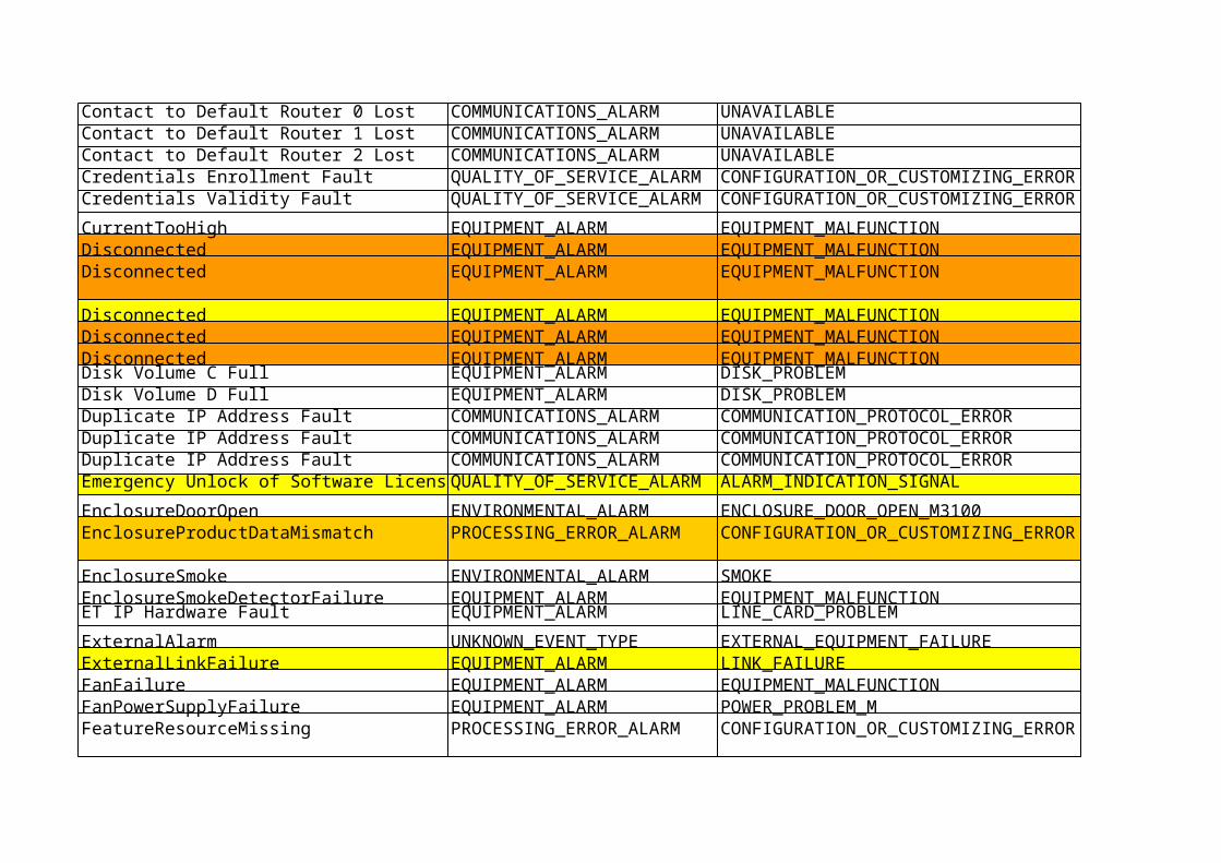
Contact to Default Router X Lost COMMUNICATIONS_ALARM UNAVAILABLE
Credentials Validity Fault QUALITY_OF_SERVICE_ALARMCONFIGURATION_OR_CUSTOMIZING_ERROR
Disconnected EQUIPMENT_ALARM EQUIPMENT_MALFUNCTION
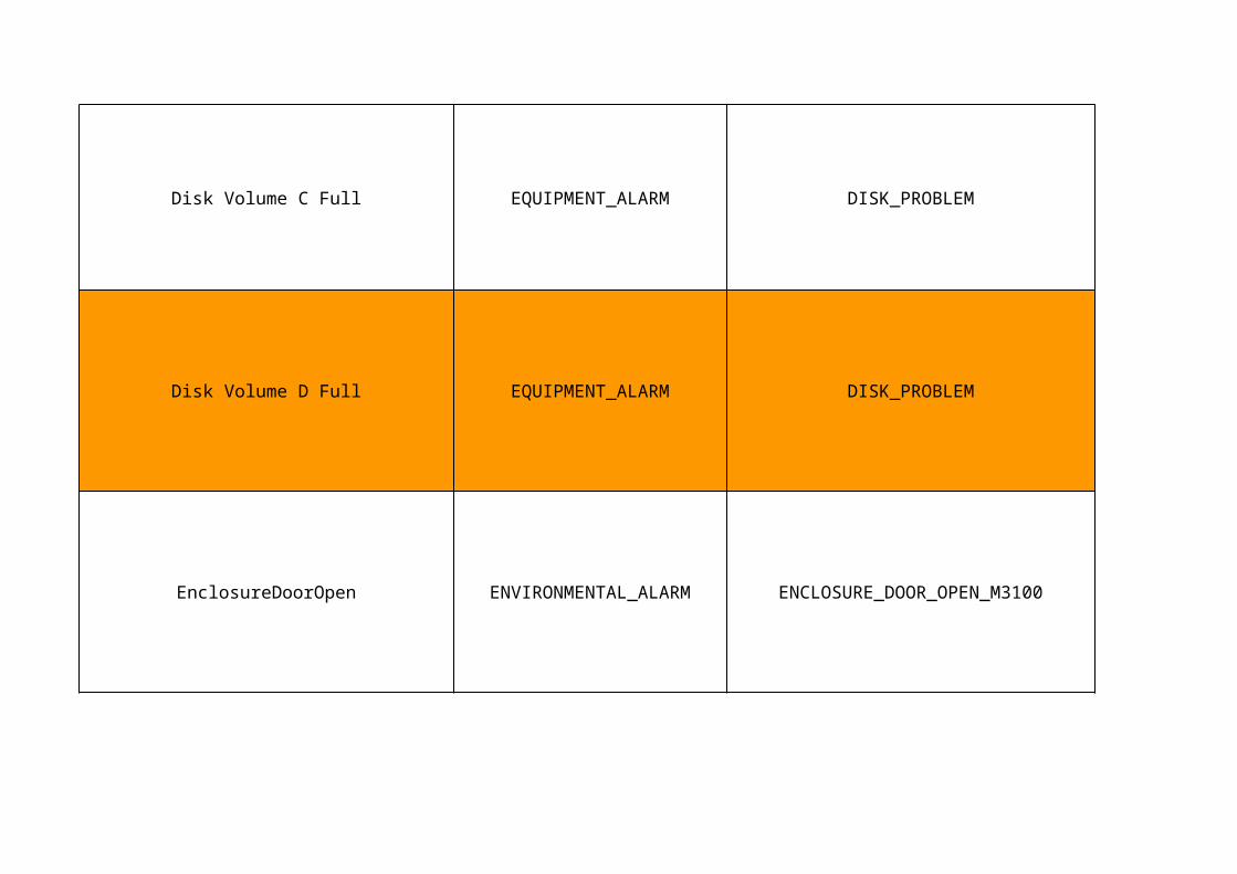
Disk Volume C Full EQUIPMENT_ALARM DISK_PROBLEM
Disk Volume D Full EQUIPMENT_ALARM DISK_PROBLEM
EnclosureDoorOpen ENVIRONMENTAL_ALARM ENCLOSURE_DOOR_OPEN_M3100

EnclosureProductDataMismatch
EnclosureSmoke ENVIRONMENTAL_ALARM SMOKE
EnclosureSmokeDetectorFailure EQUIPMENT_ALARM EQUIPMENT_MALFUNCTION
PROCESSING_ERROR_ALARM
CONFIGURATION_OR_CUSTOMIZING_ERROR
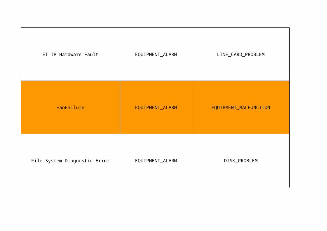
ET IP Hardware Fault EQUIPMENT_ALARM LINE_CARD_PROBLEM
FanFailure EQUIPMENT_ALARM EQUIPMENT_MALFUNCTION
File System Diagnostic Error EQUIPMENT_ALARM DISK_PROBLEM
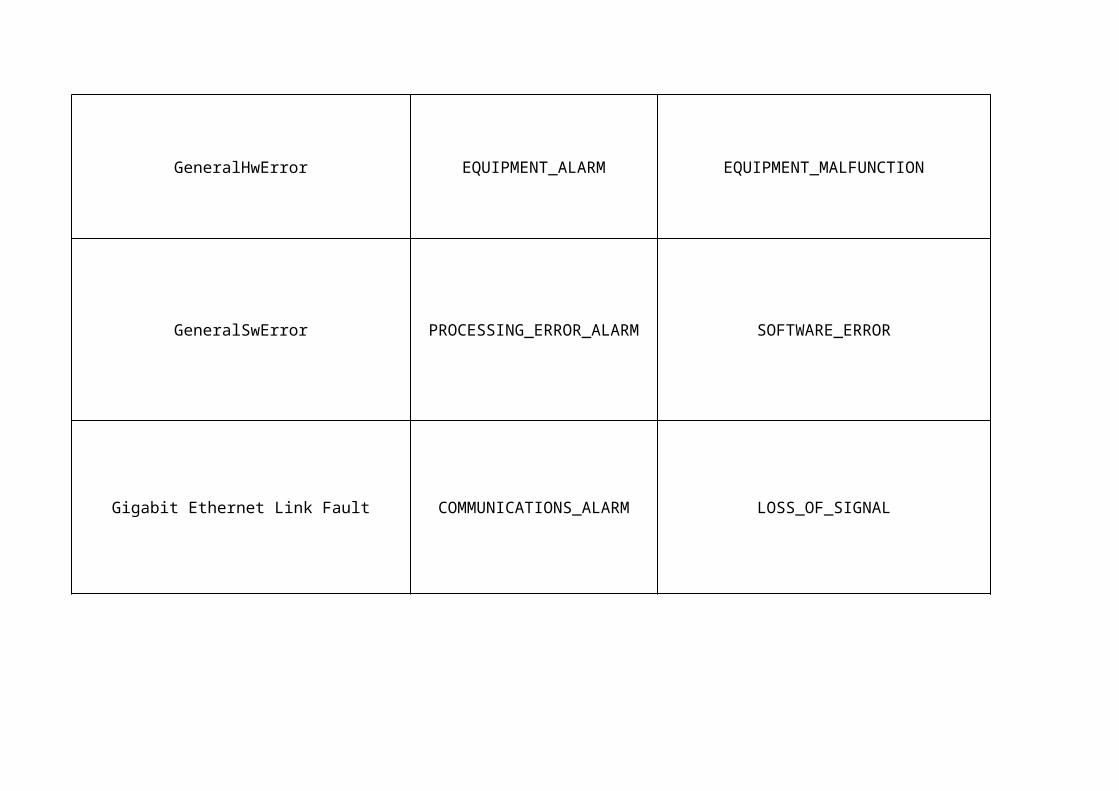
GeneralHwError EQUIPMENT_ALARM EQUIPMENT_MALFUNCTION
GeneralSwError SOFTWARE_ERROR
Gigabit Ethernet Link Fault COMMUNICATIONS_ALARM LOSS_OF_SIGNAL
PROCESSING_ERROR_ALARM
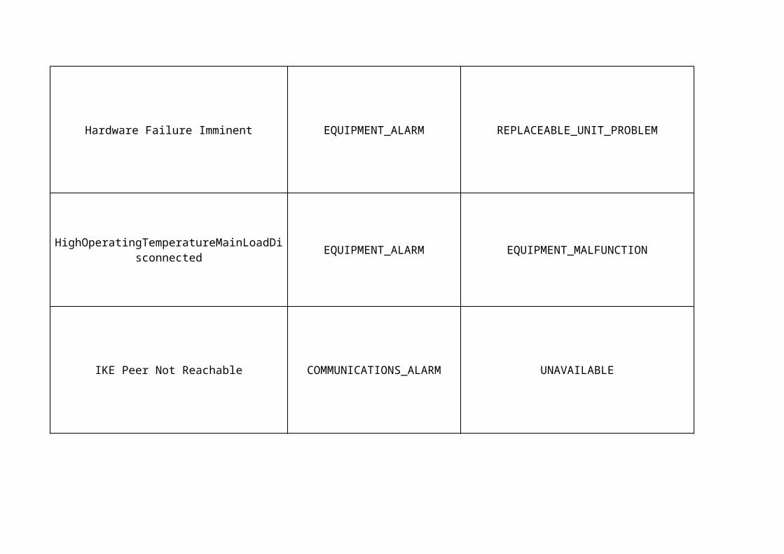
Hardware Failure Imminent EQUIPMENT_ALARM REPLACEABLE_UNIT_PROBLEM
EQUIPMENT_ALARM EQUIPMENT_MALFUNCTION
IKE Peer Not Reachable COMMUNICATIONS_ALARM UNAVAILABLE
HighOperatingTemperatureMainLoadDisconnected
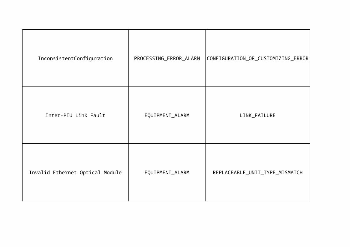
InconsistentConfiguration
Inter-PIU Link Fault EQUIPMENT_ALARM LINK_FAILURE
Invalid Ethernet Optical Module EQUIPMENT_ALARM REPLACEABLE_UNIT_TYPE_MISMATCH
PROCESSING_ERROR_ALARM
CONFIGURATION_OR_CUSTOMIZING_ERROR

IPsec Certificate Fault COMMUNICATIONS_ALARMCONFIGURATION_OR_CUSTOMIZING_ERROR
License Key File Fault QUALITY_OF_SERVICE_ALARMCONFIGURATION_OR_CUSTOMIZING_ERROR

Loss of System Clock EQUIPMENT_ALARM REPLACEABLE_UNIT_PROBLEM

Loss of Tracking EQUIPMENT_ALARM REPLACEABLE_UNIT_PROBLEM
LossOfMains
ENVIRONMENTAL_ALARM COMMERCIAL_POWER_FAILURE
ENVIRONMENTAL_ALARM COMMERCIAL_POWER_FAILURE
LowBatteryCapacity EQUIPMENT_ALARM BATTERY_FAILURE

NTP Server Reachability Fault COMMUNICATIONS_ALARM UNAVAILABLE
NumberOfHwEntitiesMismatch
EQUIPMENT_ALARM EQUIPMENT_MALFUNCTION
PROCESSING_ERROR_ALARM
CONFIGURATION_OR_CUSTOMIZING_ERROR
OperatingTemperatureTooHighBatteryDisconnected

OperatingTemperatureTooHighNoService ENVIRONMENTAL_ALARM TEMPERATURE_UNACCEPTABLE
ENVIRONMENTAL_ALARM TEMPERATURE_UNACCEPTABLE
Plug-In Unit General Problem EQUIPMENT_ALARM REPLACEABLE_UNIT_PROBLEM
OperatingTemperatureTooLowCommunicationLost

Plug-In Unit HW Failure EQUIPMENT_ALARM REPLACEABLE_UNIT_PROBLEM
Power Failure Right Slot EQUIPMENT_ALARM POWER_PROBLEM_M3100
ResourceAllocationFailurePROCESSING_ERROR_ALA
RMCONFIGURATION_OR_CUSTOMIZING_
ERROR

ResourceConfigurationFailure TIMEOUT_EXPIRED
RunningOnBatterySupply ENVIRONMENTAL_ALARM BATTERY_DISCHARGING
ServiceUnavailable
PROCESSING_ERROR_ALARM
QUALITY_OF_SERVICE_ALARM
UNDERLYING_RESOURCE_UNAVAILABLE
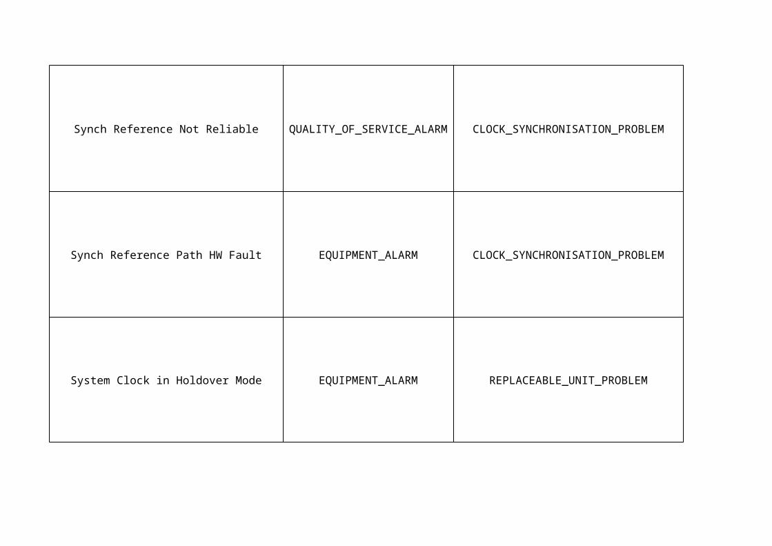
Synch Reference Not Reliable QUALITY_OF_SERVICE_ALARMCLOCK_SYNCHRONISATION_PROBLEM
Synch Reference Path HW Fault EQUIPMENT_ALARM CLOCK_SYNCHRONISATION_PROBLEM
System Clock in Holdover Mode EQUIPMENT_ALARM REPLACEABLE_UNIT_PROBLEM
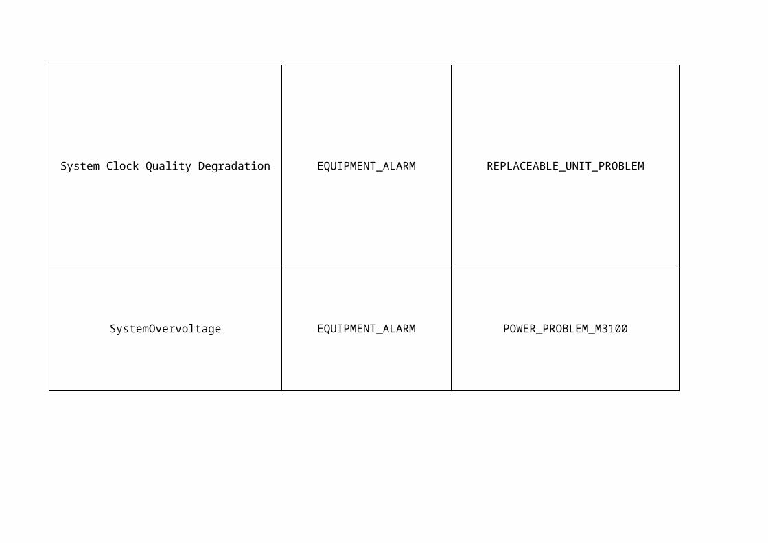
System Clock Quality Degradation EQUIPMENT_ALARM REPLACEABLE_UNIT_PROBLEM
SystemOvervoltage EQUIPMENT_ALARM POWER_PROBLEM_M3100

SystemUndervoltage EQUIPMENT_ALARM POWER_PROBLEM_M3100
TemperatureSensorFailure EQUIPMENT_ALARM EQUIPMENT_MALFUNCTION
TU Synch Reference Loss of Signal COMMUNICATIONS_ALARM LOSS_OF_SIGNAL
Auto-Configuration of Board Not Possible EQUIPMENT_ALARM UNAVAILABLEAutomatic CV Creation Failed EQUIPMENT_ALARM UNAVAILABLE
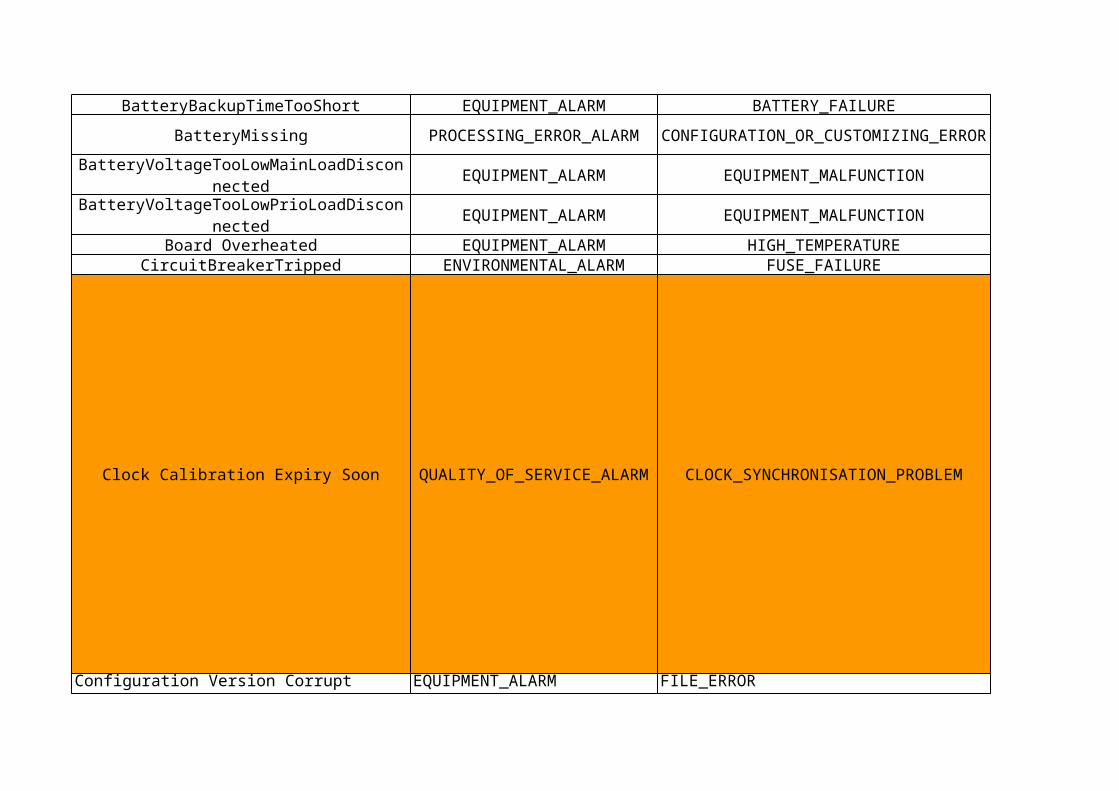
BatteryBackupTimeTooShort EQUIPMENT_ALARM BATTERY_FAILURE
BatteryMissing
EQUIPMENT_ALARM EQUIPMENT_MALFUNCTION
EQUIPMENT_ALARM EQUIPMENT_MALFUNCTION
Board Overheated EQUIPMENT_ALARM HIGH_TEMPERATURECircuitBreakerTripped ENVIRONMENTAL_ALARM FUSE_FAILURE
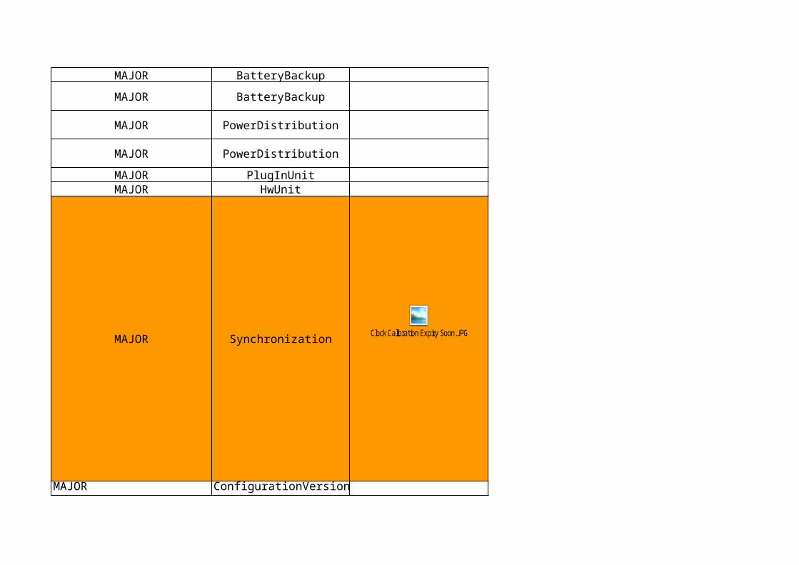
Clock Calibration Expiry Soon QUALITY_OF_SERVICE_ALARMCLOCK_SYNCHRONISATION_PROBLEM
Configuration Version Corrupt EQUIPMENT_ALARM FILE_ERROR
PROCESSING_ERROR_ALARM
CONFIGURATION_OR_CUSTOMIZING_ERROR
BatteryVoltageTooLowMainLoadDisconnected
BatteryVoltageTooLowPrioLoadDisconnected
Contact to Default Router 0 Lost COMMUNICATIONS_ALARM UNAVAILABLEContact to Default Router 1 Lost COMMUNICATIONS_ALARM UNAVAILABLEContact to Default Router 2 Lost COMMUNICATIONS_ALARM UNAVAILABLECredentials Enrollment Fault QUALITY_OF_SERVICE_ALARCONFIGURATION_OR_CUSTOMIZING_ECredentials Validity Fault QUALITY_OF_SERVICE_ALARCONFIGURATION_OR_CUSTOMIZING_E
CurrentTooHigh EQUIPMENT_ALARM EQUIPMENT_MALFUNCTIONDisconnected EQUIPMENT_ALARM EQUIPMENT_MALFUNCTIONDisconnected EQUIPMENT_ALARM EQUIPMENT_MALFUNCTION
Disconnected EQUIPMENT_ALARM EQUIPMENT_MALFUNCTIONDisconnected EQUIPMENT_ALARM EQUIPMENT_MALFUNCTIONDisconnected EQUIPMENT_ALARM EQUIPMENT_MALFUNCTIONDisk Volume C Full EQUIPMENT_ALARM DISK_PROBLEMDisk Volume D Full EQUIPMENT_ALARM DISK_PROBLEMDuplicate IP Address Fault COMMUNICATIONS_ALARM COMMUNICATION_PROTOCOL_ERRORDuplicate IP Address Fault COMMUNICATIONS_ALARM COMMUNICATION_PROTOCOL_ERRORDuplicate IP Address Fault COMMUNICATIONS_ALARM COMMUNICATION_PROTOCOL_ERROREmergency Unlock of Software Licensing QUALITY_OF_SERVICE_ALARALARM_INDICATION_SIGNAL
EnclosureDoorOpen ENVIRONMENTAL_ALARM ENCLOSURE_DOOR_OPEN_M3100EnclosureProductDataMismatch
EnclosureSmoke ENVIRONMENTAL_ALARM SMOKEEnclosureSmokeDetectorFailure EQUIPMENT_ALARM EQUIPMENT_MALFUNCTIONET IP Hardware Fault EQUIPMENT_ALARM LINE_CARD_PROBLEM
ExternalAlarm UNKNOWN_EVENT_TYPE EXTERNAL_EQUIPMENT_FAILUREExternalLinkFailure EQUIPMENT_ALARM LINK_FAILUREFanFailure EQUIPMENT_ALARM EQUIPMENT_MALFUNCTIONFanPowerSupplyFailure EQUIPMENT_ALARM POWER_PROBLEM_MFeatureResourceMissing
PROCESSING_ERROR_ALARM
CONFIGURATION_OR_CUSTOMIZING_ERROR
PROCESSING_ERROR_ALARM
CONFIGURATION_OR_CUSTOMIZING_ERROR

FeatureResourceMissing
FeatureResourceMissing
File System Diagnostic Error EQUIPMENT_ALARM DISK_PROBLEM
GeneralHwError EQUIPMENT_ALARM EQUIPMENT_MALFUNCTIONGeneralSwError SYSTEM_CALL_UNSUCCESSFUL
GeneralSwError TIMEOUT_EXPIRED
GeneralSwError SOFTWARE_DOWNLOAD_FAILURE
GeneralSwError SOFTWARE_ERROR
GeneralSwError SOFTWARE_DOWNLOAD_FAILURE
GeneralSwError SYSTEM_CALL_UNSUCCESSFUL
GeneralSwError TIMEOUT_EXPIRED
GeneralSwError SOFTWARE_ERROR
GeneralSwError SYSTEM_CALL_UNSUCCESSFUL
GeneralSwError TIMEOUT_EXPIRED
GeneralSwError SOFTWARE_DOWNLOAD_FAILURE
GeneralSwError SOFTWARE_ERROR
PROCESSING_ERROR_ALARM
CONFIGURATION_OR_CUSTOMIZING_ERROR
PROCESSING_ERROR_ALARM
CONFIGURATION_OR_CUSTOMIZING_ERROR
PROCESSING_ERROR_ALARMPROCESSING_ERROR_ALARMPROCESSING_ERROR_ALARMPROCESSING_ERROR_ALARMPROCESSING_ERROR_ALARMPROCESSING_ERROR_ALARMPROCESSING_ERROR_ALARMPROCESSING_ERROR_ALARMPROCESSING_ERROR_ALARMPROCESSING_ERROR_ALARMPROCESSING_ERROR_ALARMPROCESSING_ERROR_ALARM

GeneralSwError SOFTWARE_DOWNLOAD_FAILURE
GeneralSwError SYSTEM_CALL_UNSUCCESSFUL
GeneralSwError TIMEOUT_EXPIRED
GeneralSwError SOFTWARE_ERROR
Gigabit Ethernet Link Fault COMMUNICATIONS_ALARM LOSS_OF_SIGNALGigabit Ethernet Link Redundancy Fault EQUIPMENT_ALARM REPLACEABLE_UNIT_PROBLEM
GpsConnectivityDownstreamFault EQUIPMENT_ALARM
GpsHardwareFault EQUIPMENT_ALARM REPLACEABLE_UNIT_PROBLEM GracePeriodExpires THRESHOLD_CROSSED
GracePeriodStarted THRESHOLD_CROSSED
Hardware Failure Imminent EQUIPMENT_ALARM REPLACEABLE_UNIT_PROBLEM
EQUIPMENT_ALARM EQUIPMENT_MALFUNCTION
HwFault EQUIPMENT_ALARM EQUIPMENT_MALFUNCTIONHwFault EQUIPMENT_ALARM EQUIPMENT_MALFUNCTIONHwFault EQUIPMENT_ALARM EQUIPMENT_MALFUNCTIONIKE Peer Not Reachable COMMUNICATIONS_ALARM UNAVAILABLE
InconsistentConfiguration
InconsistentConfiguration
InconsistentConfiguration
PROCESSING_ERROR_ALARMPROCESSING_ERROR_ALARMPROCESSING_ERROR_ALARMPROCESSING_ERROR_ALARM
CLOCK_SYNCHRONISATION_PROBLEM
QUALITY_OF_SERVICE_ALARMQUALITY_OF_SERVICE_ALARM
HighOperatingTemperatureMainLoadDisconnected
PROCESSING_ERROR_ALARM
CONFIGURATION_OR_CUSTOMIZING_ERROR
PROCESSING_ERROR_ALARM
CONFIGURATION_OR_CUSTOMIZING_ERROR
PROCESSING_ERROR_ALARM
CONFIGURATION_OR_CUSTOMIZING_ERROR
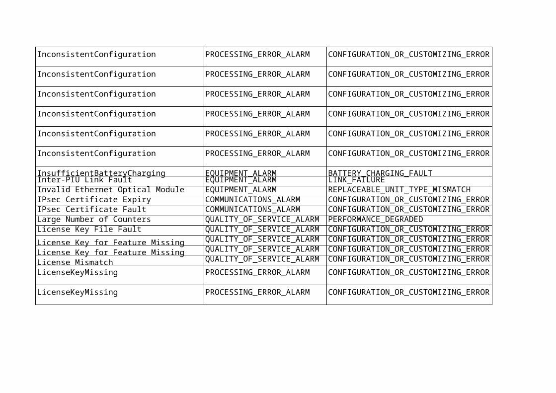
InconsistentConfiguration
InconsistentConfiguration
InconsistentConfiguration
InconsistentConfiguration
InconsistentConfiguration
InconsistentConfiguration
InsufficientBatteryCharging EQUIPMENT_ALARM BATTERY_CHARGING_FAULTInter-PIU Link Fault EQUIPMENT_ALARM LINK_FAILUREInvalid Ethernet Optical Module EQUIPMENT_ALARM REPLACEABLE_UNIT_TYPE_MISMATCHIPsec Certificate Expiry COMMUNICATIONS_ALARM CONFIGURATION_OR_CUSTOMIZING_EIPsec Certificate Fault COMMUNICATIONS_ALARM CONFIGURATION_OR_CUSTOMIZING_ELarge Number of Counters QUALITY_OF_SERVICE_ALARPERFORMANCE_DEGRADEDLicense Key File Fault QUALITY_OF_SERVICE_ALARCONFIGURATION_OR_CUSTOMIZING_E
License Key for Feature Missing QUALITY_OF_SERVICE_ALARCONFIGURATION_OR_CUSTOMIZING_E
License Key for Feature Missing QUALITY_OF_SERVICE_ALARCONFIGURATION_OR_CUSTOMIZING_E
License Mismatch QUALITY_OF_SERVICE_ALARCONFIGURATION_OR_CUSTOMIZING_E
LicenseKeyMissing
LicenseKeyMissing
PROCESSING_ERROR_ALARM
CONFIGURATION_OR_CUSTOMIZING_ERROR
PROCESSING_ERROR_ALARM
CONFIGURATION_OR_CUSTOMIZING_ERROR
PROCESSING_ERROR_ALARM
CONFIGURATION_OR_CUSTOMIZING_ERROR
PROCESSING_ERROR_ALARM
CONFIGURATION_OR_CUSTOMIZING_ERROR
PROCESSING_ERROR_ALARM
CONFIGURATION_OR_CUSTOMIZING_ERROR
PROCESSING_ERROR_ALARM
CONFIGURATION_OR_CUSTOMIZING_ERROR
PROCESSING_ERROR_ALARM
CONFIGURATION_OR_CUSTOMIZING_ERROR
PROCESSING_ERROR_ALARM
CONFIGURATION_OR_CUSTOMIZING_ERROR

LinkFailure EQUIPMENT_ALARM LINK_FAILURE
Local AA DB Installation Fault QUALITY_OF_SERVICE_ALARCONFIGURATION_OR_CUSTOMIZING_ELoss of Synch Reference Redundancy EQUIPMENT_ALARM REPLACEABLE_UNIT_PROBLEM

Loss of Tracking EQUIPMENT_ALARM REPLACEABLE_UNIT_PROBLEM
LossOfMains ENVIRONMENTAL_ALARM COMMERCIAL_POWER_FAILURELossOfMains ENVIRONMENTAL_ALARM COMMERCIAL_POWER_FAILURELowBatteryCapacity EQUIPMENT_ALARM BATTERY_FAILUREMaximum Number of Counters Exceeded QUALITY_OF_SERVICE_ALARPERFORMANCE_DEGRADEDNetwork Synch Time from GPS Missing COMMUNICATIONS_ALARM CLOCK_SYNCHRONISATION_PROBLEMNetwork Synch Time from GPS Missing COMMUNICATIONS_ALARM CLOCK_SYNCHRONISATION_PROBLEM
NoContact EQUIPMENT_ALARM EQUIPMENT_MALFUNCTIONNoContact EQUIPMENT_ALARM EQUIPMENT_MALFUNCTIONNoContact
NoContact EQUIPMENT_ALARM EQUIPMENT_MALFUNCTIONNTP Server Reachability Fault COMMUNICATIONS_ALARM UNAVAILABLENTP System Time Sync Fault COMMUNICATIONS_ALARM CLOCK_SYNCHRONISATION_PROBLEMNTP System Time Sync Problem COMMUNICATIONS_ALARM CLOCK_SYNCHRONISATION_PROBLEM
NumberOfHwEntitiesMismatch
NumberOfHwEntitiesMismatch
EQUIPMENT_ALARM EQUIPMENT_MALFUNCTION
EQUIPMENT_ALARM EQUIPMENT_MALFUNCTION
ENVIRONMENTAL_ALARM HIGH_TEMPERATURE
OperatingTemperatureTooHighNoService ENVIRONMENTAL_ALARM TEMPERATURE_UNACCEPTABLE
ENVIRONMENTAL_ALARM LOW_TEMPERATURE
PROCESSING_ERROR_ALARM
CONFIGURATION_OR_CUSTOMIZING_ERROR
PROCESSING_ERROR_ALARM
CONFIGURATION_OR_CUSTOMIZING_ERROR
PROCESSING_ERROR_ALARM
CONFIGURATION_OR_CUSTOMIZING_ERROR
OperatingTemperatureTooHighBatteryDisconnectedOperatingTemperatureTooHighBatteryDisconnectedOperatingTemperatureTooHighCapacityReduced
OperatingTemperatureTooLowCapacityReduced

ENVIRONMENTAL_ALARM TEMPERATURE_UNACCEPTABLE
Packet Server Availability Fault COMMUNICATIONS_ALARM UNAVAILABLEPacket Server Availability Fault COMMUNICATIONS_ALARM UNAVAILABLE
Password File Fault QUALITY_OF_SERVICE_ALARCONFIGURATION_OR_CUSTOMIZING_EPlug-In Unit General Problem EQUIPMENT_ALARM REPLACEABLE_UNIT_PROBLEMPlug-In Unit HW Failure EQUIPMENT_ALARM REPLACEABLE_UNIT_PROBLEMPower Feeding Fault EQUIPMENT_ALARM EQUIPMENT_MALFUNCTION
PowerFailure EQUIPMENT_ALARM POWER_SUPPLY_FAILUREProblemsToScheduleSiMessages CONGESTION
Remote IP Address Unreachable COMMUNICATIONS_ALARM UNAVAILABLE
ResourceAllocationFailure
ResourceAllocationFailure
ResourceConfigurationFailure EQUIPMENT_ALARM EQUIPMENT_MALFUNCTIONResourceConfigurationFailure SYSTEM_CALL_UNSUCCESSFUL
ResourceConfigurationFailure TIMEOUT_EXPIRED
ResourceConfigurationFailure
ResourceConfigurationFailure TIMEOUT_EXPIRED
RetFailure EQUIPMENT_ALARM EQUIPMENT_MALFUNCTIONRunningOnBatterySupply ENVIRONMENTAL_ALARM BATTERY_DISCHARGING
OperatingTemperatureTooLowCommunicationLost
QUALITY_OF_SERVICE_ALARM
PROCESSING_ERROR_ALARM
CONFIGURATION_OR_CUSTOMIZING_ERROR
PROCESSING_ERROR_ALARM
CONFIGURATION_OR_CUSTOMIZING_ERROR
PROCESSING_ERROR_ALARMPROCESSING_ERROR_ALARMPROCESSING_ERROR_ALARM
CONFIGURATION_OR_CUSTOMIZING_ERROR
PROCESSING_ERROR_ALARM

Security Level Fault QUALITY_OF_SERVICE_ALARCONFIGURATION_OR_CUSTOMIZING_E
ServiceDegraded EQUIPMENT_ALARM PERFORMANCE_DEGRADEDServiceUnavailable
Signed Software Problem
Slave TU Out of Synchronization EQUIPMENT_ALARM CLOCK_SYNCHRONISATION_PROBLEMSync Reference PDV Problem QUALITY_OF_SERVICE_ALARCLOCK_SYNCHRONISATION_PROBLEMSynch Reference Not Reliable QUALITY_OF_SERVICE_ALARCLOCK_SYNCHRONISATION_PROBLEMSynch Reference Path HW Fault EQUIPMENT_ALARM CLOCK_SYNCHRONISATION_PROBLEMSystem Clock Quality Degradation EQUIPMENT_ALARM REPLACEABLE_UNIT_PROBLEM
SystemOvervoltage EQUIPMENT_ALARM POWER_PROBLEM_M3100SystemUndervoltage EQUIPMENT_ALARM POWER_PROBLEM_M3100TemperatureAbnormal ENVIRONMENTAL_ALARM HIGH_TEMPERATURETemperatureAbnormal ENVIRONMENTAL_ALARM LOW_TEMPERATURE
ENVIRONMENTAL_ALARM HIGH_TEMPERATURE
ENVIRONMENTAL_ALARM LOW_TEMPERATURE
ENVIRONMENTAL_ALARM HIGH_TEMPERATURE
TemperatureSensorFailure EQUIPMENT_ALARM EQUIPMENT_MALFUNCTIONTemperatureSensorFailure EQUIPMENT_ALARM EQUIPMENT_MALFUNCTIONTimingSyncFault EQUIPMENT_ALARM
Trusted Certificate Installation Fault QUALITY_OF_SERVICE_ALARCONFIGURATION_OR_CUSTOMIZING_ETU Hardware Fault COMMUNICATIONS_ALARM REPLACEABLE_UNIT_PROBLEMTU Oscillator Temperature Fault ENVIRONMENTAL_ALARM TEMPERATURE_UNACCEPTABLETU Synch Reference Loss of Signal COMMUNICATIONS_ALARM LOSS_OF_SIGNAL
PROCESSING_ERROR_ALARM
UNDERLYING_RESOURCE_UNAVAILABLE
QUALITY_OF_SERVICE_ALARM
CONFIGURATION_OR_CUSTOMIZING_ERROR
TemperatureAbnormalPerformanceDegradedTemperatureExceptionalTakenOutOfServiceTemperatureExceptionalTakenOutOfService
CLOCK_SYNCHRONISATION_PROBLEM

UnreliableResource
UnreliableResource THRESHOLD_CROSSED
Upgrade Package Corrupt EQUIPMENT_ALARM FILE_ERRORUser-Defined Profiles File Error PROCESSING_ERROR_ALAR FILE_ERROR
VswrOverThreshold EQUIPMENT_ALARM EQUIPMENT_MALFUNCTION
Heartbeat Failure Communications alarm LAN Error/Communication Error
PROCESSING_ERROR_ALARM
CONFIGURATION_OR_CUSTOMIZING_ERROR
QUALITY_OF_SERVICE_ALARM

LTE Alarm List for EnodeB
PerceivedSeverity Managed Object Alarm Print
MAJOR BatteryBackup
MAJOR BatteryBackup

MAJOR PowerDistribution
MAJOR PowerDistribution
MAJOR PlugInUnit

MAJOR HwUnit
MAJOR ConfigurationVersion
MAJOR IpInterface

MAJOR Security
MAJOR
MAJOR FanGroup
MAJOR HwUnit
EquipmentSupportFunction
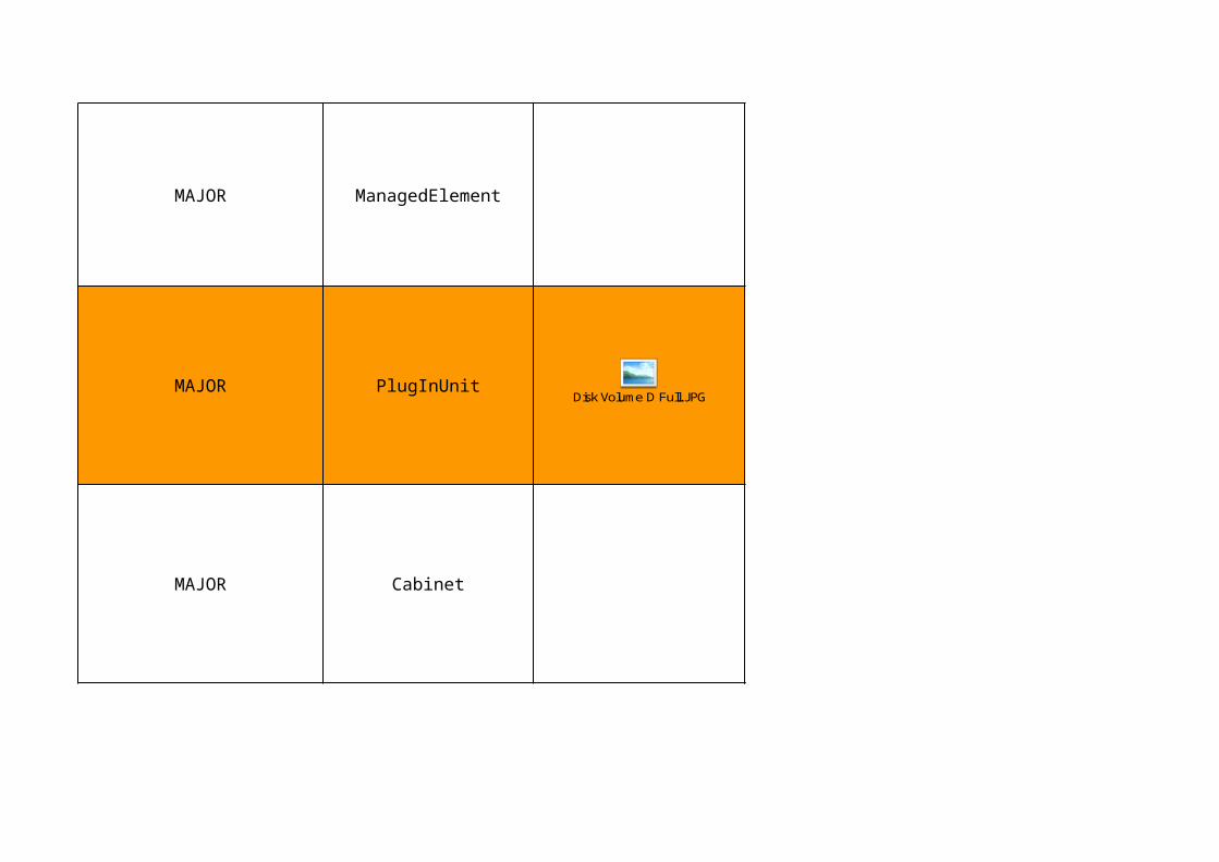
MAJOR ManagedElement
MAJOR PlugInUnit
MAJOR Cabinet
Disk Volume D Full.J PG

MAJOR Cabinet
CRITICAL Cabinet
MAJOR Cabinet

MAJOR ExchangeTerminalIp
MAJOR FanGroup
MAJOR PlugInUnit
FanFailure.J PG

MAJOR HwUnit
MAJOR HwUnit
MAJOR GigaBitEthernet
MAJOR PlugInUnit
MAJOR PowerDistribution
MAJOR IkePeer

MAJOR
MAJOR InterPiuLink
MAJOR GigaBitEthernet
SectorEquipmentFunction

MAJOR IPsec
CRITICAL LicensingLicense Key File Fault.J PG

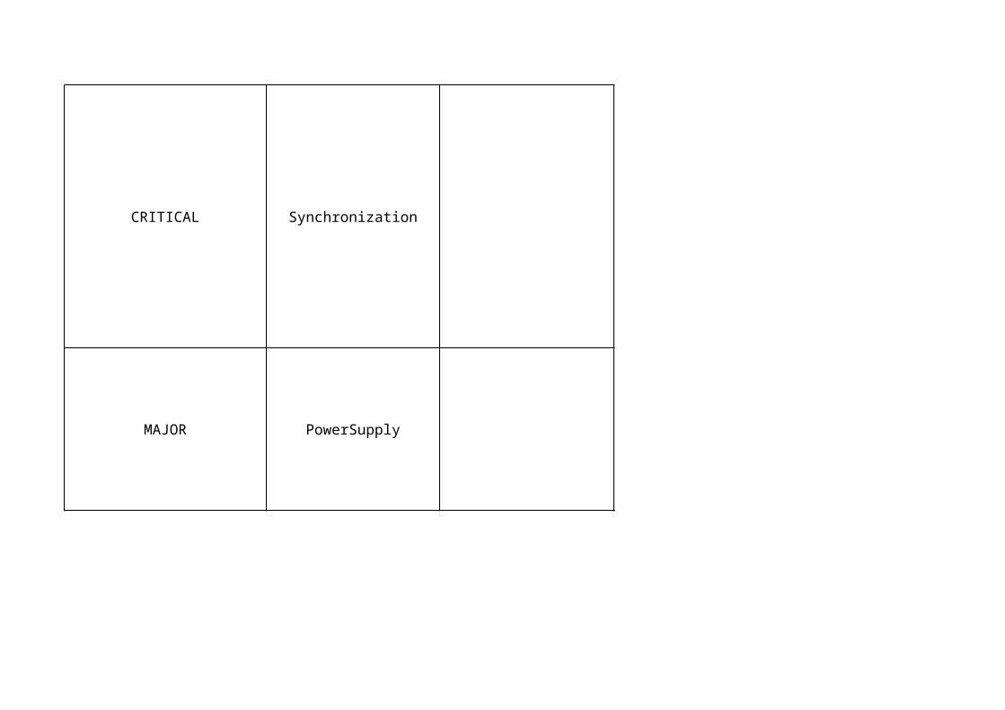
CRITICAL Synchronization

MAJOR Synchronization
MAJOR HwUnit
MAJOR PowerSupply
MAJOR BatteryBackup

MAJOR IpSyncRef
MAJOR Cabinet
MAJOR BatteryBackup
MAJOR HwUnit

MAJOR HwUnit
MAJOR HwUnit
MAJOR PlugInUnit

MAJOR PlugInUnit
MAJOR Subrack
MAJOR EUtranCellFDD

MAJOR EUtranCellFDD
MAJOR BatteryBackup
MAJOR EUtranCellTDD
ResourceConfigurationFailure.J PG
ServiceUnavailable.J PG
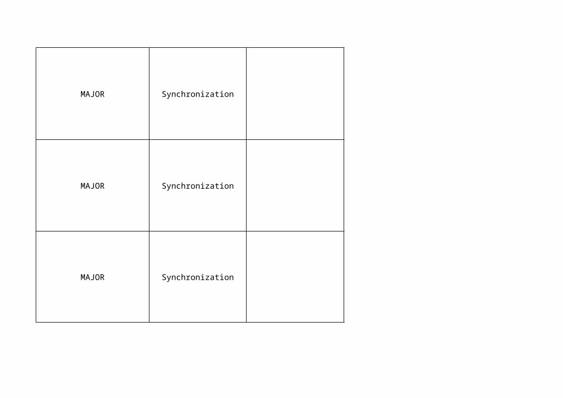
MAJOR Synchronization
MAJOR Synchronization
MAJOR Synchronization
CRITICAL Synchronization
MAJOR PowerSupply

MAJOR PowerSupply
MAJOR BatteryBackup
MAJOR TuSyncRef
WARNING SlotWARNING ConfigurationVersion
TU Synch Reference Loss of Signal.J PG
MAJOR BatteryBackup
MAJOR BatteryBackup
MAJOR PowerDistribution
MAJOR PowerDistribution
MAJOR PlugInUnitMAJOR HwUnit
MAJOR Synchronization
MAJOR ConfigurationVersion
Clock Calibration Expiry Soon.J PG
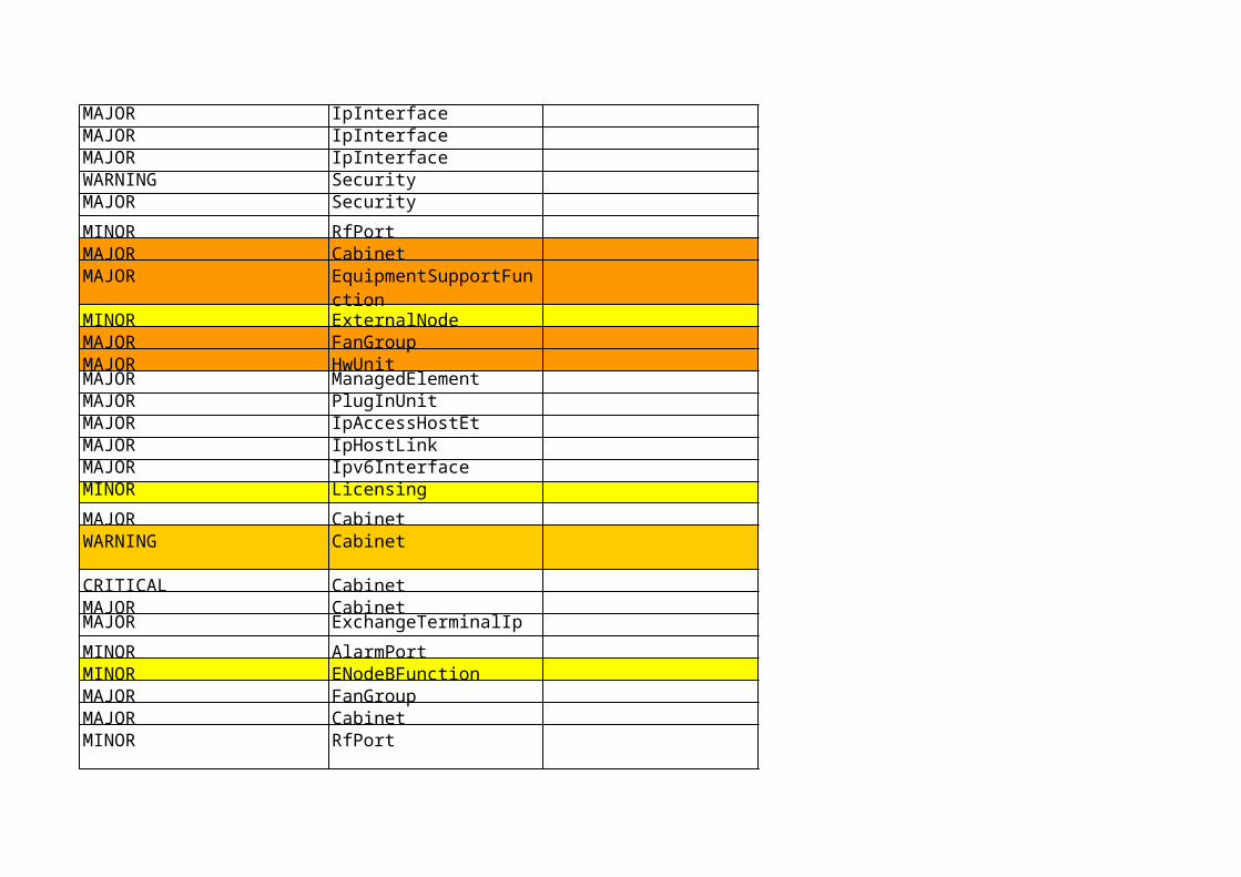
MAJOR IpInterfaceMAJOR IpInterfaceMAJOR IpInterfaceWARNING SecurityMAJOR Security
MINOR RfPortMAJOR CabinetMAJOR
MINOR ExternalNodeMAJOR FanGroupMAJOR HwUnitMAJOR ManagedElementMAJOR PlugInUnitMAJOR IpAccessHostEtMAJOR IpHostLinkMAJOR Ipv6InterfaceMINOR Licensing
MAJOR CabinetWARNING Cabinet
CRITICAL CabinetMAJOR CabinetMAJOR ExchangeTerminalIp
MINOR AlarmPortMINOR ENodeBFunctionMAJOR FanGroupMAJOR CabinetMINOR RfPort
EquipmentSupportFunction

MAJOR
MAJOR EUtranCellFDD
MAJOR PlugInUnit
MAJOR HwUnitMINOR AntennaNearUnit
MINOR AntennaNearUnit
MINOR AntennaNearUnit
MINOR DeviceGroup
MINOR DeviceGroup
MINOR DeviceGroup
MINOR DeviceGroup
MAJOR HwUnit
MINOR AntennaNearUnit
MINOR AntennaNearUnit
MINOR AntennaNearUnit
MINOR DeviceGroup
SectorEquipmentFunction
MINOR DeviceGroup
MINOR DeviceGroup
MINOR DeviceGroup
MAJOR HwUnit
MAJOR GigaBitEthernetWARNING GigaBitEthernet
MAJOR DeviceGroup
MAJOR DeviceGroupMINOR CapacityFeatureLicense
MINOR CapacityFeatureLicense
MAJOR PlugInUnit
MAJOR PowerDistribution
MINOR AntennaNearUnitMINOR DeviceGroupMINOR RiPortMAJOR IkePeer
MINOR AntennaUnit
MINOR DeviceGroup
MINOR RetSubUnit

MINOR RfPort
MINOR RiPort
MAJOR
MAJOR MbsfnArea
MINOR AlarmPort
MINOR EcPort
MINOR BatteryBackupMAJOR InterPiuLinkMAJOR GigaBitEthernetWARNING IpSecMAJOR IpSecWARNING ManagedElementCRITICAL LicensingMAJOR IpSec
MAJOR Ipv6MAJOR Licensing
MAJOR CapacityFeatureLicense
MAJOR OptionalFeatureLicense
SectorEquipmentFunction

MINOR RiPort
MINOR SecurityMINOR Synchronization
LinkFailure.J PG

MAJOR Synchronization
MAJOR HwUnitMAJOR PowerSupplyMAJOR BatteryBackupMINOR ManagedElementMAJOR TuSyncRefMAJOR GpsSyncRef
MINOR AuxPlugInUnitMINOR AntennaNearUnitMINOR AntennaNearUnit
MINOR AuxPlugInUnitMAJOR IpSyncRefMAJOR ManagedElementDataMINOR ManagedElementData
MAJOR Cabinet
MAJOR
MAJOR BatteryBackup
MAJOR HwUnit
MINOR HwUnit
MAJOR HwUnit
MINOR HwUnit
EquipmentSupportFunction
MAJOR HwUnit
MAJOR PacketFrequencySyncRefMAJOR PacketTimeSyncRef
MINOR SecurityMAJOR PlugInUnitMAJOR PlugInUnitMAJOR PfmUnit
MINOR AuxPlugInUnitMINOR EUtranCellFDD
MINOR Sctp
MAJOR EUtranCellFDD
MAJOR MbmsService
MINOR RetSubUnitMAJOR
MAJOR
MAJOR EUtranCellFDD
MAJOR EUtranCellFDD
MINOR RetSubUnitMAJOR BatteryBackup
SectorEquipmentFunctionSectorEquipmentFunction
Password File Fault.J PG
MAJOR Security
MINOR EUtranCellFDDMAJOR EUtranCellFDD
WARNING Security
MAJOR TimingUnitMAJOR SynchronizationMAJOR SynchronizationMAJOR SynchronizationCRITICAL Synchronization
MAJOR PowerSupplyMAJOR PowerSupplyWARNING DeviceGroupWARNING DeviceGroupMINOR DeviceGroup
MINOR DeviceGroup
MINOR DeviceGroup
MAJOR BatteryBackupMINOR HwUnitMAJOR DeviceGroup
MINOR SecurityMAJOR TimingUnitWARNING TimingUnitMAJOR TuSyncRef
MINOR EUtranCellFDD
MAJOR EUtranCellFDD
MAJOR UpgradePackageMAJOR Security
MINOR RfPort
CRITICAL ONRM_ROOT_MO
VswrOverThreshold.J PG
Heartbeat Failure.J PG
LTE Alarm List for EnodeB
Description
This alarm is raised when a test on demand or periodic battery backup time test has indicated that the estimated remaining battery backup time is shorter than expected. The alarm indicates that the battery capacity is not sufficient and that the battery should be changed in order to fulfil the required backup time.
Generated because of a disconnected or faulty cable between the battery and the Battery Fuse Unit (BFU), or because of a faulty battery.

The alarm is issued when the temperature of a board becomes higher than the maximum allowed temperature.
The alarm is raised when the main load is disconnected because of low battery voltage.The disconnected level is defined by the attribute mainLoadUnderVoltageDisconnect .
The alarm is raised when the battery is disconnected because of low battery voltage.The disconnect level is defined by the attribute priorityLoadUnderVoltageDisconnect
This alarm is raised from MO HwUnit with hwUnitType Baterry Fuse Unit (BFU). The alarm is raised when the battery is disconnected because of a tripped circuit breaker either by user intervention or as an automatic BFU safe guard.
The Configuration Version (CV) is corrupt.
The traffic on the network is disturbed. This can be caused by high traffic load, a hardware fault or wrong configuration of the network;or The router itself is not answering the ping request;or The IP address is invalid, or it is pointing to something other than a router.

The Node Credentials will expire in less than seven days.
This alarm is raised when a fan group that is expected to be present is disconnected.
The alarm is raised if there is no contact with a hardware unit that is expected to be present in the RBS
The alarm is raised when the secondary node has lost contact with the primary node. The secondary node is dependent on the primary node for support system control.
This alarm is raised when the cabinet door is opened.
The alarm is issued if the amount of stored data on the distributed C volume becomes so large that the volume is full, or nearly full.
The alarm is issued if the amount of stored data on the distributed D volume becomes so large that the volume is full, or nearly full.

This alarm is raised when the smoke detector detects smoke in the cabinet. The cause of this can be a fire.
This alarm is raised when the smoke detector hardware is faulty.
This alarm is issued if attribute productData on managed object Cabinet is empty or if the attribute value differs from the copy store internally in the node. The alarm is raised if the Support Control Unit (SCU) is moved from another RBS to this RBS because the productData copy stored in the SCU/SUP(Support Part) differs from the original data stored in the Digital Unit LTE(DUL).

Initial hardware tests have failed.
This alarm is raised when a fan is detected as faulty. The yellow led on the fan port is lit.
The file system has failed.

There is no configured link with operational state ENABLED.
The alarm is raised if there is a hardware fault in the unit. The alarm indicates that the unit must be replaced , unrecoverable hardware fault.
General software error on the unit. This fault needs a correction-delivery. Unit affected are Support Control Unit (SCU), Support Alarm Unit (SAU), Baterry Fuse Unit (BFU), and Power Supply Unit (PSU).

The flash disk is almost worn out and must be replaced.
This alarm is raised when the main load has been disconnected because of high temperature in the PDU (1). A likely cause is one of the following:
- fault in the climate system;- high environmental temperature;
The operational state for the IkePeer MO is DISABLED because an IKE Security Association (SA) could not be established with the IKE peer node. This can be for the following reasons:
- No response from the IKE peer node- Authentication failure- No proposal chosen
Cable between linked boards is missing, faulty or not properly connected.
Ethernet optical module is invalid or is not installed.
This alarm is raised because of, for example, an incorrect configuration of how the hardware, such as antenna near products, or radio equipment, are connected.

The operational state for the IpSec MO is DISABLED because: - There is no IPsec certificate installed or - There is no trusted certificate installed or
- The IPsec certificate has expired.
This alarm is raised when the LKF is corrupt or it is not valid for the node, or it has been deleted or it does not exist for other reasons.

The alarm is issued when no system clock is available in the node. The alarm provides information about the fault indicated in the corresponding primary alarm that can be: TU Hardware Fault
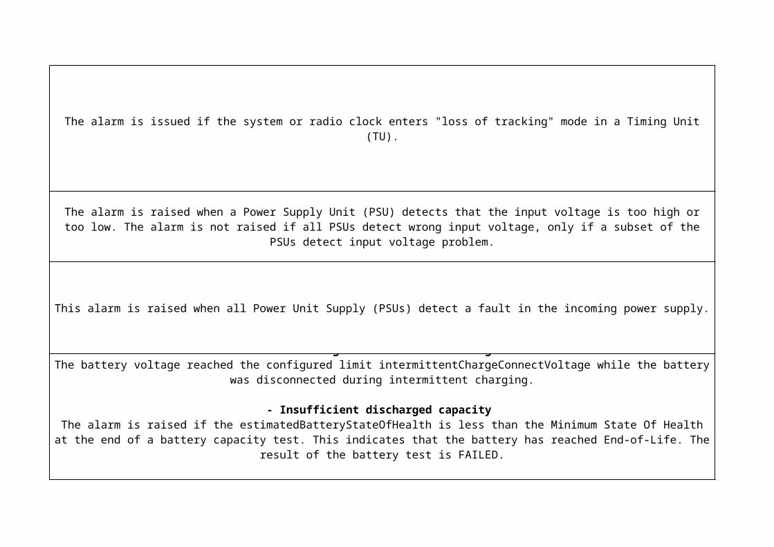
The alarm is issued if the system or radio clock enters "loss of tracking" mode in a Timing Unit (TU).
This alarm is raised when all Power Unit Supply (PSUs) detect a fault in the incoming power supply.
The alarm is raised when a Power Supply Unit (PSU) detects that the input voltage is too high or too low. The alarm is not raised if all PSUs detect wrong input voltage, only if a subset of the PSUs detect input voltage problem.
This alarm can be raised in three different situations. This is indicated by the alarms additional text:- Low voltage at intermittent charge
The battery voltage reached the configured limit intermittentChargeConnectVoltage while the battery was disconnected during intermittent charging.
- Insufficient discharged capacity The alarm is raised if the estimatedBatteryStateOfHealth is less than the Minimum State Of Health at the end of a battery
capacity test. This indicates that the battery has reached End-of-Life. The result of the battery test is FAILED.
- Insufficient recharged capacity The alarm is raised if the batteries are not sufficiently recharged after a discharge. This indicates poor battery performance.
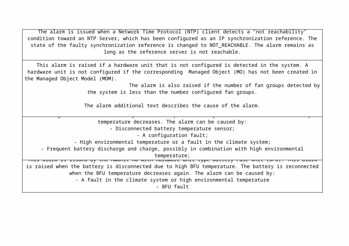
The alarm is issued when a Network Time Protocol (NTP) client detects a "not reachability" condition toward an NTP Server, which has been configured as an IP synchronization reference. The state of the faulty synchronization reference is changed
to NOT_REACHABLE. The alarm remains as long as the reference server is not reachable.
This alarm is raised if a hardware unit that is not configured is detected in the system. A hardware unit is not configured if the corresponding Managed Object (MO) has not been created in the Managed Object Model (MOM). The alarm is also raised if the number of fan groups detected by the system is less than
the number configured fan groups.
The alarm additional text describes the cause of the alarm.
This alarm is raised when the battery is disconnected because of high battery temperature, according to the attribute batteryDisconnectTemp. The battery is reconnected when the battery temperature decreases. The alarm can be caused by:
- Disconnected battery temperature sensor;- A configuration fault;
- High environmental temperature or a fault in the climate system;- Frequent battery discharge and charge, possibly in combination with high environmental temperature;
- A battery temperature sensor fault;- Battery failure;
This alarm is issued by the HwUnit MO with hardware unit type Battery Fuse Unit (BFU). This alarm is raised when the battery is disconnected due to high BFU temperature. The battery is reconnected when the BFU temperature decreases
again. The alarm can be caused by:- A fault in the climate system or high environmental temperature
- BFU fault

The alarm is issued by the Managed Object (MO) HwUnit with hardware unit type Power Supply Unit (PSU). The alarm is raised when the PSU operating temperature is too high and the PSU is not able to provide any service. The PSU does not
supply power to the RBS 6601.
This alarm is issued by the MO HwUnit with the hardware unit type Power Supply Unit (PSU). The alarm is raised when the PSU operating temperature is too low. The PSU is not able to communicate with the Digital Unit (DU). The PSU performance
can be reduced .
The alarm is issued when:- All defined recovery attempts are performed for the PlugInUnit (PIU);
- Contact with the PIU is lost for at least five minutes.
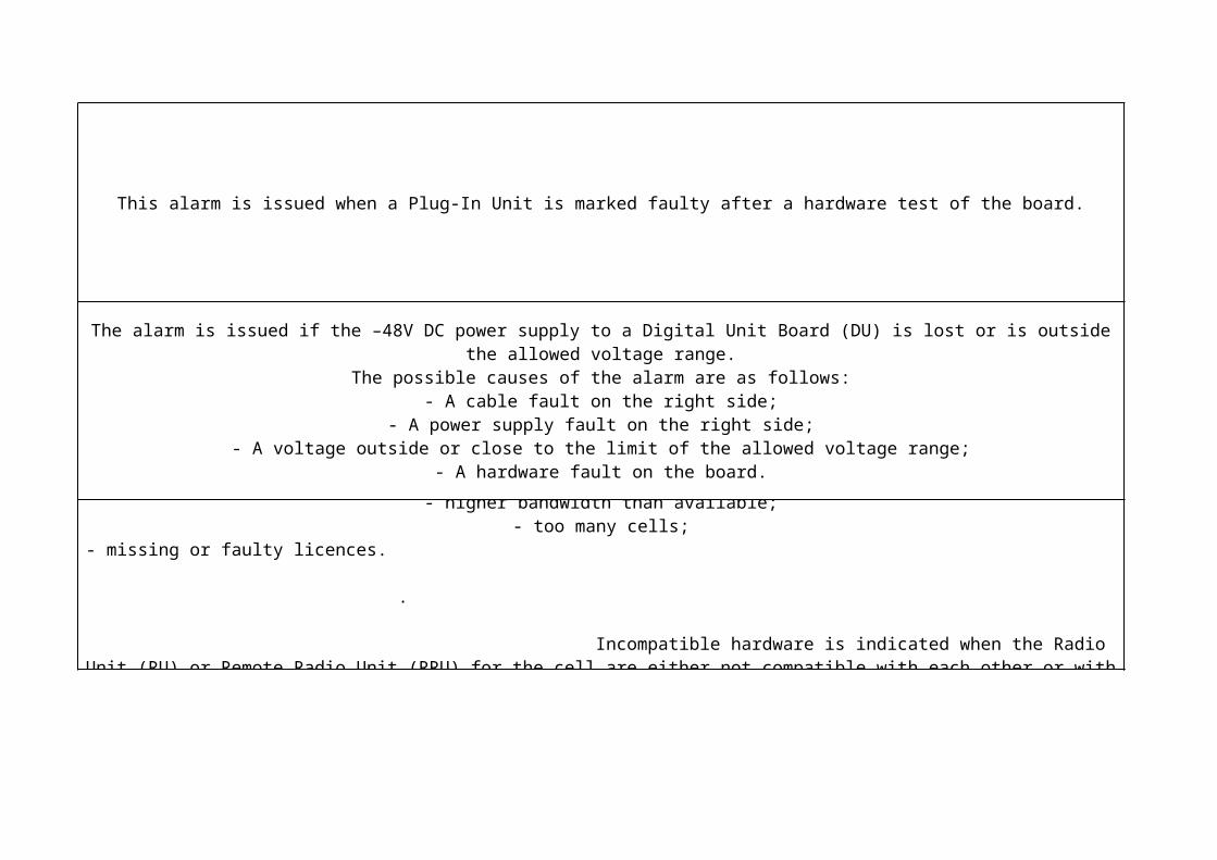
This alarm is issued when a Plug-In Unit is marked faulty after a hardware test of the board.
The alarm is issued if the –48V DC power supply to a Digital Unit Board (DU) is lost or is outside the allowed voltage range.The possible causes of the alarm are as follows:
- A cable fault on the right side;- A power supply fault on the right side;
- A voltage outside or close to the limit of the allowed voltage range;- A hardware fault on the board.
The system fault message indicates missing or incompatible hardware.Lack of hardware resources can, for example, be caused by request for:
- higher bandwidth than available;- too many cells;
- missing or faulty licences. .
Incompatible hardware is indicated when the Radio Unit (RU) or Remote Radio Unit (RRU) for the cell are either not compatible with each other or with the other RUs or RRUs connected to the DUL. The
AdditionalText Incompatible hardware resources is then displayed

This alarm occurs when a cell is disabled due to faults in underlying resources.
The alarm is raised when the cell is activated and the resource allocation for the cell fails. This can be caused by a missing signal from the requested resource or by disabled (failed) resources during startup of the node.
This alarm is raised when the RBS is running on batteries. A possible fault is an AC mains failure forcing the RBS to run on battery supply.

The Time Server is not locked to a valid synchronization source or the traffic on the IP network is disturbed. This can be caused by traffic load.
The alarm is issued if a "not reliability" condition on a supervised IP synchronization reference is detected by the MO, IpSyncRef or TimingUnit (TU). The value of the attribute, syncRefStatus for the faulty synchronization reference is changed to NOT_RELIABLE, if the condition is detected by the
IpSyncRef MO, or to LOW_QUALITY, if the condition is detected by the TimingUnit MO.
The alarm is issued if the Timing Unit (TU) detects a loss of signal on a supervised synchronization reference. In a node equipped with the Digital Unit (DU), the state of the faulty synchronization reference is changed to REF_PATH_FAILED_A, if the reference is connected to a primary DU and if the DU detects the loss of signal. The state is changed to REF_PATH_FAILED_B, if the reference is connected to a
secondary DU and if the DU detects the loss of signal.Faulty synchronization reference path of the TU (Timing Unit).
The alarm remains active as long as there is at least one synchronization reference that has a failed path. Normally, the fault must be attended to on site.
The alarm is issued if the system or radio clock enters holdover mode, which means that the Timing Unit (TU) is not locked to an external reference. This can be caused by the fault indicated in a corresponding primary alarm, which can be:
- TU Synch Reference Loss of Signal - Loss of Tracking
- Synch Reference Path HW Fault - Synch Reference Not Reliable
- PDH physical path termination: Plug-In Unit HW Failure, or ET IP Hardware Fault. - SDH physical path termination: Plug-In Unit HW Failure, or ET IP Hardware Fault.
- IP Synchronization reference: NTP Server Reachability Fault, or Gigabit Ethernet Link Fault
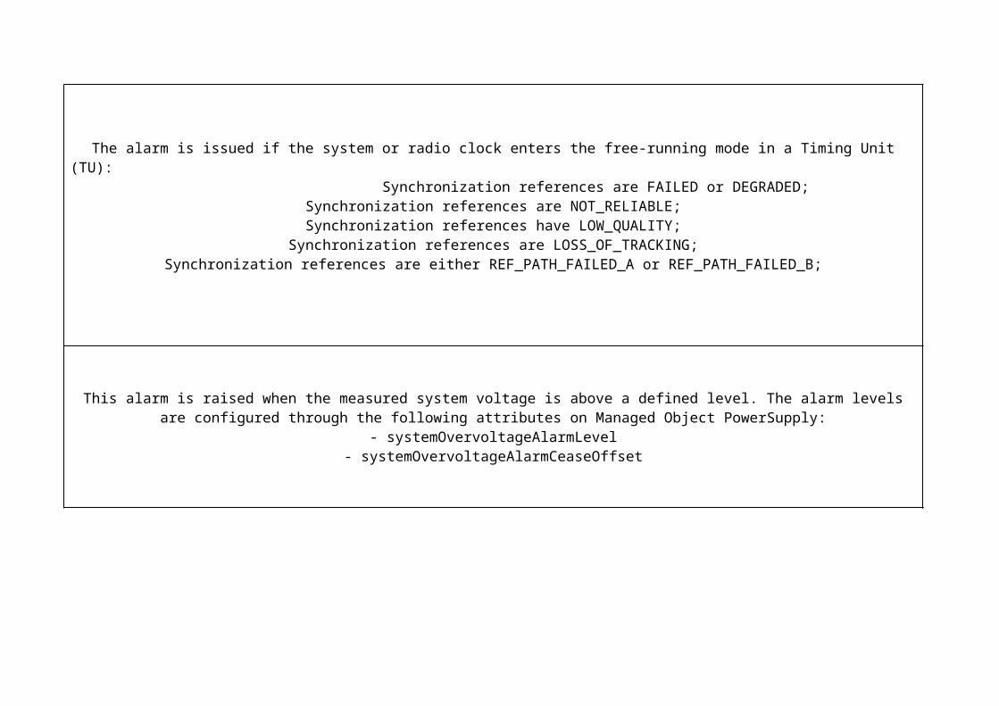
The alarm is issued if the system or radio clock enters the free-running mode in a Timing Unit (TU): Synchronization references are FAILED or DEGRADED;
Synchronization references are NOT_RELIABLE;Synchronization references have LOW_QUALITY;
Synchronization references are LOSS_OF_TRACKING;Synchronization references are either REF_PATH_FAILED_A or REF_PATH_FAILED_B;
This alarm is raised when the measured system voltage is above a defined level. The alarm levels are configured through the following attributes on Managed Object PowerSupply:
- systemOvervoltageAlarmLevel- systemOvervoltageAlarmCeaseOffset
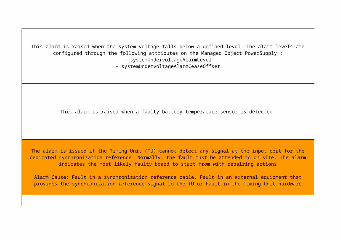
This alarm is raised when a faulty battery temperature sensor is detected.
This alarm is raised when the system voltage falls below a defined level. The alarm levels are configured through the following attributes on the Managed Object PowerSupply :
- systemUndervoltageAlarmLevel- systemUndervoltageAlarmCeaseOffset
The alarm is issued if the Timing Unit (TU) cannot detect any signal at the input port for the dedicated synchronization reference. Normally, the fault must be attended to on site. The alarm indicates the most likely faulty board to start from with
repairing actions
Alarm Cause: Fault in a synchronization reference cable, Fault in an external equipment that provides the synchronization reference signal to the TU or Fault in the Timing Unit hardware

The alarm informs that the radio clock is about to enter FREE_RUNNING_MODE. The alarm is issued if there is no synchronization reference configured on the node, or as a result of a fault indication in the corresponding
As a consequence of the fault, the clock fulfills the accuracy requirements for normal operation, both for transport and radio interfaces, but only for a limited period of time. During this period, the required accuracy is maintained for traffic over radio
interfaces, and over SDH or PDH transport interfaces.


Communication link problem, radio interface connection.
Possible source for the alarm is a faulty DU, cable, or RU.
The alarm also occurs if the SFP module is faulty, disconnected or does not support the required bit rate. The additional texts Faulty or Incompatible SFP Module or Missing SFP Module will then be displayed.Communication link problem, radio interface connection.
Possible source for the alarm is a faulty DU, cable, or RU.
The alarm also occurs if the SFP module is faulty, disconnected or does not support the required bit rate. The additional texts Faulty or Incompatible SFP Module or Missing SFP Module will then be displayed.

The alarm indicates that the password required at Security Level 1 and 2, for user access via Telnet, SSH, FTP, SFTP or a serial port, was never set or that the locally stored passwd file has been found to be corrupt. A missing or corrupt passwd file
disables authentication at the access points mentioned above.


The alarm is caused by a decrease of return loss below the sensitivity threshold because of problems in the antenna unit or antenna feeder.
fffkkkkkkHeartbeat Failure.J PG

LTE Alarm List for EnodeB
Impact
The battery backup time can be shorter than expected during the next power failure.
The RBS is not able to provide any service in case mains power fails.
The battery power backup system is disconnected and not available in case of mains power failure.
The RBS and the external equipment are shut down.
The RBS and the external equipment are shut down
The high temperature can damage the overheated board and the traffic will be affected.

The battery backup is not available. The RBS is not able to provide service in case of main power failure.
The CV is not valid.
No impact, if at least one default router is reachable.
No traffic, if all default routers are unreachable.

If Node Credentials are not renewed before they expire, the node will be unable to operate on Security Levels 2 and 3. If the node is operating on Security Level 2 or 3 when expiry occurs, the Security Level will drop to level 1, and the alarm, Security Level Fault is issued.Climate control in the cabinet is not adapted to secondary node hardware unit needs. There is a risk of hardware unit overheating. The HW unit may provide reduced service or performance but there is no risk of hardware unit damage. The secondary node is not informed about when the RBS is running on batteries. External alarms that originate from ports on Support Alarm Unit (SAU) and/or Support Control Unit (SCU) are not possible to report from the secondary node.The climate system does not work properly. There is risk of equipment overheating within the RBS cabinet.
The RBS is not able to communicate with or control the hardware unit. The hardware unit works in autonomous mode which results in reduced performance. The actual performance degradation depends on the type of hardware unit.

As a result of the fault, there might not be enough space to store important new data or to create new files on the C volume. Also, there might be not enough space for new upgrade packages.
As a result of the fault, there might not be enough space to store important new data or to create new files on the D volume. Also, there might be not enough space for new upgrade packages.
If a door is opened by an unauthorized person, there is an imminent risk of damage to the RBS in connection with the intrusion.
There is also a risk for temperature problems caused by disturbed airflow.
Correct cabinet Product Data (PID) is not available for the primary node or any secondary nodes in this RBS.
The RBS equipment and surroundings can be damaged by smoke or fire. People and property are in danger if there is a fire.
It is not possible to detect any smoke or fire in the RBS.

No traffic.
The climate system does not work properly. There is a risk of equipment overheating within the RBS cabinet.
Possible loss of node's functionality.
The unit cannot carry any climate or alarm functions.
The hardware unit will not work properly. Depending on the type of hardware unit the RBS service and performance is degraded.
Traffic disturbance.
The board will fail soon if it is not replaced.
All equipment connected to outputs, configured as main, is disconnected from power distribution. If the temperature
does not decrease or even increases, the prioritized load is also disconnected.
IP Security (IPSec) traffic is not possible for this IkePeer MO and consequently not for any IpSecTunnel MO
associated to it.

The requested sector cannot be used.
Loss of traffic capacity and loss of redundancy.Note:
The alarm can be issued as a result of a maintenance activity.
Traffic disturbance.

No IPsec traffic processing is possible for any IkePeer MO with authenticationMethod set to CERTIFICATE.
Possible serious disturbances in the node, either immediately or after a restart. The licensed features are
disabled and the licensed capacities are set to zero.
The traffic over the Synchronous Digital Hierarchy (SDH) or Plesiochronous Digital Hierarchy (PDH) interfaces is
stopped or disturbed. Some slips or bit errors can occur since the clock is not locked to any timing reference and it
cannot fulfill the required accuracy.
The likely cause is a fault in the main subrack on the Timing Unit (TU).

Traffic disturbance.
Power supply to the Radio Base Station (RBS) is reduced. Depending on configuration, the RBS can remain functional
with one or more faulty PSUs.
There is no external power supply to the RBS.The severity of this alarm is related to the capacity of the
battery backup system.
The battery capacity is lower than expected. The backup time at the next mains power failure is likely to be shorter
than expected.

No impact on traffic, if there is a working standby synchronization reference.
Traffic disturbances can occur, if there is no working standby synchronization reference.
<hwUnitType>that is not configured detected: There can be service or performance degradation because hardware that
is installed but not configured is not used properly by the system.
Too many configured fan groups: Not enough installed fan groups lead to cabinet climate problems. A faulty RBS configuration can also lead to service or performance
degradation.
The battery power backup system is disconnected and not available in case of mains power failure. The RBS is not
able to provide any service in case of mains power failure.
The consequence of the fault is that the battery power backup system is disconnected and not available in case of
mains power failure. The RBS is not able to provide any service in case of mains power failure.

The power supply to the RBS is reduced. There is a risk the RBS stops providing service.
Possibly reduced performance in the RBS power system control functions. The power supply to the RBS can be
reduced.
As a result of the fault, the traffic handled by the board is lost. The fault may need to be handled on site.

As a result of the fault, traffic handled by the board is lost. The fault must be attended to on site.
The cause is that the software that handles the hardware has found an unrecoverable hardware fault.
The power supply is not duplicated. Each Digital Unit board receives its own power.
Note: There is normally no alarm in this case, because there is no power to send the alarm. However, an alarm might be
issued if the voltage level decreases slowly.
As a consequence of the fault, the Digital Unit board loses power, and cannot carry any traffic.
The cell is not created.

The requested resource cannot be activated. The RBS cannot determine which resources to use for the cell.
The RBS stops providing service if AC mains power does not return before the battery backup power is consumed.
The cell is disabled and carries no traffic.
No impact on traffic, if there are standby synchronization references.
If no stand-by synchronization reference is available, the fault can stop or disturb the traffic or the network
synchronization
Traffic is not disturbed.
Traffic is stopped or disturbed
AC/DC rectification or DC/DC conversion: a Power Supply Unit (PSU) delivers excessive voltage, or the input voltage is too high. If the system voltage continues to rise, the PSU will be shut down as a protection mechanism. The RBS can
run on batteries if the defective PSU does not have redundant backup.
Direct -48 VDC power supply: incoming power supply voltage is too high. If the system voltage continues to rise,
services fail and RBS equipment can be damaged.
If the system voltage drops further, the RBS and other equipment are shut down.
Battery overheating problems are not possible to detect and the batteries are not charged in the most efficient way. The battery is not disconnected from charging if it becomes
overheated.
If no stand-by synchronization reference is available, the fault can stop or disturb the traffic or the network
synchronization
The board is not started and cannot carry any traffic.
There is a risk that the subrack cooling is not sufficient.

Traffic is not disturbed


The faulty unit carries no traffic.


As a result of the fault, the node has reduced protection against unauthorized access. A corrupt passwd file is automatically removed from the file system.

A return loss below the sensitivity threshold results in a disabled cell.

LTE Alarm List for EnodeB
O&M Procedure
Contact the Field Team in order to replace the battery.
Use readBatteryTestResult to read the result of the latest battery test.If the result status was ""failed"", contact the Field Team in order to replace the battery.

Contact the Field Team in order to replace the battery.
Contact the Field Team in order to replace the battery.
1- Perform a moshell connection to the RBS: ./moshell <RBS_IP_Address>
1.1- Insert the rbs user and password
1.2- The following prompt appears: <RBS_IP_Address> >
1.3- Load all MOs configured. lt all
1.4- Check the temperature with the command "cabx" and look for Fan alarms.
2- If there is Fan alarm, lock the board and contact the Field Team in orde to replace the fault Fan.
3- In case there are no fan alarms, lock the board and restart Digital Unit (DU).
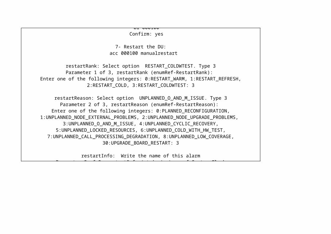
3.1- Lock DU board. NOTE: Lock DU stops all traffic on the site. When the board is locked, the processor load is reduced and the temperature decreases. bl 000100 Confirm: yes
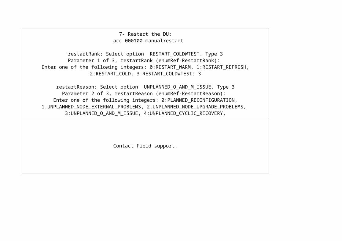
4- Restart the DU: acc 000100 manualrestart
restartRank: Select option RESTART_COLDWTEST. Type 3Parameter 1 of 3, restartRank (enumRef-RestartRank): Enter one of the following integers: 0:RESTART_WARM, 1:RESTART_REFRESH, 2:RESTART_COLD, 3:RESTART_COLDWTEST: 3
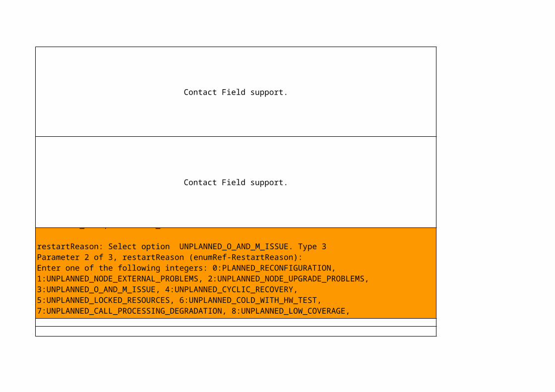
restartReason: Select option UNPLANNED_O_AND_M_ISSUE. Type 3Parameter 2 of 3, restartReason (enumRef-RestartReason): Enter one of the following integers: 0:PLANNED_RECONFIGURATION, 1:UNPLANNED_NODE_EXTERNAL_PROBLEMS, 2:UNPLANNED_NODE_UPGRADE_PROBLEMS, 3:UNPLANNED_O_AND_M_ISSUE, 4:UNPLANNED_CYCLIC_RECOVERY, 5:UNPLANNED_LOCKED_RESOURCES, 6:UNPLANNED_COLD_WITH_HW_TEST, 7:UNPLANNED_CALL_PROCESSING_DEGRADATION, 8:UNPLANNED_LOW_COVERAGE, 30:UPGRADE_BOARD_RESTART: 3
restartInfo: Write the name of this alarmParameter 3 of 3, restartInfo (string): Board Overheated
5- The connection will be lost.
6- Unlock Digital Unit (DU) board: deb 000100 Confirm: yes
7- Wait for some minutes and connection will be re-established. 8- If the alarm has ceased, exit this procedure, otherwise continue with the next step. 9- Contact Field operation.

Contact Field support.Perform a moshell connection to the RBS: ./moshell <RBS_IP_Address>
1.1- Insert the rbs user and password
1.2- The following prompt appears: <RBS_IP_Address> >
1.3- Load all MOs configured. lt all
1.4- Check the latest CVs created cvls
1.5 - Choose the CV before the faulty CV (use CV which date is before the faulty):
1.6- Set this CV as Startable. cvset <cv_name >
1.7- Reload the RBS acc 0 manualrestart
1.8- If the alarm has ceased, exit this procedure.
1.1 Analyzing the AlarmPerform the following steps at the maintenance center, to determine if any default router is reachable:1. Investigate whether any other default router is reachable. A router is reachable, if there no alarm on it. Examine the value of the attribute defaultRouterXstate, where X stands for the default router number, on the MO IpInterface. If the attribute value is enabled, there is no alarm raised on that default router. Note: The instance of the MO IpInterface whose attribute is examined, must be the same as the instance that issues the alarm.2. If no default router is reachable, contact Back Office support. If at least one default router is reachable, continue with the next step. 3. Wait at least two minutes to find out if there are temporary network problems. 4. If the alarm ceases, exit this procedure. If the alarm does not cease, contact Back Office support.

Contact the RAN Back Office.
Contact Field support.
Contact Field support.
Contact Field support.

N/A
The alarm ceases when the amount of free space (that is, the value of the attribute, hdVolumeDFreespace in the MO, GeneralProcessorUnit) increases to at least one megabyte larger than the value of minimumHdVolumeDFreespace. Normally, it is necessary to delete files from the D volume to make sufficient space available for the alarm to cease.
Type: vols to see the volumes used.
Before starting this procedure, ensure that there is no system upgrade activity in progress. If an UpgradePackage MO is executing software installation or upgrade, wait until the activity terminates.
Determine whether there are old UpgradePackage MOs to be deleted. If so, delete them.
If the alarm is issued only for Core MP board(s), investigate if there are old configuration versions that should be deleted. (Examine the attribute faultTolerantCoreStates in the MO ManagedElement.) If so, delete them.
Read the attribute hdVolumeDFreespace. Its value must be at least one megabyte greater than the value of the attribute minimumHdVolumeDFreespace.
get . hdVolumeDFreespace
Wait for a maximum of 15 minutes and see if the alarm ceases. Alternatively, read the value of the attribute minimumHdVolumeDFreespace, and set the same value again, in which case, the alarm might cease at once.
get . minimumHdVolumeCFreespace
If the alarm does not cease, investigate whether there are further upgrade package MOs, or CVs that can be deleted. If so, delete them as described above.
If the alarm still does not cease, consult the next level of maintenance support.
1- Check whether there is any authorized personnel at the site. Follow the security routines.2- Contact Field support.

Contact the RAN Back Office.
Contact Field support.
Contact Field support.

Contact Field support.
Contact the RAN Back Office.
1- Perform a moshell connection to the RBS: ./moshell <RBS_IP_Address>
2- Insert the rbs user and password
3- The following prompt appears: <RBS_IP_Address> >
4- Load all MOs configured. lt all
5- Check if there is traffic ue print -admitted
6- If there is no traffic, lock the board
7- Lock Digital Unit (DU) board stops all traffic on the site. bl 000100 Confirm: yes
8- Restart the DU: acc 000100 manualrestart
restartRank: Select option RESTART_COLDWTEST. Type 3Parameter 1 of 3, restartRank (enumRef-RestartRank): Enter one of the following integers: 0:RESTART_WARM, 1:RESTART_REFRESH, 2:RESTART_COLD, 3:RESTART_COLDWTEST: 3
restartReason: Select option UNPLANNED_O_AND_M_ISSUE. Type 3Parameter 2 of 3, restartReason (enumRef-RestartReason): Enter one of the following integers: 0:PLANNED_RECONFIGURATION, 1:UNPLANNED_NODE_EXTERNAL_PROBLEMS, 2:UNPLANNED_NODE_UPGRADE_PROBLEMS, 3:UNPLANNED_O_AND_M_ISSUE, 4:UNPLANNED_CYCLIC_RECOVERY, 5:UNPLANNED_LOCKED_RESOURCES, 6:UNPLANNED_COLD_WITH_HW_TEST, 7:UNPLANNED_CALL_PROCESSING_DEGRADATION, 8:UNPLANNED_LOW_COVERAGE, 30:UPGRADE_BOARD_RESTART: 3
restartInfo: Write the name of this alarmParameter 3 of 3, restartInfo (string): ET IP Hardware Fault
9 - The connection will be lost.
10- Unlock Digital Unit (DU) board: deb 000100 Confirm: yes
11- Wait for some minutes and connection will be re-established 12- If the alarm is not issued again, exit this procedure. 13- If the alarm does not cease, lock the DU board again and replace it using instruction Replacing Digital Unit for RBS 6601 in LTE RAN 11A Alex library (EN/LZN 785 0001 R3C). 14- If the alarm is issued again, contact Ericsson support. Further actions are outside the scope of this instruction.

1- Identify and restart the faulty board. See Restart Board instructions for RBS 6601 in LTE RAN L11A Alex library (EN/LZN 785 0001 R3C).
.2- Check that the alarm has ceased.
3- If the alarm remains, identify and lock the faulty board. See Lock Board for instructions in LTE RAN L11A Alex library (EN/LZN 785 0001 R3C).
4- Contact Field Operation.
Contact Ericsson support to retrieve an upgrade package with correct resource configuration.
If the cause of the alarm is a hardware fault on a board, a site visit is necessary to repair the fault. The board can be an Exchange Terminal (ET) board or a Digital Unit (DU) depending on the configuration of
the node.
Alarm Analysis:1- Ensure that the attribute, autoNegotiation in the MO, GigaBitEthernet, is set to true. If the alarm
ceases, exit this procedure.2- Contact the maintenance center for the remote node, and ask whether autonegotiation is set and whether any alarms have been issued in the remote node. If the fault is in the remote node and if the alarm ceases when the fault has been repaired, exit this procedure. If there is no fault in the remote
node, go to Step 3.3- Identify the subrack and slot for the faulty Gigabit Ethernet Link.
4- Lock the faulty board, using the instruction:4.1- Perform a moshell connection to the RBS:
./moshell <RBS_IP_Address>
4.2- Insert the rbs user and password
4.3- The following prompt appears: <RBS_IP_Address> >
4.4- Load all MOs configured. lt all
4.5- If there is no traffic, lock the board
4.6- Lock Digital Unit (DU) board stops all traffic on the site. bl 000100
Confirm: yes
5- Restart the faulty board, using the instruction:5.1- Restart the DU:
acc 000100 manualrestart
restartRank: Select option RESTART_COLDWTEST. Type 3Parameter 1 of 3, restartRank (enumRef-RestartRank):
Enter one of the following integers: 0:RESTART_WARM, 1:RESTART_REFRESH, 2:RESTART_COLD, 3:RESTART_COLDWTEST: 3
restartReason: Select option UNPLANNED_O_AND_M_ISSUE. Type 3Parameter 2 of 3, restartReason (enumRef-RestartReason):
Enter one of the following integers: 0:PLANNED_RECONFIGURATION, 1:UNPLANNED_NODE_EXTERNAL_PROBLEMS, 2:UNPLANNED_NODE_UPGRADE_PROBLEMS,
3:UNPLANNED_O_AND_M_ISSUE, 4:UNPLANNED_CYCLIC_RECOVERY, 5:UNPLANNED_LOCKED_RESOURCES, 6:UNPLANNED_COLD_WITH_HW_TEST,
7:UNPLANNED_CALL_PROCESSING_DEGRADATION, 8:UNPLANNED_LOW_COVERAGE, 30:UPGRADE_BOARD_RESTART: 3
restartInfo: Write the name of this alarmParameter 3 of 3, restartInfo (string): ET IP Hardware Fault
5.3 - The connection will be lost.
6- Unlock the board, using the instruction:6.1- Unlock Digital Unit (DU) board:
deb 000100 Confirm: yes
6.3- Wait for some minutes and connection will be re-established.
7- If the alarm is not issued again, exit this procedure.
8- If the alarm remains, contact Field Operation.

Contact Field support.
Contact Field support.
1- Verify that the attribute peerIpAddress in the IkePeer MO corresponds to the IP address of the IKE Peer.
2- Use the IP address for the IKE peer node to ping toward the IKE peer node, by using the ping action on the IpAccessHostEt MO for the outer IP host.
3- If the ping is not successful, this indicates a problem in the transport network. Consult the next level of maintenance support. Further actions are outside the scope of this instruction.
4- If the alarm has ceased, exit this procedure. If the alarm remains, continue with the next step.5- Investigate whether the event Authfail has been recorded for the IkePeer MO in the log
CELLO_IPTRAN_LOG. If no event has been recorded, go to Step 13. If the event has been recorded, continue with the next step.
6- Verify the value of the attribute peerIdentity in the IkePeer MO, so that it corresponds to the configuration of the IKE peer.
7- Determine the authentication method by reading the attribute authenticationMethod in the IkePeer MO.
8- If the value of the attribute authenticationMethod is PRESHARED_KEY, verify that the same pre-shared key is used in the IkePeer MO as on the IKE peer node. Install the pre-shared key in the IkePeer
MO, using the action installPreSharedKey. If the alarm has ceased, exit this procedure. If the alarm remains, go to Step 13.
9- If the attribute authenticationMethod has the value CERTIFICATE, investigate whether a valid and correct trusted certificate is installed in the attribute installedTrustedCertificates in the IpSec MO. If there
are no valid or correct trusted certificates, install a trusted certificate in the node by using the action installTrustedCertificates on the IpSec MO.
10- If the alarm has ceased, exit this procedure. If the alarm remains, continue with the next step.11- Confirm that the installed IPsec certificate is correct by reading the attribute certificate in the IpSec MO. If the certificate is not correct, initiate an enrollment of an IPsec certificate in the node by using the
action initCertEnrollment on the IpSec MO.Note:
The Certificate Authority (CA) might demand that a CA administrator approves the request for the new certificate. The enrollment process state will be ONGOING until the request is approved. The enrollment
state can be monitored by reading the attribute certEnrollState in the IpSec MO.
12- If the alarm has ceased, exit this procedure. If the alarm remains, continue with the next step.13- Verify that the attribute allowedTransforms in the IkePeer MO contains at least one set of transforms
that is supported by the IKE peer.14- If the alarm has ceased, exit this procedure. If the alarm remains, consult the next level of
maintenance support. Further actions are outside the scope of this instruction.

Contact Field support.
Contact Field support.
1- Check if the hardware, such as antenna near products or radio equipment, is correctly configured in the Managed Object Model (MOM).2- Check that the alarm has ceased.
3- If the alarm remains, contact the RAN Back Office.

Contact the RAN Back Office.
If there is no valid License Key File (LKF) in the node, all traffic and features that are dependent on license keys are affected, possibly resulting in serious service and traffic disturbances. A valid LKF is essential for the working of the node. Therefore, the procedure of this instruction must be initiated immediately to make sure that a valid LKF is ordered and installed in the node, so that normal operation is restored as soon as possible. For example, use of Emergency Unlock does not solve the problem. The LKF must still be installed in the node as soon as possible.
To activate the emergency license:
acc 6 setEmergencyStatey
After check it using the command:
license server (The emergency status should be: activated)
Or:
Arrange a new license for site and load it.
Install the new LKF in the node from the FTP or SFTP server. Use the action updateLicenseKeyFile on the MO Licensing:
Use the ftput command to download the archive of license from OSS to Nodeb:
ftput /path/license.xml /d/
After, use the updatelicensekeyfile command to install the new license. The user and password is “rbs” and the Ipaddress will be the Ipaddress of Enodeb.
acc 6 updatelicenkeyfileyuserid: rbspassword: rbsipadress: ip_enodebsfile: /d/license.xml
1- Contact Transmission Team and check if there is any problem on the transmission path to this Enode-B.
2- If it is ok, perform a moshell connection to the RBS: ./moshell <RBS_IP_Address>
3- Insert the rbs user and password
4- The following prompt appears: <RBS_IP_Address> >
5- Load all MOs configured. lt all
6- Lock Digital Unit (DU) board. NOTE: Lock DU stops all traffic on the site. bl 000100
Confirm: yes
7- Restart the DU: acc 000100 manualrestart
restartRank: Select option RESTART_COLDWTEST. Type 3Parameter 1 of 3, restartRank (enumRef-RestartRank):
Enter one of the following integers: 0:RESTART_WARM, 1:RESTART_REFRESH, 2:RESTART_COLD, 3:RESTART_COLDWTEST: 3
restartReason: Select option UNPLANNED_O_AND_M_ISSUE. Type 3Parameter 2 of 3, restartReason (enumRef-RestartReason):
Enter one of the following integers: 0:PLANNED_RECONFIGURATION, 1:UNPLANNED_NODE_EXTERNAL_PROBLEMS, 2:UNPLANNED_NODE_UPGRADE_PROBLEMS,
3:UNPLANNED_O_AND_M_ISSUE, 4:UNPLANNED_CYCLIC_RECOVERY, 5:UNPLANNED_LOCKED_RESOURCES, 6:UNPLANNED_COLD_WITH_HW_TEST,
7:UNPLANNED_CALL_PROCESSING_DEGRADATION, 8:UNPLANNED_LOW_COVERAGE, 30:UPGRADE_BOARD_RESTART: 3
restartInfo: Write the name of this alarmParameter 3 of 3, restartInfo (string): Loss of System Clock
8- The connection will be lost.
9- Unlock Digital Unit (DU) board: deb 000100 Confirm: yes
10- Wait for some minutes and connection will be re-established 11- If the alarm has ceased, exit this procedure, otherwise continue with the next step.
12- Contact Field operation.

Contact Field support.
Contact Field support.
Contact Field support.
1- Contact Transmission Team and check if there is any problem on the transmission path to this Enode-B.
2- If it is ok, perform a moshell connection to the RBS: ./moshell <RBS_IP_Address>
3- Insert the rbs user and password
4- The following prompt appears: <RBS_IP_Address> >
5- Load all MOs configured. lt all
6- Lock Digital Unit (DU) board. NOTE: Lock DU stops all traffic on the site. bl 000100
Confirm: yes
7- Restart the DU: acc 000100 manualrestart
restartRank: Select option RESTART_COLDWTEST. Type 3Parameter 1 of 3, restartRank (enumRef-RestartRank):
Enter one of the following integers: 0:RESTART_WARM, 1:RESTART_REFRESH, 2:RESTART_COLD, 3:RESTART_COLDWTEST: 3
restartReason: Select option UNPLANNED_O_AND_M_ISSUE. Type 3Parameter 2 of 3, restartReason (enumRef-RestartReason):
Enter one of the following integers: 0:PLANNED_RECONFIGURATION, 1:UNPLANNED_NODE_EXTERNAL_PROBLEMS, 2:UNPLANNED_NODE_UPGRADE_PROBLEMS,
3:UNPLANNED_O_AND_M_ISSUE, 4:UNPLANNED_CYCLIC_RECOVERY, 5:UNPLANNED_LOCKED_RESOURCES, 6:UNPLANNED_COLD_WITH_HW_TEST,
7:UNPLANNED_CALL_PROCESSING_DEGRADATION, 8:UNPLANNED_LOW_COVERAGE, 30:UPGRADE_BOARD_RESTART: 3
restartInfo: Write the name of this alarmParameter 3 of 3, restartInfo (string): Loss of Tracking
8- The connection will be lost.
9- Unlock Digital Unit (DU) board: deb 000100 Confirm: yes
10- Wait for some minutes and connection will be re-established. 11- Reset the LOSS_OF_TRACKING state, using the action, resetLossOfTracking in the MO,
Synchronization in OSS-RC Element Manager, for all synchronization references. Wait at least five minutes to see if the alarm reappears. If the alarm is not issued again, exit this procedure.
12- If the alarm remains, contact Field Operation.
Contact Field support.
Contact Field support.
Contact Field support.
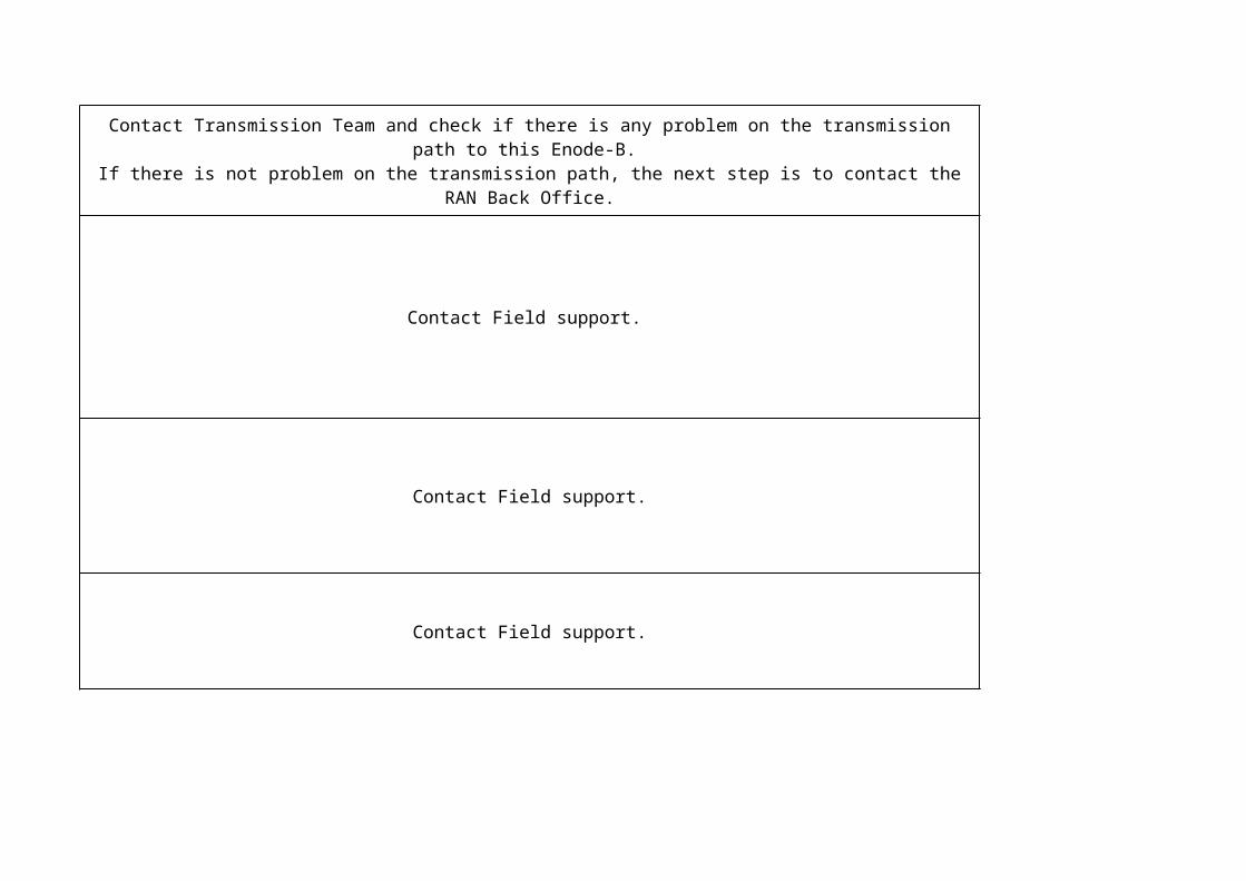
Contact Transmission Team and check if there is any problem on the transmission path to this Enode-B. If there is not problem on the transmission path, the next step is to contact the RAN Back Office.

Contact Field support.
Contact Field support.
5. Lock the faulty board, using the instruction:
5.1- Perform a moshell connection to the RBS: ./moshell <RBS_IP_Address>
5.2- Insert the rbs user and password
5.3- The following prompt appears: <RBS_IP_Address> >
5.4- Load all MOs configured. lt all
5.5- Lock Digital Unit (DU) board. NOTE: Lock DU stops all traffic on the site. bl 000100
Confirm: yes
6. Restart the faulty board, using the instruction:6.1- Restart the DU:
acc 000100 manualrestart
restartRank: Select option RESTART_COLDWTEST. Type 3Parameter 1 of 3, restartRank (enumRef-RestartRank):
Enter one of the following integers: 0:RESTART_WARM, 1:RESTART_REFRESH, 2:RESTART_COLD, 3:RESTART_COLDWTEST: 3
restartReason: Select option UNPLANNED_O_AND_M_ISSUE. Type 3Parameter 2 of 3, restartReason (enumRef-RestartReason):
Enter one of the following integers: 0:PLANNED_RECONFIGURATION, 1:UNPLANNED_NODE_EXTERNAL_PROBLEMS, 2:UNPLANNED_NODE_UPGRADE_PROBLEMS,
3:UNPLANNED_O_AND_M_ISSUE, 4:UNPLANNED_CYCLIC_RECOVERY, 5:UNPLANNED_LOCKED_RESOURCES, 6:UNPLANNED_COLD_WITH_HW_TEST,
7:UNPLANNED_CALL_PROCESSING_DEGRADATION, 8:UNPLANNED_LOW_COVERAGE, 30:UPGRADE_BOARD_RESTART: 3
restartInfo: Write the name of this alarmParameter 3 of 3, restartInfo (string): Plug-In Unit General Problem
6.2 - The connection will be lost.
7. Unlock the board, using the instruction:
7.1- Unlock Digital Unit (DU) board: deb 000100 Confirm: yes
7.2- Wait for some minutes and connection will be re-established.
8. Confirm that the alarm has ceased. If the alarm remains, consult Ericsson support. Further actions are outside the scope of this instruction.

Contact Field support.
Contact the RAN Back Office.
Restarting DU board1- Perform a moshell connection to the RBS:
./moshell <RBS_IP_Address>
2- Insert the rbs user and password
3- The following prompt appears: <RBS_IP_Address> >
4- Load all MOs configured. lt all
5- Lock Digital Unit (DU) board stops all traffic on the unit. bl 000100
Confirm: yes
6- Restart the DU: acc 000100 manualrestart
restartRank: Select option RESTART_COLDWTEST. Type 3Parameter 1 of 3, restartRank (enumRef-RestartRank):
Enter one of the following integers: 0:RESTART_WARM, 1:RESTART_REFRESH, 2:RESTART_COLD, 3:RESTART_COLDWTEST: 3
restartReason: Select option UNPLANNED_O_AND_M_ISSUE. Type 3Parameter 2 of 3, restartReason (enumRef-RestartReason):
Enter one of the following integers: 0:PLANNED_RECONFIGURATION, 1:UNPLANNED_NODE_EXTERNAL_PROBLEMS, 2:UNPLANNED_NODE_UPGRADE_PROBLEMS,
3:UNPLANNED_O_AND_M_ISSUE, 4:UNPLANNED_CYCLIC_RECOVERY, 5:UNPLANNED_LOCKED_RESOURCES, 6:UNPLANNED_COLD_WITH_HW_TEST,
7:UNPLANNED_CALL_PROCESSING_DEGRADATION, 8:UNPLANNED_LOW_COVERAGE, 30:UPGRADE_BOARD_RESTART: 3
restartInfo: Write the name of this alarmParameter 3 of 3, restartInfo (string): Plug-In Unit HW Failure
7 - The connection will be lost.
8- Unlock Digital Unit (DU) board: deb 000100 Confirm: yes
9- Wait for some minutes and connection will be re-established
10- If the alarm remains, contact the Field Support.

1- Lock celllbl cell
2- Unlock cellldeb cell
3- Check that the alarm has ceased
Or:
1- Restart RUExample RRU-1 (sector 1): lhsh BXP_0_1 restart coldwtest or see file restart_board in column ALEX description
2- Check that the alarm has ceased
Or:
1- Restart the node.acc 0 manualrestart or see file restart_node.pdf in column ALEX description2- Check that the alarm has ceased.3- If the alarm remains, consult Field operation
1- Check if the alarm LossOfMains on the PowerSupply Managed Object is raised in the RBS Element Manager and if the mains power is not available. In this case, the RBS stops running on battery supply
when the mains power returns and therefore no further action is required.
Contact Transmission Team and check if there is any problem on the transmission path to this Enode-B.
If there is not problem on the transmission path, the next step is check any primary alarms:
■HwFault■NoContact■GeneralSwError■PowerFailure■TemperatureExceptionalTakenOutOfService■LinkFailure■InconsitentConfiguration■ResourceConfigurationFailure
If there is no primary alarm in the RBS, the communication between the RBS and the MME is lost. If this is the case, the alarm cannot be resolved from the RBS. The alarm must then be resolved from the MME instead.
Contact the RAN Back Office.
1. Examine the value of the attribute, syncRefStatus in the MO, Synchronization, for all defined references.
For all references with status, NOT_RELIABLE, go to Step 2.For all references with status, LOW_QUALITY, go to Step 4.
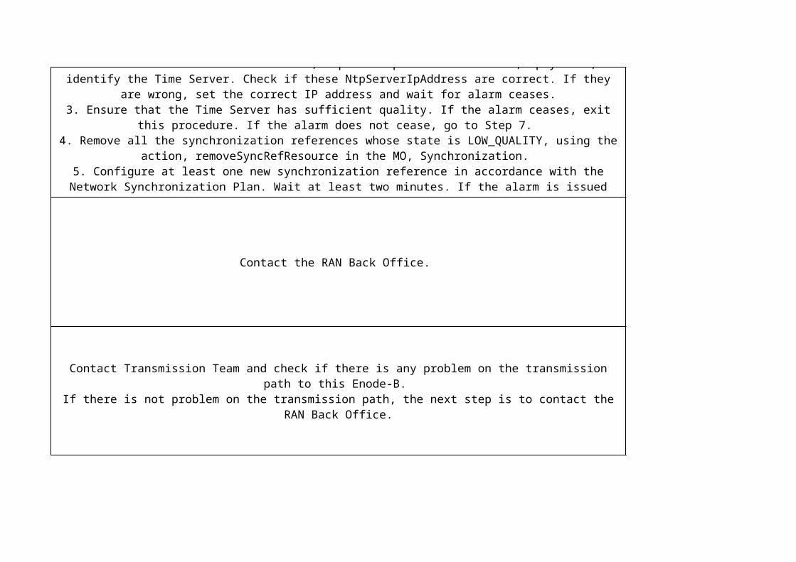
2. Examine the value of the attribute, NtpServerIpAddress in the MO, IpSyncRef, to identify the Time Server. Check if these NtpServerIpAddress are correct. If they are wrong, set the correct IP address and
wait for alarm ceases.3. Ensure that the Time Server has sufficient quality. If the alarm ceases, exit this procedure. If the alarm
does not cease, go to Step 7. 4. Remove all the synchronization references whose state is LOW_QUALITY, using the action,
removeSyncRefResource in the MO, Synchronization. 5. Configure at least one new synchronization reference in accordance with the Network Synchronization
Plan. Wait at least two minutes. If the alarm is issued again, continue with the next step. If the alarm is not issued again, exit this procedure.
6. Consult Ericsson support. Further actions are outside the scope of this instruction.
Contact Transmission Team and check if there is any problem on the transmission path to this Enode-B. If there is not problem on the transmission path, the next step is to contact the RAN Back Office.
Contact Field support.
Wait 16 minutes for the alarm to cease. 1- Contact Transmission Team and check if there is any problem on the transmission path to this Enode-
B. 2- If it is ok, perform a moshell connection to the RBS:
./moshell <RBS_IP_Address>
3- Insert the rbs user and password
4- The following prompt appears: <RBS_IP_Address> >
5- Load all MOs configured. lt all
6- Lock Digital Unit (DU) board. NOTE: Lock DU stops all traffic on the site. bl 000100
Confirm: yes
7- Restart the DU: acc 000100 manualrestart
restartRank: Select option RESTART_COLDWTEST. Type 3Parameter 1 of 3, restartRank (enumRef-RestartRank):
Enter one of the following integers: 0:RESTART_WARM, 1:RESTART_REFRESH, 2:RESTART_COLD, 3:RESTART_COLDWTEST: 3
restartReason: Select option UNPLANNED_O_AND_M_ISSUE. Type 3Parameter 2 of 3, restartReason (enumRef-RestartReason):
Enter one of the following integers: 0:PLANNED_RECONFIGURATION, 1:UNPLANNED_NODE_EXTERNAL_PROBLEMS, 2:UNPLANNED_NODE_UPGRADE_PROBLEMS,
3:UNPLANNED_O_AND_M_ISSUE, 4:UNPLANNED_CYCLIC_RECOVERY, 5:UNPLANNED_LOCKED_RESOURCES, 6:UNPLANNED_COLD_WITH_HW_TEST,
7:UNPLANNED_CALL_PROCESSING_DEGRADATION, 8:UNPLANNED_LOW_COVERAGE, 30:UPGRADE_BOARD_RESTART: 3
restartInfo: Write the name of this alarmParameter 3 of 3, restartInfo (string): Loss of System Clock
8- The connection will be lost.
9- Unlock Digital Unit (DU) board: deb 000100 Confirm: yes
10- Wait for some minutes and connection will be re-established 11- If the alarm has ceased, exit this procedure, otherwise continue with the next step.
12- Contact Field operation.
Contact Field support.
Contact Field support.
TUSyncref is used when external equipment provides the sync e.g. SIU. So check the external clock reference.
Locking, Restarting and Unlocking board:
1- On Element manager RBS, if the specified port is used for synchronization, remove the port from the synchronization reference list, using the action, removeSyncRefResource on the MO, Synchronization. 2- Lock the faulty board, using the instruction2.5- Lock Digital Unit (DU) board. NOTE: All traffic on E-nodeB will be stopped. bl 000100 Confirm: yes
3- Restart the faulty board, using the instruction:3.1- Restart the DU: acc 000100 manualrestart
restartRank: Select option RESTART_COLDWTEST. Type 3Parameter 1 of 3, restartRank (enumRef-RestartRank): Enter one of the following integers: 0:RESTART_WARM, 1:RESTART_REFRESH, 2:RESTART_COLD, 3:RESTART_COLDWTEST: 3
restartReason: Select option UNPLANNED_O_AND_M_ISSUE. Type 3Parameter 2 of 3, restartReason (enumRef-RestartReason): Enter one of the following integers: 0:PLANNED_RECONFIGURATION, 1:UNPLANNED_NODE_EXTERNAL_PROBLEMS, 2:UNPLANNED_NODE_UPGRADE_PROBLEMS, 3:UNPLANNED_O_AND_M_ISSUE, 4:UNPLANNED_CYCLIC_RECOVERY, 5:UNPLANNED_LOCKED_RESOURCES, 6:UNPLANNED_COLD_WITH_HW_TEST, 7:UNPLANNED_CALL_PROCESSING_DEGRADATION, 8:UNPLANNED_LOW_COVERAGE, 30:UPGRADE_BOARD_RESTART: 3
restartInfo: Write the name of this alarmParameter 3 of 3, restartInfo (string):
3.2 - The connection will be lost.
4- Unlock the board, using the instruction:4.1- Unlock Digital Unit (DU) board: TU Synch Reference Loss of Signal deb 000100 Confirm: yes
4.2- Wait for some minutes and connection will be re-established.
5- On Element Manager, if the port was removed from the synchronization priority list, at the appropriate time, set the synchronization reference again using the action, addSyncRefResource on the MO, Synchronization. 6- If the alarm is not issued again, exit this procedure.
7- If the alarm remains, contact Field Operation.
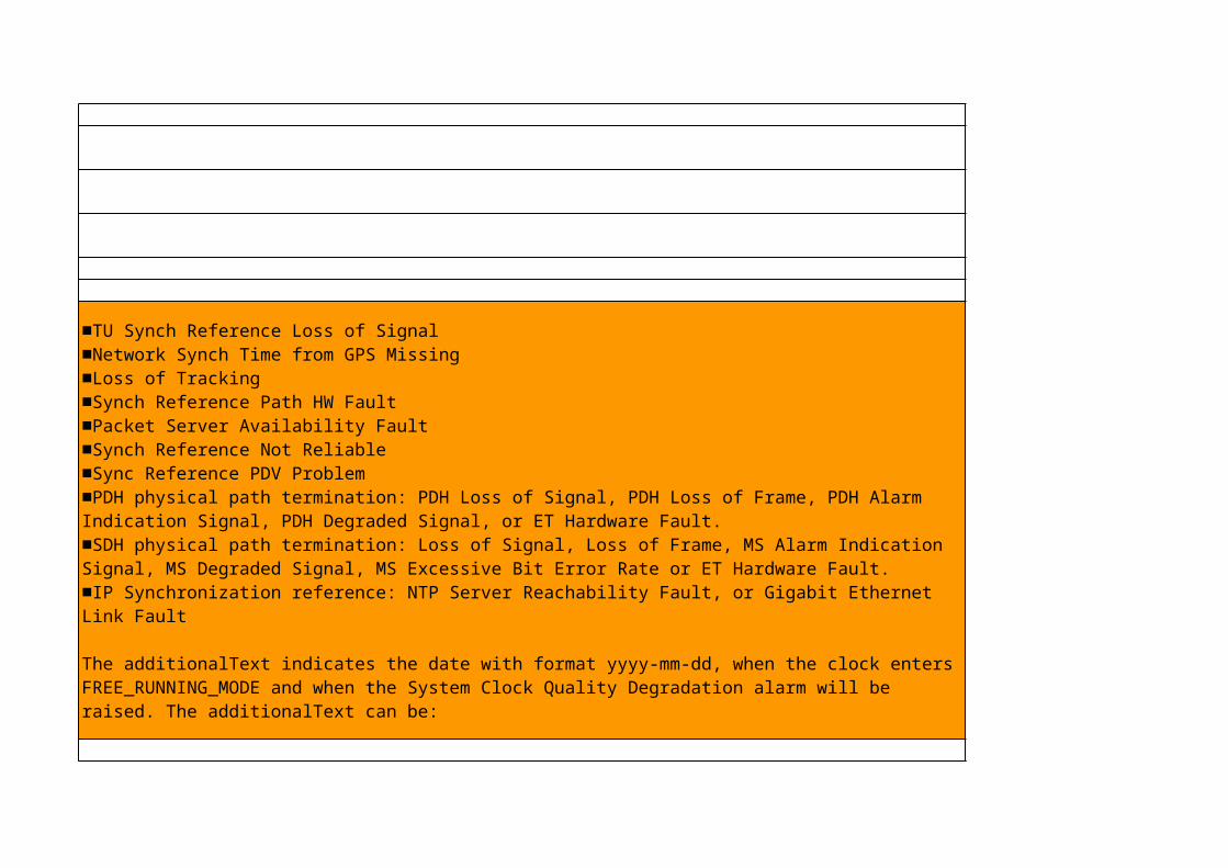
Solve the primary alarm, which can be:
■TU Synch Reference Loss of Signal■Network Synch Time from GPS Missing■Loss of Tracking■Synch Reference Path HW Fault■Packet Server Availability Fault■Synch Reference Not Reliable■Sync Reference PDV Problem■PDH physical path termination: PDH Loss of Signal, PDH Loss of Frame, PDH Alarm Indication Signal, PDH Degraded Signal, or ET Hardware Fault. ■SDH physical path termination: Loss of Signal, Loss of Frame, MS Alarm Indication Signal, MS Degraded Signal, MS Excessive Bit Error Rate or ET Hardware Fault.■IP Synchronization reference: NTP Server Reachability Fault, or Gigabit Ethernet Link Fault
The additionalText indicates the date with format yyyy-mm-dd, when the clock enters FREE_RUNNING_MODE and when the System Clock Quality Degradation alarm will be raised. The additionalText can be:
■DATE: expiry date of the calibration


Identify the Affected Hardware
1. In order to find out what type of unit generates the alarm, identify the parent MO of the RiPort generating the alarm:
• If the parent MO is PlugInUnit , it refers to Digital Unit (DU).• If the parent MO is AuxPlugInUnit , it refers to Radio Unit (RU).
2. Identify the position of the affected unit by checking: • For AuxPlugInUnit: the attribute position or positionInformation • For PlugInUnit: the attribute SlotId of the parent Slot MO
3. Identify where the cable is connected by checking the attribute RiPortId of the RiPort generating the alarm. The value is corresponding to the connector marking on the front of the unit.
4. Check the attribute remoteRiPortRef of the RiPort in order to determine the RiPort on the remote unit. Identify unit type and position in the same way as described above.
5. Depending on which unit generates the alarm, continue with one of the following steps: • If the RiPort generating the alarm belongs to an RU shared by two RANs in a multistandard configuration, or if the RU is in a cascadechain with shared RUs, verify that both DUs are properly configured, and the DUs are not trying to set an RU cascade chain to each other. • If the RiPort generating the alarm belongs to an RU, perform a restart of this unit • If the RiPort generating the alarm belongs to a DU, restart the connected RU identified
Restart RRU
lhsh <ru> restart coldwtest

Access the node via SSH or telnet and set a new password, using the shell command passwd
passwd ; rbs ; rbs


LTE Alarm List for EnodeB
Field Operation
Replacing the BatteryTo replace the battery, perform the following steps:
1- In the RBS EM, lock the BFU.2- Replace the battery according to the instructions in Replacing Power Units for RBS 6601 in LTE RAN Alex library (EN/LZN 785 0001 R3C).3- Unlock the BFU and check the RBS EM alarm list to see if the alarm clears.4- If the alarm reappears, then restart the BFU.5- If the alarm does not clear, then lock the BFU and put back the original battery. Contact Ericsson maintenance support.
Before replacing the battery, do the following steps:
ProcedureTo resolve the alarm, do the following:1- Restart the BFU in the RBS Element Manager (EM). Check the RBS EM alarm list to see if the alarm clears.2- Add the battery block if it is absent.3- Connect the battery if it is not connected properly. For instructions, see Section 3.1.4- Check and possibly replace the battery cables. For instructions, see Section 3.1.5- Check the battery condition. Replace faulty battery. For instruction, see Section 3.3.
3.1 Checking the Battery CablesTo check the battery cables, perform the following steps:
1- Ensure that the battery cables are undamaged and correctly connected between the BFU and to the battery.2- If the battery cables are not connected, lock the BFU in the RBS EM and replace or reconnect the cables according to the instructions in Replacing Power Units.3- Unlock the Batterry Fuse Unit (BFU) and check the RBS EM alarm list to see if the alarm clears.4- If the alarm reappears, then restart the BFU.5- If the alarm does not clear, then lock the BFU and put back the original cable. Proceed with Section 3.2.Note: Never return any cable not showing visible damage to Ericsson, unless the alarm has been cleared due to the replacement of this particular cable.
3.2 Replacing the BFUTo replace the BFU, perform the following steps:
1- In the RBS EM, lock the BFU.2- Replace the BFU according to the instructions in Replacing Power Units for RBS 6601 in LTE RAN Alex library (EN/LZN 785 0001 R3C).3- Unlock the BFU and check the RBS EM alarm list to see if the alarm clears.4- If the alarm does not clear, then lock the BFU and put back the original BFU. Proceed with Section 3.3.Note: Never return any BFU to Ericsson, unless the alarm has been cleared due to the replacement of the BFU.
3.3 Replacing the BatteryTo replace the battery, perform the following steps:
1- In the RBS EM, lock the BFU.2- Replace the battery according to the instructions in Replacing Power Units for RBS 6601 in LTE RAN Alex library (EN/LZN 785 0001 R3C)..3- Unlock the BFU and check the RBS EM alarm list to see if the alarm clears.4- If the alarm reappears, then restart the BFU.5- If the alarm does not clear, then lock the BFU and put back the original battery. Contact the next level of maintenance support.Note: Never return a battery to Ericsson, unless the alarm has been cleared due to the replacement of this particular battery.

Replacing the BatteryTo replace the battery, perform the following steps:
1- In the RBS EM, lock the BFU. See instruction for RBS 6601 in LTE RAN L11A Alex library (EN/LZN 785 0001 R3C).2- Replace the battery according to the instructions in Replacing Power Units in LTE RAN L11A Alex library (EN/LZN 785 0001 R3C).3- Unlock the BFU and check the RBS EM alarm list to see if the alarm clears.4- If the alarm reappears, then restart the BFU.5- If the alarm does not clear, then lock the BFU and put back the original battery. Contact the next level of maintenance support.Replacing the BatteryTo replace the battery, perform the following steps:
1- In the RBS EM, lock the BFU for RBS 6601 in LTE RAN L11A Alex library (EN/LZN 785 0001 R3C).2- Replace the battery according to the instructions in Replacing Power Units.3- Unlock the BFU and check the RBS EM alarm list to see if the alarm clears.4- If the alarm reappears, then restart the BFU.5- If the alarm does not clear, then lock the BFU and put back the original battery. Contact Ericsson support.
Lock the faulty board.1- Perform a moshell connection to the RBS: ./moshell <RBS_IP_Address>
2- Insert the rbs user and password
3- The following prompt appears: <RBS_IP_Address> >
4- Load all MOs configured. lt all
5- Lock Digital Unit (DU) board. Note: All traffic on E-nodeB will be stopped. bl 000100 Confirm: yes
6- The field technician replaces the faulty board, using the instruction Replacing Digital Units (DU) for RBS 6601 in LTE RAN L11A Alex library (EN/LZN 785 0001 R3C).
7- Unlock Digital Unit (DU) board: deb 000100 Confirm: yes
7- If the alarm is not issued again, go to step 9.
8- If the alarm remains, consult Ericsson support.
9- Exit this procedure.
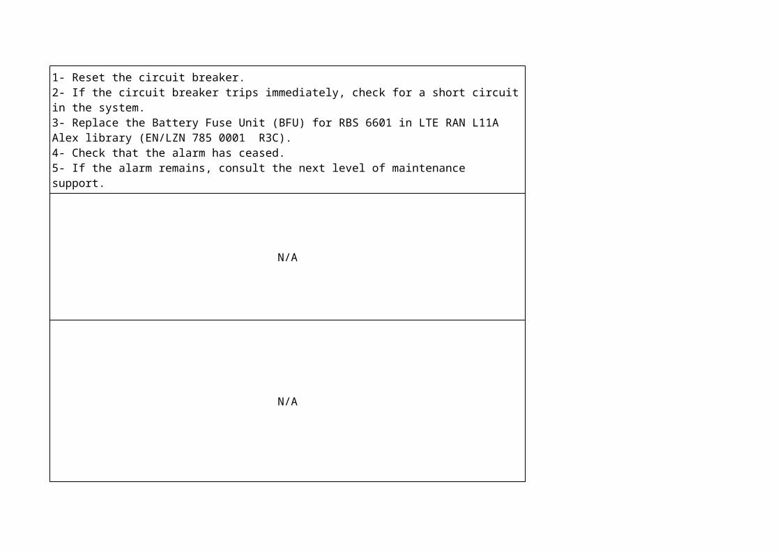
N/A
N/A
To resolve the alarm, perform the following procedure:
1- Reset the circuit breaker.2- If the circuit breaker trips immediately, check for a short circuit in the system.3- Replace the Battery Fuse Unit (BFU) for RBS 6601 in LTE RAN L11A Alex library (EN/LZN 785 0001 R3C).4- Check that the alarm has ceased.5- If the alarm remains, consult the next level of maintenance support.

N/ATo resolve the alarm, do the following:
1- Check that the secondary node Digital Unit (DU) and primary node DU are connected to the Enclosure Control (EC) bus on correct hubPosition.2- Check that secondary node and primary node are configured properly through attributes SupportSystemControl and hubPosition.3- Restart the secondary node DU.4- Restart the primary node DU.5- Change the cable that connects the secondary node DU in this node to the EC bus.6- Change the cable that connects the primary node DU in the other node to the EC bus.7- Change the EC bus hub/SHU(Support Hub Unit).8- Check that the alarm has ceased.9- If the alarm remains, put the original cables and EC bus back and consult the next level of maintenance support.
To resolve the alarm, do the following:
1- Restart the System Control Unit/Support Part (SCU/SUP). See Restart Board for RBS 6601 in LTE RAN L11A Alex library (EN/LZN 785 0001 R3C).2- Check that the alarm has ceased.3- If the alarm remains, check that attribute climateSystem is correctly configured for this RBS 6601 and that the corresponding correct number of fan groups is installed in the RBS.4- Check that the alarm has ceased.5- If the alarm remains, Check that the fans are properly connected.6- Check that the alarm has ceased.If the alarm remains, consult Ericsson support.
1- Check that the node is configured properly and that the hardware unit is present in this RBS6601 node. Correct number of MO HwUnit with correct HwUnitType must be configured on the node.2- Check that the alarm has ceased.3- If the alarm remains, restart the hardware unit4- Check that the alarm has ceased.5- If the alarm remains, check that the hardware unit is properly connected to the EC bus or superior unit.6- Check that the alarm has ceased.7- If the alarm remains, change the cable that connects the hardware unit to the EC bus or superior unit.8- Check that the alarm has ceased.9- If the alarm remains, identify and lock the faulty unit. See Lock Board for instructions.10- Change the faulty unit. See Replacing Internal Supplementary Parts for instructions.11- Unlock the unit. See Unlock Board for instructions.12- Check that the alarm has ceased.13- If the alarm remains, change the EC bus hub/SHU(Support Hub Unit).14- Check that the alarm has ceased.15- If the alarm remains, put the original units back and consult the next level of maintenance support.

N/A
1- Close the RBS door.2- Check that the alarm has ceased.
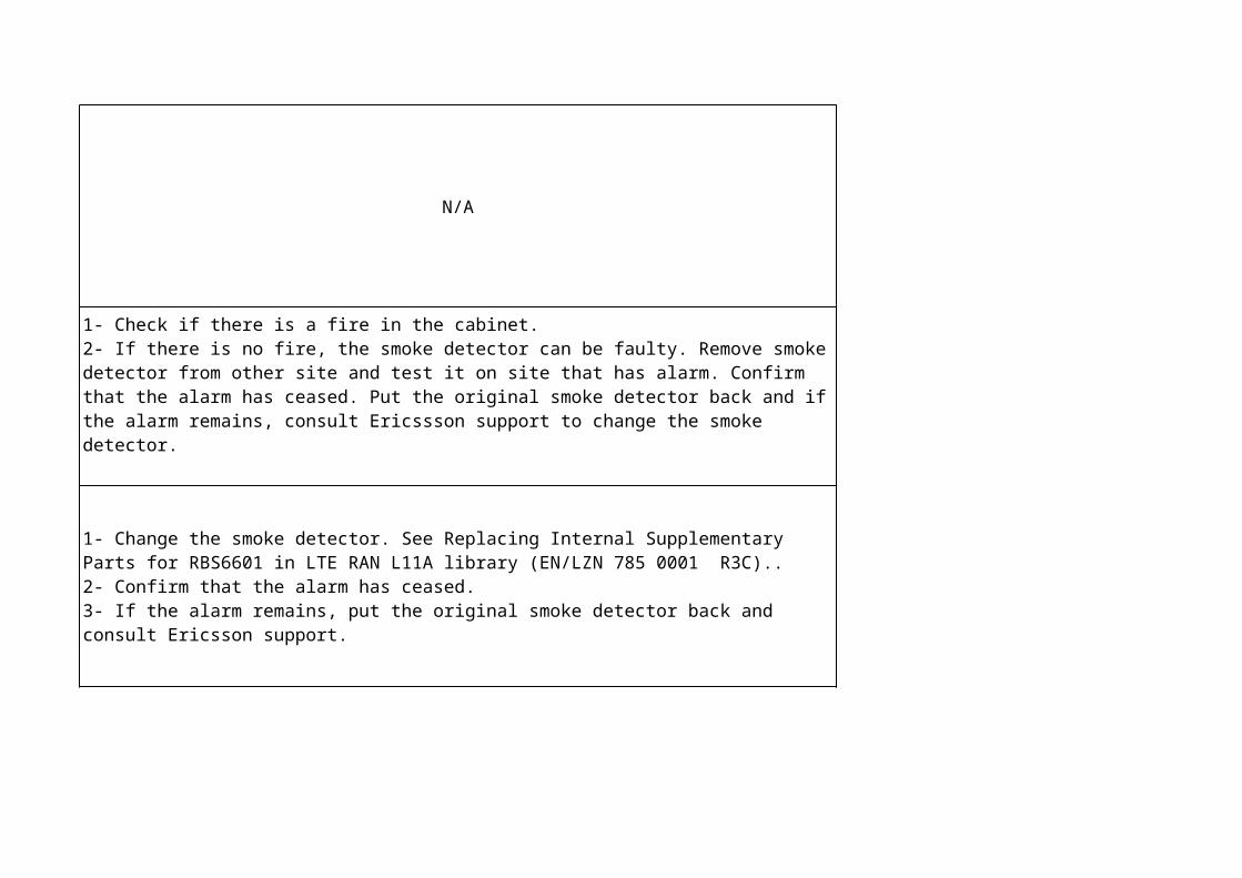
N/A
1- Check if there is a fire in the cabinet.2- If there is no fire, the smoke detector can be faulty. Remove smoke detector from other site and test it on site that has alarm. Confirm that the alarm has ceased. Put the original smoke detector back and if the alarm remains, consult Ericssson support to change the smoke detector.
1- Change the smoke detector. See Replacing Internal Supplementary Parts for RBS6601 in LTE RAN L11A library (EN/LZN 785 0001 R3C)..2- Confirm that the alarm has ceased.3- If the alarm remains, put the original smoke detector back and consult Ericsson support.

N/A
Note: Please, check instructions for RBS 6601 in LTE RAN L13B Alex library (EN/LZN 785 0001/1 R8B) for:
- Lock Board (Alex reference 41/1543-LZA 701 6008 Uen L or see .pdf beside)- Unlock Board (Alex reference 40/1543-LZA 701 6008 Uen K or see .pdf beside)- Restart Board (Alex reference 39/1543-LZA 701 6008 Uen N or see .pdf beside)- Replacing Fans and Climate Units (Alex reference 17/1543-LZA 701 6001 Uen J or see .pdf beside)
1. Restart the Support Control Unit (SCU). See Restart Board for instructions. 2. Check that the alarm has ceased. 3. If the alarm remains, make a visual inspection of the fans. 4. If the alarm remains, lock the SCU. See Lock Board for instructions. 5. Change the fan. See Replacing Fans and Climate Units for instructions. 6. Unlock the SCU. See Unlock Board for instructions. 7. Check that the alarm has ceased. 8. If the alarm remains, consult Ericsson support.
2.3-. Single Core MPPerform the following steps:
1- Replace the board, using the instruction for replacing that board.2- Restore the node, using the instruction Emergency Restoring a Configuration Version
Backup
2.4- Redundant Core MPThis procedure is normally performed by Ericsson personnel only and it is described in
detail in reference, which is an internal Ericsson document.

N/A
1- Change the board. See Replacing Alarm Units or Replacing Control Units instructions for RBS 6601 in LTE RAN L11A Alex library (EN/LZN 785 0001 R3C).
2- Unlock the board. See Unlock Board instructions RBS 6601 in LTE RAN L11A Alex library (EN/LZN 785 0001 R3C).
3- Check that the alarm has ceased.4- If the alarm remains, put the original board back and consult Ericsson support.
1- If necessary, replace the first Gigabit Ethernet link, follow the steps described in Section 2.2. Continue with the next step.
2- If the alarm ceases, exit this procedure. If the alarm does not cease, continue with the next step.
3- If there is a second Gigabit Ethernet link, follow the steps described in Section 2.2 to replace the second Gigabit Ethernet link. If there is not a second Gigabit Ethernet link,
go to Section 2.3 and then continue with the next step4- If the alarm is not issued again, exit this procedure. If the alarm remains, contact
Ericsson support. Further actions are outside the scope of this instruction.
2.2 Verifying and Replacing the Gigabit Ethernet LinkPerform the following steps at the node:
Note: After all steps involving hardware, wait at least two minutes to see if the alarm
reappears.
1- If a Small Form-Factor plugable (SFP) module is used, verify its status. Ensure that the power is on. Examine the port indications. If necessary, replace the SFP module.
2- If the alarm ceases, exit this procedure. If the alarm does not cease, continue with the next step.
3- If an Ethernet switch or router is used, examine its status. Ensure that the power is on. Examine the port indications. If necessary, move the cable to a different port and
test the port.Note:
The Ethernet switch or router might be owned by another operator. Also, it might be located in a different room from the subrack.
4- If the alarm ceases, exit this procedure. If the alarm does not cease, continue with the next step.
5- Lock the Gigabit Ethernet link by setting its administrativeState to LOCKED.6- Examine the Gigabit Ethernet link. Ensure that the connectors are not loose and that
the Gigabit Ethernet link is connected correctly.7- Unlock the Gigabit Ethernet link by setting its administrativeState to UNLOCKED.
8- If the alarm ceases, exit this procedure. If the alarm does not cease, continue with the next step.
9- Lock the Gigabit Ethernet link by setting its administrativeState to LOCKED.10- Replace the Gigabit Ethernet link temporarily.
11- Unlock the Gigabit Ethernet link by setting its administrativeState to UNLOCKED.12- If the alarm is issued again, go to Step 17. If the alarm is not issued again, continue
with the next step.13- Lock the Gigabit Ethernet Link again.
14- Disconnect the temporary Gigabit Ethernet link and replace the Gigabit Ethernet Link permanently.
15- Unlock the Gigabit Ethernet link again.16- Return to the procedure, Alarm Analysis.
17- Lock the Gigabit Ethernet Link again.18- Disconnect the temporary Gigabit Ethernet Link and reconnect the original Gigabit
Ethernet Link.19- Unlock the Gigabit Ethernet Link again.
20- Return to the procedure, Alarm Analysis.
2.3 Verifying and Replacing the BoardPerform the following steps at the node:
Note: After all steps involving hardware, wait at least two minutes to see if the alarm
reappears.
1- Verify that the board is correctly installed and that any associated cables are connected. If the alarm ceases, go to Step 10.
2- If the faulty board is a Digital Unit (DUL or DUW) continue with the next step. 3- Lock the faulty board.
4- Replace the faulty board using the instruction for replacing that board and unlock the board (RBS 6601 in LTE RAN L11A Alex library -EN/LZN 785 0001 R3C).
5- Return to the procedure, Alarm Analysis.6- Perform a loopback test on the faulty board.
If the alarm does not cease, go to Step 10.
Note: The loopback test involves disconnecting the cables and using a suitable crossover
cable to connect both electrical connectors on the board to each other. After the test, remove the crossover cable and reconnect the associated cables.
Note: Do not lock the port on this node before the loop test, because locking the port hides
alarms.
7- The board is at fault and needs to be replaced. Lock the board.8- Replace the faulty board, using the instruction for replacing the board (RBS 6601 in
LTE RAN L11A Alex library -EN/LZN 785 0001 R3C).9- Unlock the board.
10- Return to the procedure, Alarm Analysis.

N/A
Lock the faulty board.1- Perform a moshell connection to the RBS:
./moshell <RBS_IP_Address>
2- Insert the rbs user and password
3- The following prompt appears: <RBS_IP_Address> >
4- Load all MOs configured. lt all
5- Lock Digital Unit (DU) board. Note: All traffic on E-nodeB will be stopped. bl 000100
Confirm: yes
6- The field technician replaces the faulty board, using the instruction Replacing Digital Units (DU) for RBS 6601 in LTE RAN L11A Alex library (EN/LZN 785 0001 R3C).
7- Unlock Digital Unit (DU) board: deb 000100 Confirm: yes
7- If the alarm is not issued again, go to step 9.
8- If the alarm remains, consult Ericsson support.
9- Exit this procedure.
1- Check for other temperature-related alarms from RBS 6601 in LTE RAN 11A Alex library (EN/LZN 785 0001 R3C).
2- Investigate whether the problem is the result of high environmental temperature or a fault in the climate system.
3- Resolve possible climate problem.4- Check that the alarm has ceased.
5- If the alarm remains, consult Ericsson support.
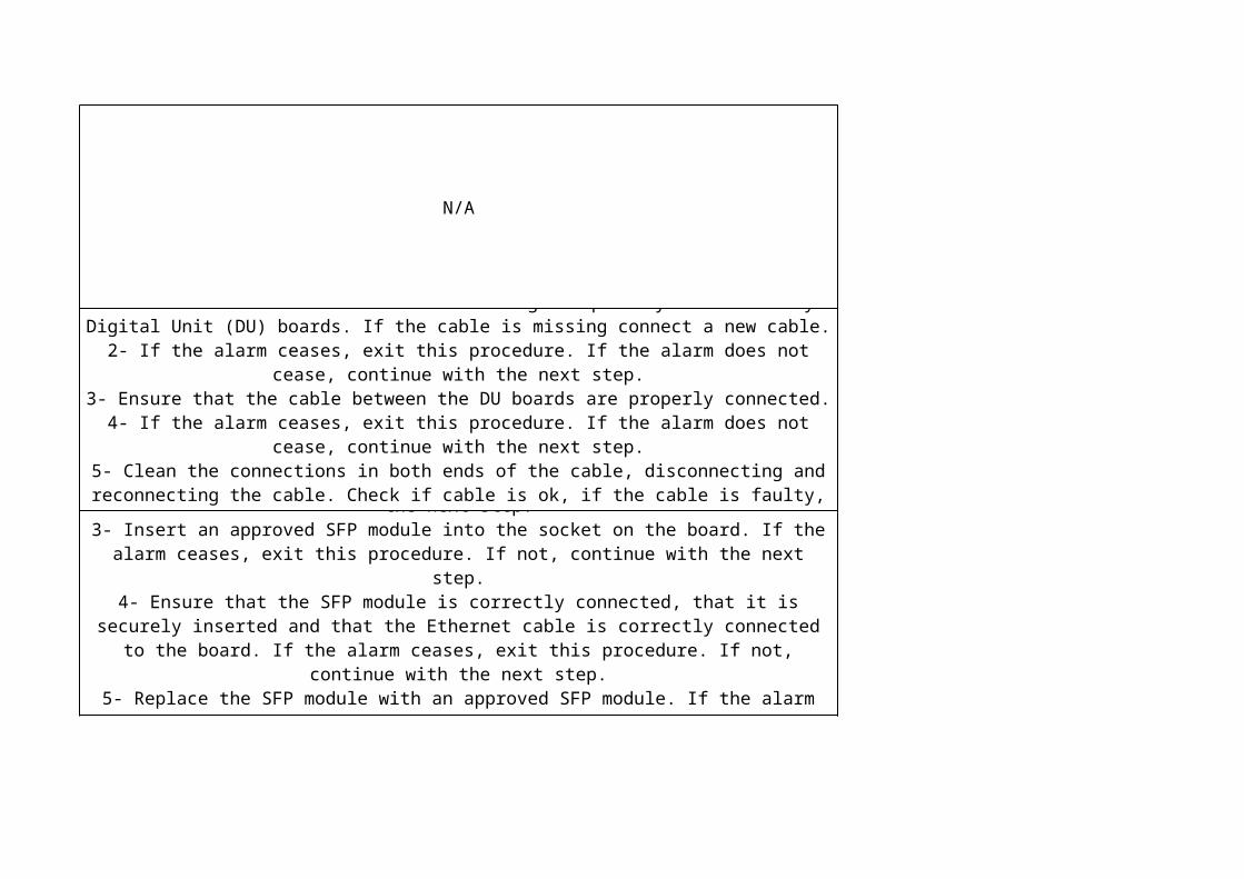
N/A
Note: After all steps involving hardware, wait at least two minutes before taking further action.
The alarm may cease during this time.
Perform the following steps:1- Check that there is a cable connecting the primary and secondary Digital Unit (DU)
boards. If the cable is missing connect a new cable.2- If the alarm ceases, exit this procedure. If the alarm does not cease, continue with the
next step.3- Ensure that the cable between the DU boards are properly connected.
4- If the alarm ceases, exit this procedure. If the alarm does not cease, continue with the next step.
5- Clean the connections in both ends of the cable, disconnecting and reconnecting the cable. Check if cable is ok, if the cable is faulty, it needs to be replaced.
6- If the alarm ceases, exit this procedure. If the alarm remains, continue with the next step.
7- Consult Ericsson support. Further actions are outside the scope of this instruction.
1- Identify the subrack and slot for the board with the missing, faulty or not supported Small Form-Factor Plugable (SFP) module.
2- If an SFP module is present, go to Step 4. If not, continue with the next step.3- Insert an approved SFP module into the socket on the board. If the alarm ceases, exit
this procedure. If not, continue with the next step.4- Ensure that the SFP module is correctly connected, that it is securely inserted and
that the Ethernet cable is correctly connected to the board. If the alarm ceases, exit this procedure. If not, continue with the next step.
5- Replace the SFP module with an approved SFP module. If the alarm ceases, exit this procedure. If not, continue with the next step.
6- Consult Ericsson support. Further actions are outside the scope of this procedure. There can be a hardware fault on the board.

N/A
N/A
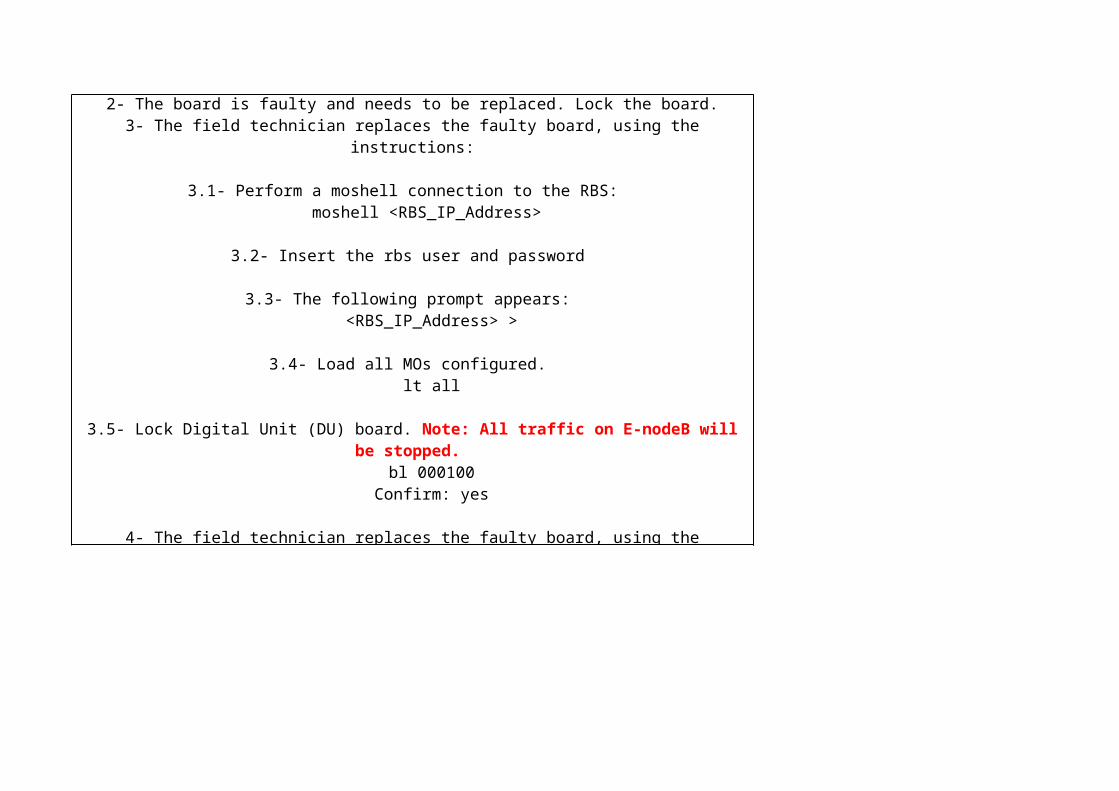
Verifying and Replacing the BoardPerform the following steps at the node:
Note: After all steps involving hardware, wait at least two minutes to see if the alarm
reappears.
1- The field technician ensures that the board is correctly installed and that any associated cables are connected.If the alarm ceases, go to Step 8.
2- The board is faulty and needs to be replaced. Lock the board.3- The field technician replaces the faulty board, using the instructions:
3.1- Perform a moshell connection to the RBS: moshell <RBS_IP_Address>
3.2- Insert the rbs user and password
3.3- The following prompt appears: <RBS_IP_Address> >
3.4- Load all MOs configured. lt all
3.5- Lock Digital Unit (DU) board. Note: All traffic on E-nodeB will be stopped. bl 000100
Confirm: yes
4- The field technician replaces the faulty board, using the instruction for Replacing Digital Unit (DU) RBS 6601 in LTE RAN L11A Alex library (EN/LZN 785 0001 R3C).
5- Unlock Digital Unit (DU) board: deb 000100 Confirm: yes
6- If the alarm is not issued again, go to step 8.
7- If the alarm remains, consult Ericsson support.
8- Exit this procedure.

After all steps involving hardware, wait at least two minutes to see if the alarm reappears.
1- The field technician ensures that the board is correctly installed and that any associated cables are connected.If the alarm ceases, go to Step 9.
2- The field technician cleans the connections on the board.If the alarm ceases, go to Step 9.
Note: The cleaning involves disconnecting the cable and reconnecting the cables.
3- The board is faulty and needs to be replaced. Lock the board.4- The field technician replaces the faulty board, using the instructions:
4.1- Perform a moshell connection to the RBS: ./moshell <RBS_IP_Address>
4.2- Insert the rbs user and password
4.3- The following prompt appears: <RBS_IP_Address> >
4.4- Load all MOs configured. lt all
4.5- Lock Digital Unit (DU) board. Note: All traffic on E-nodeB will be stopped. bl 000100
Confirm: yes
5- The field technician replaces the faulty board, using the instruction for Replacing Digital Unit (DU) for RBS 6601 in LTE RAN 11A Alex library (EN/LZN 785 0001 R3C).
6- Unlock Digital Unit (DU) board: deb 000100 Confirm: yes
7- If the alarm is not issued again, go to step 8.
8- If the alarm remains, consult Ericsson support. Further actions are outside the scope of this instruction. Contact the maintenance center for the remote node to inform them of
the action taken.
9- Exit this procedure.
1- Check the power source fuses. Change any defective fuse.
2- Check the incoming power supply.If the incoming power supply is absent, contact the incoming power supplier or the next
level of maintenance support.
3- Check that the alarm has ceased.4- If the alarm remains, consult Ericsson support.1- Check the incoming power supply.
If the incoming power supply is absent, contact the incoming power supplier.
2- Check the power source fuses.Change any defective fuse.
3- Check that the alarm has ceased.4- If the alarm remains, consult Ericsson support.
1- Action for Low Voltage at Intermittent ChargeTo resolve the alarm, perform the following procedure:
1.1- Check that the intermittentChargeConnectVoltage attribute is properly configured.1.2- Check the battery condition by performing a battery test on demand .
1.3- Verify that the battery test function is switched on (the batteryTestEnable supply system attribute is TRUE).
1.4- In the RBS EM Equipment view, right-click Battery and select Start Battery Test.Note:
Estimated time depends on the battery and a test can take several hours. It is possible to stop the test at any time by right-clicking Battery and selecting Stop Battery Test.
1.5- If the alarm reappears after the battery test, replace the battery. For instruction about how to replace the battery, see Replacing Power Units.
1.6- Repeat the battery test again and check the RBS EM alarm list to see if the alarm clears.
1.7- If the alarm remains, check the battery test result and replace the original battery. Contact the next level of maintenance support.
2- Action for Insufficient Discharged CapacityTo resolve the alarm, perform the following procedure:
2.1- Refer to the test result of the last performed battery test using the readBatteryTestResult action. Verify that the test was properly performed and that the
outcome was FAILED.2.2- Check that the battery capacity test is properly configured in the BatteryBackup MO.
Check that the minimumStateOfHealth attribute is properly configured.2.3- Check that no other RBS or other equipment is connected to the same battery.
Shared batteries must not be used if battery capacity tests are performed. The sharedBattery attribute must be properly configured.
2.4- Replace the battery. For instruction about how to replace the battery, see Replacing Power Units.
2.5- If the alarm remains, consult Ericsson support.
3- Action for Insufficient Recharged CapacityTo resolve the alarm, perform the following procedure:
3.1- Check that no other RBS or other equipment is connected to the same battery. The sharedBattery attribute must be properly configured.
3.2- Check the battery condition by performing a battery test on demand.3.3- Verify that the battery test function is switched on (the batteryTestEnable supply
system attribute is TRUE).3.4- In the RBS EM Equipment view, right-click Battery and select Start Battery Test.
Note: Estimated time depends on the battery and a test can take several hours. It is possible
to stop the test at any time by right-clicking Battery and selecting Stop Battery Test.
3.5- If the alarm reappears after the battery test, replace the battery. For instruction about how to replace the battery, see Replacing Power Units.
3.6- Repeat the battery test and check the RBS EM alarm list to see if the alarm clears.3.7- If the alarm remains, check the battery test result, and replace the original battery.
Contact Ericsson support.

N/A
Note: Please, check instructions for RBS 6601 in LTE RAN L11A Alex library (EN/LZN 785 0001 R3C).for:
- Lock Board - Unlock Board - Restart Board
- Replacing Fans and Climate Units
Choose action depending on Impact: as follows:- <hwUnitType>that is not configured detected
- Too many configured fan groups
1- Actions for <hwUnitType> That Is Not Configured DetectedTo resolve the alarm, do the following:
1.1- Find the faulty unit. 1.2- Configure the hardware unit if it is needed.
1.3- Remove/disconnect the hardware unit that is not needed, see Lock Board, Replacing Fans and Climate Units, and Unlock Board for instructions.
1.4- Check that the alarm has ceased. 1.5- If the alarm remains, put the original unit back and consult Ericsson support.
2- Actions for Too Many Configured Fan GroupsTo resolve the alarm, do the following:
2.1- Check that correct number of fan groups are installed and configured. MO FanGroup represents configured fan groups.
2.2- Check that the alarm has ceased. 2.3- If the alarm remains, consult Ericsson support.
1- Check that the battery temperature sensor is properly connected2- Check that the attributes batteryDisconnectTemp and
batteryDisconnectTempCeaseOffset are properly configured3- Check for other temperature related alarms from this RBS 6601. Investigate if the problem could be result of high environmental temperature or a fault in the climate
system. Resolve the climate problem.4- Check that the alarm has ceased.
5- If the alarm remains, check if the temperature is too high due to frequent battery discharge and charge, possibly in combination with high environmental temperature.
The battery log may be used for this purpose.6- Change the battery temperature sensor. If it is an internally placed battery, see Replacing Power Units for instructions (RBS 6601 in LTE RAN 11A Alex library -
EN/LZN 785 0001 R3C). . If the battery is placed in an external Battery Backup Unit (BBU), refer to Site
documentation for instructions (RBS 6601 in LTE RAN 11A Alex library - EN/LZN 785 0001 R3C).
7- Check that the alarm has ceased.8- If the alarm remains, check the battery condition. A battery test on demand can be
used for this.9- Change the defective battery. If it is an internally placed battery, see Replacing Power
Units for instructions. If the battery is placed in an external BBU, refer to Site documentation for instructions.
Note: Do not attempt to change hot batteries.
10- Check that the alarm has ceased.11- If the alarm remains, consult the next level of maintenance.
1- Investigate if other HW units in the same cabinet have raised temperature related alarms. This could indicate a climate system fault in the cabinet where the Battery Fuse
Unit (BFU) is located or too high environmental temperature. Resolve the climate problem.
2- Check that the alarm has ceased.3- If the alarm remains, restart the BFU
4- Check that the alarm has ceased.5- If the alarm remains, change the BFU. If it is an internally placed battery, see instruction Replacing Power Unitsfor for RBS 6601 in LTE RAN 11A Alex library
(EN/LZN 785 0001 R3C). If the battery is placed in an external Battery Backup Unit (BBU), refer to Site documentation for instructions.
6- If the alarm reappears shortly after changing the BFU, then the unit was probably not at fault. The fault can be a general cabinet climate problem.
7- Check that the alarm has ceased.8- If the alarm remains, consult the next level of maintenance support.

N/A
Note: Please, check instructions for RBS 6601 in LTE RAN L11A Alex library (EN/LZN 785 0001 R3C) for:
- Lock Board - Unlock Board - Restart Board
- Replacing Fans and Climate Units
1. Check for other temperature related alarms from this RBS. Investigate if the problem could be a result of high environmental temperature or a fault in the climate system.
Resolve climate problem. 2. Check that the alarm has ceased.
3. If the alarm remains, restart the PSU. See Restart Board for instructions. 4. Check that the alarm has ceased.
5. If the alarm remains, identify and lock the faulty unit. See Lock Board for instructions. 6. Change the PSU. See Replacing Power Units for instructions.
7. Unlock the unit. See Unlock Board for instructions. 8. Check that the alarm has ceased.
9. If the alarm remains, put the original board back, and consult the next level of maintenance support.
Note: Please, check instructions for RBS 6601 in LTE RAN L11A Alex library (EN/LZN 785 0001 R3C) for:
- Lock Board - Unlock Board - Restart Board
- Replacing Fans and Climate Units
1. Check for other temperature related alarms from this RBS. Investigate if the problem could be a result of low environmental temperature or a fault in the climate system.
Resolve climate problem. 2. Check that the alarm has ceased.
3. If the alarm remains, restart the PSU. See Restart Board for instructions. 4. Check that the alarm has ceased.
5. If the alarm remains, identify and lock the faulty unit. See Lock Board for instructions. 6. Change the PSU. See Replacing Power Units for instructions.
7. Unlock the unit. See Unlock Board for instructions. 8. Check that the alarm has ceased.
9. If the alarm remains, put the original board back, and consult the next level of maintenance support.

After all steps involving hardware, wait at least two minutes to see if the alarm reappears.
1- The field technician ensures that the board is correctly installed and that any associated cables are connected.
If the alarm ceases, exit this procedure.
2- The board is faulty and needs to be replaced. Lock the board.
2.1- Perform a moshell connection to the RBS: ./moshell <RBS_IP_Address>
2.2- Insert the rbs user and password
2.3- The following prompt appears: <RBS_IP_Address> >
2.4- Load all MOs configured. lt all
2.5- Lock Digital Unit (DU) board. Note: All traffic on E-nodeB will be stopped. bl 000100
Confirm: yes
3- The field technician replaces the faulty board, using the instruction for Replacing Digital Unit (DU) RBS 6601 in LTE RAN L11A Alex library (EN/LZN 785 0001 R3C).
4- Unlock Digital Unit (DU) board: deb 000100 Confirm: yes
5- If the alarm is not issued again, exit this procedure.
6- If the alarm remains, consult Ericsson support. Further actions are outside the scope of this instruction. Contact the maintenance center for the remote node to inform them of
the action taken.
After all steps involving hardware, wait at least two minutes to see if the alarm reappears.
1. The field technician verifies the power supply. Note:
This involves verifying the external power distribution system and the voltage level. Verify also the voltage level in the cables on the board side.
See the description of the external power distribution system. The alarm threshold varies slightly depending on the board, but is approximately –40V.
2. The field technician verifies that the power cables are correctly connected to the right board and have the correct voltage level.If the alarm ceases, exit this procedure.
3- If the board is faulty and needs to be replaced. Lock the board.3.1- Perform a moshell connection to the RBS:
./moshell <RBS_IP_Address>
3.2- Insert the rbs user and password
3.3- The following prompt appears: <RBS_IP_Address> >
3.4- Load all MOs configured. lt all
3.5- Lock Digital Unit (DU) board. Note: All traffic on E-nodeB will be stopped. bl 000100
Confirm: yes
4- The field technician replaces the faulty board, using the instruction for Replacing Digital Unit (DU) RBS 6601 in LTE RAN L11A Alex library (EN/LZN 785 0001 R3C)
.5- Unlock Digital Unit (DU) board:
deb 000100 Confirm: yes
6- If the alarm is not issued again, exit this procedure.
7- If the alarm remains, consult Ericsson support. Further actions are outside the scope of this instruction. Contact the maintenance center for the remote node to inform them of
the action taken.
2 Action for EUtranCellFDD and AdditionalText: Incompatible Hardware Resources2.1. Lock the cell.
2.2. Change the incompatible RU or RRU. See Replacing Radio Units or Replacing Remote Radio Units for instructions.
2.3. Unlock the cell. 2.4. Check that the alarm has ceased.
2.5. If the alarm remains, consult Ericsson support.

Check if there is hardware faulty on Remote Radio Unit (RRU).
N/A
It depends of primary alarm and O&M instruction.

N/A
N/A
After all steps involving hardware, wait at least two minutes to see if the alarm reappears.
1- The field technician ensures that the board is correctly installed and that any associated cables are connected.If the alarm ceases, go to Step 9.
2- The field technician cleans the connections on the board.If the alarm ceases, go to Step 9.
Note: The cleaning involves disconnecting the cable and reconnecting the cables.
3- The board is faulty and needs to be replaced. Lock the board.4- The field technician replaces the faulty board, using the instructions:
4.1- Perform a moshell connection to the RBS: ./moshell <RBS_IP_Address>
4.2- Insert the rbs user and password
4.3- The following prompt appears: <RBS_IP_Address> >
4.4- Load all MOs configured. lt all
4.5- Lock Digital Unit (DU) board. Note: All traffic on E-nodeB will be stopped. bl 000100
Confirm: yes
5- The field technician replaces the faulty board, using the instruction for Replacing Digital Unit (DU) for RBS 6601 in LTE RAN 11A Alex library (EN/LZN 785 0001 R3C).
6- Unlock Digital Unit (DU) board: deb 000100 Confirm: yes
7- If the alarm is not issued again, go to step 8.
8- If the alarm remains, consult Ericsson support. Further actions are outside the scope of this instruction. Contact the maintenance center for the remote node to inform them of
the action taken.
9- Exit
N/A
Choose action depending on the type of power system as follows:Action for Power System AC/DC Rectification or DC/DC Conversion
Action for Power System Direct -48 VDC Power Supply
1 Action for Power System AC/DC Rectification or DC/DC ConversionTo resolve the alarm, perform the following procedure:
1- Check that alarm levels are properly configured. 2- Check if the system voltage is correct. Measure the system voltage through the port on the Power Distribution Unit (PDU). Replace the PDU if systemVoltage is correct and
the alarm is still raised. 3- Check incoming power supply.
4- Change the faulty Power Suplly Unit (PSU). For instructions, go to Section 1.1. 5- Check that the alarm has ceased.
6- If the alarm remains, consult the next level of maintenance support.
1.1 Replacing PSUTo replace the PSU, perform the following steps:
1- Locate the faulty PSU, which is identified by a red fault indicator. 2- In the RBS EM, lock the PSU.
3- Replace the PSU according to the instructions in Replacing Power Units for RBS 6601 in LTE RAN L11A Alex library (EN/LZN 785 0001 R3C).
4- Unlock the PSU and check the RBS EM alarm list to see if the alarm clears. 5- If the alarm reappears, lock the PSU and reinstal the original PSU. For instructions,
go to Section 1.2.Note: Never return any PSU to Ericsson unless the alarm has been cleared after
replacement of the unit.
1.2 Replacing Battery Fuse Unit (BFU)To replace the BFU, perform the following steps:
1- In the RBS EM, lock the BFU. 2- Replace the BFU according to the instructions in Replacing Power Units for RBS
6601 in LTE RAN L11A Alex library (EN/LZN 785 0001 R3C). 3- Unlock the BFU and check the RBS EM alarm list to see if the alarm clears.
4- If the alarm does not clear, then lock the BFU and put back the original BFU. Contact the next level of maintenance support.
Note: Never return a BFU to Ericsson, unless the alarm has been cleared after replacement of the unit.
2 Action for Power System Direct -48 VDC Power SupplyTo resolve the alarm, do the following:
1- Check that alarm levels are properly configured. 2- Check if the system voltage is correct. Measure the system voltage through the port
on PDU. Replace PDU if systemVoltage is correct and the alarm is still present. 3- Check the input power.
4- Check that the alarm has ceased. 5- If the alarm remains, consult the next level of maintenance support.

Choose action depending on the type of power system as follows:- Action for Power System AC/DC Rectification or DC/DC Conversion
- Action for Power System Direct -48 VDC Power Supply
1 Action for Power System AC/DC Rectification or DC/DC ConversionTo resolve the alarm, perform the following procedure:
1. Check that alarm levels are properly configured. 2. Check incoming power supply.
3. Check that there are sufficient Power Supply Units (PSUs) installed for the power demand. If necessary, install more PSUs. For PSU installation instructions, see Section
1.2. 4. Change the faulty PSU. For instructions, go to Section 1.1.
5. Check that the alarm has ceased. 6. If the alarm remains, consult the next level of maintenance support.
1.1 Replacing PSUTo replace a PSU, perform the following steps:
1. Locate the faulty PSU (displays a red indicator). 2. In the RBS EM, lock the PSU.
3. Replace the PSU according to the instructions in Replacing Power Units for RBS 6601 in LTE RAN L11A Alex library (EN/LZN 785 0001 R3C).
4. Unlock the PSU, and check the RBS EM alarm list to see if the alarm clears. 5. If the alarm reappears, then lock the PSU and put back the original PSU. Contact the
next level of maintenance support.Note:
Never return a PSU to Ericsson, unless the alarm has been cleared after changing the unit.
1.2 Installing PSUTo install a PSU, do the following:
1. Install the PSU according to the instructions in Replacing Power Units for RBS 6601 in LTE RAN L11A Alex library (EN/LZN 785 0001 R3C).
2. Re-configure the RBS according to the instructions in the document Support System in LTE RAN L11A Alex library (EN/LZN 785 0001 R3C).
3. Unlock the PSU. 4. Check the RBS EM alarm list to see if the alarm clears. If the alarm reappears, then
contact the next level of maintenance support. 5. Update the CV according to the document Software Management 6601 in LTE RAN
L11A Alex library (EN/LZN 785 0001 R3C).
2 Action for Power System Direct -48 VDC Power Supply- Check that alarm levels are properly configured.
- Check the input power supply. - Check the power source fuses.
1- Change the battery temperature sensor. If it is an internally placed battery, see instruction Replacing Fans and Climate Units for RBS 6601 in LTE RAN L11A Alex
library (EN/LZN 785 0001 R3C)). If the battery is placed in an external Battery Backup Unit (BBU), refer to Site documentation for instructions.
2- Check that the alarm has ceased.3- If the alarm remains, consult Ericsson support.
First check the GPS timing reference cable that is connected to the DUS. Verify that the cable is good. If not replace the cable.
The sync cable between SIU and DUS has same connector in both sides but different pinout so it is very important to connect the right connector to each side. Exchange cable position, connector in the GPS DUS port side should be connected in the CLOCK SIU port.
Verifying and Replacing the Synchronization Reference Cable. Perform the following steps at the node:
Note: After all steps involving hardware, wait at least two minutes to see if the alarm reappears.
Lock the port to which the Synchronization Reference Cable (SRC) is attached, by setting its administrativeState to LOCKED.The field technician verifies the SRC.Note: If the SRC is not connected to the correct ports, the field technician should connect it correctly.The field technician replaces the SRC temporarily.Unlock the port to which the SRC is attached, by setting its administrativeState to UNLOCKED.If the alarm is not issued again, continue with the next step. If the alarm is issued again, go to Step 9.Lock the port to which the SRC is attached, by setting its administrativeState to LOCKED.The field technician disconnects the temporary SRC and replaces the SRC permanently, using the instruction for replacing the SRC.Unlock the port to which the SRC is attached by setting its administrativeState to UNLOCKED.Return to the procedure, Analyzing the Alarm.Lock the port to which the SRC is attached by setting its administrativeState to LOCKED.The field technician disconnects the temporary SRC and reconnects the original SRC.Unlock the port to which the SRC is attached by setting its administrativeState to UNLOCKED.Return to the procedure, Analyzing the Alarm.
Verifying and Replacing the BoardPerform the following steps at the node:
Note: After all steps involving hardware, wait at least two minutes to see if the alarm reappears.
1- The field technician ensures that the board is correctly installed and that any associated cables are connected.If the alarm ceases, go to step 7.
2- The field technician should disconnect and reconnect the cable.If the alarm ceases, go to step 7.If the alarm remains, go to step 3.
3- The board is faulty and needs to be replaced. Lock the board.3.1- Perform a moshell connection to the RBS: ./moshell <RBS_IP_Address>
3.2- Insert the rbs user and password
3.3- The following prompt appears: <RBS_IP_Address> >
3.4- Load all MOs configured. lt all
3.5- Lock Digital Unit (DU) board. Note: All traffic on E-nodeB will be stopped. bl 000100 Confirm: yes
4- The field technician replaces the faulty board, using the instruction for Replacing Digital Unit (DU) RBS 6601 in LTE RAN L11A Alex library (EN/LZN 785 0001 R3C).
5- Unlock Digital Unit (DU) board: deb 000100 Confirm: yes6- If the alarm is not issued again, go to step 7.7- Exit this procedure.8- If the alarm remains, consult Ericsson support. Further actions are outside the scope of this instruction.

It depends of primary alarm and O&M instruction.


LTE Alarm List for EnodeB
ALEX Instructions


1- In the Element Manager, Software view, select the additional tab UP to display all UPs.

2- Right-click the relevant UP and select UP Properties from the shortcut menu. The UP Configuration window is displayed.
3- Click Delete Package. A confirmation window appears.
Note1:

It is not possible to delete an UP that has a CV connected to it, if the CV is in the rollback list, or is startable. First remove the CV from the rollback list, or from being startable.
Note2:
Lock Board Unlock Board Restart Board Replacing Fans and Climate Units
Note3:
It is not possible to delete an UP, if there is a delta UP that is based on it. First delete the delta UP.

It is not possible to delete an UP that is currently being used in the node.
4- In the confirmation window, click Yes.


Restart Board Restart Node


Unlock BoardLock_Board Restart Board


LTE Alarm List for EnodeB
Additional information
N/A
To resolve the alarm, do the following:
1- Use readBatteryTestResult to read the result of the latest battery test.2- Verify that the test was properly performed and that the result status was: failed.3- Check that the battery backup time test is properly configured in Managed Object (MO) BatteryBackup. Check that the minimumBackupTime is properly configured.4- If any other RBS is connected to the same battery, verify that a battery time test was performed at the same time on the other RBS.5- Check that no equipment, other than this RBS, is connected to the same battery.6- Change the battery if needed. If it is an internally placed battery, see Replacing Power Units for instructions. If the battery is placed in an external Battery Backup Unit (BBU), refer to Site documentation for instructions.7- Check that the alarm has ceased.8- If the alarm remains, consult the next level of maintenance support.

N/A
N/A
To lock a board, perform the following steps:
1- Identify the instance of the Managed Object (MO) for the relevant board.The following MOs are used:
Type of unit or board: Related MODigital Units PlugInUnitRadio Units AuxPlugInUnitSupport System Units HwUnit 2- Set the attribute administrativeState for the instance of the MO to 0.--------------------------------------------------------------------------------Stop! Locking a Digital Unit LTE (DUL) or a Radio Unit (RU) stops all traffic on the unit. This can cause reduced capacity, and in cases of a single DUL configuration, can cause a total traffic stoppage. -------------------------------------------------------------------------------- 3- Verify that the administrativeState attribute is now LOCKED.
To restart a board, do the following:1. Identify the instance of the MO for the relevant board. 2. The following MOs are used:Type of unit or board: Related MO Digital Units PlugInUnit Radio Units AuxPlugInUnitSupport System Units HwUnit3. For PlugInUnit: Perform the action manualRestart, and specify restartRank and restartReason. The parameter, restartInfo is optional. It is a free text field where extra information can be added. It has a maximum length of 80 characters.
RestartRank0 RESTART_WARM Restarts the MO with the same software. The software is not reloaded from the disk. The traffic is affected least. 1 RESTART_REFRESH Reloads the software from the disk, restarts the MO, and resets parts of the hardware. The traffic is affected more than for a warm restart. 2 RESTART_COLD Reloads the software from the disk, restarts the MO, and resets all hardware. The traffic is affected more than for a refresh restart. 3 RESTART_COLDWTEST Reloads the software from the disk, restarts the MO, and resets and tests the hardware. The traffic is affected most.
RestartReason0 PLANNED_RECONFIGURATION Restart ordered to perform planned activities such as reconfigurations. 1 UNPLANNED_NODE_EXTERNAL_PROBLEMS Restart ordered to resolve node external problems. 2 UNPLANNED_NODE_UPGRADE_PROBLEMS Restart ordered to resolve upgrade problems. 3 UNPLANNED_O_AND_M_ISSUE Restart ordered to resolve O&M issues. 4 UNPLANNED_CYCLIC_RECOVERY Restart ordered to stop further auto recovery attempts. 5 UNPLANNED_LOCKED_RESOURCES Restart ordered to release locked resources. 6 UNPLANNED_COLD_WITH_HW_TEST Restart ordered to perform HW tests. 7 UNPLANNED_CALL_PROCESSING_DEGRADATION Restart ordered to improve Call Set Up or Call Drop Rate. 8 UNPLANNED_LOW_COVERAGE Restart ordered to improve Cell Availability. 30 UPGRADE_BOARD_RESTART Restart ordered to effectuate autoconfiguration of a plug-in unit.
This is only used for PlugInUnit MO.
For AuxPlugInUnit:Perform the action restartUnit.For HwUnit:Perform the action restartUnit.
To unlock a board, perform the following steps:
1- Identify the instance of the Managed Object (MO) for the relevant board.The following MOs are used:
Type of unit or board: Related MO Digital Units PlugInUnit Radio Units AuxPlugInUnitSupport System Units HwUnit 2- Set the attribute administrativeState for the instance of the MO to 1.3- Verify that the administrativeState attribute is now UNLOCKED.
Restart RankThis is used in the manualRestart action for the MOs ManagedElement, PlugInUnit and PiuDevice.
0 RESTART_WARM Restarts the MO with the same software. The software is not reloaded from the disk. The traffic is affected least. 1 RESTART_REFRESH Reloads the software from the disk, restarts the MO, and resets parts of the hardware. The traffic is affected more than for a warm restart. 2 RESTART_COLD Reloads the software from the disk, restarts the MO, and resets all hardware. The traffic is affected more than for a refresh restart. 3 RESTART_COLDWTEST Reloads the software from the disk, restarts the MO, and resets and tests the hardware. The traffic is affected most.
RestartReason0 PLANNED_RECONFIGURATION Restart ordered to perform planned activities such as reconfigurations. 1 UNPLANNED_NODE_EXTERNAL_PROBLEMS Restart ordered to resolve node external problems. 2 UNPLANNED_NODE_UPGRADE_PROBLEMS Restart ordered to resolve upgrade problems. 3 UNPLANNED_O_AND_M_ISSUE Restart ordered to resolve O&M issues. 4 UNPLANNED_CYCLIC_RECOVERY Restart ordered to stop further auto recovery attempts. 5 UNPLANNED_LOCKED_RESOURCES Restart ordered to release locked resources. 6 UNPLANNED_COLD_WITH_HW_TEST Restart ordered to perform HW tests. 7 UNPLANNED_CALL_PROCESSING_DEGRADATION Restart ordered to improve Call Set Up or Call Drop Rate. 8 UNPLANNED_LOW_COVERAGE Restart ordered to improve Cell Availability. 30 UPGRADE_BOARD_RESTART Restart ordered to effectuate autoconfiguration of a plug-in unit.
This is only used for PlugInUnit MO.

N/A
N/A
N/A
N/A
N/A
N/A
N/A

N/A
Delete Upgrade Package1- In the Element Manager, Software view, select the additional tab UP to display all UPs.2- Right-click the relevant UP and select UP Properties from the shortcut menu. The UP Configuration window is displayed.3- Click Delete Package. A confirmation window appears.Note: It is not possible to delete an UP that has a CV connected to it, if the CV is in the rollback list, or is startable. First remove the CV from the rollback list, or from being startable.
Note: It is not possible to delete an UP, if there is a delta UP that is based on it. First delete the delta UP.
Note: It is not possible to delete an UP that is currently being used in the node.
4- In the confirmation window, click Yes.
Delete Upgrade Package1- In the Element Manager, Software view, select the additional tab UP to display all UPs.2- Right-click the relevant UP and select UP Properties from the shortcut menu. The UP Configuration window is displayed.3- Click Delete Package. A confirmation window appears.Note1: It is not possible to delete an UP that has a CV connected to it, if the CV is in the rollback list, or is startable. First remove the CV from the rollback list, or from being startable.
Note2: It is not possible to delete an UP, if there is a delta UP that is based on it. First delete the delta UP.
Note3: It is not possible to delete an UP that is currently being used in the node.
4- In the confirmation window, click Yes.

N/A
N/A
N/A

N/A
N/A
N/A

N/A
N/A
N/A

N/A
N/A
N/A

N/A
N/A
N/A

N/A
Procedure to Install/update the License Key File (LKF) through AMOS/Moshell:Remote or Onsite connection to Enode-B: 1- Perform a moshell connection to the RBS: ./moshell <RBS_IP_Address>2- Insert the rbs user and password 3- The following prompt appears: <RBS_IP_Address> >4- Load all MOs configured. lt allExample of output from the moshell 10.0.0.1> lt all110406-15:08:53 10.15.122.235 7.1 stopfile=/tmp/17060Checking MOM version...RBS_NODE_MODEL_M_1_8Parsing MOM (cached): /home/user/moshell//jarxml/RBS_NODE_MODEL_M_1_8.xml.cache.gz .....................................Done.Fetching IOR file...Done.Connecting to 10.0.0.1:56834 (**** Welcome to the Simple Mo Browser (version 3.0)!Trying file=/home/user/moshell_logfiles/logs_moshell/tempfiles/20110406-150839_17035/ior17035**** Test Construction OK****$mobrowser_pid = 17120 Last MO: 887. Loaded 887 MOs. Total: 888 MOs.
5. Verify the presence of LKF / Emergency LKF; >get 3
090129-17:29:26 10.112.240.165 7.1f RBS_NODE_MODEL_J_5_17 stopfile=/tmp/17815=================================================================================================================3 SystemFunctions=1,Licensing=1=================================================================================================================LicensingId 1emergencyStateInfo Struct{2}>>> 1.state = 4 (USE_DISABLED)>>> 2.time = 0licenseFileUrl http://10.112.240.165/keyfiles/Licensing.xmluserLabel =================================================================================================================Total: 1 MOs
6. Check MO Licensing to start updating the LKF; >acl licensing updatelicensekeyfile090129-18:03:17 10.112.240.165 7.1f RBS_NODE_MODEL_J_5_17 stopfile=/tmp/17815=================================================================================================================Proxy MO Action Nr of Params=================================================================================================================3 Licensing=1 updateLicenseKeyFile 4=================================================================================================================
7. Start the update using the LKF Moshell >acc licensing updatelicensekeyfile
Call Action updatelicensekeyfile on following MOs ?
===================================================================================
3 SystemFunctions=1,Licensing=1
===================================================================================
Are you Sure [y/n] ? y
=================================================================================================================
Proxy MO Action Nr of Params
=================================================================================================================
3 Licensing=1 updateLicenseKeyFile 4
Parameter 1 of 4, userId (string): <userid>
Parameter 2 of 4, password (string): <userid>
Parameter 3 of 4, ipAddress (string): 10.11.41.65
Parameter 4 of 4, sFile (string): X911513134_071214_153339.xml (exemple)
>>> Return value = null
=================================================================================================================
Total: 1 MOs attempted, 1 MOs actionedFI: updateLicenseKeyFile:This action sends a request to the FTP/SFTP server to update the license key file.User Id for login to FTP/SFTP server where license key files are located.If a null string userId is given, anonymous FTP/SFTP transfer is assumed.Max length is 20 characters.Password for login to the FTP/SFTP server where license key files are located.Max length is 20 characters.The IpAddress of the FTP/SFTP server where license key files are located.Max length is 16 characters.Source name and path of the license key file on the FTP/SFTP server.Max length is 256 charcters.Transaction required = NoReturnType: voidParameter 1: userId (string).Parameter 2: password (string).Parameter 3: ipAddress (string).Parameter 4: sFile (string).
8. Check the status of the new LKF inserted
>cat /c/license/licensekeys.xml090129-17:34:10 10.112.240.165 7.1f RBS_NODE_MODEL_J_5_17 stopfile=/tmp/17815$ cat /c/license/licensekeys.xml<?xml version="1.0" encoding="UTF-8"?><licFile xmlns:xsi="http://www.w3.org/2001/XMLSchema-instance"><body formatVersion="1.0" signatureType="1"><sequenceNumber>4</sequenceNumber><ELSN elsnId="EL14402860007"><generalInfo><generated>2009-01-27T16:11:07</generated><issuer>Ericsson AB</issuer></generalInfo><fingerprint method="1" print="X911562229"><featureKey id="CXC4030567"><description>LOAD MODULE/INTERACT. PS (16/16) + SRB (</description><start>2007-04-26</start><stop>9999-12-31</stop></featureKey>

N/A

N/A
N/A
N/A
N/A

N/A
N/A
N/A
N/A

N/A
N/A
N/A

N/A
N/A
N/A

N/A
N/A
N/A

N/A
N/A
N/A

N/A
N/A

N/A
N/A
N/A


OK 2m3s SLSPBT02no contact 0m13s SLSPCC02no contact 9m41s SLSPBF05no contact 6m44s SLSPBF10no contact 0m13s SLSPTC08no contact 3m28s SLSPJS05no contact 3m23s SLSPCV07no contact 0m17s SLSPJN02no contact 0m18s SLSPJS08no contact 0m18s SLSPSM12no contact 0m23s SLSPSM06no contact 0m17s SLSPJN01no contact 3m24s SLSPEM03no contact 0m13s SLSPCC05no contact 0m23s SLSPCV18no contact 0m20s SLSPEM07no contact 0m11s SLSPBL08no contact 0m12s SLSPCN05no contact 0m18s SLSPVT06no contact 0m18s SLSPBT06no contact 3m28s SLSPCI01no contact 0m23s SLSPSU02no contact 0m13s SLSPCG02no contact 3m28s SLSPCL06no contact 3m23s SLSPLJ06no contact 0m10s SLSPLP02no contact 6m47s SLSPVR04no contact 0m12s SLSPJQ06no contact 0m18s SLSPJS06no contact 6m37s SLSPSM05no contact 3m27s SLSPVA09no contact 6m27s SLSPPI03no contact 0m23s SLSPIT08no contact 0m17s SLSPSM30no contact 0m12s SLSPTC02no contact 0m10s SLSPMN06no contact 0m20s SLSPEM05no contact 0m18s SLSPVT04no contact 0m12s SLSPBL04no contact 3m18s SLSPSD03no contact 0m20s SLSPVS05no contact 0m13s SLSBVL02no contact 0m3s SLSBPC05no contact 0m3s SLSBVM01no contact 0m5s SLSBRR01

no contact 0m13s SLSPCC02no contact 9m41s SLSPBF05no contact 6m44s SLSPBF10no contact 0m13s SLSPTC08no contact 3m28s SLSPJS05no contact 3m23s SLSPCV07no contact 0m17s SLSPJN02no contact 0m18s SLSPJS08no contact 0m18s SLSPSM12no contact 0m23s SLSPSM06no contact 0m17s SLSPJN01no contact 3m24s SLSPEM03no contact 0m13s SLSPCC05no contact 0m23s SLSPCV18no contact 0m20s SLSPEM07no contact 0m11s SLSPBL08no contact 0m12s SLSPCN05no contact 0m18s SLSPVT06no contact 0m18s SLSPBT06no contact 3m28s SLSPCI01no contact 0m23s SLSPSU02no contact 0m13s SLSPCG02no contact 3m28s SLSPCL06no contact 3m23s SLSPLJ06no contact 0m10s SLSPLP02no contact 6m47s SLSPVR04no contact 0m12s SLSPJQ06no contact 0m18s SLSPJS06no contact 6m37s SLSPSM05no contact 3m27s SLSPVA09no contact 6m27s SLSPPI03no contact 0m23s SLSPIT08no contact 0m17s SLSPSM30no contact 0m12s SLSPTC02no contact 0m10s SLSPMN06no contact 0m20s SLSPEM05no contact 0m18s SLSPVT04no contact 0m12s SLSPBL04no contact 3m18s SLSPSD03no contact 0m20s SLSPVS05no contact 0m13s SLSBVL02no contact 0m3s SLSBPC05no contact 0m3s SLSBVM01no contact 0m5s SLSBRR01