ALARM COMMUNICATOR - Document · PDF filerespective companies and are hereby acknowledged. ......
8
FOR SALES & PRODUCT INFORMATION Uplink 1600 Parkwood Circle Suite 500 Atlanta, GA 30339 (888) 9-UPLINK [email protected] www.uplink.com FOR TECHNICAL SUPPORT Please visit our website at www.uplink.com. MODEL 2500 UNIVERSAL GSM ALARM COMMUNICATOR INSTALLATION & USER’S GUIDE
Transcript of ALARM COMMUNICATOR - Document · PDF filerespective companies and are hereby acknowledged. ......
FOR SALES & PRODUCT INFORMATIONUplink 1600 Parkwood CircleSuite 500Atlanta, GA 30339(888) [email protected]
FOR TECHNICAL SUPPORTPlease visit our website at www.uplink.com.
model 2500
UNIVERSAL GSM ALARM COMMUNICATOR
INSTALLATION &USER’S GUIDE
model 2500
UN
IVER
SAL
GSM
A
LARM
CO
MM
UN
ICAT
OR
© 2009 Uplink Security llC. All rights reserved.
No part of this publication may be reproduced or used in any form without permission
in writing from Uplink. This includes electronic or mechanical means, such as
photocopying, recording, or information storage and retrieval systems. The material in
this manual is subject to change without notice.
Uplink reserves the right to make changes to any software or product to improve
reliability, function or design.
Uplink is a trademark of Uplink Security, LLC. All rights reserved. Other products’
names mentioned in this manual may be trademarks or registered trademarks of their
respective companies and are hereby acknowledged.
UNIVERSAL GSM ALARM COMMUNICATOR
Product ID: 20214251334001
TABLE OF CONTENTS
Table of Contents ......................................................... 1
Warranty Information & Liability Waiver ........................ 2
Technical Support ......................................................... 3
Description ................................................................... 4
Installation Steps .......................................................... 5-7
Unit Wiring .................................................................... 8-10
Antenna Specification ................................................... 10
FCC & Industry Canada Regulatory Compliance ......... 11
FCC RF Exposure Information ...................................... 12
1.
UNIVERSAL GSM ALARM COMMUNICATORmodel 2500
12.
FCC RF EXPOSURE INFORMATIONIn August 1996 the Federal Communications Commission (FCC) of the United
States with its action in Report and Order FCC 96-326 adopted an updated
safety standard for human exposure to radio frequency electromagnetic energy
emitted by FCC regulated transmitters. Those guidelines are consistent with the
safety standard previously set by both U.S. and international standards bodies.
The design of this unit complies with the FCC guidelines and these international
standards. For more information about RF exposure, please visit the FCC website
at www.fcc.gov. THE TERM “IC:” BEFORE THE CERTIFICATION/REGISTRATION
NUMBER ONLY SIGNIFIES THAT THE INDUSTRY CANADA TECHNICAL
SPECIFICATIONS WERE MET.
THE EXTERNAL ANTENNAS USED FOR THIS UNIT MUST PROVIDE A
SEPARATION DISTANCE OF AT LEAST 20 CM FROM ALL PERSONS AND
MUST NOT BE CO-LOCATED OR OPERATING IN CONJUNCTION WITH ANY
OTHER ANTENNA OR TRANSMITTER.
For Sales & Product Information:
Uplink
1600 Parkwood Circle
Suite 500
Atlanta, GA 30339
(888) 9-UPLINK
www.uplink.com
For Technical Support, please visit our website at www.uplink.com.
model 2500
LIMITED WARRANTY – UPLINK Devices Uplink warrants, to parties purchasing Uplink equipment (including, withoutlimitation, the Uplink Model 2500) directly from Uplink, i.e., to its authorized distributors and to no other parties, that for 12 months following the date of purchase, Uplink equipment will be free of defects in materials and workmanship when installed, operated, maintained, and serviced in strict accordance with Uplink’s and, if applicable, the manufacturer’s requirements. If Uplink equipment fails because of a defect in materials or workmanship within the warranty period, Uplink will, at its sole option and at no charge, repair or replace it. Uplink’s agreement to repair (using new or reconditioned parts) or replace (with a comparable new or reconditioned Uplink unit) is the exclusive remedy with respect to Uplink equipment found to be defective in materials or workmanship; this remedy will not be deemed to have failed of its essential purpose so long as Uplink is willing and able to repair or replace the defective unit as provided above or, at Uplink’s sole option, to refund the purchase price paid. Parties purchasing Uplink equipment from a distributor are referred to the distributor with respect to any product claims they may have.
THE FOREGOING WARRANTY IS LIMITED AND IS THE ONLY WARRANTYOFFERED HEREUNDER. UPLINK MAKES NO OTHER WARRANTIES, EXPRESS OR IMPLIED, INCLUDING, WITHOUT LIMITATION, THE IMPLIED WARRANTIES OF MERCHANTABILITY AND FITNESS FOR A PARTICULAR PURPOSE, TITLE, NON-INFRINGEMENT, AND NON-OBSOLESCENCE. THE FOREGOINGWARRANTY FURTHERMORE DOES NOT COVER UPLINK DEVICES THAT (A) HAVE BEEN IMPROPERLY INSTALLED, MAINTAINED, OR SERVICED; (B) HAVE BEEN TAMPERED WITH OR DEFACED; OR (C) HAVE BEEN SUBJECTED TO ABUSE OR A HOSTILE OPERATING ENVIRONMENT.
NO WARRANTY – SERVICESALL SERVICES ASSOCIATED WITH UPLINK DEVICES INCLUDING, WITHOUT LIMITATION, NETWORK CONNECTIONS ENABLED BY UPLINK, ARE PROVIDED STRICTLY AS-IS, WITHOUT WARRANTY OF ANY KIND INCLUDING, WITHOUT LIMITATION, WARRANTIES OF MERCHANTABILITY AND FITNESS FOR A PARTICULAR PURPOSE, TITLE, NON-INFRINGEMENT, NON-OBSOLESCENCE, NON-INTERRUPTION, AND FREEDOM FROM ERROR. Other terms and conditions and limitations of liability apply as set forth in theapplicable contractual agreement with Uplink.
2. 11.
UNIVERSAL GSM ALARM COMMUNICATOR
FCC & INDUSTRY CANADAREGULATORY COMPLIANCEThis device complies with Part 15 of the FCC Rules. Operation is subject to the
following two conditions: (1) this device may not cause harmful interference, and
(2) this device must accept any interference received, including interference that
may cause undesired operation.
This equipment has been tested and found to comply with the limits for a Class
B digital device, pursuant to Part 15 of the FCC Rules. These limits are designed
to provide reasonable protection against harmful interference in a residential
installation. This equipment generates, uses and can radiate radio frequency
energy and, if not installed and used in accordance with the instructions, may
cause harmful interference to radio communications.
However, there is no guarantee that interference will not occur in a particular
installation. If this equipment does cause harmful interference to radio or television
reception, which can be determined by turning the equipment off and on, the
user is encouraged to try to correct the interference by one or more of the
following measures:
• Reorient or relocate the receiving antenna.
• Increase the separation between the equipment and receiver.
• Connect the equipment into an outlet on a circuit different from that
to which the receiver is connected.
• Consult the dealer or an experienced technician for help.
TECHNICAL SUPPORT
Technical support is available monday through Friday 8:00 Am to 8:00 Pm eST excluding
holidays. Before calling or emailing technical support please ensure you have
read the installation guide completely.
Technical support requires you to provide:
• Login name
• Password
• Serial number of the unit
These items are required in order to assist you.
UPlINK Technical Support 1600 Parkwood Circle, Suite 500
Atlanta, GA 30339
1-888-9-UPLINK
Log in: https://login.uplink.com
For Customer Support, call 1-888-9-UPlINK, or visit www.uplink.com
3.
UNIVERSAL GSM ALARM COMMUNICATORmodel 2500
10.
Power Supply - The customer-supplied 12 VDC, 2 A rated power supply must
be connected to the unit at the 12 V terminal block connector. Terminate the
positive voltage from the power source to the “+” connector of the unit and
terminate the ground of the power source to the “-” connector. The power
supply must be capable of delivering at least 2 A.
Serial Interface - The Unit’s six-pin connector provides for network retransmission
of user-defined data packets via the built-in RS-232 port.
ANTENNA SPECIFICATIONThe following types of antennas should be used with this unit:
Antenna type: External Dual Band ¼ wave antenna
Maximum Antenna Gain: 3.0 dBi
Antenna connector: SMA
Antenna type: External Dual Band ¼ wave antenna Magnet mount
Maximum Antenna Gain: 3.5 dBi
Antenna connector: SMA
Cable length and loss: 3 meter, RG-174, total loss 2.8 dB
model 2500
DESCRIPTIONThe Uplink 2500 utilizes the GSM (Global Standard for Mobile Communications)
network and transmits SMS (Short Message Service) signals.
This Uplink 2500 is an always on multi-purpose FCC certified device capable
of sending and receiving digital data over the GSM Network. The operating
frequencies are in the 850 MHz and 1900 MHz bands. The unit can be powered
using a nominal 12 VDC supply and the transmitter is capable of operating
as a class 4 (2 W output) on 850 MHz and Class 1 (1 Watt output) on 1900 MHz
transmitter. The unit comes with a dual band quarter-wave antenna with
frequency bands of 850 MHz and 1900 MHz. The four discrete inputs are
triggered by DC voltage signals.
4. 9.
UNIVERSAL GSM ALARM COMMUNICATOR
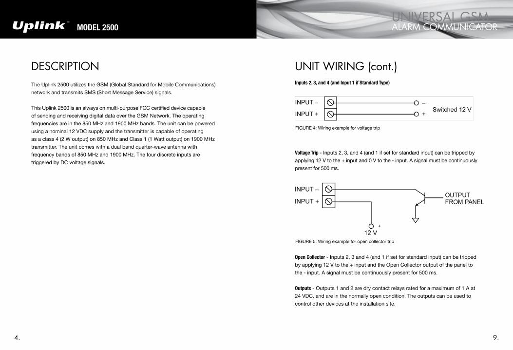
UNIT WIRING (cont.)Inputs 2, 3, and 4 (and Input 1 if Standard Type)
Voltage Trip - Inputs 2, 3, and 4 (and 1 if set for standard input) can be tripped by
applying 12 V to the + input and 0 V to the - input. A signal must be continuously
present for 500 ms.
open Collector - Inputs 2, 3 and 4 (and 1 if set for standard input) can be tripped
by applying 12 V to the + input and the Open Collector output of the panel to
the - input. A signal must be continuously present for 500 ms.
outputs - Outputs 1 and 2 are dry contact relays rated for a maximum of 1 A at
24 VDC, and are in the normally open condition. The outputs can be used to
control other devices at the installation site.
FIGURE 4: Wiring example for voltage trip
FIGURE 5: Wiring example for open collector trip
5.
UNIVERSAL GSM ALARM COMMUNICATORmodel 2500
8.
INSTALLATION STEPS1. For new customers, simply register to become an Uplink dealer by visiting
the website at www.uplink.com and clicking on the new dealer account tab.
2. The 2500 must be activated and configured from the Uplink website at
www.uplink.com or ex.uplink.com for web-enabled mobile phones.
3. Install the antenna on top of the unit.
4. Before permanently installing the unit, test signal strength by connecting a
12 VDC, 2 A capable power supply.
5. Upon initial power up, observe the status LEDs located on the Unit ‘s front
panel to determine unit and network status:
NETWORK
Fast Blink No networks available
Slow Blink GSM (SMS) network available
NoTe If after waiting for at least three minutes, the unit continues with a fast blink, call Uplink customer support at 1-888-987-5465 to check with network availability in your area.
SERVICE
Off No GSM service
Slow Blink < = -111dBm
Fast Blink Between -109dBm and -51dBm
ON > = -51dBm
COMMS
Intermittent Blink Active (internal device communications only)
TABL
E 1
: LE
D IN
DIC
ATI
ON
S
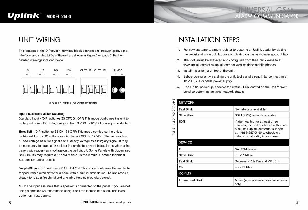
UNIT WIRINGThe location of the DIP switch, terminal block connections, network port, serial
interface, and status LEDs of the unit are shown in Figure 2 on page 7. Further
detailed drawings included below.
Input 1 (Selectable Via DIP Switches)
Standard Input - (DIP switches S3 OFF, S4 OFF) This mode configures the unit to
be tripped from a DC voltage ranging from 9 VDC to 12 VDC or an open collector.
Timed Bell - (DIP switches S3 ON, S4 OFF) This mode configures the unit to
be tripped from a DC voltage ranging from 9 VDC to 12 VDC. The unit reads a
pulsed voltage as a fire signal and a steady voltage as a burglary signal. It may
be necessary to place a 1k resistor in parallel to prevent false alarms when using
panels with supervisory voltage on the bell circuit. Some Panels with Supervised
Bell Circuits may require a 1KohM resistor in the circuit. Contact Technical
Support for further details.
Sampled Siren - (DIP switches S3 ON, S4 ON) This mode configures the unit to be
tripped from a siren driver or a panel with a built in siren driver. The unit reads a
steady tone as a fire signal and a yelping tone as a burglary signal.
NoTe: The input assumes that a speaker is connected to the panel. If you are not
using a speaker we recommend using a bell trip instead of a siren. This is an
option on most panels.
(UNIT WIRING continued next page)
FIGURE 3: DETAIL OF CONNECTIONS
IN1 IN2 IN3 IN4 OUTPUT1 OUTPUT2 12VDC

6. After successfully testing the unit, disconnect all power before installation.
7. Mount or place the unit in an area with the best signal strength that is dry
and free from metal objects and obstructions. It is recommended that the
unit be installed above grade level.
8. Wire unit per the Unit Wiring section on page 9.
9. The Uplink 2500 is configured via the DIP switches on the front panel.
Set DIP switches according to the following table:
SWITCH # SETTINGS
S1 reserved (set to off)
S2 reserved (set to off)
S3 and S4 S3OFFOFFONON
S4OFFONOFFON
Input 1 TypeStandard InputPulse CounterTimed BellSampled Siren
S5 OFF Output 1 Normal Operation
ON Output 1 Trouble
S6 reserved
(INSTALLATION STEPS continued next page)
model 2500
6. 7.
UNIVERSAL GSM ALARM COMMUNICATOR
FIGURE 1: Detail of Dip Switch
TABL
E 2
: D
IP S
WIT
CH
SET
TIN
GS
INSTALLATION STEPS (cont.)10. After attaching power, wait at least 2 minutes and then perform a central
station test to verify correct operation.
FIGURE 2: MODEL 2500