
Alamos HIPPI-SONET Gateway Author(s): B. H./67531/metadc623939/m2/1/high... · Los Alamos...
11
Author(s): Submitted to: Los Alamos NATIONAL LABORATORY Wide-Area Gigabit Networking: Los Alamos HIPPI-SONET Gateway Wallace B. St. John David H. DuBois Supercomputing '95, San Diego, CA December 3-8, 1995 Los Alamos National Laboratory, an affirmativeactionlequal opportunity empidyer, is operated by the University of California for the US. Department of Energy under contract W-7405-ENG-36. By accsptance of this article, the publisher recognizes that the U.S. Government retains a nonexclusive, royalty-free license to publish or reproduce the published form of this contnbution, or to allow others to do so, for U.S. Government purposes. The Los Alamos National Laboratory requests that the publisher identify this article as work performed und Form No. 836 R5 ST 2629 1 OB1 ST uspices of the US. Department ' '*~~~~~~O~ OF WB FL .- I *
Transcript of Alamos HIPPI-SONET Gateway Author(s): B. H./67531/metadc623939/m2/1/high... · Los Alamos...

Author(s):
Submitted to:
Los Alamos N A T I O N A L L A B O R A T O R Y
Wide-Area Gigabit Networking: Los Alamos HIPPI-SONET Gateway
Wallace B. St. John David H. DuBois
Supercomputing '95, San Diego, CA December 3-8, 1995
Los Alamos National Laboratory, an affirmative actionlequal opportunity empidyer, is operated by the University of California for the US. Department of Energy under contract W-7405-ENG-36. By accsptance of this article, the publisher recognizes that the U.S. Government retains a nonexclusive, royalty-free license to publish or reproduce the published form of this contnbution, or to allow others to do so, for U.S. Government purposes. The Los Alamos National Laboratory requests that the publisher identify this article as work performed und
Form No. 836 R5 ST 2629 1 OB1 ST uspices of the US. Department
' ' * ~ ~ ~ ~ ~ ~ O ~ OF WB F L .- I *

DISCLAIMER
Portions of this document may be illegible in electronic image products. Images are produced from the best available original document.

Wide-Area Gigabit Networking: Los Alamos HIPPI - SONET Gateway
Wally St. John and Dave &Bois Los Alamos National Laboratory
Computing, Information and Communications Division Los Alamos, NM 87545
Phone 505-667-3310, FAX 505-665-7793 Internet: [email protected] and [email protected]
CIC-5, MS-B255
Abstract This paper describes a HIPPI-SONET Gateway which
has been designed by members of the Computer Network Engineering Group at Los Ahmos National Laboratory. The Gateway has been used in the C A S A Gigabit Testbed at Caltech, Los Alamos National Laboratory, and the Sun Diego Supercomputer Center to provide communications between the sites Ill. This paper will also make some qualitative statements as to lessons learned during the deployment and maintenance ofthis wide area network.
We report record throughput for transmission of data across a wide area network. W e have sustained data rates using the T C P / P protocol of 550 Mbitslsecond and the rate of 792 Mbitslsecond for raw HIPPI data transfer over the 2,000 kilometers fYom the Sun Diego Supercomputer Center to the Los Alamos National Laborato y.
Networking vs. Communications One of the first lessons learned in the early days of
the CASA Gigabit Testbed was that the histories, cultures, and practices used by the networking and telecommunications communities are really quite different. To optimize communication between computers, the networking community has focused on links which feature the ability to provide high throughput for brief intervals using variable packet sizes. Their emphasis has been on accurate data delivery, and, in the event of congestion, the networking approach has been to slow all users down while still maintaining service to everyone.
In contrast, the telecommunication carriers have focused on links which feature the ability to multiplex many low bandwidth circuits to large numbers of users. They are somewhat less concerned with accurate data delivery (an occasional single bit error will hardly
affect normal voice traffic) and in the event of congestion, the telephony approach has been to deny service to new entrants (busy signal).
In the early stages of the program even the grammar was occasionally a problem. One group spoke of bytes while the other spoke of octets. The networking engineers spoke of packets and bursts while the communication engineers spoke of frames and payload envelopes. Fortunately these differences were not insurmountable and we discovered that both communities are ultimately concerned with the delivery of data from one point to another. The HIPPI- SONET Gateway was designed to "bridge the gap" between the techniques commonly employed by the two communities.
The High-Performance Parallel Interface (HIPPI) [21 was originally conceived at Los Alamos and was used successfully there to implement a prototype network called the Multiple Crossbar Network [31. That Local Area Network (LAN) connects supercomputers, frame buffers, and high-performance storage systems via HIPPI and Crossbar Switches. Since completing standardization by the American National Standards Institute (ANSI), similar LANs are now widely deployed at all major supercomputer centers.
The Synchronous Optical Network (SONET) [41[51 standard is being widely adopted by the Regional Bell Operating Companies and the private long-haul carriers as their primary means for communication over optical fiber.
A HIPPI-based LAN was configured at each of the CASA sites and SONET links were provided by MCI, Pacific Bell, and US West to provide communications between the individual LANs. The connection between each individual LAN and the SONET network was provided by the HIPPI-SONET Gateway
1

H/PP/ Characteristics HIPPI-PH is the physical layer of an efficient
simplex high-performance point-to-point interface for transmitting digital data at peak data rates of 800 Mbit/s between data-processing equipment using multiple twisted-pair copper cabling at distances up to 25 meters. HIPPI uses Emitter Coupled Logic (ECL) signalling on the cable. A fiber-optic version for extension to 10 kilometers has been defined by the Serial HIPPI [61 Implementors Group. No standard has evolved for transmission of HIPPI over distances longer than 10 kilometers.
HIPPI provides for transmission of 32-bit data (or &bit data, however only 32-bit data was addressed by the HIPPI-SONET Gateway) with byte parity and a checksum (LLRC) on bursts of data. The data is transmitted with very simple signalling sequences. The result is that nearly the full 800 Mbit/s data rate can be sustained.
As a result of the ANSI standardization success, many computer companies have adopted HIPPI as their means for providing high-speed 1 / 0 for their computing products. It was this fact that meant that it was possible to configure high-performance LANs using off-the-shelf HIPPI crossbar switches and computer interfaces. The problem of how to connect these sites into one logical Wide Area Network (WAN) was the subject of the Los Alamos networking research participation in CASA.
SONET Characteristics SONET defines a digital hierarchy for fiber optic
transmission and a frame structure for multiplexing digital traffic. The basic ra te is known as the Synchronous Transport Signal Level 1 (STS-1) which corresponds to 51.84 Mbit/s. Integer multiples of STS-1 are defined in the hierarchy (e.g. STS-3 multiplexes three STS-1 tributaries to yield 155.52 Mbit/s). Not all integer multiples of the STS-1 rate are popular, and hence only some are expected to be utilized by commercial equipment. The most popular rates are STS-3, STS-12 (622.08 Mbit/s), and STS-48 (2488.32 Mbit/s). For each defined rate, a portion is dedicated to overhead with the balance being available for payload. For STS-1 the payload capacity is 49.536 Mbit/s. To provide for services that exceed this rate, SONET defines "concatenated" hierarchical signals in which several STS-1's are combined to provide the higher capacity. For example an STS-3C (C stands for concatenated) signal can carry a payload of 149.76
Mbit/s. The overhead for the concatenated STS-3C is less than three times the overhead of a single STS-1. For each STS signal rate in the hierarchy, there is defined an optical stream carrying that payload, known as the Optical Carrier (OC) (e.g. OC-3 carries one STS-3C).
A good deal of effort was spent in making the decision to use multiple OC-3s to achieve the full HIPPI rate vs. using two OC-l2s, one OC-24, or one OC-48. The considerations are summarized as follows:
The OC-3 SONET rate is expected to be the first and most available SONET service provided to end- users for the near future. It is expected to very popular with end-users, its popularity only being limited by the fact that even a single OC-3 will be quite expensive to lease until prices are reduced. We reasoned that by designing the Gateway to use one or more OC-~S, for any application in the future, users could analyze the bandwidth required by the application and trade that off against the cost per OC-3. We feel that having the flexibility to use as little as one OC-3 (minimal cost) or as many as eight OC-3s (maximum throughput and reliability) offers users the most options.
We rejected the OC-12 SONET rate because it is much more expensive, is expected to be less available to end-users for the foreseeable future, and because one OC-12 can not support the full HIPPI rate (a testbed requirement), while two OC-12s result in a good deal of wasted bandwidth.
We discovered that the OC-24 SONET rate, while specified fully in the SONET standards, is not really a popular rate, even with the telecommunication carriers or their equipment providers. We rejected this rate based on lack of availability of terminal equipment.
As for the SONET OC-48 rate, it is the backbone rate that most carriers will be using for cross-country traffic, and it did not make much sense a t all to demand that they provide a user interface which would use all of their capacity on one fiber pair. The cost would be way too much.
For CASA, the telecommunication carriers transport the data cross-country on an OC-48 line. At each end point, their terminal equipment breaks the STS-48 into 16 OC-3 stripes, of which eight are made available for use in CASA. The aggregate capacity of eight OC-3Cs is 1.2 gigabits/sec.
2

Overall Gafeway Description Because it is required to provide bi-directional
extension of the MCNs to each other, each Gateway contains both a SONET transmit section and a SONET receive section. Figure 1 is a block diagram which shows one direction of transmission. The Gateway
(Outgoing Direction)
design takes advantage of the fact that both directions are always supplied (dual simplex). A few reverse signals are required for operation of the Gateway and these are provided for by the link operating in the opposite direction.
(Incomlng Direction)
oc-3 PAYLOADS
(15552 Mbk)
1-8 active SONET are recalved and delivered to the stripe collector
Buffer memory st- ~ l p p l bursts until a connection can be made to the destination host and the bursts are delivered
HIPPI Packets are "DEALT"
K S GATEWAY
HIPPI PACKER
CORRECTION
Gateway Source performs striping, correction stripe generation, SONET overhead aeneratlon. SONET overhead. mrforms
- HIPPI PACKETS
and E O conversi& Stripe recombinauon and Error Gorreotion
Figure 1. - Block diagram describing transfer of HIPPI packets using HIPPI-SONET Gateways and multiple SONET OC3 links.
Descripfion of Functions required for Gateway HIPPI Destination Interface
The HIPPI Destination Interface terminates the HIPPI signalling locally (i.e. these signals are not directly transmitted across the SONET link). This feature is crucial because the HIPPI standard uses a full handshake sequence to setup each connection. Over a wide area network a round trip delay would result in unacceptable delays before communication of data could commence. Likewise, the HIPPI flow control scheme (READYs) cannot be used directly because it was designed to operate at distances of less than 64 kilometers. The HIPPI Destination Interface uses HIPPI READYs to support the local HIPPI network and uses a credit-based flow control scheme which is designed to support full speed HIPPI operation at arbitrarily large distances.
If the HIPPI Destination detects that it has no SONET bandwidth available or if the HIPPI I-Field has
a parity error, it generates a rejected connection sequence. This feature allows hosts to retry the same Gateway or to select alternate paths more quickly and also unblocks the crossbar switch for other local communications.
As stated above, the HIPPI control signals (REQUEST, CONNECT, PACKET, BURST and READY) are not communicated directly across the SONET link. Instead they are encoded as tokens which traverse the SONET link along with the HIPPI data. When packets arrive at the remote Gateway, the HIPPI Source Engine will generate appropriate HIPPI signalling based on the tokens that it receives.
As HIPPI data is accepted, incoming HIPPI Parity is discarded after checking and one new odd parity bit is generated spanning each entire 32-bit data word and its associated control token. All this information is stored in a 1K x 36 bit wide Input FIFO. The Input FIFO provides for timing adjustment between the HIPPI Interface and the Stripe Dealer and provides for storage of three full HIPPI bursts plus gaps (771 words). The Flow Controller will take advantage of the
3
existence of the Input FIFO to allow up to three READYs to be outstanding at a time.
Stripe Dealer
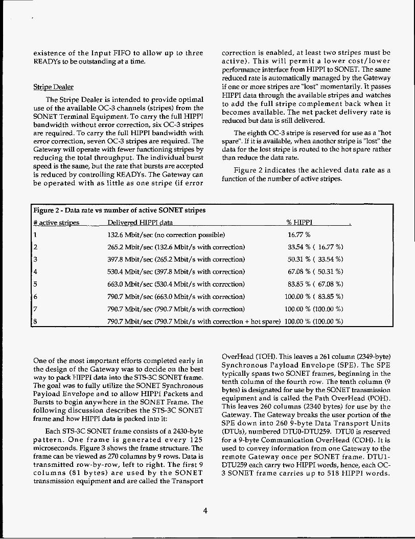
The Stripe Dealer is intended to provide optimal use of the available OC-3 channels (stripes) from the SONET Terminal Equipment. To carry the full HIPPI bandwidth without error correction, six OC-3 stripes are required. To carry the full HIPPI bandwidth with error correction, seven OC-3 stripes are required. The Gateway will operate with fewer functioning stripes by reducing the total throughput. The individual burst speed is the same, but the rate that bursts are accepted is reduced by controlling READYs. The Gateway can be operated with a s little as one stripe (if error
correction is enabled, at least two stripes must be active). This will permit a lower cost/ lower performance interface from HIPPI to SONET. The same reduced rate is automatically managed by the Gateway if one or more stripes are "lost" momentarily. It passes HIPPI data through the available stripes and watches to add the full stripe complement back when it becomes available. The net packet delivery rate is reduced but data is still delivered.
The eighth OC-3 stripe is reserved for use as a "hot spare". If it is available, when another stripe is "lost" the data for the lost stripe is routed to the hot spare rather than reduce the data rate.
Figure 2 indicates the achieved data rate as a function of the number of active stripes.
~~ ~~ ~~~ ~~ ~
Figure 2 - Data rate vs number of active SONET stripes # active stripes Delivered HIPPI data % HIPPI 1 132.6 Mbit/sec (no correction possible) 16.77 %
2
3 4
5 6 7
8
265.2 Mbit/sec (132.6 Mbit/s with Correction) 33.54 % ( 16.77 %)
397.8 Mbit/sec (265.2 Mbit/s with correction) 50.31 % ( 33.54 %)
530.4 Mbit/sec (397.8 Mbit/s with correction) 67.08 % ( 50.31 %)
663.0 Mbit/sec (530.4 Mbit/s with correction) 83.85 % ( 67.08 %)
790.7 Mbit/sec (663.0 Mbit/s with correction) 100.00 % ( 83.85 %)
790.7 Mbit/sec (790.7 Mbit/s with correction) 100.00 % (lOO.00 %)
790.7 Mbit/sec (790.7 Mbit/s with correction + hot spare) 100.00 % (100.00 %)
One of the most important efforts completed early in the design of the Gateway was to decide on the best way to pack HIPPI data into the STSSC SONET frame. The goal was to fully utilize the SONET Synchronous Payload Envelope and to allow HIPPI Packets and Bursts to begin anywhere in the SONET Frame. The following discussion describes the STS-3C SONET frame and how HIPPI data is packed into it:
Each STS3C SONET frame consists of a 2430-byte p a t t e r n . O n e f r a m e is genera ted every 125 microseconds. Figure 3 shows the frame structure. The frame can be viewed as 270 columns by 9 rows. Data is transmitted row-by-row, left to right. The first 9 co lumns (81 by tes ) a r e used by t h e SONET transmission equipment and are called the Transport
OverHead (TOH). This leaves a 261 column (2349-byte) Synchronous Payload Envelope (SPE). The SPE typically spans two SONET frames, beginning in the tenth column of the fourth row. The tenth column (9 bytes) is designated for use by the SONET transmission equipment and is called the Path OverHead (POH). This leaves 260 columns (2340 bytes) for use by the Gateway. The Gateway breaks the user portion of the SPE down into 260 9-byte Data Transport Units (DTUs), numbered DTUO-DTU259. DTUO is reserved for a 9-byte Communication OverHead (COH). It is used to convey information from one Gateway to the remote Gateway once per SONET frame. DTU1- DTU259 each carry two HIPPI words, hence, each OC- 3 SONET frame carries u p to 518 HIPPI words.
4

1 1 1 1 1 1 1 1 1 1 -- I - , - . I I " I . - I ' ' 1 1 1 1 1 1 1 1 . .
SP Figure 3 - SONET Gateway Frame Structure - Dashed area indicates next SONET frame.
The Communication OverHead conveys:
A byte to signal the remote Gateway that a reset
A byte to support realignment of the stripes at
A byte to signal the remote Gateway as to which
A flag to indicate if forward-error-correction is to
A byte to tell the remote Gateway which stripes
A byte to support a telephone handset for remote
A byte to carry data from the local Auxiliary
A byte to carry flow control credits from the
is required
the remote Gateway
stripes are to be used for the current SPE
be performed
are being received correctly from the SONET terminal
maintenance of the Gateway
Processor to the remote Auxiliary Processor
local buffer memory to the remote Gateway
The Stripe Dealer builds 9-byte DTUs (DTU1- DTU259) by removing consecutive words from the
Input FIFO and assigning 2 HIPPI words, the associated token, and parity to each DTU. If no Burst Buffers are available, or if the Input FIFO is empty, 'zero' data with the token set to 'discard' is used. HIPPI words are "dealt" by the Stripe Dealer to alternate available stripes, with two going to each DTLJ for each active stripe. By way of example, with stripes 0,1, and 2 active and with correction disabled; HIPPI words i and i+3 go to stripe 0 DTUx, words i+l and i+4 go to stripe 1 DTUx, and words i+2 and i+5 go to stripe 2 DTUx.
Error Control Generator Error Correction can optionally be enabled if two
or more stripes are active. The Error Control Generator generates odd parity across "n-1" active stripes and supplies that parity to the largest numbered active stripe. See the section on the Forward Error Corrector to determine how stripe parity is used for error correction.
Auxiliarv Processor For configuration, control, and performance
monitoring, one microprocessor is used in each
5

Gateway. Configuration options include the ability to indicate which SONET stripes should be used to carry data and whether forward-error-correction should be enabled. The processor can also control how long the HIPPI Source will wait before discarding data.
Control includes the ability to reset both the local and remote Gateway. Resets can be initiated on command or periodically if desired.
Performance monitoring includes counting and readout of number of HIPPI REQUESTS, PACKETS, BURSTS received a t the HIPPI Destination and delivered from the Gateway's HIPPI Source. Other important parameters related to the Gateway's condition can also be monitored.
Each Auxiliary Processor communicates with the Auxiliary Processor at the other end of the link using the Auxiliary Data Byte transmitted in the COH. Each Auxiliary Processor supports a 9600 baud RS-232 interface to which a terminal (or workstation) can be connected. Local remote parameters can be read and written from a connected terminal located at either end of the link.
SONET Transmit Framers
The functions performed by the SONET transmit framers include insertion of the TOH and POH bytes, insertion of the COH bytes from the Stripe Dealer, insertion of parallel DTU data into the SPE, insertion of the SONET G1 byte (FEBE and Path Yellow), generation and insertion of the B2a, B2b, B2c, and B3 BIP-8 check bytes, error injection for testing, scrambling of the signal for DC balance and serialization of the stream. Separate framers are used for each stripe. The output of each framer is a SONET compatible serial bit stream at 155.52 Mbit/s.
OC-3 TX Optics Each STS-3C transmit framer applies its 155.52
Mbit/s serial stream to an optical transmitter module. For SONET medium-reach applications, a laser transmitter is used with Single-mode fiber. An FC-PC type optical connector is used. The optical modules convert the electrical serial stream to an optical signal which is provided to the telecommunications carrier's SONET Terminal Equ ipmen t o r A d d / D r o p Multiplexer.
The following sections describe features provided by the remote Gateway receive function:
OC-3 RX O ~ t i a
The eight OC-3 stripes are received by eight optical receiver modules at the destination. The receiver modules have FC-PC type connectors for Single-Mode use. The optical modules convert the optical signal from the telecommunications carrier's SONET Terminal equipment or Add/Drop Multiplexer to an electrical serial data stream. A clock recovery circuit receives the serial data stream and generates a synchronized bit-clock.
SONET Receive Framers
The functions performed by the SONET receive framers include serial-to-parallel conversion, descrambling of data, SONET frame detection, B3 BIP- 8 error checking, AIS detection (SONET alarms), Path Yellow indication, payload pointer processing, and generation of the Reverse Active Stripe Flag Byte. Separate receive framers are used for each stripe. The output of each framer is a byte-wide parallel path which is delivered to an associated Stripe Alignment and Skew Removal FIFO.
Stripe Alignment and Skew Removal FIFOs These FIFOs each hold 8 bits of data along with a
single control flag indicating that the receive framer has detected the start of the COH (SCOH). Data and the SCOH flag are only written into the FIFO if the associated framer IC indicates that the incoming signal is framed and that the byte is in the DTU area of the SPE (i.e. not the TOH or POH).
Within the Gateway the process of alignment ensures that all active channels supply stripe data in a time aligned manner. Any skew between active channels is effectively removed so that a single source of control can handle the unloading of data with minimal overhead.
The Alignment/Skew Removal section of the Gateway utilizes a 4096 byte wide FIFO for each channel to provide buffering for the alignment process.
6

There are several stages involved within the alignment phase:
Reset to First Stripe Active - Out of the reset, all stripes of the gateway are treated as individual, non- related stripes. As soon as data is supplied to any stripe from its associated receive framer the alignment process begins.
AIS Dehy - Each stripe comes active at a different time out of a reset condition, therefore, the Gateway implements a fairly lengthy delay (on the order of one second) during which data from all active stripes is dumped. When the AIS delay expires, the aligner will take a snap shot of the active channels and will proceed with the alignment phase. The aligner monitors the number of active channels from this point forward and if a new channel becomes active it will signal an error and initiate a reset cycle.
Waif for Start of Control OverHead - Once the number of active channels has been determined the aligner will notify the individual channels to start scanning incoming data for the SCOH signal. This signal indicates the Start of the Control OverHead used by the Gateway for passing control information. Once SCOH is detected by an individual stripe, all reading of data from that stripe will halt. Once all active stripes have detected the SCOH signals the aligner will begin the actual alignment phase.
The COH contains a byte called the SPE count which is supplied to all stripes simultaneously at the transmitting end. This SPE count is the same for all channels and forms the basis for the alignment.
Due to differences in fiber length and delays through equipment data may arrive at the Gateway skewed. There will be no running skew, i.e. a skew that will accumulate, however, there will be some fixed skew between the stripes.
Examine the SPE Count Byte - Once all active stripes have detected their SCOH signal the aligner will check to see if the SPE count bytes are equivalent. If any particular stripe is not within 1 SPE count from the maximum detected SPE count, that stripe will dump data until the next SCOH signal is detected by that stripe. If any stripes show a difference of greater that 1 SPE count, the aligner signal an error and initiate a reset cycle.
After all stripes are brought into alignment, the aligner will pass control onto the global stripe collector which will now treat all active stripes as a single unit.
Communication OverHead Processor
The Communication OverHead is transmitted in all active stripes. If more than two stripes are being used, added reliability of these critical values is obtained by taking a vote aaoss all functioning stripes.
Stripe Collector
The Stripe Collector receives bytes from all active OC-3 stripes via the Stripe Alignment and Skew Removal FIFOs. It rebuilds the bytes into 36-bit words; 32 bits of data, 3 bits of token, and 1 parity bit across the other 35 bits. The Stripe Collector checks the parity across the data and token bits for each word and compares that calculated value with the transmitted parity bit. If they are not the same it will flag the associated word for possible correction by the Error Corrector. One word from each stripe is applied to the Error Corrector.
Forward-Error-Corrector
If error correction is not enabled, words are sent directly to the Burst Buffer Memory.
If error correction is enabled and if none of the active stripes is marked as having had a parity error during the current word, then the words are passed as- is to the Burst Buffer Memory. If only one of the stripes has a parity error during the current word then that word can be corrected using the parity stripe. To correct the flawed word, the entire word is regenerated by using the other active stripes including the parity stripe to infer what the value of the flawed word must have been to have resulted in the associated parity word. The resulting words are passed to the Burst Buffer Memory. If more than one of the stripes has a parity error during the current word then those words cannot be corrected. They will be marked as uncorrectable.
The forward-error-corrector proved to be one of the most challenging sections of the design. It is not conceptually difficult to see how a single-bit error can be corrected as is described above. The challenge came in accomplishing the correction in "real time". Our first thought was to take advantage of the fact that all of the stripes have FIFOs that were used for alignment. We considered that we could use an extra clock cycle or two to accomplish the correction of a corrupted word by allowing all of the stripes to back up into the Skew
7

Removal FIFOs by a word or two. After further consideration we realized that this is not practical because some types of errors result in a ”flurry” of errors which would quickly back the Skew Removal FIFOs up to the point of being full. To accomplish the “real time” correction it is necessary to recognize that a HIPPI word or token has an error and then to regenerate it within the same clock period. At full HIPPI rate this must be accomplished in less than 40 nanoseconds. This feature was accomplished by extensive pipelining which allowed the corrupted data to progress through the pipeline while the corrected word is generated. As the corrupted word reaches the end of the pipeline the newly generated word is substituted in its place.
As words are moved from the error corrector to the Burst Buffer Memory, the associated token is evaluated. The token determines what will be done with the that data word. It may be discarded, may be treated as control, in which case it is stored in a FIFO for later use by the HIPPI Source Interface, or may be stored in the Burst Buffer Memory if it is actual HIPPI data.
Burst Buffer Memory; Memory Manager In this section, dynamic RAMS are used to emulate
a 4 megabyte FIFO. Triple-port VRAMS are used to sustain the needed input and output bandwidth to and from the buffers. The VRAM is managed as a large circular buffer. Entries in the buffer are bursts. The Memory Manager maintains a list of burst pointers, one for each burst that has been received. This list is stored in a 4K FIFO. As bursts are removed from the Burst Buffer Memory by the HIPPI Source Interface, their pointers are removed from the list so that the buffers can be reused.
HIPPI Source Interface The HIPPI Source Interface monitors the Memory
Manager to determine when a burst is available in the Burst Buffer Memory. If the burst is the first of a new connection, it makes a connection using the I-Field indicated by the Memory Manager. Once a connection is established, i t generates packets and bursts according to the HIPPI-PH specification. Burst Buffer Memory bit 32 is monitored to generate short bursts. The connection is maintained until a connection-end token is encountered. The MPPI Source Interface also generates fresh byte-parity for each HIPPI word and
converts the TTL data and signals to ECL signals per the HIPPI specification. If any word is marked as uncorrectable, it forces bad parity on bytes 0 and 1.
PERFORMANCE On November 14,1994, CASA researchers reported
record throughput for transmission of data across a wide-area network [7]. They reported sustained data transmission using the TCP/IP protocol of 550 Mbits/second over the 2,000 kilometers separating computers at Los Alamos National Laboratory and the San Diego Supercomputer Center. For the UDP/IP protocol, rates of 578 Mbits/second were measured and using HIPPI Testers, sustained simultaneous bi- directional data transfer was measured at the rate of 792 Mbits/second. These bandwidths were the maximum that could be sustained by the CRAY computers involved, indicating that the wide-area network did not limit the achievable bandwidth. Similar results have been measured for the link from San Diego to Caltech.
One interesting observation has been made regarding the type of SONET errors that were encountered on the links during a period of nearly two years of operation of the Gateways. The expected type of errors, single-bit-hits, were not observed in nearly the quantity that the SONET specification allows. This suggests that the SONET terminal equipment, regenerators, amplifiers, and fibers provided more reliable data transfer than the worst case specified bit- error-rate of 10E-10 allows.
There was, however, a second type of error phenomenon encountered. There seemed to be times when the error rate was temporarily so bad that the gateways couldn’t even operate correctly with forward-error-correction enabled. The errors were so frequent that they corrupted the SONET overhead bits and frame synchronization was lost or payload pointer processing failed. At other times, the errors were so infrequent that no errors were measured for a period of several days, even with forward-error-correction disabled. The cause of the second error type was not clearly identified, although clock synchronization problems in the SONET network are suspected.
There is no quantitative analysis possible with the data taken to date, but observations suggest that the forward-error-correction scheme employed by the Gateway is very useful for the first of the two types of errors encountered and is of little value for the more serious occasional error phenomenon
8

SUMMARY A total of 13 HIPPI-SONET Gateways were
constructed in support of the CASA Gigabit Testbed, and, later, the Advanced Communications Technology Satellite (ACTS) programs. These Gateways have successfully met the original requirements of the programs, to interconnect remotely located HIPPI- based LANs into Wide Area Networks using the SONET standard services provided by the commercial telecommunication carriers. As a result of the success of these programs, the HIPPI-SONET Gateway has been t ransfer red to a n indus t ry par tner for m a n u f a c t u r i n g a n d m a r k e t i n g a n d is n o w commercially available.
ACKNOWLEDGMENTS The Los Alamos National Laboratory is operated
by the University of California for the United States Department of Energy under contract W-7405-ENG-36. The HIPPI-SONET Gateway design work was performed under auspices of the U.S. Department of Energy, Office of Energy Research.
The CASA Gigabit Testbed work was performed under contract with the Corporation for National Research Initiatives and was a joint program sponsored by the Advanced Research Projects Agency (ARPA) and the National Science Foundation (NSF).
T1.105-1988, "Digital Hierarchy-Optical Interface Rates and Formats Specifications".
[5] American National Standards Institute Committee x3. T1.106-1988, "Digital Hierarchy-Optical Interface Specifications (single mode)".
[6] Serial HIPPI Implementors Group. "Serial-HIPPI Specification". May 17,1991.
[7] San Diego Supercomputer Center - Bilal Chinoy
Press Release - "RECORD BANDWIDTHS ACHIEVED ACROSS THE CASA GIGABIT TESTBED NETWORK November 14,1994
I REFERENCES [l] Paul Messina, Larry Bergman, Robert Logan, Michael McGowen, Reagan Moore, John Morrison, Gerard Newman, and Wally St. John. "CASA Network Plan; A Testbed for Distributed Supercomputing." Corporation for National Research Initiatives Gigabit Testbed Plans, Feb. 14,1990.
[2] American National Standard for Information Systems. X3.183-199 1, "High-Performance Parallel Interface. Mechanical, Electrical, and Signalling Protocol Specification (HIPPI-PH)".
[31 Randy Hoebelheinrich and Richard Thomsen. " M u l t i p l e C r o s s b a r N e t w o r k : I n t e g r a t e d Supercomputer Framework". Proceedings of Supercomputing '89, Reno, Nevada, November 1989. 141 American National Standards Institute Committee x3.
I
9