Alameda Corridor Trench Design-Build Project...ALAMEDA CORRIDOR TRENCH DESIGN-BUILD PROJECT By James...
29
ALAMEDA CORRIDOR TRENCH DESIGN-BUILD PROJECT By James K. Kessler, P.E. HNTB / Thomas K. Dyer, Inc. 343 E. Six Forks Road, Suite 200 Raleigh, NC 27609 Telephone (919) 836-8152 Lawrence E. Meeker, P.E. Parsons Transportation Group Post Office Box 696 Reno, NV 89504 Telephone (775) 887-1801 Wayne J. Mauthe, P.E. HNTB Corporation 611 West Sixth Street, Suite 1800 Los Angeles, CA 90017 Telephone (213) 622-4117 4945 Words + 3 Figures: 07/05/00
Transcript of Alameda Corridor Trench Design-Build Project...ALAMEDA CORRIDOR TRENCH DESIGN-BUILD PROJECT By James...

ALAMEDA CORRIDOR TRENCH DESIGN-BUILD PROJECT
By
James K. Kessler, P.E.
HNTB / Thomas K. Dyer, Inc. 343 E. Six Forks Road, Suite 200
Raleigh, NC 27609 Telephone (919) 836-8152
Lawrence E. Meeker, P.E.
Parsons Transportation Group Post Office Box 696
Reno, NV 89504 Telephone (775) 887-1801
Wayne J. Mauthe, P.E.
HNTB Corporation 611 West Sixth Street, Suite 1800
Los Angeles, CA 90017 Telephone (213) 622-4117
4945 Words + 3 Figures: 07/05/00

ABSTRACT
The Alameda Corridor is a 20 mile-long railroad corridor improvement project designed
to enhance the movement of rail freight between the Ports of Los Angeles and Long
Beach, and the rail yards east of downtown Los Angeles, California. The ports handle
nearly 25% of the maritime freight traffic in the United States, and an efficient rail
connection is vital to maintaining projected growth.
The Mid-Corridor Trench is a 10 mile-long section of the Corridor that will separate the
rail line from the adjacent streets. It will be 30 feet deep and 51 feet wide. Initially it will
have two tracks but will include room for a third. The Trench will replace 30 at-grade
crossings with overhead bridges.
Project backers awarded the $712 million Mid-Corridor Trench design-build contract in
October 1998; the job will be complete in April 2002. The design-build process enables
the Designer and Contractor to work together and deliver the project on-time and for a
set price. It is very advantageous in developing workable solutions for complex
engineering and construction issues.
This paper describes the Alameda Corridor project with a focus on the Mid-Corridor
Trench. Topics include a project description and scope, schedules, construction
methods and sequences, and coordination aspects with railroads, public agencies,

utilities, and municipalities. The authors also outline the design-build process using
examples of issues the parties have resolved in this manner.
INTRODUCTION
This paper presents an overview of the 20-mile long Alameda Corridor project in
southern California, with a specific focus on the 10-mile long Mid-Corridor Trench. The
Corridor will improve rail freight service from the Ports of Los Angeles and Long Beach
through downtown Los Angeles rail yards and points east.
The Ports and the cities along the route formed the Alameda Corridor Transportation
Authority (ACTA) to secure project financing and represent them during the project
construction. ACTA awarded the $712 million Mid-Corridor design-build project to The
Tutor-Saliba Team, a joint venture of the Tutor Saliba Corporation, O&G Industries,
Parsons Transportation Group (PTG), and the HNTB Corporation. PTG and HNTB
jointly are designing it. The Union Pacific Railroad (UPRR) and the Burlington Northern
Santa Fe Railway (BNSF) are the major railroads that will move traffic through the
completed Trench.
For continuity, the authors have also included a brief description of the Alameda
Corridor East project. That project lies between Los Angeles and San Bernardino and
has no contractual links to the original/main Alameda Corridor. It will, however, expedite
train movements passing through the Corridor.

PROJECT DESCRIPTION
Alameda Corridor
The Alameda Corridor is a 20-mile long rail corridor that connects the Ports of Los
Angeles and Long Beach to the rail yards east of downtown Los Angeles (Figure 1).
This $2.4 billion project will provide improved rail access from the ports to the rail yards
and to points east. The Ports combined move about 25% of the waterborne cargo in
the United States and the quantity is growing significantly each year.
Recent rapid growth of rail traffic to the Ports has led to heavy use of the three existing
rail access lines and significant vehicle delays at at-grade crossings (over 200 in total).
The railroads now in place, built during the late 19th and early 20th Centuries, likewise
will not accommodate future anticipated growth at the Ports. The new Corridor thus will
alleviate existing traffic inadequacies and provide needed capacity to accept future
growth.
The Alameda Corridor consists of three sections:
• The North End near downtown Los Angeles extends from Santa Fe Avenue east to
Perrino Place near the Los Angeles River. This section, where the track is at grade,
includes grade separations at Santa Fe Avenue and Washington Boulevard, the
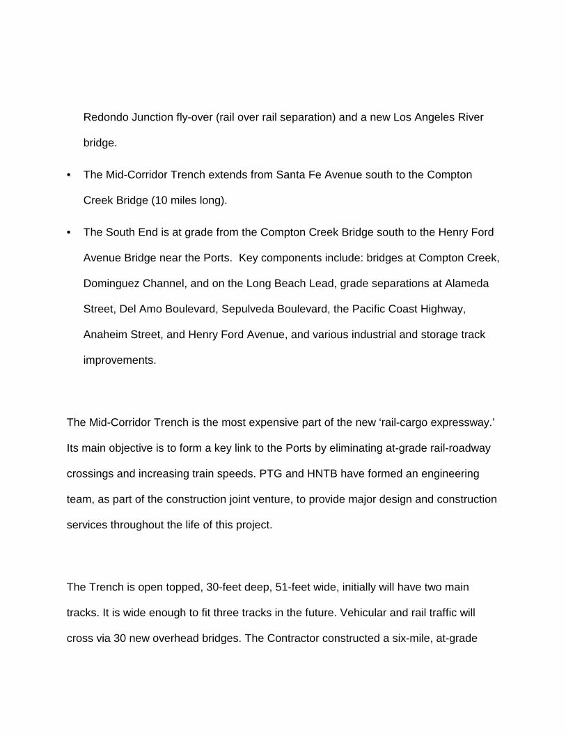
Redondo Junction fly-over (rail over rail separation) and a new Los Angeles River
bridge.
• The Mid-Corridor Trench extends from Santa Fe Avenue south to the Compton
Creek Bridge (10 miles long).
• The South End is at grade from the Compton Creek Bridge south to the Henry Ford
Avenue Bridge near the Ports. Key components include: bridges at Compton Creek,
Dominguez Channel, and on the Long Beach Lead, grade separations at Alameda
Street, Del Amo Boulevard, Sepulveda Boulevard, the Pacific Coast Highway,
Anaheim Street, and Henry Ford Avenue, and various industrial and storage track
improvements.
The Mid-Corridor Trench is the most expensive part of the new ‘rail-cargo expressway.’
Its main objective is to form a key link to the Ports by eliminating at-grade rail-roadway
crossings and increasing train speeds. PTG and HNTB have formed an engineering
team, as part of the construction joint venture, to provide major design and construction
services throughout the life of this project.
The Trench is open topped, 30-feet deep, 51-feet wide, initially will have two main
tracks. It is wide enough to fit three tracks in the future. Vehicular and rail traffic will
cross via 30 new overhead bridges. The Contractor constructed a six-mile, at-grade

Bypass Track along the east edge to allow temporary detouring of UPRR trains during
Trench construction. This line will also be a permanent means for accessing rail-served
industries in the area and for re-routing rail traffic during any future Trench shutdown.
The narrowness of the Corridor along the north end of the Trench requires that existing
city streets and another UPRR drill track cantilever over the top of the structure. A short
section of the Bypass Track at Rosecrans Avenue, mid way along the Trench, will also
cantilever over the Trench due to the location of overhead bridge piers and the
alignment of the adjacent streets.
Alameda Corridor East
The Alameda Corridor East project extends from near downtown Los Angeles east to
Ontario in San Bernardino County. The first phase of this project grade separates 11
existing crossings and improves 11 others. The goal is to enhance vehicle queuing,
eliminate vehicle movements around lowered gates, correct excessive or faulty gate
closures, improve pedestrian crossings, and widen selected crossings. The second
phase will grade separate nine existing crossings and improve traffic signalization at 29
others. The total project cost estimate is $900 million, and it should be complete by the
year 2007.

MID-CORRIDOR TRENCH DESIGN-BUILD PROJECT
Major design-build components of the Mid-Corridor Trench include constructing the
structure itself, relocating existing tracks and utilities, building tracks within, north and
south of the Trench, completing civil improvements (primarily roadways and site work),
and installing railroad signal / communications systems.
The design-build project consists of 12 design segments (geographical and/or
functional), including North End Track, seven Trench structure segments, Trench Track,
South End Track, Signals, and Communications:
• North End Track is farthest north and is east of the Trench. Design-build work here
is limited to track construction and signals installation. The Contractor coordinates
this work with other related projects ongoing in this segment. These include the Los
Angeles River bridge, the Redondo fly-over structure and the Washington Street
and Santa Fe Street bridge structures. This is about one-mile long.
• Trench Segments 2, 2X, 3, 4, 5, 6 and 7 form the Trench, 10.2-miles long.
• Trench Track, including ACTA main line tracks 1 and 2
• South End Track is the south part of the Corridor. The design-build work here also
is limited to constructing track and signals. The Contractor interfaces in these
locations with other storage track contracts, grade separations of several streets, the
Compton Creek and Dominguez Channel bridge projects, and the Henry Ford
Bridge project. Also included are connections to several industries and local tracks.

• Signals (entire Corridor)
• Communications (entire Corridor)
General Configuration
The general configuration of the new Trench consists of a wall system of three-foot
diameter cast-in-drilled hole (CIDH) piles placed four feet on center. Connecting
components are the shotcrete facing, cast-in-place concrete invert slab, integral top
wale, and precast concrete struts. Trench drain troughs collect storm water along each
wall and send it to two in-trench pump stations. Strut spacing typically will be 25-feet,
but will reduce to 15-feet (in order to provide more support) where the Bypass and
UPRR Drill Tracks overhang the Trench.
Track Structure
The ACTA main tracks will have 136-lb., continuously-welded rail on concrete ties and
crushed rock ballast. Tracks will rest on a concrete invert within the Trench and on
prepared subgrade or concrete bridge decks outside Trench limits. The bridge over
Compton Creek will have an open timber deck due to clearance constraints. All other
ACTA tracks will have 136-lb. rail on timber ties. This includes the Bypass Track,
Storage Track Area 1, and industrial tracks.
Crossovers between ACTA tracks will be No. 20 inside the Trench and either No.14 or
20 elsewhere. ACTA main track crossovers and turnouts will be on concrete switch
ties; others are on timber.
The main track design speed generally is 40 miles per hour. ACTA standards, based on
a combination of AREMA and railroad industry standards, will prevail on ACTA tracks.
ACTA standards also provide uniformity of components for tracks already in service at
the Ports. Connections to the UPRR and BNSF tracks, as well as tracks belonging to
those lines, will meet the standards of those respective railroads.
Trench Structure
Figure 2 depicts the standard cross section of the new Trench. It has 51-feet of
horizontal clearance and 24-feet, 3-inch minimum-vertical clearance above top of rail.
The Trench wall consists of three-foot diameter CIDH piles spaced at four-feet on
center with six to eight-inch shotcrete facing. A cast-in-place concrete invert slab, from
one to four feet thick, is at the bottom of the Trench. Drainage troughs along each wall
convey storm water run-off to two separate pump stations in the Trench itself.
On the top of the wall is an integral top wale with a concrete barrier and a chain-link
fence. Precast concrete struts, located near the top of the walls, span the width of the
Trench between the top wales. Strut spacing will typically be a 25-feet. Where West

Alameda Street, the UPRR Drill Track and the Bypass Track overhang the Trench
section, the strut spacing will be 15 feet in order to provide support for the overhead
facility. At these locations a deck that supports either a track or roadway partially covers
the Trench (Figure 3).
At Rosecrans Avenue an existing overhead roadway bridge spans above East and
West Alameda Streets, the at-grade Bypass Track and the new Trench. The Trench
and Bypass Track alignments therefore had to avoid the existing bridge piers. This
required the Contractor to cantilever the Bypass Track over and parallel to the Trench
for approximately 700 feet.
Between Randolph Street and 27th Street at the north end of the Trench, West
Alameda Street overhangs the west wall of the Trench due to right-of-way constraints.
The UPRR Drill Track, in addition, extends out over the east wall of the Trench in the
same general area between 41st Street and 27th Street. Here that narrows the opening
in the top of the Trench to about four feet.
Bridges
Thirty bridges will grade separate existing roadways (local and arterial streets) and
BNSF/MTA and UPRR rail lines over the Trench. These crossing streets are (north to
south): 25th, 27th, and 38th/41st Streets, Vernon Avenue, 55th Street, Slauson Avenue /

BNSF, Randolph Street / UPRR, Gage and Zoe Avenues, Florence Avenue, Metro
Commercial Parkway, Nadeau Street, Engle and HON Driveways, Firestone Boulevard,
92nd Street / Southern Avenue, Tweedy, MLK, and Santa Ana Boulevards, Imperial
Highway, Lynwood Road, 124th Street / Weber Avenue, El Segundo Boulevard, 134th
Street / Pine Avenue, Elm Street, Palmer Avenue, Compton Boulevard, Myrrh Street,
and Alondra and Greenleaf Boulevards.
Bridge Types
The Corridor will have three distinct types: double-tee girder bridges, I-beam girder
bridges, and box-girder bridges. The double-tee and I-beam girder bridges will be
precast, prestressed, and have cast-in place decks; the box girder bridges will have
slurry-filled decks.
Double-Tee Girder Bridges
Most of the bridges will have double-tee girders with cast-in-place decks. They will form
simple spans between Trench walls, and serve as a strut to brace the top of the Trench
section. Bridge deck flares are frequently required for turning lanes at exterior girders.
Several bridge decks, including Palmer Avenue, Compton Boulevard, Myrrh Street, and
Alondra Boulevard are “highly enhanced” with the addition of planters, supporting trees,
ground cover, and other ‘urban design’ features.
I-Beam Girder Bridges
Five structures will be I-beam girder bridges: those at 25th, 27th, and 38th/41st Streets,
Vernon Avenue and 55th Street. All of these, with the exception of 25th Street, will have
a greater depth than the double-tee girder bridges due to the need to support the
overhanging UPRR Drill Track and/or West Alameda Street sections.
Box-Girder Bridges
Two bridges will be box-girders. Those at Slauson Avenue and Randolph Street will
support rail (BNSF/MTA and UPRR, respectively) and roadway. Parallel box girder
structures (nearly perpendicular to the Trench) with ballasted decks support the
railroad, and similar girders with cast-in-place decks support the roads.
Utilities and Drainage
The drainage system for the Mid-Corridor Trench will be a dual, open-channel box
trough with grating cover. The troughs, which run longitudinally for the length of the
Trench, intercept runoff from the Trench cross-section. The trough section is of uniform
width and varying depth that changes with run-off rate and longitudinal slope. The slope
matches the proposed rail profile slope.

Two separate pump-station systems (at Nadeau Avenue and Greenleaf Boulevard) will
discharge to existing storm drain facilities adjacent to the Trench. The pump stations
are necessary because the Trench drains are located below the existing storm-water
utility lines. Due to the capacity limitations of the receiving systems, and to meet
requirement to provide 50-year drainage capacity within the Trench, the pump stations
include detention basins under the track. They will provide storage of the volume
difference between the allowable discharge and the 50-year run-off (the design
requirement for the Trench). Los Angeles County Unit Hydrograph Methods determine
volume requirements of the onsite detention basins.
Since the project will be in a dense urban area, the Contractor must complete extensive
utility relocations and protections. The design team is working with public agencies and
private companies in order to complete this work within the project construction
schedule constraints. Affected utilities include sewer and water lines, oil and gas
pipelines, fiber optic lines and electrical and communication facilities.
Roadway and Site Improvements
East and West Alameda Streets parallel the Trench on both side, and 30 cross streets
pass over it. The project will rehabilitate street intersections by placing new traffic
control devices, installing grade crossing warning devices for the Bypass Track,

repaving roadway surfaces, and building new curbs and sidewalks. New Bypass Track
grade crossings will have precast-concrete surfaces.
Schedule
This design-build project is on a fast-track schedule, going from award to in-service
status in just over three years. Awarded in October 1998, the construction work
commenced in January 1999. The project presently is on schedule. The Contractor
completed the majority of the Storage Tracks by the fall of 1999 and the Bypass Track
by January of 2000. Two simultaneous Trench headings are well underway. Track,
signal, and communications design are all approaching completion. The Contractor
faces significant liquidated damages for not having the Trench and three ACTA main
tracks open and operating on time, currently scheduled for April 15, 2002.
Construction Sequence
Existing rail freight service operating through the Corridor must continue during
construction. New storage yards to the south now replace storage capacity removed
from the area of the Trench. A new six-mile Bypass Track maintains through UPRR
freight service during construction, provides an alternate route after the Mid-Corridor
Trench is complete, and gives industrial track access to rail customers.

Build Storage Track Yards
New railroad storage yards were the first major-construction component of the Alameda
Corridor project. The Contractor built these tracks on both ACTA right of way (Storage
Track Area 1) and UPRR rights-of-way (Storage Track Areas 2, 3, 4, and 5) south of the
Trench. This included all the 'civil' work, that is the demolition, utility protection, clearing
and grubbing, drainage installation, and grade balancing, subgrade and subballast (as
well as the track itself). Because the tracks will eventually become parts of the ACTA
main tracks, Storage Track Area 1 has concrete ties. The other Storage Tracks Areas
have timber ties. UPRR forces completed 'live' cut ins to all UPRR tracks.
Build Bypass Track
The Bypass Track extends from the south end of the Trench north to Firestone
Boulevard, a distance of about six miles. It parallels the Trench, which follows the
former Southern Pacific (now UPRR) San Pedro Branch, and connects to UPRR's
Santa Ana Branch. The new track has 136 lb. continuously-welded rail on timber ties.
The Contractor needed to maintain rail traffic (up to 12 trains daily) along Corridor
during the construction of the Bypass Track, building it and cutting it into service in
three phases. Construction began at the south end and proceeded north. Several
temporary cutovers between the new and old tracks were necessary as the work
proceeded.

UPRR subsequently completed upgrades on its parallel Wilmington Subdivision line
one mile to the west to take most trains away from the Trench and Bypass Track during
construction.
The general sequence of work for the Bypass Track was similar to that of the Storage
Track Areas: demolition, utility protection, clearing and grubbing, drainage installation,
grade balancing, subgrade, subballast, and track installation. This work also included
the identification and removal of contaminated and hazardous ballast and soils, and the
construction of a special drainage line along the entire length of the track.
There are 16 public at-grade crossings along the new Bypass Track. The Contractor will
replace the existing temporary asphalt surfaces with precast concrete panels prior to
completion of the project. All of these public crossings will have CPUC-approved
warning devices that include flashing lights and gates.
Remove Existing Tracks / Initial Grading and Excavation
As the Contractor opened segments of the Bypass Track he concurrently removed
existing adjacent tracks, removed all contaminated ballast and soils, and began the
initial grading and excavation of the Trench. The initial excavation is six feet across the
60' width of the right-of-way in order to permit the drilling of the piles for the Trench
walls.
Relocating the utilities affected by the Trench construction has proved to be one of the
most challenging and expensive elements of the project. Affected utilities include lines
for storm water, sanitary sewer, oil, gas, telephone, electrical power, and fiber optics.
The nature of the Trench itself by default forced utility companies to reroute their lines
either under the Trench, across it, or around it. Those going under the Trench, an
extremely expensive endeavor, included several large diameter water lines. Smaller
lines go through cells in the roadway bridges, or through struts or casings, that span the
Trench. Crossing over is somewhat less costly but just as challenging due to the need
to immediately bend underneath ACTA’s By-pass Track running parallel to the east side
of the Trench.
Trench Construction
The placement of CIDH piles that form the Trench wall is progressing northward from
two separate headings. The first started near Greenleaf Boulevard at the south end of
the Trench. The second heading began (after completion of the Bypass Track) near the
center of the Trench north of Firestone Boulevard.
As CIDH installation proceeds the Contractor excavates the top part of the Trench as
deep as the piles' cantilever deflection will permit. He then sets in place precast
concrete struts prior to reaching the full Trench excavation depth at the invert elevation.
The Contractor next installs the top wale and wall, and caps this with temporary chain-
Utility Relocation

link fencing (to retard potential climbers). The finished concrete invert sections are 76
feet long. The last processes are to face the CIDH walls with shotcrete and to build the
drainage curbs.
Bridges
Bridge construction moves forward concurrently with Trench wall construction. The
Contractor detours street traffic over to adjacent streets or to temporary roadways
constructed across ACTA's right-of-way.
CIDH piles form the bridge abutments in a manner similar to those on the Trench walls.
Precast girders support the roadway surfaces and vehicular traffic. The Contractor
excavates beneath the bridges simultaneous with the excavation of the Trench itself.
Track and Systems Installation
As the Trench construction proceeds northward, ACTA main track construction on the
invert slab will begin. The Contractor will deposit crushed-rock ballast on the concrete
invert slab, and will soon follow with the delivery and installation of concrete ties and
welded rail strings.

Where we are today
The overall design of the track, including the tracks in the Trench and the North and
South End connecting tracks, is 75% complete. Signal and communication systems
design has progressed to a similar level. The first (southern) heading now has more
than one mile of completed Trench structure (without tracks), while the second
(northern) heading has about one-half mile completed. Construction is on schedule to
meet the year 2002 completion deadline, and the first train will run through the Trench
on or before April 15.
COORDINATION WITH OUTSIDE ENTITIES
Railroad Coordination
Coordinating the design and construction of the Mid-Corridor Trench with outside
entities has at times been challenging but has proceeded well to date. These entities
include the local railroads, governing agencies, utility companies and the municipalities.
Railroad coordination involves working closely with the UPRR, the BNSF and the
Pacific Harbor Lines. UPRR owns and operates main tracks and branch lines of the
former Southern Pacific in the area as well as its own previously existing lines that
generally paralleled those of the Southern Pacific.
BNSF operates on former Atchison, Topeka and Santa Fe Railway lines in the region
and shares some line ownership with the Los Angeles County Metropolitan

Transportation Authority (MTA). Pacific Harbor Lines operates over Port-owned
beltway trackage on which the Harbor Belt Line previously had operated. The UPRR
and BNSF both have sold major parts of their tracks and rights-of-way to ACTA, the
Port’s representative. The tracks and train movements on nearly all of these railroads
interact with those of ACTA.
To keep the project on schedule, help ensure railroad acceptance of design and
construction plans, and to allow trains to keep moving through the project site, the
Contractor maintains nearly daily communications with both UPRR and BNSF
personnel. The two railroads or their representatives review and comment on all major
design work for rail-related parts of the project. The Contractor also schedules a
monthly railroad-coordination meeting that gives all parties a chance to review work,
report any concerns, and consult on other issues.
The UPRR uses ACTA’s new Bypass Track, adjacent to the Trench, for industry access
and for three to six daily through train movements from downtown Los Angeles to the
Ports. The Contractor constructed this line in three phases, working closely with the
railroad to secure track time to coordinate live-track tie-ins. Although there is a contract
clause that allows the Contractor to shut down this line daily for 12-hour work windows
for Trench construction, he has elected to give the UPRR more flexibility for movements
by only requesting limited track time.

In another arrangement worked out with the UPRR, the railroad has allowed the
Contractor to eliminate a temporary shoofly track that would have temporarily carried
the UPRR La Habra Branch along Randolph Street where it will cross over the Trench.
In return the Contractor will construct for the railroad two new storage tracks at its J-
Yard facility and will install a crossover and complete other non-funded UPRR track
improvements near the south end of the Trench.
The Contractor works in a similar fashion with the BNSF and MTA on the Harbor
Subdivision crossing (BNSF trains on MTA tracks) over the Trench at Slauson Avenue.
This intersection is particularly challenging due to restricted railroad and roadway
geometry, 12 BNSF daily train movements, and very high vehicular traffic levels
crossing the Corridor parallel to the tracks. Contractor work at this location includes
constructing an 800’ long shoofly track through the intersection, complex roadway traffic
detours, and utility protection and relocation during the four-month period of bridge
construction over the Trench.
The Contractor also is working with the BNSF, the UPRR, and a local rail-served
customer near the south end of the Trench to accommodate complicated trackwork on
very limited real estate. ACTA’s preliminary design had the BNSF’s new Watson Yard
lead track crossing over industry tracks and a UPRR drill track via five unique, curved
diamonds. The Contractor is negotiating with ACTA and the local industry in attempts
to rearrange the industry yard tracks and reduce the crossings to two or three tangent
diamonds.
Agency Coordination
ACTA and the Contractor have worked very closely with the California Public Utilities
Commission (CPUC) since inception of the project. Major items of interest to the CPUC
are at-grade crossing warning devices, intersection geometries, clearances, and
walkways for trainmen. The Contractor communicates with the local CPUC office on a
weekly or biweekly basis, meets on-site with CPUC staff regularly to review pending
design and construction work, and together coordinate the submittal of plans for grade
crossing modifications. In addition to the CPUC, the Federal Railroad Administration
has made regular visits to the project to inspect track and signal work.
Utility Coordination
The Contractor coordinated the assignment of the bridge cells to the various utility
entities via ‘Bridge Cell Bingo’ sessions as the design of each bridge advanced. Of the
Contractor’s total initial budget of $712M, about $50 went to utility relocations. ACTA,
the project owner, also will spend a comparable amount above and beyond that figure
along the entire length of the Alameda Corridor.

Municipal Coordination
Municipal coordination included extensive meetings and special arrangements with nine
different cities, as well as Los Angeles County, that claim jurisdiction along the length of
the project. ACTA previously had negotiated Memoranda of Understanding with each
entity. The Contractor used these agreements as a starting point, but soon found that
each city had its own ideas about the nature of the ‘Understanding’ part of the
Memoranda. Some cities apparently felt that ACTA and the Contractor were fair game
as deep pockets; accordingly they demanded special intersection designs with
upgrades. Several intersections had three different municipalities each owning one or
two corner quadrants.
Dust, noise, and temporary traffic controls have been very sensitive issues and
naturally have demanded very special attention to detail. The Contractor regularly
waters the worksite and adjacent roads to control dust, and even had to water ballast
during track tamping and regulating. To control noise, he is constructing expensive
soundwalls in selected locations and limits work hours near residential communities.
Traffic control is probably the most delicate matter, and the Contractor spends much
energy devising and revising detours and traffic control plans. The Contractor is building
bridges in alternate locations so that, generally, no two adjacent existing roads remain
closed at the same time.

DESIGN-BUILD PROCESS
The design-build process is a relatively new method in the USA to construct large,
complex, urban construction projects. In contrast to the conventional design-bid-build
process, where project design is complete before the bids for construction go out,
design and construction take place simultaneously on design-build projects. Design-
build is a fast-track method ideally suited for big transportation projects in crowded,
polluted urban regions where changes in procedure may occur on a weekly or even
daily basis. It gives the Contractor the flexibility to change the design to respond to
immediate geotechnical, geometric or political constraints well before design is at the
90% or 100% level. The Contractor saves time on his schedule by beginning work on
selected parts of the project while design is still underway, and the process allows him
to adapt to changing project needs without having to backtrack extensively.
Design-build can also be tremendous benefit to the owner and his representatives. It
requires the Contractor to accept a percentage of the risks involved in the project.
Design-build can save the owner from many of the costly change orders required during
the design-bid-build process whenever unforeseen obstacles appear that would impact
costs and/or the schedule.
The Design-build process will allow the Mid-Corridor Trench to go from contract award
to ‘in-service’ status in just 3 years. Other specific examples where the process has
benefited the project include traffic routing, utility relocation methods, and the

arrangement outlined above with both the UPRR and BNSF regarding the Randolph
Street line and the Watson Lead.
CONCLUSIONS
Construction of the Alameda Corridor project is now one-third complete. After opened
to service in 2002, its track enhancements will allow the UPRR and BNSF to speed
trains to and from the Ports of Los Angeles and Long Beach on 20 miles of grade
separated tracks. It will also bypass existing century-old track networks ringed with at-
grade crossings, thereby improving traffic movements for vehicles and municipalities.
This project is a win-win endeavor for the transportation industry in the Los Angeles
basin.
ACRONYMS
ACTA: Alameda Corridor Transportation Authority
BNSF: Burlington Northern Santa Fe Railway
CIDH: Cast-in-Drill Hole (Pile)
CPUC: California Public Utilities Commission
MTA: Metropolitan Transportation Authority (County of Los Angeles)
PTG: Parsons Transportation Group
UPRR: Union Pacific Railroad

Figure 1: Map of Alameda Corridor

Figure 2: Standard Trench Cross Section

Figure 3: Trench Cross Section with Cantilever Overhangs

FIGURE CAPTIONS: Figure 1: Map of Alameda Corridor Figure 2: Standard Trench Cross Section Figure 3: Trench Cross Section with Cantilever Overhangs