Alabama Department of Transportation Testing Manual Reports/2005 ALDOT... · Form BMT-16 should be...
678
REVISED 05/14/03 TESTING MANUAL Bureau of Materials and Tests
Transcript of Alabama Department of Transportation Testing Manual Reports/2005 ALDOT... · Form BMT-16 should be...
REVISED 05/14/03
TESTING MANUAL
Bureau of Materials and Tests
Alabama Dept. of Transportation General InstructionsBureau of Materials and Tests Page 1 of 2Testing Manual
GENERAL INSTRUCTIONS
This manual aids uniform sampling and testing procedures by the Alabama Department ofTransportation. Compliance with these procedures ensures all materials incorporated in a project can bedocumented as conforming satisfactorily with specification requirements and established Departmentpolicies. Revised or additional schedules and procedures are issued periodically. They should beimmediately placed in the appropriate section of this manual. Note that the primary units used in thisdocument are English. For projects that may be administered in metric units, appropriate metric values havebeen included in parentheses. English and metric units are provided in a manner consistent with the intentof the specifications and may not be exact conversions.
The Sampling and Testing Program
A copy of the Department's official sampling and testing program is for reference and study byproject personnel. It defines their responsibilities for acceptance of materials incorporated in the work.Many items are produced or fabricated away from the project site and, inspected and tested by otherDepartment personnel or agencies. Thoroughly study procedure ALDOT-195 before allowing contractorsto incorporate these items.
The Sampling and Testing Schedule
To provide a cost effective sampling and testing program, schedules contained herein weredeveloped for major projects when materials are produced by previously unused sources. For materialsdelivered to a major project from sources consistently producing quality material, the sampling and testingfrequency may be decreased on a job-by-job basis. The Materials and Tests Engineer must approve thisfrequency decrease. Conversely, the frequency may be increased for a source with a history of supplyingmarginal quality material.
Requirements for testing material may be waived on certain minor projects. Material must bevisually inspected to ensure it is in reasonable close conformance with specifications and will do theintended job. This includes projects with very small materials quantities of a noncritical nature. Examplesare certain intersection improvements, safety projects, etc. Before beginning work, the Divisionrecommends this waiver in writing to the Materials and Tests Engineer. This approval would then be onfile. Form BMT-16 should be completed at the time the materials are incorporated into the project to showa visual inspection of all materials was acceptable. BMT-16 accompanies the Division Materials Certificateand becomes a part of the project files.
For contracts requiring miscellaneous material items in quantities smaller than normal lots for testingpurposes, quantities may be accepted by a certified test report from the manufacturer when validated by theTesting Engineer. (Examples are steel fence posts, nuts, bolts, filter fabrics, etc.). For sources consistentlyproducing quality materials, the Division Materials Engineer may authorize project personnel to acceptthese materials following visual inspections. Project personnel will execute Form BMT-16 for materialsaccepted on a visual basis at the time of acceptance and incorporation into the project. State on the reportthe quantity accepted and observed physical characteristics such as dimensions where applicable, generalcondition, workmanship, appearance, etc.
Alabama Dept. of TransportationGeneral InstructionsBureau of Materials and TestsPage 2 of 2
Testing Manual
Sampling and Testing Procedures
Generally, American Association of State Highway and Transportation Officials (AASHTO) orAlabama Department of Transportation Procedures (ALDOT) are used; occasionally, ASTM or otheragencies such as FAA or Corps of Engineers procedures are required. AASHTO, ASTM, or other agencyprocedures are not in this manual. Project personnel may obtain these procedures from the DistrictEngineer's Office, Division Materials Engineer, or Bureau of Materials and Tests.
ALDOT-210 is used to determine when or where a sample or test will be taken for normal lot orsublot of material. This procedure provides unbiased samples and tests. If it is apparent that failing materialexists due to segregation, mishandling, or worn equipment, the contractor will be required to rework orreplace the failing portion before taking the acceptance sample or test. All personnel engaged in samplingand testing duties should thoroughly study this procedure.
Retest Provisions
Some AASHTO, ASTM, or Alabama Department of Transportation procedures contain retestprovisions. The following general policy applies for those provisions not contained in the procedure. Foroccasionally failing samples, two additional samples or tests (randomly selected per ALDOT-210), will beobtained for the failing lot. If the two additional tests meet the requirements, the lot may be accepted; ifonly one or none of the samples or tests meet the requirements, the entire lot is rejected until replaced orreworked per the Standard Specifications, Section 106. When more than two failing lots of material aresampled and tested during the same time period, all lots may be rejected without retests. In this event, thesource of material and/or contractor's workmanship should be evaluated before allowing any furthershipments or work to proceed.
In conclusion, project personnel are urged to thoroughly study the individual sampling and testingschedules and procedures before beginning any item of work. Place particular emphasis on ALDOT-195.This results in timely payments to the contractor and rapid clearance of the final Materials Certificate ofConformance (BMT-38).
Alabama Dept. of Transportation Sampling and Testing ProgramBureau of Materials and Tests Page 1 of 11Testing Manual
INDEX
FOREWORD .................................................................................................................................................... 2
SECTION I ....................................................................................................................................................... 3
1. General Information........................................................................................................................ 3
2. Types of Samples and Tests............................................................................................................ 4
SECTION II ...................................................................................................................................................... 5
1. Acceptance and Independent Assurance Samples and Tests ........................................................ 5
2. Comparative Testing by the Department ...................................................................................... 5
SECTION III..................................................................................................................................................... 7
1. Materials Certification .................................................................................................................. 7
2. Acceptance of Small Quantities of Miscellaneous Materials on the Basis of Visual Inspection orManufacturer Certification.................................................................................................................... 7
SECTION IV .................................................................................................................................................... 8
1. National Reference Laboratory Inspections.................................................................................. 8
SECTION V...................................................................................................................................................... 9
1. EXHIBIT A: Certification of Materials and Tests.......................................................................... 9
2. EXHIBIT B: BMT-38................................................................................................................... 10
3. EXHIBIT C: BMT-16................................................................................................................... 11
Alabama Dept. of TransportationSampling and Testing ProgramBureau of Materials and TestsPage 2 of 11
Testing Manual
FOREWORD
Sampling and testing schedules prepared prior to job (project) construction are general guides forevaluating the quality of materials and workmanship incorporated in a highway or bridge. Accordingly, thismanual contains a general frequency schedule for acceptance sampling and testing. Select lots or sites forsampling/testing under these frequencies per the random number procedure (ALDOT-210) in this manual.If test results vary significantly and/or marginal quality of materials or workmanship are noted-developmore frequent schedules of sampling and testing. Our objective is to ensure acceptance eligibility of anygiven lot of materials or workmanship. Materials from sources consistently producing acceptable materialmay require less frequent testing.
Alabama Dept. of Transportation Sampling and Testing ProgramBureau of Materials and Tests Page 3 of 11Testing Manual
SECTION I
GENERAL INFORMATION
The Bureau of Materials and Tests of the Alabama Department of Transportation is directed by theMaterials and Tests Engineer. He is responsible for evaluation of all materials functions within theDepartment. The Bureau is composed of the following sections: Materials, Central Testing Laboratory, andGeotechnical. Responsibilities of the Materials and Tests Engineer are further executed through DivisionMaterials Engineers.
Division and Project Laboratories are under the general supervision of the Division MaterialsEngineer. Responsibilities include the quality of all acceptance sampling and testing of materials fabricatedat or near the project site, i.e., soils and/or aggregate bases, Portland cement concrete, bituminous concretemixes, etc. Duties include the review of the capabilities of all testing personnel, and their proficiency in andknowledge of the sampling and testing frequencies/procedures. He is also responsible for frequentcondition checks of testing equipment used in laboratories under his supervision. When consistent failuresof acceptance samples or tests occur, the Division Materials Engineer initiates an investigation. He reportshis findings and actions taken or recommendations to alleviate further occurrence to the Materials and TestsEngineer. Additionally, the Division Materials Engineer directs periodic reviews of all Testing Manuals inhis area for current additions or deletions.
The Central Testing Laboratory in Montgomery is directed by the Testing Engineer.Responsibilities include all chemical tests, specialty tests, standardization and uniformity of tests, andquality tests that Division or Project Laboratories are not equipped to perform. Tests are performed inaccordance with Standard or Interim Standard ASTM, AASHTO, Federal Standard SpecificationProcedures or Alabama Department of Transportation Test Procedures.
The Materials and Tests Engineer establishes test frequencies and procedures for new products orprocedures incorporated in contracts. This is accomplished for required test methods and frequencies notincluded in this manual.
Alabama Dept. of TransportationSampling and Testing ProgramBureau of Materials and TestsPage 4 of 11
Testing Manual
TYPES OF SAMPLES AND TESTS
A. Quality or Informational Samples and Tests are, in general, performed on a pre-contract basis in order todetermine the eligibility of a source to furnish materials or products that will consistently meetacceptance test requirements.
B. Acceptance Samples and Tests are those performed during construction for determining if contractrequirements are being fulfilled.
C. Certified Acceptance Samples and Tests are performed by authorized producers shown in the Manual ofMaterials, Sources and Devices with Special Acceptance Requirements which contains a current list ofpre-qualified producers and products.
D. Comparison and Correlation Samples and Tests are used to determine if any significant variation inresults is occurring between laboratories or operators performing test(s) on a given lot or standardizedsample of material.
E. Independent Assurance Samples and Tests are similar to comparison samples but may representdifferent lots of material than used for acceptance sampling and tests.
Alabama Dept. of Transportation Sampling and Testing ProgramBureau of Materials and Tests Page 5 of 11Testing Manual
SECTION II
1. Acceptance and Independent Assurance Samples and Tests
a. Acceptance Samples and Tests are those samples taken and tested for determining the quality andacceptability of the materials and workmanship which have been or are being incorporated in theproject. The collection of samples and proper tests (materials fabricated or produced at points awayfrom the job site excepted) along with test reports are the responsibility of the Project Engineer(State, Municipal, County). The Project Engineer or his representative should review all test reportsfor accuracy and completeness regardless of whether the test was performed on the project, in theDivision Laboratory, the Central Testing Laboratory, by a Certified Producer Laboratory or anyother approved inspection agency. Acceptance samples and tests will be taken and performed at theproper point or stage of construction and in accordance with the scheduled frequency contained inthe current Testing Manual or subsequently adopted plan for a specific project.
Acceptance samples and tests of materials manufactured and/or fabricated away from the project sitemay be pre-sampled and tested before delivery to the project by Division or Central Office Materialsand Tests personnel or by manufacturer's personnel when the material is from an approved source ofproducer certified materials. All pre-inspected materials will be marked in accordance with therequired markings contained in the Testing Manual and test reports forwarded to the ProjectEngineer. The Project Engineer will determine the final acceptability of pre-inspected and testedmaterials at the time they are incorporated in the work.
b. All pre-inspected and tested materials, whether by Department or other authorized personnel, aresubject to further verification or comparison tests obtained under the Independent AssuranceSampling and Testing Program.
c. Independent Assurance Samples and Tests are those samples and tests performed or observed byDepartment personnel who do not normally have direct responsibility for acceptance sampling andtesting at the project level. These teams operate under the direct supervision of the DivisionMaterials Engineer or Central Office Materials and Tests Certification Engineer using equipmentother than that assigned to the project for acceptance sampling and testing. These tests are used forthe purpose of making independent checks on reliability of the results obtained in acceptancesampling and testing. Independent Assurance samples may also be taken or observed by members ofthe Division or Central Office Construction Engineer's staff as well as construction engineeringrepresentatives of the Federal Highway Administration.
Independent Assurance samples and tests will be taken or observed in accordance with the currentschedule.
2. Comparative Testing by the Department
a. Verification of acceptance samples and tests on materials conducted by project using fieldlaboratories and equipment will be done under a program of comparative testing of companionsamples. Samples and tests taken under the Independent Assurance Sampling and Testing Programmay be used for this purpose and should be companion samples or tests. Comparison of field andCentral Laboratory test results will assure that the test equipment in use is in good condition andaccurate, and that the test procedures are being followed correctly. This comparison is the direct
Alabama Dept. of TransportationSampling and Testing ProgramBureau of Materials and TestsPage 6 of 11
Testing Manual
responsibility of the Division Materials Engineer and will be made promptly to assure that materialsand workmanship being incorporated in the project are of acceptable quality. Any substantialvariations of tests results will be investigated promptly by the Division Materials and ConstructionEngineers or their representatives and reported. The report will be furnished to the Central OfficeMaterials and Tests Certification Engineer and will state whether variations were caused by testingequipment, procedures used in acceptance sampling and testing, or contractor mishandling of thematerial, and steps taken to correct or resolve the unacceptable variation in test results.
b. When acceptance sample tests are performed in a Division Laboratory, verification and reports ofcomparison checks on companion or independent assurance sample test results performed by theCentral Laboratory are the direct responsibility of the Division Materials Engineer and anysignificant variation(s) reported will be handled the same as in the preceding article.
c. When acceptance sample tests are performed by the Central Testing Laboratory or by a producer'slaboratory, verification of comparison checks on companion or independent assurance sample testresults will be the direct responsibility of the Materials and Tests Certification Engineer. Whensubstantial variations of test results occur, he will initiate a prompt investigation through theresponsible division head of the Central Laboratory, and include the findings and resolution of suchproblems in the Independent Assurance Samples and Tests report.
d. Definition of significant or substantial variation in comparison or correlation test results is asfollows:
i) If the required test procedure, i.e. AASHTO, ASTM or ALDOT, has a precision statement,multi-laboratory precision requirements may be allowed; or,
ii) In the absence of such precision statement in the test procedure, results, obviously in error, orin general when differing by more than twenty-five percentage points from the mean of the testresults, shall be considered a significant variation.
Alabama Dept. of Transportation Sampling and Testing ProgramBureau of Materials and Tests Page 7 of 11Testing Manual
SECTION III
1. Materials Certification
a. All materials incorporated into the construction of a highway or bridge project with Federal Aidparticipation will be certified. The certificate attests that all materials used were in substantialcompliance with the pertinent specification requirements of the contract except as noted on thecertificate. Items that were accepted with less than normal or no test results will be listed on formsBMT-16 (Exhibit C) or BMT-38 (Exhibit B) at the end of the project showing date, material,manufacturer, quantities accepted, and any comments applicable such as dimension checks (ifapplicable), workmanship, and general appearance, etc. The forms should be signed by the projectengineer and forwarded to the Division Materials Engineer for acceptance prior to beingincorporated into the final certification report BMT-38.
b. The Materials Certificate (Exhibit A) is initiated by the Project Engineer preparing a list of quantitiesand the corresponding laboratory test number for such quantities of all materials incorporated in theconstruction of the project. This report is prepared on standard form BMT-38 (Exhibit B) and uponcompletion of all work is forwarded to the Central Office Materials and Tests Engineer for finalpreparation of the Materials Certificate which is submitted to the FHWA Division Administrator.
2. Acceptance of Small Quantities of Miscellaneous Materials on the Basis of Visual Inspection orManufacturer Certification
The Testing Manual general instructions have provisions for acceptance of miscellaneous materialitems when quantities received are in lots substantially less than those used for minimum samplingand testing. When authorized by the Division Materials Engineer, the Project Engineer may acceptsuch materials by manufacturer's certified test report, or by visual inspection if the material is from areputable manufacturer. When accepted on a visual basis, the Project Engineer will prepare astandard miscellaneous materials test report form BMT-16 (Exhibit C) at the time the material isincorporated into the project. Form BMT-16 will list the date, material, manufacturer, quantitiesaccepted, and any comments applicable such as dimension checks, workmanship, generalappearance, etc. The test report will be included in the final materials certificate preparation report(BMT-38).
Alabama Dept. of TransportationSampling and Testing ProgramBureau of Materials and TestsPage 8 of 11
Testing Manual
SECTION IV
1. National Reference Laboratory Inspections
a. The Alabama Department of Transportation Central Laboratory regularly participates in laboratoryinspections and testing of comparative samples conducted by AMRL and CCRL. These referencelaboratories have been authorized to furnish copies of their inspection and comparative test results toboth FHWA Division and Regional Administrators. Laboratory test equipment and standard testprocedures are reviewed for tests on soil, aggregate, liquid bituminous materials and bituminousmixtures by AMRL, and by CCRL for cement, concrete and reinforcing steel standard tests. Anydiscrepancies noted in such reports are resolved by equipment replacement or thorough study of testprocedures. Also, the Central Laboratory is accredited by AASHTO in many areas under AASHTOR 18, Establishing and Implementing a Quality System for Construction Materials TestingLaboratories.
b. Due to the expense involved, the Department does not provide for AMRL or CCRL inspection toursand comparative tests for its Division Laboratories. The Department's Central Laboratory hasconducted a comparative testing program for soils and bituminous mixtures with the DivisionLaboratories for several years. An annual inspection tour by Central Laboratory teams of Divisionand producer laboratory equipment and procedures similar to AMRL and CCRL inspections hasbeen adopted by the Department. A check list type of report showing discrepancies in equipmentand procedures is forwarded to the Materials and Tests Engineer, Testing Engineer, DivisionEngineer, and Division Materials Engineer. A copy of this report will be forwarded to the FHWADivision Administrator on a regular basis if requested. After action has been taken to correct alldiscrepancies shown on the check list, the Division Materials Engineer will be responsible forwriting a letter to the Materials and Tests Engineer explaining this corrective action. Thedistribution of this letter will be the same as the check list. All equipment found in substantialcompliance will be tagged and the tag number recorded on the inspection report.
c. Regular inspections of Division and project laboratory equipment and test procedures are theresponsibility of the Division Materials Engineer. A written report of any discrepancies noted andactions taken are to be forwarded to the Central Office Materials and Tests Engineer.
Alabama Dept. of Transportation Sampling and Testing ProgramBureau of Materials and Tests Page 9 of 11Testing Manual
SECTION V
Certification of Materials and Tests
Division AdministratorFederal Highway Administration500 Eastern Blvd., Suite 200Montgomery, Alabama 36117-2018
or Office EngineerAlabama Department of Transportation1409 Coliseum BoulevardMontgomery, Alabama 36110
Re:
Dear Sir:
This is to certify that the results of the tests used in the acceptance program indicate that the materialincorporated in the construction work, and the construction operations controlled by sampling and testing,were in conformity with the approved plans and specifications. All independent assurance samples and testsare within the tolerance limits of the samples and tests that are used in the acceptance program. Both theIAS&T Record Check (Accepted 00/00/00) and the BMT-38 Materials Certification are now complete.
Yours very truly,
Materials & Tests Engineer
cc: Office Engineer (if addressed to FHWA)Construction EngineerCounty Transportation Engineer (if applicable)Division EngineerFile (2)
EXHIBIT A

Alabama Dept. of TransportationSampling and Testing ProgramBureau of Materials and TestsPage 10 of 11
Testing Manual
BMT-38
See BMT-38
EXHIBIT B

Alabama Dept. of Transportation Sampling and Testing ProgramBureau of Materials and Tests Page 11 of 11Testing Manual
BMT-16
See BMT-16
EXHIBIT C
Page 1 of 6
Alabama Dept. of Transportation Acceptance Sampling and Testing ScheduleBureau of Materials and Tests IndexTesting Manual Revision: 2/14/01
Page 1 of 6
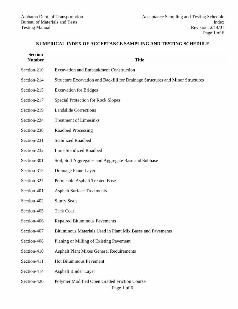
NUMERICAL INDEX OF ACCEPTANCE SAMPLING AND TESTING SCHEDULE
SectionNumber Title
Section-210 Excavation and Embankment Construction
Section-214 Structure Excavation and Backfill for Drainage Structures and Minor Structures
Section-215 Excavation for Bridges
Section-217 Special Protection for Rock Slopes
Section-219 Landslide Corrections
Section-224 Treatment of Limesinks
Section-230 Roadbed Processing
Section-231 Stabilized Roadbed
Section-232 Lime Stabilized Roadbed
Section-301 Soil, Soil Aggregates and Aggregate Base and Subbase
Section-315 Drainage Plane Layer
Section-327 Permeable Asphalt Treated Base
Section-401 Asphalt Surface Treatments
Section-402 Slurry Seals
Section-405 Tack Coat
Section-406 Repaired Bituminous Pavements
Section-407 Bituminous Materials Used in Plant Mix Bases and Pavements
Section-408 Planing or Milling of Existing Pavement
Section-410 Asphalt Plant Mixes General Requirements
Section-411 Hot Bituminous Pavement
Section-414 Asphalt Binder Layer
Section-420 Polymer Modified Open Graded Friction Course
Page 2 of 6
Alabama Dept. of TransportationAcceptance Sampling and Testing ScheduleBureau of Materials and TestsIndex
Testing ManualRevision: 2/14/01Page 2 of 6
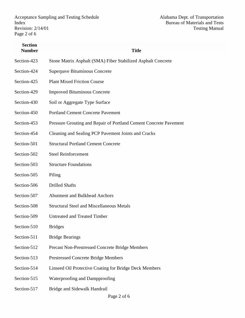
SectionNumber Title
Section-423 Stone Matrix Asphalt (SMA) Fiber Stabilized Asphalt Concrete
Section-424 Superpave Bituminous Concrete
Section-425 Plant Mixed Friction Course
Section-429 Improved Bituminous Concrete
Section-430 Soil or Aggregate Type Surface
Section-450 Portland Cement Concrete Pavement
Section-453 Pressure Grouting and Repair of Portland Cement Concrete Pavement
Section-454 Cleaning and Sealing PCP Pavement Joints and Cracks
Section-501 Structural Portland Cement Concrete
Section-502 Steel Reinforcement
Section-503 Structure Foundations
Section-505 Piling
Section-506 Drilled Shafts
Section-507 Abutment and Bulkhead Anchors
Section-508 Structural Steel and Miscellaneous Metals
Section-509 Untreated and Treated Timber
Section-510 Bridges
Section-511 Bridge Bearings
Section-512 Precast Non-Prestressed Concrete Bridge Members
Section-513 Prestressed Concrete Bridge Members
Section-514 Linseed Oil Protective Coating for Bridge Deck Members
Section-515 Waterproofing and Dampproofing
Section-517 Bridge and Sidewalk Handrail
Page 3 of 6
Alabama Dept. of Transportation Acceptance Sampling and Testing ScheduleBureau of Materials and Tests IndexTesting Manual Revision: 2/14/01
Page 3 of 6
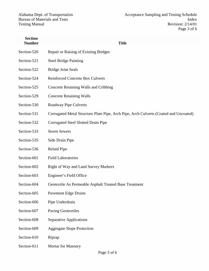
SectionNumber Title
Section-520 Repair or Raising of Existing Bridges
Section-521 Steel Bridge Painting
Section-522 Bridge Joint Seals
Section-524 Reinforced Concrete Box Culverts
Section-525 Concrete Retaining Walls and Cribbing
Section-529 Concrete Retaining Walls
Section-530 Roadway Pipe Culverts
Section-531 Corrugated Metal Structure Plate Pipe, Arch Pipe, Arch Culverts (Coated and Uncoated)
Section-532 Corrugated Steel Slotted Drain Pipe
Section-533 Storm Sewers
Section-535 Side Drain Pipe
Section-536 Relaid Pipe
Section-601 Field Laboratories
Section-602 Right of Way and Land Survey Markers
Section-603 Engineer’s Field Office
Section-604 Geotextile As Permeable Asphalt Treated Base Treatment
Section-605 Pavement Edge Drains
Section-606 Pipe Underdrain
Section-607 Paving Geotextiles
Section-608 Separative Applications
Section-609 Aggregate Slope Protection
Section-610 Riprap
Section-611 Mortar for Masonry
Page 4 of 6
Alabama Dept. of TransportationAcceptance Sampling and Testing ScheduleBureau of Materials and TestsIndex
Testing ManualRevision: 2/14/01Page 4 of 6
SectionNumber Title
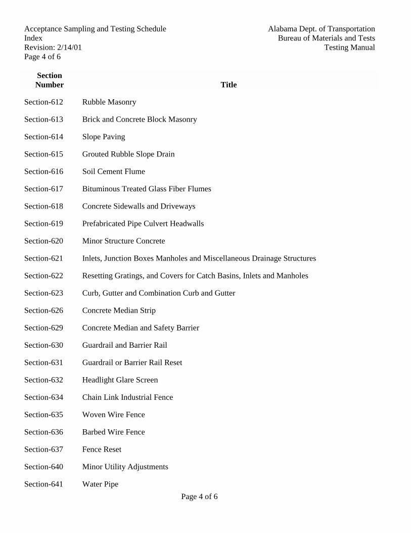
Section-612 Rubble Masonry
Section-613 Brick and Concrete Block Masonry
Section-614 Slope Paving
Section-615 Grouted Rubble Slope Drain
Section-616 Soil Cement Flume
Section-617 Bituminous Treated Glass Fiber Flumes
Section-618 Concrete Sidewalls and Driveways
Section-619 Prefabricated Pipe Culvert Headwalls
Section-620 Minor Structure Concrete
Section-621 Inlets, Junction Boxes Manholes and Miscellaneous Drainage Structures
Section-622 Resetting Gratings, and Covers for Catch Basins, Inlets and Manholes
Section-623 Curb, Gutter and Combination Curb and Gutter
Section-626 Concrete Median Strip
Section-629 Concrete Median and Safety Barrier
Section-630 Guardrail and Barrier Rail
Section-631 Guardrail or Barrier Rail Reset
Section-632 Headlight Glare Screen
Section-634 Chain Link Industrial Fence
Section-635 Woven Wire Fence
Section-636 Barbed Wire Fence
Section-637 Fence Reset
Section-640 Minor Utility Adjustments
Section-641 Water Pipe
Page 5 of 6
Alabama Dept. of Transportation Acceptance Sampling and Testing ScheduleBureau of Materials and Tests IndexTesting Manual Revision: 2/14/01
Page 5 of 6
SectionNumber Title
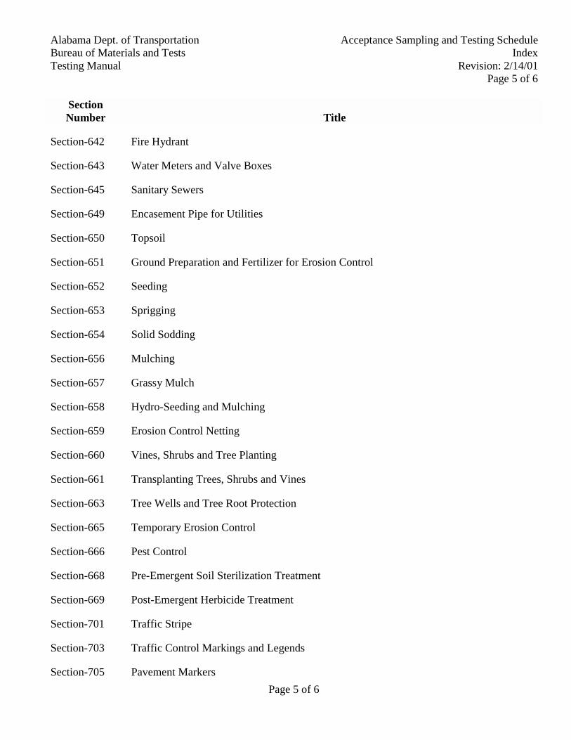
Section-642 Fire Hydrant
Section-643 Water Meters and Valve Boxes
Section-645 Sanitary Sewers
Section-649 Encasement Pipe for Utilities
Section-650 Topsoil
Section-651 Ground Preparation and Fertilizer for Erosion Control
Section-652 Seeding
Section-653 Sprigging
Section-654 Solid Sodding
Section-656 Mulching
Section-657 Grassy Mulch
Section-658 Hydro-Seeding and Mulching
Section-659 Erosion Control Netting
Section-660 Vines, Shrubs and Tree Planting
Section-661 Transplanting Trees, Shrubs and Vines
Section-663 Tree Wells and Tree Root Protection
Section-665 Temporary Erosion Control
Section-666 Pest Control
Section-668 Pre-Emergent Soil Sterilization Treatment
Section-669 Post-Emergent Herbicide Treatment
Section-701 Traffic Stripe
Section-703 Traffic Control Markings and Legends
Section-705 Pavement Markers
Page 6 of 6
Alabama Dept. of TransportationAcceptance Sampling and Testing ScheduleBureau of Materials and TestsIndex
Testing ManualRevision: 2/14/01Page 6 of 6
SectionNumber Title
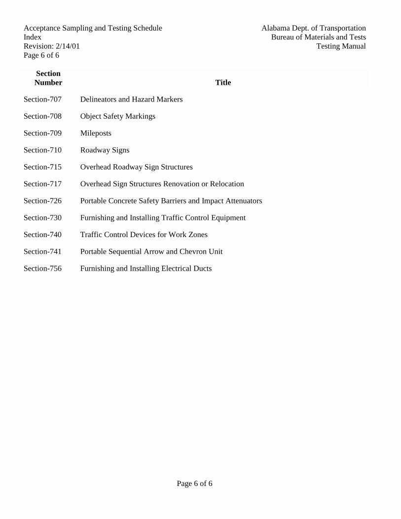
Section-707 Delineators and Hazard Markers
Section-708 Object Safety Markings
Section-709 Mileposts
Section-710 Roadway Signs
Section-715 Overhead Roadway Sign Structures
Section-717 Overhead Sign Structures Renovation or Relocation
Section-726 Portable Concrete Safety Barriers and Impact Attenuators
Section-730 Furnishing and Installing Traffic Control Equipment
Section-740 Traffic Control Devices for Work Zones
Section-741 Portable Sequential Arrow and Chevron Unit
Section-756 Furnishing and Installing Electrical Ducts
Alabama Department of TransportationBureau of Materials and TestsTesting Manual
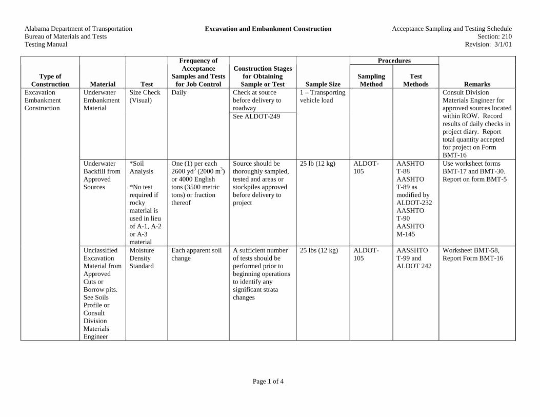
Excavation and Embankment Construction Acceptance Sampling and Testing ScheduleSection: 210
Revision: 3/1/01
Page 1 of 4
Procedures
Type ofConstruction Material Test
Frequency ofAcceptance
Samples and Testsfor Job Control
Construction Stagesfor Obtaining
Sample or Test Sample SizeSamplingMethod
TestMethods Remarks
Check at sourcebefore delivery toroadway
UnderwaterEmbankmentMaterial
Size Check(Visual)
Daily
See ALDOT-249
1 – Transportingvehicle load
Consult DivisionMaterials Engineer forapproved sources locatedwithin ROW. Recordresults of daily checks inproject diary. Reporttotal quantity acceptedfor project on FormBMT-16
UnderwaterBackfill fromApprovedSources
*SoilAnalysis
*No testrequired ifrockymaterial isused in lieuof A-1, A-2or A-3material
One (1) per each2600 yd3 (2000 m3)or 4000 Englishtons (3500 metrictons) or fractionthereof
Source should bethoroughly sampled,tested and areas orstockpiles approvedbefore delivery toproject
25 lb (12 kg) ALDOT-105
AASHTOT-88AASHTOT-89 asmodified byALDOT-232AASHTOT-90AASHTOM-145
Use worksheet formsBMT-17 and BMT-30.Report on form BMT-5
ExcavationEmbankmentConstruction
UnclassifiedExcavationMaterial fromApprovedCuts orBorrow pits.See SoilsProfile orConsultDivisionMaterialsEngineer
MoistureDensityStandard
Each apparent soilchange
A sufficient numberof tests should beperformed prior tobeginning operationsto identify anysignificant stratachanges
25 lbs (12 kg) ALDOT-105
AASSHTOT-99 andALDOT 242
Worksheet BMT-58,Report Form BMT-16

Alabama Department of TransportationBureau of Materials and TestsTesting Manual
Excavation and Embankment Construction Acceptance Sampling and Testing ScheduleSection: 210
Revision: 3/1/01
Page 2 of 4
Procedures
Type ofConstruction Material Test
Frequency ofAcceptance
Samples and Testsfor Job Control
Construction Stagesfor Obtaining
Sample or Test Sample SizeSamplingMethod
TestMethods Remarks
Minimum one (1)test eachcompacted 8 in(200 mm) of fillheight per 12 in(300 m) or fractionthereof
After compactionoperations have beencompleted, andbefore placing nextlift
ALDOT-222 Report on form BMT-57In-placeDensity
Or AASHTOT-191 whenauthorized
Report on form BMT-1B
CBR When Required*Sample each ½mile (1 km) or eachsoil change perroadway. Note:Both roadwaysmay be representedby one samplefrom major cutareas. State onsample card ifsample representsboth roadways.*Consult DivisionMaterials Engineerfor individualprojectrequirements
After completion ofcompaction andfinished elevationchecks.
Sample top 12 in(300 mm) ofsubgrade
90 lb (45 kg) ALDOT-105
This test is performed bythe Central TestingLaboratory inMontgomery. Submitsamples to Central Lab.Use Sample InformationCard BMT-18

Alabama Department of TransportationBureau of Materials and TestsTesting Manual
Excavation and Embankment Construction Acceptance Sampling and Testing ScheduleSection: 210
Revision: 3/1/01
Page 3 of 4
Procedures
Type ofConstruction Material Test
Frequency ofAcceptance
Samples and Testsfor Job Control
Construction Stagesfor Obtaining
Sample or Test Sample SizeSamplingMethod
TestMethods
RemarksRemarksRemarks
SoilAnalysis
Minimum one (1)each 12 in (300 m)per roadway breaksamples at eachsoil change
Sample top 12 in(300 mm) ofsubgrade
Same as for CBRSchedule
25 lbs (12 kg) ALDOT-105
AASHTO T-88 AASHTOT-89 asmodified byALDOT-232AASHTOT-90AASHTOM-145
Use worksheet formsBMT-17 and BMT-30,Report on form BMT-5
MoistureDensityStandard
Minimum one (1)each per ½ mile(1000 m) per layer,or source changefor each roadway
Sample after mixingprocess has beencompleted
25 lbs (12 kg) ALDOT-105
AASHTO T-99
Worksheet form BMT-58, report on form BMT-16
ALDOT-210for locationALDOT-222
Report on form BMT-57In-PlaceDensity
Minimum one (1)each 1000 ft (300m) per layer, perroadway
After compactionoperations have beencompleted
Or AASHTOT-191 whenauthorized
Report on form BMT-1B
ImprovedRoadbedfromApprovedCuts andBorrow Pits.See SoilsProfile forApprovedCut Areas
Visual forOversize
Each 1000 ft (300m) per layer, perroadway
Continuous checksduring mixing andcompactionoperations
Note: Results should berecorded in Project Diaryby station limits
ImprovedRoadbedfrom BorrowAreas
SoilAnalysis
Each 1000 ft (300m) per layer perroadway
Sample after mixingprocess has beencompleted
25 lbs (12 kg) ALDOT-105
AASHTOT-88AASHTOT-89 asmodified byALDOT-232AASHTOT-90AASHTOM-145
Use worksheet formBMT-17 and BMT-30.Report on form BMT-5

Alabama Department of TransportationBureau of Materials and TestsTesting Manual
Excavation and Embankment Construction Acceptance Sampling and Testing ScheduleSection: 210
Revision: 3/1/01
Page 4 of 4
Procedures
Type ofConstruction Material Test
Frequency ofAcceptance
Samples and Testsfor Job Control
Construction Stagesfor Obtaining
Sample or Test Sample SizeSamplingMethod
TestMethods Remarks
CBR Minimum 1 mile(1.5 km) perroadway – break atapparent soilchanges
Note: Certaintypes of materialfrom approvedborrow areas willrequire more tests.When thiscondition occurs,consult DivisionMaterials Engineerfor samplingfrequency
After mixing processhas been completed
90 lbs (45 kg) ALDOT-210ALDOT-105
Submit sample toCentral TestingLaboratory. Use sampleinformation cardBMT-18
ThicknessMeasure-ments
Each 150 malternating left andright of centerline,each roadway
After compaction testhas been approvedand accepted
ALDOT-105 WorksheetRecord in field notebook
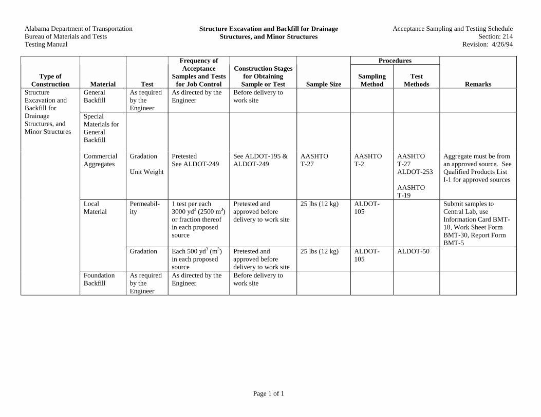
Alabama Department of TransportationBureau of Materials and TestsTesting Manual
Structure Excavation and Backfill for DrainageStructures, and Minor Structures
Acceptance Sampling and Testing ScheduleSection: 214
Revision: 4/26/94
Page 1 of 1
Procedures
Type ofConstruction Material Test
Frequency ofAcceptance
Samples and Testsfor Job Control
Construction Stagesfor Obtaining
Sample or Test Sample SizeSamplingMethod
TestMethods Remarks
GeneralBackfill
As requiredby theEngineer
As directed by theEngineer
Before delivery towork site
SpecialMaterials forGeneralBackfill
CommercialAggregates
Gradation
Unit Weight
PretestedSee ALDOT-249
See ALDOT-195 &ALDOT-249
AASHTOT-27
AASHTOT-2
AASHTOT-27ALDOT-253
AASHTOT-19
Aggregate must be froman approved source. SeeQualified Products ListI-1 for approved sources
Permeabil-ity
1 test per each3000 yd3 (2500 m3)or fraction thereofin each proposedsource
Pretested andapproved beforedelivery to work site
25 lbs (12 kg) ALDOT-105
Submit samples toCentral Lab, useInformation Card BMT-18, Work Sheet FormBMT-30, Report FormBMT-5
LocalMaterial
Gradation Each 500 yd3 (m3)in each proposedsource
Pretested andapproved beforedelivery to work site
25 lbs (12 kg) ALDOT-105
ALDOT-50
StructureExcavation andBackfill forDrainageStructures, andMinor Structures
FoundationBackfill
As requiredby theEngineer
As directed by theEngineer
Before delivery towork site

Alabama Department of TransportationBureau of Materials and TestsTesting Manual
Excavation for Bridges Acceptance and Testing ScheduleSection: 215
Revision: 4/26/94
Page 1 of 1
Procedures
Type ofConstruction Material Test
Frequency ofAcceptance
Samples and Testsfor Job Control
Construction Stagesfor Obtaining
Sample or Test Sample SizeSamplingMethod
TestMethods Remarks
Excavation forBridges
GeneralBackfill &SpecialMaterials forGeneralBackfill
See Section214
FoundationBackfill
See Section214
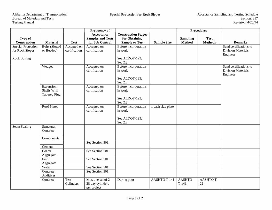
Alabama Department of TransportationBureau of Materials and TestsTesting Manual
Special Protection for Rock Slopes Acceptance Sampling and Testing ScheduleSection: 217
Revision: 4/26/94
Page 1 of 2
Procedures
Type ofConstruction Material Test
Frequency ofAcceptance
Samples and Testsfor Job Control
Construction Stagesfor Obtaining
Sample or Test Sample SizeSamplingMethod
TestMethods Remarks
Bolts (Slottedor Headed)
Accepted oncertification
Accepted oncertification
Before incorporationin work
See ALDOT-195,Sec 2.3
Send certifications toDivision MaterialsEngineer
Wedges Accepted oncertification
Before incorporationin work
See ALDOT-195,Sec 2.3
Send certifications toDivision MaterialsEngineer
ExpansionShells WithTapered Plug
Accepted oncertification
Before incorporationin work
See ALDOT-195,Sec 2.3
Special Protectionfor Rock Slopes
Rock Bolting
Roof Plates Accepted oncertification
Before incorporationin work
See ALDOT-195,Sec 2.3
1 each size plate
StructuralConcrete
Components
CementSee Section 501
CoarseAggregate
See Section 501
FineAggregate
See Section 501
Water See Section 501ConcreteAdditives
See Section 501
Seam Sealing
Concrete TestCylinders
Min. one set of 228 day cylindersper project
During pour AASHTO T-141 AASHTOT-141
AASHTO T-22
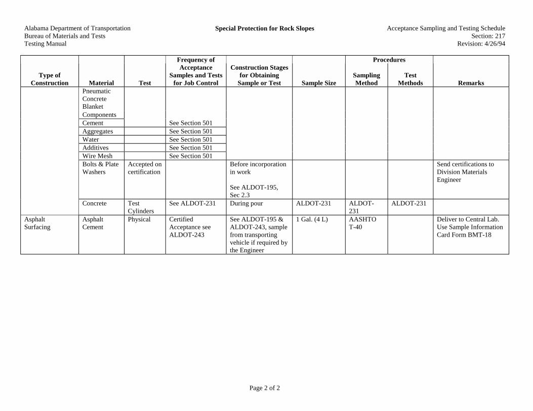
Alabama Department of TransportationBureau of Materials and TestsTesting Manual
Special Protection for Rock Slopes Acceptance Sampling and Testing ScheduleSection: 217
Revision: 4/26/94
Page 2 of 2
Procedures
Type ofConstruction Material Test
Frequency ofAcceptance
Samples and Testsfor Job Control
Construction Stagesfor Obtaining
Sample or Test Sample SizeSamplingMethod
TestMethods Remarks
PneumaticConcreteBlanketComponentsCement See Section 501Aggregates See Section 501Water See Section 501Additives See Section 501Wire Mesh See Section 501Bolts & PlateWashers
Accepted oncertification
Before incorporationin work
See ALDOT-195,Sec 2.3
Send certifications toDivision MaterialsEngineer
Concrete TestCylinders
See ALDOT-231 During pour ALDOT-231 ALDOT-231
ALDOT-231
AsphaltSurfacing
AsphaltCement
Physical CertifiedAcceptance seeALDOT-243
See ALDOT-195 &ALDOT-243, samplefrom transportingvehicle if required bythe Engineer
1 Gal. (4 L) AASHTOT-40
Deliver to Central Lab.Use Sample InformationCard Form BMT-18
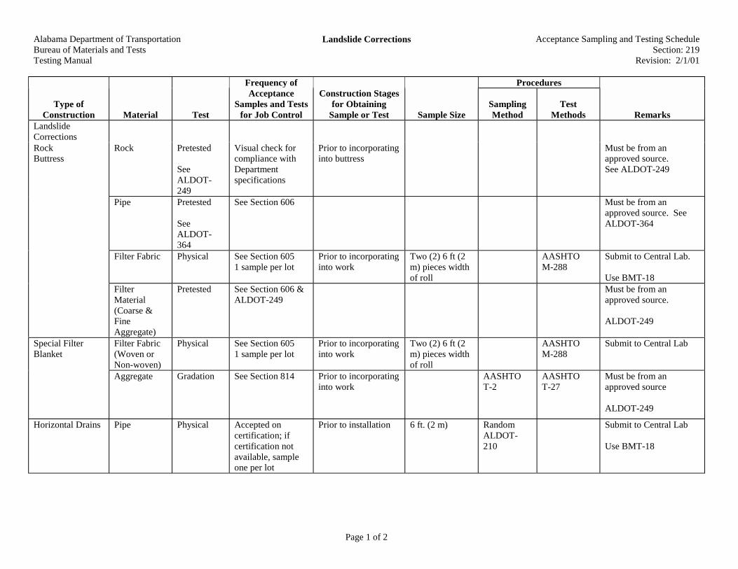
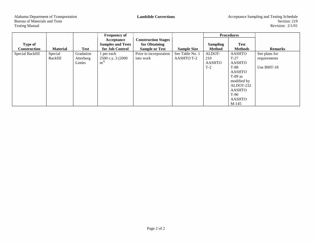
Alabama Department of TransportationBureau of Materials and TestsTesting Manual
Landslide Corrections Acceptance Sampling and Testing ScheduleSection: 219
Revision: 2/1/01
Page 1 of 2
Procedures
Type ofConstruction Material Test
Frequency ofAcceptance
Samples and Testsfor Job Control
Construction Stagesfor Obtaining
Sample or Test Sample SizeSamplingMethod
TestMethods Remarks
LandslideCorrections
Rock Pretested
SeeALDOT-249
Visual check forcompliance withDepartmentspecifications
Prior to incorporatinginto buttress
Must be from anapproved source.See ALDOT-249
Pipe Pretested
SeeALDOT-364
See Section 606 Must be from anapproved source. SeeALDOT-364
Filter Fabric Physical See Section 6051 sample per lot
Prior to incorporatinginto work
Two (2) 6 ft (2m) pieces widthof roll
AASHTOM-288
Submit to Central Lab.
Use BMT-18
RockButtress
FilterMaterial(Coarse &FineAggregate)
Pretested See Section 606 &ALDOT-249
Must be from anapproved source.
ALDOT-249
Filter Fabric(Woven orNon-woven)
Physical See Section 6051 sample per lot
Prior to incorporatinginto work
Two (2) 6 ft (2m) pieces widthof roll
AASHTOM-288
Submit to Central LabSpecial FilterBlanket
Aggregate Gradation See Section 814 Prior to incorporatinginto work
AASHTOT-2
AASHTOT-27
Must be from anapproved source
ALDOT-249
Horizontal Drains Pipe Physical Accepted oncertification; ifcertification notavailable, sampleone per lot
Prior to installation 6 ft. (2 m) RandomALDOT-210
Submit to Central Lab
Use BMT-18
Alabama Department of TransportationBureau of Materials and TestsTesting Manual
Landslide Corrections Acceptance Sampling and Testing ScheduleSection: 219
Revision: 2/1/01
Page 2 of 2
Procedures
Type ofConstruction Material Test
Frequency ofAcceptance
Samples and Testsfor Job Control
Construction Stagesfor Obtaining
Sample or Test Sample SizeSamplingMethod
TestMethods Remarks
Special Backfill SpecialBackfill
GradationAtterbergLimits
1 per each2500 c.y..3 (2000m3)
Prior to incorporationinto work
See Table No. 1AASHTO T-2
ALDOT-210AASHTOT-2
AASHTOT-27AASHTOT-88AASHTOT-89 asmodified byALDOT-232AASHTOT-90AASHTOM-145
See plans forrequirements
Use BMT-18
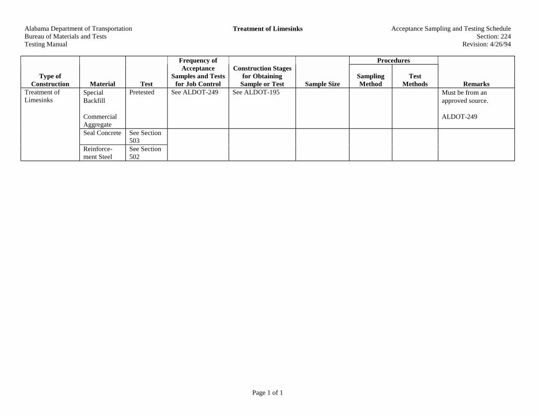
Alabama Department of TransportationBureau of Materials and TestsTesting Manual
Treatment of Limesinks Acceptance Sampling and Testing ScheduleSection: 224
Revision: 4/26/94
Page 1 of 1
Procedures
Type ofConstruction Material Test
Frequency ofAcceptance
Samples and Testsfor Job Control
Construction Stagesfor Obtaining
Sample or Test Sample SizeSamplingMethod
TestMethods Remarks
SpecialBackfill
CommercialAggregate
Pretested See ALDOT-249 See ALDOT-195 Must be from anapproved source.
ALDOT-249
Seal Concrete See Section503
Treatment ofLimesinks
Reinforce-ment Steel
See Section502

Alabama Department of TransportationBureau of Materials and TestsTesting Manual
Roadbed Processing Acceptance Sampling and Testing ScheduleSection: 230
Revision: 5/19/97
Page 1 of 1
Procedures
Type ofConstruction Material Test
Frequency ofAcceptance
Samples and Testsfor Job Control
Construction Stagesfor Obtaining
Sample or Test Sample SizeSamplingMethod
TestMethods Remarks
MoistureDensityStandard
Min. 1 each .5 mi.(1000 m) for eachroadway. Breaksamples at apparentsoil changes.Sample top 6 in.(150 mm)
Sample after mixingprocess is completed
25 .lbs (12 kg) ALDOT-105
AASHTOT-99
Use Work Sheet FormBMT-58, Report FormBMT-16
ModifiedRoadbed
In-placeDensity &MoistureContent
Min. 1 test for each1000 ft. (300 m)per roadway,sampleTop 6 .in (150 mm)
After compactionprocess has beencompleted
50 .lbs (25 kg) ALDOT-222or AASHTOT-191 whenauthorized
Report Form BMT-57Report Form BMT-1B
MoistureDensityStandard
Same test andfrequency asshown forModified Roadbed
In-placeDensity
Same as ModifiedRoadbed
RoadbedProcessing
ImprovedRoadbed
(Upper Layerfor Base &PaveContractsOnly)
ThicknessMeasurement
Same as Section210
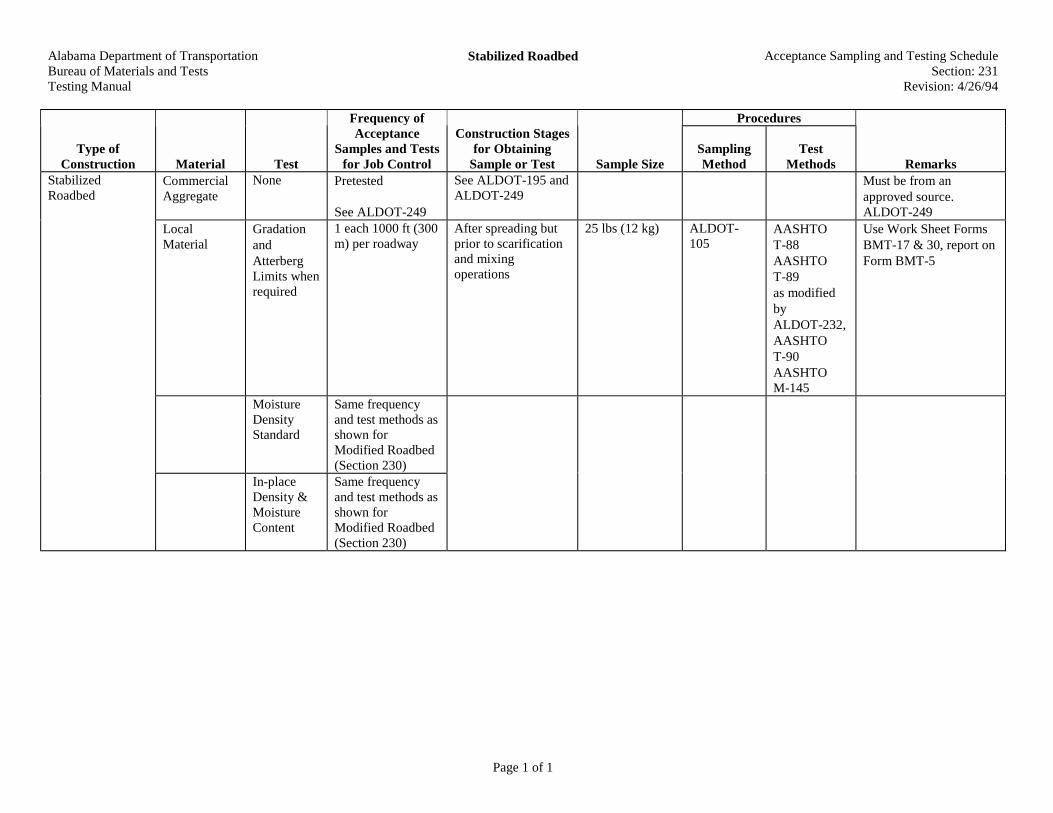
Alabama Department of TransportationBureau of Materials and TestsTesting Manual
Stabilized Roadbed Acceptance Sampling and Testing ScheduleSection: 231
Revision: 4/26/94
Page 1 of 1
Procedures
Type ofConstruction Material Test
Frequency ofAcceptance
Samples and Testsfor Job Control
Construction Stagesfor Obtaining
Sample or Test Sample SizeSamplingMethod
TestMethods Remarks
CommercialAggregate
None Pretested
See ALDOT-249
See ALDOT-195 andALDOT-249
Must be from anapproved source.ALDOT-249
LocalMaterial
GradationandAtterbergLimits whenrequired
1 each 1000 ft (300m) per roadway
After spreading butprior to scarificationand mixingoperations
25 lbs (12 kg) ALDOT-105
AASHTOT-88AASHTOT-89as modifiedbyALDOT-232,AASHTOT-90AASHTOM-145
Use Work Sheet FormsBMT-17 & 30, report onForm BMT-5
MoistureDensityStandard
Same frequencyand test methods asshown forModified Roadbed(Section 230)
StabilizedRoadbed
In-placeDensity &MoistureContent
Same frequencyand test methods asshown forModified Roadbed(Section 230)
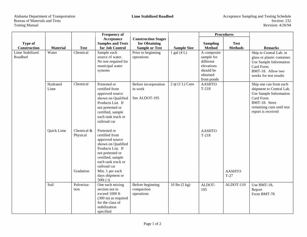
Alabama Department of TransportationBureau of Materials and TestsTesting Manual
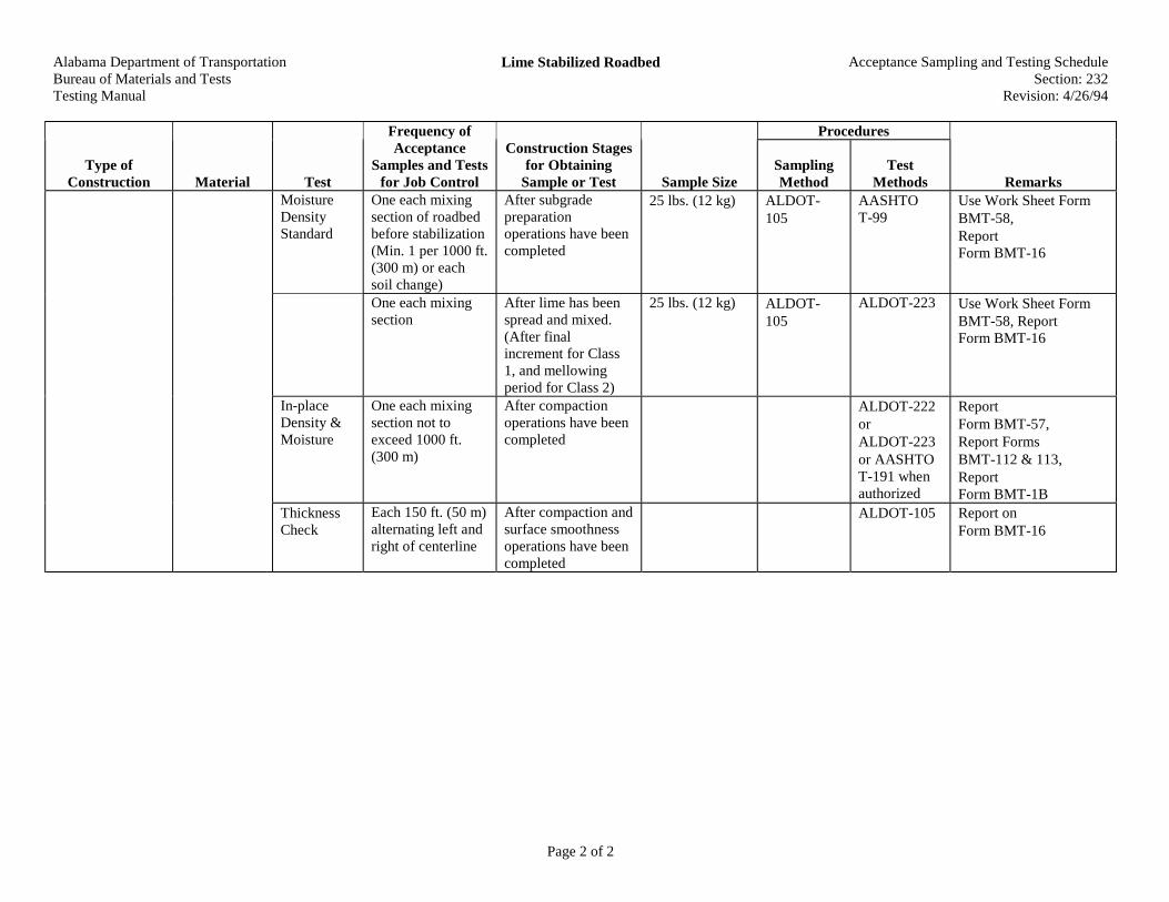
Lime Stabilized Roadbed Acceptance Sampling and Testing ScheduleSection: 232
Revision: 4/26/94
Page 1 of 2
Procedures
Type ofConstruction Material Test
Frequency ofAcceptance
Samples and Testsfor Job Control
Construction Stagesfor Obtaining
Sample or Test Sample SizeSamplingMethod
TestMethods Remarks
Water Chemical Sample eachsource of water.No test required formunicipal watersystems
Prior to beginningoperations
1 gal (4 L) A compositesample fordifferentelevationsshould beobtainedfrom ponds
Ship to Central Lab. inglass or plastic container.Use Sample InformationCard FormBMT-18. Allow twoweeks for test results
HydratedLime
Chemical Pretested orcertified fromapproved sourceshown on QualifiedProducts List. Ifnot pretested orcertified, sampleeach tank truck orrailroad car
Before incorporationin work
See ALDOT-195
2 qt (1 L) Cans AASHTOT-218
Ship one can from eachshipment to Central Lab.Use Sample InformationCard FormBMT-18. Storeremaining cans until testreport is received
Chemical &Physical
Pretested orcertified fromapproved sourceshown on QualifiedProducts List. Ifnot pretested orcertified, sampleeach tank truck orrailroad car
AASHTOT-218
Quick Lime
Gradation Min. 1 per eachdays shipment or500t ( t)
AASHTOT-27
Lime StabilizedRoadbed
Soil Pulveriza-tion
One each mixingsection not toexceed 1000 ft(300 m) as requiredfor the class ofstabilizationspecified
Before beginningcompactionoperations
10 lbs (5 kg) ALDOT-105
ALDOT-110 Use BMT-18,ReportForm BMT-78
Alabama Department of TransportationBureau of Materials and TestsTesting Manual
Lime Stabilized Roadbed Acceptance Sampling and Testing ScheduleSection: 232
Revision: 4/26/94
Page 2 of 2
Procedures
Type ofConstruction Material Test
Frequency ofAcceptance
Samples and Testsfor Job Control
Construction Stagesfor Obtaining
Sample or Test Sample SizeSamplingMethod
TestMethods Remarks
MoistureDensityStandard
One each mixingsection of roadbedbefore stabilization(Min. 1 per 1000 ft.(300 m) or eachsoil change)
After subgradepreparationoperations have beencompleted
25 lbs. (12 kg) ALDOT-105
AASHTOT-99
Use Work Sheet FormBMT-58,ReportForm BMT-16
One each mixingsection
After lime has beenspread and mixed.(After finalincrement for Class1, and mellowingperiod for Class 2)
25 lbs. (12 kg) ALDOT-105
ALDOT-223 Use Work Sheet FormBMT-58, ReportForm BMT-16
In-placeDensity &Moisture
One each mixingsection not toexceed 1000 ft.(300 m)
After compactionoperations have beencompleted
ALDOT-222orALDOT-223or AASHTOT-191 whenauthorized
ReportForm BMT-57,Report FormsBMT-112 & 113,ReportForm BMT-1B
ThicknessCheck
Each 150 ft. (50 m)alternating left andright of centerline
After compaction andsurface smoothnessoperations have beencompleted
ALDOT-105 Report onForm BMT-16

Alabama Department of TransportationBureau of Materials and TestsTesting Manual
Soil, Soil Aggregate, and Aggregate Base and SubbaseAcceptance Sampling and Testing Schedule
Section: 301Revision: 7/30/01
Page 1 of 3
Procedures
Type ofConstruction
Material Test
Frequency ofAcceptance
Samples and Testsfor Job Control
Construction Stagesfor Obtaining
Sample or TestSample Size Sampling
MethodTest
MethodsRemarks
Gradation25 lbs. (12 kg)
UseAASHTO T-27 and T-11for gradationof CrushedAggregateBases
ClayContentWhenRequired
AASHTOT 88
AtterbergLimits
Each 500 ft. (150m) each layer, eachroadway.
For road- or yard-mixed basescontaining 100%crushedcommercialaggregate, sampleeach 1000 ft. (300m) per layer perroadway; forplant-mixed (seeRemarks), Pre-tested, seeALDOT-249.
Sample fromroadway as soon asmixing process iscompleted
Plant mixed basecourse may besampled at plant fromfeeder belt on loosevolume basisequivalent to 1000 ft.(300 m)
For crushedAggregateBases seeAASHTO T-2Table 1 forsample size
ALDOT-105ALDOT-210
ALDOT-105
AASHTOT 89 as
modified byALDOT-232
AASHTOT 90
ALDOT-310
Use Work Sheets FormBMT-17 & BMT-30,Report on Form BMT-5.
If Pre-tested, (ALDOT-249) must be mixed in aplant or pugmill , hauleddirectly to job, andplaced with a mechanicalspreader.
50 lbs.(25 kg)AASHTOT-180orALDOT-140
Use Work SheetForm BMT-58, ReportFormBMT-16
MoistureDensityStandard
Min. 1 each 10,000ft (3000 m) eachroadway, eachlayer, or eachproportion orcomponent sourcechange
Sample fromroadway as soon asmixing process iscompleted
or 100 lbs (50kg) forALDOT-140
ALDOT-105
Or ALDOT-225 whenauthorized
Report Form BMT-112
Soil, SoilAggregate, andAggregate Baseand Subbase
Plant- (exceptfor 100%crushedcommercialaggregate),Road- , orSubbaseWithoutChemicalAdditives
In-placeDensity andMoistureCount
Min. 1 each 1000 ft(300 m) each layer,each roadway
After compactionoperations arecompleted
ALDOT-210
ALDOT-225Or AASHTOT-191 and/orALDOT-225whenauthorized
Work Sheet From BMT-112. Report Form BMT-57, BMT-18
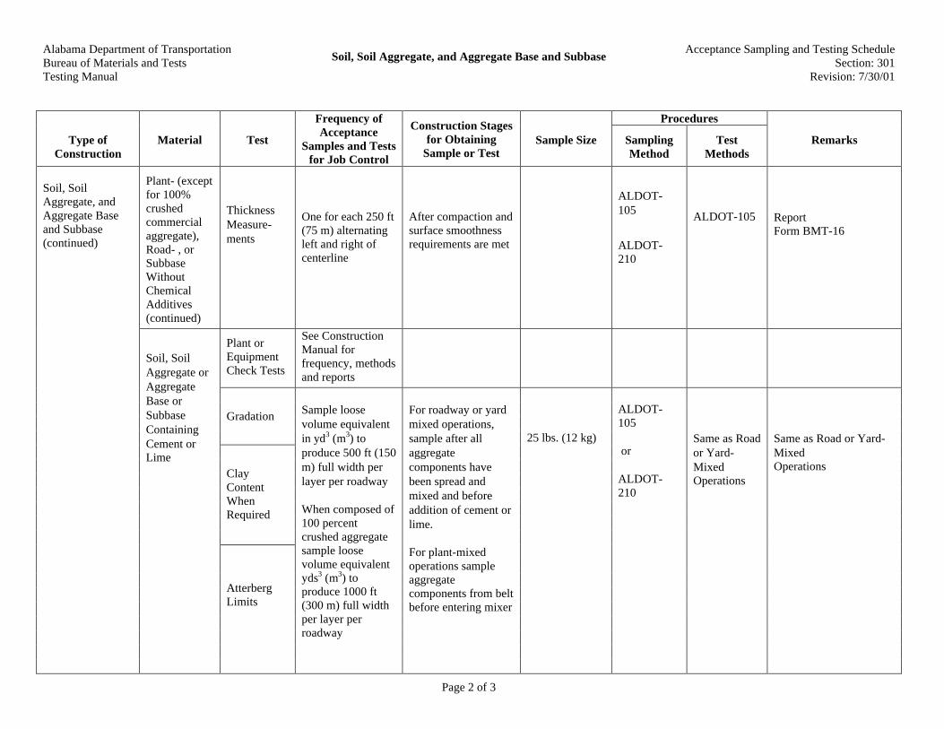
Alabama Department of TransportationBureau of Materials and TestsTesting Manual
Soil, Soil Aggregate, and Aggregate Base and SubbaseAcceptance Sampling and Testing Schedule
Section: 301Revision: 7/30/01
Page 2 of 3
Procedures
Type ofConstruction
Material Test
Frequency ofAcceptance
Samples and Testsfor Job Control
Construction Stagesfor Obtaining
Sample or TestSample Size Sampling
MethodTest
MethodsRemarks
Plant- (exceptfor 100%crushedcommercialaggregate),Road- , orSubbaseWithoutChemicalAdditives(continued)
ThicknessMeasure-ments
One for each 250 ft(75 m) alternatingleft and right ofcenterline
After compaction andsurface smoothnessrequirements are met
ALDOT-105
ALDOT-210
ALDOT-105 ReportForm BMT-16
Plant orEquipmentCheck Tests
See ConstructionManual forfrequency, methodsand reports
Gradation
ClayContentWhenRequired
Soil, SoilAggregate, andAggregate Baseand Subbase(continued)
Soil, SoilAggregate orAggregateBase orSubbaseContainingCement orLime
AtterbergLimits
Sample loosevolume equivalentin yd3 (m3) toproduce 500 ft (150m) full width perlayer per roadway
When composed of100 percentcrushed aggregatesample loosevolume equivalentyds3 (m3) toproduce 1000 ft(300 m) full widthper layer perroadway
For roadway or yardmixed operations,sample after allaggregatecomponents havebeen spread andmixed and beforeaddition of cement orlime.
For plant-mixedoperations sampleaggregatecomponents from beltbefore entering mixer
25 lbs. (12 kg)
ALDOT-105
or
ALDOT-210
Same as Roador Yard-MixedOperations
Same as Road or Yard-MixedOperations
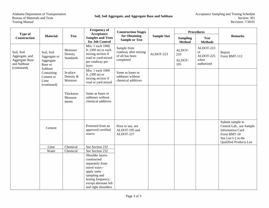
Alabama Department of TransportationBureau of Materials and TestsTesting Manual
Soil, Soil Aggregate, and Aggregate Base and SubbaseAcceptance Sampling and Testing Schedule
Section: 301Revision: 7/30/01
Page 3 of 3
ProceduresType of
ConstructionMaterial Test
Frequency ofAcceptance
Samples and Testsfor Job Control
Construction Stagesfor Obtaining
Sample or TestSample Size
SamplingMethod
TestMethods
Remarks
MoistureDensityStandards
Min. 1 each 1000ft. (300 m) or eachmixing section ifroad or yard-mixedper roadway perlayer
Sample fromroadway after mixingof all has beencompleted
ALDOT-223ALDOT-210
ALDOT-105
ALDOT-223orALDOT-225whenauthorized
ReportForm BMT-112
In-placeDensity &Moisture
Min. 1 each 1000ft. (300 m) ormixing section ifroad or yard mixed
Same as bases orsubbases withoutchemical additives
Soil, SoilAggregate orAggregateBase orSubbaseContainingCement orLime(continued)
ThicknessMeasure-ments
Same as bases orsubbases withoutchemical additives
CementPretested from anapproved certifiedsource
Prior to use, seeALDOT-195 andALDOT-227
Submit sample toCentral Lab., use SampleInformation CardForm BMT-18See List I-2 in theQualified Products List
Lime Chemical See Section 232Water Chemical See Section 232
Soil, SoilAggregate, andAggregate Baseand Subbase(continued)
Shoulder layersconstructedseparately fromtravel ways--apply samesampling andtesting frequency,except alternate leftand right shoulders
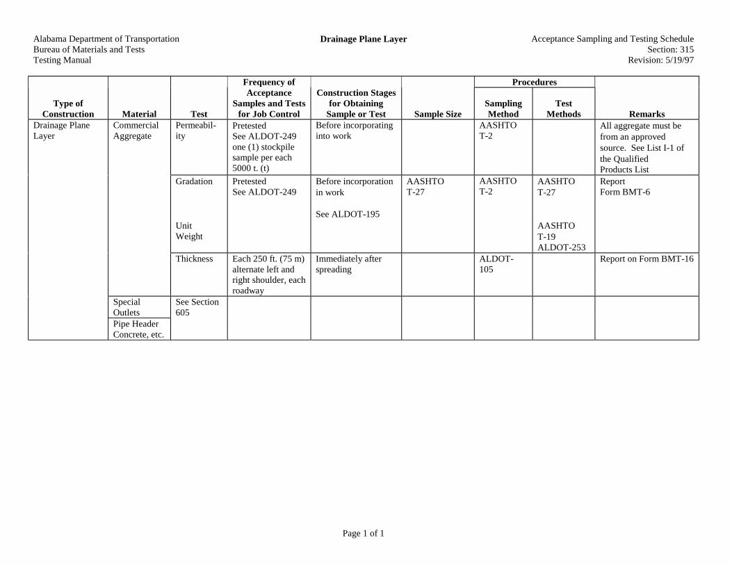
Alabama Department of TransportationBureau of Materials and TestsTesting Manual
Drainage Plane Layer Acceptance Sampling and Testing ScheduleSection: 315
Revision: 5/19/97
Page 1 of 1
Procedures
Type ofConstruction Material Test
Frequency ofAcceptance
Samples and Testsfor Job Control
Construction Stagesfor Obtaining
Sample or Test Sample SizeSamplingMethod
TestMethods Remarks
CommercialAggregate
Permeabil-ity
PretestedSee ALDOT-249one (1) stockpilesample per each5000 t. (t)
Before incorporatinginto work
AASHTOT-2
All aggregate must befrom an approvedsource. See List I-1 ofthe QualifiedProducts List
Gradation
UnitWeight
PretestedSee ALDOT-249
Before incorporationin work
See ALDOT-195
AASHTOT-27
AASHTOT-2
AASHTOT-27
AASHTOT-19ALDOT-253
ReportForm BMT-6
Thickness Each 250 ft. (75 m)alternate left andright shoulder, eachroadway
Immediately afterspreading
ALDOT-105
Report on Form BMT-16
SpecialOutlets
See Section605
Drainage PlaneLayer
Pipe HeaderConcrete, etc.

Alabama Department of TransportationBureau of Materials and TestsTesting Manual
Plant Mix Bituminous Base Acceptance Sampling and Testing ScheduleSection: 327
Revision: 4/26/94
Page 1 of 1
Procedures
Type ofConstruction Material Test
Frequency ofAcceptance
Samples and Testsfor Job Control
Construction Stagesfor Obtaining
Sample or Test Sample SizeSamplingMethod
TestMethods Remarks
PermeableAsphalt TreatedBase
No density orair voidstestingrequired. SeeSection 410for all otherrequirements
Alabama Department of TransportationBureau of Materials and TestsTesting Manual
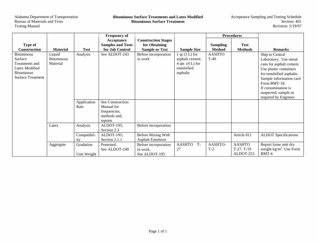
Bituminous Surface Treatments and Latex ModifiedBituminous Surface Treatment
Acceptance Sampling and Testing ScheduleSection: 401
Revision: 5/19/97
Page 1 of 1
Procedures
Type ofConstruction Material Test
Frequency ofAcceptance
Samples and Testsfor Job Control
Construction Stagesfor Obtaining
Sample or Test Sample SizeSamplingMethod
TestMethods Remarks
LiquidBituminousMaterial
Analysis See ALDOT-243 Before incorporationin work
1 qt (1 L) forasphalt cement.4 qts (4 L) foremulsifiedasphalts
AASHTOT-40
Ship to CentralLaboratory. Use metalcans for asphalt cement.Use plastic containersfor emulsified asphalts.Sample information cardForm BMT-18.If contamination issuspected, sample asrequired by Engineer
ApplicationRate
See ConstructionManual forfrequencies,methods and,reports
Latex Analysis ALDOT-195;Section 2.3
Before incorporation
Compatibil-ity
ALDOT-195;Section 2.1.1
Before Mixing WithAsphalt Emulsion
Article 811 ALDOT Specifications
BituminousSurfaceTreatments andLatex ModifiedBituminousSurface Treatment
Aggregate Gradation
Unit Weight
Pretested.See ALDOT-249
Before incorporationin work.See ALDOT-195
AASHTO T-27
AASHTO-T-2
AASHTOT-27, T-19ALDOT-253
Report loose unit dryweight kg/m3. Use FormBMT-6

Alabama Department of TransportationBureau of Materials and TestsTesting Manual
Slurry Seal Acceptance Sampling and Testing ScheduleSection: 402
Revision: 5/19/97
Page 1 of 1
Procedures
Type ofConstruction Material Test
Frequency ofAcceptance
Samples and Testsfor Job Control
Construction Stagesfor Obtaining
Sample or Test Sample SizeSamplingMethod
TestMethods Remarks
Slurry Seal LiquidBituminousMaterial
Analysis Same as Section as401
Aggregateand MineralFiller
Gradation Same as Section401
Contractor should submitsamples of his proposedsources to the CentralLaboratory at least twoweeks before beginningoperations forestablishment of bitumencontent
Water Chemical Pretested byCentral Laboratory.Sample eachsource proposedfor use if a pond orstream. No testrequired formunicipal systems
At least two weeksbefore beginningoperations
4 qt. (4 L) See Section232
Ship to CentralLaboratory for tests.Report on BMT-18
Hardness All SourcesMixture Bitumen
ContentMinimum onedaily
During operations 4 qt. (4 L) ALDOT-210
AASHTOT-110,ALDOT-319
Report on BMT-20

Alabama Department of TransportationBureau of Materials and TestsTesting Manual
Tack Coat Acceptance Sampling and Testing ScheduleSection: 405
Revision: 4/26/94
Page 1 of 1
Procedures
Type ofConstruction Material Test
Frequency ofAcceptance
Samples and Testsfor Job Control
Construction Stagesfor Obtaining
Sample or Test Sample SizeSamplingMethod
TestMethods Remarks
Tack Coat BituminousMaterial
Analysis Same as Section401
Tempera-tureCorrection
ApplicationRate
See ConstructionManual forfrequencies,methods, andreports
BMT-4

Alabama Department of TransportationBureau of Materials and TestsTesting Manual
Repaved Bituminous Pavements Acceptance Sampling and Testing ScheduleSection: 406
Revision: 4/26/94
Page 1 of 1
Procedures
Type ofConstruction Material Test
Frequency ofAcceptance
Samples and Testsfor Job Control
Construction Stagesfor Obtaining
Sample or Test Sample SizeSamplingMethod
TestMethods Remarks
EquipmentChecks
See ConstructionManual forequipment checklist and reportforms
AbsonRecovery ofAsphaltCement
Minimum 1 mile(1.5 km) perroadway
After mixing 1 gal (4 L) ALDOT-210,AASHTOT-168
Submit to Division orCentral Laboratory.Report on BMT-18
RepavedBituminousPavements
Recycled In-PlaceBituminousPavement
In-PlaceDensity
See Section 410

Alabama Department of TransportationBureau of Materials and TestsTesting Manual
Bituminous Material Used in Plant Mix Bases andPavements
Acceptance Sampling and Testing ScheduleSection: 407
Revision: 4/26/94
Page 1 of 1
Procedures
Type ofConstruction Material Test
Frequency ofAcceptance
Samples and Testsfor Job Control
Construction Stagesfor Obtaining
Sample or Test Sample SizeSamplingMethod
TestMethods Remarks
BituminousMaterial Used inPlant Mix Basesand Pavements
LiquidBituminousMaterial
SeeALDOT-243 andSection 410for require-ments

Alabama Department of TransportationBureau of Materials and TestsTesting Manual
Planing or Milling of Existing Pavement Acceptance Sampling and Testing ScheduleSection: 408
Revision: 4/26/94
Page 1 of 1
Procedures
Type ofConstruction Material Test
Frequency ofAcceptance
Samples and Testsfor Job Control
Construction Stagesfor Obtaining
Sample or Test Sample SizeSamplingMethod
TestMethods Remarks
Planing or Millingof ExistingPavement
See ConstructionManual forequipment checklists andconstruction
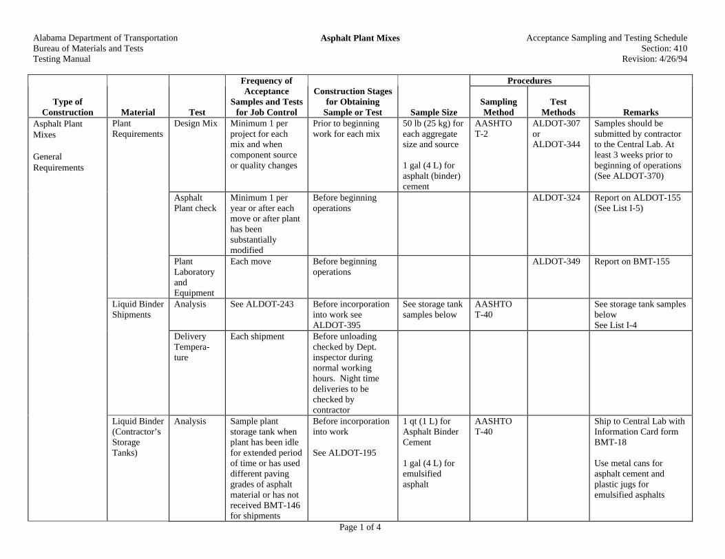
Alabama Department of TransportationBureau of Materials and TestsTesting Manual
Asphalt Plant Mixes Acceptance Sampling and Testing ScheduleSection: 410
Revision: 4/26/94
Page 1 of 4
Procedures
Type ofConstruction Material Test
Frequency ofAcceptance
Samples and Testsfor Job Control
Construction Stagesfor Obtaining
Sample or Test Sample SizeSamplingMethod
TestMethods Remarks
Asphalt PlantMixes
GeneralRequirements
PlantRequirements
Design Mix Minimum 1 perproject for eachmix and whencomponent sourceor quality changes
Prior to beginningwork for each mix
50 lb (25 kg) foreach aggregatesize and source
1 gal (4 L) forasphalt (binder)cement
AASHTOT-2
ALDOT-307orALDOT-344
Samples should besubmitted by contractorto the Central Lab. Atleast 3 weeks prior tobeginning of operations(See ALDOT-370)
AsphaltPlant check
Minimum 1 peryear or after eachmove or after planthas beensubstantiallymodified
Before beginningoperations
ALDOT-324 Report on ALDOT-155(See List I-5)
PlantLaboratoryandEquipment
Each move Before beginningoperations
ALDOT-349 Report on BMT-155
Liquid BinderShipments
Analysis See ALDOT-243 Before incorporationinto work seeALDOT-395
See storage tanksamples below
AASHTOT-40
See storage tank samplesbelowSee List I-4
DeliveryTempera-ture
Each shipment Before unloadingchecked by Dept.inspector duringnormal workinghours. Night timedeliveries to bechecked bycontractor
Liquid Binder(Contractor’sStorageTanks)
Analysis Sample plantstorage tank whenplant has been idlefor extended periodof time or has useddifferent pavinggrades of asphaltmaterial or has notreceived BMT-146for shipments
Before incorporationinto work
See ALDOT-195
1 qt (1 L) forAsphalt BinderCement
1 gal (4 L) foremulsifiedasphalt
AASHTOT-40
Ship to Central Lab withInformation Card formBMT-18
Use metal cans forasphalt cement andplastic jugs foremulsified asphalts
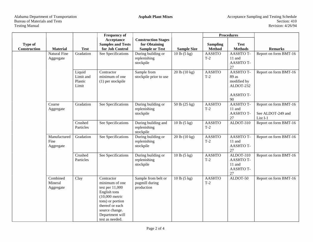
Alabama Department of TransportationBureau of Materials and TestsTesting Manual
Asphalt Plant Mixes Acceptance Sampling and Testing ScheduleSection: 410
Revision: 4/26/94
Page 2 of 4
Procedures
Type ofConstruction Material Test
Frequency ofAcceptance
Samples and Testsfor Job Control
Construction Stagesfor Obtaining
Sample or Test Sample SizeSamplingMethod
TestMethods Remarks
Natural FineAggregate
Gradation See Specifications During building orreplenishingstockpile
10 lb (5 kg) AASHTOT-2
AASHTO T-11 andAASHTO T-27
Report on form BMT-16
LiquidLimit andPlasticLimit
Contractorminimum of one(1) per stockpile
Sample fromstockpile prior to use
20 lb (10 kg) AASHTOT-2
AASHTO T-89 asmodified byALDOT-232
AASHTO T-90
Report on form BMT-16
CoarseAggregate
Gradation See Specifications During building orreplenishingstockpile
50 lb (25 kg) AASHTOT-2
AASHTO T-11 andAASHTO T-27
Report on form BMT-16
See ALDOT-249 andList I-1
CrushedParticles
See Specifications During building andreplenishingstockpile
10 lb (5 kg) AASHTOT-2
ALDOT-310 Report on form BMT-16
ManufacturedFineAggregate
Gradation See Specifications During building orreplenishingstockpile
20 lb (10 kg) AASHTOT-2
AASHTO T-11 andAASHTO T-27
Report on form BMT-16
CrushedParticles
See Specifications During building orreplenishingstockpile
10 lb (5 kg) AASHTOT-2
ALDOT-310AASHTO T-11 andAASHTO T-27
Report on form BMT-16
CombinedMineralAggregate
Clay Contractorminimum of onetest per 11,000English tons(10,000 metrictons) or portionthereof or eachsource change.Department willtest as needed.
Sample from belt orpugmill duringproduction
10 lb (5 kg) AASHTOT-2
ALDOT-50 Report on form BMT-16
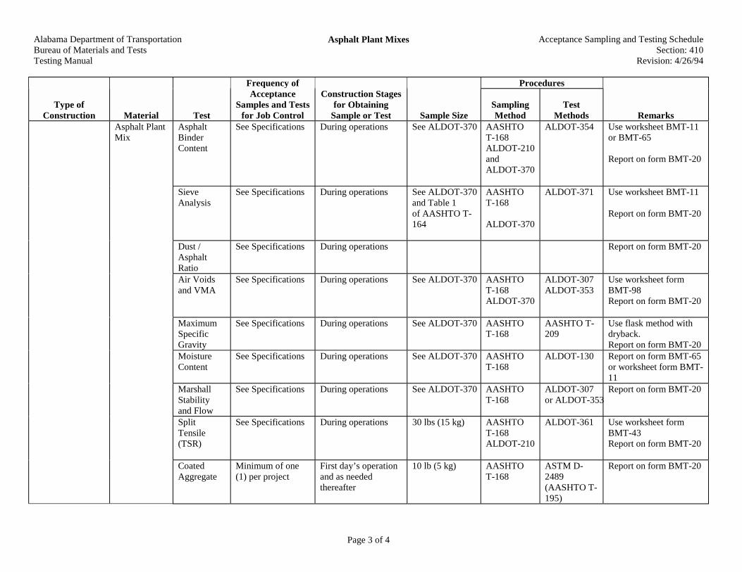
Alabama Department of TransportationBureau of Materials and TestsTesting Manual
Asphalt Plant Mixes Acceptance Sampling and Testing ScheduleSection: 410
Revision: 4/26/94
Page 3 of 4
Procedures
Type ofConstruction Material Test
Frequency ofAcceptance
Samples and Testsfor Job Control
Construction Stagesfor Obtaining
Sample or Test Sample SizeSamplingMethod
TestMethods Remarks
Asphalt PlantMix
AsphaltBinderContent
See Specifications During operations See ALDOT-370 AASHTOT-168ALDOT-210andALDOT-370
ALDOT-354 Use worksheet BMT-11or BMT-65
Report on form BMT-20
SieveAnalysis
See Specifications During operations See ALDOT-370and Table 1of AASHTO T-164
AASHTOT-168
ALDOT-370
ALDOT-371 Use worksheet BMT-11
Report on form BMT-20
Dust /AsphaltRatio
See Specifications During operations Report on form BMT-20
Air Voidsand VMA
See Specifications During operations See ALDOT-370 AASHTOT-168ALDOT-370
ALDOT-307ALDOT-353
Use worksheet formBMT-98Report on form BMT-20
MaximumSpecificGravity
See Specifications During operations See ALDOT-370 AASHTOT-168
AASHTO T-209
Use flask method withdryback.Report on form BMT-20
MoistureContent
See Specifications During operations See ALDOT-370 AASHTOT-168
ALDOT-130 Report on form BMT-65or worksheet form BMT-11
MarshallStabilityand Flow
See Specifications During operations See ALDOT-370 AASHTOT-168
ALDOT-307or ALDOT-353
Report on form BMT-20
SplitTensile(TSR)
See Specifications During operations 30 lbs (15 kg) AASHTOT-168ALDOT-210
ALDOT-361 Use worksheet formBMT-43Report on form BMT-20
CoatedAggregate
Minimum of one(1) per project
First day’s operationand as neededthereafter
10 lb (5 kg) AASHTOT-168
ASTM D-2489(AASHTO T-195)
Report on form BMT-20
Alabama Department of TransportationBureau of Materials and TestsTesting Manual
Asphalt Plant Mixes Acceptance Sampling and Testing ScheduleSection: 410
Revision: 4/26/94
Page 4 of 4
Procedures
Type ofConstruction Material Test
Frequency ofAcceptance
Samples and Testsfor Job Control
Construction Stagesfor Obtaining
Sample or Test Sample SizeSamplingMethod
TestMethods Remarks
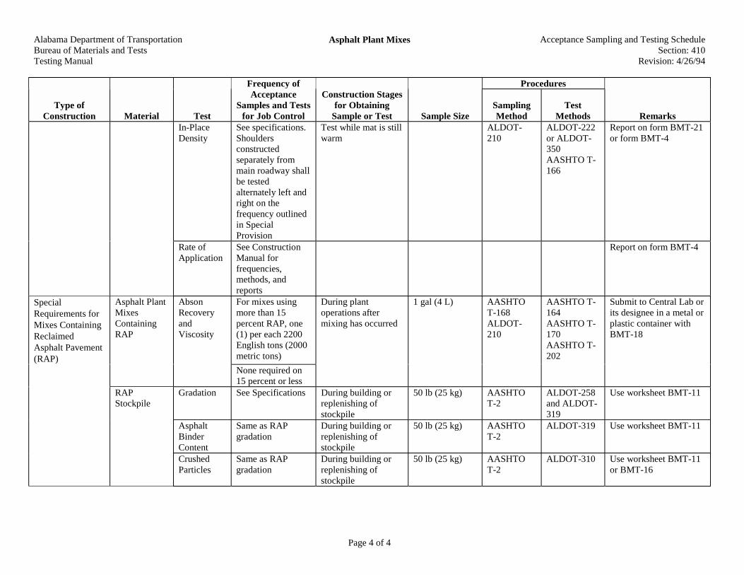
In-PlaceDensity
See specifications.Shouldersconstructedseparately frommain roadway shallbe testedalternately left andright on thefrequency outlinedin SpecialProvision
Test while mat is stillwarm
ALDOT-210
ALDOT-222or ALDOT-350AASHTO T-166
Report on form BMT-21or form BMT-4
Rate ofApplication
See ConstructionManual forfrequencies,methods, andreports
Report on form BMT-4
SpecialRequirements forMixes ContainingReclaimedAsphalt Pavement(RAP)
Asphalt PlantMixesContainingRAP
AbsonRecoveryandViscosity
For mixes usingmore than 15percent RAP, one(1) per each 2200English tons (2000metric tons)
During plantoperations aftermixing has occurred
1 gal (4 L) AASHTOT-168ALDOT-210
AASHTO T-164AASHTO T-170AASHTO T-202
Submit to Central Lab orits designee in a metal orplastic container withBMT-18
None required on15 percent or less
RAPStockpile
Gradation See Specifications During building orreplenishing ofstockpile
50 lb (25 kg) AASHTOT-2
ALDOT-258and ALDOT-319
Use worksheet BMT-11
AsphaltBinderContent
Same as RAPgradation
During building orreplenishing ofstockpile
50 lb (25 kg) AASHTOT-2
ALDOT-319 Use worksheet BMT-11
CrushedParticles
Same as RAPgradation
During building orreplenishing ofstockpile
50 lb (25 kg) AASHTOT-2
ALDOT-310 Use worksheet BMT-11or BMT-16

Alabama Department of TransportationBureau of Materials and TestsTesting Manual
Hot Bituminous Pavement Acceptance Sampling and Testing ScheduleSection: 411
Revision: 4/26/1994
Page 1 of 1
Procedures
Type ofConstruction Material Test
Frequency ofAcceptance
Samples and Testsfor Job Control
Construction Stagesfor Obtaining
Sample or Test Sample SizeSamplingMethod
TestMethods Remarks
Hot BituminousPavement
BituminousMix
See Section 410 forall generalrequirements

Alabama Department of TransportationBureau of Materials and TestsTesting Manual
Asphalt Binder Layer Acceptance Sampling and Testing ScheduleSection: 414
Revision: 4/26/94
Page 1 of 1
Procedures
Type ofConstruction Material Test
Frequency ofAcceptance
Samples and Testsfor Job Control
Construction Stagesfor Obtaining
Sample or Test Sample SizeSamplingMethod
TestMethods Remarks
Asphalt BinderLayer
See Section410 forrequirements

Alabama Department of TransportationBureau of Materials and TestsTesting Manual
Polymer Modified Open Graded Friction Course Acceptance Sampling and Testing ScheduleSection: 420
Revision: 4/26/94
Page 1 of 1
Procedures
Type ofConstruction Material Test
Frequency ofAcceptance
Samples and Testsfor Job Control
Construction Stagesfor Obtaining
Sample or Test Sample SizeSamplingMethod
TestMethods Remarks
Polymer ModifiedOpen GradedFriction Course
No density orair void testsrequired.See Section410 for allotherrequirements

Alabama Department of TransportationBureau of Materials and TestsTesting Manual
Stone Matrix Asphalt (SMA)Fiber Stabilized Asphalt Concrete
Acceptance Sampling and Testing ScheduleSection: 423
Revision: 5/10/01
Page 1 of 1
Procedures
Type ofConstruction Material Test
Frequency ofAcceptance
Samples and Testsfor Job Control
Construction Stagesfor Obtaining
Sample or Test Sample SizeSamplingMethod
TestMethods Remarks
Stone MatrixAsphalt (SMA)
Fiber StabilizedAsphalt Concrete
See Section410 forrequirements

Alabama Department of TransportationBureau of Materials and TestsTesting Manual
Superpave Bituminous Concrete Acceptance Sampling and Testing ScheduleSection: 424
Revision: 5/10/01
Page 1 of 1
Procedures
Type ofConstruction Material Test
Frequency ofAcceptance
Samples and Testsfor Job Control
Construction Stagesfor Obtaining
Sample or Test Sample SizeSamplingMethod
TestMethods Remarks
SuperpaveBituminousConcrete
See Section410 forrequirements

Alabama Department of TransportationBureau of Materials and TestsTesting Manual
Plant Mixed Friction Courses Acceptance Sampling and Testing ScheduleSection: 425
Revision:4/26/94
Page 1 of 1
Procedures
Type ofConstruction Material Test
Frequency ofAcceptance
Samples and Testsfor Job Control
Construction Stagesfor Obtaining
Sample or Test Sample SizeSamplingMethod
TestMethods Remarks
Plant MixedFriction Courses
See Section410 forrequirements
Alabama Department of TransportationBureau of Materials and TestsTesting Manual
Soil or Aggregate Type Surface Acceptance Sampling and Testing ScheduleSection: 430
Revision: 4/26/94
Page 1 of 1
Procedures
Type ofConstruction Material Test
Frequency ofAcceptance
Samples and Testsfor Job Control
Construction Stagesfor Obtaining
Sample or Test Sample SizeSamplingMethod
TestMethods Remarks
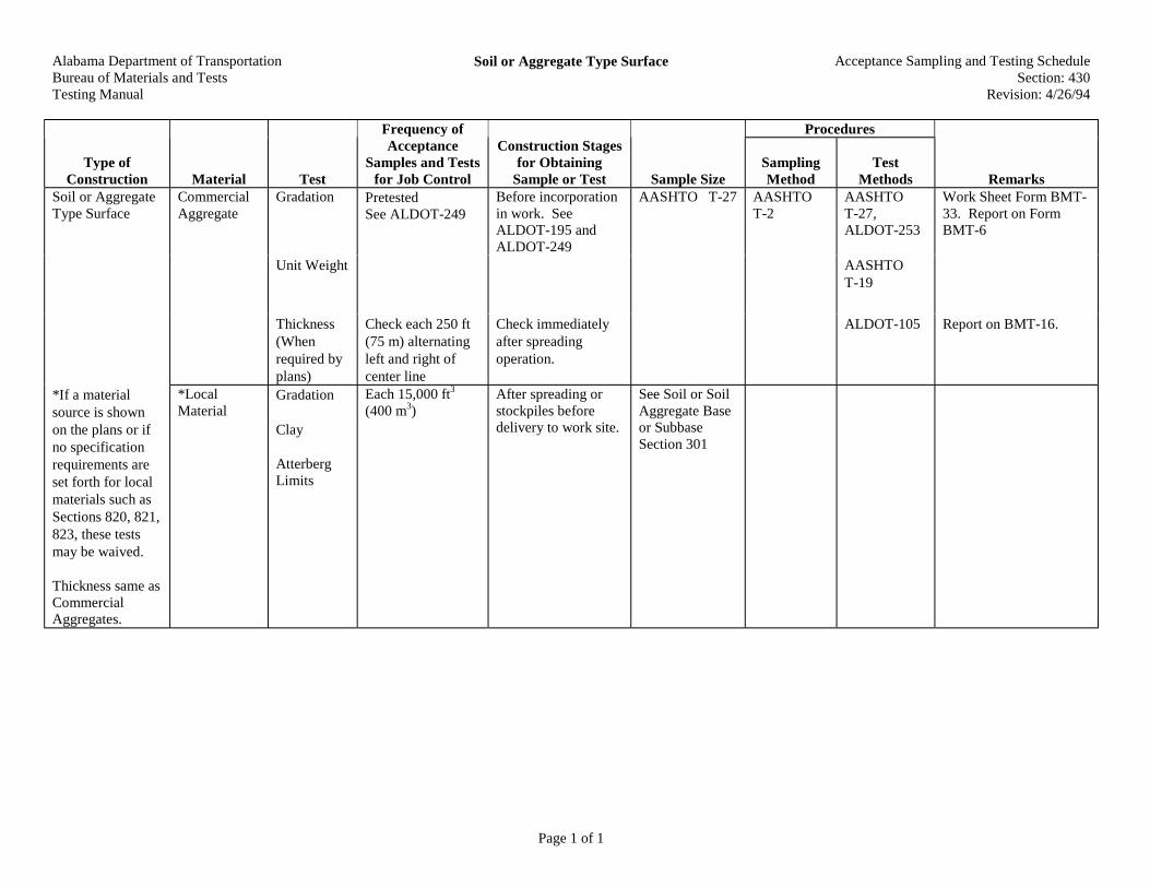
Gradation PretestedSee ALDOT-249
Before incorporationin work. SeeALDOT-195 andALDOT-249
AASHTO T-27 AASHTOT-2
AASHTOT-27,ALDOT-253
Work Sheet Form BMT-33. Report on FormBMT-6
Unit Weight AASHTOT-19
Soil or AggregateType Surface
CommercialAggregate
Thickness(Whenrequired byplans)
Check each 250 ft(75 m) alternatingleft and right ofcenter line
Check immediatelyafter spreadingoperation.
ALDOT-105 Report on BMT-16.
*If a materialsource is shownon the plans or ifno specificationrequirements areset forth for localmaterials such asSections 820, 821,823, these testsmay be waived.
Thickness same asCommercialAggregates.
*LocalMaterial
Gradation
Clay
AtterbergLimits
Each 15,000 ft3
(400 m3)After spreading orstockpiles beforedelivery to work site.
See Soil or SoilAggregate Baseor SubbaseSection 301
Alabama Department of TransportationBureau of Materials and TestsTesting Manual
Portland Cement Concrete Pavement Acceptance Sampling and Testing ScheduleSection: 450
Revision: 2/1/01
Page 1 of 6
Procedures
Type ofConstruction Material Test
Frequency ofAcceptance
Samples and Testsfor Job Control
Construction Stagesfor Obtaining
Sample or Test Sample SizeSamplingMethod
TestMethods Remarks
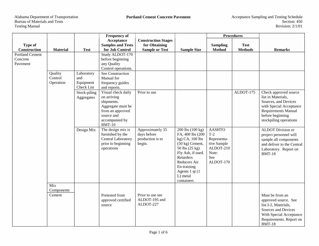
Study ALDOT-170before beginningany QualityControl operations.
LaboratoryandEquipmentCheck List
See ConstructionManual forfrequency guidesand reports.
Stock-pilingAggregates
Visual check dailyon arrivingshipments.Aggregate must befrom an approvedsource andaccompanied byBMT-10
Prior to use ALDOT-175 Check approved sourcelist in Materials,Sources, and Deviceswith Special AcceptanceRequirements Manualbefore beginningstockpiling operations
QualityControlOperation
Design Mix The design mix isfurnished by theCentral Laboratoryprior to beginningoperations
Approximately 35days beforeproduction is tobegin.
200 lbs (100 kg)FA, 400 lbs (200kg) CA, 100 lbs(50 kg) Cement,50 lbs (25 kg)Fly Ash, if used.RetardersReducers AirEn-trainingAgents 1 qt (1L) metalcontainers
AASHTOT-2Representa-tive SampleALDOT-210Note:SeeALDOT-170
ALDOT Division orproject personnel willsample all componentsand deliver to the CentralLaboratory. Report onBMT-18
MixComponents
Portland CementConcretePavement
Cement Pretested fromapproved certifiedsource
Prior to use seeALDOT-195 andALDOT-227
Must be from anapproved source. Seelist I-2, Materials,Sources and DevicesWith Special AcceptanceRequirements. Report onBMT-18
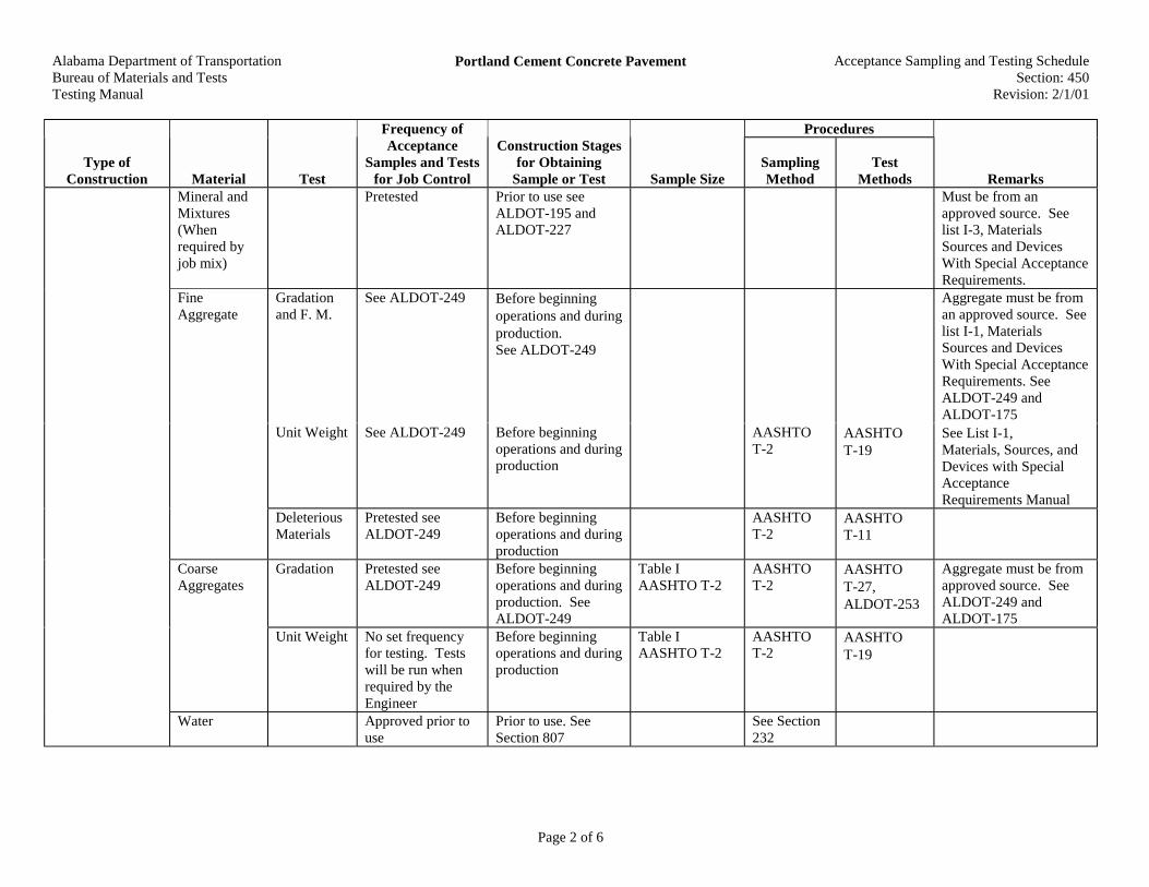
Alabama Department of TransportationBureau of Materials and TestsTesting Manual
Portland Cement Concrete Pavement Acceptance Sampling and Testing ScheduleSection: 450
Revision: 2/1/01
Page 2 of 6
Procedures
Type ofConstruction Material Test
Frequency ofAcceptance
Samples and Testsfor Job Control
Construction Stagesfor Obtaining
Sample or Test Sample SizeSamplingMethod
TestMethods Remarks
Mineral andMixtures(Whenrequired byjob mix)
Pretested Prior to use seeALDOT-195 andALDOT-227
Must be from anapproved source. Seelist I-3, MaterialsSources and DevicesWith Special AcceptanceRequirements.
Gradationand F. M.
See ALDOT-249 Before beginningoperations and duringproduction.See ALDOT-249
Aggregate must be froman approved source. Seelist I-1, MaterialsSources and DevicesWith Special AcceptanceRequirements. SeeALDOT-249 andALDOT-175
Unit Weight See ALDOT-249 Before beginningoperations and duringproduction
AASHTOT-2
AASHTOT-19
See List I-1,Materials, Sources, andDevices with SpecialAcceptanceRequirements Manual
FineAggregate
DeleteriousMaterials
Pretested seeALDOT-249
Before beginningoperations and duringproduction
AASHTOT-2
AASHTOT-11
Gradation Pretested seeALDOT-249
Before beginningoperations and duringproduction. SeeALDOT-249
Table IAASHTO T-2
AASHTOT-2
AASHTOT-27,ALDOT-253
Aggregate must be fromapproved source. SeeALDOT-249 andALDOT-175
CoarseAggregates
Unit Weight No set frequencyfor testing. Testswill be run whenrequired by theEngineer
Before beginningoperations and duringproduction
Table IAASHTO T-2
AASHTOT-2
AASHTOT-19
Water Approved prior touse
Prior to use. SeeSection 807
See Section232

Alabama Department of TransportationBureau of Materials and TestsTesting Manual
Portland Cement Concrete Pavement Acceptance Sampling and Testing ScheduleSection: 450
Revision: 2/1/01
Page 3 of 6
Procedures
Type ofConstruction Material Test
Frequency ofAcceptance
Samples and Testsfor Job Control
Construction Stagesfor Obtaining
Sample or Test Sample SizeSamplingMethod
TestMethods Remarks
AirEntrainingAgents,Retarders,and WaterReducers
Approved prior touse
Prior to use, seeALDOT-195 andALDOT-170,Section 808, 809
Must be from approvedsource, see List II-1,Materials Sources andDevices with SpecialAcceptanceRequirementsManual
Rein-forcingSteel
See Section502
PreformedJoint Filler
Physical Pretested Prior to use, seeALDOT-195
1 yd (1 m) byfull depthminimum 6 in(150 mm)
AASHTOM-33AASHTOM-153AASHTOM-213AASHTOM-220ALDOT-210
Visual fordamage
Submit samples toCentral Laboratory.Report onBMT-18
PreformedElastomericJoints(CompressionSeals)
ChemicalandPhysical
Must be from anapproved sourcefor design. Sampleat project level onesample per source,per size, per lot, orcertified testreports
Prior to use, seeALDOT-195.
For joints up toand including 3in (75 mm)submit 5 ft (1.5m). For jointsover 3 in (75mm) submit 3 ft(1 m)
ALDOT-210 Visual fordamage
Submit samples toCentral Laboratory.Report on BMT-18
Cork Physical Sample at projectlevel and submitfor testing toCentral Laboratoryor Certified testreports
Prior to use, seeALDOT-195
3 ft (1 m) ALDOT-210each loteach sizeeach source
Visual fordamage
Submit samples toCentral Laboratory.Report onBMT-18
Hot Pour Physical See ALDOT-195 See List III-4 List III-4 in Materials,Sources, and Deviceswith Special AcceptanceRequirements
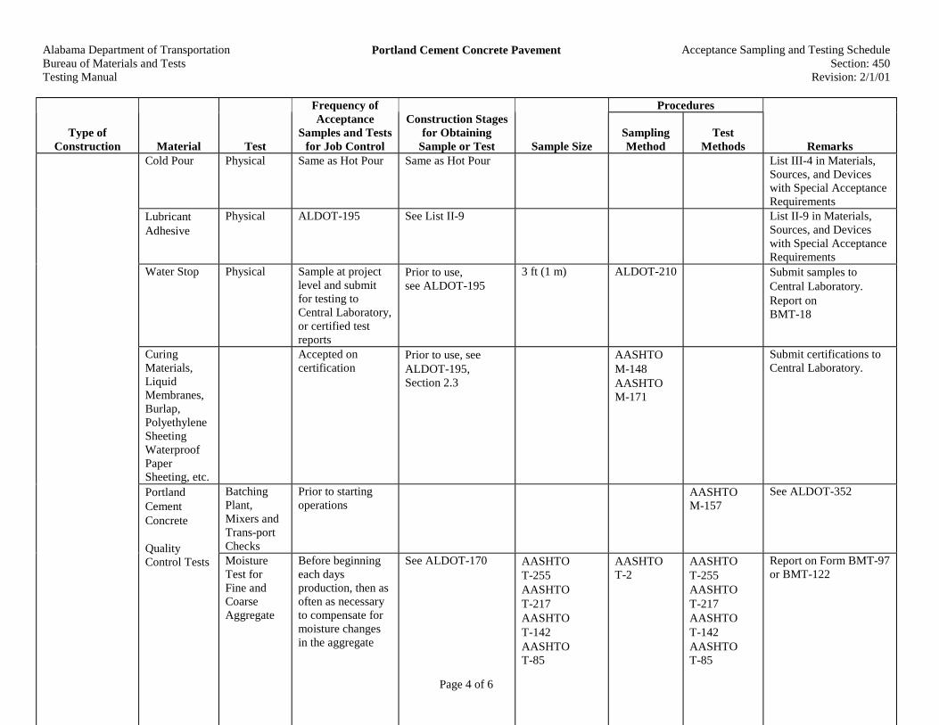
Alabama Department of TransportationBureau of Materials and TestsTesting Manual
Portland Cement Concrete Pavement Acceptance Sampling and Testing ScheduleSection: 450
Revision: 2/1/01
Page 4 of 6
Procedures
Type ofConstruction Material Test
Frequency ofAcceptance
Samples and Testsfor Job Control
Construction Stagesfor Obtaining
Sample or Test Sample SizeSamplingMethod
TestMethods Remarks
Cold Pour Physical Same as Hot Pour Same as Hot Pour List III-4 in Materials,Sources, and Deviceswith Special AcceptanceRequirements
LubricantAdhesive
Physical ALDOT-195 See List II-9 List II-9 in Materials,Sources, and Deviceswith Special AcceptanceRequirements
Water Stop Physical Sample at projectlevel and submitfor testing toCentral Laboratory,or certified testreports
Prior to use,see ALDOT-195
3 ft (1 m) ALDOT-210 Submit samples toCentral Laboratory.Report onBMT-18
CuringMaterials,LiquidMembranes,Burlap,PolyethyleneSheetingWaterproofPaperSheeting, etc.
Accepted oncertification
Prior to use, seeALDOT-195,Section 2.3
AASHTOM-148AASHTOM-171
Submit certifications toCentral Laboratory.
BatchingPlant,Mixers andTrans-portChecks
Prior to startingoperations
AASHTOM-157
See ALDOT-352PortlandCementConcrete
QualityControl Tests Moisture
Test forFine andCoarseAggregate
Before beginningeach daysproduction, then asoften as necessaryto compensate formoisture changesin the aggregate
See ALDOT-170 AASHTOT-255AASHTOT-217AASHTOT-142AASHTOT-85
AASHTOT-2
AASHTOT-255AASHTOT-217AASHTOT-142AASHTOT-85
Report on Form BMT-97or BMT-122
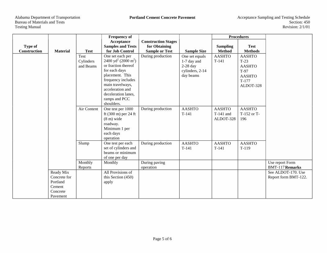
Alabama Department of TransportationBureau of Materials and TestsTesting Manual
Portland Cement Concrete Pavement Acceptance Sampling and Testing ScheduleSection: 450
Revision: 2/1/01
Page 5 of 6
Procedures
Type ofConstruction Material Test
Frequency ofAcceptance
Samples and Testsfor Job Control
Construction Stagesfor Obtaining
Sample or Test Sample SizeSamplingMethod
TestMethods
Remarks
TestCylindersand Beams
One set each per2400 yd2 (2000 m2)or fraction thereoffor each daysplacement. Thisfrequency includesmain travelways,acceleration anddeceleration lanes,ramps and PCCshoulders.
During production One set equals1-7 day and2-28 daycylinders, 2-14day beams
AASHTOT-141
AASHTOT-23AASHTOT-97AASHTOT-177ALDOT-328
Submit cylinders orbeams to project orDivision Laboratory forstrength tests. Use FormBMT-15 for necessaryinformation
Air Content One test per 1000ft (300 m) per 24 ft(8 m) wideroadway.Minimum 1 pereach daysoperation
During production AASHTOT-141
AASHTOT-141 andALDOT-328
AASHTOT-152 or T-196
Report on Form BMT-18
Slump One test per eachset of cylinders andbeams or minimumof one per day
During production AASHTOT-141
AASHTOT-141
AASHTOT-119
Report on Form BMT-83
RemarksMonthlyReports
Monthly During pavingoperation
Use report FormBMT-117
Ready MixConcrete forPortlandCementConcretePavement
All Provisions ofthis Section (450)apply
See ALDOT-170. UseReport form BMT-122.
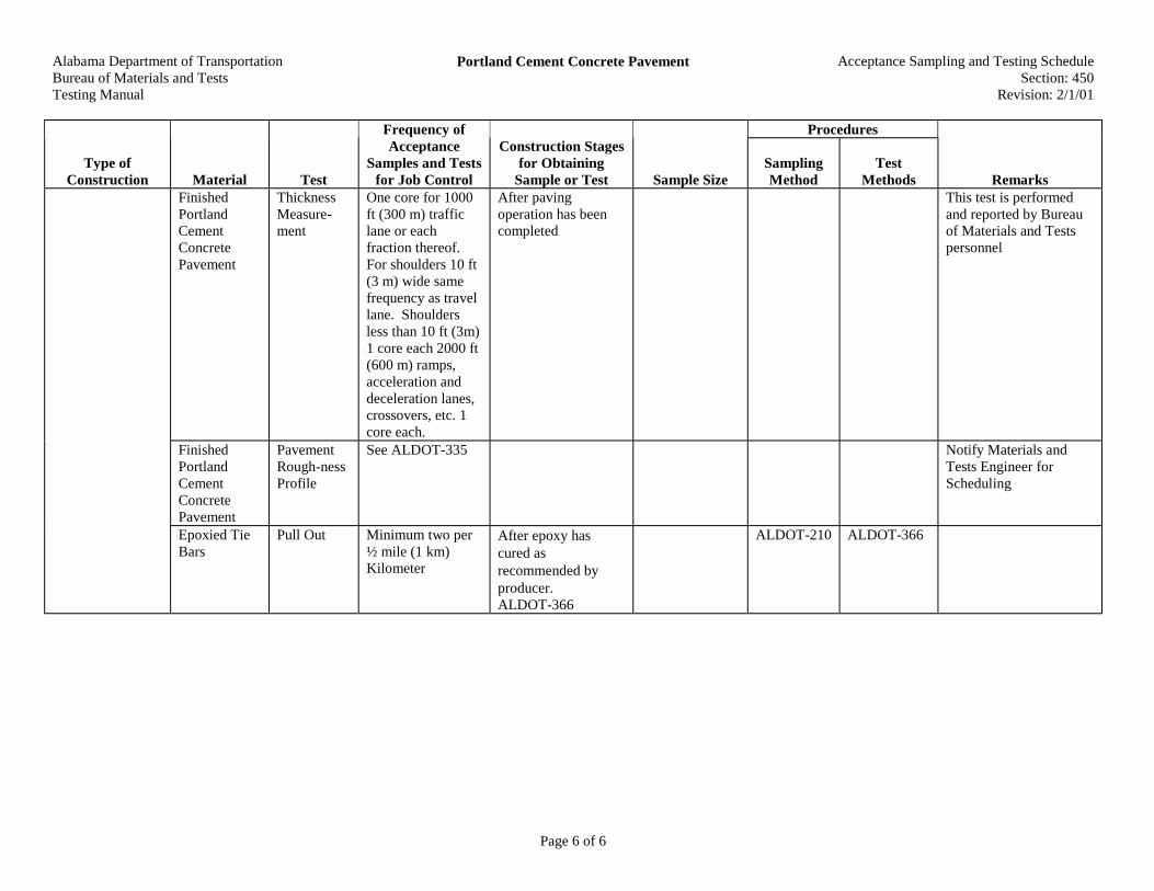
Alabama Department of TransportationBureau of Materials and TestsTesting Manual
Portland Cement Concrete Pavement Acceptance Sampling and Testing ScheduleSection: 450
Revision: 2/1/01
Page 6 of 6
Procedures
Type ofConstruction Material Test
Frequency ofAcceptance
Samples and Testsfor Job Control
Construction Stagesfor Obtaining
Sample or Test Sample SizeSamplingMethod
TestMethods Remarks
FinishedPortlandCementConcretePavement
ThicknessMeasure-ment
One core for 1000ft (300 m) trafficlane or eachfraction thereof.For shoulders 10 ft(3 m) wide samefrequency as travellane. Shouldersless than 10 ft (3m)1 core each 2000 ft(600 m) ramps,acceleration anddeceleration lanes,crossovers, etc. 1core each.
After pavingoperation has beencompleted
This test is performedand reported by Bureauof Materials and Testspersonnel
FinishedPortlandCementConcretePavement
PavementRough-nessProfile
See ALDOT-335 Notify Materials andTests Engineer forScheduling
Epoxied TieBars
Pull Out Minimum two per½ mile (1 km)Kilometer
After epoxy hascured asrecommended byproducer.ALDOT-366
ALDOT-210 ALDOT-366

Alabama Department of TransportationBureau of Materials and TestsTesting Manual
Pressure Grouting and Repair of Portland CementConcrete Pavement
Acceptance Sampling and Testing ScheduleSection: 453
Revision: 5/19/97
Page 1 of 1
Procedures
Type ofConstruction Material Test
Frequency ofAcceptance
Samples and Testsfor Job Control
Construction Stagesfor Obtaining
Sample or Test Sample SizeSamplingMethod
TestMethods Remarks
QualityControlOperations
StockpilingComponents
Visual check dailyon arrivingshipments.Cement, fly ashand aggregatesmust be fromapproved sources
Prior to use Check Materials,Sources and DevicesWith Special AcceptanceRequirements Manualbefore operations arebegun
Grout MixComponentsCement Shipped from
approved certifiedsource
Prior to use.See ALDOT-195 andALDOT-227
AASHTOT-127
See List I-2,Materials, Sources andDevices With SpecialAcceptanceRequirements Manual
Fly Ash(WhenRequired)
Shipped fromapproved certifiedsource
Prior to use.See ALDOT-195 andALDOT-227
AASHTOT-127
See List I-3,Materials, Sources andDevices With SpecialAcceptanceRequirements Manual
FineAggregate(WhenRequired)
Gradation Minimum one testdailySee ALDOT-249
Prior to beginningeach days operations
AASHTOT-2
AASHTOT-27
Use Work Sheet formBMT-33 & BMT-91.Aggregate must be froman approved source.
Water Approved prior touse
Prior to use.See Section 807.
QualityControl Testfor Grout
Flow Test Minimum one testdaily, morefrequent if deemednecessary
Prior to beginningeach days operationsand when necessaryduring production
ALDOT-338 ALDOT-338 Flow Cone Method
ConcretePavementReplacement
See Requirementsof Section 501 and450
Pressure Groutingand Repair ofPortland CementConcretePavement
Epoxied TieBars
Pull Out Minimum three per40 yd3 (m3) ofconcrete
After epoxy hascured asrecommended byproducer
ALDOT-210 ALDOT-366

Alabama Department of TransportationBureau of Materials and TestsTesting Manual
Cleaning and Sealing PCP Pavement Joints andCracks
Acceptance Sampling and Testing ScheduleSection: 454
Revision: 5/19/97
Page 1 of 1
Procedures
Type ofConstruction Material Test
Frequency ofAcceptance
Samples and Testsfor Job Control
Construction Stagesfor Obtaining
Sample or Test Sample SizeSamplingMethod
TestMethods Remarks
Cleaning andSealing PCPPavement Jointsand Cracks
Low ModulusSiliconeSealant
Physical ALDOT-195;Section 2.4
Must come from ListIII-4 or go throughthe ProductEvaluation Board
See Department’sMaterials, Sources, andDevices with SpecialAcceptanceRequirements Manual
Hot PourJoint Sealant
Physical ALDOT-195;Section 2.4. If notsample each lot.ALDOT-195;Section 2.1.3
Prior to use One Container ALDOT-210
Water-proofingMembrane
Must be fromapproved source
Prior to use See List II-10 forrequirements
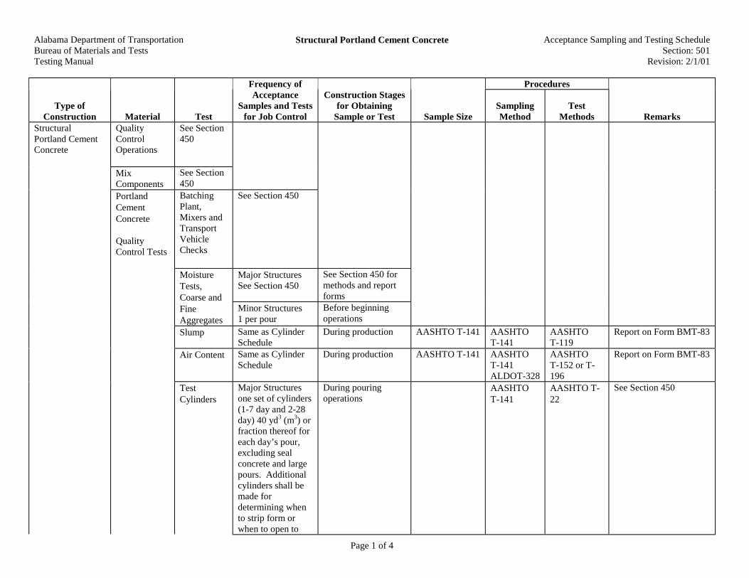
Alabama Department of TransportationBureau of Materials and TestsTesting Manual
Structural Portland Cement Concrete Acceptance Sampling and Testing ScheduleSection: 501
Revision: 2/1/01
Page 1 of 4
Procedures
Type ofConstruction Material Test
Frequency ofAcceptance
Samples and Testsfor Job Control
Construction Stagesfor Obtaining
Sample or Test Sample SizeSamplingMethod
TestMethods Remarks
StructuralPortland CementConcrete
QualityControlOperations
See Section450
MixComponents
See Section450
PortlandCementConcrete
QualityControl Tests
BatchingPlant,Mixers andTransportVehicleChecks
See Section 450
Major StructuresSee Section 450
See Section 450 formethods and reportforms
MoistureTests,Coarse andFineAggregates
Minor Structures1 per pour
Before beginningoperations
Slump Same as CylinderSchedule
During production AASHTO T-141 AASHTOT-141
AASHTOT-119
Report on Form BMT-83
Air Content Same as CylinderSchedule
During production AASHTO T-141 AASHTOT-141ALDOT-328
AASHTOT-152 or T-196
Report on Form BMT-83
TestCylinders
Major Structuresone set of cylinders(1-7 day and 2-28day) 40 yd3 (m3) orfraction thereof foreach day’s pour,excluding sealconcrete and largepours. Additionalcylinders shall bemade fordetermining whento strip form orwhen to open to
During pouringoperations
AASHTOT-141
AASHTO T-22
See Section 450

Alabama Department of TransportationBureau of Materials and TestsTesting Manual
Structural Portland Cement Concrete Acceptance Sampling and Testing ScheduleSection: 501
Revision: 2/1/01
Page 2 of 4
Procedures
Type ofConstruction Material Test
Frequency ofAcceptance
Samples and Testsfor Job Control
Construction Stagesfor Obtaining
Sample or Test Sample SizeSamplingMethod
TestMethods Remarks
traffic. For Seal Concretemake two extra sets(1-7 day and 2-28day) at intervalsdirected by theEngineer.Additionalcylinders shall bemade fordewatering before7 days.
For large poursover 40 yd3 (m3), 1set (1-7 day and 2-28 day) for each 4hours ofcontinuousconcretingoperation or majorportion thereofwith a minimum ofone set per eachindividualstructural unit(footing, column orcap) which exceeds40 yd3 (m3)Minor Structures1 set of cylinders(1-7 day and 2-28day) per each 40yd3 (m3 ) poured, orminimum of 1 setper project if lessthat 40 yd3 (m3)
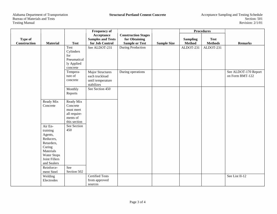
Alabama Department of TransportationBureau of Materials and TestsTesting Manual
Structural Portland Cement Concrete Acceptance Sampling and Testing ScheduleSection: 501
Revision: 2/1/01
Page 3 of 4
Procedures
Type ofConstruction Material Test
Frequency ofAcceptance
Samples and Testsfor Job Control
Construction Stagesfor Obtaining
Sample or Test Sample SizeSamplingMethod
TestMethods Remarks
TestCylindersforPneumatically Appliedconcrete
See ALDOT-231 During Production ALDOT-231 ALDOT-231
Tempera-ture ofconcrete
Major Structureseach truckloaduntil temperaturestabilizes
During operations See ALDOT-170 Reporton Form BMT-122
MonthlyReports
See Section 450
Ready MixConcrete
Ready MixConcretemust meetall require-ments ofthis section
Air En-trainingAgents,Reducers,Retarders,CuringMaterialsWater StopsJoint Fillersand Sealers
See Section450
Reinforce-ment Steel
SeeSection 502
WeldingElectrodes
Certified Testsfrom approvedsources
See List II-12
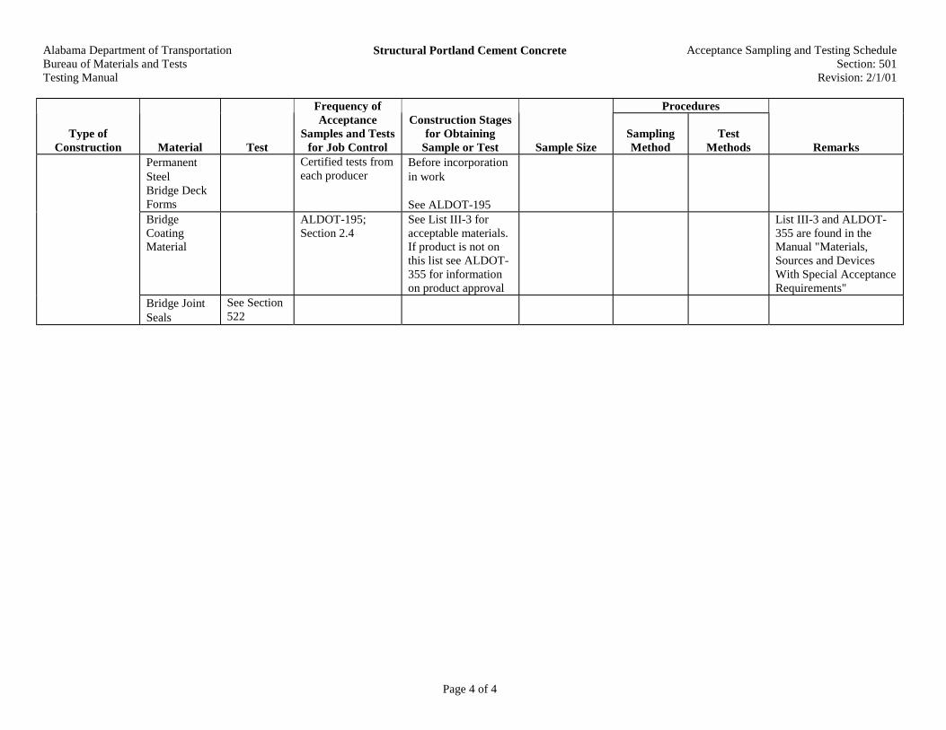
Alabama Department of TransportationBureau of Materials and TestsTesting Manual
Structural Portland Cement Concrete Acceptance Sampling and Testing ScheduleSection: 501
Revision: 2/1/01
Page 4 of 4
Procedures
Type ofConstruction Material Test
Frequency ofAcceptance
Samples and Testsfor Job Control
Construction Stagesfor Obtaining
Sample or Test Sample SizeSamplingMethod
TestMethods Remarks
PermanentSteelBridge DeckForms
Certified tests fromeach producer
Before incorporationin work
See ALDOT-195BridgeCoatingMaterial
ALDOT-195;Section 2.4
See List III-3 foracceptable materials.If product is not onthis list see ALDOT-355 for informationon product approval
List III-3 and ALDOT-355 are found in theManual "Materials,Sources and DevicesWith Special AcceptanceRequirements"
Bridge JointSeals
See Section522
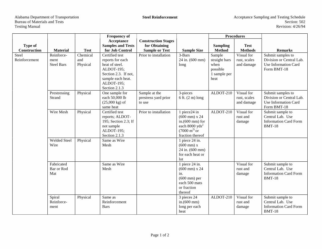
Alabama Department of TransportationBureau of Materials and TestsTesting Manual
Steel Reinforcement Acceptance Sampling and Testing ScheduleSection: 502
Revision: 4/26/94
Page 1 of 2
Procedures
Type ofConstruction Material Test
Frequency ofAcceptance
Samples and Testsfor Job Control
Construction Stagesfor Obtaining
Sample or Test Sample SizeSamplingMethod
TestMethods Remarks
SteelReinforcement
Reinforce-mentSteel Bars
ChemicalandPhysical
Certified testreports for eachheat of steel.ALDOT-195;Section 2.3. If not,sample each heat.ALDOT-195;Section 2.1.3
Prior to installation 3-Bars24 in. (600 mm)long
Samplestraight barswhenpossible1 sample perheat
Visual forrust, scalesand damage
Submit samples toDivision or Central Lab.Use Information CardForm BMT-18
PrestressingStrand
Physical One sample foreach 50,000 lb(25,000 kg) ofsame heat
Sample at theprestress yard priorto use
3-pieces6 ft. (2 m) long
ALDOT-210 Visual forrust, scalesand damage
Submit samples toDivision or Central Lab.Use Information CardForm BMT-18
Wire Mesh Physical Certified testreports; ALDOT-195; Section 2.3; Ifnot sampleALDOT-195;Section 2.1.3
Prior to installation 1 piece24 in(600 mm) x 24in.(600 mm) foreach 8000 yds2
(7000 m2) orfraction thereof
ALDOT-210 Visual forrust anddamage
Submit sample toCentral Lab. UseInformation Card FormBMT-18
Welded SteelWire
Physical Same as WireMesh
1 piece 24 in.(600 mm) x24 in. (600 mm)for each heat orlot
FabricatedBar or RodMat
Same as WireMesh
1 piece 24 in.(600 mm) x 24in.(600 mm) pereach 500 matsor fractionthereof
Visual forrust anddamage
Submit sample toCentral Lab. UseInformation Card FormBMT-18
SpiralReinforce-ment
Physical Same asReinforcementBars
3 pieces 24in.(600 mm)long per eachheat
ALDOT-210 Visual forrust anddamage
Submit sample toCentral Lab. UseInformation Card FormBMT-18

Alabama Department of TransportationBureau of Materials and TestsTesting Manual
Steel Reinforcement Acceptance Sampling and Testing ScheduleSection: 502
Revision: 4/26/94
Page 2 of 2
Procedures
Type ofConstruction Material Test
Frequency ofAcceptance
Samples and Testsfor Job Control
Construction Stagesfor Obtaining
Sample or Test Sample SizeSamplingMethod
TestMethods Remarks
Electrodes forWelding
ALDOT-195;Section 2.4
See List II-12 foracceptable electrodesProcedure II-12 forinformation
None None Visual fordampness andunsealedcontainers
List II-12 is found in theManual "Materials,Sources and Deviceswith Special AcceptanceRequirements"

Alabama Department of TransportationBureau of Materials and TestsTesting Manual
Structure Foundations Acceptance Sampling and Testing ScheduleSection: 503
Revision: 4/26/94
Page 1 of 1
Procedures
Type ofConstruction Material Test
Frequency ofAcceptance
Samples and Testsfor Job Control
Construction Stagesfor Obtaining
Sample or Test Sample SizeSamplingMethod
TestMethods Remarks
FoundationBackfill
SeeSection 214or 215
Concrete See Section501
SealConcreteCores
See ConstructionManual forfrequencies,procedures, andreports
StructureFoundations
Piling See Section505
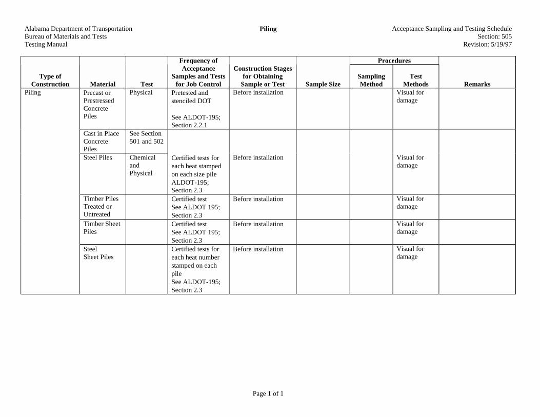
Alabama Department of TransportationBureau of Materials and TestsTesting Manual
Piling Acceptance Sampling and Testing ScheduleSection: 505
Revision: 5/19/97
Page 1 of 1
Procedures
Type ofConstruction Material Test
Frequency ofAcceptance
Samples and Testsfor Job Control
Construction Stagesfor Obtaining
Sample or Test Sample SizeSamplingMethod
TestMethods Remarks
Precast orPrestressedConcretePiles
Physical Pretested andstenciled DOT
See ALDOT-195;Section 2.2.1
Before installation Visual fordamage
Cast in PlaceConcretePiles
See Section501 and 502
Steel Piles ChemicalandPhysical
Certified tests foreach heat stampedon each size pileALDOT-195;Section 2.3
Before installation Visual fordamage
Timber PilesTreated orUntreated
Certified testSee ALDOT 195;Section 2.3
Before installation Visual fordamage
Timber SheetPiles
Certified testSee ALDOT 195;Section 2.3
Before installation Visual fordamage
Piling
SteelSheet Piles
Certified tests foreach heat numberstamped on eachpileSee ALDOT-195;Section 2.3
Before installation Visual fordamage
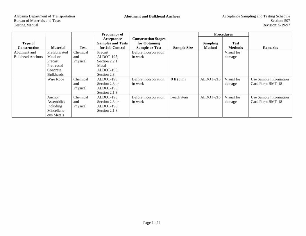
Alabama Department of TransportationBureau of Materials and TestsTesting Manual
Abutment and Bulkhead Anchors Acceptance Sampling and Testing ScheduleSection: 507
Revision: 5/19/97
Page 1 of 1
Procedures
Type ofConstruction Material Test
Frequency ofAcceptance
Samples and Testsfor Job Control
Construction Stagesfor Obtaining
Sample or Test Sample SizeSamplingMethod
TestMethods Remarks
PrefabricatedMetal orPrecastPretressedConcreteBulkheads
ChemicalandPhysical
PrecastALDOT-195;Section 2.2.1MetalALDOT-195,Section 2.3
Before incorporationin work
Visual fordamage
Wire Rope ChemicalandPhysical
ALDOT-195;Section 2.3 orALDOT-195;Section 2.1.3
Before incorporationin work
9 ft (3 m) ALDOT-210 Visual fordamage
Use Sample InformationCard Form BMT-18
Abutment andBulkhead Anchors
AnchorAssembliesIncludingMiscellane-ous Metals
ChemicalandPhysical
ALDOT-195;Section 2.3 orALDOT-195;Section 2.1.3
Before incorporationin work
1-each item ALDOT-210 Visual fordamage
Use Sample InformationCard Form BMT-18
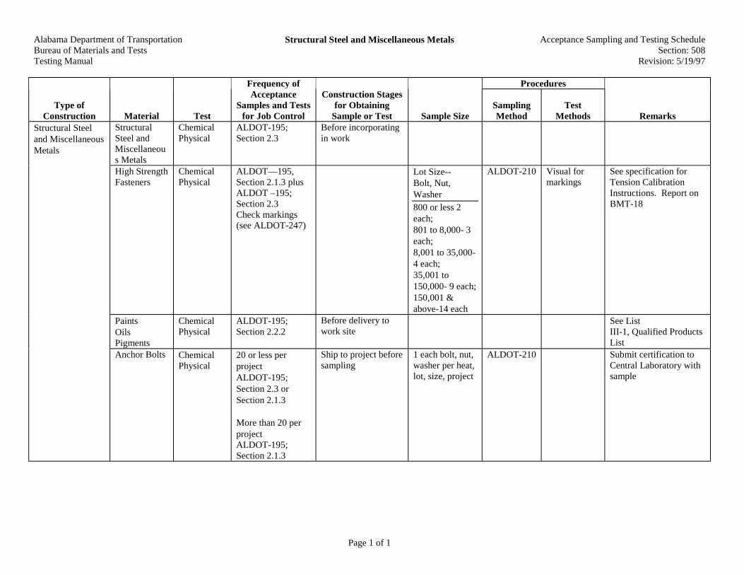
Alabama Department of TransportationBureau of Materials and TestsTesting Manual
Structural Steel and Miscellaneous Metals Acceptance Sampling and Testing ScheduleSection: 508
Revision: 5/19/97
Page 1 of 1
Procedures
Type ofConstruction Material Test
Frequency ofAcceptance
Samples and Testsfor Job Control
Construction Stagesfor Obtaining
Sample or Test Sample SizeSamplingMethod
TestMethods Remarks
Structural Steeland MiscellaneousMetals
StructuralSteel andMiscellaneous Metals
ChemicalPhysical
ALDOT-195;Section 2.3
Before incorporatingin work
High StrengthFasteners
ChemicalPhysical
ALDOT—195,Section 2.1.3 plusALDOT –195;Section 2.3Check markings(see ALDOT-247)
Lot Size--Bolt, Nut,Washer
800 or less 2each;801 to 8,000- 3each;8,001 to 35,000-4 each;35,001 to150,000- 9 each;150,001 &above-14 each
ALDOT-210 Visual formarkings
See specification forTension CalibrationInstructions. Report onBMT-18
PaintsOilsPigments
ChemicalPhysical
ALDOT-195;Section 2.2.2
Before delivery towork site
See ListIII-1, Qualified ProductsList
Anchor Bolts ChemicalPhysical
20 or less perprojectALDOT-195;Section 2.3 orSection 2.1.3
More than 20 perprojectALDOT-195;Section 2.1.3
Ship to project beforesampling
1 each bolt, nut,washer per heat,lot, size, project
ALDOT-210 Submit certification toCentral Laboratory withsample
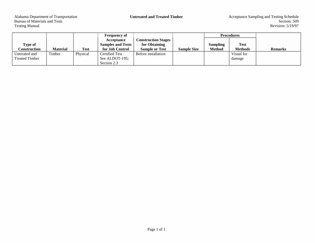
Alabama Department of TransportationBureau of Materials and TestsTesting Manual
Untreated and Treated Timber Acceptance Sampling and Testing ScheduleSection: 509
Revision: 5/19/97
Page 1 of 1
Procedures
Type ofConstruction Material Test
Frequency ofAcceptance
Samples and Testsfor Job Control
Construction Stagesfor Obtaining
Sample or Test Sample SizeSamplingMethod
TestMethods Remarks
Untreated andTreated Timber
Timber Physical Certified TestSee ALDOT-195;Section 2.3
Before installation Visual fordamage
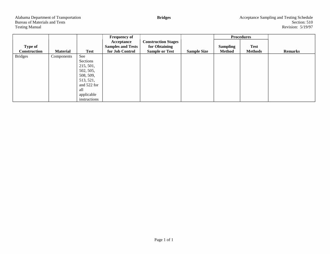
Alabama Department of TransportationBureau of Materials and TestsTesting Manual
Bridges Acceptance Sampling and Testing ScheduleSection: 510
Revision: 5/19/97
Page 1 of 1
Procedures
Type ofConstruction Material Test
Frequency ofAcceptance
Samples and Testsfor Job Control
Construction Stagesfor Obtaining
Sample or Test Sample SizeSamplingMethod
TestMethods Remarks
Bridges Components SeeSections215, 501,502, 505,508, 509,513, 521,and 522 forallapplicableinstructions

Alabama Department of TransportationBureau of Materials and TestsTesting Manual
Bridge Bearings Acceptance Sampling and Testing ScheduleSection: 511
Revision: 5/19/97
Page 1 of 1
Procedures
Type ofConstruction Material Test
Frequency ofAcceptance
Samples and Testsfor Job Control
Construction Stagesfor Obtaining
Sample or Test Sample SizeSamplingMethod
TestMethods Remarks
Bridge Bearings ElastomericBearing Pads
PhysicalandChemical
ALDOT-195;Section 2.3 plusALDOT-195;Section 2.1.3 orALDOT-195;Section 2.2.21 Pad per lot or seeALDOT-368
Before installation Complete pad ALDOT-210 Visual forworkmanship
See ALDOT-368 fordetails

Alabama Department of TransportationBureau of Materials and TestsTesting Manual
Precast Non-Prestressed Concrete Bridge Members Acceptance Sampling and Testing ScheduleSection: 512
Revision: 5/19/97
Page 1 of 1
Procedures
Type ofConstruction Material Test
Frequency ofAcceptance
Samples and Testsfor Job Control
Construction Stagesfor Obtaining
Sample or Test Sample SizeSamplingMethod
TestMethods Remarks
PrecastNonPrestressedConcrete BridgeMembers
AbutmentCaps, BentCaps, SpanSections,Curb Spans,AbutmentPanels, WingPanels, WingCap Panels
Pretested andstenciled DOT
See ALDOT-364
Visual fordamage
See ALDOT-364

Alabama Department of TransportationBureau of Materials and TestsTesting Manual
Prestressed Concrete Bridge Members Acceptance Sampling and Testing ScheduleSection: 513
Revision: 5/19/97
Page 1 of 1
Procedures
Type ofConstruction Material Test
Frequency ofAcceptance
Samples and Testsfor Job Control
Construction Stagesfor Obtaining
Sample or Test Sample SizeSamplingMethod
TestMethods Remarks
PrestressedConcrete Bridge
Girdersand/orSpan Sections
Physical Pretested andstenciled DOT
Before delivery towork site
See ALDOT-195
Visual fordamage
See BMT-367

Alabama Department of TransportationBureau of Materials and TestsTesting Manual
Linseed Oil Protective Coating for Bridge DecksMembers
Acceptance Sampling and Testing ScheduleSection: 514
Revision: 5/19/97
Page 1 of 1
Procedures
Type ofConstruction Material Test
Frequency ofAcceptance
Samples and Testsfor Job Control
Construction Stagesfor Obtaining
Sample or Test Sample SizeSamplingMethod
TestMethods Remarks
Linseed OilProtective Coatingfor Bridge DecksMembers
Linseed Oiland MineralSpirits
ChemicalandPhysical
Pretested or if notpretested sample atproject level
Prior to mixing ofcomponents.
See ALDOT-195
1 qt. (1 L) each ALDOT-210Each lot -Mixthoroughlybeforesampling
Ship to Central Lab.Use Information CardForm BMT-18

Alabama Department of TransportationBureau of Materials and TestsTesting Manual
Waterproofing and Dampproofing Acceptance Sampling and Testing ScheduleSection: 515
Revision: 5/19/97
Page 1 of 1
Procedures
Type ofConstruction Material Test
Frequency ofAcceptance
Samples and Testsfor Job Control
Construction Stagesfor Obtaining
Sample or Test Sample SizeSamplingMethod
TestMethods Remarks
AsphaltCement
Physical See ALDOT-243If not pretestedsample at projectlevel
Before incorporationin work
See ALDOT-195
1 quart (1 L) AASHTOT-40
Ship to Central Lab.Use Information CardForm BMT-18
Asphalt Plank Physical Certified Tests Before incorporationin work
See ALDOT-195
ALDOT-210 Check fordamage anddimensions
AASHTOM-46
Ship to Central Lab. UseBMT-18
Water-proofing andDamp-proofingFabric
ChemicalandPhysical
Pretested CertifiedTests. If notsample at projectlevel 1 sample pereach 200 rolls orfraction thereof
Before incorporatingin work
See ALDOT-195
1 yard (1 m) byfull width of roll
ALDOT-210 Visual checkfor damage
Submit samples toCentral Lab. UseInformation CardBMT-18
WaterproofingandDampproofing
Mortar SeeSection 611

Alabama Department of TransportationBureau of Materials and TestsTesting Manual
Bridge and Sidewalk Handrail Acceptance Sampling and Testing ScheduleSection: 517
Revision: 5/29/97
Page 1 of 1
Procedures
Type ofConstruction Material Test
Frequency ofAcceptance
Samples and Testsfor Job Control
Construction Stagesfor Obtaining
Sample or Test Sample SizeSamplingMethod
TestMethods Remarks
GalvanizedSteel Pipe,Steel ShapeBeam TypeHandrail andAccessoriesNuts, Boltsand Washers
Aluminum orGalvanizedSteelSidewalkHandrail andSteel Postsfor BeamTypeHandrail
ChemicalandPhysical
Certified TestReports
ALDOT-195;Section 2.3orSample at jobALDOT-195;Section 2.1.3
Before incorporatingin work
See ALDOT-195
1 each hardwareand pipe items.3 each nuts,bolts, andwashers
ALDOT-210 Visual checkfor damage
Submit sample toCentral Lab. UseInformation Card BMT-18
Timber Posts Physical Certified Test SeeALDOT-195;Section 2.3
Visual fordamage
Bridge andSidewalk Handrail
ConcreteHandrail
See Section501

Alabama Department of TransportationBureau of Materials and TestsTesting Manual
Repair or Raising Existing Bridges Acceptance Sampling and Testing ScheduleSection: 520
Revision: 5/19/97
Page 1 of 1
Procedures
Type ofConstruction Material Test
Frequency ofAcceptance
Samples and Testsfor Job Control
Construction Stagesfor Obtaining
Sample or Test Sample SizeSamplingMethod
TestMethods Remarks
Repair or RaisingExisting Bridges
All NewComponents
See Section510

Alabama Department of Transportation Bureau of Materials and Tests Testing Manual
Steel Bridge Painting Acceptance Sampling and Testing Schedule Section: 521
Revision: 04/16/02
Page 1 of 1
Procedures
Type of Construction Material Test
Frequency of Acceptance
Samples and Tests for Job Control
Construction Stages for Obtaining
Sample or Test Sample Size Sampling Method
Test Methods Remarks
Steel Bridge Painting
Paints, Oils and Pigments
Physical ALDOT-195; Section 2.4.
1 qt. (1 L) each component
See Procedure and List III-1 in Materials, Sources, and Devices with Special Acceptance Requirements Manual

Alabama Department of TransportationBureau of Materials and TestsTesting Manual
Bridge Joint Seals Acceptance Sampling and Testing ScheduleSection: 522
Revision: 5/19/97
Page 1 of 1
Procedures
Type ofConstruction Material Test
Frequency ofAcceptance
Samples and Testsfor Job Control
Construction Stagesfor Obtaining
Sample or Test Sample SizeSamplingMethod
TestMethods Remarks
Bridge Joint Seals PreformedElastomericCompressionSeals
See Section450
Un-ReinforcedDiaphragmSeal
Physical ALDOT-195;Section 2.1.3 1sample per lot
Prior to installing 3 ft. (1 m) ALDOT-210 Submit samples toCentral Lab. UseSample InformationCard Form BMT-18
ReinforcedDiaphragmSeal
Physical Certified TestReports ALDOT-195; Section 2.3
Prior to installing

Alabama Department of TransportationBureau of Materials and TestsTesting Manual
Reinforced Concrete Box Culverts Precast Sections Acceptance Sampling and Testing ScheduleSection: 524
Revision: 5/19/97
Page 1 of 1
Procedures
Type ofConstruction Material Test
Frequency ofAcceptance
Samples and Testsfor Job Control
Construction Stagesfor Obtaining
Sample or Test Sample SizeSamplingMethod
TestMethods Remarks
ReinforcedConcrete BoxCulverts PrecastSections
See Section214, 501, and502
Sections arepretested andstenciled DOT andTechnicianNumber
Visual fordamage
ALDOT-364

Alabama Department of TransportationBureau of Materials and TestsTesting Manual
Concrete Retaining Walls and Cribbing Acceptance Sampling and Testing ScheduleSection: 525
Revision: 5/19/1997
Page 1 of 1
Procedures
Type ofConstruction Material Test
Frequency ofAcceptance
Samples and Testsfor Job Control
Construction Stagesfor Obtaining
Sample or Test Sample SizeSamplingMethod
TestMethods Remarks
ConcreteRetaining Wallsand Cribbing
SeeSection 214,501, and 502
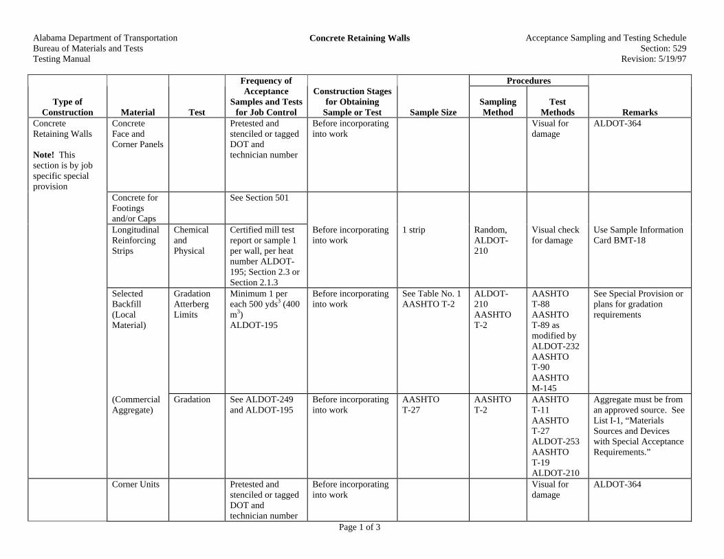
Alabama Department of TransportationBureau of Materials and TestsTesting Manual
Concrete Retaining Walls Acceptance Sampling and Testing ScheduleSection: 529
Revision: 5/19/97
Page 1 of 3
Procedures
Type ofConstruction Material Test
Frequency ofAcceptance
Samples and Testsfor Job Control
Construction Stagesfor Obtaining
Sample or Test Sample SizeSamplingMethod
TestMethods Remarks
ConcreteRetaining Walls
Note! Thissection is by jobspecific specialprovision
ConcreteFace andCorner Panels
Pretested andstenciled or taggedDOT andtechnician number
Before incorporatinginto work
Visual fordamage
ALDOT-364
Concrete forFootingsand/or Caps
See Section 501
LongitudinalReinforcingStrips
ChemicalandPhysical
Certified mill testreport or sample 1per wall, per heatnumber ALDOT-195; Section 2.3 orSection 2.1.3
Before incorporatinginto work
1 strip Random,ALDOT-210
Visual checkfor damage
Use Sample InformationCard BMT-18
SelectedBackfill(LocalMaterial)
GradationAtterbergLimits
Minimum 1 pereach 500 yds3 (400m3)ALDOT-195
Before incorporatinginto work
See Table No. 1AASHTO T-2
ALDOT-210AASHTOT-2
AASHTOT-88AASHTOT-89 asmodified byALDOT-232AASHTOT-90AASHTOM-145
See Special Provision orplans for gradationrequirements
(CommercialAggregate)
Gradation See ALDOT-249and ALDOT-195
Before incorporatinginto work
AASHTOT-27
AASHTOT-2
AASHTOT-11AASHTOT-27ALDOT-253AASHTOT-19ALDOT-210
Aggregate must be froman approved source. SeeList I-1, “MaterialsSources and Deviceswith Special AcceptanceRequirements.”
Corner Units Pretested andstenciled or taggedDOT andtechnician number
Before incorporatinginto work
Visual fordamage
ALDOT-364
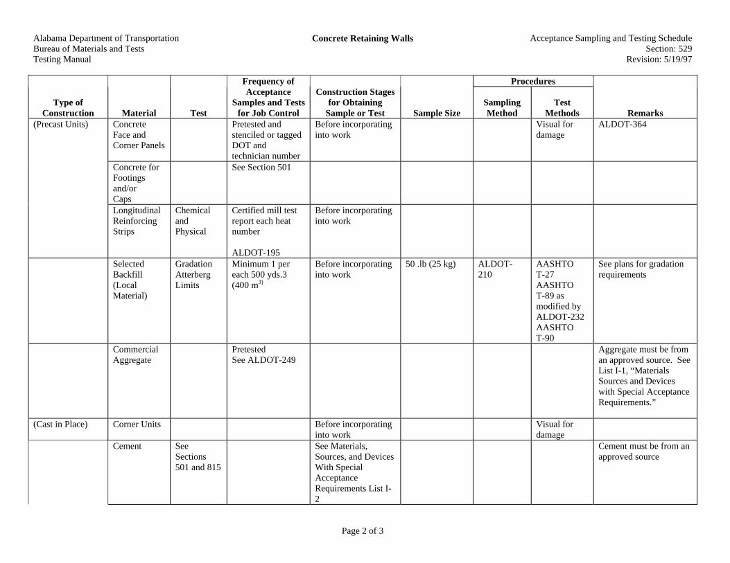
Alabama Department of TransportationBureau of Materials and TestsTesting Manual
Concrete Retaining Walls Acceptance Sampling and Testing ScheduleSection: 529
Revision: 5/19/97
Page 2 of 3
Procedures
Type ofConstruction Material Test
Frequency ofAcceptance
Samples and Testsfor Job Control
Construction Stagesfor Obtaining
Sample or Test Sample SizeSamplingMethod
TestMethods Remarks
(Precast Units) ConcreteFace andCorner Panels
Pretested andstenciled or taggedDOT andtechnician number
Before incorporatinginto work
Visual fordamage
ALDOT-364
Concrete forFootingsand/orCaps
See Section 501
LongitudinalReinforcingStrips
ChemicalandPhysical
Certified mill testreport each heatnumber
ALDOT-195
Before incorporatinginto work
SelectedBackfill(LocalMaterial)
GradationAtterbergLimits
Minimum 1 pereach 500 yds.3(400 m3)
Before incorporatinginto work
50 .lb (25 kg) ALDOT-210
AASHTOT-27AASHTOT-89 asmodified byALDOT-232AASHTOT-90
See plans for gradationrequirements
CommercialAggregate
PretestedSee ALDOT-249
Aggregate must be froman approved source. SeeList I-1, “MaterialsSources and Deviceswith Special AcceptanceRequirements.”
(Cast in Place) Corner Units Before incorporatinginto work
Visual fordamage
Cement SeeSections501 and 815
See Materials,Sources, and DevicesWith SpecialAcceptanceRequirements List I-2
Cement must be from anapproved source

Alabama Department of TransportationBureau of Materials and TestsTesting Manual
Concrete Retaining Walls Acceptance Sampling and Testing ScheduleSection: 529
Revision: 5/19/97
Page 3 of 3
Procedures
Type ofConstruction Material Test
Frequency ofAcceptance
Samples and Testsfor Job Control
Construction Stagesfor Obtaining
Sample or Test Sample SizeSamplingMethod
TestMethods Remarks
ReinforcedSteel
Accepted onCertifica-tion
Certified MillTest ReportALDOT-195
Submit Certifications toDivision MaterialsEngineer
Aggregates PretestedALDOT-249
See Materials,Sources, and DevicesWith SpecialAcceptanceRequirements List I-1
Aggregate must be froman approved source. SeeList I-1, “MaterialsSources and Deviceswith Special AcceptanceRequirements.”
Water SeeSections501 and 807
Admixtures Pretested See Materials,Sources, and DevicesWith SpecialAcceptanceRequirements List II-1
Admixtures must befrom an approved source
Joint Fillers,Sealers, andWaterstopMaterials
Pretested See Materials,Sources, and DevicesWith SpecialAcceptanceRequirements List II-10 and III-4
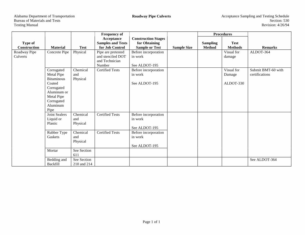
Alabama Department of TransportationBureau of Materials and TestsTesting Manual
Roadway Pipe Culverts Acceptance Sampling and Testing ScheduleSection: 530
Revision: 4/26/94
Page 1 of 1
Procedures
Type ofConstruction Material Test
Frequency ofAcceptance
Samples and Testsfor Job Control
Construction Stagesfor Obtaining
Sample or Test Sample SizeSamplingMethod
TestMethods Remarks
Roadway PipeCulverts
Concrete Pipe Physical Pipe are pretestedand stenciled DOTand TechnicianNumber
Before incorporationin work
See ALDOT-195
Visual fordamage
ALDOT-364
CorrugatedMetal PipeBituminousCoatedCorrugatedAluminum orMetal PipeCorrugatedAluminumPipe
ChemicalandPhysical
Certified Tests Before incorporationin work
See ALDOT-195
Visual forDamage
ALDOT-330
Submit BMT-60 withcertifications
Joint SealersLiquid orPlastic
ChemicalandPhysical
Certified Tests Before incorporationin work
See ALDOT-195Rubber TypeGaskets
ChemicalandPhysical
Certified Tests Before incorporationin work
See ALDOT-195Mortar See Section
611Bedding andBackfill
See Section210 and 214
See ALDOT-364
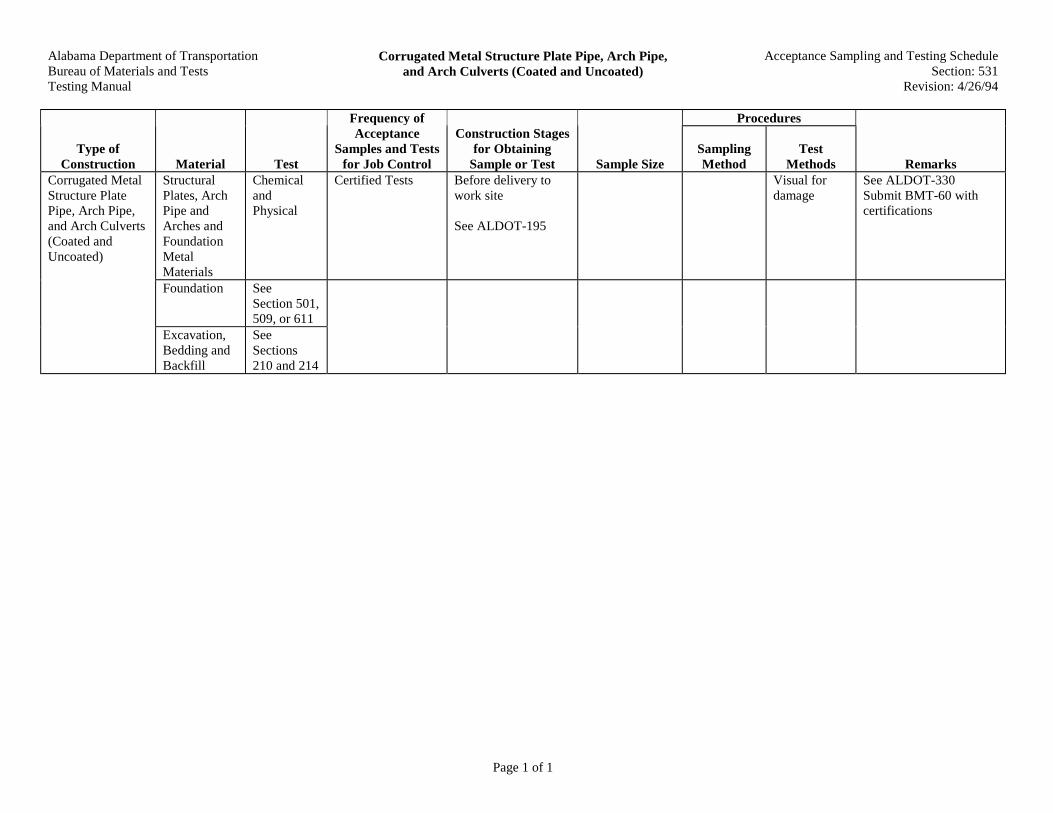
Alabama Department of TransportationBureau of Materials and TestsTesting Manual
Corrugated Metal Structure Plate Pipe, Arch Pipe,and Arch Culverts (Coated and Uncoated)
Acceptance Sampling and Testing ScheduleSection: 531
Revision: 4/26/94
Page 1 of 1
Procedures
Type ofConstruction Material Test
Frequency ofAcceptance
Samples and Testsfor Job Control
Construction Stagesfor Obtaining
Sample or Test Sample SizeSamplingMethod
TestMethods Remarks
StructuralPlates, ArchPipe andArches andFoundationMetalMaterials
ChemicalandPhysical
Certified Tests Before delivery towork site
See ALDOT-195
Visual fordamage
See ALDOT-330Submit BMT-60 withcertifications
Foundation SeeSection 501,509, or 611
Corrugated MetalStructure PlatePipe, Arch Pipe,and Arch Culverts(Coated andUncoated)
Excavation,Bedding andBackfill
SeeSections210 and 214
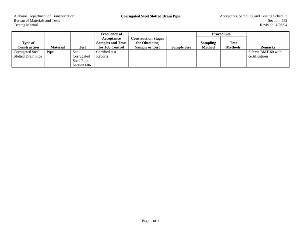
Alabama Department of TransportationBureau of Materials and TestsTesting Manual
Corrugated Steel Slotted Drain Pipe Acceptance Sampling and Testing ScheduleSection: 532
Revision: 4/26/94
Page 1 of 1
Procedures
Type ofConstruction Material Test
Frequency ofAcceptance
Samples and Testsfor Job Control
Construction Stagesfor Obtaining
Sample or Test Sample SizeSamplingMethod
TestMethods Remarks
Corrugated SteelSlotted Drain Pipe
Pipe SeeCorrugatedSteel PipeSection 606
Certified testReports
Submit BMT-60 withcertifications

Alabama Department of TransportationBureau of Materials and TestsTesting Manual
Storm Sewers Acceptance Sampling and Testing ScheduleSection: 533
Revision: 4/26/94
Page 1 of 1
Procedures
Type ofConstruction Material Test
Frequency ofAcceptance
Samples and Testsfor Job Control
Construction Stagesfor Obtaining
Sample or Test Sample SizeSamplingMethod
TestMethods Remarks
Cast IronPipe, DuctileIron Pipe,Vitrified ClayPipe, ABSCompositePipe, PVCPipe JointSealersBedding andBackfill
ChemicalandPhysical
Certified Test Before incorporationin work
See ALDOT-195
Concrete Pipe PretestedALDOT-364
Visual fordamage
All pipe must be from anapproved source
Storm Sewers
CorrugatedMetal Pipe
ChemicalandPhysical
Certified Test Submit BMT-60 toDivision MaterialsEngineer

Alabama Department of TransportationBureau of Materials and TestsTesting Manual
Side Drain Pipe Acceptance Sampling and Testing ScheduleSection: 535
Revision: 4/26/94
Page 1 of 1
Procedures
Type ofConstruction Material Test
Frequency ofAcceptance
Samples and Testsfor Job Control
Construction Stagesfor Obtaining
Sample or Test Sample SizeSamplingMethod
TestMethods Remarks
Side Drain Pipe Vitrified ClayPipe
SeeSections530 and 533
ConcretePipe
Pipe are pre-testedand stenciled DOTand TechnicianNumber
Visual fordamage
ALDOT-364
CorrugatedMetal andArch Pipe,CorrugatedAluminumand ArchPipe JointSealersBackfill
SeeSections530 and 533

Alabama Department of TransportationBureau of Materials and TestsTesting Manual
Relaid Pipe Acceptance Sampling and Testing ScheduleSection: 536
Revision: 4/26/94
Page 1 of 1
Procedures
Type ofConstruction Material Test
Frequency ofAcceptance
Samples and Testsfor Job Control
Construction Stagesfor Obtaining
Sample or Test Sample SizeSamplingMethod
TestMethods Remarks
Relaid Pipe NewMaterials
SeeappropriateSections530, 531,533, and535

Alabama Department of TransportationBureau of Materials and TestsTesting Manual
Field Laboratories Acceptance Sampling and Testing ScheduleSection: 601
Revision: 4/26/94
Page 1 of 1
Procedures
Type ofConstruction Material Test
Frequency ofAcceptance
Samples and Testsfor Job Control
Construction Stagesfor Obtaining
Sample or Test Sample SizeSamplingMethod
TestMethods Remarks
Field Laboratories SeeSpecification

Alabama Department of TransportationBureau of Materials and TestsTesting Manual
Right of Way and Land Survey Markers Acceptance Sampling and Testing ScheduleSection: 602
Revision: 4/26/94
Page 1 of 1
Procedures
Type ofConstruction Material Test
Frequency ofAcceptance
Samples and Testsfor Job Control
Construction Stagesfor Obtaining
Sample or Test Sample SizeSamplingMethod
TestMethods Remarks
Right of Way andLand SurveyMarkers
Marker Postsand Caps
Pretested
ALDOT-364
Visual fordamage
Markers must befrom an approvedsource
ALDOT-364

Alabama Department of TransportationBureau of Materials and TestsTesting Manual
Engineer's Field Office Acceptance Sampling and Testing ScheduleSection: 603
Revision: 4/26/94
Page 1 of 1
Procedures
Type ofConstruction Material Test
Frequency ofAcceptance
Samples and Testsfor Job Control
Construction Stagesfor Obtaining
Sample or Test Sample SizeSamplingMethod
TestMethods Remarks
Engineer's FieldOffice
SeeSpecification

Alabama Department of TransportationBureau of Materials and TestsTesting Manual
Geotextile as Permeable Asphalt Treated BaseTreatment
Acceptance Sampling and Testing ScheduleSection: 604
Revision: 4/26/94
Page 1 of 1
Procedures
Type ofConstruction Material Test
Frequency ofAcceptance
Samples and Testsfor Job Control
Construction Stagesfor Obtaining
Sample or Test Sample SizeSamplingMethod
TestMethods Remarks
Geotextile asPermeableAsphalt TreatedBase Treatment
Filter Fabric See Section605
Submit sample toCentral Lab
Use BMT-18
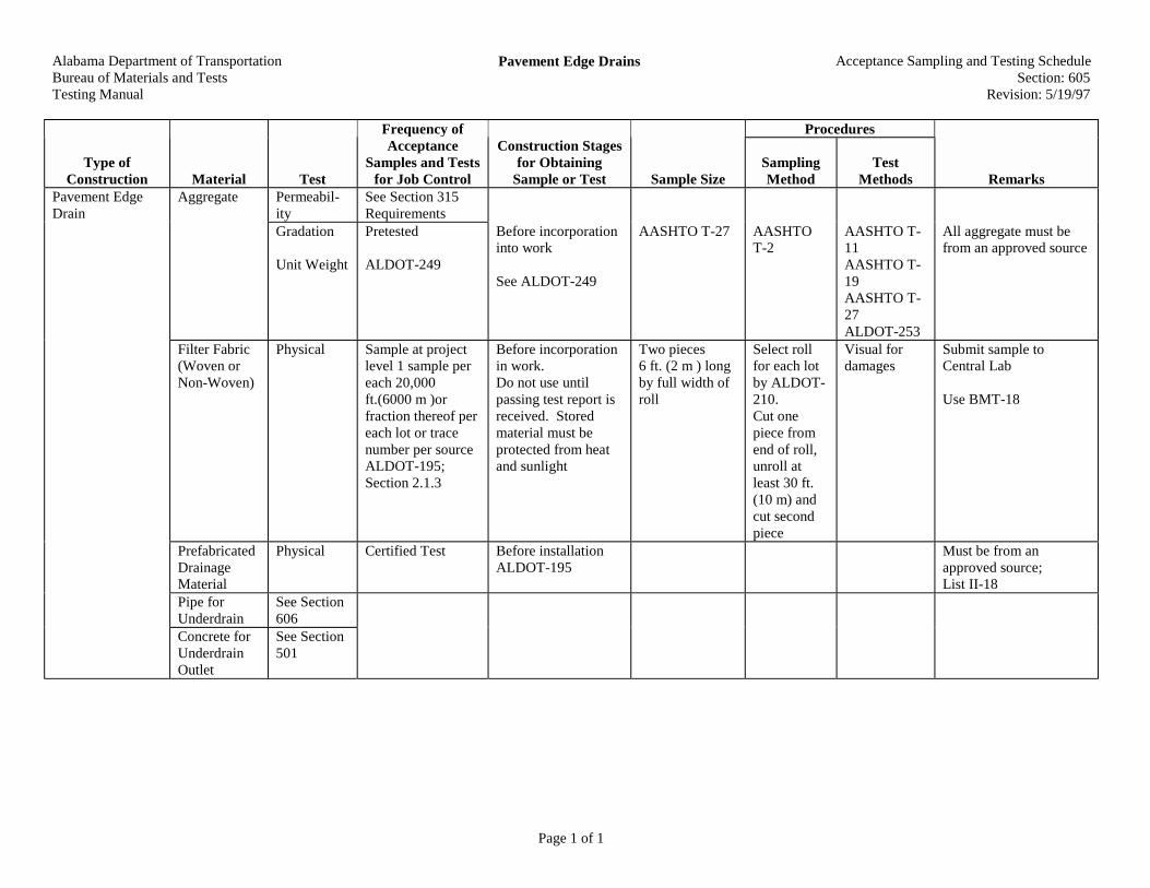
Alabama Department of TransportationBureau of Materials and TestsTesting Manual
Pavement Edge Drains Acceptance Sampling and Testing ScheduleSection: 605
Revision: 5/19/97
Page 1 of 1
Procedures
Type ofConstruction Material Test
Frequency ofAcceptance
Samples and Testsfor Job Control
Construction Stagesfor Obtaining
Sample or Test Sample SizeSamplingMethod
TestMethods Remarks
Pavement EdgeDrain
Aggregate Permeabil-ity
See Section 315Requirements
Gradation
Unit Weight
Pretested
ALDOT-249
Before incorporationinto work
See ALDOT-249
AASHTO T-27 AASHTOT-2
AASHTO T-11AASHTO T-19AASHTO T-27ALDOT-253
All aggregate must befrom an approved source
Filter Fabric(Woven orNon-Woven)
Physical Sample at projectlevel 1 sample pereach 20,000ft.(6000 m )orfraction thereof pereach lot or tracenumber per sourceALDOT-195;Section 2.1.3
Before incorporationin work.Do not use untilpassing test report isreceived. Storedmaterial must beprotected from heatand sunlight
Two pieces6 ft. (2 m ) longby full width ofroll
Select rollfor each lotby ALDOT-210.Cut onepiece fromend of roll,unroll atleast 30 ft.(10 m) andcut secondpiece
Visual fordamages
Submit sample toCentral Lab
Use BMT-18
PrefabricatedDrainageMaterial
Physical Certified Test Before installationALDOT-195
Must be from anapproved source;List II-18
Pipe forUnderdrain
See Section606
Concrete forUnderdrainOutlet
See Section501
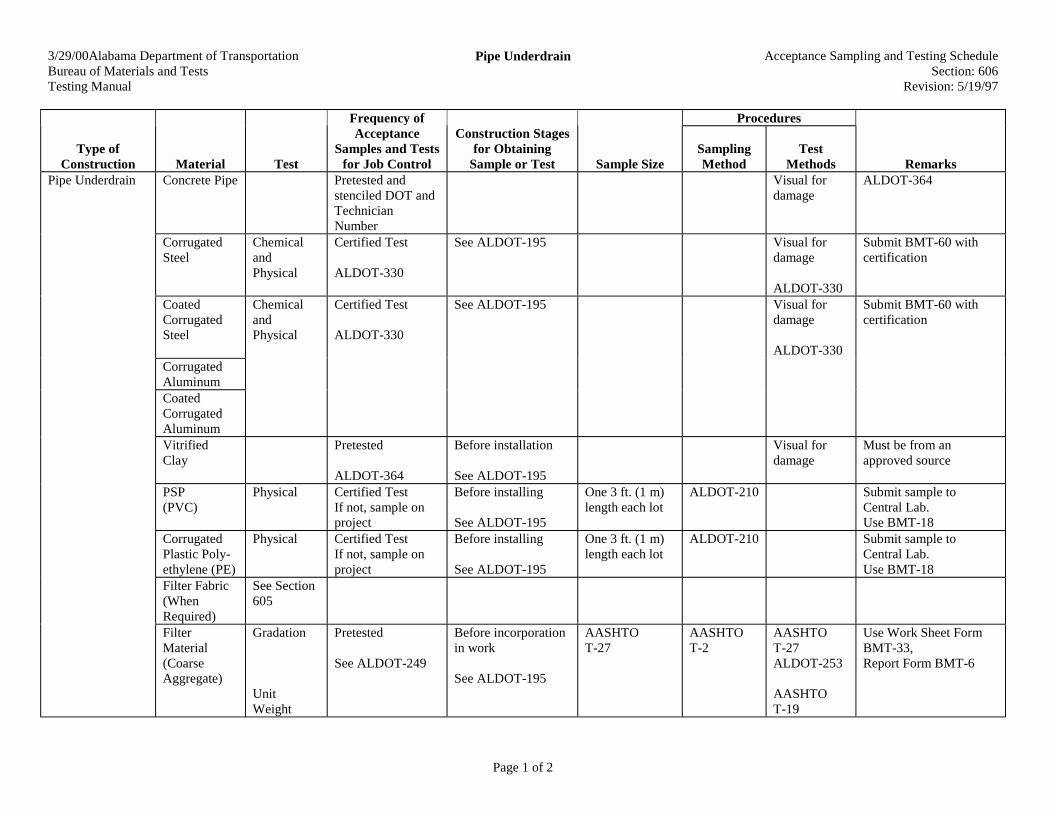
3/29/00Alabama Department of TransportationBureau of Materials and TestsTesting Manual
Pipe Underdrain Acceptance Sampling and Testing ScheduleSection: 606
Revision: 5/19/97
Page 1 of 2
Procedures
Type ofConstruction Material Test
Frequency ofAcceptance
Samples and Testsfor Job Control
Construction Stagesfor Obtaining
Sample or Test Sample SizeSamplingMethod
TestMethods Remarks
Pipe Underdrain Concrete Pipe Pretested andstenciled DOT andTechnicianNumber
Visual fordamage
ALDOT-364
CorrugatedSteel
ChemicalandPhysical
Certified Test
ALDOT-330
See ALDOT-195 Visual fordamage
ALDOT-330
Submit BMT-60 withcertification
CoatedCorrugatedSteel
ChemicalandPhysical
Certified Test
ALDOT-330
See ALDOT-195 Visual fordamage
ALDOT-330
Submit BMT-60 withcertification
CorrugatedAluminumCoatedCorrugatedAluminumVitrifiedClay
Pretested
ALDOT-364
Before installation
See ALDOT-195
Visual fordamage
Must be from anapproved source
PSP(PVC)
Physical Certified TestIf not, sample onproject
Before installing
See ALDOT-195
One 3 ft. (1 m)length each lot
ALDOT-210 Submit sample toCentral Lab.Use BMT-18
CorrugatedPlastic Poly-ethylene (PE)
Physical Certified TestIf not, sample onproject
Before installing
See ALDOT-195
One 3 ft. (1 m)length each lot
ALDOT-210 Submit sample toCentral Lab.Use BMT-18
Filter Fabric(WhenRequired)
See Section605
FilterMaterial(CoarseAggregate)
Gradation
UnitWeight
Pretested
See ALDOT-249
Before incorporationin work
See ALDOT-195
AASHTOT-27
AASHTOT-2
AASHTOT-27ALDOT-253
AASHTOT-19
Use Work Sheet FormBMT-33,Report Form BMT-6
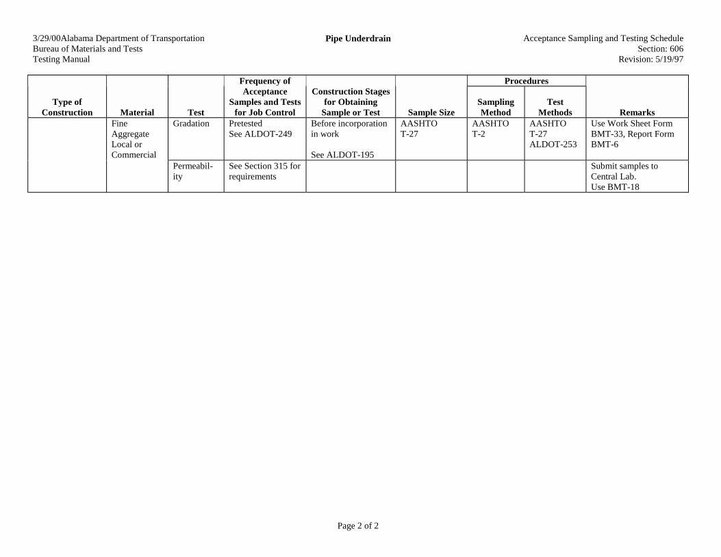
3/29/00Alabama Department of TransportationBureau of Materials and TestsTesting Manual
Pipe Underdrain Acceptance Sampling and Testing ScheduleSection: 606
Revision: 5/19/97
Page 2 of 2
Procedures
Type ofConstruction Material Test
Frequency ofAcceptance
Samples and Testsfor Job Control
Construction Stagesfor Obtaining
Sample or Test Sample SizeSamplingMethod
TestMethods Remarks
FineAggregateLocal orCommercial
Gradation PretestedSee ALDOT-249
Before incorporationin work
See ALDOT-195
AASHTOT-27
AASHTOT-2
AASHTOT-27ALDOT-253
Use Work Sheet FormBMT-33, Report FormBMT-6
Permeabil-ity
See Section 315 forrequirements
Submit samples toCentral Lab.Use BMT-18

Alabama Department of TransportationBureau of Materials and TestsTesting Manual
Paving Geotextiles Acceptance Sampling and Testing ScheduleSection: 607
Revision: 5/19/97
Page 1 of 1
Procedures
Type ofConstruction Material Test
Frequency ofAcceptance
Samples and Testsfor Job Control
Construction Stagesfor Obtaining
Sample or Test Sample SizeSamplingMethod
TestMethods Remarks
PavingGeotextiles
Filter Fabric See Section605
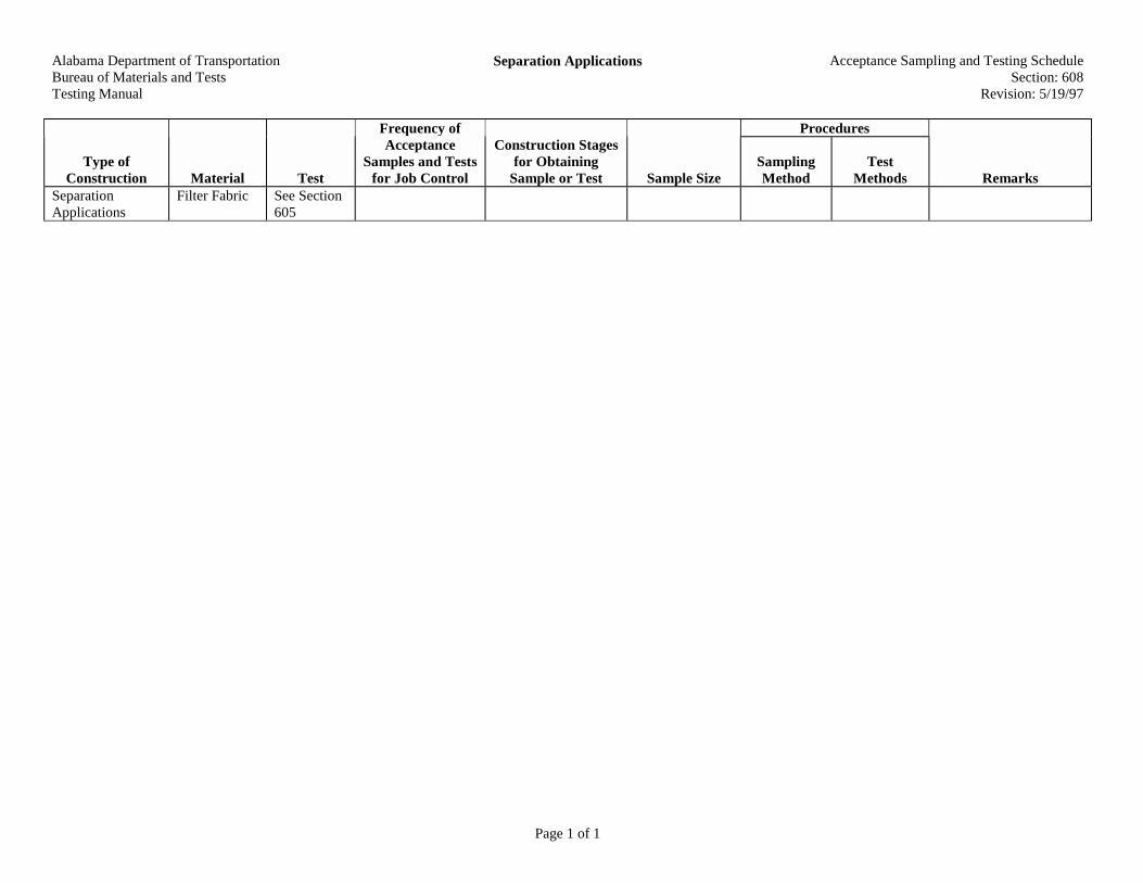
Alabama Department of TransportationBureau of Materials and TestsTesting Manual
Separation Applications Acceptance Sampling and Testing ScheduleSection: 608
Revision: 5/19/97
Page 1 of 1
Procedures
Type ofConstruction Material Test
Frequency ofAcceptance
Samples and Testsfor Job Control
Construction Stagesfor Obtaining
Sample or Test Sample SizeSamplingMethod
TestMethods Remarks
SeparationApplications
Filter Fabric See Section605

Alabama Department of TransportationBureau of Materials and TestsTesting Manual
Aggregate Slope Protection Acceptance Sampling and Testing ScheduleSection: 609
Revision: 5/19/97
Page 1 of 1
Procedures
Type ofConstruction Material Test
Frequency ofAcceptance
Samples and Testsfor Job Control
Construction Stagesfor Obtaining
Sample or Test Sample SizeSamplingMethod
TestMethods Remarks
Aggregate Pretested
ALDOT-249
Aggregate must be froman approved source
Aggregate SlopeProtection
Filter Fabric See Section605
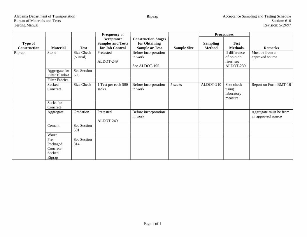
Alabama Department of TransportationBureau of Materials and TestsTesting Manual
Riprap Acceptance Sampling and Testing ScheduleSection: 610
Revision: 5/19/97
Page 1 of 1
Procedures
Type ofConstruction Material Test
Frequency ofAcceptance
Samples and Testsfor Job Control
Construction Stagesfor Obtaining
Sample or Test Sample SizeSamplingMethod
TestMethods Remarks
Riprap Stone Size Check(Visual)
Pretested
ALDOT-249
Before incorporationin work
See ALDOT-195
If differenceof opinionrises, seeALDOT-239
Must be from anapproved source
Aggregate forFilter Blanket
See Section605
Filter FabricsSackedConcrete
Size Check 1 Test per each 500sacks
Before incorporationin work
5 sacks ALDOT-210 Size checkusinglaboratorymeasure
Report on Form BMT-16
Sacks forConcreteAggregate Gradation Pretested
ALDOT-249
Before incorporationin work
Aggregate must be froman approved source
Cement See Section501
WaterPre-PackagedConcreteSackedRiprap
See Section814

Alabama Department of TransportationBureau of Materials and TestsTesting Manual
Mortar for Masonry Acceptance Sampling and Testing ScheduleSection: 611
Revision: 4/26/94
Page 1 of 1
Procedures
Type ofConstruction Material Test
Frequency ofAcceptance
Samples and Testsfor Job Control
Construction Stagesfor Obtaining
Sample or Test Sample SizeSamplingMethod
TestMethods Remarks
Cement SandWater
See Section501
Mortar forMasonry
HydratedLime
From approvedsource
Before incorporationin work
See ALDOT-195
Lime must be from anapproved source. CheckList I-6
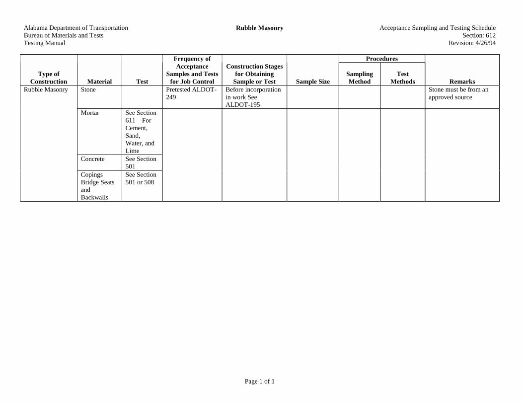
Alabama Department of TransportationBureau of Materials and TestsTesting Manual
Rubble Masonry Acceptance Sampling and Testing ScheduleSection: 612
Revision: 4/26/94
Page 1 of 1
Procedures
Type ofConstruction Material Test
Frequency ofAcceptance
Samples and Testsfor Job Control
Construction Stagesfor Obtaining
Sample or Test Sample SizeSamplingMethod
TestMethods Remarks
Rubble Masonry Stone Pretested ALDOT-249
Before incorporationin work SeeALDOT-195
Stone must be from anapproved source
Mortar See Section611—ForCement,Sand,Water, andLime
Concrete See Section501
CopingsBridge SeatsandBackwalls
See Section501 or 508

Alabama Department of TransportationBureau of Materials and TestsTesting Manual
Brick and Concrete Block Masonry Acceptance Sampling and Testing ScheduleSection: 613
Revision: 4/26/94
Page 1 of 1
Procedures
Type ofConstruction Material Test
Frequency ofAcceptance
Samples and Testsfor Job Control
Construction Stagesfor Obtaining
Sample or Test Sample SizeSamplingMethod
TestMethods Remarks
Brick orConcreteBlock
Physical Minimum one (1)sample per sourceper project
Before incorporationin work
See ALDOT-195
Brick—AASHTO T-32
Block--Ten (10) blockseach lot eachsource
ASTM C-90AASHTOT-32 andALDOT-210
See Section805
Submit to DivisionMaterials Engineer
Use BMT-18
Brick andConcrete BlockMasonry
Mortar See Section611

Alabama Department of TransportationBureau of Materials and TestsTesting Manual
Slope Paving Acceptance Sampling and Testing ScheduleSection: 614
Revision: 4/26/94
Page 1 of 1
Procedures
Type ofConstruction Material Test
Frequency ofAcceptance
Samples and Testsfor Job Control
Construction Stagesfor Obtaining
Sample or Test Sample SizeSamplingMethod
TestMethods Remarks
Slope Paving Concrete See Section501
Must be fromapproved sources
Consult DivisionMaterials Engineer forapproved sources
SteelReinforce-ment
See Section502
Joint Fillersand Sealers
See Section502
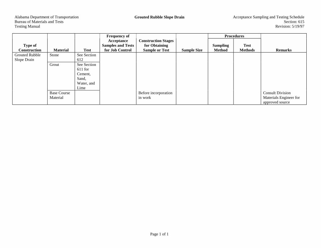
Alabama Department of TransportationBureau of Materials and TestsTesting Manual
Grouted Rubble Slope Drain Acceptance Sampling and Testing ScheduleSection: 615
Revision: 5/19/97
Page 1 of 1
Procedures
Type ofConstruction Material Test
Frequency ofAcceptance
Samples and Testsfor Job Control
Construction Stagesfor Obtaining
Sample or Test Sample SizeSamplingMethod
TestMethods Remarks
Stone See Section612
Grout See Section611 forCement,Sand,Water, andLime
Grouted RubbleSlope Drain
Base CourseMaterial
Before incorporationin work
Consult DivisionMaterials Engineer forapproved source
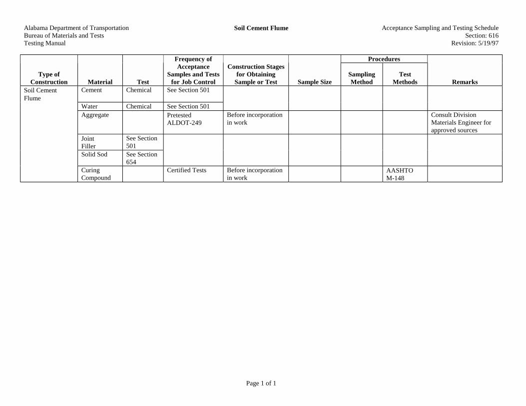
Alabama Department of TransportationBureau of Materials and TestsTesting Manual
Soil Cement Flume Acceptance Sampling and Testing ScheduleSection: 616
Revision: 5/19/97
Page 1 of 1
Procedures
Type ofConstruction Material Test
Frequency ofAcceptance
Samples and Testsfor Job Control
Construction Stagesfor Obtaining
Sample or Test Sample SizeSamplingMethod
TestMethods Remarks
Soil CementFlume
Cement Chemical See Section 501
Water Chemical See Section 501Aggregate Pretested
ALDOT-249Before incorporationin work
Consult DivisionMaterials Engineer forapproved sources
JointFiller
See Section501
Solid Sod See Section654
CuringCompound
Certified Tests Before incorporationin work
AASHTOM-148

Alabama Department of TransportationBureau of Materials and TestsTesting Manual
Bituminous Treated Glass Fiber Flumes Acceptance Sampling and Testing ScheduleSection: 617
Revision: 4/26/94
Page 1 of 1
Procedures
Type ofConstruction Material Test
Frequency ofAcceptance
Samples and Testsfor Job Control
Construction Stagesfor Obtaining
Sample or Test Sample SizeSamplingMethod
TestMethods Remarks
GlassFibers
ChemicalPhysical
From approvedSource
Before incorporationin work
See ALDOT-195
See List II-8 inMaterials, Sources, andDevices with SpecialAcceptanceRequirements Manualfor approved sources
BituminousTreated GlassFiber Flumes
AsphaltEmulsion
See ALDOT-243 Before incorporationin work

Alabama Department of TransportationBureau of Materials and TestsTesting Manual
Concrete Sidewalks and Driveways Acceptance Sampling and Testing ScheduleSection: 618
Revision: 4/26/94
Page 1 of 1
Procedures
Type ofConstruction Material Test
Frequency ofAcceptance
Samples and Testsfor Job Control
Construction Stagesfor Obtaining
Sample or Test Sample SizeSamplingMethod
TestMethods Remarks
ConcreteSidewalks andDriveways
Concrete See Section501 for allrequirements
ReinforcingSteel
See Section502
CuringCompound
Certified Test Before incorporatinginto work
AASHTOM-148

Alabama Department of TransportationBureau of Materials and TestsTesting Manual
Prefabricated Pipe Culvert Headwalls Acceptance Sampling and Testing ScheduleSection: 619
Revision: 4/26/94
Page 1 of 1
Procedures
Type ofConstruction Material Test
Frequency ofAcceptance
Samples and Testsfor Job Control
Construction Stagesfor Obtaining
Sample or Test Sample SizeSamplingMethod
TestMethods Remarks
Prefabricated PipeCulvert Headwalls
Concrete EndSections andConcrete EndSec-ions withMetal SleevesMetal EndSectionGrates
Pretested andstenciled DOT andTechnicianNumber
Visual fordamage
ALDOT-364

Alabama Department of TransportationBureau of Materials and TestsTesting Manual
Minor Structure Concrete Acceptance Sampling and Testing ScheduleSection: 620
Revision: 4/26/94
Page 1 of 1
Procedures
Type ofConstruction Material Test
Frequency ofAcceptance
Samples and Testsfor Job Control
Construction Stagesfor Obtaining
Sample or Test Sample SizeSamplingMethod
TestMethods Remarks
Concrete SeeSection 501for allrequire-ments
Minor StructureConcrete
ReinforcingSteel
SeeSection 502

Alabama Department of TransportationBureau of Materials and TestsTesting Manual
Inlets, Junction Boxes Manholes and MiscellaneousDrainage Structures
Acceptance Sampling and Testing ScheduleSection: 621
Revision: 4/26/94
Page 1 of 1
Procedures
Type ofConstruction Material Test
Frequency ofAcceptance
Samples and Testsfor Job Control
Construction Stagesfor Obtaining
Sample or Test Sample SizeSamplingMethod
TestMethods Remarks
Inlets, JunctionBoxes Manholesand MiscellaneousDrainageStructures
Concrete SeeSection501
Pretested andstenciled DOT andTechnicianNumber (Ifprecast)
Visual fordamage
ALDOT-364(If precast)
Brick orBlockMasonry
See Section613
CastingsCoversGrates PipesPrecast Inletsand Manholes
Physical Certified TestReports
Before delivery towork site
See ALDOT-195
Visual fordamage

Alabama Department of TransportationBureau of Materials and TestsTesting Manual
Resetting Gratings, and Covers for Catch Basins,Inlets and Manholes
Acceptance Sampling and Testing ScheduleSection: 622
Revision: 4/26/94
Page 1 of 1
Procedures
Type ofConstruction Material Test
Frequency ofAcceptance
Samples and Testsfor Job Control
Construction Stagesfor Obtaining
Sample or Test Sample SizeSamplingMethod
TestMethods Remarks
NewMaterials
See Section621
Masonry See Section613
ResettingGratings, andCovers for CatchBasins, Inlets andManholes Concrete See Section
501
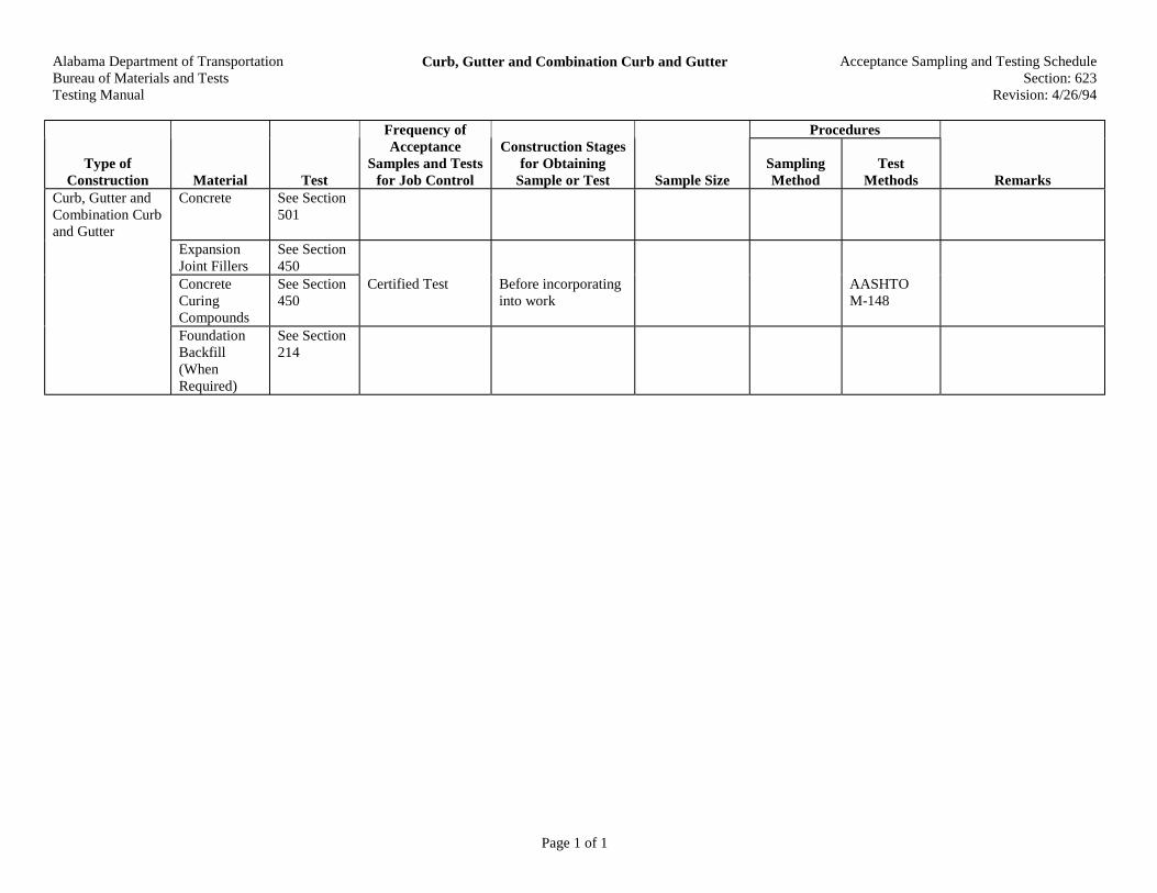
Alabama Department of TransportationBureau of Materials and TestsTesting Manual
Curb, Gutter and Combination Curb and Gutter Acceptance Sampling and Testing ScheduleSection: 623
Revision: 4/26/94
Page 1 of 1
Procedures
Type ofConstruction Material Test
Frequency ofAcceptance
Samples and Testsfor Job Control
Construction Stagesfor Obtaining
Sample or Test Sample SizeSamplingMethod
TestMethods Remarks
Curb, Gutter andCombination Curband Gutter
Concrete See Section501
ExpansionJoint Fillers
See Section450
ConcreteCuringCompounds
See Section450
Certified Test Before incorporatinginto work
AASHTOM-148
FoundationBackfill(WhenRequired)
See Section214

Alabama Department of TransportationBureau of Materials and TestsTesting Manual
Concrete Median Strip Acceptance Sampling and Testing ScheduleSection: 626
Revision: 5/19/97
Page 1 of 1
Procedures
Type ofConstruction Material Test
Frequency ofAcceptance
Samples and Testsfor Job Control
Construction Stagesfor Obtaining
Sample or Test Sample SizeSamplingMethod
TestMethods Remarks
Concrete See Section501
Concrete MedianStrip
CuringCompound
See Section450

Alabama Department of TransportationBureau of Materials and TestsTesting Manual
Concrete Median and Safety Barrier Acceptance Sampling and Testing ScheduleSection: 629
Revision: 5/19/97
Page 1 of 1
Procedures
Type ofConstruction Material Test
Frequency ofAcceptance
Samples and Testsfor Job Control
Construction Stagesfor Obtaining
Sample or Test Sample SizeSamplingMethod
TestMethods Remarks
PrecastBarriers
Physical Pretested andstenciled DOT andtechnician number
Before delivery towork site
See ALDOT-364
Concrete ForCast In PlaceBarriers
See Section501
See ALDOT-170
SteelReinforcing
See Section502
Concrete Medianand Safety Barrier
Backfill See Section214
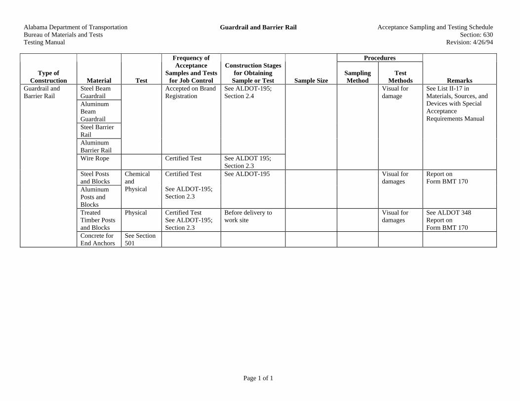
Alabama Department of TransportationBureau of Materials and TestsTesting Manual
Guardrail and Barrier Rail Acceptance Sampling and Testing ScheduleSection: 630
Revision: 4/26/94
Page 1 of 1
Procedures
Type ofConstruction Material Test
Frequency ofAcceptance
Samples and Testsfor Job Control
Construction Stagesfor Obtaining
Sample or Test Sample SizeSamplingMethod
TestMethods Remarks
Steel BeamGuardrailAluminumBeamGuardrailSteel BarrierRailAluminumBarrier Rail
Accepted on BrandRegistration
See ALDOT-195;Section 2.4
Wire Rope Certified Test See ALDOT 195;Section 2.3
Visual fordamage
See List II-17 inMaterials, Sources, andDevices with SpecialAcceptanceRequirements Manual
Steel Postsand BlocksAluminumPosts andBlocks
ChemicalandPhysical
Certified Test
See ALDOT-195;Section 2.3
See ALDOT-195 Visual fordamages
Report onForm BMT 170
TreatedTimber Postsand Blocks
Physical Certified TestSee ALDOT-195;Section 2.3
Before delivery towork site
Visual fordamages
See ALDOT 348Report onForm BMT 170
Guardrail andBarrier Rail
Concrete forEnd Anchors
See Section501

Alabama Department of TransportationBureau of Materials and TestsTesting Manual
Guardrail or Barrier Rail Reset Acceptance Sampling and Testing ScheduleSection: 631
Revision: 4/26/94
Page 1 of 1
Procedures
Type ofConstruction Material Test
Frequency ofAcceptance
Samples and Testsfor Job Control
Construction Stagesfor Obtaining
Sample or Test Sample SizeSamplingMethod
TestMethods Remarks
Guardrail orBarrier Rail Reset
NewMaterials
ChemicalandPhysical
See Section 630 forall requirements

Alabama Department of TransportationBureau of Materials and TestsTesting Manual
Headlight Glare Screen Acceptance Sampling and Testing ScheduleSection: 632
Revision: 4/26/94
Page 1 of 1
Procedures
Type ofConstruction Material Test
Frequency ofAcceptance
Samples and Testsfor Job Control
Construction Stagesfor Obtaining
Sample or Test Sample SizeSamplingMethod
TestMethods Remarks
Glare Screen ChemicalandPhysical
Certified TestsSee ALDOT-195;Section 2.3
Before delivery towork site
Visual fordamages
Headlight GlareScreen
New Post ChemicalandPhysical
See Section 630
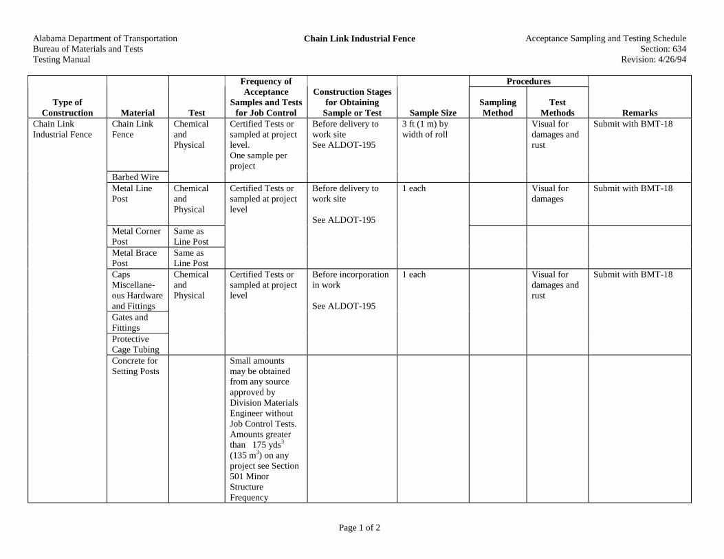
Alabama Department of TransportationBureau of Materials and TestsTesting Manual
Chain Link Industrial Fence Acceptance Sampling and Testing ScheduleSection: 634
Revision: 4/26/94
Page 1 of 2
Procedures
Type ofConstruction Material Test
Frequency ofAcceptance
Samples and Testsfor Job Control
Construction Stagesfor Obtaining
Sample or Test Sample SizeSamplingMethod
TestMethods Remarks
Chain LinkIndustrial Fence
Chain LinkFence
ChemicalandPhysical
Certified Tests orsampled at projectlevel.One sample perproject
Before delivery towork siteSee ALDOT-195
3 ft (1 m) bywidth of roll
Visual fordamages andrust
Submit with BMT-18
Barbed WireMetal LinePost
ChemicalandPhysical
Certified Tests orsampled at projectlevel
Before delivery towork site
See ALDOT-195
1 each Visual fordamages
Submit with BMT-18
Metal CornerPost
Same asLine Post
Metal BracePost
Same asLine Post
CapsMiscellane-ous Hardwareand Fittings
ChemicalandPhysical
Certified Tests orsampled at projectlevel
Before incorporationin work
See ALDOT-195
1 each Visual fordamages andrust
Submit with BMT-18
Gates andFittingsProtectiveCage TubingConcrete forSetting Posts
Small amountsmay be obtainedfrom any sourceapproved byDivision MaterialsEngineer withoutJob Control Tests.Amounts greaterthan 175 yds3
(135 m3) on anyproject see Section501 MinorStructureFrequency
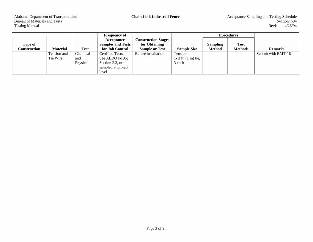
Alabama Department of TransportationBureau of Materials and TestsTesting Manual
Chain Link Industrial Fence Acceptance Sampling and Testing ScheduleSection: 634
Revision: 4/26/94
Page 2 of 2
Procedures
Type ofConstruction Material Test
Frequency ofAcceptance
Samples and Testsfor Job Control
Construction Stagesfor Obtaining
Sample or Test Sample SizeSamplingMethod
TestMethods Remarks
Tension andTie Wire
ChemicalandPhysical
Certified Tests.See ALDOT-195;Section 2.3, orsampled at projectlevel
Before installation Tension-1- 3 ft. (1 m) tie,3 each
Submit with BMT-18

Alabama Department of TransportationBureau of Materials and TestsTesting Manual
Woven Wire Fence Acceptance Sampling and Testing ScheduleSection: 635
Revision: 4/26/94
Page 1 of 1
Procedures
Type ofConstruction Material Test
Frequency ofAcceptance
Samples and Testsfor Job Control
Construction Stagesfor Obtaining
Sample or Test Sample SizeSamplingMethod
TestMethods Remarks
Woven WireFence
Woven Wire ChemicalandPhysical
Certified TestsALDOT-195;Section 2.3, orsampled at projectlevel
Before installation 3 ft. (1 m) Submit with BMT-18
Gates,Miscellane-ous HardwareandFittings,Tension andTie Wire
See Section634
Wood LinePost
Physical Certified TestALDOT-195;Section 2.3
Before installation Visual fordamages
Wood CornerPost
Physical Certified TestALDOT-195;Section 2.3
Before installation Visual fordamages
Wood BracePost
Same asWoodCorner Post

Alabama Department of TransportationBureau of Materials and TestsTesting Manual
Barbed Wire Fence Acceptance Sampling and Testing ScheduleSection: 636
Revision: 4/26/94
Page 1 of 1
Procedures
Type ofConstruction Material Test
Frequency ofAcceptance
Samples and Testsfor Job Control
Construction Stagesfor Obtaining
Sample or Test Sample SizeSamplingMethod
TestMethods Remarks
Barbed WireFence
See Section634 and 635for allapplicableitems

Alabama Department of TransportationBureau of Materials and TestsTesting Manual
Fence Reset Acceptance Sampling and Testing ScheduleSection: 637
Revision: 4/26/94
Page 1 of 1
Procedures
Type ofConstruction Material Test
Frequency ofAcceptance
Samples and Testsfor Job Control
Construction Stagesfor Obtaining
Sample or Test Sample SizeSamplingMethod
TestMethods Remarks
Fence Reset NewMaterials
Approval ofreplacementmaterial shall bemade by theEngineer; Notesting of thismaterial will berequired unlesssuch is ordered bythe Engineer

Alabama Department of TransportationBureau of Materials and TestsTesting Manual
Minor Utility Adjustments Acceptance Sampling and Testing ScheduleSection: 640
Revision: 4/26/94
Page 1 of 1
Procedures
Type ofConstruction Material Test
Frequency ofAcceptance
Samples and Testsfor Job Control
Construction Stagesfor Obtaining
Sample or Test Sample SizeSamplingMethod
TestMethods Remarks
Minor UtilityAdjustments
New orSalvagedMaterials
No set frequencyfor testing. Allmaterials to betested will be asscheduled by theDepartment'sConstruction orElectrical Engineer

Alabama Department of TransportationBureau of Materials and TestsTesting Manual
Water Pipe Acceptance Sampling and Testing ScheduleSection: 641
Revision: 4/26/94
Page 1 of 1
Procedures
Type ofConstruction Material Test
Frequency ofAcceptance
Samples and Testsfor Job Control
Construction Stagesfor Obtaining
Sample or Test Sample SizeSamplingMethod
TestMethods Remarks
Pipe Certified Tests orsampled at projectlevel
Before delivery towork site
See ALDOT-195
3 ft (1 m) Visual fordamages
Submit with BMT-18
Fittings
Water Pipe
Joint SealingMaterials
ChemicalandPhysical

Alabama Department of TransportationBureau of Materials and TestsTesting Manual
Fire Hydrant Acceptance Sampling and Testing ScheduleSection: 642
Revision: 4/26/94
Page 1 of 1
Procedures
Type ofConstruction Material Test
Frequency ofAcceptance
Samples and Testsfor Job Control
Construction Stagesfor Obtaining
Sample or Test Sample SizeSamplingMethod
TestMethods Remarks
Fire Hydrant NewMaterials
ChemicalandPhysical
Certified Tests Before installing seeALDOT-195

Alabama Department of TransportationBureau of Materials and TestsTesting Manual
Water Meters and Valve Boxes Acceptance Sampling and Testing ScheduleSection: 643
Revision: 4/26/94
Page 1 of 1
Procedures
Type ofConstruction Material Test
Frequency ofAcceptance
Samples and Testsfor Job Control
Construction Stagesfor Obtaining
Sample or Test Sample SizeSamplingMethod
TestMethods Remarks
Water Meters andValve Boxes
NewMaterials
ChemicalandPhysical
Certified Tests Before installing seeALDOT-195
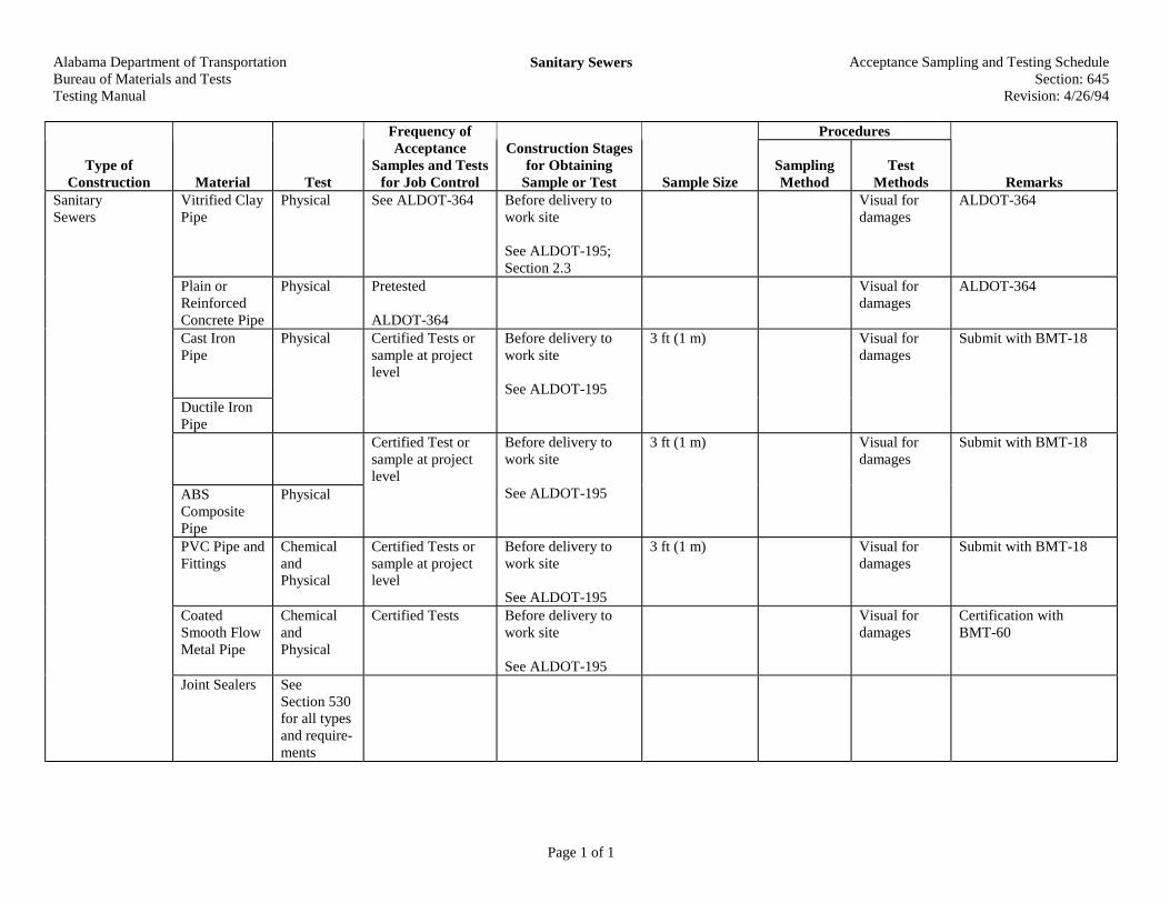
Alabama Department of TransportationBureau of Materials and TestsTesting Manual
Sanitary Sewers Acceptance Sampling and Testing ScheduleSection: 645
Revision: 4/26/94
Page 1 of 1
Procedures
Type ofConstruction Material Test
Frequency ofAcceptance
Samples and Testsfor Job Control
Construction Stagesfor Obtaining
Sample or Test Sample SizeSamplingMethod
TestMethods Remarks
Vitrified ClayPipe
Physical See ALDOT-364 Before delivery towork site
See ALDOT-195;Section 2.3
Visual fordamages
ALDOT-364
Plain orReinforcedConcrete Pipe
Physical Pretested
ALDOT-364
Visual fordamages
ALDOT-364
Cast IronPipe
Physical Certified Tests orsample at projectlevel
Before delivery towork site
See ALDOT-195
3 ft (1 m) Visual fordamages
Submit with BMT-18
Ductile IronPipe
Certified Test orsample at projectlevel
3 ft (1 m) Visual fordamages
Submit with BMT-18
ABSCompositePipe
Physical
Before delivery towork site
See ALDOT-195
PVC Pipe andFittings
ChemicalandPhysical
Certified Tests orsample at projectlevel
Before delivery towork site
See ALDOT-195
3 ft (1 m) Visual fordamages
Submit with BMT-18
CoatedSmooth FlowMetal Pipe
ChemicalandPhysical
Certified Tests Before delivery towork site
See ALDOT-195
Visual fordamages
Certification withBMT-60
SanitarySewers
Joint Sealers SeeSection 530for all typesand require-ments

Alabama Department of TransportationBureau of Materials and TestsTesting Manual
Encasement Pipe for Utilities Acceptance Sampling and Testing ScheduleSection: 649
Revision: 4/26/94
Page 1 of 1
Procedures
Type ofConstruction Material Test
Frequency ofAcceptance
Samples and Testsfor Job Control
Construction Stagesfor Obtaining
Sample or Test Sample SizeSamplingMethod
TestMethods Remarks
Encasement Pipefor Utilities
Pipe ChemicalandPhysical
Certified Tests orsampled at projectlevel
Before delivery towork site
See ALDOT-195
3 ft (1 m) Visual fordamages
Submit with BMT-18

Alabama Department of TransportationBureau of Materials and TestsTesting Manual
Topsoil Acceptance Sampling and Testing ScheduleSection: 650
Revision: 4/26/94
Page 1 of 1
Procedures
Type ofConstruction Material Test
Frequency ofAcceptance
Samples and Testsfor Job Control
Construction Stagesfor Obtaining
Sample or Test Sample SizeSamplingMethod
TestMethods Remarks
Topsoil Topsoil Visual forQuality
Must be fromsource shown onplans or previouslyapproved areas
Visual

Alabama Department of TransportationBureau of Materials and TestsTesting Manual
Ground Preparation and Fertilizer for ErosionControl
Acceptance Sampling and Testing ScheduleSection: 651
Revision: 4/26/94
Page 1 of 1
Procedures
Type ofConstruction Material Test
Frequency ofAcceptance
Samples and Testsfor Job Control
Construction Stagesfor Obtaining
Sample or Test Sample SizeSamplingMethod
TestMethods Remarks
Fertilizer Chemical Certified analysisattached to eachbag or test reportfor bulk shipment
Before incorporationin work
See ALDOT-195
Analysis should beattached to FormBMT-16
GroundPreparation andFertilizer forErosion Control
AgriculturalLimestone orBasic Slag
ChemicalandPhysical
Certified Tests Before incorporationin work
See ALDOT-195

Alabama Department of TransportationBureau of Materials and TestsTesting Manual
Seeding Acceptance Sampling and Testing ScheduleSection: 652
Revision: 4/26/94
Page 1 of 1
Procedures
Type ofConstruction Material Test
Frequency ofAcceptance
Samples and Testsfor Job Control
Construction Stagesfor Obtaining
Sample or Test Sample SizeSamplingMethod
TestMethods Remarks
Seeding Seed Analysis Certified Test Eachbag of seed shallhave attached a tagor label certifyingto contents, testsand analysis
Before incorporationin work
See ALDOT-195
Fertilizer See Section651
MulchingMaterials
See Section656
ApplicationRates
See ConstructionManual forfrequencies andreports

Alabama Department of TransportationBureau of Materials and TestsTesting Manual
Sprigging Acceptance Sampling and Testing ScheduleSection: 653
Revision: 4/26/94
Page 1 of 1
Procedures
Type ofConstruction Material Test
Frequency ofAcceptance
Samples and Testsfor Job Control
Construction Stagesfor Obtaining
Sample or Test Sample SizeSamplingMethod
TestMethods Remarks
Sprigging Sprigs Sprigs must befrom a sourceapproved inadvance by theEngineer
Visual forcondition attime of use
See Section 860
Fertilizer SeeSection 651
MulchingMaterials
SeeSection 656
ErosionControlMaterial
SeeSection 659

Alabama Department of TransportationBureau of Materials and TestsTesting Manual
Solid Sodding Acceptance Sampling and Testing ScheduleSection: 654
Revision: 4/26/94
Page 1 of 1
Procedures
Type ofConstruction Material Test
Frequency ofAcceptance
Samples and Testsfor Job Control
Construction Stagesfor Obtaining
Sample or Test Sample SizeSamplingMethod
TestMethods Remarks
Sod Physical See ConstructionManual
Sod must be from anacceptable source
RandomStrips
Size andconditionchecks
Fertilizer See Section651
Solid Sodding
ErosionControlMaterial
See Section659
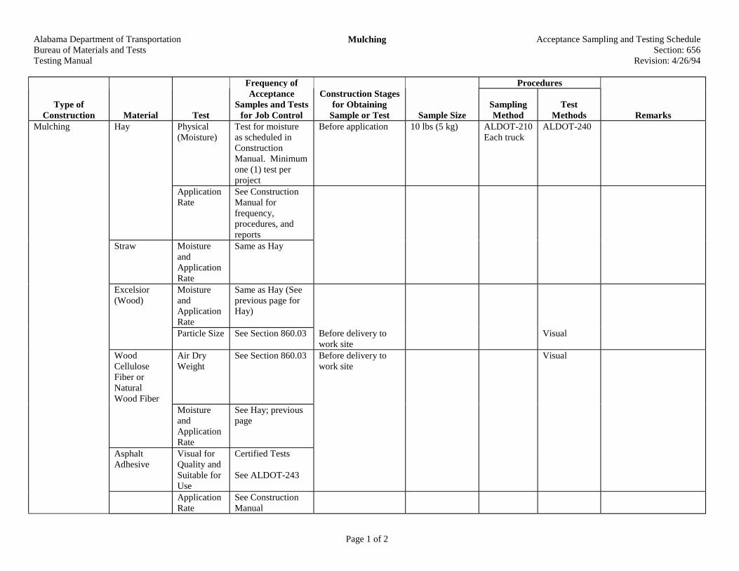
Alabama Department of TransportationBureau of Materials and TestsTesting Manual
Mulching Acceptance Sampling and Testing ScheduleSection: 656
Revision: 4/26/94
Page 1 of 2
Procedures
Type ofConstruction Material Test
Frequency ofAcceptance
Samples and Testsfor Job Control
Construction Stagesfor Obtaining
Sample or Test Sample SizeSamplingMethod
TestMethods Remarks
Hay Physical(Moisture)
Test for moistureas scheduled inConstructionManual. Minimumone (1) test perproject
Before application 10 lbs (5 kg) ALDOT-210Each truck
ALDOT-240
ApplicationRate
See ConstructionManual forfrequency,procedures, andreports
Straw MoistureandApplicationRate
Same as Hay
Excelsior(Wood)
MoistureandApplicationRate
Same as Hay (Seeprevious page forHay)
Particle Size See Section 860.03 Before delivery towork site
Visual
WoodCelluloseFiber orNaturalWood Fiber
Air DryWeight
See Section 860.03 Before delivery towork site
Visual
MoistureandApplicationRate
See Hay; previouspage
AsphaltAdhesive
Visual forQuality andSuitable forUse
Certified Tests
See ALDOT-243
Mulching
ApplicationRate
See ConstructionManual
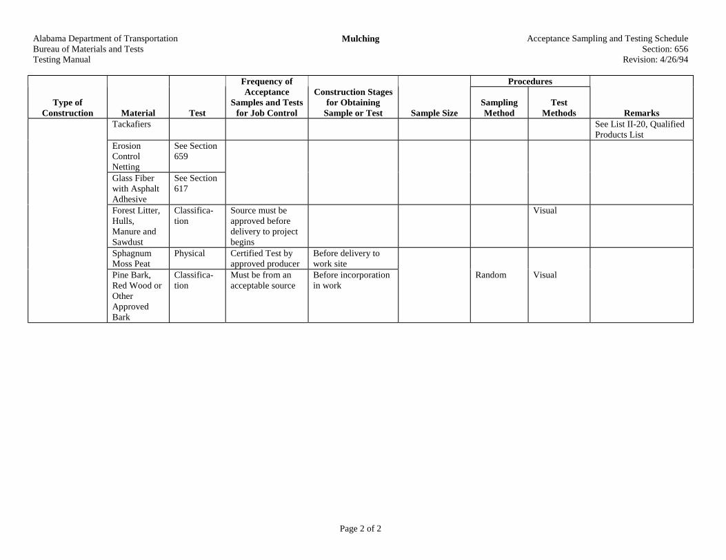
Alabama Department of TransportationBureau of Materials and TestsTesting Manual
Mulching Acceptance Sampling and Testing ScheduleSection: 656
Revision: 4/26/94
Page 2 of 2
Procedures
Type ofConstruction Material Test
Frequency ofAcceptance
Samples and Testsfor Job Control
Construction Stagesfor Obtaining
Sample or Test Sample SizeSamplingMethod
TestMethods Remarks
Tackafiers See List II-20, QualifiedProducts List
ErosionControlNetting
See Section659
Glass Fiberwith AsphaltAdhesive
See Section617
Forest Litter,Hulls,Manure andSawdust
Classifica-tion
Source must beapproved beforedelivery to projectbegins
Visual
SphagnumMoss Peat
Physical Certified Test byapproved producer
Before delivery towork site
Pine Bark,Red Wood orOtherApprovedBark
Classifica-tion
Must be from anacceptable source
Before incorporationin work
Random Visual

Alabama Department of TransportationBureau of Materials and TestsTesting Manual
Grassy Mulch Acceptance Sampling and Testing ScheduleSection: 657
Revision: 4/26/94
Page 1 of 1
Procedures
Type ofConstruction Material Test
Frequency ofAcceptance
Samples and Testsfor Job Control
Construction Stagesfor Obtaining
Sample or Test Sample SizeSamplingMethod
TestMethods Remarks
Grassy Mulch ApplicationRate
Mulch must befrom an approvedsource. Minimumone (1) test per day
During application Random Visualmeasurementof volumeand area
Grassy Mulch
Fertilizer See Section652

Alabama Department of TransportationBureau of Materials and TestsTesting Manual
Hydro-Seeding and Mulching Acceptance Sampling and Testing ScheduleSection: 658
Revision: 4/26/94
Page 1 of 1
Procedures
Type ofConstruction Material Test
Frequency ofAcceptance
Samples and Testsfor Job Control
Construction Stagesfor Obtaining
Sample or Test Sample SizeSamplingMethod
TestMethods Remarks
Hydro-Seedingand Mulching
Fertilizer SeeSection 651
Mulch SeeSection 656
Seed SeeSection 652
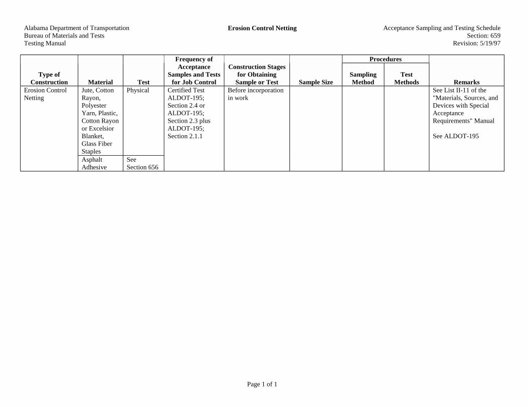
Alabama Department of TransportationBureau of Materials and TestsTesting Manual
Erosion Control Netting Acceptance Sampling and Testing ScheduleSection: 659
Revision: 5/19/97
Page 1 of 1
Procedures
Type ofConstruction Material Test
Frequency ofAcceptance
Samples and Testsfor Job Control
Construction Stagesfor Obtaining
Sample or Test Sample SizeSamplingMethod
TestMethods Remarks
Jute, CottonRayon,PolyesterYarn, Plastic,Cotton Rayonor ExcelsiorBlanket,Glass FiberStaples
PhysicalErosion ControlNetting
AsphaltAdhesive
SeeSection 656
Certified TestALDOT-195;Section 2.4 orALDOT-195;Section 2.3 plusALDOT-195;Section 2.1.1
Before incorporationin work
See List II-11 of the"Materials, Sources, andDevices with SpecialAcceptanceRequirements" Manual
See ALDOT-195
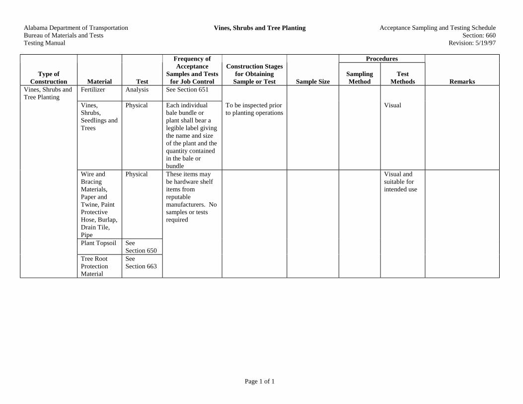
Alabama Department of TransportationBureau of Materials and TestsTesting Manual
Vines, Shrubs and Tree Planting Acceptance Sampling and Testing ScheduleSection: 660
Revision: 5/19/97
Page 1 of 1
Procedures
Type ofConstruction Material Test
Frequency ofAcceptance
Samples and Testsfor Job Control
Construction Stagesfor Obtaining
Sample or Test Sample SizeSamplingMethod
TestMethods Remarks
Vines, Shrubs andTree Planting
Fertilizer Analysis See Section 651
Vines,Shrubs,Seedlings andTrees
Physical Each individualbale bundle orplant shall bear alegible label givingthe name and sizeof the plant and thequantity containedin the bale orbundle
To be inspected priorto planting operations
Visual
Wire andBracingMaterials,Paper andTwine, PaintProtectiveHose, Burlap,Drain Tile,Pipe
Physical These items maybe hardware shelfitems fromreputablemanufacturers. Nosamples or testsrequired
Visual andsuitable forintended use
Plant Topsoil SeeSection 650
Tree RootProtectionMaterial
SeeSection 663

Alabama Department of TransportationBureau of Materials and TestsTesting Manual
Transplanting Trees, Shrubs, and Vines Acceptance Sampling and Testing ScheduleSection: 661
Revision: 4/26/94
Page 1 of 1
Procedures
Type ofConstruction Material Test
Frequency ofAcceptance
Samples and Testsfor Job Control
Construction Stagesfor Obtaining
Sample or Test Sample SizeSamplingMethod
TestMethods Remarks
TransplantingTrees, Shrubs, andVines
See Section660 for allnew materials
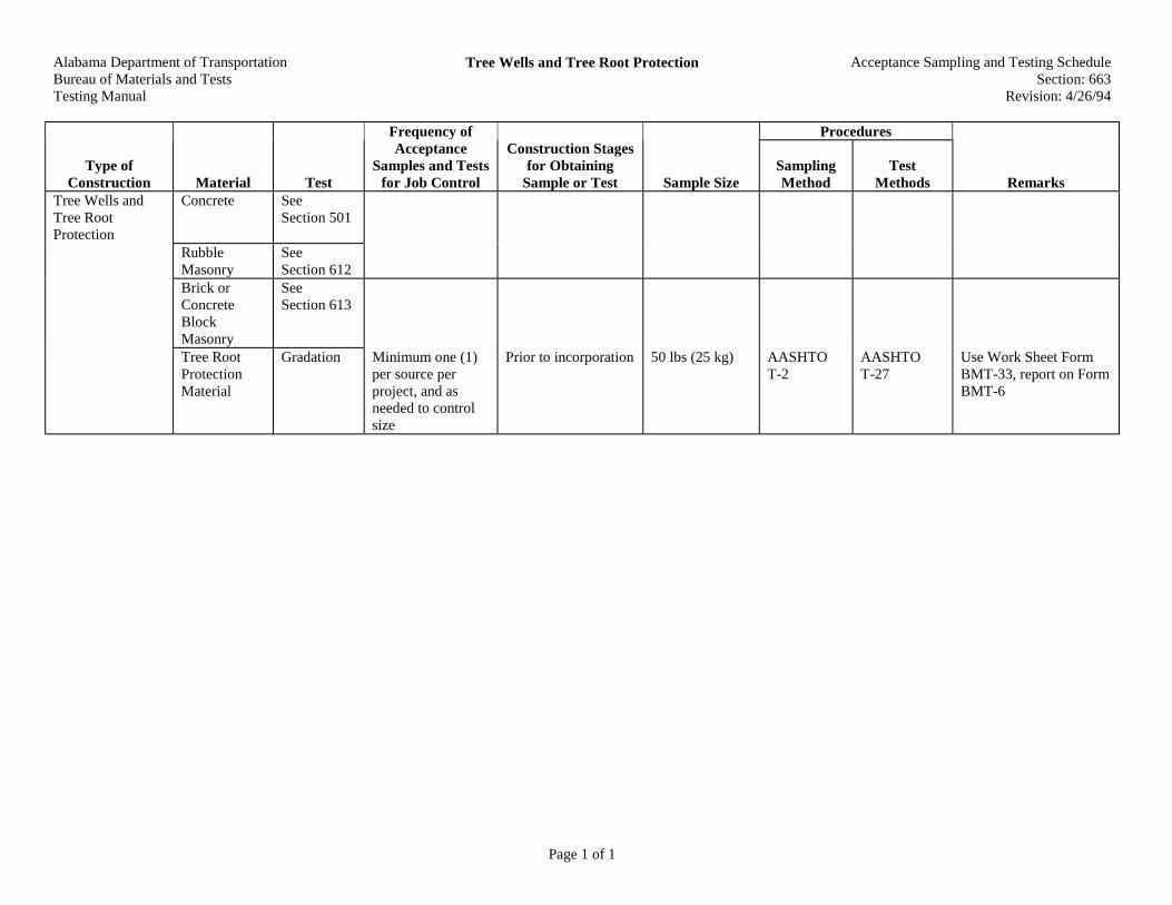
Alabama Department of TransportationBureau of Materials and TestsTesting Manual
Tree Wells and Tree Root Protection Acceptance Sampling and Testing ScheduleSection: 663
Revision: 4/26/94
Page 1 of 1
Procedures
Type ofConstruction Material Test
Frequency ofAcceptance
Samples and Testsfor Job Control
Construction Stagesfor Obtaining
Sample or Test Sample SizeSamplingMethod
TestMethods Remarks
Tree Wells andTree RootProtection
Concrete SeeSection 501
RubbleMasonry
SeeSection 612
Brick orConcreteBlockMasonry
SeeSection 613
Tree RootProtectionMaterial
Gradation Minimum one (1)per source perproject, and asneeded to controlsize
Prior to incorporation 50 lbs (25 kg) AASHTOT-2
AASHTOT-27
Use Work Sheet FormBMT-33, report on FormBMT-6
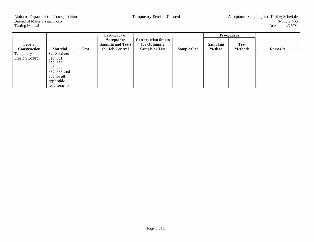
Alabama Department of TransportationBureau of Materials and TestsTesting Manual
Temporary Erosion Control Acceptance Sampling and Testing ScheduleSection: 665
Revision: 4/26/94
Page 1 of 1
Procedures
Type ofConstruction Material Test
Frequency ofAcceptance
Samples and Testsfor Job Control
Construction Stagesfor Obtaining
Sample or Test Sample SizeSamplingMethod
TestMethods Remarks
TemporaryErosion Control
See Sections610, 651,652, 653,654, 656,657, 658, and659 for allapplicablerequirements

Alabama Department of TransportationBureau of Materials and TestsTesting Manual
Pest Control Acceptance Sampling and Testing ScheduleSection: 666
Revision: 4/26/94
Page 1 of 1
Procedures
Type ofConstruction Material Test
Frequency ofAcceptance
Samples and Testsfor Job Control
Construction Stagesfor Obtaining
Sample or Test Sample SizeSamplingMethod
TestMethods Remarks
Pest Control Insecticides May be shelf itemsapproved byAgricultureDepartment. Notest required

Alabama Department of TransportationBureau of Materials and TestsTesting Manual
Pre-Emergent Soil Sterilization Treatment Acceptance Sampling and Testing ScheduleSection: 668
Revision: 4/26/94
Page 1 of 1
PPrroocceedduurreess
TTyyppee ooffCCoonnssttrruuccttiioonn MMaatteerriiaall TTeesstt
FFrreeqquueennccyy ooffAAcccceeppttaannccee
SSaammpplleess aanndd TTeessttssffoorr JJoobb CCoonnttrrooll
CCoonnssttrruuccttiioonn SSttaaggeessffoorr OObbttaaiinniinngg
SSaammppllee oorr TTeesstt SSaammppllee SSiizzeeSSaammpplliinnggMMeetthhoodd
TTeessttMMeetthhooddss RReemmaarrkkss
Pre-Emergent SoilSterilizationTreatment
SoilSterilizationMaterial
Shelf items frommanufacturersprequalified byU.S. Department ofAgriculture orAlabamaAgricultureExperimentStation. (No testrequired)

Alabama Department of TransportationBureau of Materials and TestsTesting Manual
Post-Emergent Herbicide Treatment Acceptance Sampling and Testing ScheduleSection: 669
Revision: 4/26/94
Page 1 of 1
Procedures
Type ofConstruction Material Test
Frequency ofAcceptance
Samples and Testsfor Job Control
Construction Stagesfor Obtaining
Sample or Test Sample SizeSamplingMethod
TestMethods Remarks
Post-EmergentHerbicideTreatment
SyntheticAuxins
Pre-qualifiedmanufacturersapproved by U.S.Department ofAgriculture and theState of AlabamaAgricultureDepartment.Formulations to beapproved by theDepartment'sLandscapeEngineer

Alabama Department of TransportationBureau of Materials and TestsTesting Manual
Traffic Stripe Acceptance Sampling and Testing ScheduleSection: 701
Revision: 5/19/97
Page 1 of 1
Procedures
Type ofConstruction Material Test
Frequency ofAcceptance
Samples and Testsfor Job Control
Construction Stagesfor Obtaining
Sample or Test Sample SizeSamplingMethod
TestMethods Remarks
Traffic Stripe Reflective orNonreflectivePaint
ChemicalandPhysical
ALDOT-195;Section 2.4 List V-4 (Permanent) ListV-3 (Temporary)Verify batchnumbers ofpermanent paints
Prior to use Materials, Sources, andDevices With SpecialAcceptanceRequirements Manual
Thermo-plastic Strips(ColdApplied)
Physical ALDOT-195;Section 2.4 List V-4 (Permanent) ListV-3 (Temporary)
Prior to use Materials, Sources, andDevices With SpecialAcceptanceRequirements Manual
Thermo-plastic (Hot-Pour)
ChemicalPhysical
ALDOT-195;Section 2.4 List V-4 Verify batchnumbers
Prior to use Materials, Sources, andDevices With SpecialAcceptanceRequirements Manual
Drop-onSpheres
ChemicalPhysical
ALDOT-195;Section 2.2.2Verify batchnumbers if notALDOT-195;Section 2.1.3
Prior to use
See ALDOT-195
Three (3) bagsper each100,000 lbs.(45,000 kg) orfraction thereof
ALDOT-210
Use Sample InformationCard Form BMT-18

Alabama Department of TransportationBureau of Materials and TestsTesting Manual
Traffic Control Markings and Legends Acceptance Sampling and Testing ScheduleSection: 703
Revision: 4/26/94
Page 1 of 1
Procedures
Type ofConstruction Material Test
Frequency ofAcceptance
Samples and Testsfor Job Control
Construction Stagesfor Obtaining
Sample or Test Sample SizeSamplingMethod
TestMethods Remarks
Traffic ControlMarkings andLegends
See Section701 for allapplicablerequirements

Alabama Department of TransportationBureau of Materials and TestsTesting Manual
Pavement Markers Acceptance Sampling and Testing ScheduleSection: 705
Revision: 4/26/94
Page 1 of 1
Procedures
Type ofConstruction Material Test
Frequency ofAcceptance
Samples and Testsfor Job Control
Construction Stagesfor Obtaining
Sample or Test Sample SizeSamplingMethod
TestMethods Remarks
Single orDoubleReflectors
Physical ALDOT-195;Section 2.4List V-2
Prior to use Materials, Sources, andDevices With SpecialAcceptanceRequirements Manual
Pavement Markers
BituminousAdhesiveMaterials
None ALDOT-195;Section 2.4List V-2
Prior to use Materials, Sources, andDevices With SpecialAcceptanceRequirements Manual
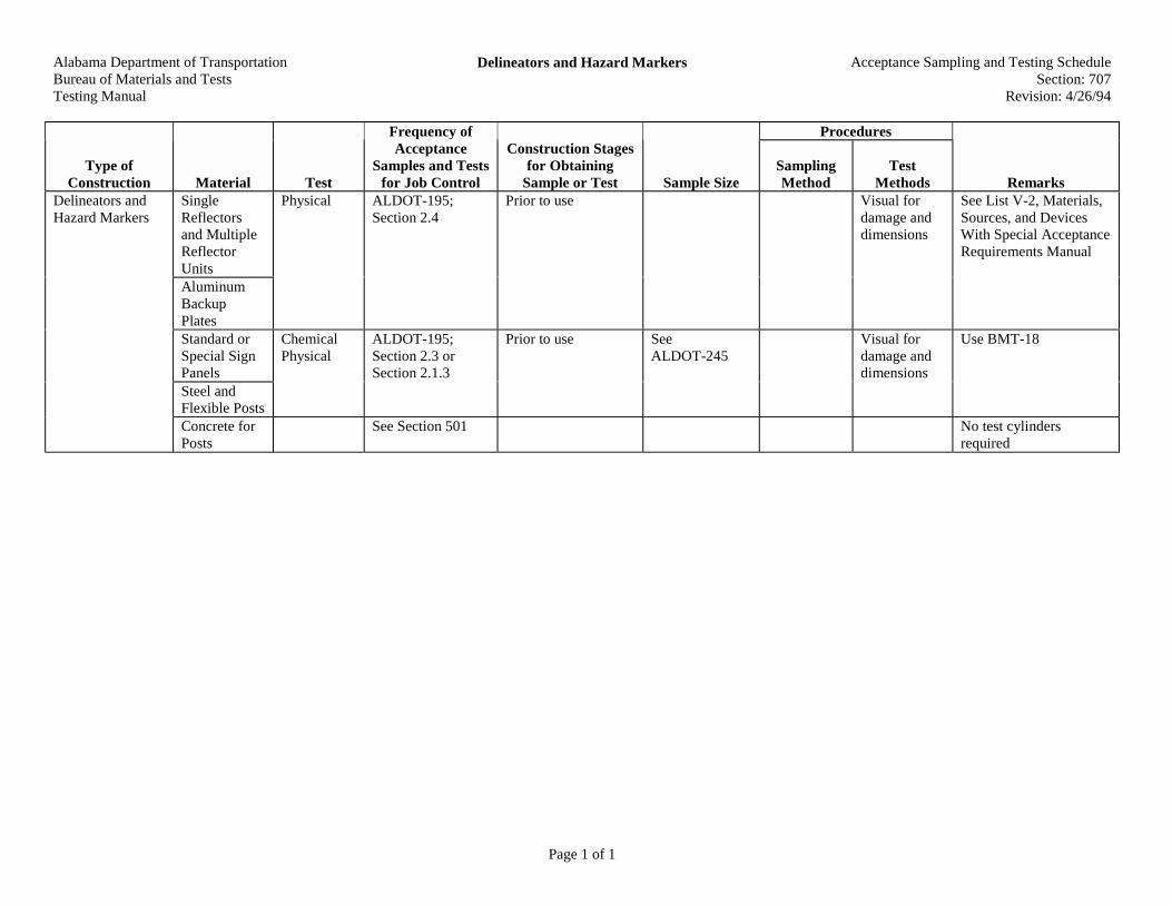
Alabama Department of TransportationBureau of Materials and TestsTesting Manual
Delineators and Hazard Markers Acceptance Sampling and Testing ScheduleSection: 707
Revision: 4/26/94
Page 1 of 1
Procedures
Type ofConstruction Material Test
Frequency ofAcceptance
Samples and Testsfor Job Control
Construction Stagesfor Obtaining
Sample or Test Sample SizeSamplingMethod
TestMethods Remarks
Delineators andHazard Markers
SingleReflectorsand MultipleReflectorUnits
Physical ALDOT-195;Section 2.4
Prior to use Visual fordamage anddimensions
See List V-2, Materials,Sources, and DevicesWith Special AcceptanceRequirements Manual
AluminumBackupPlatesStandard orSpecial SignPanels
ChemicalPhysical
ALDOT-195;Section 2.3 orSection 2.1.3
Prior to use SeeALDOT-245
Visual fordamage anddimensions
Use BMT-18
Steel andFlexible PostsConcrete forPosts
See Section 501 No test cylindersrequired

Alabama Department of TransportationBureau of Materials and TestsTesting Manual
Object Safety Markings Acceptance Sampling and Testing ScheduleSection: 708
Revision: 5/19/97
Page 1 of 1
Procedures
Type ofConstruction Material Test
Frequency ofAcceptance
Samples and Testsfor Job Control
Construction Stagesfor Obtaining
Sample or Test Sample SizeSamplingMethod
TestMethods Remarks
ReflectivePaint
ChemicalPhysical
ALDOT-195;Section 2.4
Prior to use See List V-5,Materials, Sources, andDevices With SpecialAcceptanceRequirements Manual
Object SafetyMarkings
NonreflectivePaint
ChemicalPhysical
ALDOT-195;Section 2.3 orSection 2.1.3
Prior to use 1 qt. (1 L)

Alabama Department of TransportationBureau of Materials and TestsTesting Manual
Mileposts Acceptance Sampling and Testing ScheduleSection: 709
Revision: 5/19/97
Page 1 of 1
Procedures
Type ofConstruction Material Test
Frequency ofAcceptance
Samples and Testsfor Job Control
Construction Stagesfor Obtaining
Sample or Test Sample SizeSamplingMethod
TestMethods Remarks
Mileposts See Section710 for allrequirements
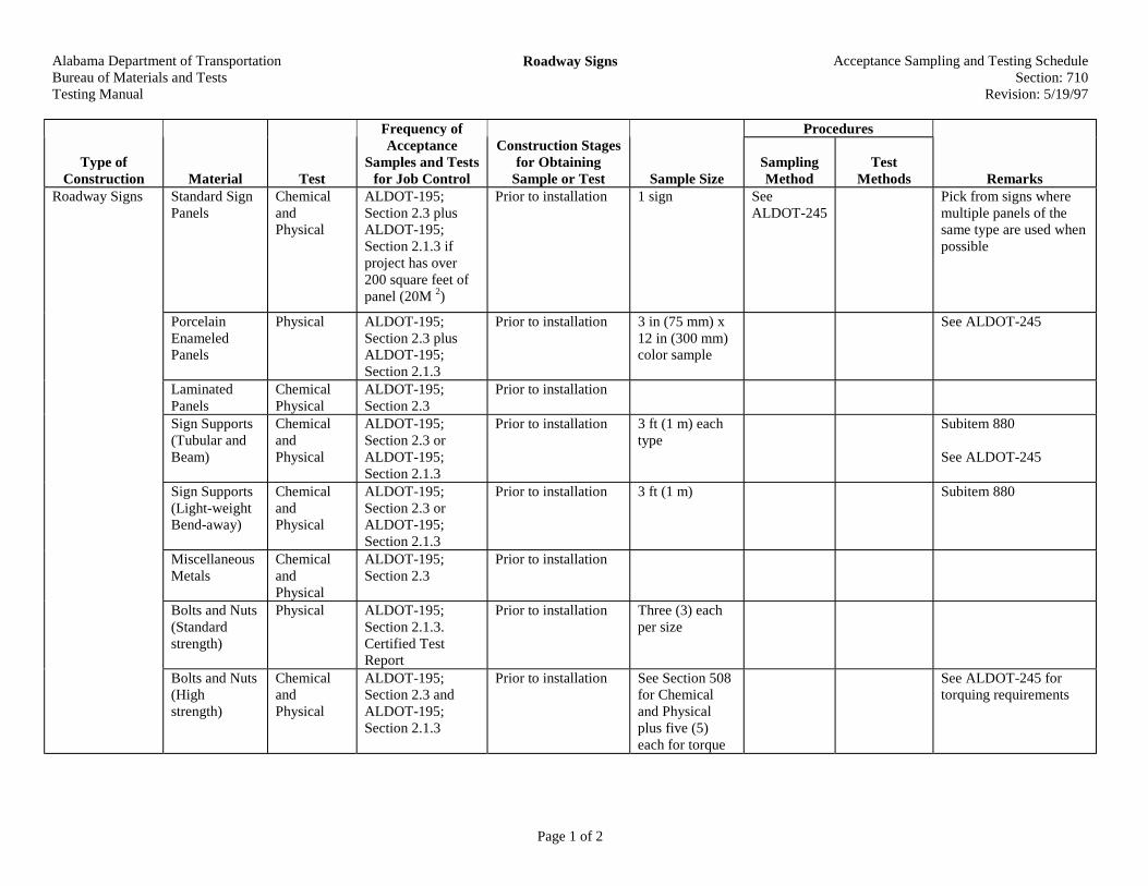
Alabama Department of TransportationBureau of Materials and TestsTesting Manual
Roadway Signs Acceptance Sampling and Testing ScheduleSection: 710
Revision: 5/19/97
Page 1 of 2
Procedures
Type ofConstruction Material Test
Frequency ofAcceptance
Samples and Testsfor Job Control
Construction Stagesfor Obtaining
Sample or Test Sample SizeSamplingMethod
TestMethods Remarks
Roadway Signs Standard SignPanels
ChemicalandPhysical
ALDOT-195;Section 2.3 plusALDOT-195;Section 2.1.3 ifproject has over200 square feet ofpanel (20M 2)
Prior to installation 1 sign SeeALDOT-245
Pick from signs wheremultiple panels of thesame type are used whenpossible
PorcelainEnameledPanels
Physical ALDOT-195;Section 2.3 plusALDOT-195;Section 2.1.3
Prior to installation 3 in (75 mm) x12 in (300 mm)color sample
See ALDOT-245
LaminatedPanels
ChemicalPhysical
ALDOT-195;Section 2.3
Prior to installation
Sign Supports(Tubular andBeam)
ChemicalandPhysical
ALDOT-195;Section 2.3 orALDOT-195;Section 2.1.3
Prior to installation 3 ft (1 m) eachtype
Subitem 880
See ALDOT-245
Sign Supports(Light-weightBend-away)
ChemicalandPhysical
ALDOT-195;Section 2.3 orALDOT-195;Section 2.1.3
Prior to installation 3 ft (1 m) Subitem 880
MiscellaneousMetals
ChemicalandPhysical
ALDOT-195;Section 2.3
Prior to installation
Bolts and Nuts(Standardstrength)
Physical ALDOT-195;Section 2.1.3.Certified TestReport
Prior to installation Three (3) eachper size
Bolts and Nuts(Highstrength)
ChemicalandPhysical
ALDOT-195;Section 2.3 andALDOT-195;Section 2.1.3
Prior to installation See Section 508for Chemicaland Physicalplus five (5)each for torque
See ALDOT-245 fortorquing requirements

Alabama Department of TransportationBureau of Materials and TestsTesting Manual
Roadway Signs Acceptance Sampling and Testing ScheduleSection: 710
Revision: 5/19/97
Page 2 of 2
Procedures
Type ofConstruction Material Test
Frequency ofAcceptance
Samples and Testsfor Job Control
Construction Stagesfor Obtaining
Sample or Test Sample SizeSamplingMethod
TestMethods Remarks
Anchor Boltsand Nuts
ChemicalandPhysical
ALDOT-195;Section 2.3 andALDOT-195;Section 2.1.3 whenproject requiresover twenty (20)
Prior to installation One (1) bolt,nut, and washerper heat, lot,size
DemountableCopy
ChemicalandPhysical
ALDOT-195;Section 2.3
Prior to installation
PrismaticReflectors
Physical ALDOT-195;Section 2.4
Prior to installation See List V-2, Materials,Sources, and DevicesWith Special AcceptanceRequirements Manual
Concrete andSteel Footings
SeeSections501, 502,and 508 forallapplicablerequirements
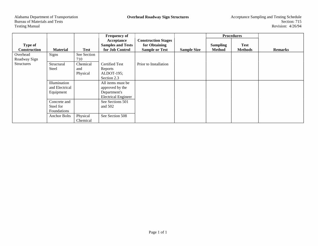
Alabama Department of TransportationBureau of Materials and TestsTesting Manual
Overhead Roadway Sign Structures Acceptance Sampling and Testing ScheduleSection: 715
Revision: 4/26/94
Page 1 of 1
Procedures
Type ofConstruction Material Test
Frequency ofAcceptance
Samples and Testsfor Job Control
Construction Stagesfor Obtaining
Sample or Test Sample SizeSamplingMethod
TestMethods Remarks
Signs See Section710
StructuralSteel
ChemicalandPhysical
Certified TestReportsALDOT-195;Section 2.3
Prior to Installation
Illuminationand ElectricalEquipment
All items must beapproved by theDepartment'sElectrical Engineer
Concrete andSteel forFoundations
See Sections 501and 502
OverheadRoadway SignStructures
Anchor Bolts PhysicalChemical
See Section 508

Alabama Department of TransportationBureau of Materials and TestsTesting Manual
Overhead Sign Structures Renovation or Relocation Acceptance Sampling and Testing ScheduleSection: 717
Revision: 5/19/97
Page 1 of 1
Procedures
Type ofConstruction Material Test
Frequency ofAcceptance
Samples and Testsfor Job Control
Construction Stagesfor Obtaining
Sample or Test Sample SizeSamplingMethod
TestMethods Remarks
Overhead SignStructuresRenovation orRelocation
Any NewMaterials
ChemicalPhysical
ALDOT-195;Section 2.3 orSection 2.1.3
Prior to installation See Remarks Sample materials atfrequencies set for newstructures

Alabama Department of TransportationBureau of Materials and TestsTesting Manual
Portable Concrete Safety Barriers and ImpactAttenuators
Acceptance Sampling and Testing ScheduleSection: 726
Revision: 5/19/97
Page 1 of 1
Procedures
Type ofConstruction Material Test
Frequency ofAcceptance
Samples and Testsfor Job Control
Construction Stagesfor Obtaining
Sample or Test Sample SizeSamplingMethod
TestMethods Remarks
PortableConcreteSafetyBarriers
Pretested andstenciled DOT
Before delivery tosite
See ALDOT-195 forpreviously usedportable concretesafety barriers
Visual fordamage
Note: ALDOTfurnished barriers willnot require test reports
See ALDOT-364
Contractor suppliedbarriers to be retained bythe Department must besupplied new.
Portable ConcreteSafety Barriersand ImpactAttenuators
ImpactAttenuators
Certified Test Before delivery tosite
See ALDOT-195
Visual fordamage
Note: ALDOTfurnished attenuatorswill not require testreports

Alabama Department of TransportationBureau of Materials and TestsTesting Manual
Furnishing and Installing Traffic Control Equipment Acceptance Sampling and Testing ScheduleSection: 730
Revision: 5/19/97
Page 1 of 1
Procedures
Type ofConstruction Material Test
Frequency ofAcceptance
Samples and Testsfor Job Control
Construction Stagesfor Obtaining
Sample or Test Sample SizeSamplingMethod
TestMethods Remarks
Furnishing andInstalling TrafficControlEquipment
Equipment All traffic controlequipment may beproduction runstock or CertifiedTest reports
Contact Traffic Engineerfor requirements andreports
Anchor Bolts PhysicalChemical
See Section 508

Alabama Department of TransportationBureau of Materials and TestsTesting Manual
Traffic Control Devices for Work Zones Acceptance Sampling and Testing ScheduleSection: 740
Revision: 5/19/97
Page 1 of 1
Procedures
Type ofConstruction Material Test
Frequency ofAcceptance
Samples and Testsfor Job Control
Construction Stagesfor Obtaining
Sample or Test Sample SizeSamplingMethod
TestMethods Remarks
Traffic ControlDevices for WorkZones
SignsBarricadesand OtherTrafficControlDevices
Nonerequired
Approved byEngineer beforeinstallation
Visual fordamage

Alabama Department of TransportationBureau of Materials and TestsTesting Manual
Portable Sequential Arrow and Chevron Unit Acceptance Sampling and Testing ScheduleSection: 741
Revision: 4/26/94
Page 1 of 1
Procedures
Type ofConstruction Material Test
Frequency ofAcceptance
Samples and Testsfor Job Control
Construction Stagesfor Obtaining
Sample or Test Sample SizeSamplingMethod
TestMethods Remarks
PortableSequential Arrowand Chevron Unit
New Units Approved byEngineer
Visual forsize anddamages

Alabama Department of TransportationBureau of Materials and TestsTesting Manual
Furnishing and Installing Electrical Ducts Acceptance Sampling and Testing ScheduleSection: 756
Revision: 4/26/94
Page 1 of 1
Procedures
Type ofConstruction Material Test
Frequency ofAcceptance
Samples and Testsfor Job Control
Construction Stagesfor Obtaining
Sample or Test Sample SizeSamplingMethod
TestMethods Remarks
Furnishing andInstallingElectrical Ducts
ElectricalEquipment
Contact theDepartment'sElectrical Engineerfor required testreports
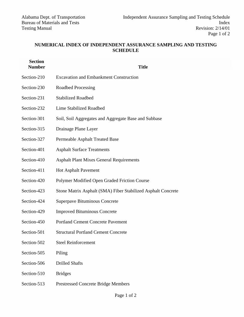
Page 1 of 2
Alabama Dept. of Transportation Independent Assurance Sampling and Testing ScheduleBureau of Materials and Tests IndexTesting Manual Revision: 2/14/01
Page 1 of 2
NUMERICAL INDEX OF INDEPENDENT ASSURANCE SAMPLING AND TESTINGSCHEDULE
SectionNumber Title
Section-210 Excavation and Embankment Construction
Section-230 Roadbed Processing
Section-231 Stabilized Roadbed
Section-232 Lime Stabilized Roadbed
Section-301 Soil, Soil Aggregates and Aggregate Base and Subbase
Section-315 Drainage Plane Layer
Section-327 Permeable Asphalt Treated Base
Section-401 Asphalt Surface Treatments
Section-410 Asphalt Plant Mixes General Requirements
Section-411 Hot Asphalt Pavement
Section-420 Polymer Modified Open Graded Friction Course
Section-423 Stone Matrix Asphalt (SMA) Fiber Stabilized Asphalt Concrete
Section-424 Superpave Bituminous Concrete
Section-429 Improved Bituminous Concrete
Section-450 Portland Cement Concrete Pavement
Section-501 Structural Portland Cement Concrete
Section-502 Steel Reinforcement
Section-505 Piling
Section-506 Drilled Shafts
Section-510 Bridges
Section-513 Prestressed Concrete Bridge Members
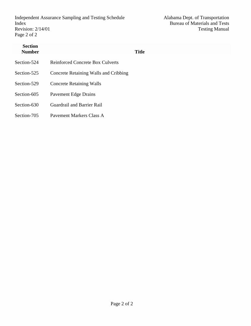
Page 2 of 2
Alabama Dept. of TransportationIndependent Assurance Sampling and Testing ScheduleBureau of Materials and TestsIndex
Testing ManualRevision: 2/14/01Page 2 of 2
SectionNumber Title
Section-524 Reinforced Concrete Box Culverts
Section-525 Concrete Retaining Walls and Cribbing
Section-529 Concrete Retaining Walls
Section-605 Pavement Edge Drains
Section-630 Guardrail and Barrier Rail
Section-705 Pavement Markers Class A

Alabama Department of TransportationBureau of Materials and TestsTesting Manual
Excavation and Embankment Construction Independent Assurance Sampling and Testing ScheduleSection: 210
Revision: 2/1/01
Page 1 of 1
Procedures
Type ofConstruction Material Test
Guide Frequencyfor Independent
AssuranceSamples and Tests
Construction Stagesfor Obtaining
Sample or Test Sample SizeSamplingMethod
TestMethods Remarks
12 kg
AASHTO T-2
ALDOT-105andALDOT-210
AASHTOT-99
ALDOT-222
UnclassifiedExcavationand BorrowExcavation
MoistureDensityStandardand In-PlaceDensity
One (1) per each10 AcceptanceTests randomlyspread throughoutproject. Nonerequired on19,000 m3 or less
In-place density testat same point in theprocess as theAcceptance Test
AASHTO T-191 whenauthorized
IAS&T-D Item
Send new P.D. sample toCentral Laboratory foreach In-Place DensityTest
Make comparisons inaccordance withALDOT-341
ExcavationEmbankmentConstruction
ImprovedRoadbedfrom BorrowAreas
SoilAnalysis
One (1) per layerper 3 km perroadway. Nonerequired on 1.5 kmor less
Sample at same pointin the process as theAcceptance Test
12 kg
AASHTO T-2
ALDOT-105
AASHTOT-88AASHTOT-89 asmodified byALDOT-232AASHTOT-90AASHTOM-145
IAS&T-D Item
Send sample to CentralLaboratory
Make comparisons inaccordance withALDOT-341

Alabama Department of TransportationBureau of Materials and TestsTesting Manual
Roadbed Processing Independent Assurance Sampling and Testing ScheduleSection: 230
Revision: 4/29/94
Page 1 of 1
Procedures
Type ofConstruction Material Test
Guide Frequencyfor Independent
AssuranceSamples and Tests
Construction Stagesfor Obtaining
Sample or Test Sample SizeSamplingMethod
TestMethods Remarks
25 lbs (12 kg)
AASHTO T-2
ALDOT-105 AASHTOT-99.SeeSpecificationSection 306for T-99method
IAS&T-D Items
Send new P.D. sample toCentral Laboratory foreach in-place density test
ModifiedRoadbed
MoistureDensityStandardand In-placeDensity
One (1) per 2 miles(3 km) perroadway. Nonerequired on 1 mile(1.5 km) or less.None required onareas to bestabilized
In-place density testat same point in theprocess as JobControl
AASHTOT-191 whenauthorized
ALDOT-222or AASHTOT-191 (whenauthorized)
Make comparison inaccordance withALDOT-341
RoadbedProcessing
ImprovedRoadbed
MoistureDensityStandardand In-placeDensity
One (1) per 3 miles(5 km) per roadwayper layer (Upperlayer for base andpave contractsonly). Nonerequired on 1 miles(1.5 km) or less
(Same Stage, Size,Procedures andRemarks as ModifiedRoadbed)
IAS&T-D Item

Alabama Department of TransportationBureau of Materials and TestsTesting Manual
Stabilized Roadbed Independent Assurance Sampling and Testing ScheduleSection: 231
Revision: 5/19/97
Page 1 of 1
Procedures
Type ofConstruction Material Test
Guide Frequencyfor Independent
AssuranceSamples and Tests
Construction Stagesfor Obtaining
Sample or Test Sample SizeSamplingMethod
TestMethods Remarks
StabilizedRoadbed
BlendedMixture ofRoadbedMaterial andStabilizingMaterial
MoistureDensityStandardand In-placeDensity
(Same as ModifiedRoadbed)
IAS&T-D Item (same asmodified roadbed)

Alabama Department of TransportationBureau of Materials and TestsTesting Manual
Lime Stabilized Roadbed Independent Assurance Sampling and Testing ScheduleSection: 232
Revision: 4/29/94
Page 1 of 1
Procedures
Type ofConstruction Material Test
Guide Frequencyfor Independent
AssuranceSamples and Tests
Construction Stagesfor Obtaining
Sample or Test Sample SizeSamplingMethod
TestMethods Remarks
Lime StabilizedRoadbed
BlendedMixture ofRoadbedMaterial andLime
In-placeDensity
Same as ModifiedRoadbed, but useJob Control'sALDOT-223Standard, insteadof submitting anew MoistureDensity Standard
IAS&T-D Item
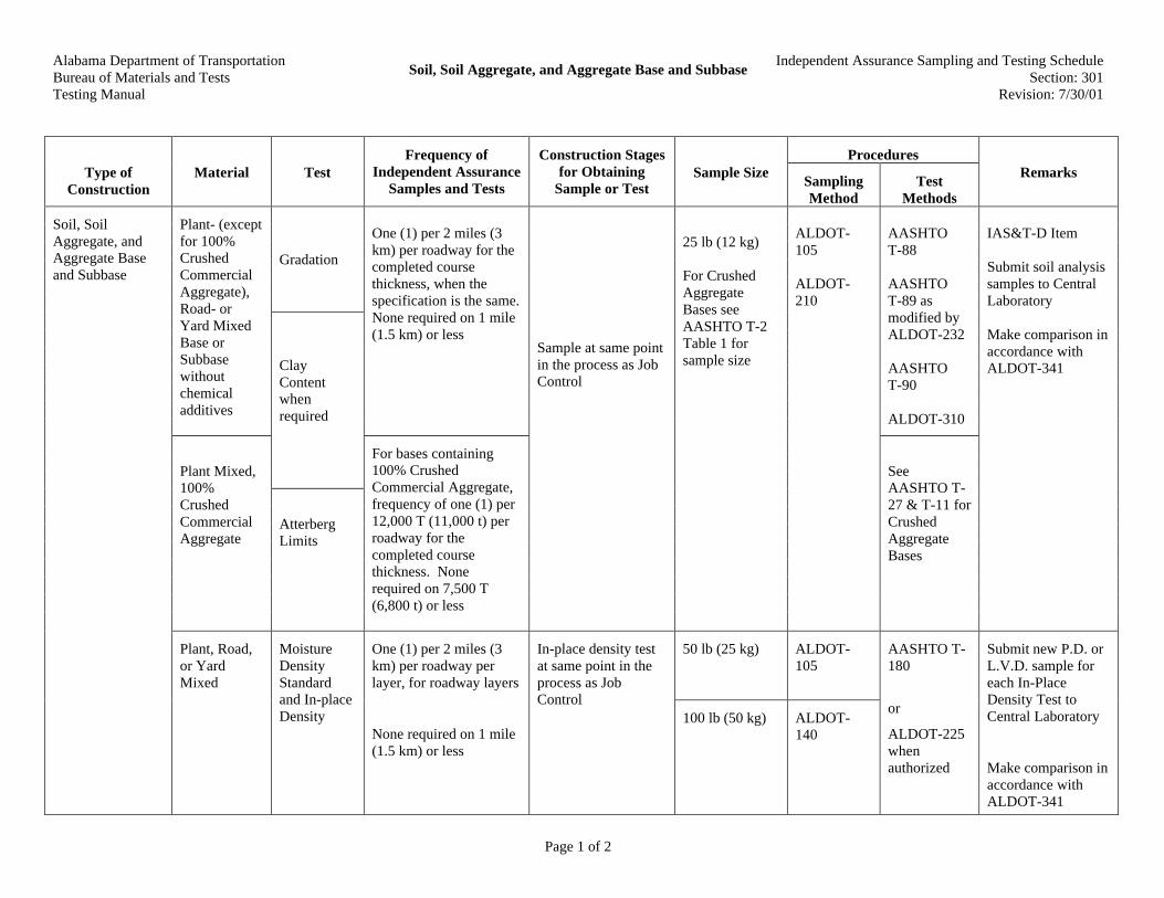
Alabama Department of TransportationBureau of Materials and TestsTesting Manual
Soil, Soil Aggregate, and Aggregate Base and SubbaseIndependent Assurance Sampling and Testing Schedule
Section: 301Revision: 7/30/01
Page 1 of 2
ProceduresType of
ConstructionMaterial Test
Frequency ofIndependent Assurance
Samples and Tests
Construction Stagesfor Obtaining
Sample or TestSample Size
SamplingMethod
TestMethods
Remarks
Gradation
Plant- (exceptfor 100%CrushedCommercialAggregate),Road- orYard MixedBase orSubbasewithoutchemicaladditives
One (1) per 2 miles (3km) per roadway for thecompleted coursethickness, when thespecification is the same.None required on 1 mile(1.5 km) or less
AASHTOT-88
AASHTOT-89 asmodified byALDOT-232
AASHTOT-90
ALDOT-310
ClayContentwhenrequired
Plant Mixed,100%CrushedCommercialAggregate
AtterbergLimits
For bases containing100% CrushedCommercial Aggregate,frequency of one (1) per12,000 T (11,000 t) perroadway for thecompleted coursethickness. Nonerequired on 7,500 T(6,800 t) or less
Sample at same pointin the process as JobControl
25 lb (12 kg)
For CrushedAggregateBases seeAASHTO T-2Table 1 forsample size
ALDOT-105
ALDOT-210
SeeAASHTO T-27 & T-11 forCrushedAggregateBases
IAS&T-D Item
Submit soil analysissamples to CentralLaboratory
Make comparison inaccordance withALDOT-341
50 lb (25 kg) ALDOT-105
Soil, SoilAggregate, andAggregate Baseand Subbase
Plant, Road,or YardMixed
MoistureDensityStandardand In-placeDensity
One (1) per 2 miles (3km) per roadway perlayer, for roadway layers
None required on 1 mile(1.5 km) or less
In-place density testat same point in theprocess as JobControl
100 lb (50 kg) ALDOT-140
AASHTO T-180
or
ALDOT-225whenauthorized
Submit new P.D. orL.V.D. sample foreach In-PlaceDensity Test toCentral Laboratory
Make comparison inaccordance withALDOT-341
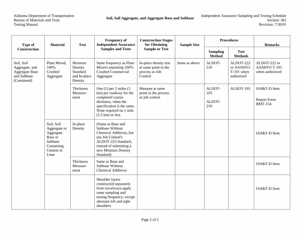
Alabama Department of TransportationBureau of Materials and TestsTesting Manual
Soil, Soil Aggregate, and Aggregate Base and SubbaseIndependent Assurance Sampling and Testing Schedule
Section: 301Revision: 7/30/01
Page 2 of 2
ProceduresRemarksType of
ConstructionMaterial Test
Frequency ofIndependent Assurance
Samples and Tests
Construction Stagesfor Obtaining
Sample or TestSample Size
SamplingMethod
TestMethods
MoistureDensityStandardand In-placeDensity
Same frequency as PlantMixed containing 100%Crushed CommercialAggregate
In-place density testat same point in theprocess as JobControl
Same as above ALDOT-210
ALDOT-222or AASHTOT-191 whenauthorized
ALDOT-222 orAASHTO T-191when authorized
Plant Mixed,100%CrushedAggregate
ThicknessMeasure-ment
One (1) per 2 miles (3km) per roadway for thecompleted coursethickness, when thespecification is the same.None required on 1 mile(1.5 km) or less
Measure at samepoint in the processas job control
ALDOT-105
ALDOT-210
ALDOT-105 IAS&T-D Item
Report FormBMT-154
In-placeDensity
(Same as Base andSubbase WithoutChemical Additives, butuse Job Control'sALDOT-223 Standard,instead of submitting anew Moisture DensityStandard)
IAS&T-D Item
Soil, SoilAggregate orAggregateBase orSubbaseContainingCement orLime
ThicknessMeasure-ment
Same as Base andSubbase WithoutChemical Additives
IAS&T-D Item
Soil, SoilAggregate, andAggregate Baseand Subbase(Continued)
Shoulder layersconstructed separatelyfrom travelways-applysame sampling andtesting frequency, exceptalternate left and rightshoulders
IAS&T-D Item

Alabama Department of TransportationBureau of Materials and TestsTesting Manual
Drainage Plane Layer Independent Assurance Sampling and Testing ScheduleSection: 315
Revision: 4/29/94
Page 1 of 1
Procedures
Type ofConstruction Material Test
Guide Frequencyfor Independent
AssuranceSamples and Tests
Construction Stagesfor Obtaining
Sample or Test Sample SizeSamplingMethod
TestMethods Remarks
Drainage PlaneLayer
CommercialAggregate
Gradation One (1) sample per2 miles (3 km) perroadway, alternateleft and rightshoulder. Nonerequired on 1 miles(1.5 km) or less
Sample on project 50 lbs. (25 kg)
AASHTO T-2
AASHTOT-2
AASHTOT-27
IAS&T-D Item
Submit samples toCentral Laboratory
Make comparison inaccordance withALDOT-341
ThicknessMeasure-ment
One (1) per 2 miles(3 km) perroadway, alternateleft and rightshoulder. Nonerequired on 1 mile(1.5 km) or less
Measure as samepoint in the processas Job Control
ALDOT-105 IAS&T-D Item
Report on FormALDOT-154

Alabama Department of TransportationBureau of Materials and TestsTesting Manual
Permeable Asphalt Treated Base Independent Assurance Sampling and Testing ScheduleSection: 327E
Revision: 4/26/94
Page 1 of 1
Procedures
Type ofConstruction Material Test
Guide Frequencyfor Independent
AssuranceSamples and Tests
Construction Stagesfor Obtaining
Sample or Test Sample SizeSamplingMethod
TestMethods Remarks
PermeableAsphalt TreatedBase
No density orair voidsrequired.See Section410 for allotherrequirements
IAS&T-D
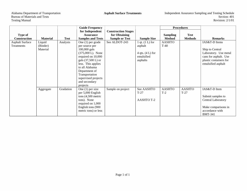
Alabama Department of TransportationBureau of Materials and TestsTesting Manual
Asphalt Surface Treatments Independent Assurance Sampling and Testing ScheduleSection: 401
Revision: 2/1/01
Page 1 of 1
Procedures
Type ofConstruction Material Test
Guide Frequencyfor Independent
AssuranceSamples and Tests
Construction Stagesfor Obtaining
Sample or Test Sample SizeSamplingMethod
TestMethods Remarks
Liquid(Binder)Material
Analysis One (1) per gradeper source per100,000 gals(375,000 L). Nonerequired on 10,000gals (37,500 L) orless. This appliesto all AlabamaDepartment ofTransportationsupervised projectsand secondaryprojects
See ALDOT-243 1 qt. (1 L) forasphalt
4 qts. (4 L) foremulsifiedasphalts
AASHTOT-40
IAS&T-D Items
Ship to CentralLaboratory. Use metalcans for asphalt. Useplastic containers foremulsified asphalt
Asphalt SurfaceTreatments
Aggregate Gradation One (1) per sizeper 5,000 Englishtons (4,500 metrictons). Nonerequired on 1,000English tons (900metric tons) or less
Sample on project See AASHTOT-27
AASHTO T-2
AASHTOT-2
AASHTOT-27
IAS&T-D Item
Submit samples toCentral Laboratory
Make comparisons inaccordance withBMT-341
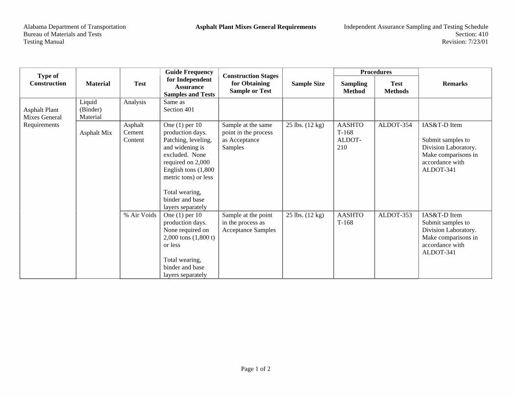
Alabama Department of Transportation Bureau of Materials and Tests Testing Manual
Asphalt Plant Mixes General Requirements
Independent Assurance Sampling and Testing Schedule Section: 410
Revision: 7/23/01
Page 1 of 2
Procedures Type of
Construction Material Test
Guide Frequency for Independent
Assurance Samples and Tests
Construction Stages for Obtaining
Sample or Test Sample Size Sampling
Method Test
Methods Remarks
Liquid (Binder) Material
Analysis Same as Section 401
Asphalt Cement Content
One (1) per 10 production days. Patching, leveling, and widening is excluded. None required on 2,000 English tons (1,800 metric tons) or less Total wearing, binder and base layers separately
Sample at the same point in the process as Acceptance Samples
25 lbs. (12 kg) AASHTO T-168 ALDOT-210
ALDOT-354 IAS&T-D Item Submit samples to Division Laboratory. Make comparisons in accordance with ALDOT-341
Asphalt Plant Mixes General Requirements
Asphalt Mix
% Air Voids One (1) per 10 production days. None required on 2,000 tons (1,800 t) or less Total wearing, binder and base layers separately
Sample at the point in the process as Acceptance Samples
25 lbs. (12 kg) AASHTO T-168
ALDOT-353 IAS&T-D Item Submit samples to Division Laboratory. Make comparisons in accordance with ALDOT-341
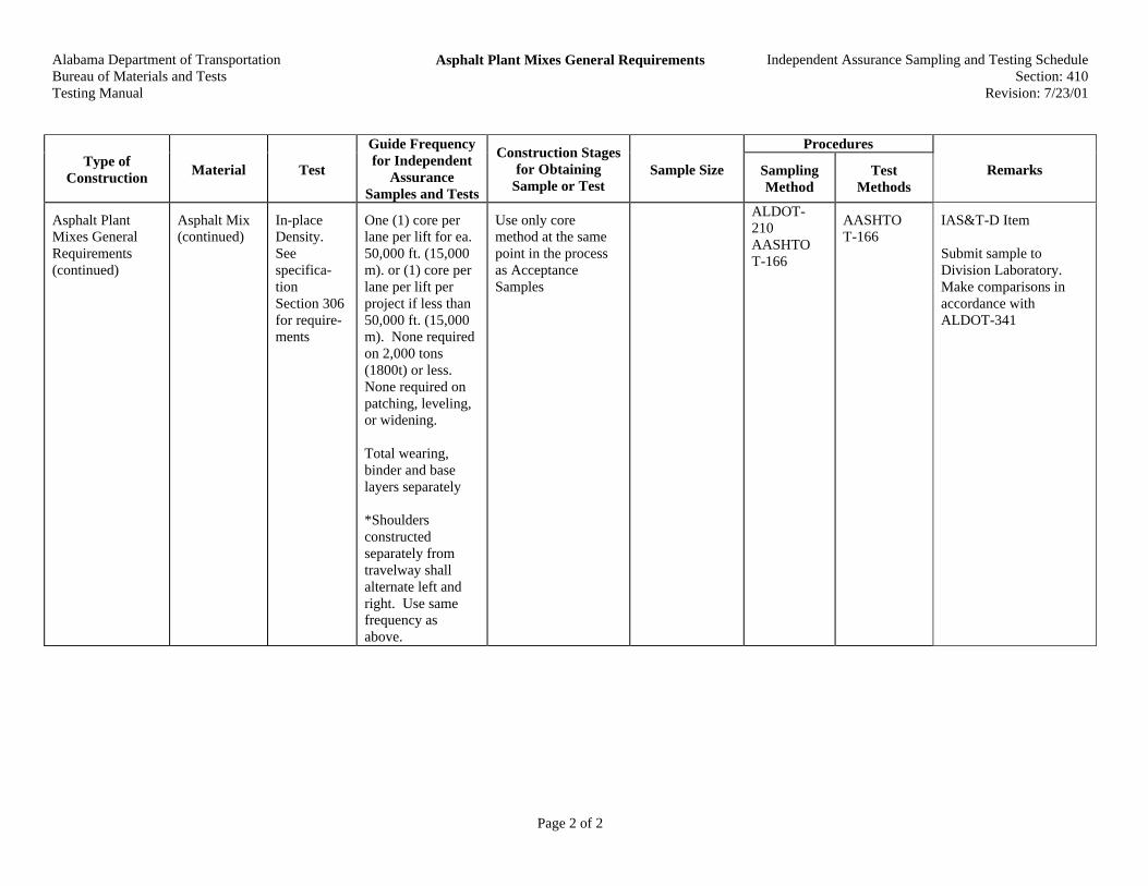
Alabama Department of Transportation Bureau of Materials and Tests Testing Manual
Asphalt Plant Mixes General Requirements
Independent Assurance Sampling and Testing Schedule Section: 410
Revision: 7/23/01
Page 2 of 2
Procedures
Type of Construction
Material Test
Guide Frequency for Independent
Assurance Samples and Tests
Construction Stages for Obtaining
Sample or Test Sample Size Sampling
Method Test
Methods Remarks
Asphalt Plant Mixes General Requirements (continued)
Asphalt Mix (continued)
In-place Density. See specifica-tion Section 306 for require-ments
One (1) core per lane per lift for ea. 50,000 ft. (15,000 m). or (1) core per lane per lift per project if less than 50,000 ft. (15,000 m). None required on 2,000 tons (1800t) or less. None required on patching, leveling, or widening. Total wearing, binder and base layers separately *Shoulders constructed separately from travelway shall alternate left and right. Use same frequency as above.
Use only core method at the same point in the process as Acceptance Samples
ALDOT-210 AASHTO T-166
AASHTO T-166
IAS&T-D Item Submit sample to Division Laboratory. Make comparisons in accordance with ALDOT-341

Alabama Department of TransportationBureau of Materials and TestsTesting Manual
Hot Asphalt Pavement Independent Assurance Sampling and Testing ScheduleSection: 411
Revision: 5/19/97
Page 1 of 1
Procedures
Type ofConstruction Material Test
Guide Frequencyfor Independent
AssuranceSamples and Tests
Construction Stagesfor Obtaining
Sample or Test Sample SizeSamplingMethod
TestMethods Remarks
Hot AsphaltPavement
See Section410 for allrequirements
IAS&T-D Item

Alabama Department of TransportationBureau of Materials and TestsTesting Manual
Polymer Modified Open Graded Friction Course Independent Assurance Sampling and Testing ScheduleSection: 420
Revision: 4/29/94
Page 1 of 1
Procedures
Type ofConstruction Material Test
Guide Frequencyfor Independent
AssuranceSamples and Tests
Construction Stagesfor Obtaining
Sample or Test Sample SizeSamplingMethod
TestMethods Remarks
Polymer ModifiedOpen GradedFriction Course
No density orair void testsrequired.See Section410 for allotherrequirements
IAS&T-D Item

Alabama Department of TransportationBureau of Materials and TestsTesting Manual
Stone Matrix Asphalt (SMA) Fiber Stabilized AsphaltConcrete
Independent Assurance Sampling and Testing ScheduleSection: 423
Revision: 3/1/01
Page 1 of 1
Procedures
Type ofConstruction Material Test
Guide Frequencyfor Independent
AssuranceSamples and Tests
Construction Stagesfor Obtaining
Sample or Test Sample SizeSamplingMethod
TestMethods Remarks
Stone MatrixAsphalt (SMA)Fiber StabilizedAsphalt Concrete
See Section410 for allrequirements
IAS&T-D Item

Alabama Department of TransportationBureau of Materials and TestsTesting Manual
Superpave Bituminous Concrete Independent Assurance Sampling and Testing ScheduleSection: 424
Revision: 3/1/01
Page 1 of 1
Procedures
Type ofConstruction Material Test
Guide Frequencyfor Independent
AssuranceSamples and Tests
Construction Stagesfor Obtaining
Sample or Test Sample SizeSamplingMethod
TestMethods Remarks
SuperpaveBituminousConcrete
See Section410 for allrequirements
IAS&T-D Item

Alabama Department of TransportationBureau of Materials and TestsTesting Manual
Improved Bituminous Concrete Independent Assurance Sampling and Testing ScheduleSection: 429
Revision: 3/1/01
Page 1 of 1
Procedures
Type ofConstruction Material Test
Guide Frequencyfor Independent
AssuranceSamples and Tests
Construction Stagesfor Obtaining
Sample or Test Sample SizeSamplingMethod
TestMethods Remarks
ImprovedBituminousConcrete
See Section410 for allrequirements
IAS&T-D Item
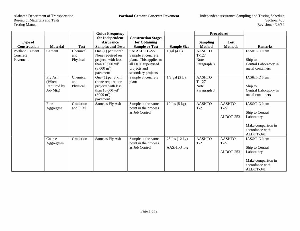
Alabama Department of TransportationBureau of Materials and TestsTesting Manual
Portland Cement Concrete Pavement Independent Assurance Sampling and Testing ScheduleSection: 450
Revision: 4/29/94
Page 1 of 2
Procedures
Type ofConstruction Material Test
Guide Frequencyfor Independent
AssuranceSamples and Tests
Construction Stagesfor Obtaining
Sample or Test Sample SizeSamplingMethod
TestMethods Remarks
Cement ChemicalandPhysical
One (1) per month.None required onprojects with lessthan 10,000 yd2
(8,000 m2)pavement
See ALDOT-227.Sample at concreteplant. This applies toall DOT supervisedprojects andsecondary projects
1 gal (4 L) AASHTOT-127NoteParagraph 3
IAS&T-D Item
Ship toCentral Laboratory inmetal containers
Fly Ash(WhenRequired byJob Mix)
ChemicalandPhysical
One (1) per 3 km.(none required onprojects with lessthan 10,000 yd2
(8000 m2)pavement
Sample at concreteplant
1/2 gal (2 L) AASHTOT-127NoteParagraph 3
IAS&T-D Item
Ship toCentral Laboratory inmetal containers
FineAggregate
Gradationand F. M.
Same as Fly Ash Sample at the samepoint in the processas Job Control
10 lbs (5 kg) AASHTOT-2
AASHTOT-27
ALDOT-253
IAS&T-D Item
Ship to CentralLaboratory
Make comparison inaccordance withALDOT-341
Portland CementConcretePavement
CoarseAggregates
Gradation Same as Fly Ash Sample at the samepoint in the processas Job Control
25 lbs (12 kg)
AASHTO T-2
AASHTOT-2
AASHTOT-27
ALDOT-253
IAS&T-D Item
Ship to CentralLaboratory
Make comparison inaccordance withALDOT-341

Alabama Department of TransportationBureau of Materials and TestsTesting Manual
Portland Cement Concrete Pavement Independent Assurance Sampling and Testing ScheduleSection: 450
Revision: 4/29/94
Page 2 of 2
Procedures
Type ofConstruction Material Test
Guide Frequencyfor Independent
AssuranceSamples and Tests
Construction Stagesfor Obtaining
Sample or Test Sample SizeSamplingMethod
TestMethods Remarks
FinishedPortlandCementConcretePavement
ThicknessMeasure-ment
One core for 1000ft (300 m) trafficlane or eachfraction thereof.For shoulders 10 ft(3 m) wide samefrequency as travellane. Shouldersless than 10 ft (3m) wide one (1)core each 2000 ft(600 m). Ramps,acceleration anddeceleration lanes,crossovers, etc.,one (1) core each
After pavingoperation has beencompleted
AASHTOT-24
AASHTOT-148
IAS&T-M Items
Compres-siveStrengthTest
AASHTOT-23 (InCentralLaboratory)
SteelPlacement
Measure inCentralLaboratory
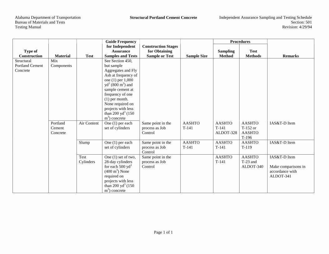
Alabama Department of TransportationBureau of Materials and TestsTesting Manual
Structural Portland Cement Concrete Independent Assurance Sampling and Testing ScheduleSection: 501
Revision: 4/29/94
Page 1 of 1
Procedures
Type ofConstruction Material Test
Guide Frequencyfor Independent
AssuranceSamples and Tests
Construction Stagesfor Obtaining
Sample or Test Sample SizeSamplingMethod
TestMethods Remarks
MixComponents
See Section 450,but sampleAggregates and FlyAsh at frequency ofone (1) per 1,000yd3 (800 m3) andsample cement atfrequency of one(1) per month.None required onprojects with lessthan 200 yd3 (150m3) concrete
Air Content One (1) per eachset of cylinders
Same point in theprocess as JobControl
AASHTOT-141
AASHTOT-141ALDOT-328
AASHTOT-152 orAASHTOT-196
IAS&T-D Item
Slump One (1) per eachset of cylinders
Same point in theprocess as JobControl
AASHTOT-141
AASHTOT-141
AASHTOT-119
IAS&T-D Item
StructuralPortland CementConcrete
PortlandCementConcrete
TestCylinders
One (1) set of two,28-day cylindersfor each 500 yd3
(400 m3) Nonerequired onprojects with lessthan 200 yd3 (150m3) concrete
Same point in theprocess as JobControl
AASHTOT-141
AASHTOT-23 andALDOT-340
IAS&T-D Item
Make comparisons inaccordance withALDOT-341

Alabama Department of TransportationBureau of Materials and TestsTesting Manual
Steel Reinforcement Independent Assurance Sampling and Testing ScheduleSection: 502
Revision: 4/29/94
Page 1 of 1
Procedures
Type ofConstruction Material Test
Guide Frequencyfor Independent
AssuranceSamples and Tests
Construction Stagesfor Obtaining
Sample or Test Sample SizeSamplingMethod
TestMethods Remarks
SteelReinforcement
Reinforce-ment steelbars
Physical One (1) sample anyheat, any bar size,for each 100,000lbs (45,000 kg)None required onprojects with lessthan 200 yd3 (150m3) concrete
Three (3)bars 24 in.(600 mm)long
Samplestraight barswhenpossible
IAS&T-D Items
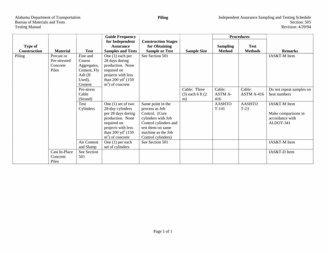
Alabama Department of TransportationBureau of Materials and TestsTesting Manual
Piling Independent Assurance Sampling and Testing ScheduleSection: 505
Revision: 4/29/94
Page 1 of 1
Procedures
Type ofConstruction Material Test
Guide Frequencyfor Independent
AssuranceSamples and Tests
Construction Stagesfor Obtaining
Sample or Test Sample SizeSamplingMethod
TestMethods Remarks
Fine andCoarseAggregates,Cement, FlyAsh (IfUsed),Cement
IAS&T-M Item
Pre-stressCable(Strand)
One (1) each per28 days duringproduction. Nonerequired onprojects with lessthan 200 yd3 (150m3) of concrete
See Section 501
Cable: Three(3) each 6 ft (2m)
Cable:ASTM A-416
Cable:ASTM A-416
Do not repeat samples onheat numbers
Piling Precast orPre-stressedConcretePiles
TestCylinders
One (1) set of two28-day cylindersper 28 days duringproduction. Nonerequired onprojects with lessthan 200 yd3 (150m3) of concrete
Same point in theprocess as JobControl. (Curecylinders with JobControl cylinders andtest them on samemachine as the JobControl cylinders)
AASHTOT-141
AASHTOT-23
IAS&T-M Item
Make comparisons inaccordance withALDOT-341
Air Contentand Slump
One (1) per eachset of cylinders
See Section 501 IAS&T-M Item
Cast In-PlaceConcretePiles
See Section501
IAS&T-D Item

Alabama Department of TransportationBureau of Materials and TestsTesting Manual
Drilled Shafts Independent Assurance Sampling and Testing ScheduleSection: 506
Revision: 3/1/01
Page 1 of 1
Procedures
Type ofConstruction Material Test
Guide Frequencyfor Independent
AssuranceSamples and Tests
Construction Stagesfor Obtaining
Sample or Test Sample SizeSamplingMethod
TestMethods Remarks
Drilled Shafts See Section501
IAS&T-D Item

Alabama Department of TransportationBureau of Materials and TestsTesting Manual
Bridges Independent Assurance Sampling and Testing ScheduleSection: 510
Revision: 4/29/94
Page 1 of 1
Procedures
Type ofConstruction Material Test
Guide Frequencyfor Independent
AssuranceSamples and Tests
Construction Stagesfor Obtaining
Sample or Test Sample SizeSamplingMethod
TestMethods Remarks
Bridges AllComponents
See Section501

Alabama Department of TransportationBureau of Materials and TestsTesting Manual
Prestressed Concrete Bridge Members Independent Assurance Sampling and Testing ScheduleSection: 513
Revision: 4/29/94
Page 1 of 1
PPrroocceedduurreess
TTyyppee ooffCCoonnssttrruuccttiioonn MMaatteerriiaall TTeesstt
GGuuiiddee FFrreeqquueennccyyffoorr IInnddeeppeennddeenntt
AAssssuurraanncceeSSaammpplleess aanndd TTeessttss
CCoonnssttrruuccttiioonn SSttaaggeessffoorr OObbttaaiinniinngg
SSaammppllee oorr TTeesstt SSaammppllee SSiizzeeSSaammpplliinnggMMeetthhoodd
TTeessttMMeetthhooddss RReemmaarrkkss
PrestressedConcrete BridgeMembers
See Section505
IAS&T-M Item

Alabama Department of TransportationBureau of Materials and TestsTesting Manual
Reinforced Concrete Box Culverts Independent Assurance Sampling and Testing ScheduleSection: 524
Revision: 4/29/94
Page 1 of 1
Procedures
Type ofConstruction Material Test
Guide Frequencyfor Independent
AssuranceSamples and Tests
Construction Stagesfor Obtaining
Sample or Test Sample SizeSamplingMethod
TestMethods Remarks
ReinforcedConcrete BoxCulverts
See Section501
IAS&T-D Item

Alabama Department of TransportationBureau of Materials and TestsTesting Manual
Concrete Retaining Walls and Cribbing Independent Assurance Sampling and Testing ScheduleSection: 525
Revision: 4/29/94
Page 1 of 1
Procedures
Type ofConstruction Material Test
Guide Frequencyfor Independent
AssuranceSamples and Tests
Construction Stagesfor Obtaining
Sample or Test Sample SizeSamplingMethod
TestMethods Remarks
ConcreteRetaining Wallsand Cribbing
Concrete forFootingand/or Caps
See Section501
IAS&T-D Item

Alabama Department of TransportationBureau of Materials and TestsTesting Manual
Concrete Retaining Walls Independent Assurance Sampling and Testing ScheduleSection: 529
Revision: 4/29/94
Page 1 of 1
Procedures
Type ofConstruction Material Test
Guide Frequencyfor Independent
AssuranceSamples and Tests
Construction Stagesfor Obtaining
Sample or Test Sample SizeSamplingMethod
TestMethods Remarks
ConcreteRetaining Walls
Note: ThisSection is by JobSpecific SpecialProvision
SelectedBackfill(LocalMaterials)
GradationAtterbergLimits
One (1) per 7500yd3 (6000 m3) orless
Same point in theprocess as theAcceptance Test
See AASHTOT-2, Table No. 1
ALDOT-210
AASHTOT-2
AASHTOT-27AASHTOT-89 asmodified byALDOT-232AASHTOT-90AASHTOM-145
IAS&T-D Item
See Special Provision orplans for gradationrequirements.Make comparison inaccordance withALDOT-341
(CommercialAggregate)
Gradation See Section 401 IAS&T-D Item

Alabama Department of TransportationBureau of Materials and TestsTesting Manual
Pavement Edge Drains Independent Assurance Sampling and Testing ScheduleSection: 605
Revision: 4/29/94
Page 1 of 1
Procedures
Type ofConstruction Material Test
Guide Frequencyfor Independent
AssuranceSamples and Tests
Construction Stagesfor Obtaining
Sample or Test Sample SizeSamplingMethod
TestMethods Remarks
Pavement EdgeDrains
Aggregate Gradation See Section 401 IAS&T-D Item
Sample if aggregate isused

Alabama Department of TransportationBureau of Materials and TestsTesting Manual
Guardrail and Barrier Rail Independent Assurance Sampling and Testing ScheduleSection: 630
Revision: 4/29/94
Page 1 of 1
Procedures
Type ofConstruction Material Test
Guide Frequencyfor Independent
AssuranceSamples and Tests
Construction Stagesfor Obtaining
Sample or Test Sample SizeSamplingMethod
TestMethods Remarks
Guardrail andBarrier Rail
Steel BeamGuardrail
CoatingThickness
One spot check railusing thin filmgauge (nonerequired onprojects with lessthan 400 ft (120 m)
Prior to or duringassembly or after it isassembled in place
See Remarks Permanufactur-ersinstructions
IAS&T-D Item
Average of five readingsat different locations.Report results toCertification andIAS&T-M Offices onBMT-16

Alabama Department of TransportationBureau of Materials and TestsTesting Manual
Pavement Markers Class A Independent Assurance Sampling and Testing ScheduleSection: 705
Revision: 5/19/97
Page 1 of 1
Procedures
Type ofConstruction Material Test
Guide Frequencyfor Independent
AssuranceSamples and Tests
Construction Stagesfor Obtaining
Sample or Test Sample SizeSamplingMethod
TestMethods Remarks
Pavement MarkersClass A
Single andDouble Lens
Physical One (1) sampleeach type onprojects requiringmore that 1000markers. When lessthan 200 markersof any one type areused, no samplewill be required forthat type
Prior to installation Three (3) each ALDOT-210 ASTME 1696
IAS&T-D Item
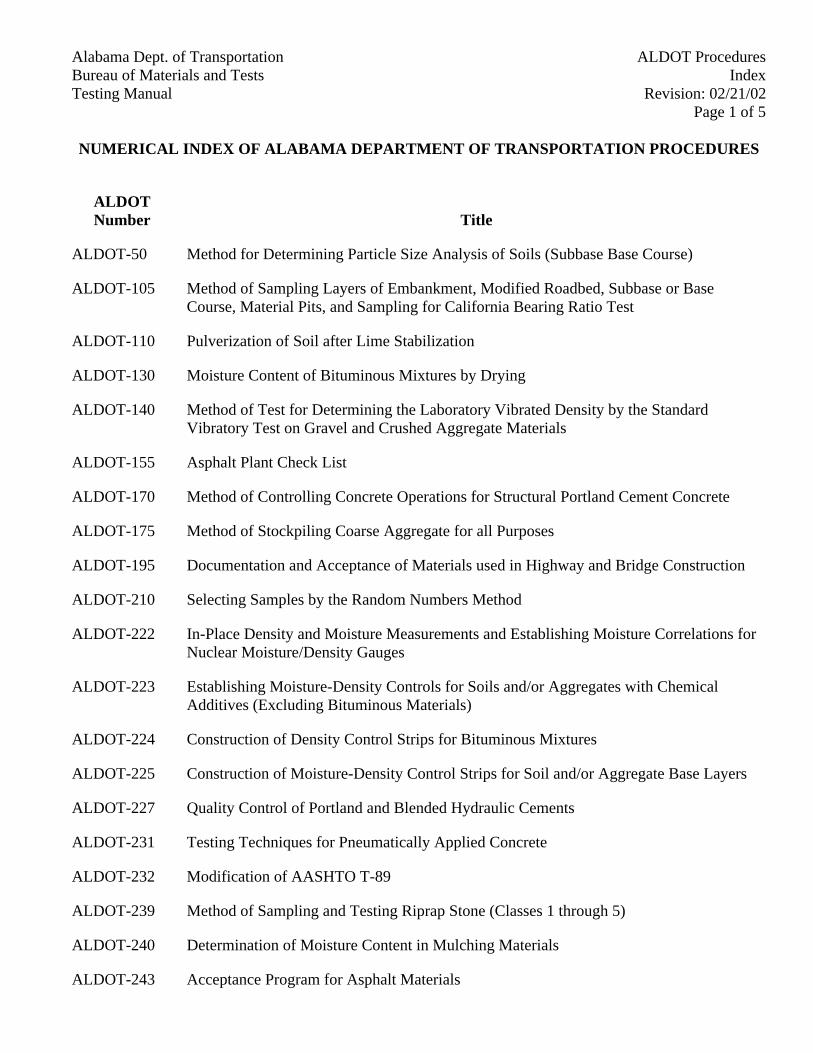
Alabama Dept. of Transportation ALDOT ProceduresBureau of Materials and Tests Index
Revision: 02/21/02Testing ManualPage 1 of 5
NUMERICAL INDEX OF ALABAMA DEPARTMENT OF TRANSPORTATION PROCEDURES
ALDOTNumber Title
ALDOT-50 Method for Determining Particle Size Analysis of Soils (Subbase Base Course)
ALDOT-105 Method of Sampling Layers of Embankment, Modified Roadbed, Subbase or BaseCourse, Material Pits, and Sampling for California Bearing Ratio Test
ALDOT-110 Pulverization of Soil after Lime Stabilization
ALDOT-130 Moisture Content of Bituminous Mixtures by Drying
ALDOT-140 Method of Test for Determining the Laboratory Vibrated Density by the StandardVibratory Test on Gravel and Crushed Aggregate Materials
ALDOT-155 Asphalt Plant Check List
ALDOT-170 Method of Controlling Concrete Operations for Structural Portland Cement Concrete
ALDOT-175 Method of Stockpiling Coarse Aggregate for all Purposes
ALDOT-195 Documentation and Acceptance of Materials used in Highway and Bridge Construction
ALDOT-210 Selecting Samples by the Random Numbers Method
ALDOT-222 In-Place Density and Moisture Measurements and Establishing Moisture Correlations forNuclear Moisture/Density Gauges
ALDOT-223 Establishing Moisture-Density Controls for Soils and/or Aggregates with ChemicalAdditives (Excluding Bituminous Materials)
ALDOT-224 Construction of Density Control Strips for Bituminous Mixtures
ALDOT-225 Construction of Moisture-Density Control Strips for Soil and/or Aggregate Base Layers
ALDOT-227 Quality Control of Portland and Blended Hydraulic Cements
ALDOT-231 Testing Techniques for Pneumatically Applied Concrete
ALDOT-232 Modification of AASHTO T-89
ALDOT-239 Method of Sampling and Testing Riprap Stone (Classes 1 through 5)
ALDOT-240 Determination of Moisture Content in Mulching Materials
ALDOT-243 Acceptance Program for Asphalt Materials
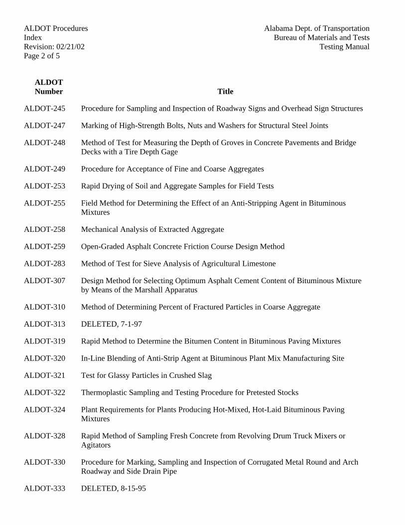
Alabama Dept. of TransportationALDOT ProceduresBureau of Materials and TestsIndex
Revision: 02/21/02 Testing ManualPage 2 of 5
ALDOTNumber Title
ALDOT-245 Procedure for Sampling and Inspection of Roadway Signs and Overhead Sign Structures
ALDOT-247 Marking of High-Strength Bolts, Nuts and Washers for Structural Steel Joints
ALDOT-248 Method of Test for Measuring the Depth of Groves in Concrete Pavements and BridgeDecks with a Tire Depth Gage
ALDOT-249 Procedure for Acceptance of Fine and Coarse Aggregates
ALDOT-253 Rapid Drying of Soil and Aggregate Samples for Field Tests
ALDOT-255 Field Method for Determining the Effect of an Anti-Stripping Agent in BituminousMixtures
ALDOT-258 Mechanical Analysis of Extracted Aggregate
ALDOT-259 Open-Graded Asphalt Concrete Friction Course Design Method
ALDOT-283 Method of Test for Sieve Analysis of Agricultural Limestone
ALDOT-307 Design Method for Selecting Optimum Asphalt Cement Content of Bituminous Mixtureby Means of the Marshall Apparatus
ALDOT-310 Method of Determining Percent of Fractured Particles in Coarse Aggregate
ALDOT-313 DELETED, 7-1-97
ALDOT-319 Rapid Method to Determine the Bitumen Content in Bituminous Paving Mixtures
ALDOT-320 In-Line Blending of Anti-Strip Agent at Bituminous Plant Mix Manufacturing Site
ALDOT-321 Test for Glassy Particles in Crushed Slag
ALDOT-322 Thermoplastic Sampling and Testing Procedure for Pretested Stocks
ALDOT-324 Plant Requirements for Plants Producing Hot-Mixed, Hot-Laid Bituminous PavingMixtures
ALDOT-328 Rapid Method of Sampling Fresh Concrete from Revolving Drum Truck Mixers orAgitators
ALDOT-330 Procedure for Marking, Sampling and Inspection of Corrugated Metal Round and ArchRoadway and Side Drain Pipe
ALDOT-333 DELETED, 8-15-95
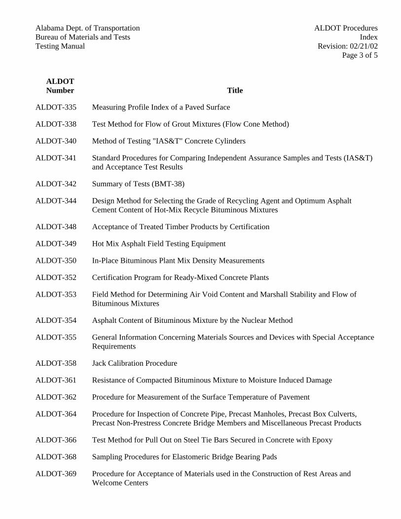
Alabama Dept. of Transportation ALDOT ProceduresBureau of Materials and Tests Index
Revision: 02/21/02Testing ManualPage 3 of 5
ALDOTNumber Title
ALDOT-335 Measuring Profile Index of a Paved Surface
ALDOT-338 Test Method for Flow of Grout Mixtures (Flow Cone Method)
ALDOT-340 Method of Testing "IAS&T" Concrete Cylinders
ALDOT-341 Standard Procedures for Comparing Independent Assurance Samples and Tests (IAS&T)and Acceptance Test Results
ALDOT-342 Summary of Tests (BMT-38)
ALDOT-344 Design Method for Selecting the Grade of Recycling Agent and Optimum AsphaltCement Content of Hot-Mix Recycle Bituminous Mixtures
ALDOT-348 Acceptance of Treated Timber Products by Certification
ALDOT-349 Hot Mix Asphalt Field Testing Equipment
ALDOT-350 In-Place Bituminous Plant Mix Density Measurements
ALDOT-352 Certification Program for Ready-Mixed Concrete Plants
ALDOT-353 Field Method for Determining Air Void Content and Marshall Stability and Flow ofBituminous Mixtures
ALDOT-354 Asphalt Content of Bituminous Mixture by the Nuclear Method
ALDOT-355 General Information Concerning Materials Sources and Devices with Special AcceptanceRequirements
ALDOT-358 Jack Calibration Procedure
ALDOT-361 Resistance of Compacted Bituminous Mixture to Moisture Induced Damage
ALDOT-362 Procedure for Measurement of the Surface Temperature of Pavement
ALDOT-364 Procedure for Inspection of Concrete Pipe, Precast Manholes, Precast Box Culverts,Precast Non-Prestress Concrete Bridge Members and Miscellaneous Precast Products
ALDOT-366 Test Method for Pull Out on Steel Tie Bars Secured in Concrete with Epoxy
ALDOT-368 Sampling Procedures for Elastomeric Bridge Bearing Pads
ALDOT-369 Procedure for Acceptance of Materials used in the Construction of Rest Areas andWelcome Centers
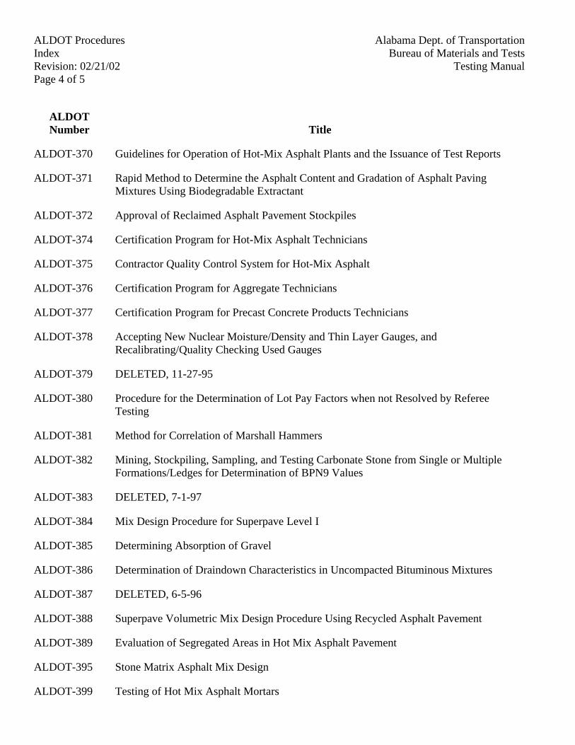
Alabama Dept. of TransportationALDOT ProceduresBureau of Materials and TestsIndex
Revision: 02/21/02 Testing ManualPage 4 of 5
ALDOTNumber Title
ALDOT-370 Guidelines for Operation of Hot-Mix Asphalt Plants and the Issuance of Test Reports
ALDOT-371 Rapid Method to Determine the Asphalt Content and Gradation of Asphalt PavingMixtures Using Biodegradable Extractant
ALDOT-372 Approval of Reclaimed Asphalt Pavement Stockpiles
ALDOT-374 Certification Program for Hot-Mix Asphalt Technicians
ALDOT-375 Contractor Quality Control System for Hot-Mix Asphalt
ALDOT-376 Certification Program for Aggregate Technicians
ALDOT-377 Certification Program for Precast Concrete Products Technicians
ALDOT-378 Accepting New Nuclear Moisture/Density and Thin Layer Gauges, andRecalibrating/Quality Checking Used Gauges
ALDOT-379 DELETED, 11-27-95
ALDOT-380 Procedure for the Determination of Lot Pay Factors when not Resolved by RefereeTesting
ALDOT-381 Method for Correlation of Marshall Hammers
ALDOT-382 Mining, Stockpiling, Sampling, and Testing Carbonate Stone from Single or MultipleFormations/Ledges for Determination of BPN9 Values
ALDOT-383 DELETED, 7-1-97
ALDOT-384 Mix Design Procedure for Superpave Level I
ALDOT-385 Determining Absorption of Gravel
ALDOT-386 Determination of Draindown Characteristics in Uncompacted Bituminous Mixtures
ALDOT-387 DELETED, 6-5-96
ALDOT-388 Superpave Volumetric Mix Design Procedure Using Recycled Asphalt Pavement
ALDOT-389 Evaluation of Segregated Areas in Hot Mix Asphalt Pavement
ALDOT-395 Stone Matrix Asphalt Mix Design
ALDOT-399 Testing of Hot Mix Asphalt Mortars
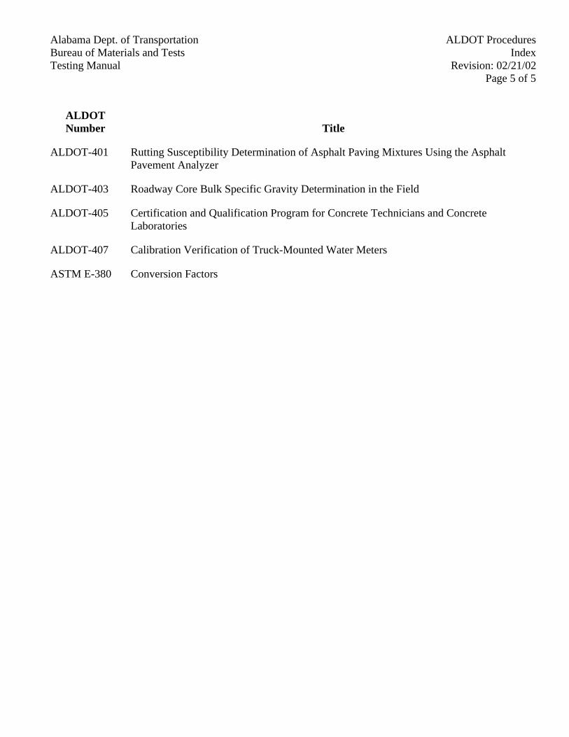
Alabama Dept. of Transportation ALDOT ProceduresBureau of Materials and Tests Index
Revision: 02/21/02Testing ManualPage 5 of 5
ALDOTNumber Title
ALDOT-401 Rutting Susceptibility Determination of Asphalt Paving Mixtures Using the AsphaltPavement Analyzer
ALDOT-403 Roadway Core Bulk Specific Gravity Determination in the Field
ALDOT-405 Certification and Qualification Program for Concrete Technicians and ConcreteLaboratories
ALDOT-407 Calibration Verification of Truck-Mounted Water Meters
ASTM E-380 Conversion Factors

Alabama Dept. of Transportation ALDOT ProceduresBureau of Materials and Tests ALDOT-50Testing Manual Revision: 2-25-94
Page 1 of 3
ALDOT-50-83METHOD FOR DETERMINING PARTICLE SIZE ANALYSIS OF SOILS
(SUBBASE AND BASE COURSE)
1. Scope
1.1. This method covers the procedure for the quantitative determination of the distribution of particlesizes in soils.
2. Applicable Documents
2.1. AASHTO T-87, Dry Preparation of Disturbed Soil and Soil Aggregate Samples for Test
2.2. AASHTO T-248, Reducing Field Samples of Aggregate to Testing Size
2.3. AASHTO T-27, Sieve Analysis of Fine and Coarse Aggregates
2.4. AASHTO M-231, Weights and Balances used in Testing of Highway Materials
2.5. AASHTO M-92, Wire Cloth Sieves for Testing Purposes
2.6. Alabama Department of Transportation Standard Specifications (Section 820 through 825 and/orany Special Provisions that may apply).
3. Apparatus
3.1. Balances - The balances shall conform to AASHTO M-231, Class D for samples less than 2000 gand Class E for samples of 2000 g or more.
3.2. Oven - The oven shall be capable of maintaining a uniform temperature not to exceed 140°F(60°C). (To prevent the physical properties from changing.).
3.3. Sieves - Suitable sieve sizes shall be selected to furnish the information required by thespecifications covering the material to be tested. (These sieves shall conform to the StandardSpecifications for Sieves for Testing Purposes - AASHTO M-92.)
3.4. Bottle for Clay Content - This bottle should be round having a capacity of 500 ml and measuringapproximately 6 in. (150 mm) in height.
4. Procedure
4.1. Reduce the sample to the correct size and weight in accordance with AASHTO T-248.
4.1.1. Samples having 20% or more of coarse aggregate are reduced to 10 lb (5 kg.) Samples nothaving an appreciable amount of aggregate are reduced to a weight of 5 to 8 lb( 2-4 kg)
4.2. Dry sample at a controlled temperature not to exceed 140°F (60°C.).
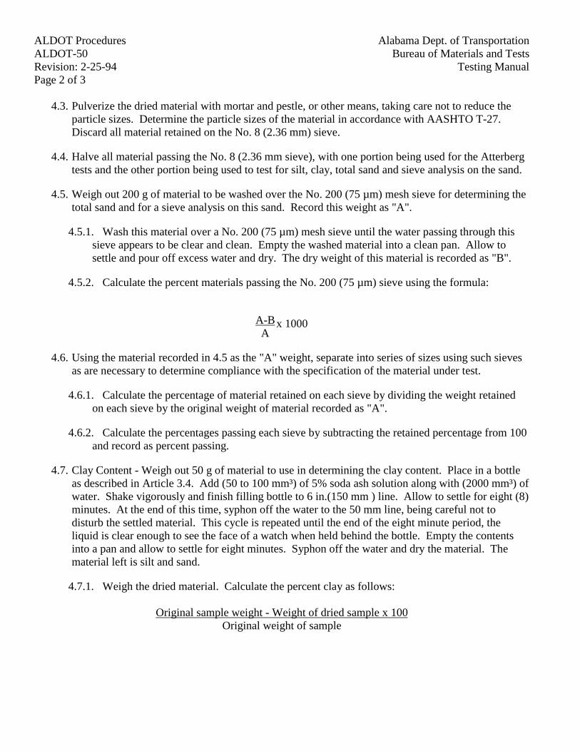
Alabama Dept. of TransportationALDOT ProceduresBureau of Materials and TestsALDOT-50
Testing ManualRevision: 2-25-94Page 2 of 3
4.3. Pulverize the dried material with mortar and pestle, or other means, taking care not to reduce theparticle sizes. Determine the particle sizes of the material in accordance with AASHTO T-27.Discard all material retained on the No. 8 (2.36 mm) sieve.
4.4. Halve all material passing the No. 8 (2.36 mm sieve), with one portion being used for the Atterbergtests and the other portion being used to test for silt, clay, total sand and sieve analysis on the sand.
4.5. Weigh out 200 g of material to be washed over the No. 200 (75 µm) mesh sieve for determining thetotal sand and for a sieve analysis on this sand. Record this weight as "A".
4.5.1. Wash this material over a No. 200 (75 µm) mesh sieve until the water passing through thissieve appears to be clear and clean. Empty the washed material into a clean pan. Allow tosettle and pour off excess water and dry. The dry weight of this material is recorded as "B".
4.5.2. Calculate the percent materials passing the No. 200 (75 µm) sieve using the formula:
A-BA
x 1000
4.6. Using the material recorded in 4.5 as the "A" weight, separate into series of sizes using such sievesas are necessary to determine compliance with the specification of the material under test.
4.6.1. Calculate the percentage of material retained on each sieve by dividing the weight retainedon each sieve by the original weight of material recorded as "A".
4.6.2. Calculate the percentages passing each sieve by subtracting the retained percentage from 100and record as percent passing.
4.7. Clay Content - Weigh out 50 g of material to use in determining the clay content. Place in a bottleas described in Article 3.4. Add (50 to 100 mm³) of 5% soda ash solution along with (2000 mm³) ofwater. Shake vigorously and finish filling bottle to 6 in.(150 mm ) line. Allow to settle for eight (8)minutes. At the end of this time, syphon off the water to the 50 mm line, being careful not todisturb the settled material. This cycle is repeated until the end of the eight minute period, theliquid is clear enough to see the face of a watch when held behind the bottle. Empty the contentsinto a pan and allow to settle for eight minutes. Syphon off the water and dry the material. Thematerial left is silt and sand.
4.7.1. Weigh the dried material. Calculate the percent clay as follows:
Original sample weight - Weight of dried sample x 100Original weight of sample
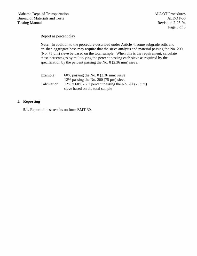
Alabama Dept. of Transportation ALDOT ProceduresBureau of Materials and Tests ALDOT-50Testing Manual Revision: 2-25-94
Page 3 of 3
Report as percent clay
Note: In addition to the procedure described under Article 4, some subgrade soils andcrushed aggregate base may require that the sieve analysis and material passing the No. 200(No. 75 µm) sieve be based on the total sample. When this is the requirement, calculatethese percentages by multiplying the percent passing each sieve as required by thespecification by the percent passing the No. 8 (2.36 mm) sieve.
Example: 60% passing the No. 8 (2.36 mm) sieve12% passing the No. 200 (75 µm) sieve
Calculation: 12% x 60% - 7.2 percent passing the No. 200(75 µm)sieve based on the total sample
5. Reporting
5.1. Report all test results on form BMT-30.
Alabama Dept. of Transportation ALDOT ProceduresBureau of Materials and Tests ALDOT-105Testing Manual Revision: 2/25/94
Page 1 of 3
ALDOT-105-83METHOD OF SAMPLING LAYERS OF EMBANKMENT, MODIFIED ROADBED, IMPROVED
ROADBED, SUBBASE OR BASE COURSE, MATERIAL PITS AND SAMPLING FORCALIFORNIA BEARING RATIO TESTS
1. Scope
1.1. This procedure covers sampling methods for soils to be used in the various roadwaycomponents.
2. Sampling Tools
2.1. Hand or power auger, pick or mattock and square or round point shovel.
3. Method of Sampling for Gradation and Atterberg Limit Tests
3.1. By using an auger, pick and a square point shovel, dig a hole or trench of sufficient length toprovide visual inspection of the face of the material exposed. The depth of the hole isgoverned by the thickness of the layer and should extend slightly below the layer to besampled.
3.2. The sample should be taken by removing material from the exposed face being careful toinclude approximately the same amount of material from the bottom to the top of the samplehole. Several passes from the bottom to the top of the hole may be necessary to obtain asample of sufficient size.
3.3. Place 25 to 30 lbs (10 to 15 kg) of the material being sampled into a clean sample sack fortransporting to the field, Division or Central Laboratory as required.
3.4. Include a sample card, Form BMT-18, with all pertinent information regarding the sample.The card should be folded so that the written information is protected from moisture in thesample. The sample card is then placed in the sack and the sack tied with heavy twine. Thesample without the sample card is worthless.
4. Thickness Measurements
4.1. Dig a test hole as outlined above through the compacted layer to be measured. Remove thematerial from the hole in a manner that will allow visual inspection to determine the limits ofthe layer being measured.
4.2. Place a straight edge over the surface of the layer and measure to the dividing line of theunderlying layer. Record this measurement in a field notebook. Report the measurement onForm BMT-16.
Alabama Dept. of TransportationALDOT ProceduresBureau of Materials and TestsALDOT-105
Testing ManualRevision: 2/25/94Page 2 of 3
5. Sampling Material Pits
5.1. Using an earth auger, either manual or power, the soil is remove from the test hole an augerfull at a time. The soil should be placed in a circle around the test hole with each auger fullin a separate pile.
5.2. The length of auger stems are usually 3 ft. (1 m) for manual augers and 6 ft. (2 m) for poweraugers. At the end of each 3 or 6 ft. (1 or 2 m) section of the circle of soil, a pile should beoffset from the circle to indicate the depth from which the material was removed from thehole. This method readily indicates the depth of stripping required, the total depth of usablematerial, and information regarding stratification of the material.
5.3. Samples are taken from the completed test hole by taking a small amount of soil from eachauger pile and placing it in a clean sample sack. If a soil analysis is required, each sampleshould weigh 25 to 30 lb (10 to 15 kg) and should be submitted to the Division Laboratory.If a soil analysis and C.B.R. is required, a sample weighing 100 lbs (45 kg) should besubmitted to the Central Laboratory.
5.4. Include a sample card, Form BMT-18, in each sample sack of soil with all pertinentinformation such as stratification, underground water, rocks or boulders encountered and anyother information that will be useful in working the pit.
5.5. When completed, all test holes must be filled with dry friable material with special effortbeing made to fill the hole completely from bottom to top, allowing over--fill for futuresettlement.
5.6. Test holes should be arranged over the pit area by using a base line and a grid system so thatthe boundaries of the pit and test hole location may be reestablished. A sketch should bemade showing distances to the test holes using trees, fences or other natural landmarks. Thesketch should be filed in the project records for future use.
6. Method of Sampling for C.B.R. Tests
6.1. C.B.R. samples from a "cut" section of a roadway should be taken of the material at the gradeline and 6 in. (300 mm) below. This is done by the use of earth augers, either manual orpower. No material will be sampled above the grade line unless the material is to be used ina "fill section" or for subbase or base layers. If a C.B.R. is required, it will be sampled by thesame method as shown in Section 5.
6.2. When sampling at the grade line, the depth of the sample hole must be measured and extremecare must be taken to assure that the sample comes from the proper elevation as shown on theplan and profile sheets.
6.3. If the sample is taken from an open cut or slope, material should be taken along the entireslope from bottom to top and submitted as a composite sample.
Alabama Dept. of Transportation ALDOT ProceduresBureau of Materials and Tests ALDOT-105Testing Manual Revision: 2/25/94
Page 3 of 3
6.4. The sample size for C.B.R. tests is approximately 100 lbs (45 kg.)
6.5. Three (3) sample cards, BMT-18, must be included in each sample sack clearly marked thatthe material is for C.B.R. tests. Also, the cards must be completely filled out showing allpertinent information such as station, type material, depth at which sample was taken and anyother information that may be of use.
6.6. When sampling is completed, the auger hole should be filled as previously described inSection 5.5
Alabama Dept. of Transportation ALDOT ProceduresBureau of Materials and Tests ALDOT-110Testing Manual Revision: 2/25/94
Page 1 of 1
ALDOT-110-82PULVERIZATION OF SOIL AFTER LIME STABILIZATION
1. Scope
1.1. This procedure covers sampling of lime stabilized soil for sieve analysis.
2. Class I (first increment) Lime Stabilization
2.1. When Class I (first increment) lime stabilization is used, a visual inspection shall be madeafter the lime is spread and mixed. After completion of the mixing and water application, allmaterial, including stone and gravel, shall pass visual inspection of a No. 200 (75 um) sieve.Record in the field book that visual inspection has been made and is accepted each 1000 ft.(300 m.).
3. Class I (second increment), Class II, or Class III Lime Stabilization
3.1. When Class I (second increment), Class II, or Class III lime stabilization is used, arepresentative sample is taken every 1000 ft. (300 m.) A hole is dug approximately 2 ft (60.0cm) wide to a full depth of stabilized material, with vertical face on one side. With shovelpoint, a sample is taken from bottom to top of hole (approximately 10 lbs. (5 kg)). Thissample is taken during final mixing operation and before water is applied. This material isscreened over the 2 in. (50 mm) sieve and No. 4 (4.75 mm) sieve by hand shaking--DO NOTFORCE THE LARGE PARTICLES THROUGH. Record weights and calculate percentpassing by the following method:
Weight Total Sample - Weight Retained x 100% Passing =
Weight Total Sample
Alabama Dept. of Transportation ALDOT ProceduresBureau of Materials and Tests ALDOT-130Testing Manual Revision: 1/31/96
Page 1 of 4
ALDOT-130MOISTURE CONTENT OF BITUMINOUS MIXTURES BY DRYING
1. Scope
1.1. This method provides two procedures for determining the moisture content of bituminousmixtures. Section 4 describes the method for drying in a conventional or convection oven,which may be used for bituminous mixtures containing any type of aggregate materialincluding slag aggregate or metal. Section 5 describes the method for drying in a microwaveoven, which is not to be used for bituminous mixtures which contain slag aggregate or metal.
1.2. This standard may involve hazardous materials, operations, and equipment. This standarddoes not address all the safety problems associated with its use. It is the responsibility ofusers of this standard to consult and establish appropriate safety and health practices, anddetermine the applicability of regulatory limitations prior to use.
2. Referenced Documents
2.1. AASHTO T 168 - Sampling Bituminous Paving Mixtures.
2.2. AASHTO T 164 - Quantitative Extraction of Bitumen from Bituminous Paving Mixtures.
2.3. ALDOT-354 - Asphalt Content of Bituminous Mixture by the Nuclear Method.
2.4. ALDOT-361 - Resistance of Compacted Bituminous Mixture to Moisture Induced Damage.
3. Sample
3.1. Samples taken to determine the moisture content of the mixture shall be taken from thehauling vehicle as soon as possible after the vehicle is loaded. Immediately after taking thesample it shall be placed into a tarred moisture tight container and weighed as soon aspossible. Any moisture condensing on the sealed container lid shall be accounted for andincluded in the moisture determination. The container lid shall be dried and weighed alongwith the uncovered moisture sample.
4. Drying in Conventional or Convection Oven
4.1. Significance and Use
4.1.1. This procedure describes the method for determining the moisture content of abituminous mixture by drying in a conventional or convection oven. It may be usedfor bituminous mixtures containing any type of aggregate material including slagaggregate or metal.
4.2. Apparatus
4.2.1. A balance with sufficient capacity to determine the mass of the combined sample,pan, and cover, with a readability and sensitivity of at least 0.0035 oz (0.1 g).

Alabama Dept. of TransportationALDOT ProceduresBureau of Materials and TestsALDOT-130
Testing ManualRevision: 1/31/96Page 2 of 4
4.2.2. A thermostatically controlled conventional or convection oven capable of maintainingthe temperature at 230 ± 9°F (110 ± 5°C).
4.2.3. A covered pan of sufficient size for the test sample to be spread out to a maximumdepth of 1.5 in (40 mm). An aluminum cake pan 11 x 7 x 1.5 in (275 x 175 x 40 mm)has been found satisfactory.
4.2.4. Scoop, sample container with sealed lid, and heat resistant gloves.
4.3. Procedure
4.3.1. Determine the tare mass of the drying pan and cover, and record to the nearest 0.0035oz (0.1 g).
4.3.2. A test sample of approximately 2.65 lbs (1200 g) shall be obtained as described inSection 3.
4.3.3. Immediately place the test sample in drying pan, determine and record the mass of thepan, cover, and sample to the nearest 0.0035 oz (0.1 g). This mass must be taken assoon as possible, but no longer than 10 minutes after the test sample is obtained. Thedrying pan should be covered during handling and determining the mass of thesample, but uncovered during drying.
4.3.4. Determine the mass of the test sample to the nearest 0.0035 oz (0.1 g) and record asthe original test sample mass. Spread the sample of bituminous mixture to a uniformdepth, assuring there is no loss of the sample.
4.3.5. Place the pan and sample in the oven. After drying for 90 minutes, determine themass and record the mass of the pan, cover, and sample to the nearest 0.0035 oz(0.1g).
4.3.6. Return the pan and sample to the oven and dry for an additional 20 minutes.Determine the mass of the pan, cover, and sample, and record the mass to the nearest0.0035 oz (0.1 g). Determine and record the mass of the test sample to the nearest0.0035 oz (0.1 g) and check to see if constant mass has been attained. Constant massshall be defined as the mass at which further drying at 230 ± 9°F (110 ± 5°C) doesnot alter the mass more than 0.05 percent of the original test sample mass in a 20minute heating cycle. If the sample has not attained constant mass, continue the 20minute heating and mass determination cycles until constant mass is attained.
4.3.7. The percent moisture shall be calculated and reported as given in Section 6.
Alabama Dept. of Transportation ALDOT ProceduresBureau of Materials and Tests ALDOT-130Testing Manual Revision: 1/31/96
Page 3 of 4
5. Drying in Microwave Oven
5.1. Significance and Use
5.1.1. This procedure describes the method for determining the moisture content of abituminous mixture by drying in a microwave oven. It is not to be used forbituminous mixtures which contain slag aggregate or metal.
5.2. Apparatus
5.2.1. A balance with sufficient capacity to determine the mass of the combined sample,pyrex container, and cover, with a readability and sensitivity of at least 0.0035 oz (0.1g).
5.2.2. Microwave oven with variable power control and 1 cubic foot (0.03 cubic meter)minimum capacity.
5.2.3. Covered pyrex container capable of holding a minimum 1.1 lbs (500 g) bituminousmixture test sample.
5.2.4. Thermometer capable of measuring to 350°F (180°C).
5.2.5. Scoop, sample container with sealed lid, and heat resistant gloves.
5.3. Determination of Power Control Setting
5.3.1. Determine the power control setting of the microwave oven which will be used to drythe test sample to constant mass by the following:
5.3.2. Set variable power control of microwave to approximately 50% power.
5.3.3. Place 500 mL (or 500 g) of tap water in the pyrex container. Record temperature ofwater as "T1." Heat the 500 mL of water for 5 minutes. Record temperature of wateras "T2." The difference between temperature "T1" and "T2" should be 77 ± 1°F (25± 0.5°C).
5.3.4. If the difference between temperature "T1" and "T2" is too low (or high), increase (ordecrease) the variable power control and repeat section 5.3.3.
5.4. Procedure
5.4.1. Determine the tare mass of the pyrex container and cover, and record to the nearest0.0035 oz (0.1 g).
5.4.2. A minimum test sample of approximately 1.1 lb (500 g) (for normal mixtures, i.e.,nominal maximum aggregate size of one inch) shall be obtained as described inSection 3.
Alabama Dept. of TransportationALDOT ProceduresBureau of Materials and TestsALDOT-130
Testing ManualRevision: 1/31/96Page 4 of 4
5.4.3. Immediately place the test sample in the pyrex container. Determine and record themass of the container, cover, and sample to the nearest 0.0035 oz (0.1 g). This massmust be taken as soon as possible, but no longer than 10 minutes after the test sampleis obtained. The drying container shall be covered during handling and weighing ofthe sample, but uncovered during drying.
5.4.4. Determine the mass of the test sample to the nearest 0.0035 oz (0.1 g) and record asthe original test sample mass. Spread the sample of bituminous mixture to a uniformdepth, assuring there is no loss of the sample.
5.4.5. Place the pyrex container and sample in the microwave oven and dry using the powersetting determined in Section 5.3. After 30 minutes, determine the mass and recordthe mass of the pyrex container, cover, and sample to the nearest 0.0035 oz (0.1 g).Determine the mass of test sample and record to the nearest 0.0035 oz (0.1 g).
5.4.6. Return the pyrex container and sample to the microwave and dry for an additional 5minutes. Determine the mass of the pyrex container, cover, and sample and recordthe mass to the nearest 0.0035 oz (0.1 g). Determine and record the mass of the testsample to the nearest 0.0035 oz (0.1 g) and check to see if constant mass has beenattained. Constant mass shall be defined as the mass at which further drying at thepredetermined power control setting does not alter the mass more than 0.018 oz(0.5g) in a 5 minute heating cycle. If the sample has not attained constant mass,continue the 5 minute heating and mass determination cycles until constant mass isattained. Care should be taken to avoid overheating the sample. The appearance ofblue smoke is an indication of overheating. If overheating does occur, the test shouldbe repeated at a lower power control setting.
5.4.7. The percent moisture shall be calculated and reported as in Section 6.
6. Calculation and Reporting
6.1. Determine the percent moisture as follows, and report to the nearest 0.1 percent.
Percent Moisture = A-B X 100B
Where: A = Original (wet) mass of test sample.B = Constant (dry) mass of test sample.
Alabama Dept. of Transportation ALDOT ProceduresBureau of Materials and Tests ALDOT-140Testing Manual Revision: 2/25/94
Page 1 of 5
ALDOT-140-84METHOD OF TEST FOR DETERMINING THE LABORATORY VIBRATED DENSITY BY THE
STANDARD VIBRATORY TEST ON GRAVEL AND CRUSHED AGGREGATE MATERIALS
1. Scope
1.1. This method of test is for determining the maximum density and optimum moisture on agiven gradation of base material.
2. Applicable Documents
2.1. AASHTO T-2AASHTO T-19 For Mold CalibrationAASHTO T-27AASHTO T-100AASHTO T-248
3. Apparatus
3.1. Mold - The mold shall be a solid wall, metal cylinder manufactured with dimensions andcapacity shown in 3.1.1 below.
3.1.1. An 8 in. (200 mm) mold having a capacity of 0.25 ft3 ± 0.015 ft3 (0.0071 m³ ± 0.0004m³) with an internal diameter of 8 in ± 0.10 in. (200 mm ± 3 mm) and a height ofapproximately 8 in ± 0.5 in.(200 mm ± 10 mm ) equipped with a detachable metalcollar, 4 in. (100 mm) in height.
Note: Molds currently in use which exceed the Volume shown in 3.1.1 may becontinued in use provided the results obtained on a comparison sample fall within theprecision limits acceptable for multi-laboratory results.
3.2. Base Plate - A steel plate, 0.24 in.(6 mm) in thickness, with an external vibrator riveted orbolted to the underside. This plate shall be equipped with a threaded collar, or other meansfor attaching the mold.
3.3. Support Rods - The support rods shall be of steel, adequate in size, to support the mold andplate assembly during the test. The ends of these rods are embedded in a heavy concrete castbase. These rods may carry large rubber stoppers above and below the base plate that isattached to the top of these rods for added resilience.
3.4. Pedestal for LVD Machine - See page 2.
3.5. Vibrator Motor - The vibrator motor shall be set to produce 500 lbs (2500 N.)
3.6. Balances or Scales - The balances or scales shall have a capacity of 30,000 g, graduated to 9g.
Alabama Dept. of TransportationALDOT ProceduresBureau of Materials and TestsALDOT-140
Testing ManualRevision: 2/25/94Page 2 of 5
3.7. Ovens - An oven with sufficient capacity to hold moisture samples capable of maintaining atemperature of 230 ± 9°F (110°C ± 5°C).
3.8. Steel Straight Edge - A steel straight edge at least 12 in. (300 mm) long and 0.10 in. (3 mm)thick.
3.9. Moisture Sample Containers - Moisture sample containers capable of holding a minimum of5 lbs (2.3 kg).
3.10. Mixing pans 36 in x 36 in x 6 in (900 mm x 900 mm x 150 mm) trowels, scoop, etc.
4. Sample
4.1. A blended mixture of gravel and soil, or a graded crushed aggregate meeting thespecification requirements.
5. Procedure
5.1. Determine the gradation of the sample submitted.
5.2. The gradation of the material submitted will be used to establish a job mix formula. Fromthis same material, the Laboratory Vibrated Density will be determined. This LVD will beused to control the field densities for all material whose gradation falls within plus or minusfive (5) percent for each sieve shown on the job mix formula.
5.2.1. Samples for the LVD test shall be air or oven dried with oven temperatures notexceeding 140°F (60°C) until less than one (1) percent moisture remains.
5.3. Two (2) percent water, by weight, will be mixed thoroughly and uniformly with a driedsample weighing approximately 60 lbs (27 kg).
5.4. A representative portion of the sample shall be taken from the pan of mixed material todetermine the water content (minimum of 6 lbs (3 kg)).
5.5. With the collar attached to the mold, sufficient material is then placed in the mold to producea slightly overflowing condition, and vibrated for three (3) minutes. The mold is thenremoved from the base plate and the collar detached. The material shall be struck off levelwith the top of the mold and the weight of the material established. (mold + sample - moldweight)
5.6. Successive increments of water in sufficient amount to increase the moisture content of thesample by approximately two (2) percent (usually 2.0 to 3 lb (0.9 to1.4 kg)) shall be addedand the procedure in 5.4 and 5.5 repeated for each increment of water added, until there is asubstantial decrease in the wet weight of the vibrated sample.
6. Calculations
Alabama Dept. of Transportation ALDOT ProceduresBureau of Materials and Tests ALDOT-140Testing Manual Revision: 2/25/94
Page 3 of 5
6.1. The optimum moisture content and dry weight per yd3 (m³) of the material vibrated shall becalculated as follows:
w1 – w2 x 100 D1 x 100W =w2
D =W + 100
Where:W = Optimum moisture content in percent based on the weight of oven dry material.w1 = Weight of wet material.w2 = Weight of oven dry material.D = Dry weight/yd3 (m3) of vibrated material.D1 = Wet weight/yd3 (m3) of vibrated material.
7. Plotting And Determining The Moisture-Density Relationship
7.1. The calculations in 6.1 are made to determine the moisture content and corresponding oven-dry weight/yd3 (m³) of the compacted material for each determination made.
7.2. The moisture content is plotted as abscissas and the dry weight/yd3 (m3) as ordinates. Asmooth line will be drawn through these points to establish a curve.
7.3. The moisture content corresponding to the peak of the curve shall be the Optimum MoistureContent for the compaction specified herein.
7.4. The oven-dry weight in grams/g3 (m³) of the soil at optimum moisture shall be termedLaboratory Vibrated Density for the compaction specified herein.
8. Reporting
8.1. Report the following item for each test on form BMT-16.
8.1.1. Optimum Moisture Content to nearest 0.1%.
8.1.2. Lab Vibrated Density (LVD) to nearest lb (kg.)
8.1.3. Gradation
1. If the material is 100 percent crushed stone, gravel or slag, the gradation willbe reported, based on the sample as a whole.
2. If the material is a blend of stone and soil binder, it will be reported in thecurrently used method based on splitting the sample on the No. 8 (2.36 mm)sieve.
8.1.4. Specific Gravity (AASHTO T-100).
8.1.5. Percent Voids or Porosity
Alabama Dept. of TransportationALDOT ProceduresBureau of Materials and TestsALDOT-140
Testing ManualRevision: 2/25/94Page 4 of 5
8.1.6. Calculate the Voids as follows:(A X W) - C
A X Wx 100
Where:A = Specific gravity of material.W = Wt./yd3 (m³) of water.C = Plotted dry wt./ yd3 (m³) of material.
9. Precision Statement
9.1. Reproducibility (multi-laboratory) - Two results obtained from the same material by differentoperators in different laboratories should be considered suspect if they differ by more thanfifteen (15) percent of their mean for Optimum Moisture and 3lb/ft³ (46.8 kg/m³) forMaximum Density.
Alabama Dept. of Transportation ALDOT ProceduresBureau of Materials and Tests ALDOT-140Testing Manual Revision: 2/25/94
Page 5 of 5
Pedestal for L.V.D. Machine
The 0.5 in. (13 mm) steel rods are 12 in. (300 mm) long. The bottom 6 in. (150 mm) will be cast in theconcrete, leaving a 6 in.(150 mm) stub above the concrete. A 6 in. (150 mm) piece will be threaded to fitthe base plate of the machine and will be furnished. The center to center location of the rods is veryimportant since they will be connected to the ones on machine base with rubber tubing. The #10 rubberstoppers are to be cast 0.2 in.(6 mm) deep in the bottom block; are obtainable at the Montgomery CentralLab. Everything pertaining to the machine will be furnished but a 3-phase, 220 volt line will be necessaryto install the starter box.
Dimensions shall be sufficient to produce a block weighing a minimum of 200 lbs (92 kg).See Materials and Tests Soils Laboratory for design of L.V.D. Machine.
Alabama Dept. of Transportation ALDOT ProceduresBureau of Materials and Tests ALDOT-155Testing Manual Revision: 2/25/94
Page 1 of 13
ALDOT-155ASPHALT PLANT CHECK LIST
Company:
Location: Inspected By: Date:
Type Plant and Manufacturer Name:
Maximum Batch: .lb (kg)
Rated English (Metric) Tons Per Hour:
Project No.: County:
General Specification Section
Batch Plants: Sections I thru XXI, XXX.Continuous Plants: Sections I thru XII, XXII thru XXVI, XXX.Dryer Drum Plants: Sections I thru XII, XXVII thru XXX.
I Stockpiles
1 Properly Separated.Yes No
2 Material Segregated.Yes No
3 Has Contractor submitted and received approval of his intended Materials Sources and his Job MixFormula?Yes No
4 Is area clean and properly kept?Yes No
II General Requirements for all Plants
1 Are tanks for storage of bituminous material equipped for heating the material under effective andpositive control at all time?Yes No
2 Are tanks for storage of bituminous material properly heated?Yes NoBy what means?
Alabama Dept. of TransportationALDOT ProceduresBureau of Materials and TestsALDOT-155
Testing ManualRevision: 2/25/94Page 2 of 13
3 Is a circulating system for the bituminous material of adequate capacity to provide proper andcontinuous circulation between storage tank and proportioning units during the entire operatingperiod?Yes No
4 Is the discharge end of the bituminous material circulating pipe kept below the surface of thebituminous material in the storage tank?Yes No
5 Are all pipe links and fittings steamed, oil jacketed or otherwise properly insulated to prevent heatloss?Yes No
6 Is storage tank capacity such as to insure continuous operation of the plant and uniform temperatureof the bituminous material when it is mixed with the aggregate?
7 Are tanks accurately calibrated to 100 gal. (400 L) and accessible for measuring the volume of thebituminous material?Yes No
8 Is a sampling top and valve provided in the bituminous storage tank or in the feed line between thepump and the return line discharge?Yes No
9 Is a drainage receptacle provided for flushing the outlet prior to sampling?Yes No
III Anti-Strip and Other Additive Systems
1 Is Anti-Strip material added at plant site?Yes No
2 If Anti-Strip material is added at plant site, does the anti-strip system meet ALDOT-320Specifications?Yes No
3 If other approved additives are used, are they handled in accordance with an established procedure?Yes No
IV Cold Feed System
1 Number of Cold bins.
2 Does plant have mechanical means for uniformly feeding the aggregates into the dryer?Yes No
Alabama Dept. of Transportation ALDOT ProceduresBureau of Materials and Tests ALDOT-155Testing Manual Revision: 2/25/94
Page 3 of 13
3 Does cold feed have a synchronized proportioning method when blending aggregates from two ormore bins?Yes No
4 If mineral filler is required, is a separate bin provided?Yes No
5 Is the feeder for mineral filler furnished with the feeder drive positively interlocked andsynchronized with the aggregate feeds?Yes No
V Dryer
1 Number of dryers.
2 Is a dryer of satisfactory design provided?Yes No
VI Dust Collectors and Emission Controls
1 What type dust collector is provided?
2 Can the material collected in the dust collector be wasted or any part or all of the material bereturned to the aggregate mixture?Yes No
3 If baghouse fines are recirculated into the mix, are they handled in accordance with AASHTO M-156?Yes No
4 Does the plant meet applicable limitations on emissions in accordance with Article 107?Yes No
5 Has company received Permit to Operate from EPA?Yes No (Attach copy to plant check list)
VII Thermometric Equipment
1 Is an armored recording thermometer located in the bituminous material feed line near the dischargeend at the mixer unit?Yes No
2 Is the plant equipped with approved recording thermometers, pyrometers, or other recordingthermometric instruments at the discharge end of the dryer?Yes No
Alabama Dept. of TransportationALDOT ProceduresBureau of Materials and TestsALDOT-155
Testing ManualRevision: 2/25/94Page 4 of 13
3 Has accuracy of pyrometers or thermometers been checked?Yes No
VIII Surge and Storage Bins
1 Is plant equipped with surge or storage bins?Yes No
2 What type bin?Surge or Storage
3 Is unit enclosed, insulated, weather proof?Yes No
4 Is unit equipped with material level indicator?Yes No
5 Is the indicator visible from plant operator or weighmaster's station?Yes No
6 Is conveyer system covered and insulated (if necessary) so as to prevent excessive loss of heatduring transfer of material from mixing plant to storage bin?Yes No
7 Does storage bin have acceptable heating system?Yes No
8 Are the storage or surge bins equipped with load cells to determine the net amount of mix deliveredfrom the bin?Yes No
IX Safety and Inspection Provisions
1 Are gears, pulleys, chains, sprockets and other dangerous moving parts thoroughly protected?Yes No
2 Is an unobstructed and adequately guarded passage provided and maintained in and around the truckloading space for visual inspection purposes?Yes No
3 Does plant have adequate and safe stairways or guarded ladders to plan units such as, mixerplatforms, control platforms, hot storage bins, bituminous storage tanks, etc., where inspections arerequired?Yes No
4 Is an inspection platform provided with a safe stairway for sampling the bituminous mixture fromloaded trucksYes No
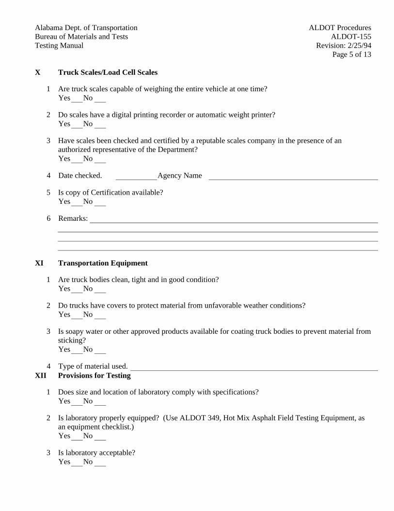
Alabama Dept. of Transportation ALDOT ProceduresBureau of Materials and Tests ALDOT-155Testing Manual Revision: 2/25/94
Page 5 of 13
X Truck Scales/Load Cell Scales
1 Are truck scales capable of weighing the entire vehicle at one time?Yes No
2 Do scales have a digital printing recorder or automatic weight printer?Yes No
3 Have scales been checked and certified by a reputable scales company in the presence of anauthorized representative of the Department?Yes No
4 Date checked. Agency Name
5 Is copy of Certification available?Yes No
6 Remarks:
XI Transportation Equipment
1 Are truck bodies clean, tight and in good condition?Yes No
2 Do trucks have covers to protect material from unfavorable weather conditions?Yes No
3 Is soapy water or other approved products available for coating truck bodies to prevent material fromsticking?Yes No
4 Type of material used.XII Provisions for Testing
1 Does size and location of laboratory comply with specifications?Yes No
2 Is laboratory properly equipped? (Use ALDOT 349, Hot Mix Asphalt Field Testing Equipment, asan equipment checklist.)Yes No
3 Is laboratory acceptable?Yes No
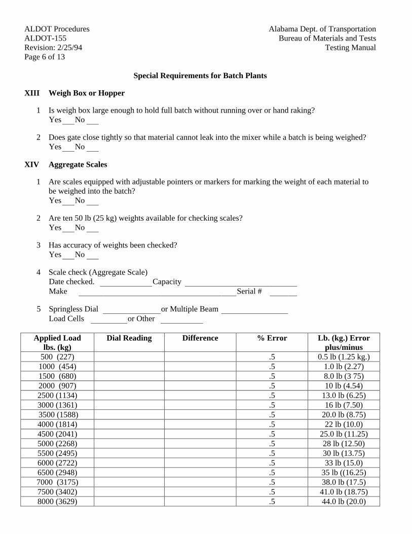
Alabama Dept. of TransportationALDOT ProceduresBureau of Materials and TestsALDOT-155
Testing ManualRevision: 2/25/94Page 6 of 13
Special Requirements for Batch Plants
XIII Weigh Box or Hopper
1 Is weigh box large enough to hold full batch without running over or hand raking?Yes No
2 Does gate close tightly so that material cannot leak into the mixer while a batch is being weighed?Yes No
XIV Aggregate Scales
1 Are scales equipped with adjustable pointers or markers for marking the weight of each material tobe weighed into the batch?Yes No
2 Are ten 50 lb (25 kg) weights available for checking scales?Yes No
3 Has accuracy of weights been checked?Yes No
4 Scale check (Aggregate Scale)Date checked. CapacityMake Serial #
5 Springless Dial or Multiple BeamLoad Cells or Other
Applied Loadlbs. (kg)
Dial Reading Difference % Error Lb. (kg.) Errorplus/minus
500 (227) .5 0.5 lb (1.25 kg.)1000 (454) .5 1.0 lb (2.27)1500 (680) .5 8.0 lb (3 75)2000 (907) .5 10 lb (4.54)2500 (1134) .5 13.0 lb (6.25)3000 (1361) .5 16 lb (7.50) 3500 (1588) .5 20.0 lb (8.75)4000 (1814) .5 22 lb (10.0)4500 (2041) .5 25.0 lb (11.25)5000 (2268) .5 28 lb (12.50)5500 (2495) .5 30 lb (13.75)6000 (2722) .5 33 lb (15.0)6500 (2948) .5 35 lb ((16.25)7000 (3175) .5 38.0 lb (17.5)7500 (3402) .5 41.0 lb (18.75)8000 (3629) .5 44.0 lb (20.0)
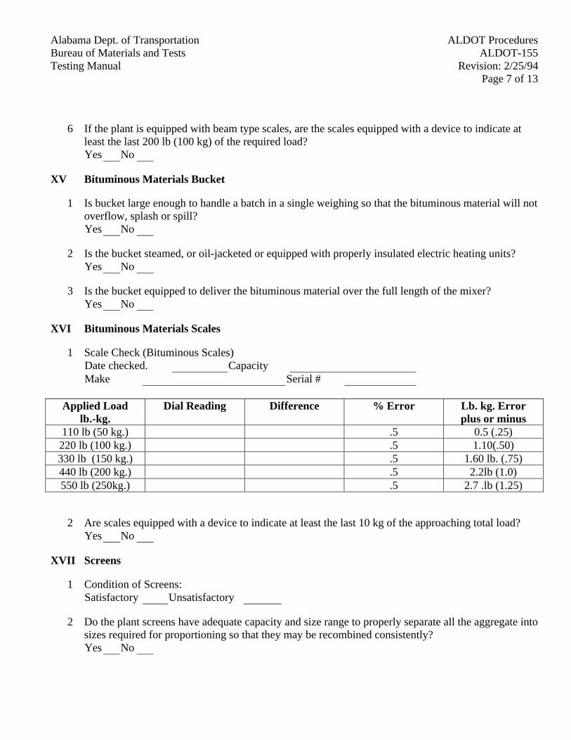
Alabama Dept. of Transportation ALDOT ProceduresBureau of Materials and Tests ALDOT-155Testing Manual Revision: 2/25/94
Page 7 of 13
6 If the plant is equipped with beam type scales, are the scales equipped with a device to indicate atleast the last 200 lb (100 kg) of the required load?Yes No
XV Bituminous Materials Bucket
1 Is bucket large enough to handle a batch in a single weighing so that the bituminous material will notoverflow, splash or spill?Yes No
2 Is the bucket steamed, or oil-jacketed or equipped with properly insulated electric heating units?Yes No
3 Is the bucket equipped to deliver the bituminous material over the full length of the mixer?Yes No
XVI Bituminous Materials Scales
1 Scale Check (Bituminous Scales)Date checked. CapacityMake Serial #
Applied Loadlb.-kg.
Dial Reading Difference % Error Lb. kg. Errorplus or minus
110 lb (50 kg.) .5 0.5 (.25)220 lb (100 kg.) .5 1.10(.50)330 lb (150 kg.) .5 1.60 lb. (.75)440 lb (200 kg.) .5 2.2lb (1.0)550 lb (250kg.) .5 2.7 .lb (1.25)
2 Are scales equipped with a device to indicate at least the last 10 kg of the approaching total load?Yes No
XVII Screens
1 Condition of Screens:Satisfactory Unsatisfactory
2 Do the plant screens have adequate capacity and size range to properly separate all the aggregate intosizes required for proportioning so that they may be recombined consistently?Yes No
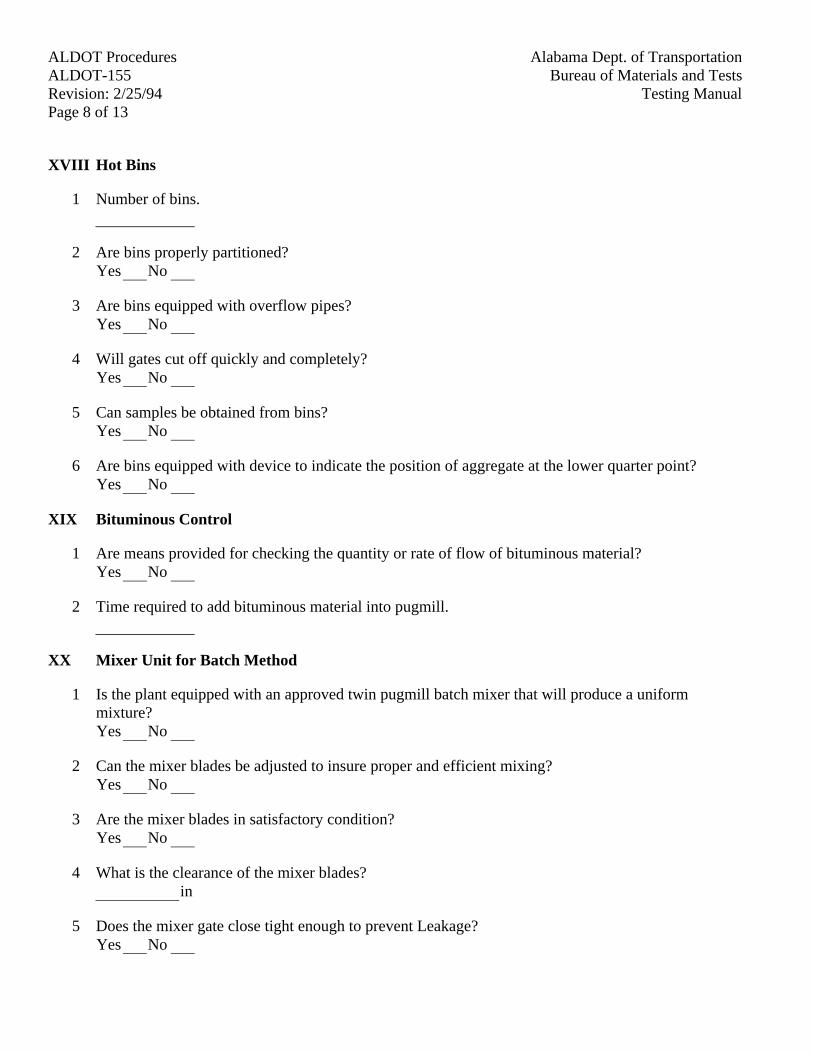
Alabama Dept. of TransportationALDOT ProceduresBureau of Materials and TestsALDOT-155
Testing ManualRevision: 2/25/94Page 8 of 13
XVIII Hot Bins
1 Number of bins.
2 Are bins properly partitioned?Yes No
3 Are bins equipped with overflow pipes?Yes No
4 Will gates cut off quickly and completely?Yes No
5 Can samples be obtained from bins?Yes No
6 Are bins equipped with device to indicate the position of aggregate at the lower quarter point?Yes No
XIX Bituminous Control
1 Are means provided for checking the quantity or rate of flow of bituminous material?Yes No
2 Time required to add bituminous material into pugmill.
XX Mixer Unit for Batch Method
1 Is the plant equipped with an approved twin pugmill batch mixer that will produce a uniformmixture?Yes No
2 Can the mixer blades be adjusted to insure proper and efficient mixing?Yes No
3 Are the mixer blades in satisfactory condition?Yes No
4 What is the clearance of the mixer blades?in
5 Does the mixer gate close tight enough to prevent Leakage?Yes No
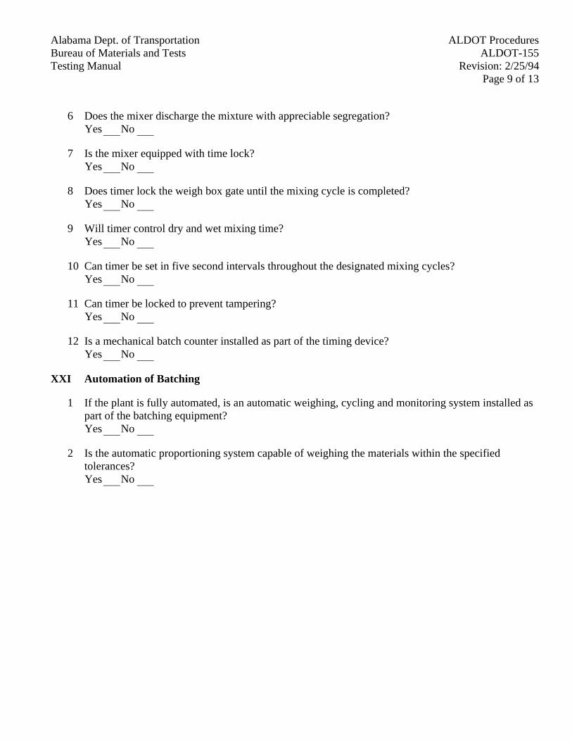
Alabama Dept. of Transportation ALDOT ProceduresBureau of Materials and Tests ALDOT-155Testing Manual Revision: 2/25/94
Page 9 of 13
6 Does the mixer discharge the mixture with appreciable segregation?Yes No
7 Is the mixer equipped with time lock?Yes No
8 Does timer lock the weigh box gate until the mixing cycle is completed?Yes No
9 Will timer control dry and wet mixing time?Yes No
10 Can timer be set in five second intervals throughout the designated mixing cycles?Yes No
11 Can timer be locked to prevent tampering?Yes No
12 Is a mechanical batch counter installed as part of the timing device?Yes No
XXI Automation of Batching
1 If the plant is fully automated, is an automatic weighing, cycling and monitoring system installed aspart of the batching equipment?Yes No
2 Is the automatic proportioning system capable of weighing the materials within the specifiedtolerances?Yes No
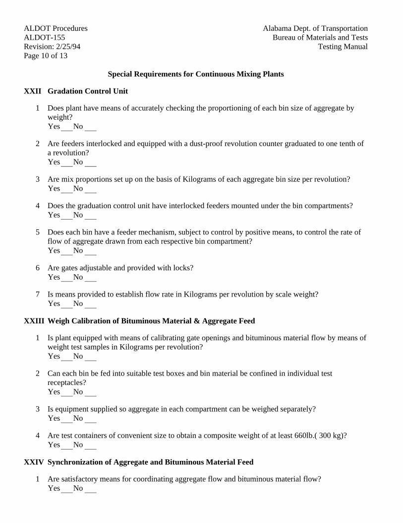
Alabama Dept. of TransportationALDOT ProceduresBureau of Materials and TestsALDOT-155
Testing ManualRevision: 2/25/94Page 10 of 13
Special Requirements for Continuous Mixing Plants
XXII Gradation Control Unit
1 Does plant have means of accurately checking the proportioning of each bin size of aggregate byweight?Yes No
2 Are feeders interlocked and equipped with a dust-proof revolution counter graduated to one tenth ofa revolution?Yes No
3 Are mix proportions set up on the basis of Kilograms of each aggregate bin size per revolution?Yes No
4 Does the graduation control unit have interlocked feeders mounted under the bin compartments?Yes No
5 Does each bin have a feeder mechanism, subject to control by positive means, to control the rate offlow of aggregate drawn from each respective bin compartment?Yes No
6 Are gates adjustable and provided with locks?Yes No
7 Is means provided to establish flow rate in Kilograms per revolution by scale weight?Yes No
XXIII Weigh Calibration of Bituminous Material & Aggregate Feed
1 Is plant equipped with means of calibrating gate openings and bituminous material flow by means ofweight test samples in Kilograms per revolution?Yes No
2 Can each bin be fed into suitable test boxes and bin material be confined in individual testreceptacles?Yes No
3 Is equipment supplied so aggregate in each compartment can be weighed separately?Yes No
4 Are test containers of convenient size to obtain a composite weight of at least 660lb.( 300 kg)?Yes No
XXIV Synchronization of Aggregate and Bituminous Material Feed
1 Are satisfactory means for coordinating aggregate flow and bituminous material flow?Yes No
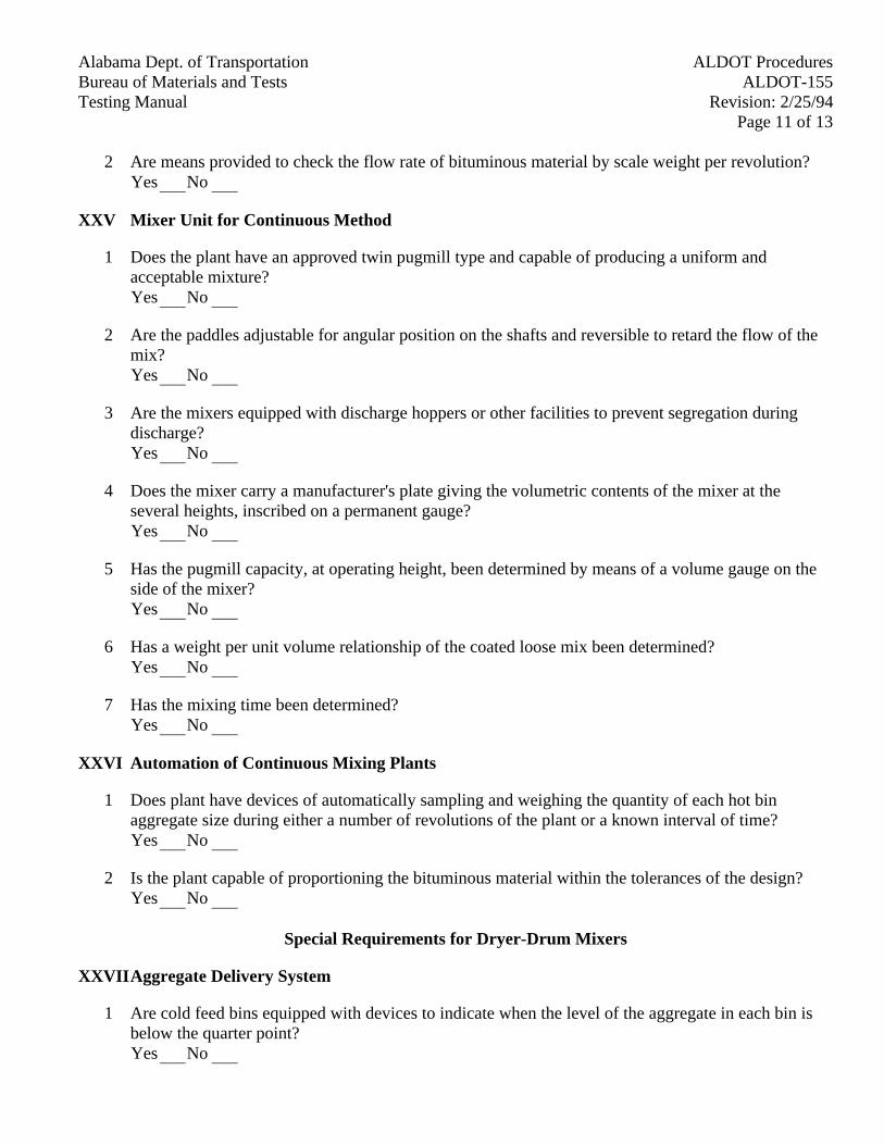
Alabama Dept. of Transportation ALDOT ProceduresBureau of Materials and Tests ALDOT-155Testing Manual Revision: 2/25/94
Page 11 of 13
2 Are means provided to check the flow rate of bituminous material by scale weight per revolution?Yes No
XXV Mixer Unit for Continuous Method
1 Does the plant have an approved twin pugmill type and capable of producing a uniform andacceptable mixture?Yes No
2 Are the paddles adjustable for angular position on the shafts and reversible to retard the flow of themix?Yes No
3 Are the mixers equipped with discharge hoppers or other facilities to prevent segregation duringdischarge?Yes No
4 Does the mixer carry a manufacturer's plate giving the volumetric contents of the mixer at theseveral heights, inscribed on a permanent gauge?Yes No
5 Has the pugmill capacity, at operating height, been determined by means of a volume gauge on theside of the mixer?Yes No
6 Has a weight per unit volume relationship of the coated loose mix been determined?Yes No
7 Has the mixing time been determined?Yes No
XXVI Automation of Continuous Mixing Plants
1 Does plant have devices of automatically sampling and weighing the quantity of each hot binaggregate size during either a number of revolutions of the plant or a known interval of time?Yes No
2 Is the plant capable of proportioning the bituminous material within the tolerances of the design?Yes No
Special Requirements for Dryer-Drum Mixers
XXVII Aggregate Delivery System
1 Are cold feed bins equipped with devices to indicate when the level of the aggregate in each bin isbelow the quarter point?Yes No
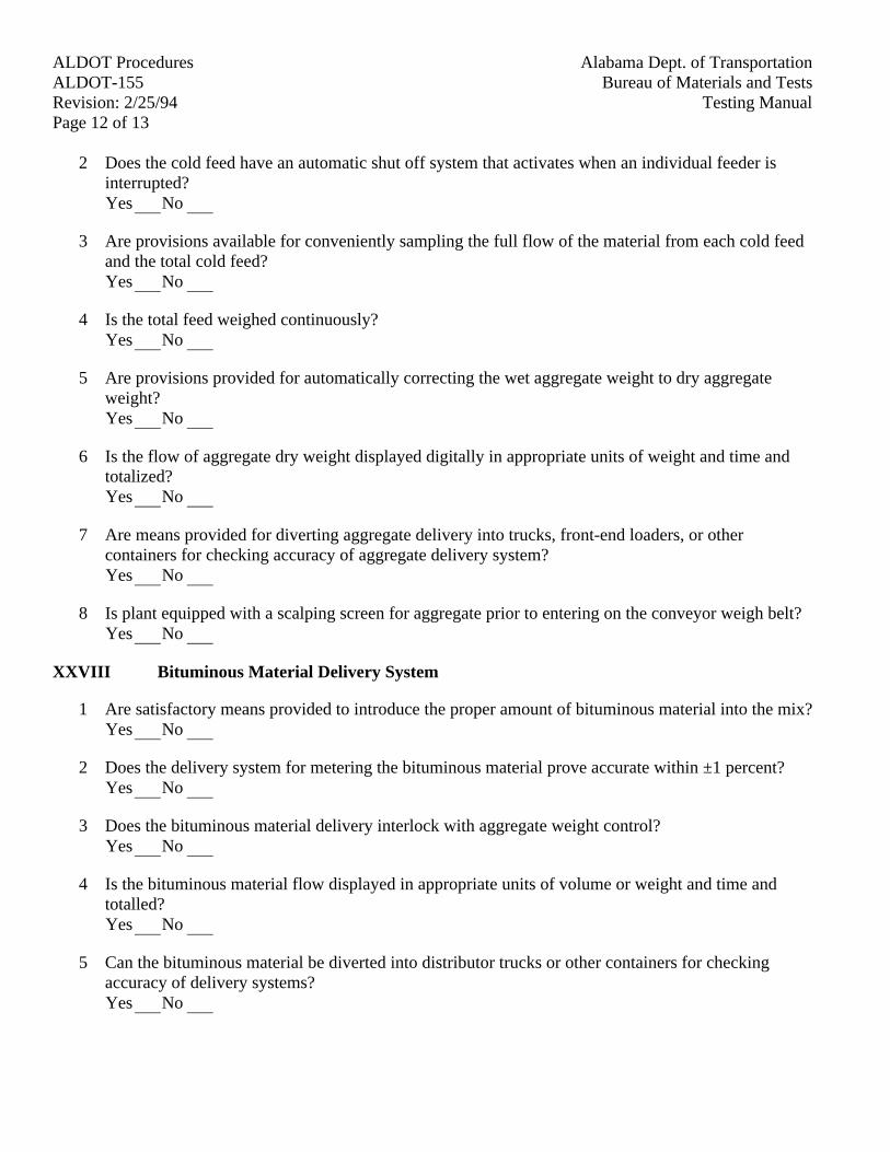
Alabama Dept. of TransportationALDOT ProceduresBureau of Materials and TestsALDOT-155
Testing ManualRevision: 2/25/94Page 12 of 13
2 Does the cold feed have an automatic shut off system that activates when an individual feeder isinterrupted?Yes No
3 Are provisions available for conveniently sampling the full flow of the material from each cold feedand the total cold feed?Yes No
4 Is the total feed weighed continuously?Yes No
5 Are provisions provided for automatically correcting the wet aggregate weight to dry aggregateweight?Yes No
6 Is the flow of aggregate dry weight displayed digitally in appropriate units of weight and time andtotalized?Yes No
7 Are means provided for diverting aggregate delivery into trucks, front-end loaders, or othercontainers for checking accuracy of aggregate delivery system?Yes No
8 Is plant equipped with a scalping screen for aggregate prior to entering on the conveyor weigh belt?Yes No
XXVIII Bituminous Material Delivery System
1 Are satisfactory means provided to introduce the proper amount of bituminous material into the mix?Yes No
2 Does the delivery system for metering the bituminous material prove accurate within ±1 percent?Yes No
3 Does the bituminous material delivery interlock with aggregate weight control?Yes No
4 Is the bituminous material flow displayed in appropriate units of volume or weight and time andtotalled?Yes No
5 Can the bituminous material be diverted into distributor trucks or other containers for checkingaccuracy of delivery systems?Yes No
Alabama Dept. of Transportation ALDOT ProceduresBureau of Materials and Tests ALDOT-155Testing Manual Revision: 2/25/94
Page 13 of 13
XXIX Drum Mixer
1 Is the drum mixer capable of drying and heating the aggregate to the moisture and temperaturerequirements set forth in the Specifications and capable of producing a uniform mix?Yes No
2 Does plant have provisions for diverting mixes at start-up and shutdowns or where mixing is notcomplete or uniform?Yes No
XXX Is plant approved for use?Yes NoIf not, explain what needs to be corrected. (Show Item Number)
Signed:Inspector
Approved:Materials Engineer
Alabama Dept. of Transportation ALDOT ProceduresBureau of Materials and Tests ALDOT-170Testing Manual Revision: 01/01/02
Page 1 of 15
ALDOT-170-82METHOD OF CONTROLLING CONCRETE OPERATIONS FOR STRUCTURAL PORTLAND
CEMENT CONCRETE
TABLE OF CONTENTS
Section Title Page
1. SCOPE ......................................................................................................................................... 2
2. REFERENCED DOCUMENTS ................................................................................................... 2
3. MATERIALS ............................................................................................................................... 3
4. MIX DESIGN ............................................................................................................................... 4
5. SUBMITTAL OF CONCRETE MIX DESIGN ........................................................................... 5
6. MIX DESIGN BY THE DEPARTMENT .................................................................................... 6
7. APPROVED CONCRETE MIX DESIGN DISTRIBUTION ...................................................... 6
8. RE-APPROVAL OF CONCRETE MIX DESIGN ...................................................................... 7
9. INSPECTION OF CONCRETE PLANTS AND CONCRETE EQUIPMENT ........................... 9
10. HANDLING AND STORAGE OF MATERIALS ....................................................................... 9
11. CONTROL OF MIXING OPERATIONS .................................................................................... 10
12. TIME LIMITATIONS FOR DELIVERY OF CONCRETE ........................................................ 11
13. CONCRETE PLACING ............................................................................................................... 12
14. RECORDS AND REPORTS ........................................................................................................ 12
15. PROCEDURE FOR FORENSIC INVESTIGATIONS ................................................................ 15
16. REPAIR OF CORE DRILLED HOLES ....................................................................................... 15

Alabama Dept. of TransportationALDOT ProceduresBureau of Materials and TestsALDOT-170
Testing ManualRevision: 01/01/02Page 2 of 15
1. Scope
1.1. This procedure shall establish the compliance requirements for the control of all aspects ofconcrete operations pertaining to concrete structures as set forth by the Alabama Department ofTransportation, herein referred to as ALDOT or as the Department.
2. Referenced Documents
2.1. ALDOT Specifications:
2.1.1. 501 Structural Portland Cement Concrete.
2.1.2. 801 Coarse Aggregate.
2.1.3. 802 Fine Aggregates.
2.1.4. 806 Mineral Admixtures.
2.1.5. 807 Water.
2.1.6. 808 Air Entraining Additives.
2.1.7. 809 Chemical Admixtures for Concrete.
2.1.8. 815 Cement.
2.2. ALDOT Procedures:
2.2.1. 175 Method for Stockpiling Coarse Aggregate for All Purposes.
2.2.2. 352 Certification Program for Portland Cement Concrete Producers.
2.2.3. 355 General Information Concerning Materials, Sources, and Devices with SpecialAcceptance.
2.2.4. 405 Certification and Qualification Program for Concrete Technicians andConcrete Laboratories.
2.2.5. 407 Calibration Verification of Truck Mounted Water Meters.
2.3. BMT Forms:
2.3.1. 10 Notice for Acceptance of Aggregates.
2.3.2. 75 Concrete Mix Design.
Alabama Dept. of Transportation ALDOT ProceduresBureau of Materials and Tests ALDOT-170Testing Manual Revision: 01/01/02
Page 3 of 15
2.3.3. 83 Concrete Placing Daily Report.
2.3.4. 95 Monthly Concrete Plant Checklist.
2.3.5. 114 Certified Cement Shipment.
2.3.6. 122 Concrete Batch Ticket.
2.4. AASHTO Standards:
2.4.1. T 22 Compressive Strength of Cylindrical Concrete Specimens.
2.4.2. T 24 Obtaining and Testing Drilled Cores and Sawed Beams of Concrete.
2.4.3. T 126 Making and Curing Concrete Test Specimens in the Laboratory.
2.4.4. T 255 Total Evaporable Moisture Content of Aggregate by Drying.
2.4.5. M 157 Ready-Mixed Concrete.
2.5. ASTM Standards:
2.5.1. C 457 Test Method for Microscopical Determination of Parameters of the Air-VoidSystem in Hardened Concrete.
2.5.2. C 642 Test Method for Density, Absorption, and Voids in Hardened Concrete.
2.5.3. C 823 Practice for Examination and Sampling of Hardened Concrete inConstructions.
2.5.4. C 856 Practice for Petrographic Examination of Hardened Concrete.
2.6. ACI Standard:
2.6.1. 211.1 Practice for Selecting Proportions for Normal, Heavyweight, and MassConcrete.
3. Materials
3.1. Materials shall meet the requirements in Division 800 of the Department’s Specifications andshall be from approved sources as listed in the Department’s manual, “Materials, Sources, andDevices with Special Acceptance Requirements”. Specific reference is made to the followingsections of the specifications and approved lists from the manual.
3.1.1. Cement, Section 815 and List I-2.
3.1.2. Fine and coarse aggregates, Sections 801 & 802 and List I-1.
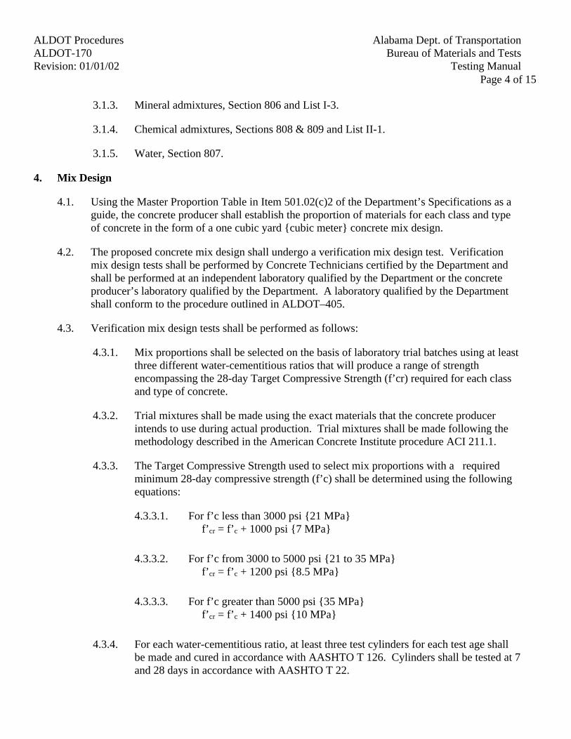
Alabama Dept. of TransportationALDOT ProceduresBureau of Materials and TestsALDOT-170
Testing ManualRevision: 01/01/02Page 4 of 15
3.1.3. Mineral admixtures, Section 806 and List I-3.
3.1.4. Chemical admixtures, Sections 808 & 809 and List II-1.
3.1.5. Water, Section 807.
4. Mix Design
4.1. Using the Master Proportion Table in Item 501.02(c)2 of the Department’s Specifications as aguide, the concrete producer shall establish the proportion of materials for each class and typeof concrete in the form of a one cubic yard {cubic meter} concrete mix design.
4.2. The proposed concrete mix design shall undergo a verification mix design test. Verificationmix design tests shall be performed by Concrete Technicians certified by the Department andshall be performed at an independent laboratory qualified by the Department or the concreteproducer’s laboratory qualified by the Department. A laboratory qualified by the Departmentshall conform to the procedure outlined in ALDOT–405.
4.3. Verification mix design tests shall be performed as follows:
4.3.1. Mix proportions shall be selected on the basis of laboratory trial batches using at leastthree different water-cementitious ratios that will produce a range of strengthencompassing the 28-day Target Compressive Strength (f’cr) required for each classand type of concrete.
4.3.2. Trial mixtures shall be made using the exact materials that the concrete producerintends to use during actual production. Trial mixtures shall be made following themethodology described in the American Concrete Institute procedure ACI 211.1.
4.3.3. The Target Compressive Strength used to select mix proportions with a requiredminimum 28-day compressive strength (f’c) shall be determined using the followingequations:
4.3.3.1. For f’c less than 3000 psi {21 MPa}f’cr = f’c + 1000 psi {7 MPa}
4.3.3.2. For f’c from 3000 to 5000 psi {21 to 35 MPa}f’cr = f’c + 1200 psi {8.5 MPa}
4.3.3.3. For f’c greater than 5000 psi {35 MPa}f’cr = f’c + 1400 psi {10 MPa}
4.3.4. For each water-cementitious ratio, at least three test cylinders for each test age shallbe made and cured in accordance with AASHTO T 126. Cylinders shall be tested at 7and 28 days in accordance with AASHTO T 22.
Alabama Dept. of Transportation ALDOT ProceduresBureau of Materials and Tests ALDOT-170Testing Manual Revision: 01/01/02
Page 5 of 15
4.3.5. The air content and temperature of the concrete for each trial batch shall be reported.
4.3.6. Laboratory trial mixes shall be designed for the maximum permitted slump and aircontent.
4.3.7. For each trial mixture, a curve shall be plotted showing the relationship betweenwater-cementitious ratio and strength, and the relationship between 7-day and 28-daystrengths.
4.4. Separate verification mix design tests shall be performed for each combination of cementitiousmaterials and each combination of admixtures proposed for use. Separate verification mixdesign tests shall also be made for concrete for any conveying or placing method proposedwhich requires special properties and for concrete to be placed in unusually difficult placinglocations.
4.5. Changes in a mix design, other than the ones allowed in Division 500 of the Department’sspecifications, shall require a new mix design verification test.
5. Submittal of Concrete Mix Design
5.1. The concrete producer shall submit to the State Materials and Tests Engineer a letter requestingapproval of the proposed concrete mix design. This letter shall be accompanied by theverification concrete mix design tests and supporting information. The following minimumsupporting information shall be required prior to approval of any mix design:
5.1.1. The source and type of each material proposed, including vendor codes.
5.1.2. The individual gradation of each aggregate, the combined gradation of the totalblended aggregates, the fineness modulus of fine aggregate, and the saturated-surface-dry (SSD) specific gravity and absorption of all aggregates.
5.1.3. The Class and Type of the proposed concrete mix and the proportions for one cubicyard {cubic meter}.
5.1.4. Freshly mixed concrete properties. This shall include actual results for slump, aircontent, and temperature of the concrete for each trial mix.
5.1.5. Evaluation of compressive strength test results showing the Target CompressiveStrength.
5.1.6. Laboratory trial mixtures and three point curves.
5.2. A laboratory Quality Control Manager or a Technical Service Manager authorized by thelaboratory performing the verification mix design, or a professional Engineer, licensed in theState of Alabama and not employed by ALDOT, shall sign all test results and supporting datasubmitted to the Department.
Alabama Dept. of TransportationALDOT ProceduresBureau of Materials and TestsALDOT-170
Testing ManualRevision: 01/01/02Page 6 of 15
6. Mix Design by the Department
6.1. Upon request from the concrete producer, the Department will perform verification tests withthe concrete producer supplying all the materials and paying the applicable fees as stated inALDOT-355.
6.2. The Department will provide a mix design to the concrete producer for each verification testrequested. This mix design shall then be the property and responsibility of the concreteproducer.
6.3. For each verification test requested to the Department, the concrete producer shall submit thefollowing:
6.3.1. A letter to the State Materials and Tests Engineer requesting a verification test mix. The Class and Type of mix design requested shall also be included in this letter.
6.3.2. The type, source, and vendor code of each of the concrete mix ingredients shall besubmitted as part of the request.
6.3.3. The following amounts of material shall be submitted to the Concrete Section of theBureau of Materials and Tests:
6.3.3.1. 300 lb {140 Kg} of cement
6.3.3.2. 150 lb {70 Kg} of mineral admixtures
6.3.3.3. 600 lb {280 Kg} of fine aggregate
6.3.3.4. 1200 lb {560 kg} of coarse aggregate
6.3.3.5. One quart {liter} of each chemical admixture
6.3.4. Chemical admixtures used in a concrete mix shall be from the same manufacturer (i.e.air-entraining agents and water reducer and retarder admixtures).
6.4. The verification test request and materials shall be submitted to the Concrete Section of theBureau of Materials and Tests, at least 45 calendar days prior to the intended date of using theconcrete mix.
7. Approved Concrete Mix Design Distribution
7.1. Upon approval, the Bureau of Materials and Tests will provide the concrete producer withBMT-75 form containing the approved concrete mix design(s) from which the concreteproducer shall choose to use in supplying concrete to Department projects.
7.2. The concrete mix design will not show a project number. The concrete mix design shall bevalid for a period of four years, but it can be used only if the concrete producer maintains itsNational Ready Mix Concrete Association (NRMCA) certification status.

Alabama Dept. of Transportation ALDOT ProceduresBureau of Materials and Tests ALDOT-170Testing Manual Revision: 01/01/02
Page 7 of 15
7.3. Prior to use of any concrete on a specific project, the Contractor shall submit BMT-75 forreview and approval of the concrete mix design to the Division Materials Engineer along withthe project number, County, Class and Type of concrete requested, and a description of thestructure where the concrete mix will be used. This request shall be done a minimum of sevencalendar days prior to use of the concrete mix design.
7.4. The Division Materials Engineer will review the information on BMT-75 and verify that theconcrete mix design(s) submitted meets the requirements for the project contract. The DivisionMaterials Engineer will also verify that the concrete producer has a current NRMCAcertification prior to granting approval to use a concrete mix on a specific project.
7.5. The Division Materials Engineer, upon approval, will notify the Contractor. If the mix designsubmitted does not meet the requirements for the specific project and structure, the DivisionMaterials Engineer will notify the Contractor of the reason(s) for non-approval.
7.6. Upon approval, the Division Materials Engineer will submit copies of the approved concretemix design(s), with the project number of the designated project recorded in the proper locationon the approved mix design document, to the Bureau of Materials and Tests.
7.7. The Division Materials Engineer may approve the use of back-up plants on any projectprovided that the materials used by each of the plants are compatible (i.e. the use of the sametype of cementitious materials or the same type of aggregates may be allowed even if fromdifferent sources). Back-up plants will only be allowed when technical difficulties hinder theprimary plant from providing concrete to the job site within the Department specifications. When the use of a back-up plant is allowed, the Project Engineer will maintain records of exactplacement locations for further reference.
7.8. Copies of the approved design concrete mix shall be kept in the project files and at the concreteproducer’s plant at all times.
8. Re-Approval of Concrete Mix Design
8.1. For concrete mix design(s) that have performed satisfactorily in the field and for which theconcrete producer wishes to continue use after the four-year approval period, the ConcreteSection of the Bureau of Materials and Tests will perform a re-evaluation.
8.2. The concrete producer shall request a re-evaluation of the mix design to the State Materials andTests Engineer not earlier than 30 calendar days prior to the expiration of the concrete mix.
8.3. The concrete producer shall submit with the re-evaluation request the minimum followinginformation:
8.3.1. Original data submitted with original concrete mix design approval.
8.3.2. Statistical analysis of data collected from concurrent placements since the time theconcrete mix design was originally approved.
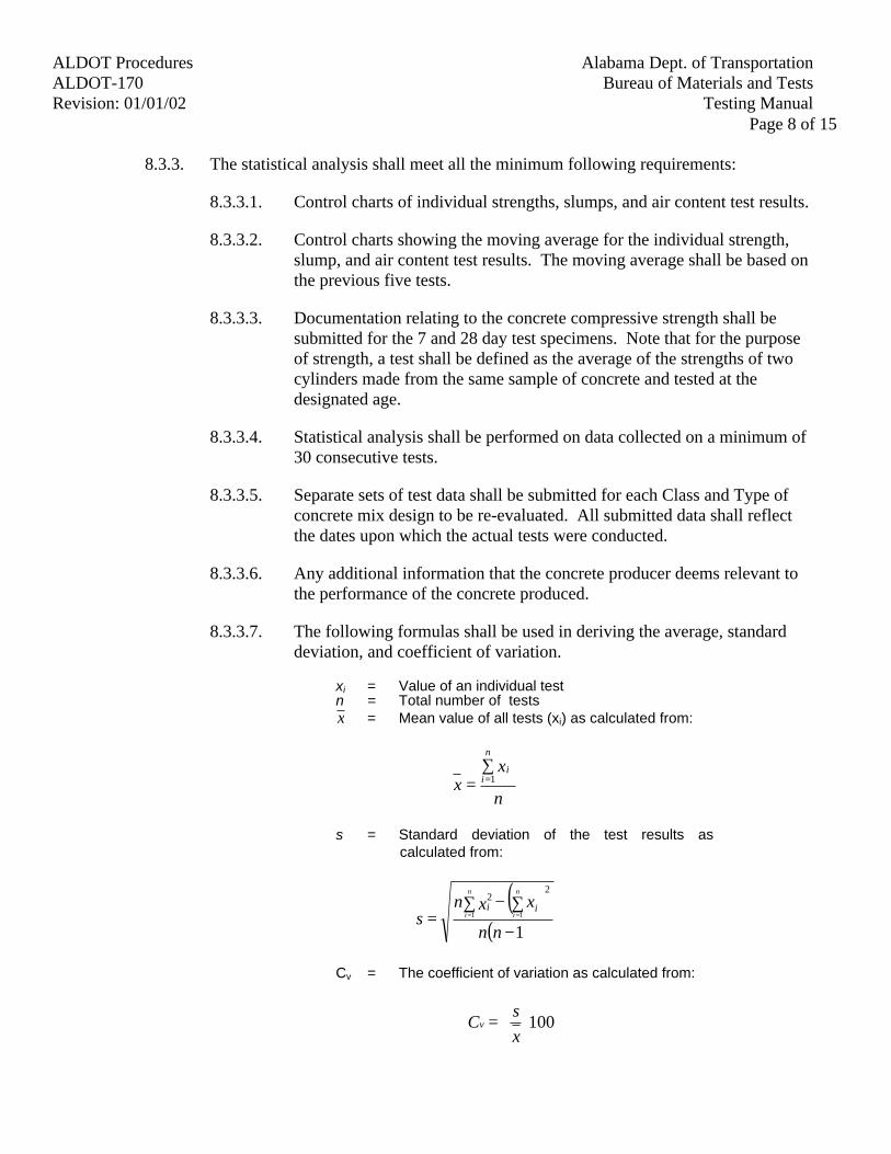
Alabama Dept. of TransportationALDOT ProceduresBureau of Materials and TestsALDOT-170
Testing ManualRevision: 01/01/02Page 8 of 15
8.3.3. The statistical analysis shall meet all the minimum following requirements:
8.3.3.1. Control charts of individual strengths, slumps, and air content test results.
8.3.3.2. Control charts showing the moving average for the individual strength,slump, and air content test results. The moving average shall be based onthe previous five tests.
8.3.3.3. Documentation relating to the concrete compressive strength shall besubmitted for the 7 and 28 day test specimens. Note that for the purposeof strength, a test shall be defined as the average of the strengths of twocylinders made from the same sample of concrete and tested at thedesignated age.
8.3.3.4. Statistical analysis shall be performed on data collected on a minimum of30 consecutive tests.
8.3.3.5. Separate sets of test data shall be submitted for each Class and Type ofconcrete mix design to be re-evaluated. All submitted data shall reflectthe dates upon which the actual tests were conducted.
8.3.3.6. Any additional information that the concrete producer deems relevant tothe performance of the concrete produced.
8.3.3.7. The following formulas shall be used in deriving the average, standarddeviation, and coefficient of variation.
xi = Value of an individual testn = Total number of testsx = Mean value of all tests (xi) as calculated from:
n
xx
n
ii∑
= =1
s = Standard deviation of the test results ascalculated from:
( )( )1
1 1
22
−
∑ ∑−= = =
nn
xxns
n
i
n
iii
Cv = The coefficient of variation as calculated from:
100
=
xs
Cv
Alabama Dept. of Transportation ALDOT ProceduresBureau of Materials and Tests ALDOT-170Testing Manual Revision: 01/01/02
Page 9 of 15
8.4. Re-approval of the concrete mix design will be at the sole discretion of the State Materials andTests Engineer.
9. Inspection of Concrete Plants and Concrete Equipment
9.1. All equipment, tools, and machinery necessary for forming, mixing, placing, finishing, andcuring concrete shall be in satisfactory working condition before the Contractor will be allowedto place concrete on Department projects. The Department reserves the right to inspect thisequipment at any time to insure its workability.
9.2. Concrete plants shall maintain NRMCA certification status. Concrete plants shall also meet therequirements of Section 501 of the Department’s Specifications and AASHTO M 157.
9.3. Moisture probes shall be calibrated every six months by comparing readings obtained from themoisture meter with the total moisture content of the aggregates as determined by AASHTO T255.
9.4. Concrete transit mixers shall be equipped with an approved in line water-metering devicecapable of accurately measuring the amount of water discharged into the concrete load to within± 1% of the reading indicated. The accuracy of water meters shall be determined as perALDOT-407.
9.5. Each transit mixer shall be equipped with an approved automatic counter that shall record thenumber of drum revolutions regardless of the drum speed.
9.6. The Division Materials Engineer will assign a certified Concrete Technician employed by theDepartment to conduct monthly concrete plant inspections. The results of the plant inspectionsshall be recorded on BMT-95.
10. Handling and Storage of Materials
10.1. Cementitious Materials:
10.1.1. Cementitious materials shall be stored in weatherproof and properly ventilated bins toprevent moisture accumulation.
10.1.2. At all times, cementitious materials shall be exposed to air as little as practical toavoid partial hydration from the moisture in the air.
10.1.3. The equipment used to haul cementitious material shall be maintained leak-proof andcontaminant free.
10.2. Aggregates:
10.2.1. Aggregates shall be handled and stored in a way that minimizes segregation anddegradation and prevents contamination by deleterious substances.
Alabama Dept. of TransportationALDOT ProceduresBureau of Materials and TestsALDOT-170
Testing ManualRevision: 01/01/02Page 10 of 15
10.2.2. Aggregate stockpiles shall be built up in successive horizontal layers of uniformthickness to minimize segregation. The work should be done in such a manner as toreduce to a minimum the rolling of aggregates down the slope of the stockpile. Dampening can reduce segregation of fine aggregate that is dry enough to be freeflowing.
10.2.3. Keep the moisture content of aggregates as uniform as possible. Variation in themoisture content of aggregates increases the variability of the concrete produced. Aggregate stockpiles shall be allowed adequate time for drainage to a uniformmoisture content before use.
10.2.4. Section 801 of the Department’s specifications requires that the stockpiling of coarseaggregate be done as per ALDOT-175. It shall be the responsibility of the producer’sConcrete Technician, certified by ALDOT, to ensure proper stockpiling operations.
10.2.5. Aggregates of different grading or from different sources shall be stored separately. Bulkheads or dividers high enough to avoid contamination shall separate stockpiles.
10.2.6. Moisture and gradation tests on both coarse and fine aggregate shall be made as perALDOT-352.
10.3. Chemical Admixtures:
10.3.1. Liquid admixtures shall be stored in watertight drums or tanks and protected fromfreezing.
10.3.2. Admixtures in the form of powder, flakes, or semisolids shall be diluted into asolution prior to use, following the manufacturer’s recommendations.
10.3.3. Admixtures stored for more than six months shall be re-tested before use and rejectedif it fails to conform to any of the requirements of Sections 808 and 809 of theDepartment’s specifications.
11. Control of Mixing Operations
11.1. The Producer’s Concrete Technician, certified by ALDOT, shall refer to the approved concretemix design in regard to the desired proportions of each ingredient that enters into the mix.
11.2. Before concrete production, the Producer’s Concrete Technician, certified by ALDOT, shallcheck that all materials used are from Department approved sources.
11.3. The Producer’s Concrete Technician, certified by ALDOT, shall be responsible for aggregatemoisture adjustments. Each concrete mix design will produce a specific volume of concrete;any changes in the moisture content of the aggregates will result in changes of producedconcrete volume
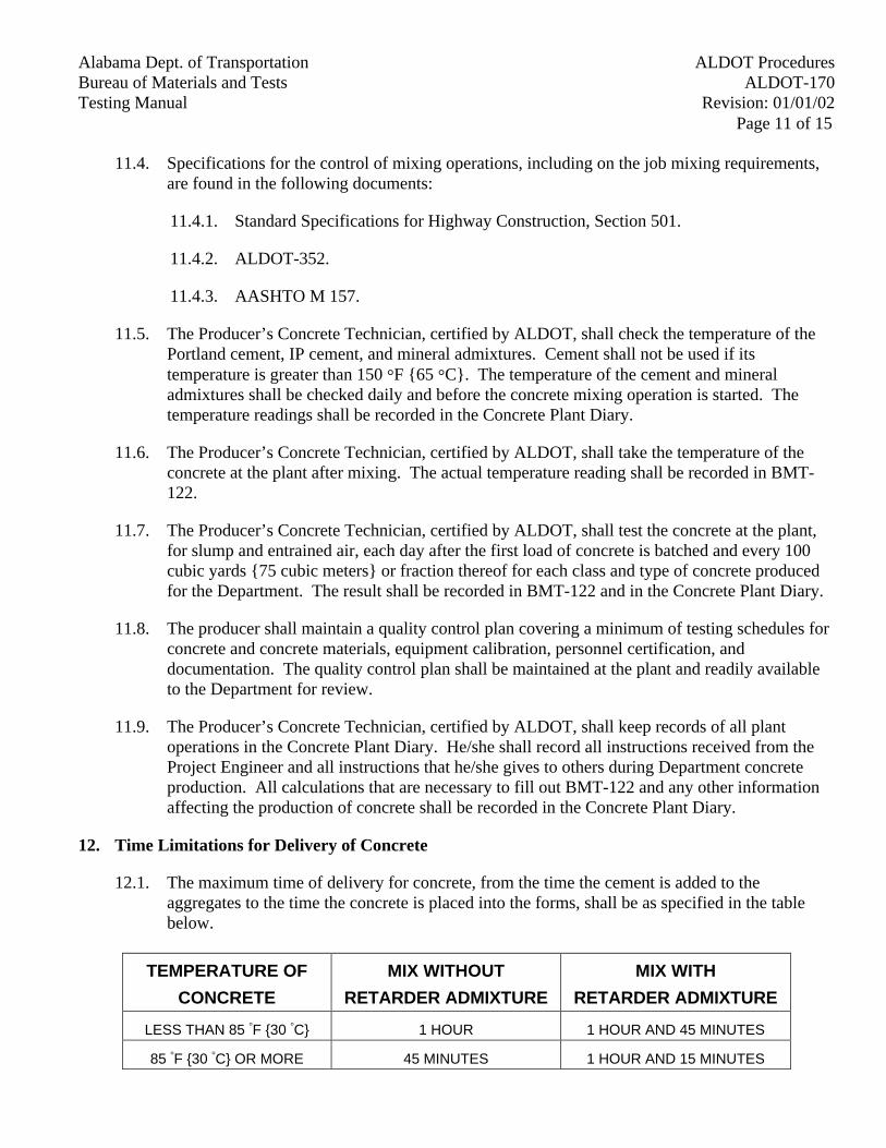
Alabama Dept. of Transportation ALDOT ProceduresBureau of Materials and Tests ALDOT-170Testing Manual Revision: 01/01/02
Page 11 of 15
11.4. Specifications for the control of mixing operations, including on the job mixing requirements,are found in the following documents:
11.4.1. Standard Specifications for Highway Construction, Section 501.
11.4.2. ALDOT-352.
11.4.3. AASHTO M 157.
11.5. The Producer’s Concrete Technician, certified by ALDOT, shall check the temperature of thePortland cement, IP cement, and mineral admixtures. Cement shall not be used if itstemperature is greater than 150 °F {65 °C}. The temperature of the cement and mineraladmixtures shall be checked daily and before the concrete mixing operation is started. Thetemperature readings shall be recorded in the Concrete Plant Diary.
11.6. The Producer’s Concrete Technician, certified by ALDOT, shall take the temperature of theconcrete at the plant after mixing. The actual temperature reading shall be recorded in BMT-122.
11.7. The Producer’s Concrete Technician, certified by ALDOT, shall test the concrete at the plant,for slump and entrained air, each day after the first load of concrete is batched and every 100cubic yards {75 cubic meters} or fraction thereof for each class and type of concrete producedfor the Department. The result shall be recorded in BMT-122 and in the Concrete Plant Diary.
11.8. The producer shall maintain a quality control plan covering a minimum of testing schedules forconcrete and concrete materials, equipment calibration, personnel certification, anddocumentation. The quality control plan shall be maintained at the plant and readily availableto the Department for review.
11.9. The Producer’s Concrete Technician, certified by ALDOT, shall keep records of all plantoperations in the Concrete Plant Diary. He/she shall record all instructions received from theProject Engineer and all instructions that he/she gives to others during Department concreteproduction. All calculations that are necessary to fill out BMT-122 and any other informationaffecting the production of concrete shall be recorded in the Concrete Plant Diary.
12. Time Limitations for Delivery of Concrete
12.1. The maximum time of delivery for concrete, from the time the cement is added to theaggregates to the time the concrete is placed into the forms, shall be as specified in the tablebelow.
TEMPERATURE OF
CONCRETE
MIX WITHOUT
RETARDER ADMIXTURE
MIX WITH
RETARDER ADMIXTURE
LESS THAN 85 °F {30 °C} 1 HOUR 1 HOUR AND 45 MINUTES
85 °F {30 °C} OR MORE 45 MINUTES 1 HOUR AND 15 MINUTES

Alabama Dept. of TransportationALDOT ProceduresBureau of Materials and TestsALDOT-170
Testing ManualRevision: 01/01/02Page 12 of 15
13. Concrete Placing
13.1. Concrete shall be placed as per the requirements in Section 501 of the Department’sspecifications. The plans and contract for the project shall be checked for special concreteplacing requirements.
13.2. Concrete shall be deposited continuously as near as possible to its final position. Concrete shallbe placed in horizontal layers of uniform thickness and each layer shall be thoroughlyconsolidated before the next is placed.
14. Records and Reports
14.1. The Project Engineer shall keep records and reports of all concrete operations. The records andreports will be used to determine if Department specifications are properly followed. Somerecords and reports will be used to control concrete operations and to ensure timely action intaking corrective steps to avoid substandard quality.
14.2. The concrete producer shall keep proper records and reports for all concrete operationsperformed at the concrete plant.
14.3. The concrete producer shall keep on file the following minimum references, records, andreports. Some of these documents may be accessed from the Department’s website atwww.dot.state.al.us
14.3.1. Copy of Alabama Department of Transportation specifications.
14.3.2. Copy of Alabama Department of Transportation Testing Manual.
14.3.3. Copy of the Materials, Sources, and Devices with Special Acceptance Requirementsmanual.
14.3.4. Copy of AASHTO Specifications. Part I and II.
14.3.5. Approved concrete mix design.
14.3.6. BMT-10.
14.3.7. BMT-83,
14.3.8. BMT-114.
14.3.9. BMT-122.
14.3.10. Test reports for all compressive strength tests.
14.3.11. Concrete Plant Dairy with records of moisture corrections and aggregate gradations.
14.3.12. Copy of NRMCA Certification.

Alabama Dept. of Transportation ALDOT ProceduresBureau of Materials and Tests ALDOT-170Testing Manual Revision: 01/01/02
Page 13 of 15
14.3.13. Control charts for air content, slump, and strength for each Class and Type of concretemix.
15. Procedure for Forensic Investigations
15.1. The testing laboratory will notify the Division Materials Engineer when the compressivestrength of the specimens tested is below the specified strength.
15.2. The Division Materials Engineer will conduct an investigation on the substandard concrete todetermine the cause of the low break. The results of the investigation and recommendation willbe reported to the State Materials and Tests Engineer.
15.3. The State Materials and Tests Engineer will forward the Division’s findings andrecommendations and any additional recommendation to the State Construction Engineer forfinal handling.
15.4. The Division Materials Engineer may request the assistance of the Bureau of Materials andTests to perform forensic investigations that are outside the Division’s capabilities. Thisrequest must be in writing (letter, fax, or e-mail), addressed to the State Materials and TestsEngineer, attention Concrete Section, stating the problem and request.
15.5. Upon receiving the forensic investigation request, the Concrete Section of the Bureau ofMaterials and Tests will determine if an investigation is necessary, which may include coringand/or petrographic analyses, to determine the cause(s) of the problem.
15.6. A core investigation will be conducted by the Concrete Section of the Bureau of Materials andTests, or its consultant, as follows. For structural components that are not accessible or toosmall for coring, the Department may use other methods to determine the acceptability of theconcrete.
15.6.1. Delineate the area on the structure representing the set of concrete cylinders withsubstandard strength.
15.6.2. The Swiss hammer instrument will be used to select a location for coring within theaffected area of the structure.
15.6.3. The procedure for the use of the Swiss hammer is as follows:
15.6.3.1. For linear members the length of the member affected will be divided intoten equal segments or three foot {one meter} long segments if the affectedlength is greater than thirty feet {ten meters}.
15.6.3.2. For area members the area of the member affected will be divided intosixteen equal segments or nine square foot {one square meter} segmentsif the affected area is greater than 150 square feet {fifteen square meters}.
15.6.3.3. Three Swiss hammer readings will be taken in each segment and
Alabama Dept. of TransportationALDOT ProceduresBureau of Materials and TestsALDOT-170
Testing ManualRevision: 01/01/02Page 14 of 15
averaged. The segment with the lowest average readings will be thelocation for coring.
15.6.4. Three cores will be obtained, cured, and tested within 42 days from concreteplacement. One set of three cores will be obtained for every set of low compressivestrength cylinders. Cores will be obtained within 35 days after placement of theconcrete to allow for the required curing and testing to be completed within the abovestated 42 days. The Materials and Tests Engineer shall approve any deviation fromthis schedule in writing.
15.6.5. A laboratory qualified by the Department, as per ALDOT-405, shall be used by theContractor to obtain the cores. Cores shall be obtained as per AASHTO T 24 andimmediately protected and shipped to the Bureau of Materials and Tests, attentionConcrete Section, with all pertinent information. An ALDOT representative will bepresent during the coring operation
15.6.6. Extreme caution will be taken to ensure that no reinforcing steel or prestressed strandsare cut during the coring operation.
15.6.7. Core specimens will be measured, cured, and tested in accordance with AASHTO T24. Proper strength correction factor will be applied to cores having a length-to-diameter (L/D) ratio less than two.
15.7. The Concrete Section of the Bureau of Materials and Tests, or its consultant, will conduct apetrographic investigation. The petrographic investigation will be conducted as follows:
15.7.1. The specimens for petrographic analyses will be obtained at the same time that corespecimens are obtained.
15.7.2. Specimens for petrographic analyses will be prepared and tested in accordance to thefollowing specification:
15.7.2.1. ASTM C 457.
15.7.2.2. ASTM C 642.
15.7.2.3. ASTM C 823.
15.7.2.4. ASTM C 856.
15.8. The core investigation and petrographic investigation will be used to determine theacceptability or rejection of substandard concrete.
15.9. The Department reserves the right to use other types of investigation as necessary to fullydetermine the cause(s) for substandard concrete, and use them to determine the acceptability orrejection of the questionable concrete.
Alabama Dept. of Transportation ALDOT ProceduresBureau of Materials and Tests ALDOT-170Testing Manual Revision: 01/01/02
Page 15 of 15
15.10. The State Materials and Tests Engineer will forward its findings and recommendations to theState Construction Engineer and copy the State Bridge Engineer and Division Engineer.
16. Repair of Core Drilled Holes
16.1. All accepted members shall have cores holes repaired using the same concrete mix design usedto originally cast the members.
16.2. The following procedure outlines the minimum requirements to repair core drilled holes:
16.2.1. Mixing of concrete shall be completed a minimum of 45 minutes prior to placing.
16.2.2. The concrete mix shall be re-mixed without adding water just before placing.
16.2.3. The area to be repaired shall be prepared by scarifying and roughening the concretesurface.
16.2.4. Apply an approved Type II or Type V Epoxy in accordance with the epoxymanufacturer’s recommendations.
16.2.5. The re-mixed concrete shall be packed in place with small tools and consolidated bytamping.
16.2.6. The repair shall be cured for seven days using wet curing or approved membrane-curing compounds. For repairs on bridge decks, only wet curing shall be allowed.
16.2.7. After curing, the repaired area shall be finished so as to provide a uniform appearancewith the adjacent concrete.
16.3. Other repair methods may be used if requested in writing to, and approved by, the StateMaterials and Tests Engineer. Alternate repair procedures shall not be used until approved bythe State Materials and Tests Engineer.
Alabama Dept. of Transportation ALDOT ProceduresBureau of Materials and Tests ALDOT-175Testing Manual Revision: 2/25/94
Page 1 of 1
ALDOT 175METHOD OF STOCKPILING COARSE AGGREGATE FOR ALL PURPOSES
1. Scope
1.1. This method of stockpiling coarse aggregate is intended to keep stockpiles from segregating.
2. Equipment
2.1. Crane equipped with a clamshell, front-end loader or bulldozer equipped with largepneumatic tires.
3. Procedure
3.1. Stockpiles shall be placed on firm, well drained ground that is free of any material that couldcause contamination. Stockpiles shall be built in layers of uniform thickness and not incone-shaped piles which result in segregation of piles. After the first layer of the stockpile isplaced, heavy transporting equipment shall not be allowed to run on top of this layer as thistends to degrade the aggregate by grinding the particles together, also contaminating theaggregate with mud and other deleterious substances from the wheels or tracks of the vehicle.If the stockpile is to be constructed in more than one layer in height, the aggregate shall bedumped in a small pile at the base of the stockpile, then moved over the stockpiled layer inplace by a crane equipped with a clamshell, front-end loader or bulldozer equipped with largepneumatic tires. If there is any doubt by the inspector that the aggregate has been degraded,obtain a sample and run gradation on the first layer of the stockpile before the equipment isused and compare this gradation with original gradation test. After the equipment has run onthe layer twenty passes over a given point, obtain sample and run gradation test. If thegradation test shows the aggregate is being degraded to the extent that it fails to meet thespecifications, the equipment being used shall be replaced by another type.
Alabama Dept. of Transportation ALDOT ProceduresBureau of Materials and Tests ALDOT-195Testing Manual Revision: 2/14/94
Page 1 of 2
ALDOT 195-83DOCUMENTATION AND ACCEPTANCE OF MATERIALS USED IN HIGHWAY AND BRIDGE
CONSTRUCTION
1. Scope
1.1. All materials used in the construction of Alabama Department of Transportation projectsmust be inspected, tested, or approved prior to incorporation into the project. The inspectionand documentation process should provide the project with the documentation necessary tocomplete the "Summary of Tests" (BMT-38) at the completion of the project. The necessityfor this documentation can be found in Section 106 of the Department's StandardSpecifications.
1.2. Several methods of acceptance have been established to cover the wide variety of materialsused in construction. The "Acceptance Sampling and Testing Schedule" found in theDepartment's Testing Manual divides these materials by pay item and outlines the minimummethod of acceptance for these materials. This document gives a more detailed descriptionof these methods.
2. Categories Of Acceptance
2.1. On The Job Sampling--This is the most used acceptance method. This form of acceptancewill take precedence over other forms. Should there be doubt as to the quality of a materialthen this method should be used. Authorization for sampling materials can be found inSubarticle 106 of the Standard Specifications. Materials are sampled and/or inspected asthey arrive on the project and testing is then conducted by one of the following.
2.1.1. On site testing by project personnel.
2.1.2. Testing conducted at a Division Laboratory.
2.1.3. Testing conducted at the Department's Central Laboratory.
2.2. Pretested Materials--Pretesting is done for a variety of materials. These materials aregenerally sampled by personnel from the Central Laboratory or Division and are tested priorto shipment to the project. Authority to use these materials is obtained by the following.
2.2.1. Premarked stock--These materials will be either stamped, marked or provided withsome form of Department verification (test report) that the product has been testedand approved. Should there be doubt then this documentation should be verified withthe Bureau of Materials and Tests.
2.2.2. Batch or Lot Numbers--Some materials are marked by the producer's batch, lot, orheat numbers. These groups are sampled and tested as a group. Test reports will beissued for all or a portion of the group. Authorization or verification for use may beobtained by contacting the Bureau of Materials and Tests.
Alabama Dept. of TransportationALDOT ProceduresBureau of Materials and TestsALDOT-195
Testing ManualRevision: 2/14/94Page 2 of 2
2.2.3. Test reports are generally not issued on pretested stocks until shipping releases aresubmitted to the Bureau by the producers or suppliers. Therefore, there will be a timedelay between the use of the material and receipt of the test report.
2.3. Certified Test Reports--Many items are accepted on the basis of certified test reportsfurnished by the producer. These tests are conducted by company and/or privatelaboratories. They should be submitted to the Project Engineer via the Contractor. TheProject Engineer will submit these test reports to the Bureau of Materials and Tests in lieu ofsamples of these materials. They will be checked to assure that they contain actual testresults for all parameters required in the specification and that they meet the requirements ofthe specification. This report will then be placed in the Bureau project file and a Bureau testreport issued to the project. Certifications found to be incomplete or having failing testresults will be stamped as inadequate and returned to the project so that the contractor canresolve the deficiencies.
2.4. Materials, Sources, and Devices with Special Acceptance Requirements--The Departmenthas elected to accept certain products according to special programs. The Product EvaluationBoard oversees these programs. The Bureau of Materials and Tests publishes the manual, bythe same name, containing both the procedures and list of products falling into this category.Each list has an individual procedure established for it. The Project Engineer must consultthe procedure before using these materials.
2.5. Small Quantities--When a contract requires miscellaneous materials (i.e. fence posts, nuts,bolts, etc.) in quantities smaller than normal lots for testing purposes, such quantities may beaccepted by visual inspection or by manufacturer's certification. When authorized by theDivision Materials Engineer, acceptance on a visual basis, by project personnel, will bedocumented on Form BMT-16. The Project Engineer will document the quantity acceptedalong with the observed physical characteristics such as dimension measurements whereapplicable, general condition, workmanship, appearance, etc.
3. Guaranteed Material
3.1. The Project Engineer will have occasions when the Contractor will want to use materialsbefore test reports are in hand. Section 106 of the Standard Specifications, allows theContractor to use certain materials prior to testing under specified conditions. The PrimeContractor is required to execute a Material Guaranty Form (BMT-73).
3.2. The Material Guaranty Form (BMT-73) is an agreement between the Prime Contractor andthe Department. The Prime Contractor agrees to remove all materials in-stalled under thisagreement, as well as any related materials, without additional cost to the Department, shouldthe material fail to meet specifications when tested.
3.3. The Material Guaranty Form (BMT-73) should not be open-ended. The Project Engineershould use discretion in allowing its use. Subarticle 106 states: "The Engineer reserves theright to refuse permission for use of materials on the guaranty basis at any time".
Alabama Dept. of Transportation ALDOT ProceduresBureau of Materials and Tests ALDOT-210Testing Manual Revision: 2/24/94
Page 1 of 9
ALDOT-210-90SELECTING SAMPLES BY THE RANDOM NUMBERS METHOD
Definition: A random sample is a sample taken by the use of a sampling plan in which each unit of a lotmust have an equal chance of being chosen.
The following is an explanation of the procedure of sampling by random numbers. This system of samplingcan be used for all types of materials. It can be used to determine the location for sampling (as stationsalong a roadway and distances from a pavement edge), truck numbers, or the point in production forsampling. We will give five examples. This procedure may be expanded to other materials andcircumstances as needed.
Example No. 1
This example procedure will result in stratified random samples. The procedure is used when sampling isaccomplished as construction progresses. The material that is to be sampled must be divided into lots. Thenit must be determined how many samples will be required to represent a lot so that the lot can be dividedinto sublots.
In this example we will select stations and distances from the right edge of a base course from whichsamples shall be taken to represent base course layers for 50 stations of a project. For this example, we willuse Station 137+00 to 187+00 as the lot. The width to be sampled will be 24 ft. (7.2 m) and the location ofthe sample will be measured from the right edge of the base. We will use five samples to represent the 50station lot. Five sublots will be set up from which the five stratified random samples are selected. Use thefollowing steps to select where the five samples will be taken.
1. The 50 station lot is first divided into 10 station sublots as shown. Each sublot will be 10 stations or1000 ft (300m) in length.
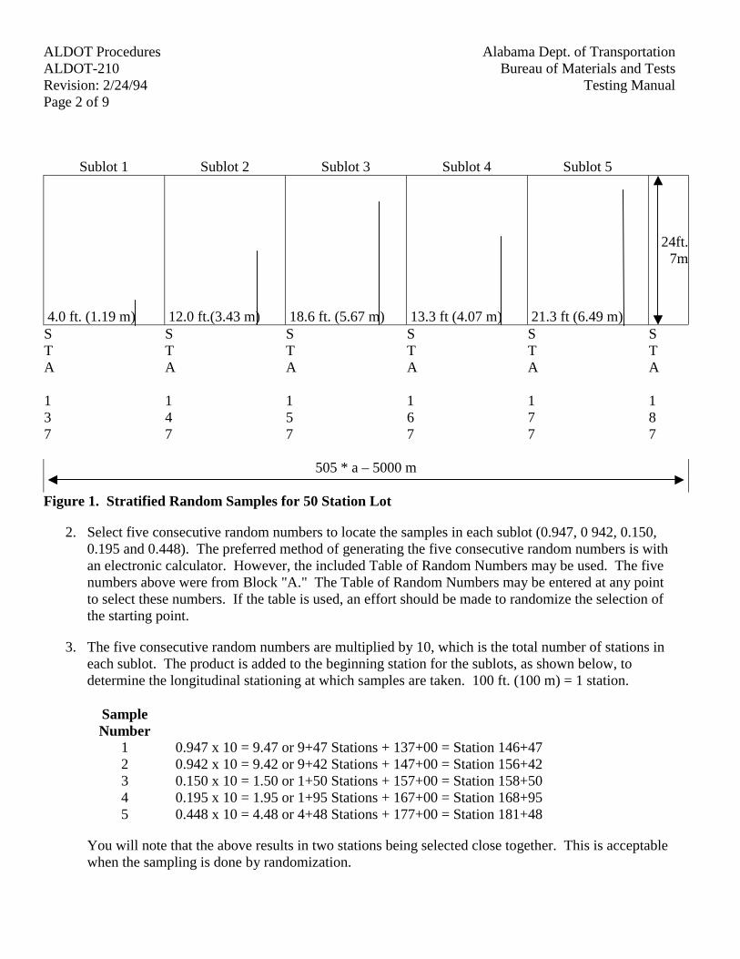
Alabama Dept. of TransportationALDOT ProceduresBureau of Materials and TestsALDOT-210
Testing ManualRevision: 2/24/94Page 2 of 9
Sublot 1 Sublot 2 Sublot 3 Sublot 4 Sublot 5
4.0 ft. (1.19 m) 12.0 ft.(3.43 m) 18.6 ft. (5.67 m) 13.3 ft (4.07 m) 21.3 ft (6.49 m)
24ft.7m
STA
137
STA
147
STA
157
STA
167
STA
177
STA
187
505 * a – 5000 m
Figure 1. Stratified Random Samples for 50 Station Lot
2. Select five consecutive random numbers to locate the samples in each sublot (0.947, 0 942, 0.150,0.195 and 0.448). The preferred method of generating the five consecutive random numbers is withan electronic calculator. However, the included Table of Random Numbers may be used. The fivenumbers above were from Block "A." The Table of Random Numbers may be entered at any pointto select these numbers. If the table is used, an effort should be made to randomize the selection ofthe starting point.
3. The five consecutive random numbers are multiplied by 10, which is the total number of stations ineach sublot. The product is added to the beginning station for the sublots, as shown below, todetermine the longitudinal stationing at which samples are taken. 100 ft. (100 m) = 1 station.
SampleNumber
1 0.947 x 10 = 9.47 or 9+47 Stations + 137+00 = Station 146+472 0.942 x 10 = 9.42 or 9+42 Stations + 147+00 = Station 156+423 0.150 x 10 = 1.50 or 1+50 Stations + 157+00 = Station 158+504 0.195 x 10 = 1.95 or 1+95 Stations + 167+00 = Station 168+955 0.448 x 10 = 4.48 or 4+48 Stations + 177+00 = Station 181+48
You will note that the above results in two stations being selected close together. This is acceptablewhen the sampling is done by randomization.
Alabama Dept. of Transportation ALDOT ProceduresBureau of Materials and Tests ALDOT-210Testing Manual Revision: 2/24/94
Page 3 of 9
4. To select the transverse distance from the right edge of the base course, five additional consecutiverandom numbers are selected and calculations are made using the 24 ft (7.2 m) distances from theright edge of the base. The numbers below are from Block "B" in the Table of Random Numbers.
SampleNumber
1 0.165 x 24 ft.(7.2 m )= 3.96 ft. ( 1.19 m) from right edge of base course2 0.477 x 24 ft. ( 7.2 m) = 11.4 ft (3.43 m )from right edge of base course3 0.788 x 24 ft.(7.2 m) = 18..9 ft. (5.67 m)from right edge of base course4 0.566 x 24 ft. (7.2 m )= 16.0 ft. (4.07 m )from right edge of base course5 0.901 x 24 ft. (7.2 m)= 21.6 ft. (6.49 m) from right edge of base course
5. From the above calculations we find the following sampling schedule for the fifty station lot:
SampleNumber
Station Distance FromRight Edge
1 146+47 3.96 ft (1.19m)2 156+42 11.4 ft (3.43m)3 158+50 18.9 ft (5.67m)4 168+95 16.0 ft (4.07m)5 181+48 21.6 ft (6.49m)
Example No. 2
This example procedure will result in random samples. The procedure is used when the entirepopulation is available for sampling at one time. The project shows 9,657 reflective roadwaymarkers are required. The specifications require that each 3,000 unit lot be represented by 50 unitsor samples. This will result in four lots to represent the project. The markers are packaged 50 fiftyto each carton. The following procedure is used to select random samples to represent this project.
1. Separate the 9,657 markers into four lots. This will result in 60 cartons to each whole lot.
2. Stack the cartons for each lot in an arrangement that will permit numbering each cartonconsecutively from one to 60.
3. Select 50 consecutive random numbers with an electronic calculator or the Table of RandomNumbers. The following numbers are from Block "C" of the Table of Random Numbers. Multiplyeach number by 3,000. This product is the roadway marker number selected for one sample of 50samples to represent the lot of 3,000 markers.
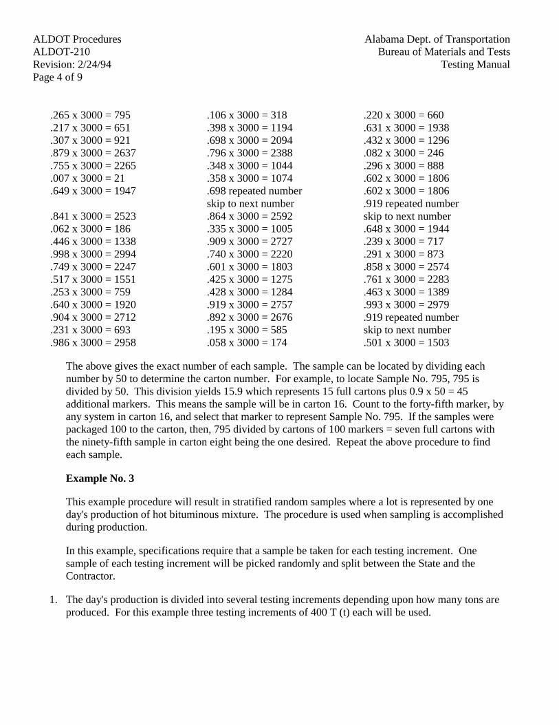
Alabama Dept. of TransportationALDOT ProceduresBureau of Materials and TestsALDOT-210
Testing ManualRevision: 2/24/94Page 4 of 9
.265 x 3000 = 795 .106 x 3000 = 318 .220 x 3000 = 660
.217 x 3000 = 651 .398 x 3000 = 1194 .631 x 3000 = 1938
.307 x 3000 = 921 .698 x 3000 = 2094 .432 x 3000 = 1296
.879 x 3000 = 2637 .796 x 3000 = 2388 .082 x 3000 = 246
.755 x 3000 = 2265 .348 x 3000 = 1044 .296 x 3000 = 888
.007 x 3000 = 21 .358 x 3000 = 1074 .602 x 3000 = 1806
.649 x 3000 = 1947 .698 repeated number .602 x 3000 = 1806skip to next number .919 repeated number
.841 x 3000 = 2523 .864 x 3000 = 2592 skip to next number
.062 x 3000 = 186 .335 x 3000 = 1005 .648 x 3000 = 1944
.446 x 3000 = 1338 .909 x 3000 = 2727 .239 x 3000 = 717
.998 x 3000 = 2994 .740 x 3000 = 2220 .291 x 3000 = 873
.749 x 3000 = 2247 .601 x 3000 = 1803 .858 x 3000 = 2574
.517 x 3000 = 1551 .425 x 3000 = 1275 .761 x 3000 = 2283
.253 x 3000 = 759 .428 x 3000 = 1284 .463 x 3000 = 1389
.640 x 3000 = 1920 .919 x 3000 = 2757 .993 x 3000 = 2979
.904 x 3000 = 2712 .892 x 3000 = 2676 .919 repeated number
.231 x 3000 = 693 .195 x 3000 = 585 skip to next number
.986 x 3000 = 2958 .058 x 3000 = 174 .501 x 3000 = 1503
The above gives the exact number of each sample. The sample can be located by dividing eachnumber by 50 to determine the carton number. For example, to locate Sample No. 795, 795 isdivided by 50. This division yields 15.9 which represents 15 full cartons plus 0.9 x 50 = 45additional markers. This means the sample will be in carton 16. Count to the forty-fifth marker, byany system in carton 16, and select that marker to represent Sample No. 795. If the samples werepackaged 100 to the carton, then, 795 divided by cartons of 100 markers = seven full cartons withthe ninety-fifth sample in carton eight being the one desired. Repeat the above procedure to findeach sample.
Example No. 3
This example procedure will result in stratified random samples where a lot is represented by oneday's production of hot bituminous mixture. The procedure is used when sampling is accomplishedduring production.
In this example, specifications require that a sample be taken for each testing increment. Onesample of each testing increment will be picked randomly and split between the State and theContractor.
1. The day's production is divided into several testing increments depending upon how many tons areproduced. For this example three testing increments of 400 T (t) each will be used.
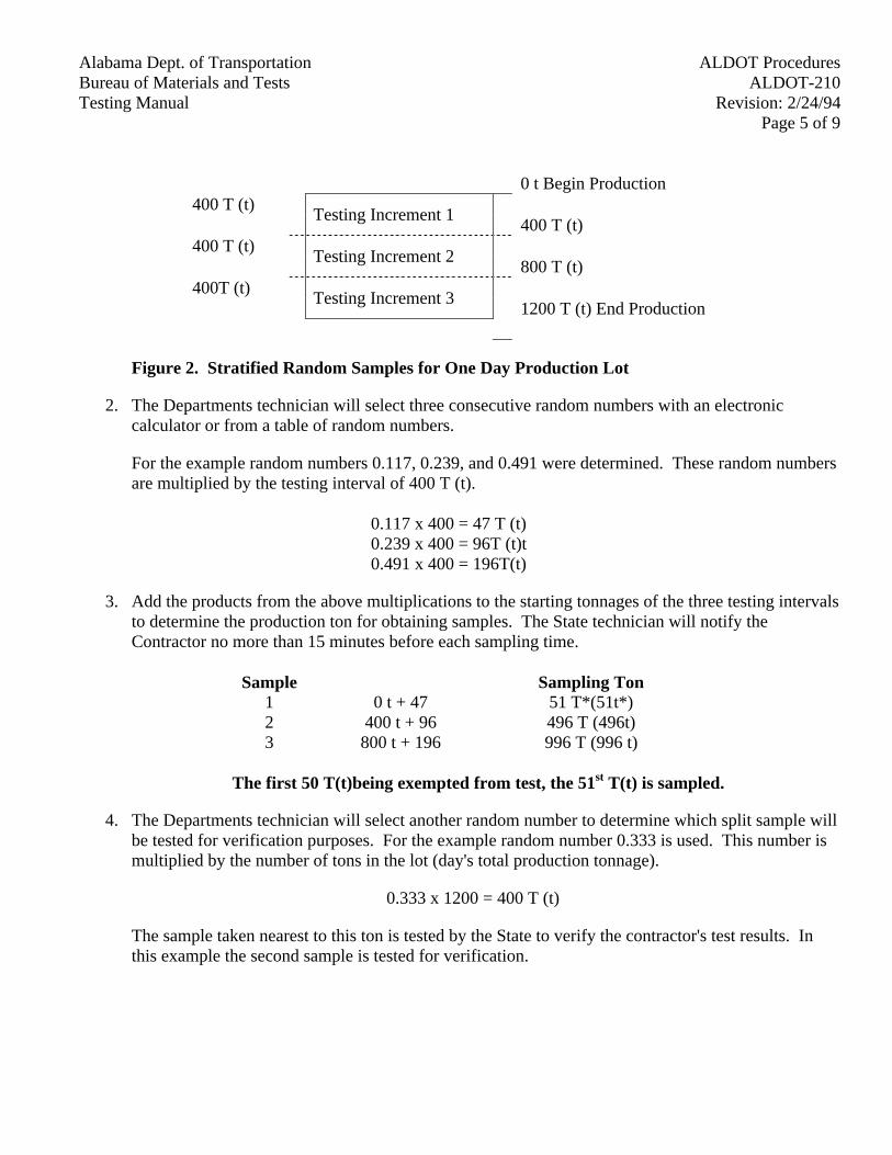
Alabama Dept. of Transportation ALDOT ProceduresBureau of Materials and Tests ALDOT-210Testing Manual Revision: 2/24/94
Page 5 of 9
0 t Begin Production400 T (t)
Testing Increment 1400 T (t)
400 T (t)Testing Increment 2
800 T (t)400T (t)
Testing Increment 31200 T (t) End Production
Figure 2. Stratified Random Samples for One Day Production Lot
2. The Departments technician will select three consecutive random numbers with an electroniccalculator or from a table of random numbers.
For the example random numbers 0.117, 0.239, and 0.491 were determined. These random numbersare multiplied by the testing interval of 400 T (t).
0.117 x 400 = 47 T (t)0.239 x 400 = 96T (t)t0.491 x 400 = 196T(t)
3. Add the products from the above multiplications to the starting tonnages of the three testing intervalsto determine the production ton for obtaining samples. The State technician will notify theContractor no more than 15 minutes before each sampling time.
Sample Sampling Ton1 0 t + 47 51 T*(51t*)2 400 t + 96 496 T (496t)3 800 t + 196 996 T (996 t)
The first 50 T(t)being exempted from test, the 51st T(t) is sampled.
4. The Departments technician will select another random number to determine which split sample willbe tested for verification purposes. For the example random number 0.333 is used. This number ismultiplied by the number of tons in the lot (day's total production tonnage).
0.333 x 1200 = 400 T (t)
The sample taken nearest to this ton is tested by the State to verify the contractor's test results. Inthis example the second sample is tested for verification.
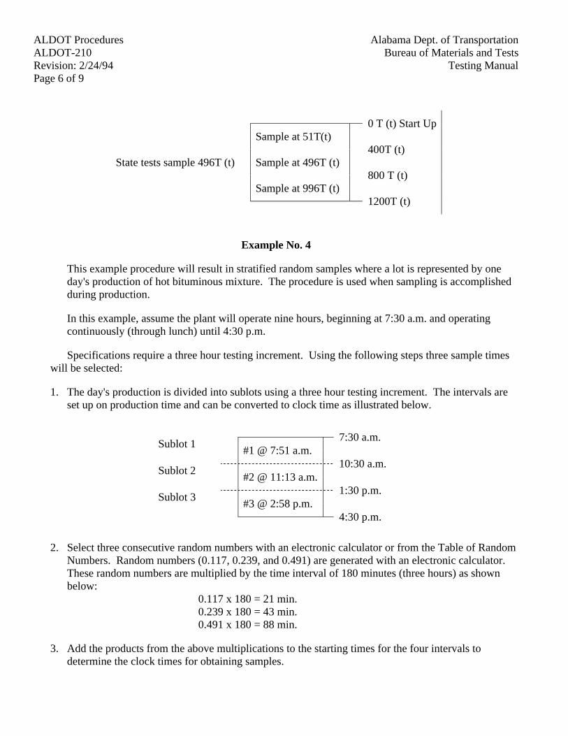
Alabama Dept. of TransportationALDOT ProceduresBureau of Materials and TestsALDOT-210
Testing ManualRevision: 2/24/94Page 6 of 9
0 T (t) Start UpSample at 51T(t)
400T (t)State tests sample 496T (t) Sample at 496T (t)
800 T (t)Sample at 996T (t)
1200T (t)
Example No. 4
This example procedure will result in stratified random samples where a lot is represented by oneday's production of hot bituminous mixture. The procedure is used when sampling is accomplishedduring production.
In this example, assume the plant will operate nine hours, beginning at 7:30 a.m. and operatingcontinuously (through lunch) until 4:30 p.m.
Specifications require a three hour testing increment. Using the following steps three sample timeswill be selected:
1. The day's production is divided into sublots using a three hour testing increment. The intervals areset up on production time and can be converted to clock time as illustrated below.
Sublot 17:30 a.m.
#1 @ 7:51 a.m.
Sublot 210:30 a.m.
#2 @ 11:13 a.m.
Sublot 31:30 p.m.
#3 @ 2:58 p.m.4:30 p.m.
2. Select three consecutive random numbers with an electronic calculator or from the Table of RandomNumbers. Random numbers (0.117, 0.239, and 0.491) are generated with an electronic calculator.These random numbers are multiplied by the time interval of 180 minutes (three hours) as shownbelow:
0.117 x 180 = 21 min.0.239 x 180 = 43 min.0.491 x 180 = 88 min.
3. Add the products from the above multiplications to the starting times for the four intervals todetermine the clock times for obtaining samples.
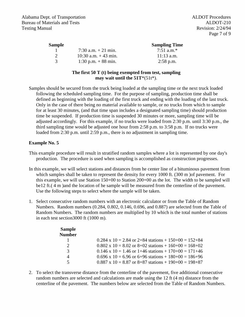
Alabama Dept. of Transportation ALDOT ProceduresBureau of Materials and Tests ALDOT-210Testing Manual Revision: 2/24/94
Page 7 of 9
Sample Sampling Time1 7:30 a.m. + 21 min. 7:51 a.m.*2 10:30 a.m. + 43 min. 11:13 a.m.3 1:30 p.m. + 88 min. 2:58 p.m.
The first 50 T (t) being exempted from test, samplingmay wait until the 51T*(51t*).
Samples should be secured from the truck being loaded at the sampling time or the next truck loadedfollowing the scheduled sampling time. For the purpose of sampling, production time shall bedefined as beginning with the loading of the first truck and ending with the loading of the last truck.Only in the case of there being no material available to sample, or no trucks from which to samplefor at least 30 minutes, (and that time span includes a designated sampling time) should productiontime be suspended. If production time is suspended 30 minutes or more, sampling time will beadjusted accordingly. For this example, if no trucks were loaded from 2:30 p.m. until 3:30 p.m., thethird sampling time would be adjusted one hour from 2:58 p.m. to 3:58 p.m. If no trucks wereloaded from 2:30 p.m. until 2:59 p.m., there is no adjustment in sampling time.
Example No. 5
This example procedure will result in stratified random samples where a lot is represented by one day'sproduction. The procedure is used when sampling is accomplished as construction progresses.
In this example, we will select stations and distances from he center line of a bituminous pavement fromwhich samples shall be taken to represent the density for every 1000 ft. (300 m )of pavement. Forthis example, we will use Station 150+00 to Station 200+00 as the lot. The width to be sampled willbe12 ft.( 4 m )and the location of he sample will be measured from the centerline of the pavement.Use the following steps to select where the sample will be taken.
1. Select consecutive random numbers with an electronic calculator or from the Table of RandomNumbers. Random numbers (0.284, 0.802, 0.146, 0.696, and 0.887) are selected from the Table ofRandom Numbers. The random numbers are multiplied by 10 which is the total number of stationsin each test section3000 ft (1000 m).
SampleNumber
1 0.284 x 10 = 2.84 or 2+84 stations + 150+00 = 152+842 0.802 x 10 = 8.02 or 8+02 stations + 160+00 = 168+023 0.146 x 10 = 1.46 or 1+46 stations + 170+00 = 171+464 0.696 x 10 = 6.96 or 6+96 stations + 180+00 = 186+965 0.887 x 10 = 8.87 or 8+87 stations + 190+00 = 198+87
2. To select the transverse distance from the centerline of the pavement, five additional consecutiverandom numbers are selected and calculations are made using the 12 ft (4 m) distance from thecenterline of the pavement. The numbers below are selected from the Table of Random Numbers.
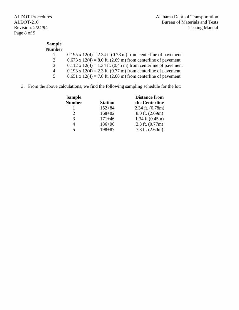
Alabama Dept. of TransportationALDOT ProceduresBureau of Materials and TestsALDOT-210
Testing ManualRevision: 2/24/94Page 8 of 9
SampleNumber
1 0.195 x 12(4) = 2.34 ft (0.78 m) from centerline of pavement2 0.673 x 12(4) = 8.0 ft. (2.69 m) from centerline of pavement3 0.112 x 12(4) = 1.34 ft. (0.45 m) from centerline of pavement4 0.193 x 12(4) = 2.3 ft. (0.77 m) from centerline of pavement5 0.651 x 12(4) = 7.8 ft. (2.60 m) from centerline of pavement
3. From the above calculations, we find the following sampling schedule for the lot:
SampleNumber Station
Distance fromthe Centerline
1 152+84 2.34 ft. (0.78m)2 168+02 8.0 ft. (2.69m)3 171+46 1.34 ft (0.45m)4 186+96 2.3 ft. (0.77m)5 198+87 7.8 ft. (2.60m)
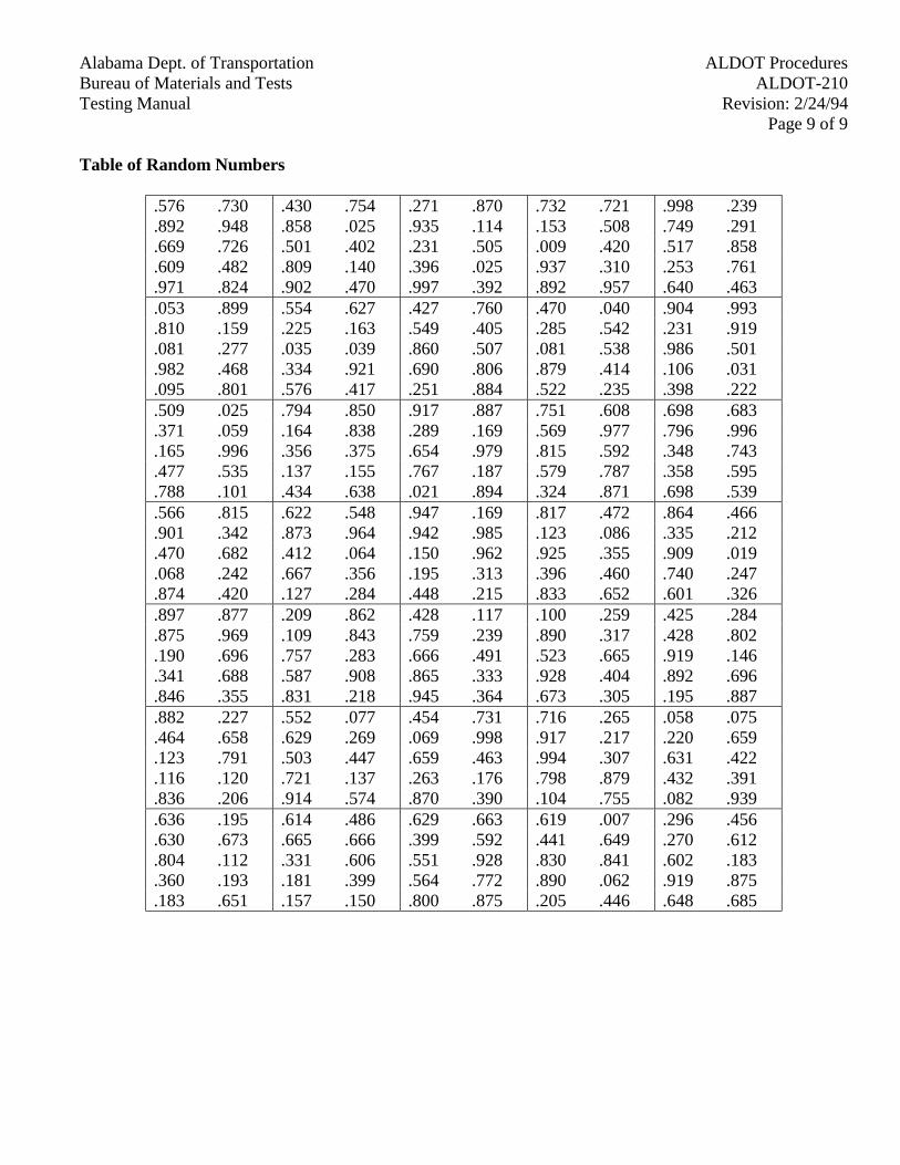
Alabama Dept. of Transportation ALDOT ProceduresBureau of Materials and Tests ALDOT-210Testing Manual Revision: 2/24/94
Page 9 of 9
Table of Random Numbers
.576 .730 .430 .754 .271 .870 .732 .721 .998 .239
.892 .948 .858 .025 .935 .114 .153 .508 .749 .291
.669 .726 .501 .402 .231 .505 .009 .420 .517 .858
.609 .482 .809 .140 .396 .025 .937 .310 .253 .761
.971 .824 .902 .470 .997 .392 .892 .957 .640 .463
.053 .899 .554 .627 .427 .760 .470 .040 .904 .993
.810 .159 .225 .163 .549 .405 .285 .542 .231 .919
.081 .277 .035 .039 .860 .507 .081 .538 .986 .501
.982 .468 .334 .921 .690 .806 .879 .414 .106 .031
.095 .801 .576 .417 .251 .884 .522 .235 .398 .222
.509 .025 .794 .850 .917 .887 .751 .608 .698 .683
.371 .059 .164 .838 .289 .169 .569 .977 .796 .996
.165 .996 .356 .375 .654 .979 .815 .592 .348 .743
.477 .535 .137 .155 .767 .187 .579 .787 .358 .595
.788 .101 .434 .638 .021 .894 .324 .871 .698 .539
.566 .815 .622 .548 .947 .169 .817 .472 .864 .466
.901 .342 .873 .964 .942 .985 .123 .086 .335 .212
.470 .682 .412 .064 .150 .962 .925 .355 .909 .019
.068 .242 .667 .356 .195 .313 .396 .460 .740 .247
.874 .420 .127 .284 .448 .215 .833 .652 .601 .326
.897 .877 .209 .862 .428 .117 .100 .259 .425 .284
.875 .969 .109 .843 .759 .239 .890 .317 .428 .802
.190 .696 .757 .283 .666 .491 .523 .665 .919 .146
.341 .688 .587 .908 .865 .333 .928 .404 .892 .696
.846 .355 .831 .218 .945 .364 .673 .305 .195 .887
.882 .227 .552 .077 .454 .731 .716 .265 .058 .075
.464 .658 .629 .269 .069 .998 .917 .217 .220 .659
.123 .791 .503 .447 .659 .463 .994 .307 .631 .422
.116 .120 .721 .137 .263 .176 .798 .879 .432 .391
.836 .206 .914 .574 .870 .390 .104 .755 .082 .939
.636 .195 .614 .486 .629 .663 .619 .007 .296 .456
.630 .673 .665 .666 .399 .592 .441 .649 .270 .612
.804 .112 .331 .606 .551 .928 .830 .841 .602 .183
.360 .193 .181 .399 .564 .772 .890 .062 .919 .875
.183 .651 .157 .150 .800 .875 .205 .446 .648 .685

Alabama Dept. of Transportation ALDOT ProceduresBureau of Materials and Tests ALDOT-222Testing Manual Revision: 2/15/94
Page 1 of 5
ALDOT-222-82IN-PLACE DENSITY AND MOISTURE MEASUREMENTS AND ESTABLISHING MOISTURE
CORRELATIONS FOR NUCLEAR MOISTURE/DENSITY GAUGES
1. Scope
1.1. This method of test provides a non-destructive measurement of in-place density and moisturecontent of soils and/or aggregate bases and thick layers of bituminous mixtures of 225 lbs/yd2
(120 kg/m2) or greater.
Note 1: Operators shall have a current operator's card issued by the Bureau of Materials andTests after completion of the Radiation Safety Course. Operators are also required to becertified as Roadway Technician's by the Bureau of Materials and Tests.
2. Applicable Documents
2.1. Radiological Safety Manual; Manufacturers Operating Manual Supplied with gauge; NuclearGauge Training Manual available from the Bureau of Materials and Tests; AASHTO T-265Laboratory Determination of Moisture Content of Soils; M&T-14 Revised TechnicalSpecifications for Nuclear Moisture/Density Gauges; ALDOT-341 Standard Procedures forComparing Independent Assurance Samples and Tests (IAS&T); Acceptance Test Results;AASHTO T-166 Bulk Specific Gravity of Compacted Bituminous Mixtures Using SaturatedSurface-Dry Specimens; and, ALDOT-210 Selecting Samples by the Random NumbersMethod.
3. Nuclear Gauging Device
3.1. This device must meet M&T 14 Revised, available at the Bureau of Materials and Tests.
Note 2: Before acceptance, gauge will be checked on Alabama Department ofTransportation calibration standards and gauge accuracy will be required to be within ± 1.5%(1.5 lbs) (0.6818 kg) of calibration standards.
4. Apparatus
4.1. Cans - Four cans with a capacity of 500 g minimum with lids to prevent loss of moisture.
5. Procedure for Standardizing Check of Equipment
5.1. Check the gauge against a reference standard at least twice a day or more frequently ifclimatic, transporting, background or other conditions necessitate.
5.2. When using a CPN MC-1 or a Troxler 3401-B, a warm-up period for the gauge is required(use the manufacturer's recommendations for warm-up). After warm-up, take five one-minute counts on reference standard and average (to be used as a Standard Count).
Alabama Dept. of TransportationALDOT ProceduresBureau of Materials and TestsALDOT-222
Testing ManualRevision: 2/15/94Page 2 of 5
5.3. The average for the five one-minute counts should be within the permissible variations setforth in Table 1. If any one individual count is outside of the statistical limits, a repeat of theentire count run is required.
6. Table 1
Acceptable Range of Count Variations Used for Standardizing and Calibrating Moisture DensityNuclear Gauges
Average Standard Counts (ASC) Permissible Variations ± (1.96 ASC)70,000 ± 52045,000 ± 41536,000 ± 37516,000 ± 2507,000 ± 1654,000 ± 1253,000 ± 1072,000 ± 88
7. Procedure For In-Place Density And Moisture Tests
7.1. Clear away all loose surface material or dried crust and obtain a plane sufficient in area toaccommodate the gauge and extending 6 in. (150 mm) beyond the gauge housing. (A probehole is required for a direct transmission type gauge.)
7.2. Where sheepsfoot and similar type tamping rollers have been used, remove the loose surfacematerial to a depth at least equal to the deepest penetration of the roller foot.
7.3. Modes of transmission shall be as follows:
7.3.1. Direct - May be used on all materials exceeding 2 in. (50 mm) in thickness and willbe required for embankment, roadbed and fine grained base layers.
7.3.2. Backscatter - For most bituminous mixtures, and high coarse aggregate content baselayers.
7.3.3. Backscatter/Air Gap - For very open graded high coarse aggregate content base layersand bituminous mixtures.
Note 3: Careful seating of the gauge is necessary. The surface under the gauge mustbe plane. When direct transmission mode is used, the access hole for the probe mustbe perpendicular to the base plane. Minor depressions, not exceeding 0.13 in. (3 mm)may be filled with native fines removed from the layer being tested. (Ottowa sand orany fine sand may be substituted for native fines.)
7.4. Take one one-minute reading, recording both moisture and density counts.
Alabama Dept. of Transportation ALDOT ProceduresBureau of Materials and Tests ALDOT-222Testing Manual Revision: 2/15/94
Page 3 of 5
7.5. Rotate gauge at least 90° over the same centerpoint and obtain one additional one-minutetime reading and record the moisture and density counts.
7.6. When operating gauge within 24 in. (600 mm) of the edge of the road-bed or asphalt mat, usethe following procedure. For initial reading, place gauge parallel to the edge of the layerbeing tested. Then, rotate gauge at 60° intervals (over same centerpoint) to obtain the nextthree (3) readings. The last reading should be taken opposite the first reading, leaving thegauge parallel to the edge of the layer being tested.
Note 4: Measurement counts should be repeated if any count varies more than ± five (5)times the square root of the average.
Note 5: Nuclear gauge systems having radiation source materials in individual housingsmust be separated at least 3 m when counts are being taken.
8. Calculations
8.1. Wet density
nR =
asc
WhereR = wet density count ration = average count for the one minute time readings for density probeasc = average standard count for density probe
8.1.1. Wet density (D) in lbs/ft3(kg/m3). Locate R on calibration chart and recordcorresponding wet density (D) to nearest 0.25 lb (0.113 kg).
Note 6: Manufacturers supply a computer print-out for density and moisture measurements.These measurements are to the nearest 0.5 lb (0.227 kg) for density and 0.25 lb (0.113 kg) formoisture. To record to nearest 0.2 lb (0.0909 kg), interpolation is required for the densityprintout.
8.2. Moisture Content
n1R1 = asc1
WhereR1 = moisture count ration 1= average count for the one minute time readings for moisture probeasc 1= average standard count for moisture probe
8.2.1. Moisture content (M) in lbs/ft3 (kg/m3). Locate R on calibration chart and recordcorresponding moisture content (M) to nearest 0.2 lb (0.113 kg).
Alabama Dept. of TransportationALDOT ProceduresBureau of Materials and TestsALDOT-222
Testing ManualRevision: 2/15/94Page 4 of 5
8.3. Dry density in lbs/ft3 (kg/m3)
D1 = D - M
WhereD1 = dry density in lb/ft3 (kg/m3)
8.4. Percent moisture
MP =
D1
X 100
WhereP = percent moisture (soil dry basis)M=moisture content in lb/ft3 (kg/m3)D1=dry density in lb/ft3 (kg/m3)
8.5. Percent comparative compaction
D1P =D2
X 100
WhereP = percent of comparative compactionD1 = dry density in lbs/ft3 (kg/m3)D2 = control weight of material expressed in lbs/ft3 (kg/m3).
9. Correlation of Moisture and Density Curves
9.1. Correlation moisture curves, when deemed necessary, will be under the direction of theMaterials and Tests Engineer. Moisture curves will be correlated to values determined byAASHTO T-265.
9.2. For a moisture correlation, run four separate density tests. Record wet density in lbs/ft3
(kg/m3) and moisture content in lbs/ft3 (kg/m3) from the nuclear gauge for each separate test.Obtain a moisture sample with a minimum weight of 500 g from each test site and place incans for transportation to division lab. Run moisture samples per AASHTO T265 to obtainoven dried moisture content of the samples. Using the nuclear gauge wet density andmoisture content in lbs/ft3 (kg/m3), along with the results (percent moisture) of the laboratoryoven dried moisture tests, Division Materials personnel will determine an individual moisturecorrelation for each of the four separate density tests, and will then average the individualvalues to obtain an overall moisture correlation. Sound engineering judgment should beutilized in the averaging process. If one of the individual moisture correlation values issignificantly different from the other values, it should not be included in the averagingprocess to determine the overall moisture correlation. After the moisture correlation has beendetermined, Division Materials personnel will report the value in writing, with a copy sent to
Alabama Dept. of Transportation ALDOT ProceduresBureau of Materials and Tests ALDOT-222Testing Manual Revision: 2/15/94
Page 5 of 5
the Central Office Materials Engineer. Data/Calculations used in determining the moisturecorrelation are to be placed in the project file at the Division office.
Note 7: Division Materials personnel will issue a temporary moisture correlation, if needed,based on gauge wet density and moisture content along with results from field dried moisturesamples until oven dried results are available.
10. Procedure
10.1. Density of asphalt base and pavement layers determined by nuclear gauge readings will becorrelated to density of core specimens obtained from the layer as determined by AASHTOT-166. Four core specimens from the layer being tested will be required for density curvecorrelations. The density correlation will be determined by establishing the differencebetween the average gauge density readings and the average bituminous core densities. If theaverage gauge wet density lbs/ft3 (kg/m3) is higher than the aver-age bituminous core densitylbs/ft3 (kg/m3) the correlation will be negative. If the average gauge wet density lbs/ft3
(kg/m3) is lower than the average bituminous core density lbs/ft3 (kg/m3) the correlation willbe positive.
Example: Average gauge wet density 130.0 lbs/ft3 (2028.4 kg/m³) average bituminous coredensity 137.5 lbs/ft3 (2145.5 kg/m³) equals a plus 7.5 lbs/ft3 (117.1 kg/m³) correlation.
Note 8: The density correlation shall be added to or subtracted from the nuclear gauge wetdensity reading.
11. Comparing IAS&T Samples and Tests and Acceptance Test Results
11.1. Compare in accordance with ALDOT-341 and pay special attention to Table #1.
Alabama Dept. of Transportation ALDOT ProceduresBureau of Materials and Tests ALDOT-223Testing Manual Revision: 2/15/94
Page 1 of 4
ALDOT-223-71AESTABLISHING MOISTURE-DENSITY CONTROLS FOR SOILS AND/OR
AGGREGATES WITH CHEMICAL ADDITIVES(EXCLUDING BITUMINOUS MATERIALS)
1. Scope
1.1. These methods of test are intended for determining the relation between the moisture contentand density of soils compacted in a mold of a given size with a 5.5 lb (2.5 kg) rammerdropped from a height of 12 in (300 mm). Two alternate procedures are provided as follows:
1.1.1. Method A – 4 in. (100 mm mold): For material with 20% or less aggregate retainedon the ¾ in. (19 mm sieve).
1.1.2. Method B - 6 in. (150 mm mold): For material with greater than 20% aggregateretained on the ¾ in, (19 mm sieve)
2. Equipment
2.1. Molds - the molds shall be cylindrical in shape, made of metal, and shall have the capacityand dimensions indicated in Method A or B. They shall have a detachable collar assemblyapproximately 2.5 in.(60 mm)in height, to permit preparation of compacted specimens ofsoil-water mixtures of the desired height and volume. The molds may be of the "split" type,consisting of two half-round sections, or a section of pipe split along one element, which canbe securely locked in place to form a cylinder. The mold and collar assembly shall be soconstructed that it can be fastened firmly to a detachable base plate. Capacity anddimensions of the molds shall be as follows:
2.1.1. 4 in. (100 mm) mold having a capacity of 1/30 ± 0.0003 ft3 (0.000943 m3 ±0.000008m3) with an internal diameter of 4 in. (102 mm) ± 0.2 in (0.407 mm) and a height of4.58 in ± 0.005in (116.43 ± 0.127 mm) (see Note 1).
2.1.2. 6 in (150 mm) mold having a capacity of 1/13.33 ± 0.00075 ft3 (0.002124 ±0.000021m3) with an internal diameter of 150 mm ± 0.6604 mm and a height of 116.43 ±0.1270 mm (see Note 1).
2.2. Rammer - A rammer of 2.0 ± 0.005 in (50.8 ± 0.127 mm) diameter having a flat circular faceand weighing 5.5 ± 0.02 lb (2.495 ± 0.009 kg). The rammer shall be equipped with asuitable arrangement to control the height of drop to a free fall of 12.00 ± 0.06 in (300 ± 2mm) above the elevation of the soil.
2.3. Sample Extruder (optional) - A jack, lever, frame, or other device adapted for the purpose ofextruding compacted specimens from the mold.
2.4. Balances and Scales - A balance or scale of at least 31.75 kg sensitive to 0.009 kg and abalance of at least 2500 g capacity sensitive to 0.1 g.
Alabama Dept. of TransportationALDOT ProceduresBureau of Materials and TestsALDOT-223
Testing ManualRevision: 2/15/94Page 2 of 4
2.5. Stove or Oven - For drying moisture samples.
2.6. Straightedge - A steel straightedge 12 in (300 mm) in length and having one beveled edge.
2.7. Sieves – ¾ in (19 mm) and No. 4 (4.75 mm) sieves conforming to the requirements of theSpecifications for Sieves for Testing Purposes (AASHTO Designation: M-92).
2.8. Mixing Tools - Miscellaneous tools such as mixing pans, spoon, trowel, spatula, etc., or asuitable mechanical device for thoroughly mixing the sample of soil with increments ofwater.
Note 1: Molds shall comply with dimension requirements set forth in AASHTO T-99.(Figure 1 and 2)
3. Sample Preparation
3.1. From the completed mixture, obtain from the immediate area of the in-place density test theproper weight of material listed below: (Note 2)
3.1.1. Method A - 13.62 kg
3.1.2. Method B - 31.75 kg
Note 2: Sample should be taken immediately after final mixing, or spreading, and beforerolling begins.
3.2. Divide material by quartering into approximately four equal samples.
3.3. Place the individual portions into separate pans marked A, B, C, and D.
3.4. Place pans A, C, and D so that they will receive the same atmospheric exposure as thecompleted mixture on the roadway.
4. Procedure And Preparation Of Samples
4.1. Method A - Three (3) layers in 4 in (100 mm) mold 25 blows per layer with all soil particlespassing No. 4 (4.75 mm) sieve and all aggregate particles broken up to pass a ¾ in (19 mm)sieve.
4.2. Method B - Three (3) layers in 6 in (150 mm) mold 56 blows per layer with all soil particlespassing No. 4 (4.75 mm) sieve and all aggregate particles broken up to pass a ¾ in (19 mm)sieve.
4.3. From pan B prepare a specimen, using the appropriate method. During compaction, the moldshall rest on a uniform, rigid foundation, such as provided by a cube of concrete weighing notless than 90 kg. Following compaction, remove the extension collar and carefully trim thetop and bottom of the compacted soil even with the mold by means of astraightedge. (Note 3)
Alabama Dept. of Transportation ALDOT ProceduresBureau of Materials and Tests ALDOT-223Testing Manual Revision: 2/15/94
Page 3 of 4
4.4. Weigh and record the molded weight. (Note 4)
Note 3: During the straightedge operation, high metal content samples will leave voids dueto loss of metal. Sieve some of the struck-off material over the 4 in (100 mm) sieve and fromthe passing 4 in (100 mm) portion fill the void space and lightly tamp with the flat side of thestraightedge. Then strike off the material flush with mold again.
Note 4: A tare weigh should be provided for each mold, in order that only the wet weight ofthe material will be recorded.
4.5. Remove the material from the mold and slice vertically through the center. Take arepresentative moisture sample from one of the cut faces, weigh immediately and record.
4.6. Place moisture sample in stove or oven for drying. (Note 5)
Note 5: Moisture samples shall be dried until the loss is less than 0.5 of one percent.
4.7. To pan C, add enough water to increase the moisture content by approximately two (2)percent. Mix water and material thoroughly and repeat Steps 4.3 through 4.6.
4.8. To pan D, add enough water to increase the moisture content by approximately four (4)percent. Mix water and material thoroughly and repeat Steps 4.3 through 4.6.
4.9. Thoroughly mix the material in pan A and repeat Steps 4.3 through 4.6. (Note 6)
Note 6: At least 1 1/2 hours should have elapsed since mixing before beginning this point.
5. Calculations
5.1. Calculate the moisture content as percent and the dry weight of the soil as compacted foreach trial, as follows:
A - BP =
B - Cx 100
and
w1W =P + 100
x 100
Where:P = percentage of moisture in the specimen, based on oven dry weight of soil.A = weight of container and wet soil in kg.B = weight of container and dry soil in kg.C = weight of container in kg.W = dry weight in kg/m3 of compacted soil.w1 = wet weight, in kg/m3 of compacted soil.
Alabama Dept. of TransportationALDOT ProceduresBureau of Materials and TestsALDOT-223
Testing ManualRevision: 2/15/94Page 4 of 4
6. Moisture-Density Relationship
6.1. The calculations in Step 5.1 shall be made to determine the moisture content andcorresponding oven-dry weight (density) for each of the compacted soil samples. The oven-dry weights per cubic foot (densities) of the soil shall be plotted as ordinates andcorresponding moisture contents as abscissas.
7. Optimum Moisture Content
7.1. When the densities and corresponding moisture contents for the soil have been determinedand plotted as indicated in Step 6.1, it will be found that by connecting the plotted pointswith a smooth line, a curve is produced. The moisture content corresponding to the peak ofthe curve shall be termed the "optimum moisture content" of the soil under the abovecompaction.
8. Maximum Density
8.1. The oven-dry weight per kg/m3 of the soil at optimum moisture content shall be termed"maximum density" under the above compaction.
9. Reporting
9.1. The report shall include the following:
9.1.1. The method used (Method A or B).
9.1.2. The optimum moisture content.
9.1.3. The maximum density.

Alabama Dept. of Transportation ALDOT ProceduresBureau of Materials and Tests ALDOT-224Testing Manual Revision: 2/15/94
Page 1 of 2
ALDOT-224-71ACONSTRUCTION OF DENSITY CONTROL STRIPS FOR BITUMINOUS MIXTURES
1. Scope
1.1. For use in conjunction with nondestructive in-place density test methods contained inALDOT-222.
2. Location
2.1. Each control strip shall be constructed on a normal tangent section of the project and on anunderlying surface approved by the Engineer.
Note 1: When a 500 ft. (150 m) length tangent section is not available, a curved section maybe used.
3. Materials
3.1. The materials used in constructing control strips for each of the respective courses shallconform to the specified requirements for the material to be used in such courses. Further,the material used in each control strip shall be furnished from the same source, shall be of thesame type, and manufactured from the same job mix formula, as the material to be used inthe test sections whose density requirements are to be established by that control strip.
4. Equipment
4.1. Equipment proposed by the Contractor for use in the construction of control strips shall besubject to the approval of the Engineer prior to use. The type and weight of the compactionequipment shall be such that uniform density shall be obtained throughout the depth of thelayer of material being compacted. A steel wheel breakdown roller capable of applying atotal applied force (sum of static and dynamic forces) of a minimum of 400 lbs/in (71.6kg/cm) of roller width, a multi-wheel pneumatic tired intermediate roller having a weight ofnot less than 12 T.(10.9 t) and a tandem steel wheel finish roller having a weight of not lessthan 10 T (9 t)shall be provided. On thin layers (those of 150 lbs/yd2 (81.5 kg/m2) or less)and for leveling, a pneumatic tired roller may be used both as the breakdown and compactiveor intermediate roller as long as acceptable results are achieved. On thick layers (those of500 lbs/yd2 (271.8 kg/m2) or more, a self-propelled, multi-wheel pneumatic tired rollerhaving a weight not less than 25 T (22.7 t) shall be provided.
5. Temperature
5.1. The placement temperature of the mixture shall be within ± 20°F (11°C) of the temperaturespecified in writing by the Engineer.
Alabama Dept. of TransportationALDOT ProceduresBureau of Materials and TestsALDOT-224
Testing ManualRevision: 2/15/94Page 2 of 2
6. Procedure
6.1. The spreader speed shall be controlled to the extent that the breakdown roller will never bemore than 100 ft. (30 m) behind the spreader, and rolling shall begin immediately afterplacement for hot mixes. The rolling shall begin at the pavement edge and in passes parallelto the edge progress inward to the center of the pavement. A test point within the controlsection shall be selected, and each coverage of this point shall be checked by the non-destructive test device. Complete roller coverage of the control strip layer being tested shallcontinue until no significant increase in density is measured by the nondestructive test deviceat the test point.
Note 2: When a control strip is constructed on a curved section, rolling shall begin at thelower edge and, in passes parallel to the lower edge, progress to the high side.
Note 3: If the mixture has a tendency to stick to the roller wheels, a nonfoaming detergentshall be added to the water in an amount sufficient to reduce or eliminate the sticking.
6.2 After completion of the breakdown and intermediate rolling, the finish rolling with thetandem steel wheel roller shall begin. Finish rolling shall be in the same sequence as thebreakdown and intermediate rolling and shall continue until no significant increase in densityis recorded by the nondestructive test device, all breakdown roller marks are eliminated, andthe surface requirements are in compliance with the specifications for the applicable layer.
6.3 After completion of the finish rolling, ten (10) test points within the control strip shall beselected. These will be selected by use of a random number table for both longitudinal andtransverse location.
6.4 After selection of test sites, two individual readings will be taken at each test point.
6.5 Determine the mean reading for the twenty tests; if individual test points vary more than ± 5percent of the mean, the control strip will be disregarded but may remain in place as a testsection provided 95 percent of the standard design density (91.2% of the theoreticalmaximum density) has been obtained, or if it meets the requirements of ALDOTSpecifications, Section 306, control strip method on a subsequently established control strip.After evaluation of equipment, a new control strip shall be constructed.
6.6 Convert the mean reading into in-place density, expressed in lbs/ft3 (kg/m3) from calibrationdata supplied with the nondestructive test device.
Alabama Dept. of Transportation ALDOT ProceduresBureau of Materials and Tests ALDOT-225Testing Manual Revision: 2/15/94
Page 1 of 4
ALDOT-225-83CONSTRUCTION OF MOISTURE-DENSITY CONTROL STRIPS FOR SOIL AND/OR
AGGREGATE BASE LAYERS
1. Scope
1.1. This method is for use in conjunction with non-destructive in-place moisture-density testdevices on soil and/or aggregate base layers with or without chemical additives. (Excludingbituminous materials.)
2. Applicable Documents
2.1. Alabama Department of Transportation Specifications, Section 306.
2.2. ALDOT 105.
2.3. ALDOT 222.
2.4. ALDOT 253.
3. Location
3.1. Each control strip shall be constructed on a normal tangent section of the project and on anunderlying surface approved by the Engineer.
Note 1: When a 500 ft. (150 m )length tangent section does not exist, a control strip may beconstructed on a curved section.
3.2. An in-place density test will be taken on the underlying layer to assure that it meetsspecifications as to density requirements.
4. Materials
4.1. The materials used in constructing control strips for each of the respective courses shallconform to the specified requirements for the material to be used in such courses.
4.2. Sufficient material shall be dumped and spread in order to obtain the minimum requiredcompacted thickness for the required widths.
4.3. After the material has been placed and processed, a sample for analysis will be obtained andsplit with one-half going to the Division Laboratory and the other half going to the CentralLaboratory. The same shall apply for a Laboratory Density sample.
4.3.1. In conjunction with the above, a moisture sample will be picked up and dried in thefield laboratory.
Alabama Dept. of TransportationALDOT ProceduresBureau of Materials and TestsALDOT-225
Testing ManualRevision: 2/15/94Page 2 of 4
5. Equipment
5.1. Equipment proposed by the Contractor for use in construction of control strips shall besubject to the approval of the Engineer prior to use. The type and weight of the compactionequipment shall be such that uniform density shall be obtained throughout the depth of thelayer of material being compacted, and in addition thereto, the following shall be provided:
5.1.1. For base layers containing fine-grained slightly cohesive soil binders, a roller withstaggered contact points (sheeps foot type) or a self-propelled pneumatic-tired rollerand/or a grid roller. The loaded roller weight shall not be less than 15 T (13.6 t).
5.1.2. For base layers composed of all crushed aggregates or aggregate bases with coarse-grained friable binders, a three-wheel steel roller weighing not less than 15 T (13.6 t)loaded or a vibratory steel wheel roller with a dead weight of not less than 5 T (4.5 t)and an impact load of at least 15 T (13.6 t) shall be provided.
5.1.3. Finish rollers may be either tandem steel wheel or self-propelled pneumatic-tiredrollers weighing not less than 12 T (10.9 t).
6. Lift Thickness
6.1. Control strips shall not be constructed in lifts greater than 6 in. (150 mm) in compactedthickness.
6.1.1. If, during the initial rolling, testing indicates that uniform density is not beingobtained for the full thickness of the lift, the following procedure will apply: With amotor patrol, shift approximately one-half (1/2) of the material in one travelway ontothe adjacent travelway (Note 2) and proceed with initial rolling on the travelway fromwhich the material was removed.
Note 2: On shoulder layers that are constructed separate from the main travelway, thematerial removed may be shifted onto the main travelway, in order that rollercoverage may be obtained for full width of the shoulder layer.
6.1.2. After completion of the initial rolling on the travelway referred to in Step 6.1.1, shiftapproximately one-half (1/2) of the material from the adjacent travelway onto thiscompleted travelway.
6.1.3. Proceed with initial rolling on the travelway from which the material was removed inStep 6.1.2.
6.1.4. After completion of the initial rolling in the travelway referred to in Step 6.1.3,distribute the remaining loose material over the entire width and proceed with initialrolling.
Alabama Dept. of Transportation ALDOT ProceduresBureau of Materials and Tests ALDOT-225Testing Manual Revision: 2/15/94
Page 3 of 4
7. Moisture Control
7.1.1. Water from an approved source shall be uniformly distributed throughout the loosemass until the content is above the optimum content established during laboratorymoisture-density tests. Moisture content of the target optimum moisture should bedetermined as directed by the Materials and Tests Engineer.
8. Procedure
8.1 Rolling shall begin immediately after the final mixing or spreading operations. The rollingshall begin at the edge of each layer and with overlapping coverage parallel to the edgesprogress into the center.
Note 3: When a control strip is constructed on a curved section, rolling shall begin at thelower edge and, in successive passes parallel to edge, progress to the high side.
Note 4: A test point within the control strip shall be selected and each roller coverage overthis point shall be checked by the non-destructive test device. Complete roller coverage overthe entire control strip.
Note 5: The entire strip shall have the same number of passes as at the test point.
Note 6: On base layers not placed full width, it may be necessary to place a berm of loosematerial adjacent to the edge of the material being compacted.
Note 7: When sheepsfoot type rollers are being used, occasional light blading by motorpatrol will be required and may be required when using other aforementioned type rollers.
Note 8: Sheepsfoot type rollers shall not be operated at speeds exceeding that recommendedby the manufacturer.
Note 9: During hot and dry climatic conditions, additional watering will be required.
8.2 After completion of the initial rolling, finish rolling shall begin.
8.3 Finish rolling and light blading shall continue until all breakdown roller marks are eliminatedand the surface requirements are in compliance for the applicable layer. (Note 9)
8.4 After completion of the finish rolling, ten test points within the control strip shall be selected.Test points will be selected by use of a random number table for both longitudinal andtransverse location.
8.5 At each test point, obtain gauge response for both moisture and density. Rotate gauge at least90° over the same center point and obtain equal time readings for both moisture and density.All twenty moisture and density readings must be obtained on the same day that the controlstrip was constructed. Delays due to rain showers or equipment malfunction will void the
Alabama Dept. of TransportationALDOT ProceduresBureau of Materials and TestsALDOT-225
Testing ManualRevision: 2/15/94Page 4 of 4
control strip; also, delays due to rain showers which increase the moisture content by morethan one (1) percent will void the control strip.
8.6 Convert the mean readings into lbs/ft3 (kg/m3) for both moisture and density from calibrationsupplied with the testing device.
8.7 Convert to dry density and percent moisture. (Note 10)
Note 10: Calculations for dry density and percent moisture are located in test methodALDOT-222.
Alabama Dept. of Transportation ALDOT ProceduresBureau of Materials and Tests ALDOT-227Testing Manual Revision: 8/23/99
Page 1 of 9
ALDOT-227-92QUALITY CONTROL OF PORTLAND AND BLENDED HYDRAULIC CEMENTS
1. Scope
1.1. The control of the quality of all portland and blended hydraulic cements used on Federal Aidand State Highway projects is the responsibility of the Testing Division of the Bureau ofMaterials and Tests. The basic principles of the testing program shall be as follows:
1.1.1. All materials used must be from approved sources as listed in the “Department'sMaterials, Sources, and Devices with Special Acceptance Requirements” manual.
1.1.2. In order to be listed in the “Materials, Sources, and Devices with Special AcceptanceRequirements” List I-2, a producer must meet certain minimum criteria specified bythe Alabama Department of Transportation.
1.1.3. All sources listed in the Approved Sources List will be visited and materials sampledby Alabama Department of Transportation personnel on an annual basis.
1.1.4. Samples for the Independent Assurance Samples & Tests (IAS&T) Program will betaken from material delivered to projects.
1.1.5. The only blended hydraulic cement acceptable is type 1P conforming to Section 815of the Department's Standard Specifications.
2. Requirements for Approved Sources
2.1. Approved cement producers must have an effective Quality Control Plan. The QualityControl Program shall be sufficient to insure that the finished product possesses uniformcharacteristics fully within the specifications. The Quality Assurance Program shall providetest results showing bona fide characteristics of materials produced.
2.2. The Quality Control and Quality Assurance Programs shall be reviewed and approved by theAlabama Department of Transportation. The Quality Assurance Program shall include butnot be limited to the following:
2.2.1. Sampling
2.2.1.1. Cement samples should be taken every two hours for analysis. The samplemay be secured by either the grab or the continuous method.
2.2.1.2. Every 24 hours the samples taken every 2 hours should be composited forcomplete analysis.
2.2.2. Analysis of Sample
2.2.2.1. Before testing, samples shall be passed through a No. 20 Sieve (850 µm sieve)in order to mix the sample, break up lumps, and remove foreign materials.
Alabama Dept. of TransportationALDOT ProceduresBureau of Materials and TestsALDOT-227
Testing ManualRevision: 8/23/99Page 2 of 9
Foreign materials and hardened lumps that do not break up on sieving orbrushing shall be discarded. The cement shall be stored in airtight, moisture-proof containers to prevent aeration or absorption of moisture prior to testing.
2.2.2.2. All tests should be performed according to AASHTO M-85 Specifications forLow Alkali Cement.
2.2.2.3. Every two hours run a Blaine Fineness Test on the cement sample.
2.2.2.4. Every four hours run a Blaine Fineness Test and Oxide Test on the cementsample.
2.2.2.5. Every 24 hours run a complete physical and chemical analysis on thecomposited cement sample.
2.2.3. A complete physical analysis consists of the following tests: Normal Consistency,Autoclave Expansion, Vicat or Gillmore Setting Time, Air Content of Mortar, C-109Cubes for one, three, and seven day compressive strength, and Blaine Fineness.
2.2.4. A complete chemical analysis consists of the following tests: Silicon Dioxide,Aluminum Oxide, Ferric Oxide, Calcium Oxide, Magnesium Oxide, Sulfur Trioxide,Loss on Ignition, Insoluble Residue, Sodium Oxide, Potassium Oxide, TricalciumSilicate, Tricalcium Aluminate, Dicalcium Silicate, and Total Alkali as SodiumOxide.
2.2.5. Composite test samples for the physical and chemical tests shall be prepared byarranging all individual samples in a group. Each group shall represent no more thanthe number of barrels of that type cement produced in a 24-hour period. From eachof the individual samples in a group, equal portions, sufficient in amount to form acomposite sample large enough to permit making the required mill physical andchemical analysis and a 20 pound (9kg.) companion sample shall be taken. Thecomposite test samples thus prepared shall be thoroughly mixed before separation ofthe mill test sample and the Alabama Department of Transportation companionsample. The test sample and companion sample thus prepared shall be identified withthe date secured.
3. Certification and Standardization
3.1. Every year balances shall be checked and verified.
3.2. Every year the compression machine shall be calibrated.
3.3. Every two years the laboratory should be inspected by the Cement and Concrete ReferenceLaboratory.
3.4. All Cement Mill laboratories shall participate in the CCRL Proficiency Samples Program.
4. Quantity Represented By Test Samples
Alabama Dept. of Transportation ALDOT ProceduresBureau of Materials and Tests ALDOT-227Testing Manual Revision: 8/23/99
Page 3 of 9
4.1. The quantity represented by the test sample and the companion sample shall be all of thattype cement produced in no more than one 24-hour period or any produced in a portion ofthis period.
5. Amount of Testing
5.1. Portland Cement
5.1.1. All chemical and physical tests required by "Specifications for Portland Cement",AASHTO Designation M-85 for Low Alkali Cement shall be conducted on every testsample and shall include the alkali content and Insoluble Residue Test. Deletion ofspecific tests or a reduction in the testing rate for a specific test must be approved bythe Materials and Tests Engineer.
5.2. Type 1P (fly ash only) Cement
5.2.1. All chemical and physical tests required by the Standard Specifications for BlendedHydraulic Cements, ASTM C-595 (as modified by this document) for Type 1Pcement shall be conducted on every test sample and in addition the alkali content.Deletion of specific tests or a reduction in the testing rate for a specific test must beapproved by the Materials and Tests Engineer.
5.3. Fly Ash
5.3.1. All tests, except shrinkage, required by Section 806, Fly Ash, Alabama Department ofTransportation Specifications, will be conducted on a monthly basis when fly ash isobtained from the same source, unless the type of coal (chemical composition) hasradically changed at which time tests will be performed at a frequency specified bythe materials and tests engineer.
5.3.2. Tests will be conducted on a new source of fly ash before it is used in the productionof 1P cement.
5.4. Cement producers must provide cement samples representative of their production to theCentral Laboratory.
5.4.1. Each week, one 10 lbs (5 kg) portion of one of the companion samples of cementprepared in accordance with the above paragraph will be delivered to theDepartment's Central Laboratory. This mill sample shall be selected from thepreceding seven-day period by an approved method of random selection devised bythe manufacturer.
5.4.2. The samples should not be selected by a fixed predetermined day of the week.
5.4.3. At least a 10 lbs (5 kg ) portion of the remaining companion samples must be retainedat the mill laboratory for 90 days. Fly ash samples will be submitted monthly to the
Alabama Dept. of TransportationALDOT ProceduresBureau of Materials and TestsALDOT-227
Testing ManualRevision: 8/23/99Page 4 of 9
Central Laboratory and also when the chemical composition or source changes asoutlined in Section 5.3.
5.5. Identification cards or tags must accompany each sample and contain the followinginformation:
5.5.1. Cement producer
5.5.2. Mill location
5.5.3. Type of cement or fly ash
5.5.4. Date of production represented by sample of cement or date fly ash was sampled
5.5.5. Sample identification number
5.5.6. Source of fly ash, if applicable
5.5.7. Samples will be shipped "Prepaid" to:Alabama Department of TransportationBureau of Materials and Tests3704 Fairground RoadMontgomery AL 36110
5.5.8. If there is no cement of the specified type produced during a seven day period,notification should be provided to the Central Laboratory by mail.
5.6. Approved cement producers shall have facilities where all materials and production recordscan be reviewed by the Department periodically.
5.7. Records of all test values shall be maintained at the mill laboratory and available forinspection by representatives of the Alabama Department of Transportation, Bureau ofMaterials and Tests.
5.8. Approved cement producers shall furnish certain data to the Department.
5.8.1. Each month a list of the dates of production of the type of cement to be furnishedwith the corresponding test results for each of the composite test samples will bedelivered to the Materials and Tests Engineer.
5.8.2. The test values must be a tabulation of individual values and not averaging values. Ifthe producer statistically analyzes any of the test values, these parameters would be ofinterest to the Department.
5.8.3. The required test values and any available statistical analysis should be forwarded to:Alabama Department of TransportationMaterials and Tests EngineerAttention: Concrete Section

Alabama Dept. of Transportation ALDOT ProceduresBureau of Materials and Tests ALDOT-227Testing Manual Revision: 8/23/99
Page 5 of 9
3704 Fairground RoadMontgomery AL 36110
5.9. Approved producers shall have an acceptable record of comparison between mill sample testresults, record sample test results, and producer test results. All results shall meet"Specifications for Portland Cement", AASHTO Designation M-85 for Low Alkali Cement.
5.10. Cement producers must warrant that the cement furnished and used in Department projectswill meet the Department specifications for the type cement furnished.
5.11. Approved cement producers must have an acceptable record of production of materialexhibiting uniform characteristics within the specifications.
5.12. Upon request, the cement producer will be required to submit to the Materials and TestsEngineer a current list of those ready mix plants and locations which have been furnishedbulk cement that is acceptable for use and may be used in Alabama Department ofTransportation projects.
5.13. Approved producers shall have a testing laboratory properly equipped to perform all requiredtests and shall further participate in the Cement and Concrete Reference Laboratory (CCRL)Proficiency Sampling Program.
6. Use of Material
6.1. Approved Sources
6.1.1. Project Engineers may allow use of material from approved sources without furthertesting provided they ensure that such shipments are from sources shown on theApproved Sources List. If material used on this basis later fails mill or IAS&T tests,notification will be given to the Project Engineer by the Materials and Tests Engineerand he/she shall discontinue use of this material until further notice.
6.1.2. If the Project Engineer, for any reason, suspects non-uniform or non-specificationmaterial he/she may, at his/her option, submit samples to the Central Laboratory fortests and not use the material until it has been determined whether or not the materialmeets the specification requirements.
7. Documentation
7.1. Approved Sources
7.1.1. The cement producer shall complete part 1 of the Form BMT-114 for each shipmentof cement. The Certified Concrete Batcher/Technician shall complete part 2 of theForm BMT-114 ensuring the source of the cement is clearly identified.
7.1.2. A copy of the BMT-114 will be retained by the Division Materials Engineer, whowill be responsible for the documentation of all field records.
Alabama Dept. of TransportationALDOT ProceduresBureau of Materials and TestsALDOT-227
Testing ManualRevision: 8/23/99Page 6 of 9
7.1.3. A copy of the BMT-114 will be forwarded for verification to the Testing Engineer,Bureau of Materials and Tests. No verified copies will be returned to the field.Unless otherwise notified by the Materials and Tests Engineer, the materialrepresented by this test report may be accepted for full payment. In the event failureof IAS&T samples or mill samples occurs to the extent that an adjustment isnecessary, notice will be given to the Division Engineer by the Materials and TestsEngineer.
7.1.4. All projects served by the concrete plant should be listed on every BMT-114.
7.1.5. In case of conflict of documentation, central file records will govern.
8. Approved Sources List
8.1. General
8.1.1. The Bureau of Materials and Tests will publish and maintain an approved list ofsources of cement producers in the Department's "Materials, Sources, and Deviceswith Special Acceptance Requirements" manual. As sources are added or taken fromthe list, notice will be given by letter. The list will designate the name of thecompany, location of the approved mill and terminals, and any other data consideredpertinent.
8.2. New Sources
8.2.1. These sources of cement desiring to be added to the Approved Sources List shouldmake application in writing to the Materials and Tests Engineer. The request shouldinclude the following items:
8.2.1.1. A manufacturer's guarantee stating that all material furnished for use inAlabama Department of Transportation projects is warranted to meet thespecifications. This guarantee shall be signed by a responsible officer of thecompany with authority to bind the company to contract and shall benotarized. An example of such a guarantee is as follows:The undersigned certifies that all the cement to be furnished by (cementproducer) from (mill location) for use on Highway projects in the AlabamaDepartment of Transportation has been manufactured under strict qualitycontrol and will meet "Specifications for Portland Cement", AASHTODesignation: M-85 for Low Alkali Cement or Standard Specifications forBlended Hydraulic Cements, ASTM C-595 (as modified by ALDOT 227),depending on the type of cement shipped and that all tests are performed inaccordance with the latest AASHTO or ASTM standard methods. (Cementproducer) agrees to have the mill and mill laboratory checked at regularintervals by a representative of the Alabama Department of Transportation,Bureau of Materials and Tests. (Cement producer) will comply with ALDOT227, "Quality Control of Portland and Blended Hydraulic Cements", for
Alabama Dept. of Transportation ALDOT ProceduresBureau of Materials and Tests ALDOT-227Testing Manual Revision: 8/23/99
Page 7 of 9
cement mills listed as "Approved Sources of Portland and Blended Hydraulic(Type 1P) cements".
8.2.1.2. An outline of the producer's quality control sampling and testing proceduresand of the Quality Assurance Sampling and Testing Program.
8.2.1.3. A brief discussion of materials to be marketed and their sources. This neednot be detailed but should state where the material is manufactured and wherestored or terminated.
8.2.2. Upon receipt of such a request an inspection of the plant will be scheduled by theTesting Division. At the time of the inspection, the facilities of the plant includingthe testing and quality control facilities will be reviewed and samples of materialswill be taken. If the inspection of their facilities and testing procedures indicates theability to consistently furnish material of uniform characteristics conforming to thespecifications, the source will be added to the list.
8.3. Removal from the Approved Sources List
8.3.1. The Department reserves the right to remove any source from the Approved SourcesList at any time confidence is lost in a producer's ability or intention to producematerial of uniform characteristics complying with the specifications.
8.4. Reinstatement to the Approved Sources List
8.4.1. Once removed from the Approved Sources List, a source may gain reinstatement inthe following manner: Supplier should make a written request to the Materials andTests Engineer asking to be reinstated to the Approved Sources List. The requestshould detail the causes and solution to the problem areas which caused removal fromthe Approved Sources List. In addition, the supplier should state measures taken toprevent reoccurrence of problems.
8.4.2. If, after review of the request for reinstatement, it is evident that all problems havebeen solved, an inspection of facilities will be made and all material in stock will besampled.
8.4.3. If, after examination of data gained from subparagraph 1 and 2 above, the Materialsand Tests Engineer feels it advisable, the supplier may be reinstated to the ApprovedSources List. In some cases, extenuating circumstances may warrant conditionalreinstatement.
9. Inspections
9.1. Unscheduled visits will be made to all producers periodically by inspectors from theAlabama Department of Transportation. The producer's testing, Quality Assurance andQuality Control Programs will be reviewed and materials being produced or stored will besampled.
Alabama Dept. of TransportationALDOT ProceduresBureau of Materials and TestsALDOT-227
Testing ManualRevision: 8/23/99Page 8 of 9
10. Travel Costs and Expenses
10.1. All out of state producers whose mills are located more than eight hours travel by automobileor cannot be accessed by automobile from the Department's Central Laboratory will berequired to pay for the Department's per diem and transportation. This will apply for initialinspections, annual inspections or at anytime deemed necessary by the Department. Costshall include meals, lodging, air fare, and vehicle rental cost if required, and for mileage ratesif a Department vehicle is used. Should multiple sources be evaluated/inspected on the sametrip, all costs will be proportionally divided.
10.2. All costs as mentioned above shall be borne by the producer(s). Payment for expenses shallbe made by check, payable to the Alabama Department of Transportation prior to any visit orinspection.
10.3. Checks shall be submitted to:Materials and Tests Engineer3700 Fairground RoadMontgomery AL 36110
11. Alabama Department of Transportation Testing
11.1. Sample types
11.1.1. Independent Assurance Samples and Tests (IAS&T) - These are samples taken by theIAS&T-D personnel from the Divisions from each of the project sites on a monthlybasis when concrete operations are in progress.
11.1.2. Companion Mill Samples - These are samples submitted by the mill or facility to theCentral Laboratory as outlined previously in Section 5.4.
11.1.3. Stock samples - These samples will be taken by inspectors from the AlabamaDepartment of Transportation on periodic visits to the mills or terminals.
11.2. The degree of testing for each sample taken by or submitted to the Central Laboratory will bedependent on several factors and will be left to the discretion of the Testing Engineer. In theabsence of other instructions from him, a guide for testing shall be as follows:
11.2.1. Independent Assurance Samples and Tests (IAS&T) - These monthly samples whichwill arrive at the Central Laboratory throughout the month will be assembled bysource (cement mill) on a weekly basis. At least one sample will be randomlyselected from each source and a complete analysis will be conducted on that sample.
11.2.2. Companion Mill Samples - A complete analysis will be performed on samples fromeach approved source biweekly except that fly ash samples will be tested monthly.
11.2.3. Stock Samples - Instructions for testing stock samples will be shown on the samplecard submitted with the sample.
Alabama Dept. of Transportation ALDOT ProceduresBureau of Materials and Tests ALDOT-227Testing Manual Revision: 8/23/99
Page 9 of 9
12. Distribution Points
12.1. Storage terminals shall be considered as an extension of the mill storage facilities. Materialfrom approved or non-approved sources stored at distant terminals will not be mixed orplaced in the same cement storage compartment with different brands of cement, or the samebrand of cement, but from different mills.
12.2. Cement producers must submit to the Materials and Tests Engineer the names of currentemployees who are responsible weighmen of the company at all bulk loading facilities thatdeliver cement for use on Alabama Department of Transportation projects.
12.3. For soil-cement construction and cement stabilized graded aggregate construction:
12.3.1. Each portland or blended hydraulic (Type 1P) cement shipment shall be supported bya validated delivery ticket which must be signed by "a responsible employee of theplant or producer". The following statement must be placed on each ticket by thecement producer:
12.3.1.1. (Name of cement manufacturer) certifies that the weights shown onthis ticket are correct.
Signed(Signature of cement manufacturer employee responsible for weighing)
12.3.2. An Alabama Department of Transportation seal shall be placed on the discharge capof each unit by the cement producer after the unit is weighed. This seal shall be intactand in place upon arrival to the project. The seals shall be retained by the ProjectEngineer until completion of the final audit.
12.3.3. The project number and county shall be shown on the delivery ticket.
12.4. Cement producers shall show on the delivery ticket or invoice the mill source of eachshipment of portland or blended hydraulic (Type 1P) cement.
Alabama Dept. of Transportation ALDOT Procedures
Bureau of Materials and Tests ALDOT-231
Testing Manual Revision: 2/16/94
Page 1 of 3
ALDOT-231-73 TESTING TECHNIQUES FOR PNEUMATICALLY APPLIED CONCRETE
1. Responsibilities
1.1. The Alabama Department of Transportation will provide the cylinder molds upright and concentric during casting.
1.1.1. The 6 in (150 mm) x 12 in (300 mm) cylinder molds shall be fabricated from ½” (13 mm) mesh hardware cloth in accordance with the design shown in Appendix A.
1.1.2. The device or restraining frame for holding the mold-cylinder shall be constructed in accordance with the design criteria depicted in Appendix B.
1.2. The contractor will place the concrete in the molds. Project personnel will cut and screed the cylinders at the appropriate time.
2. Frequency Of Testing
2.1. Three 28 day cylinders will be made every other day and at other times deemed necessary by the project engineer.
3. Consistency
3.1. Air pressure will remain the same in cylinder production as in the actual work.
3.2. Test cylinders will be cast by the same technique throughout the entire job unless changes are ordered in writing by the engineer.
4. Handling
4.1. Cylinders shall be carefully cut and screeded using a trowel after initial set, normally about two hours.
4.2. After cutting and screeding, the cylinders shall be cured under polyethylene sheeting until time for stripping.
4.3. After 24 ± hours, the cylinders will be placed on a sand cushion and the wire mesh stripped, taking precautions not to damage the cylinders. Cylinders will be shipped to the Division or Central Laboratory for moist curing.
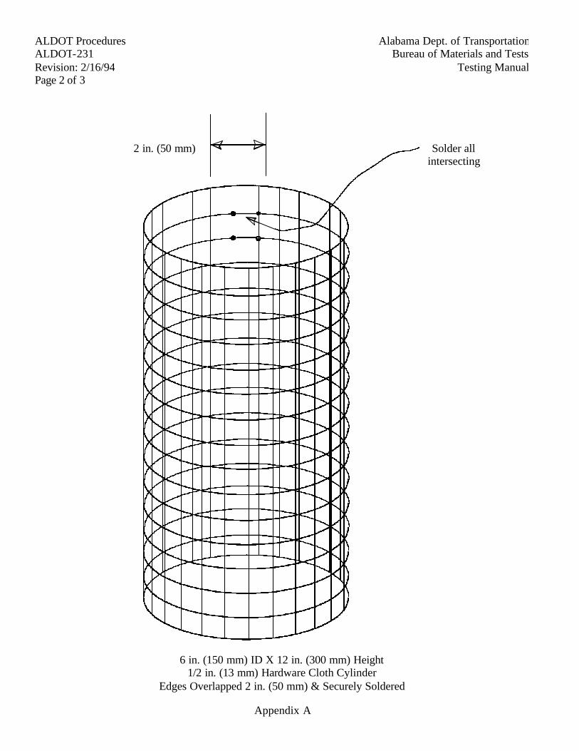
Alabama Dept. of Transportation ALDOT Procedures
Bureau of Materials and Tests ALDOT-231
Testing Manual Revision: 2/16/94
Page 2 of 3
6 in. (150 mm) ID X 12 in. (300 mm) Height 1/2 in. (13 mm) Hardware Cloth Cylinder
Edges Overlapped 2 in. (50 mm) & Securely Soldered
Appendix A
2 in. (50 mm) Solder all intersecting
wires
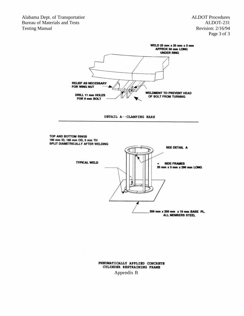
Alabama Dept. of Transportation ALDOT Procedures
Bureau of Materials and Tests ALDOT-231
Testing Manual Revision: 2/16/94
Page 3 of 3
Appendix B
Alabama Dept. of Transportation ALDOT ProceduresBureau of Materials and Tests ALDOT-232Testing Manual Revision: 2/16/94
Page 1 of 1
ALDOT-232-74AMODIFICATION OF AASHTO T-89
1. Scope
1.1. The purpose of this test is to modify the AASHTO T89 test procedure to conform to particularcharacteristics inherent in base and subbase type soils and fine aggregate proposed for use inbituminous plant mixes which have a plasticity index of 10 or less. Therefore, in order toaccommodate the testing of these low plasticity index materials, the following verbiage shallreplace Note 4 in its entirety, which immediately follows Section 5.3 in the Method A Procedureportion of T89:
Some soils tend to slide on the surface of the cup instead of flowing. If this occurs, more watershould be added to the sample and remixed, then place the soil water mixture in the cup. Then cut agroove with a grooving tool and repeat Section 5.2, Method A, T-89 is repeated. If, after severaltrials at successively higher water contents, the soil continues to slide in the cup or if the number ofblows required to close the groove is always less than 25, (i.e., repeated attempts made to obtain therange of shocks as outlined in 5.6 have not been successful) the following procedure will beutilized. The first point determined shall be the dry side point and shall not be less than ten (10)blows. The wet point shall not be less than two (2) blows. If possible, there shall be three (3)points in which the number of blows is determined to extrapolate for the LL. There shall be aminimum space of at least three (3) blows between points where three (3) points are determined anda minimum of six (6) blows when only two (2) points are determined. The moisture in the dry sidepoint may be adjusted at the beginning of the test by adding dry material or water as needed toprevent sliding in the cup at ten (10) or more blows. If the sample continues to slide at ten (10) ormore blows after the moisture adjustment, report the soil as non-plastic without performing theplastic limit test.
Alabama Dept. of Transportation ALDOT ProceduresBureau of Materials and Tests ALDOT-239Testing Manual Revision: 2/16/94
Page 1 of 2
ALDOT-239METHOD OF SAMPLING AND TESTING RIPRAP STONE
(CLASSES 1- 5)
1. Scope
1.1. This test method covers the procedure for determining the specified percent of various sizesof riprap stone.
2. Applicable Documents
2.1. Alabama Department of Transportation Standard Specifications.
3. Apparatus
3.1. Dump truck with body in good condition.
3.2. Scales capable of weighing the loaded truck being used.
3.3. Approved portable platform scales with a capacity of 1000 lbs, (500 kg).
4. Sampling
4.1. A representative sample consisting of a truckload of stone shall be obtained.
5. Procedure
5.1. Select a truckload at random.
5.2. Weigh and record the truck loaded.
5.3. Dump the truckload of stone on a clean area. Physically separate the pieces of stone so thatthe various sizes to be checked may be easily recognized.
5.4. By trial weights, select and sort into three (3) separate piles, the following size pieces:
5.4.1. Pieces that weigh less than 10 lbs. (5 kg).
5.4.2. Pieces that weigh more than 80 lbs (40kg) but less than 200 lbs. (100 kg).
5.4.3. Pieces that weigh more than 200 lbs (100 kg).
5.5. Obtain the tare weight of the empty truck and record.
5.6. Place in the truck those pieces that weigh less than 10 lbs. Weigh and record. (Total wt.minus the tare wt.)
5.7. Place in the truck those pieces that weigh more than 80 lbs. (40 kg) but less than 200 lbs.(100 kg) Weigh and record. (Total wt. minus the tare wt.)
Alabama Dept. of TransportationALDOT ProceduresBureau of Materials and TestsALDOT-239
Testing ManualRevision: 2/16/94Page 2 of 2
5.8. Place in the truck those pieces that weigh more than 200 lbs. (100kg). Weigh and record.(Total wt. minus the tare wt.)
6. Calculations
6.1. Calculate the percent of specified sizes where:
6.1.1. "A" = Total weight of those pieces weighing less than 10 lbs. (5 kg).
6.1.2. "B" = Total weight of those pieces weighing more than 80 lbs. (40 kg) but less than200 lbs. (100 kg.)
6.1.3. "C" = Total weight of those pieces weighing more than 200 lbs. (100 kg.)
6.1.4. "D" = Total weight of the sample being tested.
6.1.5. Percent of sample weighing less than 10 lbs. (5kg.)
A
DX 100
6.1.6. Percent of sample weighing more than 80 lbs. (40 kg) but less than 200 lbs. (100 kg.)
B
DX 100
6.1.7. Percent of sample weighing more than 200 lbs. (100 kg.)
C
DX 100
7. Reporting
7.1. Report the test results on form BMT-16.
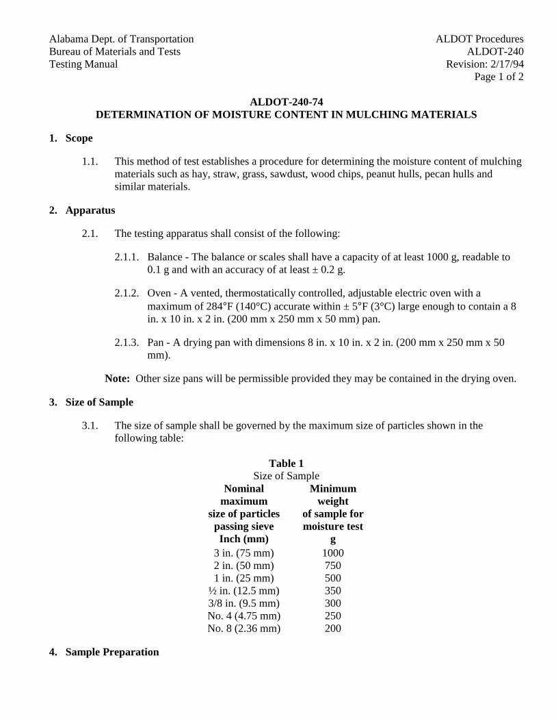
Alabama Dept. of Transportation ALDOT ProceduresBureau of Materials and Tests ALDOT-240Testing Manual Revision: 2/17/94
Page 1 of 2
ALDOT-240-74DETERMINATION OF MOISTURE CONTENT IN MULCHING MATERIALS
1. Scope
1.1. This method of test establishes a procedure for determining the moisture content of mulchingmaterials such as hay, straw, grass, sawdust, wood chips, peanut hulls, pecan hulls andsimilar materials.
2. Apparatus
2.1. The testing apparatus shall consist of the following:
2.1.1. Balance - The balance or scales shall have a capacity of at least 1000 g, readable to0.1 g and with an accuracy of at least ± 0.2 g.
2.1.2. Oven - A vented, thermostatically controlled, adjustable electric oven with amaximum of 284°F (140°C) accurate within ± 5°F (3°C) large enough to contain a 8in. x 10 in. x 2 in. (200 mm x 250 mm x 50 mm) pan.
2.1.3. Pan - A drying pan with dimensions 8 in. x 10 in. x 2 in. (200 mm x 250 mm x 50mm).
Note: Other size pans will be permissible provided they may be contained in the drying oven.
3. Size of Sample
3.1. The size of sample shall be governed by the maximum size of particles shown in thefollowing table:
Table 1Size of Sample
Nominalmaximum
size of particlespassing sieve
Minimumweight
of sample formoisture test
Inch (mm) g3 in. (75 mm) 10002 in. (50 mm) 7501 in. (25 mm) 500
½ in. (12.5 mm) 3503/8 in. (9.5 mm) 300No. 4 (4.75 mm) 250No. 8 (2.36 mm) 200
4. Sample Preparation
Alabama Dept. of TransportationALDOT ProceduresBureau of Materials and TestsALDOT-240
Testing ManualRevision: 2/17/94Page 2 of 2
4.1. Reduce sample as received to the size required in Step 3.1.
4.2. This may be done by using a Riffle or by quartering using AASHTO T-248.
5. Procedure
5.1. Weigh and record the wet weight of the prepared sample. Place sample in pan and then intooven. Open the vents on the oven approximately 25% and set the oven for 248° F (120°C).Allow sample to remain in oven for at least 12 hours.
5.2. Remove sample from oven, weigh and record.
5.3. Return sample to oven and allow to remain at 248°F (120°C) for two hours.
5.4. Remove sample from oven and weigh. If the weights of the dried sample in Steps 5.3 and5.2 are the same, then the test is complete. If the weight in Step 5.3 is less than that obtainedin Step 5.2, the sample must be re-turned to the 248°F (120°C) oven setting and allowed toremain for two hours. Repeat steps 5.2 and 5.3 until a constant weight is obtained.
6. Calculations
A-B6.1. Moisture Content =
BX 100
WhereA = wet weight of sample in gramsB = dry weight of sample in grams
7. Reporting
7.1. Report test results on Form BMT-16.
Alabama Dept. of Transportation ALDOT Procedures Bureau of Materials and Tests ALDOT-243 Testing Manual Revision: 11/29/01 Page 1 of 14
ALDOT-243-84 ACCEPTANCE PROGRAM FOR ASPHALT MATERIALS
1. Scope
1.1. The purpose of this procedure is to establish a uniform set of guidelines for the acceptance by the Department and quality control by a supplier of asphalt materials and establish guidelines for training and certification of both technicians and laboratories involved with the testing of these materials. The procedure outlines accepted methods to be followed by the Project Engineer, Prime Contractor and Supplier. This procedure applies to all suppliers of asphalt materials for projects in Alabama. Participation in the AMRL Proficiency Sampling Program with periodic inspection by ALDOT personnel is required and will enhance a laboratory's ability to meet those requirements described herein.
2. Definitions
2.1. Asphalt Materials - Pertains to performance graded asphalt binders, asphalt cements, cutback asphalts, and asphalt emulsions. Modified asphalt products where additives, polymers, and related products are added at the supplier's facility will also be considered under this term.
2.2. Liquid Asphalt Binder -Performance Graded Asphalt Binders.
2.3. Department - Alabama Department of Transportation (ALDOT).
2.4. Bureau - Bureau of Materials and Tests.
2.5. Materials and Tests Engineer - The Chief of the Bureau of Materials and Tests.
2.6. Supplier - This term includes individual refineries and terminals supplying asphalt materials for Department projects. Each facility will be treated as a separate entity even when owned by the same parent company. There are two levels of supplier: (1) Refinery (or Manufacturer) and (2) Terminal (a storage/shipping and/or pass through point). It is possible for a single supplier to be both a refinery and a terminal as defined in paragraph 2.7 and 2.8.
2.7. Refinery - An industrial facility that refines asphalt petroleum crudes to produce liquid asphalt binders, or for the purposes of this procedure, a facility that manufactures a product (i.e. asphalt emulsions, asphalt cutbacks) by blending or milling of liquid asphalt binder will be considered a refinery. A facility that modifies asphalt products (liquid asphalt binders, cut-backs, emulsions) by the addition of polymers, or other additives other than liquid anti-strip, or creates a third liquid asphalt binder by blending two (2) other liquid asphalt binders, is included as this level of supplier.
Alabama Dept. of Transportation ALDOT Procedures Bureau of Materials and Tests ALDOT-243 Testing Manual Revision: 11/29/01 Page 2 of 14
2.8. Terminal - A facility that is used primarily for the storage of and shipping point for asphalt materials. The addition of an anti-stripping agent is the only modification allowed at a terminal. Terminals owned by an approved parent company or refinery are considered subsidiary laboratories.
2.9. BMT -164 - "Participation Agreement" form. Executed between the Department and suppliers of asphalt materials. Supplier agrees to abide by Departmental requirements and the Department in-turn allows the supplier to sell products for Department projects.
2.10. BMT -146 - "Asphalt Material Certificate of Compliance" form. Supplier executes form with each shipment slated for Department projects verifying compliance with Department specifications and procedures. This form serves as project acceptance certificate.
2.11. BMT -168 - "Notification to Suspend Shipment of Asphalt Material." The Department will execute this form when asphalt materials fail to meet Department specifications and/or supplier fails to follow Department specifications and/or procedures.
2.12. IAS&T-D - Independent Assurance Sampling and Testing-Division function. It is an internal, independent check on the Department's sampling, testing, and acceptance programs.
2.13. AMRL - AASHTO's Materials Reference Laboratory (AMRL) proficiency testing program allows individual laboratories to compare their results to a national average to determine if potential problems exist in their operation.
2.14. AASHTO R18 - Procedure for Establishing and Implementing a Quality System for Construction Materials Testing Laboratories.
2.15. BBR - Bending Beam Rheometer - Determines the flexural creep stiffness of asphalt binders.
2.16. DSR - Dynamic Shear Rheometer - Determines the linear viscoelastic properties of asphalt binders.
2.17. PAV - Pressure Aging Vessel - Accelerates aging of asphalt binders.
2.18. DT - Direct Tension- Determines fracture properties of asphalt binders.
2.19. RTFO - Rolling Thin Film Oven - Measures the effect of heat and air on a moving film of semi-solid asphaltic material.
2.20. FTIR – Fourier Transform Infrared Spectrophotometer
2.21. Central Laboratory - The liquid asphalt laboratory of the Bureau of Materials and Tests located at 3704 Fairground Road, Montgomery, AL 36110.
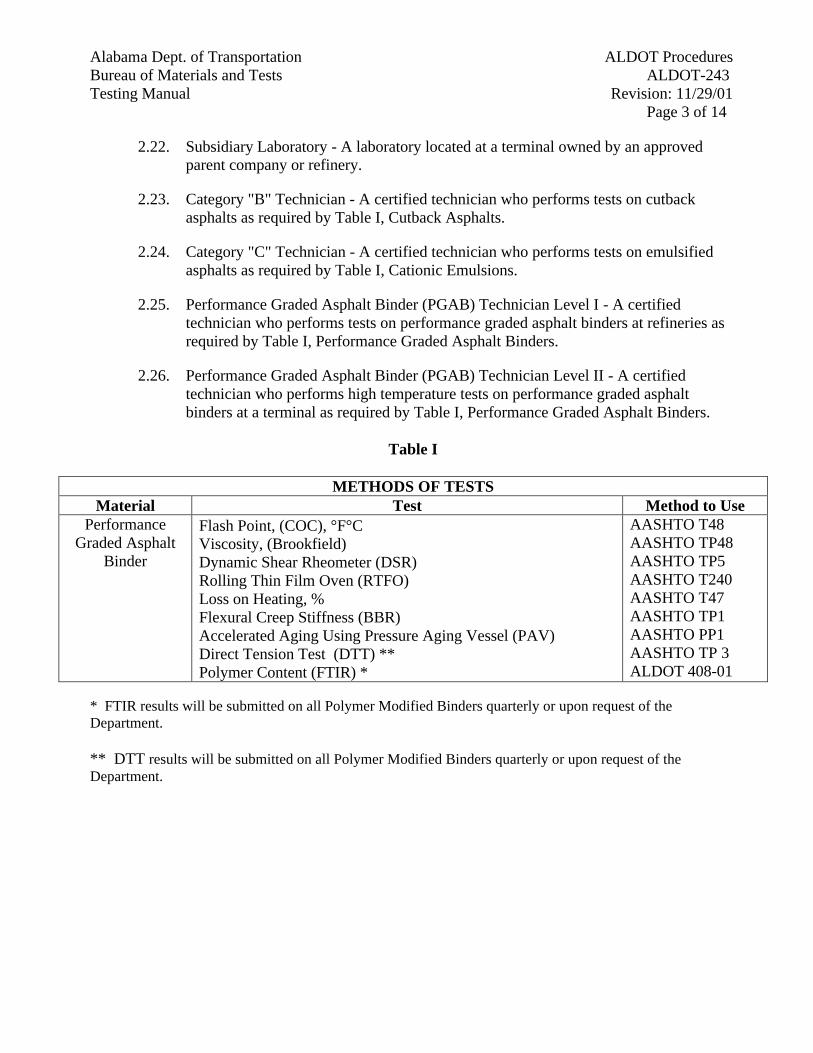
Alabama Dept. of Transportation ALDOT Procedures Bureau of Materials and Tests ALDOT-243 Testing Manual Revision: 11/29/01 Page 3 of 14
2.22. Subsidiary Laboratory - A laboratory located at a terminal owned by an approved parent company or refinery.
2.23. Category "B" Technician - A certified technician who performs tests on cutback asphalts as required by Table I, Cutback Asphalts.
2.24. Category "C" Technician - A certified technician who performs tests on emulsified asphalts as required by Table I, Cationic Emulsions.
2.25. Performance Graded Asphalt Binder (PGAB) Technician Level I - A certified technician who performs tests on performance graded asphalt binders at refineries as required by Table I, Performance Graded Asphalt Binders.
2.26. Performance Graded Asphalt Binder (PGAB) Technician Level II - A certified technician who performs high temperature tests on performance graded asphalt binders at a terminal as required by Table I, Performance Graded Asphalt Binders.
Table I
METHODS OF TESTS
Material Test Method to Use Performance
Graded Asphalt Binder
Flash Point, (COC), °F°C Viscosity, (Brookfield) Dynamic Shear Rheometer (DSR) Rolling Thin Film Oven (RTFO) Loss on Heating, % Flexural Creep Stiffness (BBR) Accelerated Aging Using Pressure Aging Vessel (PAV) Direct Tension Test (DTT) ** Polymer Content (FTIR) *
AASHTO T48 AASHTO TP48 AASHTO TP5 AASHTO T240 AASHTO T47 AASHTO TP1 AASHTO PP1 AASHTO TP 3 ALDOT 408-01
* FTIR results will be submitted on all Polymer Modified Binders quarterly or upon request of the Department. ** DTT results will be submitted on all Polymer Modified Binders quarterly or upon request of the Department.
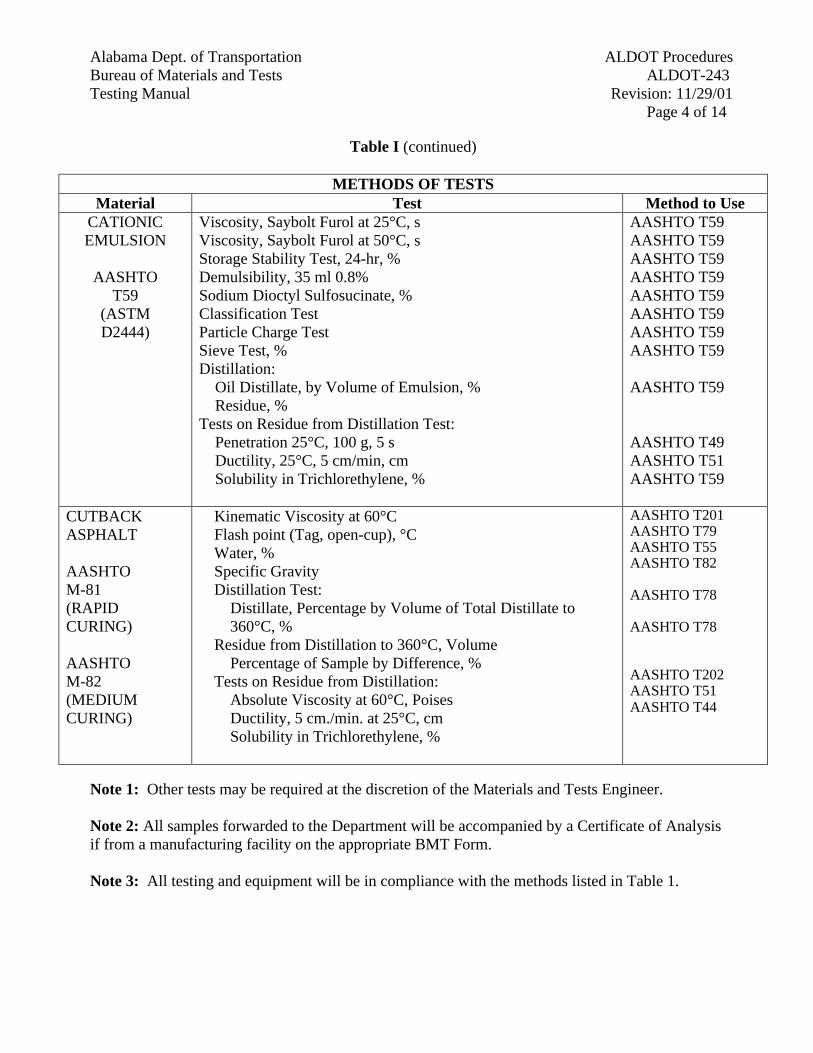
Alabama Dept. of Transportation ALDOT Procedures Bureau of Materials and Tests ALDOT-243 Testing Manual Revision: 11/29/01 Page 4 of 14
Table I (continued)
METHODS OF TESTS Material Test Method to Use
CATIONIC EMULSION
AASHTO
T59 (ASTM D2444)
Viscosity, Saybolt Furol at 25°C, s Viscosity, Saybolt Furol at 50°C, s Storage Stability Test, 24-hr, % Demulsibility, 35 ml 0.8% Sodium Dioctyl Sulfosucinate, % Classification Test Particle Charge Test Sieve Test, % Distillation: Oil Distillate, by Volume of Emulsion, % Residue, % Tests on Residue from Distillation Test: Penetration 25°C, 100 g, 5 s Ductility, 25°C, 5 cm/min, cm Solubility in Trichlorethylene, %
AASHTO T59 AASHTO T59 AASHTO T59 AASHTO T59 AASHTO T59 AASHTO T59 AASHTO T59 AASHTO T59 AASHTO T59 AASHTO T49 AASHTO T51 AASHTO T59
CUTBACK ASPHALT AASHTO M-81 (RAPID CURING) AASHTO M-82 (MEDIUM CURING)
Kinematic Viscosity at 60°C Flash point (Tag, open-cup), °C Water, % Specific Gravity Distillation Test: Distillate, Percentage by Volume of Total Distillate to 360°C, % Residue from Distillation to 360°C, Volume Percentage of Sample by Difference, % Tests on Residue from Distillation: Absolute Viscosity at 60°C, Poises Ductility, 5 cm./min. at 25°C, cm Solubility in Trichlorethylene, %
AASHTO T201 AASHTO T79 AASHTO T55 AASHTO T82 AASHTO T78 AASHTO T78 AASHTO T202 AASHTO T51 AASHTO T44
Note 1: Other tests may be required at the discretion of the Materials and Tests Engineer. Note 2: All samples forwarded to the Department will be accompanied by a Certificate of Analysis if from a manufacturing facility on the appropriate BMT Form. Note 3: All testing and equipment will be in compliance with the methods listed in Table 1.
Alabama Dept. of Transportation ALDOT Procedures Bureau of Materials and Tests ALDOT-243 Testing Manual Revision: 11/29/01 Page 5 of 14
3. Qualification Program for Supplier
3.1. The Department will establish and maintain a list (I-4, "Materials, Sources, and Devices with Special Acceptance Requirements" manual) of suppliers presently complying with this procedure. Suppliers must be on this list in order to sell their product for Department projects.
3.2. Suppliers desiring to be placed on this list must submit a request along with any applicable fees, as out-lined in the "Materials, Sources, and Devices with Special Acceptance Requirements" manual. The Department will make an initial inspection of the facility to determine compliance with the minimum standards as outlined in Department specifications and those listed in this procedure.
3.3. Suppliers must comply with the following in order to sell to Department projects.
3.3.1. Each supplier shall execute a "Participation Agreement" form (BMT -164). This agreement must be executed by an officer of the company who has responsibility for the overall operation of the facility and/or selling of the product for Department projects.
3.3.2. Each supplier must furnish, equip, and staff a laboratory meeting the requirements of Section 9 capable of testing, within precision statement tolerances as defined in applicable ASTM or AASHTO test procedures, all the required parameters listed in Table I for each different type of material supplied (i.e. performance graded asphalt binders, asphalt cements, asphalt emulsions, or cut-back asphalt) and furnish the Department with a written Quality Control Plan. An acceptable Quality Control Plan should include what steps will be taken in case of equipment problems, loss of certified technician, etc. Exceptions may be allowed, with approval of the Materials and Tests Engineer for research, experimental projects, equipment problems, FTIR testing, personnel problems, etc., on a project-by-project basis.
3.3.3. All testing by the supplier must be performed by technicians that have been certified by the Department as described in Section 10 or by technicians under the direct supervision of a Department certified technician. In addition, all testing must be done in a laboratory certified by the Department. The laboratory shall be located at site of the facility. However, with written approval of the Materials and Tests Engineer, the testing laboratory may be located at a site other than the facility site.
Note! All suppliers of asphalt materials that are participating in this program and not addressed in Section 3.4 must participate in the AMRL Proficiency Sampling Program with periodic inspection of the facilities by Bureau personnel.
3.3.4. The supplier shall furnish the following documents and materials to the Department:
Alabama Dept. of Transportation ALDOT Procedures Bureau of Materials and Tests ALDOT-243 Testing Manual Revision: 11/29/01 Page 6 of 14
3.3.4.1. The supplier shall furnish an original white copy of the BMT -146 to the Testing Engineer on a weekly basis for each load of asphalt materials shipped.
3.3.4.2. All shipments of asphalt materials to the project or contractor's plant shall be accompanied by a BMT -146 (yellow copy).
3.3.4.3. A current full analysis (all required parameters), for each grade of asphalt materials shipped, shall be furnished to the Department's Central Laboratory each week.
3.3.4.4. A full FTIR analysis shall be performed on all Polymer Modified Binders quarterly or upon request of the department in accordance with ALDOT 408.
3.3.4.5. When a supplier ships to Department projects, one verification sample per grade, per week, shall be shipped to the Department Central Laboratory. These samples are to be obtained from the supplier's storage tank (See Table II).
3.3.4.6. Supplier laboratories will submit a copy of all AMRL proficiency reports to the Bureau for review.
3.3.5. All testing shall be in accordance with the current ASTM, AASHTO, or ALDOT procedures, as specified in the Department Specifications.
3.4. Special Exceptions for Terminal Suppliers
3.4.1. Any terminal receiving performance graded asphalt binder from an approved refinery shall perform high temperature tests which includes DSR, RTFO, Brookfield Viscometer and Cleveland Open Cup Flash Tests. Low and intermediate temperature testing which includes DSR, PAV, and BBR tests are also required; but may be performed at an off-site location.
3.4.2. Any terminal receiving asphalt materials from a refinery that is not approved by the Department, shall meet all refinery testing requirements.
3.5. The inspection by the supplier of transporting vehicles, tank cars, etc., shall be required as stated in the BMT -146. This inspection shall include all vehicles, tank cars, etc., whether owned by the suppliers, contractor, or common carrier.
3.6. Periodic and unannounced inspections will be made at the supplier's facility by Department inspectors. The supplier will allow the inspector free access to all test records, production, storage, testing facilities, and shipping documents showing quantities of asphalt and additives loaded on transports.
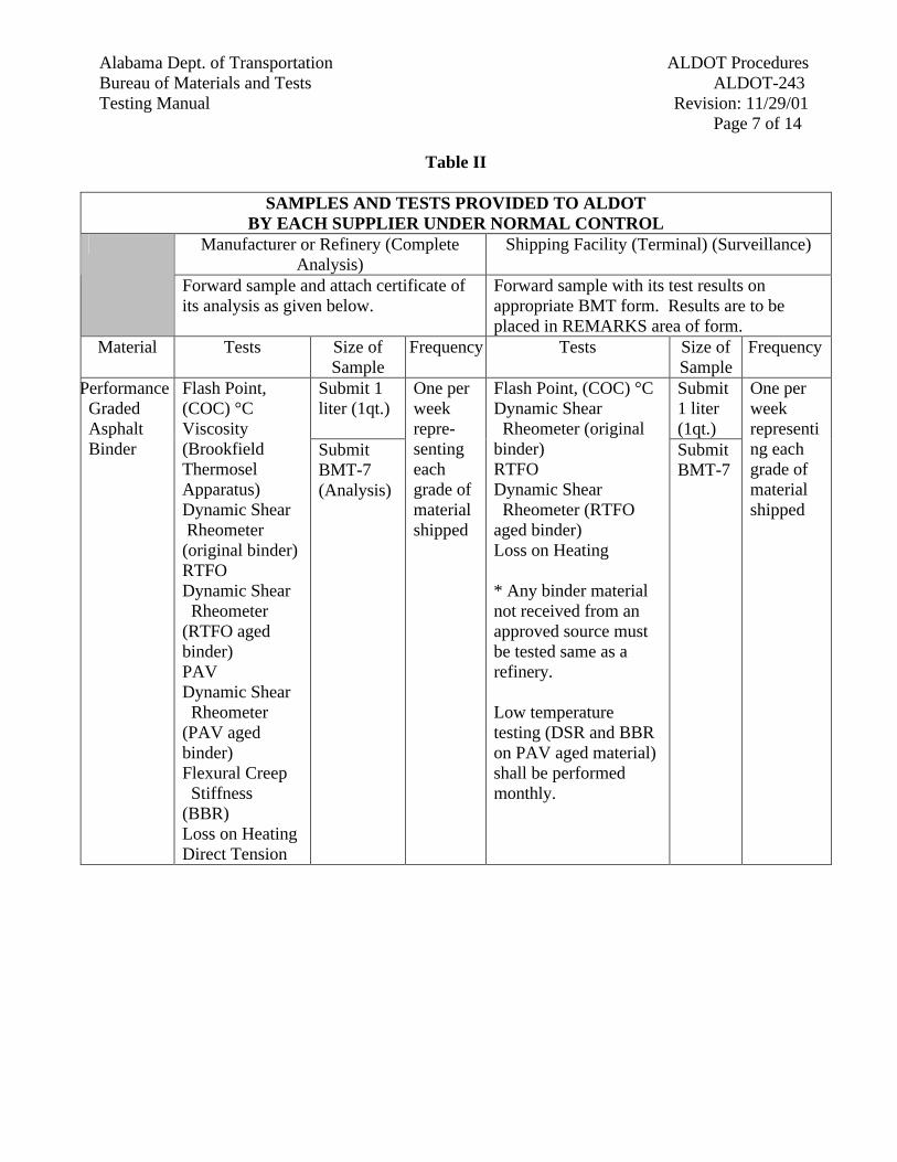
Alabama Dept. of Transportation ALDOT Procedures Bureau of Materials and Tests ALDOT-243 Testing Manual Revision: 11/29/01 Page 7 of 14
Table II
SAMPLES AND TESTS PROVIDED TO ALDOT BY EACH SUPPLIER UNDER NORMAL CONTROL
Manufacturer or Refinery (Complete Analysis)
Shipping Facility (Terminal) (Surveillance)
Forward sample and attach certificate of its analysis as given below.
Forward sample with its test results on appropriate BMT form. Results are to be placed in REMARKS area of form.
Material Tests Size of Sample
Frequency Tests Size of Sample
Frequency
Submit 1 liter (1qt.)
Submit 1 liter (1qt.)
Performance Graded Asphalt Binder
Flash Point, (COC) °C Viscosity (Brookfield Thermosel Apparatus) Dynamic Shear Rheometer (original binder) RTFO Dynamic Shear Rheometer (RTFO aged binder) PAV Dynamic Shear Rheometer (PAV aged binder) Flexural Creep Stiffness (BBR) Loss on Heating Direct Tension
Submit BMT-7 (Analysis)
One per week repre-senting each grade of material shipped
Flash Point, (COC) °C Dynamic Shear Rheometer (original binder) RTFO Dynamic Shear Rheometer (RTFO aged binder) Loss on Heating * Any binder material not received from an approved source must be tested same as a refinery. Low temperature testing (DSR and BBR on PAV aged material) shall be performed monthly.
Submit BMT-7
One per week representing each grade of material shipped
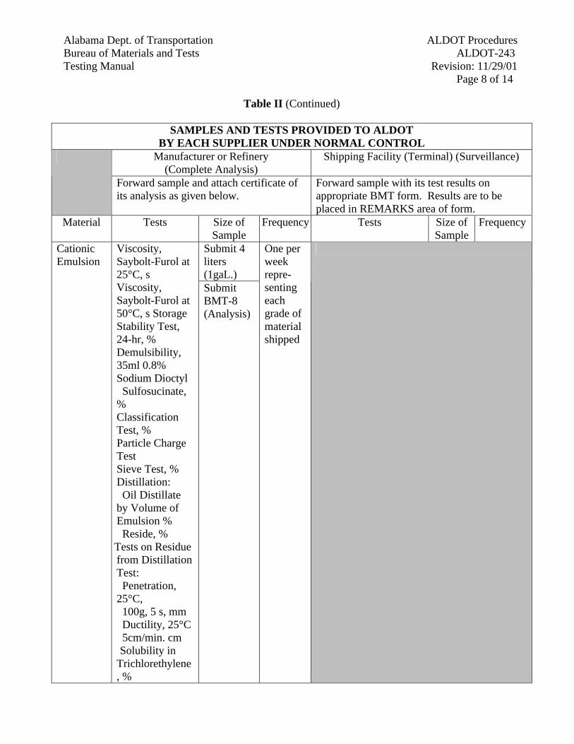
Alabama Dept. of Transportation ALDOT Procedures Bureau of Materials and Tests ALDOT-243 Testing Manual Revision: 11/29/01 Page 8 of 14
Table II (Continued)
SAMPLES AND TESTS PROVIDED TO ALDOT BY EACH SUPPLIER UNDER NORMAL CONTROL
Manufacturer or Refinery (Complete Analysis)
Shipping Facility (Terminal) (Surveillance)
Forward sample and attach certificate of its analysis as given below.
Forward sample with its test results on appropriate BMT form. Results are to be placed in REMARKS area of form.
Material Tests Size of Sample
Frequency Tests Size of Sample
Frequency
Submit 4 liters (1gaL.)
Cationic Emulsion
Viscosity, Saybolt-Furol at 25°C, s Viscosity, Saybolt-Furol at 50°C, s Storage Stability Test, 24-hr, % Demulsibility, 35ml 0.8% Sodium Dioctyl Sulfosucinate, % Classification Test, % Particle Charge Test Sieve Test, % Distillation: Oil Distillate by Volume of Emulsion % Reside, % Tests on Residue from Distillation Test: Penetration, 25°C, 100g, 5 s, mm Ductility, 25°C 5cm/min. cm Solubility in Trichlorethylene, %
Submit BMT-8 (Analysis)
One per week repre-senting each grade of material shipped
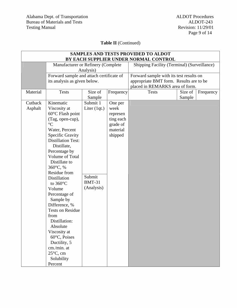
Alabama Dept. of Transportation ALDOT Procedures Bureau of Materials and Tests ALDOT-243 Testing Manual Revision: 11/29/01 Page 9 of 14
Table II (Continued)
SAMPLES AND TESTS PROVIDED TO ALDOT BY EACH SUPPLIER UNDER NORMAL CONTROL
Manufacturer or Refinery (Complete Analysis)
Shipping Facility (Terminal) (Surveillance)
Forward sample and attach certificate of its analysis as given below.
Forward sample with its test results on appropriate BMT form. Results are to be placed in REMARKS area of form.
Material Tests Size of Sample
Frequency Tests Size of Sample
Frequency
Submit 1 Liter (1qt.)
Cutback Asphalt
Kinematic Viscosity at 60°C Flash point (Tag, open-cup), °C Water, Percent Specific Gravity Distillation Test: Distillate, Percentage by Volume of Total Distillate to 360°C, % Residue from Distillation to 360°C Volume Percentage of Sample by Difference, % Tests on Residue from Distillation: Absolute Viscosity at 60°C, Poises Ductility, 5 cm./min. at 25°C, cm Solubility Percent
Submit BMT-31 (Analysis)
One per week representing each grade of material shipped
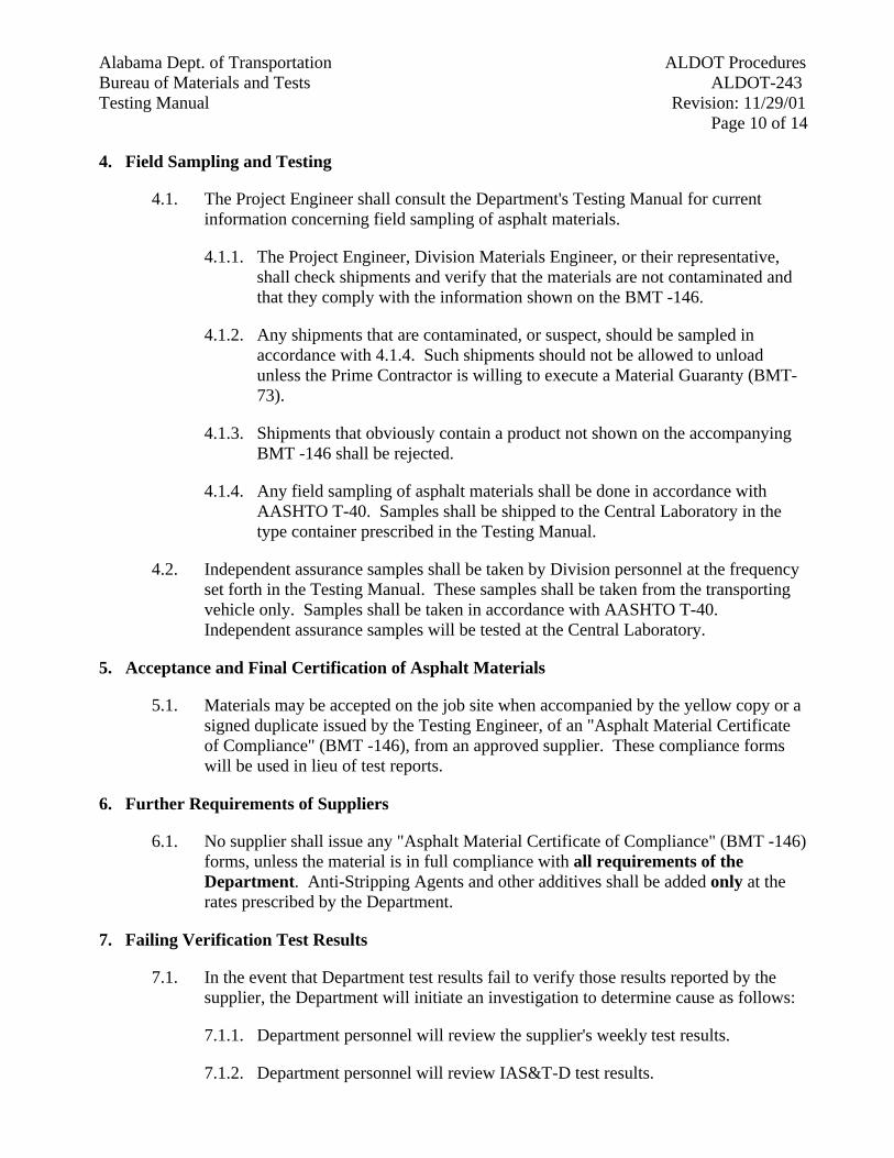
Alabama Dept. of Transportation ALDOT Procedures Bureau of Materials and Tests ALDOT-243 Testing Manual Revision: 11/29/01 Page 10 of 14
4. Field Sampling and Testing
4.1. The Project Engineer shall consult the Department's Testing Manual for current information concerning field sampling of asphalt materials.
4.1.1. The Project Engineer, Division Materials Engineer, or their representative, shall check shipments and verify that the materials are not contaminated and that they comply with the information shown on the BMT -146.
4.1.2. Any shipments that are contaminated, or suspect, should be sampled in accordance with 4.1.4. Such shipments should not be allowed to unload unless the Prime Contractor is willing to execute a Material Guaranty (BMT-73).
4.1.3. Shipments that obviously contain a product not shown on the accompanying BMT -146 shall be rejected.
4.1.4. Any field sampling of asphalt materials shall be done in accordance with AASHTO T-40. Samples shall be shipped to the Central Laboratory in the type container prescribed in the Testing Manual.
4.2. Independent assurance samples shall be taken by Division personnel at the frequency set forth in the Testing Manual. These samples shall be taken from the transporting vehicle only. Samples shall be taken in accordance with AASHTO T-40. Independent assurance samples will be tested at the Central Laboratory.
5. Acceptance and Final Certification of Asphalt Materials
5.1. Materials may be accepted on the job site when accompanied by the yellow copy or a signed duplicate issued by the Testing Engineer, of an "Asphalt Material Certificate of Compliance" (BMT -146), from an approved supplier. These compliance forms will be used in lieu of test reports.
6. Further Requirements of Suppliers
6.1. No supplier shall issue any "Asphalt Material Certificate of Compliance" (BMT -146) forms, unless the material is in full compliance with all requirements of the Department. Anti-Stripping Agents and other additives shall be added only at the rates prescribed by the Department.
7. Failing Verification Test Results
7.1. In the event that Department test results fail to verify those results reported by the supplier, the Department will initiate an investigation to determine cause as follows:
7.1.1. Department personnel will review the supplier's weekly test results.
7.1.2. Department personnel will review IAS&T-D test results.
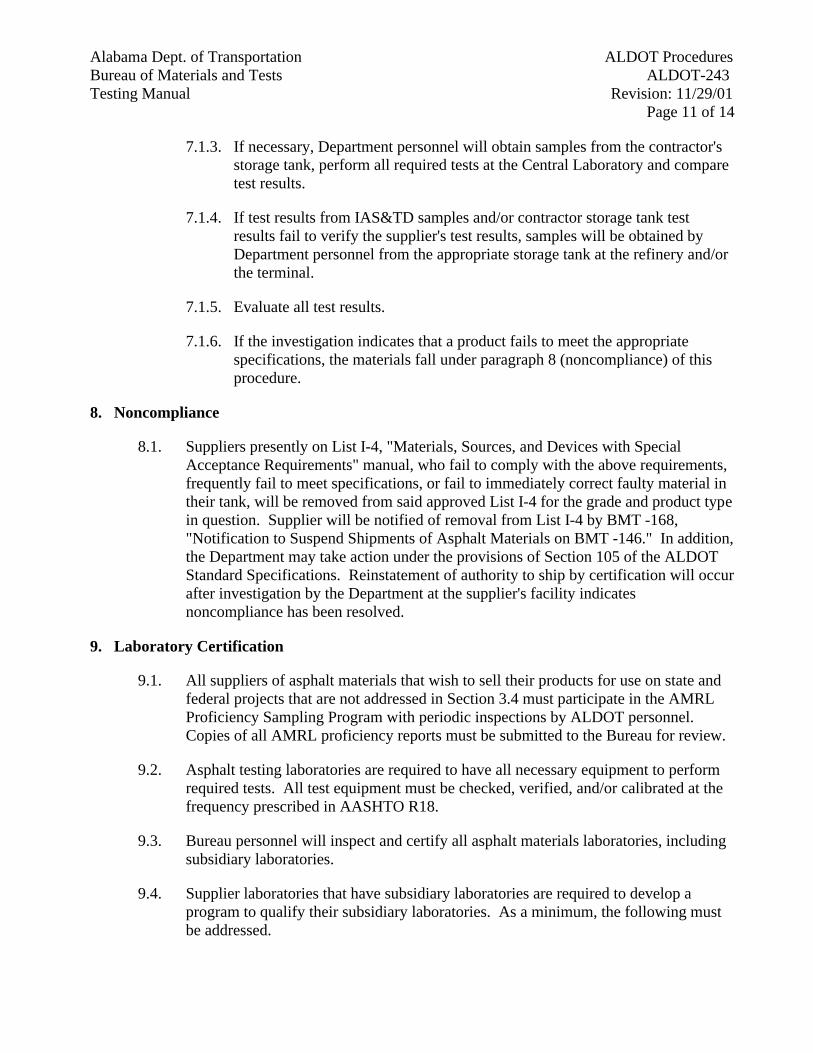
Alabama Dept. of Transportation ALDOT Procedures Bureau of Materials and Tests ALDOT-243 Testing Manual Revision: 11/29/01 Page 11 of 14
7.1.3. If necessary, Department personnel will obtain samples from the contractor's storage tank, perform all required tests at the Central Laboratory and compare test results.
7.1.4. If test results from IAS&TD samples and/or contractor storage tank test results fail to verify the supplier's test results, samples will be obtained by Department personnel from the appropriate storage tank at the refinery and/or the terminal.
7.1.5. Evaluate all test results.
7.1.6. If the investigation indicates that a product fails to meet the appropriate specifications, the materials fall under paragraph 8 (noncompliance) of this procedure.
8. Noncompliance
8.1. Suppliers presently on List I-4, "Materials, Sources, and Devices with Special Acceptance Requirements" manual, who fail to comply with the above requirements, frequently fail to meet specifications, or fail to immediately correct faulty material in their tank, will be removed from said approved List I-4 for the grade and product type in question. Supplier will be notified of removal from List I-4 by BMT -168, "Notification to Suspend Shipments of Asphalt Materials on BMT -146." In addition, the Department may take action under the provisions of Section 105 of the ALDOT Standard Specifications. Reinstatement of authority to ship by certification will occur after investigation by the Department at the supplier's facility indicates noncompliance has been resolved.
9. Laboratory Certification
9.1. All suppliers of asphalt materials that wish to sell their products for use on state and federal projects that are not addressed in Section 3.4 must participate in the AMRL Proficiency Sampling Program with periodic inspections by ALDOT personnel. Copies of all AMRL proficiency reports must be submitted to the Bureau for review.
9.2. Asphalt testing laboratories are required to have all necessary equipment to perform required tests. All test equipment must be checked, verified, and/or calibrated at the frequency prescribed in AASHTO R18.
9.3. Bureau personnel will inspect and certify all asphalt materials laboratories, including subsidiary laboratories.
9.4. Supplier laboratories that have subsidiary laboratories are required to develop a program to qualify their subsidiary laboratories. As a minimum, the following must be addressed.

Alabama Dept. of Transportation ALDOT Procedures Bureau of Materials and Tests ALDOT-243 Testing Manual Revision: 11/29/01 Page 12 of 14
9.4.1. Proficiency sample testing must be performed quarterly between the supplier laboratory and the subsidiary laboratories. The results must be forwarded to the Bureau.
9.4.2. Develop a formal training program and training outlines for all new hires.
9.4.3. Develop a competency evaluation program for all technicians.
9.4.4. Develop equipment calibration/verification policies and procedures.
9.4.5. All documentation must be retained and updated for inspection by Bureau personnel.
9.5. A written plan to qualify subsidiary laboratories must be submitted to the Bureau for approval prior to implementation. Equipment in subsidiary laboratories will be checked by Bureau personnel at the time technicians are certified. Once approved, any changes made to the qualification plan must be approved by the Bureau.
9.6. A copy of the report of the subsidiary laboratory inspection shall be provided to the Bureau.
10. Certification for Performance Graded Asphalt Binder (PGAB) Technicians and Category B, C, Technicians
10.1. The company shall make requests for technician certification to the Bureau by letter. The request shall include specific information such as experience, length of training, subject matter, instructors, location of training, and category of certification being requested.
10.2. Bureau personnel will monitor and observe all "hands-on" tests performed by the applicant. The technician will be allowed to use any notes, checklists, or specifications to perform the required tests. It will be the subjective opinion of the Bureau technician that determines whether or not a technician demonstrated the level of competency required for certification.
10.3. A technician may be certified for more than one category, provided that all requirements have been met.
10.4. The company's quality control plan shall identify alternatives for testing in the event of equipment failure and/or the loss of their certified technician. Generally, the company will be allowed no more than 30 working days to overcome equipment and/or technician problems; however, the Materials and Tests Engineer has the discretion to consider special circumstances in enforcement of this provision.
10.5. Personnel meeting the requirements shall be certified by the Working Task Force and approved by the Certification Board. Certification is also contingent upon the technician signing a BMT -169, "Certified Technician Warrant."
Alabama Dept. of Transportation ALDOT Procedures Bureau of Materials and Tests ALDOT-243 Testing Manual Revision: 11/29/01 Page 13 of 14
10.6. A technician shall be certified for a period of three years. Recertification will require the submittal of a new request for technician certification as outlined in section 10.1.
10.7. To satisfy the terms of the certification program, at least one technician must be certified per establishment. Technicians who are not certified may perform tests provided they are working under the direct supervision of a certified technician.
10.8. Technician Training
10.8.1. Individual companies will be responsible to ensure their technicians are trained to perform all tests relating to asphalt materials (see attached tables). The required training may be accomplished in-house, through academia, or through private companies. Training can be arranged through the Asphalt Institute and the National Center for Asphalt Technology (NCAT) if necessary.
11. Decertification of Certified Laboratories and Technicians
11.1. The Working Task Force shall review laboratories and/or personnel who fail to comply with the above requirements as reported by a representative of the Bureau. Actions shall be implemented upon recommendations by the Working Task Force and approval by the Certification Board, and will range from a minimum 60 day suspension to permanent revocation.
12. Certification Board for Laboratories and Technicians
12.1. Membership of the Certification Board shall be comprised of the following:
12.1.1. Materials and Tests Engineer, (Position), Chairman
12.1.2. Assistant Chief Engineer, (Appointed by the Transportation Director)
12.1.3. Construction Engineer, (Position)
12.1.4. Division Engineer, (Appointed by the Transportation Director)
12.1.5. Industry Member, (Appointed by the Alabama Asphalt Pavement Association)
12.2. The Certification Board will meet on an as-needed basis to consider and/or act upon the recommendations of the Working Task Force.
13. Working Task Force
13.1. The membership of the Working Task Force shall be comprised of the following:
13.1.1. Testing Engineer, (Position)
13.1.2. Assistant Testing Engineer, (Position)

Alabama Dept. of Transportation ALDOT Procedures Bureau of Materials and Tests ALDOT-243 Testing Manual Revision: 11/29/01 Page 14 of 14
13.1.3. Assistant Roadway Construction Engineer, (Position)
13.1.4. Industry Association Member, (Appointed by the Alabama Asphalt Pavement Association)
13.2. The Working Task Force will meet on an as-needed basis to review laboratories and/or personnel who fail to comply with the above requirements.
Alabama Dept. of Transportation ALDOT ProceduresBureau of Materials and Tests ALDOT-245Testing Manual Revision: 2/18/94
Page 1 of 2
ALDOT-245-83PROCEDURES FOR SAMPLING AND INSPECTION OF ROADWAY SIGNS, AND OVERHEAD
SIGN STRUCTURES
1. Scope
1.1. This procedure establishes the requirements of project and Central Laboratory personnel in relationto the inspection and sampling of roadway signs, and overhead sign structures.
1.2. All required certifications should be shipped to the Project Engineer, with the exception of overheadsign structures. Certifications for overhead sign structures should be shipped to the Bureau ofMaterials and Tests, Certification Engineer for approval. If samples are required, on projects withless than 200 ft 2 of sign material, the Project Engineer should select samples from the materialdelivered to the project. The Project Engineer will in turn process these items through the properchannels prior to authorizing payment for the item.
1.3. Signs and structures should not be installed until the engineer has a passing test report in hand.When samples are required, in addition to certified test reports, payment should not be authorizeduntil sample testing is complete and certified test reports are approved by the Central Laboratory.
2. Job Sampling Requirements
2.1. Projects requiring 200 ft2 (20 m2) or less of standard sign panel may be accepted under ALDOT-195without sampling. The Project Engineer should make a visual inspection of all materials in additionto this to assure items are correct. If any items look suspect, samples may be taken in the samemanner as would be required for large projects.
2.2. On projects requiring over 200 ft2 (20 m2), the Project Engineer shall notify the Bureau of Materialsand Tests, Certification Lab, of the arrival of sign materials on the job prior to installation. Aninspector from the Certification Lab will make an inspection visit to the project to check allhardware such as nuts, bolts, washers, angles, channels, supports, and sign panels. The inspectoralong with project personnel will inspect these materials and select samples, in accordance withSection 710 of the Testing Manual. Due to the destructive nature of the testing no samples will betaken from large multi-panel signs unless material certifications are not correct for materialspecifications or material is suspect.
2.3. When tube and beam supports are used on ground mount signs, the producer may furnish certifiedtest reports as outlined in ALDOT-195 or furnish an additional 39 in (1 m) length of each type withthe shipment. This section shall be used as the sample in lieu of destroying a prefabricated support.Should this sample fail to meet the required specification, it will be necessary to sample acompleted support.
2.4. High strength bolts, nuts, and washers for break-away signs shall be shipped to the project in sealedcontainers with lot numbers marked in accordance with Section 508 and 836 of the Specifications.Samples and certifications shall be furnished in accordance with Article 836.33 of theSpecifications and Section 508 of the Testing Manual and submitted to the Central Laboratory foranalysis. In addition, the contractor shall supply additional fasteners to compensate for five (5) setsof fasteners, per lot, selected by the Department Inspector for calibration of the contractor’s torque

Alabama Dept. of TransportationALDOT ProceduresBureau of Materials and TestsALDOT-245
Testing ManualRevision: 2/18/94Page 2 of 2
wrench used for installation. All fasteners selected as samples will be randomly sampled from thesealed and marked containers. Project Engineers should contact the Bureau of Materials and Tests,Certification Laboratory, prior to installation to arrange for an inspector to come and calibrate thecontractor's equipment.
2.5. A 3 in x 12 in (75 mm x 300 mm) sample shall be furnished by the producer for each run ofporcelain-enameled signs. This sample shall be submitted to the Central Laboratory for testing.Samples of completed signs will not be required unless non-specification materials are suspected.
3. Overhead Sign Structures
3.1. Upon Department approval of shop drawings, the fabricator shall notify the Bridge Bureau of theintended time that fabrication is to begin. The Department may elect to send an inspector to visitthe plant prior to fabrication or the Department may elect to allow the producer to begin without aninspection, depending on the history of the fabricator, size and type of structure, and availability ofthe inspector.
3.2. Upon completion of fabrication and prior to galvanization, the fabricator will contact theDepartment (Bridge Bureau Steel Inspector) for an inspection. The Department may elect to have arepresentative present at the coating process. This, again, is dependent on the factors listed in 3.1.
3.3. Should the Department elect not to have an inspector present at galvanization the fabricator may beallowed to furnish certified test reports covering the galvanization of the structure to the projectengineer or attach two metal coupons made of the same material as the structure to each structureprior to galvanization. If coupons are used then they will remain in place during the coating processand the project engineer will remove the coupons and submit them to either Division or CentralLaboratory for testing.
3.4. The Project Engineer shall notify the Bureau of Materials and Tests, Certification Lab, of the arrivalof sign materials on the job prior to installation. An inspector from the Certification Lab will makean inspection visit to the project to check all hardware such as nuts, bolts, washers, angles, channels,supports, and sign panels. The inspector along with project personnel will inspect these materialsand select samples, in accordance with Section 710 of the Testing Manual. Due to the destructivenature of the testing and the large size of the panels, no samples will be taken from them unlessmaterial certifications are not correct for material specifications or material is suspect.
3.5. High strength bolts, nuts, and washers for overhead sign structures shall be shipped to the project insealed containers with lot numbers marked in accordance with Section 508 and 836 of theSpecifications. Samples and certifications shall be furnished in accordance with 836 of theSpecifications and Section 508 of the Testing Manual and submitted to the Central Laboratory foranalysis. In addition, the contractor shall supply additional fasteners to compensate for five (5) setsof fasteners, per lot, selected by the Department Inspector for calibration of the contractor’s torquewrench used for installation. All fasteners selected as samples will be randomly sampled from thesealed and marked containers. Project Engineers should contact the Bureau of Materials and Tests,Certification Laboratory, prior to installation to arrange for an inspector to come and calibrate thecontractor's equipment.

Alabama Dept. of Transportation ALDOT Procedures Bureau of Materials and Tests ALDOT-247 Testing Manual Revision: 2/23/94
Page 1 of 4
ALDOT-247-82 MARKING OF HIGH-STRENGTH BOLTS, NUTS, AND WASHERS FOR STRUCTURAL STEEL
JOINTS
1. Scope
1.1. The purpose of this procedure is to set forth the method of identifying high-strength bolts, nuts, and washers by the manufacturer's markings.
2. General
2.1. Type 1. These bolts are made from medium-carbon steel, supplied in sizes M16 to M36, inclusive, in diameter. will have hex heads unless otherwise stipulated in appropriate drawings, plans, purchase orders or specifications.
2.2. Type 2. These bolts are made from what is described as low-carbon martensite steel, supplied in sizes M16 toM36, inclusive, in diameter. Bolts will have hex heads unless otherwise stipulated in appropriate drawings, plans, purchase orders or specifications.
2.3. Type 3. These bolts are made from steel having atmospheric corrosive resistance and weathering characteristics supplied in sizes M16 to M36, inclusive, in diameter. Bolts will have hex heads unless otherwise stipulated in appropriate drawings, plans, purchase orders or specifications.
2.4. Production Lot - for the purposes of assigning an identification number and from which test samples shall be selected, shall consist of all bolts processed essentially together through all operations to the shipping container that are of the same nominal size, the same nominal length, and produced from the same heat of steel.
3. Nuts
3.1. Nuts authorized for use with A 325M Bolts: Unless otherwise specified, nuts shall be heavy hex and the grade and surface finish of nut for each type of bolt shall be as follows:
Bolt Type Nut Grade and Finish Type 1 & 2, Plain (Noncoated) 8S, 8S3, Plain
Type 1 & 2, Zinc Coated 10S Zinc Coated Type 3 8S3 Plain
4. Markings on Heavy Hex Bolt Head
4.1. All bolts, Type 1, 2 and 3, shall be marked A 325M and shall also be marked with a symbol identifying the manufacturer.
4.2. In addition to paragraph 4.1 above, Type 1 bolts shall be Marked 8S.
4.3. In addition to paragraph 4.1 above, Type 2 bolts shall be marked 8S with this marking underlined.
Alabama Dept. of Transportation ALDOT Procedures Bureau of Materials and Tests ALDOT-247
Testing Manual Revision: 2/23/94 Page 2 of 4
4.4. In addition to paragraph 4.1 above, Type 3 bolts shall be marked 8S3, and the manufacturer may add other distinguishing marks indicating that the bolt is atmospheric corrosion resistant and of a weathering type.
4.5. All markings shall be located on the top of the bolt head and may be either raised or depressed at the option of the manufacturer.
5. Markings on Heavy Hex Nuts
5.1. All nuts shall be marked with a symbol to identify the manufacturer.
5.2. In addition to the manufacturer's symbol, nuts of all classes shall be marked with property class designation (8S, 10S, 8S3, or 10S3) on the top or bearing surface, on the top of flange, or on one of the wrenching flats of the nut. Markings located on the top or bearing surface or on the top of the flange shall be positioned with the base of the numeral(s) oriented toward the nut periphery.
5.3. For Classes 8S3 and 10S3 nuts, the manufacturer may add other distinguishing marks to indicate the nut is atmospheric corrosion resistant and of a weathering grade of steel.
5.4. Marks on the above nuts may be raised or depressed at the option of the manufacturer. However, if markings are located on the bearing surface, they shall be depressed.
6. Markings on Circular Washers
6.1. All circular washers shall be marked with a symbol identifying the manufacturer. Markings shall be depressed on one face of the washer. Clip washers need not be marked.
6.2. In addition to the manufacturer's mark, circular washers manufactured from steel having improved atmospheric corrosion resistance and of a weathering type shall be marked with the numeral 3.
6.3. Other identifying or distinguishing marks, or both, may be used by the manufacturer.
6.4. Additionally, washers shall be marked to identify their being metric size. Preferably, the metric marking shall be the symbol "M", but may be of other distinguishing design as determined by the manufacturer.
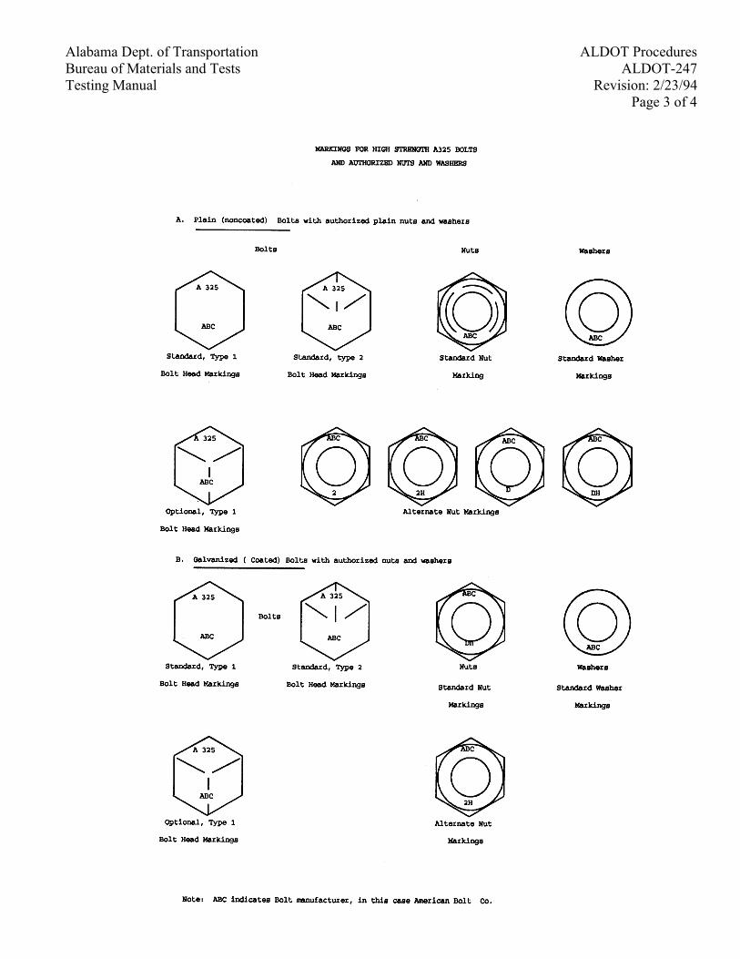
Alabama Dept. of Transportation ALDOT Procedures Bureau of Materials and Tests ALDOT-247 Testing Manual Revision: 2/23/94
Page 3 of 4
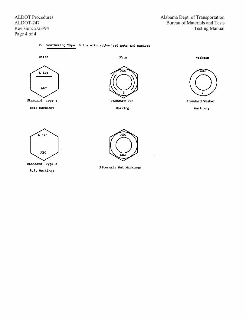
Alabama Dept. of Transportation ALDOT Procedures Bureau of Materials and Tests ALDOT-247
Testing Manual Revision: 2/23/94 Page 4 of 4
Alabama Dept. of Transportation ALDOT ProceduresBureau of Materials and Tests ALDOT-248Testing Manual Revision: 3/18/94
Page 1 of 4
ALDOT-248-76METHOD OF TEST FOR MEASURING THE DEPTH OF GROOVES IN CONCRETE
PAVEMENTS AND BRIDGE DECKS WITH A TIRE TREAD DEPTH GAGE
1. Scope
1.1. This method of test describes the procedure for sampling, preparing and measuring the depth ofgrooves in bridge decks, concrete pavements and ramps using a Tire Tread Depth Gage.
1.2. This method of test can measure the depth of grooves in concrete pavements produced by thefollowing methods: Tine Finish, Broom Finish and Pavement Grooving.
2. Apparatus
2.1. Tire Tread Depth Gage - A gage, calibrated in increments of 1/32 in. (1 mm) and capable ofmeasuring to a depth of
2.2. ½ in (13 mm) shall be used.
2.3. Miscellaneous Equipment - Hand broom or brush, 12 in (300 mm) ruler, 100 ft. (50 m) tapemeasure and notebook.
3. Sampling Procedure for Securing Test Area
3.1. The lot size for bridge decks shall be the lengths of the span by the width of the lane and lanes inone direction.
3.2. The lot size for concrete pavements shall be a minimum of 5000 yds2 (4200 m2) to a maximum of10000 yds2 (8400 m2) in one direction. If the contractor's production is below the minimum, the lotsize shall be the yd 2 (m2) of pavement placed.
3.3. The lot size for ramps or separate lanes connecting with cross streets shall be the yd2 (m2) ofpavement placed in one direction.
3.4. A lot shall consist of five approximately equal sublots. Within each sublot, one test area shall berandomly secured in accordance with ALDOT-210.
4. Preparing the Test Area
4.1. Brush all loose material from the area to be measured.
5. Measuring the Depth of the Grooves
5.1. Measure ten grooves in a straight line perpendicular to the grooves; starting with the point that wasrandomly secured in Section 3.5.
5.2. Place the Tire Tread Depth Gage on the groove to be measured and firmly seat it to the surface.Make sure that the needlepoint will fall in the middle of the groove.
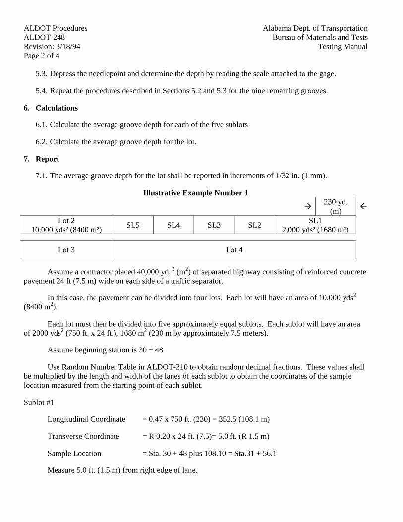
Alabama Dept. of TransportationALDOT ProceduresBureau of Materials and TestsALDOT-248
Testing ManualRevision: 3/18/94Page 2 of 4
5.3. Depress the needlepoint and determine the depth by reading the scale attached to the gage.
5.4. Repeat the procedures described in Sections 5.2 and 5.3 for the nine remaining grooves.
6. Calculations
6.1. Calculate the average groove depth for each of the five sublots
6.2. Calculate the average groove depth for the lot.
7. Report
7.1. The average groove depth for the lot shall be reported in increments of 1/32 in. (1 mm).
Illustrative Example Number 1
!230 yd.
(m)"
Lot 210,000 yds² (8400 m²)
SL5 SL4 SL3 SL2SL1
2,000 yds² (1680 m²)
Lot 3 Lot 4
Assume a contractor placed 40,000 yd. 2 (m2) of separated highway consisting of reinforced concretepavement 24 ft (7.5 m) wide on each side of a traffic separator.
In this case, the pavement can be divided into four lots. Each lot will have an area of 10,000 yds2
(8400 m2).
Each lot must then be divided into five approximately equal sublots. Each sublot will have an areaof 2000 yds2 (750 ft. x 24 ft.), 1680 m2 (230 m by approximately 7.5 meters).
Assume beginning station is 30 + 48
Use Random Number Table in ALDOT-210 to obtain random decimal fractions. These values shallbe multiplied by the length and width of the lanes of each sublot to obtain the coordinates of the samplelocation measured from the starting point of each sublot.
Sublot #1
Longitudinal Coordinate = 0.47 x 750 ft. (230) = 352.5 (108.1 m)
Transverse Coordinate = R 0.20 x 24 ft. (7.5)= 5.0 ft. (R 1.5 m)
Sample Location = Sta. 30 + 48 plus 108.10 = Sta.31 + 56.1
Measure 5.0 ft. (1.5 m) from right edge of lane.

Alabama Dept. of Transportation ALDOT ProceduresBureau of Materials and Tests ALDOT-248Testing Manual Revision: 3/18/94
Page 3 of 4
Calculate the coordinates for the remaining sublots.
Be sure to go through all numbers in the table before using the same numbers over.
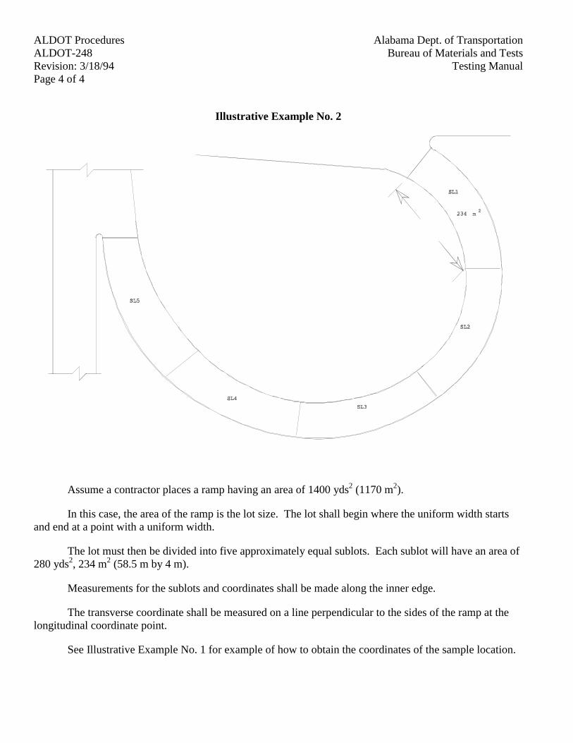
Alabama Dept. of TransportationALDOT ProceduresBureau of Materials and TestsALDOT-248
Testing ManualRevision: 3/18/94Page 4 of 4
Illustrative Example No. 2
Assume a contractor places a ramp having an area of 1400 yds2 (1170 m2).
In this case, the area of the ramp is the lot size. The lot shall begin where the uniform width startsand end at a point with a uniform width.
The lot must then be divided into five approximately equal sublots. Each sublot will have an area of280 yds2, 234 m2 (58.5 m by 4 m).
Measurements for the sublots and coordinates shall be made along the inner edge.
The transverse coordinate shall be measured on a line perpendicular to the sides of the ramp at thelongitudinal coordinate point.
See Illustrative Example No. 1 for example of how to obtain the coordinates of the sample location.
Page 1 of 19
Alabama Dept. of Transportation ALDOT ProceduresBureau of Materials and Tests ALDOT-249Testing Manual Revision: 7/30/01
ALDOT-249PROCEDURE FOR ACCEPTANCE OF FINE AND COARSE AGGREGATES
Table of Contents
Table of Contents Page
Applicable Documents (Listing) 2
Section 1: Scope 3
Section 2: Purpose 3
Section 3: Referenced Documents 4
Section 4: Definitions 5
Section 5: Source Approval Requirements 7
Section 6: Quality Control Program 8
Section 7: Approval Levels 11
Section 8: Source Classifications 13
Section 9: Fees and Cost 15
Section 10: Control Charts (Analysis and Recording of Data) 15
Section 11: Comparison/Verification Test, Test Reports and Shipping 16
Section 12: Responsibilities 19
Section 13: Tests and Frequency of Sampling Material for Quality Control Program, ALDOT-249 23
Page 2 of 19
Alabama Dept. of TransportationALDOT ProceduresBureau of Materials and TestsALDOT-249
Testing ManualRevision: 7/30/01
Applicable Documents
BMT 10 Notice Stamp for Acceptance
BMT 18 Sample Card
BMT 29 Aggregate Source Inspection Checklist
BMT 29-A Verification Test
BMT 91 Aggregate Test Report
BMT-116 Aggregate Plant Checklist
BMT 131 Request for Source Approval
BMT 141 Agreement to Participate in Aggregate Control Program
Page 3 of 19
Alabama Dept. of Transportation ALDOT ProceduresBureau of Materials and Tests ALDOT-249Testing Manual Revision: 7/30/01
1. Scope
1.1. This procedure provides the requirements and procedures for obtaining and maintaining Departmentapproval of developed and operational aggregate sources, including redistribution terminals, whichare intended to be the source of construction aggregates for use on Department projects. Thissource approval recognizes the existence of suitable raw materials; processing facilities capable ofproducing specified aggregates meeting Department specification requirements; and an effectiveQuality Control Program assuring the continuing quality and uniformity of that production. Sourceapproval for aggregates is the initial step in the Department's method of acceptance of aggregatesfor use on Department projects.
2. Purpose
2.1. This procedure sets out a standardized method for the Department to approve sources or aggregatesthrough a producer Quality Control Program (QCP). The Department's procedures for sourceapproval and quality assurance, at the source and/or at the point of use or project, comprise theDepartment's method of accepting aggregate for use on Department projects.
2.2. A Quality Control Program requires producers of construction materials to be responsible for thequality of their products; to establish, maintain, and implement their own individualized processcontrol system; and to certify to the Department compliance of their product with applicablestandard and contract specifications.
2.3. Approval of a source by the Department and implementation of a Quality Assurance Program by theDepartment does not relieve the producer of the responsibility for shipping aggregates which meetspecifications. Contractors are also responsible for transporting and handling aggregates in amanner which will preclude significant variation in the properties of the aggregates. TheDepartment reserves the right to test all aggregates at the source, point of use, or project site todetermine acceptability for use according to contract specifications.
2.4. Nothing in this procedure is intended to prohibit the evaluation and approval of any operation notspecifically covered herein that, in the opinion of the Department, complies with the criteria setforth in this procedure.
Page 4 of 19
Alabama Dept. of TransportationALDOT ProceduresBureau of Materials and TestsALDOT-249
Testing ManualRevision: 7/30/01
3. Referenced Documents
Referenced Documents
3.1. BMT 10 Certificate from producer that documents the source of the aggregate.
3.2. BMT 18 Sample card that is submitted with each sample for testing.
3.3. BMT 91 Aggregate Test Report
3.4. BMT 116 Aggregate Plant Check List
3.5. BMT 131 Request for Source Approval
3.6. BMT-136 Application for Certification and Recertification
3.7. BMT-138 Certified Technician Warrant
3.8. BMT-141 Agreement for Participation in Quality Control Program for Acceptance ofFine and Coarse Aggregates
3.9. ALDOT-175 Method of Stockpiling Coarse Aggregate for all Purposes
3.10. ALDOT-239 Method of Sampling and Testing Riprap Stone (Classes 1 through 5)
3.11. ASTM D4791 Standard Test Method for Flat Particles, Elongated Particles, or Flat andElongated Particles in Coarse Aggregate
3.12. ALDOT-321 Test for Glassy Particles in Crushed Slag
3.13. ALDOT-355 General Information Concerning Materials, Sources, and Devices withSpecial Acceptance Requirements
3.14. ALDOT-376 Certification Program for Aggregate Technicians
3.15. AASHTO T-2 Sampling Aggregates
3.16. AASHTO T-11 Materials Finer Than 75µm Sieve in Mineral Aggregates by Washing
3.17. AASHTO T-19 Unit Weight and Voids in Aggregate
3.18. AASHTO T-27 Sieve Analysis of Fine and Coarse Aggregate
3.19. AASHTO M-92 Wire-Cloth Sieves for Testing Purposes
3.20. AASHTO M-231 Weighing Devices Used in the Testing of Materials
3.21. AASHTO T-248 Reducing Field Samples of Aggregate to Testing Size
Page 5 of 19
Alabama Dept. of Transportation ALDOT ProceduresBureau of Materials and Tests ALDOT-249Testing Manual Revision: 7/30/01
4. Definitions
4.1. The following words or phrases as used in this document shall have the following meaning, exceptwhere the context clearly indicates a different meaning.
4.2. "Aggregate" (coarse) - a granular mineral material such as crushed/uncrushed gravel, crushed stone(limestone, granite, sandstone) or crushed slag having hard strong durable pieces free from adherentcoating, used as a component in mortar mixes, concrete or hot mix asphalt, or alone as a base orsubbase course, or used loose for drainage, foundation, scour protection, water barrier, etc., meetingthe requirements of Section 801 of the Department's specifications.
4.3. "Aggregate" (fine) - a natural or manufactured sand having hard, clean, durable, uncoated particlesused as a component in mortar mixes, concrete, hot mix asphalt, or used loose for drainage, etc.,meeting the requirements of Section 802 of the Department's specifications.
4.4. "Approved Sources List" means the Department's Manual entitled "Material, Sources, and Deviceswith Special Acceptance Requirements".
4.5. "Central Laboratory" means the Aggregate Laboratory of the Bureau of Materials and Tests locatedin Montgomery, Alabama.
4.6. "Certified Aggregate Technician" means a person who has been tested by the Department and hassuccessfully passed both the written and practical examinations and certified by the Department or aperson who has been certified in another state under a similar aggregate quality control programwho has submitted the necessary documentation satisfying the Department's requirements forcertification. See ALDOT Procedure 376, "Certification Program for Aggregate Technicians", foradditional information.
4.7. "Comparison tests" means the quarterly gradation analysis (AASHTO T-27) performed by theproducer's certified aggregate technician on each size aggregate shipped during that quarter.
4.8. "Department" means the Alabama Department of Transportation.
4.9. "Independent Assurance Samples and Tests" or "IAS&T" means samples and tests performed byDepartment personnel who do not normally have direct responsibilities for Quality Assurancesampling and testing. They are used for the purpose of making independent checks on thereliability of the QC/QA Program, and are not used for determining the quality and acceptability ofaggregate.
4.10. "Point of production" means the physical location (excluding redistribution terminals) wherethe material is removed from the earth and/or processed for use as aggregate.
4.11. "Point of use" means the physical location where the aggregate is incorporated into theproject (i.e., project site, asphalt plant or concrete plant).
4.12. "Producer" means any business or individual supplying or seeking to supply aggregate foruse on Department projects.
Page 6 of 19
Alabama Dept. of TransportationALDOT ProceduresBureau of Materials and TestsALDOT-249
Testing ManualRevision: 7/30/01
4.13. "Quality assurance" or "QA" means the Department's management method of evaluating theeffectiveness of the producers Quality Control Program including the use of comparison tests,verification tests, annual source approval tests and on-site inspections to monitor the quality,uniformity and acceptability of aggregate.
4.14. "Quality control" or "QC" means the producer's management method of controlling andmaking adjustments to processing techniques, including the use of QC samples, control charts, tests,and other available information to establish and maintain the specified quality and uniformity of aproduct.
4.15. "Quality Control Program" or "QCP" means the overall system implemented by the producerto ensure compliance with Department Specifications.
4.16. "Redistribution Terminal" means the physical location where aggregates are received fromapproved sources for use on Department projects and stockpiled according to DepartmentSpecifications.
4.17. "Source" means the physical location (excluding redistribution terminals) where theaggregate material is removed from the earth and/or processed for use as an aggregate.
4.18. "The Testing Manual" means the Department's Manual of standardized methods of samplingand testing of aggregates.
4.19. “Verification Tests" means gradation analysis (AASHTO T-27) and material finer than the75µm Sieve (AASHTO T-11) performed by the Department's technician at the producer's source orredistribution terminal monthly when shipping.
4.20. "Weighmaster" means a person employed by the producer or a public weighmaster who hasbeen qualified by the Alabama Department of Agriculture for the purpose of certifying weighttickets or certified in another state.
5. Source Approval Requirements
5.1. In order for a producer to qualify his aggregate for use on Department projects, the followingrequirements must be satisfied:
5.1.1. A completed BMT-131 "Request for Source Approval" shall be submitted to the Materialsand Tests Engineer.
5.1.2. The producer shall submit a quality control program and same shall be individualized foreach source based on deposit characteristics, to include processing and handling techniques.The "QCP" shall be submitted to the Materials & Tests Engineer.
5.1.3. A completed and signed BMT-141, "Agreement for Participation in the Aggregate QualityControl Program" shall be submitted to the Materials & Tests Engineer.
5.1.4. Request Division personnel to sample and submit same to the Central Laboratory for initialtesting and approval. Sample sizes shall be as per AASHTO T-2, Table 1.
Page 7 of 19
Alabama Dept. of Transportation ALDOT ProceduresBureau of Materials and Tests ALDOT-249Testing Manual Revision: 7/30/01
5.1.5. Submit a check as outlined in ALDOT-355, "General Information Concerning Materials,Sources, and Devices with Special Acceptance Requirements" made payable to theALABAMA DEPARTMENT OF TRANSPORTATION.
5.1.6. The producer shall employ a "Certified Aggregate Technician" who has been certified and/orapproved by the Department.
5.1.7. The producer shall employ a certified weighmaster or use a public weighmaster whenshipping materials measured by weight for a direct pay item by the Department as perDepartment specifications.
5.1.8. All sources must pass the initial on-site inspection conducted by the Department andsubsequent monitoring and inspections necessary to verify compliance with this document andapplicable Department specifications. Material must meet DOT Specifications, Section 801 or802.
5.2. After all the above items have been satisfactorily met, the Central Laboratory will recommendapproval of the source to the Product Evaluation Board, requesting the source be placed on List I-1,Approved Sources List. The Product Evaluation Board normally meets during the first week ineach month. The producer will be notified of any item not meeting the Department's requirements.
5.3. It shall be the responsibility of the producer to ensure that all operations are in compliance withtheir Quality Control Program. Continuing approval is contingent upon the effectiveness of theproducer's Quality Control Program as evidenced by the quality and uniformity of the aggregate.
5.4. Submit all required items to:
Materials and Tests Engineer3700 Fairground RoadMontgomery, Al 36110
5.5. If a source is relocated or extended beyond the boundaries shown on the sketch of the originalsource approval, even though it is in the same general area, a new inspection will be required. Earlynotification to the Department of any relocation/extension will result in a mutual benefit to bothparties.
5.6. A new inspection will be required if there are any significant changes in the engineering propertiesof the materials.
5.7. The producer is required to notify the Department of any pending changes in ownership and/orpersonnel. If the approved source is indeed, sold, the new owner is required to submit an updatedQuality Control Plan.
6. Quality Control Program
6.1. The Quality Control Program, as developed, implemented and submitted for each individual source,shall contain, as a minimum, the following items:
Page 8 of 19
Alabama Dept. of TransportationALDOT ProceduresBureau of Materials and TestsALDOT-249
Testing ManualRevision: 7/30/01
6.1.1. Name, address and telephone number of the source; names of company officers, i.e., Owner,President, Vice President, etc.;
6.1.2. Names of key personnel, i.e., Superintendent, General Manager, Quality Control Manager,Certified Aggregate Technician, Production Foreman, etc.;
6.1.3. A pinpoint location of the source, i.e., section, township, range, distances from any knownlandmarks such as highway intersections, etc., in order to find the location by automobile, and asketch with dimensions of the boundaries.
6.1.4. Statements to the effect that stockpiles will be constructed in accordance with ALDOT-175,"Method of Stockpiling Aggregate for All Purposes", so as to minimize segregation andprevent contamination with foreign materials;
6.1.5. Loading and shipping controls including a detailed description of the methods by which theaggregate is to be loaded and shipped for use on Department projects and safeguards againstcontamination, degradation and segregation of the aggregate;
6.1.6. A detailed description of the material being produced, i.e., limestone, granite, sandstone, toinclude any geological information;
6.1.7. A list of all major production equipment to include brand name, size, capacity, etc.;
6.1.8. Source of water;
6.1.9. Location and size of aggregate testing facility;
6.1.10. Duties of the Certified Aggregate Technician;
6.1.11. Methods by which statistical data will be computed and plotted.
6.2. The producer shall furnish a fully equipped laboratory at the production site or redistributionterminal. The Department may allow a producer to use one centrally located testing laboratory toserve more than one (1) source, provided testing can be performed as per the frequency guide withina reasonable amount of time. The laboratory shall be furnished with the necessary testingequipment and supplies for performing producer quality control sampling and testing. To assureaccuracy, the testing equipment shall be checked periodically as directed by the Bureau of Materialsand Tests in accordance with applicable standards. Minimum requirements are as follows:
6.2.1. Weighing devices meeting the requirements of AASHTO M-231;
6.2.2. Mechanical shakers for fine and coarse aggregate;
6.2.3. Mechanical splitter as per AASHTO T-248;
6.2.4. Hand sieves 8 in or 12 in (200 mm and/or 300 mm) meeting the requirements of AASHTOM-92;
Page 9 of 19
Alabama Dept. of Transportation ALDOT ProceduresBureau of Materials and Tests ALDOT-249Testing Manual Revision: 7/30/01
6.2.5. Unit weight measures meeting the requirements of AASHTO T-19;
6.2.6. Drying apparatus;
6.2.7. Water supply;
6.2.8. Miscellaneous utensils such as buckets, pans, stirring spoons, etc.;
6.2.9. Copies of the most current testing methods.
6.3. It shall be the producer's responsibility to ensure that all testing equipment is checked, verified,and/or calibrated at the required frequency and documentation for same shall be maintained at thesource. The Department may require actual demonstration of the accuracy of the testing equipment.
6.4. Required frequencies for checking, verifying and/or calibrating aggregate test equipment is asfollows:
Unit Weight Measures 12 mo AASHTO T-19Mechanical Shakers 12 mo AASHTO T-27General Purpose Balances 12 mo AASHTO M-231Hand Sieves (Visual inspections) 6 mo AASHTO M-92Drying Apparatus (Hot plate, electric or gas) ALDOT-253
6.4.1. If producers are using drying ovens to dry aggregates, temperature settings shall be verifiedevery four months as per AASHTO T-27.
6.5. All documentation (work sheets) shall be maintained to verify that all testing equipment has beenchecked, verified and/or calibrated at the required frequency.
6.6. The Department will furnish procedures and work sheets for checking, verifying and/or calibratingthe above equipment if requested.
7. Approval Levels
7.1. Upon successful application for source approval, each source shall be assigned the appropriateapproval level by the Department. No source shall he approved unless the source has at least oneapproved aggregate.
7.2. Full Approval. When a source or redistribution terminal is fully approved, the producer may shipand certify aggregate for Department usage without additional Department acceptance testing priorto usage. However, the Department reserves the right to reject defective material at any time.
7.3. Conditional Approval. When a source is placed on conditional approval status, the producer mayship aggregate for Department use, and must certify each shipment, but the material will beaccepted based on results of the Department’s quality assurance samples. A source placed onconditional approval status will be subject to increased sampling frequency; pre-testing of materialprior to shipment; restriction on production of aggregate for Department usage from specific layers,pits or location; and other controls or tests as deemed necessary by the Department. The
Page 10 of 19
Alabama Dept. of TransportationALDOT ProceduresBureau of Materials and TestsALDOT-249
Testing ManualRevision: 7/30/01
Department will place all new sources on conditional approval to determine if the source canmaintain consistent production of aggregate meeting Department specifications.
7.4. Time Limits. A source will be kept on conditional approval status for only as long as it is deemednecessary, but not to exceed six months. Should the source not gain full approval during this timeframe, it shall be revoked.
7.5. Revocation - when a source is revoked, the producer is restricted from shipping aggregates for useon Department projects. Source approval will be revoked by the Department if the producersQuality Control Program proves ineffective in controlling the production of aggregates whichcomply with Department specifications and standards.
7.6. A source shall be revoked when one of the following occurs:
7.6.1. Failure of material to meet specification requirements;
7.6.2. The producer fails to maintain proper or timely records, or the producer fails to have test dataavailable for themselves and for the Department;
7.6.3. The producer varies their procedures from the approved Quality Control Program withoutDepartment approval;
7.6.4. The producer fails to correct any deficiency related to any requirement of this procedureand/or the producers Quality Control Program, having received notice from the Departmentwithin a reasonable amount of time not to exceed 30 days;
7.6.5. The producer performs improper sampling and/or testing of aggregates;
7.6.6. The producer adds or mixes aggregates or materials not processed according to the QualityControl Program;
7.6.7. The producer fails to maintain aggregate testing equipment in compliance with theappropriate test method or fails to have the equipment checked;
7.6.8. Other conditions related to the quality of aggregate.
7.7. A source that has been revoked must remain revoked for a minimum period of 60 days. If theproblems are corrected within this time frame, the source will be placed on conditional approval.
7.8. The Department will closely monitor the source for at least 30 days and will reinstate approvalstatus provided the producer has again demonstrated the effectiveness of the Quality ControlProgram assuring the continued quality and uniformity of the aggregates.
7.9. A source's approval will automatically expire if it has not furnished material for use on Departmentprojects for a period of one calendar year, unless an extension of approval is requested in writing,prior to the expiration date, by the producer to the Materials & Tests Engineer.
Page 11 of 19
Alabama Dept. of Transportation ALDOT ProceduresBureau of Materials and Tests ALDOT-249Testing Manual Revision: 7/30/01
7.10. Extension of approval will be predicated on the continued operation of the source's qualitycontrol program during the previous calendar year and the source's continuing to meet all therequirements of this procedure. Approval will be extended only once for an additional calendaryear. If, at the end of the extension, the source still has not furnished aggregate for Department use,source approval will again expire and reapproval is subject to reapplication.
7.11. Individual products from any source which have not been supplied for use on Departmentprojects for a period of one calendar year will be removed from the Approved Sources List for thatsource, unless an extension is requested. This includes existing stockpiles of material made under aQC Program, meeting specifications, and for which identification and specific records and test dataare available.
7.12. Denial of Source Approval. A producer's request for source approval will be denied whenany one of the following occurs:
7.12.1. Incomplete or inadequate Quality Control Program.
7.12.2. Failure of material to meet specification requirements.
7.12.3. Results of the Department's inspection and testing do not agree with information and testresults furnished by the producer.
7.12.4. Results of the Department's inspection indicate material properties or characteristics whichmay be a potential problem.
7.12.5. Falsification of any approval information submitted by the producer.
7.12.6. Inadequate testing facility and/or equipment.
7.13. The producer may reapply for source approval as per Section 4, "Source ApprovalRequirements", when documented evidence is presented to the Department identifying all correctiveactions.
7.14. Annual Recertification. Recertification of all sources is required annually. Each Divisionwill sample all sources within their jurisdiction and submit same to the Central Laboratory fortesting and reevaluation. If the source meets all applicable DOT Specifications, the source willagain be placed on the Approved Sources List (I-1). There is no fee charged for the annualreevaluation. The producer must also sign, notarize and submit BMT-141, Agreement forParticipation in the Department's Aggregate Quality Control Program.
8. Source Classifications
8.1. These classifications are based on the Department's ability and resources. In circumstances thatpreclude the Department's ability to perform its QA function at the source, the Department reservesthe right to change a source classification with a minimum of a months notice given to the producer.
Page 12 of 19
Alabama Dept. of TransportationALDOT ProceduresBureau of Materials and TestsALDOT-249
Testing ManualRevision: 7/30/01
8.2. Type I sources are those sources located within Alabama. These sources will be inspected monthlyby the Department. The source may ship directly to Department projects or RedistributionTerminals, self certifying each shipment with a BMT-10.
8.3. Type II sources include out-of-state sources which are more than a oneway distance of a halfday's(250 miles) travel by automobile from the appropriate Division but are within a oneway distance ofa day's (8 hours) travel by automobile from the appropriate Division. These sources will beinspected monthly by the Department. The source may ship directly to Department projects, orRedistribution Terminals, self certifying each shipment with a BMT-10. QA samples will beobtained at the point-of-use or redistribution terminal.
8.4. Type III sources include out-of-state (and out-of-country) sources which are more than a one-waydistance of a day's (eight hours) travel by automobile or cannot be accessed by automobile from theDepartment's Central Laboratory. Shipments may only be made to redistribution terminals selfcertifying each shipment. The source will be monitored at the redistribution terminal. Thesesources must provide their source numbers, material identifications and QC test data for eachshipment to a terminal. These sources will be inspected annually by the Department. The producershall pay all per diem and travel costs for the Department's Inspectors.
8.5. Type IV sources are those sources located within the state and which produce aggregate solely fortheir own use. Testing shall be performed as per the frequency guide, e.g., concrete plant and HMAplant.
8.6. Redistribution terminals may only be located in-state. Approval of the terminal and the qualitycontrol program at the terminal will be required, and the Department will assign a terminal number.Material certification by the source will be accepted; however, additional quality control tests forthose aggregate characteristics subject to change due to handling, shipping, stockpiling, or otheractions affecting aggregate characteristics, will be required at the time of reshipment from theterminal. Certification by the terminal of materials for Department usage will require both sourceand terminal numbers. These terminals will be inspected monthly by the appropriate Division.
8.7. The owner/operator of the redistribution terminal shall employ a full time Certified AggregateTechnician who will perform duties as listed.
9. Fees and Costs
9.1. All producers for proposed Type III sources of aggregate whose source locations are located morethan eight hours travel by automobile or cannot be accessed by automobile from the Department'sCentral laboratory will be required to pay for the Department's per diem and transportation. Thiswill apply for initial inspections, annual inspections, or at anytime deemed necessary by theDepartment. Costs shall include meals, lodging, air fare and vehicle rental cost if required, and/ormileage rates if a Department vehicle is used. Should multiple sources be evaluated/ inspected onthe same trip, all costs will be proportionally divided.
9.2. All costs as mentioned above shall be borne by the producer(s). Payment for expenses shall bemade by check, payable to the Alabama Department of Transportation prior to any visit orinspection.
Page 13 of 19
Alabama Dept. of Transportation ALDOT ProceduresBureau of Materials and Tests ALDOT-249Testing Manual Revision: 7/30/01
9.3. Checks shall be submitted to:
Materials and Tests Engineer3700 Fairground RoadMontgomery, Al 36110
10. Control Charts (Analysis and Recording of Data)
10.1. All test results of conforming and nonconforming aggregates shall be recorded on approvedforms and charts which shall be kept up to date and complete, and shall be available at all times tothe Department.
10.2. Aggregate quality during the production process can be effectively monitored by the controlchart method of analysis. A control chart is simply a graphical record of the quality of a particularcharacteristic of the aggregate. Example control charts will be furnished by the Department.Computer generated control charts or control charts different from the examples provided by theDepartment must be approved by the Department.
10.3. The use of control charts by the aggregate producer serves the following purposes:
10.3.1. To provide early detection of trouble before rejections occur;
10.3.2. To decrease aggregate variability and provide information for quality improvement.
10.4. All test results of conforming and nonconforming aggregates shall be recorded on approvedforms and charts which shall be kept up to date and complete, and shall be available at all times tothe Department.
10.5. The producer must have the necessary equipment (i.e., calculator, and/or computer, etc.) toperform statistical analysis such as "mean and standard deviation" and maintain adequate records ofall samples, tests and other data to substantiate aggregate compliance to Department specifications.Control charts shall be maintained and visibly displayed by the producer at the source and/orredistribution terminal on those aggregate characteristics designated by the Department.
10.6. A copy of the Quality Control Plan as well as current copies of the appropriate test methods(AASHTO/ASTM), ALDOT Procedures, Department specifications, and current test data shall beavailable and on-hand at all times.
10.7. The producer shall submit copies of all control charts to the Central Laboratory orappropriate Division each month while shipping.
10.8. Where there is an indication that the process is not being adequately controlled, the producermust immediately take the necessary actions to adjust the process.
10.9. The producer is required to compute the mean and standard deviation for each sieve size forboth coarse and fine aggregate each time gradation analysis is required by the Frequency Guide.The mean and standard deviation is also required for unit weight and fineness modulus. If there isnot a gradation analysis required by the Frequency Guide, as a minimum, the producer shall
Page 14 of 19
Alabama Dept. of TransportationALDOT ProceduresBureau of Materials and TestsALDOT-249
Testing ManualRevision: 7/30/01
perform one (1) gradation analysis per shipping day for coarse and fine aggregate, determine unitweight and compute the fineness modulus (FM). The means and standard deviations shall becomputed, plotted, displayed on control charts and submitted to the Central Laboratory andappropriate Division each month while shipping.
11. Comparison/Verification Test, Test Reports and Shipping
11.1. Comparison Tests - To ensure uniformity and compliance with prescribed test procedures, allproducers are required to sample and perform at least one (1) comparison test per quarter, per sizeaggregate shipped that quarter. Comparison tests will be performed by the producer's CertifiedAggregate Technician at their facility. When the technician is finished, he/she will prepare samplecards (BMT-18) for each sample tested and maintain the identical samples until picked up by aDOT Inspector, who will, in turn, send same to the Central Laboratory in Montgomery forcomparison testing. The Central Laboratory will compare gradation analysis to ensure a + 5 percenttolerance for each sieve size. Samples found to be out of tolerance will be resampled, retested andcompared. Copies of comparison sample test results will be distributed by the Central Laboratory,Aggregate Control Section to the Division Materials Engineer, and to the Certified AggregateTechnician.
11.1.1. If a producer does not ship any material during the quarter, no comparison tests are required.
11.2. All BMT-18s submitted with comparison samples will have the following informationwritten on the card:
Front Side:
11.2.1. DOT size number and type; such as #57 crushed slag;
11.2.2. Producer's name, and source number;
11.2.3. Date, name and number of technician who took sample;
11.2.4. The word "comparison" written in large letters across the top of the card;
Back Side:
11.2.5. Put gradation analysis, i.e., sieve size, percent passing each sieve, and total weight.
11.3. Shipping Control - Each producer's shipping unit and Quality Control Technician will beresponsible for loading the specified sized or non-sized materials with special attention to the useintended for the ordered material, i.e., whether there is specification requirements applicable toPortland cement concrete, bituminous treatment layers or bituminous plant mix materials, etc.
11.4. Test Reports - A stamped (BMT-10) is REQUIRED with each load of aggregate shippedfrom a Source. A BMT-91 (Aggregate Test Report) is required as per the Frequency guide if thepay item for which the aggregate is to be used requires gradation analysis, otherwise a BMT-91 isnot required. A list of all pay item numbers along with the sampling and testing frequencies forgradation and unit weight are shown on the last page for ready reference. BMT-91s will be
Page 15 of 19
Alabama Dept. of Transportation ALDOT ProceduresBureau of Materials and Tests ALDOT-249Testing Manual Revision: 7/30/01
checked, initialed and dated by the DOT inspector during his monthly verification visits. The DOTInspector will keep copies of all BMT-91s on file in the Division Materials office.
11.5. Verification Sampling and Testing - Division personnel will visit each source orredistribution terminal located in their respective area at least monthly to perform verificationtesting. Division personnel will sample, from approved stockpiles, each size material being shippedduring that period at each site and perform all verification tests at the producers facility. It isimportant that verification tests be performed at the producer's facility. In the event problems areencountered, a resample can be taken, equipment can be checked and a more timely resolution tothe problem can be found. When all verification tests are completed, the responsible DOT Divisioninspector will forward a copy of all verification test results to the Central Laboratory inMontgomery. If stockpiles have been exhausted, trucks or railroad cars that have been approved bythe technician may be sampled. All samples shall be taken as per AASHTO T-2. During eachverification visit, DOT personnel will check BMT-91s as per Section 11.4. Gradation anddecantation tests will be performed on all verification tests. Stockpiles or individual shipments thathave not been approved by the Certified Aggregate Technician will not be sampled. If samplestaken from stockpiles or shipments, either at the plant or on the project, are of questionable quality,they should be promptly submitted to the Central Laboratory with cards and bags marked RUSH, toprevent incorporation of possible failing material into the construction. These samples will be giventop priority in testing. Failing results will initiate an immediate investigation by the AggregateControl Section of the Central Laboratory. All testing will be performed in strict compliance withthe appropriate AASHTO, ASTM or ALDOT Procedures prescribed in the Specifications.
11.5.1. If the producer does not ship any material during the month, no verification tests arerequired. The appropriate Division should document same.
11.6. Sample Size - The appropriate sample size taken shall be as per AASHTO T-2.
11.7. Monitoring - The Aggregate Control Section of the Central Laboratory is assigned theresponsibility of monitoring all aggregate test results. The bulk of these results will be collectedfrom the verification sampling program. Records showing the current properties of each aggregatesource will be maintained, and all significant changes in these properties will be investigated andpromptly reported to the aggregate user laboratories in the Central Laboratory, e.g., BituminousConcrete Laboratory, Concrete Section, etc. All failing test results will be investigated by theAggregate Control Section of the Central Laboratory, and if, after evaluation, it is judged that thematerial would jeopardize the quality of construction, it will be reported to project and producerpersonnel in time to prevent further use of the material in question.
12. Responsibilities
12.1. The Department, in conjunction with the Academia, will administer a viable training programto train Quality Control Technicians as per ALDOT Procedure 376, "Certification Program forAggregate Technicians."
12.2. The Certified Aggregate Technician must be capable of performing all applicable tests andmust demonstrate proficiency to the Department and be certified by the Department for test
Page 16 of 19
Alabama Dept. of TransportationALDOT ProceduresBureau of Materials and TestsALDOT-249
Testing ManualRevision: 7/30/01
procedures as applicable. Aggregate technicians shall be certified and/or recertified in accordancewith ALDOT Procedure 376, "Certification Program for Aggregate Technicians".
12.3. The Certified Aggregate Technicians will:
12.3.1. Be responsible for the overall Aggregate Quality Control Program;
12.3.2. Take aggregate samples as per AASHTO T2, ALDOT-150 and ALDOT-239;
12.3.3. Ensure stockpiles are constructed as per ALDOT-175;
12.3.4. Perform gradations (AASHTO T-27) when required by the specifications and determine theamount of material finer than the No.200 (75 µm sieve); (AASHTO T-11) (Document onBMT-91);
12.3.5. Determine loose unit weight (AASHTO T-19, Shoveling Procedure) as required by the payitem of the material;
12.3.6. Determine flat and elongated pieces in coarse aggregates as per ASTM D4791, if a visualinspection indicates the need;
12.3.7. Determine glassy particles content if used in bituminous wearing surface layers as perALDOT-321, if a visual inspection indicates the need;
12.3.8. Provide a signed BMT-10 with each load of aggregate shipped from each source;
12.3.9. Provide a BMT-91 as per the frequency guide if gradation is required;
12.3.10. Perform comparison tests;
12.3.11. Assist DOT personnel with verification tests;
12.3.12. Ensure all aggregate testing equipment is maintained as per the appropriatespecification;
12.3.13. Maintain a copy of the most current testing specifications;
12.3.14. Display and maintain current control charts.
12.3.15. Ensure that weighing scales are checked every four (4) months as per Departmentspecifications.
12.4. The Contractor will:
12.4.1. Maintain and make available to Department personnel upon request all BMT-10s that willclearly document the tonnage and identify the source of all aggregates used or proposed to beused;
Page 17 of 19
Alabama Dept. of Transportation ALDOT ProceduresBureau of Materials and Tests ALDOT-249Testing Manual Revision: 7/30/01
12.4.2. Construct and maintain aggregate stockpiles as per ALDOT-175.
12.5. DOT Division Personnel will:
12.5.1. Visit each source twice per month;
12.5.2. Check BMT-10s;
12.5.3. Sample aggregate stockpiles at the source/ contractor's site each year and submit same to theCentral Laboratory in Montgomery for annual reevaluation;
12.5.4. Notify the central laboratory of any problems;
12.5.5. Perform verification tests monthly;
12.5.6. Check, date and initial producer's BMT-91s and maintain files in Division Materials section;
12.5.7. Pick up "comparison" samples in a timely manner and ship to Central Laboratory inMontgomery;
12.5.8. Perform annual inspections to all sources to include a visual inspection of plant operations,laboratory space and all test equipment as per the Aggregate Plant Check List, BMT-116.
12.5.9. Conduct at least one (1) unannounced independent weight check as per DOT Specificationsif the producer is shipping aggregates that are measured by weight for a direct pay item by theDepartment.
12.5.10. Review control charts.
12.5.11. Ensure that the producer's equipment is checked, verified and/or calibrated as perSection 6.4.
12.6. Central Laboratory, Aggregate Control Section will:
12.6.1. Administer the Aggregate Control Program and monitor effectiveness of same;
12.6.2. Assist the Academia with classroom and practical laboratory training as required;
12.6.3. Perform all initial on-site inspections for all potential sources.
12.6.4. Provide classroom and laboratory space for training as required;
12.6.5. Test and certify aggregate technicians;
12.6.6. Perform annual reevaluation testing for all sources;
12.6.7. Perform comparison tests;
12.6.8. Review verification test results;
Page 18 of 19
Alabama Dept. of TransportationALDOT ProceduresBureau of Materials and TestsALDOT-249
Testing ManualRevision: 7/30/01
12.6.9. Maintain files for all approved sources. Files will include evaluation reports, geologicalassessments, annual reevaluation test results and other data necessary to ensure aggregatesource and quality;
12.6.10. Approve new sources;
12.6.11. Ensure oversight responsibilities by visiting all Divisions on a yearly basis. The visitswill include a trip to one (1) of the approved sources located in the particular Division with aDivision representative; Central Laboratory will generate a written report to document the visit;
12.6.12. Be the focal point for any aggregate problem;
12.6.13. Generate the required recommendations to the Product Evaluation Board when itappears necessary to remove a source from the Approved Sources Lists;
12.6.14. Conduct at least one (1) unannounced independent weight check as per DOTSpecifications if the producer is shipping aggregates that are measured by weight for a directpay item by the Department;
12.6.15. Review and maintain copies of producer control charts.
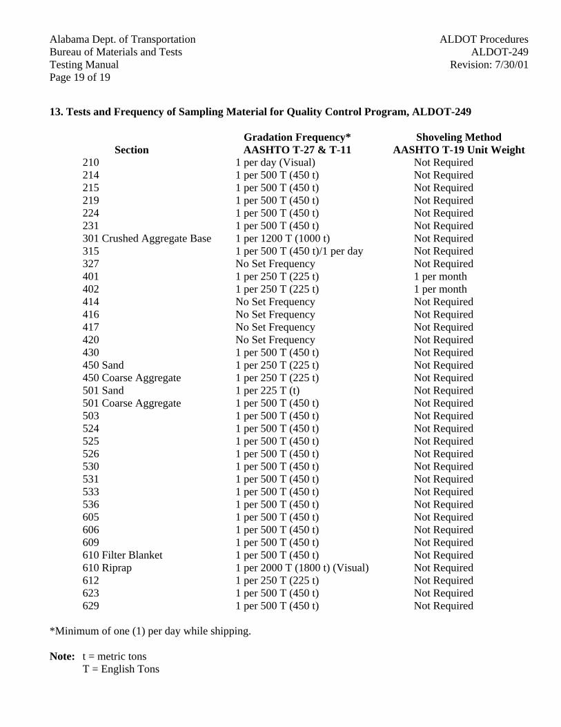
Page 19 of 19
Alabama Dept. of Transportation ALDOT ProceduresBureau of Materials and Tests ALDOT-249Testing Manual Revision: 7/30/01
13. Tests and Frequency of Sampling Material for Quality Control Program, ALDOT-249
SectionGradation Frequency*AASHTO T-27 & T-11
Shoveling MethodAASHTO T-19 Unit Weight
210 1 per day (Visual) Not Required214 1 per 500 T (450 t) Not Required215 1 per 500 T (450 t) Not Required219 1 per 500 T (450 t) Not Required224 1 per 500 T (450 t) Not Required231 1 per 500 T (450 t) Not Required301 Crushed Aggregate Base 1 per 1200 T (1000 t) Not Required315 1 per 500 T (450 t)/1 per day Not Required327 No Set Frequency Not Required401 1 per 250 T (225 t) 1 per month402 1 per 250 T (225 t) 1 per month414 No Set Frequency Not Required416 No Set Frequency Not Required417 No Set Frequency Not Required420 No Set Frequency Not Required430 1 per 500 T (450 t) Not Required450 Sand 1 per 250 T (225 t) Not Required450 Coarse Aggregate 1 per 250 T (225 t) Not Required501 Sand 1 per 225 T (t) Not Required501 Coarse Aggregate 1 per 500 T (450 t) Not Required503 1 per 500 T (450 t) Not Required524 1 per 500 T (450 t) Not Required525 1 per 500 T (450 t) Not Required526 1 per 500 T (450 t) Not Required530 1 per 500 T (450 t) Not Required531 1 per 500 T (450 t) Not Required533 1 per 500 T (450 t) Not Required536 1 per 500 T (450 t) Not Required605 1 per 500 T (450 t) Not Required606 1 per 500 T (450 t) Not Required609 1 per 500 T (450 t) Not Required610 Filter Blanket 1 per 500 T (450 t) Not Required610 Riprap 1 per 2000 T (1800 t) (Visual) Not Required612 1 per 250 T (225 t) Not Required623 1 per 500 T (450 t) Not Required629 1 per 500 T (450 t) Not Required
*Minimum of one (1) per day while shipping.
Note: t = metric tonsT = English Tons
Alabama Dept. of Transportation ALDOT ProceduresBureau of Materials and Tests ALDOT-253Testing Manual Revision: 2/22/94
Page 1 of 1
ALDOT-253-83RAPID DRYING OF SOIL AND AGGREGATE SAMPLES FOR FIELD TESTS
1. Scope
1.1. The purpose of this test procedure is to permit rapid drying of soil, coarse and fine aggregatesamples when performed at job site or producer laboratories.
2. Equipment
2.1. AASHTO Test Method requirements for uniform temperature ovens are waived for fieldtesting purposes. Hot plate (electric or gas) will be permitted.
3. Procedure
3.1. Frequent stirring will be required.
3.1.1. Sample will be dried, allowed to cool, reheated, and cooled until the mass has reached aconstant weight.
Alabama Dept. of Transportation ALDOT ProceduresBureau of Materials and Tests ALDOT-255Testing Manual Revision: 2/22/94
Page 1 of 1
ALDOT-255-83FIELD METHOD FOR DETERMINING THE EFFECT OF AN ANTI-STRIPPING
AGENT IN BITUMINOUS MIXTURES
1. Scope
1.1. This method covers the procedure to be used by asphalt plant inspectors to determinewhether an anti-stripping agent is present in samples of plant mix produced by an asphaltplant, when the use of an anti-stripping agent is required.
2. Apparatus
2.1. Balances (accurate to 0.1 g)
2.2. Pans
2.3. Spatulas
2.4. Beakers (approx. 1000 ml)
2.5. Hot plate or gas burner (for heating water in beakers)
2.6. Timer
2.7. Asbestos shields
3. Procedure
3.1. Obtain a 300-g sample of the bituminous mixture.
3.2. Place the sample in slow boiling water and let simmer for ten (10) minutes. An asbestosshield, the double boiler method or some other suitable means should be used to distributethe heat evenly under the container.
3.3. Drain the water from the mixture and place the mixture on a paper towel.
3.4. Visually inspect the mixture and determine the amount of stripping. (This should be donewith a minimum amount of disturbance to the sample.)
3.5. If the mixture appears to be borderline, the sample should then be allowed to dry beforemaking a final evaluation.
4. Reporting
4.1. Mixtures that fail to retain at least 95% coating, after testing, will not be acceptable. Reportas failing or passing.
Alabama Dept. of Transportation ALDOT ProceduresBureau of Materials and Tests ALDOT-258Testing Manual Revision: 2/22/94
Page 1 of 2
ALDOT-258-82MECHANICAL ANALYSIS OF EXTRACTED AGGREGATE
1. Scope
1.1. This method of test covers a procedure for the determination of the particle size distributionof fine and coarse aggregate extracted from bituminous mixtures, using sieves with squareopenings. The method described is a modification of AASHTO T-30 to allow its adaptationto a field procedure.
2. Apparatus
2.1. The apparatus shall consist of the following:
2.1.1. Balance - A balance shall conform to AASHTO M-231, Class D for samples less than5000 g, Class E for samples 5000 g or more.
2.1.2. Sieves - The sieves with square opening shall be mounted on substantial framesconstructed in a manner will prevent loss of material during sieving. Suitable sievesizes shall be selected to furnish the information required by the specificationscovering the material to be tested. The woven wire cloth sieves shall conform to therequirements of AASHTO M-92.
3. Sample
3.1. The sample shall consist of the entire lot or sample or aggregate determined according toALDOT-319 for Rapid Method to determine the Bitumen Content In Bituminous PavingMixtures from which the bituminous material has been extracted.
4. Procedure
4.1. The sample shall be dried until further drying at 230 +/-5°F (110° +/- 5°C) does not alter themass 0.1 percent. The total mass of aggregate in the bituminous mixture being tested is thesum of the masses of the dried aggregates and the mineral matter contained in the extractedbitumen. The latter is to be taken as the sum of the mass of ash in the extract and theincrease in mass of the filter element as determined in ALDOT-319.
4.2. After drying, record the mass of the test sample and place the sample in a container and coverit with water. Add sufficient amount of wetting agent to assure a thorough separation of thematerial finer than the No. 200 (75 µm) sieve from the coarser particles. The con-tents of thecontainer shall be agitated vigorously and the washwater immediately poured over a No. 8(2.36 mm) sieve superimposed on a No. 200 (75 µm) sieve. The use of a large spoon to stirand agitate the aggregate in the wash water has been found satisfactory.
Note: Wetting agents may include any dispersing agent such as Calgon, Joy, or other detergent, ora soap, which will promote the separation of fine material.
Alabama Dept. of TransportationALDOT ProceduresBureau of Materials and TestsALDOT-258
Testing ManualRevision: 2/22/94Page 2 of 2
4.3. The agitation shall be sufficiently vigorous to result in the complete separation from thecoarse particles of all particles finer than the No. 200 (75 µm) sieve and bring them intosuspension in order that they may be removed by decantation of the washwater. Care shallbe taken to avoid, as much as possible, the decantation of the coarse particles of the sample.The operation shall be repeated until the washwater is clear.
4.4. All material retained on the nested sieves shall be returned to the container. The washedaggregate in the container shall be dried to a constant mass at a temperature of 230 +/-5°F(110° ± 5°C) and weighed to the nearest 0.1 percent. The aggregate shall then be sieved oversieves of the various sizes required by specification covering the mixture. The weight ofmaterial passing each sieve and retained on the next shall be recorded. The summation ofthese various weights must check with the dried weight after washing within 0.2 percent ofthe total weight. The weights of fractions retained on the various sieves and the total passingthe No. 200 (75 µm) sieve shall be converted to percentage by dividing each by the totalweight of aggregate in the bituminous mixture from 4.1.
Note: For further explanation see AASHTO T-30.
5. Reporting
5.1. The results of the sieve analysis shall be reported as total percentages passing each sieve.Percentages shall be reported to the nearest whole number except for the percentage passingthe No. 200 (75 µm) sieve which shall be reported to the nearest 0.1 percent.
Alabama Dept. of Transportation ALDOT ProceduresBureau of Materials and Tests ALDOT-259Testing Manual Revision: 8/23/99
Page 1 of 13ALDOT-259-97
OPEN-GRADED ASPHALT CONCRETE FRICTION COURSE DESIGN METHOD
1. Scope
1.1. This is the laboratory procedure approved by the Department of Transportation for designingopen-graded asphalt concrete friction courses containing a fiber stabilizer.
2. Referenced Documents
2.1. Alabama Department of Transportation Specifications for Highway Construction
2.2. AASHTO T 209, Maximum Specific Gravity of Bituminous Paving Mixtures
2.3. ALDOT-361, Resistance of Compacted Bituminous Mixture to Moisture Induced Damage
2.4. ALDOT-384, Mix Design Procedure for Superpave Level I
2.5. ALDOT-386, Determination of Drain Down Characteristics in Uncompacted BituminousMixtures
3. Test Procedure
3.1. Check the coarse and fine aggregate along with the mineral filler for specificationcompliance. Test for gradation, absorption, bulk dry specific gravity, and apparent specificgravity.
3.2. Separate from the combined aggregate blend, material passing the 3/8 in,.( 9.5 mm )sieve andretained on the No. 4 (4.75 mm)sieve. (This is usually the predominate aggregate portion ofthe blend.) Quarter out 105 grams (± 2 grams) of this aggregate and dry in an oven at 230 ±9°F (110 ± 5oC ) to a constant mass. Then allow the sample to cool to room temperature.
3.3. Place approximately 100 grams of the a sample into a metal funnel measuring 4.5 in. (115mm )in height, with a top diameter of 3.5 in. (90 mm )and a bottom diameter of ½ in. (15mm). Cover the bottom orifice with wire mesh from a No. 10 (2.00 mm) sieve. Immerse thefunnel containing the sample into a container filled with S.A.E. No. 10 lubricating oil untilthe aggregate is completely covered. If the aggregate has less than 2 percent absorption, let itsoak for five minutes. If the aggregate has an absorption greater than 2 percent, let it soak for30 minutes.
3.4. Let the funnel and its contents drain for approximately two minutes at room temperature.Then pace in a n oven at 140 ± 5°F (60 ± 3oC) and let it drain an additional 15 minutes.Empty contents of the funnel into a tarred pan and let cool to room temperature. Record themass of the sample to the nearest 0.1 gram.
Alabama Dept. of TransportationALDOT ProceduresBureau of Materials and TestsALDOT-259
Testing ManualRevision: 8/23/99Page 2 of 13
3.5. Calculate the percent oil retained (POR) in the surface of the aggregate using thefollowing equation:
POR = Gsa / 2.65 * (B-A) / A * 100
Where:
Gsa = apparent specific gravity of sample aggregateA = dry weight of sample (paragraph 3.3)B = coated weight of sample (paragraph 3.4)
3.6. If the aggregate has less than 2 percent absorption move to paragraph 3.10.
3.7. If the aggregate has more than 2 percent absorption, go on to paragraph 3.8.
3.8. If the aggregate has more than 2 percent absorption, after completing paragraph 3.4, pour theaggregate onto a clean absorptive cloth and obtain a saturated surface dry condition.
3.9. Obtain the mass of the S. S. D. sample, to the nearest 0.1 gram, and calculate the percent oilabsorbed (POA) using the following equation:
POA = (SSD - A) / A * 100
Where:
SSD = saturated surface dry mass (paragraph 3.8)A = dry weight of sample (paragraph 3.3)
3.10. Determine the percent free oil (PFO) using the following equation:
PFO = POR - POA
Where:
POA = percent oil absorbed (paragraph 3.8)POR = percent oil retained (paragraph 3.5)
3.11. For aggregate with less than 2 percent absorption, calculate the surface constant value usingthe following equation:
SC = 0.1 + 0.4 * POR
Alabama Dept. of Transportation ALDOT ProceduresBureau of Materials and Tests ALDOT-259Testing Manual Revision: 8/23/99
Page 3 of 13
3.12. For aggregate with more than 2 percent absorption, calculate the surfaceconstant value using the following equation:
SC = 0.1 + 0.4 * PFO
3.13. For aggregate with less than 2 percent absorption the asphalt content, percent binder (Pb), iscomputed using the following equation:
Pb = (2 * SC + 4) * 2.65 / Gsa
3.14. For aggregate with more than 2 percent absorption the effective asphalt content, percentbinder effective (Pbe), is computed using the following equation:
Pbe = (2 * SC + 4) * 2.65 / Gsa
3.15. Complete section 4 and 5 of this procedure, then prepare at least one batch using at least 0.2percent mineral fiber, (size based upon nominal maximum aggregate size from AASHTO T209, Maximum Specific Gravity of Bituminous Paving Mixtures), of this gradation.Estimate the amount of asphalt binder that will be absorbed (ALDOT-384 contains anequation to help with this estimate). Mix and age this batch according to ALDOT-384 usingan asphalt content equal to or slightly higher than the sum of the effective and (estimated)absorbed asphalt content. Run the AASHTO T 209 test on the sample and use the equationsin ALDOT-384 to calculate the percent of binder that is actually absorbed (Pba). The totalamount of asphalt cement needed for aggregates with more than 2 percent absorption iscalculated by the following equation:
Pb = Pbe + Pba
4. Void Capacity of Coarse Aggregate
4.1. Determine the unit weight (unit mass) of the coarse aggregate fraction of the proposedgradation by either of the following methods.
4.1.1. Apparatus
4.1.1.1. Compaction Mold: A solid wall metal cylinder, approximately 6 in. (150 mm)nominal diameter, with a detachable metal base plate. A detachable metalguide-reference bar as shown in figure 2 is required for the first method.
4.1.1.2. Timer: A stopwatch or equivalent timing device accurate to ± one second pertwo minutes. A circuit breaker connected to the clock is allowed.
4.1.1.3. Dial Indicator (or other measuring device): Indicator shall be accurate to aleast 0.001in. (0.025 mm) with a range of at least 3 in. (75 mm).
4.1.1.4. Vibratory Compactor, First Method:
Alabama Dept. of TransportationALDOT ProceduresBureau of Materials and TestsALDOT-259
Testing ManualRevision: 8/23/99Page 4 of 13
4.1.1.4.1. Rammer: A portable electromagnetic vibratingrammer as shown in figure 3, having a frequency of 3,600 cycles perminute. The rammer shall have a tamper and extension as shown infigure 4.
4.1.1.4.2. Wooden Base: A plywood disc approximately 15 in. (380 mm) indiameter, 2 in. (50 mm) thick, with a cushion (rubber hose) attached tothe bottom. This base shall be constructed so that it can be firmlyattached to the base plate of the compaction mold.
4.1.1.5. Vibratory Compactor, Second Method:
4.1.1.5.1. Vibrating Table: A vibratory table capable of inducing vibratorycompaction at 3,600 cycles per minute with an amplitude of 0.013 ±0.002 in.(0.33 ± 0.05 mm) (i.e. Soiltest CN-166).
4.1.1.5.2. Confining Load: A circular steel disc with a mass ofapproximately 27 kg and a diameter 2/16 to 3/16 in. (3 to 4 mm)smaller than the compaction mold (i.e. Soiltest CN-167).
4.2. Quarter out a sample from the coarse aggregate of the proposed blend. The sample size shallbe approximately 2,270 grams. For light weight aggregate (bulk specific gravity less than2.0), reduce the sample size to 1,590 grams.
Note: Most light weight aggregate will be crushed when subject to field compaction and willnot make a suitable open graded mix.
4.3. Tare the compaction mold and place the sample into the mold. Record the sample mass tothe nearest gram.
4.4. First Method:
4.4.1. Place the tamper foot on the sample. Place the guide/reference bar over the shaft ofthe tamper foot and secure the bar to the mold with the thumb screws.
4.4.2. Place the vibratory rammer on the shaft of the tamper foot and vibrate for 15 seconds.During vibration exert just enough pressure on the rammer to maintain contactbetween the sample and the tamper foot.
4.4.3. Remove the vibratory rammer from the shaft of the tamper foot and brush any finesfrom the top of the tamper foot.
4.4.4. Measure the thickness (t) of the compacted material to the nearest 0.01 in. (1/4millimeter).
4.5. Second Method:
4.5.1. Place the surcharge base plate on the sample and place the sample onto the vibratingtable.
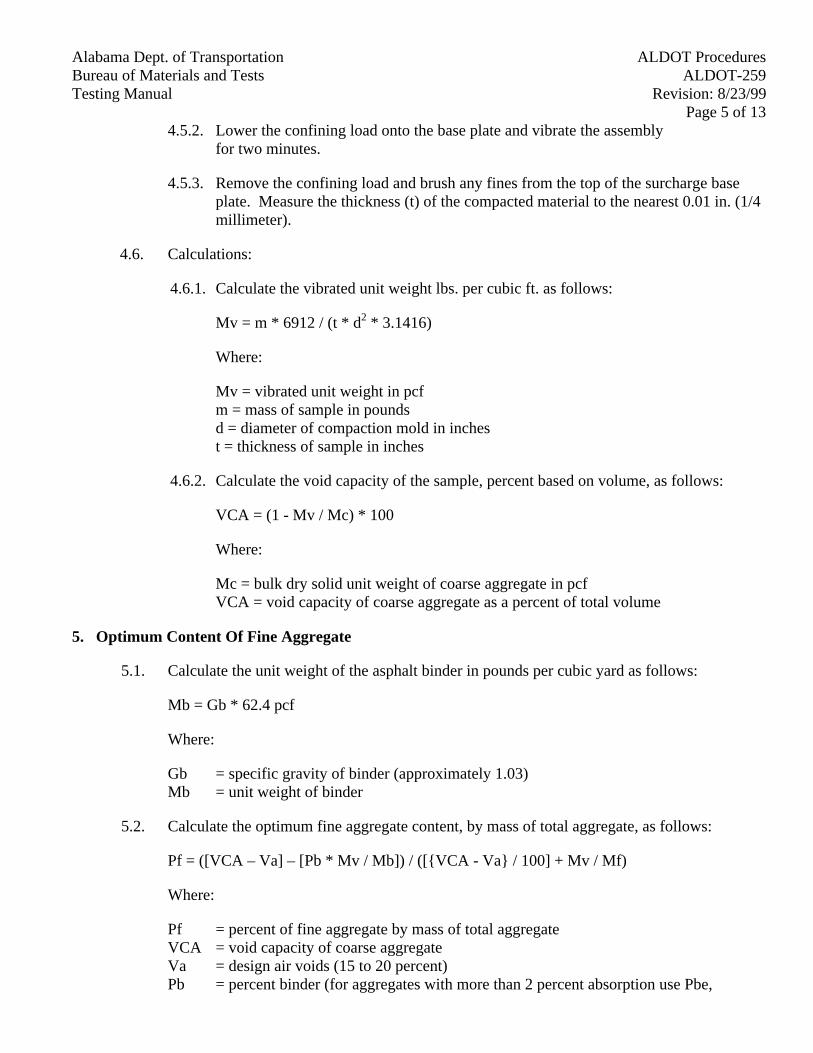
Alabama Dept. of Transportation ALDOT ProceduresBureau of Materials and Tests ALDOT-259Testing Manual Revision: 8/23/99
Page 5 of 134.5.2. Lower the confining load onto the base plate and vibrate the assembly
for two minutes.
4.5.3. Remove the confining load and brush any fines from the top of the surcharge baseplate. Measure the thickness (t) of the compacted material to the nearest 0.01 in. (1/4millimeter).
4.6. Calculations:
4.6.1. Calculate the vibrated unit weight lbs. per cubic ft. as follows:
Mv = m * 6912 / (t * d2 * 3.1416)
Where:
Mv = vibrated unit weight in pcfm = mass of sample in poundsd = diameter of compaction mold in inchest = thickness of sample in inches
4.6.2. Calculate the void capacity of the sample, percent based on volume, as follows:
VCA = (1 - Mv / Mc) * 100
Where:
Mc = bulk dry solid unit weight of coarse aggregate in pcfVCA = void capacity of coarse aggregate as a percent of total volume
5. Optimum Content Of Fine Aggregate
5.1. Calculate the unit weight of the asphalt binder in pounds per cubic yard as follows:
Mb = Gb * 62.4 pcf
Where:
Gb = specific gravity of binder (approximately 1.03)Mb = unit weight of binder
5.2. Calculate the optimum fine aggregate content, by mass of total aggregate, as follows:
Pf = ([VCA – Va] – [Pb * Mv / Mb]) / ([{VCA - Va} / 100] + Mv / Mf)
Where:
Pf = percent of fine aggregate by mass of total aggregateVCA = void capacity of coarse aggregateVa = design air voids (15 to 20 percent)Pb = percent binder (for aggregates with more than 2 percent absorption use Pbe,
Alabama Dept. of TransportationALDOT ProceduresBureau of Materials and TestsALDOT-259
Testing ManualRevision: 8/23/99Page 6 of 13
effective binder content)Mv = vibrated unit weight in pounds per cubic yardMb = unit weight of binderMf = bulk dry solid unit weight of fine aggregate
5.3. Compare the optimum fine aggregate content (Pf) at both 15 and 20 percent design air voidsto the amount passing the No. 8 (2.36 mm) sieve of the job mix formula (JMF). If the JMF isoutside the optimum range by more than 1 percent recompute the proportions of coarse andfine aggregates to meet the optimum fine aggregate content. If this changes the coarseaggregate portion of the JMF by more than 5 percent the design procedure shall be repeated.
5.4. After completing sections 4 and 5, prepare at least one batch to determine the maximumspecific gravity of the bituminous paving mixture. Add at least 0.2 per-cent fiber to theaggregate and mix thoroughly before adding the liquid asphalt binder. The size of sampleshould be based upon the nominal maximum aggregate size from AASHTO T 209. Estimatethe amount of asphalt binder that will be absorbed. (Use the equation found in ALDOT-384to help with this estimation.) Mix and age this batch according to ALDOT-384 using anasphalt content equal to or slightly higher than the sum of the effective and estimatedabsorbed asphalt con-tent. Determine the maximum specific gravity of the bituminouspaving mixture in accordance with AASHTO T 209. Use the equation in ALDOT-384 tocalculate the percent of binder that is actually absorbed (Pba).
Pb = Pbe + Pba
6. Drain Down
6.1. In general, the mixing temperature is the temperature where the liquid asphalt binder has aviscosity of 170 ± 20cSt; however, when the liquid asphalt binder contains polymer themixing temperature may be different, so the manufacturer's recommendation and guidelinesshould be followed to determine mixing temperature.
6.2. Prepare a sample and test it by ALDOT-386, Determination of Drain Down Characteristics inUncompacted Bituminous Mixtures, using the mixing temperature as the anticipated plantproduction temperature. If the drain down exceeds 0.3 per-cent when the temperature is 27°F(15°C) higher than the anticipated plant production temperature then the O.G.F.C. shall beredesigned with a higher fiber content. Include the amount of drain down in the mix designreport.
7. Resistance to Moisture Damage
7.1. At the mixing temperature prepare at least six specimens according to ALDOT-384, using100 gyrations.
7.2. Use the height versus gyration data to estimate each specimen's bulk specific gravity.Separate the specimens into two groups with equal, or as close to equal as possible, bulkspecific gravity averages.
Alabama Dept. of Transportation ALDOT ProceduresBureau of Materials and Tests ALDOT-259Testing Manual Revision: 8/23/99
Page 7 of 137.3. Immerse one group in 140°F (60°C) water for 24 hours (as in ALDOT-361).
Store the other group in air at room temperature. Place both groups into a 77°F (25 ± 1°C)water bath for a minimum of one hour (both groups must be at the same temperature fortesting).
7.4. Determine the tensile strength for both groups and calculate the ratio of conditioned at 140°F(60°C) strength to stored at room temperature strength. If this ratio is not 80 percent orhigher anti-strip or other additives shall be added until the 80 percent ratio is met whenperforming this procedure.
8. Reporting
8.1. The contractor shall submit to Materials and Tests the job mix formula for review. Thecontractor shall include all the data this procedure requires including the data required tocomplete the HMA OGFC Design Work Sheet, included in this procedure.
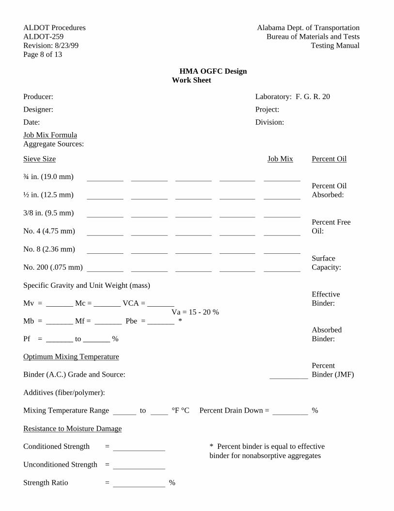
Alabama Dept. of TransportationALDOT ProceduresBureau of Materials and TestsALDOT-259
Testing ManualRevision: 8/23/99Page 8 of 13
HMA OGFC DesignWork Sheet
Producer: Laboratory: F. G. R. 20
Designer: Project:
Date: Division:
Job Mix FormulaAggregate Sources:
Sieve Size Job Mix Percent Oil
¾ in. (19.0 mm)Percent Oil
½ in. (12.5 mm) Absorbed:
3/8 in. (9.5 mm)Percent Free
No. 4 (4.75 mm) Oil:
No. 8 (2.36 mm)Surface
No. 200 (.075 mm) Capacity:
Specific Gravity and Unit Weight (mass)Effective
Mv = _______ Mc = _______ VCA = _______ Binder:Va = 15 - 20 %
Mb = _______ Mf = _______ Pbe = _______ *Absorbed
Pf = _______ to _______ % Binder:
Optimum Mixing TemperaturePercent
Binder (A.C.) Grade and Source: Binder (JMF)
Additives (fiber/polymer):
Mixing Temperature Range to °F °C Percent Drain Down = %
Resistance to Moisture Damage
Conditioned Strength = * Percent binder is equal to effectivebinder for nonabsorptive aggregates
Unconditioned Strength =
Strength Ratio = %
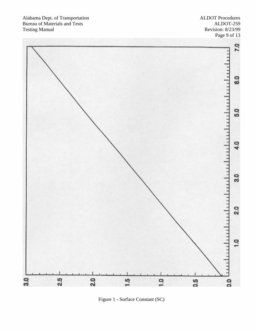
Alabama Dept. of Transportation ALDOT ProceduresBureau of Materials and Tests ALDOT-259Testing Manual Revision: 8/23/99
Page 9 of 13
Figure 1 - Surface Constant (SC)
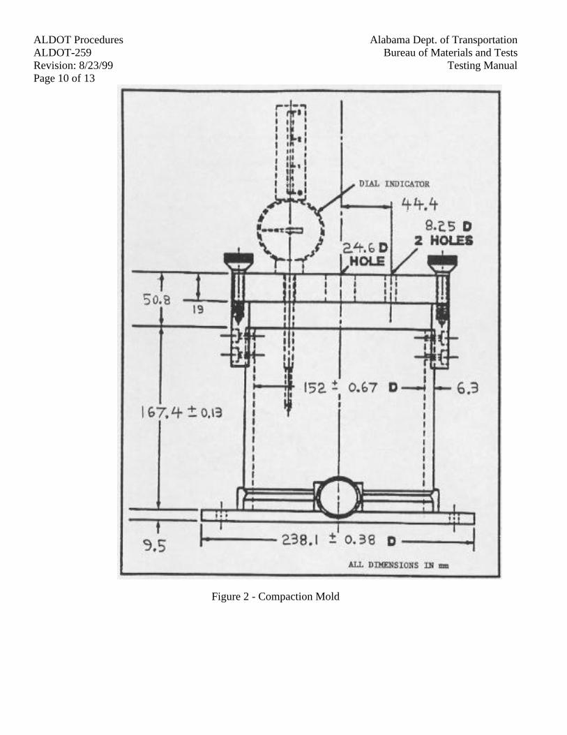
Alabama Dept. of TransportationALDOT ProceduresBureau of Materials and TestsALDOT-259
Testing ManualRevision: 8/23/99Page 10 of 13
Figure 2 - Compaction Mold
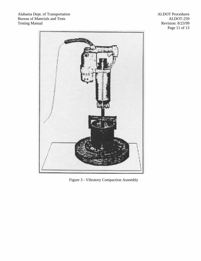
Alabama Dept. of Transportation ALDOT ProceduresBureau of Materials and Tests ALDOT-259Testing Manual Revision: 8/23/99
Page 11 of 13
Figure 3 - Vibratory Compaction Assembly

Alabama Dept. of TransportationALDOT ProceduresBureau of Materials and TestsALDOT-259
Testing ManualRevision: 8/23/99Page 12 of 13
Figure 4 - Tamper Foot
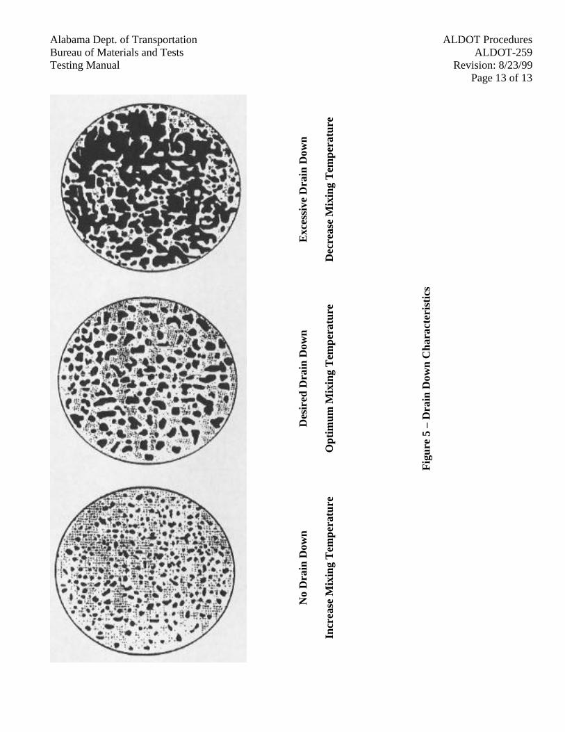
Alabama Dept. of Transportation ALDOT ProceduresBureau of Materials and Tests ALDOT-259Testing Manual Revision: 8/23/99
Page 13 of 13
Exc
essi
ve D
rain
Dow
n
Dec
reas
e M
ixin
g T
emp
erat
ure
Des
ired
Dra
in D
own
Op
tim
um
Mix
ing
Tem
per
atu
re
No
Dra
in D
own
Incr
ease
Mix
ing
Tem
per
atu
re
Fig
ure
5 –
Dra
in D
own
Ch
arac
teri
stic
s
Alabama Dept. of Transportation ALDOT ProceduresBureau of Materials and Tests ALDOT-283Testing Manual Revision: 2/22/94
Page 1 of 1
ALDOT-283-82METHOD OF TEST FOR SIEVE ANALYSIS OF AGRICULTURAL LIMESTONE
1. Scope
1.1. This test is used to determine the size gradation of crushed limestone or marl.
2. Equipment
2.1. Sieve No. 10 (2.00 mm) mesh
2.2. Sieve No. 60 (250 µm) mesh
3. Procedure
3.1. Reduce sample size to approximately 300g by rifling or quartering per AASHTO T-248.
3.2. Dry to constant weight in an oven at 230°F(110°C).
3.3. Weigh out 150g of sample and place in No.10 (2.00 mm) mesh sieve. Sieve sample through No. 10(2.00 mm) mesh and No. 60 (250 µm) mesh sieves by lateral motions.
3.4. Weigh portion of material retained on each sieve and calculate % of total weight of sample.
3.5. Report as passing percent on each sieve.

Alabama Dept. of Transportation ALDOT ProceduresBureau of Materials and Tests ALDOT-307Testing Manual Revision: 10/27/97
Page 1 of 5
ALDOT-307-83DESIGN METHOD FOR SELECTING OPTIMUM ASPHALT CEMENT CONTENT OF
BITUMINOUS MIXTURE BY MEANS OF THE MARSHALL APPARATUS
1. Scope
1.1. This procedure covers the Department's method of designing bituminous paving mixturesusing the Marshall Stability Apparatus for the measurement of the resistance to plastic flowof cylindrical specimens of bituminous paving mixtures loaded on the lateral surface. Thismethod is for use with mixtures containing aggregate up to 1 in. (25 mm) maximum particlesize.
2. Applicable Documents
2.1. AASHTO T 84, Specific Gravity and Absorption of Fine Aggregates
2.2. AASHTO T 85, Specific Gravity and Absorption of Coarse Aggregates
2.3. AASHTO T 166, Bulk Specific Gravity of Compacted Bituminous Mixtures
2.4. AASHTO T 209, Maximum Specific Gravity of Bituminous Paving Mixtures
2.5. AASHTO T 245, Resistance to Plastic Flow of Bituminous Mixtures using the MarshallApparatus
2.6. AASHTO T 269, Percent Air Voids in Compacted Dense and Open Bituminous PavingMixtures
2.7. The Asphalt Institute Manual, Series No. 2 (MS-2), Current Edition
3. Test Procedures
3.1. Stability and Flow
3.1.1. AASHTO T 245 shall apply except where amended as follows:
Paragraph 3.4, 1st sentence, shall be amended to include the following formula foradjusting the amount of aggregate to obtain the required 63-mm specimen thickness:
International System of Unit (SI)
63 X mass of Agg. (g)Adjusted Wt. (Agg)=
Measured Specimen Hgt. (mm)
3.1.2. Age the specimens (samples for compaction, samples for maximum specific gravity)in a forced draft oven at compaction temperature for 45 minutes.
3.2. Bulk Specific Gravity of Compacted Bituminous Mixtures
Alabama Dept. of TransportationALDOT ProceduresBureau of Materials and TestsALDOT-307
Testing ManualRevision: 10/27/97Page 2 of 5
3.2.1. AASHTO T 166, Method A, shall apply.
3.2.2. Prior to testing for stability and flow, the Bulk Specific Gravity shall be determinedon the compacted specimen prepared in accordance with AAHSTO T 245 asamended.
3.2.3. Average the Bulk Specific Gravities for all compacted specimens of a given asphaltcontent. Values obviously in error shall not be included in average. Values shall becarried out to three decimal places.
3.3. Maximum Specific Gravity of Bituminous Paving Mixtures
3.3.1. AASHTO T 209 shall apply.
3.3.2. Determine the Maximum Specific Gravity of the bituminous mix for at least twoasphalt contents, preferable on mixes at or near the optimum asphalt content andcompute average. The Maximum Specific Gravity of the mixes with other asphaltcontents can be computed as described in paragraph 4.4.
4. Density and Voids Analysis
4.1. Nomenclature
4.1.1. The following nomenclature will be used in the section:
Gb = Specific Gravity of AsphaltGmb = Bulk Specific Gravity of Compacted MixtureGmm = Maximum Specific Gravity of Bituminous Mixture at a particular
asphalt contentGsa = Apparent Specific Gravity of the combined coarse and fine aggregatesGsb = Bulk Specific Gravity of the combined coarse and fine aggregatesGse = Effective Specific Gravity of AggregatePa = Percent Air Voids by total volume in compacted mixturePb = Percent Binder by total mass of mixturePba = Percent Absorbed Binder by mass of aggregatePbe = Percent Effective Binder Content by total mass of mixturePs = Percent Aggregate by total mass of mixtureVF = Percent of Total Voids filledVMA = Percent Voids, by volume of compacted mix, in mineral aggregate
4.2. Bulk and Apparent Specific Gravity of Coarse and Fine Aggregates
4.2.1. Calculate the Bulk and Apparent Specific Gravity of Coarse Aggregate in accordancewith AASHTO T 85. (See Note 1)
4.2.2. Calculate the Bulk and Apparent Specific Gravity of Fine Aggregate in accordancewith AASHTO T 84 on the material retained on the No. 200 (75 µm) sieve after the
Alabama Dept. of Transportation ALDOT ProceduresBureau of Materials and Tests ALDOT-307Testing Manual Revision: 10/27/97
Page 3 of 5
materials passing the No. 200 (75 µm) sieve has been re-moved by washing.(Assume that the No. 200 (75 µm) material washed from the sample has the samespecific gravity as the material retained on the No. 200 (75 µm). (See Note 1, 2)
4.2.3. Calculate the Bulk Specific Gravity (Gsb) of the total combined mineral aggregate asfollows: (See Note 1)
100Gsb =
Percent Agg. 1 Percent Agg. 2 Percent Agg. nGsb Agg. 1 + Gsb Agg. 2 + Gsb Agg. n
4.2.4. Calculate the Apparent Specific Gravity (Gsa) of the total combined mineralaggregate as shown in paragraph 4.2.3 by substituting the Apparent Specific Gravityof the aggregate in the formula for the Bulk Specific Gravity (Gsb). (See Note 1)
Note 1: Test results shall be carried out to three decimal places.
Note 2: The Bulk Specific Gravity of mineral filler is difficult to determine. However, if theApparent Specific Gravity of mineral filler is used instead, the error is usuallynegligible.
4.3. Effective Specific Gravity of Aggregate (Gse)
4.3.1. Calculate the Effective Specific Gravity of aggregate using average Gmm asdetermined in paragraph 3.3.2.
100 - PbGsb =
100 PbGmm - Gb
Note: The asphalt content (Pb) should be the asphalt content at which Gmm wasdetermined in paragraph 3.3.2.
4.4. Maximum Specific Gravity of Bituminous Mixture with other Asphalt Contents. (Gmm)
4.4.1. Compute Maximum Specific Gravity of bituminous mixtures at other asphalt contentsas follows:
100Gmm =
Ps PbGse + Gb
4.5. Percent Voids in Mineral Aggregate (VMA)
Alabama Dept. of TransportationALDOT ProceduresBureau of Materials and TestsALDOT-307
Testing ManualRevision: 10/27/97Page 4 of 5
4.5.1. Compute Percent Voids in Mineral Aggregate of the compacted bituminous mixturefor each asphalt content as follows:
(Gmb) (Ps)VMA = 100 -
Gsb
4.6. Percent Air Voids in Compacted Mixture (Pa)
4.6.1. Compute percent Air Voids of the compacted bituminous mixture for each asphaltcontent as follows:
Gmm - GmbPa = 100
Gmm
4.7. Percent Voids filled in compacted mixture (VF)
4.7.1. Compute Voids filled in the compacted bituminous mixture for each asphalt contentas follows:
VMA - PaVF = 100
VMA
4.8. Other Parameters
4.8.1. Asphalt Absorption (Pba) - Compute the percent of asphalt absorption as follows:
(Gse – Gsb)Pba = 100
(Gsb) (Gse)Gb
4.8.2. Effective Asphalt Content (Pbe) - Compute the effective asphalt content forbituminous mix as follows:
PbaPbe = Pb
100Ps
5. Selecting Optimum Asphalt Content
5.1. Measure stability values for a given asphalt content and average results. Values that areobviously in error should not be included in average.
5.2. Compute the average density for each asphalt content by multiplying the average bulkspecific gravity value as determined in paragraph 3.2.3 by 62.4 lb/ft3 (1000 kg/m3) and by0.997 to correct for the density of water at 77°F (25°C).
5.3. Plot a separate graph for the following values:
Alabama Dept. of Transportation ALDOT ProceduresBureau of Materials and Tests ALDOT-307Testing Manual Revision: 10/27/97
Page 5 of 5
Stability vs. Asphalt ContentDensity vs. Asphalt ContentPercent Air Voids vs. Asphalt ContentPercent Voids Filled vs. Asphalt ContentPercent VMA vs. AC
Note: In each graph connect the plotted values with a smooth curve that is the "best fit" forall values.
5.4. Optimum Asphalt Content
5.4.1. The optimum asphalt content of the mix is the percent asphalt cement that yields therequired percent air voids as specified for a particular mix.
5.4.2. Adjustments should be made in the bituminous mix if all the design criteria are notmet by the optimum asphalt content.
5.4.3. Determine from density curve the Laboratory Density of the mix at the OptimumAsphalt Content. This density will be reported for use in adjustment of materialthickness along within place density determinations.
Note: Refer to ALDOT-153 for typical Work Sheet and Report Form.
Alabama Dept. of Transportation ALDOT ProceduresBureau of Materials and Tests ALDOT-310Testing Manual Revision: 10/17/95
Page 1 of 2
ALDOT-310METHOD OF DETERMINING PERCENT OF FRACTURED PARTICLES IN COARSE
AGGREGATE
1. Scope
1.1. This method of test is for the determination of the percent of crushed particles in coarseaggregate.
2. Definitions and Standards
2.1. A fully fractured face is defined as an angular, rough or broken surface of an aggregateparticle created by crushing, by other artificial means, or by nature. A face is consideredfractured only if it has a projected area at least as large as one-quarter of the maximumprojected area (maximum cross-sectional area) of the particle and also has sharp and well-defined edges.
3. Apparatus
3.1. Balances (Accurate to 0.1 g).
3.2. Oven (Capable of maintaining the temperature at 230 ± 10°F (110 ± 5°C).
3.3. No. 4 (75 mm) Sieve.
3.4. Pans.
4. Procedure
4.1. Determine sample size based on Nominal Maximum Aggregate size as per AASHTO T-27.
4.2. Thoroughly mix and then reduce the field sample for testing in accordance with AASHTO T-248.
4.3. Wash the sample thoroughly over the No. 4 (4.75 mm) sieve.
4.4. Dry the sample at 230 ± 10 °F (110 ± 5°C) and record total mass of sample.
4.5. Separate the aggregate particles into three groups: (1) one crushed face, (2) two or morecrushed faces, and (3) what remains with no crushed faces. To check this criterion (asdefined in 2.1), hold each aggregate particle so that the face is viewed directly. See Figure 1showing a schematic of a fractured particle with one fractured face.
4.6. Record the mass of each of these groups and the total sample mass to the nearest 0.1g.
4.7. Check total sample mass after the test with the mass recorded in 4.4. If different by morethan 0.1g repeat test.
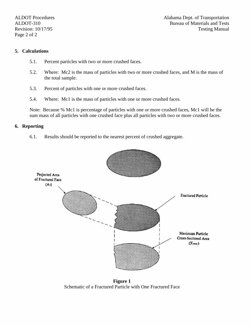
Alabama Dept. of TransportationALDOT ProceduresBureau of Materials and TestsALDOT-310
Testing ManualRevision: 10/17/95Page 2 of 2
5. Calculations
5.1. Percent particles with two or more crushed faces.
5.2. Where: Mc2 is the mass of particles with two or more crushed faces, and M is the mass ofthe total sample.
5.3. Percent of particles with one or more crushed faces.
5.4. Where: Mc1 is the mass of particles with one or more crushed faces.
Note: Because % Mc1 is percentage of particles with one or more crushed faces, Mc1 will be thesum mass of all particles with one crushed face plus all particles with two or more crushed faces.
6. Reporting
6.1. Results should be reported to the nearest percent of crushed aggregate.
Figure 1Schematic of a Fractured Particle with One Fractured Face
Alabama Dept. of Transportation ALDOT ProceduresBureau of Materials and Tests ALDOT-319Testing Manual Revision: 2/28/94
Page 1 of 3
ALDOT-319-82RAPID METHOD TO DETERMINE THE BITUMEN CONTENT IN
BITUMINOUS PAVING MIXTURES
1. Scope
1.1. This is a rapid test method to be used in routinely determining the bitumen content in hotmixed paving mixtures. The method described is a modification of AASHTO T-164,Method A.
2. Apparatus
2.1. Rotorex (Electric or Manual)
2.2. Beaker (200-500 ml capacity)
2.3. Pans (Approximately 18 x 12 in (450 x 300 mm))
2.4. Filter Rings (Appropriate size)
2.5. Hot Plate (Electric or Gas)
2.6. Balance (Conforming to the requirements of AASHTO M-231 Class G2)
2.7. Spatula
2.8. 2 in Paint Brush
3. Reagents
3.1. Trichloroethylene, Technical Grade, Type I, Federal Specification 0-T-634, latest revision.
3.2. 1,1,1, Trichloroethane, Conforming to Federal Specification 0-T-620, (Interim Amendment3).
Note 1: The Solvents should be used only under a hood in a well ventilated area.
4. Determination of Water in Mineral Aggregate
4.1. Obtain sample and test in accordance with ALDOT-130.
5. Procedure
5.1. Secure a representative sample of the Bituminous Mixture in accordance to AASHTO T-168.
5.2. Quarter the sample to the size required (in AASHTO T-164, Table I) by AASHTO T-248.For samples containing aggregate greater than 1 in. (25 mm) in diameter, a sample of a least
Alabama Dept. of TransportationALDOT ProceduresBureau of Materials and TestsALDOT-319
Testing ManualRevision: 2/28/94Page 2 of 3
1.5 to 2 kg. may be used. However, before any material can be rejected, the requirements forsample size shown in Table I of AASHTO T-164 must be complied with.
5.3. Weigh filter rings after drying to a constant weight over hot plate or heater fan. Record themass.
5.4. Weigh sample and record weight.
5.5. Place sample in the rotor bowl, cover the sample in the bowl with solvent and allowsufficient time for the solvent to disintegrate the sample (not over one hour, usually 5 to 10minutes).
5.6. Start rotorex bowl revolving slowly and gradually increase the speed to a maximum of 3600rpm or until solvent ceases to flow from the drain. Allow the machine to stop, add 200 ml ofsolvent and repeat the procedure. Use sufficient 200 ml solvent additions (not less thanthree) so that the extract is clear and not darker than a light straw color. Collect the extractedsolvent in a suitable graduate.
5.7. Remove bowl from rotorex. Place in pan so as no edges will protrude over side of pan.Remove funnel screw, take approximately 50 mm paintbrush and clean bowl lid. Next, brushany adhering particles of filter pad off into the pan, then remove material from the bowl intopan by using a brush.
5.8. Dry the sample slowly on a hot plate and agitate aggregates repeatedly with spatula until noodor from the solvent can be detected.
5.9. Dry filter rings until no odor can be detected. Weigh and record weight gain in the filterrings.
5.10. Weigh extracted aggregate and record mass.
6. Calculations
6.1. Calculate the percentage of bitumen in sample as follows:
Percent Bitumen content based on total sample
(W1 – W2) - (W3 + W4 + W5)W1 – W2
X 100
Where:W1 = original mass of sampleW2 = mass of water in sampleW3 = mass of extracted mineral matterW4 = mass of mineral matter in extract, based on ash correction factor (See Note 4 and 5)W5 = increase of mass of filter rings

Alabama Dept. of Transportation ALDOT ProceduresBureau of Materials and Tests ALDOT-319Testing Manual Revision: 2/28/94
Page 3 of 3
Note 3: The ash correction factor can be obtained by placing all of the effluent from theextraction test (Article 5.5 and 5.6) in a sealed water tight container and submitting it alongwith the total mass of the mineral water to the Division or Central Laboratory.
Note 4: If the Asphalt Laboratory at the plant site is equipped to determine the ash test inaccordance with AASHTO T-164, it shall be used instead of the ash correction factor.
Page 1 of 5
Alabama Dept. of Transportation ALDOT ProceduresBureau of Materials and Tests ALDOT-320Testing Manual Revision: 3/18/94
Page 1 of 5
ALDOT-320-79IN-LINE BLENDING OF ANTI-STRIP AGENT AT BITUMINOUS PLANT MIX
MANUFACTURING SITE
1. Scope
1.1. This procedure establishes the method and control of in-line blending of asphalt cement andanti-strip agent when the additive is introduced during the manufacture of bituminous plantmix.
2. Apparatus
2.1. Balance - The balance shall have a capacity of 5 kg or more and conform to AASHTO M-231, Class F.
2.2. Stop Watch - Graduated in seconds and accurate to ± 0.1 percent when checked over a 15minute period.
2.3. Sample Container - Any open top, leak proof container with a minimum capacity of 2 gal (8L).
3. In-Line Blending System
3.1. The position for the introduction of the anti-strip agent to the asphalt cement may be at anyaccessible point between A-A' shown in Figure I.
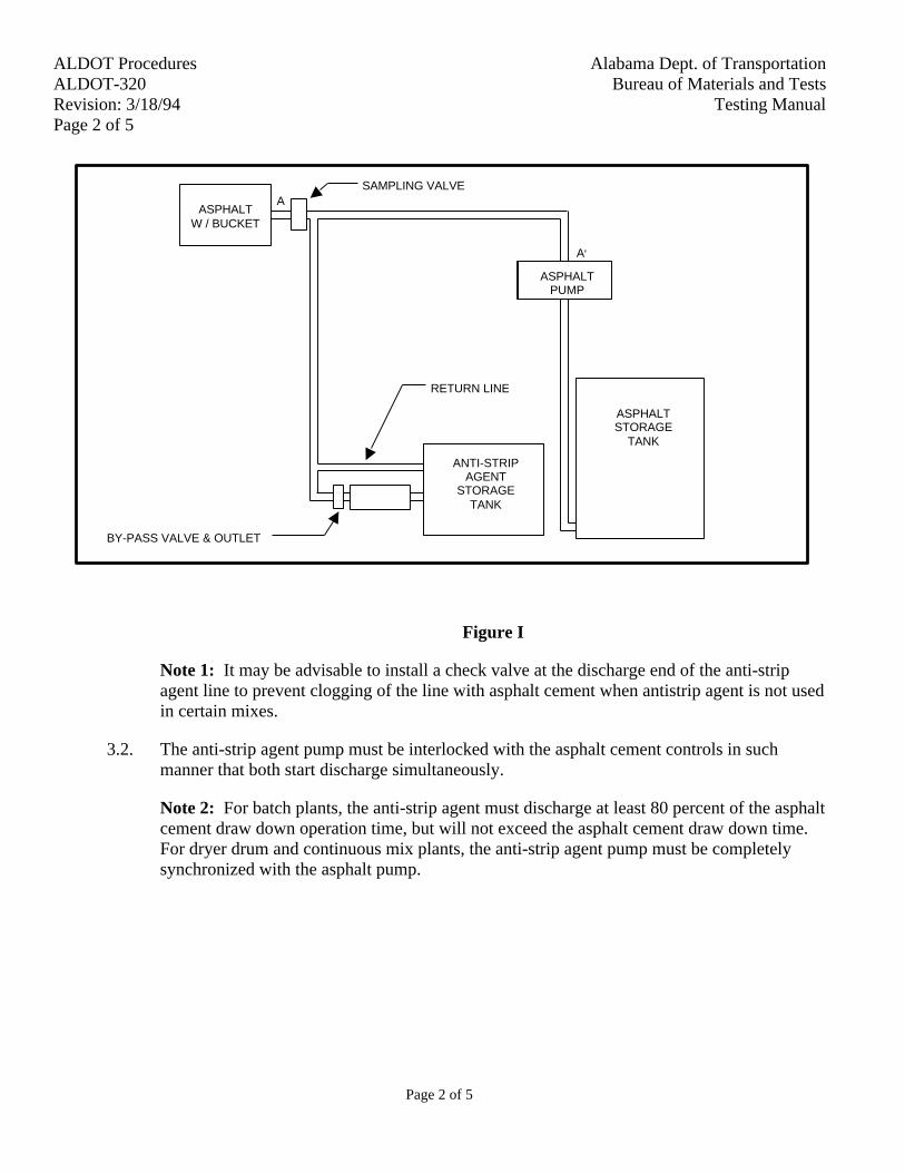
Page 2 of 5
Alabama Dept. of TransportationALDOT ProceduresBureau of Materials and TestsALDOT-320
Testing ManualRevision: 3/18/94Page 2 of 5
ASAMPLING VALVE
A'
RETURN LINE
BY-PASS VALVE & OUTLET
ANTI-STRIPAGENT
STORAGETANK
ASPHALTSTORAGE
TANK
ASPHALTW / BUCKET
ASPHALTPUMP
Figure I
Note 1: It may be advisable to install a check valve at the discharge end of the anti-stripagent line to prevent clogging of the line with asphalt cement when antistrip agent is not usedin certain mixes.
3.2. The anti-strip agent pump must be interlocked with the asphalt cement controls in suchmanner that both start discharge simultaneously.
Note 2: For batch plants, the anti-strip agent must discharge at least 80 percent of the asphaltcement draw down operation time, but will not exceed the asphalt cement draw down time.For dryer drum and continuous mix plants, the anti-strip agent pump must be completelysynchronized with the asphalt pump.

Page 3 of 5
Alabama Dept. of Transportation ALDOT ProceduresBureau of Materials and Tests ALDOT-320Testing Manual Revision: 3/18/94
Page 3 of 5
10 20 30 40 50 60 70 80 90TIME (SECONDS)
0.20
0.50
0.70
0.90
1.10
1.40D
ELIV
ER
Y
(KIL
OG
RA
MS
)
PUMP-VARIABLE SPEED SETTINGDRIVE SPROCKET TOOTH
CALIBRATED BYANTI-STRIP BRANDDATELOCATIONPRODUCER
CALIBRATION OF ANTI-STRIP ADDITIVE SYSTEM
Figure II
4. Calibration Of Anti-Strip Agent - Pumping Time
Note 3: A bypass outlet must be installed on the anti-strip agent line for the purpose ofcollecting and measuring the flow of the anti-strip agent. (Figure I)
4.1. If the anti-strip agent pump has more than one speed setting such as variable speed selectorsor drive tooth sprockets, determine speed setting or number of teeth on drive sprocket andrecord.
4.2. Position sample container under the anti-strip agent bypass valve outlet.
4.3. Open bypass outlet valve.
4.4. Start anti-strip agent pump and stop watch simultaneously.
4.5. Run anti-strip agent pump for the smallest time interval selected and record time.
4.6. Allow all of the anti-strip agent to drain into the sample container, weigh the container andrecord the net weight collected.
4.7. Repeat steps 4.2 - 4.6 for at least three or more time intervals; for batch plants suggested timeintervals 5 seconds, 10 seconds, 20 seconds, 60 seconds; for continuous mix and dryer drumplants 0.5 min., 1 min., 3 min., 5 min., 10 min.
4.8. Prepare calibration curve(s) with delivery rate plotted on vertical axis and time on horizontalaxis. Example Figure II.
5. Control of Anti-Strip Agent
Page 4 of 5
Alabama Dept. of TransportationALDOT ProceduresBureau of Materials and TestsALDOT-320
Testing ManualRevision: 3/18/94Page 4 of 5
5.1. Specifications require the addition of 0.5 to 1.0 percent of an approved anti-strip agent byweight of the asphalt cement when certain types of coarse aggregates are being used.
5.2. The specified concentration rate of the anti-strip agent may vary ± 10 percent by weight.
Note 4: Consult the approved job-mix formula for the brand and concentration percent ofthe anti-strip agent.
6. Calculations
6.1. Determine amount of asphalt cement in lbs required per batch or per minute.
6.2. For batch plants the asphalt cement pumping time to nearest second will be required.
6.3. For dryer drum and continuous mix plants the weight in lbs of asphalt cement per minute willbe required.
6.4. Multiply the determined amount of asphalt cement by the appropriate agent percentexpressed as a decimal, to obtain the required amount of the anti-strip agent in lbs.
6.5. Multiply the product obtained in step 6.2 by the ± 10 percent tolerance expressed as adecimal.
6.6. From calibration curve, Figure II, determine if the required amount of anti-strip agent can beobtained during the required time period.
6.7. Note 5: If the required amount of anti-strip agent cannot be obtained, it will be necessary toadjust anti-strip pump in the direction required and repeat steps 4.1 - 4.8.
6.8. Example of calculations:
For batch plant - required 130 kg PG 67-22 / 15 seconds pumping time. Then add 0.5% bywt. Tyfo A-40 (anti-strip)
130 x 0.005 = 0.65 kg 0.65 x 0.90 = 0.585 kg0.65 x 1.10 = 0.715 kg0.80 x 15 = 12 Seconds
Range = 0.585- 0.715 kg / 15 seconds
Required at least 0.585 kg in 15 seconds and not more than 0.715 kg in 12 seconds.
For dryer drum or continuous mix plants required 275 kg AC-20 / min., 275 x 0.005 = 1.375 kg anti-strip agent / min., required tolerance = 1.375 x .90 = 1.2375, 1.357 x 1.10 = 1.4027 kg
Required anti-strip agent / minute = 1.2 - 1.5 kg

Page 5 of 5
Alabama Dept. of Transportation ALDOT ProceduresBureau of Materials and Tests ALDOT-320Testing Manual Revision: 3/18/94
Page 5 of 5
7. Reporting
7.1. Report results of step 6.5 on form BMT-16.
7.2. Attach work sheet(s) to Project Engineer's copy of BMT-16 for master files.
Alabama Dept. of Transportation ALDOT ProceduresBureau of Materials and Tests ALDOT-321Testing Manual Revision: 3/18/94
Page 1 of 2
ALDOT-321-79TEST FOR GLASSY PARTICLES IN CRUSHED SLAG
1. Scope
1.1. This method of test covers a procedure for the determination of the amount, by weight, ofglassy particles contained in crushed slag coarse aggregate.
2. Apparatus
2.1. The apparatus shall consist of the following:
2.1.1. Balance - The balance shall conform to AASHTO M-231, Class D for samples lessthan 2 kg, Class E for samples of at least 2 kg but less than 5 kg, and Class F forsamples of 5 kg or more.
2.1.2. Sieves - The sieves with square openings shall be mounted on substantial framesconstructed in a manner that will prevent loss of material during sieving. The wovenwire cloth sieves shall conform to AASHTO M-92. Perforated plate sieves withsquare openings shall conform to the requirements of ASTM E 323.
2.1.3. Oven - The oven shall be capable of maintaining a uniform temperature of 230 ± 9°F(110 ± 5°C).
3. Test Samples
3.1. Samples for glassy particle determination shall be obtained in accordance with AASHTO T-2. Samples shall be dried and reduced to testing size in accordance with AASHTO T-248.
3.2. Samples of coarse aggregate shall not weigh less than the weight indicated in AASHTO T-27.
4. Procedure
4.1. Sieve in accordance with AASHTO T-27.
4.2. Physically examine all particles retained on each sieve size used through the No. 4 (4.75 mm)sieve. Place all particles that have a glossy, slick, non-porous glassy finish on any one face,into a weighing container.
4.3. Weigh and record the total weight of all glassy particles.
5. Calculations
5.1. Calculate the percentage of glassy particles retained on the No. 4 (4.75 mm) sieve on thebasis of the total weight of the sample.
6. Reporting

Alabama Dept. of TransportationALDOT ProceduresBureau of Materials and TestsALDOT-321
Testing ManualRevision: 3/18/94Page 2 of 2
6.1. The percent of glassy particles shall be reported on form BMT-91 when tested by approvedproducers. When test is performed by Department personnel, percent of glassy particles shallbe reported on BMT-16.
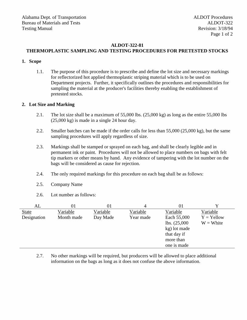
Alabama Dept. of Transportation ALDOT ProceduresBureau of Materials and Tests ALDOT-322Testing Manual Revision: 3/18/94
Page 1 of 2
ALDOT-322-81THERMOPLASTIC SAMPLING AND TESTING PROCEDURES FOR PRETESTED STOCKS
1. Scope
1.1. The purpose of this procedure is to prescribe and define the lot size and necessary markingsfor reflectorized hot applied thermoplastic striping material which is to be used onDepartment projects. Further, it specifically outlines the procedures and responsibilities forsampling the material at the producer's facilities thereby enabling the establishment ofpretested stocks.
2. Lot Size and Marking
2.1. The lot size shall be a maximum of 55,000 lbs. (25,000 kg) as long as the entire 55,000 lbs(25,000 kg) is made in a single 24 hour day.
2.2. Smaller batches can be made if the order calls for less than 55,000 (25,000 kg), but the samesampling procedures will apply regardless of size.
2.3. Markings shall be stamped or sprayed on each bag, and shall be clearly legible and inpermanent ink or paint. Procedures will not be allowed to place numbers on bags with felttip markers or other means by hand. Any evidence of tampering with the lot number on thebags will be considered as cause for rejection.
2.4. The only required markings for this procedure on each bag shall be as follows:
2.5. Company Name
2.6. Lot number as follows:
AL 01 01 4 01 YStateDesignation
VariableMonth made
VariableDay Made
VariableYear made
VariableEach 55,000lbs. (25,000kg) lot madethat day ifmore thanone is made
VariableY = YellowW = White
2.7. No other markings will be required, but producers will be allowed to place additionalinformation on the bags as long as it does not confuse the above information.
Alabama Dept. of TransportationALDOT ProceduresBureau of Materials and TestsALDOT-322
Testing ManualRevision: 3/18/94Page 2 of 2
3. Producer's Responsibility
3.1. The producer will notify the Department each time he has produced a lot of material.Notification should be made to the following:
Alabama Department of Transportation3704 Fairground RoadAttn: Paint LabMontgomery, Al 36110
(205) 242-6552
3.2. The producer will furnish the Department with a certified test report showing actual testresults for each parameter listed in current specifications for the thermoplastic. These reportswill be submitted to the Department when the samples are submitted for testing.
3.3. The producer will furnish the Department (See 3.1 above) a current status report of approvedmaterial, by lot, each time a shipment or change occurs. This report will contain thequantities shipped, and to whom.
4. Sampling Procedures at Production Facility
4.1. If the producer has a sample splitter the producer will obtain a 1 gal, (4 L) sample from thesplitter from each bag in the sample. The remainder of the material will be turned over to theproducer. The 1 gal (4 L) samples will be properly identified by lot number, date, producer,quantity in lot, consignee and project number if available, and sent immediately to theCentral Laboratory.
4.2. One of these samples will be tested and the remainder held in reserve. If the sample meetsall of the test requirements, the lot will be accepted. However, if it fails any of the testrequirements, two of the remaining samples from that lot will be tested as a resample andboth samples must meet the test requirements or the lot will be rejected. No further samplingor testing will take place once these three individual samples have been analyzed for that lot.
5. Sampling at the Job Site
5.1. In those cases where the material arrives at the project site which has not been pretested,project personnel may sample the thermoplastic in accordance with paragraph 4.1 above.
Alabama Dept. of Transportation ALDOT ProceduresBureau of Materials and Tests ALDOT-324Testing Manual Revision: 3/18/94
Page 1 of 2
ALDOT-324-83PLANT REQUIREMENTS FOR PLANTS PRODUCING HOT-MIXED,
HOT-LAID BITUMINOUS PAVING MIXTURES
1. Scope
1.1. This procedure covers the requirements for plants suitable for producing hot mixed, hot laidbituminous paving mixtures. This procedure is similar but not equivalent to AASHTO M-156 and ASTM D-995.
2. Applicable Documents
2.1. Standard Specifications (Article 107, Environmental Protection).
2.2. AASHTO M-20 or M-226 - Penetration Graded Asphalt Cement or Viscosity GradedAsphalt Cement.
2.3. AASHTO M-156 - Requirements for Mixing Plants for Hot-Mixed, Hot-Laid BituminousPaving Mixtures.
2.4. AASHTO T-164 - Quantitative Extraction of Bitumen from Bituminous Paving Mixture.
2.5. AASHTO T-170 - Recovery of Asphalt from Solution by Abson Method.
2.6. AASHTO T-195 - Determining Degree of Particle Coating of Bituminous-AggregateMixtures.
2.7. ALDOT-320.
3. AASHTO M-156 (Requirements for Mixing Plants for Hot-Mixed, Hot-Laid BituminousPaving Mixtures) Shall Apply Except as Modified Hereinafter.
Section 3 shall be amended as follows:
Article 3.1 shall be amended by adding the following:
Plants which do not comply with all the requirements set forth, but have a history ofproducing a uniform mixture, may be considered as in substantial compliance uponrecommendation of the Division Materials Engineer and approval by the Materials and TestsEngineer. The asphalt plant check (ALDOT-155) shall be performed as currently scheduled in theJob Control Manual.
Add new Article 3.2.6 as follows:
When liquid anti-strip material is added to the bituminous material at the plant site, the anti-strip system must be in accordance with ALDOT-320. Other approved additives will be handled inaccordance with an established procedure.
Alabama Dept. of TransportationALDOT ProceduresBureau of Materials and TestsALDOT-324
Testing ManualRevision: 3/18/94Page 2 of 2
Delete the first sentence of Article 3.4 and add the following in its place:
The plant should be equipped with a cold feed bin for each aggregate used, but at least four(4) cold feed bins will be required, with mechanical means for uniformly feeding the aggregate intothe dryer so that uniform production and temperature may be assured.
Delete Article 3.9.3 and add the following in its place:
Mixtures may be stored in properly sealed and insulated silos for 48 hours. At the discretionof the Engineer, test for determining asphalt hardening will be taken and governed in accordancewith Section 9.
Add new Article 3.9.4 as follows:
A surge or storage silo may be equipped with load cells and/or strain gauges to determine theamount of mix delivered from the bin.
Add the following new Articles:
3.1.1. Testing Provisions
3.1.1.1. The plant shall be equipped with a testing laboratory meeting the requirements ofArticle 106 of the Alabama Department of Transportation Standard Specifications.
3.1.1.2. The laboratory shall be equipped with the testing equipment as outlined in ALDOT-349.
Section 6 shall be amended as follows:
Article 6.3.1 shall be amended by adding the following:
If the scales are used for pay purposes, this tolerance shall not exceed 0.2% of the indicatedweight when tested for accuracy.
Alabama Dept. of Transportation ALDOT ProceduresBureau of Materials and Tests ALDOT-328Testing Manual Revision: 3/18/94
Page 1 of 1
ALDOT-328-82RAPID METHOD OF SAMPLING FRESH CONCRETE FROM REVOLVING DRUM TRUCK
MIXERS OR AGITATORS
1. Scope
1.1. This method describes a procedure for obtaining early samples of fresh concrete from truck mixersor agitators. The samples obtained are considered adequate for determining compliance with aircontent, slump specifications and temperature specifications.
2. Significance and Use
2.1. AASHTO T-141, requires that approximately half the load of concrete be discharged before thetotal sample can be obtained. This generally results in some of the concrete being placed in thework before the results of the tests are known. If the subsequent tests indicate that the material doesnot comply with the specifications, it becomes a very difficult and time-consuming operation toremove the unacceptable material from the job. This method allows the sample to be taken from thefirst 8.83ft3 (0.25 m³) load. Thus, all the concrete can be held in either the truck or the tremiebucket until the results of the air content, slump test and temperature test are known.
3. Size of Sample
3.1. The sample shall consist of not less than 0.7 ft3 (0.02 m³).
4. Procedure for Sampling
4.1. The sample shall be taken after not less than 1.76 ft3 (0.05 m³) of concrete has been discharged fromthe batch being sampled.
4.2. Sampling shall be done by repeatedly passing a receptacle through the entire discharge stream, orby diverting the stream completely so that it discharges into a container.
5. Remixing Sample
5.1. The sample shall be remixed with a shovel to insure uniformity.
5.2. The sample shall be protected from sunlight and wind.
5.3. The period between taking and using the sample shall not exceed 15 minutes.
Alabama Dept. of Transportation ALDOT ProceduresBureau of Materials and Tests ALDOT-330Testing Manual Revision: 3/18/94
Page 1 of 3
ALDOT-330-83PROCEDURE FOR MARKING, SAMPLING AND INSPECTION OF CORRUGATED METAL
ROUND AND ARCH ROADWAY AND SIDE DRAIN PIPE
1. Scope
1.1. Corrugated metal pipe is supplied by in-state and out-of-state fabricators. The process ofcertifying test reports and inspection is basically the same. The following procedures willbreak down the responsibilities of the various individuals in this process.
2. Definitions and Abbreviations
2.1. Producer - The company which produces the flat coiled metal which is used in fabricating thepipe.
2.2. Fabricator - The company which produces the finished product for shipment to the project.
2.3. Base Metal - The flat coil metal from which the pipe is made. Base metal may be steel oraluminum.
2.4. Coating - The material used as a protective cover on the plain metal pipe. May be asphalt orpolymeric coating.
2.5. Central Lab - The Alabama Department of Transportation Testing Laboratory, 3704Fairground Road, Montgomery, Alabama 36110.
2.6. C.S. - Corrugated Steel
2.7. C.A. - Corrugated Aluminum
2.8. P.I. - Paved Invert
2.9. C.C.S. - Coated Corrugated Steel
2.10. C.C.A. - Coated Corrugated Aluminum
2.11. C.C.S.P.I. - Coated Corrugated Steel with Paved Invert
2.12. C.C.A.P.I. - Coated Corrugated Aluminum with Paved Invert
2.13. C.S.L.C.M. - Smooth Line Corrugated Metal (S for Steel, A for Aluminum)
2.14. C.S.F.C.M. - Smooth Flow Corrugated Metal (S for Steel, A for Aluminum)
3. Certifications
Alabama Dept. of TransportationALDOT ProceduresBureau of Materials and TestsALDOT-330
Testing ManualRevision: 3/18/94Page 2 of 3
3.1. Certified test report containing, physical results, chemical results, galvanization in oz/ft2
(g/m²), for each heat number and each gauge thickness of metal, in accordance with AlabamaDepartment of Transportation Specifications Section 850 and AASHTO M-36.
3.2. Asphalt coating - certified test report meeting require-ments of AASHTO M-190. Allcertifications shall be submitted to the Project Engineer with pipe; then forwarded to theCentral Laboratory.
3.3. Pipe coated with polymeric type B coating shall have certified test report meetingrequirements of AASHTO M-246. The markings may be put on all sheets with a markerrather than being stamped.
4. Marking of Finished Products
4.1. Plain corrugated metal pipe will be marked with the metal producer's stamped logo, heatnumber and thickness.
4.2. Coated corrugated metal pipe will be marked as follows:
4.2.1. Each length of pipe will have one section, containing heat number and metalthickness, covered with duct tape before pipe is coated with asphalt. (This spot willbe marked for easy field identification.)
4.2.2. Pipe that is not properly marked will not be placed on a project until samples havebeen cut from the pipe and tested by the Central Laboratory.
5. Fabricator's Responsibility
5.1. Certify base metal and pipe coating as outlined in Section 3 of this procedure.
5.2. Identify all pipes as outlined in Section 4.
5.3. Furnish a copy of the metal producer's certified analysis for each heat and thickness of metal.This copy should be sent to the Project Engineer with pipe.
5.4. For welded seam pipe, the fabricator will furnish a certified test report for each heat numbershowing that the production will meet the strength requirements. One test will be reportedfor each heat number. This report will be submitted to the Project Engineer with pipe.
6. Project Engineer's Responsibility
6.1. Inspect pipe after it arrives on the project and before it is installed. This will be a visualinspection using BMT-60 as a guideline.
6.2. After heat number is checked by removing duct tape, asphalt will be repaired with 5X KnifeGrade Asphalt, or Bitumastic 50 or approved equal.
Alabama Dept. of Transportation ALDOT ProceduresBureau of Materials and Tests ALDOT-330Testing Manual Revision: 3/18/94
Page 3 of 3
6.3. After all necessary checks have been made attach copy of completed BMT-60 tocertifications and send to Central Laboratory Certifications Section in Montgomery.
6.4. If the pipe is damaged it shall be rejected.
6.5. If the pipe is not properly marked, it cannot be installed. Samples must be cut from it andsubmitted to the Central Laboratory for testing. Only after these samples have been testedand approved can the pipe then be installed.
7. Approval for Payment
7.1. Payment for pipe cannot be made until the Project Engineer has made his final pipeinspection and received a Certification (Form CERT C.M.P.) from the Central Laboratory.
8. Additional Testing
8.1. The Alabama Department of Transportation will reserve the right to sample any pipe after thepipe has arrived on the project. This may be done at the Project Engineer's request orwhenever the Testing Engineer feels that it is necessary. The results of this testing will beconsidered to take precedent over all other testing or certification performed previous to thistime.
Alabama Dept. of Transportation ALDOT Procedures Bureau of Materials and Tests ALDOT-335 Testing Manual Revision 03/03/03 Page 1 of 9
ALDOT-335-83 MEASURING PROFILE INDEX OF A PAVED SURFACE
1. Scope
1.1. This method covers the profile measurement of hot mix asphalt and Portland cement concrete pavement and the determination of profile index.
2. Apparatus
2.1. The device used to measure the profile shall be a California-type profilograph with a mainline section or truss of approximately 24.6 ft in length supported by clusters of support wheels located at either end and having a measuring wheel at the center point of the span. The profilograph shall be assembled and operated according to the manufacturer's specifications.
2.1.1. Before a pavement surface profile is measured, the profilograph shall be inspected by the Engineer or his representative to determine its mechanical condition.
2.1.2. Calibration, horizontal—The Engineer or his representatives should check the profilograph for accuracy before being used on the project. The horizontal distance should be checked by traversing a known distance of 300 ft on a straight, level surface and measuring the length of chart paper used. Care should be taken when beginning the calibration section to eliminate any slackness in the gearing of the profilograph by raising the distance wheel slightly off the surface and turning it in the forward direction with the recorder in gear, then lowering the measuring wheel carefully back to the surface. A beginning point is marked on the profilogram, the test section traversed, and then the ending point is marked. The length of trace between the points should be 12 in. plus or minus 0.1 in.
2.1.3. Calibration, vertical—The vertical calibration should be checked using three ¼-inch thick plates of metal or other hard material approximately 3 in. wide and 6 in. long. The profilograph should be positioned on a level flat section of paved surface with the profile measuring wheel resting on a smooth piece of 1/8-inch Formica or sheet metal approximately 12 in. square such that it will not rock or tilt. Advance the profilogram (chart) at least ½ in. without moving the profile measuring wheel. Lift the profilograph measuring wheel and place one of the ¼-inch blocks under it, carefully lower the wheel and again advance the chart. Continue with the above sequence until all three of the ¼-inch blocks are under the wheel, one on top of another. Remove all the plates and return the measuring wheel to the base plate. Advance the profilogram again. Remove the profilogram and measure the deviations. If the deviation of the measured trace is greater than 1/32 in. from the correct thickness, then adjustments must be made to the profilograph.
ALDOT Procedures Alabama Dept. of Transportation ALDOT-335 Bureau of Materials and Tests Revision: 03/03/03 Testing Manual Page 2 of 9 3. General
3.1. Test Section—A test section shall be defined as a single lane (normally 12 ft wide) of main line pavement surface where the posted speed will be 40 mph or greater beginning at a point where the rear wheels of the profilograph are located just on the new surface (the profile measuring wheel will then be approximately 16 ft onto the new surface). The test section shall continue for a distance of 0.1 mile unless altered by Section 3.3 or 3.4.
3.1.1. If the contractor is responsible for the adjoining existing surface, the profile shall include the last 16 ft of existing roadway surface.
3.2. When a test section begins or ends at a bridge and there is no bridge end slab or if the bridge end slab is recessed and overlaid with plant mix, the measuring wheel of the profilograph shall be approximately 16 ft from the bridge end when beginning or completing the test section.
3.2.1. If there is a bridge end slab to which the pavement abuts, the measuring wheel shall be approximately 16 ft from the bridge end slab when beginning or ending the test section.
3.3. A test section shall be 0.1 mile in length unless altered by a bridge or the end of the paved surface. When a profile is terminated at a point where it is less than 250 ft long, it shall be included with the previous section. If the section is greater than 250 ft in length, it shall be considered a test section.
3.4. If a section is isolated where neither end joins another section (i.e., between bridges or between a bridge and the end of the paved surface) and it is less than 0.1 mile long, it shall be considered a test section.
4. Testing Procedure
4.1. Surface Preparation—The paved surfaces to be profiled shall be reasonably cleaned by the contractor of all mud, loose gravel, debris, etc., before the profile is made.
4.2. Pavement profiles shall be taken in the right wheelpath of the right lane, in the left wheelpath of the left lane and in the wheelpath that the Engineer chooses if the paved surface is wider than two lanes.
4.3. The profilograph shall be manually propelled longitudinally along the pavement at a speed no greater than 3 mph in the direction that the pavement was placed. That test section shall be repeated only to define the limits of an out of tolerance surface variation or as requested by the Engineer.
4.4. The trace should be preceded and followed by at least 12 inches of blank paper.
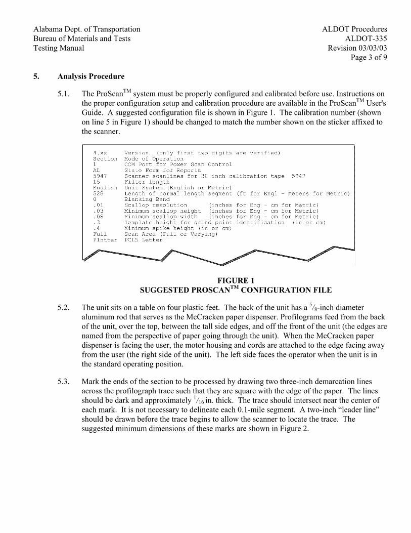
Alabama Dept. of Transportation ALDOT Procedures Bureau of Materials and Tests ALDOT-335 Testing Manual Revision 03/03/03 Page 3 of 9 5. Analysis Procedure
5.1. The ProScanTM system must be properly configured and calibrated before use. Instructions on the proper configuration setup and calibration procedure are available in the ProScanTM User's Guide. A suggested configuration file is shown in Figure 1. The calibration number (shown on line 5 in Figure 1) should be changed to match the number shown on the sticker affixed to the scanner.
FIGURE 1 SUGGESTED PROSCANTM CONFIGURATION FILE
5.2. The unit sits on a table on four plastic feet. The back of the unit has a 5/8-inch diameter aluminum rod that serves as the McCracken paper dispenser. Profilograms feed from the back of the unit, over the top, between the tall side edges, and off the front of the unit (the edges are named from the perspective of paper going through the unit). When the McCracken paper dispenser is facing the user, the motor housing and cords are attached to the edge facing away from the user (the right side of the unit). The left side faces the operator when the unit is in the standard operating position.
5.3. Mark the ends of the section to be processed by drawing two three-inch demarcation lines across the profilograph trace such that they are square with the edge of the paper. The lines should be dark and approximately 1/16 in. thick. The trace should intersect near the center of each mark. It is not necessary to delineate each 0.1-mile segment. A two-inch “leader line” should be drawn before the trace begins to allow the scanner to locate the trace. The suggested minimum dimensions of these marks are shown in Figure 2.
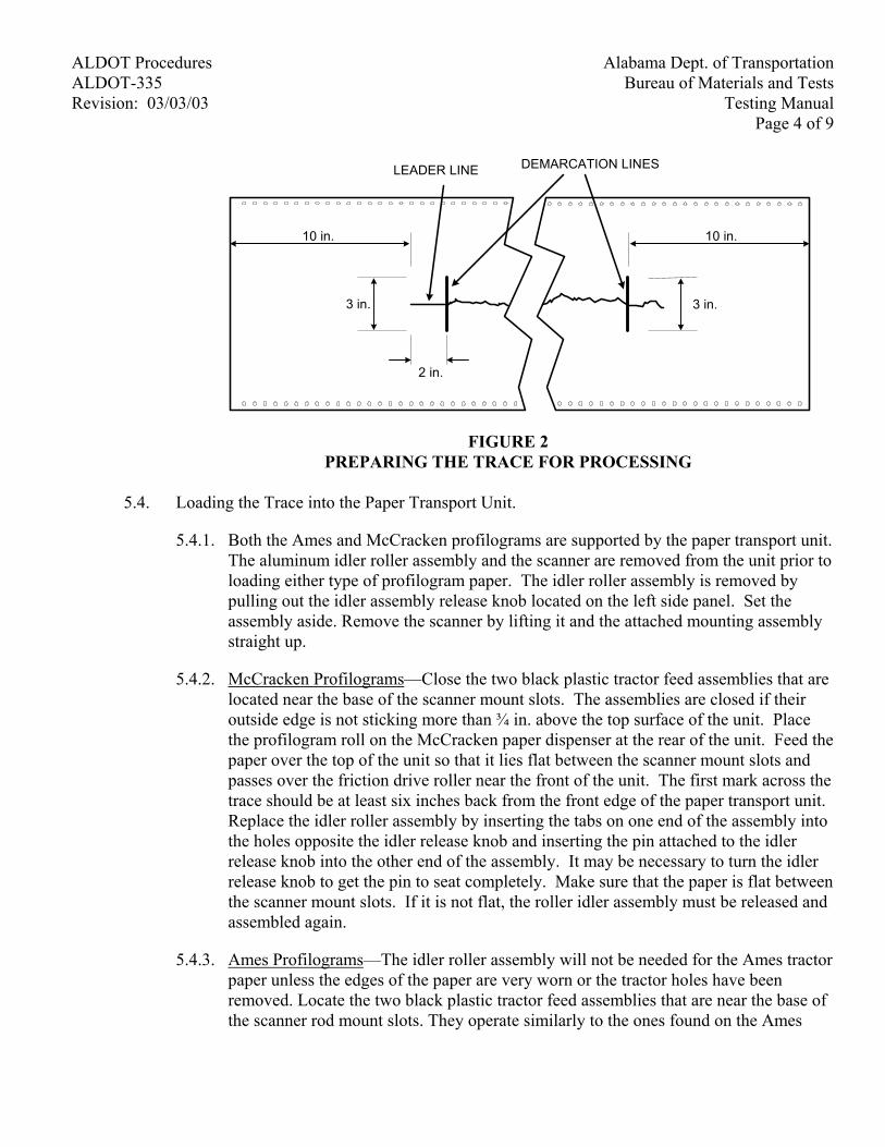
ALDOT Procedures Alabama Dept. of Transportation ALDOT-335 Bureau of Materials and Tests Revision: 03/03/03 Testing Manual Page 4 of 9
2 in.
3 in.
10 in.
DEMARCATION LINESLEADER LINE
10 in.
3 in.
FIGURE 2 PREPARING THE TRACE FOR PROCESSING
5.4. Loading the Trace into the Paper Transport Unit.
5.4.1. Both the Ames and McCracken profilograms are supported by the paper transport unit. The aluminum idler roller assembly and the scanner are removed from the unit prior to loading either type of profilogram paper. The idler roller assembly is removed by pulling out the idler assembly release knob located on the left side panel. Set the assembly aside. Remove the scanner by lifting it and the attached mounting assembly straight up.
5.4.2. McCracken Profilograms—Close the two black plastic tractor feed assemblies that are located near the base of the scanner mount slots. The assemblies are closed if their outside edge is not sticking more than ¾ in. above the top surface of the unit. Place the profilogram roll on the McCracken paper dispenser at the rear of the unit. Feed the paper over the top of the unit so that it lies flat between the scanner mount slots and passes over the friction drive roller near the front of the unit. The first mark across the trace should be at least six inches back from the front edge of the paper transport unit. Replace the idler roller assembly by inserting the tabs on one end of the assembly into the holes opposite the idler release knob and inserting the pin attached to the idler release knob into the other end of the assembly. It may be necessary to turn the idler release knob to get the pin to seat completely. Make sure that the paper is flat between the scanner mount slots. If it is not flat, the roller idler assembly must be released and assembled again.
5.4.3. Ames Profilograms—The idler roller assembly will not be needed for the Ames tractor paper unless the edges of the paper are very worn or the tractor holes have been removed. Locate the two black plastic tractor feed assemblies that are near the base of the scanner rod mount slots. They operate similarly to the ones found on the Ames

Alabama Dept. of Transportation ALDOT Procedures Bureau of Materials and Tests ALDOT-335 Testing Manual Revision 03/03/03 Page 5 of 9
profilograph. Mount the profilogram so that the first mark across the trace is at least six inches back from the front edge of the paper transport unit.
5.4.4. For both types of paper, the scanner must be placed flat on the paper. The scanner cord should drape over the side of the scanner to avoid interfering with paper movement.
5.5. Scanning a Section of Profilogram
5.5.1. The scanning of the section will proceed automatically after the ProScanTM program is started. After the initial user entry, the user is required to provide responses to the computer prompts as shown below.
User proscan (Enter) or proscan config_file where config_file specifies the
name of the configuration file matching the desired scan parameters
Computer (Fills computer screen with ProScanTM copyright and
configuration information) Computer Enter file name for this session: User Enter file name (≤ 8 characters) (Enter) Computer Creating new files
Reading rptinfo.gen for report header information Enter Date Paved:
User Enter date (Enter) Computer Enter Date Tested : User Enter date (Enter) Computer (Displays Current RPI [report header information])
Modify report information ? (y or [n]) User Press Enter (to proceed without changing report
header information) Computer Enter track number ([1], 2, or 3): User Enter track number (or Enter or Space Bar to accept
track 1)
ALDOT Procedures Alabama Dept. of Transportation ALDOT-335 Bureau of Materials and Tests Revision: 03/03/03 Testing Manual Page 6 of 9
Computer Is up to the left or right of scanner? (l or [r]) User Press Enter or space bar (see Sect. 6.8.1 for further
discussion) Computer Is scan up station or down station? ([u] or d): User Press Enter or space bar. Computer Enter beginning station number for track 1 segment 1
(nnnn+nn): User Enter beginning station in nnnn+nn format.
ProScanTM will accept values to the tenth of a station (i.e., nnnn+nn.n format).
5.5.2. Scanning begins immediately after entering a response to the final information request. The paper transport unit will start moving the paper and the text on the monitor will be replaced with graphics. As the paper transport unit moves the paper, an image of the area that is being scanned scrolls up from the bottom of the screen. If this scrolling does not occur as soon as the paper transport starts moving paper, it means that the scanner is not in scan mode. This can be corrected by pressing the scan button on the scanner. If anything appears to be going wrong at any time during the scanning process, the system can be stopped by pressing any key on the keyboard. Restart the scanning by pressing “c” (Continue previous activity).
5.5.3. The computer screen must be closely monitored during the scanning process. The newly scanned area should scroll up from the bottom of the screen, scrolling to disappear off the top. The image on the screen is greatly magnified, especially in the vertical dimension. A 4-inch wide strip of profilogram is shown over the entire width of the screen. A 1.75-inch high section of the strip fills the screen from top to bottom. If the scanner contrast is set correctly, the trace itself should be black and very distinct on a white background.
5.5.4. When the program recognizes the first demarcation line (constructed in step 6.3) across the trace, it will sound a beep to indicate that the processing of a segment has begun. If an audible alarm is not heard, then the scanning must be stopped and the paper reversed. To reverse the paper, stop the scanning by pressing the space bar, remove the scanner and release the paper from the feed mechanism. If the demarcation line is visible on the screen but the audible signal fails to sound, the line must be made thicker and of equal length on both sides of the trace.
Alabama Dept. of Transportation ALDOT Procedures Bureau of Materials and Tests ALDOT-335 Testing Manual Revision 03/03/03 Page 7 of 9
5.5.5. During the scrolling process, the program adds a thin line to the display that does not appear on the profilogram itself. This line runs beside, and slightly to the right of, the trace being processed and represents what the program has determined to be the center of the track. It is offset to prevent obliterating any of the trace. One of the principal duties of the user is to verify that the line does in fact parallel the actual track.
5.5.6. After 20 seconds of scanning, the paper transport unit will pause for about one second while the 0.1-mile segment just scanned is processed and written to disk. This pausing action should occur three times. After the last pause, the end mark will be encountered in a few seconds. At that time the paper transport unit will stop, the screen will freeze, the short segment will be analyzed and written to disk, and the program will wait until a key is pressed.
5.5.7. Slight variation in the roughness measures will occur between scans on the same trace. This is due to the physical variance in the scanning process and rounding of values for each scallop. It is impossible to eliminate all variation from one scan to the next. This variation is extremely small, however, when compared to the variations obtained by manual reduction of profilograms that are performed by different people. It is even small compared to the variation obtained when the same person reduces the same trace multiple times. Successive profile index averages obtained by ProScanTM over a long section are always nearly identical.
5.6. Printing a Report
5.6.1. A report can be printed by selecting the "Generate Report" (r) option. When it is specified, the user will be asked to select a report type. The options are inforMation, Initial, inTermediate, or Final (m,i,t or f). The only difference between them is that one of those four words will appear at the top of the report. The report itself is printed in a convenient form and contains several additional pieces of information. Segments are numbered sequentially for each track, beginning at 1, in the order they were scanned.
5.6.2. Track one segments will always appear in ascending order. The other tracks will not necessarily be in that order, but generally so. The actual order will be determined by matching each segment with a corresponding segment from a previous track, if possible. If each track was scanned in the same direction, then all track segment numbers should match up. If one track was scanned in the opposite direction, then its numbers will be reversed.
5.6.3. The bump locations appear in ascending station order and, in the case of identical station numbers, in ascending track number order. In parentheses following the station number of each bump is the track and segment in which it is located. This makes it easy to know which segment to plot to obtain a detail of the bump. When segments are plotted, the grid lines are drawn on the bumps to show the amount of corrective action that is required.
ALDOT Procedures Alabama Dept. of Transportation ALDOT-335 Bureau of Materials and Tests Revision: 03/03/03 Testing Manual Page 8 of 9
5.6.4. When the printing of the report is finished, ProScanTM returns to the main menu.
5.7. Plotting Segments
5.7.1. Plotting segments is the most time-consuming aspect of the program. It takes five to six times longer to plot a segment than it does to scan and reduce the segment. The segment of the trace is plotted in 180 dpi resolution, with station marks shown every .25 sta. Marks showing the beginning and ending of the segment and ¼ in. of trace beyond each are shown. Strum lines that were detected are plotted and the measured roughness of each scallop is given beside it. In addition, all the parameters in effect for the reduction, the final reduction value, and the filename of the ProScanTM data (.psd) file containing the raw data are given.
5.7.2. A single segment, all segments of a track, all tracks for a given segment number (not necessarily corresponding station number), or all segments in the current file can be plotted from a single command. If the file contains a considerable number of segments (80 would not be unreasonable for one day's asphalt paving), a several-hour print job could be requested. Unlike the scanning process, the printing can occur in an unattended mode. Should a multiple segment job be requested, it can be interrupted by pressing a key on the keyboard. Please note that the plotting of the current segment will complete, even if the job is interrupted with a keystroke. Therefore, it may be as much as two minutes before it is obvious that the interruption has worked.
5.7.3. To specify a single segment, enter the track and segment number. To get all the tracks of a segment or all the segments of a track (or both), use an asterisk (*) instead of a number.
5.7.4. When the plotting of the segments is finished, ProScanTM returns to the same menu.
5.8. Additional suggestions for using the ProScanTM system
5.8.1. The terms “up station” or “down station” refer to whether station numbers are increasing or decreasing as the trace progresses. If the station numbers are increasing, the scan is considered “up station.” Likewise, if the station numbers are decreasing, the scan is “down station.”
5.8.2. Marks locating various points of interest on the trace (such as pavement joints, stations, debris, etc.) can be made by stopping the profilograph and pulling down on the cable linking the wheel and the marking apparatus (“strum” marks). These marks typically do not affect the scanning procedure or results, but will be indicated on the plotted output from ProScanTM.
5.8.3. To avoid errors in processing the trace, do not make marks within 1 inch of the trace, with the exception of the leader line and demarcation lines discussed earlier.

Alabama Dept. of Transportation ALDOT Procedures Bureau of Materials and Tests ALDOT-335 Testing Manual Revision 03/03/03 Page 9 of 9
5.8.4. Additional reports can be printed by restarting ProScanTM and selecting a file name corresponding to a previous scan.
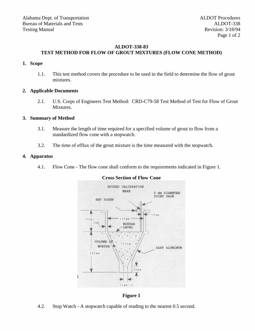
Alabama Dept. of Transportation ALDOT ProceduresBureau of Materials and Tests ALDOT-338Testing Manual Revision: 3/18/94
Page 1 of 2
ALDOT-338-83TEST METHOD FOR FLOW OF GROUT MIXTURES (FLOW CONE METHOD)
1. Scope
1.1. This test method covers the procedure to be used in the field to determine the flow of groutmixtures.
2. Applicable Documents
2.1. U.S. Corps of Engineers Test Method: CRD-C79-58 Test Method of Test for Flow of GroutMixtures.
3. Summary of Method
3.1. Measure the length of time required for a specified volume of grout to flow from astandardized flow cone with a stopwatch.
3.2. The time of efflux of the grout mixture is the time measured with the stopwatch.
4. Apparatus
4.1. Flow Cone - The flow cone shall conform to the requirements indicated in Figure 1.
Cross Section of Flow Cone
Figure 1
4.2. Stop Watch - A stopwatch capable of reading to the nearest 0.5 second.
Alabama Dept. of TransportationALDOT ProceduresBureau of Materials and TestsALDOT-338
Testing ManualRevision: 3/18/94Page 2 of 2
5. Preparation of Apparatus
5.1. The flow cone shall be firmly mounted in such a manner that the top will be level and thecone free from vibration.
5.2. The discharge tube shall be closed by placing the finger over the lower end.
5.3. A quantity of water equal to 1725 ± 1 mL shall be introduced into the cone.
5.4. The point gage shall be adjusted to indicate the level of the water surface.
6. Sample
6.1. The test sample shall consist of 1725 ± 1 ml of grout.
7. Procedure
7.1. Moisten the inside surface of the flow cone, refer to Note 1.
7.2. Place the finger over the outlet of the discharge tube.
7.3. Introduce grout into the cone until the grout surface rises into contact with the point gage.
7.4. Start the stopwatch and remove the finger simultaneously.
7.5. Stop the stopwatch at the clean out of grout from the discharge tube.
7.6. At least two tests shall be made for any grout mixture and the average time will be used toverify compliance with specifications.
Note 1: A recommended procedure for insuring that the interior of the cone is properlywetted is to fill the cone with water and, one minute before beginning to add the groutsample, allow the water to drain from the cone.
Alabama Dept. of Transportation ALDOT ProceduresBureau of Materials and Tests ALDOT-340Testing Manual Revision: 3/18/94
Page 1 of 1
ALDOT-340-83METHOD OF TESTING "IAS&T" CONCRETE CYLINDERS
1. Scope
1.1. This method of test permits testing "IAS&T" concrete cylinders in Division Laboratories.
2. Applicable Documents
2.1. FHWA, FHPM Volume 6, latest edition.
2.2. ASTM C39 Test Method for Compressive Strength of Cylindrical Concrete Specimens.
2.3. ASTM C617 Method of Capping Cylindrical Concrete Specimens.
2.4. AASHTO T23 Making and Curing Concrete Test Specimens in the Field.
3. Summary of Method
3.1. In accordance with FHWA FHPM, the Department does hereby adopt a policy to permittesting "IAS&T" concrete cylinders in Division Laboratories, provided the breaking of thecylinders is observed by someone from the Division Construction Engineer's office orsomeone from the Division Materials Engineer's office, who is not assigned to this testingoperation on a regular basis. The observer's name shall be on the test report.
3.2. Each calendar year the Central Laboratory will check each Division Laboratory for properprocedures, equipment, and machine calibration.

Alabama Dept. of Transportation ALDOT ProceduresBureau of Materials and Tests ALDOT-341Testing Manual Revision: 4/1/98
Page 1 of 3
ALDOT-341-83STANDARD PROCEDURES FOR COMPARING INDEPENDENT ASSURANCE SAMPLES
AND TESTS (IAS&T) AND ACCEPTANCE TEST RESULTS
1. Scope
1.1. This method covers the procedure for comparing IAS&T samples and tests and AcceptanceTest results.
2. Applicable Documents
2.1. FAPG Subchapter G, Part 637, Subpart B.
2.2. Alabama Department of Transportation Testing Manual.
3. Summary of Method
Note: No more than 20 percent of IAS&T may be observed tests. All observed tests must be noted assuch on the test report. This, for example, applies to the observation of in-place density tests, makingconcrete test cylinders, and any other IAS&T frequency item's test that is the IAS&T Engineer'sresponsibility.
3.1. The Division Materials Engineer will designate a qualified employee from the MaterialsSection to review and compare IAS&T test results with Acceptance Test results. Referencethe Testing Manual for the frequency and location of testing for IAS&T samples.
3.2. IAS&T results should be compared with the Acceptance Test as soon as possible. When thiscomparison is made, using Table 1, it should be noted on the test reports, by a note, that acomparison was made, dated, and initialed by the person making the comparison. Anysignificant discrepancies or variations should be investigated and corrected immediately withactions noted on the test reports and shown on the BMT-111.
3.3. The attached Table 1 designates the maximum limits of variability between an individualIAS&T test result and an Acceptance Test result for the various types of materials and testsincluded within this program. Differences between results in excess of those indicated in theTable 1 should be investigated for assignable cause (including additional testing asnecessary) and subsequent findings and/or corrective actions (if any) shall be documented aspart of the IAS&T Certification. The limits in the table are intended to apply only when testsare performed as nearly as feasible on the same material and at the same time, but bydifferent personnel using different test equipment.
3.3.1. To ensure that job control sampling and testing, and, IAS&T sampling and testingproduce valid results, it is necessary to (1) take a representative sample from the samebatch, lot, etc., and split (2) perform all tests according to the appropriate procedurewithout deviation and, (3) ensure accuracy by using like or similar equipment that hasbeen checked, verified, and/or calibrated. Samples for each test shall then be
Alabama Dept. of TransportationALDOT ProceduresBureau of Materials and TestsALDOT-341
Testing ManualRevision: 4/1/98Page 2 of 3
obtained by quartering, splitting or other acceptable procedure such as to minimizesampling variation.
3.3.2. Procedures other than those described above are acceptable within the IndependentAssurance program. However, it is beyond the scope of this method to provideguidelines for limits of variability, which would pertain to all acceptable procedures.The IAS&T personnel are expected to use judgment in performing comparisonsdepending on procedures actually used. (In general, as additional inherent productionand sampling variations are introduced, normal test results would be expected toexhibit increasing variability when compared whereas employing techniques such ascomparing lot average of numerous test data should result in less variability.)
3.3.3. It is recommended that, as a minimum, procedures which permit direct comparison ofIAS&T and Acceptance Tests in accordance with the above guidelines be utilized onthe initial test for each type of assurance sample and test required on a project to theextent feasible.
3.3.4. As sampling procedures (which are essentially eliminated as variables in the aboveprocedure) are considered as important as testing procedures or equipment indetermining final test results, it is recommended that IAS&T tests be obtainedquarterly with particular emphasis on test result variations attributable to sampling.For this purpose one sample should be independently obtained by IAS&T and one byAcceptance Testing personnel, from essentially the same material, with all testingbeing performed either by the IAS&T or Acceptance personnel and using the sameequipment throughout. With this procedure, the guidelines provided in Table 1 mayalso be used to evaluate any differences in results considered due to samplingprocedures.
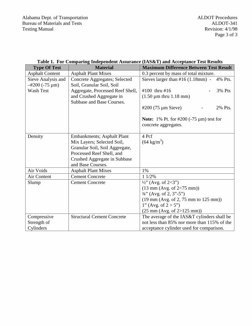
Alabama Dept. of Transportation ALDOT ProceduresBureau of Materials and Tests ALDOT-341Testing Manual Revision: 4/1/98
Page 3 of 3
Table 1. For Comparing Independent Assurance (IAS&T) and Acceptance Test ResultsType Of Test Material Maximum Difference Between Test Result
Asphalt Content Asphalt Plant Mixes 0.3 percent by mass of total mixture.Sieve Analysis and–#200 (-75 µm)Wash Test
Concrete Aggregates; SelectedSoil, Granular Soil, SoilAggregate, Processed Reef Shell,and Crushed Aggregate inSubbase and Base Courses.
Sieves larger than #16 (1.18mm) - 4% Pts.
#100 thru #16 - 3% Pts(1.50 µm thru 1.18 mm)
#200 (75 µm Sieve) - 2% Pts.
Note: 1% Pt. for #200 (-75 µm) test forconcrete aggregates.
Density Embankments; Asphalt PlantMix Layers; Selected Soil,Granular Soil, Soil Aggregate,Processed Reef Shell, andCrushed Aggregate in Subbaseand Base Courses.
4 Pcf(64 kg/m3)
Air Voids Asphalt Plant Mixes 1%Air Content Cement Concrete 1 1/2%Slump Cement Concrete ½” (Avg. of 2<3”)
(13 mm (Avg. of 2<75 mm))¾” (Avg. of 2, 3”-5”)(19 mm (Avg. of 2, 75 mm to 125 mm))1” (Avg. of 2 > 5”)(25 mm (Avg. of 2>125 mm))
CompressiveStrength ofCylinders
Structural Cement Concrete The average of the IAS&T cylinders shall benot less than 85% nor more than 115% of theacceptance cylinder used for comparison.
Alabama Dept. of Transportation ALDOT ProceduresBureau of Materials and Tests ALDOT-342Testing Manual Revision: 3/28/94
Page 1 of 2
ALDOT-342-83SUMMARY OF TESTS (BMT-38)
1. Scope
1.1. Requirements for submitting Summary of Tests (BMT-38).
2. Applicable Document
2.1. FHWA FHPM Volume 6, Current Edition
2.2. Construction Information Memorandum 5-88.
3. Summary of Method
3.1. Form BMT-38 is required to be submitted by each Division to the Materials and TestsEngineer along with a letter of certification (Exhibit A) indicating that all materials used onall projects containing Federal funds, and State projects subject to future federal fundingwere tested and met the required specifications. The letter of certification shall be signed bythe Division Engineer, the Division Materials Engineer or the Division ConstructionEngineer. This is submitted at the completion of the project. Please note that the BMT-38Form has two sheets. Sheet 1 will be used for a cover letter and Sheet 2 will be usedthereafter. The Specification Item Number under which this material was paid should also beshown in addition to the Laboratory Number in the Laboratory Number column.
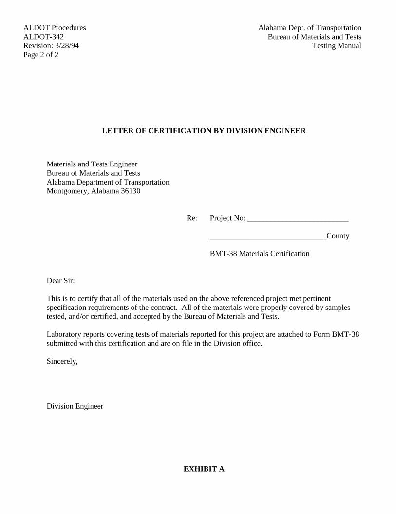
Alabama Dept. of TransportationALDOT ProceduresBureau of Materials and TestsALDOT-342
Testing ManualRevision: 3/28/94Page 2 of 2
LETTER OF CERTIFICATION BY DIVISION ENGINEER
Materials and Tests EngineerBureau of Materials and TestsAlabama Department of TransportationMontgomery, Alabama 36130
Re: Project No: __________________________
______________________________County
BMT-38 Materials Certification
Dear Sir:
This is to certify that all of the materials used on the above referenced project met pertinentspecification requirements of the contract. All of the materials were properly covered by samplestested, and/or certified, and accepted by the Bureau of Materials and Tests.
Laboratory reports covering tests of materials reported for this project are attached to Form BMT-38submitted with this certification and are on file in the Division office.
Sincerely,
Division Engineer
EXHIBIT A
Alabama Dept. of Transportation ALDOT Procedures Bureau of Materials and Tests ALDOT-344 Testing Manual Revision: 10/27/97
Page 1 of 5
ALDOT-344-83 DESIGN METHOD FOR SELECTING THE GRADE OF RECYCLING AGENT AND OPTIMUM
ASPHALT CEMENT CONTENT OF HOT-MIX RECYCLE BITUMINOUS MIXTURES
1. Scope
1.1. This procedure covers the method of designing recycle bituminous mixtures using the Marshall Stability apparatus. This method is for use with mixtures containing aggregate up to 25 mm maximum particle size.
2. Applicable Documents
2.1. AASHTO T 49, Penetration of Bituminous Materials
2.2. AASHTO T 84, Specific Gravity and Absorption of Fine Aggregates
2.3. AASHTO T 85, Specific Gravity and Absorption of Course Aggregates
2.4. AASHTO T 164, Quantitative Extraction of Bitumen from Bituminous Paving Mixtures
2.5. AASHTO T 166, Bulk Specific Gravity of Compacted Bituminous Mixtures
2.6. AASHTO T 170, Recovery of Asphalt from Solution by Abson Method
2.7. AASHTO T 201, Kinematic Viscosity of Asphalts
2.8. AASHTO T 202, Viscosity of Asphalts by Vacuum Capillary Viscometer
2.9. AASHTO T 209, Maximum Specific Gravity of Bituminous Paving Mixtures
2.10. AASHTO T 245, Resistance to Plastic Flow of Bituminous Mixtures using the Marshall Apparatus
2.11. ALDOT-258, Mechanical Analysis of Extracted Aggregate
2.12. ALDOT-307, Design Method for Selecting Optimum Asphalt Cement Content of Bituminous Mixture by Means of the Marshall Apparatus
3. Evaluate Reclaimed Asphalt Pavement
3.1. Determine the asphalt content of the reclaimed asphalt pavement using AASHTO T 164.
3.2. Determine the gradation of the extracted aggregate by ALDOT-258.
3.3. Recover approximately 75 - 100 g of asphalt cement in accordance with AASHTO T 170. If the reclaimed asphalt pavement contains less than one percent asphalt, assume the asphalt cannot be recovered and treat the reclaimed asphalt pavement as untreated aggregate.
Alabama Dept. of Transportation ALDOT Procedures Bureau of Materials and Tests ALDOT-344
Testing Manual Revision: 10/27/97 Page 2 of 5
3.4. Determine the viscosity of the reclaimed asphalt at 140°F (60°C) by AASHTO T 202. Plot on left y-axis of Figure 2.
3.5. If the viscosity of the reclaimed asphalt is too high to easily measure, measure penetration at 77°F (25°C) and viscosity at 275°F (135°C) by AASHTO T 49 and AASHTO T 201. Using Figure 1, estimate the viscosity at 140°F (60°C).
3.6. Plot specification design target viscosity of the final binder. Draw horizontal line at target viscosity.
3.7. Select the grade of recycling agent to be used.
3.8. Determine percent of recycling agent to use.
3.8.1. Use Figure 2 to determine how much recycling agent is needed to soften the reclaimed asphalt to the desired viscosity.
3.9. Check the blend for specification compliance.
3.9.1. The blend must meet the specified asphalt specifications. If the blend does not substantially meet asphalt specifications, select another grade of recycling agent.
4. Test Procedures
4.1. Stability and Flow
4.1.1. AASHTO T 245 shall apply except where amended as follows:
Paragraph 2.4 shall be amended to include the following:
For the double or triple compaction hammers, a pedestal of suitable material and construction may be used, provided results are comparable to the results using the wooden pedestal.
Paragraph 2.5 shall be amended to read as follows:
Specimen mold holder shall be mounted on the compaction pedestal so as to be centered over the post. It shall hold the compaction mold, collar and base plate securely in position during compaction of the specimen.
Paragraph 3.2 shall be amended to read as follows:
Dry the new virgin aggregates to constant mass at 220 to 230°F (105 to 110°C). The reclaimed asphalt pavement should be air dried to prevent any further hardening of the asphalt cement. If moisture is suspected, reclaimed asphalt pavement may be oven dried at 140°F (60°C).
Paragraph 3.4 shall be amended to read as follows:
Alabama Dept. of Transportation ALDOT Procedures Bureau of Materials and Tests ALDOT-344 Testing Manual Revision: 10/27/97
Page 3 of 5
Proportion by weight the amount by percentages into separate pans of each material required to a batch that will result in a compacted specimen 65 ± 1 mm in height (about 1200 g). Place the pan or pans of the virgin aggregate in the oven and heat to a temperature not exceeding 600°F (316°C). Charge the mixing bowl with the heated aggregate and combine with the ambient re-claimed asphalt pavement. Dry mixes the blend for about 30 seconds to obtain heat transfer and to avoid smoking on addition of the recycle agent. Then add the heated recycling agent at the specified levels and mix until a uniform, complete, coating is obtained. If the mix is too cold to achieve complete coating or too stiff to compact, discard the mix, make new mix at an elevated virgin aggregate temperature.
4.1.2. Age the specimens (samples for compaction, samples for maximum specific gravities) in a forced draft oven at compaction temperature for 45 minutes.
4.2. Bulk specific gravity of compacted bituminous mixtures.
4.2.1. AASHTO T 166 shall apply.
4.2.2. Prior to testing for stability and flow, the Bulk Specific Gravity shall be determined on the compacted specimen prepared in accordance with AASHTO T 245 as amended.
4.2.3. Average the Bulk Specific Gravities for all compacted specimens of a given asphalt content. Values obviously in error shall not be included in average.
4.3. Maximum Specific Gravity of bituminous mixtures.
4.3.1. AASHTO T 209 shall apply.
4.3.2. Determine the Maximum Specific Gravity of the bituminous mix for at least two asphalt con-tents, preferably on mixes at or near the optimum asphalt content and compute average. The Maximum Specific Gravity of the mixes with other contents can be computed as described in paragraph 4.4 of ALDOT-307.
5. Density and Voids Analysis
5.1. ALDOT-307 shall apply.
6. Selecting Optimum Asphalt Content
6.1. ALDOT-307 shall apply.
7. Determine the Viscosity of the Asphalt Cement at Optimum Asphalt Content.
7.1. Extract asphalt cement in accordance with AASHTO T 164.
7.2. Recover the asphalt cement in accordance with AASHTO T 170.
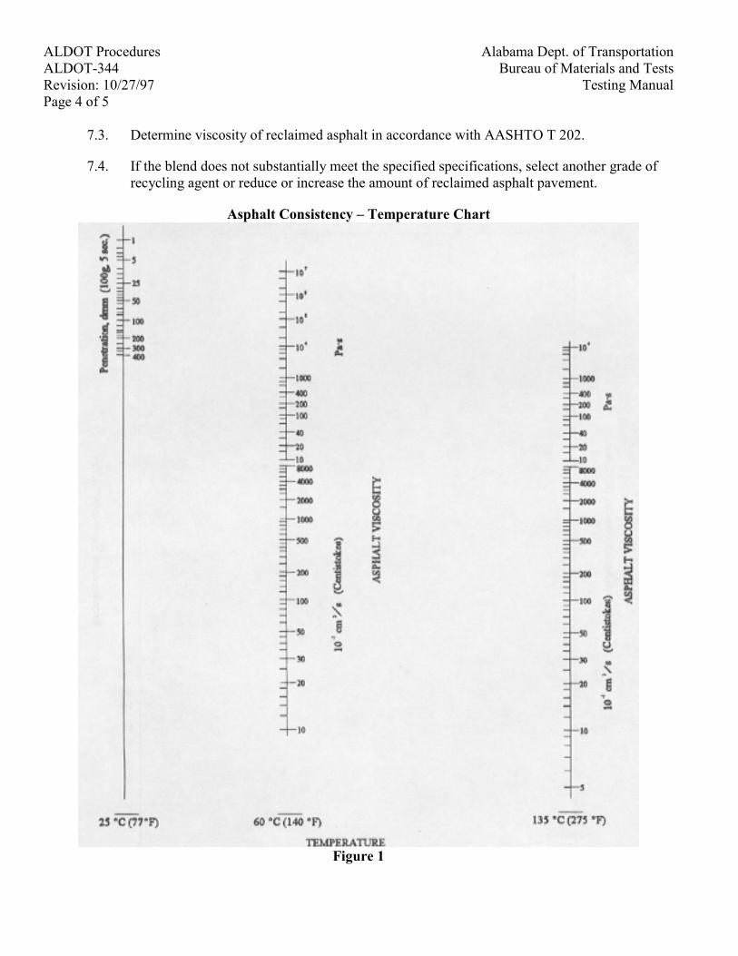
Alabama Dept. of Transportation ALDOT Procedures Bureau of Materials and Tests ALDOT-344
Testing Manual Revision: 10/27/97 Page 4 of 5
7.3. Determine viscosity of reclaimed asphalt in accordance with AASHTO T 202.
7.4. If the blend does not substantially meet the specified specifications, select another grade of recycling agent or reduce or increase the amount of reclaimed asphalt pavement.
Asphalt Consistency – Temperature Chart
Figure 1
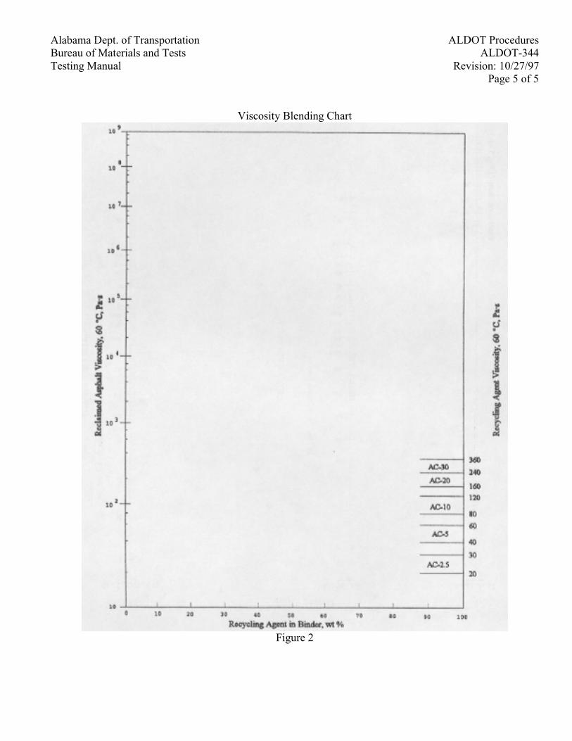
Alabama Dept. of Transportation ALDOT Procedures Bureau of Materials and Tests ALDOT-344 Testing Manual Revision: 10/27/97
Page 5 of 5
Viscosity Blending Chart
Figure 2
Alabama Dept. of Transportation ALDOT ProceduresBureau of Materials and Tests ALDOT-348Testing Manual Revision: 3/18/94
Page 1 of 2
ALDOT-348-84ACCEPTANCE OF TREATED TIMBER PRODUCTS BY CERTIFICATION
1. Scope
1.1. The purpose of this procedure is to establish a method whereby treated timber products maybe accepted by certification from the treating agency hereinafter referred to as the Supplier.This procedure covers all treated timber products listed in Section 833 of the Department'sSpecifications.
1.2. Under this procedure the Alabama Department of Transportation will not provide inspectionat the treating plant either by State Inspectors or by Commercial Laboratories. This isapplicable to in-state and out-of-state suppliers.
2. Applicable Documents
2.1. Alabama Department of Transportation Specifications Sections 833, 834, and 864.
2.2. American Wood-Preservers' Association Standard A-3, A-5, A-6, A-7, C-1, M-4, M-6, & C-14.
2.3. Southern Pine Inspection Bureau Grading Rules (SPIB).
3. Acceptance of Material
3.1. The supplier will furnish or have access to quality control personnel with the capability andknowledge to grade timber in accordance with SPIB Standards. The supplier will provide aquality control technician and laboratory equipment to perform all necessary assay retentiontests required.
3.2. The supplier will furnish the Certification Engineer a Certificate of Treatment for eachcharge treated for use by the Department. The Certificate of Treatment will include allmeasurements of the timber products, made in the "white", an analysis of the preservativeused in the treatment and the preservative retention assay after treatment. The Certificate ofTreatment will be signed by the supplier's quality control technician or a responsibleemployee of the supplier and the certificate will be notarized.
3.3. The Certificate of Treatment will serve as a test report to be approved by the CertificationEngineer.
3.4. Each post will be stamped or branded on one end with the logo of the treating plant.
4. Shipping Notice
4.1. When the timber products are shipped to an Alabama Department of Transportation Project,send a copy of the Certificate of Treatment with shipment to the Project Engineer with aBMT-170 completed and attached. Use a separate sheet for each type of end anchor..
Alabama Dept. of TransportationALDOT ProceduresBureau of Materials and TestsALDOT-348
Testing ManualRevision: 3/18/94Page 2 of 2
4.2. Upon receipt of the Certificate of Treatment the Project Engineer will forward a copy to theDivision Materials Engineer. The Division Materials Engineer will send a copy of the BMT-170 and the Certificate of Treatment to the Certification Section. The Certification Engineerwill check/verify and issue test report.
5. Departmental Inspections
5.1. Timber products shipped to projects will be visually inspected by the Project Engineer forappearance and measured for dimension compliance, spacing, and size of holes.
6. Storage of Supplier
6.1. All timber products which are to be stocked for future shipment will be stacked in a mannerwhich will permit circulation of air within the stack.
7. Failure to Maintain Adequate Quality Control
7.1. If it is determined that there is evidence that a supplier has failed to maintain adequate qualitycontrol during the inspection and treatment of the material at his treating facility, or if thetimber products fail to meet the required specifications on the project inspections, allshipments from that supplier will stop immediately and an in-depth investigation will bemade by the Bureau of Materials and Tests to determine what corrective action is necessary.
7.2. If, after due notice, corrective action is not taken by the supplier his product will not beacceptable by the Department.
Alabama Dept. of Transportation ALDOT ProceduresBureau of Materials and Tests ALDOT-349Testing Manual Revision: 10/27/97
Page 1 of 3
ALDOT-349HOT MIX ASPHALT FIELD TESTING EQUIPMENT
1. Scope
1.1. This procedure covers equipment required for field testing of bituminous asphalt mixtures.All testing equipment shall meet or exceed the following requirements, as well as anyrequirements in the referenced AASHTO, ASTM, or ALDOT documents (includingadditional equipment), and be present on sight and maintained in proper working orderduring all hot mix asphalt (HMA) production. Any equipment not meeting the requirementsherein shall not be used without the written approval of the Materials and Tests Engineer.
2. Referenced Documents
2.1. AASHTO Standards
2.1.1. AASHTO T27, Standard Method of Test for Sieve Analysis of Fine and CoarseAggregates
2.1.2. AASHTO T30, Standard Method of Test for Mechanical Analysis of ExtractedAggregates
2.1.3. AASHTO T84, Standard Method of Test for Specific Gravity and Absorption of FineAggregate
2.1.4. AASHTO T85, Standard Method of Test for Specific Gravity and Absorption ofCoarse Aggregate
2.1.5. AASHTO T164, Standard Method of Test for Quantitative Extraction of Bitumenfrom Bituminous Paving Mixtures
2.1.6. AASHTO T166, Standard Method of Test for Bulk Specific Gravity of CompactedBituminous Mixtures Using Saturated Surface-Dry Specimens
2.1.7. AASHTO T168, Standard Method of Test for Sampling Bituminous Paving Mixtures
2.1.8. AASHTO T176, Standard Method of Test for Plastic Fines in Graded Aggregates andSoils by Use of the Sand Equivalent Test
2.1.9. AASHTO T209, Standard Method of Test for Maximum Specific Gravity ofBituminous Paving Mixtures
2.1.10. AASHTO T245, Standard Method of Test for Resistance to Plastic Flow ofBituminous Mixtures Using Marshall Apparatus
2.1.11. AASHTO T248, Standard Method of Test for Reducing Field Samples of Aggregateto Testing Size
Alabama Dept. of TransportationALDOT ProceduresBureau of Materials and TestsALDOT-349
Testing ManualRevision: 10/27/97Page 2 of 3
2.1.12. AASHTO T283, Standard Method of Test for Resistance of Compacted Mixture toMoisture Induced Damage
2.1.13. AASHTO TP4-93, Method for Preparing and Determining the Density of Hot MixAsphalt (HMA) Specimens by Means of the SHRP Gyratory Compactor
2.1.14. AASHTO TP33-93, Test Method for Uncompacted Void Content of Fine Aggregate(As Influenced by Particle Shape, Surface Texture, and Grading)
2.1.15. AASHTO TP53-95, Test Method for Determining the Asphalt Content of Hot MixAsphalt (HMA) by Ignition Method
2.2. ASTM Standards
2.2.1. ASTM D2041, Standard Test Method for Theoretical Maximum Specific Gravity andDensity of Bituminous Paving Mixtures
2.2.2. ASTM D4125, Standard Test Methods for Asphalt Content of Bituminous Mixturesby the Nuclear Method
2.2.3. ASTM D4791, Standard Test Method for Flat Particles, Elongated Particles, or Flatand Elongated Particles in Coarse Aggregate
2.3. ALDOT Procedures
2.3.1. ALDOT-130, Moisture Content of Bituminous Mixtures by Drying
2.3.2. ALDOT-307, Design Method for Selecting Optimum Asphalt Cement Content ofBituminous Mixture by Means of the Marshall Apparatus
2.3.3. ALDOT-319, Rapid Method to Determine the Bitumen Content in BituminousPaving Mixtures
2.3.4. ALDOT-354, Asphalt Content of Bituminous Mixtures by the Nuclear Method
2.3.5. ALDOT-361, Resistance of Compacted Bituminous Mixture to Moisture InducedDamage
2.3.6. ALDOT-381, Method for Correlation of Marshall Hammers
3. General Equipment Needed
3.1. Sample quartering table (AASHTO T248).
3.2. Sieve nest and shaker, 8 in or 12 in (200 or 300 mm) diameter. (AASHTO T30).
3.3. Washing screen deck and decanter (AASHTO T27).
3.4. Balances/scales with 11 kg capacity and 0.1 g sensitivity calibrated annually.
Alabama Dept. of Transportation ALDOT ProceduresBureau of Materials and Tests ALDOT-349Testing Manual Revision: 10/27/97
Page 3 of 3
3.5. Wire basket or platform suspended from scales into overflow equipped temperaturecontrolled water bath to determine compacted specimen bulk specific gravity (AASHTOT166).
3.6. Vacuum pump, mamometer, accurate to 1 mm mercury absolute pressure, fan (for dry back),and Rice picnometer (AASHTO T209).
3.7. TSR breaking head (sized for the proper specimen diameter and height) and vacuumsaturation picnometer, sufficient capacity to completely immerse the specimen while thespecimen is held off the bottom of the picnometer with a mesh spacer or other device, andTSR loading machine (AASHTO T283).
3.8. Constant temperature water bath, 140ºF (60°C) (AASHTO T283 & T245).
3.9. Thermometers accurate to 1°F (0.5 ºC) from 68 to 356 ºF (20 to 180°C).
3.10. Specimen extruder using a rigid 0.5 in (12.7 mm) thick steel disk having a diameter no morethan 1/16 in (1.6 mm) smaller than the diameter of the specimen mold.
3.11. Forced draft oven(s), having a minimum interior oven space of 10ft3 (0.3 m³) total. Twoovens, one for mix and one for molds, are required for Marshall. The Superpave molds arelarger, but in the field molds and mix are at the same temperature.
3.12. Trowels and towels, pans, bowls, spoons and spatulas, insulated and rubber gloves, lumbercrayons or paints pens, scoops, machine lubricant, asphalt solvent and soap, and protectivepaper specimen disks.
3.13. (For 424 & 429 mixes) Sand Equivalent apparatus (AASHTO T176), Uncompacted VoidContent apparatus (AASHTO TP33), and Flat or Elongated Proportional Caliper (ASTMD4791).
3.14. Microwave oven and pyrex dish (ALDOT-130).
3.15. Nuclear gauge (ALDOT-354) or Ignition Furnace (AASHTO TP53-95).
4. Equipment for Marshall Mixes
4.1. Marshall molds and compactor assembly, including a concrete slab with approximatedimensions of 3ft x 3ft x 1 ft (1.0 x 1.0 x 0.3 m), calibrated and correlated according toALDOT-381. Marshall molds, and a stability and flow breaking head with recording devices(AASHTO T245).
5. Superpave Equipment
5.1. SHRP (Superpave) gyratory compactor with molds and specimen height recorder maintainedand calibrated according to the manufacturer's or Superpave's recommended schedule,whichever is more frequent (AASHTO TP4-93).
Alabama Dept. of Transportation ALDOT ProceduresBureau of Materials and Tests ALDOT-350Testing Manual Revision: 12/15/95
Page 1 of 3
ALDOT-350-87IN-PLACE BITUMINOUS PLANT MIX DENSITY MEASUREMENTS
1. Scope
1.1. This method of test provides a non-destructive measurement of in-place density ofbituminous plant mix using a thin layer or dual-purpose nuclear density gauge for thin liftoverlays.
Note: All operators must be certified as Roadway Technicians by the Bureau of Materialsand Tests. Before becoming certified as a Roadway Technician, operators must pass theRadiological Safety Course. When these requirements are met, an operator will be issued acard by the Bureau of Materials and Tests certifying him/her as an operator.
2. Applicable Documents
2.1. M&T-33, Technical Specifications for Thin Layer Nuclear Density Gauges.
2.2. Nuclear Gauge Training Manual.
2.3. Radiological and Operational Manual on use of Nuclear Moisture and Density Gauges.
2.4. AASHTO T-166, Bulk Specific Gravity of Compacted Bituminous Mixture Using SaturatedSurface-Dry Specimens.
2.5. ALDOT-210, Selecting Samples Using Random Numbers.
2.6. ALDOT-341, Standard Procedures for Comparing Independent Assurance Samples and Tests(IAS&T) and Acceptance Test Results.
3. Nuclear Gauging Device
3.1. This device must meet Technical Specifications M&T-33, available at the Bureau ofMaterials and Tests.
4. Gauge Application Thicknesses
4.1. Troxler Electronic Labs Model 4640-A - 1 in. (25 mm) to 2 ½ in. (63 mm)Troxler Electronic Labs Model 4640-B – 1 in. (25 mm) to 4 in. (100 mm)Troxler Electronic Labs Model 3430, 3440, & 3450 – 1 in. (25 mm) to 4 in (100 mm)Campbell Pacific Nuclear Corp. Model MC-3 - 1 in. (25 mm) to 4 in. (100 mm)
5. Gauge Operation
5.1. Operation of the gauge shall be in accordance with the manufacturer's instruction manual andAlabama Department of Transportation Nuclear Gauge Training Manual, available from theBureau of Materials and Tests.
Alabama Dept. of TransportationALDOT ProceduresBureau of Materials and TestsALDOT-350
Testing ManualRevision: 12/15/95Page 2 of 3
5.2. When operating nuclear gauges, standard counts must be taken on a daily basis in order tomaintain gauge accuracy while testing. The gauges and standard frequency are as follows:
Gauge Type/Model Standard InformationTroxler 4640-A & B Daily / Default timeTroxler 3430, 3440 & 3450 Daily / Default timeCampbell-Pacific MC-3 Daily / Default time
5.3. When operating the Troxler Electronics Model 4640-A Thin Layer Gauge, a standardreference value will be established every six- (6) months or at the beginning of the project,whichever is shorter. In order to establish a reference value with this device, five four-minute counts will be taken on the 1 in (25 mm) thick standard plate supplied with the gauge.The average of these counts must fall between 105 lbs/ft3 (1680 kg/m3) and 115 lbs/ft3 (1840kg/m3). If not, the gauge should be replaced. Once this value is established, it becomes thestandard value used when daily reference values are taken. One four-minute count must betaken on the standard plate each day the gauge is used. The daily count must be within 2lbs/ft3 (32 kg/m3) of the established standard.
6. Calibration
6.1. Calibration of gauges will be under the direction of personnel from the Bureau of Materialsand Tests.
6.2. All gauges will be calibrated to densities of cores taken from the material being tested, asdetermined by AASHTO T-166.
6.3. Calibration of the thin layer or dual-purpose gauges shall be in accordance with AlabamaDepartment of Transportation Nuclear Gauge Training Manual available from the Bureau ofMaterials and Tests.
6.4. The certified technicians will select an area within the first 500 T. (500 t) test section that isfree of segregation and between the wheel paths. A minimum of five (5) cores will be takenand used to calibrate the thin-layer or dual-purpose gauges. The gauge(s) to be calibratedwill take four (4) one (1) minute counts around each of the five (5) cores, in accordance witharticle 7.3. The average density of these 20 counts is compared to the average density of thefive cores. This difference is the correction value for the layer being tested.
6.5. Once the correction value has been applied, the technician will retake the same four (4) one(1) minute counts around each of the five (5) cores. The average density derived by thegauge, at each core location, must be within ± 1.5% of the actual core density. This must beperformed for each of the five (5) cores. If the gauge reads within ± 1.5% of each calibrationcore, no recalibration will be necessary.
6.6. If recalibration is necessary, the cores previously taken, as outlined in article 6.4 should beused and the calibration process repeated.
7. In-Place Density Test
Alabama Dept. of Transportation ALDOT ProceduresBureau of Materials and Tests ALDOT-350Testing Manual Revision: 12/15/95
Page 3 of 3
7.1. Determine the stations and locations for the In-Place Density Test in accordance withALDOT-210. (Select samples by the random numbers method.) Use an engineering tape orother suitable measuring device to precisely locate the test location. Pacing is notpermissible. Record/document, and maintain all random number test locations.
7.2. Place the gauge on the surface of the asphalt pavement as determined above. Check foruniform seating by placing hands on opposite corners of the gauge. If the gauge cannot beproperly seated, cores shall be taken at the exact random number location to determine thedensity.
7.3. Take four one-minute counts rotating the gauge 90° over the same centerpoint after eachcount. Record these readings and average for the in-place density.
7.4. When operating nuclear gauge within 24 in, (600 mm) of the edge of the asphalt mat, use thefollowing procedure. For initial reading, place gauge parallel to the edge of the layer beingtested. Then, rotate gauge at 60° intervals (over same centerpoint) to obtain the next three (3)readings. The last reading should be taken opposite the first reading, leaving the gaugeparallel to the edge of the layer being tested.
8. Comparing IAS&T Samples and Tests and Acceptance Test Results
8.1. Frequency of (IAS&T) Tests shall be in accordance with the IAS&T schedule section of thetesting manual. IAS&T tests shall be taken at the same location as the acceptance test takenby field or contractor personnel. IAS&T tests shall follow the guidelines set forth inALDOT-341 with comparison tolerances outlined in Table 1.
Alabama Dept. of Transportation ALDOT ProceduresBureau of Materials and Tests ALDOT-352Testing Manual Revision: 6/10/94
Page 1 of 8
ALDOT-352-87CERTIFICATION PROGRAM FOR PORTLAND CEMENT CONCRETE PRODUCERS
1. Scope
1.1. The Alabama Department of Transportation hereby establishes the Certification Program forPortland Cement Concrete Producers.
1.2. The purpose of this program is to establish the requirements necessary for certification ofconcrete plants producing concrete for Department projects.
1.3. The Quality Control and Quality Assurance of the concrete produced for Department projectswill be the responsibility of the producer.
1.4. The Alabama Department of Transportation will be responsible for monitoring and enforcingthis program.
1.5. The Alabama Department of Transportation will be responsible for verifying that PortlandCement Concrete produced for the Department's use meets the applicable specifications.
2. Applicable Documents
2.1. Alabama Department of Transportation Specifications, Sections 106, 450, 501, 801, 802,806, 807, 808, 809, and 815.
2.2. ALDOT-170.
2.3. ALDOT-328.
2.4. AASHTO M-157.
2.5. The Alabama Department of Transportation's "Materials, Sources, and Devices with SpecialAcceptance Requirements" manual.
3. Procedure for Plant Approval
3.1. The concrete plant owner or manager shall schedule an inspection of the plant facilities withthe Department.
3.2. Plants with facilities that are found to meet the Department's requirements shall provide theMaterials and Tests Engineer with a certification stating that all concrete supplied forDepartment work shall be produced from materials from approved sources, proportioned inaccordance with a mix design approved by the Department and under the provisions outlinedin this document. This certified statement will then be resubmitted annually on the firstmonth of each calendar year.
Alabama Dept. of TransportationALDOT ProceduresBureau of Materials and TestsALDOT-352
Testing ManualRevision: 6/10/94Page 2 of 8
3.3. The physical plant equipment of an approved plant shall meet all requirements as specified inALDOT-170 and Sections 450 and 501 of the Alabama Department of TransportationSpecifications.
3.4. The concrete producer is responsible for materials, aggregate moisture determinations, scaleweight corrections, batching, weighing, mixing, delivery, and completion/transmission ofnecessary documentation in the manner and to the degree provided for in the AlabamaDepartment of Transportation Specifications and procedures.
3.5. Approved plants will have certified personnel to fulfill the concrete plant's responsibility oftesting and accurately proportioning concrete. Certified personnel shall demonstrateproficiency in respective areas of Responsibilities by successfully meeting the requirementsof Section 6 of this procedure.
4. List of Approved Portland Cement Concrete Producers
4.1. The Department will maintain a list of Approved Sources of Portland Cement ConcreteProducers (List I-7) that are in compliance with this document in the "Materials, Sources, andDevices with Special Acceptance Requirements" manual. Only plants on this List will beeligible to supply concrete for Department work. The List will include the producer's name,assigned vendor's code, plant's classification, and the certified personnel.
4.2. Any producer may be removed from the List I-7 for deliberate violation of the Department'sSpecifications, the deliberate use of nonspecification materials, or for the use of materialsfrom a non-approved source.
4.3. The Concrete Engineer or authorized representative will conduct random and unscheduledvisits to approved concrete plants in List I-7.
5. Plant Classification
5.1. The classification of an approved plant shall be predicated upon the fulfillment of specifiedminimum requirements. Plants shall not produce Department concrete when certifiedpersonnel are not present.
5.2. Plant classification will be based upon the following definitions. Concrete production andplacement schedules shall be governed accordingly.
5.2.1. Classification A Plants
5.2.1.1. Classification A plants are defined as those plants with approved concreteproduction facilities and Quality Control equipment, staffed and operated in amanner that insures concrete is produced in accordance with the Department'sSpecifications and with minimum production inspection by the Department'sconcrete inspectors.
Alabama Dept. of Transportation ALDOT ProceduresBureau of Materials and Tests ALDOT-352Testing Manual Revision: 6/10/94
Page 3 of 8
5.2.1.2. Classification A plants may maintain concrete production schedules at theconvenience of the Project Engineer and the Contractor. The Engineer may atrandom intervals assign a Department inspector to observe batching andmixing techniques. Unscheduled visits will be made to all concrete producersperiodically by inspecters from the various Division Offices.
5.2.1.3. Classification A plants shall have a full time plant employee certified by theDepartment to be proficient in concrete technology. The Certified ConcreteTechnician shall have a sound knowledge of the Department's Specificationsas they relate to concrete production and testing of fresh concrete.
5.2.1.4. Classification A plants shall have a full time plant employee certified by theDepartment to be proficient in concrete batching technology. The CertifiedBatcher shall have a sound knowledge of the Department's Specifications asthey relate to concrete material components.
5.3. Any plant which violates the requirements of this document or any other applicablespecification will be subject to loss of its classification status.
5.4. Any Classification A plant found to be in violation shall be removed from the List ofApproved Portland Cement Concrete Producers (List I-7) and will not be allowed to produceDepartment concrete.
5.5. A plant may apply to be reinstated after three months from removal, provided the cause forremoval has been corrected to the satisfaction of the Department. A plant that has beenremoved and then reinstated will be placed in a probational period of six months.
6. Certified Personnel
6.1. Certified personnel will fulfill the concrete plant's responsibility of testing, accuratelyproportioning concrete, and managing the plant's quality control program.
6.2. The Alabama Department of Transportation will certify plant personnel as ConcreteTechnicians or Concrete Batchers after they successfully pass a written examination onconcrete technology.
6.3. Alabama Department of Transportation personnel who will inspect any concrete operationmust be certified as Concrete Technicians.
6.4. Applicants for Certification as Concrete Technicians shall pass a Department approvedpractical examination prior to taking the Alabama Department of Transportation's test. PCITechnician or ACI Level I Technician are examples of approved practical examinations.
6.5. A three-month waiting period is required before retaking the Department's concretetechnology test.
Alabama Dept. of TransportationALDOT ProceduresBureau of Materials and TestsALDOT-352
Testing ManualRevision: 6/10/94Page 4 of 8
6.6. The Concrete Technician and Concrete Batcher certification will be valid for a period of five(5) years.
6.7. Re-certification of Concrete Technicians and Concrete Batchers shall be as per the followingschedule:
6.7.1. All re-certifications, shall be completed before the last day of the month shown as theexpiration date of the certified card.
6.8. Certified Concrete Technicians and Concrete Batchers must be assigned to only one concreteplant; however, certified personnel may work at other plants if their assigned plant is notproducing concrete for the Alabama Department of Transportation and they have previouslynotified the Division Office.
6.9. The Certified Concrete Batcher at the concrete plant will be responsible for, but not limitedto, the following tasks:
6.9.1. Concrete batching from approved mix design.
6.9.2. Temperature check of cement.
6.9.3. Temperature check of concrete.
6.9.4. Conducting moisture tests on aggregates.
6.9.5. Batch weight corrections.
6.9.6. Transmission of certified delivery tickets.
6.9.7. Documentation.
6.10. The Certified Concrete Technician at the concrete plant will be responsible for, but notlimited to, the following tasks:
6.10.1. Responsible for the plant's Quality Control Program.
6.10.2. Perform gradation on aggregates.
6.10.3. Determine Fineness Modulus.
6.10.4. Determine Working Fineness Modulus.
6.10.5. Determine moisture in aggregates.
6.10.6. Perform slump test.
6.10.7. Determine air content of concrete.
Alabama Dept. of Transportation ALDOT ProceduresBureau of Materials and Tests ALDOT-352Testing Manual Revision: 6/10/94
Page 5 of 8
6.10.8. Determine unit weight of concrete.
6.10.9. Perform compression testing of concrete cylinders.
6.11. The Certified Concrete Technician must have a thorough knowledge of concrete mix design,be a partner with the Department to resolve problems, and be qualified to perform thoseduties assigned to the Certified Concrete Batcher.
7. Laboratory Requirements
7.1. Classification A and B plants shall maintain a laboratory approved by the Department thatcontains equipment to perform tests for aggregate surface moisture.
7.2. Classification A plants shall also have sufficient equipment to conduct slump, air content,and unit weight tests on fresh concrete and gradation tests on aggregates.
7.3. Reference material to be maintained at the plant will include but not be limited to:
7.3.1. Alabama Department of Transportation Specifications (current edition).
7.3.2. A copy of applicable AASHTO or ASTM specifications.
7.3.3. All applicable Alabama Department of Transportation Procedures.
7.3.4. Copies of any Supplemental Specifications or Special Provisions which apply to theconcrete to be produced.
8. Concrete Production
8.1. The concrete producer shall be responsible for producing concrete, which meets allapplicable specification requirements.
8.2. The Department will administer a materials assurance program for approved PortlandCement Concrete Producers which will insure the Department that materials incorporatedinto the concrete mix are from approved sources and in compliance with the Specifications.
8.3. The quality of the materials will be verified by testing plant control and IndependentAssurance Samples of materials secured by Department inspectors from plant storage duringrandom periods of production of Department concrete.
8.4. Each concrete plant will be issued concrete mix designs for each class of concrete to beproduced. The batched concrete shall adhere to those mix designs.
8.5. Any changes to any of the components making up the mix will not be allowed unless they areapproved in writing prior to concrete production.
Alabama Dept. of TransportationALDOT ProceduresBureau of Materials and TestsALDOT-352
Testing ManualRevision: 6/10/94Page 6 of 8
8.6. If changes are necessary, the concrete producer is responsible for contacting the appropriateDivision Materials Engineer to request the needed changes.
9. Required Testing
9.1. Production of the required aggregate gradation in the mix will be the responsibility of theconcrete producer.
9.2. Certified plant personnel will be responsible for performing gradation tests and determiningFineness Modulus and Working Fineness Modules at Classification A plants.
9.3. Gradation tests on both coarse and fine aggregate shall be made once before Departmentconcrete production begins and then at least once for every 500 yd3 (400 m3) of totalconcrete production that takes place while Department concrete is being produced.
9.4. Where Department concrete is not produced on a continuous day to day basis, gradation testswill start over each time production of Department concrete is resumed.
9.5. Plants which have a total concrete production of less than 500 yd3 (400 m3)in a one weekperiod will be required to perform one gradation test per week, and it will be performedimmediately before that week's production of Department concrete is begun. Additionalgradation tests shall be made as often as required.
9.6. Checks for aggregate moisture determination shall be performed before batch operationsbegin and then as often as it is necessary to compensate for moisture changes in theaggregate.
9.7. The method used to determine moisture in the aggregates, such as heat drying, SpeedyMoisture Test, Chapman flask, drying with a Turkish towel, or any other accepted testmethod, will be the decision of the concrete producer.
9.8. The use of an accurate automatic moisture indicating device (such as a moisture probe) shallbe allowed provided that its accuracy can be demonstrated by an alternate method ofmoisture determination, and that it is maintained in good operating condition.
9.9. Tests for slump and air content will be performed whenever necessary to check or to adjustthe mix for slump or air content requirements.
9.10. The slump test must be performed according to AASHTO T-119 (ASTM C-143).
9.11. The air content test must be performed according to either the volumetric method inAASHTO T-196 (ASTM C-173) or the pressure method in AASHTO T-152 (ASTM C-231).
9.12. Temperature checks of both the cement and the concrete must be performed as often asnecessary to insure compliance with the Department Specifications.
10. Documentation
Alabama Dept. of Transportation ALDOT ProceduresBureau of Materials and Tests ALDOT-352Testing Manual Revision: 6/10/94
Page 7 of 8
10.1. It will be the responsibility of the certified personnel at each concrete plant to see that allrequired documentation is completed and properly maintained.
10.2. The Department will furnish any necessary forms. However, if requested, alternate forms(such as ones generated by a computerized control system) may be approved by the Materialsand Tests Engineer provided that all required information is clearly shown and sufficientcopies are available.
10.3. The required minimum documents to be maintained at the concrete plant are:
10.3.1. Approved Concrete Mix Design:Each plant will maintain a file containing all concrete mix designs issued to thatplant.
10.3.2. Concrete Delivery Ticket (BMT-122):All plants shall have a system for transmitting with each delivery of concrete a formwhich documents specific Specification requirements, such as project number, trucknumber, date, time of batching, batch proportions, mixing revolutions, volume ofconcrete, aggregate moisture, quantity of mixing water withheld, etc. Authorizedplant personnel shall complete this form and certify the data to be correct.
10.3.3. Certified Cement Shipment (BMT-114):Authorized plant personnel will collect these forms when each shipment of cementarrives and the Certified Concrete Technician shall complete part two. The formswill then be held until a Department representative picks them up.
10.3.4. Aggregate Shipment:Inspection notices (BMT-10) received with aggregate shipments will be maintainedon file to document the sources of all aggregates used in the production of concreteand shall be made available to the Department's representative when requested.
10.3.5. Test Reports:All plants will maintain records of compliance testing performed by or under thesupervision of the Certified Concrete Batcher or the Certified Concrete Technician.These records will include, but not be limited to the following: Aggregate moisturedetermination, gradation checks, Fineness Modulus determinations, temperaturechecks on cement and concrete, slump tests, air content tests, and equipmentperformance tests.
10.3.6. Plant Diary:The Certified Concrete Batcher or Technician shall keep a plant diary furnished bythe Department with entries on, but not limited to, dates Department concrete isproduced and calculations of moisture corrections, etc.
10.3.7. Plant Visit Checklist:Plants that produce Department concrete on a daily basis shall be visited by DivisionMaterials or Project Personnel every two weeks. Other plants shall be visited

Alabama Dept. of TransportationALDOT ProceduresBureau of Materials and TestsALDOT-352
Testing ManualRevision: 6/10/94Page 8 of 8
monthly. These visits shall be documented on form BMT-95 (Concrete Plant VisitChecklist) by Division Materials or Project Personnel.
Alabama Dept. of Transportation ALDOT ProceduresBureau of Materials and Tests ALDOT-353Testing Manual Revision: 5/8/00
Page 1 of 6
ALDOT-353-90DETERMINING HOT MIX ASPHALT (HMA) LABORATORY
QUALITY CONTROL/ASSURANCE PARAMETERS
1. SCOPE
1.1 These are the guidelines for field quality control and quality assurance of eachparameter such as the determination of laboratory compacted air voids, Marshallstability and flow, percent of maximum theoretical density versus gyrations (forgyratory mixes such as Superpave 424), roadway mat density, dust to asphaltratio, and voids in the mineral aggregate (VMA). This procedure also covers theoperation of field laboratories and issuing test reports. There are other require-ments that are not outlined in this procedure that must also be followed such astesting for gradation, liquid asphalt binder content, moisture content, tensilestrength ratio, coarse and fine aggregate angularity, etc. Also, this procedure doesnot cover all of the Department/contractor responsibilities such as inspection ofstockpiles, truck beds, etc. These are beyond the scope of this procedure.
2. APPLICABLE DOCUMENTS
2.1 AASHTO STANDARDS
2.1.1 AASHTO T-166, Bulk Specific Gravity of Compacted Bituminous Mix-tures Using Saturated Surface-Dry Specimens.
2.1.2 AASHTO T-168, Sampling Bituminous Paving Mixtures.
2.1.3 AASHTO T-209, Theoretical Maximum Specific Gravity and Density ofBituminous Paving Mixtures.
2.1.4 AASHTO T-245, Resistance to Plastic Flow of Bituminous MixturesUsing Marshall Apparatus.
2.1.5 AASHTO T-248, Reducing Samples of Aggregate to Testing Size.
2.2 Alabama Department of Transportation Specification, Section 106, Control ofMaterials.
2.3 Alabama Department of Transportation Testing Manual.
2.4 ALDOT PROCEDURES
2.4.1 ALDOT-210, Selecting Samples by the Random Numbers Method.
ALDOT Procedures Alabama Dept. of TransportationALDOT-353 Bureau of Materials and TestsRevision: 5/8/00 Testing ManualPage 2 of 6
2.4.2 ALDOT-222, In-Place Density and Moisture Measurements and Estab-lishing Moisture Correlation for Nuclear Moisture/Density Gauges.
2.4.3 ALDOT-307, Design Method for Selecting Optimum Asphalt CementContent of Bituminous Mixture by Means of the Marshall Apparatus.
2.4.4 ALDOT-324, Plant Requirements for Plants Producing Hot-Mixed, Hot-Laid Bituminous Paving Mixtures.
2.4.5 ALDOT-344, Design Method for Selecting the Grade of Recycling Agentand Optimum Asphalt Cement Content of Hot-Mix Recycle BituminousMixtures.
2.4.6 ALDOT-349, Hot Mix Asphalt Field Testing Equipment.
2.4.7 ALDOT-350, In-Place Bituminous Plant Mix Density Measurements.
2.4.8 ALDOT-375, Contractor Quality Control System for Hot-Mix Asphalt.
2.4.9 ALDOT-380, Forms and Examples for Sampling and Computing PayFactors for Hot Mix Asphalt.
2.4.10 ALDOT-384, Mix Design Procedure for Superpave Level I.
2.4.11 ALDOT-388, Superpave Volumetric Mix Design Procedure Using Recy-cled Asphalt Pavement.
2.5 BMT-20, Asphalt Plant Mixture Test Report.
3. REQUIRED EQUIPMENT
3.1 Required equipment for field control laboratories is listed in ALDOT-349. In-spection of the field laboratories and equipment is the responsibility of the Engi-neer (Division).
4. CONTRACTOR'S RESPONSIBILITY
4.1 Refer to ALDOT-375 and ALDOT-324.
4.2 Sample and store samples according to AASHTO T-168, ALDOT-210, andALDOT-380.
4.3 Sample and test using the frequency set in the ALDOT Testing Manual andDepartment Specifications, Section 106.
Alabama Dept. of Transportation ALDOT ProceduresBureau of Materials and Tests ALDOT-353Testing Manual Revision: 5/8/00
Page 3 of 6
4.4 Furnish daily test reports including the raw data to the Engineer. When the jobmix formula is the same for different pay items on the same project or even fordifferent projects run from the same plant, the total tonnage of these items shall becombined into one lot for testing purposes. For pay purposes, the tonnage of eachpay item shall be noted on BMT-20 or split proportionately into separateBMT-20's for different projects.
5. DEPARTMENT'S RESPONSIBILITY
5.1 Inspect contractor's field laboratory and equipment in accordance withALDOT-349.
5.2 Monitor Contractor's sampling and testing to insure accuracy.
5.3 Select random numbers by ALDOT-210 to determine what time or ton to sample.Notify the Contractor approximately fifteen minutes before sampling time (orton).
5.4 Sample (when needed) and select a verification sample by AASHTO T-168, AL-DOT-210, and ALDOT-380. If the contractor shares or furnishes a laboratory andequipment for verification testing to the Department, the Department will use thislaboratory to expedite the verification tests. However, separate scales, manome-ters, sieves, and compactors must be used for verification testing (even if they arelocated within the same laboratory).
5.5 Sample and test using the frequency set in the current Testing Manual andDepartment Specifications Section 106.
5.6 Keep a daily diary concerning plant and testing activities.
5.7 Visually inspect for segregation, contamination, etc.
5.8 Check and verify the Contractor's raw data, compare verification test results, anddetermine lot pay factors.
6. ISSUANCE OF TEST REPORTS BY PRODUCTION LOT ON VERIFICATIONTESTS
6.1 When the job mix formula is the same for different pay items on the same project,the total tonnage of these pay items shall be combined into one lot. For pay pur-poses, the tonnage for each pay item shall be noted on BMT-20 in the remarkssection.
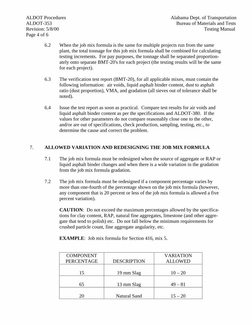
ALDOT Procedures Alabama Dept. of TransportationALDOT-353 Bureau of Materials and TestsRevision: 5/8/00 Testing ManualPage 4 of 6
6.2 When the job mix formula is the same for multiple projects run from the sameplant, the total tonnage for this job mix formula shall be combined for calculatingtesting increments. For pay purposes, the tonnage shall be separated proportion-ately onto separate BMT-20's for each project (the testing results will be the samefor each project).
6.3 The verification test report (BMT-20), for all applicable mixes, must contain thefollowing information: air voids, liquid asphalt binder content, dust to asphaltratio (dust proportion), VMA, and gradation (all sieves out of tolerance shall benoted).
6.4 Issue the test report as soon as practical. Compare test results for air voids andliquid asphalt binder content as per the specifications and ALDOT-380. If thevalues for other parameters do not compare reasonably close one to the other,and/or are out of specifications, check production, sampling, testing, etc., todetermine the cause and correct the problem.
7. ALLOWED VARIATION AND REDESIGNING THE JOB MIX FORMULA
7.1 The job mix formula must be redesigned when the source of aggregate or RAP orliquid asphalt binder changes and when there is a wide variation in the gradationfrom the job mix formula gradation.
7.2 The job mix formula must be redesigned if a component percentage varies bymore than one-fourth of the percentage shown on the job mix formula (however,any component that is 20 percent or less of the job mix formula is allowed a fivepercent variation).
CAUTION: Do not exceed the maximum percentages allowed by the specifica-tions for clay content, RAP, natural fine aggregates, limestone (and other aggre-gate that tend to polish) etc. Do not fall below the minimum requirements forcrushed particle count, fine aggregate angularity, etc.
EXAMPLE: Job mix formula for Section 416, mix 5.
COMPONENTPERCENTAGE DESCRIPTION
VARIATIONALLOWED
15 19 mm Slag 10 – 20
65 13 mm Slag 49 – 81
20 Natural Sand 15 – 20
Alabama Dept. of Transportation ALDOT ProceduresBureau of Materials and Tests ALDOT-353Testing Manual Revision: 5/8/00
Page 5 of 6
7.3 When two consecutive gradations yield results that exceed specification toler-ances on the same size sieve, no plant mix produced may be accepted by theEngineer until proper adjustments are made.
7.4 When VMA and/or dust to asphalt ratio (dust proportion) are outside the specifi-cation limits for two or more consecutive samples, no plant mix produced may beaccepted by the engineer until both VMA and dust to asphalt ratio (dust propor-tion) are tested and shown to be within specification limits.
8. DETERMINING AIR VOIDS, VMA, AND DUST TO ASPHALT RATIO (DUSTPROPORTION)
8.1 Sample the HMA mix from the loaded truck according to AASHTO T-168, AL-DOT-210, and ALDOT-380. Sample from four places, one from each quadrant ofthe truck bed, immediately after the truck has completed loading and moves to thesampling stand. Take care to avoid contamination and/or segregation.
8.2 Using a flat non-absorptive surface (that may be heated), reduce the sample byAASHTO T-248 (method B) to the required amount to compact specimens anddetermine the maximum gravity of the mix. See ALDOT-307, ALDOT-344,ALDOT-384, and ALDOT-388 for sample compaction requirements. Compactthree specimens when making 100 mm diameter specimens and compact twospecimens when making 150 mm diameter specimens. When using slag as an ag-gregate, compact one additional specimen; after determining the average bulkspecific gravity of all these specimens, disregard the specimen's individual bulkspecific gravity that is furthest from that average and then recompute the averagebulk specific gravity using the remaining specimens for determining the labora-tory compacted air voids.
8.3 Determine the maximum gravity of the mix by AASHTO T-209. The maximumgravity used to compute contractor air voids is the average of the last four maxi-mum gravity test results. At start up, first one, then two, then three maximumgravity test results are averaged until four results are available to use. These carryover from day-to-day in a continuous running average of the last four test results.This running average is used by the Department and the contractor to determinethe percent of maximum gravity for mat density (roadway compaction) as in AL-DOT-222 and ALDOT-350.
8.4 When slag is used as an aggregate, the contractor shall use a running average (asin section 8.3) of the last four bulk specific gravity determinations to calculate airvoids. The department will not use a running average to calculate air voids.
8.5 Where 100 mm diameter specimens are used, use ALDOT-307 to calculate VMA,air voids, and the stability and flow (as in AASHTO T-245).
ALDOT Procedures Alabama Dept. of TransportationALDOT-353 Bureau of Materials and TestsRevision: 5/8/00 Testing ManualPage 6 of 6
8.6 Where 150 mm diameter specimens are used, use ALDOT-384 to calculate VMA,air voids, and percent of maximum theoretical density at Ni, Nd, and Nm.
8.7 Where effective asphalt content is used to calculate the dust proportion (dust toasphalt ratio), use ALDOT-384 to calculate the dust proportion (dust to asphaltratio). Where total asphalt content is used to calculate the dust to asphalt ratio,use ALDOT-307 to calculate the dust to asphalt ratio.
9. REPORTING
9.1 Report these calculated values on BMT-20, along with gradation, mix tempera-ture, etc.
Alabama Dept. of Transportation ALDOT ProceduresBureau of Materials and Tests ALDOT-354Testing Manual Revision: 5/8/00
Page 1 of 3
ALDOT-354-87ASPHALT CONTENT OF BITUMINOUS MIXTURE
BY THE NUCLEAR METHOD
1. Scope
1.1 This test method covers the quantitative determination of the asphalt content ofbituminous mixtures by examining a sample with a device that utilizes neutronthermalization techniques.
NOTE 1: Operators shall have a current operator's card issued by the Bureau ofMaterials and Tests and wear a Neutron Film Badge.
2. Applicable Documents
2.1 ASTM D-4125 Asphalt Content of Bituminous Mixtures by the Nuclear Method.
2.2 M&T 30 Technical Specifications for Nuclear Asphalt Content Gauge.
2.3 Radiological Safety Manual for the use of Nuclear Moisture Density and AsphaltContent gauges.
2.4 Nuclear Gauge Training Manual.
2.5 Gauge Instruction Manual.
2.6 AASHTO T-168, Sampling Bituminous Paving Mixtures.
3. Apparatus
3.1 Nuclear Asphalt Content Gauge meeting Technical Specification M&T 30.
3.2 Metal Sample Pans - Supplied with AC gauge.
3.3 Balance, capable of weighing to 01 kg, readable to 0.1 g.
3.4 Straightedge, steel approximately 450 mm in length.
3.5 Plywood, 20 mm or heavier, or 10 mm or heavier metal plate having an areaslightly larger than the sample pans.
3.6 Assorted spoons, mixing bowls, spatula, scoop, putty knife, and heat resistantgloves.
ALDOT Procedures Alabama Dept. of Transportation ALDOT-354 Bureau of Materials and Tests Revision: 5/8/00 Testing Manual Page 2 of 3
3.7 Microwave oven with variable power control and approximately .03 m3 minimumcapacity.
3.8 Laboratory oven and thermostatically controlled hot plate.
3.9 Thermometer capable of measuring to 177°C.
3.10 Two large metal mixing bowls.
3.11 Pyrex container capable of holding 500 g minimum of sample.
NOTE 2: The asphalt content gauge is sensitive to its surroundings. Before cali-brating, be sure that it is located in a place in the laboratory where it will not needto be moved and where it will be away from water storage tanks, other bitumenmaterial and other nuclear testing devices.
4. Preparation of Calibration Specimens
4.1 Prepare three calibration specimens in accordance with Alabama Department ofTransportation Nuclear Gauge Training Manual instructions. The specimens mustbe prepared at the same weight within ± 10 g. The aggregate blend and asphaltcement to be used in the mix must be used to prepare the calibration specimens.Prepare one specimen at the design bitumen content. Prepare another specimen at1% higher than the design bitumen content and one specimen at 1% lower thanthe design bitumen content.
4.2 The calibration specimens shall be kept in moisture proof containers until thecalibration is accomplished or placed in an oven at low temperature to preventmoisture accumulation.
NOTE 3: The calibration temperature of calibration materials should be between150°C and 160°C at start of calibration.
5. Calibration of Gauge
5.1 Use the calibration specimens prepared in Section 4 and calibrate the gauge inaccordance with Alabama Department of Transportation Nuclear Gauge TrainingManual instructions.
5.2 To check calibration of the gauge take the specimen at the design bitumen contentand run a four minute test count to check gauge calibration. Gauge accuracy mustbe within ± 0.25.
Alabama Dept. of Transportation ALDOT ProceduresBureau of Materials and Tests ALDOT-354Testing Manual Revision: 5/8/00
Page 3 of 3
5.3 Any change in aggregate source and/or liquid asphalt grade will require a newcalibration.
NOTE 4: Calibration specimen at design bitumen content shall be retained aftergauge calibration to be used as a check sample for gauge accuracy. The specimenshall be sealed in a plastic bag to prevent the specimen from accumulating mois-ture.
6. Preparation of Test Specimen
6.1 Obtain a representative sample of mix from the hauling vehicle as perAASHTO T-168.
6.2 Place mix in test pan in three equal layers.
6.3 The tared weight of the test specimen should be ± 10 g of the initial calibrationpan weight.
6.4 Prepare a second specimen of 500 to 1000 g for a moisture test as given in ALDOT-130.
7. Procedure
7.1 Place test specimen in the AC gauge and take two, four-minute counts, rotatingthe specimen 180° after the first count. Average the two counts for % AC.
7.2 Correct the % AC for moisture by subtracting the percent moisture obtained inparagraph 8.2 from the percent asphalt obtained in paragraph 7.1 above andrecord as the corrected percent asphalt.
7.3 Remove specimen from the gauge, empty and clean the specimen pan.
8. Reportiing
8.1 Report the bitumen content to the nearest 0.01 percent on BMT 65.
8.2 Determine moisture content of bituminous mixture as per ALDOT-130. Themoisture sample used to correct the % AC shall be split from the sample obtainedin paragraph 6.
ALDOT ProceduresAlabama Dept. of TransportationALDOT-355Bureau of Materials and Tests
Revision: 01/01/02Testing ManualPage 1 of 5
ALDOT-355-88GENERAL INFORMATION CONCERNING MATERIALS, SOURCES, AND
DEVICES WITH SPECIAL ACCEPTANCE REQUIREMENTS
1. Scope
1.1. The Alabama Department of Transportation presently maintains several lists of materials,sources, and devices, which have undergone some form of preliminary evaluation. Lists areestablished both as reference sources of materials and as methods to eliminate lengthy timedelays required in evaluating certain products. Each list is unique. Product requirementsand job control acceptance vary. Before using any products, read all requirements carefully.
1.2. The lists are in no way a blanket approval which relieves the contractor of the responsibilityof furnishing quality materials, nor the Project Engineer the responsibility of inspecting allmaterials. The Project Engineer must inspect the material and, if doubt exists, job controlsamples should be taken. Project and Maintenance personnel should also report anyproblems in workability or premature failure of products on these lists since these factors arevery important in maintaining these lists.
1.3. These lists are found in the publication "Materials, Sources, and Devices with SpecialAcceptance Requirements". They are established and maintained by the individual sectionsin the Department of Transportation concerned with quality assurance for the products. Toobtain information concerning a particular list, persons should either contact the sectionlisted under "Jurisdiction", which can be found at the beginning of the individual procedurefor that list or the Product Evaluation Engineer.
1.4. The Alabama Department of Transportation Product Evaluation Board is composed ofemployees from the various disciplines within the Department of Transportation. The Boardis the final authority over this program and decides the ultimate fate of products andrequirements.
1.5. The Bureau of Materials and Tests acts as a clearinghouse to duplicate and disseminate thesedocuments
1.6. Lists are divided into five general categories of similar requirements
I. Qualified Sources
II. Approved Materials
III. Qualified Materials
IV. Approved Traffic Control Devices and Materials
V. Qualified Traffic Control Devices and Materials
1.7. The Board has one additional category of products which has been termed “SpecialtyItems”. Specialty Items are items, which do not fall into any area of the present DepartmentSpecifications or Standard Drawings but may be useful in construction or maintenance workon a very limited and specialized basis. The Product Evaluation Board has reviewed onlythe paper work submitted by the producers of these items. No tests or research evaluating theproduct’s usefulness or other attributes has been conducted by the Department. Individual
ALDOT Procedures Alabama Dept. of TransportationALDOT-355 Bureau of Materials and TestsRevision: 01/01/02 Testing ManualPage 2 of 5
Divisions may elect to try these products on a limited basis should they find a specializedneed for such items. The Board would caution that the items are basically experimental innature and should be approached as such. If a Division elects to try such an item, the Boardwould encourage them to contact the Bureau of Research & Development for more detailedinformation about the product, and in order that the Bureau may monitor the usefulness ofthe item. If an item proves useful, the Department may wish to develop a specification for itsgeneral use.
2. Definitions
2.1. Qualified Sources - Sources of materials such as cement, lime, and aggregates. Thesesources may be quarries, plants, or refineries that have agreed to a systematic program ofsampling, testing, and inspection to provide quality assurance for Department work.Materials from these sources may be used without Job Control Testing, provided they meetthe visual inspection by the Project Engineer.
2.2. Approved Materials - Materials and/or products that may fall into one or both of thefollowing categories: A. Items having a high probability of acceptance. B. Items whose useis non-critical to the performance of the finished roadway. Because these items are of thisnature, the Alabama Department of Transportation allows an abbreviated testing program forquality assurance. Job Control testing is not required.
2.3. Qualified Materials - These are materials, which the Department requires field performancetesting in addition to laboratory testing. Job control testing will not be required, howeversome items may require pretesting. (Requirements for pretesting may be found in theinstructions for individual lists.)
2.4. Approved Traffic Control Devices and Materials - These are items evaluated prior to biddingon projects. This is necessary so that only items which meet current project requirementswill be furnished. Job Control Testing will not be necessary. Project personnel will verifythat the equipment and materials received on the project are those called for by the approvedsubmittal data.
2.5. Qualified Traffic Control Devices and Materials - These items are initially evaluated forcolor, design, and satisfactory field performance. The items must then either have jobcontrol samples taken or be pretested as stock (see ALDOT-195). The Project Engineermust consult with the Testing Manual to determine current requirements.
3. Eligibility Procedures for Existing Lists
3.1. Persons wishing to place items on any of the lists maintained by the Alabama Department ofTransportation may obtain detailed information by contacting the Product EvaluationEngineer for the Department at:
MAILING ADDRESS:
Product Evaluation EngineerBureau of Research and DevelopmentAlabama Department of Transportation1409 Coliseum BoulevardMontgomery, AL 36130-3050
ALDOT ProceduresAlabama Dept. of TransportationALDOT-355Bureau of Materials and Tests
Revision: 01/01/02Testing ManualPage 3 of 5
PHYSICAL ADDRESS:(For bulk submittals)
Product Evaluation EngineerBureau of Research and DevelopmentAlabama Department of Transportation3704 Fairground RoadMontgomery, AL 36110
Phone: (334) 206-2240
3.2. The Department will forward detailed instructions concerning the information, test data, feesand samples required for evaluation of the item.
3.3. Please read thoroughly and compare company product data with current specifications forconformance. Submit only those items, which meet these specifications.
3.4. Items that perform the same function as currently specified items, but do not meet currentspecifications, should be processed as new products (see Section 4).
3.5. Complete and submit all forms, samples, fees, and correspondence to the addresses above.
4. New Products
4.1. Products that do not meet current specifications or for which specifications have not beenestablished are considered as new products. This includes items that perform the samefunction as currently specified materials.
4.2. The Department will forward detailed instructions concerning the information, test data, feesand samples required for evaluation of the item.
4.3. Complete and submit all forms, samples, fees and correspondence (including proposed uses)to the address above.
5. Alternate Evaluation of Items Requiring Field Testing
5.1. Some lists require field testing for extended periods. Unless these requirements arecompleted well in advance of the anticipated marketing time, the producer will be delayed inselling products. To give as much flexibility as possible for the use of these products thisprocedure may be utilized.
5.2. The producer may negotiate with a prime contractor to have the product used in an ongoingproject that will then be used as the field test.
5.3. The prime contractor will be required to post a bond equal to a value of the total bid price forthat item (estimated quantity multiplied by the unit bid price). Where the item is not a directpay item, but is an incidental part of a larger pay item, the bond shall be equal to the amountof the larger pay item.
5.4. Approval for this procedure must be authorized by the Product Evaluation Board prior to anyinstallation.
ALDOT Procedures Alabama Dept. of TransportationALDOT-355 Bureau of Materials and TestsRevision: 01/01/02 Testing ManualPage 4 of 5
5.5. This procedure will not be an acceptable alternate for "Approved Traffic Control Devicesand Materials", Lists IV-1, IV-2, IV-3, IV-4). State Law requires that these items beapproved prior to bidding on projects for direct Department purchase. When these items arefurnished on projects by a contractor, approval must be obtained prior to installation.
5.6. Any item, which fails during the testing period, shall be removed, and the posted bond willbe kept and utilized to make repairs.
6. Fees
6.1. To control requests for unnecessary testing of marginally used products and help defray costto the Department for this testing, nominal fees will be required for the testing andinspection performed by the Department.
6.2. Manufacturers should narrow selections of products to those where a real market isanticipated prior to submittal. This will lessen the cost to the Department and manufacturerfor these services.
6.3 Fees are as follows:
Submittal Fee $50Laboratory Testing $500Field Testing $500Laboratory/Field Test $750Source Approval $200Portland Cement Concrete Plants $200Asphalt Mix Design (Virgin Mix) $1900Asphalt Mix Design (Recycle Mix) $2200Concrete Verification Mix Design Tests $3000
6.3.1. The submittal fee covers the paperwork necessary for initial processing of a requestand is required for all submittals.
6.3.2. Fees for "Approved Traffic Control Devices" can be found in Section iii of themanual "Materials, Sources and Devices with Special Acceptance Requirements".
6.3.3. Source approval fees will be charged for the initial approval and each time thesource relocates.
6.3.4. Sources of Bituminous Concrete (List I-5) will be inspected annually or when theplant relocates or is significantly changed, and will be charged for each inspection($50 submittal, plus $200 inspection fee).
6.3.5. Sources of Portland Cement Concrete (List I-7) will be inspected as required in theDepartment Specifications, Sections 450 and 501.
6.3.6. When specifications are changed to an extent that new testing or inspection isrequired, fees will be required as if the submittal is new.
6.3.7. When the formulation of a product is changed, new testing and fees will be required.
ALDOT ProceduresAlabama Dept. of TransportationALDOT-355Bureau of Materials and Tests
Revision: 01/01/02Testing ManualPage 5 of 5
6.3.8. All fees should be paid by check or money order made payable to the "AlabamaDepartment of Transportation".
7. Testing and Evaluation of Products
7.1. All testing and evaluation will be conducted at the convenience of the Department.
7.2. Tests will be conducted according to the Alabama Department of TransportationSpecifications.
7.3. Test reports are property of the Department and will not be given to producers. Producersmay view copies of their reports only in the offices of the Department.
7.4. The costs for samples, shipping and field installation requiring special equipment andpersonnel are the responsibility of the producer.
7.5. The producer will be responsible for clean up and disposal of all materials remaining afterinstallation of each field test.
7.6. Any item for which there has been an opportunity to be evaluated by the AASHTO’sNational Transportation Product Evaluation Program (NTPEP) will not be reviewed by theProduct Evaluation Board until the vendor has submitted the results of the NTPEPevaluation. Producers with products now under evaluation at these facilities should waituntil testing is complete and data published before submitting to the PEB for approval.
ALDOT ProceduresAlabama Dept. of TransportationALDOT-358Bureau of Materials and Tests
Revision: 3/18/94Testing ManualPage 1 of 4
ALDOT-358-88JACK CALIBRATION PROCEDURE
1. Scope
1.1. The Alabama Department of Transportation hereby establishes procedures for the calibrationof piling jacks; jacks and/or jack systems used with the three-edge bearing apparatus; jacksand gauges, load cells, dynamometers, etc.,used in prestress operations.
2. Piling Jacks
2.1. The testing machine used for calibration shall be calibrated in accordance with ASTM E-74.
2.2. The capacity of the jack shall be divided into 10 equal increments for the calibration.
2.3. When calibrating the jack, the Ram shall be extended.
2.4. The first cycle readings shall be taken with the ram extended 25% of its stroke. The secondand third cycle readings shall be taken with the ram extended 50% and 75% of its strokerespectively. The average of the calibrations of the three (3) Ram extensions shall be used togenerate the dial versus indicated load.
2.5. The jack shall be capable of holding the load and the jack dial shall be clean and easilyreadable.
2.6. The calibration shall be valid for six (6) months from date calibrated for all DOT projects.
2.7. Calibration shall be conducted by applying pressure with the jack to the testing machine, andit shall be the Contractor's responsibility to furnish personnel to operate the jack during testprocedure.
2.8. All calibrations shall be accurate within ± 5% of the applied load, i.e., the indicated load shallbe within ± 5% of the actual load applied.
2.9. When a jack, gauge and hydraulic pump are calibrated they shall remain as a unit. Changingany one of the three components shall require a recalibration.
3. Jacks, Three-Edge Bearing Apparatus
3.1. Double ram pipe testing racks with a dual hydraulic ram loading system.
3.2. Calibration force measuring instruments for verifying the load indications of above rack shallbe calibrated in accordance with ASTM E74.
3.3. Procedure for calibration:
3.3.1. For the first calibration each Ram must be extended approximately 25% of the ramstroke with a minimum of six calibration points divided equally over the scale range.
ALDOT Procedures Alabama Dept. of TransportationALDOT-358 Bureau of Materials and TestsRevision: 3/18/94 Testing ManualPage 2 of 4
Readings on the proving rings or load cells shall be averaged at each calibration pointand the average reading of each calibration point must be with-in ± 2% of the pipetesting rack dial reading.
3.3.2. For the second calibration each ram must be extended approximately 50% of the ramstroke with a minimum of six calibration points divided equally over the scale range.Readings on the proving rings or load cells shall be averaged at each calibration pointand the average reading of each calibration point must be with-in ± 2% of the pipetesting rack dial reading.
3.3.3. Calibration No. 1 and Calibration No. 2 are independent of each other and bothcalibrations must be within ± 2%.
3.3.4. The calibrations shall be valid for one year from date of calibration unless theEngineer or quality control has reason to suspect that another calibration is warranted.
3.3.5. The intent of the two (2) calibrations (one (1) at 25% and one (1) at 50% of ramextension) is to assure that jack(s) is/are calibrated within operating range of ramwhen used to test pipe.
3.4. Single ram pipe testing racks with a single hydraulic ram loading system.
3.5. Calibration force measuring instruments for verifying the load indications of above rack shallbe calibrated in accordance with ASTM E74.
3.6. Procedure for Calibration:
3.6.1. For the first calibration, the ram must be ex-tended approximately 25% of the ramstroke with a minimum of six calibration points divided equally over the scale range.Readings on the proving ring or load cell must be within ± 2% of the pipe testing rackdial reading.
3.6.2. For the second calibration the ram must be extended approximately 50% of the ramstroke with a minimum of six calibration divided equally over the scale range.Readings on the proving ring or load cell must be within ± 2% of the pipe testing rackdial reading.
3.6.3. Calibration No. 1 and Calibration No. 2 are independent of each other and bothcalibrations must be within ± 2%.
3.6.4. The calibrations shall be valid for one year from date of calibration unless theEngineer or quality control has reason to suspect that another calibration is warranted.
3.6.5. The intent of the two (2) calibrations (one (1) at 25% and one (1) at 50% of ramextension) is to assure that jack(s) is/are calibrated within operating range of ramwhen used to test pipe.
4. Tensioning Systems, Prestress Concrete - Post-Tensioned Concrete
ALDOT ProceduresAlabama Dept. of TransportationALDOT-358Bureau of Materials and Tests
Revision: 3/18/94Testing ManualPage 3 of 4
4.1. Tensioning systems for prestress and post tensioned concrete items. Jacks and Gauges, LoadCells, Dynamometers.
4.2. Calibration force measuring instruments for verifying the load indications shall be calibratedin accordance with ASTM E-74.
4.3. Calibration for low pressure gauges shall be conducted at no greater than 5 kN increments.
4.4. Calibration for high pressure gauges shall be conducted at no greater than 25 kN increments.
4.5. The tensioning system must be capable of holding the load and the dial shall be clean andeasily readable.
4.6. The calibration shall be accurate within ± 2%, i.e., the indicated load shall be within ± 2% ofactual applied load.
4.7. The calibration shall be valid for one year from date of calibration.
4.8. When a tensioning unit is calibrated, i.e., jack, gauge and hydraulic pump, it shall remain as aunit. Changing any of the components shall require a recalibration.
4.9. Stressing jack calibrations shall be conducted by applying pressure with the jack to thecalibration measuring instrument.
4.10. When calibrating the jack, the Ram shall be extended. The first cycle readings shall be takenwith the Ram extended 25% of its stroke. The second and third cycle readings shall be takenwith the Ram extended 50% and 75% of its stroke respectively. The average of the three (3)Ram extensions shall be used to generate the dial versus indicated load.
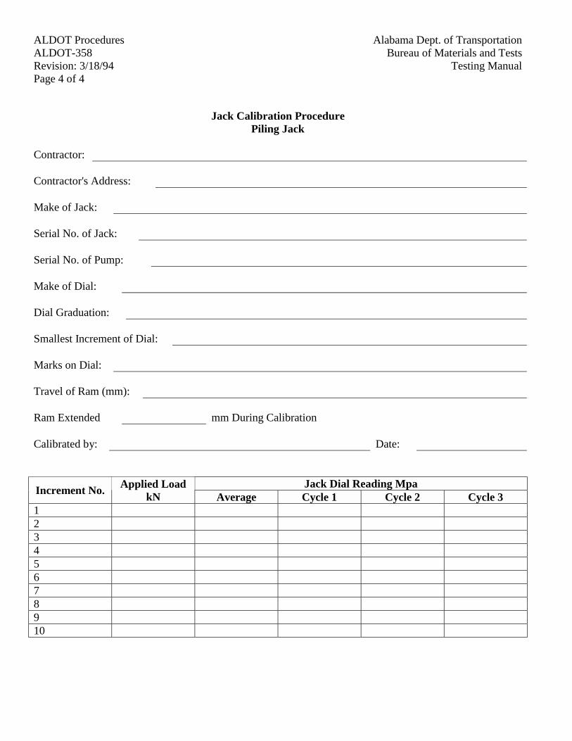
ALDOT Procedures Alabama Dept. of TransportationALDOT-358 Bureau of Materials and TestsRevision: 3/18/94 Testing ManualPage 4 of 4
Jack Calibration ProcedurePiling Jack
Contractor:
Contractor's Address:
Make of Jack:
Serial No. of Jack:
Serial No. of Pump:
Make of Dial:
Dial Graduation:
Smallest Increment of Dial:
Marks on Dial:
Travel of Ram (mm):
Ram Extended mm During Calibration
Calibrated by: Date:
Jack Dial Reading MpaIncrement No.
Applied LoadkN Average Cycle 1 Cycle 2 Cycle 3
12345678910
ALDOT ProceduresAlabama Dept. of TransportationALDOT-361Bureau of Materials and Tests
Revision: 6/11/96Testing ManualPage 1 of 5
ALDOT-361-88RESISTANCE OF COMPACTED BITUMINOUS MIXTURE TO MOISTURE INDUCED
DAMAGE
1. Scope
1.1. This method covers preparation of specimens and measurements of the change of diametraltensile strength resulting from the effects of saturation and accelerated water conditioning ofcompacted bituminous mixtures in the laboratory. The results may be used to predict longterm stripping susceptibility of the bituminous mixtures, and evaluating liquid anti-strippingadditives which are added to the asphalt cement of pulverulent solids, such as hydrated lime,which are added to the mineral aggregate.
2. Applicable Documents
2.1. AASHTO T 166, Bulk Specific Gravity of Compacted Bituminous Mixtures
2.2. AASHTO T 167, Compressive Strength of Bituminous Mixtures
2.3. AASHTO T 168, Sampling Bituminous Paving Mixtures
2.4. AASHTO T 209, Maximum Specific Gravity of Bituminous Paving Mixtures
2.5. AASHTO T 245, Resistance to Plastic Flow of Bituminous Mixtures Using MarshallApparatus
2.6. AASHTO T 269, Percent Air Voids in Compacted Dense and Open Bituminous PavingMixtures
2.7. AASHTO T 283, Resistance of Compacted Bituminous Mixture to Moisture InducedDamage
2.8. AASHTO M 156, Requirements for Mixing Plants for Hot-Mixed, Hot-Laid BituminousPaving Mixtures
2.9. ASTM D 3549, Test for Thickness or Height of Compacted Bituminous Paving MixtureSpecimens
2.10. ASTM D 2041, Test Method for Theoretical Maximum Specific Gravity of BituminousPaving Mixture
3. Significance and Use
3.1. As noted in the scope, this method is intended to evaluate the effects of saturation andaccelerated water conditioning of compacted bituminous mixtures in the laboratory. Thismethod can be used (a) to test bituminous mixtures in conjunction with mixture designtesting; (b) to test bituminous mixtures produced at mixing plants; and, (c) to test thebituminous concrete cores obtained from completed pavements of any age.
ALDOT Procedures Alabama Dept. of TransportationALDOT-361 Bureau of Materials and TestsRevision: 6/11/96 Testing ManualPage 2 of 5
3.2. Numerical indices of retained indirect tensile properties are obtained by comparing theretained indirect properties of saturated, accelerated water-conditioned laboratory specimenswith the similar properties of dry specimens.
4. Summary of Method
4.1. Six test specimens for each set of mix conditions, such as, plain asphalt, asphalt with anti-stripping agent, and aggregate treated with lime, are tested (Note 1). Each set of specimensis divided into two subsets and one subset tested in dry condition for indirect tensile strength.The other subset is subjected to vacuum saturation and then tested for indirect tensilestrength. Numerical indices of retained indirect tensile strength properties are computedfrom the test data obtained on the two subsets: dry and conditioned.
Note 1: It is recommended to prepare two additional specimens for the set. These specimenscan then be used to establish the vacuum saturation technique as given in Section 9.3.
5. Apparatus
5.1. Equipment for preparing and compacting specimens from AASHTO T 245.
5.2. Vacuum Container, preferably Type D, from ASTM D 2041 and vacuum pump or wateraspirator from ASTM D 2041 including manometer or vacuum gauge.
5.3. Balance and water bath from AASHTO T 166.
5.4. Water bath capable of maintaining a temperature of 140 ± 2ºF (60 ± 1ºC).
5.5. Forced air draft oven capable of maintaining a temperature of 140 ± 2ºF (60 ± 1ºC).
5.6. Loading jack and ring dynamometer from AASHTO T 245, or a mechanical or hydraulictesting machine from AASHTO T 167 to provide a range of accurately controllable rates ofvertical deformation including 2in (50 mm) per minute.
5.7. Loading Strips - If used, steel loading strips with a concave surface having a radius ofcurvature equal to the nominal radius of the test specimen. For specimens 4 in (100 mm )indiameter the loading strips shall ½ in (13 mm )wide, and for specimens 6 in (150 mm) indiameter the loading strips shall be ¾ in (19 mm )wide. The length of the loading strips shallexceed the thickness of the specimens. The edges of the loading strips shall be rounded bygrinding.
6. Preparation of Laboratory Test Specimens
6.1. Specimens 4 in (100 mm )in diameter and 2 ½ in (63 mm) thick are usually used. Specimens6 in. (150 mm) in diameter and 4 in (100 mm ) thick (either by compaction or sawing) areused in all Superpave mixes and in mixes with aggregate retained on the 1 in (25 mm )sieve.
ALDOT ProceduresAlabama Dept. of TransportationALDOT-361Bureau of Materials and Tests
Revision: 6/11/96Testing ManualPage 3 of 5
6.2. Place the mixture in an oven at 276ºF (130ºC )for one-half hour prior to compaction. Themixture shall be compacted to 7 ± 1.0 percent or a void level expected in the field. This levelof voids can be obtained by adjusting the number of blows in AASHTO T 245.
6.3. For superpave mixes use the conditioning time and compaction temperature as per ALDOT-384. Adjust the number of gyrations to achieve 7 ± 1.0 percent air voids.
6.4. After extraction from the molds, the test specimens shall be allowed to cool to roomtemperature.
7. Preparation of Core Test Specimens
7.1. Select locations on the completed pavement to be sampled, and obtain cores. The number ofcores shall be at least six for each set of mix conditions.
7.2. Separate core layers as necessary by sawing or other suitable means, and store layers to betested at room temperature.
8. Evaluation of Test Specimens and Grouping
8.1. Determine theoretical Maximum Specific Gravity of mixture by AASHTO T 209.
8.2. Determine specimen thickness by ASTM D 3549.
8.3. Determine Bulk Specific Gravity by AASHTO T 166. Express volume of specimens in mm3.
8.4. Calculate air voids by AASHTO T 269.
8.5. Sort specimens into two subsets of three specimens each so that average air voids of the twosubsets are approximately equal.
9. Preconditioning of Test Specimens
9.1. One subset will be tested dry and the other will be preconditioned before testing.
9.2. The dry subset will be stored at room temperature until testing. The specimens shall then beplaced in a 77ºF (25ºC) water bath for one hour and then tested as described in Section 10.
9.3. The other subset shall be conditioned as follows:
9.4. Place the specimen in the vacuum container supported above the container bottom by aspacer. Fill the container with distilled water at room temperature so that the specimens haveat least one inch of water above their surface. Apply partial vacuum, such as 30 in. (500 mm)Hg for a short time, such as five minutes. Remove the vacuum and leave the specimensubmerged in water for five minutes.
9.5. Determine Bulk Specific Gravity by AASHTO T 166. Compare saturated surface-dry weightwith dry weight determined in Section 8.3. Calculate volume of absorbed water.
ALDOT Procedures Alabama Dept. of TransportationALDOT-361 Bureau of Materials and TestsRevision: 6/11/96 Testing ManualPage 4 of 5
9.6. Determine degree of saturation by comparing volume of absorbed water with volume of airvoids from Section 8.4. If the volume of water is between 55 percent and 80 percent of thevolume of air, proceed to Section 9.3.4. If volume of water is less than 55 percent, repeat theprocedure beginning with Section 9.3.1 using more vacuum and/or time. If volume of wateris more than 80 percent, specimen has been damaged and is discarded. Repeat the procedurebeginning with Section 9.3.1 using less vacuum and/or time.
9.7. Place the specimens into a 140± 2ºF (60 ± 1ºC) water bath filled with distilled water for 24hours.
9.8. After 24 hours in the 140ºF (60ºC) water bath, remove the specimens and place them in awater bath already at 77±1ºF (25 ± 0.5ºC) for one hour. It may be necessary to add ice to thewater bath to prevent the water temperature from rising above 77ºF (25ºC). Not more than15 minutes should be required for the water bath to reach 77ºF (25ºC). Test the specimens asdescribed in Section 10.
10. Testing
10.1. Determine the indirect tensile strength of dry and conditioned specimens at 77ºF (25ºC).
10.2. Remove the specimen from 77ºF (25ºC) water bath and place between the two bearing platesin the testing machine. Care must be taken so that the load will be applied along the diameterof the specimen. Apply the load to the specimen by means of the constant rate of movementof the testing machine head of 2 in (50 mm) per minute.
10.3. If steel loading strips are used, record the maximum compressive strength noted on thetesting machine, and continue loading until a vertical crack appears. Remove the specimenfrom the machine and pull apart at the crack. Inspect the interior surface for stripping andrecord the observations.
11. Calculations
11.1. Calculate the tensile strength as follows:2P
St =t D 3.14
where:St = tensile strength, psi (pascals)P = maximum load, pounds (Newton)t = specimen thickness, inches ( mm)D = specimen diameter, inches, (mm)
11.2. Express the numerical index or resistance of asphalt mixtures to the detrimental effect ofwater as the ratio of the original strength that is retained after the freeze-warm waterconditioning. Calculate as follows:
S2Tensile Strength Ratio (TSR) =
S1

ALDOT ProceduresAlabama Dept. of TransportationALDOT-361Bureau of Materials and Tests
Revision: 6/11/96Testing ManualPage 5 of 5
where:S1 = average tensile strength of dry subset, andS2 = average tensile strength of conditioned subset.
ALDOT ProceduresAlabama Dept. of TransportationALDOT-362Bureau of Materials and Tests
Revision: 3/18/94Testing ManualPage 1 of 1
ALDOT-362-89PROCEDURE FOR MEASUREMENT OF THE SURFACE
TEMPERATURE OF PAVEMENT
1. Scope
1.1. This procedure describes the equipment and techniques used in measuring the surfacetemperature of pavement. Pavement temperatures are used to control placement of asphalt,rolling, and other operations in the field. This procedure should be followed as closely aspossible to insure accurate and reproducible results.
2. Apparatus
2.1. Surface Temperature Thermometer, dial type, having a range of 0ºF – 300ºF (5ºC - 150ºC),accurate to 2.5 percent. Silicone grease or equivalent.
3. Procedure
3.1. Find a smooth spot on the surface of the pavement large enough to place the thermometer.The smoother the pavement the more accurate the reading.
3.2. Place a small amount of silicone grease on the back of the thermometer and stick thethermometer to the surface of the pavement. Apply enough pressure to the thermometer toassure that the grease has spread and that the thermometer is in good contact with thepavement.
3.3. Protect the thermometer from direct wind and sunlight and allow the thermometer to stabilizefor a minimum of three minutes. No physical contact should be made with the thermometerduring this period. The temperature can be read at the end of the stabilization period. Thethermometer should be removed after the reading has been taken and all grease removed.
3.4. The accuracy of the thermometer should be checked periodically by placing it on a surface ofknown temperature.
Page 1 of 14
ALDOT ProceduresAlabama Dept. of TransportationALDOT-364Bureau of Materials and Tests
Revision: 4/3/95Testing Manual
ALDOT 364-89PROCEDURE FOR INSPECTION OF CONCRETE PIPE, PRECAST MANHOLES, PRECAST
BOX CULVERTS, PRECAST NON-PRESTRESS CONCRETE BRIDGE MEMBERS ANDMISCELLANEOUS PRECAST PRODUCTS
Note: Miscellaneous precast products are such items as right-of-way Markers, Concrete Pipe EndTreatments, and Barrier Rail.
1. Scope
1.1. The Alabama Department of Transportation (hereinafter referred to as the Department)hereby establishes the Quality Control Program for Production, Inspection and Acceptance ofConcrete Pipe Precast Manholes, Precast Box Culverts, Precast Non-Prestress ConcreteBridge Members and Miscellaneous Precast Concrete Products (hereinafter referred to as thePrecast Concrete Products Program). The purpose of this procedure is to ensure that allprecast concrete products purchased by the Department, directly, or through its contractorsand subcontractors meet and otherwise conform to the Department's Specifications. This willbe accomplished by placing the responsibility of quality control on the producer.
1.2. This program is a supplement to the Department's established procedures for ensuring andmaintaining a quality supply of precast concrete products. In order to qualify for thisprogram, the producer's company must be contained in the current listing of the Department's"Materials, Sources and Devices with Special Acceptance Requirements", List I-8,hereinafter referred to as the "Approved Sources List".
2. Producer Qualification Requirements
2.1. Any producer of precast concrete products who wishes to furnish his product for use inhighway construction must:
2.2. Make request by letter to the Materials and Tests Engineer;
2.3. Request plant inspection;
2.4. Submit Quality Control Plan;
2.5. Employ a Certified Precast Concrete Products Technician;
2.6. Submit a signed BMT-45, "Annual Certification and Guarantee for Precast Products";
2.7. Submit initial fees per ALDOT-355, "General Information Concerning Materials Sources andDevices with Special Acceptance Requirements"; and,
Note: Fees should be paid by check, made payable to the Alabama Department ofTransportation.
2.8. Submit a list, identifying the source of all materials.
ALDOT Procedures Alabama Dept. of TransportationALDOT-364 Bureau of Materials and TestsRevision: 4/3/95 Testing Manual
Page 2 of 14
2.9. After all requirements of Section 2 have been met, the Working Task Force will recommendapproval of the source to the Product Evaluation Board requesting the source be placed onList I-8, Approved Sources Lists. The Product Evaluation Board normally meets during thefirst week in each month.
3. Responsibilities
3.1. The Department in conjunction with the Alabama Concrete Pipe Association will administera viable training program to train Precast Concrete Products Technicians per ALDOT-377,"Certification Program for Precast Concrete Products Technicians".
3.2. The Producer's Certified Technician will:
3.2.1. Be responsible to the producer's Registered Professional Engineer for the QualityControl Program;
3.2.2. Be present during the production and shipment of their particular product;
3.2.3. Perform tests per Section 6;
3.2.4. Ensure test equipment is calibrated/maintained per Section 6.
3.2.5. Visually inspect each joint, section, unit, etc.;
3.2.6. Ensure all products are properly cured per the applicable specification;
3.2.7. Ensure that all materials used are from an approved source (per Section 5);
3.2.8. Maintain a daily production log;
3.2.9. Ensure all products are marked per Section 8 and the attached "Marking Guide";
3.2.10. Stencil DOT and Technician Number on each unit;
3.2.11. Ensure all products are properly stored;
3.2.12. Fill out, submit and maintain test reports per Section 7; and,
3.2.13. Maintain documentation files to substantiate testing and material sources.
3.3. DOT Division Personnel will:
3.3.1. Visit each producer in his/her particular Division twice each month (Divisions 1, 3, 5and 9);
3.3.2. Monitor the producer's Quality Control Procedures;
3.3.3. Review shipping reports, BMT-72;
Page 3 of 14
ALDOT ProceduresAlabama Dept. of TransportationALDOT-364Bureau of Materials and Tests
Revision: 4/3/95Testing Manual
3.3.4. Review test reports, BMT-47 and BMT-53;
3.3.5. Ensure testing per Section 6;
3.3.6. Visually inspect products that have been accepted and stenciled by producer'stechnician;
3.3.7. Perform required tests if applicable;
3.3.8. Perform and complete "Check List for Periodic Review", and submit copy of same toCentral Lab in Montgomery;
3.3.9. Pick up and submit one (1) absorption test sample (core) per year per producer(preferably during October) to the Central Laboratory in Montgomery. (Pipe andPrecast manholes only) Cores may be obtained from any size pipe;
3.3.10. Provide producer's technician with copies of test reports;
3.3.11. Inspect out-of-state producers twice each month if shipping products frequently toAlabama;
3.3.12. Inspect "Three-Edge Bearing" apparatus if applicable per AASHTO T-280; and, Issuetest reports, (Divisions 1, 3, 5 and 9) and submit original to Central Laboratory inMontgomery.
3.4. Central Laboratory Personnel will:
3.4.1. Administer the Precast Concrete Products Program and monitor effectiveness ofsame;
3.4.2. Assist the Alabama Concrete Pipe Association with classroom and practical "hands-on" training as required;
3.4.3. Provide classroom space as required;
3.4.4. Test and certify Precast Concrete Products Technicians;
3.4.5. Perform all initial plant inspections;
3.4.6. Approve all new sources and Producer Quality Control plans;
3.4.7. Issue test reports;
3.4.8. Perform annual absorption tests for all sources;
3.4.9. Maintain files for all approved producers;
3.4.10. Be the focal point for any problem;
ALDOT Procedures Alabama Dept. of TransportationALDOT-364 Bureau of Materials and TestsRevision: 4/3/95 Testing Manual
Page 4 of 14
3.4.11. Generate the required actions if required to remove a source from the ApprovedSources List;
3.4.12. Ensure oversight responsibilities by visiting Divisions 1, 3, 5 and 9 each year. Thevisits will include a trip to one (1) of the producers in the particular Division with aDivision representative to ensure all duties and responsibilities are complied with asoutlined in this procedure. The Central Laboratory will generate a written report todocument the visit; and,
3.4.13. Perform all duties as listed in Section 3.3, except those specifically pertaining to theDivisions.
3.5. Producers of Precast Non-Prestress Concrete Bridge Members will be required to provide apermanent identification method for each unit to identify the unit as to which standarddrawing it was built and what use requirements it meets. See Section 8.
4. Producer Quality Control Plan
4.1. Each producer must submit a Quality Control Plan for approval by the Materials and TestsEngineer. The Quality Control Plan must contain at least, but not limited to, the following;
4.1.1. A statement defining how the particular company intends to control the quality of theproduct(s) being produced;
4.1.2. Name, address, (location if different from mailing address) and telephone number ofcompany;
4.1.3. Names of company officers, i.e., owner, president, etc.;
4.1.4. Name of key plant personnel and specific duties, i.e., superintendent, generalmanager, technician, production foreman, etc.;
4.1.5. Name and specific duties of person who will perform quality control duties;
4.1.6. Name and registration number of Professional Engineer who will be responsible forthe overall Quality Control Program;
4.1.7. List of all products being produced to include sizes;
4.1.8. List of all major production equipment;
4.1.9. If applicable, name, address, telephone number and services of Independent TestingLab; and,
4.1.10. List of testing equipment for "in-house" testing.
Page 5 of 14
ALDOT ProceduresAlabama Dept. of TransportationALDOT-364Bureau of Materials and Tests
Revision: 4/3/95Testing Manual
5. Materials
5.1. Materials used in the production of Precast Concrete Products shall meet the requirements ofthe appropriate sections of the Department's Specifications and must be purchased from anapproved source as listed in the Approved Sources Lists.
5.1.1. Coarse/Fine Aggregate - List I-1;
5.1.2. Cement - List I-2;
5.1.3. Admixtures - List II-1;
5.1.4. Reinforcing steel used must be traceable to a certified mill test report and meet allrequirements of the Department's Specifications with special attention directed toSection 106; and,
5.1.5. Water used shall be per the Department's Specifications, Section 807; (Water forCement Concrete).
5.2. The producer must maintain all documentation necessary to substantiate the purchase and useof all approved materials and shall make same available to the Department upon request.
6. Acceptance
6.1. Acceptance of all precast concrete pipe shall be in accordance with DepartmentSpecifications and the following ASHTO/ASTM Specifications: AASHTO M-86/ASTM C-14, AASHTO M-170/ASTM C-76, AASHTO M-175/ASTM C-444, AASHTO M-176/ASTM C-654, AASHTO M-178/ASTM C-412, AASHTO M-206/ASTM C-506,AASHTO M-207/ASTM C-507 and AASHTO M-242/ASTM C-655.
6.1.1. In general, concrete pipe in all diameters and classes shall be accepted on strength testresults determined by the Three-Edge Bearing test, AASHTO T-280. Producers havethe option to cut cores from pipe that have a wall thickness of 4 in.(100 mm) andgreater. Cores may be tested according to AASHTO T-280 or AASHTO T-22.Concrete cylinders shall be tested according to AASHTO T-22.
6.2. Acceptance of precast concrete box culvert sections shall be in accordance with DepartmentSpecifications and the following AASHTO/ASTM Specifications: AASHTO M-259/ASTMC-789, and AASHTO M-273/ASTM C-850.
6.2.1. Precast concrete box culvert sections shall be accepted on strength test resultsdetermined by compression testing of concrete cores or concrete cylinders. Coresmay be tested according to AASHTO T-280 or AASHTO T-22. Concrete cylindersshall be tested according to AASHTO T-22.
ALDOT Procedures Alabama Dept. of TransportationALDOT-364 Bureau of Materials and TestsRevision: 4/3/95 Testing Manual
Page 6 of 14
6.3. Acceptance of precast concrete manholes shall be in accordance with DepartmentSpecifications and the following ASHTO/ASTM Specifications: AASHTO M-199/ASTMC-478.
6.3.1. Precast concrete manholes shall be accepted on the same basis as precast concretebox culvert sections as outlined above.
6.4. Precast concrete pipe end treatments shall be accepted on strength test results determined bycompression testing (AASHTO T-280 or AASHTO T-22).
6.5. Precast concrete right-of-way markers - (Visual Inspection).
6.6. Joints of concrete pipe or any unit of a precast concrete product that have been cored andfound to meet requirements may be accepted for use if the core holes have been repaired inan acceptable manner.
6.7. Precast non-prestress concrete bridge members shall be accepted on strength test resultsdetermined by compression testing of concrete cylinders (AASHTO T-22).
6.8. Visual inspections for defects and imperfections shall be made immediately after the form isremoved. The technician will allow only cosmetic repairs to enhance finish and appearanceto be made.
6.9. Concrete Cylinders shall be made and cured in accordance with AASHTO T-23. Cappingshall be in accordance with AASHTO T-231.
6.10. Independent Testing Labs identified in the Producer's Quality Control Plan must be inspectedand approved by the Department, prior to the producer being approved. The Department willconduct annual inspections there after. Inspections cover the following:
6.10.1. Concrete cylinder/core breaking machine for calibration - ASTM C-39 and ASTM E-4,
Note: The Independent Testing Lab shall furnish the producer with a copy of the annualcertified calibration report.
6.10.2. Capping apparatus - ASTM C-617;
6.10.3. Capping material - ASTM C-617; and,
6.10.4. Curing facilities - ASTM C-511.
6.11. Testing equipment used by the producer for "in-house" testing shall be inspected by theDepartment on an annual basis or as often as deemed necessary. Inspections shall be thesame (if applicable) as described in Section 6., Independent Testing Labs, with the followingaddition:
Page 7 of 14
ALDOT ProceduresAlabama Dept. of TransportationALDOT-364Bureau of Materials and Tests
Revision: 4/3/95Testing Manual
6.11.1. The three-edge bearing apparatus shall be inspected annually to ensure compliancewith AASHTO T-280;
6.11.2. The producer shall have the three-edge bearing jacks calibrated annually. Theproducer is required to submit a copy of the calibration certificate to the appropriateDivision Materials Engineer or the Central Lab;
6.11.3. The producer shall ensure that the three-edge bearing jacks are calibrated inaccordance with ALDOT-358, utilizing the Department's forms;
6.11.4. Curing methods required for the finished product shall be in accordance with theapplicable AASHTO/ASTM Specification; and,
6.11.5. Concrete compression testing machines are required to be calibrated annually.Producers are required to furnish a copy of the certified calibration report to theDepartment. The Department will perform inspections as per Section 6.
6.12. Testing Frequency - For every lot of precast product, at least one joint or unit shall be testedaccording to this section. A "Lot" of precast product is specifically defined as follows:
6.12.1. Pipe (all diameters and classes), 1-day's production or a maximum of 300 joints;
6.12.2. Box culvert sections - 1-day's production or a maximum of 15 units;
6.12.3. Manholes (wet cast) - 1-week's production or a maximum of 50 units;
6.12.4. Manholes (dry cast) - 1-day's production or a maximum of 100 units;
6.12.5. Pipe end sections - 1-week's production or a maximum of 50 joints;
6.12.6. Right-of-way markers - 100 units;
6.12.7. Testing frequency for precast non-prestress concrete bridge members shall be inaccordance with Department Specifications, Section 512; and,
6.12.8. Miscellaneous precast structures - 1-week's production or a maximum of 50 units.
7. Reporting
7.1. All producers shall comply with the approved system of reporting each shipment of productto a Department project. Each shipment shall be reported to the appropriate DivisionMaterials Engineer or Central Lab on Form BMT-72, "Shipping Report", within one (1)week of delivery. The Precast Concrete Products Technician will complete this form andcertify the data to be correct.
7.2. The Central Lab or Division Materials Engineer, whichever is responsible, will review eachshipping report. If the information furnished is complete and correct, form BMT-72 will bedistributed to the appropriate project along with a test report.

ALDOT Procedures Alabama Dept. of TransportationALDOT-364 Bureau of Materials and TestsRevision: 4/3/95 Testing Manual
Page 8 of 14
7.3. As soon as the inspection and testing of the product is completed, Form BMT-47 or BMT-53,whichever is applicable, will be submitted to the appropriate Division Materials Engineer orCentral Lab on a weekly basis. Sufficient evidence must be provided on the forms toindicate that the appropriate acceptance tests have been performed in accordance withSection F.
Page 9 of 14
ALDOT ProceduresAlabama Dept. of TransportationALDOT-364Bureau of Materials and Tests
Revision: 4/3/95Testing Manual
8. Marking, Shipping, Handling and Storage
8.1. In addition to inspection and testing prior to shipment, the Technician will visually inspecteach joint or unit of product before and after loading to ensure no damage has occurred andthat each joint or unit of product is properly marked.
8.2. Precast Products will be marked as follows:
8.2.1. Concrete pipe, precast manholes and precast box culvert sections will beappropriately marked as per the applicable AASHTO/ASTM Specification;
8.2.2. Concrete pipe end treatments - class, date of manufacture, name or trademark and lotno.;
8.2.3. Right-of-way markers - date of manufacture and lot no.; and,
8.2.4. Precast non-prestress concrete bridge members will be appropriately marked per theattached "Marking Guide for Precast Non-Prestressed Concrete Bridge Members" toinclude the number code that indicates the name and size of the unit and the StandardDrawing number and date of same.
8.3. In addition to the above requirements for markings, the Technician will stencil the letters"DOT" plus his technician number on the inside or outside of each joint or unit of productalong with the lot number.
8.4. The Project Engineer may accept precast concrete products at the job site provided theproduct is properly marked and a visual inspection reveals no damage due to shipping andhandling. Any joint or unit found to be damaged to the extent that serviceability is impaired,will be rejected and shall not be used in the work.
8.5. Precast concrete products shall be stored in a manner that will not damage the product andwill allow easy access for inspecting, marking and handling.
9. Miscellaneous
9.1. Recertification of all producers is required annually. At that time, the producer will submit asigned BMT-45, "Annual Certification and Guarantee for Precast Products". There is no feecharged for the annual recertification.
9.2. Quality Control Technicians - Each producer must be staffed with a Certified PrecastConcrete Products Technician. The technician, once certified, will be issued a CertifiedTechnician Card, BMT-145, by the Department. The technician's certification is valid for aperiod of three (3) years, provided he has been employed and performing those duties asoutlined in Section 3.
9.2.1. Certification/Recertification shall be as outlined in ALDOT-377, "CertificationProgram for Precast Concrete Products Technicians".
ALDOT Procedures Alabama Dept. of TransportationALDOT-364 Bureau of Materials and TestsRevision: 4/3/95 Testing Manual
Page 10 of 14
9.3. When quality problems persist, or if they are severe enough in nature, the producer may beremoved from the Precast Concrete Products Program. Upon receiving due written notice,the producer will surrender the inspection stamp and any test report forms remaining in hispossession.
9.4. The Department will provide guidance and assistance to producers in identifying andcorrecting problems which may arise. Cooperation between the producer and theDepartment in recognition and correction of a problem in early stages will result in a mutualbenefit to both.
9.5. The producer is required to report to the Department any significant changes in personnel,production and Quality Control Procedures as identified in the Quality Control Plan.
Page 11 of 14
ALDOT ProceduresAlabama Dept. of TransportationALDOT-364Bureau of Materials and Tests
Revision: 4/3/95Testing Manual
MARKING GUIDE FOR PRECAST NON-PRESTRESS CONCRETE BRIDGE MEMBERS
The following procedure explains how code numbers have been assigned to the "Marking Guide."
Example: 340304 34 - Span0 - Skew3 - Design Loading
04 - Unit Description
The first two digits indicate the span length for which the unit was designed (i.e., 19’, 24', 34' (6m, 7m,10m).
Even though the cap numbers can apply to other span lengths, they are assigned as to the longest span thedesign meets.
The third digit indicates the skew of the bridge.0 = 0° Skew3 = 30° Skew (Left Ahead)4 = 30° Skew (Right Ahead)
The fourth digit indicates design loading.For 34' (10m) Spans: 2 = H-15 Loading
3 = HS-20 Loading*9 = Denotes a modification to the
standard.
For 19'(6m) &24'(7m) Spans:
1 = H-15 Loading
6 = HS-20 Loading*9 = Denotes a modification to the
standard.
The fifth and sixth digits indicate the type unit itself.02 through 09 Interior Units11 through 22 Curb Units and Exterior Units
(Except Barrier Rail Exterior Units)92, 93, & 94 Barrier Rails
95 Barrier Rail Exterior
For Abutment Panels: (i.e., 700490)
The first two digits indicate the pile spacing on a standard roadway as follows:
70 - 28' (8.5m) Roadway80 - 26' (8m) Roadway90 - 24' (7m) Roadway

ALDOT Procedures Alabama Dept. of TransportationALDOT-364 Bureau of Materials and TestsRevision: 4/3/95 Testing Manual
Page 12 of 14
*Note: When 9 is used as the fourth digit in the code number it indicates a modification to the standard.This modification will appear on the project drawings.
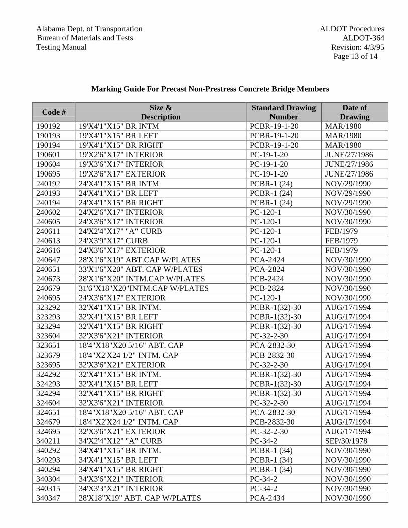
Page 13 of 14
ALDOT ProceduresAlabama Dept. of TransportationALDOT-364Bureau of Materials and Tests
Revision: 4/3/95Testing Manual
Marking Guide For Precast Non-Prestress Concrete Bridge Members
Code #Size &
DescriptionStandard Drawing
NumberDate of
Drawing190192 19'X4'1"X15" BR INTM PCBR-19-1-20 MAR/1980190193 19'X4'1"X15" BR LEFT PCBR-19-1-20 MAR/1980190194 19'X4'1"X15" BR RIGHT PCBR-19-1-20 MAR/1980190601 19'X2'6"X17" INTERIOR PC-19-1-20 JUNE/27/1986190604 19'X3'6"X17" INTERIOR PC-19-1-20 JUNE/27/1986190695 19'X3'6"X17" EXTERIOR PC-19-1-20 JUNE/27/1986240192 24'X4'1"X15" BR INTM PCBR-1 (24) NOV/29/1990240193 24'X4'1"X15" BR LEFT PCBR-1 (24) NOV/29/1990240194 24'X4'1"X15" BR RIGHT PCBR-1 (24) NOV/29/1990240602 24'X2'6"X17" INTERIOR PC-120-1 NOV/30/1990240605 24'X3'6"X17" INTERIOR PC-120-1 NOV/30/1990240611 24'X2'4"X17" "A" CURB PC-120-1 FEB/1979240613 24'X3'9"X17" CURB PC-120-1 FEB/1979240616 24'X3'6"X17" EXTERIOR PC-120-1 FEB/1979240647 28'X1'6"X19" ABT.CAP W/PLATES PCA-2424 NOV/30/1990240651 33'X1'6"X20" ABT. CAP W/PLATES PCA-2824 NOV/30/1990240673 28'X1'6"X20" INTM.CAP W/PLATES PCB-2424 NOV/30/1990240679 31'6"X18"X20"INTM.CAP W/PLATES PCB-2824 NOV/30/1990240695 24'X3'6"X17" EXTERIOR PC-120-1 NOV/30/1990323292 32'X4'1"X15" BR INTM. PCBR-1(32)-30 AUG/17/1994323293 32'X4'1"X15" BR LEFT PCBR-1(32)-30 AUG/17/1994323294 32'X4'1"X15" BR RIGHT PCBR-1(32)-30 AUG/17/1994323604 32'X3'6"X21" INTERIOR PC-32-2-30 AUG/17/1994323651 18'4"X18"X20 5/16" ABT. CAP PCA-2832-30 AUG/17/1994323679 18'4"X2'X24 1/2" INTM. CAP PCB-2832-30 AUG/17/1994323695 32'X3'6"X21" EXTERIOR PC-32-2-30 AUG/17/1994324292 32'X4'1"X15" BR INTM. PCBR-1(32)-30 AUG/17/1994324293 32'X4'1"X15" BR LEFT PCBR-1(32)-30 AUG/17/1994324294 32'X4'1"X15" BR RIGHT PCBR-1(32)-30 AUG/17/1994324604 32'X3'6"X21" INTERIOR PC-32-2-30 AUG/17/1994324651 18'4"X18"X20 5/16" ABT. CAP PCA-2832-30 AUG/17/1994324679 18'4"X2'X24 1/2" INTM. CAP PCB-2832-30 AUG/17/1994324695 32'X3'6"X21" EXTERIOR PC-32-2-30 AUG/17/1994340211 34'X2'4"X12" "A" CURB PC-34-2 SEP/30/1978340292 34'X4'1"X15" BR INTM. PCBR-1 (34) NOV/30/1990340293 34'X4'1"X15" BR LEFT PCBR-1 (34) NOV/30/1990340294 34'X4'1"X15" BR RIGHT PCBR-1 (34) NOV/30/1990340304 34'X3'6"X21" INTERIOR PC-34-2 NOV/30/1990340315 34'X3'3"X21" INTERIOR PC-34-2 NOV/30/1990340347 28'X18"X19" ABT. CAP W/PLATES PCA-2434 NOV/30/1990
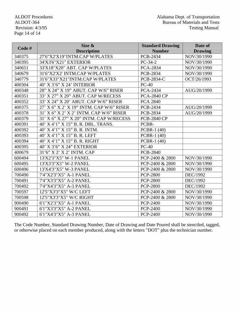
ALDOT Procedures Alabama Dept. of TransportationALDOT-364 Bureau of Materials and TestsRevision: 4/3/95 Testing Manual
Page 14 of 14
Code #Size &
DescriptionStandard Drawing
NumberDate of
Drawing340375 27'6"X2'X19"INTM.CAP W/PLATES PCB-2434 NOV/30/1990340395 34'X3'6"X21" EXTERIOR PC-34-2 NOV/30/1990340651 33'X18"X20" ABT. CAP W/PLATES PCA-2834 NOV/30/1990340679 31'6"X2'X2' INTM.CAP W/PLATES PCB-2834 NOV/30/1990340779 31'6"X33"X21"INTM.CAP W/PLATES PCB-2834-C OCT/26/1993400304 40’ X 3’6” X 24’ INTERIOR PC-40400348 28” X 24” X 19” ABUT. CAP W/6” RISER PCA-2434 AUG/20/1999400351 33’ X 27” X 20” ABUT. CAP W/RECESS PCA-2840 CP400352 33’ X 24” X 20’ ABUT. CAP W/6” RISER PCA 2840400375 27’ X 6” X 2’ X 19” INTM. CAP W/6” RISER PCB-2434 AUG/20/1999400378 31’ X 6” X 2’ X 2’ INTM. CAP W/6” RISER PCB-2834 AUG/20/1999400379 31’ X 6” X 27” X 20” INTM. CAP W/RECESS PCB-2840 CP400391 40’ X 4’1” X 15” B. R. DBL. TRANS. PCBR-400392 40’ X 4’1” X 15” B. R. INTM. PCBR-1 (40)400393 40’ X 4’1” X 15” B. R. LEFT PCBR-1 (40)400394 40’ X 4’1” X 15” B. R. RIGHT PCBR-1 (40)400395 40’ X 3’6” X 24” EXTERIOR PC-40400679 31’6” X 2’ X 2’ INTM. CAP PCB-2840600494 13'X2'3"X5" W-1 PANEL PCP-2400 & 2800 NOV/30/1990600495 13'X3'3"X5" W-2 PANEL PCP-2400 & 2800 NOV/30/1990600496 13'X4'3"X5" W-3 PANEL PCP-2400 & 2800 NOV/30/1990700490 7'4"X2'3"X5" A-1 PANEL PCP-2800 DEC/1992700491 7'4"X3'3"X5" A-2 PANEL PCP-2800 DEC/1992700492 7'4"X4'3"X5" A-3 PANEL PCP-2800 DEC/1992700597 12'5"X3'3"X5" W/C LEFT PCP-2400 & 2800 NOV/30/1990700598 12'5"X3'3"X5" W/C RIGHT PCP-2400 & 2800 NOV/30/1990900490 6'1"X2'3"X5" A-1 PANEL PCP-2400 NOV/30/1990900491 6'1"X3'3"X5" A-2 PANEL PCP-2400 NOV/30/1990900492 6'1"X4'3"X5" A-3 PANEL PCP-2400 NOV/30/1990
The Code Number, Standard Drawing Number, Date of Drawing and Date Poured shall be stenciled, tagged,or otherwise placed on each member produced, along with the letters "DOT" plus the technician number.
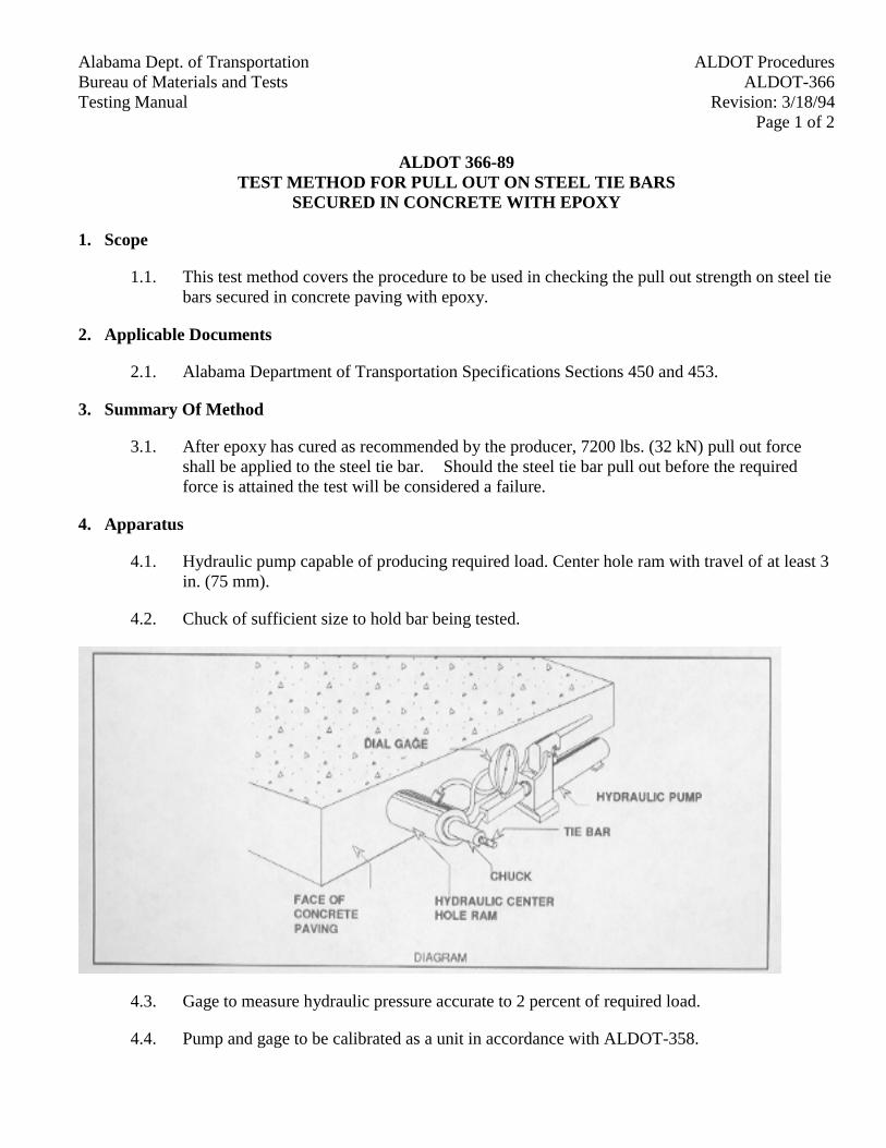
ALDOT ProceduresAlabama Dept. of TransportationALDOT-366Bureau of Materials and Tests
Revision: 3/18/94Testing ManualPage 1 of 2
ALDOT 366-89TEST METHOD FOR PULL OUT ON STEEL TIE BARS
SECURED IN CONCRETE WITH EPOXY
1. Scope
1.1. This test method covers the procedure to be used in checking the pull out strength on steel tiebars secured in concrete paving with epoxy.
2. Applicable Documents
2.1. Alabama Department of Transportation Specifications Sections 450 and 453.
3. Summary Of Method
3.1. After epoxy has cured as recommended by the producer, 7200 lbs. (32 kN) pull out forceshall be applied to the steel tie bar. Should the steel tie bar pull out before the requiredforce is attained the test will be considered a failure.
4. Apparatus
4.1. Hydraulic pump capable of producing required load. Center hole ram with travel of at least 3in. (75 mm).
4.2. Chuck of sufficient size to hold bar being tested.
4.3. Gage to measure hydraulic pressure accurate to 2 percent of required load.
4.4. Pump and gage to be calibrated as a unit in accordance with ALDOT-358.
ALDOT Procedures Alabama Dept. of TransportationALDOT-366 Bureau of Materials and TestsRevision: 3/18/94 Testing ManualPage 2 of 2
5. Procedure
5.1. Place ram over steel tie bar with base against face of concrete.
5.2. Place chuck over steel tie bar against face of ram.
5.3. Apply 7200 lbs (32 kN) pull out force with hydraulic pump.
5.4. If tie bar pulls out at less than 7200 lbs (32 kN) all the tie bars shall be pulled until at leastfive consecutive pulls in each direction have been made that do not pull out at an appliedload 7200 lbs (32 kN) or in the case of a full depth spall repair, until all tie bars in the areabeing repaired have been tested.
ALDOT Procedures Alabama Dept. of Transportation
ALDOT-368 Bureau of Materials and Tests
Revision: 5/01/01 Testing Manual Page 1 of 2
ALDOT-368-89 SAMPLING PROCEDURES FOR ELASTOMERIC BRIDGE BEARING PADS
1. Scope
1.1. This procedure covers the requirements for marking and sampling of elastomeric bridge bearing pads. The specifications for these items can be found in Section 837 of the Department's Specifications.
2. Definitions
2.1. Elastomeric Bridge Bearing - A vibration absorbing pad made from an elastomeric material and designed to compensate for thermal expansion and contraction, rotation, camber changes, creep and shrinkage of structural members. These bearings are divided into five types according to the design of the pad. Specifications for components of these pads can be found in Section 837 of the Department's Specifications.
2.2. Manufacturer - The company actually taking raw components and producing a finished bearing.
2.3. Department - The Alabama Department of Transportation.
2.4. Lot - A lot of pads shall be considered to be a group of 100 or less pads which are manufactured from the same batch of elastomer, cured under the same conditions, and are of the same type. A lot may include different sizes of pads, but not different types.
2.5. Type - Refers to general design of a bearing as outlined in section 837 of the Department's Specifications.
3. Marking
3.1. The manufacturer shall stencil each pad with a legible order number, lot number, bearing identification number, elastomer type and grade number. All markings shall be done with paint or a semi-permanent material not easily removed from the surface of the pad. All markings shall be applied on a face visible after installation, if possible, and shall be applied prior to shipment to the project.
4. Sampling
4.1. All pads along with certified test reports for each lot of bearings shall be shipped to the project for sampling and inspection.
4.2. A representative of the Department will inspect all pads for workmanship and markings. He/she will divide the pads according to lots and choose a random sample
ALDOT Procedures Alabama Dept. of Transportation
ALDOT-368 Bureau of Materials and Tests
Revision: 5/01/01 Testing Manual Page 2 of 2
of one pad from each lot (see ALDOT-210). When a lot contains more than one size of pad the inspector will treat the lot as if all pads were the same size and choose only one sample.
4.3. The Department inspector will complete a BMT-18 and attach it to the sample. The sample, sample card and a copy of the manufacturer's test report shall be sent to the Department's Central Laboratory for testing.
4.4. In cases where larger and more expensive pads, Type 3, Type 4 and Type 5 pads, are used, an alternate sampling plan may be elected by the Department. Some bridge structures require a large variety of Type 3, Type 4 and Type 5 pads in small quantities. The cost and time required to make additional replacement pads is not feasible. When this occurs the contractor may furnish the Materials and Tests Engineer, in writing, the number and types of pads involved. The Materials and Tests Engineer may, at his option, elect to specify which types and sizes of pads from which the samples shall be taken. This will allow the contractor to have additional pads of that size and type made at the same time as the other pads are produced. The inspector will then choose at random from these pads.
4.5. Should the contractor elect this option, he/she should make arrangements prior to production of the pads, in order that the manufacturer may make these additional pads along with the balance of the order. This should be done immediately after the shop drawings have been approved by the Bridge Bureau.
ALDOT ProceduresAlabama Dept. of TransportationALDOT-369Bureau of Materials and Tests
Revision: 3/18/94Testing ManualPage 1 of 2
ALDOT-369-89PROCEDURE FOR ACCEPTANCE OF MATERIALS USED IN THE CONSTRUCTION OF REST
AREAS AND WELCOME CENTERS
1. Scope
1.1. The purpose of this procedure is to establish the requirements for acceptance anddocumentation of materials to be used in the construction of the buildings and grounds at restareas and welcome centers.
2. Materials Used in Grounds Construction
2.1. Materials used in grounds construction will be accepted by test reports or certifications, beingsubmitted as required by Testing Manual, specifications, or shop drawings.
Example: 1. Base Material2. Paving3. Drainage Pipe4. Concrete (Cement and Aggregates)5. Steel Reinforcement6. Fencing Materials7. Light Poles
3. Materials Used in Building Construction
3.1. Cast-in-Place Concrete Materials used in the Cast-in-Place Concrete will be tested by theAlabama Department of Transportation and must meet applicable ArchitecturalSpecifications. Items used in the building construction are governed by the ArchitecturalSpecifications included in the Contract. These specifications cover the buildings plus 3 feet(1 m) outside the building structure. Products such as those listed below are accepted bybrand name, model number, etc. as specified by approved submittal data, plans and/orspecifications. Documentation should be inserted in project files by project personnel.Examples are typical and this list is not intended to be all inclusive.
Example: 1. House Paint2. Roofing Materials3. Plumbing Supplies and Fixtures4. Lumber5. Lighting Supplies and Fixtures6. Brick or Block7. Caulk8. Windows
ALDOT Procedures Alabama Dept. of TransportationALDOT-369 Bureau of Materials and TestsRevision: 3/18/94 Testing ManualPage 2 of 2
4. Miscellaneous Supplies
4.1. Miscellaneous supplies will be accepted on visual inspection by the Project Engineer.
Example: 1. Nails2. Screws3. Bolts4. 5. 6. 7. 8.
5. Additional Testing
5.1. The Alabama Department of Transportation reserves the right to sample and test anymaterials delivered to the project. These test results will take precedent over any other testreport or certification previously submitted.
ALDOT ProceduresAlabama Dept. of TransportationALDOT-370Bureau of Materials and Tests
Revision: 6/5/96Testing ManualPage 1 of 3
ALDOT-370-90GUIDELINES FOR OPERATION OF HOT MIX ASPHALT PLANTS AND THE ISSUANCE OF
TEST REPORTS
1. Scope
1.1. These are the guidelines for the operation of hot mix asphalt plants and the issuance of dailyreports. There are other requirements that are not outlined in this procedure that must beadhered to, such as, moisture content, viscosity of recycled asphalt mixes, tensile strengthratio, Marshall Stability, flow, VMA, etc., and must be handled on an individual basis andare beyond the scope of this procedure. Also, this procedure does not outline all of theroutine inspection responsibilities of the Department, such as, the visual inspections ofstockpiles, truck beds, etc.
2. Division Of Responsibility
2.1. Contractor's Responsibility.
2.1.1. Refer to ALDOT-375.
2.1.2. Take a sample as directed by the Department (approximately 130 lbs (60 kg)). Splitthis sample into two 65 lb (30 kg) samples, the Contractor’s sample and the RefereeSample.
2.1.3. Take an independent sample (from the next loaded truck, for example) as directed bythe Department (approximately 130 lbs (60 kg)). Split this sample into two 65 lb (30kg) samples, the Department’s Sample and the Contractor Verification Sample (thecontractor may test this sample if desired; it is not required).
2.1.4. Give the Referee Sample to the Department (in case it is needed later) and run allneeded tests on the Contractor Sample.
2.1.5. The following tests shall be conducted using the frequency outlined in the currentDepartment Testing Manual: (a) Moisture content of aggregates and bituminousmixtures, (b) Crushed particles of bituminous mixtures and aggregates, (c) Claycontent, (d) Adherent coating test and (e) Coated aggregates of bituminous mixtures.
2.1.6. Furnish DOT daily test reports including raw data: (a) When the job mix formula isthe same for different pay items on the same project the total tonnage of these payitems shall be combined into one Lot. For pay purposes, the tonnage of each pay itemshall be noted on BMT-20 in the remarks section, (b) When the job mix formula isthe same for multiple projects being run simultaneously from a single plant, the totaltonnage for this job mix formula, regardless of pay item designation for these projectsshall be combined for calculating testing increments and testing the hot mix asphalt.For pay purposes, the tonnage of each project shall be separated proportionately intoindividual lots for each separate project on separate test reports but testing results willbe the same for each project.
ALDOT Procedures Alabama Dept. of TransportationALDOT-370 Bureau of Materials and TestsRevision: 6/5/96 Testing ManualPage 2 of 3
2.2. Department's Responsibility.
2.2.1. Monitor Contractor's sampling and testing for compliance with appropriate procedureor standard.
2.2.2. Select random numbers to determine sampling times.
2.2.3. Notify Contractor's technician approximately fifteen (15) minutes before samplingtime.
2.2.4. Randomly select one of the stored samples and run verification tests. TheDepartment will make every effort to issue the verification test report as soon aspossible but no later than noon the next normal working day. Should the Contractordesire to furnish a laboratory and equipment for verification testing or share hislaboratory with the Department, the Department will utilize such laboratory.However, separate Compactors shall be used by the Contractor and the Department.The Department can use a Compactor furnished by the Contractor or Department.Sample and test the bituminous asphalt cement, using the frequency set forth in thecurrent Department's Testing Manual.
2.2.5. Determine the viscosity of the recovered asphalt cement from recycled mixtures usingthe frequency and procedure set forth in the current Department Testing Manual.
2.2.6. Keep a daily diary concerning Contractor's testing procedures and compliance withspecifications.
2.2.7. Check Contractor's raw data to verify computations.
2.2.8. Visually inspect stockpiles for contamination, cold feed bins for proper operation,finished mix for segregation, etc.
2.2.9. Compare verification test results to Contractor's data.
2.2.10. Determine pay factor for Lot.
3. Issuance of Test Reports on Verification Tests
3.1. Organize test results according to production Lot. When the job mix formula is the same fordifferent pay items on the same project, the total tonnage of these pay items shall becombined into one Lot. For pay purposes, the tonnage of each pay item shall be noted onBMT-20 in the remarks section. When the job mix formula is the same for multiple projectsbeing run simultaneously, the total tonnage for this job mix formula, regardless of pay itemdesignation for these projects shall be combined for calculating testing increments and testingthe hot mix asphalt. For pay purposes, the tonnage of each project shall be separatedproportionately into individual Lots for each separate project on separate test reports buttesting results will be the same for each project. Minimum information included in test
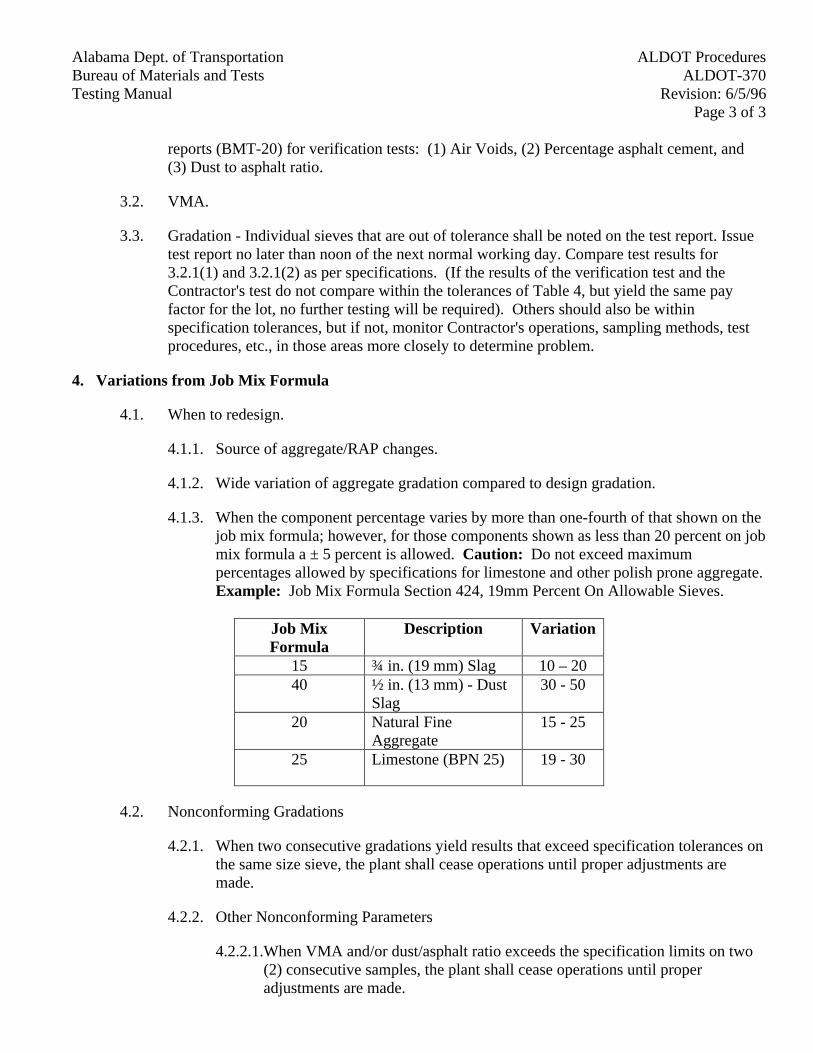
ALDOT ProceduresAlabama Dept. of TransportationALDOT-370Bureau of Materials and Tests
Revision: 6/5/96Testing ManualPage 3 of 3
reports (BMT-20) for verification tests: (1) Air Voids, (2) Percentage asphalt cement, and(3) Dust to asphalt ratio.
3.2. VMA.
3.3. Gradation - Individual sieves that are out of tolerance shall be noted on the test report. Issuetest report no later than noon of the next normal working day. Compare test results for3.2.1(1) and 3.2.1(2) as per specifications. (If the results of the verification test and theContractor's test do not compare within the tolerances of Table 4, but yield the same payfactor for the lot, no further testing will be required). Others should also be withinspecification tolerances, but if not, monitor Contractor's operations, sampling methods, testprocedures, etc., in those areas more closely to determine problem.
4. Variations from Job Mix Formula
4.1. When to redesign.
4.1.1. Source of aggregate/RAP changes.
4.1.2. Wide variation of aggregate gradation compared to design gradation.
4.1.3. When the component percentage varies by more than one-fourth of that shown on thejob mix formula; however, for those components shown as less than 20 percent on jobmix formula a ± 5 percent is allowed. Caution: Do not exceed maximumpercentages allowed by specifications for limestone and other polish prone aggregate.Example: Job Mix Formula Section 424, 19mm Percent On Allowable Sieves.
Job MixFormula
Description Variation
15 ¾ in. (19 mm) Slag 10 – 2040 ½ in. (13 mm) - Dust
Slag30 - 50
20 Natural FineAggregate
15 - 25
25 Limestone (BPN 25) 19 - 30
4.2. Nonconforming Gradations
4.2.1. When two consecutive gradations yield results that exceed specification tolerances onthe same size sieve, the plant shall cease operations until proper adjustments aremade.
4.2.2. Other Nonconforming Parameters
4.2.2.1. When VMA and/or dust/asphalt ratio exceeds the specification limits on two(2) consecutive samples, the plant shall cease operations until properadjustments are made.
ALDOT ProceduresAlabama Dept. of TransportationALDOT-371Bureau of Materials and Tests
Revision: 3/18/94Testing ManualPage 1 of 2
ALDOT-371-90RAPID METHOD TO DETERMINE THE ASPHALT CONTENT AND GRADATION OF
ASPHALT PAVING MIXTURES USING BIODEGRADABLE EXTRACTANT
1. Scope
1.1. This is a rapid method to be used routinely for determining the asphalt content and thegradation of hot-mixed paving mixtures.
2. Apparatus
2.1. Apparatus as required in ALDOT-354.
2.2. Pan, approximately 12 in x 8 in x 1 in deep (300 mm x 200 mm x 25 mm) deep or 10 qt, (L)rounded plastic pail.
2.3. Balance: AASHTO M-231, Class D.
2.4. Solvent: Biodegradable, high flash, non-toxic asphalt extractant. DOT approved.
2.5. Oven: Capable of maintaining a uniform temperature of 230 ± 9°F (110 ± 5°C).
2.6. Sieves: As required by the gradation specifications and meeting the requirements ofAASHTO M-92.
2.7. Liquid detergent (powder detergents are not permitted), optional.
3. Procedure
3.1. Secure a representative sample of the asphalt mixture in accordance with AASHTO T-168.
3.2. Determine the percent asphalt and moisture in accordance with ALDOT-354.
3.3. Select an extraction test sample of the size as required in Table 1, AASHTO T-164. Recordmass to the nearest 0.1 g.
3.4. Place the extraction sample in pan or pail and cover with extractant. Gently agitate thesample frequently with a spatula or trowel allowing sufficient time (20-30 minutes for virginmixtures; 45 min. - one hour for recycle mixtures) for the extract-ant to dissolve the asphaltfrom the aggregate.
3.5. Decant extractant, pouring over a No. 8 (2.36mm) sieve nested over a No. 200 (75 µm)sieve, continue decanting with water until wash water is clear.
Note: Care must be taken while agitating and decanting to prevent loss of particles.
3.6. Dry sample to constant mass in an oven at a temperature of 230 ± 9°F (110 ± 5°C).
ALDOT Procedures Alabama Dept. of TransportationALDOT-371 Bureau of Materials and TestsRevision: 3/18/94 Testing ManualPage 2 of 2
3.7. Screen the sample over sieves required by the job mix formula and weigh the accumulativematerial retained on each sieve to the nearest gram.
4. Calculations
4.1. Calculate total extracted weight of mineral aggregate as follows:
W1 = Ws (1-AC - Wm)
Where:W1 = total extracted weight of mineral aggregate in grams.Ws = total sample weight in grams (AC and aggregate).AC = asphalt content expressed as a decimal number.Wm = Moisture in mix expressed as a decimal number.
4.2. The accumulative weights of material retained on each sieve from subsection 3.7 shall beconverted to percent-age by dividing by the weight of total aggregate (W1) as obtained insubsection 4.1, and multiplying by 100.
5. Reporting
5.1. The results of the sieve analysis shall be reported as total percentages passing each sieve.Percentages shall be reported to the nearest whole number in accordance with AASHTO R11except for the percentage passing the No.200 (75 µm) sieve which shall be reported to thenearest 0.1 percent.
ALDOT ProceduresAlabama Dept. of TransportationALDOT-372Bureau of Materials and Tests
Revision: 6/5/96Testing ManualPage 1 of 2
ALDOT-372-90APPROVAL OF RECLAIMED ASPHALT PAVEMENT STOCKPILES
1. Scope
1.1. This method describes the procedure to be used for approval of reclaimed asphalt pavement(RAP) stockpiles.
2. Stockpile Constructed of Rap Traceable to a Prior DOT Job that had an Approved Job MixFormula
2.1. Keep the RAP materials separated by projects milled, unless evidence can be provided toindicate that the reclaimed material from other projects have similar analysis, such as thesame coarse aggregate, asphalt grade and content and is traceable back to a job mix formula.
2.2. Assign a number to the stockpile containing the year and Division such as 94 1-1, 94 2-1, 943-1 so that mix designs can be properly referenced. The first number is the year the stockpilewas constructed, the second number is the Division in which the stockpile is located and thethird number is a sequential number for that Division. After a stockpile has been properlyreferenced, the Contractor shall furnish the Department documentation to identify thatstockpile. The Department will have the responsibility of monitoring the stockpiles.
2.3. No new materials shall be added to a stockpile already sampled and evaluated for design.
2.4. Materials and Tests Engineer will approve, disapprove, request additional testing, etc., basedon the report and test results. The information shall be included with submittal of job mixformula.
3. Stockpiles of Rap of Unknown Origin or from Several Sources
3.1. In no case will the contractor utilize RAP from multiple and/or unknown origins at a rate thatexceeds 15 percent by weight of total mix. When 15 percent or less is used, the contractorshall obtain five (5) representative samples from the first 10,000 T (t) or portion thereof. Anadditional two (2) samples shall be taken for each 5,000 T (t) thereafter. Samples shall betaken randomly throughout the stockpile. Remove at least 6 in. (150 mm of the materialfrom the surface of the stockpile before obtaining samples to minimize any potentialsegregation effect. Whenever possible, samples should be taken as the stockpile is beingbuilt, so samples will represent the entire stockpile.
3.2. Scalp off and discard the materials retained on the 2 in. (50 mm) sieve.
3.3. Sample size should be at least 30 lbs. (15 kg) after scalping.
3.4. Samples shall be utilized by the Contractor for evaluation and mix design purposes.
3.5. Testing RAP from unknown or blended stockpiles.
ALDOT Procedures Alabama Dept. of TransportationALDOT-372 Bureau of Materials and TestsRevision: 6/5/96 Testing ManualPage 2 of 2
3.5.1. Contractor shall determine gradation and asphalt content on all samples in accordancewith current departmental procedures.
3.5.2. Contractor shall evaluate the recovered properties such as type of coarse aggregate,fractured face count, etc.
3.6. Submit report to Materials and Tests Engineer with mix design.
3.6.1. Report results of each individual sample.
3.6.2. Mean and standard deviation of gradation of all samples.
3.6.3. Mean and standard deviation of asphalt content of all samples.
3.6.4. Mean and standard deviation of fractured faces of all samples.
3.7. Materials and Test Engineer will approve, disapprove, request additional testing, etc., basedon these report and test results from split samples submitted.

Alabama Dept. of Transportation ALDOT ProceduresBureau of Materials and Tests ALDOT-374Testing Manual Revision: 5/8/00
Page 1 of 4
ALDOT-374-91CERTIFICATION PROGRAM FOR HOT-MIX ASPHALT TECHNICIANS
1. Scope
1.1 The purpose of this program is to develop and maintain a pool of well-trainedtechnicians for Department and contractors to design, test, and manage hot mixedasphalt materials. The intent of this program is to improve the quality and per-formance of hot mixed asphalt pavements through knowledge and understandingof the product. This program will provide training and certification for RoadwayTechnician, Laboratory Technician (Level I), Quality Management Technician(Level II), Mix Design Technician (Level III), and Superpave Technician.
2. Certification Standards
2.1 Level I - Laboratory Technician
2.1.1 Training: Licensing by the State Health Department to operate nucleargauges and Aggregate Technician certification are prerequisites for Labo-ratory Technician (Level I) training (see ALDOT-376, Certification Pro-gram for Aggregate Technicians). In addition, the candidate must com-plete three to five days of classroom and laboratory training covering sam-pling, testing, and analysis of HMA (Hot Mix Asphalt) specimens.
2.1.2 Performance: A Laboratory Technician (Level I) is able to perform alltests and calculations (including random sampling) required to analyzeHMA samples in the laboratory.
2.1.3 A Laboratory Technician must properly perform HMA testing in the pres-ence of a qualified evaluator and/or instructor approved by the Departmentand pass a written examination administered by the Department.
2.2 Level II - Quality Management Technician
2.2.1 Training: Roadway Technician and Laboratory Technician (Level I) certi-fication are prerequisites for Quality Management Technician (Level II)training. In addition, the candidate must complete two to four days oftraining covering basic mix design principles, asphalt plant operations,Alabama's HMA specifications, and statistical analysis of test results.
2.2.2 Performance: A Quality Management Technician (Level II) may performall the duties of both a Laboratory Technician (Level I) and a Roadway
ALDOT Procedures Alabama Dept. of TransportationALDOT-374 Bureau of Materials and TestsRevision: 5/8/00 Testing ManualPage 2 of 4
Technician. Additionally, a Quality Management Technician is able toimprove HMA quality by using statistical analysis of test results andchanging the asphalt plant operations.
2.2.3 A Quality Management Technician must pass a written examination administered by the Department.
2.3 Level III - Mix Design Technician
2.3.1 Training: Laboratory Technician (Level I) certification is a prerequisitefor Mix Design (Level III) training. In addition, the candidate must com-plete three to five days of classroom and laboratory training covering Alabama's HMA specifications and mix design procedures.
2.3.2 Performance: A Mix Design Technician (Level III) may perform all theduties of a Laboratory Technician (Level I). Additionally, a Mix DesignTechnician is able to design HMA job mix formulas according to Alabama's specifications to be used on all Department projects.
2.3.3 A Mix Design Technician must pass a written examination administeredby the Department and demonstrate the ability to design a HMA job mixformula that meets all of Alabama's specifications using materials selectedby the Departmental evaluator.
2.4 Roadway Technician
2.4.1 Training: Successful completion of a two to three day training course con-sisting of classroom and laboratory sessions. Also, the successful comple-tion of Radiological Safety course and licensed by the State Health Depart-ment to operate/handle nuclear gauges. The technician shall have receivedtraining and must be capable of operating a nuclear density gauge.
2.4.2 Performance: Demonstrate ability to operate a nuclear density gauge and becapable of performing thin layer gauge calibrations under the supervision ofa certified Level II Technician. He/she must thoroughly understand randomsampling as well as paving operations.
2.5 Superpave Technician
2.5.1 Training: Laboratory (Level I) or Quality Management (Level II) or MixDesign (Level III) Technician certification is a prerequisite for Superpavecertification. Additionally, the candidate must complete a prescribed course
of classroom and laboratory training using the gyratory compactor and

Alabama Dept. of Transportation ALDOT ProceduresBureau of Materials and Tests ALDOT-374Testing Manual Revision: 5/8/00
Page 3 of 4
Alabama's Superpave specifications.
2.5.2 Performance: A Superpave Technician may perform all the duties for whichhe or she is certified through Marshall mix design procedures. Additionally,Superpave certification allows the technician to perform Laboratory (LevelI) and Design (Level III) testing on all Superpave projects. For example, aSuperpave Quality Management Technician (Superpave Level II) may per-form all the duties of laboratory testing, roadway testing, and quality man-agement on both Marshall and Superpave projects.
2.5.3 A Superpave Technician must pass a written examination administered bythe Department.
2.6 Design Laboratory
2.6.1 A mixture design laboratory must have all the required equipment necessaryto perform a mixture design as outlined in ALDOT-307 and ALDOT-344except for Abson recoveries. All equipment must be in compliance with theappropriate specification.
2.6.2 The Marshall compactor must be calibrated continuously with the Materialsand Tests Marshall compactor.
2.6.3 All balances must be checked and calibrated annually for accuracy by areputable scale service company.
2.6.4 The Materials and Tests Central Laboratory will check and certify a mixturedesign laboratory every 18-24 months.
2.7 Certification
2.7.1 Personnel meeting all the qualifications for any of the aforementioned certi-fied technician positions shall be certified upon recommendation by theWorking Task Force and approval by the Certification Board. The WorkingTask Force may allow experience and/or other education to substitute forthe schools required for certification. The request should be made in writ-ing (BMT-100) to the Working Task Force. Certification shall be contin-gent upon the technician signing a document (BMT-105) informing him ofhis rights and responsibilities as a certified technician and the penalties at-tached to the abuse or neglect of these rights and responsibilities.
2.8 Decertification
ALDOT Procedures Alabama Dept. of TransportationALDOT-374 Bureau of Materials and TestsRevision: 5/8/00 Testing ManualPage 4 of 4
2.8.1 Accusations of abuse or neglect of these rights and responsibilities shall bemade to the Working Task Force. Penalties shall be implemented upon recommendation by the Working Task Force and approval by the Certifica-tion Board, and will range from a minimum 30 day suspension to permanentrevocation.
2.9 Recertification
2.9.1 Certification of a technician is good for three (3) years, after which the tech-nician must be recertified. Recertification can be accomplished in one ofthe following:
2.9.1.1 The technician may take a one (1) day refresher course to updatehim/her on changes in specifications and procedures.
2.9.1.2 The Working Task Force may designate the technician "active"(the technician having kept pace with changes in specificationsand procedures by working with or for the Alabama Departmentof Transportation on a continuously competent basis) and there-by continue his certification for another three (3) years.
2.10 Certification Board
2.10.1 Membership of the Certification Board shall be composed of the following:
2.10.1.1 Materials and Tests Engineer (Position), Chairman
2.10.1.2 Assistant Chief Engineer (Appointed by Transportation Direc-tor)
2.10.1.3 Construction Engineer (Position)
2.10.1.4 Division Engineer (Appointed by Transportation Director)
2.10.1.5 Industry Member (Appointed by Alabama Asphalt PavementAssociation)
2.11 Working Task Force
2.11.1 The Membership of the Working Task Force shall be composed of the fol-lowing:
2.11.1.1 Bituminous Engineer (Position)
2.11.1.2 Assistant Construction Engineer Roadway (Position)
2.11.1.3 Industry Association Member
ALDOT ProceduresAlabama Dept. of TransportationALDOT-375Bureau of Materials and Tests
Revision: 3/18/94Testing ManualPage 1 of 5
ALDOT-375-91CONTRACTOR QUALITY CONTROL SYSTEM FOR HOT MIX ASPHALT
1. Scope
1.1. This establishes minimum requirements and activities for a Contractor Quality ControlSystem for hot mix asphalt. These requirements pertain to the inspections and testsnecessary to substantiate material and product conformance to contract requirements and toall inspections and tests required by the contract. Unless the Department is otherwisenotified in writing by the Contractor, the Contractor formally adopts this Quality ControlPlan as his own.
2. Functions and Responsibilities
2.1. The Department - The Department will approve material and mix designs, inspect plants andequipment, and monitor control of the operations to assure conformity with thespecifications. The Department will perform testing to verify Contractor's data used foracceptance or rejection of work. The Department will design all opengraded friction mixes(Section 420), if any. The Department's Quality Assurance Plan is outlined in thespecifications.
2.2. The Contractor - Prior to the preconstruction conference, the Contractor shall submit inwriting his proposed Quality Control Plan for approval by the Engineer. The plan shallcontain the sampling, testing, inspection and the anticipated frequencies of each that the Con-tractor expects to accomplish to maintain control. The Contractor's minimum requiredsampling and testing plan is outlined in the specifications. A minimum series of sampling,testing, and inspecting activities are shown below.
3. Minimum Requirements for a Contractor Quality Control Plan
3.1. All Types of Plants
3.1.1. Stockpiles - (a) Determine gradation of all incoming aggregates, and (b) Inspectstockpiles for separation, contamination, segregation, etc.
3.1.2. Cold Bins - (a) Calibrate the cold feed gate settings and prepare calibration charts, (b)Observe operation of cold feed for uniformity, and (c) Observe loading of bins toinsure correct procedures are followed.
3.1.3. RAP - (a) Inspect stockpiles for contamination, segregation and material variations,(b) insure that additional material is not added to approved stockpiles, and (c)Determine bitumen content and gradation.
3.1.4. Dryer - (a) Observe pyrometer for aggregate temperature control, and (b) Observeefficiency of the burner

ALDOT Procedures Alabama Dept. of TransportationALDOT-375 Bureau of Materials and TestsRevision: 3/18/94 Testing ManualPage 2 of 5
3.1.5. Bituminous Mixture - (a) Determine percent bitumen with nuclear gauge or furnace(ALDOT-354), (b) check mix temperature, (c) compact samples in field laboratoryand determine voids, VMA, stability, flow, and (d) measure Rice Specific Gravityand Bulk Specific Gravity, (e) determine in-place density, and (f) Determinegradation, dust-to-asphalt ratio, moisture content of mix.
3.1.6. Trucks - (a) Inspect trucks to insure clean beds and approved release agent used, and(b) insure that segregation does not occur when loading trucks.
3.1.7. Asphalt Cement - (a) Obtain only from Department approved sources, and (b)Maintain copies of temperature viscosity curves generated by suppliers for each loadof asphalt cement received
3.2. Batch Plants
3.2.1. Batch Weights - Determine percent used and amount to be pulled from each hot binto assure compliance with Job Mix Formula.
3.2.2. Check mixing time.
3.2.3. Check operations of weight bucket and scales.
3.3. Continuous Mix Plant
3.3.1. Determine gradation of aggregates and gate calibration chart for each bin.
3.3.2. Determine settings for each hot bin to assure compliance with the Job Mix Formula.
3.3.3. Determine Gallons (Liters) of bitumen per revolution or gallons (Liters) per minute toassure compliance with the Job Mix Formula.
3.3.4. Set dam gate to insure satisfactory mixing time.
3.3.5. Observe overflow chutes to insure no excessive overflow
3.4. Drum Mix Plant
3.4.1. Calibrate the cold feed and prepare a calibration chart for each feeder.
3.4.2. Evaluate moisture content of aggregate.
3.4.3. Develop information for the synchronization of the aggregate feed and the bituminousmaterial feed including allowance for moisture content in the cold feed aggregate.
3.5. The activities shown above are considered to be normal activities necessary to control theproduction of bituminous plant mix at an acceptable quality level. It is recognized, however,depending on the type of process or materials, some of the activities listed may not benecessary and in other cases, additional activities may be required. The frequency of these
ALDOT ProceduresAlabama Dept. of TransportationALDOT-375Bureau of Materials and Tests
Revision: 3/18/94Testing ManualPage 3 of 5
activities will also vary with the process and the materials. When the process varies from thedefined process average and variability targets, the frequency of these activities will beincreased until the proper conditions have been restored. The Contractor or Producer shallplot and keep up-to-date control charts for all Quality Sampling and Testing. Control chartsshall be provided for the following:
3.5.1. Gradation of aggregate and RAP stockpiles.
3.5.2. Bitumen content of bituminous mixture and RAP.
3.5.3. Stability and flow.
3.5.4. Average percent maximum density of each sublot.
3.5.5. Percent air voids (laboratory compacted samples).
3.5.6. Voids in the mineral aggregate (laboratory compacted samples).
3.5.7. Theoretical maximum density.
3.5.8. Mixture gradation (3/8 in. (9.5 mm), No.4 (4.75 mm), No. 8 (2.36 mm) and No. 200(75 µm) sieves) and dust-to-asphalt ratio.
3.6. The Contractor shall maintain all current control charts in the laboratory where they can beseen. Individual values as well as running average of last four samples shall be plotted.
3.7. The Contractor shall be responsible for the development of all mix designs. Contractor-furnished mix designs shall be approved by the Materials and Tests Engineer prior to theiruse. See Section 410. The Contractor shall be responsible for the process control of allmaterials during handling, blending, mixing, and placing operations. When the Contractordesires to change the Job Mix Formula he must request approval for the change in writing.The Materials and Tests Engineer must approve the request prior to permitting the change tobe made. After prior approval, an adjustment of the job mix formula for individual sievessizes without a redesign will be permitted under the following range as long as the job mixformula remains in the master range.
3.7.1. ± 7% for the No. 4 (4.75 mm) and larger sieves
3.7.2. ± 4% for the No. 8 (2.36 mm) through the No. 100 (150 µm) sieve
3.7.3. ± 2% for the No. 200 (75 µm) sieve
3.7.4. ± 0.40% for the asphalt cement
4. Quality Control System
4.1. General Requirements - The Contractor shall perform or have performed the inspections andtests required to substantiate product conformance to contract requirements and shall also
ALDOT Procedures Alabama Dept. of TransportationALDOT-375 Bureau of Materials and TestsRevision: 3/18/94 Testing ManualPage 4 of 5
perform or have performed all inspections and tests otherwise required by the Contractor.The Contractor shall have at least one (1) Certified Field Tester (Level I) and at least one (1)
Certified Roadway Technician present when producing or placing hot-mix asphalt, respect-fully. In addition, the Contractor shall have a Certified Quality Management Technician(Level II) readily available during the production and placement of hot-mix asphalt. SeeALDOT-374 for certification program. When it becomes evident to the Department that theQuality Control Technician cannot perform as required by the position, the Department willrevoke the certifications and require appropriate replacements. The Contractor's qualitycontrol procedures, inspection, and tests shall be documented and that information shall bemade available to the Department on a daily basis throughout the life of the contract. TheDepartment reserves the right to sample and test the mix and to make and test Marshallspecimens at the plant for informational purposes. The information will be used to determineif the Contractor is producing the mix established by the approved mix design and todetermine if the design mix should be modified to meet field conditions.
4.2. Documentation - The Contractor shall maintain adequate records of all inspections and tests.The records shall indicate the nature and number of tests made, test results, the number andtype of deficiencies found, the quantities approved and rejected, and the nature of correctiveaction taken as appropriate. The Contractor's proposed documentation procedures will besubject to the review and approval of the Department prior to the start of the work and toperform compliance checks during the progress of the work. All charts and recordsdocumenting the Contractor's quality control tests and inspections shall become the propertyof the Department upon completion of the work.
4.3. Charts and Forms - All inspections and test results of conforming and non-conformingmaterials shall be recorded on approved forms and charts which shall be kept up to date andcomplete, and shall be available at all times to the Department during the performance of thework. Test properties for the various materials and mixtures shall be charted on forms whichare in accordance with the applicable requirements of the Department. A copy of each chartand form to be used by the Contractor will be furnished by the Department. The Contractorshall furnish his own supply of the charts and forms.
4.4. Corrective Actions - The Contractor shall take prompt action to correct any errors, equipmentmalfunctions, process changes, or other assignable causes which have resulted or could resultin the submission of materials, products, and completed construction which do not con-formto the requirements of the specifications. When it becomes evident to the Department thatthe Contractor is not controlling his process and is making no effort to take corrective action,the Department will require that plant operations be ceased until such time as the Contractorcan demonstrate that he can and will control the process.
4.5. Laboratories with Measuring and Testing Equipment – The Contractor or Producer shallfurnish a fully equipped laboratory at the production site. This facility shall meet therequirements of Article 106. The laboratory shall be furnished with the necessary testingequipment and supplies for performing Contractor Quality Control sampling and testing. Toassure accuracy, the testing equipment shall be checked periodically as directed by the
ALDOT ProceduresAlabama Dept. of TransportationALDOT-375Bureau of Materials and Tests
Revision: 3/18/94Testing ManualPage 5 of 5
Bureau of Materials and Tests in accordance with applicable standards. In addition to theabove requirements, the Contractor's Marshall hammer and the Department's Marshallhammer used for verification testing shall be correlated with the Materials and Tests Mar-shall hammer as outlined in ALDOT-381.
4.6. Sampling and Testing - Sampling and testing methods and procedures used by the Contractorto determine quality conformance of the materials and products will be furnished by theDepartment and will be the same as those used by the Department.
4.7. Nonconforming Materials - The Contractor shall establish and maintain an effective andpositive system for controlling nonconforming material, including procedures foridentification, isolation, and disposition. Re-claiming or reworking nonconforming materialsshall be in accordance with procedures acceptable to the Department. The details of thissystem will be discussed at the preconstruction conference and become a part of the record ofthe conference.
4.8. Department Inspection at Subcontractor or Supplier Facilities - The Department reserves theright to inspect materials not manufactured within the Contractor's facility. Departmentinspection will not constitute acceptance nor shall it in any way replace the Contractor'sinspection or otherwise relieve the Con-tractor of his responsibility to furnish an acceptablematerial or product. Subcontracted or purchased materials shall be inspected by theContractor when received, as necessary, to assure conformance to con-tract requirements.The Contractor shall report to the Department any nonconformance found on Departmentsource inspected material and shall require his supplier to take necessary corrective action.
ALDOT ProceduresAlabama Dept. of TransportationALDOT-376Bureau of Materials and Tests
Revision: 3/29/95Testing ManualPage 1 of 3
ALDOT-376-92CERTIFICATION PROGRAM FOR AGGREGATE TECHNICIANS
1. Scope
1.1. The purpose of this program is to develop, train, maintain, and certify a pool of qualifiedtechnicians for the Department and aggregate producers necessary to manage the QualityControl and Quality Assurance Programs for aggregate materials. The intent of this programis to improve the performance of aggregates that are used in the highway constructionindustry through knowledge and understanding of the product. This program will providetraining and certification for aggregate technicians participating in a producer’s QualityControl Program and the Department's Quality Assurance Program.
2. Training
2.1. Each applicant must complete both classroom and laboratory training provided by theDepartment in cooperation with the Academia. The classroom training shall consist of allAASHTO Test Specifications and Alabama Department of Transportation (ALDOT)Procedures necessary to perform all required tests. They are as follows:
2.1.1. ALDOT-249, Aggregate Control Program
2.1.2. AASHTO T-2, Sampling Aggregates
2.1.3. AASHTO T-11, Materials Finer Than No. 200 (75 µm) Sieve in Mineral Aggregatesby Washing
2.1.4. AASHTO T-19, Unit Weight and Voids in Aggregates
2.1.5. AASHTO T-27, Sieve Analysis of Fine and Coarse Aggregates
2.1.6. AASHTO M-92, Wire Cloth Sieves for Testing Purposes
2.1.7. AASHTO M-231, Weighing Devices Used in the Testing of Materials
2.1.8. AASHTO T-248, Reducing Field Samples of Aggregate to Testing Size
2.1.9. ALDOT-150, Method of Sampling Coarse and Fine Aggregate from a Conveyor Belt
2.1.10. ALDOT-239, Method of Sampling and Testing Riprap Stone
2.1.11. ALDOT-253, Rapid Drying of Soil and Aggregate Samples for Field Tests
2.1.12. ALDOT-321, Test for Glassy Particles in Crushed Slag
2.1.13. ASTM D4791, Method of Determining Flat and Elongated Pieces in CoarseAggregate

ALDOT Procedures Alabama Dept. of TransportationALDOT-376 Bureau of Materials and TestsRevision: 3/29/95 Testing ManualPage 2 of 3
2.1.14. Sections 801 and 802, DOT Specifications
3. Certification
3.1. Written Examination:
3.1.1. Alabama Department of Transportation, Central Laboratory personnel, willadminister an open-book, written examination at the conclusion of the classroomtraining. The participant must attain a score of 70 to pass.
3.2. Practical Examination:
3.2.1. All applicants are expected to successfully demonstrate proficiency with performanceof the following laboratory tests: AASHTO T-11, AASHTO T-19, AASHTO T-27,and AASHTO T-248.
3.3. Actual proficiency testing will be performed in the presence of a qualified evaluatorapproved by the Materials and Tests Engineer. The evaluator will utilize a proficiency guidethat was prepared by the Bureau of Materials and Tests and reviewed by the AggregateIndustry. At the completion of the practical laboratory examination, the evaluator will rendera decision as to whether the applicant demonstrated a level of competence necessary toperform the above tests in strict compliance with the particular testing specification.Personnel meeting the qualifications for both the written and practical laboratoryexaminations shall be certified upon recommendation by the Working Task Force andapproved by the Certification Board. Certification shall be contingent on the techniciansigning the Certified Technician Warrant (BMT-138) which informs the technician of hisrights and responsibilities as a Certified Aggregate Technician and the penalties attached tothe abuse and/or neglect of these rights and responsibilities.
3.4. Certification Board: The Aggregate Technician Certification Board will be composed of thefollowing:
3.4.1. Materials and Tests Engineer, Chairman (Position)
3.4.2. Assistant Chief Engineer (Appointed by Transportation Director)
3.4.3. Construction Engineer (Position)
3.4.4. Division Engineer (Appointed by Transportation Director)
3.4.5. Industry Member (Appointed by the Road Builders Association)
3.5. Working Task Force:
3.5.1. Testing Engineer (position)
3.5.2. Aggregate Engineer (position)
ALDOT ProceduresAlabama Dept. of TransportationALDOT-376Bureau of Materials and Tests
Revision: 3/29/95Testing ManualPage 3 of 3
3.5.3. Division Materials Engineer (approved by the Materials and Tests Engineer)
3.5.4. Industry Member (appointed by Alabama Road Builders Association)
4. Recertification
4.1. Certification of a technician is good for three (3) years, after which the technicians must bere-certified. Re-certification can be accomplished as follows:
4.1.1. The Technician must attend a refresher course or seminar to update him/her onspecification changes, procedures, etc., (if available).
4.1.2. The Technician must complete BMT-136, "Application for Recertification", whichprovides a summary of work, education and training received since initialcertification or last recertification.
4.1.3. The Technician must complete and sign BMT-138, “Certified Technician Warrant".
4.1.4. All required documentation must be sent to the Working Task Force.
5. Decertification
5.1. Accusations of abuse or neglect of the Technician's rights and responsibilities shall be madeto the Working Task Force. Charges and accusations shall be investigated by same.Penalties shall be implemented upon recommendation by the Working Task Force andapproval by the Certification Board after a thorough review of all facts. Penalties shall rangefrom a minimum 30 day suspension to permanent revocation.
ALDOT ProceduresAlabama Dept. of TransportationALDOT-377Bureau of Materials and Tests
Revision: 3/29/95Testing ManualPage 1 of 4
ALDOT-377-92CERTIFICATION PROGRAM FOR PRECAST CONCRETE PRODUCTS TECHNICIANS
1. Scope
1.1. The purpose of this program is to develop, train, maintain and certify a pool of qualifiedtechnicians for the Department and producers of concrete pipe, precast manholes, precast boxculvert sections, precast, non-prestress concrete bridge members and miscellaneous precastconcrete products to manage the Quality Control and Quality Assurance Programs. Theintent of this program is to improve the quality and performance of all precast concreteproducts that are used in the highway construction industry through knowledge and an under-standing of the product. The program will provide training and certification for precastconcrete products technicians participating in the producer's Quality Control Program and theDepartment's Quality Assurance Program.
2. Training
2.1. Each applicant is required to complete both classroom and practical "hands-on" training. TheDepartment in conjunction with industry will provide the training.
2.2. Classroom training shall consist of all applicable AASHTO/ASTM Specifications,Department Specifications and Department (ALDOT) procedures. They are as follows:
2.2.1. ALDOT-364 "Production, Inspection and Acceptance of Pipe, Precast Manholes,Precast Box Culverts, Precast Nonprestress Concrete Bridge Members andMiscellaneous Precast Concrete Products";
2.2.2. Department Specifications, all applicable sections;
2.2.3. AASHTO T-22 (ASTM C-39), Compressive Strength of Cylindrical ConcreteSpecimens;
2.2.4. AASHTO T-23 (ASTM C-31), Making and Curing Concrete Test Specimens in theField;
2.2.5. AASHTO T-24 (ASTM C-42), Obtaining and Testing Drilled Cores and SawedBeams of Concrete;
2.2.6. AASHTO M-86 (ASTM C-14), Concrete Sewer, StormDrain and Culvert Pipe;
2.2.7. AASHTO M-170 (ASTM C-76), Reinforced Concrete Culvert, Storm Drain andSewer Pipe;
2.2.8. AASHTO M-175 (ASTM C-444), Perforated Concrete Pipe;
2.2.9. AASHTO M-176 (ASTM C-654), Porous Concrete Pipe;
2.2.10. AASHTO M-178 (ASTM C-412), Concrete Drain Tile;
ALDOT Procedures Alabama Dept. of TransportationALDOT-377 Bureau of Materials and TestsRevision: 3/29/95 Testing ManualPage 2 of 4
2.2.11. AASHTO M-199 (ASTM C-478), Precast Reinforced Concrete Manhole Sections;
2.2.12. AASHTO M-206 (ASTM C-506), Reinforced Concrete Arch Culvert Storm Drainand Sewer Pipe;
2.2.13. AASHTO M-207 (ASTM C-507), Reinforced Concrete Elliptical Culvert, StormDrain and Sewer Pipe;
2.2.14. AASHTO M-242 (ASTM C-655), Reinforced Concrete D-Load Culvert, Storm Drainand Sewer Pipe;
2.2.15. AASHTO M-259 (ASTM C-789), Precast Reinforced Concrete Box Sections forCulverts, Storm Drains and Sewers;
2.2.16. AASHTO M-273 (ASTM C-850), Precast Reinforced Concrete Box Sections forCulverts, Storm Drains and Sewers with less than two (2) feet of cover subjected tohighway loadings;
2.2.17. AASHTO T-231 (ASTM C-617), Capping Cylindrical Concrete Specimens; and,
2.2.18. AASHTO T-280 (ASTM C-497), Concrete Pipe, Sections or Tile.
2.3. Technicians working for companies who produce PRECAST, NONPRESTRESSCONCRETE BRIDGE MEMBERS will be required to be PCI certified as anInspector/Technician Level I and ACI Field Testing Technician Grade I. Technicians in thiscategory will not be required to comply with Section 3.1 and Section 3.2.
3. Certification
3.1. Written Examination:
3.1.1. Alabama Department of Transportation, Central Laboratory Personnel, willadminister an open-book, written examination at the conclusion of the classroomtraining. The participant must attain a score of 75 to pass.
3.2. Practical "Hands-On" Examination:
3.2.1. All applicants are expected to successfully demonstrate proficiency with AASHTO T-280, Three-Edge Bearing apparatus to include inspection of same and AASHTO T-23, Making and Curing Concrete Test Specimens in the field.
3.2.2. Practical "Hands-On" testing will be performed at the producer's site in the presenceof a qualified evaluator approved by the Materials and Tests Engineer. The evaluatorwill use AASHTO T-23 and AASHTO T-280 to determine if the applicantdemonstrated a satisfactory level of competence necessary to perform the test. Arating of satisfactory or unsatisfactory will be given by the evaluator for the practicaltest.
ALDOT ProceduresAlabama Dept. of TransportationALDOT-377Bureau of Materials and Tests
Revision: 3/29/95Testing ManualPage 3 of 4
3.2.3. Applicants meeting the qualifications and requirements for both the written andpractical examinations shall be certified upon recommendation by the Working TaskForce and approved by the Certification Board. Certification shall be contingent onthe technician signing BMT-133, Certified Technician Warrant, which informs thetechnician of his rights and responsibilities as a Certified Precast Concrete ProductsTechnician and the penalties attached to the abuse and/or neglect of these rights andresponsibilities. The applicant/technician must also submit BMT-134, Applicationfor Certification or Recertification. Once approved by the Certification Board, theDepartment will issue BMT-145, Certified Technician Card, to the technician.
3.2.4. Applicants meeting the requirements of Section 2.3 shall be certified in accordancewith Section 3.2.3 provided they present documentation and/or certificate ofsatisfactory completion of all PCI and ACI training.
4. Certification Board
4.1. The Certification Board will be composed of the following:
4.1.1. Materials and Tests Engineer, Chairman (Position).
4.1.2. Assistant Chief Engineer (Appointed by Transportation Director).
4.1.3. Construction Engineer (Position).
4.1.4. Division Engineer (Appointed by Transportation Director).
4.1.5. Industry Member (Appointed by the Alabama Concrete Pipe Association).
5. Working Task Force
5.1. The Working Task Force shall be composed of the following:
5.1.1. Testing Engineer, Chairman (position).
5.1.2. Aggregate Engineer (position).
5.1.3. Division Materials Engineer (appointed by Materials and Tests Engineer).
5.1.4. Industry Member (appointed by the Alabama Concrete Pipe Association).
6. Recertification
6.1. Certification of a technician is good for three (3) years, after which the technicians must berecertified. Recertification can be accomplished as follows:
6.1.1. The technician may attend a seminar to update him/her on specification changes,procedures, etc., (if available);
ALDOT Procedures Alabama Dept. of TransportationALDOT-377 Bureau of Materials and TestsRevision: 3/29/95 Testing ManualPage 4 of 4
6.1.2. The technician must complete BMT-134, "Application for Recertification", whichprovides a summary of work, education and training received since initialcertification or last recertification;
6.1.3. The technician must complete and sign BMT-133, "Certified Technician Warrant";and, all required documentation must be sent to the Working Task Force.
7. Decertification
7.1. Accusations of abuse or neglect of the Technician's rights and responsibilities shall be madeto the Working Task Force. Charges and accusations shall be investigated by same.Penalties shall be implemented upon recommendation by the Working Task Force andapproval by the Certification Board after a thorough review of all facts. Penalties shall rangefrom a minimum 30 day suspension to permanent revocation.
ALDOT ProceduresAlabama Dept. of TransportationALDOT-378Bureau of Materials and Tests
Revision: 3/18/94Testing ManualPage 1 of 2
ALDOT-378-92ACCEPTING NEW NUCLEAR MOISTURE/DENSITY AND THIN LAYER GAUGES, AND
RECALIBRATING/QUALITY CHECKING USED GAUGES
1. Scope
1.1. This method covers the procedures for the acceptance of new Nuclear Moisture/Density andThin Layer Gauges and the recalibration and quality check of older gauges.
2. Applicable Documents
2.1. Manufacturers operating instruction manuals.
2.2. Materials and Tests-14 and -33 Specifications.
3. Apparatus
3.1. Standard density calibration blocks and standard moisture block.
Section A
4. Procedures for Acceptance of New Gauges
4.1. Using manufacturers' recommendations, establish a standard count for density and moisture.
4.2. Standard counts should be verified as being in acceptable tolerances utilizing ALDOT-222Section 6, or a built-in calculation contained in the gauge software.
4.3. Density aspects of the gauge operated in normal mode are verified by taking one minutecounts at each interval (BS thru 8 in. (200mm)) on a known standard mag/alum block of 150lbs/ft3 (2140 kg/m³). Tolerances shall be within ± 1.5 percent of the known block density.
4.4. Moisture aspects of the gauge shall be determined by taking two one-minute counts andaverage. Counts are taken on a mag/poly block. This block simulates 40 lbs/ft3 (628 kg/m³)of moisture. The gauge must count within ± 2 lbs/ft3 (32 kg/m³) of the known 40 lbs/ft3 (628kg/m³) of moisture.
4.5. Thin Layer aspects of the gauge are verified by taking ten one-minute calibration countstaken in the backscatter position. These counts are taken on a 1 in. (25 mm) thick mag/alumplate, placed on the mag/alum standard block. These counts are averaged and the differenceis calculated between the gauge readings and the known mag/alum plate density of 133.5lbs/ft3 (2140 kg/m³). This difference is utilized as a D-Bias/OFFSET entered into the gaugesoftware to calibrate the gauge. With the gauge calibrated, four one-minute counts are takenunder the same conditions that the calibration counts were taken. The counts are averagedand shall be within ± 1.5% of the 133.5 lbs/ft3 (2140 kg/m³).
4.6. When the requirements of the above procedures have been met, the gauge will be acceptedfor use on Alabama Department of Transportation construction projects.
ALDOT Procedures Alabama Dept. of TransportationALDOT-378 Bureau of Materials and TestsRevision: 3/18/94 Testing ManualPage 2 of 2
Section B
5. Recalibration and Quality Check of Used Gauges
5.1. Gauges designed for Thin Layer Asphalt Density determinations only (Troxler 4640-A &4640-B) shall be recalibrated according to the following procedures. The gauge shall becalibrated using the 3-block calibration procedure obtained from Troxler Electronic Labs,Inc. The data is accumulated, then entered into the computer program supplied by Troxler.This program generates calibration constants and gauge parameters to be manually input intothe gauge. Once the gauge has been calibrated, procedure 4.5 (Section A) is utilized to verifyand check the recalibration.
5.2. Moisture/Density and Dual Purpose gauges shall be recalibrated according to the calibrationprocedures used by Campbell-Pacific Nuclear Corp. This procedure has proven to beacceptable and reliable for Troxler and CPN gauges. These procedures consist of collectingcount data on Magnesium, Aluminum, Mag/Alum and Mag/Poly Standard blocks. Fourminute counts are taken at each interval and the data processed through the computerprogram supplied by Campbell-Pacific. This program generates calibration constants used tocalibrate the gauge. Once the gauge has been calibrated, procedures of Section A, 4.3, 4.4,and if applicable, 4.5 are followed to establish a quality check of the recalibration.
Alabama Dept. of Transportation ALDOT ProceduresBureau of Materials and Tests ALDOT-380Testing Manual Revision: 5/8/00
Page 1 of 8
ALDOT-380-93FORMS AND EXAMPLES FOR SAMPLING AND
COMPUTING PAY FACTORS FOR HOT MIX ASPHALT
1. Scope
1.1 This procedure shows how to sample Hot Mix Asphalt and calculate the pay fac-tors as defined in Department Specification Section 106, Control of Materials.
2. Applicable Documents
2.1 Specification Section 106, Control of Materials.
2.2 BMT-19, Work Sheet Summary of Lot Test Results for Air Voids and ACContent.
2.3 BMT-20, Asphalt Plant Mixture Test Report.
2.4 BMT-135, Work Sheet to Determine Pay Factors when they Cannot be Deter-mined from Verification Samples.
2.5 ALDOT-210, Selecting Samples by the Random Numbers Method.
2.6 ALDOT-353, Field Method for Determining Air Void Content and Marshall Sta-bility and Flow of Bituminous Mixtures.
2.7 AASHTO R-11, Indicating Which Places of Figures are to be Considered Signifi-cant in Specified Limiting Values.
2.8 AASHTO R-18, Establishing and Implementing a Quality System for Construc-tion Materials Testing Laboratories.
2.9 AASHTO T-168, Sampling Bituminous Paving Mixtures.
3. Procedure
3.1 Sampling and storage of the Hot Mix Asphalt by the contractor and the Depart-ment shall be in accordance with AASHTO T-168, Department SpecificationsSection 106, ALDOT-210, and ALDOT-353. Sample size of the mixture shall beadequate for each parameter required for each testing increment.
3.2 When notified by the Engineer, the contractor shall sample and test the HMAaccording to Department Specifications, Section 106.

ALDOT Procedures Alabama Dept. of TransportationALDOT-380 Bureau of Materials and TestsRevision: 5/8/00 Testing ManualPage 2 of 8
3.3 The Department and the contractor shall compute and compare tests resultsaccording to the following examples.
3.3.1 EXAMPLE I (424 SLAG MIX).
Bulk Specific Gravities of Compacted Specimens.
Lot 1 Sub-lot 12.468 2.476 2.481
(2.468 + 2.476 + 2.480) / 3 = 2.475
The average of the three specimens is 2.475. Because 2.481 is the furthestfrom the average, it is discarded (if by chance two values are equally dis-tant from the average, discard both values or discard neither value). Theremaining values are averaged.
(2.468 + 2.476) / 2 = 2.472
New Average = 2.472. This is the bulk specific gravity value used for thislot and sub-lot.
Both the State and contractor use this method when calculating slag mixbulk gravities.
3.3.2 EXAMPLE II.
Maximum (Rice) Specific Gravity Results.
Lot 1 Sub-lot 1 Lot 1 Sub-lot 2 Lot 1 Sub-lot 3 Lot 1 Sub-lot 42.575 2.562 2.561 2.570
Running Average Lot 1 Sub-lot 12.575 / 1 = 2.575
Running Average Lot 1 Sub-lot 2(2.575 + 2.562) / 2 = 2.568
Running Average Lot 1 Sub-lot 3(2.575 + 2.562 + 2.561) / 3 = 2.566
Running Average Lot 1 Sub-lot 4(2.575 + 2.562 + 2.561 + 2.570) / 4 = 2.567
Lot 2 Sub-lot 1 Lot 2 Sub-lot 2 Lot 2 Sub-lot 3 Lot 2 Sub-lot 42.579 2.580 2.575 2.577
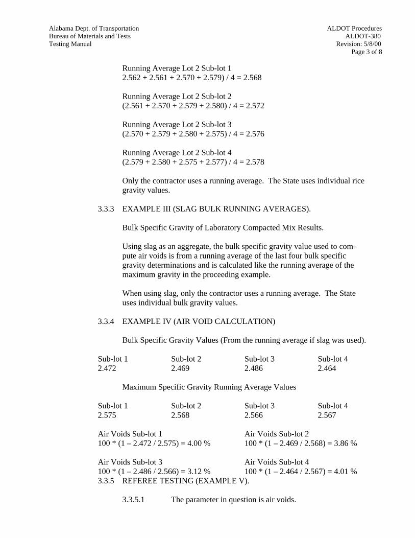
Alabama Dept. of Transportation ALDOT ProceduresBureau of Materials and Tests ALDOT-380Testing Manual Revision: 5/8/00
Page 3 of 8
Running Average Lot 2 Sub-lot 12.562 + 2.561 + 2.570 + 2.579) / 4 = 2.568
Running Average Lot 2 Sub-lot 2(2.561 + 2.570 + 2.579 + 2.580) / 4 = 2.572
Running Average Lot 2 Sub-lot 3(2.570 + 2.579 + 2.580 + 2.575) / 4 = 2.576
Running Average Lot 2 Sub-lot 4(2.579 + 2.580 + 2.575 + 2.577) / 4 = 2.578
Only the contractor uses a running average. The State uses individual ricegravity values.
3.3.3 EXAMPLE III (SLAG BULK RUNNING AVERAGES).
Bulk Specific Gravity of Laboratory Compacted Mix Results.
Using slag as an aggregate, the bulk specific gravity value used to com-pute air voids is from a running average of the last four bulk specificgravity determinations and is calculated like the running average of themaximum gravity in the proceeding example.
When using slag, only the contractor uses a running average. The Stateuses individual bulk gravity values.
3.3.4 EXAMPLE IV (AIR VOID CALCULATION)
Bulk Specific Gravity Values (From the running average if slag was used).
Sub-lot 1 Sub-lot 2 Sub-lot 3 Sub-lot 42.472 2.469 2.486 2.464
Maximum Specific Gravity Running Average Values
Sub-lot 1 Sub-lot 2 Sub-lot 3 Sub-lot 42.575 2.568 2.566 2.567
Air Voids Sub-lot 1 Air Voids Sub-lot 2100 * (1 – 2.472 / 2.575) = 4.00 % 100 * (1 – 2.469 / 2.568) = 3.86 %
Air Voids Sub-lot 3 Air Voids Sub-lot 4100 * (1 – 2.486 / 2.566) = 3.12 % 100 * (1 – 2.464 / 2.567) = 4.01 %3.3.5 REFEREE TESTING (EXAMPLE V).
3.3.5.1 The parameter in question is air voids.
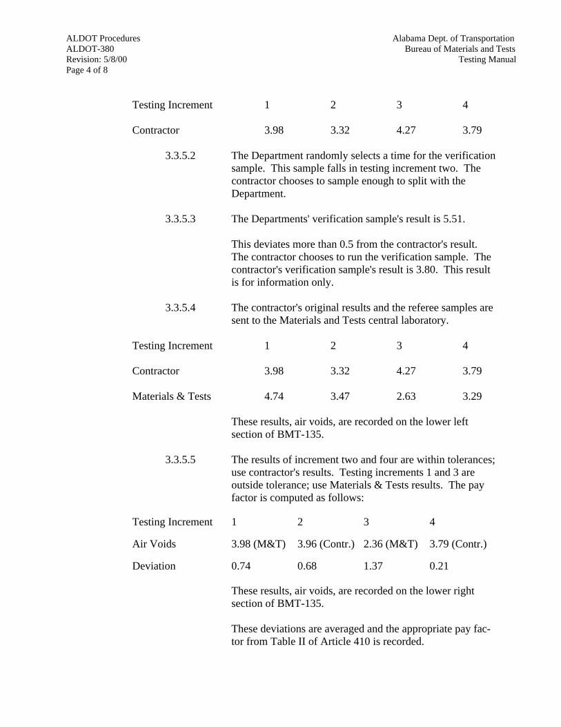
ALDOT Procedures Alabama Dept. of TransportationALDOT-380 Bureau of Materials and TestsRevision: 5/8/00 Testing ManualPage 4 of 8
Testing Increment 1 2 3 4
Contractor 3.98 3.32 4.27 3.79
3.3.5.2 The Department randomly selects a time for the verificationsample. This sample falls in testing increment two. Thecontractor chooses to sample enough to split with theDepartment.
3.3.5.3 The Departments' verification sample's result is 5.51.
This deviates more than 0.5 from the contractor's result.The contractor chooses to run the verification sample. Thecontractor's verification sample's result is 3.80. This resultis for information only.
3.3.5.4 The contractor's original results and the referee samples aresent to the Materials and Tests central laboratory.
Testing Increment 1 2 3 4
Contractor 3.98 3.32 4.27 3.79
Materials & Tests 4.74 3.47 2.63 3.29
These results, air voids, are recorded on the lower leftsection of BMT-135.
3.3.5.5 The results of increment two and four are within tolerances;use contractor's results. Testing increments 1 and 3 areoutside tolerance; use Materials & Tests results. The payfactor is computed as follows:
Testing Increment 1 2 3 4
Air Voids 3.98 (M&T) 3.96 (Contr.) 2.36 (M&T) 3.79 (Contr.) Deviation 0.74 0.68 1.37 0.21
These results, air voids, are recorded on the lower rightsection of BMT-135.
These deviations are averaged and the appropriate pay fac-tor from Table II of Article 410 is recorded.

Alabama Dept. of Transportation ALDOT ProceduresBureau of Materials and Tests ALDOT-380Testing Manual Revision: 5/8/00
Page 5 of 8
BMT-19REV. 5-8-00
ALABAMA DEPARTMENT OF TRANSPORTATIONWORK SHEET SUMMARY OF LOT TEST
RESULTS FOR AIR VOIDS AND AC CONTENT
Project No. STPAA-208 (51) Lot No. 1
County Montgomery Pay Item No. 416 A, B, C, AND D
Date 5-8-00 Mix No. 3
% AC CONTENT REQUIRED = 6.55
REFERENCETESTINGINCREMENT CONTRACTOR STATE CONTRACTOR STATE DEVIATION
1 6.87 0.32
2 6.55 6.62 0.00
3 6.23 0.32
4 6.82 0.27
5
AVERAGE 0.23Remarks _________________________________________________
PAY FACTOR 1.00
% AIR VOIDS REQUIRED = 4.00
VERIFICATIONTESTINGINCREMENT CONTRACTOR STATE CONTRACTOR STATE DEVIATION
1 3.98 0.02
2 3.32 4.46 4.61 3.42
3 4.27 0.27
4 3.79 0.21
5
AVERAGERemarks: ________________________________________________
PAY FACTOR

ALDOT Procedures Alabama Dept. of TransportationALDOT-380 Bureau of Materials and TestsRevision: 5/8/00 Testing ManualPage 6 of 8
BMT-19REV. 5-8-00
NOTES: (1) If Pay Factor is determined on original state verification test, enter Pay Factor on QC/QA Form 1.
(2) If Pay Factor is determined on contractor verification test, enter Pay Factor onQC/QA Form 2; If not resolved on contractor verification test, use M & T refereetests and go to BMT-135 and ALDOT-380.
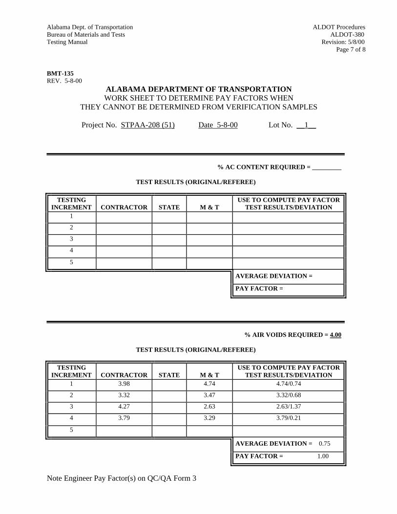
Alabama Dept. of Transportation ALDOT ProceduresBureau of Materials and Tests ALDOT-380Testing Manual Revision: 5/8/00
Page 7 of 8
BMT-135REV. 5-8-00
ALABAMA DEPARTMENT OF TRANSPORTATIONWORK SHEET TO DETERMINE PAY FACTORS WHEN
THEY CANNOT BE DETERMINED FROM VERIFICATION SAMPLES
Project No. STPAA-208 (51) Date 5-8-00 Lot No. __1__
% AC CONTENT REQUIRED = _________
TEST RESULTS (ORIGINAL/REFEREE)
TESTINGINCREMENT CONTRACTOR STATE M & T
USE TO COMPUTE PAY FACTORTEST RESULTS/DEVIATION
1
2
3
4
5
AVERAGE DEVIATION =
PAY FACTOR =
% AIR VOIDS REQUIRED = 4.00
TEST RESULTS (ORIGINAL/REFEREE)
TESTINGINCREMENT CONTRACTOR STATE M & T
USE TO COMPUTE PAY FACTORTEST RESULTS/DEVIATION
1 3.98 4.74 4.74/0.74
2 3.32 3.47 3.32/0.68
3 4.27 2.63 2.63/1.37
4 3.79 3.29 3.79/0.21
5
AVERAGE DEVIATION = 0.75
PAY FACTOR = 1.00
Note Engineer Pay Factor(s) on QC/QA Form 3
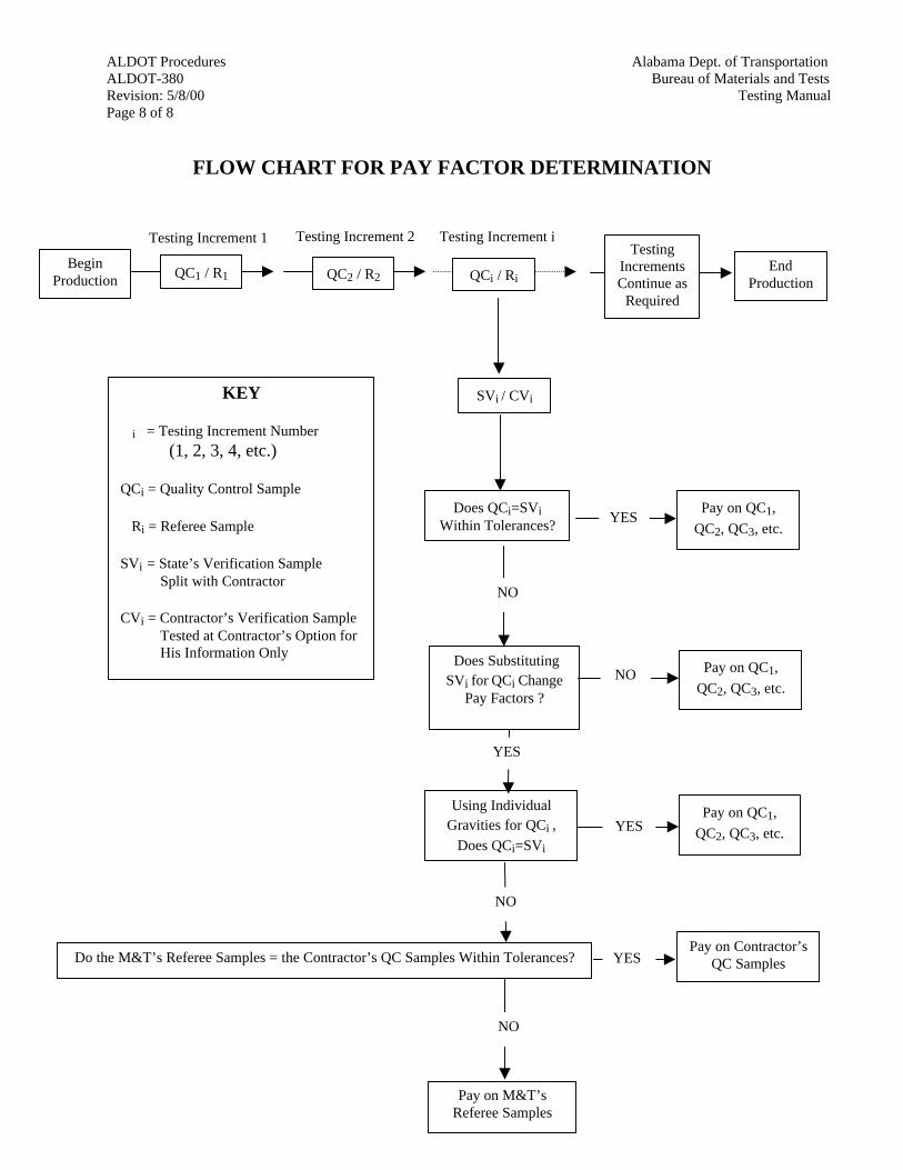
ALDOT Procedures Alabama Dept. of TransportationALDOT-380 Bureau of Materials and TestsRevision: 5/8/00 Testing ManualPage 8 of 8
FLOW CHART FOR PAY FACTOR DETERMINATION
BeginProduction
Testing Increment 1
QC1 / R1
Testing Increment i
QCi / Ri
Testing Increment 2
QC2 / R2End
Production
TestingIncrementsContinue as
Required
SVi / CVi
Does QCi=SViWithin Tolerances?
YESPay on QC1,
QC2, QC3, etc.
NO
Does SubstitutingSVi for QCi Change
Pay Factors ?
NO Pay on QC1,
QC2, QC3, etc.
NO
Do the M&T’s Referee Samples = the Contractor’s QC Samples Within Tolerances?
NO
Pay on M&T’sReferee Samples
YESPay on Contractor’s
QC Samples
KEY
i = Testing Increment Number
(1, 2, 3, 4, etc.)
QCi = Quality Control Sample
Ri = Referee Sample
SVi = State’s Verification SampleSplit with Contractor
CVi = Contractor’s Verification SampleTested at Contractor’s Option forHis Information Only
Using IndividualGravities for QCi ,
Does QCi=SViwithin tolerances?
YES
YESPay on QC1,
QC2, QC3, etc.

ALDOT ProceduresAlabama Dept. of TransportationALDOT-381Bureau of Materials and Tests
Revision: 3/18/94Testing ManualPage 1 of 4
ALDOT-381-93METHOD FOR CORRELATION OF MARSHALL HAMMERS
1. Scope
1.1. This procedure explains the Alabama Department of Transportation method for correlatingall Marshall hammers used on Department quality control (QC) work. All contractor qualitycontrol hammers, all Division quality assurance (QA) hammers and all design hammers shallbe calibrated to the Bureau of Materials and Tests' Marshall hammer.
2. Referenced Documents
2.1. AASHTO T-166 Bulk Specific Gravity of Compacted Bituminous Mixtures.
2.2. ALDOT-307 Design Method for Selecting Optimum Asphalt Cement Content of BituminousMixture by Means of The Marshall Apparatus.
2.3. ALDOT-375 Contractor Quality Control System for Hot Mix Asphalt.
3. Correlation Procedure
3.1. The Bureau of Materials and Tests' Marshall hammer is the standard to which all Marshallhammers performing Alabama Department of Transportation work shall be calibrated. Thecontractor assumes responsibility for beginning work if no correlation factor has beenestablished and/or if there is no correlation history for either the contractor's QC hammer orthe Divisions QA hammer. A job mix formula and the recommended compactiontemperature must be included in every hammer correlation.
3.2. Mixture Design Hammer
3.2.1. The hammer calibration factor (HCF) will be developed from the data generated bythe Department's one-point checks of the submitted mixture designs. The averagebulk specific gravity (AASHTO T-166) of the Marshall specimens made by Materialsand Tests will be divided by the uncorrected bulk specific gravity for the Contractor'smixture design Mar-shall specimens obtained from the plot of unit weight versusasphalt content at the design asphalt content.
Materials and Tests Compacted Marshall SGHCF =
Contractor Marshall SG from Data Curve
3.2.2. A HCF will be developed for all designs from a given hammer. A running average ofthe last 10 HCF will be maintained by the contractor. If less than 10 values are avail-able, the average shall include all data that is available. The current running averagefor HCF will be used to correct the actual test data for mixture design submitted andfor calibrating the quality control hammer. If a new hammer is being used formixture design, the procedures in Section 3.5 should be conducted in cooperationwith the Bureau of Materials and Tests.
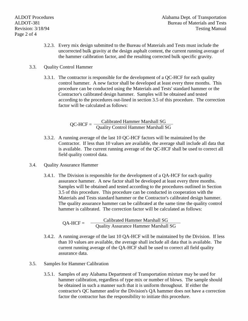
ALDOT Procedures Alabama Dept. of TransportationALDOT-381 Bureau of Materials and TestsRevision: 3/18/94 Testing ManualPage 2 of 4
3.2.3. Every mix design submitted to the Bureau of Materials and Tests must include theuncorrected bulk gravity at the design asphalt content, the current running average ofthe hammer calibration factor, and the resulting corrected bulk specific gravity.
3.3. Quality Control Hammer
3.3.1. The contractor is responsible for the development of a QC-HCF for each qualitycontrol hammer. A new factor shall be developed at least every three months. Thisprocedure can be conducted using the Materials and Tests' standard hammer or theContractor's calibrated design hammer. Samples will be obtained and testedaccording to the procedures out-lined in section 3.5 of this procedure. The correctionfactor will be calculated as follows:
Calibrated Hammer Marshall SGQC-HCF =
Quality Control Hammer Marshall SG
3.3.2. A running average of the last 10 QC-HCF factors will be maintained by theContractor. If less than 10 values are available, the average shall include all data thatis available. The current running average of the QC-HCF shall be used to correct allfield quality control data.
3.4. Quality Assurance Hammer
3.4.1. The Division is responsible for the development of a QA-HCF for each qualityassurance hammer. A new factor shall be developed at least every three months.Samples will be obtained and tested according to the procedures outlined in Section3.5 of this procedure. This procedure can be conducted in cooperation with theMaterials and Tests standard hammer or the Contractor's calibrated design hammer.The quality assurance hammer can be calibrated at the same time the quality controlhammer is calibrated. The correction factor will be calculated as follows:
Calibrated Hammer Marshall SGQA-HCF =
Quality Assurance Hammer Marshall SG
3.4.2. A running average of the last 10 QA-HCF will be maintained by the Division. If lessthan 10 values are available, the average shall include all data that is available. Thecurrent running average of the QA-HCF shall be used to correct all field qualityassurance data.
3.5. Samples for Hammer Calibration
3.5.1. Samples of any Alabama Department of Transportation mixture may be used forhammer calibration, regardless of type mix or number of blows. The sample shouldbe obtained in such a manner such that it is uniform throughout. If either thecontractor's QC hammer and/or the Division's QA hammer does not have a correctionfactor the contractor has the responsibility to initiate this procedure.
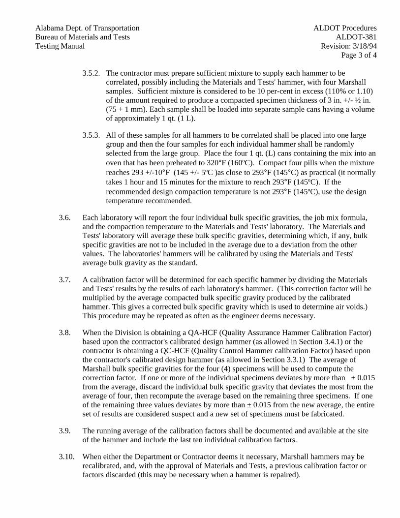
ALDOT ProceduresAlabama Dept. of TransportationALDOT-381Bureau of Materials and Tests
Revision: 3/18/94Testing ManualPage 3 of 4
3.5.2. The contractor must prepare sufficient mixture to supply each hammer to becorrelated, possibly including the Materials and Tests' hammer, with four Marshallsamples. Sufficient mixture is considered to be 10 per-cent in excess (110% or 1.10)of the amount required to produce a compacted specimen thickness of 3 in. +/- ½ in.(75 + 1 mm). Each sample shall be loaded into separate sample cans having a volumeof approximately 1 qt. (1 L).
3.5.3. All of these samples for all hammers to be correlated shall be placed into one largegroup and then the four samples for each individual hammer shall be randomlyselected from the large group. Place the four 1 qt. (L) cans containing the mix into anoven that has been preheated to 320°F (160ºC). Compact four pills when the mixturereaches 293 +/-10°F (145 +/- 5ºC )as close to 293°F (145°C) as practical (it normallytakes 1 hour and 15 minutes for the mixture to reach 293°F (145ºC). If therecommended design compaction temperature is not 293°F (145ºC), use the designtemperature recommended.
3.6. Each laboratory will report the four individual bulk specific gravities, the job mix formula,and the compaction temperature to the Materials and Tests' laboratory. The Materials andTests' laboratory will average these bulk specific gravities, determining which, if any, bulkspecific gravities are not to be included in the average due to a deviation from the othervalues. The laboratories' hammers will be calibrated by using the Materials and Tests'average bulk gravity as the standard.
3.7. A calibration factor will be determined for each specific hammer by dividing the Materialsand Tests' results by the results of each laboratory's hammer. (This correction factor will bemultiplied by the average compacted bulk specific gravity produced by the calibratedhammer. This gives a corrected bulk specific gravity which is used to determine air voids.)This procedure may be repeated as often as the engineer deems necessary.
3.8. When the Division is obtaining a QA-HCF (Quality Assurance Hammer Calibration Factor)based upon the contractor's calibrated design hammer (as allowed in Section 3.4.1) or thecontractor is obtaining a QC-HCF (Quality Control Hammer calibration Factor) based uponthe contractor's calibrated design hammer (as allowed in Section 3.3.1) The average ofMarshall bulk specific gravities for the four (4) specimens will be used to compute thecorrection factor. If one or more of the individual specimens deviates by more than ± 0.015from the average, discard the individual bulk specific gravity that deviates the most from theaverage of four, then recompute the average based on the remaining three specimens. If oneof the remaining three values deviates by more than ± 0.015 from the new average, the entireset of results are considered suspect and a new set of specimens must be fabricated.
3.9. The running average of the calibration factors shall be documented and available at the siteof the hammer and include the last ten individual calibration factors.
3.10. When either the Department or Contractor deems it necessary, Marshall hammers may berecalibrated, and, with the approval of Materials and Tests, a previous calibration factor orfactors discarded (this may be necessary when a hammer is repaired).
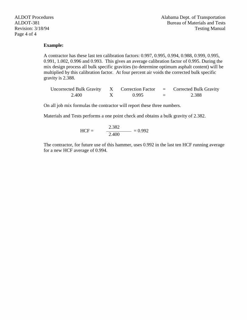
ALDOT Procedures Alabama Dept. of TransportationALDOT-381 Bureau of Materials and TestsRevision: 3/18/94 Testing ManualPage 4 of 4
Example:
A contractor has these last ten calibration factors: 0.997, 0.995, 0.994, 0.988, 0.999, 0.995,0.991, 1.002, 0.996 and 0.993. This gives an average calibration factor of 0.995. During themix design process all bulk specific gravities (to determine optimum asphalt content) will bemultiplied by this calibration factor. At four percent air voids the corrected bulk specificgravity is 2.388.
Uncorrected Bulk Gravity X Correction Factor = Corrected Bulk Gravity2.400 X 0.995 = 2.388
On all job mix formulas the contractor will report these three numbers.
Materials and Tests performs a one point check and obtains a bulk gravity of 2.382.
2.382HCF =
2.400= 0.992
The contractor, for future use of this hammer, uses 0.992 in the last ten HCF running averagefor a new HCF average of 0.994.
ALDOT ProceduresAlabama Dept. of TransportationALDOT-382Bureau of Materials and Tests
Revision: 10/11/94Testing ManualPage 1 of 3
ALDOT-382-94MINING, STOCKPILING, SAMPLING, AND TESTING CARBONATE STONE FROM SINGLE
OR MULTIPLE FORMATIONS/LEDGES FOR DETERMINATION OF BPN9 VALUES
1. Scope
1.1. The purpose of this procedure is to establish a uniform set of guidelines necessary toestablish British Polishing Numbers (BPN9) for carbonate stone and determine the extent towhich different coarse carbonate stone will polish and to further determine the surfacefrictional properties of the carbonate stone.
2. Referenced Standards
2.1. ASTM D 3319, "Accelerated Polishing of Aggregate Using the British Wheel."
2.2. ASTM E 303, "Measuring Surface Frictional Properties Using the British Pendulum Tester."
2.3. AASHTO T 2, "Sampling Aggregates."
2.4. Alabama Department of Transportation Specifications.
2.5. ALDOT-175, "Method of Stockpiling Coarse Aggregate for All Purposes."
2.6. ALDOT-249, "Procedure for Acceptance of Fine and Coarse Aggregates."
3. Calibration and Testing Procedure for British Polish and Pendulum Testing
3.1. Pendulum Calibration
3.1.1. Two (2) sets of four (4) polish specimens each will be prepared and used to keep theBritish Pendulum Tester calibrated. The two (2) sets of specimens will have averageBPN values of 20 and 35. At the beginning of each specimen fabrication-polishing-testing sequence for a set of 14 specimens, the calibration specimens will be tested.The British Pendulum Tester will be adjusted until the averages for each of the two(2) groups are within ± one (1) unit from the established averages of 20 and 35.
3.2. Specimen Preparation and Polish Calibration
3.2.1. Polish specimens will be prepared in accordance with procedures contained in ASTMD 3319. A minimum of six (6) specimens will be prepared for each aggregate source.
3.2.2. A control sample (approximately 1800 lbs. (800 kg) of ½ in (12.5 mm) to 3/8 in. (9.5mm) aggregate) has been obtained from Vulcan Materials Company, Calera, Alabama(ID Number 0155). The aggregate has been sieved, washed, dried, and stored inplastic lined barrels. This aggregate will be used to develop consistency in specimenpreparation and polishing. Two (2) specimens will be prepared and included (with 12others) in each run of the British Polish Wheel. The average of the two calibrationspecimens BPN0 values tested in accordance with section 3.3 will be within ± two
ALDOT Procedures Alabama Dept. of TransportationALDOT-382 Bureau of Materials and TestsRevision: 10/11/94 Testing ManualPage 2 of 3
(2.0) units of a bench mark BPN0 = 35 value. If this criteria is not met, all specimensprepared for the polish sequence will be discarded and new specimens prepared.
3.2.3. After polishing for nine (9) hours, the BPN9 values for the two calibration specimenswill be measured in accordance with section 3.3. The average BPN9 value will bewithin ± one and one-half (1.5) units of the benchmark BPN9 = 25 value. If only one(1) calibration specimen survives the nine (9) hour polishing sequence it will bewithin ± two and one-half (2.5) units of the bench mark BPN9 = 25 value. If thesecriteria are not met, the results from the polish testing sequence will not be used. Thefabrication-polishing-testing sequence for the complete wheel of 14 specimens will berepeated until the criteria for the calibration specimens are met.
3.2.4. Control charts will be prepared and maintained for calibration BPN0, and BPN9values. The average of the two (2) values for each run will be plotted with benchmark values of BPN0, and BPN9.
3.3. Pendulum Testing and Reporting
3.3.1. Specimens will be tested according to procedures outlined in ASTM E 303. Brokenspecimens and specimens with stones missing in the slider or contact area will bediscarded.
3.3.2. The reported values of BPN0 and BPN9 for any aggregate will be the average from aminimum of four (4) samples.
4. Sampling (Single Formations)
4.1. The producer shall construct stockpiles in accordance with ALDOT-175, "Method ofStockpiling Coarse Aggregate for All Purposes." Samples shall be taken in accordance withAASHTO T 2, "Sampling Aggregates."
4.2. After samples have been taken, tests shall be performed as per this procedure and BPN9values established.
5. Sampling (Multiple Formations)
5.1. If a source contains multiple formations and the producer desires to mine each formationindependently of the other, separate stockpiles shall be constructed for each formation inaccordance with ALDOT-175. BPN9 values will be established for each different formationstockpile. The producer will be required to physically identify each stockpile as to theappropriate formation from which the material was taken. Stockpile identifiers must be usedwhen shipping.
5.2. If the producer cannot or desires not to mine each formation independently of the others,conglomerate stockpiles may be constructed in accordance with ALDOT-175.

ALDOT ProceduresAlabama Dept. of TransportationALDOT-382Bureau of Materials and Tests
Revision: 10/11/94Testing ManualPage 3 of 3
5.2.1. The producer will assist the Department in obtaining representative samples fromeach formation. BPN9 numbers will be established for each formation; however, thelowest BPN9 number will be assigned to the conglomerate stockpile.
6. Requirements
6.1. All producers of carbonate stone, that sell same for use on Department projects, must be anapproved source meeting all requirements of ALDOT-249, "Procedure for Acceptance ofFine and Coarse Aggregates." New BPN9 values will be determined annually on eachapproved carbonate stone source. All sampling and testing for BPN9 values will beperformed by Central Laboratory personnel.
Alabama Dept. of Transportation ALDOT ProceduresBureau of Materials and Tests ALDOT-384Testing Manual Revision: 5/8/00
Page 1 of 21
ALDOT-384-95MIX DESIGN PROCEDURE FOR SUPERPAVE LEVEL I
1. SCOPE
1.1 This procedure provides instructions for designing bituminous concrete pavingmixtures using the Strategic Highway Research Program (SHRP) gyratory compac-tor for making hot mix asphalt specimens. This method is for use with mixtureswith a gradation such that 100 percent of the aggregate passes the 63 mm sieve.
2. REFERENCED DOCUMENTS
2.1 AASHTO STANDARDS
2.1.1 AASHTO T-11, Materials Finer Than 75 µm Sieve in Mineral Aggre-gates by Washing
2.1.2 AASHTO T-27, Sieve Analysis of Fine and Coarse Aggregate
2.1.3 AASHTO T-37, Sieve Analysis of Mineral Filler for Road and PavingMaterials
2.1.4 AASHTO T-84, Specific Gravity and Absorption of Fine Aggregates
2.1.5 AASHTO T-85, Specific Gravity and Absorption of Coarse Aggregates
2.1.6 AASHTO T-100, Specific Gravity of Soils
2.1.7 AASHTO T-166, Bulk Specific Gravity of Compacted Bituminous Mix-tures Using Saturated Surface Dry Specimens
2.1.8 AASHTO T-201, Kinematic Viscosity of Asphalts
2.1.9 AASHTO T-209, Maximum Specific Gravity of Bituminous PavingMixtures
2.1.10 AASHTO T-228, Specific Gravity of Semi-Solid Bituminous Materials
2.1.11 AASHTO T-269, Percent Air Voids in Compacted Dense and OpenBituminous Paving Mixtures
2.1.12 AASHTO MP-1, Specifications for Performance-Graded AsphaltBinder
ALDOT Procedures Alabama Dept. of TransportationALDOT-384 Bureau of Materials and TestsRevision: 5/8/00 Testing ManualPage 2 of 21
2.1.13 AASHTO TP-33, Test Method for Uncompacted Void Content of FineAggregate (As Influenced by Particle Shape, Surface Texture, andGrading)
2.1.14 AASHTO PP-19, Practice for Volumetric Analysis of Compacted HotMix Asphalt (HMA)
2.1.15 AASHTO TP-4, Method for Preparing and Determining the Density ofHot Mix Asphalt (HMA) Specimens by means of the SHRP GyratoryCompactor
2.1.16 AASHTO TP-6, Test Method for the Measurement of Initial AsphaltAdsorption and Desorption in the Presence of Moisture
2.1.17 AASHTO TP-39, Test Method for Determining the Maximum SpecificGravity of Bituminous Paving Mixtures
2.1.18 AASHTO TP-48, Test Method for Viscosity Determinations of UnfilledAsphalts Using the Brookfield Thermosel Apparatus
2.1.19 AASHTO PP-2, Practice for Short and Long Term Aging of Hot MixAsphalt (HMA)
2.2 ASTM STANDARDS
2.2.1 ASTM D-4402, Test Method for Viscosity Determinations of UnfilledAsphalts Using the Brookfield Thermosel Apparatus
2.2.2 ASTM D-4791, Test Method for Flat or Elongated Particles in CoarseAggregate
2.3 STRATEGIC HIGHWAY RESEARCH PROJECT (SHRP) DOCUMENTS
2.3.1 SHRP-A-379, The Superpave Mix Design System Manual of Specifi-cations, Test Methods, and Practices
2.3.2 SHRP A-407 Superpave Mix Design Manual for New Construction andOverlays, National Research Council, Washington, DC, 1993
Alabama Dept. of Transportation ALDOT ProceduresBureau of Materials and Tests ALDOT-384Testing Manual Revision: 5/8/00
Page 3 of 21
2.4 ALDOT PROCEDURES
2.4.1 ALDOT-310, Method of Determining Percent of Fractured Particles inCoarse Aggregate
2.4.2 ALDOT-361, Resistance of Compacted Bituminous Mixtures to Mois-ture Induced Damage
2.4.3 ALDOT-386, Determination of Draindown Characteristics in Uncom-pacted Bituminous Mixtures
2.4.4 ALDOT-355, Materials, Sources, and Devices with Special Acceptance Requirements
2.5 OTHER DOCUMENTS
2.5.1 The Asphalt Institute Manual, SP-2, Superpave Level I Mix Design.The Asphalt Institute, Lexington, KY, Current Edition.
3. DEFINITIONS AND NOMENCLATURE
3.1 Asphalt binder is the liquid asphalt cement, with or without a modifier, used tocement the aggregates and other material into a structural mixture.
3.2 The air voids (Va) are the total volume of the small pockets of air between thecoated aggregate particles throughout a compacted paving mixture, expressed as apercent of the bulk volume of the compacted paving mixture. Please see AASHTOT-269, Percent Air Voids in Compacted Dense and Open Bituminous Paving Mix-tures.
3.3 The voids in the mineral aggregate (VMA) are the volume of intergranular voidspace between the aggregate particles of a compacted paving mixture that includesthe air voids and the effective asphalt content, expressed as a percent of the totalvolume of the specimen.
3.4 The absorbed asphalt binder volume (Vba) is the volume of asphalt binderabsorbed into the pore structure of the aggregate. Vba is the volume of asphaltbinder in the HMA not accounted for by the effective asphalt content. Pba is theabsorbed binder based on mass.
3.5 The asphalt binder content (Pb) is the percent by mass of asphalt binder in the totalmixture, including the asphalt binder, the aggregate and other additives.
ALDOT Procedures Alabama Dept. of TransportationALDOT-384 Bureau of Materials and TestsRevision: 5/8/00 Testing ManualPage 4 of 21
3.6 The effective asphalt binder content (Pbe) is the total asphalt binder content (bymass) which is not absorbed into the aggregate. Vbe is the effective binder basedon volume.
3.7 The voids filled with asphalt binder (VFA) are the portion of the volume of inter-granular void space between the aggregate particles that is occupied by the effec-tive asphalt. VFA represents the volume of the effective asphalt content.
3.8 The dust to asphalt ratio (D/A) is the percent by mass of aggregate passing the75 µm sieve divided by the effective asphalt content percent by mass of total mix.
3.9 The specific gravity of asphalt binder (Gb) is the density of the asphalt cementbinder as per AASHTO T-228, Specific Gravity of Semi-Solid BituminousMaterials.
3.10 The bulk specific gravity of compacted mixture (Gsb) is the density of the com-pacted specimen as in AASHTO T-166, Bulk Specific Gravity of Compacted Bitu-minous Mixtures Using Saturated Surface Dry Specimens.
3.11 Theoretical maximum specific gravity (Gmm) is the ratio of the mass of a givenvolume of voidless mix at a 25°C to a mass of an equal volume of gas free distilledwater at the same temperature.
3.12 The apparent specific gravity of the combined coarse and fine aggregates (Gsa) isthe ratio of the mass in air of a unit volume of the impermeable portion of theaggregate at 25°C to the mass in air of an equal volume of gas-free distilled waterat the same temperature.
3.13 The bulk specific gravity of the combined coarse and fine aggregates (Gsb) is theratio of the mass in air of a unit volume of aggregate (including the permeable andimpermeable voids in the particles, but not including the voids between particles) at25°C to the mass in air of an equal volume of gas-free distilled water at the sametemperature.
3.14 The effective specific gravity of the combined coarse and fine aggregate (Gse) isthe ratio of the mass in air of a unit volume of aggregate excluding the voids per-meable to asphalt in the particles, at 25°C to the mass in air of an equal volume ofgas-free distilled water at the same temperature.
3.15 The percent aggregate (Ps) is the percent by mass of combined aggregates in thetotal mix including the asphalt binder and the aggregates.
3.16 The weight of aggregate per unit volume of mix (Ws) is the theoretical mass of ag-gregate in one cubic centimeter (one milliliter) of mix at a given air void content
Alabama Dept. of Transportation ALDOT ProceduresBureau of Materials and Tests ALDOT-384Testing Manual Revision: 5/8/00
Page 5 of 21
(used to calculate the initial trial asphalt cement binder content).3.17 The initial trial asphalt binder content (Pbi) is the estimated asphalt binder content,
based on the total mass of mixture, to achieve four percent air voids at the designnumber of gyrations.
3.18 The nominal maximum sieve size (Sn) is defined as one sieve size larger than thefirst sieve to retain more than 10% of the material.
3.19 The maximum sieve size (Sm) is defined as one sieve size larger than the nominalmaximum size.
3.20 The initial number of gyrations (Ni) performed by the SHRP Gyratory Compactorto predict if the mix is tender. Ni is based on the projected traffic volume.
3.21 The maximum number of gyrations (Nm) performed by the SHRP Gyratory Com-pactor to predict if the mix will rut. Nm represents the maximum compactive effortthe mix will undergo based on the projected traffic volume.
3.22 The design number of gyrations (Nd) performed by SHRP Gyratory Compactor topredict if the mix is subject to raveling or bleeding. Nd is based on the projectedtraffic volume.
3.23 The percent of mix maximum specific gravity (% Gmm) is the bulk specific grav-ity of a compacted specimen expressed as a percentage of the rice gravity.
4. APPARATUS
4.1 Gyratory Compactor - An electrohydraulic compactor, with a ram and ram headsthat are restrained from revolving during compaction. The axis of the ram shall beperpendicular to the platen of the compactor. The ram shall apply and maintain apressure 600 ± 18 kPa to a specimen cross section with a diameter of 150 mm(Note 1). The compactor shall tilt specimen molds at an angle of 22 ± 0.35 mrad(1.25 ± 0.02 degrees) and gyrate specimen molds at a rate of 30.0 ± 0.5 gyrationsper minute throughout compaction. The compactor shall be designed to permit a150 mm diameter mold to revolve freely on its tilted axis during gyration.
NOTE 1: This stress calculates to 10600 ± 320 N total force for 150 mm speci-mens.
4.1.1 Specimen Height Measurement and Recording Device - When specimendensity is to be monitored during compaction, a means shall be providedto continuously measure and record the height of the specimen to thenearest 0.1 mm during compaction once per gyration.
ALDOT Procedures Alabama Dept. of TransportationALDOT-384 Bureau of Materials and TestsRevision: 5/8/00 Testing ManualPage 6 of 21
4.2 Specimen Molds - Specimen Molds shall have steel walls that are at least 8.5 mmthick and are hardened to at least Rockwell C 48. The inside finish of the moldsshall have a root mean square (rms) of 0.40 µm or smoother (Note 2). Molds shallhave an inside diameter of 149.90 to 150.00 mm and be a least 250 mm high.
NOTE 2: Smoothness measurement is in accordance with ANSI B 46.1. Onesource of supply for a surface comparator, which is used to verify the rms value of0.40 µm, is GAR Electroforming, Danbury, Connecticut.
4.3 Ram Heads and Mold Bottoms - Ram heads and mold bottoms shall be fabricatedfrom steel with a minimum Rockwell hardness of C 48. The ram heads shall have ameans for staying fixed to the ram and perpendicular to its axis. The platen side ofeach mold bottom shall be flat and parallel to its face. All ram and base plate faces(the sides presented to the specimen) shall be ground flat and shall have a diameterof 149.70 to 149.75 mm.
4.4 Thermometers - Armored, glass, or dial-type thermometers with metal stems fordetermining temperature of aggregates, asphalt and asphalt mixtures between 10°Cto 232°C.
4.5 Balance - A balance meeting the requirements of M231, Class G5 for determiningthe mass of aggregates and asphalt.
4.6 Oven - A force draft oven, thermostatically controlled to ± 3°C for heating asphaltmix, asphalt mix components, and equipment as required. The oven or ovens shallhave sufficient volume to accommodate as a minimum, two gyratory molds, twopans for gyratory pills and two pans for Rice Gravity. See paragraph 4.7 for pansizes. The oven(s) shall be capable of maintaining the temperature required(135°C) for short term aging as per AASHTO PP2.
4.7 Miscellaneous - Flat bottom pans for heating asphalt mix, and asphalt mix compo-nents. As a minimum, four pans approximately 375 x 375 x 25 mm are required.Other miscellaneous equipment includes scoop, mixing bowls, mechanical mixer,beakers, containers for heating liquid asphalt binder, mixing spoons/spatulas, paperdisks, lubricating oil, and insulated gloves.
5. PROCEDURE
5.1 Aggregate Structure Selection. In accordance with the specifications select anaggregate structure. Base the selection upon the following:
5.1.1 Determine whether the mix is for a wearing surface, binder, or baselayer.
Alabama Dept. of Transportation ALDOT ProceduresBureau of Materials and Tests ALDOT-384Testing Manual Revision: 5/8/00
Page 7 of 21
5.1.2 Determine the specified performance grade of asphalt binder by con-sulting the specifications, plans, and proposal.
5.1.3 Select fine and coarse aggregates from ALDOT approved sources. See"Materials, Sources, and Devices with Special Acceptance Require-ments," List I-1, Sources of Coarse and Fine Aggregate.
5.1.4 Make sure the aggregate blend is within the gradation limits (the grada-tion may touch the control points but may not cross or exceed the controlpoints) and outside the restricted zone (the gradation may not touch orcross the restricted zone), based on nominal maximum aggregate size,established on the sieve size raised to the 0.45 power curve (see Tables2A - 2D of Article 424.02 and Article 424.03 of the specifications orSHRP-A-379, The Superpave Mix Design System Manual of Specifi-cations, Test Methods, and Practices or SHRP Superpave Mix DesignManual for New Construction and Overlays, National Research Council,Washington, DC, 1993).
5.1.5 Determine the coarse aggregate angularity by BMTP-310, Method ofDetermining Percent of Fractured Particles in Coarse Aggregate.
5.1.6 Determine the fine aggregate angularity by AASHTO TP-33 (ASTMC-1252) Method A, Uncompacted Void Content of Fine Aggregate.
5.1.7 The net adsorption may be calculated, as determined by AASHTOTP-6, Measurement of Initial Asphalt Adsorption and Desorption in thePresence of Moisture to determine the aggregate's propensity to strip.
5.1.8 NOTE: Several different trial aggregate gradations may be necessary tofind one that satisfies all the mix design requirements (i.e., VOIDS,VMA, VFA, D/A, etc.). Select three trial aggregate blends that meetgradation requirements for that particular mixture. Select a fine interme-diate, and coarse composite gradation. These trial blends will be used toselect a design aggregate structure.
5.2 Batching Aggregates
5.2.1 Dry the aggregates to a constant mass at 110 ± 5°C and separate eachaggregate by dry sieving into these fractions:
63 to 50 mm 19.0 to 12.5 mm50 to 37.5 mm 12.5 to 9.5 mm37.5 to 25 mm 9.5 to 4.75 mm25 to 19.0 mm 4.75 to 2.36 mm
passing 2.36 mm
ALDOT Procedures Alabama Dept. of TransportationALDOT-384 Bureau of Materials and TestsRevision: 5/8/00 Testing ManualPage 8 of 21
5.2.2 Prepare a minimum of five batches of aggregates for each trial gradation;two batches approximately 5000 g (for producing compacted specimens150 mm in diameter and approximately 115 mm in height) and threebatches according to the nominal maximum aggregate size fromAASHTO T-11 or AASHTO T-209 (one batch for a wash gradation andtwo for maximum gravity tests).
5.2.3 Randomly select one of the three smaller batches to perform a washedgradation and sieve analysis by AASHTO T-11 and T-27 to confirmthat the design gradation will pass between the control points and maytouch the control points but will not touch or cross the restricted zone.
5.3 Determining Trial Asphalt Binder Content
NOTE: Designers with enough experience to know the range of trial asphalt con-tents for their aggregate blend may skip to section 5.4.
5.3.1 Estimate the effective specific gravity of the trial aggregate blend usingthis equation:
Gse = Gsb + 0.8 (Gsa - Gsb)
The multiplier, 0.8, may be changed at the discretion of the designer. Forexample, absorptive aggregates may require a value of 0.6 or less. Seesection 6 for specific gravity computation.
5.3.2 Estimate the volume of the asphalt binder absorbed into the aggregateusing this equation:
Va is always assumed to be 0.04, but Pb and Ps are changed at the dis-cretion of the designer (usually 0.05 and 0.95 respectively).
5.3.3 Estimate the volume of the effective asphalt binder using this metricequation:
Vbe = 0.176 - 0.0675 Log Sn
Sn = Sieve size in millimeters
)Gse
1 -
Gsb1
( x )
GsePs
+ GbPb
(
Va) - (1 (Ps) = Vba
Alabama Dept. of Transportation ALDOT ProceduresBureau of Materials and Tests ALDOT-384Testing Manual Revision: 5/8/00
Page 9 of 21
5.3.4 Estimate the weight of aggregate per unit of mix using this equation:
5.3.5 Estimate the initial trial asphalt binder content using this equation:
Pbi = 100 [Gb (Vbe + Vba)] / [Gb (Vbe + Vba) + Ws]
5.4 Specimen Preparation (Mixing the Batches with Asphalt Binder)
5.4.1 The required mixing temperature is the temperature in Celsius (°C)where the asphalt binder has a viscosity that is between 0.15 to 0.19Pascal-seconds (150 and 190 centiStokes) as determined by AASHTOT-201 or ASTM D-4402.
5.4.2 Dry mix the four remaining batches and heat them in an oven to at leastthe required mixing temperature and no more than 25°C above therequired mixing temperature. Heat the asphalt binder to the desiredmixing temperature. (Discard any binder held at mixing temperaturemore than one hour.)
5.4.3 Charge the mixing bowl with the heated aggregate and form a crater onthe top of the aggregate (with one of the four batches).
5.4.4 Weigh into the crater the amount of preheated asphalt binder to obtainthe initial trial asphalt binder content (Pbi) for the two compaction speci-mens (two of the four batches) and at 1% above Pbi and at 1% below Pbi(the remaining two batches).
5.4.5 Using a mechanical mixer and a bowl of sufficient size to handle at least5000 g of materials, thoroughly mix and stir the sample until all aggre-gate is coated. Do this as quickly as possible to maintain the specifiedmixing temperature.
5.4.6 Age the four remaining specimens (two samples for compaction; twosamples for maximum specific gravity) in a forced draft oven for twohours at the required compaction temperature. The required compactiontemperature is the temperature in Celsius (°C) where the asphalt binderhas a viscosity that is between 0.25 and 0.31 Pascal-seconds (250 and310 centiStokes) as determined by AASHTO T-201 or ASTM D-4402.
)GsePs
+ GbPb
(
Va) - (1 (Ps) = Ws
ALDOT Procedures Alabama Dept. of TransportationALDOT-384 Bureau of Materials and TestsRevision: 5/8/00 Testing ManualPage 10 of 21
In a flat pan, place the loose mix to a depth not to exceed the maximumaggregate size in the mix. This is to allow the binder to age and absorbinto the aggregates. The loose mix should be stirred every hour. SeeAASHTO PP-2, Short and Long Term Aging of HMA.
5.4.7 Perform the theoretical maximum specific gravity of bituminous pavingmixtures in accordance with AASHTO T-209 on the two theoreticalmaximum specific gravity samples, preferably on mixes at or near theoptimum asphalt content and compute the average. The theoreticalmaximum specific gravity of the mixes with other asphalt contents canbe computed as described in section 6.3.1. Compute the maximum spe-cific gravity at the trial asphalt content. This is 100% Gmm.
5.5 Compaction of Specimen
5.5.1 Place a compaction mold and base plate in a compaction temperatureoven at least 45 minutes prior to the estimated beginning of compaction.
5.5.2 When the compaction temperature is achieved, remove the paving mix-ture along with the heated mold and base plate from the oven. Place apaper disc on the bottom of the mold (for compactor and mold specifica-tions see AASHTO TP-4). Then place the paving mixture in the mold.
5.5.3 Load the mold with paving mix into the compactor.
NOTE: No rodding of the mix is required, but the mix should be leveledor slightly rounded in the mold.
5.5.4 Apply the correct pressure and gyratory angle to the specimen and com-pact the specimen to the design number of gyrations (based on trafficloads in ESALs) in accordance with the specifications.
5.5.5 Remove the angle and pressure from the specimen. Extrude the speci-men from the mold as soon as the tenderness of the mix will allow(NOTE: Most specimens can be extruded immediately, otherwise, coolmold in front of a fan).
5.5.6 Repeat (using heated molds) until all of the specimens are compacted.
5.5.7 Determine the bulk specific gravity of the compacted specimensaccording to AASHTO T-166. Calculated values shall be carried out tothree decimal places.
5.5.8 Average the bulk specific gravities for all the compacted specimens of agiven asphalt content and gradation.
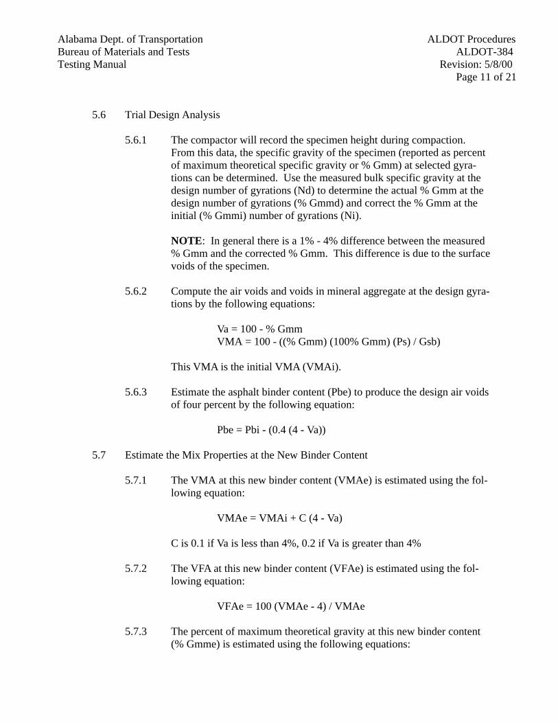
Alabama Dept. of Transportation ALDOT ProceduresBureau of Materials and Tests ALDOT-384Testing Manual Revision: 5/8/00
Page 11 of 21
5.6 Trial Design Analysis
5.6.1 The compactor will record the specimen height during compaction.From this data, the specific gravity of the specimen (reported as percentof maximum theoretical specific gravity or % Gmm) at selected gyra-tions can be determined. Use the measured bulk specific gravity at thedesign number of gyrations (Nd) to determine the actual % Gmm at thedesign number of gyrations (% Gmmd) and correct the % Gmm at theinitial (% Gmmi) number of gyrations (Ni).
NOTE: In general there is a 1% - 4% difference between the measured% Gmm and the corrected % Gmm. This difference is due to the surfacevoids of the specimen.
5.6.2 Compute the air voids and voids in mineral aggregate at the design gyra-tions by the following equations:
Va = 100 - % Gmm VMA = 100 - ((% Gmm) (100% Gmm) (Ps) / Gsb)
This VMA is the initial VMA (VMAi).
5.6.3 Estimate the asphalt binder content (Pbe) to produce the design air voidsof four percent by the following equation:
Pbe = Pbi - (0.4 (4 - Va))
5.7 Estimate the Mix Properties at the New Binder Content
5.7.1 The VMA at this new binder content (VMAe) is estimated using the fol-lowing equation:
VMAe = VMAi + C (4 - Va)
C is 0.1 if Va is less than 4%, 0.2 if Va is greater than 4%
5.7.2 The VFA at this new binder content (VFAe) is estimated using the fol-lowing equation:
VFAe = 100 (VMAe - 4) / VMAe
5.7.3 The percent of maximum theoretical gravity at this new binder content(% Gmme) is estimated using the following equations:
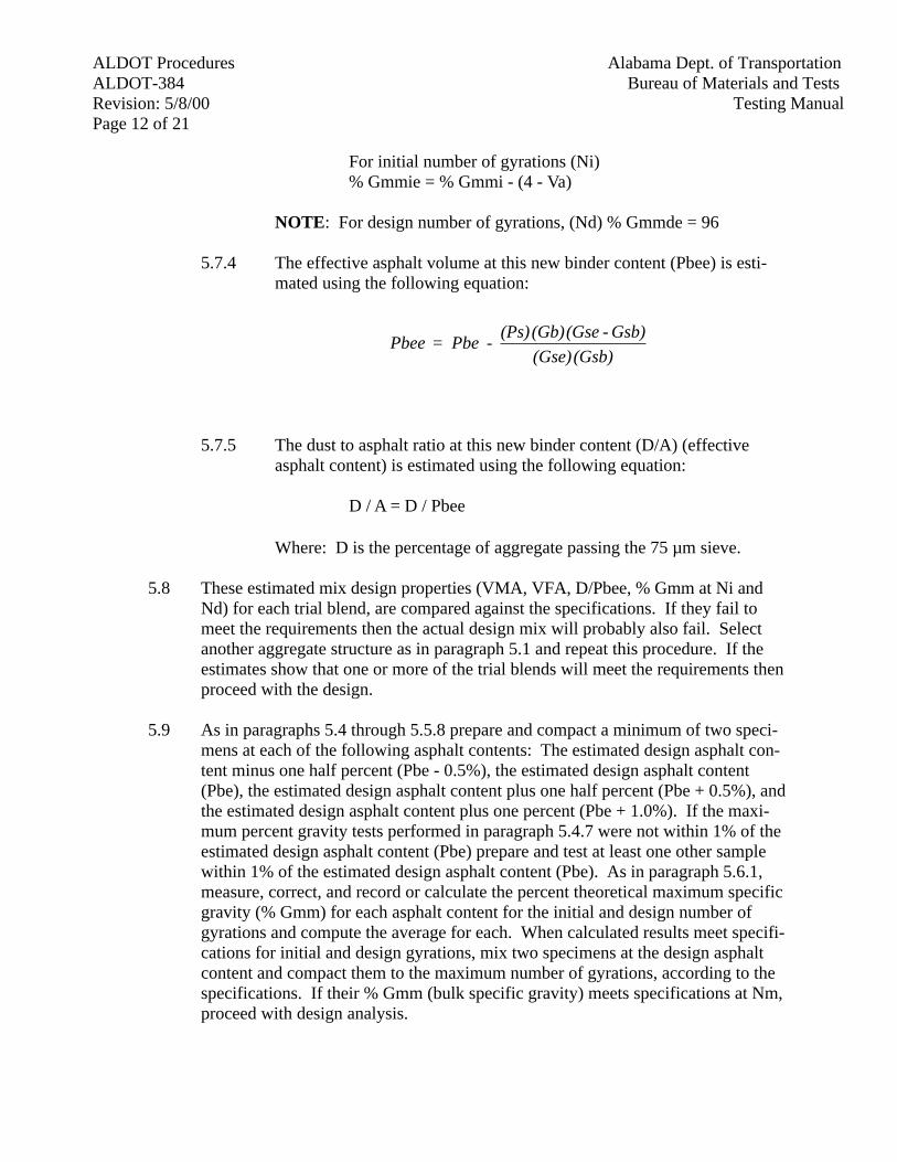
ALDOT Procedures Alabama Dept. of TransportationALDOT-384 Bureau of Materials and TestsRevision: 5/8/00 Testing ManualPage 12 of 21
For initial number of gyrations (Ni) % Gmmie = % Gmmi - (4 - Va)
NOTE: For design number of gyrations, (Nd) % Gmmde = 96
5.7.4 The effective asphalt volume at this new binder content (Pbee) is esti-mated using the following equation:
5.7.5 The dust to asphalt ratio at this new binder content (D/A) (effectiveasphalt content) is estimated using the following equation:
D / A = D / Pbee
Where: D is the percentage of aggregate passing the 75 µm sieve.
5.8 These estimated mix design properties (VMA, VFA, D/Pbee, % Gmm at Ni andNd) for each trial blend, are compared against the specifications. If they fail tomeet the requirements then the actual design mix will probably also fail. Selectanother aggregate structure as in paragraph 5.1 and repeat this procedure. If theestimates show that one or more of the trial blends will meet the requirements thenproceed with the design.
5.9 As in paragraphs 5.4 through 5.5.8 prepare and compact a minimum of two speci-mens at each of the following asphalt contents: The estimated design asphalt con-tent minus one half percent (Pbe - 0.5%), the estimated design asphalt content(Pbe), the estimated design asphalt content plus one half percent (Pbe + 0.5%), andthe estimated design asphalt content plus one percent (Pbe + 1.0%). If the maxi-mum percent gravity tests performed in paragraph 5.4.7 were not within 1% of theestimated design asphalt content (Pbe) prepare and test at least one other samplewithin 1% of the estimated design asphalt content (Pbe). As in paragraph 5.6.1,measure, correct, and record or calculate the percent theoretical maximum specificgravity (% Gmm) for each asphalt content for the initial and design number ofgyrations and compute the average for each. When calculated results meet specifi-cations for initial and design gyrations, mix two specimens at the design asphaltcontent and compact them to the maximum number of gyrations, according to thespecifications. If their % Gmm (bulk specific gravity) meets specifications at Nm,proceed with design analysis.
(Gsb) (Gse)Gsb) - (Gse (Gb) (Ps)
- Pbe = Pbee
Alabama Dept. of Transportation ALDOT ProceduresBureau of Materials and Tests ALDOT-384Testing Manual Revision: 5/8/00
Page 13 of 21
6. DENSITY AND VOIDS ANALYSIS (AT DESIGN NUMBER OF GYRATIONS)
NOTE! Equations were taken from the Asphalt Institute Manual, SP-2, Superpave Level Imix design.
6.1 Aggregate Bulk and Apparent Specific Gravity Calculation
6.1.1 Calculate the bulk and apparent specific gravity of the coarse aggregatein accordance with AASHTO T-85 (See Note 1).
6.1.2 Calculate the Bulk and Apparent Specific Gravity of Fine Aggregate inaccordance with AASHTO T-84 on the material retained on the 75 µmsieve after the material passing the 75 µm sieve has been removed by
washing (Assume that the 75 µm material washed from the sample hasthe same specific gravity as the material retained on the 75 µm sieve).(See Note 2.)
6.1.3 Calculate the bulk specific gravity (Gsb) of the total aggregate blend asfollows:
6.1.4 Calculate the Apparent Specific Gravity (Gsa) of the total combinedmineral aggregate as shown in paragraph 5.6.3 by substituting the Appar-ent Specific Gravity of the aggregate in the formula for the Bulk SpecificGravity (Gsb) (See Note 1).
NOTE 1: All test results shall be carried out to three decimal places.
NOTE 2: The Bulk Specific Gravity of mineral filler is difficult todetermine. However, if the Apparent Specific Gravity of mineral filler isused instead, the error is usually negligible (refer to AASHTO T-37 andAASHTO T-100).
6.2 Effective Specific Gravity of Aggregate Calculations (Gse)
6.2.1 Calculate the Effective Specific Gravity of aggregate using averageGmm as determined in paragraph 5.4.7 or 5.9 as follows:
)n Agg. Gsb
n Agg. Percent( + )
2 Agg. Gsb2 Agg. Percent
( + )1 Agg. Gsb
1 Agg. Percent(
100 = Gsb
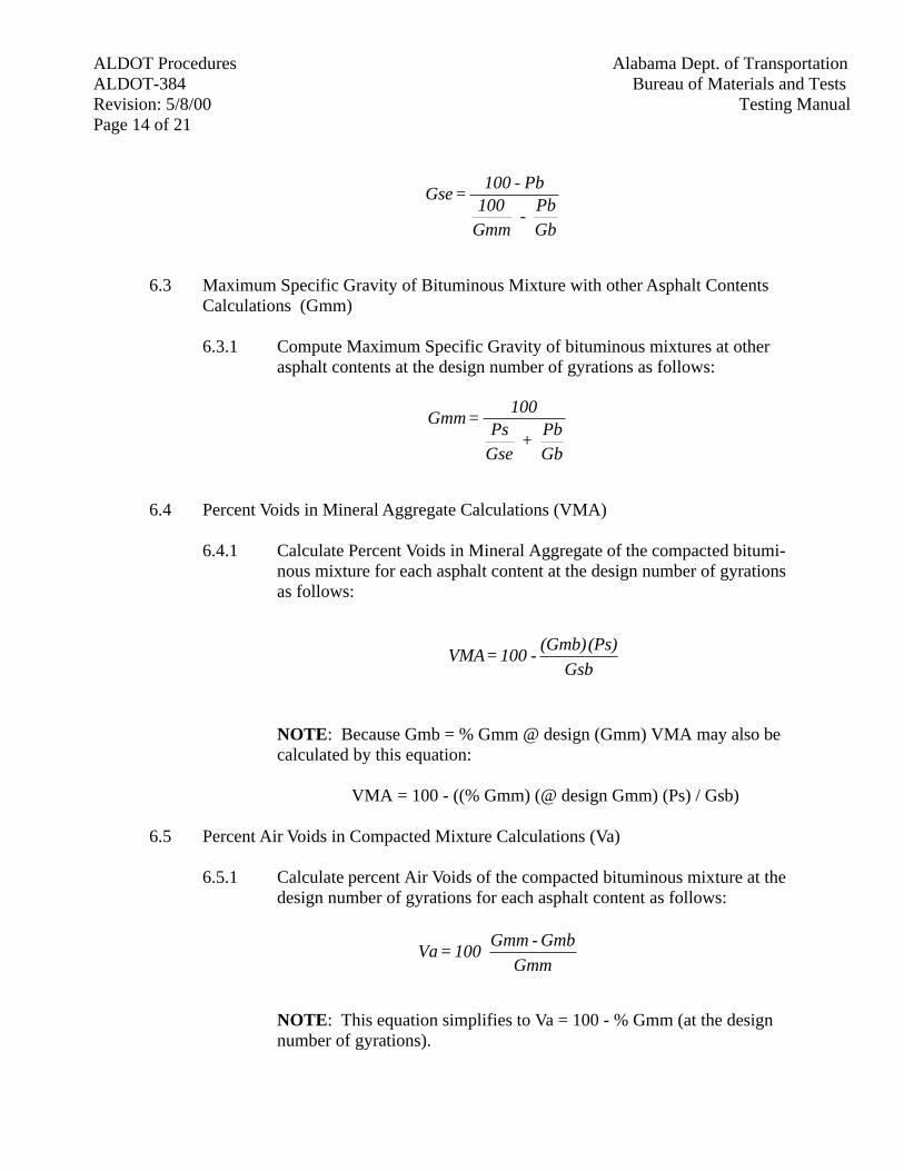
ALDOT Procedures Alabama Dept. of TransportationALDOT-384 Bureau of Materials and TestsRevision: 5/8/00 Testing ManualPage 14 of 21
6.3 Maximum Specific Gravity of Bituminous Mixture with other Asphalt ContentsCalculations (Gmm)
6.3.1 Compute Maximum Specific Gravity of bituminous mixtures at otherasphalt contents at the design number of gyrations as follows:
6.4 Percent Voids in Mineral Aggregate Calculations (VMA)
6.4.1 Calculate Percent Voids in Mineral Aggregate of the compacted bitumi-nous mixture for each asphalt content at the design number of gyrationsas follows:
NOTE: Because Gmb = % Gmm @ design (Gmm) VMA may also becalculated by this equation:
VMA = 100 - ((% Gmm) (@ design Gmm) (Ps) / Gsb)
6.5 Percent Air Voids in Compacted Mixture Calculations (Va)
6.5.1 Calculate percent Air Voids of the compacted bituminous mixture at thedesign number of gyrations for each asphalt content as follows:
NOTE: This equation simplifies to Va = 100 - % Gmm (at the designnumber of gyrations).
GbPb
- Gmm100
Pb - 100 = Gse
GbPb
+ GsePs
100 = Gmm
Gsb(Ps) (Gmb)
- 100 = VMA
GmmGmb - Gmm
100 = Va
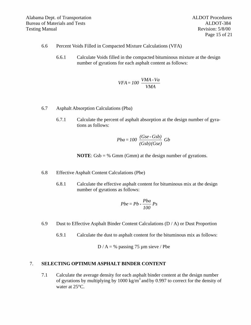
Alabama Dept. of Transportation ALDOT ProceduresBureau of Materials and Tests ALDOT-384Testing Manual Revision: 5/8/00
Page 15 of 21
6.6 Percent Voids Filled in Compacted Mixture Calculations (VFA)
6.6.1 Calculate Voids filled in the compacted bituminous mixture at the designnumber of gyrations for each asphalt content as follows:
6.7 Asphalt Absorption Calculations (Pba)
6.7.1 Calculate the percent of asphalt absorption at the design number of gyra-tions as follows:
NOTE: Gsb = % Gmm (Gmm) at the design number of gyrations.
6.8 Effective Asphalt Content Calculations (Pbe)
6.8.1 Calculate the effective asphalt content for bituminous mix at the designnumber of gyrations as follows:
6.9 Dust to Effective Asphalt Binder Content Calculations (D / A) or Dust Proportion
6.9.1 Calculate the dust to asphalt content for the bituminous mix as follows:
D / A = % passing 75 µm sieve / Pbe
7. SELECTING OPTIMUM ASPHALT BINDER CONTENT
7.1 Calculate the average density for each asphalt binder content at the design numberof gyrations by multiplying by 1000 kg/m3 and by 0.997 to correct for the density ofwater at 25°C.
VMAVa - VMA
100 = VFA
Gb (Gse) (Gsb)Gsb)-(Gse
100 = Pba
Ps 100Pba
- Pb = Pbe
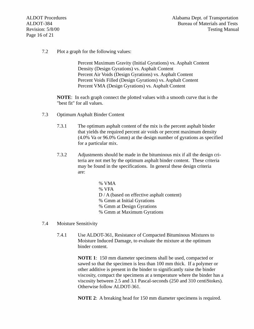
ALDOT Procedures Alabama Dept. of TransportationALDOT-384 Bureau of Materials and TestsRevision: 5/8/00 Testing ManualPage 16 of 21
7.2 Plot a graph for the following values:
Percent Maximum Gravity (Initial Gyrations) vs. Asphalt Content Density (Design Gyrations) vs. Asphalt Content Percent Air Voids (Design Gyrations) vs. Asphalt Content Percent Voids Filled (Design Gyrations) vs. Asphalt Content Percent VMA (Design Gyrations) vs. Asphalt Content
NOTE: In each graph connect the plotted values with a smooth curve that is the"best fit" for all values.
7.3 Optimum Asphalt Binder Content
7.3.1 The optimum asphalt content of the mix is the percent asphalt binderthat yields the required percent air voids or percent maximum density(4.0% Va or 96.0% Gmm) at the design number of gyrations as specifiedfor a particular mix.
7.3.2 Adjustments should be made in the bituminous mix if all the design cri-teria are not met by the optimum asphalt binder content. These criteria may be found in the specifications. In general these design criteriaare:
% VMA
% VFA D / A (based on effective asphalt content) % Gmm at Initial Gyrations
% Gmm at Design Gyrations% Gmm at Maximum Gyrations
7.4 Moisture Sensitivity
7.4.1 Use ALDOT-361, Resistance of Compacted Bituminous Mixtures toMoisture Induced Damage, to evaluate the mixture at the optimumbinder content.
NOTE 1: 150 mm diameter specimens shall be used, compacted orsawed so that the specimen is less than 100 mm thick. If a polymer orother additive is present in the binder to significantly raise the binderviscosity, compact the specimens at a temperature where the binder has aviscosity between 2.5 and 3.1 Pascal-seconds (250 and 310 centiStokes).Otherwise follow ALDOT-361.
NOTE 2: A breaking head for 150 mm diameter specimens is required.
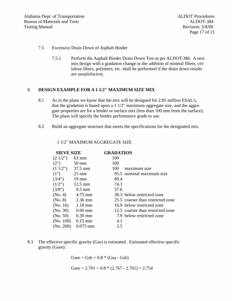
Alabama Dept. of Transportation ALDOT ProceduresBureau of Materials and Tests ALDOT-384Testing Manual Revision: 5/8/00
Page 17 of 21
7.5 Excessive Drain Down of Asphalt Binder
7.5.1 Perform the Asphalt Binder Drain Down Test as per ALDOT-386. A newmix design with a gradation change or the addition of mineral fibers, cel-lulose fibers, polymers, etc. shall be performed if the drain down resultsare unsatisfactory.
8. DESIGN EXAMPLE FOR A 1 1/2" MAXIMUM SIZE MIX
8.1 As in the plans we know that the mix will be designed for 2.85 million ESAL's,that the gradation is based upon a 1 1/2" maximum aggregate size, and the aggre-gate properties are for a binder or surface mix (less than 100 mm from the surface).The plans will specify the binder performance grade to use.
8.2 Build an aggregate structure that meets the specifications for the designated mix.
1 1/2" MAXIMUM AGGREGATE SIZE
SIEVE SIZE GRADATION (2 1/2") 63 mm 100 (2") 50 mm 100 (1 1/2") 37.5 mm 100 maximum size
(1") 25 mm 95.5 nominal maximum size (3/4") 19 mm 89.4 (1/2") 12.5 mm 74.1
(3/8") 9.5 mm 57.6 (No. 4) 4.75 mm 38.3 below restricted zone (No. 8) 2.36 mm 25.5 coarser than restricted zone (No. 16) 1.18 mm 16.9 below restricted zone (No. 30) 0.60 mm 12.5 coarser than restricted zone (No. 50) 0.30 mm 7.9 below restricted zone (No. 100) 0.15 mm 4.1 (No. 200) 0.075 mm 3.5
8.3 The effective specific gravity (Gse) is estimated. Estimated effective specific gravity (Gsee):
Gsee = Gsb + 0.8 * (Gsa - Gsb)
Gsee = 2.701 + 0.8 * (2.767 - 2.701) = 2.754
ALDOT Procedures Alabama Dept. of TransportationALDOT-384 Bureau of Materials and TestsRevision: 5/8/00 Testing ManualPage 18 of 21
8.4 The volume of asphalt binder absorbed (Vba) is estimated. Estimated volume ofasphalt binder absorbed (Vbae):
Vbae = {[(1 / Gsb) - (1 / Gsee)] [Ps (1 - Va)]} / [(Pb / Gb) + (Ps / Gsee)]
Vbae = {[(1 / 2.701) - (1 / 2.754)] [0.95 (1 - 0.04)]} / [(0.05 / 1.02) + (0.95 / 2.754)]
Vbae = 0.0165 = 1.65%
8.5 The volume of effective binder (Vbe) is estimated. Estimated volume of effectivebinder (Vbee):
Vbee = 0.176 - 0.0675 * (logarithm base ten (Sn))
Vbee = 0.176 - 0.0675 * (logarithm (25)) = 0.0816 = 8.16%
NOTE: Sn is the nominal maximum size in millimeters.
8.6 The weight of aggregate per unit of mix (Ws) is estimated. Estimated weight ofaggregate per unit of mix (Wse):
Wse = [Ps (1 - Va)] / [(Pb / Gb) + (Ps / Gsee)]
Wse = [0.95 (1 - 0.04)] / [(0.05 / 1.02) + (0.95 / 2.754)] = 2.315
8.7 The initial trial asphalt binder content (Pbi) is estimated. Estimated initial trialasphalt binder content (Pbie):
Pbie = 100 [Gb (Vbee + Vbae)] / [Gb (Vbee + Vbae) + Wse]
Pbi = 100 [1.02 (0.0816 + 0.0165)] / [1.02 (0.0816 + 0.0165) + 2.315] = 4.14%
8.8 Two pills with the above gradation and 4.14% binder content are compacted withthe gyratory compactor and a maximum specific (Rice) gravity test is performed onthe mix. The bulk specific gravity of the pills at the design number of gyrations isperformed and from the compaction curve generated by the gyratory compactor acorrection factor is calculated. The bulk specific gravity of the pills is calculatedusing this correction factor at the initial number of gyrations from the compactioncurve data. Using these bulk specific gravities the percent of maximum specificgravity at initial and design number of gyrations is computed.
Alabama Dept. of Transportation ALDOT ProceduresBureau of Materials and Tests ALDOT-384Testing Manual Revision: 5/8/00
Page 19 of 21
8.9 The average percent of maximum specific gravity at the design number of gyrationsis calculated to be 95.2%. Calculate the percent of air voids (Va) and the VMA atthe design number of gyrations:
Va = 100 - % Gmm (corrected) at design gyrations
Va = 100 - 95.2 = 4.8%
VMA = 100 - ((% Gmm) (100% Gmm) (Ps) / Gsb)This VMA is the initial VMA (VMAi).
VMAi = 100 - (95.2 * 2.568 * 0.955 / 2.701) = 13.56
8.10 Estimate the asphalt binder content (Pbe) to produce the design air voids of fourpercent:
Pbe = Pbi - (0.4 (4 - Va))
Pbe = 4.5 - (0.4 (4 - 4.8)) = 4.8
8.11 Estimate the VMA at this new binder content (VMAe):
VMAe = VMAi + C (4 - Va)
C is 0.1 if Va is less than 4%, 0.2 if Va is greater than 4%
VMAe = 13.5 + (0.2 (4.0 - 4.8)) = 13.3
A 1 1/2" maximum size mix must have a minimum VMA of 13.0, so the estimate looks good.
8.12 Estimate the VFA at this new binder content (VFAe).
VFAe = 100 (VMAe - 4) / VMAe
VFAe = 100 (13.3 - 4.0) / 13.3 = 69.9
A 2.85 million ESAL's mix should have between 65 and 78% VFA, sothe estimate looks good.
ALDOT Procedures Alabama Dept. of TransportationALDOT-384 Bureau of Materials and TestsRevision: 5/8/00 Testing ManualPage 20 of 21
8.13 Estimate the percent of maximum theoretical gravity at this new binder content(% Gmme)
For initial number of gyrations% Gmmie = % Gmmi - (4 - Va)
NOTE: For design number of gyrations, % Gmmde = 96.0%
Initial% Gmm = 86.3 - (4.0 - 4.8) = 87.1%
For a superpave mix the percent of maximum specific gravity at the ini-tial number of gyrations must be below 89.0%, so the estimate looksgood.
8.14 Estimate the effective asphalt content (Pbee):
Pbee = Pbe - [PsGb (Gse - Gsb) / GseGsb]
(Pbe is the estimated binder content from section 8.10.)
Pbee = 4.8 - [(95.3) (1.02) (2.754 - 2.701)] / (2.754) (2.701) = 4.1%
8.15 Estimate the dust to asphalt ratio at this new binder content (D/A).
D / A = D / Pbee
D / A = 3.5 / 4.1 = 0.85
The SP-2 manual refers to this as the Dust Proportion (DP). The percentof aggregate passing the 0.075 mm sieve by mass of aggregate (% 0.075)is divided by the effective binder content, percent by mass of total mix-ture (Pbe).
DP = 3.5/4.1 = 0.85
For a coarse superpave mix the dust to asphalt ratio (the dust proportion)must be from 0.6 to 1.6, so the estimate looks good.
8.16 If these estimated values fail, then the mix will probably also fail. If the estimated% Gmmi is above 89.0% and % Gmmm is above 98.0% then the pills will probablyclose up during compaction which means that the mix will probably be tender and
Pbemm 0.075 %
= DP
Alabama Dept. of Transportation ALDOT ProceduresBureau of Materials and Tests ALDOT-384Testing Manual Revision: 5/8/00
Page 21 of 21
prone to rutting on the road. The same holds true for the estimated VMA, VFA,and D/A (DP). If these estimated values fail then a new gradation or different gradebinder or other methods to strengthen the mix (like adding fibers or hydrated lime)should be tried to improve the mix.
8.17 If these estimates pass then the mix will probably also pass when compacted at theproper binder content to achieve 4.0% air voids (96.0% Gmm). Continue by com-pacting pills at four different binder contents as in the procedure.
9. REPORTING
9.1 The contractor shall submit a cover letter with the following information attached.
9.1.1 Source of all materials. All materials used shall be from an approvedsource.
9.1.2 Aggregate gradation and gravities.
9.1.3 .45 Power Chart.
9.1.4 Gyratory Compaction Data (Ni, Nd, and Nm).
9.1.5 Mix Properties (Plots from Section 7.2).
9.1.6 The Laboratory Density of the mix at the Optimum Asphalt Binder Con-tent and the design number of gyrations.
9.1.7 Maximum theoretical specific gravity.
9.1.8 TSR Data.

ALDOT ProceduresAlabama Dept. of TransportationALDOT-385Bureau of Materials and Tests
Revision: 2/16/96Testing ManualPage 1 of 1
ALDOT-385DETERMINING ABSORPTION OF GRAVEL
1. Scope
1.1. This procedure modifies AASHTO T-85 to simulate long term absorption of gravel.
2. Applicable Documents
2.1. Alabama Department of Transportation Standard Specifications for Highway Construction,Section 801.
2.2. AASHTO T-85, Specific Gravity and Absorption of Coarse Aggregate.
2.3. AASHTO T-209, Maximum Specific Gravity of Bituminous Paving Mixtures.
3. Apparatus
3.1. All of the equipment listed in AASHTO T-85 is used. In addition, the following equipmentfrom AASHTO T-209 is needed.
3.2. Container--The container may be either a glass or metal bowl, or a volumetric flask having acapacity of at least one liter. Containers shall be sufficiently strong to withstand a hardvacuum and shall have an airtight cover fitted with a hose connection to apply and measurethe vacuum.
3.3. Vacuum Pump or Aspirator--A device capable of producing a vacuum of 30 mm Hg or less,measured in absolute pressure, is needed to remove the entrapped air from the gravel.
3.4. Hose and Manometer--This is needed to connect the container and the vacuum pump, and toinsure that enough vacuum is applied.
4. Test Procedures
4.1. This test shall be run according to AASHTO T-85 with this addition to section 8.1 ofAASHTO T-85.
4.1.1. Immediately prior to immersing the aggregate in water at room temperature for 15 to19 hours perform the following. Place the gravel sample into the container and coverthe sample with water at approximately room temperature. Remove entrapped air bysubjecting the contents to a vacuum of 30 mm Hg or less absolute pressure for 13 to17 minutes. Agitate the container and contents either continuously by mechanicaldevice or manually by vigorous shaking at intervals of about two minutes. This isfrom sections 6.2 and 6.3 of AASHTO T-209. Minimize the gravel's exposure to airas the procedure continues according to AASHTO T-85, section 8.1.

ALDOT ProceduresAlabama Dept. of TransportationALDOT-386Bureau of Materials and Tests
Revision: 8/22/95Testing ManualPage 1 of 4
ALDOT-386-95DETERMINATION OF DRAINDOWN CHARACTERISTICS IN UNCOMPACTED
BITUMINOUS MIXTURES
1. Scope
1.1. This test method covers the determination of the amount of draindown in an uncompactedbituminous mixture sample when the sample is held at elevated temperatures comparable tothose encountered during the production, storage, transport, and placement of the mixture.The test is particularly applicable to mixtures such as porous asphalt (open-graded frictioncourse) and Stone Matrix Asphalt (SMA).
1.2. The values stated in the gram-millimeter units are to be regarded as the standard.
1.3. This standard may involve hazardous materials, operations, and equipment. This standarddoes not purport to address all of the safety problems associated with its use. It is theresponsibility of the user of this standard to establish appropriate safety and health practicesand determine the applicability of regulatory limitations prior to use.
2. Referenced Documents
2.1. AASHTO Standards:
2.1.1. T 245, Resistance to Plastic Flow of Bituminous Mixtures Using Marshall Apparatus.
2.1.2. M 92, Standard Specification for Wire-Cloth Sieves for Testing Purposes.
3. Definitions
3.1. Draindown - For the purpose of this test method, draindown is considered to be that portionof material, which separates itself from the sample as a whole and is deposited outside thewire basket during the test. The material, which drains, may be composed of either asphaltcement or a combination of asphalt cement and fine aggregate.
4. Summary of Method
4.1. A sample of the bituminous mixture to be tested is pre-pared in the laboratory or obtainedfrom field production. The sample is placed in a wire basket, which is positioned on a pre-weighted dry plate. The sample, basket, and plate are placed in a forced air oven for onehour at a pre-selected temperature. At the end of one hour, the basket containing the sampleis removed from the oven along with the plate and the plate is weighed to determine theamount of draindown that occurred.
5. Significance and Use
5.1. This test method can be used to determine whether the amount of draindown measured for agiven bituminous mixture is within acceptable levels. The test also provides an evaluation ofthe draindown potential of an asphalt mixture produced in the field.
ALDOT Procedures Alabama Dept. of TransportationALDOT-386 Bureau of Materials and TestsRevision: 8/22/95 Testing ManualPage 2 of 4
6. Apparatus
6.1. Oven, capable of maintaining the temperature in a range from 250 to 350°F (120 to 175°C).The oven should maintain the set temperature to within ± 4°F (2°C).
6.2. Plates of appropriate size. The plates used should be of appropriate durability to withstandthe oven temperatures. Paper or metal plates (disposable or otherwise) are acceptable.
6.3. Standard basket meeting the dimensions shown in Figure 1. The basket shall be constructedusing ¼ in (6.3mm) square openings.
6.4. Spatulas, trowels, mixer, and bowls as needed.
6.5. Balance accurate to 0.1 gram.
7. Sample Preparation
7.1. Laboratory Prepared Samples.
7.1.1. Number of Samples - For each mixture tested, the draindown characteristics shall bedetermined at three different temperatures. The three temperatures are the anticipatedplant production temperature and 27°F (15°C) above and below. For eachtemperature, duplicate samples should be tested. Thus for one bituminous mixture, amini-mum of six samples will be tested.
7.1.2. Dry the aggregate to constant mass and sieve it into appropriate size fractions asindicated in AASHTO T 245, section 3.2.
7.1.3. Determine the anticipated plant production temperature or select a mixingtemperature in accordance with AASHTO T 245, section 3.3.1.
7.1.4. Weigh into separate pans for each test sample the amount of each size fractionrequired to produce completed mixture samples having a mass of 1200 grams. Theaggregate fractions shall be combined such that the resulting aggregate blend has thesame gradations as the job-mix-formula. Place the samples in an oven and heat to atemperature not to exceed the mixing temperature established in 7.1.3 by more thanapproximately 80°F (28°C).
7.1.5. Heat the asphalt cement to the temperature established in 7.1.3.
7.1.6. Place the heated aggregate in the mixing bowl. Add any stabilizers (Note 1) andthoroughly mix the dry components. Form a crater in the aggregate blend and add therequired amount of asphalt. The amount of asphalt shall be that established in thejob-mix-formula. At this point, the temperature of the aggregate and asphalt cementshall be within the limits of the mixing temperature established in 7.1.3. Mix theaggregate (and stabilizer if any) and asphalt cement quickly until the aggregate isthoroughly coated.
ALDOT ProceduresAlabama Dept. of TransportationALDOT-386Bureau of Materials and Tests
Revision: 8/22/95Testing ManualPage 3 of 4
7.2. Plant Produced Samples.
7.2.1. Number of Samples - For plant produced samples, duplicate samples should be testedat the plant production temperature. Samples may be obtained during plant productionby sampling the mixture at any appropriate location such as the trucks prior to themixture leaving the plant or at the paver.
7.2.2. Samples obtained during actual production should be reduced to the proper testsample size by the quartering method.
8. Procedure
8.1. Transfer the laboratory produced or plant produced uncompacted mixture sample to a taredwire basket described in 6.3. Any aggregate that falls through the basket and onto the plateduring the transfer should be removed and wasted. Place the entire sample in the wirebasket. Do not consolidate or otherwise disturb the sample after transfer to the basket.Determine the mass of the sample to the nearest 0.1 gram.
8.2. Dry a plate, at the temperature listed below, for a minimum of 10 minutes. Immediatelydetermine and record the mass of the plate to the nearest 0.1-gram. Place the basket on thepaper plate and place the assembly into the oven at the temperature as determined in 7.1.1 or7.2.1 for 1-hour ± 1 minute.
8.3. After the sample has been in the oven for 1-hour ± 1 minute, remove the basket and paperplate. Remove any pieces of aggregate, which may have passed through the sieve and ontothe plate. Determine and record the mass of the plate plus drained asphalt cement to thenearest 0.1-gram.
9. Calculations
9.1. Calculate the percent of mixture which drained by subtracting the initial paper plate massfrom the final paper plate mass and divide this by the initial total sample mass. Multiply theresult by 100 to obtain a percentage.
10. Reporting
10.1. Report the average percent draindown at each of the test temperatures.
Note 1: Some types of stabilizers such as fibers or some polymers must be added directly tothe aggregate prior to mixing with the asphalt cement. Other types must be added directly tothe asphalt cement prior to blending with the aggregate. Also, some modifiers arepreblended with asphalt cement.
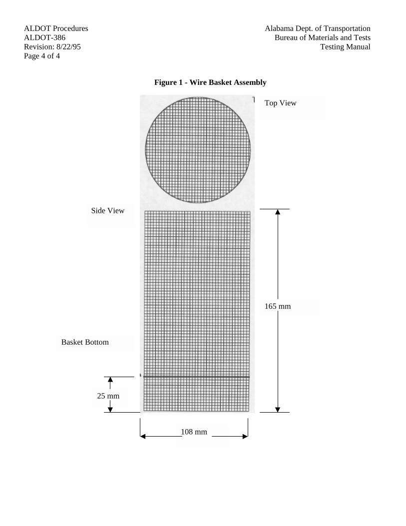
ALDOT Procedures Alabama Dept. of TransportationALDOT-386 Bureau of Materials and TestsRevision: 8/22/95 Testing ManualPage 4 of 4
Figure 1 - Wire Basket Assembly
165 mm
108 mm
25 mm
Basket Bottom
Side View
Top View
ALDOT ProceduresAlabama Dept. of TransportationALDOT-388Bureau of Materials and Tests
Revision: 5/8/96Testing ManualPage 1 of 9
ALDOT-388SUPERPAVE VOLUMETRIC MIX DESIGN PROCEDURE USING RECLAIMED ASPHALT
PAVEMENT
1. Scope
1.1. This procedure covers designing hot mix asphalt paving mixtures using reclaimed asphaltpavement (RAP) and should be used in conjunction with ALDOT-384. This method is foruse with mixtures with a gradation such that one hundred percent of the aggregate passes the2.5 in (63.0 mm) sieve and one hundred percent of the RAP passes the 2.0 in (50.0 mm)sieve.
2. Referenced Documents
2.1. AASHTO Standards
2.1.1. AASHTO T-49, Penetration of Bituminous Materials
2.1.2. AASHTO T-164, Quantitative Extraction of Bitumen from Bituminous PavingMixtures
2.1.3. AASHTO T-170, Recovery of Asphalt from Solution by Abson Method
2.1.4. AASHTO T-201, Kinematic Viscosity of Asphalts
2.1.5. AASHTO T-202, Viscosity of Asphalts by Vacuum Capillary Viscometer
2.1.6. AASHTO T-228, Specific Gravity of Semi-Solid Bituminous Materials
2.1.7. AASHTO MP1, Performance-Graded Asphalt Binder
2.2. ASTM Standards
2.2.1. ASTM D 4402, Standard Test Method for Viscosity Determinations of UnfilledAsphalts Using the Brookfield Thermosel Apparatus
2.3. ALDOT Procedures
2.3.1. ALDOT-258, Mechanical Analysis of Extracted Aggregate
2.3.2. ALDOT-372, Approval of RAP Stockpiles
2.3.3. ALDOT-384, Mix Design Procedure for Superpave Level One
2.4. Other Documents
2.4.1. The Asphalt Institute Manual, SP-1, Performance Graded Binder Specification andTesting, The Asphalt Institute, Lexington, KY, Current Edition.
ALDOT Procedures Alabama Dept. of TransportationALDOT-388 Bureau of Materials and TestsRevision: 5/8/96 Testing ManualPage 2 of 9
2.4.2. The Asphalt Institute Manual, SP-2, Superpave Level 1 Mix Design, The AsphaltInstitute, Lexington, KY, Current Edition.
2.4.3. The Asphalt Institute Manual, MS-2, Mix Design Methods for Asphalt Concrete, TheAsphalt Institute, Lexington, KY, Current Edition.
3. Evaluate Reclaimed Asphalt Pavement
3.1. Sample and test the RAP stockpile according to ALDOT-372.
3.2. Determine the gradation of the extracted aggregate by ALDOT-258.
3.3. Recover approximately 100 g of binder by AASHTO T-170. If the binder can not berecovered from the RAP (i.e. the RAP contains less than 1% binder) treat the RAP as anaggregate.
3.4. Determine the viscosity of the reclaimed binder at 140°F (60°C) by AASHTO T-202. Ifpossible, run three to five samples and take the average, however, one to two will suffice.
3.5. If the viscosity of the binder is too high to easily measure, measure penetration at 77°F(25°C) by AASHTO T-49 and viscosity at 135°C by AASHTO T-201; using the AsphaltConsistency Temperature Chart (Figure 1), estimate the viscosity at 140°F (60°C).
For example, suppose that at 77°F (25°C) the recovered binder has a penetration of 25, and at275°F (135°C) the recovered binder has a viscosity of 4,500 centistokes. Using the AsphaltConsistency Temperature Chart, the viscosity at 140°F (60°C) estimated to be 6,000 pascal-seconds (60,000 poises).
NOTE:To convert the viscosity in centistokes to poises multiply the viscosity in stokes bythe specific gravity of the binder (from AASHTO T-228). To convert the viscosity in poisesto pascal-seconds divide the viscosity in poises by ten (10).
3.6. The average value of the viscosity of the recovered asphalt will later (see section 4.6) beplotted on the left vertical axis on Figure 2, "Viscosity Blending Chart."
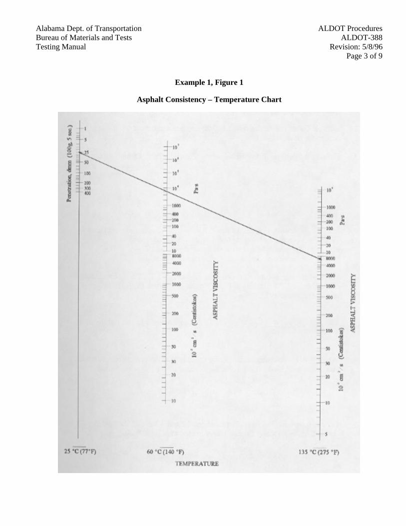
ALDOT ProceduresAlabama Dept. of TransportationALDOT-388Bureau of Materials and Tests
Revision: 5/8/96Testing ManualPage 3 of 9
Example 1, Figure 1
Asphalt Consistency – Temperature Chart
ALDOT Procedures Alabama Dept. of TransportationALDOT-388 Bureau of Materials and TestsRevision: 5/8/96 Testing ManualPage 4 of 9
4. Estimate Rap Blend Properties (From MS-2)
4.1. Using the extracted RAP aggregates, estimate the percent of RAP to be used in the mixture todesign an aggregate structure required in ALDOT-384 (the most practical amounts are 25%or less).
4.2. Estimate the asphalt binder demand of the combined aggregate blend using section 5.3 ofALDOT 384.
4.3. Estimate the percent of new asphalt in the mix using the following formula:
Prb X % RAPPnb = Pb –
100
Where:Pnb = estimated percent of new binder (recycling agent) in recycled mix.% RAP = percent RAP aggregate (by mass of total aggregate).Pb = percent binder content estimated in section 4.2.Prb = percent binder content determined in section 3.1.
For example, suppose the estimated binder demand is 5.4%, the binder content of the RAP is4.7% and 25% of the aggregate comes from the RAP (the new aggregate content is 75%).
4.7% X 0.25Pnb = 5.4% -
100= 4.2% new binder in mix (estimated)
4.4. Where R is the percentage ratio of new to old binder, the percent of new binder, Pnb, to thetotal binder content, Pb, is calculated by the following formula:
100 X PnbR =
Pb
For example, using the values from sections 4.2 and 4.3 above, the binder demand, Pb, is5.4% and the new binder in mix, Pnb, is 4.7%.
4.2R = 100 X
5.4= 78 Percent
4.5. Select the desired target viscosity of the final binder (check the specifications, this is usually300 Pa-s or 3,000 Poises).
4.6. Use Figure 2, Asphalt Cement Blending Chart, to estimate the viscosity of the new binder(recycling agent) to be used. Plot the viscosity of the aged RAP binder on the left handvertical scale from section 3.4 or 3.5. Draw a vertical line representing the percentage ofnew asphalt, R, from section 4.4 and determine its intersection with the horizontal linerepresenting the target viscosity from section 4.5. Then draw a straight line from the RAPbinder viscosity through this intersection point until it intersects the right vertical scale. The
ALDOT ProceduresAlabama Dept. of TransportationALDOT-388Bureau of Materials and Tests
Revision: 5/8/96Testing ManualPage 5 of 9
binder viscosity through this intersection point until it intersects the right vertical scale. Thepoint on the right vertical scale is the estimated viscosity of the new binder (recycling agent)used to obtain the target viscosity in section 4.5.
For example, using the values from sections 3.5 and 4.4, suppose the aged RAP binderviscosity is 6,000 Pascal-seconds and 78 percent of the total binder in the mix will be newbinder. Also assume the mix target viscosity is 300 Pascal-seconds. Using the AsphaltCement Blending Chart the new binder used in the mix should have a viscosity of 130 Pa-s.If this recycling agent may not be used, according to the specifications, reduce the amount ofRAP to be used and recalculate.
5. Modifications to ALDOT-384, Mix Design Procedure for Superpave Level I
5.1. Use ALDOT-384 with the following modifications, adding the same percentage of RAP toeach batch while mixing.
5.2. Use the percentage of binder needed as estimated in step 4.2 as the estimate of the mix designcontent (from section 5.3 in ALDOT-384).
5.3. When drying the aggregates prior to bathing do not dry the RAP above 140°F (60°C). Ifpossible, air dry the RAP to avoid further hardening.
5.4. When batching, do not mix the RAP with the other aggregates. Keep the RAP dry, in aseparate container until mixing.
5.5. Heat the aggregates, still separate from the RAP, approximately 10°C higher than inALDOT-384. Charge the heated mixing bowl with the heated aggregates.
5.6. Dry mix the RAP into the heated aggregates for approximately 30 seconds. Then add therecycling agent (binder) and mix as in ALDOT-384 (i.e. a mini-mum of two specimens ateach of the following binder contents: Pb-0.5%, Pb, Pb+0.5% and Pb+1.0%). If the mixtureis too stiff for complete coating and mixing, return to step 4.4 and elevate the aggregatetemperature further. If the recycling agent smokes at this elevated temperature while mixingthe percentage of RAP used and the mixing temperature should be reduced.
5.7. Compaction, density and voids analysis, and selection of optimum asphalt binder content areas in ALDOT-384.
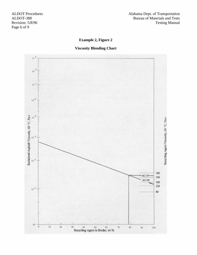
ALDOT Procedures Alabama Dept. of TransportationALDOT-388 Bureau of Materials and TestsRevision: 5/8/96 Testing ManualPage 6 of 9
Example 2, Figure 2
Viscosity Blending Chart
ALDOT ProceduresAlabama Dept. of TransportationALDOT-388Bureau of Materials and Tests
Revision: 5/8/96Testing ManualPage 7 of 9
6. Viscosity, Dust Proportion, and Fine Aggregate Angularity
6.1. Make at least one batch of at least 5,000 g according to section 4 of this procedure at theoptimum binder content as determined by ALDOT-384.
6.2. Extract and recover the asphalt binder by AASHTO T-164 and T-170. Save the remainingaggregate. Determine the viscosity of the recovered asphalt binder using AASHTO T-202.
6.3. Determine if this viscosity meets the specifications.
6.4. Check the aggregate properties of the aggregate (saved in step 5.2) to determine if they meetthe specifications. Particularly check the dust to effective asphalt ratio (dust proportion) andthe fine aggregate angularity (uncompacted voids analysis).
6.5. If step 6.3 fails to meet the specifications use a lower viscosity recycling agent or reduce thepercentage of RAP. If step 6.4 fails to meet the specifications the aggregate structure(percentage RAP or RAP source) must be changed.
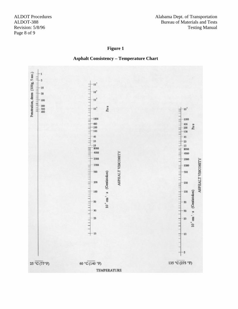
ALDOT Procedures Alabama Dept. of TransportationALDOT-388 Bureau of Materials and TestsRevision: 5/8/96 Testing ManualPage 8 of 9
Figure 1
Asphalt Consistency – Temperature Chart
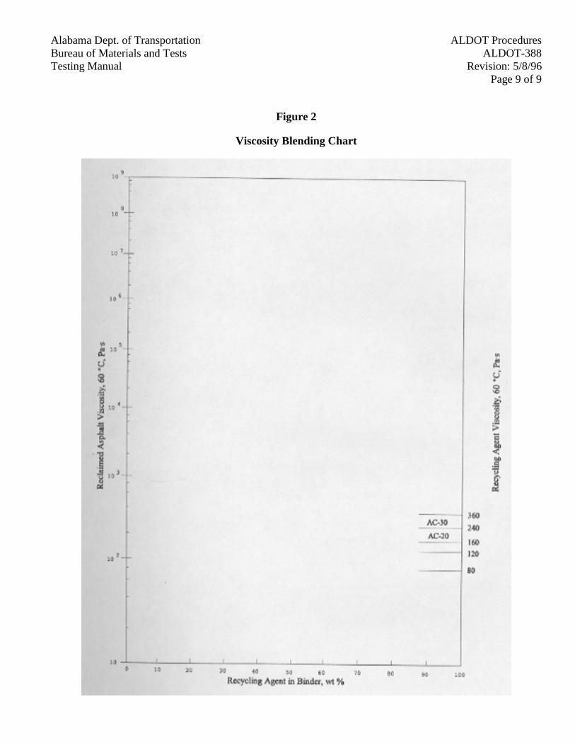
ALDOT ProceduresAlabama Dept. of TransportationALDOT-388Bureau of Materials and Tests
Revision: 5/8/96Testing ManualPage 9 of 9
Figure 2
Viscosity Blending Chart
ALDOT ProceduresAlabama Dept. of TransportationALDOT-389Bureau of Materials and Tests
Revision: 3/16/98Testing ManualPage 1 of 5
ALDOT-389EVALUATION OF SEGREGATED AREAS IN HOT MIX ASPHALT PAVEMENT
1. Scope
1.1. The objective of this procedure is to quantify areas of unacceptable segregation. Segregationin hot mix asphalt is the non-uniform distribution of aggregate with different sizes. Thus,segregation involves a concentration of coarse materials in a specific area and fines inanother area.
2. Referenced Documents
2.1. Alabama Department of Transportation Specifications
2.2. ALDOT-258, "Mechanical Analysis of Extracted Aggregates"
2.3. AASHTO TP 53, "Standard Test Method for Determining the Asphalt Content of Hot MixAsphalt (HMA) by Ignition Method"
3. Summary of Procedure
3.1. This procedure identifies unacceptable segregation by evaluating the gradation analysis andasphalt content of 6 in (150mm) diameter cores taken anytime visual observation indicatessegregated areas.
3.2. Observations should be made and cores should be taken as soon as possible after matcompaction; however, cores may be taken anytime prior to covering with an overlying layer,or, in case of wearing surface layer, upon completion of the hot mix pay items. Anytimevisual observations indicate obvious or suspected unacceptable segregation, cores shall betaken no later than the next working day. The asphalt content and gradation analysis of thecore will be used in determining deviations from the Job Mix Formula (JMF) andspecification tolerances.
3.3. All areas determined to be beyond specification limits shall be marked and referenced forremoval.
4. Determination of Test Locations
4.1. Segregation may be present in isolated areas or may be in continuous longitudinal stripsalong the roadway. By visual observance, all suspicious or obvious segregation shall bemarked and referenced for testing. Coarse areas and fine areas shall be marked separately.
5. Test Procedure
5.1. Within isolated marked areas, select the two most segregated spots (points), at least 20 in(0.5m) apart, and extract one core at each point.
ALDOT Procedures Alabama Dept. of TransportationALDOT-389 Bureau of Materials and TestsRevision: 3/16/98 Testing ManualPage 2 of 5
5.2. Within continuous longitudinal strips, select the two most segregated spots (points) within a150 ft (50 m) section, and extract one core at each point.
5.3. See Figure 1 showing examples of sampling points.
5.4. The percent asphalt content of the two cores should be determined in accordance withAASHTO TP 53 (ignition oven). Once the asphalt content has been determined, utilizeALDOT-258 to obtain a gradation analysis of the remaining aggregates. Aggregates fromboth cores should be combined before per-forming a gradation analysis.
5.5. When coring, each core shall be taken completely through the layer to be tested. The layer tobe tested shall be separated from other layers in the laboratory by sawing or other suitablemeans.
5.6. All testing of the cores shall be performed by Department or contractor technicians using anignition oven and testing laboratory. Contractor testing will be witnessed by Departmenttechnicians; likewise, Department testing may be witnessed by contractor technicians.
5.7. The location of cores taken shall be determined by the Department inspector.
6. Evaluations
6.1. Segregated areas will be evaluated by comparing the percent asphalt content and gradationanalysis of two cores to the design information found on the job mix formula.
6.2. Compute the deviation between the percent asphalt content of the cores deter-mined by theignition method to the design percent asphalt content from the job mix formula. Average thetwo deviations. If the average deviation is in excess of ± 0.50 percentage points from thedesign amount, then the area is considered segregated.
6.3. Determine the maximum size aggregate utilized in the mix from the Job Mix Formula (JMF)and use Table 1 to determine which sieves to use in the evaluation process.
Table IDetermination of Sieves Utilized In Segregation Evaluation
Maximum Size Aggregate Sieves Utilized1.5 in (37.5 mm) ½ in and No. 4 (12.5 mm and 4.75 mm)1.0 in (25.0 mm) 3/8 in and No. 4 (9.5 mm and 4.75 mm)¾ in (19.0 mm) No. 4 and No. 8 (4.75 mm and 2.36 mm)½ in (12.5 mm) No. 8 (2.36 mm)
6.4. Compare the gradation of the selected sieves to the design gradation from the Job MixFormula. If the deviation for either sieve varies ± 10 percentage points or more from thedesign gradation, the area is considered segregated.
6.5. If either asphalt content or gradation analysis of any selected sieves are deter-mined toexceed the allowable tolerances found in Table 2, the area will be considered segregated.
ALDOT ProceduresAlabama Dept. of TransportationALDOT-389Bureau of Materials and Tests
Revision: 3/16/98Testing ManualPage 3 of 5
Table IITest Allowable Tolerances
Asphalt Content ± 0.50 % Deviation of Design Percent ACGradation Analysis ± 10 % Deviation from Job Mix Formula
7. Report
7.1. The following information shall be included on a report for each segregated area or section.See Figure 2 for a sample report form.
7.1.1. Project Number and County
7.1.2. Production Lot and Date Produced
7.1.3. Location of Cores (Station and Offset)
7.1.4. Copy of Approved JMF
7.1.5. Percent AC from JMF
7.1.6. Percent AC from Ignition Method
7.1.7. Average Deviation of Core Percent AC to the Percent AC from JMF
7.1.8. Maximum Aggregate Size and Select Sieves Utilized
7.1.9. Gradation Analysis of Combined Cores on Selected Sieves
7.1.10. JMF - Percent Passing Selected Sieves
7.1.11. Deviation of the Combined Gradation Analysis of the two Cores on Selected Sievesto the Percent Passing from JMF
7.1.12. Signatures of Certified Technicians
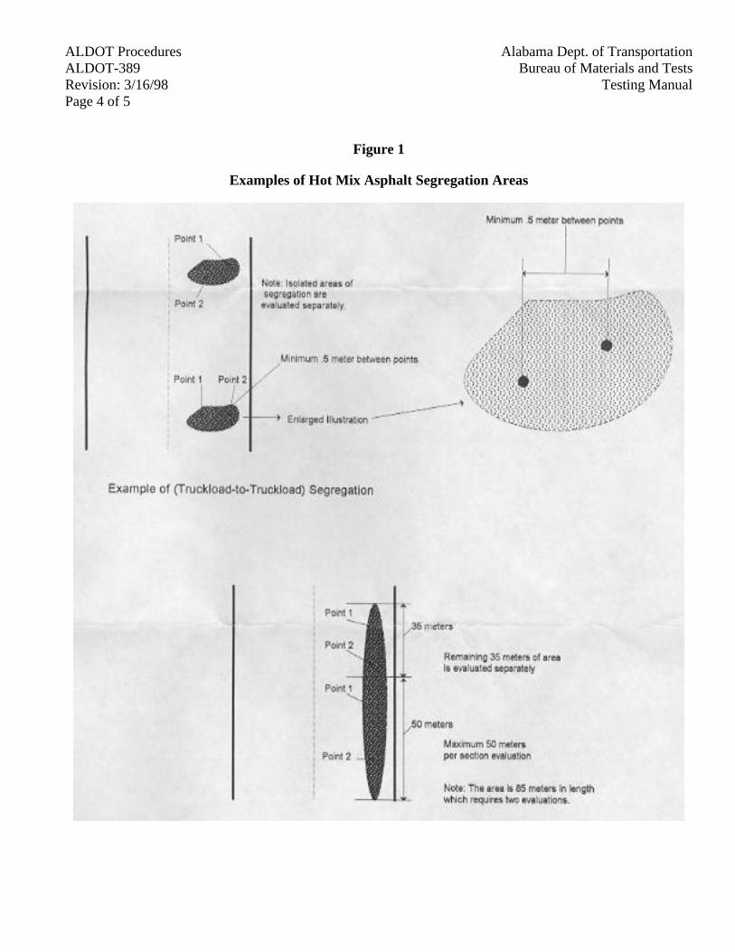
ALDOT Procedures Alabama Dept. of TransportationALDOT-389 Bureau of Materials and TestsRevision: 3/16/98 Testing ManualPage 4 of 5
Figure 1
Examples of Hot Mix Asphalt Segregation Areas
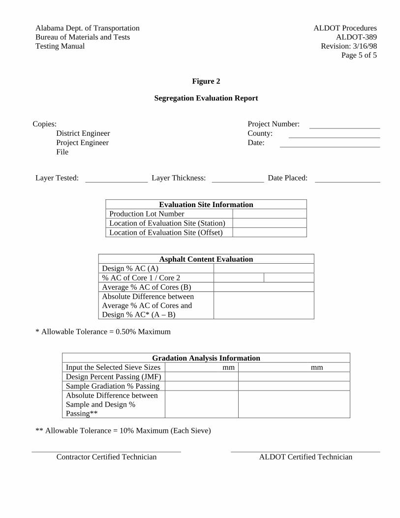
ALDOT ProceduresAlabama Dept. of TransportationALDOT-389Bureau of Materials and Tests
Revision: 3/16/98Testing ManualPage 5 of 5
Figure 2
Segregation Evaluation Report
Copies: Project Number:District Engineer County:Project Engineer Date:File
Layer Tested: Layer Thickness: Date Placed:
Evaluation Site InformationProduction Lot NumberLocation of Evaluation Site (Station)Location of Evaluation Site (Offset)
Asphalt Content EvaluationDesign % AC (A)% AC of Core 1 / Core 2Average % AC of Cores (B)Absolute Difference betweenAverage % AC of Cores andDesign % AC* (A – B)
* Allowable Tolerance = 0.50% Maximum
Gradation Analysis InformationInput the Selected Sieve Sizes mm mmDesign Percent Passing (JMF)Sample Gradiation % PassingAbsolute Difference betweenSample and Design %Passing**
** Allowable Tolerance = 10% Maximum (Each Sieve)
Contractor Certified Technician ALDOT Certified Technician
Alabama Dept. of Transportation ALDOT ProceduresBureau of Materials and Tests ALDOT- 395Testing Manual Revision: 7/23/99
Page 1 of 11
ALDOT-395STONE MATRIX ASPHALT MIX DESIGN
1. Scope
1.1. This procedure covers the design of stone matrix asphalt (SMA) using either the SHRPgyratory compactor or the Marshall hammer. The design is based on the volumetricproperties of the SMA including air voids, voids in the mineral aggregate, stone on stonecontact, and mortar properties.
2. Referenced Documents
2.1. AASHTO Standards
2.1.1. AASHTO MP1, Specification for Performance Graded Asphalt Binder
2.1.2. AASHTO T-19, Unit Weight and Voids in Aggregate
2.1.3. AASHTO T-27, Sieve Analysis of Fine and Coarse Aggregates
2.1.4. AASHTO T-84, Specific Gravity and Absorption of Fine Aggregate
2.1.5. AASHTO T-85, Specific Gravity and Absorption of Coarse Aggregate
2.1.6. AASHTO TP1, Determining the Flexural Creep Stiffness of Asphalt BinderUsing the Bending Beam Rheometer (BBR)
2.1.7. AASHTO TP5, Determining the Rheological Properties of Asphalt BinderUsing a Dynamic Shear Rheometer (DSR)
2.2. ALDOT Documents
2.2.1. Materials, Sources, and Devices with Special Acceptance Requirementsmanual
2.2.2. ALDOT-307, Design Method for Selecting Optimum Asphalt Cement Con-tent of Bituminous Mixtures by Means of the Marshall Apparatus
2.2.3. ALDOT-361, Resistance of Compacted Bituminous Mixture to MoistureInduced Damage
2.2.4. ALDOT-384, Mix Design Procedure for Superpave Level 1
2.2.5. ALDOT-386, Determination of Draindown Characteristics in UncompactedBituminous Mixtures
2.2.6. ALDOT-399, Testing of HMA Mortars
ALDOT Procedures Alabama Dept. of TransportationALDOT-395 Bureau of Materials and TestsRevision:7/23/99 Testing Manual
Page 2 of 11
3. Definitions And Nomenclature
3.1. SMA - stone matrix asphalt - SMA is a hot mix asphalt consisting of two parts - a coarseaggregate skeleton and an asphalt rich mortar. The aggregate skeleton must have stone onstone contact and the mortar must possess good rheometric properties as in the specifications.
3.2. SMA mortar - The mixture of polymerized liquid asphalt binder, mineral dust (mineralfiller), and fiber.
3.3. Voids in the Coarse Aggregate (VCA) - The volume in between the coarse aggregateparticles. This volume includes the mineral filler, the fine aggregate, air voids, polymerizedliquid asphalt binder, and fiber.
4. Procedures
4.1. Determine if the mix is for a wearing layer. Select an aggregate structure (gradation) andperformance grade liquid asphalt binder based upon the specifications, plans, and proposal.
4.2. Select fine and coarse aggregates (reclaimed asphalt pavement is not allowed in SMA) fromALDOT approved sources (see Materials, Sources, and Devices with Special AcceptanceRequirements manual, List I-1). Select a mineral filler that meets the specifications.
4.3. Dry aggregates to a constant weight (mass) at approximately 230°F (110°C) and separateeach aggregate into the following size fractions:
1 1/2 to 1" (37.5 to 25.0 mm)1 to 3/4" (25.0 to 19.0 mm)3/4 to 1/2" (19.0 to 12.5 mm)1/2 to 3/8" (12.5 to 9.5 mm)3/8" to No. 4 (9.5 to 4.75 mm)No. 4 to No. 8 (4.75 to 2.36 mm)Passing No. 8 (2.36 mm)
4.4. Combine the aggregates in a blend that falls within the master ranges specified. These rangesare based on percent passing by volume. These gradations based on volume are converted toweight (mass) for mixture design and control. It is recommended that at least three trialblends be evaluated.
4.5. In general, the mixing temperature is the temperature where the liquid asphalt binder has aviscosity of 170 ± 20 cSt and the compaction temperature is the temperature where the liquidasphalt binder has a viscosity of 280 ± 30 cSt; however, since the liquid asphalt bindercontains polymer the mixing and compaction temperatures may be different, so themanufacturer's recommendations and guidelines should be followed to determine mixing andcompaction temperatures.
4.6. Using a mechanical mixer, an initial batch shall be mixed to coat the mixing bowl and stirrers(this is usually referred to as "buttering"). This batch shall be emptied after mixing and thesides of the bowl and stirrers scraped clean with a limber spatula. Do not clean the bowl and
Alabama Dept. of Transportation ALDOT ProceduresBureau of Materials and Tests ALDOT- 395Testing Manual Revision: 7/23/99
Page 3 of 11
stirrer with solvents unless the liquid asphalt binder or aggregate source is changed (in whichcase, re-butter the bowl and stirrers).
4.7. Weigh into separate containers for each test specimen the amount of each size fractionrequired to produce a batch of aggregate that will result in a compacted specimen of thecorrect size. For Marshall compaction this is 2 1/2" (63.5 mm) and approximately 1200grams. Up to four Marshall specimens may be batched at once, but care must be taken not tosegregate the mixture. For Superpave compaction this is 4 1/2" (115 mm) and approximately4500 grams. The amount of aggregate in each batch shall be adjusted to produce compactedspecimens of the correct height (within 5 percent is usually accurate enough).
4.8. Mix the aggregate in each container and place in an oven and heat to no more than 500°F(280°C) above the mixing temperature established in section 4.5. Heat the liquid asphaltbinder to the mixing temperature. The stabilizing fiber shall be added to and mixed with theaggregates prior to the addition of the liquid asphalt binder. If the fiber is not thoroughlymixed with the aggregate prior to the liquid asphalt binder, the fiber will clump and theresults will be invalid.
4.9. Form a crater in the dry blended aggregate and fiber and pour into the crater the requiredamount of liquid asphalt binder. At or above the mixing temperature, mix the aggregate,liquid asphalt binder, and fiber until the aggregate and fiber are thoroughly coated.
4.10. Age and compact the specimens according to ALDOT-307 (Marshall) or ALDOT-384(Superpave) and the specifications. Use the procedures in ALDOT-307 (Marshall) orALDOT-384 (Superpave) to determine the optimum asphalt content for each trial blend.
4.11. Evaluate the trial blends for air voids (Va) and voids in the mineral aggregate (VMA) usingthe equations in ALDOT-307 (Marshall) or ALDOT-384 (Superpave). Evaluate the trialblends for voids in the coarse aggregate of the mix (VCAMIX) using the equations found inSection 6, Examples, in this procedure.
4.12. Evaluate the tensile strength ratio (TSR) and drain down properties of the best trial gradationat the optimum asphalt content using ALDOT-361 and ALDOT-386.
Note: It may be difficult to obtain more than 7 percent Va for the TSR test; as long as the Va isequal to or greater than 6 percent the results will still be valid.
4.13. Evaluate the mortar properties of the best trial gradation using ALDOT-399. If theequipment to perform the evaluation is not available, the Liquid Asphalt Section of theBituminous Laboratories will evaluate the mortar.
4.14. At least 200 grams of the filler composing the mortar must be proportioned and provided in aseparate container. The correct amount of liquid asphalt binder to be added to 100 g of thefiller must be shown in the report or included with the filler.
4.15. The mortar is tested at the high temperature of the PG grade using the Dynamic ShearRheometer (TP5) in accordance with MP1.
ALDOT Procedures Alabama Dept. of TransportationALDOT-395 Bureau of Materials and TestsRevision:7/23/99 Testing Manual
Page 4 of 11
4.16. The mortar is tested at the low temperature of the PG grade using the Bending BeamRheometer (TP1) in accordance with MP1.
5. Mixture Adjustments
5.1. The Air Void content may be adjusted by changing the asphalt content. If changing theasphalt content drops the VMA or asphalt content below the minimum in the specifications,the air voids must be adjusted by changing the gradation.
5.2. The VMA may be raised by increasing the percentage of coarse aggregate. Changing theaggregate source may also help raise VMA.
5.3. The VCAMIX may be lowered by changing the gradation (typically by increasing thepercentage of coarse aggregate) or by changing the aggregate source.
5.4. The drain down may be lowered by increasing the amount of fibers used or by changing thesource of the fibers.
5.5. The mortar may be adjusted by changing the type and/or amount of filler, fiber, and/orpolymer used in the mortar.
6. Examples
6.1. Percent Passing By Volume: With SMA the specific gravities of different aggregatecomponents are not always similar enough to blend based upon weight (mass); this isespecially true when comparing mineral fillers to the other aggregates. Therefore, SMAgradation bands are based upon percent passing by volume. If the bulk specific gravities ofthe different aggregates (including the mineral filler) vary by less than 0.025, gradationsbased on weight (mass) may be used.
6.2. Perform gradation testing by AASHTO T-27. Determine the bulk specific gravity of theaggregates by AASHTO T-84 and T-85. Table 1 gives the results.
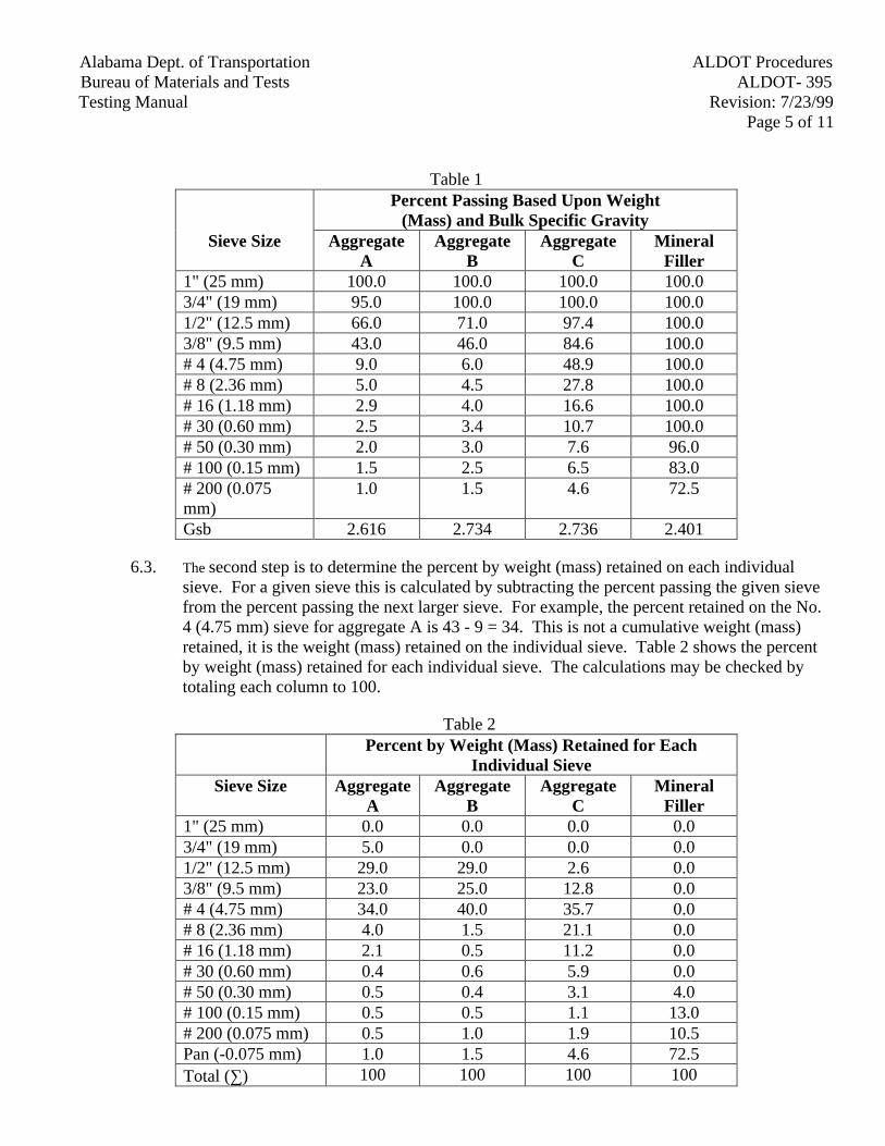
Alabama Dept. of Transportation ALDOT ProceduresBureau of Materials and Tests ALDOT- 395Testing Manual Revision: 7/23/99
Page 5 of 11
Table 1Percent Passing Based Upon Weight
(Mass) and Bulk Specific GravitySieve Size Aggregate
AAggregate
BAggregate
CMineral
Filler1" (25 mm) 100.0 100.0 100.0 100.03/4" (19 mm) 95.0 100.0 100.0 100.01/2" (12.5 mm) 66.0 71.0 97.4 100.03/8" (9.5 mm) 43.0 46.0 84.6 100.0# 4 (4.75 mm) 9.0 6.0 48.9 100.0# 8 (2.36 mm) 5.0 4.5 27.8 100.0# 16 (1.18 mm) 2.9 4.0 16.6 100.0# 30 (0.60 mm) 2.5 3.4 10.7 100.0# 50 (0.30 mm) 2.0 3.0 7.6 96.0# 100 (0.15 mm) 1.5 2.5 6.5 83.0# 200 (0.075mm)
1.0 1.5 4.6 72.5
Gsb 2.616 2.734 2.736 2.401
6.3. The second step is to determine the percent by weight (mass) retained on each individualsieve. For a given sieve this is calculated by subtracting the percent passing the given sievefrom the percent passing the next larger sieve. For example, the percent retained on the No.4 (4.75 mm) sieve for aggregate A is 43 - 9 = 34. This is not a cumulative weight (mass)retained, it is the weight (mass) retained on the individual sieve. Table 2 shows the percentby weight (mass) retained for each individual sieve. The calculations may be checked bytotaling each column to 100.
Table 2Percent by Weight (Mass) Retained for Each
Individual SieveSieve Size Aggregate
AAggregate
BAggregate
CMineral
Filler1" (25 mm) 0.0 0.0 0.0 0.03/4" (19 mm) 5.0 0.0 0.0 0.01/2" (12.5 mm) 29.0 29.0 2.6 0.03/8" (9.5 mm) 23.0 25.0 12.8 0.0# 4 (4.75 mm) 34.0 40.0 35.7 0.0# 8 (2.36 mm) 4.0 1.5 21.1 0.0# 16 (1.18 mm) 2.1 0.5 11.2 0.0# 30 (0.60 mm) 0.4 0.6 5.9 0.0# 50 (0.30 mm) 0.5 0.4 3.1 4.0# 100 (0.15 mm) 0.5 0.5 1.1 13.0# 200 (0.075 mm) 0.5 1.0 1.9 10.5Pan (-0.075 mm) 1.0 1.5 4.6 72.5Total (∑) 100 100 100 100
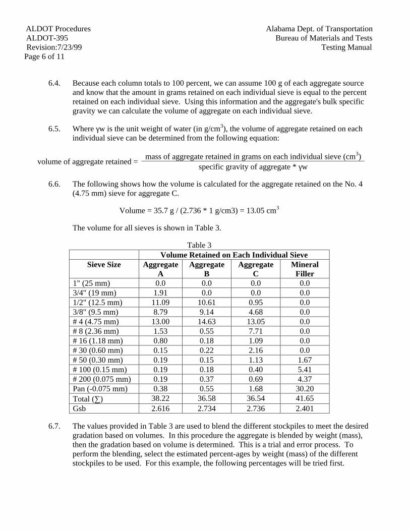
ALDOT Procedures Alabama Dept. of TransportationALDOT-395 Bureau of Materials and TestsRevision:7/23/99 Testing Manual
Page 6 of 11
6.4. Because each column totals to 100 percent, we can assume 100 g of each aggregate sourceand know that the amount in grams retained on each individual sieve is equal to the percentretained on each individual sieve. Using this information and the aggregate's bulk specificgravity we can calculate the volume of aggregate on each individual sieve.
6.5. Where γw is the unit weight of water (in g/cm3), the volume of aggregate retained on eachindividual sieve can be determined from the following equation:
mass of aggregate retained in grams on each individual sieve (cm3)volume of aggregate retained =
specific gravity of aggregate * γw
6.6. The following shows how the volume is calculated for the aggregate retained on the No. 4(4.75 mm) sieve for aggregate C.
Volume = 35.7 g / (2.736 * 1 g/cm3) = 13.05 cm3
The volume for all sieves is shown in Table 3.
Table 3Volume Retained on Each Individual Sieve
Sieve Size AggregateA
AggregateB
AggregateC
MineralFiller
1" (25 mm) 0.0 0.0 0.0 0.03/4" (19 mm) 1.91 0.0 0.0 0.01/2" (12.5 mm) 11.09 10.61 0.95 0.03/8" (9.5 mm) 8.79 9.14 4.68 0.0# 4 (4.75 mm) 13.00 14.63 13.05 0.0# 8 (2.36 mm) 1.53 0.55 7.71 0.0# 16 (1.18 mm) 0.80 0.18 1.09 0.0# 30 (0.60 mm) 0.15 0.22 2.16 0.0# 50 (0.30 mm) 0.19 0.15 1.13 1.67# 100 (0.15 mm) 0.19 0.18 0.40 5.41# 200 (0.075 mm) 0.19 0.37 0.69 4.37Pan (-0.075 mm) 0.38 0.55 1.68 30.20Total (∑) 38.22 36.58 36.54 41.65Gsb 2.616 2.734 2.736 2.401
6.7. The values provided in Table 3 are used to blend the different stockpiles to meet the desiredgradation based on volumes. In this procedure the aggregate is blended by weight (mass),then the gradation based on volume is determined. This is a trial and error process. Toperform the blending, select the estimated percent-ages by weight (mass) of the differentstockpiles to be used. For this example, the following percentages will be tried first.
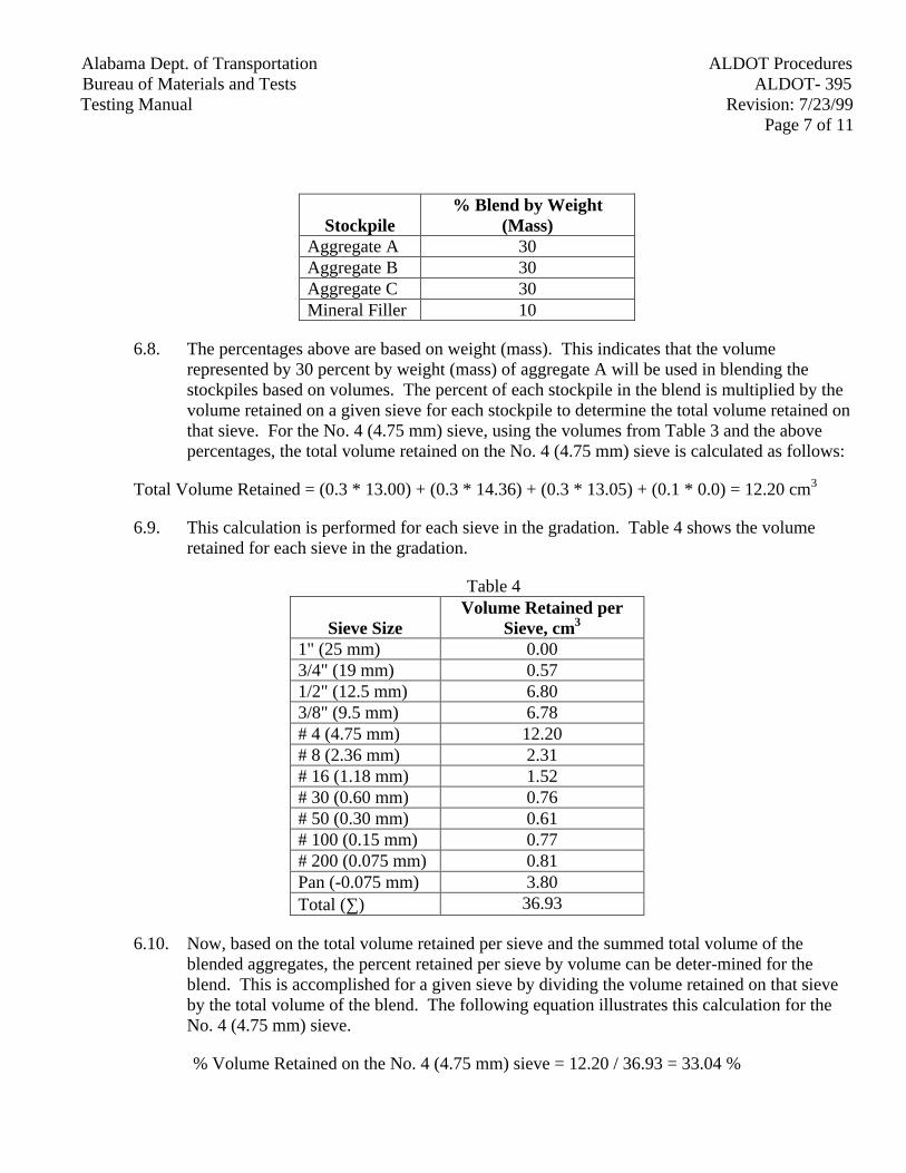
Alabama Dept. of Transportation ALDOT ProceduresBureau of Materials and Tests ALDOT- 395Testing Manual Revision: 7/23/99
Page 7 of 11
Stockpile% Blend by Weight
(Mass)Aggregate A 30Aggregate B 30Aggregate C 30Mineral Filler 10
6.8. The percentages above are based on weight (mass). This indicates that the volumerepresented by 30 percent by weight (mass) of aggregate A will be used in blending thestockpiles based on volumes. The percent of each stockpile in the blend is multiplied by thevolume retained on a given sieve for each stockpile to determine the total volume retained onthat sieve. For the No. 4 (4.75 mm) sieve, using the volumes from Table 3 and the abovepercentages, the total volume retained on the No. 4 (4.75 mm) sieve is calculated as follows:
Total Volume Retained = (0.3 * 13.00) + (0.3 * 14.36) + (0.3 * 13.05) + (0.1 * 0.0) = 12.20 cm3
6.9. This calculation is performed for each sieve in the gradation. Table 4 shows the volumeretained for each sieve in the gradation.
Table 4
Sieve SizeVolume Retained per
Sieve, cm3
1" (25 mm) 0.003/4" (19 mm) 0.571/2" (12.5 mm) 6.803/8" (9.5 mm) 6.78# 4 (4.75 mm) 12.20# 8 (2.36 mm) 2.31# 16 (1.18 mm) 1.52# 30 (0.60 mm) 0.76# 50 (0.30 mm) 0.61# 100 (0.15 mm) 0.77# 200 (0.075 mm) 0.81Pan (-0.075 mm) 3.80Total (∑) 36.93
6.10. Now, based on the total volume retained per sieve and the summed total volume of theblended aggregates, the percent retained per sieve by volume can be deter-mined for theblend. This is accomplished for a given sieve by dividing the volume retained on that sieveby the total volume of the blend. The following equation illustrates this calculation for theNo. 4 (4.75 mm) sieve.
% Volume Retained on the No. 4 (4.75 mm) sieve = 12.20 / 36.93 = 33.04 %
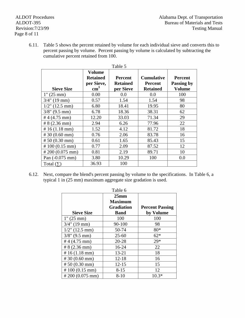
ALDOT Procedures Alabama Dept. of TransportationALDOT-395 Bureau of Materials and TestsRevision:7/23/99 Testing Manual
Page 8 of 11
6.11. Table 5 shows the percent retained by volume for each individual sieve and converts this topercent passing by volume. Percent passing by volume is calculated by subtracting thecumulative percent retained from 100.
Table 5
Sieve Size
VolumeRetainedper Sieve,
cm3
PercentRetainedper Sieve
CumulativePercent
Retained
PercentPassing by
Volume1" (25 mm) 0.00 0.0 0.0 1003/4" (19 mm) 0.57 1.54 1.54 981/2" (12.5 mm) 6.80 18.41 19.95 803/8" (9.5 mm) 6.78 18.36 38.31 62# 4 (4.75 mm) 12.20 33.03 71.34 29# 8 (2.36 mm) 2.94 6.26 77.96 22# 16 (1.18 mm) 1.52 4.12 81.72 18# 30 (0.60 mm) 0.76 2.06 83.78 16# 50 (0.30 mm) 0.61 1.65 85.43 15# 100 (0.15 mm) 0.77 2.09 87.52 12# 200 (0.075 mm) 0.81 2.19 89.71 10Pan (-0.075 mm) 3.80 10.29 100 0.0Total (∑) 36.93 100
6.12. Next, compare the blend's percent passing by volume to the specifications. In Table 6, atypical 1 in (25 mm) maximum aggregate size gradation is used.
Table 6
Sieve Size
25mmMaximumGradiation
BandPercent Passing
by Volume1" (25 mm) 100 1003/4" (19 mm) 90-100 981/2" (12.5 mm) 50-74 80*3/8" (9.5 mm) 25-60 62*# 4 (4.75 mm) 20-28 29*# 8 (2.36 mm) 16-24 22# 16 (1.18 mm) 13-21 18# 30 (0.60 mm) 12-18 16# 50 (0.30 mm) 12-15 15# 100 (0.15 mm) 8-15 12# 200 (0.075 mm) 8-10 10.3*
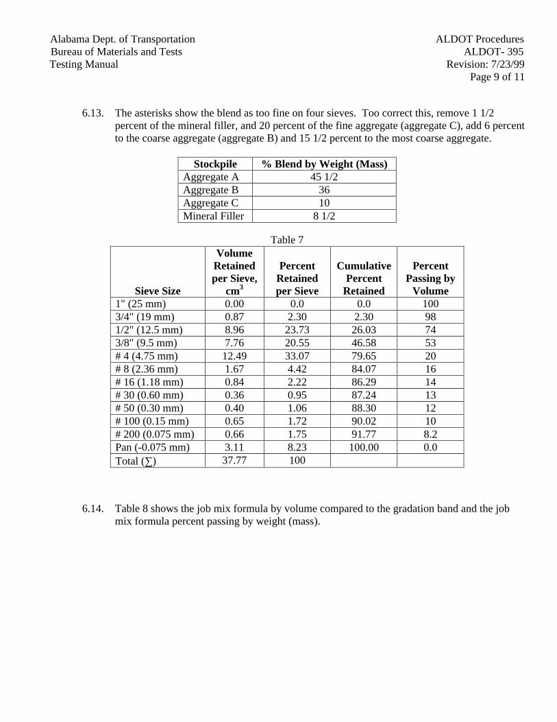
Alabama Dept. of Transportation ALDOT ProceduresBureau of Materials and Tests ALDOT- 395Testing Manual Revision: 7/23/99
Page 9 of 11
6.13. The asterisks show the blend as too fine on four sieves. Too correct this, remove 1 1/2percent of the mineral filler, and 20 percent of the fine aggregate (aggregate C), add 6 percentto the coarse aggregate (aggregate B) and 15 1/2 percent to the most coarse aggregate.
Stockpile % Blend by Weight (Mass)Aggregate A 45 1/2Aggregate B 36Aggregate C 10Mineral Filler 8 1/2
Table 7
Sieve Size
VolumeRetainedper Sieve,
cm3
PercentRetainedper Sieve
CumulativePercent
Retained
PercentPassing by
Volume1" (25 mm) 0.00 0.0 0.0 1003/4" (19 mm) 0.87 2.30 2.30 981/2" (12.5 mm) 8.96 23.73 26.03 743/8" (9.5 mm) 7.76 20.55 46.58 53# 4 (4.75 mm) 12.49 33.07 79.65 20# 8 (2.36 mm) 1.67 4.42 84.07 16# 16 (1.18 mm) 0.84 2.22 86.29 14# 30 (0.60 mm) 0.36 0.95 87.24 13# 50 (0.30 mm) 0.40 1.06 88.30 12# 100 (0.15 mm) 0.65 1.72 90.02 10# 200 (0.075 mm) 0.66 1.75 91.77 8.2Pan (-0.075 mm) 3.11 8.23 100.00 0.0Total (∑) 37.77 100
6.14. Table 8 shows the job mix formula by volume compared to the gradation band and the jobmix formula percent passing by weight (mass).
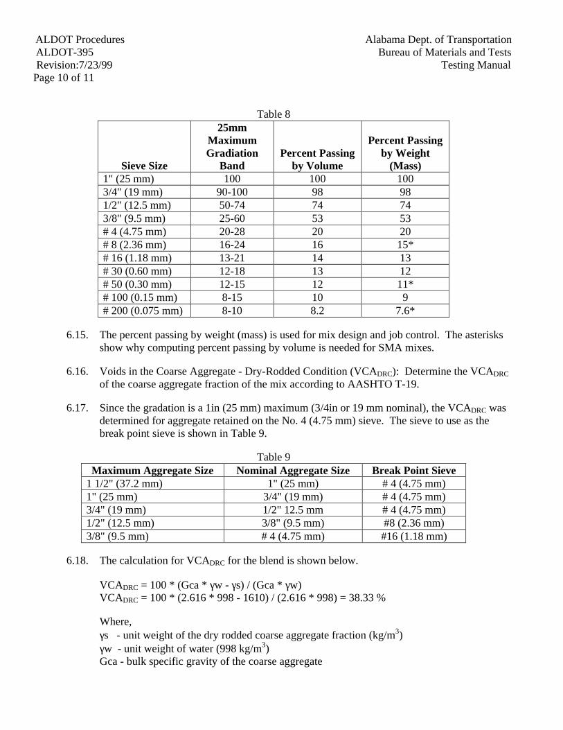
ALDOT Procedures Alabama Dept. of TransportationALDOT-395 Bureau of Materials and TestsRevision:7/23/99 Testing Manual
Page 10 of 11
Table 8
Sieve Size
25mmMaximumGradiation
BandPercent Passing
by Volume
Percent Passingby Weight
(Mass)1" (25 mm) 100 100 1003/4" (19 mm) 90-100 98 981/2" (12.5 mm) 50-74 74 743/8" (9.5 mm) 25-60 53 53# 4 (4.75 mm) 20-28 20 20# 8 (2.36 mm) 16-24 16 15*# 16 (1.18 mm) 13-21 14 13# 30 (0.60 mm) 12-18 13 12# 50 (0.30 mm) 12-15 12 11*# 100 (0.15 mm) 8-15 10 9# 200 (0.075 mm) 8-10 8.2 7.6*
6.15. The percent passing by weight (mass) is used for mix design and job control. The asterisksshow why computing percent passing by volume is needed for SMA mixes.
6.16. Voids in the Coarse Aggregate - Dry-Rodded Condition (VCADRC): Determine the VCADRC
of the coarse aggregate fraction of the mix according to AASHTO T-19.
6.17. Since the gradation is a 1in (25 mm) maximum (3/4in or 19 mm nominal), the VCADRC wasdetermined for aggregate retained on the No. 4 (4.75 mm) sieve. The sieve to use as thebreak point sieve is shown in Table 9.
Table 9Maximum Aggregate Size Nominal Aggregate Size Break Point Sieve
1 1/2" (37.2 mm) 1" (25 mm) # 4 (4.75 mm)1" (25 mm) 3/4" (19 mm) # 4 (4.75 mm)3/4" (19 mm) 1/2" 12.5 mm # 4 (4.75 mm)1/2" (12.5 mm) 3/8" (9.5 mm) #8 (2.36 mm)3/8" (9.5 mm) # 4 (4.75 mm) #16 (1.18 mm)
6.18. The calculation for VCADRC for the blend is shown below.
VCADRC = 100 * (Gca * γw - γs) / (Gca * γw)VCADRC = 100 * (2.616 * 998 - 1610) / (2.616 * 998) = 38.33 %
Where,γs - unit weight of the dry rodded coarse aggregate fraction (kg/m3)γw - unit weight of water (998 kg/m3)Gca - bulk specific gravity of the coarse aggregate
Alabama Dept. of Transportation ALDOT ProceduresBureau of Materials and Tests ALDOT- 395Testing Manual Revision: 7/23/99
Page 11 of 11
6.19. Next, the percent VCA of the compacted mix (VCAMIX) is calculated. The calculation forthe percent VCA is shown below. A liquid asphalt binder content of 6.5 percent and a bulkspecific gravity of 2.168 for the compacted specimens are used in this example.
Pbp = Ps * PabpPbp = 93.5 * 0.80 = 74.8 %VCA = 100 - Pbp * Gmb / GcaVCA = 100 - 74.8 * 2.168 / 2.616 = 38.01
Where,Pbp - percent (by weight [mass] total mix) aggregate retained on the breakpoint sieve (4.75mm)Ps - percent (by weight [mass] total mix) aggregate in the mixPAbp - percent (by weight [mass] aggregate) aggregate retained on the breakpoint sieve (4.75mm)Gmb - bulk specific gravity of the compacted specimensGca - bulk specific gravity of the coarse aggregate
6.20. The VCAMIX is compared to the VCADRC. The VCAMIX is less than VCADRC, so this is agood mix.
VCAMIX = 38.01 < 38.33 = VCADRC
7. Reporting
7.1. For Marshall designed mixes, report as required in ALDOT-307. For Superpave designedmixes, report as required in ALDOT-384.
7.2. In addition, include in the report the gradation by volume as compared to the gradation byweight (mass), the results of the HMA Mortar tests at the high and low temperatures, thedrain down results, and the comparison of the VCAMIX to the VCADRC.
ALDOT ProceduresAlabama Dept. of TransportationALDOT-399Bureau of Materials and Tests
Revision: 7/26/99Testing ManualPage 1 of 3
ALDOT-399TESTING OF HOT MIX ASPHALT MORTARS
1. Scope
1.1. This method covers the blending and specimen preparation of hot mix asphalt (HMA)mortars to predetermine the physical characteristics of mortars used in HMA.
2. Referenced Documents
2.1. AASHTO Standards
2.1.1. M231, Weighing Devices used in the Testing of Materials
2.1.2. PP1, Accelerated Aging of Asphalt Binder Using a Pressurized Aging Vessel (PAV)
2.1.3. TP1, Determining the Flexural Creep Stiffness of an Asphalt Binder Using theBending Beam Rheometer (BBR)
2.1.4. TP5, Determining the Rheological Properties of an Asphalt Binder Using theDynamic Shear Rheometer (DSR)
2.1.5. T240, Effect of Heat and Air on a Moving Film of Asphalt (RTFO)
2.2. ASTM Standards
2.2.1. D4402, Viscosity Determinations of Unfilled Asphalts Using theBrookfieldThermosel Apparatus
2.2.2. D4753, Evaluating, Selecting, and Specifying Balances and Scales for use in Soil andRock Testing
2.2.3. E11, Wire-Cloth Sieves for Testing Purposes
2.3. ALDOT PROCEDURES
2.3.1. ALDOT-395, Stone Matrix Asphalt Mix Design
3. Apparatus for Preparation
3.1. Balance, 2-kg capacity, sensitive to 0.1 g. The balance shall conform to the requirement ofASTM D4753, class GP2 or AASHTO M231, class G2.
3.2. Oven, capable of maintaining the needed temperature within ± 10oF (5oC).
3.3. Hot plate, at least 700-W capacity with adjustable temperature control.
3.4. Sample containers, capable of holding at least 100 g of filler and 200 g of liquid asphaltbinder. A 6 oz. (0.18 L) seamless ointment tin is recommended.
ALDOT Procedures Alabama Dept. of TransportationALDOT-399 Bureau of Materials and TestsRevision: 7/26/99 Testing ManualPage 2 of 3
3.5. Mixing tools, wooden tongue depressors, spatulas, and spoons.
3.6. Insulated gloves, for handling hot samples and equipment.
4. Procedure
4.1. Dry respective aggregate fractions containing material passing the No. 200 (0.075 mm) sieve(as per ASTM E11) to constant weight (mass) at 230 ± 10oF (110 ± 5oC). Dry sieve theseaggregates and collect the dust from each aggregate. Blend the fillers to meet the percent byvolume on the job-mix-formula. An example of how to blend by volume can be found inALDOT-395.
4.2. Place a quart can of pre-aged liquid asphalt binder into an oven set at 330 ± 10oF (165 ±5oC) (see paragraph 5.1).
4.3. Weigh 100 ± 0.1 g of minus No. 200 (0.075 mm) blended filler into the 6 oz. (0.18 L)seamless ointment tin and place into a 350 ± 10oF (175 ± 5oC) oven. The material shouldremain in the oven for at least 30 minutes.
4.4. Weigh into the filler the proper amount of liquid asphalt binder to the nearest 0.1 g.
4.5. Place the tin on the hot plate and hand mix with a spatula. Slowly add the proper amount offiber (weighed to the nearest 0.1 g) and continue mixing until the mortar is homogeneous.
4.6. When asphalt-fiber pellets are used, either use loose fiber of the same type to create themortar or use a high-shear mixer. Asphalt-pellet fibers will not blend into the filler underlow-shear mixing conditions.
5. Testing of Mortars
5.1. When performing Superpave Liquid Asphalt Binder testing of the mortar, the liquid asphaltbinder should be aged following AASHTO T240 and/or PP1 prior to blending with fillersand fibers.
5.2. Follow ASTM D4402; except that readings should be taken as soon as the temperaturestabilizes because the fillers will sink to the bottom over time.
5.3. Follow AASHTO TP5; except use a higher preheat temperature of 136°F (58°C). This is toinsure that the specimen will adhere strongly to both plates.
5.4. Follow AASHTO TP1; except, using aluminum molds:
5.4.1. Place the mold over the corner of the warm hot plate so that the mold is on the hotplate and the rubber O-rings are not.
5.4.2. Using a wooden tongue depressor, gently tamp the mortar into the mold. A lightcoating of release agent (glycerin and talc) will assist in this procedure.
5.4.3. Repeat step 5.4.2 until the mold is full of mortar.

ALDOT ProceduresAlabama Dept. of TransportationALDOT-399Bureau of Materials and Tests
Revision: 7/26/99Testing ManualPage 3 of 3
5.4.4. Continue according to TP1.
6. Reporting
6.1. Report as required in ALDOT-395.
ALDOT-4011-19-01PAGE 1 OF 12
ALABAMA DEPARTMENT OF TRANSPORTATIONBUREAU OF MATERIALS AND TESTS
ALDOT-401
RUTTING SUSCEPTIBILITY DETERMINATION OF ASPHALTPAVING MIXTURES USING THE ASPHALT PAVEMENT ANALYZER
1. SCOPE
1.1 This method describes a procedure for testing the rutting susceptibility of as-phalt-aggregate mixtures using the Asphalt Pavement Analyzer (APA).
1.2 This standard does not purport to address all of the safety concerns, if any, associ-ated with its use. It is the responsibility of the user of this standard to establishappropriate safety and health standards and determine the applicability of regula-tions prior to use.
2. REFERENCED DOCUMENTS
2.1 AASHTO STANDARDS
2.1.1 AASHTO T-166, Standard Test Method for Bulk Specific Gravity andDensity of Compacted Bituminous Mixtures Using Saturated Surface-DrySpecimens
2.1.2 AASHTO T-169, Standard Practice for Sampling Bituminous PavingMixtures
2.2.3 AASHTO T-209, Standard Test Method for Theoretical Maximum Spe-cific Gravity and Density of Bituminous Paving Mixture
2.2.4 AASHTO T-269, Standard Test Method for Percent Air Voids in Com-pacted Dense and Open Bituminous Mixtures
2.2.5 AASHTO MP-2, Standard Specification for Superpave Volumetric MixDesign
2.2.6 AASHTO PP-35, Practice for Evaluation of Superpave Gyratory Com-pactors (SGCs)
3. APPARATUS
ALDOT-4011-19-01PAGE 2 OF 12
3.1 Asphalt Pavement Analyzer (APA) - A thermostatically controlled device de-signed to test the rutting susceptibility of asphalt-aggregate mixtures by applyingrepetitive linear loads to compacted test specimens through three pressurizedhoses via wheels.
3.1.1 The APA shall be thermostatically controlled to maintain the test tem-perature and conditioning chamber at any set point between 4° and 72°C(40° and 160°F) within 1°C (2°F).
3.1.2 The APA shall be capable of independently applying loads up to 534 N(120 lbs) to the three wheels. The loads shall be calibrated to the desiredtest load by an external force transducer.
3.1.3 The pressure in the test hoses shall be adjustable and capable of maintain-ing pressure up to 830 kPa (120 psi).
3.1.4 The APA shall be capable of testing six cylindrical specimens simultane-ously.
3.1.5 The APA shall have a programmable master cycle counter which can bepreset to the desired number of cycles for a test. The APA shall be capa-ble of automatically stopping the test at the completion of the programmednumber of cycles.
3.1.6 The hoses shall be Gates 77B Paint Spray and Chemical 3/4 inch(19.0 mm), 750 psi (5.17 MPa) W.P. GL 07148. The hoses should be re-placed when any of the outer rubber casing has worn through and threadsare exposed. Follow the APA manufacturer's instructions for the tech-nique on replacing hoses.
3.2 Balance, 12,000 gram capacity, accurate to 0.1 gram.
3.3 Mixing utensils (bowls, spoon, spatula).
3.4 Ovens for heating aggregate and asphalt binder.
3.5 Superpave gyratory compactor and molds.
4. PREPARATION OF TEST SPECIMENS
4.1 Number of Test Specimens - Six cylindrical (150 mm diameter x 75 mm) speci-mens.
4.2 Roadway Core Specimens
ALDOT-4011-19-01PAGE 3 OF 12
4.2.1 Roadway core specimens shall be 150 mm diameter with all surfaces ofthe perimeter perpendicular to the surface of the core within 5 mm. Coresshall be trimmed with a wet masonry saw to a height of 75 ± 3 mm. If thecore has a height of less than 75 ± 3 mm, plaster-of-Paris may be used toachieve the proper height. Testing shall be conducted on the uncut face ofthe core.
4.3 Plant Produced Mixtures
4.3.1 Samples of plant produced mixtures shall be obtained in accordance withAASHTO T 169. Mixture samples shall be reduced to the appropriate testsize and compacted to the appropriate number of gyrations as determinedin AASHTO MP-2 while the mixture is still hot. Reheating of loose plantmixture should be avoided.
4.4 Laboratory Prepared Mixtures
4.4.1 Mixture proportions are batched in accordance to the desired Job MixFormula.
4.4.2 The temperature to which the asphalt binder must be heated to achieve aviscosity of 170 ± 20 cSt shall be the mixing temperature. For modifiedasphalt binder use the mixing temperature recommended by the bindermanufacturer.
4.4.3 Dry mix aggregates and hydrated lime (when lime is used) first, then addoptimum percentage of asphalt cement. Mix the materials until all aggre-gates are thoroughly coated.
4.4.4 Test samples shall be aged two hours at compaction temperature or in ac-cordance with the short-term aging procedure in AASHTO PP2.
4.4.5 The temperature to which the asphalt binder must be heated to achieve aviscosity of 290 ± 30 cSt shall be the compaction temperature. For modi-fied asphalt binders, use the compaction temperature recommended by thebinder manufacturer. The mixture shall not be heated at the compactiontemperature for more than two hours.
4.5 Laboratory Compaction of Specimens
4.5.1. A Superpave gyratory compactor approved in accordance with AASHTOPP-35 shall be used to compact samples. The gyratory compactor shallhave passed the Standard Protocol for the Evaluation of Superpave Gyra-tory Compactors.
ALDOT-4011-19-01PAGE 4 OF 12
4.5.2 Laboratory prepared specimens shall be compacted to the design numberof gyrations (Ndes) as determined in AASHTO MP-2 with a final height of115 ± 5 mm. If the APA does not accommodate 115 mm high compactedspecimens, the specimens shall be sawed to a height of 75 ± 1 mm. Onlythe bottom portion of the compacted specimens should be sawed off. Theuncut side of the specimen shall be tested.
4.5.3 Compacted specimens should be left at room temperature (approximately25°C (77°F) for a minimum of 3 hours to allow the entire specimen tocool.
5. DETERMINING THE AIR VOID CONTENTS
5.1 Determine the bulk specific gravity of the test specimens in accordance withAASHTO T 166.
5.2 Determine the maximum specific gravity of the test mixture in accordance withAASHTO T 209.
5.3 Determine the air void contents of the test specimens in accordance withAASHTO T 269.
6. SELECTING THE TEST TEMPERATURE
6.1 The test temperature shall be set to the high temperature of the standard Super-pave binder Performance Grade for the specifying agency. For circumstanceswhere the binder grade has been bumped, the APA test temperature will remain atthe standard PG high temperature. This is currently 67°C (146°F) for Alabama.
7. SPECIMEN PREHEATING
7.1 Place the specimens in the molds.
7.2 Specimens shall be preheated in the temperature calibrated APA test chamber or aseparate calibrated oven for a minimum of 6 hours. Specimens should not be heldat elevated temperatures for more than 24 hours prior to testing.
8. PROCEDURE
8.1 Set the hose pressure gap reading to 700 ± 35 kPa (100 ± 5 psi). Set the load cyl-inder pressure reading for each wheel to achieve a load of 445 ± 22 N (100 ± 5lb.).
ALDOT-4011-19-01PAGE 5 OF 12
8.2 Stabilize the testing chamber temperature at the temperature selected in Paragraph6.
8.3 Secure the preheated, molded specimens in the APA. The preheated APA cham-ber should not be open more than six minutes when securing the test specimensinto the machine. Close the chamber doors and allow 10 minutes for the tem-perature to restabilize prior to starting the test.
8.4 Apply 25 cycles to seat the specimens before the initial measurements. Make ad-justments to the hose pressure as needed during the 25 cycles.
8.5 Open the chamber doors, unlock and pull out the sample holding tray.
8.6 Place the rut depth measurement template over the specimen. Make sure that therut depth measurement template is properly seated and firmly rests on top of thetesting mold.
8.7 Zero the digital measuring gauge so that the display shows 0.00 mm with thegauge completely extended. The display should also have a bar below the “inc.”position. Take initial readings at each of the four outside locations on the tem-plate. The center measurement is not used for cylindrical specimens. Measure-ments shall be determined by placing the digital measuring gauge in the templateslots and sliding the gauge slowly across each slot. Record the smallest measure-ment for each location to the nearest 0.01 mm.
8.8 Repeat steps 8.6 and 8.7 for each set of cylinders in the testing position. Allmeasurements shall be completed within six minutes.
8.9 Push the sample holding tray in and secure. Close the chamber doors and allow10 minutes for the temperature to equalize.
8.10 Set the PRESET COUNTER to 8000 cycles.
8.11 Start the test. When the test reaches 8000 cycles, the APA will stop and the loadwheels will automatically retract.
8.12 Repeat steps 8.5 through 8.8 to obtain final measurements.
NOTE: Some APA’s have been equipped with automatic measurement systems thatmake steps 8.5 through 8.12 unnecessary. Some APA users have reported significant dif-ferences in rut depths between the automatic measurements and manual measurements.
9. CALCULATIONS
ALDOT-4011-19-01PAGE 6 OF 12
9.1 The rut depth at each location is determined by subtracting the final measurementfrom the initial measurement.
9.2 Determine the overall average rut depth for each test position. Use the average ofall twelve measurements to calculate the average rut depth.
9.3 Calculate the average rut depth from the three test positions. Also, calculate thestandard deviation for the three test positions.
9.4 Outlier evaluation - If the standard deviation of the set is greater than or equal to2.0 mm, then the position with the rut depth farthest from the average may be dis-carded. The testing procedure, device calibration, and test specimens should beinvestigated to determine the possible causes for the excessive variation.
9.5 The APA rut depth for the mixture is the average of the six cylindrical specimensat 8000 cycles.
10. REPORTING
10.1 The test report shall include the following information:
10.1.1 The laboratory name, technician name, and date of test.
10.1.2 The mixture type and description.
10.1.3 Average air void content of the test specimens.
10.1.4 The test temperature.
10.1.5 The average rut depth, to the nearest 0.1 mm, at 8000 cycles.
11. PRECISION AND BIAS
11.1 Work is underway to develop a precision statement for this standard.
ALDOT-4011-19-01PAGE 7 OF 12
ANNEX
MANDATORY INFORMATION
1. CALIBRAT1ON
NOTE: The following items should be checked for calibration no less than once peryear: (1) preheating oven, (2) APA temperature, (3) APA wheel load, and (4) APA hosepressure. Instructions for each of these calibration checks are included in this section.
1.1. Temperature calibration of the preheating oven.
1.1.1 The preheating oven must be calibrated with a NIST traceable thermome-ter (an ASTM 65°C calibrated thermometer is recommended) and a metalthermometer well to avoid rapid heat loss when checking the temperature.
1.1.2 Temperature Stability
1.1.2.1 Set the oven to the chosen temperature (e.g., 67°C). Placethe thermometer in the well and place them on the center ofthe shelf where the samples and molds will be preheated. Itusually takes an hour or so for the oven chamber, well andthermometer to stabilize. After one hour, open the ovendoor and read the thermometer without removing it fromthe well. Record this temperature. Close the oven door.
1.1.2.2 Thirty minutes after obtaining the first reading obtain an-other reading of the thermometer. Record this temperature. If the readings from step 1.1.2.1 and 1.1.2.2 are within0.4°C, then average the readings. If the readings differ bymore than 0.4°C then continue to take readings every thirtyminutes until the temperature stabilizes within 0.4°C ontwo consecutive readings.
1.1.3 Temperature Uniformity
1.1.3.1 To check the uniformity of the temperature in the ovenchamber, move the thermometer and well to another loca-tion in the oven so that they are on a shelf where samplesand molds will be preheated, but as far as possible from thefirst location. Take and record readings of the thermometerat the second location every thirty minutes until two con-secutive readings at the second location are within 0.4°C.
ALDOT-4011-19-01PAGE 8 OF 12
1.1.3.2 Compare the average of the two readings at the first loca-tion with the average of the stabilized temperature at thesecond location. If the average temperatures from the twolocations are within 0.4°C, then the oven temperature isrelatively uniform and it is suitable for use in preheatingAPA samples. If the average of the readings at the two lo-cations differ by more than 0.4°C then you must find an-other oven that will hold this level of uniformity and meetscalibration.
1.1.4 Temperature Accuracy
1.1.4.1 Average the temperatures from the two locations. If thataverage temperature is within 0.4°C of the set point tem-perature on the oven, then the oven is reasonably accurateand calibration is complete.
1.1.4.2 If the set point differs from the average temperature bymore than 0.4°C, then adjust the oven set point appropri-ately to raise or lower the temperature inside the chamberso that the thermometer and well will be at the desired tem-perature (e.g., 67°C).
1.1.4.3 Place the thermometer and well in the center of the shelf. At thirty-minute intervals, take readings of the thermome-ter. When two consecutive readings are within 0.4°C, andthe average of the two consecutive readings are within0.4°C of the desired test temperature (e.g., 67°C), then theoven has been properly adjusted and calibration is com-plete. If these two conditions are not met, then repeat steps1.1.4.2 and 1.1.4.3.
1.2 APA Temperature Calibration
1.2.1 The APA must be calibrated with a NIST traceable thermometer (anASTM 65°C calibrated thermometer is recommended) and a metal ther-mometer well to avoid rapid heat loss when checking the temperature.
1.2.2 Temperature Stability
1.2.2.1 Turn on the APA main power and set the chamber tem-perature controller so that the inside the testing chamber isat anticipated testing temperature (e.g., 67°C). Also, set thewater temperature controller to achieve the anticipatedtesting temperature. (NOTE: Experience has shown that
ALDOT-4011-19-01PAGE 9 OF 12
the temperature controller on the APA is not always accu-rate. The thermometer should always be considered cham-ber temperature.) Place the thermometer in the well andplace them on the left side of the APA where the samplesand molds will be tested. (NOTE: It may be helpful toremove the hose rack from the APA during temperaturecalibration to avoid breaking the thermometer.)
1.2.2.2 It usually takes about five hours for the APA to stabilize. After the temperature display on the controller has stabi-lized, open the chamber doors and read the thermometerwithout removing it from the well. Record this tempera-ture. Close the chamber doors.
1.2.2.3 Thirty minutes after obtaining the first reading obtain an-other reading of the thermometer. Record this temperature. If the readings from step 1.2.2.2 and 1.2.2.3 are within0.4°C, then average the readings. If the readings differ bymore than 0.4°C then continue to take readings every thirtyminutes until the temperature stabilizes within 0.4°C ontwo consecutive readings.
1.2.3 Temperature Uniformity
1.2.3.1 To check the uniformity of the temperature in the APAchamber, move the thermometer and well to the right sideof the APA, where the samples are tested. Take and recordreadings of the thermometer at the second location everythirty minutes until two consecutive readings at the secondlocation are within 0.4°C.
1.2.3.2 Compare the average of the two readings obtained in1.2.2.3 and 1.2.3.1. If the average temperatures from thetwo locations are within 0.4°C, then the APA temperatureis relatively uniform and it is suitable for use. If the aver-age of the readings at the two locations differ by more than0.4°C then consult with the manufacturer on improvingtemperature uniformity.
1.2.4 Temperature Accuracy
1.2.4.1 Average the temperatures from the two locations. If thataverage temperature is within 0.4°C of the desired test tem-perature (e.g., 67°C), then the APA temperature is reasona-bly accurate and calibration is complete.
ALDOT-4011-19-01PAGE 10 OF 12
1.2.4.2 If the average temperature differs from the desired test tem-perature (e.g., 67°C) by more than 0.4°C, then adjust theAPA temperature controller so that the thermometer andwell will be at the desired test temperature. (NOTE: It isadvisable to keep the water bath set at the same temperatureas the test chamber.)
1.2.4.3 Place the thermometer and well in the center of the shelf. At thirty minute intervals, take readings of the thermome-ter. When two consecutive readings are within 0.4°C, andthe average of the two consecutive readings are within0.4°C of the desired test temperature, then the APA tem-perature has been properly adjusted and calibration at thattemperature is complete. Record the current set points onthe temperature controllers for later reference. If these twoconditions are not met, then repeat steps 1.2.4.2 and 1.2.4.3.
1.3 APA Wheel Load calibration of the air cylinders at the three test positions.
1.3.1 The APA wheel loads will be checked with the calibrated load cell pro-vided with the APA. The loads will be checked and adjusted one at a timewhile the other wheels are in the down position and bearing on a dummysample or wooden block of approximately the same height as a test sam-ple. Calibration of the wheel loads should be accomplished with the APAat room temperature. A sheet is provided to record the calibration loads.
1.3.1.1 Remove the hose rack from the APA.
1.3.1.2 Jog the wheel carriage until the wheels are over the centerof the sample tray when the wheels are in the down posi-tion.
1.3.1.3 Raise and lower the wheels 20 times to heat up the cylin-ders.
1.3.1.4 Adjust the bar on top of the load cell by screwing it in orout until the total height of the load cell-load bar assemblyis 105 mm.
1.3.1.5 Position the load cell under one of the wheels. Placewooden blocks or dummy samples under the other twowheels.
1.3.1.6 Zero the load cell.
1.3.1.7 Lower all wheels by turning the cylinder switch to CAL.
ALDOT-4011-19-01PAGE 11 OF 12
1.3.1.8 If the load cell is not centered left to right beneath thewheel, then raise the wheel and adjust the position of theload cell. To determine if the load cell is centered front toback beneath the wheel, unlock the sample tray and move itSLOWLY until the wheel rests in the indentation on theload cell bar (where the screw is located).
1.3.1.9 After the load cell has been properly centered, adjust thepressure in the cylinder to obtain 445 ± 5 N (100 ± 1lbs.). Allow three minutes for the load cell reading to stabilizebetween adjustments. Record the pressure and the load.
1.3.1.10 With the wheel on the load cell remaining in the down po-sition, raise and lower the other wheels one time. Allowthree minutes for the load cell reading to stabilize. Recordthe pressure and the load.
1.3.1.11 With the other wheels remaining in the down position, raiseand lower the wheel over the load cell. Allow three min-utes for the load cell reading to stabilize. Record the pres-sure and the load.
1.3.1.12 Repeat steps 1.3.1.5 through 1.3.1.11 for eachwheel/cylinder.
1.3.1.13 Return the load cell to the first wheel and repeat steps1.3.1.5 through 1.3.1.11.
1.3.1.14 Place the load cell under the second wheel and repeat steps1.3.1.5 through 1.3.1.11.
1.3.1.15 Place the load cell under the third wheel and repeat steps1.3.1.5 through 1.3.1.11. The current cylinder pressureswill be used to set wheel loads to 445 N (100 lbs.).
1.4 Replacement of the APA hoses
1.4.1 New hoses shall be placed in service in accordance with 2.1.6.
1.4.1.1 Remove the hose rack from the APA.
1.4.1.2 Remove the used hoses from the hose rack. Place the newhose on the barbed nipples and secure with the hoseclamps.
1.4.1.3 Position the hoses in the rack such that the hose curvature isvertical. Tighten the nuts at the ends of the hoses only until
ALDOT-4011-19-01PAGE 12 OF 12
the hoses are secure. Over-tightening will effect the contactpressure and hose life.
1.4.1.4 Place the hose rack back into the APA and make sure thatthe hoses are aligned beneath the wheels.
1.4.1.5 Prior to testing, break in the new hoses by running 8000 cy-cles on a set of previously tested samples at a temperatureof 55°C (131°F) or higher.
1.5 APA Hose Pressure Check
1.5.1 The air pressure in the APA test hoses shall be checked with a NIST trace-able test gauge or transducer with a suitable range. The check shall bemade while the APA is operating Since the hoses are connected in series,it is satisfactory to connect the test gauge to the end of the right-most hose.The pressure should not fluctuate outside of the range of 690 ± 35 kPa(100 ± 3 psi) during normal operation. Adjust the pressure as necessarywith the hose pressure regulator.
NOTE: The Ashcroft test gauge model 450182As02L200# has beenfound to be satisfactory for this purpose. This gauge may be availablethrough Grainger (Stock No. 2F008).
ALDOT ProceduresAlabama Dept. of TransportationALDOT-403Bureau of Materials and Tests
Revision: 02/07/01Testing ManualPage 1 of 3
ALDOT-403ROADWAY CORE BULK SPECIFIC GRAVITY DETERMINATION IN THE FIELD
1. Scope
1.1 This method describes a procedure for testing roadway cores in the field usingportable scales for calibrating the nuclear density gauges.
1.2 This standard does not purport to address all of the safety concerns, if any, associ-ated with its use. It is the responsibility of the user of this standard to establishappropriate safety and health standards and determine the applicability of regula-tions prior to use.
2. Referenced Documents
2.1 AASHTO Standards
2.1.1 AASHTO T-166, Standard Test Method for Bulk Specific Gravity andDensity of Compacted Bituminous Mixtures Using Saturated Surface-DrySpecimens
2.2 ASTM Standards
2.2.1 ASTM D 2726-96a, Standard Test Method for Bulk Specific Gravity andDensity of Non-Absorptive Compacted Bituminous Mixtures
3. Procedure
3.1 AASHTO T 166, Standard Test Method for Bulk Specific Gravity and Density ofCompacted Bituminous Mixtures Using Saturated Surface-Dry (SSD) Specimens,is followed as usual with the following additional precautions taken:
3.2 The underwater weight and SSD weight may be taken first to expedite the proc-ess. When the dry weight of the sample is determined, care must be taken to en-sure that the sample is completely dry. Do not heat the sample until it becomesmalleable (T 166, Method C), as the samples are to be re-tested at the laboratory. Fans and low heat (less than 130°F (55°C)) may be used to dry the sample.
ALDOT Procedures Alabama Dept. of TransportationALDOT-403 Bureau of Materials and TestsRevision: 02/07/01 Testing ManualPage 2 of 3
3.3 Calibration weights lighter and heavier than the average core sample shall be usedto check the calibration of the scales every time the scales (or the vehicle haulingthe scales) are moved. These weights must be traceable to the National Instituteof Standards and Technology (NIST). A shift test shall be performed as part ofthe calibration check (shifting the weights to the edge of the weighing platform) toensure that the scales are level. The scales shall be accurate to within 0.2 gramsor 0.1% of the weight of the sample. If the scales do not meet this level of accu-racy, they must be calibrated until they do. In any case, the scales shall be cali-brated by a reputable scale company every six months.
3.4 The temperature of the sample weighed and the temperature of the water bathshall be equal. As per ASTM D 2726, if the specimen’s temperature is differentfrom the bath’s temperature by more than 3.6°F (2°C), the specimen shall besoaked in the bath until the temperatures are equal (10 to 15 minutes).
3.5 If the sample and/or water bath have a temperature that is not 77 +/- 1.8°F (25 +/-1°C), the temperature correction factors found in ASTM D 2726 shall be appliedto correct the Bulk Specific Gravity value (see appendix A for this table). If thebath is at 77°F (25°C), no correction need be applied.
3.6 As soon as practical, the samples shall be tested in a laboratory (AASHTO ac-credited, M&T certified, or Division approved). The Bulk Specific Gravity in thefield shall be used unless the Bulk Specific Gravity in the laboratory differs bymore than 0.012 from the Bulk Specific Gravity in the field; in which case, thelaboratory value shall be substituted for the field value.
4. Reporting
4.1 Note the field value and the laboratory value, and indicate which value was usedin the report. Send a copy of the report including project number, county, mixtype, and placement rate to the State Bituminous Engineer.
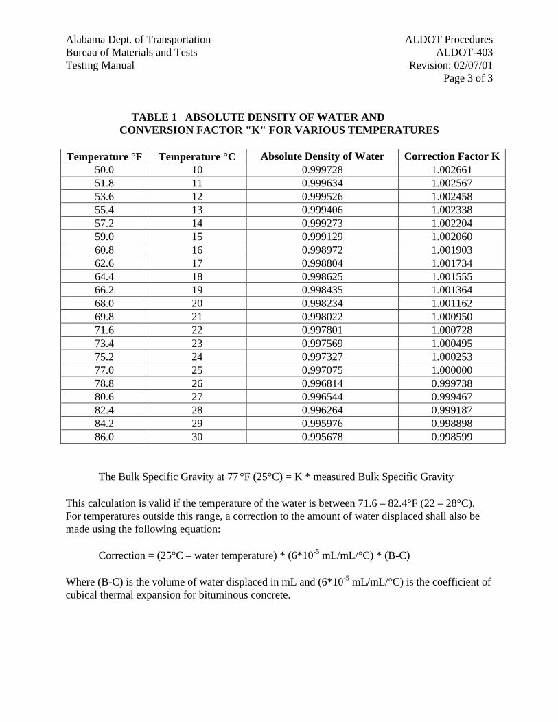
ALDOT ProceduresAlabama Dept. of TransportationALDOT-403Bureau of Materials and Tests
Revision: 02/07/01Testing ManualPage 3 of 3
TABLE 1 ABSOLUTE DENSITY OF WATER ANDCONVERSION FACTOR "K" FOR VARIOUS TEMPERATURES
Temperature °F Temperature °C Absolute Density of Water Correction Factor K
50.0 10 0.999728 1.00266151.8 11 0.999634 1.00256753.6 12 0.999526 1.00245855.4 13 0.999406 1.00233857.2 14 0.999273 1.00220459.0 15 0.999129 1.00206060.8 16 0.998972 1.00190362.6 17 0.998804 1.00173464.4 18 0.998625 1.00155566.2 19 0.998435 1.00136468.0 20 0.998234 1.00116269.8 21 0.998022 1.00095071.6 22 0.997801 1.00072873.4 23 0.997569 1.00049575.2 24 0.997327 1.00025377.0 25 0.997075 1.00000078.8 26 0.996814 0.99973880.6 27 0.996544 0.99946782.4 28 0.996264 0.99918784.2 29 0.995976 0.99889886.0 30 0.995678 0.998599
The Bulk Specific Gravity at 77 °F (25°C) = K * measured Bulk Specific Gravity
This calculation is valid if the temperature of the water is between 71.6 – 82.4°F (22 – 28°C). For temperatures outside this range, a correction to the amount of water displaced shall also bemade using the following equation:
Correction = (25°C – water temperature) * (6*10-5 mL/mL/°C) * (B-C)
Where (B-C) is the volume of water displaced in mL and (6*10-5 mL/mL/°C) is the coefficient ofcubical thermal expansion for bituminous concrete.

Alabama Dept. of Transportation ALDOT ProceduresBureau of Materials and Tests ALDOT-405Testing Manual 01/01/02
Page 1 of 8
ALDOT-405-01CERTIFICATION AND QUALIFICATION PROGRAM FOR CONCRETE TECHNICIANS AND
CONCRETE LABORATORIES
1. Scope
1.1. This program establishes the compliance requirements for concrete certifications required forpersonnel inspecting, testing, and managing the production, placement, finishing, and qualitycontrol of concrete operations for the Alabama Department of Transportation, herein referred to asALDOT or as the Department.
1.2. This program will also establish the requirements necessary for the qualification of private concretelaboratories to design concrete mixes and to sample and test concrete materials used on ALDOTprojects.
1.3. This procedure will outline the requirement for two levels of concrete certifications and threeconcrete laboratory qualifications.
1.3.1. Concrete Technician Certifications:
1.3.1.1. Concrete Technician.
1.3.1.2. Concrete Strength Testing Technician.
1.3.2. Concrete Laboratory Qualifications:
1.3.2.1. Class A Laboratory.
1.3.2.2. Class B Laboratory.
1.3.2.3. Class C Laboratory.
2. Referenced Documents
2.1. AASHTO Standards:
2.1.1. T-22 Compressive Strength of Cylindrical Concrete Specimens.
2.1.2. T-24 Obtaining and Testing Drilled Cores and Sawed Beams of Concrete.
2.1.3. T-67 Standard Practices for Force Verification of Testing Machines.
2.1.4. T-119 Slump of Hydraulic Cement Concrete.
2.1.5. T-121 Weight per Cubic Foot {Mass per Cubic Meter}, yield, and Air Content(Gravimetric) of concrete.
2.1.6. T-126 Making and Curing Concrete Test Specimens in the Laboratory.
Alabama Dept. of TransportationALDOT ProceduresBureau of Materials and TestsALDOT-405
Testing Manual01/01/02Page 2 of 8
2.1.7. T-141 Sampling Freshly Mixed Concrete.
2.1.8. T-152 Air Content of Freshly Mixed Concrete by the Pressure Method.
2.1.9. T-197 Time of Setting of Concrete Mixtures by Penetration Resistance.
2.1.10. T-231 Capping Cylindrical Concrete Specimens.
2.1.11. M-201 Moist Cabinets, Moist Rooms, and Water Storage Tanks Used in the Testing ofHydraulic Cements and Concretes.
2.2. ASTM Standards:
2.2.1. C-1064 Temperature of Freshly Mixed Portland Cement Concrete.
2.2.2. C-1231 Use of Unbonded Caps in Determination of Compressive Strength of HardenedConcrete Cylinders.
3. Program Administration
3.1. A Certification Board (CB) and a Working Task Force (WTF) will administer the certificationprogram and qualification program for concrete technicians and concrete laboratories.
3.1.1. Certification Board:
3.1.1.1. Membership of the Certification Board will consist of the following.
3.1.1.1.1. State Materials and Tests Engineer, Chairman.
3.1.1.1.2. An Assistant Chief Engineer appointed by the Transportation Director.
3.1.1.1.3. State Construction Engineer.
3.1.1.1.4. A Division Engineer appointed by the Transportation Director.
3.1.1.1.5. Industry Representative appointed by the Alabama Concrete IndustriesAssociation.
3.1.2. Working Task Force:
3.1.2.1. Membership of the Working Task Force will consist of the following.
3.1.2.1.1. State Concrete Engineer.
3.1.2.1.2. State Bridge Construction Engineer.
3.1.2.1.3. Industry Representative appointed by the Alabama Concrete IndustriesAssociation.
Alabama Dept. of Transportation ALDOT ProceduresBureau of Materials and Tests ALDOT-405Testing Manual 01/01/02
Page 3 of 8
3.2. Members of the Certification Board and Working Task Force will meet a minimum of once a year.The Working Task Force will meet any time disciplinary actions have to be taken.
4. Definitions
4.1. Concrete Technician Certifications:
4.1.1. Concrete Technician.
4.1.1.1. Required for Department, its consultants, and industry personnel responsible forinspecting and testing concrete.
4.1.1.2. The technician shall be qualified to inspect concrete operations and to performquality control testing on concrete.
4.1.1.3. The technician shall be knowledgeable of basic concrete technology.
4.1.1.4. Industry personnel certified as Concrete Technicians are qualified to batchconcrete for the Department.
4.1.2. Concrete Strength Testing Technician.
4.1.2.1. Required for Department, its consultants, and industry personnel responsible fortesting concrete specimens for compressive and flexural strength.
4.1.2.2. The technician shall be knowledgeable and have the ability to properly perform,record, and report the results of testing compressive strength of cylindricalconcrete specimens and flexural strength of concrete beam specimens.
4.1.2.3. The technician shall be knowledgeable on capping cylindrical concrete specimensand unbonded caps for concrete cylinders.
4.2. Concrete Laboratory Qualifications:
4.2.1. Class A Laboratory.
4.2.1.1. Required for industry laboratories performing concrete mix designs and concretetesting for use on Department projects.
4.2.1.2. It shall be capable of performing laboratory concrete mix designs.
4.2.1.3. It shall be capable of handling, storing, and curing concrete specimens.
4.2.1.4. It shall be capable of performing compressive strength tests on concretespecimens.
Alabama Dept. of TransportationALDOT ProceduresBureau of Materials and TestsALDOT-405
Testing Manual01/01/02Page 4 of 8
4.2.2. Class B Laboratory.
4.2.2.1. Required for industry laboratories performing concrete mix designs for use onDepartment projects.
4.2.2.2. It shall be capable of performing laboratory concrete mix designs.
4.2.3. Class C Laboratory.
4.2.3.1. Required for industry laboratories performing concrete testing as required by theDepartment.
4.2.3.2. It shall be capable of handling, storing, and curing concrete specimens.
4.2.3.3. It shall be capable of performing compressive strength tests on concretespecimens.
4.2.3.4. It shall be, if requested by the laboratory at the time of the qualification process,capable of obtaining, preparing and testing cores drilled from concrete.
5. Technician Certification Requirements
5.1. Concrete Technician:
5.1.1. Prerequisite: Applicants for certification as Concrete Technicians shall pass a practicalexamination approved by the Department. Examples of approved practical examinationsare ACI Level I Technician and PCI Technician.
5.1.2. Training: Successful completion of classroom training on concrete technology.
5.1.3. Testing: Successfully passing a written examination administered by the Department.
5.2. Concrete Strength Testing Technician:
5.2.1. Training: Successful completion of classroom training on concrete compressive andflexural strength testing.
5.2.2. Testing: Successfully passing a written and performance examinations.
6. Laboratory Qualification Requirements
6.1. General Requirements:
6.1.1. Request for Laboratory Qualification shall be done in writing to the Bureau of Materialsand Tests Engineer, attention Concrete Section.
6.1.2. Inspection: personnel of the Bureau of Materials and Tests will inspect Laboratories everytwo years. The inspection will cover documentation, equipment, and procedures.
Alabama Dept. of Transportation ALDOT ProceduresBureau of Materials and Tests ALDOT-405Testing Manual 01/01/02
Page 5 of 8
6.1.3. Documentation: All laboratories shall maintain the following minimum documentation.
6.1.3.1. Manual of standard operating procedures to include.
6.1.3.1.1. Quality control and quality assurance.
6.1.3.1.2. Procedure for handling technical complaints.
6.1.3.2. Record of personnel’s training, evaluations, and experience.
6.1.3.3. Inventory of all testing equipment to include the following.
6.1.3.3.1. Equipment descriptions.
6.1.3.3.2. Equipment brand names.
6.1.3.3.3. Equipment identification numbers.
6.1.3.3.4. Equipment calibration and verification records.
6.1.3.3.5. Equipment maintenance records.
6.1.3.4. A current library of AASHTO and ASTM test methods.
6.1.3.5. Laboratory test reports with the following minimum information.
6.1.3.5.1. Name and address of the laboratory.
6.1.3.5.2. Identification of test report.
6.1.3.5.3. Date test is performed.
6.1.3.5.4. Date report is issued.
6.1.3.5.5. Identification of specimen(s) tested.
6.1.3.5.6. Identification of the standard test method used.
6.1.3.5.7. Notation of all known deviations from the standard test method.
6.1.3.5.8. Requirements of the standard test method not performed by thelaboratory.
6.1.3.5.9. Technician name and certification number.
6.1.3.6. A system of records that permits verification of any issued report.
6.2. Class A Laboratory:
6.2.1. Class A laboratories shall meet the requirements for Class B and Class C laboratories.
Alabama Dept. of TransportationALDOT ProceduresBureau of Materials and TestsALDOT-405
Testing Manual01/01/02Page 6 of 8
6.3. Class B Laboratory:
6.3.1. Personnel: Class B laboratories shall have at least one Concrete Technician certified by theDepartment.
6.3.2. Equipment: The following equipment will be inspected during the laboratory inspectionprocess.
6.3.2.1. Concrete mixer.
6.3.2.2. Type “B” pressure meters.
6.3.2.3. Slump cone molds.
6.3.2.4. Unit weight measure.
6.3.2.5. Penetration needles and loading apparatus.
6.3.2.6. Temperature measuring devices.
6.3.2.7. Wire sieves.
6.3.2.8. Cylinder molds.
6.3.2.9. Mortar container.
6.3.2.10. Weighing balances.
6.3.2.11. Tamping rods.
6.3.2.12. Strike off bars and plates.
6.3.2.13. Hand tools (mallet, trowel, scoops, etc).
6.3.3. Procedure: The following procedures will be observed during the laboratory inspectionprocess. Concrete Technicians certified by the Department shall perform the procedures.
6.3.3.1. AASHTO T-119.
6.3.3.2. AASHTO T-121.
6.3.3.3. AASHTO T-126.
6.3.3.4. AASHTO T-141.
6.3.3.5. AASHTO T-152.
6.3.3.6. AASHTO T-197.
6.3.3.7. ASTM C-1064.
Alabama Dept. of Transportation ALDOT ProceduresBureau of Materials and Tests ALDOT-405Testing Manual 01/01/02
Page 7 of 8
6.4. Class C Laboratory
6.4.1. Personnel: Class C laboratories shall have at least one certified Concrete Strength TestingTechnician.
6.4.2. Equipment: The following equipment will be inspected during the laboratory inspectionprocess.
6.4.2.1. Compressive strength testing machine.
6.4.2.2. Moist cabinets, moist rooms, and water storage tanks for curing cylinders.
6.4.2.3. Capping plates.
6.4.2.4. Alignment devices.
6.4.2.5. Melting pots for sulfur mortars.
6.4.2.6. Unbonded caps.
6.4.2.7. Core drill. *
6.4.2.8. Core barrels. *
6.4.2.9. Rebar locator. *
6.4.2.10. Saw. *
6.4.3. Procedure: The following procedures will be observed during the laboratory inspectionprocess. Concrete Strength Testing Technicians shall perform the procedures.
6.4.3.1. AASHTO T-22.
6.4.3.2. AASHTO T-24. *
6.4.3.3. AASHTO T-67.
6.4.3.4. AASHTO T-231.
6.4.3.5. AASHTO M-201.
6.4.3.6. ASTM C-1231.
6.4.4. Extra Qualification: Items marked with an asterisk (*) in 5.42 and 5.43 are not required toQualify as Class C laboratory. If the laboratory will obtain, prepare, and test cores drilledfrom concrete for Department projects, the equipment and procedure shall be required andwill be inspected at the time of the inspection process. All the other requirements for ClassC laboratory will also apply. This procedure will be added to the qualification certificateissued by the Department to the laboratory.

Alabama Dept. of TransportationALDOT ProceduresBureau of Materials and TestsALDOT-405
Testing Manual01/01/02Page 8 of 8
7. Certification and Qualification
7.1. Concrete Certifications
7.1.1. Personnel meeting all the qualifications for any of the two types of concrete certificationswill be certified as such upon recommendation by the Working Task Force and approval bythe Certification Board.
7.1.2. Concrete certifications are valid for a period of five years.
7.2. Laboratory Qualifications
7.2.1. Laboratories meeting all the qualifications for any of the three types of concretelaboratories will be certified as such upon recommendation by the Working Task Force andapproval by the Certification Board.
7.2.2. Laboratory qualifications are valid for a period of two years.
8. Decertification and Disqualification
8.1. Abuse or neglect of the responsibilities of concrete certification or laboratory qualifications isgrounds for disciplinary action.
8.2. Charges or accusations shall be made in writing to the Working Task Force, which will investigatethem.
8.3. Disciplinary actions will be implemented upon recommendation of the Working Task Force andapproval of the Certification Board.
8.4. Disciplinary actions will range from written reprimand to suspension of certification orqualification.
8.5. Suspension will be a minimum of six months, plus six months probation, to permanent revocationof certification or qualification rights.
8.6. Falsification of records will result in permanent revocation of certification or qualification.
8.7. Laboratories with non-working equipment or improper procedures will have their qualificationtemporarily suspended until corrections to the equipment or procedures are made.
9. Recertification and Requalification
9.1. Personnel seeking recertification shall meet the requirements of Section 5 of this procedure.
9.2. Laboratories seeking requalification shall meet the requirements of Section 6 of this procedure.
Alabama Dept. of Transportation ALDOT ProceduresBureau of Materials and Tests ALDOT-407Testing Manual 01/01/02
Page 1 of 2
ALDOT-407-01CALIBRATION VERIFICATION OF TRUCK MOUNTED WATER METERS
1. Scope
1.1. This procedure will outline the requirements necessary to verify the calibration of truck mountedwater meters used in all Alabama Department of Transportation, herein referred to as ALDOT or asthe Department, projects.
1.2. This procedure will also establish the verification frequency for truck mounted water meters.
2. Required Equipment
2.1. The following equipment shall be supplied by the concrete producer:
2.1.1. A 1000 lb {454 kg} platform scale.
2.1.2. Standard test weights {masses}to verify scale accuracy.
2.1.3. A 55-gallon {210 L}drum reserved for calibration verification.
3. Calibration Verification Procedure
3.1. The concrete producer’s Concrete Technician, certified by the Department, shall perform thecalibration verification procedure in the presence of an ALDOT representative.
3.2. Verify that the calibration of the scale does not exceed six months.
3.2.1. If the last calibration exceeds six months, the scale shall be re-calibrated before proceedingwith the calibration verification of the truck mounted water meters.
3.3. Determine the scale accuracy by weighing 500 lb {227 kg} of the standard test weights {masses}.Note any deviation for later adjustments.
3.4. Place drum on scale and determine its tare weight {mass}.
3.5. Discharge 25 gallons {94.6 L} of water into the drum through the meter and record the weight{mass}.
3.6. Adjust the weight {mass} for any deviation obtained in step 3.3 and record as total weight {mass}.
3.7. The total weight {mass} recorded shall be 208.63 lb {94.63 kg} ± 1%
3.8. If the total weight {mass} recorded is not within 1% of 208.63 lb {94.63 kg} the concrete producershall adjust the meter in accordance with the manufacturer’s recommendations.
3.9. After the meter is adjusted repeat steps 3.4 through 3.7
Alabama Dept. of TransportationALDOT ProceduresBureau of Materials and TestsALDOT-407
Testing Manual01/01/02Page 2 of 2
4. Calibration Verification Frequency
4.1. The verification of the calibration of truck mounted water meters shall be performed every twelvemonths or when the Engineer suspects inaccuracy in the meter readings.
4.2. A record of the calibration verification will be maintained by the Department on BMT-172,“Record of Calibration Verification of Truck Mounted Water Meters”.
Alabama Dept. of Transportation BMT Forms and Worksheets
Bureau of Materials and Tests Index
Revision: 5/13/03 Testing Manual Page 1 of 3
NUMERICAL INDEX of BMT FORMS and WORKSHEETS
BMT Number Title
BMT-1-B Inspectors Daily Report Compaction Sand Cone Method
BMT-3 Traffic Marking Materials Certificate of Compliance
BMT-4 Plant Mix Daily Placement Report
BMT-5 Soils and Base Course Analysis
BMT-6 Field Inspectors Material Report
BMT-7 Report on Analysis of Performance Graded Asphalt Binders
BMT-10 Notice Stamp for Acceptance
BMT-16 General Test Report (Non-Specific)
BMT-17 Check Test
BMT-19 Work Sheet Summary of Lot Test Results for Air Voids and AC Content
BMT-20-G Asphalt Plant Mixture Test Report (Gyratory)
BMT-20-M Asphalt Plant Mixture Test Report (Marshall)
BMT-21 QC/QA MAT Density Report
BMT-30 Soil / Hydrometer Worksheet
BMT-33 Aggregate Work Sheet and Test Report
BMT-38 Summary of Tests
BMT-45 Annual Certification and Guarantee for Precast Concrete Products
BMT-47 Concrete Pipe and Culvert Test and Inspection Report
BMT-53 Precast Manhole Precast Box Culvert and Miscellaneous Precast Inspection Report
BMT-55 Inspectors Daily Report Thin Layer Gauge Compaction
BMT-57 Inspector's Daily Report Roadway Compaction Nuclear Probe
BMT-58 Proctor Density Compaction Sheet
BMT-58A Proctor Density Laboratory Vibrated Density Compaction Sheet
Alabama Dept. of Transportation BMT Forms and Worksheets
Bureau of Materials and Tests Index
Revision: 5/13/03 Testing Manual Page 2 of 3
BMT Number Title
BMT-60 Project Engineer's Check List for Final Field Inspection of Corrugated Metal Pipe
BMT-65 Asphalt Content Gauge Worksheet
BMT-66 Asphalt Content Gauge Calibration Worksheet
BMT-72 Precast Concrete Products Shipping Report
BMT-73 Material Guaranty
BMT-82 Concrete Plant Inspector’s Work Sheet and Gradation Report
BMT-83 Concrete Placing Daily Report
BMT-90 Statement of Receipt of Radioactive Materials
BMT-91 Quality Control Program Aggregate Test Report
BMT-92 Daily Report Traffic Stripe
BMT-97 Worksheet to Calculate Mat Density Lot Pay Factors
BMT-100 Application for Certification
BMT-105 Certified Technician Warrant
BMT-111 Comparison Check
BMT-112 Inspectors Worksheet for Control Strip Density-Moisture/Nuclear Probe
BMT-113 Inspectors Daily Test for in-Place Density Moisture Control Strip Method/Nuclear Probe
BMT-114 Certified Cement Shipments
BMT-117 Monthly Quantities of Concrete to be Used for Testing Charges
BMT-122 Concrete Batch Ticket
BMT-131 Request for Source Approval Aggregate Quality Control Program
BMT-135 Worksheet to Determine Pay Factors When They Cannot Be Determined From Verification Samples
BMT-139 Shipping Notice Prestress Concrete Bridge Members
BMT-141 Agreement for Participation in Quality Control Program for Acceptance of Fine and Coarse Aggregates
Alabama Dept. of Transportation BMT Forms and Worksheets
Bureau of Materials and Tests Index
Revision: 5/13/03 Testing Manual Page 3 of 3
BMT Number Title
BMT-146 Bituminous Material Certificate of Compliance
BMT-153 Hot Mix Design by the Marshall Method
BMT-154 Summary of Independent Assurance Samples and Tests Coring Report
BMT-164 Agreement for Participation in Certified Acceptance and Quality Control of Asphalt Materials Program
BMT-168 Notification to Suspend Shipments of Asphalt Materials on BMT-146, Asphalt Certificate of Compliance
BMT-169 Certified Technician Warrant
BMT-170 Guardrail Submittal Form
BMT-171 Evaporation Rate Record
BMT-172 Record of Calibration Verification of Truck Mounted Water Meters
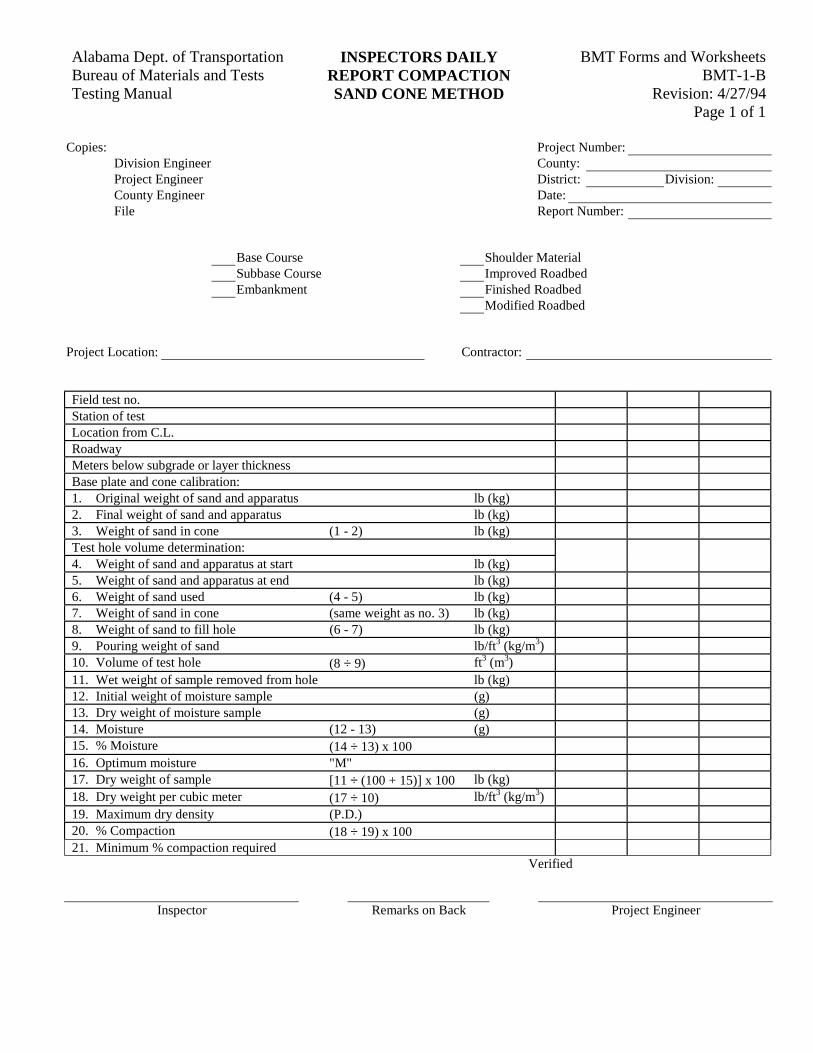
BMT Forms and WorksheetsAlabama Dept. of Transportation INSPECTORS DAILYBMT-1-BBureau of Materials and Tests REPORT COMPACTION
Revision: 4/27/94Testing Manual SAND CONE METHODPage 1 of 1
Copies: Project Number:Division Engineer County:Project Engineer District: Division:County Engineer Date:File Report Number:
Base Course Shoulder MaterialSubbase Course Improved RoadbedEmbankment Finished Roadbed
Modified Roadbed
Project Location: Contractor:
Field test no.Station of testLocation from C.L.RoadwayMeters below subgrade or layer thicknessBase plate and cone calibration:1. Original weight of sand and apparatus lb (kg)2. Final weight of sand and apparatus lb (kg)3. Weight of sand in cone (1 - 2) lb (kg)Test hole volume determination:4. Weight of sand and apparatus at start lb (kg)5. Weight of sand and apparatus at end lb (kg)6. Weight of sand used (4 - 5) lb (kg)7. Weight of sand in cone (same weight as no. 3) lb (kg)8. Weight of sand to fill hole (6 - 7) lb (kg)9. Pouring weight of sand lb/ft3 (kg/m3)10. Volume of test hole (8 ÷ 9) ft3 (m3)11. Wet weight of sample removed from hole lb (kg)12. Initial weight of moisture sample (g)13. Dry weight of moisture sample (g)14. Moisture (12 - 13) (g)15. % Moisture (14 ÷ 13) x 10016. Optimum moisture "M"17. Dry weight of sample [11 ÷ (100 + 15)] x 100 lb (kg)18. Dry weight per cubic meter (17 ÷ 10) lb/ft3 (kg/m3)19. Maximum dry density (P.D.)20. % Compaction (18 ÷ 19) x 10021. Minimum % compaction required
Verified
Inspector Remarks on Back Project Engineer
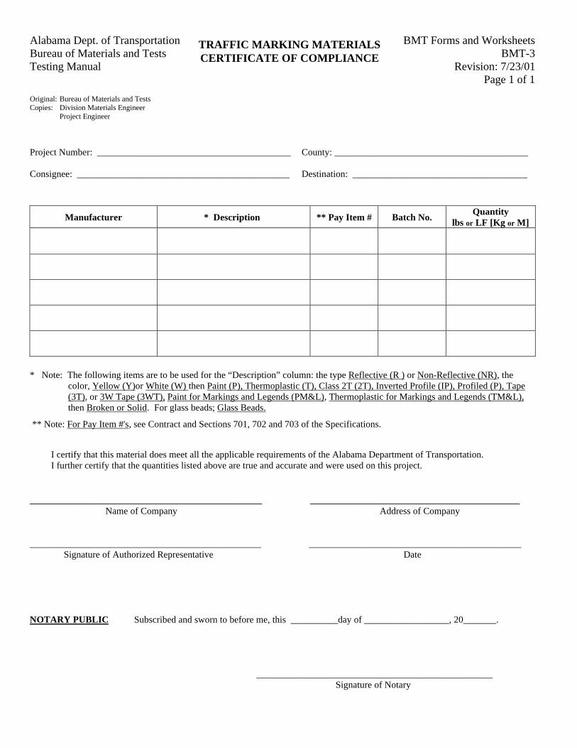
BMT Forms and WorksheetsAlabama Dept. of TransportationBMT-3Bureau of Materials and Tests
Revision: 7/23/01Testing ManualPage 1 of 1
TRAFFIC MARKING MATERIALSCERTIFICATE OF COMPLIANCE
Original: Bureau of Materials and TestsCopies: Division Materials Engineer Project Engineer
Project Number: _________________________________________ County: _________________________________________
Consignee: _____________________________________________ Destination: _____________________________________
Manufacturer * Description ** Pay Item # Batch No.Quantity
lbs or LF [Kg or M]
* Note: The following items are to be used for the “Description” column: the type Reflective (R ) or Non-Reflective (NR), thecolor, Yellow (Y)or White (W) then Paint (P), Thermoplastic (T), Class 2T (2T), Inverted Profile (IP), Profiled (P), Tape(3T), or 3W Tape (3WT), Paint for Markings and Legends (PM&L), Thermoplastic for Markings and Legends (TM&L),then Broken or Solid. For glass beads; Glass Beads.
** Note: For Pay Item #'s, see Contract and Sections 701, 702 and 703 of the Specifications.
I certify that this material does meet all the applicable requirements of the Alabama Department of Transportation.I further certify that the quantities listed above are true and accurate and were used on this project.
_________________________________________ _____________________________________Name of Company Address of Company
_________________________________________________ _____________________________________________ Signature of Authorized Representative Date
NOTARY PUBLIC Subscribed and sworn to before me, this __________day of __________________, 20_______.
__________________________________________________ Signature of Notary
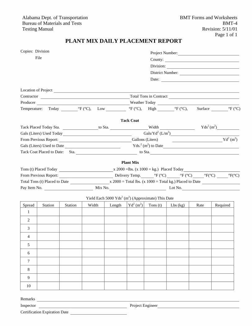
BMT Forms and Worksheets Alabama Dept. of Transportation
BMT-4 Bureau of Materials and Tests
Revision: 5/11/01 Testing Manual Page 1 of 1
PLANT MIX DAILY PLACEMENT REPORT
Copies: Division Project Number: File County: Division:
District Number: Date:
Location of Project
Contractor Total Tons in Contract
Producer Weather Today
Temperature: Today °F (°C), Low °F (°C), High °F (°C), Surface °F (°C)
Tack Coat
Tack Placed Today Sta. to Sta. Width Yds2 (m2)
Gals (Liters) Used Today Gals/Yd2 (L/m2)
From Previous Report: Gallons (Liters) Yd2 (m2)
Gals (Liters) Used to Date Yds.2 (m2) to Date
Tack Coat Placed to Date: Sta. to Sta.
Plant Mix
Tons (t) Placed Today x 2000 =lbs. (x 1000 = kg.) Placed Today
From Previous Report: Delivery Temp. °F (°C) °F (°C) °F(°C) °F(°C)
Total Tons (t) Placed to Date x 2000 = Total lbs. (x 1000 = Total kg.) Placed to Date
Pay Item No. Mix No. Lot No.
Yield Each 5000 Yds2 (m2) (Approximate) This Date
Spread Station Station Width Length Yd2 (m2) Tons (t) Lbs (kg) Rate Required
1
2
3
4
5
6
7
8
9
10
Remarks
Inspector Project Engineer
Certification Expiration Date
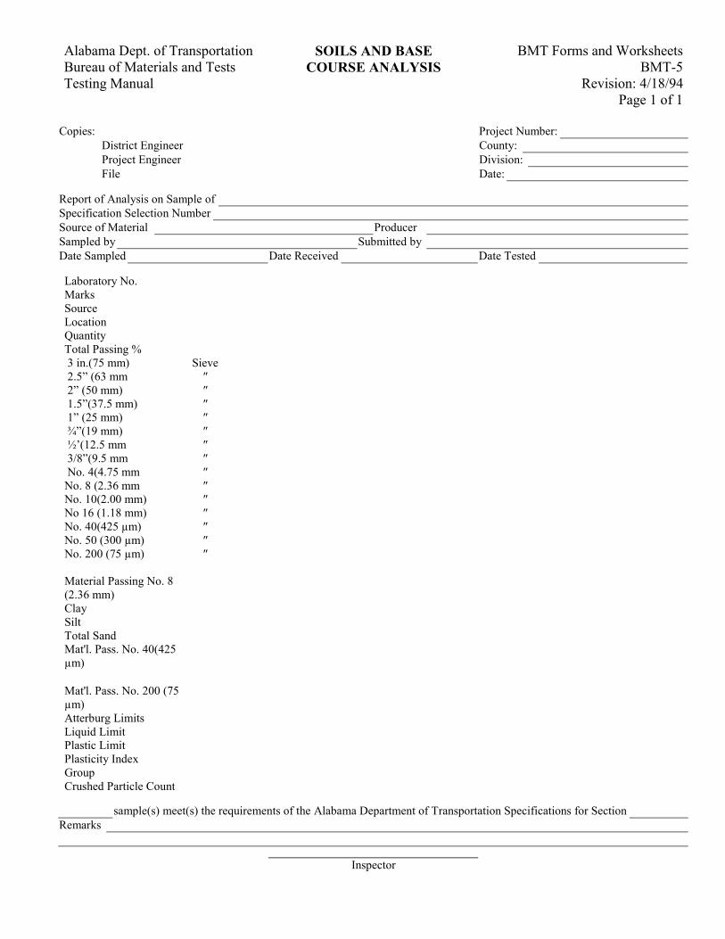
BMT Forms and Worksheets Alabama Dept. of Transportation SOILS AND BASE BMT-5 Bureau of Materials and Tests COURSE ANALYSIS
Revision: 4/18/94 Testing Manual Page 1 of 1
Copies: Project Number: District Engineer County: Project Engineer Division: File Date:
Report of Analysis on Sample of Specification Selection Number Source of Material Producer Sampled by Submitted by Date Sampled Date Received Date Tested
Laboratory No. Marks Source Location Quantity Total Passing % 3 in.(75 mm) Sieve 2.5” (63 mm ″ 2” (50 mm) ″ 1.5”(37.5 mm) ″ 1” (25 mm) ″ ¾”(19 mm) ″ ½’(12.5 mm ″ 3/8”(9.5 mm ″ No. 4(4.75 mm ″ No. 8 (2.36 mm ″ No. 10(2.00 mm) ″ No 16 (1.18 mm) ″ No. 40(425 µm) ″ No. 50 (300 µm) ″ No. 200 (75 µm) ″ Material Passing No. 8 (2.36 mm)
Clay Silt Total Sand Mat'l. Pass. No. 40(425 µm)
Mat'l. Pass. No. 200 (75 µm)
Atterburg Limits Liquid Limit Plastic Limit Plasticity Index Group Crushed Particle Count
sample(s) meet(s) the requirements of the Alabama Department of Transportation Specifications for Section Remarks
Inspector
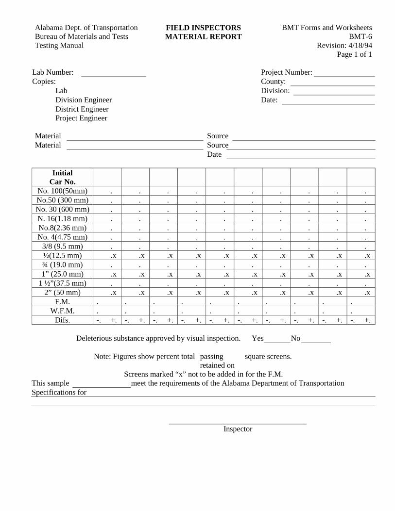
BMT Forms and WorksheetsAlabama Dept. of Transportation FIELD INSPECTORSBMT-6Bureau of Materials and Tests MATERIAL REPORT
Revision: 4/18/94Testing ManualPage 1 of 1
Lab Number: Project Number:Copies: County:
Lab Division:Division Engineer Date:District EngineerProject Engineer
Material SourceMaterial Source
Date
InitialCar No.
No. 100(50mm) . . . . . . . . . .No.50 (300 mm) . . . . . . . . . .No. 30 (600 mm) . . . . . . . . . .N. 16(1.18 mm) . . . . . . . . . .No.8(2.36 mm) . . . . . . . . . .No. 4(4.75 mm) . . . . . . . . . .
3/8 (9.5 mm) . . . . . . . . . .½(12.5 mm) .x .x .x .x .x .x .x .x .x .x¾ (19.0 mm) . . . . . . . . . .1” (25.0 mm) .x .x .x .x .x .x .x .x .x .x
1 ½”(37.5 mm) . . . . . . . . . .2” (50 mm) .x .x .x .x .x .x .x .x .x .x
F.M. . . . . . . . . . .W.F.M. . . . . . . . . . .
Difs. -. +. -. +. -. +. -. +. -. +. -. +. -. +. -. +. -. +. -. +.
Deleterious substance approved by visual inspection. Yes No
Note: Figures show percent total passing square screens.retained on
Screens marked “x” not to be added in for the F.M.This sample meet the requirements of the Alabama Department of TransportationSpecifications for
Inspector
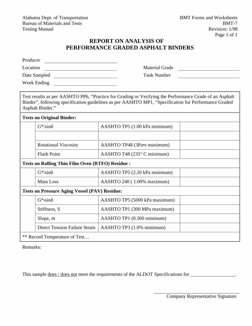
BMT Forms and WorksheetsAlabama Dept. of TransportationBMT-7Bureau of Materials and Tests
Revision: 1/98Testing ManualPage 1 of 1
REPORT ON ANALYSIS OFPERFORMANCE GRADED ASPHALT BINDERS
Producer
Location Material Grade
Date Sampled Tank Number
Week Ending
Test results as per AASHTO PP6, “Practice for Grading or Verifying the Performance Grade of an AsphaltBinder”, following specification guidelines as per AASHTO MP1, “Specification for Performance GradedAsphalt Binder.”
Tests on Original Binder:
G*/sinδ AASHTO TP5 (1.00 kPa minimum)
Rotational Viscosity AASHTO TP48 (3Pa•s maximum)
Flash Point AASHTO T48 (235° C minimum)
Tests on Rolling Thin Film Oven (RTFO) Residue :
G*/sinδ AASHTO TP5 (2.20 kPa minimum)
Mass Loss AASHTO 240 ( 1.00% maximum)
Tests on Pressure Aging Vessel (PAV) Residue:
G*•sinδ AASHTO TP5 (5000 kPa maximum)
Stiffness, S AASHTO TP1 (300 MPa maximum)
Slope, m AASHTO TP1 (0.300 minimum)
Direct Tension Failure Strain AASHTO TP3 (1.0% minimum)
** Record Temperature of Test…
Remarks:
This sample does / does not meet the requirements of the ALDOT Specifications for __________________.
Company Representative Signature
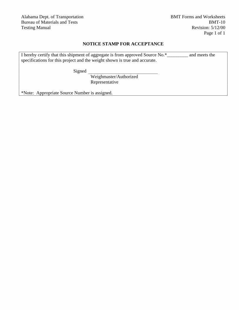
BMT Forms and WorksheetsAlabama Dept. of TransportationBMT-10Bureau of Materials and Tests
Revision: 5/12/00Testing ManualPage 1 of 1
NOTICE STAMP FOR ACCEPTANCE
I hereby certify that this shipment of aggregate is from approved Source No.*_________ and meets thespecifications for this project and the weight shown is true and accurate.
SignedWeighmaster/AuthorizedRepresentative
*Note: Appropriate Source Number is assigned.
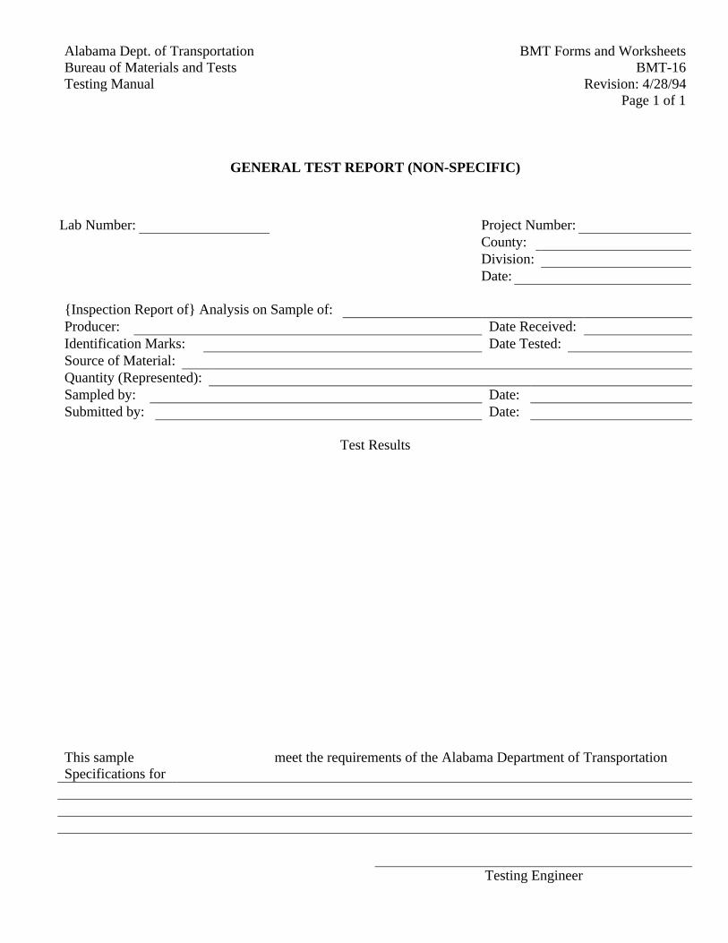
Alabama Dept. of Transportation BMT Forms and WorksheetsBureau of Materials and Tests BMT-16Testing Manual Revision: 4/28/94
Page 1 of 1
GENERAL TEST REPORT (NON-SPECIFIC)
Lab Number: Project Number:County:Division:Date:
{Inspection Report of} Analysis on Sample of:Producer: Date Received:Identification Marks: Date Tested:Source of Material:Quantity (Represented):Sampled by: Date:Submitted by: Date:
Test Results
This sample meet the requirements of the Alabama Department of TransportationSpecifications for
Testing Engineer
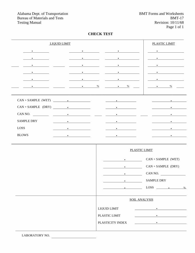
Alabama Dept. of Transportation BMT Forms and WorksheetsBureau of Materials and Tests BMT-17Testing Manual Revision: 10/11/68
Page 1 of 1
CHECK TEST
LIQUID LIMIT PLASTIC LIMIT
• • • •
• • • •
• • • •
• • • •
• • • •
• • % • % • %
CAN + SAMPLE (WET) • • •
CAN + SAMPLE (DRY) • • •
CAN NO. • • •
SAMPLE DRY • • •
LOSS • • •
BLOWS • • •
PLASTIC LIMIT
• CAN + SAMPLE (WET)
• CAN + SAMPLE (DRY)
• CAN NO.
• SAMPLE DRY
• LOSS • %
SOIL ANALYSIS
LIQUID LIMIT •
PLASTIC LIMIT •
PLASTICITY INDEX •
LABORATORY NO.
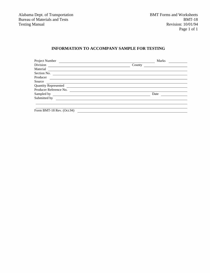
Alabama Dept. of Transportation BMT Forms and WorksheetsBureau of Materials and Tests BMT-18Testing Manual Revision: 10/01/94
Page 1 of 1
INFORMATION TO ACCOMPANY SAMPLE FOR TESTING
Project Number MarksDivision CountyMaterialSection No.ProducerSourceQuantity RepresentedProducer Reference No.Sampled by DateSubmitted by
Form BMT-18 Rev. (Oct.94)
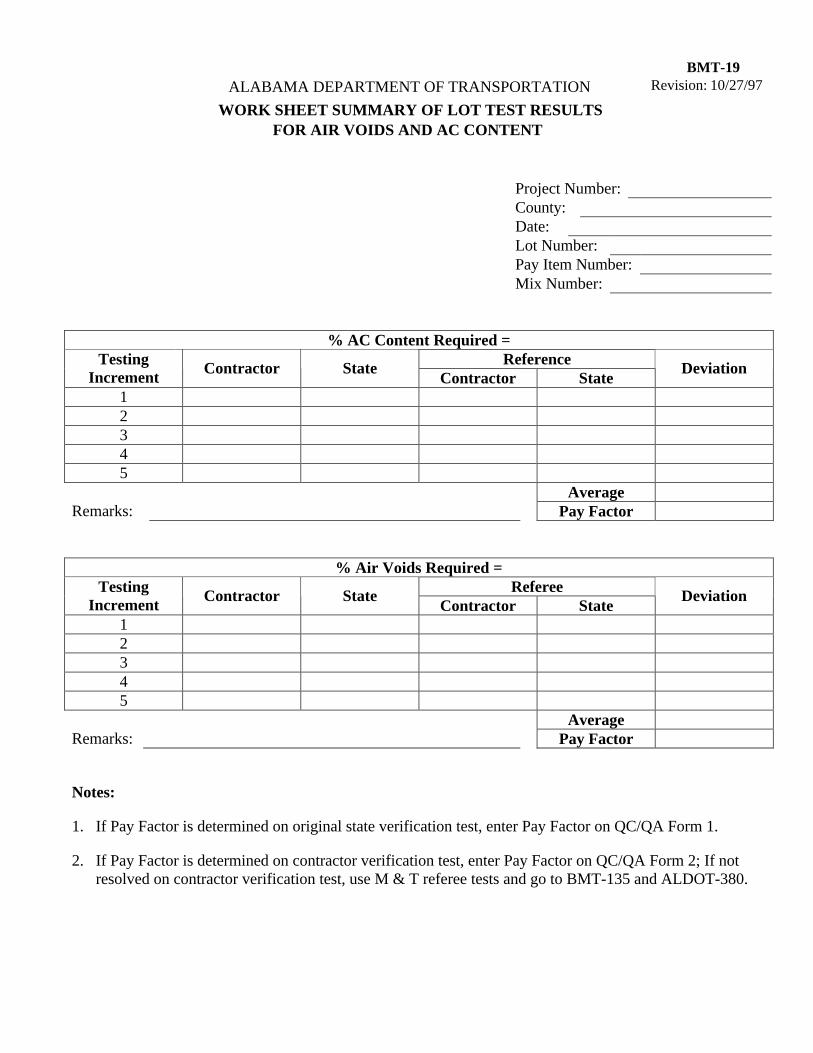
BMT-19 Revision: 10/27/97 ALABAMA DEPARTMENT OF TRANSPORTATION
WORK SHEET SUMMARY OF LOT TEST RESULTS FOR AIR VOIDS AND AC CONTENT
Project Number: County: Date:
Lot Number: Pay Item Number: Mix Number:
% AC Content Required = Reference Testing
Increment Contractor State
Contractor State Deviation
1 2 3 4 5
Average Remarks: Pay Factor
% Air Voids Required = Referee Testing
Increment Contractor State
Contractor State Deviation
1 2 3 4 5
Average Remarks: Pay Factor
Notes:
1. If Pay Factor is determined on original state verification test, enter Pay Factor on QC/QA Form 1.
2. If Pay Factor is determined on contractor verification test, enter Pay Factor on QC/QA Form 2; If not resolved on contractor verification test, use M & T referee tests and go to BMT-135 and ALDOT-380.
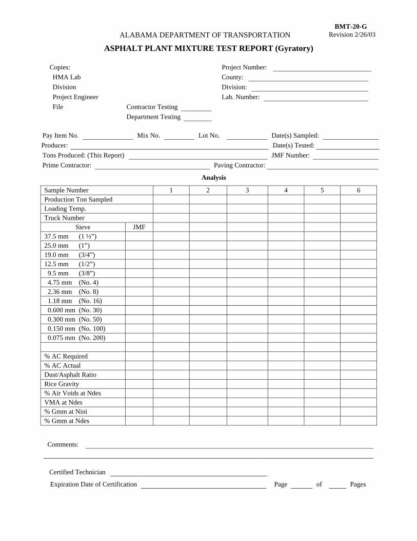
BMT-20-G ALABAMA DEPARTMENT OF TRANSPORTATION Revision 2/26/03
ASPHALT PLANT MIXTURE TEST REPORT (Gyratory)
Copies: Project Number:
HMA Lab County:
Division Division:
Project Engineer Lab. Number:
File Contractor Testing
Department Testing
Pay Item No. Mix No. Lot No. Date(s) Sampled:
Producer: Date(s) Tested:
Tons Produced: (This Report) JMF Number:
Prime Contractor: Paving Contractor:
Analysis
Sample Number 1 2 3 4 5 6 Production Ton Sampled Loading Temp. Truck Number
Sieve JMF 37.5 mm (1 ½”) 25.0 mm (1”) 19.0 mm (3/4”) 12.5 mm (1/2”) 9.5 mm (3/8”) 4.75 mm (No. 4) 2.36 mm (No. 8) 1.18 mm (No. 16) 0.600 mm (No. 30) 0.300 mm (No. 50) 0.150 mm (No. 100) 0.075 mm (No. 200) % AC Required % AC Actual Dust/Asphalt Ratio Rice Gravity % Air Voids at Ndes VMA at Ndes % Gmm at Nini % Gmm at Ndes
Comments:
Certified Technician
Expiration Date of Certification Page of Pages
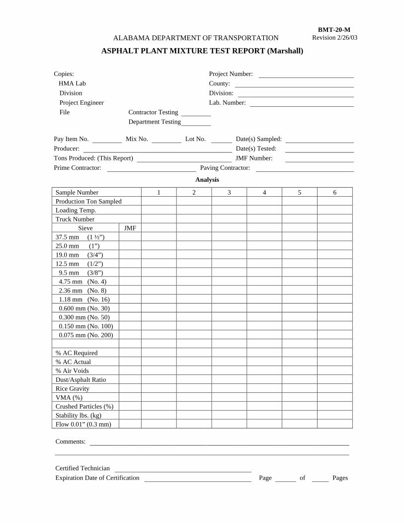
BMT-20-M ALABAMA DEPARTMENT OF TRANSPORTATION Revision 2/26/03
ASPHALT PLANT MIXTURE TEST REPORT (Marshall)
Copies: Project Number:
HMA Lab County:
Division Division:
Project Engineer Lab. Number:
File Contractor Testing
Department Testing
Pay Item No. Mix No. Lot No. Date(s) Sampled:
Producer: Date(s) Tested:
Tons Produced: (This Report) JMF Number:
Prime Contractor: Paving Contractor:
Analysis
Sample Number 1 2 3 4 5 6 Production Ton Sampled Loading Temp. Truck Number
Sieve JMF 37.5 mm (1 ½”) 25.0 mm (1”) 19.0 mm (3/4”) 12.5 mm (1/2”) 9.5 mm (3/8”) 4.75 mm (No. 4) 2.36 mm (No. 8) 1.18 mm (No. 16) 0.600 mm (No. 30) 0.300 mm (No. 50) 0.150 mm (No. 100) 0.075 mm (No. 200) % AC Required % AC Actual % Air Voids Dust/Asphalt Ratio Rice Gravity VMA (%) Crushed Particles (%) Stability lbs. (kg) Flow 0.01” (0.3 mm)
Comments:
Certified Technician
Expiration Date of Certification Page of Pages
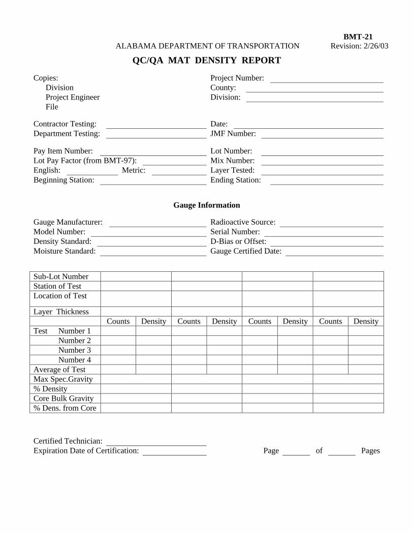
BMT-21
ALABAMA DEPARTMENT OF TRANSPORTATION Revision: 2/26/03
QC/QA MAT DENSITY REPORT Copies: Project Number:
Division County: Project Engineer Division: File
Contractor Testing: Date: Department Testing: JMF Number: Pay Item Number: Lot Number: Lot Pay Factor (from BMT-97): Mix Number: English: Metric: Layer Tested: Beginning Station: Ending Station:
Gauge Information Gauge Manufacturer: Radioactive Source: Model Number: Serial Number: Density Standard: D-Bias or Offset: Moisture Standard: Gauge Certified Date:
Sub-Lot Number
Station of Test
Location of Test
Layer Thickness
Counts Density Counts Density Counts Density Counts Density Test Number 1
Number 2
Number 3
Number 4
Average of Test
Max Spec.Gravity
% Density
Core Bulk Gravity
% Dens. from Core
Certified Technician: Expiration Date of Certification: Page of Pages
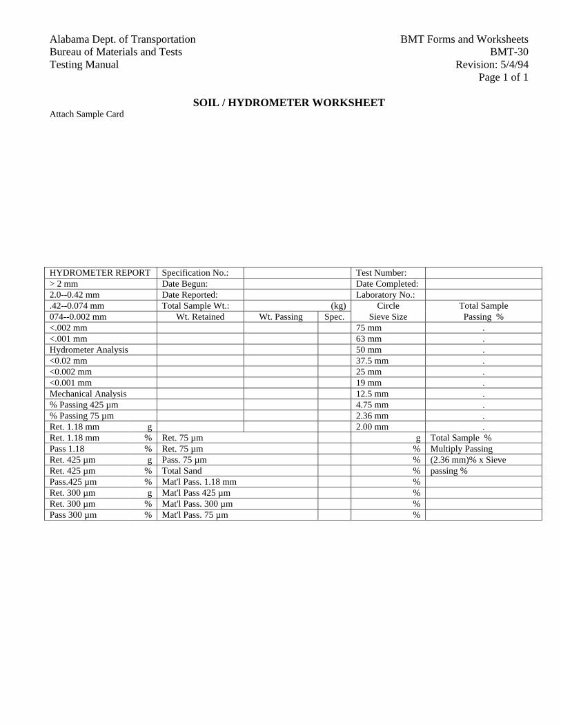
BMT Forms and WorksheetsAlabama Dept. of TransportationBMT-30Bureau of Materials and Tests
Revision: 5/4/94Testing ManualPage 1 of 1
SOIL / HYDROMETER WORKSHEETAttach Sample Card
HYDROMETER REPORT Specification No.: Test Number:> 2 mm Date Begun: Date Completed:2.0--0.42 mm Date Reported: Laboratory No.:.42--0.074 mm Total Sample Wt.: (kg) Circle Total Sample074--0.002 mm Wt. Retained Wt. Passing Spec. Sieve Size Passing %<.002 mm 75 mm .<.001 mm 63 mm .Hydrometer Analysis 50 mm .<0.02 mm 37.5 mm .<0.002 mm 25 mm .<0.001 mm 19 mm .Mechanical Analysis 12.5 mm .% Passing 425 µm 4.75 mm .% Passing 75 µm 2.36 mm .Ret. 1.18 mm g 2.00 mm .Ret. 1.18 mm % Ret. 75 µm g Total Sample %Pass 1.18 % Ret. 75 µm % Multiply PassingRet. 425 µm g Pass. 75 µm % (2.36 mm)% x SieveRet. 425 µm % Total Sand % passing %Pass.425 µm % Mat'l Pass. 1.18 mm %Ret. 300 µm g Mat'l Pass 425 µm %Ret. 300 µm % Mat'l Pass. 300 µm %Pass 300 µm % Mat'l Pass. 75 µm %
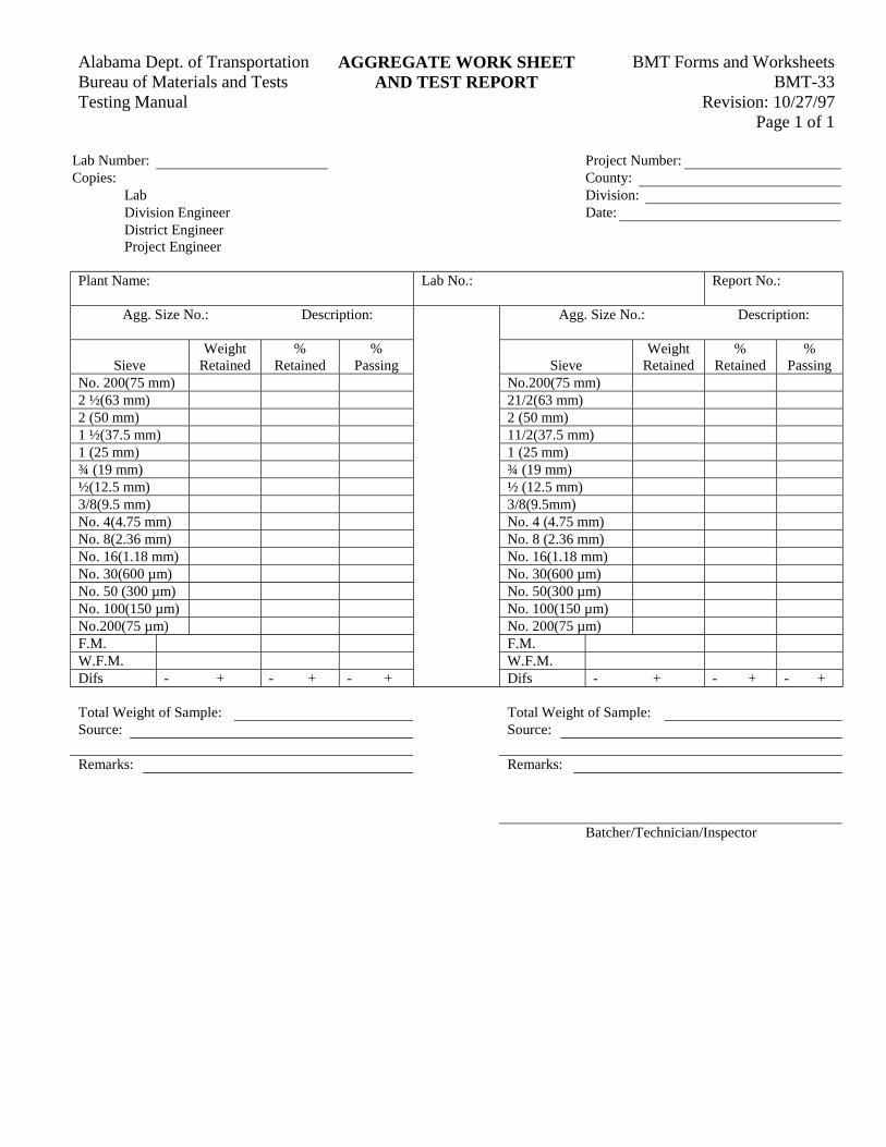
BMT Forms and WorksheetsAlabama Dept. of Transportation AGGREGATE WORK SHEETBMT-33Bureau of Materials and Tests AND TEST REPORT
Revision: 10/27/97Testing ManualPage 1 of 1
Lab Number: Project Number:Copies: County:
Lab Division:Division Engineer Date:District EngineerProject Engineer
Plant Name: Lab No.: Report No.:
Agg. Size No.: Description: Agg. Size No.: Description:
SieveWeight
Retained%
Retained%
Passing SieveWeight
Retained%
Retained%
PassingNo. 200(75 mm) No.200(75 mm)2 ½(63 mm) 21/2(63 mm)2 (50 mm) 2 (50 mm)1 ½(37.5 mm) 11/2(37.5 mm)1 (25 mm) 1 (25 mm)¾ (19 mm) ¾ (19 mm)½(12.5 mm) ½ (12.5 mm)3/8(9.5 mm) 3/8(9.5mm)No. 4(4.75 mm) No. 4 (4.75 mm)No. 8(2.36 mm) No. 8 (2.36 mm)No. 16(1.18 mm) No. 16(1.18 mm)No. 30(600 µm) No. 30(600 µm)No. 50 (300 µm) No. 50(300 µm)No. 100(150 µm) No. 100(150 µm)No.200(75 µm) No. 200(75 µm)F.M. F.M.W.F.M. W.F.M.Difs - + - + - + Difs - + - + - +
Total Weight of Sample: Total Weight of Sample:Source: Source:
Remarks: Remarks:
Batcher/Technician/Inspector
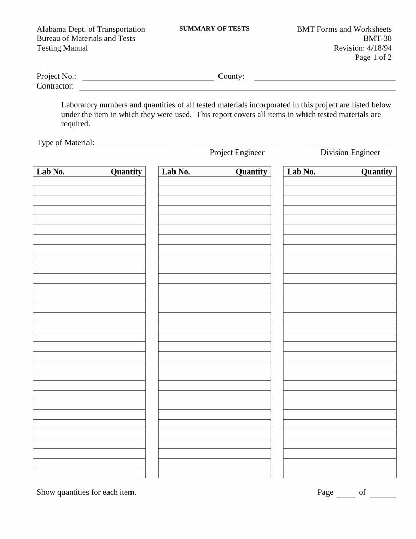
BMT Forms and WorksheetsAlabama Dept. of Transportation SUMMARY OF TESTS
BMT-38Bureau of Materials and TestsRevision: 4/18/94Testing Manual
Page 1 of 2
Project No.: County:Contractor:
Laboratory numbers and quantities of all tested materials incorporated in this project are listed belowunder the item in which they were used. This report covers all items in which tested materials arerequired.
Type of Material:Project Engineer Division Engineer
Lab No. Quantity Lab No. Quantity Lab No. Quantity
Show quantities for each item. Page of
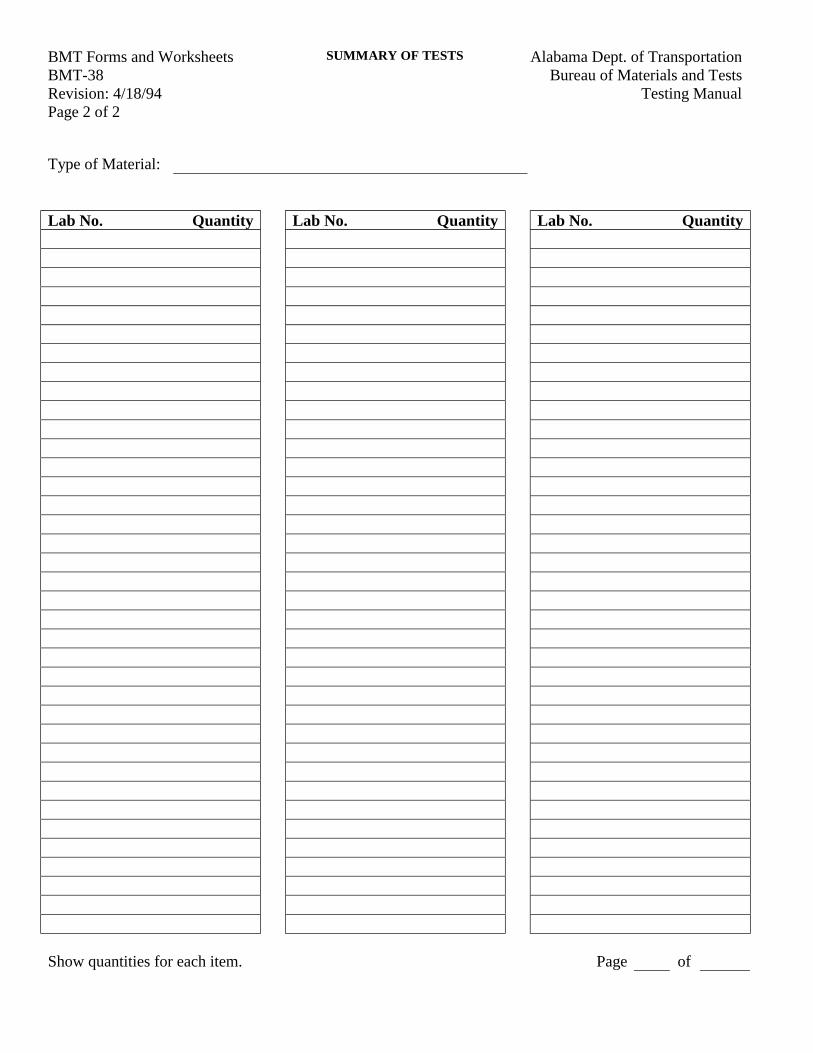
BMT Forms and Worksheets Alabama Dept. of TransportationSUMMARY OF TESTS
BMT-38 Bureau of Materials and TestsRevision: 4/18/94 Testing ManualPage 2 of 2
Type of Material:
Lab No. Quantity Lab No. Quantity Lab No. Quantity
Show quantities for each item. Page of
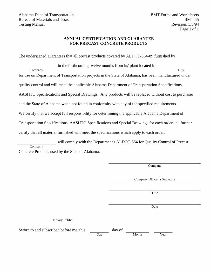
BMT Forms and WorksheetsAlabama Dept. of TransportationBMT-45Bureau of Materials and Tests
Revision: 5/3/94Testing ManualPage 1 of 1
ANNUAL CERTIFICATION AND GUARANTEEFOR PRECAST CONCRETE PRODUCTS
The undersigned guarantees that all precast products covered by ALDOT-364-89 furnished by
in the forthcoming twelve months from its' plant located inCompany City
for use on Department of Transportation projects in the State of Alabama, has been manufactured under
quality control and will meet the applicable Alabama Department of Transportation Specifications,
AASHTO Specifications and Special Drawings. Any products will be replaced without cost to purchaser
and the State of Alabama when not found in conformity with any of the specified requirements.
We certify that we accept full responsibility for determining the applicable Alabama Department of
Transportation Specifications, AASHTO Specifications and Special Drawings for each order and further
certify that all material furnished will meet the specifications which apply to each order.
will comply with the Department's ALDOT-364 for Quality Control of PrecastCompany
Concrete Products used by the State of Alabama.
Company
Company Officer’s Signature
Title
Date
Notary Public
Sworn to and subscribed before me, this day of .Day Month Year
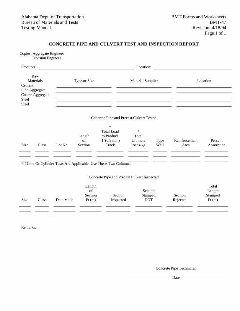
BMT Forms and WorksheetsAlabama Dept. of TransportationBMT-47Bureau of Materials and Tests
Revision: 4/18/94Testing ManualPage 1 of 1
CONCRETE PIPE AND CULVERT TEST AND INSPECTION REPORT
Copies: Aggregate Engineer Division Engineer
Producer: Location:
RawMaterials Type or Size Material Supplier Location
CementFine AggregateCoarse AggregateSteelSteel
Concrete Pipe and Precast Culvert Tested
Size Class Lot No.
Lengthof
Section
*Total Loadto Produce
.1”(0.3 mm)Crack
*Total
UltimateLoads-kg.
TypeWall
ReinforcementArea
PercentAbsorption
*If Core Or Cylinder Tests Are Applicable, Use These Two Columns.
Concrete Pipe and Precast Culvert Inspected
Size Class Date Made
Lengthof
SectionFt (m)
SectionInspected
SectionStamped
DOTSection
Rejected
TotalLength
StampedFt (m)
Remarks:
Concrete Pipe Technician
Date
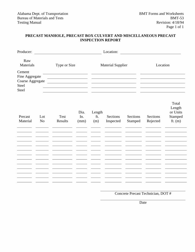
BMT Forms and WorksheetsAlabama Dept. of TransportationBMT-53Bureau of Materials and Tests
Revision: 4/18/94Testing ManualPage 1 of 1
PRECAST MANHOLE, PRECAST BOX CULVERT AND MISCELLANEOUS PRECASTINSPECTION REPORT
Producer: Location:
RawMaterials Type or Size Material Supplier Location
CementFine AggregateCoarse AggregateSteelSteel
PrecastMaterial
LotNo
TestResults
Dia.In.
(mm)
Lengthft.
(m)SectionsInspected
SectionsStamped
SectionsRejected
TotalLengthor UnitsStampedft. (m)
Concrete Precast Technician, DOT #
Date
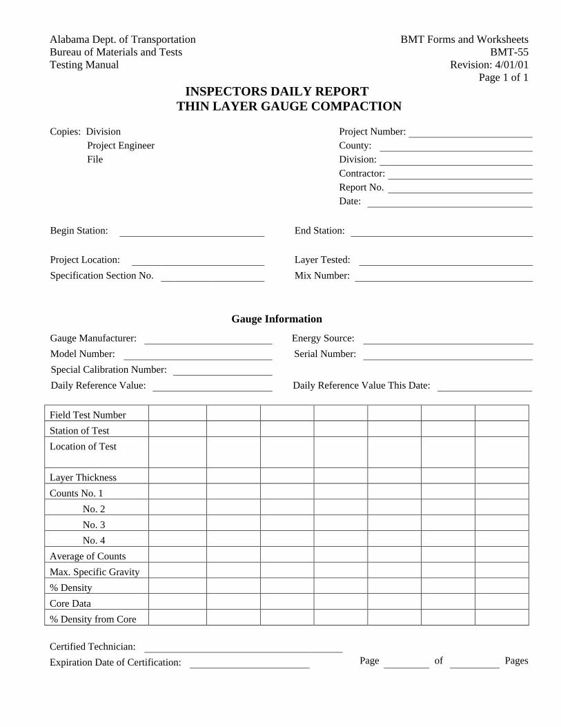
BMT Forms and WorksheetsAlabama Dept. of TransportationBMT-55Bureau of Materials and Tests
Revision: 4/01/01Testing ManualPage 1 of 1
INSPECTORS DAILY REPORTTHIN LAYER GAUGE COMPACTION
Copies: Division Project Number:
Project Engineer County:
File Division:
Contractor:
Report No.
Date:
Begin Station: End Station:
Project Location: Layer Tested:
Specification Section No. Mix Number:
Gauge Information
Gauge Manufacturer: Energy Source:
Model Number: Serial Number:
Special Calibration Number:
Daily Reference Value: Daily Reference Value This Date:
Field Test Number
Station of Test
Location of Test
Layer Thickness
Counts No. 1
No. 2
No. 3
No. 4
Average of Counts
Max. Specific Gravity
% Density
Core Data
% Density from Core
Certified Technician:
Expiration Date of Certification: Page of Pages
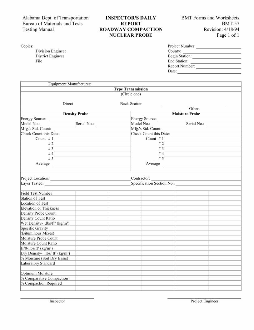
BMT Forms and Worksheets Alabama Dept. of Transportation INSPECTOR'S DAILY BMT-57 Bureau of Materials and Tests REPORT
Revision: 4/18/94 Testing Manual ROADWAY COMPACTION Page 1 of 1 NUCLEAR PROBE
Copies: Project Number: Division Engineer County: District Engineer Begin Station: File End Station:
Report Number: Date:
Equipment Manufacturer: Type Transmission
(Circle one) Direct Back-Scatter Other
Density Probe Moisture Probe Energy Source: Energy Source: Model No.: Serial No.: Model No.: Serial No.: Mfg.'s Std. Count: Mfg.'s Std. Count: Check Count this Date: Check Count this Date:
Count # 1 Count # 1 # 2 # 2 # 3 # 3 # 4 # 4 # 5 # 5
Average Average Project Location: Contractor: Layer Tested: Specification Section No.: Field Test Number Station of Test Location of Test Elevation or Thickness Density Probe Count Density Count Ratio Wet Density- .lbs/ft³ (kg/m³) Specific Gravity (Bituminous Mixes) Moisture Probe Count Moisture Count Ratio H²0-.lbs/ft³ (kg/m³) Dry Density- .lbs/ ft³ (kg/m³) % Moisture (Soil Dry Basis) Laboratory Standard Optimum Moisture % Comparative Compaction % Compaction Required
Inspector Project Engineer
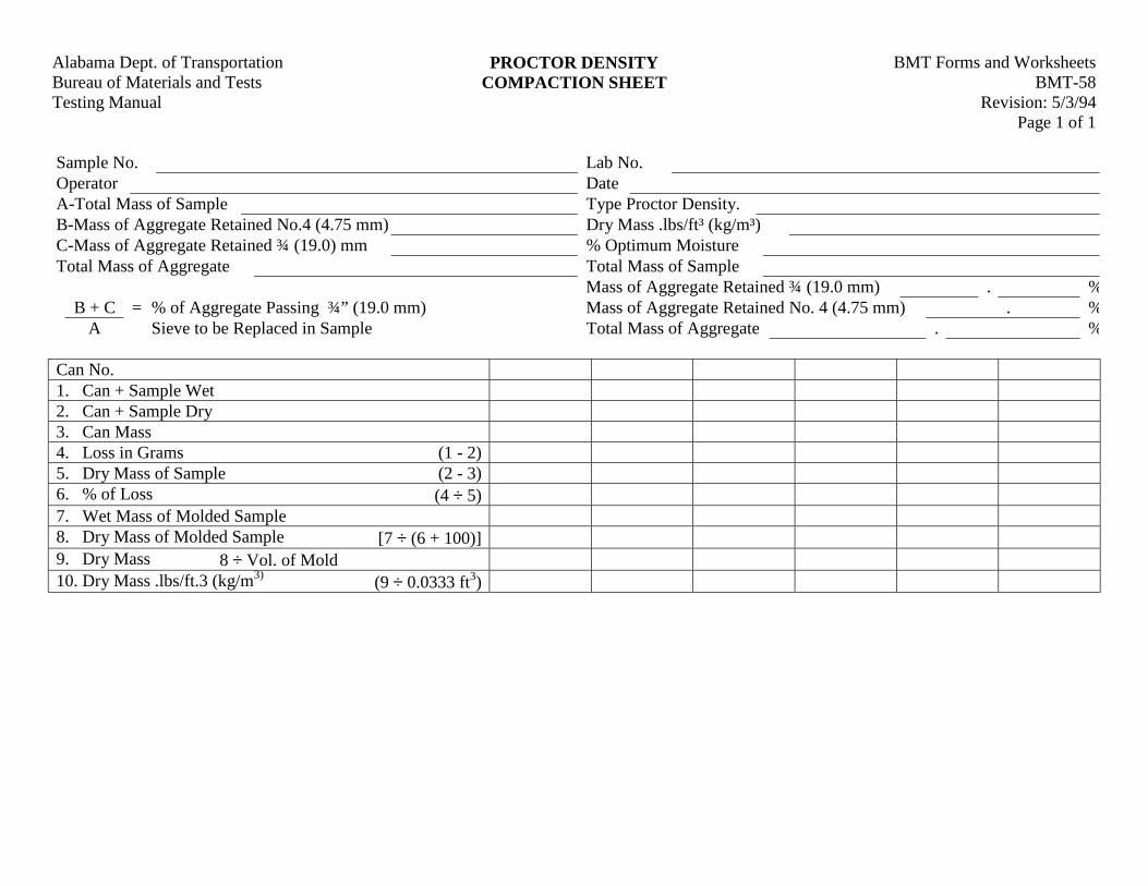
BMT Forms and WorksheetsAlabama Dept. of Transportation PROCTOR DENSITYBMT-58Bureau of Materials and Tests COMPACTION SHEET
Revision: 5/3/94Testing ManualPage 1 of 1
Sample No. Lab No.Operator DateA-Total Mass of Sample Type Proctor Density.B-Mass of Aggregate Retained No.4 (4.75 mm) Dry Mass .lbs/ft³ (kg/m³)C-Mass of Aggregate Retained ¾ (19.0) mm % Optimum MoistureTotal Mass of Aggregate Total Mass of Sample
Mass of Aggregate Retained ¾ (19.0 mm) . %B + C = % of Aggregate Passing ¾” (19.0 mm) Mass of Aggregate Retained No. 4 (4.75 mm) . %
A Sieve to be Replaced in Sample Total Mass of Aggregate . %
Can No.1. Can + Sample Wet2. Can + Sample Dry3. Can Mass4. Loss in Grams (1 - 2)5. Dry Mass of Sample (2 - 3)6. % of Loss (4 ÷ 5)7. Wet Mass of Molded Sample8. Dry Mass of Molded Sample [7 ÷ (6 + 100)]9. Dry Mass 8 ÷ Vol. of Mold10. Dry Mass .lbs/ft.3 (kg/m3) (9 ÷ 0.0333 ft3)
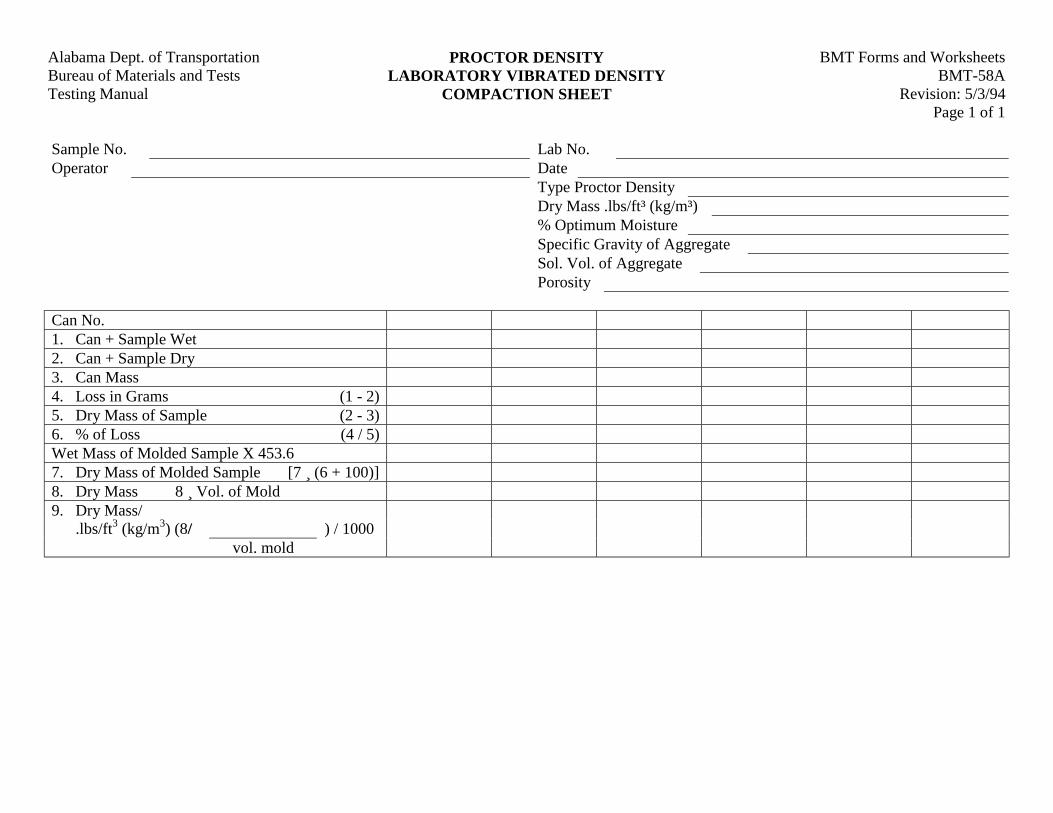
BMT Forms and WorksheetsAlabama Dept. of Transportation PROCTOR DENSITYBMT-58ABureau of Materials and Tests LABORATORY VIBRATED DENSITY
Revision: 5/3/94Testing Manual COMPACTION SHEETPage 1 of 1
Sample No. Lab No.Operator Date
Type Proctor DensityDry Mass .lbs/ft³ (kg/m³)% Optimum MoistureSpecific Gravity of AggregateSol. Vol. of AggregatePorosity
Can No.1. Can + Sample Wet2. Can + Sample Dry3. Can Mass4. Loss in Grams (1 - 2)5. Dry Mass of Sample (2 - 3)6. % of Loss (4 / 5)Wet Mass of Molded Sample X 453.67. Dry Mass of Molded Sample [7 ¸ (6 + 100)]8. Dry Mass 8 ¸ Vol. of Mold9. Dry Mass/
.lbs/ft3 (kg/m3) (8/ ) / 1000vol. mold
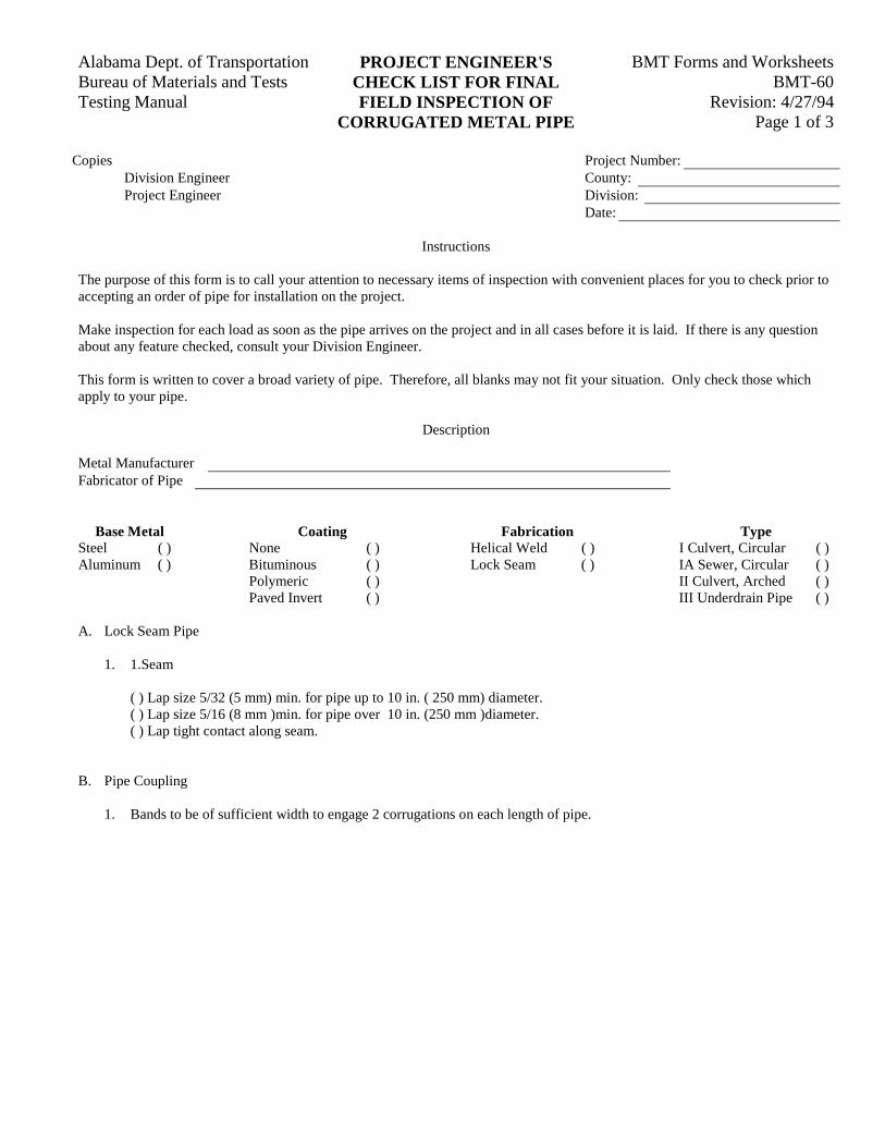
BMT Forms and WorksheetsAlabama Dept. of Transportation PROJECT ENGINEER'SBMT-60Bureau of Materials and Tests CHECK LIST FOR FINAL
Revision: 4/27/94Testing Manual FIELD INSPECTION OFPage 1 of 3CORRUGATED METAL PIPE
Copies Project Number:Division Engineer County:Project Engineer Division:
Date:
Instructions
The purpose of this form is to call your attention to necessary items of inspection with convenient places for you to check prior toaccepting an order of pipe for installation on the project.
Make inspection for each load as soon as the pipe arrives on the project and in all cases before it is laid. If there is any questionabout any feature checked, consult your Division Engineer.
This form is written to cover a broad variety of pipe. Therefore, all blanks may not fit your situation. Only check those whichapply to your pipe.
Description
Metal ManufacturerFabricator of Pipe
Base Metal Coating Fabrication TypeSteel ( ) None ( ) Helical Weld ( ) I Culvert, Circular ( )Aluminum ( ) Bituminous ( ) Lock Seam ( ) IA Sewer, Circular ( )
Polymeric ( ) II Culvert, Arched ( )Paved Invert ( ) III Underdrain Pipe ( )
A. Lock Seam Pipe
1. 1.Seam
( ) Lap size 5/32 (5 mm) min. for pipe up to 10 in. ( 250 mm) diameter.( ) Lap size 5/16 (8 mm )min. for pipe over 10 in. (250 mm )diameter.( ) Lap tight contact along seam.
B. Pipe Coupling
1. Bands to be of sufficient width to engage 2 corrugations on each length of pipe.
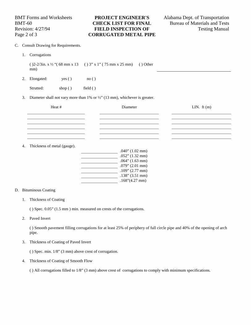
BMT Forms and Worksheets Alabama Dept. of TransportationPROJECT ENGINEER'SBMT-60 Bureau of Materials and TestsCHECK LIST FOR FINALRevision: 4/27/94 Testing ManualFIELD INSPECTION OFPage 2 of 3 CORRUGATED METAL PIPE
C. Consult Drawing for Requirements.
1. Corrugations
( )2-2/3in. x ½ “( 68 mm x 13mm)
( ) 3” x 1” ( 75 mm x 25 mm) ( ) Other
2. Elongated: yes ( ) no ( )
Strutted: shop ( ) field ( )
3. Diameter shall not vary more than 1% or ½” (13 mm), whichever is greater.
Heat # Diameter LIN. ft (m)
4. Thickness of metal (gauge)..040” (1.02 mm).052” (1.32 mm).064” (1.63 mm).079” (2.01 mm).109” (2.77 mm).138” (3.51 mm).168”(4.27 mm)
D. Bituminous Coating
1. Thickness of Coating
( ) Spec. 0.05” (1.5 mm ) min. measured on crests of the corrugations.
2. Paved Invert
( ) Smooth pavement filling corrugations for at least 25% of periphery of full circle pipe and 40% of the opening of archpipe.
3. Thickness of Coating of Paved Invert
( ) Spec. min. 1/8” (3 mm) above crest of corrugation.
4. Thickness of Coating of Smooth Flow
( ) All corrugations filled to 1/8” (3 mm) above crest of corrugations to comply with minimum specifications.
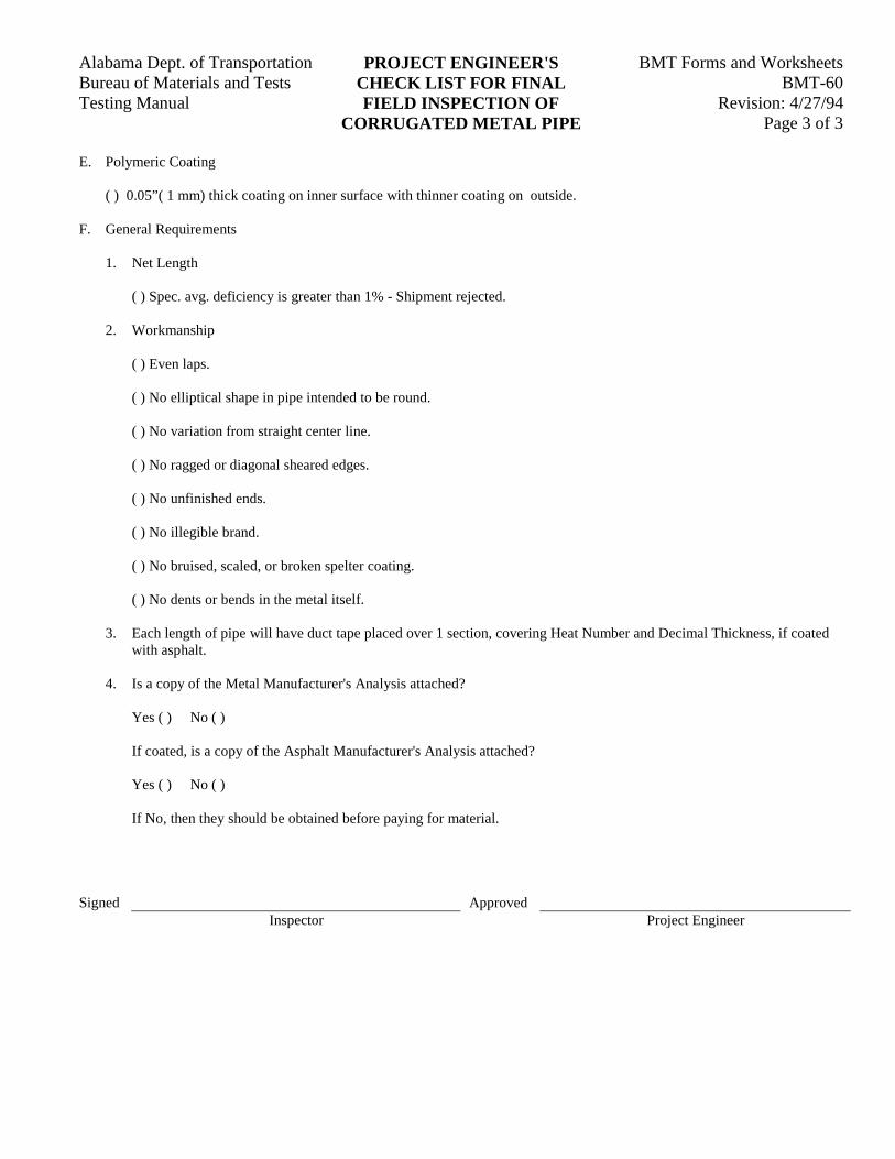
BMT Forms and WorksheetsAlabama Dept. of Transportation PROJECT ENGINEER'SBMT-60Bureau of Materials and Tests CHECK LIST FOR FINAL
Revision: 4/27/94Testing Manual FIELD INSPECTION OFPage 3 of 3CORRUGATED METAL PIPE
E. Polymeric Coating
( ) 0.05”( 1 mm) thick coating on inner surface with thinner coating on outside.
F. General Requirements
1. Net Length
( ) Spec. avg. deficiency is greater than 1% - Shipment rejected.
2. Workmanship
( ) Even laps.
( ) No elliptical shape in pipe intended to be round.
( ) No variation from straight center line.
( ) No ragged or diagonal sheared edges.
( ) No unfinished ends.
( ) No illegible brand.
( ) No bruised, scaled, or broken spelter coating.
( ) No dents or bends in the metal itself.
3. Each length of pipe will have duct tape placed over 1 section, covering Heat Number and Decimal Thickness, if coatedwith asphalt.
4. Is a copy of the Metal Manufacturer's Analysis attached?
Yes ( ) No ( )
If coated, is a copy of the Asphalt Manufacturer's Analysis attached?
Yes ( ) No ( )
If No, then they should be obtained before paying for material.
Signed ApprovedInspector Project Engineer
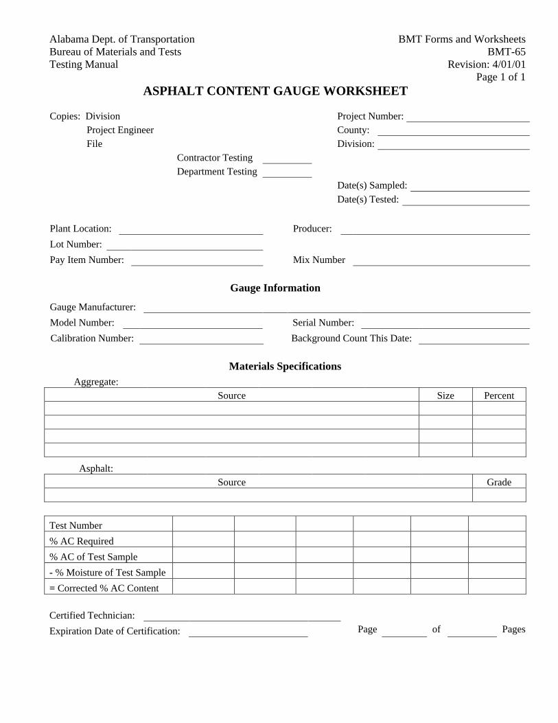
BMT Forms and WorksheetsAlabama Dept. of TransportationBMT-65Bureau of Materials and Tests
Revision: 4/01/01Testing ManualPage 1 of 1
ASPHALT CONTENT GAUGE WORKSHEET
Copies: Division Project Number:
Project Engineer County:
File Division:
Contractor Testing
Department Testing
Date(s) Sampled:
Date(s) Tested:
Plant Location: Producer:
Lot Number:
Pay Item Number: Mix Number
Gauge Information
Gauge Manufacturer:
Model Number: Serial Number:
Calibration Number: Background Count This Date:
Materials Specifications
Aggregate:
Source Size Percent
Asphalt:
Source Grade
Test Number
% AC Required
% AC of Test Sample
- % Moisture of Test Sample
= Corrected % AC Content
Certified Technician:
Expiration Date of Certification: Page of Pages
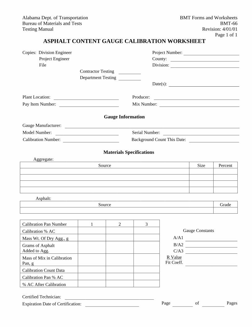
BMT Forms and WorksheetsAlabama Dept. of TransportationBMT-66Bureau of Materials and Tests
Revision: 4/01/01Testing ManualPage 1 of 1
ASPHALT CONTENT GAUGE CALIBRATION WORKSHEET
Copies: Division Engineer Project Number:
Project Engineer County:
File Division:
Contractor Testing
Department Testing
Date(s):
Plant Location: Producer:
Pay Item Number: Mix Number:
Gauge Information
Gauge Manufacturer:
Model Number: Serial Number:
Calibration Number: Background Count This Date:
Materials Specifications
Aggregate:
Source Size Percent
Asphalt:
Source Grade
Calibration Pan Number 1 2 3
Calibration % AC Gauge Constants
Mass Wt. Of Dry Agg., g A/A1
B/A2Grams of AsphaltAdded to Agg. C/A3
Mass of Mix in CalibrationPan, g
R ValueFit Coeff.
Calibration Count Data
Calibration Pan % AC
% AC After Calibration
Certified Technician:
Expiration Date of Certification: Page of Pages
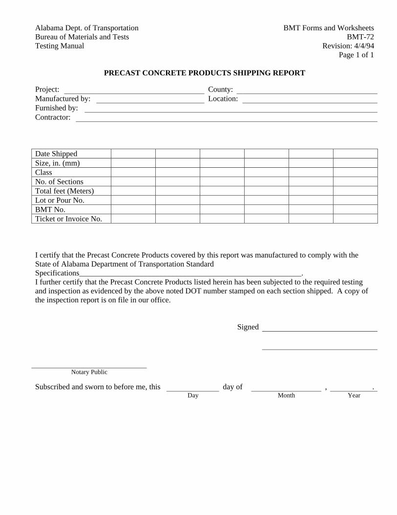
BMT Forms and WorksheetsAlabama Dept. of TransportationBMT-72Bureau of Materials and Tests
Revision: 4/4/94Testing ManualPage 1 of 1
PRECAST CONCRETE PRODUCTS SHIPPING REPORT
Project: County:Manufactured by: Location:Furnished by:Contractor:
Date ShippedSize, in. (mm)ClassNo. of SectionsTotal feet (Meters)Lot or Pour No.BMT No.Ticket or Invoice No.
I certify that the Precast Concrete Products covered by this report was manufactured to comply with theState of Alabama Department of Transportation StandardSpecifications_________________________________________________________.I further certify that the Precast Concrete Products listed herein has been subjected to the required testingand inspection as evidenced by the above noted DOT number stamped on each section shipped. A copy ofthe inspection report is on file in our office.
Signed
Notary Public
Subscribed and sworn to before me, this day of , .Day Month Year
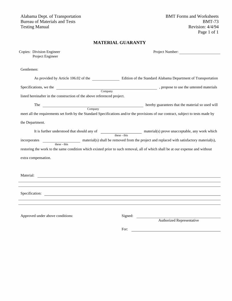
BMT Forms and WorksheetsAlabama Dept. of TransportationBMT-73Bureau of Materials and Tests
Revision: 4/4/94Testing ManualPage 1 of 1
MATERIAL GUARANTY
Copies: Division Engineer Project Number:Project Engineer
Gentlemen:
As provided by Article 106.02 of the Edition of the Standard Alabama Department of Transportation
Specifications, we the , propose to use the untested materialsCompany
listed hereinafter in the construction of the above referenced project.
The hereby guarantees that the material so used willCompany
meet all the requirements set forth by the Standard Specifications and/or the provisions of our contract, subject to tests made by
the Department.
It is further understood that should any of material(s) prove unacceptable, any work whichthese - this
incorporates material(s) shall be removed from the project and replaced with satisfactory material(s),these - this
restoring the work to the same condition which existed prior to such removal, all of which shall be at our expense and without
extra compensation.
Material:
Specification:
Approved under above conditions: Signed:Authorized Representative
For:
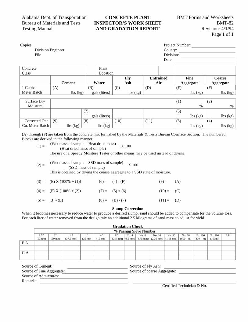
BMT Forms and WorksheetsAlabama Dept. of Transportation CONCRETE PLANTBMT-82Bureau of Materials and Tests INSPECTOR’S WORK SHEET
Revision: 4/1/94Testing Manual AND GRADATION REPORTPage 1 of 1
Copies Project Number:Division Engineer County:File Division:
Date:
ConcreteClass
PlantLocation
Cement WaterFlyAsh
EntrainedAir
FineAggregate
CoarseAggregate
(A) (B) (C) (D) (E) (F)1 CubicMeter Batch lbs (kg) gals (liters) lbs (kg) lbs (kg) lbs (kg)
(1) (2)Surface DryMoisture % %
(7) (5)gals (liters) lbs (kg) lbs (kg)
(9) (8) (10) (11) (3) (4)Corrected OneCu. Meter Batch lbs (kg) lbs (kg) lbs (kg) lbs (kg)
(A) through (F) are taken from the concrete mix furnished by the Materials & Tests Bureau Concrete Section. The numberedBlocks are derived in the following manner:
(Wet mass of sample – Heat dried mass)(1) =
(Heat dried mass of sample)X 100
The use of a Speedy Moisture Tester or other means may be used instead of drying.
(Wet mass of sample – SSD mass of sample)(2) =
(SSD mass of sample)X 100
This is obtained by drying the coarse aggregate to a SSD state of moisture.
(3) = (E) X (100% + (1)) (6) = (4) - (F) (9) = (A)
(4) = (F) X (100% + (2)) (7) = (5) + (6) (10) = (C)
(5) = (3) - (E) (8) = (B) - (7) (11) = (D)
Slump CorrectionWhen it becomes necessary to reduce water to produce a desired slump, sand should be added to compensate for the volume loss.For each liter of water removed from the design mix an additional 2.5 kilograms of sand mass to adjust for yield.
Gradation Check% Passing Sieve Number
2.5”(63mm)
2”(50 mm
1.5(37.5 mm)
1”(25 mm
¾”(19 mm)
½”(12.5 mm)
No. 4(9.5 mm)
No. 8(4.75 mm)
No. 16(2.36 mm)
No. 30(1.18 mm)
No. 50(600 �m)
No. 100(300 �m)
No. 200(150m)
F.M.
F.A.
C.A.
Source of Cement: Source of Fly Ash:Source of Fine Aggregate: Source of coarse Aggregate:Source of Admixtures:Remarks:
Certified Technician & No.
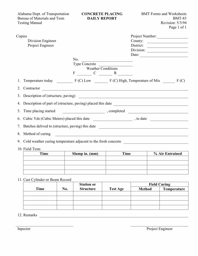
BMT Forms and Worksheets Alabama Dept. of Transportation CONCRETE PLACING BMT-83 Bureau of Materials and Tests DAILY REPORT
Revision: 5/3/94 Testing Manual Page 1 of 1
Copies Project Number: Division Engineer County: Project Engineer District: Division: Date:
No. Type Concrete
Weather Conditions F C R
1. Temperature today F (C) Low F (C) High, Temperature of Mix F (C) 2. Contractor 3. Description of (structure, paving) 4. Description of part of (structure, paving) placed this date 5. Time placing started , completed 6. Cubic Yds (Cubic Meters) placed this date , to date 7. Batches delived to (structure, paving) this date 8. Method of curing 9. Cold weather curing temperature adjacent to the fresh concrete 10. Field Tests
Time Slump in. (mm) Time % Air Entrained
11. Cast Cylinder or Beam Record
Field Curing Time No.
Station or Structure Test Age Method Temperature
12. Remarks Inpector Project Engineer
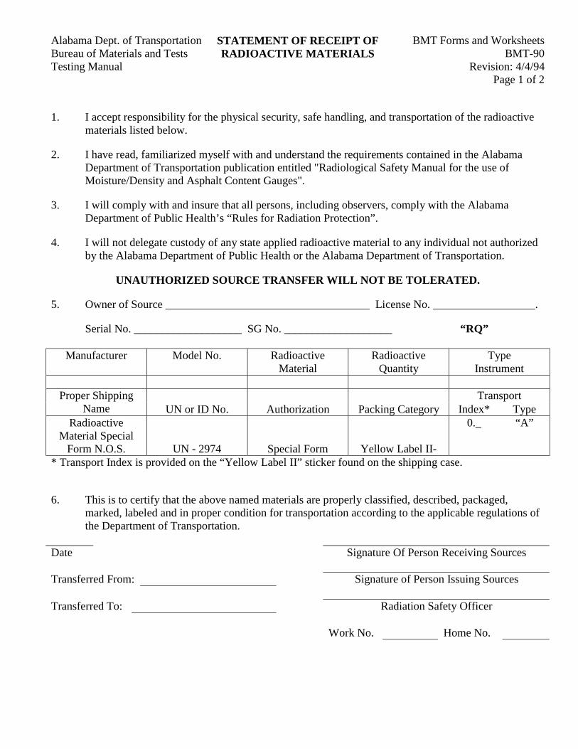
BMT Forms and WorksheetsAlabama Dept. of Transportation STATEMENT OF RECEIPT OFBMT-90Bureau of Materials and Tests RADIOACTIVE MATERIALS
Revision: 4/4/94Testing ManualPage 1 of 2
1. I accept responsibility for the physical security, safe handling, and transportation of the radioactivematerials listed below.
2. I have read, familiarized myself with and understand the requirements contained in the AlabamaDepartment of Transportation publication entitled "Radiological Safety Manual for the use ofMoisture/Density and Asphalt Content Gauges".
3. I will comply with and insure that all persons, including observers, comply with the AlabamaDepartment of Public Health’s “Rules for Radiation Protection”.
4. I will not delegate custody of any state applied radioactive material to any individual not authorizedby the Alabama Department of Public Health or the Alabama Department of Transportation.
UNAUTHORIZED SOURCE TRANSFER WILL NOT BE TOLERATED.
5. Owner of Source ____________________________________ License No. __________________.
Serial No. ___________________ SG No. ___________________ “RQ”
Manufacturer Model No. RadioactiveMaterial
RadioactiveQuantity
TypeInstrument
TransportProper ShippingName UN or ID No. Authorization Packing Category Index* Type
RadioactiveMaterial Special
Form N.O.S. UN - 2974 Special Form Yellow Label II-
0._ “A”
* Transport Index is provided on the “Yellow Label II” sticker found on the shipping case.
6. This is to certify that the above named materials are properly classified, described, packaged,marked, labeled and in proper condition for transportation according to the applicable regulations ofthe Department of Transportation.
Date Signature Of Person Receiving Sources
Transferred From: Signature of Person Issuing Sources
Transferred To: Radiation Safety Officer
Work No. Home No.
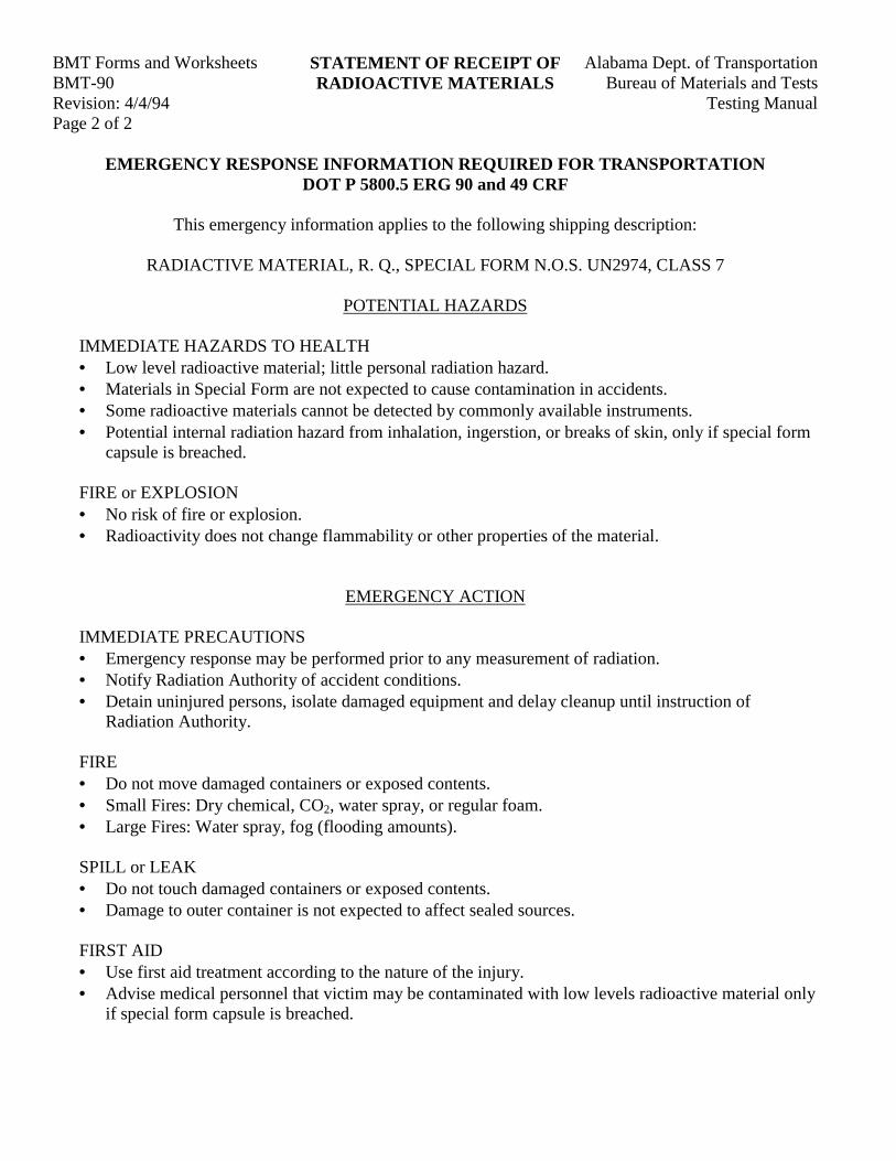
BMT Forms and Worksheets Alabama Dept. of TransportationSTATEMENT OF RECEIPT OFBMT-90 Bureau of Materials and TestsRADIOACTIVE MATERIALSRevision: 4/4/94 Testing ManualPage 2 of 2
EMERGENCY RESPONSE INFORMATION REQUIRED FOR TRANSPORTATIONDOT P 5800.5 ERG 90 and 49 CRF
This emergency information applies to the following shipping description:
RADIACTIVE MATERIAL, R. Q., SPECIAL FORM N.O.S. UN2974, CLASS 7
POTENTIAL HAZARDS
IMMEDIATE HAZARDS TO HEALTH• Low level radioactive material; little personal radiation hazard.• Materials in Special Form are not expected to cause contamination in accidents.• Some radioactive materials cannot be detected by commonly available instruments.• Potential internal radiation hazard from inhalation, ingerstion, or breaks of skin, only if special form
capsule is breached.
FIRE or EXPLOSION• No risk of fire or explosion.• Radioactivity does not change flammability or other properties of the material.
EMERGENCY ACTION
IMMEDIATE PRECAUTIONS• Emergency response may be performed prior to any measurement of radiation.• Notify Radiation Authority of accident conditions.• Detain uninjured persons, isolate damaged equipment and delay cleanup until instruction of
Radiation Authority.
FIRE• Do not move damaged containers or exposed contents.• Small Fires: Dry chemical, CO2, water spray, or regular foam.• Large Fires: Water spray, fog (flooding amounts).
SPILL or LEAK• Do not touch damaged containers or exposed contents.• Damage to outer container is not expected to affect sealed sources.
FIRST AID• Use first aid treatment according to the nature of the injury.• Advise medical personnel that victim may be contaminated with low levels radioactive material only
if special form capsule is breached.

BMT Forms and WorksheetsAlabama Dept. of TransportationBMT-91Bureau of Materials and Tests
Revision: 5/3/94Testing ManualPage 1 of 1
QUALITY CONTROL PROGRAMAGGREGATE TEST REPORT
Lab No. Project Number:County:Date:
Producer Source NumberMaterial Redistribution Terminal No.Consigned to DestinationAmount Represented by this ReportDry Unit Weight (kg/m3) (Loose) (Rodded)
Transport Co. InitialsVehicle NumberSieve Opening4” (100 mm) X X X X X X3.5”(90 mm) X X X X X X3.0”(75 mm)2.5”(63 mm) X X X X X X2.0”(50 mm) X X X X X X1.5”(37.5 mm)1” (25.0 mm) X X X X X X3/4” (19.0 mm)1/2” (12.5 mm) X X X X X X3/8” (9.5 mm)No. 4(4.75 mm)No. 8(2.36 mm)No.16 (1.18 mm)No. 30(600 µm)No. 50(300 µm)No. 100(150 µm)No. 200(75 µm) X X X X X X
F.M.W.F.M.Difs - +. - +. - +. - +. - +. - +.
Deleterious substance approved by visual inspection. Yes No AASHTO T-11 = %
Note: Figures show percent total passing on square mesh sieves. Sieves marked "X" are not to be added infor the F.M. The material represented by this report meets all of the applicable Alabama Department ofTransportation Specifications for incorporation in .
(Fill in item number and description)
Quality Control Technician Certificate #
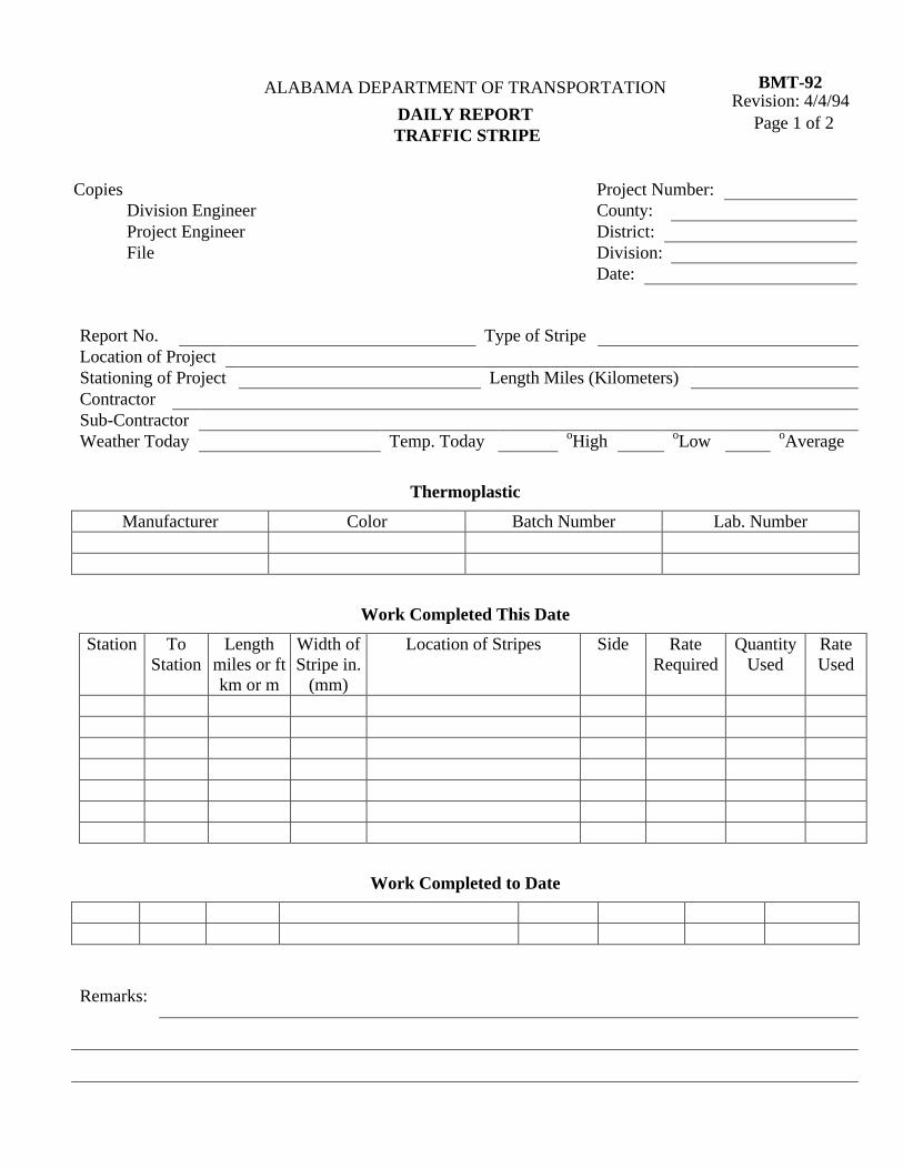
BMT-92 Revision: 4/4/94
ALABAMA DEPARTMENT OF TRANSPORTATION
Page 1 of 2 DAILY REPORT TRAFFIC STRIPE
Copies Project Number: Division Engineer County: Project Engineer District: File Division: Date:
Report No. Type of Stripe Location of Project Stationing of Project Length Miles (Kilometers) Contractor Sub-Contractor Weather Today Temp. Today oHigh oLow oAverage
Thermoplastic
Manufacturer Color Batch Number Lab. Number
Work Completed This Date
Station To Station
Length miles or ft km or m
Width of Stripe in.
(mm)
Location of Stripes Side Rate Required
Quantity Used
Rate Used
Work Completed to Date
Remarks:
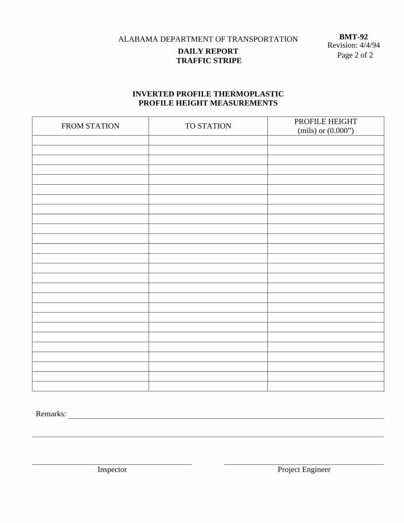
BMT-92 Revision: 4/4/94
ALABAMA DEPARTMENT OF TRANSPORTATION
Page 2 of 2 DAILY REPORT TRAFFIC STRIPE
INVERTED PROFILE THERMOPLASTIC
PROFILE HEIGHT MEASUREMENTS
FROM STATION TO STATION PROFILE HEIGHT (mils) or (0.000”)
Remarks:
Inspector Project Engineer
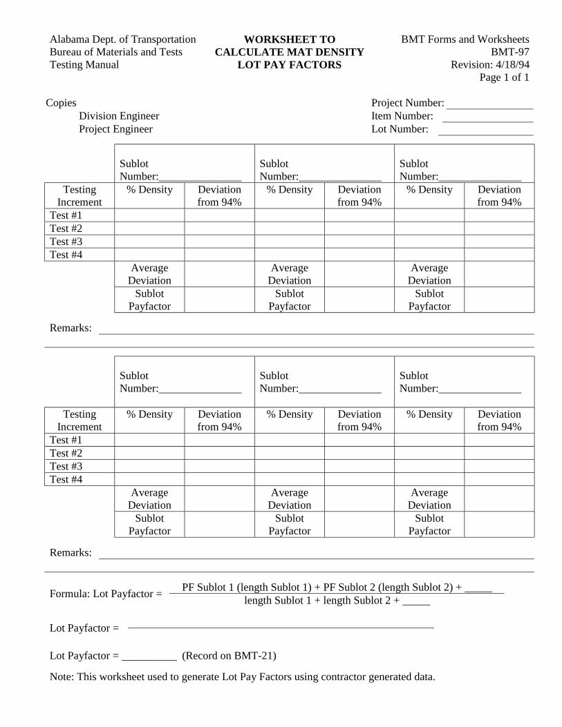
BMT Forms and WorksheetsAlabama Dept. of Transportation WORKSHEET TOBMT-97Bureau of Materials and Tests CALCULATE MAT DENSITY
Revision: 4/18/94Testing Manual LOT PAY FACTORSPage 1 of 1
Copies Project Number:Division Engineer Item Number:Project Engineer Lot Number:
SublotNumber:_______________
SublotNumber:_______________
SublotNumber:_______________
TestingIncrement
% Density Deviationfrom 94%
% Density Deviationfrom 94%
% Density Deviationfrom 94%
Test #1Test #2Test #3Test #4
AverageDeviation
AverageDeviation
AverageDeviation
SublotPayfactor
SublotPayfactor
SublotPayfactor
Remarks:
SublotNumber:_______________
SublotNumber:_______________
SublotNumber:_______________
TestingIncrement
% Density Deviationfrom 94%
% Density Deviationfrom 94%
% Density Deviationfrom 94%
Test #1Test #2Test #3Test #4
AverageDeviation
AverageDeviation
AverageDeviation
SublotPayfactor
SublotPayfactor
SublotPayfactor
Remarks:
PF Sublot 1 (length Sublot 1) + PF Sublot 2 (length Sublot 2) + _____Formula: Lot Payfactor =
length Sublot 1 + length Sublot 2 + _____
Lot Payfactor =
Lot Payfactor = __________ (Record on BMT-21)
Note: This worksheet used to generate Lot Pay Factors using contractor generated data.
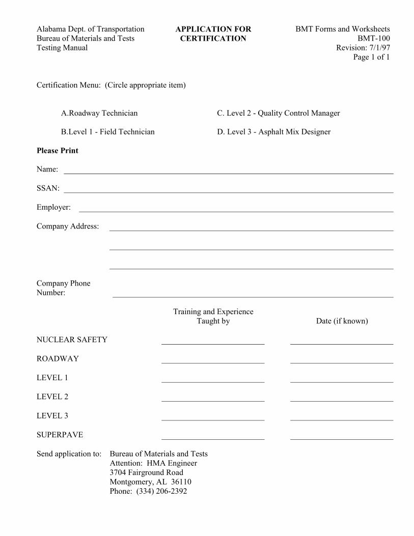
BMT Forms and Worksheets Alabama Dept. of Transportation APPLICATION FOR BMT-100 Bureau of Materials and Tests CERTIFICATION
Revision: 7/1/97 Testing Manual Page 1 of 1
Certification Menu: (Circle appropriate item)
A.Roadway Technician C. Level 2 - Quality Control Manager
B.Level 1 - Field Technician D. Level 3 - Asphalt Mix Designer
Please Print Name: SSAN: Employer: Company Address: Company Phone Number:
Training and Experience
Taught by Date (if known) NUCLEAR SAFETY ROADWAY LEVEL 1 LEVEL 2 LEVEL 3 SUPERPAVE Send application to: Bureau of Materials and Tests Attention: HMA Engineer 3704 Fairground Road Montgomery, AL 36110 Phone: (334) 206-2392
BMT Forms and Worksheets Alabama Dept. of Transportation CERTIFIED TECHNICIAN BMT-105 Bureau of Materials and Tests WARRANT
Revision: 4/4/94 Testing Manual Page 1 of 1
This document affirms that ______________________________ is certified by the Alabama
Department of Transportation as an Asphalt Technician (______________________________).
This certification carries inherent rights and responsibilities. These rights include-but are not limited
to-being exclusively sanctioned by the Alabama Department of Transportation to perform sampling,
__________ and testing for quality control and quality assurance programs. These responsibilities include
but are not limited to performing and reporting sampling, ___________________ and tests with the
accuracy and precision expected of a certified Asphalt Technician.
Abuse or neglect of these rights and responsibilities shall be penalized upon recommendation by the
working task force and approval by the Certification Board. The difference between neglect and abuse is
intent and shall be determined by the working task force. The first instance of neglect shall result in a
thirty-day suspension of the Asphalt Technician's certification. The second offense shall result in a one
hundred and eighty day suspension; any subsequent instances shall be considered as and treated the same as
abuse. The first instance of abuse shall result in permanent revocation of the Asphalt Technician's
certification.
Working Task Force Chairman Certification Board Chairman
I, _________________________, have read and understand the rights, responsibilities and penalties and
know that this warrant expires on ____________________.
BMT Forms and Worksheets Alabama Dept. of Transportation COMPARISON CHECK BMT-111 Bureau of Materials and Tests
Revision: 4/4/94 Testing Manual Page 1 of 1
Copies Project Number: Project Engineer County: IAS & T File
Mr. Date: District Engineer Alabama Department of Transportation , Alabama
Re: Comparison Check
Dear Sir: Attached is a copy of the comparison check made from the Layer of on the above-mentioned project. A study of the IAS&T test results and the Acceptance test indicate
Concrete Aggregate:
Bituminous Plant Mix:
Other Material:
The test results (are) (are not) reasonably close. Further comments, if any, on attached sheet.
Yours very truly,
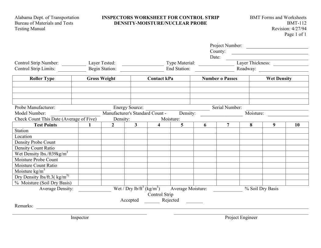
BMT Forms and Worksheets Alabama Dept. of Transportation INSPECTORS WORKSHEET FOR CONTROL STRIP BMT-112 Bureau of Materials and Tests DENSITY-MOISTURE/NUCLEAR PROBE
Revision: 4/27/94 Testing Manual Page 1 of 1
Project Number: County: Date: Control Strip Number: Layer Tested: Type Material: Layer Thickness: Control Strip Limits: Begin Station: End Station: Roadway:
Roller Type Gross Weight Contact kPa Number o Passes Wet Density Probe Manufacturer: Energy Source: Serial Number: Model Number: Manufacturer's Standard Count - Density: Moisture: Check Count This Date (Average of Five) Density: Moisture:
Test Points 1 2 3 4 5 6 7 8 9 10 Station Location Density Probe Count Density Count Ratio Wet Density lbs./ft39kg/m3 Moisture Probe Count Moisture Count Ratio Moisture kg/m3 Dry Density lbs/ft.3( kg/m3) % Moisture (Soil Dry Basis)
Average Density: Wet / Dry lb/ft3 (kg/m3) Average Moisture: % Soil Dry Basis Control Strip
Accepted Rejected Remarks:
Inspector Project Engineer
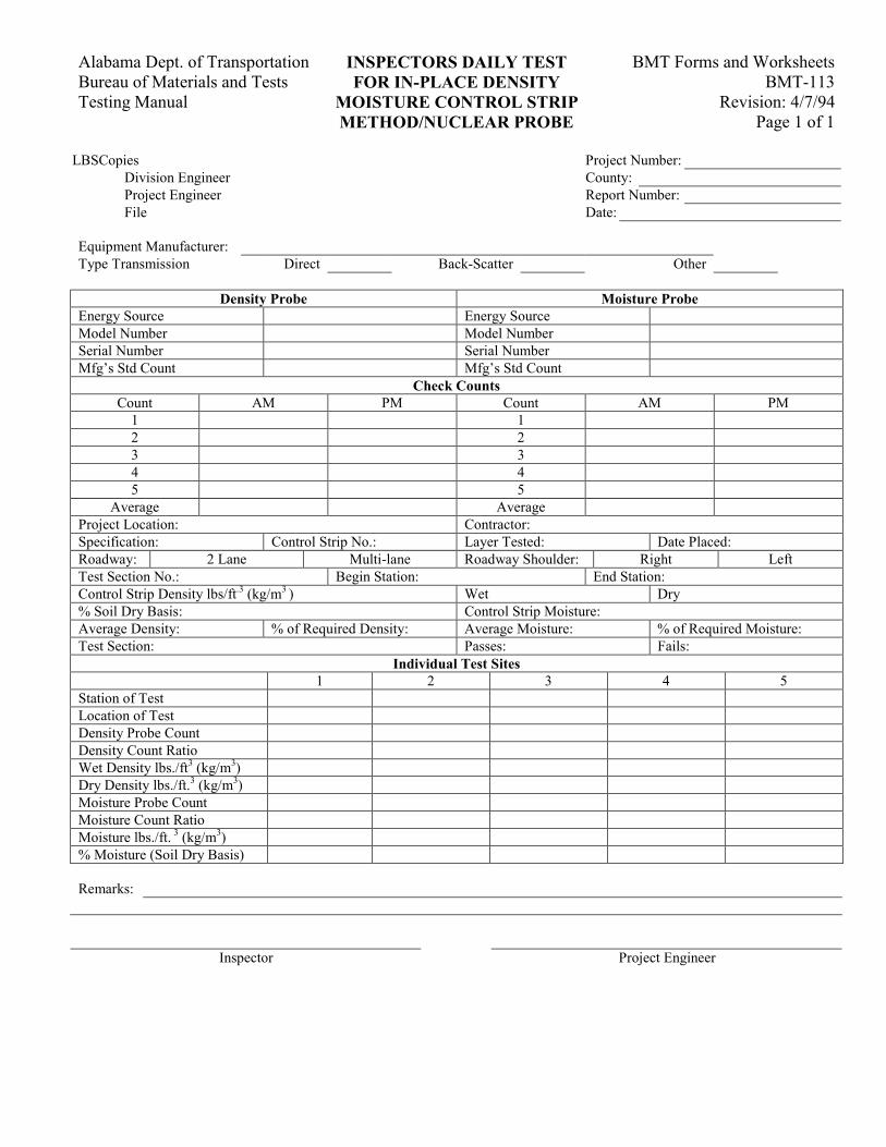
BMT Forms and Worksheets Alabama Dept. of Transportation INSPECTORS DAILY TEST BMT-113 Bureau of Materials and Tests FOR IN-PLACE DENSITY
Revision: 4/7/94 Testing Manual MOISTURE CONTROL STRIP Page 1 of 1 METHOD/NUCLEAR PROBE
LBSCopies Project Number: Division Engineer County: Project Engineer Report Number: File Date:
Equipment Manufacturer: Type Transmission Direct Back-Scatter Other
Density Probe Moisture Probe Energy Source Energy Source Model Number Model Number Serial Number Serial Number Mfg’s Std Count Mfg’s Std Count
Check Counts Count AM PM Count AM PM
1 1 2 2 3 3 4 4 5 5
Average Average Project Location: Contractor: Specification: Control Strip No.: Layer Tested: Date Placed: Roadway: 2 Lane Multi-lane Roadway Shoulder: Right Left Test Section No.: Begin Station: End Station: Control Strip Density lbs/ft.3 (kg/m3 ) Wet Dry % Soil Dry Basis: Control Strip Moisture: Average Density: % of Required Density: Average Moisture: % of Required Moisture: Test Section: Passes: Fails:
Individual Test Sites 1 2 3 4 5
Station of Test Location of Test Density Probe Count Density Count Ratio Wet Density lbs./ft3 (kg/m3) Dry Density lbs./ft.3 (kg/m3) Moisture Probe Count Moisture Count Ratio Moisture lbs./ft. 3 (kg/m3) % Moisture (Soil Dry Basis) Remarks:
Inspector Project Engineer

BMT Forms and Worksheets Alabama Dept. of Transportation CERTIFIED CEMENT BMT-114 Bureau of Materials and Tests SHIPMENTS
Revision: 7/14/95 Testing Manual Page 1 of 1
Copies White – Concrete Engineer Canary – Project Engineer Pink - Vendor Green – Concrete Plant
Part One for Producer
Producer: Type: Brand of Cement: Location of Cement Plant: Consignee: Location Shipped to: Car or Truck Initials and No.: Date Shipped: No. T (t) Tons Shipped: From Bin or Silo No.: Car or Truck Seal No.:
I hereby certify that the above information is correct and that the cement shipped is in accordance with our current certification to the Alabama Department of Transportation that the cement meets Alabama Department of Transportation Specifications.
Signed Date (To be signed by Company employee responsible for weighing.)
Part Two Executed by Certified Concrete Technician Project No.: County: Division: Car or Truck Seal No.: Source of Cement: Certification Accepted by: Cert. No.: Date:
Part Three Executed by Testing Engineer This cement has been supplied from a current approved source and has been approved for use.
Testing Engineer
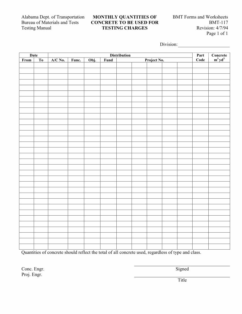
BMT Forms and Worksheets Alabama Dept. of Transportation MONTHLY QUANTITIES OF BMT-117 Bureau of Materials and Tests CONCRETE TO BE USED FOR
Revision: 4/7/94 Testing Manual TESTING CHARGES Page 1 of 1
Division:
Date Distribution From To A/C No. Func. Obj. Fund Project No.
Part Code
Concretem3 yd3
Quantities of concrete should reflect the total of all concrete used, regardless of type and class. Conc. Engr. Signed Proj. Engr. Title
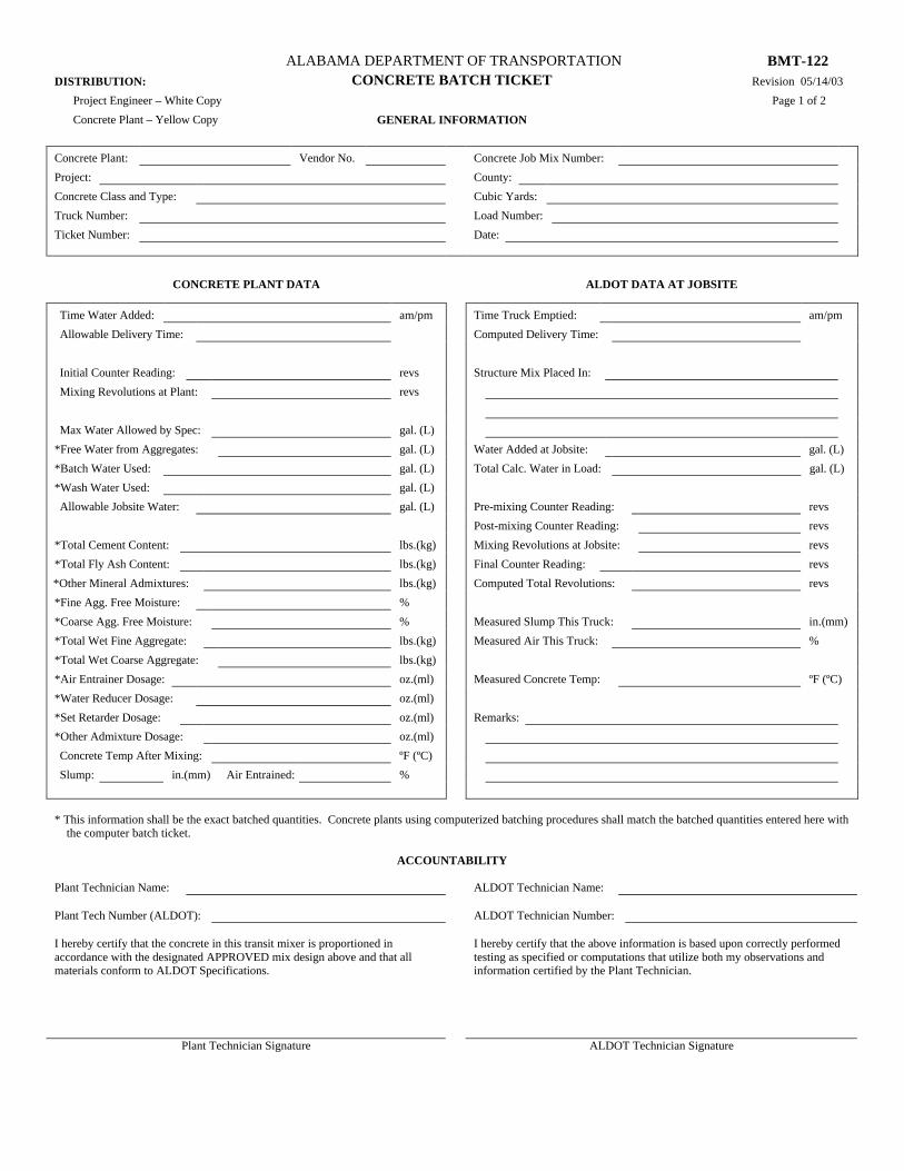
ALABAMA DEPARTMENT OF TRANSPORTATION BMT-122
DISTRIBUTION: CONCRETE BATCH TICKET Revision 05/14/03
Project Engineer – White Copy Page 1 of 2
Concrete Plant – Yellow Copy GENERAL INFORMATION
Concrete Plant: Vendor No. Concrete Job Mix Number:
Project: County:
Concrete Class and Type: Cubic Yards:
Truck Number: Load Number:
Ticket Number: Date:
CONCRETE PLANT DATA ALDOT DATA AT JOBSITE
Time Water Added: am/pm Time Truck Emptied: am/pm
Allowable Delivery Time: Computed Delivery Time:
Initial Counter Reading: revs Structure Mix Placed In:
Mixing Revolutions at Plant: revs
Max Water Allowed by Spec: gal. (L)
*Free Water from Aggregates: gal. (L) Water Added at Jobsite: gal. (L)
*Batch Water Used: gal. (L) Total Calc. Water in Load: gal. (L)
*Wash Water Used: gal. (L)
Allowable Jobsite Water: gal. (L) Pre-mixing Counter Reading: revs
Post-mixing Counter Reading: revs
*Total Cement Content: lbs.(kg) Mixing Revolutions at Jobsite: revs
*Total Fly Ash Content: lbs.(kg) Final Counter Reading: revs
*Other Mineral Admixtures: lbs.(kg) Computed Total Revolutions: revs
*Fine Agg. Free Moisture: %
*Coarse Agg. Free Moisture: % Measured Slump This Truck: in.(mm)
*Total Wet Fine Aggregate: lbs.(kg) Measured Air This Truck: %
*Total Wet Coarse Aggregate: lbs.(kg)
*Air Entrainer Dosage: oz.(ml) Measured Concrete Temp: ºF (ºC)
*Water Reducer Dosage: oz.(ml)
*Set Retarder Dosage: oz.(ml) Remarks:
*Other Admixture Dosage: oz.(ml)
Concrete Temp After Mixing: ºF (ºC)
Slump: in.(mm) Air Entrained: %
* This information shall be the exact batched quantities. Concrete plants using computerized batching procedures shall match the batched quantities entered here with
the computer batch ticket.
ACCOUNTABILITY Plant Technician Name: ALDOT Technician Name: Plant Tech Number (ALDOT): ALDOT Technician Number: I hereby certify that the concrete in this transit mixer is proportioned in accordance with the designated APPROVED mix design above and that all materials conform to ALDOT Specifications.
I hereby certify that the above information is based upon correctly performed testing as specified or computations that utilize both my observations and information certified by the Plant Technician.
Plant Technician Signature ALDOT Technician Signature
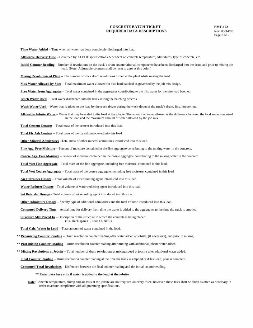
CONCRETE BATCH TICKET BMT-122 REQUIRED DATA DESCRIPTIONS Rev. 05/14/03
Page 2 of 2
Time Water Added – Time when all water has been completely discharged into load. Allowable Delivery Time – Governed by ALDOT specifications dependent on concrete temperature, admixtures, type of concrete, etc. Initial Counter Reading – Number of revolutions on the truck’s drum counter after all components have been discharged into the drum and prior to mixing the
load. (Note: Adjustable counters shall be reset to zero at this point.) Mixing Revolutions at Plant – The number of truck drum revolutions turned at the plant while mixing the load. Max Water Allowed by Spec – Total maximum water allowed for size load batched as governed by the job mix design. Free Water from Aggregates – Total water contained in the aggregates contributing to the mix water for the size load batched. Batch Water Used – Total water discharged into the truck during the batching process. Wash Water Used – Water that is added to the load by the truck driver during the wash-down of the truck’s drum, fins, hopper, etc.
Allowable Jobsite Water – Water that may be added to the load at the jobsite. The amount of water allowed is the difference between the total water contained
in the load and the maximum amount of water allowed by the job mix. Total Cement Content – Total mass of the cement introduced into this load. Total Fly Ash Content – Total mass of the fly ash introduced into this load. Other Mineral Admixtures –Total mass of other mineral admixtures introduced into this load. Fine Agg. Free Moisture – Percent of moisture contained in the fine aggregate contributing to the mixing water in the concrete. Coarse Agg. Free Moisture – Percent of moisture contained in the coarse aggregate contributing to the mixing water in the concrete. Total Wet Fine Aggregate – Total mass of the fine aggregate, including free moisture, contained in this load. Total Wet Coarse Aggregate – Total mass of the coarse aggregate, including free moisture, contained in this load. Air Entrainer Dosage – Total volume of air entraining agent introduced into this load. Water Reducer Dosage – Total volume of water reducing agent introduced into this load. Set Retarder Dosage – Total volume of set retarding agent introduced into this load. Other Admixture Dosage – Specify type of additional admixtures and the total volume introduced into this load. Computed Delivery Time – Actual time for delivery from time the water is added to the aggregates to the time the truck is emptied. Structure Mix Placed In – Description of the structure in which the concrete is being placed.
(Ex. Deck span #1, Pour #1, NBR) Total Calc. Water in Load – Total amount of water contained in the load.
** Pre-mixing Counter Reading – Drum revolution counter reading after water added at jobsite, (if necessary), and prior to mixing.
** Post-mixing Counter Reading – Drum revolution counter reading after mixing with additional jobsite water added.
** Mixing Revolutions at Jobsite – Total number of drum revolutions at mixing speed at jobsite after additional water added. Final Counter Reading – Drum revolution counter reading at the time the truck is emptied or if last load, pour is complete. Computed Total Revolutions – Difference between the final counter reading and the initial counter reading.
** Enter data here only if water is added to the load at the jobsite.
Note: Concrete temperature, slump and air tests at the jobsite are not required on every truck, however, these tests shall be taken as often as necessary in order to assure compliance with all governing specifications.
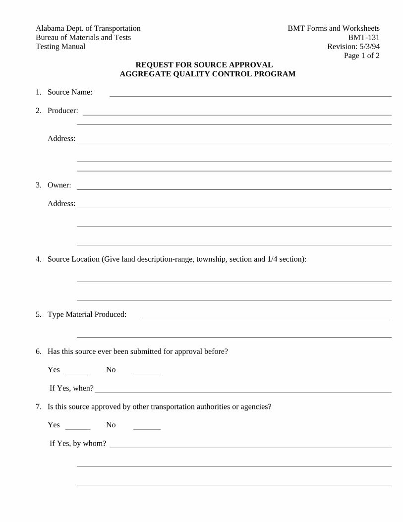
BMT Forms and WorksheetsAlabama Dept. of TransportationBMT-131Bureau of Materials and Tests
Revision: 5/3/94Testing ManualPage 1 of 2
REQUEST FOR SOURCE APPROVALAGGREGATE QUALITY CONTROL PROGRAM
1. Source Name:
2. Producer:
Address:
3. Owner:
Address:
4. Source Location (Give land description-range, township, section and 1/4 section):
5. Type Material Produced:
6. Has this source ever been submitted for approval before?
Yes No
If Yes, when?
7. Is this source approved by other transportation authorities or agencies?
Yes No
If Yes, by whom?
BMT Forms and Worksheets Alabama Dept. of TransportationBMT-131 Bureau of Materials and TestsRevision: 5/3/94 Testing ManualPage 2 of 2
The vendor is hereby notified that the Product Evaluation Board of the Alabama Department ofTransportation reserves the right to release or distribute any of the information included in this form as wellas any recommendations the Board might make concerning this source.
Signed
Type Name
Title
Date
The Product Evaluation Board will not consider any new source for approval until this form iscompleted and signed by a responsible official of the firm promoting the source. A check for $250.00,which includes a $50.00 submittal fee and a $200.00 evaluation fee, as per BMTP-355, should be madepayable to: Alabama Department of Transportation. The completed form, along with the $250.00 checkshould be returned to the address below:
Materials and Tests EngineerAttention: Aggregate Control SectionAlabama Department of Transportation3704 Fairground RoadMontgomery, Alabama 36110
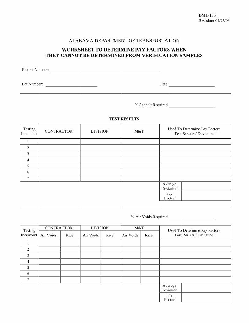
Revision: 04/25/03 BMT-135
ALABAMA DEPARTMENT OF TRANSPORTATION
WORKSHEET TO DETERMINE PAY FACTORS WHEN THEY CANNOT BE DETERMINED FROM VERIFICATION SAMPLES
Project Number:
Lot Number: Date:
% Asphalt Required:
TEST RESULTS
Testing Increment
CONTRACTOR DIVISION M&T Used To Determine Pay Factors
Test Results / Deviation
1
2
3
4
5
6
7
Average Deviation
Pay Factor
% Air Voids Required:
CONTRACTOR DIVISION M&T Testing
Increment Air Voids Rice Air Voids Rice Air Voids Rice Used To Determine Pay Factors
Test Results / Deviation
1
2
3
4
5
6
7
Average Deviation
Pay Factor
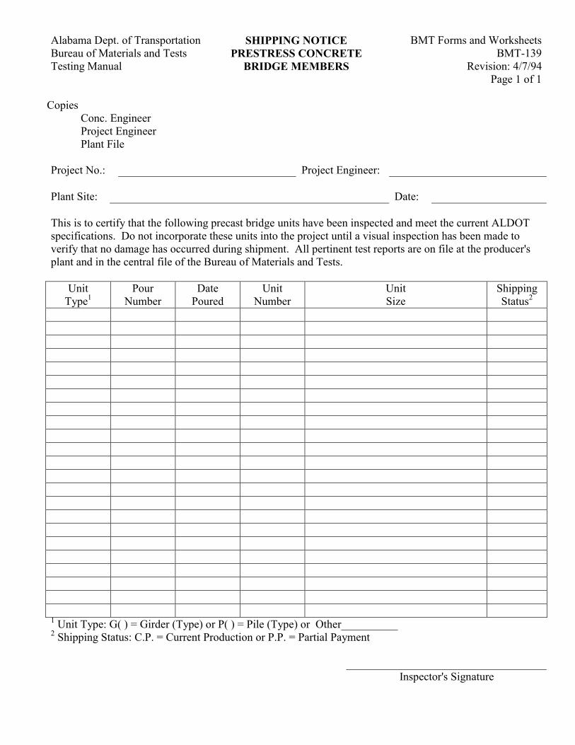
Alabama Dept. of Transportation SHIPPING NOTICE BMT Forms and Worksheets Bureau of Materials and Tests PRESTRESS CONCRETE BMT-139 Testing Manual BRIDGE MEMBERS Revision: 4/7/94
Page 1 of 1
Copies Conc. Engineer Project Engineer Plant File
Project No.: Project Engineer: Plant Site: Date: This is to certify that the following precast bridge units have been inspected and meet the current ALDOT specifications. Do not incorporate these units into the project until a visual inspection has been made to verify that no damage has occurred during shipment. All pertinent test reports are on file at the producer's plant and in the central file of the Bureau of Materials and Tests.
Unit Type1
Pour Number
Date Poured
Unit Number
Unit Size
Shipping Status2
1 Unit Type: G( ) = Girder (Type) or P( ) = Pile (Type) or Other__________ 2 Shipping Status: C.P. = Current Production or P.P. = Partial Payment Inspector's Signature
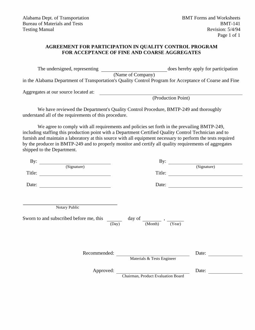
Alabama Dept. of Transportation BMT Forms and WorksheetsBureau of Materials and Tests BMT-141Testing Manual Revision: 5/4/94
Page 1 of 1
AGREEMENT FOR PARTICIPATION IN QUALITY CONTROL PROGRAMFOR ACCEPTANCE OF FINE AND COARSE AGGREGATES
The undersigned, representing does hereby apply for participation(Name of Company)
in the Alabama Department of Transportation's Quality Control Program for Acceptance of Coarse and Fine
Aggregates at our source located at:(Production Point)
We have reviewed the Department's Quality Control Procedure, BMTP-249 and thoroughlyunderstand all of the requirements of this procedure.
We agree to comply with all requirements and policies set forth in the prevailing BMTP-249,including staffing this production point with a Department Certified Quality Control Technician and tofurnish and maintain a laboratory at this source with all equipment necessary to perform the tests requiredby the producer in BMTP-249 and to properly monitor and certify all quality requirements of aggregatesshipped to the Department.
By: By:(Signature) (Signature)
Title: Title:
Date: Date:
Notary Public
Sworn to and subscribed before me, this day of ,(Day) (Month) (Year)
Recommended: Date:Materials & Tests Engineer
Approved: Date:Chairman, Product Evaluation Board
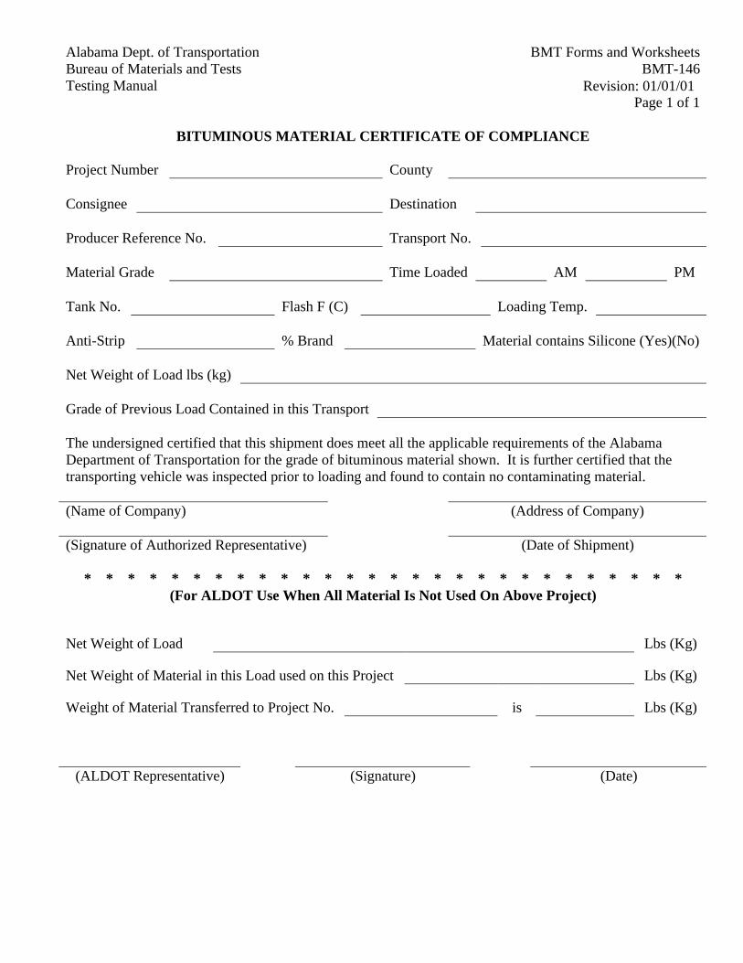
Alabama Dept. of Transportation BMT Forms and WorksheetsBureau of Materials and Tests BMT-146Testing Manual Revision: 01/01/01
Page 1 of 1
BITUMINOUS MATERIAL CERTIFICATE OF COMPLIANCE
Project Number County
Consignee Destination
Producer Reference No. Transport No.
Material Grade Time Loaded AM PM
Tank No. Flash F (C) Loading Temp.
Anti-Strip % Brand Material contains Silicone (Yes)(No)
Net Weight of Load lbs (kg)
Grade of Previous Load Contained in this Transport
The undersigned certified that this shipment does meet all the applicable requirements of the AlabamaDepartment of Transportation for the grade of bituminous material shown. It is further certified that thetransporting vehicle was inspected prior to loading and found to contain no contaminating material.
(Name of Company) (Address of Company)
(Signature of Authorized Representative) (Date of Shipment)
* * * * * * * * * * * * * * * * * * * * * * * * * * * *(For ALDOT Use When All Material Is Not Used On Above Project)
Net Weight of Load Lbs (Kg)
Net Weight of Material in this Load used on this Project Lbs (Kg)
Weight of Material Transferred to Project No. is Lbs (Kg)
(ALDOT Representative) (Signature) (Date)
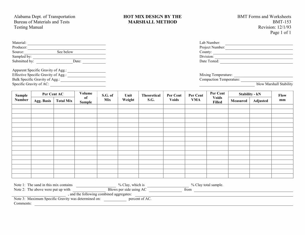
Alabama Dept. of Transportation HOT MIX DESIGN BY THE BMT Forms and Worksheets Bureau of Materials and Tests MARSHALL METHOD BMT-153 Testing Manual Revision: 12/1/93
Page 1 of 1
Material: Lab Number: Producer: Project Number: Source: See below County: Sampled by: Division: Submitted by: Date: Date Tested: Apparent Specific Gravity of Agg.: Effective Specific Gravity of Agg.: Mixing Temperature: Bulk Specific Gravity of Agg.: Compaction Temperature: Specific Gravity of AC: blow Marshall Stability
Per Cent AC Stability - kN Sample Number Agg. Basis Total Mix
Volume of
Sample
S.G. of Mix
Unit Weight
TheoreticalS.G.
Per Cent Voids
Per CentVMA
Per CentVoids Filled Measured Adjusted
Flow mm
Note 1: The sand in this mix contains % Clay, which is % Clay total sample. Note 2: The above were put up with Blows per side using AC from , and the following combined aggregates: Note 3: Maximum Specific Gravity was determined on: percent of AC. Comments:

Alabama Dept. of Transportation BMT Forms and WorksheetsBureau of Materials and Tests BMT-154Testing Manual Revision: 10/22/01
Page 1 of 1
SUMMARY OF INDEPENDENT ASSURANCE SAMPLESAND TESTS CORING REPORT
PROJECT NUMBER COUNTY DIVISION
ROADWAY DESIGN (SINGLE RDWY.) (DOUBLE RDWY.)
ROADWAY CORED LAYER CORED
CORED BY DATES CORED
Plan Requirements:
THICKNESS THICKNESSSTATION
LEFT RIGHTSTATION
LEFT RIGHT
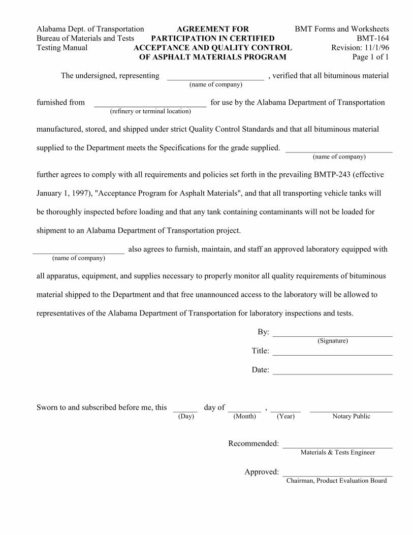
Alabama Dept. of Transportation AGREEMENT FOR BMT Forms and Worksheets Bureau of Materials and Tests PARTICIPATION IN CERTIFIED BMT-164 Testing Manual ACCEPTANCE AND QUALITY CONTROL Revision: 11/1/96
OF ASPHALT MATERIALS PROGRAM Page 1 of 1
The undersigned, representing , verified that all bituminous material (name of company) furnished from for use by the Alabama Department of Transportation (refinery or terminal location) manufactured, stored, and shipped under strict Quality Control Standards and that all bituminous material supplied to the Department meets the Specifications for the grade supplied.
(name of company) further agrees to comply with all requirements and policies set forth in the prevailing BMTP-243 (effective January 1, 1997), "Acceptance Program for Asphalt Materials", and that all transporting vehicle tanks will be thoroughly inspected before loading and that any tank containing contaminants will not be loaded for shipment to an Alabama Department of Transportation project. also agrees to furnish, maintain, and staff an approved laboratory equipped with
(name of company) all apparatus, equipment, and supplies necessary to properly monitor all quality requirements of bituminous material shipped to the Department and that free unannounced access to the laboratory will be allowed to representatives of the Alabama Department of Transportation for laboratory inspections and tests.
By: (Signature) Title: Date:
Sworn to and subscribed before me, this day of , (Day) (Month) (Year) Notary Public
Recommended: Materials & Tests Engineer
Approved:
Chairman, Product Evaluation Board
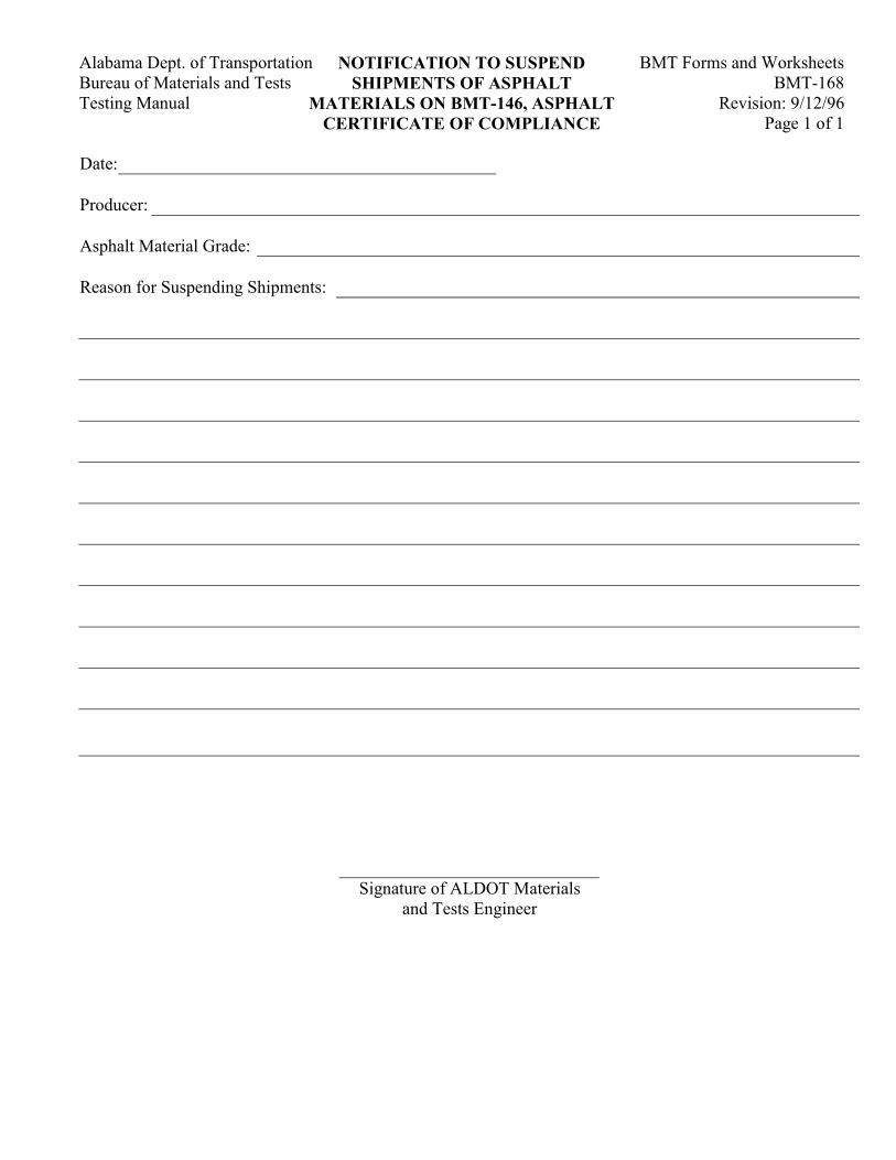
Alabama Dept. of Transportation BMT Forms and Worksheets NOTIFICATION TO SUSPEND Bureau of Materials and Tests BMT-168 SHIPMENTS OF ASPHALT Testing Manual Revision: 9/12/96 MATERIALS ON BMT-146, ASPHALT
Page 1 of 1 CERTIFICATE OF COMPLIANCE
Date: Producer: Asphalt Material Grade: Reason for Suspending Shipments: Signature of ALDOT Materials
and Tests Engineer
BMT Forms and Worksheets Alabama Dept. of Transportation CERTIFIED TECHNICIAN BMT-169 Bureau of Materials and Tests WARRANT
Revision: 11/1/96 Testing Manual Page 1 of 1
This document affirms that ________________________________________ is certified by the Alabama Department of Transportation as a Certified Asphalt Materials Technician, with the following certification designation: _______________________________________________________________________________________ This certification carries inherent rights and responsibilities. These rights include, but are not limited to, being exclusively sanctioned by the Alabama Department of Transportation to perform inspection and testing of asphalt products necessary to ensure a high level of quality control. These responsibilities include the reporting of test results with accuracy and precision expected of a Certified Asphalt Materials Technician. Abuse or neglect of these rights and responsibilities shall be penalized upon recommendation by the Working Task Force and approval by the Certification Board. The difference between neglect and abuse is intent and shall be determined by the Working Task Force. The first instance of neglect shall result in a thirty (30) day suspension of the Certified Asphalt Materials Technician's certification. The second offense of neglect shall result in a one hundred and eighty (180) day suspension; the first instance of abuse shall result in a one (1) year suspension. The second instance of abuse shall result in a permanent revocation of the Certified Asphalt Materials Technician's certification. ___________________________________ Chairman, Working Task Force ___________________________________ Chairman, Certification Board I, _______________________________________, have read and understand the rights, responsibilities, and penalties as they pertain to my duties. I further acknowledge that this warrant expires on _____________________________, subject to renewal as per BMTP-243.
BMT Forms and WorksheetsAlabama Dept. of TransportationBMT-170Bureau of Materials and Tests
Revision: 4/6/01Testing ManualPage 1 of 1
GUARDRAIL SUBMITTAL FORM
Project NumberCountyDivisionDate
GUARDRAIL MATERIAL (Feet or Meters) AND TYPE OF ANCHOR
BRAND QUANTITY PAY ITEM NO. & DESCRIPTION
STEEL POSTS AND BLOCKS
HEAT/LOT NO. QUANTITY DESCRIPTION
TREATED WOOD POSTS AND BLOCKS
CHARGE NO. QUANTITY DESCRIPTION
BMT-171
ALABAMA DEPARTMENT OF TRANSPORTATION Revision: 07/26/02 EVAPORATION RATE RECORD
Distribution: Project Engineer – White Division Engineer – Green Contractor - Yellow
GENERAL INFORMATION
Project No.: County: Date:
Concrete Class and Type: Concrete Job Mix Number:
Hygrometer Number: M&T - Anemometer Number: M&T -
DATA RECORD
TIME
AIR
TEMP. (°F)
RELATIVE
HUMIDITY
(%)
CONCRETE
TEMP. (°F)
WIND
SPEED
(Mile/hr)
RATE OF
EVAPORATION
(lb/Ft2/hr)
REMARKS
ACCOUNTABILITY
Technician Name: _____________________________ Technician Number (ALDOT No.): ____________________
I hereby certify that the above information is based upon correctly performed testing as specified and/or computations using the above instruments.
_____________________________ Technician Signature
BMT-172 Distribution: Rev. 07/26/02 Proj. Engineer - White Div. Engineer - Green Ready Mix Plant - Yellow
ALABAMA DEPARTMENT OF TRANSPORTATION RECORD OF CALIBRATION VERIFICATION OF TRUCK MOUNTED WATER METERS
GENERAL INFORMATION
Concrete Producer: Vendor Code:
Verification Date: Truck Number:
Scale Calibration Date: Meter Serial No.:
DATA
WEIGHT OF DRUM (lb)
[1]
WEIGHT OF DRUM PLUS WATER (lb)
[2]
WEIGHT OF WATER (lb) [3] = [2] – [1]
TOTALWATER IN GALLONS
[3] ÷ 8.34
METER READING
TOLERANCE METER
READING (gl) [4] + 1% [5] - 1% [6]
DELIVERED GALLONS
[3]
==DELIVEROFTIME
GALLONSDELIVEREDRATEFLOW
gl/min
YES NO DOES METER MEETS CALIBRATION:
ACCOUNTABILITY
Plant Technician Name: ALDOT Technician Name:
Plant Technician Number (ALDOT) ALDOT Technician Number: I hereby certify that the above calibration verification was performed in accordance with ALDOT– 407 and that the results meet the requirement of ALDOT Specifications.
I hereby certify that I observe the calibration verification of the above water meter and that all the recorded information is correct.
__________________________ __________________________ Plant Technician Signature ALDOT Technician Signature
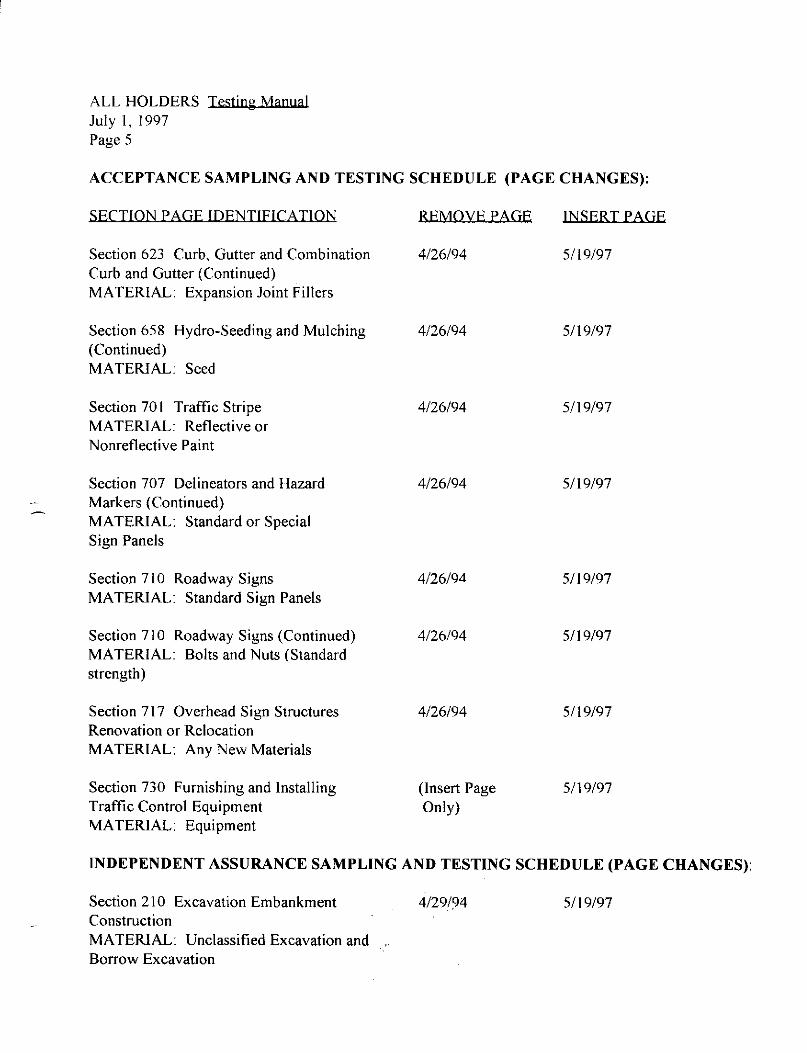
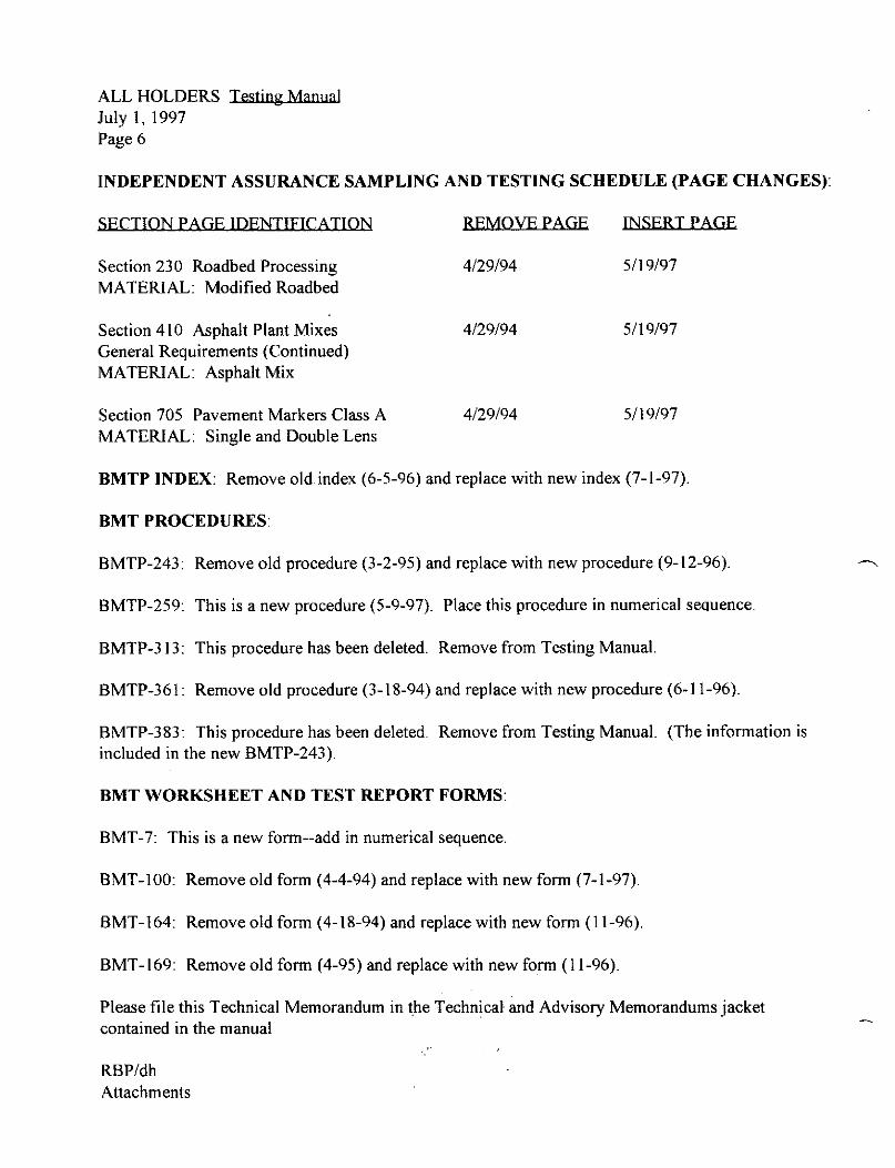
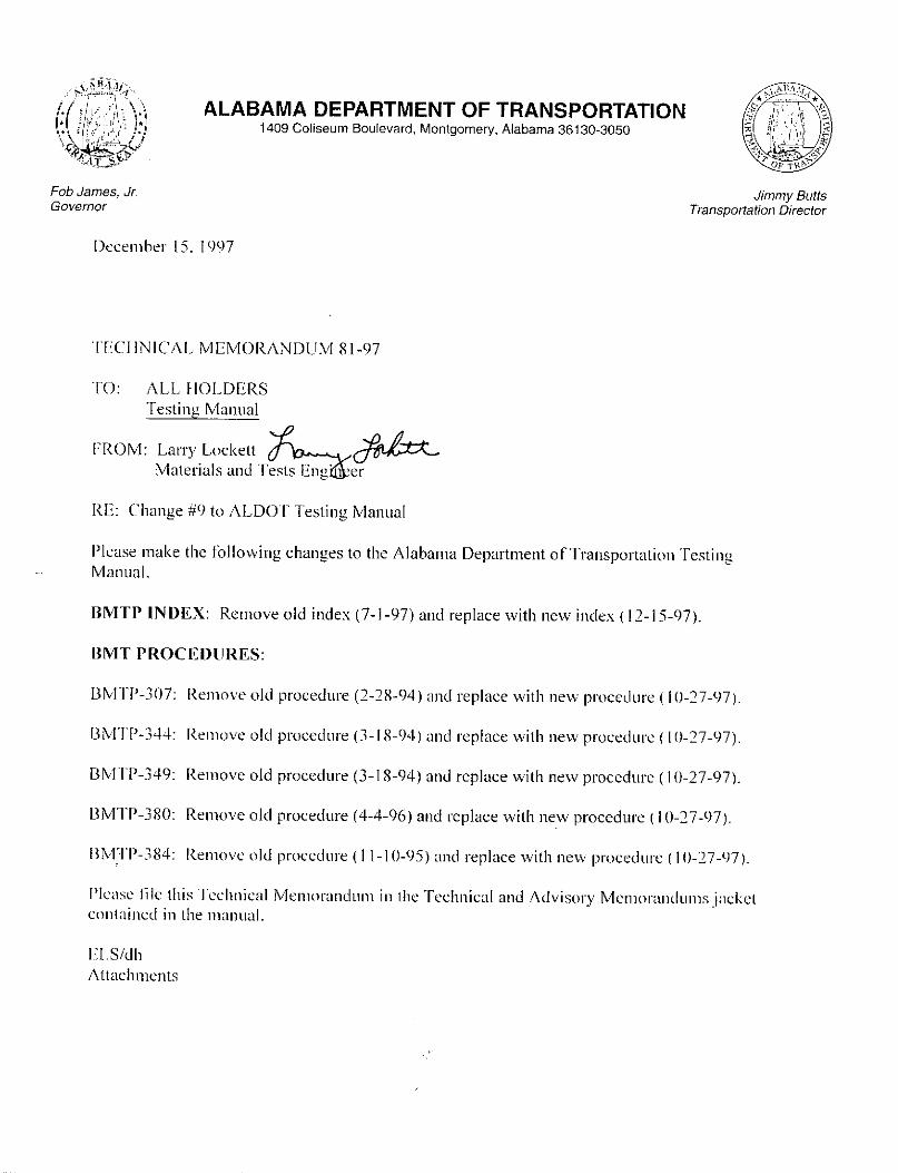
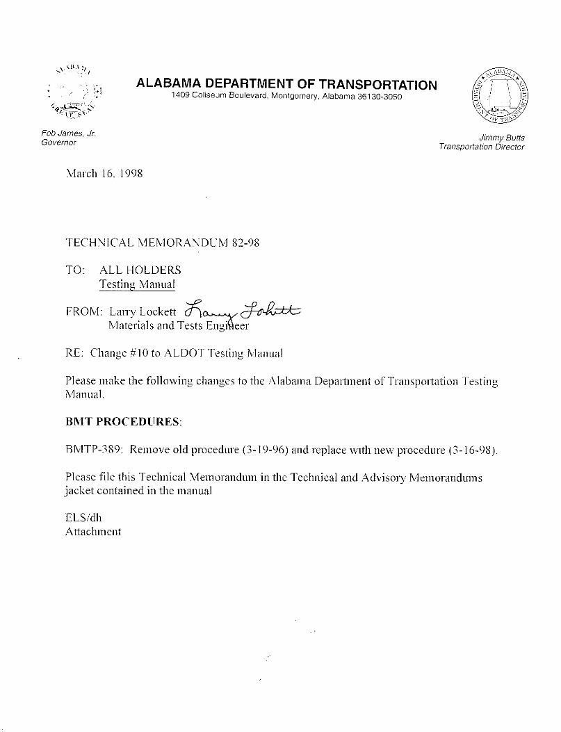
ALABAMA DEPARTMENT OF TRANSPORTATIONBUREAU OF MATERIALS AND TESTS
1409 Coliseum Boulevard, Montgomery, Alabama 36130-3050Telephone: 334/206-2300 - Fax No: 334/264-6263
Don Siegelman. Paul BowlinGovernor Transportation Director
MEMORANDUM
August 1, 2001
To: All Division Materials EngineersAll Division Construction EngineersAll Traffic Striping/Marking Contractors
From: Larry LockettMaterials and Tests Engineer
Re: “Traffic Marking Materials Certificate of Compliance”, Form BMT-3
Effective immediately, all contractors responsible for the placement of traffic striping or traffic controlmarkings and legends shall use form BMT-3 to report the quantities of materials specified by Sections701 (Traffic Stripe), 702 (Profiled Traffic Stripe), 703 (Traffic Control Markings and Legends), and 856(Traffic Marking Materials) of the Standard Specifications that are used in project construction.
Copies of the BMT-3 form shall be distributed as follows:
Original - Bureau of Materials and TestsCopy - Division Materials EngineerCopy - Project Engineer
The Paint Laboratory of the Central Testing Labs will use only the information provided on the BMT-3form to release test reports to the project office. No other form will be acceptable.
The BMT-3 form will be used by the Project Engineer to determine the final quantities to be reported inthe BMT-38 form, Summary of Tests. Therefore, all required information must be provided in carefuldetail. The completed BMT-3 must be signed by an authorized representative of the company andnotarized.
A copy of the BMT-3 form may be viewed in the electronic version of the Testing Manual availablethrough the ALDOT homepage at:
http://www.dot.state.al.us/Bureau/Materials_Tests/Testing/ALDOT_Testing_Manual.pdf
A copy of the BMT-3 form in Microsoft “Word” format suitable for use in entering required informationis available upon request from Mr. Butch Bolling at (334) 206-2341.
LL/jkb
Cc: Mr. Lynn WolfeFile
ALABAMA DEPARTMENT OF TRANSPORTATIONBUREAU OF MATERIALS AND TESTS
1409 Coliseum Boulevard, Montgomery, Alabama 36130-3050Telephone: 334/206-2300 - Fax No: 334/264-6263
Don Siegelman. Paul BowlinGovernor Transportation Director
February 14, 2002
TECHNICAL MEMORANDUM 87-02
To: All Division Materials EngineersAll Division Construction EngineersConstruction Bureau
From: Larry LockettMaterials and Tests Engineer
Re: “QC/QA Mat Density Report”, Form BMT-21
Effective immediately, the revised BMT-21 form (Revision: 02/12/002) shall be used to report matdensity.
A copy of the revised BMT-21 form may be viewed in the electronic version of the Testing Manualavailable through the ALDOT homepage at:
http://www.dot.state.al.us/Bureau/Materials_Tests/Testing/ALDOT_Testing_Manual.pdf
A copy of the BMT-21 form in Microsoft “Word” format suitable for use in entering requiredinformation is available upon request from Mr. Sandy Marshal at (334) 206-2402.
LL/rlw
Cc: Mr. Gary BrunsonMr. Lynn WolfeFile
ALABAMA DEPARTMENT OF TRANSPORTATIONBUREAU OF MATERIALS AND TESTS
1409 Coliseum Boulevard, Montgomery, Alabama 36130-3050Telephone: 334/206-2300 - Fax No: 334/264-6263
Don Siegelman. Paul BowlinGovernor Transportation Director
February 21, 2002
TECHNICAL MEMORANDUM 88-02
To: Testing Manual Users
From: Larry LockettMaterials and Tests Engineer
Re: Procedure ALDOT-401, "Rutting Susceptibility Determination of Asphalt Paving MixturesUsing the Asphalt Pavement Analyzer"
Please be advised that the above referenced procedure has been added to the Testing Manual on this date. This procedure was approved for use on February 7, 2001.
A copy of the procedure may be viewed in the electronic version of the Testing Manual available throughthe ALDOT homepage at:
http://www.dot.state.al.us/Bureau/Materials_Tests/Testing/ALDOT_Testing_Manual.pdf
LL/rlw
Cc: Mr. Lynn WolfeFile
ALABAMA DEPARTMENT OF TRANSPORTATIONBUREAU OF MATERIALS AND TESTS
1409 Coliseum Boulevard, Montgomery, Alabama 36130-3050Telephone: 334/206-2300 - Fax No: 334/264-6263
Don Siegelman. Paul BowlinGovernor Transportation Director
February 22, 2002
TECHNICAL MEMORANDUM 89-02
To: Testing Manual Users
From: Larry LockettMaterials and Tests Engineer
Re: Procedure ALDOT-243, "Acceptance Program for Asphalt Materials"
Please be advised that the above referenced procedure has been revised on this date. This revisions ofthis procedure were approved for use on February 15, 2001.
The revisions include the following:
Section 2.20 - FTIR added.
Section 2.22 - Category "A" Technician deleted.
Section 2.25 - Category "D" Technician deleted.
Section 3.3.4.3 - Last two sentences regarding method of submittal deleted.
Section 3.3.4.4 - FTIR requirements added.
Section 3.4.1 - Requirements revised.
Table I - DTT and FTIR requirements added for PGAB
Table I - Anionic Emulsion section removed
Table II - Direct Tension Test (DTT) requirement added for PGAB.
Table II - Asphalt Cement section deleted.
Table II - Anionic Emulsion section removed.
A copy of the revised procedure may be viewed in the electronic version of the Testing Manual availablethrough the ALDOT homepage at:
http://www.dot.state.al.us/Bureau/Materials_Tests/Testing/ALDOT_Testing_Manual.pdf
LL/rlw
Cc: Mr. Lynn WolfeFile
May 6, 2003 TECHNICAL MEMORANDUM 91-03 To: Testing Manual Users From: Larry Lockett Materials and Tests Engineer Re: Procedure ALDOT-368, "Sampling Procedures for Elastomeric Bridge Bearing Pads" Please be advised that the above referenced procedure was revised on May 1, 2001. The revisions to the procedure were approved for use on June 25, 2002. The revisions include the following: Revisions to reflect a change from four types of bearing pads to five types of bearing pads. Revisions in references to fabricators and the handling and distribution of bearing pads to
projects. A copy of the revised procedure may be viewed in the electronic version of the Testing Manual available through the ALDOT homepage at:
http://www.dot.state.al.us/Bureau/Materials_Tests/Testing/ALDOT_Testing_Manual.pdf
LL/rlw Cc: Mr. Lynn Wolfe File
May 14, 2003 TECHNICAL MEMORANDUM 92-03 To: Testing Manual Users From: Larry Lockett Materials and Tests Engineer Re: Revisions to ALDOT Testing Manual Please note that the following revisions have been made to the Alabama Department of Transportation Testing Manual since the release of the previous edition dated 06/12/02: Cover Page: Replace page dated 06/12/02 with page dated 05/14/03. Acceptance Sampling and Testing Schedule: Replace Section 521 dated 5/19/97 with page dated 04/16/02. ALDOT-243-84: Replace version dated 9/12/96 with version dated 11/29/01 (see Technical Memorandum
89-02). ALDOT-335-83: Replace version dated 6/7/01 with version dated 03/03/03 (see Technical Memorandum
90-03). ALDOT-368-89: Replace version dated 1/20/95 with version dated 5/01/01 (see Technical Memorandum
91-03). Numerical Index of BMT Forms and Worksheets: Replace version dated 7/23/01 with version dated 5/13/03. BMT-4: Replace version dated 4/27/94 with version dated 5/11/01. BMT-19: Replace version dated 10/27/97 with sample data with blank form dated 10/27/97. BMT-20: Replace with BMT-20-G dated 2/26/03 and BMT-20-M dated 2/26/03. BMT-21: Replace version dated 2/12/02 with version dated 2/26/03. BMT-92: Replace single-page form dated 4/4/94 with two-page form dated 4/4/94. BMT-122: Replace version dated 4/27/94 with version dated 5/14/03. BMT-135: Replace version dated 10/27/97 with version dated 4/25/03. BMT-171: Add form dated 07/26/02.

Technical Memorandum 92-03 May 14, 2003 Page 2 of 2
BMT-172: Add form dated 07/26/02. Technical Memorandum 88-02: Add memo dated February 21, 2002. Technical Memorandum 89-02: Add memo dated February 22, 2002. Technical Memorandum 90-03: Add memo dated March 4, 2003. Technical Memorandum 91-03: Add memo dated May 6, 2003. The revised Testing Manual dated 05/14/03 is available through the ALDOT homepage at:
http://www.dot.state.al.us/Bureau/Materials_Tests/Testing/ALDOT_Testing_Manual.pdf
LL/rlw Cc: Mr. Lynn Wolfe File