
AL-TR-1 992-0042 AD-A255 332 - Defense Technical ... · AL-TR-1 992-0042 AD-A255 332 .... A...
14
AL-TR-1 992-0042 AD-A255 332 .... A ADVANTAGES OF USING A PROJECTED R HEAD-UP DISPLAY IN A FUGHT SIMULATOR M S T R 0 Philipp W. Peppier N HUMAN RESOURCES DIRECTORATE G AIRCREW TRAINING RESEARCH DIVISION Williams Air Force Base, AZ 85240-6457 DTIC. EECTF~ SEP 101992 A •July 1992 0 Final Technical Report for Period January 1991 - June 1992 R A T T Approved for public release; distribution is unlimited. R V 92 192-24909 AIR FORCE MATERIEL COMMAND BROOKS AIR FORCE BASE, TEXAS 78235-5000
Transcript of AL-TR-1 992-0042 AD-A255 332 - Defense Technical ... · AL-TR-1 992-0042 AD-A255 332 .... A...

AL-TR-1 992-0042
AD-A255 332 ....
A ADVANTAGES OF USING A PROJECTED
R HEAD-UP DISPLAY IN A FUGHT SIMULATOR
MSTR0 Philipp W. Peppier
N HUMAN RESOURCES DIRECTORATE
G AIRCREW TRAINING RESEARCH DIVISIONWilliams Air Force Base, AZ 85240-6457
DTIC.EECTF~
SEP 101992
A •July 1992
0 Final Technical Report for Period January 1991 - June 1992
RATT Approved for public release; distribution is unlimited.
RV
92 192-24909
AIR FORCE MATERIEL COMMANDBROOKS AIR FORCE BASE, TEXAS 78235-5000
NOTICES
When Government drawings, specifications, or other data are used for any purposeother than in connection with a definitely Government-related procurement, the UnitedStates Government incurs no responsibility or any obligation whatsoever. The fact thatthe Government may have formulated or in any way supplied the said drawings,specifications, or other data, is not to be regarded by implication, or otherwise in anymanner construed, as licensing the holder, or any other person or corporation; or asconveying any rights or permission to manufacture, use, or sell any patented inventionthat may in any way be rulated thereto.
The Office of Public Affairs has reviewed this report, and it is releasable to theNational Technical Information Service, where it will be available to the general public,including foreign nationals.
This report has been reviewed and is approved for publication.
PHIUPP W. PEPPLER DEE H. ANDREWS, Technical DirectorProject Scientist Aircrew Training Research Division
. N AROLColonel, USAFL.'Chie ircrew Training Research Division

Form AprovedREPORT DOCUMENTATION PAGE OMB o0704-0188
iPublic repoling burden for this collection of Infornaton Is estimated to average 1 hour rer response, including the time orerewing instructions, searching existing data sources, gatheringandmalntadnlng the dats needed, and completing and reviewlng the collection of Infoernatlon. Send comments regarding this burden estimate or any other aspect of this collection ofkmformation, Inctuding suggestions for reducing this burden, to Washington Headquantens Services, Directorate for Information Operations and Reports, 1215 Jefferson Davis Highway, Suite1204, Arlington. VA 22202-4302, and to the Office of Management and Budget, Paperwork Reduction Project (0704-0188). Washington, DC 20603.
1. AGENCY USE ONLY (Leave blank) 2. REPORT DATE 3. REPORT TYPE AND DATES COVEREDJuly 1992 Final - January 1991 - June 1992
4. TITLE AND SUBTITLE 5. FUNDING NUMBERSAdvantages of Using a Projected Head-Up Display in a Flight Simulator PE - 62205F
PR - 1123TA - 05
6. AUTHOR(S) WU - 01
Philipp W. Peppier
7. PERFORMING ORGANIZATION NAME(S) AND ADDRESS(ES) S. PERFORMING ORGANIZATIONArmstrong Laboratory REPORT NUMBERHuman Resources Directorate AL-TR-1992-0042Aircrew Training Research DivisionWilliams Air Force Base, AZ 85240-6457
9. SPONSORING/MONITORING AGENCY NAMES(S) AND ADDRESS(ES) 10. SPONSORING/MONITORING AGENCYREPORT NUMBER
11. SUPPLEMENTARY NOTES
12a. DISTRIBUTION/AVAILABILITY STATEMENT 12b. DISTRIBUTION CODE
Approved for public release; distribution is unlimited.
13.ABSTRACT (Maximum 200 words)
When viewing a real planar image through an aircraft head-up display (HUD) focused for "infinity,"diplopia and other related problems render the HUD useless as a training device. Future flight simulatorvisual displays are being developed with real planar image projections; therefore, this problem must beresolved. Past research into decollimating aircraft HUDs for real planar visual displays presented severalsolutions, but major side effects limited the tasks that could be trained with a decollimated HUD. Recentadvances in projector and graphics technology have made projecting a real planar HUD an attractivesolution. Projected HUD technology at Armstrong Laboratory, Aircrew Training Research Division, WilliamsAFB, Arizona is described. The advantages of using a projected HUD were investigated and are discussed.Advantages of using projected HUDs in simulators with a real planar visual display are numerous. ProjectedHUDs are lower cost, produce an accurate HUD field of view, are easily maintained, and are flexible.Projected HUDs are undoubtedly a technology for tomorrow.
14. SUBJECT TERMS 15. NUMBER OF PAGESField-of-view Head-up display Panel instruments 18Flight simulation Image projections Training devicesFlight simulators lIlages Visual displays 16. PRICE CODE
17. SECURITY CLASSIFICATION 18. SECURITY CLASSIFICATION 19. SECURITY CLASSIFICATION 20. LIMITATION OF ABSTRACTOF REPORT OF THIS PAGE OF ABSTRACT
Unclassified Unclassified UnclassifiedNSN 7540-01-280-5W0 Standard Form 296 (RV 8%)
Prescribed by ANSI 2391i 296-102
CONTENTS
PageSUM MARY .. . . . .. . . .. . .. .. . .. .. . .. . .. .. . .. . . . .. 1
INTRODUCTION .................................. 1
THE TECHNOLOGY ................................ 2
ADVANTAGES ................................... 6
CONCLUSIONS .................................. 8
REFERENCES ................................... 9
BIBLIOGRAPHY .................................. 9
List of Figures
Fig.No.
1 HUD Symbology in the DART ...................... 3
2 Schematic of Projected HUD in the DART .............. 5
3 HUD and Visual Alignment T ...................... 6
4 Schematic of Projected HUD in the FFOV Dome ............ 7
Ust of Tables
TableNo.
1 Cost Comparison: Aircraft HUD vs. Projected HUD 8........8
iii

PREFACE
This investigation contributes to the development of cost-effective fligt.Vsimulation visual display technology. For a pilot to perform air-to-air,air-to-ground, and terrain-following fighter aircraft maneuvers in a flightsimulator, it is mandatory that information presented via the head-up display(HUD) be seen singly and clearly against the computer generatedout-of-the-cockpit visual scene. Specifically, effective combat missiontraining depends upon proper integration of HUD symbology and the simulatorvisual display. This investigation addresses this critical requirement fordevelopment of a cost effective, high fidelity visual display system.
I wish to thank Dr. Harry Warner of the University of Dayton ResearchInstitute, Mr. Gale Reining of General Electric Government Services, and Mr.Todd Baruch of Armstrong Laboratory for their assistance in preparing thisreport. I would also like to acknowledge the General Electric engineeringsupport team for their expertise in developing the HUD projection systemdescribed herein.
This work was conducted under Work Unit 1123-05-01, In-HouseResearch and Development Support. Work Unit monitor was Mr. Burlin M.Griffin.
Accesior. For
NTIS CRA&I)TIC I A6•- -
Unanlno w, I:~
JUStlfi'jt10o 1
ByU;:A 1bution,-v l 5 i'. . ; , 1
SAva!;. ", ý -:ii
[Dist
iv

ADVANTAGES OF USING A PROJECTED HEAD-UPDISPLAY IN A FLIGHT SIMULATOR
SUMMARY
To develop wider, brighter, and less expensive flight simulator visual displays,engineers have developed domes and rear-projection systems for flight simulatorsthat present real planar images. When collimated aircraft Head-Up Displays(HUDs) are used with planar displays, pilots experience severe doubling ofHUD symbology and other related problems. To make these visual displaysuseful with HUD equipped aircraft simulations, this problem must be addressedand solved. Several simulations have used external decollimating lenses onaircraft HUDs, but major side effects (such as 12% shrinkage of the HUD fieldof view (FOV)) make certain tasks impossible. At Armstrong Laboratory, AircrewTraining Research Division (AL/HRA), Williams AFB, Arizona, General Electrichas developed a projected HUD that will function with dome displays,rear-projection displays, and "infinity" optics. The projected HUD has two majorcomponents: a HUD symbology generation system and a projector. An alignmentprocedure is used to ensure mapping between the visual system and the HUDsymbology. Using a projected HUD in a flight simulator can offer manyadvantages. Projected HUDs can be mapped to ensure accurate HUD FOVand placement. As long as HUD symbology is accurate, the ability to correctlymap a projected HUD with the visual improves the capability of the simulatorto perform tasks with similar fidelity as the aircraft. A projected HUD isapproximately one-fifth the cost of using aircraft components. Projected HUDsystems use commercially available, nonproprietary, low-cost parts makingmaintenance and spares inventory an affordable and straightforward task.Considering the problems and costs associated with using aircraft HUDs in aflight simulator, projected HUDs are undoubtedly a technology for tomorrow.
INTRODUCTION
To "blend in" the pilot's view of the world on actual real-life missions,head-up displays (HUDs) were designed with "infinity" optics. Thatis, HUDs were so designed that their images would appear to originate at"infinity." Light from HUD symbology appears to come from a great distanceaway and is collimated; i.e., the light rays are practically parallel. Thus, whenpilots fixate on a target through the HUD in the real world, all the informationthey need is presented by the HUD without the pilots having to shift their gazeand change their visual accommodation (deGroot & Peppler, 1986).
Recently, simulators with 'infinity" windows were used so there would beno conflict with HUD imagery. But simulators with "infinity" windows are dim,can be expensive, and present a small field of view (FOV) when used singly(usually the straightahead scene). To develop wider, brighter, and less expensivedisplays, engineers have developed domes and rear-projection displays for flight
1

simulators. However, these displays present real planar images.' Whencollimated HUDs are used with planar displays, pilots experience severe doublingof HUD symbology and other related problems (deGroot & Peppier, 1986).
Several simulations, including the F-16A limited-field-of-view (LFOV) domesimulator at AL/HRA, Williams AFB, Arizona, have used external decollimatinglenses mounted on top of the exit lens of the HUD display unit to diverge theHUD symbology so that it appears to fall on the surface of the dome. Thatis, light from the HUD is focused so that it appears to match the distancebetween the pilot's eyepoint and the dome surface. The lens is inexpensiveand cures the double imaging, but it has one major side effect. For a 7.3-m(24-ft) dome application, the external lens causes a 12% shrinkage of theHUD's FOV. Internal adjustments to the gain potentiometers in the HUD displayunit decreased the shrinkage some, but pilots found the shrunken FOV madecertain F-16A HUD tasks such as high angle-of-attack (AOA), instrument landingsystem (ILS) approaches difficult if not impossible. Smaller domes wouldproduce even greater HUD FOV shrinkage. Clearly, an approach that providesreal HUD symbology without shrinking the FOV would be beneficial.
THE TECHNOLOGY
At AL/HRA, General Electric has developed a projected HUD that will functionwith dome displays, rear-projection displays, and "infinity" optics. The projectedHUD is operational in the Display for Advanced Research and Training (DART),"a rear-projection, full FOV, flight simulator display system. The DART projects"a real image. HUD symbology for an F-16C aircraft is rear projected onto thefronm window of the DART display. The symbology appears to overlay theout-the-window visual scene (Fig. 1). An alignment procedure is used to ensuremapping between the visual system and the HUD symbology. Future plansare to use the projected HUD in ALiHRA's full-field-of-view (FFOV) dome andfiber-optic helmet-mounted display (FOHMD). The projected HUD has two majorcomponents: a HUD symbology generation system and a projector.
The HUD symbology generation system is an I/O Incorporated graphicsboard set. AL/HRA has previously used these Versabus Modified for Eurocard(VME) bus-based graphics boards in various part-task trainers. The HUDsymbology for an F-16C aircraft is programmed into the graphics system.Navigation and air-to-air weapon delivery capability is available. Avionics datadriving the HUD symbology is calculated in the avionics simulation softwareand sent to the symbology generation system in the same 1,553 bus formatused in the aircraft. The same data could drive an aircraft HUD if required.This format allows the projected HUD and an aircraft HUD to be quicklyinterchangeable. The HUD symbology generation system outputs a 1,023 x1,023 line interlaced image at 30-Hz frame rate to the projector.
1A real image occurs when the rays of light from an object actually converge to form an image that can be seen on a screen fromwhich rays of light appear to diverge.
2
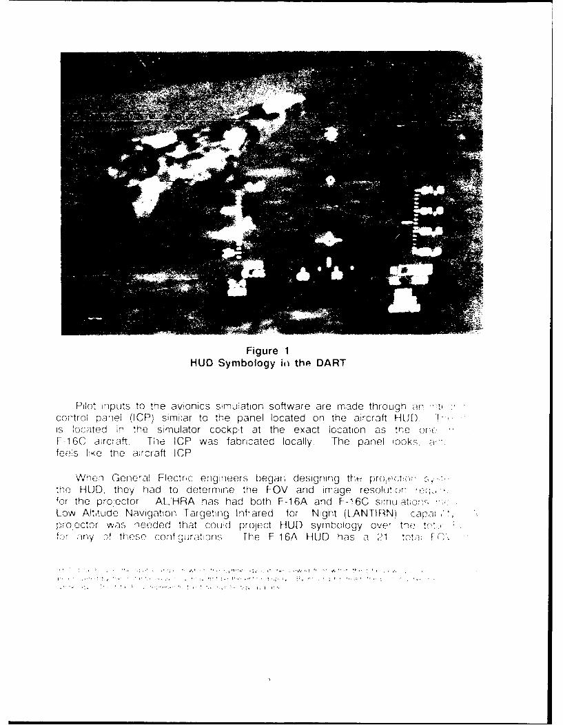
Figure 1HUD Symbology i~i the DART
Pilot inputs to the avionics simulation software are made through an 'a-control panel (ICP) similar to the panel located on the aircraft HUD .is located in the simulator cockpit at the exact location as the one "F-16C aircraft The ICP was fabricated locally. The panel lookz a;fees like the aircraft ICP
When General Electric engineers began designing the prooj..`-It::',, ,,.the HUD, they had to determine the FOV and image resolutior-n,...for the projector ALHRA has had both F-16A and F-16C SIMUatia',Low Altitude Navigation Targeting Infrared for Night (LANTIRN) caF:a"projector was needed that could project HUD symbology over the tt:'or iny of these configurations. The F- 16A HUD has a 21 tota1, -: F
........ ,.,' I ' "' ,•" '' ', '-.. . ... . . . . . . . . . . . . . . . ...

F-16C, a 250 total FOV, and the LANTIRN HUD, a 30" total FOV. Therefore,the projector had to have the capability to project an image with a total FOVof as much as 30'. Desired resolution for the HUD symbology was establishedat 1.5 arcminutes.3 The projector also had to display the 1,023 x 1,023 linerate coming from the symbology generation system.
With the requirements for the projector established, General Electric choseto procure a Macro Data Incorporated 36 (Macro Data 36) projector. TheMacro Data 36 is a portable, monochrome, auto-lock computer projector designedto project a high contrast image from a personal computer/terminal to a curvedhigh gain, flat, or rear screen. The projector displays monochrome (greenimage) from most standard video outputs. The auto-lock circuitry searches forhorizontal and vertical sync signals in the 13 kHz to 36+ kHz frequency rangehorizontal and 45 Hz to 85+ Hz vertical. Brightness output is 300 Lumens.
The Macro Data 36 has easy-to-locate controls for tilt and leveling, brightness,contrast, keystone effect, horizontal size, vertical size, center focus, top/bottomalignment, and electronic focus.
For rear-screen projection the scan can be reversed on the projector. Insidethe projector there are two yoke scan jacks. One jack is for standard scan,the other for reverse scan. The desired scan pattern is selected by placingthe yoke wires into the appropriate jack.
To install the HUD projector in the DART the Macro Data 36 projector wasconnected to the symbology generator and then placed behind the front screen(Fig. 2). Placing the projector in this location required that reverse scan beselected. The projector is placed approximately 1.2 m (4 ft) from the screenand below the mirror reflecting the out-the-cockpit visual scene. There is noconflict between the out-the-cockpit scene and the projected HUD.
It should be noted here that as long as a cockpit and its associatedsimulation has a HUD symbology generator compatible with the Macro Data36 projector, the same projection setup in the DART could be used for thatcockpit as well. This 3;etup could be useful if quick change out ofcockpits/simulators and visual displays is a priority.
To ensure correct mapping of the HUD symbology with the visual displayan alignment procedure is required. First of all, a boresight alignment T mustbe modelled in the visual database (Fig. 3). This T is commanded on in thescene by setting a discrete variable at the simulator control station. An identicalalignment T is modelled in the HUD symbology generation system and iscommanded on in a similar manner as the visual alignment T. To begin
3 An arcminute is a measurement of a visual angle, which is subtended at the eye by the viewed object. For visual angles lessthan 100 an arcminute equals (57.3) x (60) x L divided by D where L is the size of the object measured perpendicular to the lineof sight, and D is the distance from the eye to the object; 57.3 and 60 are constants for angles less than 600 minutes.
4

alignment, both alignment Ts should be commanded on. Assuming the visualprojectors are properly aligned, the HUD projector is then adjusted until theHUD alignment T exactly overlays the visual alignment T. Once this alignmentis complete the HUD symbology should be mapped with the visual scene andeverything should line up. The "pipper should overlay the target." Thisalignment procedure can be modified depending upon the application andcapabilities of the simulators involved.
W1 DART Projector
44 -DART RearProjectionScreen
M irror
EyepointHIUDImage
I ( I) Projector
Figure 2Schematic of Projected HUD In the DART
AL/HRA plans to install a HUD projection system in the FFOV dome. Forthis installation the same equipment will be used but the approach will bedifferent (Fig. 4). The simulator will have a similar HUD symbology generatoras the F-1 6 in the DART. Another Macro Data 36 or similar projector will beused. Because the projected HUD is on the surface of a 7.3-m (24-ft) diameterdome, standard scan will be set in the projector. Due to the nature of thevisual projection system in the FFOV dome, the HUD projector will be mountedsuch that a reflecting mirror will direct the image onto the surface of the dome.
5

Because the distance from the dome to the reflecting mirror is greater thanthe distance between the projector and the rear-projection screen of the DART,the exit lens of the projector may have to be modified to obtain correct mappingand focus.
Hi Alignment Te Azimuth & Elevaon (mils)
Thrlin e t p ro ess rt h Hash Mawl s are 3 mils thick
ovr naicAft crHUD.Even touht HU syblgdslydnacthd-a
And -Extend +/- 20miulsI---- ] -80
]- - 160
EL.
Figure 3HUD and Visual Alignment T
The alignment process for the FFOV dome application will be similar to theone used for the DART. Depending on which cockpit/simulator is in the dome,some modifications to the alignment procedures may have to be made.
ADVANTAGES
Using a projected HUD in a flight simulator can offer many advantagesover an aircraft HUD. Even though HUD symbology displayed on a cathode-raytube (CRT) may have possible application with FOHMD "infinity" optics visualdisplay systems, this report only addresses the advantages of using a projectedHUD in simulators with visuals that project real planar images.
One significant advantage of using. a projected HUD is its ability to producean accurate HUD FOV. Aircraft HUDs decollimated for use with a real planar
6

image experience a shrinkage in total FOV. This shrinkage has been determinedto be 12% for a 7.3-m (24-ft) dome. Smaller domes would cause even greatershrinkage. This shrinkage can make tasks such as high AOA ILS approachesand high drag bomb deliveries unachievable (deGroot & Peppier, 1986).
DomeDisplay
Surface
Mirror
ProjectedHIUD
Eyepoint - Image
FFOVD CockpitProjectionOptics HUD Image
Generator
HUD Projector
Figure 4Schematic of Projected HUD in the FFOV Dome
Projected HUDs can be mapped to ensure accurate HUD FOV and placement.As long as HUD symbology is accurate (this can be verified through testing),the ability to correctly map a projected HUD with the visual improves thecapability of the simulator to perform training tasks with similar fidelity as theaircraft.
When developing training devices, cost is always a major factor. Whenone evaluates the cost of procuring an aircraft HUD vs. a projected HUD, costis clearly in favor of the projected HUD system (Table 1). A projected HUDis approximately one-fifth the cost of using aircraft components.
7

Table 1. Cost Comparison Aircraft HUD vs. Projected HUD
CostAircraft HUD
F-1 6 HUD Pilot Display Unit (PDU) $150,000F-1 6 HUD Electronic Unit (EU) $ 75,000External Decollimating Lens $ 5,000
TOTAL $230,000
Projected HUD
HUD Symbology Generation SystemI/O Inc. Graphics Set $ 12,000HUD Symbology Graphics Software $ 30,000
HUD Integrated Control Panel w/Cabling $ 4,000Micro Data HUD Projector $ 3,000
TOTAL $ 49,000
Projected HUD systems are flexible. If designed properly, they are visualdisplay and cockpit independent. That is, a projected HUD system can beused in a rear-projection visual display or, with adjustments, it can be used ina dome visual display. A projected HUD system can be used with variousfidelity trainers, from part-task trainers to weapon system trainers and anythingin between. A properly designed projected HUD system can satisfy the HUDrequirements for various simulations (F-16, F-15, F-18, etc.).
Projected HUDs are useful for instructors who prefer looking over theshoulder of the trainee. Aircraft HUDs are focused to an eyepoint, makingobservance of the HUD impossible. With a projected HUD, the symbologyoverlays the visual scene so that both the trainee and instructor can see it.
Repairing aircraft HUDs can be difficult and time-consuming. Spares foraircraft HUDs are usually impossible to obtain. Therefore, when repairs arerequired, the simulator can be without a HUD for weeks. Projected HUDsystems use commercially available, nonproprietary low cost parts makingmaintenance, spares inventory, and if necessary, replacement an affordable andstraightforward task.
CONCLUSIONS
The advantages to using a projected HUD are obvious. With the push forhigher fidelity, lower cost training devices in full swing, the projected HUDshould help bolster that effort and should become a valuable tool in futuredevelopments. With the probability that future visual displays will be real planar
8

projection systems, projected HUDs may find their place in production simulatorsas well.
It is probably too early to conclude that there are no disadvantages involvedwith projected HUDs. There may be some, such as the ability of the pilot tomove his head out of the eyepoint and still see the projected HUD. Theremay be others. Hopefully, future use will uncover any disadvantages that mayexist, but, the advantages gained by using a projected HUD cannot be overlooked.
Projected HUDs are lower cost; they produce an accurate HUD FOV; theyare easily maintained; and they are flexible. If designed properly, they arevisual display and cockpit independent. Considering the problems and costsassociated with using aircraft HUDs in a flight simulator, projected HUDS areundoubtedly a technology for tomorrow.
REFERENCES
de Groot S., & Peppler P. (1986). Integrating a Head-Up Display with Dome VisualSimulation Technology (AFHRL-TP-86-43, AD-A175 222). Williams AFB, AZ:Operations Training Division, Air Force Human Resources Laboratory.
BIBLIOGRAPHY
Grether, W.F., & Baker, C.A. (1972) Visual Detection, Identification, and Estimation.Chapter 3 in Van Cott and Kinkade (Eds.), Human Engineering Guide toEquipment Design. Washington, D.C.: U.S. Government Printing Office.
Haber, R.N., & Hershenson, M. (1980). The Psychology of Visual Perception (2nded. pp. 11). New York: Holt, Reinhart and Winston.
Newman, R.L. (1987). Design Guide for Head-Up Displays (HUDs) for Fixed-WingAircraft (AFWAL-TR-87-3055, Vol. I). Wright-Patterson AFB, OH: Air ForceWright Aeronautical Laboratories, Flight Dynamics Laboratory.
-U.S. OV•R"• ET PRINTING OFFICE 19924-61-04916034


![Untitled-1 [scindeks-clanci.ceon.rs]scindeks-clanci.ceon.rs/data/pdf/0042-8426/2014/0042-8426140207… · су политика Балкана или спољашње политике](https://static.fdocuments.in/doc/165x107/5f28d0eb162266785e2e821b/untitled-1-scindeks-scindeks-f-.jpg)